SIN int 06 07 · 2018-06-20 · con foro quadro, esagonale o con dimensioni e/o profilo a disegno....
12
20125 Milano - Via Zuretti, 100 Tel. 02 67861 - Fax 02 6701062 Internet: http://www.bianchicuscinetti.it E-mail: [email protected] 40012 Calderara di Reno (BO) Loc. Bargellino - Via Turrini, 2 Tel. 051 728266 Fax 051 729301 [email protected] 50145 Firenze Via G. Di Vittorio, 5/43 Tel. 055 319205 Fax 055 319316 [email protected] 63033 Monteprandone (AP) Via Scopa, 4 Tel. 0735 705273 Fax 0735 713196 [email protected] 70026 Modugno (BA) Via delle Camelie Tel. 080 5370606 Fax 080 5314551 [email protected] 09122 Cagliari V.le Monastir, 210 Tel. 070 548114 Fax 070 531145 [email protected] 10146 Torino Via Rochemolles, 6 Tel. 011 721670 Fax 011 724187 [email protected] 20025 Legnano Via M. Venegoni, 80 Tel. 0331 597762 Fax 0331 545417 [email protected] 25124 Brescia Via della Volta, 181 Tel. 030 5105024 Fax 030 5105022 [email protected] 35127 Padova Via Polonia, 21 Tel. 049 8701233 Fax 049 8701209 [email protected] SIN ® BC - SIN - 10.07 Catalogo tecnico Technical catalogue Catálogo Técnico Giunti e Trasmissioni Cardaniche Universal Joints and Shafts Juntas y Transmisiones de Cardán
Transcript of SIN int 06 07 · 2018-06-20 · con foro quadro, esagonale o con dimensioni e/o profilo a disegno....
20125 Milano - Via Zuretti, 100 Tel. 02 67861 - Fax 02 6701062
Internet: http://www.bianchicuscinetti.it E-mail: [email protected]
40012 Calderara di Reno (BO) Loc. Bargellino - Via Turrini, 2
Tel. 051 728266 Fax 051 729301
50145 Firenze Via G. Di Vittorio, 5/43
Tel. 055 319205 Fax 055 319316
63033 Monteprandone (AP)Via Scopa, 4
Tel. 0735 705273Fax 0735 713196
70026 Modugno (BA) Via delle Camelie
Tel. 080 5370606 Fax 080 5314551
09122 Cagliari V.le Monastir, 210 Tel. 070 548114 Fax 070 531145
10146 Torino Via Rochemolles, 6 Tel. 011 721670 Fax 011 [email protected]
20025 Legnano Via M. Venegoni, 80 Tel. 0331 597762 Fax 0331 [email protected]
25124 BresciaVia della Volta, 181Tel. 030 5105024Fax 030 [email protected]
35127 Padova Via Polonia, 21 Tel. 049 8701233 Fax 049 [email protected]
SIN®
BC
- S
IN -
10
.07
Catalogo tecnicoTechnical catalogueCatálogo Técnico
Giunti e Trasmissioni CardanicheUniversal Joints and ShaftsJuntas y Transmisiones de Cardán
2
SIN®
3
SIN®SIN®
Da oltre trent’anni i giunti cardanici SIN® sono forniti nelle tre versioni:■ A perni: coppie elevate e prodotto velocità (rpm) x angolo (°) di lavoro <12.000■ A rullini: forniti lubrificati a vita per elevate velocità in ingombri limitati■ A crociera: con vere e proprie crociere cardaniche con ingrassatore ed intercambiabili
I giunti cardanici SIN® possono essere forniti nelle versioni: giunto cardanico semplice, giunto doppio, giunto con attacco rapido, trasmissione cardanica fissa o con allungamento telescopico. Le forature possono essere eseguite, oltre che nelle esecuzioni standard con cava per linguetta, con foro quadro, esagonale o con dimensioni e/o profilo a disegno. Sono inoltre fornibili esecuzioni speciali a disegno, extra corte, con molla di spinta, con giunti di diversa dimensione alle estremità, con scanalato in acciaio trattato e rettificato, con un dente dell’albero telescopico ribassato (per evitare errori di allineamento). Oltre che nei materiali standard i mozzi e gli scanalati possono essere forniti in acciaio inossidabile.I giunti e le trasmissioni SIN® a perni possono inoltre essere forniti sia con forcelle in acciaio bonificato ad elevata resistenza sia con perni e sfera interamente inox. Su richiesta giunti e trasmissioni possono essere zincati, cromati, bruniti, cadmiati, nichelati.ESECUZIONE STANDARD La lunghezza minima S indicata nelle tabelle rappresenta la lunghezza chiusa minima con l’allungamento “X” indicato.ESECUZIONE SU SPECIFICA DEL CLIENTE: il cliente definisce la lunghezza chiusa “S” e l’allungamento “X” desiderati.Se la differenza S-X risulta inferiore allo standard a catalogo, bisognerà verificare se possibile un’esecuzione “monoblocco”.Per allungamenti molto elevati ed in presenza di alte velocità di rotazione è necessario usare cautela.Per queste condizioni d’impiego consultare il nostro Ufficio Tecnico.
Since over 30 years SIN® universal joints have been available in three executions:■ Pin type: high torques and speed (rpm) x working angle (°) <12,000■ Needle bearings type: lubricated for life for high speeds and reduced external dimensions ■ Cross type: standard bearings crosses with grease nipples and interchangeable.
The universal joints SIN® can be supplied as: simple joint, double joint, with quick release connection, fixed length or with elongation shafts.In addition to standard plain bore to keyway executions, square, hexagonal, splined and/or other customized bore versions can be supplied according to drawing. Special executions according to customer’s drawing can be supplied, extra short lengths, with expansion spring, with joints of different size at the two sides, with spline shaft heat treated and ground, with a tooth of the spline reduced for avoiding misalignment during assembling. The joints and splines can be supplied in standard or stainless steel. The universal joints and shafts SIN® pin type can be supplied in high strength steel or with pins and core in stainless steel. On request the joints and shafts can be galvanized, chromed, burnished, cadmium and nickel plated. STANDARD EXECUTION The minimum length “S” on the data sheets is the minimum closed length with the indicated elongation “X”. EXECUTION ON CUSTOMER’S SPECIFICATION: defines the closed length “S” and different “X” required elongation. If the difference S-X is under the standard, an “integral” execution is recommendable. For very high elongations and high speeds it is necessary to carefully study the application and to contact our Technical Department.
Desde hace más de 30 años las juntas de cardan SIN® vienen siendo fabricadas en tres versiones:■ Con pasador: Pares elevados y velocidad (rpm) x ángulo de trabajo (°) < 12.000■ De agujas: Lubricados de por vida para altas velocidades y dimensiones exteriores reducidas■ De cruceta: Con crucetas de cardan intercambiables con engrasador.
Estos tres tipos pueden ser suministrados con las versiones: junta de cardán simple, junta doble, junta con anclaje rápido, transmisión de cardán fija o con alargamiento telescópico. Los agujeros pueden mecanizarse con o sin chavetero y con otras ejecuciones como la cuadrada, hexagonal o según el plano o diseño del cliente. Bajo demanda también se suministran tipos especiales: juntas muy cortas, con muelle empujador, con juntas de dimensiones diferentes a cada lado, con eje estriado tratado y rectificado, con un diente del eje telescópico rebajado para evitar errores de alineación en el montaje. Además de los materiales estándar, los cubos y ejes estriados pueden suministrarse en acero inoxidable. Las juntas y las transmisiones SIN® con pasador se pueden suministrar tanto con aceros bonificados de alta resistencia como con ejes y esferas enteramente de acero�EJECUCIÓN ESTÁNDARLa longitud mínima “S” indicada en las tablas, representa la longitud mínima cerrada con el alargamiento “X” indicado.EJECUCIÓN BAJO DEMANDA DEL CLIENTE: El cliente puede definir la longitud cerrada S y el alargamiento “X” deseados. Si el valor S-X resulta inferior al estándar indicado en la tabla, es necesario verificar la viabilidad como versión “monobloque”. Hay que tener prudencia en caso de elo�
GIUNTI E TRASMISSIONI CARDANICHE SIN®
SIN® UNIVERSAL JOINTS AND SHAFTS
JUNTAS Y TRANSMISIONES DE CARDÁN SIN®
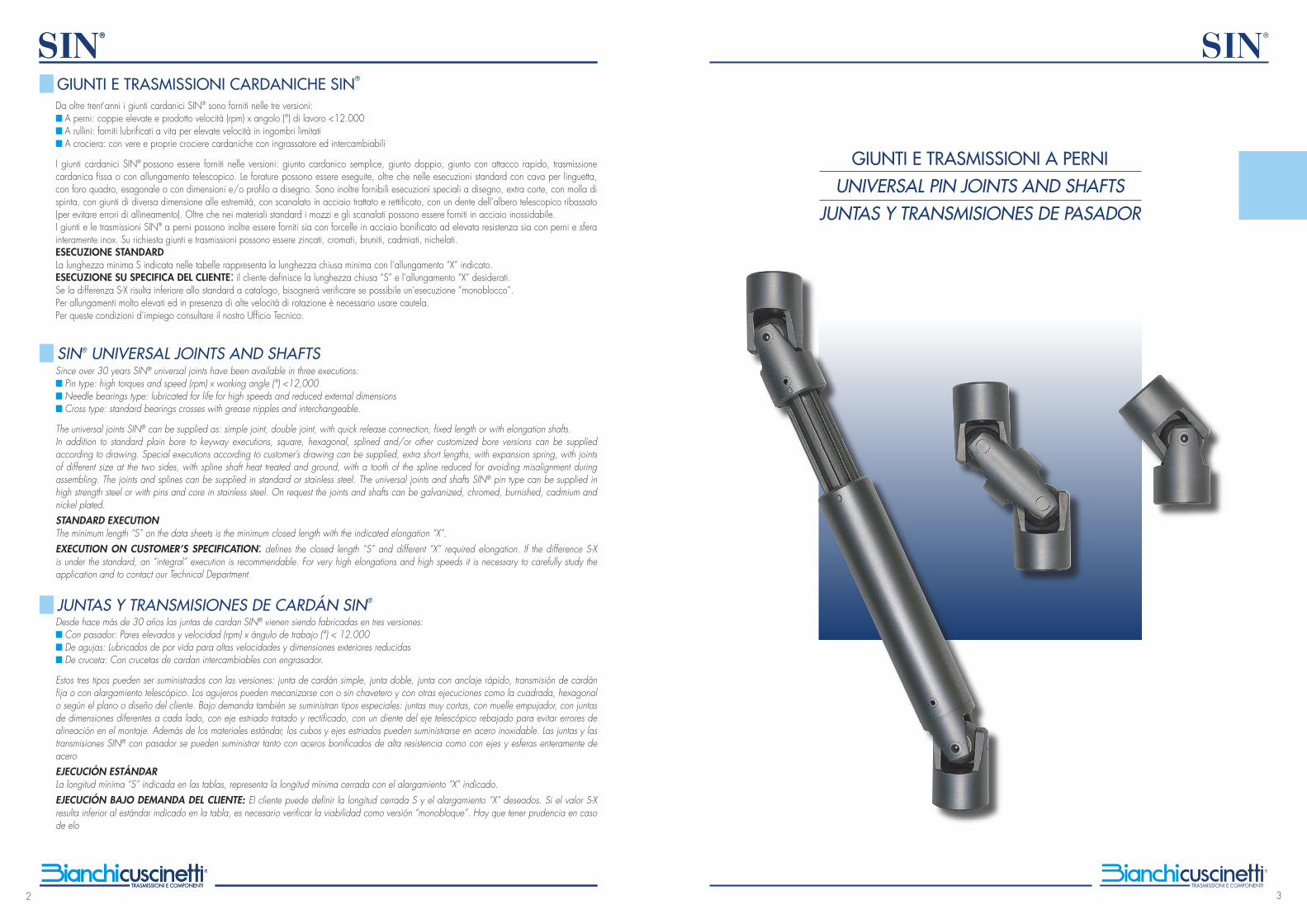
GIUNTI E TRASMISSIONI A PERNIUNIVERSAL PIN JOINTS AND SHAFTS
JUNTAS Y TRANSMISIONES DE PASADOR
4
SIN®
5
SIN®
Nel giunto cardanico SIN® a perni, costruito in acciaio, la coppia viene trasmessa dalle ali dei due semigiunti ad un nocciolo centrale tramite perni cementati e rettificati. Le ali delle forcelle sono ricavate direttamente per fresatura dai mozzi dei semigiunti, assicurando rigidezza e capacità torsio-nale, con ridotto ingombro esterno. Nei giunti con diametro esterno fino a 60 mm, i perni sono fissati alle ali delle forcelle e ruotano entro il nocciolo centrale. Questo assicura un’elevata superficie di contatto dei perni e garantisce il mantenimento del gioco iniziale a lungo.I giunti di diametro esterno da 70, 80, 90 e 100 mm hanno i perni fissati nel nocciolo centrale e ruotano entro bussole di usura montate sulle ali dei semigiunti dato il maggior spessore disponibile.I giunti e le trasmissioni cardaniche SIN® a perni sono provvisti normalmente di ingrassatori a sfera posti sull’estremità di uno dei perni, e richiedono un’adeguata lubrificazione. ■ CODIFICA DEI GIUNTI E TRASMISSIONI CARDANICHE SIN® A PERNILa grandezza dei giunti a perni è codificata tramite la dimensione del diametro esterno e la dimensione del foro standard liscio, separate da un “punto”. Per indicare il giunto doppio si sostituisce al “punto” la lettera “D”. Misure e finiture diverse dei fori devono essere descritte per esteso.
■ ESEMPI:20.10 - giunto semplice con diametro esterno 20 mm e foro diametro 10 mm20D10 - giunto doppio con diametro esterno 20 mm e foro diametro 10 mm20.20.10 – trasmissione con due giunti
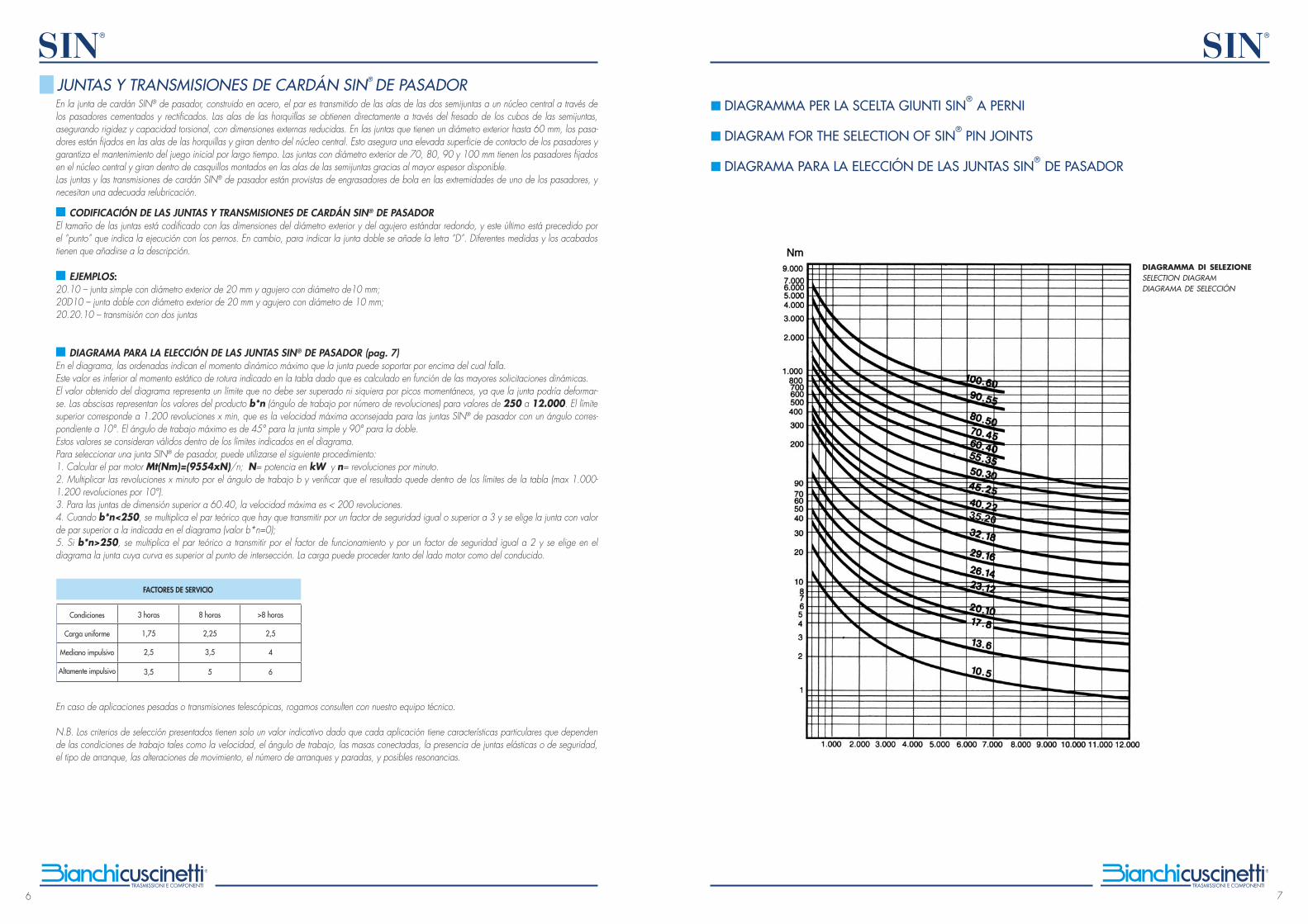
■ DIAGRAMMA PER LA SCELTA DEI GIUNTI SIN® A PERNI (pag. 7)Il diagramma riporta sull’asse delle ordinate il massimo momento dinamico supportabile dal giunto, oltre il quale si ha il cedimento.Tale valore è inferiore al momento statico di rottura indicato nella tabella in quanto è calcolato in funzione delle maggiori sollecitazioni dinamiche. Il valore ricavato dal diagramma rappresenta un limite da non superare neppure per brevi istanti con momenti impulsivi di picco, pena la deformazio-ne del giunto.Sull’asse delle ascisse sono riportati i valori del prodotto b * n (angolo di lavoro per n° di giri) per valori da 250 a 12.000. Il limite superiore corri-sponde a 1.200 giri/min, che è la velocità massima consigliata per i giunti SIN® a perni con un angolo corrispondente a 10°.L’angolo di lavoro massimo è di 45° per il giunto semplice e 90° per quello doppio.Tali valori sono da considerarsi validi entro i limiti dati dal diagramma.Per effettuare la selezione di un giunto SIN® a perni è opportuno seguire questa procedura:1 – Calcolare la coppia motrice Mt(Nm)=(9554xN)/n dove N=potenza in kW e n=giri al minuto.2 - Moltiplicare i giri/min per l’angolo di lavoro b e verificare che il risultato resti nei limiti della tabella (max 1.000-1.200 giri per 10°)3 - Per giunti di taglia superiore alla 60.40, velocità max < 200 giri.4 - Quando b*n<250, moltiplicare la coppia teorica da trasmettere per un fattore di sicurezza uguale o superiore a 3 e scegliere il giunto con valo-re di coppia superiore a quello indicato nel diagramma (valore b*n=0)5 - Se b*n>250, moltiplicare la coppia teorica da trasmettere per il fattore di funzionamento e per un fattore di sicurezza uguale a 2 e scegliere nel diagramma il giunto la cui curva è superiore al punto d’intersezione. Il carico può sia provenire dal lato motore che essere condotto.
Per impieghi molto gravosi e per trasmissioni telescopiche è raccomandabile consultare il nostro Ufficio Tecnico.
N.B. I criteri di selezione sopra esposti sono puramente indicativi poichè ogni applicazione ha caratteristiche particolari che dipendono dalle condi-zioni di impiego quali velocità, angolo di lavoro, masse collegate, presenza di giunti elastici o di sicurezza, tipo di avviamento, inversioni del moto, numero di partenze e fermate, possibili risonanze.
FATTORI DI SERVIZIO
Carico ore/gg.
Uniforme
Medio impulsivo
Molto impulsivo
1,75
2,5
3,5
2,5
4
6
2,25
3,5
5
3 ore 8 ore >8 ore
GIUNTI E TRASMISSIONI CARDANICHE SIN® A PERNISIN® universal joints, steel made, transmit the torque by the wings of the two half couplings to the central core through two pins case hardened and grinded. The wings are directly machined on the half couplings, thus assuring high torsional strength and stiffness with reduced external dimensions. The joints with outside diameter up to 60 mm, have the pins fixed to the wings and rotating in the central core. This construction of the joint assures a high contact surface and guarantees the initial tolerance for a long time. The joints size 70, 80, 90 and 100 mm have the pins fixed on the central core and rotating in sliding bushes fixed in the wings. This is made possible by the greater available thickness. The universal joints and shafts SIN® pin type need periodic lubrication and are supplied with nipple greaser on one of the pins. ■ CODING OF THE UNIVERSAL JOINTS AND SHAFTS SIN® PIN EXECUTIONThe size of pin joints is coded according to the dimensions of the outside diameter and the standard plain bore diameter with a “dot” in between. For the double joint the “dot” has to be replaced by the letter D. Different bore dimensions and executions have to be shown in extended form.
■ EXAMPLES: 20.10 - single joint outside diameter 20 mm and standard plain bores diameter 10 mm. 20D10 - double joint with outside diameter 20 mm and standard plain bores diameter 10 mm. 20.20.10 – shafts with two joints.
■ DIAGRAM FOR THE SELECTION OF SIN® PIN JOINTS (pag. 7)The axis of ordinates in the diagram shows the maximum dynamic torque of the joint, over which the joint might fail. This value is lower than the breaking static moment shown in the data sheets because it has been calculated by adding the dynamic stresses. The value in the diagram represents a limit not to be exceeded even for short times with impulsive peak torques, otherwise the joint could deform. The axis of abscissas shows the values of the product b * n (working angle for rpm) for values from 250 to 12,000. The top limit is 1,200 rpm, that is the maximum recommended speed for the pin joints SIN® with an angle of 10°. The maximum working angle is 45° for the simple joint and 90° for the double. These values are to be considered valid within the limits shown in the diagram. To select a pin joint SIN® it is recommendable to follow this procedure: 1 - Calculate motor torque Mt(Nm)=(9554xN)/n where N=power in kW and n=rpm. 2 - Multiply the rpm by the working angle b and verify that the result is within the limits in the chart (max 1,000-1,200 rpm for 10°)3 - For sizes over 60.40, max speed <200 rpm. 4 - When b*n <250, multiply the theoretical torque to be transmitted by the safety factor equal or superior to 3 and choose the joint whose torque value is higher than that shown in the diagram (value b*n=0) 5 - when b*n>250, multiply the theoretical torque to be transmitted by the operating factor and by a safety factor of 2, and then choose in the dia-gram the joint whose curve is above the point of intersection. The load can originate from the drive and/or driven side.
For very heavy applications and shafts with elongation please contact our Technical Department.
N.B. The above mentioned selection criteria are indicative only as each application has specific dynamic characteristics depending on the working conditions such as speed, working angle, connected masses, presence of elastic or safety joints, type of starting, inversions of the motion, number of starts and stops, possible resonances.
SERVICE FACTORS
Load hour/day
Costant load
Medium impulsive
Highly impulsive
1.75
2.5
3.5
2.5
4
6
2.25
3.5
5
3 hours 8 hours >8 hours
SIN® UNIVERSAL PIN JOINTS AND SHAFTS
6
SIN®
7
SIN®
En la junta de cardán SIN® de pasador, construido en acero, el par es transmitido de las alas de las dos semijuntas a un núcleo central a través de los pasadores cementados y rectificados. Las alas de las horquillas se obtienen directamente a través del fresado de los cubos de las semijuntas, asegurando rigidez y capacidad torsional, con dimensiones externas reducidas. En las juntas que tienen un diámetro exterior hasta 60 mm, los pasa-dores están fijados en las alas de las horquillas y giran dentro del núcleo central. Esto asegura una elevada superficie de contacto de los pasadores y garantiza el mantenimiento del juego inicial por largo tiempo. Las juntas con diámetro exterior de 70, 80, 90 y 100 mm tienen los pasadores fijados en el núcleo central y giran dentro de casquillos montados en las alas de las semijuntas gracias al mayor espesor disponible.Las juntas y las transmisiones de cardán SIN® de pasador están provistas de engrasadores de bola en las extremidades de uno de los pasadores, y necesitan una adecuada relubricación. ■ CODIFICACIÓN DE LAS JUNTAS Y TRANSMISIONES DE CARDÁN SIN® DE PASADOREl tamaño de las juntas está codificado con las dimensiones del diámetro exterior y del agujero estándar redondo, y este último está precedido por el “punto” que indica la ejecución con los pernos. En cambio, para indicar la junta doble se añade la letra “D”. Diferentes medidas y los acabados tienen que añadirse a la descripción.
■ EJEMPLOS: 20.10 – junta simple con diámetro exterior de 20 mm y agujero con diámetro de10 mm;20D10 – junta doble con diámetro exterior de 20 mm y agujero con diámetro de 10 mm;20.20.10 – transmisión con dos juntas
■ DIAGRAMA PARA LA ELECCIÓN DE LAS JUNTAS SIN® DE PASADOR (pag. 7)En el diagrama, las ordenadas indican el momento dinámico máximo que la junta puede soportar por encima del cual falla.Este valor es inferior al momento estático de rotura indicado en la tabla dado que es calculado en función de las mayores solicitaciones dinámicas.El valor obtenido del diagrama representa un límite que no debe ser superado ni siquiera por picos momentáneos, ya que la junta podría deformar-se. Las abscisas representan los valores del producto b*n (ángulo de trabajo por número de revoluciones) para valores de 250 a 12.000. El límite superior corresponde a 1.200 revoluciones x min, que es la velocidad máxima aconsejada para las juntas SIN® de pasador con un ángulo corres-pondiente a 10°. El ángulo de trabajo máximo es de 45° para la junta simple y 90° para la doble.Estos valores se consideran válidos dentro de los límites indicados en el diagrama.Para seleccionar una junta SIN® de pasador, puede utilizarse el siguiente procedimiento:1. Calcular el par motor Mt(Nm)=(9554xN)/n; N= potencia en kW y n= revoluciones por minuto.2. Multiplicar las revoluciones x minuto por el ángulo de trabajo b y verificar que el resultado quede dentro de los límites de la tabla (max 1.000-1.200 revoluciones por 10°).3. Para las juntas de dimensión superior a 60.40, la velocidad máxima es < 200 revoluciones.4. Cuando b*n<250, se multiplica el par teórico que hay que transmitir por un factor de seguridad igual o superior a 3 y se elige la junta con valor de par superior a la indicada en el diagrama (valor b*n=0);5. Si b*n>250, se multiplica el par teórico a transmitir por el factor de funcionamiento y por un factor de seguridad igual a 2 y se elige en el diagrama la junta cuya curva es superior al punto de intersección. La carga puede proceder tanto del lado motor como del conducido.
En caso de aplicaciones pesadas o transmisiones telescópicas, rogamos consulten con nuestro equipo técnico.
N.B. Los criterios de selección presentados tienen solo un valor indicativo dado que cada aplicación tiene características particulares que dependen de las condiciones de trabajo tales como la velocidad, el ángulo de trabajo, las masas conectadas, la presencia de juntas elásticas o de seguridad, el tipo de arranque, las alteraciones de movimiento, el número de arranques y paradas, y posibles resonancias.
FACTORES DE SERVICIO
Condiciones
Carga uniforme
Mediano impulsivo
Altamente impulsivo
1,75
2,5
3,5
2,5
4
6
2,25
3,5
5
3 horas 8 horas >8 horas
JUNTAS Y TRANSMISIONES DE CARDÁN SIN® DE PASADOR
DIAGRAMMA DI SELEZIONESELECTION DIAGRAMDIAGRAMA DE SELECCIÓN
■ DIAGRAMMA PER LA SCELTA GIUNTI SIN®
A PERNI
■ DIAGRAM FOR THE SELECTION OF SIN® PIN JOINTS
■ DIAGRAMA PARA LA ELECCIÓN DE LAS JUNTAS SIN®
DE PASADOR
8
SIN®
9
SIN®
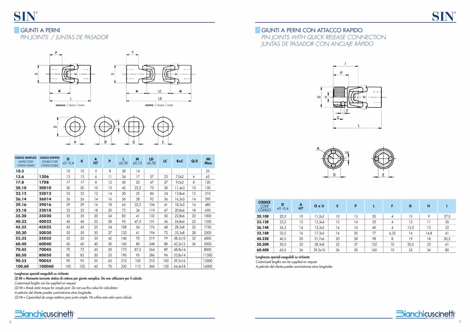
Lunghezze speciali eseguibili su richiesta (2) Mt = Momento torcente statico di rottura per giunto semplice. Da non utilizzare per il calcoloCustomized lengths can be supplied on request (2) Mt = Break static torque for simple joint. Do not use this value for calculationA petición del cliente pueden suministrarse otras longitudes (2) Mt = Capacidad de carga estática para junta simple. No utilice este valor para cálculo
PIN JOINTS / JUNTAS DE PASADOR
25651201502102904806901000135017502500400050008000115001350016000
1013172023262932354045505560708090100
1013172023262932354045505560728292102
568101214161820222530354045505560
81112131416182024283437425050556570
28344045505665728295108122140160175190210230
141720
22,52528
32,53641
47,554617080
87,595105115
5767758492106119132151176194219248264286310360
232730343641475056687279888996100130
7,0x29,0x211,4x313,8x416,3x518,3x520,8x622,8x624,8x628,3x833,3x838,3x1043,3x1248,8x1453,8x1459,3x1664,4x18
681012141618202225283236
10.513.617.820.1023.1226.1429.1632.1835.2040.2245.2550.3055.3560.4070.4580.5090.55100.60
13D617D820D1023D1226D1429D1632D1835D2040D2245D2550D3055D3560D4070D4580D5090D55100D60
CODICE SEMPLICESIMPLE CODE
CÓDIGO SIMPLE
D+0 -0,4 K A
H7 P L ±0,30
M ±0,15
LD ±0,30 LC BxC Q/E Mt
MaxCODICE DOPPIO
DOUBLE CODECÓDIGO DOBLE
GIUNTI A PERNI
SINGOLO / SINGLE / SIMPLE DOPPIO / DOUBLE / DOBLE
Lunghezze speciali eseguibili su richiestaCustomized lengths can be supplied on requestA petición del cliente pueden suministrarse otras longitudes
20,523,526,532,540,550,560,5
20.10R23.12R26.14R32.18R40.22R50.30R60.40R
CODICECODE
CÓDIGOD
+0 -0,4A
H7O x U E P L F G H I
10121416202536
11,2x313,3x415,3x517,3x521,7x628,3x839,3x10
10121416202536
13141620283750
5055607798122160
444
6,3581010
1313
13,51419
20,525
91113
14,8182334
27,5303241
50,56180
PIN JOINTS WITH QUICK RELEASE CONNECTIONJUNTAS DE PASADOR CON ANCLAJE RÁPIDO
GIUNTI A PERNI CON ATTACCO RAPIDO
10
SIN®
11
SIN®
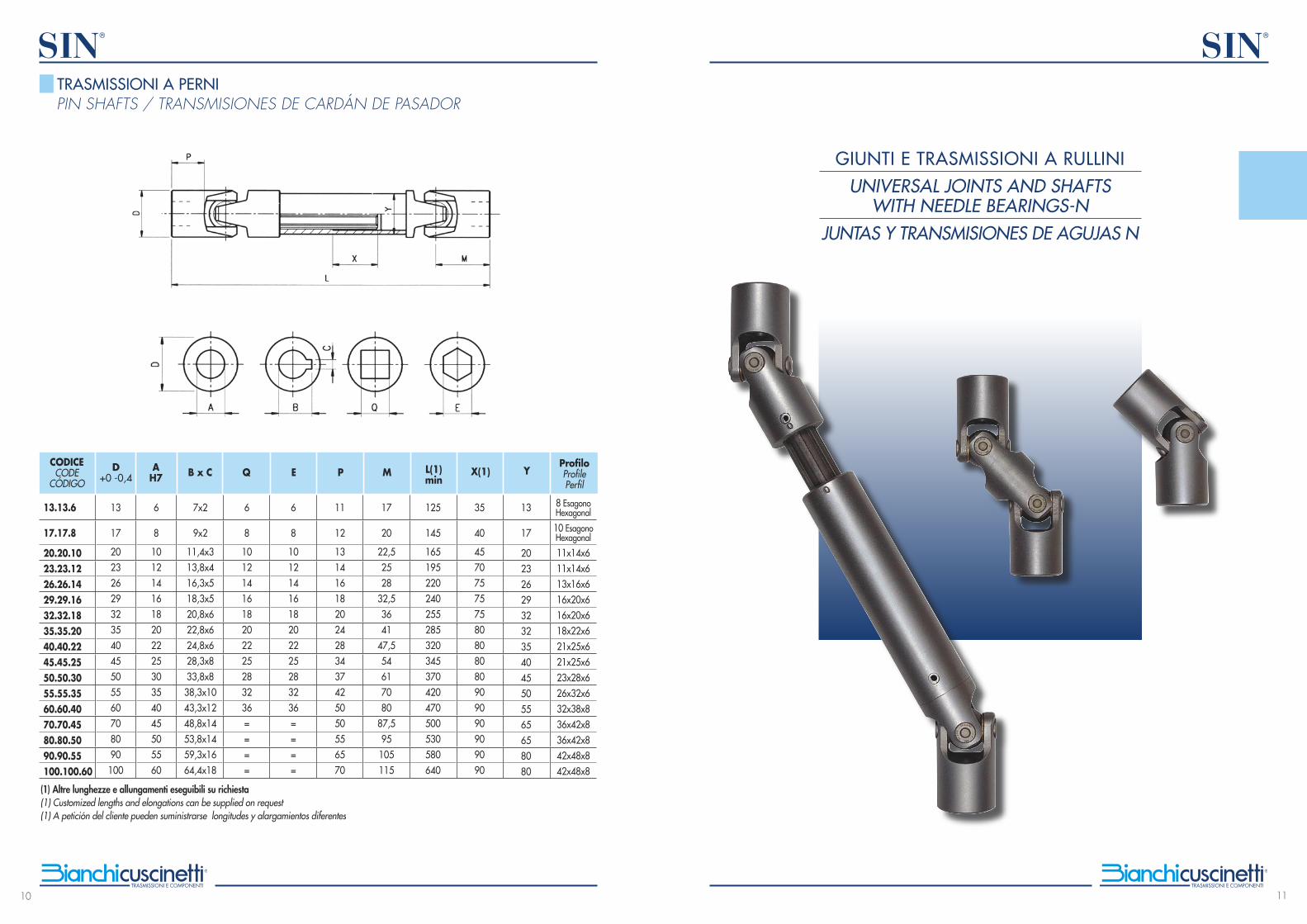
(1) Altre lunghezze e allungamenti eseguibili su richiesta(1) Customized lengths and elongations can be supplied on request(1) A petición del cliente pueden suministrarse longitudes y alargamientos diferentes
13
17
2023262932354045505560708090100
13.13.6
17.17.8
20.20.1023.23.1226.26.1429.29.1632.32.1835.35.2040.40.2245.45.2550.50.3055.55.3560.60.4070.70.4580.80.5090.90.55100.100.60
CODICECODE
CÓDIGO
D+0 -0,4
AH7 B x C Q E P M L(1)
minX(1) Y
ProfiloProfilePerfil
6
8
101214161820222530354045505560
7x2
9x2
11,4x313,8x416,3x518,3x520,8x622,8x624,8x628,3x833,8x838,3x1043,3x1248,8x1453,8x1459,3x1664,4x18
6
8
1012141618202225283236====
6
8
1012141618202225283236====
11
12
131416182024283437425050556570
17
20
22,52528
32,53641
47,554617080
87,595105115
125
145
165195220240255285320345370420470500530580640
35
40
457075757580808080909090909090
13
17
202326293232354045505565658080
8 EsagonoHexagonal
10 EsagonoHexagonal
11x14x611x14x613x16x616x20x616x20x618x22x621x25x621x25x623x28x626x32x632x38x836x42x836x42x842x48x842x48x8
PIN SHAFTS / TRANSMISIONES DE CARDÁN DE PASADORTRASMISSIONI A PERNI
GIUNTI E TRASMISSIONI A RULLINIUNIVERSAL JOINTS AND SHAFTS
WITH NEEDLE BEARINGS-NJUNTAS Y TRANSMISIONES DE AGUJAS N
12
SIN®
13
SIN®
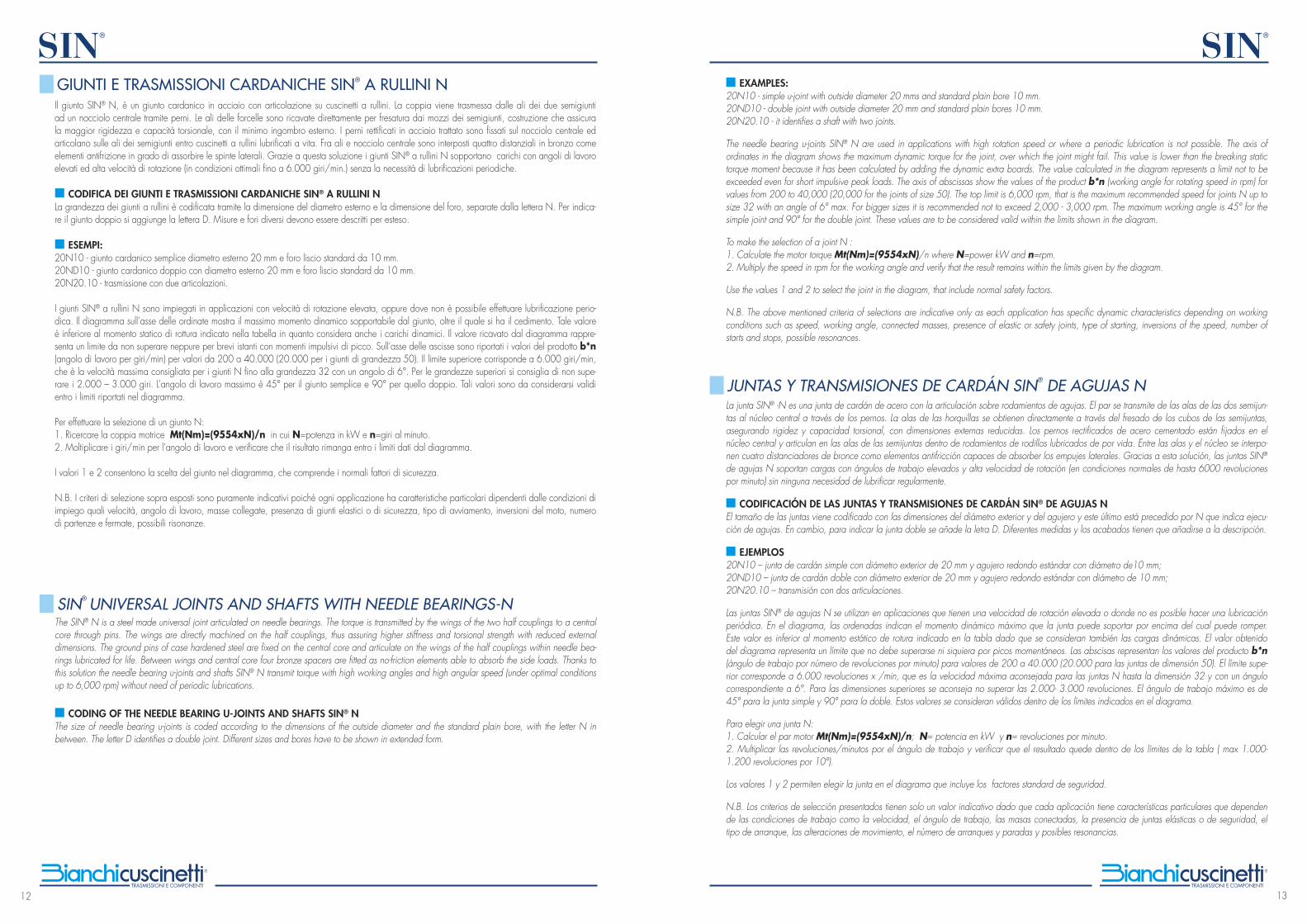
Il giunto SIN® N, è un giunto cardanico in acciaio con articolazione su cuscinetti a rullini. La coppia viene trasmessa dalle ali dei due semigiunti ad un nocciolo centrale tramite perni. Le ali delle forcelle sono ricavate direttamente per fresatura dai mozzi dei semigiunti, costruzione che assicura la maggior rigidezza e capacità torsionale, con il minimo ingombro esterno. I perni rettificati in acciaio trattato sono fissati sul nocciolo centrale ed articolano sulle ali dei semigiunti entro cuscinetti a rullini lubrificati a vita. Fra ali e nocciolo centrale sono interposti quattro distanziali in bronzo come elementi antifrizione in grado di assorbire le spinte laterali. Grazie a questa soluzione i giunti SIN® a rullini N sopportano carichi con angoli di lavoro elevati ed alta velocità di rotazione (in condizioni ottimali fino a 6.000 giri/min.) senza la necessità di lubrificazioni periodiche.
■ CODIFICA DEI GIUNTI E TRASMISSIONI CARDANICHE SIN® A RULLINI NLa grandezza dei giunti a rullini è codificata tramite la dimensione del diametro esterno e la dimensione del foro, separate dalla lettera N. Per indica-re il giunto doppio si aggiunge la lettera D. Misure e fori diversi devono essere descritti per esteso.
■ ESEMPI:20N10 - giunto cardanico semplice diametro esterno 20 mm e foro liscio standard da 10 mm.20ND10 - giunto cardanico doppio con diametro esterno 20 mm e foro liscio standard da 10 mm.20N20.10 - trasmissione con due articolazioni.
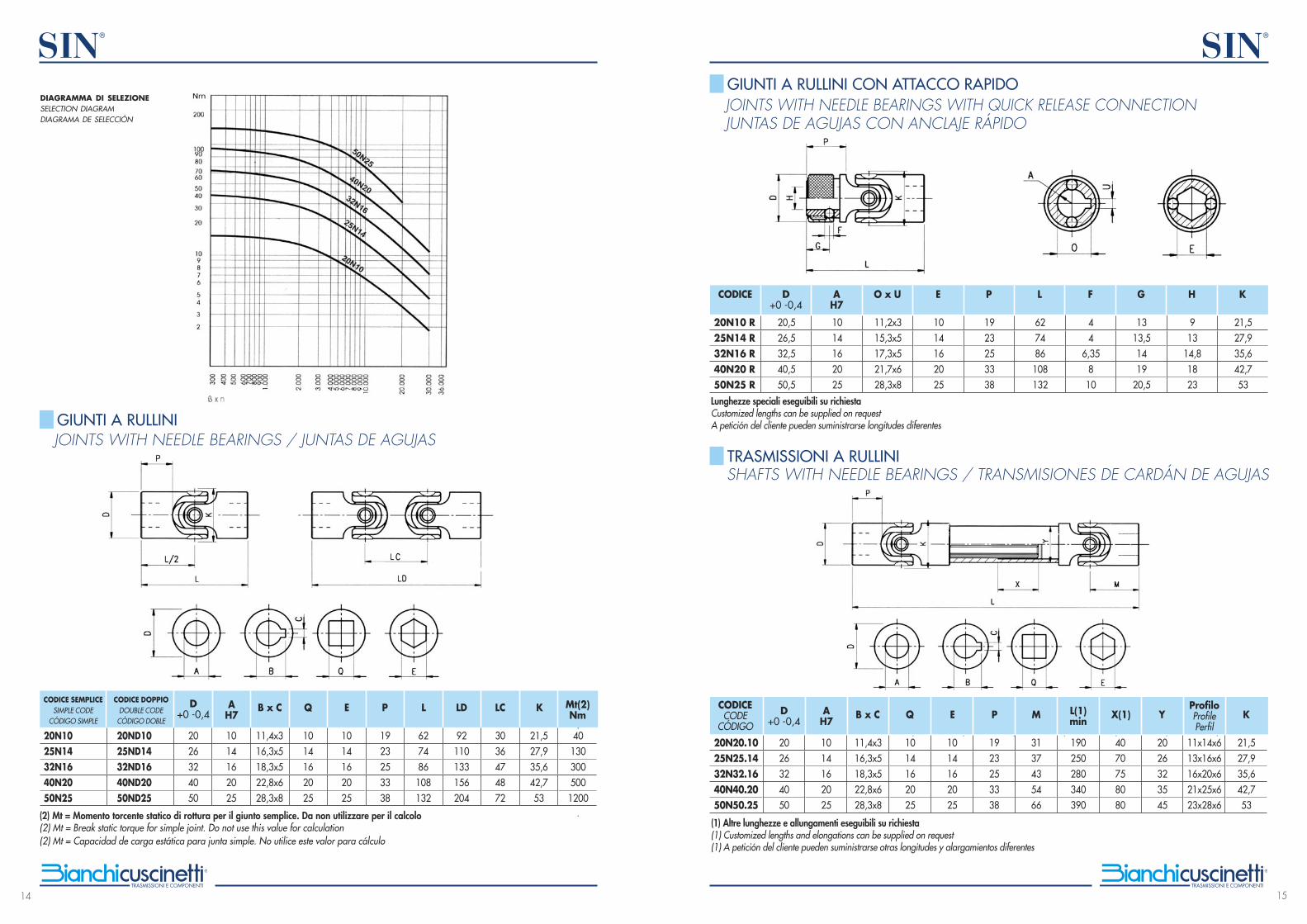
I giunti SIN® a rullini N sono impiegati in applicazioni con velocità di rotazione elevata, oppure dove non è possibile effettuare lubrificazione perio-dica. Il diagramma sull’asse delle ordinate mostra il massimo momento dinamico sopportabile dal giunto, oltre il quale si ha il cedimento. Tale valore è inferiore al momento statico di rottura indicato nella tabella in quanto considera anche i carichi dinamici. Il valore ricavato dal diagramma rappre-senta un limite da non superare neppure per brevi istanti con momenti impulsivi di picco. Sull’asse delle ascisse sono riportati i valori del prodotto b*n (angolo di lavoro per giri/min) per valori da 200 a 40.000 (20.000 per i giunti di grandezza 50). Il limite superiore corrisponde a 6.000 giri/min, che è la velocità massima consigliata per i giunti N fino alla grandezza 32 con un angolo di 6°. Per le grandezze superiori si consiglia di non supe-rare i 2.000 – 3.000 giri. L’angolo di lavoro massimo è 45° per il giunto semplice e 90° per quello doppio. Tali valori sono da considerarsi validi entro i limiti riportati nel diagramma.
Per effettuare la selezione di un giunto N:1. Ricercare la coppia motrice Mt(Nm)=(9554xN)/n in cui N=potenza in kW e n=giri al minuto.2. Moltiplicare i giri/min per l’angolo di lavoro e verificare che il risultato rimanga entro i limiti dati dal diagramma.
I valori 1 e 2 consentono la scelta del giunto nel diagramma, che comprende i normali fattori di sicurezza.
N.B. I criteri di selezione sopra esposti sono puramente indicativi poichè ogni applicazione ha caratteristiche particolari dipendenti dalle condizioni di impiego quali velocità, angolo di lavoro, masse collegate, presenza di giunti elastici o di sicurezza, tipo di avviamento, inversioni del moto, numero di partenze e fermate, possibili risonanze.
The SIN® N is a steel made universal joint articulated on needle bearings. The torque is transmitted by the wings of the two half couplings to a central core through pins. The wings are directly machined on the half couplings, thus assuring higher stiffness and torsional strength with reduced external dimensions. The ground pins of case hardened steel are fixed on the central core and articulate on the wings of the half couplings within needle bea-rings lubricated for life. Between wings and central core four bronze spacers are fitted as no-friction elements able to absorb the side loads. Thanks to this solution the needle bearing u-joints and shafts SIN® N transmit torque with high working angles and high angular speed (under optimal conditions up to 6,000 rpm) without need of periodic lubrications. ■ CODING OF THE NEEDLE BEARING U-JOINTS AND SHAFTS SIN® N The size of needle bearing u-joints is coded according to the dimensions of the outside diameter and the standard plain bore, with the letter N in between. The letter D identifies a double joint. Different sizes and bores have to be shown in extended form.
GIUNTI E TRASMISSIONI CARDANICHE SIN® A RULLINI N
SIN® UNIVERSAL JOINTS AND SHAFTS WITH NEEDLE BEARINGS-N
■ EXAMPLES:20N10 - simple u-joint with outside diameter 20 mms and standard plain bore 10 mm. 20ND10 - double joint with outside diameter 20 mm and standard plain bores 10 mm. 20N20.10 - it identifies a shaft with two joints.
The needle bearing u-joints SIN® N are used in applications with high rotation speed or where a periodic lubrication is not possible. The axis of ordinates in the diagram shows the maximum dynamic torque for the joint, over which the joint might fail. This value is lower than the breaking static torque moment because it has been calculated by adding the dynamic extra boards. The value calculated in the diagram represents a limit not to be exceeded even for short impulsive peak loads. The axis of abscissas show the values of the product b*n (working angle for rotating speed in rpm) for values from 200 to 40,000 (20,000 for the joints of size 50). The top limit is 6,000 rpm, that is the maximum recommended speed for joints N up to size 32 with an angle of 6° max. For bigger sizes it is recommended not to exceed 2,000 - 3,000 rpm. The maximum working angle is 45° for the simple joint and 90° for the double joint. These values are to be considered valid within the limits shown in the diagram. To make the selection of a joint N : 1. Calculate the motor torque Mt(Nm)=(9554xN)/n where N=power kW and n=rpm. 2. Multiply the speed in rpm for the working angle and verify that the result remains within the limits given by the diagram. Use the values 1 and 2 to select the joint in the diagram, that include normal safety factors.
N.B. The above mentioned criteria of selections are indicative only as each application has specific dynamic characteristics depending on working conditions such as speed, working angle, connected masses, presence of elastic or safety joints, type of starting, inversions of the speed, number of starts and stops, possible resonances.
La junta SIN® -N es una junta de cardán de acero con la articulación sobre rodamientos de agujas. El par se transmite de las alas de las dos semijun-tas al núcleo central a través de los pernos. La alas de las horquillas se obtienen directamente a través del fresado de los cubos de las semijuntas, asegurando rigidez y capacidad torsional, con dimensiones externas reducidas. Los pernos rectificados de acero cementado están fijados en el núcleo central y articulan en las alas de las semijuntas dentro de rodamientos de rodillos lubricados de por vida. Entre las alas y el núcleo se interpo-nen cuatro distanciadores de bronce como elementos antifricción capaces de absorber los empujes laterales. Gracias a esta solución, las juntas SIN® de agujas N soportan cargas con ángulos de trabajo elevados y alta velocidad de rotación (en condiciones normales de hasta 6000 revoluciones por minuto) sin ninguna necesidad de lubrificar regularmente.
■ CODIFICACIÓN DE LAS JUNTAS Y TRANSMISIONES DE CARDÁN SIN® DE AGUJAS NEl tamaño de las juntas viene codificado con las dimensiones del diámetro exterior y del agujero y este último está precedido por N que indica ejecu-ción de agujas. En cambio, para indicar la junta doble se añade la letra D. Diferentes medidas y los acabados tienen que añadirse a la descripción.
■ EJEMPLOS20N10 – junta de cardán simple con diámetro exterior de 20 mm y agujero redondo estándar con diámetro de10 mm;20ND10 – junta de cardán doble con diámetro exterior de 20 mm y agujero redondo estándar con diámetro de 10 mm;20N20.10 – transmisión con dos articulaciones.
Las juntas SIN® de agujas N se utilizan en aplicaciones que tienen una velocidad de rotación elevada o donde no es posible hacer una lubricación periódica. En el diagrama, las ordenadas indican el momento dinámico máximo que la junta puede soportar por encima del cual puede romper. Este valor es inferior al momento estático de rotura indicado en la tabla dado que se consideran también las cargas dinámicas. El valor obtenido del diagrama representa un límite que no debe superarse ni siquiera por picos momentáneos. Las abscisas representan los valores del producto b*n (ángulo de trabajo por número de revoluciones por minuto) para valores de 200 a 40.000 (20.000 para las juntas de dimensión 50). El límite supe-rior corresponde a 6.000 revoluciones x /min, que es la velocidad máxima aconsejada para las juntas N hasta la dimensión 32 y con un ángulo correspondiente a 6°. Para las dimensiones superiores se aconseja no superar las 2.000- 3.000 revoluciones. El ángulo de trabajo máximo es de 45° para la junta simple y 90° para la doble. Estos valores se consideran válidos dentro de los límites indicados en el diagrama.
Para elegir una junta N:1. Calcular el par motor Mt(Nm)=(9554xN)/n; N= potencia en kW y n= revoluciones por minuto.2. Multiplicar las revoluciones/minutos por el ángulo de trabajo y verificar que el resultado quede dentro de los límites de la tabla ( max 1.000-1.200 revoluciones por 10°).
Los valores 1 y 2 permiten elegir la junta en el diagrama que incluye los factores standard de seguridad.
N.B. Los criterios de selección presentados tienen solo un valor indicativo dado que cada aplicación tiene características particulares que dependen de las condiciones de trabajo como la velocidad, el ángulo de trabajo, las masas conectadas, la presencia de juntas elásticas o de seguridad, el tipo de arranque, las alteraciones de movimiento, el número de arranques y paradas y posibles resonancias.
JUNTAS Y TRANSMISIONES DE CARDÁN SIN® DE AGUJAS N
14
SIN®
15
SIN®
(2) Mt = Momento torcente statico di rottura per il giunto semplice. Da non utilizzare per il calcolo(2) Mt = Break static torque for simple joint. Do not use this value for calculation(2) Mt = Capacidad de carga estática para junta simple. No utilice este valor para cálculo
JOINTS WITH NEEDLE BEARINGS / JUNTAS DE AGUJAS
20N1025N1432N1640N2050N25
2026324050
D+0 -0,4
AH7
B x C Q E P L LD K Mt(2)Nm
20ND1025ND1432ND1640ND2050ND25
1014162025
11,4x316,3x518,3x522,8x628,3x8
1014162025
1014162025
1923253338
627486108132
92110133156204
21,527,935,642,753
401303005001200
CODICE SEMPLICESIMPLE CODE
CÓDIGO SIMPLE
CODICE DOPPIODOUBLE CODE
CÓDIGO DOBLE
DIAGRAMMA DI SELEZIONESELECTION DIAGRAMDIAGRAMA DE SELECCIÓN
GIUNTI A RULLINI
(1) Altre lunghezze e allungamenti eseguibili su richiesta(1) Customized lengths and elongations can be supplied on request(1) A petición del cliente pueden suministrarse otras longitudes y alargamientos diferentes
2026324050
20N20.1025N25.1432N32.1640N40.2050N50.25
CODICECODE
CÓDIGOD
+0 -0,4A
H7B x C Q E P M L(1)
minX(1) Y
ProfiloProfilePerfil
K
1014162025
11,4x316,3x518,3x522,8x628,3x8
1014162025
1014162025
1923253338
3137435466
190250280340390
4070758080
2026323545
11x14x613x16x616x20x621x25x623x28x6
21,527,935,642,753
SHAFTS WITH NEEDLE BEARINGS / TRANSMISIONES DE CARDÁN DE AGUJAS
Lunghezze speciali eseguibili su richiestaCustomized lengths can be supplied on requestA petición del cliente pueden suministrarse longitudes diferentes
20,526,532,540,550,5
20N10 R25N14 R32N16 R40N20 R50N25 R
CODICE D+0 -0,4
AH7
O x U E P L F G H K
1014162025
11,2x315,3x517,3x521,7x628,3x8
1014162025
1923253338
627486108132
44
6,35810
1313,51419
20,5
913
14,81823
21,527,935,642,753
JOINTS WITH NEEDLE BEARINGS WITH QUICK RELEASE CONNECTIONJUNTAS DE AGUJAS CON ANCLAJE RÁPIDO
GIUNTI A RULLINI CON ATTACCO RAPIDO
TRASMISSIONI A RULLINI
LC
3036474872
16
SIN®
17
SIN®
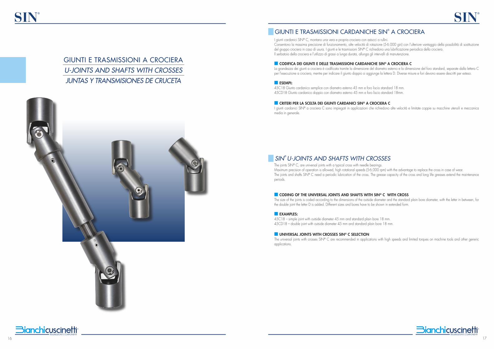
I giunti cardanici SIN® C, montano una vera e propria crociera con astucci a rullini. Consentono la massima precisione di funzionamento, alte velocità di rotazione (5-6.000 giri) con l’ulteriore vantaggio della possibilità di sostituzione del gruppo crociera in caso di usura. I giunti e le trasmissioni SIN® C richiedono una lubrificazione periodica della crociera. Il serbatoio della crociera e l’utilizzo di grassi a lunga durata, allunga gli intervalli di manutenzione.
■ CODIFICA DEI GIUNTI E DELLE TRASMISSIONI CARDANICHE SIN® A CROCIERA CLa grandezza dei giunti a crociera è codificata tramite la dimensione del diametro esterno e la dimensione del foro standard, separate dalla lettera C per l’esecuzione a crociera, mentre per indicare il giunto doppio si aggiunge la lettera D. Diverse misure e fori devono essere descritti per esteso.
■ ESEMPI:45C18 Giunto cardanico semplice con diametro esterno 45 mm e foro liscio standard 18 mm.45CD18 Giunto cardanico doppio con diametro esterno 45 mm e foro liscio standard 18mm.
■ CRITERI PER LA SCELTA DEI GIUNTI CARDANICI SIN® A CROCIERA C I giunti cardanici SIN® a crociera C sono impiegati in applicazioni che richiedono alte velocità e limitate coppie su macchine utensili e meccanica media in generale.
The joints SIN® C, are universal joints with a typical cross with needle bearings. Maximum precision of operation is allowed, high rotational speeds (5-6,000 rpm) with the advantage to replace the cross in case of wear. The joints and shafts SIN® C need a periodic lubrication of the cross. The grease capacity of the cross and long life greases extend the maintenance periods.
■ CODING OF THE UNIVERSAL JOINTS AND SHAFTS WITH SIN® C WITH CROSS The size of the joints is coded according to the dimensions of the outside diameter and the standard plain bore diameter, with the letter in between, for the double joint the letter D is added. Different sizes and bores have to be shown in extended form.
■ EXAMPLES:45C18 – simple joint with outside diameter 45 mm and standard plain bore 18 mm. 45CD18 – double joint with outside diameter 45 mm and standard plain bore 18 mm.
■ UNIVERSAL JOINTS WITH CROSSES SIN® C SELECTION The universal joints with crosses SIN® C are recommended in applications with high speeds and limited torques on machine tools and other generic applications.
GIUNTI E TRASMISSIONI CARDANICHE SIN® A CROCIERA
SIN® U-JOINTS AND SHAFTS WITH CROSSES
GIUNTI E TRASMISSIONI A CROCIERAU-JOINTS AND SHAFTS WITH CROSSES JUNTAS Y TRANSMISIONES DE CRUCETA
18
SIN®
19
SIN®
Las juntas de cardán SIN® C son juntas universales provistas de la tipica cruceta con rodamientos de agujas. Esta junta permite la máxima precisión de funcionamiento, elevadas velocidades de rotación (5-6.000 revoluciones) y también la posibilidad de sustituir la cruceta en caso de desgaste.Las juntas y las transmisiones SIN® necesitan una lubricación periódica de la cruceta. La capacidad de esta y el uso de una grasa de larga duración prolongan los intervalos de mantenimiento. ■ CODIFICACIÓN DE LAS JUNTAS Y TRANSMISIONES DE CARDÁN SIN® DE CRUCETA C El tamaño de las juntas está codificado con las dimensiones del diámetro exterior y del agujero estándar, y este último está precedido por la letra C que indica la ejecución con el crucero. En cambio, para indicar la junta doble se añade la letra D. Diferentes medidas y los acabados tienen que añadirse a la descripción.
■ EJEMPLOS45C18 – junta de cardán simple con diámetro exterior de 45 mm y agujero redondo estándar de 18 mm.45CD18 – junta de cardán doble con diámetro exterior de 45 mm y agujero redondo estándar de 18 mm.
■ CRITERIOS PARA ELEGIR LAS JUNTAS DE CARDÁN SIN® DE CRUCERO CLas juntas de cardán SIN® de cruceta C se utilizan en aplicaciones que requieren altas velocidades y pares limitados en máquinas herramientas y por lo general en aplicaciones mecánicas de tipo medio.
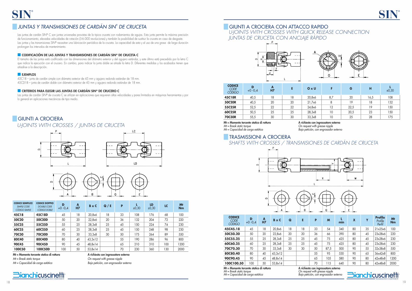
Mt = Momento torcente statico di rottura A richiesta con ingrassatore esternoMt = Break static torque On request with grease nippleMt = Capacidad de carga estática Bajo petición, con engrasador externo
U-JOINTS WITH CROSSES / JUNTAS DE CRUCETA
45C1850C2055C2560C2570C3080C4090C45100C50
D+0 -0,4
AH7
B x C Q / E P L ±0,30
LD ±0,30
MtNm
45505560708090100
45C18D50C20D55C25D60C25D70C30D80C40D90C45D100C50D
1820252530404550
20,8x622,8x628,3x828,3x833,3x843,3x1248,8x1453,8x14
1820252530
687274988996100130
3336454550556570
108132150150175190210230
176204224248264286310360
10022023023055080012002000
CODICE SEMPLICESIMPLE CODE
CÓDIGO SIMPLE
CODICE DOPPIODOUBLE CODE
CÓDIGO DOBLE
JUNTAS Y TRANSMISIONES DE CARDÁN SIN® DE CRUCETA
GIUNTI A CROCIERA
LC
Mt = Momento torcente statico di rottura A richiesta con ingrassatore esternoMt = Break static torque On request with grease nippleMt = Capacidad de carga estática Bajo petición, con engrasador externo
40,540,552,550,555,5
45C18R50C20R55C25R60C25R70C30R
CODICECODE
CÓDIGO
D+0 -0,4
AH7 O x UE L
±0,30F G H
1820222530
20,8x621,7x624,8x628,3x833,3x8
1820222530
108132150150175
8,78121010
2019
22,520,525
16,518192328
Mt = Momento torcente statico di rottura A richiesta con ingrassatore esterno Mt = Break static torque On request with grease nippleMt = Capacidad de carga estática Bajo petición, con engrasador externo
45505560708090100
45C45.1850C50.2055C55.2560C60.2570C70.3080C80.4090C90.45100C100.50
CODICECODE
CÓDIGO
D+0 -0,4
AH7
B x C Q E
1820252530404550
20,8x622,8x628,3x828,3x833,3x843,3x1248,8x1453,8x14
1820252530
1820252530
3336454550556570
54667575
87,595105115
340390425425500530580640
8080808090909090
3545454555658080
21x25x623x28x623x28x623x28x632x38x836x42x842x48x842x48x8
10022023023055080012002000
P M Lmin
X YProfiloProfilePerfil
MtNm
U-JOINTS WITH CROSSES WITH QUICK RELEASE CONNECTIONJUNTAS DE CRUCETA CON ANCLAJE RÁPIDO
SHAFTS WITH CROSSES / TRANSMISIONES DE CARDÁN DE CRUCETA
GIUNTI A CROCIERA CON ATTACCO RAPIDO
TRASMISSIONI A CROCIERA
20
SIN®
21
SIN®
figura D figura E
figura A
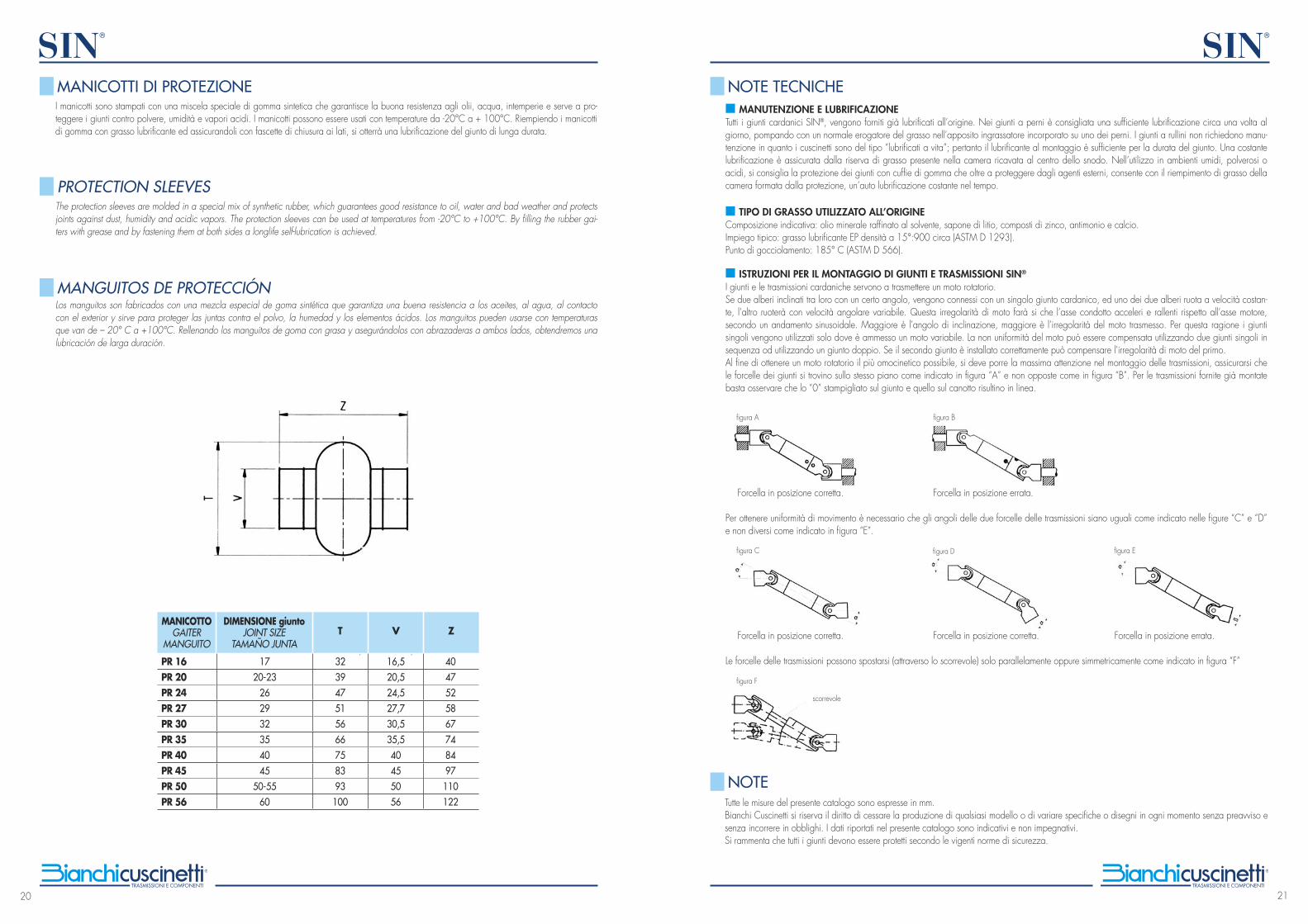
I manicotti sono stampati con una miscela speciale di gomma sintetica che garantisce la buona resistenza agli olii, acqua, intemperie e serve a pro-teggere i giunti contro polvere, umidità e vapori acidi. I manicotti possono essere usati con temperature da -20°C a + 100°C. Riempiendo i manicotti di gomma con grasso lubrificante ed assicurandoli con fascette di chiusura ai lati, si otterrà una lubrificazione del giunto di lunga durata.
The protection sleeves are molded in a special mix of synthetic rubber, which guarantees good resistance to oil, water and bad weather and protects joints against dust, humidity and acidic vapors. The protection sleeves can be used at temperatures from -20°C to +100°C. By filling the rubber gai-ters with grease and by fastening them at both sides a longlife self-lubrication is achieved.
Los manguitos son fabricados con una mezcla especial de goma sintética que garantiza una buena resistencia a los aceites, al agua, al contacto con el exterior y sirve para proteger las juntas contra el polvo, la humedad y los elementos ácidos. Los manguitos pueden usarse con temperaturas que van de – 20° C a +100°C. Rellenando los manguitos de goma con grasa y asegurándolos con abrazaderas a ambos lados, obtendremos una lubricación de larga duración.
PR 16PR 20PR 24PR 27PR 30PR 35PR 40PR 45PR 50PR 56
MANICOTTOGAITER
MANGUITO
DIMENSIONE giuntoJOINT SIZE
TAMAÑO JUNTAT
1720-23
262932354045
50-5560
323947515666758393100
16,520,524,527,730,535,540455056
4047525867748497110122
V Z
MANICOTTI DI PROTEZIONE
PROTECTION SLEEVES
MANGUITOS DE PROTECCIÓN
■ MANUTENZIONE E LUBRIFICAZIONETutti i giunti cardanici SIN®, vengono forniti già lubrificati all’origine. Nei giunti a perni è consigliata una sufficiente lubrificazione circa una volta al giorno, pompando con un normale erogatore del grasso nell’apposito ingrassatore incorporato su uno dei perni. I giunti a rullini non richiedono manu-tenzione in quanto i cuscinetti sono del tipo “lubrificati a vita”; pertanto il lubrificante al montaggio è sufficiente per la durata del giunto. Una costante lubrificazione è assicurata dalla riserva di grasso presente nella camera ricavata al centro dello snodo. Nell’utilizzo in ambienti umidi, polverosi o acidi, si consiglia la protezione dei giunti con cuffie di gomma che oltre a proteggere dagli agenti esterni, consente con il riempimento di grasso della camera formata dalla protezione, un’auto lubrificazione costante nel tempo.
■ TIPO DI GRASSO UTILIZZATO ALL’ORIGINE Composizione indicativa: olio minerale raffinato al solvente, sapone di litio, composti di zinco, antimonio e calcio. Impiego tipico: grasso lubrificante EP densità a 15°:900 circa (ASTM D 1293).Punto di gocciolamento: 185° C (ASTM D 566).
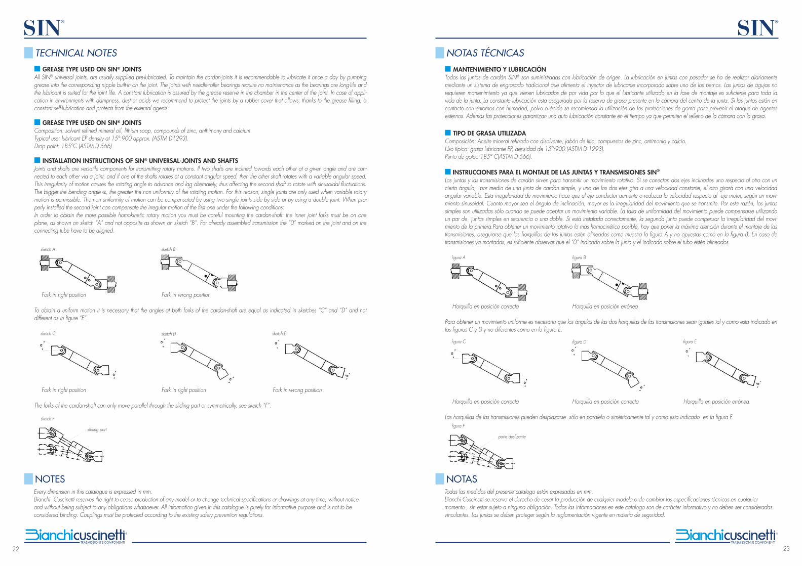
■ ISTRUZIONI PER IL MONTAGGIO DI GIUNTI E TRASMISSIONI SIN®
I giunti e le trasmissioni cardaniche servono a trasmettere un moto rotatorio.Se due alberi inclinati tra loro con un certo angolo, vengono connessi con un singolo giunto cardanico, ed uno dei due alberi ruota a velocità costan-te, l’altro ruoterà con velocità angolare variabile. Questa irregolarità di moto farà si che l’asse condotto acceleri e rallenti rispetto all’asse motore, secondo un andamento sinusoidale. Maggiore è l’angolo di inclinazione, maggiore è l’irregolarità del moto trasmesso. Per questa ragione i giunti singoli vengono utilizzati solo dove è ammesso un moto variabile. La non uniformità del moto può essere compensata utilizzando due giunti singoli in sequenza od utilizzando un giunto doppio. Se il secondo giunto è installato correttamente può compensare l’irregolarità di moto del primo.Al fine di ottenere un moto rotatorio il più omocinetico possibile, si deve porre la massima attenzione nel montaggio delle trasmissioni, assicurarsi che le forcelle dei giunti si trovino sullo stesso piano come indicato in figura “A” e non opposte come in figura “B”. Per le trasmissioni fornite già montate basta osservare che lo “0” stampigliato sul giunto e quello sul canotto risultino in linea.
Forcella in posizione corretta. Forcella in posizione errata.
Per ottenere uniformità di movimento è necessario che gli angoli delle due forcelle delle trasmissioni siano uguali come indicato nelle figure “C” e “D” e non diversi come indicato in figura “E”.
Forcella in posizione corretta. Forcella in posizione corretta. Forcella in posizione errata.
Le forcelle delle trasmissioni possono spostarsi (attraverso lo scorrevole) solo parallelamente oppure simmetricamente come indicato in figura “F”
figura B
figura C
figura F
scorrevole
Tutte le misure del presente catalogo sono espresse in mm.Bianchi Cuscinetti si riserva il diritto di cessare la produzione di qualsiasi modello o di variare specifiche o disegni in ogni momento senza preavviso e senza incorrere in obblighi. I dati riportati nel presente catalogo sono indicativi e non impegnativi.Si rammenta che tutti i giunti devono essere protetti secondo le vigenti norme di sicurezza.
NOTE TECNICHE
NOTE
22
SIN®
23
SIN®
■ GREASE TYPE USED ON SIN® JOINTSAll SIN® universal joints, are usually supplied pre-lubricated. To maintain the cardan-joints it is recommendable to lubricate it once a day by pumping grease into the corresponding nipple built-in on the joint. The joints with needle-roller bearings require no maintenance as the bearings are long-life and the lubricant is suited for the joint life. A constant lubrication is assured by the grease reserve in the chamber in the center of the joint. In case of appli-cation in environments with dampness, dust or acids we recommend to protect the joints by a rubber cover that allows, thanks to the grease filling, a constant self-lubrication and protects from the external agents. ■ GREASE TYPE USED ON SIN® JOINTSComposition: solvent refined mineral oil, lithium soap, compounds of zinc, anthimony and calcium.Typical use: lubricant EP density at 15°:900 approx. (ASTM D1293).Drop point: 185°C (ASTM D 566).
■ INSTALLATION INSTRUCTIONS OF SIN® UNIVERSAL-JOINTS AND SHAFTSJoints and shafts are versatile components for transmitting rotary motions. If two shafts are inclined towards each other at a given angle and are con-nected to each other via a joint, and if one of the shafts rotates at a constant angular speed, then the other shaft rotates with a variable angular speed. This irregularity of motion causes the rotating angle to advance and lag alternately, thus affecting the second shaft to rotate with sinusoidal fluctuations. The bigger the bending angle α, the greater the non uniformity of the rotating motion. For this reason, single joints are only used when variable rotary motion is permissible. The non uniformity of motion can be compensated by using two single joints side by side or by using a double joint. When pro-perly installed the second joint can compensate the irregular motion of the first one under the following conditions:In order to obtain the more possible homokinetic rotary motion you must be careful mounting the cardan-shaft: the inner joint forks must be on one plane, as shown on sketch “A” and not opposite as shown on sketch “B”. For already assembled transmission the “0” marked on the joint and on the connecting tube have to be aligned.
Fork in right position Fork in wrong position
To obtain a uniform motion it is necessary that the angles at both forks of the cardan-shaft are equal as indicated in sketches “C” and “D” and not different as in figure “E”.
Fork in right position Fork in right position Fork in wrong position
The forks of the cardan-shaft can only move parallel through the sliding part or symmetrically, see sketch “F”.
sketch Esketch Dsketch C
sketch F
sliding part
Every dimension in this catalogue is expressed in mm.Bianchi Cuscinetti reserves the right to cease production of any model or to change technical specifications or drawings at any time, without notice and without being subject to any obligations whatsoever. All information given in this catalogue is purely for informative purpose and is not to be considered binding. Couplings must be protected according to the existing safety prevention regulations.
TECHNICAL NOTES
NOTES
figura A figura B
figura C figura D figura E
■ MANTENIMIENTO Y LUBRICACIÓNTodas las juntas de cardán SIN® son suministradas con lubricación de origen. La lubricación en juntas con pasador se ha de realizar diariamente mediante un sistema de engrasado tradicional que alimenta el inyector de lubricante incorporado sobre uno de los pernos. Las juntas de agujas no requieren mantenimiento ya que vienen lubricados de por vida por lo que el lubricante utilizado en la fase de montaje es suficiente para toda la vida de la junta. La constante lubricación esta asegurada por la reserva de grasa presente en la cámara del centro de la junta. Si las juntas están en contacto con entornos con humedad, polvo o ácido se recomienda la utilización de las protecciones de goma para prevenir el ataque de agentes externos. Además las protecciones garantizan una auto lubricación constante en el tiempo ya que permiten el relleno de la cámara con la grasa. ■ TIPO DE GRASA UTILIZADA Composición: Aceite mineral refinado con disolvente, jabón de litio, compuestos de zinc, antimonio y calcio.Uso típico: grasa lubricante EP, densidad de 15°:900 (ASTM D 1293).Punto de goteo:185° C(ASTM D 566).
■ INSTRUCCIONES PARA EL MONTAJE DE LAS JUNTAS Y TRANSMISIONES SIN®
Las juntas y las transmisiones de cardán sirven para transmitir un movimiento rotativo. Si se conectan dos ejes inclinados uno respecto al otro con un cierto ángulo, por medio de una junta de cardán simple, y uno de los dos ejes gira a una velocidad constante, el otro girará con una velocidad angular variable. Esta irregularidad de movimiento hace que el eje conductor aumente o reduzca la velocidad respecto al eje motor, según un movi-miento sinusoidal. Cuanto mayor sea el ángulo de inclinación, mayor es la irregularidad del movimiento que se transmite. Por esta razón, las juntas simples son utilizadas sólo cuando se puede aceptar un movimiento variable. La falta de uniformidad del movimiento puede compensarse utilizando un par de juntas simples en secuencia o una doble. Si está instalada correctamente, la segunda junta puede compensar la irregularidad del movi-miento de la primera.Para obtener un movimiento rotativo lo mas homocinético posible, hay que poner la máxima atención durante el montaje de las transmisiones, asegurarse que las horquillas de las juntas estén alineadas como muestra la figura A y no opuestas como en la figura B. En caso de transmisiones ya montadas, es suficiente observar que el “0” indicado sobre la junta y el indicado sobre el tubo estén alineados.
Horquilla en posición correcta Horquilla en posición errónea
Para obtener un movimiento uniforme es necesario que los ángulos de las dos horquillas de las transmisiones sean iguales tal y como esta indicado en las figuras C y D y no diferentes como en la figura E.
Horquilla en posición correcta Horquilla en posición correcta Horquilla en posición errónea
Las horquillas de las transmisiones pueden desplazarse sólo en paralelo o simétricamente tal y como esta indicado en la figura F.figura F
parte deslizante
Todas las medidas del presente catalogo están expresadas en mm.Bianchi Cuscinetti se reserva el derecho de cesar la producción de cualquier modelo o de cambiar las especificaciones técnicas en cualquier momento , sin estar sujeto a ninguna obligación. Todas las informaciones en este catalogo son de carácter informativo y no deben ser consideradas vinculantes. Las juntas se deben proteger según la reglamentación vigente en materia de seguridad.
NOTAS TÉCNICAS
NOTAS
sketch Bsketch A