SERIE MX - hncgroup.dk · generale per l’uso nell’industria chimica ed alimentare. La...
8
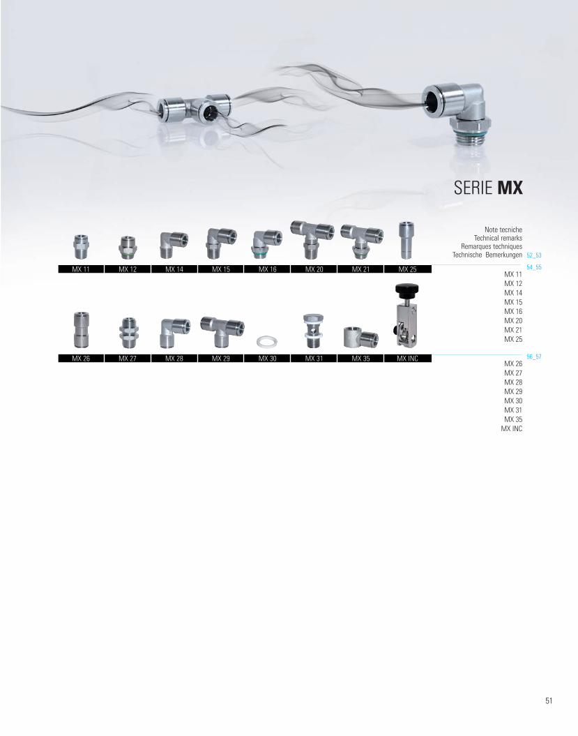
SERIE MX 54_55 56_57 MX 11 MX 12 MX 14 MX 15 MX 16 MX 20 MX 21 MX 25 Note tecniche Technical remarks Remarques techniques Technische Bemerkungen MX 26 MX 27 MX 28 MX 29 MX 30 MX 31 MX 35 MX INC MX 12 MX 11 MX 14 MX 15 MX 16 MX 20 MX 21 MX 25 MX 26 MX 27 MX 28 MX 29 MX 30 MX 31 MX 35 MX INC 52_53 51
Transcript of SERIE MX - hncgroup.dk · generale per l’uso nell’industria chimica ed alimentare. La...
SERIE MX
54_55
56_57
MX 11MX 12MX 14MX 15MX 16MX 20MX 21MX 25
Note tecnicheTechnical remarks
Remarques techniquesTechnische Bemerkungen
MX 26MX 27MX 28MX 29MX 30MX 31MX 35
MX INC
MX 12MX 11 MX 14 MX 15 MX 16 MX 20 MX 21 MX 25
MX 26 MX 27 MX 28 MX 29 MX 30 MX 31 MX 35 MX INC
52_53
51
MX
catalogo cmatic 2010:Layout 1 26/11/10 14:53 Pagina 51
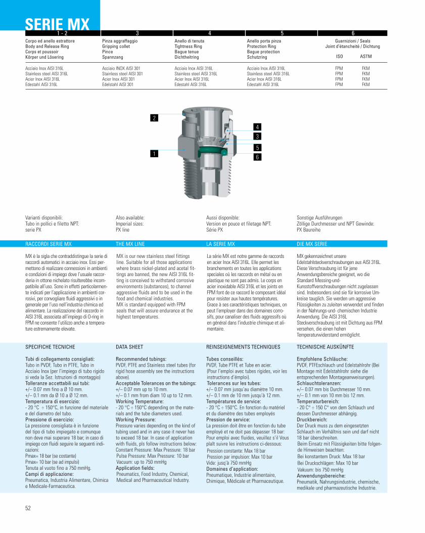
61 - 2 3 4 5 6
Corpo ed anello estrattore Body and Release RingCorps et poussoir Körper und Lösering
Pinza aggraffaggioGripping collet Pince Spannzang
Anello di tenuta Tightness RingBague tenue Dichtheitring
Anello porta pinza Protection RingBague protectionSchutzring
Guarnizioni / Seals Joint d’étancheité / Dichtung
ISO ASTM
Acciaio Inox AISI 316LStainless steel AISI 316LAcier Inox AISI 316LEdestahl AISI 316L
Acciaio INOX AISI 301Stainless steel AISI 301Acier Inox AISI 301Edelstahl AISI 301
Acciaio Inox AISI 316LStainless steel AISI 316LAcier Inox AISI 316LEdestahl AISI 316L
Acciaio Inox AISI 316LStainless steel AISI 316LAcier Inox AISI 316LEdestahl AISI 316L
FPM FKMFPM FKMFPM FKMFPM FKM
SERIE MX
RACCORDI SERIE MX
MX è la sigla che contraddistingue la serie diraccordi automatici in acciaio inox. Essi per-mettono di realizzare connessioni in ambientie condizioni di impiego dove l’usuale raccor-deria in ottone nichelato risulterebbe incom-patibile all’uso. Sono in effetti particolarmen-te indicati per l’applicazione in ambienti cor-rosivi, per convogliare fluidi aggressivi o ingenerale per l’uso nell’industria chimica edalimentare. La realizzazione del raccordo inAISI 316L associata all’impiego di O-ring inFPM ne consente l’utilizzo anche a tempera-ture estremamente elevate.
SPECIFICHE TECNICHE
Tubi di collegamento consigliati:Tubo in PVDF, Tubo in PTFE, Tubo inAcciaio Inox (per l’impiego di tubo rigidosi veda la Sez. Istruzioni di montaggio)Tolleranze accettabili sui tubi:+/– 0.07 mm fino a Ø 10 mm. +/– 0.1 mm da Ø 10 a Ø 12 mm.Temperatura di esercizio: - 20 °C ÷ 150°C, in funzione del materialee del diametro del tubo.Pressione di esercizio: La pressione consigliata è in funzione del tipo di tubo impiegato e comunque non deve mai superare 18 bar; in caso diimpiego con fluidi seguire le seguenti indi-cazioni:Pmax= 18 bar (se costante) Pmax= 10 bar (se ad impulsi)Tenuta al vuoto fino a 750 mmHg.Campi di applicazione: Pneumatica, Industria Alimentare, Chimicae Medicale-Farmaceutica.
THE MX LINE
MX is our new stainless steel fittingsline. Suitable for all those applicationswhere brass nickel-plated and acetal fit-tings are banned, the new AISI 316L fit-ting is conceived to withstand corrosiveenvironments (substances), to channelaggressive fluids and to be used in thefood and chemical industries.MX is standard equipped with FPMseals that will assure endurance at thehighest temperatures.
DATA SHEET
Recommended tubings: PVDF, PTFE and Stainless steel tubes (forrigid hose assembly see the instructionsabove).Acceptable Tolerances on the tubings:+/– 0.07 mm up to 10 mm.+/– 0.1 mm from diam 10 up to 12 mm.Working Temperature: - 20 °C ÷ 150°C depending on the mate-rials and the tube diameters used.Working Pressure: Pressure varies depending on the kind oftubing used and in any case it never hasto exceed 18 bar. In case of applicationwith fluids, pls follow instructions below:Constant Pressure: Max Pressure: 18 barPulse Pressure: Max Pressure: 10 barVacuum: up to 750 mmHgApplication fields: Pneumatics, Food Industry, Chemical,Medical and Pharmaceutical Industry.
LA SERIE MX
La série MX est notre gamme de raccordsen acier Inox AISI 316L. Elle permet lesbranchements en toutes les applicationsspeciales où les raccords en métal ou enplastique ne sont pas admis. Le corps enacier inoxidable AISI 316L et les joints enFPM font de ce raccord le composant idéalpour resister aux hautes températures.Grace à ses caractéristiques techniques, onpeut l’employer dans des domaines corro-sifs, pour canaliser des fluids aggressifs oùen général dans l’industrie chimique et ali-mentaire.
REINSEIGNEMENTS TECHNIQUES
Tubes conseillés:PVDF, Tube PTFE et Tube en acier.(Pour l’emploi avec tubes rigides, voir lesinstructions d’émploi).Tolerances sur les tubes:+/– 0.07 mm jusqu’au diamètre 10 mm.+/– 0.1 mm de 10 mm jusqu’à 12 mm.Températures de service: - 20 °C ÷ 150°C. En fonction du matérielet du diamètre des tubes employésPression de service: La pression doit être en fonction du tubeemployé et ne doit pas dépasser 18 bar:Pour emploi avec fluides, veuillez s’il Vousplaît suivre les instructions ci-dessous:Pression constante: Max 18 bar Pression par impulsion: Max 10 barVide: jusq’à 750 mmHgDomaines d’application: Pneumatique, Industrie alimentaire,Chimique, Médicale et Pharmaceutique.
DIE MX SERIE
MX gekennzeichnet unsereEdelstahIsteckverschraubungen aus AISI 316L.Diese Verschraubung ist für jeneAnwendungsbereiche geeignet, wo dieStandard Messing-und-Kunsstoffverschraubungen nicht zugelassensind. Insbesonders sind sie für korrosive Um -kreise tauglich. Sie werden um aggressiveFlüssigkeiten zu zuleiten verwendet und findenin der Nahrungs-und- chemischen IndustrieAnwendung. Die AISI 316LSteckverschraubung ist mit Dichtung aus FPMversehen, die einen hohenTemperaturwiderstand ermöglicht.
TECHNISCHE AUSKÜNFTE
Empfohlene Schläuche:PVDF, PTFEschlauch und EdelstahIrohr (BeiMontage mit Edel stahIrohr siehe dieentsprechenden Montageanweisungen).Schlauchtoleranzen: +/– 0.07 mm bis Durchmesser 10 mm.+/– 0.1 mm von 10 mm bis 12 mm.Temperaturbereich: - 20 C° ÷ 150 C° von dem SchIauch unddessen Durchmesser abhängig.Druckbereich: Der Druck muss zu dem eingesetztenSchlauch im Verhältnis sein und darf nicht18 bar überschreiten. Beim Einsatz mit Flüssigkeiten bitte folgen-de Hinweisen beachten:Bei konstantem Druck: Max 18 barBei Druckschlägen: Max 10 barVakuum: bis 750 mmHgAnwendungsbereiche: Pneumatik, Nahrungsindustrie, chemische,medikale und pharmazeutische Industrie.
52
Varianti disponibili:Tubo in pollici e filetto NPT:serie PX
Also available:Imperial sizes:PX line
Aussi disponible:Version en pouce et filetage NPT:Série PX
Sonstige Ausführungen Zöllige Durchmesser und NPT Gewinde:PX Baureihe
2
1
4
5
6
3
catalogo cmatic 2010:Layout 1 26/11/10 14:54 Pagina 52
53
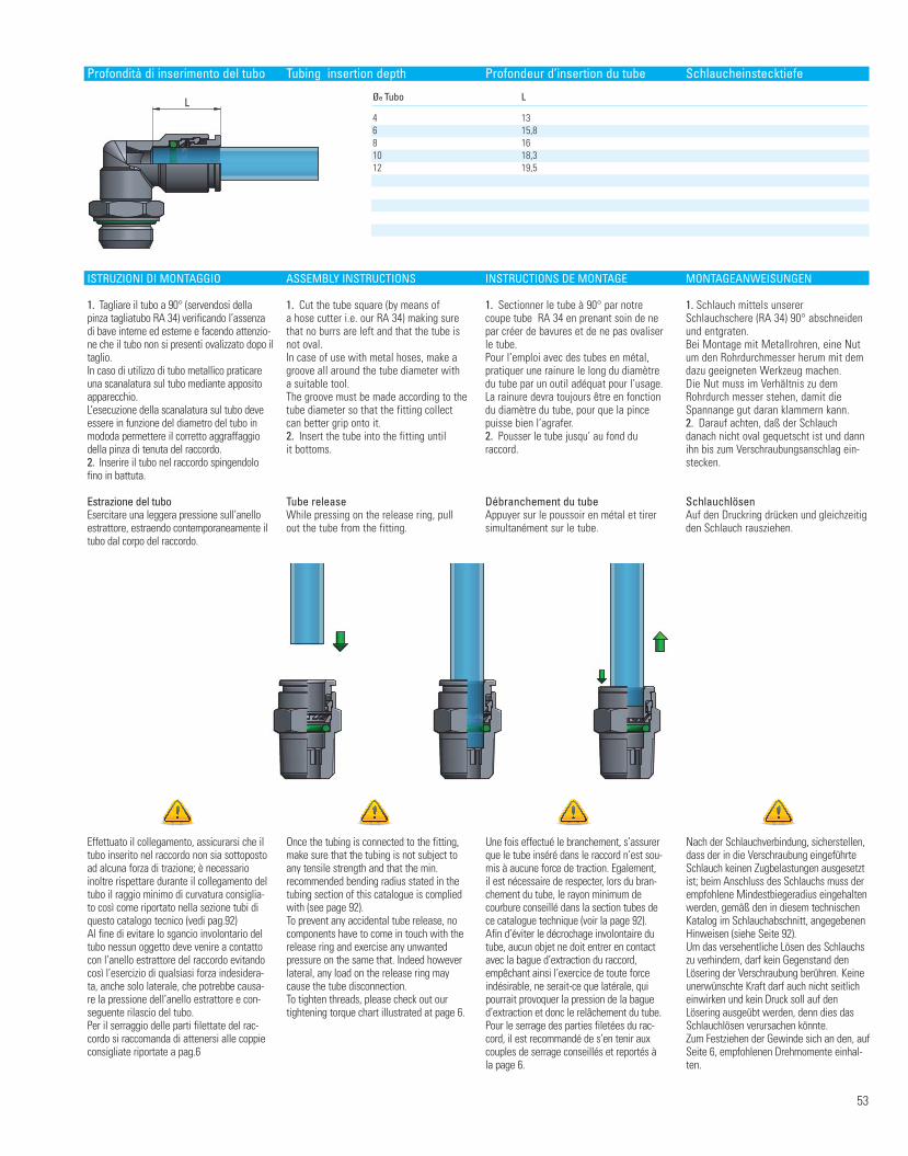
Profondità di inserimento del tubo Tubing insertion depth Profondeur d’insertion du tube Schlaucheinstecktiefe
L Øe Tubo L
4 136 15,88 1610 18,312 19,5
Effettuato il collegamento, assicurarsi che iltubo inserito nel raccordo non sia sottopostoad alcuna forza di trazione; è necessarioinoltre rispettare durante il collegamento deltubo il raggio minimo di curvatura consiglia-to così come riportato nella sezione tubi diquesto catalogo tecnico (vedi pag.92)Al fine di evitare lo sgancio involontario deltubo nessun oggetto deve venire a contattocon l’anello estrattore del raccordo evitandocosì l’esercizio di qualsiasi forza indesidera-ta, anche solo laterale, che potrebbe causa-re la pressione dell’anello estrattore e con-seguente rilascio del tubo.Per il serraggio delle parti filettate del rac-cordo si raccomanda di attenersi alle coppieconsigliate riportate a pag.6
Once the tubing is connected to the fitting,make sure that the tubing is not subject toany tensile strength and that the min.recommended bending radius stated in thetubing section of this catalogue is compliedwith (see page 92).To prevent any accidental tube release, nocomponents have to come in touch with therelease ring and exercise any unwantedpressure on the same that. Indeed howeverlateral, any load on the release ring maycause the tube disconnection.To tighten threads, please check out ourtightening torque chart illustrated at page 6.
Une fois effectué le branchement, s’assurerque le tube inséré dans le raccord n’est sou-mis à aucune force de traction. Egalement,il est nécessaire de respecter, lors du bran-chement du tube, le rayon minimum decourbure conseillé dans la section tubes dece catalogue technique (voir la page 92).Afin d’éviter le décrochage involontaire dutube, aucun objet ne doit entrer en contactavec la bague d’extraction du raccord,empêchant ainsi l’exercice de toute forceindésirable, ne serait-ce que latérale, quipourrait provoquer la pression de la bagued’extraction et donc le relâchement du tube. Pour le serrage des parties filetées du rac-cord, il est recommandé de s’en tenir auxcouples de serrage conseillés et reportés àla page 6.
Nach der Schlauchverbindung, sicherstellen,dass der in die Verschraubung eingeführteSchlauch keinen Zugbelastungen ausgesetztist; beim Anschluss des Schlauchs muss derempfohlene Mindestbiegeradius eingehaltenwerden, gemäß den in diesem technischenKatalog im Schlauchabschnitt, angegebenenHinweisen (siehe Seite 92). Um das versehentliche Lösen des Schlauchszu verhindern, darf kein Gegenstand denLösering der Verschraubung berühren. Keineunerwünschte Kraft darf auch nicht seitlicheinwirken und kein Druck soll auf denLösering ausgeübt werden, denn dies dasSchlauchlösen verursachen könnte.Zum Festziehen der Gewinde sich an den, aufSeite 6, empfohlenen Drehmomente einhal-ten.
ISTRUZIONI DI MONTAGGIO
1. Tagliare il tubo a 90° (servendosi dellapinza tagliatubo RA 34) verificando l’assenzadi bave interne ed esterne e facendo attenzio-ne che il tubo non si presenti ovalizzato dopo iltaglio.In caso di utilizzo di tubo metallico praticareuna scanalatura sul tubo mediante appositoapparecchio.L’esecuzione della scanalatura sul tubo deveessere in funzione del diametro del tubo inmododa permettere il corretto aggraffaggiodella pinza di tenuta del raccordo.2. Inserire il tubo nel raccordo spingendolofino in battuta.
Estrazione del tuboEsercitare una leggera pressione sull’anelloestrattore, estraendo contemporaneamente iltubo dal corpo del raccordo.
ASSEMBLY INSTRUCTIONS
1. Cut the tube square (by means of a hose cutter i.e. our RA 34) making surethat no burrs are left and that the tube isnot oval.In case of use with metal hoses, make agroove all around the tube diameter witha suitable tool.The groove must be made according to thetube diameter so that the fitting collectcan better grip onto it.2. Insert the tube into the fitting untilit bottoms.
Tube releaseWhile pressing on the release ring, pullout the tube from the fitting.
INSTRUCTIONS DE MONTAGE
1. Sectionner le tube à 90° par notrecoupe tube RA 34 en prenant soin de nepar créer de bavures et de ne pas ovaliserle tube.Pour l’emploi avec des tubes en métal,pratiquer une rainure le long du diamètredu tube par un outil adéquat pour l’usage.La rainure devra toujours être en fonctiondu diamètre du tube, pour que la pincepuisse bien l’agrafer.2. Pousser le tube jusqu’ au fond duraccord.
Débranchement du tubeAppuyer sur le poussoir en métal et tirersimultanément sur le tube.
MONTAGEANWEISUNGEN
1. Schlauch mittels unsererSchlauchschere (RA 34) 90° abschneidenund entgraten.Bei Montage mit Metallrohren, eine Nutum den Rohrdurchmesser herum mit demdazu geeigneten Werkzeug machen.Die Nut muss im Verhältnis zu demRohrdurch messer stehen, damit dieSpannange gut daran klammern kann.2. Darauf achten, daß der Schlauch danach nicht oval gequetscht ist und dannihn bis zum Verschraubungsanschlag ein-stecken.
SchlauchlösenAuf den Druckring drücken und gleichzeitigden Schlauch rausziehen.
MX
catalogo cmatic 2010:Layout 1 26/11/10 14:54 Pagina 53
ØTub
o
L2
L3
D1
D2
L1
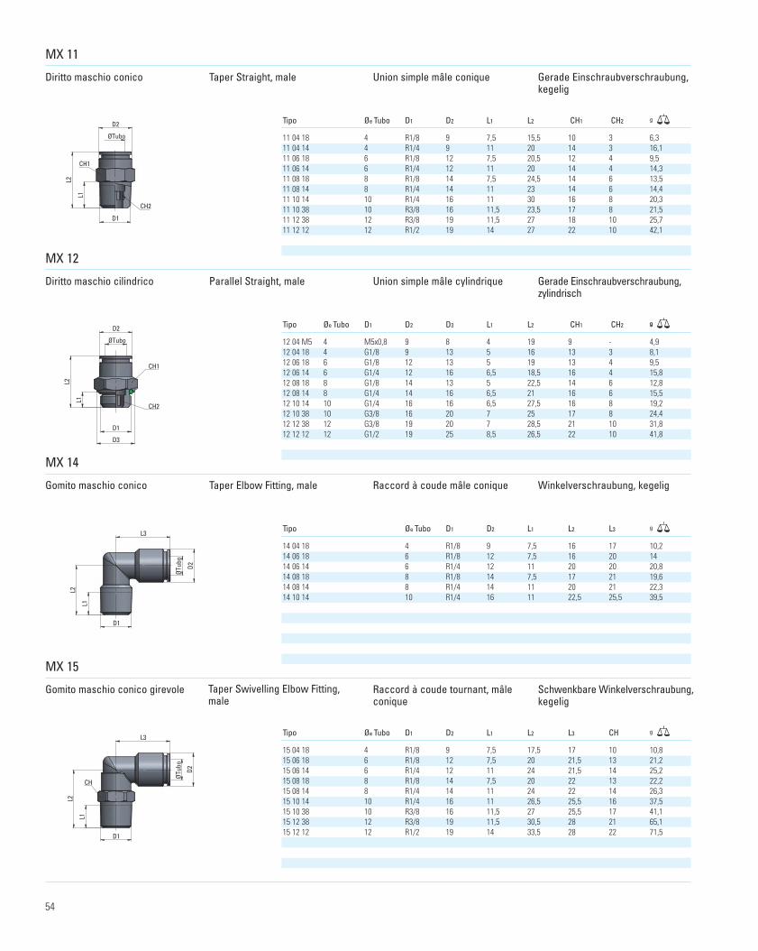
MX 11
Diritto maschio conico Taper Straight, male Union simple mâle conique Gerade Einschraubverschraubung,kegelig
Diritto maschio cilindrico Parallel Straight, male Union simple mâle cylindrique Gerade Einschraubverschraubung,zylindrisch
Gomito maschio conico Taper Elbow Fitting, male Raccord à coude mâle conique Winkelverschraubung, kegelig
Gomito maschio conico girevole Taper Swivelling Elbow Fitting,male
Raccord à coude tournant, mâleconique
Schwenkbare Winkelverschraubung,kegelig
ØTubo
D2
D1
L1
L2
CH2
CH1
Tipo Øe Tubo D1 D2 L1
D3
L2 CH1 CH2
Tipo Øe Tubo D1 D2 L1 L2
L1D1 D2 L2 L3
L1D2 L2 L3 CH
CH1 CH2
g
g
11 04 18 4 R1/8 9 7,5 15,5 10 3 6,311 04 14 4 R1/4 9 11 20 14 3 16,111 06 18 6 R1/8 12 7,5 20,5 12 4 9,511 06 14 6 R1/4 12 11 20 14 4 14,311 08 18 8 R1/8 14 7,5 24,5 14 6 13,511 08 14 8 R1/4 14 11 23 14 6 14,411 10 14 10 R1/4 16 11 30 16 8 20,311 10 38 10 R3/8 16 11,5 23,5 17 8 21,511 12 38 12 R3/8 19 11,5 27 18 10 25,711 12 12 12 R1/2 19 14 27 22 10 42,1
MX 12
ØTubo
D2
L1
L2
D1
D3
CH1
CH2
g
MX 14
g
MX 15
D1
D2
L2
L3
ØTub
o
L1
CH
Tipo Øe Tubo D1
Tipo Øe Tubo
g
14 04 18 4 R1/8 9 7,5 16 17 10,214 06 18 6 R1/8 12 7,5 16 20 1414 06 14 6 R1/4 12 11 20 20 20,814 08 18 8 R1/8 14 7,5 17 21 19,614 08 14 8 R1/4 14 11 20 21 22,314 10 14 10 R1/4 16 11 22,5 25,5 39,5
15 04 18 4 R1/8 9 7,5 17,5 17 10 10,815 06 18 6 R1/8 12 7,5 20 21,5 13 21,215 06 14 6 R1/4 12 11 24 21,5 14 25,215 08 18 8 R1/8 14 7,5 20 22 13 22,215 08 14 8 R1/4 14 11 24 22 14 26,315 10 14 10 R1/4 16 11 26,5 25,5 16 37,515 10 38 10 R3/8 16 11,5 27 25,5 17 41,115 12 38 12 R3/8 19 11,5 30,5 28 21 65,115 12 12 12 R1/2 19 14 33,5 28 22 71,5
12 04 M5 4 M5x0,8 9 8 4 19 9 - 4,912 04 18 4 G1/8 9 13 5 16 13 3 8,112 06 18 6 G1/8 12 13 5 19 13 4 9,512 06 14 6 G1/4 12 16 6,5 18,5 16 4 15,812 08 18 8 G1/8 14 13 5 22,5 14 6 12,812 08 14 8 G1/4 14 16 6,5 21 16 6 15,512 10 14 10 G1/4 16 16 6,5 27,5 16 8 19,212 10 38 10 G3/8 16 20 7 25 17 8 24,412 12 38 12 G3/8 19 20 7 28,5 21 10 31,812 12 12 12 G1/2 19 25 8,5 26,5 22 10 41,8
54
catalogo cmatic 2010:Layout 1 26/11/10 14:54 Pagina 54
ØTub
o
D2
D1
L1
L2
L3
CH
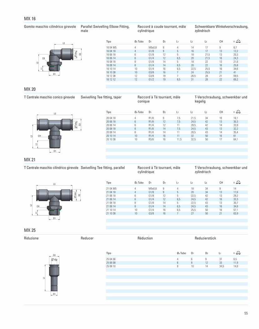
Gomito maschio cilindrico girevole Parallel Swivelling Elbow Fitting,male
Raccord à coude tournant, mâlecylindrique
Schwenkbare Winkelverschraubung,zylindrisch
T Centrale maschio conico girevole Swivelling Tee fitting, taper Raccord à Té tournant, mâle conique
T-Verschraubung, schwenkbar und kegelig
T Centrale maschio cilindrico girevole Swivelling Tee fitting, parallel Raccord à Té tournant, mâle cylindrique
T-Verschraubung, schwenkbar undzylindrisch
MX 16
Tipo Øe Tubo D1 D2 L1 L2 L3 CH g
MX 20
D1
L2
L3
ØTub
o
D2
L1
CH
D2
L3
D1
L2
L1
ØTub
o
CH
MX 21
MX 25
ØTubo
D2
D1
L1
16 04 M5 4 M5x0,8 9 4 14 17 9 8,716 04 18 4 G1/8 9 5 16 17 13 12,216 06 18 6 G1/8 12 5 18 21,5 13 20,316 06 14 6 G1/4 12 6,5 20 21,5 16 24,316 08 18 8 G1/8 14 5 18 22 13 21,616 08 14 8 G1/4 14 6,5 20 22 16 25,816 10 14 10 G1/4 16 6,5 22,5 25,5 16 34,616 10 38 10 G3/8 16 7 24 25,5 21 4116 12 38 12 G3/8 19 7 26,5 28 21 59,516 12 12 12 G1/2 19 8,5 31 28 22 69,2
Tipo Øe Tubo D1 D2 L1 L2 L3 CH g
20 04 18 4 R1/8 9 7,5 21,5 34 10 16,120 06 18 6 R1/8 12 7,5 24,5 42 13 30,320 06 14 6 R1/4 12 11 28,5 42 14 33,920 08 18 8 R1/8 14 7,5 24,5 43 13 32,220 08 14 8 R1/4 14 11 28,5 43 14 35,420 10 14 10 R1/4 16 11 32 50 16 6120 10 38 10 R3/8 16 11,5 32,5 50 17 64,1
Tipo Øe Tubo D1 D2 L1 L2 L3 CH g
21 04 M5 4 M5x0,8 9 4 18 34 9 1421 04 18 4 G1/8 9 5 20 34 13 17,621 06 18 6 G1/8 12 5 22,5 42 13 29,221 06 14 6 G1/4 12 6,5 24,5 42 16 33,321 08 18 8 G1/8 14 5 22,5 43 13 30,721 08 14 8 G1/4 14 6,5 24,5 43 16 34,821 10 14 10 G1/4 16 6,5 25,5 50 16 57,121 10 38 10 G3/8 16 7 27 50 21 63,9
Tipo Øe Tubo D1 D2 L1 g
25 04 06 4 6 9 31 6,525 06 08 6 8 12 33 11,925 08 10 8 10 14 34,5 14,8
Riduzione Reducer Réduction Reduzierstück
55
MX
catalogo cmatic 2010:Layout 1 26/11/10 14:54 Pagina 55
L2
ØTub
o
L1
D2
ØTubo1
ØTubo2
D2
L1
L1
L1
D2
ØTub
o
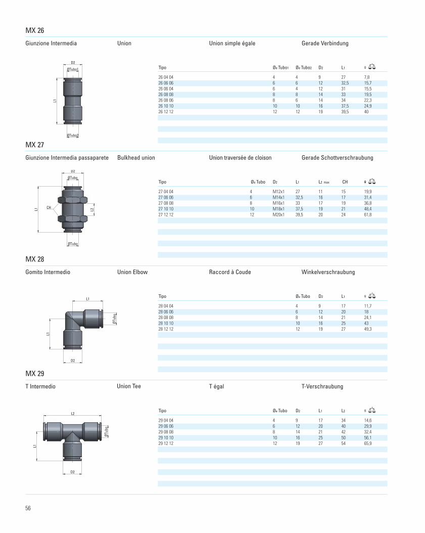
MX 26
Giunzione Intermedia Union Union simple égale Gerade Verbindung
Giunzione Intermedia passaparete Bulkhead union Union traversée de cloison Gerade Schottverschraubung
Gomito Intermedio Union Elbow Raccord à Coude Winkelverschraubung
T Intermedio Union Tee T égal T-Verschraubung
Tipo Øe Tubo D2 L1 L2 max CH g
MX 27
ØTubo
D2
ØTubo
L2L1 CH
g
MX 28
g
MX 29
g
27 04 04 4 M12x1 27 11 15 19,927 06 06 6 M14x1 32,5 16 17 31,427 08 08 8 M16x1 33 17 19 36,827 10 10 10 M18x1 37,5 19 21 48,427 12 12 12 M20x1 39,5 20 24 61,8
Tipo Øe Tubo D2 L1
28 04 04 4 9 17 11,728 06 06 6 12 20 1828 08 08 8 14 21 24,128 10 10 10 16 25 4328 12 12 12 19 27 49,3
Tipo Øe Tubo D2 L1 L2
29 04 04 4 9 17 34 14,629 06 06 6 12 20 40 29,929 08 08 8 14 21 42 32,429 10 10 10 16 25 50 56,129 12 12 12 19 27 54 65,9
Tipo Øe Tubo1 Øe Tubo2 D2 L1 g
26 04 04 4 4 9 27 7,826 06 06 6 6 12 32,5 15,726 06 04 6 4 12 31 15,526 08 08 8 8 14 33 19,526 08 06 8 6 14 34 22,326 10 10 10 10 16 37,5 24,926 12 12 12 12 19 39,5 40
56
catalogo cmatic 2010:Layout 1 26/11/10 14:54 Pagina 56
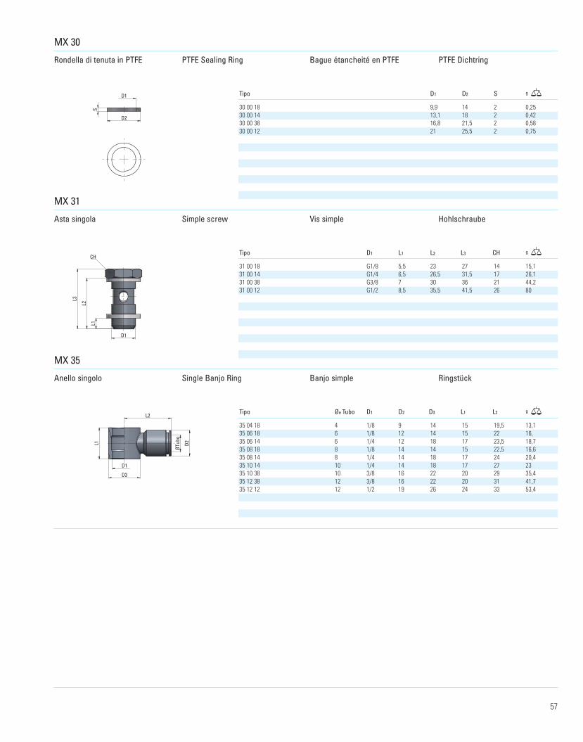
Bague étancheité en PTFE PTFE Dichtring
Asta singola Simple screw Vis simple Hohlschraube
D1
D3
L1
ØTub
o
D2
L2
MX 30
D1
D2
STipo D1 D2 S g
MX 31
D1
L1
L2
L3
CH
MX 35
30 00 18 9,9 14 2 0,2530 00 14 13,1 18 2 0,4230 00 38 16,8 21,5 2 0,5830 00 12 21 25,5 2 0,75
Tipo D1 L1 L2 L3 CH g
31 00 18 G1/8 5,5 23 27 14 15,131 00 14 G1/4 6,5 26,5 31,5 17 26,131 00 38 G3/8 7 30 36 21 44,231 00 12 G1/2 8,5 35,5 41,5 26 80
Tipo Øe Tubo D1 D2 D3 L1 L2 g
35 04 18 4 1/8 9 14 15 19,5 13,135 06 18 6 1/8 12 14 15 22 16,35 06 14 6 1/4 12 18 17 23,5 18,735 08 18 8 1/8 14 14 15 22,5 16,635 08 14 8 1/4 14 18 17 24 20,435 10 14 10 1/4 14 18 17 27 2335 10 38 10 3/8 16 22 20 29 35,435 12 38 12 3/8 16 22 20 31 41,735 12 12 12 1/2 19 26 24 33 53,4
Anello singolo Single Banjo Ring Banjo simple Ringstück
Rondella di tenuta in PTFE PTFE Sealing Ring
57
MX
catalogo cmatic 2010:Layout 1 26/11/10 14:54 Pagina 57
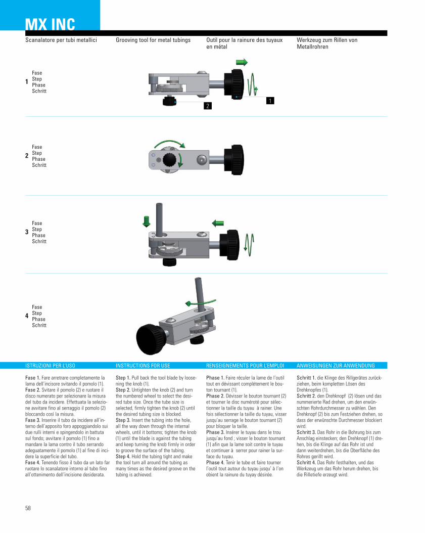
MX INC
ISTRUZIONI PER L’USO
Fase 1. Fare arretrare completamente lalama dell’incisore svitando il pomolo (1).Fase 2. Svitare il pomolo (2) e ruotare ildisco numerato per selezionare la misuradel tubo da incidere. Effettuata la selezio-ne avvitare fino al serraggio il pomolo (2)bloccando così la misura.Fase 3. Inserire il tubo da incidere all’in-terno dell’apposito foro appoggiandolo suidue rulli interni e spingendolo in battutasul fondo; avvitare il pomolo (1) fino amandare la lama contro il tubo serrandoadeguatamente il pomolo (1) al fine di inci-dere la superficie del tubo.Fase 4. Tenendo fisso il tubo da un lato farruotare lo scanalatore intorno al tubo finoall’ottenimento dell’incisione desiderata.
INSTRUCTIONS FOR USE
Step 1. Pull back the tool blade by loose-ning the knob (1).Step 2. Untighten the knob (2) and turnthe numbered wheel to select the desi-red tube size. Once the tube size isselected, firmly tighten the knob (2) untilthe desired tubing size is blocked.Step 3. Insert the tubing into the hole,all the way down through the internalwheels, until it bottoms; tighten the knob(1) until the blade is against the tubingand keep turning the knob firmly in orderto groove the surface of the tubing.Step 4. Hold the tubing tight and makethe tool turn all around the tubing asmany times as the desired groove on thetubing is achieved.
RENSEIGNEMENTS POUR L’EMPLOI
Phase 1. Faire réculer la lame de l’outiltout en dévissant complétement le bou-ton tournant (1).Phase 2. Dévisser le bouton tournant (2)et tourner le disc numéroté pour sélec-tionner la taille du tuyau à rainer. Unefois sélectionner la taille du tuyau, visserjusqu’au serrage le bouton tournant (2)pour bloquer la taille.Phase 3. Insérer le tuyau dans le troujusqu’au fond ; visser le bouton tournant(1) afin que la lame soit contre le tuyauet continuer à serrer pour rainer la sur-face du tuyau.Phase 4. Tenir le tube et faire tournerl’outil tout autour du tuyau jusqu’ à l’onobient la rainure du tuyay désirée.
ANWEISUNGEN ZUR ANWENDUNG
Schritt 1. die Klinge des Rillgerätes zurück-ziehen, beim kompletten Lösen desDrehknopfes (1).Schritt 2. den Drehknopf (2) lösen und dasnummerierte Rad drehen, um den erwün-schten Rohrdurchmesser zu wählen. DenDrehknopf (2) bis zum Festziehen drehen, sodass der erwünschte Durchmesser blockiertwird.Schritt 3. Das Rohr in die Bohrung bis zumAnschlag einstecken; den Drehknopf (1) dre-hen, bis die Klinge auf das Rohr ist unddann weiterdrehen, bis die Oberfläche desRohres gerillt wird.Schritt 4. Das Rohr festhalten, und dasWerkzeug um das Rohr herum drehen, bisdie Rilletiefe erzeugt wird.
12
Scanalatore per tubi metallici Grooving tool for metal tubings Outil pour la rainure des tuyauxen métal
Fase Step Phase Schritt
1
Fase Step Phase Schritt
2
Fase Step Phase Schritt
3
Fase Step Phase Schritt
4
Werkzeug zum Rillen vonMetallrohren
58
catalogo cmatic 2010:Layout 1 26/11/10 14:54 Pagina 58