lecchiimpianti - Mese della Sicurezza - Offerta TVCC e Videosorveglianza Urmet
DS 1783-005 LBT 8681
Mod.1783
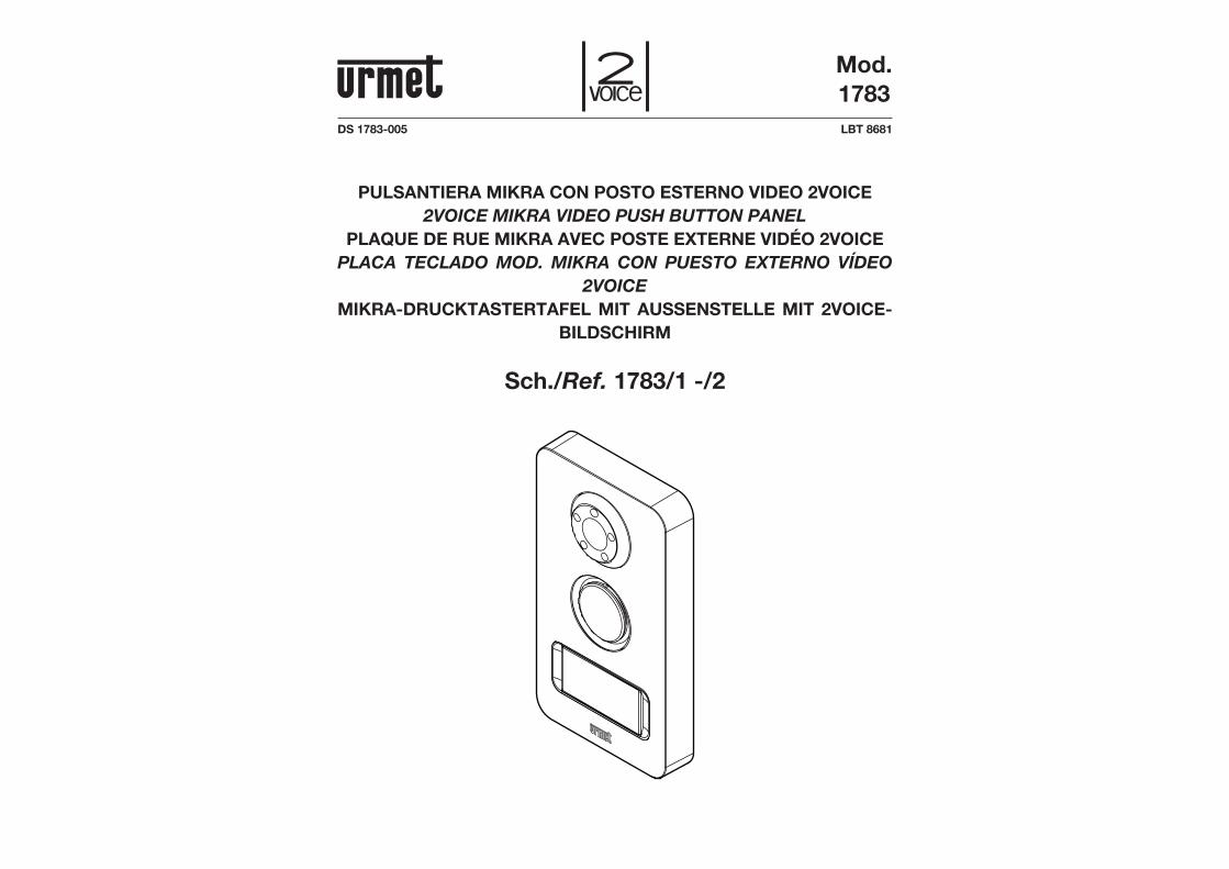
PULSANTIERA MIKRA CON POSTO ESTERNO VIDEO 2VOICE2VOICE MIKRA VIDEO PUSH BUTTON PANEL
PLAQUE DE RUE MIKRA AVEC POSTE EXTERNE VIDÉO 2VOICEPLACA TECLADO MOD. MIKRA CON PUESTO EXTERNO VÍDEO
2VOICEMIKRA-DRUCKTASTERTAFEL MIT AUSSENSTELLE MIT 2VOICE-
BILDSCHIRM
Sch./Ref. 1783/1 -/2
2 DS1783-005 3DS1783-005
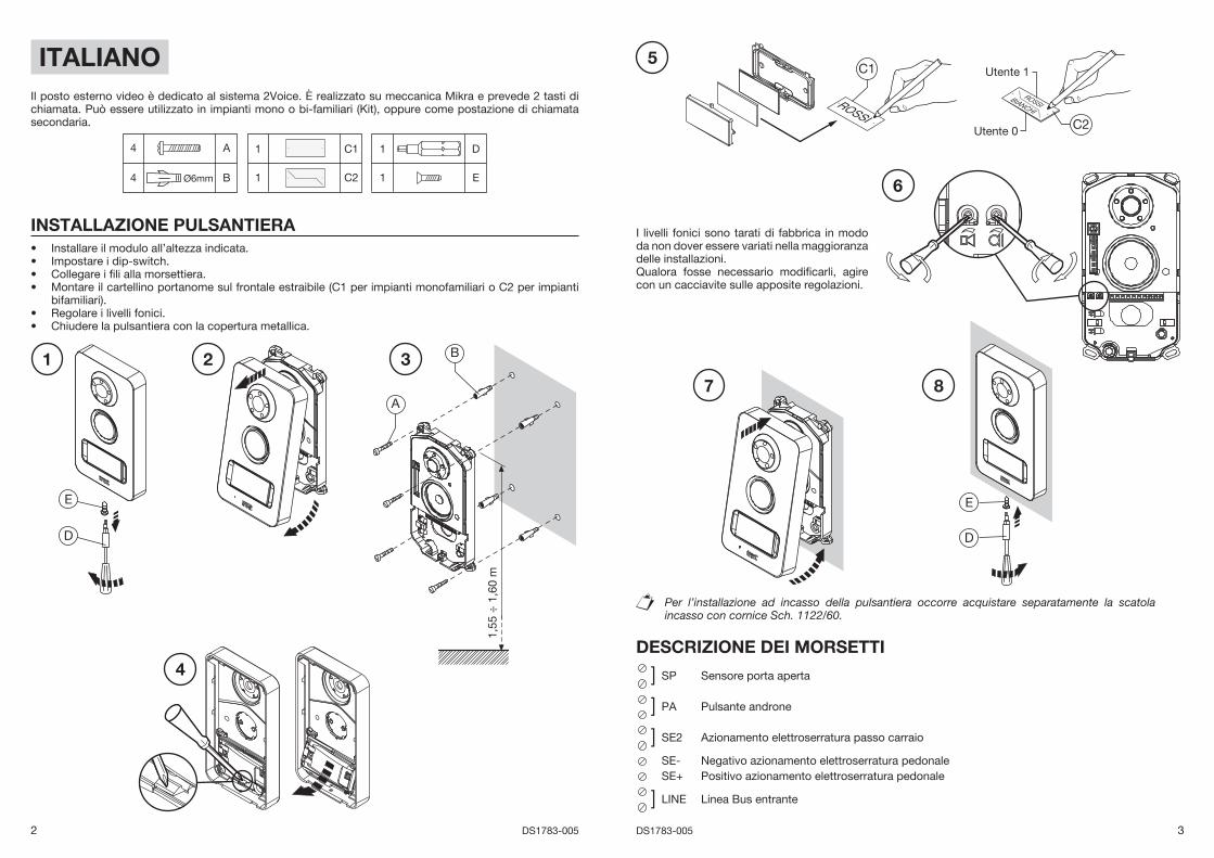
ITALIANOIl posto esterno video è dedicato al sistema 2Voice. È realizzato su meccanica Mikra e prevede 2 tasti di chiamata. Può essere utilizzato in impianti mono o bi-familiari (Kit), oppure come postazione di chiamata secondaria.
4 A
4 Ø6mm B
1 C1
1 C2
1 D
1 E
INSTALLAZIONE PULSANTIERAInstallare il modulo all’altezza indicata.Impostare i dip-switch.Collegare i fi li alla morsettiera.Montare il cartellino portanome sul frontale estraibile (C1 per impianti monofamiliari o C2 per impianti bifamiliari).Regolare i livelli fonici.Chiudere la pulsantiera con la copertura metallica.
••••
••
Per l’installazione ad incasso della pulsantiera occorre acquistare separatamente la scatola incasso con cornice Sch. 1122/60.
DESCRIZIONE DEI MORSETTI
] SP Sensore porta aperta
] PA Pulsante androne
] SE2 Azionamento elettroserratura passo carraio
SE- Negativo azionamento elettroserratura pedonaleSE+ Positivo azionamento elettroserratura pedonale
] LINE Linea Bus entrante
I livelli fonici sono tarati di fabbrica in modo da non dover essere variati nella maggioranza delle installazioni.Qualora fosse necessario modifi carli, agire con un cacciavite sulle apposite regolazioni.
1,55
÷ 1
,60
m
A
B1 2 3
4
D
E
5
7
D
E
C1
C2
Utente 1
Utente 0
6
8
4 DS1783-005 5DS1783-005
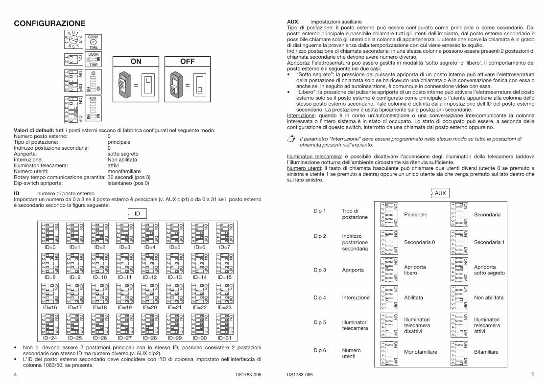
CONFIGURAZIONE
= =ONON
0
5
38
4
9 1
6
2
7
ON2
1
ON
DIP
43
21
5
ON
DIP
43
21
56
Valori di default: tutti i posti esterni escono di fabbrica confi gurati nel seguente modo:Numero posto esterno: 0Tipo di postazione: principaleIndirizzo postazione secondaria: 0Apriporta: sotto segretoInterruzione: Non abilitataIlluminatori telecamera: attiviNumero utenti: monofamiliareRotary tempo comunicazione garantita: 30 secondi (pos 3)Dip-switch apriporta: istantaneo (pos 0)
ID: numero di posto esternoImpostare un numero da 0 a 3 se il posto esterno è principale (v. AUX dip1) o da 0 a 31 se il posto esterno è secondario secondo la fi gura seguente.
ID
ON
DIP
43
21
5
ID=0
ON
DIP
43
21
5
ID=1
ON
DIP
43
21
5
ID=2
ON
DIP
43
21
5
ID=3
ON
DIP
43
21
5
ID=4
ON
DIP
43
21
5
ID=5
ON
DIP
43
21
5
ID=6
ON
DIP
43
21
5
ID=7
ON
DIP
43
21
5
ID=8
ON
DIP
43
21
5
ID=9
ON
DIP
43
21
5
ID=10
ON
DIP
43
21
5
ID=11
ON
DIP
43
21
5
ID=12
ON
DIP
43
21
5
ID=13
ON
DIP
43
21
5
ID=14
ON
DIP
43
21
5
ID=15
ON
DIP
43
21
5
ID=16
ON
DIP
43
21
5
ID=17
ON
DIP
43
21
5
ID=18
ON
DIP
43
21
5
ID=19
ON
DIP
43
21
5
ID=20
ON
DIP
43
21
5
ID=21
ON
DIP
43
21
5
ID=22
ON
DIP
43
21
5
ID=23
ON
DIP
43
21
5
ID=24
ON
DIP
43
21
5
ID=25
ON
DIP
43
21
5
ID=26
ON
DIP
43
21
5
ID=27
ON
DIP
43
21
5
ID=28
ON
DIP
43
21
5
ID=29O
ND
IP
43
21
5
ID=30
ON
DIP
43
21
5
ID=31
Non ci devono essere 2 postazioni principali con lo stesso ID, possono coesistere 2 postazioni secondarie con stesso ID ma numero diverso (v. AUX dip2).L’ID del posto esterno secondario deve coincidere con l’ID di colonna impostato nell’interfaccia di colonna 1083/50, se presente.
•
•
AUX: impostazioni ausiliarieTipo di postazione: il posto esterno può essere confi gurato come principale o come secondario. Dal posto esterno principale è possibile chiamare tutti gli utenti dell’impianto, dal posto esterno secondario è possibile chiamare solo gli utenti della colonna di appartenenza. L’utente che riceve la chiamata è in grado di distinguerne la provenienza dalla temporizzazione con cui viene emesso lo squillo.Indirizzo postazione di chiamata secondaria: in una stessa colonna possono essere presenti 2 postazioni di chiamata secondarie che devono avere numero diverso.Apriporta: l’elettroserratura può essere gestita in modalità ‘sotto segreto’ o ‘libero’. Il comportamento del posto esterno è il seguente nei due casi:
“Sotto segreto”: la pressione del pulsante apriporta di un posto interno può attivare l’elettroserratura della postazione di chiamata solo se ha ricevuto una chiamata o è in conversazione fonica con essa o anche se, in seguito ad autoinserzione, è comunque in connessione video con essa.“Libero”: la pressione del pulsante apriporta di un posto interno può attivare l’elettroserratura del posto esterno solo se il posto esterno è confi gurato come principale o l’utente appartiene alla colonna dello stesso posto esterno secondario. Tale colonna è defi nita dalla impostazione dell’ID del posto esterno secondario. La prestazione è usata tipicamente sulle postazioni secondarie.
Interruzione: quando è in corso un’autoinserzione o una conversazione intercomunicante la colonna interessata o l’intero sistema è in stato di occupato. Lo stato di occupato può essere, a seconda della confi gurazione di questo switch, interrotto da una chiamata dal posto esterno oppure no.
Il parametro “Interruzione” deve essere programmato nello stesso modo su tutte le postazioni di chiamata presenti nell’impianto.
Illuminatori telecamera: è possibile disattivare l’accensione degli illuminatori della telecamera laddove l’illuminazione notturna dell’ambiente circostante sia ritenuta suffi ciente.Numero utenti: il tasto di chiamata basculante può chiamare due utenti diversi (utente 0 se premuto a sinistra e utente 1 se premuto a destra) oppure un unico utente sia che venga premuto sul lato destro che sul lato sinistro.
AUX
ON
DIP
43
21
56
Principale
ON
DIP
43
21
56
Secondaria
ON
DIP
43
21
56
Secondaria 0
ON
DIP
43
21
5
Secondaria 1
ON
DIP
43
21
5
Apriportalibero
ON
DIP
43
21
56
6
Apriportasotto segreto
ON
DIP
43
21
56
6
Abilitata
ON
DIP
43
21
5
Non abilitata
ON
DIP
43
21
56
Illuminatoritelecameradisattivi
Tipo dipostazione
Indirizzopostazionesecondaria
Apriporta
Interruzione
Illuminatoritelecamera
ON
DIP
43
21
5
Illuminatoritelecameraattivi
66
ON
DIP
43
21
56
MonofamiliareNumeroutenti
Dip 1
Dip 2
Dip 3
Dip 4
Dip 5
Dip 6
ON
DIP
43
21
5
Bifamiliare
6
•
•
6 DS1783-005 7DS1783-005
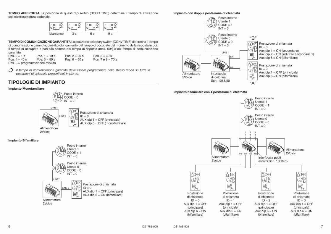
TEMPO APRIPORTA La posizione di questi dip-switch (DOOR TIME) determina il tempo di attivazione dell’elettroserratura pedonale.
ON2
Istantaneo
1 ON2
3 s
1 ON2
6 s
1 ON2
9 s
1
TEMPO DI COMUNICAZIONE GARANTITA La posizione del rotary switch (CONV TIME) determina il tempo di comunicazione garantita, cioè il prolungamento del tempo di occupato dal momento della risposta in poi. Il tempo di occupato è pari alla somma del tempo di risposta (max. 60s) e del tempo di comunicazione garantita.Pos. 0 = 1 s Pos. 1 = 10 s Pos. 2 = 20 s Pos. 3 = 30 sPos. 4 = 40 s Pos. 5 = 50 s Pos. 6 = 60 s Pos. 7 e 8 = 70 sPos. 9 = programmazione evoluta
Il tempo di comunicazione garantita deve essere programmato nello stesso modo su tutte le postazioni di chiamata presenti nell’impianto.
TIPOLOGIE DI IMPIANTOImpianto Monofamiliare
Alimentatore2Voice
LINE 2
LINE 1
Postazione di chiamataID = 0AUX dip 1 = OFF (principale)AUX dip 6 = OFF (monofamiliare)
Posto internoCODE = 0INT = 0
Impianto Bifamiliare
Alimentatore2Voice
Posto internoUtente 1CODE = 1INT = 0
Posto internoUtente 0CODE = 0INT = 0
LINE 2
LINE 1
Postazione di chiamataID = 0AUX dip 1 = OFF (principale)AUX dip 6 = ON (bifamiliare)
Impianto con doppia postazione di chiamata
“B”
“A”
Alimentatore2Voice
LINE 1
Interfacciadi colonnaSch. 1083/50
Posto internoUtente 1CODE = 1INT = 0
Posto internoUtente 0CODE = 0INT = 0 Postazione di chiamata
ID = 0Aux dip 1 = ON (secondaria)Aux dip 2 = ON (indirizzo secondaria 1)Aux dip 6 = ON (bifamiliare)
Postazione di chiamataID = 0Aux dip 1 = OFF (principale)Aux dip 6 = ON (bifamiliare)
Impianto bifamiliare con 4 postazioni di chiamata
Alimentatore2Voice
Alimentatore2Voice
Interfaccia postiesterni Sch. 1083/75
1 2 3 4
IN0 IN1 IN2 IN3
Posto internoUtente 1CODE = 1INT = 0
Posto internoUtente 0CODE = 0INT = 0
Postazionedi chiamata
ID = 0Aux dip 1 = OFF
(principale)Aux dip 6 = ON
(bifamiliare)
Postazionedi chiamata
ID = 3Aux dip 1 = OFF
(principale)Aux dip 6 = ON
(bifamiliare)
Postazionedi chiamata
ID = 2Aux dip 1 = OFF
(principale)Aux dip 6 = ON
(bifamiliare)
Postazionedi chiamata
ID = 1Aux dip 1 = OFF
(principale)Aux dip 6 = ON
(bifamiliare)
8 DS1783-005 9DS1783-005
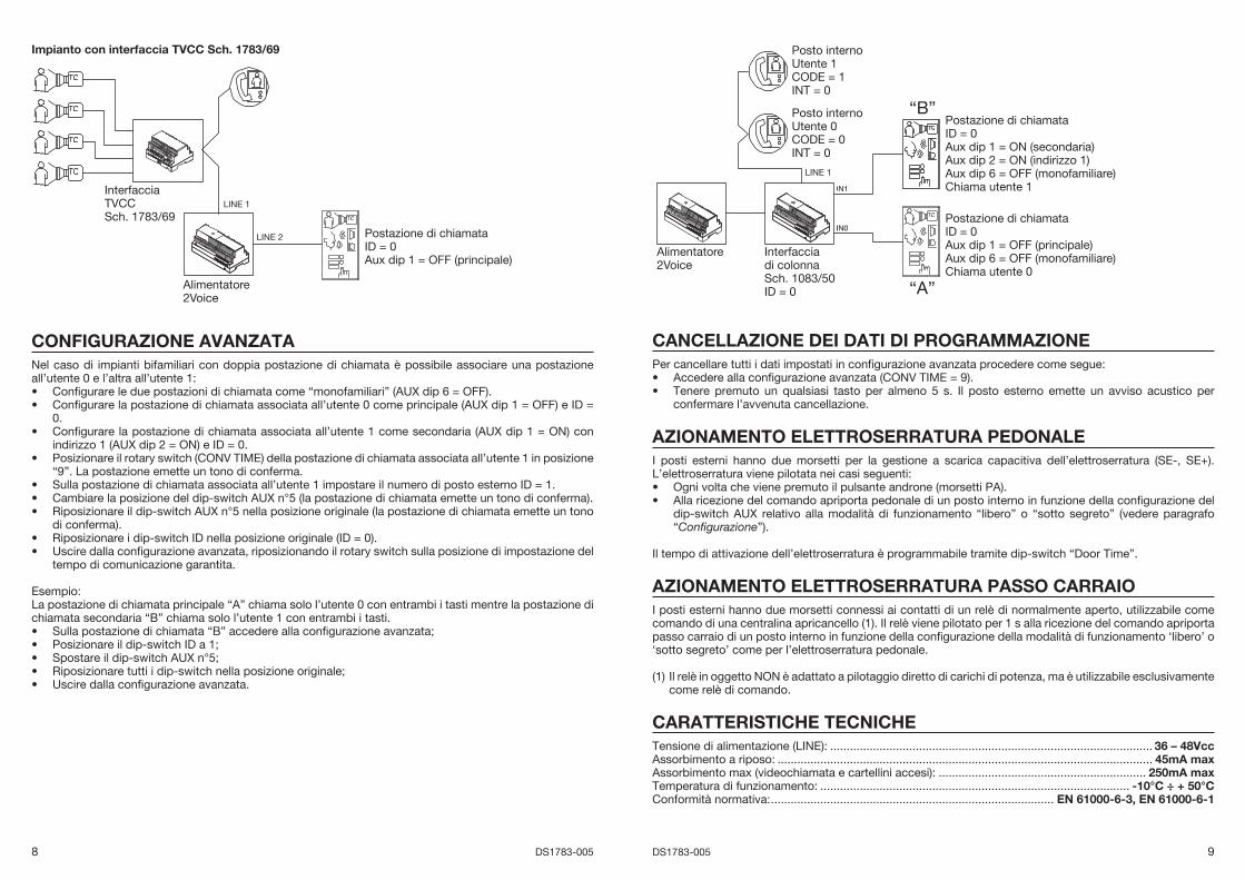
Impianto con interfaccia TVCC Sch. 1783/69
Alimentatore2Voice
LINE 1
LINE 2
InterfacciaTVCCSch. 1783/69
Postazione di chiamataID = 0Aux dip 1 = OFF (principale)
CONFIGURAZIONE AVANZATANel caso di impianti bifamiliari con doppia postazione di chiamata è possibile associare una postazione all’utente 0 e l’altra all’utente 1:
Confi gurare le due postazioni di chiamata come “monofamiliari” (AUX dip 6 = OFF).Confi gurare la postazione di chiamata associata all’utente 0 come principale (AUX dip 1 = OFF) e ID = 0.Confi gurare la postazione di chiamata associata all’utente 1 come secondaria (AUX dip 1 = ON) con indirizzo 1 (AUX dip 2 = ON) e ID = 0.Posizionare il rotary switch (CONV TIME) della postazione di chiamata associata all’utente 1 in posizione “9”. La postazione emette un tono di conferma.Sulla postazione di chiamata associata all’utente 1 impostare il numero di posto esterno ID = 1.Cambiare la posizione del dip-switch AUX n°5 (la postazione di chiamata emette un tono di conferma).Riposizionare il dip-switch AUX n°5 nella posizione originale (la postazione di chiamata emette un tono di conferma).Riposizionare i dip-switch ID nella posizione originale (ID = 0).Uscire dalla confi gurazione avanzata, riposizionando il rotary switch sulla posizione di impostazione del tempo di comunicazione garantita.
Esempio: La postazione di chiamata principale “A” chiama solo l’utente 0 con entrambi i tasti mentre la postazione di chiamata secondaria “B” chiama solo l’utente 1 con entrambi i tasti.
Sulla postazione di chiamata “B” accedere alla confi gurazione avanzata;Posizionare il dip-switch ID a 1;Spostare il dip-switch AUX n°5;Riposizionare tutti i dip-switch nella posizione originale;Uscire dalla confi gurazione avanzata.
••
•
•
•••
••
•••••
“B”
“A”
Alimentatore2Voice
LINE 1
Interfacciadi colonna Sch. 1083/50ID = 0
Posto internoUtente 1CODE = 1INT = 0
Posto internoUtente 0CODE = 0INT = 0
Postazione di chiamataID = 0Aux dip 1 = ON (secondaria)Aux dip 2 = ON (indirizzo 1)Aux dip 6 = OFF (monofamiliare)Chiama utente 1
Postazione di chiamataID = 0Aux dip 1 = OFF (principale)Aux dip 6 = OFF (monofamiliare)Chiama utente 0
CANCELLAZIONE DEI DATI DI PROGRAMMAZIONEPer cancellare tutti i dati impostati in confi gurazione avanzata procedere come segue:
Accedere alla confi gurazione avanzata (CONV TIME = 9).Tenere premuto un qualsiasi tasto per almeno 5 s. Il posto esterno emette un avviso acustico per confermare l’avvenuta cancellazione.
AZIONAMENTO ELETTROSERRATURA PEDONALEI posti esterni hanno due morsetti per la gestione a scarica capacitiva dell’elettroserratura (SE-, SE+). L’elettroserratura viene pilotata nei casi seguenti:
Ogni volta che viene premuto il pulsante androne (morsetti PA).Alla ricezione del comando apriporta pedonale di un posto interno in funzione della confi gurazione del dip-switch AUX relativo alla modalità di funzionamento “libero” o “sotto segreto” (vedere paragrafo “Confi gurazione”).
Il tempo di attivazione dell’elettroserratura è programmabile tramite dip-switch “Door Time”.
AZIONAMENTO ELETTROSERRATURA PASSO CARRAIOI posti esterni hanno due morsetti connessi ai contatti di un relè di normalmente aperto, utilizzabile come comando di una centralina apricancello (1). Il relè viene pilotato per 1 s alla ricezione del comando apriporta passo carraio di un posto interno in funzione della confi gurazione della modalità di funzionamento ‘libero’ o ‘sotto segreto’ come per l’elettroserratura pedonale.
(1) Il relè in oggetto NON è adattato a pilotaggio diretto di carichi di potenza, ma è utilizzabile esclusivamente come relè di comando.
CARATTERISTICHE TECNICHETensione di alimentazione (LINE): .................................................................................................. 36 – 48VccAssorbimento a riposo: .................................................................................................................. 45mA maxAssorbimento max (videochiamata e cartellini accesi): ............................................................... 250mA maxTemperatura di funzionamento: .............................................................................................. -10°C ÷ + 50°CConformità normativa: ...................................................................................... EN 61000-6-3, EN 61000-6-1
••
••
10 DS1783-005 11DS1783-005
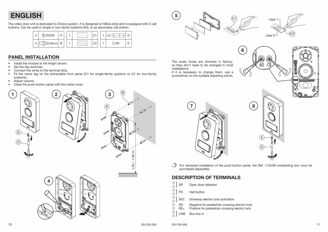
ENGLISHThe video door unit is dedicated to 2Voice system. It is designed on Mikra style and is equipped with 2 call buttons. Can be used in single or two-family systems (Kit), or as secondary call station.
4 A
4 Ø6mm B
1 C1
1 C2
1 D
1 E
PANEL INSTALLATIONInstall the module at the height shown.Set the dip-switches.Connect the wires to the terminal strip.Fit the name tag on the extractable front panel (C1 for single-family systems or C2 for two-family systems).Adjust volume.Close the push-button panel with the metal cover.
••••
••
The audio levels are trimmed in factory, so they don’t need to be changed in most installations. If it is necessary to change them, use a screwdriver on the suitable adjusting points.
For recessed installation of the push-button panel, the Ref. 1122/60 embedding box must be purchased separately.
DESCRIPTION OF TERMINALS
] SP Open door detector
] PA Hall button
] SE2 Driveway electric lock activation
SE- Negative for pedestrian crossing electric lockSE+ Positive for pedestrian crossing electric lock
] LINE Bus line in
1,55
÷ 1
,60
m
A
B1 2 3
4
D
E
5
7
D
E
C1
C2
User 1
User 0
6
8
12 DS1783-005 13DS1783-005
CONFIGURATION
= =ONON
0
5
38
4
9 1
6
2
7
ON2
1
ON
DIP
43
21
5
ON
DIP
43
21
56
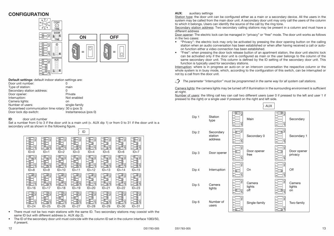
Default settings: default indoor station settings are:Door unit number: 0Type of station: mainSecondary station address: 0Door opener: PrivateInterruption: Not enabledCamera lights: onNumber of users: single-familyGuaranteed communication time rotary: 30 s (pos 3)Door lock dip-switch: Instantaneous (pos 0)
ID: door unit numberSet a number from 0 to 3 if the door unit is a main unit (v. AUX dip 1) or from 0 to 31 if the door unit is a secondary unit as shown in the following fi gure.
ID
ON
DIP
43
21
5
ID=0
ON
DIP
43
21
5
ID=1
ON
DIP
43
21
5
ID=2
ON
DIP
43
21
5
ID=3
ON
DIP
43
21
5
ID=4
ON
DIP
43
21
5
ID=5
ON
DIP
43
21
5
ID=6
ON
DIP
43
21
5
ID=7
ON
DIP
43
21
5
ID=8
ON
DIP
43
21
5
ID=9
ON
DIP
43
21
5
ID=10
ON
DIP
43
21
5
ID=11
ON
DIP
43
21
5
ID=12
ON
DIP
43
21
5
ID=13
ON
DIP
43
21
5
ID=14
ON
DIP
43
21
5
ID=15
ON
DIP
43
21
5
ID=16
ON
DIP
43
21
5
ID=17
ON
DIP
43
21
5
ID=18
ON
DIP
43
21
5
ID=19
ON
DIP
43
21
5
ID=20
ON
DIP
43
21
5
ID=21
ON
DIP
43
21
5
ID=22
ON
DIP
43
21
5
ID=23
ON
DIP
43
21
5
ID=24
ON
DIP
43
21
5
ID=25
ON
DIP
43
21
5
ID=26
ON
DIP
43
21
5
ID=27
ON
DIP
43
21
5
ID=28
ON
DIP
43
21
5
ID=29O
ND
IP
43
21
5
ID=30
ON
DIP
43
21
5
ID=31
There must not be two main stations with the same ID. Two secondary stations may coexist with the same ID but with different address (v. AUX dip 2).The ID of the secondary door unit must coincide with the column ID set in the column interface 1083/50, if present.
•
•
AUX: auxiliary settingsStation type: the door unit can be confi gured either as a main or a secondary device. All the users in the system may be called from the main door unit. A secondary door unit may only call the users of the column to which it belongs. Users can identify the source of the call by the ring tone. Secondary station address: Two secondary calling stations may be present in a column and must have a different addressDoor opener: The electric lock can be managed in “privacy” or “free” mode. The door unit works as follows in the two cases:
“Privacy”: the electric lock may only be activated by pressing the door opening button on the calling station when an audio conversation has been established or when after having received a call or auto-on function either a video connection has been established.“Free”: when pressing the door lock release button of an apartment station, the door unit electric lock can be activated only if the door unit is confi gured as main or the user belongs to the column of the same secondary door unit. This column is defi ned by the ID setting of the secondary door unit. This function is typically used for secondary stations.
Interruption: where is in progress an auto-on or an intercom conversation the respective column or the whole system is in busy mode, which, according to the confi guration of this switch, can be interrupted or not by a call from the door unit.
The parameter “interruption” must be programmed in the same way for all system call stations.
Camera lights: the camera lights may be turned off if illumination in the surrounding environment is suffi cient at night.Number of users: the tilting call key can call two different users (user 0 if pressed to the left and user 1 if pressed to the right) or a single user if pressed on the right and left side.
AUX
ON
DIP
43
21
56
Main
ON
DIP
43
21
56
Secondary
ON
DIP
43
21
56
Secondary 0
ON
DIP
43
21
5
Secondary 1
ON
DIP
43
21
5
Door openerfree
ON
DIP
43
21
56
6
Door openerprivacy
ON
DIP
43
21
56
6
On
ON
DIP
43
21
5
Off
ON
DIP
43
21
56
Cameralightsoff
Stationtype
Secondarystationaddress
Door opener
Interruption
Cameralights
ON
DIP
43
21
5
Cameralightson
66
ON
DIP
43
21
56
Single-familyNumber ofusers
ON
DIP
43
21
5
Two-family
6
Dip 1
Dip 2
Dip 3
Dip 4
Dip 5
Dip 6
•
•
14 DS1783-005 15DS1783-005
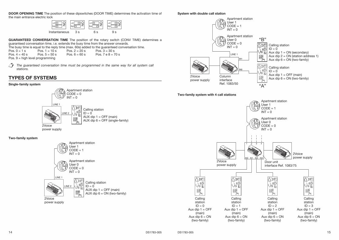
DOOR OPENING TIME The position of these dipswitches (DOOR TIME) determines the activation time of the main entrance electric lock
ON2
Instantaneous
1
3 s 6 s
ON2
9 s
1ON2
1 ON2
1
GUARANTEED CONVERSATION TIME The position of the rotary switch (CONV TIME) determines a guaranteed conversation time, i.e. extends the busy time from the answer onwards.The busy time is equal to the reply time (max. 60s) added to the guaranteed conversation time.Pos. 0 = 1 s Pos. 1 = 10 s Pos. 2 = 20 s Pos. 3 = 30 sPos. 4 = 40 s Pos. 5 = 50 s Pos. 6 = 60 s Pos. 7 e 8 = 70 sPos. 9 = high level programming
The guaranteed conversation time must be programmed in the same way for all system call stations.
TYPES OF SYSTEMSSingle-family system
2Voicepower supply
LINE 2
LINE 1
Calling stationID = 0AUX dip 1 = OFF (main)AUX dip 6 = OFF (single-family)
Apartment stationCODE = 0INT = 0
Two-family system
2Voicepower supply
LINE 2
LINE 1
Calling stationID = 0AUX dip 1 = OFF (main)AUX dip 6 = ON (two-family)
Apartment stationUser 1CODE = 1INT = 0
Apartment stationUser 0CODE = 0INT = 0
System with double call station
“B”
“A”
2Voicepower supply
LINE 1
ColumninterfaceRef. 1083/50
Calling stationID = 0Aux dip 1 = ON (secondary)Aux dip 2 = ON (station address 1)Aux dip 6 = ON (two-family)
Calling stationID = 0Aux dip 1 = OFF (main)Aux dip 6 = ON (two-family)
Apartment stationUser 1CODE = 1INT = 0
Apartment stationUser 0CODE = 0INT = 0
Two-family system with 4 call stations
2Voicepower supply
2Voicepower supply
Door unitinterface Ref. 1083/75
1 2 3 4
IN0 IN1 IN2 IN3
Apartment stationUser 1CODE = 1INT = 0
Apartment stationUser 0CODE = 0INT = 0
CallingstationID = 0
Aux dip 1 = OFF(main)
Aux dip 6 = ON(two-family)
CallingstationID = 3
Aux dip 1 = OFF(main)
Aux dip 6 = ON(two-family)
CallingstationID = 2
Aux dip 1 = OFF(main)
Aux dip 6 = ON(two-family)
CallingstationID = 1
Aux dip 1 = OFF(main)
Aux dip 6 = ON(two-family)
16 DS1783-005 17DS1783-005
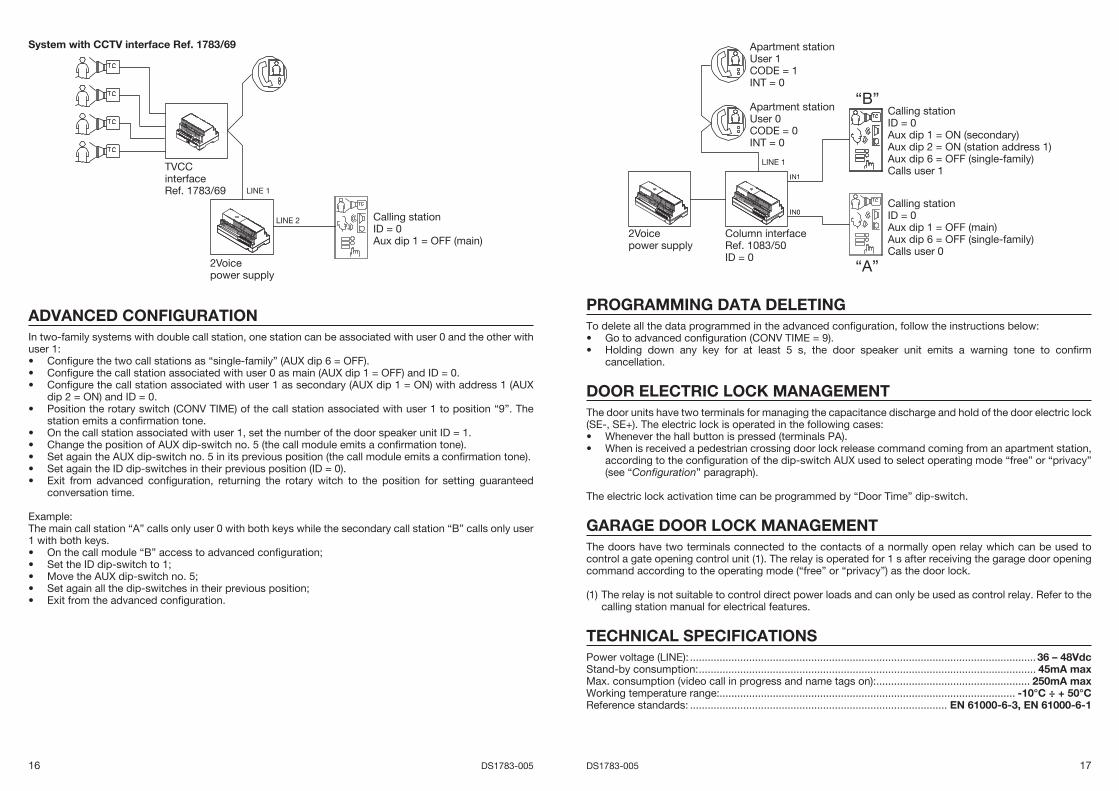
System with CCTV interface Ref. 1783/69
2Voicepower supply
LINE 1
LINE 2
TVCCinterfaceRef. 1783/69
Calling stationID = 0Aux dip 1 = OFF (main)
ADVANCED CONFIGURATIONIn two-family systems with double call station, one station can be associated with user 0 and the other with user 1:
Confi gure the two call stations as “single-family” (AUX dip 6 = OFF).Confi gure the call station associated with user 0 as main (AUX dip 1 = OFF) and ID = 0.Confi gure the call station associated with user 1 as secondary (AUX dip 1 = ON) with address 1 (AUX dip 2 = ON) and ID = 0.Position the rotary switch (CONV TIME) of the call station associated with user 1 to position “9”. The station emits a confi rmation tone.On the call station associated with user 1, set the number of the door speaker unit ID = 1.Change the position of AUX dip-switch no. 5 (the call module emits a confi rmation tone).Set again the AUX dip-switch no. 5 in its previous position (the call module emits a confi rmation tone).Set again the ID dip-switches in their previous position (ID = 0).Exit from advanced confi guration, returning the rotary witch to the position for setting guaranteed conversation time.
Example: The main call station “A” calls only user 0 with both keys while the secondary call station “B” calls only user 1 with both keys.
On the call module “B” access to advanced confi guration;Set the ID dip-switch to 1;Move the AUX dip-switch no. 5;Set again all the dip-switches in their previous position;Exit from the advanced confi guration.
•••
•
•••••
•••••
“B”
“A”
2Voicepower supply
LINE 1
Column interfaceRef. 1083/50ID = 0
Calling stationID = 0Aux dip 1 = OFF (main)Aux dip 6 = OFF (single-family)Calls user 0
Apartment stationUser 1CODE = 1INT = 0
Apartment stationUser 0CODE = 0INT = 0
Calling stationID = 0Aux dip 1 = ON (secondary)Aux dip 2 = ON (station address 1)Aux dip 6 = OFF (single-family)Calls user 1
PROGRAMMING DATA DELETINGTo delete all the data programmed in the advanced confi guration, follow the instructions below:
Go to advanced confi guration (CONV TIME = 9).Holding down any key for at least 5 s, the door speaker unit emits a warning tone to confi rm cancellation.
DOOR ELECTRIC LOCK MANAGEMENTThe door units have two terminals for managing the capacitance discharge and hold of the door electric lock (SE-, SE+). The electric lock is operated in the following cases:
Whenever the hall button is pressed (terminals PA).When is received a pedestrian crossing door lock release command coming from an apartment station, according to the confi guration of the dip-switch AUX used to select operating mode “free” or “privacy” (see “Confi guration” paragraph).
The electric lock activation time can be programmed by “Door Time” dip-switch.
GARAGE DOOR LOCK MANAGEMENTThe doors have two terminals connected to the contacts of a normally open relay which can be used to control a gate opening control unit (1). The relay is operated for 1 s after receiving the garage door opening command according to the operating mode (“free” or “privacy”) as the door lock.
(1) The relay is not suitable to control direct power loads and can only be used as control relay. Refer to the calling station manual for electrical features.
TECHNICAL SPECIFICATIONSPower voltage (LINE): .....................................................................................................................36 – 48VdcStand-by consumption: .................................................................................................................. 45mA maxMax. consumption (video call in progress and name tags on): .................................................... 250mA maxWorking temperature range:.................................................................................................... -10°C ÷ + 50°CReference standards: ....................................................................................... EN 61000-6-3, EN 61000-6-1
••
••
18 DS1783-005 19DS1783-005
FRANÇAISLe poste externe vidéo a été projeté exprès pour le système 2Voice. Il a été réalisé selon le modèle Mikra et prévoit 2 touches d’appel. Il peut être utilisé sur des installations individuelles ou en duplex (Kit), ou servir de poste d’appel secondaire.
4 A
4 Ø6mm B
1 C1
1 C2
1 D
1 E
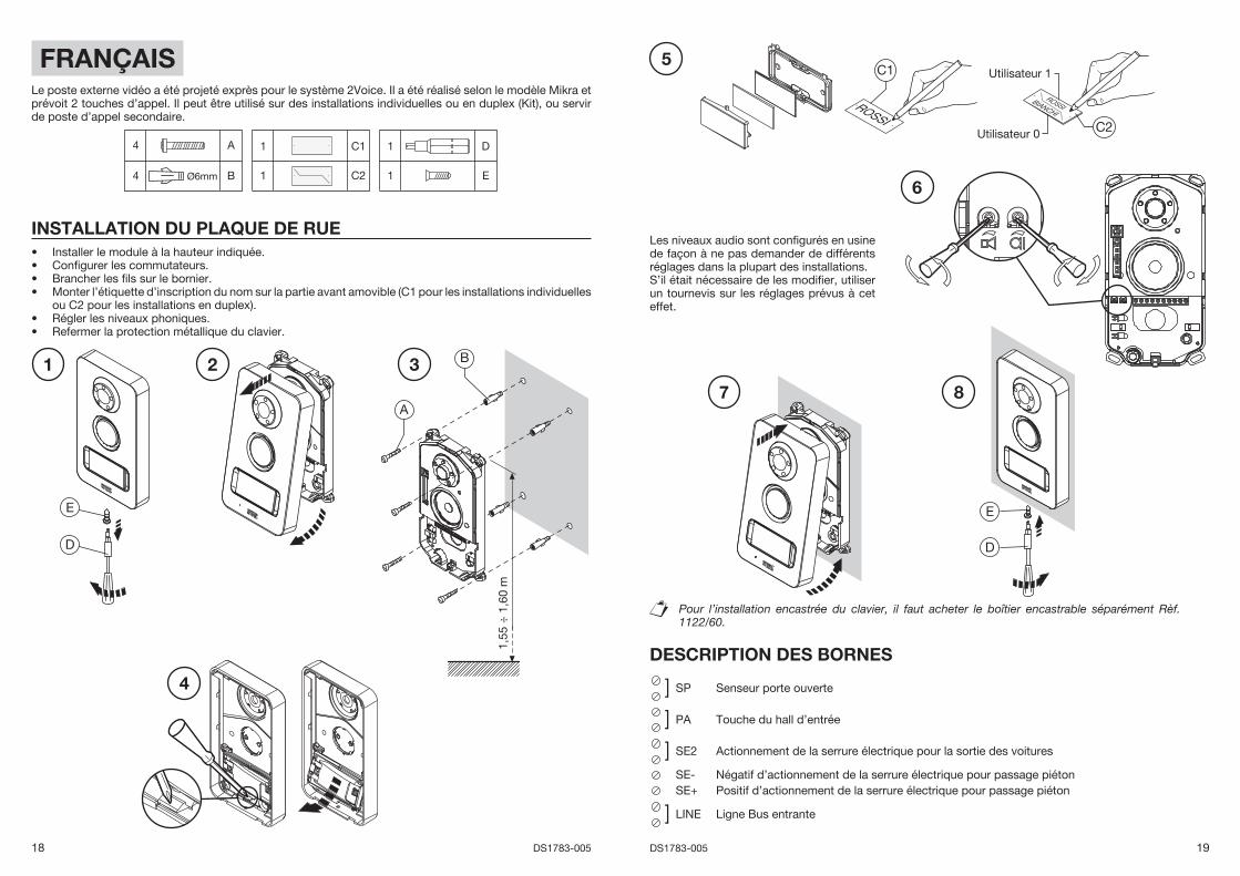
INSTALLATION DU PLAQUE DE RUEInstaller le module à la hauteur indiquée.Confi gurer les commutateurs.Brancher les fi ls sur le bornier.Monter l’étiquette d’inscription du nom sur la partie avant amovible (C1 pour les installations individuelles ou C2 pour les installations en duplex).Régler les niveaux phoniques.Refermer la protection métallique du clavier.
••••
••
Les niveaux audio sont confi gurés en usine de façon à ne pas demander de différents réglages dans la plupart des installations.S’il était nécessaire de les modifi er, utiliser un tournevis sur les réglages prévus à cet effet.
Pour l’installation encastrée du clavier, il faut acheter le boîtier encastrable séparément Rèf. 1122/60.
DESCRIPTION DES BORNES
] SP Senseur porte ouverte
] PA Touche du hall d’entrée
] SE2 Actionnement de la serrure électrique pour la sortie des voitures
SE- Négatif d’actionnement de la serrure électrique pour passage piétonSE+ Positif d’actionnement de la serrure électrique pour passage piéton
] LINE Ligne Bus entrante
1,55
÷ 1
,60
m
A
B1 2 3
4
D
E
5
7
D
E
C1
C2
Utilisateur 1
Utilisateur 0
6
8
20 DS1783-005 21DS1783-005
CONFIGURATION
= =ONON
0
5
38
4
9 1
6
2
7
ON2
1
ON
DIP
43
21
5
ON
DIP
43
21
56
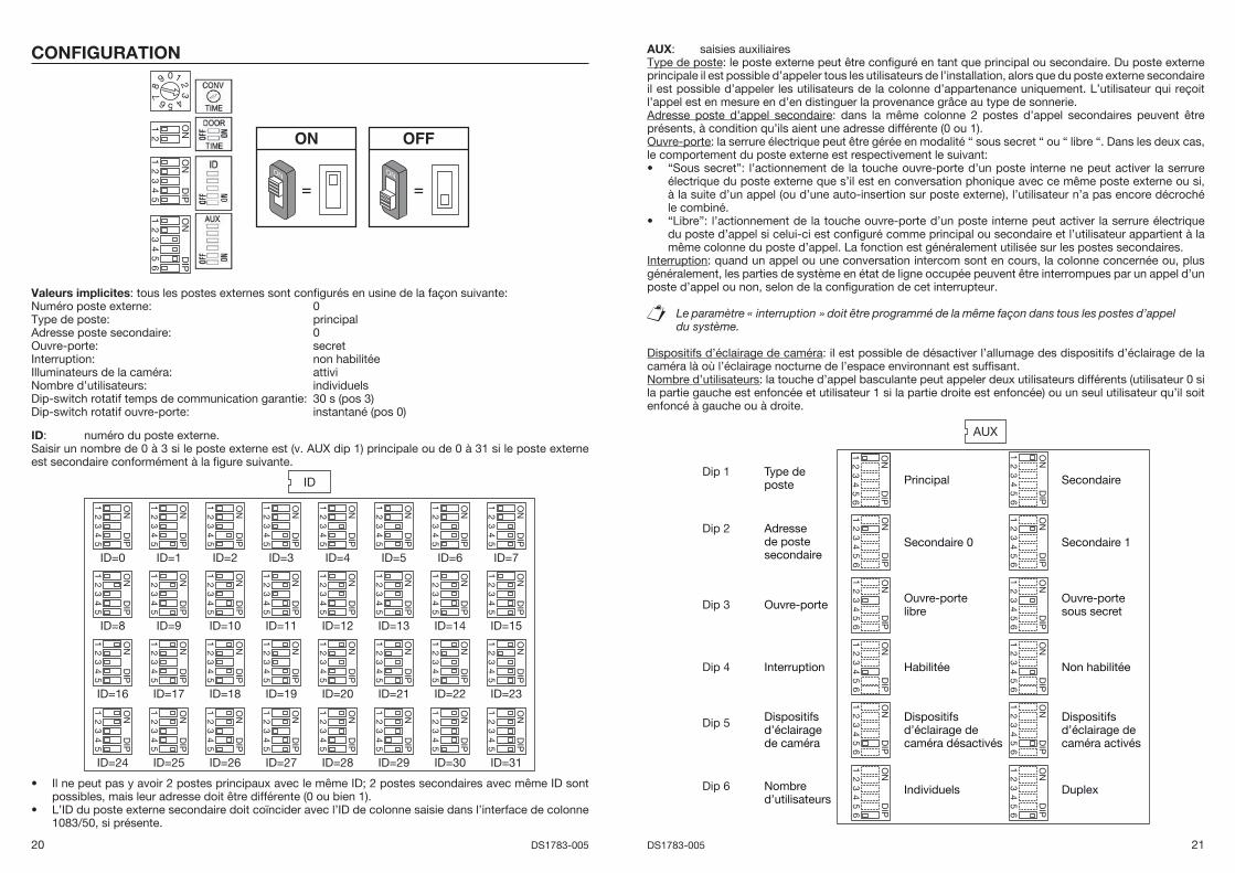
Valeurs implicites: tous les postes externes sont confi gurés en usine de la façon suivante:Numéro poste externe: 0Type de poste: principalAdresse poste secondaire: 0Ouvre-porte: secretInterruption: non habilitéeIlluminateurs de la caméra: attiviNombre d’utilisateurs: individuelsDip-switch rotatif temps de communication garantie: 30 s (pos 3)Dip-switch rotatif ouvre-porte: instantané (pos 0)
ID: numéro du poste externe.Saisir un nombre de 0 à 3 si le poste externe est (v. AUX dip 1) principale ou de 0 à 31 si le poste externe est secondaire conformément à la fi gure suivante.
ID
ON
DIP
43
21
5
ID=0
ON
DIP
43
21
5
ID=1
ON
DIP
43
21
5
ID=2
ON
DIP
43
21
5
ID=3
ON
DIP
43
21
5
ID=4
ON
DIP
43
21
5
ID=5
ON
DIP
43
21
5
ID=6
ON
DIP
43
21
5
ID=7
ON
DIP
43
21
5
ID=8
ON
DIP
43
21
5
ID=9
ON
DIP
43
21
5
ID=10
ON
DIP
43
21
5
ID=11
ON
DIP
43
21
5
ID=12
ON
DIP
43
21
5
ID=13
ON
DIP
43
21
5
ID=14
ON
DIP
43
21
5
ID=15
ON
DIP
43
21
5
ID=16
ON
DIP
43
21
5
ID=17
ON
DIP
43
21
5
ID=18
ON
DIP
43
21
5
ID=19
ON
DIP
43
21
5
ID=20
ON
DIP
43
21
5
ID=21
ON
DIP
43
21
5
ID=22
ON
DIP
43
21
5
ID=23
ON
DIP
43
21
5
ID=24
ON
DIP
43
21
5
ID=25
ON
DIP
43
21
5
ID=26
ON
DIP
43
21
5
ID=27
ON
DIP
43
21
5
ID=28
ON
DIP
43
21
5
ID=29O
ND
IP
43
21
5
ID=30
ON
DIP
43
21
5
ID=31
Il ne peut pas y avoir 2 postes principaux avec le même ID; 2 postes secondaires avec même ID sont possibles, mais leur adresse doit être différente (0 ou bien 1). L’ID du poste externe secondaire doit coïncider avec l’ID de colonne saisie dans l’interface de colonne 1083/50, si présente.
•
•
AUX: saisies auxiliairesType de poste: le poste externe peut être confi guré en tant que principal ou secondaire. Du poste externe principale il est possible d’appeler tous les utilisateurs de l’installation, alors que du poste externe secondaire il est possible d’appeler les utilisateurs de la colonne d’appartenance uniquement. L’utilisateur qui reçoit l’appel est en mesure en d’en distinguer la provenance grâce au type de sonnerie.Adresse poste d’appel secondaire: dans la même colonne 2 postes d’appel secondaires peuvent être présents, à condition qu’ils aient une adresse différente (0 ou 1).Ouvre-porte: la serrure électrique peut être gérée en modalité “ sous secret “ ou “ libre “. Dans les deux cas, le comportement du poste externe est respectivement le suivant:
“Sous secret”: l’actionnement de la touche ouvre-porte d’un poste interne ne peut activer la serrure électrique du poste externe que s’il est en conversation phonique avec ce même poste externe ou si, à la suite d’un appel (ou d’une auto-insertion sur poste externe), l’utilisateur n’a pas encore décroché le combiné.“Libre”: l’actionnement de la touche ouvre-porte d’un poste interne peut activer la serrure électrique du poste d’appel si celui-ci est confi guré comme principal ou secondaire et l’utilisateur appartient à la même colonne du poste d’appel. La fonction est généralement utilisée sur les postes secondaires.
Interruption: quand un appel ou une conversation intercom sont en cours, la colonne concernée ou, plus généralement, les parties de système en état de ligne occupée peuvent être interrompues par un appel d’un poste d’appel ou non, selon de la confi guration de cet interrupteur.
Le paramètre « interruption » doit être programmé de la même façon dans tous les postes d’appel du système.
Dispositifs d’éclairage de caméra: il est possible de désactiver l’allumage des dispositifs d’éclairage de la caméra là où l’éclairage nocturne de l’espace environnant est suffi sant.Nombre d’utilisateurs: la touche d’appel basculante peut appeler deux utilisateurs différents (utilisateur 0 si la partie gauche est enfoncée et utilisateur 1 si la partie droite est enfoncée) ou un seul utilisateur qu’il soit enfoncé à gauche ou à droite.
AUX
ON
DIP
43
21
56
Principal
ON
DIP
43
21
56
Secondaire
ON
DIP
43
21
56
Secondaire 0
ON
DIP
43
21
5
Secondaire 1
ON
DIP
43
21
5
Ouvre-portelibre
ON
DIP
43
21
56
6
Ouvre-porte sous secret
ON
DIP
43
21
56
6
Habilitée
ON
DIP
43
21
5
Non habilitée
ON
DIP
43
21
56
Dispositifsd’éclairage de caméra désactivés
Type deposte
Adresse de poste secondaire
Ouvre-porte
Interruption
Dispositifsd’éclairagede caméra
ON
DIP
43
21
5
Dispositifsd’éclairage de caméra activés
66
ON
DIP
43
21
56
IndividuelsNombre d’utilisateurs
ON
DIP
43
21
5
Duplex
6
Dip 1
Dip 2
Dip 3
Dip 4
Dip 5
Dip 6
•
•
22 DS1783-005 23DS1783-005
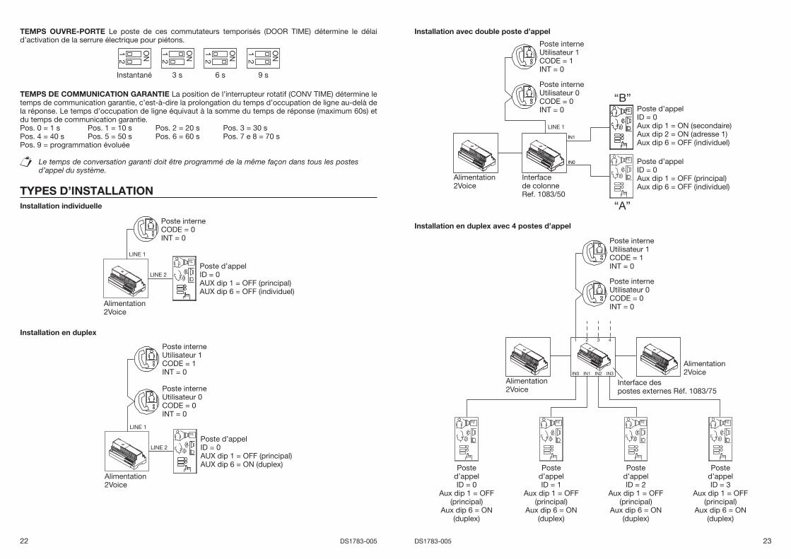
TEMPS OUVRE-PORTE Le poste de ces commutateurs temporisés (DOOR TIME) détermine le délai d’activation de la serrure électrique pour piétons.
ON2
Instantané
1
3 s 6 s
ON2
9 s
1ON2
1 ON2
1
TEMPS DE COMMUNICATION GARANTIE La position de l’interrupteur rotatif (CONV TIME) détermine le temps de communication garantie, c’est-à-dire la prolongation du temps d’occupation de ligne au-delà de la réponse. Le temps d’occupation de ligne équivaut à la somme du temps de réponse (maximum 60s) et du temps de communication garantie.Pos. 0 = 1 s Pos. 1 = 10 s Pos. 2 = 20 s Pos. 3 = 30 sPos. 4 = 40 s Pos. 5 = 50 s Pos. 6 = 60 s Pos. 7 e 8 = 70 sPos. 9 = programmation évoluée
Le temps de conversation garanti doit être programmé de la même façon dans tous les postes d’appel du système.
TYPES D’INSTALLATIONInstallation individuelle
Alimentation2Voice
LINE 2
LINE 1
Poste d’appelID = 0AUX dip 1 = OFF (principal)AUX dip 6 = OFF (individuel)
Poste interneCODE = 0INT = 0
Installation en duplex
Alimentation2Voice
LINE 2
LINE 1
Poste d’appelID = 0AUX dip 1 = OFF (principal)AUX dip 6 = ON (duplex)
Poste interneUtilisateur 1CODE = 1INT = 0
Poste interneUtilisateur 0CODE = 0INT = 0
Installation avec double poste d’appel
“B”
“A”
Alimentation2Voice
LINE 1
Interfacede colonneRef. 1083/50
Poste d’appelID = 0Aux dip 1 = ON (secondaire)Aux dip 2 = ON (adresse 1)Aux dip 6 = OFF (individuel)
Poste d’appelID = 0Aux dip 1 = OFF (principal)Aux dip 6 = OFF (individuel)
Poste interneUtilisateur 1CODE = 1INT = 0
Poste interneUtilisateur 0CODE = 0INT = 0
Installation en duplex avec 4 postes d’appel
Alimentation2Voice
Alimentation2Voice
Interface despostes externes Réf. 1083/75
1 2 3 4
IN0 IN1 IN2 IN3
Poste interneUtilisateur 1CODE = 1INT = 0
Poste interneUtilisateur 0CODE = 0INT = 0
Posted’appelID = 0
Aux dip 1 = OFF(principal)
Aux dip 6 = ON(duplex)
Posted’appelID = 3
Aux dip 1 = OFF(principal)
Aux dip 6 = ON(duplex)
Posted’appelID = 2
Aux dip 1 = OFF(principal)
Aux dip 6 = ON(duplex)
Posted’appelID = 1
Aux dip 1 = OFF(principal)
Aux dip 6 = ON(duplex)
24 DS1783-005 25DS1783-005
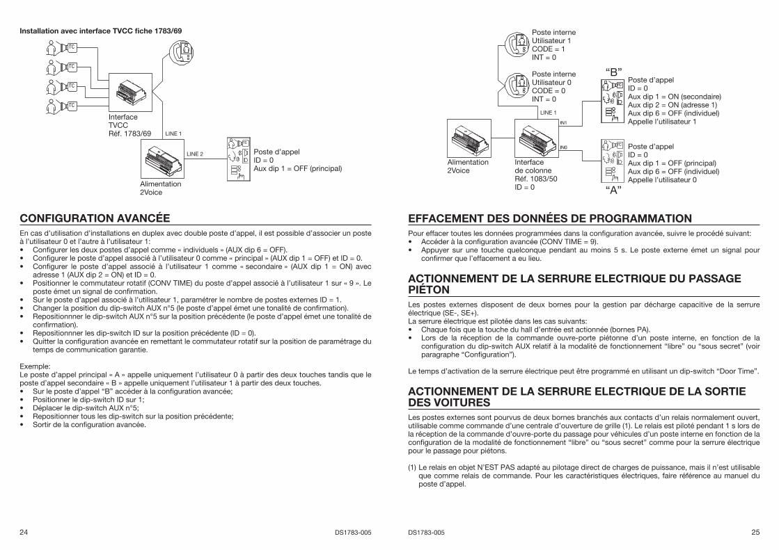
Installation avec interface TVCC fi che 1783/69
Alimentation2Voice
LINE 1
LINE 2
InterfaceTVCCRéf. 1783/69
Poste d’appelID = 0Aux dip 1 = OFF (principal)
CONFIGURATION AVANCÉEEn cas d’utilisation d’installations en duplex avec double poste d’appel, il est possible d’associer un poste à l’utilisateur 0 et l’autre à l’utilisateur 1:
Confi gurer les deux postes d’appel comme « individuels » (AUX dip 6 = OFF).Confi gurer le poste d’appel associé à l’utilisateur 0 comme « principal » (AUX dip 1 = OFF) et ID = 0.Confi gurer le poste d’appel associé à l’utilisateur 1 comme « secondaire » (AUX dip 1 = ON) avec adresse 1 (AUX dip 2 = ON) et ID = 0.Positionner le commutateur rotatif (CONV TIME) du poste d’appel associé à l’utilisateur 1 sur « 9 ». Le poste émet un signal de confi rmation.Sur le poste d’appel associé à l’utilisateur 1, paramétrer le nombre de postes externes ID = 1.Changer la position du dip-switch AUX n°5 (le poste d’appel émet une tonalité de confi rmation).Repositionnner le dip-switch AUX n°5 sur la position précédente (le poste d’appel émet une tonalité de confi rmation).Repositionnner les dip-switch ID sur la position précédente (ID = 0).Quitter la confi guration avancée en remettant le commutateur rotatif sur la position de paramétrage du temps de communication garantie.
Exemple: Le poste d’appel principal « A » appelle uniquement l’utilisateur 0 à partir des deux touches tandis que le poste d’appel secondaire « B » appelle uniquement l’utilisateur 1 à partir des deux touches.
Sur le poste d’appel “B” accéder à la confi guration avancée;Positionner le dip-switch ID sur 1;Déplacer le dip-switch AUX n°5;Repositionner tous les dip-switch sur la position précédente; Sortir de la confi guration avancée.
•••
•
•••
••
•••••
“B”
“A”
Alimentation2Voice
LINE 1
Interfacede colonneRéf. 1083/50ID = 0
Poste d’appelID = 0Aux dip 1 = OFF (principal)Aux dip 6 = OFF (individuel)Appelle l’utilisateur 0
Poste interneUtilisateur 1CODE = 1INT = 0
Poste interneUtilisateur 0CODE = 0INT = 0
Poste d’appelID = 0Aux dip 1 = ON (secondaire)Aux dip 2 = ON (adresse 1)Aux dip 6 = OFF (individuel)Appelle l’utilisateur 1
EFFACEMENT DES DONNÉES DE PROGRAMMATIONPour effacer toutes les données programmées dans la confi guration avancée, suivre le procédé suivant:
Accéder à la confi guration avancée (CONV TIME = 9).Appuyer sur une touche quelconque pendant au moins 5 s. Le poste externe émet un signal pour confi rmer que l’effacement a eu lieu.
ACTIONNEMENT DE LA SERRURE ELECTRIQUE DU PASSAGE PIÉTONLes postes externes disposent de deux bornes pour la gestion par décharge capacitive de la serrure électrique (SE-, SE+).La serrure électrique est pilotée dans les cas suivants:
Chaque fois que la touche du hall d’entrée est actionnée (bornes PA).Lors de la réception de la commande ouvre-porte piétonne d’un poste interne, en fonction de la confi guration du dip-switch AUX relatif à la modalité de fonctionnement “libre” ou “sous secret” (voir paragraphe “Confi guration”).
Le temps d’activation de la serrure électrique peut être programmé en utilisant un dip-switch “Door Time”.
ACTIONNEMENT DE LA SERRURE ELECTRIQUE DE LA SORTIE DES VOITURESLes postes externes sont pourvus de deux bornes branchés aux contacts d’un relais normalement ouvert, utilisable comme commande d’une centrale d’ouverture de grille (1). Le relais est piloté pendant 1 s lors de la réception de la commande d’ouvre-porte du passage pour véhicules d’un poste interne en fonction de la confi guration de la modalité de fonctionnement “libre” ou “sous secret” comme pour la serrure électrique pour le passage pour piétons.
(1) Le relais en objet N’EST PAS adapté au pilotage direct de charges de puissance, mais il n’est utilisable que comme relais de commande. Pour les caractéristiques électriques, faire référence au manuel du poste d’appel.
••
••
26 DS1783-005 27DS1783-005
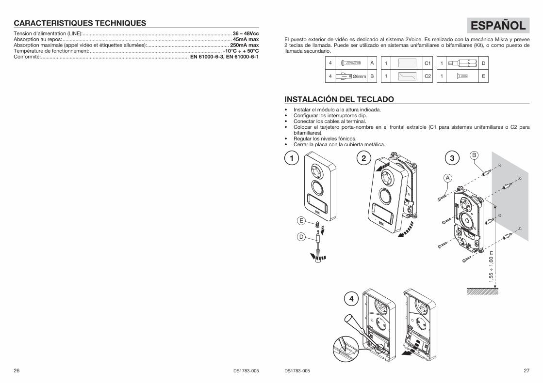
ESPAÑOLEl puesto exterior de vidéo es dedicado al sistema 2Voice. Es realizado con la mecánica Mikra y prevee 2 teclas de llamada. Puede ser utilizado en sistemas unifamiliares o bifamiliares (Kit), o como puesto de llamada secundario.
4 A
4 Ø6mm B
1 C1
1 C2
1 D
1 E
INSTALACIÓN DEL TECLADOInstalar el módulo a la altura indicada.Confi gurar los interruptores dip.Conectar los cables al terminal.Colocar el tarjetero porta-nombre en el frontal extraíble (C1 para sistemas unifamiliares o C2 para bifamiliares).Regular los niveles fónicos.Cerrar la placa con la cubierta metálica.
••••
••
1,55
÷ 1
,60
m
A
B1 2 3
4
D
E
CARACTERISTIQUES TECHNIQUESTension d’alimentation (LINE): ........................................................................................................ 36 – 48VccAbsorption au repos: ...................................................................................................................... 45mA maxAbsorption maximale (appel vidéo et étiquettes allumées): ......................................................... 250mA maxTempérature de fonctionnement: ............................................................................................ -10°C ÷ + 50°CConformité: ....................................................................................................... EN 61000-6-3, EN 61000-6-1
28 DS1783-005 29DS1783-005
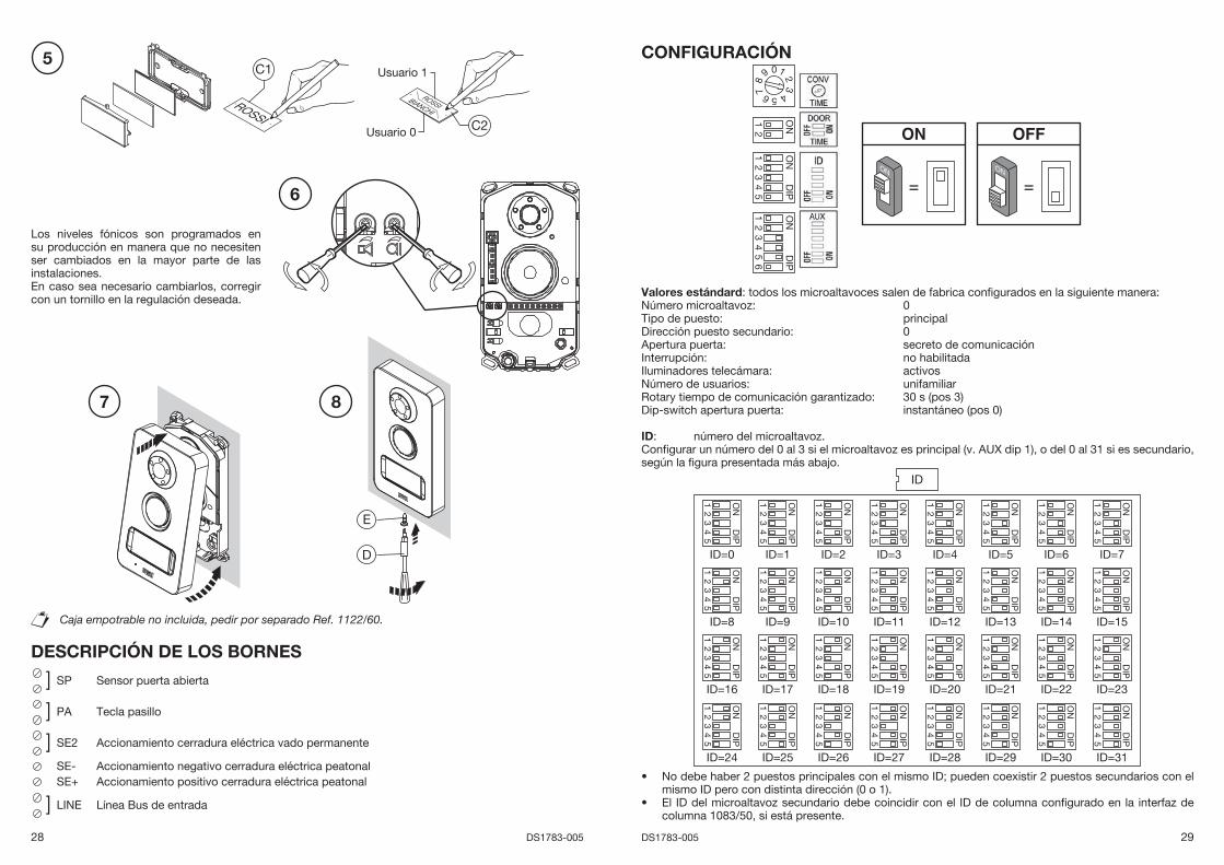
Los niveles fónicos son programados en su producción en manera que no necesiten ser cambiados en la mayor parte de las instalaciones.En caso sea necesario cambiarlos, corregir con un tornillo en la regulación deseada.
Caja empotrable no incluida, pedir por separado Ref. 1122/60.
DESCRIPCIÓN DE LOS BORNES
] SP Sensor puerta abierta
] PA Tecla pasillo
] SE2 Accionamiento cerradura eléctrica vado permanente
SE- Accionamiento negativo cerradura eléctrica peatonalSE+ Accionamiento positivo cerradura eléctrica peatonal
] LINE Línea Bus de entrada
5
7
D
E
C1
C2
Usuario 1
Usuario 0
6
8
CONFIGURACIÓN
= =ONON
0
5
384
9 1
6
2
7
ON2
1
ON
DIP
43
21
5
ON
DIP
43
21
56
Valores estándard: todos los microaltavoces salen de fabrica confi gurados en la siguiente manera:Número microaltavoz: 0Tipo de puesto: principalDirección puesto secundario: 0Apertura puerta: secreto de comunicaciónInterrupción: no habilitadaIluminadores telecámara: activosNúmero de usuarios: unifamiliarRotary tiempo de comunicación garantizado: 30 s (pos 3)Dip-switch apertura puerta: instantáneo (pos 0)
ID: número del microaltavoz.Confi gurar un número del 0 al 3 si el microaltavoz es principal (v. AUX dip 1), o del 0 al 31 si es secundario, según la fi gura presentada más abajo.
IDO
ND
IP
43
21
5
ID=0
ON
DIP
43
21
5
ID=1
ON
DIP
43
21
5
ID=2
ON
DIP
43
21
5
ID=3
ON
DIP
43
21
5
ID=4
ON
DIP
43
21
5
ID=5
ON
DIP
43
21
5
ID=6
ON
DIP
43
21
5
ID=7
ON
DIP
43
21
5
ID=8
ON
DIP
43
21
5
ID=9
ON
DIP
43
21
5
ID=10
ON
DIP
43
21
5
ID=11
ON
DIP
43
21
5
ID=12
ON
DIP
43
21
5
ID=13
ON
DIP
43
21
5
ID=14
ON
DIP
43
21
5
ID=15
ON
DIP
43
21
5
ID=16
ON
DIP
43
21
5
ID=17
ON
DIP
43
21
5
ID=18
ON
DIP
43
21
5
ID=19
ON
DIP
43
21
5
ID=20
ON
DIP
43
21
5
ID=21
ON
DIP
43
21
5
ID=22
ON
DIP
43
21
5
ID=23
ON
DIP
43
21
5
ID=24
ON
DIP
43
21
5
ID=25
ON
DIP
43
21
5
ID=26
ON
DIP
43
21
5
ID=27
ON
DIP
43
21
5
ID=28
ON
DIP
43
21
5
ID=29
ON
DIP
43
21
5
ID=30
ON
DIP
43
21
5
ID=31
No debe haber 2 puestos principales con el mismo ID; pueden coexistir 2 puestos secundarios con el mismo ID pero con distinta dirección (0 o 1). El ID del microaltavoz secundario debe coincidir con el ID de columna confi gurado en la interfaz de columna 1083/50, si está presente.
•
•
30 DS1783-005 31DS1783-005
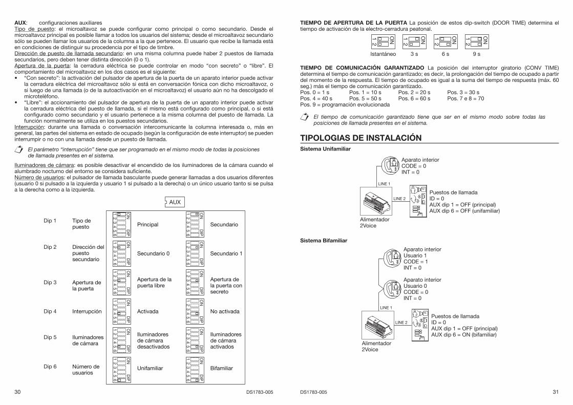
AUX: confi guraciones auxiliaresTipo de puesto: el microaltavoz se puede confi gurar como principal o como secundario. Desde el microaltavoz principal es posible llamar a todos los usuarios del sistema; desde el microaltavoz secundario sólo se pueden llamar los usuarios de la columna a la que pertenece. El usuario que recibe la llamada está en condiciones de distinguir su procedencia por el tipo de timbre.Dirección de puesto de llamada secundario: en una misma columna puede haber 2 puestos de llamada secundarios, pero deben tener distinta dirección (0 o 1).Apertura de la puerta: la cerradura eléctrica se puede controlar en modo “con secreto” o “libre”. El comportamiento del microaltavoz en los dos casos es el siguiente:
“Con secreto”: la activación del pulsador de apertura de la puerta de un aparato interior puede activar la cerradura eléctrica del microaltavoz sólo si está en conversación fónica con dicho microaltavoz, o si luego de una llamada (o de la autoactivación en el microaltavoz) el usuario aún no ha descolgado el microteléfono.“Libre”: el accionamiento del pulsador de apertura de la puerta de un aparato interior puede activar la cerradura eléctrica del puesto de llamada, si el mismo está confi gurado como principal, o si está confi gurado como secundario y el usuario pertenece a la misma columna del puesto de llamada. La función normalmente se utiliza en los puestos secundarios.
Interrupción: durante una llamada o conversación intercomunicante la columna interesada o, más en general, las partes del sistema en estado de ocupado (según la confi guración de este interruptor) se pueden interrumpir o no con una llamada desde un puesto de llamada.
El parámetro “interrupción” tiene que ser programado en el mismo modo de todas la posiciones de llamada presentes en el sistema.
Iluminadores de cámara: es posible desactivar el encendido de los iluminadores de la cámara cuando el alumbrado nocturno del entorno se considera sufi ciente.Número de usuarios: el pulsador de llamada basculante puede generar llamadas a dos usuarios diferentes (usuario 0 si pulsado a la izquierda y usuario 1 si pulsado a la derecha) o un único usuario tanto si se pulsa a la derecha como a la izquierda.
AUX
ON
DIP
43
21
56
Principal
ON
DIP
43
21
56
Secundario
ON
DIP
43
21
56
Secundario 0
ON
DIP
43
21
5
Secundario 1
ON
DIP
43
21
5
Apertura de la puerta libre
ON
DIP
43
21
56
6
Apertura de la puerta consecreto
ON
DIP
43
21
56
6
Activada
ON
DIP
43
21
5
No activada
ON
DIP
43
21
56
Iluminadoresde cámara desactivados
Tipo de puesto
Dirección del puestosecundario
Apertura de la puerta
Interrupción
Iluminadores de cámara
ON
DIP
43
21
5
Iluminadores de cámara activados
66
ON
DIP
43
21
56
UnifamiliarNúmero deusuarios
ON
DIP
43
21
5
Bifamiliar
6
Dip 1
Dip 2
Dip 3
Dip 4
Dip 5
Dip 6
•
•
TIEMPO DE APERTURA DE LA PUERTA La posición de estos dip-switch (DOOR TIME) determina el tiempo de activación de la electro-cerradura peatonal.
ON2
Istantáneo
1
3 s 6 s
ON2
9 s
1ON2
1 ON2
1
TIEMPO DE COMUNICACIÓN GARANTIZADO La posición del interruptor giratorio (CONV TIME) determina el tiempo de comunicación garantizado; es decir, la prolongación del tiempo de ocupado a partir del momento de la respuesta. El tiempo de ocupado es igual a la suma del tiempo de respuesta (máx. 60 seg.) más el tiempo de comunicación garantizado.Pos. 0 = 1 s Pos. 1 = 10 s Pos. 2 = 20 s Pos. 3 = 30 sPos. 4 = 40 s Pos. 5 = 50 s Pos. 6 = 60 s Pos. 7 e 8 = 70Pos. 9 = programación evolucionada
El tiempo de comunicación garantizado tiene que ser en el mismo modo sobre todas las posiciones de llamada presentes en el sistema.
TIPOLOGIAS DE INSTALACIÓNSistema Unifamiliar
Alimentador2Voice
LINE 2
LINE 1
Puestos de llamadaID = 0AUX dip 1 = OFF (principal)AUX dip 6 = OFF (unifamiliar)
Aparato interiorCODE = 0INT = 0
Sistema Bifamiliar
Alimentador2Voice
LINE 2
LINE 1
Puestos de llamadaID = 0AUX dip 1 = OFF (principal)AUX dip 6 = ON (bifamiliar)
Aparato interiorUsuario 1CODE = 1INT = 0
Aparato interiorUsuario 0CODE = 0INT = 0
32 DS1783-005 33DS1783-005
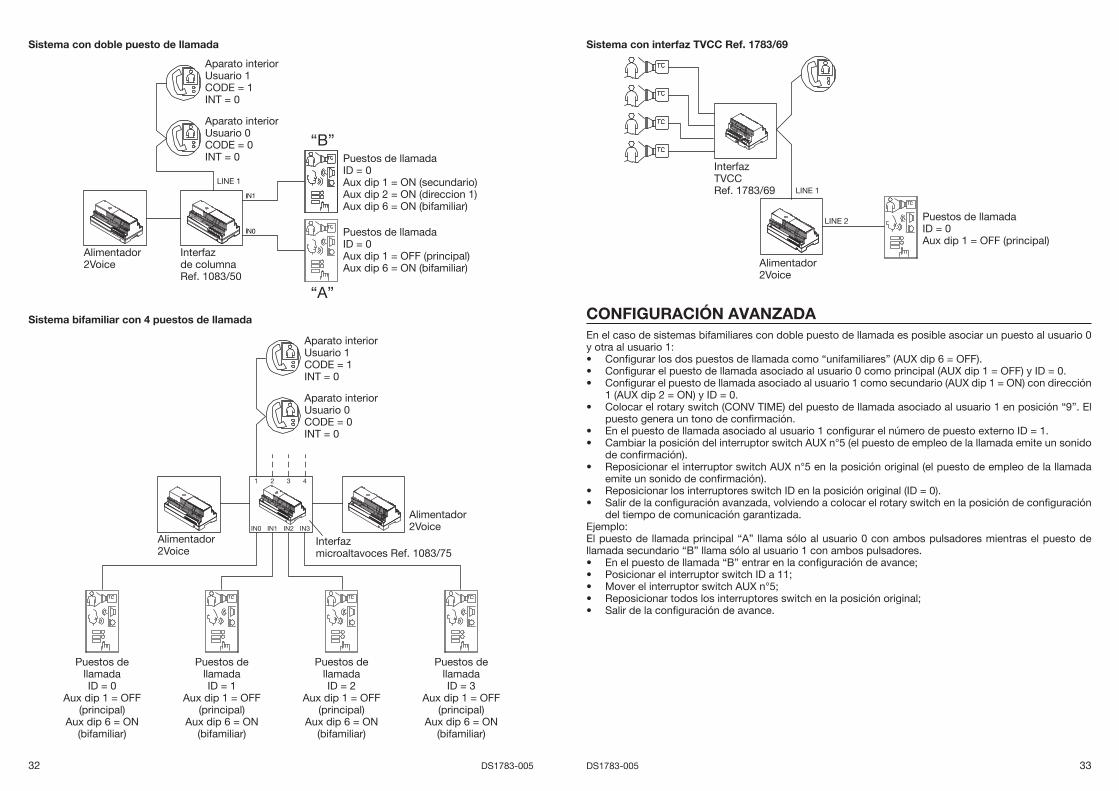
Sistema con doble puesto de llamada
“B”
“A”
Alimentador2Voice
LINE 1
Interfazde columnaRef. 1083/50
Puestos de llamadaID = 0Aux dip 1 = ON (secundario)Aux dip 2 = ON (direccion 1)Aux dip 6 = ON (bifamiliar)
Puestos de llamadaID = 0Aux dip 1 = OFF (principal)Aux dip 6 = ON (bifamiliar)
Aparato interiorUsuario 1CODE = 1INT = 0
Aparato interiorUsuario 0CODE = 0INT = 0
Sistema bifamiliar con 4 puestos de llamada
Alimentador2Voice
Alimentador2Voice
Interfazmicroaltavoces Ref. 1083/75
1 2 3 4
IN0 IN1 IN2 IN3
Aparato interiorUsuario 1CODE = 1INT = 0
Aparato interiorUsuario 0CODE = 0INT = 0
Puestos dellamadaID = 0
Aux dip 1 = OFF(principal)
Aux dip 6 = ON(bifamiliar)
Puestos dellamadaID = 3
Aux dip 1 = OFF(principal)
Aux dip 6 = ON(bifamiliar)
Puestos dellamadaID = 2
Aux dip 1 = OFF(principal)
Aux dip 6 = ON(bifamiliar)
Puestos dellamadaID = 1
Aux dip 1 = OFF(principal)
Aux dip 6 = ON(bifamiliar)
Sistema con interfaz TVCC Ref. 1783/69
Alimentador2Voice
LINE 1
LINE 2
InterfazTVCCRef. 1783/69
Puestos de llamadaID = 0Aux dip 1 = OFF (principal)
CONFIGURACIÓN AVANZADAEn el caso de sistemas bifamiliares con doble puesto de llamada es posible asociar un puesto al usuario 0 y otra al usuario 1:
Confi gurar los dos puestos de llamada como “unifamiliares” (AUX dip 6 = OFF).Confi gurar el puesto de llamada asociado al usuario 0 como principal (AUX dip 1 = OFF) y ID = 0.Confi gurar el puesto de llamada asociado al usuario 1 como secundario (AUX dip 1 = ON) con dirección 1 (AUX dip 2 = ON) y ID = 0.Colocar el rotary switch (CONV TIME) del puesto de llamada asociado al usuario 1 en posición “9”. El puesto genera un tono de confi rmación.En el puesto de llamada asociado al usuario 1 confi gurar el número de puesto externo ID = 1.Cambiar la posición del interruptor switch AUX n°5 (el puesto de empleo de la llamada emite un sonido de confi rmación).Reposicionar el interruptor switch AUX n°5 en la posición original (el puesto de empleo de la llamada emite un sonido de confi rmación).Reposicionar los interruptores switch ID en la posición original (ID = 0).Salir de la confi guración avanzada, volviendo a colocar el rotary switch en la posición de confi guración del tiempo de comunicación garantizada.
Ejemplo: El puesto de llamada principal “A” llama sólo al usuario 0 con ambos pulsadores mientras el puesto de llamada secundario “B” llama sólo al usuario 1 con ambos pulsadores.
En el puesto de llamada “B” entrar en la confi guración de avance;Posicionar el interruptor switch ID a 11;Mover el interruptor switch AUX n°5;Reposicionar todos los interruptores switch en la posición original;Salir de la confi guración de avance.
•••
•
••
•
••
•••••
34 DS1783-005 35DS1783-005
“B”
“A”
Alimentador2Voice
LINE 1
Interfazde columnaID = 0
Puestos de llamadaID = 0Aux dip 1 = OFF (principal)Aux dip 6 = OFF (unifamiliar)Llama el usuario 0
Aparato interiorUsuario 1CODE = 1INT = 0
Aparato interiorUsuario 0CODE = 0INT = 0
Puestos de llamadaID = 0Aux dip 1 = ON (secundario)Aux dip 2 = ON (dirección 1)Aux dip 6 = OFF (unifamiliar)Llama el usuario 1
BORRE DE LOS DATOS DE PROGRAMACIÓNPara cancelar todos los datos programados en la confi guración avanzada proceder como sigue:
Entrar en la confi guración avanzada (CONV TIME = 9).Mantener presionado uno de los pulsadores durante 5 s, como mínimo. El puesto externo genera un aviso acústico para confi rmar que se ha ejecutado la cancelación.
ACCIONAMIENTO CERRADURA ELÉCTRICA PEATONALLos microaltavoces tienen dos bornes para la gestión con descarga capacitiva de la cerradura eléctrica (SE-, SE+).La cerradura eléctrica es activada en los siguientes casos:
Cada vez que es presionada la tecla pasillo (bornes PA).Con la recepción del mando apertura de la puerta peatonal de un interfono en función de la confi guración del interruptor dip AUX relativo con la modalidad de funcionamiento “libre” o “con secreto” (consultar párrafo “Confi guración”).
El tiempo de activación de la cerradura electrica es programable por medio de dip-switch “Door time”.
ACCIONAMIENTO CERRADURA ELÉCTRICA VADO PERMANENTELos microaltavoces tienen dos bornes conectados con los contactos de un relé normalmente abierto, que se utiliza como mando de una centralita para el dispositivo de apertura del portón (1). Cuando se recibe el mando de apertura de la puerta del pasaje de vehículos desde un aparato interior, el relé se controla durante 1 s, según la confi guración del modo de funcionamiento “libre” o “con secreto”, como en el caso de la cerradura eléctrica para peatones.
(1) El relé en cuestión NO es apropiado para el control directo de cargas de potencia, sino que se debe utilizar exclusivamente como relé de mando. Consultar las características eléctricas en el manual del puesto de llamada.
CARACTERISTICAS TECNICASTensión de alimentación (LINE): ..................................................................................................... 36 – 48VccAbsorción en reposo: ..................................................................................................................... 45mA maxAbsorción máx. (llamada vídeo y tarjeteros encendidos):............................................................ 250mA maxTemperatura de funcionamiento: ............................................................................................ -10°C ÷ + 50°CConformidad con las normas: .......................................................................... EN 61000-6-3, EN 61000-6-1
••
••
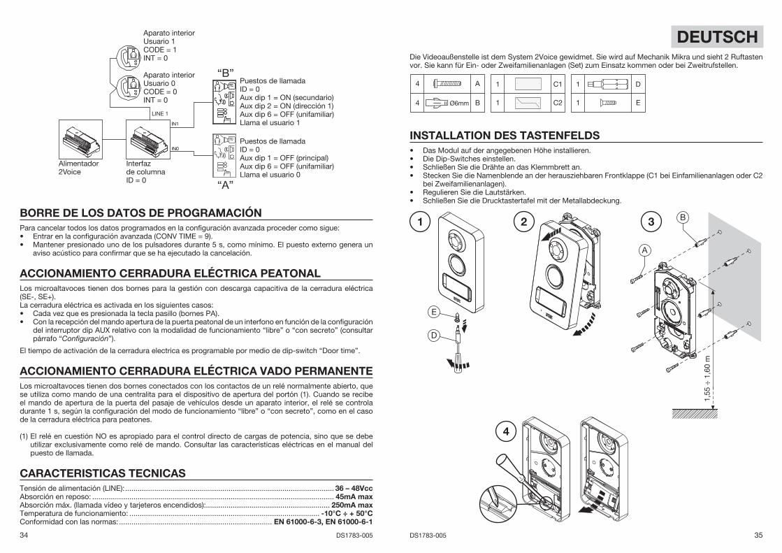
DEUTSCHDie Videoaußenstelle ist dem System 2Voice gewidmet. Sie wird auf Mechanik Mikra und sieht 2 Ruftasten vor. Sie kann für Ein- oder Zweifamilienanlagen (Set) zum Einsatz kommen oder bei Zweitrufstellen.
4 A
4 Ø6mm B
1 C1
1 C2
1 D
1 E
INSTALLATION DES TASTENFELDSDas Modul auf der angegebenen Höhe installieren.Die Dip-Switches einstellen.Schließen Sie die Drähte an das Klemmbrett an.Stecken Sie die Namenblende an der herausziehbaren Frontklappe (C1 bei Einfamilienanlagen oder C2 bei Zweifamilienanlagen).Regulieren Sie die Lautstärken.Schließen Sie die Drucktastertafel mit der Metallabdeckung.
••••
••
1,55
÷ 1
,60
m
A
B1 2 3
4
D
E
36 DS1783-005 37DS1783-005
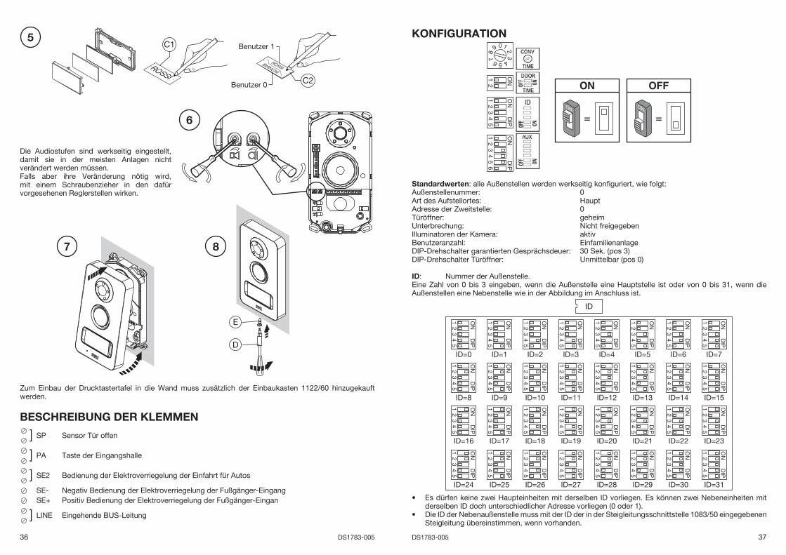
Die Audiostufen sind werkseitig eingestellt, damit sie in der meisten Anlagen nicht verändert werden müssen.Falls aber ihre Veränderung nötig wird, mit einem Schraubenzieher in den dafür vorgesehenen Reglerstellen wirken.
Zum Einbau der Drucktastertafel in die Wand muss zusätzlich der Einbaukasten 1122/60 hinzugekauft werden.
BESCHREIBUNG DER KLEMMEN
] SP Sensor Tür offen
] PA Taste der Eingangshalle
] SE2 Bedienung der Elektroverriegelung der Einfahrt für Autos
SE- Negativ Bedienung der Elektroverriegelung der Fußgänger-EingangSE+ Positiv Bedienung der Elektroverriegelung der Fußgänger-Eingan
] LINE Eingehende BUS-Leitung
5
7
D
E
C1
C2
Benutzer 1
Benutzer 0
6
8
KONFIGURATION
= =ONON
0
5
384
9 1
6
2
7
ON2
1
ON
DIP
43
21
5
ON
DIP
43
21
56
Standardwerten: alle Außenstellen werden werkseitig konfi guriert, wie folgt:Außenstellenummer: 0Art des Aufstellortes: Haupt Adresse der Zweitstelle: 0Türöffner: geheim Unterbrechung: Nicht freigegeben Illuminatoren der Kamera: aktivBenutzeranzahl: EinfamilienanlageDIP-Drehschalter garantierten Gesprächsdeuer: 30 Sek. (pos 3)DIP-Drehschalter Türöffner: Unmittelbar (pos 0)
ID: Nummer der Außenstelle.Eine Zahl von 0 bis 3 eingeben, wenn die Außenstelle eine Hauptstelle ist oder von 0 bis 31, wenn die Außenstellen eine Nebenstelle wie in der Abbildung im Anschluss ist.
IDO
ND
IP
43
21
5
ID=0
ON
DIP
43
21
5
ID=1
ON
DIP
43
21
5
ID=2
ON
DIP
43
21
5
ID=3
ON
DIP
43
21
5
ID=4
ON
DIP
43
21
5
ID=5
ON
DIP
43
21
5
ID=6
ON
DIP
43
21
5
ID=7
ON
DIP
43
21
5
ID=8
ON
DIP
43
21
5
ID=9
ON
DIP
43
21
5
ID=10
ON
DIP
43
21
5
ID=11
ON
DIP
43
21
5
ID=12
ON
DIP
43
21
5
ID=13
ON
DIP
43
21
5
ID=14
ON
DIP
43
21
5
ID=15
ON
DIP
43
21
5
ID=16
ON
DIP
43
21
5
ID=17
ON
DIP
43
21
5
ID=18
ON
DIP
43
21
5
ID=19
ON
DIP
43
21
5
ID=20
ON
DIP
43
21
5
ID=21
ON
DIP
43
21
5
ID=22
ON
DIP
43
21
5
ID=23
ON
DIP
43
21
5
ID=24
ON
DIP
43
21
5
ID=25
ON
DIP
43
21
5
ID=26
ON
DIP
43
21
5
ID=27
ON
DIP
43
21
5
ID=28
ON
DIP
43
21
5
ID=29
ON
DIP
43
21
5
ID=30
ON
DIP
43
21
5
ID=31
Es dürfen keine zwei Haupteinheiten mit derselben ID vorliegen. Es können zwei Nebeneinheiten mit derselben ID doch unterschiedlicher Adresse vorliegen (0 oder 1). Die ID der Nebenaußenstelle muss mit der ID der in der Steigleitungsschnittstelle 1083/50 eingegebenen Steigleitung übereinstimmen, wenn vorhanden.
•
•
38 DS1783-005 39DS1783-005
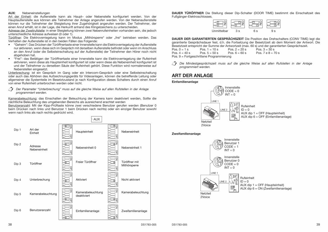
AUX: NebeneinstellungenArt der Einheit: die Außenstelle kann als Haupt– oder Nebenstelle konfi guriert werden. Von der Hauptaußenstelle aus können alle Teilnehmer der Anlage angerufen werden. Von der Nebenaußenstelle können nur die Teilnehmer der Steigleitung ihrer Zugehörigkeit angerufen werden. Der Teilnehmer, der einen Anruf erhält, ist in der Lage, die Herkunft anhand des Klingelzeichens zu unterscheiden. Adresse der Zweitrufstelle: in einer Steigleitung können zwei Nebenrufeinheiten vorhanden sein, die jedoch unterschiedliche Adresse aufweisen (0 oder 1).Türöffner: Die Elektroverriegelung kann im Modus „Mithörsperre“ oder „frei“ betrieben werden. Das Verhalten der Außenstelle ist in den beiden Fällen das Folgende:
“Geheim”: Das Drücken der Türöffnertaste einer Innenstelle kann die Elektroverriegelung der Außenstelle nur aktivieren, wenn diese sich im Gespräch mit derselben Außenstelle befi ndet oder wenn im Anschluss an den Anruf (oder die Selbsteinschaltung auf der Außenstelle) der Teilnehmer den Hörer noch nicht abgehoben hat.“Frei”: das Betätigen der Türöffnertaste einer Innenstelle kann die Elektroverriegelung der Rufeinheit aktivieren, wenn diese als Haupteinheit konfi guriert ist oder wenn diese als Nebeneinheit konfi guriert ist und der Teilnehmer zu derselben Säule der Rufeinheit gehört. Diese Funktion wird normalerweise auf Nebenstellen eingesetzt.
Unterbrechung: ist ein Gespräch im Gang oder ein Intercom-Gespräch oder eine Selbsteinschaltung oder auch das Abhören des Aufzeichnungsgeräts für Videoanlagen, können die betreffende Leitung oder allgemeiner die Systemteile im Besetztzustand je nach Konfi guration dieses Schalters durch einen Anruf von einer Rufeinheit unterbrochen werden oder nicht.
Der Parameter “Unterbrechung” muss auf die gleiche Weise auf allen Rufstellen in der Anlage programmiert werden.
Kamerabeleuchtung: das Einschalten der Beleuchtung der Kamera kann deaktiviert werden, Sollte die nächtliche Beleuchtung des umgebenden Bereichs als ausreichend erachtet werdenBenutzeranzahl: Mit der Kipp-Prüftaste könne zwei verschiedene Benutzer gerufen werden (Benutzer 0 beim Drücken nach links und Benutzer 1 beim Drücken nach rechts) oder ein einziger Benutzer sowohl wenn nach links als nach rechts gedrückt wird.
AUX
ON
DIP
43
21
56
Haupteinheit
ON
DIP
43
21
56
Nebeneinheit
ON
DIP
43
21
56
Nebeneinheit 0
ON
DIP
43
21
5
Nebeneinheit 1
ON
DIP
43
21
5
Freier Türöffner
ON
DIP
43
21
56
6
Türöffner mit Mithörsperre
ON
DIP
43
21
56
6
Aktiviert
ON
DIP
43
21
5
Nicht aktiviert
ON
DIP
43
21
56
Kamerabeleuchtungdeaktiviert
Art derEinheit
Adresse Nebeneinheit
Türöffner
Unterbrechung
Kamerabeleuchtung
ON
DIP
43
21
5
Kamerabeleuchtung
66
ON
DIP
43
21
56
EinfamilienanlageBenutzeranzahlO
ND
IP
43
21
5
Zweifamilienanlage
6
Dip 1
Dip 2
Dip 3
Dip 4
Dip 5
Dip 6
•
•
DAUER TÜRÖFFNER Die Stellung dieser Dip-Schalter (DOOR TIME) bestimmt die Einschaltzeit des Fußgänger-Elektroschlosses.
ON2
Unmittelbar
1
3 s 6 s
ON2
9 s
1ON2
1 ON2
1
DAUER DER GARANTIERTEN GESPRÄCHSZEIT Die Position des Drehschalters (CONV TIME) legt die garantierte Gesprächsdauer fest, d.h. die Fortsetzung der Besetztzeit ab dem Moment der Antwort. Die Besetztzeit entspricht der Summe der Antwortzeit (max. 60 s) und der garantierten Gesprächszeit.Pos. 0 = 1 s Pos. 1 = 10 s Pos. 2 = 20 s Pos. 3 = 30 sPos. 4 = 40 s Pos. 5 = 50 s Pos. 6 = 60 s Pos. 7 e 8 = 70 sPos. 9 = Fortgeschrittene Programmierung
Die Mindestgesprächszeit muss auf die gleiche Weise auf allen Rufstellen in der Anlage programmiert werden.
ART DER ANLAGEEinfamilienanlage
Netzteil2Voice
LINE 2
LINE 1
RufeinheitID = 0AUX dip 1 = OFF (Haupteinheit)AUX dip 6 = OFF (Einfamilienanlage)
InnenstelleCODE = 0INT = 0
Zweifamilienanlage
Netzteil2Voice
LINE 2
LINE 1
RufeinheitID = 0AUX dip 1 = OFF (Haupteinheit)AUX dip 6 = ON (Zweifamilienanlage)
InnenstelleBenutzer 1CODE = 1INT = 0
InnenstelleBenutzer 0CODE = 0INT = 0
40 DS1783-005 41DS1783-005
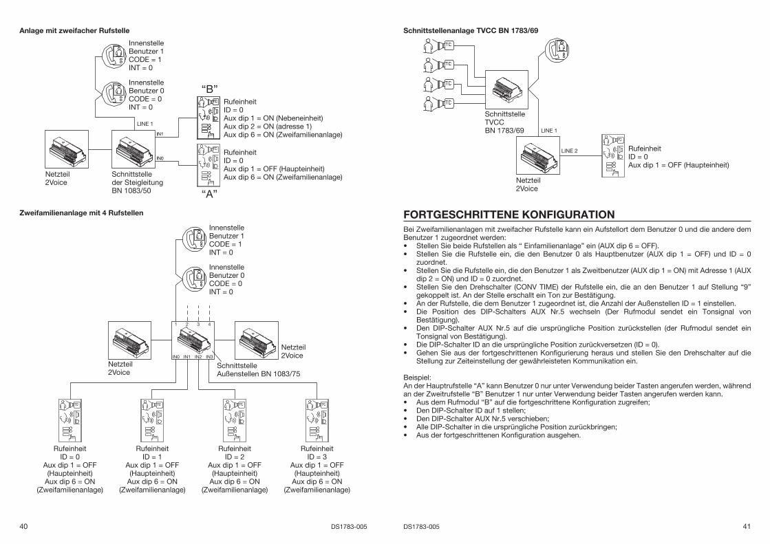
Anlage mit zweifacher Rufstelle
“B”
“A”
Netzteil2Voice
LINE 1
Schnittstelleder SteigleitungBN 1083/50
RufeinheitID = 0Aux dip 1 = ON (Nebeneinheit)Aux dip 2 = ON (adresse 1)Aux dip 6 = ON (Zweifamilienanlage)
RufeinheitID = 0Aux dip 1 = OFF (Haupteinheit)Aux dip 6 = ON (Zweifamilienanlage)
InnenstelleBenutzer 1CODE = 1INT = 0
InnenstelleBenutzer 0CODE = 0INT = 0
Zweifamilienanlage mit 4 Rufstellen
Netzteil2Voice
Netzteil2Voice
SchnittstelleAußenstellen BN 1083/75
1 2 3 4
IN0 IN1 IN2 IN3
InnenstelleBenutzer 1CODE = 1INT = 0
InnenstelleBenutzer 0CODE = 0INT = 0
RufeinheitID = 0
Aux dip 1 = OFF(Haupteinheit)
Aux dip 6 = ON(Zweifamilienanlage)
RufeinheitID = 3
Aux dip 1 = OFF(Haupteinheit)
Aux dip 6 = ON(Zweifamilienanlage)
RufeinheitID = 2
Aux dip 1 = OFF(Haupteinheit)
Aux dip 6 = ON(Zweifamilienanlage)
RufeinheitID = 1
Aux dip 1 = OFF(Haupteinheit)
Aux dip 6 = ON(Zweifamilienanlage)
Schnittstellenanlage TVCC BN 1783/69
Netzteil2Voice
LINE 1
LINE 2
SchnittstelleTVCCBN 1783/69
RufeinheitID = 0Aux dip 1 = OFF (Haupteinheit)
FORTGESCHRITTENE KONFIGURATIONBei Zweifamilienanlagen mit zweifacher Rufstelle kann ein Aufstellort dem Benutzer 0 und die andere dem Benutzer 1 zugeordnet werden:
Stellen Sie beide Rufstellen als “ Einfamilienanlage” ein (AUX dip 6 = OFF).Stellen Sie die Rufstelle ein, die den Benutzer 0 als Hauptbenutzer (AUX dip 1 = OFF) und ID = 0 zuordnet.Stellen Sie die Rufstelle ein, die den Benutzer 1 als Zweitbenutzer (AUX dip 1 = ON) mit Adresse 1 (AUX dip 2 = ON) und ID = 0 zuordnet.Stellen Sie den Drehschalter (CONV TIME) der Rufstelle ein, die an den Benutzer 1 auf Stellung “9” gekoppelt ist. An der Stelle erschallt ein Ton zur Bestätigung.An der Rufstelle, die dem Benutzer 1 zugeordnet ist, die Anzahl der Außenstellen ID = 1 einstellen.Die Position des DIP-Schalters AUX Nr.5 wechseln (Der Rufmodul sendet ein Tonsignal von Bestätigung).Den DIP-Schalter AUX Nr.5 auf die ursprüngliche Position zurückstellen (der Rufmodul sendet ein Tonsignal von Bestätigung).Die DIP-Schalter ID an die ursprüngliche Position zurückversetzen (ID = 0).Gehen Sie aus der fortgeschrittenen Konfi gurierung heraus und stellen Sie den Drehschalter auf die Stellung zur Zeiteinstellung der gewährleisteten Kommunikation ein.
Beispiel: An der Hauptrufstelle “A” kann Benutzer 0 nur unter Verwendung beider Tasten angerufen werden, während an der Zweitrufstelle “B” Benutzer 1 nur unter Verwendung beider Tasten angerufen werden kann.
Aus dem Rufmodul “B” auf die fortgeschrittene Konfi guration zugreifen;Den DIP-Schalter ID auf 1 stellen;Den DIP-Schalter AUX Nr.5 verschieben;Alle DIP-Schalter in die ursprüngliche Position zurückbringen;Aus der fortgeschrittenen Konfi guration ausgehen.
••
•
•
••
•
••
•••••

42 DS1783-005 43DS1783-005
“B”
“A”
Netzteil2Voice
LINE 1
Schnittstelleder SteigleitungID = 0
RufeinheitID = 0Aux dip 1 = OFF (Haupteinheit)Aux dip 6 = OFF (Einfamilienanlage)Ruft der Benutzer 0 an
InnenstelleBenutzer 1CODE = 1INT = 0
InnenstelleBenutzer 0CODE = 0INT = 0
RufeinheitID = 0Aux dip 1 = ON (Nebeneinheit)Aux dip 2 = ON (Adresse 1)Aux dip 6 = OFF (Einfamilienanlage)Ruft der Benutzer 1 an
LÖSCHEN DER PROGRAMMIERDATENUm alle in der fortgeschrittenen Konfi guration eingestellten Daten zu löschen, folgende Vorgänge ausführen:
Auf die fortgeschrittene Konfi guration zugreifen (CONV TIME = 9).Halten Sie eine beliebige Taste mindestens 5 s lang gedrückt. An der Außenstelle erschallt ein Ton mit dem der Löschvorgang bestätigt wird.
STEUERUNG DER ELEKTROVERRIEGELUNG DER FUßGÄNGER-EINGANGDie Außenstellen verfügen über zwei Klemmen für die Verwaltung der Elektroverriegelung über kapazitive Entladung (SE-, SE+).Die Elektroverriegelung wird in den folgenden Fällen gesteuert:
Jedes Mal beim Drücken der Taste der Eingangshalle (Klemmen PA).Bei Empfang des Türoffnerbefehls der Fußgänger-Eingang einer Innenstelle, abhängig von der Konfi guration des Dip-Switch AUX, bezüglich auf “frei” oder “geheim” Betriebsmodus (siehe Abschnitt “Konfi guration”).
Die Aktivierungszeit der Elektroverriegelung ist durch DIP-Schalter programmierbar “Door Time”.
BETÄTIGUNG DER ELEKTROVERRIEGELUNG DER EINFAHRT FÜR AUTOSDie Außenstellen verfügen über zwei an die Kontakte eines Ruhekontakts angeschlossene Klemmen, die als Steuerung eines Steuergeräts zum Öffnen des Tors eingesetzt werden kann (1). Das Relais wird beim Empfang des Befehls der Türöffnerfunktion Zufahrt von einer Innenstelle abhängig von der Konfi guration der Betriebsart ‚frei’ oder ‚Mithörsperre’ gesteuert wie für die Türöffnerfunktion des Eingangs.
(1) Das betreffende Relais ist NICHT dazu geeignet, die Leistungsbelastung direkt zu steuern, sondern ausschließlich als Steuerrelais einsetzbar. Beziehen Sie sich wegen der elektrischen Charakteristiken auf das Handbuch der Rufeinheiten.
••
••
TECHNISCHE EIGENSCHAFTENVersorgungsspannung (LINE): ........................................................................................................36 – 48VdcStromentnahme bei Ruhestellung: ................................................................................................. 45mA maxMax. Stromaufnahme (Videoanlagenanruf und eingeschaltete Namensschilder): ....................... 250mA maxBetriebstemperatur: ................................................................................................................ -10°C ÷ + 50°CÜbereinstimmung mit den gesetzlichen Bestimmungen: ................................. EN 61000-6-3, EN 61000-6-1
44 DS1783-005 45DS1783-005
CONTATTO MAGNETICO NC =PORTA CHIUSA
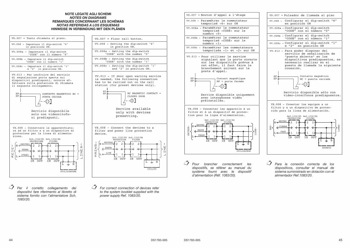
NOTE LEGATE AGLI SCHEMI NOTES ON DIAGRAMS
REMARQUES CONCERNANT LES SCHÉMASNOTAS REFERIDAS A LOS ESQUEMAS
HINWEISE IN VERBINDUNG MIT DEN PLÄNEN
NC MAGNETIC CONTACT =CLOSED DOOR
Per il corretto collegamento dei dispositivi fare riferimento al libretto di sistema fornito con l’alimentatore Sch. 1083/20.
For correct connection of devices refer to the system booklet supplied with the power supply Ref. 1083/20.
Pour brancher correctement les dispositifs, se référer au manuel du système fourni avec le dispositif d’alimentation (Réf. 1083/20).
1
2
IN OUT
2
1
Réf.1332/85
2
1
Réf.1332/86
IN OUT
2
1
PROTECTION FILTRE
MASSE
N
L
NEUTRE
PHASE
UTILISATEUR
LIGNE~
SECTEUR~
L N
VX.008 - Connecter les appareils à un filtre et à un dispositif de protec-tion pour la ligne dʼalimentation.
Contact magnétiqueNF = porte fermée
Bouton dʼappel a lʼétage
Paramétrer le commutateur temporisé «6» sur ON
Paramétrer le commutateurtemporisé «CODE» sur lenuméro «0»
Paramétrer les commutateurs temporisés «1» et «2» sur ON
Pour utiliser le service signalant que la porte ouverte sur les dispositifs prévus à cet effet, il faut faire le branchement suivant sur le poste dʼappel.
Paramétrer le commutateurtemporisé «CODE» sur lenuméro «1»
Service disponible uniquement avec interphones vidéo préinstallés.
1
2
IN OUT
2
1
Ref.1332/85
2
1
Ref.1332/86
IN OUT
2
1
PROTECCIÓN FILTRO
TIERRA
N
L
NEUTRO
FASE
USUARIO
LINEA~
RED~
L N
VX.008 - Conectar los equipos a un filtro y a un dispositivo de protec-ción para la línea de alimentación.
Contacto magnéticoNC = puerta cerrada
Pulsador de llamada al piso
Configurar el dip-switch “6” en posición ON
Configurar el dip-switch “CODE” con el número “0”
Configurar el dip-switch “CODE” con el número “1”
Configurar el dip-switch “1” e “2” en posición ON
Para poder disponer del servicio de señalización de “puerta abierta” en los dispositivos predispuestos, es necesario realizar en el puesto de llamada la siguiente conexión.
Servicio disponible sólo convideo-interfonos predispuestos.
Para la conexión correcta de los dispositivos, consultar el manual de sistema suministrado en dotación con el alimentador Ref.1083/20.
46 DS1783-005 47DS1783-005
1
2
IN OUT
2
1
BN 1332/85
2
1
BN 1332/86
IN OUT
2
1
SCHUTZ FILTER
ERDUNG
N
L
NEUTRAL
PHASE
BENUTZER
LEITUNG~
NETZ~
L N
VX.008 - Die Geräte an einen Filter oder eine Schutzvorrichtung für die Versorgungsleitung anschließen.
Magnetkontakt NC = Tür zu
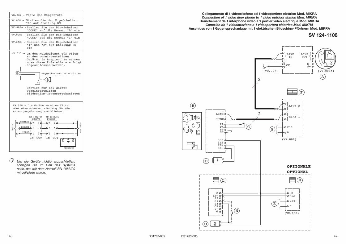
Taste des Etagenrufs
Stellen Sie den Dip-Schalter “6” auf Stellung ON
Stellen Sie den Dip-Schalter “CODE” auf die Nummer “0” ein
Stellen Sie den Dip-Schalter “CODE” auf die Nummer “1” ein
Stellen Sie den Dip-Schalter “1” und “2” auf Stellung ON ein
Um den Meldedienst Tür offen an den voreingestellten Geräten in Anspruch zu nehmen muss diese Rufstelle wie folgt angeschlossen werden.
Service nur bei darauf voreingestelltenBildschirm-Gegensprechanlagen
Um die Geräte richtig anzuschließen, schlagen Sie im Heft des Systems nach, das mit dem Netzteil BN 1083/20 mitgelieferte wurde.
Collegamento di 1 videocitofono ad 1 videoportiere elettrico Mod. MIKRAConnection of 1 video door phone to 1 video outdoor station Mod. MIKRA
Branchement de 1 interphone vidéo à 1 portier vidéo électrique Mod. MIKRAConexión de 1 videointerfono a 1 videoportero eléctrico Mod. MIKRA
Anschluss von 1 Gegensprechanlage mit 1 elektrischen Bildschirm-Pförtnern Mod. MIKRA
SV 124-1108
N
48 DS1783-005 49DS1783-005
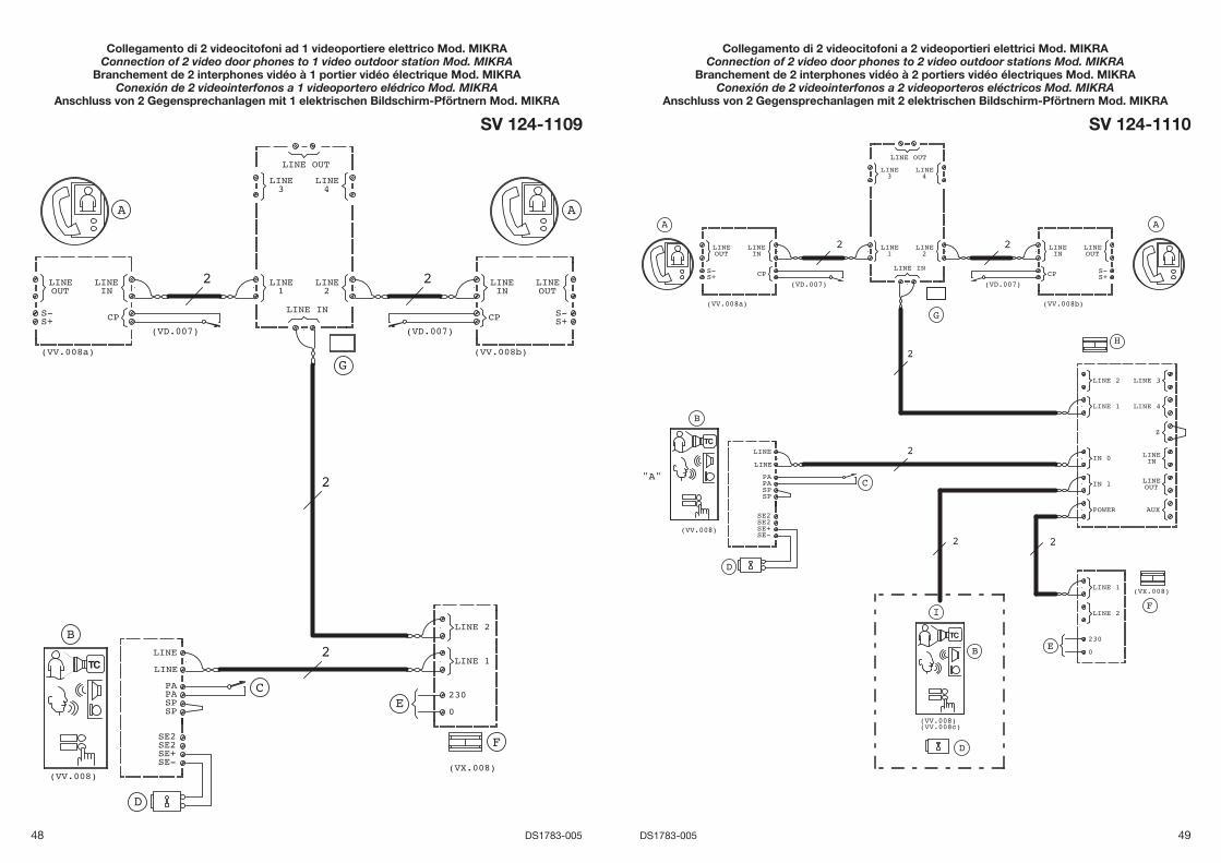
Collegamento di 2 videocitofoni ad 1 videoportiere elettrico Mod. MIKRAConnection of 2 video door phones to 1 video outdoor station Mod. MIKRA
Branchement de 2 interphones vidéo à 1 portier vidéo électrique Mod. MIKRAConexión de 2 videointerfonos a 1 videoportero elédrico Mod. MIKRA
Anschluss von 2 Gegensprechanlagen mit 1 elektrischen Bildschirm-Pförtnern Mod. MIKRA
SV 124-1109
Collegamento di 2 videocitofoni a 2 videoportieri elettrici Mod. MIKRAConnection of 2 video door phones to 2 video outdoor stations Mod. MIKRA
Branchement de 2 interphones vidéo à 2 portiers vidéo électriques Mod. MIKRAConexión de 2 videointerfonos a 2 videoporteros eléctricos Mod. MIKRA
Anschluss von 2 Gegensprechanlagen mit 2 elektrischen Bildschirm-Pförtnern Mod. MIKRA
SV 124-1110
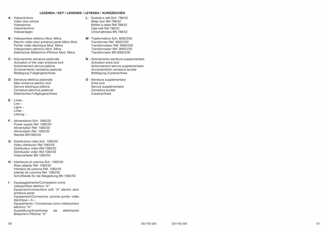
50 DS1783-005 51DS1783-005
LEGENDA / KEY / LEGENDE / LEYENDA / KURZZEICHEN
A - Videocitofono Video door phone Videophone Videointerfono Videoanlagen
B - Videoportiere elettrico Mod. Mikra Electric video door entrance panel Mikra Mod. Portier vidéo électrique Mod. Mikra Videoportero eléctrico Mod. Mikra Elektrischer Bildschirm-Pförtner Mod. Mikra
C - Azionamento serratura pedonale Activation of the main entrance lock Actionnement serrure piétons Accionamiento cerradura peatonal Betätigung Fußgängerschloss
D - Serratura elettrica pedonale Main entrance electric lock Serrure électrique piétons Cerradura eléctrica peatonal Elektrisches Fußgängerschloss
E - Linea~ Line ~ Ligne ~ Línea ~ Leitung ~
F - Alimentatore Sch. 1083/20 Power supply Ref. 1083/20 Alimentation Réf. 1083/20 Alimentador Ref. 1083/20 Netzteil BN1083/20
G - Distributore video Sch. 1083/55 Video distributor Ref.1083/55 Distributeur video Réf.1083/55 Distribuidor video Ref.1083/55 Videoverteiler BN 1083/55
H - Interfaccia di colonna Sch. 1083/50 Riser adapter Ref. 1083/50 Interface de colonne Réf. 1083/50 Interfaz de columna Ref. 1083/50 Schnittstelle für die Steigleitung BN 1083/50
I - Equipaggiamento/Connessioni come videoportiere elettrico “A”
Equipment/connections with “A” electric door entrance panel
Equipement/Connexions comme portier vidéo électrique « A »
Equipamiento / Conexiones como videoportero eléctrico “A”
Ausstattung/Anschlüsse als elektrischer Bildschirm-Pförtner “A”
L - Scatola a relé Sch. 788/52 Relay box Ref.788/52 Boîtier à relais Réf.788/52 Caja relé Ref.788/52 Umschaltrelais BN 788/52
M - Trasformatore Sch. 9000/230 Transformer Ref. 9000/230 Transformateur Réf. 9000/230 Transformador Ref. 9000/230 Transformator BN 9000/230
N - Azionamento serratura supplementare Activation extra lock Actionnement serrure supplémentaire Accionamiento cerradura auxiliar Betätigung Zusatzschloss
O - Serratura supplementare Extra lock Serrure supplémentaire Cerradura auxiliar Zusatzschloss
DS 1783-005 LBT 8681
Area tecnicaservizio clienti +39 011.23.39.810http://www.urmet.come-mail: [email protected] da Urmet Electronics Limited(azienda del gruppo Urmet) - Made in P.R.C.Manufactured by Urmet Electronics Limited(an Urmet group company) - Made in P.R.C.
URMET S.p.A.10154 TORINO (ITALY)VIA BOLOGNA 188/CTelef. +39 011.24.00.000 (RIC. AUT.)Fax +39 011.24.00.300 - 323