Sbi Pdp Adv80
60
...... Instruction manual SIEIDrive Profibus -DP Interface card SBI-PDP-ADV80
-
Upload
roxana-negoita -
Category
Documents
-
view
17 -
download
0
description
Sbi Pdp Adv80
Transcript of Sbi Pdp Adv80

...... Instruction manual
SIE
IDriv
eProfibus -DP Interface card
SBI-PDP-ADV80
2 SBI-PDP-ADV80
Informazioni riguardo a questo manuale
Prima dell’utilizzo del prodotto, leggere attentamente il capitolo relativo alle istruzioni di sicurezza. Durante il suo periodo di funzionamento conservate il manuale in un luogo sicuro e a disposi-zione del personale tecnico.Gefran spa si riserva la facoltà di apportare modifiche e varianti a prodotti, dati, dimensioni, in qualsiasi momento senza obbligo di preavviso. I dati indicati servono unicamente alla descrizione del prodotto e non devono essere intesi come proprietà assicurate nel senso legale.
Vi ringraziamo per avere scelto questo prodotto Gefran.Saremo lieti di ricevere all’indirizzo e-mail: [email protected] qualsiasi informazione che possa aiutarci a migliorare questo manuale.Tutti i diritti riservati.
Before using the product, read the safety instruction section carefully. Keep the manual in a safe place and available to engineering and installation personnel dur-ing the product functioning period.Gefran S.p.A has the right to modify products, data and dimensions without notice. The data can only be used for the product description and they can not be understood as legally stated properties.
Thank you for choosing this Gefran product.We will be glad to receive any possible information which could help us improvingthis manual. The e-mail address is the following: [email protected] rights reserved.

SBI-PDP-ADV80 3
Sommario - Contents
Informazioni riguardo a questo manuale ................................. 2
Capitolo 1 - Introduzione ........................................................... 51.1 Il Manuale ...................................................................................................................51.2 Profibus-DP in Generale ............................................................................................5
Capitolo 2 - Descrizione Hardware ........................................... 62.1 Dimensioni ................................................................................................................ 62.2 Montaggio ................................................................................................................. 62.3 Alimentazione ........................................................................................................... 72.4 LED........................................................................................................................... 72.5 Configurazione del DIP-Switch ................................................................................. 72.6 Specifiche Tecniche .................................................................................................. 82.7 Interfaccia ................................................................................................................. 8
Capitolo 3 - Assegnazione dei Byte per lo Scambio Dati ..... 10
Capitolo 4 - Attivazione del Drive tramite il Profilo Profidrive . ................................................................................................... 134.1 Descrizione di PPO ................................................................................................ 134.2 Parte PDC .............................................................................................................. 14
4.2.1 Control word / Status word ....................................................................................144.2.2 PDC Word 1-4 .......................................................................................................19
4.3 Parte PCV............................................................................................................... 194.4 Esempio di Accesso ai Parametri del Drive ............................................................ 21
Capitolo 5 - Allarmi Profibus-DP ............................................. 22
Capitolo 6 - Controllo Virtuale ................................................ 236.1 Controllo Ingresso / Uscita Digitale Virtuale ........................................................... 236.2 Controllo Uscita Analogica Virtuale ..................................................................... 23
Capitolo 7 - Attivazione del Drive senza il Profilo Profidrive 25
Capitolo 8 - Interfaccia Tastiera .............................................. 278.1 Struttura Menù Principale ...................................................................................... 278.2 Informazioni su SBI ............................................................................................... 278.3 Configurazione di SBI ............................................................................................. 288.4 Gestione Allarmi ..................................................................................................... 29
Capitolo 9 - Codici di Identificazione ..................................... 309.1 Numero di Identificazione della Scheda ................................................................ 309.2 Codici di Configurazione della Scheda .................................................................. 309.3 File Gsd ................................................................................................................. 30
Capitolo 10 - Altro .................................................................... 3110.1 Glossario .............................................................................................................. 3110.2 Abbreviazioni ........................................................................................................ 3110.3. Riferimenti ........................................................................................................... 31
4 SBI-PDP-ADV80
Chapter 1 - Introduction .......................................................... 321.1 About this manual .....................................................................................................321.2 Overview of Profibus-DP ..........................................................................................32
Chapter 2 - Hardware Description .......................................... 332.1 Dimensions ............................................................................................................. 332.2 Mounting ................................................................................................................. 332.3 Power Supply ......................................................................................................... 342.4 LEDs ....................................................................................................................... 342.5 Configurazione del DIP-Switch ............................................................................... 342.6 Technical Specification ........................................................................................... 352.7 Interface.................................................................................................................. 35
Chapter 3 - Bytes Assignment for Data Exchange ............... 37
Chapter 4 - Operating the Drive via Profidrive Profile .......... 404.1 PPO Description ..................................................................................................... 404.2 PDC-part................................................................................................................. 41
4.2.1 Control / Status word .............................................................................................414.2.2 PDC Word 1-4 .......................................................................................................46
4.3 PCV Part................................................................................................................. 464.4 Example of Drive Parameter Access ...................................................................... 48
Chapter 5 - Profibus-DP Alarms ............................................. 49
Chapter 6 - Virtual Control ...................................................... 506.1 Virtual Digital Input/Output Control ......................................................................... 506.2 Virtual Analog Output Control ................................................................................. 50
Chapter 7 - Operating the Drive without Profidrive Profile .. 52
Chapter 8 - Keyboard Interface ............................................... 548.1 Main Menu Structure ............................................................................................. 548.2 SBI Info .................................................................................................................. 548.3 SBI Configuration ................................................................................................... 558.4 Alarm Handling ....................................................................................................... 56
Chapter 9 - Identification Codes ............................................. 579.1 Card Identification Number .................................................................................... 579.2 Card Configuration Codes ..................................................................................... 579.3 Gsd file ................................................................................................................... 57
Chapter 10 - Miscellaneous ..................................................... 5810.1 Glossary ............................................................................................................... 5810.2 Abbreviations ........................................................................................................ 5810.3. References .......................................................................................................... 58

SBI-PDP-ADV80 • Manuale istruzione 5
Eng
lish
Italiano
Capitolo 1 - Introduzione
Questo manuale descrive la scheda opzionale SBI-PDP-ADV80 per la connessio-ne degli inverter alle reti Profibus-DP.Questo manuale è indirizzato a progettisti e tecnici responsabili per la manuten-zione, messa in servizio e funzionamento dei sistemi Profibus-DP. Si suppone una conoscenza di base di Profibus-DP mentre ulteriori informazioni sono disponibili nel manuale “Draft Standard DIN 19245 Parte 3”.
1.1 Il ManualeCapitolo 2 Montaggio meccanico della scheda e connessioni elettriche.Capitolo 3 Trasmissione dati Master - SlaveCapitolo 4 Questa sezione descrive come gestire il drive tramite la control word
e la status word e come accedere ai parametri del drive. Capitolo 5 Gestione diagnostica Profibus-DPCapitolo 6 Assegnazione dei parametri del drive agli I/O virtuali digitaliCapitolo 7 Questa sezione descrive come agire senza Profidrive Profile.Capitolo 8 Menù tastierino del driveCapitolo 9 Numero di identificazione e codici per la connessione del BusCapitolo 10 Altro: glossario, abbreviazioni e riferimenti
1.2 Profibus-DP in GeneraleProfibus-DP è un Bus di campo progettato per un veloce scambio di dati a livello sensore/attuatori; la comunicazione viene stabilita tra l’unità centrale del Master (PLC oppure PC) e le unità dello Slave, vale a dire sensori, attuatori, drive ecc. Lo scambio di dati è ciclico; l’unità Master legge i dati in ingresso dello Slave e scrive i dati in uscita dello Slave. La durata del ciclo del Bus è inferiore a quella dell’unità centrale; i Baud Rate della scheda SBI possono essere inclusi tra 9,6 kbit/s e 12 Mbit/s in base agli standard di Profibus-DP, sezione 3. La durata totale del ciclo dipende dal numero di Slave collegati; il Baud Rate da 1,5-Mbit/s permette di interrogare 8 drive Gefran in un periodo di 6 millisecondi. Il supporto fisico è dato dalla linea seriale RS485; al Bus può essere collegato un numero massimo di 125 Slave. Esempio di sistema Profibus-DP Mono-Master.
MASTER
SLAVESLAVE SLAVE
Profibus-DP permette anche di ottenere un sistema Multi-Master. Per ulteriori informazioni fare riferimento ai capitoli 6 e 7 del manuale “Draft Standard DIN 19245 Parte 3”.
6 SBI-PDP-ADV80 • Manuale istruzione
Eng
lish
Italiano
Capitolo 2 - Descrizione Hardware
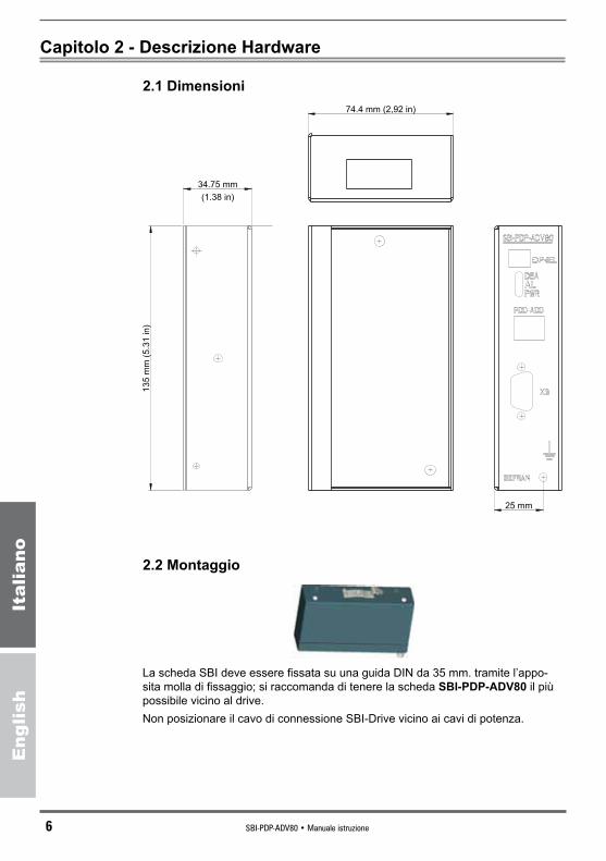
2.1 Dimensioni
34.75 mm
13
5 m
m (
5.3
1 in
)
74.4 mm (2,92 in)
25 mm
(1.38 in)
2.2 Montaggio
La scheda SBI deve essere fissata su una guida DIN da 35 mm. tramite l’appo-sita molla di fissaggio; si raccomanda di tenere la scheda SBI-PDP-ADV80 il più possibile vicino al drive. Non posizionare il cavo di connessione SBI-Drive vicino ai cavi di potenza.

SBI-PDP-ADV80 • Manuale istruzione 7
Eng
lish
Italiano
EXP-SELDip-switch che seleziona l’indirizzo dell’opzione
DEA,AL,PWRLeds di segnalazione
PDP-ADDdisplay a 2 cifre che visualizza l’indirizzo Profibus dell’azionamento
XSconnettore per il collegamento del Bus
PEconnettori per la messa a terra, devono essere collegati entrambi per aumentare l’immunità ai disturbi.
XOPTconnettori in parallelo per il collegamento a drive e a un altro eventuale dispositivo.
1. Spegnere il drive.2. Il cavo di connessione SBI-Drive (cod. S7QAE0 - CAVO SCHERMATO
8 POLI, L=400 mm, a corredo con il prodotto) deve essere connesso tra il connettore XOPT sulla scheda di Regolazione del drive e uno dei due connettori XOPT sulla scheda SBI-PDP-ADV80.
3. Collegare il cavo del Bus al connettore XS.4. Accendere il drive.5. Il LED PWR si accende.6. Il LED DEA si accende quando la comunicazione entra nella fase Scambio
Dati.7. Sul display verrà visualizzato l’indirizzo del nodo Profibus, impostato con il
parametro I.750 - SBI Address.
2.3 Alimentazione
L’alimentazione viene fornita al connettore XOPT che viene utilizzato anche per il trasferimento dei dati tra la scheda SBI e la scheda di regolazione del drive.
2.4 LED
PWR (Verde) Alimentazione a +5V.AL (Rosso) Allarme attivo.DEA (Giallo) Fase di Scambio Dati attiva.
2.5 Configurazione del DIP-Switch
La configurazione dello switch EXP-SEL deve essere in accordo all’impostazione software dei parametri I.700-Option 1 type e I.701-Option 2 type:

8 SBI-PDP-ADV80 • Manuale istruzione
Eng
lish
Italiano
1 2
ON
ON
OFF
- se I.700 = [4] impostare EXP-SEL: 1=ON e 2=OFF.- se I.701 = [4] impostare EXP-SEL: 1=OFF e 2=ON
2.6 Specifiche Tecniche
Temperatura d’immagazzinaggio: � -20°... +70°C (-68...+158°F).
Temperatura d’esercizio: ������� 0°... +55°C (32...+131°F)
Queste temperature sono adeguate a quelle del drive al quale le schede vengono connesse.
2.7 Interfaccia
Per la connessione al Bus utilizzare un doppino schermato come indicato dalla specifica Profibus. I pinout dei connettori del Bus (XS) sono i seguenti:
1
5
6
9
XS PIN RIFERIMENTO SIGNIFICATO1 Schermo Schermo / massa a terra
2 Non collegato
3 RX / TX - B Ricezione / trasmissione dato P
4 Non collegato
5 0V - GND Potenziale trasmissione dato (terra a 5V)
6 +5V Alimentazione della resistenza -P di terminazione (P 5V)
7 Non collegato
8 RX / TX - A Ricezione / trasmissione dato P
9 Non collegato Le resistenze di terminazione del primo e dell’ultimo componente della rete devono essere attive. I pin 5 (GND) e 6 (+5V) forniscono la connessione delle resistenze di terminazione. E’ consigliabile utilizzare connettori standard già provvisti di resistenza.
390 ohm (±5%, min W)1/4
220 ohm (±5%, min W)1/4
390 ohm (±5%, min W)1/4
+5V (6)
B-B’ (3)
A-A’ (8)
GND (5)
SBI-PDP-ADV80 • Manuale istruzione 9
Eng
lish
Italiano
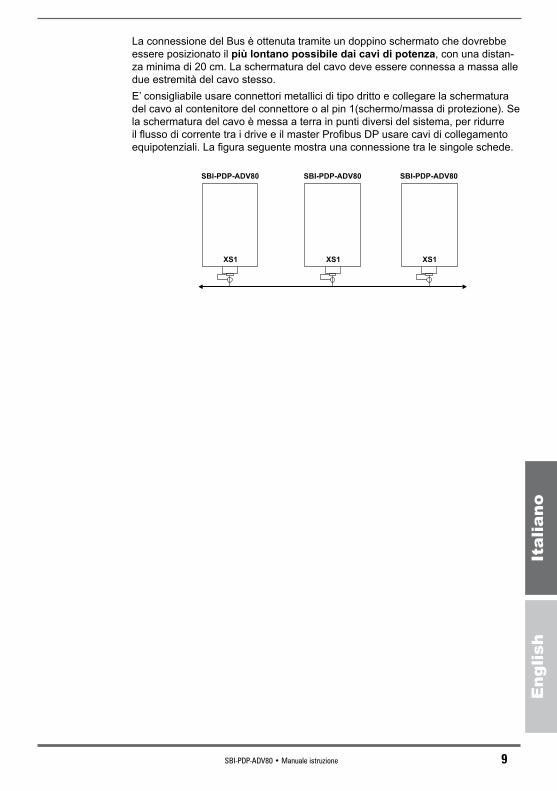
La connessione del Bus è ottenuta tramite un doppino schermato che dovrebbe essere posizionato il più lontano possibile dai cavi di potenza, con una distan-za minima di 20 cm. La schermatura del cavo deve essere connessa a massa alle due estremità del cavo stesso. E’ consigliabile usare connettori metallici di tipo dritto e collegare la schermatura del cavo al contenitore del connettore o al pin 1(schermo/massa di protezione). Se la schermatura del cavo è messa a terra in punti diversi del sistema, per ridurre il flusso di corrente tra i drive e il master Profibus DP usare cavi di collegamento equipotenziali. La figura seguente mostra una connessione tra le singole schede.
SBI-PDP-ADV80
XS1
SBI-PDP-ADV80
XS1
SBI-PDP-ADV80
XS1

10 SBI-PDP-ADV80 • Manuale istruzione
Eng
lish
Italiano
Capitolo 3 - Assegnazione dei Byte per lo Scambio Dati
I primi 8 byte rappresentano il Configuration Channel per lo scambio dati non cicli-co, gli altri rappresentano invece il Process Data Channel per lo scambio ciclico. Nella comunicazione tra Sbi e Master di rete Profibus si è seguito lo standard Profidrive.Anche nell’area dati della comunicazione tra SBI e azionamento vengono inserite le informazioni cercando di ricalcare lo standard Profidrive.Con il parametro PPO type si può selezionare la modalità di funzionamento. Le modalità PPO-1..4 sono standard Profidrive, la prima modalità è una modalità custom.I Dati vengono scambiati su due diversi canali:- PCV, Canale di Configurazione- canale di processo scambiato ciclicamente CTW/STW SP/AF PDC-W0..W5.
OffsetSubOffset
Custom PPO-1 PPO-2 PPO-3 PPO-4
1 1
PCV PCV PCV Nu Nu
2 2
3 3
4 4
5 5
6 6
7 7
8 8
9 1PDC-W0 CTW/STW CTW/STW CTW/STW CTW/STW
10 2
11 3PDC-W1 SP/AF SP/AF SP/AF SP/AF
12 4
13 5PDC-W2 Nu PDC-W0 Nu PDC-W0
14 6
15 7PDC-W3 Nu PDC-W1 Nu PDC-W1
16 8
17 9PDC-W4 Nu PDC-W2 Nu PDC-W2
18 10
19 11PDC-W5 Nu PDC-W3 Nu PDC-W3
20 12 Nu Non utilizzato CTW Control word standard ProfidriveSTW Status word standard ProfidriveSP Riferimento di frequenza standard ProfidriveAF Frequenza reale standard Profidrive
PDC-W0..W5 Con queste word si possono leggere e scrivere ciclicamente i parametri dell’azionamento. Le informazioni scambiate vengo-

SBI-PDP-ADV80 • Manuale istruzione 11
Eng
lish
Italiano
no configurate tramite parametri dell’azionamento. I parametri di configurazione sono accessibili da canale lento, quindi è possibile modificare dalla rete le informazioni scambiate cicli-camente.
PCV (Parameter Area Channel - Canale lento) L’area PCV è costituita da 7 byte e serve per leggere e scrive-
re i parametri dell’azionamento uno alla volta.
PCV1 2 3 - 4 5 6 7 8
PCA LOW PCA HIGH WL-BL WL-BH WH-BL WH-BH
PCA SIND PVA
PCA 16 bits
PCA(16bits)15 14 13 12 11 10 9 8 7 6 5 4 3 2 1 0
RC TB Index RC Richiesta risposta caratteristiche. Definisce la richiesta/rispo-
sta che deve essere eseguita
Richiesta 0 Nessuna richiesta1 Lettura parametro 2 Scrittura parametro (word)3..15 Non utilizzato
Risposta0 Nessuna risposta1 Lettura parametro2 Scrittura parametro 3 Non utilizzato4 Non utilizzato5 Non utilizzato6 Non utilizzato7 Richiesta rifiutata8..15 Non utilizzato
TB Toggle bit. Non utilizzato.Index Index 0..1999 contiene ipa del parametro che si vuole scam-
biare.
I dati provenienti da Profibus-DP e letti dallo Slave vengono indicati come dati in ingresso; i dati scritti in Profibus-DP dallo Slave vengono indicati come dati in

12 SBI-PDP-ADV80 • Manuale istruzione
Eng
lish
Italiano
uscita. I parametri dello Slave vengono letti ciclicamente dal Master assegnando i para-metri del drive ai parametri di configurazione dell’uscita PDC. Il Master trasmette ciclicamente i parametri del drive allo Slave assegnando i parametri del drive ai parametri di configurazione dell’ingresso PDC. L’assegnazione dei parametri del drive alla Word del Process Data Channel viene eseguita utilizzando l’indice del parametro stesso (I.760 e seguenti).Al Process Data Channel possono essere assegnati solo parametri del drive con un’ampiezza di 16 bit (1 Word). I parametri I.760 ... I.775 con indice uguale a 0000 indicano che la word non è stata assegnata a nessun parametro dell’azionamento.Per la configurazione dei Process Data Channel (PDC) vedere il manuale di istruzione dell’azionamento (paragrafo 7.4, Menu I - INTERFACE, parametri I.760 e successivi).
Nota! A seconda della configurazione selezionata si dovranno configurare un numero di Word differenti; esempi:
- se la modalità è Custom si potranno definire tutte le 6 word; - se la modalità è PPO2 o PPO4si dovranno definire solo le prime 4 Word; - se la modalità è PPO1 o PPO3 non se ne dovrà configurare nessuna.
Riferimento di frequenza / Frequenza realeIl formato dei dati è un “valore standardizzato” dove 0 hex = 0% e 4000 hex corri-sponde al 100% della frequenza massima specificata nel parametro F.020 .
Valore standardizzato
Un valore lineare.0%=0 (0h), 100% è ����������� 214 (4000h)
Range ��������������������� -200% ... 200% - 214
Risoluzione ����������������� 214 = 0.00061%
Lunghezza ������������������ 2 bytes
Per abilitare la scrittura del Riferimento di frequenza bisogna selezionare il para-metro F.050 “Ref 1 channel” = [8] Profidrive.
SBI-PDP-ADV80 • Manuale istruzione 13
Eng
lish
Italiano
Capitolo 4 - Attivazione del Drive tramite il Profilo Profidrive
Per operare con il profilo Profidrive è necessario impostare i seguenti parametri sul drive.Abilitare la scheda opzionale I.700 Opt1 type = [4] SBI Board oppure I.701 Opt2 type = [4] SBI Board.Configurare l’indirizzo SBI desiderato I.750 = [3] (default) e la modalità Profibus di SBI desiderata SBI Profibus Mode I.752 - SBI Profibus mode = [2] PPO2 (default)P.000 - Cmd source sel = [4] Control word.F.050 - Ref 1 channel = [8] Profidrive.Salvare i parametri e successivamente spegnere e riaccendere il drive.
4.1 Descrizione di PPO
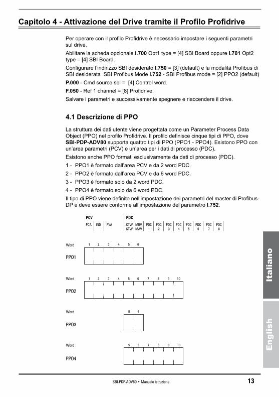
La struttura dei dati utente viene progettata come un Parameter Process Data Object (PPO) nel profilo Profidrive. Il profilo definisce cinque tipi di PPO, dove SBI-PDP-ADV80 supporta quattro tipi di PPO (PPO1 - PPO4). Esistono PPO con un’area parametri (PCV) e un’area per i dati di processo (PDC). Esistono anche PPO formati esclusivamente da dati di processo (PDC). 1 - PPO1 è formato dall’area PCV e da 2 word PDC.2 - PPO2 è formato dall’area PCV e da 6 word PDC.3 - PPO3 è formato solo da 2 word PDC.4 - PPO4 è formato solo da 6 word PDC.Il tipo di PPO viene definito nell’impostazione dei parametri del master di Profibus-DP e deve essere conforme all’impostazione del parametro I.752.
PCV PDC
PCA IND PVA CTW
STW
MRV
MAV
PDC
1
PDC
2
PDC
3
PDC
4
PDC
5
PDC
6
PDC
7
PDC
8
Word
Word
Word
Word
PPO1
PPO2
PPO3
PPO4
1 2 3 4 5 6
1 2 3 4 5 6 7 8 9 10
5 6 7 8 9 10
5 6
14 SBI-PDP-ADV80 • Manuale istruzione
Eng
lish
Italiano
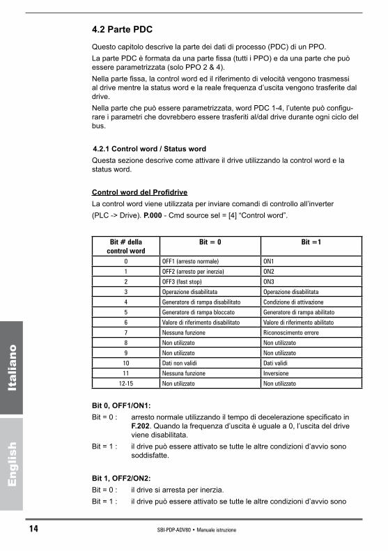
4.2 Parte PDC
Questo capitolo descrive la parte dei dati di processo (PDC) di un PPO.La parte PDC è formata da una parte fissa (tutti i PPO) e da una parte che può essere parametrizzata (solo PPO 2 & 4).Nella parte fissa, la control word ed il riferimento di velocità vengono trasmessi al drive mentre la status word e la reale frequenza d’uscita vengono trasferite dal drive. Nella parte che può essere parametrizzata, word PDC 1-4, l’utente può configu-rare i parametri che dovrebbero essere trasferiti al/dal drive durante ogni ciclo del bus.
4.2.1 Control word / Status wordQuesta sezione descrive come attivare il drive utilizzando la control word e la status word.
Control word del ProfidriveLa control word viene utilizzata per inviare comandi di controllo all’inverter (PLC -> Drive). P.000 - Cmd source sel = [4] “Control word”.
Bit#dellacontrolword
Bit=0 Bit=1
0 OFF1 (arresto normale) ON1
1 OFF2 (arresto per inerzia) ON2
2 OFF3 (fast stop) ON3
3 Operazione disabilitata Operazione disabilitata
4 Generatore di rampa disabilitato Condizione di attivazione
5 Generatore di rampa bloccato Generatore di rampa abilitato
6 Valore di riferimento disabilitato Valore di riferimento abilitato
7 Nessuna funzione Riconoscimento errore
8 Non utilizzato Non utilizzato
9 Non utilizzato Non utilizzato
10 Dati non validi Dati validi
11 Nessuna funzione Inversione
12-15 Non utilizzato Non utilizzato
Bit 0, OFF1/ON1:Bit = 0 : arresto normale utilizzando il tempo di decelerazione specificato in
F.202. Quando la frequenza d’uscita è uguale a 0, l’uscita del drive viene disabilitata.
Bit = 1 : il drive può essere attivato se tutte le altre condizioni d’avvio sono soddisfatte.
Bit 1, OFF2/ON2:Bit = 0 : il drive si arresta per inerzia.Bit = 1 : il drive può essere attivato se tutte le altre condizioni d’avvio sono
SBI-PDP-ADV80 • Manuale istruzione 15
Eng
lish
Italiano
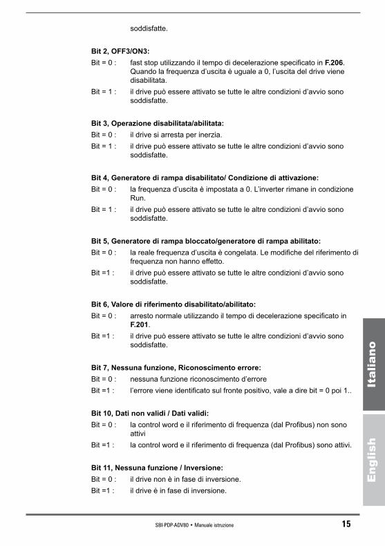
soddisfatte.
Bit 2, OFF3/ON3:Bit = 0 : fast stop utilizzando il tempo di decelerazione specificato in F.206.
Quando la frequenza d’uscita è uguale a 0, l’uscita del drive viene disabilitata.
Bit = 1 : il drive può essere attivato se tutte le altre condizioni d’avvio sono soddisfatte.
Bit 3, Operazione disabilitata/abilitata:Bit = 0 : il drive si arresta per inerzia.Bit = 1 : il drive può essere attivato se tutte le altre condizioni d’avvio sono
soddisfatte.
Bit 4, Generatore di rampa disabilitato/ Condizione di attivazione:Bit = 0 : la frequenza d’uscita è impostata a 0. L’inverter rimane in condizione
Run.Bit = 1 : il drive può essere attivato se tutte le altre condizioni d’avvio sono
soddisfatte.
Bit 5, Generatore di rampa bloccato/generatore di rampa abilitato:Bit = 0 : la reale frequenza d’uscita è congelata. Le modifiche del riferimento di
frequenza non hanno effetto. Bit =1 : il drive può essere attivato se tutte le altre condizioni d’avvio sono
soddisfatte.
Bit 6, Valore di riferimento disabilitato/abilitato:Bit = 0 : arresto normale utilizzando il tempo di decelerazione specificato in
F.201.Bit =1 : il drive può essere attivato se tutte le altre condizioni d’avvio sono
soddisfatte.
Bit 7, Nessuna funzione, Riconoscimento errore:Bit = 0 : nessuna funzione riconoscimento d’erroreBit =1 : l’errore viene identificato sul fronte positivo, vale a dire bit = 0 poi 1..
Bit 10, Dati non validi / Dati validi:Bit = 0 : la control word e il riferimento di frequenza (dal Profibus) non sono
attiviBit =1 : la control word e il riferimento di frequenza (dal Profibus) sono attivi.
Bit 11, Nessuna funzione / Inversione:Bit = 0 : il drive non è in fase di inversione.Bit =1 : il drive è in fase di inversione.
16 SBI-PDP-ADV80 • Manuale istruzione
Eng
lish
Italiano
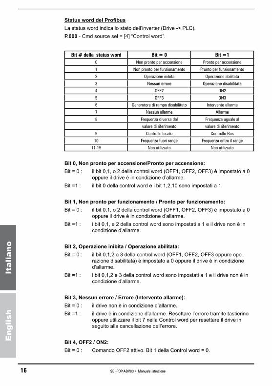
Status word del ProfibusLa status word indica lo stato dell’inverter (Drive -> PLC).P.000 - Cmd source sel = [4] “Control word”.
Bit#dellastatusword Bit=0 Bit=10 Non pronto per accensione Pronto per accensione
1 Non pronto per funzionamento Pronto per funzionamento
2 Operazione inibita Operazione abilitata
3 Nessun errore Operazione disabilitata
4 OFF2 ON2
5 OFF3 ON3
6 Generatore di rampa disabilitato Intervento allarme
7 Nessun allarme Allarme
8 Frequenza diversa dal Frequenza uguale al
valore di riferimento valore di riferimento
9 Controllo locale Controllo Bus
10 Frequenza fuori range Frequenza entro il range
11-15 Non utilizzato Non utilizzato
Bit 0, Non pronto per accensione/Pronto per accensione:Bit = 0 : il bit 0,1, o 2 della control word (OFF1, OFF2, OFF3) è impostato a 0
oppure il drive è in condizione d’allarme.Bit =1 : il bit 0 della control word e i bit 1,2,10 sono impostati a 1.
Bit 1, Non pronto per funzionamento / Pronto per funzionamento:Bit = 0 : il bit 0,1, o 2 della control word (OFF1, OFF2, OFF3) è impostato a 0
oppure il drive è in condizione d’allarme.Bit =1 : i bit 0,1, e 2 della control word sono impostati a 1 e il drive non è in
condizione d’allarme.
Bit 2, Operazione inibita / Operazione abilitata:Bit = 0 : il bit 0,1,2 o 3 della control word (OFF1, OFF2, OFF3 oppure ope-
razione disabilitata) è impostato a 0 oppure il drive è in condizione d’allarme.
Bit =1 : i bit 0,1,2 e 3 della control word sono impostati a 1 e il drive non è in condizione d’allarme.
Bit 3, Nessun errore / Errore (Intervento allarme):Bit = 0 : il drive non è in condizione d’allarme.Bit =1 : il drive è in condizione d’allarme. Resettare l’errore tramite tastierino
oppure utilizzare il bit 7 nella Control word per resettare il drive in seguito alla cancellazione dell’errore.
Bit 4, OFF2 / ON2:Bit = 0 : Comando OFF2 attivo. Bit 1 della Control word = 0.

SBI-PDP-ADV80 • Manuale istruzione 17
Eng
lish
Italiano
Bit =1 : Bit 1 della Control word = 1
Bit 5, OFF3 / ON3:Bit = 0 : Comando OFF3 attivo. Bit 2 della Control word = 0.Bit =1 : Bit 2 della Control word = 1.
Bit 6, Disabilitazione attivazione / Abilitazione attivazione:Bit = 0 : bit 0 e bit 10 della Control word = 1.Bit =1 : il bit 1 o 2 della Control word (OFF2, OFF3) è impostato a 0 oppure è
stato identificato un falso intervento d’allarme.
Bit 8, Frequenza diversa dal valore di riferimento / Frequenza uguale al valo-re di riferimento:
Bit = 0 : la reale frequenza d’uscita non è uguale al riferimento di frequenza (il motore sta accelerando/decelerando).
Bit =1 : la reale frequenza d’uscita è uguale al riferimento di frequenza.
Nota! L’ampiezza di tolleranza della frequenza viene configurata nel parametro P.460.
Bit 9, Controllo locale / Controllo Bus:Bit = 0 : Il comando Run e l’impostazione della Frequenza non sono validi
tramite Profibus.Bit =1 : Il comando Run o l’impostazione della Frequenza sono validi tramite
Profibus. P.000 - Cmd source sel = [4] “Control word” and F.050 - Ref 1 channel
= [8] “Profidrive”.
Bit 10, Frequenza fuori range / Frequenza entro il range:Bit = 0 : la reale frequenza d’uscita è inferiore al limite specificato nei parametri
P.440 e P.441.Bit =1 : la reale frequenza d’uscita è superiore o uguale al limite specificato
nei parametri P.440 e P.441.
Nota! La Status Word non è letta se il controllo è locale.
18 SBI-PDP-ADV80 • Manuale istruzione
Eng
lish
Italiano
Voltage
sw
itched-o
ff
Inhib
itopera
tion
active
Sw
itch-o
nin
hib
it
Not
ready
for
sw
itch-o
n
Enable
opera
tion
Bit
1=
1
Ram
pfu
ncti
on
genera
tor
Accel.
Enable
d
Ram
pfu
ncti
on
genera
tor
Enable
doutp
ut
Opera
tion
sta
te
Ready
Bit
2=
1
Bit
0=
1
Bit
6=
1
Ready
tosw
itch-o
n
OFF3
acti
ve
sta
ge
1
OFF1
acti
ve
sta
ge
2
Bit
1=
0O
pen
load
conta
cto
r
Norm
al
sto
p
Bit
2C
oast
sto
p
Open
load
conta
cto
r
Quic
ksto
pB
it5=
0C
oast
sto
pB
it4=
0
Sto
pdri
ve
Bit
3=
1
OFF3
acti
ve
sta
ge
2
OFF2
acti
ve
Fault
OFF1
acti
ve
sta
ge
1
Cont
rolw
ord
,bit
pat
tern
:X
XX
XX
IXX
XX
XX
XII
0
OFF
1(b
it0
=0)
ON
1(b
it0
=1)
RFG
out
put
dis
able
d(b
it4
=0)
Ena
ble
opera
tion
(bit
3=
1)
Ena
ble
setp
oin
t(b
it6
=1)
RFG
acce
lera
tion
ena
ble
d(b
it5
=1)
Voltag
eO
N
Dri
vest
opped
AB
CD
Inhi
bit
opera
tion
(bit
3=
0)
BC
D
RFG
out
put
ena
ble
d(b
it4
=1)
CD
D
Sto
pR
FG(b
it5
=0)
Inhi
bit
setp
oin
t(b
it6
=0)
Fro
me
ve
ryst
ate
Dri
vest
opped
OFF
1(b
it0
=0)
Load
cont
acto
ropen
Fro
me
ve
ryst
ate
Fro
me
ve
ryst
ate
Load
cont
acto
ropen
Load
cont
acto
ropen
Dri
vest
opped
OFF
3(b
it2
=0)
OFF
2(b
it1
=0)
Faul
tac
know
ledge
(bit
7:
0to
1)
A B C
D
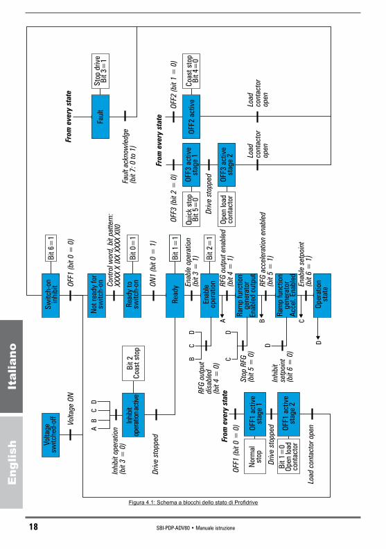
Figura 4.1: Schema a blocchi dello stato di Profidrive
SBI-PDP-ADV80 • Manuale istruzione 19
Eng
lish
Italiano
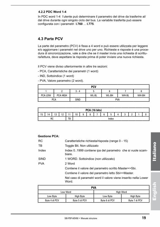
4.2.2 PDC Word 1-4In PDC word 1-4 l’utente può determinare il parametro del drive da trasferire al/dal drive durante ogni singolo ciclo del bus. La variabile trasferita può essere configurata con i parametri I.760 ... I.775.
4.3 Parte PCV
La parte del parametro (PCV) è fissa a 4 word e può essere utilizzata per leggere e/o aggiornare i parametri nel drive uno per uno. Richieste e risposte è una proce-dura di sincronizzazione, vale a dire che se il master invia una richiesta di scrittu-ra/lettura, deve aspettare la risposta prima di poter inviare una nuova richiesta.
Il PCV viene diviso ulteriormente in altre tre sezioni:- PCA, Caratteristiche dei parametri (1 word)- IND, Sottoindice (1 word)- PVA, Valore parametro (2 word).
PCV1 2 3 - 4 5 6 7 8
PCA LOW PCA HIGH WL-BL WL-BH WH-BL WH-BH
PCA SIND PVA
PCA(16bits)15 14 13 12 11 10 9 8 7 6 5 4 3 2 1 0
RC TB Index
Gestione PCA: RC Caratteristiche richiesta/risposta (range 0 - 15)TB Toggle Bit. Non utilizzatoIndex Index 0..1999 contiene ipa del parametro che si vuole scam-
biare.SIND 1 WORD. Sottoindice (non utilizzato)PVA 2 Word Contiene il valore del parametro scritto Master=>Sbi. Contiene il valore del parametro letto Sbi=>Master. Nel caso di parametri word il valore viene inserito nella Lower
Word.
PVALow Word High Word
Low Byte High Byte Low Byte High Byte
Byte 4 di PCV Byte 5 di PCV Byte 6 di PCV Byte 7 di PCV
20 SBI-PDP-ADV80 • Manuale istruzione
Eng
lish
Italiano
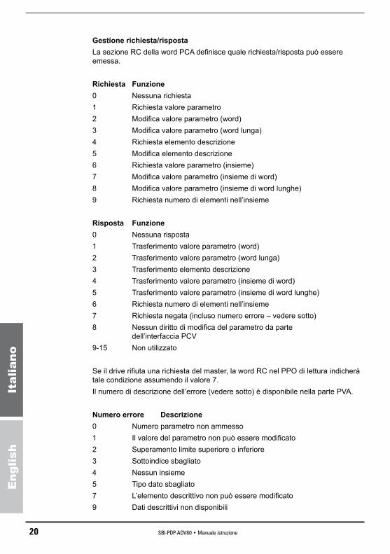
Gestione richiesta/rispostaLa sezione RC della word PCA definisce quale richiesta/risposta può essere emessa.
Richiesta Funzione0 Nessuna richiesta1 Richiesta valore parametro2 Modifica valore parametro (word)3 Modifica valore parametro (word lunga)4 Richiesta elemento descrizione5 Modifica elemento descrizione6 Richiesta valore parametro (insieme)7 Modifica valore parametro (insieme di word)8 Modifica valore parametro (insieme di word lunghe)9 Richiesta numero di elementi nell’insieme
Risposta Funzione0 Nessuna risposta1 Trasferimento valore parametro (word)2 Trasferimento valore parametro (word lunga)3 Trasferimento elemento descrizione4 Trasferimento valore parametro (insieme di word)5 Trasferimento valore parametro (insieme di word lunghe)6 Richiesta numero di elementi nell’insieme7 Richiesta negata (incluso numero errore – vedere sotto)8 Nessun diritto di modifica del parametro da parte
dell’interfaccia PCV9-15 Non utilizzato
Se il drive rifiuta una richiesta del master, la word RC nel PPO di lettura indicherà tale condizione assumendo il valore 7. Il numero di descrizione dell’errore (vedere sotto) è disponibile nella parte PVA.
Numero errore Descrizione0 Numero parametro non ammesso1 Il valore del parametro non può essere modificato2 Superamento limite superiore o inferiore3 Sottoindice sbagliato4 Nessun insieme5 Tipo dato sbagliato7 L’elemento descrittivo non può essere modificato9 Dati descrittivi non disponibili
SBI-PDP-ADV80 • Manuale istruzione 21
Eng
lish
Italiano
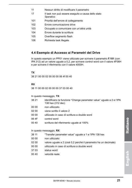
11 Nessun diritto di modificare il parametro17 Il task non può essere eseguito a causa dello stato
0perativo101 Priorità dell’errore di collegamento102 Errore comunicazione drive103 Occupato a comunicare con un’altra unità104 Errore durante la scrittura105 Overflow segmento flash106 Richiesta task illegale
4.4 Esempio di Accesso ai Parametri del Drive
In questo esempio un PP01 viene utilizzato per scrivere il parametro F.101 (con IPA 312) ad un valore uguale a 0,2, per scrivere control word con il valore 4F06H e per scrivere il riferimento con il valore 4000H.
TX38 21 00 00 02 00 00 00 06 4f 00 40
RX38 11 00 00 02 00 00 00 37 03 00 40
In questo messaggio, TX:38 21 identificano la funzione “Change parameter value” uguale a 2 e l’IPA
138 hex (312 dec)00 00 non utilizzato02 00 viene scritto il valore 200 00 utilizzato in caso di scrittura a double word06 4F control word00 40 scrittura del riferimento uguale al 100%
In questo messaggio, RX:38 11 “Transfer parameter value” uguale a 1 e l’IPA 138 hex00 00 non utilizzato02 00 valore uguale a 2 (cioè 0,2 perché il parametro ha un decimale)00 00 utilizzato in caso di scrittura a double word37 03 status word 00 40 velocità reale

22 SBI-PDP-ADV80 • Manuale istruzione
Eng
lish
Italiano
Capitolo 5 - Allarmi Profibus-DP
Gli allarmi indicati al drive dalla scheda SBI sono i seguenti:
1 - Bus loss: questo allarme si attiva in caso di interruzione accidentale della connessione.
2 - SBI Hardware Fault: questo allarme si attiva se la scheda SBI è difettosa.
La gestione degli allarmi da parte del drive dipende dal drive stesso e dalla confi-gurazione degli allarmi.Se il Master viene spento prima dello Slave, si verifica l’allarme Bus-Loss; il drive gestisce la situazione non memorizzando l’allarme al fine di evitare che alla riac-censione del drive l’allarme venga di nuovo segnalato. La comunicazione tra il Master e lo Slave può avvenire solo se sono state termi-nate con successo l’inizializzazione del drive e della scheda SBI; in caso contrario non è possibile determinare la causa dell’errata inizializzazione utilizzando il Bus.

SBI-PDP-ADV80 • Manuale istruzione 23
Eng
lish
Italiano
Capitolo 6 - Controllo Virtuale
Tramite una ”impostazione virtuale” grazie ad una linea seriale o un bus di campo è possibile utilizzare tutte le funzioni disponibili sugli ingressi digitali ed eseguire un controllo diretto delle uscite digitali e analogiche.
6.1 Controllo Ingresso / Uscita Digitale Virtuale
L’impostazione può essere eseguita in quelle configurazioni dove i comandi digitali sono un insieme di “virtuale” e morsetti e le uscite sono un insieme di “virtuale” e funzioni drive.
La selezione tra i morsetti e gli ingressi digitali virtuali è determinata dal codice binario scritto nei parametri maschera I.400, I.410. L’ingresso digitale virtuale è ottenuto scrivendo gli ingressi digitali virtuali H.000, H.001
Le uscite digitali nei morsetti della scheda vengono normalmente controllate dal drive in base alle funzioni programmate dai parametri da I.000 a I.152. In ogni caso è possibile controllare qualsiasi uscita digitale sulla scheda direttamente tra-mite linea seriale o bus di campo scrivendo le uscite digitali virtuali H.010, H.011. Il possibile utilizzo delle impostazioni virtuali è determinato dai parametri masche-ra I.420, I.430.
I parametri maschera devono essere gestiti in base ai bit. Ad ogni bit corrisponde uno switch in base alla logica seguente.
Maschera Bit i Sorgente DI i Sorgente DO i0 Morsetto Funzione Drive1 Virtuale Controllo virtuale
Fare anche riferimento al paragrafo 7.4, Menu I Interface, sezione “Abilitazione I/O virtuali” del manuale d’istruzioni del drive.
Per ulteriori informazioni riguardo la configurazione degli I/O digitali virtuali, fare riferimento al paragrafo 7.9 HIDDEN, sezione “Comandi I/O virtuali” del manuale d’istruzioni del drive:- per gli ingressi digitali virtuali, scrivendo i parametri H.000 e H.001,- per le uscite digitali virtuali, scrivendo i parametri H.010, H.011,
6.2 Controllo Uscita Analogica Virtuale
Le uscite analogiche nei morsetti della scheda vengono normalmente controllate dal drive in base alle funzioni programmate dai parametri I.300, I.310, I.350. In ogni caso è possibile controllare quella della uscita analogica sulla scheda diretta-mente tramite linea seriale o bus di campo scrivendo le uscite analogiche virtuali H.020, H.021, H.022.

24 SBI-PDP-ADV80 • Manuale istruzione
Eng
lish
Italiano
Il possibile utilizzo delle impostazioni virtuali è determinato dal parametro masche-ra I.450.I parametri maschera devono essere gestiti in base ai bit. Ad ogni bit corrisponde uno switch in base alla logica seguente.
Maschera Bit i Sorgente An Out0 Funzione Drive1 Controllo virtuale
Fare anche riferimento al paragrafo 7.4, Menu I Interface, sezione “Abilitazione I/O virtuali” del manuale d’istruzioni del drive.
Per ulteriori informazioni riguardo la configurazione degli I/O digitali virtuali, fare riferimento al paragrafo 7.9 HIDDEN, sezione “Comandi I/O virtuali” del manuale d’istruzioni del drive:- per le uscite analogiche, scrivendo i parametri H.020, H.021, H.022.
SBI-PDP-ADV80 • Manuale istruzione 25
Eng
lish
Italiano
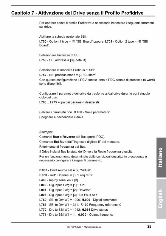
Capitolo 7 - Attivazione del Drive senza il Profilo Profidrive
Per operare senza il profilo Profidrive è necessario impostare i seguenti parametri sul drive.
Abilitare la scheda opzionale SBI:I.700 - Option 1 type = [4] “SBI Board” oppure I.701 - Option 2 type = [4] “SBI Board”.
Selezionare l’indirizzo di SBI:I.750 - SBI address = [3] (default)
Selezionare la modalità Profibus di SBI:I.752 - SBI profibus mode = [0] “Custom”Con questa configurazione il PCV canale lento e PDC canale di processo (6 word) sono disponibili.
Configurare il parametro del drive da trasferire al/dal drive durante ogni singolo ciclo del bus:I.760 .. I.775 = ipa dei parametri desiderati.
Salvare i parametri con C.000 - Save parameters:Spegnere e riaccendere il drive.
Esempio:Comandi Run e Reverse dal Bus (parte PDC).Comando Ext fault dall’”Ingresso digitale 5” del morsetto.Riferimento di frequenza dal Bus.Il Drive invia al Bus lo stato del Drive e la Reale frequenza d’uscita.Per un funzionamento determinato dalle condizioni descritte in precedenza è necessario configurare i seguenti parametri::
P.000 - Cmd source sel = [2] “Virtual”F.050 - Ref1 Channel = [3] “Freq ref x”I.400 - Inp by serial en = [3]I.000 - Dig input 1 cfg = [1] “Run”I.001 - Dig input 2 cfg = [2] “Reverse”I.005 - Dig input 5 cfg = [3] “Ext Fault NO”I.760 - SBI to Drv W0 = 1000, H.000 - Digital commandI.761 - SBI to Drv W1 = 311, F.100 Frequency reference 0I.770 - Drv to SBI W0 = 1042, H.034 Drive statusI.771 - Drv to SBI W1 = 1, d.000 - Output frequency

26 SBI-PDP-ADV80 • Manuale istruzione
Eng
lish
Italiano
Scrivendo (PDC 2) F.100 = 50, il drive imposta il riferimento a 5,00 HzScrivendo (PDC 1) H.000 = 1, il motore ruota in senso orario a 5,00 HzScrivendo (PDC 1) H.000 = 3, il motore ruota in senso anti-orario a 5,00 HzScrivendo (PDC 1) H.000 = 0, il motore si ferma
Leggendo (PDC 1) H.034, viene ripristinato lo stato del drive. bit 0 = (1) Drive pronto -- (0) Drive non pronto bit 1 = (1) Allarme attivo -- (0) Allarme non attivo bit 2 = (1) Motore in funzione -- (0) Motore non in funzione bit 3 = (1) Stato stazionario -- (0) Stato non stazionario
Leggendo (PDC 2) d.000, viene ripristinata la reale frequenza d’uscita. 500 se il motore ruota in senso orario -500 se il motore ruota in senso anti-orario 0 se il drive si ferma
Attivando l’ingresso digitale 5 il drive assume una condizione d’allarme.
SBI-PDP-ADV80 • Manuale istruzione 27
Eng
lish
Italiano
Capitolo 8 - Interfaccia Tastiera
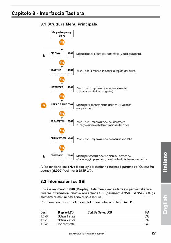
8.1 Struttura Menù Principale
DISPLAY d000
- - - - - - - - - - - - - -
Output frequency
0.0 Hz
STARTUP S000
- - - - - - - - - - - - - -
INTERFACE I000
- - - - - - - - - - - - - -
FREQ & RAMP F000
- - - - - - - - - - - - - -
PARAMETER P000
- - - - - - - - - - - - - -
APPLICATION A000
- - - - - - - - - - - - - -
COMMAND C000
- - - - - - - - - - - - - -
Prg
Prg
Prg
Prg
Prg
Prg
Prg
Menu di sola lettura dei parametri (visualizzazione).
Menu per l’impostazione ingressi/uscitedel drive (digitali/analogiche).
Menu per l’impostazione delle multi velocità,rampe etcc...
Menu per l’impostazione dei parametridi regolazione ed ottimizzazione del drive.
Menu per l’impostazione della funzione PID.
Menu per esecuzione funzioni su comando(Salvataggio parametri, Load default, Autotaratura, etc.).
Prg
Menu per la messa in servizio rapida del drive.
All’accensione del drive il display del tastierino mostra il parametro “Output fre-quency (d.000)” del menù DISPLAY.
8.2 Informazioni su SBI
Entrare nel menù d.000 (Display); tale menù viene utilizzato per visualizzare diverse informazioni relative alla scheda SBI (parametri d.350 ... d.354); tutti gli elementi relativi ai dati sono di sola lettura.Per muoversi tra i vari elementi del menù utilizzare i tasti ▲o ▼.
Cod. DisplayLCD [Cod.]&Selez.LCD IPAd.350 Option 1 state 038d.351 Option 2 state 039d.352 Par port state 040
28 SBI-PDP-ADV80 • Manuale istruzione
Eng
lish
Italiano
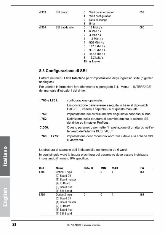
d.353 SBI State 0 Wait parametrization 059 1 Wait configuration 2 Data exchange 3 Error d.354 SBI Baude rate 0 12 Mbit / s 060 1 6 Mbit / s 2 3 Mbit / s 3 1.5 Mbit / s 4 500 Mbit / s 5 187.5 kbit / s 6 93.75 kbit / s 7 45.45 kbit / s 8 19.2 kbit / s 15 unknowk
8.3 Configurazione di SBI
Entrare nel menù I.000 Interface per l’impostazione degli ingressi/uscite (digitale/analogico).Per ulteriori informazioni fare riferimento al paragrafo 7.4, Menu I - INTERFACE del manuale d’istruzioni del drive.
I.700 e I.701: configurazione opzionale. L’impostazione deve essere eseguita in base al dip-switch
EXP-SEL, vedere il capitolo 2.5 di questo manuale.I.750: impostazione dei diversi indirizzi degli slave connessi al bus.I.752: Definizione della struttura di scambio dati tra la scheda SBI
del drive ed il master Profibus.C.000: Questo parametro permette l’impostazione di un ritardo nell’in-
tervento dell’allarme BUS FAULT.I.760 ... I.775: impostazione dello “scambio word” tra il drive e la scheda SBI
e viceversa.
La struttura di scambio dati è disponibile nel formato da 6 word.In ogni singola word la lettura o scrittura del parametro deve essere indirizzata impostando il numero IPA specifico.
Cod. Nome Default MIN MAX IPA I.700 Option 1 type 0 0 4 161 [0] Board Off [1] Board master [2] IO Board [3] Board free [4] SBI Board I.701 Option 2 type 0 0 4 162 [0] Board Off [1] Board master [2] IO Board [3] Board free [4] SBI Board

SBI-PDP-ADV80 • Manuale istruzione 29
Eng
lish
Italiano
I.750 SBI address 3 0 255 163 I.752 SBI Profibus mod 2 0 4 165 [0] Custom [1] PPO1 [2] PPO2 [3] PPO3 [4] PPO4 C.000 Bus Flt Holdoff 0.0 0.1 60 179 I.760 SBI to Drv W 0 0 0 1999 167 I.761 SBI to Drv W 1 0 0 1999 168 I.762 SBI to Drv W 2 0 0 1999 169 I.763 SBI to Drv W 3 0 0 1999 170 I.764 SBI to Drv W 4 0 0 1999 171 I.765 SBI to Drv W 5 0 0 1999 172 I.770 Drv to SBI W 0 1 0 1999 173 I.771 Drv to SBI W 1 2 0 1999 174 I.772 Drv to SBI W 2 3 0 1999 175 I.773 Drv to SBI W 3 4 0 1999 176 I.774 Drv to SBI W 4 5 0 1999 177 I.775 Drv to SBI W 5 6 0 1999 178
8.4 Gestione Allarmi
Alarm code blinking
Rev Fwd Limit AlarmPrg
Prg
Enter
Al Op
0U
Red LEDs blinking
Display a 7 segmentiIl tastierino del drive indica sul display a 7 segmenti un messaggio lampeggiante con il codice dell’allarme intervenuto.
Riconoscimento allarmeL’allarme attivo può essere riconosciuto premendo il tasto Prg sul tastierino. Que-sta operazione permette di navigare all’interno del menù e di editare il parametro mentre il drive è in condizione d’allarme (i LED rossi lampeggiano). Per far ripren-dere l’attività del drive è necessario utilizzare il comando di reset dell’Allarme.
Per ulteriori informazioni vedere il Capitolo 9, Ricerca Guasti, del manuale d’istru-zioni del drive.

30 SBI-PDP-ADV80 • Manuale istruzione
Eng
lish
Italiano
Capitolo 9 - Codici di Identificazione
9.1 Numero di Identificazione della Scheda
Il protocollo PROFIBUS-DP richiede un numero di identificazione per ogni tipo di dispositivo che può essere collegato al Bus. Il numero di identificazione assegnato alla scheda SBI dalla Profibus Nutzerorga-nisation è il seguente:
SBI-PDP-QX 07FD esadecimale corrispondente a 2045 decimale
Nota: GSD file SBI-PDP-QX= SBI-PDP-ADV80
9.2 Codici di Configurazione della Scheda
La scheda SBI non richiede i dati del parametro utente.I dati di configurazione consistono in 2 byte formati da:
Configurazione Byte1 Byte2Module=”Custom defined” 0xF3 0xF5
Module=”PPO Typ 1” 0xF3 0xF1
Module=”PPO Typ 2” 0xF3 0xF5
Module=”PPO Typ 3” 0xF1
Module=”PPO Typ 4” 0xF5
Per il significato di questi byte fare riferimento al paragrafo 8.3.5 del manuale “Draft Standard PROFIBUS -DP DIN 19245 Parte 3”.
9.3 File Gsd
Il file GSD adatto per la configurazione della rete Profibus-DP è disponibile per il download sul sito web www.gefran.com, sezione download di ADV80.

SBI-PDP-ADV80 • Manuale istruzione 31
Eng
lish
Italiano
Capitolo 10 - Altro
10.1 Glossario
Master Dispositivo PLC oppure PC per il controllo di Profibus-DP; può accedere al Bus.
Slave Moduli Azionamento o I/O che non possono accedere al Bus.Process Channel Canale per un trasferimento dati veloce, ciclico e ad alta prio-
rità di parametri configurati precedentemente.Configuration Channel Canale per un trasferimento dati aciclico e a bassa priorità
utilizzato, ad esempio, per la configurazione dell’azionamento.
10.2 Abbreviazioni
PDC Process Data Channel.DP Decentralized Peripherals.PDU Protocol Data UnitPPO Parameter process data objectPCV Canale parametri lento. Canale di configurazione.CTW Control Word Standard ProfidriveSTV Status Word Standard ProfidriveSP Set point del riferimento di frequenza standard ProfidriveAF Frequenza attuale standard Profidrive
10.3. Riferimenti
1 - Draft Standard PROFIBUS-DP DIN 19245 Parte 3. Pubblicazione del 1994 dalla Profibus Nutzeroganisation e. V.2 - Manuale istruzione inverter ADV80 - General-Purpose Inverter Serie
230/400/460V / 575V

32 SBI-PDP-ADV80 • Instruction manual
Eng
lish
Italiano
Chapter 1 - Introduction
This manual describes the SBI-PDP-ADV80 optional cards for connecting of inverters to Profibus-DP networks:This manual is intended for design engineeres and technicians responsible for the maintenance, commissioning and operation of Profibus-DP systems. A basic knowledge of Profibus-DP is assumed and may be found in the “Draft Standard DIN 19245 Part 3” manual.
1.1 About this manualChapter 2 Mechanical Card mounting and electrical connections.Chapter 3 Master - Slave transmission dataChapter 4 This section describes how to control drive via control word/status
word and how to access drive parameters.Chapter 5 Profibus-DP diagnostic handlingChapter 6 Assignment of the drive parameter to the virtual digital I/OChapter 7 This section describes how to operate without Profidrive Profile.Chapter 8 Keypad drive menuChapter 9 Identification number and codes for Bus connectionChapter 10 Miscellaneous: glossary, abbreviations and references
1.2 Overview of Profibus-DPProfibus-DP is a field Bus designed for a fast data exchange relating to sensors / actuators level; the communication is established between a Master central unit (PLC or PC) and Slave units, i.e. sensors, actuators, drives, etc.The data exchange is cyclic; the Master unit reads the Slaves input data and writes the Slaves output data. The Bus cycle time is shorter than the cycle time of the central unit; the Baud Rates for the SBI cards are from 9.6 kbit/s to 12 Mbit/s according to Profibus-DP standard part. 3.The total cycle time depends on the number of Slaves connected; the 1.5-Mbit/s Baud Rate allows 8 Gefran drives to be polled in 6 milliseconds.The physical support is the RS485 serial line; the max. number of Slaves con-nected to the Bus is 125.Example of Mono-Master Profibus-DP system.
MASTER
SLAVESLAVE SLAVE
Profibus-DP allows a Multi-Master system as well. For further information please refer to chapters 6 and 7 of the “Draft Standard DIN 19245 Part 3” manual.
SBI-PDP-ADV80 • Instruction manual 33
Eng
lish
Italiano
Chapter 2 - Hardware Description
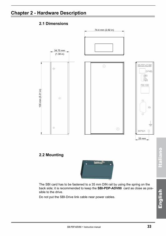
2.1 Dimensions
34.75 mm
13
5 m
m (
5.3
1 in
)
74.4 mm (2,92 in)
25 mm
(1.38 in)
2.2 Mounting
The SBI card has to be fastened to a 35 mm DIN rail by using the spring on the back side; it is recommended to keep the SBI-PDP-ADV80 card as close as pos-sible to the drive. Do not put the SBI-Drive link cable near power cables.
34 SBI-PDP-ADV80 • Instruction manual
Eng
lish
Italiano
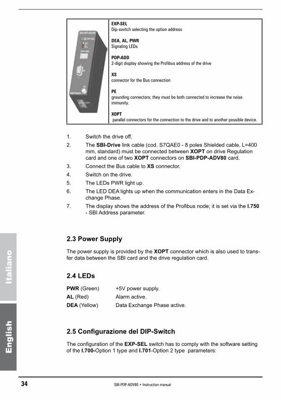
EXP-SELDip-switch selecting the option address
DEA,AL,PWRSignaling LEDs
PDP-ADD2-digit display showing the Profibus address of the drive
XSconnector for the Bus connection
PEgrounding connectors; they must be both connected to increase the noise immunity.
XOPT parallel connectors for the connection to the drive and to another possible device.
1. Switch the drive off.2. The SBI-Drive link cable (cod. S7QAE0 - 8 poles Shielded cable, L=400
mm, standard) must be connected between XOPT on drive Regulation card and one of two XOPT connectors on SBI-PDP-ADV80 card.
3. Connect the Bus cable to XS connector.4. Switch on the drive.5. The LEDs PWR light up.6. The LED DEA lights up when the communication enters in the Data Ex-
change Phase.7. The display shows the address of the Profibus node; it is set via the I.750
- SBI Address parameter.
2.3 Power Supply
The power supply is provided by the XOPT connector which is also used to trans-fer data between the SBI card and the drive regulation card.
2.4 LEDs
PWR (Green) +5V power supply.AL (Red) Alarm active.DEA (Yellow) Data Exchange Phase active.
2.5 Configurazione del DIP-Switch
The configuration of the EXP-SEL switch has to comply with the software setting of the I.700-Option 1 type and I.701-Option 2 type parameters:

SBI-PDP-ADV80 • Instruction manual 35
Eng
lish
Italiano
1 2
ON
ON
OFF
- if I.700 = [4] set EXP-SEL: 1=ON and 2=OFF..- if I.701 = [4] set EXP-SEL: 1=OFF and 2=ON
2.6 Technical Specification
Storage temperature:���������� -20°... +70°C (-68...+158°F).
Operating temperature: �������� 0°... +55°C (32...+131°F)
These temperatures are adequate to those of the drive, to which the cards are connected.
2.7 Interface
For the connection to the Bus please use a shielded twisted cable recommended by Profibus specification.The pinout of the Bus (XS) connectors are the following:
1
5
6
9
XS PIN REFERENCE MEANING1 Shield Shield / grounding
2 Not connected
3 RX / TX - B P datum reception/transmission
4 Not connected
5 0V - GND Datum transmission potential (grounding at 5V)
6 +5V Resistance power supply -Terminating P (P 5V)
7 Not connected
8 RX / TX - A P datum reception/transmission
9 Not connected The terminating resistances of the first and last network components must be active. Pins 5 (GND) and 6 (+5V) provide the connection of the terminating resist-ances.It is suggested to use resistance-supplied standard connectors.
390 ohm (±5%, min W)1/4
220 ohm (±5%, min W)1/4
390 ohm (±5%, min W)1/4
+5V (6)
B-B’ (3)
A-A’ (8)
GND (5)
36 SBI-PDP-ADV80 • Instruction manual
Eng
lish
Italiano
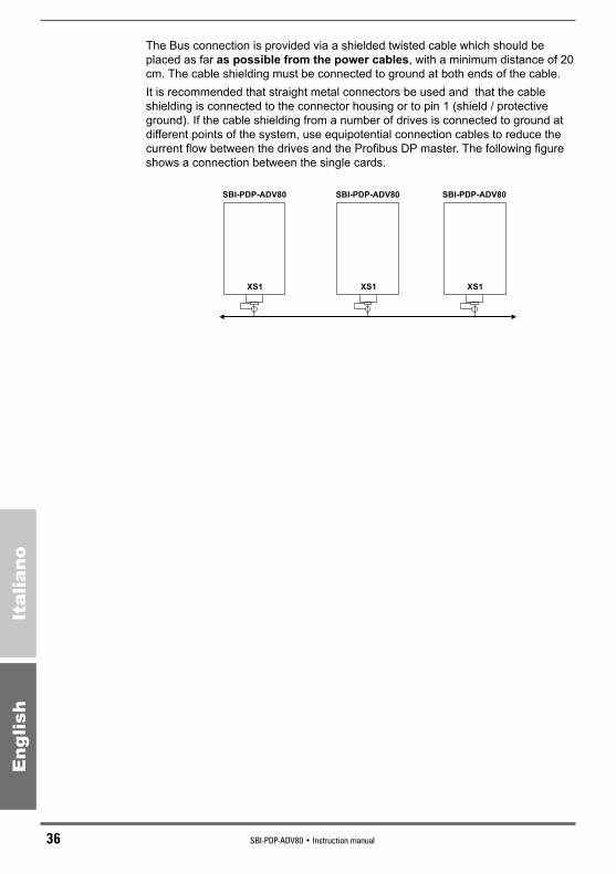
The Bus connection is provided via a shielded twisted cable which should be placed as far as possible from the power cables, with a minimum distance of 20 cm. The cable shielding must be connected to ground at both ends of the cable. It is recommended that straight metal connectors be used and that the cable shielding is connected to the connector housing or to pin 1 (shield / protective ground). If the cable shielding from a number of drives is connected to ground at different points of the system, use equipotential connection cables to reduce the current flow between the drives and the Profibus DP master. The following figure shows a connection between the single cards.
SBI-PDP-ADV80
XS1
SBI-PDP-ADV80
XS1
SBI-PDP-ADV80
XS1

SBI-PDP-ADV80 • Instruction manual 37
Eng
lish
Italiano
Chapter 3 - Bytes Assignment for Data Exchange
The first 8 bytes represent the configuration channel for the acyclic data ex-change, the other are the process data channel for the cyclic exchange.The communication between the Sbi card and the Profibus network Master respects the Profidrive standard. In the data area for the communication between the SBI and the drive the information are entered trying to follow the rules stated by the Profidrive standard. The functioning mode can be selected using the PPO type parameter. The PPO-1..4 modes are Profidrive standard; the first mode is a custom mode. The data are exchanged on two different channels:- PCV Configuration Channel- process channel, which is cyclically exchanged: CTW/STW SP/AF PDC-W0..
W5.
OffsetSubOffset
Custom PPO-1 PPO-2 PPO-3 PPO-4
1 1
PCV PCV PCV Nu Nu
2 2
3 3
4 4
5 5
6 6
7 7
8 8
9 1PDC-W0 CTW/STW CTW/STW CTW/STW CTW/STW
10 2
11 3PDC-W1 SP/AF SP/AF SP/AF SP/AF
12 4
13 5PDC-W2 Nu PDC-W0 Nu PDC-W0
14 6
15 7PDC-W3 Nu PDC-W1 Nu PDC-W1
16 8
17 9PDC-W4 Nu PDC-W2 Nu PDC-W2
18 10
19 11PDC-W5 Nu PDC-W3 Nu PDC-W3
20 12 Nu Not Used CTW Control word standard ProfidriveSTW Status word standard ProfidriveSP Set point frequency standard ProfidriveAF Actual Frequency standard ProfidrivePDC-W0..W5 With these words it is possible to cyclically read and write the
drive parameters. The exchanged information are configured via the drive parameters. The configuration parameters can be accessed via the slow channel, therefore the cyclically exchanged information can be modified through the network.

38 SBI-PDP-ADV80 • Instruction manual
Eng
lish
Italiano
PCV (Parameter Area Channel - Slow channel) The PCV area is formed by 7 bytes and is used to read and
write the drive parameters one by one.
PCV1 2 3 - 4 5 6 7 8
PCA LOW PCA HIGH WL-BL WL-BH WH-BL WH-BH
PCA SIND PVA
PCA 16 bits
PCA(16bits)15 14 13 12 11 10 9 8 7 6 5 4 3 2 1 0
RC TB Index RC Features of the request/response. It defines the request/re-
sponse to be performed
Request 0 No request1 Parameter reading 2 Parameter writing (word)3..15 Not Used
Response0 No response1 Parameter reading2 Parameter writing 3 Not Used4 Not Used5 Not Used6 Not Used7 Refused request8..15 Not Used
TB Toggle bit. Not used.Index Index 0..1999 contains the ipa of the parameter to be ex-
changed
The data read from Profibus-DP by the Slave are referred to as input data; the data written in Profibus-DP by the Slave are referred to as output data.The Slave parameters are cyclically read by the Master by assignign drive param-eters to the PDC output configuration parameters.The Master cyclically transmits drive parameters to the Slave by assigning drive parameters to the PDC input configuration parameters.The drive parameters assignment to the Process Data Channel Word is carried

SBI-PDP-ADV80 • Instruction manual 39
Eng
lish
Italiano
out by means of the index of the parameter itself (I.760 and following).Only drive parameters with a 16-Bit width (1 Word) may be assigned to the Proc-ess Data Channel.The I.760 ... I.775 parameters with an index equal to 0000 show that the word has not been assigned to any parameter of the drive.As for the configuration of the Process Data Channel (PDC) see the drive instruc-tion manual (paragraph 7.4, Menu I - INTERFACE, parameters I.760 and follow-ing).
Note! A number of different Words has to be configured according to the selected configuration; examples:
- if the mode is Custom, all the 6 Words can be defined; - if the mode is PPO2 or PPO4, only the first 4 Words have to be defined; - if the mode is PPO1 or PPO3, no Word has to be configured.
Frequency Setpoint / Actual FrequencyThe data format is “Standardized value”, where 0 hex = 0% and 4000 hex is 100% of Max. frequency specified in parameter F.020 .
Standardized value
A linear value.0%=0 (0h), 100% è ����������� 214 (4000h)
Range ��������������������� -200% ... 200% - 214
Resolution ������������������ 214 = 0.00061%
Length �������������������� 2 bytes
The use of Frequency Setpoint can be enabled by selecting the parameter F.050 “Ref 1 channel” = [8] Profidrive.
40 SBI-PDP-ADV80 • Instruction manual
Eng
lish
Italiano
Chapter 4 - Operating the Drive via Profidrive Profile
The following parameters have to be set on the drive to operate with Profidrive profile.Enable the Option card I.700 Opt1 type = [4] SBI Board or I.701 Opt2 type = [4] SBI Board.Configure the desidered SBI address I.750 = [3] (default), and the desidered SBI Profibus Mode I.752 - SBI Profibus mde = [2] PPO2 (default)P.000 - Cmd source sel = [4] Control word.F.050 - Ref 1 channel = [8] Profidrive.Save parameters and switch-off and switch-on the drive.
4.1 PPO Description
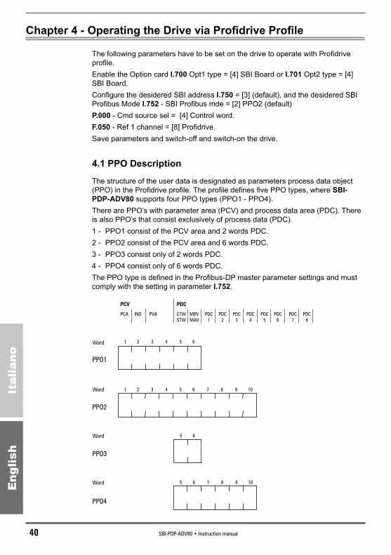
The structure of the user data is designated as parameters process data object (PPO) in the Profidrive profile. The profile defines five PPO types, where SBI-PDP-ADV80 supports four PPO types (PPO1 - PPO4).There are PPO’s with parameter area (PCV) and process data area (PDC). There is also PPO’s that consist exclusively of process data (PDC).1 - PPO1 consist of the PCV area and 2 words PDC.2 - PPO2 consist of the PCV area and 6 words PDC.3 - PPO3 consist only of 2 words PDC.4 - PPO4 consist only of 6 words PDC.The PPO type is defined in the Profibus-DP master parameter settings and must comply with the setting in parameter I.752.
PCV PDC
PCA IND PVA CTW
STW
MRV
MAV
PDC
1
PDC
2
PDC
3
PDC
4
PDC
5
PDC
6
PDC
7
PDC
8
Word
Word
Word
Word
PPO1
PPO2
PPO3
PPO4
1 2 3 4 5 6
1 2 3 4 5 6 7 8 9 10
5 6 7 8 9 10
5 6
SBI-PDP-ADV80 • Instruction manual 41
Eng
lish
Italiano
4.2 PDC-part
In this chapter the process data part (PDC) of a PPO is discussed.The PDC part consist of a fixed part (all PPO’s) and a parametrable part (only PPO 2 & 4).In the fixed part, control word and speed reference are transferred to the drive while status word and actual output frequency are transferred from the drive.In the parametrable part, PDC word 1-4, the user can configure what parameters that should be transferred to/from the drive every bus-cycle.
4.2.1 Control / Status wordThis section describes how to operate the drive with the control / status word.
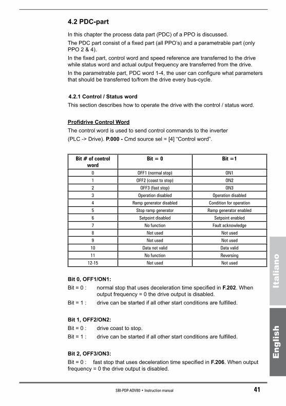
Profidrive Control WordThe control word is used to send control commands to the inverter (PLC -> Drive). P.000 - Cmd source sel = [4] “Control word”.
Bit#ofcontrolword
Bit=0 Bit=1
0 OFF1 (normal stop) ON1
1 OFF2 (coast to stop) ON2
2 OFF3 (fast stop) ON3
3 Operation disabled Operation disabled
4 Ramp generator disabled Condition for operation
5 Stop ramp generator Ramp generator enabled
6 Setpoint disabled Setpoint enabled
7 No function Fault acknowledge
8 Not used Not used
9 Not used Not used
10 Data not valid Data valid
11 No function Reversing
12-15 Not used Not used
Bit 0, OFF1/ON1:Bit = 0 : normal stop that uses deceleration time specified in F.202. When
output frequency = 0 the drive output is disabled.Bit = 1 : drive can be started if all other start conditions are fulfilled.
Bit 1, OFF2/ON2:Bit = 0 : drive coast to stop.Bit = 1 : drive can be started if all other start conditions are fulfilled.
Bit 2, OFF3/ON3:Bit = 0 : fast stop that uses deceleration time specified in F.206. When output frequency = 0 the drive output is disabled.
42 SBI-PDP-ADV80 • Instruction manual
Eng
lish
Italiano
Bit = 1 : drive can be started if all other start conditions are fulfilled.
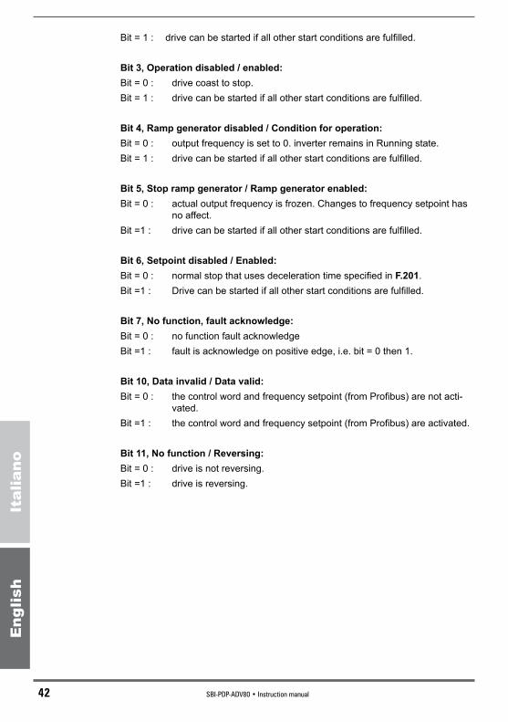
Bit 3, Operation disabled / enabled:Bit = 0 : drive coast to stop.Bit = 1 : drive can be started if all other start conditions are fulfilled.
Bit 4, Ramp generator disabled / Condition for operation:Bit = 0 : output frequency is set to 0. inverter remains in Running state.Bit = 1 : drive can be started if all other start conditions are fulfilled.
Bit 5, Stop ramp generator / Ramp generator enabled:Bit = 0 : actual output frequency is frozen. Changes to frequency setpoint has
no affect. Bit =1 : drive can be started if all other start conditions are fulfilled.
Bit 6, Setpoint disabled / Enabled:Bit = 0 : normal stop that uses deceleration time specified in F.201.Bit =1 : Drive can be started if all other start conditions are fulfilled.
Bit 7, No function, fault acknowledge:Bit = 0 : no function fault acknowledgeBit =1 : fault is acknowledge on positive edge, i.e. bit = 0 then 1.
Bit 10, Data invalid / Data valid:Bit = 0 : the control word and frequency setpoint (from Profibus) are not acti-
vated.Bit =1 : the control word and frequency setpoint (from Profibus) are activated.
Bit 11, No function / Reversing:Bit = 0 : drive is not reversing.Bit =1 : drive is reversing.

SBI-PDP-ADV80 • Instruction manual 43
Eng
lish
Italiano
Profibus Status WordThe status word indicates the status of the inverter (Drive -> PLC).P.000 - Cmd source sel = [4] “Control word”.
Bit#ofstatusword Bit=0 Bit=10 Not ready for switch-on Ready to switch-on
1 Not ready for operation Ready for operation
2 Operation inhibited Operation enabled
3 No fault Operation disabled
4 OFF2 ON2
5 OFF3 ON3
6 Ramp generator disabled Trip
7 No alarm Alarm
8 Frequency not equal to Frequency equal to
setpoint setpoint
9 Local control Bus control
10 Frequency out of range Frequency within range
11-15 Not used Not used
Bit 0, Not ready for switch-on / Ready to switch-on:Bit = 0 : control word bit 0,1 or 2 (OFF1, OFF2, OFF3) is set to 0, or the drive
has tripped.Bit =1 : control word bit 0 and bits 1,2,10 are set to 1.
Bit 1, Not ready for operation / Ready for operation:Bit = 0 : control word bit 0,1 or 2 (OFF1, OFF2, OFF3) is set to 0, or the drive
has tripped.Bit =1 : control word bit 0,1 and 2 are set to 1, and the drive has not tripped.
Bit 2, Operation inhibited / Operation enabled:Bit = 0 : control word bit 0,1,2 or 3 (OFF1, OFF2, OFF3 or operation disabled)
is set to 0, or the drive has tripped.Bit =1 : control word bit 0,1,2 and 3 are set to 1, and the drive has not tripped.
Bit 3, No fault / Fault (Trip):Bit = 0 : drive has not tripped.Bit =1 : drive is tripped. Fault reset from keypad or bit 7 in Control Word is
needed to reset the drive after the fault is cleared.
Bit 4, OFF2 / ON2:Bit = 0 : OFF2 command active. Control word bit 1 = 0.Bit =1 : control word bit 1 = 1.

44 SBI-PDP-ADV80 • Instruction manual
Eng
lish
Italiano
Bit 5, OFF3 / ON3:Bit = 0 : OFF3 command active. Control word bit 2 = 0.Bit =1 : control word bit 2 = 1.
Bit 6, Start disable / Start enable:Bit = 0 : control word bit 0 and bit 10 = 1.Bit =1 : control word bit 1 or 2 (OFF2, OFF3) is set to 0 or fault trip has been
acknowledged.
Bit 8, Frequency not equal to setpoint / Frequency equal to setpoint:Bit = 0 : actual output frequency does not equal frequency setpoint (i.e. motor
is accelerating / decelerating).Bit =1 : actual output frequency does equal frequency setpoint.
Note! The frequency tolerance width is configured in parameter P.460.
Bit 9, Local control / Bus control:Bit = 0 : Run command and Frequency setting are invalid via Profibus.Bit =1 : Run command or Frequency setting are valid via Profibus. P.000 - Cmd source sel = [4] “Control word” and F.050 - Ref 1 channel
= [8] “Profidrive”.
Bit 10, Frequency out of range / Frequency within range:Bit = 0 : actual output frequency is lower than the limit specified in parameters
P.440 and P.441.Bit =1 : actual output frequency is above or equal to the limit specified in
parameters P.440 and P.441.
Note! The status Word is not read if the control is local.

SBI-PDP-ADV80 • Instruction manual 45
Eng
lish
Italiano
Voltage
sw
itched-o
ff
Inhib
itopera
tion
active
Sw
itch-o
nin
hib
it
Not
ready
for
sw
itch-o
n
Enable
opera
tion
Bit
1=
1
Ram
pfu
ncti
on
genera
tor
Accel.
Enable
d
Ram
pfu
ncti
on
genera
tor
Enable
doutp
ut
Opera
tion
sta
te
Ready
Bit
2=
1
Bit
0=
1
Bit
6=
1
Ready
tosw
itch-o
n
OFF3
acti
ve
sta
ge
1
OFF1
acti
ve
sta
ge
2
Bit
1=
0O
pen
load
conta
cto
r
Norm
al
sto
p
Bit
2C
oast
sto
p
Open
load
conta
cto
r
Quic
ksto
pB
it5=
0C
oast
sto
pB
it4=
0
Sto
pdri
ve
Bit
3=
1
OFF3
acti
ve
sta
ge
2
OFF2
acti
ve
Fault
OFF1
acti
ve
sta
ge
1
Cont
rolw
ord
,bit
pat
tern
:X
XX
XX
IXX
XX
XX
XII
0
OFF
1(b
it0
=0)
ON
1(b
it0
=1)
RFG
out
put
dis
able
d(b
it4
=0)
Ena
ble
opera
tion
(bit
3=
1)
Ena
ble
setp
oin
t(b
it6
=1)
RFG
acce
lera
tion
ena
ble
d(b
it5
=1)
Voltag
eO
N
Dri
vest
opped
AB
CD
Inhi
bit
opera
tion
(bit
3=
0)
BC
D
RFG
out
put
ena
ble
d(b
it4
=1)
CD
D
Sto
pR
FG(b
it5
=0)
Inhi
bit
setp
oin
t(b
it6
=0)
Fro
me
ve
ryst
ate
Dri
vest
opped
OFF
1(b
it0
=0)
Load
cont
acto
ropen
Fro
me
ve
ryst
ate
Fro
me
ve
ryst
ate
Load
cont
acto
ropen
Load
cont
acto
ropen
Dri
vest
opped
OFF
3(b
it2
=0)
OFF
2(b
it1
=0)
Faul
tac
know
ledge
(bit
7:
0to
1)
A B C
D
Figure 4.1: Profidrive state block diagram

46 SBI-PDP-ADV80 • Instruction manual
Eng
lish
Italiano
4.2.2 PDC Word 1-4In PDC word 1-4 the user can determine which drive parameter that should be transferred to / from the drive every bus cycle. The transferred variable can be configured with the parameters I.760 ... I.775.
4.3 PCV Part
The parameter part (PCV) is fixed to 4 words and can be used for reading and/or updating the parameters in the drive one by one. Requests and responses is a handshake procedure and cannot be barched, meaning that if the master sends out a read/write request, it has to wait for the response, before it sends a new request.
The PCV is further divided into three parts:- PCA, Parameter Characterics (1 word)- IND, Subindex (1 word)- PVA, Parameter value (2 words).
PCV1 2 3 - 4 5 6 7 8
PCA LOW PCA HIGH WL-BL WL-BH WH-BL WH-BH
PCA SIND PVA
PCA(16bits)15 14 13 12 11 10 9 8 7 6 5 4 3 2 1 0
RC TB Index
PCA handling: RC Request / response characteristics (range 0 - 15)TB Toggle Bit. Not usedIndex Index 0..1999 contains the ipa of the parameter to be ex-
changed.SIND 1 WORD. Subindex (not used)PVA 2 Word It contains the value of the Master=>Sbi written parameter. It contains the value of the Sbi=>Master read parameter. In case of word parameters, the value is entered in the Lower
Word.
PVALow Word High Word
Low Byte High Byte Low Byte High Byte
Byte 4 di PCV Byte 5 di PCV Byte 6 di PCV Byte 7 di PCV
SBI-PDP-ADV80 • Instruction manual 47
Eng
lish
Italiano
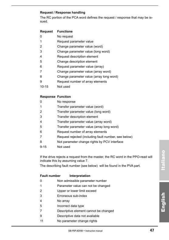
Request / Response handlingThe RC portion of the PCA word defines the request / response that may be is-sued.
Request Functione0 No request1 Request parameter value2 Change parameter value (word)3 Change parameter value (long word)4 Request description element5 Change description element6 Request parameter value (array)7 Change parameter value (array word)8 Change parameter value (array long word)9 Request number of array elements10-15 Not used
Response Function0 No response1 Transfer parameter value (word)2 Transfer parameter value (long word)3 Transfer description element4 Transfer parameter value (array word)5 Transfer parameter value (array long word)6 Request number of array elements7 Request rejected (including fault number, see below)8 Not parameter change rights by PCV interface9-15 Not used
If the drive rejects a request from the master, the RC word in the PPO-read will indicate this by assuming value 7. The describing fault number (see below) will be found in the PVA part.
Fault number Interpretation0 Non admissible parameter number1 Parameter value can not be changed2 Upper or lower limit exceed3 Erroneous sub-index4 No array5 Incorrect data type7 Descriptive element cannot be changed9 Descriptive data not available11 No parameter change rights

48 SBI-PDP-ADV80 • Instruction manual
Eng
lish
Italiano
17 Task can not be executed due to operating status101 Priority of link error102 Drive communication error103 Busy communicating with another unti104 Error during writing105 Flash segment overflow106 Illegal task requested
4.4 Example of Drive Parameter Access
In this example a PP01 is used to write the F.101 parameter (with IPA 312) with a value equal to 0.2, to write control word with a value equal to 4F06H and to write reference with a value equal 4000H.
TX38 21 00 00 02 00 00 00 06 4f 00 40
RX38 11 00 00 02 00 00 00 37 03 00 40
In this message TX:38 21 identify the “Change parameter value” function equal to 2 and the IPA
138 hex (312 dec)00 00 not used02 00 the value 2 is written00 00 it is used in case of double word writing06 4F control word00 40 reference writing equal to 10
In this message RX:38 11 “Transfer parameter value” equal to 1 and IPA 138 hex00 00 not used02 00 value equal to 2 (i.e. 0.2 because the parameter has a decimal)00 00 it is used in case of double word writing37 03 word status 00 40 actual speed
SBI-PDP-ADV80 • Instruction manual 49
Eng
lish
Italiano
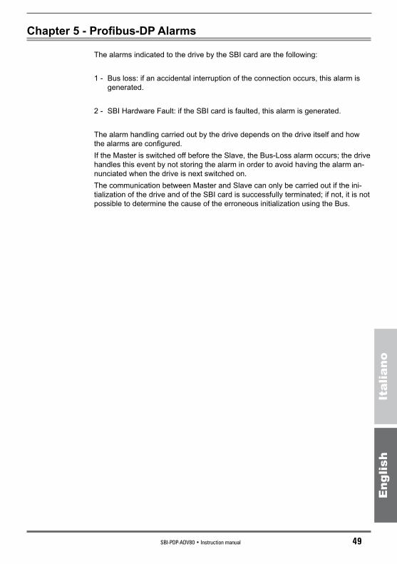
Chapter 5 - Profibus-DP Alarms
The alarms indicated to the drive by the SBI card are the following:
1 - Bus loss: if an accidental interruption of the connection occurs, this alarm is generated.
2 - SBI Hardware Fault: if the SBI card is faulted, this alarm is generated.
The alarm handling carried out by the drive depends on the drive itself and how the alarms are configured.If the Master is switched off before the Slave, the Bus-Loss alarm occurs; the drive handles this event by not storing the alarm in order to avoid having the alarm an-nunciated when the drive is next switched on.The communication between Master and Slave can only be carried out if the ini-tialization of the drive and of the SBI card is successfully terminated; if not, it is not possible to determine the cause of the erroneous initialization using the Bus.

50 SBI-PDP-ADV80 • Instruction manual
Eng
lish
Italiano
Chapter 6 - Virtual Control
Through a “virtual setting” via serial line or fieldbus, it is possible to use all the functions available on the digital inputs and perform a direct control of the digital and analog outputs.
6.1 Virtual Digital Input/Output Control
Through a “virtual setting” via serial line or fieldbus, it is possible to use all the functions available on the digital inputs and perform a direct control of the digital and analog outputs.The setting can be carried out in such configurations, where the digital commands are a mix of “virtual” and terminals and the outputs are a mix of “virtual” and drive function.The selection between terminals and virtual digital inputs is determined by the binary code written in the mask parameters I.400, I.410. The virtual digital input is done by writing the virtual digital inputs H.000, H.001.Digital outputs at the terminals of the board are normally driven by the drive, ac-cording to the functions programmed by the parameters I.000 to I.152. However, it is possible to drive any of the digital outputs on the board directly from serial line or fieldbus, by writing the virtual digital outputs H.010, H.011. Whether to use the virtual settings is determined by mask parameters I.420, I.430.
Mask parameters have to be managed bitwise. At each bit corresponds a switch, according to the following logic.
Mask Bit i DI i source DO i source0 Terminal Drive function1 Virtual Virtual control
See also paragraph 7.4, Menu I Interface, “Enabling Virtual I/O” section of the drive instruction manual.
For more info on virtual digital I/O configuration, please refer to the paragraph 7.9 HIDDEN, “Virtual I/O Commands” section of the drive instruction manual:- for virtual digital inputs, writing the H.000 and H.001 parameters,- for virtual digital outputs, writing the H.010, H.011 parameters,
6.2 Virtual Analog Output Control
Analog output at the terminals of the board are normally driven by the drive, according to the function programmed by the parameters I.300, I.310, I.350. How-ever it is possible to drive the one of the analog output on the board directly from serial line or fieldbus, by writing the virtual analog output H.020, H.021, H.022. Whether to use the virtal settings is determined by mask parameter I.450.
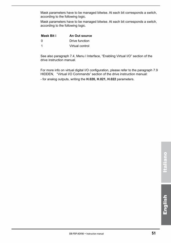
SBI-PDP-ADV80 • Instruction manual 51
Eng
lish
Italiano
Mask parameters have to be managed bitwise. At each bit corresponds a switch, according to the following logic.Mask parameters have to be managed bitwise. At each bit corresponds a switch, according to the following logic.
Mask Bit i An Out source0 Drive function1 Virtual control
See also paragraph 7.4, Menu I Interface, “Enabling Virtual I/O” section of the drive instruction manual.
For more info on virtual digital I/O configuration, please refer to the paragraph 7.9 HIDDEN, “Virtual I/O Commands” section of the drive instruction manual:- for analog outputs, writing the H.020, H.021, H.022 parameters.
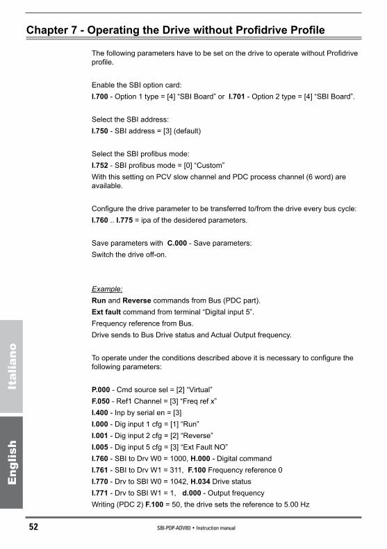
52 SBI-PDP-ADV80 • Instruction manual
Eng
lish
Italiano
Chapter 7 - Operating the Drive without Profidrive Profile
The following parameters have to be set on the drive to operate without Profidrive profile.
Enable the SBI option card:I.700 - Option 1 type = [4] “SBI Board” or I.701 - Option 2 type = [4] “SBI Board”.
Select the SBI address:I.750 - SBI address = [3] (default)
Select the SBI profibus mode:I.752 - SBI profibus mode = [0] “Custom”With this setting on PCV slow channel and PDC process channel (6 word) are available.
Configure the drive parameter to be transferred to/from the drive every bus cycle:I.760 .. I.775 = ipa of the desidered parameters.
Save parameters with C.000 - Save parameters:Switch the drive off-on.
Example:Run and Reverse commands from Bus (PDC part).Ext fault command from terminal “Digital input 5”.Frequency reference from Bus.Drive sends to Bus Drive status and Actual Output frequency.
To operate under the conditions described above it is necessary to configure the following parameters:
P.000 - Cmd source sel = [2] “Virtual”F.050 - Ref1 Channel = [3] “Freq ref x”I.400 - Inp by serial en = [3]I.000 - Dig input 1 cfg = [1] “Run”I.001 - Dig input 2 cfg = [2] “Reverse”I.005 - Dig input 5 cfg = [3] “Ext Fault NO”I.760 - SBI to Drv W0 = 1000, H.000 - Digital commandI.761 - SBI to Drv W1 = 311, F.100 Frequency reference 0I.770 - Drv to SBI W0 = 1042, H.034 Drive statusI.771 - Drv to SBI W1 = 1, d.000 - Output frequencyWriting (PDC 2) F.100 = 50, the drive sets the reference to 5.00 Hz
SBI-PDP-ADV80 • Instruction manual 53
Eng
lish
Italiano
Writing (PDC 1) H.000 = 1, the motor Runs in forward direction at 5.00 HzWriting (PDC 1) H.000 = 3, the motor Runs in reverse direction at 5.00 HzWriting (PDC 1) H.000 = 0, the motor Stops
Reading (PDC 1) H.034, the drive status is returned. bit 0 = (1) Drive ready -- (0) Drive not ready bit 1 = (1) Alarm active -- (0) Alarm not active bit 2 = (1) Motor running -- (0) Motor not running bit 3 = (1) Steady state -- (0) Not Steady state
Reading (PDC 2) d.000, the actual output frequency is returned. 500 if the motor Runs in forward direction -500 if the motor Runs in reverse direction 0 if the motor Stops
Activating the digital input 5 the drive goes in alarm condition.

54 SBI-PDP-ADV80 • Instruction manual
Eng
lish
Italiano
Chapter 8 - Keyboard Interface
8.1 Main Menu Structure
DISPLAY d000
- - - - - - - - - - - - - -
Output frequency
0.0 Hz
STARTUP S000
- - - - - - - - - - - - - -
INTERFACE I000
- - - - - - - - - - - - - -
FREQ & RAMP F000
- - - - - - - - - - - - - -
PARAMETER P000
- - - - - - - - - - - - - -
APPLICATION A000
- - - - - - - - - - - - - -
COMMAND C000
- - - - - - - - - - - - - -
Prg
Prg
Prg
Prg
Prg
Prg
Prg
Menu of read-only parameters (display)
Menu of basic drive start up parameters
Menu of input/output drive settings (digital/analog)
Menu of multi frequencies and ramps settings
Menu of read/write drive parameters
Menu of PID function settings
Menu of control-type parameters (Save, Load default, etc.)
Prg
At the drive power up the keypad display will show d.000 “Output frequency” parameter of DISPLAY menu.
8.2 SBI Info
Enter the d.000 Display menu, it is used to display various information about the SBI card (d.350 ... d.354 parameters); all data items are strictly read-only.Move between the Menu items by pressing the ▲or ▼ keys.
Cod. LCDdisplay [Code]&LCDselect. IPAd.350 Option 1 state 038d.351 Option 2 state 039d.352 Par port state 040d.353 SBI State 0 Wait parametrization 059

SBI-PDP-ADV80 • Instruction manual 55
Eng
lish
Italiano
1 Wait configuration 2 Data exchange 3 Error d.354 SBI Baude rate 0 12 Mbit / s 060 1 6 Mbit / s 2 3 Mbit / s 3 1.5 Mbit / s 4 500 Mbit / s 5 187.5 kbit / s 6 93.75 kbit / s 7 45.45 kbit / s 8 19.2 kbit / s 15 unknowk
8.3 SBI Configuration
Enter the I.000 Interface menu, for the input/output (digital/analog) setting.For more info see paragraph 7.4, Menu I - INTERFACE of the drive instruction manual.
I.700 and I.701 option configuration. This setting must be according to the EXP-SEL dip-switch,
see chapter 2.5 of this manual.I.750 setting of the different addresses of the slaves connected to
the bus.I.752 Definition of the data exchange structure, between the SBI
card of the drive and the Profibus master.I.754 This parameter allows the setting of a delay for the interven-
tion of the BUS FAULT alarm.
The data exchanging structure is available as a 6 words format.In each word the parameters reading or writing, has to be addressed setting the relative number of IPA.
Cod. Name Default MIN MAX IPA I.700 Option 1 type 0 0 4 161 [0] Board Off [1] Board master [2] IO Board [3] Board free [4] SBI Board I.701 Option 2 type 0 0 4 162 [0] Board Off [1] Board master [2] IO Board [3] Board free [4] SBI Board I.750 SBI address 3 0 255 163 I.752 SBI Profibus mod 2 0 4 165 [0] Custom [1] PPO1

56 SBI-PDP-ADV80 • Instruction manual
Eng
lish
Italiano
[2] PPO2 [3] PPO3 [4] PPO4 C.000 Bus Flt Holdoff 0.0 0.1 60 179 I.760 SBI to Drv W 0 0 0 1999 167 I.761 SBI to Drv W 1 0 0 1999 168 I.762 SBI to Drv W 2 0 0 1999 169 I.763 SBI to Drv W 3 0 0 1999 170 I.764 SBI to Drv W 4 0 0 1999 171 I.765 SBI to Drv W 5 0 0 1999 172 I.770 Drv to SBI W 0 1 0 1999 173 I.771 Drv to SBI W 1 2 0 1999 174 I.772 Drv to SBI W 2 3 0 1999 175 I.773 Drv to SBI W 3 4 0 1999 176 I.774 Drv to SBI W 4 5 0 1999 177 I.775 Drv to SBI W 5 6 0 1999 178
8.4 Alarm Handling
Alarm code blinking
Rev Fwd Limit AlarmPrg
Prg
Enter
Al Op
0U
Red LEDs blinking
7 segments displayThe drive keypad will show on the 7th segment display a blinking message with code of the alarm occurred.
Alarm acknowledgeThe active alarm can be acknowledged by pressing the Prg button on the keypad. This operation will allow menu navigation and parameter editing while the drive is in alarm state (red LEDs blinking). In order to resume drive operation, an Alarm reset command is necessary.
For more info see Chapter 9, Troubleshooting of the drive instruction manual.

SBI-PDP-ADV80 • Instruction manual 57
Eng
lish
Italiano
Chapter 9 - Identification Codes
9.1 Card Identification Number
The PROFIBUS-DP protocol requires an identification number for every kind of devices that can be connected to the Bus. The identification number assigned to the SBI card by the Profibus Nutzerorgani-sation is the following:
SBI-PDP-QX 07FD hexadecimal corresponding to 2045 decimal
Note: GSD file SBI-PDP-QX= SBI-PDP-ADV80
9.2 Card Configuration Codes
The SBI card does not require user parameter data.The configuration data consist of 2 Bytes made up as follows:
Configuration Byte1 Byte2Module=”Custom defined” 0xF3 0xF5
Module=”PPO Typ 1” 0xF3 0xF1
Module=”PPO Typ 2” 0xF3 0xF5
Module=”PPO Typ 3” 0xF1
Module=”PPO Typ 4” 0xF5
For the meaning of these bytes please refer to the paragraph 8.3.5 of the “Draft Standard PROFIBUS -DP DIN 19245 Part 3” manual.
9.3 Gsd file
The GSD file suitable for the Profibus-DP network configure is available on web site www.gefran.com, download section on ADV80.

58 SBI-PDP-ADV80 • Instruction manual
Eng
lish
Italiano
Chapter 10 - Miscellaneous
10.1 Glossary
Master PLC or PC device controlling the Profibus-DP; it has the right to access the Bus.
Slave Drive or Input/Output modules without rights to access the Bus.
Process Channel Channel for the fast, cyclic and high-priority data transfer of parameters previously configured.
Configuration Channel Channel for the non-cyclic and low-priority data transfer used,
for instance, for the drive configuration.
10.2 Abbreviations
PDC Process Data Channel.DP Decentralized Peripherals.PDU Protocol Data UnitPPO Parameter process data objectPCV Slow parameter channel. Configuration channelCTW Control Word Standard ProfidriveSTV Status Word Standard ProfidriveSP Set point frequency standard ProfidriveAF Actual frequency standard Profidrive
10.3. References
1 - Draft Standard PROFIBUS-DP DIN 19245 Part 3. Issue 1994 by Profibus Nutzeroganisation e. V.2 - General-Purpose Inverter 400/460V Class - ADV80 drive manual.


Gef
ran
wo
rld
wid
e
GEFRAN BENELUXLammerdries-Zuid, 14AB-2250 OLENPh. +32 (0) 14248181Fax. +32 (0) [email protected]
GEFRAN BRASILELETROELETRÔNICAAvenida Dr. Altino Arantes,377/379 Vila Clementino04042-032 SÂO PAULO - SPPh. +55 (0) 1155851133Fax +55 (0) [email protected]
GEFRAN DEUTSCHLANDPhilipp-Reis-Straße 9a63500 SELIGENSTADTPh. +49 (0) 61828090Fax +49 (0) [email protected]
SIEI AREG - GERMANYGottlieb-Daimler-Strasse 17/3D-74385 PleidelsheimPh. +49 7144 89 736 0 Fax +49 7144 89 736 [email protected]
GEFRAN ESpAñA Josep Pla, 163 2°-6ª08020 BARCELONAPh. +34 934982643Fax +34 932662713 [email protected]
GEFRAN FRANCE4, rue Jean Desparmet - BP 823769355 LYON Cedex 08Ph. +33 (0) 478770300Fax +33 (0) [email protected]
GEFRAN SUISSE SARue Fritz Courvoisier 402302 La Chaux-de-FondsPh. +41 (0) 329684955Fax +41 (0) [email protected]
GEFRAN - UK Ltd.7 Pearson Road, Central ParkTELFORD, TF2 9TX Ph. +44 (0) 845 2604555Fax +44 (0) 845 [email protected]
GEFRAN Inc.8 Lowell AvenueWINCHESTER - MA 01890Toll Free 1-888-888-4474Ph. +1 (781) 7295249Fax +1 (781) [email protected]
GEFRAN SIEI - ASIABlk. 30 Loyang way 03-19 Loyang Industrial Estate 508769 SINGAPORE Ph. +65 6 8418300 Fax. +65 6 7428300 [email protected]
GEFRAN INDIA pvt. Ltd.Head office (Pune office)Survey No: 182/1 KH, Bhukum, Paud road, Taluka – Mulshi, Pune - 411 042. MH, INDIAPh:+91-20-3939 4400Fax: +91-20-3939 [email protected]
Branch office (Mumbai office) Laxmi Palace, M.G. RoadNaupada, Thane (W)400602 MumbaiPh. +91 22 2540 3384Ph. +91 22 2542 6640 Fax +91 22 2542 7889 [email protected]
GEFRAN SIEI Drives Technology (Shanghai) Co., Ltd.No. 1285, Beihe Road, Jiading District, Shanghai, China 201807Ph. +86 21 69169898Fax +86 21 [email protected]
GEFRAN SIEI Electric (Shanghai) pte. Ltd.No. 1285, Beihe Road, Jiading District, Shanghai, China 201807Ph. +86 21 69169898Fax +86 21 [email protected]
GEFRAN S.p.A.Via Sebina 7425050 Provaglio d’Iseo (BS) ITALYPh. +39 030 98881Fax +39 030 [email protected]
Drive & Motion Control UnitVia Carducci 2421040 Gerenzano [VA] ITALYPh. +39 02 967601Fax +39 02 [email protected]
Technical Assistance : [email protected]
Customer Service : [email protected]. +39 02 96760500Fax +39 02 96760278 M
anualeSBI-PDP-ADV80-IT/EN
0.0
- 28-
10-2
011
1S5F
31