RIVELATORE A TRIPLA TECNOLOGIA DA ESTERNO … · • LED rosso lampeggiante: auto-rivelazione della...
12
DS1033-120C LBT8254 RIVELATORE A TRIPLA TECNOLOGIA DA ESTERNO OUTDOORS THREE-FOLD TECHNOLOGY DETECTOR Sch./Ref. 1033/138 INSTALLAZIONE INSTALLATION Mod. 1033
Transcript of RIVELATORE A TRIPLA TECNOLOGIA DA ESTERNO … · • LED rosso lampeggiante: auto-rivelazione della...
DS1033-120C LBT8254
RIVELATORE A TRIPLA TECNOLOGIA DA ESTERNO OUTDOORS THREE-FOLD TECHNOLOGY DETECTOR
Sch./Ref. 1033/138
INSTALLAZIONE INSTALLATION
Mod.1033

2 DS1033-120C
ITALIANO CARATTERISTICHE TECNICHE Tensione nominale di alimentazione...................................................................... 12V— Tensione di funzionamento min./max .................................................................... 9 ÷ 15V— Assorbimento a 12V— ........................................................................................... 9mA nom. Tecnologia.............................................................................................................. microonda a doppio canale ed infrarosso passivo Range di rivelazione............................................................................................... 10m Sensibilità Microonda............................................................................................. regolabile con trimmer Frequenza .............................................................................................................. 10.525 GHz Sensibilità infrarosso .............................................................................................. fissa Zone sensibili infrarosso ........................................................................................ sette fasci a tenda Compensazione temperatura................................................................................. presente(regolazione digitale) Durata allarme........................................................................................................ 3 secondi Uscita di allarme..................................................................................................... NC a riposo max 35V— / 150 mA Tamper antimanomissione.................................................................................................................NC max. 24V— / 500 mA Immunità agli animali ............................................................................................. fino a 35 Kg Temperatura di funzionamento .............................................................................. -25°C +55°C Umidità ................................................................................................................... 5 ~ 95% Grado di protezione involucro ................................................................................ IP43 Dimensioni (l x h x p).............................................................................................. 75 x 152 x 55 mm Note: - Rivelazione della microonda tridimensionale (anti allarmi impropri) - Riconoscimento delle rivelazioni di movimento
AVVERTENZE • Altezza consigliata per l’installazione tra 2 e 2,3 metri (Fig.1) • Per una corretta protezione del giardino o balcone fare in modo che l’infrarosso riveli spostamenti che incrociano la zona
protetta e che il modulo microonda riveli quelli in avvicinamento (Fig.2) • Non installare in posizioni diverse da quelle prescritte o capovolto(Fig.3) • Non installare in prossimità di ostacoli (es: piante, auto in movimento) (Fig.4) • Non installare in prossimità di condizionatori d’aria (Fig.5) • Non installare in condizioni precarie (reti) - (Fig.6)
Fig.1 Fig.2 Fig.3
Fig.4 Fig.5 Fig.6
2 m
DS1033-120C 3
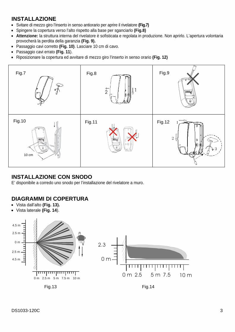
INSTALLAZIONE • Svitare di mezzo giro l’inserto in senso antiorario per aprire il rivelatore (Fig.7) • Spingere la copertura verso l’alto rispetto alla base per sganciarlo (Fig.8) • Attenzione: la struttura interna del rivelatore è sofisticata e regolata in produzione. Non aprirlo. L’apertura volontaria
provocherà la perdita della garanzia (Fig. 9). • Passaggio cavi corretto (Fig. 10). Lasciare 10 cm di cavo. • Passaggio cavi errato (Fig. 11). • Riposizionare la copertura ed avvitare di mezzo giro l’inserto in senso orario (Fig. 12)
INSTALLAZIONE CON SNODO E’ disponibile a corredo uno snodo per l’installazione del rivelatore a muro.
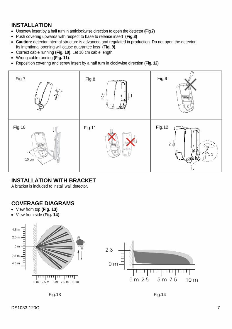
DIAGRAMMI DI COPERTURA • Vista dall’alto (Fig. 13). • Vista laterale (Fig. 14).
0 m
4.5 m
4.5 m
2.5 m
2.5 m
10 m 2.5 m 5 m 7.5 m0 m
Fig.7 Fig.8 Fig.9
Fig.10 Fig.11 Fig.12
Fig.13 Fig.14
0 m
10 m 2.5 5 m 7.5 0 m
2.3
10 cm

4 DS1033-120C
DESCRIZIONE MORSETTIERA (FIG. 15) Attenzione: controllare di aver effettuato correttamente tutte le connessioni prima di dare alimentazione al sensore. • Terminali V+ , V-: alimentazione 9.5 ÷ 15V— • Terminali NC , C: uscite dall’allarme – max. portata del contatto 35 V— / 150 mA. • Terminali T1,T2: uscita tamper,attivata quando viene rimossa la copertura: max. portata del contatto 24 V— / 500 mA.
DESCRIZIONE DIP SWITCH (FIG. 16) • Dip switch 1: determina il modo di funzionamento tra 24 ore e notturno. ON: funzionamento in modalità notturna, il rivelatore inizia a lavorare al tramonto, di notte o quando l’ambiente è poco illuminato. OFF: funzionamento 24H, il rivelatore lavora durante tutto l’arco della giornata ma il sistema di riconoscimento tra giorno e notte permette una auto-regolazione interna del rivelatore per ottimizzare le prestazioni. • Dip switch 2: determina l’accensione o meno del LED. ON: il LED si accende quando il rivelatore rivela movimento OFF: il LED non si accende. TARATURA DELLA MICROONDA (FIG. 17) Regolare la sensibilità della microonda in base all’ambiente circostante. Girare in senso orario per raggiungere il massimo della portata. Girare in senso antiorario verso il minimo per coprire circa 2 metri, impostando una posizione intermedia la microonda coprirà intorno ai 4 - 5 metri. VISUALIZZAZIONI • LED rosso lampeggiante: auto-rivelazione della tensione per circa 1 minuto • LED verde lampeggiante: la microonda ha rivelato un movimento • LED verde acceso: l’infrarosso ha rivelato un movimento • LED rosso acceso: sia la microonda che l’infrarosso hanno contemporaneamente rivelato un movimento.
50%
Fig.17 Taratura MW
Fig.16 Impostazione di fabbrica
Fig.15 1 2 3 4 5 6
V+ V- NCC T1 T2
DS1033-120C 5
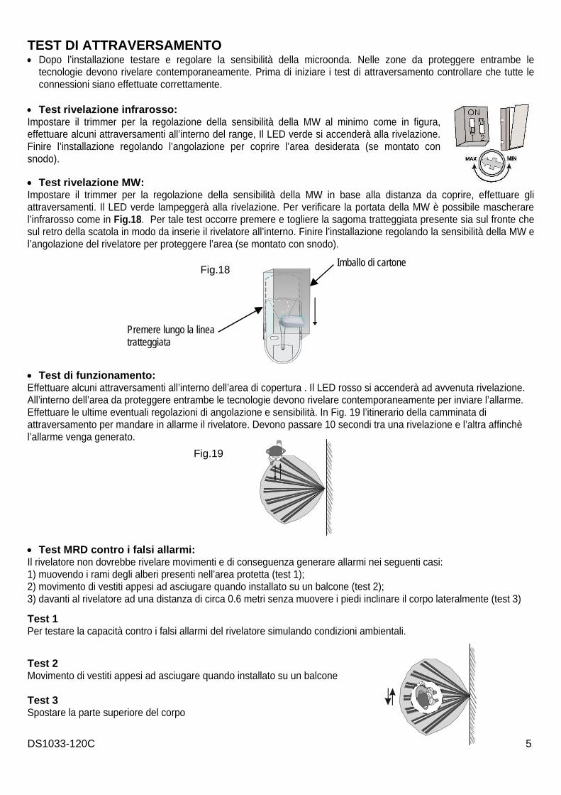
TEST DI ATTRAVERSAMENTO • Dopo l’installazione testare e regolare la sensibilità della microonda. Nelle zone da proteggere entrambe le
tecnologie devono rivelare contemporaneamente. Prima di iniziare i test di attraversamento controllare che tutte le connessioni siano effettuate correttamente.
• Test rivelazione infrarosso: Impostare il trimmer per la regolazione della sensibilità della MW al minimo come in figura, effettuare alcuni attraversamenti all’interno del range, Il LED verde si accenderà alla rivelazione. Finire l’installazione regolando l’angolazione per coprire l’area desiderata (se montato con snodo). • Test rivelazione MW: Impostare il trimmer per la regolazione della sensibilità della MW in base alla distanza da coprire, effettuare gli attraversamenti. Il LED verde lampeggerà alla rivelazione. Per verificare la portata della MW è possibile mascherare l’infrarosso come in Fig.18. Per tale test occorre premere e togliere la sagoma tratteggiata presente sia sul fronte che sul retro della scatola in modo da inserie il rivelatore all’interno. Finire l’installazione regolando la sensibilità della MW e l’angolazione del rivelatore per proteggere l’area (se montato con snodo). • Test di funzionamento: Effettuare alcuni attraversamenti all’interno dell’area di copertura . Il LED rosso si accenderà ad avvenuta rivelazione. All’interno dell’area da proteggere entrambe le tecnologie devono rivelare contemporaneamente per inviare l’allarme. Effettuare le ultime eventuali regolazioni di angolazione e sensibilità. In Fig. 19 l’itinerario della camminata di attraversamento per mandare in allarme il rivelatore. Devono passare 10 secondi tra una rivelazione e l’altra affinchè l’allarme venga generato.
• Test MRD contro i falsi allarmi: Il rivelatore non dovrebbe rivelare movimenti e di conseguenza generare allarmi nei seguenti casi: 1) muovendo i rami degli alberi presenti nell’area protetta (test 1); 2) movimento di vestiti appesi ad asciugare quando installato su un balcone (test 2); 3) davanti al rivelatore ad una distanza di circa 0.6 metri senza muovere i piedi inclinare il corpo lateralmente (test 3) Test 1 Per testare la capacità contro i falsi allarmi del rivelatore simulando condizioni ambientali.
Test 2 Movimento di vestiti appesi ad asciugare quando installato su un balcone Test 3 Spostare la parte superiore del corpo
Fig.18 Imballo di cartone
Premere lungo la linea tratteggiata
Fig.19

6 DS1033-120C
ENGLISH TECHNICAL CHARACTERISTICS Supply nominal voltage.......................................................................................... 12V— Min/max operation voltage..................................................................................... 9 ÷ 15V— Absorption at 12V—............................................................................................... 9mA nom. Technology............................................................................................................. double channel microwave and passive infrared Detection range...................................................................................................... 10m Microwave sensitivity ............................................................................................. adjustable by trimmer Frequency .............................................................................................................. 10.525 GHz Infrared sensitivity .................................................................................................. fixed Infrared sensitive zones ......................................................................................... seven curtain beams Temperature compensation ................................................................................... present (digital regulation) Alarm duration........................................................................................................ 3 seconds Alarm output........................................................................................................... NC at rest max 35V— / 150 mA Anti-tampering system .........................................................................................................................NC max. 24V— / 500 mA Pet immunity .......................................................................................................... up to 35 kg Operation temperature........................................................................................... -25°C +55°C Humidity ................................................................................................................. 5 ~ 95% Shell grade protection ............................................................................................ IP43 Dimensions (l x h x d)............................................................................................. 75 x 152 x 55 mm Notes: - Three-dimension microwave detection (against improper alarms) - Movement detections identification WARNINGS • Height suggested for installation ranging between 2 and 2.3 metres (Fig.1) • For garden or balcony correct protection, have infrared detect movements crossing protected zone and microwave
module detect approaching movements (Fig.2) • Do not install either in positions other than prescribed or upside down (Fig.3) • Do not install in the vicinity of obstacles (e.g.: trees, moving cars) (Fig.4) • Do not install in the vicinity of air conditioners (Fig.5) • Do not install in precarious conditions (mashes) - (Fig.6)
Fig.1 Fig.2 Fig.3
Fig.4 Fig.5 Fig.6
2 m
DS1033-120C 7
INSTALLATION • Unscrew insert by a half turn in anticlockwise direction to open the detector (Fig.7) • Push covering upwards with respect to base to release insert (Fig.8) • Caution: detector internal structure is advanced and regulated in production. Do not open the detector.
Its intentional opening will cause guarantee loss (Fig. 9). • Correct cable running (Fig. 10). Let 10 cm cable length. • Wrong cable running (Fig. 11). • Reposition covering and screw insert by a half turn in clockwise direction (Fig. 12).
INSTALLATION WITH BRACKET A bracket is included to install wall detector. COVERAGE DIAGRAMS • View from top (Fig. 13). • View from side (Fig. 14).
0 m
4.5 m
4.5 m
2.5 m
2.5 m
10 m 2.5 m 5 m 7.5 m0 m
Fig.7 Fig.8 Fig.9
Fig.10 Fig.11 Fig.12
0 m
10 m2.5 5 m 7.5 0 m
2.3
Fig.13 Fig.14
10 cm
8 DS1033-120C
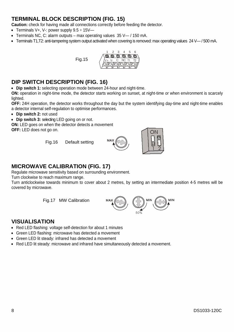
TERMINAL BLOCK DESCRIPTION (FIG. 15) Caution: check for having made all connections correctly before feeding the detector. • Terminals V+, V-: power supply 9.5 ÷ 15V— • Terminals NC, C: alarm outputs – max operating values 35 V— / 150 mA. • Terminals T1,T2: anti-tampering system output activated when covering is removed: max operating values 24 V— / 500 mA.
DIP SWITCH DESCRIPTION (FIG. 16) • Dip switch 1: selecting operation mode between 24-hour and night-time. ON: operation in night-time mode, the detector starts working on sunset, at night-time or when environment is scarcely lighted. OFF: 24H operation, the detector works throughout the day but the system identifying day-time and night-time enables a detector internal self-regulation to optimise performances. • Dip switch 2: not used • Dip switch 3: selecting LED going on or not. ON: LED goes on when the detector detects a movement OFF: LED does not go on. MICROWAVE CALIBRATION (FIG. 17) Regulate microwave sensitivity based on surrounding environment. Turn clockwise to reach maximum range. Turn anticlockwise towards minimum to cover about 2 metres, by setting an intermediate position 4-5 metres will be covered by microwave.
VISUALISATION • Red LED flashing: voltage self-detection for about 1 minutes • Green LED flashing: microwave has detected a movement • Green LED lit steady: infrared has detected a movement • Red LED lit steady: microwave and infrared have simultaneously detected a movement.
50%
Fig.17 MW Calibration
Fig.15 1 2 3 4 5 6
V+ V- NCC T1 T2
Fig.16 Default setting

DS1033-120C 9
CROSSING TEST After installation has been made, test and regulate microwave sensitivity. In areas to be protected, infrared and microwave technologies must detect simultaneously. Before starting crossing test, check that all connections are made correctly. • Infrared detection test: Set the trimmer to regulate MW sensitivity to minimum as in figure, make some crossings inside the range, green LED will go on at detection. End installation by regulating the angulation in order to cover the desired area (if the detector has been mounted with an articulated joint). • MW detection test: Set trimmer for regulating MW sensitivity based on distance to be covered, make crossings. Green LED will flash at detection. To check MW range, infrared can be masked as in Fig.18. For such test there has to be pressed and taken off the dotted shape that is present on box both front and rear side so as to put the detector inside. End installation by regulating both MW sensitivity and detector angulation in order to protect the area (if the detector has been mounted with an articulated joint). • Operation test: Make some crossings inside coverage area. Red LED will go on on detection having occurred. Inside the area to be protected, infrared and microwave technologies must detect simultaneously in order that the alarm is sent. Make any last angulation and sensitivity regulations. In Fig. 19, crossing walking path to put the detector into alarm is shown. 10 seconds must elapse between one detection and next one in order that the alarm is generated.
Fig.18 Paperboard packing
Press along dotted line
Fig.19
10 DS1033-120C
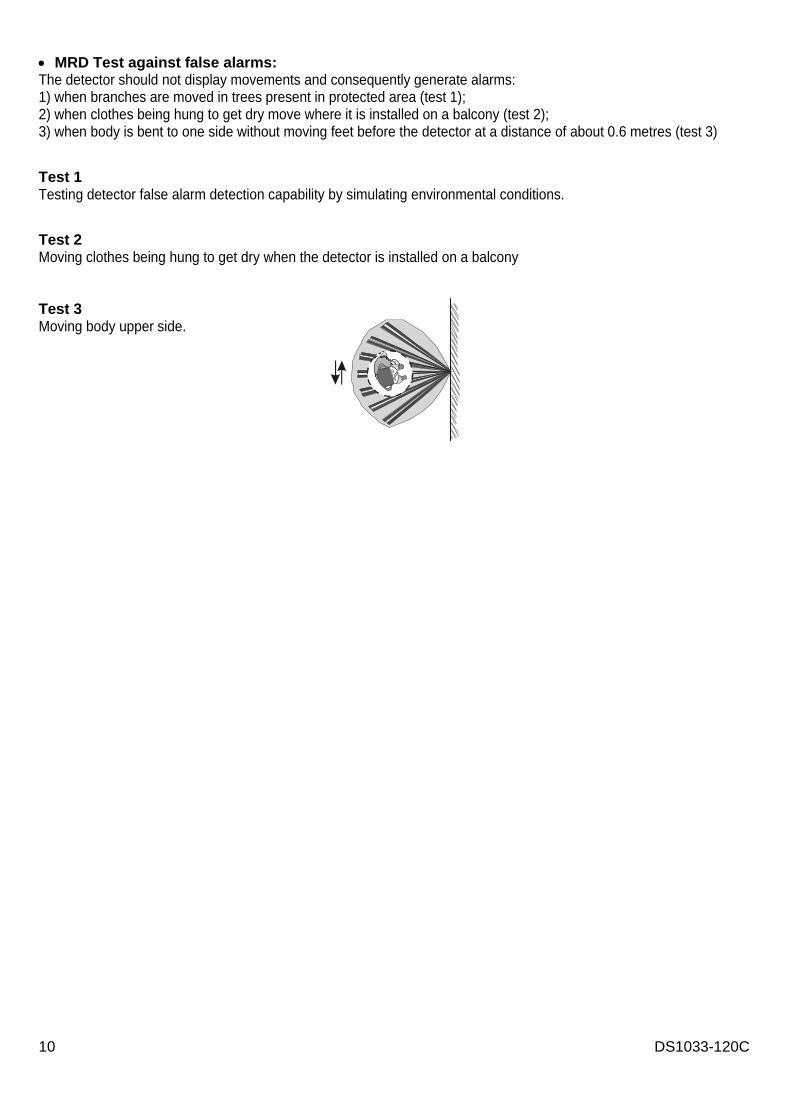
• MRD Test against false alarms: The detector should not display movements and consequently generate alarms: 1) when branches are moved in trees present in protected area (test 1); 2) when clothes being hung to get dry move where it is installed on a balcony (test 2); 3) when body is bent to one side without moving feet before the detector at a distance of about 0.6 metres (test 3) Test 1 Testing detector false alarm detection capability by simulating environmental conditions.
Test 2 Moving clothes being hung to get dry when the detector is installed on a balcony Test 3 Moving body upper side.

DS1033-120C 11
SCHEMI DI COLLEGAMENTO CON CENTRALE ANTINTRUSIONE CONNECTION DIAGRAMS TO INTRUDER CONTROL PANEL
SSF112-0268

12 DS1033-120C
DS1033-120C
SEDE URMET DOMUS S.p.A. 10154 TORINO (ITALY) VIA BOLOGNA 188/C Telef. +39. 011.24.00.000 (RIC.AUT.)Fax +39. 011.24.00.300 - 323 Area tecnica servizio clienti +39. 011.23.39.810
http://www.urmetdomus.com e-mail: [email protected]
LBT8254
FILIALI 20151 MILANO – V.Gallarate 218 Tel. 02.380.111.75 - Fax 02.380.111.80 00043 CIAMPINO (ROMA) V.L.Einaudi 17/19A Tel. 06.791.07.30 - Fax 06.791.48.97
80013 CASALNUOVO (NA) V.Nazionale delle Puglie 3 Tel. 081.193.661.20 - Fax 081.193.661.04 30030 VIGONOVO (VE) – V.del Lavoro 71 Tel. 049.738.63.00 r.a. - Fax 049.738.63.11 66020 S.GIOVANNI TEATINO (CH) – V.Nenni 17 loc. Sambuceto Tel. 085.44.64.851 Tel. 085.44.64.033 - Fax 085.44.61.862
(Made in P.R.C.)