Research Ideas FMICS-AVoCS 2016fmt.isti.cnr.it/~mtbeek/2016-TR-010.pdfMatteo Rossi Politecnico di...
28
Istituto di Scienza e Tecnologie dell’Informazione “A. Faedo” Consiglio Nazionale delle Ricerche Technical Report 2016–TR–010 Research Ideas FMICS-AVoCS 2016 International Workshop on Formal Methods for Industrial Critical Systems and Automated Verification of Critical Systems ISTI–CNR, Pisa, Italy 26–28 September 2016 Editors Maurice H. ter Beek, Stefania Gnesi, and Alexander Knapp
-
Upload
truongnhan -
Category
Documents
-
view
214 -
download
0
Transcript of Research Ideas FMICS-AVoCS 2016fmt.isti.cnr.it/~mtbeek/2016-TR-010.pdfMatteo Rossi Politecnico di...

Istituto di Scienza e Tecnologie dell’Informazione “A. Faedo”
Consiglio Nazionale delle Ricerche
Technical Report 2016–TR–010
Research Ideas
FMICS-AVoCS 2016
International Workshop onFormal Methods for Industrial Critical Systemsand Automated Verification of Critical Systems
ISTI–CNR, Pisa, Italy26–28 September 2016
EditorsMaurice H. ter Beek, Stefania Gnesi, and Alexander Knapp


Table of Contents
Preface . . . . . . . . . . . . . . . . . . . . . . . . . . . . . . . . . . . . . . . . . . . . . . . . . . . . . . . . . . IIIMaurice H. ter Beek, Stefania Gnesi and Alexander Knapp
Automated Verification Techniques
Towards Multi-Core Symbolic Model Checking of Timed Automata . . . . . 1Arnd Hartmanns, Sybe van Hijum, Jeroen Meijer and Jaco van de Pol
Parametric Interval Markov Chains: Synthesis Revisited . . . . . . . . . . . . . . . 5Laure Petrucci and Jaco van de Pol
Model-based System Analysis
Towards a High-Level Model Checking Language: Object-orientation,Data Structures and Local Variable Pruning . . . . . . . . . . . . . . . . . . . . . . . . . . 9
Paolo Milazzo, Giovanni Pardini and Giovanna Broccia
Applications and Case Studies
Formal Verification of Non-Linear Hybrid Systems Using Ariadne . . . . . . . 13Luca Geretti, Davide Bresolin and Tiziano Villa
Automation of Test Case Assessment in SPLs — Experiences and OpenQuestions . . . . . . . . . . . . . . . . . . . . . . . . . . . . . . . . . . . . . . . . . . . . . . . . . . . . . . . . 17
Josh Taylor, Alexander Knapp, Markus Roggenbach and Holger Schlin-glo↵


Preface
This technical report of ISTI contains the research ideas presented at the In-ternational Workshop on Formal Methods for Industrial Critical Systems andAutomated Verification of Critical Systems (FMICS-AVoCS), which was heldin Pisa, Italy, September 26–28, 2016. FMICS-AVoCS 2016 combines the 21st
International Workshop on Formal Methods for Industrial Critical Systems andthe 16th International Workshop on Automated Verification of Critical Systems.
The aim of the FMICS workshop series is to provide a forum for researcherswho are interested in the development and application of formal methods in in-dustry. In particular, FMICS brings together scientists and engineers that areactive in the area of formal methods and interested in exchanging their expe-riences in the industrial usage of these methods. The FMICS workshop seriesalso strives to promote research and development for the improvement of formalmethods and tools for industrial applications.
The aim of the AVoCS workshop series is to contribute to the interaction andexchange of ideas among members of the international research community ontools and techniques for the verification of critical systems. It covers all aspects ofautomated verification, including model checking, theorem proving, SAT/SMTconstraint solving, abstract interpretation, and refinement pertaining to varioustypes of critical systems which need to meet stringent dependability requirements(safety-critical, business-critical, performance-critical, etc.).
FMICS-AVoCS 2016 encouraged the submission of research ideas in order tostimulate discussions at the workshop. These research ideas typically concernreports on ongoing work or surveys on work published elsewhere related to thetopics of interest to FMICS-AVoCS, which include but are not limited to:
– Design, specification, refinement, code generation and testing of critical sys-tems based on formal methods
– Methods, techniques and tools to support automated analysis, certification,debugging, learning, optimization and transformation of critical systems, inparticular distributed, real-time systems and embedded systems
– Automated verification (model checking, theorem proving, SAT/SMT con-straint solving, abstract interpretation, etc.) of critical systems
– Verification and validation methods that address shortcomings of existingmethods with respect to their industrial applicability (e.g., scalability andusability issues)
– Tools for the development of formal design descriptions– Case studies and experience reports on industrial applications of formal
methods, focussing on lessons learned or identification of new research di-rections
– Impact of the adoption of formal methods on the development process andassociated costs
– Application of formal methods in standardization and industrial forums

IV
We received 5 research abstracts, which we decided to accept all for a short pre-sentation during the workshop and inclusion in this technical report. This techni-cal report accompanies the formal proceedings of FMICS-AVoCS 2016 publishedby Springer as volume 9933 of their Lectures Notes in Computer Science series.
We are very grateful to our sponsors, the European Research Consortiumfor Informatics and Mathematics (ERCIM), Formal Methods Europe (FME),and Springer International Publishing AG. We also thank Tiziana Margaria(University of Limerick & LERO, the Irish Software Research Center, Ireland),the coordinator of the ERCIM working group FMICS, and the other boardmembers, as well as the steering committee of AVoCS, all listed below, for theircontinuous support during the organization of FMICS-AVoCS. We acknowledgethe support of EasyChair for assisting us in managing the complete process fromsubmission to this technical report.
Finally, we thank all authors for their submissions and all attendees of theworkshop for their participation.
September 2016 Maurice ter BeekStefania Gnesi
Alexander Knapp

Organization
General Chair
Maurice H. ter Beek ISTI–CNR, Pisa, Italy
Program Committee Co-chairs
Stefania Gnesi ISTI–CNR, Pisa, ItalyAlexander Knapp Universitat Augsburg, Germany
Program Committee
Maria Alpuente Universitat Politecnica de Valencia, SpainJiri Barnat Masarykova Univerzita, Czech RepublicMichael Dierkes Rockwell Collins, Blagnac, FranceCindy Eisner IBM Research, Haifa, IsraelAlessandro Fantechi Universita di Firenze, ItalyFrancesco Flammini Ansaldo STS, Naples, ItalyMarıa del Mar Gallardo Universidad de Malaga, SpainMichael Goldsmith University of Oxford, UKGudmund Grov Heriot-Watt University, UKMatthias Gudemann Di↵blue ltd., Oxford, UKMarieke Huisman Universiteit Twente, The NetherlandsGerwin Klein NICTA and University of New South Wales, AustraliaPeter Gorm Larsen Aarhus Universitet, DenmarkThierry Lecomte ClearSy, Aix-en-Provence, FranceTiziana Margaria University of Limerick and LERO, IrelandRadu Mateescu INRIA Grenoble Rhone-Alpes, FranceDavid Mentre Mitsubishi ElectricR&DCentreEurope, Rennes, FranceStephan Merz INRIA Nancy and LORIA, FranceManuel Nunez Universidad Complutense de Madrid, SpainPeter Olveczky Universitetet i Oslo, NorwayCharles Pecheur Universite Catholique de Louvain, BelgiumMarielle Petit-Doche Systerel, Aix-en-Provence, FranceRalf Pinger Siemens AG, Braunschweig, GermanyJaco van de Pol Universiteit Twente, The NetherlandsMarkus Roggenbach Swansea University, UKMatteo Rossi Politecnico di Milano, ItalyMarco Roveri FBK-irst, Trento, ItalyThomas Santen MicrosoftResearchAdvancedTechnologyLabsEurope,
Aachen, Germany

VI
Bernhard Ste↵en Universitat Dortmund, GermanyJun Sun University of Technology and Design, SingaporeHelen Treharne University of Surrey, UK
FMICS WG Board Members
Alvaro Arenas IE Business School, Madrid, SpainLubos Brim Masarykova Univerzita, Czech RepublicAlessandro Fantechi Universita di Firenze, ItalyHubert Garavel INRIA Grenoble Rhone-Alpes, FranceStefania Gnesi ISTI–CNR, Pisa, ItalyDiego Latella ISTI–CNR, Pisa, ItalyTiziana Margaria University of Limerick and LERO, IrelandRadu Mateescu INRIA Grenoble Rhone-Alpes, FrancePedro Merino Universidad de Malaga, SpainJaco van de Pol Universiteit Twente, The Netherlands
AVoCS Steering Committee
Michael Goldsmith University of Oxford, UKStephan Merz INRIA Nancy and LORIA, FranceMarkus Roggenbach Swansea University, UK
Sponsors

Towards Multi-Core Symbolic
Model Checking of Timed Automata
?
Arnd Hartmanns, Sybe van Hijum, Jeroen Meijer, and Jaco van de Pol
University of Twente, Enschede, The Netherlands
1 Introduction
Timed automata (TA) are widely used for modeling, analysis and optimisation.Typical applications, where timing is crucial, include distributed protocols, em-bedded systems, and hard real-time control. Their analysis is supported by modelcheckers like Uppaal [1] or Rabbit [3]. Model checking is an exhaustive technique,limiting its scalability. One solution direction is to reduce resource usage by partialorder reduction (POR) or by concise symbolic representations using decision dia-grams (BDDs). An orthogonal direction is to exploit more resources efficiently byhigh-performance model checking. LTSmin [7] provides distributed and multi-corealgorithms for model checking, compatible with POR, and supporting multi-coredecision diagrams through Sylvan [5]. Earlier, we applied LTSmin to TA throughOpaal [4], an open-source code generator for Uppaal models. The Pins-API ofLTSmin supports multiple specification languages, by an on-the-fly next-state func-tion. We applied this for reachability analysis and LTL model checking [8] on TA.Clock zones were encoded as difference bound matrices (DBM) in a single mono-lithic variable, and the Pins API was extended with a subsumption check on DBMs.This led to a competitive, scalable explicit-state model checker for TA.
In this extended abstract, we investigate whether reductions like POR and BDDrepresentations can be combined with high-performance model checking of TA.Technically, this comes for free with the implementation of the Pins API. Yet inpractice, those techniques are only effective for specifications with high locality,i.e. when the dependency matrix between state variables and transition groups issparse. Viewing DBMs as a monolithic variable, which by the nature of time affectsall transition groups, destroys locality.
2 Zone Representations
Opaal provides an interface to a TA’s zone graph using an explicit representationof discrete state variables plus DBMs for zones. A DBM explicitly stores the re-lationships between all pairs of clocks. To represent zones in a more space-efficientway, specialised variants of decision diagrams have been developed:– A CDD [2] represents the difference between a pair of clocks using a single node.
Its multiple outgoing edges are labelled with disjoint intervals. CDD algorithmsneed to re-establish disjointness after every step.
? This work is partly supported by the 3TU project “Big Software on the Run”.
2
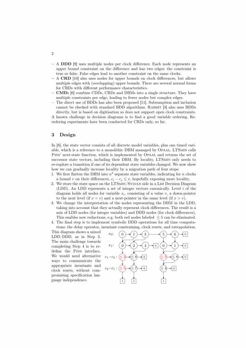
– A DDD [9] uses multiple nodes per clock difference. Each node represents anupper bound constraint on the difference and has two edges: the constraint istrue or false. False edges lead to another constraint on the same clocks.
– A CRD [10] also uses nodes for upper bounds on clock differences, but allowsmultiple edges with (overlapping) upper bounds. There are several normal formsfor CRDs with different performance characteristics.
– CMDs [6] combine CDDs, CRDs and DBMs into a single structure. They havemultiple constraints per edge, leading to fewer nodes but complex edges.
– The direct use of BDDs has also been proposed [11]. Subsumption and inclusioncannot be checked with standard BDD algorithms. Rabbit [3] also uses BDDsdirectly, but is based on digitisation so does not support open clock constraints.
A known challenge in decision diagrams is to find a good variable ordering. Re-ordering experiments have been conducted for CRDs only, so far.
3 Design
In [8], the state vector consists of all discrete model variables, plus one timed vari-able, which is a reference to a monolithic DBM managed by Opaal. LTSmin callsPins’ next-state function, which is implemented by Opaal and returns the set ofsuccessor state vectors, including their DBM. By locality, LTSmin only needs tore-explore a transition if one of its dependent state variables changed. We now showhow we can gradually increase locality by a migration path of four steps:1. We first flatten the DBM into n
2 separate state variables, indicating for n clocksa bound v on their differences, ci � cj v, hopefully exposing more locality.
2. We store the state space on the LTSmin/Sylvan side in a List Decision Diagram(LDD). An LDD represents a set of integer vectors canonically. Level i of thediagram holds all nodes for variable xi, consisting of a value v, a down-pointerto the next level (if x = v) and a next-pointer in the same level (if x > v).
3. We change the interpretation of the nodes representing the DBM in the LDD,taking into account that they actually represent clock differences. The result is amix of LDD nodes (for integer variables) and DDD nodes (for clock differences).This enables new reductions, e.g. both red nodes labeled 5 can be eliminated.
4. The final step is to implement symbolic DDD operations for all time computa-tions: the delay operator, invariant constraining, clock resets, and extrapolation.
x0: 0 1 3 5 6
x1: 0 2 4 0 1
c1�c2 : 3 8
c2�c1 : 5 7
5 8
4
0
0 0
0
0
0
0
1 1 1
This diagram shows a mixedLDD/DDD, as in Step 3.The main challenge towardscompleting Step 4 is to re-define the Pins interface.We would need alternativeways to communicate theappropriate invariants andclock resets, without com-promising specification lan-guage independence.

3
4 Preliminary Results and Outlook
model tLDD nLDD tDDD nDDD
fisher5 5.9 17,131 10.2 5,535critreg3 2.2 3,743 3.6 3,825csmacd8 22.8 324,047 10.4 36,098viking10 31.5 304 34.0 304
We show the runtime (tLDD, tDDD, inseconds) and number of decision diagramnodes (nLDD, nDDD) of our current pro-totype implementation for four standardbenchmarks on the right. We see thatDDD lead to smaller diagrams here, sothey indeed appear to be more memory-efficient. In terms of runtime, the compar-ison is not so clear; we expect improvements here as the implementation progresses.
There are several venues for further experimentation and design improvements.Since Sylvan is a multi-core LDD package, one could now investigate the speedupof multi-core symbolic TA model checking. Also, one could investigate the effective-ness of existing variable reordering heuristics (which we used already for the LDDcolumns above), or design specialised heuristics for clock variables. The flattenedDBMs also provide a first step to experiment with partial-order reduction for TA.
More fundamental improvements would be to further improve the locality, re-design the Pins-API for timed constraints and clock updates, and implement moresymbolic timed operations. One could extend the design with other decision dia-gram types, like CRDs, CDDs and CMDs. Finally, this line of research could becompared with the use of symbolic model checking for TA with discretised clocks [3].
References1. Behrmann, G., David, A., Larsen, K.G.: A tutorial on Uppaal. In: FORMATS. LNCS
3185, Springer (2004)2. Behrmann, G., Larsen, K.G., Pearson, J., Weise, C., Yi, W.: Efficient timed reach-
ability analysis using clock difference diagrams. In: CAV. LNCS, vol. 1633. Springer(1999)
3. Beyer, D., Lewerentz, C., Noack, A.: Rabbit: A tool for BDD-based verification ofreal-time systems. In: CAV. LNCS, vol. 2725. Springer (2003)
4. Dalsgaard, A., Hansen, R., Jørgensen, K., Larsen, K., Olesen, M., Olsen, P., Srba, J.:opaal: A lattice model checker. In: NFM. LNCS 6617, Springer (2011)
5. van Dijk, T., van de Pol, J.: Sylvan: Multi-core decision diagrams. In: TACAS. LNCS9636 (2015)
6. Ehlers, R., Fass, D., Gerke, M., Peter, H.: Fully symbolic timed model checking usingconstraint matrix diagrams. In: RTSS. IEEE Comp. Soc. (2010)
7. Kant, G., Laarman, A., Meijer, J., van de Pol, J., Blom, S., van Dijk, T.: LTSmin: High-performance language-independent model checking. In: TACAS. LNCS 9636 (2015)
8. Laarman, A., Olesen, M.C., Dalsgaard, A.E., Larsen, K.G., van de Pol, J.: Multi-core emptiness checking of timed Büchi automata using inclusion abstraction. In:Sharygina, N., Veith, H. (eds.) CAV. LNCS 8044, Springer (2013)
9. Møller, J.B., Lichtenberg, J., Andersen, H.R., Hulgaard, H.: Fully symbolic modelchecking of timed systems using difference decision diagrams. ENTCS 23(2) (1999)
10. Wang, F.: Efficient verification of timed automata with BDD-like data-structures. In:VMCAI. LNCS, vol. 2575. Springer (2003)
11. Zhang, H., Du, J., Cao, L., Zhu, G.: A full symbolic reachability analysis algorithm oftimed automata based on BDD. In: ISADS. IEEE Comp. Soc. (2015)

4

Parametric Interval Markov Chains: Synthesis Revisited
Laure Petrucci1? and Jaco van de Pol2??
1 LIPN, CNRS UMR 7030, Universite Paris 13, Sorbonne Paris Cite, Villetaneuse, France2 Formal Methods and Tools, University of Twente, Enschede, The Netherlands
1 Introduction
Markov Chains (MC) are widely used to model stochastic systems, like randomisedprotocols, failure and risk analysis, and modelling phenomena in molecular biology.Here we focus on discrete time MCs, where transitions between states are governed bya state probability distribution, denoted by µ : S ⇥ S ! [0, 1]. Practical applicationsare often hindered by the fact that the probabilities µ(s, t), to go from state s to t are un-known. Several solutions have been proposed, for instance Parametric Markov Chains(PMC) [3] and Interval Markov Chains (IMC) [7], in which unknown probabilities arereplaced by parameters or intervals, respectively; see the diagram (a), (b). Following [4],we study their common generalization, Parametric Interval Markov Chains (PIMC),which allow intervals with parametric bounds. PIMCs allow to study the boundaries ofadmissible probability intervals, which is useful in the design exploration phase. Thisleads to the study of parameter synthesis for PIMCs, started in [6].
IMCs can be viewed as specifications of MCs. An IMC is consistent if there ex-ists some MC that implements it. The main requirements of this relation are: (1) allbehaviour of the MC can be simulated by the IMC; (2) the transition probabilities outof each state sum up to 1. The consistency synthesis problem for PIMCs computesall parameter values leading to a consistent IMC. E.g., PIMC (c) is consistent whenq = 0, p = 1, or p + q = 1, r = 1. The implementation MC (d) corresponds tor = 1, p =
14 , q =
34 .
Our contribution is a simplification of the theory in [6], together with a formal verifi-cation in PVS. In particular, we provide a simple co-inductive definition of consistency,and prove that it coincides with the inductive notion of n-consistency in [6]. Finally,based on these definitions, we provide algorithms for the consistency check of IMCsand the consistency parameter synthesis of PIMCs. We implemented the latter as aConstraint Logic Program over the reals, in SWI-prolog with clp(R).
0
1 2
(a) a PMC
p 1� p
2
3 4
(b) an IMC
[0, 14 ] [ 14 , 1]
0
11 2
3 4 151
(c) a PIMC
[p, p] [q, q]
[0, r] [ 14 , r][p+ q,
45 ]
0
1 1 2
4 1
(d) MC ✏ PIMC
14
34
1
R
R
R
? This work has been partially supported by project PACS ANR-14-CE28-0002.?? This research was performed when the author was invited professor at Universite Paris 13.

6
2 Consistency of Parametric Interval Markov Chains
We first define (Parametric Interval) Markov Chains and their relation. For PIMCs,P denotes the set of parameters and Int[0, 1](P ) denotes intervals [p, q] with p, q 2P [ [0, 1]. For IMCs, P = ? and PMCs only have point intervals [p, p].
Definition 1 (MC, PIMC, ✏, consistency [7,4]). A Markov Chain (MC) is a tuple
M = (S, s0, µ), with initial state s0 2 S and probability distribution µ : S ⇥ S ![0, 1], i.e., 8s 2 S :
Ps02S µ(s, s0) = 1. A Parametric Interval Markov Chain (PIMC)
is a tuple I = (T, t0, P,'), with initial state t0 2 T , parameters P , and parametric
probability distribution ' : T ⇥ T ! Int[0, 1](P ).
M implements I (M ✏ I) if there exists a simulation relation R ✓ S ⇥ T , such that
for all sRt, there exists a probabilistic correspondence � : S ⇥ T ! Int[0, 1], with:
1. 8t0 2 T :
Ps02S µ(s, s0) · �(s0, t0) 2 '(t, t0)
(the total contribution of the implementing transitions satisfies the specification)
2. 8s0 2 S : µ(s, s0) > 0 ) Pt02T �(s0, t0) = 1
(the implementing transitions yield a probability distribution)
3. 8s0 2 S, t0 2 T : �(s0, t0) > 0 ) s0Rt0
(corresponding successors are in the simulation relation)
A PIMC I is consistent if for some parameters P and MC M, we have M ✏ I(P ).
We write '(t)(t0) for '(t, t0). For ⌫ = '(t), lower/upper bounds are denoted by⌫(t0) = [⌫`(t0), ⌫u(t0)]. The support sup(⌫) = {t0 | ⌫u(t0) 6= 0}. From now on, weassume that sup('(t)) is a finite set, so all sums below are well-defined.
Local consistency of state s w.r.t. a selected subset X ✓ T indicates compatibilitywith the associated ⌫ = '(s): The lower and upper bounds of the selected transitionsare properly ordered and summing them up admits the probability mass 1. The unse-lected transitions should allow probability 0.
Definition 2. We define local consistency constraints LC (⌫, X) as a conjunction of:
up(⌫, X) =
Pt2X ⌫u(t) � 1
low(⌫, X) =
Pt2X ⌫`(t) 1
local(⌫, X) = (8t 2 X : ⌫`(t) ⌫u(t)) ^ (8t 62 X : ⌫`(t) = 0)
We now provide three characterisations of consistency for IMCs: Cons containsthose states whose set of Cons-successors are locally consistent. States in Consn canperform n consistent steps in a row. The third definition will be needed for PIMCs.
Definition 3. Let I = (T, t0,') be an IMC. We define consistency as:
co-inductive: the largest set Cons ✓ T satisfying 8t : t 2 Cons ⌘ LC ('(t),Cons).n-recursive: t 2 Consn ⌘ n > 0 ) LC('(t),Consn�1)
n-recursive (X): t 2 ConsXn ⌘ n > 0 ) 9X : LC('(t), X) ^X ✓ ConsXn�1
Theorem 1. Let I = (T, t0,') be an IMC.
1. t0 2 Cons if and only if M ✏ I for some MC M = (S, s0, µ).2. For all t 2 T , t 2 Cons if and only if 8n 2 N : t 2 Consn.
3. For all t 2 T , t 2 Consn if and only if t 2 ConsXn .
4. If all simple paths from t have length m, then Consm(t) ⌘ 8n : Consn(t).

7
The full version of this paper will contain the proofs, which have been checked in theinteractive theorem prover PVS, based on higher-order classical logic. Here we remarkthat Theorem 1(2) essentially requires the assumption that '(t) has finite support (8t).
3 Algorithms for Consistency Checking and Synthesis
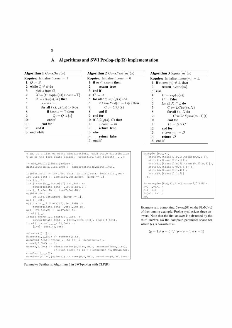
Theorem 1(1) leads to the backward Algorithm 1 to check IMC consistency (cf. Ap-pendix A), while Thm. 1(2) justifies the forward Algorithm 2. Thm. 1(3) uses finitequantifications only, so it provides a basis to generate a consistency constraint over theparameters as a nested conjunction/disjunction over linear inequalities, as in Alg. 3. Fi-nally, Thm. 1(4) lowers the upper bound on n from |T | [6] to the length of the longestsimple path. For instance, in binary trees the length of longest path is log(|T |).Theorem 2. Let (S, s0,') be an IMC, with maximal outdegree d.
1. Algorithm 1 checks consistency in time O(|'| · d).2. Algorithm 2 checks consistency in time O(|S| · |'|).3. Algorithm 3 synthesises consistency constraints in time O(|S|3 · 2d).
We prototyped Algorithm 3 as a Constraint Logic Program (linear arithmetic overreals). Appendix A contains a direct implementation in SWI-prolog over clp(R). It usesbacktracking to enumerate all subsets X . The constraint solver is used to prune in-consistent computations early. However, note that this corresponds to unfolding theconstraints to a disjunctive normal form, so the polynomial time bound will be lost.
4 Conclusion
The algorithms can be further improved by storing intermediate results, pruning irrel-evant parts of the computation earlier, and treating strongly connected components inisolation. We are implementing the algorithms, in order to run them on realistic PMCsfrom Prism [1] and IMCs from Tulip [2]. We would like to study the scalability ofparallel synthesis algorithms as well. Finally, it would be interesting to generalise ourresults to Parametric Interval Markov Decision Processes, thus generalising results forAPA [5].
References
1. Prism – probabilistic model checker. http://www.prismmodelchecker.org2. Tulip – Interval Markov Chains. http://tulip.lenhardt.co.uk/index.jsp3. Daws, C.: Symbolic and Parametric Model Checking of Discrete-Time Markov Chains. In:
ICTAC’04. pp. 280–294 (2004)4. Delahaye, B.: Consistency for Parametric Interval Markov Chains. In: SynCoP’15. pp. 17–32
(2015)5. Delahaye, B., Katoen, J., Larsen, K.G., Legay, A., Pedersen, M.L., Sher, F., Wasowski, A.:
Abstract probabilistic automata. Information and Computation 232, 66–116 (2013)6. Delahaye, B., Lime, D., Petrucci, L.: Parameter Synthesis for Parametric Interval Markov
Chains. In: VMCAI’16. pp. 372–390 (2016)7. Jonsson, B., Larsen, K.G.: Specification and refinement of probabilistic processes. In:
LICS’91. pp. 266–277 (1991)
8
A Algorithms and SWI Prolog-clp(R) implementation
Algorithm 1 ConsBwd(s)Require: Initialise t.cons := >1: Q := S
2: while Q 6= ? do
3: pick s from Q
4: X :={t2sup('(s))|t.cons=>}5: if ¬LC('(s), X) then
6: s.cons := ?7: for all t s.t. '(t, s) > 0 do
8: if t.cons = > then
9: Q := Q [ {t}10: end if
11: end for
12: end if
13: end while
Algorithm 2 ConsFwd(m)(s)Require: Initialise t.cons := 01: if m s.cons then
2: return true
3: end if
4: C := ?5: for all t 2 sup('(s)) do
6: if ConsFwd(m� 1)(t) then
7: C := C [ {t}8: end if
9: end for
10: if LC('(s), C) then
11: s.cons := m
12: return true
13: else
14: return false
15: end if
Algorithm 3 Synth(m)(s)
Require: Initialise t.cons[m] := ?1: if s.cons[m] 6= ? then
2: return s.cons[m]3: else
4: L := sup('(s))5: D := false
6: for all X ✓ L do
7: C := LC ('(s), X)8: for all t 2 X do
9: C:=C^Synth(m�1)(t)10: end for
11: D := D _ C
12: end for
13: s.cons[m] := D
14: return D
15: end if
% IMC is a list of state distributions, each state distribution
% is of the form state(source,[ trans(low,high,target), ...])
:- use_module(library(clpr)).
distribution(S,Dist,IMC) :- member(state(S,Dist),IMC).
lc(Dist,Set) :- low(Dist,Set), up(Dist,Set), local(Dist,Set).
low(Dist,Set) :- low(Dist,Set,Expr), {Expr =< 1}.low([],_,0).
low([trans(A,_,State)|T],Set,A+B) :-
member(State,Set),!,low(T,Set,B).
low([_|T],Set,B) :- low(T,Set,B).
up(Dist,Set) :-
up(Dist,Set,Expr), {Expr >= 1}.up([],_,0).
up([trans(_,A,State)|T],Set,A+B) :-
member(State,Set),!,up(T,Set,B).
up([_|T],Set,B) :- up(T,Set,B).
local([],_).
local([trans(L,U,State)|T],Set) :-
member(State,Set),!, {0=<L,L=<U,U=<1}, local(T,Set).
local([trans(L,_,_)|T],Set) :-
{L=0}, local(T,Set).
subsets([],[]).
subsets(L,[_|K]) :- subsets(L,K).
subsets([A|L],[trans(_,_,A)|K]) :- subsets(L,K).
cons(0,S,IMC) :- !.
cons(N,S,IMC) :- distribution(S,Dist,IMC), subsets(Succ,Dist),
lc(Dist,Succ),N1 is N-1,consSucc(N1,IMC,Succ).
consSucc(_,_,[]).
consSucc(N,IMC,[S|Succ]) :- cons(N,S,IMC), consSucc(N,IMC,Succ).
Parameter Synthesis: Algorithm 3 in SWI-prolog with CLP(R).
example([P,Q,R],
[ state(0,[trans(P,P,1),trans(Q,Q,2)]),
state(1,[trans(0,1,1)]),
state(2,[trans(0,R,3),trans(0.25,R,4)]),
state(3,[trans(P+Q,0.8,5)]),
state(4,[trans(0,1,4)]),
state(5,[trans(0,1,5)])
]).
?- example([P,Q,R],PIMC),cons(3,0,PIMC).
P=0, Q=R=1 ;
P=1, Q=0 ;
P+Q=1, R=1 ;
no.
Example run, computing Cons3(0) on the PIMC (c)of the running example. Prolog synthesizes three an-swers. Note that the first answer is subsumed by thethird answer. So the complete parameter space forwhich (c) is consistent is:
(p = 1 ^ q = 0) _ (p+ q = 1 ^ r = 1)

Towards a High-Level Model CheckingLanguage: Object-orientation, Data Structures
and Local Variable Pruning
Paolo Milazzo, Giovanni Pardini, and Giovanna Broccia
Dipartimento di Informatica, Universita di Pisa{milazzo,pardinig,broccia}@di.unipi.it
Abstract. We propose Objective/MC, a high-level object-oriented lan-guage for the modelling of finite-state systems. The language features anddata structures are selected with the aim of making modelling a friendlytask and of enabling the translation of models into compact transitionsystems, amenable to e�cient verification via Model Checking.At the moment, we have defined the imperative core of Objective/MC,developed a local variable pruning technique and developed a compilerof the core language into the input language of the PRISM probabilisticmodel checker. As future work, we plan to add concurrency, data struc-tures, object-oriented features and probabilistic/stochastic features.
1 Motivations
Modelling is often a challenging task. It requires: (i) understanding the mecha-nisms that govern the dynamics of the system, (ii) performing suitable abstrac-tions in order to express such mechanisms in a concise way, and (iii) constructingan unambiguous representation at the chosen abstraction level. In the case ofmodel checking, the system dynamics is often formalized as a transition system(or Kripke structure). The way in which a transition system is expressed in theinput languages of model checking tools can vary significantly from tool to tool.In many cases the input language allows transitions to be specified as updates ofthe system’s variables to be performed when certain conditions are satisfied (asif-then clauses or rewrite rules). However, if-then clauses and rewrite rules areoften too low level as a modelling paradigm to express systems’ mechanisms ina natural way. They can lead to huge and complex descriptions that are di�cultto read and error-prone.
In this paper we describe the proposal of Objective/MC, a new language forthe specification of system models to be analysed by means of model checking.
2 The Objective/MC Modelling Language
2.1 Desired language features
Objective/MC aims to be a general purpose modelling language. It will have animperative semantics with standard control flow constructs. These are the main

10
features we aim to include in the language (preliminarly discussed in [2] with,actually, game modelling in mind):
Concurrency We plan to include the possibility of defining parallel processesthat can synchronize on specific labels (CSP-like).
Object-oriented features (with statically allocated objects) We plan toinclude class definitions with standard Java-like inheritance. Objects will bedefined as statically allocated global variables (the will be no new operator).
Probabilistic/stochastic choices We plan to include a selection statement(like a C switch) in which cases are chosen on the basis either of a user-defined probability distribution or of stochastic rates.
Arrays and graphs (statically allocated) We plan to include (fixed size)arrays and a primitive notion of graph (with a fixed structure). Moreover,we wish to include array filtering and graph exploration primitives.
The presence of data structures in the language calls for the presence of localvariables also (to be used, e.g., as array indexes). One of the main characteristicsof the language is that it makes a very di↵erent treatment of global and localvariables. Global variables are assumed to actually describe the state of themodelled system, whereas local variables are only used to ease the specificationof the system’s internal mechanisms, and can be pruned from the model.
The semantics of the language is hence a transition system whose states corre-spond to di↵erent evaluations of the global variables and transitions correspondto the assignments to global variables as specified in the Objective/MC model.In addition, a hidden global variable pc is considered in order to put sequentialassignments in the correct order in the transition system.
2.2 Current State of Development
At the moment, we have defined the imperative core of Objective/MC, withbounded integers and booleans as data types, arrays as the only data structure,procedures (void functions) and a basic notion of class (analogous to a C struct).The syntax of the language (apart from classes) is presented through the exampleof job processor scheduler in Figure 1. Objective/MC is a C-like language. Thenon-standard constructs are the bounded integer type (denoted int(n..m)),the times loop (that iterates a fixed number of times), the run block (analogousto the main function in C), the select(n,m) operator (representing the non-deterministic choice of a value in [n,m]) and the yield statement (to be usedin the body of a while loop when no global variable assignments are reachable).
An implementation of the compiler of Objective/MC into the modelling lan-guage of the PRISM model checker is available [1]. The compiler transforms themodel in order to prune all local variables. Hence, the generated transition sys-tem will consist of transitions that correspond to the updates of only the globalvariables. For the sake of local variable pruning the language includes some syn-tactic constraints: (i) a local variable cannot be read after a global variable itdepends upon may have been modified, (ii) a local variable declared outside of

11
1 int(0..10)[5] P; // array of five processors
2 int(0..10) nextjob; // duration of the next job
3 void execute_step() { // decreases the load of each processor by one unit
4 int(0..4) i = 0;
5 times (5) {
6 if (P[i] > 0) { P[i] = P[i] as int(1..10) - 1; }
7 i = (i < 4 ? i + 1 : i) as int(0..4); }
8 }
9 run {
10 while (true) {
11 execute_step();
12 if (nextjob == 0) nextjob = select(0,3);
13 int(0..4) min_idx = 0;
14 int(0..4) i = 1;
15 times (4) {
16 if (P[i] < P[min_idx]) min_idx = i;
17 i = (i < 4 ? i + 1 : i) as int(0..4); }
18 if (P[min_idx] + nextjob <= 10) {
19 P[min_idx] = (P[min_idx] + nextjob) as int(0..10);
20 nextjob = 0;
21 } else yield;
22 }
23 }
Fig. 1. An Objective/MC model of a job processor scheduler.
a while loop cannot be updated inside the loop body, and (iii) each iteration ofa while loop must include at least one global variable assignment (or a yield).
Constraints (i) and (ii) may look very restrictive. However, they deal withlocal variables and are necessary in order to ensure that the value of each localvariable can be at any time computed by the current values of the global vari-ables. A model that does not satisfy one of the two constraints can be triviallyfixed by turning the problematic local variable into a global variable.
The local variable pruning technique implemented in the Objective/MC com-piler consists in a sequence of transformations applied to the Control Flow Graphof the model, as exemplified in the diagram in Fig. 2. The output of the compileris a model expressed in the input language of the PRISM model checker, thatis then used to build the transition system. The choice of PRISM as the targetmodel checking tool is related with the aim of including probabilistic/stochasticfeatures in the language. Moreover, PRISM has been chosen among probabilis-tic/stochastic model checkers since it is one of the most used tools and since weare familiar with it. In principle, the Objective/MC compiler could be extendedin order to deal with more than one translation targets.
More detailed information about the current definition of Objective/MC andthe local variable pruning technique can be found in [3].

12
Objective/MC model PRISM model
Objective/MC PRISM input language
PRISM (model building)
Internal PRISM data structures
TRANSITIONSYSTEM
Objective/MC compiler
Local variables pruning
Fig. 2. Schematic representation of the translation of an Objective/MC model into atransition system. The Objective/MC compiler computes the control flow graph of themodel and applies a number of transformations to it aimed at pruning local variables.The obtaned graph is then translated into a model in the PRISM input language.Finally, the transition system is built (and analysed) by using the standard PRISMfacilities.
References
1. ObjMC: The Objective/MC compiler, http://pages.di.unipi.it/pardini/ObjMC2. Broccia, G.: Un Domain Specific Language per la modellazione e l’analisi di giochi.
Master’s thesis, University of Pisa, Italy (2015), https://etd.adm.unipi.it/t/etd-09032015-150400/
3. Pardini, G., Milazzo, P.: A high-level model checking language with compile-timepruning of local variables. In: Proc. of DataMod 2016. Lecture Notes in Com-puter Science, vol. 9946. Springer (in press), http://pages.di.unipi.it/datamod/wp-content/uploads/sites/8/2016/06/DataMod_2016_paper_4_Pardini.pdf

Formal Verification of Non-Linear HybridSystems Using Ariadne
Luca Geretti1, Davide Bresolin2, and Tiziano Villa1
1 Universita di Verona, Verona, Italy {luca.geretti, tiziano.villa}@univr.it2 Universita di Bologna, Bologna, Italy [email protected]
1 Introduction
Hybrid systems are dynamical systems that exhibit both a discrete and a con-tinuous behaviour. In order to model and specify hybrid systems in a formalway, the notion of hybrid automata has been introduced [1]. Intuitively, a hy-brid automaton is a “finite-state automaton” with continuous variables thatevolve according to dynamics characterizing each discrete state (called a loca-tion). However, such model enables the definition of monolithic systems only,with no support for the decomposition of the state space. On the other hand,hybrid I/O automata [10] extend hybrid automata to support the compositionof multiple (simpler) automata that operate on subsets of the continuous state.
Of particular importance in the analysis of hybrid (I/O) automata is the com-putation of the reachable set, i.e., the set of all states that can be reached underthe dynamical evolution starting from a given initial state set. Many approxi-mation techniques and tools to estimate the reachable set have been proposedin the literature. Most of the available software packages, like PhaVer [8] andSpaceEx [9], are limited to a�ne dynamics. Others, like HSOLVER [13] can han-dle more complex dynamics, but are based on abstractions which prevent thedesigner from observing the dynamical evolution of the system. Finally, mostof these tools use a numerical engine which does not guarantee correctness inrespect to numerical rounding.
To overcome such limitations, we recently proposed a development environ-ment for hybrid systems verification, called Ariadne [4], which di↵ers fromexisting tools by being based on the theory of computable analysis [6]. Suchtheory provides a rigorous mathematical semantics for the numerical analysis ofdynamical systems, suitable for implementing formal verification algorithms, en-abling tasks such as dominance checking [3] and parametric controller synthesis.However, in the following we will discuss about verification of safety properties,which is currently the main focus of Ariadne.
2 Safety Verification with Ariadne
Suppose we wish to verify that a safety property ' holds for a hybrid automatonH; in other words, that ' remains true for all possible executions starting froma set X0 of initial states. Then we only need to prove that ReachSetA(X0) ✓

14
Sat('), where Sat(') is the set of states where ' is true. Unfortunately, thereachability problem is not decidable in general [1]. Nevertheless, formal verifi-cation methods can be applied to hybrid automata: suppose we can compute anover-approximation S ◆ ReachSetA(X0). Then if S is a subset of Sat('), thenso is the reachable set and the automaton H respects the property. Conversely,if we can compute an under-approximation S ✓ ReachSetA(X0) that turns outto contain at least one point outside Sat('), we have proved that H does notrespect the safety property '.
Finite-time evolution is obtained by integration of a (non-linear) vector fieldX = f(X): starting from a set Xi and choosing an integration step ti, we ob-tain the next set Xi+1 and the corresponding partial reached set Ri,i+1. Thisrepresents a continuous step of evolution, as opposed to a discrete step wherea transition is activated, changing the discrete state and possibly the contin-uous state. Evolution up to a time T therefore becomes a simple sequence ofcontinuous and discrete transitions.
In order to account for numerical errors, all the computed sets are over-approximations of the actual sets. These over-approximations are called enclo-sures, and are represented as Taylor expansions to o↵er an accurate and flexiblerepresentation of the included set. In our theory, evolution can be computedaccording to two di↵erent semantics:
– upper semantics: if we evolve the system for a finite time, the set of pointsthat we obtain is a superset of the reachable set;
– lower semantics: if we evolve the system for a finite time, each point that weobtain has a bounded distance " to a point of the reachable set.
Lower semantics in particular is a bounded approximation, rather than anunder-approximation of the reachable set, which is not computable in general.If we prove that the evolution under lower semantics reaches a point outsideSat(') by at least ", then ReachSetA(X0) has a point outside Sat(') and theproperty ' is not satisfied.
While the computation of evolution for a finite time is straightforward, thesame cannot be said for the case of infinite time. The termination condition forinfinite time evolution is that no additional reachable region can be obtainedafter an evolution step. Such check requires to perform inclusion test, intersec-tion and subtraction of enclosures. Unfortunately, the subtraction and inclusiontests are not computable, while the intersection is very ine�cient. Consequently,enclosures are discretised onto a set of non-overlapping cells of a grid, internallyrepresented by means of a binary decision diagram.
Summarizing, given a hybrid automaton A, and an initial set X0, Ariadnecan compute two kinds of approximations to the reachable set, for both finiteand infinite-time evolution:
– An outer approximation O of the reachable set using upper semantics. For-mally, a closed set O such that the closure of ReachSetA(X0) is strictlycontained in the interior of O.

15
– An "-lower approximation L" of the reachable set using lower semantics.Formally, an open set L" where for every point x 2 L" there exists a pointy 2 ReachSetA(X0) such that |x� y| < ".
In the case of O, the evolution can be performed either in the forward or back-wards direction. On the contrary, backwards evolution for L", while computable,has not been implemented, since lower semantics causes backwards transitions toyield very coarse enclosures. This results in a large bound on the approximation,which is ine↵ective for reachability analysis.
3 Ongoing Work
Formal verification of non-linear hybrid systems is still in its infancy, but toolslike Ariadne show promising results on industrial-strength case studies. Exper-imentally, we are applying the tool to model and verify robotic surgery tasks [11,5]. In such a field, formally proving safety properties is of the utmost importancein order to implement reliable controllers for semi-automatic surgery operations.
From the technical viewpoint, we have discussed how Ariadne is able tocompute both outer approximations (sets O) and bounded approximations (setsL") of the reachable set, allowing to observe the system evolution with fine de-tail. However, these features are responsible for bottlenecks, in particular withrespect to scalability and accuracy of the approximations. To overcome the cur-rent limitations of the tool, we are working on the following improvements:
– improve automated tuning of the accuracy parameters in order to controlthe over-approximation error; this applies to the integration step and themaximum Taylor expansion order;
– improve heuristics for discretization events, to minimize convergence for in-finite time evolution;
– address scalability by means of counterexample-based abstraction refinementtechniques [2].
In addition, we plan to extend the model to di↵erential inclusions, basedon the work of [14], to enable the representation of noisy inputs. The obviousapplication of di↵erential inclusions is to model uncertainty, but they are neededalso to enable contract-based design[12]: given a complex system, we can replacethe actual input of an automaton with an input having partially defined behavior.Such decoupling of automata ultimately allows to analyze automata separately,trading-o↵ system complexity for verification accuracy.
Further information on the Ariadne framework can be found in [7] aboutfunctional calculus, [3] regarding the reachability routines, and [4] for advancedverification strategies. We are currently preparing a first o�cial release of thelibrary, providing user documentation and tutorial resources.
16
References
1. R. Alur, C. Courcoubetis, T. A. Henzinger, and P. H. Ho. Hybrid automata: Analgorithmic approach to the specification and verification of hybrid systems. InHybrid Systems, volume 736 of LNCS, pages 209–229. Springer, 1993.
2. R. Alur, T. Dang, and F. Ivancic. Counterexample-guided predicate abstractionof hybrid systems. Theor. Comput. Sci., 354(2):250–271, 2006.
3. L. Benvenuti, D. Bresolin, P. Collins, A. Ferrari, L. Geretti, and T. Villa. Ariadne:Dominance checking of nonlinear hybrid automata using reachability analysis. InReachability Problems, volume 7550 of LNCS, pages 79–91. Springer, 2012.
4. L. Benvenuti, D. Bresolin, P. Collins, A. Ferrari, L. Geretti, and T. Villa. Assume-guarantee verification of nonlinear hybrid systems with ARIADNE. Int. J. Robust.Nonlinear Control, 24(4):699–724, 2014.
5. D. Bresolin, L. Geretti, R. Muradore, P. Fiorini, and T. Villa. Formal verification ofrobotic surgery tasks by reachability analysis. Microprocess. Microsyst., 39(8):836–842, 2015.
6. P. Collins. Semantics and computability of the evolution of hybrid systems. SIAMJ. Control Optim., 49:890–925, 2011.
7. P. Collins, D. Bresolin, L. Geretti, and T. Villa. Computing the evolution ofhybrid systems using rigorous function calculus. In Proc. 4th IFAC Conferenceon Analysis and Design of Hybrid Systems (ADHS’12), volume 45(9) of IFACProceedings Volumes, pages 284–290. Elsevier, 2012.
8. G. Frehse. PHAVer: algorithmic verification of hybrid systems past HyTech. Int.J. Softw. Tools Technol. Transf., 10:263–279, 2008.
9. G. Frehse, C. Le Guernic, A. Donze, S. Cotton, R. Ray, O. Lebeltel, R. Ripado,A. Girard, T. Dang, and O. Maler. SpaceEx: Scalable verification of hybrid systems.In Proc. 23rd International Conference on Computer Aided Verification (CAV’11),volume 6806 of LNCS, pages 379–395. Springer, 2011.
10. N. Lynch, R. Segala, and F. Vaandrager. Hybrid I/O automata. Inform. Comput.,185(1):105–157, 2003.
11. R. Muradore, D. Bresolin, L. Geretti, P. Fiorini, and T. Villa. Robotic Surgery:Formal Verification of Plans. IEEE Robot. Autom. Mag., 18(3):24–32, 2011.
12. P. Nuzzo, A. L. Sangiovanni-Vincentelli, D. Bresolin, L. Geretti, and T. Villa. Aplatform-based design methodology with contracts and related tools for the designof cyber-physical systems. Proc. IEEE, 103(11):2104–2132, 2015.
13. S. Ratschan and Z. She. Safety verification of hybrid systems by constraint prop-agation based abstraction refinement. ACM Trans. Embed. Comp. Syst., 6(1),2007.
14. S. Zivanovic and P. Collins. Numerical solutions to noisy systems. In Proc. 49thIEEE Conference on Decision and Control (CDC’10), pages 798–803, 2010.

Automation of Test Case Assessment in SPLs —Experiences and Open Questions
Josh Taylor1, Alexander Knapp2,Markus Roggenbach1, and Bernd-Holger Schlingloff3
1 Swansea University, Wales, United [email protected]
2 Universitat Augsburg, Germany3 Humboldt Universitat and Fraunhofer FOKUS, Germany
Abstract. This research idea turns a theory for test case assessment in the model-based development of multi-variant systems, so called Software Products Lines(SPL), into practice. To this end, we provide a tool chain for automated test caseassessment, validate it on the example of a coffee machine product line, andfinally, successfully apply it to “The Body Comfort System” product line from theautomotive domain.
1 Introduction
The concept of a software product line originates by the work of D. Parnas [6]. It hasgained much attention by the research and consultancy of the Carnegie Mellon UniversitySoftware Engineering Institute [1,5]. According to the CMU-SEI definition, “a softwareproduct line (SPL) is a set of software-intensive systems that share a common, managedset of features satisfying the specific needs of a particular market segment or missionand that are developed from a common set of core assets in a prescribed way”4. SPLsare abundant in today’s software-intensive systems: most electronic control units, e.g., incars or trains, come in multiple variants, as well as consumer products such as coffeemachines, dishwashers, mobile phones, etc.
A challenge common to the development of such systems is that their built-insoftware is similar, but not identical in all products; there are slight differences accordingto the features exhibited by a particular product. Sources of variability include planneddiversity for different user groups, evolution and enhancement of products, and re-use ofmodules from one product in another one.
SPL engineering addresses this challenge. The main goal of SPL development is thestrategic re-use of software artefacts. There have been various approaches to re-use: bycopy and paste, macros, subroutines, modules, objects, components and services. Thecommon problem in all of these approaches is that re-use increases the risk of errors.Therefore, quality assurance for SPLs is of utmost importance.
Given an SPL and a software test suite, not all tests apply to all possible products.Often, it is clear from the context whether a test can be executed with a product or
4 CMU Software Engineering Institute: Product Line Web Page. http://www.sei.cmu.edu/productlines/
(2015/01)

18
not. However, there are cases where this is not obvious: consider the case that a certainadditional feature blocks some behaviour present in the ‘standard’ product. In general,for a sufficiently expressive specification language the problem of test case assessmentis undecidable.
In [2,3], some of the authors presented a theory for test case assessment in themodel-based development of multi-variant systems. This deals with both positive (green)and negative (red) test cases, and introduces a third colour (yellow) for test cases whoseoutcome is not determined with a given product model. This means that it is needless toexecute them with products based on this model. This approach thus allows to assess andselect those test cases from a universal test suite which are relevant for a given product.
2 Tool Chain
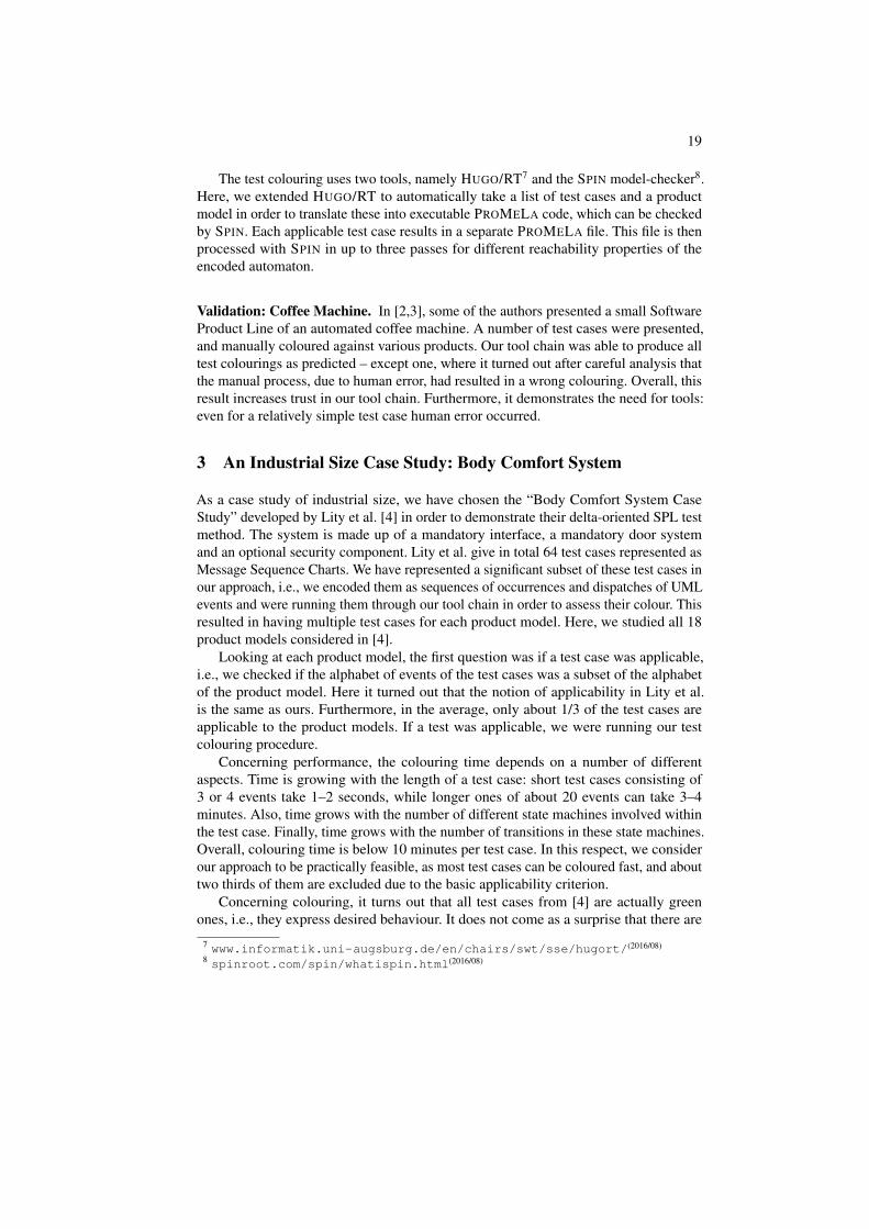
Our tool chain can be separated into two main parts: the modelling and the test colouringpart. It re-uses existing tools, where our contribution lays in the automation of theirco-operation.
Fig. 1. Tool chain for test case colouring for SPLs
For the modelling part, we completely rely on existing technology. We utilise theUML model editor PAPYRUS5 to define a base model (consisting of class diagrams,state machines, and a composite structure diagram) and PUREVARIANTS6 to deal withvariability, namely to create a feature model and a variability model (above shown asone integrated variability model). In PUREVARIANTS, the user then realises a resolutionmodel by selecting which features to include. This results in a product model in UML.
5www.eclipse.org/papyrus/
(2016/08)
6www.pure-systems.com/products/pure-variants-9.html
(2015/06)
19
The test colouring uses two tools, namely HUGO/RT7 and the SPIN model-checker8.Here, we extended HUGO/RT to automatically take a list of test cases and a productmodel in order to translate these into executable PROMELA code, which can be checkedby SPIN. Each applicable test case results in a separate PROMELA file. This file is thenprocessed with SPIN in up to three passes for different reachability properties of theencoded automaton.
Validation: Coffee Machine. In [2,3], some of the authors presented a small SoftwareProduct Line of an automated coffee machine. A number of test cases were presented,and manually coloured against various products. Our tool chain was able to produce alltest colourings as predicted – except one, where it turned out after careful analysis thatthe manual process, due to human error, had resulted in a wrong colouring. Overall, thisresult increases trust in our tool chain. Furthermore, it demonstrates the need for tools:even for a relatively simple test case human error occurred.
3 An Industrial Size Case Study: Body Comfort System
As a case study of industrial size, we have chosen the “Body Comfort System CaseStudy” developed by Lity et al. [4] in order to demonstrate their delta-oriented SPL testmethod. The system is made up of a mandatory interface, a mandatory door systemand an optional security component. Lity et al. give in total 64 test cases represented asMessage Sequence Charts. We have represented a significant subset of these test cases inour approach, i.e., we encoded them as sequences of occurrences and dispatches of UMLevents and were running them through our tool chain in order to assess their colour. Thisresulted in having multiple test cases for each product model. Here, we studied all 18product models considered in [4].
Looking at each product model, the first question was if a test case was applicable,i.e., we checked if the alphabet of events of the test cases was a subset of the alphabetof the product model. Here it turned out that the notion of applicability in Lity et al.is the same as ours. Furthermore, in the average, only about 1/3 of the test cases areapplicable to the product models. If a test was applicable, we were running our testcolouring procedure.
Concerning performance, the colouring time depends on a number of differentaspects. Time is growing with the length of a test case: short test cases consisting of3 or 4 events take 1–2 seconds, while longer ones of about 20 events can take 3–4minutes. Also, time grows with the number of different state machines involved withinthe test case. Finally, time grows with the number of transitions in these state machines.Overall, colouring time is below 10 minutes per test case. In this respect, we considerour approach to be practically feasible, as most test cases can be coloured fast, and abouttwo thirds of them are excluded due to the basic applicability criterion.
Concerning colouring, it turns out that all test cases from [4] are actually greenones, i.e., they express desired behaviour. It does not come as a surprise that there are
7www.informatik.uni-augsburg.de/en/chairs/swt/sse/hugort/
(2016/08)
8spinroot.com/spin/whatispin.html
(2016/08)

20
no yellow test cases: the UML models are close to implementation where all relevantdesign decisions have been resolved. That there are no red test cases is a question ofmethodology: apparently, Lity et al. were concentrating on demonstrating expectedbehaviour rather than trying to demonstrate that certain error situations have beenavoided.
4 Conclusions and Open Questions
We have successfully implemented a tool chain for SPL test assessment according to thetheory presented in [2,3]. We validated the tool chain on a simple example, and showedthat the developed implementation scales up. However, there are a number of researchquestions arising:
1. What are appropriate coverage metrics for SPL models and coloured test cases?2. Currently we are focusing on individual products for colouring. However, in princi-
ple, it should be possible to colour classes of products. This would reduce colouringtime. How to refine the base model adequately?
3. As we obtain only green test cases in our case study, we presume that Lity et al. wereperforming testing for functionality. How to extend this to testing for safety, i.e.,“show whether or not each software module performs its intended function and doesnot perform unintended functions” (IEC 61508)? A first step towards this would beto formulate safety properties as test objectives, that one then would turn into redtest cases.
Overall, it is still an open question of how to relate our approach with incrementaldevelopment methods such as step-wise refinement and software evolution.
References
1. P. Clements and L. Northrop. Software Product Lines: Practices and Patterns. Addison-Wesley,2001.
2. A. Knapp, M. Roggenbach, and B.-H. Schlingloff. On the Use of Test Cases in Model-based Software Product Line Development. In S. Gnesi, A. Fantechi, P. Heymans, J. Rubin,K. Czarnecki, and D. Dhungana, editors, Proc. 18
th
Intl. Software Product Line Conf. (SPLC’14),pages 247–251. ACM, 2014.
3. A. Knapp, M. Roggenbach, and B.-H. Schlingloff. Automating Test Case Selection in Model-Based Software Product Line Development. Intl. J. Softw. Inform., 9(2):153–175, 2015.
4. S. Lity, R. Lachmann, M. Lochau, and I. Schaefer. Delta-oriented Software Product LineTest Models — The Body Comfort System Case Study. Informatik-Bericht 2012-07, v1.2,Technische Universitat Carolo-Wilhemina zu Braunschweig, 2015.
5. J. D. McGregor, L. M. Northrop, S. Jarrad, and K. Pohl. Initiating Software Product Lines.IEEE Softw., 19(4):24–27, 2002.
6. D. L. Parnas. On the Design and Development of Program Families. IEEE Trans. Softw. Eng.,2(1):1–9, 1976.