PSRTf BTItrSAîtr ISTRUZ'ONI DI MONTAGGIO I NSTALLATION...
6
n,t$îHl P0ìIt BttHoÀIt PSRTf BTItrSAîtr Master Costruzioni Tecniche di Sicurezza srl Strada dei Dossarelli, 45 - 291 00 Piacenza (ltaly) Tel. 0523.59.30.00 - 5 linee r.a - Fax 0523.59.08.91 Sito internet http://www.masterdoor.it E-mail : master.srl@îlashnet.it ISTRUZ'ONI DI MONTAGGIO INSTALLATION INSTRUCTIONS lstruzioni usoe manutenzione porta . Non lubrificare laserratura Do not lubricate locking system: blocking danger . Togliere il film plastico che protegge il pannello di legno una volta terminato il montaggio della porta, non oltre 30 gg. dalla consegna e immediatamente se esposto ai raggi solari Peel off the plastic protective film not later than 30 days aîter delivery 0r immediately in case ofdirect exposure tosun rays . Pulire solo con un panno umido Clean the door only with a damp cloth . Lubrificare lecerniere con grasso idoneo Use specific grease t0lubricate hinges * NB: tutte le quote espresse nelpresente opuscolo si riîeriscono ad una porta di misura nominale 900x 2100 mm Allquotes of thisleaflet arereferred to a door withnominal dimensions 900x 2100 mm. Rev. 00 (Valide solo per porte predisposte per serratura a cilindro/0nly for cylinder lock) v 7 7 7 7 \
Transcript of PSRTf BTItrSAîtr ISTRUZ'ONI DI MONTAGGIO I NSTALLATION...

n,t$îHlP0ìIt BttHoÀIt
PSRTf BTItrSAîtr
Master Costruzioni Tecniche di Sicurezza sr lStrada dei Dossarel l i , 45 - 291 00 Piacenza ( l taly)Te l . 0523.59 .30 .00 - 5 l inee r .a - Fax 0523.59 .08 .91Sito internet http:/ /www.masterdoor. i tE-mail : master.srl@îlashnet.it
ISTRUZ'ONI DI MONTAGGIOI NSTALLATION I NSTRUCTIONS
lstruzioni uso e manutenzione porta. Non lubrificare la serraturaDo not lubricate locking system: blocking danger
. Togliere il film plastico che protegge il pannello di legno una voltaterminato il montaggio della porta, non oltre 30 gg. dalla consegna eimmediatamente se esposto ai raggi solariPeel off the plastic protective film not later than 30 days aîter delivery 0rimmediately in case of direct exposure to sun rays
. Pulire solo con un panno umidoClean the door only with a damp cloth
. Lubrificare le cerniere con grasso idoneoUse specific grease t0 lubricate hinges
* NB: tutte le quote espresse nel presente opuscolo si riîeriscono aduna porta di misura nominale 900 x 2100 mmAll quotes of this leaflet are referred to a door with nominaldimensions 900 x 2100 mm.
Rev. 00
(Valide solo per porte predisposte per serratura a cilindro/0nly for cylinder lock)
v7777\

Montaggio eseguito tramite la muratura delle zancheFixing by wall anchors
nA lyrutrlaH,H,tu utruH,utlu 1l'a]]ille ta tilut'atura ueile Lid,]tultet{ Fixing by wall anchors'Predisporre lo scasso nel muro come indicato in fig. APrepare the wall seat as per picture A
'Alzare le zanche dal falsotelaio e aprire le linguette alle loro estremitàPut the anchors out from subframe
'Mettere a piombo entrambe le spalle del falso util izzando il f i lo a piombo (A:1mmvedi retro per dim. luce falso)/Plumb both sides of subframe (A:1 mm see backside of this instrutions sheet for dimensions of subframe light))
'Murare il falso telaio/Wall the anchorsD Montaggio tramite tasselli.) Fixing by expansion bolts'Forare il muro all'allezze indicate e îissare il îalso telaio con tasselli MB x 200 mmcome indicato in îig. ADrill the wall at the height shown in picture A and fix the subframe with M8 x 200 mmexpansion bolts
(\ Fissa$$io tramite zanche smontabiliv Fixing by removable anchors'Predisporre lo scasso nel muro come indicato in îig. APrepare the wall seat as per picture A
'Fissare le zanche al controtelaio con viti MB x 20 mmFix the anchors onto subframe by MB x 20 mm screws
'Posizionare il controtelaio nel mur0 e murare le zancheSet the subframe and wall the anchors
* NB: Rimuovere i distanzieri solo a presaavvenuta tranciando le teste dei rivetticome in fig. BRemove the spacing bars only after thetotal setting of cement by trimming therivets head as per picture B

. lnserire le squadrette nelle gabbiette come in fig. CInsert the plates into the îrame holder as per picture C
'Posizionare il telaio sul falso telaio/Set the frame onto the subîrame'Fissare il telaio sul îalso telaio con le viti MB x 35 t.s.c.i. contenute nella scatolaaccessori Master come illustrato in fig. DFix the frame by using the MB x 35 screws contained in the accessories box (seepicture D)
'Inserire a pressione i tappi nei îori rostri sulla spalla lato cerniera come illustrato infig. EPress the plastic deadbolt cover into the frame as per picture E
Squadre t fa /P la tes
F a l s o f e l a i o /Sub f rame
6 a b b i e t t a /Frame ho lder
V i t e M 8 x l 5 /Screws l" l8x35
. Le cerniere sono registrabili inallezta e larghezza.lJlilizzare una chiave a brugoladel 6 ed agire sul grano situatonella parte superiore dellacerniera per regolare l' alfezza esulle viti îrontali per regolare lalarghezza (fig. F).Verificare che i chiavistelli sianoallineati con i îori del telaio.
Hinges are adjustable both inheight and width.Use the Allenwrench and turn thewrench screw on the upper sideof the hinge to adjust height andon the front screws to adjustwidth (see picture F).Check that the bolts are in linewith the corresponding holes ofthe îrame (from 3 to 6 mm).
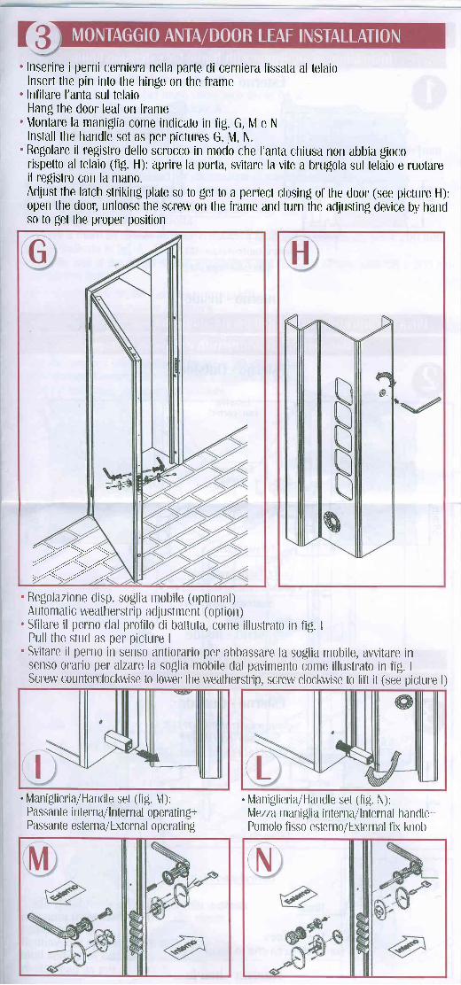
' Inserire i perni cerniera nella parte di cerniera fissata al telaioInsert the pin into the hinge on the îrame
. Infilare l'anta sul telaioHang the door leaf on frame
. Montare la maniglia come indicato in îig. G, M e NInstall the handle set as per pictures G, M, N.
'Regolare il registro dello scrocco in modo che l'anta chiusa non abbia gi0c0rispetto al telaio (fig. H): aprire la porta, svitare la vite a brugola sul telaio e ruotareil registro con la mano.Adjust the latch striking plate so t0 get to a perfect closing of the door (see picture H):Open the d00r, unloose the screw on the frame and turn the adjusting device by handso to get the proper position
. Regolazione disp. soglia mobile (optional)Automatic weatherstrip adjustment (option)
. Sfilare il perno dal profilo di battuta, come illustrato in fig. IPull the stud as per picture I
'Svitare il perno in senso antiorario per abbassare la soglia mobile, avvitare insenso orario per alzare la so$lia mobile dal pavimento come illustrato in fig. IScrew counterclockwise to lower the weatherstrip, screw clockwise to lift it (see picture l)
. Maniglieria/Handle set (fig. [4):Passante interna/lnternal operating+Passante esterna/External operating
. Mlaniglieria/Handle set (fig. N):\Aezza man iglia interna/l nternal hand le+Pomolo fisso esterno/External îix knob
're

E€
Cl-.tlì
eE
O\rll
Esterno - 0utside
4 8 . S r n m 4 8 . 5 m m
f on l r o te Ia i o /Sub f r ame
Te la io /F rame
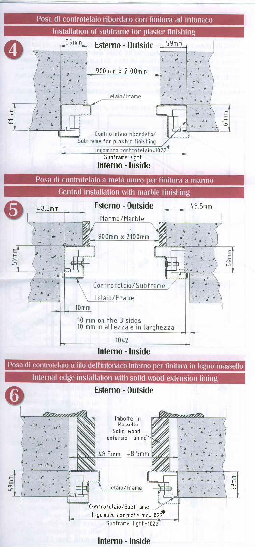
Inqombro con i ro f e ta i o=1g2 f
Subf rame t igh t=102
Interno - Inside
EE
O\Lll
Esterno - 0utside
lmbot tec0n c0rn tc l
Ex tens iont i n i ng
Tetaio/Fr arne
I on l r o t e ta i o / sub f r ame
lnqm+Subf r . * . t igh t=1022*
Interno - Inside
Esterno - OutsideI n g o m b r o c o n t r o t e t a i o = 1 0 2 2 *
4B.5mm
Te ta io /F rame
Ion l ro f e la io /5ubf ranre
10mm
10 mm on the J s ides10rnm s ia in a I tezza che in targhezza
4 8 . 5 m m
ee
O\
Interno - Inside
5 9 m m Esterno - 0utside
900mm x 2100mm
59mm
eE
\o
ee
U
Sub f r ame
Interno -t igh t
Inside
48 .5mm Esterno - OutsideM a r m o / M a r b t e
Interno - Inside
l . 8 .5mm
€(}\Lfl
Ee
9\r.r'l
Esterno - Outside
lmbotte inMasse l lo
Sot id woodextension t in ing
&8.5mm 48 .5mm
Teta io /Frame
Iont ro te ta io /Subf ramer 'Wzf
S u b f r a m e t i g h t = 1 0 2
Interno - Inside