Programming Abstractions for Nano-drone Teams · droni (5/10), ciascuno che esegua un’azione...
141
POLITECNICO DI MILANO Scuola di Ingegneria Industriale e dell’Informazione Corso di Laurea Magistrale in Ingegneria Informatica Dipartimento di Elettronica Informazione e Bioingegneria Programming Abstractions for Nano-drone Teams Relatore: Prof. Luca Mottola Correlatore: Mikhail Afanasov Tesi di Laurea di: Manuel Belgioioso, matricola 804149 Alberto Cardellini, matricola 818246 Anno Accademico 2014-2015
Transcript of Programming Abstractions for Nano-drone Teams · droni (5/10), ciascuno che esegua un’azione...
POLITECNICO DI MILANOScuola di Ingegneria Industriale e dell’Informazione
Corso di Laurea Magistrale in Ingegneria InformaticaDipartimento di Elettronica Informazione e Bioingegneria
Programming Abstractionsfor Nano-drone Teams
Relatore: Prof. Luca MottolaCorrelatore: Mikhail Afanasov
Tesi di Laurea di:Manuel Belgioioso, matricola 804149Alberto Cardellini, matricola 818246
Anno Accademico 2014-2015


Alle nostre famiglie.
III

IV
Abstract
Drone-teams programming is rapidly expanding since it allows to automaticallyperform a lot of useful tasks. Existing systems are able to manage a group of dronesand dispatching them in the environment. All these systems deal with outdoorapplications, where medium/big sized drones collaboratively perform tasks makinguse of the Global Positioning System (GPS) to navigate in the space. We want todeal with the indoor context, and no one of the existing system is fully suitablefor it. Indeed, the indoor context implies applications with different requirementscompared to the outdoor ones: there is need for a small number of drones(5/10),each one performing a different action independently from the others, while inthe outdoor environment generally there is need for a large number of drones toperform the same action. To address this problem, we propose the concept ofTrip, that is nothing but a movement of a drone from a point A to a point B atthe end of which an action (picture,measurement etc.) can be performed. No oneof the existing programming systems provides the concept of Trip. Furthermorethe second important goal is to make the system autonomous in the choice ofthe drone to allocate for each Trip. This means that the user does not need totake this important decision. We propose the Pluto programming framework asa solution to these problems. It consists of two main components: the GraphicalEditor and the Main Application. With the former a programmer can build anapplication by simply connecting functional blocks. Each block implements aprecise functionality, for example there is one that chooses the drones to assignto each sensing task, one that manages the priority of the sensing tasks etc. Then,through the "Generate code" command, the Pluto Graphical Editor generates thesource code of the second main component, the Pluto Main Application. Thefinal user uses this generated Pluto Main Application to define and execute thesensing tasks. The key strength of our programming framework is its scalablearchitecture, in which the central brain is independent from the particular navigation
V

API, which means that the system manages the dispatching of drones and theirfailures independently of the specific navigation algorithm. We evaluated the Plutoprogramming framework by proposing its use to real testers and asking them fora feedback. Moreover we measured its software and hardware performance andalso tried to implement some existing applications with it. After the evaluation wenoticed that, even if with some limits, Pluto could really simplify the developing ofdrone-teams applications.
VI
Sommario
La programmazione di team di droni è in rapida espansione, in quanto permettedi eseguire in maniera automatica un gran numero di azioni utili. I sistemi esistentisono in grado di gestire un gruppo di droni e farli navigare nell’ambiente. Tuttiquesti sistemi trattano applicazioni outdoor, nelle quali droni di dimensione medio/ grande collaborano insieme per svolgere varie azioni, utilizzando il sistema di po-sizionamento globale (GPS) per navigare nello spazio. Il nostro obbiettivo è quellodi affrontare il contesto indoor, e nessuno dei sistemi esistenti è completamenteadatto per esso. Infatti, il contesto indoor implica lo sviluppo di applicazioni conrequisiti differenti rispetto a quello outdoor: c’è bisogno di un piccolo numero didroni (5/10), ciascuno che esegua un’azione diversa, indipendentemente da tutti glialtri, mentre in ambiente outdoor generalmente c’è bisogno di un gran numero didroni che eseguano la stessa azione. Per risolvere questo problema proponiamoil concetto di Trip, che non è altro che un movimento di un drone da un punto Aad un punto B al termine del quale viene eseguita un’azione (scatto di una foto,misurazione di una grandezza fisica ecc.). Nessuno dei modelli di programmazioneesistenti fornisce il concetto di Trip. Inoltre, il secondo obiettivo importante èquello di rendere il sistema autonomo nella scelta del drone da assegnare ad ogniTrip. Ciò significa che l’utente non deve prendere questa importante decisione.Per rispondere a tutti questi problemi, abbiamo sviluppato il framework di pro-grammazione Pluto. Pluto ha due componenti principali: il Graphical Editor e laMain Application. Con il primo, un programmatore può costruire un’applicazionesemplicemente collegando dei blocchi funzionali. Ogni blocco implementa unafunzionalità precisa, per esempio ce n’è uno che sceglie i droni da assegnare aciascun Trip, un altro che gestisce la priorità dei Trip ecc. Quindi, grazie allafunzionalità di generazione del codice, il Pluto Graphical Editor genera il codicesorgente del secondo componente principale, la Pluto Main Application. L’utentefinale utilizza questa Main Application per definire ed eseguire i compiti nell’am-
VII
biente. Il punto di forza del nostro framework è la sua architettura scalabile chelo rende indipendente dalle API di navigazione utilizzate. Ciò significa che ilsistema è capace di gestire l’invio dei droni e i loro fallimenti indipendentementedall’algoritmo di navigazione specifico. Abbiamo testato l’utilizzo del frameworkdi programmazione Pluto, proponendone l’uso a dei tester reali e chiedendo loroun feedback. Inoltre abbiamo misurato le prestazioni software e hardware edabbiamo cercato di implementare con esso alcune applicazioni realmente esistenti.Grazie alla fase di valutazione, abbiamo notato che, anche se è caratterizzato daalcuni limiti, Pluto risulta uno strumento utile al fine di semplificare lo sviluppo diapplicazioni per team di droni.
VIII

Acknowledgements
It is a pleasure to thank those who made this thesis possible with advices, criticsand observations.We would like to thank our supervisor Prof. Luca Mottola and our mentor MikhailAfanasov: without their help and support, this thesis would not have been possible.
We would like to thank Prof. Thiemo Voigt, who kindly let us developing partof this work at SICS Swedish ICT and all the colleagues who have greeted andhelped us during the three months in Sweden, in particular Simon Duquennoy,Liam McNamara, Joel Höglund and Niklas Wirström.
We owe our deepest gratitude to our families and friends for the continuous supportduring these years at university.
Finally, we would like to thank one with the other for having lived together thisexperience.
IX

X
Contents
Abstract V
Sommario VII
Acknowledgements IX
1 Introduction 11.1 Contribution . . . . . . . . . . . . . . . . . . . . . . . . . . . . . 21.2 Outline . . . . . . . . . . . . . . . . . . . . . . . . . . . . . . . 4
2 State of the art 72.1 Drone-level approach . . . . . . . . . . . . . . . . . . . . . . . . 82.2 Swarm-level approach . . . . . . . . . . . . . . . . . . . . . . . 9
2.2.1 Robot Operating System . . . . . . . . . . . . . . . . . . 102.2.2 Karma . . . . . . . . . . . . . . . . . . . . . . . . . . . . 112.2.3 Proto . . . . . . . . . . . . . . . . . . . . . . . . . . . . 13
2.3 Team-level approach . . . . . . . . . . . . . . . . . . . . . . . . 152.4 Data-flow programming . . . . . . . . . . . . . . . . . . . . . . . 16
2.4.1 Business Process Modeling Notation . . . . . . . . . . . 172.4.2 Node-RED . . . . . . . . . . . . . . . . . . . . . . . . . 18
3 Indoor applications using autonomous drones 213.1 Motivating scenario . . . . . . . . . . . . . . . . . . . . . . . . . 213.2 Drone programming . . . . . . . . . . . . . . . . . . . . . . . . . 223.3 Implementation challenges . . . . . . . . . . . . . . . . . . . . . 25
3.3.1 Indoor localization . . . . . . . . . . . . . . . . . . . . . 253.3.2 Drones and Objects size limitation . . . . . . . . . . . . . 27
XI
4 Programming with Pluto 294.1 Programming model . . . . . . . . . . . . . . . . . . . . . . . . 294.2 Functional blocks . . . . . . . . . . . . . . . . . . . . . . . . . . 334.3 Toolchain . . . . . . . . . . . . . . . . . . . . . . . . . . . . . . 41
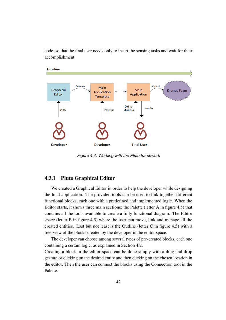
4.3.1 Pluto Graphical Editor . . . . . . . . . . . . . . . . . . . 424.3.2 Pluto Main Application . . . . . . . . . . . . . . . . . . . 44
4.4 Navigation System . . . . . . . . . . . . . . . . . . . . . . . . . 474.5 Design Choices . . . . . . . . . . . . . . . . . . . . . . . . . . . 47
4.5.1 Solution without Trip entity . . . . . . . . . . . . . . . . 474.5.2 Solution without the DroneAllocator and MissionModifier 48
5 Implementation 515.1 Object-oriented approach . . . . . . . . . . . . . . . . . . . . . . 525.2 Graphical editor . . . . . . . . . . . . . . . . . . . . . . . . . . . 535.3 Code generation . . . . . . . . . . . . . . . . . . . . . . . . . . . 545.4 Runtime Management . . . . . . . . . . . . . . . . . . . . . . . . 575.5 User interface . . . . . . . . . . . . . . . . . . . . . . . . . . . . 585.6 Prototype drone . . . . . . . . . . . . . . . . . . . . . . . . . . . 60
6 Evaluation 636.1 Generality . . . . . . . . . . . . . . . . . . . . . . . . . . . . . . 63
6.1.1 Basic applications . . . . . . . . . . . . . . . . . . . . . 646.1.2 Alfalfa Crop Monitoring and Pollination . . . . . . . . . . 696.1.3 Aerial mapping of archaeological sites . . . . . . . . . . . 776.1.4 PM10 . . . . . . . . . . . . . . . . . . . . . . . . . . . . 816.1.5 PURSUE . . . . . . . . . . . . . . . . . . . . . . . . . . 83
6.2 Usability . . . . . . . . . . . . . . . . . . . . . . . . . . . . . . . 856.2.1 Proposed exercises . . . . . . . . . . . . . . . . . . . . . 856.2.2 Evaluation metrics . . . . . . . . . . . . . . . . . . . . . 916.2.3 Baseline . . . . . . . . . . . . . . . . . . . . . . . . . . . 926.2.4 User Survey . . . . . . . . . . . . . . . . . . . . . . . . . 926.2.5 Results . . . . . . . . . . . . . . . . . . . . . . . . . . . 93
6.3 Performance evaluation . . . . . . . . . . . . . . . . . . . . . . . 986.3.1 Software Metrics . . . . . . . . . . . . . . . . . . . . . . 996.3.2 Resources Consumption . . . . . . . . . . . . . . . . . . 996.3.3 Results . . . . . . . . . . . . . . . . . . . . . . . . . . . 101
XII

7 Conclusions and future works 1077.1 Conclusions . . . . . . . . . . . . . . . . . . . . . . . . . . . . . 1077.2 Pluto limits and future works . . . . . . . . . . . . . . . . . . . . 109
Bibliography 111
A User survey 113
B User survey answers 121
XIII

XIV
List of Figures
2.1 The iRobot Create . . . . . . . . . . . . . . . . . . . . . . . . . . 92.2 ROS communication layer functioning . . . . . . . . . . . . . . . 112.3 The basic schema of Karma . . . . . . . . . . . . . . . . . . . . . 122.4 The amorphous medium abstraction . . . . . . . . . . . . . . . . 132.5 Proto: problem decomposition . . . . . . . . . . . . . . . . . . . 142.6 Voltron APIs . . . . . . . . . . . . . . . . . . . . . . . . . . . . 162.7 Example of a BPMN diagram . . . . . . . . . . . . . . . . . . . . 172.8 Example of a nodeRED application . . . . . . . . . . . . . . . . 18
3.1 The basic functioning of the Drugs distribution application . . . . 22
4.1 Relationship among model entities . . . . . . . . . . . . . . . . . 304.2 The MissionModifier block . . . . . . . . . . . . . . . . . . . . . 384.3 An example Pluto application . . . . . . . . . . . . . . . . . . . . 414.4 Working with the Pluto framework . . . . . . . . . . . . . . . . . 424.5 Pluto Graphical Editor interface . . . . . . . . . . . . . . . . . . 434.6 Mission Page interface . . . . . . . . . . . . . . . . . . . . . . . 444.7 Trips Page interface . . . . . . . . . . . . . . . . . . . . . . . . . 454.8 Monitor Page interface . . . . . . . . . . . . . . . . . . . . . . . 464.9 Solution without the Trip concept . . . . . . . . . . . . . . . . . 484.10 Solution without the MissionModifier block . . . . . . . . . . . . 49
5.1 Pluto architecture representation . . . . . . . . . . . . . . . . . . 515.2 MVC design applied to the Main Application . . . . . . . . . . . 525.3 Graphical entities in the editor . . . . . . . . . . . . . . . . . . . 545.4 Observer design pattern example . . . . . . . . . . . . . . . . . . 555.5 Example of thread concurrency . . . . . . . . . . . . . . . . . . . 575.6 Trips Page structure . . . . . . . . . . . . . . . . . . . . . . . . . 59
XV
5.7 The Crazyflie Nano-Quadcopter . . . . . . . . . . . . . . . . . . 60
6.1 The basic graph pattern of OF, DD and WIF applications . . . . . 656.2 The basic functioning of the Object-finder application . . . . . . . 666.3 The basic functioning of the Warehouse item-finder application . . 676.4 Pluto graph for the Alfalfa Crop Monitoring and Pollination ap-
plication . . . . . . . . . . . . . . . . . . . . . . . . . . . . . . . 706.5 The circular area to monitor . . . . . . . . . . . . . . . . . . . . 746.6 Sequence diagram of a starting mission . . . . . . . . . . . . . . 746.7 Sequence diagram of the mission execution flow . . . . . . . . . . 756.8 Sequence diagram of the trip execution flow . . . . . . . . . . . . 766.9 Sequence diagram of the mission ending flow . . . . . . . . . . . 766.10 The archaeological site on the map . . . . . . . . . . . . . . . . . 806.11 The area to sample on the map . . . . . . . . . . . . . . . . . . . 836.12 Solution of the first step . . . . . . . . . . . . . . . . . . . . . . . 876.13 Solution of the second step with Priority Manager . . . . . . . . . 886.14 Solution of the second step with Clock block . . . . . . . . . . . 896.15 Solution of the third step . . . . . . . . . . . . . . . . . . . . . . 906.16 Fist step of exercise 1 results . . . . . . . . . . . . . . . . . . . . 946.17 Second step of exercise 1 results . . . . . . . . . . . . . . . . . . 946.18 Third step of exercise 1 results . . . . . . . . . . . . . . . . . . . 956.19 Editor functioning results . . . . . . . . . . . . . . . . . . . . . . 956.20 First step of exercise 2 results . . . . . . . . . . . . . . . . . . . . 966.21 Second step of exercise 2 results . . . . . . . . . . . . . . . . . . 966.22 Third step of exercise 2 results . . . . . . . . . . . . . . . . . . . 976.23 VisualVM interface . . . . . . . . . . . . . . . . . . . . . . . . . 986.24 Very Complex Diagram Example . . . . . . . . . . . . . . . . . . 1006.25 Resources consumption of the Graphical Editor . . . . . . . . . . 1026.26 Evaluation results of Main Application with fixed missions and trips1036.27 Evaluation results of Main Application with fixed missions and
drones . . . . . . . . . . . . . . . . . . . . . . . . . . . . . . . . 1046.28 Evaluation results of Main Application with fixed trips and drones 104
XVI
Chapter 1
Introduction
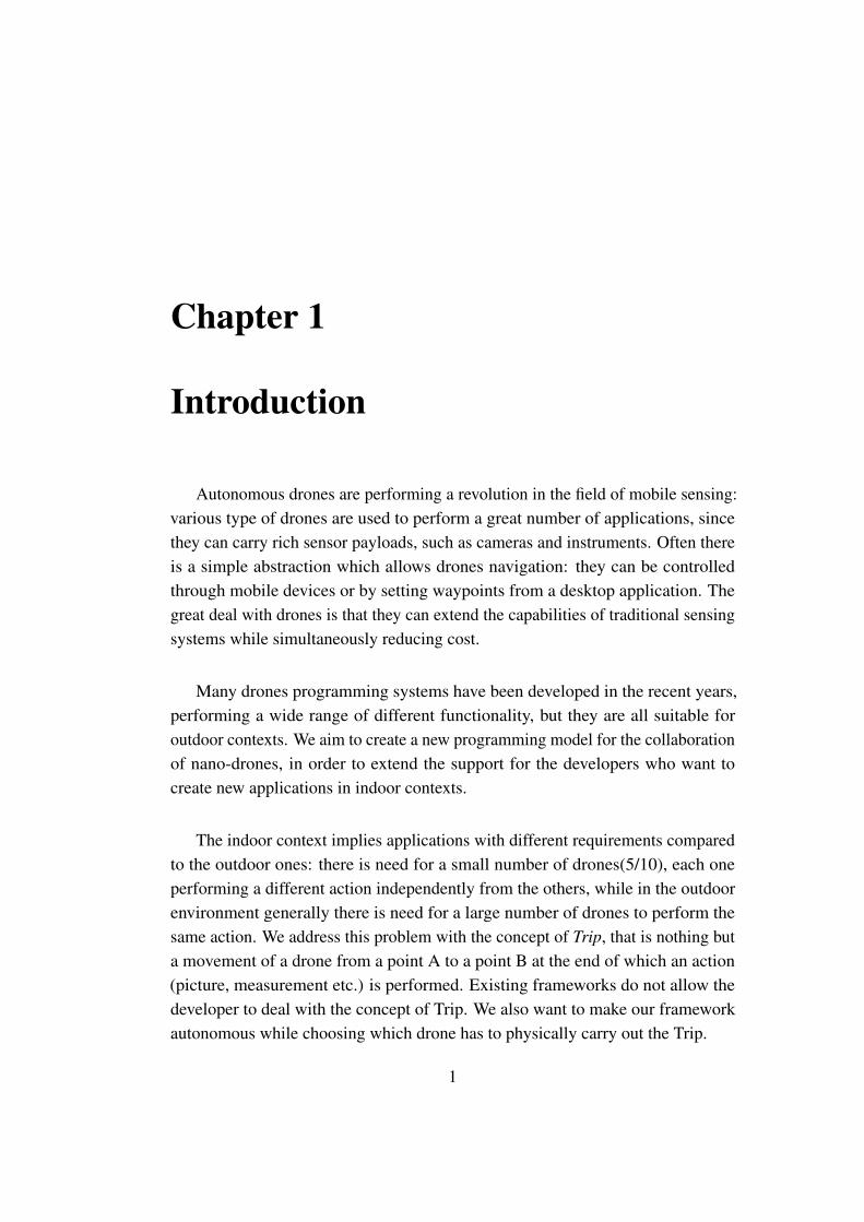
Autonomous drones are performing a revolution in the field of mobile sensing:various type of drones are used to perform a great number of applications, sincethey can carry rich sensor payloads, such as cameras and instruments. Often thereis a simple abstraction which allows drones navigation: they can be controlledthrough mobile devices or by setting waypoints from a desktop application. Thegreat deal with drones is that they can extend the capabilities of traditional sensingsystems while simultaneously reducing cost.
Many drones programming systems have been developed in the recent years,performing a wide range of different functionality, but they are all suitable foroutdoor contexts. We aim to create a new programming model for the collaborationof nano-drones, in order to extend the support for the developers who want tocreate new applications in indoor contexts.
The indoor context implies applications with different requirements comparedto the outdoor ones: there is need for a small number of drones(5/10), each oneperforming a different action independently from the others, while in the outdoorenvironment generally there is need for a large number of drones to perform thesame action. We address this problem with the concept of Trip, that is nothing buta movement of a drone from a point A to a point B at the end of which an action(picture, measurement etc.) is performed. Existing frameworks do not allow thedeveloper to deal with the concept of Trip. We also want to make our frameworkautonomous while choosing which drone has to physically carry out the Trip.
1
From a technological point of view, GPS cannot be used in indoor contexts.Furthermore, the indoor context implies moving in small areas which are usuallyfull of people and obstacles, so the drones have to be small, in order to avoid crasheswith both human and environmental obstacles. Size limitations result in otherproblems such as the low battery duration and the maximum transportable weight.So, we need to give a contribution to the actual state of the art in order to derive anew programming system crossing all the previous requirements. Our programmingframework has an architecture in which the central brain is independent from theparticular navigation API, which means that the system manages the dispatchingof drones and their failures independently of the specific navigation algorithm.
1.1 Contribution
Imagine a medical context where the nurses’ duty is to deliver, every day at thesame hour, the patients’ daily medicines. A drone could achieve this task flyingroom by room and leaving the pills to the relative patient’s desk. It would be waybetter if a group of drones could manage these tasks simultaneously. This scenariois described in Section 3.1.
In order to create an application able to carry out this task, a developer couldprogram each drone individually, making use of a specific API to command them,and taking care of the complex duty of managing the coordination between them.Our goal is to build a more clever programming framework, where a central brainmanages the dispatching of the drones simultaneously and expresses how thedrones should behave to accomplish these tasks, managing also the failures dueto crashes of the drones and batteries getting empty. This mechanism is done in aprogrammer transparent manner, so that he does not need to manage the drones’dispatching. Chapter 2 illustrates in details the possible ways to achieve this goal:instead of using a Drone Oriented approach, the developer could use either aSwam Oriented or a Team Level approach. There are several available frameworkssuch as Karma[1] and Voltron[2], but no one of them is fully suitable for indoorapplications.
2
As already said, we deal with the indoor context, that implies applications withdifferent requirements compared to the outdoor ones: there is need for a smallnumber of drones(5/10), each one performing a different action independentlyfrom the others, while in the outdoor environment generally there is need for alarge number of drones to perform the same action. We formalize this problemwith the concept of Trip. No other framework allows the user to define the idea ofa Trip as a movement from point A to point B to accomplish an action. Anotherfundamental feature of our framework is that the central brain takes care of theimportant decision to choose which drone to assign to a given Trip, facilitating thework of the programmer in the development of his application. As said, the systemmanages the failed trips in the same way. For example, when a drone crashes,the system chooses a new drone to complete the interrupted Trip, without anyintervention of the programmer or the final user.
We wanted to facilitate as much as possible the work of the programmer, sowe decided to create the Graphical Editor. Thanks to this editor, the programmercan develop its application by drawing functional blocks and then connecting them.Each block represents a feature: there is a block that assigns a Drone to a Trip,one that sends the drones to the target location, etc. The developer can connectthe blocks needed according to the requirements of the specific application. Fromthe drawn graph, the editor generates the source code of the Main Applicationmentioned before. This source code is dependent on the graph and adds to theMain Application all the features expressed by the chosen blocks.
In order to define the sensing tasks, we developed the Pluto Main Application,that is the final user interface. It allows the final user to choose the actions toperform and where they must be performed, by simply dragging and dropping theactions on a map. An Action could be the taking of a photo, a measurement ofsome parameters or a custom task expressed by the developer.
Finally we evaluated the Pluto framework under different points of view. Firstof all, we chose some already existing applications and tried to develop themfrom scratch with Pluto. Then we evaluated the framework usability, proposingsome exercises to real testers and asking them for a feedback through a survey.Finally we focused our attention on the software and hardware metrics such as the
3
code complexity and the CPU consumption. We defined some metrics to evaluateboth the users’ exercises and the software and hardware metrics. After a detailedanalysis of both the quantitative results and the answers to the user survey, theresults convinced us about Pluto capability to simplify the duties of a developer inimplementing a drone application.
1.2 Outline
In this Chapter, we have given the general context and the general goals of thework together with a brief description of our work.
In Chapter 2 there is a description of the actual state of the art in the contextof our work. In Sections 2.1, 2.2 and 2.3 we describe the three main existingapproaches for drone programming, the "Swarm-level","Drone-level" and "Team-level" respectively, also proposing existing examples for each one of them. Weshow that no one of these approaches is suitable for our requirements, since weneed the concepts of Mission and Trip. A Mission is a list of sensing tasks tobe performed sequentially and a Trip represents the sensing task itself. Then, inSection 2.4, we describe the dataflow programming method, that we adopted forthe Pluto Graphical Editor, providing two existing examples of it. Also in this case,we show that we need a different approach, since we need to use only a group ofbasic components for our work, while the existing solutions are too general andinclude a lot of complex components.
Chapter 3 is focused on the problems stemming from the indoor context and onthe requirements deriving from it. In Section 3.1, we show a motivating exampleapplication, in order to better explain the requirements and problems deriving fromour work. In Section 3.2 we show the programming problems deriving from usinga Team-level approach for our system, also proposing the solutions to fix them.Finally, in Section 3.3 we show the technological limitations affecting our system,such as the indoor localization and nano-drone batteries problems.
Chapter 4 presents our solution for the research problems described in Chapter3, the Pluto programming framework. In Section 4.1 we present our programmingmodel: we show the entities of our model and the relationships between them.
4

In Section 4.2 we describe in details the functionality of the available blocks ofthe Pluto Graphical Editor, that are the basic elements that the programmer canconnect to graphically build an application. In Section 4.3 we describe in detailsthe two components of the Pluto framework: the Graphical Editor, that is used bythe programmer to graphically build an application and the Main Application, thatis used by the final user to define the sensing tasks to be performed. In Section 4.4we describe the navigation system, that is the conjunction point between the MainApplication and the drones team. The last Section of the Chapter, the 4.5, describesall the steps performed to arrive to the final system, showing all the previouslyimplemented solutions which, once refined, brought us to the development of thePluto programming framework.
Chapter 5 shows how the designed choices have been implemented technically,describing all the software and tools used for the development of Pluto program-ming framework. In Section 5.1 we motivate the choice of an Object-Orientedprogramming model for the Pluto framework. In Section 5.2 we describe the GEFframework, which we used to implement the Pluto Graphical Editor. In Section5.3 we show the code generation process that creates a Java application from thegraph built with the Pluto Graphical Editor. In Section 5.4 we describe the runtimefeatures of Pluto: the parallel architecture and the management of all the neededthreads. In Section 5.5 we describe the SWING tool, which we used to developthe Pluto Main Application. Finally, in Section 5.6 we describe the Crazyflienano-quadcopter, which we used for our example prototype.
Chapter 6 starts with an analysis on the applicability of the Pluto framework.In Section 6.1 we describe four already existing applications and three case study,and we discuss whether they can be developed or not with Pluto. In Section 6.2we propose two exercises to real testers, in order to test "on the field" the effectiveusability of Pluto: the first one deals with the Graphical Editor, the second one withthe Main Application. Then we propose a third exercise, in which we ask the usersto directly use the API of the Crazyflie nano-quadcopter, shown in section 5.6, tomake it move from a point A to a point B. We also propose a survey to the usersand then present the result in a graphical way, in order to have opinions on theframework and possibly to improve it with the suggestions of the testers. In Section6.3 we measure the software and hardware consumption metrics required by Pluto,
5

in order to evaluate the effective impact of Pluto on an ordinary computing machine.
Finally, Chapter 7 draws the conclusion and recaps the results obtained, alsoshowing the possibilities for future works to extend our programming model.
6

Chapter 2
State of the art
In the last years, the drone technology is expanding rapidly;especially theaerial drones, which are often used as toys controlled by joystick or to make aerialvideos through mounted cameras. There exist also aquatic and terrestrial drones,which can be used for many applications. For example, through aquatic dronesthe submarine network infrastructure[3] could be managed more efficiently, andthrough terrestrial drones some emergency situations, like fires, can be managedwithout involving human life.
Basically, the mobile sensing through drones represents a technological revolu-tion, opening the way for many applications which could not have been developedwith the traditional technologies. Actually, there are a lot of fields where thisnew technology could be applied, improving performance and reducing costs: forexample surveillance applications, instructing drones to fly over an area monitoringpeople, or an application in a domestic context, for example instructing drones tofind a lost object or to perform some kind of actions, like bringing some objects tothe final user.
In the following Section we present three main approaches for programmingdrones , providing existing examples for each one of them:
• Drone-level approach, described in Section 2.1
• Swarm-level approach, described in Section 2.2
• Team-level approach, described in Section 2.3
The former is focused on the programming of an every single drone, whilethe second implies basic rules to execute for the whole swarm of drones. The
7
third approach is the most modern work. It creates a middle-ground betweendrone and swarm approaches, by providing a flexibility in expressing sophisticatedcollaborative tasks without addressing to a single drone.
After presenting the three main approaches for programming drones, we showsome examples of data-flow
2.1 Drone-level approach
In the Drone-level approach, the programmer must manage the single drone,taking care of giving a list of instructions that the drone will perform sequentially.This approach may be suitable for applications where there is a single drone per-forming some actions, like searching for a lost object and bringing it back to theuser.But scaling the application to a number of drones makes programmer to dealwith concurrency and parallelism. Moreover, battery and crashes/failures shouldbe managed manually for every drone. Finally, timing constraints and a dynamicload balance drastically increase the complexity of the programming. For thesereasons drone-level approach is not suitable for a large number of drones.
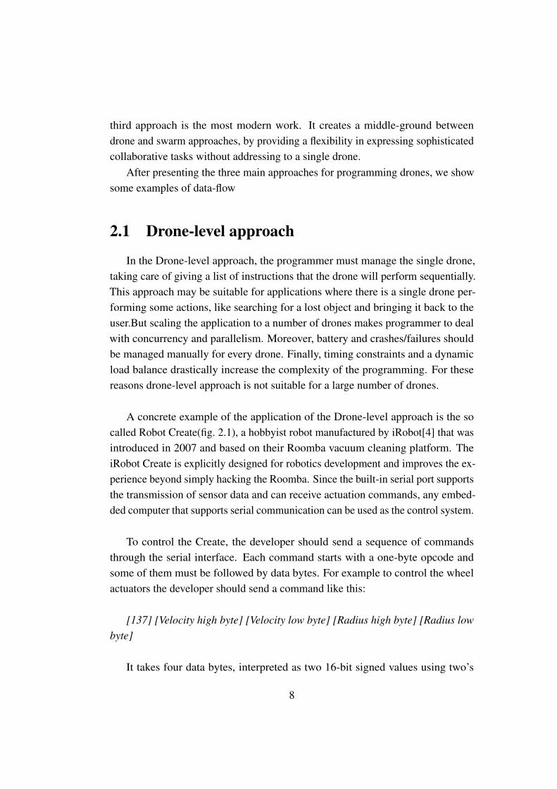
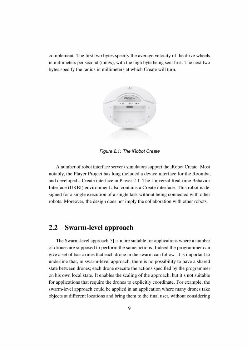
A concrete example of the application of the Drone-level approach is the socalled Robot Create(fig. 2.1), a hobbyist robot manufactured by iRobot[4] that wasintroduced in 2007 and based on their Roomba vacuum cleaning platform. TheiRobot Create is explicitly designed for robotics development and improves the ex-perience beyond simply hacking the Roomba. Since the built-in serial port supportsthe transmission of sensor data and can receive actuation commands, any embed-ded computer that supports serial communication can be used as the control system.
To control the Create, the developer should send a sequence of commandsthrough the serial interface. Each command starts with a one-byte opcode andsome of them must be followed by data bytes. For example to control the wheelactuators the developer should send a command like this:
[137] [Velocity high byte] [Velocity low byte] [Radius high byte] [Radius lowbyte]
It takes four data bytes, interpreted as two 16-bit signed values using two’s
8
complement. The first two bytes specify the average velocity of the drive wheelsin millimeters per second (mm/s), with the high byte being sent first. The next twobytes specify the radius in millimeters at which Create will turn.
Figure 2.1: The iRobot Create
A number of robot interface server / simulators support the iRobot Create. Mostnotably, the Player Project has long included a device interface for the Roomba,and developed a Create interface in Player 2.1. The Universal Real-time BehaviorInterface (URBI) environment also contains a Create interface. This robot is de-signed for a single execution of a single task without being connected with otherrobots. Moreover, the design does not imply the collaboration with other robots.
2.2 Swarm-level approach
The Swarm-level approach[5] is more suitable for applications where a numberof drones are supposed to perform the same actions. Indeed the programmer cangive a set of basic rules that each drone in the swarm can follow. It is important tounderline that, in swarm-level approach, there is no possibility to have a sharedstate between drones; each drone execute the actions specified by the programmeron his own local state. It enables the scaling of the approach, but it’s not suitablefor applications that require the drones to explicitly coordinate. For example, theswarm-level approach could be applied in an application where many drones takeobjects at different locations and bring them to the final user, without considering
9
any time or space coordination between them; each drone will simply bring theobject back to the user when found. There are several existing applications usingthe swarm-level approach, but we decided to describe three of them: the RobotOperating System (ROS)[6], which provides a Publish/Subscribe coordinationlayer for decentralized computations, as shown in Section 2.2.1; Karma[1], whichlets programmers specify modes of operation for the swarm, such as “Monitor”or “Pollinate”(as shown in Section 2.2.2); and Proto[7], which lets programmersspecify actions in space and time(as shown in Section 2.2.3).
2.2.1 Robot Operating System
ROS[6] is not an operating system in the traditional sense, indeed it provides alayer for communication between many, possibly heterogeneous, operating systemsconnected in a cluster.
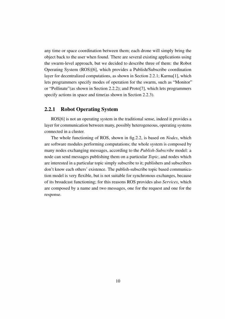
The whole functioning of ROS, shown in fig.2.2, is based on Nodes, whichare software modules performing computations; the whole system is composed bymany nodes exchanging messages, according to the Publish-Subscribe model: anode can send messages publishing them on a particular Topic, and nodes whichare interested in a particular topic simply subscribe to it; publishers and subscribersdon’t know each others’ existence. The publish-subscribe topic based communica-tion model is very flexible, but is not suitable for synchronous exchanges, becauseof its broadcast functioning; for this reasons ROS provides also Services, whichare composed by a name and two messages, one for the request and one for theresponse.
10
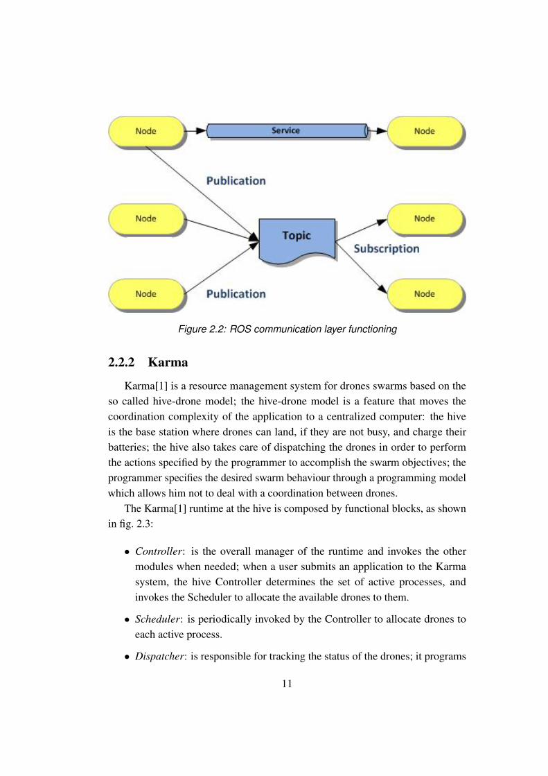
Figure 2.2: ROS communication layer functioning
2.2.2 Karma
Karma[1] is a resource management system for drones swarms based on theso called hive-drone model; the hive-drone model is a feature that moves thecoordination complexity of the application to a centralized computer: the hiveis the base station where drones can land, if they are not busy, and charge theirbatteries; the hive also takes care of dispatching the drones in order to performthe actions specified by the programmer to accomplish the swarm objectives; theprogrammer specifies the desired swarm behaviour through a programming modelwhich allows him not to deal with a coordination between drones.
The Karma[1] runtime at the hive is composed by functional blocks, as shownin fig. 2.3:
• Controller: is the overall manager of the runtime and invokes the othermodules when needed; when a user submits an application to the Karmasystem, the hive Controller determines the set of active processes, andinvokes the Scheduler to allocate the available drones to them.
• Scheduler: is periodically invoked by the Controller to allocate drones toeach active process.
• Dispatcher: is responsible for tracking the status of the drones; it programs
11
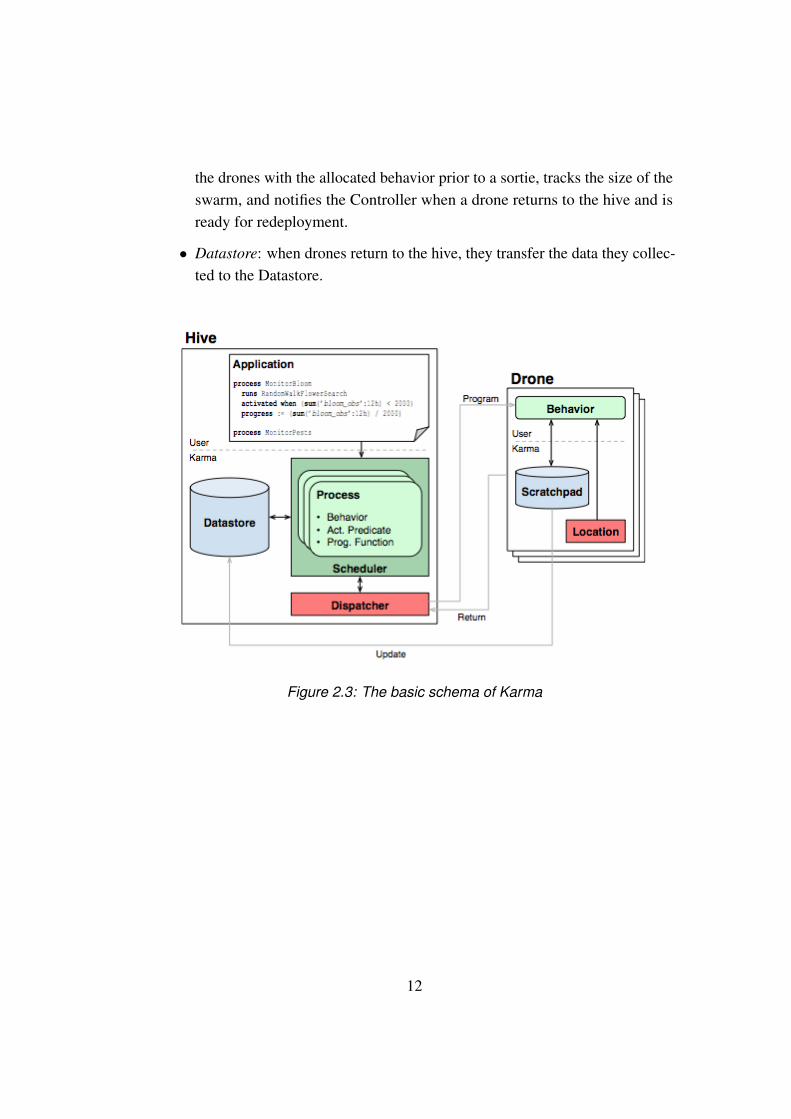
the drones with the allocated behavior prior to a sortie, tracks the size of theswarm, and notifies the Controller when a drone returns to the hive and isready for redeployment.
• Datastore: when drones return to the hive, they transfer the data they collec-ted to the Datastore.
Figure 2.3: The basic schema of Karma
12
2.2.3 Proto
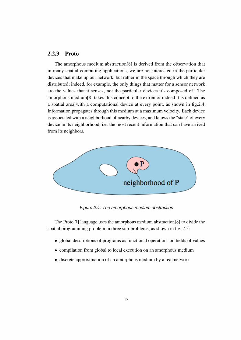
The amorphous medium abstraction[8] is derived from the observation thatin many spatial computing applications, we are not interested in the particulardevices that make up our network, but rather in the space through which they aredistributed; indeed, for example, the only things that matter for a sensor networkare the values that it senses, not the particular devices it’s composed of. Theamorphous medium[8] takes this concept to the extreme: indeed it is defined asa spatial area with a computational device at every point, as shown in fig.2.4:Information propagates through this medium at a maximum velocity. Each deviceis associated with a neighborhood of nearby devices, and knows the "state" of everydevice in its neighborhood, i.e. the most recent information that can have arrivedfrom its neighbors.
Figure 2.4: The amorphous medium abstraction
The Proto[7] language uses the amorphous medium abstraction[8] to divide thespatial programming problem in three sub-problems, as shown in fig. 2.5:
• global descriptions of programs as functional operations on fields of values
• compilation from global to local execution on an amorphous medium
• discrete approximation of an amorphous medium by a real network
13
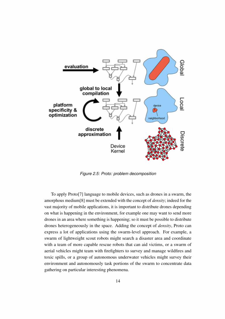
Figure 2.5: Proto: problem decomposition
To apply Proto[7] language to mobile devices, such as drones in a swarm, theamorphous medium[8] must be extended with the concept of density; indeed for thevast majority of mobile applications, it is important to distribute drones dependingon what is happening in the environment, for example one may want to send moredrones in an area where something is happening; so it must be possible to distributedrones heterogeneously in the space. Adding the concept of density, Proto canexpress a lot of applications using the swarm-level approach. For example, aswarm of lightweight scout robots might search a disaster area and coordinatewith a team of more capable rescue robots that can aid victims, or a swarm ofaerial vehicles might team with firefighters to survey and manage wildfires andtoxic spills, or a group of autonomous underwater vehicles might survey theirenvironment and autonomously task portions of the swarm to concentrate datagathering on particular interesting phenomena.
14
2.3 Team-level approach
In this Section we describe the team-level programming approach[2], whichallows the user to express a list of sensing tasks to be performed by the system,without dealing with the management of the single drone and with complex pro-gramming tasks such as concurrent programming and parallel execution; the usercan also require a layer of coordination, defining constraints in space and timefor the tasks’ execution, and the system will follow these constraints choosingthe actions for each drone at run-time, in order to collaboratively accomplish allthe tasks. This run-time drones management makes the whole system scalable,since one can add as many drones as he wants, and also fault tolerant, becauseit can easily manage crashes or exceptions. So, the main advantage of using theteam-level approach is that the user can simply specify a list of tasks to be per-formed,together with constraints in space and time for the execution, not caringabout the dispatching and coordination of the drones; this is also a limitation,because one cannot develop applications which require explicit communicationbetween drones. So, the team-level approach is most suitable for applicationsinvolving tasks that could be also performed by a single drone, but require a largenumber of drones to be completed faster and/or to operate in a big area.
A concrete example of team-level approach application is Voltron[2], a systemcontaining a set of programming constructs to explore the notion of team-leveldrone programming. Voltron’s[2] basic functioning includes:
• the so-called abstract drone, which makes the application scalable, allowingto add drones without changing the code
• spatial semantics, which allow the drones to execute parallel tasks at differentlocations
• the possibility to dinamically re-schedule drones operations in case of crashesor failures
• the possibility to define time constraints for the tasks
Voltron[2] exposes an API, as shown in fig.2.6, that programmers can use totask the drones without individual addressing; since the abstract drone is the onlyentry point to the system’s functionality, an application’s code can remain unaltered
15

no matter how many real devices are deployed.
Figure 2.6: Voltron APIs
The team-level approach represents a middle-ground between the drone-leveland swarm-level approaches, and it also solves many problems. Unlike the drone-level approach, there is no need to address the single drone and, unlike the swarm-level approach, there can be a "global state" and also time and space constraints canbe defined; as already said, the team-level approach’s main limitation is that thereis no possibility to perform tasks which require explicit communication betweendrones, such as passing an object between them.
2.4 Data-flow programming
Dataflow Programming is a useful programming paradigm that allows a de-veloper to represent the execution model of his application through a directed graph.The flow of the data processed during the execution streams between all nodes.Each node is a functional block that accept data as input, manages it performing itstasks and then drive it forward to the next block.The final dataflow application is nothing but a composition of these active blockswith at least one initial and one ending blocks, connected by directed arrows. Ablock is connected to another when it has a dependency on the result of the manip-ulation of the data from that block. Values are propagated after they are processedfrom all the dependent blocks triggering their execution.
16

This paradigm present some limits of expression. The main one is that eachimplementation of this paradigm is specific for the context where it is used. Thismeans that there are no general frameworks that can be used in more than onecontext. This is why we created our own dataflow editor, shown in Section 4.3.1.
2.4.1 Business Process Modeling Notation
Business Process Modeling Notation (BPMN) is an example of the power ofthe dataflow programming paradigm. Its primary goal is to help business usersproviding a readily understandable notation, filling the gap between the businessprocess design and the final process implementation.
BPMN defines a diagram that contains graphical models of the business pro-cess operations. A Business Process Model, is nothing but a graph where nodesrepresent graphical models representing the operations, and edges are the flowcontrols that define their order of performance. An example is shown in figure 2.7.
Figure 2.7: Example of a BPMN diagram
17
There are different kinds of elements in a diagram:
• Flow Objects: they can be Events (circles), Activities (rounded rectangles)or a Gateway (diamonds)
• Connecting Objects: they can represent a Sequence Flow (solid line), aMessage (dashed line) or an Association (dotted lines)
• Swimlanes: they can be a Pool representing the Actor of the process, or aLane that is a sub-partition within a Pool
• Artifacts: they are useful to extend the basic notation adding new ways todescribes context based information
2.4.2 Node-RED
Node-RED is an example of the dataflow paradigm applied to the Internetof Things world. It is a browser-based editor that let the developer wire togetherdifferent nodes with directed edges. Each node provides a different feature or adifferent management of the input data. All features are web-based functionality,such as receiving an HTTP request or a Javascript snippet. In this context, adiagram represents the back-end of the web application and When the graph iscompleted, the user can deploy it with a single-click in the runtime environment.The light-weight runtime is built on Node.js, taking full advantage of its event-driven, non-blocking model. This makes it ideal to run at the edge of the networkon low-cost hardware as well as in the cloud.
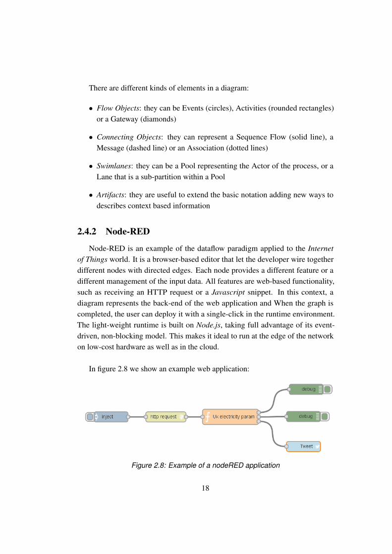
In figure 2.8 we show an example web application:
Figure 2.8: Example of a nodeRED application
18

The yellow node makes a GET request to the UK electric company website.The response data follow the edges and pass through the orange node, which
lets the developer write its custom Javascript code inside it. In this case, the customcode takes the payload data in input and put them on the third output, formattingthem in readable way. Through the first two outputs, the block sends only debugstrings that go to the green nodes. In the end the blue node will send a tweetcontaining the data received as input.
In this Chapter we have described the actual state of the art in the field of droneprogramming and dataflow programming. We needed to overcome the limits of theactual state of the art by performing some modifications to the existing solutions,which we show in Section 3.2.
19

20

Chapter 3
Indoor applications usingautonomous drones
In this Chapter we show all the problems we had to face in the developmentof our programming framework. We first show a concrete application we wantedto develop, and then the problems deriving from its development. No one of theexisting drone programming approaches, shown in Chapter 2, is fully suitable forour problem. We chose a Team-level programming approach, described in Section2.3, but we had to perform some modifications on it, as we explain in Section3.2. There are also some technological limitations, such as the lack of a stableindoor localization system and the short duration of nano-drones battery, which weexplain in Section 3.3.
3.1 Motivating scenario
In order to concretely show all the limitations and problems encountered in thedevelopment of our system, we start this Chapter describing a concrete scenario. Wewant to develop an application to assist elders to take their medicines, for examplein a hospital context. A team of nano-drones could help the nurses to deliver thedaily medicines to the patients at the right time of the day. A representation of thebehavior of the application, which we named Drugs Distribution(DD), is shown infigure 3.1:
21
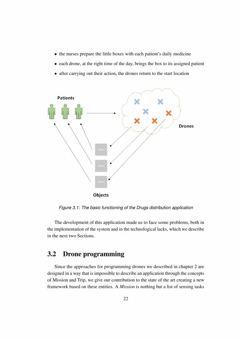
• the nurses prepare the little boxes with each patient’s daily medicine
• each drone, at the right time of the day, brings the box to its assigned patient
• after carrying out their action, the drones return to the start location
Figure 3.1: The basic functioning of the Drugs distribution application
The development of this application made us to face some problems, both inthe implementation of the system and in the technological lacks, which we describein the next two Sections.
3.2 Drone programming
Since the approaches for programming drones we described in chapter 2 aredesigned in a way that is impossible to describe an application through the conceptsof Mission and Trip, we give our contribution to the state of the art creating a newframework based on these entities. A Mission is nothing but a list of sensing tasks
22
to be performed sequentially in the environment. Each one of these sensing tasksis a Trip, that is a movement from a point A to a point B to perform an Action.
Neither the Drone-level nor the swarm-level approaches, described in Sections2.1 and 2.2 respectively, are suitable for our goal. The former because we do notwant the user to deal with the coding of each drone separately with an external API.The latter because we want to avoid the complexity to create a communicationnetwork protocol between drones and because it would be difficult to maintainthe status of the missions and trips entities among the swarm. Moreover we alsoneed to address time and space constraints, which cannot be expressed with thisapproach.
The most suitable approach for our framework is the Team-level model, de-scribed in Section 2.3, but we need to apply some modifications to it, in order tomake it suitable for our work. Using a Team level approach entails some problems:the user can neither address individual drones nor express actions that involve dir-ect interactions between drones, such as those required to pass an object betweenthem. This is the main limitation of the approach, but it does not directly affectthe development of our DD application, described in Section 3.1. So we have tomodify the Team-level approach in order to make each drone deliver the box ofmedicine to its assigned patient, independently from the other drones. So we needthe concept of Trip. A Trip is nothing but a movement from a point A to a pointB in the environment to perform an action. In this way, we can tell each drone togo to the precise location of its assigned patient, making the Trip of each Droneindependent from the others. The concept of Trip is a fundamental feature of ourmodel, and it is fully described in Section 4.1.
Another very important feature of our system is the transparent dispatching ofdrones: the central brain takes care of assigning the drones to the sensing tasks to beperformed, managing also the drones failures, without involving the programmer.
Another problem of the Team-level approach is that, having a single brainwhich manages all the application logic and the dispatching of drones, the systemget a single point of failure, so, if the central brain breaks then the whole systemcrashes. This problem can be fixed or at least weakened by applying some depend-able systems methods, improving reliability of the central brain, reducing its rateof failure etc.
23
Even though team-level approach has his own limitations, other approacheswe discussed in Chapter 2 are less suitable. Indeed, the Drone-oriented approach,described in Section 2.1, has the problem that the programmer has to manageindividually the drone’s movements and the interactions with other drones: hemust code a list of instructions and commands that the drone will perform se-quentially. This can only be achieved with the exploiting of specific API of eachdrones. In the case of multiple drones,the programmer should deal with difficultprogramming tasks, like concurrency and parallelism, and it should also managethe drone batteries discharge and their crashes/failures. Adding one or more dronesto the system could complicate a lot the programming task. The programmershould also deal with timing constraints and he should balance the load betweendrones in a dynamic way. Is clear that the drone-level approach is most suitable forapplications involving only a few drones.
On the other hand, the Swarm-level approach, described in Section 2.2, ismore suitable for applications where there’s need of a lot of drones performing thesame actions. Indeed the programmer can give a set of basic rules that each droneshould follow. It is important to underline that, in swarm-level approach, there isno possibility to have a shared state between drones; each one execute the actionsspecified by the programmer on his own local state. This means that this approachis very easy to scale up adding new drones, but it’s not suitable for applicationsthat require the drones to explicitly coordinate.
Regarding the dataflow programming, we need a new framework that allowsthe user to design the behavior of the central brain taking care of the missionsexecution, from the beginning to the end. This modeling tool helps the developer toadd the features needed by the application simply drawing the proper nodes in thedataflow graph. The BPMN and Node-RED dataflow models, described in Sections2.4.1 and 2.4.2 respectively, are too general for our system, since they allow tomodel almost every kind of project. They offer a great number of components, butwe only need basic components for our editor, like rectangles and arrows. So wedecided to develop our own dataflow model, offering only the functionality andcomponents needed for our programming framework. This part of the project isfully described in Section 4.3.1.
24
3.3 Implementation challenges
The DD application, shown in Section 3.1, makes drone bring medicines to theelders in an hospital, so in an indoor context. One big problem is that there is nota stable localization method for the indoor environment. Besides of localizationproblem, indoor context also leads to the limits of the size of the drone. As a result,programmers constantly confront with a limited battery resource and a small weighthe drone can carry out. These problems, as well as their possible solutions, aredescribed in the following Section.
3.3.1 Indoor localization
The main issue that all developers are facing, working on an indoor applicationfor drones, is that they are not able to use the Global Positioning System (GPS); itcannot be used because of walls,roofs or ceilings. For this reason Indoor Position-ing System(IPS) is widely applied for indoor localization. In this Section we willgive an overview of existing IPS methods.
An indoor positioning system is a solution to locate objects or people inside abuilding using radio waves, magnetic fields, acoustic signals, or other informationcollected from the sensors of mobile devices. The IPS methods rely on alternativetechnologies, such as magnetic positioning and dead reckoning, to actively locatemobile devices and provide ambient location for devices to get sensed.
Today many IPS methods have been developed and they can be divided in twomain categories: Non-radio technologies and Wireless technologies.
Non-radio technologies have been developed for localization without usingthe existing wireless infrastructures, and they can provide very high accuracy.Nevertheless, they also require expensive installations and costly equipment.
For example, Magnetic positioning[9] is based on the iron inside buildings thatcreate local variations in the Earth’s magnetic field. Modern smartphones can usetheir magnetometers to sense these variations in order to map indoor locations.
With Inertial measurements[10] pedestrians can carry an inertial measurementunit(IMU) by measuring steps indirectly or in a foot mounted approach, referring
25
to maps or additional sensors to constrain the sensor drift encountered with inertialnavigation.
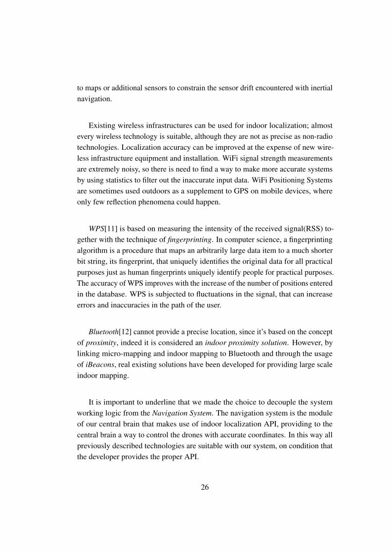
Existing wireless infrastructures can be used for indoor localization; almostevery wireless technology is suitable, although they are not as precise as non-radiotechnologies. Localization accuracy can be improved at the expense of new wire-less infrastructure equipment and installation. WiFi signal strength measurementsare extremely noisy, so there is need to find a way to make more accurate systemsby using statistics to filter out the inaccurate input data. WiFi Positioning Systemsare sometimes used outdoors as a supplement to GPS on mobile devices, whereonly few reflection phenomena could happen.
WPS[11] is based on measuring the intensity of the received signal(RSS) to-gether with the technique of fingerprinting. In computer science, a fingerprintingalgorithm is a procedure that maps an arbitrarily large data item to a much shorterbit string, its fingerprint, that uniquely identifies the original data for all practicalpurposes just as human fingerprints uniquely identify people for practical purposes.The accuracy of WPS improves with the increase of the number of positions enteredin the database. WPS is subjected to fluctuations in the signal, that can increaseerrors and inaccuracies in the path of the user.
Bluetooth[12] cannot provide a precise location, since it’s based on the conceptof proximity, indeed it is considered an indoor proximity solution. However, bylinking micro-mapping and indoor mapping to Bluetooth and through the usageof iBeacons, real existing solutions have been developed for providing large scaleindoor mapping.
It is important to underline that we made the choice to decouple the systemworking logic from the Navigation System. The navigation system is the moduleof our central brain that makes use of indoor localization API, providing to thecentral brain a way to control the drones with accurate coordinates. In this way allpreviously described technologies are suitable with our system, on condition thatthe developer provides the proper API.
26

3.3.2 Drones and Objects size limitation
Indoor contexts imply small areas which are usually full of people and obstacleshence, drones have to be small, in order to avoid crashes with both human andenvironmental obstacles.
Size limitations result in many problems; the first is battery duration, whichcan reach a maximum of 8 minutes, having a recharge time of about 20/30 minutes.It limits the programmer in developing applications which require the drones toperform their actions in this limited amount of time.
Another problem arising from size limitations is that the smaller the drone isthe less stable he is. Almost every kind of micro-drone has serious stability issues,and a lot of research efforts goes in this direction. This problem is lowered by thedeveloping of programming libraries that could improve stability of the drones atreal-time, adjusting a set of parameters while the drone is flying.
Micro-drones are obviously more fragile than the big ones, so a crash withhumans or obstacles can definitely destroy the drone or make it seriously damaged.This is the price to be paid for having little drones that can operate in small indoorcontexts.
Finally, the use of small drones means that only small objects can be taken, sothe applications developed with Pluto framework must take this into account. Forexample, a pair of keys can be brought to a person, not a book nor a pair of shoes.
27

28

Chapter 4
Programming with Pluto
We already said our goal is to perform user-defined sensing tasks using nano-drones, in an indoor context. We chose the Team Level approach, which wedescribed in Section 2.3, applying some modifications to it, to manage the sensingtasks execution. As we have shown in Section 3.2, the Team-Level approach isthe most suitable approach for the kind of applications that can be developed withour framework. The most important advantage of this approach is the reducedcomplexity given to the final user, while expressing the sensing tasks. There is noneed to describe how the drones should execute them. These details are chosen bythe Ground Control Station whose duty is to assign the right drone to the relatedtask and check that each drone takes its mission to the end with a successful status.In this chapter we describe the whole programming model of our system as asolution for the problems shown in Chapter 3.
4.1 Programming model
Through our programming model, the user is able to specify a list of sensingtasks that the drones can perform.Each one of the sensing tasks is represented by the Trip entity, that is the virtualrepresentation of a physical movement of the drone from a source location to adestination. The Trip always ends with an Action, that is the physical representationof the task. For example the drone can bring an Item, take a photo or measure thetemperature in a specific location.
Then, we decided to create a container entity called Mission, that includes the
29
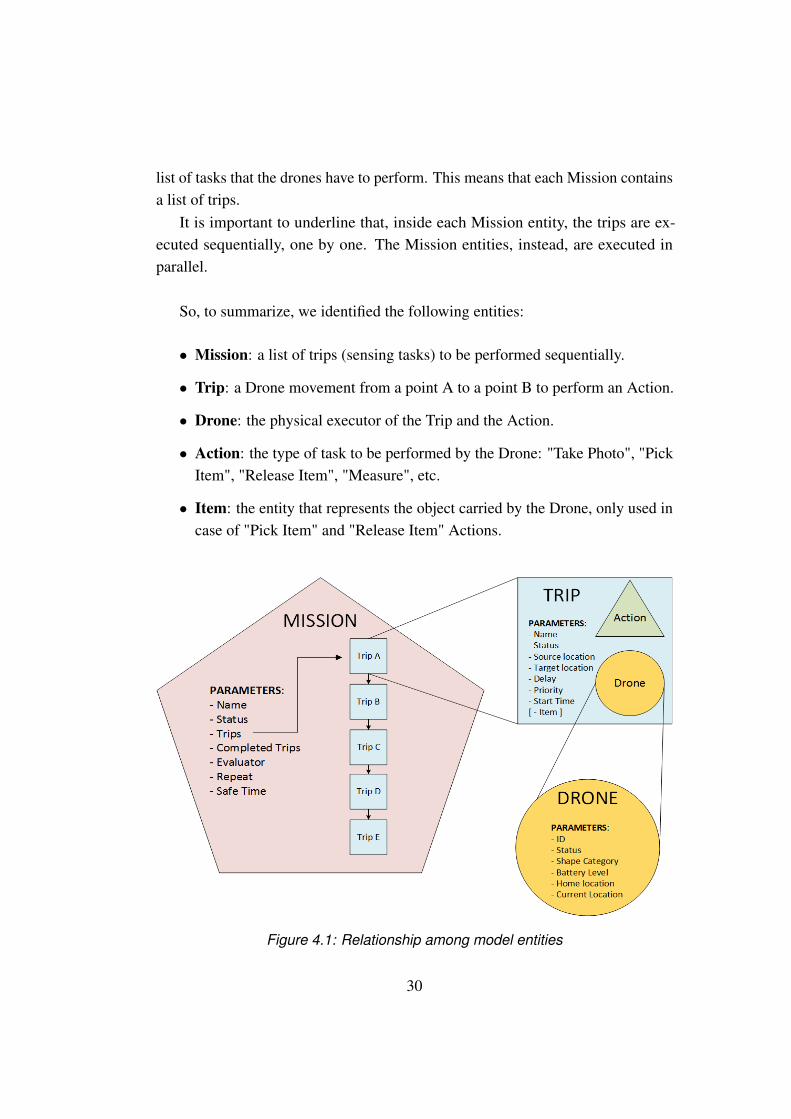
list of tasks that the drones have to perform. This means that each Mission containsa list of trips.
It is important to underline that, inside each Mission entity, the trips are ex-ecuted sequentially, one by one. The Mission entities, instead, are executed inparallel.
So, to summarize, we identified the following entities:
• Mission: a list of trips (sensing tasks) to be performed sequentially.
• Trip: a Drone movement from a point A to a point B to perform an Action.
• Drone: the physical executor of the Trip and the Action.
• Action: the type of task to be performed by the Drone: "Take Photo", "PickItem", "Release Item", "Measure", etc.
• Item: the entity that represents the object carried by the Drone, only used incase of "Pick Item" and "Release Item" Actions.
Figure 4.1: Relationship among model entities
30
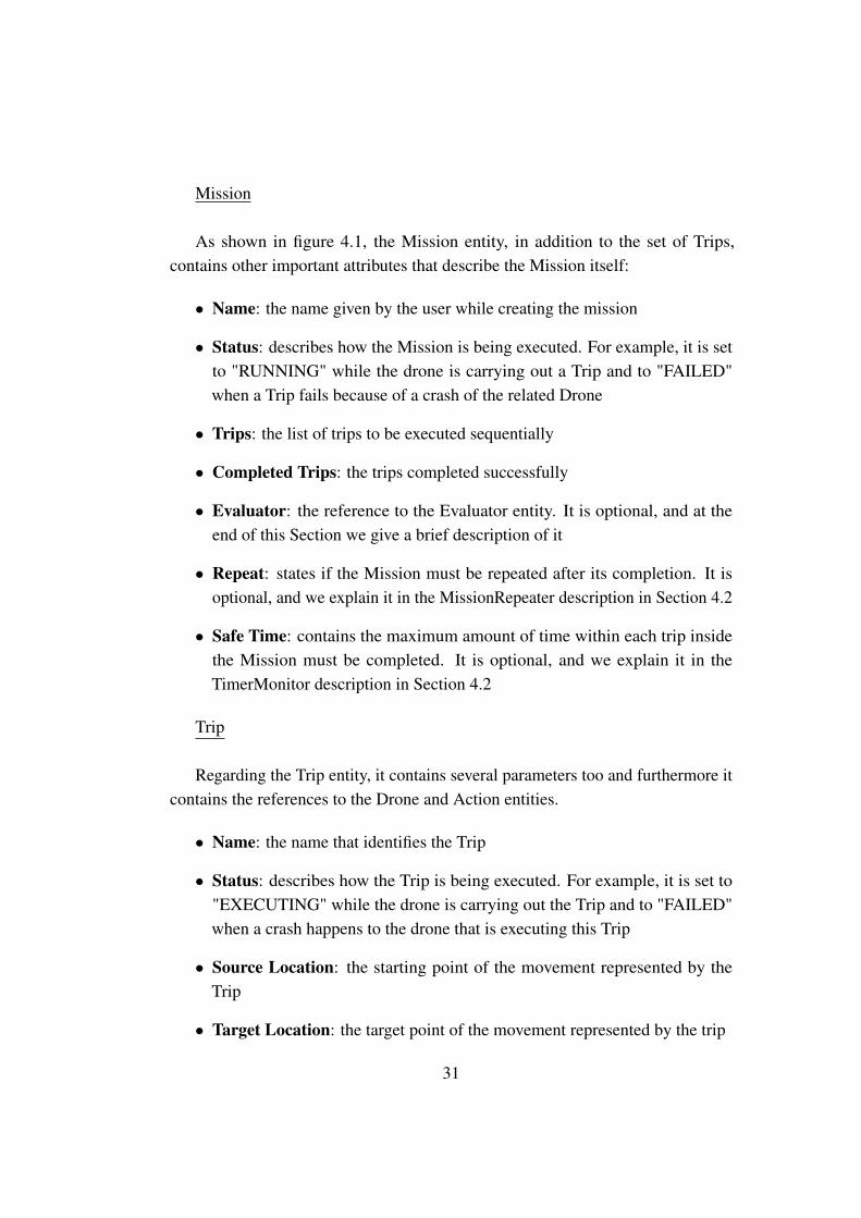
Mission
As shown in figure 4.1, the Mission entity, in addition to the set of Trips,contains other important attributes that describe the Mission itself:
• Name: the name given by the user while creating the mission
• Status: describes how the Mission is being executed. For example, it is setto "RUNNING" while the drone is carrying out a Trip and to "FAILED"when a Trip fails because of a crash of the related Drone
• Trips: the list of trips to be executed sequentially
• Completed Trips: the trips completed successfully
• Evaluator: the reference to the Evaluator entity. It is optional, and at theend of this Section we give a brief description of it
• Repeat: states if the Mission must be repeated after its completion. It isoptional, and we explain it in the MissionRepeater description in Section 4.2
• Safe Time: contains the maximum amount of time within each trip insidethe Mission must be completed. It is optional, and we explain it in theTimerMonitor description in Section 4.2
Trip
Regarding the Trip entity, it contains several parameters too and furthermore itcontains the references to the Drone and Action entities.
• Name: the name that identifies the Trip
• Status: describes how the Trip is being executed. For example, it is set to"EXECUTING" while the drone is carrying out the Trip and to "FAILED"when a crash happens to the drone that is executing this Trip
• Source Location: the starting point of the movement represented by theTrip
• Target Location: the target point of the movement represented by the trip
31
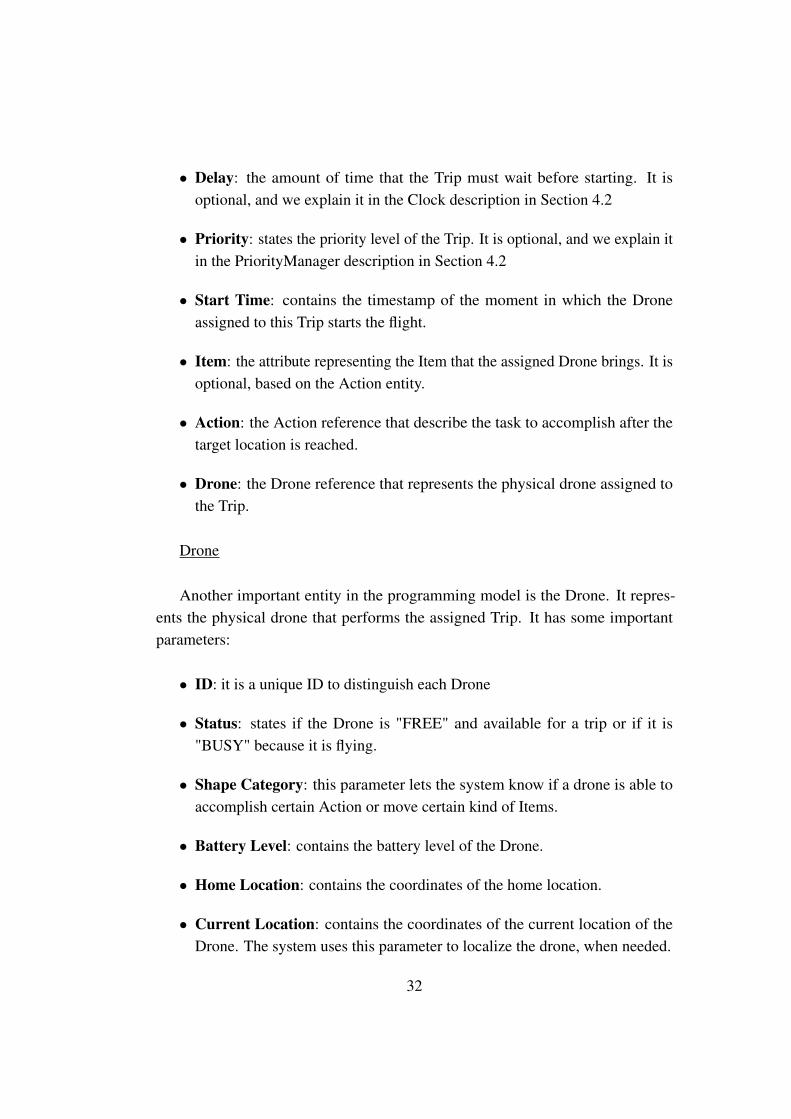
• Delay: the amount of time that the Trip must wait before starting. It isoptional, and we explain it in the Clock description in Section 4.2
• Priority: states the priority level of the Trip. It is optional, and we explain itin the PriorityManager description in Section 4.2
• Start Time: contains the timestamp of the moment in which the Droneassigned to this Trip starts the flight.
• Item: the attribute representing the Item that the assigned Drone brings. It isoptional, based on the Action entity.
• Action: the Action reference that describe the task to accomplish after thetarget location is reached.
• Drone: the Drone reference that represents the physical drone assigned tothe Trip.
Drone
Another important entity in the programming model is the Drone. It repres-ents the physical drone that performs the assigned Trip. It has some importantparameters:
• ID: it is a unique ID to distinguish each Drone
• Status: states if the Drone is "FREE" and available for a trip or if it is"BUSY" because it is flying.
• Shape Category: this parameter lets the system know if a drone is able toaccomplish certain Action or move certain kind of Items.
• Battery Level: contains the battery level of the Drone.
• Home Location: contains the coordinates of the home location.
• Current Location: contains the coordinates of the current location of theDrone. The system uses this parameter to localize the drone, when needed.
32
Action
The Action entity describes the tasks that the drones must perform at the endof their trips. We decided to create four basic actions whose names explain them-selves: "Measure", "Take photo", "Pick item" and "Release Item". Moreover weadded a "Custom Action" feature, which enables the developer to define a personalimplementation of a new Action depending on the application requisites. Thedeveloper can add this implementation after the code generation phase, explainedin Section 5.3, by adding his custom algorithm directly in the code.
Evaluator
In figure 4.1, inside the Mission object, there is a reference to the Evaluatorentity. The Evaluator is the entity whose duty is to evaluate the outcomes of theactions performed inside a Mission.This means that some trips can be completed successfully but the Action done atthe end can return a bad result. Therefore these actions should be repeated and sothe related trips. This feature is provided by the MissionEvaluator functional block,described in Section 4.2.We decided to decouple this mechanism from our system, so that the developeris able to include its personal implementation of the evaluation algorithm in ourframework. In Section 5.3 we describe this process in a more detailed way.
4.2 Functional blocks
As already said in Section 3.2, we decided to create a new dataflow program-ming framework that allows the user to design the behavior of the application whiletaking care of the missions execution.
This framework consists of a modeling tool that allows the developer to addthe application’s requested features by drawing the proper nodes in an editor area.Each diagram created with this tool is made up of many functional blocks, eachone including a particular logic. The user can select the blocks needed for hisparticular application and connect them through simple connection elements. The
33
graphical editor is fully described in Section 4.3.1.
Here we provide a detailed description of each functional block available in theeditor:
Mission Creator block
Input: a list of TripsOutput: a Mission object
The Mission Creator block receives as an input the trips that the user wantsto be performed by the drones, then it creates a Mission container including allthese trips and returns that new Mission object. This block is the starting point ofeach Pluto-developed application because it creates the Mission object that passesthrough all the blocks of the graph.
Clock block
Input: a Mission objectOutput: a Mission object
The Clock block checks the delay attribute (Figure 4.1) of the next Trip to beexecuted in the Mission. If it is greater than zero, it makes the Trip waiting for thatamount of time, and finally returns the Mission Object. Delaying the execution ofthe next Trip means stopping the Mission execution too, because, as said in Section4.1, the trips are executed sequentially.If the programmer puts the Clock block in the graph, the Main Application willask the user, during the Mission definition phase, the amount of time of the delay.This block can be used in an application where the user wants to measure thetemperature in a location every 10 minutes. He has to set a delay of 10 minutes forevery Trip, so that they wait for that time before starting.Usually, this block is put between the Mission Creator and the Drone Allocatorblocks, in order to wait for the delay time before allocating a Drone to the Trip.
34

Drone Allocator block
Input: a Mission objectOutput: a Mission object
The Drone Allocator block allocates the proper Drone to the next Trip of theMission taken as input. It bases its choice on the availability of the drones and theircapability to perform the desired action.This block can be implemented with different policies. Indeed, this choice is noth-ing but an optimization problem and the developer can choose a custom algorithm.We intentionally decoupled this problem from the system implementation, in a waythat it is possible for the developer to change the policy as he wishes.This block is usually put before the Trip Launcher, because an assigned Drone isessential for the Trip execution. For example it can be put between the Clock andthe Trip Launcher blocks in order to assign a Drone to the next Trip, after the delaytime has passed.
Trip Launcher block
Input: a Mission objectOutput: a Mission object
The Trip Launcher block takes the next Trip to be performed from the Mission,checks if it has an allocated Drone and then starts its execution. The assignedDrone fly to the target location and execute the defined Action. Usually this blockis put right after the Drone Allocator, and is fundamental in order to start theexecution of the trips of the Mission.
Trip Monitor block
Input: a Mission objectOutput: a Mission object
The Trip Monitor block continuously checks the status of the Trip that isrunning in that moment. As said in Section 4.1, the system executes the trips
35

sequentially, so only one Trip at a time is executing and is monitored by this block.We need to monitor the running trips because a flying Drone could crash or itsbattery could become empty before the end of the Trip. In this way we guaranteethe correct completion of the Mission even if a failure happens.Depending on whether the Trip is failed or completed, this block changes its statusparameter in the appropriate way. Of course, the Mission that contains that Tripwill change its status,accordingly. The Trip Monitor is put after the Trip Launcherbecause it needs to monitor a Trip that already started its execution.
Mission Repeater block
Input: a Mission object
Output: a Mission object
This block takes as input only a completed Mission object.So when a completed Mission arrive to the Mission Repeater, the block verifies ifthe Repeat attribute (Figure 4.1) of the Mission is true. if so, this block moves thelist of the completed trips into the list of trips to be executed. Then resets the statusof the Mission itself and the status of all the trips to execute again.This block can be useful if a Mission has to be repeated many times. For example,in a surveillance application, it lets the drones monitor the neighborhood withoutstopping when the Mission ends.In order to emulate this behavior without the block, the user should create a newidentical Mission every time the previous one ends.This block is usually put after the Trip Monitor and before the Drone Allocator,because a Mission can be completed only after it pass through the Trip Monitorand the trips’ status must be set to "WAITING" before the allocation of the drones.
Mission Evaluator block
Input: a Mission object
Output: a Mission object
The Mission Evaluator block, as the Mission Repeater, takes as input only acompleted Mission. Its task is to evaluate all the actions performed by the drones
36
at the end of their trips. Since the Mission arrives to this block only at the endof its lifecycle, all the trips are already executed and all the actions are alreadyperformed.The evaluation consists in invoking the Evaluator entity, which is referenced insidethe Mission object (Figure 4.1).If the evaluation returns a fail result, it means that some actions should be repeatedand the related trips too. The block finds these trips and put them in the list oftrips to execute. After that, it changes the status of the Mission, because it is notcompleted anymore since it has still some trips to complete.This block can be used in an application that needs to take many pictures of anatural site to build a map. Therefore, the actions consist in taking photos atdifferent coordinates and the evaluation in trying to build the whole map of the sitestitching these photos together. If some photos are not good enough, the evaluationreturns a fail result and the related trips and actions are repeated again.Usually this block is put after the Trip Monitor and before the Drone Allocator forthe same reasons explained in the description of the Mission Repeater block.
Mission Modifier block
Input: a Mission object
Output: a Mission object
The Mission Modifier block allows the programmer to express new features,not yet implemented by the existing functional blocks. It allows the developer tocreate a brand new block performing a specific feature.This feature must be expressed with a code snippet that the developer can writedirectly in the editor.For example, imagine a programmer that needs a new feature that change someparameters of the Mission after the assignment of the Drone, but before the firstTrip starts. He can insert the Mission Modifier block between the Drone Allocatorand the Trip Launcher blocks. Then he can open the window shown in figure 4.2by clicking on the proper menu entry called "Write Custom Code".Inside this window, the programmer can write the code that describes the featuresrequested by the new functional block. So, following the example, here he changesthe parameters of the Mission.
37

In the end, we strongly recommend to rename the Mission Modifier block with ameaningful name that describes the new implemented feature.This block can be put in every point of the Pluto Editor graph, depending on theparticular feature it provides. The inserted code is executed by the system whenthe Mission object reach this block, following the graph flow.
Figure 4.2: The MissionModifier block
PriorityManager block
Input: a Mission objectOutput: a Mission object
This block accepts as input only failed missions. It takes the first Trip in thelist and increments its priority. After that, it sends the same Mission object as anoutput to the next blocks.This block is useful in order to not stop the execution flow of a Mission in casea Trip fails. Normally, without this feature, if the Trip Monitor finds out that themonitored Trip has failed, it sets the Mission’s status to FAILED and stops theexecution flow.Instead this block raises the priority of the failed Trip and changes the status of theMission to STANDBY, as if the failure is never happened.
38
Then, to restart the execution flow of the Mission, we need a connection from thePriority Manager to the Drone Allocator.
Timer Monitor block
Input: a Mission object
Output: a Mission object
The Timer Monitor block adds a time constraint check to the Trip Monitorsupervision. It is useless to add the Timer Monitor without the Trip Monitor, indeedthey should be used in parallel.This means that while the Trip Monitor monitors the Trip execution, the TimerMonitor supervises the same Trip, ensuring that the execution time will not exceedthe amount of time set in the "Safe Time" Mission’s parameter (Figure 4.1).As for the Trip Monitor, the developer should put the Timer Monitor after the TripLauncher. Therefore the Trip Launcher has two output connections, one that goesto the Trip Monitor and the other one that goes to the Timer Monitor.Adding this block in parallel to the Trip Monitor means cloning the Mission objectwhich goes into the two blocks at the same time. This is why we need the Gateblocks described further.There are several applications that could request the feature introduced by theTimer Monitor. Indeed it can be used to consider a Trip failed if its executionexceeds the Safe Time amount. For example we could consider a drone crashed ifthe Trip takes more than 5 minutes to complete.
Gate FIFO block
Input: a Mission object
Output: a Mission object
The GateFIFO block is used when two or more blocks works in parallel, andonly one instance of the Mission entity must propagate. This block is put right afterthese parallel blocks, for example when the developer inserts in the graph eitherthe Trip Monitor and the Timer Monitor in parallel. In this case the Mission objectis cloned and the two blocks receive the same Mission object. The GateFIFO block
39
propagates only the first Mission instance that arrives to it.The GateFIFO usually has more than one incoming connections and it propagatesonly the first Mission object arriving from them. This is why the FIFO acronym isused, since the first Mission instance that arrive is the only one that propagates inthe graph.
Gate Funnel block
Input: a Mission objectOutput: a Mission object
This block is similar to the GateFIFO, but its implementation logic is different.It waits for the Mission instances coming from each incoming connection. Onlyafter all of them arrive it merges them in one single instance and propagates it. Forexample, if before this block, there are 4 blocks in parallel, the propagation of theMission is activated only when all the 4 instances arrive.
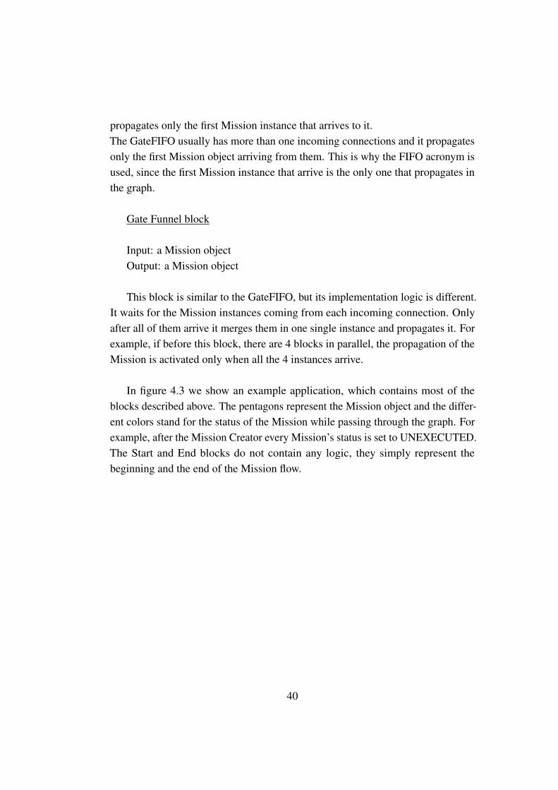
In figure 4.3 we show an example application, which contains most of theblocks described above. The pentagons represent the Mission object and the differ-ent colors stand for the status of the Mission while passing through the graph. Forexample, after the Mission Creator every Mission’s status is set to UNEXECUTED.The Start and End blocks do not contain any logic, they simply represent thebeginning and the end of the Mission flow.
40

Figure 4.3: An example Pluto application
4.3 Toolchain
The Pluto programming framework consists of two main components:
• Pluto Graphical Editor.
• Pluto Main Application.
The former is used by the first actor of the Pluto life-cycle: a developer. The latteris used by a final user whose duty is to insert the sensing tasks and to start theirexecution. As shown in figure 4.4, the Pluto Graphical Editor lets the developercreate a scenario based on the Team Level approach, as we show in Section 4.3.1.After that, the Pluto Main Application is generated according to the diagramcreated in the previous step. The developer can create new features adding his own
41
code, so that the final user needs only to insert the sensing tasks and wait for theiraccomplishment.
Figure 4.4: Working with the Pluto framework
4.3.1 Pluto Graphical Editor
We created a Graphical Editor in order to help the developer while designingthe final application. The provided tools can be used to link together differentfunctional blocks, each one with a predefined and implemented logic. When theEditor starts, it shows three main sections: the Palette (letter A in figure 4.5) thatcontains all the tools available to create a fully functional diagram. The Editorspace (letter B in figure 4.5) where the user can move, link and manage all thecreated entities. Last but not least is the Outline (letter C in figure 4.5) with atree-view of the blocks created by the developer in the editor space.
The developer can choose among several types of pre-created blocks, each onecontaining a certain logic, as explained in Section 4.2.Creating a block in the editor space can be done simply with a drag and dropgesture or clicking on the desired entity and then clicking on the chosen location inthe editor. Then the user can connect the blocks using the Connection tool in thePalette.
42

Figure 4.5: Pluto Graphical Editor interface
The Connection is a directed arch that defines the direction of the execution flowin the graph. This means that the Mission entity traveling among the functionalblocks can only move in the direction pointed out by the arrow.
Apart from the standard functionality, such as Undo, Save, and Load, theContext Menu provides a command to generate the source-code of the Main Ap-plication, based on the designed diagram. The Toolbar provides Undo/Redo, Delete,and Magnify commands (letter D in in figure 4.5).
To better understand the Pluto Graphical Editor, it is worth to clarify the mean-ing of creating a diagram: each block in the diagram is a black box which isintended to manage a Mission entity. It takes a Mission as an input, works with itand sends it out as an output. The connections among blocks represents the paththat the Mission entity follows in the graph. Each block can have multiple outgoingand incoming connections.
In the editor area the developer creates a set of blocks linked together with aset of connections. This drawing can be interpreted as the behavior of the MainApplication while managing the missions. For example, figure 4.5 represents thediagram that can handle the example described in Section 3.1.In this case the graph includes only the basic features: the creation of the Mission,
43
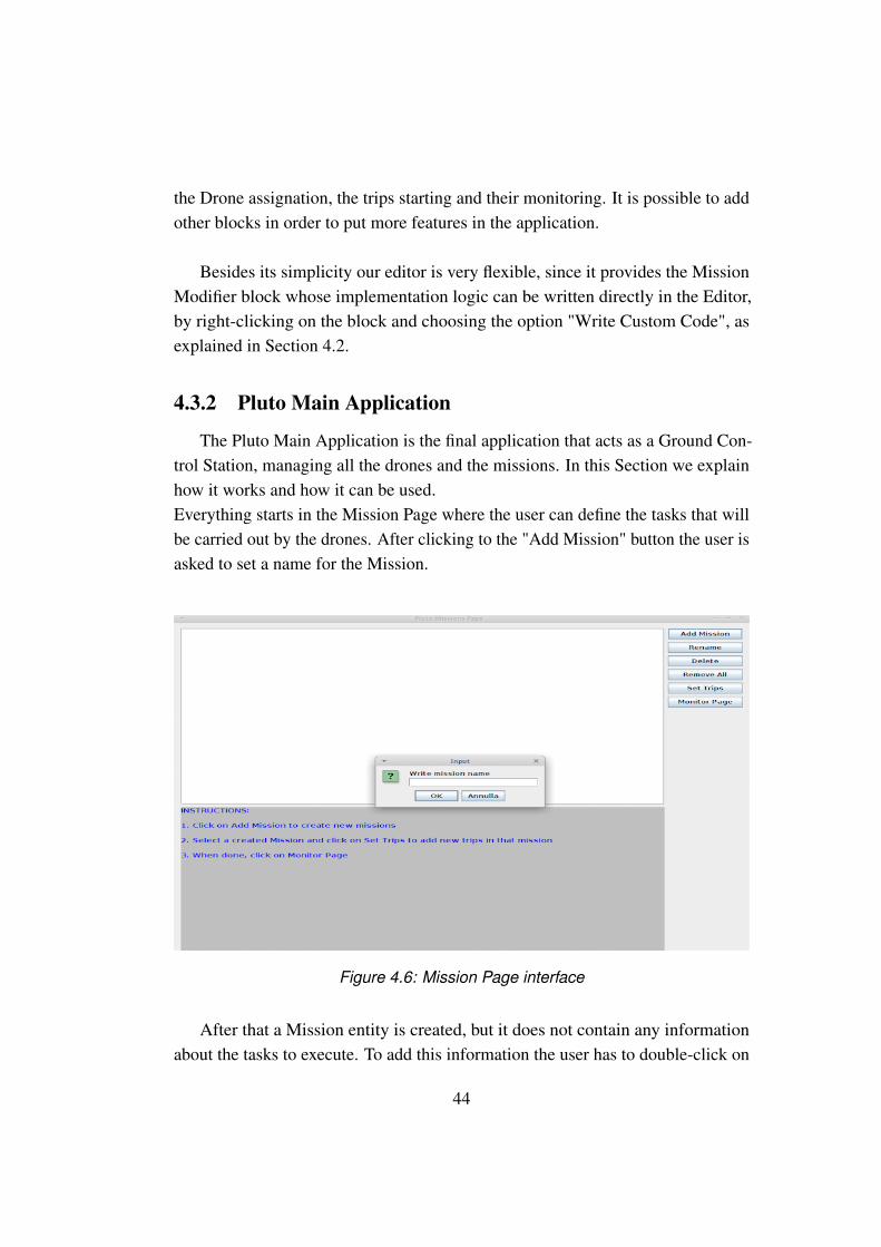
the Drone assignation, the trips starting and their monitoring. It is possible to addother blocks in order to put more features in the application.
Besides its simplicity our editor is very flexible, since it provides the MissionModifier block whose implementation logic can be written directly in the Editor,by right-clicking on the block and choosing the option "Write Custom Code", asexplained in Section 4.2.
4.3.2 Pluto Main Application
The Pluto Main Application is the final application that acts as a Ground Con-trol Station, managing all the drones and the missions. In this Section we explainhow it works and how it can be used.Everything starts in the Mission Page where the user can define the tasks that willbe carried out by the drones. After clicking to the "Add Mission" button the user isasked to set a name for the Mission.
Figure 4.6: Mission Page interface
After that a Mission entity is created, but it does not contain any informationabout the tasks to execute. To add this information the user has to double-click on
44
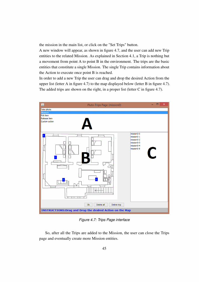
the mission in the main list, or click on the "Set Trips" button.A new window will appear, as shown in figure 4.7, and the user can add new Tripentities to the related Mission. As explained in Section 4.1, a Trip is nothing buta movement from point A to point B in the environment. The trips are the basicentities that constitute a single Mission. The single Trip contains information aboutthe Action to execute once point B is reached.In order to add a new Trip the user can drag and drop the desired Action from theupper list (letter A in figure 4.7) to the map displayed below (letter B in figure 4.7).The added trips are shown on the right, in a proper list (letter C in figure 4.7).
Figure 4.7: Trips Page interface
So, after all the Trips are added to the Mission, the user can close the Tripspage and eventually create more Mission entities.
45

Finally he can pass to the Monitor Page with the corresponding button. The Mon-itor Page, shown in figure 4.8, is the window where the user can obtain informationabout the running missions, at run-time.On the top, there is a table (letter A in figure 4.8) where each row is assigned toa Mission. Each column displays the information about the current Trip that isexecuting and the Drone assigned to that Trip.Below the table there is a console (letter B in figure 4.7) where the log messagesare printed during the execution of each mission. In this way the user can obtainrun-time information about the status of the entire system.
Of course the "Start" button starts the execution of the created missions, whilethe "Stop" button brings the user to a make a choice: "RTL" or "Land". The first isthe Return To Launch and it makes all the drones return to the home location. Thesecond option makes all the drones land in their current locations. After the stopcommand, the missions status is preserved and the execution of the Mission can bestarted again in the future.
Figure 4.8: Monitor Page interface
46
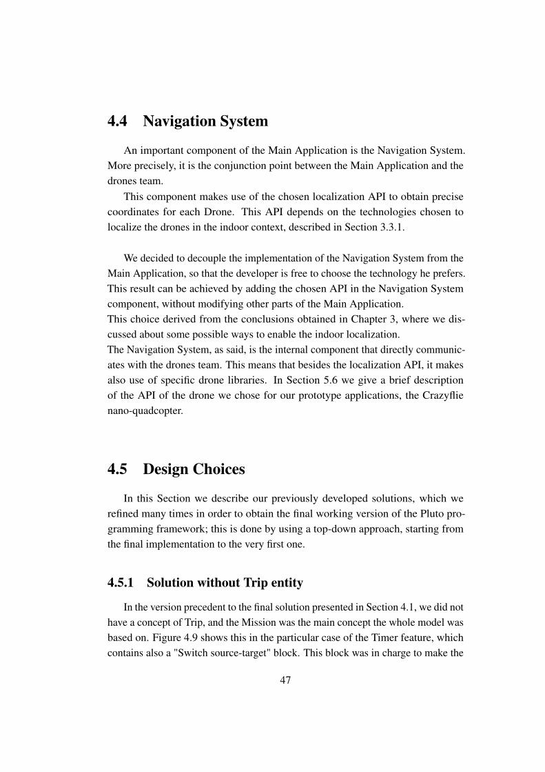
4.4 Navigation System
An important component of the Main Application is the Navigation System.More precisely, it is the conjunction point between the Main Application and thedrones team.
This component makes use of the chosen localization API to obtain precisecoordinates for each Drone. This API depends on the technologies chosen tolocalize the drones in the indoor context, described in Section 3.3.1.
We decided to decouple the implementation of the Navigation System from theMain Application, so that the developer is free to choose the technology he prefers.This result can be achieved by adding the chosen API in the Navigation Systemcomponent, without modifying other parts of the Main Application.This choice derived from the conclusions obtained in Chapter 3, where we dis-cussed about some possible ways to enable the indoor localization.The Navigation System, as said, is the internal component that directly communic-ates with the drones team. This means that besides the localization API, it makesalso use of specific drone libraries. In Section 5.6 we give a brief descriptionof the API of the drone we chose for our prototype applications, the Crazyflienano-quadcopter.
4.5 Design Choices
In this Section we describe our previously developed solutions, which werefined many times in order to obtain the final working version of the Pluto pro-gramming framework; this is done by using a top-down approach, starting fromthe final implementation to the very first one.
4.5.1 Solution without Trip entity
In the version precedent to the final solution presented in Section 4.1, we did nothave a concept of Trip, and the Mission was the main concept the whole model wasbased on. Figure 4.9 shows this in the particular case of the Timer feature, whichcontains also a "Switch source-target" block. This block was in charge to make the
47
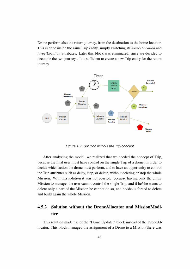
Drone perform also the return journey, from the destination to the home location.This is done inside the same Trip entity, simply switching its sourceLocation andtargetLocation attributes. Later this block was eliminated, since we decided todecouple the two journeys. It is sufficient to create a new Trip entity for the returnjourney.
Figure 4.9: Solution without the Trip concept
After analyzing the model, we realized that we needed the concept of Trip,because the final user must have control on the single Trip of a drone, in order todecide which action the drone must perform, and to have an opportunity to controlthe Trip attributes such as delay, stop, or delete, without deleting or stop the wholeMission. With this solution it was not possible, because having only the entireMission to manage, the user cannot control the single Trip, and if he/she wants todelete only a part of the Mission he cannot do so, and he/she is forced to deleteand build again the whole Mission.
4.5.2 Solution without the DroneAllocator and MissionModi-fier
This solution made use of the "Drone Updater" block instead of the DroneAl-locator. This block managed the assignment of a Drone to a Mission(there was
48

not the Trip concept yet), but only under certain conditions. Indeed the "DroneUpdater" was used only if the system had to assign another drone to a Mission,for example because of a failure of the precedent assigned Drone. This happenedbecause the MissionCreator managed the first assignment of a Drone to the Mis-sion, so we did not need the DroneUpdater for the first assignment of a Drone toa Mission. Furthermore, there was not the MissionModifier block, but only thePriorityManager case, shown in figure 4.10, so the programmer could not insert hiscustom code in the application.
Figure 4.10: Solution without the MissionModifier block
We decided to create the DroneAllocator block because we needed to separatethe creation of a Mission Object from the assignment of a Drone to it. So, theMissionCreator should only create a Mission entity and the DroneAllocator shouldtake care of the drones dispatching. In this way we could also remove the "DroneUpdater" block, because now we have a specific block which manage only theassignment of drones, so there is no more need to distinguish between the firstassignment of a Drone to a Mission and the "special assignment" in case of afailure. We also decided to create a MissionModifier block in which the user canput his own code to customize the application.
49

50
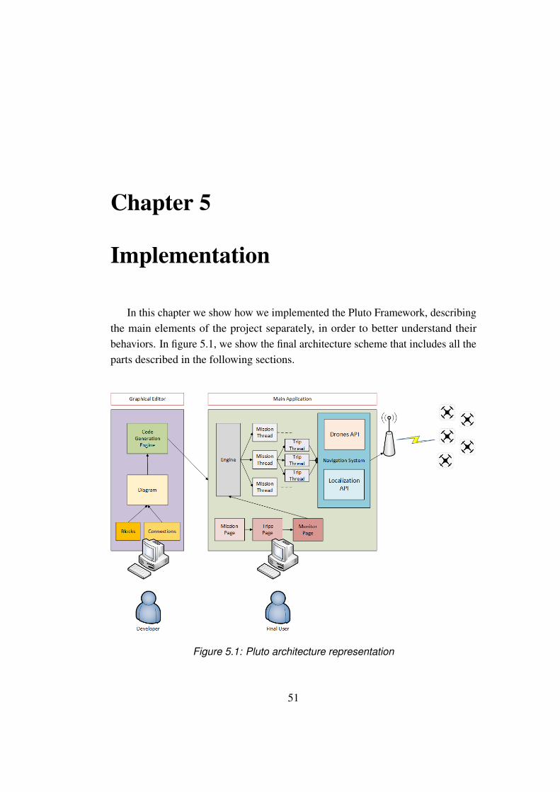
Chapter 5
Implementation
In this chapter we show how we implemented the Pluto Framework, describingthe main elements of the project separately, in order to better understand theirbehaviors. In figure 5.1, we show the final architecture scheme that includes all theparts described in the following sections.
Figure 5.1: Pluto architecture representation
51
5.1 Object-oriented approach
We used the Java programming language to implement both the Graphical Ed-itor and the Main Application. We made this choice because we are very familiarwith Java, since almost every academic project we implemented in these yearsmade use of this Object-Oriented programming language. The Object-Orientedapproach perfectly suits the Pluto model, since we have different independententities such as Drones,Missions and Trips that interact together in the executionof tasks.
We decided to adopt a Model View Controller(MVC) approach. The centralcomponent of MVC, the model, captures the behavior of the application in termsof its problem domain, and it is independent from the user interface. The modeldirectly manages the data, logic and rules of the application. A view can be anyoutput representation of information, such as a chart or a diagram; multiple viewsof the same information are possible. The third part, the controller, accepts inputand converts it to commands for the model or view.
Figure 5.2: MVC design applied to the Main Application
52
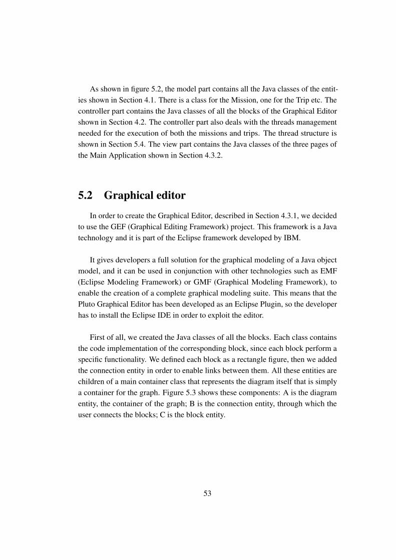
As shown in figure 5.2, the model part contains all the Java classes of the entit-ies shown in Section 4.1. There is a class for the Mission, one for the Trip etc. Thecontroller part contains the Java classes of all the blocks of the Graphical Editorshown in Section 4.2. The controller part also deals with the threads managementneeded for the execution of both the missions and trips. The thread structure isshown in Section 5.4. The view part contains the Java classes of the three pages ofthe Main Application shown in Section 4.3.2.
5.2 Graphical editor
In order to create the Graphical Editor, described in Section 4.3.1, we decidedto use the GEF (Graphical Editing Framework) project. This framework is a Javatechnology and it is part of the Eclipse framework developed by IBM.
It gives developers a full solution for the graphical modeling of a Java objectmodel, and it can be used in conjunction with other technologies such as EMF(Eclipse Modeling Framework) or GMF (Graphical Modeling Framework), toenable the creation of a complete graphical modeling suite. This means that thePluto Graphical Editor has been developed as an Eclipse Plugin, so the developerhas to install the Eclipse IDE in order to exploit the editor.
First of all, we created the Java classes of all the blocks. Each class containsthe code implementation of the corresponding block, since each block perform aspecific functionality. We defined each block as a rectangle figure, then we addedthe connection entity in order to enable links between them. All these entities arechildren of a main container class that represents the diagram itself that is simplya container for the graph. Figure 5.3 shows these components: A is the diagramentity, the container of the graph; B is the connection entity, through which theuser connects the blocks; C is the block entity.
53
Figure 5.3: Graphical entities in the editor
When the user creates a new block in the editor area, a relative block entity isautomatically created and added to the diagram container class. The same operationstands for the connections creation.
After the user draws the desired graph he can choose to generate the final codeof the Main Application, through the apposite voice in the context menu. SeeSection 5.3 for further details.
5.3 Code generation
Once the programmer has created the graph of the application through thePluto Graphical Editor, he can generate the code in order to make the Pluto MainApplication behavior coherent with the graph.
This can be done by right clicking on the graph and choosing the "Generatecode" command.
The main issue in the generation process was to understand how to generate thecode from a general diagram. Potentially, a developer could draw a very complexgraph with lot of blocks and connections between them. At first, we focused ongraph exploration methods, but we immediately noticed that they were too complex.
54

So, we decided to adopt a Publish-Subscribe design, making use of the Ob-server pattern. This mechanism let us describe the execution flow of very complexdiagrams, besides the more simple ones.
The Observer pattern consists in the declaration of some elements as observersand of other entities as observable. When an observable object change its status, itsends a notification to all its observer entities. These observers react according tothe change of the observable object.
In Figure 5.4 there is a sequence diagram that describes how the observerpattern works with a simple diagram with four blocks (A, B, C and D).The "Observe" message in the sequence is the declaration of a block that wantsto observe another block. The "Notify" message represents the notification thata block sends to its observers when it changes its status, or in this case when theblock ends the management of the Mission object.
Figure 5.4: Observer design pattern example
In our specific case, we made each declared block of the Graphical Editor bothObserver and Observable. This means that each block observes another block thatcomes before it, but at the same time, it is observed by other blocks coming after it.
55
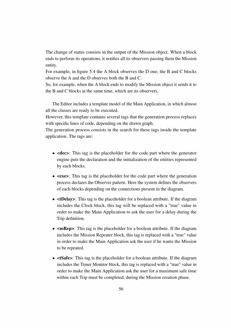
The change of status consists in the output of the Mission object. When a blockends to perform its operations, it notifies all its observers passing them the Missionentity.For example, in figure 5.4 the A block observes the D one; the B and C blocksobserve the A and the D observes both the B and C.So, for example, when the A block ends to modify the Mission object it sends it tothe B and C blocks at the same time, which are its observers.
The Editor includes a template model of the Main Application, in which almostall the classes are ready to be executed.However, this template contains several tags that the generation process replaceswith specific lines of code, depending on the drawn graph.The generation process consists in the search for these tags inside the templateapplication. The tags are:
• <dec>: This tag is the placeholder for the code part where the generatorengine puts the declaration and the initialization of the entities representedby each blocks.
• <exe>: This tag is the placeholder for the code part where the generationprocess declares the Observer pattern. Here the system defines the observersof each blocks depending on the connections present in the diagram.
• <tDelay>: This tag is the placeholder for a boolean attribute. If the diagramincludes the Clock block, this tag will be replaced with a "true" value inorder to make the Main Application to ask the user for a delay during theTrip definition.
• <mRep>: This tag is the placeholder for a boolean attribute. If the diagramincludes the Mission Repeater block, this tag is replaced with a "true" valuein order to make the Main Application ask the user if he wants the Missionto be repeated.
• <tSafe>: This tag is the placeholder for a boolean attribute. If the diagramincludes the Timer Monitor block, this tag is replaced with a "true" value inorder to make the Main Application ask the user for a maximum safe timewithin each Trip must be completed, during the Mission creation phase.
56
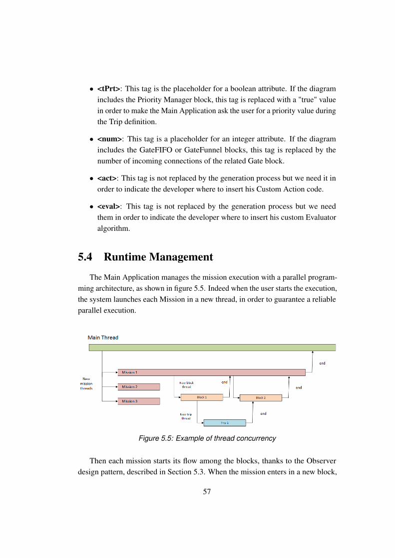
• <tPrt>: This tag is the placeholder for a boolean attribute. If the diagramincludes the Priority Manager block, this tag is replaced with a "true" valuein order to make the Main Application ask the user for a priority value duringthe Trip definition.
• <num>: This tag is a placeholder for an integer attribute. If the diagramincludes the GateFIFO or GateFunnel blocks, this tag is replaced by thenumber of incoming connections of the related Gate block.
• <act>: This tag is not replaced by the generation process but we need it inorder to indicate the developer where to insert his Custom Action code.
• <eval>: This tag is not replaced by the generation process but we needthem in order to indicate the developer where to insert his custom Evaluatoralgorithm.
5.4 Runtime Management
The Main Application manages the mission execution with a parallel program-ming architecture, as shown in figure 5.5. Indeed when the user starts the execution,the system launches each Mission in a new thread, in order to guarantee a reliableparallel execution.
Figure 5.5: Example of thread concurrency
Then each mission starts its flow among the blocks, thanks to the Observerdesign pattern, described in Section 5.3. When the mission enters in a new block,
57
the application launches a new thread, in order to run the Mission managementcode of the block. We need this new thread because there is the possibility that twoor more parallel blocks have to manage the same Mission entity at the same time.
Therefore, when the mission reaches the "Trip Launcher" block, the systemstarts the execution of the first Trip. Doing this, it creates a new thread, to managethe trip execution till its end.
As said, each Mission and Trip created by the user have a respective threadthat deal with the execution of the entity from the beginning to the end. In thisway, the blocks that need to monitor these entities can observe the status of thethreads, in order to know if the Trip/Mission is still running or is already completed.
It is important to underline that we don’t have any synchronization problemamong the various threads. Indeed, there are no dependencies between missions,since each one of them is executed independently from the others.Inside each Mission entity the trips are executed sequentially: one trip can start itsexecution only if the precedent trip in the list has been completed.Given this independence between missions, the system could dispatch them in amultiple machines cluster. In this way each Mission can run on a different environ-ment, maximizing the performances and reducing the load of the single machine.
5.5 User interface
Swing is an advanced GUI toolkit. It has a rich set of widgets: from basicwidgets like buttons, labels, scrollbars to advanced like trees and tables. Swingitself is written in Java and is part of JFC, Java Foundation Classes: it is a collectionof packages for creating full featured desktop applications.
We used the Swing framework to develop the view part of the MVC patternshown in Section 5.1, We needed to develop the three pages of the Pluto MainApplication, already described in Section 4.3.2, and we knew that Swing providesall the components that we wanted to put in them. Indeed, since we used it forthe development of many academic projects, we noticed that it allows to build
58

graphical interface in a very fast and easy way.As an illustrative example, figure 5.6 shows the structure of the Trips Page:
Figure 5.6: Trips Page structure
The Trips Page contains 7 components:
• Component A is a JList, a list of textual values, in this case the name of theActions
• Component B is a JImage, simply an image representing the Map
• Component C is a JList, a list of textual values, in this case the name of thecreated trips
• Components D,E and F are JButton, rectangles that the user can click on
59
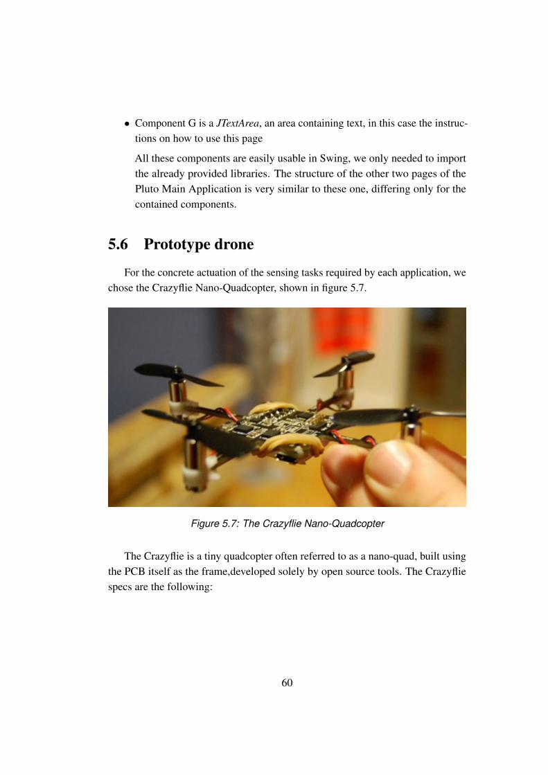
• Component G is a JTextArea, an area containing text, in this case the instruc-tions on how to use this page
All these components are easily usable in Swing, we only needed to importthe already provided libraries. The structure of the other two pages of thePluto Main Application is very similar to these one, differing only for thecontained components.
5.6 Prototype drone
For the concrete actuation of the sensing tasks required by each application, wechose the Crazyflie Nano-Quadcopter, shown in figure 5.7.
Figure 5.7: The Crazyflie Nano-Quadcopter
The Crazyflie is a tiny quadcopter often referred to as a nano-quad, built usingthe PCB itself as the frame,developed solely by open source tools. The Crazyfliespecs are the following:
60
• Small and lightweight, around 19g and about 90mm motor to motor
• Flight time up to 7 minutes with standard 170mAh Li-Po battery
• Standard micro-USB connector for charging which takes 20min for the stock170mAh Li-Po battery
• On-board low-energy radio@1mW based on the nRF24L01+ chip. Up to80m range (environment dependent) when using the Crazyradio USB dongle
• Radio bootloader which enables wireless update of the firmware
• Powerful 32 bit MCU: STM32F103CB @ 72 MHz (128kb flash, 20kb RAM)
• 3-axis high-performance MEMs gyros with 3-axis accelerometer: InvensenseMPU-6050
• Available footprints to manually solder magnetometer HMC5883L/HMC5983or/and barometer MS5611
• 4-layer low noise PCB design with separate voltage regulators for digital andanalog supply
We use a particular API that makes the drone move from a startingLocation toa destination in the environment:
1 move(startingLocation, destination)
To concretely control the Crazyflie, there is a Python library which gives highlevel functions and hides the details. The precedent API uses the following to sendthe control commands to the Crazyflie:
1 send_setpoint(roll, pitch, yaw, thrust)
The arguments roll/pitch/yaw/trust is the new set-points that should be sent tothe copter. For example, to send a new control set-point:
1 roll = 0.0
2 pitch = 0.0
3 yawrate = 0
4 thrust = 0
5 crazyflie.commander.send_setpoint(roll, pitch, yawrate, thrust)
61
Changing the roll and pitch will make the quadcopter tilt to the sides andthus change the direction that it’s moving in. Changing the yaw will make thequadcopter spin. The thrust is used to control the altitude of the quadcopter.
By dynamically adjusting these four parameters we can make the Crazyfliesmove to the locations specified by the user through the Pluto User Interface.
62
Chapter 6
Evaluation
In this Chapter we evaluate the Pluto programming framework. In Section 6.1we describe four already existing applications and three case study; we also discusswhether they can be developed or not with Pluto. In this way we understand theexpressive power of Pluto and the possible limits to overcome. In Section 6.2we propose two exercises to real testers, in order to test concretely the effectiveusability of Pluto: the first one deals with the Graphical Editor, described in Section4.3.1, the second one with the Main Application, described in Section 4.3.2. Thenwe ask the users to directly use the API of the Crazyflie nano-quadcopter, shown inSection 5.6, to make it move from a point A to a point B. In this way, we are ableto highlight the advantages of using our framework instead of the Crazyflie API.We also propose a survey to the users and then present the result in a graphical way,in order to have opinions on the framework and possibly to improve it with thesuggestions of the testers. In Section 6.3 we measure the software and hardwareconsumption metrics required by Pluto, in order to evaluate the effective impact ofPluto on an ordinary computing machine.
6.1 Generality
We developed our programming framework thinking about indoor applica-tions utilizing nano-drones. Actually, since we work at a sufficiently high levelof abstraction, because we can use an API which make the drones navigate inthe environment, the model can be extended to almost every kind of drone, aerialterrestrial and aquatic.
63
So, we can say that the Pluto programming framework is "drone independent", andthis greatly extends its applicability, including also outdoor, aquatic and terrestrialenvironments; it is in charge of the programmer to manage the interaction betweenPluto and the specific type of drone he wants to use for the particular applicationhe is developing.
Since we decided to use a Team-level approach (see 2.3), our model can beused for developing applications where the user can give to the system a set ofactions to be performed; the dispatching of these actions is managed by the "centralbrain", which takes care of assigning the drones to the action and to handle allthe exceptions (battery low, crashes etc.). So, the drones are only actuators thatperform an action, there is no communication between them, their behavior ismonitored and decided by the central brain.
Since drones cannot communicate between them, Pluto cannot be used forapplications where drones must perform some kind of action requiring explicitcommunication or data exchange between them; the logic is managed by the centralbrain, so communication between drones is always mediated by this component;a drone can send data to the central brain, and this could send again that data toanother drone.Hereinafter we analyzed some example applications, showing whether they can bemanaged/developed with the Pluto programming framework or not.
6.1.1 Basic applications
In this Section we describe three applications we developed with the Plutoprogramming framework. They are all represented by the basic Pluto graph offigure 6.1:
64

Figure 6.1: The basic graph pattern of OF, DD and WIF applications
The graph represents the pattern on which all the three applications base theirbehavior, but of course it assumes a different meaning for each one of them,since each application needs different actions to be performed in the environment.These different meanings are explained in the specific parts describing the threeapplications, shown in the proceedings of this Section. The three applications are:
• Object-finder (OF)
• Warehouse item-finder (WIF)
• Drugs distribution (DD)
Object-finder (OF)
This application help users find various objects, like shoes, keys and books, ina domestic environment. The user decides which item wants the drones to look for
65
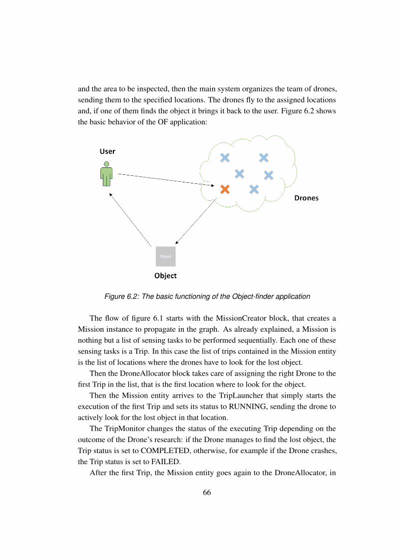
and the area to be inspected, then the main system organizes the team of drones,sending them to the specified locations. The drones fly to the assigned locationsand, if one of them finds the object it brings it back to the user. Figure 6.2 showsthe basic behavior of the OF application:
Figure 6.2: The basic functioning of the Object-finder application
The flow of figure 6.1 starts with the MissionCreator block, that creates aMission instance to propagate in the graph. As already explained, a Mission isnothing but a list of sensing tasks to be performed sequentially. Each one of thesesensing tasks is a Trip. In this case the list of trips contained in the Mission entityis the list of locations where the drones have to look for the lost object.
Then the DroneAllocator block takes care of assigning the right Drone to thefirst Trip in the list, that is the first location where to look for the object.
Then the Mission entity arrives to the TripLauncher that simply starts theexecution of the first Trip and sets its status to RUNNING, sending the drone toactively look for the lost object in that location.
The TripMonitor changes the status of the executing Trip depending on theoutcome of the Drone’s research: if the Drone manages to find the lost object, theTrip status is set to COMPLETED, otherwise, for example if the Drone crashes,the Trip status is set to FAILED.
After the first Trip, the Mission entity goes again to the DroneAllocator, in
66

order to execute also the other trips in the Mission, that is to say in order to senddrones in the other specified locations to look for the object.
Warehouse item-finder (WIF)
This application help users manage a warehouse, bringing them a list of neededobjects. The user creates a list of needed items and writes it on his laptop, then themain system organizes the drones and simultaneously sends each one of them totake one of the objects of the specified list. Finally the drones fly to the assignedobjects and bring them back to the user. Figure 6.3 shows the basic behavior of theWIF application:
Figure 6.3: The basic functioning of the Warehouse item-finder application
As always, the flow starts with the MissionCreator block, that creates a Missioninstance to propagate in the graph. In this case, each Mission entity contains only aTrip to execute: each Trip is associated to one of the objects that the drones haveto bring to the user. As already explained, the Mission entities are executed in
67

parallel, so in this case there is one Mission for each object to bring, since thedrones have to work simultaneously.
Then the DroneAllocator block takes care of assigning the right Drone to theTrip of each Mission, that is the associated object to pick. Then the Missionentities arrive to the TripLauncher, that simply starts the execution of each Tripand sets their status to RUNNING, sending each drone to bring its associated object.
The TripMonitor changes the status of the executing trips depending on theoutcome of the drones research: if the Drone accomplishes to bring the objectto the user, the Trip status is set to COMPLETED, otherwise, for example if theDrone crashes, the Trip status is set to FAILED. After each Trip is COMPLETED,the execution of the flow ends and the Mission status is set to COMPLETED.
Drugs Distribution (DD)
The description of the behavior of this application is shown in Section 3.1.
The flow starts with the MissionCreator block, that creates a Mission instanceto propagate in the graph. In this case there are multiple Mission entities containingmultiple trips: in this way the drones bring the first group of medicine boxessimultaneously to the patients and, after the boxes are delivered, a second group ofboxes can be delivered simultaneously to the other patients, and so on. Each Tripis associated to one of the box to bring to the patients.
Then the DroneAllocator block takes care of assigning the right Drone to thefirst Trip in the list of each Mission, managing the first group of boxes to bring tothe first group of patients.
Then the Mission entities arrive to the TripLauncher that simply starts theexecution of the first Trip of each Mission and sets their status to RUNNING,sending the drones to bring the first group of boxes.
The TripMonitor changes the status of the executing trips depending on theoutcome of the drones actions: if the Drone accomplishes to bring the box to thepatient, the Trip status is set to COMPLETED, otherwise, for example if the Dronecrashes, the Trip status is set to FAILED. After the first group of trips, the Missionentities go again to the DroneAllocator, in order to execute also the other trips anddeliver the remaining boxes.
68
Summary
We built the Pluto programming framework in order to address the problemsissued by the indoor context. We based the development of Pluto on the threeapplications described above, which deal with houses, warehouses and hospitalscontexts.
Since we wanted to test the generality of our framework, we tried to extendits use also to outdoor applications. In the next Sections we describe four outdoorapplications, developed with other programming systems, showing all the limitsand problems encountered by developing them with Pluto.
6.1.2 Alfalfa Crop Monitoring and Pollination
The Alfalfa Crop Monitoring and Pollination[13] is a typical example of swarm-level approach application. Alfalfa is an important food crop for cattle and requiresan external pollinator (e.g. bees) to produce seeds. In recent years, colony collapsedisorder has devastated honeybee populations and jeopardized the cultivation ofimportant crops[14]. A swarm of drones can pollinate the alfalfa plants and alsomonitor them for pests and diseases, trough visual spot checks.So, the whole application provide three periodic actions: searching for pests,searching for diseases, and looking for flowers in bloom. Each one of these actionsis achieved by taking pictures of the plants. The user may need to define timeconstraints within the pollination action must be completed.Thanks to the Take photo action, already implemented in Pluto, the drones are ableto perform the monitoring of leaves for pests, diseases and flowers in bloom.
The following Pluto Editor graph describes the behavior of the Alfalfa CropMonitoring and Pollination[13] application:
69

Figure 6.4: Pluto graph for the Alfalfa Crop Monitoring and Pollination application
The flow starts with the MissionCreator block, that creates a Mission instanceto propagate in the graph. In this case, the Mission contains the list of locationswhere the drones have to take the pictures. Then the DroneAllocator block takescare of assigning the right Drone to the next Trip in the list of trips to be executedof each Mission entity, that is the first location where to take the picture. Then theMission entity arrives to the TripLauncher that simply starts the execution of thefirst Trip and sets its status to RUNNING.
After the TripLauncher the Mission entity is doubled. One instance goes tothe TripMonitor block and the other one to the TimerMonitor. The TripMonitorchanges the status of the executing Trip depending on the outcome of the Drone’sjourney: if the Drone accomplishes to take the picture on its assigned location,then the Trip status is set to COMPLETED, if the Drone crashes the Trip status isset to FAILED. The time constraints, which are set by the user thanks to the timerattribute of the Mission entity, are fulfilled thanks to the TimerMonitor block. This
70
block takes care of setting the Mission status to FAILED if one of its Trips is notcompleted within the timer. For example, the user may want the drones to take thepictures within 3 minutes. If one Drone takes more than 3 minutes to perform itsaction, the TimerMonitor sets the Mission status to FAILED.
The GateFIFO block takes as input two Mission instances, one from the TripMonitor and the other one from the Timer Monitor. It takes care of propagatingonly the first instance that arrives to it. For example, if the timer has expired then itpropagates the Timer Monitor instance, otherwise the Trip Monitor one.
After the GateFIFO block there is a bifurcation: if all the pictures inside theMission have been taken, the Mission is COMPLETED and it is sent to the Mis-sionEvaluator block. Otherwise, some pictures must be taken again, that is to saythere are some trips of the Mission that must be executed again, so the Mission issent to the DroneAllocator block, which assigns new drones to these trips.
The MissionEvaluator block enables the evaluation of the photos taken by thedrones. If the pest and/or disease attributes are true, the system notifies the farmerof the damaged location, adding a log line in the console of the Monitor Page of thePluto User Interface. If the bloom attribute is true, a new Trip will be created and anew Drone, capable to perform the Pollinate action, will be sent to that location topollinate the flowers.
The Mission Repeater block takes care of continuously sending the drones tomonitor these locations. Regarding the "Pollination" task, it can be added thanksto the custom action feature, through which the programmer can add to the modela brand new Action, making use of a specific external API. The full explanation ofthe functionality of each block can be found in Section 4.2.
Concerning the pictures evaluation to detect pests, diseases and flowers inbloom, the developer has to add the custom code in the Evaluator class, using againan external API. Each photo will have three associated parameters: the booleanattributes pest, disease and bloom. These attributes are false by default and theyare set to true when the leaves are damaged, their color turns greenish-white or theflowers are in bloom, respectively.
71
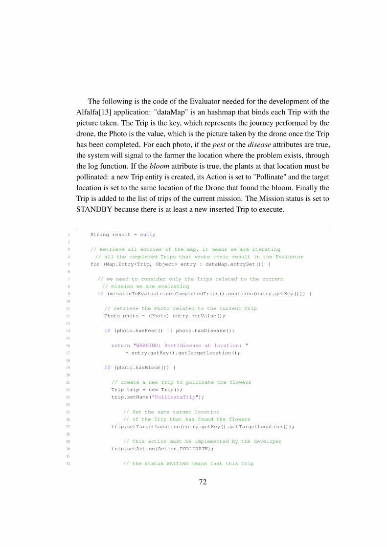
The following is the code of the Evaluator needed for the development of theAlfalfa[13] application: "dataMap" is an hashmap that binds each Trip with thepicture taken. The Trip is the key, which represents the journey performed by thedrone, the Photo is the value, which is the picture taken by the drone once the Triphas been completed. For each photo, if the pest or the disease attributes are true,the system will signal to the farmer the location where the problem exists, throughthe log function. If the bloom attribute is true, the plants at that location must bepollinated: a new Trip entity is created, its Action is set to "Pollinate" and the targetlocation is set to the same location of the Drone that found the bloom. Finally theTrip is added to the list of trips of the current mission. The Mission status is set toSTANDBY because there is at least a new inserted Trip to execute.
1 String result = null;
2
3 // Retrieve all entries of the map, it means we are iterating
4 // all the completed Trips that wrote their result in the Evaluator
5 for (Map.Entry<Trip, Object> entry : dataMap.entrySet()) {
6
7 // we need to consider only the Trips related to the current
8 // mission we are evaluating
9 if (missionToEvaluate.getCompletedTrips().contains(entry.getKey())) {
10
11 // retrieve the Photo related to the current Trip
12 Photo photo = (Photo) entry.getValue();
13
14 if (photo.hasPest() || photo.hasDisease())
15
16 return "WARNING: Pest/disease at location: "
17 + entry.getKey().getTargetLocation();
18
19 if (photo.hasBloom()) {
20
21 // create a new Trip to pollinate the flowers
22 Trip trip = new Trip();
23 trip.setName("PollinateTrip");
24
25 // Set the same target location
26 // of the Trip that has found the flowers
27 trip.setTargetLocation(entry.getKey().getTargetLocation());
28
29 // This action must be implemented by the developer
30 trip.setAction(Action.POLLINATE);
31
32 // the status WAITING means that this Trip
72
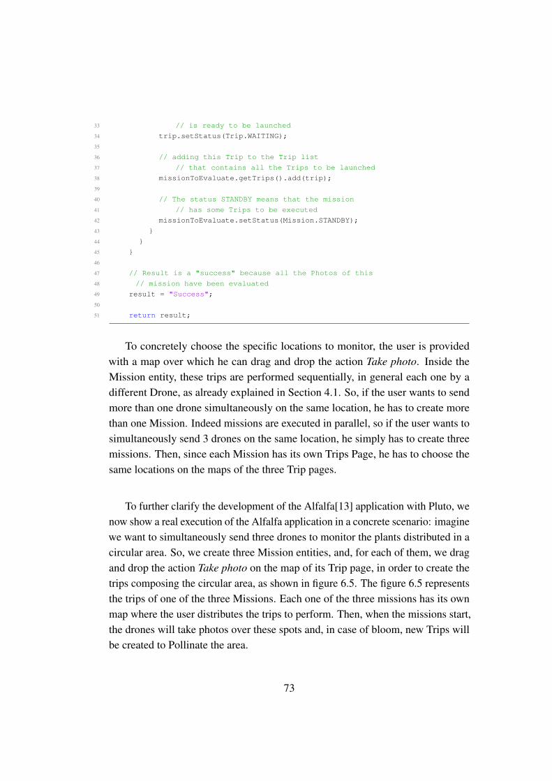
33 // is ready to be launched
34 trip.setStatus(Trip.WAITING);
35
36 // adding this Trip to the Trip list
37 // that contains all the Trips to be launched
38 missionToEvaluate.getTrips().add(trip);
39
40 // The status STANDBY means that the mission
41 // has some Trips to be executed
42 missionToEvaluate.setStatus(Mission.STANDBY);
43 }
44 }
45 }
46
47 // Result is a "success" because all the Photos of this
48 // mission have been evaluated
49 result = "Success";
50
51 return result;
To concretely choose the specific locations to monitor, the user is providedwith a map over which he can drag and drop the action Take photo. Inside theMission entity, these trips are performed sequentially, in general each one by adifferent Drone, as already explained in Section 4.1. So, if the user wants to sendmore than one drone simultaneously on the same location, he has to create morethan one Mission. Indeed missions are executed in parallel, so if the user wants tosimultaneously send 3 drones on the same location, he simply has to create threemissions. Then, since each Mission has its own Trips Page, he has to choose thesame locations on the maps of the three Trip pages.
To further clarify the development of the Alfalfa[13] application with Pluto, wenow show a real execution of the Alfalfa application in a concrete scenario: imaginewe want to simultaneously send three drones to monitor the plants distributed in acircular area. So, we create three Mission entities, and, for each of them, we dragand drop the action Take photo on the map of its Trip page, in order to create thetrips composing the circular area, as shown in figure 6.5. The figure 6.5 representsthe trips of one of the three Missions. Each one of the three missions has its ownmap where the user distributes the trips to perform. Then, when the missions start,the drones will take photos over these spots and, in case of bloom, new Trips willbe created to Pollinate the area.
73

Figure 6.5: The circular area to monitor
To describe in a detailed way the execution flow, we now show the sequencediagrams of the Pluto Main Application behavior:
Figure 6.6: Sequence diagram of a starting mission
In figure 6.6 we show the first calls after the user clicks on the Start button inthe Monitor Page. The Main Application receives the start command from the user,then activates the Engine entity. Now, a new Thread is created and started for eachmissions. The status of the Missions are sent to the Pluto Main Application and
74

showed to the final user, through the log() function.
Figure 6.7: Sequence diagram of the mission execution flow
In figure 6.7 the Mission Execution is shown. The Mission Thread entity man-ages the Mission flow through all the blocks and the execution of the logic insidethem. For example, the first two method calls belong to the Drone Allocator.For each Trip a new Trip Thread instance is created, that will manage the parallelexecution of the trips. After that, the mission thread waits for the completion ofthe started Trip, and then the Mission Status is set to STANDBY, since there areother trips to be executed.Finally, the completed Trip is removed from the list of trips to be executed and theDrone status is set to FREE. Otherwise, if the launched Trips was the last one, theMission status would have been set to COMPLETED.
75
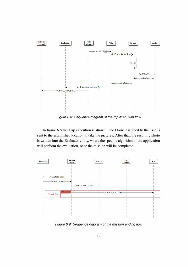
Figure 6.8: Sequence diagram of the trip execution flow
In figure 6.8 the Trip execution is shown. The Drone assigned to the Trip issent to the established location to take the pictures. After that, the resulting photois written into the Evaluator entity, where the specific algorithm of the applicationwill perform the evaluation, once the mission will be completed.
Figure 6.9: Sequence diagram of the mission ending flow
76
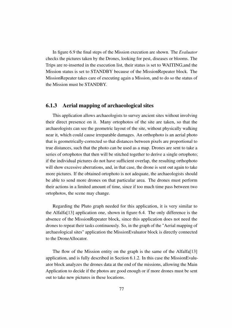
In figure 6.9 the final steps of the Mission execution are shown. The Evaluatorchecks the pictures taken by the Drones, looking for pest, diseases or blooms. TheTrips are re-inserted in the execution list, their status is set to WAITING,and theMission status is set to STANDBY because of the MissionRepeater block. TheMissionRepeater takes care of executing again a Mission, and to do so the status ofthe Mission must be STANDBY.
6.1.3 Aerial mapping of archaeological sites
This application allows archaeologists to survey ancient sites without involvingtheir direct presence on it. Many ortophotos of the site are taken, so that thearchaeologists can see the geometric layout of the site, without physically walkingnear it, which could cause irreparable damages. An orthophoto is an aerial photothat is geometrically-corrected so that distances between pixels are proportional totrue distances, such that the photo can be used as a map. Drones are sent to take aseries of ortophotos that then will be stitched together to derive a single ortophoto;if the individual pictures do not have sufficient overlap, the resulting orthophotowill show excessive aberrations, and, in that case, the drone is sent out again to takemore pictures. If the obtained ortophoto is not adequate, the archaeologists shouldbe able to send more drones on that particular area. The drones must performtheir actions in a limited amount of time, since if too much time pass between twoortophotos, the scene may change.
Regarding the Pluto graph needed for this application, it is very similar tothe Alfalfa[13] application one, shown in figure 6.4. The only difference is theabsence of the MissionRepeater block, since this application does not need thedrones to repeat their tasks continuously. So, in the graph of the "Aerial mapping ofarchaeological sites" application the MissionEvaluator block is directly connectedto the DroneAllocator.
The flow of the Mission entity on the graph is the same of the Alfalfa[13]application, and is fully described in Section 6.1.2. In this case the MissionEvalu-ator block analyzes the drones data at the end of the missions, allowing the MainApplication to decide if the photos are good enough or if more drones must be sentout to take new pictures in these locations.
77

It is important to underline that, using the Pluto framework, it is not possible toobtain the very same behavior of the original application. Indeed, two consecutivephotos must be taken within a time constraint. Since each photo is taken by theDrone at the end of its assigned Trip, there should be a way to define a timeconstraint between the execution of two trips. This cannot be fulfilled with Pluto,since the TimerMonitor block deals with a time interval that starts when the droneleaves the base station, ensuring that it will take the picture before the time intervalexpires. So, there is no way to state a time constraint between two consecutivephotos with Pluto.
Concerning the code of the Evaluator block needed for the development of theAerial Mapping[15] application, as for the previous application, we can find eachphoto taken during the missions in the "dataMap" parameter, that is an hashmapthat create a relation between a Trip and the photo taken through its Action. Firstof all, the ortophotos are stitched together to obtain the final ortophoto, trough thestitch function. If the final ortophoto shows excessive aberration, the ortophotoscomposing it are analyzed and if they don’t have sufficient overlap, few new Tripsare created with the same target locations of the photos to be taken again. TheMission status is set to STANDBY because there is at least a new inserted Trip toexecute.
It is important to underline that this application differs from the Alfalfa[13] one,because the Evaluator algorithm acts in a different way: in Alfalfa[13] applicationthe algorithm takes care of analyzing the photos of a single Mission withoutconsidering the others; now, instead, the evaluation needs to merge all the photos ofevery missions to calculate the aberration. This is possible thanks to the centralizeddata store of Pluto: each Drone sends its data to the central brain, that collectsthem together and perform the computations on the data following the Evaluatoralgorithm.
The following code snippet shows our implementation of the Evaluator al-gorithm:
1 String result = null;
2 // The "stitch" method takes a collection of photos as input
3 // and return an Ortophoto object derived by a proper algorithm
78
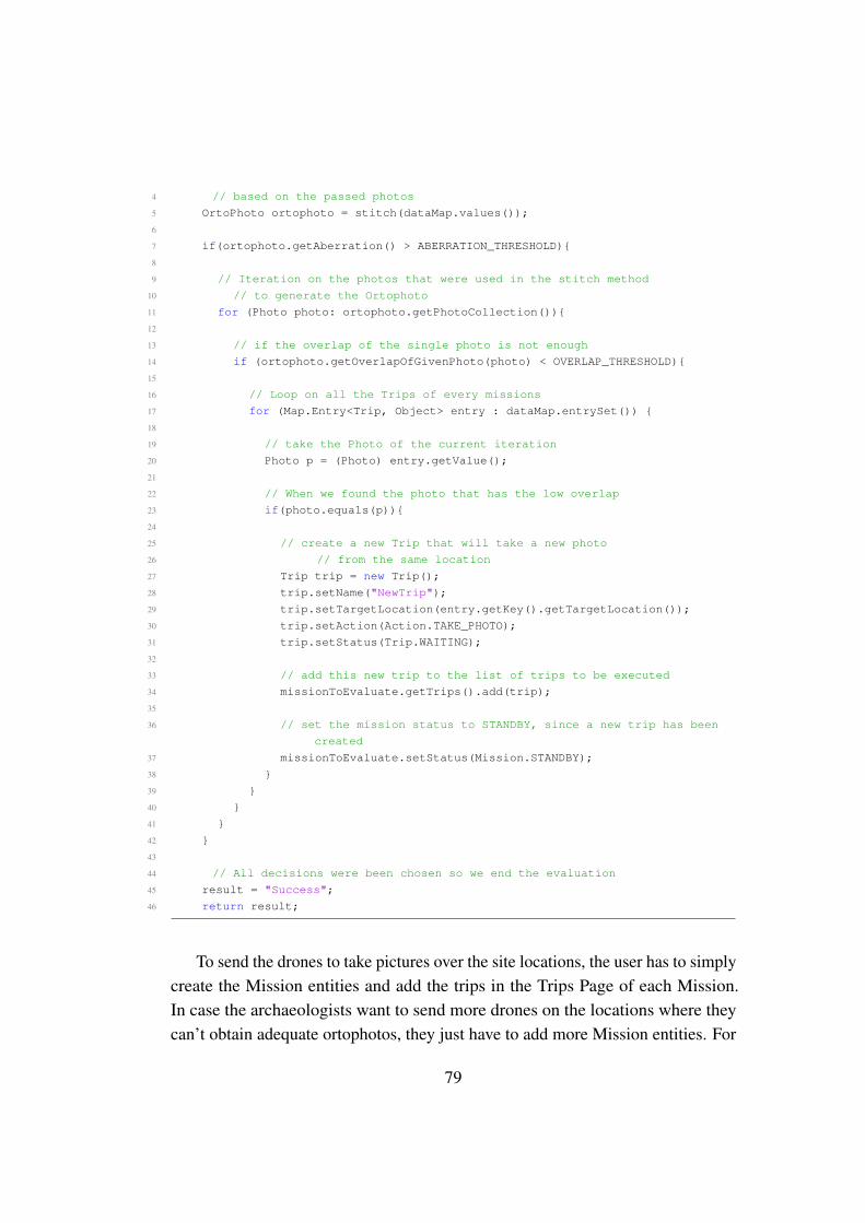
4 // based on the passed photos
5 OrtoPhoto ortophoto = stitch(dataMap.values());
6
7 if(ortophoto.getAberration() > ABERRATION_THRESHOLD){
8
9 // Iteration on the photos that were used in the stitch method
10 // to generate the Ortophoto
11 for (Photo photo: ortophoto.getPhotoCollection()){
12
13 // if the overlap of the single photo is not enough
14 if (ortophoto.getOverlapOfGivenPhoto(photo) < OVERLAP_THRESHOLD){
15
16 // Loop on all the Trips of every missions
17 for (Map.Entry<Trip, Object> entry : dataMap.entrySet()) {
18
19 // take the Photo of the current iteration
20 Photo p = (Photo) entry.getValue();
21
22 // When we found the photo that has the low overlap
23 if(photo.equals(p)){
24
25 // create a new Trip that will take a new photo
26 // from the same location
27 Trip trip = new Trip();
28 trip.setName("NewTrip");
29 trip.setTargetLocation(entry.getKey().getTargetLocation());
30 trip.setAction(Action.TAKE_PHOTO);
31 trip.setStatus(Trip.WAITING);
32
33 // add this new trip to the list of trips to be executed
34 missionToEvaluate.getTrips().add(trip);
35
36 // set the mission status to STANDBY, since a new trip has been
created
37 missionToEvaluate.setStatus(Mission.STANDBY);
38 }
39 }
40 }
41 }
42 }
43
44 // All decisions were been chosen so we end the evaluation
45 result = "Success";
46 return result;
To send the drones to take pictures over the site locations, the user has to simplycreate the Mission entities and add the trips in the Trips Page of each Mission.In case the archaeologists want to send more drones on the locations where theycan’t obtain adequate ortophotos, they just have to add more Mission entities. For
79
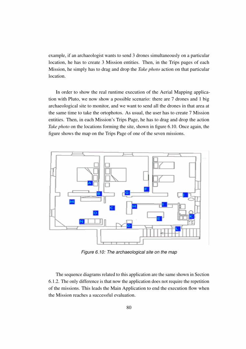
example, if an archaeologist wants to send 3 drones simultaneously on a particularlocation, he has to create 3 Mission entities. Then, in the Trips pages of eachMission, he simply has to drag and drop the Take photo action on that particularlocation.
In order to show the real runtime execution of the Aerial Mapping applica-tion with Pluto, we now show a possible scenario: there are 7 drones and 1 bigarchaeological site to monitor, and we want to send all the drones in that area atthe same time to take the ortophotos. As usual, the user has to create 7 Missionentities. Then, in each Mission’s Trips Page, he has to drag and drop the actionTake photo on the locations forming the site, shown in figure 6.10. Once again, thefigure shows the map on the Trips Page of one of the seven missions.
Figure 6.10: The archaeological site on the map
The sequence diagrams related to this application are the same shown in Section6.1.2. The only difference is that now the application does not require the repetitionof the missions. This leads the Main Application to end the execution flow whenthe Mission reaches a successful evaluation.
80

6.1.4 PM10
The PM10[16] application is used to build 3D maps of pollution concentrationin the atmosphere. Initially, there is a predefined 3D grid over which drones aresent to sample the quantity of pollution. So the drones build a spatial profile ofpollution concentration and compute gradients among the areas of higher concen-tration. Finally the drones are sent along this gradients to sample the pollutionconcentration, in order to improve the spatial profile representation. Any twoconsecutive samples must be gathered within a given time bound, otherwise thesystem will take care of speeding up the execution.
Regarding the Pluto graph needed for this application, it is very similar tothe Alfalfa[13] application one, shown in figure 6.4. The only difference is theabsence of the MissionRepeater block, since this application does not need thedrones to repeat their tasks continuously. So, in the graph of the "Aerial mapping ofarchaeological sites" application the MissionEvaluator block is directly connectedto the DroneAllocator.
The flow of the Mission entity on the graph is the same of the Alfalfa[13]application, and is fully described in Section 6.1.2. The data collected by thedrones are not photos anymore, but a pollutionQuantity value which indicates thepercentage of pollution in that area. In this case the Mission Evaluator block takescare of confronting the pollutionQuantity variables and to compute the gradientsbetween areas of higher concentration. So new drones are sent along this gradients,improving the spatial profile.
As for the Aerial Mapping application, shown in Section 6.1.3, Pluto cannotfulfill the time constraint between two consecutive pollution samples. As alreadyexplained, the timer of Pluto starts when the drone leaves the base station andensures that it will perform the action within that time interval, but there is no wayto constrain the time between two consecutive samples.
Below there is our implementation of a possible Evaluator algorithm:
1 String result = null;
2
3 // building a new map with only the trip-measure couples of the mission
81
4 // to evaluate
5 Map<Trip, Integer> missionMap = new Map<Trip, Integer>();
6 for (Map.Entry<Trip, Object> entry : dataMap.entrySet()) {
7 if (missionToEvaluate.getCompletedTrips().contains(entry.getKey())) {
8 missionMap.put(entry.getKey(), (Integer) entry.getValue());
9 }
10 }
11
12 // this method use the Trip location and the pollution measure to
13 // calculate
14 // the gradients and then return a list of String that indicates
15 // the positions of these gradients
16 List<String> gradientsPositions = calculateGradients(missionMap);
17
18 for (String position : gradientsPositions) {
19
20 // create a new Trip to calculate pollution at the gradient position
21 Trip trip = new Trip();
22 trip.setName("GradientTrip");
23 trip.setTargetLocation(position);
24 trip.setAction(Action.MEASURE);
25 trip.setStatus(Trip.WAITING);
26
27 // add this new trip to the list of trips to be executed
28 missionToEvaluate.getTrips().add(trip);
29 // set the mission status to STANDBY, since there are new trips to perform
30 missionToEvaluate.setStatus(Mission.STANDBY);
31
32 }
33
34 // set the result of the evaluation
35 result = "Success";
36 return result;
For the measurements of pollution quantity, the Measure action can be used.The spatial grid must be manually built by the user, organizing the Trips of eachMission on the map he is provided with.
Now we show the execution of the PM10 application with Pluto in a particularscenario: we have 5 drones and we want to measure the pollution quantity in thearea shown in figure 6.11 using all of them. As usual, the user has to create 5Missions and has to choose the locations of the area to sample through the map onthe Trips Page of each Mission. In this way, five drones will monitor simultaneouslythe area to sample.
82
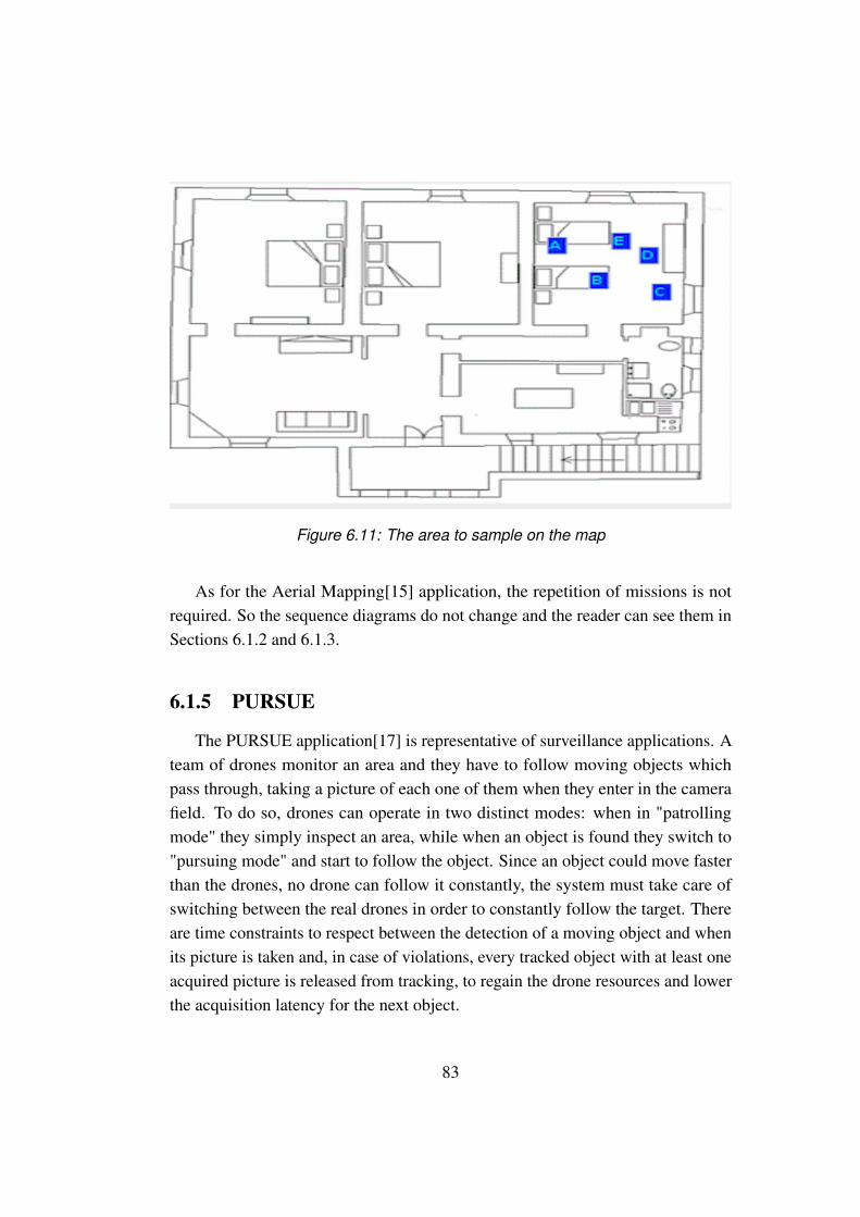
Figure 6.11: The area to sample on the map
As for the Aerial Mapping[15] application, the repetition of missions is notrequired. So the sequence diagrams do not change and the reader can see them inSections 6.1.2 and 6.1.3.
6.1.5 PURSUE
The PURSUE application[17] is representative of surveillance applications. Ateam of drones monitor an area and they have to follow moving objects whichpass through, taking a picture of each one of them when they enter in the camerafield. To do so, drones can operate in two distinct modes: when in "patrollingmode" they simply inspect an area, while when an object is found they switch to"pursuing mode" and start to follow the object. Since an object could move fasterthan the drones, no drone can follow it constantly, the system must take care ofswitching between the real drones in order to constantly follow the target. Thereare time constraints to respect between the detection of a moving object and whenits picture is taken and, in case of violations, every tracked object with at least oneacquired picture is released from tracking, to regain the drone resources and lowerthe acquisition latency for the next object.
83

The PURSUE application represents a limit for the Pluto programming frame-work. Indeed, in our model, the drones perform their action only at the end oftheir Trip, so it is not possible for them to actively take a picture in the very samemoment the moving object enters in the camera field. This problem can be loweredby sending a great number of drones in the area to monitor, with strict time con-straints on them, in order to obtain a lot of pictures of the monitored area. But inthis way, not only it is not sure to capture the moving object, but there would be alot of useless empty pictures. And, above all, there is still no way for the drones toactively follow the moving objects.
We can conclude that the PURSUE application is too "dynamic" for the Plutoprogramming framework, and this can be an hint for a future expansion of ourwork.
84
6.2 Usability
To evaluate the concrete usability of the Pluto programming framework, wedecided to recruit some people and to make them test our framework, proposingthem two "exercises". We involved five testers, recruited both in the "Politecnicodi Milano" and "SICS Swedish ICT" environment, in order to guarantee a soliddevelopment background and to avoid possible lack of programming knowledge.We created one exercise based on the Graphical Editor and another one based onthe Main Application.
The first exercise is split in three levels, starting from a very basic version andgoing through more difficult versions. Each version asks the user to add a newfunctionality by using the available components in the Editor.The second exercise, instead, asks the user to use the generated code from theprevious exercise to run the Pluto Main Application, then asks to create somemissions and, in the end, to run them.
The application we choose for the exercises is the Drugs Distribution, alreadydescribed in Section 3.1, because it’s very suitable for the type of evaluation wewant to perform. Indeed its basic version can be extended with many features,for example using the Mission Modifier block (Section 4.2), and this is exactlyour purpose. After the execution of the exercises, we asked the users to leave afeedback, proposing them a survey, built according to some metrics that we havedefined and that we describe in Section 6.2.4, while the results are shown in Section6.2.5.
6.2.1 Proposed exercises
We gave to the testers a complete and sound explanation of the Pluto program-ming framework, showing how the Graphical Editor works (shown in Section4.3.1), giving them a description of the involved entities such as the Mission, theTrip, the Drone and the Action (shown in Section 4.1) and the list of the functionalblocks (shown in Section 4.2), together with an explanation of the meaning andfunctionality of each one of them.The same explanations were given for the Pluto Main Application too (shown inSection 4.3.2), of course showing them only a summary of its features because our
85
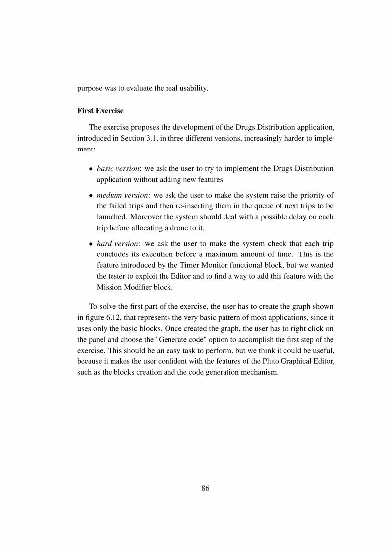
purpose was to evaluate the real usability.
First Exercise
The exercise proposes the development of the Drugs Distribution application,introduced in Section 3.1, in three different versions, increasingly harder to imple-ment:
• basic version: we ask the user to try to implement the Drugs Distributionapplication without adding new features.
• medium version: we ask the user to make the system raise the priority ofthe failed trips and then re-inserting them in the queue of next trips to belaunched. Moreover the system should deal with a possible delay on eachtrip before allocating a drone to it.
• hard version: we ask the user to make the system check that each tripconcludes its execution before a maximum amount of time. This is thefeature introduced by the Timer Monitor functional block, but we wantedthe tester to exploit the Editor and to find a way to add this feature with theMission Modifier block.
To solve the first part of the exercise, the user has to create the graph shownin figure 6.12, that represents the very basic pattern of most applications, since ituses only the basic blocks. Once created the graph, the user has to right click onthe panel and choose the "Generate code" option to accomplish the first step of theexercise. This should be an easy task to perform, but we think it could be useful,because it makes the user confident with the features of the Pluto Graphical Editor,such as the blocks creation and the code generation mechanism.
86
Figure 6.12: Solution of the first step
To solve the first part of the second step of the exercise, the user has to under-stand that the functionality to add is already implemented by the Priority Managerblock, so the solution is to add this block to the graph in the right point. Since weask him to re-insert the failed trips in the queue of the trips to launch, he has toput the Priority Manager between the Trip Monitor and the Drone Allocator, as infigure 6.13.
87

Figure 6.13: Solution of the second step with Priority Manager
Then to add the Delay feature in the diagram the user needs to do the samething with the Clock block, that provides the feature to wait for an amount oftime, set in the delay attribute of a Trip. This block is taking as input the missionprovided by the Trip Monitor and the by the Mission Creator then, after the delaytime has passed, gives the mission to the DroneAllocator block, as shown in figure6.14.
This is a useful step to compute, because the user learns how to use the connec-tion element, that is a very important feature in the Pluto framework, and also thePriority Manager and Clock blocks.
88
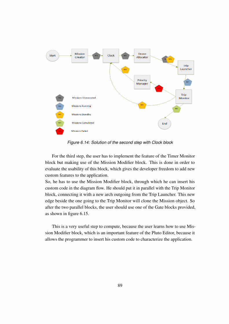
Figure 6.14: Solution of the second step with Clock block
For the third step, the user has to implement the feature of the Timer Monitorblock but making use of the Mission Modifier block. This is done in order toevaluate the usability of this block, which gives the developer freedom to add newcustom features to the application.So, he has to use the Mission Modifier block, through which he can insert hiscustom code in the diagram flow. He should put it in parallel with the Trip Monitorblock, connecting it with a new arch outgoing from the Trip Launcher. This newedge beside the one going to the Trip Monitor will clone the Mission object. Soafter the two parallel blocks, the user should use one of the Gate blocks provided,as shown in figure 6.15.
This is a very useful step to compute, because the user learns how to use Mis-sion Modifier block, which is an important feature of the Pluto Editor, because itallows the programmer to insert his custom code to characterize the application.
89
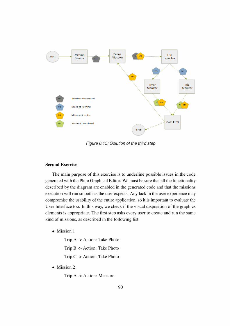
Figure 6.15: Solution of the third step
Second Exercise
The main purpose of this exercise is to underline possible issues in the codegenerated with the Pluto Graphical Editor. We must be sure that all the functionalitydescribed by the diagram are enabled in the generated code and that the missionsexecution will run smooth as the user expects. Any lack in the user experience maycompromise the usability of the entire application, so it is important to evaluate theUser Interface too. In this way, we check if the visual disposition of the graphicselements is appropriate. The first step asks every user to create and run the samekind of missions, as described in the following list:
• Mission 1
Trip A -> Action: Take Photo
Trip B -> Action: Take Photo
Trip C -> Action: Take Photo
• Mission 2
Trip A -> Action: Measure
90

Trip B -> Action: Measure
• Mission 3
Trip A -> Action: Pick Item
Trip B -> Action: Release Item
Trip C -> Action: Take Photo
Trip D -> Action: Measure
The location in the map of the Trips was not important while testing, so thetester could decide any places. In the second step the users were asked to open theMonitor Page and to start the missions following their execution using the providedtable and the log console inside the page itself. The third step of the exerciseconsists in calling back the Drone with an RTL (Return To Launch) command.
6.2.2 Evaluation metrics
To concretely evaluate the usability of the Pluto programming framework wedefined the following metrics, which we applied for both exercises:
1. Number of people who correctly solved the first part of the exercise
2. Number of people who correctly solved the first and second parts of theexercise
3. Number of people who correctly solved the whole exercise
4. Mean time for the resolution of the first part of the exercise
5. Mean time for the resolution of the second part of the exercise
6. Mean time for the resolution of the third part of the exercise
7. Mean time for the resolution of the whole exercise
8. Number of people who solved the whole exercise, but in a wrong way
9. Number of people who could not solve the exercise at all
91

Through metrics 1,2 and 3 we can understand which parts of the exercises arenot clear for the user and/or too difficult to implement. Through metrics 4,5,6 and7 we can understand, once the user has understood how to implement each feature,how much it is difficult to solve each part of the exercises by measuring the timerequired to solve each step. Through metrics 8 and 9, finally, we can understandhow easy is to confuse the specifications and how many people couldn’t solve anystep of the exercises.
6.2.3 Baseline
We want to demonstrate the effective usefulness of the Pluto programmingframework, so we decide to compare its features with the API of the CrazyflieNano-quadcopter, which was described in Section 5.6.
Actually, the crazyflie is the drone we chose to use for our applications casestudy, and we want to demonstrate that, without Pluto and using only the CrazyflieAPI would be more difficult to build the same kind of applications.
So we decide to propose another exercise to our users, but this time they canuse only the Crazyflie API and they have a limited amount of time.
The Crazyflie API is written in Python, so we address to people who knowsPython language features.
The exercise consists in make the drone moving from a point A to a point B ona map, performing a single Trip.
It may seem easy, but it can can take a long time to fully understand and applythe API in the correct way.
6.2.4 User Survey
Since we want to evaluate the usability of Pluto, we propose a survey to theusers, in order to understand how easy it is to use and which modifications shouldbe applied to improve the user experience.
We ask users to tell us how easy was the development of the various steps ofthe exercises, and to provide us with a feedback on the usability of the editor andthe main application underlining any problems found. We also ask for suggestionsto improve the usability of Pluto. The survey can be found in the Appendix A.
92

Actually, this survey gives us very useful information about the Pluto frame-work. We can understand how "usable" it is and which modifications should beperformed to improve the user’s experience, also thanks to the visualization of theanswers in a graphical way. Through the questions on the exercises developmentwe can understand how difficult it is to create, modify,customize and execute aparticular application, validating "on field" the use of the various blocks, especiallythe Mission Modifier, and the usability of the user interface.
6.2.5 Results
Thanks to the combination of the answers to the user survey of Section 6.2.4and the numeric data collected according to the metrics defined in Section 6.2.2, inthis Section we show the results of the Pluto evaluation. The metrics data are putinto the table 6.1.
Table 6.1: Results of the Metrics of Section 6.2.2
Metric 1 2 3 4 5 6 7 8 9Exercise 1 5 5 5 10 mins 10 mins 20 mins 40 mins 0 0Exercise 2 5 5 5 5 mins 5 mins 5 mins 15 mins 0 0
As shown in the table above, all the users completed the two proposed exercises.Except for the third step of the first exercise, which required to use the MissionModifier block, the other steps took few minutes to get solved. This is a goodresponse on the usability of the framework.Instead, the third step of the first exercise resulted harder than expected. Fromthe testers’ comments we understood that this difficulty derives from the lack ofknowledge about the way to manage the attributes of the trips and mission entitiesin the code.We realized that a complete reference of the entities and an example of use of themis essential in order to simplify the developer duties.
The questions in the survey follow a pattern where, at first we ask for a difficultymark for each exercise’s step (from "easy" to "very hard" or "not solved") and thenwe ask for a written comment or an advice about it.
93
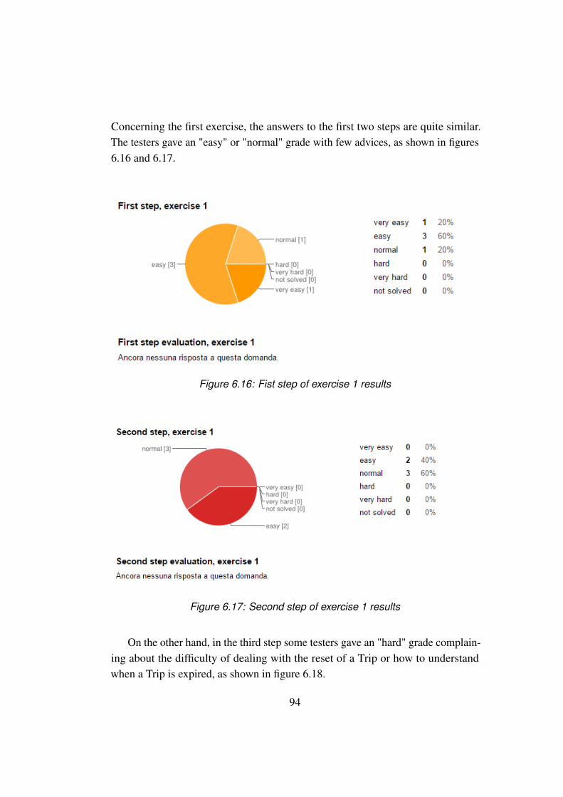
Concerning the first exercise, the answers to the first two steps are quite similar.The testers gave an "easy" or "normal" grade with few advices, as shown in figures6.16 and 6.17.
Figure 6.16: Fist step of exercise 1 results
Figure 6.17: Second step of exercise 1 results
On the other hand, in the third step some testers gave an "hard" grade complain-ing about the difficulty of dealing with the reset of a Trip or how to understandwhen a Trip is expired, as shown in figure 6.18.
94
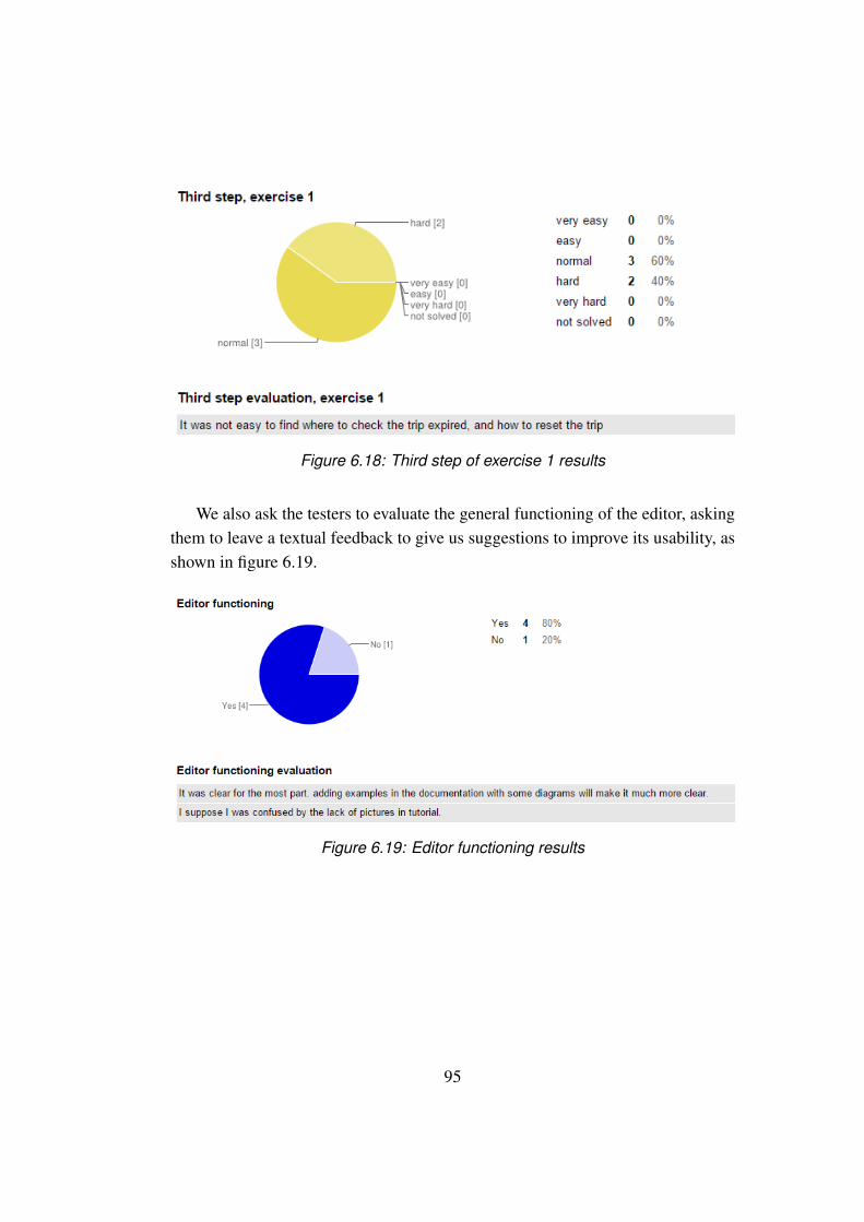
Figure 6.18: Third step of exercise 1 results
We also ask the testers to evaluate the general functioning of the editor, askingthem to leave a textual feedback to give us suggestions to improve its usability, asshown in figure 6.19.
Figure 6.19: Editor functioning results
95
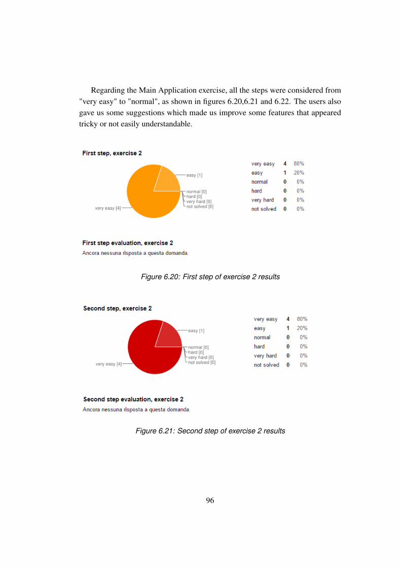
Regarding the Main Application exercise, all the steps were considered from"very easy" to "normal", as shown in figures 6.20,6.21 and 6.22. The users alsogave us some suggestions which made us improve some features that appearedtricky or not easily understandable.
Figure 6.20: First step of exercise 2 results
Figure 6.21: Second step of exercise 2 results
96
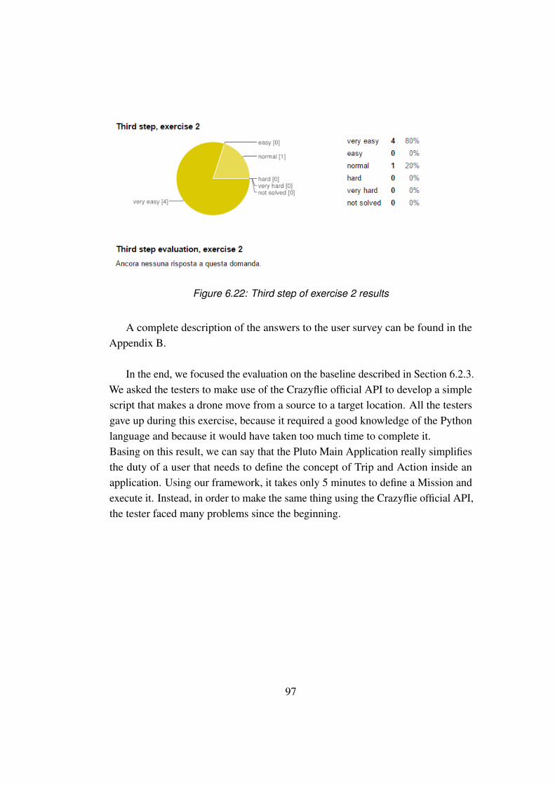
Figure 6.22: Third step of exercise 2 results
A complete description of the answers to the user survey can be found in theAppendix B.
In the end, we focused the evaluation on the baseline described in Section 6.2.3.We asked the testers to make use of the Crazyflie official API to develop a simplescript that makes a drone move from a source to a target location. All the testersgave up during this exercise, because it required a good knowledge of the Pythonlanguage and because it would have taken too much time to complete it.Basing on this result, we can say that the Pluto Main Application really simplifiesthe duty of a user that needs to define the concept of Trip and Action inside anapplication. Using our framework, it takes only 5 minutes to define a Mission andexecute it. Instead, in order to make the same thing using the Crazyflie official API,the tester faced many problems since the beginning.
97
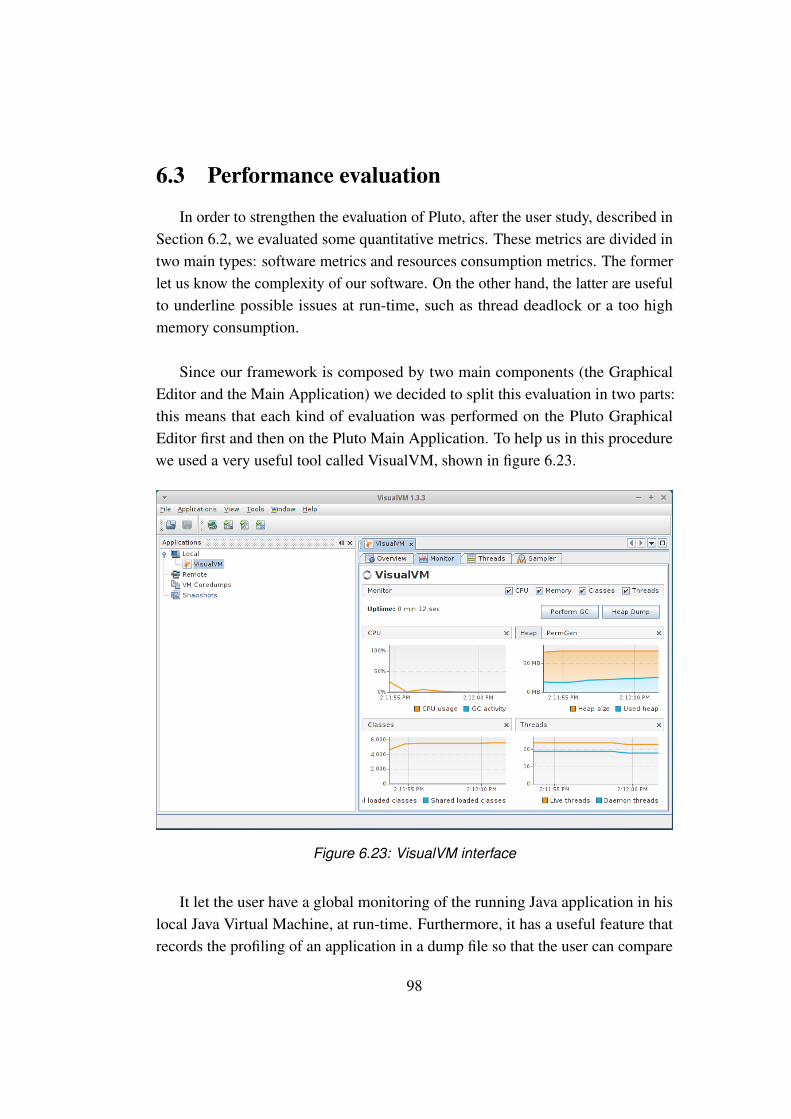
6.3 Performance evaluation
In order to strengthen the evaluation of Pluto, after the user study, described inSection 6.2, we evaluated some quantitative metrics. These metrics are divided intwo main types: software metrics and resources consumption metrics. The formerlet us know the complexity of our software. On the other hand, the latter are usefulto underline possible issues at run-time, such as thread deadlock or a too highmemory consumption.
Since our framework is composed by two main components (the GraphicalEditor and the Main Application) we decided to split this evaluation in two parts:this means that each kind of evaluation was performed on the Pluto GraphicalEditor first and then on the Pluto Main Application. To help us in this procedurewe used a very useful tool called VisualVM, shown in figure 6.23.
Figure 6.23: VisualVM interface
It let the user have a global monitoring of the running Java application in hislocal Java Virtual Machine, at run-time. Furthermore, it has a useful feature thatrecords the profiling of an application in a dump file so that the user can compare
98
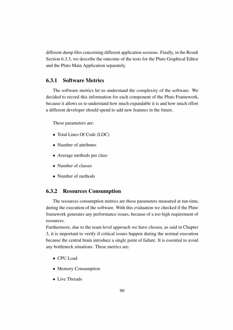
different dump files concerning different application sessions. Finally, in the ResultSection 6.3.3, we describe the outcome of the tests for the Pluto Graphical Editorand the Pluto Main Application separately.
6.3.1 Software Metrics
The software metrics let us understand the complexity of the software. Wedecided to record this information for each component of the Pluto Framework,because it allows us to understand how much expandable it is and how much efforta different developer should spend to add new features in the future.
These parameters are:
• Total Lines Of Code (LOC)
• Number of attributes
• Average methods per class
• Number of classes
• Number of methods
6.3.2 Resources Consumption
The resources consumption metrics are those parameters measured at run-time,during the execution of the software. With this evaluation we checked if the Plutoframework generates any performance issues, because of a too high requirement ofresources.Furthermore, due to the team level approach we have chosen, as said in Chapter3, it is important to verify if critical issues happen during the normal executionbecause the central brain introduce a single point of failure. It is essential to avoidany bottleneck situations. These metrics are:
• CPU Load
• Memory Consumption
• Live Threads
99
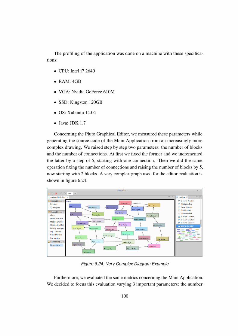
The profiling of the application was done on a machine with these specifica-tions:
• CPU: Intel i7 2640
• RAM: 4GB
• VGA: Nvidia GeForce 610M
• SSD: Kingston 120GB
• OS: Xubuntu 14.04
• Java: JDK 1.7
Concerning the Pluto Graphical Editor, we measured these parameters whilegenerating the source code of the Main Application from an increasingly morecomplex drawing. We raised step by step two parameters: the number of blocksand the number of connections. At first we fixed the former and we incrementedthe latter by a step of 5, starting with one connection. Then we did the sameoperation fixing the number of connections and raising the number of blocks by 5,now starting with 2 blocks. A very complex graph used for the editor evaluation isshown in figure 6.24.
Figure 6.24: Very Complex Diagram Example
Furthermore, we evaluated the same metrics concerning the Main Application.We decided to focus this evaluation varying 3 important parameters: the number
100
of Mission, the number of Trips related to a single Mission and the number ofavailable Drones. We started fixing the number of missions and trips, while varyingthe number of available drones. Then we fixed the number of missions and drones,while varying the number of trips. In the end we fixed the number of trips anddrones, while varying the number of missions. In this way, we could evaluate theperformance of the Main Application in an accurate way. The results are shown inthe next Section 6.3.3.
6.3.3 Results
In this Section we show the results of the software and resources consump-tion evaluation. First of all, we evaluated the software complexity of the Plutoframework, according to some important software metrics. Table 6.2 proposes theresults.
Main Application Graphical EditorTotal lines of code 2132 5072Number of classes 48 129Number of attributes 104 141Number of methods 197 569Weighted methods per class 325 848
Table 6.2: The metrics concerning the two Pluto components
Thanks to these measures, we can make some considerations about the sizeand the effort spent in developing the Pluto framework.Concerning the Main Application, these values depend from the diagram genera-tion process, because the amount of the generated surplus code does not exceedthe 2-3% of the total lines of code of the template Main Application. Indeed thegeneration adds no more than 50 lines.Instead, the Graphical Editor has a higher volume than the Main Application,with all the measured values doubled. This can be explained by the fact that, todevelop the Editor, we based our code on the Eclispe GEF Framework. Most of theclasses inherit from other parent classes inside this framework, and we inherited itscomplexity too.The higher size explains also the time we spent to develop the Graphical Editor
101

and the time needed to add new features during the software revision steps. Indeedwe found the GEF framework a bit hard to maintain.
Now we present the results concerning the resources consumption of the twoPluto framework.Starting from the Graphical Editor evaluation, the diagrams in picture 6.25 de-scribe the results of the resources consumption during the code generation process.The left one represents the results while increasing the blocks amount with fixedconnections. The right one instead represents the results when the connectionsnumber varies with a fixed number of blocks.
20 40 60 80 1000
50
100
Blocks
Fixed 10 Connections
CPU
Mem(MB)
Threads
20 40 60 80 1000
50
100
Connections
Fixed 15 Blocks
CPU
Mem(MB)
Threads
Figure 6.25: Resources consumption of the Graphical Editor
Inside each diagram there are three curves representing the three metrics wemeasured: the CPU load (magenta), the memory consumption (blue) and the num-ber of active threads (green).The Graphical Editor does not load the CPU more than 10% while generating thecode, even in the case of complex diagrams. This can be explained by the fact thatthe generated code is a little percentage inside the whole Main Application code.The memory consumption is not stable but it waves between 40MB and 70MB. Wenoticed that this fluctuation is independent from the Graphical Editor process, andis due to the Operating System.We realized that the Graphical Editor does not require an high amount of resourcesduring the generation of the Main Application template code.
102

Instead, The Main Application evaluation gave us different results, shown inthe following figures.
20 40 60 80 1000
20
40
60
80
100
Drones
Fixed 10 Missions and 5 Trips
CPU
Mem(MB)
Threads
Figure 6.26: Evaluation results of Main Application with fixed missions and trips
The diagram of figure 6.26 describes the resources consumption of the MainApplication with a fixed number of missions and trips and a raising number ofdrones. We created 10 missions with 5 trips each.The CPU load is constantly over 95%: we suppose that this is caused by thesimulation environment we built in order to execute the tests. For example wesimulate the Drone flight and the Action execution by pausing the related threadfor two seconds. Our believe that this brought the system to require more resourcesthan in a normal situation.
The memory consumption value is even fewer than the one obtained in the testof the Graphical Editor, and the fluctuation is less highlighted.
103

20 40 60 80 1000
20
40
60
80
100
Trips
Fixed 10 Missions and 15 Drones
CPU
Mem(MB)
Threads
Figure 6.27: Evaluation results of Main Application with fixed missions and drones
The diagram 6.27 describes the resources consumption of the Main Applicationwith a fixed number of missions and drones while increasing the number of tripsfor each mission. We created 10 missions and made available 15 drones.The situation is almost the same of the previous test, represented in figure 6.26.
20 40 60 80 1000
20
40
60
80
100
Missions
Fixed 5 Trips and 15 Drones
CPU
Mem(MB)
Threads
Figure 6.28: Evaluation results of Main Application with fixed trips and drones
104

The diagram 6.28 describes the resources consumption of the Main Applicationwith a fixed number of trips and drones and a raising number of missions. Wecreated 5 trips for each mission and made available 15 drones.The evident difference from the previous diagrams is that the number of activethreads during the execution raises with the increase of the number of missions setby the user.This can be explained by the fact that each Mission is managed by a dedicatedthread. in this way if the user creates 100 missions at least 100 threads are created.This behavior lets us think about the possibility to run each mission on a differentmachine, in order to reduce the threads concurrency and reduce the CPU load.
105

106
Chapter 7
Conclusions and future works
In this final Chapter we recap the structure of the whole document and thedevelopment phases of the Pluto programming framework. We also show thelimits of Pluto and the possible future works thanks to which these limits could beovercome.
7.1 Conclusions
We have developed the Pluto programming framework, a system which al-lows to build nano-drones applications for indoor contexts, simply by graphicallyconnecting blocks.
In this document we have fully described the development process of Pluto andthe context surrounding our work:
In Chapter 1 we have given the general context and the general goals of thework together with a brief description of the Pluto development process.
In Chapter 2 we have described the three main existing approaches for droneprogramming, also proposing existing examples for each one of them. We haveshown that no one of these approaches is suitable for our requirements, since weneeded the concepts of Mission and Trip. A Mission is a list of sensing tasks tobe performed sequentially and a Trip is a movement from a point A to a point Bin the environment to perform an Action. We have also described the dataflowprogramming method, providing two existing examples of it. Also in this case, we
107

have shown that we needed a different approach, since we needed to use only agroup of basic features for our work, while the existing solutions were too generaland contained a lot of complex components.
Chapter 3 is focused on the problems stemming from the indoor context and onthe requirements deriving from it. Starting from a motivating example application,in order to better explain the requirements and problems deriving from our work,we have shown the implementation problems deriving from using a Team-levelapproach for our system, also proposing the solutions to fix them. Finally wehave shown the technological limitations affecting our system, such as the indoorlocalization and nano-drone batteries problems.
In Chapter 4 we have presented our solution for the research problems de-scribed in Chapter 3, the Pluto programming framework. We have presented ourprogramming model, that is to say the main entities and the relationships betweenthem. We have described the functionality of the blocks of the Pluto GraphicalEditor, that are the basic elements that the programmer can connect to graphicallybuild an application. We also have described in details the two components ofthe Pluto framework: the Graphical Editor, that is used by the programmer tographically build an application and the Main Application, that is used by the finaluser to specify the sensing tasks to be performed. We have describe the navigationsystem, that is the conjunction point between the Main Application and the dronesteam. We finally have shown all the steps performed to arrive to the final system,showing all the previously implemented solutions which, once refined, brought usto the development of the Pluto programming framework.
In Chapter 5 we have shown how the designed choices have been implementedtechnically, describing all the software and tools we used for the development ofPluto programming framework. We have described: The GEF framework, whichwe have used to implement the Pluto Graphical Editor. The code generation pro-cess that creates a Java application from the graph built with the Pluto GraphicalEditor. The Object-Oriented programming model of the Pluto framework. Theruntime features of Pluto: the parallel architecture and the management of all theneeded threads. The SWING tool, which we have used to develop the Pluto MainApplication. The Crazyflie nano-quadcopter, which we have used to perform the
108
sensing tasks of our prototype applications.
In Chapter 6 we have described four already existing applications and threecase study, and we have discussed on whether they can be developed or not withPluto. We have proposed two exercises to real testers, in order to test "on the field"the effective usability of Pluto: the first one deals with the Graphical Editor, thesecond one with the Main Application. Then we have proposed a third exercise, inwhich we ask the users to directly use the API of the Crazyflie nano-quadcopter,shown in Section 5.6, to make it move from a point A to a point B. We have alsoproposed a survey to the users, in order to have opinions on the framework andpossibly to improve it with the suggestions of the testers. We also have measuredthe software and hardware consumption metrics required by Pluto, in order toevaluate the effective impact of Pluto on an ordinary computing machine.
7.2 Pluto limits and future works
In this Section we show the limits of the Pluto programming framework.There are two type of limits: the limits in the implementation can possibly be
overcome by modifying the source code and/or adding new features, or changingthe whole model of the system. The technological limits cannot be overcome inthe present, and only research and studies can find a way to improve or find newtechnologies which would solve these problems.
The PURSUE application, described in Section 6.1.5, put in evidence the Plutomain limitation: the immediate execution of actions in response to instantaneousevents.
As already explained in chapter 4, the Pluto system allows the drones to performtheir actions only at the end of the Trip, that is a movement from a point A to apoint B in the environment. For example, if the Drone has to take a picture in aspecific location, it flies from the ground station to that location and then it takesthe picture.
There is no way to actively perform actions reacting on events: so, as alreadyexplained, this is the problem of the PURSUE application, which requires toactively follow a moving object when it enters in the camera range.
This is an hint for the future expansion of Pluto, in order to manage also thiskind of applications.
109
As already explained in chapter 3, the actuation in indoor contexts is trickybecause of the localization problem. We showed some IPS methods, but stillthey are not as efficient and standardized as GPS. They introduce latency in thelocalization mechanism and their precision is lowered by physical obstacles, roofsand ceilings.
In this direction, research and future studies will certainly find a better indoorlocalization method, and Pluto will take advantage from it, since it has an archi-tecture that is decoupled from the particular localization method. So, when thisnew method will be implemented, it will be easily integrated with Pluto. This isan important missing feature, since the actuation tasks performed by the dronescompletely relies and depends on a localization base: in order to send a drone in aspecific location to take a picture there is need of a method that precisely indicatesthat location.
Research and future studies will also find a way to improve the capacity of thenano-drones batteries. Nowadays their duration is approximately of 7 minutes, witha recharge time of 20 minutes. This is a great limitation, because the programmeris forced to develop applications where the sensing tasks must be performed withinthis limited amount of time.
Finding a solution to the limitation of the instantaneous actuation, togetherwith new technological discoveries that will improve the drones battery durationand find a good and stable indoor localization method, can greatly enrich the Plutoprogramming framework.
110

Bibliography
[1] Karthik Dantu and Bryan Kate and Jason Waterman and Peter Bailis and MattWelsh, “Programming Micro-Aerial Vehicle Swarms With Karma,” in SenSys’11 Proceedings of the 9th ACM Conference on Embedded Networked SensorSystems. ACM, 2011, pp. 121–134.
[2] Luca Mottola and Mattia Moretta and Kamin Whitehouse and Carlo Ghezzi,“Team-level Programming of Drone Sensor Network,” in SenSys ’14 Proceed-ings of the 12th ACM Conference on Embedded Network Sensor Systems.ACM, 2014, pp. 177–190.
[3] CNN.com, “Your personal 849 dollars underwater drone,” in goo.gl/m1JRuD.
[4] iRobot, “Create Programmable Robot,” in goo.gl/bJhrMR.
[5] M. Brambilla et al., “A review from the swarm engineering perspective,” inSwarm Intelligence, 2013.
[6] Morgan Quigley and Brian Gerkey and Ken Conley and Josh Faust and TullyFoote and Jeremy Leibs and Eric Berger and Rob Wheeler and Andrew Ng,“ROS: an open-source Robot Operating System,” in ICRA Workshop on OpenSource Software, 2009.
[7] Jonathan Bachrach and Jacob Beal and James McLurkin, “Composablecontinuous-space programs for robotic swarms,” in Neural Computing andApplications. ACM, IEEE, 2010, pp. 825–847.
[8] Jacob Beal, “Programming an amorphous computational medium,” in Uncon-ventional Programming Paradigms. Springer Berlin, 2005, pp. 97–97.
[9] Greg Sterling, “Magnetic positioning,” in Opus Research Report, 2014.
111

[10] Fan Li and Chunshui Zhao and Guanzhong Ding and Jian Gong and ChenxingLiu and Feng Zhao, “A reliable and accurate indoor localization methodusing phone inertial sensors ,” in UbiComp ’12 Proceedings of the 2012 ACMConference on Ubiquitous Computing. ACM New York, 2012, pp. 421–430.
[11] Frédéric Evennou and François Marx, “Advanced integration of WIFI andinertial navigation systems for indoor mobile positioning,” in EURASIPJournal on Applied Signal Processing. Hindawi Publishing Corp, Ne York,2006, pp. 164–164.
[12] Silke Feldmann and Kyandoghere Kyamakya and Ana Zapater and ZighuoLue, “ An indoor Bluetooth-based positioning system: concept, Implementa-tion and experimental evaluation ,” in International Conference on WirelessNetworks - ICWN, 2003, pp. 109–113.
[13] Keith S. Delaplane and Daniel F. Mayer, Crop Pollination by Bees. CABINew York, 2000.
[14] E. Stokstad, “The Case of the Empty Hives,” in Science, 2007.
[15] F. Nex and F. Remondingl, “UAV for 3D mapping applications: A review,”in Applied Geomatics. Springer, 2003.
[16] U.S. Environmental Protection Agencyl, “Air Pollutants,” in goo.gl/stvh8.
[17] J. Villasenorl, “Observations from above: Unmanned Aircraft Systems,” inHarvard Journal of Law and Public Policy, 2012.
112
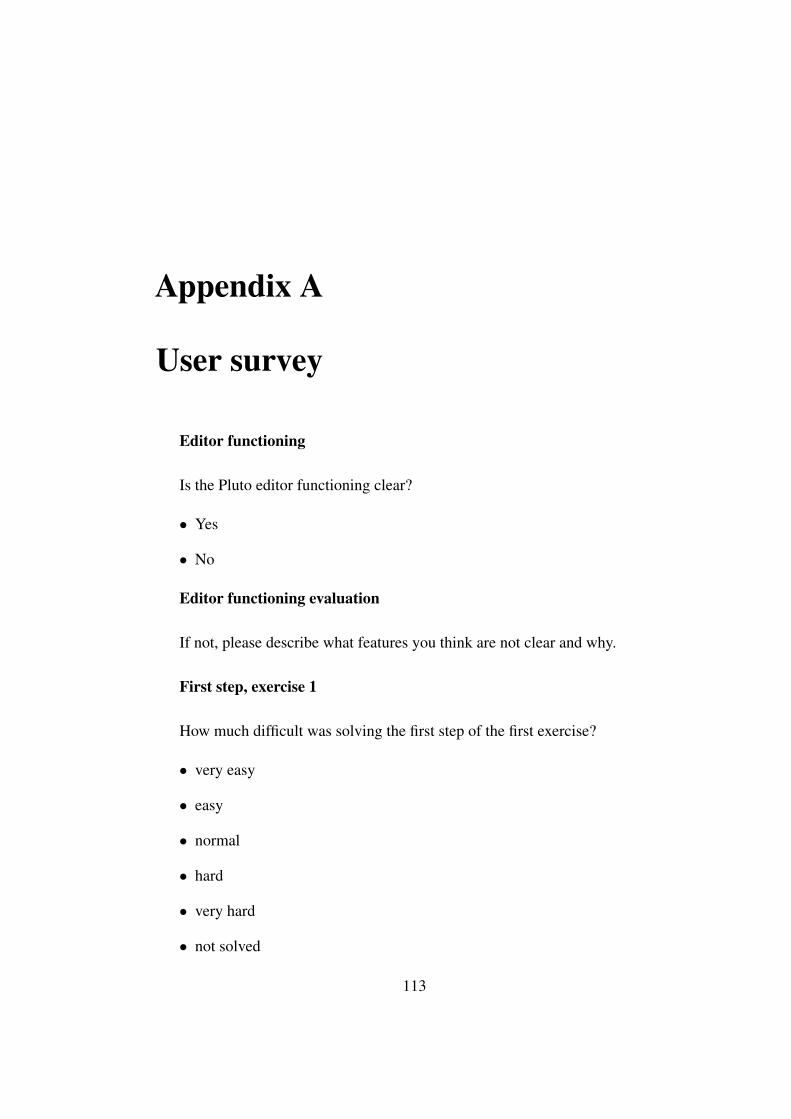
Appendix A
User survey
Editor functioning
Is the Pluto editor functioning clear?
• Yes
• No
Editor functioning evaluation
If not, please describe what features you think are not clear and why.
First step, exercise 1
How much difficult was solving the first step of the first exercise?
• very easy
• easy
• normal
• hard
• very hard
• not solved
113
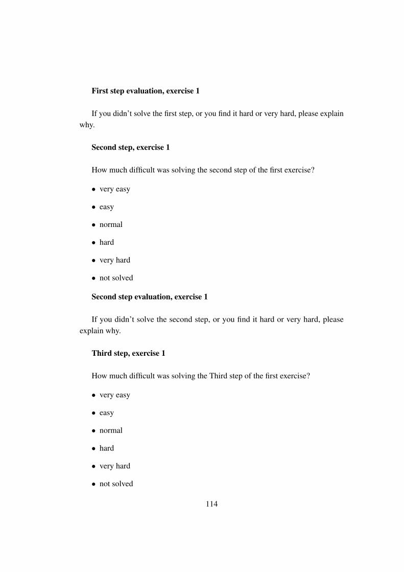
First step evaluation, exercise 1
If you didn’t solve the first step, or you find it hard or very hard, please explainwhy.
Second step, exercise 1
How much difficult was solving the second step of the first exercise?
• very easy
• easy
• normal
• hard
• very hard
• not solved
Second step evaluation, exercise 1
If you didn’t solve the second step, or you find it hard or very hard, pleaseexplain why.
Third step, exercise 1
How much difficult was solving the Third step of the first exercise?
• very easy
• easy
• normal
• hard
• very hard
• not solved
114
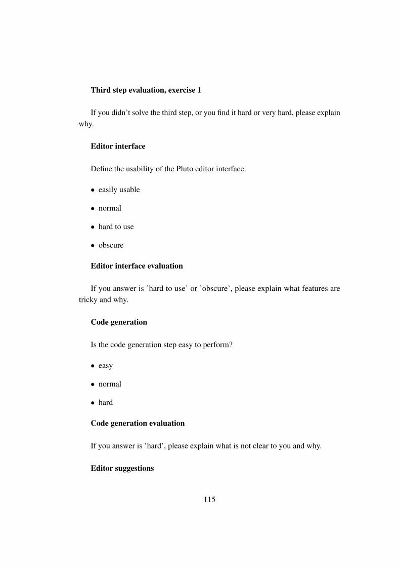
Third step evaluation, exercise 1
If you didn’t solve the third step, or you find it hard or very hard, please explainwhy.
Editor interface
Define the usability of the Pluto editor interface.
• easily usable
• normal
• hard to use
• obscure
Editor interface evaluation
If you answer is ’hard to use’ or ’obscure’, please explain what features aretricky and why.
Code generation
Is the code generation step easy to perform?
• easy
• normal
• hard
Code generation evaluation
If you answer is ’hard’, please explain what is not clear to you and why.
Editor suggestions
115
Please write here any comment/suggestions to improve Pluto Editor.
User application functioning
Is the Pluto user application functioning clear?
• Yes
• No
User application functioning evaluation
If not, please explain what features you think are not clear.
First step, exercise 2
How much difficult was solving the first step of the second exercise?
• very easy
• easy
• normal
• hard
• very hard
• not solved
First step evaluation, exercise 2
If you didn’t solve the first step, or you find it hard or very hard, please explainwhy.
Second step, exercise 2
How much difficult was solving the second step of the second exercise?
• very easy
116

• easy
• normal
• hard
• very hard
• not solved
Second step evaluation, exercise 2
If you didn’t solve the second step, or you find it hard or very hard, pleaseexplain why.
Third step, exercise 2
How much difficult was solving the third step of the second exercise?
• very easy
• easy
• normal
• hard
• very hard
• not solved
Third step evaluation, exercise 2
If you didn’t solve the third step, or you find it hard or very hard, please explainwhy.
Missions page
How much difficult was to use the Missions Page of the Pluto user application?
• very easy
117
• easy
• normal
• hard
• very hard
Missions page evaluation
If you find it hard or very hard, please explain why.
Trips page
How much difficult was to use the Trips Page of the Pluto user application?
• very easy
• easy
• normal
• hard
• very hard
Trips page evaluation
If you find it hard or very hard, please explain why.
Monitor page
How much difficult was to use the Monitor Page of the Pluto user application?
• very easy
• easy
• normal
• hard
118
• very hard
Monitor page evaluation
If you find it hard or very hard, please explain why.
User application suggestions
Please write here any comment/suggestions to improve Pluto user application.
119

120

Appendix B
User survey answers
List of figures
121
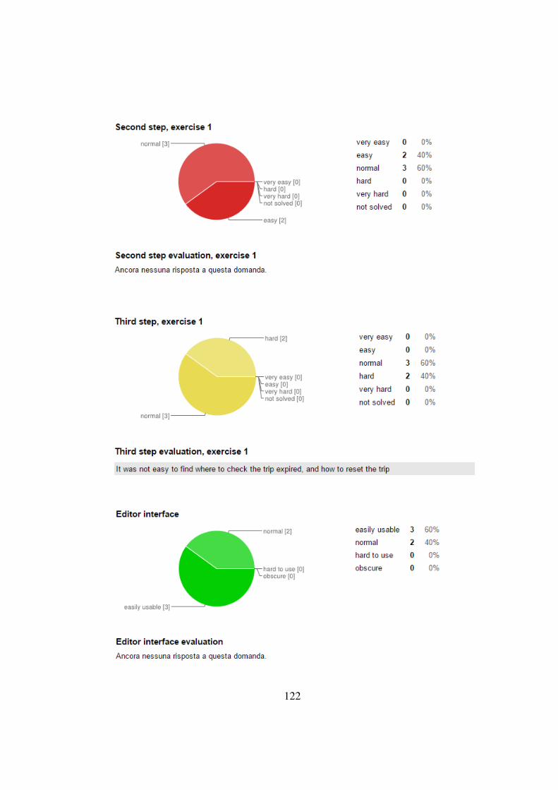
122

123
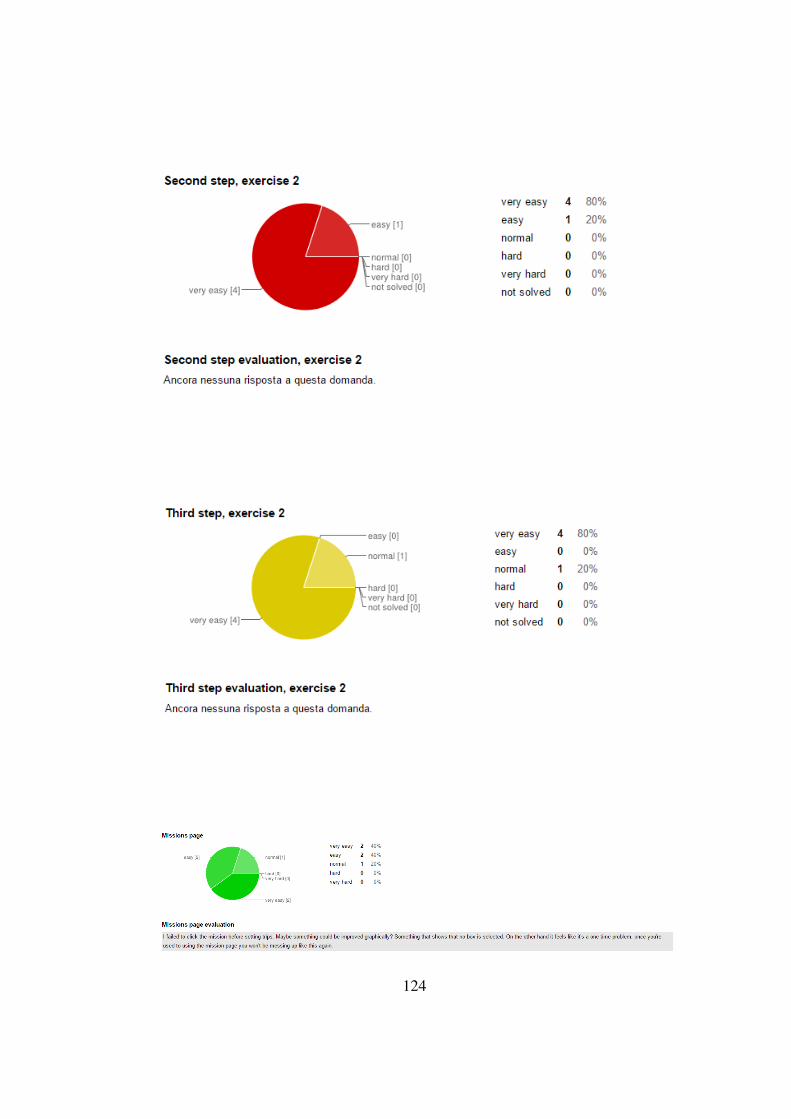
124

125