Prestazioni Aerauliche - Aeraulic Performances
13
Transcript of Prestazioni Aerauliche - Aeraulic Performances

�

Prestazioni Aerauliche - Aeraulic Performances Page 01
PREMESSA
Per esprimere dei valori universali, ripetibili e verificabili in qualsiasi
laboratorio, si rende necessario dichiarare le prestazioni dell’unità in accordo alle normative: solo così possono essere effettuati in ogni
momento dei nuovi test, seguendo le prescrizioni delle norme (nelle stesse condizioni “normalizzate”), e misurare dei valori che possono essere
confrontati con quelli dichiarati. Per questo motivo tutti gli ambienti scientifici, noi, come anche la
maggior parte dei costruttori qualificati che operano a livello internazionale (anche nostri concorrenti), riportano le prestazioni in
accordo alle normative: trattasi questo di un metodo universalmente condiviso, valido per tutti, che garantisce trasparenza, ripetibilità e
possibilità di confronto dei dati. Convenzionalmente, in accordo a criteri di semplicità e chiarezza
internazionalmente condivisi, le tabelle principali del costruttore devono riportare solo i “Dati Tecnici Nominali”.
� Assorbimento elettrico “I” del motore: le tabelle devono riportare il
valore nominale = “I.n” = Assorbimento massimo (di targa) del motore. � Portata aria “Qa”: le tabelle devono riportare il valore nominale:
- “Qa.n” = Portata aria dell’unità alla velocità massima e pressione statica ESP=0Pa (bocca libera) – (Fig.1).
- Qualora l’unità abbia un Limite di funzionamento inferiore “LFI”, contraddistinto da una ESP>0Pa (al di sotto della quale non si può
lavorare, pena la bruciatura del motore per sovrassorbimento elettrico), la portata aria nominale “Qa.n” sarà quella
corrispondente all’unità alla velocità massima e tale valore minimo di ESP (Fig.2).
INTRODUCTION
In order to express the technical data in universal way, repeatable and
verifiable in any laboratory, it is necessary to declare the performances of the unit according with the norms: only in this way it is possible to make
the test, following the norms (at the same “normalised” working conditions), and to measure the values which can be compared with the
nominal ones. For the here above reason in all scientific community, for us, same as for
most of the qualified manufacturers operating at international level (same is for our competitors), are specifying the performances of the units
according with the norms: this is a universally recognised method, valid for anybody, able to guarantee transparency, repeatability and
comparability of the data. Conventionally, according with criteria of simplicity and clarity
internationally recognised, main tables data must show only the “Nominal Technical Data”.
� Electrical absorption “I” of the motor: the tables data must show the
nominal value = “I.n” = Max electrical absorption of the (plate) motor. � Air flow “Qa”: the tables data must show the nominal value:
- “Qa.n” = Air flow of the unit at max speed and ESP=0Pa (free discharge) – (Fig.1).
- In case the unit may have a lower working limit “LFI”, with ESP>0Pa (below this value the unit cannot work, as the motor, due to over-
electrical absorption can be burnt), the nominal air flow “Qa.n” is the one with unit working at max speed, with such lower ESP limit
(Fig.2).
Qa [m3/h] Portata aria Air flow
ESP [Pa] Pressione statica utile External static pressure I [A] Assorbimento elettrico Electrical absorption
0 200 400 600 800 1000 Qa [m3/h]
0
20
40
60
80
100
ESP [Pa]
0,0
0,2
0,4
0,6
0,8
I [A]
ESP1
I.n Qa-ESP
I-Qa
LFI
Se esiste LFI : LFI > 0Pa ���� l’unità NON può lavorare a bocca libera ���� L’unità può lavorare solo con ESP ≥ ESP1 � Portata aria nominale = Qa.n = Qa con ESP1
(ESP1 identificato dal LFI) � Assorbimento elettrico nominale = I.n = I.max, relativo
ad ESP1 (ESP1 identificato dal LFI) � Per ESP<ESP1 � Qa > Qa.n ed I > I.n � Surriscaldamento
del motore e probabile bruciatura.
In case there is LFI limit: LFI > 0Pa ���� the unit can NOT work at free discharge ���� the unit can work with ESP ≥ ESP1 only � Nominal air flow = Qa.n = Qa with ESP1
(ESP1 identified by LFI value) � Nominal electrical absorption = I.n = I.max, at ESP1
(ESP1 identified by LFI value) � With ESP<ESP1 � Qa > Qa.n and I > I.n � Motor
overheated and possible serious damage (burnt).
Qa.n
I.max
Fig. 2
0 200 400 600 800 Qa [m3/h]
0
20
40
60
80
100
ESP [Pa]
0,0
0,2
0,4
0,6
0,8
I [A]
Qa.n
I.max Qa-ESP
I-Qa
Se non esiste LFI: LFI = 0Pa ���� l’unità può lavorare a bocca libera � Portata aria nominale = Qa.n = Qa con ESP=0Pa � per motori non sovradimensionati:
Assorbimento elettrico nominale = I.n = I.max rif. ESP=0Pa � per motori sovradimensionati:
Assorbimento elettrico nominale = I.n > I.max rif. ESP=0Pa
In case there is no LFI limit: LFI = 0Pa ���� the unit can work at free discharge � Nominal air flow = Qa.n = Qa with ESP=0Pa � with non-oversized motors:
Nominal electrical absorption = I.n = I.max ref. ESP=0Pa
� with oversized motors: Nominal electrical absorption = I.n > I.max ref. ESP=0Pa
Fig. 1

Prestazioni Aerauliche - Aeraulic Performances Page 02
ASSORBIMENTO ELETTRICO
Sulla nostra documentazione viene riportato l’assorbimento elettrico nominale in accordo alla EN 60335. Tale valore è quello di targa del motore = “I.n” = valore max, di riferimento, da usare per progettare in sicurezza l’impianto elettrico (per scegliere gli interruttori con la giusta portata dei contatti, per calcolare la sezione dei cavi di alimentazione, ecc.). Viene riportato solo questo dato, sia sulla documentazione che sui report del software di calcolo: un unico valore (nominale, limite, max) indipendentemente dalle velocità ed indipendentemente dall’effettivo punto Qa-ESP in cui l’unità va effettivamente a lavorare. Tale assorbimento elettrico è quello max di progetto del motore. Il motore avrà l’assorbimento nominale solo in un ben determinato (ed unico) punto di funzionamento: solo quando viene alimentato con tensione stabilizzata 230V-1Ph-50Hz e sta erogando la potenza nominale (= potenza max che è in grado di sviluppare senza comprometterne durata e funzionalità) … in altre parole, solo quando tutta la potenza (max) che il motore è in grado di generare viene assorbita ed utilizzata dal carico (nel nostro caso, carico = ventilatore).
In definitiva, l’assorbimento elettrico nominale “I.n” può essere considerato come il valore limite max, che si registra quando il motore sta lavorando nella condizione di “max sforzo”. Qualora per un qualsiasi motivo si registrasse un assorbimento elettrico maggiore di quello nominale � il ventilatore sta assorbendo una potenza maggiore di quella max generabile dal motore � maggiore potenza � maggiore assorbimento elettrico � sviluppo di maggiore potenza termica interna al motore � il motore non riesce a dissipare il surplus di potenza termica � innalzamento della temperatura interna � shock termici (dannosi surriscaldamenti) e bruciatura degli avvolgimenti del motore (Nota: il max valore di temperatura interna sopportabile dal motore è definito dalla classe di isolamento dei suoi avvolgimenti (ad es. 130°C per la classe B)).
Quindi nelle effettive condizioni di funzionamento, l’unità deve avere sempre un assorbimento elettrico inferiore al valore nominale “I.n” (al limite uguale), pena la bruciatura del motore. In particolare: � Quando l’unità lavora alle velocità più basse (med e min) � il
ventilatore tratta una portata aria inferiore � il ventilatore richiede una potenza inferiore � il motore sviluppa ed eroga al ventilatore una potenza inferiore � il motore avrà un assorbimento elettrico inferiore di quello nominale/max (Fig.3).
� Quando l’unità lavora con una maggiore pressione statica “ESP” (ad es. per effetto delle perdite di carico introdotte da un canale, da una serranda di taratura, da una griglia, dall’intasamento di un filtro, ecc.) � diminuisce la portata aria � il ventilatore tratta una portata aria inferiore � il ventilatore richiede una potenza inferiore � il motore sviluppa ed eroga al ventilatore una potenza inferiore � il motore avrà un assorbimento elettrico inferiore di quello nominale/max (Fig.4).
� Qualora sia previsto un accoppiamento motore-ventilatore adatto per funzionamento dell’unità solo con ESP>0Pa � per ESP minori di quelli del Limite di funzionamento inferiore “LFI” � il ventilatore tende a trattare un portata aria maggiore � il ventilatore richiede una potenza maggiore � il motore sviluppa ed eroga una potenza maggiore � il motore avrà un assorbimento elettrico maggiore di quello nominale/max � surriscaldamento e bruciatura del motore (Fig.2).
� Viceversa, qualora un ventilatore sia accoppiato ad un motore sovradimensionato � l’assorbimento elettrico effettivo dell’unità è sempre inferiore a quello nominale riportato sulla etichetta del motore (anche quando l’unità lavora a bocca libera, con ESP=0Pa). Infatti in questo caso il ventilatore richiede sempre una potenza inferiore a quella max che il motore (sovradimensionato) sarebbe in grado di erogare. Questo si verifica in qualsiasi condizione di funzionamento, anche a bocca libera, condizione per la quale il ventilatore tratta la max portata aria con richiesta quindi della max potenza (Fig.1).
ELECTRICAL ABSORPTION
In our documentation it is specified the nominal electrical absorption
according to the EN 60335.
The hereby value is the one shown on the motor plate = “I.n” = max
reference value, to be used to design in security the electrical system (to
chose the correct sizes of the switches, the correct size of the wires,
etc…).
Only the hereby value is specified, on the documentation and on the
selection software reports: just a single value (nominal, limit, max) not
depending on the speed and not depending on the actual working point
of the unit Qa-ESP.
This value is the max electrical absorption for the design of the motor.
The motor will have a nominal absorption in a single working point: when
the motor is working at stabilised voltage 230V-1Ph-50Hz and is delivering
nominal power (= max possible output power able to avoid any trouble in
terms of durability and functionality)… in other words, only when all the
produced power (max) that the motor is able to provide is absorbed and
used by the load (in this case, load = fan).
Ultimately, the nominal electrical absorption “I.n” can be considered as
the max limit value, which can be measured when the motor is working at
its “max strain” condition.
May for any reason be measured an electrical absorption higher than the
nominal one � the fan is absorbing higher power than the max one
generated by the motor � higher power � higher electrical absorption
� higher internal thermal power inside the motor � the motor is not able
to dissipate the extra thermal energy � the internal temperature will be
increased � thermal shock (damage due to overheating) and motor
wiring will be burnt (Note: the max value of internal motor temperature is
given by the class of isolation of the motor winding (for ex. 130°C for class B)).
At the actual working conditions, the unit must always have an electrical
absorption lower to the nominal value “I.n” (at the limit the same), with risk
for the motor to be burnt.
In more detail:
� When the unit works at lower speed (med or min) � the fan treats
reduced air flow � the fan requires lower power � the motor develops
lower power to the fan � the motor will have a lower electrical
absorption in comparison with nominal/max value (Fig.3).
� When the unit works with higher static pressure “ESP” (for example by
effect of the pressure drops produced by a duct, by a louver, by a grill,
by a dirty filter, etc…) � the air flow is reduced � the fan treats
reduced air flow � the fan needs reduced power � the motor
provides to the fan lower power � the motor will have a lower
electrical absorption in comparison with nominal/max value (Fig.4).
� In case is foreseen a motor-fan coupling suitable to make unit working
with ESP>0Pa only � with ESP values lower than lower working limit “LFI”
� the fan is near treating higher air flow � the fan requires higher
power � the motor produces higher power � the motor will have a
higher electrical absorption in comparison with nominal/max value �
motor overheating and burnt (Fig.2).
� Vice versa, in case the fan is coupled with an oversized motor � the
actual electrical absorption of the unit will always be lower in
comparison with the value specified in the motor plate (even in case
the unit is working at free discharge, with ESP=0Pa). In fact in this case
the fan always requires an electrical power lower to the max power
that the motor (oversized) is able to produce. This happens at any
working condition, even at free discharge, which is the condition with
max possible treated air flow with max possible electric power (Fig.1).
� Velocità/speed MAX ….. Qa.max ���� I.max � Velocità/speed MED ….. Qa.med < Qa.max ���� I.med < I.max � Velocità/speed MIN …... Qa.min < Qa.med ���� I.min < I.med
0,0
0,2
0,4
0,6
0,8
I [A]
Qa.max
I.max
Qa.med Qa.min
Min
Med
Max
I.med
I.min
0 200 400 Qa [m3/h]
0
20
40
60
80
100
ESP [Pa]
Qa-ESP
I-Qa
Max Med Min
Fig. 3
Con Portata aria minori (cioè ESP>) ���� Assorbimenti elettrici minori With Air flow lower (i.e. ESP>) ���� Lower Electrical absorptions P1 (Qa1 ; ESP1) ���� I1 ; P2 (Qa2<Qa1 ; ESP2>ESP1) ���� I2 < I1
I2
0 200 400 600 800 1000 Qa [m3/h]
0
20
40
60
80
100
ESP [Pa]
Qa-ESP
I-Qa
Qa1 Qa2
I1
0,0
0,2
0,4
0,6
0,8
1,0
I [A]
P1
P2
Fig. 4
ESP1
ESP2

Prestazioni Aerauliche - Aeraulic Performances Page 03
PORTATA ARIA
Sulla nostra documentazione viene riportata la portata aria nominale “Qa.n”: � Qa.n = portata aria alla velocità max ed ESP=0Pa (Fig.5). � Qa.n = portata aria alla velocità max ed ESP=LFI (qualora esista un
Limite di funzionamento inferiore “LFI”) – (Fig.6). Viene poi riportata la portata aria alle diverse velocità ed alle diverse pressioni statiche sotto forma di coefficienti correttivi, tabelle, grafici, o risultati del software di calcolo. In tutti i casi, trattasi di portata aria “normalizzata”, misurata in condizioni ben precise, in accordo alle seguenti norme internazionali:
� ASHRAE 51-75 (“AMCA standard 210-74 : Laboratory methods of testing fans for rating”)
� CNR-UNI 10023 (standard according with ISO 5167 - “Measured of fluid flow by means of orifice plates, nozzles or Venturi tubes inserted in circular cross-section conduits running full”)
� UNI EN 1397-2001 (“Heat exchangers – Hydronic room fan coils units – Test procedures for estabilishing the performances”)
� Eurovent 6/C/002:2001 (“Rating Standard for fan-coil units”)
Queste normative prevedono la misurazione della portata aria alle seguenti condizioni normalizzate: � Condizioni isotermiche con batteria secca (quindi con batteria non
alimentata con acqua, ed in particolare non durante il funzionamento in condizionamento)
� Temperatura aria 20°Cb.s. – 50% U.R. � Tensione e frequenza nominali e stabilizzate (per queste unità
230V-1Ph-50hz) � Pressione atmosferica 1.013 mbar (ossia ad altitudine s.l.m. = 0m) � Nessuna resistenza all’ingresso e all’uscita dell’aria (ossia unità senza
filtro aria, senza griglia aspirazione e senza griglia di mandata, anche perché l’unità può essere equipaggiata con diversi tipi di filtro, griglie ed accessori, con differenti perdite di carico che implicano differenti portate aria) (*).
In queste condizioni viene misurata la portata aria “Qa” alle diverse pressioni statiche “ESP” (da ESP=0Pa fino ad ESP max per la quale Qa =0 m3/h) e costruita l’intera curva Qa-ESP (Fig.5 – Fig.6). La Tolleranza ammessa dalle normative citate è del 10% (max differenza fra il valore di “Qa” dichiarato ed il valore misurato).
Nelle reali condizioni di funzionamento il reale valore della portata aria differirà sempre, in più o in meno, dal valore normalizzato così dichiarato, a seconda delle effettive condizioni in cui l’unità andrà a lavorare.
AIR FLOW
In our documentation it is specified the nominal air-flow “Qa.n”:
� Qa.n = air-flow at max speed and ESP=0Pa (Fig.5).
� Qa.n = air-flow at max speed and ESP=LFI (in case there is a lower
working limit “LFI”) – (Fig.6).
The air flow at different speed, different static pressure, is shown, with
corrective coefficients, tables, diagrams or software results.
In any case, these are “normalised” air flow values, in specific conditions,
according with international norms:
� ASHRAE 51-75 (“AMCA standard 210-74 : Laboratory methods of
testing fans for rating”)
� CNR-UNI 10023 (standard according with ISO 5167 - “Measured of
fluid flow by means of orifice plates, nozzles or Venturi tubes
inserted in circular cross-section conduits running full”)
� UNI EN 1397-2001 (“Heat exchangers – Hydronic room fan coils units
– Test procedures for establishing the performances”)
� Eurovent 6/C/002:2001 (“Rating Standard for fan-coil units”)
According with the hereby norms the normalised air flow measurement
must be done with:
� Isothermal conditions with dry coil (empty coil, not working in cooling
conditions)
� Dry bulb air temperature = 20°C – 50% relative humidity
� Nominal stabilised voltage and frequency (for hereby units 230V-1Ph-
50hz)
� Atmospheric pressure 1.013 mbar (i.e. at altitude a.s.l. = 0m)
� No resistance on the air inlet or outlet (unit without air filter, no intake
grill or supply grill, even because the unit can be supplied with different
type of filter, no grills or accessories, with different pressure drops,
having different air flow) (*).
At here above conditions the “Qa” air flow is measured at different static
pressure values “ESP” (from ESP=0Pa up to ESP max value where
Qa =0 m3/h) and drawn the complete Qa-ESP diagram (Fig.5 – Fig.6).
Admitted tolerance by the norms is 10% (max permitted difference
between the measured “Qa” and declared value).
In standard working conditions the actual air flow value will always differ,
from the normalised value depending on the actual conditions in which
the unit is working.
(*) Di conseguenza per la selezione dell’unità (e per determinare la “Qa” effettiva) devono essere considerate le perdite di carico “Pdc” dei vari componenti che si intende accoppiare all’unità stessa (filtri, griglie e quant’altro). Perdite di carico che vengono esposte nella nostra documentazione, per ogni singolo componente, con relativa portata aria di riferimento.
(*)In order to select the unit (or in order to find the actual air flow “Qa”) the different components pressure drops must be considered (filters, grills, etc…). Pressure drops are shown in our documentation per each component, with its reference air flow.
Qa [m3/h] Portata aria Air flow
ESP [Pa] Pressione statica utile External static pressure I [A] Assorbimento elettrico Electrical absorption
Se non esiste LFI (LFI = 0Pa) : � Portata aria nominale = Qa.n =
= Qa con ESP=0Pa e velocità max = Qa.max � ESPmax = ESP con Qa=0m3/h
In case there is no LFI limit (LFI = 0Pa): � Nominal air flow = Qa.n =
= Qa with ESP=0Pa and max speed = Qa.max
� ESPmax = ESP wit Qa=0m3/h
Se esiste LFI (LFI > 0Pa) : � Portata aria nominale = Qa.n =
= Qa con ESP=LFI e velocità max = Qa.max
� ESPmax = ESP con Qa=0m3/h
In case there is LFI limit (LFI > 0Pa): � Nominal air flow = Qa.n =
= Qa with ESP=LFI and max speed = Qa.max � ESPmax = ESP with Qa=0m3/h
0 200 400 600 800 Qa [m3/h]
0
20
40
60
80
100
ESP [Pa]
0,0
0,2
0,4
0,6
0,8
1,0
I [A]
Qa.n = Qa.max
Curve/Curves Qa-ESP
ESP=0
Max
Med
Min
ESP.max
0 200 400 600 800 1000 Qa [m3/h]
0
20
40
60
80
100
ESP [Pa]
0,0
0,2
0,4
0,6
0,8
1,0
I [A]
LFI
ESP=0
ESP.max
Qa.n = Qa.max
Curve/Curves Qa-ESP
Max
Med
Min
ESP=LFI
Fig. 5
Fig. 6

Prestazioni Aerauliche - Aeraulic Performances Page 04
RACCOMANDAZIONI PER LA SELEZIONE
Per realizzare un impianto a regola d’arte, ottimale, in grado di soddisfare
completamente l’utente finale e garantire un elevato livello di comfort
termico ed acustico, è necessario scegliere “l’unità giusta”:
� non troppo piccola (una unità sottodimensionata non riuscirebbe a
raggiungere i livelli di temperatura, ventilazione e ricircolo aria attesi)
� non troppo grande (una unità sovradimensionata andrebbe a lavorare
con continui attacca e stacca, con fastidiose fluttuazioni della
temperatura interna dei locali ed una molesta/incostante ventilazione)
Per un corretto calcolo dei fabbisogni termici ed aeraulici dell’edificio,
per la progettazione/realizzazione di impianti nel rispetto delle norme e
leggi locali, per la scelta del tipo/serie di unità più adeguata da installare,
per la corretta selezione della taglia e della versione di unità da installare,
per dimensionare opportunamente la rete impiantistica da accoppiare
all’unità scelta (dimensionamento della rete idraulica, della rete elettrica
e della rete aeraulica con forme e dimensioni adeguate dei tubi acqua,
dei canali aria, dei cavi elettrici, ecc.), si raccomanda di affidarsi ad un
progettista di provata esperienza e di grande competenza.
Solo un buon progettista che opera in loco può dialogare e confrontarsi
con il cliente con il necessario grado di approfondimento e sensibilità,
recepire le sue necessità/richieste/aspettative, analizzare le effettive
esigenze tecniche dei locali da climatizzare, verificare e tener conto dei
reali vincoli dettati da spazi, ingombri, destinazione d’uso, ed in definitiva
selezionare l’unità ottimale per l’utilizzo a cui sarà destinata.
Un bravo progettista non deve tener conto delle sole prestazioni
dell’unità fini a se stesse, ma soprattutto deve valutare come l’unità va
ad integrarsi nel contesto impiantisco in cui viene inserita e come essa va
ad interagire con l’edificio e le persone che lo occupano.
In particolare il progettista, e/o chi seleziona l’unità, deve tenere presenti
almeno i seguenti 10 punti, che riportiamo quale breve promemoria.
1- La Portata aria ha influenza diretta su tutte le altre prestazioni dell’unità.
Per una unità terminale di trattamento aria, il valore della portata aria ha
una influenza diretta/proporzionale su tutte le altre prestazioni dell’unità
stessa, ossia sulla Potenzialità frigorifera totale, sulla Potenzialità frigorifera
sensibile, sulla Potenzialità termica, ecc.:
� Con la portata aria nominale (massima) si ottengono le prestazioni
nominali (potenzialità termica massima e potenzialità frigorifera
massima).
� Qualora per un qualsiasi motivo la portata aria sia inferiore a quella
nominale/max (ad es. per funzionamento con velocità inferiori, ESP
maggiori, filtro sporco, ecc.), tutte le altre prestazioni dell’unità
(potenzialità termica e frigorifera) subiscono una conseguente ed
analoga riduzione.
� Come limite inferiore, con portata aria Qa=0m3/h, anche le
potenzialità frigorifera e termica, ovviamente, saranno = 0W (se non
viene trattata aria, non c’è scambio termico !!).
2- Selezionare l’unità sempre alla velocità media.
(per unità a più velocità)
In questo modo quando il carico termico dell’ambiente da climatizzare è
basso (ad es. nelle mezze stagioni, quando il carico termico non è quello
massimo di progetto, ossia nella maggior parte dell’anno) � sono
richieste prestazioni inferiori � l’unità può funzionare con una portata aria
inferiore � l’utente può far funzionare l’unità alla velocità min �
maggiore silenziosità e comfort acustico.
Viceversa, in caso di carico termico eccezionale (ad es. nei regimi
transitori, quando la temperatura ambiente si discosta di molto dalla
temperatura di set-point / durante le giornate con temperature esterne
oltre la media, e quindi con richiesta di prestazioni superiori a quelle di
progetto / negli start-up dopo lunghi periodi di inattività, come ad es.
nella riapertura dopo periodi di vacanze / qualora avvenga un
eccezionale affollamento, con conseguente elevato carico termico
interno oltre i valori previsti / ecc.) � si rendono necessarie delle
prestazioni superiori � l’unità deve lavorare con una portata aria
superiore � l’utente ha a disposizione la velocità max, che gli consente
di ottenere le maggiori prestazioni desiderate.
La velocità max, quindi, in fase di progettazione dovrebbe sempre essere
considerata come velocità di scorta/sicurezza per far fronte a condizioni
impreviste.
RECOMMENDATIONS TO MAKE THE SELECTION
In order to make an installation at the state of the art, able to satisfy the
final user and to guarantee high thermal and acoustic level of comfort, it
is necessary to select the “correct unit”:
� not too small (undersized unit not able to reach the wished
temperature and ventilation levels)
� not too big (oversized unit working with continuous ON/OFF, with
annoying fluctuations of the internal temperature and
troublesome/inconstant ventilation)
In order to calculate correct thermal and aeraulic need of a building, for
the design of the systems in the respect of the norms and local laws, for
the choice of the type/series of most suitable unit to be installed, for the
correct selection of the size and the version of the unit to be installed, and
in order to design correctly the system (hydraulic network design,
electrical and aeraulic network, with suitable shapes and dimensions of
water pipes, air ducts, and electric wires, etc…) it is recommended to ask
the advice of a specialised and experienced designer.
Only a good designer which operates locally can dialog and discuss with
the client with the required level and appropriate preparation, he will be
able to get the client needs/requirements/expectations, to analyse the
actual technical needs of the rooms to be air-conditioned, to verify and
to take into account of the actual obligations due to the spaces,
volumes, destination of use, and finally to select the optimal unit to which
it has been designated.
A good designer won’t simply take into account only the performances
of the unit itself, but above all he will evaluate how the units will be
integrated in the all system where the unit is going to be fitted and how
the same will react with the building and the persons who are occupying it.
In detail, the designer, and/or who is going to select the unit, must
necessarily consider following 10 points, that we are here below
mentioning as a short reminder.
1- The air flow has a direct influence on all the performances of the unit.
On an terminal air treatment unit, the value of the air flow has an
influence direct/proportional on all the other performances of the unit: on
the Total cooling capacity, Sensible cooling capacity, Heating capacity,
etc…:
� At nominal air flow (max) the nominal performances are obtained
(max heating capacity and max cooling capacity).
� If for any reason the air flow is lower than the nominal/max one (for ex.
unit at lower speed, EPS higher, dirty filter, etc.), all the other
performances (heating and cooling capacity) of the unit will be
affected and they will have similar reduction.
� As lower limit, with air flow Qa=0m3/h, the heating and cooling capacity
will be =0W (without air treatment there is no heat exchange !!).
2- Select the unit always at medium speed.
(for units provided with more than 1 speed)
In this way when the thermal load of the room to be conditioned is low
(for ex. during the middle seasons, when the thermal load is not the one
of the design/max, i.e. in most of the time during the year) � lower
performances are required � the unit can work with lower air flow � the
user can keep the unit working at min speed � more silent unit and
improved acoustic comfort.
Vice versa, in case of extremely high thermal load (for ex. during the
transitory phases, when the room temperature is far away from the
set-point temperature / in the days with very different external average
temperature, then with requested performances higher than the design
conditions / in the start-up phases after long inactivity periods, as for ex.
when reopening after long period of holidays / in case of unusual crowd,
with consequent very high thermal load further the expected values /
etc.) � are required improved performances � unit must work with
improved airflow � the user has available the max speed which enables
improved wished performances.
The max speed must always be considered as a spare/security speed in
order to cope with unexpected conditions.
Prestazioni Aerauliche - Aeraulic Performances Page 05
RACCOMANDAZIONI PER LA SELEZIONE (... continuazione) 3- Valutare le perdite di carico dell’impianto aeraulico. Definizione:
Impianto aeraulico = canali, filtri, griglie e dispositivi vari che interagiscono con il flusso aria durante il suo percorso = componenti che costituiscono il
sistema di aspirazione, trasporto, distribuzione e diffusione dell’aria trattata dall’unità.
Le perdite di carico dell’impianto aeraulico riducono le prestazioni dell’unità.
Talvolta le perdite di carico dell’impianto aeraulico possono penalizzare tantissimo le prestazioni dell’unità: alte perdite di carico aria � grande
riduzione della portata aria � grande riduzione di tutte le prestazioni
dell’unità. Si ricorda che una elevata perdita di carico dell’impianto aeraulico
(canali + filtri + griglie + ecc.) può ridurre la portata aria anche del 50-60-70%, con conseguente analoga riduzione di tutte le altre prestazioni
dell’unità (potenzialità termica e frigorifera). Ricordiamo che elevate perdite di carico lato aria possono derivare da
moltissimi fattori, fra i quali: canali lunghi ; canali con molti raccordi/curve/diramazioni ; canali con sezioni non adeguate (sezioni
troppo piccole) ; canali con curve a piccolo raggio ; canali gonfiabili con distribuzione dell’aria ad alta pressione ; canali flessibili/ondulati (le onde
interne introducono elevate turbolenze e quindi elevate perdite di carico) ; canali con brusche riduzioni od allargamenti ; canali con tratti
divergenti e cambi di sezione non opportunamente raccordati ; mancanza di deflettori interni che “accompagnino” il flusso d’aria in
corrispondenza di curve o diramazioni ad elevato rischio di turbolenze ; filtri aria ad alta efficienza (alta efficienza corrisponde ad alta perdita di
carico) ; serrande di taratura ; griglie con alte perdite di carico (come spesso per le griglie ad alta induzione) ; ostruzioni ed elementi estranei in
genere ; ecc.. Una elevata perdita di carico del circuito aeraulico implica un enorme
dispendio di costi e risorse, dal momento che per riuscire ad ottenere le prestazioni desiderate si rende necessario installare una unità molto più
grande di quella che sarebbe sufficiente se le perdite di carico fossero
inferiori. Ad es. se la perdita di carico è così alta da far dimezzare le prestazioni
nominali dell’unità, si renderà necessario installare una unità grande il doppio !!
Pertanto un impianto aeraulico con alte perdite di carico, corrisponde ad uno spreco di risorse energetiche (lo dice la parola stessa: “perdita” di
carico = perdita), quindi una scelta che va contro i criteri di efficienza e certificazione energetica degli edifici e degli impianti. In definitiva uno
sfregio allo spirito ecologico ed ai principi di eco-sostenibilità che dovrebbero sempre più caratterizzare la società del futuro.
Di conseguenza, per un efficiente uso delle risorse, è bene predisporre un impianto aeraulico ben dimensionato, progettato in modo ottimizzato:
canali della sezione max possibile ; poche curve ad ampio raggio ; impianto che non vada a penalizzare troppo l’unità.
In definitiva un impianto aeraulico che consenta all’unità di fornire delle prestazioni di poco inferiori a quelle nominali, anche dopo essere stata
collegata all’impianto stesso.
4- Considerare le perdite di carico del filtro aria sporco. Non è sufficiente tener conto delle perdite di carico del filtro aria
dell’unità (filtro pulito). Per una corretta progettazione bisogna considerare le perdite di carico
del filtro aria sporco.
Infatti man mano che l’unità funziona, il filtro si intasa ed aumenta la sua perdita di carico, raggiungendo la perdita di carico massima al
momento della sua pulizia o sostituzione. Allo stesso tempo, però, l’unità deve garantire le prestazioni termiche ed
aerauliche previste dal progetto in tutte le condizioni di funzionamento, anche nelle condizioni più sfavorite, ossia anche quando il filtro aria è
sporco al massimo livello, un attimo prima della sua sostituzione/pulizia. Con filtro sporco � maggiori perdite di carico aria � riduzione della
portata aria � riduzione di tutte le prestazioni dell’unità.
5 – Considerare le perdite di carico addizionali per accumulo di sporcizia. Man mano che l’unità funziona, i suoi elementi interni (soprattutto le pale
delle ventole, le coclee e le batterie di scambio termico), possono ricoprirsi di polvere, grassi, sporcizia ed elementi estranei, con aumento
delle perdite di carico aria interne � riduzione della portata aria � riduzione di tutte le prestazioni dell’unità.
Durante il funzionamento, quindi, si verifica una “perdita di efficienza” dell’unità, che può essere ripristinata solo con una accurata pulizia.
Di solito, per contrastare questo fenomeno ed assorbirne gli effetti negativi, si scelgono delle unità sovradimensionate rispetto all’effettivo
fabbisogno termico ed aeraulico dell’ambiente. Addizionalmente, noi raccomandiamo anche di stabilire e seguire un
regolare programma di ispezioni, manutenzioni e pulizia: una manutenzione accurata è sempre fonte di risparmio e sicurezza !!
Si garantiscono le caratteristiche tecniche di progetto dell’unità solo con
ventilatore e batteria puliti ed efficienti. Diventa quindi essenziale controllare periodicamente lo stato di pulizia
interna sia dell’unità (ventilatori, batterie, ecc.), sia di tutto l’impianto aeraulico (filtri, canali, griglie, ecc.).
RECOMMENDATIONS TO MAKE THE SELECTION (... continuation)
3- Aeraulic system pressure drops correct evaluation.
Definition:
Aeraulic system = ducts, filters, grills, and other devices interfering with the
air flow in its path = all the components which are making up the suction,
transport, distribution and diffusion of the air which is treated by the unit.
The pressure drops of the aeraulic system reduce the performances of the
unit.
At times, the pressure drops of the aeraulic system can hardly penalise
the performances of the unit: high air pressure drops � big reduction of
the air flow � big reduction of all the performances of the unit.
We like to remind that an elevated pressure drops of the aeraulic system
(ducts + filters + grills + etc.) can reduce the air flow up to 50-60-70%, with
similar consequent reduction of all other performances of the unit
(cooling and heating capacity).
We also like to remind high pressure drops on the air side can be the result
of several factors, between them: long ducts ; ducts with several
junction/curves/ramifications ; ducts with not suitable sections (too small
sections) ; ducts with too small radius ; inflatable ducts with distribution of
the air at high pressure ; flexible/undulated ducts (the waves inside the
duct induce high turbulences and high pressure drops) ; ducts with rough
reductions or enlargements ; diverging ducts and sudden section
changes improperly connected ; missing internal deflectors able to
“drive” the air flow where there are curves or ramifications with high risk of
turbulences ; high efficiency filters (high efficiency means high pressure
drops) ; adjustment dampers ; grills with high air pressure drops (as often
for the high induction grills) ; obstructions and other additional elements ;
etc…
High pressure drops in the aeraulic circuit means huge expenses and
resources, as in order to get the wished performances it is required to
install a much bigger unit than the required one, in case the pressure
drops are lower.
For ex., in case the pressure drop is so high to reduce at 50% the nominal
performances of the unit, it will be necessary to install a double sized unit!!
Therefore, an aeraulic system with high pressure drops, means a big waste
of energetic resources, then the choice must be done with criteria of
efficiency and energy efficiency certified buildings and installations.
Finally a gash to the environment and to the eco-friendly principles which
should always characterise the society of the future.
Accordingly, for an efficient use of the resources, it is convenient to
design an aeraulic system well proportioned, with optimised design: ducts
with max possible section ; few curves with wide radius ; installation
designed in order not to penalise the unit.
Finally, an aeraulic system which enables the unit to supply performances
very close to the nominal ones, even after it has been connected to the
system.
4- Consider the pressure drops of the dirty filter.
It is not enough to consider the pressure drops of the air filter (clean filter).
For a correct design, the pressure drops of dirty filter must be considered.
In fact gradually, with the unit working, the filter get obstructed and the
pressure drops are increased, reaching the maximum pressure drops at
the moment of its cleaning or replacement.
At the same time, the unit must anyway provide the expected thermal
and aeraulic performances at any working condition, even with more
unfavourable conditions, i.e. when the filter is at its max obstruction level,
a while before its cleaning/replacement.
With dirty filter � higher air pressure drops � air flow reduction �
reduction of all the performances of the unit.
5 – Consider the additional pressure drops due to dirtiness accumulation.
As much as the unit is working, its internal elements (first of all the fins of
the fans, the cochleae and heat exchanger), can be covered by the
dust, greases, dirty things and foreign elements, with increased of the
internal air pressure drops � air flow reduction � reduction of all the
performances of the unit.
When the unit is working, then there is a “loss of efficiency” of the unit,
which can be restored with an accurate cleaning.
Usually, in order to reduce this phenomenon and to absorb the negative
effects, it is common to oversize the selected units in comparison with the
actual need.
Additionally, we recommend to establish and follow a regular inspection
program, maintenance and cleaning: an accurate maintenance is
always source of saving and security !!
The technical characteristics of the unit are guaranteed only in case the
fan and the coil are properly cleaned and efficient.
It becomes quite essential to make periodical inspections on the internal
parts of the unit (fans, coils, etc…), same for the full installation (filters,
ducts, grills, etc…).

Prestazioni Aerauliche - Aeraulic Performances Page 06
RACCOMANDAZIONI PER LA SELEZIONE (... continuazione)
6- Considerare che le portate aria sono dichiarate con batteria secca. Le portate aria e le relative curve dei grafici (ed i valori che risultano dal software di calcolo del costruttore), in accordo alla normativa, sono riferite a condizioni isotermiche con batteria secca. Con funzionamento in riscaldamento, la portata volumetrica (m3/h) sarà pertanto ben allineata con i dati dichiarati, poiché in riscaldamento non intervengono fenomeni specifici che vadano ad influenzare positivamente o negativamente la portata aria. Con funzionamento in condizionamento, invece, le alette della batteria si ricoprono esternamente di un film di condensa � il film di condensa provoca una ostruzione � perdita di carico aggiuntiva � diminuisce la portata aria dell’unità � diminuiscono tutte le prestazioni dell’unità. Generalmente, con funzionamento in condizionamento, per piccole e medie unità canalizzabili le riduzioni della portata aria possono essere dell’ordine del 8-13%, per arrivare fino al 20-25% sui piccoli fan-coils (i quali hanno basse ESP, e pertanto la Qa cala molto rapidamente anche con piccoli incrementi delle perdite di carico). La riduzione della portata aria per effetto della “batteria bagnata” dipende dalla pendenza della curva “Qa-ESP” del ventilatore, dalle temperature in gioco dell’acqua e dell’aria, dalle caratteristiche geometriche della batteria. � Influenza della curva “Qa-ESP” (portata aria – pressione statica):
- se la curva è molto verticale, ossia per grandi unità canalizzabili (dotate di ventilatori di grande diametro, quindi con alta ESP), la perdita di carico aggiuntiva del film di condensa ha una piccola influenza, quindi provoca una piccola riduzione della portata aria
- viceversa se la curva è molto piatta, ossia per piccole unità (dotate di ventilatori di piccolo diametro, quindi con basse ESP), anche una piccola perdita di carico addizionale introdotta da un piccolo film di condensa provoca una grande riduzione della portata aria
� Influenza delle temperature dell’acqua e dell’aria: La riduzione della portata aria è tanto maggiore quanto maggiore è la potenza frigorifera latente, ossia quanto maggiore è la quantità d’acqua che condensa all’esterno delle alette della batteria. - Maggiore temperatura ed umidità dell’aria � maggiore condensa
� maggiori perdite di carico � maggiore riduzione della portata aria - Minore temperatura dell’acqua (acqua più fredda) � maggiore
condensa � maggiori perdite di carico � maggiore riduzione della portata aria
� Influenza delle caratteristiche geometriche della batteria: Il numero di ranghi, il passo alette, la geometria, il diametro dei tubi, il tipo di alette, il materiale delle alette, ecc., favoriscono o meno “l’intasamento” della batteria da parte della condensa. Ad es. esistono trattamenti superficiali dell’alluminio che favoriscono lo scivolamento delle gocce di condensa, in particolare l’alluminio idrofilico garantisce fra le migliori caratteristiche di evacuazione della condensa e quindi il minor intasamento della batteria. Batterie con “geometrie compatte” (batterie con piccoli passi alette, alette corrugate, alto numero di ranghi, ecc.) subiscono maggiormente il fenomeno di riduzione della portata aria in condizionamento. Infatti per batterie con “geometrie compatte”: - anche un piccolo spessore del film di condensa è confrontabile con il
piccolo spazio a disposizione per il passaggio dell’aria, quindi il film di condensa và comunque a ridurre una percentuale sostanziale della sezione utile di passaggio dell’aria (ossia il film di condensa va ad ostruire in modo consistente la batteria)
- essendo l’alta efficienza la caratteristica intrinseca delle batterie con geometrie compatte, queste batterie generano anche molta condensa � maggiori perdite di carico � maggiore riduzione della portata aria.
7- Valutare la tensione di alimentazione. Le portate aria e le relative curve dei grafici (ed i valori che risultano dal software di calcolo del costruttore), in accordo alla normativa, sono riferite al motore elettrico alimentato con tensione e frequenza nominali e stabilizzate (per queste unità 230V-1Ph-50Hz). Frequenza: Una variazione della frequenza della corrente di alimentazione, dai 50 Hz nominali e stabilizzati, ha una influenza sostanziale sulla velocità di rotazione “RPM” del motore, quindi sul numero di giri del ventilatore, quindi sulla portata aria e pressione statica dell’unità. Per i motori asincroni la frequenza ha una influenza diretta/lineare con la velocità di rotazione del campo magnetico dello statore e quindi (tenuto conto dello scorrimento) mantiene una influenza significativa sull’effettivo numero di giri del rotore � quindi sul numero di giri dell’albero motore � quindi sul numero di giri del ventilatore. Normalmente le aziende di distribuzione dell’energia elettrica (di solito rete di distribuzione nazionale) garantiscono una frequenza costante (50 Hz), quindi la variazione di “RPM” con la frequenza è una eventualità assai improbabile, più teorica che reale, tranne nei rari casi di energia elettrica autoprodotta (gruppi elettrogeni, impianti di cogenerazione, ecc.) dove le tecnologie adottate per il controllo, la correzione e la stabilizzazione della frequenza sono di solito meno efficaci. Tensione: La tensione, invece, pur collegandosi alla rete di distribuzione nazionale, può talvolta discostarsi in modo sensibile dal valore nominale (ad es. su tratti di linea terminali con molte utenze collegate, linee sottodimensionate per i carichi serviti, allacciamento sulla linea di carichi non previsti, ecc.).
RECOMMENDATIONS TO MAKE THE SELECTION (... continuation)
6- Consider that the air flows are specified with dry coil. The air flow and related curves (and the values issued from the selection
software of the manufacturer), according with the norm, refers to the
isothermal condition with dry coil.
With unit working in heating conditions, the air flow (m3/h) will be in line
with the specified data, because in heating there isn’t any particular
condition able to reduce in positive or negative way the air flow.
While, with unit working in cooling, the fins of the coil are completely
covered with a condensate layer � this layer produce an obstruction �
additional pressure drop � air flow of the unit is reduced � reduction of
all the performances of the unit.
Generally speaking, with unit working in cooling conditions, small and
medium size ductable units the air flow reduction can be around 8-13%,
to reach up to 20-25% on small fan-coils (which have low ESP, and
therefore Qa is rapidly reduced with small pressure drops increase).
The air flow reduction, due to “wet coil” depends on the slope of the
“Qa-ESP” curve of the fan, by the working temperatures of the water and
of the air, by the geometrical characteristics of the coil.
� Influence of the “Qa-ESP” curve (air flow – static pressure):
- if the curve is very vertical, i.e. for big ductable units (provided with
fan with big diameter, with high ESP), the additional pressure drop of
the condensate layer will have a small influence, then it produces a
small air flow reduction
- vice versa if the curve is very flat, i.e. small units (provided with fans
with small diameter, with low ESP); even a small additional pressure
drop due a small layer of condensate, will produce a sensible air flow
reduction
� Influence of the water and air temperatures:
The air flow reduction is as big as big is the latent cooling capacity,
which is directly related to the quantity of condensate water laying on
the fins of the coil.
- Higher will be the air temperature and the relative humidity � higher
will be the condensate � higher pressure drops � higher air flow
reduction
- Lower will be the water temperature (cooler water) � higher will be
the condensate � higher pressure drops � higher air flow reduction
� Influence of the geometrical characteristics of the coil:
The number of rows, the fin spacing, the geometry, the diameters of
the pipes, the type of the fins, the material of the fins, etc… encourage
or discourage the “obstruction” of the coil with the condensate.
There are for example special superficial treatments of the aluminium
which encourage the water slip of the condensate drops, in detail the
hydrophilic aluminium guarantees the best condensate evacuation
and consequent reduced obstruction of the coil.
Coils with “compact geometry” (coils with reduced fin spacing,
corrugated fins, high number of rows, etc…) are more affected by the
air flow reduction in cooling conditions. In fact for coils with “compact
geometry”:
- even a thin layer of condensate is comparable with the small
available space to the air, finally the condensate layer reduces in a
significant percentage the available section to the air (the
condensate layer obstructs in consistent way the coil).
- as the high efficiency is the typical characteristic of the compact
geometry coils, the hereby coils produce high condensate volume �
higher pressure drops � higher air flow reduction.
7- Evaluation of the electrical voltage. The air flows and the related curves (and the results of the selection
software of the manufacturer), according to the norm, refer to the
electric motor working with stabilised nominal voltage and frequency (for
the hereby units 230V-1Ph-50Hz).
Frequency: A variation of the frequency from nominal and stabilised 50 Hz, has an
important influence on the “RPM” of the motor, then on the number of
revolutions of the fan, then on the available static pressure of the unit.
With asynchronous motors the frequency has a direct/linear influence
with the rotation speed of the magnetic filed of the stator and (due to the
sliding) maintains a significant influence � on the actual “RPM” number
of the rotor � on the crankshaft revolution number � on the revolution
number of the fan.
Usually the distributing electric companies (generally national electrical
company) guarantee constant frequency (50Hz), then the “RPM”
variation is quite unusual, more theoretical than actual, except when the
electrical current is self produced (gen-sets, cogeneration systems, etc.)
in which the technologies adopted for the control, the update and the
stabilisation of the frequency are usually much less effective.
Voltage: The voltage, even if connected to the distributing national electric
company, can sometime have important variations from the nominal
value (for ex. with electric lines serving several users, undersized lines for
the served loads, unexpected loads, etc.).

Prestazioni Aerauliche - Aeraulic Performances Page 07
RACCOMANDAZIONI PER LA SELEZIONE (... continuazione)
Ormai quasi tutti i motori elettrici asincroni sono costruiti ad alto scorrimento, progettati appositamente per essere regolati in tensione
(detti anche “deflussati”) � diminuendo la tensione di alimentazione, diminuisce anche il numero di giri “RPM” del motore.
Per questo motivo i motori si prestano ad essere regolati tramite trasformatori od autotrasformatori che, alimentando il motore con
tensioni minori di quella nominale di rete, realizzano così le diverse (più basse) velocità di rotazione.
Allo stesso tempo, però, una variazione della tensione di alimentazione di rete, dai 230V nominali e stabilizzati, ha una influenza sostanziale e diretta
sul numero di giri “RPM” del motore, quindi sul numero di giri del ventilatore, quindi sulla portata aria e pressione statica dell’unità.
Variazione di tensione � variazione di RPM del motore � variazione di RPM del ventilatore � variazione della portata aria (nel tradizionale
campo di lavoro dei ventilatori, 500–1400 giri/min, la portata aria “Qa” varia con buona approssimazione in modo proporzionale/lineare con
“RPM” del ventilatore).
Qualora ad es. l’unità fosse installata in una zona dove la tensione sia di 210V � sensibile riduzione del numero di giri “RPM” � sensibile riduzione
della portata aria e della pressione statica � sensibile riduzione delle potenze termiche e frigorifere.
8- Valutare l’altitudine sul livello del mare. Le portate aria e le relative curve dei grafici (ed i valori che risultano dal software di calcolo del costruttore), in accordo alla normativa, sono
riferite alla pressione atmosferica 1.013 mbar (ossia ad altitudine s.l.m.=0m). Una variazione dell’altitudine (o comunque della pressione barometrica
in generale) implica una variazione della densità dell’aria � variazione della portata di massa (kg/h) � variazione sostanziale dello scambio
termico (legato alla portata di massa dell’aria) � variazione sostanziale della potenzialità termica e frigorifera.
Per una esposizione più dettagliata dell’argomento si rimanda alla sezione “grafici prestazionali”.
In questa sede ci limitiamo solo a riferire che per effetto di piccole variazioni della pressione barometrica, non sono comunque apprezzabili
sensibili variazioni della portata aria volumetrica (m3/h).
9- Valutare il fenomeno della stratificazione. In un locale climatizzato con sistemi di trattamento dell’aria, normalmente,
esiste un gradiente termico dal basso verso l’alto di circa 1-1,5°C/m.
Questo fenomeno vede l’aria calda, “più leggera” (con peso specifico inferiore), “scappare” in alto ; una maggiore resistenza al lancio dell’aria ;
una maggiore difficoltà alla distribuzione/miscelazione dell’aria (che si trova a temperature diverse) ; una percezione di temperatura diversa da
quella effettiva ; una temperatura differente da quella di progetto con conseguente minore efficienza.
Il fenomeno è tanto più accentuato e grave quanto maggiore è l’altezza degli ambienti serviti e quanto più inefficiente è il sistema di distribuzione
e diffusione dell’aria. Di solito, per contrastare questo fenomeno ed assorbirne gli effetti
negativi, si scelgono delle unità sovradimensionate rispetto all’effettivo fabbisogno termico ed aeraulico dell’ambiente.
Addizionalmente, noi raccomandiamo anche di predisporre almeno le griglie di aspirazione aria in basso e quelle di mandata in alto: in questo
modo si favorisce il flusso dell’aria dall’alto verso il basso e quindi si migliora la diffusione e la miscelazione con l’aria ambiente.
10- Valutare i limiti del sistema di distribuzione e diffusione dell’aria. In un locale climatizzato con sistemi di trattamento dell’aria, non tutti i punti vengono areati in modo uniforme.
La distribuzione dell’aria deve essere realizzata in modo tale da evitare il crearsi di “zone morte” o la formazione di fastidiose “correnti d’aria”.
Deve concorrere cioè a creare, nelle zone occupate, una temperatura
la più uniforme possibile. Per ottenere questo, una buona distribuzione dell’aria deve contrastare, in modo efficace, le naturali correnti
convettive che si generano principalmente nelle zone perimetrali degli edifici ed è necessario che i diffusori (bocchette, griglie, anemostati,
ecc.) abbiano un buon effetto induttivo. Si ricorda che normalmente è consigliato: realizzare le prese di
aspirazione aria in basso, predisporre le griglie di mandata contrapposte, valutare opportunamente gli elementi che ostacolano la distribuzione del
flusso aria (arredamenti, tendaggi, scaffalature, mobili, pilastri, abbassamenti, travi, materiali ed ostacoli in genere).
Talvolta è conveniente lanciare l’aria contro la parete frontale per favorirne la discesa, altre volte lambire tangenzialmente il soffitto, altre
volte sfruttare fenomeni come l’effetto coanda, effetto induzione, ecc. In ogni caso, non si riesce mai a distribuire l’aria in modo ideale/ottimale
e permangono sempre delle zone con scarsa ventilazione. Di solito, per contrastare questo fenomeno ed assorbirne gli effetti
negativi, si scelgono delle unità sovradimensionate rispetto all’effettivo fabbisogno termico ed aeraulico dell’ambiente.
Addizionalmente, noi raccomandiamo anche di utilizzare sempre tutti i sistemi a disposizione per la buona distribuzione e diffusione dell’aria: è
questo il primo criterio per massimizzare l’efficienza dell’intero impianto di climatizzazione ed operare in un contesto di risparmio energetico.
RECOMMENDATIONS TO MAKE THE SELECTION (... continuation)
Almost all asynchronous electric motors are made with high sliding,
specially designed to be regulated through voltage (called “defluxed”)
� reducing the voltage, the “RPM” of the motor is also reduced.
For the hereby reason the motors can be regulated with transformers or
autotransformers which, feeding the motor with reduced voltage values,
are able to realise different (lower) rotation speed.
At the same time, a variation of the voltage from 230V nominal and
stabilised value, has a substantial and direct influence on the “RPM” of
the motor, then the “RPM” of the fan and finally on the air flow and
external static pressure of the unit.
Voltage variation � variation of the RPM of the motor � variation of the
RPM of the fan � variation of the air flow (in the traditional working filed
of the fans, between 500-1400 RPM, the air flow “Qa” changes with good
approximation in proportional/linear way with “RPM” of the fan).
In case for ex. the unit is installed where voltage is 210V � we assist to
sensible reduction of the “RPM” � sensible reduction of the air flow and
of the static pressure � sensible reduction of the heating and cooling
capacity.
8- Evaluation of the altitude above the sea level.
The air flow and the related curves (and the results of the selection
software of the manufacturer), according with the norm, refer to the
atmospheric pressure 1.013 mbar (i.e. at the altitude a.s.l. = 0m).
A variation of the altitude (or more in general a variation of the
atmospheric pressure) means a variation of the air density � variation of
the mass flow (kg/h) � substantial variation of the heat exchange
(depending on the mass air flow) � important variation of the heating
and cooling capacity.
For a depth treatment of the argument kindly refer to the “performances
graphs”.
We hereby just want to refer how the effects of small barometric pressure
variations, are not producing important variation of the volumetric air flow
(m3/h).
9- Evaluation of the stratification effect.
Inside an air-conditioned room with air treatment units system, there is
usually a thermal gradient from the floor to the ceiling of approximately
1-1,5°C/m. This effect pushes the “lighter” hot air (with lower specific
weight) to the top of the room ; a higher resistance to the air throw ; an
increased difficulty to distribute/mix of the air (which is at different
temperatures) ; a different temperature perception form the actual one ;
a different temperature from the one of the design, with consequent
lower efficiency.
The phenomenon is more critical and serious as higher is the height of the
room and as inefficient is the air system of distribution and diffusion.
Usually, in order to reduce this phenomenon and to absorb the negative
effects, it is common to oversize the selected units in comparison with the
actual need.
In addition, we recommend to foresee the use of intake grills in the lower
side of the room and the supply grills on the higher side of the room: in this
way the air will flow from the top to the bottom and the distribution and
mixing of the air is improved.
10- Evaluate the working limits of the air system distribution and diffusion
Inside an air-conditioned room with air treatment units system, not all the
points are aerated in uniform way.
The air distribution must be realised in order to avoid “dead areas” or the
presence of annoying “air streams”. It finally must contribute to create, in
the occupied areas, a temperature as uniform as possible. In order to
reach this, good air distribution must be opposed in the most possible
effective way, the natural convective streams which are mainly
generated in the perimeter areas of the buildings and it is also necessary
that the diffusers (diffusers, grills, etc.) are provided with a good inductive
effect.
We like to remind that it is usually suggested: to realise air intake in the
lower side, air supply in opposed position, to evaluate carefully the
elements which can obstruct the air distribution (furniture, curtains,
scaffolds, columns, bearing structure, lowering, etc…).
It is sometime convenient to launch the air toward the frontal wall in order
to improve the descent of the same, some other times it is suggested to
lap tangentially the ceiling in order to exploit the coanda effect,
induction effect, etc.
In any case, to obtain an ideal/optimal air distribution is basically never
possible and there will always be areas poorly ventilated.
Usually, in order to reduce this phenomenon and to absorb the negative
effects, it is common to oversize the selected units in comparison with the
actual need.
In addition, we recommend to use always all the available systems to
provide a good distribution and diffusion of the air: this is the first principle
to maximize the efficiency of the air-conditioning system and to operate
in an energy saving system.

Prestazioni Aerauliche - Aeraulic Performances Page 08
GUIDA ALLA LETTURA DEI GRAFICI “PRESTAZIONI AERAULICHE” Curve “Portata aria” e Curve “Assorbimento elettrico” Per ogni unità si riportano alle diverse velocità le prestazioni aerauliche
sotto forma di grafici (Fig.7): � Curve “Portata aria - Pressione statica” (“Qa-ESP”) = Portata aria al
variare della pressione statica con cui lavora l’unità. � Curve “Assorbimento elettrico – Portata aria” (“I/Qa”) = Ampere
assorbiti dal motore al variare della portata aria.
Entrambe le curve (“Qa-ESP” ed “I-Qa”) sono riferite all’unità standard (unità completa di gruppo ventilante, batteria, cassa portante, ecc.), già
comprensive e detratte delle perdite di carico interne.
Sugli stessi diagrammi sono riportate contemporaneamente le 2 curve “Qa-ESP” ed “I-Qa”.
Pertanto la portata aria “Qa”, la pressione statica “ESP” e l’assorbimento elettrico “I” diventano univocamente legati fra di loro: ad ogni singolo
punto di funzionamento dell’unità corrisponde una unica terna di valori
Qa-ESP-I. Di conseguenza, misurando l’assorbimento elettrico dell’unità una volta
installata (operazione da fare sempre in fase di collaudo dell’impianto) e confrontando il valore misurato con i diagrammi, si potrà in modo
semplice, veloce e preciso verificare esattamente “dove sta lavorando” l’unità � con il valore dell’effettivo assorbimento elettrico si determina
l’esatto punto di funzionamento, identificato dalla coppia di valori “Portata aria – Pressione statica”.
Vengono riportati i dati in questo modo, a garanzia della trasparenza
delle informazioni e certezza dei dati, con possibilità di verifiche e controlli incrociati. Verifiche e controlli che possono essere condotti in modo
estremamente semplice da operatori a qualsiasi livello: dall’installatore, dal manutentore, dal tecnico specializzato, dal progettista, dal
consulente, dall’utente finale.
In fase di selezione dell’unità, onde evitare errori di interpretazione ed errori di lettura grafica, per un calcolo più preciso si raccomanda di usare
il software messo a disposizione dal costruttore (nota: il software fornisce solo i punti “Qa-ESP”, mentre per l’assorbimento elettrico fornisce solo il
valore max/nominale, unico dato di riferimento da considerare per la progettazione dell’impianto elettrico).
READING GUIDE OF THE “AERAULIC PERFORMANCES” Diagrams “Air flow” and “Electric abosrption”
Per each single unit are specified the aeraulic performances at the
different speed (Fig.7):
� “Air flow – static pressure” curves (“Qa-ESP”) = Air flow depending on
the static pressure variations.
� “Electrical absorption – Air flow” curves (“I/Qa”) = Absorbed Ampere
depending on the air flow variations.
Both the curves (“Qa-ESP” and “I-Qa”) refer to the standard unit
(complete unit with fan-deck, coil, bearing structure, etc..), already
considering the internal pressure drops.
On the same diagram are shown both curves “Qa-ESP” and “I-Qa”.
Therefore the air flow “Qa”, the static pressure “ESP” and the electric
absorption “I” are univocally connected between them: to a single
working point, will correspond a single triad of values Qa-ESP-I.
Accordingly, measuring the electrical absorption of the unit after installed
(operation to make always during the start-up test) and comparing the
measured value on the diagrams, it will be possible in easy, fast and
accurate way to check in which “conditions is working” the unit � by the
actual value of the electrical absorption it is possible to find the exact
working point, identified by the couple of values “Air flow – Static
pressure”.
The data shown in this way are the guarantee of transparency in the
given information and the reliability of the provided data, with the
possibility to make cross-check and verifications. Any check can be done
in extremely simple way by the personnel of any level: by the installer, by
the maintainer, by the specialised technician, by the designer, by the
consultant, by the end user.
When selecting the unit, in order to avoid any interpretative mistake and
graphic reading errors, for a more accurate calculation it is
recommended the use of the software provided by the manufacturer
(note: the software provides only the points “Qa-ESP”, while the electrical
absorption indicate the max/nominal value, which is by the way the only
reference data for the design of the electrical wiring).
Esempio di lettura del grafico (Fig.7):
Qualora si misuri l’assorbimento elettrico “I1” � intersecando tale valore sulla curva “I-Qa” e successivamente sulla curva “Qa-ESP”, si determina il
punto di funzionamento “P1” � l’unità sta lavorando con “Qa1” ed “ESP1” � le perdite di carico “Pdc” dell’impianto aeraulico saranno
pertanto quelle rappresentate dalla curva (quadratica) “Qa-Pdc/1” (curva che interseca la curva “Qa-ESP” dell’unità nel punto “P1”, in cui
“ESP1 dell’unità” = “Pdc1 dell’impianto”).
Qualora invece si misuri l’assorbimento elettrico “I2” � l’unità lavora nel punto “P2” (con Qa2-ESP2) e l’impianto aeraulico avrà le perdite di
carico rappresentate dalla curva “Qa-Pdc/2”.
Si noti come al variare delle perdite di carico dell’impianto aeraulico
dalla curva “Qa-Pdc/1” alla curva “Qa-Pdc/2”, l’unità varia il suo punto di equilibrio/funzionamento da “P1” a “P2” ed in definitiva la portata aria
varia sensibilmente da “Qa1” a “Qa2”.
Example on the way to read the graph (Fig.7):
In case one measures the electric absorption “I1” value � intersecting this value on the “I-Qa” curve and subsequently on the “Qa-ESP” curve, it
is possible to find the working point “P1” � the unit is working with “Qa1” and “ESP1” � the pressure drops “Pdc” of the aeraulic system will be the
ones represented by the (quadratic) curve “Qa-Pdc/1” (this curve intersect the “Qa-ESP” curve of the unit in the point “P1”, where “ESP1” of
the unit =”Pdc1” of the aeraulic system).
In case one measures the electric absorption “I2” � the unit will work at point “P2” (with Qa2-ESP2) and the aeraulic system will have pressure
drops represented by the curve “Qa-Pdc/2”.
Note as with the variation of the pressure drops of the aeraulic system,
from the curve “Qa-Pdc/1” to the curve “Qa-Pdc/2”, the unit modify its equilibrium/working point from “P1” to “P2” and as the air flow finally
changes in a quite consistent way from “Qa1” to “Qa2”.
Qa [m3/h] Portata aria Air flow ESP [Pa] Pressione statica utile External static pressure
I [A] Assorbimento elettrico Electrical absorption
0 200 400 600 800 1000 Qa [m3/h]
0
20
40
60
80
100
ESP [Pa]
0,0
0,2
0,4
0,6
0,8
1,0
I [A]
Qa1
ESP1 P1
I1 P2
Qa2
ESP2
I2
Qa-ESP
I-Qa
Qa-Pdc/2
Qa-Pdc/1
Fig. 7

Prestazioni Aerauliche - Aeraulic Performances Page 09
GUIDA ALLA LETTURA DEI GRAFICI “PRESTAZIONI AERAULICHE” Portate aria “Qa” simili per alte pressioni statiche “ESP”
Considerare che per alte pressioni statiche “ESP”, le portate aria alle
diverse velocità diventano molto simili. Velocità max-med-min ben distinte con unità a bocca libera (ESP=0Pa),
man mano che aumenta la pressione statica si avvicinano fra di loro. Infatti con elevata ESP � bassa portata aria del ventilatore � bassa
potenza assorbita dal motore � il motore è sottoposto ad una “bassa resistenza” � il numero di giri (RPM) del motore aumenta e tende ad
avvicinarsi alla velocità di sincronismo(*) che è indipendente dalle differenti velocità max/med/min � RPM diventa molto simile per le
differenti velocità � Qa diventa molto simile per le differenti velocità. Ne consegue che, qualora l’unità venga fatta lavorare con elevate ESP,
pur commutando la velocità da max a med, e da med a min, non vengono percepiti sensibili cambi di velocità (Fig.8).
Ragione in più per selezionare, in fase di progetto, l’unità alla velocità media: il margine di scorta/sicurezza ottenuto con la velocità massima è
talvolta veramente molto modesto e spesso addirittura insufficiente per
correggere eventuali errori di valutazione. ______________________
(*) Per i motori asincroni la velocità dal campo magnetico rotante sullo statore (= velocità di sincronismo) è indipendente dalla “presa interna”
dalla quale si ricava la velocità max/med/min ed è indipendente dalla tensione di alimentazione.
La velocità di rotazione del campo magnetico dipende dalla sola frequenza della corrente.
Vale la relazione: RPM campo magnetico statore = (60 x f) : (P / 2)
Dove : f = frequenza della corrente ; P= numero di poli del motore.
� Ad es. per corrente con frequenza 50 Hz e motore a 2 Poli, risulta:
RPM campo magnetico statore = (60 x 50) : (2 / 2) = 3.000 giri/min � Per un motore a 4 poli risulta 1.500 giri/min
� Per un motore a 6 poli risultano 1.000 giri/min
� Per un motore a 8 poli risultano 750 giri/min
In realtà, il rotore del motore insegue il campo magnetico rotante che si
genera nello statore, ruotando un po’ più lentamente e quindi senza mai raggiungerlo, anzi “prendendosi indietro”.
La differenza fra RPM effettivo del rotore ed RPM del campo magnetico generato dalla corrente sullo statore si di definisce scorrimento.
Ecco quindi, ad es., che per un motore a 4 Poli, il cui RPM di sincronismo è 1500 giri/min, in realtà andrà a girare a 1400-1300-1200 fino anche a soli
500 giri/min !! Lo scorrimento, e quindi l’effettivo RPM del motore, dipende dal tipo di
motore, dal carico a cui è sottoposto, dalla presa di velocità max/med/min, dalla tensione di alimentazione. Non si possono
comunque fare delle generalizzazioni: ogni motore ha le proprie caratteristiche e specificità derivanti dalla sua costruzione interna.
In ogni caso: impianto aeraulico con maggiori perdite di carico “Pdc” �
l’unità lavora con maggiore pressione statica “ESP” � minore portata aria “Qa” � minore potenza richiesta dal ventilatore � minore potenza
prelevata al motore � minore “resistenza” al rotore � minore scorrimento � RPM del motore tende ad avvicinarsi alla velocità di
sincronismo del campo magnetico rotante, con minore influenzabilità da parte della tensione e da parte delle velocità interne max/med/min �
all’aumentare di “ESP” le curve “Qa-ESP” alle differenti velocità si appiattiscono e si avvicinano fra di loro (Fig.8).
READING GUIDE OF THE “AERAULIC PERFORMANCES” Air flow “Qa” similar values with high static pressure values “ESP”
It has to be noticed that with high static pressure “ESP” values, the air flow
values are very similar at the different speed.
Speed max-med-min well distinguished at free discharge condition
(ESP=0Pa), as the static pressure is increased the values are getting closer.
In fact with high ESP � low air flow of the fan � low motor absorbed
power � the motor is submitted to a “low mechanical resistance” � the
revolution number (RPM) of the motor is increased and is nearby the
synchronism speed (*) which is independent by the different speed
max/med/min � the RPM becomes very similar at the different speed �
Qa also becomes very similar at the different speed.
As a consequence, in case the unit should work at high ESP, even
switching from the max speed to med speed, and from med to min, there
is no sensible speed variation (Fig.8).
This is an additional reason, when designing the system, to select the unit
at the med speed: the safety margin obtained with the max speed is
sometime really very low and often insufficient to rectify estimation errors.
______________________
(*) In the asynchronous motors the rotating magnetic field speed on the
stator (= synchronism speed) is independent by the “internal connection”
from which one get the max/med/min speed and it is independent by
the electric voltage.
The rotation speed of the magnetic field only depends on the electric
current frequency.
It is valid the hereby relation:
RPM stator magnetic field = (60 x f) : (P / 2)
Where: f = current frequency ; P= number of pole of the motor.
� For ex. with 50 Hz frequency of the electric current and motor with 2
poles:
RPM stator magnetic field = (60 x 50) : (2 / 2) = 3.000 RPM
� 4 poles motor => 1.500 rpm
� 6 poles motor => 1.000 rpm
� 8 poles motor => 750 rpm
Actually, the rotor of the motor follows the rotating magnetic field of the
stator, rotating at lower speed and never reaching the same.
The difference between the actual RPM of the rotor and RPM of the stator
magnetic field is defined “slip”.
Hereby for ex. that a 4 poles motor, which synchronism RPM is 1500 rpm,
will actually rotate at 1400-1300-1200 even up to 500 rpm !!
The slip and the actual RPM value of the motor depends on the type of
motor, on the load, on the internal connected speed max/med/min, on
the voltage. It is not possible to generalise: each motor has its own
characteristics and specifics depending on the way it is manufactured.
In any case: the aeraulic system with higher pressure drops “Pdc” � the
unit works at higher static pressure “ESP” � lower air flow “Qa” � lower
electric power is required by the fan � lower “resistance” to the rotor �
lower slip � the RPM of the motor gets closer to the synchronism speed of
the magnetic field, less influenced by the voltage and by the internal
speed of the motor max/med/min � with the increase of the “ESP” the
curves “Qa-ESP” at the different speed are flatten and they get closer
between them (Fig.8).
Qualora una unità a 3 velocità (max-med-min) venga
collegata ad un impianto aeraulico con curva delle perdite di carico “Qa-Pdc/1”, i punti di funzionamento
alle 3 velocità diventano P1-P2-P3, con portate aria Qa1-Qa2-Qa3 ben distinte e separate.
Qualora la stessa unità venga collegata ad un impianto aeraulico con curva delle perdite di carico “Qa-Pdc/2”, i
punti di funzionamento alle 3 velocità diventano P4-P5-P6, con portate aria Qa4-Qa5-Qa6 molto simili e
vicine fra di loro: pur cambiando velocità non vengono percepite variazioni apprezzabili.
When a 3 speed unit (max-med-min) is connected to an aeraulic system with pressure drops curve “Qa-Pdc/1”,
the working points at the 3 speed become P1-P2-P3, with well separated and different air flow Qa1-Qa2-Qa3.
In case the same unit is connected to an aeraulic system with pressure drops curve “Qa-Pdc/2”, the working points
at the 3 different speed become P4-P5-P6, with air flow Qa4-Qa5-Qa6 with very similar and near values: in this
case the change of the speed will not be appreciable.
Qa [m3/h] Portata aria Air flow
ESP [Pa] Pressione statica utile External static pressure I [A] Assorbimento elettrico Electrical absorption
0 200 400 600 800 1000 Qa [m3/h]
0
20
40
60
80
100
ESP [Pa]
0,0
0,2
0,4
0,6
0,8
1,0
I [A]
Max
Qa1
P1
P4
P2
P3
P5
P6
Qa2
Qa-ESP
Qa-Pdc/1
Qa-Pdc/2
Med
Min
Qa3 Qa4 Qa5 Qa6
Fig. 8
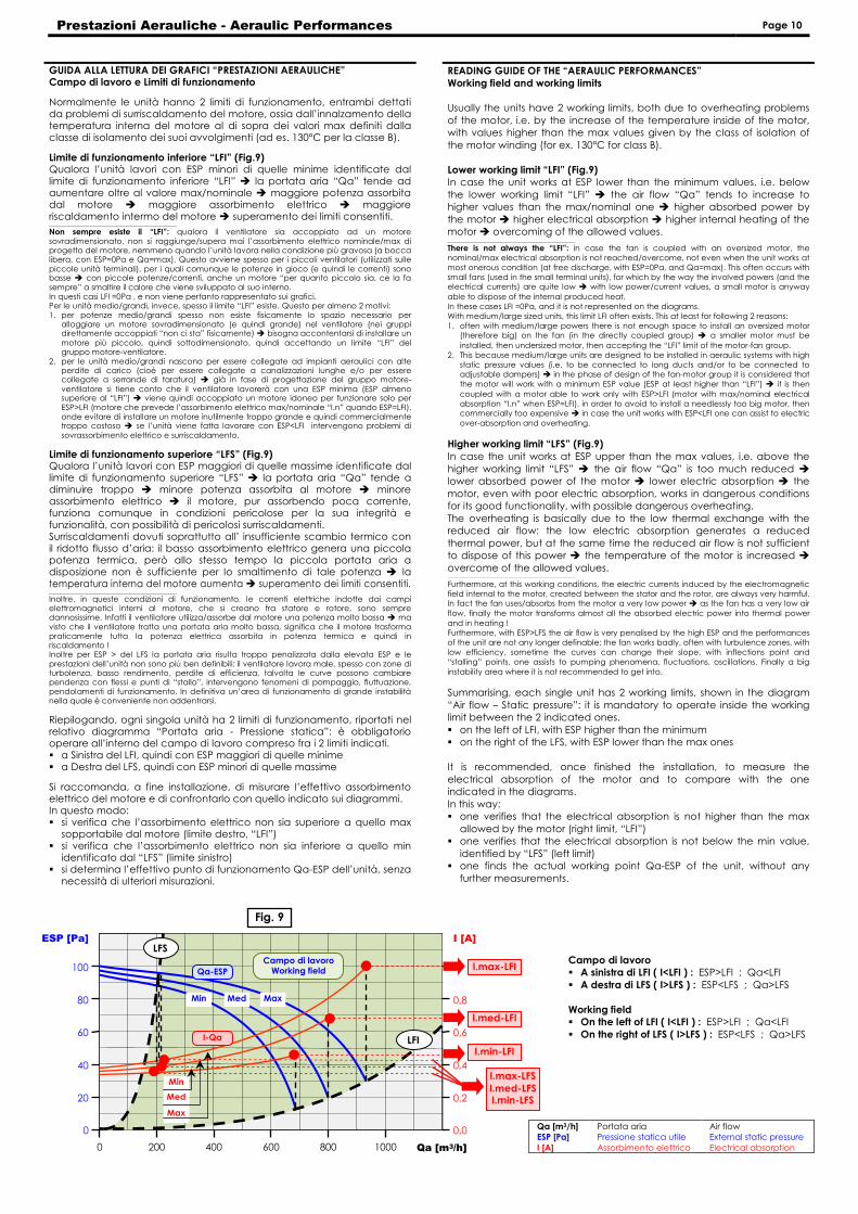
Prestazioni Aerauliche - Aeraulic Performances Page 10
GUIDA ALLA LETTURA DEI GRAFICI “PRESTAZIONI AERAULICHE” Campo di lavoro e Limiti di funzionamento
Normalmente le unità hanno 2 limiti di funzionamento, entrambi dettati da problemi di surriscaldamento del motore, ossia dall’innalzamento della temperatura interna del motore al di sopra dei valori max definiti dalla classe di isolamento dei suoi avvolgimenti (ad es. 130°C per la classe B).
Limite di funzionamento inferiore “LFI” (Fig.9) Qualora l’unità lavori con ESP minori di quelle minime identificate dal limite di funzionamento inferiore “LFI” � la portata aria “Qa” tende ad aumentare oltre al valore max/nominale � maggiore potenza assorbita dal motore � maggiore assorbimento elettrico � maggiore riscaldamento intermo del motore � superamento dei limiti consentiti. ___________________________________________________________
Non sempre esiste il “LFI”: qualora il ventilatore sia accoppiato ad un motore sovradimensionato, non si raggiunge/supera mai l’assorbimento elettrico nominale/max di progetto del motore, nemmeno quando l’unità lavora nella condizione più gravosa (a bocca libera, con ESP=0Pa e Qa=max). Questo avviene spesso per i piccoli ventilatori (utilizzati sulle piccole unità terminali), per i quali comunque le potenze in gioco (e quindi le correnti) sono basse � con piccole potenze/correnti, anche un motore “per quanto piccolo sia, ce la fa sempre” a smaltire il calore che viene sviluppato al suo interno. In questi casi LFI =0Pa , e non viene pertanto rappresentato sui grafici. Per le unità medio/grandi, invece, spesso il limite “LFI” esiste. Questo per almeno 2 motivi: 1. per potenze medio/grandi spesso non esiste fisicamente lo spazio necessario per
alloggiare un motore sovradimensionato (e quindi grande) nel ventilatore (nei gruppi direttamente accoppiati “non ci sta” fisicamente) � bisogna accontentarsi di installare un motore più piccolo, quindi sottodimensionato, quindi accettando un limite “LFI” del gruppo motore-ventilatore.
2. per le unità medio/grandi nascono per essere collegate ad impianti aeraulici con alte perdite di carico (cioè per essere collegate a canalizzazioni lunghe e/o per essere collegate a serrande di taratura) � già in fase di progettazione del gruppo motore-ventilatore si tiene conto che il ventilatore lavorerà con una ESP minima (ESP almeno superiore al “LFI”) � viene quindi accoppiato un motore idoneo per funzionare solo per ESP>LFI (motore che prevede l’assorbimento elettrico max/nominale “I.n” quando ESP=LFI), onde evitare di installare un motore inutilmente troppo grande e quindi commercialmente troppo costoso � se l’unità viene fatta lavorare con ESP<LFI intervengono problemi di sovrassorbimento elettrico e surriscaldamento.
Limite di funzionamento superiore “LFS” (Fig.9) Qualora l’unità lavori con ESP maggiori di quelle massime identificate dal limite di funzionamento superiore “LFS” � la portata aria “Qa” tende a diminuire troppo � minore potenza assorbita al motore � minore assorbimento elettrico � il motore, pur assorbendo poca corrente, funziona comunque in condizioni pericolose per la sua integrità e funzionalità, con possibilità di pericolosi surriscaldamenti. Surriscaldamenti dovuti soprattutto all’ insufficiente scambio termico con il ridotto flusso d’aria: il basso assorbimento elettrico genera una piccola potenza termica, però allo stesso tempo la piccola portata aria a disposizione non è sufficiente per lo smaltimento di tale potenza � la temperatura interna del motore aumenta � superamento dei limiti consentiti. ___________________________________________________________
Inoltre, in queste condizioni di funzionamento, le correnti elettriche indotte dai campi elettromagnetici interni al motore, che si creano fra statore e rotore, sono sempre dannosissime. Infatti il ventilatore utilizza/assorbe dal motore una potenza molto bassa � ma visto che il ventilatore tratta una portata aria molto bassa, significa che il motore trasforma praticamente tutta la potenza elettrica assorbita in potenza termica e quindi in riscaldamento ! Inoltre per ESP > del LFS la portata aria risulta troppo penalizzata dalla elevata ESP e le prestazioni dell’unità non sono più ben definibili: il ventilatore lavora male, spesso con zone di turbolenza, basso rendimento, perdite di efficienza, talvolta le curve possono cambiare pendenza con flessi e punti di “stallo”, intervengono fenomeni di pompaggio, fluttuazione, pendolamenti di funzionamento. In definitiva un’area di funzionamento di grande instabilità nella quale è conveniente non addentrarsi.
Riepilogando, ogni singola unità ha 2 limiti di funzionamento, riportati nel relativo diagramma “Portata aria - Pressione statica”: è obbligatorio operare all’interno del campo di lavoro compreso fra i 2 limiti indicati. � a Sinistra del LFI, quindi con ESP maggiori di quelle minime � a Destra del LFS, quindi con ESP minori di quelle massime
Si raccomanda, a fine installazione, di misurare l’effettivo assorbimento elettrico del motore e di confrontarlo con quello indicato sui diagrammi. In questo modo: � si verifica che l’assorbimento elettrico non sia superiore a quello max
sopportabile dal motore (limite destro, “LFI”) � si verifica che l’assorbimento elettrico non sia inferiore a quello min
identificato dal “LFS” (limite sinistro) � si determina l’effettivo punto di funzionamento Qa-ESP dell’unità, senza
necessità di ulteriori misurazioni.
READING GUIDE OF THE “AERAULIC PERFORMANCES” Working field and working limits
Usually the units have 2 working limits, both due to overheating problems
of the motor, i.e. by the increase of the temperature inside of the motor, with values higher than the max values given by the class of isolation of
the motor winding (for ex. 130°C for class B).
Lower working limit “LFI” (Fig.9) In case the unit works at ESP lower than the minimum values, i.e. below
the lower working limit “LFI” � the air flow “Qa” tends to increase to higher values than the max/nominal one � higher absorbed power by
the motor � higher electrical absorption � higher internal heating of the motor � overcoming of the allowed values. ___________________________________________________________
There is not always the “LFI”: in case the fan is coupled with an oversized motor, the nominal/max electrical absorption is not reached/overcome, not even when the unit works at most onerous condition (at free discharge, with ESP=0Pa, and Qa=max). This often occurs with small fans (used in the small terminal units), for which by the way the involved powers (and the electrical currents) are quite low � with low power/current values, a small motor is anyway
able to dispose of the internal produced heat. In these cases LFI =0Pa, and it is not represented on the diagrams. With medium/large sized units, this limit LFI often exists. This at least for following 2 reasons: 1. often with medium/large powers there is not enough space to install an oversized motor
(therefore big) on the fan (in the directly coupled group) � a smaller motor must be
installed, then undersized motor, then accepting the “LFI” limit of the motor-fan group. 2. This because medium/large units are designed to be installed in aeraulic systems with high
static pressure values (i.e. to be connected to long ducts and/or to be connected to adjustable dampers) � in the phase of design of the fan-motor group it is considered that the motor will work with a minimum ESP value (ESP at least higher than “LFI”) � it is then
coupled with a motor able to work only with ESP>LFI (motor with max/nominal electrical absorption “I.n” when ESP=LFI), in order to avoid to install a needlessly too big motor, then commercially too expensive � in case the unit works with ESP<LFI one can assist to electric
over-absorption and overheating.
Higher working limit “LFS” (Fig.9) In case the unit works at ESP upper than the max values, i.e. above the
higher working limit “LFS” � the air flow “Qa” is too much reduced � lower absorbed power of the motor � lower electric absorption � the
motor, even with poor electric absorption, works in dangerous conditions for its good functionality, with possible dangerous overheating.
The overheating is basically due to the low thermal exchange with the reduced air flow: the low electric absorption generates a reduced
thermal power, but at the same time the reduced air flow is not sufficient to dispose of this power � the temperature of the motor is increased �
overcome of the allowed values. ___________________________________________________________
Furthermore, at this working conditions, the electric currents induced by the electromagnetic field internal to the motor, created between the stator and the rotor, are always very harmful. In fact the fan uses/absorbs from the motor a very low power � as the fan has a very low air
flow, finally the motor transforms almost all the absorbed electric power into thermal power
and in heating ! Furthermore, with ESP>LFS the air flow is very penalised by the high ESP and the performances of the unit are not any longer definable: the fan works badly, often with turbulence zones, with low efficiency, sometime the curves can change their slope, with inflections point and “stalling” points, one assists to pumping phenomena, fluctuations, oscillations. Finally a big
instability area where it is not recommended to get into.
Summarising, each single unit has 2 working limits, shown in the diagram
“Air flow – Static pressure”: it is mandatory to operate inside the working limit between the 2 indicated ones.
� on the left of LFI, with ESP higher than the minimum � on the right of the LFS, with ESP lower than the max ones
It is recommended, once finished the installation, to measure the
electrical absorption of the motor and to compare with the one indicated in the diagrams.
In this way: � one verifies that the electrical absorption is not higher than the max
allowed by the motor (right limit, “LFI”) � one verifies that the electrical absorption is not below the min value,
identified by “LFS” (left limit) � one finds the actual working point Qa-ESP of the unit, without any
further measurements.
Qa [m3/h] Portata aria Air flow ESP [Pa] Pressione statica utile External static pressure
I [A] Assorbimento elettrico Electrical absorption
Campo di lavoro � A sinistra di LFI ( I<LFI ) : ESP>LFI ; Qa<LFI
� A destra di LFS ( I>LFS ) : ESP<LFS ; Qa>LFS
Working field � On the left of LFI ( I<LFI ) : ESP>LFI ; Qa<LFI
� On the right of LFS ( I>LFS ) : ESP<LFS ; Qa>LFS
0 200 400 600 800 1000 Qa [m3/h]
0
20
40
60
80
100
ESP [Pa]
0,0
0,2
0,4
0,6
0,8
I [A]
Max Med Min
Min
Med
Max
I-Qa
I.max-LFI
I.med-LFI
I.min-LFI
Qa-ESP
I.max-LFS I.med-LFS I.min-LFS
LFI
LFS Campo di lavoro
Working field
Fig. 9
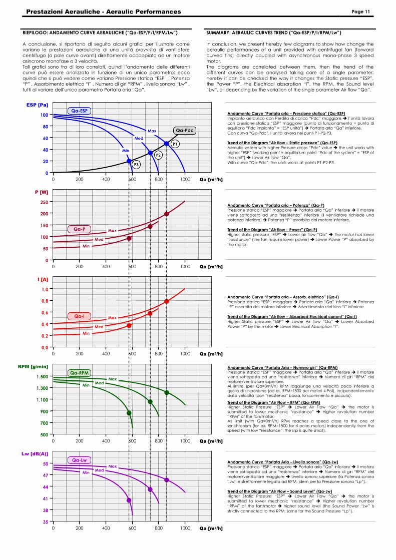
Prestazioni Aerauliche - Aeraulic Performances Page 11
RIEPILOGO: ANDAMENTO CURVE AERAULICHE (“Qa-ESP/P/I/RPM/Lw”)
A conclusione, si riportano di seguito alcuni grafici per illustrare come variano le prestazioni aerauliche di una unità provvista di ventilatore
centrifugo (a pale curve avanti) direttamente accoppiato ad un motore asincrono monofase a 3 velocità.
Tali grafici sono fra di loro correlati, quindi l’andamento delle differenti curve può essere analizzato in funzione di un unico parametro: ecco
quindi che si può vedere come variano Pressione statica “ESP” , Potenza “P” , Assorbimento elettrico “I” , Numero di giri “RPM” , livello sonoro “Lw” ,
tutti al variare dell’unico parametro Portata aria “Qa”.
SUMMARY: AERAULIC CURVES TREND (“Qa-ESP/P/I/RPM/Lw”)
In conclusion, we present hereby few diagrams to show how change the aeraulic performances of a unit provided with centrifugal fan (forward
curved fins) directly coupled with asynchronous mono-phase 3 speed motor.
The diagrams are correlated between them, then the trend of the different curves can be analysed taking care of a single parameter:
hereby it can be checked the way it changes the Static pressure “ESP”, the Power “P”, the Electrical absorption “I”, the RPM, the Sound level
“Lw”, all depending by the variation of the single parameter Air flow “Qa”.
Andamento Curve “Portata aria – Pressione statica” (Qa-ESP) Impianto aeraulico con Perdita di carico “Pdc” maggiore � l’unità lavora
con pressione statica “ESP” maggiore (punto di funzionamento = punto di equilibrio “Pdc impianto” = “ESP unità”) � Portata aria “Qa” inferiore.
Con curva “Qa-Pdc”, l’unità lavora nei punti P1-P2-P3. Trend of the Diagram “Air flow – Static pressure” (Qa-ESP) Aeraulic system with higher Pressure drops “Pdc” value � the unit works with
higher “ESP” (working point = equilibrium point “Pdc of the system” = ”ESP of the unit”) � Lower Air flow “Qa”.
With curve “Qa-Pdc”, the units works at points P1-P2-P3.
0 200 400 600 800 1000 Qa [m3/h]
0
20
40
60
80
100
ESP [Pa]
Max
Qa-ESP
Qa-Pdc
Med
Min
P1
P2
P3
0 200 400 600 800 1000 Qa [m3/h]
0
50
100
150
200
250
P [W]
Qa-P Max
Med
Min
0 200 400 600 800 1000 Qa [m3/h]
0,0
0,2
0,4
0,6
0,8
1,0
I [A]
Qa-I Max
Med
Min
0 200 400 600 800 1000 Qa [m3/h]
500
700
900
1.100
1.300
1.500
RPM [g/min]
Max
Qa-RPM
Med Min
0 200 400 600 800 1000 Qa [m3/h]
35
38
41
44
47
50
Lw [dB(A)]
Max
Qa-Lw
Med Min
Andamento Curve “Portata aria – Potenza” (Qa-P) Pressione statica “ESP” maggiore � Portata aria “Qa” inferiore � il motore
viene sottoposto ad una “resistenza” inferiore (il ventilatore richiede una potenza inferiore) � Potenza “P” assorbita dal motore inferiore.
Trend of the Diagram “Air flow – Power” (Qa-P) Higher static pressure “ESP” � Lower air flow “Qa” � the motor has lower
“resistance” (the fan require lower power) � Lower Power “P” absorbed by
the motor.
Andamento Curve “Portata aria – Assorb. elettrico” (Qa-I) Pressione statica “ESP” maggiore � Portata aria “Qa” inferiore � Potenza “P” assorbita dal motore inferiore � Assorbimento elettrico “I” inferiore.
Trend of the Diagram “Air flow – Absorbed Electrical current” (Qa-I) Higher Static pressure “ESP” � Lower Air flow “Qa” � Lower Absorbed
Power “P” by the motor � Lower Electrical Absorption “I”.
Andamento Curve “Portata Aria – Numero giri” (Qa-RPM) Pressione statica “ESP” maggiore � Portata aria “Qa” inferiore � il motore viene sottoposto ad una “resistenza” inferiore � Numero di giri “RPM” del motore/ventilatore superiore. Al limite (per Qa=0m3/h) RPM raggiunge una velocità poco inferiore a quella di sincronismo (ad es. RPM=1500 per motori 4-Poli), indipendentementedalla velocità (con “resistenza” bassa, lo scorrimento è piccolo).
Trend of the Diagram “Air Flow – RPM” (Qa-RPM) Higher Static Pressure “ESP” � Lower Air Flow “Qa” � the motor is submitted to lower mechanic “resistance” � Higher revolution number “RPM” of the fan/motor. As limit (with Qa=0m3/h) RPM reaches a speed close to the one of synchronism (for ex. RPM=1500 for 4 poles motors) independently from the speed (with low “resistance”, the slip is quite small).
Andamento Curve “Portata Aria – Livello sonoro” (Qa-Lw) Pressione statica “ESP” maggiore � Portata aria “Qa” inferiore � il motore viene sottoposto ad una “resistenza” inferiore � Numero di giri “RPM” del
motore/ventilatore maggiore � Livello sonoro superiore (la Potenza sonora
“Lw” è strettamente legata ad RPM, idem per la Pressione sonora “Lp”).
Trend of the Diagram “Air Flow – Sound Level” (Qa-Lw) Higher Static Pressure “ESP” � Lower Air Flow “Qa” � the motor is submitted to lower mechanic “resistance” � Higher revolution number
“RPM” of the fan/motor � higher sound level (the Sound Power “Lw” is
strictly connected to the RPM, same for the Sound Pressure “Lp”).