Principali riferimenti normativi Linee guida ICH GCP Decreto Legislativo 211/2003

FILTRO Per polveri secche e/o leggermente umide
CART FILTER
HIGH PRESSURE BLOWERS CENTRIFUGAL AND AXIAL FANS AIR FILTERS AIR HANDLING UNITS TUNNEL ENGINEERING
SAVIO S.r.l.
FUNZIONAMENTO
La serie di depolveratori CART-FILTER è costituita da filtri a cartucce atti al trattamento di polveri presenti nell’aria aspirata.
Essi utilizzano un mezzo filtrante di natura tessile con pulizia delle cartucce ad aria compressa in contropressione. L’aria pol-
verosa entra in modo tangenziale in una zona sotto alle cartucce e grazie all’effetto ciclonante, perde di velocità e per effetto
centrifugo le parti più pesanti trasportate dal fluido cadono nella tramoggia, salvaguardando la durata delle cartucce.
L’aria aspirata attraversa con moto ascensionale le cartucce e deposita sull’esterno di esse la parte polverosa inquinante. Lo
scuotimento delle cartucce, a mezzo dell’aria compressa favorisce il distacco della
polvere dalle cartucce e la caduta nella tramoggia.Successivamente il residuo di
inquinante nell’aria è trattenuto nel passaggio attraverso le cartucce stesse ed
infine l’aria ormai depurata viene espulsa, dopo aver attraversato il filtro. La pulizia
delle cartucce è consentita dall’aria compressa uscente dagli ugelli posti sopra le
stesse. L’aria compressa immessa nel tubo di venturi inserito in ogni manica ri-
chiama aria pulita proveniente dalle altre maniche e crea un onda di pressione che
si propaga per tutta la lunghezza della manica provocando uno scuotimento della
stessa. La polvere presente sulla superficie esterna della manica precipita nella
tramoggia e da lì viene estratta per il recupero e/o lo smaltimento. I getti di aria
compressa, controllati da un temporizzatore elettronico, vengono rilasciati median-
te apposite elettrovalvole. Gli intervalli di funzionamento di queste ultime e la
durata del getto di aria compressa (tempi di “sparo”) ed il tempo di pausa del ciclo di funzionamento delle elettrovalvole, (men-
tre il tempo di post-lavaggio è prefissato in 15 minuti) sono facilmente regolabili.
Queste impostazioni incidono sul consumo di aria compressa e dipendono dalla
granulometria, dall’inquinante filtrato e dalla quantità trasportata.
CARATTERISTICHE Questa serie di filtri a cartucce, grazie all’elevato rapporto superficie / volume,
risulta eccezionalmente compatta. Inoltre la sua forma circolare consente l’effetto
ciclonante che oltre a migliorare l’efficienza dell’azione filtrante, preserva le mani-
che dall’usura del tempo. Le cartucce sono dimensionate per offrire una elevata
efficienza filtrante anche in presenza di polveri con finissima granulometria, la loro pulizia viene assicurata tramite getti di aria
compressa in controcorrente. Tale servizio, erogato da un sistema di elettrovalvole controllate da un quadro sequenziatore
elettronico (fornito di serie, da installare a cura del cliente)
consente di non fermare l’impianto per la pulizia e di mantenere
costante la portata nel tempo. Il filtro è corredato di un portello
d’ispezione che permette un’agevole accesso alla sezione
filtrante, per verificare lo stato d’usura delle cartucce.
La costruzione standard del filtro, prevede la sostituzione delle
cartucce dall’alto nella zona pulita, riducendo notevolmente i
tempi di manutenzione, su richiesta del Cliente, le cartucce
possono essereanche estratte dalla zona inferiore “sporca”
attraverso gli appositi sportelli.
La temperatura max di esercizio è di 70 °C
Le cartucce filtranti standard utilizzate nei ns. filtri sono di alta
qualità in tessuto non tessuto, composto da fibre di polipropilene rivestite in polietilene termolegate su tutta la superficie, con
trattamento antistatico ad impregnazione permanente di grafite a trama incrociata conforme alla normativa DIN 54345 e ATEX
94/9/CE , con classe di filtrazione secondo DIN EN 60335-2-69 allegato AA: M.Le cartucce possono essere vincolate al piano
di divisione tra la zona “pulita” e la zona “polverosa” sia inferiormente che superiormente. In entrambi i casi le cartucce sono di
facile estrazione in quanto fissate con soli tre bulloni; una volta allentati con semplice rotazione delle cartucce, essi si estrag-
gono completamente. Per particolari tipi di polvere, e in caso di applicazioni speciali, possono essere utilizzate cartucce con
altre caratteristiche, si consiglia comunque di consultare il Ns. ufficio tecnico.
12 SAVIO S.r.l.

Il CART-FILTER viene normalmente verniciato con il seguente abbinamento di RAL: Corpo filtro blu RAL 5007 / Mancorrenti,
scala alla marinara, portelli manutentivi e contenitore carrellato arancio RAL 2004 A richiesta è possibile avere come optional
verniciature con Ral diversi. Di serie, con il filtro viene fornita una centralina Tipo GCP 4P(max. 4 elettrovalvole) e GCP6P (
max. 6 elettrovalvole) per il comando delle elettrovalvole di lavaggio pneumatico delle cartucce filtranti.
Tabella caratteristiche tecniche
Grand. Portata Cartucce filtranti
Superf. filtrante
Elettrovalvole
110 V – 50Hz
Collettore aria comp.
Pressione
aria compressa
Consumo aria
compressa (Nl/min)
Peso
m3/h Nr x L (mm) m2 Nr. Ø bar Min Max Kg
15 1800 1 x 1000 mm 16,7 1 – Ø1“ ½ 8“ 5 50 150 250
20 2150 1 x 1200 mm 20 1 – Ø1“ ½ 8“ 5 50 150 270
30 3600 2 x 1000 mm 33,4 1 – Ø1“ ½ 8“ 5 50 150 300
40 4300 2 x 1200 mm 40 1 – Ø1“ ½ 8“ 5 50 150 320
50 5400 3 x 1000 mm 50,1 2 – Ø1“ ½ 8“ 5 80 240 350
60 6500 3 x 1200 mm 60 2 – Ø1“ ½ 8“ 5 80 240 380
70 7200 4 x 1000 mm 66,8 2 – Ø1“ ½ 8“ 5 80 240 400
80 8650 4 x 1200 mm 80 2 – Ø1“ ½ 8“ 5 80 240 430
120 12.500 7 x 1000 mm 116,9 3 – Ø2“ 10“ 5 175 525 600
140 15.100 7 x 1200 mm 140 3 – Ø2“ 10“ 5 175 525 640
170 18.000 10 x 1000 mm 167 3 – Ø2“ 10“ 5 175 525 900
200 21.600 10 x 1200 mm 200 3 – Ø2“ 10“ 5 175 525 950
240 25.000 14 x 1000 mm 233,8 4 – Ø2“ 10“ 5 250 750 1000
290 30.000 17 x 1000 mm 283,9 5 – Ø2“ 10“ 5 300 900 1150
340 36.800 17 x 1,2 mm 340 5 – Ø2“ 10“ 5 300 900 2230
Caratteristiche dimensionali cartuccia: Caratteristiche dimensionali cartuccia:
tipo :
peso:
diametro esterno:
altezza cartuccia:
nr. pieghe :
profondità pieghe:
superficie filtrante:
LP324G10
130 gr. /m2
324 mm.
1006 mm.
175
48 mm.
16,7 m2
tipo :
peso:
diametro esterno:
altezza cartuccia:
nr. pieghe :
profondità pieghe:
superficie filtrante:
LP324G12
130 gr. /m2
324 mm.
1206 mm
175
48 mm.
20 m2
Per quanto riguarda le polveri classiche, si ottiene un’ottima resa su:
Materiale Epossidico
Cemento sabbia
Prod. chim. Inorganici
Sabbiatura metallica
Resine fenoliche
Materiali compositi
Abrasivi Plastiche
Solfuro di selenio
Polveri cosmetici
Lana minerale
Composti metallici
Ossido di ferro
Pigmenti vernice
Polietilene
Fumi da saldatura
Fumi da taglio laser
Fumi di Silice
Nailon
Marmo
Ceramica
Silice
Carbonio
Piombo
Talco
Colorante
Acciaio
Cadmio
Mica
Magnesio
Amminoacido
Zucchero
Farina
Titanio
Silicio
Roccia
Vitamine
Vetro
Grafite
Toner
Alluminio
Berillio
Zinco
Amido
Caolino
Mica
Penicillina
Ghisa
Poliuritano
Idross. di sodio
Soda
Porcellana
Argilla
Oro
Arsenico
Rame
Pvc
Carbone
Solidi lattei
Ferro
Resina
Caffè
Quarzo
Poliestere
APPLICAZIONI Questa serie di filtri a cartucce, con effetto ciclonante, ad alta efficienza, è stata progettata per l’installazione in impianti funzio-
nanti in condizioni particolarmente gravose. L’effetto ciclonante con l’adozione del controcono interno impedisce alle polveri di
lambire direttamente le cartucce filtranti, preservandone l’integrità e prolungandone sensibilmente la durata.
Numerose sono le applicazioni dove questi filtri possono essere utilizzati, tra gli altri possiamo citare gli impianti di aspirazione
delle industrie chimiche alimentari metallurgiche petrolchimiche, nei cementifici nelle ceramiche nelle fonderie e ovunque sia
necessario abbattere la presenza di fumi e/o polveri secche.
13SAVIO S.r.l.

CONSUMI DI ARIA COMPRESSA Per una rapida determinazione dei consumi di aria compressa, abbiamo riportato nella tabella di pagina 3 consumi minimi e
massimi consigliati, riferiti ad uno “sparo” di 200 m/s. con aria compressa a 5 Bar ed un tempo di pausa di 360 secondi mas-
simo e 120 secondi minimo dopo il quale si ritorna alla stessa elettrovalvola. Per un calcolo preciso del consumo di aria com-
pressa, vi indichiamo il consumo di una singola valvola nel tempo di un secondo:
Diametro 1”1/2 - 950 Nl/s. a 3 Bar – 1085 Nl/s. a 5 Bar
Diametro 2” - 1520 Nl/s. a 3 Bar – 1735 Nl/s. a 5 Bar
Calcolo consumo aria compressa :
- tempo di pausa sequenziatore = ciclo medio in secondi / numero di elettrovalvole.
- numero spari/minuto = 60 secondi / tempo di pausa sequenziatore
- consumo aria compressa Nl/min = portata elettrovalvola (Nl/s) x tempo di sparo (secondi ) x nr. di spari (minuto).
Esempio calcolo consumo aria compressa :
- pressione aria compressa : 5 Bar- tempo apertura valvola “sparo” : 0,15 secondi
- ciclo medio: 300 secondi
- nr. 3 elettovalvole diametro 2”
Nl/min. = 1735 Nl x 0.15 s. x [60 s./min. / (300 s. / nr. 3) = 156,15
- scelta del compressore : ogni 100 Nl/min. = 1 CV = 0,735 kW.
Per un risparmio di aria compressa, consigliamo l’installazione del pressostato differenziale il
quale determina il lavaggio delle cartucce sulla base dell’effettivo intasamento.
Per ulteriori notizie tecniche relative al sequenziatore consigliamo di consultare il catalogo AUTEL.
IL FILTRO IN VERSIONE STANDARD COMPRENDE
Corpo esterno con gambe e tramoggia.
Sistema di lavaggio ad aria compressa con elettrovalvola e pannello sequenziale
ACCESSORI
Scala alla marinara di accesso alla piattaforma manutentiva del filtro.
Serranda manuale a ghigliottina sulla bocca della tramoggia di scarico
Serranda manuale a ghigliottina predisposta per sacco raccolta
Contenitore carrellato sotto la tramoggia di scarico.
Contenitore carrellato con valvola manuale
Contenitore carrellato con valvola manuale predisposto per sacco
Valvola stellare posta sotto la tramoggia di scarico
Pressostato differenziale comando automatico pulizia cartucce filtranti.
Staffa sul corpo del filtro con ventilatore per grandezze 20-30-50-70-120. (vedere tabella sottostante)
TABELLA VENTILATORI ABBINATI ALLA SERIE CART-FILTER
CART-FILTER
GRANDEZZA
VENTILATORE
TIPO
PORTATA
mc/h
PREVALENZA
totale daPa
MOTORE
2 POLI – kw.
TENSIONE
Volt.
15 SCL –25/A 1800 215 2,2 230/400
20 SCL –25/A 2150 205 2,2 230/400
30 SCL –28/A 3600 255 4 230/400
40 SCL –28/A 4300 230 4 230/400
50 SCLK –32/B 5400 275 7,5 400/690
60 SCLK –32/B 6500 245 7,5 400/690
70 SCLK –35/B 7200 290 9,2 400/690
80 SCLK –35/B 8650 240 9,2 400/690
120 SCLK –42/C 12.500 315 18,5 400/690
SAVIO S.r.l. 14

PERDITA DI CARICO Mediamente un filtro è dimensionato con perdita iniziale a cartucce pulite a 500 Pa e con perdite a cartucce mediamente spor-
che a 700 Pa.
COME SELEZIONARE IL FILTRO IDONEO Di seguito riportiamo alcune semplici formule per il corretto dimensionamento di un filtro a maniche
S = Q / (V * 3600) Dove
Q = S * V * 3600
V = Q / (S * 3600)
S = Superficie filtrante in m2 del filtro
Q = Portata in m3/h di progetto
V = Velocità media di filtrazione (vedi tabella sottostante)
Quindi conoscendo la Portata in m3/h di progetto e il materiale inquinante, basterà applicare la prima formula e scegliere la
taglia che abbia la superficie filtrante di pari o superiore valore.
Il nostro Ufficio Tecnico è, in ogni caso, a Vostra disposizione per il dimensionamento del filtro più adatto.
TABELLA VELOCITA’ MEDIE DI FILTRAZIONE PER POLVERI E FUMI
Materiale inquinante Velocità medie di filtrazione mt/sec
Amido 0,03 / 0,04
Argilla silicea vetrificata 0,04 / 0,05
Argilla verde 0,03 / 0,04
Bauxite 0,025 / 0,035
Calce 0,03 / 0,04
Carbone calcinato / verde 0,025 / 0,030
Carburo di silicio 0,025 / 0,035
Cemento crudo / finito / macinato 0,03 / 0,04
Farina 0,04 / 0,05
Farina di legno 0,03 / 0,04
Frantumazione ferro cromo 0,03 / 0,04
Fumi metallurgici 0,02 / 0,03
Fumi ossido di piombo 0,02 / 0,03
Gesso idrato 0,03 / 0,04
Grafite 0,015 / 0,025
Granaglie cereali 0,05 / 0,06
Macinazione calcare 0,03 / 0,04
Macinazione refrattaria 0,03 / 0,04
Mica 0,04 / 0,05
Ossido di alluminio 0,025 / 0,035
Ossido di titanio 0,02 / 0,03
Ossido di zinco 0,015 / 0,02
Pigmenti per vernici 0,015 / 0,02
Polveri di detersivi e saponi 0,03 / 0,04
Polveri fenoliche 0,03 / 0,04
Polveri di tantanio 0,02 / 0,03
Porcellana 0,03 / 0,04
PVC 0,03 / 0,04
Sabbia 0,03 / 0,04
Segatura 0,03 / 0,04
Soia 0,03 / 0,04
Talco 0,03 / 0,04
Zinco metallico 0,03 / 0,04
15SAVIO S.r.l.
OPERATION
The Deduster Series CART-FILTER consists of cartridge filters, suitable for the handling of the dust in the intake air.
Dedusters use a filter element of textile structure, with backpressure blast-cleaning of cartridges. The dusty air enters an area
under the cartridges in a tangential way and, owing to a cyclone effect, it loses its speed and the heavier parts, carried by the
fluid, fall, by centrifugal effect, into the hopper, thus safeguarding the cartridge life.
The intake air flows through the cartridges with upward lift motion, thus leaving the polluting dust on the cartridge outside. The
cartridge jarring because of the compressed air helps the detachment of dust
from the cartridge and its falling into the hopper. The polluting remnants in the
air are retained by the filter while passing through the cartridge and finally the
air, which now is clean, is blown off through a further filter. The cartridges
blasted by the compressed air flowing out from a set of nozzles, located over
the cartridges. The compressed air let into the Venturi tube installed in each
filter-bag calls up the clean air flowing out from other bags and creates a
pressure wave which spreads out over the entire length of the bag, thus
causing its jarring. The dust falls from the external surface of the bag into the
hopper, wherefrom it is taken off for recovery and/or disposal. The air pressure
blows, controlled by electronic timer, are released through suitable solenoid
valves. The functioning frequency of these valves, as well as the compressed
air blowing times and the pause time of the solenoid valves working cycle (the post-washing pre-set time is 15 minutes) may
be easily set up. These settings affect the consumption of compressed air and
depend on the granulometry, the filtered polluting agent and the carried flow.
TECHNICAL FEATURES This set of cartridge filters is exceptionally compact owing to their high surface /
volume ratio. Besides, the round shape of the filters helps the cyclone effect that,
besides improving the filtering action efficiency, also preserves the filter-bags from
wear and tear.The cartridges are so dimensioned as to insure high filtering
efficiency, even when the dust particle size is finest. Their cleaning is insured by
reverse-flow cleaning air blows. This action, obtained through a system of solenoid vales controlled from an electronic
sequencing board (standard supplied, to be installed by the customer), avoids breaking the system running for cleaning
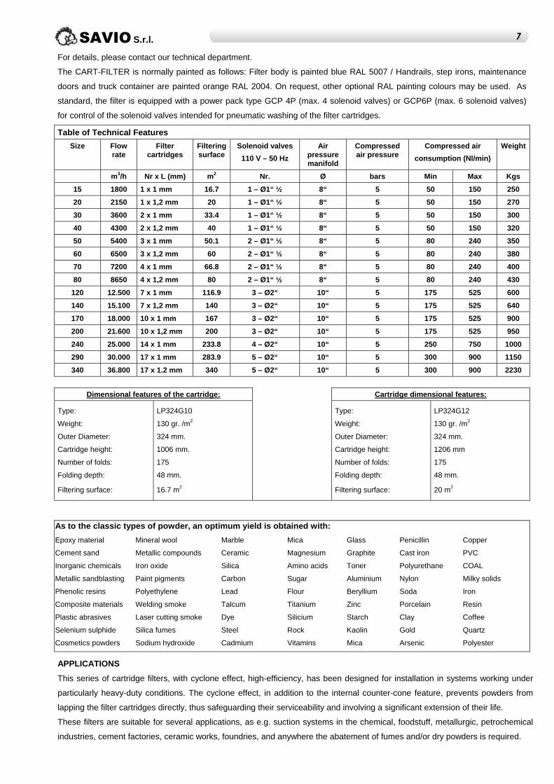
purposes, whilst maintaining a steady flow rate. The filter is
provided with inspection manhole, for easy access to the
filtering section and checking of the cartridge wearing
condition.
On the standard filter configuration, the cartridges are
replaced from the top in the clean area, with consequent
significant reduction of the servicing times; however, on
customer's request, cartridges may also be taken off from the
bottom "dirty" area, through proper cleanouts.
Max. operative temperature: 70° C.
The standard cartridges in our filters are made of high-quality
non-woven fabric, consisting of polypropylene fibres coated
with polyethylene, heat bonded on the entire surface, antistatically treated with permanent graphite-doping and having cross
weft, conforming to the standard DIN 54345 and ATEX 94/9/CE , with class of filtration according to DIN EN 60335-2-69
enclosure AA: M.
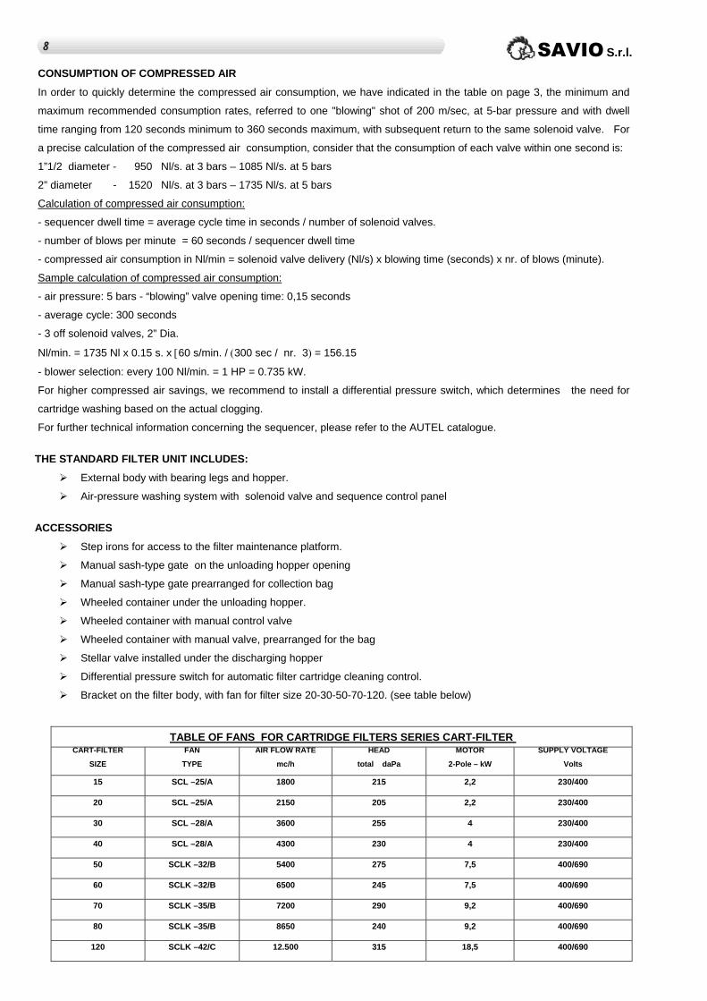
The cartridges may be constrained to the partition surface between the “clean” and the “dusty” zones, both on the top and on
the bottom. In both cases, the cartridges may be easily taken off, since they are fastened by three bolts only; once bolts have
been loosened, a simple rotation of the cartridge allows pulling it off completely. For special types of dust or special
applications, other types of cartridges may be used, having different features.
16 SAVIO S.r.l.
For details, please contact our technical department.
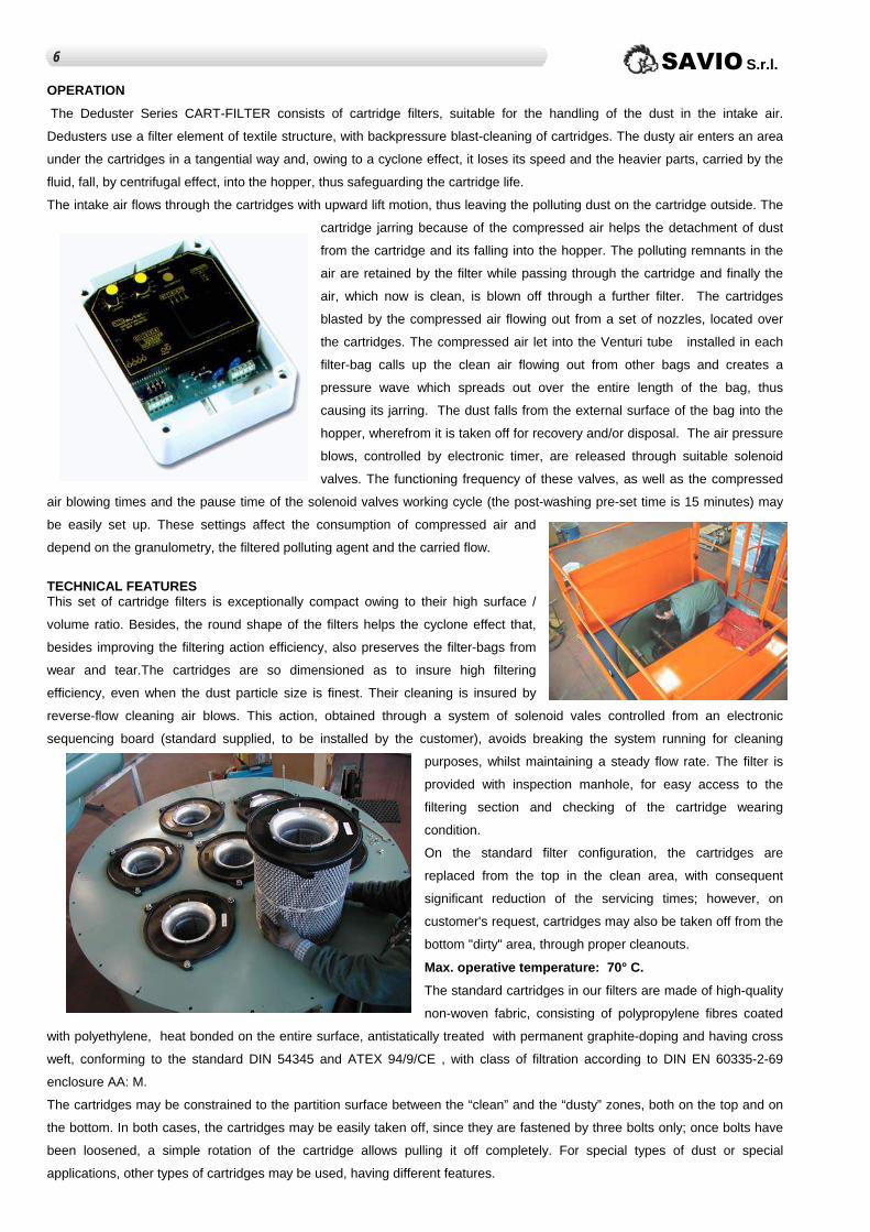
The CART-FILTER is normally painted as follows: Filter body is painted blue RAL 5007 / Handrails, step irons, maintenance
doors and truck container are painted orange RAL 2004. On request, other optional RAL painting colours may be used. As
standard, the filter is equipped with a power pack type GCP 4P (max. 4 solenoid valves) or GCP6P (max. 6 solenoid valves)
for control of the solenoid valves intended for pneumatic washing of the filter cartridges.
Table of Technical Features
Size Flow rate
Filter cartridges
Filtering surface
Solenoid valves
110 V – 50 Hz
Air pressure manifold
Compressed air pressure
Compressed air
consumption (Nl/min)
Weight
m3/h Nr x L (mm) m2 Nr. Ø bars Min Max Kgs
15 1800 1 x 1 mm 16.7 1 – Ø1“ ½ 8“ 5 50 150 250
20 2150 1 x 1,2 mm 20 1 – Ø1“ ½ 8“ 5 50 150 270
30 3600 2 x 1 mm 33.4 1 – Ø1“ ½ 8“ 5 50 150 300
40 4300 2 x 1,2 mm 40 1 – Ø1“ ½ 8“ 5 50 150 320
50 5400 3 x 1 mm 50.1 2 – Ø1“ ½ 8“ 5 80 240 350
60 6500 3 x 1,2 mm 60 2 – Ø1“ ½ 8“ 5 80 240 380
70 7200 4 x 1 mm 66.8 2 – Ø1“ ½ 8“ 5 80 240 400
80 8650 4 x 1,2 mm 80 2 – Ø1“ ½ 8“ 5 80 240 430
120 12.500 7 x 1 mm 116.9 3 – Ø2“ 10“ 5 175 525 600
140 15.100 7 x 1,2 mm 140 3 – Ø2“ 10“ 5 175 525 640
170 18.000 10 x 1 mm 167 3 – Ø2“ 10“ 5 175 525 900
200 21.600 10 x 1,2 mm 200 3 – Ø2“ 10“ 5 175 525 950
240 25.000 14 x 1 mm 233.8 4 – Ø2“ 10“ 5 250 750 1000
290 30.000 17 x 1 mm 283.9 5 – Ø2“ 10“ 5 300 900 1150
340 36.800 17 x 1.2 mm 340 5 – Ø2“ 10“ 5 300 900 2230
Dimensional features of the cartridge: Cartridge dimensional features:
Type:
Weight:
Outer Diameter:
Cartridge height:
Number of folds:
Folding depth:
Filtering surface:
LP324G10
130 gr. /m2
324 mm.
1006 mm.
175
48 mm.
16.7 m2
Type:
Weight:
Outer Diameter:
Cartridge height:
Number of folds:
Folding depth:
Filtering surface:
LP324G12
130 gr. /m2
324 mm.
1206 mm
175
48 mm.
20 m2
As to the classic types of powder, an optimum yield is obtained with:
Epoxy material
Cement sand
Inorganic chemicals
Metallic sandblasting
Phenolic resins
Composite materials
Plastic abrasives
Selenium sulphide
Cosmetics powders
Mineral wool
Metallic compounds
Iron oxide
Paint pigments
Polyethylene
Welding smoke
Laser cutting smoke
Silica fumes
Sodium hydroxide
Marble
Ceramic
Silica
Carbon
Lead
Talcum
Dye
Steel
Cadmium
Mica
Magnesium
Amino acids
Sugar
Flour
Titanium
Silicium
Rock
Vitamins
Glass
Graphite
Toner
Aluminium
Beryllium
Zinc
Starch
Kaolin
Mica
Penicillin
Cast iron
Polyurethane
Nylon
Soda
Porcelain
Clay
Gold
Arsenic
Copper
PVC
COAL
Milky solids
Iron
Resin
Coffee
Quartz
Polyester
APPLICATIONS
This series of cartridge filters, with cyclone effect, high-efficiency, has been designed for installation in systems working under
particularly heavy-duty conditions. The cyclone effect, in addition to the internal counter-cone feature, prevents powders from
lapping the filter cartridges directly, thus safeguarding their serviceability and involving a significant extension of their life.
These filters are suitable for several applications, as e.g. suction systems in the chemical, foodstuff, metallurgic, petrochemical
industries, cement factories, ceramic works, foundries, and anywhere the abatement of fumes and/or dry powders is required.
17SAVIO S.r.l.
CONSUMPTION OF COMPRESSED AIR
In order to quickly determine the compressed air consumption, we have indicated in the table on page 3, the minimum and
maximum recommended consumption rates, referred to one "blowing" shot of 200 m/sec, at 5-bar pressure and with dwell
time ranging from 120 seconds minimum to 360 seconds maximum, with subsequent return to the same solenoid valve. For
a precise calculation of the compressed air consumption, consider that the consumption of each valve within one second is:
1”1/2 diameter - 950 Nl/s. at 3 bars – 1085 Nl/s. at 5 bars
2” diameter - 1520 Nl/s. at 3 bars – 1735 Nl/s. at 5 bars
Calculation of compressed air consumption:
- sequencer dwell time = average cycle time in seconds / number of solenoid valves.
- number of blows per minute = 60 seconds / sequencer dwell time
- compressed air consumption in Nl/min = solenoid valve delivery (Nl/s) x blowing time (seconds) x nr. of blows (minute).
Sample calculation of compressed air consumption:
- air pressure: 5 bars - “blowing” valve opening time: 0,15 seconds
- average cycle: 300 seconds
- 3 off solenoid valves, 2” Dia.
Nl/min. = 1735 Nl x 0.15 s. x [60 s/min. / (300 sec / nr. 3) = 156.15
- blower selection: every 100 Nl/min. = 1 HP = 0.735 kW.
For higher compressed air savings, we recommend to install a differential pressure switch, which determines the need for
cartridge washing based on the actual clogging.
For further technical information concerning the sequencer, please refer to the AUTEL catalogue.
THE STANDARD FILTER UNIT INCLUDES:
External body with bearing legs and hopper.
Air-pressure washing system with solenoid valve and sequence control panel
ACCESSORIES
Step irons for access to the filter maintenance platform.
Manual sash-type gate on the unloading hopper opening
Manual sash-type gate prearranged for collection bag
Wheeled container under the unloading hopper.
Wheeled container with manual control valve
Wheeled container with manual valve, prearranged for the bag
Stellar valve installed under the discharging hopper
Differential pressure switch for automatic filter cartridge cleaning control.
Bracket on the filter body, with fan for filter size 20-30-50-70-120. (see table below)
TABLE OF FANS FOR CARTRIDGE FILTERS SERIES CART-FILTER
CART-FILTER
SIZE
FAN
TYPE
AIR FLOW RATE
mc/h
HEAD
total daPa
MOTOR
2-Pole – kW
SUPPLY VOLTAGE
Volts
15 SCL –25/A 1800 215 2,2 230/400
20 SCL –25/A 2150 205 2,2 230/400
30 SCL –28/A 3600 255 4 230/400
40 SCL –28/A 4300 230 4 230/400
50 SCLK –32/B 5400 275 7,5 400/690
60 SCLK –32/B 6500 245 7,5 400/690
70 SCLK –35/B 7200 290 9,2 400/690
80 SCLK –35/B 8650 240 9,2 400/690
120 SCLK –42/C 12.500 315 18,5 400/690
SAVIO S.r.l. 18
LOAD LOSS
In general, a filter is dimensioned with a starting load loss, with clean cartridges, of 500 Pa and a load loss, with middling dirty
cartridges, of 700 Pa.
HOW TO DETERMINE THE RIGHT FILTER SIZE
We give you below some simple formula, which will help you to determine the correct size of a bag filter
S = Q / (V * 3600) Dove
Q = S * V * 3600
V = Q / (S * 3600)
S = Filter surface in m2
Q = Design flow rate in m3/h
V = Mean filtering speed (see the following table)
By knowing the design flow rate in m3/h and the polluting material, apply the first formula and choose the filter size whose
filtering surface has equal or higher value.
Anyway, our Technical Department is at your disposal to give you suggestions about the most suitable filter size.
TABLE OF POWDER AD FUMES AVERAGE FILTERING RATES
Polluting material Average filtering speed in meters per second
Starch 0.03 / 0.04
Vitrified silica clay 0.04 / 0.05
Green clay 0.03 / 0.04
Bauxite 0.025 / 0.035
Lime 0.03 / 0.04
Calcined / green coal 0.025 / 0.030
Silundum 0.025 / 0.035
Crude / finished / ground cement 0.03 / 0.04
Flour 0.04 / 0.05
Wooden flour 0.03 / 0.04
Chromium iron crushing 0.03 / 0.04
Metallurgy fumes 0.02 / 0.03
Lead oxide fumes 0.02 / 0.03
Hydrated gypsum 0.03 / 0.04
Graphite 0.015 / 0.025
Corn, cereals 0.05 / 0.06
Limestone grinding 0.03 / 0.04
Refractory materials grinding 0.03 / 0.04
Mica 0.04 / 0.05
Aluminium oxide 0.025 / 0.035
Titanium oxide 0.02 / 0.03
Zinc oxide 0.015 / 0.02
Pigments for paints 0.015 / 0.02
Cleaning powders and soaps 0.03 / 0.04
Phenolic dust 0.03 / 0.04
Tantalum dust 0.02 / 0.03
Porcelain 0.03 / 0.04
PVC 0.03 / 0.04
Sand 0.03 / 0.04
Saw dust 0.03 / 0.04
Soya beans 0.03 / 0.04
Talc 0.03 / 0.04
Metallic zinc 0.03 / 0.04
19SAVIO S.r.l.
FONCTIONNEMENT La série de dépoussiéreurs CART-FILTER est constituée de filtres à cartouches pour le traitement des poussières dans l’air
aspiré. Ils emploient un système filtrant textile avec nettoyage des cartouches à l’air comprimé en contre-pression. L’air pous-
siéreux rentre tangentiellement sous les cartouches. Grâce à l’effet de cyclone, il perd de la vitesse et, grâce à l’effet centri-
fuge, les parties les plus lourdes transportées par le fluide tombent dans trémie, et allongent ainsi la durée de vie des cartou-
ches.
L’air aspiré traverse les cartouches avec un mouvement ascensionnel et dépose la partie poussiéreuse polluante à l’extérieur
de ces cartouches. Le secouage des cartouches, à l’aide de l’air comprimé, favo-
rise le décollement de la poussière des cartouches et la chute dans la trémie. Le
résidu polluant de l’air est ensuite traité par le passage à travers les cartouches.
L’air désormais épuré est expulsé après avoir traversé le filtre. Le nettoyage des
cartouches est réalisé par l’air comprimé ressortant des buses placées au-
dessus. L’air comprimé introduit dans le tube de venturi inséré dans chaque
manche attire l’air propre provenant des autres manches et crée une onde de
pression se propageant sur toute la longueur du manche en provoquant ainsi un
secouement. La poussière présente sur la surface externe du manche tombe
dans la trémie et elle est ensuite récupérée et/ou évacuée. Les jets d’air com-
primé, contrôlés par un temporisateur électronique, sont distribués par des élec-
trovannes spécifiques. Les intervalles de fonctionnement de celles-ci et la durée
du jet d’air comprimé (temps de “décharge”) et le temps de pause du cycle de fonc-
tionnement des électrovannes (alors que le temps de post-lavage est fixé à 15 mi-
nutes) sont facilement réglables. Ces réglages incident sur la consommation d’air
comprimé et dépendent de la granulométrie, du polluant filtré et de la quantité trans-
portée.
CARACTERISTIQUES Cette série de filtres à cartouches s’avère extrêmement compacte grâce à son ex-
cellent rapport surface / volume. Par ailleurs, sa forme circulaire permet un effet de
cyclone qui améliore l’efficacité de l’action et préserve les manches de l’usure.
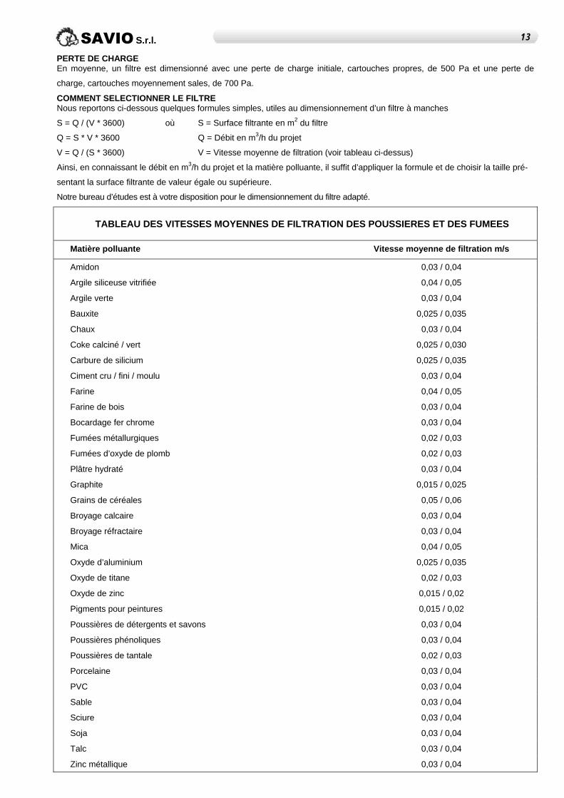
Les cartouches sont dimensionnées pour offrir une efficacité filtrante élevée, même en présence de poussières très fines. Leur
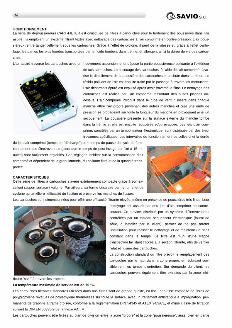
nettoyage est assuré par des jets d’air comprimé en contre-
courant. Ce service, distribué par un système d’électrovannes
contrôlées par un tableau séquenceur électronique (fourni de
série, à installer par le client), permet de ne pas arrêter
l’installation pour réaliser le nettoyage et de maintenir un débit
constant dans le temps. Le filtre est muni d’une trappe
d’inspection facilitant l’accès à la section filtrante, afin de vérifier
l’état et l’usure des cartouches.
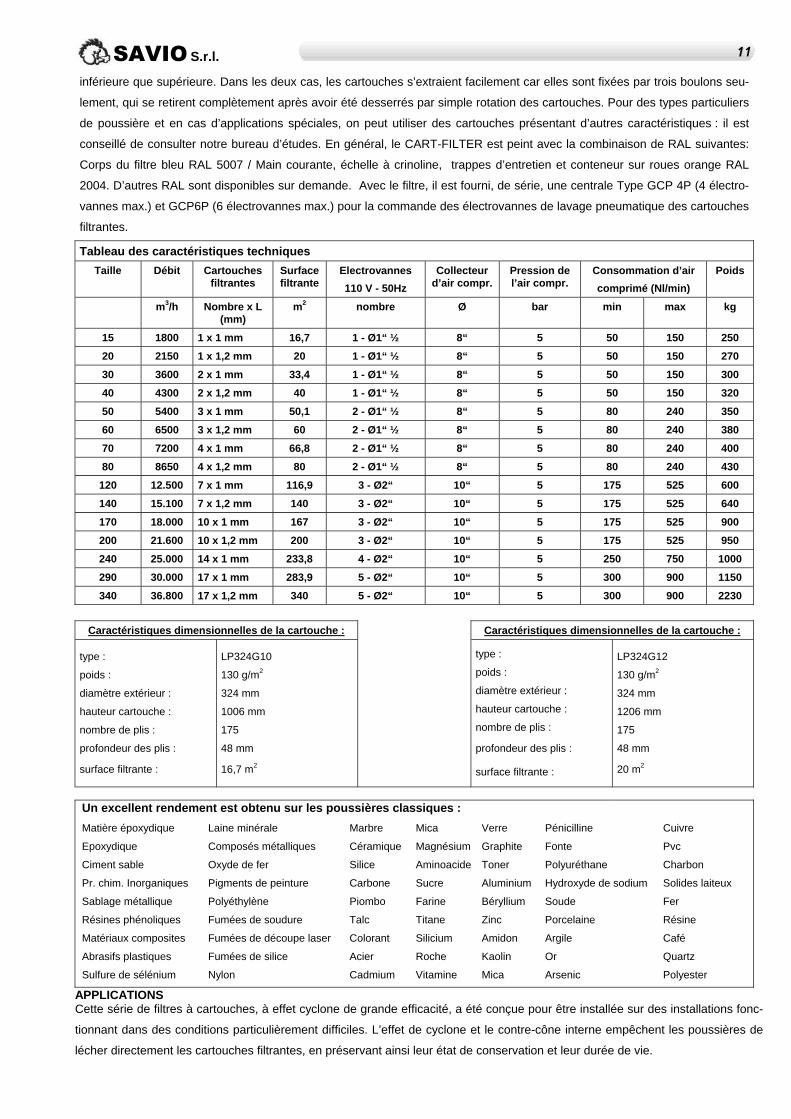
La construction standard du filtre prévoit le remplacement des
cartouches par le haut dans la zone propre, en réduisant sen-
siblement les temps d’entretien. Sur demande du client, les
cartouches peuvent également être extraites par la zone infé-
rieure “sale” à travers les trappes.
La température maximale de service est de 70 °C.
Les cartouches filtrantes standards utilisées dans nos filtres sont de grande qualité, en tissu non-tissé composé de fibres de
polypropylène revêtues de polyéthylène thermoliées sur toute la surface, avec un traitement antistatique à imprégnation per-
manente de graphite à trame croisée, conforme à la réglementation DIN 54345 et ATEX 94/9/CE, et d’une classe de filtration
suivant la DIN EN 60335-2-69, annexe AA : M.
Les cartouches peuvent être fixées au plan de division entre la zone “propre” et la zone “poussiéreuse”, aussi bien en partie
110 SAVIO S.r.l.
inférieure que supérieure. Dans les deux cas, les cartouches s’extraient facilement car elles sont fixées par trois boulons seu-
lement, qui se retirent complètement après avoir été desserrés par simple rotation des cartouches. Pour des types particuliers
de poussière et en cas d’applications spéciales, on peut utiliser des cartouches présentant d’autres caractéristiques : il est
conseillé de consulter notre bureau d’études. En général, le CART-FILTER est peint avec la combinaison de RAL suivantes:
Corps du filtre bleu RAL 5007 / Main courante, échelle à crinoline, trappes d’entretien et conteneur sur roues orange RAL
2004. D’autres RAL sont disponibles sur demande. Avec le filtre, il est fourni, de série, une centrale Type GCP 4P (4 électro-
vannes max.) et GCP6P (6 électrovannes max.) pour la commande des électrovannes de lavage pneumatique des cartouches
filtrantes.
Tableau des caractéristiques techniques
Taille Débit Cartouches filtrantes
Surface filtrante
Electrovannes
110 V - 50Hz
Collecteur d’air compr.
Pression de l’air compr.
Consommation d’air
comprimé (Nl/min)
Poids
m3/h Nombre x L (mm)
m2 nombre Ø bar min max kg
15 1800 1 x 1 mm 16,7 1 - Ø1“ ½ 8“ 5 50 150 250
20 2150 1 x 1,2 mm 20 1 - Ø1“ ½ 8“ 5 50 150 270
30 3600 2 x 1 mm 33,4 1 - Ø1“ ½ 8“ 5 50 150 300
40 4300 2 x 1,2 mm 40 1 - Ø1“ ½ 8“ 5 50 150 320
50 5400 3 x 1 mm 50,1 2 - Ø1“ ½ 8“ 5 80 240 350
60 6500 3 x 1,2 mm 60 2 - Ø1“ ½ 8“ 5 80 240 380
70 7200 4 x 1 mm 66,8 2 - Ø1“ ½ 8“ 5 80 240 400
80 8650 4 x 1,2 mm 80 2 - Ø1“ ½ 8“ 5 80 240 430
120 12.500 7 x 1 mm 116,9 3 - Ø2“ 10“ 5 175 525 600
140 15.100 7 x 1,2 mm 140 3 - Ø2“ 10“ 5 175 525 640
170 18.000 10 x 1 mm 167 3 - Ø2“ 10“ 5 175 525 900
200 21.600 10 x 1,2 mm 200 3 - Ø2“ 10“ 5 175 525 950
240 25.000 14 x 1 mm 233,8 4 - Ø2“ 10“ 5 250 750 1000
290 30.000 17 x 1 mm 283,9 5 - Ø2“ 10“ 5 300 900 1150
340 36.800 17 x 1,2 mm 340 5 - Ø2“ 10“ 5 300 900 2230
Caractéristiques dimensionnelles de la cartouche : Caractéristiques dimensionnelles de la cartouche :
type :
poids :
diamètre extérieur :
hauteur cartouche :
nombre de plis :
profondeur des plis :
surface filtrante :
LP324G10
130 g/m2
324 mm
1006 mm
175
48 mm
16,7 m2
type :
poids :
diamètre extérieur :
hauteur cartouche :
nombre de plis :
profondeur des plis :
surface filtrante :
LP324G12
130 g/m2
324 mm
1206 mm
175
48 mm
20 m2
Un excellent rendement est obtenu sur les poussières classiques :
Matière époxydique
Epoxydique
Ciment sable
Pr. chim. Inorganiques
Sablage métallique
Résines phénoliques
Matériaux composites
Abrasifs plastiques
Sulfure de sélénium
Laine minérale
Composés métalliques
Oxyde de fer
Pigments de peinture
Polyéthylène
Fumées de soudure
Fumées de découpe laser
Fumées de silice
Nylon
Marbre
Céramique
Silice
Carbone
Piombo
Talc
Colorant
Acier
Cadmium
Mica
Magnésium
Aminoacide
Sucre
Farine
Titane
Silicium
Roche
Vitamine
Verre
Graphite
Toner
Aluminium
Béryllium
Zinc
Amidon
Kaolin
Mica
Pénicilline
Fonte
Polyuréthane
Hydroxyde de sodium
Soude
Porcelaine
Argile
Or
Arsenic
Cuivre
Pvc
Charbon
Solides laiteux
Fer
Résine
Café
Quartz
Polyester
APPLICATIONS Cette série de filtres à cartouches, à effet cyclone de grande efficacité, a été conçue pour être installée sur des installations fonc-
tionnant dans des conditions particulièrement difficiles. L’effet de cyclone et le contre-cône interne empêchent les poussières de
lécher directement les cartouches filtrantes, en préservant ainsi leur état de conservation et leur durée de vie.
111SAVIO S.r.l.

Ces filtres trouvent de nombreuses applications. Citons, entre autres, les installations d’aspiration des industries chimiques, ali-
mentaires, métallurgiques, pétrochimiques, les cimenteries, les usines de céramique, les fonderies et toute installation où il faut
diminuer la présence de fumées et/ou de poussières sèches.
CONSOMMATIONS D’AIR COMPRIME Afin de déterminer rapidement les consommations d’air comprimé, nous avons reporté, dans le tableau de la page 3, les
consommations minimales et maximales conseillées, pour une “décharge” de 200 m/s avec de l’air comprimé à 5 bar et un
temps de pause de 360 secondes max et 120 secondes min après lequel on retourne sur la même électrovanne. Pour un
calcul précis de la consommation d’air comprimé, la consommation d’une vanne individuelle, en une seconde, est :
Diamètre 1”1/2 - 950 Nl/s à 3 bar - 1085 Nl/s à 5 bar
Diamètre 2” - 1520 Nl/s à 3 bar - 1735 Nl/s à 5 bar
Calcul de la consommation air comprimé :
- temps de pause du séquenceur = cycle moyen en secondes / nombre d’électrovannes.
- nombre de décharges / minute = 60 secondes / temps de pause du séquenceur
- consommation d’air comprimé Nl/min = débit de l’électrovanne (Nl/s) x temps de décharge (secondes) x nombre de dé-
charges (minute).
Exemple de calcul de consommation d’air comprimé :
- pression air comprimé : 5 bar - temps d’ouverture de la vanne en “décharge” : 0,15 seconde
- cycle moyen : 300 secondes
- 3 électrovannes d’un diamètre de 2”
Nl/min = 1735 Nl x 0.15 s x [60 s/min / (300 s / 3) = 156,15
- choix du compresseur : 100 Nl/min = 1 CV = 0,735 kW.
Pour économiser l’air comprimé, nous conseillons d’installer un pressostat différentiel qui déterminera le lavage des cartou-
ches sur la base du colmatage réel. Pour de plus amples informations techniques sur le séquenceur, consulter le catalogue AUTEL.
LE FILTRE STANDARD COMPREND :
un corps externe avec pieds et trémie,
un système de lavage à air comprimé avec électrovanne et panneau séquentiel.
ACCESSOIRES
Echelle à crinoline d’accès à la plate-forme d’entretien du filtre.
Rideau manuel à guillotine sur la gueule de la trémie de déchargement.
Rideau manuel à guillotine prédisposé pour les sacs de collecte.
Conteneur sur chariot sous la trémie de déchargement.
Conteneur sur chariot avec vanne manuelle.
Conteneur sur chariot avec vanne manuelle, prédisposé pour les sacs.
Vanne en étoile placée sous la trémie de déchargement.
Pressostat différentiel de commande automatique du nettoyage des cartouches filtrantes.
Etrier sur le corps du filtre avec ventilateur pour les tailles 20 - 30 - 50 - 70 - 120 (voir tableau ci-dessus).
TABLEAU DES VENTILATEURS ASSOCIES A LA SERIE CART-FILTER
CART-FILTER
TAILLE
VENTILATEUR
TYPE
DEBIT
m3/h
HAUTEUR MANOMETRI-
QUE TOTALE daPa
MOTEUR
2 POLES - kW
TENSION
Volts
15 SCL –25/A 1800 215 2,2 230/400
20 SCL –25/A 2150 205 2,2 230/400
30 SCL –28/A 3600 255 4 230/400
40 SCL –28/A 4300 230 4 230/400
50 SCLK –32/B 5400 275 7,5 400/690
60 SCLK –32/B 6500 245 7,5 400/690
70 SCLK –35/B 7200 290 9,2 400/690
80 SCLK –35/B 8650 240 9,2 400/690
120 SCLK –42/C 12.500 315 18,5 400/690
SAVIO S.r.l. 112
PERTE DE CHARGE En moyenne, un filtre est dimensionné avec une perte de charge initiale, cartouches propres, de 500 Pa et une perte de
charge, cartouches moyennement sales, de 700 Pa.
COMMENT SELECTIONNER LE FILTRE Nous reportons ci-dessous quelques formules simples, utiles au dimensionnement d’un filtre à manches
S = Q / (V * 3600) où
Q = S * V * 3600
V = Q / (S * 3600)
S = Surface filtrante en m2 du filtre
Q = Débit en m3/h du projet
V = Vitesse moyenne de filtration (voir tableau ci-dessus)
Ainsi, en connaissant le débit en m3/h du projet et la matière polluante, il suffit d’appliquer la formule et de choisir la taille pré-
sentant la surface filtrante de valeur égale ou supérieure.
Notre bureau d’études est à votre disposition pour le dimensionnement du filtre adapté.
TABLEAU DES VITESSES MOYENNES DE FILTRATION DES POUSSIERES ET DES FUMEES
Matière polluante Vitesse moyenne de filtration m/s
Amidon 0,03 / 0,04
Argile siliceuse vitrifiée 0,04 / 0,05
Argile verte 0,03 / 0,04
Bauxite 0,025 / 0,035
Chaux 0,03 / 0,04
Coke calciné / vert 0,025 / 0,030
Carbure de silicium 0,025 / 0,035
Ciment cru / fini / moulu 0,03 / 0,04
Farine 0,04 / 0,05
Farine de bois 0,03 / 0,04
Bocardage fer chrome 0,03 / 0,04
Fumées métallurgiques 0,02 / 0,03
Fumées d’oxyde de plomb 0,02 / 0,03
Plâtre hydraté 0,03 / 0,04
Graphite 0,015 / 0,025
Grains de céréales 0,05 / 0,06
Broyage calcaire 0,03 / 0,04
Broyage réfractaire 0,03 / 0,04
Mica 0,04 / 0,05
Oxyde d’aluminium 0,025 / 0,035
Oxyde de titane 0,02 / 0,03
Oxyde de zinc 0,015 / 0,02
Pigments pour peintures 0,015 / 0,02
Poussières de détergents et savons 0,03 / 0,04
Poussières phénoliques 0,03 / 0,04
Poussières de tantale 0,02 / 0,03
Porcelaine 0,03 / 0,04
PVC 0,03 / 0,04
Sable 0,03 / 0,04
Sciure 0,03 / 0,04
Soja 0,03 / 0,04
Talc 0,03 / 0,04
Zinc métallique 0,03 / 0,04
113SAVIO S.r.l.
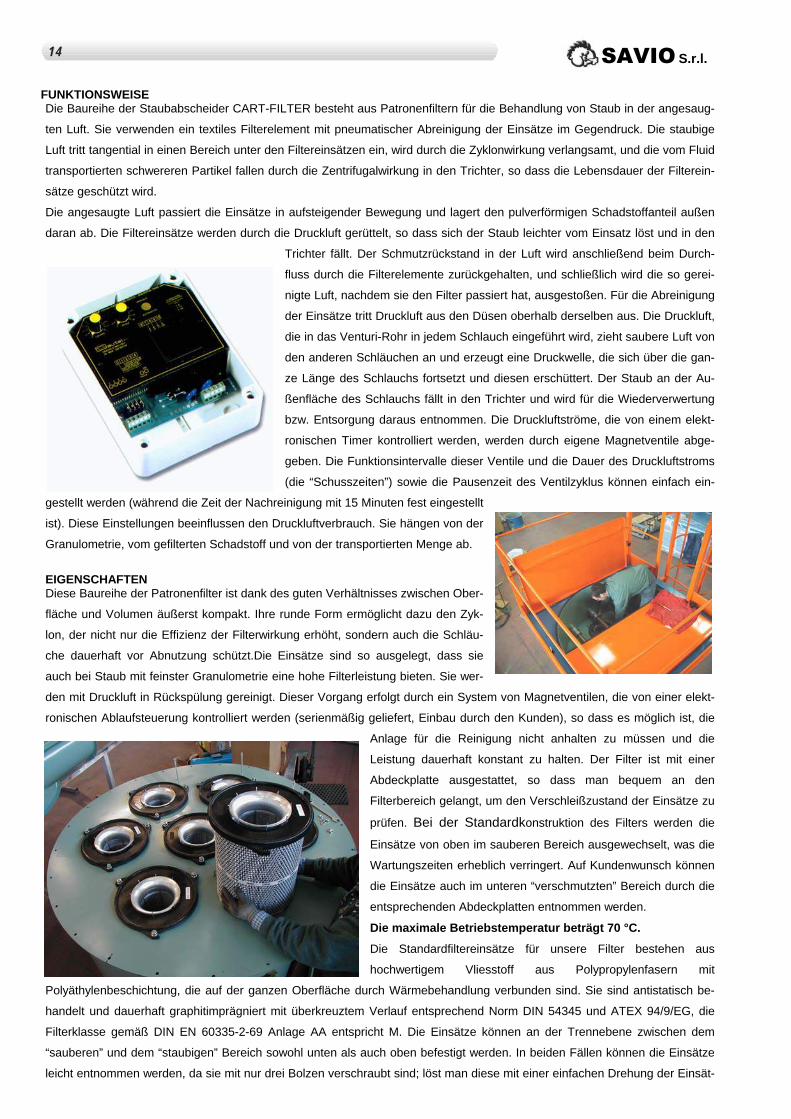
FUNKTIONSWEISE Die Baureihe der Staubabscheider CART-FILTER besteht aus Patronenfiltern für die Behandlung von Staub in der angesaug-
ten Luft. Sie verwenden ein textiles Filterelement mit pneumatischer Abreinigung der Einsätze im Gegendruck. Die staubige
Luft tritt tangential in einen Bereich unter den Filtereinsätzen ein, wird durch die Zyklonwirkung verlangsamt, und die vom Fluid
transportierten schwereren Partikel fallen durch die Zentrifugalwirkung in den Trichter, so dass die Lebensdauer der Filterein-
sätze geschützt wird.
Die angesaugte Luft passiert die Einsätze in aufsteigender Bewegung und lagert den pulverförmigen Schadstoffanteil außen
daran ab. Die Filtereinsätze werden durch die Druckluft gerüttelt, so dass sich der Staub leichter vom Einsatz löst und in den
Trichter fällt. Der Schmutzrückstand in der Luft wird anschließend beim Durch-
fluss durch die Filterelemente zurückgehalten, und schließlich wird die so gerei-
nigte Luft, nachdem sie den Filter passiert hat, ausgestoßen. Für die Abreinigung
der Einsätze tritt Druckluft aus den Düsen oberhalb derselben aus. Die Druckluft,
die in das Venturi-Rohr in jedem Schlauch eingeführt wird, zieht saubere Luft von
den anderen Schläuchen an und erzeugt eine Druckwelle, die sich über die gan-
ze Länge des Schlauchs fortsetzt und diesen erschüttert. Der Staub an der Au-
ßenfläche des Schlauchs fällt in den Trichter und wird für die Wiederverwertung
bzw. Entsorgung daraus entnommen. Die Druckluftströme, die von einem elekt-
ronischen Timer kontrolliert werden, werden durch eigene Magnetventile abge-
geben. Die Funktionsintervalle dieser Ventile und die Dauer des Druckluftstroms
(die “Schusszeiten”) sowie die Pausenzeit des Ventilzyklus können einfach ein-
gestellt werden (während die Zeit der Nachreinigung mit 15 Minuten fest eingestellt
ist). Diese Einstellungen beeinflussen den Druckluftverbrauch. Sie hängen von der
Granulometrie, vom gefilterten Schadstoff und von der transportierten Menge ab.
EIGENSCHAFTEN Diese Baureihe der Patronenfilter ist dank des guten Verhältnisses zwischen Ober-
fläche und Volumen äußerst kompakt. Ihre runde Form ermöglicht dazu den Zyk-
lon, der nicht nur die Effizienz der Filterwirkung erhöht, sondern auch die Schläu-
che dauerhaft vor Abnutzung schützt.Die Einsätze sind so ausgelegt, dass sie
auch bei Staub mit feinster Granulometrie eine hohe Filterleistung bieten. Sie wer-
den mit Druckluft in Rückspülung gereinigt. Dieser Vorgang erfolgt durch ein System von Magnetventilen, die von einer elekt-
ronischen Ablaufsteuerung kontrolliert werden (serienmäßig geliefert, Einbau durch den Kunden), so dass es möglich ist, die
Anlage für die Reinigung nicht anhalten zu müssen und die
Leistung dauerhaft konstant zu halten. Der Filter ist mit einer
Abdeckplatte ausgestattet, so dass man bequem an den
Filterbereich gelangt, um den Verschleißzustand der Einsätze zu
prüfen. Bei der Standardkonstruktion des Filters werden die
Einsätze von oben im sauberen Bereich ausgewechselt, was die
Wartungszeiten erheblich verringert. Auf Kundenwunsch können
die Einsätze auch im unteren “verschmutzten” Bereich durch die
entsprechenden Abdeckplatten entnommen werden.
Die maximale Betriebstemperatur beträgt 70 °C.
Die Standardfiltereinsätze für unsere Filter bestehen aus
hochwertigem Vliesstoff aus Polypropylenfasern mit
Polyäthylenbeschichtung, die auf der ganzen Oberfläche durch Wärmebehandlung verbunden sind. Sie sind antistatisch be-
handelt und dauerhaft graphitimprägniert mit überkreuztem Verlauf entsprechend Norm DIN 54345 und ATEX 94/9/EG, die
Filterklasse gemäß DIN EN 60335-2-69 Anlage AA entspricht M. Die Einsätze können an der Trennebene zwischen dem
“sauberen” und dem “staubigen” Bereich sowohl unten als auch oben befestigt werden. In beiden Fällen können die Einsätze
leicht entnommen werden, da sie mit nur drei Bolzen verschraubt sind; löst man diese mit einer einfachen Drehung der Einsät-
114 SAVIO S.r.l.

ze, lassen sie sich vollständig herausziehen. Für besondere Staubarten und bei Spezialanwendungen können Einsätze mit
anderen Merkmalen verwendet werden. Dafür empfehlen wir Ihnen, sich an unser technisches Büro zu wenden. Der CART-
FILTER wird normalerweise in der folgenden RAL-Farbkombination lackiert: Filtergehäuse Blau RAL 5007 / Handläufe, Steig-
leiter, Wartungsplatten und Behälter auf Rollen Orange RAL 2004. Auf Wunsch kann man als Sonderausstattung Lackierun-
gen mit anderen RAL-Farben erhalten. Serienmäßig wird mit dem Filter ein Steuergerät Typ GCP 4P (max. 4 Magnetventile)
und GCP6P (max. 6 Magnetventile) für die Steuerung der Luftdruckventile zur Abreinigung der Filtereinsätze geliefert.
Tabelle Technische Eigenschaften
Größe Durch-satz
Filtereinsätze Filter-fläche
Magnetventile
110 V – 50Hz
Druckluft-leitung
Druck
Druckluft
Verbrauch
Druckluft (Nl/min)
Gewicht
m3/h Nr x L (mm) m2 Nr. Ø bar Min Max kg
15 1800 1 x 1 mm 16,7 1 – Ø1“ ½ 8“ 5 50 150 250
20 2150 1 x 1,2 mm 20 1 – Ø1“ ½ 8“ 5 50 150 270
30 3600 2 x 1 mm 33,4 1 – Ø1“ ½ 8“ 5 50 150 300
40 4300 2 x 1,2 mm 40 1 – Ø1“ ½ 8“ 5 50 150 320
50 5400 3 x 1 mm 50,1 2 – Ø1“ ½ 8“ 5 80 240 350
60 6500 3 x 1,2 mm 60 2 – Ø1“ ½ 8“ 5 80 240 380
70 7200 4 x 1 mm 66,8 2 – Ø1“ ½ 8“ 5 80 240 400
80 8650 4 x 1,2 mm 80 2 – Ø1“ ½ 8“ 5 80 240 430
120 12.500 7 x 1 mm 116,9 3 – Ø2“ 10“ 5 175 525 600
140 15.100 7 x 1,2 mm 140 3 – Ø2“ 10“ 5 175 525 640
170 18.000 10 x 1 mm 167 3 – Ø2“ 10“ 5 175 525 900
200 21.600 10 x 1,2 mm 200 3 – Ø2“ 10“ 5 175 525 950
240 25.000 14 x 1 mm 233,8 4 – Ø2“ 10“ 5 250 750 1000
290 30.000 17 x 1 mm 283,9 5 – Ø2“ 10“ 5 300 900 1150
340 36.800 17 x 1,2 mm 340 5 – Ø2“ 10“ 5 300 900 2230
Abmessungen Filtereinsatz: Abmessungen Filtereinsatz:
Typ :
Gewicht:
Außendurchmesser:
Höhe Einsatz:
Faltenzahl:
Faltentiefe:
Filterfläche:
LP324G10
130 g/m2
324 mm
1006 mm
175
48 mm
16,7 m2
Typ :
Gewicht:
Außendurchmesser:
Höhe Einsatz:
Faltenzahl:
Faltentiefe:
Filterfläche:
LP324G12
130 g/m2
324 mm
1206 mm
175
48 mm
20 m2
Bei den klassischen Staubarten erhält man eine optimale Leistungsfähigkeit bei folgenden Materialien:
Epoxidmaterial
Zement Sand
Chem. anorgan. Prod.
Metallstaub
Phenolharze
Verbundmaterialien
Kunststoffabrieb
Selensulfid
Kosmetische Pulver
Steinwolle
Metallverbundstoffe
Eisenoxid
Farbpigmente
Polyäthylen
Schweißdämpfe
Laserschnittdämpfe
Silicadämpfe
Nylon
Marmor
Keramik
Kieselerde
Kohlenstoff
Blei
Talk
Farbstoff
Stahl
Cadmium
Glimmer
Magnesium
Aminosäure
Zucker
Mehl
Titan
Silizium
Stein
Vitamine
Glas
Graphit
Toner
Aluminium
Beryllium
Zink
Stärke
Kaolin
Glimmer
Penicillin
Gusseisen
Polyurethan
Natriumhydroxid
Soda
Porzellan
Ton
Gold
Arsen
Kupfer
PVC
Kohle
Milchfeststoffe
Eisen
Harz
Kaffee
Quarz
Polyester
ANWENDUNG Diese Baureihe von hochleistungsfähigen Zyklon-Patronenfiltern wurde für die Installation in Anlagen entwickelt, die unter
besonders schweren Bedingungen arbeiten. Der Zyklon mit Anwendung des inneren Gegenkegels verhindert, dass der Staub
direkt die Filtereinsätze streift, so dass sie unversehrt bleiben und ihre Lebensdauer spürbar verlängert wird.
Diese Filter können für zahlreiche Anwendungen eingesetzt werden, unter anderem in Absauganlagen der chemischen, Le-
bensmittel-, Metall- und Erdölchemieindustrie, in Zementwerken, Keramik- und Gießereibetrieben und überall, wo Dämpfe
15SAVIO S.r.l.
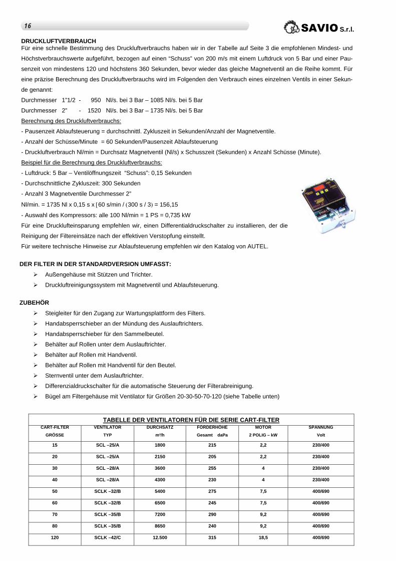
DRUCKLUFTVERBRAUCH Für eine schnelle Bestimmung des Druckluftverbrauchs haben wir in der Tabelle auf Seite 3 die empfohlenen Mindest- und
Höchstverbrauchswerte aufgeführt, bezogen auf einen “Schuss” von 200 m/s mit einem Luftdruck von 5 Bar und einer Pau-
senzeit von mindestens 120 und höchstens 360 Sekunden, bevor wieder das gleiche Magnetventil an die Reihe kommt. Für
eine präzise Berechnung des Druckluftverbrauchs wird im Folgenden den Verbrauch eines einzelnen Ventils in einer Sekun-
de genannt:
Durchmesser 1”1/2 - 950 Nl/s. bei 3 Bar – 1085 Nl/s. bei 5 Bar
Durchmesser 2” - 1520 Nl/s. bei 3 Bar – 1735 Nl/s. bei 5 Bar
Berechnung des Druckluftverbrauchs:
- Pausenzeit Ablaufsteuerung = durchschnittl. Zykluszeit in Sekunden/Anzahl der Magnetventile.
- Anzahl der Schüsse/Minute = 60 Sekunden/Pausenzeit Ablaufsteuerung
- Druckluftverbrauch Nl/min = Durchsatz Magnetventil (Nl/s) x Schusszeit (Sekunden) x Anzahl Schüsse (Minute).
Beispiel für die Berechnung des Druckluftverbrauchs:
- Luftdruck: 5 Bar – Ventilöffnungszeit “Schuss”: 0,15 Sekunden
- Durchschnittliche Zykluszeit: 300 Sekunden
- Anzahl 3 Magnetventile Durchmesser 2”
Nl/min. = 1735 Nl x 0,15 s x [60 s/min / (300 s / 3) = 156,15
- Auswahl des Kompressors: alle 100 Nl/min = 1 PS = 0,735 kW
Für eine Drucklufteinsparung empfehlen wir, einen Differentialdruckschalter zu installieren, der die
Reinigung der Filtereinsätze nach der effektiven Verstopfung einstellt.
Für weitere technische Hinweise zur Ablaufsteuerung empfehlen wir den Katalog von AUTEL.
DER FILTER IN DER STANDARDVERSION UMFASST:
Außengehäuse mit Stützen und Trichter.
Druckluftreinigungssystem mit Magnetventil und Ablaufsteuerung.
ZUBEHÖR
Steigleiter für den Zugang zur Wartungsplattform des Filters.
Handabsperrschieber an der Mündung des Auslauftrichters.
Handabsperrschieber für den Sammelbeutel.
Behälter auf Rollen unter dem Auslauftrichter.
Behälter auf Rollen mit Handventil.
Behälter auf Rollen mit Handventil für den Beutel.
Sternventil unter dem Auslauftrichter.
Differenzialdruckschalter für die automatische Steuerung der Filterabreinigung.
Bügel am Filtergehäuse mit Ventilator für Größen 20-30-50-70-120 (siehe Tabelle unten)
TABELLE DER VENTILATOREN FÜR DIE SERIE CART-FILTER
CART-FILTER
GRÖSSE
VENTILATOR
TYP
DURCHSATZ
m³/h
FÖRDERHÖHE
Gesamt daPa
MOTOR
2 POLIG – kW
SPANNUNG
Volt
15 SCL –25/A 1800 215 2,2 230/400
20 SCL –25/A 2150 205 2,2 230/400
30 SCL –28/A 3600 255 4 230/400
40 SCL –28/A 4300 230 4 230/400
50 SCLK –32/B 5400 275 7,5 400/690
60 SCLK –32/B 6500 245 7,5 400/690
70 SCLK –35/B 7200 290 9,2 400/690
80 SCLK –35/B 8650 240 9,2 400/690
120 SCLK –42/C 12.500 315 18,5 400/690
SAVIO S.r.l. 116
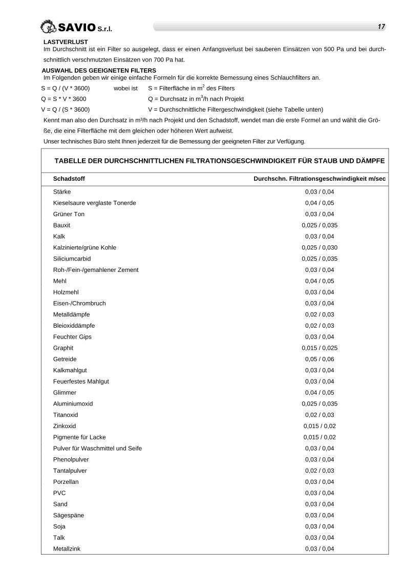
LASTVERLUST Im Durchschnitt ist ein Filter so ausgelegt, dass er einen Anfangsverlust bei sauberen Einsätzen von 500 Pa und bei durch-
schnittlich verschmutzten Einsätzen von 700 Pa hat.
AUSWAHL DES GEEIGNETEN FILTERS Im Folgenden geben wir einige einfache Formeln für die korrekte Bemessung eines Schlauchfilters an.
S = Q / (V * 3600) wobei ist
Q = S * V * 3600
V = Q / (S * 3600)
S = Filterfläche in m2 des Filters
Q = Durchsatz in m3/h nach Projekt
V = Durchschnittliche Filtergeschwindigkeit (siehe Tabelle unten)
Kennt man also den Durchsatz in m³/h nach Projekt und den Schadstoff, wendet man die erste Formel an und wählt die Grö-
ße, die eine Filterfläche mit dem gleichen oder höheren Wert aufweist.
Unser technisches Büro steht Ihnen jederzeit für die Bemessung der geeigneten Filter zur Verfügung.
TABELLE DER DURCHSCHNITTLICHEN FILTRATIONSGESCHWINDIGKEIT FÜR STAUB UND DÄMPFE
Schadstoff Durchschn. Filtrationsgeschwindigkeit m/sec
Stärke 0,03 / 0,04
Kieselsaure verglaste Tonerde 0,04 / 0,05
Grüner Ton 0,03 / 0,04
Bauxit 0,025 / 0,035
Kalk 0,03 / 0,04
Kalzinierte/grüne Kohle 0,025 / 0,030
Siliciumcarbid 0,025 / 0,035
Roh-/Fein-/gemahlener Zement 0,03 / 0,04
Mehl 0,04 / 0,05
Holzmehl 0,03 / 0,04
Eisen-/Chrombruch 0,03 / 0,04
Metalldämpfe 0,02 / 0,03
Bleioxiddämpfe 0,02 / 0,03
Feuchter Gips 0,03 / 0,04
Graphit 0,015 / 0,025
Getreide 0,05 / 0,06
Kalkmahlgut 0,03 / 0,04
Feuerfestes Mahlgut 0,03 / 0,04
Glimmer 0,04 / 0,05
Aluminiumoxid 0,025 / 0,035
Titanoxid 0,02 / 0,03
Zinkoxid 0,015 / 0,02
Pigmente für Lacke 0,015 / 0,02
Pulver für Waschmittel und Seife 0,03 / 0,04
Phenolpulver 0,03 / 0,04
Tantalpulver 0,02 / 0,03
Porzellan 0,03 / 0,04
PVC 0,03 / 0,04
Sand 0,03 / 0,04
Sägespäne 0,03 / 0,04
Soja 0,03 / 0,04
Talk 0,03 / 0,04
Metallzink 0,03 / 0,04
17SAVIO S.r.l.

P
H H
G
F
B
I
Ø A
650
O
O
COLLETTORE ARIA COMPRESSAAIR COMPRESSED COLLECTORCOLLECTEUR D'AIR COMPRIME DRUCKLUFTLEITUNG
zz
ELETTROVALVOLESOLENOID VALVESELECTROVANNESMAGNETVENTILE
Ø b
K
L
CONTENITORE CARRELLATOTROLLEY CONTAINERCONTENEUR SUR CHARIOT BEHÄLTER AUF ROLLEN
PORTELLO SOSTITUZIONE FILTRICARTRIDGES REPLACEMENT DOORTRAPPE DE REMPLACEMENT DES FILTRES ABDECKPLATTE FILTERAUSTAUSCH
Ø a
SCALA DI ACCESSO ALLA MARINARAFOOT IRONSECHELLE A CRINOLINE STEIGLEITER
Ø A
E
O x O
50
1050
CQ
D
NØ a
Ø 500M
J
Ø b
L
MANCORRENTEHANDRAILMAIN COURANTE HANDLAUF
CART FILTERDimensioni d'ingombro - Overall dimensions - Dimensions d'encombrement - Abmessungen
150
118 SAVIO S.r.l.
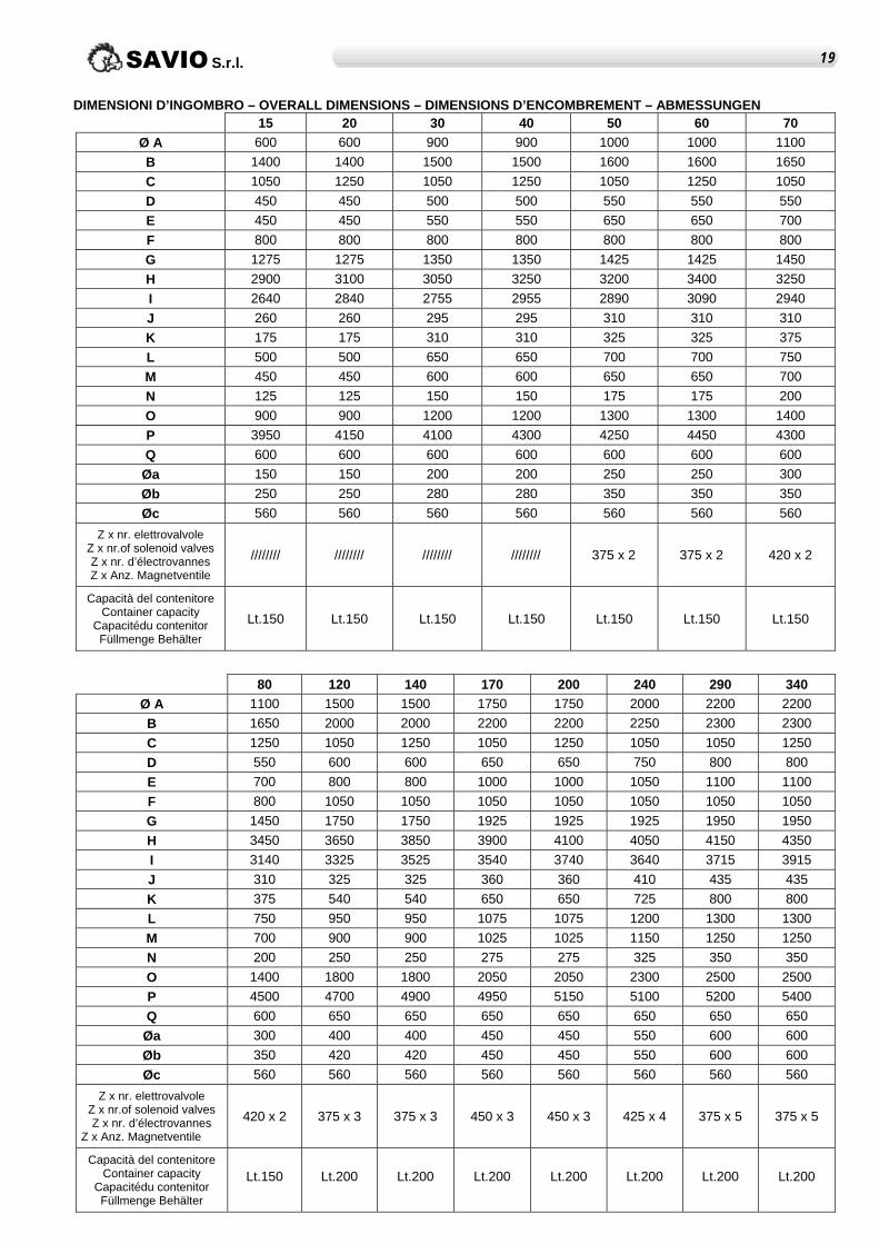
DIMENSIONI D’INGOMBRO – OVERALL DIMENSIONS – DIMENSIONS D’ENCOMBREMENT – ABMESSUNGEN
15 20 30 40 50 60 70 Ø A 600 600 900 900 1000 1000 1100
B 1400 1400 1500 1500 1600 1600 1650
C 1050 1250 1050 1250 1050 1250 1050
D 450 450 500 500 550 550 550
E 450 450 550 550 650 650 700
F 800 800 800 800 800 800 800
G 1275 1275 1350 1350 1425 1425 1450
H 2900 3100 3050 3250 3200 3400 3250
I 2640 2840 2755 2955 2890 3090 2940
J 260 260 295 295 310 310 310
K 175 175 310 310 325 325 375
L 500 500 650 650 700 700 750
M 450 450 600 600 650 650 700
N 125 125 150 150 175 175 200
O 900 900 1200 1200 1300 1300 1400
P 3950 4150 4100 4300 4250 4450 4300
Q 600 600 600 600 600 600 600
Øa 150 150 200 200 250 250 300
Øb 250 250 280 280 350 350 350
Øc 560 560 560 560 560 560 560
Z x nr. elettrovalvole Z x nr.of solenoid valves Z x nr. d’électrovannes Z x Anz. Magnetventile
//////// //////// //////// //////// 375 x 2 375 x 2 420 x 2
Capacità del contenitore Container capacity
Capacitédu contenitor Füllmenge Behälter
Lt.150 Lt.150 Lt.150 Lt.150 Lt.150 Lt.150 Lt.150
80 120 140 170 200 240 290 340 Ø A 1100 1500 1500 1750 1750 2000 2200 2200
B 1650 2000 2000 2200 2200 2250 2300 2300
C 1250 1050 1250 1050 1250 1050 1050 1250
D 550 600 600 650 650 750 800 800
E 700 800 800 1000 1000 1050 1100 1100
F 800 1050 1050 1050 1050 1050 1050 1050
G 1450 1750 1750 1925 1925 1925 1950 1950
H 3450 3650 3850 3900 4100 4050 4150 4350
I 3140 3325 3525 3540 3740 3640 3715 3915
J 310 325 325 360 360 410 435 435
K 375 540 540 650 650 725 800 800
L 750 950 950 1075 1075 1200 1300 1300
M 700 900 900 1025 1025 1150 1250 1250
N 200 250 250 275 275 325 350 350
O 1400 1800 1800 2050 2050 2300 2500 2500
P 4500 4700 4900 4950 5150 5100 5200 5400
Q 600 650 650 650 650 650 650 650
Øa 300 400 400 450 450 550 600 600
Øb 350 420 420 450 450 550 600 600
Øc 560 560 560 560 560 560 560 560
Z x nr. elettrovalvole Z x nr.of solenoid valves Z x nr. d’électrovannes
Z x Anz. Magnetventile
420 x 2 375 x 3 375 x 3 450 x 3 450 x 3 425 x 4 375 x 5 375 x 5
Capacità del contenitore Container capacity
Capacitédu contenitor Füllmenge Behälter
Lt.150 Lt.200 Lt.200 Lt.200 Lt.200 Lt.200 Lt.200 Lt.200
19SAVIO S.r.l.
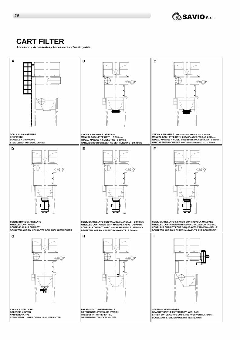
CART FILTERAccessori - Accessories - Accessoires - Zusatzgeräte
A B
VALVOLA MANUALE Ø 500mmMANUAL SASH-TYPE GATE Ø 500mmRIDEAU MANUEL A GUILLOTINE Ø 500mmHANDABSPERRSCHIEBER AN DER MÜNDUNG Ø 500mm
SCALA ALLA MARINARASTEP IRONS ECHELLE A CRINOLINE STEIGLEITER FÜR DEN ZUGANG
C
VALVOLA MANUALE PREDISPOSTA PER SACCO Ø 500mmMANUAL SASH-TYPE GATE PREARRANGED FOR BAG Ø 500mmRIDEAU MANUEL A GUILL. PREDISPOSE POUR LES SACS Ø 500mm HANDABSPERRSCHIEBER FÜR DEN SAMMELBEUTEL Ø 500mm
D
CONTENITORE CARRELLATOWHEELED CONTAINER CONTENEUR SUR CHARIOT BEHÄLTER AUF ROLLEN UNTER DEM AUSLAUFTRICHTER
E
CONT. CARRELLATO CON VALVOLA MANUALE Ø 500mmWHEELED CONTAINER WITH MANUAL VALVE Ø 500mmCONT. SUR CHARIOT AVEC VANNE MANUELLE Ø 500mmBEHÄLTER AUF ROLLEN MIT HANDVENTIL Ø 500mm
G
VALVOLA STELLARESOLENOID VALVES VANNE ROTATIVESTERNVENTIL UNTER DEM AUSLAUFTRICHTER
H
PRESSOSTATO DIFFERENZIALEDIFFERENTIAL PRESSURE SWITCH PRESSOSTAT DIFFERENTIEL DIFFERENZIALDRUCKSCHALTER
I
STAFFA & VENTILATOREBRACKET ON THE FILTER BODY WITH FAN ETRIER SUR LE CORPS DU FILTRE AVEC VENTILATEUR BÜGEL AM FILTERGEHÄUSE MIT VENTILATOR
F
CONT. CARRELLATO X SACCO CON VALVOLA MANUALE WHEELED CONTAINER WITH MANUAL VALVE FOR THE BAG CONT. SUR CHARIOT POUR SAQUE AVEC VANNE MANUELLEBEHÄLTER AUF ROLLEN MIT HANDVENTIL FÜR DEN BEUTEL
120 SAVIO S.r.l.

1
5
2
6
9 10
7
11 12
8
3 4
13 14 15 16
20191817
CART FILTERCombinazioni costruttive - Constructive combinations - Combinaisons constructives - Konstruktive Kombinationen
N.B.Portello, collettore aria compressa e uscita contenitore carrellato sono sempre obbligatoriamente allineati sullo stesso lato
Hatch, collector air compressed and exited container is always obligatorily aligns to you on the same side.
Hachez, air de collecteur comprimé et avez sorti le récipient roulé est toujours aligne obligatoirement sur vous du même côté
Brüten Sie aus, die zusammengedrückte Kollektorluft und nahm fahrbaren Behälter ist immer übereinstimmt obligatorisch mit Ihnen auf der gleichen Seite heraus
21SAVIO S.r.l.
Via Reggio Calabria,13 – Cascine Vica Rivoli (TO) Italia Tel: (+39) 011. 959.16.01 Fax: (+39) 011. 959.29.62E-mail : [email protected] http:// www.savioclima.it
Ed. Aprile 2005


![ECM Cremona 29 marzo 2013.ppt [Sola lettura] [modalità ... · “Preparazione, uso e garanzia di qualità degli emocomponenti.” Linee guida OMS GMP/GCP – ISO - Letteratura riferimenti.](https://static.fdocumenti.com/doc/165x107/5c65bf1909d3f2876e8d1db5/ecm-cremona-29-marzo-2013ppt-sola-lettura-modalita-preparazione.jpg)