Valentina Conti - Ricercatrice ENEA Chiara Martini - Ricercatrice ENEA
RICERCA DI SISTEMA ELETTRICO
Rapporto su analisi di impianti dotati di sistemi di sicurezza passivi
Osvaldo Aronica
Report RdS/2011/337
Agenzia Nazionale per le Nuove Tecnologie, l’Energia e lo Sviluppo Economico Sostenibile
RAPPORTO SU ANALISI DI IMPIANTI DOTATI DI SISTEMI DI SICUREZZA PASSIVI
Osvaldo Aronica (ENEA)
Novembre 2011
Report Ricerca di Sistema Elettrico
Accordo di Programma Ministero dello Sviluppo Economico – ENEA
Area: Governo, gestione e sviluppo del sistema elettrico nazionale
Progetto: Fissione nucleare: metodi di analisi e verifica di progetti nucleari di generazione
evolutiva ad acqua pressurizzata
Responsabile Progetto: Massimo Sepielli, ENEA

CIRTEN
Consorzio Interuniversitario per la Ricerca TEcnologicaNucleare
POLITECNICO DI MILANO ^DIPARTIMENTO DI ENERGIA, Sezione INGEGNERIA NUCLEARE-CeSNEF
Generation III+ Reactor response to
Fukushima-like scenario
Shan Yameng^, Marco Ricotti^
CERSE-POLIMI RL-1460/2011
Milano, Novembre 2011
Lavoro svolto in esecuzione dell’Obiettivo 1.1 – Attività A.2
“Studio probabilistico di eventi iniziatori che portano a condizioni incidentali di tipo severo” AdP MSE‐ENEA “Ricerca di Sistema Elettrico” - PAR2010
“Nuovo Nucleare da Fissione”.
Report on
“Generation III+ Reactor response to Fukushima-like scenario”
O1.1-A.2 2 CERSE-POLIMI RL-1460/2011
INDEX Executive Summary .......................................................................................................................................................... 3
List of Acronyms and Abbreviations ................................................................................................................................ 4
1 Fukushima Accident ............................................................................................................................................... 5
2 Lessons Learned ..................................................................................................................................................... 8
2.1 Beyond Design Accidents due to external hazards ..................................................................................... 11
2.2 Spent Fuel Pool Management ..................................................................................................................... 12
3 ENSREG “stress tests” ........................................................................................................................................... 14
3.1 Station Blackout .......................................................................................................................................... 15
4 AP1000: passive safety systems ........................................................................................................................... 16
4.1 Passive Core Cooling System ....................................................................................................................... 16
4.2 Passive Containment Cooling System ......................................................................................................... 19
5 AP1000 response to Station Blackout .................................................................................................................. 21
5.1 Station Blackout’s PRA ................................................................................................................................ 27
5.2 Systems, Structures and Components important for safety of reactor ...................................................... 27
6 Conclusion and considerations ............................................................................................................................. 30
Event trees ..................................................................................................................................................................... 32
Report on
“Generation III+ Reactor response to Fukushima-like scenario”
O1.1-A.2 3 CERSE-POLIMI RL-1460/2011
Executive Summary
This document presents the response of a reference generation III+ reactor to a Fukushima-‐like accident. The reference
plant considered in the analysis is the generation III+ AP1000.
The accident scenario considered follows the indication of ENSREG’s “stress tests” specifications. In particular an
earthquake concurrent with a flooding event is postulated, assuming the reactor in:
§ station black-‐out (SBO: loss of all AC electrical power supply) or
§ total station black-‐out characterized by SBO and loss of DC batteries (total SBO) 1.
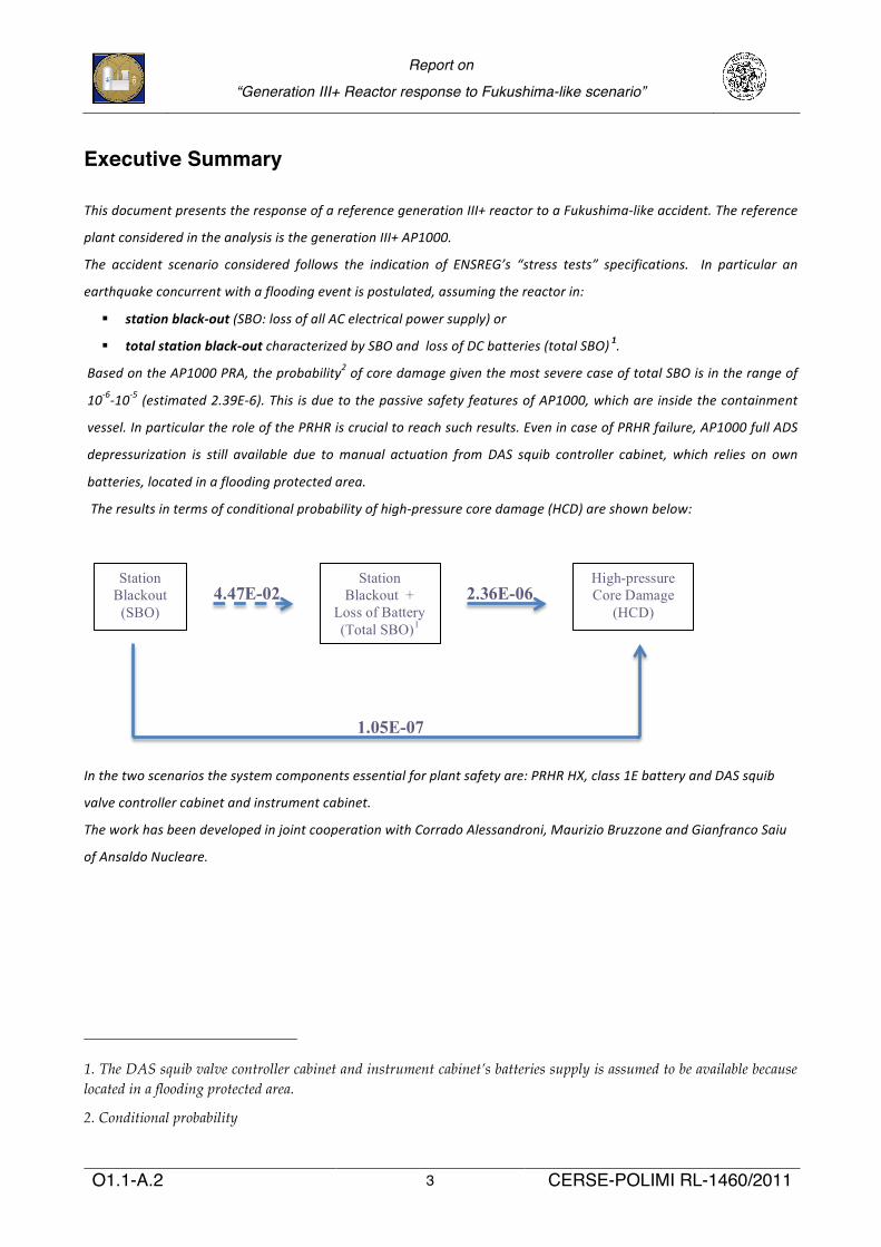
Based on the AP1000 PRA, the probability2 of core damage given the most severe case of total SBO is in the range of
10-‐6-‐10-‐5 (estimated 2.39E-‐6). This is due to the passive safety features of AP1000, which are inside the containment
vessel. In particular the role of the PRHR is crucial to reach such results. Even in case of PRHR failure, AP1000 full ADS
depressurization is still available due to manual actuation from DAS squib controller cabinet, which relies on own
batteries, located in a flooding protected area.
The results in terms of conditional probability of high-‐pressure core damage (HCD) are shown below:
In the two scenarios the system components essential for plant safety are: PRHR HX, class 1E battery and DAS squib
valve controller cabinet and instrument cabinet.
The work has been developed in joint cooperation with Corrado Alessandroni, Maurizio Bruzzone and Gianfranco Saiu
of Ansaldo Nucleare.
1. The DAS squib valve controller cabinet and instrument cabinet’s batteries supply is assumed to be available because located in a flooding protected area.
2. Conditional probability
Station Blackout
(SBO)
Station Blackout +
Loss of Battery (Total SBO)1
High-pressure Core Damage
(HCD) 2.36E-06
1.05E-07
4.47E-02
Report on
“Generation III+ Reactor response to Fukushima-like scenario”
O1.1-A.2 4 CERSE-POLIMI RL-1460/2011
List of Acronyms and Abbreviations AC
ACC Alternate Current
Accumulator ADS Automatic Depressurization System AOV Air Operated Valve CMT Core Makeup Tank DAS Diverse Alternative System DID Defense In Depth IRWST In-containment Refueling Water Storage Tank MOV Motor Operated Valve NRC
PCCWST U.S. Nuclear regulatory Commission
Passive Containment Cooling Water Storage Tank PCS Passive Containment Cooling System PMS Protection and Safety Monitoring System PRHR Passive Residual Heat Removal PRHR HX Passive Residual Heat Removal Heat Exchanger PXS Passive Core Cooling System RNS Normal Residual Heat Removal System SBO
SSCs Station Black-out
Structures Systems and Components
Report on
“Generation III+ Reactor response to Fukushima-like scenario”
O1.1-A.2 5 CERSE-POLIMI RL-1460/2011
1 Fukushima Accident
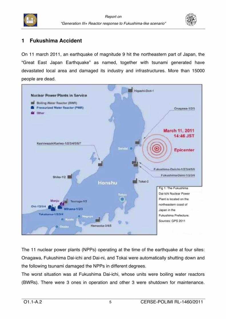
On 11 march 2011, an earthquake of magnitude 9 hit the northeastern part of Japan, the
“Great East Japan Earthquake” as named, together with tsunami generated have
devastated local area and damaged its industry and infrastructures. More than 15000
people are dead.
The 11 nuclear power plants (NPPs) operating at the time of the earthquake at four sites:
Onagawa, Fukushima Dai-ichi and Dai-ni, and Tokai were automatically shutting down and
the following tsunami damaged the NPPs in different degrees.
The worst situation was at Fukushima Dai-ichi, whose units were boiling water reactors
(BWRs). There were 3 ones in operation and other 3 were shutdown for maintenance.
Fig 1: The Fukushima
Dai-Ichi Nuclear Power
Plant is located on the
northeastern coast of
Japan in the
Fukushima Prefecture.
Sources: GPS 2011
Report on
“Generation III+ Reactor response to Fukushima-like scenario”
O1.1-A.2 6 CERSE-POLIMI RL-1460/2011
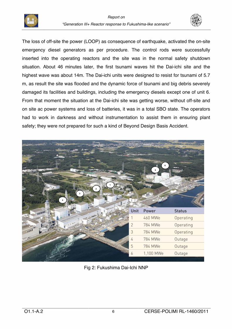
The loss of off-site the power (LOOP) as consequence of earthquake, activated the on-site
emergency diesel generators as per procedure. The control rods were successfully
inserted into the operating reactors and the site was in the normal safety shutdown
situation. About 46 minutes later, the first tsunami waves hit the Dai-ichi site and the
highest wave was about 14m. The Dai-ichi units were designed to resist for tsunami of 5.7
m, as result the site was flooded and the dynamic force of tsunami and big debris severely
damaged its facilities and buildings, including the emergency diesels except one of unit 6.
From that moment the situation at the Dai-ichi site was getting worse, without off-site and
on site ac power systems and loss of batteries, it was in a total SBO state. The operators
had to work in darkness and without instrumentation to assist them in ensuring plant
safety; they were not prepared for such a kind of Beyond Design Basis Accident.
Fig 2: Fukushima Dai-Ichi NNP
!"#$ %&'() *$+$,-
!"#$%&
!"#$%&
' !"#$%&
4
3
2
1
5
6
!"#$%&'()''!$*$+,"-.'/."0"1,"'2$13&.%'456&%'43.78'9+8.8$+':&;5%&'&.%8,<$.*&=
./0123.*402425/46!7!*58904:08;81584<!1=/0.4%3>/.4%=0<2
!"#$ <($49>(? .(+@$&)A41&"$+#"B("$A4+"C41&&D#"E4*F-$(B-??
'
>' ?@&A-&#.6.88+'&3&18%"1
>>' 'BCA"+53.8"57'157D&7+&%E'F4CBA,"#,0G%&++$%&'1553.78'"7H&18"57'+I+8&-E'JCBCA%&.185%'15%&'"+53.8"57'1553"7#'+I+8&-E'F4CKA,"#,0G%&++$%&'15%&'+G%.I'+I+8&-'
!"##$%&'()'*+,-./'$.'0"1"/23#$'4$353623
G((()(((!"#"$%&'()*+$,)-&(*./+0$1/223443/5 /"H+"@#"E4.(+@$&)4*+I($F4#"4$H(4JK-$41("$,)F
Report on
“Generation III+ Reactor response to Fukushima-like scenario”
O1.1-A.2 7 CERSE-POLIMI RL-1460/2011
The Cores were damaged without proper reactor residual removal heat capacity and the
operators tried hardly to act the controlled vent to avoid the over-pressurization of
containment. A series of explosion destroyed the reactor buildings of Unit 1, 3 and 4 due to
hydrogen explosion.
Before the supply of fresh water and of off-site power became available, fire engine pump,
helicopter, concrete pumping trunk, seawater intermittently borated were used to cool
down the reactors and the spent fuel pools (SFPs) and to mitigate the release of fission
product in surrounding environment, especially from SFPs.
The evacuation zone was extended to 20km and Japanese authorities raised the severity
rating to the highest level (level 7), the same of Chernobyl disaster.
Report on
“Generation III+ Reactor response to Fukushima-like scenario”
O1.1-A.2 8 CERSE-POLIMI RL-1460/2011
2 Lessons Learned
The Fukushima Accident generated in the world a new irrational feeling about use of
nuclear power and its safety and the risk for human; the memory of Chernobyl is still
recent. Under public opinion pressure some government decided to abandon the nuclear
power option, some others delayed release of new license.
Besides these “human conclusions”, task force and team of experts have been created to
investigate and analyze the accident, to identify initial lessons to be learned.
As point out by the MITʼs report “The lessons to be draw from the Fukushima accident are
different”. It should be understood that it was the worst earthquake and tsunami that Japan
have been hit, which caused thousands of deaths and billions of damages, and it was so
far beyond design basis accident: magnitude 9.0 mw vs. 8.2 of design, 14m high waves vs.
5.7 of design. No death was directly caused by the nuclear accident.
Although the Fukushima accident has been rated as level 7 like Chernobylʼs, there are
significant differences as radiation released, related deaths.
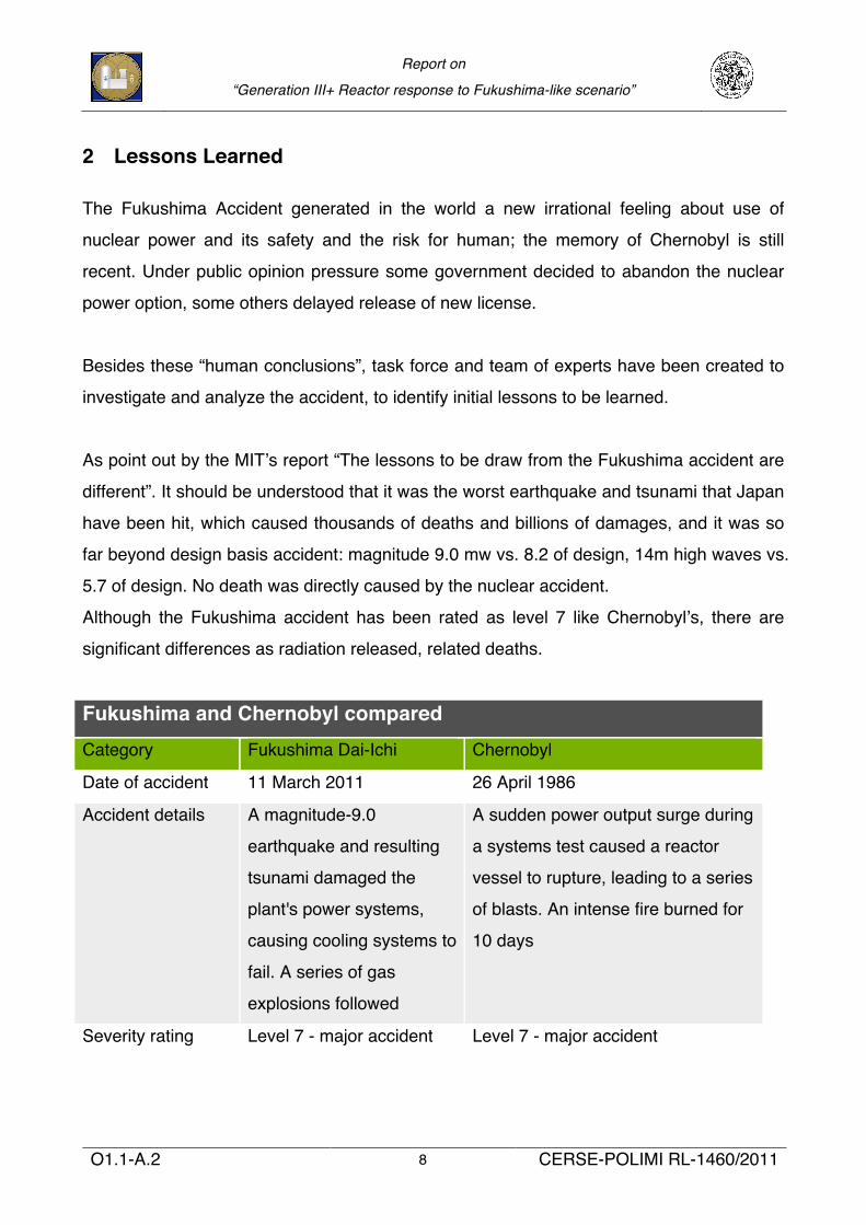
Fukushima and Chernobyl compared Category Fukushima Dai-Ichi Chernobyl
Date of accident 11 March 2011 26 April 1986
Accident details A magnitude-9.0
earthquake and resulting
tsunami damaged the
plant's power systems,
causing cooling systems to
fail. A series of gas
explosions followed
A sudden power output surge during
a systems test caused a reactor
vessel to rupture, leading to a series
of blasts. An intense fire burned for
10 days
Severity rating Level 7 - major accident Level 7 - major accident
Report on
“Generation III+ Reactor response to Fukushima-like scenario”
O1.1-A.2 9 CERSE-POLIMI RL-1460/2011
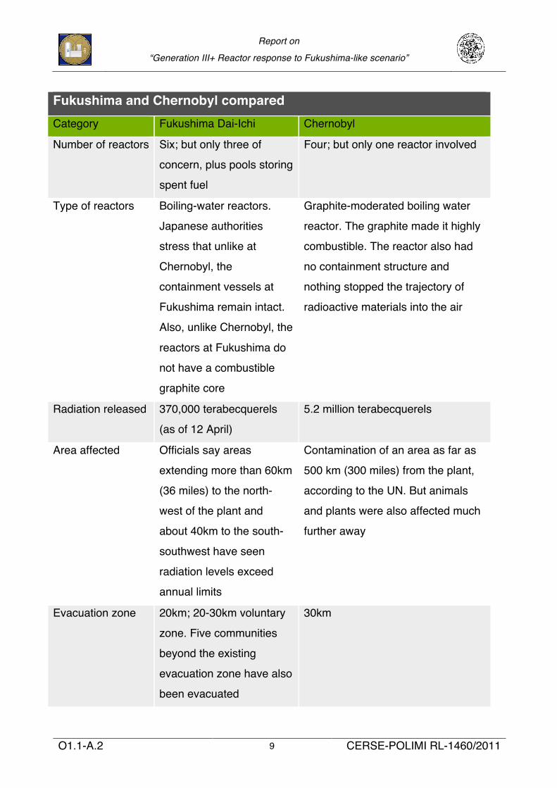
Fukushima and Chernobyl compared Category Fukushima Dai-Ichi Chernobyl
Number of reactors Six; but only three of
concern, plus pools storing
spent fuel
Four; but only one reactor involved
Type of reactors Boiling-water reactors.
Japanese authorities
stress that unlike at
Chernobyl, the
containment vessels at
Fukushima remain intact.
Also, unlike Chernobyl, the
reactors at Fukushima do
not have a combustible
graphite core
Graphite-moderated boiling water
reactor. The graphite made it highly
combustible. The reactor also had
no containment structure and
nothing stopped the trajectory of
radioactive materials into the air
Radiation released 370,000 terabecquerels
(as of 12 April)
5.2 million terabecquerels
Area affected Officials say areas
extending more than 60km
(36 miles) to the north-
west of the plant and
about 40km to the south-
southwest have seen
radiation levels exceed
annual limits
Contamination of an area as far as
500 km (300 miles) from the plant,
according to the UN. But animals
and plants were also affected much
further away
Evacuation zone 20km; 20-30km voluntary
zone. Five communities
beyond the existing
evacuation zone have also
been evacuated
30km
Report on
“Generation III+ Reactor response to Fukushima-like scenario”
O1.1-A.2 10 CERSE-POLIMI RL-1460/2011
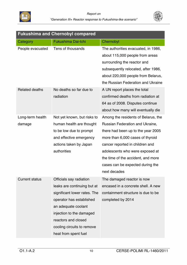
Fukushima and Chernobyl compared Category Fukushima Dai-Ichi Chernobyl
People evacuated Tens of thousands The authorities evacuated, in 1986,
about 115,000 people from areas
surrounding the reactor and
subsequently relocated, after 1986,
about 220,000 people from Belarus,
the Russian Federation and Ukraine
Related deaths No deaths so far due to
radiation
A UN report places the total
confirmed deaths from radiation at
64 as of 2008. Disputes continue
about how many will eventually die
Long-term health
damage
Not yet known, but risks to
human health are thought
to be low due to prompt
and effective emergency
actions taken by Japan
authorities
Among the residents of Belarus, the
Russian Federation and Ukraine,
there had been up to the year 2005
more than 6,000 cases of thyroid
cancer reported in children and
adolescents who were exposed at
the time of the accident, and more
cases can be expected during the
next decades
Current status Officials say radiation
leaks are continuing but at
significant lower rates. The
operator has established
an adequate coolant
injection to the damaged
reactors and closed
cooling circuits to remove
heat from spent fuel
The damaged reactor is now
encased in a concrete shell. A new
containment structure is due to be
completed by 2014
Report on
“Generation III+ Reactor response to Fukushima-like scenario”
O1.1-A.2 11 CERSE-POLIMI RL-1460/2011
Fukushima and Chernobyl compared ponds. Recently a
containment cover
structure of the Unit 1 has
been completed.
The actions to bring and
maintain the damaged
plants in a stable cooling
condition and limit the
radioactive releases will be
completed according with
the ROADMAP
established by plant
operator TEPCO (by end
of 2011 and January 2012)
2.1 Beyond Design Accidents due to external hazards
As the Fukushima accident was still evolving, the International Atomic Energy Agency
(IAEA) with agreement of Japanese Government conducted a preliminary mission to find
facts and identify initial lessons to be learned from the accident at Dai-ichi site, sharing this
information across the world nuclear community. The results of the Mission have been
reported to the IAEA Ministerial Conference on Nuclear Safety at IAEA headquarters in
Vienna on 20-24 June 2011.
There are three major areas where are necessary looking for to improve nuclear safety:
external hazards defence, severe accident management and emergency preparedness.
As reported by IAEA document, regard the external natural hazards, there should be
sufficient protection against infrequent and complex combinations of these events. The
flooding and its long term impacts should be carefully considered, provided a “dry site
concept” where possible and physical separation and diversity of critical safety systems to
increase the robustness of defence-in-depth (DID) against the risk of loss of safety
Report on
“Generation III+ Reactor response to Fukushima-like scenario”
O1.1-A.2 12 CERSE-POLIMI RL-1460/2011
functionality. In multiple unit sites, the problem of common cause failures, multiple units
failures and independent unit recovery options should not be overlooked. It requires large
resource of trained experienced people, equipment, supplies and external support, as also
point out by MIT report: a coordinated off-site pool of experts and workers should be
created to treat each type of NPP, as likely the local staff would be injured and not able to
operating in a catastrophic event like earthquake and flooding, that can be moved quickly
at damaged units. There should be an active tsunami warning system with the provision for
immediate operator action and the plant safety should be reviewed to any further important
acknowledge on external hazards.
Emergency response centers (ERS) should be housed in a seismic resistance building ,
well shielded, ventilated and protected also by other external events, such as flooding.
Adequate equipment and supply should be provided for radiological and welfare protection
of staff in case of an accident. The vital safety related monitoring parameters (coolant
levels, containment pressure etc.) should be guaranteed as long as possible and the
communication lines among vary control rooms and to outside should be ensured.
An update of Severe Accident Management Guidelines (SAMG) is necessary for
management of severe situation such as total loss of ac power or loss of all heat sinks or
of the engineering safety systems, providing alternative, rapid response and simple
devices for first days emergency recovery (mobile diesel power, compressed air, pumps,
water supplies), they should be located in a safe place, also off-site (provide quickly
transfer to site) and the operator trained to use them. Specific procedures should also be
provided for in case of unavailability of instruments, lighting, power and abnormal
conditions with high radiation.
One safety issue emerged at Fukushima is the hydrogen explosion and its consequences,
particularly at spent fuel pool (SFP) location. Necessary preventing and mitigating systems
should be implemented or reviewed.
2.2 Spent Fuel Pool Management
As the peculiarity of nuclear power, the fuel rods still produce heat by radioactive decay
after are removed from reactor and no longer used to produce electricity. Specific pool is
designed to house the spent fuel rods and to keep them cool.
Report on
“Generation III+ Reactor response to Fukushima-like scenario”
O1.1-A.2 13 CERSE-POLIMI RL-1460/2011
Generally, the SFP has an active heat removal system using off-site ac power and electric-
driven pumps. Once the LOOP occurs, the system will stop to operate and the water of
SFP increases its temperature and starts to boil off. A typical SFP have about 30 feet of
water over the top of fuel rods and in normal condition of SFPʼs integrity it takes days
before the rods are uncovered.
At Fukushima, the SFPs are allocated outside the primary containment of reactor, however
inside the reactor building, which is the second containment, its integrity will prevent that
any release of radioactive elements from SFP to atmosphere, since the pressure is kept
less than atmospheric pressure, and the air is filtered before its release to outside.
During the Fukushima accident, the operators had to vent the primary containment to
prevent over-pressurization, the leakage to reactor building has caused the accumulation
of hydrogen and a series of explosions which have destroyed units 1-3-4ʼs reactor
buildings and damaged SFPs. A probable leakage of water from SFP due to earthquake
and later damage from explosion have shortened the time before SFP uncovered and
since now the SFP is directly exposed to environment, the prompt recovery of SFP is
necessary to mitigate the radioactivity releases. All this worsened even more the situation.
Itʼs supposed that maybe the largest amount of release is due to SFP.
A more detailed review of SFP in case of external hazards of current and future plant
should be provided.
Report on
“Generation III+ Reactor response to Fukushima-like scenario”
O1.1-A.2 14 CERSE-POLIMI RL-1460/2011
3 ENSREG “stress tests”
On 24-25 March, The European Council declared that “the safety of all EU nuclear plants
should be reviewed, on the basis of a comprehensive and transparent risk assessment
(“stress tests”)”, after what happened at Fukushima”. Moreover “The European Nuclear
Safety Regulatory Group (ENSREG) and the European Commission are invited to develop
as soon as possible the scope and modalities of these tests in a coordinated framework in
the light of the lessons learned from the accident in Japan and with the full involvement of
Member States, making full use of available expertise (notably from the Western European
Nuclear Regulators Association)”.
On 13 May 2011, ENSREG and the European Commission, with the help of WENRA,
agreed upon “an initial independent regulatory technical definition of a “stress test” and
how it should be applied to nuclear facilities across Europe”.
The “stress tests” is defined “as a targeted reassessment of the safety margins of nuclear
power plants in the light of the events which occurred at Fukushima: extreme natural
events challenging the plant safety functions and leading to a severe accident.”
The reassessment consists:
“In an evaluation of the response of a nuclear power plant when facing a set of extreme
situations envisaged under the following section “technical scope” and in a verification of
the preventive and mitigative measures chosen following a defence-in-depth logic:
initiating events, consequential loss of safety functions, severe accident management.
In these extreme situations, sequential loss of the lines of defence is assumed, in a
deterministic approach, irrespective of the probability of this loss. In particular, it has to be
kept in mind that loss of safety functions and severe accident situations can occur only
when several design provisions have failed. In addition, measures to manage these
situations will be supposed to be progressively defeated”.
For a given plant, the reassessment will report on the response of the plant and on the
effectiveness of the preventive measures, noting any potential weak point and cliff-edge
effect, for each of the considered extreme situations. A cliff-edge effect could be, for
instance, exceeding a point where significant flooding of plant area starts after water
overtopping a protection dike or exhaustion of the capacity of the batteries in the event of a
Report on
“Generation III+ Reactor response to Fukushima-like scenario”
O1.1-A.2 15 CERSE-POLIMI RL-1460/2011
station blackout. This is to evaluate the robustness of the DID approach, the adequacy of
current accident management measures and to identify the potential for safety
improvements, both technical and organisational (such as procedures, human resources,
emergency response organisation or use of external resources).
By their nature, the stress tests will tend to focus on measures that could be taken after a
postulated loss of the safety systems that are installed to provide protection against
accidents considered in the design. Adequate performance of those systems has been
assessed in connection with plant licensing. Assumptions concerning their performance
are reassessed in the stress tests and they should be shown as provisions in place. It is
recognised that all measures taken to protect reactor core or spent fuel integrity or to
protect the reactor containment integrity constitute an essential part of the DID, as it is
always better to prevent accidents from happening than to deal with the consequences of
an occurred accident.
The stress test analysis will be organized into Three Topical Reviewes, performed by ad-
hoc teams working in parallel, each on one of the following topics:
1. earthquake, flooding and other external events;
2. loss of power, loss of UHS and combination of loss of power + loss of UHS;
3. severe accident management issues.
The present work will be devoted specifically on the preliminary analysis of a Station
Blackout scenario for a GenIII+ reactor.
In particular, two situations have to be considered:
l SBO: LOOP + Loss of the AC back-up electrical power sources (loss or all
emergency Diesel Generators)
l Total SBO: LOOP + Loss of the AC back-up sources + loss of any other diverse
back-up electrical sources (DC batteries)
All offsite electric power supplies are assumed to be lost for several days. The site is
isolated from delivery of heavy material for 72 hours by road, rail, and waterways. Portable
light equipment can arrive to the site from other locations after the first 24 hours.
Report on
“Generation III+ Reactor response to Fukushima-like scenario”
O1.1-A.2 16 CERSE-POLIMI RL-1460/2011
4 A GenIII+ reactor: AP1000 with passive safety systems
The AP1000 is an 1100MWe pressurized water reactor (PWR) designed by Westinghouse.
The plant is based on the AP600 designed by the same company and “Itʼs the only
Generation III+ reactor to receive Design Certification from the U.S Nuclear Regulatory
Commission (NRC)*”.
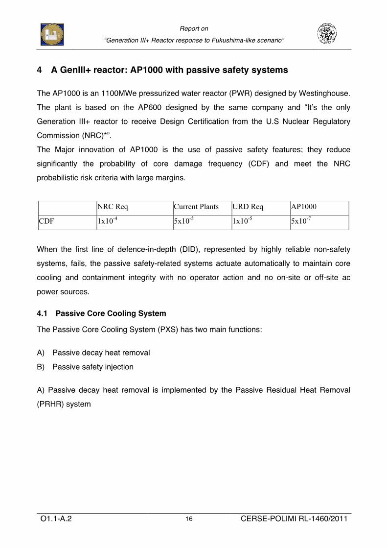
The Major innovation of AP1000 is the use of passive safety features; they reduce
significantly the probability of core damage frequency (CDF) and meet the NRC
probabilistic risk criteria with large margins.
NRC Req Current Plants URD Req AP1000
CDF 1x10⁻⁴ 5x10⁻⁵ 1x10⁻⁵ 5x10⁻⁷
When the first line of defence-in-depth (DID), represented by highly reliable non-safety
systems, fails, the passive safety-related systems actuate automatically to maintain core
cooling and containment integrity with no operator action and no on-site or off-site ac
power sources.
4.1 Passive Core Cooling System
The Passive Core Cooling System (PXS) has two main functions:
A) Passive decay heat removal
B) Passive safety injection
A) Passive decay heat removal is implemented by the Passive Residual Heat Removal
(PRHR) system
Report on
“Generation III+ Reactor response to Fukushima-like scenario”
O1.1-A.2 17 CERSE-POLIMI RL-1460/2011
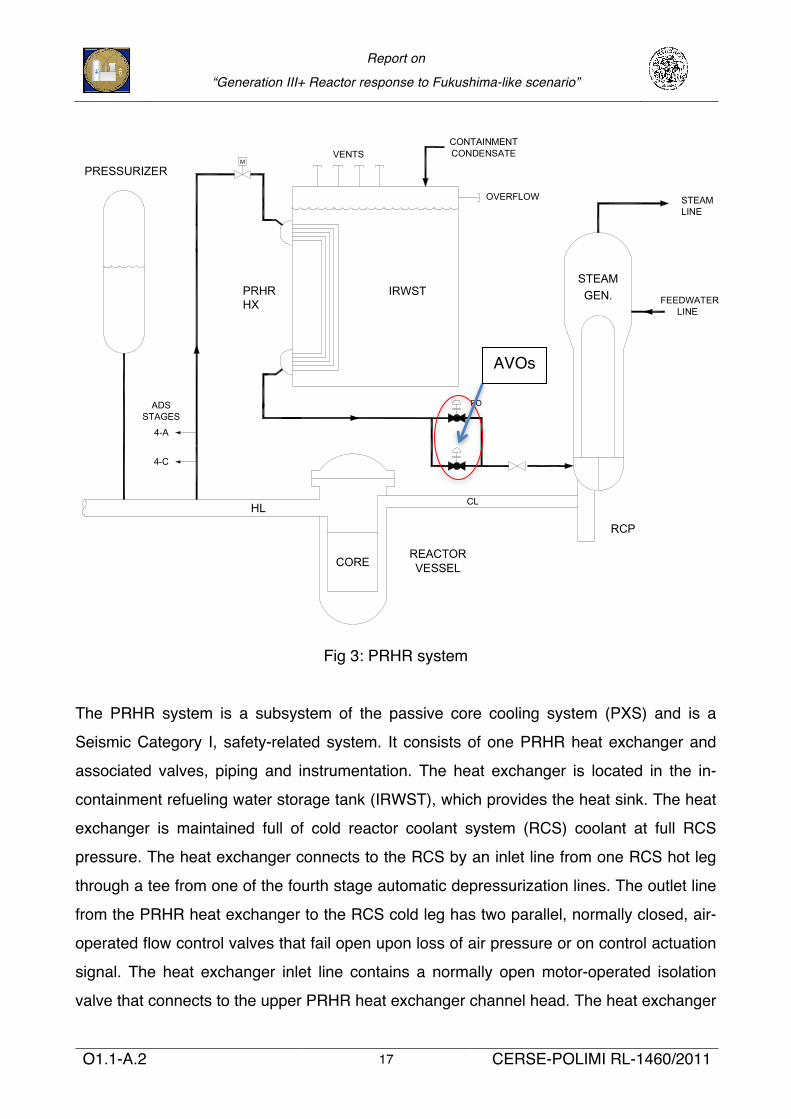
Fig 3: PRHR system
The PRHR system is a subsystem of the passive core cooling system (PXS) and is a
Seismic Category I, safety-related system. It consists of one PRHR heat exchanger and
associated valves, piping and instrumentation. The heat exchanger is located in the in-
containment refueling water storage tank (IRWST), which provides the heat sink. The heat
exchanger is maintained full of cold reactor coolant system (RCS) coolant at full RCS
pressure. The heat exchanger connects to the RCS by an inlet line from one RCS hot leg
through a tee from one of the fourth stage automatic depressurization lines. The outlet line
from the PRHR heat exchanger to the RCS cold leg has two parallel, normally closed, air-
operated flow control valves that fail open upon loss of air pressure or on control actuation
signal. The heat exchanger inlet line contains a normally open motor-operated isolation
valve that connects to the upper PRHR heat exchanger channel head. The heat exchanger
9
!"
!"##$%& '&(") *&"+ ,&-.%"/
#$%&'
()*
()+
,#$-./,0
*/1/
2-$''3-45$-
4-0'&
*,-$-$+*&,-#$''$/
'&$+6
-*2
7$%8
.,
192-1-
'&+7$'+:'
'&$+6;/4%$
.$$:0+&$-/4%$
*,%&+4%6$%&*,%:$%'+&$
60.1-"//) $#./"+&2 3) +4.
567#8 9"$/ .:&;
< 6:&;$;= > 567 "(+?"+&#
,@A (../$;= %$" ;"+?1"/
($1(?/"+$.;
< 567# "(+?"+&2 3) !BA
";2 3) '5A
C,DAE "3#.13# F&"+
< E"G&# H I F.?1# +. F&"+
?: +. #"+?1"+&2
< A+&"-$;= $# (.;2&;#&2
3) !@A ";2 1&+?1;&2 +.
C,DAE 3) =?++&1
!<
!,*, *&"+ JK(F";=&1
A$L& 3"#&2 .; +&#+ 1&#?/+#
< M?// #$L& +?3&#
< M?// :1&##?1& N +&-:&1"+?1&
@.;;&(+&2 +. C,DAE 4"//
< O@P +?3&# :1.%$2& 9/&K$3$/$+)
< 0. :$:&# $; C,DAE
< 0. :$:& 31&"G $;2?(&2
2);"-$( &99&(+#
< 5((&## 91.- .?+#$2& C,DAE
< J"#) +?3& $;#:&(+$.;
Q#&# :1.%&; AR +&(F;./.=)
< M/"+ +?3& #F&&+
< E?3& N +?3& #F&&+ (.;;&(+$.;
< SNTP C;(.;&/ UVW EE +?3&#
< AR +?3& $;#:&(+$.; -&+F.2#
1,3'4%7
&3=$'
*1+%%$/;1$+:
&3=$'1$$&
4%/$&;2424%7
$9&$%:$:;./+%7$
4-0'&;0+//
,2$-+&4%7;:$*>
;
/,0$-
,3&/$&;2424%7
322$-
6+%0+?
'322,-&
'322,-&&3=$
.-+6$
'322,-&
$/;!@AB;@C
$/;!D"B;EC
$/;!D@B;DC
4-0'&
AVOs
Report on
“Generation III+ Reactor response to Fukushima-like scenario”
O1.1-A.2 18 CERSE-POLIMI RL-1460/2011
is elevated above the RCS loops to induce natural circulation flow when the RCS pumps
are not available. The IRWST gutter circumnavigates the containment shell. The purpose
of the gutter is to collect condensed water on the containment shell and, in the event of
PRHR actuation, return the water to the IRWST, allowing the PRHR heat exchanger to
remain submerged in water.
.
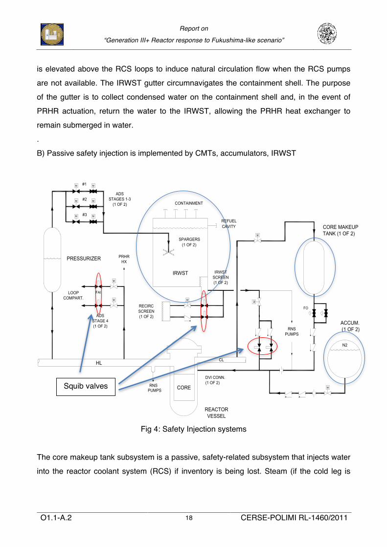
B) Passive safety injection is implemented by CMTs, accumulators, IRWST
Fig 4: Safety Injection systems
The core makeup tank subsystem is a passive, safety-related subsystem that injects water
into the reactor coolant system (RCS) if inventory is being lost. Steam (if the cold leg is
12
!"
!"##$%& '"(&)* +,-&.)$/,
#$%$
&!
'()**+(,-)(
,(.*/
0##+123453673!8
#6()
()0#/6(9)**)$
#6()310:)+'/0&:3453673!8
;"
;!
;5
70,
()7+)$#09,/<
76
(&*
*'0(=)(*
1
(&*'+1'*
$66'#61'0(/2
()#,(#*#())&453673!8
1
>9,3#6&&2453673!8
'(%(%?
453673!8
0>**/0=)*35@"453673!8
0>**/0=)3A453673!8
'+1'*
#6&/0,&1)&/
1 1
11
1 1
1
1
1
1
453673!8
,(.*/*#())&
0#&# /,& )$1& %"2%& "2$3,1&,)4 5..6162")/7 6#&# .8&.9 %"2% :;< 6#&# ("$2 /=&, 5>?4 5@' 6#&# ;>? (/7 ABCBD ",E
'F6$G# (/7 H4 +IJ'< 6#&# 'F6$G# ",E
.8&.9 %"2%&#
!A
:;< >=&7")$/,')",EG* ./,E$)$/,#
4 K$22&E L$)8 G/7")&E L")&7M /6)2&) $#/2")&EM $,2&) /=&, )/ I:'
4 N$,& 7/6)&E 6= (7/1 :N )/ )/= :;< ",E L&22 $,#62")&E O L")&7 L$22 G&8/)
4 P/71"2 :;< ./,E$)$/,# "7& QACR/K SHT/:U ",E CMCVR =#$3 SAVV G"7U
P/, N>:5 /=&7")$/,
4 :N 7&1"$,# ($22&E O 8/) L")&7 (2/L# $,)/ :;< )/=
4 W/) :N L")&7 ",E ./2E :;< L")&7 E7$%&# ,")67"2 .$7.62")$/, $,-&.)$/,
4 :;< $,-&.)# (/7 XHV 1$,6)&# 6,)$2 :;< L")&7 7&=2".&E G* 8/) :N L")&7
4 +,$)$"2 ,&) $,-&.)$/, $# X CT 2G B #&. SADYC 93 B #&.U =&7 :;<
Squib valves
Report on
“Generation III+ Reactor response to Fukushima-like scenario”
O1.1-A.2 19 CERSE-POLIMI RL-1460/2011
voided) or water (if the cold leg is solid) is supplied to the core makeup tank to displace the
cold injection water.
The accumulatorʼs function is to provide water into the reactor coolant system (RCS) if the
reactor coolant system pressure falls below the accumulator pressure.
The automatic depressurization system (ADS) valves act in conjunction with the passive
core cooling system (PXS) to mitigate accidents. Their function is to reduce the reactor
coolant system (RCS) pressure in a controlled fashion to allow the required safety injection
flow rates from the accumulators, and in-containment refueling water storage tank
(IRWST). It is required primarily to mitigate loss of coolant accidents.
The function of the IRWST/gravity injection is to provide flooding of the refueling cavity for
normal refueling, post-loss-of-coolant-accident (LOCA) flooding of the containment to
establish long-term reactor coolant system (RCS) cooling, and to support the passive
residual heat removal (PRHR) heat exchangers (HXs) operation.
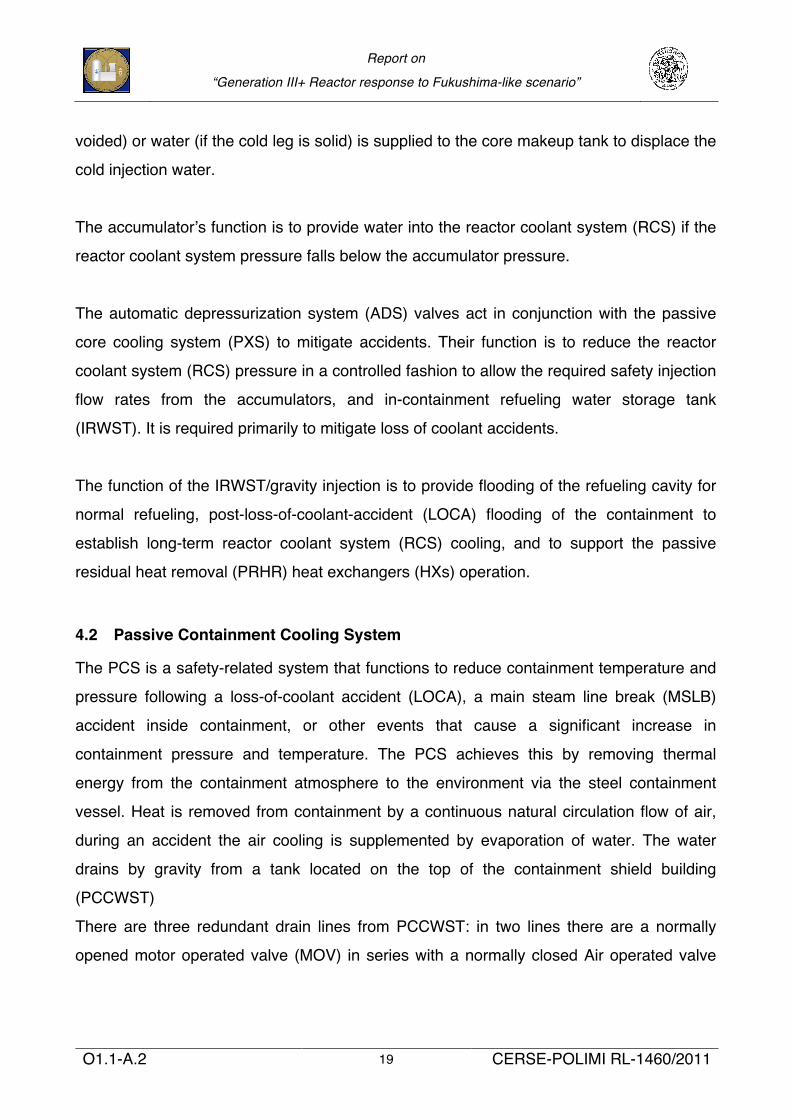
4.2 Passive Containment Cooling System
The PCS is a safety-related system that functions to reduce containment temperature and
pressure following a loss-of-coolant accident (LOCA), a main steam line break (MSLB)
accident inside containment, or other events that cause a significant increase in
containment pressure and temperature. The PCS achieves this by removing thermal
energy from the containment atmosphere to the environment via the steel containment
vessel. Heat is removed from containment by a continuous natural circulation flow of air,
during an accident the air cooling is supplemented by evaporation of water. The water
drains by gravity from a tank located on the top of the containment shield building
(PCCWST)
There are three redundant drain lines from PCCWST: in two lines there are a normally
opened motor operated valve (MOV) in series with a normally closed Air operated valve
Report on
“Generation III+ Reactor response to Fukushima-like scenario”
O1.1-A.2 20 CERSE-POLIMI RL-1460/2011
(AOV) and in the third there are a normally opened MOV in series with a normally MOV.
For the success of PCS it sufficient that one of three lines is operating.
Fig 5: PCS
Drain paths
Report on
“Generation III+ Reactor response to Fukushima-like scenario”
O1.1-A.2 21 CERSE-POLIMI RL-1460/2011
5 AP1000 response to Total Station Blackout
In order to evaluate AP1000 response to total station blackout, only data from AP1000
design control document (DCD) is used, site-specific upgrades that could be adopted by
plant owner are not taken in consideration in this report.
The goal of this study is focused on response of reference AP1000 reactor to a
Fukushima-like flooding event regardless the probability of occurrence of the event.
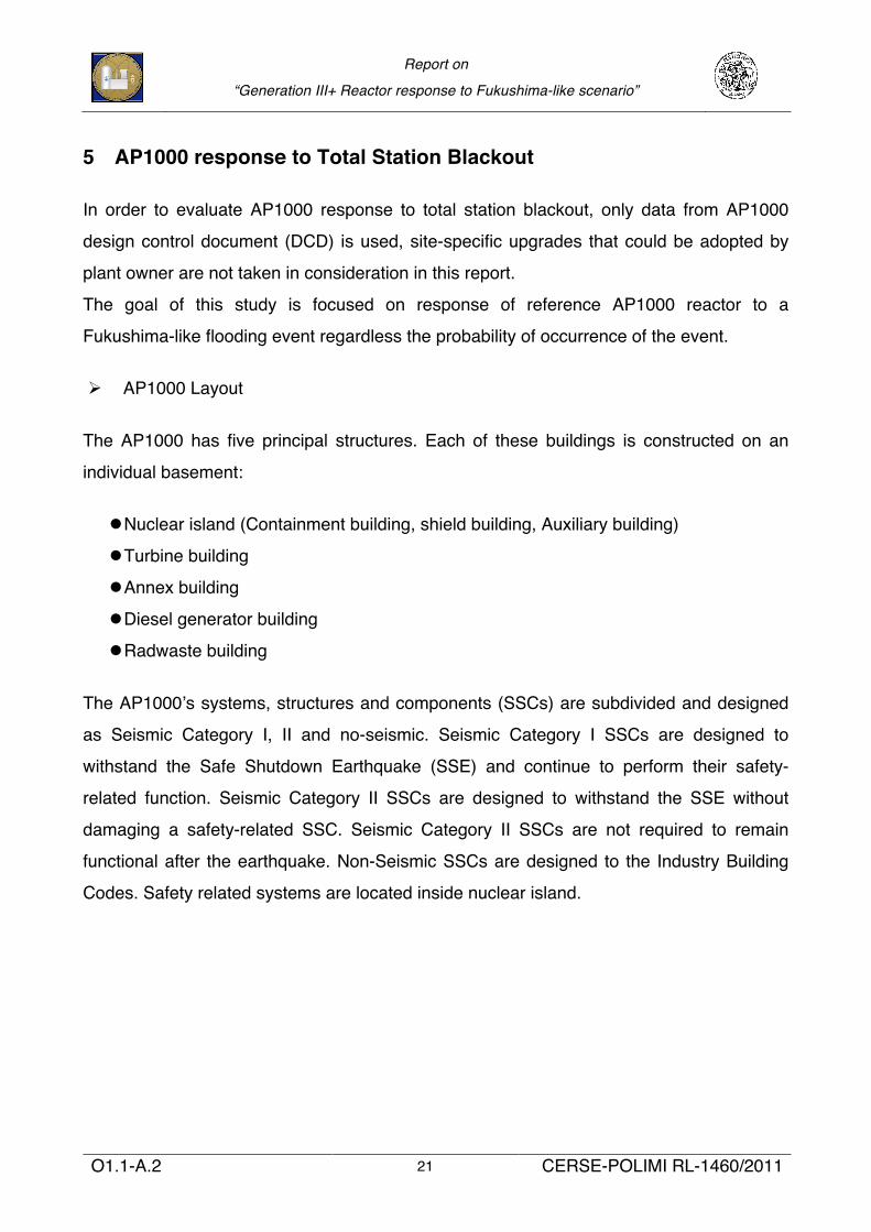
Ø AP1000 Layout
The AP1000 has five principal structures. Each of these buildings is constructed on an
individual basement:
l Nuclear island (Containment building, shield building, Auxiliary building)
l Turbine building
l Annex building
l Diesel generator building
l Radwaste building
The AP1000ʼs systems, structures and components (SSCs) are subdivided and designed
as Seismic Category I, II and no-seismic. Seismic Category I SSCs are designed to
withstand the Safe Shutdown Earthquake (SSE) and continue to perform their safety-
related function. Seismic Category II SSCs are designed to withstand the SSE without
damaging a safety-related SSC. Seismic Category II SSCs are not required to remain
functional after the earthquake. Non-Seismic SSCs are designed to the Industry Building
Codes. Safety related systems are located inside nuclear island.
Report on
“Generation III+ Reactor response to Fukushima-like scenario”
O1.1-A.2 22 CERSE-POLIMI RL-1460/2011
Fig 6: AP1000 Layout with seismic classification
All passive safety systems are located inside the steel containment vessel (44.5 mm thick)
surrounded by the shield building.
The maximum flood level assumed for AP1000 is the plant design grade elevation. Actual
grade will be a few inches lower to prevent surface water from entering doorways
The Class 1E battery banks are located under ground level in the Non-Radiologically-
Controlled Auxiliary (Non-RCA) Building.
Report on
“Generation III+ Reactor response to Fukushima-like scenario”
O1.1-A.2 23 CERSE-POLIMI RL-1460/2011
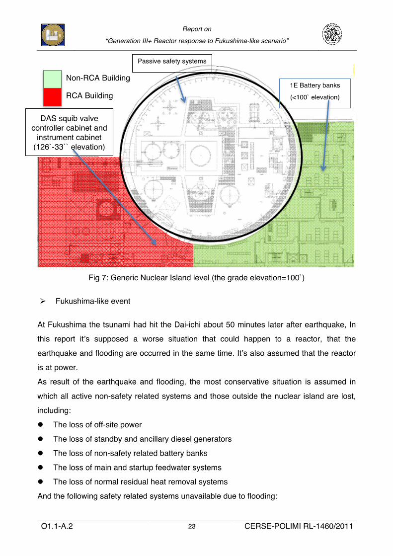
Fig 7: Generic Nuclear Island level (the grade elevation=100`)
Ø Fukushima-like event
At Fukushima the tsunami had hit the Dai-ichi about 50 minutes later after earthquake, In
this report itʼs supposed a worse situation that could happen to a reactor, that the
earthquake and flooding are occurred in the same time. Itʼs also assumed that the reactor
is at power.
As result of the earthquake and flooding, the most conservative situation is assumed in
which all active non-safety related systems and those outside the nuclear island are lost,
including:
l The loss of off-site power
l The loss of standby and ancillary diesel generators
l The loss of non-safety related battery banks
l The loss of main and startup feedwater systems
l The loss of normal residual heat removal systems
And the following safety related systems unavailable due to flooding:
1E Battery banks
(<100` elevation)
Non-RCA Building
RCA Building
Passive safety systems
DAS squib valve controller cabinet and
instrument cabinet (126`-33`` elevation)
Report on
“Generation III+ Reactor response to Fukushima-like scenario”
O1.1-A.2 24 CERSE-POLIMI RL-1460/2011
l The loss of Class 1E battery banks
l The loss of Protection and Monitoring System (PMS)
Itʼs also assumed that the Main Control Room (MCR) is inoperative, and the DAS squib
valve controller cabinet and instrument cabinet, which is located inside RCA auxiliary
building at 126` elevation with its independent battery supply is supposed to operate after
earthquake and flood.
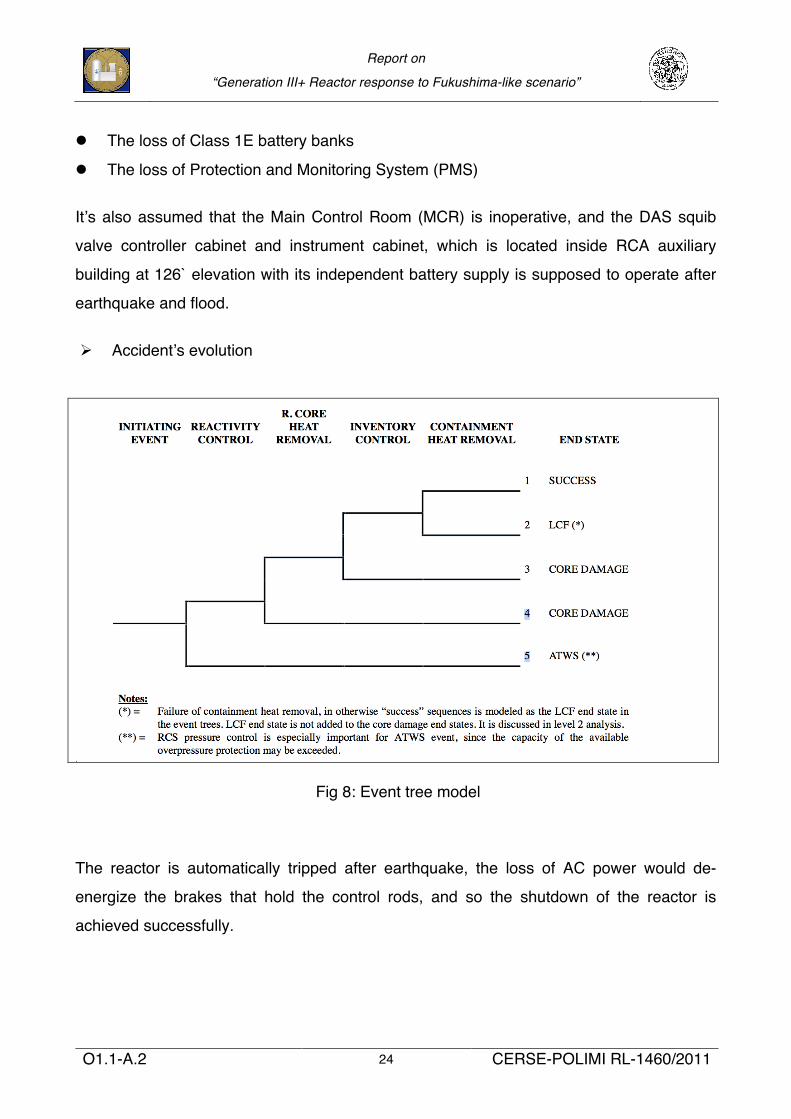
Ø Accidentʼs evolution
Fig 8: Event tree model
The reactor is automatically tripped after earthquake, the loss of AC power would de-
energize the brakes that hold the control rods, and so the shutdown of the reactor is
achieved successfully.
Report on
“Generation III+ Reactor response to Fukushima-like scenario”
O1.1-A.2 25 CERSE-POLIMI RL-1460/2011
The seismic category I SSCs of AP1000 are supposed to resist the earthquake and the
passive safety systems inside the steel containment vessel are not affected by the flooding
event. Also the RCS, which is inside the steel containment vessel, is supposed to
withstand following the accident, i.e. no loss of coolant.
Since the reactivity control is supposed to have success and RCS boundary is assumed to
be intact; the reactor residual heat removal function is needed to prevent core damage. In
a postulated SBO accident, the non safety-related DID active system (RNS, MFWS and
SFWS) are assumed to fail or not properly operating, whatever lost due to initial external
hazards or to loss of AC power. The only mean available in first stage of accident is the
PRHR HX, as noted below its correct actuation is fundament to the safety recovery of
reactor.
The PRHR HX described in chapter 4, is a completely passive system, i.e. no need of
either AC or DC power for this actuation. The AOVs at outlet line of PRHR HX (Fig 3)
would be opened by loss of control power or compressed air, i.e. in its safe fail-open
position, while the MOV of inlet line is already open. The residual heat removal is
performed by waterʼs natural circulation. The heat is transferred to IRWSTʼs water by heat
exchanger.
The IRWSTʼs water will reach the saturated temperature in few hours and the steam
generated is released to containment vessel and is cooled by PCCWSTʼs water, the
condensed water is collected and returned to IRWST.
With the plant in normal operation , the water dropped in containment vessel is collected to
sump. The use of AOVs in the collect paths to IRWST and to sump, permit that in case of
accident they will in their fail-safe position, i.e. the paths to IRWST will be opened and the
ones to sump closed in a postured SBO.
To prevent the over-pressurization of the containment, i.e. the containment vessel heat
removal, the PCS should be actuated and the amount of PCCWSTʼs water ensures that
the pressure of containment will be under the design pressure in the first three days (at
least) after the accident occurrence.
In case of SBO the drain paths of PCS are three, while in case of total SBO the drain
paths of PCS (Fig 5) are supposed to reduce to two instead of three. Itʼs assumed that at
loss of power or loss of compressed air, the paths with AOV are actuated since the AOVs
Report on
“Generation III+ Reactor response to Fukushima-like scenario”
O1.1-A.2 26 CERSE-POLIMI RL-1460/2011
are in their safe fail-open position, while the MOV path one is assumed to fail since the
MOV fails “as is” . The PCSʼs success criterion is one drain path actuated.
To avoid core damage is necessary the successful actuation of PRHR HX, the availability
of return paths of containment water to IRWST and one out of three drain paths of PCS. As
reported the PCS have at least three days range of water supply. All this is done without
operator actions by virtue of passive safety systems design of AP1000.
In an unlikely event sequence that the PRHR HX fails, the missed residual heat removal
would over-pressurize the reactor and turn in to a potential high-pressure core damage
state (see SBO event trees). Full depressurization of RCS should be actuated to prevent
the core damage.
Ø Depressurization of RCS
In case of SBO, the battery banks are still available, the success criteria of full
depressurization of RCS is
l Automatic actuation of 2 out of 4 of ADS 4th stage lines
l Automatic actuation of 3 out of 4 of ADS 2nd and 3rd stage lines.
l Manual actuation of 2 out of 4 ADS 4th stage lines
The depressurization of RCS allows the safety injection of borated cool water from ACCs
and IRWST to the reactor. When the level of water in reactor cavity reach a designed level,
the recirculation path is actuated for long term cooling. As for the PRHR HX success case,
the reactor will be in a safety state for at least three days, assumed that the PCS is
actuated.
In case of a Total SBO, the full depressurization of RCS is manual actuated from DAS
instrument cabinet by opening of squib valves of ADS 4th stage lines, same for the squib
valves of safety injection lines and of recirculation lines.
The adoption of the squib valves in ADSʼs 4th stage, IRWSTʼs gravity injection lines and
recirculation lines is justifies by the need to prevent spurious actuation that can result in
adverse effects on the overall plant safety. The squib valves fail at their normal position
Report on
“Generation III+ Reactor response to Fukushima-like scenario”
O1.1-A.2 27 CERSE-POLIMI RL-1460/2011
(closed) and this inhibit the accomplishment of their safety function in case of a complete
loss of power.
5.1 Total Station Blackout PRA
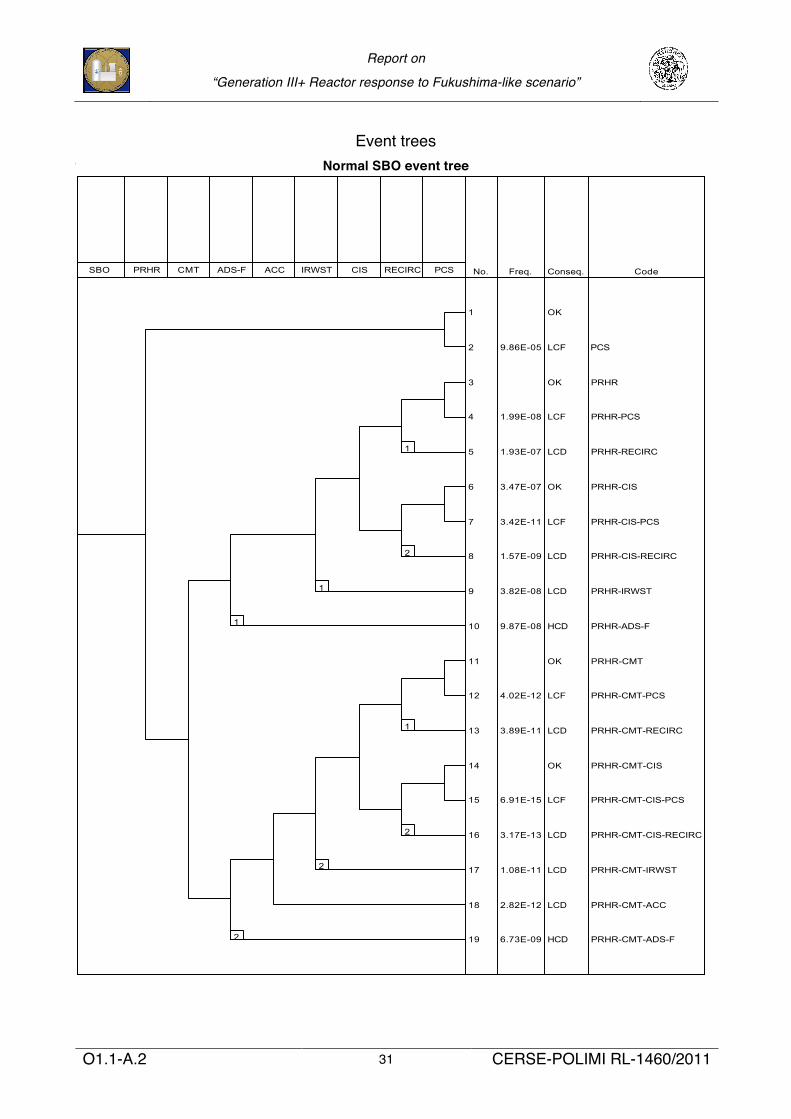
Two event trees are proposed for SBO following the indication of ENSREGʼs “stress tests”
l SBO
l Total SBO: SBO + loss of batteries (except batteries of DAS at 126`-33`` elevation)
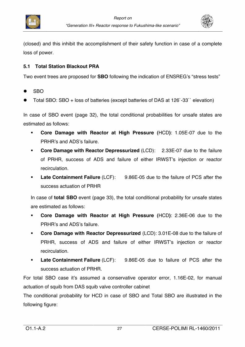
In case of SBO event (page 32), the total conditional probabilities for unsafe states are
estimated as follows:
§ Core Damage with Reactor at High Pressure (HCD): 1.05E-07 due to the
PRHRʼs and ADSʼs failure.
§ Core Damage with Reactor Depressurized (LCD): 2.33E-07 due to the failure
of PRHR, success of ADS and failure of either IRWSTʼs injection or reactor
recirculation.
§ Late Containment Failure (LCF): 9.86E-05 due to the failure of PCS after the
success actuation of PRHR
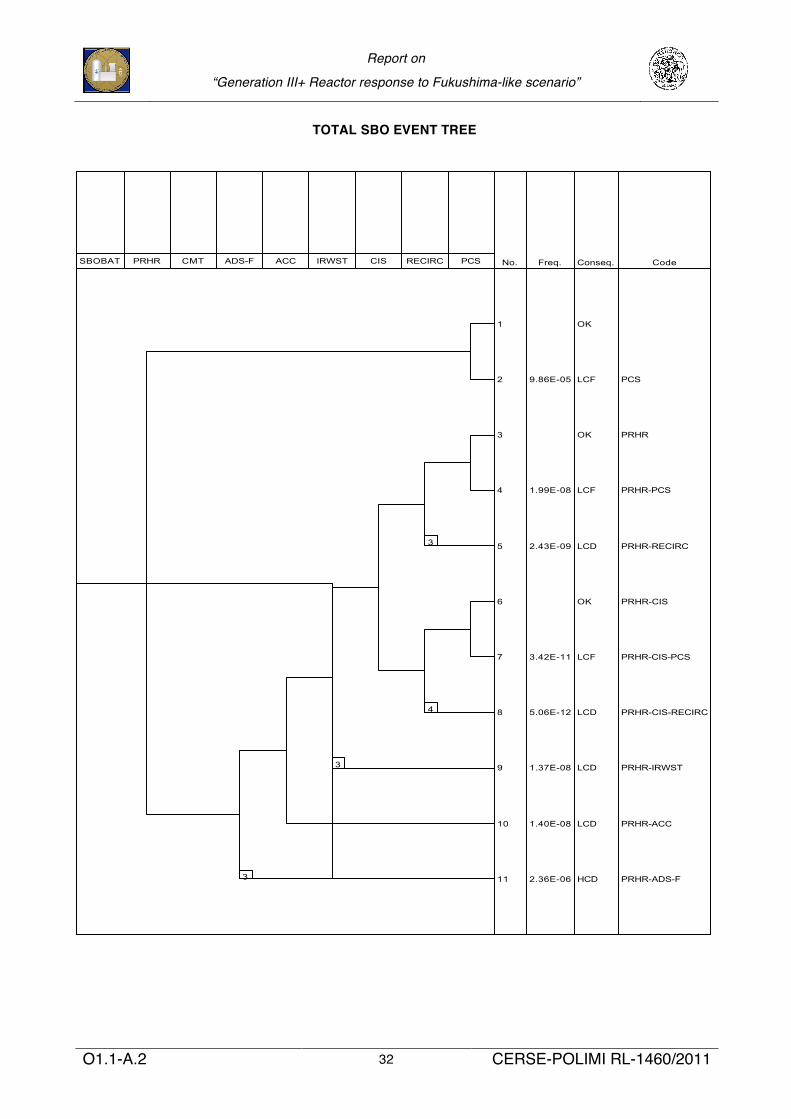
In case of total SBO event (page 33), the total conditional probability for unsafe states
are estimated as follows:
§ Core Damage with Reactor at High Pressure (HCD): 2.36E-06 due to the
PRHRʼs and ADSʼs failure.
§ Core Damage with Reactor Depressurized (LCD): 3.01E-08 due to the failure of
PRHR, success of ADS and failure of either IRWSTʼs injection or reactor
recirculation.
§ Late Containment Failure (LCF): 9.86E-05 due to failure of PCS after the
success actuation of PRHR.
For total SBO case itʼs assumed a conservative operator error, 1.16E-02, for manual
actuation of squib from DAS squib valve controller cabinet
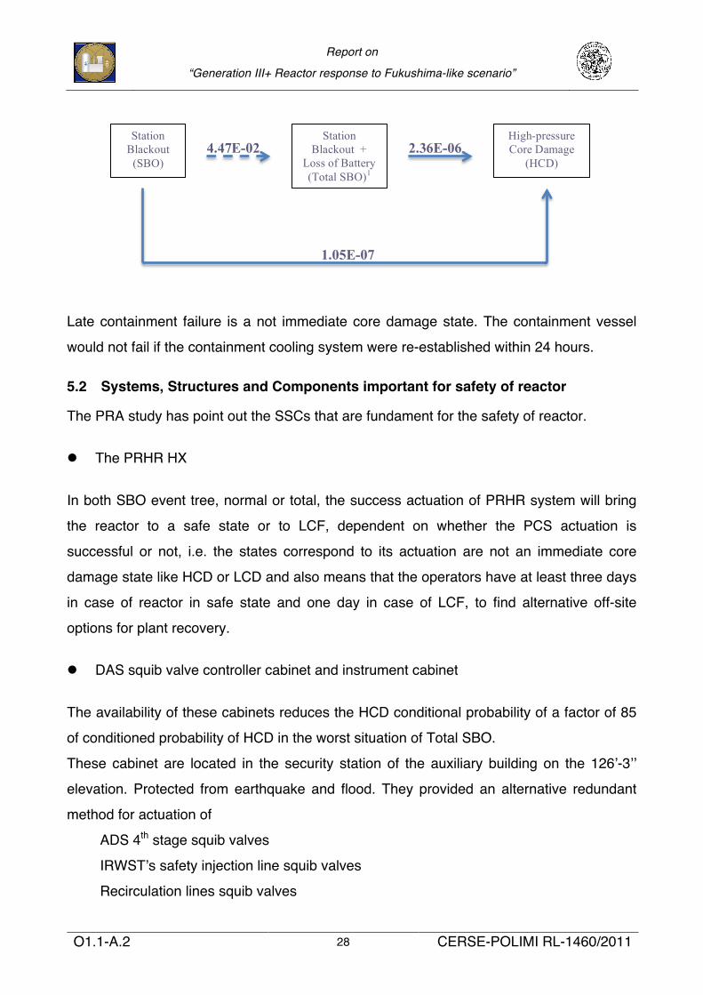
The conditional probability for HCD in case of SBO and Total SBO are illustrated in the
following figure:
Report on
“Generation III+ Reactor response to Fukushima-like scenario”
O1.1-A.2 28 CERSE-POLIMI RL-1460/2011
Late containment failure is a not immediate core damage state. The containment vessel
would not fail if the containment cooling system were re-established within 24 hours.
5.2 Systems, Structures and Components important for safety of reactor
The PRA study has point out the SSCs that are fundament for the safety of reactor.
l The PRHR HX
In both SBO event tree, normal or total, the success actuation of PRHR system will bring
the reactor to a safe state or to LCF, dependent on whether the PCS actuation is
successful or not, i.e. the states correspond to its actuation are not an immediate core
damage state like HCD or LCD and also means that the operators have at least three days
in case of reactor in safe state and one day in case of LCF, to find alternative off-site
options for plant recovery.
l DAS squib valve controller cabinet and instrument cabinet
The availability of these cabinets reduces the HCD conditional probability of a factor of 85
of conditioned probability of HCD in the worst situation of Total SBO.
These cabinet are located in the security station of the auxiliary building on the 126ʼ-3ʼʼ
elevation. Protected from earthquake and flood. They provided an alternative redundant
method for actuation of
ADS 4th stage squib valves
IRWSTʼs safety injection line squib valves
Recirculation lines squib valves
Station Blackout
(SBO)
Station Blackout +
Loss of Battery (Total SBO)1
High-pressure Core Damage
(HCD) 2.36E-06
1.05E-07
4.47E-02
Report on
“Generation III+ Reactor response to Fukushima-like scenario”
O1.1-A.2 29 CERSE-POLIMI RL-1460/2011
And they have their own battery supplies.
l The 24h and 72h Class 1E batteries
The Class 1E batteries availability reduces the HCD conditional probability of a factor of 20,
from 2.36E-06 (total SBO-no batteries) to 1.05E-07 (SBO-batteries available).
In AP1000 there are six banks of safety related Class 1E batteries, which power vital DC
and AC loads; AC loads are powered through an Uninterruptible Power Supply (UPS)
system. In particular the four banks of 24h batteries provide the alignment of valves (Air-
operated, Motor-operated, squib) to guarantee the operability of PXS, PCS and CNS while
the two banks of 72h batteries provide lighting for the Main Control Room and monitoring
critical instrumentation.
Report on
“Generation III+ Reactor response to Fukushima-like scenario”
O1.1-A.2 30 CERSE-POLIMI RL-1460/2011
6 Conclusion and considerations
In a severe accident situation, all auxiliary systems on-site could be destroyed and
damaged by earthquake and flood. AP1000 will resist for at least 3 days, since it relies on
passive systems.
The use of passive safety systems, which no dependent on active feature as pumps or
diesel neither on AC power, reduce significantly the probability of core damage even in a
Fukushima-like event. The conditional probability of a core damage starting from the worst
case of a total station blackout is still very low: estimated 2.38E-61. This means that the
plant maintains, in this severe condition, a robust set of mitigating safety features to
prevent core damage.
To gather the safety-related systems in a same basement of seismic category I and to put
the passive safety systems inside the steel containment vessel reduced significantly the
challenge from external hazards like flood and earthquake.
In addition the AP1000 has pre-built safety-related connections for off-site equipment
adopted for emergency procedures aimed to recover the reactor after 3 days. These
features have not been considered in the analysis but they can be used also to cope with a
Fukushima like accident.
The batteries and all equipment rooms necessary for activation of squib valves could be
more protected in event of flood by watertight doors.
Report on
“Generation III+ Reactor response to Fukushima-like scenario”
O1.1-A.2 31 CERSE-POLIMI RL-1460/2011
Event trees TOTAL SBO EVENT TREE 1
Normal SBO event tree SBO FLDSBO 17/11/2011
1
SBO FLDSBO 17/11/2011
1
Report on
“Generation III+ Reactor response to Fukushima-like scenario”
O1.1-A.2 32 CERSE-POLIMI RL-1460/2011
SBOBAT FLDSBO 17/11/2011
1
SBOBAT FLDSBO 17/11/2011
1
TOTAL SBO EVENT TREE
CIRTEN
Consorzio Interuniversitario per la Ricerca TEcnologica Nucleare
Lavoro svolto in esecuzione dell’Obiettivo 4.2 Attività A2 AdP MSE-ENEA sulla Ricerca di Sistema Elettrico- Piano Annuale di Realizzazione 2010
Progetto 1.3.2.a “Fissione nucleare: Metodi di analisi e verifica di progetti nucleari di generazione evolutiva alimentati ad acqua pressurizzata”
UNIVERSITY OF PISA
Analisi di affidabilità dei misuratori di flusso neutronico in-core
Autori
Francesco d'Errico
Riccardo Ciolini
CERSE-UNIPI RL 1513/2011
Pisa, Novembre 2011
2
Obiettivo 4.2 - Attività A.2 - Analisi di affidabilità dei misuratori di flusso neutronico in-core
Si dovrà condurre un'analisi di affidabilità su un insieme di misuratori neutronici preposti alla
ricostruzione della distribuzione del flusso all'interno del nocciolo. L'analisi si baserà sulle seguenti
ipotesi:
1) trattasi di un dispositivo elettronico con associato un suo tasso di guasto;
2) il dispositivo elettronico fornirà una misura distribuita secondo una distribuzione di probabilità di
tipo gaussiano;
3) a fronte di un guasto del dispositivo si suppone che sia noto di quanto il guasto del dispositivo
stesso aumenti l'errore da esso commesso. Verrà esaminato anche il caso in cui il flusso neutronico
(F) della zona considerata non sia una variabile aleatoria F, bensì un processo aleatorio F(t), come
nel caso in cui nel modello venga considerata la fisica del reattore.
3
Introduction
In the present work, a reliability analysis of Self-Powered Neutron Detectors (SPNDs), used to
measure the neutron flux distribution inside the reactor core, is performed with a Monte Carlo
technique. A brief overview is first given of the different types of nuclear reactor core
instrumentation, with particular reference to the SPND instrumentation used in the European
Pressurized Reactor (EPR).
The reliability analysis is based on the following hypothesis:
1) The detectors under consideration are electronic devices with a corresponding failure rate, which
can be different from detector to detector (in particular, a Gaussian probability distribution function
of the results of each measurements obtained with each detector can be simulated);
3) Based on the increment of the instrument error reading after a device failure, the evaluation of
the measurement error can be performed as a consequence of localized neutron flux variation,
whose time distribution can be obtained as a stochastic process or output of reactor physics
calculations.
1. Description of the of SPNDs
1.1 In-core and ex-core detectors
For nuclear reactors, a major component of reactor operation and safety is the ability to predict and
measure the nuclear power (or neutron flux) level and the three-dimensional distribution of power
in the core. The measurement of the power level is normally performed using ex-core
instrumentation, which give information only about the core integrated flux and provides signals to
monitor core criticality, while the determination of the spatial variation of the neutron flux, required
to control the axial power distribution, for core surveillance and protection and for fuel
management, is obtained with in-core instrumentation.
The Self-Powered Neutron Detectors (SPND) belong to the category of in-core nuclear reactor
instrumentation and they are part of the power reactor control system and the reactor safety system.
This type of detectors are generally sensitive to thermal neutrons and their fundamental properties is
their resistance to the extreme conditions inside the reactor core, which are normally not found in
all the other fields of nuclear measurements.
The reactor instrumentation is subdivided in two broad categories:
4
- in-core detectors;
- ex-core detectors.
The in-core detectors are located inside the coolant channels of the reactor core to measure the point
neutron flux level inside the core itself. They operate at very extreme conditions:
− neutron flux of 5·1013 n/(cm2s);
− gamma flux up to 108 R/h;
− operating temperature up to 300 °C;
− external operating pressure up to 170 bar.
Moreover, these detectors have to be very compact and miniaturized: for geometrical reasons, their
external dimensions are normally less than 10 mm.
The only type of detectors that can satisfy all the previous requirements are fission chambers or
self-powered neutron detectors (SPNDs), the latter are the subject of the present work.
This type of detectors can be repaired or replaced only during refuelling outages: this fact is
considered as a limiting factor in the detector reliability, compared to the ex-core instrumentation.
Ex-core detectors are positioned outside the core to measure quantities related to the integrated
neutron flux. These detectors can be inside or outside the vessel; in all cases their working
conditions are less severe than for in-core detectors and their dimensions are not strictly determined
by geometrical constraints.
The reactor instrumentation varies with the type of reactor, but there are some common aspects for
all types of plants. In particular three power levels can be identified:
1) initial startup range;
2) low power range;
3) power range.
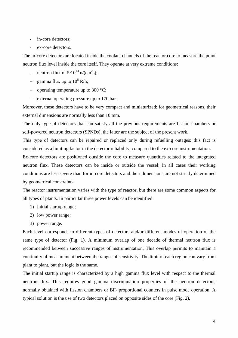
Each level corresponds to different types of detectors and/or different modes of operation of the
same type of detector (Fig. 1). A minimum overlap of one decade of thermal neutron flux is
recommended between successive ranges of instrumentation. This overlap permits to maintain a
continuity of measurement between the ranges of sensitivity. The limit of each region can vary from
plant to plant, but the logic is the same.
The initial startup range is characterized by a high gamma flux level with respect to the thermal
neutron flux. This requires good gamma discrimination properties of the neutron detectors,
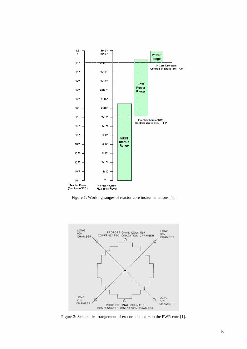
normally obtained with fission chambers or BF3 proportional counters in pulse mode operation. A
typical solution is the use of two detectors placed on opposite sides of the core (Fig. 2).
5
Figure 1: Working ranges of reactor core instrumentations [1].
Figure 2: Schematic arrangement of ex-core detectors in the PWR core [1].
6
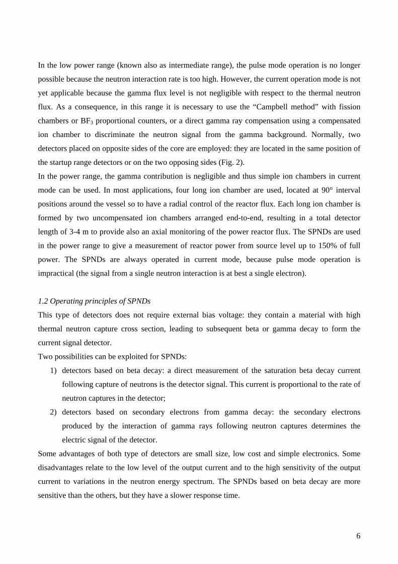
In the low power range (known also as intermediate range), the pulse mode operation is no longer
possible because the neutron interaction rate is too high. However, the current operation mode is not
yet applicable because the gamma flux level is not negligible with respect to the thermal neutron
flux. As a consequence, in this range it is necessary to use the “Campbell method” with fission
chambers or BF3 proportional counters, or a direct gamma ray compensation using a compensated
ion chamber to discriminate the neutron signal from the gamma background. Normally, two
detectors placed on opposite sides of the core are employed: they are located in the same position of
the startup range detectors or on the two opposing sides (Fig. 2).
In the power range, the gamma contribution is negligible and thus simple ion chambers in current
mode can be used. In most applications, four long ion chamber are used, located at 90° interval
positions around the vessel so to have a radial control of the reactor flux. Each long ion chamber is
formed by two uncompensated ion chambers arranged end-to-end, resulting in a total detector
length of 3-4 m to provide also an axial monitoring of the power reactor flux. The SPNDs are used
in the power range to give a measurement of reactor power from source level up to 150% of full
power. The SPNDs are always operated in current mode, because pulse mode operation is
impractical (the signal from a single neutron interaction is at best a single electron).
1.2 Operating principles of SPNDs
This type of detectors does not require external bias voltage: they contain a material with high
thermal neutron capture cross section, leading to subsequent beta or gamma decay to form the
current signal detector.
Two possibilities can be exploited for SPNDs:
1) detectors based on beta decay: a direct measurement of the saturation beta decay current
following capture of neutrons is the detector signal. This current is proportional to the rate of
neutron captures in the detector;
2) detectors based on secondary electrons from gamma decay: the secondary electrons
produced by the interaction of gamma rays following neutron captures determines the
electric signal of the detector.
Some advantages of both type of detectors are small size, low cost and simple electronics. Some
disadvantages relate to the low level of the output current and to the high sensitivity of the output
current to variations in the neutron energy spectrum. The SPNDs based on beta decay are more
sensitive than the others, but they have a slower response time.
7
In self-powered detectors, the effects of neutron and gamma-ray interactions occurring in the
connection cable can be quite significant. Normally, the SPND is connected to an amplifier by a
twin lead coaxial cable (compensation wire) for the elimination of the gamma background (a
current produced as a result of the cable irradiation): one lead is connected through the cable to the
emitter, whereas the other is included within the same cable but it terminates without electrical
contact physically near the emitter. The signal is obtained by electronic subtraction of the
unconnected lead signal from the current detected from the lead connected to the emitter. The use of
a single cable is also possible.
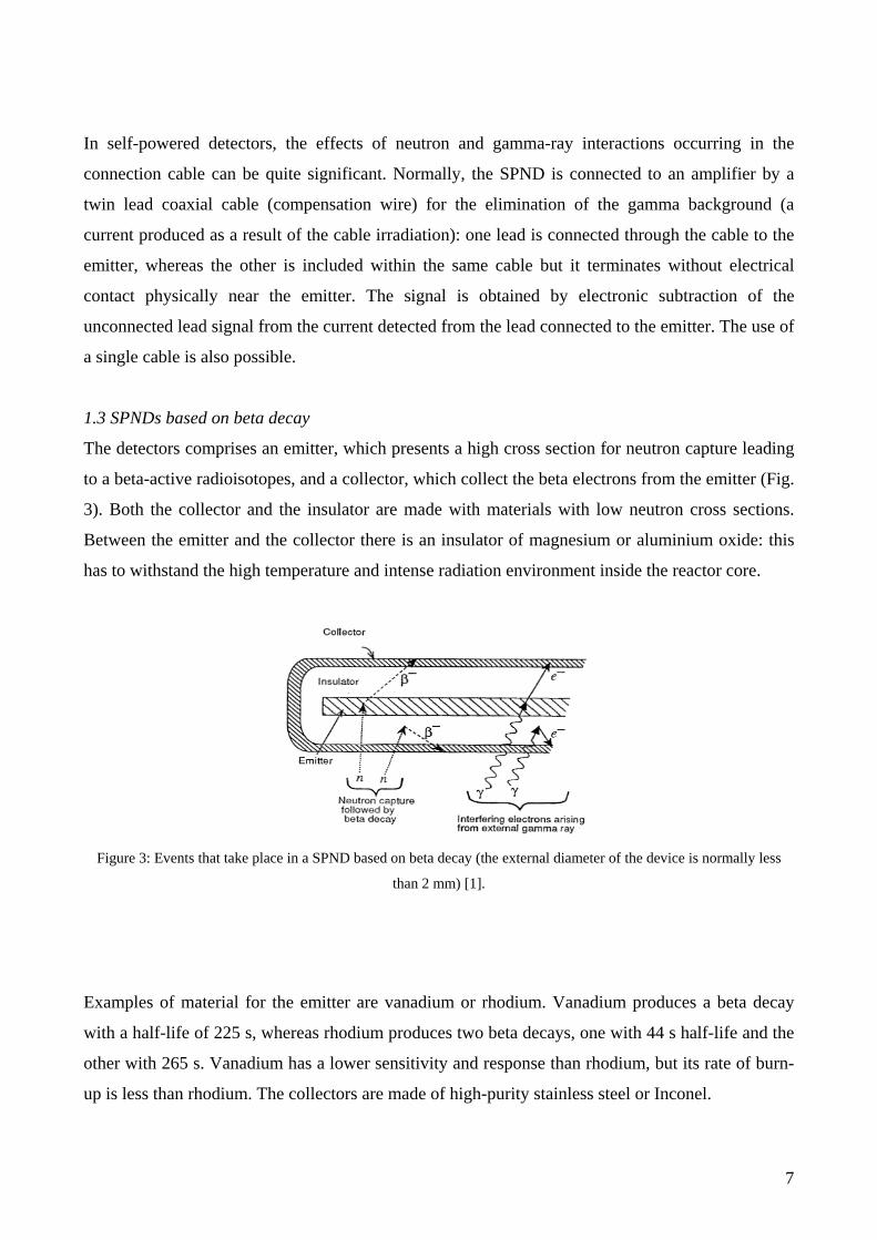
1.3 SPNDs based on beta decay
The detectors comprises an emitter, which presents a high cross section for neutron capture leading
to a beta-active radioisotopes, and a collector, which collect the beta electrons from the emitter (Fig.
3). Both the collector and the insulator are made with materials with low neutron cross sections.
Between the emitter and the collector there is an insulator of magnesium or aluminium oxide: this
has to withstand the high temperature and intense radiation environment inside the reactor core.
Figure 3: Events that take place in a SPND based on beta decay (the external diameter of the device is normally less
than 2 mm) [1].
Examples of material for the emitter are vanadium or rhodium. Vanadium produces a beta decay
with a half-life of 225 s, whereas rhodium produces two beta decays, one with 44 s half-life and the
other with 265 s. Vanadium has a lower sensitivity and response than rhodium, but its rate of burn-
up is less than rhodium. The collectors are made of high-purity stainless steel or Inconel.
8
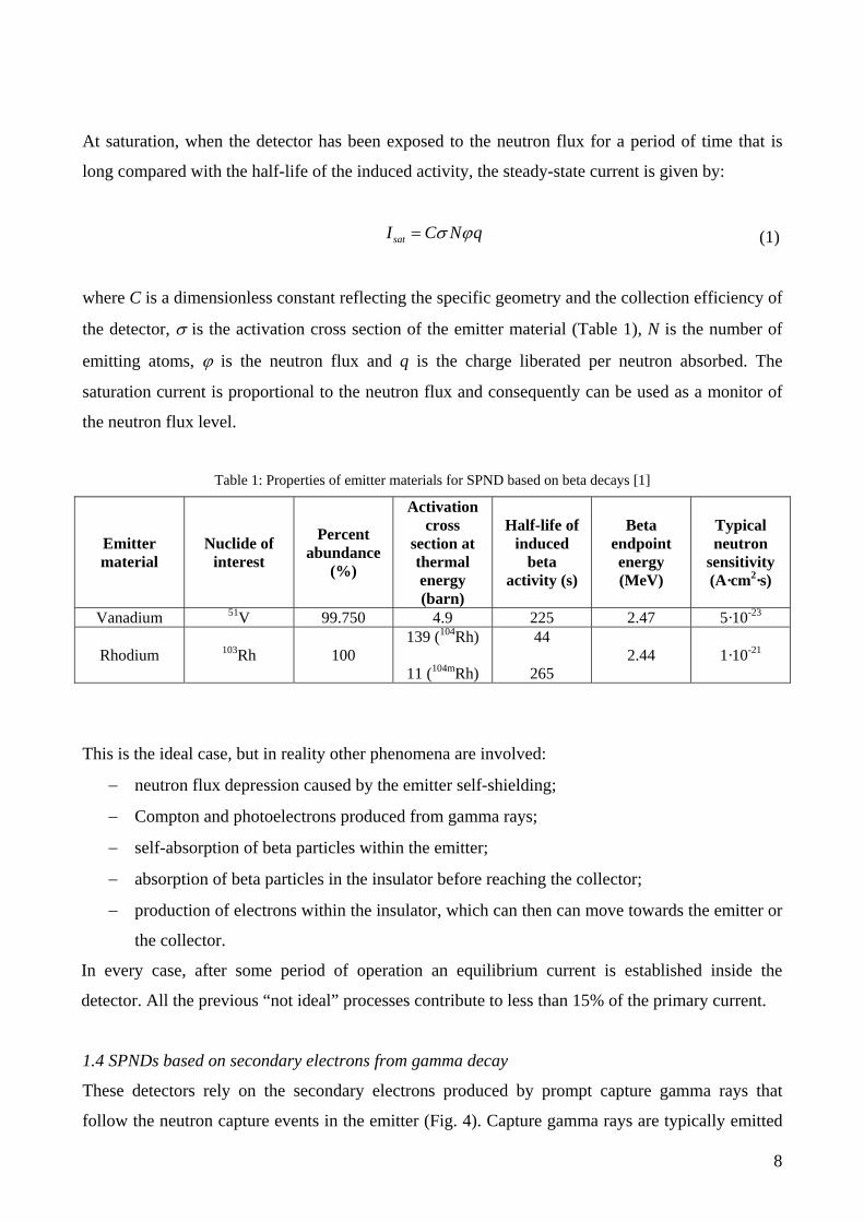
At saturation, when the detector has been exposed to the neutron flux for a period of time that is
long compared with the half-life of the induced activity, the steady-state current is given by:
satI C N qσ ϕ= (1)
where C is a dimensionless constant reflecting the specific geometry and the collection efficiency of
the detector, σ is the activation cross section of the emitter material (Table 1), N is the number of
emitting atoms, ϕ is the neutron flux and q is the charge liberated per neutron absorbed. The
saturation current is proportional to the neutron flux and consequently can be used as a monitor of
the neutron flux level.
Table 1: Properties of emitter materials for SPND based on beta decays [1]
Emitter material
Nuclide of interest
Percent abundance
(%)
Activation cross
section at thermal energy (barn)
Half-life of induced
beta activity (s)
Beta endpoint energy (MeV)
Typical neutron
sensitivity (A·cm2·s)
Vanadium 51V 99.750 4.9 225 2.47 5·10-23
Rhodium 103Rh 100 139 (104Rh)
11 (104mRh)
44
265 2.44 1·10-21
This is the ideal case, but in reality other phenomena are involved:
− neutron flux depression caused by the emitter self-shielding;
− Compton and photoelectrons produced from gamma rays;
− self-absorption of beta particles within the emitter;
− absorption of beta particles in the insulator before reaching the collector;
− production of electrons within the insulator, which can then can move towards the emitter or
the collector.
In every case, after some period of operation an equilibrium current is established inside the
detector. All the previous “not ideal” processes contribute to less than 15% of the primary current.
1.4 SPNDs based on secondary electrons from gamma decay
These detectors rely on the secondary electrons produced by prompt capture gamma rays that
follow the neutron capture events in the emitter (Fig. 4). Capture gamma rays are typically emitted
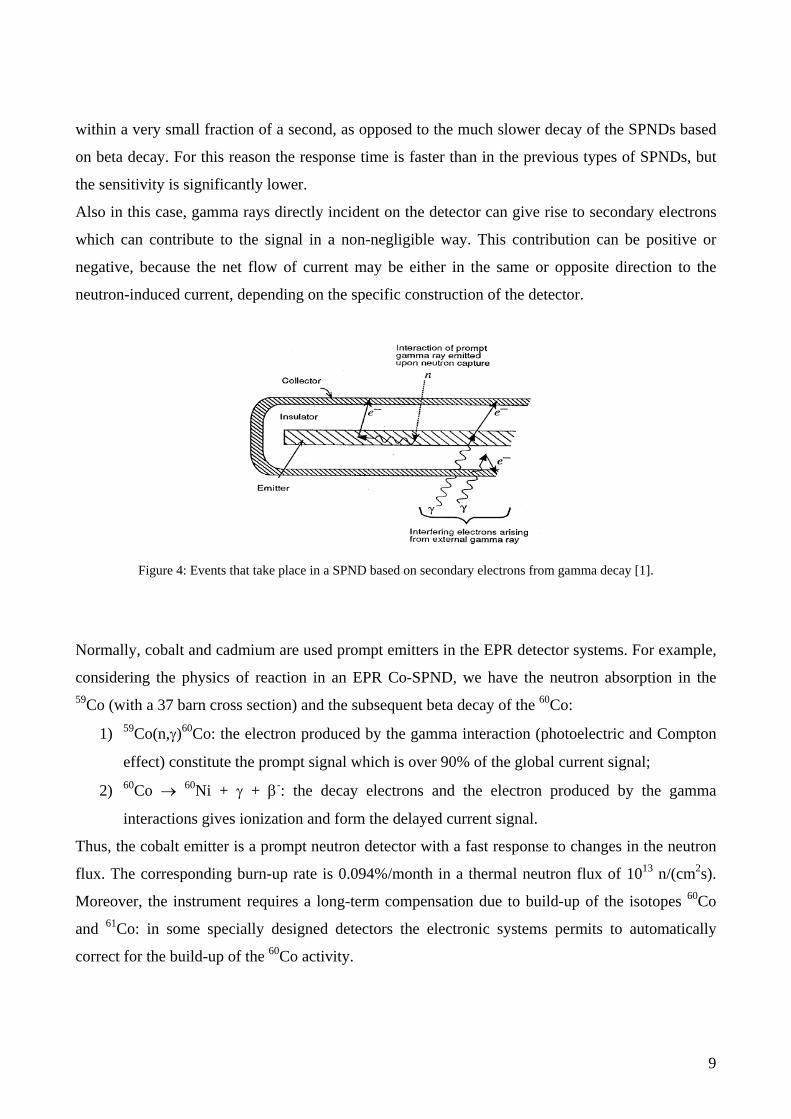
9
within a very small fraction of a second, as opposed to the much slower decay of the SPNDs based
on beta decay. For this reason the response time is faster than in the previous types of SPNDs, but
the sensitivity is significantly lower.
Also in this case, gamma rays directly incident on the detector can give rise to secondary electrons
which can contribute to the signal in a non-negligible way. This contribution can be positive or
negative, because the net flow of current may be either in the same or opposite direction to the
neutron-induced current, depending on the specific construction of the detector.
Figure 4: Events that take place in a SPND based on secondary electrons from gamma decay [1].
Normally, cobalt and cadmium are used prompt emitters in the EPR detector systems. For example,
considering the physics of reaction in an EPR Co-SPND, we have the neutron absorption in the 59Co (with a 37 barn cross section) and the subsequent beta decay of the 60Co:
1) 59Co(n,γ)60Co: the electron produced by the gamma interaction (photoelectric and Compton
effect) constitute the prompt signal which is over 90% of the global current signal;
2) 60Co → 60Ni + γ + β-: the decay electrons and the electron produced by the gamma
interactions gives ionization and form the delayed current signal.
Thus, the cobalt emitter is a prompt neutron detector with a fast response to changes in the neutron
flux. The corresponding burn-up rate is 0.094%/month in a thermal neutron flux of 1013 n/(cm2s).
Moreover, the instrument requires a long-term compensation due to build-up of the isotopes 60Co
and 61Co: in some specially designed detectors the electronic systems permits to automatically
correct for the build-up of the 60Co activity.
10
2. EPR in-core instrumentation In the EPR, the fixed in-core instrumentation consists of neutron detectors and thermocouples to
measure the neutron flux radial and axial distribution in the core, and temperature radial distribution
at the core outlet, respectively.
The core outlet thermocouples measure the fuel assembly outlet temperature and provide signals for
core monitoring in case of loss-of-coolant event; they also provide information on radial power
distribution and thermal-hydraulic local conditions. Relying on temperature measurements in the
cold and hot legs of the four primary loops, a quadruple-redundant primary heat balance is achieved
and complemented by neutron flux measurements with very short response time.
Prediction and measurement of the three-dimensional power distribution relies on two types of in-
core instrumentation [2]:
− “movable” reference instrumentation validates the core design and calibrates other core
surveillance and protection sensors;
− “fixed” instrumentation delivers online information to the surveillance and protection
systems, which actuate appropriate actions and countermeasures in case of anomalies or
exceeding of predefined limits.
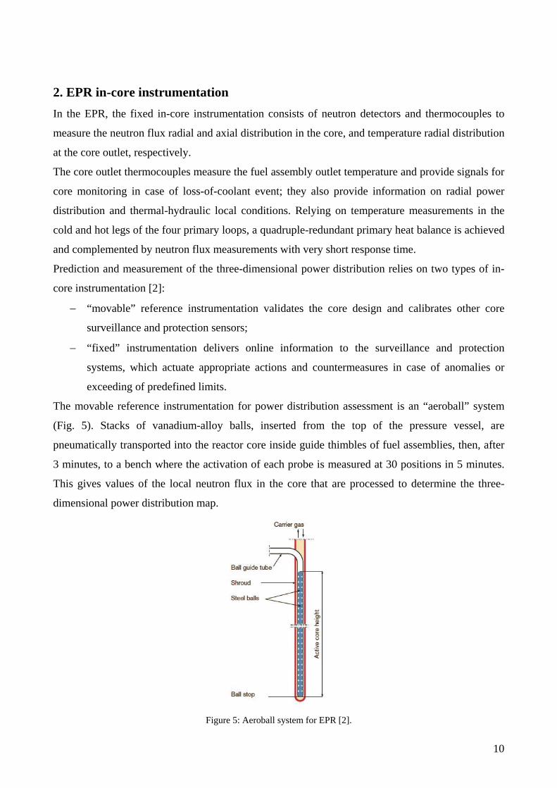
The movable reference instrumentation for power distribution assessment is an “aeroball” system
(Fig. 5). Stacks of vanadium-alloy balls, inserted from the top of the pressure vessel, are
pneumatically transported into the reactor core inside guide thimbles of fuel assemblies, then, after
3 minutes, to a bench where the activation of each probe is measured at 30 positions in 5 minutes.
This gives values of the local neutron flux in the core that are processed to determine the three-
dimensional power distribution map.
Figure 5: Aeroball system for EPR [2].
11
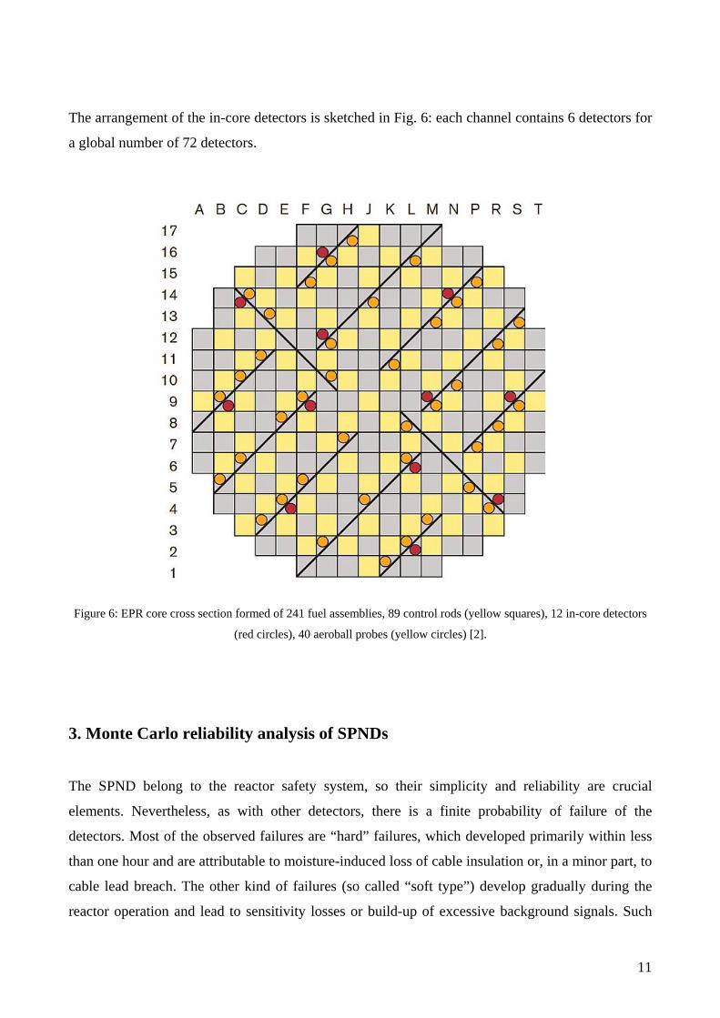
The arrangement of the in-core detectors is sketched in Fig. 6: each channel contains 6 detectors for
a global number of 72 detectors.
Figure 6: EPR core cross section formed of 241 fuel assemblies, 89 control rods (yellow squares), 12 in-core detectors
(red circles), 40 aeroball probes (yellow circles) [2].
3. Monte Carlo reliability analysis of SPNDs
The SPND belong to the reactor safety system, so their simplicity and reliability are crucial
elements. Nevertheless, as with other detectors, there is a finite probability of failure of the
detectors. Most of the observed failures are “hard” failures, which developed primarily within less
than one hour and are attributable to moisture-induced loss of cable insulation or, in a minor part, to
cable lead breach. The other kind of failures (so called “soft type”) develop gradually during the
reactor operation and lead to sensitivity losses or build-up of excessive background signals. Such
12
failures do not compromise plant availability, but they can determine errors in the neutron flux
evaluation. A sum of soft errors can be considered equivalent to a hard error.
In the present work, we considered hard failures that determine the malfunction of the detector. The
object of the work was evaluating if the SPND system can guarantee a functional reliability even if
the individual detectors perform imperfectly. The two main design principles adopted for SPNDs
can help to this purpose:
- in-situ calibration capability, allowing detector signals to be checked at any time, greatly
aiding detector performance assessment
- redundancy allowing part of the SPNDs to be dispensed with if the need should arise.
As explained in the introduction, we assumed a known failure rate considering the cumulative
experience with SPNDs in German 1300 MWe plants which shows a failure rate of typically 2% per
operating year. The assumed EPR positions of the SPND instrumentation are shown in Fig. 6.
3.1 Description of the Monte Carlo method
The SPND-EPR system reliability is simulated with an ad-hoc Monte Carlo code. It is assumed that
the reliability values for each detector is known: the rate of failure is assumed to be 2%/year as with
German PWRs [2]. Each detector can be considered an independent system: the failure of a detector
is assumed to be independent on the failure of the other in-core detectors. The flexibility of the code
permit to manage also situations in which the failure of one detector can influence the answer of the
other detectors: the system is more complex but the method can work the same way. Using a known
component reliability, with the Monte Carlo code it is possible to evaluate the reliability of the
entire detector system.
The Monte Carlo method generates random failure times from each detector’s failure distribution
probability. Generating a large number of these configurations, for the central limit theorem, the
EPR detector system reliability is obtained with the Monte Carlo simulation.
In a first simple case, the probability for each detector to fail at a time t is the product of the
probability to survive up to the time t multiplied by the probability to fail in the interval between t
and t + dt. This is assumed to be:
/1( ) τ
τ−= tp t e (2)
where τ is the average life of each detector, calculated as the inverse of the number of failure in a
considered period, one year in the present case (for example, if the failure rate is 2% at year, the
13
average life of each detector is 50 years). From equation (2) it is possible to calculate the
cumulative probability as follows:
/ /
0 0
1( ) ( ) 1τ τ
τ− −= = = −∫ ∫
t tt tP t p t e e (3)
which represents the probability to have a failure time shorter than t. It is easy to verify the
normalization condition:
( ) 1∞ =P (4)
Now considering a random number uniformly distributed between 0 and 1, we can write:
/( ) 1 τ−= − =tP t e r (5)
from which we obtain the failure time:
( )log 1τ= − −t r (6)
If the failure time is shorter than the time increment, a failure will be counted. The same method can
be used without any restrictions for the probability distribution functions of other types of detector
failure.
3.2 Monte Carlo reliability simulation procedure
The code comprises an inner loop and an outer loop of iterations: each inner loop iteration
corresponds to the generation of a random number for one of the Nd = 72 detectors, i.e. the
determination of the failure time of the detectors. For each inner loop, the number of failure in the
considered period is evaluated. The number of outer loops Ne is the number of repetitions of the
inner loop: it corresponds to the number of simulation points to be generated for each component.
By repeating the cycle (outer loop) a large number of times, the number of failure in the considered
period is calculated.
The simulation procedure is composed of the following steps:
1) selection of the number of outer loops (Monte Carlo iteration);
2) start of the internal loop: generation of a random number for each detector;
14
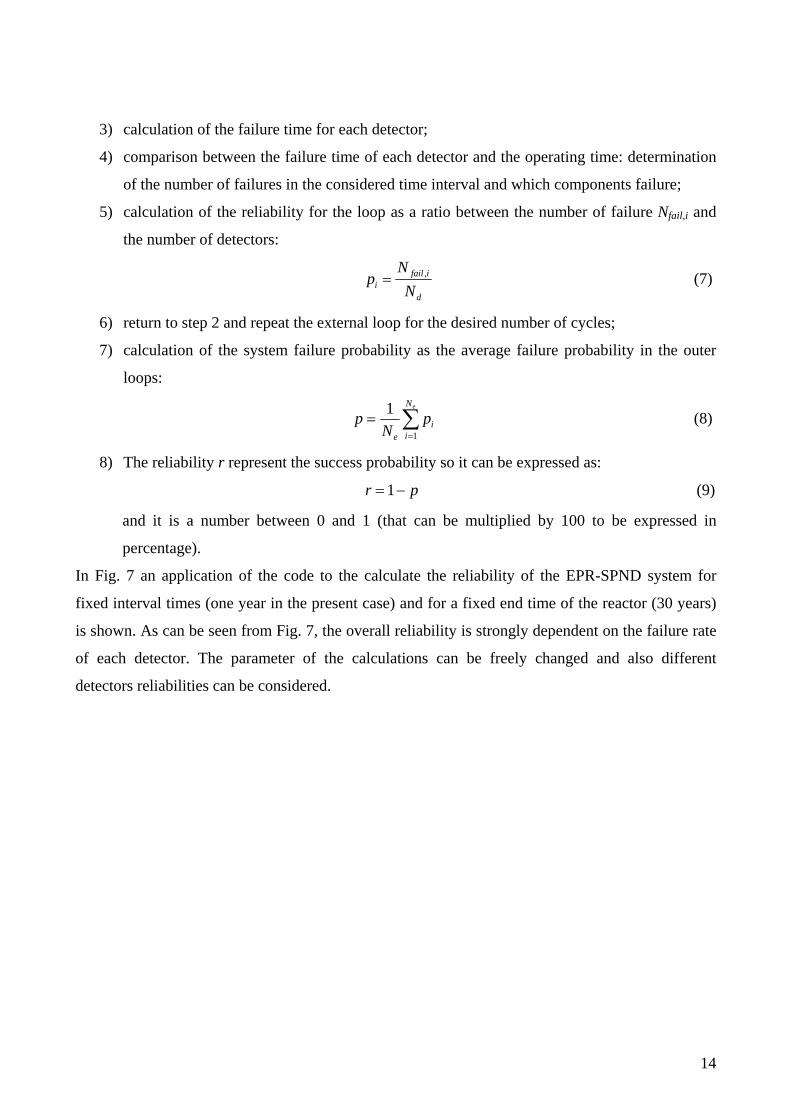
3) calculation of the failure time for each detector;
4) comparison between the failure time of each detector and the operating time: determination
of the number of failures in the considered time interval and which components failure;
5) calculation of the reliability for the loop as a ratio between the number of failure Nfail,i and
the number of detectors:
,= fail ii
d
Np
N (7)
6) return to step 2 and repeat the external loop for the desired number of cycles;
7) calculation of the system failure probability as the average failure probability in the outer
loops:
1
1=
= ∑eN
iie
p pN
(8)
8) The reliability r represent the success probability so it can be expressed as:
1= −r p (9)
and it is a number between 0 and 1 (that can be multiplied by 100 to be expressed in
percentage).
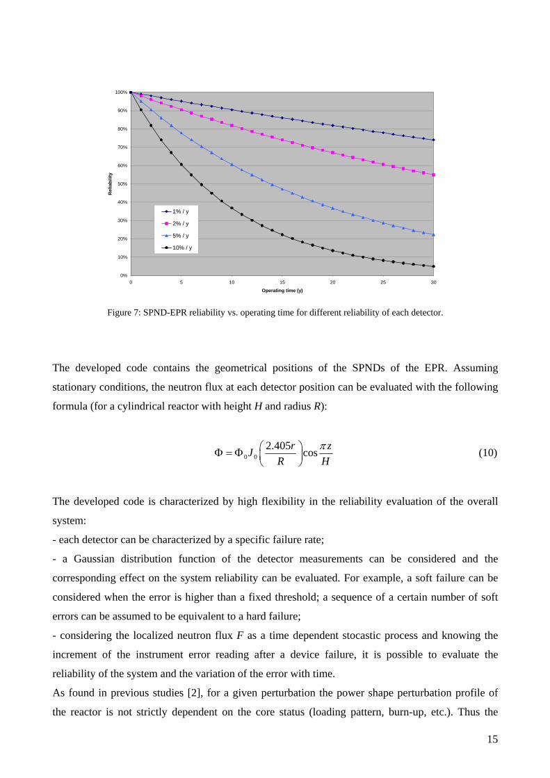
In Fig. 7 an application of the code to the calculate the reliability of the EPR-SPND system for
fixed interval times (one year in the present case) and for a fixed end time of the reactor (30 years)
is shown. As can be seen from Fig. 7, the overall reliability is strongly dependent on the failure rate
of each detector. The parameter of the calculations can be freely changed and also different
detectors reliabilities can be considered.
15
0%
10%
20%
30%
40%
50%
60%
70%
80%
90%
100%
0 5 10 15 20 25 30
Operating time (y)
Rel
iabi
lity
1% / y
2% / y
5% / y
10% / y
Figure 7: SPND-EPR reliability vs. operating time for different reliability of each detector.
The developed code contains the geometrical positions of the SPNDs of the EPR. Assuming
stationary conditions, the neutron flux at each detector position can be evaluated with the following
formula (for a cylindrical reactor with height H and radius R):
0 02.405 cosπ⎛ ⎞Φ = Φ ⎜ ⎟
⎝ ⎠r zJ
R H (10)
The developed code is characterized by high flexibility in the reliability evaluation of the overall
system:
- each detector can be characterized by a specific failure rate;
- a Gaussian distribution function of the detector measurements can be considered and the
corresponding effect on the system reliability can be evaluated. For example, a soft failure can be
considered when the error is higher than a fixed threshold; a sequence of a certain number of soft
errors can be assumed to be equivalent to a hard failure;
- considering the localized neutron flux F as a time dependent stocastic process and knowing the
increment of the instrument error reading after a device failure, it is possible to evaluate the
reliability of the system and the variation of the error with time.
As found in previous studies [2], for a given perturbation the power shape perturbation profile of
the reactor is not strictly dependent on the core status (loading pattern, burn-up, etc.). Thus the

16
tracking accuracy of the SPNDs, i.e. the error in the evaluation of the reactor power or in the
evaluation of LPD (Local Power Distribution) and DNBR (Departure from Nuclear Boiling Ratio),
is a property of the monitoring system itself .

17
Bibliography
[1] Knoll G.F., Radiation detection and measurements, John Wiley & Sons, 1989.
[2] Düweke C., Thillosen N., Ziethe J., Neutron flux incore instrumentation of AREVA’s EPRTM,
First International Conference on “Advancements in Nuclear Instrumentation Measurement
Methods and their Applications (ANIMMA)”, 7-10 June 2009, pages 1-6, IEEE 2009.
18
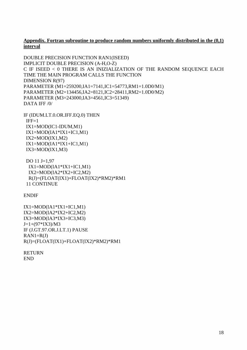
Appendix. Fortran subroutine to produce random numbers uniformly distributed in the (0,1) interval DOUBLE PRECISION FUNCTION RAN1(ISEED) IMPLICIT DOUBLE PRECISION (A-H,O-Z) C IF ISEED < 0 THERE IS AN INIZIALIZATION OF THE RANDOM SEQUENCE EACH TIME THE MAIN PROGRAM CALLS THE FUNCTION DIMENSION R(97) PARAMETER (M1=259200,IA1=7141,IC1=54773,RM1=1.0D0/M1) PARAMETER (M2=134456,IA2=8121,IC2=28411,RM2=1.0D0/M2) PARAMETER (M3=243000,IA3=4561,IC3=51349) DATA IFF /0/ IF (IDUM.LT.0.OR.IFF.EQ.0) THEN IFF=1 IX1=MOD(IC1-IDUM,M1) IX1=MOD(IA1*IX1+IC1,M1) IX2=MOD(IX1,M2) IX1=MOD(IA1*IX1+IC1,M1) IX3=MOD(IX1,M3) DO 11 J=1,97 IX1=MOD(IA1*IX1+IC1,M1) IX2=MOD(IA2*IX2+IC2,M2) R(J)=(FLOAT(IX1)+FLOAT(IX2)*RM2)*RM1 11 CONTINUE ENDIF IX1=MOD(IA1*IX1+IC1,M1) IX2=MOD(IA2*IX2+IC2,M2) IX3=MOD(IA3*IX3+IC3,M3) J=1+(97*IX3)/M3 IF (J.GT.97.OR.J.LT.1) PAUSE RAN1=R(J) R(J)=(FLOAT(IX1)+FLOAT(IX2)*RM2)*RM1 RETURN END