Organizzazione pipeline della CPU - diit.unict.it · D. A. Patterson, J.L. Hennessy, “Struttura e...
53
Calcolatori Elettronici 1 Prof. G. Ascia Organizzazione pipeline della CPU Riferimento: D. A. Patterson, J.L. Hennessy, “Struttura e Progetto dei Calcolatori – L'interfaccia Hardware-Software” -II edizione Zanichelli editore, ISBN: 8808091457
Transcript of Organizzazione pipeline della CPU - diit.unict.it · D. A. Patterson, J.L. Hennessy, “Struttura e...
Calcolatori Elettronici 1
Prof. G. Ascia
Organizzazione pipeline della CPU
Riferimento: D. A. Patterson, J.L. Hennessy, “Struttura e Progetto dei Calcolatori – L'interfaccia Hardware-Software” -II edizione Zanichelli editore, ISBN: 8808091457
Calcolatori Elettronici 2
Prof. G. Ascia
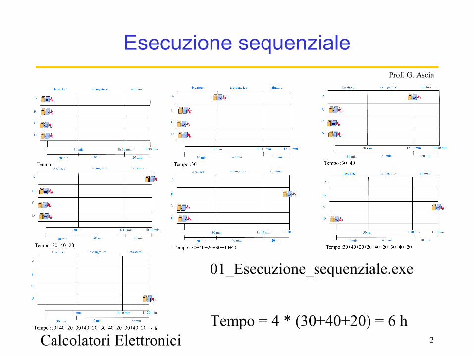
Esecuzione sequenziale
Tempo = 4 * (30+40+20) = 6 h
01_Esecuzione_sequenziale.exe
Calcolatori Elettronici 3
Prof. G. Ascia
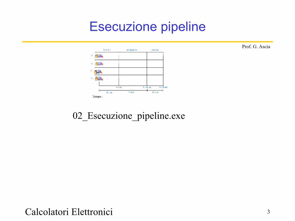
Esecuzione pipeline
02_Esecuzione_pipeline.exe
Calcolatori Elettronici 4
Prof. G. Ascia
Pipeline
• Il pipeline non riduce la latenza del singolo task, aumenta il throughput dell’intero workload
• Il pipeline rate è limitato dal più lento pipeline stage• Più task operano simultaneamente• Potenziale miglioramento = Numero di pipe stages• Lunghezze non bilanciate dei pipeline stages riducono il
miglioramento
Calcolatori Elettronici 5
Prof. G. Ascia
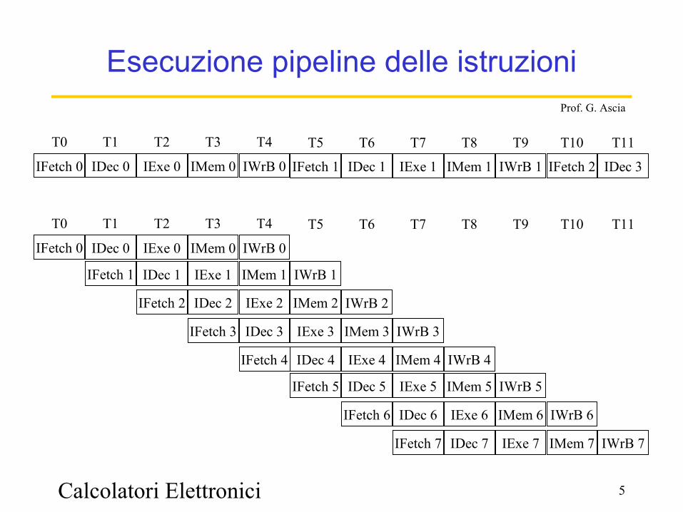
Esecuzione pipeline delle istruzioni
IFetch 0
T0
IDec 0
T1
IExe 0
T2
IMem 0
T3
IWrB 0
T4
IFetch 1
T5
IDec 1
T6
IExe 1
T7
IMem 1
T8
IWrB 1
T9
IFetch 2
T10
IDec 3
T11
IFetch 0
T0
IDec 0
T1
IFetch 1
IExe 0
T2
IDec 1
IFetch 2
IMem 0
T3
IExe 1
IDec 2
IFetch 3
IWrB 0
T4
IMem 1
IExe 2
IDec 3
IFetch 4
IWrB 1
IMem 2
IExe 3
IDec 4
T5
IFetch 5
IWrB 2
IMem 3
IExe 4
T6
IDec 5
IFetch 6
IWrB 3
IMem 4
T7
IExe 5
IDec 6
IFetch 7
IWrB 4
T8
IMem 5
IExe 6
IDec 7
T9
IWrB 5
IMem 6
IExe 7
T10
IWrB 6
IMem 7
T11
IWrB 7
Calcolatori Elettronici 6
Prof. G. Ascia
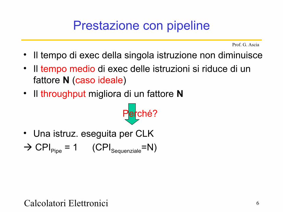
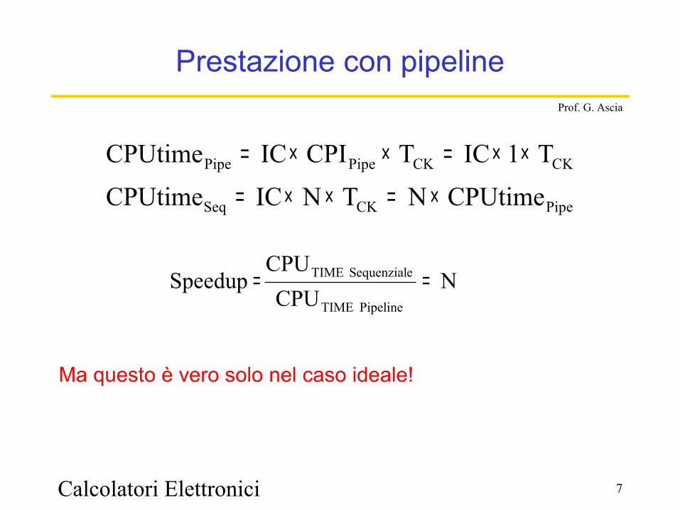
Prestazione con pipeline
• Il tempo di exec della singola istruzione non diminuisce• Il tempo medio di exec delle istruzioni si riduce di un
fattore N (caso ideale)• Il throughput migliora di un fattore N
• Una istruz. eseguita per CLK CPIPipe = 1 (CPISequenziale=N)
Perché?
Calcolatori Elettronici 7
Prof. G. Ascia
Prestazione con pipeline
PipeCKSeq
CKCKPipePipe
CPUtimeNTNICCPUtime
T1ICTCPIICCPUtime
×=××=
××=××=
Ma questo è vero solo nel caso ideale!
NCPU
CPUSpeedup
Pipeline TIME
eSequenzial TIME ==
8
Prof. G. Ascia
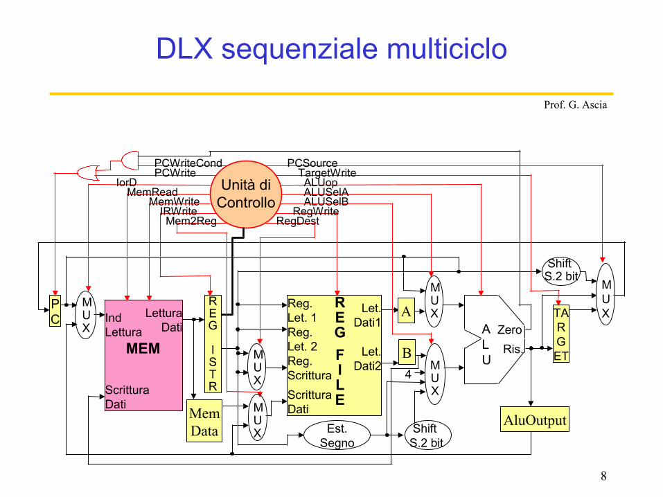
DLX sequenziale multiciclo
PC
MUX
Ind Lettura
ScritturaDati
Lettura Dati
MEM
REG
ISTR
Reg. Let. 1
Reg.ScritturaScritturaDati
Let. Dati1
MUX
MUX
Reg. Let. 2 Let.
Dati2
MUX
MUX
ALU
Est.Segno
Shift S.2 bit
ZeroRis.
REGFILE
Shift S.2 bit
TARGET
MUX
Unità di Controllo
RegDestRegWrite
ALUSelBALUSelAALUop
TargetWritePCSource
Mem2RegIRWrite
MemWriteMemRead
IorDPCWritePCWriteCond
A
B
AluOutputMemData
4
Calcolatori Elettronici 9
Prof. G. Ascia
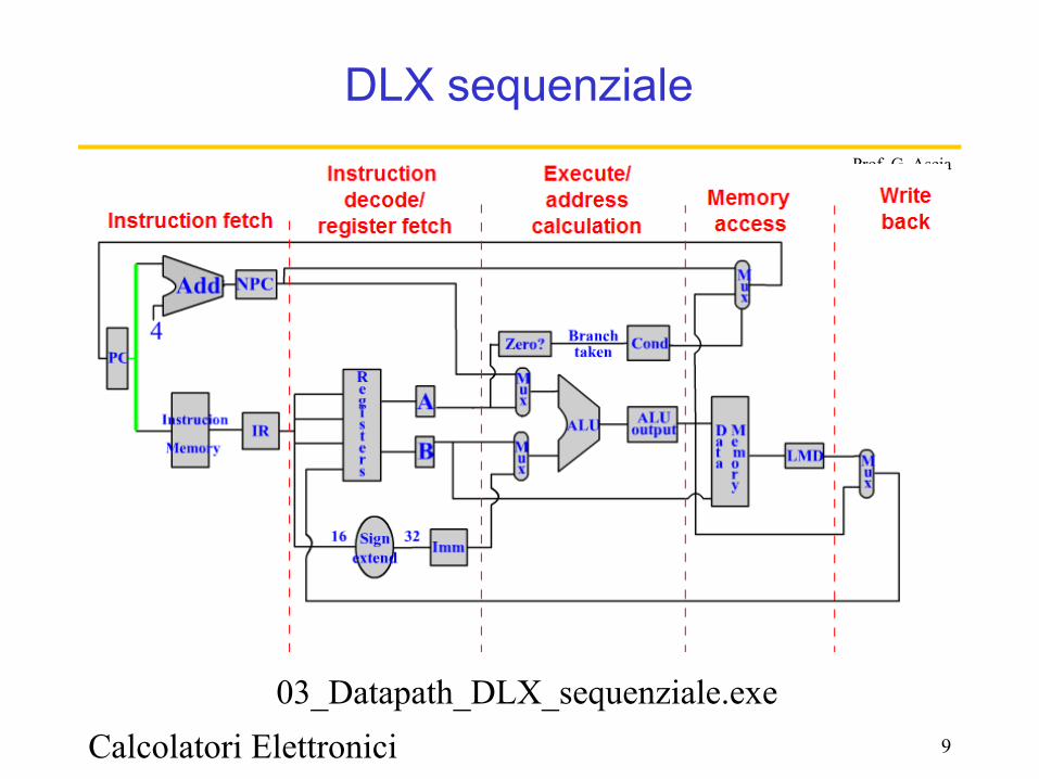
DLX sequenziale
03_Datapath_DLX_sequenziale.exe

Calcolatori Elettronici 10
Prof. G. Ascia
DLX pipeline
4
Add
Signextend
16 32
RegFile
ALU
Zero?Branch
taken
IF/ID
IR 6..10
IR11..15
ID/EX EX/MEM
IR
MEM/WB
M e m o r y
PC
MUX
MUX
MUX
M e m o r y
MUX
Calcolatori Elettronici 11
Prof. G. Ascia
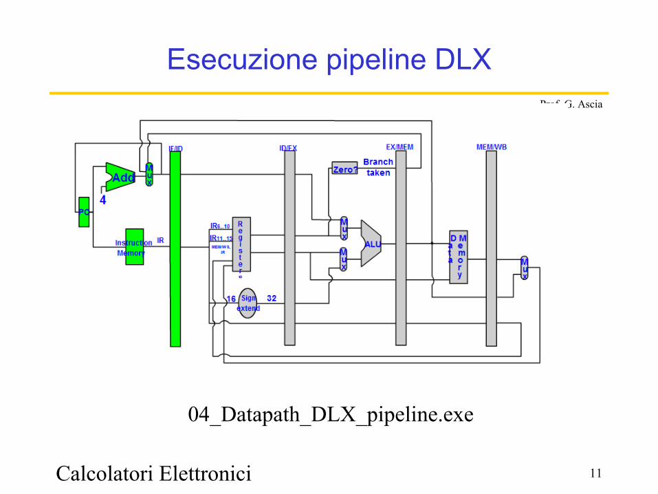
Esecuzione pipeline DLX
04_Datapath_DLX_pipeline.exe
Calcolatori Elettronici 12
Prof. G. Ascia
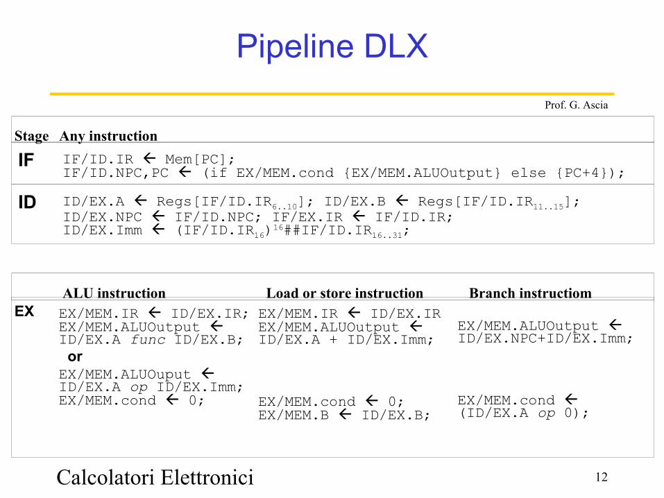
Pipeline DLX
Stage Any instruction
IF IF/ID.IR Mem[PC];IF/ID.NPC,PC (if EX/MEM.cond {EX/MEM.ALUOutput} else {PC+4});
ID ID/EX.A Regs[IF/ID.IR6..10]; ID/EX.B Regs[IF/ID.IR11..15];ID/EX.NPC IF/ID.NPC; IF/EX.IR IF/ID.IR;ID/EX.Imm (IF/ID.IR16)16##IF/ID.IR16..31;
ALU instruction Load or store instruction Branch instructiomEX EX/MEM.IR ID/EX.IR;
EX/MEM.ALUOutput ID/EX.A func ID/EX.B; orEX/MEM.ALUOuput ID/EX.A op ID/EX.Imm;EX/MEM.cond 0;
EX/MEM.IR ID/EX.IREX/MEM.ALUOutput ID/EX.A + ID/EX.Imm;
EX/MEM.cond 0;EX/MEM.B ID/EX.B;
EX/MEM.ALUOutput ID/EX.NPC+ID/EX.Imm;
EX/MEM.cond (ID/EX.A op 0);
Calcolatori Elettronici 13
Prof. G. Ascia
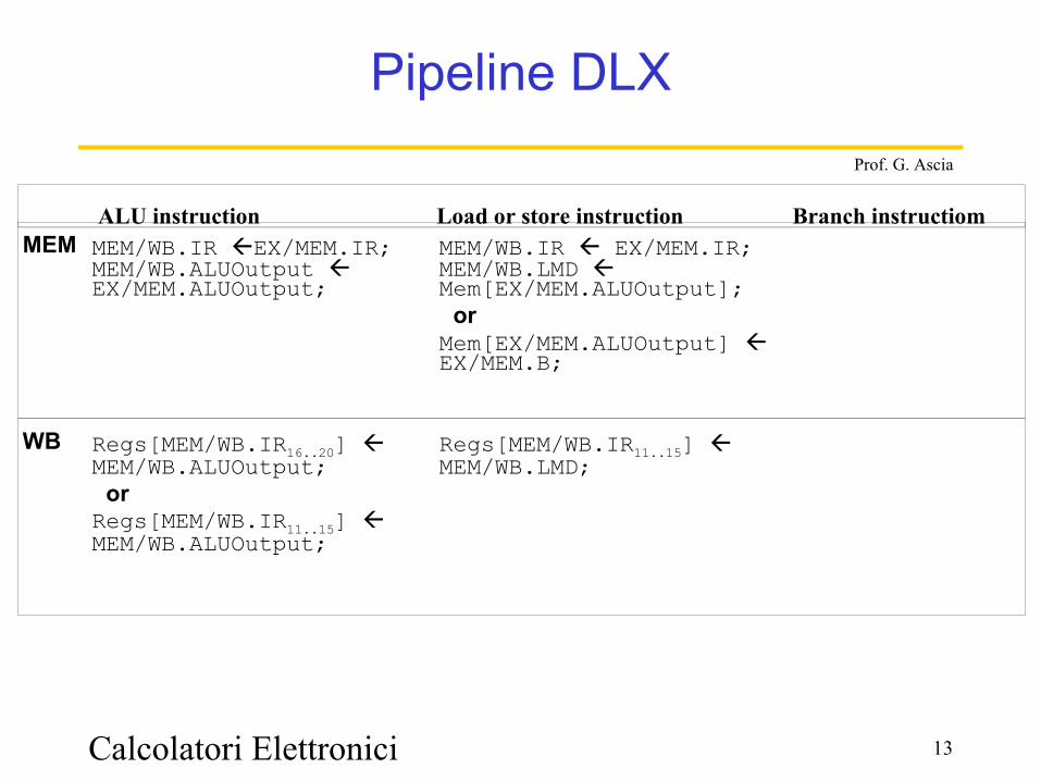
Pipeline DLX
ALU instruction Load or store instruction Branch instructiomMEM MEM/WB.IR EX/MEM.IR;
MEM/WB.ALUOutput EX/MEM.ALUOutput;MEM/WB.IR EX/MEM.IR;MEM/WB.LMD Mem[EX/MEM.ALUOutput]; orMem[EX/MEM.ALUOutput] EX/MEM.B;
WB Regs[MEM/WB.IR16..20] MEM/WB.ALUOutput; orRegs[MEM/WB.IR11..15] MEM/WB.ALUOutput;
Regs[MEM/WB.IR11..15] MEM/WB.LMD;
Calcolatori Elettronici 14
Prof. G. Ascia
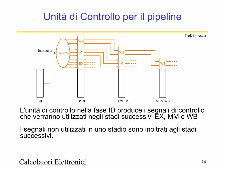
Unità di Controllo per il pipeline
Control
EX
M
WB
M
WB
WB
IF/ID ID/EX EX/MEM MEM/WB
Instruction
L'unità di controllo nella fase ID produce i segnali di controllo che verranno utilizzati negli stadi successivi EX, MM e WB
I segnali non utilizzati in uno stadio sono inoltrati agli stadi successivi.
Calcolatori Elettronici 15
Prof. G. Ascia
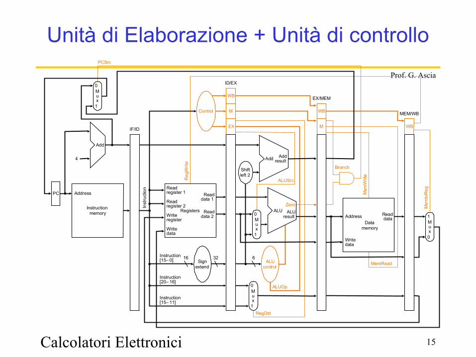
Unità di Elaborazione + Unità di controllo
PC
Instructionmemory
Inst
ruct
ion
Add
Instruction[20– 16]
Mem
toR
eg
ALUOp
Branch
RegDst
ALUSrc
4
16 32Instruction[15– 0]
0
0
Mux
0
1
Add Addresult
RegistersWriteregister
Writedata
Readdata 1
Readdata 2
Readregister 1
Readregister 2
Signextend
Mux
1
ALUresult
Zero
Writedata
Readdata
Mux
1
ALUcontrol
Shiftleft 2
Reg
Writ
e
MemRead
Control
ALU
Instruction[15– 11]
6
EX
M
WB
M
WB
WBIF/ID
PCSrc
ID/EX
EX/MEM
MEM/WB
Mux
0
1
Mem
Writ
e
AddressData
memory
Address
Calcolatori Elettronici 16
Prof. G. Ascia
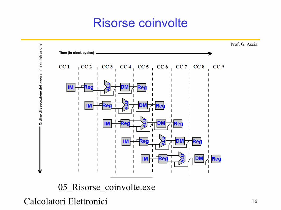
Risorse coinvolte
05_Risorse_coinvolte.exe
Calcolatori Elettronici 17
Prof. G. Ascia
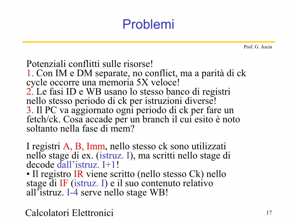
Problemi
Potenziali conflitti sulle risorse!1. Con IM e DM separate, no conflict, ma a parità di ckcycle occorre una memoria 5X veloce!2. Le fasi ID e WB usano lo stesso banco di registri nello stesso periodo di ck per istruzioni diverse!3. Il PC va aggiornato ogni periodo di ck per fare unfetch/ck. Cosa accade per un branch il cui esito è notosoltanto nella fase di mem?
I registri A, B, Imm, nello stesso ck sono utilizzati nello stage di ex. (istruz. I), ma scritti nello stage di decode dall’istruz. I+1!• Il registro IR viene scritto (nello stesso Ck) nello stage di IF (istruz. I) e il suo contenuto relativo all’istruz. I-4 serve nello stage WB!
Calcolatori Elettronici 18
Prof. G. Ascia
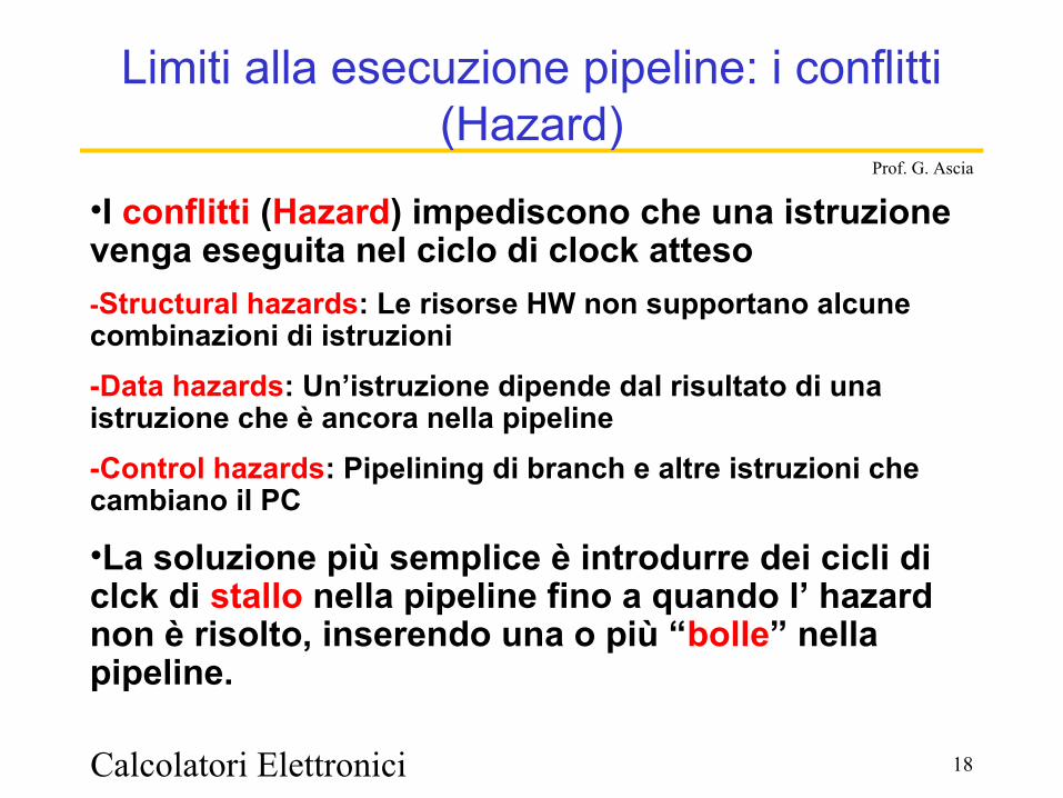
Limiti alla esecuzione pipeline: i conflitti (Hazard)
•I conflitti (Hazard) impediscono che una istruzione venga eseguita nel ciclo di clock atteso-Structural hazards: Le risorse HW non supportano alcune combinazioni di istruzioni-Data hazards: Un’istruzione dipende dal risultato di una istruzione che è ancora nella pipeline-Control hazards: Pipelining di branch e altre istruzioni che cambiano il PC
•La soluzione più semplice è introdurre dei cicli di clck di stallo nella pipeline fino a quando l’ hazard non è risolto, inserendo una o più “bolle” nella pipeline.
Calcolatori Elettronici 19
Prof. G. Ascia
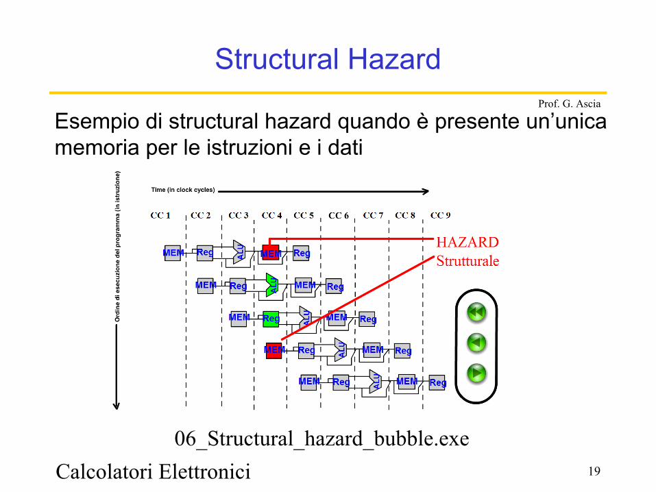
Structural Hazard
Esempio di structural hazard quando è presente un’unica memoria per le istruzioni e i dati
06_Structural_hazard_bubble.exe
Calcolatori Elettronici 20
Prof. G. Ascia
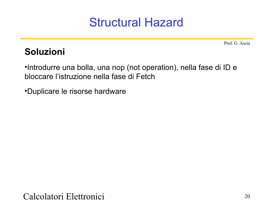
Structural Hazard
Soluzioni•Introdurre una bolla, una nop (not operation), nella fase di ID e bloccare l’istruzione nella fase di Fetch
•Duplicare le risorse hardware
Calcolatori Elettronici 21
Prof. G. Ascia
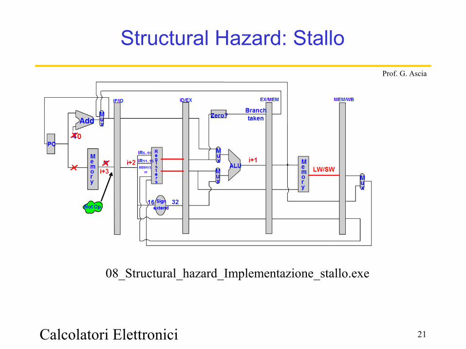
Structural Hazard: Stallo
08_Structural_hazard_Implementazione_stallo.exe
Calcolatori Elettronici 22
Prof. G. Ascia
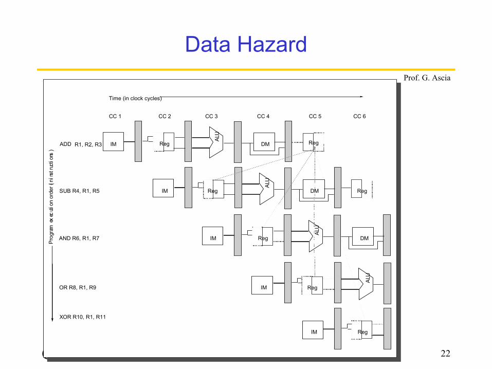
Data Hazard
CC 1 CC 2 CC 3 CC 4 CC 5 CC 6
Time (in clock cycles)
R1, R2, R3
Reg
DM
DM
DM
ADD
SUB R4, R1, R5
AND R6, R1, R7
OR R8, R1, R9
XOR R10, R1, R11
Reg
Reg Reg
RegIM
IM
IM
IM
IM
Reg
ALU
ALU
ALU
ALU
Reg
Prog
ram e
xec
ution
ord
er (in
ins
truc
tion
s)
Calcolatori Elettronici 23
Prof. G. Ascia
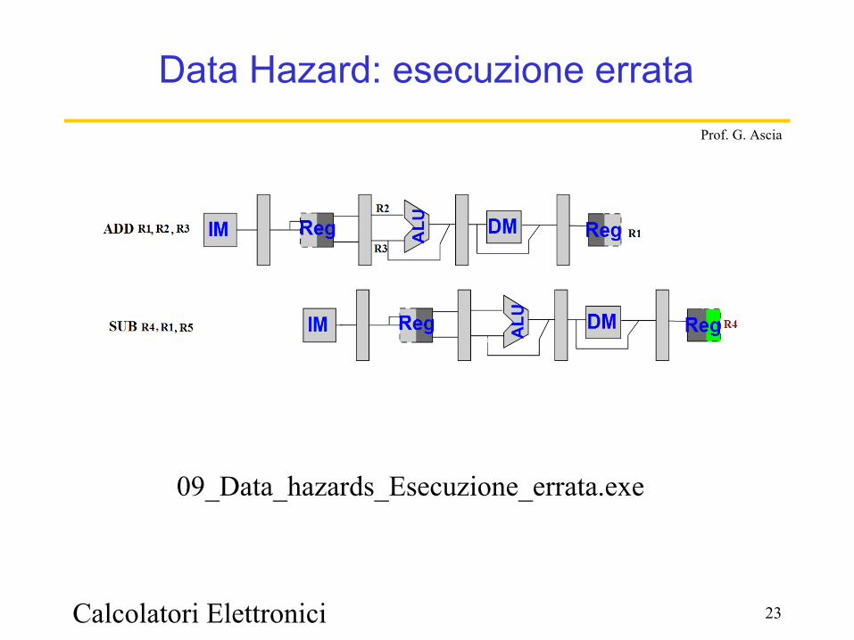
Data Hazard: esecuzione errata
09_Data_hazards_Esecuzione_errata.exe
Calcolatori Elettronici 24
Prof. G. Ascia
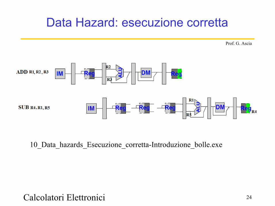
Data Hazard: esecuzione corretta
10_Data_hazards_Esecuzione_corretta-Introduzione_bolle.exe
Calcolatori Elettronici 25
Prof. G. Ascia
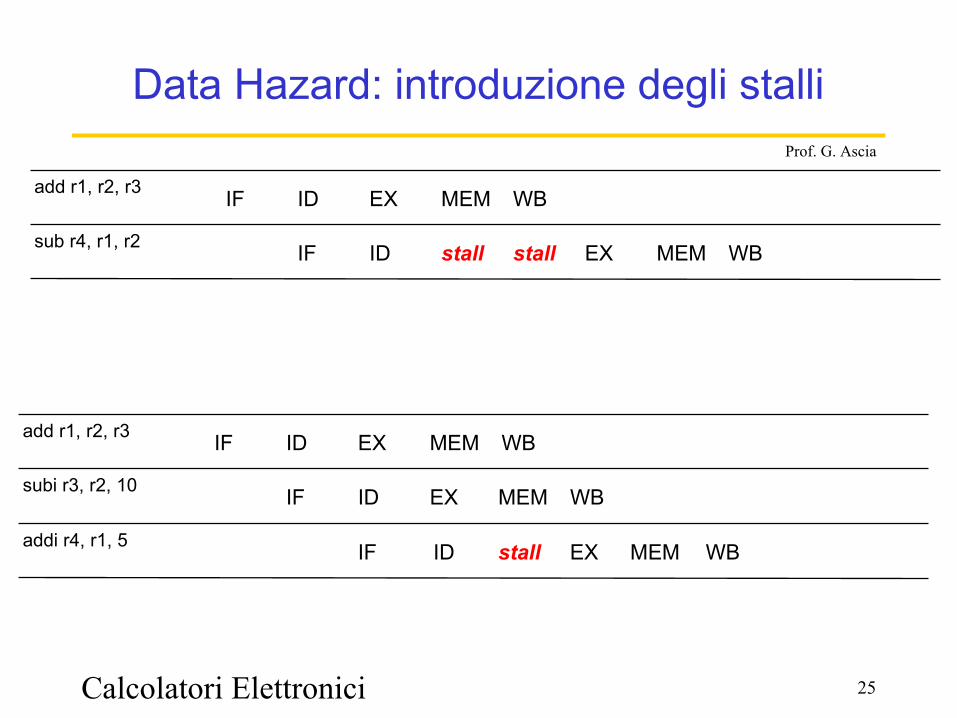
Data Hazard: introduzione degli stalli
WBMEMEXstallstallIDIFsub r4, r1, r2
WBMEMEXIDIFadd r1, r2, r3
WBMEMEXIDIFsubi r3, r2, 10
WBMEMEXIDIFadd r1, r2, r3
WBMEMstallIFaddi r4, r1, 5 ID EX
Calcolatori Elettronici 26
Prof. G. Ascia
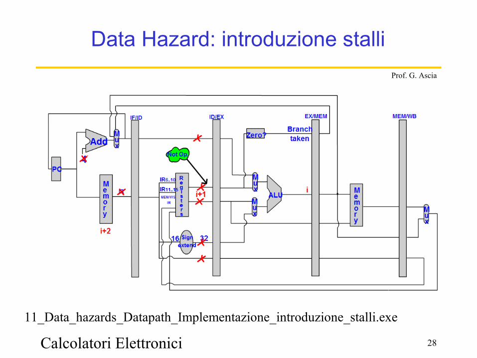
Data Hazard: introduzione degli stalli
Una soluzione ai data hazard è l'introduzione di cicli di clock di stallo.
Poichè il data hazard viene scoperto nella fase ID, quando viene introdotto uno stallo per i data hazard:
• Viene bloccata l'istruzione nella fase ID impedendo l'aggiornamento del registro IF/ID;
• Viene bloccata l'istruzione nella fase IF non aggiornando il PC
• Vengono scritti sul registro ID/EX i segnali di controllo relativi a una nop
I cicli di stallo vengono ripetuti fino a quando non viene aggiornato il registro destinazione
Il numero di cicli di clock di stallo dipende dalla distanza tra le istruzioni
Calcolatori Elettronici 27
Prof. G. Ascia
4PC
Add
Signextend
16 32
Registers
ALU
Zero?Branch
taken
M e m o r y
Mux
IF/ID
IR6..10
IR11..15
ID/EX EX/MEM
MEM/WS,IR
IR
MEM/WB
Mux
Mux M
ux
M e m o r y
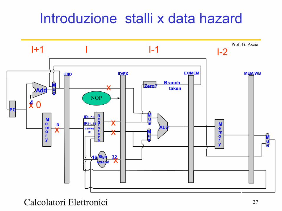
Introduzione stalli x data hazard
xxx
x
x 0
I+1
NOP
x
I I-1 I-2
Calcolatori Elettronici 28
Prof. G. Ascia
Data Hazard: introduzione stalli
11_Data_hazards_Datapath_Implementazione_introduzione_stalli.exe

Calcolatori Elettronici 29
Prof. G. Ascia
Data Hazard: introduzione degli stalli
i : add r1, r2,r3i+1: sub r4, r1,r2
Supponendo che la scrittura in r1 avvenga nel primo semiperiodo del clock e la lettura nel secondo semiperiodo tra le istruzioni a distanza 1 sono necessari 2 cicli di clock di stallo
i : add r1, r2,r3i+1: subi r3, r2, 10i+2: addi r4, r1, 5
Supponendo che la scrittura in r1 avvenga nel primo semiperiodo del clock e la lettura nel secondo semiperiodo tra le istruzioni a distanza 2 sono necessari 1 cicli di clock di stallo
Calcolatori Elettronici 30
Prof. G. Ascia
Data Hazard: Forwarding
Non si aspetta che il registro destinazione rD sia stato aggiornato per fare avanzare nella fase di execute l'istruzione che ha bisogno del risultato
Il dato viene immediatamente utilizzato non appena è prodotto
Calcolatori Elettronici 31
Prof. G. Ascia
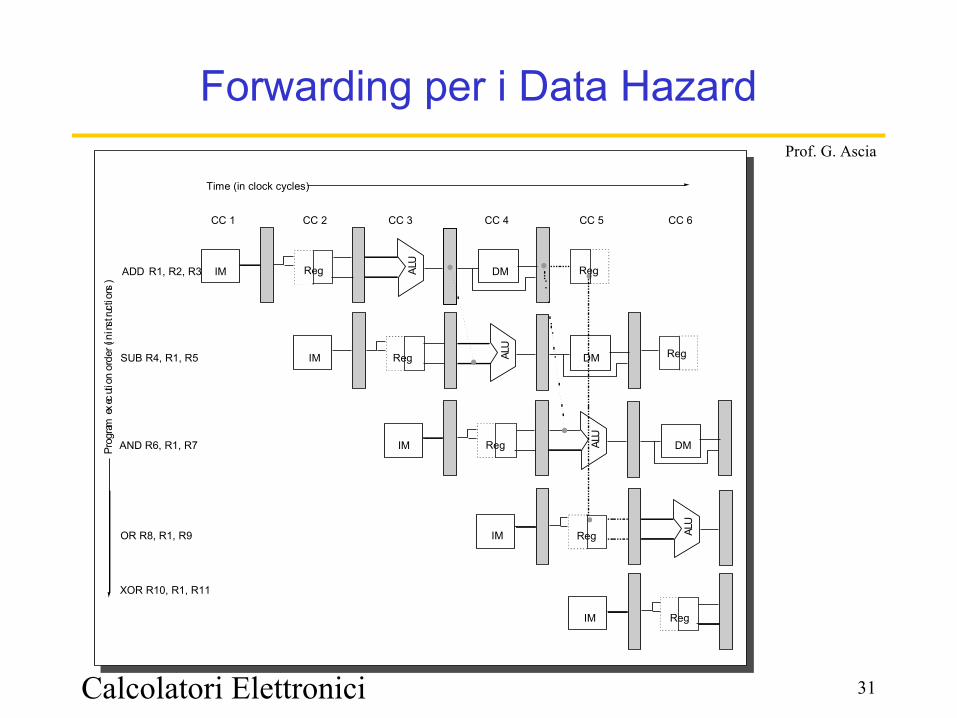
Forwarding per i Data Hazard
DM
DM
DM
CC 1 CC 2 CC 3 CC 4 CC 5 CC 6
Time (in clock cycles)
ADD R1, R2, R3
SUB R4, R1, R5
AND R6, R1, R7
OR R8, R1, R9
XOR R10, R1, R11
Reg
Reg
ALU
ALU
ALU
ALU
Reg
Reg
RegIM
IM
IM
IM
IM
Reg
RegProg
ram e
xecu
tion
orde
r (in
inst
ructio
ns)
Calcolatori Elettronici 32
Prof. G. Ascia
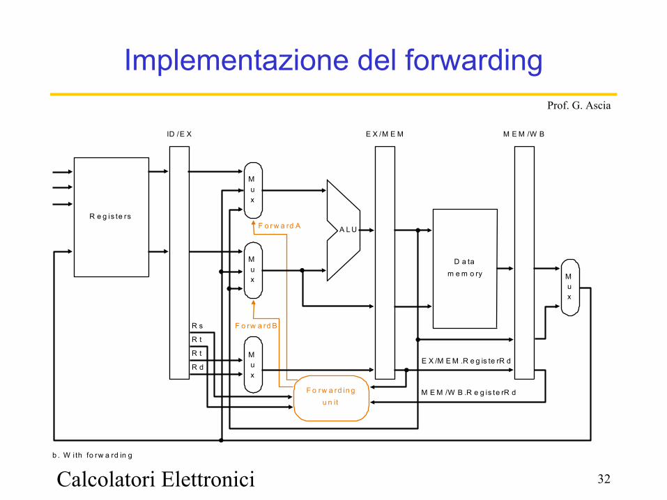
Implementazione del forwarding
R e g is te rs
Mux M
ux
A L U
ID /E X M E M /W B
D a tam e m o ry
Mux
F o rw a rd in gu n it
E X /M E M
b . W i th fo rw a rd in g
F o rw a rd B
R dE X /M E M .R e g is te rR d
M E M /W B .R e g is te rR d
R t
R t
R s
F o r w a rd A
Mux

Calcolatori Elettronici 33
Prof. G. Ascia
Forwarding per lw
R e g
IM
R e g
R e g
IM
C C 1 C C 2 C C 3 C C 4 C C 5 C C 6
T im e ( in c lo c k c y c le s )
lw $ 2 , 2 0 ($ 1 )
P ro g ra m
e x e c u t io n
o rd e r
(in in s t ru c t io n s )
a n d $ 4 , $ 2 , $ 5
IM R e g D M R e g
IM D M R e g
IM D M R e g
C C 7 C C 8 C C 9
o r $ 8 , $ 2 , $ 6
a d d $ 9 , $ 4 , $ 2
s l t $ 1 , $ 6 , $ 7
D M R e g
R e g
R e g
D M
Calcolatori Elettronici 34
Prof. G. Ascia
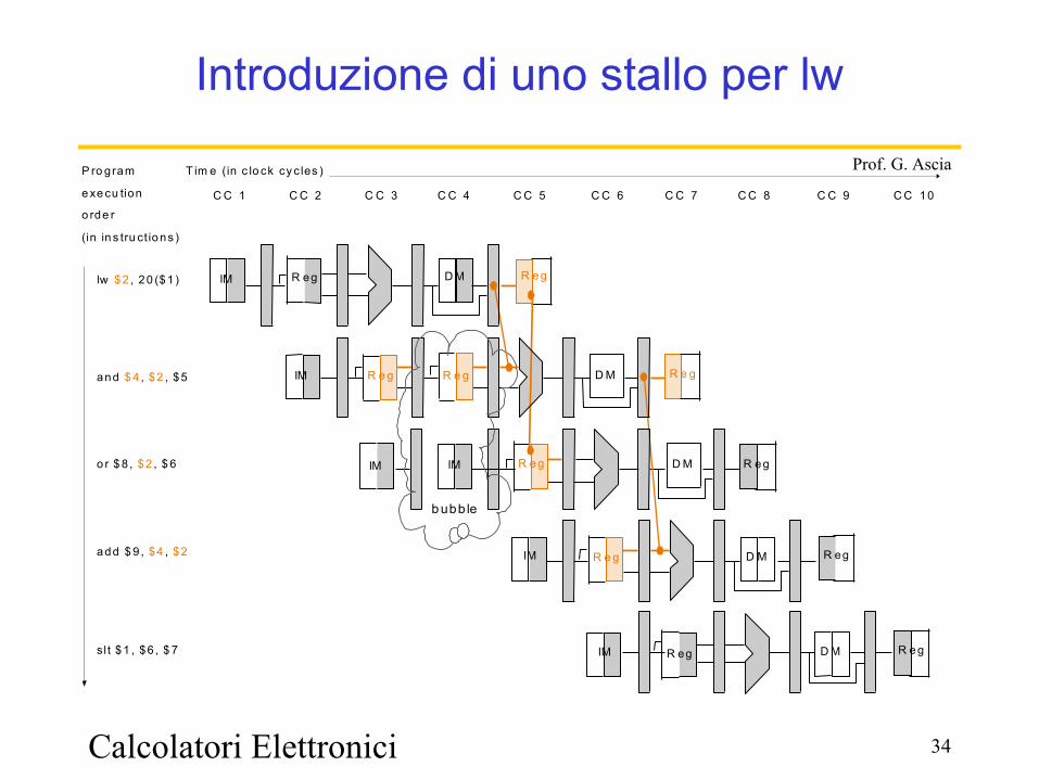
Introduzione di uno stallo per lw
lw $ 2 , 20 ($1 )
P ro gram
e xe cu tion
o rde r
(in in s tru ct io ns )
and $ 4 , $2 , $5
o r $ 8 , $2 , $ 6
add $ 9 , $4 , $2
sl t $1 , $6 , $ 7
R e g
IM
R eg
R eg
IM D M
C C 1 C C 2 C C 3 C C 4 C C 5 C C 6
T im e (in c lo ck cy c les )
IM R e g D M R egIM
IM D M R eg
IM D M R e g
C C 7 C C 8 C C 9 C C 10
D M R e g
R e gR e g
R e g
b ubb le
35
Prof. G. Ascia
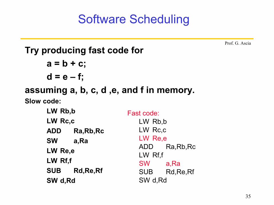
Try producing fast code fora = b + c;d = e – f;
assuming a, b, c, d ,e, and f in memory. Slow code:
LW Rb,bLW Rc,cADD Ra,Rb,RcSW a,Ra LW Re,e LW Rf,fSUB Rd,Re,RfSW d,Rd
Software Scheduling
Fast code:LW Rb,bLW Rc,cLW Re,e ADD Ra,Rb,RcLW Rf,fSW a,Ra SUB Rd,Re,RfSW d,Rd
36
Prof. G. Ascia
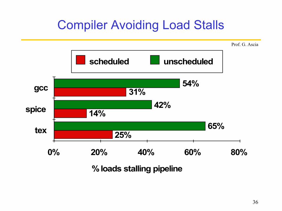
Compiler Avoiding Load Stalls
% loads stalling pipeline
0% 20% 40% 60% 80%
tex
spice
gcc
25%
14%
31%
65%
42%
54%
scheduled unscheduled
Calcolatori Elettronici 37
Prof. G. Ascia
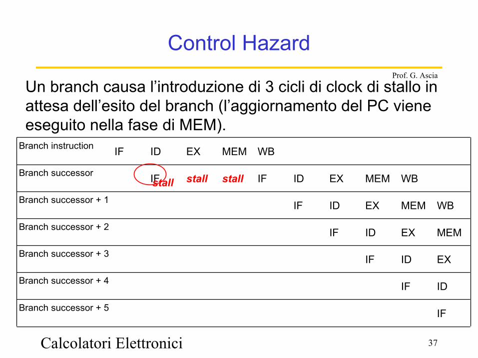
Control Hazard
IFBranch successor + 5
IDIFBranch successor + 4
EXIDIFBranch successor + 3
MEMEXIDIFBranch successor + 2
WBMEMEXIDIFBranch successor + 1
WBMEMEXIDIFstallstallIFBranch successor
WBMEMEXIDIFBranch instruction
Un branch causa l’introduzione di 3 cicli di clock di stallo in attesa dell’esito del branch (l’aggiornamento del PC viene eseguito nella fase di MEM).
stall

Calcolatori Elettronici 38
Prof. G. Ascia
Control Hazard
DataALU
Signextend
16 32
memory
PC
Instruction memory
ADD
ADD
IF/ID
4
ID/EX
EX/MEM MEM/WB
IR6..10
MEM/WB.IR
IR11..15
Registers
Zero?
M u x
M u x
M u x
IR
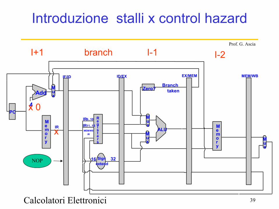
Il numero di cicli può essere ridotto a un solo ciclo anticipando la verifica nello stadio ID
Calcolatori Elettronici 39
Prof. G. Ascia
4PC
Add
Signextend
16 32
Registers
ALU
Zero?Branch
taken
M e m o r y
Mux
IF/ID
IR6..10
IR11..15
ID/EX EX/MEM
MEM/WS,IR
IR
MEM/WB
Mux
Mux M
ux
M e m o r y
Introduzione stalli x control hazard
x
x 0
I+1
NOP
branch I-1 I-2

Calcolatori Elettronici 40
Prof. G. Ascia
Control Hazard: stalli
12_Control_hazard_Datapath_Implementazione_introduzione_stalli.exe
Calcolatori Elettronici 41
Prof. G. Ascia
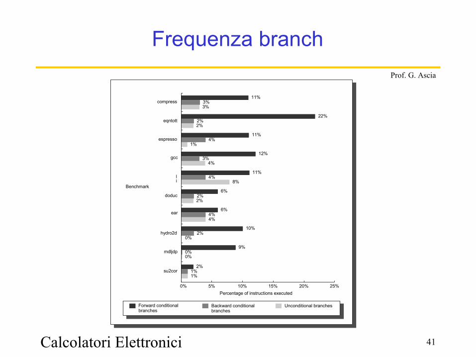
Frequenza branch
Percentage of instructions executed0% 25%5% 10% 15% 20%
10%
0%
0%
2%
1%
2%
6%
4%4%
6%
2%2%
11%
8%4%
12%
4%3%
11%
1%4%
22%
2%2%
11%
3%3%
9%0%
1%
Forward conditional branches
Unconditional branchesBackward conditional branches
Benchmark
compress
eqntott
espresso
gcc
li
doduc
ear
hydro2d
mdljdp
su2cor
Calcolatori Elettronici 42
Prof. G. Ascia
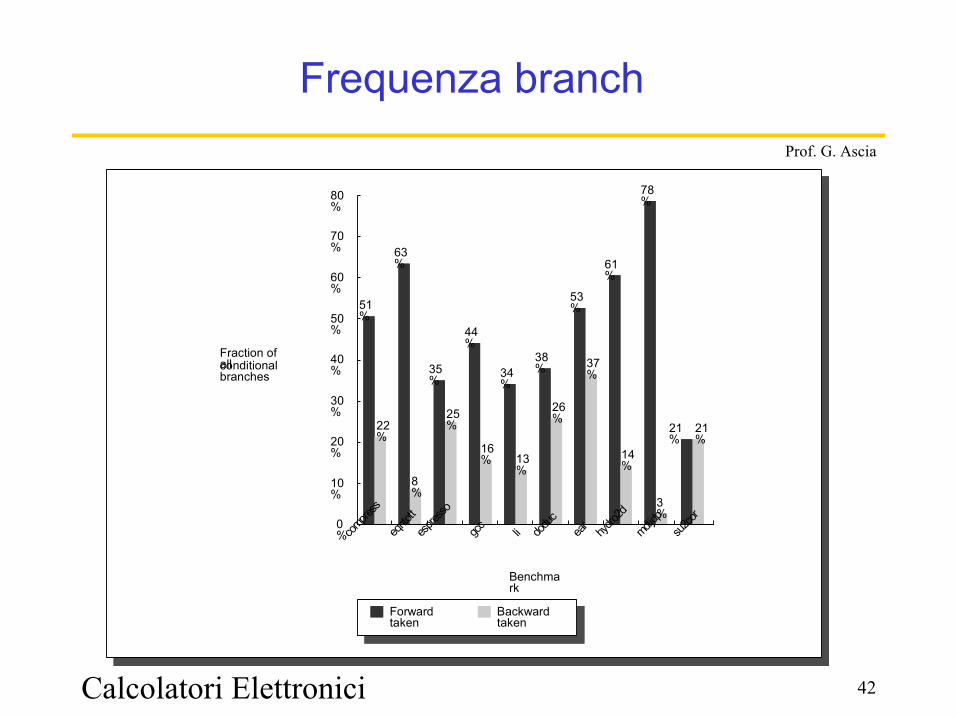
Frequenza branch
Fraction of all conditional branches
0%
80%
10%
20%
30%
40%
50%
70%
60%
61%
21%
14%
53%
37%
38%
26%
34%
13%
44%
16%
35%
25%
63%
8%
51%
22%
78%
3%
21%
Backward taken
Forward taken
Benchmark
compre
ss
eqnto
tt
espres
so
gcc li dodu
cea
r
hydro2
d
mdljdp
su2co
r
Calcolatori Elettronici 43
Prof. G. Ascia
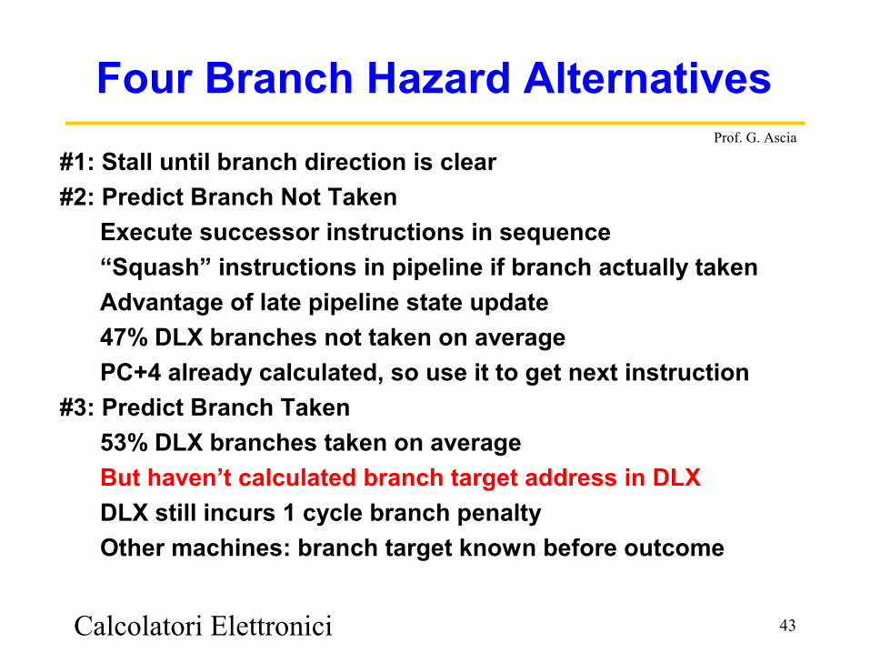
Four Branch Hazard Alternatives
#1: Stall until branch direction is clear#2: Predict Branch Not Taken Execute successor instructions in sequence “Squash” instructions in pipeline if branch actually taken Advantage of late pipeline state update 47% DLX branches not taken on average PC+4 already calculated, so use it to get next instruction#3: Predict Branch Taken 53% DLX branches taken on average But haven’t calculated branch target address in DLX DLX still incurs 1 cycle branch penalty Other machines: branch target known before outcome
Calcolatori Elettronici 44
Prof. G. Ascia
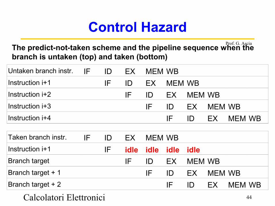
Control HazardThe predict-not-taken scheme and the pipeline sequence when the branch is untaken (top) and taken (bottom)
Untaken branch instr. IF ID EX MEM WBInstruction i+1 IF ID EX MEM WBInstruction i+2 IF ID EX MEM WBInstruction i+3 IF ID EX MEM WBInstruction i+4 IF ID EX MEM WB
Taken branch instr. IF ID EX MEM WBInstruction i+1 IF idle idle idle idleBranch target IF ID EX MEM WBBranch target + 1 IF ID EX MEM WBBranch target + 2 IF ID EX MEM WB

Calcolatori Elettronici 45
Prof. G. Ascia
Four Branch Hazard Alternatives
#4: Delayed Branch– Define branch to take place AFTER a following instruction
branch instructionsequential successor1sequential successor2........sequential successorn
branch target if taken
– 1 slot delay allows proper decision and branch target address in 5 stage pipeline
– DLX uses this
Calcolatori Elettronici 46
Prof. G. Ascia
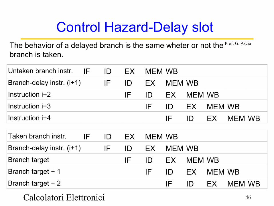
Control Hazard-Delay slotThe behavior of a delayed branch is the same wheter or not the branch is taken.
Untaken branch instr. IF ID EX MEM WBBranch-delay instr. (i+1) IF ID EX MEM WBInstruction i+2 IF ID EX MEM WBInstruction i+3 IF ID EX MEM WBInstruction i+4 IF ID EX MEM WB
Taken branch instr. IF ID EX MEM WBBranch-delay instr. (i+1) IF ID EX MEM WBBranch target IF ID EX MEM WBBranch target + 1 IF ID EX MEM WBBranch target + 2 IF ID EX MEM WB
Calcolatori Elettronici 47
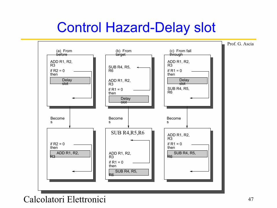
Prof. G. Ascia(a) From before
(b) From target
(c) From fall through
SUB R4, R5, R6 ADD R1, R2, R3 if R1 = 0 then
ADD R1, R2, R3 if R1 = 0 then SUB R4, R5, R6
ADD R1, R2, R3 if R1 = 0 then SUB R4, R5, R6
ADD R1, R2, R3 if R1 = 0 then SUB R4, R5, R6
ADD R1, R2, R3 if R2 = 0 then
if R2 = 0 then ADD R1, R2, R3
Becomes
Becomes
Becomes
Delay slot
Delay slot
Delay slot
SUB R4,R5,R6
Control Hazard-Delay slot
Calcolatori Elettronici 48
Prof. G. Ascia
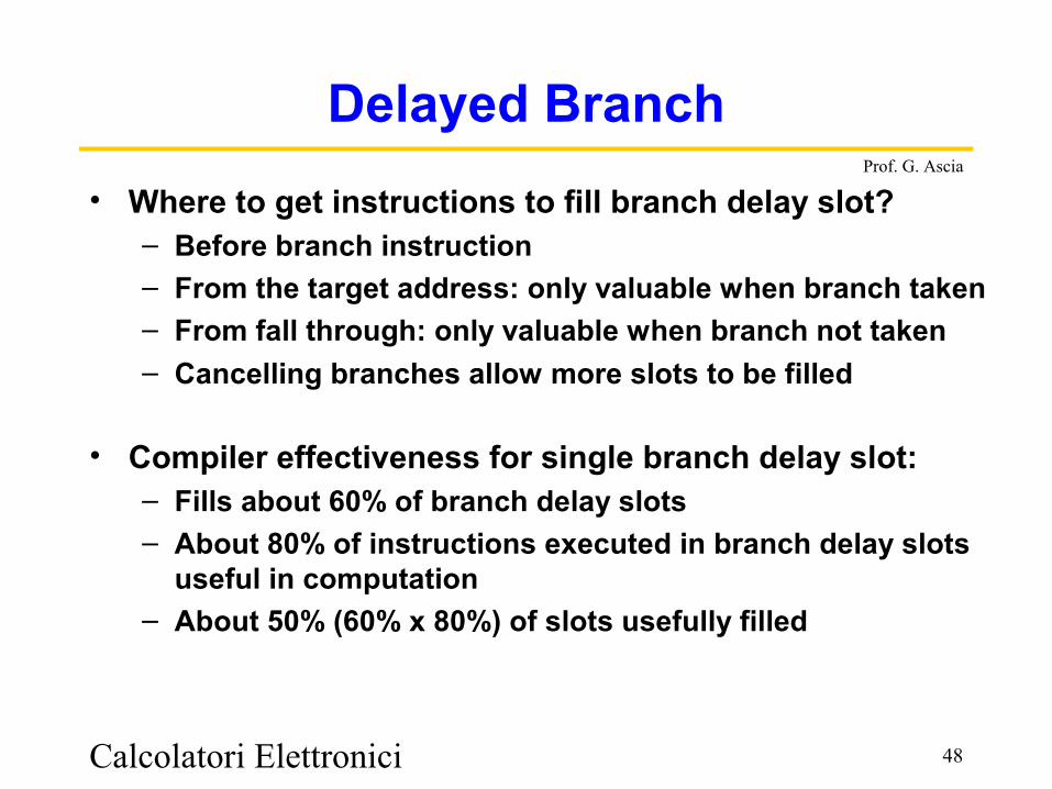
Delayed Branch• Where to get instructions to fill branch delay slot?
– Before branch instruction– From the target address: only valuable when branch taken– From fall through: only valuable when branch not taken– Cancelling branches allow more slots to be filled
• Compiler effectiveness for single branch delay slot:– Fills about 60% of branch delay slots– About 80% of instructions executed in branch delay slots
useful in computation– About 50% (60% x 80%) of slots usefully filled
Calcolatori Elettronici 49
Prof. G. Ascia
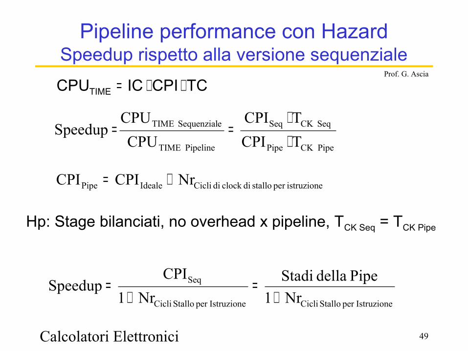
Pipeline performance con HazardSpeedup rispetto alla versione sequenziale
TC CPI ICCPUTIME ⋅⋅=
PipeCK Pipe
SeqCK Seq
Pipeline TIME
eSequenzial TIME
TCPITCPI
CPUCPU
Speedup⋅⋅
==
istruzioneper stallo diclock di CicliIdealePipe NrCPICPI +=
Hp: Stage bilanciati, no overhead x pipeline, TCK Seq = TCK Pipe
Istruzioneper Stallo CicliIstruzioneper Stallo Cicli
Seq
Nr1Pipe della Stadi
Nr1CPI
Speedup+
=+
=
Calcolatori Elettronici 50
Prof. G. Ascia
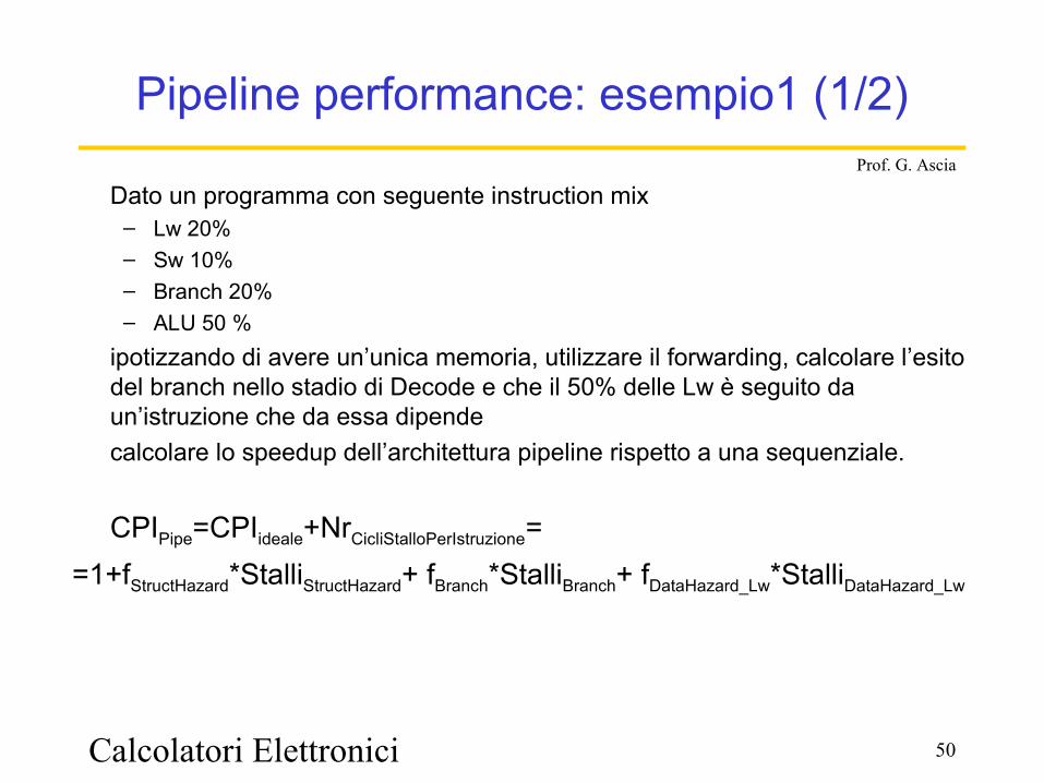
Pipeline performance: esempio1 (1/2)
Dato un programma con seguente instruction mix – Lw 20% – Sw 10%– Branch 20%– ALU 50 %
ipotizzando di avere un’unica memoria, utilizzare il forwarding, calcolare l’esito del branch nello stadio di Decode e che il 50% delle Lw è seguito da un’istruzione che da essa dipendecalcolare lo speedup dell’architettura pipeline rispetto a una sequenziale.
CPIPipe=CPIideale+NrCicliStalloPerIstruzione==1+fStructHazard*StalliStructHazard+ fBranch*StalliBranch+ fDataHazard_Lw*StalliDataHazard_Lw

Calcolatori Elettronici 51
Prof. G. Ascia
Pipeline performance: esempio1 (2/2)
Poiché
• fStructHazard= fLw + fSw =0,2+0,1=0,3 StalliStructHazard =1• fBranch =0,2 StalliBranch =1• fDataHazard_Lw=20%*50%=0,1 StalliDataHazard_Lw =1
CPIPipe= 1+ 0,3*1+0,2*1+0,1*1=1+0,6=1,6
125,36,1
5Nr1
Pipe della StadiCPICPI
SpeedupIstruzioneper Stallo CicliPipe
Seq ==+
==
Calcolatori Elettronici 52
Prof. G. Ascia
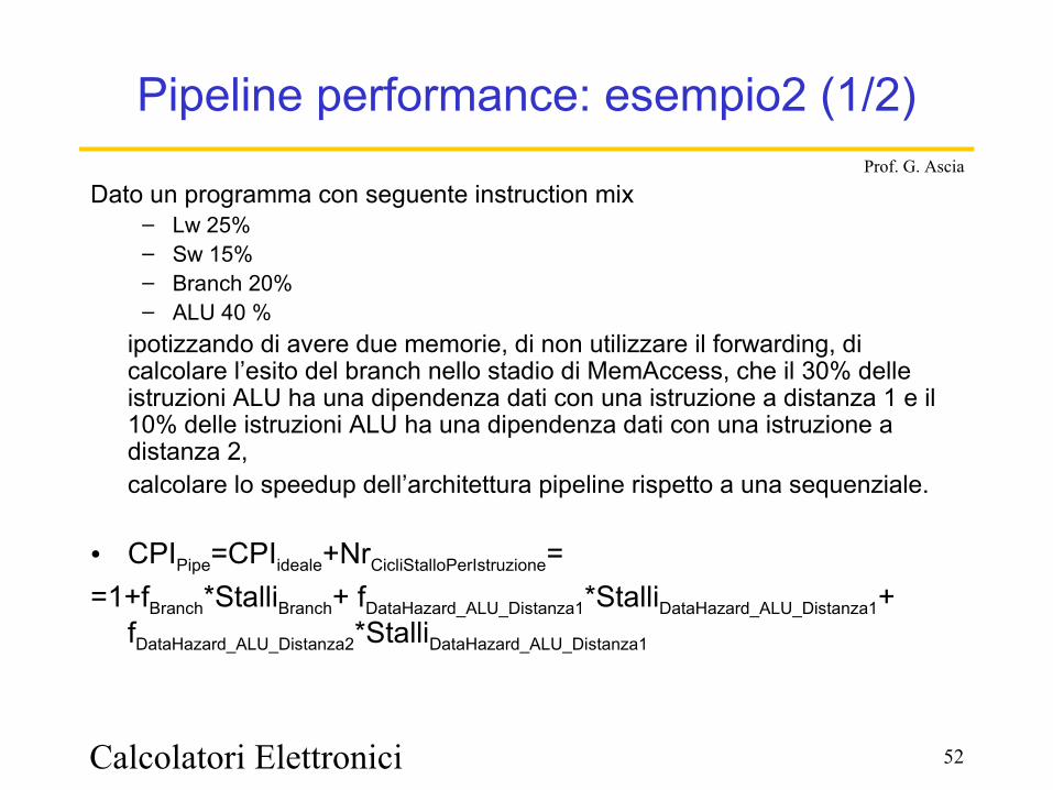
Pipeline performance: esempio2 (1/2)
Dato un programma con seguente instruction mix – Lw 25% – Sw 15%– Branch 20%– ALU 40 %
ipotizzando di avere due memorie, di non utilizzare il forwarding, di calcolare l’esito del branch nello stadio di MemAccess, che il 30% delle istruzioni ALU ha una dipendenza dati con una istruzione a distanza 1 e il 10% delle istruzioni ALU ha una dipendenza dati con una istruzione a distanza 2, calcolare lo speedup dell’architettura pipeline rispetto a una sequenziale.
• CPIPipe=CPIideale+NrCicliStalloPerIstruzione==1+fBranch*StalliBranch+ fDataHazard_ALU_Distanza1*StalliDataHazard_ALU_Distanza1+
fDataHazard_ALU_Distanza2*StalliDataHazard_ALU_Distanza1
Calcolatori Elettronici 53
Prof. G. Ascia
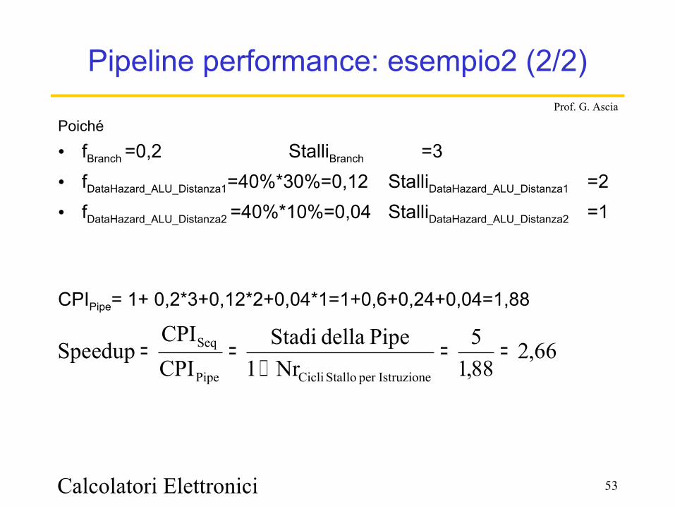
Pipeline performance: esempio2 (2/2)
Poiché
• fBranch =0,2 StalliBranch =3• fDataHazard_ALU_Distanza1=40%*30%=0,12 StalliDataHazard_ALU_Distanza1 =2• fDataHazard_ALU_Distanza2 =40%*10%=0,04 StalliDataHazard_ALU_Distanza2 =1
CPIPipe= 1+ 0,2*3+0,12*2+0,04*1=1+0,6+0,24+0,04=1,88
66,288,15
Nr1Pipe della Stadi
CPICPI
SpeedupIstruzioneper Stallo CicliPipe
Seq ==+
==


![Architettura degli elaboratori 2018-2019homes.di.unimi.it/mdamiani/corsi/architettura/presenta...M.Morris Mano, C. R. Kime, Reti logiche, Pearson [prima parte] D.A. Patterson, J.L.](https://static.fdocumenti.com/doc/165x107/60da6600219a6d680d7d881b/architettura-degli-elaboratori-2018-mmorris-mano-c-r-kime-reti-logiche.jpg)
![al ‘Ankabūt (Il ragno) di Muṣṭafà Maḥmūd: un esempio tra ... · [J.L. Borges, El inmortal, 1947] ... Gilgamesh apre così la strada ad una produzione letteraria che esplica,](https://static.fdocumenti.com/doc/165x107/5bc7be4209d3f2d22a8c05e6/al-ankabut-il-ragno-di-muafa-mamud-un-esempio-tra-jl.jpg)