
Operation Manual NINA 2010-05 (G19502553) - maschio.com€¦ · In caso di contestazione il testo...
54
NINA Cod. G19502553 2010-05 *) *) Valido per Paesi UE *) Valid for EU member countries *) Valable dans les Pays UE *) Gilt für EU-Mitgliedsländer *) Válido para Países UE MASCHIO GASPARDO S.p.A. USO E MANUTENZIONE USE AND MAINTENANCE GEBRAUCH UND WARTUNG EMPLOI ET ENTRETIEN EMPLEO Y MANTENIMIENTO IT EN DE FR ES
-
Upload
truongthuy -
Category
Documents
-
view
216 -
download
2
Transcript of Operation Manual NINA 2010-05 (G19502553) - maschio.com€¦ · In caso di contestazione il testo...
NINA
Cod. G19502553 2010-05
*)
*) Valido per Paesi UE*) Valid for EU member countries*) Valable dans les Pays UE*) Gilt für EU-Mitgliedsländer*) Válido para Países UE
MASCHIO GASPARDO S.p.A.
USO E MANUTENZIONE
USE AND MAINTENANCE
GEBRAUCH UND WARTUNG
EMPLOI ET ENTRETIEN
EMPLEO Y MANTENIMIENTO
IT
EN
DE
FR
ES
pizzolitto
Rettangolo
ITALIANO ENGLISH DEUTSCH
INDICE INDEX INHALT
2 cod. G19502553
1.0 Premessa ................................................... 4
1.1 Garanzia ...................................................... 4
1.1.1 Scadenza della garanzia ............................. 4
1.2 Descrizione della seminatrice ..................... 5
1.3 Dati tecnici ................................................... 6
1.4 Identifi cazione ............................................. 6
1.5 Movimentazione .......................................... 6
1.6 Disegno complessivo .................................. 7
1.7 Segnali di sicurezza e indicazione .............. 8
2.0 Norme di sicurezza e prevenzione
infortuni ...................................................... 9
3.0 Norme d’uso .............................................11
3.1 Completamento macchina .........................11
3.2 Applicazione al trattore ...............................11
3.2.1 Aggancio ....................................................11
3.2.2 Sgancio della seminatrice dalla trattrice .....11
3.3 Stabilità in trasporto seminatrice-trattore .. 12
3.4 Preparativi per la semina .......................... 12
3.4.1 Cambio di velocità ..................................... 12
3.4.2 Regolazione tastatori ................................ 13
3.4.3 Regolazione rulli dosatori .......................... 13
3.4.4 Regolazione lamine ................................... 13
3.4.5 Regolazione della profondità di semina .... 14
3.4.6 Regolazione distanza tra le fi le ................. 15
3.4.7 Esclusione semina mezza macchina ........ 15
3.5 Segnafi le ................................................... 16
3.5.1 Regolazione braccio marcafi le .................. 17
3.6 Erpice posteriore a molle .......................... 18
3.7 Livello dei semi nella tramoggia ................ 18
3.8 Pedana di carico ....................................... 19
3.9 Raschiaterra ruote di trasmissione ............ 19
3.10 Regolazione ancore rompitraccia .............. 19
3.11 Distribuzione ............................................. 20
3.11.1 Tabelle indice di semina ............................ 20
3.11.2 Tabella giri cambio per prova di semina .... 22
3.11.3 Determinazione con metodo pratico del
numero di giri cambio per prova di semina 22
3.11.4 Tabella regolazione seminatrice ................ 22
3.11.5 Prova di semina ........................................ 23
3.12 Scarico semi dalla tramoggia .................... 24
3.13 Durante il lavoro ........................................ 24
4.0 Manutenzione .......................................... 25
4.1 A macchina nuova ..................................... 25
4.2 Ogni 20/30 ore dl lavoro ............................ 25
4.3 Ogni 50 ore di lavoro ................................. 25
4.4 Ogni 400 ore dl lavoro ............................... 25
4.5 Lubrifi canti consigliati ................................ 25
4.6 Messa a riposo .......................................... 25
5.0 Demolizione e smaltimento .................... 26
Dichiarazione di conformità ............................ 123
1.0 Introduction ............................................. 28
1.1 Guarantee ................................................. 28
1.1.1 Expiry of guarantee ................................... 28
1.2 Description of the seeder .......................... 29
1.3 Technical data ........................................... 30
1.4 Identifi cation .............................................. 30
1.5 Handling .................................................... 30
1.6 Assembly drawing ..................................... 31
1.7 Danger and indicator signals ..................... 32
2.0 Safety regulations and accident preven-
tion ............................................................ 33
3.0 Rules of use ............................................. 35
3.1 Completion of the machine ...................... 35
3.2 Attachment to the tractor ........................... 35
3.2.1 Hooking ..................................................... 35
3.2.2 Unhooking the seed drill from the tractor .. 35
3.3 Stability of planting unit and tractor during
transport .................................................... 36
3.4 Preparations for sowing ............................ 36
3.4.1 Speed change gear ................................... 36
3.4.2 Feeler pin adjustment ................................ 37
3.4.3 Distributor roller adjustment ...................... 37
3.4.4 Blade adjustment ...................................... 37
3.4.5 Sowing depth adjustment .......................... 38
3.4.6 Adjustment of the distance between rows . 39
3.4.7 Disabling sowing by half of the machine ... 39
3.5 Row marker disk adjustment ..................... 40
3.5.1 Row marker disk adjustment ....................... 41
3.6 Rear spring harrow .................................... 42
3.7 Seed level in the hopper ........................... 42
3.8 Loading plataform ..................................... 43
3.9 Soil scrapers of transmission wheels ........ 43
3.10 Hoe adjustment ......................................... 43
3.11 Distribution ................................................ 44
3.11.1 Seed distribution tables ............................. 44
3.11.2 Trial sowing speed change gear table....... 46
3.11.3 Easy method for determining the number of
sowing test rotations ................................. 46
3.11.4 Adjustment table of the seeder ................. 46
3.11.5 Trial sowing ............................................... 47
3.12 Seed discharge from the hopper ............... 48
3.13 During work ............................................... 48
4.0 Maintenance ............................................ 49
4.1 When the machine ls new ......................... 49
4.2 Every 20/30 working hours ........................ 49
4.3 Every 50 working hours ............................. 49
4.4 Every 400 working hours ........................... 49
4.5 Recommended lubricants ......................... 49
4.6 Setting aside ............................................. 49
5.0 Demolition and disposal ......................... 50
Conformity declaration .................................... 123
1.0 Vorwort ..................................................... 52
1.1 Garantie .................................................... 52
1.1.1 Verfall des Garantieanspruchs .................. 52
1.2 Beschreibung der Sämaschine ................. 53
1.3 Technische Daten ...................................... 54
1.4 Identifi zierung ............................................ 54
1.5 Fortbewegung ........................................... 54
1.6 Zusammenfassend .................................... 55
1.7 Warnsignale und Anzeigesignale .............. 56
2.0 Sicherheits- und unfall verhütungs-
bestimmungen ......................................... 57
3.0 Betriebs-anleitungen .............................. 59
3.1 Ergänzender ausbau der Maschine .......... 59
3.2 Einbau am Schlepper ................................ 59
3.2.1 Ankuppeln ................................................. 59
3.2.2 Abkuppeln der Säemaschine vom Schlepper . 59
3.3 Stabilität von Sämaschine-Schlepper beim
transport .................................................... 60
3.4 Vorbereitungen vor dem säen ................... 60
3.4.1 Wechselgetriebe ....................................... 60
3.4.2 Einstellung der Taster ................................ 61
3.4.3 Einstellung der Särollen ............................ 61
3.4.4 Einstellung der Blatter ............................... 61
3.4.5 Einstellung der Aussaattiefe ...................... 62
3.4.6 Einstellung des Abstandes Zwischen den
reihen ........................................................ 63
3.4.7 Ausschluss der halben Maschine vom Sävor-
gang .......................................................... 63
3.5 Spurreisser ................................................ 64
3.5.1 Einstellung des Epurreisserarms .............. 65
3.6 Rückwärtige Egge mit federung ................ 66
3.7 Samenstand im Trichter ............................ 66
3.8 Ladetrittbrett .............................................. 67
3.9 Abstreifer Antriebsräder ............................ 67
3.10 Einstellung der Spurhackenanker ............. 67
3.11 Steuerung .................................................. 68
3.11.1 Saatguttabellen ......................................... 68
3.11.2 Getriebedrehzahl tabelle für aussaatprobe 70
3.11.3 Praktisches verfahren für die Bestmmung der
Getriebedrehzahl für die Säprobe ............. 70
3.11.4 Einstellungtabelle für die Sämaschine ...... 70
3.11.5 Aussaatprobe ............................................ 71
3.12 Entladen der Samen aus dem trichter ....... 72
3.13 Während des betriebs ............................... 72
4.0 Wartung .................................................... 73
4.1 Bei neuer maschine .................................. 73
4.2 Alle 20/30 arbeitsstunden .......................... 73
4.3 Alle 50 arbeitsstunden ............................... 73
4.4 Alle 400 arbeitsstunden ............................. 73
4.5 Empfohlene schmiermittel ......................... 73
4.6 Ruheperioden ............................................ 73
5.0 Zerlegen und Entsorgen der Maschine . 74
Konformitätsenklärung .................................... 123

ITALIANO
4 cod. G19502553
1.0 PREMESSA
Questo manuale descrive le norme d’uso e di manutenzione per la seminatrice. Il presente manuale è parte integrante del prodotto, e deve essere custodito in luogo sicuro per essere consultato durante tutto l’arco di vita della macchina.
ATTENZIONE• La Ditta Costruttrice si riserva la facoltà di modificare
l’attrezzatura senza aggiornare tempestivamente questa pubblicazione. In caso di contestazione il testo valido di riferimento rimane l’italiano.
• La macchina è stata costruita per il dosaggio e lo spargimento qualità di semente normalmente in commercio.
• La macchina è destinata ad una utenza professionale, se ne consente l’utilizzo ai soli operatori specializzati.
• Non è consentito l’uso da parte di minori, analfabeti, persone in condizione fi siche o psichiche alterate.
• Non è consentito l’uso a personale sprovvisto di patente di guida adeguata o non suffi cientemente informato ed addestrato.
• L’operatore è responsabile del controllo della funzionalità della macchina, la sostituzione e la riparazione delle parti soggette ad usura che potrebbero causare danni.
• Il cliente dovrà provvedere ad istruire il personale sui rischi da infortunio, sui dispositivi predisposti per la sicurezza e la salute dell’operatore, sui rischi legati all’esposizione al rumore e sulle regole antinfortunistiche generali previste da direttive internazio-nali e dalla legislazione del paese di destinazione della macchina.
• In ogni caso la macchina deve essere usata esclusivamente da operatori qualifi cati che saranno tenuti a rispettare scrupolosa-mente le istruzioni tecniche ed antinfortunistiche contenute nel presente manuale.
• E’ compito dell’utilizzatore controllare che la macchina venga azionata unicamente in condizioni ottimali di sicurezza sia per le persone, per gli animali e per le cose.
1.1 GARANZIALa garanzia ha validità di un anno, contro ogni difetto dei materiali, dalla data di consegna dell’attrezzatura.Verifi care all’atto della consegna che la macchina non abbia su-bito danni durante il trasporto e che gli accessori siano integri e al completo.EVENTUALI RECLAMI DOVRANNO ESSERE PRESENTATI PER ISCRITTO ENTRO 8 GIORNI DAL RICEVIMENTO PRESSO IL CONCESSIONARIO.L’acquirente potrà far valere i suoi diritti sulla garanzia solo quando egli abbia rispettato le condizioni concernenti la prestazione della garanzia, riportate nel contratto di fornitura.
1.1.1 SCADENZA GARANZIAOltre a quanto riportato nel contratto di fornitura, la garanzia decade:- Qualora si dovessero oltrepassare i limiti riportati nella tabella
dei dati tecnici.- Qualora non fossero state attentamente seguite le istruzioni
descritte in questo opuscolo.- In caso di uso errato, di manutenzione difettosa e in caso di altri
errori effettuati dal cliente.- Qualora siano fatte modifi che senza l’autorizzazione scritta del
costruttore e qualora si siano utilizzati ricambi non originali.
USO E MANUTENZIONE
5
ITALIANO
cod. G19502553
1.2 DESCRIZIONE DELLA SEMINATRICEQuesta attrezzatura agricola, può operare solo tramite un trattore agricolo munito di gruppo sollevatore, con attacco universale a tre punti.
La seminatrice è adatta per impieghi a sè stanti su terreni lavorati, o in combinazione con attrezzatura per la lavorazione del terreno (erpice, fresa, ecc.).
È idonea per la semina di cereali: frumento, orzo, segala, avena, riso.
Per sementi fi ne e foraggere: colza, trifoglio, erba medica, loglio.
Per sementi grosse: soia, piselli.
Le sementi vengono depositate nel terreno a mezzo organi assol-catori, stivaletto o disco Corex, e sono distribuite in modo continuo da un rullo a denti per ogni fi la.Le quantità da distribuire vengono regolate attraverso un variatore a camme (cambio), il cui moto è derivato dalle ruote motrici per aderenza. I bracci degli organi assolcatori indipendenti tra loro, dispongono di un ampio margine di oscillazione per adeguarsi alla superfi cie del terreno.
ATTENZIONELe seminatrici sono idonee esclusivamente per l’impiego indicato. La velocità di lavoro consigliata è di 8÷10 km/h. Il trasporto su strada della seminatrice deve avvenire con serbatoi vuoti e ad una velocità massima di 25 km/h. Ogni altro uso diverso da quello descritto in queste istruzioni può recare danno alla macchina e costituire serio pericolo per l’utilizzatore. La macchina deve essere utilizzata esclusiva-mente dal personale qualifi cato del Cliente. L’operatore deve essere dotato di adeguati dispositivi di protezione individuale (calzature di sicurezza, tuta da lavoro e guanti, ecc.). La macchina è destinata ad un uso professionale e deve es-sere utilizzata esclusivamente da personale preventivamente istruito, addestrato ed autorizzato, nonché munito di regolare patente di guida.
Modo d’impiego• La macchina è stata costruita per il dosaggio e lo spargimento
qualità di semente normalmente in commercio.• Deve essere combinata con un’attrezzatura per la lavorazione
del terreno (erpice rotante) collegata a un trattore tramite attacco a tre punti dello stesso e manovrata da un operatore.
• La macchina è destinata ad una utenza professionale, se ne consente l’utilizzo ai soli operatori specializzati.
• La macchina deve essere manovrata da un solo operatore.• La macchina non è indicata per essere usata in settori diversi da
quello agricolo.
Rientrano nell’utilizzo conforme anche:• il rispetto di tutte le indicazioni del presente manuale;• l’esecuzione delle operazioni di ispezione e di manutenzione
riportate nel presente manuale;• l’uso esclusivo di ricambi originali GASPARDO.
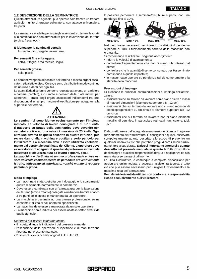
È possibile percorrere e seminare/distribuire superfi ci con una pendenza fi no al 10%.
Max. 10% Max. 10% Max. 10% Max. 10%
Nel caso fosse necessario seminare in condizioni di pendenza superiore al 10% il funzionamento corretto della macchina non è garantito. Si raccomanda di utilizzare i seguenti accorgimenti:• ridurre la velocità di avanzamento;• controllare frequentemente che non ci siano tubi intasati dal
seme;• controllare che la quantità di seme consumato per Ha seminato
corrisponda a quella impostata;• in nessun caso operare su pendenze tali da compromettere la
stabilità della macchina.
Precauzioni di impiegoSi elencano le principali controindicazioni di impiego dell’attrez-zatura:• assicurarsi che sul terreno da lavorare non ci siano pietre o massi
di notevoli dimensioni (diametro superiore a 8 - 12 cm);• assicurarsi che sul terreno da lavorare non ci siano monconi di
alberi sporgenti oltre 10 cm circa e di diametro superiore a 8 - 12 cm circa;
• assicurarsi che sul terreno da lavorare non ci siano elementi metallici di ogni tipo, in particolare reti, cavi, funi, catene, tubi, ecc.
Dal corretto uso e dall’adeguata manutenzione dipende il regolare funzionamento dell’attrezzatura. È consigliabile quindi, osservare scrupolosamente quanto descritto allo scopo di prevenire un qualsiasi inconveniente che potrebbe pregiudicare il buon funzio-namento e la sua durata. È altresì importante attenersi a quanto descritto nel presente manuale in quanto la Ditta Costruttrice declina ogni e qualsiasi responsabilità dovuta a negligenza ed alla mancata osservanza di tali norme.La Ditta Costruttrice, è comunque a completa disposizione per assicurare un’immediata e accurata assistenza tecnica e tutto ciò che può essere necessario per il miglior funzionamento e la massima resa dell’attrezzatura. Per i danni derivanti da utilizzo non conforme la responsabilità ricade esclusivamente sull’utilizzatore.
USO E MANUTENZIONE
6
ITALIANO
cod. G19502553
1.3 DATI TECNICI U.M. NINA 250 NINA 300 NINA 400
Larghezza di lavoro [m] 2,50 300 400
Numero max fi le - versione stivaletti [nr.] 21 29 33
Numero max fi le - disco Corex [nr.] 21 25 33
Numero max fi le - Disco Semplice [nr.] 21 25 31
Interfi la minima [cm] 12 12 12
Capacità tramoggia seme [l] 400 510 641
Rialzo tramoggia seme (optional) [l] 230 280 400
Peso - versione stivaletti [kg] 510 595 920
Peso - versione disco Corex [kg] 600 700 950
Peso - versione Disco Semplice [kg] 545 580 880
Pneumatici [Tipo] 6.00-16 6.50/80-15 10.50/75-16
Pressione gonfi aggio pneumatici [bar (Psi)] 2,4 (35) 2,4 (35) 2,7 (39)
CARATTERISTICHE RICHIESTE DELLA TRATTRICE
Potenza richiesta [HP (kw)] 60 (44) 70 (52) 90 (67)
Categoria attacchi [nr.] II
Tensione della batteria [V] 12
Pressione della pompa del trattore (max) [bar] 180
Collegamenti oleodinamici trattrice Segnafi le (optional): nr. 1 doppio effetto;
Regolazione pressione assolcatori (optional): nr. 1 doppio effetto;
Collegamenti elettrici a 12 V Kit luci connettore a 7 poli;
I dati tecnici ed i modelli indicati si intendono non impegnativi. Ci riserviamo il diritto di modifi carli senza obbligo di preavviso.
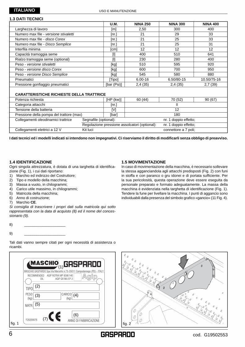
1.4 IDENTIFICAZIONEOgni singola attrezzatura, è dotata di una targhetta di identifi ca-zione (Fig. 1), i cui dati riportano:1) Marchio ed indirizzo del Costruttore;2) Tipo e modello della macchina;3) Massa a vuoto, in chilogrammi;4) Carico utile massimo, in chilogrammi;5) Matricola della macchina;6) Anno di costruzione;7) Marchio CE.Si consiglia di trascrivere i propri dati sulla matricola qui sotto rappresentata con la data di acquisto (8) ed il nome del conces-sionario (9).
8) ____________________
9) ____________________
Tali dati vanno sempre citati per ogni necessità di assistenza o ricambi.
fi g. 2
1.5 MOVIMENTAZIONE In caso di movimentazione della macchina, è necessario sollevare la stessa agganciandola agli attacchi predisposti (Fig. 2) con funi in stoffa e con paranco o gru idonei e di portata suffi ciente. Per la sua pericolosità, questa operazione deve essere eseguita da personale preparato e formato adeguatamente. La massa della macchina è evidenziata nella targhetta di identifi cazione (Fig. 1). Tendere la fune per livellare la macchina. I punti di aggancio sono individuabili dalla presenza del simbolo grafi co «gancio» (11 Fig. 4).
fi g. 1
(1)
(2)
(3)
(5)
(7)
(4)
(6)
USO E MANUTENZIONE
7
ITALIANO
cod. G19502553
fi g. 3
8
11
9
10
2
3
1
16
13
12
6
15
7
14
4
5
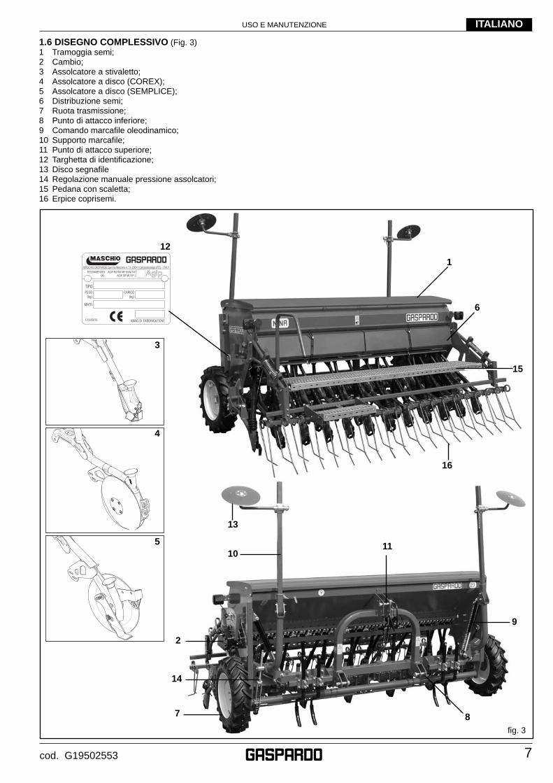
1.6 DISEGNO COMPLESSIVO (Fig. 3)1 Tramoggia semi;2 Cambio;3 Assolcatore a stivaletto;4 Assolcatore a disco (COREX);5 Assolcatore a disco (SEMPLICE);6 Distribuzione semi;7 Ruota trasmissione;8 Punto di attacco inferiore;9 Comando marcafi le oleodinamico;10 Supporto marcafi le;11 Punto di attacco superiore;12 Targhetta di identifi cazione;13 Disco segnafi le14 Regolazione manuale pressione assolcatori;15 Pedana con scaletta;16 Erpice coprisemi.
USO E MANUTENZIONE
8
ITALIANO
cod. G19502553
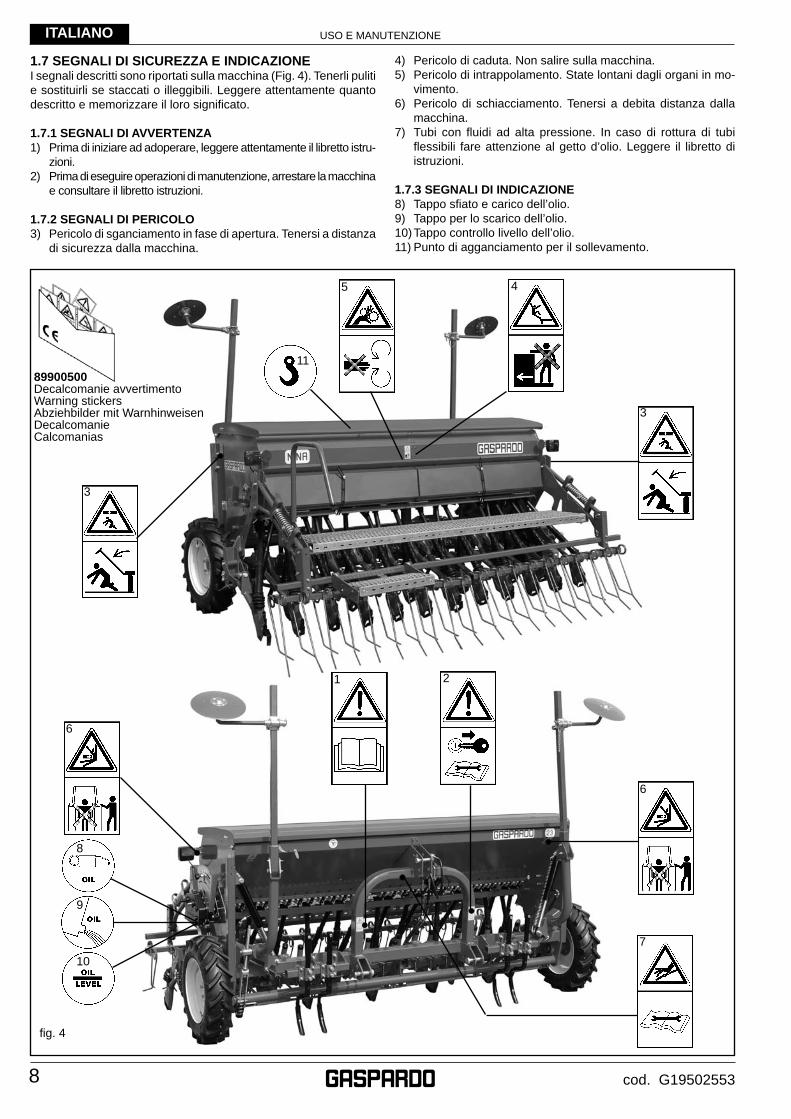
1.7 SEGNALI DI SICUREZZA E INDICAZIONEI segnali descritti sono riportati sulla macchina (Fig. 4). Tenerli puliti e sostituirli se staccati o illeggibili. Leggere attentamente quanto descritto e memorizzare il loro signifi cato.
1.7.1 SEGNALI DI AVVERTENZA1) Prima di iniziare ad adoperare, leggere attentamente il libretto istru-
zioni.2) Prima di eseguire operazioni di manutenzione, arrestare la macchina
e consultare il libretto istruzioni.
1.7.2 SEGNALI DI PERICOLO3) Pericolo di sganciamento in fase di apertura. Tenersi a distanza
di sicurezza dalla macchina.
4) Pericolo di caduta. Non salire sulla macchina.5) Pericolo di intrappolamento. State lontani dagli organi in mo-
vimento.6) Pericolo di schiacciamento. Tenersi a debita distanza dalla
macchina.7) Tubi con fl uidi ad alta pressione. In caso di rottura di tubi
fl essibili fare attenzione al getto d’olio. Leggere il libretto di istruzioni.
1.7.3 SEGNALI DI INDICAZIONE8) Tappo sfi ato e carico dell’olio.9) Tappo per lo scarico dell’olio. 10) Tappo controllo livello dell’olio.11) Punto di agganciamento per il sollevamento.
fi g. 4
8
10
9
4
3
2
6
1
5
7
11
6
3
89900500Decalcomanie avvertimentoWarning stickersAbziehbilder mit WarnhinweisenDecalcomanieCalcomanias
USO E MANUTENZIONE
9
ITALIANO
cod. G19502553
15) Prima di abbandonare il trattore, abbassare l’attrezzatura agganciata al gruppo sollevatore, arrestare il motore, inserire il freno di stazionamento e togliere la chiave di accensione dal quadro comandi, assicurarsi che nessuno possa avvicinarsi alle sostanze chimiche.
16) Con trattore in moto, non lasciare mai il posto di guida.17) Prima di mettere in funzione l’attrezzatura controllare che i
piedini di sostegno siano stati tolti da sotto la seminatrice; controllare che la seminatrice sia stata correttamente montata e regolata; controllare che la macchina sia perfettamente in ordine, e che tutti gli organi soggetti ad usura e deterioramento siano effi cienti.
18) Prima di sganciare l’attrezzatura dall’attacco terzo punto, mettere in posizione di blocco la leva di comando sollevatore e abbassare i piedini di appoggio.
Aggancio al trattore19) Agganciare l’attrezzatura, come previsto, su di un trattore
di adeguata potenza e confi gurazione mediante l’apposito dispositivo (sollevatore), conforme alle norme.
20) La categoria dei perni di attacco dell’attrezzatura deve corri-spondere a quella dell’attacco del sollevatore.
21) Fare attenzione quando si lavora nella zona dei bracci del sollevamento, è un’area molto pericolosa.
22) Prestare la massima attenzione nella fase di aggancio e sgan-cio dell’attrezzatura.
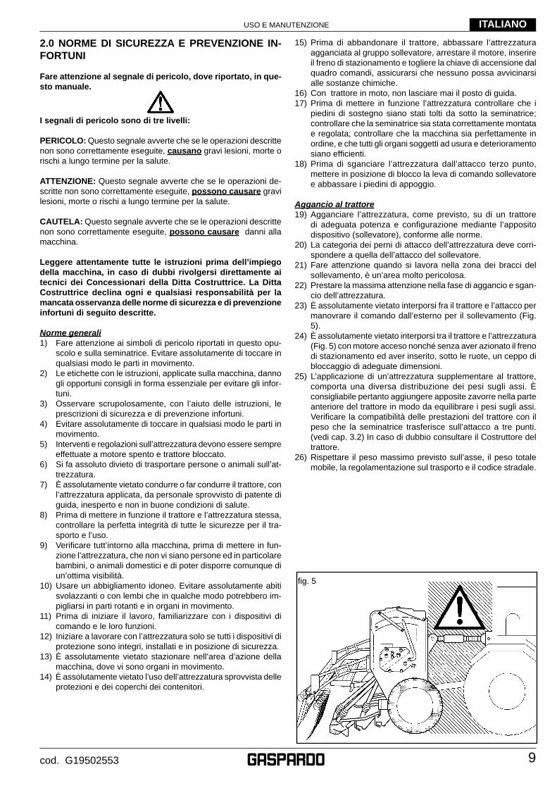
23) È assolutamente vietato interporsi fra il trattore e l’attacco per manovrare il comando dall’esterno per il sollevamento (Fig. 5).
24) È assolutamente vietato interporsi tra il trattore e l’attrezzatura (Fig. 5) con motore acceso nonché senza aver azionato il freno di stazionamento ed aver inserito, sotto le ruote, un ceppo di bloccaggio di adeguate dimensioni.
25) L’applicazione di un’attrezzatura supplementare al trattore, comporta una diversa distribuzione dei pesi sugli assi. È consigliabile pertanto aggiungere apposite zavorre nella parte anteriore del trattore in modo da equilibrare i pesi sugli assi. Verifi care la compatibilità delle prestazioni del trattore con il peso che la seminatrice trasferisce sull’attacco a tre punti. (vedi cap. 3.2) In caso di dubbio consultare il Costruttore del trattore.
26) Rispettare il peso massimo previsto sull’asse, il peso totale mobile, la regolamentazione sul trasporto e il codice stradale.
2.0 NORME DI SICUREZZA E PREVENZIONE IN-FORTUNI
Fare attenzione al segnale di pericolo, dove riportato, in que-sto manuale.
I segnali di pericolo sono di tre livelli:
PERICOLO: Questo segnale avverte che se le operazioni descritte non sono correttamente eseguite, causano gravi lesioni, morte o rischi a lungo termine per la salute.
ATTENZIONE: Questo segnale avverte che se le operazioni de-scritte non sono correttamente eseguite, possono causare gravi lesioni, morte o rischi a lungo termine per la salute.
CAUTELA: Questo segnale avverte che se le operazioni descritte non sono correttamente eseguite, possono causare danni alla macchina.
Leggere attentamente tutte le istruzioni prima dell’impiego della macchina, in caso di dubbi rivolgersi direttamente ai tecnici dei Concessionari della Ditta Costruttrice. La Ditta Costruttrice declina ogni e qualsiasi responsabilità per la mancata osservanza delle norme di sicurezza e di prevenzione infortuni di seguito descritte.
Norme generali1) Fare attenzione ai simboli di pericolo riportati in questo opu-
scolo e sulla seminatrice. Evitare assolutamente di toccare in qualsiasi modo le parti in movimento.
2) Le etichette con le istruzioni, applicate sulla macchina, danno gli opportuni consigli in forma essenziale per evitare gli infor-tuni.
3) Osservare scrupolosamente, con l’aiuto delle istruzioni, le prescrizioni di sicurezza e di prevenzione infortuni.
4) Evitare assolutamente di toccare in qualsiasi modo le parti in movimento.
5) Interventi e regolazioni sull’attrezzatura devono essere sempre effettuate a motore spento e trattore bloccato.
6) Si fa assoluto divieto di trasportare persone o animali sull’at-trezzatura.
7) È assolutamente vietato condurre o far condurre il trattore, con l’attrezzatura applicata, da personale sprovvisto di patente di guida, inesperto e non in buone condizioni di salute.
8) Prima di mettere in funzione il trattore e l’attrezzatura stessa, controllare la perfetta integrità di tutte le sicurezze per il tra-sporto e l’uso.
9) Verifi care tutt’intorno alla macchina, prima di mettere in fun-zione l’attrezzatura, che non vi siano persone ed in particolare bambini, o animali domestici e di poter disporre comunque di un’ottima visibilità.
10) Usare un abbigliamento idoneo. Evitare assolutamente abiti svolazzanti o con lembi che in qualche modo potrebbero im-pigliarsi in parti rotanti e in organi in movimento.
11) Prima di iniziare il lavoro, familiarizzare con i dispositivi di comando e le loro funzioni.
12) Iniziare a lavorare con l’attrezzatura solo se tutti i dispositivi di protezione sono integri, installati e in posizione di sicurezza.
13) È assolutamente vietato stazionare nell’area d’azione della macchina, dove vi sono organi in movimento.
14) È assolutamente vietato l’uso dell’attrezzatura sprovvista delle protezioni e dei coperchi dei contenitori.
fi g. 5
USO E MANUTENZIONE
10
ITALIANO
cod. G19502553
Circolazione su strada27) Per la circolazione su strada, è necessario attenersi alle nor-
mative del codice stradale in vigore nel relativo Paese.28) Gli eventuali accessori per il trasporto devono essere muniti
di segnalazioni e protezioni adeguate.29) È molto importante tenere presente che la tenuta di strada e la
capacità di direzione e frenatura, possono essere infl uenzati, anche in modo notevole, dalla presenza di un’attrezzatura portata o trainata.
30) In curva, fare attenzione alla forza centrifuga esercitata in po-sizione diversa, del centro di gravità, con e senza l’attrezzatura portata.
31) Per la fase di trasporto, regolare e fi ssare le catene dei bracci laterali di sollevamento del trattore; controllare che siano ben chiusi i coperchi dei serbatoi delle sementi e del concime; met-tere in posizione di blocco la leva di comando del sollevatore idraulico.
32) Effettuare gli spostamenti su strada con tutti i serbatoi vuoti.33) Gli spostamenti fuori dalla zona di lavoro devono avvenire con
l’attrezzatura in posizione di trasporto.34) La Ditta Costruttrice fornisce a richiesta supporti e tabelle per
segnalazione ingombro.35) Qualora gli ingombri costituiti da attrezzature portate o semi-
portate occultino la visibilità dei dispositivi di segnalazione e di illuminazione della trattrice, questi ultimi devono essere ripetuti adeguatamente sulle attrezzature, attenendosi alle normative del codice stradale in vigore nel relativo paese. Accertarsi, quando in uso, che l’impianto luci sia perfettamente funzionante.
Sicurezza relativa all’idraulica36) Al momento dell’allacciamento dei tubi idraulici all’impianto
idraulico del trattore, fare attenzione che gli impianti idraulici della macchina operatrice e della trattrice non siano in pres-sione.
37) In caso di collegamenti funzionali di tipo idraulico tra trattrice e macchina operatrice, prese e spine dovrebbero essere contrassegnate per mezzo di colori, in modo da escludere impieghi errati. Ove si verifi casse uno scambio, sussisterebbe il pericolo di incidente.
38) L’impianto idraulico si trova sotto alta pressione; a causa del pericolo d’infortunio, in caso di ricerca di punti di perdita vanno utilizzati gli strumenti ausiliari idonei.
39) Non effettuare MAI la ricerca perdite con le dita o le mani. I liquidi che fuoriescono dai forellini possono essere quasi invisibili.
40) Durante il trasporto su strada i collegamenti idraulici fra trat-trice e macchina operatrice devono essere scollegati e fi ssati nell’apposito supporto.
41) Non utilizzare in alcun caso olii vegetali. Questi potrebbero provocare rischi di danneggiamento alle guarnizioni dei cilindri.
42) Le pressioni di esercizio dell’impianto oleodinamico devono essere comprese tra le 100 bar e le 180 bar.
43) Mai superare la pressione prevista dell’impianto oleodinamico.44) Verifi care il corretto innesto degli attacchi rapidi, si potrebbero
verifi care danneggiamenti ai componenti dell’impianto.45) La fuoriuscita di olio ad alta pressione può causare ferite
cutanee con il rischio di gravi ferite ed infezioni. In tal caso consultare immediatamente un medico. Se non si rimuove rapidamente l’olio con mezzi chirurgici, possono verifi carsi gravi allergie e/o infezioni. Quindi si vieta assolutamente di installare componenti oleodinamici nella cabina del trattore. Tutti i componenti facenti parte dell’impianto, vanno accurata-mente sistemati per evitare danneggiamenti durante l’utilizzo dell’attrezzatura.
46) In caso di intervento sull’impianto oleodinamico, scaricare la pressione oleodinamica portando tutti i comandi idraulici in tutte le posizioni alcune volte dopo aver spento il motore.
Manutenzione in sicurezzaDurante le operazioni di lavoro e manutenzione, utilizzare gliidonei dispositivi di protezione individuale (es.):
Tuta Guanti Calzature Occhiali Cuffi e
47) Non procedere con i lavori di manutenzione e di pulizia se prima non è stata disinserita la presa di potenza, spento il motore, inserito il freno di stazionamento e bloccato il trattore con un ceppo o un sasso, di dimensioni adeguate, sotto le ruote.
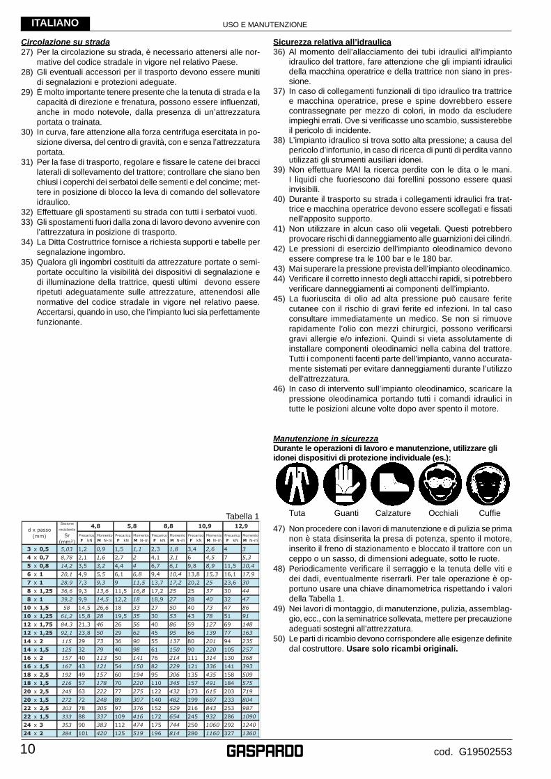
48) Periodicamente verifi care il serraggio e la tenuta delle viti e dei dadi, eventualmente riserrarli. Per tale operazione è op-portuno usare una chiave dinamometrica rispettando i valori della Tabella 1.
49) Nei lavori di montaggio, di manutenzione, pulizia, assemblag-gio, ecc., con la seminatrice sollevata, mettere per precauzione adeguati sostegni all’attrezzatura.
50) Le parti di ricambio devono corrispondere alle esigenze defi nite dal costruttore. Usare solo ricambi originali.
Tabella 1
USO E MANUTENZIONE
11
ITALIANO
cod. G19502553
3.0 NORME D’USO
Per ottenere le migliori prestazioni dell’attrezzatura, seguire atten-tamente quanto di seguito riportato.
ATTENZIONE
Tutte le operazioni di manutenzione, regolazione e di prepara-zione al lavoro, devono essere eseguite tassativamente con trattore spento e ben fermo, chiave disinserita e seminatrice a terra.
3.1 COMPLETAMENTO MACCHINAPer ragioni connesse al trasporto, l’erpice copriseme, il gruppo segnalazione ottica posteriore, le pedane ed i dischi marcafi le non sono montati.Provvedere alla loro installazione prima di utilizzare la seminatrice secondo gli schemi allegati alla macchina.
3.2 APPLICAZIONE AL TRATTORELa seminatrice è applicabile a qualsiasi trattore munito di attacco universale a tre punti.
PERICOLO
L’applicazione al trattore è una fase molto pericolosa. Fare molta attenzione ad effettuare l’intera operazione seguendo le istruzioni.
3.2.1 AGGANCIO La corretta posizione trattore/seminatrice, viene determinata, ponendo l’attrezzatura su un piano orizzontale.
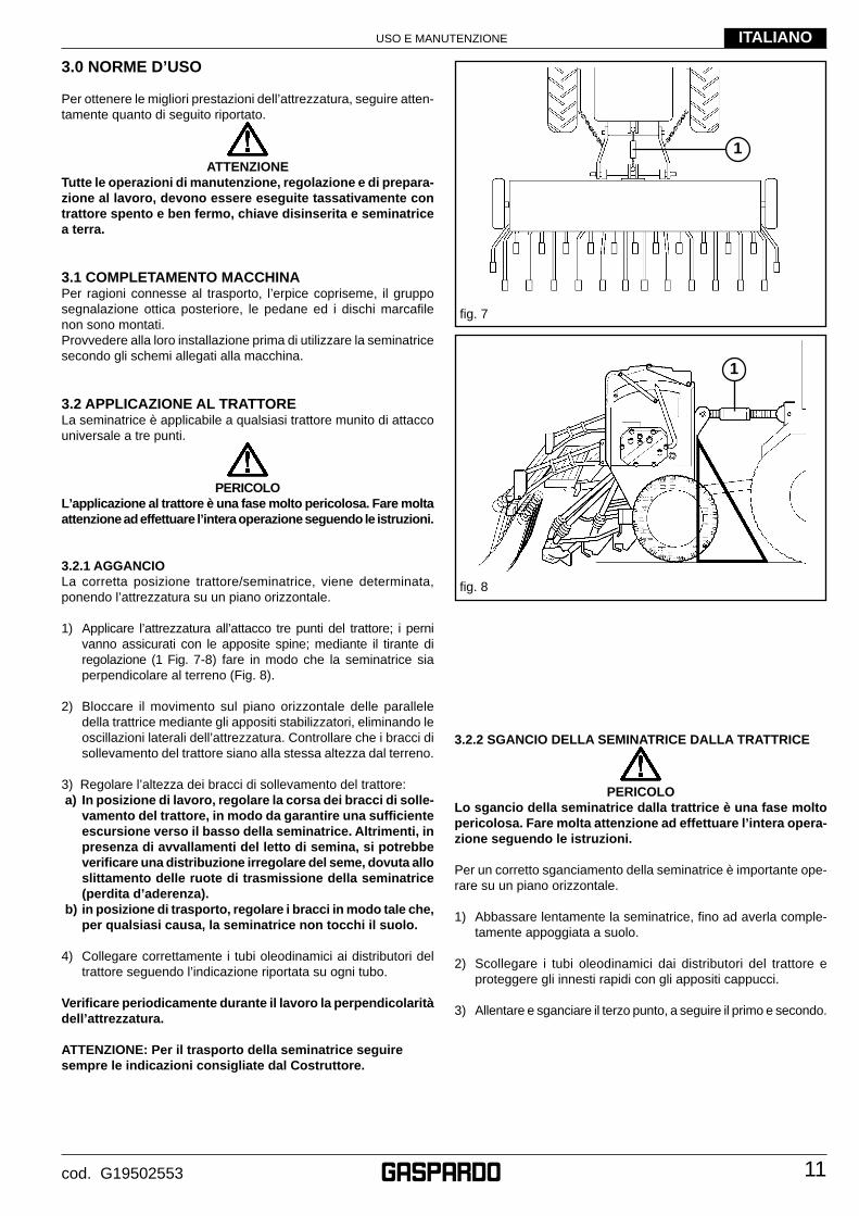
1) Applicare l’attrezzatura all’attacco tre punti del trattore; i perni vanno assicurati con le apposite spine; mediante il tirante di regolazione (1 Fig. 7-8) fare in modo che la seminatrice sia perpendicolare al terreno (Fig. 8).
2) Bloccare il movimento sul piano orizzontale delle parallele della trattrice mediante gli appositi stabilizzatori, eliminando le oscillazioni laterali dell’attrezzatura. Controllare che i bracci di sollevamento del trattore siano alla stessa altezza dal terreno.
3) Regolare l’altezza dei bracci di sollevamento del trattore: a) In posizione di lavoro, regolare la corsa dei bracci di solle-
vamento del trattore, in modo da garantire una suffi ciente escursione verso il basso della seminatrice. Altrimenti, in presenza di avvallamenti del letto di semina, si potrebbe verifi care una distribuzione irregolare del seme, dovuta allo slittamento delle ruote di trasmissione della seminatrice (perdita d’aderenza).
b) in posizione di trasporto, regolare i bracci in modo tale che, per qualsiasi causa, la seminatrice non tocchi il suolo.
4) Collegare correttamente i tubi oleodinamici ai distributori del trattore seguendo l’indicazione riportata su ogni tubo.
Verifi care periodicamente durante il lavoro la perpendicolarità dell’attrezzatura.
ATTENZIONE: Per il trasporto della seminatrice seguire sempre le indicazioni consigliate dal Costruttore.
fi g. 8
fi g. 7
3.2.2 SGANCIO DELLA SEMINATRICE DALLA TRATTRICE
PERICOLO
Lo sgancio della seminatrice dalla trattrice è una fase molto pericolosa. Fare molta attenzione ad effettuare l’intera opera-zione seguendo le istruzioni.
Per un corretto sganciamento della seminatrice è importante ope-rare su un piano orizzontale.
1) Abbassare lentamente la seminatrice, fi no ad averla comple-tamente appoggiata a suolo.
2) Scollegare i tubi oleodinamici dai distributori del trattore e proteggere gli innesti rapidi con gli appositi cappucci.
3) Allentare e sganciare il terzo punto, a seguire il primo e secondo.
1
1
USO E MANUTENZIONE
12
ITALIANO
cod. G19502553
fi g. 10
fi g. 9
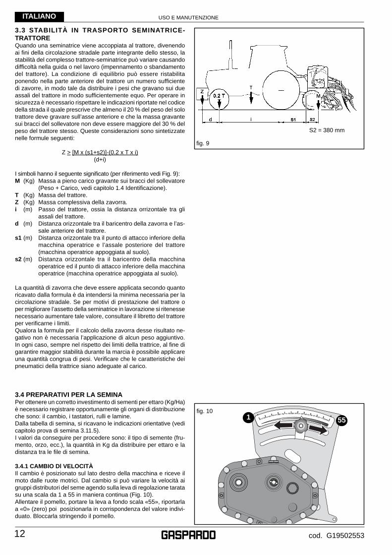
3.3 STABILITÀ IN TRASPORTO SEMINATRICE-TRATTOREQuando una seminatrice viene accoppiata al trattore, divenendo ai fi ni della circolazione stradale parte integrante dello stesso, la stabilità del complesso trattore-seminatrice può variare causando diffi coltà nella guida o nel lavoro (impennamento o sbandamento del trattore). La condizione di equilibrio può essere ristabilita ponendo nella parte anteriore del trattore un numero suffi ciente di zavorre, in modo tale da distribuire i pesi che gravano sui due assali del trattore in modo suffi cientemente equo. Per operare in sicurezza è necessario rispettare le indicazioni riportate nel codice della strada il quale prescrive che almeno il 20 % del peso del solo trattore deve gravare sull’asse anteriore e che la massa gravante sui bracci del sollevatore non deve essere maggiore del 30 % del peso del trattore stesso. Queste considerazioni sono sintetizzate nelle formule seguenti:
Z > [M x (s1+s2)]-(0.2 x T x i) (d+i)
I simboli hanno il seguente signifi cato (per riferimento vedi Fig. 9):M (Kg) Massa a pieno carico gravante sui bracci del sollevatore
(Peso + Carico, vedi capitolo 1.4 Identifi cazione).T (Kg) Massa del trattore.Z (Kg) Massa complessiva della zavorra.i (m) Passo del trattore, ossia la distanza orrizontale tra gli
assali del trattore.d (m) Distanza orizzontale tra il baricentro della zavorra e l’as-
sale anteriore del trattore.s1 (m) Distanza orizzontale tra il punto di attacco inferiore della
macchina operatrice e l’assale posteriore del trattore (macchina operatrice appoggiata al suolo).
s2 (m) Distanza orizzontale tra il baricentro della macchina operatrice ed il punto di attacco inferiore della macchina operatrice (macchina operatrice appoggiata al suolo).
La quantità di zavorra che deve essere applicata secondo quanto ricavato dalla formula è da intendersi la minima necessaria per la circolazione stradale. Se per motivi di prestazione del trattore o per migliorare l’assetto della seminatrice in lavorazione si ritenesse necessario aumentare tale valore, consultare il libretto del trattore per verifi carne i limiti.Qualora la formula per il calcolo della zavorra desse risultato ne-gativo non è necessaria l’applicazione di alcun peso aggiuntivo. In ogni caso, sempre nel rispetto dei limiti della trattrice, al fi ne di garantire maggior stabilità durante la marcia è possibile applicare una quantità congrua di pesi. Verifi care che le caratteristiche dei pneumatici della trattrice siano adeguate al carico.
3.4 PREPARATIVI PER LA SEMINAPer ottenere un corretto investimento di sementi per ettaro (Kg/Ha) è necessario registrare opportunamente gli organi di distribuzione che sono: il cambio, i tastatori, rulli e lamine.Dalla tabella di semina, si ricavano le indicazioni orientative (vedi capitolo prova di semina 3.11.5).I valori da conseguire per procedere sono: il tipo di semente (fru-mento, orzo, ecc.), la quantità in Kg da distribuire per ettaro e la distanza tra le fi le di semina.
3.4.1 CAMBIO Dl VELOCITÀIl cambio è posizionato sul lato destro della macchina e riceve il moto dalle ruote motrici. Dal cambio si può variare la velocità ai gruppi distributori del seme agendo sulla leva di regolazione tarata su una scala da 1 a 55 in maniera continua (Fig. 10).Allentare il pomello, portare la leva a fondo scala «55», riportarla a «0» (zero) poi posizionarla in corrispondenza del valore indivi-duato. Bloccarla stringendo il pomello.
S2 = 380 mm
551
USO E MANUTENZIONE
13
ITALIANO
cod. G19502553
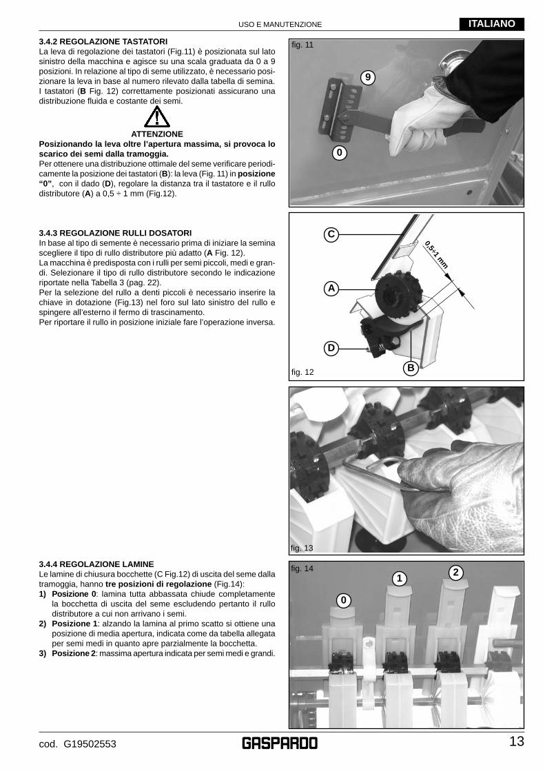
3.4.2 REGOLAZIONE TASTATORILa leva di regolazione dei tastatori (Fig.11) è posizionata sul lato sinistro della macchina e agisce su una scala graduata da 0 a 9 posizioni. In relazione al tipo di seme utilizzato, è necessario posi-zionare la leva in base al numero rilevato dalla tabella di semina. I tastatori (B Fig. 12) correttamente posizionati assicurano una distribuzione fl uida e costante dei semi.
ATTENZIONE
Posizionando la leva oltre l’apertura massima, si provoca lo scarico dei semi dalla tramoggia.Per ottenere una distribuzione ottimale del seme verifi care periodi-camente la posizione dei tastatori (B): la leva (Fig. 11) in posizione “0”, con il dado (D), regolare la distanza tra il tastatore e il rullo distributore (A) a 0,5 ÷ 1 mm (Fig.12).
3.4.3 REGOLAZIONE RULLI DOSATORIIn base al tipo di semente è necessario prima di iniziare la semina scegliere il tipo di rullo distributore più adatto (A Fig. 12).La macchina è predisposta con i rulli per semi piccoli, medi e gran-di. Selezionare il tipo di rullo distributore secondo le indicazione riportate nella Tabella 3 (pag. 22).Per la selezione del rullo a denti piccoli è necessario inserire la chiave in dotazione (Fig.13) nel foro sul lato sinistro del rullo e spingere all’esterno il fermo di trascinamento.Per riportare il rullo in posizione iniziale fare l’operazione inversa.
fi g. 11
fi g. 13
fi g. 12
0,5÷1 mm
3.4.4 REGOLAZIONE LAMINELe lamine di chiusura bocchette (C Fig.12) di uscita del seme dalla tramoggia, hanno tre posizioni di regolazione (Fig.14):1) Posizione 0: lamina tutta abbassata chiude completamente
la bocchetta di uscita del seme escludendo pertanto il rullo distributore a cui non arrivano i semi.
2) Posizione 1: alzando la lamina al primo scatto si ottiene una posizione di media apertura, indicata come da tabella allegata per semi medi in quanto apre parzialmente la bocchetta.
3) Posizione 2: massima apertura indicata per semi medi e grandi.
fi g. 14
9
0
C
A
D
B
12
0
USO E MANUTENZIONE
14
ITALIANO
cod. G19502553
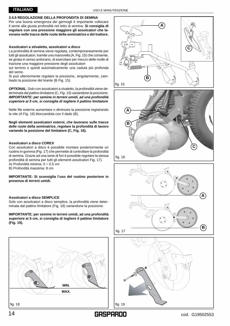
3.4.5 REGOLAZIONE DELLA PROFONDITA Dl SEMINAPer una buona emergenza dei germogli è importante collocare il seme alla giusta profondità nel letto di semina. Si consiglia di regolare con una pressione maggiore gli assolcatori che la-vorano nelle tracce delle ruote della seminatrice e del trattore.
Assolcatori a stivaletto, assolcatori a discoLa profondità di semina viene regolata, contemporaneamente per tutti gli assolcatori, tramite una manovella (A, Fig. 15) che consente, se girata in senso antiorario, di esercitare per mezzo delle molle di trazione una maggiore pressione degli assolcatorisul terreno e quindi automaticamente una caduta più profonda del seme.Si può ulteriormente regolare la pressione, singolarmente, cam-biado la posizione del tirante (B Fig. 15).
OPTIONAL: Solo con assolcatori a sivaletto, la profondità viene de-terminata dal pattino limitatore (C, Fig. 15) variandone la posizione. IMPORTANTE: per semine in terreni umidi, ad una profondità superiore ai 5 cm, si consiglia di togliere il pattino limitatore
Nelle fi le esterne aumentare o diminuire la pressione registrando la vite (A Fig. 16) bloccandola con il dado (B).
Negli elementi assolcatori esterni, che lavorano sulle tracce delle ruote della seminatrice, regolare la profondità di lavoro variando la posizione del limitatore (C, Fig. 16).
Assolcatori a disco COREXCon assolcatori a disco è possibile montare posteriormente un ruotino in gomma (Fig. 17) che permette di controllare la profondità di semina. Grazie ad una serie di fori è possibile regolare la stessa profondità di semina per tutti gli elementi assolcatori Fig. 17).A) Profondità minima: 0 ÷ 0,5 cmB) Profondità massima: 8 cm
IMPORTANTE: Si sconsiglia l’uso del ruotino posteriore in presenza di terreni umidi.
Assolcatori a disco SEMPLICESolo con assolcatori a disco semplice, la profondità viene deter-minata dal pattino limitatore (Fig. 18) variandone la posizione.
IMPORTANTE: per semine in terreni umidi, ad una profondità superiore ai 5 cm, si consiglia di togliere il pattino limitatore (Fig. 19).
fi g. 17
fi g. 15
fi g. 16
A
B
A
B
C
A
B
MIN.
MAX.
fi g. 19fi g. 18
C
USO E MANUTENZIONE
15
ITALIANO
cod. G19502553
fi g. 22
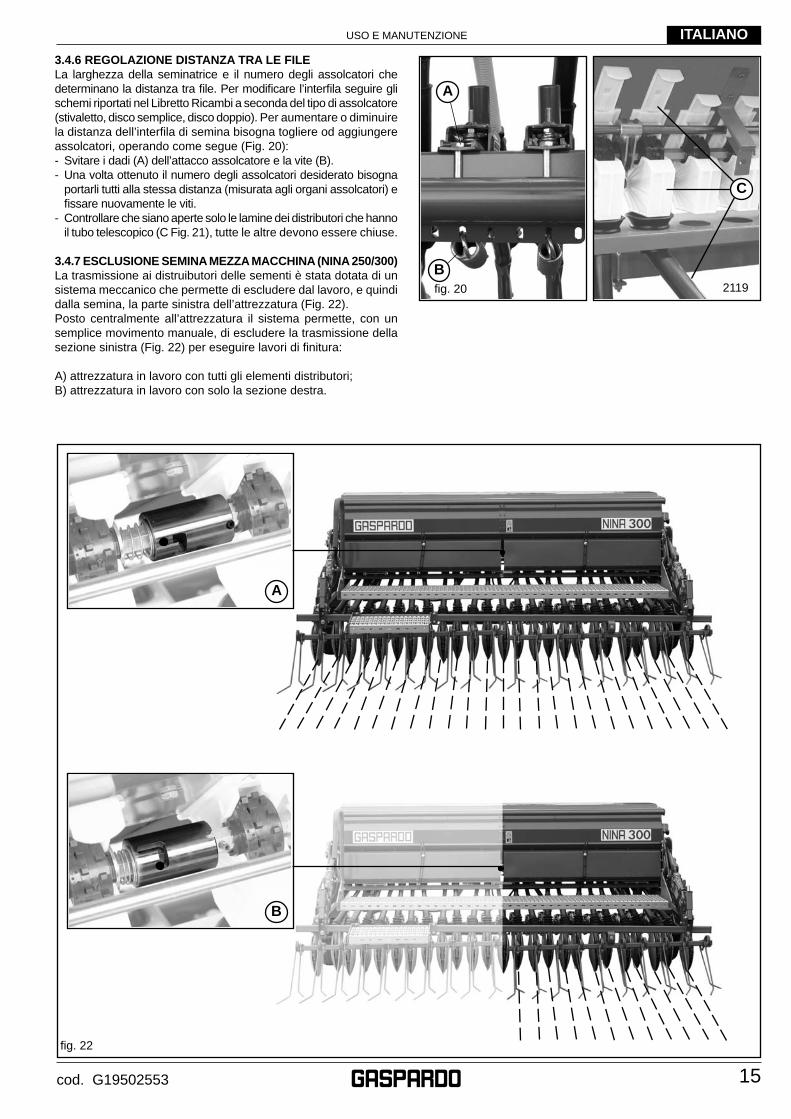
3.4.6 REGOLAZIONE DISTANZA TRA LE FILELa larghezza della seminatrice e il numero degli assolcatori che determinano la distanza tra fi le. Per modifi care l’interfi la seguire gli schemi riportati nel Libretto Ricambi a seconda del tipo di assolcatore (stivaletto, disco semplice, disco doppio). Per aumentare o diminuire la distanza dell’interfi la di semina bisogna togliere od aggiungere assolcatori, operando come segue (Fig. 20):- Svitare i dadi (A) dell’attacco assolcatore e la vite (B).- Una volta ottenuto il numero degli assolcatori desiderato bisogna
portarli tutti alla stessa distanza (misurata agli organi assolcatori) e fi ssare nuovamente le viti.
- Controllare che siano aperte solo le lamine dei distributori che hanno il tubo telescopico (C Fig. 21), tutte le altre devono essere chiuse.
3.4.7 ESCLUSIONE SEMINA MEZZA MACCHINA (NINA 250/300)La trasmissione ai distruibutori delle sementi è stata dotata di un sistema meccanico che permette di escludere dal lavoro, e quindi dalla semina, la parte sinistra dell’attrezzatura (Fig. 22). Posto centralmente all’attrezzatura il sistema permette, con un semplice movimento manuale, di escludere la trasmissione della sezione sinistra (Fig. 22) per eseguire lavori di fi nitura:
A) attrezzatura in lavoro con tutti gli elementi distributori;B) attrezzatura in lavoro con solo la sezione destra.
fi g. 20 2119
A
B
C
B
A
USO E MANUTENZIONE
16
ITALIANO
cod. G19502553
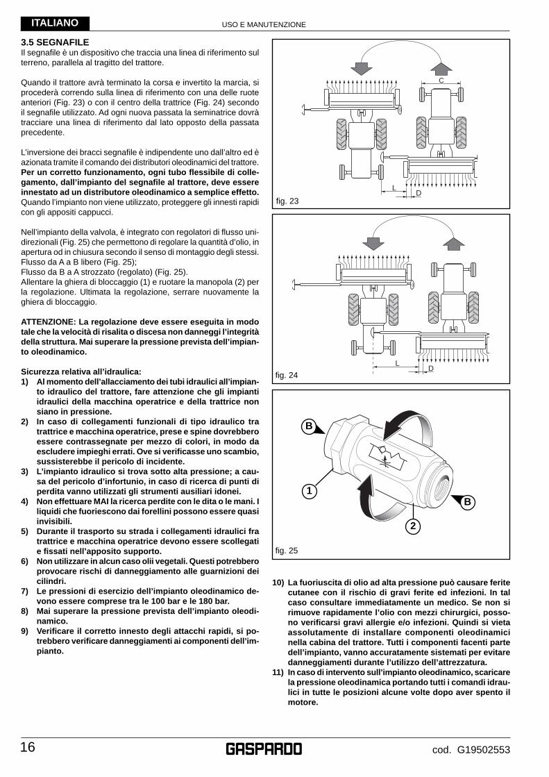
3.5 SEGNAFILEIl segnafi le è un dispositivo che traccia una linea di riferimento sul terreno, parallela al tragitto del trattore.
Quando il trattore avrà terminato la corsa e invertito la marcia, si procederà correndo sulla linea di riferimento con una delle ruote anteriori (Fig. 23) o con il centro della trattrice (Fig. 24) secondo il segnafi le utilizzato. Ad ogni nuova passata la seminatrice dovrà tracciare una linea di riferimento dal lato opposto della passata precedente.
L’inversione dei bracci segnafi le è indipendente uno dall’altro ed è azionata tramite il comando dei distributori oleodinamici del trattore. Per un corretto funzionamento, ogni tubo fl essibile di colle-gamento, dall’impianto del segnafi le al trattore, deve essere innestato ad un distributore oleodinamico a semplice effetto.Quando l’impianto non viene utilizzato, proteggere gli innesti rapidi con gli appositi cappucci.
Nell’impianto della valvola, è integrato con regolatori di fl usso uni-direzionali (Fig. 25) che permettono di regolare la quantità d’olio, in apertura od in chiusura secondo il senso di montaggio degli stessi.Flusso da A a B libero (Fig. 25);Flusso da B a A strozzato (regolato) (Fig. 25).Allentare la ghiera di bloccaggio (1) e ruotare la manopola (2) per la regolazione. Ultimata la regolazione, serrare nuovamente la ghiera di bloccaggio.
ATTENZIONE: La regolazione deve essere eseguita in modo tale che la velocità di risalita o discesa non danneggi l’integrità della struttura. Mai superare la pressione prevista dell’impian-to oleodinamico.
Sicurezza relativa all’idraulica:1) Al momento dell’allacciamento dei tubi idraulici all’impian-
to idraulico del trattore, fare attenzione che gli impianti idraulici della macchina operatrice e della trattrice non siano in pressione.
2) In caso di collegamenti funzionali di tipo idraulico tra trattrice e macchina operatrice, prese e spine dovrebbero essere contrassegnate per mezzo di colori, in modo da escludere impieghi errati. Ove si verifi casse uno scambio, sussisterebbe il pericolo di incidente.
3) L’impianto idraulico si trova sotto alta pressione; a cau-sa del pericolo d’infortunio, in caso di ricerca di punti di perdita vanno utilizzati gli strumenti ausiliari idonei.
4) Non effettuare MAI la ricerca perdite con le dita o le mani. I liquidi che fuoriescono dai forellini possono essere quasi invisibili.
5) Durante il trasporto su strada i collegamenti idraulici fra trattrice e macchina operatrice devono essere scollegati e fi ssati nell’apposito supporto.
6) Non utilizzare in alcun caso olii vegetali. Questi potrebbero provocare rischi di danneggiamento alle guarnizioni dei cilindri.
7) Le pressioni di esercizio dell’impianto oleodinamico de-vono essere comprese tra le 100 bar e le 180 bar.
8) Mai superare la pressione prevista dell’impianto oleodi-namico.
9) Verifi care il corretto innesto degli attacchi rapidi, si po-trebbero verifi care danneggiamenti ai componenti dell’im-pianto.
fi g. 23
L�D�
C�
LD
fi g. 24
fi g. 25
10) La fuoriuscita di olio ad alta pressione può causare ferite cutanee con il rischio di gravi ferite ed infezioni. In tal caso consultare immediatamente un medico. Se non si rimuove rapidamente l’olio con mezzi chirurgici, posso-no verifi carsi gravi allergie e/o infezioni. Quindi si vieta assolutamente di installare componenti oleodinamici nella cabina del trattore. Tutti i componenti facenti parte dell’impianto, vanno accuratamente sistemati per evitare danneggiamenti durante l’utilizzo dell’attrezzatura.
11) In caso di intervento sull’impianto oleodinamico, scaricare la pressione oleodinamica portando tutti i comandi idrau-lici in tutte le posizioni alcune volte dopo aver spento il motore.
B
B
1
2
USO E MANUTENZIONE
17
ITALIANO
cod. G19502553
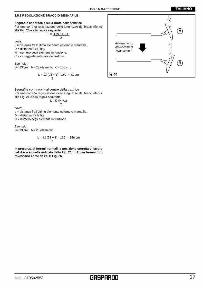
3.5.1 REGOLAZIONE BRACCIO SEGNAFILE
Segnafi le con traccia sulla ruota della trattricePer una corretta registrazione delle lunghezze dei bracci riferirsi alla Fig. 23 e alla regola seguente:
L = D (N +1) - C 2
dove:L = distanza fra l’ultimo elemento esterno e marcafi le. D = distanza fra le fi le. N = numero degli elementi in funzione. C = carreggiata anteriore del trattore.
Esempio:D= 13 cm; N= 23 elementi; C= 150 cm;
L = 13 (23 + 1) - 150 = 81 cm 2
Segnafi le con traccia al centro della trattricePer una corretta registrazione delle lunghezze dei bracci riferirsi alla Fig. 24 e alla regola seguente:
L = D (N +1) 2
dove:L = distanza fra l’ultimo elemento esterno e marcafi le. D = distanza fra le fi le. N = numero degli elementi in funzione.
Esempio:D= 13 cm; N= 23 elementi;
L = 13 (23 + 1) - 150 = 156 cm 2
In presenza di terreni normali la posizione corretta di lavoro del disco è quella indicata dalla Fig. 26 rif A; per terreni forti rovescarlo come da rif. B Fig. 26.
fi g. 26
AvanzamentoAdvancementAvancement
A
B
USO E MANUTENZIONE
18
ITALIANO
cod. G19502553
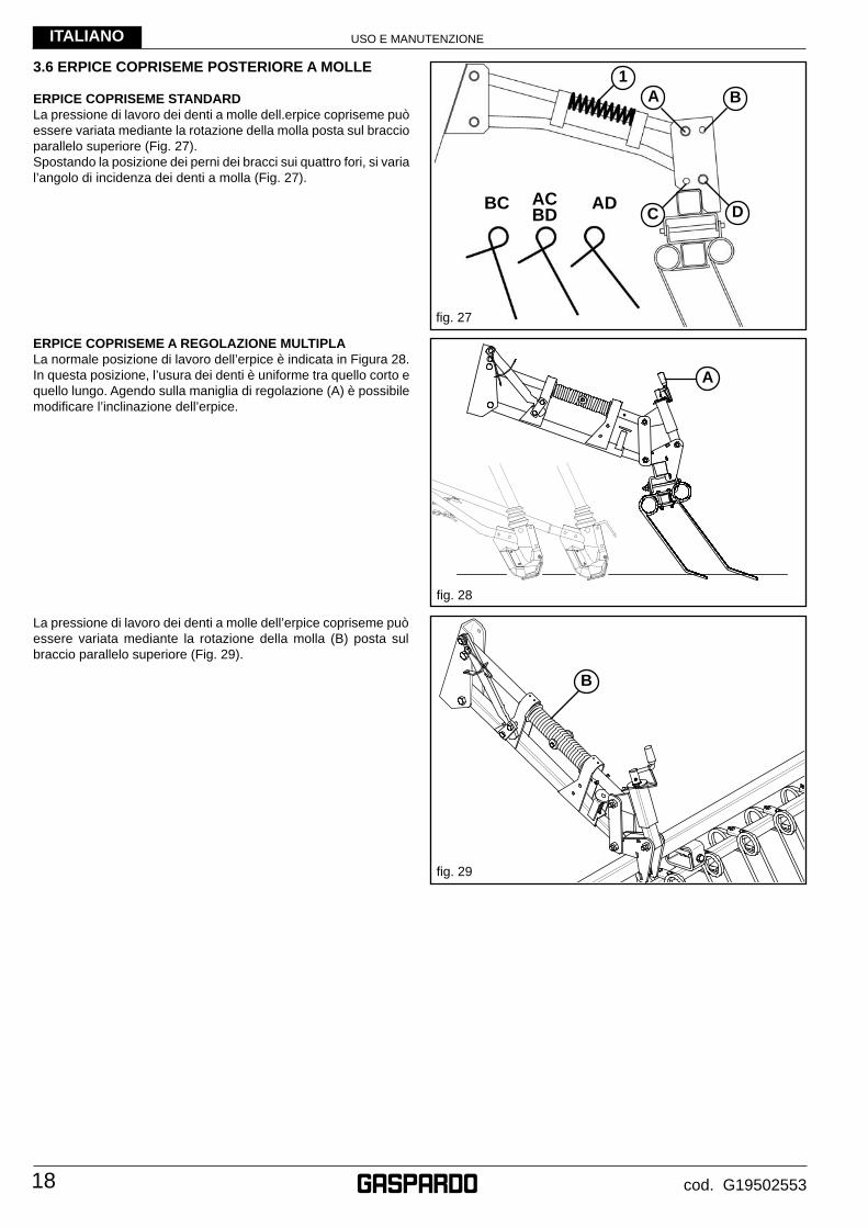
3.6 ERPICE COPRISEME POSTERIORE A MOLLE
ERPICE COPRISEME STANDARDLa pressione di lavoro dei denti a molle dell.erpice copriseme può essere variata mediante la rotazione della molla posta sul braccio parallelo superiore (Fig. 27).Spostando la posizione dei perni dei bracci sui quattro fori, si varia l’angolo di incidenza dei denti a molla (Fig. 27).
fi g. 29
fi g. 28
ERPICE COPRISEME A REGOLAZIONE MULTIPLALa normale posizione di lavoro dell’erpice è indicata in Figura 28.In questa posizione, l’usura dei denti è uniforme tra quello corto e quello lungo. Agendo sulla maniglia di regolazione (A) è possibile modifi care l’inclinazione dell’erpice.
La pressione di lavoro dei denti a molle dell’erpice copriseme può essere variata mediante la rotazione della molla (B) posta sul braccio parallelo superiore (Fig. 29).
fi g. 27
BC ACBD
AD
1
DC
BA
A
B
USO E MANUTENZIONE
19
ITALIANO
cod. G19502553
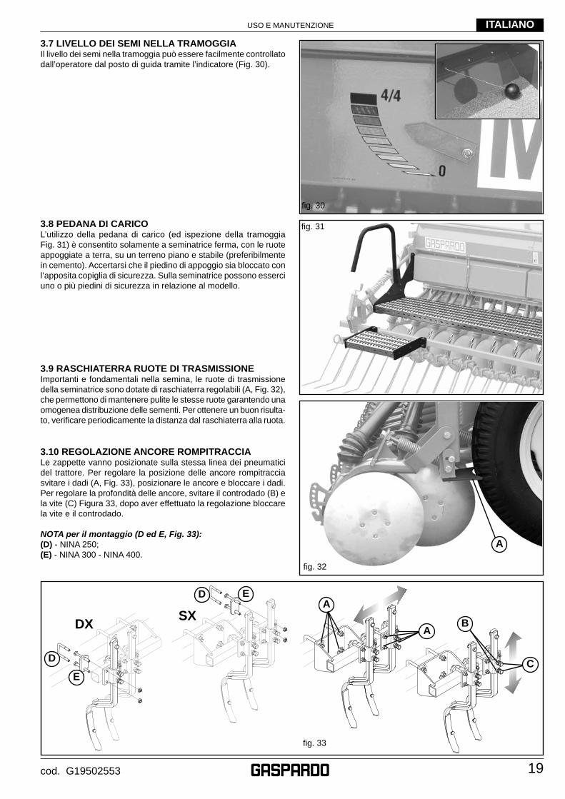
3.8 PEDANA DI CARICOL’utilizzo della pedana di carico (ed ispezione della tramoggia Fig. 31) è consentito solamente a seminatrice ferma, con le ruote appoggiate a terra, su un terreno piano e stabile (preferibilmente in cemento). Accertarsi che il piedino di appoggio sia bloccato con l’apposita copiglia di sicurezza. Sulla seminatrice possono esserci uno o più piedini di sicurezza in relazione al modello.
3.9 RASCHIATERRA RUOTE DI TRASMISSIONEImportanti e fondamentali nella semina, le ruote di trasmissione della seminatrice sono dotate di raschiaterra regolabili (A, Fig. 32), che permettono di mantenere pulite le stesse ruote garantendo una omogenea distribuzione delle sementi. Per ottenere un buon risulta-to, verifi care periodicamente la distanza dal raschiaterra alla ruota.
3.10 REGOLAZIONE ANCORE ROMPITRACCIALe zappette vanno posizionate sulla stessa linea dei pneumatici del trattore. Per regolare la posizione delle ancore rompitraccia svitare i dadi (A, Fig. 33), posizionare le ancore e bloccare i dadi. Per regolare la profondità delle ancore, svitare il controdado (B) e la vite (C) Figura 33, dopo aver effettuato la regolazione bloccare la vite e il controdado.
NOTA per il montaggio (D ed E, Fig. 33):(D) - NINA 250;(E) - NINA 300 - NINA 400.
fi g. 30
fi g. 31
3.7 LIVELLO DEI SEMI NELLA TRAMOGGIAIl livello dei semi nella tramoggia può essere facilmente controllato dall’operatore dal posto di guida tramite l’indicatore (Fig. 30).
A
fi g. 32
DXSX
A
C
fi g. 33
B
D
E
D E
A
USO E MANUTENZIONE
20
ITALIANO
cod. G19502553
3.11 DISTRIBUZIONE
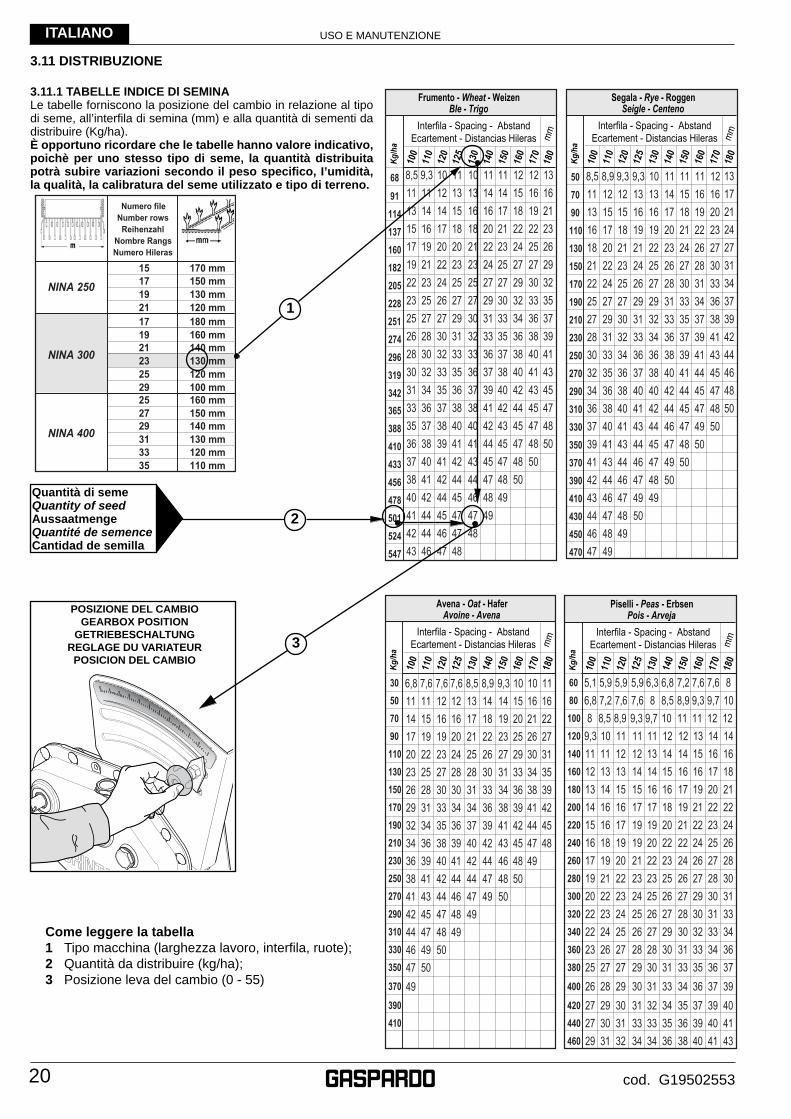
3.11.1 TABELLE INDICE Dl SEMINALe tabelle forniscono la posizione del cambio in relazione al tipo di seme, all’interfi la di semina (mm) e alla quantità di sementi da distribuire (Kg/ha).È opportuno ricordare che le tabelle hanno valore indicativo, poichè per uno stesso tipo di seme, la quantità distribuita potrà subire variazioni secondo il peso specifi co, I’umidità, la qualità, la calibratura del seme utilizzato e tipo di terreno.
Come leggere la tabella1 Tipo macchina (larghezza lavoro, interfi la, ruote);2 Quantità da distribuire (kg/ha);3 Posizione leva del cambio (0 - 55)
29
17160 mm
15
180 mm
19
120 mm
150 mm
100 mm160 mm
130 mm
170 mm
120 mm
NINA 400
NINA 300
NINA 250
110 mm
2527
21
25
19
35
Numero fileNumber rows
ReihenzahlNombre RangsNumero Hileras
17 150 mm
21130 mm140 mm
23
120 mm
140 mm29
33130 mm31
30507090110130150170190210230250270290310330350
370
390410
Kg/h
a
100
Ecartement - Distancias Hileras mm
110
120
125
130
140
150
160
170
180
Interfila - Spacing - Abstand
Avena - Oat - HaferAvoine - Avena
68
91
114
137
160
182
205
228
251
274
296
319
342
365
388
410
433
456
478
501
524
547
Kg/
ha
100
Ecartement - Distancias Hileras mm
110
120
125
130
140
150
160
170
180
Interfila - Spacing - Abstand
Frumento - Wheat - WeizenBle - Trigo
507090110130150170190210230250270290310330350370390410430450470
Kg/h
a
100
Ecartement - Distancias Hileras mm
110
120
125
130
140
150
160
170
180
Interfila - Spacing - Abstand
Segala - Rye - RoggenSeigle - Centeno
6080100120140160180200220240260280300320340360380
400
420440460
Kg/h
a
100
Ecartement - Distancias Hileras mm
110
120
125
130
140
150
160
170
180
Interfila - Spacing - Abstand
Piselli - Peas - ErbsenPois - Arveja POSIZIONE DEL CAMBIO
GEARBOX POSITIONGETRIEBESCHALTUNG
REGLAGE DU VARIATEURPOSICION DEL CAMBIO
Quantità di semeQuantity of seedAussaatmengeQuantité de semenceCantidad de semilla
1
2
3

USO E MANUTENZIONE
21
ITALIANO
cod. G19502553
115138161184207230253276299322345368391414434460483
506
529552500
Kg/h
a
100
Ecartement - Distancias Hileras mm
110
120
125
130
140
150
160
170
180
Interfila - Spacing - Abstand
Orzo - Barley - GersteOrge - Cebada
2581114172023262932353841
Kg/h
a
100
Ecartement - Distancias Hileras mm
110
120
125
130
140
150
160
170
180
Interfila - Spacing - Abstand
Trifoglio - Red Clover - RotkleeTrefle - Trebol
2124273033363942454851545760
Kg/h
a
100
Ecartement - Distancias Hileras mm
110
120
125
130
140
150
160
170
180
Interfila - Spacing - Abstand
Loglio - Darnel - WeidelgrasRyegrass - Cizaña
811141720232629323538414447
Kg/h
a
100
Ecartement - Distancias Hileras mm
110
120
125
130
140
150
160
170
180
Interfila - Spacing - Abstand
Erba medica - Lucern - LuzerneLuzerne - Alfalfa
6080100120140160180200220240260280300320340360380
400
420440460
Kg/h
a
100
Ecartement - Distancias Hileras mm
110
120
125
130
140
150
160
170
180
Interfila - Spacing - Abstand
Soia - Soya - SoiabohneSoya - Soya
246810121416182022242628
Kg/h
a
100
Ecartement - Distancias Hileras mm
110
120
125
130
140
150
160
170
180
Interfila - Spacing - Abstand
Colza - Rape - RapsColza - Colza
6080100120140160180200220240260280300320340360380
400
420440460
Kg/h
a
100
Ecartement - Distancias Hileras mm
110
120
125
130
140
150
160
170
180
Interfila - Spacing - Abstand
Sorgo - Sorghum - HirseSorgo - Sorgo
6080100120140160180200220240260280300320340360380
400
420440460
Kg/h
a
100
Ecartement - Distancias Hileras mm
110
120
125
130
140
150
160
170
180
Interfila - Spacing - Abstand
Ceci - Pulses - KichererbsePois chiche - Garbanzo
È opportuno ricordare che le tabelle hanno valore indicativo, poichè per uno stesso tipo di seme, la quantità distribuita potrà subire variazioni secondo il peso specifi co, I’umidità, la qualità, la calibratura del seme utilizzato e tipo di terreno. Per ottenere una semina precisa è consigliabile effettuare una prova di semina statica (capitolo 3.11.5).
USO E MANUTENZIONE
22
ITALIANO
cod. G19502553
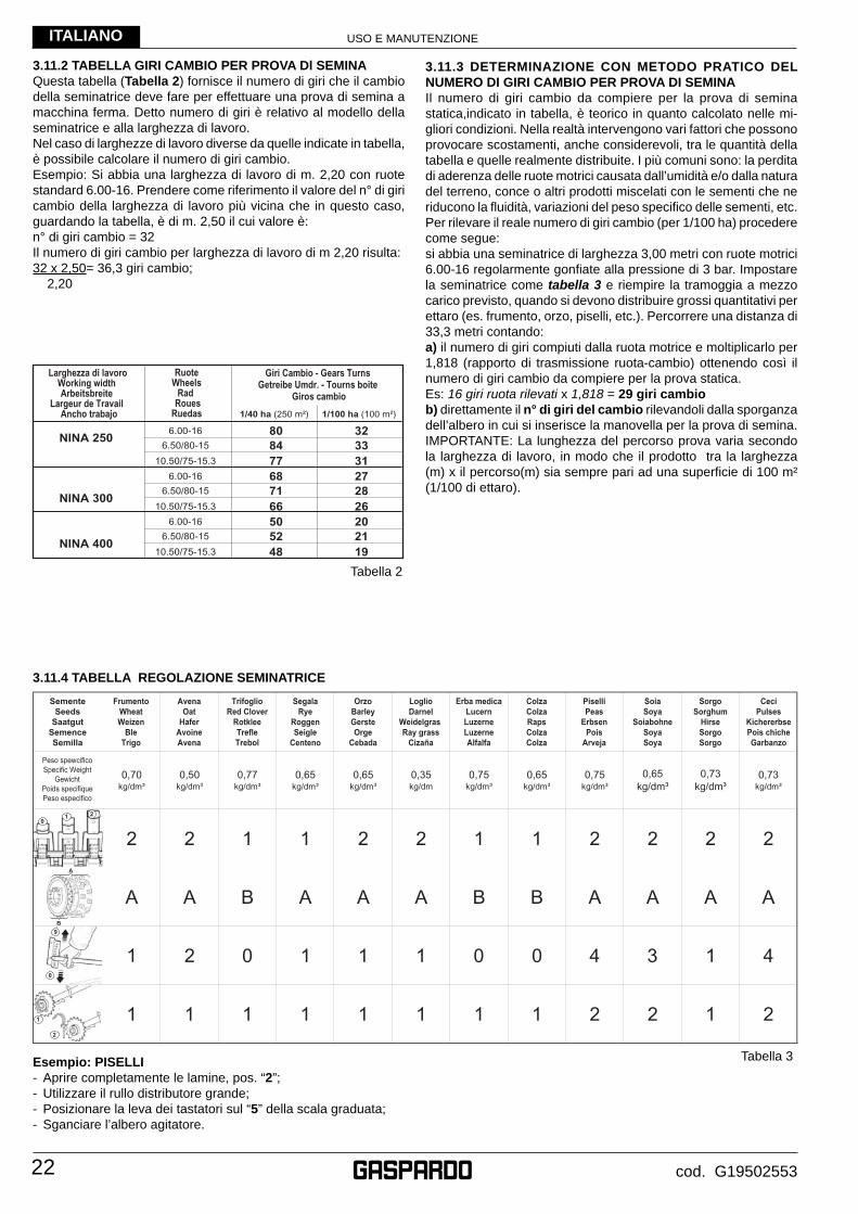
3.11.2 TABELLA GIRI CAMBIO PER PROVA Dl SEMINAQuesta tabella (Tabella 2) fornisce il numero di giri che il cambio della seminatrice deve fare per effettuare una prova di semina a macchina ferma. Detto numero di giri è relativo al modello della seminatrice e alla larghezza di lavoro.Nel caso di larghezze di lavoro diverse da quelle indicate in tabella, è possibile calcolare il numero di giri cambio.Esempio: Si abbia una larghezza di lavoro di m. 2,20 con ruote standard 6.00-16. Prendere come riferimento il valore del n° di giri cambio della larghezza di lavoro più vicina che in questo caso, guardando la tabella, è di m. 2,50 il cui valore è:n° di giri cambio = 32Il numero di giri cambio per larghezza di lavoro di m 2,20 risulta:32 x 2,50= 36,3 giri cambio; 2,20
3.11.3 DETERMINAZIONE CON METODO PRATICO DEL NUMERO DI GIRI CAMBIO PER PROVA DI SEMINAIl numero di giri cambio da compiere per la prova di semina statica,indicato in tabella, è teorico in quanto calcolato nelle mi-gliori condizioni. Nella realtà intervengono vari fattori che possono provocare scostamenti, anche considerevoli, tra le quantità della tabella e quelle realmente distribuite. I più comuni sono: la perdita di aderenza delle ruote motrici causata dall’umidità e/o dalla natura del terreno, conce o altri prodotti miscelati con le sementi che ne riducono la fl uidità, variazioni del peso specifi co delle sementi, etc.Per rilevare il reale numero di giri cambio (per 1/100 ha) procedere come segue:si abbia una seminatrice di larghezza 3,00 metri con ruote motrici 6.00-16 regolarmente gonfi ate alla pressione di 3 bar. Impostare la seminatrice come tabella 3 e riempire la tramoggia a mezzo carico previsto, quando si devono distribuire grossi quantitativi per ettaro (es. frumento, orzo, piselli, etc.). Percorrere una distanza di 33,3 metri contando:a) il numero di giri compiuti dalla ruota motrice e moltiplicarlo per 1,818 (rapporto di trasmissione ruota-cambio) ottenendo così il numero di giri cambio da compiere per la prova statica.Es: 16 giri ruota rilevati x 1,818 = 29 giri cambiob) direttamente il n° di giri del cambio rilevandoli dalla sporganza dell’albero in cui si inserisce la manovella per la prova di semina.IMPORTANTE: La lunghezza del percorso prova varia secondo la larghezza di lavoro, in modo che il prodotto tra la larghezza (m) x il percorso(m) sia sempre pari ad una superfi cie di 100 m² (1/100 di ettaro).
1/40 ha (250 m²) 1/100 ha (100 m²)
NINA 250
NINA 400
6.00-16 80 32
10.50/75-15.3 77 31
Larghezza di lavoroWorking width Arbeitsbreite
Largeur de Travail Ancho trabajo
RuoteWheels
Rad RouesRuedas
Giri Cambio - Gears Turns Getreibe Umdr. - Tourns boite
Giros cambio
6.00-16 50 20
10.50/75-15.3 48 196.50/80-15 52 21
NINA 300
6.00-16 68 27
10.50/75-15.3 66 266.50/80-15 71 28
6.50/80-15 84 33
1
2
0
9
A
B
01 2
2 0 1 1 1 0 0 4 3 1 4
3.11.4 TABELLA REGOLAZIONE SEMINATRICE
Esempio: PISELLI- Aprire completamente le lamine, pos. “2”;- Utilizzare il rullo distributore grande;- Posizionare la leva dei tastatori sul “5” della scala graduata;- Sganciare l’albero agitatore.
Tabella 3
Tabella 2
USO E MANUTENZIONE
23
ITALIANO
cod. G19502553
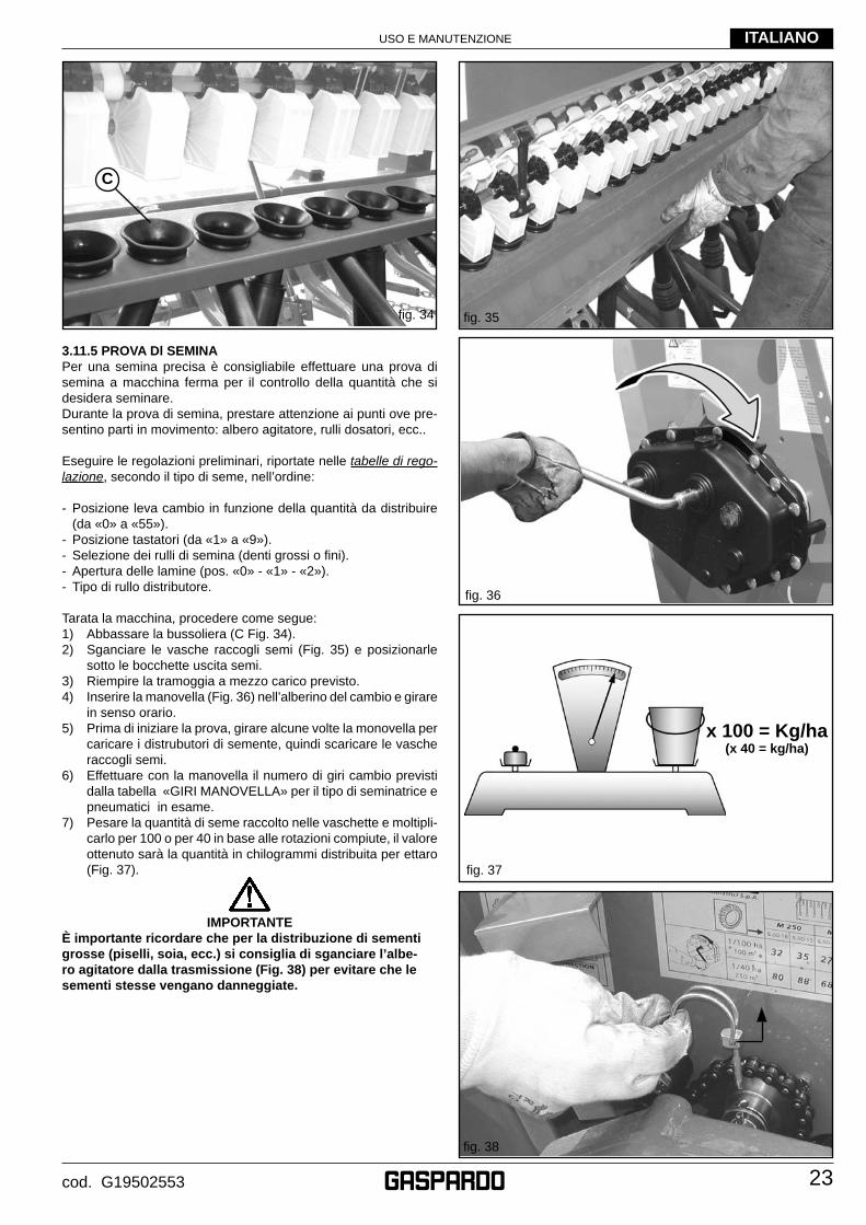
3.11.5 PROVA Dl SEMINAPer una semina precisa è consigliabile effettuare una prova di semina a macchina ferma per il controllo della quantità che si desidera seminare. Durante la prova di semina, prestare attenzione ai punti ove pre-sentino parti in movimento: albero agitatore, rulli dosatori, ecc..
Eseguire le regolazioni preliminari, riportate nelle tabelle di rego-lazione, secondo il tipo di seme, nell’ordine:
- Posizione leva cambio in funzione della quantità da distribuire (da «0» a «55»).
- Posizione tastatori (da «1» a «9»).- Selezione dei rulli di semina (denti grossi o fi ni).- Apertura delle lamine (pos. «0» - «1» - «2»).- Tipo di rullo distributore.
Tarata la macchina, procedere come segue:1) Abbassare la bussoliera (C Fig. 34).2) Sganciare le vasche raccogli semi (Fig. 35) e posizionarle
sotto le bocchette uscita semi.3) Riempire la tramoggia a mezzo carico previsto.4) Inserire la manovella (Fig. 36) nell’alberino del cambio e girare
in senso orario.5) Prima di iniziare la prova, girare alcune volte la monovella per
caricare i distrubutori di semente, quindi scaricare le vasche raccogli semi.
6) Effettuare con la manovella il numero di giri cambio previsti dalla tabella «GIRI MANOVELLA» per il tipo di seminatrice e pneumatici in esame.
7) Pesare la quantità di seme raccolto nelle vaschette e moltipli-carlo per 100 o per 40 in base alle rotazioni compiute, il valore ottenuto sarà la quantità in chilogrammi distribuita per ettaro (Fig. 37).
IMPORTANTE
È importante ricordare che per la distribuzione di sementi grosse (piselli, soia, ecc.) si consiglia di sganciare l’albe-ro agitatore dalla trasmissione (Fig. 38) per evitare che le sementi stesse vengano danneggiate.
fi g. 37
fi g. 37
fi g. 35
fi g. 38
fi g. 34
x 100 = Kg/ha(x 40 = kg/ha)
C
fi g. 36
USO E MANUTENZIONE
24
ITALIANO
cod. G19502553
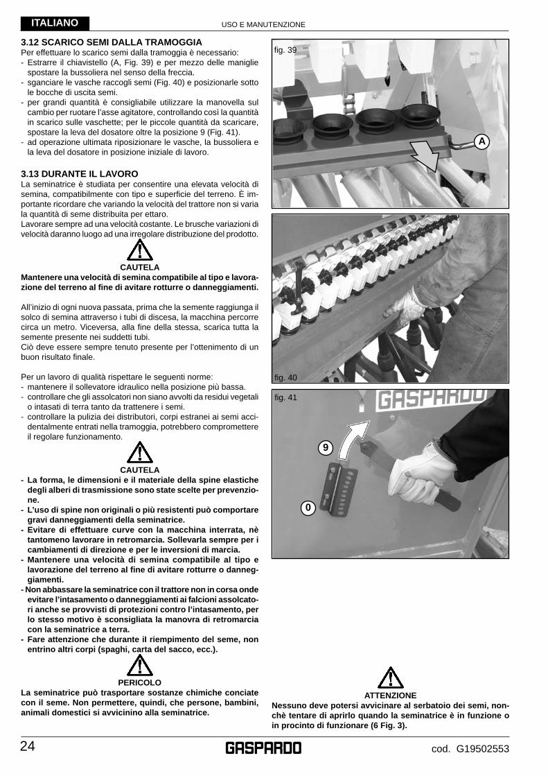
3.12 SCARICO SEMI DALLA TRAMOGGIAPer effettuare lo scarico semi dalla tramoggia è necessario:- Estrarre il chiavistello (A, Fig. 39) e per mezzo delle maniglie
spostare la bussoliera nel senso della freccia.- sganciare le vasche raccogli semi (Fig. 40) e posizionarle sotto
le bocche di uscita semi.- per grandi quantità è consigliabile utilizzare la manovella sul
cambio per ruotare l’asse agitatore, controllando così la quantità in scarico sulle vaschette; per le piccole quantità da scaricare, spostare la leva del dosatore oltre la posizione 9 (Fig. 41).
- ad operazione ultimata riposizionare le vasche, la bussoliera e la leva del dosatore in posizione iniziale di lavoro.
3.13 DURANTE IL LAVOROLa seminatrice è studiata per consentire una elevata velocità di semina, compatibilmente con tipo e superfi cie del terreno. È im-portante ricordare che variando la velocità del trattore non si varia la quantità di seme distribuita per ettaro.Lavorare sempre ad una velocità costante. Le brusche variazioni di velocità daranno luogo ad una irregolare distribuzione del prodotto.
CAUTELA
Mantenere una velocità di semina compatibile al tipo e lavora-zione del terreno al fi ne di avitare rotturre o danneggiamenti.
All’inizio di ogni nuova passata, prima che la semente raggiunga il solco di semina attraverso i tubi di discesa, la macchina percorre circa un metro. Viceversa, alla fi ne della stessa, scarica tutta la semente presente nei suddetti tubi.Ciò deve essere sempre tenuto presente per l’ottenimento di un buon risultato fi nale.
Per un lavoro di qualità rispettare le seguenti norme:- mantenere il sollevatore idraulico nella posizione più bassa.- controllare che gli assolcatori non siano avvolti da residui vegetali
o intasati di terra tanto da trattenere i semi.- controllare la pulizia dei distributori, corpi estranei ai semi acci-
dentalmente entrati nella tramoggia, potrebbero compromettere il regolare funzionamento.
CAUTELA
- La forma, le dimensioni e il materiale della spine elastiche degli alberi di trasmissione sono state scelte per prevenzio-ne.
- L’uso di spine non originali o più resistenti può comportare gravi danneggiamenti della seminatrice.
- Evitare di effettuare curve con la macchina interrata, nè tantomeno lavorare in retromarcia. Sollevarla sempre per i cambiamenti di direzione e per le inversioni di marcia.
- Mantenere una velocità di semina compatibile al tipo e lavorazione del terreno al fi ne di avitare rotturre o danneg-giamenti.
- Non abbassare la seminatrice con il trattore non in corsa onde evitare l’intasamento o danneggiamenti ai falcioni assolcato-ri anche se provvisti di protezioni contro l’intasamento, per lo stesso motivo è sconsigliata la manovra di retromarcia con la seminatrice a terra.
- Fare attenzione che durante iI riempimento del seme, non entrino altri corpi (spaghi, carta del sacco, ecc.).
PERICOLO
La seminatrice può trasportare sostanze chimiche conciate con il seme. Non permettere, quindi, che persone, bambini, animali domestici si avvicinino alla seminatrice.
fi g. 40
fi g. 41
fi g. 39
ATTENZIONE
Nessuno deve potersi avvicinare al serbatoio dei semi, non-chè tentare di aprirlo quando la seminatrice è in funzione o in procinto di funzionare (6 Fig. 3).
A
9
0
USO E MANUTENZIONE
25
ITALIANO
cod. G19502553
4.0 MANUTENZIONE
Sono di seguito elencate le varie operazioni di manutenzione da eseguirsi con periodicità. Il minor costo di esercizio ed una lunga durata della macchina dipende, tra l’altro, dalla metodica e costante osservanza di tali norme.
CAUTELA
- I tempi di intervento elencati in questo opuscolo hanno solo carattere informativo e sono relativi a condizioni normali di impiego, possono pertanto subire variazioni in relazione al genere di servizio, ambiente più o meno polveroso, fat-tori stagionali, ecc. Nel caso di condizioni più gravose di servizio, gli interventi di manutenzione vanno logicamente incrementati.
- Prima di iniettare il grasso lubrifi cante negli ingrassatori, è necessario pulire con cura gli ingrassatori stessi per impe-dire che il fango, la polvere o corpi estranei si mescolino con il grasso, facendo diminuire, o addirittura annullare, I’effetto della lubrifi cazione.
AVVERTENZA
- Tenere sempre gli olii ed i grassi al di fuori della portata dei bambini.
- Leggere sempre attentamente le avvertenze e le precauzioni indicate sui contenitori.
- Evitare il contatto con la pelle.- Dopo l’utilizzo lavarsi accuratamente e a fondo.- Trattare gli olii usati in conformità con le leggi vigenti.
4.1 A MACCHINA NUOVA - Dopo le prime otto ore di lavoro, controllare il serraggio di tutte
le viti.
4.2 OGNI 20/30 ORE Dl LAVORO- Verifi care il serraggio dei bulloni assolcatori.- Ingrassare la vite della manovella centrale (A, Fig. 15).- Ingrassare il perno dei dischi marcafi le.
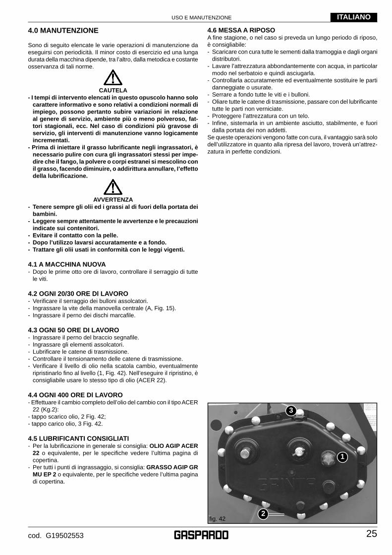
4.3 OGNI 50 ORE DI LAVORO- Ingrassare il perno del braccio segnafi le.- Ingrassare gli elementi assolcatori.- Lubrifi care le catene di trasmissione.- Controllare il tensionamento delle catene di trasmissione.- Verifi care il livello di olio nella scatola cambio, eventualmente
ripristinarlo fi no al livello (1, Fig. 42). Nell’eseguire il ripristino, è consigliabile usare lo stesso tipo di olio (ACER 22).
4.4 OGNI 400 ORE Dl LAVORO- Effettuare il cambio completo dell’olio del cambio con il tipo ACER
22 (Kg.2):- tappo scarico olio, 2 Fig. 42;- tappo carico olio, 3 Fig. 42.
4.5 LUBRIFICANTI CONSIGLIATI- Per la lubrifi cazione in generale si consiglia: OLIO AGIP ACER
22 o equivalente, per le specifi che vedere l’ultima pagina di copertina.
- Per tutti i punti di ingrassaggio, si consiglia: GRASSO AGIP GR MU EP 2 o equivalente, per le specifi che vedere l’ultima pagina di copertina.
4.6 MESSA A RIPOSOA fi ne stagione, o nel caso si preveda un lungo periodo di riposo, è consigliabile:- Scaricare con cura tutte le sementi dalla tramoggia e dagli organi
distributori.- Lavare l’attrezzatura abbondantemente con acqua, in particolar
modo nel serbatoio e quindi asciugarla.- Controllarla accuratamente ed eventualmente sostituire le parti
danneggiate o usurate.- Serrare a fondo tutte le viti e i bulloni.- Oliare tutte le catene di trasmissione, passare con del lubrifi cante
tutte le parti non verniciate.- Proteggere l’attrezzatura con un telo.- Infi ne, sistemarla in un ambiente asciutto, stabilmente, e fuori
dalla portata dei non addetti.Se queste operazioni vengono fatte con cura, il vantaggio sarà solo dell’utilizzatore in quanto alla ripresa del lavoro, troverà un’attrez-zatura in perfette condizioni.
fi g. 42
1
2
3
USO E MANUTENZIONE
26
ITALIANO
cod. G19502553
5.0 DEMOLIZIONE E SMALTIMENTO
Operazione da eseguirsi a cura del Cliente. Prima di effettuare la demolizione della macchina, si raccomanda di verifi care attentamente lo stato fi sico della stessa, valutando che non ci siano parti della struttura eventualmente soggette a possibili cedimenti strutturali o rotture in fase di demolizione.Il Cliente dovrà agire in osservanza delle leggi vigenti nel proprio paese in materia di rispetto e tutela dell’ambiente.
ATTENZIONE
Le operazioni di demolizione della macchina devono essere eseguite solamente da personale qualifi cato, dotato di adegua-ti dispositivi di protezione individuale (calzature di sicurezza e guanti) e di utensili e mezzi ausiliari.Tutte le operazioni di smontaggio per la demolizione devono avvenire a macchina ferma e staccata dal trattore.
Si raccomanda, prima di demolire la macchina, di rendere innocue tutte le parti suscettibili di fonti di pericolo e quindi:· rottamare la struttura tramite ditte specializzate,· asportare l’eventuale apparato elettrico attenendosi alle leggi
vigenti,· recuperare separatamente oli e grassi, da smaltire tramite le ditte
autorizzate, nel rispetto della normativa del Paese di utilizzo della macchina.
All’atto della demolizione della macchina la marcatura CE dovrà essere distrutta assieme al presente manuale.
Si ricorda infi ne che la Ditta Costruttrice è sempre a disposi-zione per qualsiasi necessità di assistenza e ricambi.

27cod. G19502553
Notes
ENGLISH
28 cod. G19502553
1.0 INTRODUCTION
This booklet describes the regulations for use, maintenance for seeding machine.This booklet is an integrating part of the product, and must be kept in a safe place for consultation during the whole life span of the machine.
ATTENTION• The Manufacturer reserves the right to change the machine
without having to promptly update this manual. In the event of disputes, the valid version is the Italian text.
• The machine was manufactured for dosing and distributing com-mercial seeds of standard quality.
• The machine was designed for professional skilled operators who are the only ones qualifi ed for operating it.
• Minors, illiterates and persons under altered physical or psycho-logical conditions must not be allowed to operate the machine.
• Operators who do not have a suitable driving license, or who are not properly informed and trained, must not be allowed to operate the machine.
• The operator must check that the machine operates correctly, and must replace and repair parts subject to wear that may cause damage.
• The customer should instruct personnel on accident risks, on the operator safety devices provided, on noise emission risks and on general accident prevention regulations provided for by the international directives and by the law in the country in which the machines are used.
• In any case, the machine should be used exclusively by skilled operators who will be held to follow scrupulously the technical and accident-prevention instructions in this manual.
• It is the user’s responsibility to check that the machine is opera-ted only in optimum conditions of safety for people, animals and property.
1.1 GUARANTEEThe guarantee is valid for a year, against all defects of material, from the date of delivery of the equipment.On delivery, check that the equipment has not been damaged du-ring transport and that the accessories are integral and complete.POSSIBLE CLAIMS MUST BE PRESENTED IN WRITING WITHIN EIGHT DAYS OF RECEIPT.The purchaser will enforce his rights on the guarantee only when he has respected the conditions concerning the benefi t of the guarantee, set out in the supply contract.
1.1.1 EXPIRY OF GUARANTEEBesides what has already been set out in the supply contract, the guarantee expires:- If the limits set out in the technical data table are overshot.- If the instructions set out in this booklet have not been carefully
followed.- If the equipment is used badly, defective maintenance or other
errors by the client.- If modifi cations have been carried out without written authorization
of the manufacturer and if non original spare parts have been used.
USE AND MAINTENANCE
29
ENGLISH
cod. G19502553
1.2 DESCRIPTION OF THE SEEDERThis farming implement, can only be operated by a farming tractor equipped with lift unit and universal three-point hitch.
The seeder is suitable for stand-alone use on tilled soil, or combined with equipment for the soil working (harrow, tiller, etc.). It is suitable for sowing cereal: wheat, barley, rye, oats, rice.
For minute and forage seeds: rape, clover, alfalfa, rye-grass.
For coarse seeds: soya, peas.
The seeds are deposited in the soil by means of furrower tools, cutter or disk Corex, and are distributed continuously by a toothed roller for each row. The quantities to be distributed is regulated by means of a cam variator (gear), whose motion derives from the wheels both being adherence driving wheels.The arms of the furrowing tools, independent of each other, dispose of a wide margin of oscillation to adapt to the surface of the ground.
ATTENTIONThe seeder is suitable only for the uses indicated. The recom-mended working speed is 8÷10 km/h. The planting unit must only be transported by road with the tanks and hoppers empty and at max speed of 25 km/h. Any other use different from that described in these instructions could cause damage to the machine and represent a serious hazard for the user. The machine must be operated by qualifi ed operators of the Cu-stomer. The operator must wear suitable personal protection equipment (safety footwear, overalls and gloves, etc.). This machine has been intended for professional use: it must be operated exclusively by preliminarily educated, trained and authorised operators who hold a regular driving license.
Operating instructions• The machine was manufactured for dosing and distributing com-
mercial seeds of standard quality.• It must be fi tted with a soil tilling equipment (rotating harrow),
connected to the three-point hook-up of a tractor and operated by an operator.
• The machine is intended for professional users: operation must be allowed to skilled operators only.
• The machine must be operated by one operator only.• The machine is not intended for purposes other than farming
applications.
Conforming machine operation also includes:• compliance with all the instructions provided in this manual;• performance of inspection and maintenance operations described
in this manual;• exclusive use of genuine GASPARDO spare parts.
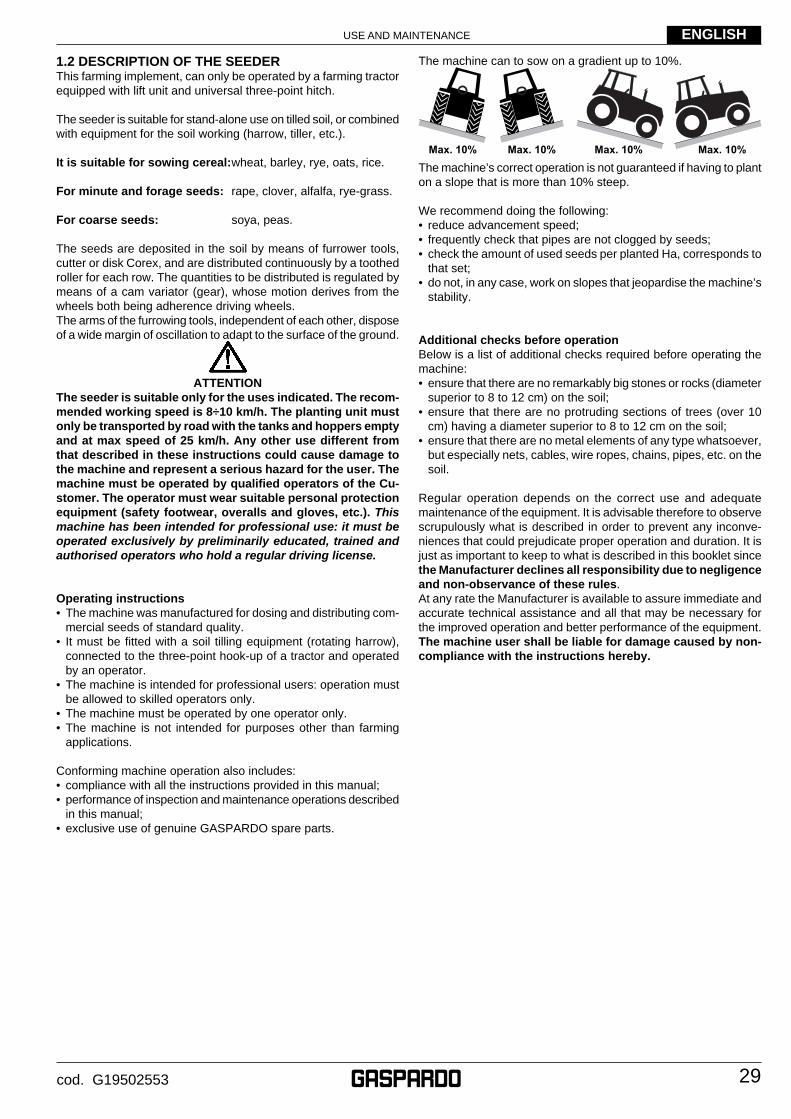
The machine can to sow on a gradient up to 10%.
Max. 10% Max. 10% Max. 10% Max. 10%
The machine’s correct operation is not guaranteed if having to plant on a slope that is more than 10% steep.
We recommend doing the following:• reduce advancement speed;• frequently check that pipes are not clogged by seeds;• check the amount of used seeds per planted Ha, corresponds to
that set;• do not, in any case, work on slopes that jeopardise the machine’s
stability.
Additional checks before operationBelow is a list of additional checks required before operating the machine:• ensure that there are no remarkably big stones or rocks (diameter
superior to 8 to 12 cm) on the soil; • ensure that there are no protruding sections of trees (over 10
cm) having a diameter superior to 8 to 12 cm on the soil; • ensure that there are no metal elements of any type whatsoever,
but especially nets, cables, wire ropes, chains, pipes, etc. on the soil.
Regular operation depends on the correct use and adequate maintenance of the equipment. It is advisable therefore to observe scrupulously what is described in order to prevent any inconve-niences that could prejudicate proper operation and duration. It is just as important to keep to what is described in this booklet since the Manufacturer declines all responsibility due to negligence and non-observance of these rules.At any rate the Manufacturer is available to assure immediate and accurate technical assistance and all that may be necessary for the improved operation and better performance of the equipment.The machine user shall be liable for damage caused by non-compliance with the instructions hereby.
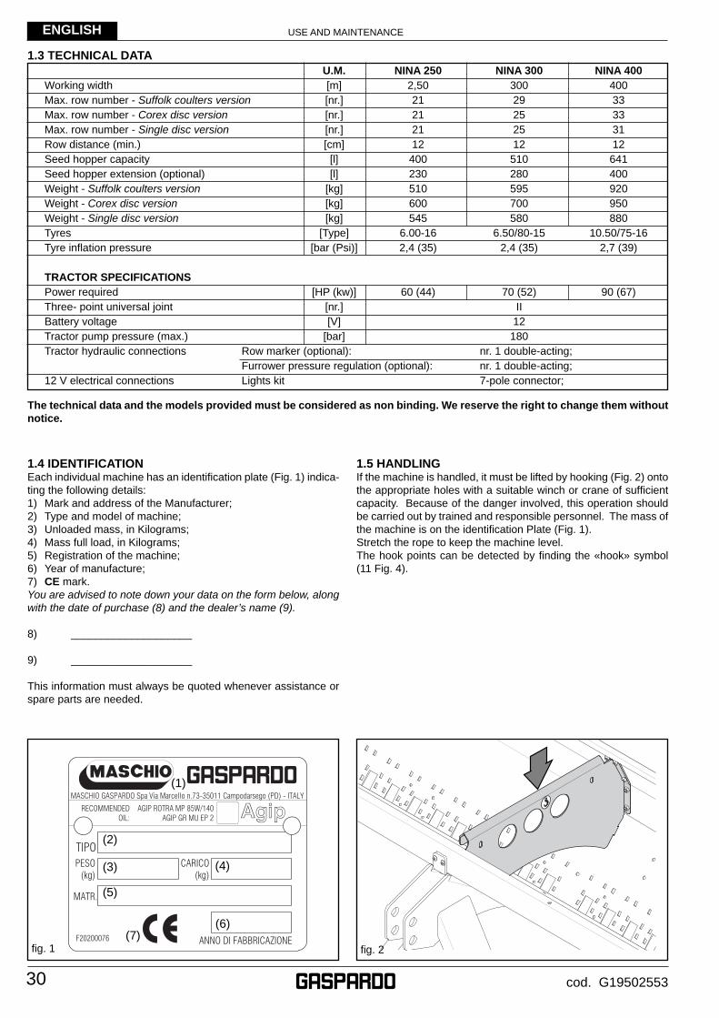
USE AND MAINTENANCE
30
ENGLISH
cod. G19502553
1.5 HANDLINGIf the machine is handled, it must be lifted by hooking (Fig. 2) onto the appropriate holes with a suitable winch or crane of suffi cient capacity. Because of the danger involved, this operation should be carried out by trained and responsible personnel. The mass of the machine is on the identifi cation Plate (Fig. 1).Stretch the rope to keep the machine level.The hook points can be detected by fi nding the «hook» symbol (11 Fig. 4).
1.4 IDENTIFICATIONEach individual machine has an identifi cation plate (Fig. 1) indica-ting the following details:1) Mark and address of the Manufacturer;2) Type and model of machine;3) Unloaded mass, in Kilograms;4) Mass full load, in Kilograms;5) Registration of the machine;6) Year of manufacture;7) CE mark.You are advised to note down your data on the form below, along with the date of purchase (8) and the dealer’s name (9).
8) ____________________
9) ____________________
This information must always be quoted whenever assistance or spare parts are needed.
1.3 TECHNICAL DATA U.M. NINA 250 NINA 300 NINA 400
Working width [m] 2,50 300 400
Max. row number - Suffolk coulters version [nr.] 21 29 33
Max. row number - Corex disc version [nr.] 21 25 33
Max. row number - Single disc version [nr.] 21 25 31
Row distance (min.) [cm] 12 12 12
Seed hopper capacity [l] 400 510 641
Seed hopper extension (optional) [l] 230 280 400
Weight - Suffolk coulters version [kg] 510 595 920
Weight - Corex disc version [kg] 600 700 950
Weight - Single disc version [kg] 545 580 880
Tyres [Type] 6.00-16 6.50/80-15 10.50/75-16
Tyre infl ation pressure [bar (Psi)] 2,4 (35) 2,4 (35) 2,7 (39)
TRACTOR SPECIFICATIONS
Power required [HP (kw)] 60 (44) 70 (52) 90 (67)
Three- point universal joint [nr.] II
Battery voltage [V] 12
Tractor pump pressure (max.) [bar] 180
Tractor hydraulic connections Row marker (optional): nr. 1 double-acting;
Furrower pressure regulation (optional): nr. 1 double-acting;
12 V electrical connections Lights kit 7-pole connector;
The technical data and the models provided must be considered as non binding. We reserve the right to change them without notice.
fi g. 2fi g. 1
(1)
(2)
(3)
(5)
(7)
(4)
(6)
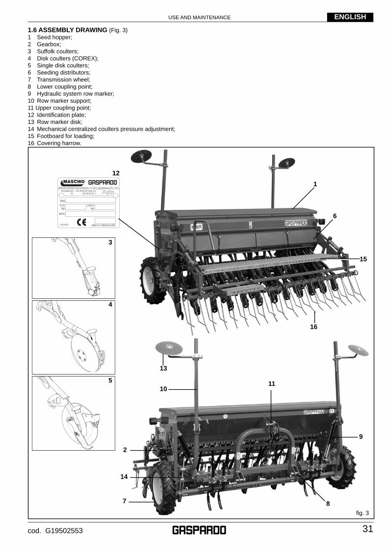
USE AND MAINTENANCE
31
ENGLISH
cod. G19502553
1.6 ASSEMBLY DRAWING (Fig. 3)1 Seed hopper;2 Gearbox;3 Suffolk coulters;4 Disk coulters (COREX);5 Single disk coulters;6 Seeding distributors;7 Transmission wheel;8 Lower coupling point;9 Hydraulic system row marker;10 Row marker support;11 Upper coupling point;12 Identifi cation plate;13 Row marker disk;14 Mechanical centralized coulters pressure adjustment;15 Footboard for loading;16 Covering harrow.
fi g. 3
8
11
9
10
2
3
1
16
13
12
6
15
7
14
4
5
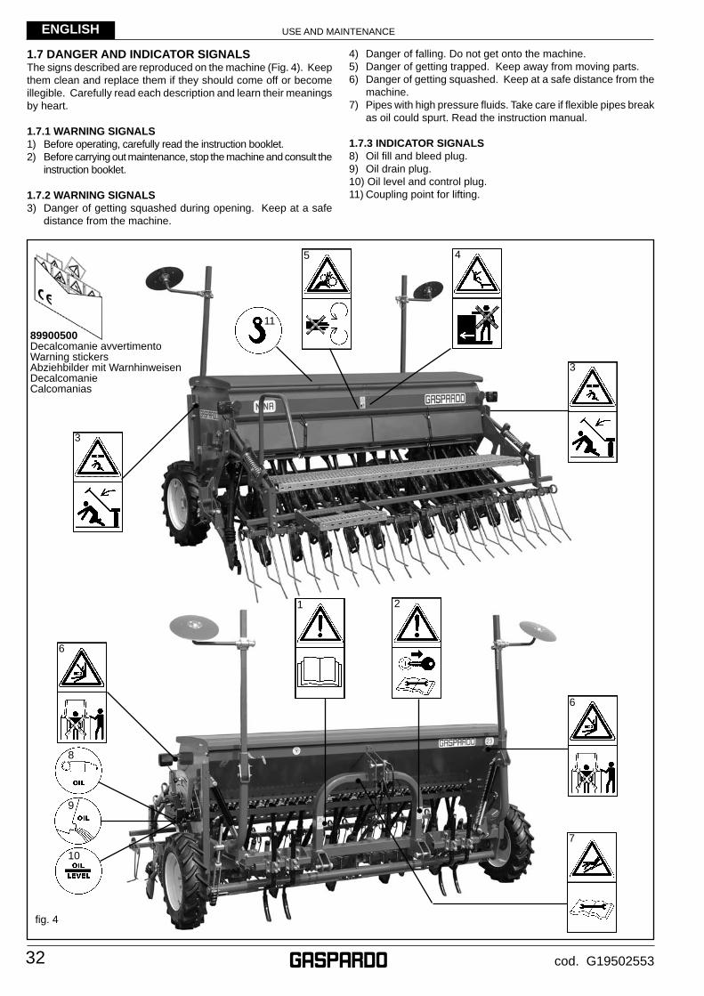
USE AND MAINTENANCE
32
ENGLISH
cod. G19502553
1.7 DANGER AND INDICATOR SIGNALSThe signs described are reproduced on the machine (Fig. 4). Keep them clean and replace them if they should come off or become illegible. Carefully read each description and learn their meanings by heart.
1.7.1 WARNING SIGNALS1) Before operating, carefully read the instruction booklet.2) Before carrying out maintenance, stop the machine and consult the
instruction booklet.
1.7.2 WARNING SIGNALS3) Danger of getting squashed during opening. Keep at a safe
distance from the machine.
4) Danger of falling. Do not get onto the machine.5) Danger of getting trapped. Keep away from moving parts.6) Danger of getting squashed. Keep at a safe distance from the
machine.7) Pipes with high pressure fl uids. Take care if fl exible pipes break
as oil could spurt. Read the instruction manual.
1.7.3 INDICATOR SIGNALS8) Oil fi ll and bleed plug.9) Oil drain plug.10) Oil level and control plug.11) Coupling point for lifting.
fi g. 4
8
10
9
4
3
2
6
1
5
7
11
6
3
89900500Decalcomanie avvertimentoWarning stickersAbziehbilder mit WarnhinweisenDecalcomanieCalcomanias
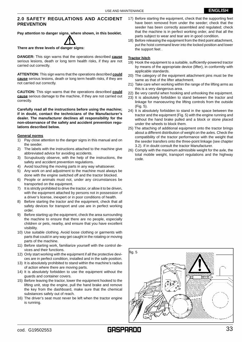
USE AND MAINTENANCE
33
ENGLISH
cod. G19502553
2.0 SAFETY REGULATIONS AND ACCIDENT PREVENTION
Pay attention to danger signs, where shown, in this booklet.
There are three levels of danger signs:
DANGER: This sign warns that the operations described cause serious lesions, death or long term health risks, if they are not carried out correctly.
ATTENTION: This sign warns that the operations described could cause serious lesions, death or long term health risks, if they are not carried out correctly.
CAUTION: This sign warns that the operations described could cause serious damage to the machine, if they are not carried out correctly.
Carefully read all the instructions before using the machine; if in doubt, contact the technicians of the Manufacturer’s dealer. The manufacturer declines all responsibility for the non-observance of the safety and accident prevention regu-lations described below.
General norms1) Pay close attention to the danger signs in this manual and on
the seeder.2) The labels with the instructions attached to the machine give
abbreviated advice for avoiding accidents.3) Scrupulously observe, with the help of the instructions, the
safety and accident prevention regulations.4) Avoid touching the moving parts in any way whatsoever.5) Any work on and adjustment to the machine must always be
done with the engine switched off and the tractor blocked.6) People or animals must not, under any circumstances be
transported on the equipment.7) It is strictly prohibited to drive the tractor, or allow it to be driven,
with the equipment attached by persons not in possession of a driver’s license, inexpert or in poor conditions of health.
8) Before starting the tractor and the equipment, check that all safety devices for transport and use are in perfect working order.
9) Before starting up the equipment, check the area surrounding the machine to ensure that there are no people, especially children or pets, nearby, and ensure that you have excellent visibility.
10) Use suitable clothing. Avoid loose clothing or garments with parts that could in any way get caught in the rotating or moving parts of the machine.
11) Before starting work, familiarize yourself with the control de-vices and their functions.
12) Only start working with the equipment if all the protective devi-ces are in perfect condition, installed and in the safe position.
13) It is absolutely prohibited to stand within the machine’s radius of action where there are moving parts.
14) It is absolutely forbidden to use the equipment without the guards and container covers.
15) Before leaving the tractor, lower the equipment hooked to the lifting unit, stop the engine, pull the hand brake and remove the key from the dashboard, make sure that the chemical substances safely out of reach.
16) The driver’s seat must never be left when the tractor engine is running.
17) Before starting the equipment, check that the supporting feet have been removed from under the seeder; check that the seeder has been correctly assembled and regulated; check that the machine is in perfect working order, and that all the parts subject to wear and tear are in good condition.
18) Before releasing the equipment from the third point attachment, put the hoist command lever into the locked position and lower the support feet .
Tractor hitch19) Hook the equipment to a suitable, suffi ciently-powered tractor
by means of the appropriate device (lifter), in conformity with applicable standards.
20) The category of the equipment attachment pins must be the same as that of the lifter attachment.
21) Take care when working within the range of the lifting arms as this is a very dangerous area.
22) Be very careful when hooking and unhooking the equipment.23) It is absolutely forbidden to stand between the tractor and
linkage for manoeuvring the lifting controls from the outside (Fig. 5).
24) It is absolutely forbidden to stand in the space between the tractor and the equipment (Fig. 5) with the engine running and without the hand brake pulled and a block or stone placed under the wheels to block them.
25) The attaching of additional equipment onto the tractor brings about a different distribution of weight on the axles. Check the compatibility of the tractor performance with the weight that the seeder transfers onto the three-point linkage (see chapter 3.2). If in doubt consult the tractor Manufacturer.
26) Comply with the maximum admissible weight for the axle, the total mobile weight, transport regulations and the highway code.
fi g. 5
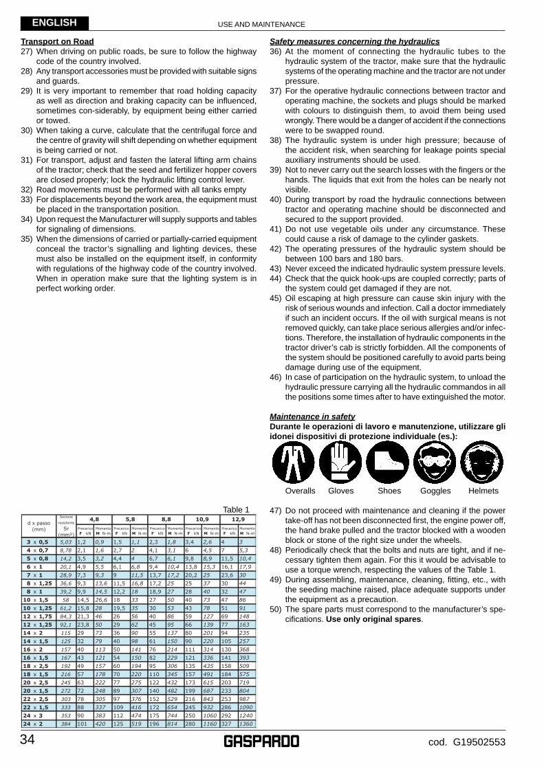
USE AND MAINTENANCE
34
ENGLISH
cod. G19502553
Transport on Road27) When driving on public roads, be sure to follow the highway
code of the country involved.28) Any transport accessories must be provided with suitable signs
and guards.29) It is very important to remember that road holding capacity
as well as direction and braking capacity can be infl uenced, sometimes con-siderably, by equipment being either carried or towed.
30) When taking a curve, calculate that the centrifugal force and the centre of gravity will shift depending on whether equipment is being carried or not.
31) For transport, adjust and fasten the lateral lifting arm chains of the tractor; check that the seed and fertilizer hopper covers are closed properly; lock the hydraulic lifting control lever.
32) Road movements must be performed with all tanks empty33) For displacements beyond the work area, the equipment must
be placed in the transportation position.34) Upon request the Manufacturer will supply supports and tables
for signaling of dimensions.35) When the dimensions of carried or partially-carried equipment
conceal the tractor’s signalling and lighting devices, these must also be installed on the equipment itself, in conformity with regulations of the highway code of the country involved. When in operation make sure that the lighting system is in perfect working order.
Safety measures concerning the hydraulics36) At the moment of connecting the hydraulic tubes to the
hydraulic system of the tractor, make sure that the hydraulic systems of the operating machine and the tractor are not under pressure.
37) For the operative hydraulic connections between tractor and operating machine, the sockets and plugs should be marked with colours to distinguish them, to avoid them being used wrongly. There would be a danger of accident if the connections were to be swapped round.
38) The hydraulic system is under high pressure; because of the accident risk, when searching for leakage points special auxiliary instruments should be used.
39) Not to never carry out the search losses with the fi ngers or the hands. The liquids that exit from the holes can be nearly not visible.
40) During transport by road the hydraulic connections between tractor and operating machine should be disconnected and secured to the support provided.
41) Do not use vegetable oils under any circumstance. These could cause a risk of damage to the cylinder gaskets.
42) The operating pressures of the hydraulic system should be between 100 bars and 180 bars.
43) Never exceed the indicated hydraulic system pressure levels.44) Check that the quick hook-ups are coupled correctly; parts of
the system could get damaged if they are not. 45) Oil escaping at high pressure can cause skin injury with the
risk of serious wounds and infection. Call a doctor immediately if such an incident occurs. If the oil with surgical means is not removed quickly, can take place serious allergies and/or infec-tions. Therefore, the installation of hydraulic components in the tractor driver’s cab is strictly forbidden. All the components of the system should be positioned carefully to avoid parts being damage during use of the equipment.
46) In case of participation on the hydraulic system, to unload the hydraulic pressure carrying all the hydraulic commandos in all the positions some times after to have extinguished the motor.
Maintenance in safetyDurante le operazioni di lavoro e manutenzione, utilizzare gli idonei dispositivi di protezione individuale (es.):
Overalls Gloves Shoes Goggles Helmets
47) Do not proceed with maintenance and cleaning if the power take-off has not been disconnected fi rst, the engine power off, the hand brake pulled and the tractor blocked with a wooden block or stone of the right size under the wheels.
48) Periodically check that the bolts and nuts are tight, and if ne-cessary tighten them again. For this it would be advisable to use a torque wrench, respecting the values of the Table 1.
49) During assembling, maintenance, cleaning, fi tting, etc., with the seeding machine raised, place adequate supports under the equipment as a precaution.
50) The spare parts must correspond to the manufacturer’s spe-cifi cations. Use only original spares.
Table 1
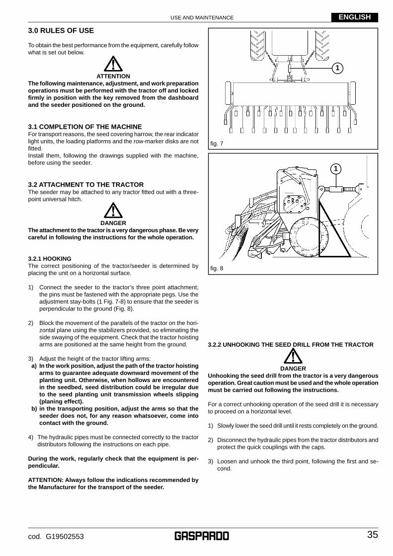
USE AND MAINTENANCE
35
ENGLISH
cod. G19502553
3.0 RULES OF USE
To obtain the best performance from the equipment, carefully follow what is set out below.
ATTENTIONThe following maintenance, adjustment, and work preparation operations must be performed with the tractor off and locked fi rmly in position with the key removed from the dashboard and the seeder positioned on the ground.
3.1 COMPLETION OF THE MACHINEFor transport reasons, the seed covering harrow, the rear indicator light units, the loading platforms and the row-marker disks are not fi tted.Install them, following the drawings supplied with the machine, before using the seeder.
3.2 ATTACHMENT TO THE TRACTORThe seeder may be attached to any tractor fi tted out with a three- point universal hitch.
DANGERThe attachment to the tractor is a very dangerous phase. Be very careful in following the instructions for the whole operation.
3.2.1 HOOKING The correct positioning of the tractor/seeder is determined by placing the unit on a horizontal surface.
1) Connect the seeder to the tractor’s three point attachment; the pins must be fastened with the appropriate pegs. Use the adjustment stay-bolts (1 Fig. 7-8) to ensure that the seeder is perpendicular to the ground (Fig. 8).
2) Block the movement of the parallels of the tractor on the hori-zontal plane using the stabilizers provided, so eliminating the side swaying of the equipment. Check that the tractor hoisting arms are positioned at the same height from the ground.
3) Adjust the height of the tractor lifting arms: a) In the work position, adjust the path of the tractor hoisting
arms to guarantee adequate downward movement of the planting unit. Otherwise, when hollows are encountered in the seedbed, seed distribution could be irregular due to the seed planting unit transmission wheels slipping (planing effect).
b) in the transporting position, adjust the arms so that the seeder does not, for any reason whatsoever, come into contact with the ground.
4) The hydraulic pipes must be connected correctly to the tractor distributors following the instructions on each pipe.
During the work, regularly check that the equipment is per-pendicular.
ATTENTION: Always follow the indications recommended by the Manufacturer for the transport of the seeder.
3.2.2 UNHOOKING THE SEED DRILL FROM THE TRACTOR
DANGERUnhooking the seed drill from the tractor is a very dangerous operation. Great caution must be used and the whole operation must be carried out following the instructions.
For a correct unhooking operation of the seed drill it is necessary to proceed on a horizontal level.
1) Slowly lower the seed drill until it rests completely on the ground.
2) Disconnect the hydraulic pipes from the tractor distributors and protect the quick couplings with the caps.
3) Loosen and unhook the third point, following the fi rst and se-cond.
fi g. 8
fi g. 7
1
1
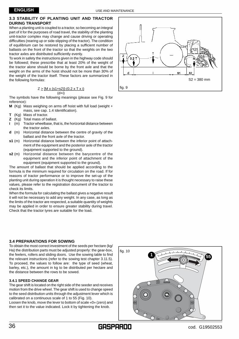
USE AND MAINTENANCE
36
ENGLISH
cod. G19502553
3.3 STABILITY OF PLANTING UNIT AND TRACTOR DURING TRANSPORT When a planting unit is coupled to a tractor, so becoming an integral part of it for the purposes of road travel, the stability of the planting unit-tractor complex may change and cause driving or operating diffi culties (rearing up or side-slipping of the tractor). The condition of equilibrium can be restored by placing a suffi cient number of ballasts on the front of the tractor so that the weights on the two tractor axles are distributed suffi ciently evenly.To work in safety the instructions given in the highway code should be followed; these prescribe that at least 20% of the weight of the tractor alone should be borne by the front axle and that the weight on the arms of the hoist should not be more than 30% of the weight of the tractor itself. These factors are summarized in the following formulas:
Z > [M x (s1+s2)]-(0.2 x T x i)(d+i)
The symbols have the following meanings (please see Fig. 9 for reference):M (Kg) Mass weighing on arms off hoist with full load (weight +
mass, see cap. 1.4 Identifi cation).T (Kg) Mass of tractor.Z (Kg) Total mass of ballast.i (m) Tractor wheelbase, that is, the horizontal distance between
the tractor axles.d (m) Horizontal distance between the centre of gravity of the
ballast and the front axle of the tractor.s1 (m) Horizontal distance between the inferior point of attach-
ment of the equipment and the posterior axle of the tractor (equipment supported to the ground).
s2 (m) Horizontal distance between the barycentre of the equipment and the inferior point of attachment of the equipment (equipment supported to the ground).
The amount of ballast that should be applied according to the formula is the minimum required for circulation on the road. If for reasons of tractor performance or to improve the set-up of the planting unit during operation it is thought necessary to raise these values, please refer to the registration document of the tractor to check its limits.When the formula for calculating the ballast gives a negative result it will not be necessary to add any weight. In any case, as long as the limits of the tractor are respected, a suitable quantity of weights may be applied in order to ensure greater stability during travel. Check that the tractor tyres are suitable for the load.
3.4 PREPARATIONS FOR SOWINGTo obtain the most correct investment of the seeds per hectare (kg/Ha) the distribution parts must be adjusted properly: the gear-box, the feelers, rollers and sliding doors. Use the sowing table to fi nd the relevant instructions (refer to the sowing test chapter 3.11.5). To proceed, the values to follow are: the type of seed (wheat, barley, etc.), the amount in kg to be distributed per hectare and the distance between the rows to be sowed.
3.4.1 SPEED CHANGE GEARThe gear shift is located on the right side of the seeder and receives motion from the drive wheel. The gear shift is used to change speed to the seed distribution units through the adjustment lever which is calibrated on a continuous scale of 1 to 55 (Fig. 10). Loosen the knob, move the lever to bottom of scale «0» (zero) and then set it to the value indicated. Lock it by tightening the knob.
fi g. 9
S2 = 380 mm
fi g. 10
551
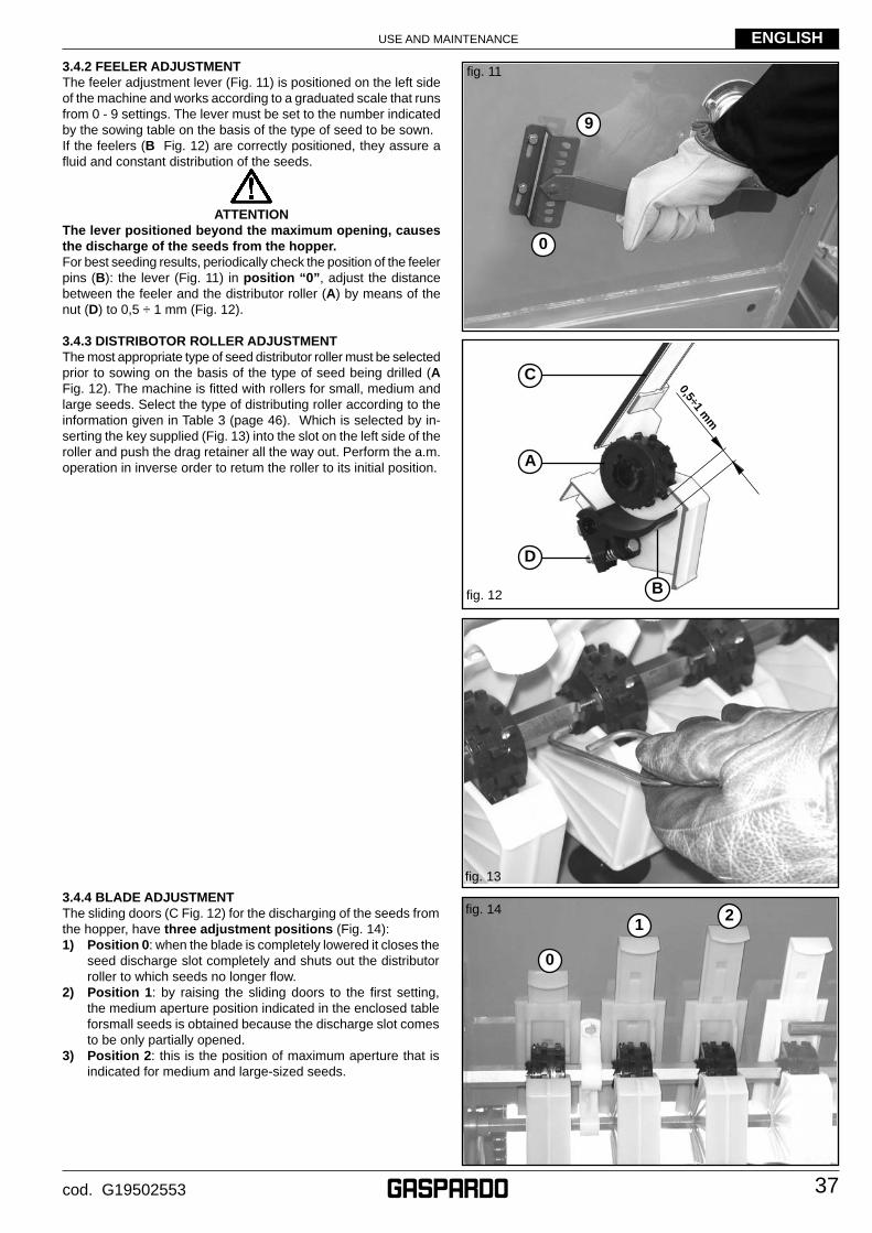
USE AND MAINTENANCE
37
ENGLISH
cod. G19502553
3.4.2 FEELER ADJUSTMENTThe feeler adjustment lever (Fig. 11) is positioned on the left side of the machine and works according to a graduated scale that runs from 0 - 9 settings. The lever must be set to the number indicated by the sowing table on the basis of the type of seed to be sown. If the feelers (B Fig. 12) are correctly positioned, they assure a fl uid and constant distribution of the seeds.
ATTENTIONThe lever positioned beyond the maximum opening, causes the discharge of the seeds from the hopper.For best seeding results, periodically check the position of the feeler pins (B): the lever (Fig. 11) in position “0”, adjust the distance between the feeler and the distributor roller (A) by means of the nut (D) to 0,5 ÷ 1 mm (Fig. 12).
3.4.3 DISTRIBOTOR ROLLER ADJUSTMENTThe most appropriate type of seed distributor roller must be selected prior to sowing on the basis of the type of seed being drilled (A Fig. 12). The machine is fi tted with rollers for small, medium and large seeds. Select the type of distributing roller according to the information given in Table 3 (page 46). Which is selected by in-serting the key supplied (Fig. 13) into the slot on the left side of the roller and push the drag retainer all the way out. Perform the a.m. operation in inverse order to retum the roller to its initial position.
fi g. 11
fi g. 13
fi g. 12
0,5÷1 mm
fi g. 14
9
0
C
A
D
B
12
0
3.4.4 BLADE ADJUSTMENTThe sliding doors (C Fig. 12) for the discharging of the seeds from the hopper, have three adjustment positions (Fig. 14):1) Position 0: when the blade is completely lowered it closes the
seed discharge slot completely and shuts out the distributor roller to which seeds no longer fl ow.
2) Position 1: by raising the sliding doors to the fi rst setting, the medium aperture position indicated in the enclosed table forsmall seeds is obtained because the discharge slot comes to be only partially opened.
3) Position 2: this is the position of maximum aperture that is indicated for medium and large-sized seeds.
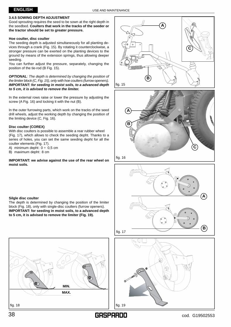
USE AND MAINTENANCE
38
ENGLISH
cod. G19502553
3.4.5 SOWING DEPTH ADJUSTMENTGood sprouting requires the seed to be sown at the right depth in the seedbed. Coulters that work in the tracks of the seeder or the tractor should be set to greater pressure.
Hoe coulter, disc coulterThe seeding depth is adjusted simultaneously for all planting de-vices through a crank (Fig. 15). By rotating it counterclockwise, a stronger pressure can be exerted on the planting devices to the ground by means of the extension springs, thus allowing deeper seeding.You can further adjust the pressure, separately, changing the position of the tie-rod (B Fig. 15).
OPTIONAL: The depth is determined by changing the position of the limiter block (C, Fig. 15), only with hoe coulters (furrow openers). IMPORTANT: for seeding in moist soils, to a advanced depth to 5 cm, it is advised to remove the limiter.
In the external rows raise or lower the pressure by adjusting the screw (A Fig. 16) and locking it with the nut (B).
In the outer furrowing parts, which work on the tracks of the seed drill wheels, adjust the working depth by changing the position of the limiting device (C, Fig. 16).
Disc coulter (COREX)With disc coulters is possible to assemble a rear rubber wheel (Fig. 17), which allows to check the seeding depht. Thanks to a series of holes, you can set the same seeding depht for all the coulter elements (Fig. 17).A) minimum depht: 0 ÷ 0,5 cmB) maximum depht: 8 cm
IMPORTANT: we advise against the use of the rear wheel on moist soils.
Silgle disc coulter The depth is determined by changing the position of the limiter block (Fig. 18), only with single-disc coulters (furrow openers).IMPORTANT: for seeding in moist soils, to a advanced depth to 5 cm, it is advised to remove the limiter (Fig. 19).
fi g. 17
fi g. 15
fi g. 16
A
B
A
B
C
A
B
MIN.
MAX.
fi g. 19fi g. 18
C
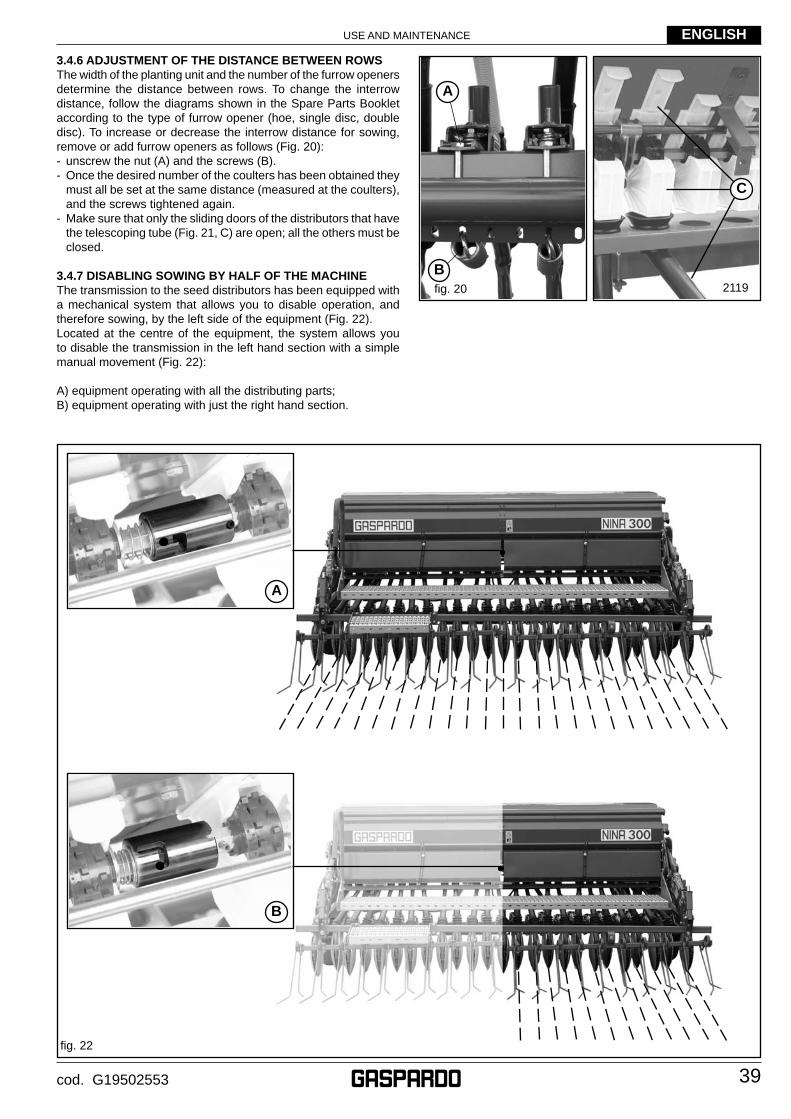
USE AND MAINTENANCE
39
ENGLISH
cod. G19502553
3.4.6 ADJUSTMENT OF THE DISTANCE BETWEEN ROWSThe width of the planting unit and the number of the furrow openers determine the distance between rows. To change the interrow distance, follow the diagrams shown in the Spare Parts Booklet according to the type of furrow opener (hoe, single disc, double disc). To increase or decrease the interrow distance for sowing, remove or add furrow openers as follows (Fig. 20):- unscrew the nut (A) and the screws (B).- Once the desired number of the coulters has been obtained they
must all be set at the same distance (measured at the coulters), and the screws tightened again.
- Make sure that only the sliding doors of the distributors that have the telescoping tube (Fig. 21, C) are open; all the others must be closed.
3.4.7 DISABLING SOWING BY HALF OF THE MACHINE The transmission to the seed distributors has been equipped with a mechanical system that allows you to disable operation, and therefore sowing, by the left side of the equipment (Fig. 22). Located at the centre of the equipment, the system allows you to disable the transmission in the left hand section with a simple manual movement (Fig. 22):
A) equipment operating with all the distributing parts;B) equipment operating with just the right hand section.
fi g. 22
fi g. 20 2119
A
B
C
B
A
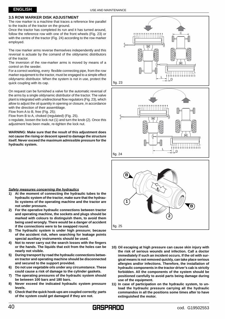
USE AND MAINTENANCE
40
ENGLISH
cod. G19502553
3.5 ROW MARKER DISK ADJUSTMENTThe row marker is a machine that traces a reference line parallel to the tracks of the tractor on the ground.Once the tractor has completed its run and it has turned around, follow the reference row with one of the front wheels (Fig. 23) or with the centre of the tractor (Fig. 24) according to the row marker employed.
The row marker arms reverse themselves independently and this reversal is actuate by the comand of the oildynamic distributors of the tractor. The inversion of the row-marker arms is moved by means of a control on the seeder. For a correct working, every fl exible connecting pipe, from the row marker equipment to the tractor, must be engaged to a simple effect oildynamic distributor. When the system is not in use, protect the quick coupling with its cap.
On request can be furnished a valve for the automatic reversal of the arms by a single oildynamic distributor of the tractor. The valve plant is integrated with unidirectional fl ow regulators (Fig. 23), which allow to adjust the oil quantity in opening or closure, in accordance with the direction of their assemblage.Flow from A to B, free (Fig. 25);Flow from B to A, choked (regulated) (Fig. 25).o regulate, loosen the lock nut (1) and turn the knob (2). Once this adjustment has been made, re-tighten the lock nut.
WARNING: Make sure that the result of this adjustment does not cause the rising or descent speed to damage the structure itself. Never exceed the maximum admissible pressure for the hydraulic system.
Safety measures concerning the hydraulics1) At the moment of connecting the hydraulic tubes to the
hydraulic system of the tractor, make sure that the hydrau-lic systems of the operating machine and the tractor are not under pressure.
2) For the operative hydraulic connections between tractor and operating machine, the sockets and plugs should be marked with colours to distinguish them, to avoid them being used wrongly. There would be a danger of accident if the connections were to be swapped round.
3) The hydraulic system is under high pressure; because of the accident risk, when searching for leakage points special auxiliary instruments should be used.
4) Not to never carry out the search losses with the fi ngers or the hands. The liquids that exit from the holes can be nearly not visible.
5) During transport by road the hydraulic connections betwe-en tractor and operating machine should be disconnected and secured to the support provided.
6) Do not use vegetable oils under any circumstance. These could cause a risk of damage to the cylinder gaskets.
7) The operating pressures of the hydraulic system should be between 100 bars and 180 bars.
8) Never exceed the indicated hydraulic system pressure levels.
9) Check that the quick hook-ups are coupled correctly; parts of the system could get damaged if they are not.
10) Oil escaping at high pressure can cause skin injury with the risk of serious wounds and infection. Call a doctor immediately if such an incident occurs. If the oil with sur-gical means is not removed quickly, can take place serious allergies and/or infections. Therefore, the installation of hydraulic components in the tractor driver’s cab is strictly forbidden. All the components of the system should be positioned carefully to avoid parts being damage during use of the equipment.
11) In case of participation on the hydraulic system, to un-load the hydraulic pressure carrying all the hydraulic commandos in all the positions some times after to have extinguished the motor.
fi g. 23
L�D�
C�
LD
fi g. 24
fi g. 25
B
B
1
2
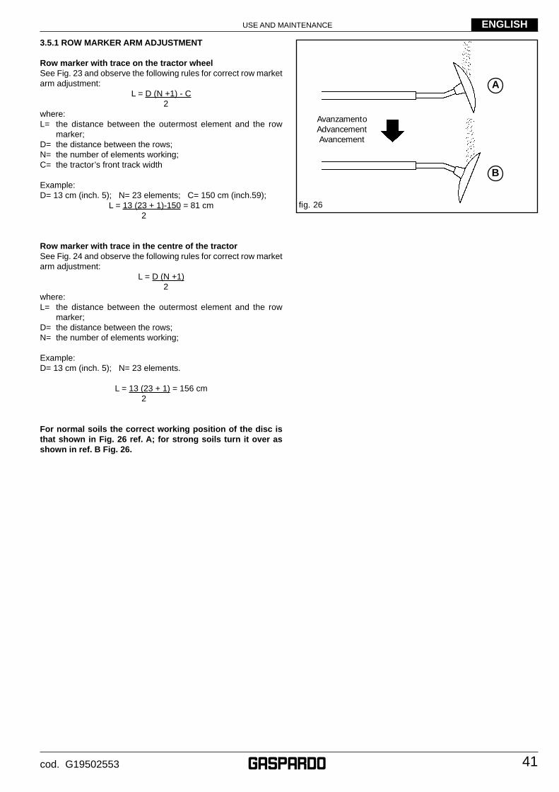
USE AND MAINTENANCE
41
ENGLISH
cod. G19502553
3.5.1 ROW MARKER ARM ADJUSTMENT
Row marker with trace on the tractor wheelSee Fig. 23 and observe the following rules for correct row market arm adjustment:
L = D (N +1) - C 2
where:L= the distance between the outermost element and the row
marker;D= the distance between the rows;N= the number of elements working;C= the tractor’s front track width
Example:D= 13 cm (inch. 5); N= 23 elements; C= 150 cm (inch.59);
L = 13 (23 + 1)-150 = 81 cm 2
Row marker with trace in the centre of the tractorSee Fig. 24 and observe the following rules for correct row market arm adjustment:
L = D (N +1) 2
where:L= the distance between the outermost element and the row
marker;D= the distance between the rows;N= the number of elements working;
Example:D= 13 cm (inch. 5); N= 23 elements.
L = 13 (23 + 1) = 156 cm 2
For normal soils the correct working position of the disc is that shown in Fig. 26 ref. A; for strong soils turn it over as shown in ref. B Fig. 26.
fi g. 26
AvanzamentoAdvancementAvancement
A
B
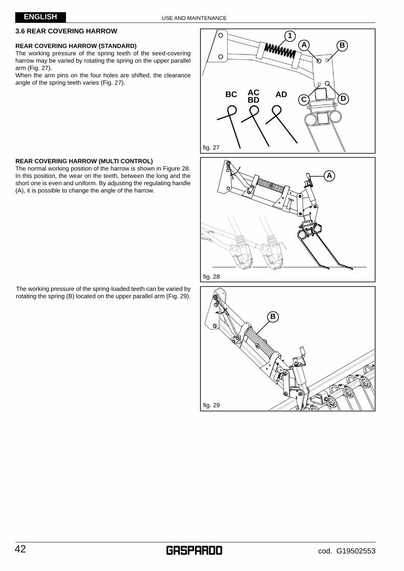
USE AND MAINTENANCE
42
ENGLISH
cod. G19502553
3.6 REAR COVERING HARROW
REAR COVERING HARROW (STANDARD)The working pressure of the spring teeth of the seed-covering harrow may be varied by rotating the spring on the upper parallel arm (Fig. 27).When the arm pins on the four holes are shifted, the clearance angle of the spring teeth varies (Fig. 27).
REAR COVERING HARROW (MULTI CONTROL)The normal working position of the harrow is shown in Figure 28.In this position, the wear on the teeth, between the long and the short one is even and uniform. By adjusting the regulating handle (A), it is possible to change the angle of the harrow.
fi g. 29
fi g. 28
fi g. 27
BC ACBD
AD
1
DC
BA
A
B
The working pressure of the spring-loaded teeth can be varied by rotating the spring (B) located on the upper parallel arm (Fig. 29).
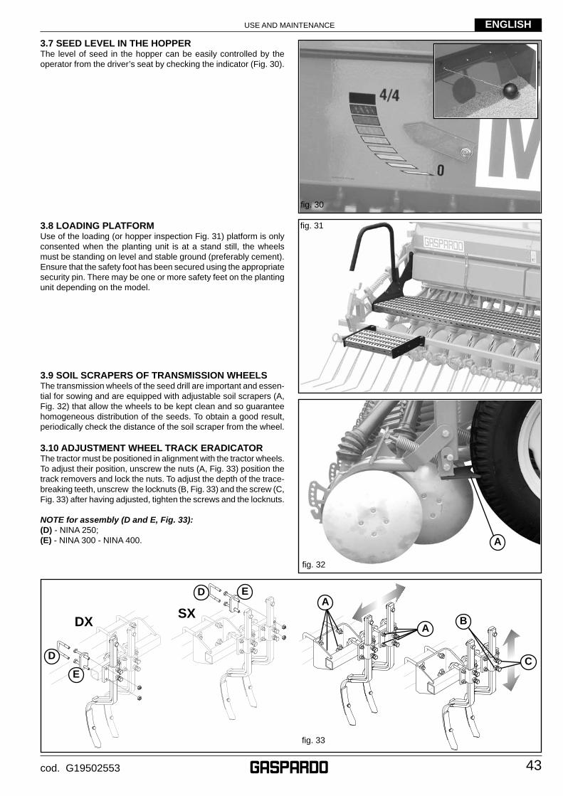
USE AND MAINTENANCE
43
ENGLISH
cod. G19502553
3.8 LOADING PLATFORMUse of the loading (or hopper inspection Fig. 31) platform is only consented when the planting unit is at a stand still, the wheels must be standing on level and stable ground (preferably cement). Ensure that the safety foot has been secured using the appropriate security pin. There may be one or more safety feet on the planting unit depending on the model.
3.9 SOIL SCRAPERS OF TRANSMISSION WHEELS The transmission wheels of the seed drill are important and essen-tial for sowing and are equipped with adjustable soil scrapers (A, Fig. 32) that allow the wheels to be kept clean and so guarantee homogeneous distribution of the seeds. To obtain a good result, periodically check the distance of the soil scraper from the wheel.
3.10 ADJUSTMENT WHEEL TRACK ERADICATORThe tractor must be positioned in alignment with the tractor wheels. To adjust their position, unscrew the nuts (A, Fig. 33) position the track removers and lock the nuts. To adjust the depth of the trace-breaking teeth, unscrew the locknuts (B, Fig. 33) and the screw (C, Fig. 33) after having adjusted, tighten the screws and the locknuts.
NOTE for assembly (D and E, Fig. 33):(D) - NINA 250;(E) - NINA 300 - NINA 400.
3.7 SEED LEVEL IN THE HOPPERThe level of seed in the hopper can be easily controlled by the operator from the driver’s seat by checking the indicator (Fig. 30).
fi g. 30
fi g. 31
A
fi g. 32
DXSX
A
C
fi g. 33
B
D
E
D E
A
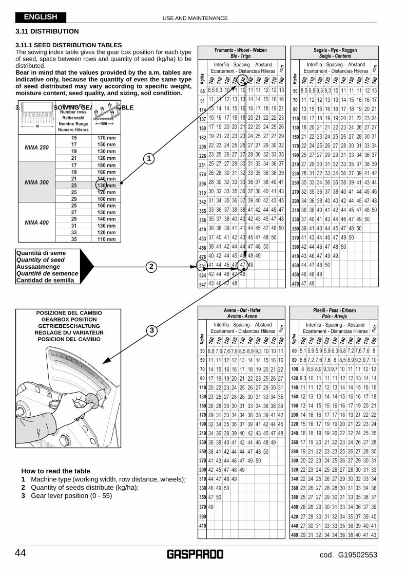
USE AND MAINTENANCE
44
ENGLISH
cod. G19502553
3.11 DISTRIBUTION
3.11.1 SEED DISTRIBUTION TABLESThe sowing index table gives the gear box position for each type of seed, space between rows and quantity of seed (kg/ha) to be distributed.Bear in mind that the values provided by the a.m. tables are indicative only, because the quantity of even the same type of seed distributed may vary according to specifi c weight, moisture content, seed quality, and sizing, soil condition.
3.11.2 TRIAL SOWING GEARBOX TABLE
How to read the table1 Machine type (working width, row distance, wheels);2 Quantity of seeds distribute (kg/ha);3 Gear lever position (0 - 55)
29
17160 mm
15
180 mm
19
120 mm
150 mm
100 mm160 mm
130 mm
170 mm
120 mm
NINA 400
NINA 300
NINA 250
110 mm
2527
21
25
19
35
Numero fileNumber rows
ReihenzahlNombre RangsNumero Hileras
17 150 mm
21130 mm140 mm
23
120 mm
140 mm29
33130 mm31
30507090110130150170190210230250270290310330350
370
390410
Kg/h
a
100
Ecartement - Distancias Hileras mm
110
120
125
130
140
150
160
170
180
Interfila - Spacing - Abstand
Avena - Oat - HaferAvoine - Avena
68
91
114
137
160
182
205
228
251
274
296
319
342
365
388
410
433
456
478
501
524
547
Kg/
ha
100
Ecartement - Distancias Hileras mm
110
120
125
130
140
150
160
170
180
Interfila - Spacing - Abstand
Frumento - Wheat - WeizenBle - Trigo
507090110130150170190210230250270290310330350370390410430450470
Kg/h
a
100
Ecartement - Distancias Hileras mm
110
120
125
130
140
150
160
170
180
Interfila - Spacing - Abstand
Segala - Rye - RoggenSeigle - Centeno
6080100120140160180200220240260280300320340360380
400
420440460
Kg/h
a
100
Ecartement - Distancias Hileras mm
110
120
125
130
140
150
160
170
180
Interfila - Spacing - Abstand
Piselli - Peas - ErbsenPois - Arveja POSIZIONE DEL CAMBIO
GEARBOX POSITIONGETRIEBESCHALTUNG
REGLAGE DU VARIATEURPOSICION DEL CAMBIO
Quantità di semeQuantity of seedAussaatmengeQuantité de semenceCantidad de semilla
1
2
3

USE AND MAINTENANCE
45
ENGLISH
cod. G19502553
SETTING INDEX TABLESThe Seeding Index Tables are only indicative since for the same seed type the quantities distribute can vary considerable according to the presence of dust, humidity and variations in specifi c gravity. In oder to sow well and precisely, it is recom-mended that a test be made with the machine at rost and make adjustements as may prove necessary.
115138161184207230253276299322345368391414434460483
506
529552500
Kg/h
a
100
Ecartement - Distancias Hileras mm
110
120
125
130
140
150
160
170
180
Interfila - Spacing - Abstand
Orzo - Barley - GersteOrge - Cebada
2581114172023262932353841
Kg/h
a
100
Ecartement - Distancias Hileras mm
110
120
125
130
140
150
160
170
180
Interfila - Spacing - Abstand
Trifoglio - Red Clover - RotkleeTrefle - Trebol
2124273033363942454851545760
Kg/h
a
100
Ecartement - Distancias Hileras mm
110
120
125
130
140
150
160
170
180
Interfila - Spacing - Abstand
Loglio - Darnel - WeidelgrasRyegrass - Cizaña
811141720232629323538414447
Kg/h
a
100
Ecartement - Distancias Hileras mm
110
120
125
130
140
150
160
170
180
Interfila - Spacing - Abstand
Erba medica - Lucern - LuzerneLuzerne - Alfalfa
6080100120140160180200220240260280300320340360380
400
420440460
Kg/h
a
100
Ecartement - Distancias Hileras mm
110
120
125
130
140
150
160
170
180
Interfila - Spacing - Abstand
Soia - Soya - SoiabohneSoya - Soya
246810121416182022242628
Kg/h
a
100
Ecartement - Distancias Hileras mm
110
120
125
130
140
150
160
170
180
Interfila - Spacing - Abstand
Colza - Rape - RapsColza - Colza
6080100120140160180200220240260280300320340360380
400
420440460
Kg/h
a
100
Ecartement - Distancias Hileras mm
110
120
125
130
140
150
160
170
180
Interfila - Spacing - Abstand
Sorgo - Sorghum - HirseSorgo - Sorgo
6080100120140160180200220240260280300320340360380
400
420440460
Kg/h
a
100
Ecartement - Distancias Hileras mm
110
120
125
130
140
150
160
170
180
Interfila - Spacing - Abstand
Ceci - Pulses - KichererbsePois chiche - Garbanzo
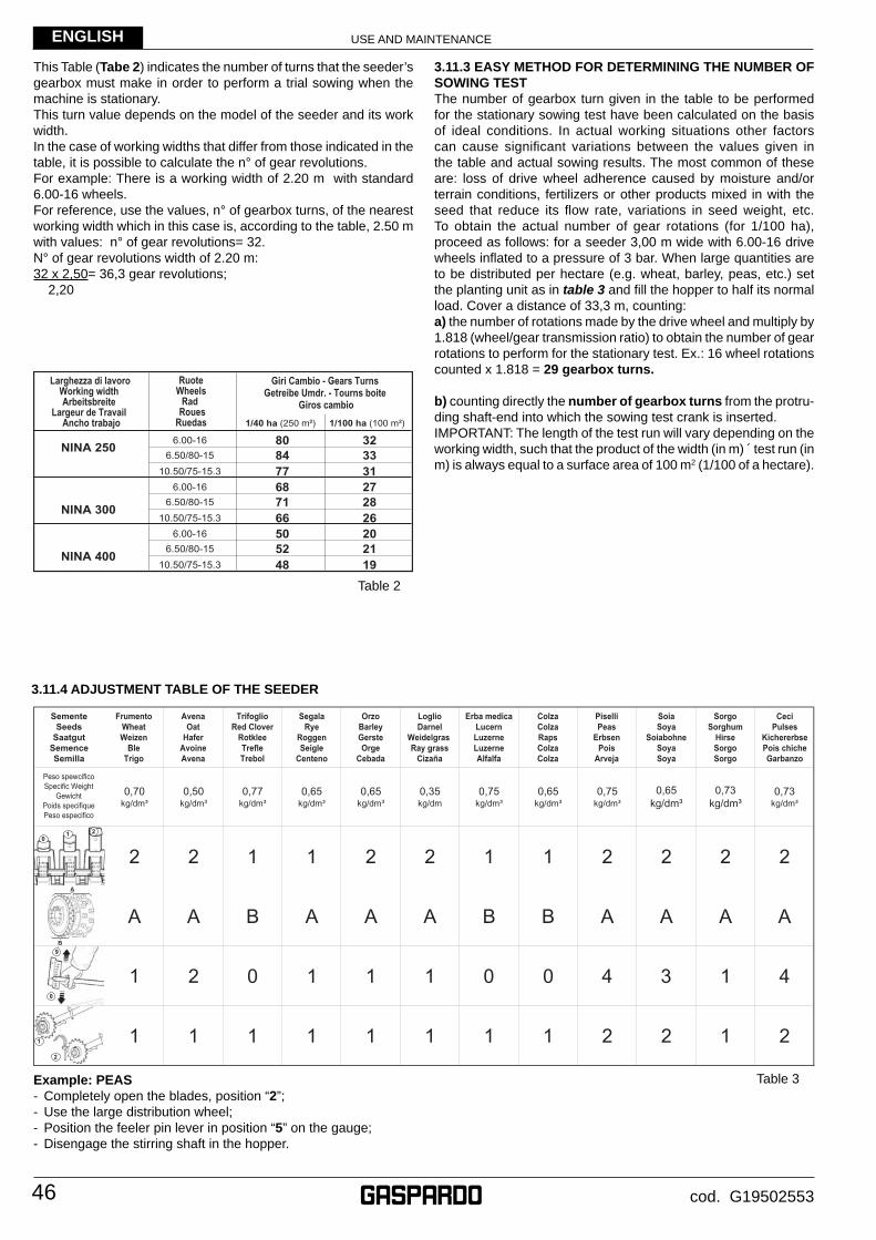
USE AND MAINTENANCE
46
ENGLISH
cod. G19502553
This Table (Tabe 2) indicates the number of turns that the seeder’s gearbox must make in order to perform a trial sowing when the machine is stationary.This turn value depends on the model of the seeder and its work width.In the case of working widths that differ from those indicated in the table, it is possible to calculate the n° of gear revolutions.For example: There is a working width of 2.20 m with standard 6.00-16 wheels.For reference, use the values, n° of gearbox turns, of the nearest working width which in this case is, according to the table, 2.50 m with values: n° of gear revolutions= 32.N° of gear revolutions width of 2.20 m:32 x 2,50= 36,3 gear revolutions; 2,20
3.11.3 EASY METHOD FOR DETERMINING THE NUMBER OF SOWING TESTThe number of gearbox turn given in the table to be performed for the stationary sowing test have been calculated on the basis of ideal conditions. In actual working situations other factors can cause signifi cant variations between the values given in the table and actual sowing results. The most common of these are: loss of drive wheel adherence caused by moisture and/or terrain conditions, fertilizers or other products mixed in with the seed that reduce its fl ow rate, variations in seed weight, etc.To obtain the actual number of gear rotations (for 1/100 ha), proceed as follows: for a seeder 3,00 m wide with 6.00-16 drive wheels infl ated to a pressure of 3 bar. When large quantities are to be distributed per hectare (e.g. wheat, barley, peas, etc.) set the planting unit as in table 3 and fi ll the hopper to half its normal load. Cover a distance of 33,3 m, counting:a) the number of rotations made by the drive wheel and multiply by 1.818 (wheel/gear transmission ratio) to obtain the number of gear rotations to perform for the stationary test. Ex.: 16 wheel rotations counted x 1.818 = 29 gearbox turns.
b) counting directly the number of gearbox turns from the protru-ding shaft-end into which the sowing test crank is inserted.IMPORTANT: The length of the test run will vary depending on the working width, such that the product of the width (in m) ́ test run (in m) is always equal to a surface area of 100 m2 (1/100 of a hectare).
Example: PEAS- Completely open the blades, position “2”;- Use the large distribution wheel;- Position the feeler pin lever in position “5” on the gauge;- Disengage the stirring shaft in the hopper.
3.11.4 ADJUSTMENT TABLE OF THE SEEDER
Table 3
1/40 ha (250 m²) 1/100 ha (100 m²)
NINA 250
NINA 400
6.00-16 80 32
10.50/75-15.3 77 31
Larghezza di lavoroWorking width Arbeitsbreite
Largeur de Travail Ancho trabajo
RuoteWheels
Rad RouesRuedas
Giri Cambio - Gears Turns Getreibe Umdr. - Tourns boite
Giros cambio
6.00-16 50 20
10.50/75-15.3 48 196.50/80-15 52 21
NINA 300
6.00-16 68 27
10.50/75-15.3 66 266.50/80-15 71 28
6.50/80-15 84 33
1
2
0
9
A
B
01 2
2 0 1 1 1 0 0 4 3 1 4
Table 2
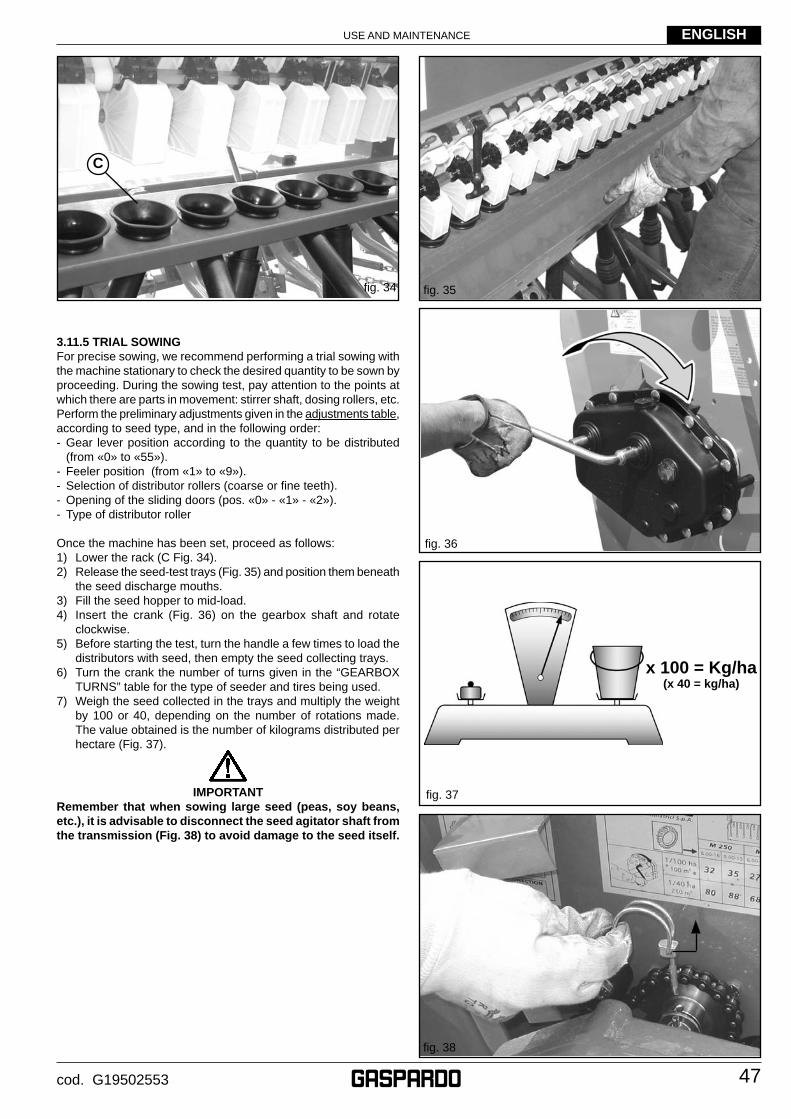
USE AND MAINTENANCE
47
ENGLISH
cod. G19502553
3.11.5 TRIAL SOWINGFor precise sowing, we recommend performing a trial sowing with the machine stationary to check the desired quantity to be sown by proceeding. During the sowing test, pay attention to the points at which there are parts in movement: stirrer shaft, dosing rollers, etc.Perform the preliminary adjustments given in the adjustments table, according to seed type, and in the following order:- Gear lever position according to the quantity to be distributed
(from «0» to «55»).- Feeler position (from «1» to «9»).- Selection of distributor rollers (coarse or fi ne teeth).- Opening of the sliding doors (pos. «0» - «1» - «2»).- Type of distributor roller
Once the machine has been set, proceed as follows:1) Lower the rack (C Fig. 34).2) Release the seed-test trays (Fig. 35) and position them beneath
the seed discharge mouths.3) Fill the seed hopper to mid-load.4) Insert the crank (Fig. 36) on the gearbox shaft and rotate
clockwise.5) Before starting the test, turn the handle a few times to load the
distributors with seed, then empty the seed collecting trays.6) Turn the crank the number of turns given in the “GEARBOX
TURNS” table for the type of seeder and tires being used.7) Weigh the seed collected in the trays and multiply the weight
by 100 or 40, depending on the number of rotations made. The value obtained is the number of kilograms distributed per hectare (Fig. 37).
IMPORTANTRemember that when sowing large seed (peas, soy beans, etc.), it is advisable to disconnect the seed agitator shaft from the transmission (Fig. 38) to avoid damage to the seed itself.
fi g. 37
fi g. 37
fi g. 35
fi g. 38
fi g. 34
x 100 = Kg/ha(x 40 = kg/ha)
C
fi g. 36
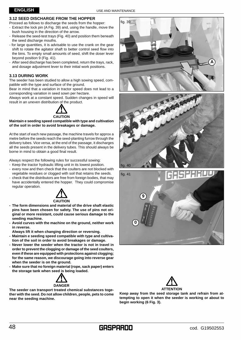
USE AND MAINTENANCE
48
ENGLISH
cod. G19502553
3.12 SEED DISCHARGE FROM THE HOPPERProceed as follows to discharge the seeds from the hopper:- Extract the lock pin (A Fig. 39) and, using the handle, move the
bush housing in the direction of the arrow.- Release the seed-test trays (Fig. 40) and position them beneath
the seed discharge mouths.- for large quantities, it is advisable to use the crank on the gear
shift to rotate the agitator shaft to better control seed fl ow into the bins. To empty small amounts of seed, shift the doser lever beyond position 9 (Fig. 41).
- After seed discharge has been completed, return the trays, rack, and dosage adjustment lever to their initial work positions.
3.13 DURING WORKThe seeder has been studied to allow a high sowing speed, com-patible with the type and surface of the ground.Bear in mind that a variation in tractor speed does not lead to a corresponding variation in seed sown per hectare.Always work at a constant speed. Sudden changes in speed will result in an uneven distribution of the product.
CAUTIONMaintain e seeding speed compatible with type and cultivation of the soil in order to avoid breakages or damage.
At the start of each new passage, the machine travels for approx a metre before the seeds reach the seed-planting furrow through the delivery tubes. Vice versa, at the end of the passage, it discharges all the seeds present in the delivery tubes. This should always be borne in mind to obtain a good fi nal result.
Always respect the following rules for successful sowing:- Keep the tractor hydraulic lifting unit in its lowest position.- every now and then check that the coulters are not blocked with
vegetable residues or clogged with soil that retains the seeds.- check that the distributors are free from foreign bodies, that may
have accidentally entered the hopper. They could compromise regular operation.
CAUTION- The form dimensions and material of the drive shaft elastic
pins have been chosen for safety. The use of pins not ori-ginal or more resistant, could cause serious damage to the seeding machine.
- Avoid curves with the machine on the ground, neither work in reverse.
Always lift it when changing direction or reversing.- Maintain e seeding speed compatible with type and cultiva-
tion of the soil in order to avoid breakages or damage.- Never lower the seeder when the tractor is not in travel in
order to prevent the clogging or damage of the seed coulters, even if these are equipped with protections against clogging; for the same reason, we discourage going into reverse gear when the seeder is on the ground.
- Make sure that no foreign material (rope, sack paper) enters the storage tank when seed is being loaded.
DANGERThe seeder can transport treated chemical substances toge-ther with the seed. Do not allow children, people, pets to come near the seeding machine.
ATTENTIONKeep away from the seed storage tank and refrain from at-tempting to open it when the seeder is working or about to begin working (6 Fig. 3).
fi g. 40
fi g. 41
9
0
fi g. 39
A
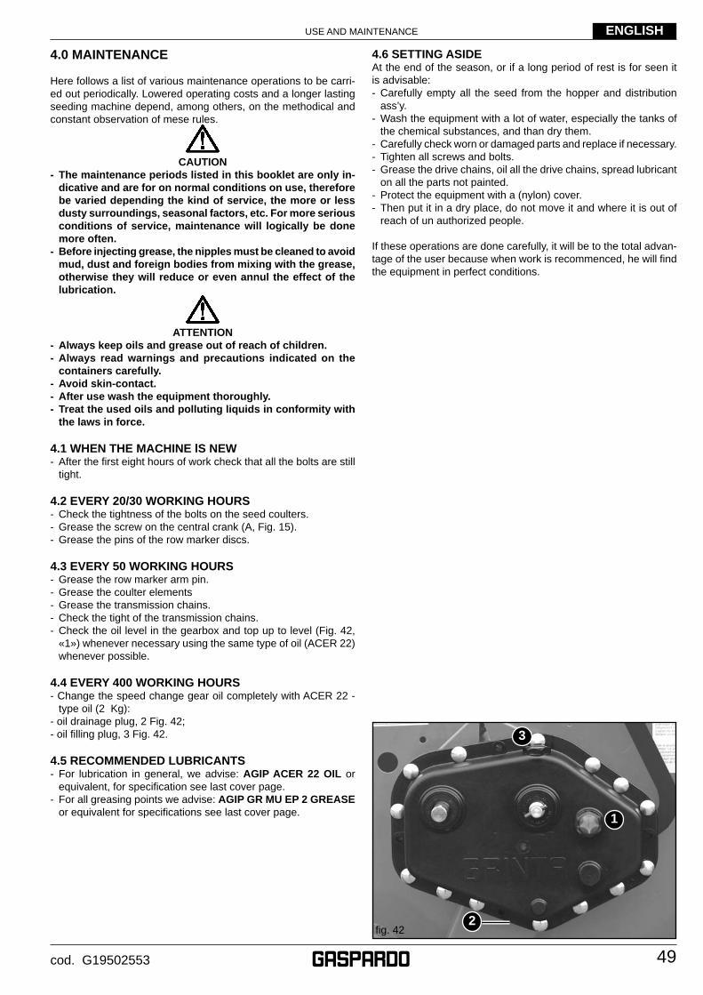
USE AND MAINTENANCE
49
ENGLISH
cod. G19502553
4.0 MAINTENANCE
Here follows a list of various maintenance operations to be carri-ed out periodically. Lowered operating costs and a longer lasting seeding machine depend, among others, on the methodical and constant observation of mese rules.
CAUTION- The maintenance periods listed in this booklet are only in-
dicative and are for on normal conditions on use, therefore be varied depending the kind of service, the more or less dusty surroundings, seasonal factors, etc. For more serious conditions of service, maintenance will logically be done more often.
- Before injecting grease, the nipples must be cleaned to avoid mud, dust and foreign bodies from mixing with the grease, otherwise they will reduce or even annul the effect of the lubrication.
ATTENTION- Always keep oils and grease out of reach of children.- Always read warnings and precautions indicated on the
containers carefully.- Avoid skin-contact.- After use wash the equipment thoroughly.- Treat the used oils and polluting liquids in conformity with
the laws in force.
4.1 WHEN THE MACHINE lS NEW- After the fi rst eight hours of work check that all the bolts are still
tight.
4.2 EVERY 20/30 WORKING HOURS- Check the tightness of the bolts on the seed coulters.- Grease the screw on the central crank (A, Fig. 15).- Grease the pins of the row marker discs.
4.3 EVERY 50 WORKING HOURS- Grease the row marker arm pin.- Grease the coulter elements- Grease the transmission chains.- Check the tight of the transmission chains.- Check the oil level in the gearbox and top up to level (Fig. 42,
«1») whenever necessary using the same type of oil (ACER 22) whenever possible.
4.4 EVERY 400 WORKING HOURS- Change the speed change gear oil completely with ACER 22 -
type oil (2 Kg):- oil drainage plug, 2 Fig. 42;- oil fi lling plug, 3 Fig. 42.
4.5 RECOMMENDED LUBRICANTS- For lubrication in general, we advise: AGIP ACER 22 OIL or
equivalent, for specifi cation see last cover page.- For all greasing points we advise: AGIP GR MU EP 2 GREASE
or equivalent for specifi cations see last cover page.
4.6 SETTING ASIDEAt the end of the season, or if a long period of rest is for seen it is advisable:- Carefully empty all the seed from the hopper and distribution
ass’y.- Wash the equipment with a lot of water, especially the tanks of
the chemical substances, and than dry them.- Carefully check worn or damaged parts and replace if necessary.- Tighten all screws and bolts.- Grease the drive chains, oil all the drive chains, spread lubricant
on all the parts not painted.- Protect the equipment with a (nylon) cover.- Then put it in a dry place, do not move it and where it is out of
reach of un authorized people.
If these operations are done carefully, it will be to the total advan-tage of the user because when work is recommenced, he will fi nd the equipment in perfect conditions.
fi g. 42
1
2
3
USE AND MAINTENANCE
50
ENGLISH
cod. G19502553
5.0 DEMOLITION AND DISPOSAL
This operation is to be carried out by the customer.Before demolishing the machine, you are advised to carefully check its physical condition and ascertain whether there are any parts of the structure that may be susceptible to structural collapse or breakage during demolition. The customer should operate in compliance with the environment protection laws in force in his/her country.
CAUTIONThe machine demolition operations should be carried out by skilled personnel only, equipped with suitable protective clothing (safety footwear and gloves) and auxiliary tools and equipment. All the disassembly operations for demolition should be carried out with the machine stopped and detached from the tractor.
Before demolishing the machine, you are advised to render harm-less all the parts that may be a source of danger and therefore:- scrap the structure using specialized fi rms,- remove any electrical apparatus according to the laws in force,- collect oils and greases separately, to be disposed of through
specialized fi rms, in accordance with the regulations of the country in which the machine was used.
When the machine is demolished the CE mark should be destroyed together with this manual.
Finally, we remind you that the manufacturer is always availa-ble for any and all necessary assistance and spares.

51cod. G19502553
Notes
TYPE MODEL DATE SERIAL NUMBER
Cod. F07040035 (04-2010) – Uff. Tecnico MASCHIO GASPARDO S.p.A.
ENGLISH NEDERLANDS
EC Declaration of Conformity EG VERKLARING VAN OVEREENSTEMMING
We hereby declare under our own responsibility that the machine complies with the safety and health requirements established by European Directive 2006/42/EC. The following harmonized standards have been used for dapting the machine: UNI EN ISO 4254-1:2006, UNI EN 708:2002*, UNI EN 745:2002**, UNI EN 14018:2009*** as well as technical specifications ISO 11684:1995. The technical file is compiled by Egidio Maschio – corporate headquarters.
Wij verklaren onder eigen verantwoordelijkheid dat de machine in overeenstemming is met de veiligheids- en gezondheidsvoorschriften volgens de Europese richtlijn 2006/42/EG. Voor de aanpassing van de machine zijn de volgende geharmoniseerde normen gebruikt: UNI EN ISO 4254-1:2006, UNI EN 708:2002*, UNI EN 745:2002**, UNI EN 14018:2009***, alsmede de technische specificaties ISO 11684:1995. Het technische dosier is tot stand gekomen door dhr. Egidio Maschio - Hoofdkantoor.
*Standard used for rotary tillers and power harrows only - **Standard used for shredders only - ***Standard used for seed drills and combined machines only. *Norm alleen gebruikt voor cultivatoren en draaiende shoffeimachinen - **Norm alleen gebruikit voor
snijmachines - ***Deze norm wordt alleen gebruikit vor gecombineerde
DEUTSCH DANSK
EG-Konformitätserklärung EU-overnesstemmelseserklæring
Hiermit erklären wir unter unserer eigenen Verantwortung, dass die Maschine den Sicherheits- und Gesundheitsschutzanforderungen der Richtlinie 2006/42/EG entspricht. Für die Anpassung der Maschine wurden die folgenden harmonisierten Normen verwendet: UNI EN ISO 4254-1:2006, UNI EN 708:2002*, UNI EN 745:2002**, UNI EN 14018:2009***, sowie die technischen Spezifikationen ISO 11684-1995. Technische Dossier zusammengestellt von Egidio Maschio - Firmensitz.
Vi erklærer på eget ansvar, at maskinen opfylder kravene vedrørende sikkerhed og arbejdsmiljø, der er fastsat i direktivet 2006/42/EF. Endvidere opfylder maskinen kravene i de harmoniserede standarder UNI EN ISO 4254-1:2006, UNI EN 708:2002*, UNI EN 745:2002**, UNI EN 14018:2009***, samt den tekniske standard ISO 11684:1995. Det tekniske dossier er udarbejdet af Mr Egidio Maschio, Hovedkontoret.
*Norm, die nur für Bodenfräsen und Kreiseleggen verwendet wird.-** Norm, die nur für Häckselmaschinen verwendet wird.-*** Norm, die nur für Sämaschinen und Kombi-Maschinen verwendet wird. *Standard, som kun vedrører jord- og roterende harve - **Standard, som kun vedrører hakkemaskiner -
*** Forskriffen gælder kun for kombi-maskiner
FRANÇAIS SVENSKA
Déclaration de Conformité CE Försäkran om EU-överensstämmelse
Nous déclarons sous notre responsabilité que la machine est conforme aux prescriptions de sécurité et de santé prévues par la Directive Européenne 2006/42/CE. Les normes harmonisées UNI EN ISO 4254-1:2006, UNI EN 708:2002*, UNI EN 745:2002**, UNI EN 14018:2009*** ainsi que les spécifications techniques ISO 11684:1995 ont été utilisées pour l’adaptation de la machine. Le dossier technique est constituè par Egidio
Maschio - siège social.
Vi försäkrar på eget ansvar att maskinen är i överensstämmelse med kraven på säkerhet och hälsa enligt direktivet 2006/42/EG. Kraven i standarderna UNI EN ISO 4254-1:2006, UNI EN 708:2002*, UNI EN 745:2002**, UNI EN 14018:2009***, samt den tekniska standarden ISO 11684:1995, har respekterats. Den tekniska manualen är gjord av Mr Egidio Maschio – Maschio huvudkontor
*Norme utilisée seulement pour les motoculteurs et les fraises rotatives - **Norme utilisée seulement pour les broyeurs- ***Norme utilisée uniquement pour les machines combinées *Standard som endast har använts till jord- och roterande harv - **Standard som endast har
använts till hackmaskiner - ***Föreskriften gäller för kombimaskiner
ITALIANO NORSK
Dichiarazione di Conformità CE EU overensstemmelseserklæring
Dichiariamo sotto la nostra responsabilità che la macchina è conforme ai requisiti di sicurezza e salute previsti dalla Direttiva Europea 2006/42/ CE. Per l’adeguamento della macchina sono state utilizzate le norme armonizzate: UNI EN ISO 4254-1:2006, UNI EN 708:2002*, UNI EN 745:2002**, UNI EN 14018:2009*** nonchè le specifiche tecniche ISO 11684:1995. Il fascicolo tecnico è costituito da Egidio Maschio – sede aziendale.
Vi erklærer under eget ansvar at maskinen er i samsvar med kravene for sikkerhet og helsevern foreskrevet i direktivet 2006/42/EF. De harmoniserte standardene UNI EN ISO 4254-1:2006, UNI EN 708:2002*, UNI EN 745:2002**, UNI EN 14018:2009***, samt den tekniske standarden ISO 11684:1995, har blitt fulgt. Den tekniske informasjon er satt opp av Mr. Egidio Maschio – Konsernets Hovedkontor
*Norma utilizzata solo per zappatrici ed erpici rotanti - **Norma utilizzata solo per i trincia ***Norma utilizzata solo per le seminatrici e le macchine combinate *Standard kun brukt for valseharver og roterende harv - **Standard kun brukt for skjæremaskiner -
***Forskriften gjelder kun for kombimaskiner
ESPAÑOL SUOMI
Declaración de Conformidad CE Vakuutus EY yhdenmukaisuudesta
Declaramos bajo nuestra responsabilidad que la máquina respeta los requisitos de seguridad y salud previstos por la Directiva Europea 2006 /42/CE. Para adecuar la máquina han sido utilizadas las normas armonizadas: UNI EN ISO 4254-1:2006, UNI EN 708:2002*, UNI EN 745:2002**, UNI EN 14018:2009*** como así también las especificaciones tecnica ISO 11684:1995. Expediente tecnico elaborado por Egidio Maschio – sede corporativa.
Vakuutamme omalla vastuullamme, että kone täyttää direktiivin 2006 /42/EY turvallisuutta ja terveyttä koskevat vaatimukset. Koneen yhdenmukauttamiseksi on käytetty harmonisoituja standardeja: UNI EN ISO 4254-1:2006, UNI EN 708:2002*, UNI EN 745:2002**, UNI EN 14018:2009*** sekä teknistä määritystä ISO 11684:1995. Tekninen tieto on laadittu Egidio Maschion toimesta.
*Norma utilizada solo para los motocultores y las fresadoras rotativas - **Norma utilizada sólo para las cortadoras - ***Norma utilizada sólo para máquines combinades *Standadi koskee ainoastaan traktorjjyrsimiä ja pyörivä äes - **Standardi koskee ainoastaan niittokoneita
- ***Ainoastaan yhdistelmäkoneita koskeva standardi
PORTUGUÊS EÄÄHNIKA Declaração de Conformidade CE Äήλωση συμμόρφωσης ΕΚ
Declaramos sob a nossa responsabilidade que a máquina está em conformidade com os requisitos de segurança e saúde previstos pela Directiva Europeia 2006/42/CE. Para a adequação da máquina foram utilizadas as normas harmonizadas: UNI EN ISO 4254-1:2006, UNI EN 708:2002*, UNI EN 745:2002**, UNI EN 14018:2009*** assim como as especificações técnicas ISO 11684:1995. Ficha técnica elaborada pelo Egidio Maschio - sede corporativa.
Äçëþíïõìå, áíáëáìâÜíïíôáò ðëÞñùò ôçí åõèýíç áõôÞò ôçò äÞëùóçò, üôé ôï ìç÷Üíçìá ðëçñïß ôéò áðáéôÞóåéò áóöÜëåéáò êáé õãéåéíÞò ðïõ ðñïâëÝðïíôáé áðü ôçí ÅõñùðáúêÞ Ïäçãßá 2006/42/ÅÊ. Ãéá ôçí ðñïóáñìïãÞ ôïõ ìç÷áíÞìáôïò åöáñìüóôçêå ôï åîÞò ÅíáñìïíéóìÝíï Ðñüôõðï: UNI EN ISO 4254-1:2006, UNI EN 708:2002*, UNI EN 745:2002**, UNI EN 14018:2009***, êáèþò êáé ïé ôå÷íéêÝò ðñïäéáãñáöÝò ISO 11684:1995. TO TEXNIKO APXEIO åXEÄIAåTHKE AðO TON KYPIO EGIDIO MASCHIO - KENTPIKA ÃPAöEIA
*Norma utilizada somente para os moto-cultivadores e roter-fresas - **Norma utilizada apenas para a trinchadora - ***Norma utilizada apenas para máquinas combinadas
Ðñüôõðï ðïõ ÷ñçóéìïðïéåßôáé ìüíï ãéá êáëëéåñãçôéêÝò ìç÷áíÝò êáé ðåñéóôñïöéêÝò óâÜñíåò - **Ðñüôõðï ðïõ ÷ñçóéìïðïéåßôáé ìüíï ãéá êïðôéêÝò ìç÷áíÝò - ***Ðñüôõðï ðïõ ÷ñçóéìïðïéåßôáé ìüíï ãéá óðáñôéêÝò ìç÷áíÝò óå óõíäõáóìü ìå óâÜñíåò.
MASCHIO GASPARDO S.p.A. Via Marcello, 73 - 35011 Campodarsego (PD) – Italy Tel. +39 049 9289810 - Fax +39 049 9289900 Email: [email protected] - http://www.maschionet.com Cap. Soc. € 7.876.625,00 i.v - C.F. R.I PD 03272800289 P.IVA IT03272800289 - R.E.A. PD 297673 Comm. Estero M/PD44469
Il Presidente Maschio Egidio
ČESKY LATVISKI
ES Prohlášení o shodě EK Atbilstības deklarācija
Prohlašujeme na vlastní zodpovědnost, že stroj vyhovuje základním požadavkům na ochranu bezpečnosti a zdraví předpokládaným v Evropské Směrnici 2006/42/ES. Pro přizpůsobení stroje byly uplatněné harmonizované normy : UNI EN ISO 4254-1:2006, UNI EN 708:2002*, UNI EN 745:2002**, UNI EN 14018:2009*** a technické charakteristiky ISO 11684:1995. Technicke udaje sestavil pan Egidio Maschio – Vedeni SpoleČnosti.
Paziņojam, ka uzņemamies atbildību par mašīnas atbilstību Eiropas Savienības Direktīvas 2006/42/EK prasībām par drošību un veselību. Lai pielāgotu mašīnu, ir izmantoti standarti UNI EN ISO 4254-1:2006, UNI EN 708:2002 *, ** UNI EN 745:2002, UNI EN 14018:2009 ***, kā arī ISO 11684:1995 specifikācijas. Tehniskos pamatdatus ir izstrādājis Egidio Maschio kungs - Korporācijas galvenajā Mītnē
*Norma používaná pouze pro kultivátory a rotační brány - **Norma používaná pouze pro řezačky ***Norma používaná pouze pro secí stroje a kombajny *Standarts attiecas tikai uz kultivatoriem un rotācijas kultivatoriem – **Standarts attiecas tikai uz
griezējiem - ***Standarts attiecas tikai uz kombinētām ierīcēm
LIETUVIŠKAI SLOVENSKY
EG-Konformitätserklärung ES Vyhlásenie o zhode
Prisiimdami atsakomybę, deklaruojame, kad ši mašina atitinka Europos Direktyvoje 2006/42/EB numatytus saugumo ir sveikatos reikalavimus. Pritaikant mašiną buvo remiamasi šiais darniaisiais standartais: UNI EN ISO 4254-1:2006, UNI EN 708:2002*, UNI EN 745:2002**, UNI EN 14018:2009***, taip pat technin÷mis specifikacijomis ISO 11684:1995. Techninė rinkmena yra sudaryta Egidio Maschio – Korporacijos vyriausioji valdyba.
Vyhlasujeme na vlastnú zodpovednosť, že stroj vyhovuje základným požiadavkám na ochranu bezpečnosti a zdravia predpokládaným v Evropskej Smernici 2006/42/ES. Pre prizpusobení stroja boly uplatnené harmonizované normy : UNI EN ISO 4254-1:2006, UNI EN 708:2002*, UNI EN 745:2002**, UNI EN 14018:2009*** a technické charakteristiky ISO 11684:1995.Tehnično dokumentacijo je sestavil-la Egidio Maschio - iz podjetja.
*Standartas taikomas tik kultivatoriams ir mechanizuotoms akėčioms - **Standartas taikomas tik pjovikliams - ***Standartas taikomas tik kombinuotoms mašinoms. *Norma používaná len pre kultivátory a rotačné brány - **Norma používaná len pre rezačky ***Norma
používaná len pre sejačky a kombajny
SLOVENŠČINA MALTI
ES Izjava o skladnosti Dikjarazzjoni tal-Konformità tal-KE
S polno odgovornostjo izjavljamo, da je stroj skladen z zahtevami za varnost in zdravje, ki so predvidene z evropsko direktivo 2006/42/ES. Za skladnost stroja si bili uporabljeni naslednji harmonizirani standardi: UNI EN ISO 4254-1:2006, UNI EN 708:2002*, UNI EN 745:2002**, UNI EN 14018:2009*** in tudi tehnične specifikacije ISO 11684:1995. Technické informácie pripravil p. Egidio Maschio – vedenie spoločnosti
Niddikjaraw taħt ir-responsabbiltà tagħna li l-magna tikkonforma malħtiāijiet tas-saħħa u ssigurtà stabbiliti mid-Direttiva Ewropea 2006/42/KE. Listandards armonizzati li āejjin intużaw sabiex tiāi addatta l-magna: UNI EN ISO 4254-1:2006, UNI EN 708:2002*, UNI EN 745:2002**, UNI EN 14018:2009*** kif ukoll bħala speëifikazzjonijiet tekniëi ISO 11684-1995. Dan il-fajl tekniku gie ippreparat mis - Sur Egidio Maschio - Kwartieri generali Korporattivi.
*Standard uporabljen samo za kultivatorje in krožne brane - **Standard uporabljen samo za rezalnike - ***Standard uporabljen samo za sejalnike in kombinirane stroje *Standard użat għal mgħażqi tal-kultivaturi u mgħażaq li jduru biss – **Standard użat għal qattiegħa biss
- ***Standard użat għal magni kombinati biss
EESTI KEEL POLSKI
EÜ vastavusdeklaratsioon Deklaracja zgodności WE
Kinnitame ja kanname vastutust selle eest, et masin vastab Euroopa direktiiviga 2006/42/EÜ sätestatud ohutus- ja tervisenõuetele. Masina seadistamisel on kasutatud järgnevaid ühtlustatud standardeid: UNI EN ISO 4254-1:2006, UNI EN 708:2002*, UNI EN 745:2002**, UNI EN 14018:2009*** ning ISO 11684:1995 tehnilisi nõudeid. Tehniline toimik (fail) on koostatud mr Egidio Maschio – Ühise Peakorteri poolt
Oświadczamy z pełną odpowiedzialnością, że maszyna jest zgodna z wymaganiami bezpieczeństwa i zdrowia przewidzianymi przez Dyrektywę Europejską 2006/42/CE. Do spełnienia zgodności maszyny zostały zastosowane normy zharmonizowane UNI EN ISO 4254-1:2006, UNI EN 708:2002*, UNI EN 745:2002**, UNI EN 14018:2009*** a także specyfikacje techniczne ISO 11684:1995. Dokumentacja techniczna zostala sporządzona przez Egidio Maschio – Zarząd Grupy Maschio Gaspardo.
*Standard kehtib ainult kultivaatoritele ja kultivaatorikäppadele - **Standard kehtib ainult lõikuritele - ***Standard kehtib ainult kombineeritud masinatele *Norma stosowana wyłącznie do kultywatorów oraz spulchniarek - **Norma stosowana wyłącznie do
krajarek ***Norma stosowana wyłącznie do urządzeń łączonych
ROMÂNA MAGYAR
Declaraţie de conformitate CE EK megfelelőségi nyilatkozat
Declarăm pe propria răspundere că masina este conformă cerin elor de siguran ă si sănătate prevăzute de Directiva Europeană 2006/42/CE. Pentru adecvarea masinii s-au considerat în schimb următoarele norme: UNI EN ISO 4254-1:2006, UNI EN 708:2002*, UNI EN 745:2002**, UNI EN 14018:2009*** precum si specifica iile tehnice ISO 11684:1995. Fisierul tehnic este elaborat de catre d-l Egidio Maschio sediul firmei.
Saját felelősségünk tudatában kijelentjük, hogy a gép megfelel az 2006 /42/CE Európai direktívában rögzített egészségügyi és biztonsági követelményeknek. A gépen alkalmazott módosításoknál az UNI EN ISO 4254-1:2006, UNI EN 708:2002*, UNI EN 745:2002**, UNI EN 14018:2009*** harmonizált szabályok, valamint az ISO 11684:1995 műszaki szabványok lettek alkalmazva. A műszaki fájl Egidio Maschio úr által jóváhagyva – A társaság felső vezetése.
*Standard utilizat exclusiv pentru utilaje de săpat si grape rotative - **Standard utilizat exclusiv pentru treierători - ***Standard utilizat exclusiv pentru semănători si combine *Csak a kultivátoroknál és a talajmaróknál használt szabvány - **Csak a szecskavágóknál használt
szabvány
БЪЛГАРСКИ ЕС Декларация за съответствие
Декларираме на своя отговорност, че машината отговаря на изискванията за
безопасност и здраве, регламентирани в европейска Директива 2006/42/CE.
При адаптирането на машината са използвани следните хармонизирани
стандарти: UNI EN ISO 4254-1:2006, UNI EN 708:2002*, UNI EN 745:2002**,
UNI EN 14018:2009***, както и техническите спецификации ISO 11684:1995. Техническият документ е редактиран от г–н Еджидио Маскио – Корпоративно
седалище на Maschio Gaspardo S.p.A.
*стандартът се използва само за култиватори и ротационни копачки - **стандартът се използва само за фрези - ***стандартът се използва само за комбинирани машини

USATE SEMPRE RICAMBI ORIGINALIALWAYS USE ORIGINAL SPARE PARTS
IMMER DIE ORIGINAL-ERSATZTEILE VERWENDENEMPLOYEZ TOUJOURS LES PIECES DE RECHANGE ORIGINALES
UTILIZAR SIEMPRE REPUESTOS ORIGINALES
*G19502553*
Servizio Assistenza Tecnica - After Sales ServiceServizio Ricambi - Spare Parts Service
+39 0434 695410
DEALER:
Research & Development MASCHIO GASPARDO S.p.A.
MASCHIO-GASPARDO ROMANIA S.R.L.Strada Înfrátirii, F.N.315100 Chisineu-Cris (Arad) - RomâniaTel. +40 257 307030Fax +40 257 [email protected]
MASCHIO-GASPARDO USA Inc120 North Scott Park RoadEldridge, IA 52748 - USAPh. +1 563 2859937Fax +1 563 [email protected]
MASCHIO IBERICA S.L.MASCHIO-GASPARDO POLANDMASCHIO-GASPARDO UCRAINAGASPARDO-MASCHIO TURCHIAMASCHIO-GASPARDO CINAMASCHIO-GASPARDO INDIAMASCHIO-GASPARDO KOREA
MASCHIO GASPARDO SpAProduction Plant Via Mussons, 7 - 33075Morsano al Tagliamento (PN) - ItalyTel. +39 0434 695410 Fax +39 0434 [email protected]
MASCHIO DEUTSCHLAND GMBHÄußere Nürmberger Straße 5D-91177 Thalmässing - DeutschlandTel. +49 (0) 9173 79000 Fax +49 (0) 9173 [email protected]
MASCHIO FRANCE Sarl1, Rue de Mérignan ZAF - 45240 La Ferte St. AubinFranceTel. +33 (0) 2.38.64.12.12 Fax +33 (0) 2.38.64.66.79 [email protected]
MASCHIO GASPARDO SpARegistered Offi ce and Production PlantVia Marcello, 73 - 35011Campodarsego (Padova) - ItalyTel. +39 049 9289810Fax +39 049 [email protected]


![Nina o sia La pazza per amore - Libretti d'opera · Atto primo Nina o sia La pazza per amore [N. 2 Coro] TUTTI Dormi, o cara, e nel tuo core scendan solo idee serene; più non tornin](https://static.fdocumenti.com/doc/165x107/5eb3b50a3241ce4e6247b7f8/nina-o-sia-la-pazza-per-amore-libretti-d-atto-primo-nina-o-sia-la-pazza-per-amore.jpg)