MATTONELLA - ascensorionline.it · MANUALE TECNICO TECHNICAL MANUAL 3 -...
4
MANUALE TECNICO TECHNICAL MANUAL 1 - MTU-LMT29X-V2-001-20141215.DOCX MATTONELLA – LMT29xxxx (V2) TILE LAMP – LMT29xxxx (V2) LAMPADE A LED PER INTERNI LED LAMPS FOR INTERIORS DESCRIZIONE DESCRIPTION Lampade a LED, con circuito di controllo e carica per batteria esterna (opzione). Elegante struttura in plastica. Illuminazione intensa e uniforme ad ampio raggio. Doppia modalità d’illuminazione: completa e di emergenza. Luce di colore bianco neutro, ideale per cabine (una lampada è sufficiente per illuminare a norme una superficie di 100x140 cm). Il basso consumo le rende adatte a sistemi d’emergenza, in cui l’autonomia è fondamentale. Una soluzione eccellente anche per montacarichi, armadi e vani motore. LED lamps with control circuit to charge and external battery (option). Elegant plastic case. Intense and uniform illumination with a wide emission angle. Dual- mode: full light and partial emergency light. Neutral white light. Ideal for cabins (a lamp is sufficient to illuminate a surface of 100 by 140 cm according to regulations).Their low power consumption makes them perfect for emergency systems, where autonomy is paramount. Also for elevators, closets & engine rooms MODELLI - MODELS Codice - Code Descrizione Description LMT29FW40 Lampada a 48 LED, luce bianca 4500K, 12Vcc, contenitore plastica bianco, 290x290mm 48-LED lamp, white light 4500K, 12Vdc, white plastic case, 290x290mm LMT29GW40 Lampada a 48 LED, luce bianca 4500K, 24Vcc, contenitore plastica bianco, 290x290mm 48-LED lamp, white light 4500K, 24Vdc, white plastic case, 290x290mm OPZIONI E ACCESSORI - OPTIONS AND ACCESSORIES Codice - Code Descrizione Description G Contenitore di colore grigio (Silver) Silver casing CB * Circuito di controllo e carica per batteria esterna, solo per modello LMT29FW40 Charging circuit for external battery, only suitable for the model LMT29FW40 S * Trattamento IP65 IP65 treatment AV0454 Protezione di linea Line protection AV0438 Alimentatore da quadro, 100-240 Vca / 12 Vcc, 25 W Panel ballast, 100-240 Vac / 12 Vdc, 25 W AV0455 Alimentatore da quadro IP67, 100-240Vca / 24Vcc, 20W Panel ballast, IP67, 100-240Vac / 24Vdc, 20W AV0456 Alimentatore da quadro IP67, 100-240Vca / 24Vcc, 35W Panel ballast, IP67, 100-240Vac / 24Vdc, 35W AV0471 Alimentatore con Batteria tampone, 230/12Vcc, 25W diretti / 3W emergenza Power supply with DC Emergency ballast, 230/12Vdc, 25w load /3W emergency load * Le opzioni CB e S non possono coesistere * The options CB and S can not coexist
Transcript of MATTONELLA - ascensorionline.it · MANUALE TECNICO TECHNICAL MANUAL 3 -...
MANUALE TECNICO TECHNICAL MANUAL
1 - MTU-LMT29X-V2-001-20141215.DOCX
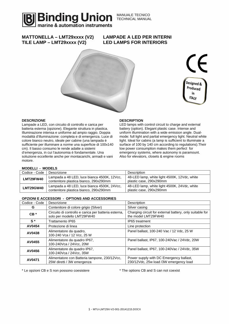
MATTONELLA – LMT29xxxx (V2) TILE LAMP – LMT29xxxx (V2)
LAMPADE A LED PER INTERNI LED LAMPS FOR INTERIORS
DESCRIZIONE DESCRIPTION Lampade a LED, con circuito di controllo e carica per batteria esterna (opzione). Elegante struttura in plastica. Illuminazione intensa e uniforme ad ampio raggio. Doppia modalità d’illuminazione: completa e di emergenza. Luce di colore bianco neutro, ideale per cabine (una lampada è sufficiente per illuminare a norme una superficie di 100x140 cm). Il basso consumo le rende adatte a sistemi d’emergenza, in cui l’autonomia è fondamentale. Una soluzione eccellente anche per montacarichi, armadi e vani motore.
LED lamps with control circuit to charge and external battery (option). Elegant plastic case. Intense and uniform illumination with a wide emission angle. Dual-mode: full light and partial emergency light. Neutral white light. Ideal for cabins (a lamp is sufficient to illuminate a surface of 100 by 140 cm according to regulations).Their low power consumption makes them perfect for emergency systems, where autonomy is paramount. Also for elevators, closets & engine rooms
MODELLI - MODELS Codice - Code Descrizione Description
LMT29FW40 Lampada a 48 LED, luce bianca 4500K, 12Vcc, contenitore plastica bianco, 290x290mm
48-LED lamp, white light 4500K, 12Vdc, white plastic case, 290x290mm
LMT29GW40 Lampada a 48 LED, luce bianca 4500K, 24Vcc, contenitore plastica bianco, 290x290mm
48-LED lamp, white light 4500K, 24Vdc, white plastic case, 290x290mm
OPZIONI E ACCESSORI - OPTIONS AND ACCESSORIES Codice - Code Descrizione Description
G Contenitore di colore grigio (Silver) Silver casing
CB * Circuito di controllo e carica per batteria esterna, solo per modello LMT29FW40
Charging circuit for external battery, only suitable for the model LMT29FW40
S * Trattamento IP65 IP65 treatment AV0454 Protezione di linea Line protection
AV0438 Alimentatore da quadro, 100-240 Vca / 12 Vcc, 25 W
Panel ballast, 100-240 Vac / 12 Vdc, 25 W
AV0455 Alimentatore da quadro IP67, 100-240Vca / 24Vcc, 20W
Panel ballast, IP67, 100-240Vac / 24Vdc, 20W
AV0456 Alimentatore da quadro IP67, 100-240Vca / 24Vcc, 35W
Panel ballast, IP67, 100-240Vac / 24Vdc, 35W
AV0471 Alimentatore con Batteria tampone, 230/12Vcc, 25W diretti / 3W emergenza
Power supply with DC Emergency ballast, 230/12Vdc, 25w load /3W emergency load
* Le opzioni CB e S non possono coesistere * The options CB and S can not coexist
MANUALE TECNICO TECHNICAL MANUAL
2 - MTU-LMT29X-V2-001-20141215.DOCX
SPECIFICHE TECNICHE TECHNICAL SPECIFICATIONS Illuminazione : 48 LED (completa) comprendente:
42 LED (luce principale) 6 LED (emergenza)
Alimentazione: 12 Vcc o 24 Vcc (vedi modelli) Consumo: 10 W (completa)
1 W (emergenza) Temperatura colore: 4500°K Intensità luminosa: 350 Lux a 1m, 100 Lux a 2m(completa)
48 Lux a 1m, 14 Lux a 2m (emerg.) Prive di raggi UV Ampiezza cono di luce: 120° Vita operativa: 30000 ore Temperatura operativa: -10...+50°C Cornice: plastica Dimensioni: 290x290x30 mm Peso: circa 600 g
Light emission: 48 LEDs (full light) including: 42 LEDs (main light) 6 LEDs (emergency light)
Power supply: 12 Vdc or 24 Vdc (see models) Power consumption: 10 W (full light)
1 W (emergency light) Light temperature: 4500°K Light intensity: 350 Lux at 1m, 100 Lux at 2m (full light)
48 Lux at 1m, 14 Lux at 2 m (emerg.) Zero UV emission Light emission angle: 120° Operating life: 30000 hours Operating temperature range: -10...+50°C Frame: plastic Dimensions: 290x290x30 mm Weight: about 600 g
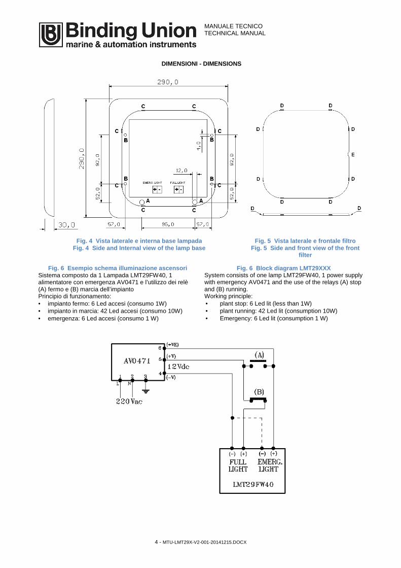
MONTAGGIO MOUNTING Togliere il filtro opaline frontale inserendo un cacciavite o un oggetto di dimensioni adeguate nell’unica asola laterale del filtro ( punto E in Fig. 5) e facendo leva in modo da sollevare il filtro stesso. Fissare la lampada alla superficie mediante quattro viti (non fornite) attraverso i quattro fori di dia. 4 mm (punti B in Fig.4) presenti nella base del contenitore. Forare la superficie attraverso il foro (dia. 12 mm) nella base della lampada (punto A in Fig. 4). Nel foro inserire e far scorrere i cavi di alimentazione. Eseguire il collegamento elettrico come indicato nel paragrafo seguente. Rimontare il filtro opaline allineando i ganci di tenuta (punti D in Fig. 5) alle asole (punti C in Fig. 4). Premere il filtro opaline anteriore in modo che si fissi saldamente incastrandosi alla base nei punti suddetti.
Remove the opaline front filter inserting a screwdriver or any other flat tool, into the side slot (E in Fig. 5). Push and leverage to raise the front filter from its housing. Fix the lamp to the surface using four screws (not provided) through the four holes (dia. 4 mm) in the lamp base (B in Fig. 4). Make a hole (dia. 12 mm) in the surface by drilling through the hole present on the base of the lamp (A in Fig. 4). Insert and slide the power cables in the hole. Connect the lamp to the power supply according to the following paragraph. Mount the front filter back on the lamp body by aligning the clips (D in Fig. 5) to the slots (C in Fig. 4). Press the front filter and make it clamp in all the eight points.
COLLEGAMENTI ELETTRICI ELECTRICAL CONNECTIONS Attenzione: i collegamenti cambiano in base alle opzioni presenti, verificare prima di procedere il tipo di alimentazione da fornire e come effettuare le connessioni elettriche facendo riferimento al codice e quanto indicato sull’etichetta apposta sul retro della lampada. Il collegamento elettrico all’impianto della bassa tensione (batteria o alimentatore) va eseguito rispettando la polarità (vedi di seguito). In caso contrario le lampade non funzionano, ma non si danneggiano, essendo protette elettricamente.
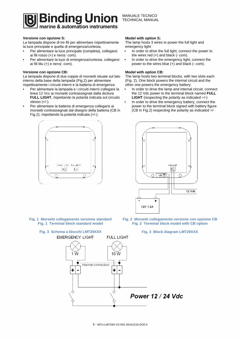
Versione standard: La lampada dispone di due coppie di morsetti situate sul lato interno della base della lampada (Fig.1) per alimentare rispettivamente la luce principale e quella di emergenza/cortesia. • Per alimentare la luce principale, collegarsi ai morsetti
contrassegnati dalla dicitura FULL LIGHT , rispettando la polarità indicata sul circuito stesso (+/-).
• Per alimentare la luce di emergenza/cortesia, collegarsi ai morsetti contrassegnati dalla dicitura EMERG. LIGHT, rispettando la polarità indicata sul circuito stesso (+/-).
• Per utilizzare la massima potenza (in caso non serva la luce di emergenza) è possibile collegare in parallelo i due circuiti.
Please note: the connections are different depending on the options present. Verify the type of power supply and the electrical connections match the description written on the label located on the back of the lamp. The electrical connections to the battery circuit must respect the voltage polarity (see below). If not connected properly, the lamp does not work but it is not damaged, since it is protected electrically.
Standard model: The lamp hosts two terminal blocks, with two slots each (Fig. 1). One block powers the main (full) light and the other one powers the emergency light. • In order to drive the main light, connect the power to
the terminal block named FULL LIGHT (respecting the polarity as indicated +/-)
• In order to drive the emergency light, connect the power to the terminal block named EMERG. LIGHT (respecting the polarity as indicated +/-)
• To use the maximum power (in case the emergency light is unnecessary) the two circuits can be connected in parallel.
MANUALE TECNICO TECHNICAL MANUAL
3 - MTU-LMT29X-V2-001-20141215.DOCX
Versione con opzione S : La lampada dispone di tre fili per alimentare rispettivamente la luce principale e quella di emergenza/cortesia. • Per alimentare la luce principale (completa), collegarsi
ai fili rosso (+) e nero(- com). • Per alimentare la luce di emergenza/cortesia, collegarsi
ai fili blu (+) e nero(- com). Versione con opzione CB: La lampada dispone di due coppie di morsetti situate sul lato interno della base della lampada (Fig.2) per alimentare rispettivamente i circuiti interni e la batteria di emergenza • Per alimentare la lampada e i circuiti interni collegare la
linea 12 Vcc ai morsetti contrassegnati dalla dicitura FULL LIGHT , rispettando la polarità indicata sul circuito stesso (+/-).
• Per alimentare la batteria di emergenza collegarsi ai morsetti contrassegnati dal disegno della batteria (CB in Fig.2), rispettando la polarità indicata (+/-).
Model with option S: The lamp hosts 3 wires to power the full light and emergency light • In order to drive the full light, connect the power to
the wires red (+) and black (- com). • In order to drive the emergency light, connect the
power to the wires blue (+) and black (- com). Model with option CB: The lamp hosts two terminal blocks, with two slots each (Fig. 2). One block powers the internal circuit and the other one powers the emergency battery. • In order to drive the lamp and internal circuit, connect
the 12 Vdc power to the terminal block named FULL LIGHT (respecting the polarity as indicated +/-)
• In order to drive the emergency battery, connect the power to the terminal block signed with battery figure (CB in Fig.2) respecting the polarity as indicated +/-
Fig. 1 Morsetti collegamento versione standard
Fig. 1 Terminal block standard model Fig. 2 Morsetti collegamento versione con opzione CB
Fig. 2 Terminal block model with CB option
Fig. 3 Schema a blocchi LMT29XXX Fig. 3 Block diagram LMT29XXX
MANUALE TECNICO TECHNICAL MANUAL
4 - MTU-LMT29X-V2-001-20141215.DOCX
DIMENSIONI - DIMENSIONS
Fig. 4 Vista laterale e interna base lampada Fig. 4 Side and Internal view of the lamp base
Fig. 5 Vista laterale e frontale filtro Fig. 5 Side and front view of the front
filter
Fig. 6 Esempio s chema illuminazione ascensori Fig. 6 Block diagram LMT29XXX Sistema composto da 1 Lampada LMT29FW40, 1 alimentatore con emergenza AV0471 e l’utilizzo dei relè (A) fermo e (B) marcia dell’impianto Principio di funzionamento: • impianto fermo: 6 Led accesi (consumo 1W) • impianto in marcia: 42 Led accesi (consumo 10W) • emergenza: 6 Led accesi (consumo 1 W)
System consists of one lamp LMT29FW40, 1 power supply with emergency AV0471 and the use of the relays (A) stop and (B) running. Working principle: • plant stop: 6 Led lit (less than 1W) • plant running: 42 Led lit (consumption 10W) • Emergency: 6 Led lit (consumption 1 W)