Manuale Spessorimetro Dg 51
118
GILARDONI S.p.A. Stabilimento: Via Arturo Gilardoni n°1 Sede: P.zza Luigi di Savoia, 28 23826 MANDELLO del LARIO (LC) 20124 Milano MODO D’USO Misuratore di spessori GILARDONI DG 51 / DG 51B 64830903 Z1893
-
Upload
francesco-livio -
Category
Documents
-
view
487 -
download
39
description
Manuale Spessorimetro Dg 51
Transcript of Manuale Spessorimetro Dg 51

GILARDONI S.p.A. Stabilimento: Via Arturo Gilardoni n°1 Sede: P.zza Luigi di Savoia, 28
23826 MANDELLO del LARIO (LC) 20124 Milano
MODO D’USO
Misuratore di spessori GILARDONI DG 51 / DG 51B
64830903
Z1893

Operation Manual - Gilardoni DG 51 / DG51B
man dg51.doc Page 2 of 123
1. AVVERTENZE 1
1.1 INDICAZIONI PER LA PULIZIA E MANUTENZIONE QUOTIDIANA . ...................................................... 8
2. PRINCIPIO E TECNICHE DI MISURA 8
2.1. PRINCIPIO ............................................................................................................................................. 8 2.2. TECNICHE DI FUNZIONAMENTO .......................................................................................................... 9 2.2.1. TECNICA S-E...................................................................................................................................... 9 2.2.2. TECNICA E-E.................................................................................................................................... 10 2.2.3. TECNICA L-R.................................................................................................................................... 10
3. DESCRIZIONE DEL DG51 11
3.1. DESCRIZIONE DG51 – DG51B: .................................................................................................... 12 3.2. DISPLAY E RELATIVA SIMBOLOGIA ..................................................................................... 13
4. ACCENSIONE DG51 14
4.1. ACCENSIONE CON SONDA COLLEGATA ALLO STRUMENTO ............................................................. 14 4.2. SONDA COLLEGATA AD ACCENSIONE AVVENUTA ............................................................................ 15 4.3. SCELTA MANUALE .............................................................................................................................. 16
5. CALIBRAZIONE 17
6. MISURA DI SPESSORE – THK - 19
7. TASTO MENU’ 22
8. FUNZIONE VELOCITA’ – VEL - 23
9. FUNZIONE SOTTOSPESSORE – MIN – 25
10. SELEZIONE DELLA FUNZIONE – MENU - 27
10.1. VELOCITÀ PER LA MISURA DI SPESSORE ......................................................................................... 27 10.2. IMPOSTAZIONI SONDA IN USO – SET................................................................................................ 28 10.3. SELEZIONE MANUALE DELLA SONDA DA UTILIZZARE ..................................................................... 30 10.4. VELOCITÀ DI SCANSIONE .................................................................................................................. 30 10.5. M ISURA DECIMALE O CENTESIMALE ................................................................................................ 30 10.6. UNITÀ DI MISURA ............................................................................................................................... 30 10.7. L IMITAZIONE DEI CONSUMI .............................................................................................................. 30 10.8. SCHEMA OPERATIVO DELLA FUNZIONE MENU .................................................................................31
11. FUNZIONE MEMORIA – MEM - 32
11.1. ACCESSO ALLA FUNZIONE MEMORIA ............................................................................................... 32 11.2. CREAZIONE NUOVO FILE ................................................................................................................... 33 11.3. MEMORIZZAZIONE DATI ................................................................................................................... 33
Operation Manual - Gilardoni DG 51 / DG51B
man dg51.doc Page 3 of 123
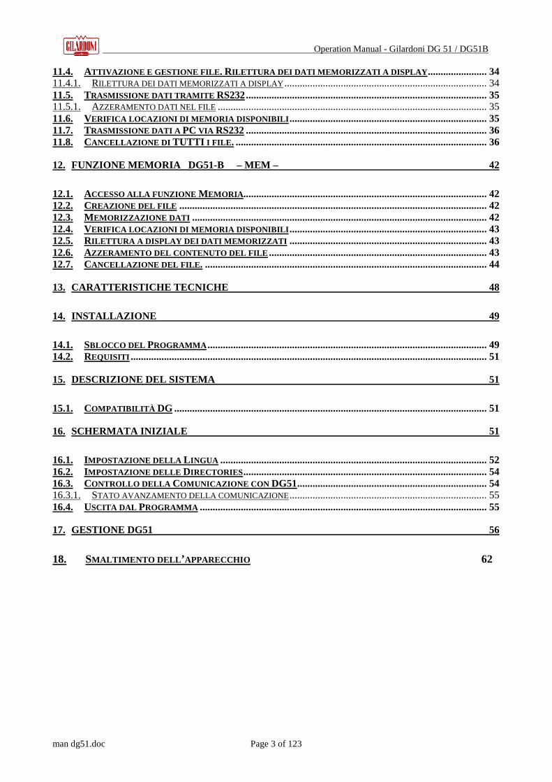
11.4. ATTIVAZIONE E GESTIONE FILE . RILETTURA DEI DATI MEMORIZZATI A DISPLAY ....................... 34 11.4.1. RILETTURA DEI DATI MEMORIZZATI A DISPLAY ............................................................................... 34 11.5. TRASMISSIONE DATI TRAMITE RS232.............................................................................................. 35 11.5.1. AZZERAMENTO DATI NEL FILE ......................................................................................................... 35 11.6. VERIFICA LOCAZIONI DI MEMORIA DISPONIBILI ............................................................................. 35 11.7. TRASMISSIONE DATI A PC VIA RS232.............................................................................................. 36 11.8. CANCELLAZIONE DI TUTTI I FILE . .................................................................................................. 36
12. FUNZIONE MEMORIA DG51-B – MEM – 42
12.1. ACCESSO ALLA FUNZIONE MEMORIA ............................................................................................... 42 12.2. CREAZIONE DEL FILE ........................................................................................................................ 42 12.3. MEMORIZZAZIONE DATI ................................................................................................................... 42 12.4. VERIFICA LOCAZIONI DI MEMORIA DISPONIBILI ............................................................................. 43 12.5. RILETTURA A DISPLAY DEI DATI MEMORIZZATI ............................................................................. 43 12.6. AZZERAMENTO DEL CONTENUTO DEL FILE ..................................................................................... 43 12.7. CANCELLAZIONE DEL FILE . .............................................................................................................. 44
13. CARATTERISTICHE TECNICHE 48
14. INSTALLAZIONE 49
14.1. SBLOCCO DEL PROGRAMMA ............................................................................................................. 49 14.2. REQUISITI ........................................................................................................................................... 51
15. DESCRIZIONE DEL SISTEMA 51
15.1. COMPATIBILITÀ DG .......................................................................................................................... 51
16. SCHERMATA INIZIALE 51
16.1. IMPOSTAZIONE DELLA L INGUA ........................................................................................................ 52 16.2. IMPOSTAZIONE DELLE DIRECTORIES ............................................................................................... 54 16.3. CONTROLLO DELLA COMUNICAZIONE CON DG51.......................................................................... 54 16.3.1. STATO AVANZAMENTO DELLA COMUNICAZIONE ............................................................................. 55 16.4. USCITA DAL PROGRAMMA ................................................................................................................ 55
17. GESTIONE DG51 56
18. SMALTIMENTO DELL ’APPARECCHIO 62
Operation Manual - Gilardoni DG 51 / DG51B
man dg51.doc Page 4 of 123
1. AVVERTENZE
Una lettura attenta del presente manuale riveste notevole importanza nella comprensione del
funzionamento degli strumenti DG51 e DG51-B, fornendo tutti i dettagli relativi alle varie
funzioni, alcune indicazioni generali per il normale utilizzo di un misuratore di spessori e di
dettaglio per un utilizzo più mirato che ne sfrutti appieno le potenzialità.
Il presente manuale e l’utilizzo da parte di un operatore di un misuratore di spessore ad
ultrasuoni della Gilardoni S.p.A., è esclusivamente rivolto agli utenti che abbiano acquisito le
conoscenze teoriche di base per il controllo ultrasonoro, in particolare sulla velocità ultrasonora
nei materiali, la geometria del fascio ultrasonoro delle sonda utilizzate e che abbia sufficiente
esperienza nell’applicazione delle procedure di misura di spessore con il metodo ultrasonoro.
Per acquisire gli elementi base della teoria ultrasonora sono d’aiuto le pubblicazioni Z.239 e
P.131 edite dalla Gilardoni S.p.A. Si ricorda che la Gilardoni S.p.A. declina ogni
responsabilità in relazione a danni a cose e/o a persone derivanti da un uso improprio e/o non
autorizzato dello strumento.
Nonostante l’uso dello strumento sia consigliato esclusivamente ad operatori qualificati e
pertanto consci dei suoi limiti e delle sue potenzialità, si ritiene opportuno indicare alcune cautele
in modo da creare una linea guida utile, in particolare, per operatori all’inizio dell’attività.
1 Tutti i componenti del Kit del misuratore di spessore DG51 e DG51-B sono stati studiati per ottenere il
massimo delle prestazioni richieste quali efficacia nelle misure, robustezza dell’insieme per un uso
cantieristico, autonomia, praticità d’uso: ogni utilizzo improprio dello spessimetro e delle sue parti non è stato
contemplato e pertanto ammesso. Non è consentito l’utilizzo del kit del misuratore o di alcuna sua parte con
altre componenti che non siano realizzate dalla Gilardoni S.p.A. per il DG51 e viceversa, in quanto si possono
creare situazioni potenzialmente fonti di errore.
2 E’ raccomandato, ed indispensabile per la regolarità della garanzia, che ogni intervento di assistenza tecnica
sullo strumento venga effettuata da un centro assistenza Gilardoni S.p.A. qualificato, dove sarà assicurato un
regolare ripristino del corretto funzionamento dello strumento. E’ bene ricordare, al di là della validità della
garanzia, che un’ assistenza tecnica eseguita da personale non specializzato potrebbe portare a
malfunzionamenti dello strumento tali da indurre misure errate e, nei casi estremi, rischio per l’integrità dello
strumento stesso.

Operation Manual - Gilardoni DG 51 / DG51B
man dg51.doc Page 5 of 123
3 Prima dell’utilizzo è bene accertarsi che il DG51 ed i suoi componenti non presentino visivamente
danneggiamenti o mancanza di parti e che non vi sia fuoriuscita di acido dall’involucro delle batterie. In caso
di mancata accensione, verificare l’assenza di fuoriuscita dell’acido dall’involucro; qualora all’accensione si
verifichino eventi anomali quali:
alcuni segmenti del display siano intermittenti o mancanti
il riconoscimento automatico della sonda sia negativo
lo spessimetro non si spenga automaticamente dopo tre minuti di mancata pressione di alcun tasto contattare
l’assistenza tecnica della GILARDONI S.p.A.
4 In caso di caduta dello strumento controllare bene lo stesso in ogni sua parte per verificare distacchi o rotture
visibili, quindi seguire i punti 2 e 3 del presente paragrafo.
5 In caso di accidentale contatto dello strumento con acqua, prima dell’uso accertarsi che sia perfettamente
asciutto, quindi ripartire ancora dal punto 2. In caso d’acqua marina o liquido corrosivo, fare pervenire DG51
al centro di assistenza autorizzato prima possibile, preferibilmente corredato di una nota che illustri la natura
dell’evento e del liquido.
6 Per la sostituzione delle batterie, attenersi strettamente alla tipologia indicata nel manuale (due pile a secco
Alcaline 1,5V AA) ed osservare scrupolosamente la polarità indicata. A prevenzione della inversione di
polarità è disponibile un sistema meccanico che impedisce, di fatto, il contatto dei poli batteria alle linguette
metalliche: nel caso fortuito che ciò avvenga è prevista internamente una protezione elettronica contro le
inversioni e/o sovracorrenti. In caso di intervento di questa protezione lo strumento deve pervenire ad un
centro assistenza Gilardoni S.p.A. dove verrà ripristinato il normale funzionamento.
7 Per il tempo necessario a completare la procedura interna di riconoscimento e calibrazione automatiche, la
superficie di accoppiamento della sonda NON deve assolutamente essere messa a contatto con nulla, in quanto
l’assorbimento acustico causato dall’accoppiamento potrebbe ostacolare il corretto svolgimento delle
procedure di cui sopra. Potrebbero quindi verificarsi malfunzionamenti tali da indurre misure errate, con tutte
le conseguenze del caso.
8 Le sonde sono il componente più critico in relazione all’usura, della strumentazione: una sonda abrasa può
ridurre notevolmente le prestazioni generali del misuratore e/o indurre errori alle procedure di
riconoscimento e calibrazione automatiche, dando adito a misure errate per le ridotte prestazioni con
scostamenti di lettura fino al 100%. E’ pertanto fondamentale controllare frequentemente lo stato delle sonde in
uso ed accertarsi che le procedure di riconoscimento e calibrazione automatiche siano avvenute entro le
tolleranze indicate: in caso negativo sarà comunque possibile procedere manualmente. Sostituire o inviare
prontamente all’assistenza Gilardoni le sonde che presentano situazioni di usura incompatibili con il normale
utilizzo.
9 Sulle superfici aventi temperature superiori ai 60° devono essere sempre utilizzate sonde destinate a tali
condizioni operative: le altre, pena la perdita repentina di sensibilità, sarebbero presto irrimediabilmente
compromesse.
Operation Manual - Gilardoni DG 51 / DG51B
man dg51.doc Page 6 of 123
10 In caso di utilizzo di sonde con protezione in Vulkollan per limitarne l’usura (ed anche, in alcuni casi su
superfici sfavorevoli, migliorarne l’accoppiamento), è indispensabile disporre un sottile strato di olio (es.
SAE10-40) tra la superficie della sonda e la protezione per l’ accoppiamento acustico. La calibrazione deve
essere effettuata in modo manuale in quanto la calibrazione automatica non contempla lo strato supplementare
aggiunto e potrebbe risultare quindi molto imprecisa. Controllare con frequenza che non siano presenti bolle
d’aria nello strato d’olio tra la sonda e la protezione: ciò potrebbe alterare la misura. Considerare che
l’applicazione della protezione reca i vantaggi precedentemente indicati ma, per contro, in alcuni casi, limita le
prestazioni della sonda in termini di range di spessori leggibili.
11 La procedura di calibrazione sonda, descritta nel seguito, deve essere eseguita utilizzando il blocchetto da
5mm a VOL 5900 m/s integrato allo strumento o altro adatto allo scopo, da 5 o 25mm in Fe (+ 0,02mm e
VOL5900 m/s + 10 m/s ), accuratamente pulito onde evitare imprecisioni che si ripercuotano poi sul controllo.
Considerare che le ispezioni effettuate in condizioni di temperatura limite del pezzo in esame (negativa o
positiva) possono essere influenzate da variazioni di velocità ultrasonora nel materiale da controllare e anche
nel materiale con cui sono realizzate le sonde (zoccoli): quindi è importante che anche il blocchetto di
calibrazione predisposto presenti una temperatura vicina al pezzo in esame per minimizzare gli errori di
misura. Questa accortezza è generalmente tassativa quando si operi, ad alte temperature, con sonde ed
accoppianti speciali. (vedi optional).
12 La scelta del mezzo accoppiante non è in genere vincolante ai fini dell’affidabilità della misura: solo in casi
particolari di superfici particolarmente sfavorevoli localmente preparate o di elevate temperature di parete,
l’operatore è tenuto a scegliere il mezzo più idoneo, quali grasso, gel e paste a base di silicone.
13 Velocità Ultrasonora: ogni materiale ha una sua specifica velocità ultrasonora (vedi tabella nel seguito): per
ottenere la massima precisione disponibile dallo strumento è raccomandato tassativamente di procedere alla
sua misura utilizzando un blocchetto di spessore noto e con caratteristiche fisiche dello stesso pezzo in misura,
liscio e il più vicino possibile a quello da misurare; per limitare gli errori di percorso a V dello zoccolo (sonda
doppia, tecnica S-E). DG51 consente la correzione automatica del percorso a V per i materiali quali Fe
(V5900m/s) Al (V6300m/s) AISI 303 (V5700m/s). Per materiali diversi dai precedenti, dopo aver misurato la
velocità, selezionare la curva di correzione (vedere nel prosieguo) più indicata. Considerare anche la
possibilità che eventuali trattamenti termici possono indurre variazioni di velocità anche significative
limitatamente alle aree interessate. Seguire le istruzioni di cui al par. 8 del presente manuale.
14 La misura di spessori o di velocità è possibile solo quando le superfici di accoppiamento e di fondo sono
parallele e limitatamente all’area interessata dal fascio ultrasonoro: occorre dunque considerare sempre la
geometria del pezzo nella zona d’ispezione per escludere la presenza di pareti o altro che possano interferire
con la corretta lettura. In caso di ricerca di corrosione, considerare che utilizzando le tecniche E-E o L-R, le
sonde a cristallo singolo impiegabili hanno una copertura del fascio ultrasonoro che tende a mediarne le
risposte nell’area insonorizzata, facilitando la misura ed assicurando una maggiore copertura di controllo. Nel
caso la risposta sia instabile è preferibile completare l’indagine con la sonda a doppio cristallo (tecnica S-E) che,
avendo una zona di copertura del fascio molto ristretta, può evidenziare la presenza di corrosione anche
localizzata. La criticità di tale controllo consiglia lo svolgimento delle misure da parte di operatori addestrati
ed esperti.

Operation Manual - Gilardoni DG 51 / DG51B
man dg51.doc Page 7 of 123
15 E’ consigliabile che la verifica delle prestazioni della strumentazione, oltre che sul blocchetto di calibrazione da
5mm (5900m/s) disponibile sullo strumento, sia effettuata attraverso le scale a spessori (vedi optional). Per
materiali diversi dall’acciaio è consigliabile preparare alcuni spessori di tali materiali per effettuare la verifica
funzionale. Per i materiali verniciati, data la variabilità delle composizioni e degli spessori delle vernici, è
consigliato l’utilizzo di spessori campione riportanti strati di vernici con pari caratteristiche e spessore a
quello da indagare, affinché sia sotto controllo l’affidabilità reale, in quelle particolari condizioni,
dell’abbinamento spessimetro – sonda. E’ consigliabile che il controllo funzionale dello strumento venga
effettuato prima e dopo l’ispezione, come verifica della affidabilità del lavoro svolto.
16 E’ raccomandato l’invio dello strumento, per la verifica annuale, presso il centro di assistenza autorizzato
Gilardoni S.p.A. dove sarà controllato in ogni sua parte e riportato nelle condizioni di funzionamento ottimale
e corredato di Dichiarazione di Conformità comprovante le prestazioni.
17 E’ indispensabile che al rientro in un centro di assistenza Gilardoni S.p.A., lo strumento sia completo del kit
standard e degli eventuali accessori affinché il controllo sia completo e l’eventuale Dichiarazione di Conformità
interessi l’intera strumentazione.
18 I cavi di collegamento sonde sono un elemento della strumentazione da non sottovalutare. La Gilardoni S.p.A.
ha dotato lo strumento di cavi di particolare elevata resistenza sia meccanica che chimica per oli e solventi, di
adeguata flessibilità. Osservare accuratamente prima di ogni utilizzo la condizione superficiale dei cavi: se
presentano danneggiamenti, schiacciamenti, tagli anche in prossimità dei connettori. In tali casi non esitare a
sostituirli e/o inviarli prontamente al centro di assistenza.
19 La strumentazione contempla le sonde ultrasonore che, generalmente di piccole dimensioni, possono essere
ingoiate e pertanto causare soffocamento e/o, nei casi estremi, morte. Si raccomanda pertanto massima cautela
e l’impedimento dell’utilizzo e manipolazione ad un bambino.
20 In caso di rotture dello strumento, cavi e sonde che diano origine a componenti o frammenti, prestare
attenzione che queste non vengano a contatto in particolare con bambini in quanto, avendo dimensioni
imprecisate ma generalmente piccole, possono essere ingoiate ed essere causa di soffocamento e/o, nei casi
estremi, di morte.
21 I cavi sonde non devono essere impiegati impropriamente e mai portati o avvolti attorno al collo, in quanto
data la loro robustezza possono portare al soffocamento e/o, nei casi estremi, alla morte o comunque a lesioni
cutanee. Pertanto devono essere tenuti lontano dalla portata di un bambino.
Come già riportato, una lettura attenta del presente manuale riveste un’ importanza primaria nella
comprensione del funzionamento di DG51 DG51-B, fornendo tutte le indicazioni in merito alle
funzioni dello strumento. In ogni capitolo potranno essere presenti ulteriori avvisi o ripetuti gli
stessi o rimandi a questo capitolo inseriti direttamente nel contesto appropriato. Queste avvertenze
saranno anticipate sempre dal logo:
Operation Manual - Gilardoni DG 51 / DG51B
man dg51.doc Page 8 of 123
1.1. Indicazioni per la pulizia e manutenzione quotidiana.
L’insieme strumento, cavi e sonde è stato concepito per un utilizzo di tipo cantieristico e pertanto
molto resistente ad oli, solventi ed ai normali e tipici agenti chimici che si possono trovare in questi
ambienti. Nonostante questa robustezza d’insieme, è da considerarsi come normale attività di
lavoro il tenere in buono stato la strumentazione, per assicurarne un funzionamento ottimale nel
tempo. E basilare verificare visivamente eventuali problemi e/o infiltrazioni di liquidi o polveri
dannose.
Per la pulizia può essere impiegato un panno inumidito d’acqua o, solo all’occorrenza e senza
abusarne, di alcool denaturato onde eliminare tracce oleose o quanto sia depositato sullo
strumento e risulti difficilmente asportabile con la prima soluzione.
Si raccomanda di eseguire una costante pulizia del tutto e di visionare sempre accuratamente lo
strumento in tutte le sue parti ad ogni utilizzo: osservare quindi in particolare le avvertenze dei
punti 3-4-5-6-18-19-20 anche per quanto riguarda la manutenzione possibile, e autorizzata, da
personale non qualificato. Per ogni altro intervento fare riferimento al cap. 10 “Anomalie di
funzionamento” e/o fare riferimento ad una assistenza qualificata come prevede il punto 2 delle
avvertenze.
In caso di mancato utilizzo dello strumento per un lungo periodo di tempo e maggiormente se le
batterie sono esaurite, si raccomanda di rimuovere le batterie onde evitare che possibili fuoriuscite
di acido o ossidi dalle stesse possano danneggiare lo strumento o alcune parti dello stesso.
2. PRINCIPIO E TECNICHE DI MISURA
2.1. Principio
Il misuratore di spessore ad ultrasuoni in Vs. possesso basa il proprio funzionamento sulla
proprietà di alcuni materiali, reperibili in natura o ottenibili per sintesi, di convertire energia
elettrica in energia meccanica e viceversa.
Lo strumento Gilardoni DG 51 o DG 51B applica alla sonda un impulso elettrico di opportuna
forma ed ampiezza che il cristallo trasmettitore converte in impulso ultrasonoro in grado di
propagarsi attraverso il materiale in esame.
L’impulso riflesso da una superficie dell’oggetto diversa da quella di accoppiamento della sonda
viene ricevuto e riconvertito in impulso elettrico dal cristallo ricevitore (che coincide con il
precedente nelle sonde singole).

Operation Manual - Gilardoni DG 51 / DG51B
man dg51.doc Page 9 of 123
Lo strumento calcola il tempo impiegato a coprire la distanza (tempo di volo): nota la velocità
ultrasonora di base del materiale in esame, lo strumento è in grado di fornire come risultato lo
spessore tramite la nota formula
Spessore = (Velocità) x (Tempo di volo)
Se invece è noto lo spessore del materiale, lo strumento può fornire come risultato la velocità
ultrasonora di propagazione tramite la formula inversa
Velocità = (Spessore)/(Tempo di volo)
2.2. Tecniche di funzionamento
Il misuratore di spessori DG51 prevede l’utilizzo delle seguenti tecniche:
Tecnica S-E trasmissione-eco con sonda doppia
Tecnica E-E eco-eco con sonda singola
Tecnica L-R eco-eco con sonda singola dotata di linea di ritardo.
Il misuratore di spessore DG51-B prevede esclusivamente l’utilizzo della tecnica S-E
(trasmissione-eco: sonda doppia).
2.2.1. Tecnica S-E
La misura è determinata dalla misura del tempo di volo tra
l’istante d’ingresso dell’onda ultrasonora nel pezzo e l’eco di
fondo. I due semi cristalli di una sonda doppia sono
generalmente angolati rispetto alla superficie di ingresso nel
materiale: il percorso delle onde ultrasonore non è pertanto,
per i tratti di trasmissione e ricezione, ortogonale alla
superficie ma angolato e divergente (percorso a V).
Per determinare esattamente lo spessore, lo strumento deve
necessariamente correggere la misura secondo una curva
caratteristica della sonda utilizzata e del materiale (correzione
del percorso a V).
Questa tecnica ha un ampio campo di applicazione ed è tipica dei misuratori di spessore essendo
indispensabile per misure su superfici corrose, con un campo di misura che va da 0,7 mm a 600
mm in relazione alla sonda utilizzata ed alle condizioni superficiali e di assorbimento del
materiale.

Operation Manual - Gilardoni DG 51 / DG51B
man dg51.doc Page 10 of 123
2.2.2. Tecnica E-E
La misura è relativa all’intervallo di tempo fra la 1° e la 2° eco
di fondo.
Questa tecnica è indispensabile per le misure di spessore su
superfici verniciate (come nel campo dei serbatoi, ad esempio)
con un campo di misura che va da 2 a 75mm. Il valore misurato
è riferito allo spessore di metallo indipendentemente dallo
spessore di vernice presente.
2.2.3. Tecnica L-R
La misura è ancora relativa all’intervallo fra la 1° e la 2° eco di
fondo di una sonda diritta speciale con linea di ritardo.
Tale tecnica di misura è valida per superfici piane e spessori nel
range da 0,5 a 10 mm. La tecnica è utilizzabile anche su superfici
verniciate purché lo strato di vernice sia molto contenuto.

Operation Manual - Gilardoni DG 51 / DG51B
man dg51.doc Page 11 of 123
3. DESCRIZIONE DEL DG51
Variante DG51-B :[ 1 ] non è presente il connettore interfaccia PC RS232/ Sub
3.1.
1
4
5
6
7
8
2
3
9
10
11
15
12
13
14
Figura 1 Aspetto del misuratore di spessore Gilardoni DG 51 / DG 51B

Operation Manual - Gilardoni DG 51 / DG51B
man dg51.doc Page 12 of 123
3.1. DESCRIZIONE DG51 – DG51B:
Connessioni :
1 – Connettore dati PC RS232 e interfaccia Sub. (per il solo DG51) 2 – Connettore collegamento cavo sonda (Ricevitore) 3 – Connettore collegamento cavo sonda (Trasmettitore)
Frontale strumento:
4 – Display LCD
5 – Tasto Menu
Selezione delle funzioni: velocità, spessore minimo, menù, memoria. Tasto di ritorno (annullamento) da una sottofunzione ad una funzione.
6 – Tasto Cal Calibrazione strumento con selezione tra 5 o 25mm. In un caso, selezione di una delle sottofunzioni.
7 – Tasto Freccia Su’ (arrow up) Tasto per le scelte di funzione e/o incremento valore.
8 – Blocco campione di taratura (Test Block 5mm Fe)
9 – Tasto Enter
Tasto di conferma.
10 – Tasto On
Tasto di accensione strumento.
11 – Tasto Freccia Giu’ (arrow down) Tasto di variazione delle scelte di funzione e/o decremento valore.
Retro strumento :
12 – Coperchio vano alloggiamento batterie Per la sostituzione delle batterie: togliere le viti (14), togliere il coperchio e procedere alla sostituzione utilizzando 2 nuove batterie alcaline 1,5V AA.
Rispettare scrupolosamente la polarità indicata. 13 – Viti chiusura strumento 14 – Etichette identificazione strumento; matricole e marchi di conformità 15 – Viti chiusura pannello alloggiamento batterie
In/Out Connettore 7 poli DG51 Pin 1 = RX RS232 Pin 2 = GND Pin 3 = interfaccia Sub. Enter Pin 4 = DTR RS232 Pin 5 = TX RS232 Pin 6 = interfaccia Sub. On Pin 7 = N.C.
Operation Manual - Gilardoni DG 51 / DG51B
man dg51.doc Page 13 of 123
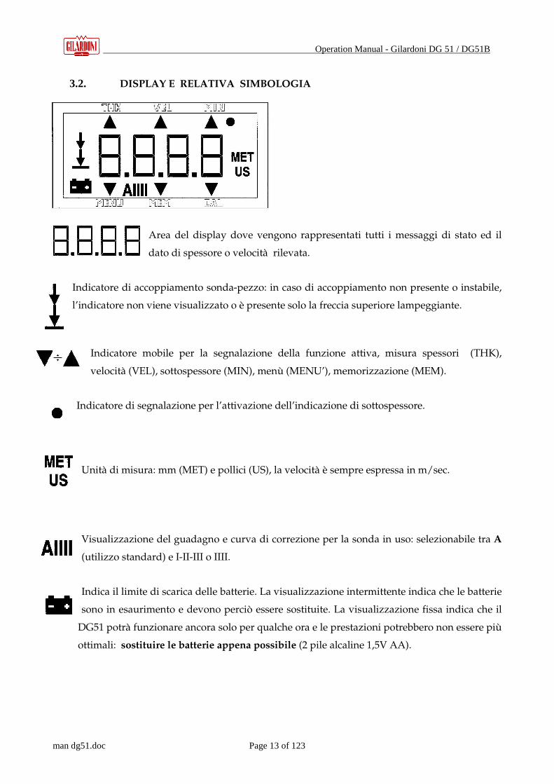
3.2. DISPLAY E RELATIVA SIMBOLOGIA
Area del display dove vengono rappresentati tutti i messaggi di stato ed il
dato di spessore o velocità rilevata.
Indicatore di accoppiamento sonda-pezzo: in caso di accoppiamento non presente o instabile,
l’indicatore non viene visualizzato o è presente solo la freccia superiore lampeggiante.
Indicatore mobile per la segnalazione della funzione attiva, misura spessori (THK),
velocità (VEL), sottospessore (MIN), menù (MENU’), memorizzazione (MEM).
Indicatore di segnalazione per l’attivazione dell’indicazione di sottospessore.
Unità di misura: mm (MET) e pollici (US), la velocità è sempre espressa in m/sec.
Visualizzazione del guadagno e curva di correzione per la sonda in uso: selezionabile tra A
(utilizzo standard) e I-II-III o IIII.
Indica il limite di scarica delle batterie. La visualizzazione intermittente indica che le batterie
sono in esaurimento e devono perciò essere sostituite. La visualizzazione fissa indica che il
DG51 potrà funzionare ancora solo per qualche ora e le prestazioni potrebbero non essere più
ottimali: sostituire le batterie appena possibile (2 pile alcaline 1,5V AA).
Operation Manual - Gilardoni DG 51 / DG51B
man dg51.doc Page 14 of 123
4. ACCENSIONE DG51
Collegare il cavo coassiale da un lato allo strumento e dall’altro alla sonda da utilizzare.
In caso di sonda doppia (tecnica S-E) il cavo doppio va collegato senza curarsi della scelta del
connettore T o R del DG51 / DG51B.
In caso di sonda singola (tecnica E-E o L-R) il cavo singolo può essere collegato indifferentemente
al T o R del DG51.
Premere il tasto ON per circa 1 secondo
Il DG51 si accende e sul display per una frazione di secondo tutti gli elementi
risultano accesi e a seguire compare la sigla Id_ _
Di seguito sono riportate le tre possibili varianti, ovvero:
• Sonda già collegata all’accensione;
• Sonda collegata dopo l’accensione (cambio sonda);
• Scelta manuale della sonda in uso.
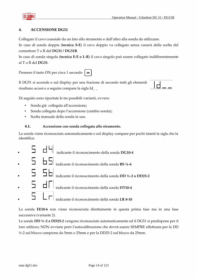
4.1. Accensione con sonda collegata allo strumento.
La sonda viene riconosciuta automaticamente e sul display compare per pochi istanti la sigla che la identifica:
� indicante il riconoscimento della sonda DG10-4
� indicante il riconoscimento della sonda BS ¼ -6
� indicante il riconoscimento della sonda DD ½ -2 o DD25-2
� indicante il riconoscimento della sonda DT10-4
� indicante il riconoscimento della sonda LR 8-10
La sonda EE10-6 non viene riconosciuta direttamente in questa prima fase ma in una fase
successiva (variante 2).
Le sonde DD ½ -2 e DD25-2 vengono riconosciute automaticamente ed il DG51 si predispone per il
loro utilizzo; NON avviene però l’autocalibrazione che dovrà essere SEMPRE effettuata per la DD
½-2 sul blocco campione da 5mm o 25mm e per la DD25-2 sul blocco da 25mm.

Operation Manual - Gilardoni DG 51 / DG51B
man dg51.doc Page 15 of 123
Controllare sempre che la sonda riconosciuta sia effettivamente quella corretta: in caso di sonde particolarmente
usurate esiste la reale possibilità che la lettura ed i conseguenti riconoscimento e calibrazione automatici non avvengano
in modo corretto. In tal caso sostituire quanto prima la sonda.
Non utilizzare sonde Gilardoni S.p.A delle serie precedenti (es. TG10-4) in quanto non sono compatibili con
l’utilizzo su DG51 DG51-B in relazione al sistema di autoriconoscimento e autocalibrazione.
4.2. Sonda collegata ad accensione avvenuta
Se al momento dell’accensione nessuna sonda è collegata, il DG51 dopo il tentativo di
autoriconoscimento si predispone per una scelta manuale della sonda: occorre
collegare tale sonda, premere contemporaneamente i tasti + ed attendere l’esito
del nuovo tentativo di autoriconoscimento terminato il quale a display
comparirà il nome della sonda riconosciuta, come al punto 5.1, ma in questo caso potrà essere
riconosciuta anche la sonda EE10-6 con la conferma attraverso il messaggio:
� a display.
La sonda EE-10-6 è riconosciuta attraverso un processo di esclusione.
� Il sistema di ricerca e calibrazione automatica della sonda tramite i tasti CAL + Freccia SU’
è utile e funzionale qualora si voglia sostituire la sonda in uso a DG51 acceso: basta infatti
premere contemporaneamente questi due tasti subito dopo averla collegata per dare inizio
alla procedura di riconoscimento automatico.
Il sistema di “riconoscimento” della sonda EE10-6 è utile anche per effettuare una verifica del funzionamento
corretto dell’insieme misuratore, sonda e cavo: ad esempio se la sonda inserita è una sonda DG , BS , LR od altra e viene
invece riconosciuta come EE10-6, questo può voler significare che il cavo non è funzionante e deve essere sostituito.
Durante la verifica sonda da parte del misuratore per effettuare l’autoriconoscimento e l’autocalibrazione, la superficie di
misura della sonda (zoccolo) NON deve assolutamente essere messa a contatto con alcunché, in quanto l’assorbimento acustico
causato dall’accoppiante (o dalle dita stesse dell’operatore) potrebbe influenzare il riconoscimento corretto della sonda o la sua
autocalibrazione e determinare così misure errate con il rischio elevato di danni a cose o, nei casi estremi, a persone.

Operation Manual - Gilardoni DG 51 / DG51B
man dg51.doc Page 16 of 123
4.3. Scelta manuale
Se al momento dell’accensione non era collegata alcuna sonda, il DG51 dopo il tentativo di
autoriconoscimento si predispone per una scelta manuale della sonda, tramite una
lista a scorrimento sul display: utilizzando i tasti si seleziona la sonda che si vuole
utilizzare e confermando con il tasto lo strumento si predispone per la misura di spessore.
In caso di scelta manuale della sonda, l’autocalibrazione, a cura dell’operatore, deve essere
SEMPRE effettuata prima dell’uso.
Schema operativo all’accensione :
Per un utilizzo corretto dello spessimetro, leggere attentamente tutte le avvertenze e le modalità di utilizzo.
Dopo l’accensione e il riconoscimento sonda secondo le tre varianti possibili, il misuratore si predispone per la misura o per la calibrazione.
Autoriconoscimento sonda da strumento Off.
Autoriconoscimento da strumento ON, cambio sonda
Selezione manuale sonda
Calibrazione Tasto MENU’
7.0 Misura spessore (THK)

Operation Manual - Gilardoni DG 51 / DG51B
man dg51.doc Page 17 of 123
5. CALIBRAZIONE
Premendo il tasto dalla funzione di misura di spessore (THK) si accede alla funzione di
calibrazione strumento.
Sul display compare un numero indicante lo spessore in mm del Test Block che si intende
utilizzare per la calibrazione, ovvero 5 mm per l’utilizzo di quello incorporato nello
strumento o 25 mm: per passare da uno spessore all’altro premere il tasto
(selezione alternata 5 – 25mm).
Accoppiare la sonda sullo spessore prescelto, avendo cura di garantire l’accoppiamento acustico
con un velo di accoppiante e, mantenendo una corretta pressione costante tra la sonda e il Test
Block, procedere alla calibrazione premendo il tasto per confermare la scelta.
Sul display compare momentaneamente la velocità US di 5900 m/s indicante la velocità nominale
del Test Block da utilizzare, ed a seguire un avanzamento di I per indicare che la
calibrazione è in atto: l’operatore dovrà avere cura di tenere ben ferma la sonda per garantire un
accoppiamento costante. Se la calibrazione avrà avuto esito positivo il misuratore passerà
automaticamente in funzione misura di spessore (THK) già pronto all’uso, mentre per un esito
negativo sul display rimarrà un tratteggio e la procedura di calibrazione andrà
ripetuta.
Per selezionare lo spessore di calibrazione, oltre al tasto , è possibile utilizzare
indifferentemente anche i tasti di incremento o decremento .
E’ consigliabile ricontrollare sempre sul Test Block la precisione di lettura dopo la calibrazione anche se questa ha avuto
esito positivo: una disomogenea pressione sulla sonda e/o una cattiva distribuzione dell’accoppiante possono determinare errori
non trascurabili.
In caso di utilizzo delle sonde con protezione in Vulkolan onde limitarne l’usura, è indispensabile lasciare un sottile strato
di olio (es. SAE10-40) tra la superficie della sonda e la protezione come accoppiante acustico e quindi effettuare la calibrazione in
modo manuale in quanto quella automatica non contempla lo strato supplementare aggiunto e risulterebbe così molto imprecisa.
Assicurarsi con frequenza che il velo d’olio sia esente da bolle d’aria che potrebbero falsare la misura. Considerare che
l’applicazione della protezione ha come vantaggi la limitazione dell’usura della sonda ed il miglioramento dell’accoppiamento su
superfici sfavorevoli ma in generale limita le prestazioni della sonda in termini di spessori controllabili..

Operation Manual - Gilardoni DG 51 / DG51B
man dg51.doc Page 18 of 123
La procedura di calibrazione sonda deve essere eseguita utilizzando il blocchetto 5mm a 5900 m/s disponibile sullo
strumento o altro blocchetto adatto allo scopo, da 5 o 25mm in Fe (+ 0,02mm V5900 m/s + 10 m/s ), accuratamente pulito onde
evitare imprecisioni che si ripercuotano poi sul controllo. Considerare che ispezioni effettuate in condizioni di temperatura limite
del pezzo in esame possono essere influenzate da variazioni di velocità ultrasonora nel materiale da controllare e nel materiale di
cui sono composte le linee di ritardo delle sonde (zoccoli): quindi è importante che anche il blocchetto di calibrazione abbia una
temperatura vicina a quella del pezzo in esame per minimizzare tali errori di misura; questa accortezza è ancora più importante
quando si opera su pareti ad alta temperature con sonde ed accoppianti speciali. (vedi optional)
Le sonde sono l’elemento soggetto ad usura più critico dell’ intera strumentazione:: una sonda consumata può ridurre
anche notevolmente le prestazioni generali del misuratore e/o indurre errori causa un autoriconoscimento o autocalibrazione
impropria, con rischio di errori anche del 100% in particolare in relazione alla tecnica S-E Controllare pertanto frequentemente lo
stato delle sonde in uso: in caso di usura, dopo l’autoriconoscimento e l’autocalibrazione, verificare che la calibrazione sia
avvenuta nelle tolleranze indicate altrimenti effettuare nuovamente la calibrazione in manuale. Sostituire o inviare prontamente
all’assistenza Gilardoni le sonde che presentano situazioni di usura incompatibili con un uso corretto.
Schema operativo della calibrazione:
Funzionamento ciclico tasto CAL per selezione tra 5 e 25mm
Conferma scelta (sonda accoppiata al Test Block)
Calibrazione in atto…. (sonda accoppiata al Test Block)
Calibrazione con esito positivo
Calibrazione con esito negativo: da ripetere procedura di calibrazione
5mm 25mm
Tasto MENU’
Misura spessore (THK)
Operation Manual - Gilardoni DG 51 / DG51B
man dg51.doc Page 19 of 123
6. MISURA DI SPESSORE – THK -
Completate correttamente le procedure di riconoscimento sonda e di calibrazione, il misuratore si
porta nella funzione di misura spessore (THK).
Il misuratore esegue la misura in base alla velocità ultrasonora impostata: essa si
visualizza/imposta nella prima funzione della selezione Menu se la velocità del materiale in
esame è nota. In caso contrario la velocità del materiale deve essere impostata utilizzando la
funzione prevista allo scopo: Velocità.
Eseguita la corretta impostazione della velocità, si può dare corso alla misura di spessore
accoppiando la sonda al pezzo in esame ed osservando le regole più volte espresse.
In fase di misura, per essere sicuri della correttezza del valore a display, verificare la presenza
della doppia freccia indicante un corretto accoppiamento acustico: in caso di assenza anche di una
sola delle frecce, accertarsi che:
• la superficie di accoppiamento non sia eccessivamente ruvida ed eventualmente prepararla
localmente;
• sia stato interposto il necessario strato di accoppiante tra la sonda ed il pezzo;
• sia interposto il velo di accoppiante fra sonda e protezione, se è utilizzata la protezione in
Vulkolan;
• il materiale in misura ed il suo spessore siano compatibili, dal punto di vista ultrasonoro,
con la sonda in uso.
La misura effettuata è ritenuta a display in modo da consentire all’operatore la lettura in ogni
momento.

Operation Manual - Gilardoni DG 51 / DG51B
man dg51.doc Page 20 of 123
Tabella 1 Tabella indicativa delle velocità ultrasonore di riferimento, in onde longitudinali, per alcuni materiali
Materiale VL VT Materiale VL VT
ACCIAIO C 5900 3230 STAGNO 3300 1300
AISI 5600-5800 3100 TITANIO 6100 2400
ALLUMINIO 6200-6400 2500 TUNGSTENO 5300 2100
ARGENTO 3600 1400 ZINCO 4100 1600
GHISA 3600 ÷ 5700 1800÷3000 FENOLICO 1400 560
INCONEL 5600 2200 GOMMA 1900 ÷ 2300 730 ÷ 900
MAGNESIO 5800 2300 NYLON 2500 1000
MANGANESE 4600 1800 NEOPRENE 1600 .630
MOLIBDENO 6300 2500 PLEXIGLAS 2730 1100
NICKEL 5600 2200 PORCELLANA 5600 2200
OTTONE 4300 1700 POLIETILENE 1800 700
ORO 3300 1300 POLISTIRENE 2400 930
PIOMBO 2200 850 POLIURETANO 1800 700
RAME 4600 1800 VETRO 5600 ÷ 6800 2200 ÷2700
NB: la presente tabella fornisce delle velocità solo ed esclusivamente a titolo indicativo: la Gilardoni S.p.A. non si assume
alcuna responsabilità per eventuali imprecisioni.

Operation Manual - Gilardoni DG 51 / DG51B
man dg51.doc Page 21 of 123
Schema operativo della funzione misura di spessore:
Per un utilizzo corretto del misuratore, leggere attentamente tutte le avvertenze e le modalità di utilizzo.
Misura spessore (THK)
3 volte
per selezione funzione Menù: verifica e impostazione velocità nota
1 volta
per selezione funzione velocità: verifica e impostazione velocità non nota
Accoppiamento instabile: accertarsi del motivo, prendere i provvedimenti necessari e ripetere la misura
Selezione funzione Memoria DG51 e DG51-B
Misura di spessore in corso
Misura di spessore in corso
Per memorizzare premere il tasto ENTER

Operation Manual - Gilardoni DG 51 / DG51B
man dg51.doc Page 22 of 123
7. TASTO MENU’
Con il Tasto si accede alla logica di funzionamento generale del misuratore.
� Dalla funzione di misura spessori (THK), premendo il tasto menù, si accede ad un altro set
di funzioni. A display una delle frecce ∇∇∇∇ andrà a posizionarsi sulla funzione selezionata fra
THK, VEL, MIN, MENU, MEM: con il tasto CAL, come si vedrà in seguito, si potranno
selezionare le varie funzioni da confermare con il tasto ENTER, mentre con il tasto MENU
sarà consentito di uscire dalla selezione per passare ad un altro set di funzioni o annullare
una scelta.
Schema operativo del funzionamento Tasto MENU
A display la V corrente: sonda non
accoppiata, il valore è 0
A display lo spessore
minimo impostato
Visualizza la V utilizzata per la
misura spessore - THK
A display lo stato corrente
della memoria
Selezione funzione Velocità
Selezione funzione Minimo
Selezione funzione Menù
Selezione funzione Memoria – DG51 e DG51-B
Misura spessore (THK)
Misura spessore (THK)

Operation Manual - Gilardoni DG 51 / DG51B
man dg51.doc Page 23 of 123
8. FUNZIONE VELOCITA’ – VEL -
Completata correttamente la procedura di autoriconoscimento sonda e di autocalibrazione, il misuratore si porta nella funzione di misura spessore (THK).
Tramite il Tasto si entra nella funzione misura velocità.
La misura di velocità è effettuata sulla base dello spessore noto: premendo il tasto si visualizza lo spessore corrente impostato da incrementare o decrementare tramite i tasti
Per confermare il nuovo valore di spessore e tornare alla funzione misura di velocità, premere il
tasto ; per annullare la variazione e/o lasciare lo spessore visualizzato in origine e tornare
alla funzione misura di velocità, premere il Tasto . Eseguita l’ impostazione dello spessore, si può procedere alla misura di velocità. appoggiando la sonda in uso sul pezzo in esame avendo cura di garantire l’accoppiamento acustico utilizzando un velo di accoppiante e mantenendo una pressione costante sulla sonda.
Per l’esecuzione delle misure, la procedura è la stessa della misura di spessore (THK), ivi comprese tutte le avvertenze relative. Determinare la velocità di un materiale può essere utile per individuarlo e/o accertarne la qualità: esempio classico è il controllo del grado di sferoidizzazione della ghisa tramite la misura della velocità ultrasonora su uno spessore noto del manufatto. La misura di velocità di un materiale è indispensabile quando si debba poi procedere, su quello stesso materiale, alla misura di spessore (MENU e THK). Per importare direttamente la velocità misurata come velocità di base per la misura di spessore ,
premere contemporaneamente i tasti + .
Per un utilizzo corretto del misuratore, leggere attentamente tutte le avvertenze e le modalità di utilizzo.

Operation Manual - Gilardoni DG 51 / DG51B
man dg51.doc Page 24 of 123
Schema operativo della funzione velocità – VEL Misura spessore (THK)
misura di velocità in atto… misura di velocità effettuata Muova misurazione
Memorizzazione velocità: tasto Importazione diretta velocità letta come velocità di base per THK:
tasti +
Tasto MENU Continua…
Selezione funzione Velocità
Visualizzazione spessore impostato precedentemente
Variazione spessore impostato
(es. incremento)
Conferma valore spessore modificato (nell’esempio 4,90mm)
Annullo valore spessore modificato (nell’esempio: torno a 4,80mm)
Selezione funzione Velocità
Selezione funzione Memoria DG51 e DG51-B
Selezione funzione menù
Operation Manual - Gilardoni DG 51 / DG51B
man dg51.doc Page 25 of 123
9. FUNZIONE SOTTOSPESSORE – MIN –
Completata correttamente la procedura di riconoscimento sonda e di calibrazione, il misuratore si porta nella funzione di misura spessore (THK).
Tramite il Tasto si accede alla funzione di sottospessore. A display compare il valore dello spessore minimo precedentemente impostato, premendo i tasti
Freccia Su-Freccia Giù si incrementa/decrementa e con il tasto si conferma il
nuovo valore e premendo il Tasto , si ritorna la valore precedente. La funzione di sottospessore è attivata con un nuovo spessore limite ed il misuratore si porta automaticamente in misura di spessore (THK) pronto per effettuare l’esame con la funzione di sottospessore attiva. Per non avere allarme di sottospessore, basta impostare uno spessore uguale a 0,00mm (0,00inc) La funzione di sottospessore presenta due possibilità di segnalazione:
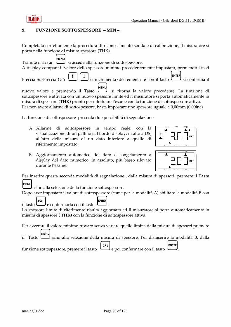
A. Allarme di sottospessore in tempo reale, con la visualizzazione di un pallino sul bordo display, in alto a DS, all’atto della misura di un dato inferiore a quello di riferimento impostato;
B. Aggiornamento automatico del dato e congelamento a
display del dato numerico, in assoluto, più basso rilevato durante l’esame.
Per inserire questa seconda modalità di segnalazione , dalla misura di spessori premere il Tasto
sino alla selezione della funzione sottospessore. Dopo aver impostato il valore di sottospessore (come per la modalità A) abilitare la modalità B con
il tasto e confermarla con il tasto . Lo spessore limite di riferimento risulta aggiornato ed il misuratore si porta automaticamente in misura di spessore ( THK) con la funzione di sottospessore attiva. Per azzerare il valore minimo trovato senza variare quello limite, dalla misura di spessori premere
il Tasto sino alla selezione della misura di spessore. Per disinserire la modalità B, dalla
funzione sottospessore, premere il tasto e poi confermare con il tasto .

Operation Manual - Gilardoni DG 51 / DG51B
man dg51.doc Page 26 of 123
Schema operativo della funzione sottospessore – MIN Misura spessore – THK Premere 2 volte
Nuova misura
Memorizzazione spessore: tasto
Selezione funzione sottospessore
Variazione spessore limite
(es. decremento)
Visualizzazione spessore impostato
Conferma valore spessore modificato (nell’esempio 3,70mm) e/o conferma
attivazione/disattivazione segnalazione modalità B
Annullo valore spessore modificato (nell’esempio 3,90mm)
attivazione/disattivazione segnalazione modalità B
In THK con funzione di spessore minimo attivato- modalità B
Tasto MENU Continua…
In THK in misura di spessore con allarme di sottospessore- modalità A
Memo a display dello spessore più basso riscontrato nell’esame- modalità B
Con il Tasto Menù si azzera la funzione e si riattiva l’iter di misura
Selezione funzione Memoria DG51 e DG51-B
Attivazione e disattivazione
segnalazione tipo B
misura di spessore con funzione di spessore minimo attivato-modalità B

Operation Manual - Gilardoni DG 51 / DG51B
man dg51.doc Page 27 of 123
10. SELEZIONE DELLA FUNZIONE – MENU -
Completata correttamente la procedura di riconoscimento sonda e di calibrazione, il misuratore si porta nella funzione di misura spessore (THK).
Tramite il Tasto si accede al menù per la selezione delle funzioni.
Con la pressione del tasto , si accede alla sequenza d’impostazioni e scelte di funzionamento di base qui elencate:
• Velocità per la misura di spessore
• Scelta delle curve di correzione e del guadagno
• Selezione manuale della sonda da utilizzare
• Velocità di scansione (PRF)
• Misura decimale o centesimale
• Unità di misura
• Limitazione dei consumi
La scelta è effettuata tramite i tasti , la conferma è affidata al tasto e l’
annullamento al tasto .
10.1. Velocità per la misura di spessore
Questa impostazione è necessaria e basilare per eseguire una corretta misura di spessore: fare
riferimento a quanto segnalato nelle avvertenze ed ai capitoli ad essa relativi, ovvero principi e tecniche di misura dello spessore (THK) e velocità (VEL).
Operation Manual - Gilardoni DG 51 / DG51B
man dg51.doc Page 28 of 123
10.2. Impostazioni sonda in uso – SET
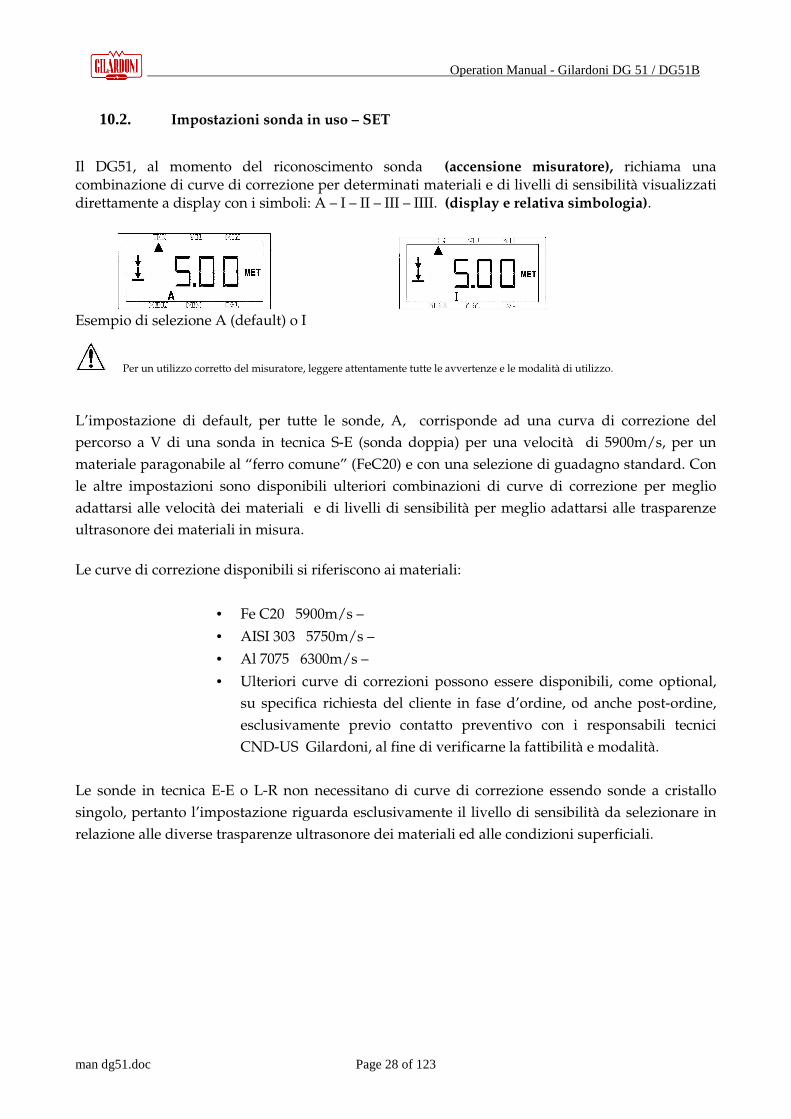
Il DG51, al momento del riconoscimento sonda (accensione misuratore), richiama una combinazione di curve di correzione per determinati materiali e di livelli di sensibilità visualizzati direttamente a display con i simboli: A – I – II – III – IIII. (display e relativa simbologia).
Esempio di selezione A (default) o I
Per un utilizzo corretto del misuratore, leggere attentamente tutte le avvertenze e le modalità di utilizzo. L’impostazione di default, per tutte le sonde, A, corrisponde ad una curva di correzione del
percorso a V di una sonda in tecnica S-E (sonda doppia) per una velocità di 5900m/s, per un
materiale paragonabile al “ferro comune” (FeC20) e con una selezione di guadagno standard. Con
le altre impostazioni sono disponibili ulteriori combinazioni di curve di correzione per meglio
adattarsi alle velocità dei materiali e di livelli di sensibilità per meglio adattarsi alle trasparenze
ultrasonore dei materiali in misura.
Le curve di correzione disponibili si riferiscono ai materiali:
• Fe C20 5900m/s –
• AISI 303 5750m/s –
• Al 7075 6300m/s –
• Ulteriori curve di correzioni possono essere disponibili, come optional,
su specifica richiesta del cliente in fase d’ordine, od anche post-ordine,
esclusivamente previo contatto preventivo con i responsabili tecnici
CND-US Gilardoni, al fine di verificarne la fattibilità e modalità.
Le sonde in tecnica E-E o L-R non necessitano di curve di correzione essendo sonde a cristallo
singolo, pertanto l’impostazione riguarda esclusivamente il livello di sensibilità da selezionare in
relazione alle diverse trasparenze ultrasonore dei materiali ed alle condizioni superficiali.
Operation Manual - Gilardoni DG 51 / DG51B
man dg51.doc Page 29 of 123
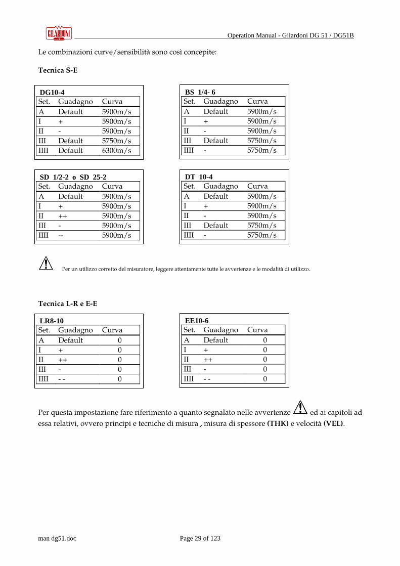
Le combinazioni curve/sensibilità sono così concepite: Tecnica S-E
Per un utilizzo corretto del misuratore, leggere attentamente tutte le avvertenze e le modalità di utilizzo.
Tecnica L-R e E-E
Per questa impostazione fare riferimento a quanto segnalato nelle avvertenze ed ai capitoli ad
essa relativi, ovvero principi e tecniche di misura , misura di spessore (THK) e velocità (VEL).
DG10-4 Set. Guadagno Curva
A Default 5900m/s
I + 5900m/s
II - 5900m/s
III Default 5750m/s
IIII Default 6300m/s
BS 1/4- 6 Set. Guadagno Curva
A Default 5900m/s
I + 5900m/s
II - 5900m/s
III Default 5750m/s
IIII - 5750m/s
SD 1/2-2 o SD 25-2 Set. Guadagno Curva
A Default 5900m/s
I + 5900m/s
II ++ 5900m/s
III - 5900m/s
IIII -- 5900m/s
LR8-10 Set. Guadagno Curva
A Default 0
I + 0
II ++ 0
III - 0
IIII - - 0
DT 10-4 Set. Guadagno Curva
A Default 5900m/s
I + 5900m/s
II - 5900m/s
III Default 5750m/s
IIII - 5750m/s
EE10-6 Set. Guadagno Curva
A Default 0
I + 0
II ++ 0
III - 0
IIII - - 0

Operation Manual - Gilardoni DG 51 / DG51B
man dg51.doc Page 30 of 123
10.3. Selezione manuale della sonda da utilizzare
E’ possibile selezionare manualmente, anziché in modo automatico, la sonda da utilizzare.
� Nella selezione manuale della sonda non avviene, ovviamente, l’ autocalibrazione: questa
deve essere effettuata SEMPRE prima dell’uso.
Fare riferimento a quanto segnalato nelle avvertenze ed ai capitoli ad essa inerenti, ovvero
principi di misura e tecniche (3.0), accensione misuratore (5.0), misura di spessore (THK) e velocità
(VEL).
10.4. Velocità di scansione
E’ possibile variare il ritmo di ripetizione degli impulsi di misura (PRF) variando, di fatto, la
velocità di ispezione massima consentita.
Sono disponibili 2 selezioni: SLO_ (2Hz) e FAST (5Hz).
10.5. Misura decimale o centesimale
E’ possibile impostare la risoluzione della lettura di spessore in modo decimale P0.1 o centesimale
P0.01
10.6. Unità di misura
E’ possibile sceglie tra l’unità di misura in mm - UU met -, o in pollici – UU us –
Per un utilizzo corretto del misuratore, leggere attentamente tutte le avvertenze e le modalità di utilizzo.
10.7. Limitazione dei consumi
Per limitare i consumi aumentando così la già considerevole autonomia dello strumento, è
possibile scegliere tra SE.Lo, relativa alla limitazione e SE.Hi, funzionamento continuo.
� E’ indispensabile attivare la selezione SE.Hi se si utilizza la comunicazione seriale
bidirezionale, in quanto la selezione SE.Lo inibisce, di fatto, la rapida risposta del
microprocessore, inibendo, in alcuni casi, la trasmissione dati a PC.

Operation Manual - Gilardoni DG 51 / DG51B
man dg51.doc Page 31 of 123
10.8. Schema operativo della funzione menù
Misura spessore – THK Premere 3 volte
Per un utilizzo corretto del misuratore, leggere attentamente tutte le avvertenze e le modalità di utilizzo
Per TUTTE le
selezioni:con i tasti Freccia Su e
Freccia Giù si varia o si seleziona; con il
tasto Enter si conferma; con il
Tasto Menù si azzera la funzione e
si ritorna alla visualizzazione
velocità
Selezione funzione Menu
Tasto MENU
Continua…
Visualizzazione Velocità impostata
per THK
Impostazione sonda in uso: tra A – I – II
– III - IIII
Selezione manuale della sonda da
utilizzare
Velocità di scansione: tra SLO_ (2Hz)e FAST (5Hz)
Misura decimale o centesimale: P0.01
o P 0.1
Unità di misura: mm - met
Pollici - us
Limitazione consumi tra SE.Lo e SE.HI
Retro illuminazione OFF
Retro illuminazione ON

Operation Manual - Gilardoni DG 51 / DG51B
man dg51.doc Page 32 of 123
11. FUNZIONE MEMORIA – MEM -
Questo capitolo è specifico per il DG51: vedi cap. 2 Generalità, cap. 3 principio e tecniche di
misura e cap. 4 struttura misuratore.
Il DG51 è stato concepito per essere uno strumento semplice completo e flessibile per quanto
possibile nell’ambito del suo campo di applicazione.
E’ possibile memorizzare fino a 4000 dati in forma sequenziale o di ripartirli in files (da 1 a 10) in
modo da avere la possibilità di suddividere le letture effettuate su manufatti (o parti di essi)
diverse. Il SW specifico Gilardoni consente poi la registrazione dei dati su PC in forma matriciale
con possibilità di memorizzazione sino ad un massimo di 4000 dati da ripartire tra i vari file creati.
I dati memorizzati possono essere dati di spessore o dati di velocità e possono essere riletti
direttamente sul display dello strumento e/o scaricati a PC tramite il collegamento RS232, cavo
specifico di collegamento a PC e SW Gilardoni DG51_MS (optional).
11.1. Accesso alla funzione Memoria
Si può accedere alla funzione Memoria tramite il Tasto .
Quando la funzione è attiva, a display è visualizzata l’indicazione dello stato della memoria: se è
visualizzato significa che nessun file è operativo e si può
agire per la relativa creazione ; se è visualizzato significa che è operativo
un file di dati di spessore ed il
numero indica la locazione di memoria in attività, se è visualizzato significa che
è operativo un file di dati di velocità.
La visualizzazione del dato Fn.01 significa che è attivo in registrazione/visualizzazione il file 1, se
è visualizzato Fn.02 significa che è attivo il file 2 e così via sino a Fn.10 (10 file disponibili).

Operation Manual - Gilardoni DG 51 / DG51B
man dg51.doc Page 33 of 123
11.2. Creazione nuovo file
Da O.ALL, tramite il tasto si seleziona la creazione di un file per misure di spessore o di un
file per misure di velocità:
Selezione per spessori Selezione per velocità
Con i tasti di scorrimento si seleziona il numero di files necessario (da 1 a 10); esempio per una
scelta di 3 file:
Tramite il tasto si conferma l’ impostazione, premendo il Tasto si annulla.
Il misuratore si porta direttamente in misura di spessori THK : se è stato predisposto un file di
spessori sul display in corrispondenza THK vi sarà una
segnalazione ∆∆∆∆ ; se è stato creato un file di dati di velocità la segnalazione a
display ∇∇∇∇ sarà in corrispondenza di VEL.
11.3. Memorizzazione dati
Una volta reso operativo il file di memorizzazione , la pressione del tasto determina l’
acquisizione del dato e sul display appare per un attimo il numero progressivo
della locazione di memoria ; per memorizzare o sovrascrivere su una altra casella
di memoria che non sia quella seguente nella successione, utilizzare i tasti di scorrimento
per portarsi sulla nuova locazione e premere il tasto per confermarla e
predisporla alla memorizzazione. Infine premere il tasto per annullare la scelta.

Operation Manual - Gilardoni DG 51 / DG51B
man dg51.doc Page 34 of 123
11.4. Attivazione e gestione file. Rilettura dei dati memorizzati a display
Premere il Tasto per accedere alla funzione Memoria.
Lo stato della memoria è reso visibile:
premendo i tasti si seleziona il file ,
premendo il tasto si attiva il file selezionato
e premendo in successione il tasto si visualizzano ciclicamente le tre possibilità di scelta
seguenti:
Rilettura dati (11.4.1),
Trasmissione dati via RS232 (11.4.2),
Azzeramento file (11.4.3).
Premendo il Tasto si torna alla misura di spessori con il file selezionato attivo.
11.4.1. Rilettura dei dati memorizzati a display
Come indicato al punto 12.4, la prima scelta possibile è la rilettura dei dati contenuti nel file.
Premendo il tasto si visualizza lo stato della memoria
tramite i tasti si seleziona la locazione di interesse e premendo Enter se ne visualizza il
contenuto
, tramite i tasti si visualizza il contenuto di altre locazioni: il dato
memorizzato nella locazione selezionata diventa intermittente per un attimo per indicare che è
avvenuto l’aggiornamento.
Per ritornare al dato di posizione, premere il tasto ; per annullare Tasto .

Operation Manual - Gilardoni DG 51 / DG51B
man dg51.doc Page 35 of 123
11.5. Trasmissione dati tramite RS232
Dopo aver premuto due volte il tasto , premendo il tasto parte la trasmissione
sequenziale verso PC dei dati memorizzati attraverso la porta RS232: questa operazione procede
fino all’ esaurimento di tutti i dati memorizzati nel file stesso (4000 celle di memoria ripartiti tra i
vari file creati).
Prima dell’utilizzo di questo comando è consigliabile disabilitare l’ opzione che limita i consumi.
11.5.1. Azzeramento dati nel file
Dopo aver premuto tre volte il tasto premendo il tasto il simbolo a display
diventa intermittente, la nuova pressione del tasto determina la
cancellazione dei dati: a display compare per un attimo la scritta ad indicare che
la cancellazione è in atto. Per annullare premere il Tasto . Al termine dell’operazione sul
display ricompare
ma i dati contenuti nel file saranno stati azzerati.
� Attenzione! Con l’azzeramento sono persi irrimediabilmente tutti i dati contenuti nel file.
Per un utilizzo corretto del misuratore, leggere attentamente tutte le avvertenze e le modalità di utilizzo.
11.6. Verifica locazioni di memoria disponibili
Per verificarne la capacità di memoria disponibile in un file, dopo averlo attivato con la solita
procedura, premere contemporaneamente i tasti + : il dato di memoria disponibile, in
termini di numero di locazioni, viene visualizzato per alcuni secondi.

Operation Manual - Gilardoni DG 51 / DG51B
man dg51.doc Page 36 of 123
11.7. Trasmissione dati a PC via RS232
E’ disponibile un software (opzionale) per la trasmissione a PC del contenuto dei files
Per accedere alla funzione Memoria, premere il Tasto .
Alla visualizzazione dello stato della memoria:
premendo il tasto per una volta si abilita la trasmissione dati: alla pressione del tasto sul
display compare il messaggio S.ALL,
alla pressione del tasto ha inizio la trasmissione sequenziale dei dati memorizzati via RS232:
questa operazione si conclude solo all’esaurimento dei dati contenuti nella memoria (4000 dati
disponibili).
Prima dell’ utilizzo di questo comando è consigliabile disabilitare l’opzione relativa alla
limitazione dei consumi.
11.8. Cancellazione di TUTTI i file.
Accedere alla funzione Memoria tramite il Tasto .
Alla visualizzazione dello stato di memoria
premendo il tasto due volte si abilita la cancellazione dei files sul display compare il dato
relativo alla prima locazione.
confermando con il tasto il dato diventa intermittente.
premendo ancora il tasto a display compare per un attimo la scritta per
indicare che la cancellazione è in atto, per poi passare a quando è stata
completata.
Con il Tasto si annulla l’operazione.
Attenzione! Con la cancellazione dei files si perdono irrimediabilmente tutti i dati in essi
contenuti.

Operation Manual - Gilardoni DG 51 / DG51B
man dg51.doc Page 37 of 123
Misura spessore – THK Premere 4 volte Visualizzazione di stato – creazione file
Selezione funzione Memoria DG51
Visualizzazione stato Memoria:
nessun file attivo.
Selezione creazione file per Velocità o
spessori(CAL)
Conferma nuovo file
Annullo creazione file: il DG51 si porta in misura di spessori senza alcuna
memorizzazione dei dati
Direttamente in misura di spessori THK, con operativo file di memoria per spessori
Il file operativo di default è FN.01
Se creato file memoria velocità , l’indicazione e l’operatività memoria alla
sola misura velocità – VEL Il file operativo è FN.01
Selezione numero files operativi. 1 -10 file max (n.01 – n.10)

Operation Manual - Gilardoni DG 51 / DG51B
man dg51.doc Page 38 of 123
Misura spessore – THK Memorizzazione Premere 4 volte
Verifica – rilettura
Selezione funzione Memoria DG51
Direttamente in misura di spessori THK, con operativo file di spessori
Memorizzazione: sul display compare per un attimo il numero progressivo della
locazione di memoria
Scelta di una locazione non sequenziale da impegnare (es. per sovrascrivere)
Conferma scelta
Annulla scelta
Visualizzazione del file operativo
Scelta del file da rendere operativo
Conferma nuovo file con visualizzazione delle
scelte di attività del file. 1a scelta: rilettura dati
Annulla scelta
2a scelta: trasmissione file dati via RS232
3a scelta: azzeramento file dati
In misura spessori THK con nuovo file operativo

Operation Manual - Gilardoni DG 51 / DG51B
man dg51.doc Page 39 of 123
rilettura dati file operativo
+
Visualizzazione stato Memoria:
Verifica memoria residua disponibile per il file attivo
Scelta locazione di cui visualizzare il dato contenuto es. locazione n°22 del file di
spessori attivo
Visualizzazione dato contenuto nella locazione
n°22
Selezione locazione di memoria con il dato
aggiornato: ∇∇∇∇ su MEM diventa intermittente ad ogni nuova locazione. Enter per
visualizzare il n° di locazion
1a scelta: rilettura dati
Annulla – ritorno in THK

Operation Manual - Gilardoni DG 51 / DG51B
man dg51.doc Page 40 of 123
Attenzione! Con l’azzeramento i dati memorizzati saranno irrimediabilmente perduti.
Prima di utilizzare il misuratore, leggere attentamente tutte le avvertenze e le modalità di utilizzo.
Selezione azzeramento dati: il display diventa
intermittente in attesa di conferma o meno
Annulla
Conferma azzeramento dati
Ritorno a selezione attività
Tasto MENU’
Continua…
2a scelta: trasmissione file dati, precedentemente selezionato, via RS232
Annulla – ritorno in THK
Conferma trasmissione dati
3a scelta: azzeramento dati nel file

Operation Manual - Gilardoni DG 51 / DG51B
man dg51.doc Page 41 of 123
Verifica – rilettura Premere 4 volte
Attenzione! Con la cancellazione del file si perdono irrimediabilmente tutti i dati in esso contenuti.
Prima di utilizzare il misuratore, leggere attentamente tutte le avvertenze e le modalità d’uso.
Selezione invio tutti i dati (file) tramite RS232
Conferma trasmissione dati
Annulla – ritorno in THK
Selezione cancellazione TUTTI i file e della loro
impostazione
Predisposizione alla cancellazione memoria: il display è intermittente in attesa di conferma o
Annulla – ritorno in THK
Conferma cancellazione memoria
Visualizzazione stato Memoria:
nessun file attivo.
Tasto MENU
Continua…
Selezione funzione Memoria DG51
Visualizzazione del file operativo

Operation Manual - Gilardoni DG 51 / DG51B
man dg51.doc Page 42 of 123
12. FUNZIONE MEMORIA DG51-B – MEM –
Questo capitolo è specifico per il DG51-B : vedi cap. 2 Generalità, cap. 3 principio e tecniche di misura, cap. 4 struttura misuratore.
Il DG51-B è stato concepito per essere uno strumento semplice ma allo stesso tempo completo e flessibile: in questa ottica è stata resa disponibile la memorizzazione dei dati in forma sequenziale, in un unico file, sino ad un massimo di 999 dati. I dati memorizzabili possono essere dati di spessore o di velocità e possono essere soltanto riletti sul display dello strumento.
12.1. Accesso alla funzione Memoria
Accedere alla funzione Memoria tramite il Tasto . Attivata la funzione a display è indicato lo stato della memoria: se è visualizzato il messaggio III significa che nessun file è operativo e si può pertanto procedere alla sua creazione ed attivazione;
se è visualizzato III con il cursore ∆∆∆∆ su THK significa che è operativo un file di dati di spessore ed il numero indica la locazione di memoria attiva;
se a display è visualizzato III con il simbolo ∇∇∇∇ su VEL significa che è operativo un file di dati di velocità.
12.2. Creazione del file
Da O.ALL, tramite il tasto si effettua la scelta fra un file di spessori ed un file di velocità:
III con ∆∆∆∆ su THK : selezione file spessori III con ∇∇∇∇ su VEL : selezione File velocità
Confermare l’ impostazione con il tasto , premere il Tasto per annullarla. Il misuratore si porta direttamente in misura di spessori THK, pronto per registrare i dati: se è stato predisposto un file di spessori sul display in corrispondenza di THK vi sarà una
segnalazione ∆∆∆∆ ; se è stato creato un file di dati di velocità la segnalazione ∇∇∇∇ sarà in corrispondenza di VEL .
12.3. Memorizzazione dati
Una volta attivato il file di memorizzazione , premendo il tasto il dato è acquisito e sul display appare per un attimo il numero progressivo
Associato alla locazione di memoria 111; per memorizzare o sovrascrivere su una altra casella di
memoria che non sia quella successiva utilizzare i tasti : alla conferma tramite il tasto
il DG51 –B è pronto per la memorizzazione, premendo il tasto si annulla la scelta di memorizzazione
Operation Manual - Gilardoni DG 51 / DG51B
man dg51.doc Page 43 of 123
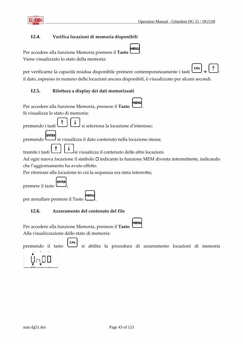
12.4. Verifica locazioni di memoria disponibili
Per accedere alla funzione Memoria premere il Tasto .
Viene visualizzato lo stato della memoria:
per verificarne la capacità residua disponibile premere contemporaneamente i tasti + :
il dato, espresso in numero delle locazioni ancora disponibili, è visualizzato per alcuni secondi.
12.5. Rilettura a display dei dati memorizzati
Per accedere alla funzione Memoria, premere il Tasto .
Si visualizza lo stato di memoria:
premendo i tasti si seleziona la locazione d’interesse;
premendo si visualizza il dato contenuto nella locazione stessa;
tramite i tasti si visualizza il contenuto delle altre locazioni.
Ad ogni nuova locazione il simbolo ∇∇∇∇ indicante la funzione MEM diventa intermittente, indicando
che l’aggiornamento ha avuto effetto.
Per ritornare alla locazione in cui la sequenza era stata interrotta;
premere il tasto ;
per annullare premere il Tasto .
12.6. Azzeramento del contenuto del file
Per accedere alla funzione Memoria, premere il Tasto .
Alla visualizzazione dello stato di memoria:
premendo il tasto si abilita la procedura di azzeramento locazioni di memoria

Operation Manual - Gilardoni DG 51 / DG51B
man dg51.doc Page 44 of 123
premendo si conferma l’ azzeramento;
premendo il Tasto si annulla.
12.7. Cancellazione del file.
Per accedere alla funzione Memoria, premere il Tasto . Alla visualizzazione dello stato di memoria:
premendo il tasto per due volte si abilita la cancellazione: a display compare CN.01
Alla conferma con il tasto il dato diventa intermittente,
per annullare premere il tasto ,
Per confermare premere il tasto .
A display compare per un attimo la scritta “EECC” per indicare la cancellazione in atto, per poi passare
a “OALL” per indicare che la cancellazione è stata completata.
Attenzione! Con la cancellazione del file si perdono irrimediabilmente tutti i dati in esso contenuti.
Operation Manual - Gilardoni DG 51 / DG51B
man dg51.doc Page 45 of 123
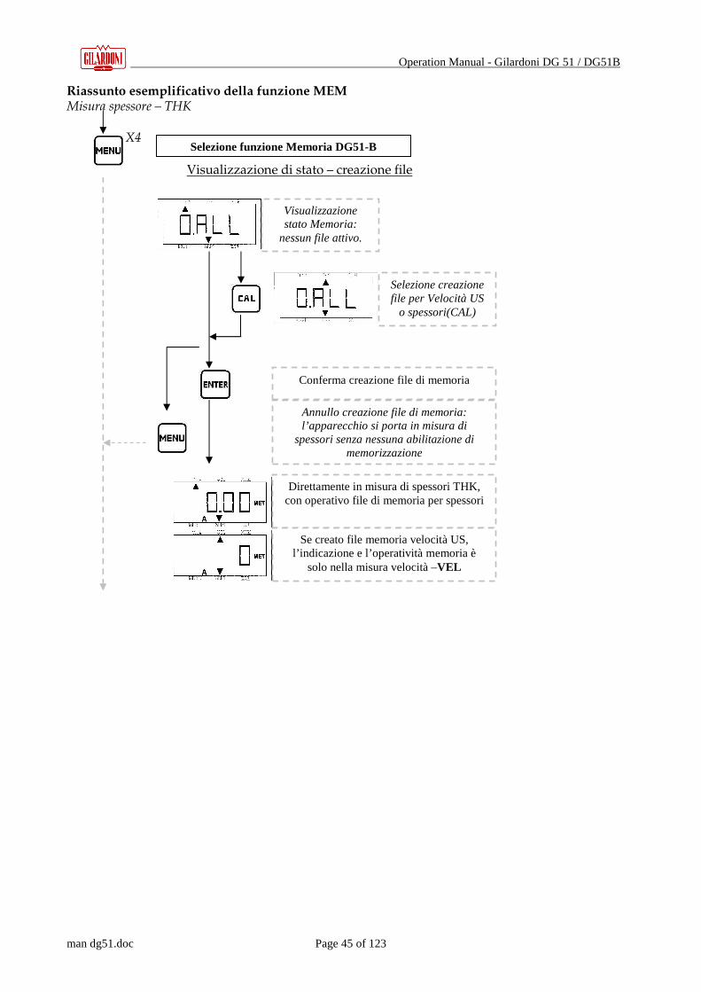
Riassunto esemplificativo della funzione MEM Misura spessore – THK X4 Visualizzazione di stato – creazione file
Selezione funzione Memoria DG51-B
Visualizzazione stato Memoria:
nessun file attivo.
Selezione creazione file per Velocità US
o spessori(CAL)
Conferma creazione file di memoria
Annullo creazione file di memoria: l’apparecchio si porta in misura di
spessori senza nessuna abilitazione di memorizzazione
Direttamente in misura di spessori THK, con operativo file di memoria per spessori
Se creato file memoria velocità US, l’indicazione e l’operatività memoria è
solo nella misura velocità –VEL

Operation Manual - Gilardoni DG 51 / DG51B
man dg51.doc Page 46 of 123
Memorizzazione X4 Verifica-rilettura
+
Selezione funzione Memoria DG51-B
Visualizzazione stato Memoria: es. attivo file di
spessori alla locazione n°27
Direttamente in misura di spessori THK, con operativo file di dati di spessore
Memorizzazione: sul display compare per un attimo il numero progressivo della
locazione di memoria
Scelta di una locazione diversa da quella successiva (es. per sovrascrivere)
Conferma nuova locazione
Annulla
Verifica capacità di memoria disponibile
Nuova locazione di cui visualizzare il contenuto
Visualizzazione dato contenuto nella
locazione
Nuova locazione e visualizzazione del dato:
la∇ su MEM è intermittente ad ogni cambio. Ripremendo
Enter si visualizza il n° di locazione.

Operation Manual - Gilardoni DG 51 / DG51B
man dg51.doc Page 47 of 123
Azzeramento – cancellazione file Attenzione! Con la cancellazione si perdono irrimediabilmente tutti i dati contenuti nel file.
Per l’utilizzo dell’ insieme misuratore, leggere attentamente tutte le avvertenze e le modalità di utilizzo.
Visualizzazione stato Memoria: es. attivo file di
spessori alla locazione n°27
Selezione azzeramento memoria (ritorno a L1)
Conferma azzeramento memoria
Annulla
Conferma cancellazione memoria
Pronto per cancellazione memoria: il display è
intermittente in attesa di conferma o meno
Annulla
Conferma cancellazione memoria
Visualizzazione stato Memoria:
nessun file attivo.
Tasto MENU’
Continua…

Operation Manual - Gilardoni DG 51 / DG51B
man dg51.doc Page 48 of 123
13. CARATTERISTICHE TECNICHE
Nel seguito vengono elencate le caratteristiche tecniche dello spessimetro DG51
Tecnica di misura Trasmissione-eco ed eco-eco * Misure Spessore e velocità
Range di misura Da 0.5 a 600 mm
Risoluzione 0.01 mm fino a 99.99 mm; 0.1 mm oltre i 100 mm
Riconoscimento sonda Automatico
Autocalibrazione All’atto del riconoscimento sonda
Taratura Su 5 o 25 mm
Range di velocità Da 1000 a 9999 m/sec
Guadagno Regolabile su 99 livelli (dinamica: ≈ 40 dB)
Correzione percorso a V Automatica da microprocessore
Aggiornamento letture SLOW (2Hz) e FAST (5Hz)
Segnalazioni Di accoppiamento e di sottospessore
Data logger 4000 dati in 10 files ** Interfaccia RS232 *** Unità di misura mm o pollici
Spegnimento Automatico dopo 3’ di non utilizzo
Alimentazione Due pile a secco AA da 1.5 V
Autonomia 200 ore
Temperatura ammessa Da -10°C a 50°C
Dimensioni 73 x 35 x 136 mm
Peso 250 g con batterie
Omologazione RINA
Marcature CE,UL
(*) Per il DG51 B la misura eco-eco non è disponibile (**) Per il DG51 B è possibile memorizzare solo 999 dati in un unico file (***) Non disponibile per il DG51 B.

Operation Manual - Gilardoni DG 51 / DG51B
man dg51.doc Page 49 of 123
14. INSTALLAZIONE
Il software di cui nel seguito viene descritto il funzionamento e le impostazioni necessarie per l’utilizzo, è disponibile ed operante per la sola versione DG51. Non è quindi possibile operare con il software per la versione base DG51B.
Inserire il CD con il software DG51_MS nel lettore Apparirà il seguente quadro:
Figura 2 - Installazione
Cliccare su “Installazione” Seguire le istruzioni a video
14.1. Sblocco del Programma
Dopo aver installato il programma, bisogna copiare manualmente il file “DG.DAT” contenuto nel CD a corredo. In caso il CD mancasse, significa che il programma è rilasciato in versione dimostrativa e quindi nella schermata di avvio comparirà la scritta “VERSIONE DEMO” mentre il titolo della finestra sarà “DG51-MS GILARDONI SPA – PROGRAMMA DIMOSTRATIVO” (vedi Figura 1.1) ma soprattutto la stampa dei report e le funzioni di export e di salvataggio dei dati saranno disabilitate.

Operation Manual - Gilardoni DG 51 / DG51B
man dg51.doc Page 50 of 123
Figura 3 – Versione Demo
NOTA: E’ comunque possibile richiedere in qualsiasi momento il file “DG.DAT” personalizzato alla Gilardoni S.p.A. specificando l’intestazione della ditta che si desidera visualizzare sui report.
Nel caso si possieda il file DG.DAT facendo doppio-clic sul logo GILARDONI S.p.A. apparirà il seguente quadro:
Figura 4 – Dati Cliente

Operation Manual - Gilardoni DG 51 / DG51B
man dg51.doc Page 51 of 123
Nel primo campo viene visualizzato il nome della ditta che non può essere modificato, mentre nei due campi successivi l’utente può inserire i dati della propria ditta che appariranno nell’intestazione del foglio di stampa dei report.
14.2. Requisiti
Per il corretto funzionamento del programma il PC deve essere settato nel seguente modo: - Risoluzione video : 800x600 (o superiore) - Dimensione caratteri monitor piccoli
15. DESCRIZIONE DEL SISTEMA
Il presente software serve ad aggiungere funzionalità al misuratore di spessore ultrasonoro DG. In particolare si potrà :
• prelevare le letture degli spessori/velocità dagli apparecchi • visualizzare i dati letti con colori differenti per eventuali distinzioni • stampare dei report a colori • esportare i dati letti e quindi creare dei report personalizzati
15.1. Compatibilità DG
Con questo software ci si può collegare tramite un cavo seriale RS-232 al seguente modello DG: • DG 51
16. SCHERMATA INIZIALE
Figura 5 – Quadro iniziale

Operation Manual - Gilardoni DG 51 / DG51B
man dg51.doc Page 52 of 123
All’avvio del programma ci si trova di fronte alla schermata riportata in figura 3.1 dalla quale è possibile accedere alle varie funzionalità del programma, quali :
Gestione del DG51
Impostazione della lingua
Impostazione delle directory
Impostazione della porta seriale per la comunicazione con il DG51
Uscita dal programma
16.1. Impostazione della Lingua
Il programma DG 51-MS ha la possibilità di essere utilizzato in più lingue. Per selezionare la lingua da utilizzare dall’HMI del DG 51 cliccare il pulsante di impostazione della lingua : Comparirà il seguente quadro :
Figura 6 – Pannello di selezione lingua

Operation Manual - Gilardoni DG 51 / DG51B
man dg51.doc Page 53 of 123
che consente di selezionare la lingua desiderata tra quelle disponibili.
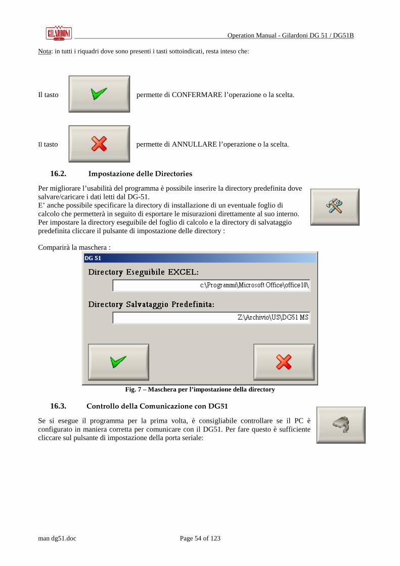
Operation Manual - Gilardoni DG 51 / DG51B
man dg51.doc Page 54 of 123
Nota: in tutti i riquadri dove sono presenti i tasti sottoindicati, resta inteso che:
Il tasto permette di CONFERMARE l’operazione o la scelta.
Il tasto permette di ANNULLARE l’operazione o la scelta.
16.2. Impostazione delle Directories
Per migliorare l’usabilità del programma è possibile inserire la directory predefinita dove salvare/caricare i dati letti dal DG-51. E’ anche possibile specificare la directory di installazione di un eventuale foglio di calcolo che permetterà in seguito di esportare le misurazioni direttamente al suo interno. Per impostare la directory eseguibile del foglio di calcolo e la directory di salvataggio predefinita cliccare il pulsante di impostazione delle directory :
Comparirà la maschera :
Fig. 7 – Maschera per l’impostazione della directory
16.3. Controllo della Comunicazione con DG51
Se si esegue il programma per la prima volta, è consigliabile controllare se il PC è configurato in maniera corretta per comunicare con il DG51. Per fare questo è sufficiente cliccare sul pulsante di impostazione della porta seriale:

Operation Manual - Gilardoni DG 51 / DG51B
man dg51.doc Page 55 of 123
Sul monitor comparirà il seguente quadro :
Fig. 8 – Pannello di selezione porta seriale
In questa schermata è possibile impostare la porta seriale del PC per la comunicazione seriale con l’apparecchio utilizzato.
16.3.1. Stato avanzamento della comunicazione
Durante una qualsiasi comunicazione con l’apparecchio DG 51 viene aperta una finestra che mostra lo stato di avanzamento della comunicazione (i bytes ricevuti). E’ comunque possibile annullare la comunicazione premendo il tasto “ANNULLA”.
16.4. Uscita dal Programma
Per uscire dal programma bisogna cliccare il pulsante :

Operation Manual - Gilardoni DG 51 / DG51B
man dg51.doc Page 56 of 123
Apparirà una richiesta di conferma del comando di uscita dal programma.
17. GESTIONE DG51
Figura 9 – Pannello di gestione SW DG51
Dopo aver cliccato sul tasto “Gestione DG 51” verrà aperta la finestra mostrata in figura 4.1 e il PC si metterà in ricezione attendendo di ricevere i dati dall’apparecchio DG 51. I dati sono suddivisi in file che vengono elencati nella sezione “FILE LETTI DA DG 51”. Selezionando tramite il mouse un file, verranno elencati i dati contenuti in quest’ultimo nella tabella della sezione “DATI FILE nome file selezionato” e ne verrà data una rappresentazione grafica. A questo punto è possibile, per meglio identificare le misurazioni, applicare dei colori differenti ai vari dati in base a tre confronti selezionabili nella sezione “CONFRONTO”.
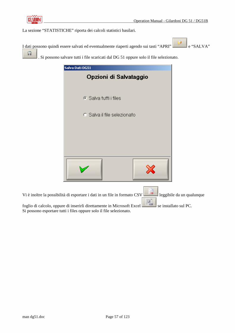
Operation Manual - Gilardoni DG 51 / DG51B
man dg51.doc Page 57 of 123
La sezione “STATISTICHE” riporta dei calcoli statistici basilari.
I dati possono quindi essere salvati ed eventualmente riaperti agendo sui tasti “APRI” e “SALVA”
. Si possono salvare tutti i file scaricati dal DG 51 oppure solo il file selezionato.
Vi è inoltre la possibilità di esportare i dati in un file in formato CSV leggibile da un qualunque
foglio di calcolo, oppure di inserirli direttamente in Microsoft Excel se installato sul PC. Si possono esportare tutti i files oppure solo il file selezionato.

Operation Manual - Gilardoni DG 51 / DG51B
man dg51.doc Page 58 of 123
Premendo il tasto “STAMPA” è possibile stampare i dati del file selezionato.
Figura 10 – Pannello per l’inserimento delle note

Operation Manual - Gilardoni DG 51 / DG51B
man dg51.doc Page 59 of 123
Apparirà la maschera di figura 4.2 che consente di completare campi preimpostati e di scrivere note che verranno inserite nella stampa.
Il tasto “CANCELLA” consente di cancellare tutti i campi. Verrà quindi chiesto di scegliere la stampante e poi comparirà una finestra mostrata in figura 4.3:
Figura 4.3
Le opzioni di stampa disponibili sono: - Stampa a COLORI se si possiede una stampante a colori - Stampa INTESTAZIONE se si desidera che nella prima pagina venga mostrata l’intestazione della ditta (con l’eventuale logo) - Stampa ANNOTAZIONI se devono essere stampati anche i commenti - Stampa GRAFICO se si desidera la stampa di un grafico dei dati I dati vengono stampati in forma tabellare. Nel caso di stampa a colori una legenda esplicherà il significato dei colori. Agendo quindi sul tasto STAMPA verrà stampato quanto richiesto. Nel caso di “VERSIONE DEMO” verrà invece stampata una pagina dimostrativa (figura 4.4).
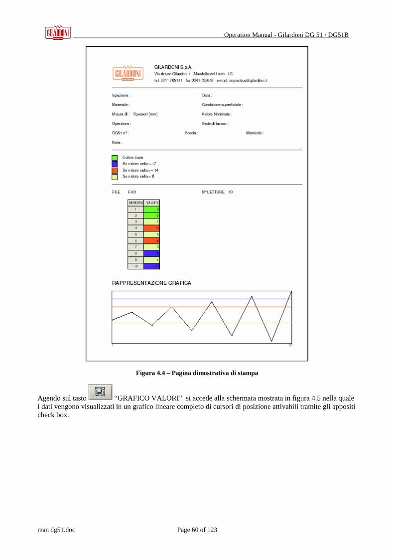
Operation Manual - Gilardoni DG 51 / DG51B
man dg51.doc Page 60 of 123
Figura 4.4 – Pagina dimostrativa di stampa
Agendo sul tasto “GRAFICO VALORI” si accede alla schermata mostrata in figura 4.5 nella quale i dati vengono visualizzati in un grafico lineare completo di cursori di posizione attivabili tramite gli appositi check box.

Operation Manual - Gilardoni DG 51 / DG51B
man dg51.doc Page 61 of 123
Figura 10 – Rappresentazione grafica delle misure effettuate

Operation Manual - Gilardoni DG 51 / DG51B
man dg51.doc Page 62 of 123
18. SMALTIMENTO DELL ’APPARECCHIO
Ai sensi della legge nazionale 1 vigente in attuazione delle Direttive 2002/95/CE, 2002/96/CE e 2003/108/CE, relative alla riduzione dell’uso di so stanze pericolose nelle apparecchiature elettriche
ed elettroniche, nonché allo smaltimento dei rifiut i
Il simbolo del cassonetto barrato riportato sull’apparecchiatura o sulla sua confezione indica che il prodotto alla fine della propria vita utile deve essere raccolto separatamente dagli altri rifiuti.
La raccolta differenziata della presente apparecchiatura giunta a fine vita è organizzata e gestita dal produttore. L’utente che vorrà disfarsi della presente apparecchiatura dovrà quindi contattare il produttore e seguire il sistema che questo ha adottato per consentire la raccolta separata dell’apparecchiatura giunta a
fine vita.
L’adeguata raccolta differenziata per l’avvio successivo dell’apparecchiatura dimessa al riciclaggio, al trattamento e allo smaltimento ambientalmente compatibile contribuisce ad evitare possibili effetti negativi
sull’ambiente e sulla salute e favorisce il reimpiego e/o riciclo dei materiali di cui è composta l’apparecchiatura.
Lo smaltimento abusivo del prodotto da parte del detentore comporta l’applicazione delle sanzioni amministrative previste dalla norma vigente.
1 Per l’Italia art. 13 del Decreto Legislativo 25 Luglio 2005, n. 151.
Operation Manual - Gilardoni DG 51 / DG51B
man dg51.doc Page 63 of 123
GILARDONI S.p.A. Plant: Via Arturo Gilardoni n°1 Head Offices: P.zza Luigi di Savoia, 28
23826 MANDELLO del LARIO (LC) 20124 Milan – Italy (EU)
OPERATION MANUAL
Thickness Gauge GILARDONI DG 51 / DG 51B
64830903
Z 1893
Operation Manual - Gilardoni DG 51 / DG51B
man dg51.doc Page 64 of 123
19. RECOMMENDATIONS 66
19.1. INSTRUCTIONS FOR CLEANING AND DAILY MAINTENANCE . ........................................................... 69
20. MEASURING PRINCIPLE AND TECHNIQUES 70
20.1. PRINCIPLE .......................................................................................................................................... 70 20.2. OPERATING TECHNIQUES ................................................................................................................. 71 20.2.1. METHOD S-E...................................................................................................................................... 71 20.2.2. METHOD E-E...................................................................................................................................... 72 20.2.3. METHOD L-R...................................................................................................................................... 72
21. DESCRIPTION OF THE DG51 73
21.1. DESCRIPTION OF THE DG51 DG51 – B (FIGURE 1): ............................................................. 74 21.2. DISPLAY AND SYMBOLS ............................................................................................................. 75
22. SWITCHING ON THE DG51 76
22.1. SWITCHING ON WITH PROBE CONNECTED TO INSTRUMENT ........................................................... 76 22.2. PROBE CONNECTED AFTER SWITCHING ON ..................................................................................... 77 22.3. MANUAL SELECTION ......................................................................................................................... 78
23. CALIBRATION 79
24. MEASUREMENT OF THICKNESS – THK - 81
25. MENU KEY 84
26. SPEED FUNCTION – VEL - 85
27. MINIMUM THICKNESS FUNCTION – MIN – 87
28. SELECTION OF FUNCTION – MENU - 89
28.1. SPEED FOR THICKNESS MEASUREMENT ........................................................................................... 89 28.2. SETTINGS FOR PROBE IN USE – SETS................................................................................................ 89 28.3. MANUAL SELECTION OF PROBE TO USE ........................................................................................... 91 28.4. SCANNING SPEED................................................................................................................................ 91 28.5. DECIMAL OR CENTESIMAL MEASUREMENT ..................................................................................... 91 28.6. UNIT OF MEASUREMENT .................................................................................................................... 91 28.7. L IMITATION OF CONSUMPTION ......................................................................................................... 92 28.8. OPERATING DIAGRAM OF MENU FUNCTION .............................................................................. 92
29. MEMORY FUNCTION – MEM - 94
29.1. ACCESS TO THE MEMORY FUNCTION ............................................................................................... 94 29.2. CREATION OF A NEW FILE ................................................................................................................. 95 29.3. SAVING DATA ...................................................................................................................................... 95

Operation Manual - Gilardoni DG 51 / DG51B
man dg51.doc Page 65 of 123
29.4. ENABLING AND MANAGEMENT OF FILES . REREADING SAVED DATA ON THE DISPLAY ................. 96 29.4.1. REREADING SAVED DATA ON DISPLAY............................................................................................. 95 29.5. DATA TRANSMISSION VIA RS232..................................................................................................... 97 29.5.1. RESETTING DATA IN FILES................................................................................................................ 97 29.6. CONTROL OF MEMORY LOCATIONS AVAILABLE ............................................................................. 98 29.7. TRANSMISSION OF DATA TO PC VIA RS232..................................................................................... 98 29.8. CANCELLATION OF ALL FILES......................................................................................................... 98
30. MEMORY FUNCTION OF DG51-B – MEM – 104
30.1. ACCESS TO MEMORY FUNCTION .................................................................................................... 104 30.2. CREATION OF THE FILE ................................................................................................................... 104 30.3. SAVING DATA .................................................................................................................................... 104 30.4. CONTROL OF AVAILABLE MEMORY LOCATIONS ........................................................................... 104 30.5. REREADING SAVED DATA ON DISPLAY ........................................................................................... 105 30.6. RESETTING FILE CONTENTS ............................................................................................................ 105 30.7. CANCELLATION OF FILE .................................................................................................................. 105
31. TECHNICAL FEATURES 109
32. SETUP 110
32.1. PROGRAM UNLOCK .......................................................................................................................... 110 32.2. FEATURES......................................................................................................................................... 112
33. SYSTEM DESCRIPTION 111
33.1. DG CLASSES COMPATIBILITY ......................................................................................................... 112
34. STARTING PANEL 113
34.1. LANGUAGE SETTING....................................................................................................................... 113 34.2. DIRECTORY SETTING...................................................................................................................... 115 34.3. RS232 SERIAL COMMUNICATION CONTROL .................................................................................. 115 34.3.1. COMMUNICATION STATE................................................................................................................ 116 34.4. EXIT FROM THE DG51-MS PROGRAM ............................................................................................ 116
35. GILARDONI DG51 MANAGING 117
36. USERS INFORMATION 123

Operation Manual - Gilardoni DG 51 / DG51B
man dg51.doc Page 66 of 123
19. RECOMMENDATIONS
It is extremely important to read the manual carefully in order to understand the operating
principles of the DG51 and DG51-B. The instructions provide full information about the various
functions, as well as some useful general indications for normal use of a thickness gauge and
details for a more targeted use that takes advantage of the full potential of the instrument.
This manual, and use by an operator of an ultrasonic thickness gauge made by Gilardoni S.p.A.,
is exclusively limited to users who have the necessary basic theoretical knowledge for
ultrasonic control, in particular as regards the speed of ultrasonic waves in materials, the
geometry of the ultrasonic beam of the probes used and sufficient experience in the application
of procedures for thickness measurement with the ultrasonic method. To acquire the basic
elements of ultrasonic theory, publications Z.239 and P.131 edited by Gilardoni S.p.A. may be
useful. Gilardoni S.p.A. is not liable for any damage to property and/or persons caused by
improper and/or unauthorized use of the instrument.
Although use of the instrument is recommended by qualified operators only, who are therefore
conscious of its limits and potential, we deem it advisable to indicate some precautions so as to
create a useful guide for the operators when starting to use it.
22 All the components of the thickness gauge DG51 and DG51-B kit have been designed to provide the maximum
performance such as effective measurement, sturdy construction for use on construction sites, autonomy,
practical features of use: any improper use of the thickness gauge and its parts has not been contemplated and
is therefore not allowed. The measuring kit or its parts should not be used with other parts not produced by
Gilardoni S.p.A. for the DG51 and vice versa, as this could create situations capable of causing errors.
23 We recommend, so as not to invalidate the warranty, that all technical service operations on the instrument be
carried out by a qualified Gilardoni S.p.A. service center, where the instrument can be correctly repaired. It is
important to remember, aside from the validity of the warranty, that service performed by personnel lacking
the necessary specialization could cause malfunction of the instrument leading to erroneous measurement and,
in extreme cases, damage to the instrument itself.
24 Before using the gauge we recommend that you inspect the DG51 and its parts for any visible damage or
missing parts and make sure there is no leakage of acid from the battery casings. If the device does not switch
on, check the batteries; if it switches on but does not function properly in any of the following ways:
- some segments of the display are blinking or missing
- automatic probe recognition is negative
- the thickness gauge does not switch off automatically three minutes after pressing any key
contact the GILARDONI S.p.A. Service Department
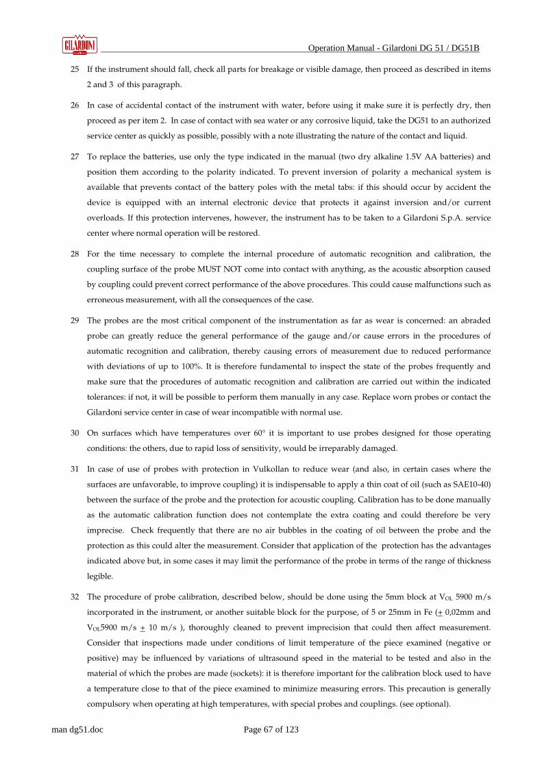
Operation Manual - Gilardoni DG 51 / DG51B
man dg51.doc Page 67 of 123
25 If the instrument should fall, check all parts for breakage or visible damage, then proceed as described in items
2 and 3 of this paragraph.
26 In case of accidental contact of the instrument with water, before using it make sure it is perfectly dry, then
proceed as per item 2. In case of contact with sea water or any corrosive liquid, take the DG51 to an authorized
service center as quickly as possible, possibly with a note illustrating the nature of the contact and liquid.
27 To replace the batteries, use only the type indicated in the manual (two dry alkaline 1.5V AA batteries) and
position them according to the polarity indicated. To prevent inversion of polarity a mechanical system is
available that prevents contact of the battery poles with the metal tabs: if this should occur by accident the
device is equipped with an internal electronic device that protects it against inversion and/or current
overloads. If this protection intervenes, however, the instrument has to be taken to a Gilardoni S.p.A. service
center where normal operation will be restored.
28 For the time necessary to complete the internal procedure of automatic recognition and calibration, the
coupling surface of the probe MUST NOT come into contact with anything, as the acoustic absorption caused
by coupling could prevent correct performance of the above procedures. This could cause malfunctions such as
erroneous measurement, with all the consequences of the case.
29 The probes are the most critical component of the instrumentation as far as wear is concerned: an abraded
probe can greatly reduce the general performance of the gauge and/or cause errors in the procedures of
automatic recognition and calibration, thereby causing errors of measurement due to reduced performance
with deviations of up to 100%. It is therefore fundamental to inspect the state of the probes frequently and
make sure that the procedures of automatic recognition and calibration are carried out within the indicated
tolerances: if not, it will be possible to perform them manually in any case. Replace worn probes or contact the
Gilardoni service center in case of wear incompatible with normal use.
30 On surfaces which have temperatures over 60° it is important to use probes designed for those operating
conditions: the others, due to rapid loss of sensitivity, would be irreparably damaged.
31 In case of use of probes with protection in Vulkollan to reduce wear (and also, in certain cases where the
surfaces are unfavorable, to improve coupling) it is indispensable to apply a thin coat of oil (such as SAE10-40)
between the surface of the probe and the protection for acoustic coupling. Calibration has to be done manually
as the automatic calibration function does not contemplate the extra coating and could therefore be very
imprecise. Check frequently that there are no air bubbles in the coating of oil between the probe and the
protection as this could alter the measurement. Consider that application of the protection has the advantages
indicated above but, in some cases it may limit the performance of the probe in terms of the range of thickness
legible.
32 The procedure of probe calibration, described below, should be done using the 5mm block at VOL 5900 m/s
incorporated in the instrument, or another suitable block for the purpose, of 5 or 25mm in Fe (+ 0,02mm and
VOL5900 m/s + 10 m/s ), thoroughly cleaned to prevent imprecision that could then affect measurement.
Consider that inspections made under conditions of limit temperature of the piece examined (negative or
positive) may be influenced by variations of ultrasound speed in the material to be tested and also in the
material of which the probes are made (sockets): it is therefore important for the calibration block used to have
a temperature close to that of the piece examined to minimize measuring errors. This precaution is generally
compulsory when operating at high temperatures, with special probes and couplings. (see optional).

Operation Manual - Gilardoni DG 51 / DG51B
man dg51.doc Page 68 of 123
33 The choice of the means of coupling is not generally binding for purposes of reliability of measurement: only in
special cases of particularly unfavorable surfaces prepared locally or cases of high wall temperature, the
operator has to choose the most suitable means, such as grease, gel and silicon paste.
34 Ultrasound speed: every material has its own specific ultrasound speed (see table below): to obtain the
maximum precision possible from the instrument we definitely recommend that you prepare to measure it
using a block of known thickness and with the same physical characteristics as the piece to be measured,
smooth and as close as possible in size to the piece to be measured; to limit the errors of the V pathway of the
socket (double probe, method S-E). DG51 permits automatic correction of the V pathway for such materials as
Fe (V5900m/s) Al (V6300m/s) AISI 303 (V5700m/s). For other materials, after measuring the speed, select the
correction curve (see below) most suitable to the case. Consider also the possibility that any heat treatments
may induce speed changes which may also be significant, limited to the areas involved. Follow the instructions
in par. 8 of this manual.
35 Thickness or speed measurement is only possible when the coupling surfaces and bottom are parallel and
limited to the area involved by the ultrasound beam: it is therefore necessary to consider, always, the geometry
of the piece in the zone of inspection to exclude the presence of walls or other which could interfere with
correct reading. In case of test of corrosion, consider that using methods E-E or L-R, the probes with a single
usable crystal have a coverage of the ultrasound beam that tends to mediate the response in the soundproofed
area, facilitating measurement and ensuring better control coverage. If the response is unstable it is preferable
to complete the study with the probe with dual crystal (method S-E) which, since it has a very narrow zone of
coverage of the beam, can indicate the presence of even localized corrosion. The critical aspect of this test
necessitates measurement by well-trained, expert operators.
36 It is advisable to check the performance of the instrument, in addition to using the calibration block of 5mm
(5900m/s) available with the instrument, also through the scales of thickness (see optional). For materials other
than steel it is advisable to prepare several thickness of the materials so as to ascertain functional performance.
For painted materials, considering the variability of the compositions and thickness of the paints, we
recommend the use of sample thickness with layers of paint with the same characteristics and thickness as the
part to be measured, so as to control the effective reliability, under those particular conditions, of the thickness
gauge–probe combination. It is a good idea to perform the functional test of the instrument before and after
inspection so as to ascertain the reliability of the work done.
37 We recommend that you send the instrument for annual inspection to the authorized Gilardoni S.p.A. service
center where it will be checked completely and restored to optimum operating conditions and equipped with a
Declaration of Conformity as proof of performance.
38 It is essential that when the instrument is sent to the Gilardoni S.p.A. service center, it is complete with the
standard kit and any accessories so that inspection is complete and the Conformity Certificate covers the entire
instrumentation.
39 The probe connecting wires are part of the instrumentation and should not be neglected. Gilardoni S.p.A. has
provided the instrument with cables having very high mechanical and chemical resistance to oils and solvents,
and good flexibility. Inspect them carefully before every use: if any surface damage is visible, or they appear
crushed or cut near the connectors, do not hesitate to replace them and/or send them promptly to the service
center.

Operation Manual - Gilardoni DG 51 / DG51B
man dg51.doc Page 69 of 123
40 The instrumentation includes ultrasound probes which are generally quite small and can be swallowed and
cause suffocation and/or, in extreme cases, even death. We recommend the maximum caution and keeping it
out of the reach of children.
41 In case of breakage of the instrument, cables and probes causing pieces or fragments, take care to prevent them
from coming into contact with children, in particular, as the pieces may be very small and could be swallowed
and cause suffocation and/or, in extreme cases, even death.
42 The probe wires should not be used improperly and never worn or wrapped around the neck at they are very
strong and could cause suffocation and/or, in extreme cases, even death or serious injury. Keep them out of
the reach of children.
As stated above, careful reading of the manual is important to understand how the DG51 DG51-B
works, as it contains complete instructions for use of the instrument. In every chapter you may
find additional warnings or repetition of the warnings or references to this chapter in the
appropriate context. These warnings will always be preceded by the symbol:
19.1. Instructions for cleaning and daily maintenance.
The instrument, cables and probes are designed for use on construction sites and are therefore very
sturdy and resistant to oil, solvents and the normal typical chemicals that may be found in such
environments. In spite of this general sturdiness, it should be one of the normal aspects of work to
keep the equipment in good conditions, to ensure optimum performance in time. It is fundamental
to inspect it visually for any problems and /or infiltration of liquid or harmful powders.
To clean the instrument use a damp cloth and water or, only if necessary and without excess,
denatured alcohol to eliminate any traces of oil or other deposit on the instrument that cannot be
easily removed with a damp cloth.
Keep the instrument clean at all times and check it carefully and thoroughly at every use: pay
particular attention to paragraphs 3-4-5-6-18-19-20 also as regards possible and authorized
maintenance by unqualified personnel. For any other operations refer to chapter 10 “Operating
problems” and/or refer to qualified service as foreseen in paragraph 2 of the recommendations.
If the instrument is unused for a prolonged period and especially if the batteries are exhausted, it
is advisable to remove them to prevent possible leakage of acid or oxidation which could damage
the instrument or parts of it.
Operation Manual - Gilardoni DG 51 / DG51B
man dg51.doc Page 70 of 123
20. MEASURING PRINCIPLE AND TECHNIQUES
20.1. Principle
The ultrasound thickness gauge in your possession bases its operation on the property of certain
materials, available in nature or obtainable by synthesis, to convert electrical energy into
mechanical energy and vice versa.
The Gilardoni DG 51 or DG 51B applies an electrical impulse of appropriate shape and size to the
probe that the crystal transmitter converts into an ultrasound impulse capable of propagating
through the material under examination.
The impulse is reflected back from a surface of the object different from the one to which the probe
is coupled, and is received and reconverted into an electrical impulse by the receiver crystal (that
coincides with the previous one in the single probes).
The instrument calculates the time required to cover the distance (flight time): knowing the basic
ultrasound speed of the material measured, the instrument can indicate the thickness through the
known formula
Thickness = (Speed) x (Time of flight)
If the thickness of the material is known, the instrument can indicate the ultrasound speed of
propagation through the reverse formula
Speed = (Thickness)/( Time of flight)
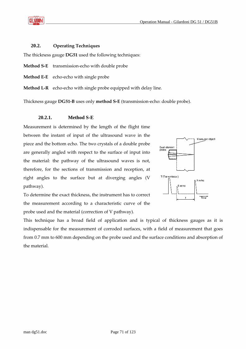
Operation Manual - Gilardoni DG 51 / DG51B
man dg51.doc Page 71 of 123
20.2. Operating Techniques
The thickness gauge DG51 used the following techniques:
Method S-E transmission-echo with double probe
Method E-E echo-echo with single probe
Method L-R echo-echo with single probe equipped with delay line.
Thickness gauge DG51-B uses only method S-E (transmission-echo: double probe).
20.2.1. Method S-E
Measurement is determined by the length of the flight time
between the instant of input of the ultrasound wave in the
piece and the bottom echo. The two crystals of a double probe
are generally angled with respect to the surface of input into
the material: the pathway of the ultrasound waves is not,
therefore, for the sections of transmission and reception, at
right angles to the surface but at diverging angles (V
pathway).
To determine the exact thickness, the instrument has to correct
the measurement according to a characteristic curve of the
probe used and the material (correction of V pathway).
This technique has a broad field of application and is typical of thickness gauges as it is
indispensable for the measurement of corroded surfaces, with a field of measurement that goes
from 0.7 mm to 600 mm depending on the probe used and the surface conditions and absorption of
the material.

Operation Manual - Gilardoni DG 51 / DG51B
man dg51.doc Page 72 of 123
20.2.2. Method E-E
Measurement is relative to the time lapse between the first and
second bottom echo.
This technique is indispensable for measurements of the
thickness of painted surfaces (as in the field of tanks, for
example) with a field of measurement that goes from 2 to
75mm. The measured value refers to the thickness of the metal
regardless of the thickness of the paint.
20.2.3. Method L-R
Here again, measurement is relative to the lapse between the first
and second bottom echo of a special straight probe with delay
line.
This method of measurement is valid for flat surfaces and
thicknesses in the range of 0.5 to 10 mm. The method can also be
used on painted surfaces if the layer of paint is very thin.
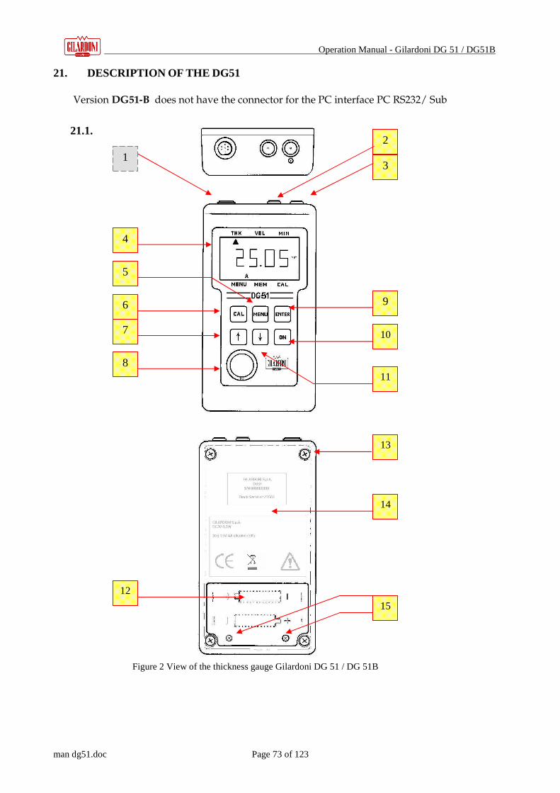
Operation Manual - Gilardoni DG 51 / DG51B
man dg51.doc Page 73 of 123
21. DESCRIPTION OF THE DG51
Version DG51-B does not have the connector for the PC interface PC RS232/ Sub
21.1.
1
4
5
6
7
8
2
3
9
10
11
15
12
13
14
Figure 2 View of the thickness gauge Gilardoni DG 51 / DG 51B
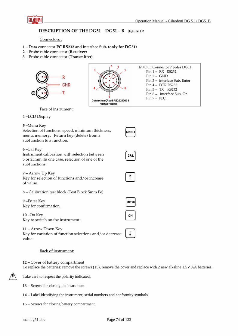
Operation Manual - Gilardoni DG 51 / DG51B
man dg51.doc Page 74 of 123
DESCRIPTION OF THE DG51 DG51 – B (figure 1):
Connectors :
1 – Data connector PC RS232 and interface Sub. (only for DG51) 2 – Probe cable connector (Receiver) 3 – Probe cable connector (Transmitter)
Face of instrument:
4 –LCD Display
5 –Menu Key
Selection of functions: speed, minimum thickness, menu, memory. Return key (delete) from a subfunction to a function.
6 –Cal Key
Instrument calibration with selection between 5 or 25mm. In one case, selection of one of the subfunctions.
7 – Arrow Up Key
Key for selection of functions and/or increase of value.
8 – Calibration test block (Test Block 5mm Fe)
9 –Enter Key
Key for confirmation.
10 –On Key
Key to switch on the instrument.
11 – Arrow Down Key
Key for variation of function selections and/or decrease value.
Back of instrument:
12 – Cover of battery compartment To replace the batteries: remove the screws (15), remove the cover and replace with 2 new alkaline 1.5V AA batteries.
Take care to respect the polarity indicated. 13 – Screws for closing the instrument 14 – Label identifying the instrument; serial numbers and conformity symbols 15 – Screws for closing battery compartment
In/Out Connector 7 poles DG51 Pin 1 = RX RS232 Pin 2 = GND Pin 3 = interface Sub. Enter Pin 4 = DTR RS232 Pin 5 = TX RS232 Pin 6 = interface Sub. On Pin 7 = N.C.
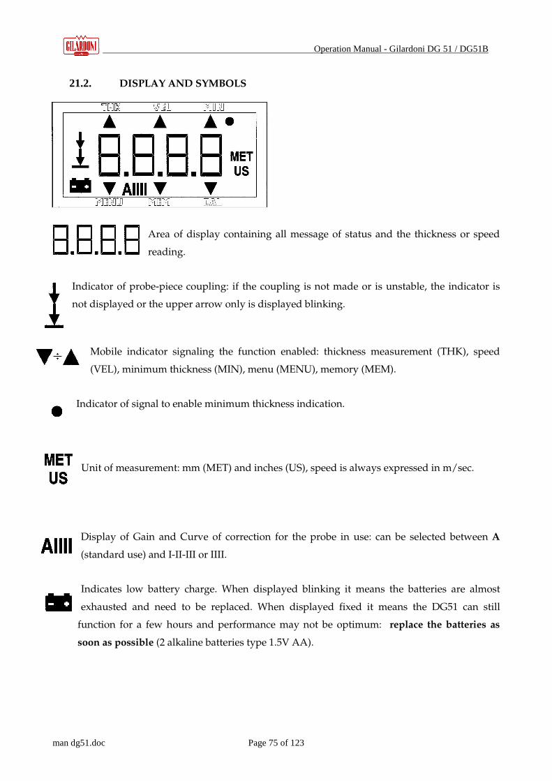
Operation Manual - Gilardoni DG 51 / DG51B
man dg51.doc Page 75 of 123
21.2. DISPLAY AND SYMBOLS
Area of display containing all message of status and the thickness or speed
reading.
Indicator of probe-piece coupling: if the coupling is not made or is unstable, the indicator is
not displayed or the upper arrow only is displayed blinking.
Mobile indicator signaling the function enabled: thickness measurement (THK), speed
(VEL), minimum thickness (MIN), menu (MENU), memory (MEM).
Indicator of signal to enable minimum thickness indication.
Unit of measurement: mm (MET) and inches (US), speed is always expressed in m/sec.
Display of Gain and Curve of correction for the probe in use: can be selected between A
(standard use) and I-II-III or IIII.
Indicates low battery charge. When displayed blinking it means the batteries are almost
exhausted and need to be replaced. When displayed fixed it means the DG51 can still
function for a few hours and performance may not be optimum: replace the batteries as
soon as possible (2 alkaline batteries type 1.5V AA).

Operation Manual - Gilardoni DG 51 / DG51B
man dg51.doc Page 76 of 123
22. SWITCHING ON THE DG51
Connect one end of the coaxial cable to the instrument and the other to the probe to be used.
In case of the double probe (method S-E) the double cable should be connected without regard to
the choice of the connector T or R of the DG51 / DG51B.
In case of single probe (method E-E or L-R) the single cable can be connected to either the T or R
connector of the DG51.
Press ON for about 1 second
The DG51 switches on and for a fraction of a second all the elements light up
on the display, then the Id _ _ code appears-
There are three possible cases, i.e.:
• The probe is already connected;
• The probe is connected after switching on (change of probe);
• Manual selection is made of the probe in use.
22.1. Switching on with probe connected to instrument.
The probe is automatically recognized and its identification code appears for a few seconds on the display:
� indicating recognition of probe DG10-4
� indicating recognition of probe BS ¼ -6
� indicating recognition of probe DD ½ -2 or DD25-2
� indicating recognition of probe TDT10-4
� indicating recognition of probe LR 8-10
The probe EE10-6 is not recognized directly in this first stage but in a later stage (case 2).
Probes DD ½ -2 and DD25-2 are automatically recognized and the DG51 is ready for their use;
automatic calibration does NOT take place, however, and always has to be done for the DD ½-2 on
the 5mm or 25mm test block and for the DD25-2 on the 25mm test block.

Operation Manual - Gilardoni DG 51 / DG51B
man dg51.doc Page 77 of 123
Always check that the probe recognized is effectively the correct one: in case of heavy wear of the probes there is a
real possibility that the reading and resulting recognition and automatic calibration are not done correctly. In this case
replace the probe as soon as possible.
Do not use Gilardoni S.p.A probes of the previous series (such as TG10-4) as they are not compatible with the
DG51 DG51-B as regards the system of automatic recognition and calibration.
22.2. Probe connected after switching on
If no probe is connected when the device is switched on, the DG51 after attempting automatic
recognition prepares for manual selection of the probe: connect the probe, press
together + and wait for the outcome of the new attempt at automatic recognition
after which the name of the probe recognized will appear on the display, as in
item 5.1, but in this case it can also recognize probe EE 10-6 with confirmation in the following
message:
� on the display.
Probe EE-10-6 is recognized through a process of exclusion.
� The automatic search and calibration system using keys CAL + UP arrow is useful and
functional when you want to replace the probe in use with the DG51 already on: just press
these two keys together immediately after connecting the new probe to start the automatic
recognition process.
The system of “recognition” of probe EE10-6 is also useful to check correct operation of the measuring device,
probe and cable: for example if the probe installed is a DG , BS , LR or other and is recognized as EE10-6, this could
mean that the cable is not functioning properly and should be replaced.
During the probe control by the device for purposes of automatic recognition and calibration, the measuring surface of the
probe MUST NOT come into contact with anything, as the acoustic absorption caused by coupling (or even by the operator’s fingers)
could affect the correct recognition of the probe or its calibration and cause erroneous measurement, with the high risk of damage to
property or, in extreme cases, to persons.
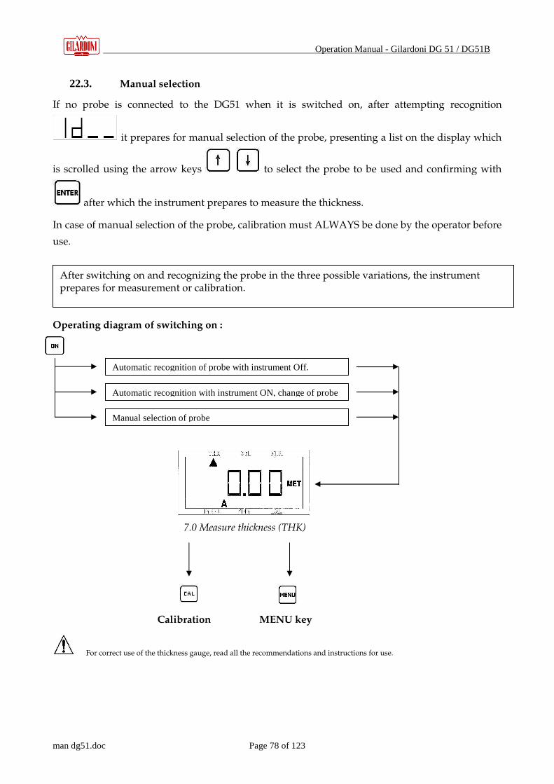
Operation Manual - Gilardoni DG 51 / DG51B
man dg51.doc Page 78 of 123
22.3. Manual selection
If no probe is connected to the DG51 when it is switched on, after attempting recognition
it prepares for manual selection of the probe, presenting a list on the display which
is scrolled using the arrow keys to select the probe to be used and confirming with
after which the instrument prepares to measure the thickness.
In case of manual selection of the probe, calibration must ALWAYS be done by the operator before
use.
Operating diagram of switching on :
For correct use of the thickness gauge, read all the recommendations and instructions for use.
After switching on and recognizing the probe in the three possible variations, the instrument prepares for measurement or calibration.
Automatic recognition of probe with instrument Off.
Automatic recognition with instrument ON, change of probe
Manual selection of probe
Calibration MENU key
7.0 Measure thickness (THK)

Operation Manual - Gilardoni DG 51 / DG51B
man dg51.doc Page 79 of 123
23. CALIBRATION
Press from the thickness measurement function (THK) to access the instrument calibration
function.
A number appears on the display indicating the thickness in mm of the Test Block to use for
calibration, either 5mm if you use the one incorporated in the instrument or
25 mm: to switch from one thickness to the other press (alternate selection of
5 – 25mm).
Couple the probe on the selected thickness, taking care to ensure acoustic coupling with a film of
coupling fluid and maintaining correct constant pressure between the probe and the Test Block,
then proceed to calibrate by pressing to confirm the choice.
On the display the speed in US of 5900 m/s appears briefly indicating the nominal speed of the
Test Block to use, and followed by an advancement of lines indicating calibration
in progress: the operator should take care to hold the probe still to ensure constant coupling. If
calibration is successful the instrument will pass automatically to the thickness measurement
function (THK) ready for use, while if calibration is not successful a series of dotted lines will
remain on the display and the procedure will have to be repeated.
To select the thickness for calibration, in addition to the key, you can use either of the
increase or decrease arrows .
It is always advisable to recheck on the Test Block the accuracy of reading after calibration even if this is successful: an
uneven pressure on the probe and/or poor distribution of the coupling fluid may cause serious errors.
In case of use of the probes with protection in Vulkolan to limit wear, it is essential to apply a thin film of oil (such as
SAE10-40) between the surface of the probe and the protection as acoustic coupling and then perform calibration in manual mode
as the automatic mode does not contemplate the extra added layer and would therefore be very inaccurate. Check frequently that
the film of oil is free of air bubbles that could interfere with correct measurement. Consider that the application of the protection
has the advantage of limiting wear of the probe and improving coupling on unfavorable surfaces, but generally limits the
performance of the probe in terms of thicknesses measurable.

Operation Manual - Gilardoni DG 51 / DG51B
man dg51.doc Page 80 of 123
The probe calibration procedure has to be done using the 5mm block at 5900 m/s incorporated in the instrument or
another block suitable for the purpose, either 5 or 25mm in Fe (+ 0,02mm V5900 m/s + 10 m/s ), carefully cleaned to prevent
imprecision that could then affect operations. Consider that inspections made under conditions of limit temperature of the tested
part can be affected by variations in ultrasound speed in the material you are testing and in the material composing the delay
lines of the probes (sockets), so it is important for the calibration block to have a temperature close to that of the test piece to
minimize errors of measurement; this is even more important when operating on walls at high temperature with special probes
and coupling fluids. (see optionals)
The probes are the element most subject to wear on the entire instrument: a worn probe can greatly reduce the general
performance of the gauge and/or cause errors because of improper automatic recognition or calibration, with the risk of errors of
as much as 100% in particular when using method S-E. Check frequently the conditions of the probes in use and, in case of wear,
after automatic recognition and calibration, make sure the calibration is within the tolerance indicated, otherwise calibrate again
in manual mode. Replace or send promptly to Gilardoni any probes that show wear incompatible with correct use.
Operating diagram of calibration:
Cyclic operation of CAL key for selection between 5 and 25mm
Confirm choice (probe coupled to Test Block)
Calibration in progress ….(probe coupled to Test Block)
Calibration with positive outcome
Calibration with negative outcome: repeat the calibration procedure
5mm 25mm
MENU key
Measure thickness (THK)

Operation Manual - Gilardoni DG 51 / DG51B
man dg51.doc Page 81 of 123
24. MEASUREMENT OF THICKNESS – THK -
After correctly completing the procedures of probe recognition and calibration, the gauge goes to
the thickness measurement function (THK).
The gauge performs measurement on the basis of the ultrasound speed setting made: it is
displayed and set in the first function of the Menu selection if the speed of the test material is
known. If not, the speed of the material has to be set using the function provided for that purpose:
Speed.
After making the correct speed setting, you can proceed to measure the thickness by coupling the
probe to the test piece and following the instructions given above.
During measurement, to be sure of the correct value on the display, check for the presence of
the double arrow indicating correct acoustic coupling: if even just one of the arrows is missing,
check the following:
• the coupling surface should not be too rough and should be prepared if necessary;
• the necessary layer of coupling fluid has been applied between the probe and the piece;
• the film of coupling fluid is placed between the probe and the protection, if the protection
in Vulkollan is used;
• the material being measured and its thickness are compatible, from the point of view of
ultrasound, with the probe in use.
The measurement is kept on the display so that the operator can read it at any time.

Operation Manual - Gilardoni DG 51 / DG51B
man dg51.doc Page 82 of 123
Table 2 Table of reference ultrasound speeds, in longitudinal waves, for various materials
Material VL VT Material VL VT
C STEEL 5900 3230 TIN 3300 1300
AISI 5600-5800 3100 TITANIUM 6100 2400
ALUMINUM 6200-6400 2500 TUNGSTEN 5300 2100
SILVER 3600 1400 ZINC 4100 1600
CAST IRON 3600 ÷ 5700 1800÷3000 PHENOL 1400 560
INCONEL 5600 2200 RUBBER 1900 ÷ 2300 730 ÷ 900
MAGNESIUM 5800 2300 NYLON 2500 1000
MANGANESE 4600 1800 NEOPRENE 1600 .630
MOLYBDENE 6300 2500 PLEXIGLAS 2730 1100
NICKEL 5600 2200 PORCELLAIN 5600 2200
BRASS 4300 1700 POLYETHYLENE 1800 700
GOLD 3300 1300 POLYSTYRENE 2400 930
LEAD 2200 850 POLYURETHANE 1800 700
COPPER 4600 1800 GLASS 5600 ÷ 6800 2200 ÷2700
NOTE: this table lists the speeds in purely indicative terms: Gilardoni S.p.A. is not responsible for any inaccuracy.

Operation Manual - Gilardoni DG 51 / DG51B
man dg51.doc Page 83 of 123
Operating diagram of the thickness measurement function:
For proper use of the gauge, read all the recommendations and instructions for use.
Measure thickness (THK)
3 times
to select Menu function: check and set known speed
1 time
to select speed function: check and set unknown speed
Coupling unstable: check the reason, take the necessary steps and repeat measurement
Selection of Memory function DG51 and DG51-B
Measurement of thickness in progress
Measurement of thickness in progress
To save press ENTER

Operation Manual - Gilardoni DG 51 / DG51B
man dg51.doc Page 84 of 123
25. MENU KEY
Press to access the general operating logic of the gauge.
� From the thickness measurement function (THK), press the menu key to access another set
of functions. On the display, one of the arrows ∇∇∇∇ will position itself on the function selected
among THK, VEL, MIN, MENU, MEM: using the CAL key, as we shall see, you can select
the various functions to confirm with the ENTER key, while the MENU key will serve to
exit the selection and go to another set of functions or cancel a selection.
Operating diagram of the MENU key
A display la V current: probe not coupled,
the value is 0
Minimum thickness
setting on the display
Displays V used to measure
thickness - THK
Current memory status on the display memory
status on the display
Select Speed function
Select Minimum function
Select Menu function
Select Memory function– DG51 and DG51-B
Measure thickness (THK)
Measure thickness (THK)

Operation Manual - Gilardoni DG 51 / DG51B
man dg51.doc Page 85 of 123
26. SPEED FUNCTION – VEL -
After correctly completing the procedures of probe recognition and calibration, the gauge goes to
the thickness measurement function (THK).
Press to switch to the speed measurement function.
Speed measurement is made on the basis of the known thickness: press to display the
current thickness setting and increase or decrease it using the arrow keys
To confirm the new thickness and return to the speed measurement function press ; to cancel the change and/or leave the thickness originally displayed and return to the speed
measurement function press . After setting the thickness, you can measure the speed by resting the probe in use on the test piece, taking care to ensure acoustic coupling using a film of coupling fluid and maintaining constant pressure on the probe.
To perform measurements, the procedure is the same as for thickness measurement (THK), including the relative recommendations. Knowing the speed of a material may be useful to identify and/or ascertain its quality: a classic example is control of the spheroidization of cast iron via measurement of the ultrasound speed through a known thickness of the product. Measurement of the speed of a material is indispensable when the thickness of that material has to be measured (MENU and THK). To import the speed measured directly as the basic speed for thickness measurement, press
together + .
For proper use of the gauge, read all the recommendations and instructions for use.
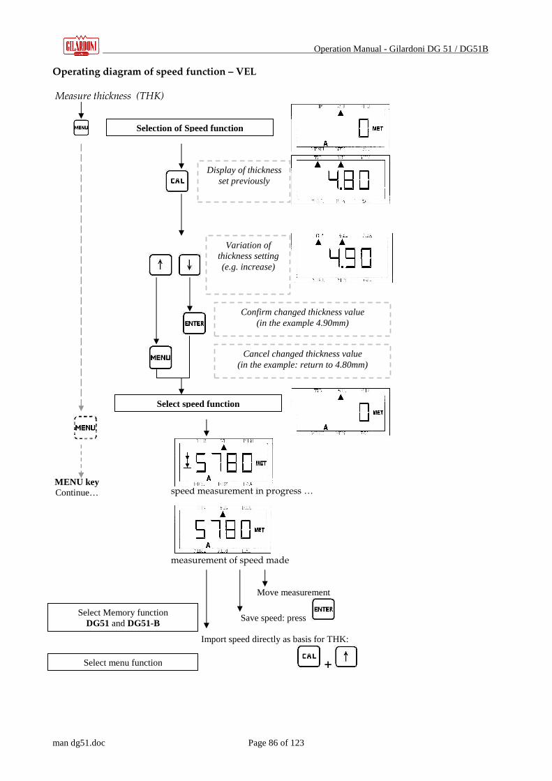
Operation Manual - Gilardoni DG 51 / DG51B
man dg51.doc Page 86 of 123
Operating diagram of speed function – VEL Measure thickness (THK)
speed measurement in progress … measurement of speed made Move measurement
Save speed: press Import speed directly as basis for THK:
+
MENU key Continue…
Selection of Speed function
Display of thickness set previously
Variation of thickness setting (e.g. increase)
Confirm changed thickness value (in the example 4.90mm)
Cancel changed thickness value (in the example: return to 4.80mm)
Select speed function
Select Memory function DG51 and DG51-B
Select menu function

Operation Manual - Gilardoni DG 51 / DG51B
man dg51.doc Page 87 of 123
27. MINIMUM THICKNESS FUNCTION – MIN –
After correctly completing the procedures of probe recognition and calibration, the gauge goes to
the thickness measurement function (THK).
Press to access the minimum thickness function.
The last minimum thickness setting appears on the display, press the arrow keys to
increase or decrease it and press to confirm the new value or to return to the previous value. The minimum thickness function is enabled with a new minimum thickness and the gauge goes automatically to the thickness measurement function (THK) ready to measure with the minimum thickness function enabled. To suppress the minimum thickness alarm just set a thickness equal to 0,00mm (0,00inc) The minimum thickness function has two possible signals:
C. Minimum thickness alarm in real time, displaying a dot on the edge of the display, at the upper right, at the time of measuring a figure below the reference setting;
D. Automatic update of the figure and freezing of the lowest
numerical reading made during measurement on the display.
To enter this second signal mode, from thickness measurement press for selection of the minimum thickness function.
After entering the minimum thickness value (as for mode A) enable mode B by pressing and
confirm with . The limit reference thickness is updated and the gauge goes automatically to thickness measurement ( THK) with the minimum thickness function enabled.
To reset the minimum value found without changing it, from thickness measurement press
for selection of thickness measurement. To disable mode B, from the minimum thickness function,
press and confirm with .
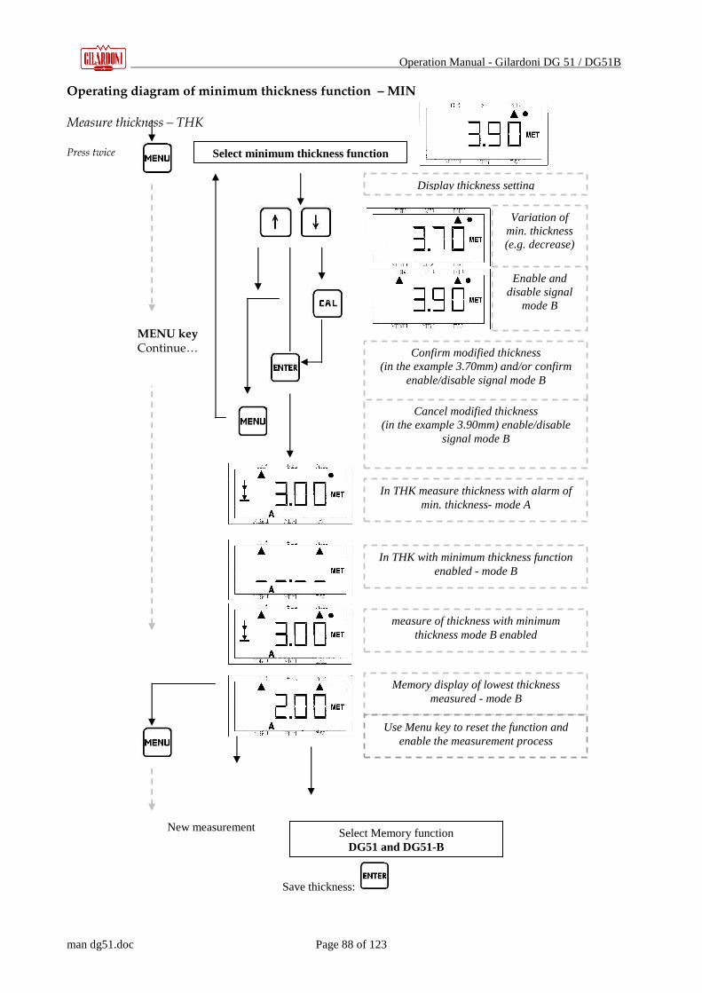
Operation Manual - Gilardoni DG 51 / DG51B
man dg51.doc Page 88 of 123
Operating diagram of minimum thickness function – MIN Measure thickness – THK Press twice
New measurement
Save thickness:
Select minimum thickness function
Variation of min. thickness (e.g. decrease)
Display thickness setting
Confirm modified thickness (in the example 3.70mm) and/or confirm
enable/disable signal mode B
Cancel modified thickness (in the example 3.90mm) enable/disable
signal mode B
In THK with minimum thickness function enabled - mode B
MENU key Continue…
In THK measure thickness with alarm of min. thickness- mode A
Memory display of lowest thickness measured - mode B
Use Menu key to reset the function and enable the measurement process
Select Memory function DG51 and DG51-B
Enable and disable signal
mode B
measure of thickness with minimum thickness mode B enabled

Operation Manual - Gilardoni DG 51 / DG51B
man dg51.doc Page 89 of 123
28. SELECTION OF FUNCTION – MENU -
After correctly completing the procedures of probe recognition and calibration, the gauge goes to
the thickness measurement function (THK).
Press to access the menu for selection of functions.
Press to access the sequence of settings and selection of functions listed below:
• Speed for thickness measurement
• Selection of correction curves and gain
• Manual selection of probe to use
• Scanning speed (PRF)
• Decimal or centesimal measurement
• Unit of measurement
• Limitation of consumption
Selection is made using the arrow keys , and confirming with or canceling with
.
28.1. Speed for thickness measurement
This setting is necessary and basic for correct measurement of: refer to the recommendations and chapters relative to it, i.e. principles and methods of thickness (THK) and speed (VEL) measurement.
28.2. Settings for probe in use – SETs
The DG51, at the time of recognizing the probe (gauge switched on), calls a combination of correction curves for specific materials and levels of sensitivity displayed directly on the screen with the symbols: A – I – II – III – IIII. (display and relative symbols).
Example of selection A (default) or I
For proper use of the gauge, read all the recommendations and instructions for use.

Operation Manual - Gilardoni DG 51 / DG51B
man dg51.doc Page 90 of 123
The default setting, for all probes, is A, corresponding to a correction curve of the V path of a probe using method S-E (double probe) for a speed of 5900m/s, for a material comparable to “common iron” (FeC20) and with a standard Gain selection. With the other settings other combinations of correction curves are available to adapt better to the speed of the materials and levels of sensitivity for greater adaptation to the ultrasound transparencies of the test materials. The correction curves available refer to the following materials:
• Fe C20 5900m/s –
• AISI 303 5750m/s –
• Al 7075 6300m/s –
• Additional correction curves may be available as optionals, at the specific request of the client at the time of ordering, or also after ordering, exclusively with prior contact with the CND-US Gilardoni technical experts, to verify the feasibility and modes. (1.0 – Service)
The probes used for method E-E or L-R do not need correction curves as they have a single crystal, so the setting concerns only the level of sensitivity to be selected on the basis of the ultrasound transparency of the material and conditions of the surface. The combinations of curves/sensitivity are designed as follows: Method S-E
For proper use of the gauge, read all the recommendations and instructions for use.
DG10-4 Set. Gain Curve
A Default 5900m/s
I + 5900m/s
II - 5900m/s
III Default 5750m/s
IIII Default 6300m/s
BS 1/4- 6 Set. Gain Curve
A Default 5900m/s
I + 5900m/s
II - 5900m/s
III Default 5750m/s
IIII - 5750m/s
SD 1/2-2 o SD 25-2 Set. Gain Curve
A Default 5900m/s
I + 5900m/s
II ++ 5900m/s
III - 5900m/s
IIII -- 5900m/s
DT 10-4 Set. Gain Curve
A Default 5900m/s
I + 5900m/s
II - 5900m/s
III Default 5750m/s
IIII - 5750m/s

Operation Manual - Gilardoni DG 51 / DG51B
man dg51.doc Page 91 of 123
Method L-R and E-E
For this setting refer to the recommendations and chapters relative to it, i.e. principles and methods of measurement, thickness (THK) and speed (VEL) measurement.
28.3. Manual selection of probe to use
Selection of the probe to use can be done manually rather than automatically.
� With manual selection of the probe, automatic calibration is obviously not done: it must
ALWAYS be done before use.
Refer to the recommendations and chapters on the subject, i.e. principles of measurement and methods (3.0), switching on the gauge (5.0), measurement of thickness (THK) and speed (VEL).
28.4. Scanning speed
It is possible to modify the rhythm of repetition of the measuring impulses (PRF) by changing the maximum speed of inspection allowed. There are two settings: SLO_ (2Hz) e FAST (5Hz).
28.5. Decimal or centesimal measurement
You can set the resolution of the thickness reading in decimal P0.1 or centesimal P0.01 mode
28.6. Unit of measurement
You can choose between mm - UU met -, and inches – UU us –
For proper use of the gauge, read all the recommendations and instructions for use.
LR8-10 Set. Gain Curve
A Default 0
I + 0
II ++ 0
III - 0
IIII - - 0
EE10-6 Set. Gain Curve
A Default 0
I + 0
II ++ 0
III - 0
IIII - - 0
Operation Manual - Gilardoni DG 51 / DG51B
man dg51.doc Page 92 of 123
28.7. Limitation of consumption
To limit consumption thereby increasing the already considerable autonomy of the instrument, you can select between SE.Lo, relative to limitation and SE.Hi, continuous function.
� It is indispensable to enable SE.Hi if you are using serial bidirectional communication, as selection of SE.Lo inhibits, effectively, the rapid response of the microprocessor, thereby making transmission of the data to the PC impossible, in some cases.

Operation Manual - Gilardoni DG 51 / DG51B
man dg51.doc Page 93 of 123
28.8. Operating diagram of MENU function
Measure thickness – THK Press 3 times
For proper use of the gauge, read all the recommendations and instructions for use
For ALL selections: use the arrow keys to change or select;
press Enter to confirm; press Menu
key to reset the function and return
to speed display
Select Menu function
MENU Key Continue…
Display speed setting for THK
Setting of probe in use: A – I – II –
III - IIII
Manual selection of probe to use
Scanning speed between: SLO_
(2Hz) and FAST (5Hz)
Decimal or centesimal measurement: P0.01 or P 0.1
Unit of measurement: mm
- met inches - us
Limit conusumption
between: SE.Lo e SE.HI
Display back light OFF
Display back light On

Operation Manual - Gilardoni DG 51 / DG51B
man dg51.doc Page 94 of 123
29. MEMORY FUNCTION – MEM -
This chapter is specific for the DG51: see Chapter 2 General Information, Chapter 3 Measuring Principle and Techniques, and Chapter 4 Structure of Gauge.
The DG51 is designed to be a simple, complete, flexible instrument as far as possible in the sphere of its field of application. It is possible to save up to 4000 items of data in sequential form or divide them into files (from 1 to 10) so as to have the possibility to divide the readings made on different products (or parts). The specific Gilardoni software also permits registration of the data on a PC in matrix form with the possibility of saving up to a maximum of 4000 data items to be divided among the various files created. The data saved can be thickness data or speed data and can be reread directly on the display of the instrument and/or downloaded to the PC via the RS232 connection, with a special cable for connection to the PC and Gilardoni DG51_MS software (optional).
29.1. Access to the Memory function
To access the Memory function press . When the function is enabled, the memory status is displayed: if you read
it means no file is operational and you can proceed to create one;
if you read , it means that a thickness data file is operational and the
number indicates its location in the memory, if you read , it means a speed data file is operational. Display of the Fn.01 means that file 1 is enabled for registration/display, display of code Fn.02 means that file 2 is enabled, and so on to Fn.10 (there are 10 files available).

Operation Manual - Gilardoni DG 51 / DG51B
man dg51.doc Page 95 of 123
29.2. Creation of a new file
From O.ALL, press to select creation of a file to measure thickness or a file to measure speed:
Selection for thickness Selection for speed Use the scroll keys to select the number of files necessary (from 1 to 10); for example to select 3
files:
Press to confirm the setting, press to cancel. The gauge goes directly to measurement of thickness THK : if a file of thicknesses has been entered on the display, on THK you will see a
signal ∆∆∆∆ ; if a file of speed data has been created the signal ∇∇∇∇ will be on VEL.
29.3. Saving data
When the file of saved data has been made operational, pressing will save the data and on the display you will see the consecutive number for an instant
showing the memory location ; to save or overwrite on another memory location
that is not the next one in the sequence, use the scroll keys to go to a new location and
press to confirm and enable it for saving. To cancel the selection press .
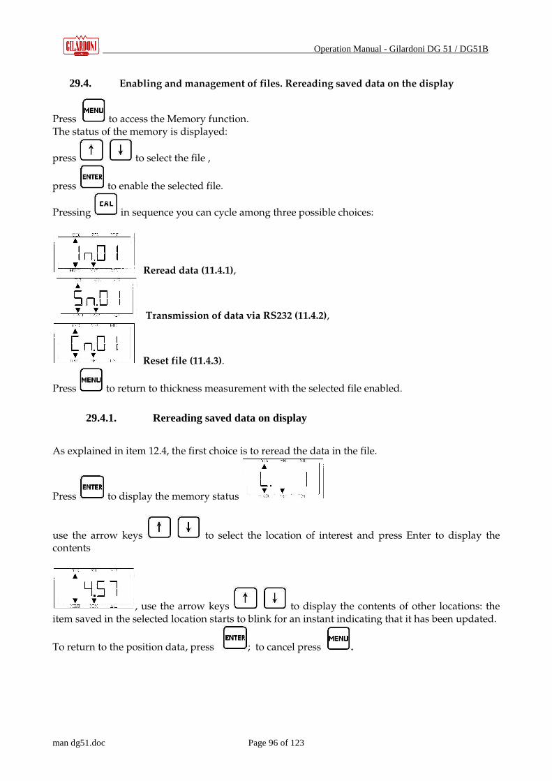
Operation Manual - Gilardoni DG 51 / DG51B
man dg51.doc Page 96 of 123
29.4. Enabling and management of files. Rereading saved data on the display
Press to access the Memory function. The status of the memory is displayed:
press to select the file ,
press to enable the selected file.
Pressing in sequence you can cycle among three possible choices:
Reread data (11.4.1),
Transmission of data via RS232 (11.4.2),
Reset file (11.4.3).
Press to return to thickness measurement with the selected file enabled.
29.4.1. Rereading saved data on display
As explained in item 12.4, the first choice is to reread the data in the file.
Press to display the memory status
use the arrow keys to select the location of interest and press Enter to display the contents
, use the arrow keys to display the contents of other locations: the item saved in the selected location starts to blink for an instant indicating that it has been updated.
To return to the position data, press ; to cancel press .

Operation Manual - Gilardoni DG 51 / DG51B
man dg51.doc Page 97 of 123
29.5. Data transmission via RS232
After pressing twice, press to start sequential transmission to the PC of the data saved through serial port RS232: this operation continues until all the data saved in the file (4000 memory cells divided among the different files created).
Before using this control it is advisable to disable the option that limits consumption.
29.5.1. Resetting data in files
After pressing three times press so that the symbol on the display
starts blinking. Press again to delete the data: the display briefly flashes the message
to indicate that deletion is in progress. To cancel the operation press . At the end of the operation the display shows
again, but the data in the file have been deleted.
� Caution! Resetting permanently eliminates all the data in the file.
For proper use of the gauge, read all the recommendations and instructions for use.
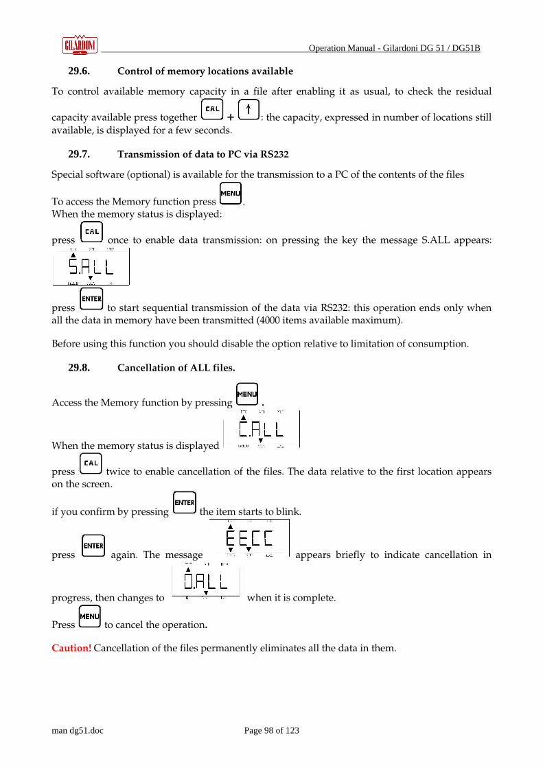
Operation Manual - Gilardoni DG 51 / DG51B
man dg51.doc Page 98 of 123
29.6. Control of memory locations available
To control available memory capacity in a file after enabling it as usual, to check the residual
capacity available press together + : the capacity, expressed in number of locations still
available, is displayed for a few seconds.
29.7. Transmission of data to PC via RS232
Special software (optional) is available for the transmission to a PC of the contents of the files
To access the Memory function press . When the memory status is displayed:
press once to enable data transmission: on pressing the key the message S.ALL appears:
press to start sequential transmission of the data via RS232: this operation ends only when all the data in memory have been transmitted (4000 items available maximum).
Before using this function you should disable the option relative to limitation of consumption.
29.8. Cancellation of ALL files.
Access the Memory function by pressing .
When the memory status is displayed
press twice to enable cancellation of the files. The data relative to the first location appears on the screen.
if you confirm by pressing the item starts to blink.
press again. The message appears briefly to indicate cancellation in
progress, then changes to when it is complete.
Press to cancel the operation.
Caution! Cancellation of the files permanently eliminates all the data in them.
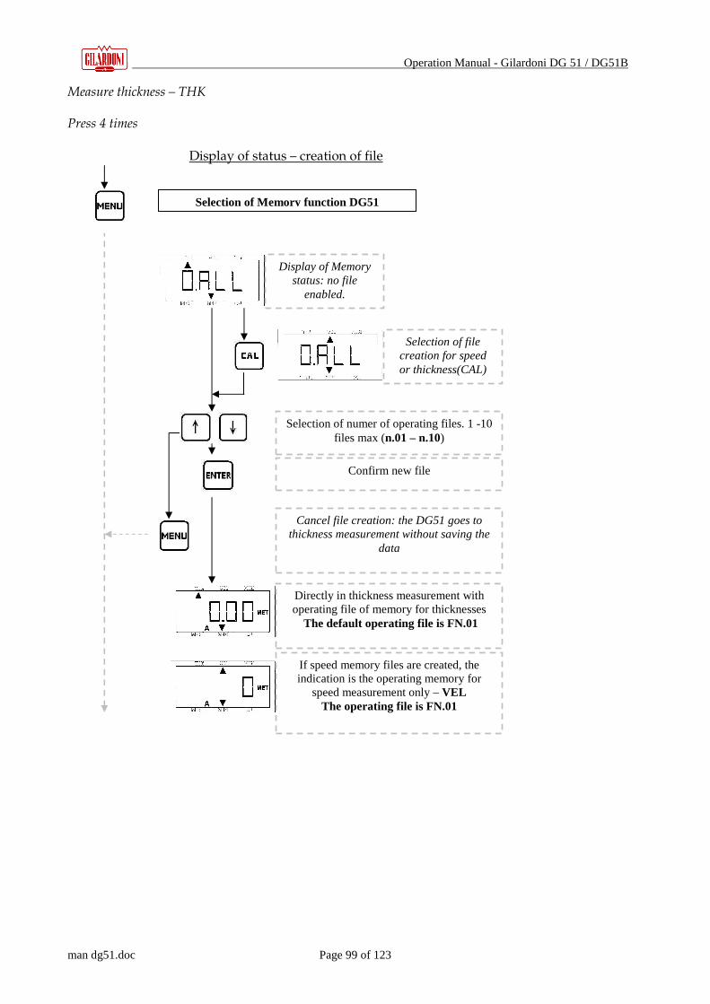
Operation Manual - Gilardoni DG 51 / DG51B
man dg51.doc Page 99 of 123
Measure thickness – THK Press 4 times Display of status – creation of file
Selection of Memory function DG51
Display of Memory status: no file
enabled.
Selection of file creation for speed or thickness(CAL)
Confirm new file
Cancel file creation: the DG51 goes to thickness measurement without saving the
data
Directly in thickness measurement with operating file of memory for thicknesses
The default operating file is FN.01
If speed memory files are created, the indication is the operating memory for
speed measurement only – VEL The operating file is FN.01
Selection of numer of operating files. 1 -10 files max (n.01 – n.10)
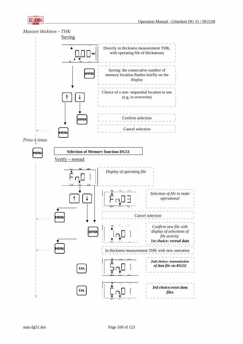
Operation Manual - Gilardoni DG 51 / DG51B
man dg51.doc Page 100 of 123
Measure thickness – THK Saving Press 4 times
Verify – reread
Selection of Memory function DG51
Directly in thickness measurement THK, with operating file of thicknesses
Saving: the consecutive number of memory location flashes briefly on the
display
Choice of a non- sequential location to use (e.g. to overwrite)
Confirm selection
Cancel selection
Display of operating file
Selection of file to make operational
Confirm new file with display of selections of
file activity. 1st choice: reread data
Cancel selection
2nd choice: transmission of data file via RS232
3rd choice:reset data files
In thickness measurement THK with new operating

Operation Manual - Gilardoni DG 51 / DG51B
man dg51.doc Page 101 of 123
reading of stored data of operating file
+
Display Memory status:
Check residual memory available for enabled file
Select location for display of data, e.g. location no22 of file of thicknesses enabled
Display of data in location no.°22
Selection of location of memory with updated data: ∇∇∇∇ on MEM starts blinking with every new location.
Enter to display location no.
1st choice: read data
Cancel – return to THK

Operation Manual - Gilardoni DG 51 / DG51B
man dg51.doc Page 102 of 123
Caution! By resetting you permanently eliminate the data saved
Before using the gauge, read all the recommendations and instructions for use.
Select to reset data: display starts blinking
awaiting confirmation or not
Cancel
Confirm data reset
Return to enabled selection
MENU key
Continue…
2nd choice: transmission of file data, previously selected,
via RS232
Cancel – return to THK
Confirm data transmission
3rd choice: reset data in file

Operation Manual - Gilardoni DG 51 / DG51B
man dg51.doc Page 103 of 123
Press 4 times Caution! By canceling the file you permanently eliminate all the data saved in it. .
Before using the gauge, read all the recommendations and instructions for use.
Selection to send all data (file )via RS232
Confirm data transmission
Cancel – return to THK
Select cancelation of ALL files and their
settings
Preparation to cancel memory: display is blinking awaiting confirmation or not
Cancel – return to THK
Confirm memory cancelation
Display memory status: no file
enabled.
MENU key
Continue…
Selection of Memory function DG51
Display operating file

Operation Manual - Gilardoni DG 51 / DG51B
man dg51.doc Page 104 of 123
30. MEMORY FUNCTION OF DG51-B – MEM –
This chapter is specific for the DG51-B: see chapter 21 General Information, chapter 2 Principle and techniques of measurement, chapter 4 structure of gauge.
The DG51-B is designed to be a simple but at the same time complete and flexible instrument: with this view the data can be saved in sequential form, in a single file up to a maximum of 999 data items. The data saved can refer to thickness or speed and can be reread only on the instrument display.
30.1. Access to Memory function
To access the Memory function press . When the function is enabled the display shows the memory status: if the message III is displayed it means no file is operational and you can create and enable it;
if III is displayed with the cursor ∆∆∆∆ on THK it means that a thickness data file is enabled and the number indicates the memory location enabled;
if the message III is displayed with the symbol ∇∇∇∇ on VEL it means a speed data file is enabled.
30.2. Creation of the file
From O.ALL, press to select between a thickness file and a speed file:
III with ∆∆∆∆ on THK : selection of thickness file - III with ∇∇∇∇ on VEL : selection of speed file
Confirm the setting by pressing , or press to cancel. The gauge goes directly to thickness measurement THK, ready to record the data: if a thickness file
has been prepared there will be a signal ∆∆∆∆ on THK; if a speed data file has been created the signal
∇∇∇∇ will be on VEL .
30.3. Saving data
After enabling the memory file, press to save the data and the consecutive number will flash briefly on the display
Associated with memory location 111; to save or overwrite on another memory block rather than
the next one, use the arrow keys : and confirm with The DG51 –B is ready to
save. Press to cancel the save selection
30.4. Control of available memory locations
To access the Memory function press . This displays the memory status:
to check the residual capacity available press together + : the capacity, expressed in
number of locations still available, is displayed for a few seconds.
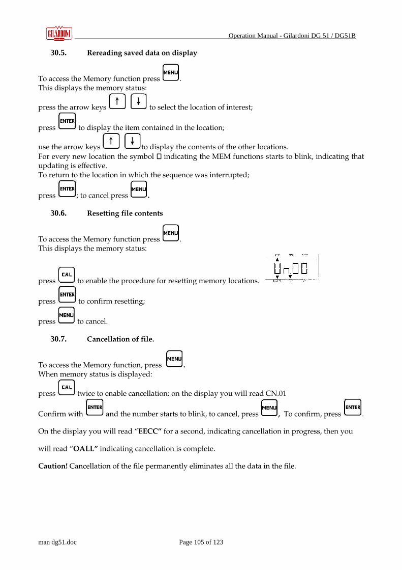
Operation Manual - Gilardoni DG 51 / DG51B
man dg51.doc Page 105 of 123
30.5. Rereading saved data on display
To access the Memory function press . This displays the memory status:
press the arrow keys to select the location of interest;
press to display the item contained in the location;
use the arrow keys to display the contents of the other locations.
For every new location the symbol ∇∇∇∇ indicating the MEM functions starts to blink, indicating that updating is effective. To return to the location in which the sequence was interrupted;
press ; to cancel press .
30.6. Resetting file contents
To access the Memory function press . This displays the memory status:
press to enable the procedure for resetting memory locations.
press to confirm resetting;
press to cancel.
30.7. Cancellation of file.
To access the Memory function, press . When memory status is displayed:
press twice to enable cancellation: on the display you will read CN.01
Confirm with and the number starts to blink, to cancel, press , To confirm, press .
On the display you will read “EECC” for a second, indicating cancellation in progress, then you
will read “OALL” indicating cancellation is complete.
Caution! Cancellation of the file permanently eliminates all the data in the file.

Operation Manual - Gilardoni DG 51 / DG51B
man dg51.doc Page 106 of 123
Breakdown and examples of MEM function Measure thickness – THK X4 Display of status – creation of file
Selection of Memory function of DG51-B
Display of Memory status: no file
enabled.
Select file creation for Speed US or thickness (CAL)
Confirm creation of memory file
Cancel creation of memory file: the device goes to thickness measurement without
enabling saving
Directly in thickness measurement THK, with operating memory file of thicknesses
If a speed memory file US has been created, the indication and memory
function are only for speed measurement
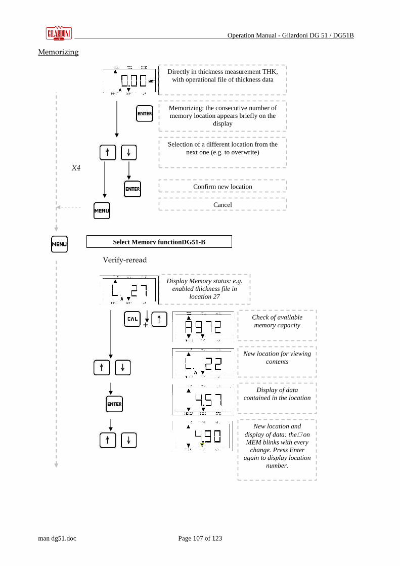
Operation Manual - Gilardoni DG 51 / DG51B
man dg51.doc Page 107 of 123
Memorizing X4 Verify-reread
+
Select Memory functionDG51-B
Display Memory status: e.g. enabled thickness file in
location 27
Directly in thickness measurement THK, with operational file of thickness data
Memorizing: the consecutive number of memory location appears briefly on the
display
Selection of a different location from the next one (e.g. to overwrite)
Confirm new location
Cancel
Check of available memory capacity
New location for viewing contents
Display of data contained in the location
New location and display of data: the∇ on MEM blinks with every
change. Press Enter again to display location
number.

Operation Manual - Gilardoni DG 51 / DG51B
man dg51.doc Page 108 of 123
Resetting – cancelation of file Caution! Cancellation permanently eliminates all the data in the file.
For the use of the measuring set, read all the instructions and recommendations carefully.
Display status of memory: e.g. active file di thicknesses
at location n°27
Selection to reset memory (return to L1)
Confirm resetting memory
Cancel
Confirm cancelation of memory
Ready for cancelation of memory: display is blinking awaiting
confirmation or not
Cancel
Confirm cancelation of memory
Display status of Memory: no active
file.
MENU Key
Continue…

Operation Manual - Gilardoni DG 51 / DG51B
man dg51.doc Page 109 of 123
31. TECHNICAL FEATURES
The table lists the technical features of the DG51 thickness gauge
Measurement technique Echo-transmission and echo-echo * Measurements Thickness and speed
Range of measurement From 0.5 to 600 mm
Resolution 0.01 mm up to 99.99 mm; 0.1 mm over 100 mm
Probe recognition Automatic
Self-calibration Coincides with probe recognition
Calibration On 5 or 25 mm
Range of speeds From 1000 to 9999 m/sec
Gain Adjustable on 99 levels (dynamics: ≈ 40 dB)
Correction of V route Automatic by microprocessor
Reading update SLOW (2Hz) and FAST (5Hz)
Signals Of coupling and minimum thickness
Data logger 4000 items in 10 files ** Interface RS232 *** Units of measurement mm or inches
Switches off Automatically after 3 min disuse
Power supply Two dry batteries type AA at 1.5 V
Autonomy 200 hours
Temperature range From -10°C to 50°C
Dimensions 73 x 35 x 136 mm
Weight 250 g with batteries
Approval RINA
Marking CE,UL
(*) For the DG51 B the echo-echo measurement is not available (**) The DG51 B can memorize only 999 items in a single file (***) Not available for the DG51 B.

Operation Manual - Gilardoni DG 51 / DG51B
man dg51.doc Page 110 of 123
32. SETUP
1. Insert the CD with DG51_MS software on your CD reader unit 2. The following mask will appears:
Figura 1.0 - Setup
3. Click Setup option; 4. Follow the instruction on the screen.
32.1. Program unlock
At the end of Setup please manually install the “DG.DAT” file disposable on the disposable Operation Manual CD. If you do not have the Operation Manual CD, the DG51-MS Software is disposable only in the demo version and it can be seen “DEMO VERSION” on the starting mask: the window title will be “DG51-MS GILARDONI SPA – DEMO PROGRAM” (See Fig. 3). Report printing, export functions and data saving will be disabled.

Operation Manual - Gilardoni DG 51 / DG51B
man dg51.doc Page 111 of 123
Fig. 3 Demo Version of DG-MS Program
NOTE: The “DG.DAT’ file can be requested in every moment, sending company data for the report customizing and option activation.
If the DG.DAT is disposable by double clicking on the icon the following mask will appears:
Fig. 4 – Customer data

Operation Manual - Gilardoni DG 51 / DG51B
man dg51.doc Page 112 of 123
The first item is the Customer Name and it can not be modified: the two following items may be modified respectively introducing the company data that will be displayed on the printed test report.
32.2. Features
For a proper working the system must has the following features: - display resolution : 800x600 minimum - Small character size
33. SYSTEM DESCRIPTION
The DG51-MS Software gives new additional functions to the thickness gauge DG class. It is possible to:
• Transfer thickness/velocity stored data from the thickness gauge to the PC • Show the data with different colors for an easy evaluation • Print a color test report • Export the stored data to create customized test reports.
33.1. DG classes compatibility
With the DG51-MS Software it is possible to operate with the following units:
• Thickness gauge GILARDONI DG 51

Operation Manual - Gilardoni DG 51 / DG51B
man dg51.doc Page 113 of 123
34. STARTING PANEL
Fig. 5 – Starting panel
Starting the program the Fig. 5 panel will appear to access to all software functions like:
DG51 Managing
Language Setting
Directory setting
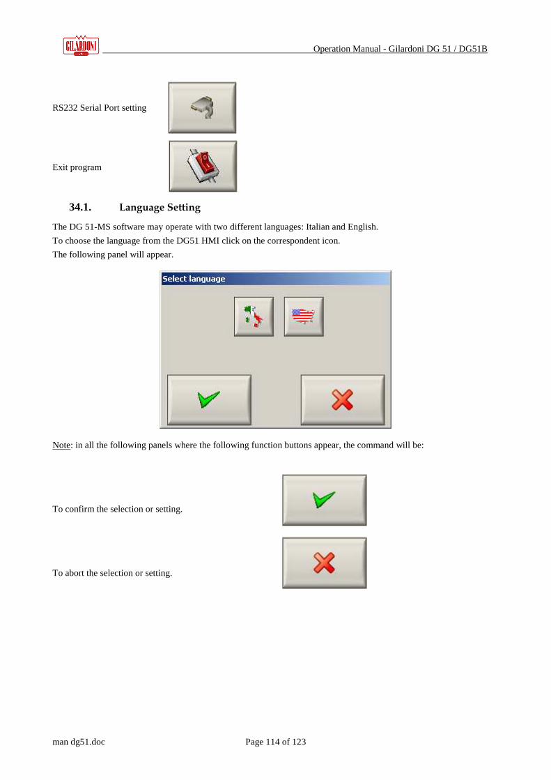
Operation Manual - Gilardoni DG 51 / DG51B
man dg51.doc Page 114 of 123
RS232 Serial Port setting
Exit program
34.1. Language Setting
The DG 51-MS software may operate with two different languages: Italian and English.
To choose the language from the DG51 HMI click on the correspondent icon.
The following panel will appear.
Note: in all the following panels where the following function buttons appear, the command will be: To confirm the selection or setting. To abort the selection or setting.

Operation Manual - Gilardoni DG 51 / DG51B
man dg51.doc Page 115 of 123
34.2. Directory setting
To increase the utilization facility it is possible to set e predefined directory for an automatic saving/reading the DG51
data.
It is also possible to specify the export directory for the data that will be managed.
To set the export and predefined save directories click on the correspondent icon.
The following panel will appears.
34.3. RS232 Serial communication control
If the program is used for the first time, it is advisable to test if the PC is correctly set to
communicate with the instrument. To make it click on the correspondent icon:
On your monitor the following panel will appears:
Fig. 6
On the panel displayed above it is possible to set the PC serial port to transfer data from the thickness gage

Operation Manual - Gilardoni DG 51 / DG51B
man dg51.doc Page 116 of 123
34.3.1. Communication state
During a normal communication with Gilardoni DG51, a communication state panel is displayed, to show the amount
of transferred data.
In any case it is possible to abort the communication by clicking the red crossed icon.
34.4. Exit from the DG51-MS program
To exit from the program, please press the following exit icon
A confirm exit command request will appears.

Operation Manual - Gilardoni DG 51 / DG51B
man dg51.doc Page 117 of 123
35. GILARDONI DG51 MANAGING
Fig. 6 When the DG51 Managing option has been chosen the panel of Fig. 6 will be displayed and the PC will be set on
receiving mode, waiting for data transferring from GILARDONI DG51 thickness gauge. Data will be divided on
several files, according to the DG51 file configuration and listed on the DG51 DATA. Choosing a file by clicking on
the correspondent raw, a graphical representation will be displayed on the right of the panel (GRAPHIC
REPRESENTATION)
Now it is possible, for a better measure identification, to associate different colors setting a three step scale of data
comparison.
The Statistics section on the left down corner, will display the calculated data.
Data will be saved and eventually read by simply clicking on OPEN and “SAVE” .icons.
It is also possible to save all the transferred files or a single one.

Operation Manual - Gilardoni DG 51 / DG51B
man dg51.doc Page 118 of 123
It is also possible to export data in .CSV format by simply clicking on “CSV” icon, readable from Excel or
equivalent software. For an Excel managing it is possible to save them by simply clicking the “XLS” icon.
It is possible to export all files or the selected files.