
Manuale dell’utente - Team Double 3 Racing · Scopo del manuale 5 1.2. Simbologia 6 1.3....
424
Transcript of Manuale dell’utente - Team Double 3 Racing · Scopo del manuale 5 1.2. Simbologia 6 1.3....
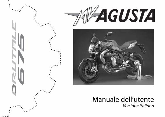
Manuale dell’utenteVersione Italiana
- 2 -
Gentile cliente,
La ringraziamo per la fiducia accordataci e ci congratuliamo con Lei per la Sua nuova Brutale 675.MV Agusta, grazie alla passione e all’impegno dei suoi tecnici, si ripropone agli appassionati con un pro-dotto caratterizzato da una inedita veste estetica accostata ad una raffinata ciclistica: elementi chehanno contraddistinto tutte le creazioni del marchio MV Agusta nell’arco della sua gloriosa storia.Il risultato è una moto esclusiva che, per le sue caratteristiche estetiche e funzionali e le innumerovoliinnovazioni tecniche, si pone al di sopra dei prodotti di più alto profilo che il mercato motociclisticopossa oggi offrire.Le soluzioni adottate conferiscono, infatti, alla Brutale 675 quell’inconfondibile carattere che la lega aglialtri modelli della famiglia MV Agusta, consolidando una filosofia progettuale che privilegia la costantericerca, l’innovazione tecnologica e l’amore per il dettaglio dando la possibilità, a chi vive la propria pas-sione motociclistica in piena libertà, di possedere un oggetto unico al mondo che si pone con prepo-tenza come riferimento di livello mondiale.
Se desiderasse ulteriori informazioni, non esiti a contattare il Servizio Assistenza Clienti MV Agusta.
Buon divertimento!Giovanni Castiglioni PresidenteMV Agusta
- 3 -
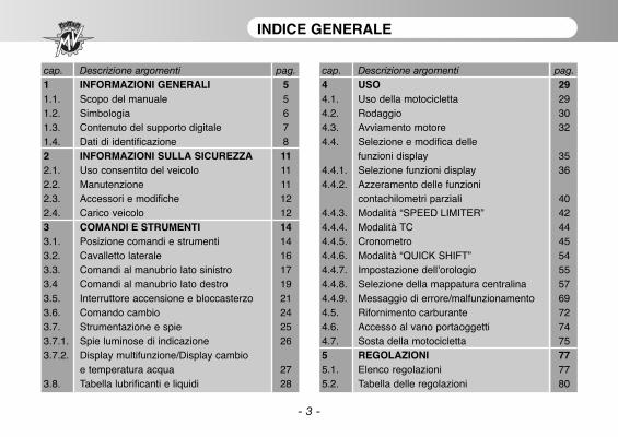
INDICE GENERALE
cap. Descrizione argomenti pag.1 INFORMAZIONI GENERALI 51.1. Scopo del manuale 51.2. Simbologia 61.3. Contenuto del supporto digitale 71.4. Dati di identificazione 82 INFORMAZIONI SULLA SICUREZZA 112.1. Uso consentito del veicolo 112.2. Manutenzione 112.3. Accessori e modifiche 122.4. Carico veicolo 123 COMANDI E STRUMENTI 143.1. Posizione comandi e strumenti 143.2. Cavalletto laterale 163.3. Comandi al manubrio lato sinistro 173.4 Comandi al manubrio lato destro 193.5. Interruttore accensione e bloccasterzo 213.6. Comando cambio 243.7. Strumentazione e spie 253.7.1. Spie luminose di indicazione 263.7.2. Display multifunzione/Display cambio
e temperatura acqua 273.8. Tabella lubrificanti e liquidi 28
cap. Descrizione argomenti pag.4 USO 294.1. Uso della motocicletta 294.2. Rodaggio 304.3. Avviamento motore 324.4. Selezione e modifica delle
funzioni display 354.4.1. Selezione funzioni display 364.4.2. Azzeramento delle funzioni
contachilometri parziali 404.4.3. Modalità “SPEED LIMITER” 424.4.4. Modalità TC 444.4.5. Cronometro 454.4.6. Modalità “QUICK SHIFT” 544.4.7. Impostazione dell’orologio 554.4.8. Selezione della mappatura centralina 574.4.9. Messaggio di errore/malfunzionamento 694.5. Rifornimento carburante 724.6. Accesso al vano portaoggetti 744.7. Sosta della motocicletta 755 REGOLAZIONI 775.1. Elenco regolazioni 775.2. Tabella delle regolazioni 80
- 4 -
INDICE GENERALE
cap. Descrizione argomenti pag.5.3. Regolazione leva freno anteriore 805.4. Regolazione specchietti retrovisori 815.5. Regolazione proiettore anteriore 82
INFORMAZIONI GENERALI 1
1 IT
- 5 -
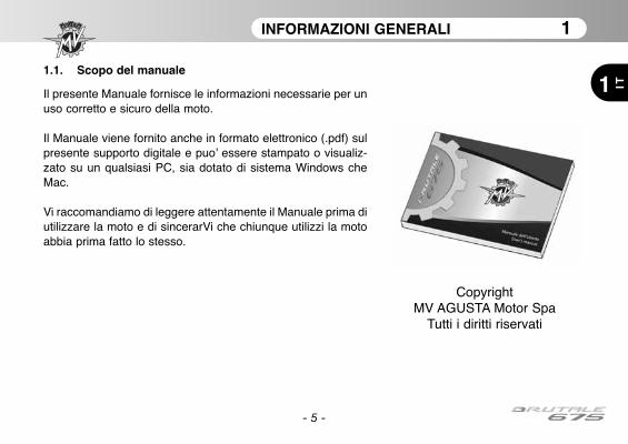
1.1. Scopo del manuale
Il presente Manuale fornisce le informazioni necessarie per unuso corretto e sicuro della moto.
Il Manuale viene fornito anche in formato elettronico (.pdf) sulpresente supporto digitale e puo’ essere stampato o visualiz-zato su un qualsiasi PC, sia dotato di sistema Windows cheMac.
Vi raccomandiamo di leggere attentamente il Manuale prima diutilizzare la moto e di sincerarVi che chiunque utilizzi la motoabbia prima fatto lo stesso.
CopyrightMV AGUSTA Motor Spa
Tutti i diritti riservati
INFORMAZIONI GENERALI 1
1
IT
- 6 -
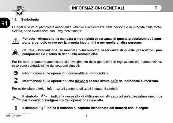
1.2. Simbologia
Le parti di testo di particolare importanza, relative alla sicurezza della persona e all’integrità della moto-cicletta, sono evidenziate con i seguenti simboli:
Pericolo - Attenzione: la mancata o incompleta os servanza di queste prescrizioni può com-portare pe ricolo grave per la propria incolumità e per quella di altre persone.
Cautela - Precauzione: la mancata o incompleta osservanza di queste prescrizioni puòcomportare un rischio di danni alla motocicletta.
Per indicare le persone autorizzate allo svolgimento delle operazioni di regolazione e/o manutenzione,esse sono contraddistinte dai se guenti simboli:
Informazioni sulle operazioni consentite al motociclista.
Informazioni sulle operazioni che devono essere svolte solo dal personale autorizzato.
Per evidenziare ulteriori informazioni vengono utilizzati i seguenti simboli:
Il simbolo indica la necessità di utilizzare un attrezzo od un’attrezzatura specificaper il corretto svolgimento dell’operazione descritta.
§ Il simbolo “ § ” indica il rimando al capitolo identificato dal numero che lo segue.
INFORMAZIONI GENERALI 1
1 IT
- 7 -
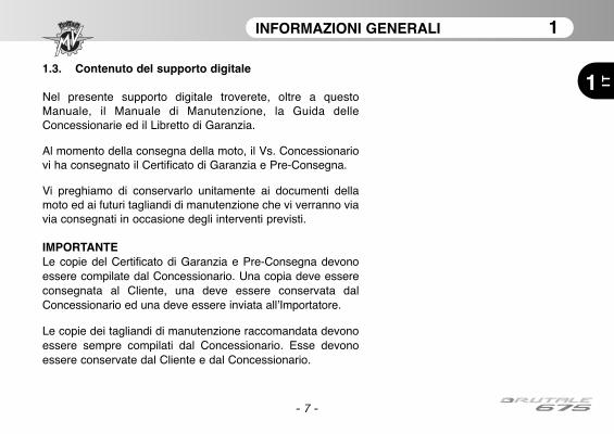
1.3. Contenuto del supporto digitale
Nel presente supporto digitale troverete, oltre a questoManuale, il Manuale di Manutenzione, la Guida delleConcessionarie ed il Libretto di Garanzia.
Al momento della consegna della moto, il Vs. Concessionariovi ha consegnato il Certificato di Garanzia e Pre-Consegna.
Vi preghiamo di conservarlo unitamente ai documenti dellamoto ed ai futuri tagliandi di manutenzione che vi verranno viavia consegnati in occasione degli interventi previsti.
IMPORTANTELe copie del Certificato di Garanzia e Pre-Consegna devonoessere compilate dal Conces sionario. Una copia deve essereconsegnata al Cliente, una deve essere conservata dalConcessionario ed una deve essere inviata all’Importatore.
Le copie dei tagliandi di manutenzione raccomandata devonoessere sempre compilati dal Concessionario. Esse devonoessere conservate dal Cliente e dal Concessionario.
INFORMAZIONI GENERALI 1
1
IT
- 8 -
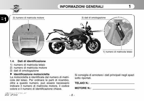
1.4. Dati di identificazione1) numero di matricola telaio2) numero di matricola motore3) dati di omologazione
Identificazione motociclettaLa motocicletta è identificata dal numero di matri-cola del telaio. Per ordinare le parti di ricambio,oltre a que sto numero, può essere necessarioindicare il nu mero di matricola motore, il codicecolore e il numero di identificazione chiave.
Si consiglia di annotare i dati principali negli spazisotto riportati.
TELAIO N.:
MOTORE N.:
2) numero di matricola motore
1) numero di matricola telaio
3) dati di omologazione

INFORMAZIONI GENERALI 1
1 IT
- 9 -
Identificazione combinazione colori motociclettaIl codice colore è indispensabile per ordinare le parti diricambio della carrozzeria. Esso si trova nella parte late-rale destra del serbatoio benzina.
Per accedere alla targhetta codice colore, è necessariorimuovere la sella.
Identificazione chiave della motociclettaViene fornita, in duplice copia, una chiave da utilizzaresia per l’avviamento che per l’azionamento di tutte leserrature. Custodire in luogo sicuro la copia di scorta.
La conoscenza del numero di identificazione chiave èessenziale nel caso in cui si renda necessario richiede-re un duplicato della chiave a ricambio. Si consiglia diannotare tale numero nel seguente spazio:
CHIAVE N.:
INFORMAZIONI GENERALI 1
1
IT
- 10 -
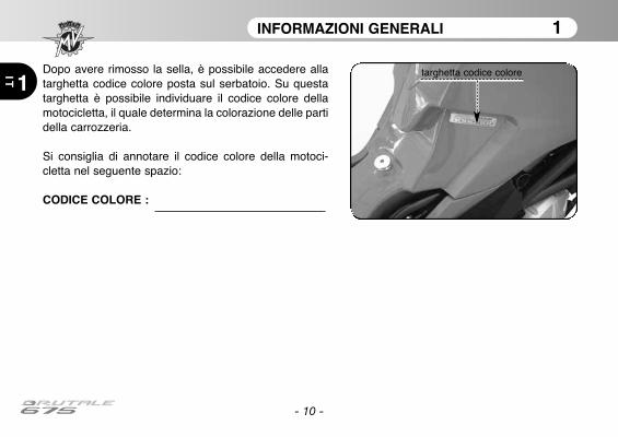
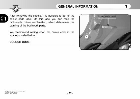
Dopo avere rimosso la sella, è possibile accedere allatarghetta codice colore posta sul serbatoio. Su questatarghetta è possibile individuare il codice colore dellamotocicletta, il quale determina la colorazione delle partidella carrozzeria.
Si consiglia di annotare il codice colore della motoci-cletta nel seguente spazio:
CODICE COLORE :
targhetta codice colore
INFORMAZIONI SULLA SICUREZZA 2
2 IT
- 11 -
2.1. USO CONSENTITO DEL VEICOLO
La Vs. motocicletta e’ stata progettata per un uti-lizzo esclusivamente stradale ed autostradale.
ATTENZIONESaltuariamente e’ possibile utilizzare lamoto in pista in occasioni non competi-tive.In tale caso, tuttavia, a causa delle mag-giori sollecitazioni a cui in tale specificoutilizzo la moto e’ sottoposta, si racco-manda di far verificare da un CentroAssistenza MV Agusta le condizionidella moto prima e dopo l’uso.Ogni altro utilizzo e’ proibito ed espres-samente escluso.
Potete trovare ulteriori informazioni circa l’usodella moto nella sezione 4 del presente Manuale.
2.2. MANUTENZIONE
Per garantire la massima efficienza ed affidabilitàdel veicolo è essenziale eseguire gli interventimanutentivi previsti nel Manuale diManutenzione.MV Agusta raccomanda che tutti gli interventi dimanutenzione siano effettuati solo da personalespecializzato appartenente ad un CentroAssistenza MV Agusta.Laddove, viceversa, decidiate di far eseguire gliinterventi di manutenzione da officine terze, dove-te farVi confermare che le stesse abbiano lacapacita’ e gli strumenti specifici necessari all’e-secuzione di tali interventi.
ATTENZIONELa garanzia MV Agusta potrebbe nonoperare laddove officine terze abbianoeffettuato interventi sulla moto in mododifforme da quanto previsto dalleCircolari Tecniche e nei relativi Manualidi Officina MV Agusta.
INFORMAZIONI SULLA SICUREZZA 2
2
IT
- 12 -
2.3. ACCESSORI E MODIFICHE
ATTENZIONEMV Agusta vieta di apportare qualsiasimodifica alle proprie motociclette.Questo è necessario al fine di salva-guardare la sicurezza dei suoi Clienti.
È tuttavia possibile personalizzare la Vs. motoci-cletta attingendo dal ricco catalogo Accessori MVAgusta.
ATTENZIONEL’installazione di alcuni di questi acces-sori può invalidare l’omologazione dellamoto e, pertanto, comportare la sua nonulteriore utilizzabilità su strada pubblica.
In caso di dubbio Vi consigliamo di consultarVicon il vostro Concessionario MV Agusta di fiduciaper decidere quali accessori siano piu’ adatti alleVs. esigenze.
2.4. CARICO VEICOLO
Il veicolo è progettato per l’impiego da parte delpilota e di un eventuale passeggero.Per un utilizzo in piena sicurezza e nel rispettodelle norme del codice stradale è obbligatorio nonsuperare mai la massa massima tecnicamenteammissibile del veicolo, il cui valore è di seguitoriportato:
BRUTALE 675Massa massima tecnicamente ammissibile
364 kgMassa massima trasportabile
180 kg
La massa massima tecnicamente ammissibilerappresenta la somma delle seguenti masse:
• massa del motociclo;• massa del pilota;• massa del passeggero;• massa del bagaglio e degli accessori.
INFORMAZIONI SULLA SICUREZZA 2
2 IT
- 13 -
ATTENZIONEDato che il carico ha un impatto enormesulla manovrabilità, la frenata, le presta-zioni e le caratteristiche di sicurezza delvostro mezzo, tenere sempre presenti leseguenti precauzioni.
• NON SOVRACCARICARE MAI ILMOTOCICLO! L’uso di un motociclosovraccaricato può provocare danneg-giamenti dei pneumatici, perdite delcontrollo o infortuni gravi. Verificare cheil peso totale del pilota, del passeggero,del carico e degli accessori non superi ilcarico massimo specificato per il moto-ciclo.

COMANDI E STRUMENTI 3
IT 3
- 14 -
3.1. Posizione comandi e strumenti
Strumentazione e spie (§3.7.)
Comandi elettrici semimanubrio sinistro (§3.3.)
Tappo serbatoio carburante (§4.5.)
Interruttore di accensione e bloccasterzo (§3.5.)
Comando acceleratore (§3.4.)Comandi elettrici semimanubrio destro (§3.4.)
Lato Sinistro
Lato Destro
COMANDI E STRUMENTI 3
IT3
- 15 -
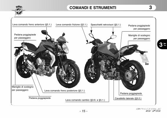
Leva comando frizione (§5.1.)
Leva comando cambio (§3.6. e §5.1.)Cavalletto laterale (§3.2.)
Pedana poggiapiedeper passeggero
Pedana poggiapiedeper passeggero
Maniglie di sostegnoper passeggero
Specchietti retrovisori (§5.1.)Leva comando freno anteriore (§5.1.)
Leva comando freno posteriore (§5.1.)
Pedana poggiapiede
Pedana poggiapiede
Maniglie di sostegnoper passeggero

COMANDI E STRUMENTI 3
3
IT
- 16 -
3.2. Cavalletto laterale
Il cavalletto laterale è dotato di uninterruttore di sicurezza che impedi-sce la partenza con il cavallettoabbassato.Nel caso in cui a motore avviato enella condizione di cavalletto abbas-sato si azioni il cambio per porsi inmovimento, l’interruttore interrompela corrente al motore provocandonel’arresto.Nel caso in cui la moto si trovi invecein condizione di stazionamento(cavalletto abbassato) e con un rap-porto del cambio inserito, l’interrutto-re impedisce l’avviamento del motoreevitando ogni rischio di caduta acci-dentale del veicolo.
Cavalletto laterale
Doppia molla di richiamo
Interruttore di sicurezza
Cavalletto laterale
COMANDI E STRUMENTI 3
3 IT
- 17 -
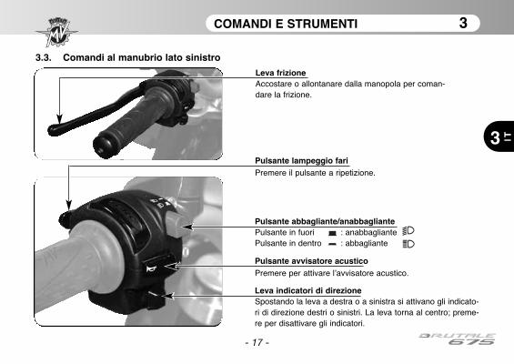
3.3. Comandi al manubrio lato sinistro
Pulsante lampeggio fariPremere il pulsante a ripetizione.
Pulsante abbagliante/anabbagliantePulsante in fuori : anabbagliantePulsante in dentro : abbagliante
Leva indicatori di direzioneSpostando la leva a destra o a sinistra si attivano gli indicato-ri di direzione destri o sinistri. La leva torna al centro; preme-re per disattivare gli indicatori.
Pulsante avvisatore acusticoPremere per attivare l’avvisatore acustico.
Leva frizioneAccostare o allontanare dalla manopola per coman-dare la frizione.
COMANDI E STRUMENTI 3
3
IT
- 18 -
Pulsante Lampeggio FaroQuesta funzione serve a richiamare l’attenzione degli altri utenti della strada in caso di possibili situazioni dipericolo; con l’abbagliante acceso tale funzione non è attiva.
Pulsante Abbagliante/AnabbaglianteNormalmente viene attivata la funzione anabbagliante; quando le condizioni di traffico e di percorso lo consen-tono, può essere attivata la funzione abbagliante agendo sul pulsante.
Leva Indicatori di DirezioneQuesta funzione permette di segnalare agli altri utenti della strada l’intenzione di cambiare direzione o corsiadi marcia.
ATTENZIONEIl mancato uso o la mancata disattivazione degli indicatori di direzione al momento opportunopuò essere causa di incidenti; gli altri utenti della strada potrebbero infatti trarre conclusioni sba-gliate riguardo all’effettivo tragitto del veicolo. Azionare sempre gli indicatori di direzione primadi svoltare o cambiare corsia.Accertarsi poi di disattivare gli indicatori non appena effettuata la suddetta manovra.
Pulsante Avvisatore AcusticoQuesta funzione serve a richiamare l’attenzione degli altri utenti della strada in caso di possibili situazioni dipericolo.
Leva FrizioneQuesta leva, attraverso un dispositivo a controllo idraulico, consente l’innesto ed il disinnesto della frizione.
COMANDI E STRUMENTI 3
3 IT
- 19 -
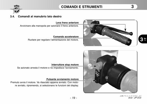
3.4. Comandi al manubrio lato destro
Interruttore stop motoreSe azionato arresta il motore e ne impedisce l’avviamento.
Pulsante avviamento motorePremuto avvia il motore. Va rilasciato appena avviato. Con moto-
re avviato, ripremendo, si selezionano le funzioni del display.
Comando acceleratoreRuotare per regolare l’alimentazione del motore.
Leva freno anterioreAvvicinare alla manopola per azionare il freno anteriore.
COMANDI E STRUMENTI 3
3
IT
- 20 -
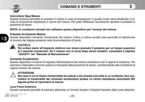
Interruttore Stop MotoreQuesta funzione permette di arrestare il motore in caso di emergenza; in questo modo viene disattivato il cir-cuito di accensione impedendo il riavvio del motore. Per poter effettuare l’avviamento riportare il pulsante inposizione di riposo.
NOTA: In condizioni normali non utilizzare questo dispositivo per l’arresto del motore.
Pulsante Avviamento MotoreQuesto dispositivo consente l’avviamento del motore; inoltre a motore avviato esso permette di selezionarele funzioni del display presente nella strumentazione di bordo.
CAUTELAPer evitare danni all’impianto elettrico non tenere premuto il pulsante per un tempo superioreai 5 secondi consecutivi. Se il motore non si avvia dopo alcuni tentativi, consultare il capitolo“GUASTI” nel “Manuale di Manutenzione”.
Comando AcceleratoreQuesto dispositivo consente di regolare l’alimentazione del motore variandone così il regime di rotazione. Perazionare il dispositivo occorre ruotare la manopola dalla posizione di riposo, corrispondente alla condizione diregime minimo del motore.
ATTENZIONENel caso in cui la Vostra motocicletta sia caduta o sia rimasta coinvolta in un incidente, fare con-trollare la funzionalità del comando acceleratore presso un centro assistenza autorizzato MVAgusta prima di riprendere la marcia.
Leva Freno AnterioreQuesto comando permette di azionare attraverso un circuito idraulico l’impianto frenante della ruota anteriore.
COMANDI E STRUMENTI 3
3 IT
- 21 -
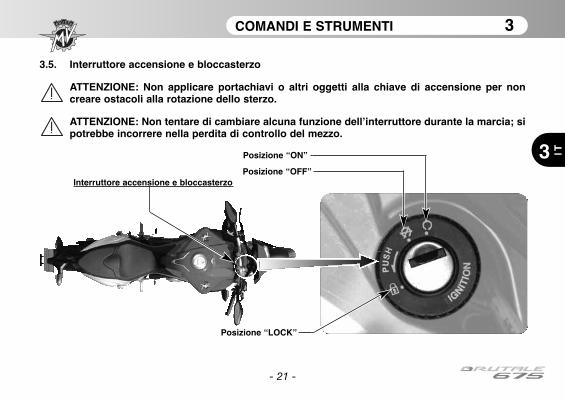
3.5. Interruttore accensione e bloccasterzo
ATTENZIONE: Non applicare portachiavi o altri oggetti alla chiave di accensione per noncreare ostacoli alla rotazione dello sterzo.
ATTENZIONE: Non tentare di cambiare alcuna funzione dell’interruttore durante la marcia; sipotrebbe incorrere nella perdita di controllo del mezzo.
Posizione “ON”
Posizione “OFF”Interruttore accensione e bloccasterzo
Posizione “LOCK”

COMANDI E STRUMENTI 3
3
IT
L’interruttore di accensione attiva e disattiva il circuito elettrico ed il bloccasterzo; le quattro posizioni di co -man do sono di seguito descritte.
Cautela-Precauzione: Non lasciare la chiave sulla posizione “ON” a motore spento per lungotempo, allo scopo di evitare il danneggiamento dei componenti elettrici della motocicletta.
Posizione “OFF”
Tutti i circuiti elettrici sono disattivati. La chiave puòes se re estratta.
Posizione “ON”
Tutti i circuiti elettrici sono attivati, la strumentazio-ne e le spie eseguono l’autodiagnosi; il motore puòessere avviato. La chiave non può essere estratta.
- 22 -

COMANDI E STRUMENTI 3
3 IT
- 23 -
Posizione “LOCK”
Ruotare il manubrio a sinistra. Premere legger-mente la chiave e contemporaneamente ruotarlain posizione “LOCK”.Tutti i circuiti elettrici sono disattivati e lo sterzo èbloccato. La chiave può essere estratta.
Lato Sinistro Lato Destro
COMANDI E STRUMENTI 3
3
IT
- 24 -
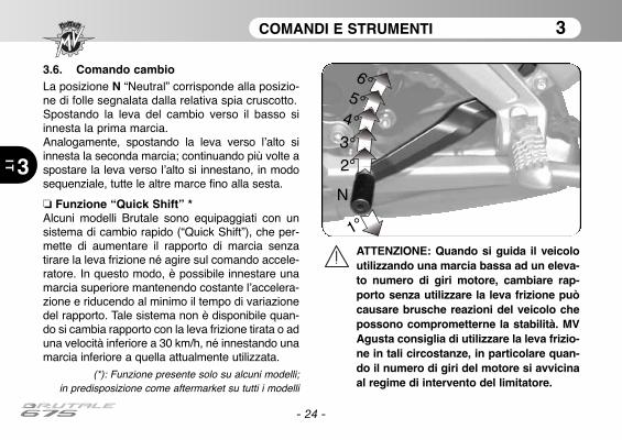
3.6. Comando cambioLa posizione N “Neutral” corrisponde alla posizio-ne di folle segnalata dalla relativa spia cruscotto.Spostando la leva del cambio verso il basso siinnesta la prima marcia.Analogamente, spostando la leva verso l’alto siinnesta la seconda marcia; continuando più volte aspostare la leva verso l’alto si innestano, in modosequenziale, tutte le altre mar ce fino alla sesta.
❏ Funzione “Quick Shift” *Alcuni modelli Brutale sono equipaggiati con unsistema di cambio rapido (“Quick Shift”), che per-mette di aumentare il rapporto di marcia senzatirare la leva frizione né agire sul comando accele-ratore. In questo modo, è possibile innestare unamarcia superiore mantenendo costante l’accelera-zione e riducendo al minimo il tempo di variazionedel rapporto. Tale sistema non è disponibile quan-do si cambia rapporto con la leva frizione tirata o aduna velocità inferiore a 30 km/h, né innestando unamarcia inferiore a quella attualmente utilizzata.
(*): Funzione presente solo su alcuni modelli;in predisposizione come aftermarket su tutti i modelli
1°
N
2°
3°
4°
5°
6°
ATTENZIONE: Quando si guida il veicoloutilizzando una marcia bassa ad un eleva-to numero di giri motore, cambiare rap-porto senza utilizzare la leva frizione puòcausare brusche reazioni del veicolo chepossono comprometterne la stabilità. MVAgusta consiglia di utilizzare la leva frizio-ne in tali circostanze, in particolare quan-do il numero di giri del motore si avvicinaal regime di intervento del limitatore.

COMANDI E STRUMENTI 3
3 IT
- 25 -
3.7. Strumentazione e spie
Gli strumenti e le spie si attivano ruotando la chiave di accensione in posizione“ON”. Dopo un check-up iniziale (~ 7 secondi) le informazioni corrispondonoalle condizioni generali della motocicletta in quel momento.
Spie luminose
di indicazione
(§3.7.1.)
Display multifunzione (§3.7.2.)
Display contagiri
COMANDI E STRUMENTI 3
3
IT
- 26 -
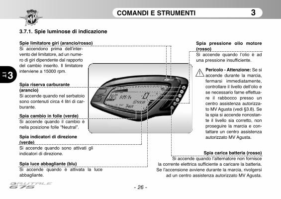
3.7.1. Spie luminose di indicazione
Spia luce abbagliante (blu)Si accende quando è attivata la luceabbagliante.
Spia cambio in folle (verde)Si accende quando il cambio ènella posizione folle “Neutral”.
Spia indicatori di direzione(verde)Si accende quando sono attivati gliindicatori di direzione.
Spia riserva carburante(arancio)Si accende quando nel serbatoiosono contenuti circa 4 litri di car-burante.
Spia carica batteria (rosso)Si accende quando l’alternatore non fornisce
la corrente elettrica sufficiente a caricare la batteria.Se l’accensione avviene durante la marcia, rivolgersi
ad un centro assistenza autorizzato MV Agusta.
Spie limitatore giri (arancio/rosso)Si accendono prima dell’inter-vento del limitatore, ad un nume-ro di giri dipendente dal rapportodel cambio inserito. Il limitatoreinterviene a 15000 rpm.
Spia pressione olio motore(rosso)Si accende quando l’olio è aduna pressione insufficiente.
Pericolo - Attenzione: Se siaccende durante la marcia,fermarsi immediatamente,controllare il livello dell’olio ese necessario farne effettua-re il rabbocco presso uncentro assistenza autorizza-to MV Agusta (vedi §3.8). Sela spia si accende nonostan-te il livello sia corretto, nonproseguire la marcia e con-tattare un centro assistenzaautorizzato MV Agusta.

COMANDI E STRUMENTI 3
3 IT
- 27 -
3.7.2. Display multifunzioneTachimetro
Indica la velocità. Il valore può apparire in chilo-metri orari (Km/h) oppure in miglia orarie (Mph).Il valore a fondo scala è di 300 Km/h (186 Mph).
Contachilometri totale “TOTAL”Indica la percorrenza totale; da 0 a 999999 (Km o mi)Contachilometri parziale 1 “TRIP 1”Indica la percorrenza parziale; da 0 a 999.9 (Km o mi)Contachilometri parziale 2 “TRIP 2”Indica la percorrenza parziale; da 0 a 999.9 (Km o mi)CronometroIndica i tempi misurati con la funzione cronometro
TermometroIndica la temperatura del liquidodi raffreddamento tramite l’accen-sione di un numero variabile disegmenti su una scala di misuragraduata. Quando la temperaturasi trova al di fuori del campo difunzionamento normale, possonoapparire le seguenti indicazioni:- sul display compare un unicosegmento lampeggiante; è ilsegnale di temperatura bassa;- tutti i segmenti sono accesi men-tre il segmento superiore lampeg-gia; è il se gnale di temperatura alta.
Pericolo - Attenzione: in caso di temperatura alta,arrestare la motocicletta e controllare il livello delliquido di raffreddamento. Nel caso in cui fossenecessario rabboccarlo, rivolgersi presso un centroassistenza autorizzato MV Agusta (vedi § 3.8). Sel’indicazione compare nonostante il livello sia cor-retto, non proseguire la marcia e contattare un cen-tro assistenza autorizzato MV Agusta.
Display rapporto cambioIndica il rapporto del cambioattualmente inserito. La posizionedi folle è indicata con la lettera “N”(neutral).
OrologioIndica l’orario attuale.
Display mappatura centralinaIndica il numero della mappaturacentralina attualmente selezionata.
Display livello controllo di trazioneIndica il livello del controllo di trazioneattualmente selezionato.
COMANDI E STRUMENTI 3
3
IT
- 28 -
3.8. Tabella lubrificanti e liquidi
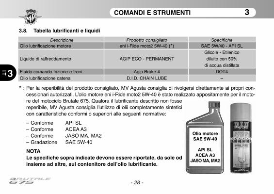
* : Per la reperibilità del prodotto consigliato, MV Agusta consiglia di rivolgersi direttamente ai propri con-cessionari autorizzati. L’olio motore eni i-Ride moto2 5W-40 è stato realizzato appositamente per il moto-re del motociclo Brutale 675. Qualora il lubrificante descritto non fossereperibile, MV Agusta consiglia l’utilizzo di olii completamente sinteticicon caratteristiche conformi o superiori alle seguenti normative:
– Conforme API SL– Conforme ACEA A3– Conforme JASO MA, MA2– Gradazione SAE 5W-40
NOTALe specifiche sopra indicate devono essere riportate, da sole odinsieme ad altre, sul contenitore dell’olio lubrificante.
Olio motoreSAE 5W-40
API SLACEA A3
JASO MA, MA2
Descrizione Prodotto consigliato SpecificheOlio lubrificazione motore eni i-Ride moto2 5W-40 (*) SAE 5W/40 - API SL
Glicole - EtilenicoLiquido di raffreddamento AGIP ECO - PERMANENT diluito con 50%
di acqua distillataFluido comando frizione e freni Agip Brake 4 DOT4Olio lubrificazione catena D.I.D. CHAIN LUBE –
USO 4
4 IT
- 29 -
4.1. Uso della motocicletta
In questa sezione vengono esposti gli argomenti principali per il corretto uso della motocicletta.
ATTENZIONEIl motociclo Brutale 675 presenta elevate caratteristiche di potenza e prestazioni; per il suouso è pertanto richiesto un’adeguato livello di conoscenza del mezzo. Al momento delprimo utilizzo di questo veicolo è necessario adottare un atteggiamento prudente. Unostile di guida aggressivo o avventato può esporre al rischio di incidenti, compromettendola Vostra incolumità e quella di altre persone.
ATTENZIONELE LIMITAZIONI RELATIVE ALL’USO CONSENTITO DEL VEICOLO SONO RIPORTATENELLA SEZIONE “INFORMAZIONI PER LA SICUREZZA”.
USO 4
4
IT
- 30 -
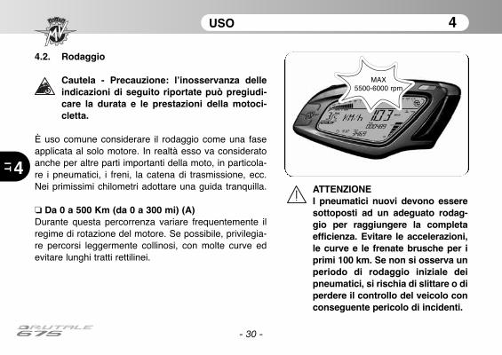
4.2. Rodaggio
Cautela - Precauzione: l’inosservanza delleindicazioni di seguito riportate può pregiudi-care la durata e le prestazioni della motoci-cletta.
È uso comune considerare il rodaggio come una faseapplicata al solo motore. In realtà esso va consideratoanche per altre parti importanti della moto, in particola-re i pneu matici, i freni, la catena di trasmissione, ecc.Nei primissimi chilometri adottare una guida tranquilla.
❏ Da 0 a 500 Km (da 0 a 300 mi) (A)Durante questa percorrenza variare frequentemente ilregime di rotazione del motore. Se possibile, privilegia-re percorsi leggermente collinosi, con molte curve edevitare lunghi tratti rettilinei.
ATTENZIONEI pneumatici nuovi devono esseresottoposti ad un adeguato rodag-gio per raggiungere la completaefficienza. Evitare le accelerazioni,le curve e le frenate brusche per iprimi 100 km. Se non si osserva unperiodo di rodaggio iniziale deipneumatici, si rischia di slittare o diperdere il controllo del veicolo conconseguente pericolo di incidenti.
MAX 5500-6000 rpm

USO 4
4 IT
- 31 -
❏ Da 500 a 1000 Km (da 300 a 600 mi)Durante questa percorrenza evitare di mantenere alungo il motore sotto sforzo.
❏ Da 1000 a 2500 Km (da 600 a 1600 mi)Durante questa percorrenza è possibile pretenderemaggiori prestazioni dal motore, senza tuttavia supera-re il regime di rotazione indicato.
MAX8000-9000 rpm
MAX 11000 rpm

USO 4
4
IT
- 32 -
4.3. Avviamento motore
ATTENZIONE: Far funzionare il motore in unambiente chiuso può essere pericoloso. I gasdi scarico contengono monossido di carbo-nio, un gas incolore ed inodore che può pro-vocare decessi o infortuni gravi. Fare funzio-nare il motore solo all’esterno, all’aria aperta.
Ruotando l’interruttore d’accensione in posizione“ON”, la strumentazione e le spie eseguono l’autodia-gnosi; durante questa fase, accertarsi dell’accensionedi tutte le spie presenti sul cruscotto.
Affinché il sistema di interruzione del circuito diaccensione dia il consenso all’avviamento, deve esserestata soddisfatta una delle seguenti condizioni:– Il cambio è in posizione di folle.– Il cambio è innestato su una marcia con la leva dellafrizione tirata ed il cavalletto laterale alzato.
NOTA: Quando mancano meno di 1000 kmall’esecuzione del prossimo intervento dimanutenzione programmata, sul display com-pare la schermata di avviso raffigurata a lato.
- 33 -
USO 4
4 IT
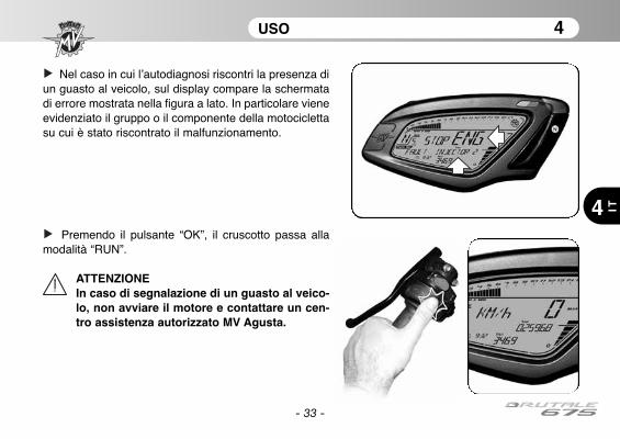
Nel caso in cui l’autodiagnosi riscontri la presenza diun guasto al veicolo, sul display compare la schermatadi errore mostrata nella figura a lato. In particolare vieneevidenziato il gruppo o il componente della motociclettasu cui è stato riscontrato il malfunzionamento.
Premendo il pulsante “OK”, il cruscotto passa allamodalità “RUN”.
ATTENZIONEIn caso di segnalazione di un guasto al veico-lo, non avviare il motore e contattare un cen-tro assistenza autorizzato MV Agusta.
USO 4
4
IT
- 34 -
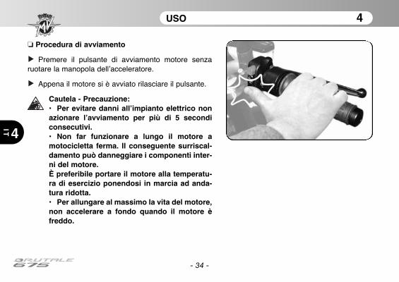
❏ Procedura di avviamento
Premere il pulsante di avviamento motore senzaruotare la manopola dell’acceleratore.
Appena il motore si è avviato rilasciare il pulsante.
Cautela - Precauzione:• Per evitare danni all’impianto elettrico nonazionare l’avviamento per più di 5 secondiconsecutivi.• Non far funzionare a lungo il motore amotocicletta ferma. Il conseguente surriscal-damento può danneggiare i componenti inter-ni del motore.È preferibile portare il motore alla temperatu-ra di esercizio ponendosi in marcia ad anda-tura ridotta.• Per allungare al massimo la vita del motore,non accelerare a fondo quando il motore èfreddo.

USO 4
4 IT
- 35 -
4.4. Selezione e modifica delle funzioni display
La strumentazione prevede la possibilità di interveni-re su alcuni dei parametri principali di misurazione. Le operazioni possibili sono :
- Selezione delle modalità di funzionamento:
“RUN” (Contachilometri)“SPEED LIMITER” (Limitatore velocità)“TC” (Controllo trazione)“CHRONO” (Cronometro)“QUICK SHIFT” (Cambio rapido)*“CLOCK” (Orologio)
- Azzeramento delle funzioni contachilometri parziali:
Contachilometri Parziale 1 “TRIP 1”Contachilometri Parziale 2 “TRIP 2
- Attivazione della funzione cronometro
- Impostazione dell’orologio
- Selezione mappatura centralina
(*): Funzione presente solo su alcuni modelli;in predisposizione come aftermarket su tutti i modelli

USO 4
4
IT
- 36 -
ATTENZIONELe operazioni di modifica o regolazione delle funzio-ni display devono essere eseguite con motore spen-to, cambio in folle, motocicletta ferma e piedi a terra.È vietato cambiare le impostazioni del display duran-te la marcia eccetto dove altrimenti indicato.
4.4.1. Selezione funzioni display
La selezione riguarda le seguentimodalità di funzionamento:
• “RUN” (Contachilometri)• “SPEED LIMITER” (Limitatore
velocità)• “TC” (Controllo trazione)• “CHRONO” (Cronometro)• “QUICK SHIFT” (Cambio rapido)*• “CLOCK” (Orologio)
La visualizzazione delle varie modalitàdi funzionamento avviene premendo ilpulsante “SET” per un tempo inferiore atre secondi. Agendo su tale pulsanteappaiono sul display le funzioni in modociclico. Selezionare la funzione deside-rata.
(*): Funzione presente solo sualcuni modelli; in predisposizione
come aftermarket su tutti i modelli
USO 4
4 IT
- 37 -
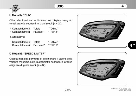
❏ Modalità “RUN”
Oltre alla funzione tachimetro, sul display vengonovisualizzate le seguenti funzioni (vedi §4.4.2.):
• Contachilometri Totale “TOTAL”• Contachilometri Parziale 1 “TRIP 1”
In alternativa:
• Contachilometri Totale “TOTAL”• Contachilometri Parziale 2 “TRIP 2”
❏ Modalità “SPEED LIMITER”
Questa modalità permette di selezionare il valore dellavelocità massima della motocicletta secondo le proprieesigenze di guida (vedi §4.4.3.).

USO 4
4
IT
- 38 -
❏ Modalità “CHRONO”
Questa modalità permette l’attivazione della funzionecronometro e l’immagazzinamento dei dati misurati(vedi §4.4.5.). Le funzioni visualizzate diventano:
• Cronometro Giro attuale “CURRENT LAP”• Cronometro Giro più veloce “BEST LAP”• Cronometro Giro precedente “LAST LAP”• Contagiri Totale giri percorsi “N° LAP”
❏ Modalità “TC”
La presente funzione permette di adattare il livello delcontrollo di trazione del motore secondo le proprie esi-genze di guida (vedi §4.4.4.).
USO 4
4 IT
- 39 -
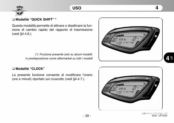
❏ Modalità “CLOCK”
La presente funzione consente di modificare l’orario(ore e minuti) riportato sul cruscotto (vedi §4.4.7.).
❏ Modalità “QUICK SHIFT” *
Questa modalità permette di attivare o disattivare la fun-zione di cambio rapido del rapporto di trasmissione(vedi §4.4.6.).
(*): Funzione presente solo su alcuni modelli;in predisposizione come aftermarket su tutti i modelli
- 40 -
USO 4
4
IT
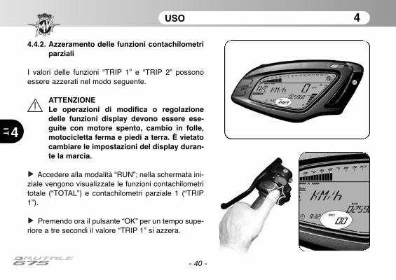
4.4.2. Azzeramento delle funzioni contachilometriparziali
I valori delle funzioni “TRIP 1” e “TRIP 2” possonoessere azzerati nel modo seguente.
ATTENZIONELe operazioni di modifica o regolazionedelle funzioni display devono essere ese-guite con motore spento, cambio in folle,motocicletta ferma e piedi a terra. È vietatocambiare le impostazioni del display duran-te la marcia.
Accedere alla modalità “RUN”; nella schermata ini-ziale vengono visualizzate le funzioni contachilometritotale (“TOTAL”) e contachilometri parziale 1 (“TRIP1”).
Premendo ora il pulsante “OK” per un tempo supe-riore a tre secondi il valore “TRIP 1” si azzera.
- 41 -
USO 4
4 IT
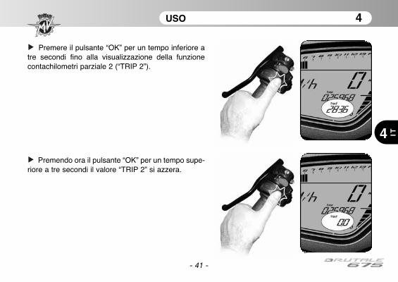
Premere il pulsante “OK” per un tempo inferiore atre secondi fino alla visualizzazione della funzionecontachilometri parziale 2 (“TRIP 2”).
Premendo ora il pulsante “OK” per un tempo supe-riore a tre secondi il valore “TRIP 2” si azzera.
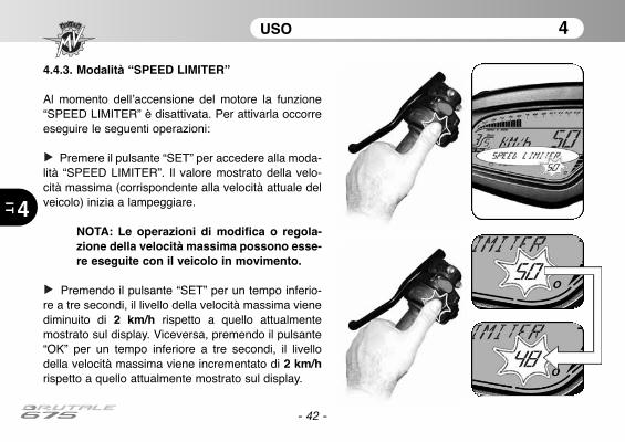
4.4.3. Modalità “SPEED LIMITER”
Al momento dell’accensione del motore la funzione“SPEED LIMITER” è disattivata. Per attivarla occorreeseguire le seguenti operazioni:
Premere il pulsante “SET” per accedere alla moda-lità “SPEED LIMITER”. Il valore mostrato della velo-cità massima (corrispondente alla velocità attuale delveicolo) inizia a lampeggiare.
NOTA: Le operazioni di modifica o regola-zione della velocità massima possono esse-re eseguite con il veicolo in movimento.
Premendo il pulsante “SET” per un tempo inferio-re a tre secondi, il livello della velocità massima vienediminuito di 2 km/h rispetto a quello attualmentemostrato sul display. Viceversa, premendo il pulsante“OK” per un tempo inferiore a tre secondi, il livellodella velocità massima viene incrementato di 2 km/hrispetto a quello attualmente mostrato sul display.
- 42 -
USO 4
4
IT
- 43 -
USO 4
4 IT
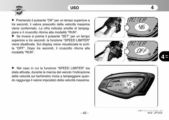
Premendo il pulsante “OK” per un tempo superiore atre secondi, il valore prescelto della velocità massimaviene confermato. La cifra indicata smette di lampeg-giare e il cruscotto ritorna alla modalità “RUN”.
Se invece si preme il pulsante “SET” per un temposuperiore a tre secondi, la funzione “SPEED LIMITER”viene disattivata. Sul display viene visualizzata la scrit-ta “OFF”. Dopo tre secondi, il cruscotto ritorna allamodalità “RUN”.
Nel caso in cui la funzione “SPEED LIMITER” siastata attivata, durante la marcia del veicolo l’indicazionedella velocità sul tachimetro inizia a lampeggiare quan-do raggiunge il valore impostato della velocità massima.
- 44 -
USO 4
4
IT
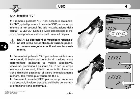
4.4.4. Modalità “TC”
Premere il pulsante “SET” per accedere alla moda-lità “TC”, quindi premere il pulsante “OK” per un tempoinferiore ai tre secondi fino alla visualizzazione dellascritta “TC LEVEL”. L’attuale livello del controllo di tra-zione corrisponde al valore visualizzato sul display.
NOTA: Le operazioni di modifica o regolazio-ne del livello del controllo di trazione posso-no essere eseguite con il veicolo in movi-mento.
Premendo il pulsante “OK” per un tempo inferiore atre secondi, il livello del controllo di trazione vieneincrementato passando al valore successivo.Viceversa, premendo il pulsante “SET” per un tempoinferiore a tre secondi, il livello del controllo di trazioneviene diminuito passando al valore immediatamenteinferiore. Tale valore può variare tra 0 e 8.
Premere il pulsante “SET” per un tempo superiorea tre secondi; il valore prescelto del livello del control-lo di trazione viene confermato.
- 45 -
USO 4
4 IT
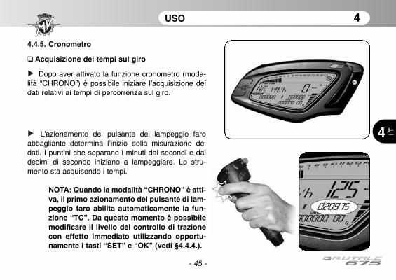
4.4.5. Cronometro
❏ Acquisizione dei tempi sul giro
Dopo aver attivato la funzione cronometro (moda-lità “CHRONO”) è possibile iniziare l’acquisizione deidati relativi ai tempi di percorrenza sul giro.
L’azionamento del pulsante del lampeggio faroabbagliante determina l’inizio della misurazione deidati. I puntini che separano i minuti dai secondi e daidecimi di secondo iniziano a lampeggiare. Lo stru-mento sta acquisendo i tempi.
NOTA: Quando la modalità “CHRONO” è atti-va, il primo azionamento del pulsante di lam-peggio faro abilita automaticamente la fun-zione “TC”. Da questo momento è possibilemodificare il livello del controllo di trazionecon effetto immediato utilizzando opportu-namente i tasti “SET” e “OK” (vedi §4.4.4.).
USO 4
4
IT
- 46 -
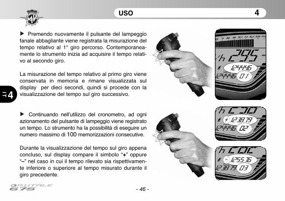
Premendo nuovamente il pulsante del lampeggiofanale abbagliante viene registrata la misurazione deltempo relativo al 1° giro percorso. Contemporanea-mente lo strumento inizia ad acquisire il tempo relati-vo al secondo giro.
La misurazione del tempo relativo al primo giro vieneconservata in memoria e rimane visualizzata suldisplay per dieci secondi, quindi si procede con lavisualizzazione del tempo sul giro successivo.
Continuando nell’utilizzo del cronometro, ad ogniazionamento del pulsante di lampeggio viene registratoun tempo. Lo strumento ha la possibilità di eseguire unnumero massimo di 100 memorizzazioni consecutive.
Durante la visualizzazione del tempo sul giro appenaconcluso, sul display compare il simbolo “+” oppure“–” nel caso in cui il tempo rilevato sia rispettivamen-te inferiore o superiore al tempo misurato durante ilgiro precedente.
USO 4
4 IT
- 47 -
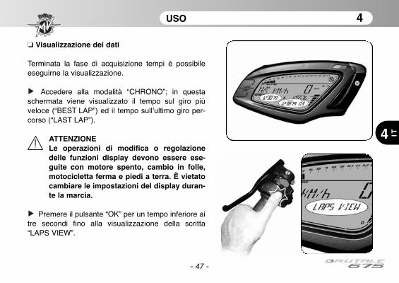
❏ Visualizzazione dei dati
Terminata la fase di acquisizione tempi è possibileeseguirne la visualizzazione.
Accedere alla modalità “CHRONO”; in questaschermata viene visualizzato il tempo sul giro piùveloce (“BEST LAP”) ed il tempo sull’ultimo giro per-corso (“LAST LAP”).
ATTENZIONELe operazioni di modifica o regolazionedelle funzioni display devono essere ese-guite con motore spento, cambio in folle,motocicletta ferma e piedi a terra. È vietatocambiare le impostazioni del display duran-te la marcia.
Premere il pulsante “OK” per un tempo inferiore aitre secondi fino alla visualizzazione della scritta“LAPS VIEW”.

USO 4
4
IT
- 48 -
La ripetuta pressione del pulsante del lampeggiofanale abbagliante consente di visualizzare insequenza tutti i tempi precedentemente acquisiti apartire dall’ultimo giro memorizzato.
Al termine della visualizzazione dei dati, la pres-sione del pulsante “SET” consente di tornare allamodalità “LAPS VIEW” per passare alla modalità suc-cessiva.
USO 4
4 IT
- 49 -
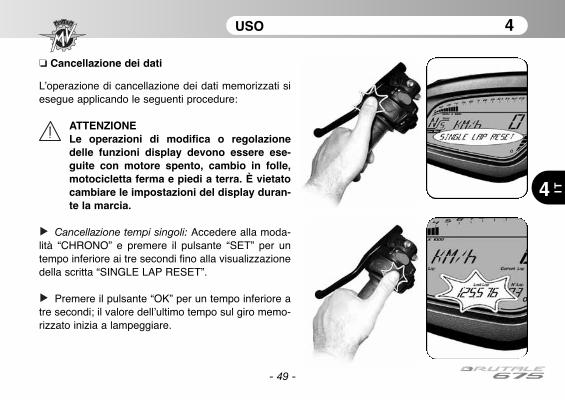
❏ Cancellazione dei dati
L’operazione di cancellazione dei dati memorizzati siesegue applicando le seguenti procedure:
ATTENZIONELe operazioni di modifica o regolazionedelle funzioni display devono essere ese-guite con motore spento, cambio in folle,motocicletta ferma e piedi a terra. È vietatocambiare le impostazioni del display duran-te la marcia.
Cancellazione tempi singoli: Accedere alla moda-lità “CHRONO” e premere il pulsante “SET” per untempo inferiore ai tre secondi fino alla visualizzazionedella scritta “SINGLE LAP RESET”.
Premere il pulsante “OK” per un tempo inferiore atre secondi; il valore dell’ultimo tempo sul giro memo-rizzato inizia a lampeggiare.
- 50 -
USO 4
4
IT
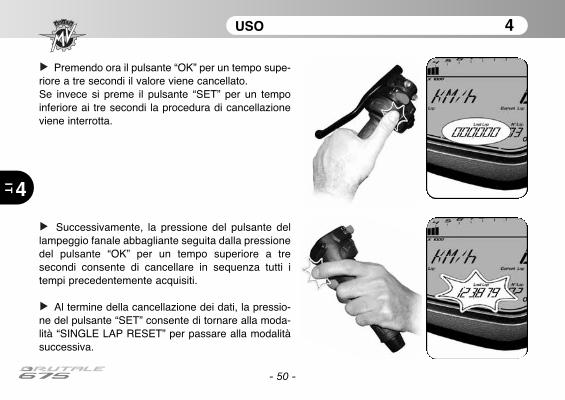
Premendo ora il pulsante “OK” per un tempo supe-riore a tre secondi il valore viene cancellato.Se invece si preme il pulsante “SET” per un tempoinferiore ai tre secondi la procedura di cancellazioneviene interrotta.
Successivamente, la pressione del pulsante dellampeggio fanale abbagliante seguita dalla pressionedel pulsante “OK” per un tempo superiore a tresecondi consente di cancellare in sequenza tutti itempi precedentemente acquisiti.
Al termine della cancellazione dei dati, la pressio-ne del pulsante “SET” consente di tornare alla moda-lità “SINGLE LAP RESET” per passare alla modalitàsuccessiva.

- 51 -
USO 4
4 IT
Cancellazione miglior tempo: Accedere alla moda-lità “CHRONO” e premere il pulsante “SET” per untempo inferiore ai tre secondi fino alla visualizzazionedella scritta “BEST LAP RESET”.
Premere il pulsante “OK” per un tempo inferiore atre secondi; il valore del tempo sul giro più veloce ini-zia a lampeggiare.
- 52 -
USO 4
4
IT
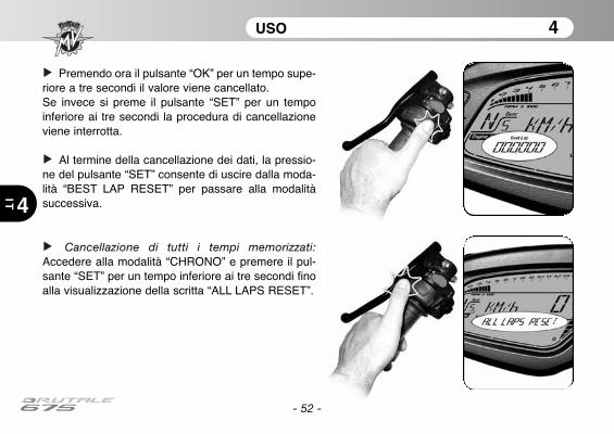
Premendo ora il pulsante “OK” per un tempo supe-riore a tre secondi il valore viene cancellato.Se invece si preme il pulsante “SET” per un tempoinferiore ai tre secondi la procedura di cancellazioneviene interrotta.
Al termine della cancellazione dei dati, la pressio-ne del pulsante “SET” consente di uscire dalla moda-lità “BEST LAP RESET” per passare alla modalitàsuccessiva.
Cancellazione di tutti i tempi memorizzati:Accedere alla modalità “CHRONO” e premere il pul-sante “SET” per un tempo inferiore ai tre secondi finoalla visualizzazione della scritta “ALL LAPS RESET”.
- 53 -
USO 4
4 IT
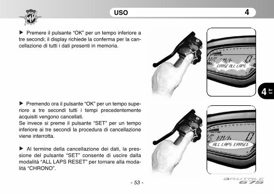
Premere il pulsante “OK” per un tempo inferiore atre secondi; il display richiede la conferma per la can-cellazione di tutti i dati presenti in memoria.
Premendo ora il pulsante “OK” per un tempo supe-riore a tre secondi tutti i tempi precedentementeacquisiti vengono cancellati.Se invece si preme il pulsante “SET” per un tempoinferiore ai tre secondi la procedura di cancellazioneviene interrotta.
Al termine della cancellazione dei dati, la pres-sione del pulsante “SET” consente di uscire dallamodalità “ALL LAPS RESET” per tornare alla moda-lità “CHRONO”.
- 54 -
USO 4
4
IT
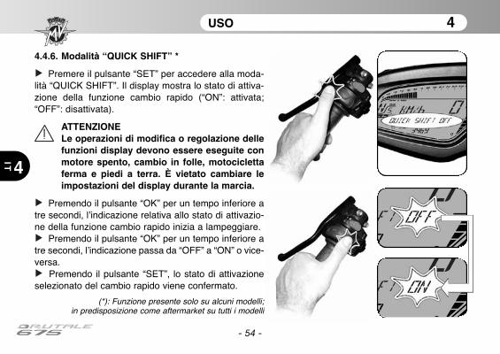
4.4.6. Modalità “QUICK SHIFT” *
Premere il pulsante “SET” per accedere alla moda-lità “QUICK SHIFT”. Il display mostra lo stato di attiva-zione della funzione cambio rapido (“ON”: attivata;“OFF”: disattivata).
ATTENZIONELe operazioni di modifica o regolazione dellefunzioni display devono essere eseguite conmotore spento, cambio in folle, motociclettaferma e piedi a terra. È vietato cambiare leimpostazioni del display durante la marcia.
Premendo il pulsante “OK” per un tempo inferiore atre secondi, l’indicazione relativa allo stato di attivazio-ne della funzione cambio rapido inizia a lampeggiare.
Premendo il pulsante “OK” per un tempo inferiore atre secondi, l’indicazione passa da “OFF” a “ON” o vice-versa.
Premendo il pulsante “SET”, lo stato di attivazioneselezionato del cambio rapido viene confermato.
(*): Funzione presente solo su alcuni modelli;in predisposizione come aftermarket su tutti i modelli
- 55 -
USO 4
4 IT
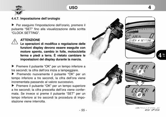
4.4.7. Impostazione dell’orologio
Per eseguire l’impostazione dell’orario, premere ilpulsante “SET” fino alla visualizzazione della scritta“CLOCK SETTING”.
ATTENZIONELe operazioni di modifica o regolazione dellefunzioni display devono essere eseguite conmotore spento, cambio in folle, motociclettaferma e piedi a terra. È vietato cambiare leimpostazioni del display durante la marcia.
Premere il pulsante “OK” per un tempo inferiore atre secondi; la cifra dell’ora inizia a lampeggiare.
Premendo nuovamente il pulsante “OK” per untempo inferiore a tre secondi, la cifra dell’ora vieneincrementata passando al valore successivo.
Premere il pulsante “OK” per un tempo superiorea tre secondi; la cifra prescelta dell’ora viene confer-mata. Se invece si preme il pulsante “SET” per untempo inferiore ai tre secondi la procedura di impo-stazione viene interrotta.
- 56 -
USO 4
4
IT
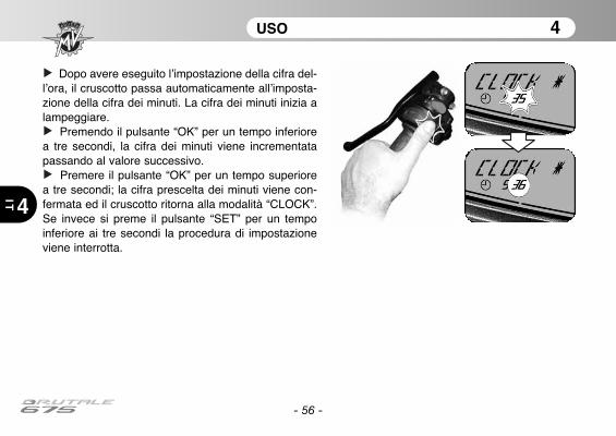
Dopo avere eseguito l’impostazione della cifra del-l’ora, il cruscotto passa automaticamente all’imposta-zione della cifra dei minuti. La cifra dei minuti inizia alampeggiare.
Premendo il pulsante “OK” per un tempo inferiorea tre secondi, la cifra dei minuti viene incrementatapassando al valore successivo.
Premere il pulsante “OK” per un tempo superiorea tre secondi; la cifra prescelta dei minuti viene con-fermata ed il cruscotto ritorna alla modalità “CLOCK”.Se invece si preme il pulsante “SET” per un tempoinferiore ai tre secondi la procedura di impostazioneviene interrotta.

- 57 -
USO 4
4 IT
4.4.8. Selezione della mappatura centralina
Sul modello Brutale 675, è possibile selezionare diffe-renti mappature della centralina che permettono di otte-nere caratteristiche variabili di potenza e prestazioni aseconda del tipo di utilizzo del veicolo.
NOTALe operazioni di selezione della mappaturacentralina possono essere eseguite con il vei-colo in movimento.
La selezione della mappatura centralina può essere effet-tuata premendo il pulsante di avviamento a motore acce-so. In questo modo la mappatura passa al valore suc-cessivo. Le relative caratteristiche della mappatura sonoelencate nella seguente tabella.
Mappatura
Modalità
N
Normale
R
Pioggia
S
Sportiva
C
Persona-lizzata
- 58 -
USO 4
4
IT
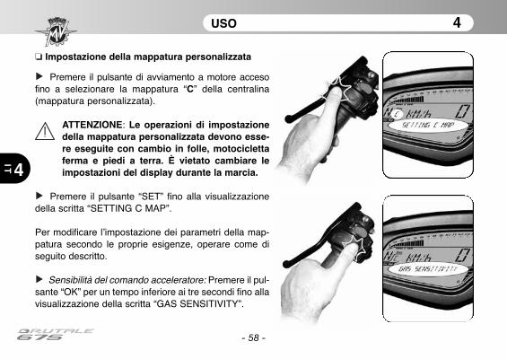
❏ Impostazione della mappatura personalizzata
Premere il pulsante di avviamento a motore accesofino a selezionare la mappatura “C” della centralina(mappatura personalizzata).
ATTENZIONE: Le operazioni di impostazionedella mappatura personalizzata devono esse-re eseguite con cambio in folle, motociclettaferma e piedi a terra. È vietato cambiare leimpostazioni del display durante la marcia.
Premere il pulsante “SET” fino alla visualizzazionedella scritta “SETTING C MAP”.
Per modificare l’impostazione dei parametri della map-patura secondo le proprie esigenze, operare come diseguito descritto.
Sensibilità del comando acceleratore: Premere il pul-sante “OK” per un tempo inferiore ai tre secondi fino allavisualizzazione della scritta “GAS SENSITIVITY”.

- 59 -
USO 4
4 IT
Premere il pulsante “SET” per un tempo inferiore aitre secondi. Sul display compare l’attuale impostazioneselezionata per la sensibilità del comando accelerato-re.
Premere il pulsante “OK” per un tempo inferiore aitre secondi; l’indicazione sul display inizia a lampeggia-re.
La ripetuta pressione del pulsante “OK” per untempo inferiore ai tre secondi permette di visualizzare insequenza le seguenti impostazioni:
• “NORMAL” (Normale)• “RAIN” (Pioggia)• “SPORT” (Sportiva)

- 60 -
USO 4
4
IT
Premere il pulsante “OK” per un tempo superiore aitre secondi; la nuova impostazione selezionata vieneconfermata. L’indicazione sul display smette di lampeg-giare e dopo alcuni secondi ritorna al menu “GAS SEN-SITIVITY”. É ora possibile passare alla regolazione delparametro successivo.
Coppia massima del motore: Premere il pulsante“OK” per un tempo inferiore ai tre secondi fino allavisualizzazione della scritta “MAX ENGINE TORQUE”.

- 61 -
USO 4
4 IT
Premere il pulsante “SET” per un tempo inferiore aitre secondi. Sul display compare l’attuale impostazioneselezionata per la coppia massima del motore.
Premere il pulsante “OK” per un tempo inferiore aitre secondi; l’indicazione sul display inizia a lampeggia-re.
La ripetuta pressione del pulsante “OK” per untempo inferiore ai tre secondi permette di visualizzare insequenza le seguenti impostazioni:
• “RAIN” (Pioggia)• “SPORT” (Sportiva)

- 62 -
USO 4
4
IT
Premere il pulsante “OK” per un tempo superiore aitre secondi; la nuova impostazione selezionata vieneconfermata. L’indicazione sul display smette di lampeg-giare e dopo alcuni secondi ritorna al menu “MAXENGINE TORQUE”.
Freno motore: Premere il pulsante “OK” per untempo inferiore ai tre secondi fino alla visualizzazionedella scritta “ENGINE BRAKE”.

- 63 -
USO 4
4 IT
Premere il pulsante “SET” per un tempo inferiore aitre secondi. Sul display compare l’attuale impostazioneselezionata per il freno motore.
Premere il pulsante “OK” per un tempo inferiore ai tresecondi; l’indicazione sul display inizia a lampeggiare.
La ripetuta pressione del pulsante “OK” per untempo inferiore ai tre secondi permette di visualizzare insequenza le seguenti impostazioni:
• “NORMAL” (Normale)• “SPORT” (Sportiva)

- 64 -
USO 4
4
IT
Premere il pulsante “OK” per un tempo superiore aitre secondi; la nuova impostazione selezionata vieneconfermata. L’indicazione sul display smette di lampeg-giare e dopo alcuni secondi ritorna al menu “ENGINEBRAKE”.
Erogazione del motore: Premere il pulsante “OK” perun tempo inferiore ai tre secondi fino alla visualizzazio-ne della scritta “ENGINE RESPONSE”.

- 65 -
USO 4
4 IT
Premere il pulsante “SET” per un tempo inferiore aitre secondi. Sul display compare l’attuale impostazioneselezionata per l’erogazione del motore.
Premere il pulsante “OK” per un tempo inferiore aitre secondi; l’indicazione sul display inizia a lampeggia-re.
La ripetuta pressione del pulsante “OK” per untempo inferiore ai tre secondi permette di visualizzare insequenza le seguenti impostazioni:
• “SLOW RESPONSE” (Erogazione lenta)• “FAST RESPONSE” (Erogazione rapida)
- 66 -
USO 4
4
IT
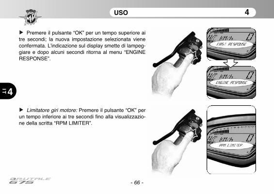
Premere il pulsante “OK” per un tempo superiore aitre secondi; la nuova impostazione selezionata vieneconfermata. L’indicazione sul display smette di lampeg-giare e dopo alcuni secondi ritorna al menu “ENGINERESPONSE”.
Limitatore giri motore: Premere il pulsante “OK” perun tempo inferiore ai tre secondi fino alla visualizzazio-ne della scritta “RPM LIMITER”.

- 67 -
USO 4
4 IT
Premere il pulsante “SET” per un tempo inferiore aitre secondi. Sul display compare l’attuale impostazioneselezionata per il limitatore giri motore.
Premere il pulsante “OK” per un tempo inferiore aitre secondi; l’indicazione sul display inizia a lampeggia-re.
La ripetuta pressione del pulsante “OK” per untempo inferiore ai tre secondi permette di visualizzare insequenza le seguenti impostazioni:
• “NORMAL” (Normale)• “SPORT” (Sportiva)
- 68 -
USO 4
4
IT
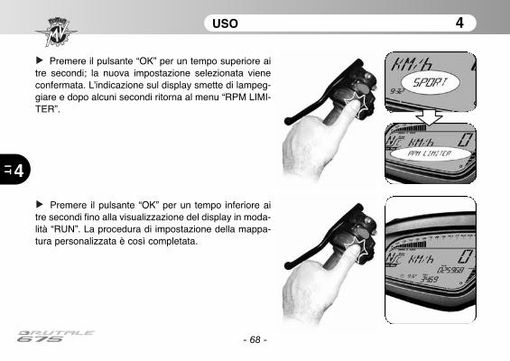
Premere il pulsante “OK” per un tempo superiore aitre secondi; la nuova impostazione selezionata vieneconfermata. L’indicazione sul display smette di lampeg-giare e dopo alcuni secondi ritorna al menu “RPM LIMI-TER”.
Premere il pulsante “OK” per un tempo inferiore aitre secondi fino alla visualizzazione del display in moda-lità “RUN”. La procedura di impostazione della mappa-tura personalizzata è così completata.
- 69 -
USO 4
4 IT
4.4.9. Messaggi di errore / malfunzionamento
Il cruscotto può segnalare la presenza di un guasto odi un malfunzionamento durante le diverse condizionidi utilizzo della motocicletta.
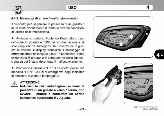
Avviamento motore: Ruotando l’interruttore d’ac-censione in posizione “ON”, la strumentazione e lespie eseguono l’autodiagnosi. In presenza di un gua-sto al veicolo, il display visualizza il messaggio dierrore mostrato nella figura a lato; in particolare, vieneevidenziato il gruppo o il componente della motoci-cletta su cui è stato riscontrato il malfunzionamento.
Premendo il pulsante “OK”, il cruscotto passa allamodalità “RUN”. Le luci di emergenza degli indicatoridi direzione iniziano a lampeggiare.
ATTENZIONENel caso in cui l’autodiagnosi evidenzi lapresenza di un guasto a veicolo fermo, nonavviare il motore e contattare un centroassistenza autorizzato MV Agusta.
- 70 -
USO 4
4
IT
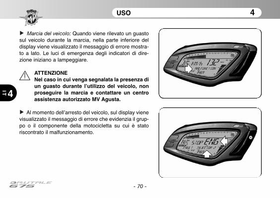
Marcia del veicolo: Quando viene rilevato un guastosul veicolo durante la marcia, nella parte inferiore deldisplay viene visualizzato il messaggio di errore mostra-to a lato. Le luci di emergenza degli indicatori di dire-zione iniziano a lampeggiare.
ATTENZIONENel caso in cui venga segnalata la presenza diun guasto durante l’utilizzo del veicolo, nonproseguire la marcia e contattare un centroassistenza autorizzato MV Agusta.
Al momento dell’arresto del veicolo, sul display vienevisualizzato il messaggio di errore che evidenzia il grup-po o il componente della motocicletta su cui è statoriscontrato il malfunzionamento.
- 71 -
USO 4
4 IT
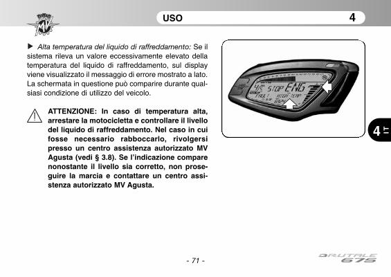
Alta temperatura del liquido di raffreddamento: Se ilsistema rileva un valore eccessivamente elevato dellatemperatura del liquido di raffreddamento, sul displayviene visualizzato il messaggio di errore mostrato a lato.La schermata in questione può comparire durante qual-siasi condizione di utilizzo del veicolo.
ATTENZIONE: In caso di temperatura alta,arrestare la motocicletta e controllare il livellodel liquido di raffreddamento. Nel caso in cuifosse necessario rabboccarlo, rivolgersipresso un centro assistenza autorizzato MVAgusta (vedi § 3.8). Se l’indicazione comparenonostante il livello sia corretto, non prose-guire la marcia e contattare un centro assi-stenza autorizzato MV Agusta.
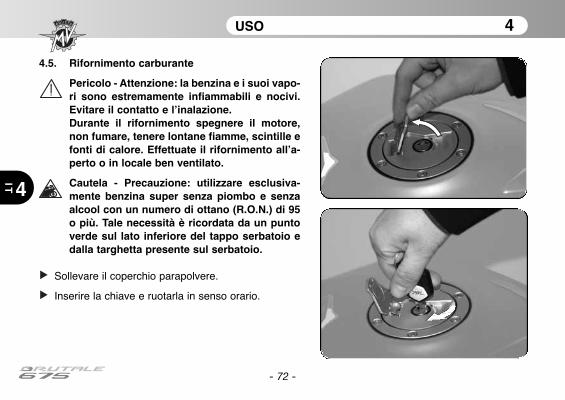
4.5. Rifornimento carburante
Pericolo - Attenzione: la benzina e i suoi vapo-ri sono estremamente infiammabili e nocivi.Evitare il contatto e l’inalazione.Durante il rifornimento spegnere il motore,non fumare, tenere lontane fiamme, scintille efonti di calore. Effettuate il rifornimento all’a-perto o in locale ben ventilato.
Cautela - Precauzione: utilizzare esclusiva-mente benzina super senza piombo e senzaalcool con un numero di ottano (R.O.N.) di 95o più. Tale necessità è ricordata da un puntoverde sul lato inferiore del tappo serbatoio edalla targhetta presente sul serbatoio.
Sollevare il coperchio parapolvere.
Inserire la chiave e ruotarla in senso orario.
- 72 -
USO 4
4
IT
- 73 -
USO 4
4 IT
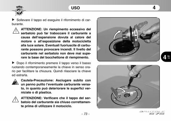
Sollevare il tappo ed eseguire il rifornimento di car-burante.
ATTENZIONE: Un riempimento eccessivo delserbatoio può far traboccare il carburante acausa dell’espansione dovuta al calore delmotore o all’esposizione della motociclettaalla luce solare. Eventuali fuoriuscite di carbu-rante possono provocare incendi. Il livello delcarburante nel serbatoio non deve mai supe-rare la base del bocchettone di riempimento.
Dopo il rifornimento premere il tappo verso il bassoruotando contemporaneamente la chiave in senso ora-rio per facilitare la chiusura. Quindi rilasciare la chiaveed estrarla.
Cautela-Precauzione: Asciugare subito conun panno pulito l’eventuale carburante versa-to, in quanto può deteriorare le superfici ver-niciate o di plastica.
ATTENZIONE: Verificare che il tappo del ser-batoio del carburante sia chiuso correttamen-te prima di utilizzare il motociclo.

USO 4
4
IT
- 74 -
4.6. Accesso al vano portaoggetti
Inserire la chiave nella serratura.
Ruotare la chiave in senso antiorario e con-temporaneamente premere leggermente sullasella. Sollevare la sella e rimuoverla comemostrato in figura.
Per il rimontaggio del particolare osservare leseguenti indicazioni :
• Ruotare la chiave nella serratura• Premere la sella • Rilasciare la chiave• Premere nuovamente la sella assicurandosi di
averla saldamente agganciata alla struttura.
ATTENZIONEDopo aver rimosso e rimontato la sella, ecomunque prima di ogni utilizzo dellamoto, assicurarsi che il componente siastato posizionato correttamente e cherisulti ben ancorato alla struttura portantedel veicolo.
USO 4
4 IT
- 75 -
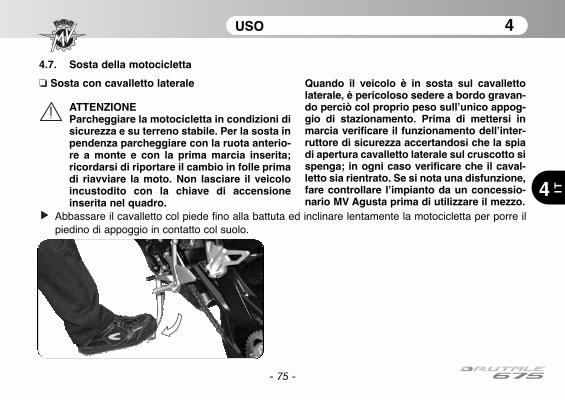
4.7. Sosta della motocicletta
❏ Sosta con cavalletto laterale
ATTENZIONEParcheggiare la motocicletta in condizioni disicurezza e su terreno stabile. Per la sosta inpendenza parcheggiare con la ruota anterio-re a monte e con la prima marcia inserita;ricordarsi di riportare il cambio in folle primadi riavviare la moto. Non lasciare il veicoloincustodito con la chiave di accensioneinserita nel quadro.
Quando il veicolo è in sosta sul cavallettolaterale, è pericoloso sedere a bordo gravan-do perciò col proprio peso sull’unico appog-gio di stazionamento. Prima di mettersi inmarcia verificare il funzionamento dell’inter-ruttore di sicurezza accertandosi che la spiadi apertura cavalletto laterale sul cruscotto sispenga; in ogni caso verificare che il caval-letto sia rientrato. Se si nota una disfunzione,fare controllare l’impianto da un concessio-nario MV Agusta prima di utilizzare il mezzo.
Abbassare il cavalletto col piede fino alla battuta ed inclinare lentamente la motocicletta per porre ilpiedino di appoggio in contatto col suolo.
USO 4
4
IT
- 76 -
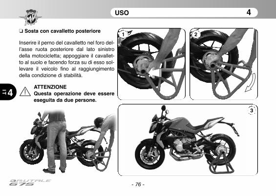
❏ Sosta con cavalletto posteriore
Inserire il perno del cavalletto nel foro del-l’asse ruota posteriore dal lato sinistrodella motocicletta; appoggiare il cavallet-to al suolo e facendo forza su di esso sol-levare il veicolo fino al raggiungimentodella condizione di stabilità.
ATTENZIONEQuesta operazione deve essereeseguita da due persone.
1 2
3

REGOLAZIONI 5
5 IT
- 77 -
5.1. Elenco regolazioni
La motocicletta possiede un’ampia possibilità di rego-lazioni che possono migliorare l’ergonomia, l’assettoe la sicurezza.
Tuttavia, poiche’ una errata regolazione di componen-ti particolarmente importanti puo’ creare una situazio-ne di pericolo, alcune di queste regolazioni sono riser-vate soltanto ai Centri Assistenza MV Agusta.
ATTENZIONETutte le regolazioni devono essere effettua-te a veicolo fermo.
REGOLAZIONI 5
5
IT
- 78 -
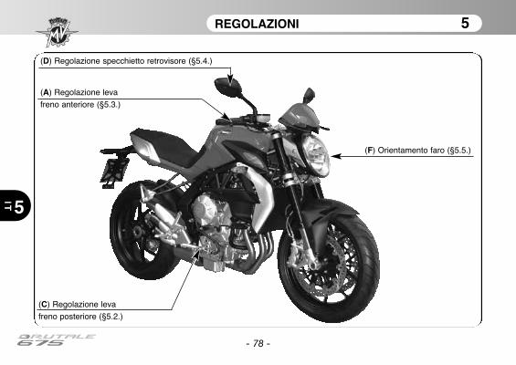
(F) Orientamento faro (§5.5.)
(D) Regolazione specchietto retrovisore (§5.4.)
(A) Regolazione leva
freno anteriore (§5.3.)
(C) Regolazione leva
freno posteriore (§5.2.)

5 IT
REGOLAZIONI 5
- 79 -
(E) Regolazione catena (§5.2.)
(B) Regolazione
leva cambio (§5.2.)
(D) Regolazione specchietto retrovisore (§5.4.)
REGOLAZIONI 5
5
IT
- 80 -
5.2. Tabella delle regolazioni
A - Regolazione leva freno anteriore: per otti-mizzare la presa in funzione delle esigenze delmotociclista (§5.3).
B - Regolazione leva cambio: per ottimizzare ilmovimento del comando in funzione delle esi-genze del motociclista.
C - Regolazione leva freno posteriore: per otti-mizzare il movimento del comando in funzionedelle esigenze del motociclista.
D - Regolazione specchietti retrovisori: perottimizzare l’orientamento (§5.4).
ATTENZIONE: Non intervenire sulla vitedi fissaggio dello specchietto retrovisoreal manubrio. In caso di necessità, rivol-gersi ad un concessionario MV Agusta
E - Regolazione catena: per l’efficienza e lasicurezza della trasmissione.
F - Orientamento faro: per regolare la profonditàdel fascio luminoso in funzione dell’assetto (§5.5).
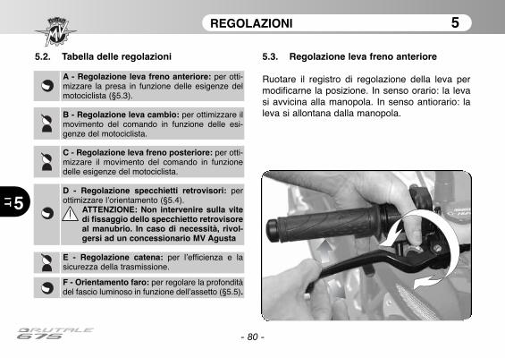
5.3. Regolazione leva freno anteriore
Ruotare il registro di regolazione della leva permodificarne la posizione. In senso orario: la levasi avvicina alla manopola. In senso antiorario: laleva si allontana dalla manopola.

REGOLAZIONI 5
5 IT
- 81 -
5.4. Regolazione specchietti retrovisori
Premere delicatamente nei punti evidenziati per regola-re la posizione nelle quattro direzioni.
Eseguire la regolazione su entrambi gli specchiettiretrovisori. Per rendere ottimale la messa a punto siconsiglia di eseguire la regolazione salendo sul veicolo.

REGOLAZIONI 5
5
IT
- 82 -
5.5. Regolazione proiettore anteriorePorre il veicolo a 10 metri di distanza da una parete verticale.Assicurarsi che il terreno sia piano e che l’asse ottico del proiettore sia perpendicolare alla parete.Il veicolo deve trovarsi in posizione verticale. Misurare l’altezza del centro del proiettore da terra e ripor-tare sulla parete una crocetta alla medesima altezza.Accendendo la luce anabbagliante, il limite superiore di demarcazione tra la zona oscura e la zona illu-minata deve risultare ad un’altezza non superiore a 9/10 dell’altezza da terra del centro del proiettore.
Centro proiettore
REGOLAZIONI 5
5 IT
- 83 -
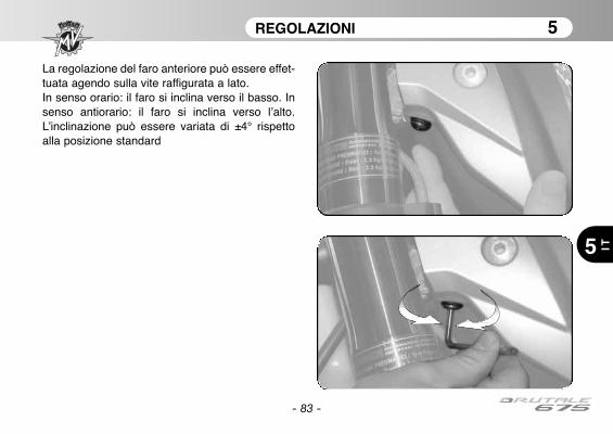
La regolazione del faro anteriore può essere effet-tuata agendo sulla vite raffigurata a lato.In senso orario: il faro si inclina verso il basso. Insenso antiorario: il faro si inclina verso l’alto.L’inclinazione può essere variata di ±4° rispettoalla posizione standard

- 84 -
NOTE
5
IT
Nota informativaMV Agusta Motor S.p.A. è impegnata in una politica di continuo miglioramento dei propri prodotti; per que-sta ragione potrebbe essere possibile riscontrare leggere differenze tra quanto riportato nel presente docu-mento ed il veicolo da Voi acquistato. I modelli MV Agusta vengono esportati in numerosi Paesi, nei qualivalgono norme differenti in relazione al Codice della Strada ed alle procedure di omologazione. Contandosulla Vostra comprensione, MV Agusta Motor S.p.A. ritiene quindi necessario riservarsi il diritto di apporta-re modifiche ai propri prodotti ed alla propria documentazione tecnica in qualsiasi momento e senza fornir-ne preavviso.
Vi consigliamo di visitare periodicamente il sito Internet www.mvagusta.it per ottenere informazioni edaggiornamenti sui prodotti MV Agusta e sulla relativa documentazione.
Rispettiamo e difendiamo l’ambienteTutto ciò che facciamo ha ripercussioni sull’intero pianeta e sulle sue risorse.MV Agusta, a tutela degli interessi della comunità, sensibilizza i Clienti e gli operatori dell’assistenza tecni-ca ad adottare modalità d’uso del mezzo e di smaltimento di sue parti, nel pieno rispetto delle normativevigenti in termini di inquinamento ambientale, smaltimento e riciclaggio dei rifiuti.
© 2012È vietata la riproduzione anche parziale di questo documento senza il consenso scritto della MV Agusta Motor S.p.A.
Part. n° 8000B6848Edizione n° 1 - Aprile 2012
User’s manualEnglish Version
- 2 -
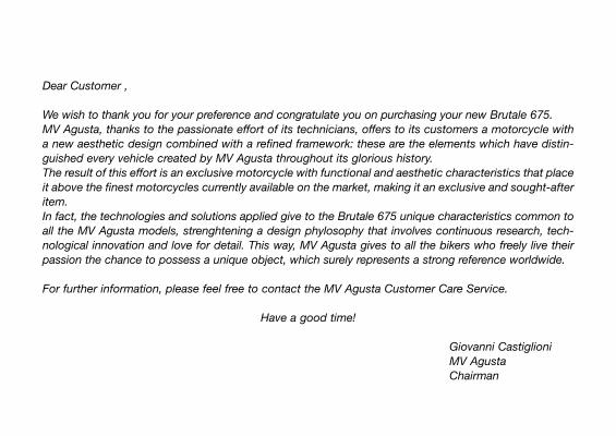
Dear Customer ,
We wish to thank you for your preference and congratulate you on purchasing your new Brutale 675.MV Agusta, thanks to the passionate effort of its technicians, offers to its customers a motorcycle witha new aesthetic design combined with a refined framework: these are the elements which have distin-guished every vehicle created by MV Agusta throughout its glorious history.The result of this effort is an exclusive motorcycle with functional and aesthetic characteristics that placeit above the finest motorcycles currently available on the market, making it an exclusive and sought-afteritem.In fact, the technologies and solutions applied give to the Brutale 675 unique characteristics common toall the MV Agusta models, strenghtening a design phylosophy that involves continuous research, tech-nological innovation and love for detail. This way, MV Agusta gives to all the bikers who freely live theirpassion the chance to possess a unique object, which surely represents a strong reference worldwide.
For further information, please feel free to contact the MV Agusta Customer Care Service.
Have a good time!
Giovanni Castiglioni MV AgustaChairman
- 3 -
CONTENTS
chap. Subject covered page1 GENERAL INFORMATION 51.1. Purpose of the manual 51.2. Symbols 61.3. Contents of the digital support 71.4. Identification data 82 SAFETY INFORMATION 112.1. Allowed use of the vehicle 112.2. Maintenance 112.3. Accessories and modifications 122.4. Vehicle load 123 CONTROLS AND INSTRUMENTS 143.1. Location of controls and instruments 143.2. Sidestand 163.3. Handlebar controls, left side 173.4 Handlebar controls, right side 193.5. Ignition switch and steering lock 213.6. Gear lever 243.7. Instruments and warning lights 253.7.1. Warning lights 263.7.2. Multifunction display/Gear and water
temperature display 273.8. Table of lubricants and fluids 28
chap. Subject covered page
4 OPERATION 294.1. Using the motorcycle 294.2. Running-in 304.3. Starting the engine 324.4. Selecting & setting of the display functions 354.4.1. Selecting the display functions 364.4.2. Trip reset 404.4.3. “SPEED LIMITER” Mode 424.4.4. TC Mode 444.4.5. Chronometer 454.4.6. “QUICK SHIFT” Mode 544.4.7. Clock settings 554.4.8. How to select the mapping
of the control unit 574.4.9. Warning/malfunction alerts 694.5. Refuelling 724.6. Glove compartment 744.7. Parking the motorcycle 755 ADJUSTMENTS 775.1. List of adjustments 775.2. Table of adjustments 805.3. Adjusting the front brake lever 80
- 4 -
CONTENTS
chap. Subject covered page5.4. Adjusting the rearview mirrors 815.5. Headlight adjustment 82
GENERAL INFORMATION 1
1 GB
- 5 -
1.1. Purpose of the manual
This User’s Manual contains the necessary information for acorrect and safe use of the motorcycle.
The User’s Manual is also supplied in electronic format (.pdf)on this digital support and it can be printed or viewed on anyPC, equipped either with Windows or Mac operative system.
We recommend to carefully read the User’s Manual beforeusing your motorcycle, and to make sure that anyone whouses the motorcycle had previously made the same.
CopyrightMV AGUSTA Motor Spa
All rights reserved
GENERAL INFORMATION 1
1
GB
- 6 -
1.2. Symbols
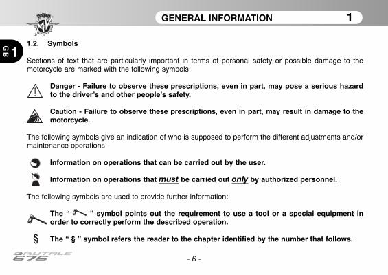
Sections of text that are particularly important in terms of personal safety or possible damage to themotorcycle are marked with the following symbols:
Danger - Failure to observe these prescriptions, even in part, may pose a serious hazardto the driver’s and other people’s safety.
Caution - Failure to observe these prescriptions, even in part, may result in damage to themotorcycle.
The following symbols give an indication of who is supposed to perform the different adjustments and/ormaintenance operations:
Information on operations that can be carried out by the user.
Information on operations that must be carried out only by authorized personnel.
The following symbols are used to provide further information:
The “ ” symbol points out the requirement to use a tool or a special equipment inorder to correctly perform the described operation.
§ The “ § ” symbol refers the reader to the chapter identified by the number that follows.
GENERAL INFORMATION 1
1 GB
- 7 -
1.3. Contents of digital support
Inside this digital support you will find, besides the User’sManual, the Maintenance Manual, the World Dealer Guide andthe Warranty Booklet.
When delivering the bike, your Dealer has also supplied theWarranty and Pre-Delivery Certificate.
We recommend to keep it together with the motorcycle docu-ments and with the service coupons that are given at themoment of servicing the bike.
IMPORTANTThe copies of the Warranty and Pre-Delivery Certificate mustbe filled in by the Dealer. A copy of the certificate must begiven to the Customer, a second copy must be kept by theDealer and the third one must be sent to the importer.
The dealer must always fill in the recommended maintenanceservice coupons. They must be kept by both, the Customerand the Dealer.
GENERAL INFORMATION 1
1
GB
- 8 -
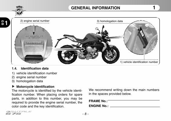
1.4. Identification data1) vehicle identification number2) engine serial number3) homologation data
Motorcycle identificationThe motorcycle is identified by the vehicle identi-fication number. When placing orders for spareparts, in addition to this number, you may berequired to provide the engine serial number, thecolor code and the key identification.
We recommend writing down the main numbersin the spaces provided below.
FRAME No.:
ENGINE No.:
2) engine serial number
1) vehicle identification number
3) homologation data

GENERAL INFORMATION 1
1 GB
- 9 -
Identification of motorcycle colour combinationThe colour code must be mentioned when orderingbody spares. It can be read on the right side of the fueltank.
In order to get to the colour code label, it is necessaryto remove the saddle.
Motorcycle key identificationA key is supplied in duplicate for both the ignition and allthe locks. Keep the duplicate in a safe place.
It is essential to provide the key identification number ifyou place an order for a spare motorcycle key. It is advi-sed to note this number in the following space:
KEY Nr.:
GENERAL INFORMATION 1
1
GB
- 10 -
After removing the saddle, it is possible to get to thecolour code label. On this label you can read themotorcycle colour combination, which determines thepainting of the bodywork parts.
We recommend writing down the colour code in thespace provided below:
COLOUR CODE:
Colour code label
SAFETY INFORMATION 2
2 GB
- 11 -
2.1. ALLOWED USE OF THE VEHICLE
Your motorcycle has been strictly designed foruse on road or highway route.
WARNINGOccasionally, it is possible to use yourmotorcycle on race track during non-competitive events.In this case, however, in consequenceof the higher stresses affecting the bikeduring this specific use, we recommendto have its conditions checked by anauthorized MV Agusta Service Centerbefore and after using it.Any other use of the vehicle is prohibit-ed and explicitly excluded.
You can find further information about the use ofthe vehicle in the section no. 4 of this Manual.
2.2. MAINTENANCE
In order to guarantee the maximum efficiency andreliability of the vehicle, it is necessary to performthe programmed maintenance operations report-ed in the Maintenance Manual.MV Agusta recommends that all maintenanceoperations are performed only by skilled person-nel from an authorized MV Agusta Service Center.Anyway, if you decide to have the maintenanceoperations performed by non-authorized work-shops, you must ensure that they have the skillsand the specific tools necessary to perform theabove operations.
WARNINGThe MV Agusta Warranty could not bevalid if non-authorized workshops hadperformed operations on the bike in adifferent way from what is described onthe Technical Circular Letters and onthe related MV Agusta WorkshopManuals.
SAFETY INFORMATION 2
2
GB
- 12 -
2.3. ACCESSORIES AND MODIFICATIONS
WARNINGMV Agusta prohibits to make any modi-fication to its motorcycles.This is necessary to preserve the safetyof its Customers.
Anyway, it is possible to customize your motorcy-cle by consulting the extensive MV AgustaAccessory Catalogue.
WARNINGThe installation of some of the aboveaccessories could invalidate the bikehomologation, and consequently makethe bike not furtherly usable on publicroads.
If you have doubts, we suggest to refer to yourMV Agusta Dealer in order to choose the acces-sories which can better suit your needs.
2.4. VEHICLE LOAD
Your motorcycle is designed for use by the riderand it can also seat a passenger.To use the vehicle in complete safety and inaccordance with the Highway Code provisions, itis compulsory that the following maximum loadconditions are never exceeded:
BRUTALE 675Maximum technically permissible mass
364 kgMaximum load mass
180 kg
The maximum technically permissible masscomes out from the sum of the following masses:
• mass of the motorcycle;• mass of the driver;• mass of the passenger;• mass of the luggage and all the accessories.
SAFETY INFORMATION 2
2 GB
- 13 -
WARNINGSince the load can strongly affect han-dling, braking, performance and safetycharacteristics of your motorcycle, youshould always keep in mind the follow-ing warnings.
• NEVER OVERLOAD YOUR MOTOR-CYCLE! Driving an overloaded motorcy-cle can cause damage to the tyres, loss ofcontrol of the vehicle and serious injury.Verify that the total weight (including theweight of the motorcycle, the driver, thepassenger, the load and all the acces-sories) does not exceed the maximumvalue specified for your vehicle.

CONTROLS AND INSTRUMENTS 3
GB 3
- 14 -
3.1. Location of controls and instruments
Instruments and warning lights (§3.7.)
Half handlebar electrical controls, left side (§3.3.)
Fuel tank cap (§4.5.)
Ignition switch and steering lock (§3.5.)
Throttle twist grip (§3.4.)Half handlebar electrical controls, right side (§3.4.)
Left side
Right side
CONTROLS AND INSTRUMENTS 3
GB3
- 15 -
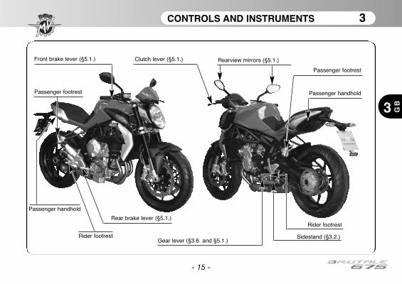
Clutch lever (§5.1.)
Gear lever (§3.6. and §5.1.)Sidestand (§3.2.)
Passenger footrest
Passenger footrest
Passenger handhold
Rearview mirrors (§5.1.)Front brake lever (§5.1.)
Rear brake lever (§5.1.)
Rider footrest
Rider footrest
Passenger handhold

CONTROLS AND INSTRUMENTS 3
3
GB
- 16 -
3.2. Sidestand
The sidestand is equipped with asafety switch that prevents themotorcycle from moving off while thestand is down.If the rider attempts to engage thegears while the engine is running andthe stand is down, the switch auto-matically turns off the engine by cut-ting the current supply.If the motorcycle is parked (side-stand down) and the gears areengaged, the switch prevents theengine from being started, therebyavoiding the risk of accidentally top-pling the vehicle.
Sidestand
Dual return spring
Safety switch
Sidestand
CONTROLS AND INSTRUMENTS 3
3 GB
- 17 -
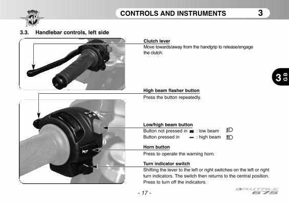
3.3. Handlebar controls, left side
High beam flasher buttonPress the button repeatedly.
Low/high beam buttonButton not pressed in : low beamButton pressed in : high beam
Turn indicator switchShifting the lever to the left or right switches on the left or rightturn indicators. The switch then returns to the central position.Press to turn off the indicators.
Horn buttonPress to operate the warning horn.
Clutch leverMove towards/away from the handgrip to release/engagethe clutch.
CONTROLS AND INSTRUMENTS 3
3
GB
- 18 -
High beam flasher buttonIt is used to attract the attention of other road users in case of danger. When the high beam is on, thefunction is inactive.
Low/high beam buttonUnder normal conditions, the low beam is on. The high beam can be switched on by pressing the but-ton when allowed by the traffic and road conditions.
Turn indicator switchIt is used to show the rider’s intention to change direction or lane.
WARNINGFailure to switch the turn indicators on or off at the right time may cause an accident in thatthe other road users may draw incorrect conclusions about the direction of motion of thevehicle. Always switch on the indicators before turning or changing lanes. Then be sure toswitch off the indicators after completing the operation.
Horn buttonIt is used to attract the attention of other road users in case of danger.
Clutch leverIt engages/disengages the clutch through a hydraulically controlled device.
CONTROLS AND INSTRUMENTS 3
3 GB
- 19 -
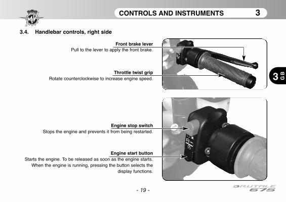
3.4. Handlebar controls, right side
Engine stop switchStops the engine and prevents it from being restarted.
Engine start buttonStarts the engine. To be released as soon as the engine starts.
When the engine is running, pressing the button selects thedisplay functions.
Throttle twist gripRotate counterclockwise to increase engine speed.
Front brake leverPull to the lever to apply the front brake.
CONTROLS AND INSTRUMENTS 3
3
GB
- 20 -
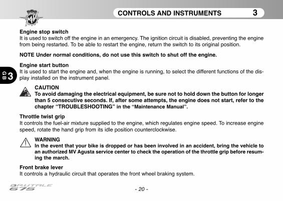
Engine stop switchIt is used to switch off the engine in an emergency. The ignition circuit is disabled, preventing the enginefrom being restarted. To be able to restart the engine, return the switch to its original position.
NOTE Under normal conditions, do not use this switch to shut off the engine.
Engine start buttonIt is used to start the engine and, when the engine is running, to select the different functions of the dis-play installed on the instrument panel.
CAUTIONTo avoid damaging the electrical equipment, be sure not to hold down the button for longerthan 5 consecutive seconds. If, after some attempts, the engine does not start, refer to thechapter “TROUBLESHOOTING” in the “Maintenance Manual”.
Throttle twist gripIt controls the fuel-air mixture supplied to the engine, which regulates engine speed. To increase enginespeed, rotate the hand grip from its idle position counterclockwise.
WARNINGIn the event that your bike is dropped or has been involved in an accident, bring the vehicle toan authorized MV Agusta service center to check the operation of the throttle grip before resum-ing the march.
Front brake leverIt controls a hydraulic circuit that operates the front wheel braking system.
CONTROLS AND INSTRUMENTS 3
3 GB
- 21 -
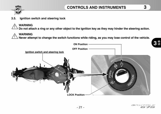
3.5. Ignition switch and steering lock
WARNINGDo not attach a ring or any other object to the ignition key as they may hinder the steering action.
WARNINGNever attempt to change the switch functions while riding, as you may lose control of the vehicle.
ON Position
OFF PositionIgnition switch and steering lock
LOCK Position

CONTROLS AND INSTRUMENTS 3
3
GB
The ignition switch enables and disables the electrical circuit and the steering lock. The four positions ofthe switch are described below.
CAUTION: Do not leave the key on the ON position for a long time when the engine is notrunning, in order to avoid damage to the electrical parts of the motorcycle
OFF position
All electrical circuits are deactivated. The key canbe removed.
ON position
All electrical circuits are activated. The instru-ments and warning lights perform the self-diag-nostic cycle. The engine can be started. The keycannot be removed.
- 22 -
CONTROLS AND INSTRUMENTS 3
3 GB
- 23 -
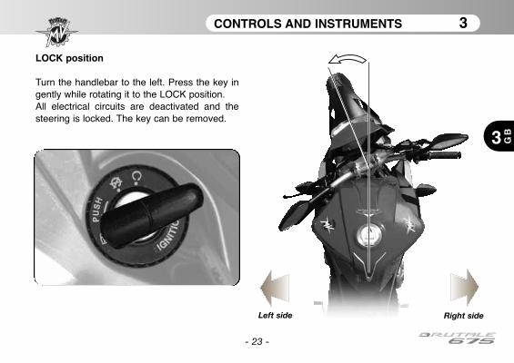
LOCK position
Turn the handlebar to the left. Press the key ingently while rotating it to the LOCK position.All electrical circuits are deactivated and thesteering is locked. The key can be removed.
Left side Right side
CONTROLS AND INSTRUMENTS 3
3
GB
- 24 -
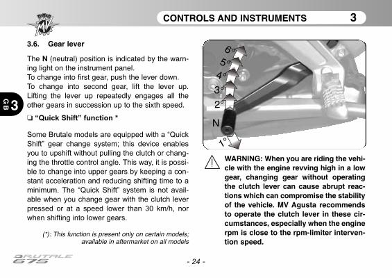
3.6. Gear lever
The N (neutral) position is indicated by the warn-ing light on the instrument panel.To change into first gear, push the lever down.To change into second gear, lift the lever up.Lifting the lever up repeatedly engages all theother gears in succession up to the sixth speed.
❏ “Quick Shift” function *
Some Brutale models are equipped with a “Quick
Shift” gear change system; this device enables
you to upshift without pulling the clutch or chang-
ing the throttle control angle. This way, it is possi-
ble to change into upper gears by keeping a con-
stant acceleration and reducing shifting time to a
minimum. The “Quick Shift” system is not avail-
able when you change gear with the clutch lever
pressed or at a speed lower than 30 km/h, nor
when shifting into lower gears.
(*): This function is present only on certain models;available in aftermarket on all models
1°
N
2°
3°
4°
5°
6°
WARNING: When you are riding the vehi-cle with the engine revving high in a lowgear, changing gear without operatingthe clutch lever can cause abrupt reac-tions which can compromise the stabilityof the vehicle. MV Agusta recommendsto operate the clutch lever in these cir-cumstances, especially when the enginerpm is close to the rpm-limiter interven-tion speed.

CONTROLS AND INSTRUMENTS 3
3 GB
- 25 -
3.7. Instruments and warning lights
The instruments and warning lights are activated by turning the ignition switchto the ON position. After a preliminary check (approx. 7 seconds) the displayedinformation reflects the current general condition of the motorcycle.
Warning lights
(§3.7.1.)
Multifunction display (§3.7.2.)
Tachometer
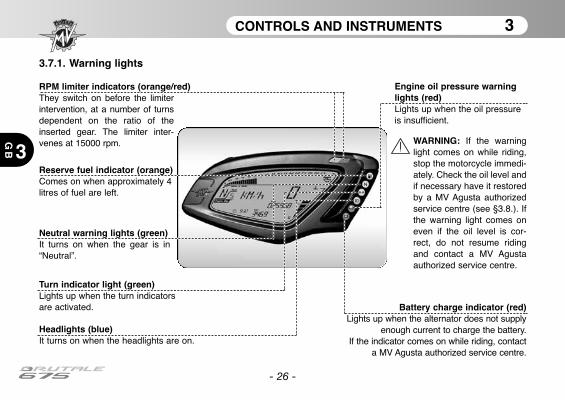
CONTROLS AND INSTRUMENTS 3
3
GB
- 26 -
3.7.1. Warning lights
Headlights (blue) It turns on when the headlights are on.
Neutral warning lights (green)It turns on when the gear is in“Neutral”.
Turn indicator light (green)Lights up when the turn indicatorsare activated.
Reserve fuel indicator (orange)Comes on when approximately 4litres of fuel are left.
Battery charge indicator (red)Lights up when the alternator does not supply
enough current to charge the battery. If the indicator comes on while riding, contact
a MV Agusta authorized service centre.
RPM limiter indicators (orange/red)They switch on before the limiterintervention, at a number of turnsdependent on the ratio of theinserted gear. The limiter inter-venes at 15000 rpm. WARNING: If the warning
light comes on while riding,stop the motorcycle immedi-ately. Check the oil level andif necessary have it restoredby a MV Agusta authorizedservice centre (see §3.8.). Ifthe warning light comes oneven if the oil level is cor-rect, do not resume ridingand contact a MV Agustaauthorized service centre.
Engine oil pressure warninglights (red)Lights up when the oil pressureis insufficient.
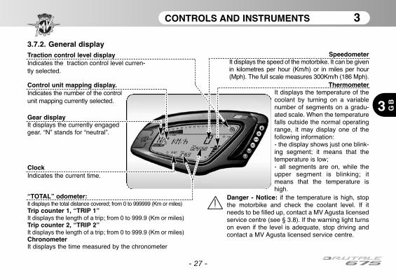
CONTROLS AND INSTRUMENTS 3
3 GB
- 27 -
3.7.2. General displaySpeedometer
It displays the speed of the motorbike. It can be givenin kilometres per hour (Km/h) or in miles per hour(Mph). The full scale measures 300Km/h (186 Mph).
“TOTAL” odometer:It displays the total distance covered; from 0 to 999999 (Km or miles)Trip counter 1, “TRIP 1”It displays the length of a trip; from 0 to 999.9 (Km or miles)Trip counter 2, “TRIP 2”It displays the length of a trip; from 0 to 999.9 (Km or miles)ChronometerIt displays the time measured by the chronometer
ThermometerIt displays the temperature of thecoolant by turning on a variablenumber of segments on a gradu-ated scale. When the temperaturefalls outside the normal operatingrange, it may display one of thefollowing information:- the display shows just one blink-ing segment; it means that thetemperature is low;- all segments are on, while theupper segment is blinking; itmeans that the temperature ishigh.
Danger - Notice: if the temperature is high, stopthe motorbike and check the coolant level. If itneeds to be filled up, contact a MV Agusta licensedservice centre (see § 3.8). If the warning light turnson even if the level is adequate, stop driving andcontact a MV Agusta licensed service centre.
Gear display It displays the currently engagedgear. “N” stands for “neutral”.
ClockIndicates the current time.
Control unit mapping display.Indicates the number of the controlunit mapping currently selected.
Traction control level displayIndicates the traction control level curren-tly selected.
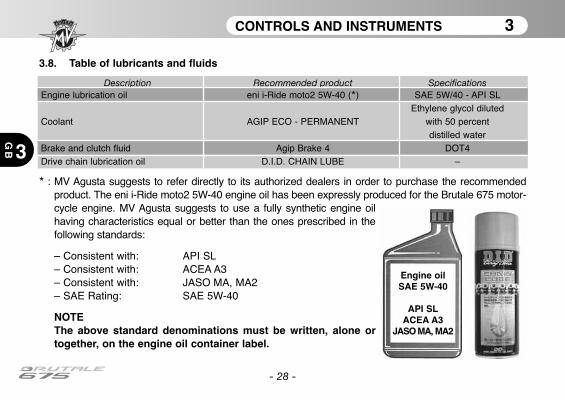
CONTROLS AND INSTRUMENTS 3
3
GB
- 28 -
* : MV Agusta suggests to refer directly to its authorized dealers in order to purchase the recommendedproduct. The eni i-Ride moto2 5W-40 engine oil has been expressly produced for the Brutale 675 motor-cycle engine. MV Agusta suggests to use a fully synthetic engine oilhaving characteristics equal or better than the ones prescribed in thefollowing standards:
– Consistent with: API SL– Consistent with: ACEA A3– Consistent with: JASO MA, MA2– SAE Rating: SAE 5W-40
NOTEThe above standard denominations must be written, alone ortogether, on the engine oil container label.
Engine oilSAE 5W-40
API SLACEA A3
JASO MA, MA2
Description Recommended product SpecificationsEngine lubrication oil eni i-Ride moto2 5W-40 (*) SAE 5W/40 - API SL
Ethylene glycol dilutedCoolant AGIP ECO - PERMANENT with 50 percent
distilled waterBrake and clutch fluid Agip Brake 4 DOT4Drive chain lubrication oil D.I.D. CHAIN LUBE –
3.8. Table of lubricants and fluids
OPERATION 4
4 GB
- 29 -
4.1. Using the motorcycle
This section provides the basic information needed to correctly operate the motorcycle.
WARNINGYour motorcycle Brutale 675 shows high power and performance characteristics; there-fore, its use requires an adequate level of knowledge of the vehicle. When you use thismotorcycle for the first time, it is essential to adopt a cautious attitude. An aggressive orreckless riding attitude can lead to accidents, compromising the driver’s and other peo-ple’s safety.
WARNINGTHE RESTRICTIONS RELATED TO THE ALLOWED USE OF THE VEHICLE AREDESCRIBED IN THE SECTION “SAFETY INFORMATIONS”.
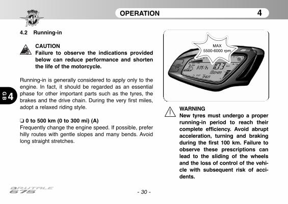
OPERATION 4
4
GB
- 30 -
4.2 Running-in
CAUTIONFailure to observe the indications providedbelow can reduce performance and shortenthe life of the motorcycle.
Running-in is generally considered to apply only to theengine. In fact, it should be regarded as an essentialphase for other important parts such as the tyres, thebrakes and the drive chain. During the very first miles,adopt a relaxed riding style.
❏ 0 to 500 km (0 to 300 mi) (A)Frequently change the engine speed. If possible, preferhilly routes with gentle slopes and many bends. Avoidlong straight stretches.
WARNINGNew tyres must undergo a properrunning-in period to reach theircomplete efficiency. Avoid abruptacceleration, turning and brakingduring the first 100 km. Failure toobserve these prescriptions canlead to the sliding of the wheelsand the loss of control of the vehi-cle with subsequent risk of acci-dents.
MAX 5500-6000 rpm
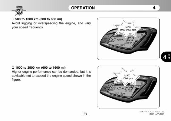
OPERATION 4
4 GB
- 31 -
❏ 500 to 1000 km (300 to 600 mi)Avoid lugging or overspeeding the engine, and varyyour speed frequently.
❏ 1000 to 2500 km (600 to 1600 mi)Higher engine performance can be demanded, but it isadvisable not to exceed the engine speed shown in thefigure.
MAX8000-9000 rpm
MAX 11000 rpm
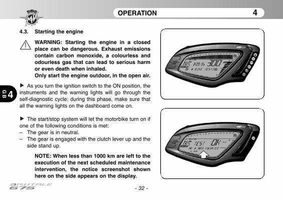
OPERATION 4
4
GB
- 32 -
4.3. Starting the engine
WARNING: Starting the engine in a closedplace can be dangerous. Exhaust emissionscontain carbon monoxide, a colourless andodourless gas that can lead to serious harmor even death when inhaled.Only start the engine outdoor, in the open air.
As you turn the ignition switch to the ON position, theinstruments and the warning lights will go through theself-diagnostic cycle; during this phase, make sure thatall the warning lights on the dashboard come on.
The start/stop system will let the motorbike turn on ifone of the following conditions is met:– The gear is in neutral.– The gear is engaged with the clutch lever up and the
side stand up.
NOTE: When less than 1000 km are left to theexecution of the next scheduled maintenanceintervention, the notice screenshot shownhere on the side appears on the display.
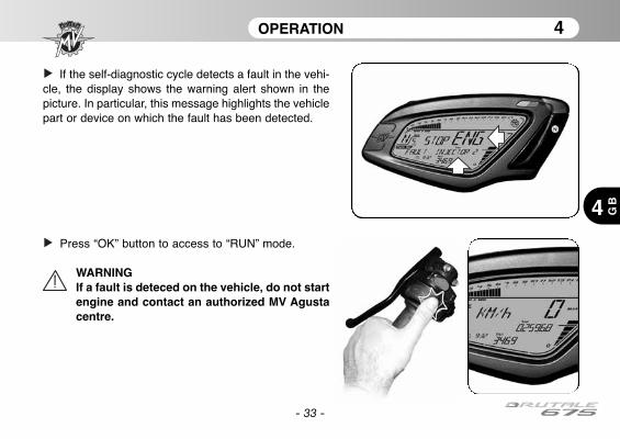
- 33 -
OPERATION 4
4 GB
If the self-diagnostic cycle detects a fault in the vehi-cle, the display shows the warning alert shown in thepicture. In particular, this message highlights the vehiclepart or device on which the fault has been detected.
Press “OK” button to access to “RUN” mode.
WARNINGIf a fault is deteced on the vehicle, do not startengine and contact an authorized MV Agustacentre.

OPERATION 4
4
GB
- 34 -
❏ Engine start procedure
Press the start button without turning the throttletwist grip.
As soon as the engine starts, release the button.
CAUTION• Do not press the start button for longer than5 consecutive seconds, in order to avoid dam-age to the electrical equipment.• Avoid warming up the engine while the vehi-cle is stationary. The subsequent engine over-heating can cause damage to the internalparts of the engine. It is advisable to bring theengine to the working temperature by ridingat reduced speed.• To ensure the maximum life of the engine,never speed up at full throttle when theengine is cold.
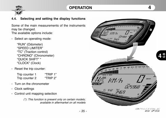
OPERATION 4
4 GB
- 35 -
4.4. Selecting and setting the display functions
Some of the main measurements of the instrumentsmay be changed. The available options include:
- Select an operating mode:
“RUN” (Odometer)“SPEED LIMITER”“TC” (Traction control)“CHRONO” (Chronometer)“QUICK SHIFT” *“CLOCK” (Clock)
- Reset the trip counter:
Trip counter 1 “TRIP 1”Trip counter 2 “TRIP 2”
- Turn on the chronometer
- Clock settings
- Control unit mapping selection
(*): This function is present only on certain models;available in aftermarket on all models
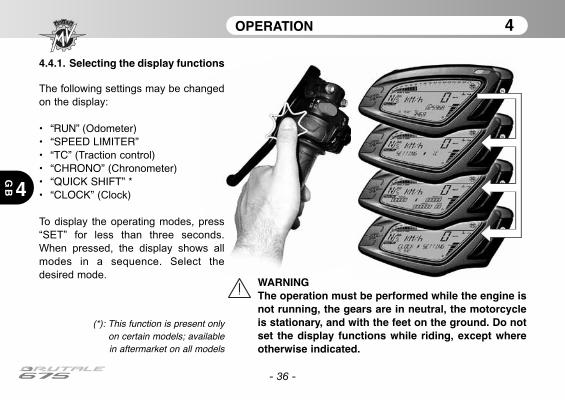
OPERATION 4
4
GB
- 36 -
WARNINGThe operation must be performed while the engine isnot running, the gears are in neutral, the motorcycleis stationary, and with the feet on the ground. Do notset the display functions while riding, except whereotherwise indicated.
4.4.1. Selecting the display functions
The following settings may be changed
on the display:
• “RUN” (Odometer)• “SPEED LIMITER”• “TC” (Traction control)• “CHRONO” (Chronometer)• “QUICK SHIFT” *• “CLOCK” (Clock)
To display the operating modes, press
“SET” for less than three seconds.
When pressed, the display shows all
modes in a sequence. Select the
desired mode.
(*): This function is present onlyon certain models; availablein aftermarket on all models

OPERATION 4
4 GB
- 37 -
❏ “RUN” mode
In addition to the speedometer, the display shows the
following functions (see §4.4.2.):
• Total odometer “TOTAL”
• Trip counter 1 “TRIP 1”
As an alternative:
• Total odometer “TOTAL”
• Trip counter 2 “TRIP 2”
❏ “SPEED LIMITER” mode
This mode adjusts the maximum value of the vehicle
speed to your driving requirements (see §4.4.3.).
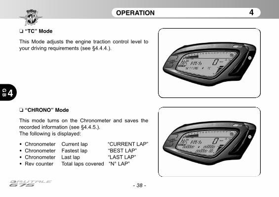
OPERATION 4
4
GB
- 38 -
❏ “CHRONO” Mode
This mode turns on the Chronometer and saves the
recorded information (see §4.4.5.).
The following is displayed:
• Chronometer Current lap “CURRENT LAP”
• Chronometer Fastest lap “BEST LAP”
• Chronometer Last lap “LAST LAP”
• Rev counter Total laps covered “N° LAP”
❏ “TC” Mode
This Mode adjusts the engine traction control level to
your driving requirements (see §4.4.4.).
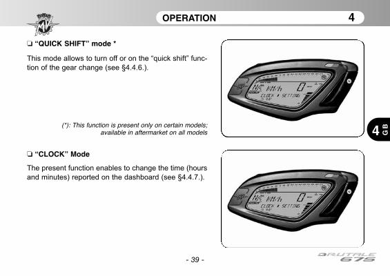
OPERATION 4
4 GB
- 39 -
❏ “CLOCK” Mode
The present function enables to change the time (hours
and minutes) reported on the dashboard (see §4.4.7.).
❏ “QUICK SHIFT” mode *
This mode allows to turn off or on the “quick shift” func-
tion of the gear change (see §4.4.6.).
(*): This function is present only on certain models;available in aftermarket on all models
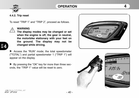
4.4.2. Trip reset
To reset “TRIP 1” and “TRIP 2”, proceed as follows.
WARNINGThe display modes may be changed or setwhen the engine is off, the gear in neutral,the motorbike stationary with your feet onthe ground. The display may not bechanged while driving.
Access the “RUN” mode; the total speedometer
("TOTAL”) and partial speedometer 1 (“TRIP 1”) will
appear on the display.
By pressing the “OK” key for more than three sec-
onds, the “TRIP 1” value will be reset to zero.
- 40 -
OPERATION 4
4
GB
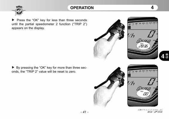
- 41 -
OPERATION 4
4 GB
Press the “OK” key for less than three seconds
until the partial speedometer 2 function (“TRIP 2”)
appears on the display.
By pressing the “OK” key for more than three sec-
onds, the “TRIP 2” value will be reset to zero.
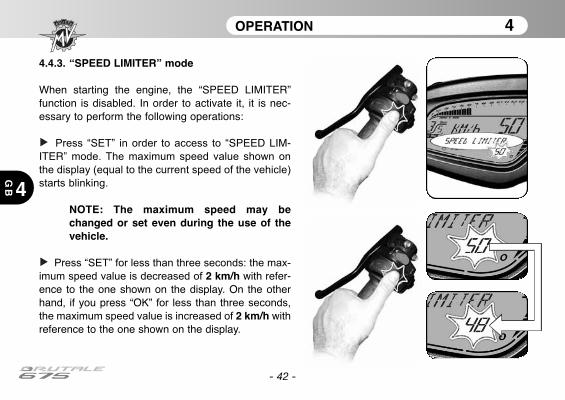
4.4.3. “SPEED LIMITER” mode
When starting the engine, the “SPEED LIMITER”function is disabled. In order to activate it, it is nec-essary to perform the following operations:
Press “SET” in order to access to “SPEED LIM-ITER” mode. The maximum speed value shown on
the display (equal to the current speed of the vehicle)
starts blinking.
NOTE: The maximum speed may bechanged or set even during the use of thevehicle.
Press “SET” for less than three seconds: the max-
imum speed value is decreased of 2 km/h with refer-ence to the one shown on the display. On the otherhand, if you press “OK” for less than three seconds,
the maximum speed value is increased of 2 km/h withreference to the one shown on the display.
- 42 -
OPERATION 4
4
GB
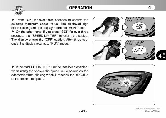
- 43 -
OPERATION 4
4 GB
Press “OK” for over three seconds to confirm the
selected maximum speed value. The displayed digit
stops blinking and the display returns to “RUN” mode.
On the other hand, if you press “SET” for over three
seconds, the “SPEED LIMITER” function is disabled.The display shows the “OFF” caption. After three sec-onds, the display returns to “RUN” mode.
If the “SPEED LIMITER” function has been enabled,when riding the vehicle the speed value shown on theodometer starts blinking when it reaches the set valueof the maximum speed.
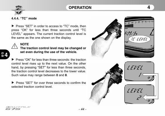
- 44 -
OPERATION 4
4
GB
4.4.4. “TC” mode
Press “SET” in order to access to “TC” mode, then
press “OK” for less than three seconds until “TC
LEVEL” appears. The current traction control level is
the same as the one shown on the display.
NOTEThe traction control level may be changed orset even during the use of the vehicle.
Press “OK” for less than three seconds: the traction
control level rises up to the next value. On the otherhand, by pressing “SET” for less than three seconds,
the traction control level decreases to the lower value.
Such value may range between 0 and 8.
Press “SET” for over three seconds to confirm the
selected traction control level.
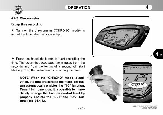
- 45 -
OPERATION 4
4 GB
4.4.5. Chronometer
❏ Lap time recording
Turn on the chronometer (“CHRONO” mode) to
record the time taken to cover a lap.
Press the headlight button to start recording the
time. The colon that separates the minutes from the
seconds and from the tenths of a second will start
blinking. Now, the instrument is recording the time.
NOTE: When the “CHRONO” mode is acti-vated, the first pressing of the headlight but-ton automatically enables the “TC” function.From this moment on, it is possible to imme-diately change the traction control level byproperly operate the “SET” and “OK” but-tons (see §4.4.4.).

OPERATION 4
4
GB
- 46 -
Press the headlight button again to record the time
taken to cover the 1st lap. At the same time, the instru-
ment starts recording the time taken to cover the sec-
ond lap.
The time measurement for the first lap is stored in the
memory and is visualised on the display for ten sec-
onds, after which the time measurement for the follow-
ing lap appears.
If using the chronometer again, every time you press
the headlight button, it records a time. The instrument
can record up to 100 consecutive times.
When the time for the lap which has just concluded is dis-
played, the symbol “+” or “-” appears if the time recorded
is respectively higher or lower than the time measured
during the previous lap.
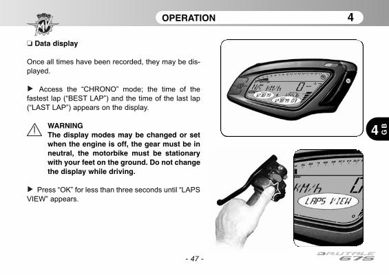
OPERATION 4
4 GB
- 47 -
❏ Data display
Once all times have been recorded, they may be dis-
played.
Access the “CHRONO” mode; the time of the
fastest lap (“BEST LAP”) and the time of the last lap
(“LAST LAP”) appears on the display.
WARNINGThe display modes may be changed or setwhen the engine is off, the gear must be inneutral, the motorbike must be stationarywith your feet on the ground. Do not changethe display while driving.
Press “OK” for less than three seconds until “LAPS
VIEW” appears.
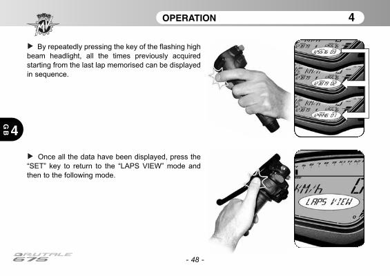
OPERATION 4
4
GB
- 48 -
By repeatedly pressing the key of the flashing high
beam headlight, all the times previously acquired
starting from the last lap memorised can be displayed
in sequence.
Once all the data have been displayed, press the
“SET” key to return to the “LAPS VIEW” mode and
then to the following mode.
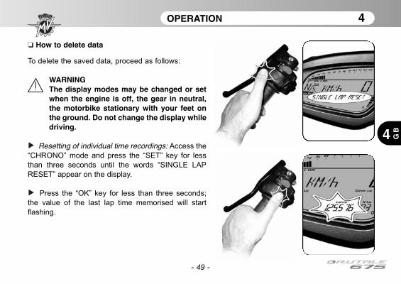
OPERATION 4
4 GB
- 49 -
❏ How to delete data
To delete the saved data, proceed as follows:
WARNINGThe display modes may be changed or setwhen the engine is off, the gear in neutral,the motorbike stationary with your feet onthe ground. Do not change the display whiledriving.
Resetting of individual time recordings: Access the
“CHRONO” mode and press the “SET” key for less
than three seconds until the words “SINGLE LAP
RESET” appear on the display.
Press the “OK” key for less than three seconds;
the value of the last lap time memorised will start
flashing.
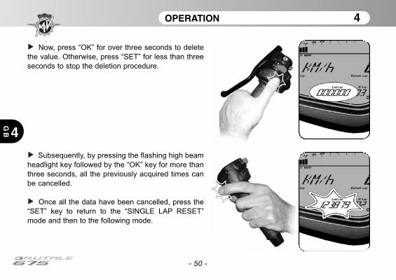
- 50 -
OPERATION 4
4
GB
Now, press “OK” for over three seconds to delete
the value. Otherwise, press “SET” for less than three
seconds to stop the deletion procedure.
Subsequently, by pressing the flashing high beam
headlight key followed by the “OK” key for more than
three seconds, all the previously acquired times can
be cancelled.
Once all the data have been cancelled, press the
“SET” key to return to the “SINGLE LAP RESET”
mode and then to the following mode.
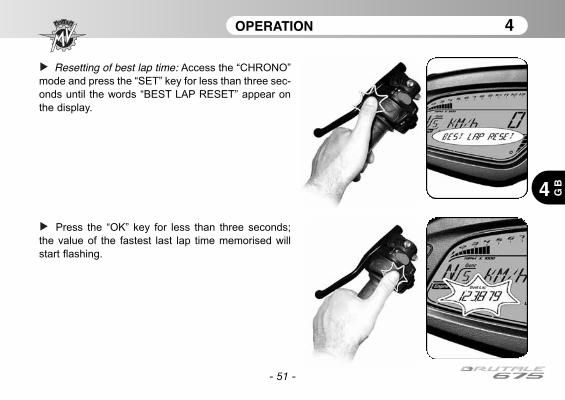
- 51 -
OPERATION 4
4 GB
Resetting of best lap time: Access the “CHRONO”
mode and press the “SET” key for less than three sec-
onds until the words “BEST LAP RESET” appear on
the display.
Press the “OK” key for less than three seconds;
the value of the fastest last lap time memorised will
start flashing.
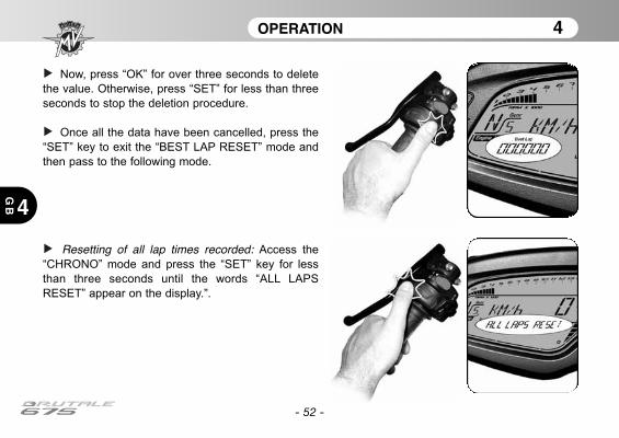
- 52 -
OPERATION 4
4
GB
Now, press “OK” for over three seconds to delete
the value. Otherwise, press “SET” for less than three
seconds to stop the deletion procedure.
Once all the data have been cancelled, press the
“SET” key to exit the “BEST LAP RESET” mode and
then pass to the following mode.
Resetting of all lap times recorded: Access the
“CHRONO” mode and press the “SET” key for less
than three seconds until the words “ALL LAPS
RESET” appear on the display.”.
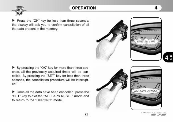
- 53 -
OPERATION 4
4 GB
Press the “OK” key for less than three seconds;
the display will ask you to confirm cancellation of all
the data present in the memory.
By pressing the “OK” key for more than three sec-
onds, all the previously acquired times will be can-
celled. By pressing the “SET” key for less than three
seconds, the cancellation procedure will be interrupt-
ed.
Once all the data have been cancelled, press the
“SET” key to exit the “ALL LAPS RESET” mode and
to return to the “CHRONO” mode.

- 54 -
OPERATION 4
4
GB
4.4.6. “QUICK SHIFT” mode *
Press “SET” in order to access to “QUICK SHIFT”
mode. The display shows the current activation state of
the “quick shift” function of the gear change.
WARNINGThe display modes may be changed or setwhen the engine is off, the gear in neutral, themotorbike stationary with your feet on theground. Do not change the display while dri-ving.
Press the "OK" button for less than three seconds;
the activation caption of the “quick shift” function
begins to flash.
By pressing the "OK" button for less than three sec-
onds, the caption toggles from “OFF” to “ON” andinversely.
Press “SET” to confirm the selected “quick shift”
activation state.
(*): This function is present only on certain models;available in aftermarket on all models
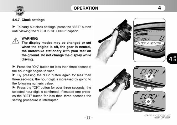
- 55 -
OPERATION 4
4 GB
4.4.7. Clock settings
To carry out clock settings, press the "SET" button
until viewing the "CLOCK SETTING" caption.
WARNINGThe display modes may be changed or setwhen the engine is off, the gear in neutral,the motorbike stationary with your feet onthe ground. Do not change the display whiledriving.
Press the "OK" button for less than three seconds;
the hour digit begins to flash.
By pressing the "OK" button again for less than
three seconds, the hour digit is increased by going to
the following numeric value.
Press the "OK" button for over three seconds; the
selected hour digit is confirmed. If instead one press-
es the "SET" button for less than three seconds the
setting procedure is interrupted.
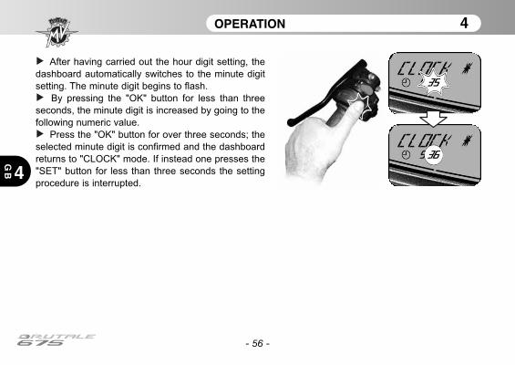
- 56 -
OPERATION 4
4
GB
After having carried out the hour digit setting, the
dashboard automatically switches to the minute digit
setting. The minute digit begins to flash.
By pressing the "OK" button for less than three
seconds, the minute digit is increased by going to the
following numeric value.
Press the "OK" button for over three seconds; the
selected minute digit is confirmed and the dashboard
returns to "CLOCK" mode. If instead one presses the
"SET" button for less than three seconds the setting
procedure is interrupted.
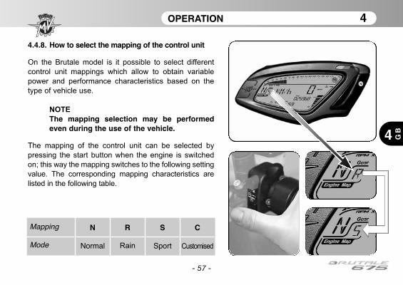
- 57 -
OPERATION 4
4 GB
4.4.8. How to select the mapping of the control unit
On the Brutale model is it possible to select different
control unit mappings which allow to obtain variable
power and performance characteristics based on the
type of vehicle use.
NOTE
The mapping selection may be performedeven during the use of the vehicle.
The mapping of the control unit can be selected by
pressing the start button when the engine is switched
on; this way the mapping switches to the following setting
value. The corresponding mapping characteristics are
listed in the following table.
Mapping
Mode
N
Normal
R
Rain
S
Sport
C
Customised
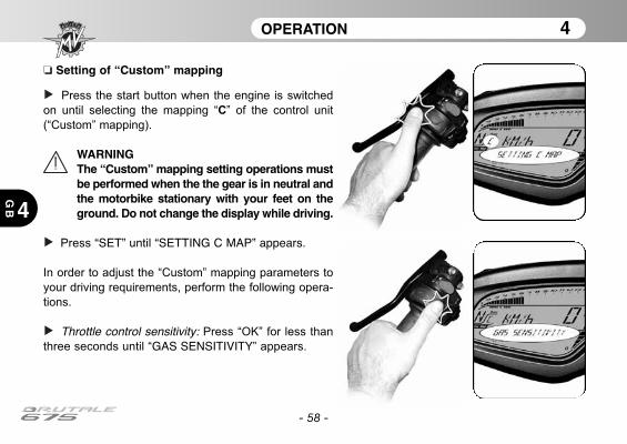
- 58 -
OPERATION 4
4
GB
❏ Setting of “Custom” mapping
Press the start button when the engine is switched
on until selecting the mapping “C” of the control unit
(“Custom” mapping).
WARNINGThe “Custom” mapping setting operations mustbe performed when the the gear is in neutral andthe motorbike stationary with your feet on theground. Do not change the display while driving.
Press “SET” until “SETTING C MAP” appears.
In order to adjust the “Custom” mapping parameters to
your driving requirements, perform the following opera-
tions.
Throttle control sensitivity: Press “OK” for less than
three seconds until “GAS SENSITIVITY” appears.

- 59 -
OPERATION 4
4 GB
Press “SET” for less than three seconds. The dis-play shows the current setting for throttle control sensi-tivity.
Press “OK” for less than three seconds; the dis-
played setting will start flashing.
By repeatedly pressing “OK” for less than three sec-
onds, the following settings can be displayed in
sequence:
• “NORMAL”• “RAIN”• “SPORT”

- 60 -
OPERATION 4
4
GB
Press “OK” for more than three seconds; the new
setting will be confirmed. The displayed caption stops
flashing and after a few seconds the display returns to
“GAS SENSITIVITY” mode. It is now possible to pro-ceed with the setting of the following parameter.
Maximum engine torque: Press “OK” for less than
three seconds until “MAX ENGINE TORQUE” appears.

- 61 -
OPERATION 4
4 GB
Press “SET” for less than three seconds. The dis-play shows the current setting for maximum enginetorque.
Press “OK” for less than three seconds; the dis-
played setting will start flashing.
By repeatedly pressing “OK” for less than three sec-
onds, the following settings can be displayed in
sequence:
• “RAIN”• “SPORT”
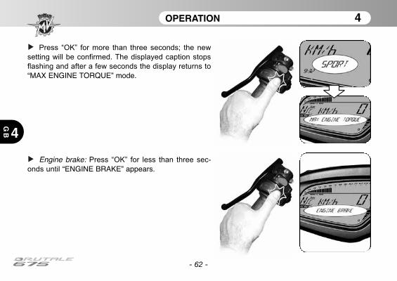
- 62 -
OPERATION 4
4
GB
Press “OK” for more than three seconds; the new
setting will be confirmed. The displayed caption stops
flashing and after a few seconds the display returns to
“MAX ENGINE TORQUE” mode.
Engine brake: Press “OK” for less than three sec-
onds until “ENGINE BRAKE” appears.

- 63 -
OPERATION 4
4 GB
Press “SET” for less than three seconds. The dis-play shows the current setting for engine brake.
Press “OK” for less than three seconds; the dis-
played setting will start flashing.
By repeatedly pressing “OK” for less than three sec-
onds, the following settings can be displayed in
sequence:
• “NORMAL”• “SPORT”

- 64 -
OPERATION 4
4
GB
Press “OK” for more than three seconds; the new
setting will be confirmed. The displayed caption stops
flashing and after a few seconds the display returns to
“ENGINE BRAKE” mode.
Engine response: Press “OK” for less than three
seconds until “ENGINE RESPONSE” appears.
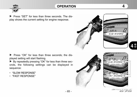
- 65 -
OPERATION 4
4 GB
Press “SET” for less than three seconds. The dis-play shows the current setting for engine response.
Press “OK” for less than three seconds; the dis-
played setting will start flashing.
By repeatedly pressing “OK” for less than three sec-
onds, the following settings can be displayed in
sequence:
• “SLOW RESPONSE”• “FAST RESPONSE”
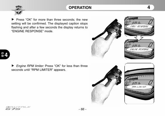
- 66 -
OPERATION 4
4
GB
Press “OK” for more than three seconds; the new
setting will be confirmed. The displayed caption stops
flashing and after a few seconds the display returns to
“ENGINE RESPONSE” mode.
Engine RPM limiter: Press “OK” for less than three
seconds until “RPM LIMITER” appears.

- 67 -
OPERATION 4
4 GB
Press “SET” for less than three seconds. The dis-play shows the current setting for engine RPM limiter.
Press “OK” for less than three seconds; the dis-
played setting will start flashing.
By repeatedly pressing “OK” for less than three sec-
onds, the following settings can be displayed in
sequence:
• “NORMAL”• “SPORT”

- 68 -
OPERATION 4
4
GB
Press “OK” for more than three seconds; the new
setting will be confirmed. The displayed caption stops
flashing and after a few seconds the display returns to
“RPM LIMITER” mode.
Press “OK” for less than three seconds until the dis-
play switches to the “RUN” mode. The setting of the
“Custom” mapping is completed.
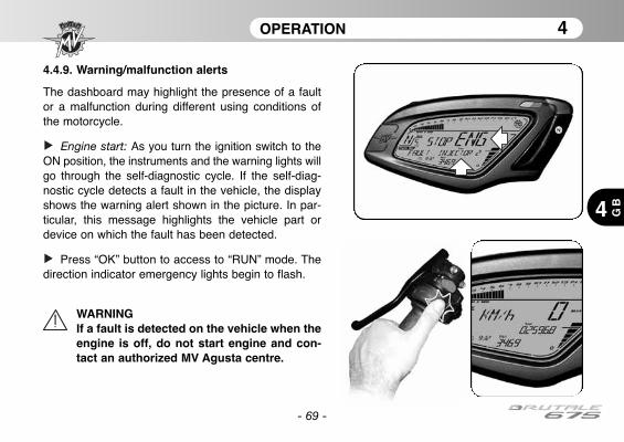
- 69 -
OPERATION 4
4 GB
4.4.9. Warning/malfunction alerts
The dashboard may highlight the presence of a faultor a malfunction during different using conditions ofthe motorcycle.
Engine start: As you turn the ignition switch to theON position, the instruments and the warning lights willgo through the self-diagnostic cycle. If the self-diag-nostic cycle detects a fault in the vehicle, the displayshows the warning alert shown in the picture. In par-ticular, this message highlights the vehicle part ordevice on which the fault has been detected.
Press “OK” button to access to “RUN” mode. Thedirection indicator emergency lights begin to flash.
WARNINGIf a fault is detected on the vehicle when theengine is off, do not start engine and con-tact an authorized MV Agusta centre.
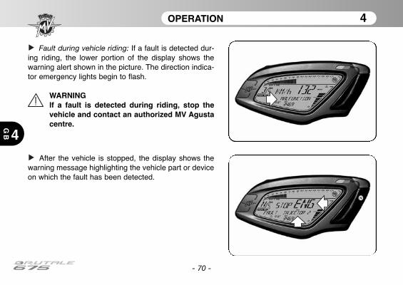
- 70 -
OPERATION 4
4
GB
Fault during vehicle riding: If a fault is detected dur-ing riding, the lower portion of the display shows thewarning alert shown in the picture. The direction indica-tor emergency lights begin to flash.
WARNINGIf a fault is detected during riding, stop thevehicle and contact an authorized MV Agustacentre.
After the vehicle is stopped, the display shows thewarning message highlighting the vehicle part or deviceon which the fault has been detected.
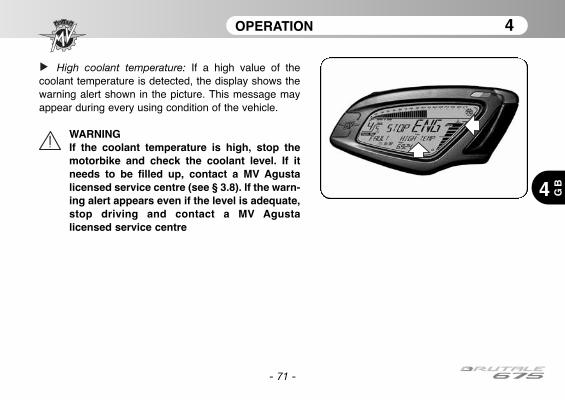
- 71 -
OPERATION 4
4 GB
High coolant temperature: If a high value of thecoolant temperature is detected, the display shows thewarning alert shown in the picture. This message mayappear during every using condition of the vehicle.
WARNINGIf the coolant temperature is high, stop themotorbike and check the coolant level. If itneeds to be filled up, contact a MV Agustalicensed service centre (see § 3.8). If the warn-ing alert appears even if the level is adequate,stop driving and contact a MV Agustalicensed service centre
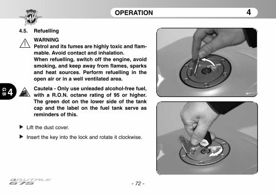
4.5. Refuelling
WARNINGPetrol and its fumes are highly toxic and flam-mable. Avoid contact and inhalation.When refuelling, switch off the engine, avoidsmoking, and keep away from flames, sparksand heat sources. Perform refuelling in theopen air or in a well ventilated area.
Cautela - Only use unleaded alcohol-free fuel,with a R.O.N. octane rating of 95 or higher.The green dot on the lower side of the tankcap and the label on the fuel tank serve asreminders of this.
Lift the dust cover.
Insert the key into the lock and rotate it clockwise.
- 72 -
OPERATION 4
4
GB
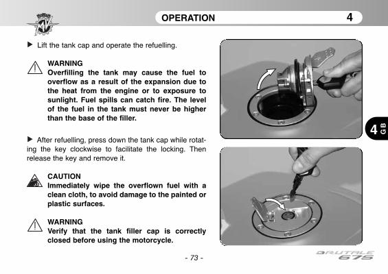
- 73 -
OPERATION 4
4 GB
Lift the tank cap and operate the refuelling.
WARNINGOverfilling the tank may cause the fuel tooverflow as a result of the expansion due tothe heat from the engine or to exposure tosunlight. Fuel spills can catch fire. The levelof the fuel in the tank must never be higherthan the base of the filler.
After refuelling, press down the tank cap while rotat-ing the key clockwise to facilitate the locking. Thenrelease the key and remove it.
CAUTIONImmediately wipe the overflown fuel with aclean cloth, to avoid damage to the painted orplastic surfaces.
WARNINGVerify that the tank filler cap is correctlyclosed before using the motorcycle.

OPERATION 4
4
GB
- 74 -
4.6. Glove compartment
Insert the key into the lock.
Rotate the key anticlockwise while slightlypushing the saddle. Lift the saddle and remove itas shown in the picture.
In order to reassemble the above mentioned part,you must perform the following operations:
• Rotate the key into the lock• Press down the seat • Release the key• Press down the seat once more, so to
make sure of its firm coupling to theframe.
WARNINGEvery time you remove and refit the seatand every time the vehicle is used, makesure that the above mentioned part iscorrectly placed and that it is firmlysecured to the motorcycle framework.
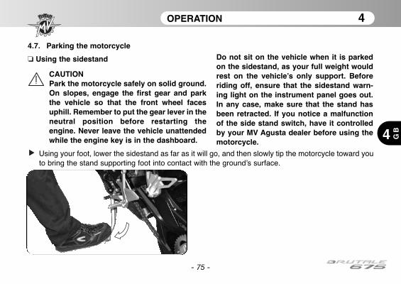
OPERATION 4
4 GB
- 75 -
4.7. Parking the motorcycle
❏ Using the sidestand
CAUTIONPark the motorcycle safely on solid ground.On slopes, engage the first gear and parkthe vehicle so that the front wheel facesuphill. Remember to put the gear lever in theneutral position before restarting theengine. Never leave the vehicle unattendedwhile the engine key is in the dashboard.
Do not sit on the vehicle when it is parkedon the sidestand, as your full weight wouldrest on the vehicle’s only support. Beforeriding off, ensure that the sidestand warn-ing light on the instrument panel goes out.In any case, make sure that the stand hasbeen retracted. If you notice a malfunctionof the side stand switch, have it controlledby your MV Agusta dealer before using themotorcycle.
Using your foot, lower the sidestand as far as it will go, and then slowly tip the motorcycle toward youto bring the stand supporting foot into contact with the ground’s surface.

OPERATION 4
4
GB
- 76 -
❏ Using the rear stand
Insert the stand pin into the rear wheelaxle hole on the left side of the motorcy-cle. Rest the stand on the ground and,pressing down on the stand, lift the vehi-cle until it reaches a stable condition.
CAUTIONThis operation is best carriedout with two people.
1 2
3
ADJUSTMENTS 5
5 GB
- 77 -
5.1. List of adjustments
There are many adjustments that can significantlyimprove the ergonomics, geometry and safety of themotorcycle.
However, since an incorrect adjustment of particularlyimportant components can lead to dangerous situa-tions, some of the above adjustments must be per-formed only by authorized MV Agusta ServiceCenters.
WARNINGAll adjustments must be performed whenthe vehicle is stationary

ADJUSTMENTS 5
5
GB
- 78 -
(F) Headlight adjustment (§5.5.)
(D) Rearview mirror adjustment (§5.4.)
(A) Front brake lever
adjustment (§5.3.)
(C) Rear brake lever
adjustment (§5.2.)

ADJUSTMENTS 5
GB5
- 79 -
(E) Drive chain adjustment (§5.2.)
(B) Gear lever
adjustment (§5.2.)
(D) Rearview mirror adjustment (§5.4.)
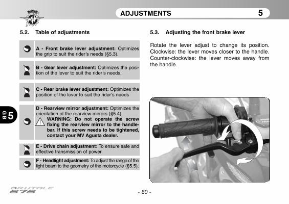
ADJUSTMENTS 5
5
GB
- 80 -
5.2. Table of adjustments
A - Front brake lever adjustment: Optimizesthe grip to suit the rider’s needs (§5.3).
B - Gear lever adjustment: Optimizes the posi-tion of the lever to suit the rider’s needs.
C - Rear brake lever adjustment: Optimizes theposition of the lever to suit the rider’s needs
D - Rearview mirror adjustment: Optimizes theorientation of the rearview mirrors (§5.4).
WARNING: Do not operate the screwfixing the rearview mirror to the handle-bar. If this screw needs to be tightened,contact your MV Agusta dealer.
E - Drive chain adjustment: To ensure safe andeffective transmission of power.
F - Headlight adjustment: To adjust the range of thelight beam to the geometry of the motorcycle (§5.5).
5.3. Adjusting the front brake lever
Rotate the lever adjust to change its position.Clockwise: the lever moves closer to the handle.Counter-clockwise: the lever moves away fromthe handle.

ADJUSTMENTS 5
5 GB
- 81 -
5.4. Adjusting the rearview mirrors
Press the mirror at the points shown in the figure toadjust its position in the four directions.
Perform the adjustment on both the rearview mirrors. Itis recommended to sit on the vehicle in order to opti-mize the rearview mirrors adjustment.
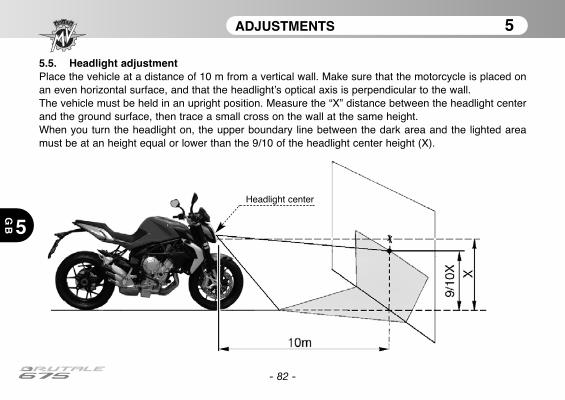
ADJUSTMENTS 5
5
GB
- 82 -
5.5. Headlight adjustmentPlace the vehicle at a distance of 10 m from a vertical wall. Make sure that the motorcycle is placed onan even horizontal surface, and that the headlight’s optical axis is perpendicular to the wall.The vehicle must be held in an upright position. Measure the “X” distance between the headlight centerand the ground surface, then trace a small cross on the wall at the same height.When you turn the headlight on, the upper boundary line between the dark area and the lighted areamust be at an height equal or lower than the 9/10 of the headlight center height (X).
Headlight center

ADJUSTMENTS 5
5 GB
- 83 -
The headlight adjustment can be performed byrotating the screw shown in the picture. Rotateclockwise to incline the headlight downwards,counterclockwise to incline it upwards. It can be tilted up to an angle of ±4° from the stan-dard position.
- 84 -
NOTES
5
GB
InformationMV Agusta Motor S.p.A. is committed to a policy of constant improvement; therefore, you may find slight dif-ferences between the information provided in this document and the vehicle you purchased. MV Agustamotorcycles are exported in several countries, in which different rules and regulations (concerning both theHighway Code and the homologation procedures) are in force. Relying on your understanding, MV AgustaMotor S.p.A. deems it necessary to reserve the right to change its products and the related documentationat any time and without notice.
We suggest to often visit the Internet site www.mvagusta.it in order to obtain informations and updatesabout the MV Agusta products and the related documentation.
Respect and defend natural environment
Everything we do affects the whole planet as well as its resources.MV Agusta, in order to protect the interests of the community, awakens the Customers and the TechnicalAssistance operators to use the vehicle and dispose of its replaced parts respecting the laws in force con-cerning environmental pollution and waste disposal and recycling.
© 2012This document may not, in whole or in part, be reproduced without prior consent, in writing, from MV Agusta Motor S.p.A.
Part No. 8000B6848Edition No. 1 - April 2012

Manuel d’utilisationVersion Française
- 2 -
Cher client,
Nous vous remercions de la confiance que vous nous accordez et vous félicitons pour votre nouvelleBrutale 675.Grâce à la passion et aux efforts de ses techniciens, MV Agusta présente aujourd'hui aux amateurs unproduit à l'esthétique inédite associée à une partie cycle raffinée. Ces éléments, qui ont caractérisétoutes les créations de la maison MV Agusta tout au long de sa glorieuse histoire.Le résultat est une moto exclusive qui se place, de par ses caractéristiques esthétiques et fonctionnelleset ses innombrables innovations techniques, au plus haut niveau que le marché motocycliste puisseoffrir à l'heure actuelle.Les solutions qui ont été mises en place confère à la Brutale 675 ce caractère unique qui la rapprochedes autres modèles de la famille MV Agusta tout en consolidant une philosophie de conception qui pri-vilégie un effort constant de recherche, l'innovation technologique et l'amour pour le détail et en don-nant la possibilité à tous ceux qui vivent leur passion pour la moto en pleine liberté de posséder un objetunique au monde qui s'impose avec fermeté sur la place mondiale.
Si vous désirez plus d’information, n’hésitez pas à contacter notre Service Après-Vente MV Agusta.
Bon divertissement!Giovanni Castiglioni PrésidentMV Agusta
- 3 -
TABLE DES MATIÈRES
Chap. Sujets abordés page1 GÉNÉRALITÉS 51.1. Utilité de ce livret 51.2. Symboles 61.3. Contenu du support digital 71.4. Données d’identification 82 INFORMATIONS SUR LA SÉCURITÉ 112.1. Utilisation admise du vehicule 112.2. Entretien 112.3. Accessoires et modifications 122.4. Chargement du véhicule 123 COMMANDES ET APPAREILS 143.1. Position des commandes et appareils 143.2. Béquille latérale 163.3. Commandes au guidon côté gauche 173.4 Commandes au guidon côté droit 193.5. Contacteur principal et verrouillage de direction 213.6. Sélecteur de vitesses 243.7. Appareils et voyants 253.7.1. Voyants lumineux 263.7.2. Écran multifonctions/Écran vitesse et
température de l’eau 273.8. Tableau des lubrifiants et liquides 28
Chap. Sujets abordés page4 UTILISATION 294.1. Utilisation de la moto 294.2. Rodage 304.3. Démarrage 324.4. Sélection et modification des fonctions
d’affichage 354.4.1. Sélection des fonctions d’affichage 364.4.2. Mise à zéro des fonctions des compteurs 404.4.3. Modalité “SPEED LIMITER” 424.4.4. Modalité TC 444.4.5. Chronomètre 454.4.6. Modalité “QUICK SHIFT” 544.4.7. Configuration de l’horloge 554.4.8. Sélection représentation de la centrale 574.4.9. Messages d'avertissement/pannes 694.5. Approvisionnement en carburant 724.6. Accès à la boîte à gants 744.7. Stationnement de la moto 755 RÉGLAGES 775.1. Liste des réglages 775.2. Tableau des réglages 805.3. Réglage du levier de frein avant 80
- 4 -
TABLE DES MATIÈRES
Chap. Sujets abordés page5.4. Réglage des rétroviseurs 815.5. Réglage du projecteur avant 82
GÉNÉRALITÉS 1
1 FR
- 5 -
1.1. Utilité de ce livret
Le présent Manuel fournit les informations nécessaires pourune utilisation correcte et sûre de la moto.
Le Manuel est fourni aussi sous format électronique (.pdf) surle présent soporte digital et peut être imprimé ou affiché surtout PC avec système Windows ou Mac.
Nous vous recommandons de lire attentivement le Manuelavant d’utiliser la moto et de vous assurer que toutes les per-sonnes utilisant la moto ont lu attentivement le Manuel.
CopyrightMV AGUSTA Motor Spa
Tous droits réservés
GÉNÉRALITÉS 1
1
FR
- 6 -
1.2. Symboles
Les parties du texte particulièrement importantes qui concernent la sécurité de la personne et l’intégritéde la moto, sont mises en évidences par les pictogrammes suivants:
Danger - Attention: le non respect partiel ou total de ces prescriptions peut être source dedanger pour soi-même et pour autrui.
Prudence - Précautions: le non respect partiel ou total de ces prescriptions peut êtrecause de dommages pour la moto.
Pour indiquer les personnes autorisées à exécuter les opérations de réglage et/ou d’entretien, celles-cisont mises en évidences par les pictogrammes suivants:
Informations sur les opérations permises au motard.
Informations sur les opérations qui doivent être effectuées uniquement par le person-nel autorisé.
Pour mettre en évidence les informations supplémentaires, les symboles suivants sont utilisés:
Le symbole indique la nécessité d’utiliser un outil ou un appareil spécial pour l’exé-cution correcte de l’opération décrite.
§ Le symbole “§” renvoie au chapitre correspondant au numéro qui l’accompagne.
GÉNÉRALITÉS 1
1 FR
- 7 -
1.3. Contenu du support digital
Le présent support digital contient en sus du présent Manuelle Manuel d’Entretien, le Guide des Concessionnaires et leLivret de Garantie.
Au moment de vous remettre la moto, votre Concessionnairevous a remis le Certificat de Garantie et de Préparation à laroute.
Nous vous invitons à conserver le Certificat avec les docu-ments de la moto et les coupons qui vous seront remis àtoutes les opérations de révision prévues par la garantie.
IMPORTANTLes copies du Certificat de Garantie et de Préparation à la routedoivent être remplie par le Concessionnaire. Une copie doit êtreremise au Client, une copie doit être conservée par leConcessionnaire et la troisième doit être envoyée à l’Importateur.
Les copies des coupons de révision recommandée doivent tou-jours être remplies par le concessionnaire. Elles doivent êtreconservées par le Client et le Concessionnaire.

GÉNÉRALITÉS 1
1
FR
- 8 -
1.4. Données d’identification1) numéro de série du cadre2) numéro de série du moteur3) données d’homologation
Identification de la motoLa moto est identifiable grâce au numéro de sériedu cadre. Pour les commandes de pièces déta-chées, il peut être nécessaire d’indiquer égale-ment le numéro de série du moteur, le code cou-leur et le numéro d’identification des clés.
Il est conseillé de noter les données principalesdans les espaces ci-dessous:
CADRE N.:
MOTEUR N.:
2) numéro de série du moteur
1) numéro de série du cadre
3) données d’homologation

GÉNÉRALITÉS 1
1 FR
- 9 -
Identification de la combinaison de couleur de la motoLe code couleur est indispensable pour la commandede pièces détachées de la carrosserie. On peut lire cecode sur la plaque qui se trouve sur la partie droit laté-rale du réservoir d’essence.
Pour accéder à la plaque du code couleur, il faut enle-ver la selle.
Identification des clés de la motoUne clé est fournie en double exemplaire, elle sert pourle contacteur de démarrage et pour toutes les autresserrures. Garder le double en lieu sûr.
Il est indispens ble de connaître le numéro d’identifica-tion de la clé pour en demander un double. Il estconseillé de noter ce numéro dans l’espace suivant:
CLÉ N°:
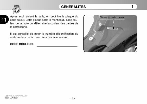
GÉNÉRALITÉS 1
1
FR
- 10 -
Après avoir enlevé la selle, on peut lire la plaque ducode coleur. Cette plaque porte la mention du code cou-leur de la moto qui détermine la couleur des parties dela carrosserie.
Il est conseillé de noter le numéro d’identification ducode couleur de la moto dans l’espace suivant:
CODE COULEUR:
Plaque du code couleur
INFORMATIONS SUR LA SÉCURITÉ 2
2 FR
- 11 -
2.1. UTILISATION ADMISE DU VEHICULE
La moto a été conçue pour une utilisation surroute et autoroute.
ATTENTIONIl est possible d’utiliser occasionnelle-ment la moto sur piste mais pas dans lecadre de compétitions.En raison des contraintes supplémen-taires auxquelles est alors soumise lamoto, nous vous recommandons defaire contrôler par un Centred’Assistance MV Agusta les conditionsde la moto avant et après l’emploi.Toute autre utilisation est interdite etexpressément exclue.
Vous trouverez d’autres informations sur l’utilisa-tion de la moto dans la section 4 du présentManuel.
2.2. ENTRETIEN
Pour garantir l’efficacité et la fiabilité maximum duvéhicule, il est indispensable d’effectuer les opé-rations d’entretien indiquées dans le Manueld’Entretien.MV Agusta insiste sur le fait que toutes les opéra-tions d’entretien doivent être effectuées unique-ment par un personnel qualifié appartenant à unCentre d’Assistance MV Agusta.Si toutefois vous décidez de faire exécuter lesinterventions d’entretien par des ateliers nonagréés, nous vous conseillons de vous assurerqu’ils disposent des instruments spécifiquesnécessaires à de telles opérations.
ATTENTIONLa garantie MV Agusta pourrait ne pasêtre valable si les ateliers non agréésont effectué des interventions sur lamoto de manière incorrecte et non pré-vue par les Circulaires Techniques et lesManuels d’Atelier MV Agusta.
INFORMATIONS SUR LA SÉCURITÉ 2
2
FR
- 12 -
2.3. ACCESSOIRES ET MODIFICATIONS
ATTENTIONPour garantir la sécurité de ses Clients,MV Agusta interdit toute modificationaux motos.
Toutefois, vous pouvez personnaliser votre motoen utilisant les Accessoires MV Agusta.
ATTENTIONL’installation de quelques-uns de cesaccessoires peut annuler l’homologa-tion de la moto et entraîner la non-utili-sation sur route publique.
Dans le doute, nous vous invitons à contactervotre Concessionnaire de confiance pour identi-fier les accessoires les plus appropriés à vos exi-gences.
2.4. CHARGEMENT DU VÉHICULE
Le véhicule a été conçu pour être utilisé par unpilote et le cas échéant un passager.Pour l'utiliser en toute sécurité et dans le respectdes dispositions du code de la route, il est obliga-toire de ne jamais dépasser le poids lourd totalmaximum admis dont le valeur est indiquée ci-dessous.
BRUTALE 675Masse maximum techniquement admissible
364 kgMasse maximum transportable
180 kg
La masse maximum techniquement admissibleest la somme des masses suivantes:
• masse de la moto;• masse du pilote;• masse du passager;• masse du bagage et des accessoires.
INFORMATIONS SUR LA SÉCURITÉ 2
2 FR
- 13 -
ATTENTIONEtant donné que le chargement a unimpact énorme sur la mania-bilité le frei-nage, les performances et les caracté-ristiques de sécurité de votre moyen detransport, prenez toujours les précau-tions suivantes.
• NE SURCHARGEZ JAMAIS LE MOTO-CYCLE! L’utilisation d’une moto sur-chargée peut provoquer des dégâts auxpneumatiques, des pertes de contrôleou des accidents graves. Vérifiez que lepoids total du pilote, du passager, duchargement et des accessoires nedépasse pas la masse maximum admis-sible spécifique à votre véhicule.
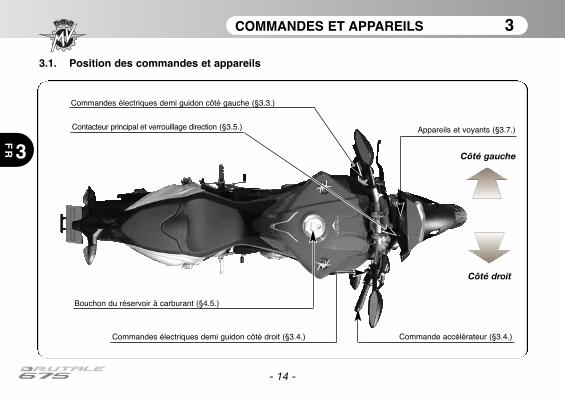
COMMANDES ET APPAREILS 3
FR 3
- 14 -
3.1. Position des commandes et appareils
Appareils et voyants (§3.7.)
Commandes électriques demi guidon côté gauche (§3.3.)
Bouchon du réservoir à carburant (§4.5.)
Contacteur principal et verrouillage direction (§3.5.)
Commande accélérateur (§3.4.)Commandes électriques demi guidon côté droit (§3.4.)
Côté gauche
Côté droit

COMMANDES ET APPAREILS 3
FR3
- 15 -
Levier d’embrayage (§5.1.)
Sélecteur de vitesses (§3.6. et §5.1.)Béquille latérale (§3.2.)
Marchepied pourpassager
Marchepied pourpassager
Poignées pourpassager
Rétroviseurs (§5.1.)Levier de frein avant(§5.1.)
Pédale de frein arrière (§5.1.)
Cale-pied
Cale-pied
Poignées pourpassager
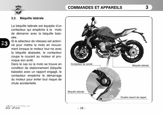
COMMANDES ET APPAREILS 3
3
FR
- 16 -
3.2. Béquille latérale
La béquille latérale est équipée d’uncontacteur qui empêche à la motode démarrer avec la béquille bais-sée.Si le sélecteur de vitesses est action-né pour mettre la moto en mouve-ment lorsque le moteur tour-ne avecla béquille abaissée, le contacteurcoupe le courant au moteur et pro-voque son arrêt.Dans le cas où la moto se trouve encondition de stationnement (béquillebaissée) avec un rapport engagé, lecontacteur empêche le démarragedu moteur pour éviter tout risque dechute accidentelle.
Béquille latérale
Double ressort de rappel
Contacteur de sûreté
Béquille latérale

COMMANDES ET APPAREILS 3
3 FR
- 17 -
3.3. Commandes au guidon côté gauche
Bouton de clignotement des pharesAppuyer sur le bouton à répétition.
Inverseur code/phareBouton sorti : feu de croisementBouton enfoncé : feu de route
Poussoir de clignotantsEn le déplaçant vers la droit ou la gauche on allume les cli-gnotants correspondants. Le poussoir revient au centre,appuyer dessus pour éteindre les clignotants.
Bouton de l’avertisseur sonoreAppuyer pour utiliser l’avertisseur.
Levier d’embrayageTirer ou relâcher la poignée pour débrayer ouembrayer.
COMMANDES ET APPAREILS 3
3
FR
- 18 -
Bouton d’appel de phareCette fonction sert pour rappeler l’attention des autres usagers de la route en présence d’une situation dange-reuse. Avec le feu de route éclairé, cette fonction est désactivée.
Bouton Inverseur code/phareC’est normalement la fonction code qui s’allume. Lorsque les de trafic et de route le permettent, il est possibled’allumer le feu de route en agissant sur l’inverseur.
Levier des clignotantsCette fonction permet de signaler aux autres usagers de la route, l’intention de changer de direction ou de voiede circulation.
ATTENTIONSi les clignotants ne sont pas utilisés ou coupés au moment opportun, il peut y avoir un risqued'accidents. En effet, les autres conducteurs pourraient tirer des conclusions erronées concer-nant la trajectoire du véhicule. Actionnez toujours les clignotants avant de tourner ou de changerde voie. Veillez à les couper dès que la manoeuvre est terminée.
Bouton de klaxonCette fonction sert pour attirer l’attention des autres usagers en cas de situations éventuelles de danger.
Levier d’embrayageCe levier, à travers un dispositif à contrôle hydraulique, permet de débrayer et d’embrayer.
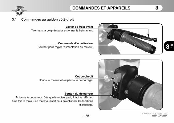
COMMANDES ET APPAREILS 3
3 FR
- 19 -
3.4. Commandes au guidon côté droit
Coupe-circuitCoupe le moteur et empêche le démarrage.
Bouton du démarreurActionne le démarreur. Dès que le moteur part, il faut le relâcher.
Une fois le moteur en marche, il sert pour sélectionner les fonctionsd’affichage.
Commande d’accélérateurTourner pour régler l’alimentation du moteur.
Levier de frein avantTirer vers la poignée pour actionner le frein avant.
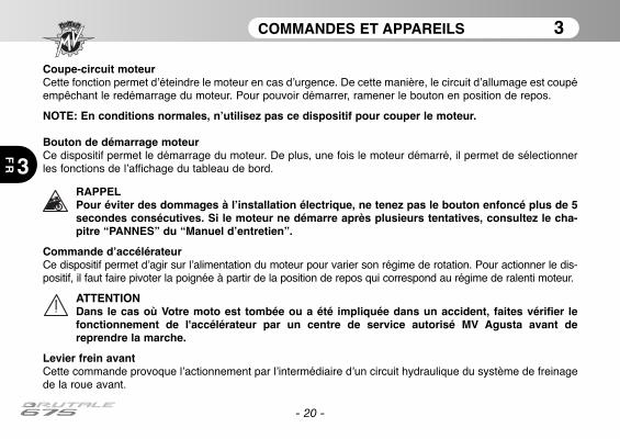
COMMANDES ET APPAREILS 3
3
FR
- 20 -
Coupe-circuit moteurCette fonction permet d’éteindre le moteur en cas d’urgence. De cette manière, le circuit d’allumage est coupéempêchant le redémarrage du moteur. Pour pouvoir démarrer, ramener le bouton en position de repos.
NOTE: En conditions normales, n’utilisez pas ce dispositif pour couper le moteur.
Bouton de démarrage moteurCe dispositif permet le démarrage du moteur. De plus, une fois le moteur démarré, il permet de sélectionnerles fonctions de l’affichage du tableau de bord.
RAPPELPour éviter des dommages à l’installation électrique, ne tenez pas le bouton enfoncé plus de 5secondes consécutives. Si le moteur ne démarre après plusieurs tentatives, consultez le cha-pitre “PANNES” du “Manuel d’entretien”.
Commande d’accélérateurCe dispositif permet d’agir sur l’alimentation du moteur pour varier son régime de rotation. Pour actionner le dis-positif, il faut faire pivoter la poignée à partir de la position de repos qui correspond au régime de ralenti moteur.
ATTENTIONDans le cas où Votre moto est tombée ou a été impliquée dans un accident, faites vérifier lefonctionnement de l'accélérateur par un centre de service autorisé MV Agusta avant dereprendre la marche.
Levier frein avantCette commande provoque l’actionnement par l’intermédiaire d’un circuit hydraulique du système de freinagede la roue avant.

COMMANDES ET APPAREILS 3
3 FR
- 21 -
3.5. Contacteur principal et verrouillage de direction
ATTENTION: Ne pas appliquer de porte-clés ou autre à la clé de contact pour ne pas risquerde gêner la rotation de la direction.
ATTENTION: Ne jamais chercher à changer certaines fonctions du contacteur en cours deroute sous peine de perdre le contrôle du véhicule .
Position “ON”
Position “OFF”Contacteur principal et verrouillage de direction
Position “LOCK”
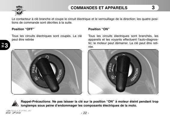
COMMANDES ET APPAREILS 3
3
FR
Le contacteur à clé branche et coupe le circuit électrique et le verrouillage de la direction; les quatre posi-tions de commande sont décrites à la suite.
Rappel-Précautions: Ne pas laisser la clé sur la position “ON” à moteur éteint pendant troplongtemps sous peine d’endommager les composants électriques de la moto.
Position “OFF”
Tous les circuits électriques sont coupés. La clépeut être retirée
Position “ON”
Tous les circuits électriques sont branchés, lesappareils et les voyants effectuent l’auto-diagnos-tic; le moteur peut démarrer. La clé peut être reti-rée.
- 22 -
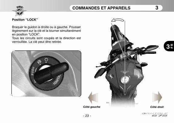
COMMANDES ET APPAREILS 3
3 FR
- 23 -
Position “LOCK”
Braquer le guidon à droite ou à gauche. Pousserlégèrement sur la clé et la tourner simultanémenten position “LOCK”.Tous les circuits sont coupés et la direction estverrouillée. La clé peut être retirée.
Côté gauche Côté droit

COMMANDES ET APPAREILS 3
3
FR
- 24 -
3.6. Sélecteur de vitessesLa position N “Neutral” correspond au point mortsignalé par le voyant correspondant sur le tableaude bord. En déplaçant le sélecteur vers le bas, onengage la première vitesse.De la même manière, en déplaçant le sélecteurvers le haut, on passe la seconde vitesse et ainside suite à mesure que l’on déplace le sélecteurvers le haut, on passe dans l’ordre toutes lesvitesses suivantes jusqu’à la sixième.
❏ Fonction “Quick Shift” *Certains modèles Brutale sont équipés d'un système dechangement rapide de vitesse (“Quick Shift”); cet appa-reil permet de enclencher le rapport supérieur sans tirerl'embrayage ou changer l'angle de la commande desgaz. De cette façon, il est possible de engager lesvitesses supérieures en gardant une accélérationconstante et de réduire les temps de changement auminimum. Le système “Quick Shift” n'est pas disponiblelorsque lors du changement de vitesse avec le levierd'embrayage enfoncée ou à une vitesse inférieure à 30km/h, ni lors du passage dans les rapports inférieurs.
(*): Fonction présente uniquement sur certains modèles;disponible en aftermarket pour tous les modèles
1°
N
2°
3°
4°
5°
6°
ATTENTION: Lorsque la conduite du véhi-cule avec le moteur à un régime élevé etune basse vitesse, changer de vitessesans tirer sur le levier d'embrayage peutprovoquer des réactions brusques ce quipeut compromettre la stabilité du véhicule.MV Agusta recommande de tirer le levierd'embrayage dans ces circonstances, enparticulier lorsque le régime moteur estproche de la vitesse de l'intervention dulimiteur.
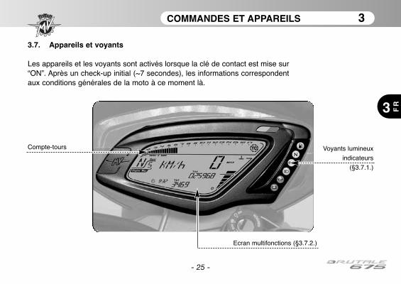
COMMANDES ET APPAREILS 3
3 FR
- 25 -
3.7. Appareils et voyants
Les appareils et les voyants sont activés lorsque la clé de contact est mise sur“ON”. Après un check-up initial (~7 secondes), les informations correspondentaux conditions générales de la moto à ce moment là.
Voyants lumineux
indicateurs
(§3.7.1.)
Ecran multifonctions (§3.7.2.)
Compte-tours
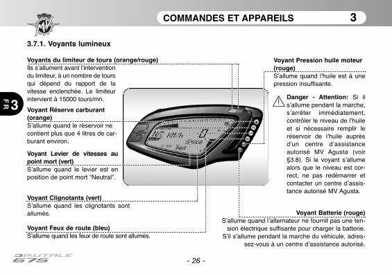
COMMANDES ET APPAREILS 3
3
FR
- 26 -
3.7.1. Voyants lumineux
Voyant Feux de route (bleu) S’allume quand les feux de route sont allumés.
Voyant Levier de vitesses aupoint mort (vert)S’allume quand le levier est enposition de point mort “Neutral”.
Voyant Clignotants (vert) S’allume quand les clignotants sontallumés.
Voyant Réserve carburant(orange)S’allume quand le réservoir necontient plus que 4 litres de car-burant environ.
Voyant Batterie (rouge)S’allume quand l’alternateur ne fournit pas une ten-
sion électrique suffisante pour charger la batterie.S’il s’allume pendant la marche du véhicule, adres-
sez-vous à un centre d’assistance autorisé.
Voyants du limiteur de tours (orange/rouge)Ils s’allument avant l’interventiondu limiteur, à un nombre de toursqui dépend du rapport de lavitesse enclenchée. Le limiteurintervient à 15000 tours/mn.
Voyant Pression huile moteur(rouge)S’allume quand l’huile est à unepression insuffisante.
Danger - Attention: Si ils’allume pendant la marche,s’arrêter immédiatement,contrôler le niveau de l’huileet si nécessaire remplir leréservoir de l’huile auprèsd’un centre d’assistanceautorisé MV Agusta (voir§3.8). Si le voyant s’allumealors que le niveau est cor-rect, ne pas redémarrer etcontacter un centre d’assis-tance autorisé MV Agusta.
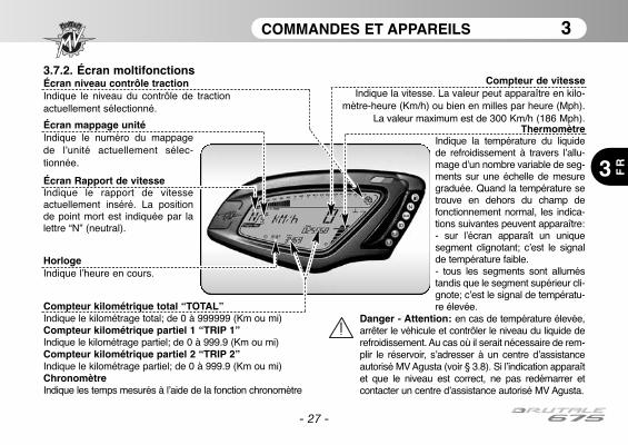
COMMANDES ET APPAREILS 3
3 FR
- 27 -
3.7.2. Écran moltifonctionsCompteur de vitesse
Indique la vitesse. La valeur peut apparaître en kilo-mètre-heure (Km/h) ou bien en milles par heure (Mph).
La valeur maximum est de 300 Km/h (186 Mph).
Compteur kilométrique total “TOTAL” Indique le kilométrage total; de 0 à 999999 (Km ou mi)Compteur kilométrique partiel 1 “TRIP 1” Indique le kilométrage partiel; de 0 à 999.9 (Km ou mi)Compteur kilométrique partiel 2 “TRIP 2” Indique le kilométrage partiel; de 0 à 999.9 (Km ou mi)ChronomètreIndique les temps mesurés à l’aide de la fonction chronomètre
ThermomètreIndique la température du liquidede refroidissement à travers l’allu-mage d’un nombre variable de seg-ments sur une échelle de mesuregraduée. Quand la température setrouve en dehors du champ defonctionnement normal, les indica-tions suivantes peuvent apparaître:- sur l’écran apparaît un uniquesegment clignotant; c’est le signalde température faible.- tous les segments sont alluméstandis que le segment supérieur cli-gnote; c’est le signal de températu-re élevée.
Danger - Attention: en cas de température élevée,arrêter le véhicule et contrôler le niveau du liquide derefroidissement. Au cas où il serait nécessaire de rem-plir le réservoir, s’adresser à un centre d’assistanceautorisé MV Agusta (voir § 3.8). Si l’indication apparaîtet que le niveau est correct, ne pas redémarrer etcontacter un centre d’assistance autorisé MV Agusta.
Écran Rapport de vitesse Indique le rapport de vitesseactuellement inséré. La positionde point mort est indiquée par lalettre “N” (neutral).
HorlogeIndique l’heure en cours.
Écran mappage unitéIndique le numéro du mappagede l’unité actuellement sélec-tionnée.
Écran niveau contrôle tractionIndique le niveau du contrôle de tractionactuellement sélectionné.
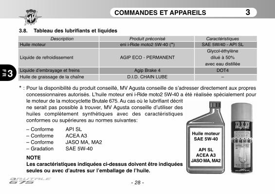
COMMANDES ET APPAREILS 3
3
FR
- 28 -
3.8. Tableau des lubrifiants et liquides
* : Pour la disponibilité du produit conseillé, MV Agusta conseille de s’adresser directement aux propresconcessionnaires autorisés. L’huile moteur eni i-Ride moto2 5W-40 a été réalisée spécialement pourle moteur de la motocyclette Brutale 675. Au cas où le lubrifiant décritne serait pas possible à trouver, MV Agusta conseille d’utiliser deshuiles complètement synthétiques avec des caractéristiquesconformes ou supérieures au normes suivantes:
– Conforme API SL– Conforme ACEA A3– Conforme JASO MA, MA2– Gradation SAE 5W-40
NOTELes caractéristiques indiquées ci-dessus doivent être indiquéesseules ou avec d’autres sur l’emballage de l’huile.
Huile moteurSAE 5W-40
API SLACEA A3
JASO MA, MA2
Description Produit préconisé CaractéristiquesHuile moteur eni i-Ride moto2 5W-40 (*) SAE 5W/40 - API SL
Glycol-éthylèneLiquide de refroidissement AGIP ECO - PERMANENT dilué à 50%
avec eau distilléeLiquide d’embrayage et freins Agip Brake 4 DOT4Huile de graissage de la chaîne D.I.D. CHAIN LUBE –
UTILISATION 4
4 FR
- 29 -
4.1. Utilisation de la moto
Cette partie du livret expose les principaux points qui permettent une utilisation correcte de la moto.
ATTENTIONLa moto Brutale 675 montre caractéristiques élevées de puissance et de performances;pour l’utilisation, il est donc requise un niveau adéquat de connaissance du véhicule. Lorsde la première utilisation de la moto, il est nécessaire de garder une attitude prudente. Uneagressive ou impulsive attitude de conduite peut augmenter les risques d’accidents etreprésenter un danger pour Votre sécurité et celle d’autrui.
ATTENTIONLES LIMITATIONS CONCERNANT L’UTILISATION ADMISE DU VEHICULE SONTREPORTÉES DANS LA SECTION “INFORMATIONS POUR LA SÉCURITÉ”.
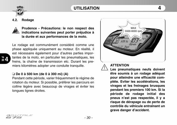
UTILISATION 4
4
FR
- 30 -
4.2. Rodage
Prudence - Précautions: le non respect desindications suivantes peut porter préjudice àla durée et aux performances de la moto.
Le rodage est communément considéré comme unephase appliquée uniquement au moteur. En réalité, ilest nécessaire également pour d’autres parties impor-tantes de la moto, en particulier les pneumatiques, lesfreins, la chaîne de transmission etc. Durant les pre-miers kilomètres adopter une conduite tranquille.
❏ De 0 à 500 km (de 0 à 300 mi) (A)Pendant cette période, varier fréquemment le régime derotation du moteur. Si possible, préférer les parcours encolline légère avec beaucoup de virages et éviter leslongues lignes droites.
ATTENTIONLes pneumatiques neufs doiventêtre soumis à un rodage adéquatpour atteindre une efficacité com-plète. Eviter les accélérations, lesvirages et les freinages brusquespendant les premiers 100 km. Si lapériode de rodage initial despneus n’est pas respectée, il y arisque de dérapage ou de perte decontrôle du véhicule entraînant ungrave danger d’accident.
MAX 5500-6000 rpm

UTILISATION 4
4 FR
- 31 -
❏ De 500 à 1000 km (de 300 à 600 mi)Pendant cette période, éviter les efforts prolongés dumoteur.
❏ De 1000 à 2500 km (de 600 à 1600 mi)Pendant cette période, il est possible de pousser un peuplus le moteur sans toutefois dépasser le régime indi-qué.
MAX8000-9000 rpm
MAX 11000 rpm
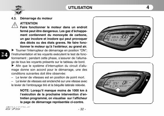
UTILISATION 4
4
FR
- 32 -
4.3. Démarrage du moteur
ATTENTIONFaire fonctionner le moteur dans un endroitfermé peut être dangereux. Les gaz d’échappe-ment contiennent du monoxyde de carbone,un gaz incolore et inodore qui peut provoquerdes décès ou des états graves. Ne faire fonc-tionner le moteur qu’à l’extérieur, au grand air.
Tourner l’interrupteur de démarrage en position “ON”;l’instrumentation et les voyants exécutent le test de fonc-tionnement ; pendant cette phase, s’assurer de l’alluma-ge de tous les voyants présents sur le tableau de bord.
Afin que le système d’interruption du circuit d’allu-mage donne son accord pour le démarrage, une desconditions suivantes doit être observée:– Le levier de vitesses est en position de point mort.– Le levier de vitesses est enclenché sur une vitesse avecle levier de l’embrayage tiré et la béquille latérale relevée.
NOTE: Lorsqu’il manque moins de 1000 km àl’exécution de la prochaine intervention d’en-tretien programmé, on visualise sur l’afficheurla page de démarrage représentée ci-contre.
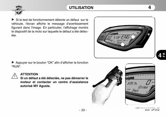
- 33 -
UTILISATION 4
4 FR
Si le test de fonctionnement détecte un défaut sur levéhicule, l'écran affiche le message d'avertissementfigurant dans l’image. En particulier, l'affichage montrele dispositif de la moto sur laquelle le défaut a été détec-tée.
Appuyer sur le bouton “OK” afin d’afficher la fonction“RUN”.
ATTENTIONSi un défaut a été détectée, ne pas démarrer lemoteur et contacter un centre d’assistanceautorisé MV Agusta.
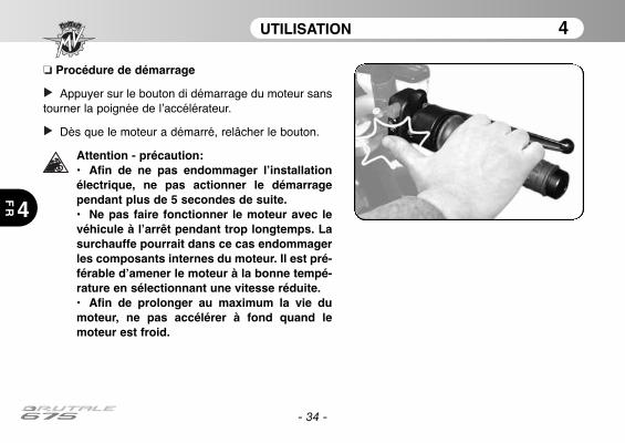
UTILISATION 4
4
FR
- 34 -
❏ Procédure de démarrage
Appuyer sur le bouton di démarrage du moteur sanstourner la poignée de l’accélérateur.
Dès que le moteur a démarré, relâcher le bouton.
Attention - précaution:• Afin de ne pas endommager l’installationélectrique, ne pas actionner le démarragependant plus de 5 secondes de suite.• Ne pas faire fonctionner le moteur avec levéhicule à l’arrêt pendant trop longtemps. Lasurchauffe pourrait dans ce cas endommagerles composants internes du moteur. Il est pré-férable d’amener le moteur à la bonne tempé-rature en sélectionnant une vitesse réduite.• Afin de prolonger au maximum la vie dumoteur, ne pas accélérer à fond quand lemoteur est froid.

UTILISATION 4
4 FR
- 35 -
4.4. Sélection et modification des fonctions à l’écran
L’instrumentation prévoit la possibilité d’intervenir surcertains des paramètres de mesure principaux. Les opérations possibles sont:
- Sélection des modalités de fonctionnement:
“RUN” (Compteur kilométrique)“SPEED LIMITER” (Limiteur de vitesse)“TC” (Contrôle de la traction)“CHRONO” (Chronomètre)“QUICK SHIFT” (Changement de vitesse rapide)*“CLOCK” (Horloge)
- Mise à zéro des fonctions des compteurs kilomé-triques partiels:Compteur kilométrique Partiel 1 “TRIP 1”Compteur kilométrique Partiel 2 “TRIP 2”
- Actionnement de la fonction chronomètre
- Configuration de l’horloge
- Sélection représentation de la centrale
(*): Fonction présente uniquement sur certains modèles;disponible en aftermarket pour tous les modèles
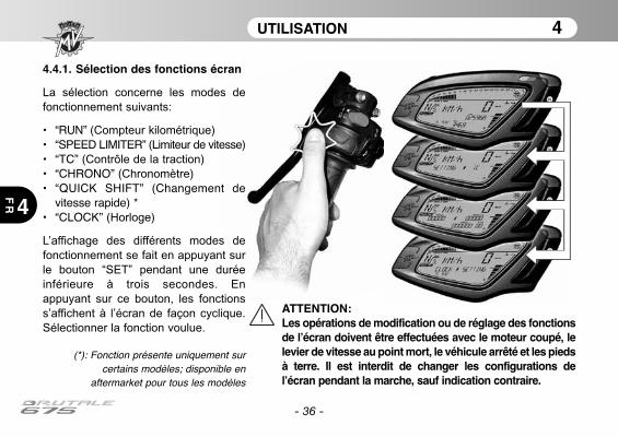
UTILISATION 4
4
FR
- 36 -
ATTENTION: Les opérations de modification ou de réglage des fonctionsde l’écran doivent être effectuées avec le moteur coupé, lelevier de vitesse au point mort, le véhicule arrêté et les piedsà terre. Il est interdit de changer les configurations del’écran pendant la marche, sauf indication contraire.
4.4.1. Sélection des fonctions écran
La sélection concerne les modes de
fonctionnement suivants:
• “RUN” (Compteur kilométrique)• “SPEED LIMITER” (Limiteur de vitesse)• “TC” (Contrôle de la traction)• “CHRONO” (Chronomètre)• “QUICK SHIFT” (Changement de
vitesse rapide) *• “CLOCK” (Horloge)
L’affichage des différents modes de
fonctionnement se fait en appuyant sur
le bouton “SET” pendant une durée
inférieure à trois secondes. En
appuyant sur ce bouton, les fonctions
s’affichent à l’écran de façon cyclique.
Sélectionner la fonction voulue.
(*): Fonction présente uniquement surcertains modèles; disponible en
aftermarket pour tous les modèles
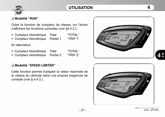
UTILISATION 4
4 FR
- 37 -
❏ Modalité “RUN”
Outre la fonction de compteur de vitesse, sur l’écran
s’affichent les fonctions suivantes (voir §4.4.2.):
• Compteur kilométrique Total “TOTAL”
• Compteur kilométrique Partiel 1 “TRIP 1”
En alternative:
• Compteur kilométrique Total “TOTAL”
• Compteur kilométrique Partiel 2 “TRIP 2”
❏ Modalité “SPEED LIMITER”
Cette fonction permet d’adapter la valeur maximale de
la vitesse du véhicule selon vos propres exigences de
conduite (voir § 4.4.3.).
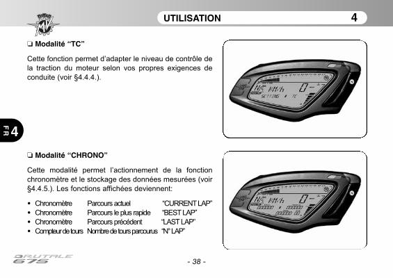
UTILISATION 4
4
FR
- 38 -
❏ Modalité “CHRONO”
Cette modalité permet l’actionnement de la fonction
chronomètre et le stockage des données mesurées (voir
§4.4.5.). Les fonctions affichées deviennent:
• Chronomètre Parcours actuel “CURRENT LAP”
• Chronomètre Parcours le plus rapide “BEST LAP”
• Chronomètre Parcours précédent “LAST LAP”
• Compteur de tours Nombre de tours parcourus “N° LAP”
❏ Modalité “TC”
Cette fonction permet d’adapter le niveau de contrôle de
la traction du moteur selon vos propres exigences de
conduite (voir §4.4.4.).
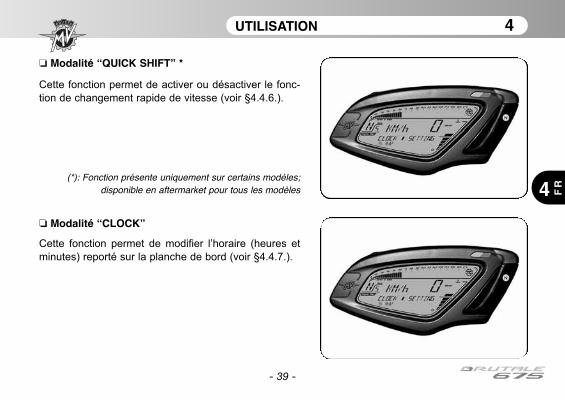
UTILISATION 4
4 FR
- 39 -
❏ Modalité “CLOCK”
Cette fonction permet de modifier l’horaire (heures et
minutes) reporté sur la planche de bord (voir §4.4.7.).
❏ Modalité “QUICK SHIFT” *
Cette fonction permet de activer ou désactiver le fonc-
tion de changement rapide de vitesse (voir §4.4.6.).
(*): Fonction présente uniquement sur certains modèles;disponible en aftermarket pour tous les modèles

- 40 -
UTILISATION 4
4
FR
4.4.2. Mise à zéro des fonctions des compteurskilométriques partiels
Les valeurs des fonctions “TRIP 1” et “TRIP 2” peu-
vent être mise à zéro de la façon suivante.
ATTENTIONLes opérations de modification ou de régla-ge des fonctions de l’écran doivent êtreeffectuées avec le moteur coupé, le levier devitesse au point mort, le véhicule arrêté etles pieds à terre. Il est interdit de changerles configurations de l’écran pendant lamarche.
Accéder à la modalité “RUN”; la page-écran initia-
le indique les fonctions de compteur kilométrique total
(“TOTAL”) et partiel 1 (“TRIP 1”).
En appuyant sur le bouton “OK” pendant plus de
trois secondes, on met la valeur “TRIP 1” à zéro.
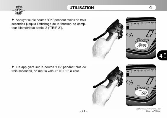
- 41 -
UTILISATION 4
4 FR
Appuyer sur le bouton “OK” pendant moins de trois
secondes jusqu’à l’affichage de la fonction de comp-
teur kilométrique partiel 2 (“TRIP 2”).
En appuyant sur le bouton “OK” pendant plus de
trois secondes, on met la valeur “TRIP 2” à zéro.
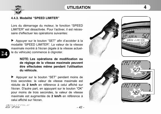
4.4.3. Modalité “SPEED LIMITER”
Lors du démarrage du moteur, le fonction “SPEEDLIMITER” est désactivée. Pour l'activer, il est néces-saire d'effectuer les opérations suivantes:
Appuyer sur le bouton “SET” afin d’accéder à la
modalité “SPEED LIMITER”. La valeur de la vitesse
maximale montré à l'écran (égale à la vitesse actuel-
le du véhicule) commence à clignoter.
NOTE: Les opérations de modification oude réglage de la vitesse maximale peuventêtre effectuées même pendant l'utilisationdu véhicule.
Appuyer sur le bouton “SET” pendant moins de
trois secondes: la valeur de vitesse maximale est
réduite de 2 km/h en référence à celui affiché sur
l'écran. D'autre part, en appuyant sur le bouton “OK ”pour moins de trois secondes, la valeur de vitesse
maximale est augmentée de 2 km/h en référence à
celui affiché sur l'écran.
- 42 -
UTILISATION 4
4
FR
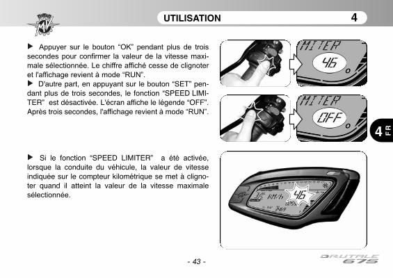
- 43 -
UTILISATION 4
4 FR
Appuyer sur le bouton “OK” pendant plus de trois
secondes pour confirmer la valeur de la vitesse maxi-
male sélectionnée. Le chiffre affiché cesse de clignoter
et l'affichage revient à mode “RUN”.
D'autre part, en appuyant sur le bouton “SET” pen-dant plus de trois secondes, le fonction “SPEED LIMI-TER” est désactivée. L'écran affiche le légende “OFF”.Après trois secondes, l'affichage revient à mode “RUN”.
Si le fonction “SPEED LIMITER” a été activée,lorsque la conduite du véhicule, la valeur de vitesseindiquée sur le compteur kilométrique se met à cligno-ter quand il atteint la valeur de la vitesse maximale
sélectionnée.
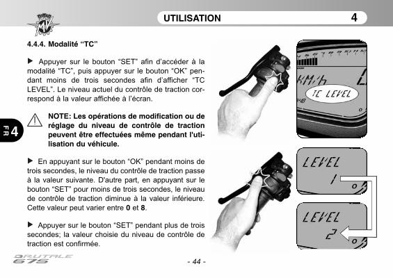
- 44 -
UTILISATION 4
4
FR
4.4.4. Modalité “TC”
Appuyer sur le bouton “SET” afin d’accéder à la
modalité “TC”, puis appuyer sur le bouton “OK” pen-
dant moins de trois secondes afin d’afficher “TC
LEVEL”. Le niveau actuel du contrôle de traction cor-
respond à la valeur affichée à l’écran.
NOTE: Les opérations de modification ou deréglage du niveau de contrôle de tractionpeuvent être effectuées même pendant l'uti-lisation du véhicule.
En appuyant sur le bouton “OK” pendant moins de
trois secondes, le niveau du contrôle de traction passe
à la valeur suivante. D'autre part, en appuyant sur le
bouton “SET” pour moins de trois secondes, le niveau
de contrôle de traction diminue à la valeur inférieure.
Cette valeur peut varier entre 0 et 8.
Appuyer sur le bouton “SET” pendant plus de trois
secondes; la valeur choisie du niveau de contrôle de
traction est confirmée.
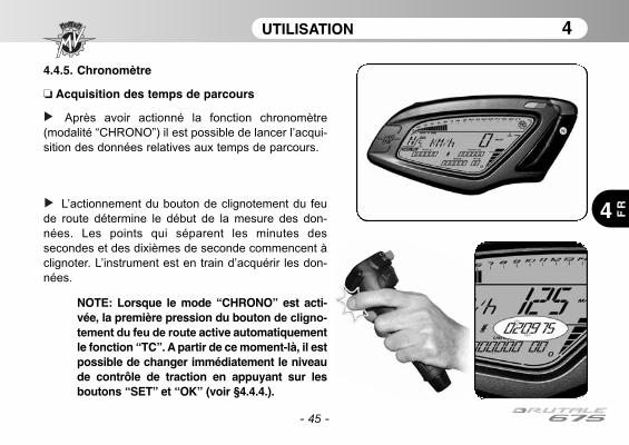
- 45 -
UTILISATION 4
4 FR
4.4.5. Chronomètre
❏ Acquisition des temps de parcours
Après avoir actionné la fonction chronomètre
(modalité “CHRONO”) il est possible de lancer l’acqui-
sition des données relatives aux temps de parcours.
L’actionnement du bouton de clignotement du feu
de route détermine le début de la mesure des don-
nées. Les points qui séparent les minutes des
secondes et des dixièmes de seconde commencent à
clignoter. L’instrument est en train d’acquérir les don-
nées.
NOTE: Lorsque le mode “CHRONO” est acti-vée, la première pression du bouton de cligno-
tement du feu de route active automatiquementle fonction “TC”. A partir de ce moment-là, il estpossible de changer immédiatement le niveaude contrôle de traction en appuyant sur lesboutons “SET” et “OK” (voir §4.4.4.).
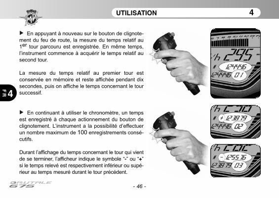
UTILISATION 4
4
FR
- 46 -
En appuyant à nouveau sur le bouton de clignote-
ment du feu de route, la mesure du temps relatif au
1er tour parcouru est enregistrée. En même temps,
l’instrument commence à acquérir le temps relatif au
second tour.
La mesure du temps relatif au premier tour est
conservée en mémoire et reste affichée pendant dix
secondes, puis on affiche le temps concernant le tour
successif.
En continuant à utiliser le chronomètre, un temps
est enregistré à chaque actionnement du bouton de
clignotement. L’instrument a la possibilité d’effectuer
un nombre maximum de 100 enregistrements consé-
cutifs.
Durant l’affichage du temps concernant le tour qui vient
de se terminer, l’afficheur indique le symbole “-” ou “+”
si le temps relevé est respectivement inférieur ou supé-
rieur au temps mesuré durant le tour précédent.

UTILISATION 4
4 FR
- 47 -
❏ Affichage des données
Une fois terminée la phase d’acquisition des temps, il
est possible de les afficher.
Accéder à la modalité “CHRONO”; cette page-
écran affiche le temps concernant le tour le plus rapi-
de (“BEST LAP”) et le temps concernant le dernier
tour parcouru (“LAST LAP”).
ATTENTIONLes opérations de modification ou de régla-ge des fonctions de l’écran doivent êtreeffectuées avec le moteur coupé, le levierde vitesse au point mort, le véhicule arrêtéet les pieds à terre. Il est interdit de changerles configurations de l’écran pendant lamarche.
Appuyer sur le bouton “OK” pendant moins de trois
secondes afin d’afficher “LAPS VIEW”.

UTILISATION 4
4
FR
- 48 -
Une pression répétée sur la touche du clignote-
ment du phare avant permet d’afficher l’un après
l’autre tous les temps saisis précédemment à partir du
dernier tour mémorisé.
Au terme de l’affichage des données, une pression
sur la touche “SET” permet de revenir à la modalité
“LAPS VIEW” pour passer à la modalité successive.
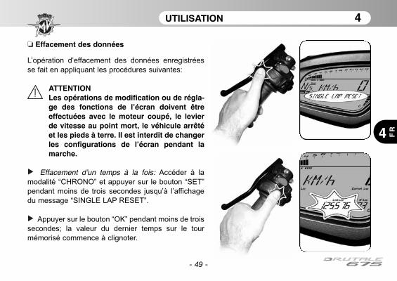
UTILISATION 4
4 FR
- 49 -
❏ Effacement des données
L’opération d’effacement des données enregistrées
se fait en appliquant les procédures suivantes:
ATTENTIONLes opérations de modification ou de régla-ge des fonctions de l’écran doivent êtreeffectuées avec le moteur coupé, le levierde vitesse au point mort, le véhicule arrêtéet les pieds à terre. Il est interdit de changerles configurations de l’écran pendant lamarche.
Effacement d’un temps à la fois: Accéder à la
modalité “CHRONO” et appuyer sur le bouton “SET”
pendant moins de trois secondes jusqu’à l’affichage
du message “SINGLE LAP RESET”.
Appuyer sur le bouton “OK” pendant moins de trois
secondes; la valeur du dernier temps sur le tour
mémorisé commence à clignoter.
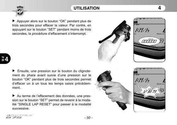
- 50 -
UTILISATION 4
4
FR
Appuyer alors sur le bouton “OK” pendant plus de
trois secondes pour effacer la valeur. Par contre, en
appuyant sur le bouton “SET” pendant moins de trois
secondes, la procédure d’effacement s’interrompt.
Ensuite, une pression sur le bouton du clignote-
ment du phare avant suivie d’une pression sur le
bouton “OK” pendant plus de trois secondes permet
d’effacer un à un tous les temps saisis précédem-
ment.
Au terme de l’effacement des données, une pres-
sion sur le bouton “SET” permet de revenir à la moda-
lité “SINGLE LAP RESET” pour passer à la modalité
successive.

- 51 -
UTILISATION 4
4 FR
Effacement du meilleur temps: Accéder à la moda-
lité “CHRONO” et appuyer sur le bouton “SET” pen-
dant moins de trois secondes jusqu’à l’affichage du
message “BEST LAP RESET”.
Appuyer sur le bouton “OK” pendant moins de trois
secondes; la valeur du temps sur le tour le plus rapi-
de commence à clignoter.
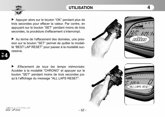
- 52 -
UTILISATION 4
4
FR
Appuyer alors sur le bouton “OK” pendant plus de
trois secondes pour effacer la valeur. Par contre, en
appuyant sur le bouton “SET” pendant moins de trois
secondes, la procédure d’effacement s’interrompt.
Au terme de l’effacement des données, une pres-
sion sur le bouton “SET” permet de quitter la modali-
té “BEST LAP RESET” pour passer à la modalité suc-
cessive.
Effacement de tous les temps mémorisés:Accéder à la modalité “CHRONO” et appuyer sur le
bouton “SET“ pendant moins de trois secondes jus-
qu’à l’affichage du message “ALL LAPS RESET”.
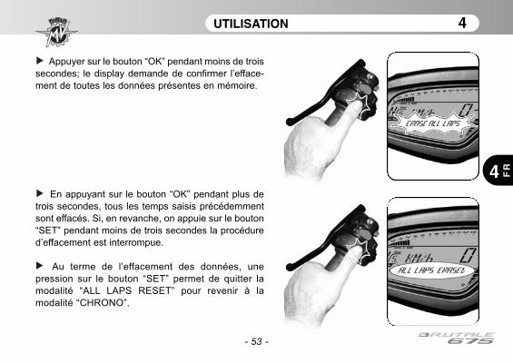
- 53 -
UTILISATION 4
4 FR
Appuyer sur le bouton “OK” pendant moins de trois
secondes; le display demande de confirmer l’efface-
ment de toutes les données présentes en mémoire.
En appuyant sur le bouton “OK” pendant plus de
trois secondes, tous les temps saisis précédemment
sont effacés. Si, en revanche, on appuie sur le bouton
“SET” pendant moins de trois secondes la procédure
d’effacement est interrompue.
Au terme de l’effacement des données, une
pression sur le bouton “SET” permet de quitter la
modalité “ALL LAPS RESET” pour revenir à la
modalité “CHRONO”.
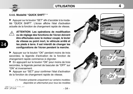
- 54 -
UTILISATION 4
4
FR
4.4.6. Modalité “QUICK SHIFT” *
Appuyer sur le bouton “SET” afin d’accéder à la moda-
lité “QUICK SHIFT”. L'écran affiche l'état d'activation
actuelle de la fonction de changement rapide de vitesse.
ATTENTION: Les opérations de modificationou de réglage des fonctions de l’écran doiventêtre effectuées avec le moteur coupé, le levierde vitesse au point mort, le véhicule arrêté etles pieds à terre. Il est interdit de changer lesconfigurations de l’écran pendant la marche.
Appuyer sur le bouton “OK” pendant moins de trois
secondes; la légende d'activation de la fonction de
changement rapide commence à clignoter.
En appuyant sur le bouton “OK” pour moins de troissecondes, la légende permet de basculer de “OFF” sur“ON” et inversement.
Appuyer sur “SET” pour confirmer l'état d'activation
de la fonction de changement rapide de vitesse.
(*): Fonction présente uniquement sur certains modèles;disponible en aftermarket pour tous les modèles
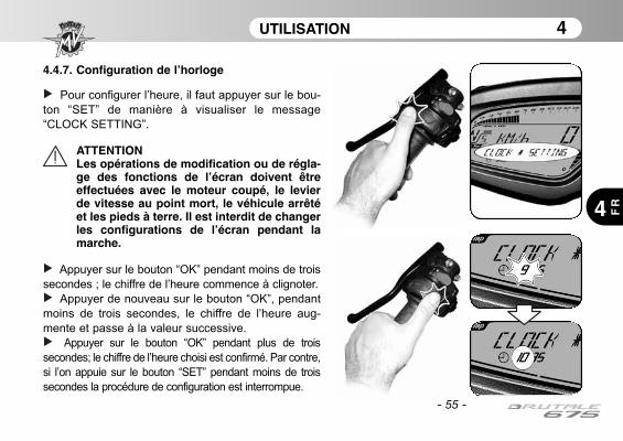
- 55 -
UTILISATION 4
4 FR
4.4.7. Configuration de l’horloge
Pour configurer l’heure, il faut appuyer sur le bou-
ton “SET” de manière à visualiser le message
“CLOCK SETTING”.
ATTENTIONLes opérations de modification ou de régla-ge des fonctions de l’écran doivent êtreeffectuées avec le moteur coupé, le levierde vitesse au point mort, le véhicule arrêtéet les pieds à terre. Il est interdit de changerles configurations de l’écran pendant lamarche.
Appuyer sur le bouton “OK” pendant moins de trois
secondes ; le chiffre de l’heure commence à clignoter.
Appuyer de nouveau sur le bouton “OK”, pendant
moins de trois secondes, le chiffre de l’heure aug-
mente et passe à la valeur successive.
Appuyer sur le bouton “OK” pendant plus de trois
secondes; le chiffre de l’heure choisi est confirmé. Par contre,
si l’on appuie sur le bouton “SET” pendant moins de trois
secondes la procédure de configuration est interrompue.
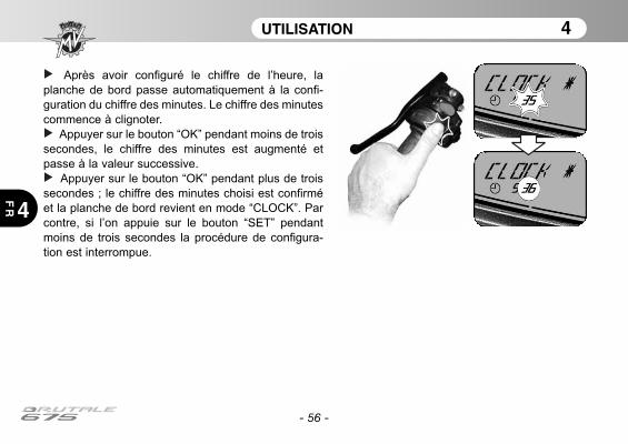
- 56 -
UTILISATION 4
4
FR
Après avoir configuré le chiffre de l’heure, la
planche de bord passe automatiquement à la confi-
guration du chiffre des minutes. Le chiffre des minutes
commence à clignoter.
Appuyer sur le bouton “OK” pendant moins de trois
secondes, le chiffre des minutes est augmenté et
passe à la valeur successive.
Appuyer sur le bouton “OK” pendant plus de trois
secondes ; le chiffre des minutes choisi est confirmé
et la planche de bord revient en mode “CLOCK”. Par
contre, si l’on appuie sur le bouton “SET” pendant
moins de trois secondes la procédure de configura-
tion est interrompue.
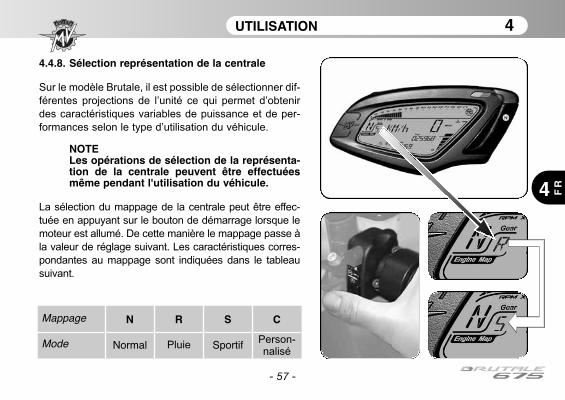
- 57 -
UTILISATION 4
4 FR
4.4.8. Sélection représentation de la centrale
Sur le modèle Brutale, il est possible de sélectionner dif-
férentes projections de l’unité ce qui permet d’obtenir
des caractéristiques variables de puissance et de per-
formances selon le type d’utilisation du véhicule.
NOTELes opérations de sélection de la représenta-tion de la centrale peuvent être effectuéesmême pendant l'utilisation du véhicule.
La sélection du mappage de la centrale peut être effec-
tuée en appuyant sur le bouton de démarrage lorsque le
moteur est allumé. De cette manière le mappage passe à
la valeur de réglage suivant. Les caractéristiques corres-
pondantes au mappage sont indiquées dans le tableau
suivant.
Mappage
Mode
N
Normal
R
Pluie
S
Sportif
C
Person-nalisé
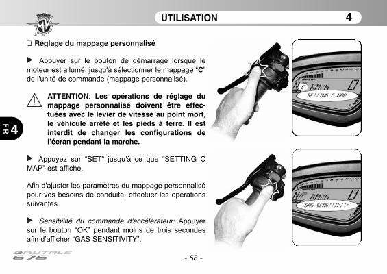
- 58 -
UTILISATION 4
4
FR
❏ Réglage du mappage personnalisé
Appuyer sur le bouton de démarrage lorsque le
moteur est allumé, jusqu'à sélectionner le mappage “C”
de l'unité de commande (mappage personnalisé).
ATTENTION: Les opérations de réglage dumappage personnalisé doivent être effec-tuées avec le levier de vitesse au point mort,le véhicule arrêté et les pieds à terre. Il estinterdit de changer les configurations del’écran pendant la marche.
Appuyez sur “SET” jusqu'à ce que “SETTING CMAP” est affiché.
Afin d'ajuster les paramètres du mappage personnalisé
pour vos besoins de conduite, effectuer les opérations
suivantes.
Sensibilité du commande d'accélérateur: Appuyer
sur le bouton “OK” pendant moins de trois secondes
afin d’afficher “GAS SENSITIVITY”.
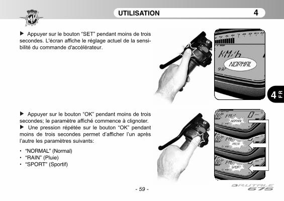
- 59 -
UTILISATION 4
4 FR
Appuyer sur le bouton “SET” pendant moins de trois
secondes. L'écran affiche le réglage actuel de la sensi-
bilité du commande d'accélérateur.
Appuyer sur le bouton “OK” pendant moins de trois
secondes; le paramètre affiché commence à clignoter.
Une pression répétée sur le bouton “OK” pendant
moins de trois secondes permet d’afficher l’un après
l’autre les paramètres suivants:
• “NORMAL” (Normal)• “RAIN” (Pluie)• “SPORT” (Sportif)

- 60 -
UTILISATION 4
4
FR
Appuyer sur le bouton “OK” pendant plus de trois
secondes; le nouveau réglage sera confirmée. La para-
mètre affiché cesse de clignoter et après quelques
secondes l'affichage revient à le mode “GAS SENSITI-VITY”. Il est possible de procéder à le réglage du para-mètre suivant.
Couple maximal du moteur: Appuyer sur le bouton
“OK” pendant moins de trois secondes afin d’afficher
“MAX ENGINE TORQUE”.

- 61 -
UTILISATION 4
4 FR
Appuyer sur le bouton “SET” pendant moins de trois
secondes. L'écran affiche le réglage actuel de la couplemaximal du moteur.
Appuyer sur le bouton “OK” pendant moins de trois
secondes; le paramètre affiché commence à clignoter.
Une pression répétée sur le bouton “OK” pendant
moins de trois secondes permet d’afficher l’un après
l’autre les paramètres suivants:
• “RAIN” (Pluie)• “SPORT” (Sportif)

- 62 -
UTILISATION 4
4
FR
Appuyer sur le bouton “OK” pendant plus de trois
secondes; le nouveau réglage sera confirmée. La para-
mètre affiché cesse de clignoter et après quelques
secondes l'affichage revient à le mode “MAX ENGINETORQUE”.
Frein moteur: Appuyer sur le bouton “OK” pendant
moins de trois secondes afin d’afficher “ENGINEBRAKE”.
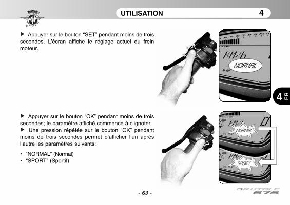
- 63 -
UTILISATION 4
4 FR
Appuyer sur le bouton “SET” pendant moins de trois
secondes. L'écran affiche le réglage actuel du frein
moteur.
Appuyer sur le bouton “OK” pendant moins de trois
secondes; le paramètre affiché commence à clignoter.
Une pression répétée sur le bouton “OK” pendant
moins de trois secondes permet d’afficher l’un après
l’autre les paramètres suivants:
• “NORMAL” (Normal)• “SPORT” (Sportif)

- 64 -
UTILISATION 4
4
FR
Appuyer sur le bouton “OK” pendant plus de trois
secondes; le nouveau réglage sera confirmée. La para-
mètre affiché cesse de clignoter et après quelques
secondes l'affichage revient à le mode “ENGINEBRAKE”.
Réponse du moteur: Appuyer sur le bouton “OK”
pendant moins de trois secondes afin d’afficher “ENGI-NE RESPONSE”.

- 65 -
UTILISATION 4
4 FR
Appuyer sur le bouton “SET” pendant moins de trois
secondes. L'écran affiche le réglage actuel de la répon-
se du moteur.
Appuyer sur le bouton “OK” pendant moins de trois
secondes; le paramètre affiché commence à clignoter.
Une pression répétée sur le bouton “OK” pendant
moins de trois secondes permet d’afficher l’un après
l’autre les paramètres suivants:
• “SLOW RESPONSE” (Réponse lente)• “FAST RESPONSE” (Réponse rapide)

- 66 -
UTILISATION 4
4
FR
Appuyer sur le bouton “OK” pendant plus de trois
secondes; le nouveau réglage sera confirmée. La para-
mètre affiché cesse de clignoter et après quelques
secondes l'affichage revient à le mode “ENGINE RES-PONSE”.
Limiteur de la vitesse de rotation du moteur: Appuyer
sur le bouton “OK” pendant moins de trois secondes
afin d’afficher “RPM LIMITER”.
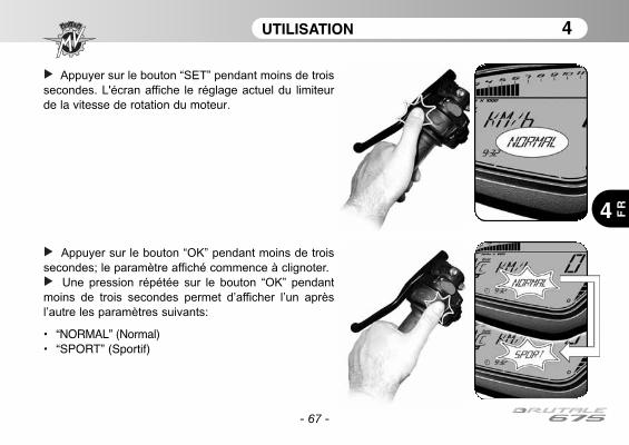
- 67 -
UTILISATION 4
4 FR
Appuyer sur le bouton “SET” pendant moins de trois
secondes. L'écran affiche le réglage actuel du limiteurde la vitesse de rotation du moteur.
Appuyer sur le bouton “OK” pendant moins de trois
secondes; le paramètre affiché commence à clignoter.
Une pression répétée sur le bouton “OK” pendant
moins de trois secondes permet d’afficher l’un après
l’autre les paramètres suivants:
• “NORMAL” (Normal)• “SPORT” (Sportif)

- 68 -
UTILISATION 4
4
FR
Appuyer sur le bouton “OK” pendant plus de trois
secondes; le nouveau réglage sera confirmée. La para-
mètre affiché cesse de clignoter et après quelques
secondes l'affichage revient à le mode “RPM LIMITER”.
Appuyer sur le bouton “OK” pendant moins de trois
secondes jusqu'à ce que l'affichage passe au mode
"RUN". Le réglage du mappage personnalisé est termi-
née.
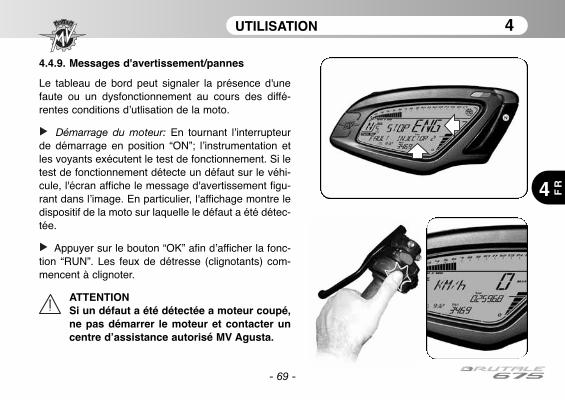
- 69 -
UTILISATION 4
4 FR
4.4.9. Messages d'avertissement/pannes
Le tableau de bord peut signaler la présence d'unefaute ou un dysfonctionnement au cours des diffé-rentes conditions d’utlisation de la moto.
Démarrage du moteur: En tournant l’interrupteurde démarrage en position “ON”; l’instrumentation etles voyants exécutent le test de fonctionnement. Si letest de fonctionnement détecte un défaut sur le véhi-cule, l'écran affiche le message d'avertissement figu-rant dans l’image. En particulier, l'affichage montre ledispositif de la moto sur laquelle le défaut a été détec-tée.
Appuyer sur le bouton “OK” afin d’afficher la fonc-tion “RUN”. Les feux de détresse (clignotants) com-mencent à clignoter.
ATTENTIONSi un défaut a été détectée a moteur coupé,ne pas démarrer le moteur et contacter uncentre d’assistance autorisé MV Agusta.
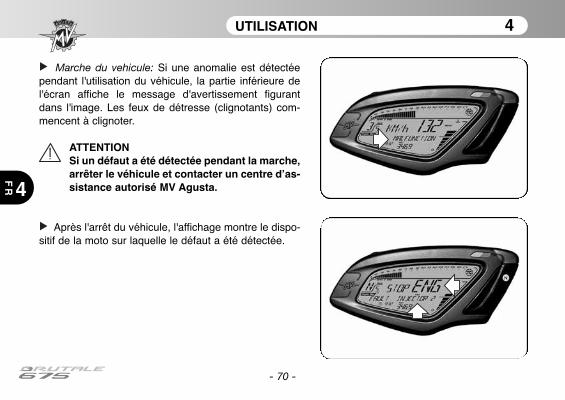
- 70 -
UTILISATION 4
4
FR
Marche du vehicule: Si une anomalie est détectéependant l'utilisation du véhicule, la partie inférieure del'écran affiche le message d'avertissement figurantdans l'image. Les feux de détresse (clignotants) com-mencent à clignoter.
ATTENTIONSi un défaut a été détectée pendant la marche,arrêter le véhicule et contacter un centre d’as-sistance autorisé MV Agusta.
Après l'arrêt du véhicule, l'affichage montre le dispo-sitif de la moto sur laquelle le défaut a été détectée.

- 71 -
UTILISATION 4
4 FR
Température élevée du liquide de refroidissement:Si une température élevée du fluide de refroidissementest détectée, l'écran affiche le message d'avertissementfigurant dans l’image. Ce message peut apparaître lorsde toutes les conditions d'utilisation du véhicule.
ATTENTION: En cas de température élevée,arrêter le véhicule et contrôler le niveau duliquide de refroidissement. Au cas où il seraitnécessaire de remplir le réservoir, s’adresserà un centre d’assistance autorisé MV Agusta(voir § 3.8). Si l’indication apparaît et que leniveau est correct, ne pas redémarrer etcontacter un centre d’assistance autorisé MVAgusta.
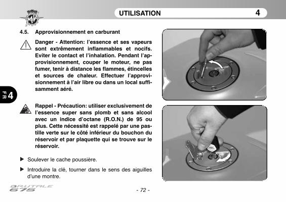
4.5. Approvisionnement en carburant
Danger - Attention: l’essence et ses vapeurssont extrêmement inflammables et nocifs.Eviter le contact et l’inhalation. Pendant l’ap-provisionnement, couper le moteur, ne pasfumer, tenir à distance les flammes, étincelleset sources de chaleur. Effectuer l’approvi-sionnement à l’air libre ou dans un local suffi-samment aéré.
Rappel - Précaution: utiliser exclusivement del’essence super sans plomb et sans alcoolavec un indice d’octane (R.O.N.) de 95 ouplus. Cette nécessité est rappelé par une pas-tille verte sur le côté inférieur du bouchon duréservoir et par plaquette qui se trouve sur leréservoir.
Soulever le cache poussière.
Introduire la clé, tourner dans le sens des aiguillesd’une montre.
- 72 -
UTILISATION 4
4
FR
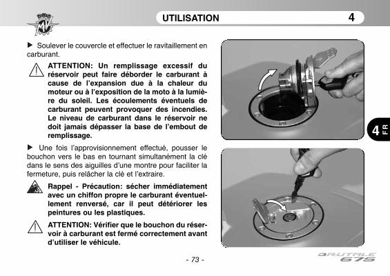
- 73 -
UTILISATION 4
4 FR
Soulever le couvercle et effectuer le ravitaillement encarburant.
ATTENTION: Un remplissage excessif duréservoir peut faire déborder le carburant àcause de l’expansion due à la chaleur dumoteur ou à l’exposition de la moto à la lumiè-re du soleil. Les écoulements éventuels decarburant peuvent provoquer des incendies.Le niveau de carburant dans le réservoir nedoit jamais dépasser la base de l’embout deremplissage.
Une fois l’approvisionnement effectué, pousser lebouchon vers le bas en tournant simultanément la clédans le sens des aiguilles d’une montre pour faciliter lafermeture, puis relâcher la clé et l’extraire.
Rappel - Précaution: sécher immédiatementavec un chiffon propre le carburant éventuel-lement renversé, car il peut détériorer lespeintures ou les plastiques.
ATTENTION: Vérifier que le bouchon du réser-voir à carburant est fermé correctement avantd’utiliser le véhicule.
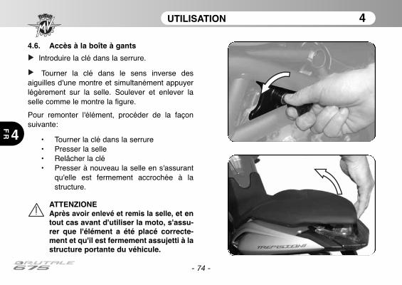
4.6. Accès à la boîte à gants
Introduire la clé dans la serrure.
Tourner la clé dans le sens inverse desaiguilles d'une montre et simultanément appuyerlégèrement sur la selle. Soulever et enlever laselle comme le montre la figure.
Pour remonter l'élément, procéder de la façonsuivante:
• Tourner la clé dans la serrure• Presser la selle • Relâcher la clé• Presser à nouveau la selle en s'assurant
qu'elle est fermement accrochée à lastructure.
UTILISATION 4
4
FR
- 74 -
ATTENZIONEAprès avoir enlevé et remis la selle, et entout cas avant d'utiliser la moto, s'assu-rer que l'élément a été placé correcte-ment et qu'il est fermement assujetti à lastructure portante du véhicule.
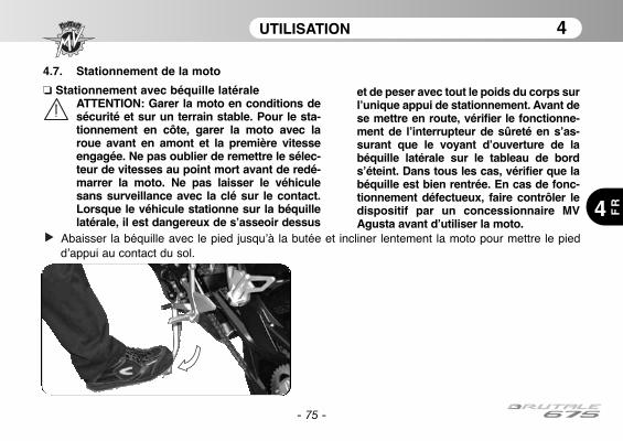
UTILISATION 4
4 FR
- 75 -
4.7. Stationnement de la moto
❏ Stationnement avec béquille latéraleATTENTION: Garer la moto en conditions desécurité et sur un terrain stable. Pour le sta-tionnement en côte, garer la moto avec laroue avant en amont et la première vitesseengagée. Ne pas oublier de remettre le sélec-teur de vitesses au point mort avant de redé-marrer la moto. Ne pas laisser le véhiculesans surveillance avec la clé sur le contact.Lorsque le véhicule stationne sur la béquillelatérale, il est dangereux de s’asseoir dessus
et de peser avec tout le poids du corps surl’unique appui de stationnement. Avant dese mettre en route, vérifier le fonctionne-ment de l’interrupteur de sûreté en s’as-surant que le voyant d’ouverture de labéquille latérale sur le tableau de bords’éteint. Dans tous les cas, vérifier que labéquille est bien rentrée. En cas de fonc-tionnement défectueux, faire contrôler ledispositif par un concessionnaire MVAgusta avant d’utiliser la moto.
Abaisser la béquille avec le pied jusqu’à la butée et incliner lentement la moto pour mettre le piedd’appui au contact du sol.
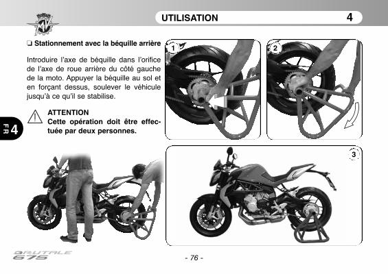
UTILISATION 4
4
FR
- 76 -
❏ Stationnement avec la béquille arrière
Introduire l’axe de béquille dans l’orificede l’axe de roue arrière du côté gauchede la moto. Appuyer la béquille au sol eten forçant dessus, soulever le véhiculejusqu’à ce qu’il se stabilise.
ATTENTIONCette opération doit être effec-tuée par deux personnes.
1 2
3
RÉGLAGES 5
5 FR
- 77 -
5.1. Liste des réglages
La moto dispose d’une grande diversité de réglagesqui peuvent améliorer l’ergonomie, l’assiette et lasécurité.
Toutefois, étant donné qu’un réglage incorrect depièces particulièrement importantes peut engendrerune situation de danger, quelques-uns des réglagessont réservés aux Centres d’Assistance MV Agusta.
ATTENTIONTous les réglages s’effectuent à l’arrêt
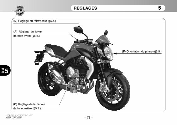
RÉGLAGES 5
5
FR
- 78 -
(F) Orientation du phare (§5.5.)
(D) Réglage du rétroviseur (§5.4.)
(A) Réglage du levier
de frein avant (§5.3.)
(C) Réglage de la pédale
de frein arrière (§5.2.)
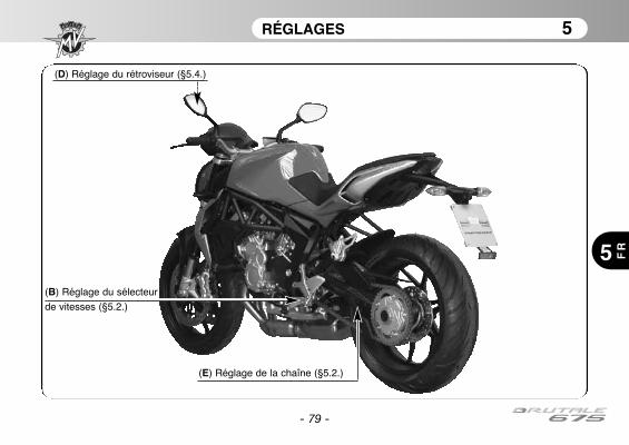
(B) Réglage du sélecteur
de vitesses (§5.2.)
RÉGLAGES 5
5 FR
- 79 -
(E) Réglage de la chaîne (§5.2.)
(D) Réglage du rétroviseur (§5.4.)
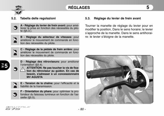
RÉGLAGES 5
5
FR
- 80 -
5.2. Tabella delle regolazioni 5.3. Réglage du levier de frein avant
Tourner la manette de réglage du levier pour enmodifier la position, Dans le sens horaire; le leviers’approche de la manette. Dans le sens antihorai-re: le levier s’éloigne de la manette.
A - Réglage du levier de frein avant: pour amé-liorer la prise en fonction des nécessités du pilo-te (§5.3.).
B - Réglage du sélecteur de vitesses: pouraméliorer le mouvement de commande en fonc-tion des nécessités du pilote.
C - Réglage de la pédale de frein arrière: pouraméliorer le mouvement de commande en fonc-tion des nécessités du pilote.
D - Réglage des rétroviseurs: pour améliorerl’orientation (§5.4).
ATTENTION: Ne pas toucher la vis de fixa-tion du rétroviseur au guidon. En cas debesoin, s'adresser à un concessionnaireMV AGUSTA
E - Tension de la chaîne: pour l’efficacité et lafiabilité de la transmission.
F - Orientation du phare: pour optimiser la pro-fondeur du faisceau lumineux en fonction de l’as-siette (§5.5).
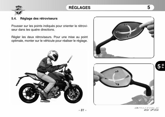
RÉGLAGES 5
5 FR
- 81 -
5.4. Réglage des rétroviseurs
Pousser sur les points indiqués pour orienter le rétrovi-seur dans les quatre directions.
Régler les deux rétroviseurs. Pour une mise au pointoptimale, monter sur le véhicule pour réaliser le réglage.

RÉGLAGES 5
5
FR
- 82 -
5.5. Réglage du projecteur avantPlacer le véhicule à 10 mètres d’une paroi verticale.Veiller à ce que le terrain soit plat et l’axe du véhicule perpendiculaire à la paroi.Le véhicule doit se trouver en position verticale. Mesurer la hauteur du centre du projecteur au sol etfaire une croix sur la paroi à la même hauteur.Allumer le code, la limite supérieure de démarcation entre la zone sombre et la zone éclairée ne doit pasdépasser 9/10 de la hauteur au sol du centre du projecteur.
Centre projecteur
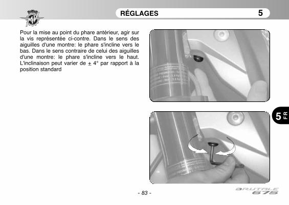
RÉGLAGES 5
5 FR
- 83 -
Pour la mise au point du phare antérieur, agir surla vis représentée ci-contre. Dans le sens desaiguilles d'une montre: le phare s'incline vers lebas. Dans le sens contraire de celui des aiguillesd'une montre: le phare s'incline vers le haut.L'inclinaison peut varier de + 4° par rapport à laposition standard
- 84 -
NOTE
5
FR
Note d’informationMV Agusta Motor S.p.A. poursuit une politique de continuelle amélioration de ses produits. Pour cette rai-son, de légères différences pourraient éventuellement se présenter entre les informations de ce livret et levéhicule que vous avez acheté. Les modèles MV Agusta s’exportent dans de nombreux pays où des normesdifférentes sont en vigueur en ce qui concerne le Code de la Route et les procédures d’homologation. Enespérant pouvoir compter sur votre compréhension, il est indispensable à MV Agusta Motor S.p.A. de seréserver le droit d’apporter des modifications à ses produits et à la documentation technique à tout momentsans fournir de préavis.
Nous suggérons de visiter souvent le site Internet www.mvagusta.it afin d'obtenir des informations et desmises à jour sur les produits MV Agusta et la documentation relative.
Respectons et défendons l’environnement
Toutes nos actions ont des répercussions sur la planète entière et sur ses ressources.MV Agusta, au profit des intérêts de tous, sensibilise les Clients et les opérateurs du service après-ventepour leur faire adopter des modalités d’utilisation du véhicule et de traitement de ses parties dans le res-pect des normes en vigueur en terme de pollution, traitement et recyclage des déchets.
© 2012Toute reproduction même partielle de ce document est formellement interdite sans autorisation écrite de MV Agusta Motor S.p.A.
Dét. n° 8000B6848Edition n° 1 - Avril 2012
BedienungsanleitungDeutsche Version
- 2 -
Sehr geehrter Kunde,
wir danken Ihnen für das Vertrauen, dass Sie uns ausgesprochen haben und gratulieren Ihnen zur WahlIhres neuen Brutale 675.Dank dem beharrlichen Einsatz und Engagement seiner Techniker ist heute MV Agusta in der Lage seinenzahlreichen Fans ein innovatives und von einer Sonderverkleidung und raffinierter Radtechnologie charak-terisiertes Produkt anzubieten: Elemente die alle mit dem MV Agusta Warenzeichen verzeichnetenErzeugnisse in der langen Zeitspanne seiner ruhmreichen Unternehmensgeschichte gekennzeichnet haben.Das Ergebnis ist ein exklusives Motorrad, das dank seinen ästhetischen und funktionellen Eigenschaftensowie den zahlreichen technischen Innovationen weit über den heutigen auf diesem Markt vertriebenenQualitätsprodukten liegt.Die angewandten Lösungen verleihen dem neuen Brutale 675 einen unverwechselbaren Charakter, derdieses Motorrad zu den anderen Modellen der Familie MV Agusta anknüpft und die Projektphilosophiediese Unternehmens, das der ständigen Forschung, und der technologischen Innovation besondersWert schenkt und das winzigste Detail schätzen kann, konsolidiert. Jedem Motorradfahrer wird somit dieMöglichkeit geschenkt, seine Leidenschaft in voller Freiheit zu genießen und zur gleichen Zeit einMotorrad zu besitzen, das einzig auf der Welt ist und sich weltweit mit starkem Übergriff durchsetzt.
Falls Sie weitere Informationen wünschen, wenden Sie sich bitte an den Kundendienst der MV Agusta.
Viel Spaß!Giovanni Castiglioni PräsidentMV Agusta
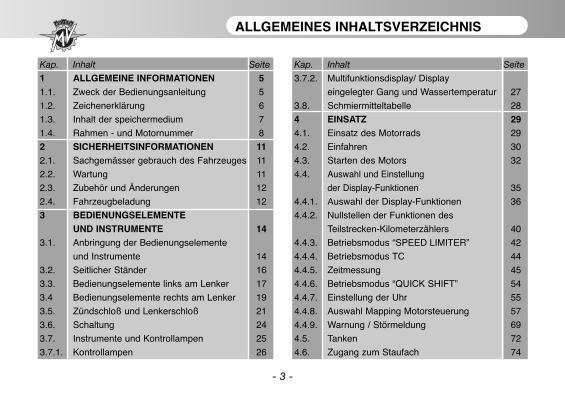
- 3 -
ALLGEMEINES INHALTSVERZEICHNIS
Kap. Inhalt Seite
1 ALLGEMEINE INFORMATIONEN 51.1. Zweck der Bedienungsanleitung 5
1.2. Zeichenerklärung 6
1.3. Inhalt der speichermedium 7
1.4. Rahmen - und Motornummer 8
2 SICHERHEITSINFORMATIONEN 112.1. Sachgemässer gebrauch des Fahrzeuges 11
2.2. Wartung 11
2.3. Zubehör und Änderungen 12
2.4. Fahrzeugbeladung 12
3 BEDIENUNGSELEMENTEUND INSTRUMENTE 14
3.1. Anbringung der Bedienungselemente
und Instrumente 14
3.2. Seitlicher Ständer 16
3.3. Bedienungselemente links am Lenker 17
3.4 Bedienungselemente rechts am Lenker 19
3.5. Zündschloß und Lenkerschloß 21
3.6. Schaltung 24
3.7. Instrumente und Kontrollampen 25
3.7.1. Kontrollampen 26
Kap. Inhalt Seite
3.7.2. Multifunktionsdisplay/ Display
eingelegter Gang und Wassertemperatur 27
3.8. Schmiermitteltabelle 28
4 EINSATZ 294.1. Einsatz des Motorrads 29
4.2. Einfahren 30
4.3. Starten des Motors 32
4.4. Auswahl und Einstellung
der Display-Funktionen 35
4.4.1. Auswahl der Display-Funktionen 36
4.4.2. Nullstellen der Funktionen des
Teilstrecken-Kilometerzählers 40
4.4.3. Betriebsmodus “SPEED LIMITER” 42
4.4.4. Betriebsmodus TC 44
4.4.5. Zeitmessung 45
4.4.6. Betriebsmodus “QUICK SHIFT” 54
4.4.7. Einstellung der Uhr 55
4.4.8. Auswahl Mapping Motorsteuerung 57
4.4.9. Warnung / Störmeldung 69
4.5. Tanken 72
4.6. Zugang zum Staufach 74
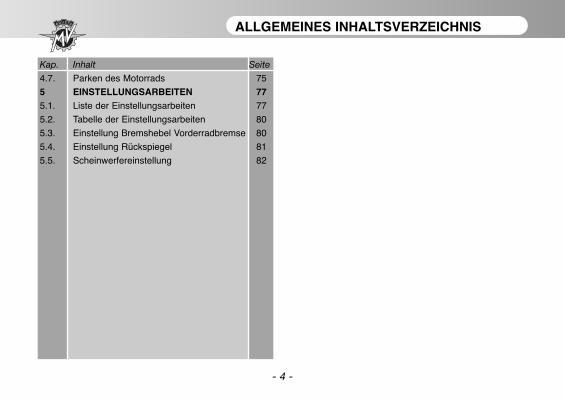
- 4 -
ALLGEMEINES INHALTSVERZEICHNIS
Kap. Inhalt Seite
4.7. Parken des Motorrads 75
5 EINSTELLUNGSARBEITEN 775.1. Liste der Einstellungsarbeiten 77
5.2. Tabelle der Einstellungsarbeiten 80
5.3. Einstellung Bremshebel Vorderradbremse 80
5.4. Einstellung Rückspiegel 81
5.5. Scheinwerfereinstellung 82

ALLGEMEINE INFORMATIONEN 1
1 DE
- 5 -
1.1. Zweck der Bedienungsanleitung
Dieses Handbuch enthält alle für einen korrekten und sicherenGebrauch Ihres Motorrades erforderlichen Informationen.
Das Handbuch wird in elektronischem Format (.pdf) auf dieserspeichermedium geliefert und kann auf jedem PC mitWindows oder Mac eingesehen oder ausgedruckt werden.
Wir bitten Sie, dieses Handbuch vor der ersten Benutzung desMotorrades aufmerksam durchzulesen und sich immer zu ver-gewissern, dass auch andere Personen, die das Motorradbenutzen, dies tun.
CopyrightMV AGUSTA Motor SpaAlle Rechte vorbehalten
ALLGEMEINE INFORMATIONEN 1
1
DE
- 6 -
1.2. Zeichenerklärung
Besonders wichtige Textstellen die sich auf die Sicherheit der Personen oder des Fahrzeugs beziehen,sind mit folgenden Symbolen gekennzeichnet:
Gefahr - Achtung: Die mangelnde oder unvollständige Beachtung dieser Vorschriften stellteine schwere Unfallgefahr für den Arbeiter oder Dritte dar.
Vorsicht - Vorsichtsmaßnahme: Die Nichteinhaltung der Anweisungen kann schwere unddauerhafte Schäden am Fahrzeug verursachen.
Folgende Symbole werden benutzt, um anzuzeigen, wer die angegebenen Wartungs- undEinstellungsarbeiten ausführen darf:
Informationen zu Arbeiten, die vom Motorradfahrer ausgeführt werden dürfen.
Informationen zu arbeiten, die ausschließlich von ausgebildetem Fachpersonal ausgeführtwerden dürfen.
Um weitere Informationen hervorzuheben, werden folgende Symbole verwendet:
Das Symbol zeigt an, dass für die richtige Durchführung der angegebenen Arbeit einSpezialwerkzeug oder Sonderausrüstung benötigt werden.
§ Das Zeichen “§” gefolgt von einen Ziffer verweist auf das entsprechende Kapitel.
ALLGEMEINE INFORMATIONEN 1
1 DE
- 7 -
1.3. Inhalt der speichrmedium
Auf dieser speichermedium finden Sie außer diesem Handbuchauch das Wartungshandbuch, die Händlerliste und dieGarantie-Heft.
Bei der Übergabe des Motorrades hat Ihnen Ihr Händler auchdas Garantiebescheinigung ausgehändigt.
Bewahren Sie es bitte sorgfältig zusammen mit denFahrzeugpapieren und den zukünftigen Bescheinigungen auf,die Sie bei jeder Inspektion ausgehändigt bekommen werden.
WICHTIGDie Kopien der Garantiebescheinigung sowie der Bescheinigungder vor Auslieferung vorgenommenen Kontrollen müssen vomVertragshändler ausgefüllt werden. Eine Kopie muss demKunden übergeben werden, eine muss vom Vertragshändler auf-bewahrt und eine an den Importeur geschickt werden.
Die Kopien der Wartungcoupons müssen immer vomVertragshändler ausgefüllt werdern. Sie müssen vom Kundenund vom Vertragshändler aufbewahrt werden.

ALLGEMEINE INFORMATIONEN 1
1
DE
- 8 -
1.4. Rahmen- und Motornummer1) Rahmennummer2) Motornummer3) Zulassungsnummer
Kennzeichnung des MotorradsDas Motorrad wird durch die Rahmennummer ein-deutig gekennzeichnet. Bei Ersatzteilbestellungenomüssen die Rahmennummer und gegebenen-falls auch die Motornummer, die Farbkennzifferund die Schlüsselnummer angegebenen werden.
Wir empfehlen Ihnen die wichtigsten Angabennachstehend einzutragen.
RAHMENNUMMER:
MOTORNUMMER:
2) Motornummer
1) Rahmennummer
3) Zulassungsnummer
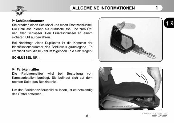
ALLGEMEINE INFORMATIONEN 1
1 DE
- 9 -
FarbkennzifferDie Farbkennziffer wird bei Bestellung vonKarosserieteilen benötigt. Sie befindet sich auf demrechten Seite des Benzintanks.
Um das Farbkennzifferschild zu lesen, ist es notwendigdas Sattel entfernen.
SchlüsselnummerSie erhalten einen Schlüssel und einen Ersatzschlüssel.Die Schlüssel dienen als Zündschlüssel und zum Öff-nen aller Schlösser. Den Ersatzschlüssel an einemsicheren Ort aufbewahren.
Bei Nachfrage eines Duplikates ist die Kenntnis derIdentifikationsnummer des Schlüssels grundlegend. Esempfiehlt sich, diese Zahl im folgenden Feld einzutragen:
SCHLÜSSEL NR.:
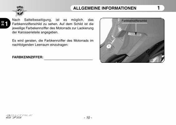
ALLGEMEINE INFORMATIONEN 1
1
DE
- 10 -
Nach Sattelbeseitigung, ist es möglich, dasFarbkennzifferschild zu sehen. Auf dem Schild ist diejeweilige Farbekennziffer des Motorrads zur Lackierungder Karosserieteile angegeben.
Es wird geraten, die Farbkennziffer des Motorrads imnachfolgenden Leerraum einzutragen:
FARBKENNZIFFER:
Farbkennzifferschild
SICHERHEITSINFORMATIONEN 2
2 DE
- 11 -
2.1. SACHGEMÄSSER GEBRAUCH DESFAHRZEUGES
Ihr Motorrad wurde ausschließlich für dieBenutzung auf Straßen und Autobahnen geplant.
ACHTUNGAusnahmsweise können Sie IhrMotorrad auch auf einer Rennstreckebenutzen – allerdings nicht, um Rennenzu fahren.Dabei ist das Motorrad jedoch sehrhohen Beanspruchungen ausgesetztund daher sollte es vorher und nachherin einer MV Agusta-Vertragswerkstattüberprüft werden.Jeder andere Einsatz ist ausdrücklichausgeschlossen und strengstens unter-sagt.
Weitere Informationen zur Benutzung desMotorrades finden Sie im Abschnitt 4 diesesHandbuches.
2.2. WARTUNG
Damit Ihr Motorrad stets einwandfrei und zuver-lässig funktioniert, müssen Sie die imWartungshandbuch vorgesehenen Inspektions-termine unbedingt einhalten.Sie sollten diese ausschließlich von Fachleuten ineiner MV Agusta-Vertragswerkstatt durchführenlassen.Sollten Sie sich hingegen für eine freie Werkstattentscheiden, müssen Sie sich von dieser bestäti-gen lassen, dass sie über alle für dieDurchführung der erforderlichen Kontrollen undEinstellungen notwendigen Ausrüstungen,Möglichkeiten und Kenntnisse verfügt.
ACHTUNGDie Garantie von MV Agusta könnte imFall von in freien Werkstätten ausgeführ-ten Eingriffen an Ihrem Motorrad, dienicht den technischen Rundschreibenund den MV Agusta-Werkstatthand-büchern entsprechen, verfallen.
SICHERHEITSINFORMATIONEN 2
2
DE
- 12 -
2.3. ZUBEHÖR UND ÄNDERUNGEN
ACHTUNGDer Hersteller untersagt jegliche eigen-mächtige Änderung an seinenFahrzeugen.Nur so kann die Sicherheit der Benutzergewährleistet werden.
Allerdings besteht die Möglichkeit, Ihr Motorradanhand des umfangreichen MV Agusta-Zubehörkatalogs zu personalisieren.
ACHTUNGDurch die Installation einiger dieserZubehörteile kann die Zulassung desMotorrades jedoch ungültig werden,was bedeutet, dass Sie damit nicht mehrauf öffentlichen Straßen fahren dürfen.
Wenden Sie sich daher im Zweifelsfall an IhrenVertragshändler MV Agusta, bevor Sie entschei-den, welches Zubehör für Ihre Erfordernissegeeignet ist.
2.4. FAHRZEUGBELADUNG
Das Motorrad wurde zum Einsatz des Fahrers undhöchstens eines Beifahrers entworfen.Für einen sicheren Einsatz und unterBerücksichtigung der Straßenverkehrsvorschriftenmüssen die technische Gewichtswert, die hierunten angegeben ist, nie überschritten werden:
BRUTALE 675Maximales technisch zulässiges Gesamtgewicht
364 kgMaximal transportierbare Masse
180 kg
Die technisch zulässige Gesamtmasse ist dieSumme der folgenden Massen:
• Motorradmasse;• Fahrermasse;• Beifahrermasse;• Gepäckmasse und das der Zubehörteile.
SICHERHEITSINFORMATIONEN 2
2 DE
- 13 -
ACHTUNGDa das Gewicht einen enormen Einflussauf die Lenkbarkeit, die Bremsleistung,die Fahrzeugeigenschaften und dieFahrzeugsicherheit hat, müssen die fol-genden Vorschriften stets eingehaltenwerden.
• DAS MOTORRAD NIE ÜBERLADEN!Ein überladenes Motorrad kann dieReifen beschädigen, zu einemKontrollverlust und schweren Unfällenführen. Überprüfen, dass dasGesamtgewicht mit Fahrer, Beifahrer,Gepäck und Zubehör das zulässigeFahrzeug-Gesamtgewicht nicht über-schreitet.
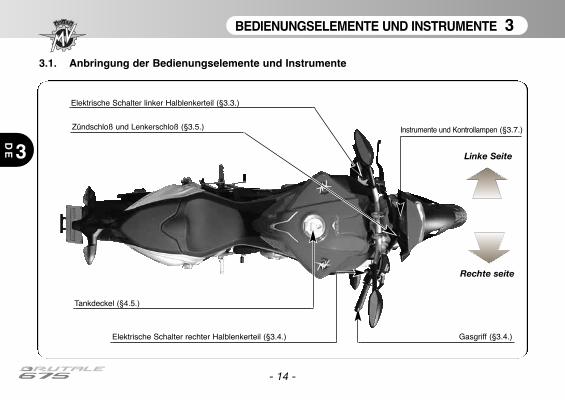
BEDIENUNGSELEMENTE UND INSTRUMENTE 3
DE 3
- 14 -
3.1. Anbringung der Bedienungselemente und Instrumente
Instrumente und Kontrollampen (§3.7.)
Elektrische Schalter linker Halblenkerteil (§3.3.)
Tankdeckel (§4.5.)
Zündschloß und Lenkerschloß (§3.5.)
Gasgriff (§3.4.)Elektrische Schalter rechter Halblenkerteil (§3.4.)
Linke Seite
Rechte seite
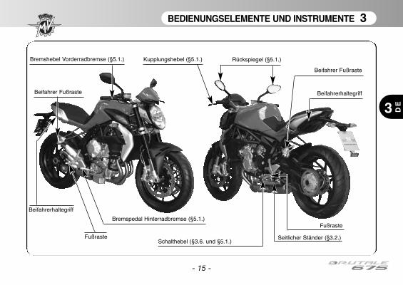
BEDIENUNGSELEMENTE UND INSTRUMENTE 3
DE3
- 15 -
Kupplungshebel (§5.1.)
Schalthebel (§3.6. und §5.1.)Seitlicher Ständer (§3.2.)
Beifahrer Fußraste
Beifahrer Fußraste
Beifahrerhaltegriff
Rückspiegel (§5.1.)Bremshebel Vorderradbremse (§5.1.)
Bremspedal Hinterradbremse (§5.1.)
Fußraste
Fußraste
Beifahrerhaltegriff
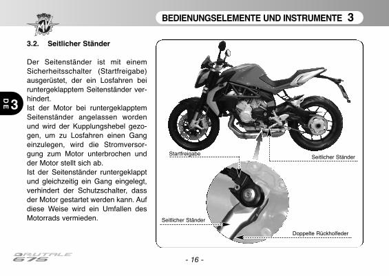
BEDIENUNGSELEMENTE UND INSTRUMENTE 3
3
DE
- 16 -
3.2. Seitlicher Ständer
Der Seitenständer ist mit einemSicherheitsschalter (Startfreigabe)ausgerüstet, der ein Losfahren beiruntergeklapptem Seitenständer ver-hindert.Ist der Motor bei runtergeklapptemSeitenständer angelassen wordenund wird der Kupplungshebel gezo-gen, um zu Losfahren einen Gangeinzulegen, wird die Stromversor-gung zum Motor unterbrochen undder Motor stellt sich ab.Ist der Seitenständer runtergeklapptund gleichzeitig ein Gang eingelegt,verhindert der Schutzschalter, dassder Motor gestartet werden kann. Aufdiese Weise wird ein Umfallen desMotorrads vermieden.
Seitlicher Ständer
Doppelte Rückholfeder
Startfreigabe
Seitlicher Ständer

BEDIENUNGSELEMENTE UND INSTRUMENTE 3
3 DE
- 17 -
3.3. Linke Lenkerschalter
Druckschalter LichthupeDen Schalter mehrmals drücken.
Druckschalter Fernlicht/FahrlichtDruckschalter hoch: FahrlichtDruckschalter tief: Fernlicht
BlinkerschalterBei Verstellen des Hebels nach rechts oder links werdenjeweils die rechten oder linken Blinker eingeschaltet. DerHebel stellt sich auf Mittelstellung zurück. Zum Ausschaltender Blinker auf den Hebel drücke
HupenschalterZur Betätigung der Hupe den Schalter drücken.
KupplungshebelZur Betätigung der Kupplung den Kupplungshebelziehen und wieder loslassen.
BEDIENUNGSELEMENTE UND INSTRUMENTE 3
3
DE
- 18 -
LichthupenschalterDie Betätigung der Lichthupe durch den Lichthupenschalter dient dazu andere Verkehrsteilnehmer auf sich auf-merksam zu machen oder Gefahren zu signalisieren. Bei eingeschaltetem Fernlicht funktioniert die Lichthupe nicht.
Druckschalter Fernlicht/ AbblendlichtSchaltet sich normalerweise das Abblendlicht ein. Wenn es der Verkehr und die Straßenführung zulassen, kannmit diesem Druckschalter auf Fernlicht umgeschaltet werden.
BlinkerschalterMit diesem Schalter kann anderen Verkehrsteilnehmern ein Fahrtrichtungs- oder Spurwechsel angezeigtwerden.
ACHTUNGDas Nichtbetätigen oder die falsche Betätigung/ das Nichtausschalten des Blinkerschalters kannUnfälle verursachen. Die anderen Verkehrsteilnehmer können dadurch falsche Rückschlüsseauf die tatsächliche Fahrtrichtung ziehen. Vorm Abbiegen oder Spurwechsel stets die Blinkerbetätigen.
HupenschalterDie Betätigung der Hupe durch den Hupenschalter dient dazu andere Verkehrsteilnehmer auf sich aufmerksamzu machen oder Gefahren zu signalisieren.
KupplungshebelMit diesem Hebel wird die Kupplung über eine hydraulische Vorrichtung ein- und ausgekuppelt.
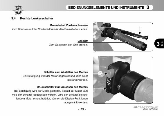
BEDIENUNGSELEMENTE UND INSTRUMENTE 3
3 DE
- 19 -
3.4. Rechte Lenkerschalter
Schalter zum Abstellen des MotorsBei Betätigung wird der Motor abgestellt und kann nicht
gestartet werden.
Druckschalter zum Anlassen des MotorsBei Betätigung wird der Motor gestartet. Sobald der Motor läuft
muß der Schalter losgelassen werden. Wird der Schalter bei lau-
fendem Motor erneut betätigt, können die Display-Funktionen
ausgewählt werden.
GasgriffZum Gasgeben den Griff drehen.
Bremshebel VorderradbremseZum Bremsen mit der Vorderradbremse den Bremshebel ziehen.
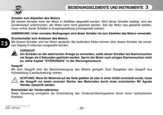
BEDIENUNGSELEMENTE UND INSTRUMENTE 3
3
DE
- 20 -
Schalter zum Abstellen des MotorsMit diesem Schalter kann der Motor in Notfällen abgestellt werden. Wird dieser Schalter betätigt, wird derZündkreislauf unterbrochen, der Motor kann nicht gestartet werden. Soll der Motor neu gestartet werden,muss vorher dieser Schalter in Ausgangsstellung zurückgestellt werden.
ANMERKUNG: Unter normalen Bedingungen wird dieser Schalter nie zum Abstellen des Motors verwendet.
Druckschalter zum Anlassen des MotorsMit diesem Schalter wird der Motor gestartet. Bei laufendem Motor können über diesen Schalter die einzel-
nen Display-Funktionen ausgewählt werden.
VORSICHTUm Schäden an der elektrischen Anlage zu vermeiden, sollte dieser Schalter bei Startversuchennie länger als 5 Sekunden gedrückt werden. Sprint der Motor nach einigen Startversuchen nichtan, siehe Kapitel “STÖRUNGEN” in der Wartungshanbuch.
GasgriffMit dem Gasgriff wird die Benzinversorgung des Motors geregelt. Zum Gasgeben den Gasgriff ausRuhestellung (Leerlaufstellung) drehen.
ACHTUNG: Wenn Ihr Motorrad auf die Seite gefallen ist oder in einen Unfall verwickelt wurde, mussder Gasgriff vor einem erneuten Starten des Motorrades durch einen autorisierten MV AgustaHändler überprüft werden.
Bremshebel der VorderradbremseDiese Steuerung ermöglicht die Einschaltung des Vorderrad-Bremssystems durch einen hydraulischenKreislauf.
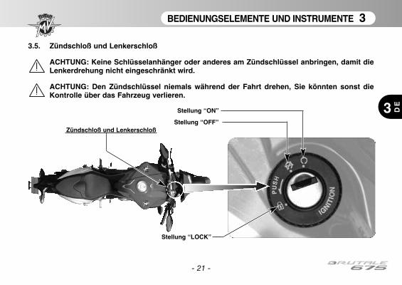
BEDIENUNGSELEMENTE UND INSTRUMENTE 3
3 DE
- 21 -
3.5. Zündschloß und Lenkerschloß
ACHTUNG: Keine Schlüsselanhänger oder anderes am Zündschlüssel anbringen, damit dieLenkerdrehung nicht eingeschränkt wird.
ACHTUNG: Den Zündschlüssel niemals während der Fahrt drehen, Sie könnten sonst dieKontrolle über das Fahrzeug verlieren.
Stellung “ON”
Stellung “OFF”Zündschloß und Lenkerschloß
Stellung “LOCK”
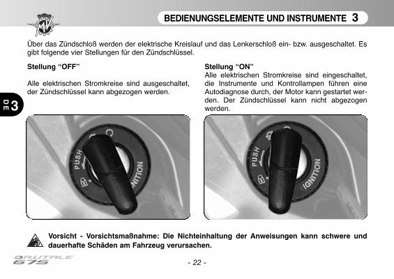
BEDIENUNGSELEMENTE UND INSTRUMENTE 3
3
DE
Über das Zündschloß werden der elektrische Kreislauf und das Lenkerschloß ein- bzw. ausgeschaltet. Esgibt folgende vier Stellungen für den Zündschlüssel.
Vorsicht - Vorsichtsmaßnahme: Die Nichteinhaltung der Anweisungen kann schwere unddauerhafte Schäden am Fahrzeug verursachen.
Stellung “OFF”
Alle elektrischen Stromkreise sind ausgeschaltet,der Zündschlüssel kann abgezogen werden.
Stellung “ON”Alle elektrischen Stromkreise sind eingeschaltet,die Instrumente und Kontrollampen führen eineAutodiagnose durch, der Motor kann gestartet wer-den. Der Zündschlüssel kann nicht abgezogenwerden.
- 22 -
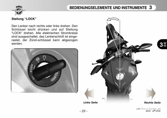
BEDIENUNGSELEMENTE UND INSTRUMENTE 3
3 DE
- 23 -
Stellung “LOCK”
Den Lenker nach rechts oder links drehen. DenSchlüssel leicht drücken und auf Stellung“LOCK” drehen. Alle elektrischen Stromkreisesind ausgeschaltet, das Lenkerschloß ist einge-rastet, der Zünd-schlüssel kann abgezogenwerden.
Linke Seite Rechte Seite
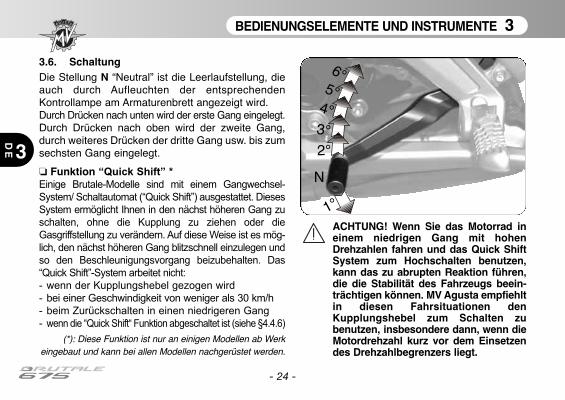
BEDIENUNGSELEMENTE UND INSTRUMENTE 3
3
DE
- 24 -
3.6. SchaltungDie Stellung N “Neutral” ist die Leerlaufstellung, dieauch durch Aufleuchten der entsprechendenKontrollampe am Armaturenbrett angezeigt wird.Durch Drücken nach unten wird der erste Gang eingelegt.Durch Drücken nach oben wird der zweite Gang,durch weiteres Drücken der dritte Gang usw. bis zumsechsten Gang eingelegt.
❏ Funktion “Quick Shift” *
Einige Brutale-Modelle sind mit einem Gangwechsel-
System/ Schaltautomat (“Quick Shift”) ausgestattet. Dieses
System ermöglicht Ihnen in den nächst höheren Gang zu
schalten, ohne die Kupplung zu ziehen oder die
Gasgriffstellung zu verändern. Auf diese Weise ist es mög-
lich, den nächst höheren Gang blitzschnell einzulegen und
so den Beschleunigungsvorgang beizubehalten. Das
“Quick Shift”-System arbeitet nicht:
- wenn der Kupplungshebel gezogen wird
- bei einer Geschwindigkeit von weniger als 30 km/h
- beim Zurückschalten in einen niedrigeren Gang
- wenn die “Quick Shift“ Funktion abgeschaltet ist (siehe §4.4.6)
(*): Diese Funktion ist nur an einigen Modellen ab Werkeingebaut und kann bei allen Modellen nachgerüstet werden.
1°
N
2°
3°
4°
5°
6°
ACHTUNG! Wenn Sie das Motorrad ineinem niedrigen Gang mit hohenDrehzahlen fahren und das Quick ShiftSystem zum Hochschalten benutzen,kann das zu abrupten Reaktion führen,die die Stabilität des Fahrzeugs beein-trächtigen können. MV Agusta empfiehltin diesen Fahrsituationen denKupplungshebel zum Schalten zubenutzen, insbesondere dann, wenn dieMotordrehzahl kurz vor dem Einsetzendes Drehzahlbegrenzers liegt.
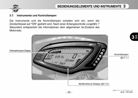
BEDIENUNGSELEMENTE UND INSTRUMENTE 3
3 DE
- 25 -
3.7. Instrumente und Kontrollampen
Die Instrumente und die Kontrolllampen schalten sich ein, wenn derZündschlüssel auf "ON" gedreht wird. Nach einer Anfangskontrolle (ungefähr 7Sekunden) entsprechen die Informationen dem allgemeinen Ist-Zustand desMotorrads.
Kontrollampen
(§3.7.1.)
Multifunktions-Display (§3.7.2.)
Drehzahlmesser-Display
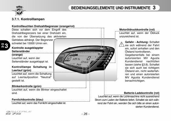
BEDIENUNGSELEMENTE UND INSTRUMENTE 3
3
DE
- 26 -
3.7.1. Kontrolllampen
Fernlichtkontrolle (blau)Leuchtet auf, wenn das Fernlicht eingeschaltet ist.
Kontrolllampe Schaltung inLeerlauf (grün)Leuchtet auf, wenn die Schaltungauf Leerlaufposition "Neutral"gestellt ist.
Blinkerkontrolle (grün)Leuchtet auf, wenn die Blinker eingeschaltetsind.
Kontrolle ausgeklappterSeitenständer(orange)Leuchtet auf, wenn derSeitenständer ausgeklappt ist.
Batterie-Ladekontrolle (rot)Leuchtet auf, wenn die Lichtmaschine nicht ausreichend
Strom zum Laden der Batterie liefert. Schaltet sie sich wäh-rend der Fahrt ein, wenden Sie sich bitte an einen autori-
sierten Kundendienst.
Kontrollleuchten Drehzahlbegrenzer (orange/rot)Diese schalten sich vor dem Eingriff desDrehzahlbegrenzers bei einer Drehzahl ein,die von der Übersetzung des aktiviertenGetriebes abhängt. Der Begrenzer schreitet bei 15000 U/min ein.
Motoröldruckkontrolle (rot)Leuchtet auf, wenn der Öldruckunzureichend ist.
Gefahr - Achtung: Schaltetsie sich während der Fahrtein, sofort anhalten und denÖlstand kontrollieren.Gegebenenfalls bei einemautorisierten MV AgustaKundendienst nachfüllenlassen (siehe §3.8). Schaltetsie sich auch bei richtigemÖlstand ein, nicht weiterfah-ren und einen autorisiertenMV Agusta Kundendienstbenachrichtigen.
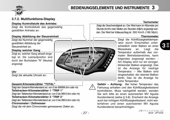
- 27 -
BEDIENUNGSELEMENTE UND INSTRUMENTE 3
DE3
3.7.2. Multifunktions-DisplayTachometer
Zeigt die Geschwindigkeit an. Der Wert kann im Kilometer proStunde (km/h) oder Meilen pro Stunden (Mph) angezeigt wer-den. Der Wert bei Vollausschlag ist 300 Km/h (186 Mph).
Gesamt-Kilometerzähler "TOTAL"Zeigt den Gesamt-Kilometerstand an; von 0 bis 999999 (km oder mi)Teilstrecken-Kilometerzähler 1 “TRIP 1”Zeigt den Teilstrecken-Kilometerstand an; von 0 bis 999.9 (km oder mi)Teilstrecken-Kilometerzähler 2 “TRIP 2”Zeigt den Teilstrecken-Kilometerstand an; von 0 bis 999.9 (km oder mi)Chronometer / ZeitmesserZeigt die mit dem Chronometer gemessenen Zeiten an.
ThermometerZeigt die Kühlflüssigkeitstempe-ratur durch Einschalten unter-schiedlich vieler Balken an einerMessskala an. Liegt dieTemperatur außerhalb des nor-malen Betriebsbereiches, kannfolgendes angezeigt werden: -Am Display wird nur ein einziger,blinkender Balken angezeigt. Dasist die Anzeige für niedrigeTemperatur. – Alle Balken sindeingeschaltet, der oberste Balkenblinkt. Das ist die Anzeige fürhohe Temperatur.
Gefahr – Achtung: Bei hoher Temperatur dasFahrzeug anhalten und den Kühlflüssigkeitsstandkontrollieren. Muss nachgefüllt werden, wendenSie sich bitte an einen autorisierten MV AgustaKundendienst (siehe § 3.8). Erscheint die Anzeigeauch bei richtigem Kühlflüssigkeitsstand, nicht wei-terfahren und einen autorisierten MV AgustaKundendienst benachrichtigen.
Display welcher Gang Zeigt an, welcher Gang aktuell einge-legt ist. Die Leerlaufposition wirddurch den Buchstaben "N" (Neutral)angezeigt.
UhrZeigt die aktuelle Uhrzeit an.
Display Abbildung der SteuereinheitZeigt die Nummer der gegenwärtig gewählten Abbildung der Steuereinheit an.
Display Kontrollstufe des AntriebsZeigt die Kontrollstufe des gegenwärtiggewählten Antriebs an.

* : Damit Sie die empfohlenen Produkte finden und kaufen können, empfiehlt Ihnen MV Agusta sichdirekt an die autorisierten Vertragshändler zu wenden. Das Motoröl eni i-Ride moto2 5W-40 wurdespeziell für den Motor des Motorrads Brutale 675 entwickelt. Stehtdas empfohlene Schmiermittel nicht zu Verfügung, rät MV Agustazum Gebrauch vollständig synthetischer Öle, die die gleichen oderbessere Eigenschaften als folgende Normen haben:
– Konform API SL– Konform ACEA A3– Konform JASO MA, MA2– Grad SAE 5W-40
ANMERKUNGDie o. a. Spezifizierungen müssen entweder allein oder zusam-men mit anderen auf dem Behälter des Motoröl aufgedruckt sein.
BEDIENUNGSELEMENTE UND INSTRUMENTE 3
3
DE
- 28 -
MotorölSAE 5W-40
API SLACEA A3
JASO MA, MA2
Beschreibung Empfohlenes Produkt Technische AngabenMotoröl eni i-Ride moto2 5W-40 (*) SAE 5W/40 - API SL
Glykolethylen mitKühlflüssigkeit AGIP ECO - PERMANENT 50% destilliertem
Wasser verdünntBrems- und Kupplungsflüssigkeit Agip Brake 4 DOT4Kettenöl D.I.D. CHAIN LUBE –
3.8. Schmiermitteltabelle
EINSATZ 4
4 DE
- 29 -
4.1. Einsatz des Motorrads
In diesem Abschnitt werden die wichtigsten Themen für einen richtigen Einsatz des Motorrades behandelt.
ACHTUNGDas Motorrad Brutale 675 zeigt hohe Leistungsmerkmale. Für sein Gebrauch wird ein aus-reichendes Niveau des Wissens des Fahrzeugs angefordert. Wenn Sie dieses Motorradzum ersten Mal benutzen, ist es notwendig, eine vorsichtige Haltung anzunehmen. Einekonkurrenzfähige Ridinghaltung kann die Gefahr der Unfälle erhöhen, welche dieSicherheit des Treibers und der Leute gefährden.
ACHTUNGDIE BESCHRÄNKUNGEN FÜR DIE ERLAUBTE NUTZUNG DES FAHRZEUGES FINDEN SIEIM ABSCHNITT “SICHERHEITSINFORMATIONEN”.
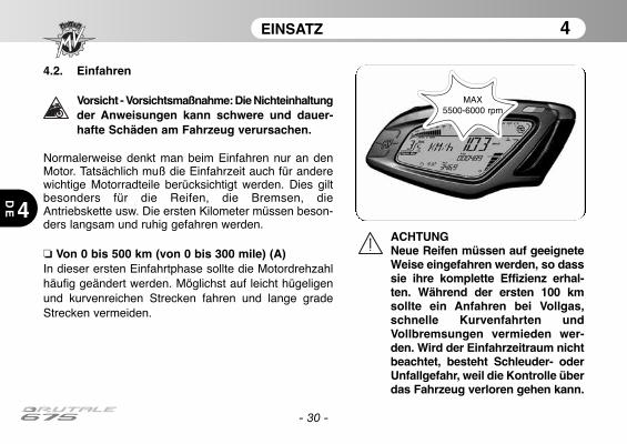
EINSATZ 4
4
DE
- 30 -
4.2. Einfahren
Vorsicht - Vorsichtsmaßnahme: Die Nichteinhaltungder Anweisungen kann schwere und dauer-hafte Schäden am Fahrzeug verursachen.
Normalerweise denkt man beim Einfahren nur an denMotor. Tatsächlich muß die Einfahrzeit auch für anderewichtige Motorradteile berücksichtigt werden. Dies giltbesonders für die Reifen, die Bremsen, dieAntriebskette usw. Die ersten Kilometer müssen beson-ders langsam und ruhig gefahren werden.
❏ Von 0 bis 500 km (von 0 bis 300 mile) (A)In dieser ersten Einfahrtphase sollte die Motordrehzahlhäufig geändert werden. Möglichst auf leicht hügeligenund kurvenreichen Strecken fahren und lange gradeStrecken vermeiden.
ACHTUNGNeue Reifen müssen auf geeigneteWeise eingefahren werden, so dasssie ihre komplette Effizienz erhal-ten. Während der ersten 100 kmsollte ein Anfahren bei Vollgas,schnelle Kurvenfahrten undVollbremsungen vermieden wer-den. Wird der Einfahrzeitraum nichtbeachtet, besteht Schleuder- oderUnfallgefahr, weil die Kontrolle überdas Fahrzeug verloren gehen kann.
MAX 5500-6000 rpm

EINSATZ 4
4 DE
- 31 -
❏ Von 500 bis 1000 km (von 300 bis 600 mile)In dieser Phase Vollgas vermeiden und nie über langeStrecken mit konstanter Geschwindigkeit fahren.
❏ Von 1000 bis 2500 km (von 600 bis 1600 mile)Das Motorrad kann jetzt stärker beansprucht werden.Trotzdem sollte die angegebene Motordrehzahl nichtüberschritten werden.
MAX8000-9000 rpm
MAX 11000 rpm
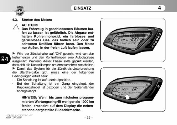
EINSATZ 4
4
DE
- 32 -
4.3. Starten des Motors
ACHTUNGDas Fahrzeug in geschlossenen Räumen lau-fen zu lassen ist gefährlich. Die Abgase ent-halten Kohlenmonoxid, ein farbloses undgeruchloses Gas, das tödlich sein oder zuschweren Unfällen führen kann. Den Motornur Außen, in der freien Luft laufen lassen.
Wird der Zündschalter auf "ON" gedreht, wird von denInstrumenten und den Kontrolllampen eine Autodiagnoseausgeführt. Während dieser Phase sollte geprüft werden,dass sich alle Kontrolllampen am Armaturenbrett einschalten.
Damit das System für die Zündkreis-Unterbrechungdie Startfreigabe gibt, muss eine der folgendenBedingungen erfüllt sein:- Die Schaltung ist auf Leerlaufposition.- Bei der Schaltung ist ein Gang eingelegt, der
Kupplungshebel ist gezogen und der Seitenständerhochgeklappt
HINWEIS: Wenn bis zum nächsten program-mierten Wartungseingriff weniger als 1000 kmfehlen, erscheint auf dem Display die neben-stehend dargestellte Bildschirmseite.
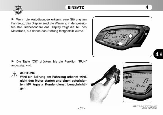
- 33 -
EINSATZ 4
4 DE
Wenn die Autodiagnose erkennt eine Störung amFahrzeug, das Display zeigt die Warnung in der gezeig-ten Bild. Insbesondere das Display zeigt die Teil desMotorrads, auf denen das Störung festgestellt wurde.
Die Taste "OK" drücken, bis die Funktion “RUN”angezeigt wird.
ACHTUNGWird ein Störung am Fahrzeug erkannt wird,nicht den Motor starten und einen autorisier-ten MV Agusta Kundendienst benachrichti-gen.
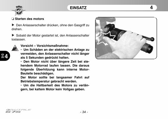
EINSATZ 4
4
DE
- 34 -
❏ Starten des motors
Den Anlasserschalter drücken, ohne den Gasgriff zudrehen.
Sobald der Motor gestartet ist, den Anlasserschalterloslassen.
Vorsicht – Vorsichtsmaßnahme:• Um Schäden an der elektrischen Anlage zuvermeiden, den Anlasserschalter nicht längerals 5 Sekunden gedrückt halten.• Den Motor nicht über längere Zeit bei ste-hendem Motorrad laufen lassen. Die darausfolgende Überhitzung kann interne Motor-Bauteile beschädigen.Der Motor sollte bei langsamer Fahrt aufBetriebstemperatur gebracht werden.• Um die Haltbarkeit des Motors zu verlän-gern, bei kaltem Motor kein Vollgas geben.
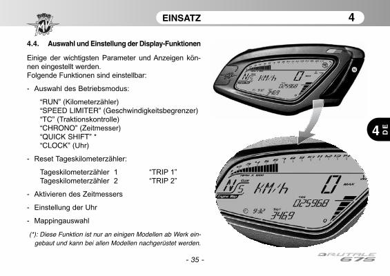
EINSATZ 4
4 DE
- 35 -
4.4. Auswahl und Einstellung der Display-Funktionen
Einige der wichtigsten Parameter und Anzeigen kön-
nen eingestellt werden.
Folgende Funktionen sind einstellbar:
- Auswahl des Betriebsmodus:
“RUN” (Kilometerzähler)“SPEED LIMITER” (Geschwindigkeitsbegrenzer)“TC” (Traktionskontrolle)“CHRONO” (Zeitmesser)“QUICK SHIFT” *“CLOCK” (Uhr)
- Reset Tageskilometerzähler:
Tageskilometerzähler 1 “TRIP 1”
Tageskilometerzähler 2 “TRIP 2”
- Aktivieren des Zeitmessers
- Einstellung der Uhr
- Mappingauswahl
(*): Diese Funktion ist nur an einigen Modellen ab Werk ein-gebaut und kann bei allen Modellen nachgerüstet werden.

EINSATZ 4
4
DE
- 36 -
ACHTUNG:
Änderungen oder Einstellungen an den Displayfunktionenmüssen bei ausgeschaltetem Motor, Schaltung in Leerlauf,angehaltenem Motorrad und Füßen auf dem Boden ausge-führt werden. Eine Änderung der Displayeinstellungen wäh-rend der Fahrt ist verboten, sofern nicht anders angegeben.
4.4.1. Auswahl der Displayfunktionen
Folgende Funktion können auf dem
Display eingestellt werden:
• “RUN” (Kilometerzähler)• “SPEED LIMITER” (Geschwindig-
keitsbegrenzer)• “TC” (Traktionskontrolle)• “CHRONO” (Zeitmesser)• “QUICK SHIFT” *• “CLOCK” (Uhr)
Die Anzeige der einzelnen Funktionen
erfolgt durch Druck auf die Taste "SET"
für weniger als 3 Sekunden. Bei
Betätigung der Taste werden die
Funktionen zyklisch am Display ange-
zeigt. Die gewünschte Funktion aus-
wählen.
(*): Diese Funktion ist nur an einigenModellen ab Werk eingebaut und kann bei
allen Modellen nachgerüstet werden.
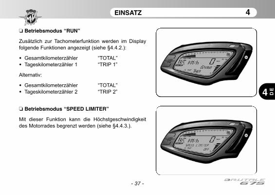
EINSATZ 4
4 DE
- 37 -
❏ Betriebsmodus “RUN”
Zusätzlich zur Tachometerfunktion werden im Display
folgende Funktionen angezeigt (siehe §4.4.2.):
• Gesamtkilometerzähler “TOTAL”
• Tageskilometerzähler 1 “TRIP 1”
Alternativ:
• Gesamtkilometerzähler “TOTAL”
• Tageskilometerzähler 2 “TRIP 2”
❏ Betriebsmodus “SPEED LIMITER”
Mit dieser Funktion kann die Höchstgeschwindigkeit
des Motorrades begrenzt werden (siehe §4.4.3.).
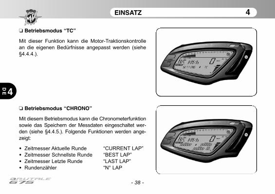
EINSATZ 4
4
DE
- 38 -
❏ Betriebsmodus “CHRONO”
Mit diesem Betriebsmodus kann die Chronometerfunktion
sowie das Speichern der Messdaten eingeschaltet wer-
den (siehe §4.4.5.). Folgende Funktionen werden ange-
zeigt:
• Zeitmesser Aktuelle Runde “CURRENT LAP”
• Zeitmesser Schnellste Runde “BEST LAP”
• Zeitmesser Letzte Runde “LAST LAP”
• Rundenzähler “N° LAP
❏ Betriebsmodus “TC”
Mit dieser Funktion kann die Motor-Traktionskontrolle
an die eigenen Bedürfnisse angepasst werden (siehe
§4.4.4.).
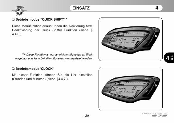
EINSATZ 4
4 DE
- 39 -
❏ Betriebsmodus“CLOCK”
Mit dieser Funktion können Sie die Uhr einstellen
(Stunden und Minuten) (siehe §4.4.7.).
❏ Betriebsmodus “QUICK SHIFT” *
Diese Menüfunktion erlaubt Ihnen die Aktivierung bzw.
Deaktivierung der Quick Shifter Funktion (siehe §
4.4.6.).
(*): Diese Funktion ist nur an einigen Modellen ab Werkeingebaut und kann bei allen Modellen nachgerüstet werden.
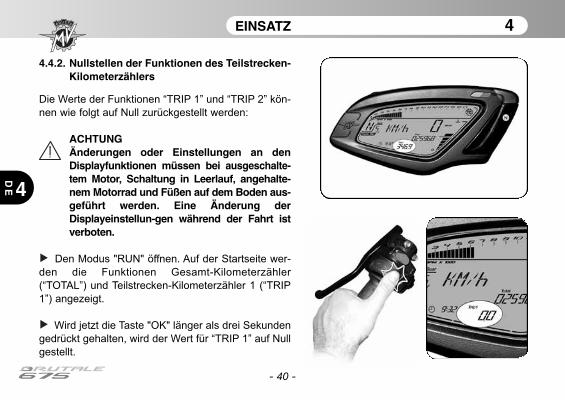
- 40 -
EINSATZ 4
4
DE
4.4.2. Nullstellen der Funktionen des Teilstrecken-Kilometerzählers
Die Werte der Funktionen “TRIP 1” und “TRIP 2” kön-
nen wie folgt auf Null zurückgestellt werden:
ACHTUNGÄnderungen oder Einstellungen an denDisplayfunktionen müssen bei ausgeschalte-tem Motor, Schaltung in Leerlauf, angehalte-nem Motorrad und Füßen auf dem Boden aus-geführt werden. Eine Änderung derDisplayeinstellun-gen während der Fahrt istverboten.
Den Modus "RUN" öffnen. Auf der Startseite wer-
den die Funktionen Gesamt-Kilometerzähler
(“TOTAL”) und Teilstrecken-Kilometerzähler 1 (“TRIP
1”) angezeigt.
Wird jetzt die Taste "OK" länger als drei Sekunden
gedrückt gehalten, wird der Wert für “TRIP 1” auf Null
gestellt.
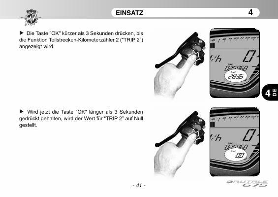
- 41 -
EINSATZ 4
4 DE
Die Taste "OK" kürzer als 3 Sekunden drücken, bis
die Funktion Teilstrecken-Kilometerzähler 2 (“TRIP 2”)
angezeigt wird.
Wird jetzt die Taste "OK" länger als 3 Sekunden
gedrückt gehalten, wird der Wert für “TRIP 2” auf Null
gestellt.
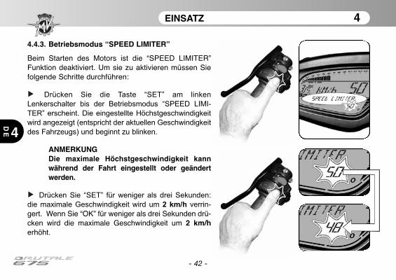
4.4.3. Betriebsmodus “SPEED LIMITER”
Beim Starten des Motors ist die “SPEED LIMITER”Funktion deaktiviert. Um sie zu aktivieren müssen Siefolgende Schritte durchführen:
Drücken Sie die Taste “SET” am linken
Lenkerschalter bis der Betriebsmodus “SPEED LIMI-
TER” erscheint. Die eingestellte Höchstgeschwindigkeit
wird angezeigt (entspricht der aktuellen Geschwindigkeit
des Fahrzeugs) und beginnt zu blinken.
ANMERKUNGDie maximale Höchstgeschwindigkeit kannwährend der Fahrt eingestellt oder geändertwerden.
Drücken Sie “SET” für weniger als drei Sekunden:
die maximale Geschwindigkeit wird um 2 km/h verrin-
gert. Wenn Sie “OK” für weniger als drei Sekunden drü-cken wird die maximale Geschwindigkeit um 2 km/herhöht.
- 42 -
EINSATZ 4
4
DE
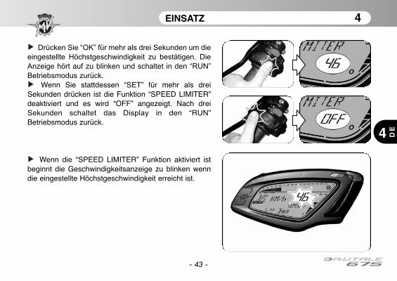
- 43 -
EINSATZ 4
4 DE
Drücken Sie “OK” für mehr als drei Sekunden um die
eingestellte Höchstgeschwindigkeit zu bestätigen. Die
Anzeige hört auf zu blinken und schaltet in den “RUN”
Betriebsmodus zurück.
Wenn Sie stattdessen “SET” für mehr als dreiSekunden drücken ist die Funktion “SPEED LIMITER”deaktiviert und es wird “OFF” angezeigt. Nach dreiSekunden schaltet das Display in den “RUN”Betriebsmodus zurück.
Wenn die “SPEED LIMITER” Funktion aktiviert istbeginnt die Geschwindigkeitsanzeige zu blinken wenndie eingestellte Höchstgeschwindigkeit erreicht ist.
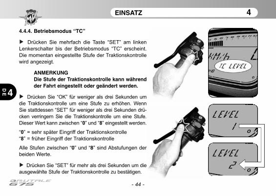
- 44 -
EINSATZ 4
4
DE
4.4.4. Betriebsmodus “TC”
Drücken Sie mehrfach die Taste “SET” am linken
Lenkerschalter bis der Betriebsmodus “TC” erscheint.
Die momentan eingestellte Stufe der Traktionskontrolle
wird angezeigt.
ANMERKUNGDie Stufe der Traktionskontrolle kann währendder Fahrt eingestellt oder geändert werden.
Drücken Sie “OK” für weniger als drei Sekunden um
die Traktionskontrolle um eine Stufe zu erhöhen. Wenn
Sie stattdessen “SET” für weniger als drei Sekunden drü-
cken verringern Sie die Traktionskontrolle um eine Stufe.
Dieser Wert kann zwischen “0” und “8” eingestellt werden.
“0” = sehr später Eingriff der Traktionskontrolle
“8” = früher Eingriff der Traktionskontrolle
Alle Stufen zwischen “0” und “8” sind Abstufungen derbeiden Werte.
Drücken Sie “SET” für mehr als drei Sekunden um die
ausgewählte Stufe der Traktionskontrolle zu bestätigen.
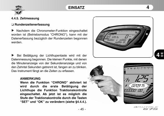
- 45 -
EINSATZ 4
4 DE
4.4.5. Zeitmessung
❏ Rundenzeitenerfassung
Nachdem die Chronometer-Funktion eingeschaltet
worden ist (Betriebsmodus “CHRONO”), kann mit der
Datenerfassung bezüglich der Rundenzeiten begonnen
werden.
Bei Betätigung der Lichthupentaste wird mit der
Datenmessung begonnen. Die kleinen Punkte, mit denen
die Minutenanzeige von der Sekundenanzeige und von
den Zehntel Sekunden getrennt ist, fangen an zu blinken.
Das Instrument fängt an die Zeiten zu erfassen.
ANMERKUNGWenn die Funktion “CHRONO” aktiviert istwird durch die erste Betätigung derLichthupe die Funktion Traktionskontrolleeingeschaltet. Ab jetzt ist es möglich dieStufe der Traktionskontrolle durch die Tasten“SET” und “OK” zu verändern (siehe §4.4.4.).
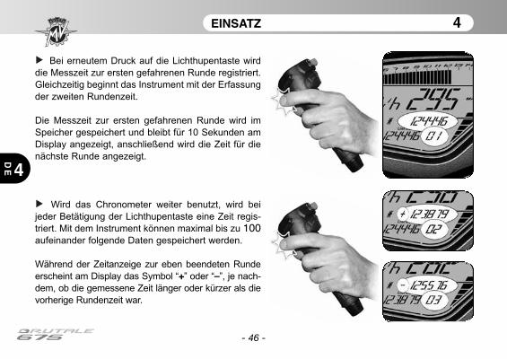
EINSATZ 4
4
DE
- 46 -
Bei erneutem Druck auf die Lichthupentaste wird
die Messzeit zur ersten gefahrenen Runde registriert.
Gleichzeitig beginnt das Instrument mit der Erfassung
der zweiten Rundenzeit.
Die Messzeit zur ersten gefahrenen Runde wird im
Speicher gespeichert und bleibt für 10 Sekunden am
Display angezeigt, anschließend wird die Zeit für die
nächste Runde angezeigt.
Wird das Chronometer weiter benutzt, wird bei
jeder Betätigung der Lichthupentaste eine Zeit regis-
triert. Mit dem Instrument können maximal bis zu 100aufeinander folgende Daten gespeichert werden.
Während der Zeitanzeige zur eben beendeten Runde
erscheint am Display das Symbol “+” oder “–”, je nach-
dem, ob die gemessene Zeit länger oder kürzer als die
vorherige Rundenzeit war.

EINSATZ 4
4 DE
- 47 -
❏ Anzeige der Daten
Nach der Erfassung der Zeiten können die Daten
angezeigt werden.
Den Modus "CHRONO" öffnen. Auf dieser Seite
werden die schnellste Rundenzeit (“BEST LAP”)
sowie die letzte Rundenzeit (“LAST LAP”) angezeigt.
ACHTUNGÄnderungen oder Einstellungen an denDisplayfunktionen müssen bei ausgeschalte-tem Motor, Schaltung in Leerlauf, angehalte-nem Motorrad und Füßen auf dem Boden aus-geführt werden. Eine Änderung derDisplayeinstellun-gen während der Fahrt istverboten.
Die Taste "OK" kürzer als 3 Sekunden drücken, bis
“LAPS VIEW” angezeigt wird

EINSATZ 4
4
DE
- 48 -
Durch wiederholten Druck auf die Lichthupentaste
können nacheinander alle vorher erfassten Zeiten ab
der letzten gespeicherten Runde angezeigt werden.
Am Ende der Datenanzeige kann durch Druck auf
die Taste “SET” wieder auf den Betriebsmodus “LAPS
VIEW” zurückgestellt und auf den nächsten Modus
umgestellt werden.
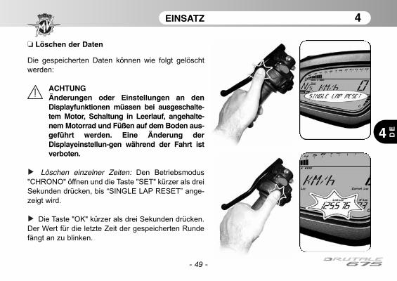
EINSATZ 4
4 DE
- 49 -
❏ Löschen der Daten
Die gespeicherten Daten können wie folgt gelöscht
werden:
ACHTUNGÄnderungen oder Einstellungen an denDisplayfunktionen müssen bei ausgeschalte-tem Motor, Schaltung in Leerlauf, angehalte-nem Motorrad und Füßen auf dem Boden aus-geführt werden. Eine Änderung derDisplayeinstellun-gen während der Fahrt istverboten.
Löschen einzelner Zeiten: Den Betriebsmodus
"CHRONO" öffnen und die Taste "SET" kürzer als drei
Sekunden drücken, bis “SINGLE LAP RESET” ange-
zeigt wird.
Die Taste "OK" kürzer als drei Sekunden drücken.
Der Wert für die letzte Zeit der gespeicherten Runde
fängt an zu blinken.
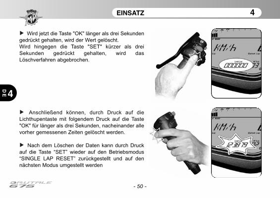
- 50 -
EINSATZ 4
4
DE
Wird jetzt die Taste "OK" länger als drei Sekunden
gedrückt gehalten, wird der Wert gelöscht.
Wird hingegen die Taste "SET" kürzer als drei
Sekunden gedrückt gehalten, wird das
Löschverfahren abgebrochen.
Anschließend können, durch Druck auf die
Lichthupentaste mit folgendem Druck auf die Taste
"OK" für länger als drei Sekunden, nacheinander alle
vorher gemessenen Zeiten gelöscht werden.
Nach dem Löschen der Daten kann durch Druck
auf die Taste “SET” wieder auf den Betriebsmodus
“SINGLE LAP RESET” zurückgestellt und auf den
nächsten Modus umgestellt werden
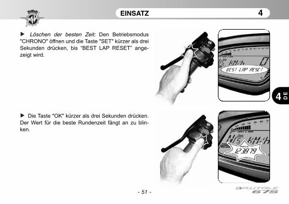
- 51 -
EINSATZ 4
4 DE
Löschen der besten Zeit: Den Betriebsmodus
"CHRONO" öffnen und die Taste "SET" kürzer als drei
Sekunden drücken, bis “BEST LAP RESET” ange-
zeigt wird.
Die Taste "OK" kürzer als drei Sekunden drücken.
Der Wert für die beste Rundenzeit fängt an zu blin-
ken.
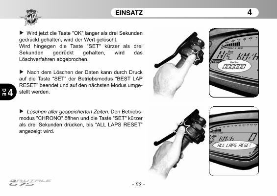
- 52 -
EINSATZ 4
4
DE
Wird jetzt die Taste "OK" länger als drei Sekunden
gedrückt gehalten, wird der Wert gelöscht.
Wird hingegen die Taste "SET" kürzer als drei
Sekunden gedrückt gehalten, wird das
Löschverfahren abgebrochen.
Nach dem Löschen der Daten kann durch Druck
auf die Taste “SET” der Betriebsmodus “BEST LAP
RESET” beendet und auf den nächsten Modus umge-
stellt werden.
Löschen aller gespeicherten Zeiten: Den Betriebs-
modus "CHRONO" öffnen und die Taste "SET" kürzer
als drei Sekunden drücken, bis “ALL LAPS RESET”
angezeigt wird.
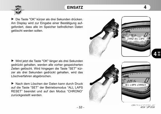
- 53 -
EINSATZ 4
4 DE
Die Taste "OK" kürzer als drei Sekunden drücken.
Am Display wird zur Eingabe einer Bestätigung auf-
gefordert, dass alle im Speicher befindlichen Daten
gelöscht werden sollen.
Wird jetzt die Taste "OK" länger als drei Sekunden
gedrückt gehalten, werden alle vorher gespeicherten
Zeiten gelöscht. Wird hingegen die Taste "SET" kür-
zer als drei Sekunden gedrückt gehalten, wird das
Löschverfahren abgebrochen.
Nach dem Löschen der Daten kann durch Druck
auf die Taste “SET” der Betriebsmodus “ALL LAPS
RESET” beendet und auf den Modus “CHRONO”
zurückgestellt werden.
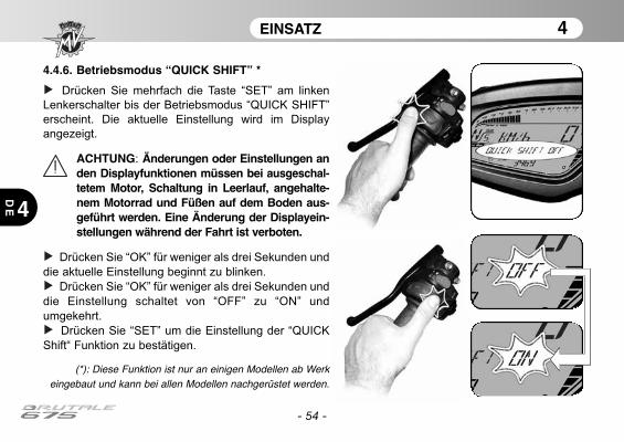
- 54 -
EINSATZ 4
4
DE
4.4.6. Betriebsmodus “QUICK SHIFT” *
Drücken Sie mehrfach die Taste “SET” am linken
Lenkerschalter bis der Betriebsmodus “QUICK SHIFT”
erscheint. Die aktuelle Einstellung wird im Display
angezeigt.
ACHTUNG: Änderungen oder Einstellungen anden Displayfunktionen müssen bei ausgeschal-tetem Motor, Schaltung in Leerlauf, angehalte-nem Motorrad und Füßen auf dem Boden aus-geführt werden. Eine Änderung der Displayein-stellungen während der Fahrt ist verboten.
Drücken Sie “OK” für weniger als drei Sekunden und
die aktuelle Einstellung beginnt zu blinken.
Drücken Sie “OK” für weniger als drei Sekunden und
die Einstellung schaltet von “OFF” zu “ON” und
umgekehrt.
Drücken Sie “SET” um die Einstellung der “QUICK
Shift“ Funktion zu bestätigen.
(*): Diese Funktion ist nur an einigen Modellen ab Werkeingebaut und kann bei allen Modellen nachgerüstet werden.
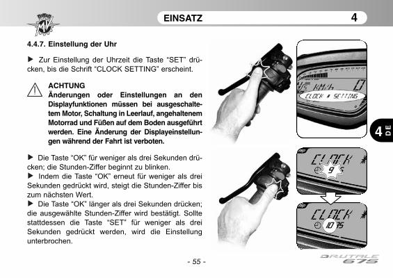
- 55 -
EINSATZ 4
4 DE
4.4.7. Einstellung der Uhr
Zur Einstellung der Uhrzeit die Taste “SET” drü-
cken, bis die Schrift “CLOCK SETTING” erscheint.
ACHTUNGÄnderungen oder Einstellungen an denDisplayfunktionen müssen bei ausgeschalte-tem Motor, Schaltung in Leerlauf, angehaltenemMotorrad und Füßen auf dem Boden ausgeführtwerden. Eine Änderung der Displayeinstellun-gen während der Fahrt ist verboten.
Die Taste “OK” für weniger als drei Sekunden drü-
cken; die Stunden-Ziffer beginnt zu blinken.
Indem die Taste “OK” erneut für weniger als drei
Sekunden gedrückt wird, steigt die Stunden-Ziffer bis
zum nächsten Wert.
Die Taste “OK” länger als drei Sekunden drücken;
die ausgewählte Stunden-Ziffer wird bestätigt. Sollte
stattdessen die Taste “SET” für weniger als drei
Sekunden gedrückt werden, wird die Einstellung
unterbrochen.

- 56 -
EINSATZ 4
4
DE
Nachdem die Stunden-Ziffer eingestellt wurde,
geht das Armaturenbrett automatisch zur Einstellung
der Minuten-Ziffer über. Die Minuten-Ziffer beginnt zu
blinken.
Indem die Taste “OK” für weniger als drei
Sekunden gedrückt wird, steigt die Minuten-Ziffer bis
zum nächsten Wert.
Die Taste “OK” länger als drei Sekunden drücken;
die ausgewählte Minuten-Ziffer wird bestätigt, und
das Armaturenbrett kehrt in den "CLOCK"-Modus
zurück. Sollte stattdessen die Taste “SET” für weniger
als drei Sekunden gedrückt werden, wird die
Einstellung unterbrochen.
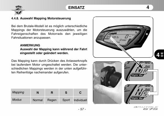
- 57 -
EINSATZ 4
4 DE
4.4.8. Auswahl Mapping Motorsteuerung
Bei dem Brutale-Modell ist es möglich unterschiedliche
Mappings der Motorsteuerung auszuwählen, um die
Fahreigenschaften des Motorrads den jeweiligen
Fahrsituationen anzupassen.
ANMERKUNGAuswahl der Mapping kann während der Fahrteingestellt oder geändert werden.
Das Mapping kann durch Drücken des Anlasserknopfs
bei laufendem Motor umgeschaltet werden. Die unter-
schiedlichen Mappings werden in der unten aufgeführ-
ten Reihenfolge nacheinander aufgerufen.
Mapping
Modus
N
Normal
R
Regen
S
Sport
C
Individuell
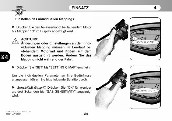
- 58 -
EINSATZ 4
4
DE
❏ Einstellen des individuellen Mappings
Drücken Sie den Anlasserknopf bei laufendem Motor
bis Mapping “C” im Display angezeigt wird.
ACHTUNG!Änderungen oder Einstellungen an dem indi-viduellen Mapping müssen im Leerlauf beistehendem Motorrad und Füßen auf demBoden ausgeführt werden. Ändern Sie dasMapping nicht während der Fahrt.
Drücken Sie “SET” bis “SETTING C MAP” erscheint.
Um die individuellen Parameter an Ihre Bedürfnisse
anzupassen führen Sie bitte folgende Schritte durch.
Sensibilität Gasgriff: Drücken Sie “OK” für weniger
als drei Sekunden bis “GAS SENSITIVITY“ angezeigt
wird.
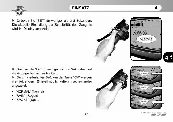
- 59 -
EINSATZ 4
4 DE
Drücken Sie “SET” für weniger als drei Sekunden.Die aktuelle Einstellung der Sensibilität des Gasgriffswird im Display angezeigt.
Drücken Sie “OK” für weniger als drei Sekunden und
die Anzeige beginnt zu blinken.
Durch wiederholtes Drücken der Taste “OK” werden
die folgenden Einstellmöglichkeiten nacheinander
angezeigt:
• “NORMAL” (Normal)• “RAIN” (Regen)• “SPORT” (Sport)

- 60 -
EINSATZ 4
4
DE
Drücken Sie “OK” für mehr als drei Sekunden um die
gewählte Einstellung zu bestätigen. Die Anzeige hört
auf zu blinken und schaltet nach ein paar Sekunden
zurück zu “GAS SENSITIVITY”. Jetzt kann mit der
Einstellung der nächsten Parameter fortgefahren wer-
den.
Maximales Drehmoment: Drücken Sie “OK” für weni-
ger als drei Sekunden bis “MAX ENGINE TORQUE”angezeigt wird.

- 61 -
EINSATZ 4
4 DE
Drücken Sie “SET” für weniger als drei Sekunden.
Die aktuelle Einstellung des maximalen Drehmoments
wird im Display angezeigt.
Drücken Sie “OK” für weniger als drei Sekunden und
die Anzeige beginnt zu blinken.
Durch wiederholtes Drücken der Taste “OK” werden
die folgenden Einstellmöglichkeiten nacheinander
angezeigt:
• “RAIN” (Regen)• “SPORT” (Sport)

- 62 -
EINSATZ 4
4
DE
Drücken Sie “OK” für mehr als drei Sekunden um die
gewählte Einstellung zu bestätigen. Die Anzeige hört
auf zu blinken und schaltet nach ein paar Sekunden
zurück zu “MAX ENGINE TORQUE”.
Motorbremse: Drücken Sie “OK” für weniger als drei
Sekunden bis “ENGINE BRAKE” angezeigt wird.

- 63 -
EINSATZ 4
4 DE
Drücken Sie “SET” für weniger als drei Sekunden.
Die aktuelle Einstellung der Motorbremse wird im
Display angezeigt.
Drücken Sie “OK” für weniger als drei Sekunden und
die Anzeige beginnt zu blinken.
Durch wiederholtes Drücken der Taste “OK” werden
die folgenden Einstellmöglichkeiten nacheinander
angezeigt:
• “NORMAL” (Normal)• “SPORT” (Sport)

- 64 -
EINSATZ 4
4
DE
Drücken Sie “OK” für mehr als drei Sekunden um die
gewählte Einstellung zu bestätigen. Die Anzeige hört
auf zu blinken und schaltet nach ein paar Sekunden
zurück zu “ENGINE BRAKE”.
Ansprechverhalten des Motors: Drücken Sie “OK” für
weniger als drei Sekunden bis “ENGINE RESPONSE”angezeigt wird.
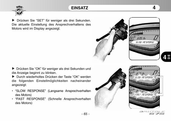
- 65 -
EINSATZ 4
4 DE
Drücken Sie “SET” für weniger als drei Sekunden.
Die aktuelle Einstellung des Ansprechverhaltens des
Motors wird im Display angezeigt.
Drücken Sie “OK” für weniger als drei Sekunden und
die Anzeige beginnt zu blinken.
Durch wiederholtes Drücken der Taste “OK” werden
die folgenden Einstellmöglichkeiten nacheinander
angezeigt:
• “SLOW RESPONSE” (Langsame Ansprechverhaltendes Motors)
• “FAST RESPONSE” (Schnelle Ansprechverhaltendes Motors)
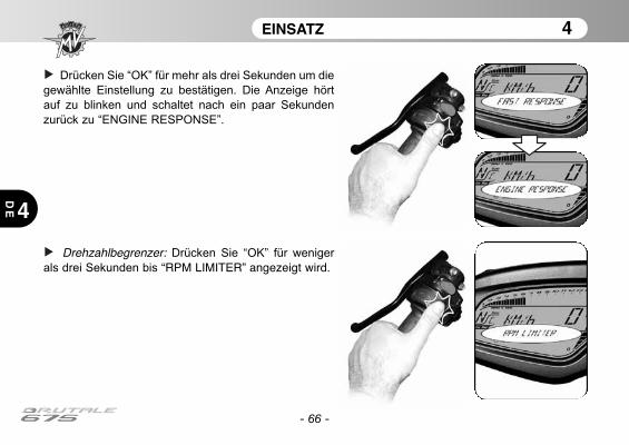
- 66 -
EINSATZ 4
4
DE
Drücken Sie “OK” für mehr als drei Sekunden um die
gewählte Einstellung zu bestätigen. Die Anzeige hört
auf zu blinken und schaltet nach ein paar Sekunden
zurück zu “ENGINE RESPONSE”.
Drehzahlbegrenzer: Drücken Sie “OK” für weniger
als drei Sekunden bis “RPM LIMITER” angezeigt wird.
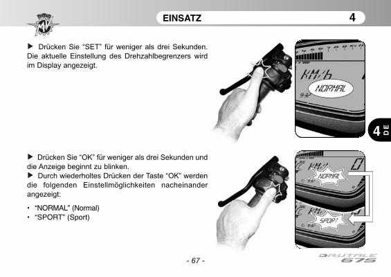
- 67 -
EINSATZ 4
4 DE
Drücken Sie “SET” für weniger als drei Sekunden.
Die aktuelle Einstellung des Drehzahlbegrenzers wird
im Display angezeigt.
Drücken Sie “OK” für weniger als drei Sekunden und
die Anzeige beginnt zu blinken.
Durch wiederholtes Drücken der Taste “OK” werden
die folgenden Einstellmöglichkeiten nacheinander
angezeigt:
• “NORMAL” (Normal)• “SPORT” (Sport)

- 68 -
EINSATZ 4
4
DE
Drücken Sie “OK” für mehr als drei Sekunden um die
gewählte Einstellung zu bestätigen. Die Anzeige hört
auf zu blinken und schaltet nach ein paar Sekunden
zurück zu “RPM LIMITER”.
Drücken Sie “OK” für weniger als drei Sekunden und
das Display schaltet in den “RUN” Betriebsmodus
zurück. Die Einstellung des individuellen Mappings ist
abgeschlossen.

- 69 -
EINSATZ 4
4 DE
4.4.9. Warnung / Störmeldung
Das Instrumentenausrüstung kann dasVorhandensein eines Störungs während der verschie-denen Bedingungen von die Verwendung desMotorrades zeigen.
Starten des Motors: Wird der Zündschalter auf"ON" gedreht, wird von den Instrumenten und denKontrolllampen eine Autodiagnose ausgeführt. Wenndie Autodiagnose erkennt eine Störung am Fahrzeug,das Display zeigt die Warnung in der gezeigten Bild.Insbesondere das Display zeigt die Teil desMotorrads, auf denen das Störung festgestellt wurde.
Die Taste "OK" drücken, bis die Funktion “RUN”angezeigt wird.
ACHTUNGWird ein Störung am Fahrzeug erkannt wird,nicht den Motor starten und einen autori-sierten MV Agusta Kundendienst benach-richtigen.
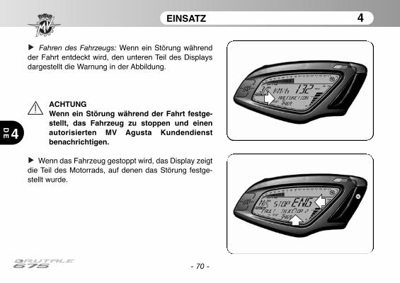
- 70 -
EINSATZ 4
4
DE
Fahren des Fahrzeugs: Wenn ein Störung währendder Fahrt entdeckt wird, den unteren Teil des Displaysdargestellt die Warnung in der Abbildung.
ACHTUNGWenn ein Störung während der Fahrt festge-stellt, das Fahrzeug zu stoppen und einenautorisierten MV Agusta Kundendienstbenachrichtigen.
Wenn das Fahrzeug gestoppt wird, das Display zeigtdie Teil des Motorrads, auf denen das Störung festge-stellt wurde.
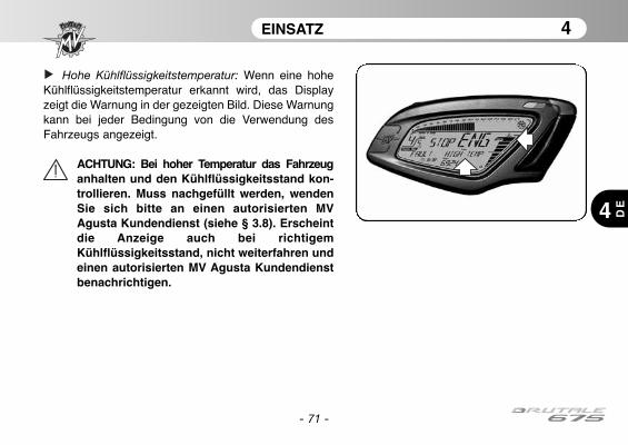
- 71 -
EINSATZ 4
4 DE
Hohe Kühlflüssigkeitstemperatur: Wenn eine hoheKühlflüssigkeitstemperatur erkannt wird, das Displayzeigt die Warnung in der gezeigten Bild. Diese Warnungkann bei jeder Bedingung von die Verwendung desFahrzeugs angezeigt.
ACHTUNG: Bei hoher Temperatur das Fahrzeuganhalten und den Kühlflüssigkeitsstand kon-trollieren. Muss nachgefüllt werden, wendenSie sich bitte an einen autorisierten MVAgusta Kundendienst (siehe § 3.8). Erscheintdie Anzeige auch bei richtigemKühlflüssigkeitsstand, nicht weiterfahren undeinen autorisierten MV Agusta Kundendienstbenachrichtigen.
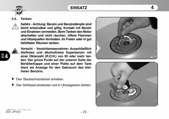
4.5. Tanken
Gefahr - Achtung: Benzin und Benzindämpfe sindleicht entzündbar und giftig. Kontakt mit Benzinund Einatmen vermeiden. Beim Tanken den Motorabschalten und nicht rauchen, offene Flammenund Hitzequellen fernhalten. Im Freien oder in gutbelüfteten Räumen tanken.
Vorsicht - Vorsichtsmassnahme: Ausschließlichbleifreies und alkoholfreies Superbenzin miteiner Oktanzahl (R.O.N.) von 95 oder mehr tan-ken. Der grüne Punkt auf der unteren Seite derBehälterkappe und einer Platte auf dem Tankdient als Anzeige für den Gebrauch des blei-freien Benzins.
Den Staubschutzdeckel anheben.
Den Schlüssel einstecken und in Uhrzeigersinn drehen.
- 72 -
EINSATZ 4
4
DE
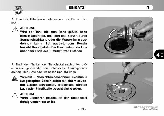
- 73 -
EINSATZ 4
4 DE
Den Einfüllstopfen abnehmen und mit Benzin tan-ken.
ACHTUNGWird der Tank bis zum Rand gefüllt, kannBenzin austreten, das sich das Benzin durchSonneneinwirkung oder die Motorwärme aus-dehnen kann. Bei austretendem Benzinbesteht Brandgefahr. Der Benzinstand darf nieüber dem Ende des Einfüllstutzens stehen.
Nach dem Tanken den Tankdeckel nach unten drü-cken und gleichzeitig den Schlüssel in Uhrzeigersinndrehen. Den Schlüssel loslassen und abziehen.
Vorsicht - Vorsichtsmassnahme: Eventuelleausgetropftes Benzin sofort mit einem saube-ren Lappen abwischen, andernfalls könnenLack oder Plastikteile beschädigt werden.
ACHTUNGVorm Losfahren prüfen, ob der Tankdeckelrichtig verschlossen ist.
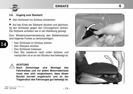
EINSATZ 4
4
DE
- 74 -
4.6. Zugang zum Staufach
Den Schlüssel ins Schloss einstecken.
Auf das Ende der Sitzbank drücken und gleichzei-tig den Schlüssel gegen den Uhrzeigersinn drehen.Die Sitzbank anheben wie in der Abbildung gezeigt.
Zum Wiederzusammensetzung des Beifahrersitzessind folgende Punkte zu berücksichtigen:
• Den Schlüssel im Schloss drehen• Den Sitzbank drücken • Den Schlüssel loslassen• Den Sitz wiederum nach unten drücken und
nachprüfen ob er an der Struktur fest befestigt ist.
ACHTUNGNach Demontage und Montage desFahrersitzes und vor jedem Motorradeinsatzmuss man sich vergewissern, dass dieserBauteil korrekt angebracht und an derTragstruktur des Fahrzeuges gut befestigt ist.
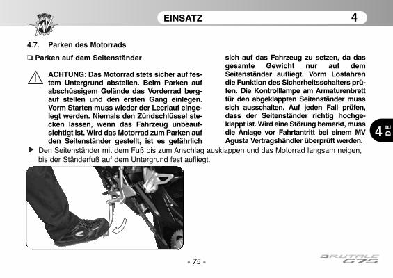
EINSATZ 4
4 DE
- 75 -
4.7. Parken des Motorrads
❏ Parken auf dem Seitenständer
ACHTUNG: Das Motorrad stets sicher auf fes-tem Untergrund abstellen. Beim Parken aufabschüssigem Gelände das Vorderrad berg-auf stellen und den ersten Gang einlegen.Vorm Starten muss wieder der Leerlauf einge-legt werden. Niemals den Zündschlüssel ste-cken lassen, wenn das Fahrzeug unbeauf-sichtigt ist. Wird das Motorrad zum Parken aufden Seitenständer gestellt, ist es gefährlich
sich auf das Fahrzeug zu setzen, da dasgesamte Gewicht nur auf demSeitenständer aufliegt. Vorm Losfahrendie Funktion des Sicherheitsschalters prü-fen. Die Kontrolllampe am Armaturenbrettfür den abgeklappten Seitenständer musssich ausschalten. Auf jeden Fall prüfen,dass der Seitenständer richtig hochge-klappt ist. Wird eine Störung bemerkt, mussdie Anlage vor Fahrtantritt bei einem MVAgusta Vertragshändler überprüft werden.
Den Seitenständer mit dem Fuß bis zum Anschlag ausklappen und das Motorrad langsam neigen, bis der Ständerfuß auf dem Untergrund fest aufliegt.

EINSATZ 4
4
DE
- 76 -
❏ Parken auf dem hinteren Ständer
Den Zapfen des Ständer von der linkenFahrzeugseite aus in die Öffnung an derRadachse stecken. Den Ständer auf denBoden stellen, festhalten und das Fahrzeugsoweit anheben, bis es sicher steht.
ACHTUNGDieser Vorgang muss von zweiPersonen zusammen ausgeführtwerden.
1 2
3
EINSTELLUNGSARBEITEN 5
5 DE
- 77 -
5.1. Liste der Einstellungsarbeiten
Das Motorrad bietet eine breite Auswahl vonEinstellungsmöglichkeiten, die Ergonomie, dieSitzposition und die Sicherheit verbessern können.
Da eine falsche Einstellung von wichtigenKomponenten eine Gefahrenquelle darstellen kann,dürfen einige dieser Einstellungen nur von einer MVAgusta-Vertragswerkstatt vorgenommen werden.
ACHTUNGAlle Einstellungsarbeiten müssen bei ste-hendem Fahrzeug vorgenommen werden
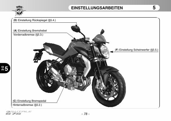
EINSTELLUNGSARBEITEN 5
5
DE
- 78 -
(F) Einstellung Scheinwerfer (§5.5.)
(D) Einstellung Rückspiegel (§5.4.)
(A) Einstellung Bremshebel
Vorderradbremse (§5.3.)
(C) Einstellung Bremspedal
Hinterradbremse (§5.2.)
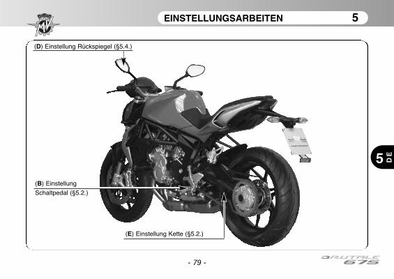
EINSTELLUNGSARBEITEN 5
5 DE
- 79 -
(E) Einstellung Kette (§5.2.)
(B) Einstellung
Schaltpedal (§5.2.)
(D) Einstellung Rückspiegel (§5.4.)
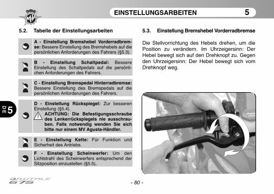
EINSTELLUNGSARBEITEN 5
5
DE
- 80 -
5.2. Tabelle der Einstellungsarbeiten 5.3. Einstellung Bremshebel Vorderradbremse
Die Stellvorrichtung des Hebels drehen, um diePosition zu verändern. Im Uhrzeigersinn: DerHebel bewegt sich auf den Drehknopf zu. Gegenden Uhrzeigersinn: Der Hebel bewegt sich vomDrehknopf weg.
A - Einstellung Bremshebel Vorderradbrem-se: Bessere Einstellung des Bremshebels auf diepersönlichen Anforderungen des Fahrers (§5.3).
B - Einstellung Schaltpedal: BessereEinstellung des Schaltpedals auf die persönli-chen Anforderungen des Fahrers.
C - Einstellung Bremspedal Hinterradbremse:Bessere Einstellung des Bremspedals auf diepersönlichen Anforderungen des Fahrers.
D - Einstellung Rückspiegel: Zur besserenEinstellung (§5.4).
ACHTUNG: Die Befestigungsschraubedes Lenkerrückspiegels nie ausschrau-ben. Falls notwendig wenden Sie sichbitte nur einem MV Agusta-Händler.
E - Einstellung Kette: Für Funktion undSicherheit des Antriebs.
F - Einstellung Scheinwerfer: Um denLichtstrahl des Scheinwerfers entsprechend derSitzposition einzustellen (§5.5).

EINSTELLUNGSARBEITEN 5
5 DE
- 81 -
5.4. Einstellung Rückspiegel
Zur Einstellung des Rückspiegels an den vier in derAbbildung gezeigten Stellen drücken.
Die Einstellung beider Rückspiegel durchführen. ZurDurchführung einer korrekten Rückspiegeleinstellungist es ratsam auf das Motorrad zu steigen.
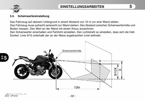
EINSTELLUNGSARBEITEN 5
5
DE
- 82 -
5.5. Scheinwerfereinstellung
Das Fahrzeug auf ebenem Untergrund in einem Abstand von 10 m vor eine Wand stellen.Das Fahrzeug muss aufrecht senkrecht zur Wand stehen. Den Abstand zwischen Scheinwerfermitte undBoden messen. Den Wert an der Wand mit einem Kreuz anzeichnen.Den Scheinwerfer einschalten und Fahrlicht einstellen. Den Lichtstrahl so einstellen, dass sich die Hell-Dunkel- Linie 9/10 unterhalb der an der Wand angebrachten Linie befindet.
Scheinwerfermitte
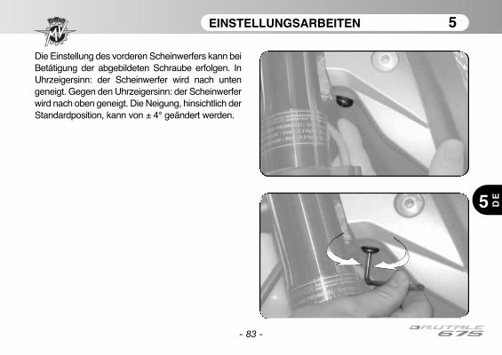
EINSTELLUNGSARBEITEN 5
5 DE
- 83 -
Die Einstellung des vorderen Scheinwerfers kann beiBetätigung der abgebildeten Schraube erfolgen. InUhrzeigersinn: der Scheinwerfer wird nach untengeneigt. Gegen den Uhrzeigersinn: der Scheinwerferwird nach oben geneigt. Die Neigung, hinsichtlich derStandardposition, kann von ± 4° geändert werden.
- 84 -
ANMERKUNGEN
5
DE
InformationshinweisMV Agusta Motor S.p.A. verfolgt eine Politik ständiger Verbesserung ihrer Produkte. Aus diesem Grundkann es vorkommen, dass kleine Abweichungen zwischen dem vorliegenden Dokument und dem vonIhnen erworbenen Fahrzeug bestehen. Die Modelle MV Agusta werden in zahlreiche Länder exportiert, indenen unterschiedliche Straßenverkehrsordnungen und Zulassungsverfahren bestehen. In der Hoffnungauf Ihr Verständnis behält sich MV Agusta Motor S.p.A. deshalb das Recht vor, jederzeit und ohneVorankündigung, Änderungen an ihren Produkten und den technischen Dokumentationen vorzunehmen.
Wir schlagen vor, um den Internetplatz www.mvagusta.it häufig zu besichtigen, um Informationen undUpdates über die MV Agusta-Produkte und die in Verbindung stehenden Unterlagen zu erhalten.
Die Umwelt schützen und respektierenAlles was wir tun hat Auswirkungen auf den gesamten Planeten und seine Ressourcen.Zum Schutz der Gemeinschaft weist MV Agusta die Kunden und die Angestellten im Kundendienst daraufhin, wie das Motorrad umweltschonend genutzt und Motorradbauteile und Flüssigkeiten entsprechend dergeltenden Umweltschutzgesetze entsorgt bzw. dem Recycling zugeführt werden können.
© 2012Die vollständige oder teilweise Vervielfältigung dieses Dokuments ist ohne vorherige schriftliche Genehmigung der MV AgustaMotor S.p.A. verboten.
Teilnr. n° 8000B6848Ausgabe n° 1 - April 2012
Manual de usoVersión en Español
- 2 -
Estimado cliente,
Le agradecemos la confianza que nos ha otorgado y le felicitamos por su nueva Brutale 675.MV Agusta, gracias a la pasión y a la escrupulosidad de sus técnicos se propone nuevamente a sus afi-cionados con un producto caracterizado por una inédita cualidad estética junto a una refinada parteciclística: elementos que han contramarcado todas las creaciones de la marca MV Agusta a lo largo desu gloriosa historia.El resultado es una moto exclusiva que por sus características estéticas y funcionales y las innumera-bles innovaciones técnicas, se coloca por encima de productos de mas alto perfil que el mercado de lamoto pueda ofrecer hoy.Las soluciones adoptadas otorgan, en efecto, a Brutale 675 ese inconfundible carácter que la atan a losotros modelos de la familia MV Agusta, reforzando una filosofía de proyecto que privilegia la constantebúsqueda, innovación tecnológica y el amor por el detalle, dando la posibilidad a quien vive la propiapasión de motociclista en plena libertad, de poseer un objeto único en el mundo que se coloca con pre-potencia como referencia en el ámbito mundial.
Si desea más información, no dude en ponerse en contacto con el Servicio de Asistencia Clientes deMV Agusta.
¡Buena diversión!Giovanni Castiglioni PresidenteMV Agusta
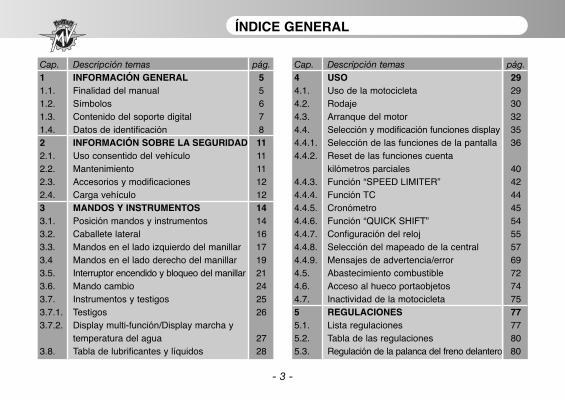
- 3 -
ÍNDICE GENERAL
Cap. Descripción temas pág.1 INFORMACIÓN GENERAL 51.1. Finalidad del manual 51.2. Símbolos 61.3. Contenido del soporte digital 71.4. Datos de identificación 82 INFORMACIÓN SOBRE LA SEGURIDAD 112.1. Uso consentido del vehículo 112.2. Mantenimiento 112.3. Accesorios y modificaciones 122.4. Carga vehículo 123 MANDOS Y INSTRUMENTOS 143.1. Posición mandos y instrumentos 143.2. Caballete lateral 163.3. Mandos en el lado izquierdo del manillar 173.4 Mandos en el lado derecho del manillar 193.5. Interruptor encendido y bloqueo del manillar 213.6. Mando cambio 243.7. Instrumentos y testigos 253.7.1. Testigos 263.7.2. Display multi-función/Display marcha y
temperatura del agua 273.8. Tabla de lubrificantes y líquidos 28
Cap. Descripción temas pág.4 USO 294.1. Uso de la motocicleta 294.2. Rodaje 304.3. Arranque del motor 324.4. Selección y modificación funciones display 354.4.1. Selección de las funciones de la pantalla 364.4.2. Reset de las funciones cuenta
kilómetros parciales 404.4.3. Función “SPEED LIMITER” 424.4.4. Función TC 444.4.5. Cronómetro 454.4.6. Función “QUICK SHIFT” 544.4.7. Configuración del reloj 554.4.8. Selección del mapeado de la central 574.4.9. Mensajes de advertencia/error 694.5. Abastecimiento combustible 724.6. Acceso al hueco portaobjetos 744.7. Inactividad de la motocicleta 755 REGULACIONES 775.1. Lista regulaciones 775.2. Tabla de las regulaciones 805.3. Regulación de la palanca del freno delantero 80
- 4 -
ÍNDICE GENERAL
Cap. Descripción temas pág.5.4. Regulación de los espejos retrovisores 815.5. Ajuste proyector delantero 82
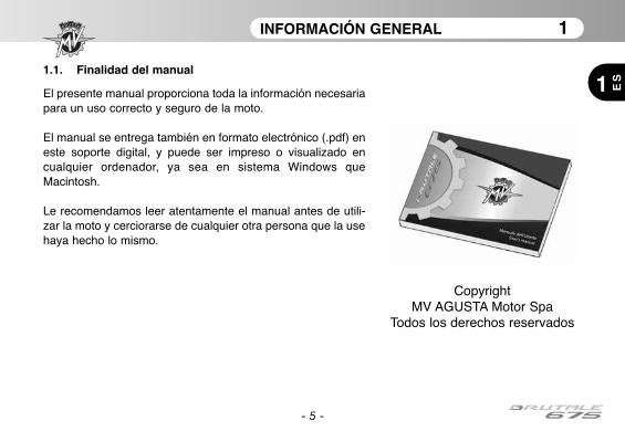
INFORMACIÓN GENERAL 1
1 ES
- 5 -
1.1. Finalidad del manual
El presente manual proporciona toda la información necesariapara un uso correcto y seguro de la moto.
El manual se entrega también en formato electrónico (.pdf) eneste soporte digital, y puede ser impreso o visualizado encualquier ordenador, ya sea en sistema Windows queMacintosh.
Le recomendamos leer atentamente el manual antes de utili-zar la moto y cerciorarse de cualquier otra persona que la usehaya hecho lo mismo.
CopyrightMV AGUSTA Motor Spa
Todos los derechos reservados
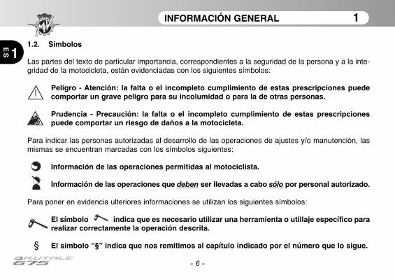
INFORMACIÓN GENERAL 1
1
ES
- 6 -
1.2. Símbolos
Las partes del texto de particular importancia, correspondientes a la seguridad de la persona y a la inte-gridad de la motocicleta, están evidenciadas con los siguientes símbolos:
Peligro - Atención: la falta o el incompleto cumplimiento de estas prescripciones puedecomportar un grave peligro para su incolumidad o para la de otras personas.
Prudencia - Precaución: la falta o el incompleto cumplimiento de estas prescripcionespuede comportar un riesgo de daños a la motocicleta.
Para indicar las personas autorizadas al desarrollo de las operaciones de ajustes y/o manutención, lasmismas se encuentran marcadas con los símbolos siguientes:
Información de las operaciones permitidas al motociclista.
Información de las operaciones que deben ser llevadas a cabo sólo por personal autorizado.
Para poner en evidencia ulteriores informaciones se utilizan los siguientes símbolos:
El símbolo indica que es necesario utilizar una herramienta o utillaje específico pararealizar correctamente la operación descrita.
§ El símbolo “§” indica que nos remitimos al capítulo indicado por el número que lo sigue.
INFORMACIÓN GENERAL 1
1 ES
- 7 -
1.3. Contenido del soporte digital
En el presente soporte digital Usted podrá encontrar, ademásde este manual, el Manual de Mantenimiento, la Guía de lasConcesionarias y el Manual de garantia.
Al momento de la entrega de la motocicleta, su Concesionario lehabrá entregado también el Certificado de Garantía y Pre-Entrega.
Le rogamos conservarlo junto con los documentos de la motoy los futuros cupones de mantenimiento que recibirá cada vezque realice las intervenciones programadas.
IMPORTANTELas copias del Certificado de Garantía y Pre-entrega debenser rellenadas por el Concesionario. Una copia debe serentregada al Cliente, una se debe mantener por elConcesionario y una debe ser enviada al Importador.
Las copias de los cupones de manutención recomendadadeben ser rellenadas siempre por los Concesionarios. Debenser guardadas por el Cliente y el Concesionario.
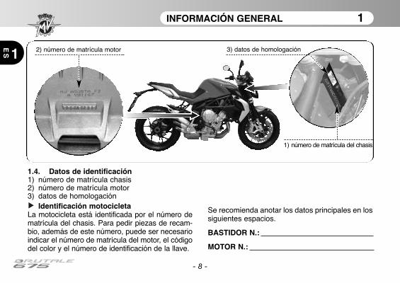
INFORMACIÓN GENERAL 1
1
ES
- 8 -
1.4. Datos de identificación1) número de matrícula chasis2) número de matrícula motor3) datos de homologación
Identificación motocicletaLa motocicleta está identificada por el número dematrícula del chasis. Para pedir piezas de recam-bio, además de este número, puede ser necesarioindicar el número de matrícula del motor, el códigodel color y el número de identificación de la llave.
Se recomienda anotar los datos principales en lossiguientes espacios.
BASTIDOR N.:
MOTOR N.:
2) número de matrícula motor
1) número de matrícula del chasis
3) datos de homologación
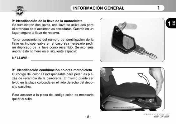
INFORMACIÓN GENERAL 1
1 ES
- 9 -
Identificación combinación colores motocicletaEl código del color es indispensable para pedir las pie-zas de recambio de la carrocería. El mismo puede serleído en la placa colocada en el lado derecho del depo-sito gasolina.
Para acceder a la placa del código color, es necesarioquitar el sillín.
Identificación de la llave de la motocicletaSe suministran dos llaves, una llave se utiliza sea parael arranque para accionar las cerraduras. Guarde en unlugar seguro la llave de reserva.
Tener conocimiento del número de identificación de lallave es indispensable en el caso sea necesario pedirun duplicado de la llave como recambio. Se aconsejaanotar este número en el siguiente espacio:
Nº LLAVE:
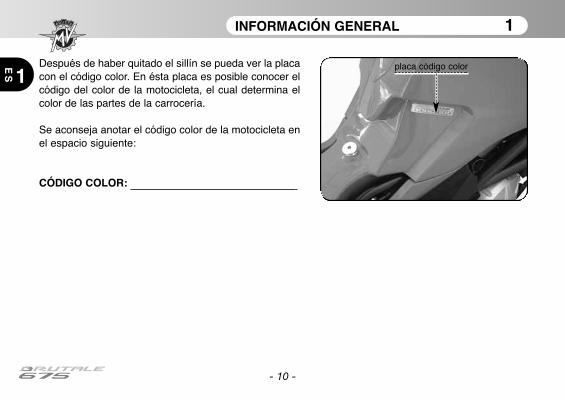
INFORMACIÓN GENERAL 1
1
ES
- 10 -
Después de haber quitado el sillín se pueda ver la placacon el código color. En ésta placa es posible conocer elcódigo del color de la motocicleta, el cual determina elcolor de las partes de la carrocería.
Se aconseja anotar el código color de la motocicleta enel espacio siguiente:
CÓDIGO COLOR:
placa código color
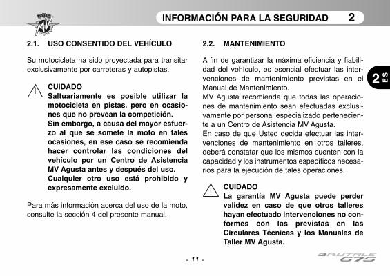
INFORMACIÓN PARA LA SEGURIDAD 2
2 ES
- 11 -
2.1. USO CONSENTIDO DEL VEHÍCULO
Su motocicleta ha sido proyectada para transitarexclusivamente por carreteras y autopistas.
CUIDADOSaltuariamente es posible utilizar lamotocicleta en pistas, pero en ocasio-nes que no prevean la competición. Sin embargo, a causa del mayor esfuer-zo al que se somete la moto en talesocasiones, en ese caso se recomiendahacer controlar las condiciones delvehículo por un Centro de AsistenciaMV Agusta antes y después del uso. Cualquier otro uso está prohibido yexpresamente excluido.
Para más información acerca del uso de la moto,consulte la sección 4 del presente manual.
2.2. MANTENIMIENTO
A fin de garantizar la máxima eficiencia y fiabili-dad del vehículo, es esencial efectuar las inter-venciones de mantenimiento previstas en elManual de Mantenimiento. MV Agusta recomienda que todas las operacio-nes de mantenimiento sean efectuadas exclusi-vamente por personal especializado pertenecien-te a un Centro de Asistencia MV Agusta.En caso de que Usted decida efectuar las inter-venciones de mantenimiento en otros talleres,deberá constatar que los mismos cuenten con lacapacidad y los instrumentos específicos necesa-rios para la ejecución de tales operaciones.
CUIDADOLa garantía MV Agusta puede perdervalidez en caso de que otros tallereshayan efectuado intervenciones no con-formes con las previstas en lasCirculares Técnicas y los Manuales deTaller MV Agusta.
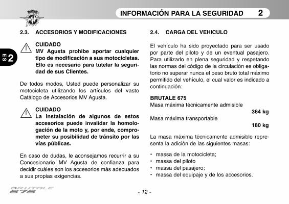
INFORMACIÓN PARA LA SEGURIDAD 2
2
ES
- 12 -
2.3. ACCESORIOS Y MODIFICACIONES
CUIDADOMV Agusta prohibe aportar cualquiertipo de modificación a sus motocicletas.Ello es necesario para tutelar la seguri-dad de sus Clientes.
De todos modos, Usted puede personalizar sumotocicleta utilizando los artículos del vastoCatálogo de Accesorios MV Agusta.
CUIDADOLa instalación de algunos de estosaccesorios puede invalidar la homolo-gación de la moto y, por ende, compro-meter su posibilidad de tránsito por lasvías públicas.
En caso de dudas, le aconsejamos recurrir a suConcesionario MV Agusta de confianza paradecidir cuáles son los accesorios más adecuadosa sus propias exigencias.
2.4. CARGA DEL VEHICULO
El vehículo ha sido proyectado para ser usadopor parte del piloto y de un eventual pasajero.Para utilizarlo en plena seguridad y respetandolas normas del código de la circulación es obliga-torio no superar nunca el peso bruto total máximopermitido del vehículo, el cual valor es indicado acontinuación:
BRUTALE 675Masa máxima técnicamente admisible
364 kgMasa máxima transportable
180 kg
La masa máxima técnicamente admisible repre-senta la adición de las siguientes masas:
• massa de la motocicleta;• massa del piloto• massa del pasajero;• massa del equipaje y de los accesorios.
INFORMACIÓN PARA LA SEGURIDAD 2
2 ES
- 13 -
ATENCIONConsiderado que la carga tiene unaenorme importancia en la manejabili-dad, la frenada, el rendimiento y lascaracterísticas de seguridad de vuestrovehículo, tener presente siempre lassiguientes precauciones.
• NO SOBRECARGAR NUNCA EL VEHI-CULO! La utilización de una moto sobrecargada puede provocar daños a losneumáticos, pérdida del control o gra-ves accidentes. Comprobar que el pesototal del piloto, del pasajero, de la cargay de los accesorios no supere el pesomáximo especificado para la moto.
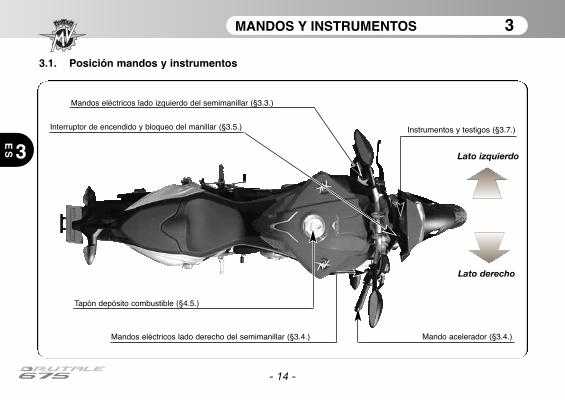
MANDOS Y INSTRUMENTOS 3
ES 3
- 14 -
3.1. Posición mandos y instrumentos
Instrumentos y testigos (§3.7.)
Mandos eléctricos lado izquierdo del semimanillar (§3.3.)
Tapón depósito combustible (§4.5.)
Interruptor de encendido y bloqueo del manillar (§3.5.)
Mando acelerador (§3.4.)Mandos eléctricos lado derecho del semimanillar (§3.4.)
Lato izquierdo
Lato derecho
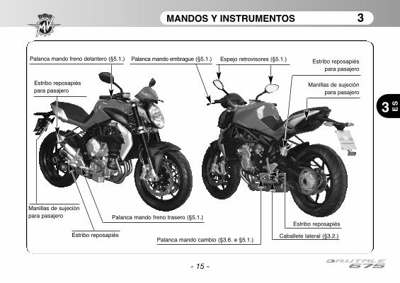
MANDOS Y INSTRUMENTOS 3
ES3
- 15 -
Palanca mando embrague (§5.1.)
Palanca mando cambio (§3.6. e §5.1.)Caballete lateral (§3.2.)
Estribo reposapiéspara pasajero
Estribo reposapiéspara pasajero
Manillas de sujeciónpara pasajero
Espejo retrovisores (§5.1.)Palanca mando freno delantero (§5.1.)
Palanca mando freno trasero (§5.1.)
Estribo reposapiés
Estribo reposapiés
Manillas de sujeciónpara pasajero
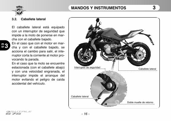
MANDOS Y INSTRUMENTOS 3
3
ES
- 16 -
3.2. Caballete lateral
El caballete lateral está equipadocon un interruptor de seguridad queimpide a la moto de ponerse en mar-cha con el caballete bajado.En el caso que con el motor en mar-cha y con el caballete bajado, seacciona el cambio para salir, el inte-rruptor corta la corriente al motor pro-vocando la parada.En el caso que la moto se encuentreestacionada (con el caballete abajo)y con una velocidad engranada, elinterruptor impide el arranque delmotor evitando el peligro de caídaaccidental del vehículo.
Caballete lateral
Doble muelle de retorno
Interruptor de seguridad
Caballete lateral

MANDOS Y INSTRUMENTOS 3
3 ES
- 17 -
3.3. Mandos lado izquierdo del manillar
Pulsador centelleo farosApriete el pulsador repetidas veces.
Pulsador carretera/crucePulsador hacia fuera : crucePulsador hacia dentro : carretera
Palanca indicadores de direcciónDesplazando la palanca hacia la derecha o hacia la izquierda seactivan los indicadores de dirección derechos o izquierdos. Lapalanca regresa al centro; apriete para desactivar los indicadores.
Pulsador claxonApriete para activar el claxon.
Palanca embragueAcercar o alejar de la manecilla para accionar elembrague.
MANDOS Y INSTRUMENTOS 3
3
ES
- 18 -
Pulsador Destello FaroEsta función sirve para llamar la atención de los demás en el caso de posible situaciones de peligro; con la luzde carretera encendida dicha función no se activa.
Pulsador De carretera/De cruceNormalmente es activada la función luz de cruce; cuando las condiciones del trafico y de recorrido lo permiten,puede ser activada la función luz de carretera actuando en el pulsador.
Leva Indicadores de DirecciónEsta función permite señalar a los demás la intención de cambiar dirección o carril de marcha.
PELIGRONo usar o no desactivar los indicadores de dirección en el momento oportuno puede provocaraccidentes; los demás conductores podrían interpretar erróneamente el trayecto del vehículo.Accionar siempre los indicadores de dirección antes de girar o cambiar carril.Asegurarse después de desactivar los indicadores apenas efectuada dicha maniobra.
Pulsador del ClaxonEsta función sirve para llamar la atención de los demás conductores en el caso de posible condición de peli-gro.
Palanca EmbragueEsta palanca, a través de un dispositivo controlado hidraulicamente, permite accionar el embrague.

MANDOS Y INSTRUMENTOS 3
3 ES
- 19 -
3.4. Mandos lado derecho del manillar
Interruptor stop motorSi se acciona detiene el motor e impide su arranque.
Pulsador arranque motorApretado arranca el motor. Se debe soltar apenas arranca el
motor. Con motor arrancado, apretándolo de nuevo, se seleccio-
nan las funciones de la pantalla.
Mando aceleradorGirar para regular la alimentación del motor.
Palanca freno delanteroAcercarse a la manecilla para accionar el freno delantero.
MANDOS Y INSTRUMENTOS 3
3
ES
- 20 -
Interruptor Parada MotorEsta función permite parar el motor en caso de emergencia; de ésta manera se desactiva el circuito de encen-dido impidiendo el arranque del motor. Para poder efectuar el arranque colocar nuevamente el pulsador enposición de descanso.
NOTA: En condiciones normales no utilizar éste dispositivo para parar el motor.
Pulsador Puesta en marcha del MotorEste dispositivo permite la puesta en marcha del motor; además con el motor en marcha permite seleccionarlas funciones del display presente en la instrumentación de a borda.
PRUDENCIA - PRECAUCIONPara evitar daños a la instalación eléctrica no tener presionado el pulsador por mas de 5 segun-dos consecutivos. Si el motor no arranca después de varios tentativos, consultar el capitulo“AVERÌAS” en el Manual del mantenimiento.
Mando AceleradorEste dispositivo permite regular la alimentación del motor variando el régimen de rotación. Para accionar eldispositivo es necesario girar la manecilla en la posición de descanso, que corresponde al régimen de ralen-tí del motor.
CUIDADOSi la moto se ha caido o ha estado involucrada en un accidente, lleve el vehículo a un centro deservicio MV Agusta al para comprobar el funcionamiento del mando del acelerador antes de rea-nudar la marcha.
Palanca Freno DelanteroEste mando permite accionar a través de un circuito hidráulico la instalación de frenos de la rueda delantera.
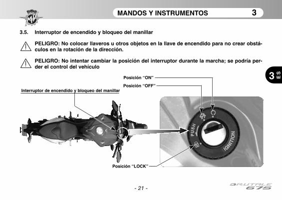
MANDOS Y INSTRUMENTOS 3
3 ES
- 21 -
3.5. Interruptor de encendido y bloqueo del manillar
PELIGRO: No colocar llaveros u otros objetos en la llave de encendido para no crear obstá-culos en la rotación de la dirección.
PELIGRO: No intentar cambiar la posición del interruptor durante la marcha; se podría per-der el control del vehículo
Posición “ON”
Posición “OFF”Interruptor de encendido y bloqueo del manillar
Posición “LOCK”

MANDOS Y INSTRUMENTOS 3
3
ES
El interruptor de encendido activa y desactiva el circuito eléctrico y el bloqueo del manillar; las cuatro posi-ciones de mando se describen a continuación.
PRUDENCIA - PRECAUCION: No dejar la llave en la posición de “ON” por mucho tiempo conel motor apagado, para no dañar los componentes eléctricos de la motocicleta.
Posición “OFF”
Todos los circuitos eléctricos están desactivados.Se puede extraer la llave.
Posición “ON”
Todos los circuitos eléctricos están activados, losinstrumentos y los testigos efectúan el autodiag-nóstico; se puede arrancar el motor. La llave no sepuede extraer.
- 22 -

MANDOS Y INSTRUMENTOS 3
3 ES
- 23 -
Posición “LOCK”
Gire el manillar a la derecha o a la izquierda.Empujar levemente la llave y al mismo tiempogirarla en posición “LOCK”.Todos los circuitos eléctricos están desactivadosy el manillar está bloqueado. Se puede extraer lallave.
Lado izquierdo Lado derecho
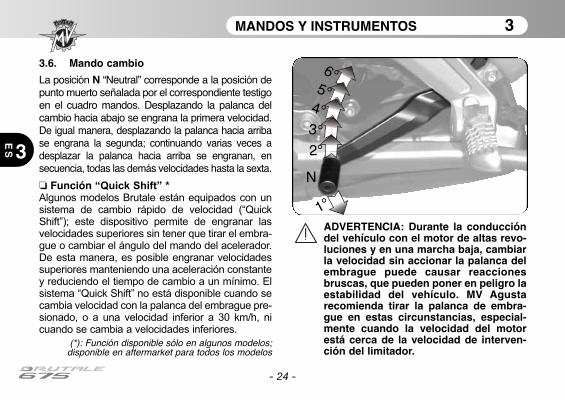
MANDOS Y INSTRUMENTOS 3
3
ES
- 24 -
3.6. Mando cambio
La posición N “Neutral” corresponde a la posición depunto muerto señalada por el correspondiente testigoen el cuadro mandos. Desplazando la palanca delcambio hacia abajo se engrana la primera velocidad.De igual manera, desplazando la palanca hacia arribase engrana la segunda; continuando varias veces adesplazar la palanca hacia arriba se engranan, ensecuencia, todas las demás velocidades hasta la sexta.
❏ Función “Quick Shift” *Algunos modelos Brutale están equipados con unsistema de cambio rápido de velocidad (“QuickShift”); este dispositivo permite de engranar lasvelocidades superiores sin tener que tirar el embra-gue o cambiar el ángulo del mando del acelerador.De esta manera, es posible engranar velocidadessuperiores manteniendo una aceleración constantey reduciendo el tiempo de cambio a un mínimo. Elsistema “Quick Shift” no está disponible cuando secambia velocidad con la palanca del embrague pre-sionado, o a una velocidad inferior a 30 km/h, nicuando se cambia a velocidades inferiores.
(*): Función disponible sólo en algunos modelos;disponible en aftermarket para todos los modelos
1°
N
2°
3°
4°
5°
6°
ADVERTENCIA: Durante la conduccióndel vehículo con el motor de altas revo-luciones y en una marcha baja, cambiarla velocidad sin accionar la palanca delembrague puede causar reaccionesbruscas, que pueden poner en peligro laestabilidad del vehículo. MV Agustarecomienda tirar la palanca de embra-gue en estas circunstancias, especial-mente cuando la velocidad del motorestá cerca de la velocidad de interven-ción del limitador.
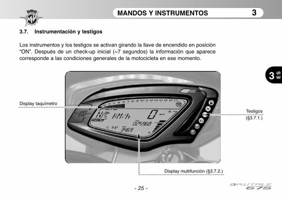
MANDOS Y INSTRUMENTOS 3
3 ES
- 25 -
3.7. Instrumentación y testigos
Los instrumentos y los testigos se activan girando la llave de encendido en posición“ON”. Después de un check-up inicial (~7 segundos) la información que aparececorresponde a las condiciones generales de la motocicleta en ese momento.
Testigos
(§3.7.1.)
Display multifunción (§3.7.2.)
Display taquímetro
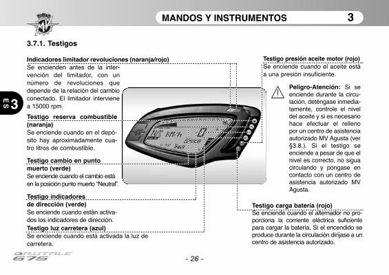
MANDOS Y INSTRUMENTOS 3
3
ES
- 26 -
3.7.1. Testigos
Testigo reserva combustible(naranja)Se enciende cuando en el depó-sito hay aproximadamente cua-tro litros de combustible.
Indicadores limitador revoluciones (naranja/rojo)Se encienden antes de la inter-vención del limitador, con unnúmero de revoluciones quedepende de la relación del cambioconectado. El limitador intervienea 15000 rpm.
Testigo luz carretera (azul)Se enciende cuando está activada la luz decarretera.
Testigo indicadores de dirección (verde)Se enciende cuando están activa-dos los indicadores de dirección.
Testigo cambio en puntomuerto (verde)Se enciende cuando el cambio estáen la posición punto muerto “Neutral”.
Testigo carga batería (rojo)Se enciende cuando el alternador no pro-porciona la corriente eléctrica suficientepara cargar la batería. Si el encendido seproduce durante la circulación diríjase a uncentro de asistencia autorizado.
Testigo presión aceite motor (rojo)Se enciende cuando el aceite estáa una presión insuficiente.
Peligro-Atención: Si seenciende durante la circu-lación, deténgase inmedia-tamente, controle el niveldel aceite y si es necesariohace efectuar el rellenopor un centro de asistenciaautorizado MV Agusta (ver§3.8.). Si el testigo seenciende a pesar de que elnivel es correcto, no siguacirculando y póngase encontacto con un centro deasistencia autorizado MVAgusta.
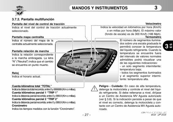
MANDOS Y INSTRUMENTOS 3
3 ES
- 27 -
3.7.2. Pantalla multifunciónVelocímetro
Indica la velocidad en kilómetros por hora (Km/h)o en millas por hora (Mph). El máximo valor
(fondo de escala) es de 300 Km/h (186 Mph).Termometro
El número de segmentos ilumina-dos sobre una escala graduada lepermitirá conocer la temperaturadel líquido refrigerante. Cuando latemperatura se encuentre fueradel intervalo de valores normalesadmisibles podrá visualizar unade las siguientes indicaciones: - un solo segmento intermitente:temperatura baja; - todos los segmentos iluminadosy el segmento superior intermi-tente: temperatura alta.
Peligro - Cuidado: En caso de alta temperatura,detenga la motocicleta y controle el nivel del líqui-do refrigerante. Si debe rellenarse a nivel, diríjasea un Centro de Asistencia MV Agusta autorizado(ver § 3.8). Si la indicación persiste a pesar de queel nivel es correcto, detenga la motocicleta y con-tacte con un Centro de Asistencia MV Agusta auto-rizado.
Pantalla relación de marchaIndica la relación correspondientea la marcha embragada. La letra“N” (“Neutral”) indica que el cambiose encuentra en punto muerto.
RelojIndica el horario actual.
Pantalla mapa centralitaIndica el número del mapa de lacentralita actualmente seleccionada.
Pantalla del nivel de control de tracciónIndica el nivel del control de tracción actualmenteseleccionado.
Cuenta kilómetros total “TOTAL” Indica la distancia total recorrida; entre 0 y 999999 (Km o millas).Cuenta kilómetros parcial 1 “TRIP 1” Indica la distancia parcial recorrida; entre 0 y 999.9 (Km o millas).Cuenta kilómetros parcial 2 “TRIP 2” Indica la distancia parcial recorrida; entre 0 y 999.9 (Km o millas).Cronómetro Indica los tiempos medidos con la función “Cronómetro”.
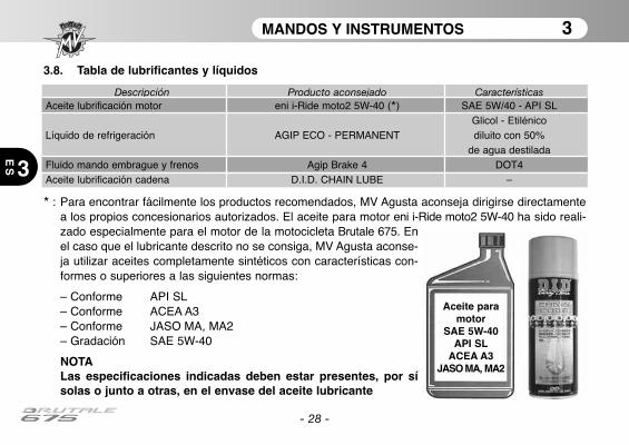
MANDOS Y INSTRUMENTOS 3
3
ES
- 28 -
* : Para encontrar fácilmente los productos recomendados, MV Agusta aconseja dirigirse directamentea los propios concesionarios autorizados. El aceite para motor eni i-Ride moto2 5W-40 ha sido reali-zado especialmente para el motor de la motocicleta Brutale 675. Enel caso que el lubricante descrito no se consiga, MV Agusta aconse-ja utilizar aceites completamente sintéticos con características con-formes o superiores a las siguientes normas:
– Conforme API SL– Conforme ACEA A3– Conforme JASO MA, MA2– Gradación SAE 5W-40
NOTALas especificaciones indicadas deben estar presentes, por sísolas o junto a otras, en el envase del aceite lubricante
Aceite paramotor
SAE 5W-40API SL
ACEA A3JASO MA, MA2
Descripción Producto aconsejado CaracterísticasAceite lubrificación motor eni i-Ride moto2 5W-40 (*) SAE 5W/40 - API SL
Glicol - EtilénicoLíquido de refrigeración AGIP ECO - PERMANENT diluito con 50%
de agua destiladaFluido mando embrague y frenos Agip Brake 4 DOT4Aceite lubrificación cadena D.I.D. CHAIN LUBE –
3.8. Tabla de lubrificantes y líquidos

USO 4
4 ES
- 29 -
4.1. Uso de la motocicleta
En esta sección se exponen los principales temas para el correcto uso de la motocicleta.
CUIDADOSu motocicleta Brutale 675 tiene altas características de potencia y prestaciones; por lotanto, para su utilización es necesario un adecuado nivel de conocimiento del vehículo.Cuando usted utiliza la motocicleta para la primera vez, es necesario adoptar una actitud pru-dente. Una agresiva o temeraria actitud de conducción podría aumentar el peligro de acci-dentes y comportar un grave peligro para su incolumidad o para la de otras personas.
CUIDADOLAS RESTRICCIONES DE USO DEL VEHÍCULO ESTÁN INDICADAS EN LA SECCIÓN“INFORMACIÓN PARA LA SEGURIDAD”.
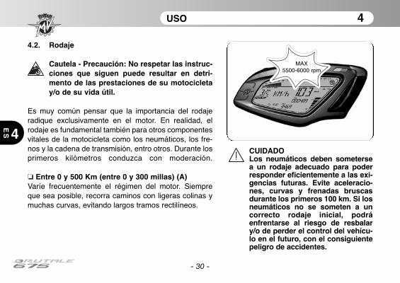
USO 4
4
ES
- 30 -
4.2. Rodaje
Cautela - Precaución: No respetar las instruc-ciones que siguen puede resultar en detri-mento de las prestaciones de su motocicletay/o de su vida útil.
Es muy común pensar que la importancia del rodajeradique exclusivamente en el motor. En realidad, elrodaje es fundamental también para otros componentesvitales de la motocicleta como los neumáticos, los fre-nos y la cadena de transmisión, entro otros. Durante losprimeros kilómetros conduzca con moderación.
❏ Entre 0 y 500 Km (entre 0 y 300 millas) (A) Varíe frecuentemente el régimen del motor. Siempreque sea posible, recorra caminos con ligeras colinas ymuchas curvas, evitando largos tramos rectilíneos.
CUIDADOLos neumáticos deben sometersea un rodaje adecuado para poderresponder eficientemente a las exi-gencias futuras. Evite aceleracio-nes, curvas y frenadas bruscasdurante los primeros 100 km. Si losneumáticos no se someten a uncorrecto rodaje inicial, podráenfrentarse al riesgo de resbalary/o de perder el control del vehícu-lo en el futuro, con el consiguientepeligro de accidentes.
MAX 5500-6000 rpm
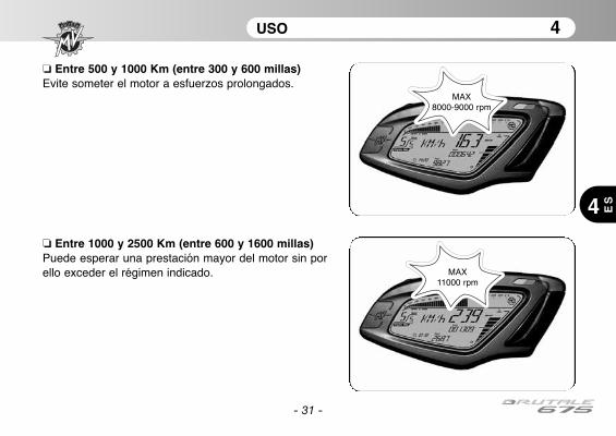
USO 4
4 ES
- 31 -
❏ Entre 500 y 1000 Km (entre 300 y 600 millas) Evite someter el motor a esfuerzos prolongados.
❏ Entre 1000 y 2500 Km (entre 600 y 1600 millas) Puede esperar una prestación mayor del motor sin porello exceder el régimen indicado.
MAX8000-9000 rpm
MAX 11000 rpm
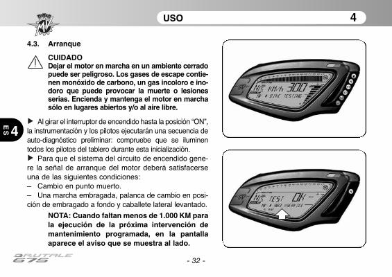
USO 4
4
ES
- 32 -
4.3. Arranque
CUIDADODejar el motor en marcha en un ambiente cerradopuede ser peligroso. Los gases de escape contie-nen monóxido de carbono, un gas incoloro e ino-doro que puede provocar la muerte o lesionesserias. Encienda y mantenga el motor en marchasólo en lugares abiertos y/o al aire libre.
Al girar el interruptor de encendido hasta la posición “ON”,la instrumentación y los pilotos ejecutarán una secuencia deauto-diagnóstico preliminar: compruebe que se iluminentodos los pilotos del tablero durante esta inicialización.
Para que el sistema del circuito de encendido gene-re la señal de arranque del motor deberá satisfacerseuna de las siguientes condiciones: – Cambio en punto muerto.– Una marcha embragada, palanca de cambio en posi-ción de embragado a fondo y caballete lateral levantado.
NOTA: Cuando faltan menos de 1.000 KM parala ejecución de la próxima intervención demantenimiento programada, en la pantallaaparece el aviso que se muestra al lado.
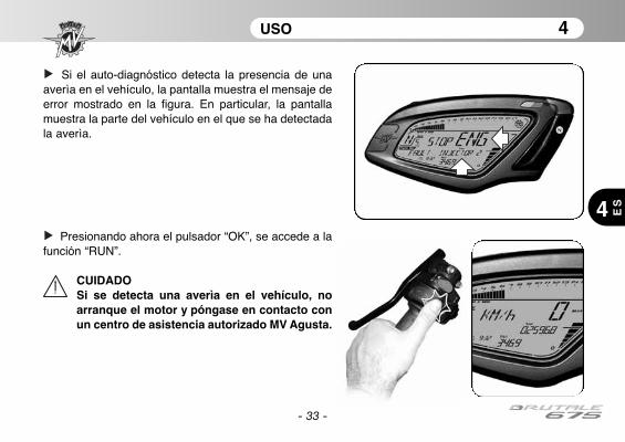
- 33 -
USO 4
4 ES
Si el auto-diagnóstico detecta la presencia de unaaverìa en el vehículo, la pantalla muestra el mensaje deerror mostrado en la figura. En particular, la pantallamuestra la parte del vehículo en el que se ha detectadala averìa.
Presionando ahora el pulsador “OK”, se accede a lafunción “RUN”.
CUIDADOSi se detecta una averìa en el vehículo, noarranque el motor y póngase en contacto conun centro de asistencia autorizado MV Agusta.
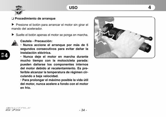
USO 4
4
ES
- 34 -
❏ Procedimiento de arranque
Presione el botón para arrancar el motor sin girar elmando del acelerador.
Suelte el botón apenas el motor se ponga en marcha.
Cautela - Precaución: • Nunca accione el arranque por más de 5segundos consecutivos para evitar dañar lainstalación eléctrica. • Nunca deje el motor en marcha durantemucho tiempo con la motocicleta parada:pueden dañarse los componentes internosdel motor debido al recalentamiento. Es pre-ferible alcanzar la temperatura de régimen cir-culando a baja velocidad. • Para prolongar el máximo posible la vida útildel motor, nunca acelere a fondo con el motoren frío.
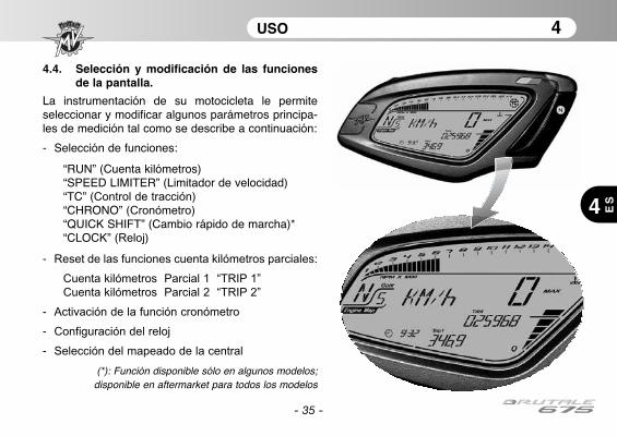
USO 4
4 ES
- 35 -
4.4. Selección y modificación de las funcionesde la pantalla.
La instrumentación de su motocicleta le permiteseleccionar y modificar algunos parámetros principa-les de medición tal como se describe a continuación:
- Selección de funciones:
“RUN” (Cuenta kilómetros)“SPEED LIMITER” (Limitador de velocidad)“TC” (Control de tracción)“CHRONO” (Cronómetro)“QUICK SHIFT” (Cambio rápido de marcha)*“CLOCK” (Reloj)
- Reset de las funciones cuenta kilómetros parciales:
Cuenta kilómetros Parcial 1 “TRIP 1”
Cuenta kilómetros Parcial 2 “TRIP 2”
- Activación de la función cronómetro
- Configuración del reloj
- Selección del mapeado de la central
(*): Función disponible sólo en algunos modelos;disponible en aftermarket para todos los modelos

USO 4
4
ES
- 36 -
CUIDADO:
Las funciones del display deben seleccionarse ymodificarse con el motor apagado, en punto muerto,con la motocicleta detenida y los pies apoyados en elsuelo. Queda terminantemente prohibido programarlas funciones durante la marcha, excepto cuando seindique lo contrario.
4.4.1. Selección de las funciones dela pantalla
Puede seleccionar las siguientes fun-
ciones:
• “RUN” (Cuenta kilómetros)• “SPEED LIMITER” (Limitador de
velocidad)• “TC” (Control de tracción)• “CHRONO” (Cronómetro)• “QUICK SHIFT” (Cambio rápido de
marcha) *• “CLOCK” (Reloj)
Presione la tecla “SET” menos de 4
segundos para poder visualizar las
diversas funciones una a la vez. Si pre-
siona la tecla por más de 3 segundos,
visualizará todas las funciones, una
luego de la otra. Seleccione la función
deseada.
(*): Función disponible sólo en algunosmodelos; disponible en aftermarket
para todos los modelos

USO 4
4 ES
- 37 -
❏ Función “RUN”
Además de la función de taquímetro, podrá visualizar
en el display las funciones que siguen (ver §4.4.2.):
• Cuenta kilómetros Total “TOTAL”
• Cuenta kilómetros Parcial 1 “TRIP 1”
En alternativa:
• Cuenta kilómetros Total “TOTAL”
• Cuenta kilómetros Parcial 2 “TRIP 2”
❏ Función “SPEED LIMITER”
Le permite adaptar la velocidad máxima del vehículo en
función de sus exigencias de conducción (ver §4.4.3.).
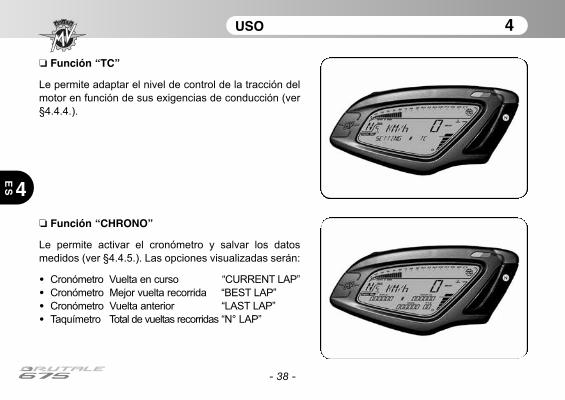
USO 4
4
ES
- 38 -
❏ Función “CHRONO”
Le permite activar el cronómetro y salvar los datos
medidos (ver §4.4.5.). Las opciones visualizadas serán:
• Cronómetro Vuelta en curso “CURRENT LAP”
• Cronómetro Mejor vuelta recorrida “BEST LAP”
• Cronómetro Vuelta anterior “LAST LAP”
• Taquímetro Total de vueltas recorridas “N° LAP”
❏ Función “TC”
Le permite adaptar el nivel de control de la tracción del
motor en función de sus exigencias de conducción (ver
§4.4.4.).
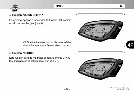
USO 4
4 ES
- 39 -
❏ Función “CLOCK”
Esta función permite modificar el horario (horas y minu-
tos) indicado en el salpicadero (ver §4.4.7.).
❏ Función “QUICK SHIFT” *
Le permite apagar o encender la función del cambio
rápido de marcha (ver § 4.4.6.).
(*): Función disponible sólo en algunos modelos;disponible en aftermarket para todos los modelos
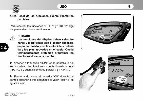
- 40 -
USO 4
4
ES
4.4.2. Reset de las funciones cuenta kilómetrosparciales
Para resetear las funciones “TRIP 1” y “TRIP 2” siga
los pasos descritos a continuación.
CUIDADOLas funciones del display deben seleccio-narse y modificarse con el motor apagado,en punto muerto, con la motocicleta deteni-da y los pies apoyados en el suelo. Quedaterminantemente prohibido programar lasfunciones durante la marcha.
Acceder a la función “RUN”; en la pantalla inicial
se visualizan las funciones cuentakilómetros total
(“TOTAL”) y cuentakilómetros parcial 1 (“TRIP 1”).
Presionando ahora el pulsador “OK” durante un
tiempo superior a tres segundos el valor “TRIP 1” se
ajusta a cero.
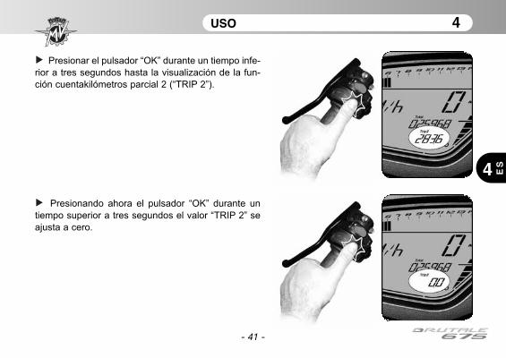
- 41 -
USO 4
4 ES
Presionar el pulsador “OK” durante un tiempo infe-
rior a tres segundos hasta la visualización de la fun-
ción cuentakilómetros parcial 2 (“TRIP 2”).
Presionando ahora el pulsador “OK” durante un
tiempo superior a tres segundos el valor “TRIP 2” se
ajusta a cero.
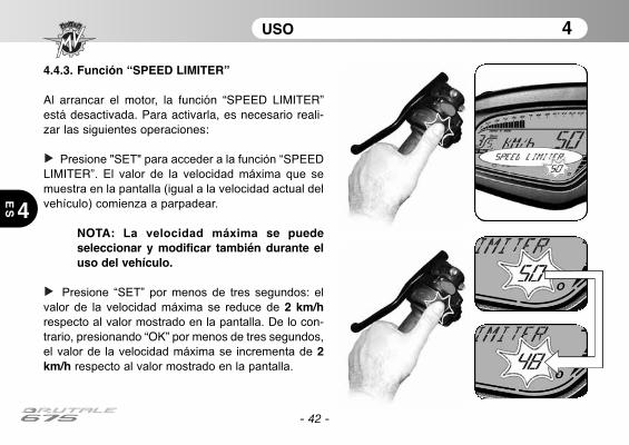
4.4.3. Función “SPEED LIMITER”
Al arrancar el motor, la función “SPEED LIMITER”está desactivada. Para activarla, es necesario reali-zar las siguientes operaciones:
Presione "SET" para acceder a la función “SPEEDLIMITER”. El valor de la velocidad máxima que se
muestra en la pantalla (igual a la velocidad actual del
vehículo) comienza a parpadear.
NOTA: La velocidad máxima se puedeseleccionar y modificar también durante eluso del vehículo.
Presione “SET” por menos de tres segundos: el
valor de la velocidad máxima se reduce de 2 km/hrespecto al valor mostrado en la pantalla. De lo con-trario, presionando “OK” por menos de tres segundos,
el valor de la velocidad máxima se incrementa de 2km/h respecto al valor mostrado en la pantalla.
- 42 -
USO 4
4
ES
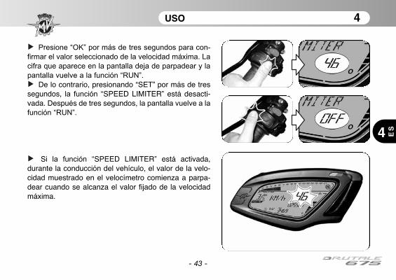
- 43 -
USO 4
4 ES
Presione “OK” por más de tres segundos para con-
firmar el valor seleccionado de la velocidad máxima. La
cifra que aparece en la pantalla deja de parpadear y la
pantalla vuelve a la función “RUN”.
De lo contrario, presionando “SET” por más de tressegundos, la función “SPEED LIMITER” está desacti-vada. Después de tres segundos, la pantalla vuelve a la
función “RUN”.
Si la función “SPEED LIMITER” está activada,durante la conducción del vehículo, el valor de la velo-cidad muestrado en el velocímetro comienza a parpa-dear cuando se alcanza el valor fijado de la velocidadmáxima.
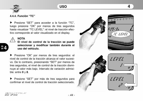
- 44 -
USO 4
4
ES
4.4.4. Función “TC”
Presione “SET” para acceder a la función “TC”,
luego presione “OK” por menos de tres segundos
hasta visualizar “TC LEVEL”: el nivel de tracción efec-
tivo corresponde al valor visualizado en el display.
NOTAEl nivel de control de la tracción se puedeseleccionar y modificar también durante eluso del vehículo.
Presione “OK” por menos de tres segundos: el
nivel de control de la tracción alcanza el valor sucesi-
vo. De lo contrario, presionando “SET” por menos detres segundos, el nivel de control de la tracción dismi-
nuye al valor más bajo. Intervalo de variación admisi-
ble: entre 0 y 8.
Presione “SET” por más de tres segundos para
confirmar el nivel de control de tracción seleccionado.
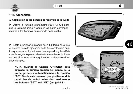
- 45 -
USO 4
4 ES
4.4.5. Cronómetro
❏ Adquisición de los tiempos de recorrido de la vuelta
Active la función cronómetro (“CHRONO”) para
que el sistema inicie a adquirir los datos correspon-
dientes a los tiempos de recorrido de la vuelta.
Basta presionar el mando de la luz larga para que
el sistema inicie la ejecución de la función: los dos pun-
tos que separan los minutos, los segundos y las déci-
mas de segundo pasan al estado intermitente, indican-
do que el sistema está adquiriendo los datos relativos
a los tiempos.
NOTA: Cuando la función “CHRONO” estáactivada, la primera presión del mando de la
luz larga activa automáticamente la función“TC”. Desde este momento, es posible modifi-car el nivel de control de tracción presionandolos botones “SET” and “OK” (ver § 4.4.4.).

USO 4
4
ES
- 46 -
Presione nuevamente el mando de la luz larga
para adquirir el tiempo correspondiente a la primera
vuelta recorrida: el instrumento empezará a adquirir
contemporáneamente el tiempo correspondiente a la
segunda vuelta.
La medición del tiempo relativo a la primera vuelta se
conserva en memoria y permanece visualizada en el
display durante diez segundos, luego se visualiza el
tiempo de la vuelta sucesiva.
Cada vez que presione el mando de la luz larga el sis-
tema salvará un tiempo en su memoria. Este instrumento
puede memorizar un máximo de 100 datos consecutivos.
Durante la visualización del tiempo de la vuelta apenas
acabada, en el display aparece el símbolo “+” o bien “–”
en el caso en que el tiempo medido sea respectiva-
mente inferior o superior al tiempo medido durante la
vuelta anterior.
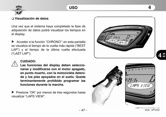
USO 4
4 ES
- 47 -
❏ Visualización de datos
Una vez que el sistema haya completado la fase de
adquisición de datos podrá visualizar los tiempos en
el display.
Acceder a la función “CHRONO”; en esta pantalla
se visualiza el tiempo de la vuelta más rápida (“BEST
LAP”) y el tiempo de la última vuelta efectuada
(“LAST LAP”).
CUIDADO:Las funciones del display deben seleccio-narse y modificarse con el motor apagado,en punto muerto, con la motocicleta deteni-da y los pies apoyados en el suelo. Quedaterminantemente prohibido programar lasfunciones durante la marcha.
Presione “OK” por menos de tres segundos hasta
visualizar “LAPS VIEW”.

USO 4
4
ES
- 48 -
La presión repetida del pulsador de ráfagas del
faro de luz larga permite visualizar en secuencia
todos los tiempos anteriormente adquiridos a partir de
la última vuelta memorizada.
Al final de la visualización de los datos, la presión
del pulsador “SET” permite regresar a la función
“LAPS VIEW” para pasar a la función sucesiva.
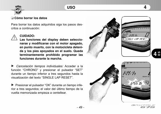
USO 4
4 ES
- 49 -
❏ Cómo borrar los datos
Para borrar los datos adquiridos siga los pasos des-
critos a continuación:
CUIDADO:Las funciones del display deben seleccio-narse y modificarse con el motor apagado,en punto muerto, con la motocicleta deteni-da y los pies apoyados en el suelo. Quedaterminantemente prohibido programar lasfunciones durante la marcha.
Cancelación tiempos individuales: Acceder a la
función “CHRONO” y presionar el pulsador “SET”
durante un tiempo inferior a tres segundos hasta la
visualización del texto “SINGLE LAP RESET”.
Presionar el pulsador “OK” durante un tiempo infe-
rior a tres segundos; el valor del último tiempo de la
vuelta memorizada empieza a centellear.
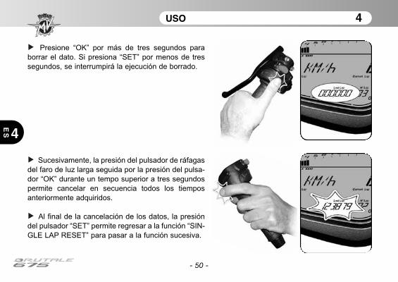
- 50 -
USO 4
4
ES
Presione “OK” por más de tres segundos para
borrar el dato. Si presiona “SET” por menos de tres
segundos, se interrumpirá la ejecución de borrado.
Sucesivamente, la presión del pulsador de ráfagas
del faro de luz larga seguida por la presión del pulsa-
dor “OK” durante un tempo superior a tres segundos
permite cancelar en secuencia todos los tiempos
anteriormente adquiridos.
Al final de la cancelación de los datos, la presión
del pulsador “SET” permite regresar a la función “SIN-
GLE LAP RESET” para pasar a la función sucesiva.
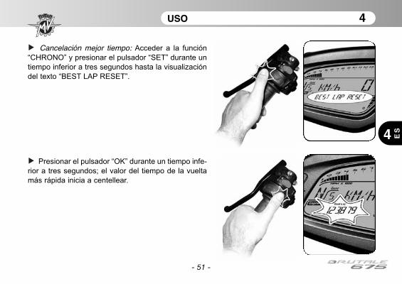
- 51 -
USO 4
4 ES
Cancelación mejor tiempo: Acceder a la función
“CHRONO” y presionar el pulsador “SET” durante un
tiempo inferior a tres segundos hasta la visualización
del texto “BEST LAP RESET”.
Presionar el pulsador “OK” durante un tiempo infe-
rior a tres segundos; el valor del tiempo de la vuelta
más rápida inicia a centellear.

- 52 -
USO 4
4
ES
Presione “OK” por más de tres segundos para
borrar el dato. Si presiona “SET” por menos de tres
segundos, se interrumpirá la ejecución de borrado.
Al final de la cancelación de los datos, la presión
del pulsador “SET” permite salir de la función “BEST
LAP RESET” para pasar a la modalidad sucesiva.
Cancelación de todos los tiempos memorizados:Acceder a la función “CHRONO” y presionar el pulsa-
dor “SET” durante un tiempo inferior a tres segundos
hasta la visualización del texto “ALL LAPS RESET”.

- 53 -
USO 4
4 ES
Presionar el pulsador “OK” durante un tiempo infe-
rior a tres segundos; el display solicita la confirmación
para la cancelación de todos los datos presentes en
memoria.
Presionando ahora el pulsador “OK” durante un
tiempo superior a tres segundos todos los tiempos
anteriormente adquiridos son cancelados. Si por el
contrario se presiona el pulsador “SET” durante un
tiempo inferior a tres segundos el procedimiento de
cancelación se interrumpe.
Al final de la cancelación de los datos, la presión
del pulsador “SET” permite salir de la función “ALL
LAPS RESET” para regresar a la modalidad “CHRO-
NO”.
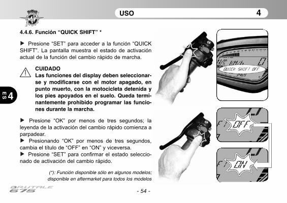
- 54 -
USO 4
4
ES
4.4.6. Función “QUICK SHIFT” *
Presione “SET” para acceder a la función “QUICKSHIFT”. La pantalla muestra el estado de activación
actual de la función del cambio rápido de marcha.
CUIDADOLas funciones del display deben seleccionar-se y modificarse con el motor apagado, enpunto muerto, con la motocicleta detenida ylos pies apoyados en el suelo. Queda termi-nantemente prohibido programar las funcio-nes durante la marcha.
Presione “OK” por menos de tres segundos; la
leyenda de la activación del cambio rápido comienza a
parpadear.
Presionando “OK” por menos de tres segundos,
cambia el título de “OFF” en “ON” y viceversa.
Presione “SET” para confirmar el estado seleccio-
nado de activación del cambio rápido.
(*): Función disponible sólo en algunos modelos;disponible en aftermarket para todos los modelos
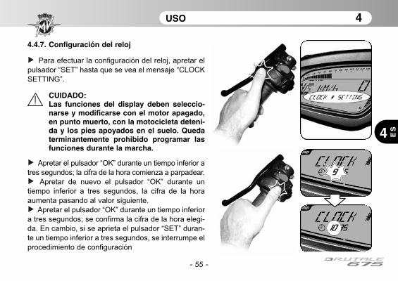
- 55 -
USO 4
4 ES
4.4.7. Configuración del reloj
Para efectuar la configuración del reloj, apretar el
pulsador “SET” hasta que se vea el mensaje “CLOCK
SETTING”.
CUIDADO:Las funciones del display deben seleccio-narse y modificarse con el motor apagado,en punto muerto, con la motocicleta deteni-da y los pies apoyados en el suelo. Quedaterminantemente prohibido programar lasfunciones durante la marcha.
Apretar el pulsador “OK” durante un tiempo inferior a
tres segundos; la cifra de la hora comienza a parpadear.
Apretar de nuevo el pulsador “OK” durante un
tiempo inferior a tres segundos, la cifra de la hora
aumenta pasando al valor siguiente.
Apretar el pulsador “OK” durante un tiempo inferior
a tres segundos; se confirma la cifra de la hora elegi-
da. En cambio, si se aprieta el pulsador “SET” duran-
te un tiempo inferior a tres segundos, se interrumpe el
procedimiento de configuración

- 56 -
USO 4
4
ES
Después de haber efectuado la configuración de
la cifra de la hora, el salpicadero pasa automática-
mente a la configuración de la cifra de los minutos. La
cifra de los minutos comienza a parpadear.
Apretar el pulsador “OK” durante un tiempo inferior
a tres segundos; la cifra de los minutos aumenta
pasando al valor siguiente.
Apretar el pulsador “OK” durante un tiempo supe-
rior a tres segundos; se confirma la cifra de los minu-
tos hora elegida yel salpicadero vuelve a la modali-
dad "CLOCK". En cambio, si se aprieta el pulsador
“SET” durante un tiempo inferior a tres segundos, se
interrumpe el procedimiento de configuración.
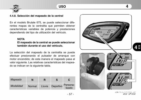
- 57 -
USO 4
4 ES
4.4.8. Selección del mapeado de la central
En el modelo Brutale 675, se puede seleccionar dife-
rentes mapas de la centralita que permiten obtener
características variables de potencia y prestaciones
dependiendo del tipo de utilización del vehículo.
NOTAEl mapeado de la central se puede seleccionartambién durante el uso del vehículo.
La selección del mapeado de la centralita se puede
efectuar presionando el pulsador de arranque con
motor encendido; de esta manera el mapeado pasa al
valor siguiente. Las relativas características del mapea-
do se indican en la siguiente tabla.
Mapeado
Modalidad
N
Normal
R
Lluvia
S
Deportivo
C
Persona-lizado
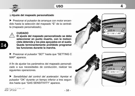
- 58 -
USO 4
4
ES
❏ Ajuste del mapeado personalizado
Presionar el pulsador de arranque con motor encen-
dido hasta la selección del mapeado “C” de la centrali-
ta (mapeado personalizado).
CUIDADOEl ajuste del mapeado personalizado se debeseleccionar en punto muerto, con la motoci-cleta detenida y los pies apoyados en el suelo.Queda terminantemente prohibido programarlas funciones durante la marcha.
Presionar el pulsador “SET” hasta que “SETTING CMAP” aparece.
A fin de ajustar los parámetros del mapeado personali-zado a sus necesidades de conducción, realizar las
siguientes operaciones.
Sensibilidad del control del acelerador: Apretar el
pulsador “OK” durante un tiempo inferior a tres segun-
dos hasta que “GAS SENSITIVITY” aparece.

- 59 -
USO 4
4 ES
Apretar el pulsador “SET” durante un tiempo inferior
a tres segundos. La pantalla muestra la configuraciónactual de la sensibilidad del control del acelerador.
Apretar el pulsador “OK” durante un tiempo inferior
a tres segundos; el ajuste mostrado comienza a parpa-
dear.
La presión repetida del pulsador “OK” durante un
tiempo inferior a tres segundos, permite visualizar en
secuencia las siguientes configuraciones:
• “NORMAL” (Normal)• “RAIN” (Lluvia)
• “SPORT” (Deportiva)

- 60 -
USO 4
4
ES
Apretar el pulsador “OK” durante un tiempo superior
a tres segundos; el nuevo ajuste será confirmado. El
ajuste mostrado deje de parpadear, y después de algu-
nos segundos la pantalla vuelve a la modalidad “GASSENSITIVITY”. Ahora es posible proceder con el ajustedel parámetro siguiente.
Par máximo del motor: Apretar el pulsador “OK”
durante un tiempo inferior a tres segundos hasta que“MAX ENGINE TORQUE” aparece.

- 61 -
USO 4
4 ES
Apretar el pulsador “SET” durante un tiempo inferior
a tres segundos. La pantalla muestra la configuraciónactual del par máximo del motor.
Apretar el pulsador “OK” durante un tiempo inferior
a tres segundos; el ajuste mostrado comienza a parpa-
dear.
La presión repetida del pulsador “OK” durante un
tiempo inferior a tres segundos, permite visualizar en
secuencia las siguientes configuraciones:
• “RAIN” (Lluvia)
• “SPORT” (Deportiva)

- 62 -
USO 4
4
ES
Apretar el pulsador “OK” durante un tiempo superior
a tres segundos; el nuevo ajuste será confirmado. El
ajuste mostrado deje de parpadear, y después de algu-
nos segundos la pantalla vuelve a la modalidad “MAXENGINE TORQUE”.
Freno motor: Apretar el pulsador “OK” durante un
tiempo inferior a tres segundos hasta que “ENGINEBRAKE” aparece.
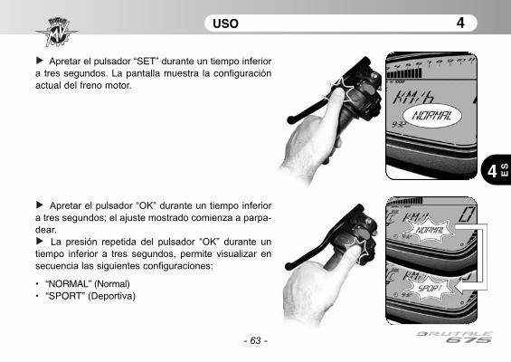
- 63 -
USO 4
4 ES
Apretar el pulsador “SET” durante un tiempo inferior
a tres segundos. La pantalla muestra la configuraciónactual del freno motor.
Apretar el pulsador “OK” durante un tiempo inferior
a tres segundos; el ajuste mostrado comienza a parpa-
dear.
La presión repetida del pulsador “OK” durante un
tiempo inferior a tres segundos, permite visualizar en
secuencia las siguientes configuraciones:
• “NORMAL” (Normal)• “SPORT” (Deportiva)
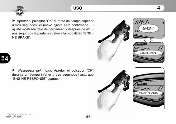
- 64 -
USO 4
4
ES
Apretar el pulsador “OK” durante un tiempo superior
a tres segundos; el nuevo ajuste será confirmado. El
ajuste mostrado deje de parpadear, y después de algu-
nos segundos la pantalla vuelve a la modalidad “ENGI-NE BRAKE”.
Respuesta del motor: Apretar el pulsador “OK”
durante un tiempo inferior a tres segundos hasta que“ENGINE RESPONSE” aparece.
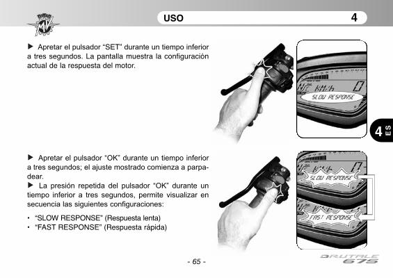
- 65 -
USO 4
4 ES
Apretar el pulsador “SET” durante un tiempo inferior
a tres segundos. La pantalla muestra la configuraciónactual de la respuesta del motor.
Apretar el pulsador “OK” durante un tiempo inferior
a tres segundos; el ajuste mostrado comienza a parpa-
dear.
La presión repetida del pulsador “OK” durante un
tiempo inferior a tres segundos, permite visualizar en
secuencia las siguientes configuraciones:
• “SLOW RESPONSE” (Respuesta lenta)• “FAST RESPONSE” (Respuesta rápida)
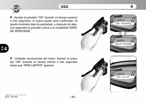
- 66 -
USO 4
4
ES
Apretar el pulsador “OK” durante un tiempo superior
a tres segundos; el nuevo ajuste será confirmado. El
ajuste mostrado deje de parpadear, y después de algu-
nos segundos la pantalla vuelve a la modalidad “ENGI-NE RESPONSE”.
Limitador revoluciones del motor: Apretar el pulsa-
dor “OK” durante un tiempo inferior a tres segundos
hasta que “RPM LIMITER” aparece.
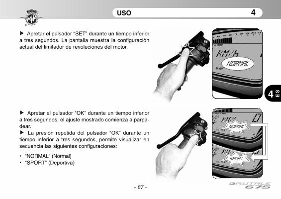
- 67 -
USO 4
4 ES
Apretar el pulsador “SET” durante un tiempo inferior
a tres segundos. La pantalla muestra la configuraciónactual del limitador de revoluciones del motor.
Apretar el pulsador “OK” durante un tiempo inferior
a tres segundos; el ajuste mostrado comienza a parpa-
dear.
La presión repetida del pulsador “OK” durante un
tiempo inferior a tres segundos, permite visualizar en
secuencia las siguientes configuraciones:
• “NORMAL” (Normal)• “SPORT” (Deportiva)
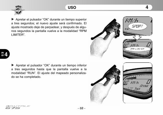
- 68 -
USO 4
4
ES
Apretar el pulsador “OK” durante un tiempo superior
a tres segundos; el nuevo ajuste será confirmado. El
ajuste mostrado deje de parpadear, y después de algu-
nos segundos la pantalla vuelve a la modalidad “RPMLIMITER”.
Apretar el pulsador “OK” durante un tiempo inferior
a tres segundos hasta que la pantalla vuelve a la
modalidad “RUN”. El ajuste del mapeado personaliza-do se ha completado.
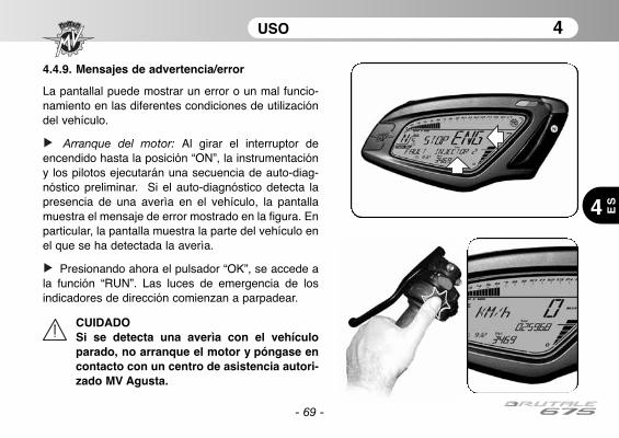
- 69 -
USO 4
4 ES
4.4.9. Mensajes de advertencia/error
La pantallal puede mostrar un error o un mal funcio-namiento en las diferentes condiciones de utilizacióndel vehículo.
Arranque del motor: Al girar el interruptor deencendido hasta la posición “ON”, la instrumentacióny los pilotos ejecutarán una secuencia de auto-diag-nóstico preliminar. Si el auto-diagnóstico detecta lapresencia de una averìa en el vehículo, la pantallamuestra el mensaje de error mostrado en la figura. Enparticular, la pantalla muestra la parte del vehículo enel que se ha detectada la averìa.
Presionando ahora el pulsador “OK”, se accede ala función “RUN”. Las luces de emergencia de losindicadores de dirección comienzan a parpadear.
CUIDADOSi se detecta una averìa con el vehículoparado, no arranque el motor y póngase encontacto con un centro de asistencia autori-zado MV Agusta.

- 70 -
USO 4
4
ES
Marcha del vehículo: Si se detecta una averìa en laconducción del vehículo, la parte inferior de la pantallamuestra el mensaje de error mostrado en la figura. Lasluces de emergencia de los indicadores de direccióncomienzan a parpadear.
CUIDADOSi se detecta una averìa en la marcha, detenerel vehículo y póngase en contacto con un cen-tro de asistencia autorizado MV Agusta.
Cuando el vehículo está detenido, la pantalla mues-tra la parte del vehículo en el que se ha detectada laaverìa.
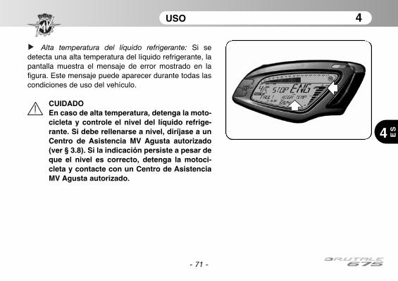
- 71 -
USO 4
4 ES
Alta temperatura del líquido refrigerante: Si sedetecta una alta temperatura del líquido refrigerante, lapantalla muestra el mensaje de error mostrado en lafigura. Este mensaje puede aparecer durante todas lascondiciones de uso del vehículo.
CUIDADOEn caso de alta temperatura, detenga la moto-cicleta y controle el nivel del líquido refrige-rante. Si debe rellenarse a nivel, diríjase a unCentro de Asistencia MV Agusta autorizado(ver § 3.8). Si la indicación persiste a pesar deque el nivel es correcto, detenga la motoci-cleta y contacte con un Centro de AsistenciaMV Agusta autorizado.

4.5. Abastecimiento combustible
Peligro – Atención: la gasolina y sus vaporesson extremamente inflamables y dañosos.Evitar el contacto y la inhalación.Durante el abastecimiento apagar el motor, nofumar, tener lejos llamas, chispas y fuentesde calor. Efectuar el llenado en un lugar abier-to o en un sitio bien ventilado.
Prudencia – Precaución: utilizar exclusiva-mente gasolina super sin plomo y sin alcoholcon 95 octanos (R.O.N.) o mas. Esta necesi-dad es recordada por un punto verde en laparte inferior de la tapa del deposito y por laetiqueta en el depósito de gasolina.
Levante la tapa parapolvo.
Introduzca la llave, gírela en sentido horario.
- 72 -
USO 4
4
ES

- 73 -
USO 4
4 ES
Levantar la tapa y efectuar el abastecimiento de car-burante.
PELIGRO: Llenando excesivamente el deposi-to puede provocar derrame del carburantedebido a la expansión del calor provocada porel calor del motor o a la exposición de la moto-cicleta a la luz del sol. Eventual derrame decarburante puede provocar incendios. El niveldel carburante en el depósito no debe superarnunca la base de la boca de llenado.
Después del abastecimiento presione el tapón haciaabajo girando contemporáneamente la llave en sentidohorario para facilitar el cierre. Suelte la llave y extráigala.
Prudencia - Precaución: secar enseguida conun trapo limpio eventual carburante derrama-do, puesto que podría dañar la superficie pin-tada o de plástico.
PELIGRO: Verificar que la tapa del depositodel carburante esté cerrada correctamenteantes de utilizar el vehículo.
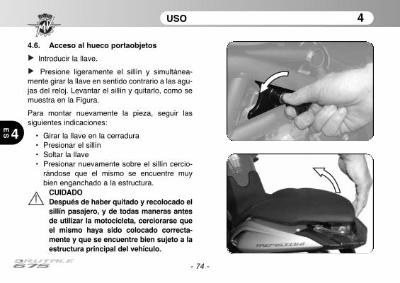
USO 4
4
ES
- 74 -
4.6. Acceso al hueco portaobjetos
Introducir la llave.
Presione ligeramente el sillín y simultánea-mente girar la llave en sentido contrario a las agu-jas del reloj. Levantar el sillín y quitarlo, como semuestra en la Figura.
Para montar nuevamente la pieza, seguir lassiguientes indicaciones:
• Girar la llave en la cerradura• Presionar el sillín • Soltar la llave• Presionar nuevamente sobre el sillín cercio-
rándose que el mismo se encuentre muybien enganchado a la estructura.
CUIDADODespués de haber quitado y recolocado elsillín pasajero, y de todas maneras antesde utilizar la motocicleta, cerciorarse queel mismo haya sido colocado correcta-mente y que se encuentre bien sujeto a laestructura principal del vehículo.

USO 4
4 ES
- 75 -
4.7. Estacionamiento de la motocicleta
❏ Estacionamiento con caballete lateral
ATENCIONAparcar la motocicleta en condiciones de segu-ridad y en un terreno estable. En las pendientesestacionar la moto con la rueda delantera haciala subida y con la primera velocidad engranada;recordarse de retornar el cambio en neutroantes de poner en marcha el vehículo.No dejar el vehículo sin custodia con la llave deencendido introducida en el cuadro.
Cuando el vehículo esté parado sobre elcaballete lateral, es peligroso sentarse sobreél cargando todo el peso sobre el únicoapoyo de estacionamiento. Antes de ponerseen marcha verificar el buen funcionamientodel interruptor de seguridad cerciorandoseque la luz testigo del caballete lateral ubicadaen el tablero se apague; de todas manerasverificar que el caballete lateral haya retorna-do. Si se nota una imperfección, hacer con-trolar la instalación por un concesionario MVAgusta antes de utilizar el vehículo.
Bajar el caballete con el pié hasta el tope e inclinar lentamente la motocicleta para colocar el pié deapoyo a contacto con el suelo.

USO 4
4
ES
- 76 -
❏ Estacionamiento con caballete trasero
Introducir el perno del caballete en el ori-ficio del eje de la rueda trasera en el ladoizquierdo de la moto; apoyar el caballeteen el suelo y empujándolo, levantar elvehículo hasta que el vehículo esté esta-ble.
CUIDADOEsta operación se debe realizarpor dos personas.
1 2
3
REGULACIONES 5
5 ES
- 77 -
5.1. Lista regulaciones
La motocicleta posee una amplia posibilidad de regu-laciones que pueden mejorar la ergonomía, la estabi-lidad y la seguridad.
Sin embargo algunas de estas regulaciones puedenser realizadas exclusivamente por los Centros deAsistencia MV Agusta, dado que una regulación erró-nea de ciertos componentes sumamente importantespuede provocar una situación de peligro.
ATENCIONLas regulaciones se deben realizar con elvehículo parado.

REGULACIONES 5
5
ES
- 78 -
(F) Orientación
faro (§5.5.)
(D) Regulación espejo retrovisor (§5.4.)
(A) Regulación palanca
freno delantero (§5.3.)
(C) Regulación palanca
freno trasero (§5.2.)
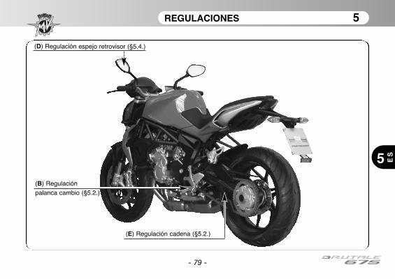
REGULACIONES 5
5 ES
- 79 -
(E) Regulación cadena (§5.2.)
(B) Regulación
palanca cambio (§5.2.)
(D) Regulación espejo retrovisor (§5.4.)
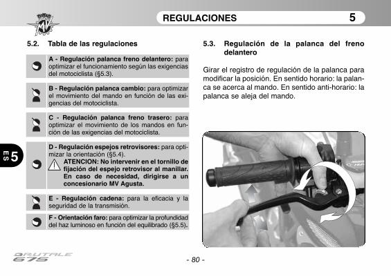
REGULACIONES 5
5
ES
- 80 -
5.2. Tabla de las regulaciones
A - Regulación palanca freno delantero: paraoptimizar el funcionamiento según las exigenciasdel motociclista (§5.3).
B - Regulación palanca cambio: para optimizarel movimiento del mando en función de las exi-gencias del motociclista.
C - Regulación palanca freno trasero: paraoptimizar el movimiento de los mandos en fun-ción de las exigencias del motociclista.
D - Regulación espejos retrovisores: para opti-mizar la orientación (§5.4).
ATENCION: No intervenir en el tornillo defijación del espejo retrovisor al manillar.En caso de necesidad, dirigirse a unconcesionario MV Agusta.
E - Regulación cadena: para la eficacia y laseguridad de la transmisión.
F - Orientación faro: para optimizar la profundidaddel haz luminoso en función del equilibrado (§5.5).
5.3. Regulación de la palanca del frenodelantero
Girar el registro de regulación de la palanca paramodificar la posición. En sentido horario: la palan-ca se acerca al mando. En sentido anti-horario: lapalanca se aleja del mando.

REGULACIONES 5
5 ES
- 81 -
5.4. Regulación de los espejos retrovisores
Apriete los puntos puestos en evidencia para regular laposición en las cuatro direcciones.
Efectuar el ajuste en ambos espejos retrovisores. Pararealizar un optimo ajuste, aconsejamos realizarlo subi-dos en el vehículo.
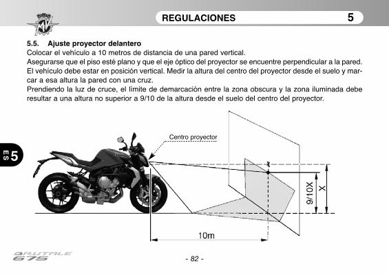
REGULACIONES 5
5
ES
- 82 -
5.5. Ajuste proyector delanteroColocar el vehículo a 10 metros de distancia de una pared vertical.Asegurarse que el piso esté plano y que el eje óptico del proyector se encuentre perpendicular a la pared.El vehículo debe estar en posición vertical. Medir la altura del centro del proyector desde el suelo y mar-car a esa altura la pared con una cruz.Prendiendo la luz de cruce, el límite de demarcación entre la zona obscura y la zona iluminada deberesultar a una altura no superior a 9/10 de la altura desde el suelo del centro del proyector.
Centro proyector
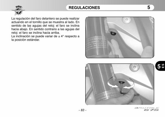
REGULACIONES 5
5 ES
- 83 -
La regulación del faro delantero se puede realizaractuando en el tornillo que se muestra al lado. Ensentido de las agujas del reloj: el faro se inclinahacia abajo. En sentido contrario a las agujas delreloj: el faro se inclina hacia arriba.La inclinación se puede variar de ± 4° respecto ala posición estándar.
- 84 -
NOTAS
5
ES
Nota informativaMV Agusta Motor S.p.A. está comprometida en una política de continuo mejoramiento de sus productos;por este motivo es posible encontrar ligeras diferencias entre el contenido de éste documento y el vehí-culo adquirido por Ustedes. Los modelos MV Agusta son exportados en muchos Países, en los cuales elCódigo del Transito y a los procedimientos de homologación son distintos a los nuestros.Confiamos en Vuestra comprensión. MV Agusta Motor S.p.A. considera por lo tanto necesario reservarseel derecho de aportar modificaciones a sus productos y a la documentación técnica en cualquier momen-to y sin ningún aviso previo.
Sugerimos para visitar a menudo el sitio Internet www.mvagusta.it para obtener informaciones y actuali-zaciones sobre los productos MV Agusta y la documentación relacionada.
Respetemos y defendamos el medioambienteTodo lo que hacemos tiene repercusiones para todo el planeta y en sus recursos.MV Agusta, a tutela de los intereses de la comunidad, sensibiliza los Clientes y los operadores de la asis-tencia técnica a adoptar una utilización del vehículo y de eliminación de sus partes, respetando plenamen-te las normativas vigentes en términos de contaminación del medio ambiente, eliminación y reciclaje de losdeshechos.
© 2012Está prohibida la reproducción aunque sea parcial de éste documento sin el consentimiento escrito por MV Agusta Motor S.p.A.
Part. n° 8000B6848Edición n° 1 - Abril 2012
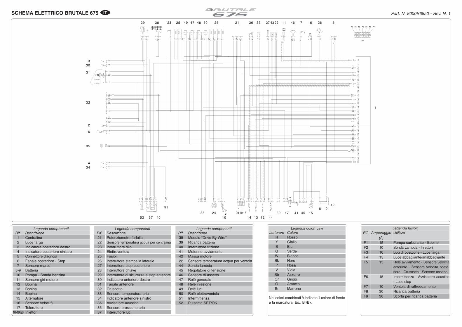
A1A2
B1
C1
C3
D1D2
D4E1E2E3
F1F2F3
G1G2G3
H1
H4J1J2J3J4K1K2K3K4L1L2L3L4
M2
M4
B4
C2
D4E1E2E3E4F3F4
H2H3
A3A4
B2B3B4
C2
C4
D3
E4
F4
G4
M1
M3
B3B2B1
A1A2A3A4
C1
C4C3
D1
G1G2G3
H1
H4
H2H3
G4
1 2 3
-+
PRESS.
AB C 1 2
+- S
1
23456
N
1
+ -
65°65°
1231 2
PASSINGLO
HITURN
75
HORN
Bk/B
P/RG
yLb
6
B
12
BB/
Gr
B/Y
OK SET
13 48 9 10
B/W
R/BBk
W
7
6
HBLB
DL
gnd
1
4
45213
G
RU
NO
FF
STA
RT
6
O B R/Y
Y/G
G/Y
ON
OFF
LOCK
R/G Gy/RR
13 24
B/Y
FRE
E
BrBk
G
DO
WN
UP P
US
H
12 3
1234
23 112
R/G
Y/G
15 A
15 A
15 A
15 A
A B A AB B A A AB B B
10 A 10 A
1
Y/G
12
1
2
1
2
3
1 2 3
12 +-13 4 5 6
1234
1234
1234123412341234121212CA B D E F
124 5 6 7 83
3
1
2
10
6
1
11
7
9
3
4
2
14
15
8
5
16
1
2
1 2
1
2
1
2
5
B
B
B
B B
10A
A B
3 2 1
3 2 1
30 A
1 2
30 A
15A
10A
15A
F1 F2 F3 F4 F5 F6 F7
10A
10A
15A
15A
30
F9
F8
1
2
3
4
5
6
7
8 9
10
11
1213141517
16
181920
21 2223
24
25 25 26272829
30
31
32
33
34
35
36
3738 39
4041
42
43
4445
4647 4849 50
51
52
RR R
R RR
R
R
R
RRR
B
B
B
B BB
B
B
B
B
BB
B
B
BB B
B
B B
B
B
Y Y Y Y Y Y
Gr-W
Gr-
W
Gr-
W R-W
R-W
R-W
R-W
R-W
R-W WW W W
Gr-
Bk
Gr-Bk
W-R
W-R
W-R
W-R
W-R
Y
YYY Y
Br-W
Br-
W
Br-W
Gr-
R
Gr-
R
Y-B
k
Y-B
k
Y-Bk
Y-B
k
Y-B
Y-B
Y-G
r
Y-G
r
Y-G
r
Y-G
r
Y-Gr
Y-G
r
O-Bk
O-B
k
P
PGy
Gy
Gr-
Bk
Gr-BkGr-P
Gr-
P
Gy-
R
Gy-R
P
P
Br-
Y
Br-Y
Br-
W
Br-W
P-B
P-B
BkBk
Gr
Gr
Gr-
B
Gr-B
O O-V
O-V
R-B
R-B
B-W
B-W
Br-Y
Br-
Y
Gr-
Bk
Gr-Bk
R-B
k
R-Bk
GyG
y Bk-
B
Bk-
BR
-Bk
R-BK
R-Bk
R-Bk
Sb
Sb
Sb
Sb
Sb-Bk
Sb-Bk
Sb-Bk
Gr
Gr
Gr
Gy-
Gr
Gy-Gr
Gr-
O
Gr-O
R-Y
R-Y
O
O
O
O
Br
Br
B-W
B-W
B-W
B-Bk
B-Bk
B-B
k
V
V
Y-B
Y-B
Y-B
Y-B
Y-B
Gr-
O
Gr
Y
Y
P
P
R
R
R
R
G
GBk
Bk
Br-Bk
Br-
Bk
V-Bk
V-B
k
Y-P
Y-P
O-B
O-B
Y-V
Y-V
Br-Gr
Br-
Gr
Br-B
Br-
B
Gr-O
W-R
W-R
Br-P
Br-
P
Gy
Gy
V
V
R-Gr
R-G
r
Gr-Bk
Gr-
Bk
Gy-Bk
Gy-
Bk
Y-Bk
Y-B
k
V-Gr
V-G
r
R-V
R-V
Sb
Sb
B-Bk
B-B
k
B-O
B-OBk
Legenda componentiRif. Descrizione1 Centralina2 Luce targa3 Indicatore posteriore destro4 Indicatore posteriore sinistro5 Connettore diagnosi6 Fanale posteriore - Stop7 Sensore marce
8-9 Batteria10 Pompa - Sonda benzina11 Sensore giri motore12 Bobina13 Bobina14 Bobina15 Alternatore16 Sensore velocità17 Teleruttore
18-19-20 Iniettori
Nei colori combinati è indicato il colore di fondoe la marcatura. Es.: Br/Bk.
SCHEMA ELETTRICO BRUTALE 675 Part. N. 8000B6850 - Rev. N. 1IT
Legenda fusibiliRif. Amperaggio Utilizzo
(A)F1 15 Pompa carburante - BobineF2 10 Sonda Lambda - IniettoriF3 10 Luci di posizione - Luce targaF4 15 Luce abbagliante/anabbaglianteF5 15 Relé avviamento - Sensore velocità
anteriore - Sensore velocità poste-riore - Cruscotto - Sensore assetto
F6 15 Intermittenza - Avvisatore acustico- Luce stop
F7 10 Ventola di raffreddamentoF8 30 Ricarica batteriaF9 30 Scorta per ricarica batteria
Legenda componentiRif. Descrizione38 Modulo “Drive By Wire”39 Ricarica batteria40 Interruttore frizione41 Motorino avviamento42 Massa motore22 Sensore temperatura acqua per ventola44 Sonda lambda45 Regolatore di tensione46 Sensore di assetto47 Relé generale48 Relé iniezione49 Relé luci50 Relé elettroventola51 Intermittenza52 Pulsante SET/OK
Legenda componentiRif. Descrizione21 Potenziometro farfalla22 Sensore temperatura acqua per centralina23 Interruttore olio24 Elettroventola25 Fusibili26 Interruttore stampella laterale27 Interruttore stop posteriore28 Interruttore chiave29 Interruttore di sicurezza e stop anteriore30 Indicatore anteriore destro31 Fanale anteriore32 Cruscotto33 Sensore temperatura aria34 Indicatore anteriore sinistro35 Avvisatore acustico36 Sensore pressione aria37 Interruttore luci
Legenda colori caviLettera/e Colore
R RossoY GialloB BluG VerdeW BiancoBk NeroP RosaV ViolaSb AzzurroGr GrigioO ArancioBr Marrone
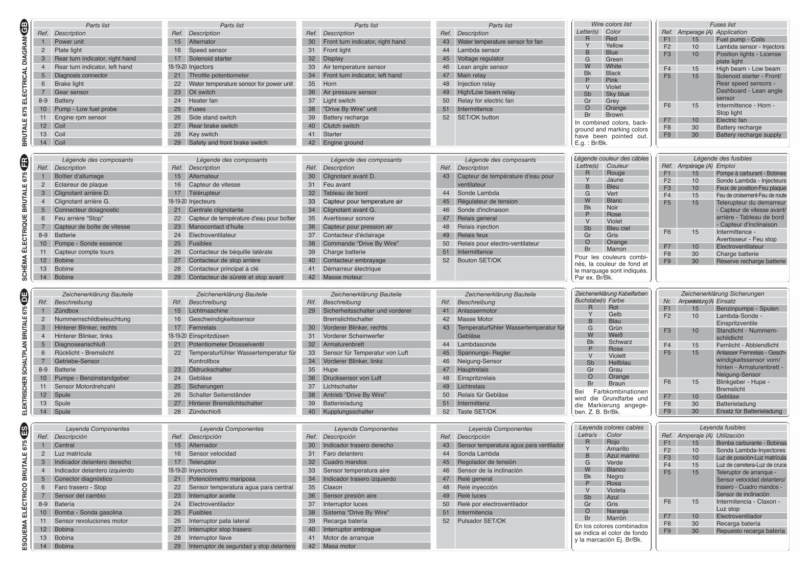
Fuses listRef. Amperage (A) ApplicationF1 15 Fuel pump - CoilsF2 10 Lambda sensor - InjectorsF3 10 Position lights - License
plate lightF4 15 High beam - Low beamF5 15 Solenoid starter - Front/
Rear speed sensors -Dashboard - Lean anglesensor
F6 15 Intermittence - Horn -Stop light
F7 10 Electric fanF8 30 Battery rechargeF9 30 Battery recharge supply
Wire colors listLetter(s) Color
R RedY YellowB BlueG GreenW WhiteBk BlackP PinkV Violet
Sb Sky blueGr GreyO OrangeBr Brown
In combined colors, back-ground and marking colorshave been pointed out.E.g. : Br/Bk. B
RU
TAL
E 6
75 E
LE
CT
RIC
AL
DIA
GR
AM
Légende couleur des câblesLettre(s) Couleur
R RougeY JauneB BleuG VertW BlancBk NoirP RoseV VioletSb Bleu cielGr GrisO OrangeBr Marron
Pour les couleurs combi-nés, la couleur de fond etle marquage sont indiqués.Par ex. Br/Bk. S
CH
ÉM
A É
LE
CT
RIQ
UE
BR
UTA
LE
675
Leyenda colores cablesLetra/s Color
R RojoY AmarilloB Azul marinoG VerdeW BlancoBk NegroP RosaV VioletaSb AzulGr GrisO NaranjaBr Marrón
En los colores combinadosse indica el color de fondoy la marcación Ej. Br/Bk.
ES
QU
EM
A E
LÉ
CT
RIC
O B
RU
TAL
E 6
75
Zeichenerklärung KabelfarbenBuchstabe(n) Farbe
R RotY GelbB BlauG GrünW WeißBk SchwarzP RoseV Violett
Sb HellblauGr GrauO OrangeBr Braun
Bei Farbkombinationenwird die Grundfarbe unddie Markierung angege-ben. Z. B. Br/Bk.EL
EKTR
ISC
HER
SC
HA
LTPL
AN
BR
UTA
LE 6
75G
BF
RD
EE
S
Légende des fusiblesRéf. Ampérage (A) EmploiF1 15 Pompe à carburant - BobinesF2 10 Sonde Lambda - InjecteursF3 10 Feux de position-Feu plaqueF4 15 Feu de croisement-Feu de routeF5 15 Telerupteur du demarreur
- Capteur de vitesse avant/arrière - Tableau de bord- Capteur d’inclinaison
F6 15 Intermittence -Avertisseur - Feu stop
F7 10 ElectroventilateurF8 30 Charge batterieF9 30 Réserve recharge batterie
Zeichenerklärung SicherungenNr. Ampereleistung (A) EinsatzF1 15 Benzinpumpe - SpulenF2 10 Lambda-Sonde -
EinspritzventileF3 10 Standlicht - Nummern-
schildlichtF4 15 Fernlicht - AbblendlichtF5 15 Anlasser Fernrelais - Gesch-
windigkeitssensor vorn/hinten - Armaturenbrett -Neigung-Sensor
F6 15 Blinkgeber - Hupe -Bremslicht
F7 10 GebläseF8 30 BatterieladungF9 30 Ersatz für Batterieladung
Leyenda fusiblesRef. Amperaje (A) UtilizaciónF1 15 Bomba carburante - BobinasF2 10 Sonda Lambda-InyectoresF3 10 Luz de posición-Luz matrículaF4 15 Luz de carretera-Luz de cruceF5 15 Teleruptor de arranque -
Sensor velocidad delantero/trasero - Cuadro mandos -Sensor de inclinación
F6 15 Intermitencia - Claxon -Luz stop
F7 10 ElectroventiladorF8 30 Recarga bateríaF9 30 Repuesto recarga batería
Parts listRef. Description
1 Power unit2 Plate light3 Rear turn indicator, right hand4 Rear turn indicator, left hand5 Diagnosis connector6 Brake light7 Gear sensor
8-9 Battery10 Pump - Low fuel probe11 Engine rpm sensor12 Coil13 Coil14 Coil
Parts listRef. Description30 Front turn indicator, right hand31 Front light32 Display33 Air temperature sensor34 Front turn indicator, left hand35 Horn36 Air pressure sensor37 Light switch38 “Drive By Wire” unit39 Battery recharge40 Clutch switch41 Starter42 Engine ground
Parts listRef. Description43 Water temperature sensor for fan44 Lambda sensor45 Voltage regulator46 Lean angle sensor47 Main relay48 Injection relay49 High/Low beam relay50 Relay for electric fan51 Intermittence52 SET/OK button
Légende des composantsRéf. Description
1 Boîtier d’allumage2 Eclaireur de plaque3 Clignotant arrière D.4 Clignotant arrière G.5 Connecteur doiagnostic6 Feu arrière “Stop”7 Capteur de boîte de vitesse
8-9 Batterie10 Pompe - Sonde essence11 Capteur compte tours12 Bobine13 Bobine14 Bobine
Légende des composantsRéf. Description30 Clignotant avant D.31 Feu avant32 Tableau de bord33 Capteur pour temperature air34 Clignotant avant G.35 Avertisseur sonore36 Capteur pour pression air37 Contacteur d’éclairage38 Commande “Drive By Wire”39 Charge batterie40 Contacteur embrayage41 Démarreur électrique42 Masse moteur
Zeichenerklärung BauteileRif. Beschreibung1 Zündbox2 Nummernschildbeleuchtung3 Hinterer Blinker, rechts4 Hinterer Blinker, links5 Diagnoseanschluß6 Rücklicht - Bremslicht7 Getriebe-Sensor
8-9 Batterie10 Pumpe - Benzinstandgeber11 Sensor Motordrehzahl12 Spule13 Spule14 Spule
Zeichenerklärung BauteileRif. Beschreibung15 Lichtmaschine16 Geschwindigkeitssensor17 Fernrelais
18-19-20 Einspritzdüsen21 Potentiometer Drosselventil22 Temperaturfühler Wassertemperatur für
Kontrollbox23 Öldruckschalter24 Gebläse25 Sicherungen26 Schalter Seitenständer27 Hinterer Bremslichtschalter28 Zündschloß
Zeichenerklärung BauteileRif. Beschreibung29 Sicherheitsschalter und vorderer
Bremslichtschalter30 Vorderer Blinker, rechts31 Vorderer Scheinwerfer32 Armaturenbrett33 Sensor für Temperatur von Luft34 Vorderer Blinker, links35 Hupe36 Drucksensor von Luft37 Lichtschalter38 Antrieb “Drive By Wire”39 Batterieladung40 Kupplungsschalter
Zeichenerklärung BauteileRif. Beschreibung41 Anlassermotor42 Masse Motor43 Temperaturfühler Wassertemperatur für
Gebläse44 Lambdasonde45 Spannungs- Regler 46 Neigung-Sensor 47 Hauptrelais48 Einspritzrelais49 Lichtrelais50 Relais für Gebläse51 Intermittenz52 Taste SET/OK
Leyenda ComponentesRef. Descripción
1 Central2 Luz matrícula3 Indicador delantero derecho4 Indicador delantero izquierdo5 Conector diagnóstico6 Faro trasero - Stop7 Sensor del cambio
8-9 Batería10 Bomba - Sonda gasolina11 Sensor revoluciones motor12 Bobina13 Bobina14 Bobina
Leyenda ComponentesRef. Descripción30 Indicador trasero derecho31 Faro delantero32 Cuadro mandos33 Sensor temperatura aire34 Indicador trasero izquierdo35 Claxon36 Sensor presión aire37 Interruptor luces38 Sistema “Drive By Wire”39 Recarga batería40 Interruptor embrague41 Motor de arranque42 Masa motor
Leyenda ComponentesRef. Descripción43 Sensor temperatura agua para ventilador44 Sonda Lambda 45 Regolador de tensión46 Sensor de la inclinación 47 Relé general48 Relé inyección49 Relé luces50 Relé por electroventilador51 Intermitencia52 Pulsador SET/OK
Légende des composantsRéf. Description43 Capteur de température d’eau pour
ventilateur44 Sonde Lambda45 Régulateur de tension 46 Sonde d'inclinaison 47 Relais general48 Relais injection49 Relais feux50 Relais pour electro-ventilateur51 Intermittence52 Bouton SET/OK
Parts listRef. Description15 Alternator16 Speed sensor17 Solenoid starter
18-19-20 Injectors21 Throttle potentiometer22 Water temperature sensor for power unit23 Oil switch24 Heater fan25 Fuses26 Side stand switch27 Rear brake switch28 Key switch29 Safety and front brake switch
Légende des composantsRéf. Description15 Alternateur16 Capteur de vitesse17 Télérupteur
18-19-20 Injecteurs21 Centrale clignotante22 Capteur de température d’eau pour boîtier23 Manocontact d’huile24 Electroventilateur25 Fusibles26 Contacteur de béquille latérale27 Contacteur de stop arrière28 Contacteur principal à clé29 Contacteur de sûreté et stop avant
Leyenda ComponentesRef. Descripción15 Alternador16 Sensor velocidad17 Teleruptor
18-19-20 Inyectores21 Potenciómetro mariposa22 Sensor temperatura agua para central23 Interruptor aceite24 Electroventilador25 Fusibles26 Interruptor pata lateral27 Interruptor stop trasero28 Interruptor llave29 Interruptor de seguridad y stop delantero


![Presentazione Formazione Consegnato[1]](https://static.fdocumenti.com/doc/165x107/548214c9b4af9f3e688b45d8/presentazione-formazione-consegnato1.jpg)
