l’Azienda - zpmotori.it · COPPIA MASSIMA: “Cm” è la coppia massima che un motore sviluppa...
32
Transcript of l’Azienda - zpmotori.it · COPPIA MASSIMA: “Cm” è la coppia massima che un motore sviluppa...


La ZP Motori elettrici presenta il catalogo della propria produzione al fine di aiutare e semplificare il comune rapporto di lavoro.L’il lustrazione, frutto di ricerca da parte dell’azienda, vuole nella sua semplicità offrire una valida guida nella identificazione e scelta del motore ideale.La ZP, impegnandosi a mantenerecon la clientela un servizio tecnico e commerciale efficiente, rimane a completa disposizione di tutti coloro che volessero far pervenire osservazioni util i al miglioramento dello stesso e porge i piùcordiali saluti auspicando una Buona collaborazione.ZP Motori Elettrici
ZP e lectr ic motors presents th is catalogue of its products with the intention of helping and simplifying normal working re lat ionships and communications.The i l lustration, fruit of the f irm’s research wishes, in its simplicity, to o f fe r a va l id gu ide in the identif ication and choice of the ideal motor for your needs.ZP binding i tse l f to maintain an efficient technical and commercial service with the customer, is at the complete disposal of those who wish to forward helpful observations for the bettering of the articles, and we offer our best wishes in advance, hoping in a useful collaboration.ZP Electric Motors.
l’Azienda
the Company
3
laboratorio prove test laboratory
lavorazione alberi shaft construction
linea montaggio e collaudo Assembly and testing line

CORRENTE NOMINALE: “In” è la corrente realmente assorbita da un motore alla potenza nominale, alimentato a tensione e frequenza nominale ed è espressa in A (ampere).
NOMINAL CURRENT: “In” is the current actually absorbed by a motor, at nominal power, supplied with nominal voltage and frequency; it is expressed in A (ampere).
CORRENTE DI AVVIAMENTO: “Ia” è la corrente massima assorbita da un motore, alimentato a tensione e frequenza nominale, a rotore fermo, ed è espressa in A (ampere).
STARTING CURRENT: “Ia” is the maximum current absorbed by a motor, supplied with nominal voltage and frequency, with rotor still, and is expressed in A (ampere).
RENDIMENTO: “η” è il rapporto tra la potenza nominale e la potenza assorbita ed è espresso in percentuale.
OUTPUT: “n” is the ratio between the nominal power and the absorbed power. It is expressed in percentage.
FATTORE DI POTENZA: “cos ϕ” è il rapporto tra potenza reale e potenza apparente.
POWER FACTOR: “cos ϕ” is the ratio between real power and apparent power.
caratteristiche elettricheelectrical characteristics
I motori asincroni trifase o monofase, trattati in questo catalogo, sono composti essenzialmente da:• Statore avvolto con filo di rame inserito in cassa di alluminio pressofuso.• Rotore a gabbia di scoiattolo in lega pressofusa.• Albero rotante su cuscinetti radiali rigidi a sfere di qualità, SKF FAG o NSK.• Scudi o flange in alluminio pressofuso.• Ventola calettata sull’albero per la ventilazione esterna.• Copriventola in acciaio stampato e zincato.• Copribasetta in alluminio pressofuso.
I motori sono eseguiti e collaudati rispettando le DIRETTIVE COMUNITARIE EUROPEE (CEE); le NORME INTERNAZIONALI (IEC); nonché le UNIFICAZIONI NAZIONALI (CEI).
The three-phase or single-phase asynchronous motors, displayed in this catalogue, are composed mainly of:• Stator wound with copper wire enclosed in a frame of die cast aluminium.• Rotor “squirrel cage type”, in die-cast alloy.• Rotating shaft on rigid radial bearings with SKF FAG or NSK quality spheres.• Shields or flanges in die-cast aluminium.• Fan keyed on the shaft for external ventilation.• Fan cover in galvanised moulded steel. • Terminal board cover in die-cast aluminium.
The motors are manufactured and tested according to the European Community Directives (EEC); International Norms (IEC); as well as National Standards (CEI).
caratteristiche generaligeneral characteristics
NORME
INTERNAZIONALI
ITALIANE
INTERNAZIONAL
ITALIAN
NORMS
CARATTERISTICHEELETTRICHE
CARATTERISTICHEDIMENSIONALI
FORME COSTRUTTIVE GRADO DI PROTEZIONE VOLTAGGI UNIFICATI
UNIFIED VOLTAGESPROTECTION DEGREECONSTRUCTIVEFORMS
DIMENSIONALCHARACTERISTICS
ELECTRICALCHARACTERISTICS
IEC 34 - 1
CEI 2 - 3fasc./fascicle; 2771
CEI 2 - 14fasc./fascicle; 2179 E
CEI 2 - 16fasc./fascicle; 1060
CEI 8 - 6
IEC 72 - 1 IEC 34 - 7 IEC 34 - 5 IEC 38
TABELLA NORME NAZIONALI E INTERNAZIONALI
The motor is an electric rotating machine which
transforms electric energy into mechanical energy.
TABLE OF NATIONAL AND INTERNATIONAL NORMS
POTENZA NOMINALE: “Pn” è la potenza meccanica disponibile all’albero ed è espressa in W (watt).NOMINAL POWER: “Pn” is the mechanical power available for the shaft and is expressed in W (watt).
TENSIONE NOMINALE: “V” è la tensione applicata ai morsetti del motore alla potenza nominale ed è espressa in V (volt).
NOMINAL VOLTAGE: “V” is the voltage applied to the binding clamps of the motor at nominal power and it is expressed in V (volt).
FREQUENZA DI ALIMENTAZIONE: “f” è la frequenza di alimentazione ed è espressa in Hz=numero di cicli al minuto.
INPUT FREQUENCY: “F” is the frequency of the power supply and is expressed in Hz = number of revolutions per minute.
NUMERO DI POLI: “p” è il numero di poli di un motore.
NUMBER OF POLES: “P” this is the number of poles in a motor.
NUMERO DI GIRI: “n” è il numero di giri di sincronismo di un motore ed è dato dalla formula:
NUMBER OF REVOLUTIONS: “n” this is the number of revolutions of synchronism of a motor and is demonstrated in the formula:
n =120 x fp [rpm] dove/where 120 = numero fisso / fixed number
f = frequenza / frequencyp = numero di poli / number of poles
rpm = giri al minuto / revolutions per minute
4

COPPIA MASSIMA: “Cm” è la coppia massima che un motore sviluppa durante il funzionamento, senza arrestarsi o rallentare bruscamente, con alimentazione a tensione e frequenza nominali.
MAXIMUM TORQUE: “Cm” is the maximum torque which a motor develops during functioning, without stopping or brusquely slowing, with nominal voltage and frequency input.
COPPIA DI AVVIAMENTO: “Ca” è la coppia minima che fornisce un motore, a rotore bloccato, alimentato con tensione e frequenza nominali.
STARTING TORQUE: “Ca” is the minimal torque which a motor supplies with blocked rotor, with nominal voltage and frequency.
COPPIA DI INSELLAMENTO: “Ci” è il valore minimo della coppia sviluppata da un motore, alimentato a tensione e frequenza nominali e velocità compresa tra zero e la velocità corrispondente alla coppia massima.
SAGGING TORQUE: “Ci” is the minimal value of the torque developed by a motor, supplied with nominal voltage and frequency and speed between zero and the corresponding speed of the max. torque.
NOMINAL TORQUE: “Cn” is the torque resulting from the ratio between the nominal power and the number of nominal revolutions/min, multiplied by the fixed number:7024 per Pn in HP9550 per Pn in KWand it is expressed in Nm (Newton/Metre)
COPPIA NOMINALE: “Cn” è la coppia risultante dal rapporto tra la potenza nominale ed il numero di giri/min nominali, moltiplicato per il numero fisso:7024 per Pn in HP9550 per Pn in KWed è espressa in Nm (Newton/metro)
Cn = Pn7024 [Nm] dove Pn = potenza nominale in HPnominal power in HPn1
= giri/min nominalinominal revolutions/min
n1dove
nominal power in KWCn = Pn9550 [Nm] dove Pn = potenza nominale in KWn1
nominal revolutions/min = giri/min nominalin1dove
Ca
(C N
m)
Ci Cm
Cn
(n G/11 rpm) n1
rappresentazione delle grandezze indicatedesign of the sizes indicated
rettifica alberi shaft grinding
avvolgimenti speciali special windings
tornitura e rettifica alberi shaft turning and grinding
5

caratteristiche costruttiveconstruction characteristics
CASSA: in lega di alluminio pressofuso nelle forme B3 - B3/BL - B5.Nelle forme B3 - B3/BL i piedini sono ricavati direttamente da fusione per tutte le grandezze.
FRAME: in die-cast aluminium alloy in the forms B3 - B3/BL - B5.In the B3 - B3/BL forms the feet are obtained directly from fusion for all sizes.
SCUDI: in lega di alluminio pressofuso. Dalla grandezza MEC 112 a MEC 160 con anello in acciaio riportato per alloggiamento cuscinetto. Su richiesta possiamo fornire, per le grandezze MEC 90 e MEC 100, scudi con anelli come sopra.
SHIELDS: these are in die-cast aluminium alloy. From size MEC 112 - MEC 160 with carrying steel ring to hold bearings. On request we can supply, for sizes MEC 90 and MEC 100, shields with rings as above.
COPRIBASETTA: in lega di alluminio pressofuso con protezione IP 55. Su richiesta forniamo la stessa in due elementi (corpo e coperchio) con protezione IP 65.In ABS (scatole di varie forme e grandezze) per il contenimento di interruttore e/o condensatore sui motori monofase (vedi pag. 15).
TERMINAL BOARD COVER: in die-cast aluminium alloy withIP 55 protection. On request we supply the same in two elements (body and cover) with IP 65 protection. In ABS (boxes of various shapes and sizes) for the holding of switches and/or condensers of single-phase motors (see page 15).
CUSCINETTI: per tutte le grandezze vengono montati cuscinetti radiali rigidi prelubrificati ad una corona di sfere con doppia schermatura. Per particolari esigenze vengono montati cuscinetti stagni 2RS o con gioco maggiorato C3 oppure con grasso speciale per alte temperature.Sono precaricati tramite anello di compensazione per eliminare i giochi assiali.
BEARINGS: pre-lubricated rigid radial bearings with a crown of double shielded spheres are installed on all sizes.For particular necessities tight 2RS bearings or with oversize bearing clearance C3, or with special lubricant for high temperatures can be installed.These are preloaded by means of the compensation ring to exclude end float.
PRESSACAVI: di serie in poliammide autoestinguente. A richiesta gli stessi in ottone nichelato.
CABLE PRESSES: in series, self-extinguishing polyamide. On request available also in nickel-plated brass.
Tolleranza centraggio flange Tolerance of flange centring
Fino a 230 mm di diametroUp to 230 mm diameter
Oltre 230 mm di diametroAbove 230 mm diameter
j6
h6
Tabella cuscinetti Bearing graph
PER MOTOREGRANDEZZA MEC.
FOR MOTOR OFMEC SIZE.
TIPO CUSCINETTO.
BEARING TYPE.
56 63 71 80 90 100 112 132 160
6201 - 2Z 6202 - 2Z 6202 - 2Z 6204 - 2Z 6205 - 2Z 6206- 2Z 6207- 2Z 6308 - 2Z 6309 - 2Z
FLANGE: in lega di alluminio pressofuso nelle forme B5 e B14 per le grandezze da MEC 56 a MEC 132. Per la grandezza MEC 160 solo B5 in ghisa.Le grandezze MEC 112 e MEC 132 sono con anello in acciaio riportato per alloggiamento cuscinetto. Su richiesta possiamo fornire, per le grandezze MEC 90 e MEC 100 flange con anelli come sopra.
FLANGES: in die-cast aluminium alloy in forms B5 and B14 for sizes from MEC 56 to MEC 132. For size MEC 160 available only B5 in cast iron.Size MEC 112 and MEC 132 are equipped with carrying steel ring to hold bearings. On request we can supply, for sizes MEC 90 and MEC 100, flanges with rings as above.
6
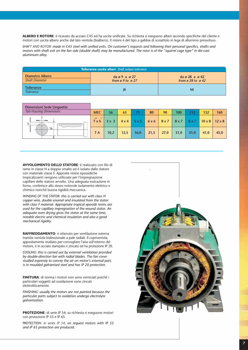
Tolleranze uscite alberi Shaft output tolerance
AVVOLGIMENTO DELLO STATORE: é realizzato con filo di rame in classe H a doppio smalto ed è isolato dallo statore con materiale classe F. Apposite resine epossidiche tropicalizzanti vengono utilizzate per l’impregnazione capillare dello statore avvolto. Una adeguata essicazione in forno, conferisce allo stesso notevole isolamento elettrico e chimico nonché buona rigidità meccanica.
WINDING OF THE STATOR: this is carried out with class H copper wire, double enamel and insulated from the stator with class F material. Appropriate tropical epoxide resins are used for the capillary impregnation of the wound stator. An adequate oven drying gives the stator at the same time, notable electric and chemical insulation and also a good mechanical rigidity.
RAFFREDDAMENTO: é ottenuto per ventilazione esterna tramite ventola bidirezionale a pale radiali. Il copriventola, appositamente studiato per convogliare l’aria sull’esterno del motore, è in acciaio stampato e zincato ed ha protezione IP 20.
COOLING: this is carried out by external ventilation provided by double-direction fan with radial blades. The fan cover studied expressly to convey the air on motor’s external part, is in moulded galvanised steel and has IP 20 protection.
FINITURA: di norma i motori non sono verniciati poiché i particolari soggetti ad ossidazione sono zincati elettroliticamente.
FINISHING: usually the motors are not painted because the particular parts subject to oxidation undergo electrolyte galvanisation.
PROTEZIONE: di serie IP 54; su richiesta si eseguono motori con protezione IP 55 e IP 65.
PROTECTION: in series IP 54; on request motors with IP 55 and IP 65 protection are produced.
ALBERO E ROTORE: é ricavato da acciaio C45 ed ha uscite unificate. Su richiesta si eseguono alberi secondo specifiche del cliente e motori con uscita albero anche dal lato ventola (bialbero). Il rotore è del tipo a gabbia di scoiattolo in lega di alluminio pressofuso.
SHAFT AND ROTOR: made in C45 steel with unified exits. On customer’s requests and following their personal specifics, shafts and motors with shaft exit on the fan side (double shaft) may be manufactured. The rotor is of the “squirrel cage type” in die-cast aluminium alloy.
Dimensioni Sede LinguetteTab Housing Dimensions
Diametro AlberoShaft Diameter
da ø 9 a ø 27from ø 9 to ø 27
j6
da ø 28 a ø 42from ø 28 to ø 42
k6TolleranzeTolerance
h 9 h ' '
h ' '
MEC 56 63 71 80 90 100 112 132 160
T x h 3 x 3 4 x 4 5 x 5 6 x 6 8 x 7 8 x 7 8 x 7 10 x 8 12 x 8
T A 10,2 12,5 16,0 21,5 27,0 31,0 31,0 41,0 45,0
h
T
TA
7

caratteristiche di funzionamentoworking characteristics
TENSIONE E FREQUENZA DI ALIMENTAZIONE: i motori trifase sono avvolti per funzionare ad una tensione di 230/400V 50 Hz fino alla grandezza MEC 112 e tensione 400/690V 50 Hz per grandezze superiori. Su richiesta si eseguono motori trifase avvolti per frequenze particolari e tensioni da 24V a 700V. Sulla tensione nominale di alimentazione è ammessa una variazione del ±5% ed entro tale limite è consentito una sovratemperatura di 10° degli avvolgimenti.In casi particolari e per brevi periodi la variazione della tensione di alimentazione può scostarsi del ±10% del valore nominale, entro tale variazione è assicurata solo la coppia nominale non i limiti di temperatura.I motori a 50 Hz possono essere alimentati anche alla frequenza di 60Hz con variazione delle caratteristiche elettriche e meccaniche di catalogo come da tabella.
INPUT VOLTAGE AND FREQUENCY: The three-phase motors are wound to work at a voltage of 230/400V 50 Hz up to size MEC 112 and at a voltage of 400/690V 50 Hz for superior sizes. On request three-phase wound motors for particular frequencies and voltages from 24V to 700V can be manufactured. On nominal input voltage a variation of ±5% is allowed and within this limit an overheating of 10° on the windings is allowed.In these particular cases and for short periods, variation of voltage may swing ±10% from the nominal value; within such variation only the nominal torque is assured, not the temperature limits.The 50 Hz motors may also be powered at 60Hz frequency with catalogue variations of the electric and mechanical characteristics as shown on the graph.
CONDIZIONI AMBIENTALI DI FUNZIONAMENTO:i motori sono progettati per funzionare in condizioni normali:1. altitudine non superiore ai 1000 mt slm,2. temperatura ambiente non superiore a 40°C.
Per condizioni diverse, da quelle sopracitate, la potenza nominale varia in funzione del coefficiente di variazione indicato nella tabella.
ENVIRONMENTAL WORKING CONDITIONS:The motors are projected to work in normal environmental conditions:1. altitude not superior to 1000 m above sea level,2. environmental temperature not superior to 40° C
In conditions different from those named above, the nominal power varies according to the coefficient of variation indicated in the graph.
• Corrente nom. • Corrente di avv. • Coppia nom.• Coppia avv. • Coppia max.
• Nom. Current • Starting Current • Nom. Torque• Starting Torque • Max. Torque
Motore avvolto a 50Hzper le tensioni
Motor wound at 50Hzfor voltages
Tensionidi alimentazione
a 60HzInput voltages
at 60 Hz
Potenza nominale
Nominal power
Giri al minutoa vuoto
Idle revolutionsper minute
230
230
230
230
380
400
400
400
400
210
220
240
260
380
380
440
460
480
0,91
0,95
1,05
1,15
1
0,95
1,1
1,15
1,2
1,2
1,2
1,2
1,2
1,2
1,2
1,2
1,2
1,2
0,76
0,80
0,86
0,95
0,83
0,80
0,91
0,95
1
COEFFICIENTI DI VARIAZIONE COEFFICIENTS OF VARIATIONTENSIONI VOLTAGE
1
0,9
0,8
0,7
0,6
0,5
0 1000 2000 3000 4000
TEMPERATURA AMBIENTE40°C45°C
50°C55°C60°C
ALTITUDINE mt. slm. ALTITUDE mt. slm.COEF
FICE
NTE
DI V
ARI
AZI
ON
E C
OEF
FIC
IEN
T O
F VA
RIAT
ION
8

CLASSI DI ISOLAMENTO E RISCALDAMENTO:i motori hanno gli avvolgimenti isolati in classe F.Per i vari tipi di isolamento le sovratemperature massime ammesse sono riportate nel grafico sottostante:
INSULATION AND HEATING CLASSES:the motors have windings insulated in F class.For the various types of insulation the max. over-heating temperatures allowed are demonstrated in the graph below:
SOVRACCARICHI: i motori utilizzati nelle condizioni normali possono essere sovraccaricati, perché questo non risulti dannoso per gli avvolgimenti, i tempi ed i valori di sovraccarico non debbono superare i coefficienti indicati in tabella.
OVERLOADING: motors used in normal conditions may become overloaded. So that this does not result dangerous for the windings, the times and values of overloading must not overflow the overloading factors (coefficients) indicated on the graph.
Ogni periodo di sovraccarico dovrà essere seguito da un periodo di funzionamento a potenza nominale o inferiore, per una durata minima di due ore.I valori e le caratteristiche elettriche nominali non sono garantite in caso di funzionamento con sovraccarichi.
Each period of overloading should be followed by a period of nominal or inferior power functioning for at least 2 hours. The nominal electric characteristics and values are not guaranteed in cases of work in overloading.
40°C
40°C
40°C
40°C
40°C
140°C
115°C
90°C
80°C
65°C
180°C
155°C
130°C
120°C
105°C
H
F
B
E
ACLAS
SI D
I ISO
LAM
ENTO
CLA
SSES
OF
INSU
LATI
ON
TEMPERATURATOTALE MAXTOTAL MAX.TEMPERATURETemperatura max ambiente
Max. environmental temperatureSovratemperatura max ammessaMax. over-heating allowed
DurataDuration
Coefficiente di sovraccaricoOverloading factors
1 1,08 1,2 1,5
PermanentePermanent
1Ora1 Hour
15 Minuti15 Minutes
1 Minuto1 Minute
COEFFICIENTI DI SOVRACCARICO OVERLOADING FACTORS
9

B3 V5
B5 V1
B14
forme costruttive
esecuzione B3manufacture B3
esecuzione B5manufacture B5
esecuzione B14manufacture B14
constructive forms
V18
10
Basetta superioreUpper terminal board
Basetta lateraleLateral terminal board

B3/B5
V6 B6 B7 B8
V3 V1/V5 V3/V6
V19 B3/B14 V18/V5 V19/V6
11

grado di protezione IPdegree of protection IP
Protetto contro corpi solidi sup. a mm 50 (es. contatti involontari con la mano).
Protected against solid masses greater than 50 mm (ex. involuntary hand contact).
Protetto contro corpi solidi sup. a mm 12 (es. dito della mano).
Protected against solid masses greater than 12 mm (ex. finger).
Protetto contro corpi solidi sup. a mm 2,5 (es. attrezzi, fili).
Protected against solid masses greater than 2.5 mm (ex. tools, wires).
Protetto contro corpi solidi sup. a mm 1 (es. piccoli fili).
Protected against solid masses greater than 1 mm (ex. small wires).
Protetto contro le polveri (es. nessun deposito nocivo).
Protected against dust (no harmful deposit).
Totalmente protetto contro le polveri.
Totally protected against dust.
Es: IP 55= Protetto contro le polveri
Protetto contro la caduta verticale di gocce d'acqua (condensa).
Protected against vertical drops of water (condensation)
Protetto contro la caduta di gocce d'acqua fino a 15° dalla verticale.
Protected against drops of water up to 15° from vertical.
Protetto contro la pioggia d'acqua fino a 60° dalla verticale.
Protected against rain water up to 60° from vertical.
Protetto contro le proiezioni d'acqua da ogni direzione.
Protected against water projected from any direction.
Protetto contro i getti d'acqua da ogni direzione mediante lancia.
Protected against jets of water projected by nozzle from any direction.
Protetto contro le proiezioni d'acqua assimilabili alle onde marine.
Protected against water projections similar to sea waves.
Protetto contro gli effetti dell'immersione.
Protected against immersion effect.
Protetto contro gli effetti dell'immersione prolungata sotto pressione.
Protected against extended immersion effect under pressure.
GRADO DI PROTEZIONE: è il livello di protezione che un motore possiede contro eventuali contatti accidentali dell’operatore, oppure contro la possibilità di intrusione di corpi estranei solidi e liquidi.Il grado di protezione è identificato con due cifre:• 1° cifra - protezione contro corpi solidi;• 2° cifra - protezione contro l’acqua.
DEGREE OF PROTECTION: the level of protection which a motor possesses against accidental contacts with the operator, or in the case of the intrusion of foreign bodies, solid and liquid. The degree of protection is indicated in two digits:• 1st digit - protection against solid masses;• 2nd digit - protection against water.
Prima cifra First digit Seconda cifra Second digit
Protetto contro i getti d'acqua da ogni direzione mediante lancia.
Ex: IP 55= Protection against dustProtected against jets of water projected by nozzle from all directions.
1 m
1
2
3
4
5
6
1
2
3
4
5
6
7
8
12

tipi di serviziotypes of service
Si possono distinguere due gruppi di servizio: • S1 = SERVIZIO CONTINUO • S2÷S9 = SERVIZIO INTERMITTENTETwo groups of service may be distinguished: • S1 = Continuous service • S2÷S9 = Intermittent service
Tempo di funzionamento a carico costanteSteady load operating time
Tempo di riposoStand by time
Tempo di avviamento o di accelerazioneStarting and accelerating time
Tempo di frenatura elettricaElectric braking time
Tempo di funzionamento a vuotoNo-load operating time
Tempo di frenataBraking time
N=
R=
D=
F=
V=
F1 F2=
Tempo di funzionamento a carico costanteSteady load operating time
Temperatura massima raggiunta durante il cicloMaximum temperature achieved during the cycle
Tempo di funzionamento a carichi variabiliOperating time with variable loads
Pieno caricoFull load
Tempo di funzionamento in sovraccaricoOverload operating time
N N N =
Omax =
L =
Cp =
S =
1 2 3
S1
N
0 max
Tem
pera
tura
Tempo
Tempo
Tempo TempoTempo
Tempo Tempo
TempoTempo
Car
ico
Perd
iteel
ettr
iche
S7
0 max
D N F
Tem
pera
tura
Car
ico
Perd
iteel
ettr
iche
Durata di un ciclo
S2
N
0 max
Tem
pera
tura
Car
ico
Perd
iteel
ettr
iche
S4
N RD
0 max
Tem
pera
tura
Car
ico
Perd
iteel
ettr
iche
Durata del ciclo
Rapporto diintermittenzadi un ciclo
D + ND + N + R
X 100%
S8
D N1 N2 N3F1 F2
0 max
Velo
cità
Tem
pera
tura
Car
ico
Perd
iteel
ettr
iche
Durata di un ciclo
Rapporti diintermittenza
D + ND + N + F + N + F + N
X 100%1
1 1 2 2 3
F + ND + N + F + N + F + N
X 100%21
1 1 2 2 3
F + ND + N + F + N + F + N
X 100%32
1 1 2 2 3
S9
SRD
C
FL
max0
Velo
cità
Tem
pera
tura
Car
ico
Perd
ite e
lett
riche
p
S3
N R
0 max
Tem
pera
tura
Car
ico
Perd
iteel
ettr
iche
Durata di un ciclo
Rapporto diintermittenza
NN + R
X 100%
S6
N V
0 max
Tem
pera
tura
Car
ico
Perd
iteel
ettr
iche
Durata di un ciclo
Rapporto diintermittenza
NN + V
X 100%S5
Car
ico
Perd
iteel
ettr
iche
Durata di un ciclo
N RFD
0max
Tem
pera
tura
Rapporto diintermittenza
D + N + FD + N + F + R
X 100%
13
motore asincrono trifaseasynchronous three-phase motor
Note: for application on single-phase motors see following page
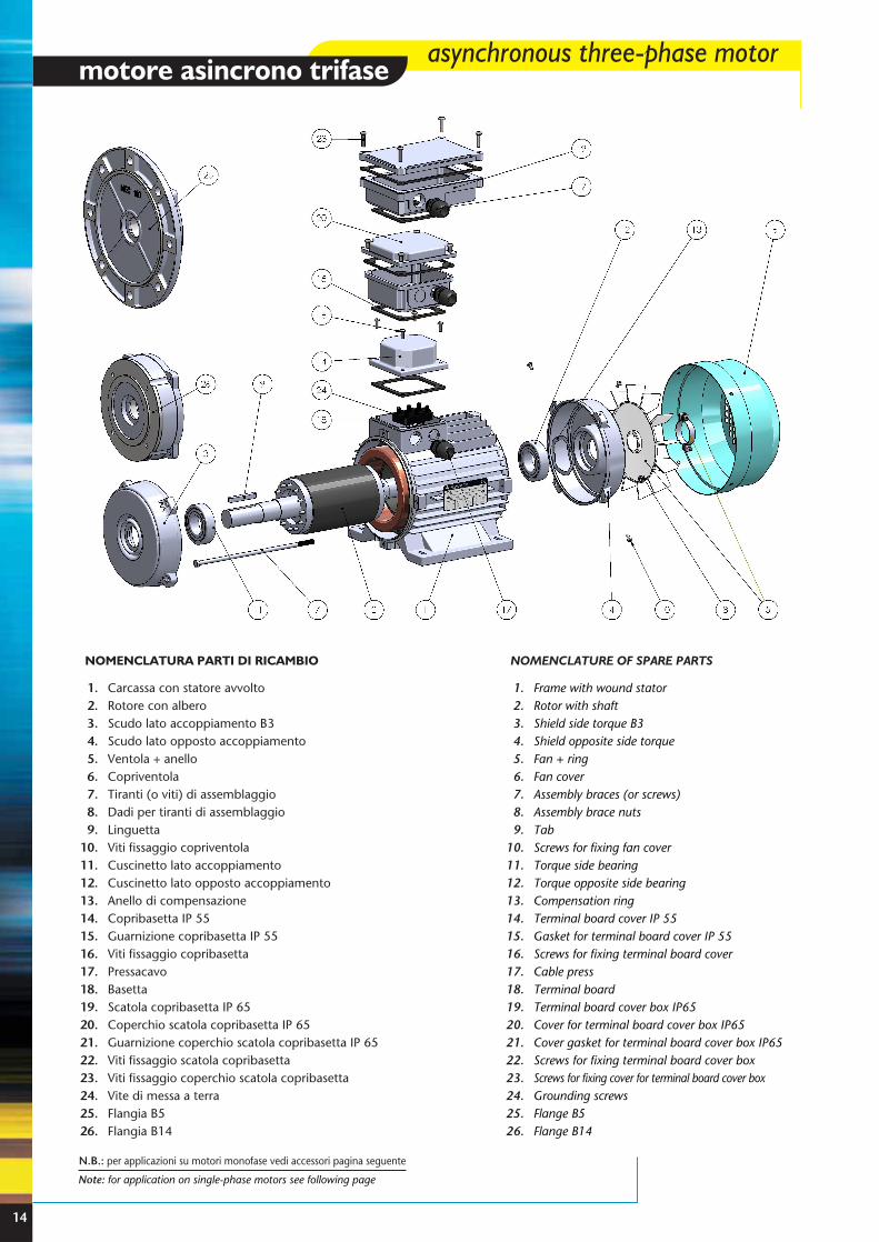
Carcassa con statore avvoltoRotore con alberoScudo lato accoppiamento B3Scudo lato opposto accoppiamentoVentola + anelloCopriventolaTiranti (o viti) di assemblaggioDadi per tiranti di assemblaggioLinguettaViti fissaggio copriventolaCuscinetto lato accoppiamentoCuscinetto lato opposto accoppiamentoAnello di compensazioneCopribasetta IP 55Guarnizione copribasetta IP 55Viti fissaggio copribasettaPressacavoBasettaScatola copribasetta IP 65Coperchio scatola copribasetta IP 65Guarnizione coperchio scatola copribasetta IP 65Viti fissaggio scatola copribasettaViti fissaggio coperchio scatola copribasettaVite di messa a terraFlangia B5Flangia B14
1.2.3.4.5.6.7.8.9.
10.11.12.13.14.15.16.17.18.19.20.21.22.23.24.25.26.
NOMENCLATURA PARTI DI RICAMBIO
Frame with wound statorRotor with shaftShield side torque B3Shield opposite side torqueFan + ringFan coverAssembly braces (or screws)Assembly brace nutsTabScrews for fixing fan coverTorque side bearingTorque opposite side bearingCompensation ringTerminal board cover IP 55Gasket for terminal board cover IP 55Screws for fixing terminal board coverCable pressTerminal boardTerminal board cover box IP65Cover for terminal board cover box IP65Cover gasket for terminal board cover box IP65Screws for fixing terminal board cover box Screws for fixing cover for terminal board cover boxGrounding screwsFlange B5Flange B14
1.2.3.4.5.6.7.8.9.
10.11.12.13.14.15.16.17.18.19.20.21.22.23.24.25.26.
NOMENCLATURE OF SPARE PARTS
N.B.: per applicazioni su motori monofase vedi accessori pagina seguente
14
Type your text
15
A
H
B
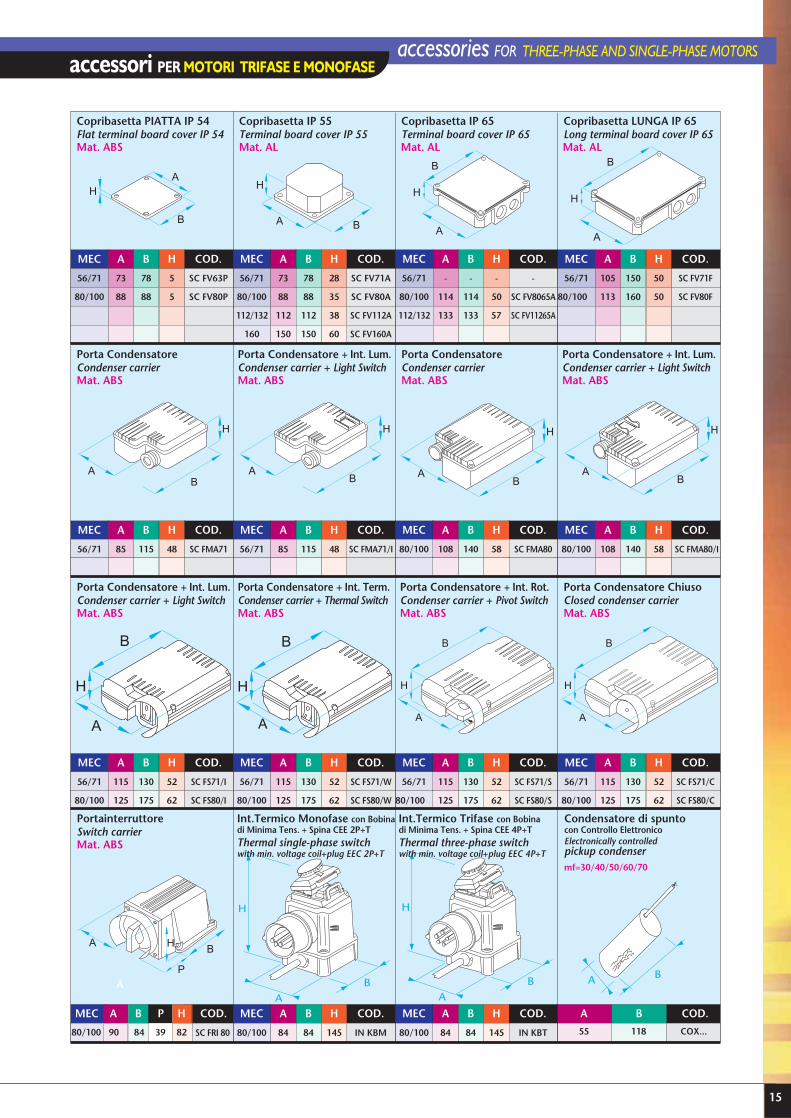
accessori PER MOTORI TRIFASE E MONOFASEaccessories FOR THREE-PHASE AND SINGLE-PHASE MOTORS
AH
BA
H
B
A
H
BA
H
B A
H
BA
H
B
A
H
B
A
B
H
A
B
H
A B
H
A B
P
H
AB
H
A
ABB
H
A
H
B
MEC A B H COD.
56/71 73 78 5 SC FV63P
80/100 88 88 5 SC FV80P
Copribasetta PIATTA IP 54Flat terminal board cover IP 54Mat. ABS
Porta CondensatoreCondenser carrierMat. ABS
Porta CondensatoreCondenser carrierMat. ABS
Porta Condensatore + Int. Lum.Condenser carrier + Light SwitchMat. ABS
Porta Condensatore + Int. Lum.Condenser carrier + Light SwitchMat. ABS
PortainterruttoreSwitch carrierMat. ABS
Int.Termico Monofase con Bobinadi Minima Tens. + Spina CEE 2P+TThermal single-phase switchwith min. voltage coil+plug EEC 2P+T
Int.Termico Trifase con Bobinadi Minima Tens. + Spina CEE 4P+TThermal three-phase switchwith min. voltage coil+plug EEC 4P+T
Condensatore di spuntocon Controllo ElettronicoElectronically controlledpickup condenser
Porta Condensatore + Int. Rot.Condenser carrier + Pivot SwitchMat. ABS
Porta Condensatore ChiusoClosed condenser carrierMat. ABS
Porta Condensatore + Int. Term.Condenser carrier + Thermal SwitchMat. ABS
Porta Condensatore + Int. Lum.Condenser carrier + Light SwitchMat. ABS
MEC A B H COD.
56/71 73 78 28 SC FV71A
80/100 88 88 35 SC FV80A
112/132 112 112 38 SC FV112A
160 150 150 60 SC FV160A
Copribasetta IP 55Terminal board cover IP 55
LA .taMLA .taM
MEC A B H COD.
56/71 - - - -
80/100 114 114 50 SC FV8065A
112/132 133 133 57 SC FV11265A
Copribasetta IP 65Terminal board cover IP 65
Mat. AL
MEC A B H COD.
56/71 105 150 50 SC FV71F
80/100 113 160 50 SC FV80F
Copribasetta LUNGA IP 65Long terminal board cover IP 65
MEC A B H COD.
56/71 85 115 48 SC FMA71
MEC A B H COD.
56/71 85 115 48 SC FMA71/I
MEC A B H COD.
80/100 108 140 58 SC FMA80
MEC A B H COD.
80/100 108 140 58 SC FMA80/I
MEC A B H COD.
56/71 115 130 52 SC FS71/I
80/100 125 175 62 SC FS80/I
MEC A B H COD.
56/71 115 130 52 SC FS71/W
80/100 125 175 62 SC FS80/W
MEC A B H COD.
56/71 115 130 52 SC FS71/S
80/100 125 175 62 SC FS80/S
MEC A B H COD.
56/71 115 130 52 SC FS71/C
80/100 125 175 62 SC FS80/C
SC FRI 80
MEC A B H COD.A B HP COD.
A
MEC
80/100 84 84 145 IN KBM
MEC A B H COD.
80/100 84 84 145 IN KBT
A B COD.
55 118 COX...
mf=30/40/50/60/70
80/100 82398490

2 POLI 2 POLES 3000 Giri/11 3000 Rpm
4 POLI 4 POLES 1500 Giri/11 1500 Rpm
TIPOTYPE
In400V
A
Rend%
η Cos
Cn
Nm
IaIn
CaCn
CmCn
PesoWeight
KgKW
POTENZA - POWER
HPMT 56 A2
MT 63 A2
MT B2
MT 71 A2
MT B2
MT 80 A2
MT B2
MT C2 *
MT 90 SA2
MT LA2
MT LB2 *
MT 100 A2
MT B2 *
MT 112 A2
MT B2 *
MT 132 SA2
MT SB2
MT MA2 *
MT MB2 *
MT 160 MA2
MT MB2
MT LA2
0,15
0,18
0,25
0,37
0,55
0,75
1,1
1,5
1,5
2,2
3
3
4
4
5,5
5,5
7,5
9,2
11
11
15
18,5
0,2
0,25
0,35
0,5
0,75
1
1,5
2
2
3
4
4
5,5
5,5
7,5
7,5
10
12,5
15
15
20
25
2800
2800
2800
2800
2800
2820
2830
2820
2830
2830
2830
2840
2840
2850
2860
2880
2890
2900
2900
2870
2920
2945
0,5
0,6
0,8
1,1
1,5
1,9
2,7
3,4
3,5
4,8
6,3
6,5
9
8,5
12
12
16
19
22,5
23
29
36
61
65
66
68
74
76
79
77
78
80
81
85
83
84
82
84
83
85
85
87
88
87
0,75
0,70
0,72
0,75
0,75
0,79
0,78
0,87
0,84
0,87
0,89
0,83
0,81
0,85
0,85
0,83
0,86
0,87
0,87
0,84
0,89
0,90
0,51
0,61
0,85
1,26
1,88
2,54
3,71
5,08
5,06
7,42
10,12
10,09
13,45
13,40
18,37
18,24
24,78
30,30
36,22
36,60
49,06
59,99
3,5
4,0
4,2
4,3
4,8
4,7
5,1
5,2
4,9
5,5
5,6
5,9
6,1
6,0
6,3
6,0
6,2
6,3
6,3
6,8
6,9
6,8
2,9
2,8
2,9
2,9
3,0
3,1
3,0
2,9
3,0
2,8
3,0
3,1
3,3
2,5
2,8
2,2
2,1
2,2
2,2
2,7
2,8
2,6
2,9
3,0
3,1
3,2
3,3
3,2
2,9
3,1
3,3
3,2
3,3
2,9
3,5
3,0
2,9
2,5
2,4
2,5
2,5
2,9
3,0
2,9
3,2
4,1
4,6
5,4
6,6
8,5
9,5
10,5
11,3
14,2
16
20
21,5
27
30
35,4
42
49
56
79
86
97
TIPOTYPE
Giri/11
Rpmn1
In400V
A
Rend%
η Cos
Cn
Nm
IaIn
CaCn
CmCn
PesoWeight
KgKW HPMT 56 A4
MT 63 A4
MT B4
MT C4 *
MT 71 A4
MT B4
MT C4 *
MT 80 A4
MT B4
MT C4 *
MT 90 SA4
MT LA4
MT LB4 *
MT LC4 *
MT 100 A4
MT B4
MT C4 *
MT 112 A4
MT B4 *
MT 132 SA4
MT MA4
MT MB4 *
MT 160 MA4
MT LA4
0,09
0,12
0,18
0,25
0,25
0,37
0,55
0,55
0,75
1
1,1
1,5
1,85
2,2
2,2
3
4
4
5,5
5,5
7,5
9,2
11
15
0,12
0,17
0,25
0,35
0,35
0,5
0,75
0,75
1
1,3
1,5
2
2,5
3
3
4
5,5
5,5
7,5
7,5
10
12,5
15
20
1380
1380
1390
1390
1400
1390
1390
1400
1400
1390
1400
1400
1400
1415
1420
1410
1400
1420
1410
1440
1450
1450
1450
1460
0,5
0,6
0,8
0,9
0,9
1,3
1,7
1,9
2,2
3
3
4
5
6,1
6
7,5
9,5
9,5
12,5
12
16
20
24
33
58
57
62
63
69
70
68
69
70
71
74
76
77
77
78
79
80
82
81
82
83
83
84
85
0,47
0,53
0,55
0,67
0,61
0,62
0,72
0,64
0,74
0,71
0,75
0,75
0,73
0,71
0,72
0,77
0,80
0,78
0,83
0,85
0,86
0,84
0,83
0,81
0,62
0,83
1,24
1,72
1,71
2,54
3,78
3,75
5,12
6,87
7,50
10,23
12,62
14,85
14,80
20,32
27,29
26,90
37,25
36,48
49,40
60,59
72,45
98,12
2,8
2,9
2,7
2,9
3,8
3,7
4,0
3,7
4,0
4,0
4,1
4,2
4,6
4,5
4,6
4,5
4,6
5,5
5,6
5,0
5,2
5,5
6,0
6,1
2,3
2,5
2,2
2,4
2,3
2,2
2,8
2,0
2,1
2,2
2,3
2,3
2,5
2,4
2,5
2,5
2,4
2,6
2,4
2,5
2,6
2,8
2,0
2,0
2,5
2,9
1,9
2,1
2,2
2,1
2,3
2,5
2,5
2,5
2,6
2,6
2,9
2,8
2,7
2,5
2,6
2,7
2,6
2,7
2,8
2,9
2,8
2,7
3
3,5
4
4,7
5,4
6,2
7,1
7,5
9
10,5
11,5
13,8
15,2
16,5
18,2
21
22
30
32
41
50
51,5
76
96
16
serie/series MT MOTORI ASINCRONI TRIFASE ASYNCHRONOUS THREE-PHASE MOTORSPROTEZIONE “IP55” - ISOLAMENTO C1 “F” - TENSIONE V 230/400-50HZ V 400/690-50HZ
PROTECTION “IP55” - INSULATION C1 “F” - VOLTAGE V 230/400-50HZ V 400/690-50HZ
VELOCITÀ SINGOLA single speed
POTENZA - POWER
Giri/11
Rpmn1
* Grandezza non unificata* not Standard sizeIn = corrente nominale; Ia = corrente avviamento; Cn = coppia nominale; Ca = coppia avviamento; Cm = coppia max; η = rendimentoIn = nominal current; Ia = starting current; Cn = nominal torque; Ca = starting torque; Cm = max. torque; η = output
φ
φ
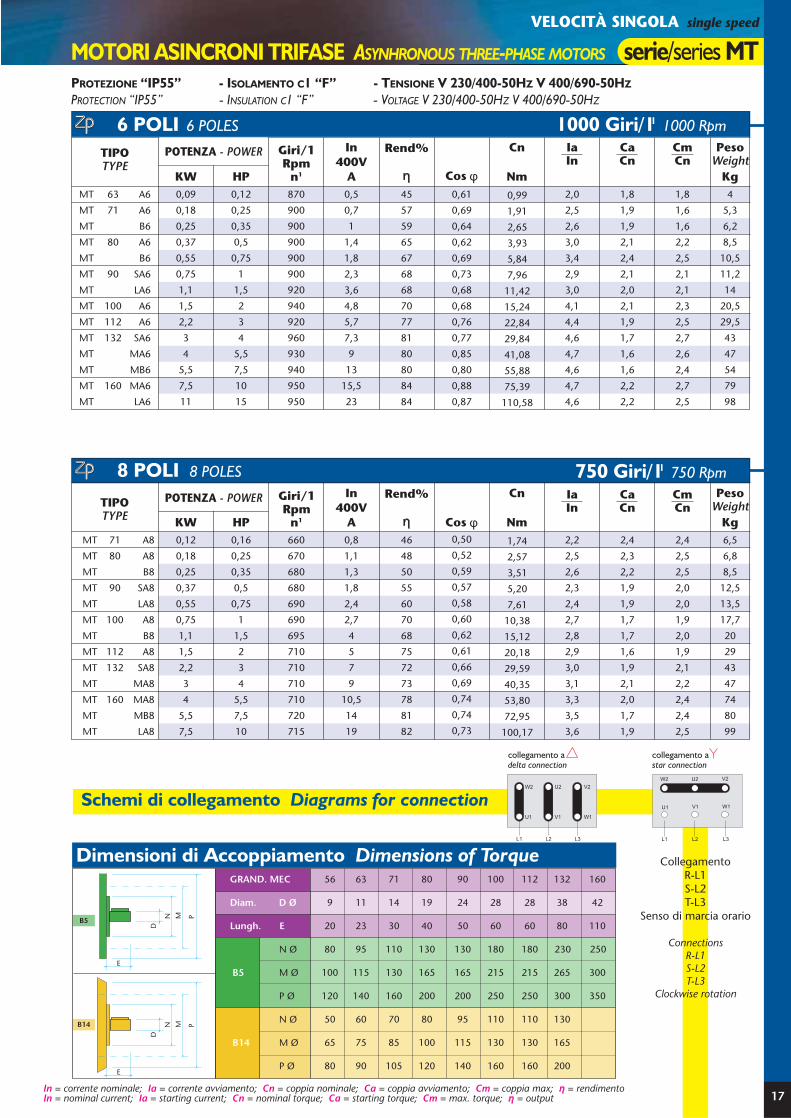
PROTEZIONE “IP55” - ISOLAMENTO C1 “F” - TENSIONE V 230/400-50HZ V 400/690-50HZ
PROTECTION “IP55” - INSULATION C1 “F” - VOLTAGE V 230/400-50HZ V 400/690-50HZ
MOTORI ASINCRONI TRIFASE ASYNHRONOUS THREE-PHASE MOTORS serie/series MT
6 POLI 6 POLES
TIPOTYPE
Giri/1Rpm
n1
In400V
A
Rend%
η Cos
Cn
Nm
IaIn
CaCn
CmCn
PesoWeight
KgKW HPMT 71 A8
MT 80 A8
MT B8
MT 90 SA8
MT LA8
MT 100 A8
MT B8
MT 112 A8
MT 132 SA8
MT MA8
MT 160 MA8
MT MB8
MT LA8
0,12
0,18
0,25
0,37
0,55
0,75
1,1
1,5
2,2
3
4
5,5
7,5
0,16
0,25
0,35
0,5
0,75
1
1,5
2
3
4
5,5
7,5
10
660
670
680
680
690
690
695
710
710
710
710
720
715
0,8
1,1
1,3
1,8
2,4
2,7
4
5
7
9
10,5
14
19
46
48
50
55
60
70
68
75
72
73
78
81
82
0,50
0,52
0,59
0,57
0,58
0,60
0,62
0,61
0,66
0,69
0,74
0,74
0,73
1,74
2,57
3,51
5,20
7,61
10,38
15,12
20,18
29,59
40,35
53,80
72,95
100,17
2,2
2,5
2,6
2,3
2,4
2,7
2,8
2,9
3,0
3,1
3,3
3,5
3,6
2,4
2,3
2,2
1,9
1,9
1,7
1,7
1,6
1,9
2,1
2,0
1,7
1,9
2,4
2,5
2,5
2,0
2,0
1,9
2,0
1,9
2,1
2,2
2,4
2,4
2,5
6,5
6,8
8,5
12,5
13,5
17,7
20
29
43
47
74
80
99
17
TIPOTYPE
Giri/1Rpm
n1
In400V
A
Rend%
η Cos φ
Cn
Nm
IaIn
CaCn
CmCn
PesoWeight
KgKW HPMT 63 A6
MT 71 A6
MT B6
MT 80 A6
MT B6
MT 90 SA6
MT LA6
MT 100 A6
MT 112 A6
MT 132 SA6
MT MA6
MT MB6
MT 160 MA6
MT LA6
0,09
0,18
0,25
0,37
0,55
0,75
1,1
1,5
2,2
3
4
5,5
7,5
11
0,12
0,25
0,35
0,5
0,75
1
1,5
2
3
4
5,5
7,5
10
15
870
900
900
900
900
900
920
940
920
960
930
940
950
950
0,5
0,7
1
1,4
1,8
2,3
3,6
4,8
5,7
7,3
9
13
15,5
23
45
57
59
65
67
68
68
70
77
81
80
80
84
84
0,61
0,69
0,64
0,62
0,69
0,73
0,68
0,68
0,76
0,77
0,85
0,80
0,88
0,87
0,99
1,91
2,65
3,93
5,84
7,96
11,42
15,24
22,84
29,84
41,08
55,88
75,39
110,58
2,0
2,5
2,6
3,0
3,4
2,9
3,0
4,1
4,4
4,6
4,7
4,6
4,7
4,6
1,8
1,9
1,9
2,1
2,4
2,1
2,0
2,1
1,9
1,7
1,6
1,6
2,2
2,2
1,8
1,6
1,6
2,2
2,5
2,1
2,1
2,3
2,5
2,7
2,6
2,4
2,7
2,5
4
5,3
6,2
8,5
10,5
11,2
14
20,5
29,5
43
47
54
79
98
VELOCITÀ SINGOLA single speed
POTENZA - POWER
POTENZA - POWER
B5
E
D
N M P
E
D
N M P
56 63 71 80 90 100 112 132 160
9 11 14 19 24 28 28 38 42
20 23 30 40 50 60 60 80 110
80 95 110 130 130 180 180 230 250
100 115 130 165 165 215 215 265 300
120 140 160 200 200 250 250 300 350
50 60 70 80 95 110 110 130
65 75 85 100 115 130 130 165
80 90 105 120 140 160 160 200
B5
B14
B14
N Ø
M Ø
P Ø
N Ø
M Ø
P Ø
GRAND. MEC
Diam. D Ø
Lungh. E
Dimensioni di Accoppiamento Dimensions of Torque
Schemi di collegamento Diagrams for connectionW2 U2 V2
U1
L1 L2 L3
V1 W1
collegamento a delta connection
W2 U2 V2
U1
L1 L2 L3
V1 W1
collegamento a star connection
In = corrente nominale; Ia = corrente avviamento; Cn = coppia nominale; Ca = coppia avviamento; Cm = coppia max; η = rendimentoIn = nominal current; Ia = starting current; Cn = nominal torque; Ca = starting torque; Cm = max. torque; η = output
1000 Giri/11 1000 Rpm
750 Giri/11 750 Rpm8 POLI 8 POLES
CollegamentoR-L1S-L2T-L3
Senso di marcia orario
ConnectionsR-L1S-L2T-L3
Clockwise rotation
φ

CnNm
PESOWEIGHT
Kg
In 400 V.A
GIRI/11 rpmn1
TIPOTYPE KW
POTENZA - POWERHP
4 P. 4 P. 8 P. 8 P. 4 P. 8 P. 4 P. 8 P. 4 P. 8 P.
CnNm
PESOWEIGHT
Kg
In 400 V.A
GIRI/11 rpmn1
2/4 POLI 2/4 POLES 3000/1500 Giri/11 3000/1500 Rpm
4/8 POLI 4/8 POLES 1500/750 Giri/11 1500/750 Rpm
18
serie/series TD MOTORI ASINCRONI TRIFASE ASYNCHRONOUS THREE-PHASE MOTORS
DOPPIA VELOCITÀ two speed
TIPOTYPE KW
POTENZA - POWERHP
2 P. 4 P. 2 P. 4 P. 2 P. 4 P. 2 P. 4 P. 2 P. 4 P.0,25 0,15
0,55 0,37
0,80 0,60
1,10 0,75
1,50 1,10
1,60 1,25
2,00 1,60
2,45 1,85
3,30 2,60
3,70 3,00
4,50 3,30
5,50 4,50
7,50 5,90
11,00 9,60
15,00 12,50
TD 63 A2/4
TD 71 A2/4
TD 80 A2/4
TD B2/4
TD 90 LA2/4
TD LB2/4
TD LC2/4
TD 100 A2/4
TD B2/4
TD 112 A2/4
TD B2/4
TD 132 SA2/4
TD MA2/4
TD 160 MA2/4
TD LA2/4
0,35 0,2
0,75 0,51,1 0,81,5 12 1,5
2,2 1,72,7 2,23,3 2,54,5 3,55 46 4,5
7,5 610 815 1320 17
0,6 0,6
1,7 1,5
2,4 1,8
3 2
3,8 3,2
4,5 3,5
4,8 3,9
6 5
8,5 6,4
8,8 7,5
9 7,5
12,4 9,4
16 13
23,5 20
30 26
0,86 1,03
1,89 2,52
2,74 4,06
3,75 5,12
5,03 7,35
5,40 8,41
6,77 10,84
8,12 12,35
11,02 17,49
12,31 20,18
15,08 22,35
18,11 29,84
24,45 38,59
35,85 63,23
49,06 82,90
7
8,5
10
12,5
13,5
15
20
30
43
48
74
78
96
0,13
0,20
0,37
0,37
0,45
0,60
0,90
1,35
2,20
3,00
3,70
4,45
5,90
0,25
0,37
0,55
0,75
0,90
1,10
1,60
2,60
3,70
4,80
5,50
7,50
10,30
0,35
0,5
0,75
1
1,2
1,5
2,2
3,5
5
6,5
7,5
10
14
0,18
0,3
0,5
0,5
0,6
0,8
1,2
1,8
3
4
5
6
8
1390
1410
1400
1390
1400
1400
1410
1420
1440
1440
1450
1440
1450
670
700
700
690
700
700
700
710
720
720
720
725
720
1
1,3
1,9
2
2,7
3,2
3,7
5,5
9
11
14
16
21,5
1
1,4
1,6
1,9
2,3
2,8
3,6
4,5
8,5
10,5
11
14
18
1,72
2,51
3,75
5,15
6,14
7,50
10,84
17,49
24,54
31,83
36,22
49,74
67,84
1,85
2,73
5,05
5,12
6,14
8,19
12,28
18,16
29,18
39,79
49,08
58,62
78,26
2780 1390
2780 1400
2790 1410
2800 1400
2850 1430
2830 1420
2820 1410
2880 1430
2860 1420
2870 1420
2850 1410
2900 1440
2930 1460
2930 1450
2920 1440
TD 71 A4/8
TD 80 A4/8
TD B4/8
TD 90 SA4/8
TD LA4/8
TD LB4/8
TD 100 A4/8
TD 112 A4/8
TD 132 SA4/8
TD MA4/8
TD 160 MA4/8
TD MB4/8
TD LA4/8
4,8
7,2
9,6
11,1
13,5
15,5
16,5
20,4
22
29
30
41
50
75
95
W2 U2 V2
U1
U1
U2
L1 L2 L3
V1
V1
V2 W1
W1
W2
U2
U1 V2
V1
W2
W1
W2 U2 V2
U1
L1 L2 L3
V1 W1
collegamento per alta velocitàconnection for high speed
collegamento per bassa velocitàconnection for low speed
Schemi di collegamento Diagrams for connection
In = corrente nominale; Cn = coppia nominale;In = nominal current; Cn = nominal torque;
PROTEZIONE “IP55” - ISOLAMENTO C1 “F” - TENSIONE V 400 - 50 HZ
PROTECTION “IP55” - INSULATION C1 “F” - VOLTAGE V 400 - 50
AVVOLGIMENTO UNICO COLLEGAMENTO DAHLANDERONE WINDING DAHLANDER CONNECTION

CnNm
PESOWEIGHT
Kg
In 400 V.A
GIRI 11 rpmn1
TIPOTYPE KW
POTENZA - POWERHP
4 P. 6 P. 4 P. 6 P. 4 P. 6 P. 4 P. 6 P. 4 P. 6 P.
CnNm
PESOWEIGHT
Kg
In 400 V.A
GIRI 11 rpmn1
TIPOTYPE KW
POTENZA - POWERHP
4 P. 6 P. 4 P. 4 P. 4 P. 4 P. 6 P. 6 P. 6 P. 6 P.8,5
10,5
11,5
14
15
20
20,2
30
48
54
77
97
TDA 80 A4/6V
TDA B4/6V
TDA 90 SA4/6V
TDA LA4/6V
TDA LB4/6V
TDA 100 A4/6V
TDA B4/6V
TDA 112 A4/6V
TDA 132 MA4/6V
TDA MB4/6V
TDA 160 MA4/6V
TDA LA4/6V
0,15
0,18
0,25
0,37
0,50
0,55
0,75
0,90
1,50
1,85
2,60
3,70
0,37
0,55
0,75
1,1
1,5
1,85
2,20
3,00
4,50
5,50
7,50
11,00
0,5
0,75
1
1,5
2
2,5
3
4
6
7,5
10
15
0,2
0,25
0,35
0,5
0,7
0,75
1
1,2
2
2,5
3,5
5
1400
1400
1400
1400
1400
1450
1425
1440
1420
1440
1450
1460
900
900
900
900
920
950
925
960
940
950
960
970
1,2
1,6
2,3
3
4
5,3
6
7
9
12
16
22
1
1
1,2
1,5
2
2,2
2,5
4
4
6
7
11
2,52
3,75
5,12
7,50
10,23
12,18
14,74
19,90
30,26
36,48
49,40
70,95
1,59
1,91
2,65
3,93
5,19
5,53
7,74
8,95
15,24
18,60
25,86
36,43
19
B5
E
D
N M P
E
D
N M P
56 63 71 80 90 100 112 132 160
9 11 14 19 24 28 28 38 42
20 23 30 40 50 60 60 80 110
80 95 110 130 130 180 180 230 250
100 115 130 165 165 215 215 265 300
120 140 160 200 200 250 250 300 350
50 60 70 80 95 110 110 130
65 75 85 100 115 130 130 165
80 90 105 120 140 160 160 200
B5
B14
B14
N Ø
M Ø
P Ø
N Ø
M Ø
P Ø
GRAND. MEC
Diam. D Ø
Lungh. E
W2U2V2
U1
L1L2L3
V1W1
W2U2V2
U1
L1L2L3
V1W1
collegamento a delta connection
collegamento a
lato alimentazione/input side
lato alimentazione/input side
star connection
W2 U2 V2
U1
L1 L2 L3
V1 W1
W2 U2 V2
U1
L1 L2 L3
V1 W1
Dimensioni di Accoppiamento Torque Dimensions
Schemi di collegamento Diagrams for connection
4/6 POLI VENT. 4/6 POLES FANS 1500/1000 Giri/11 1500/1000 Rpm
4/6 POLI 4/6 POLES 1500/1000 Giri/11 1500/1000 Rpm
TDA 71 A4/6
TDA 80 A4/6
TDA B4/6
TDA 90 SA4/6
TDA LA4/6
TDA 100 A4/6
TDA 112 A4/6
TDA B4/6
TDA 132 MA4/6
TDA MB4/6
TDA MC4/6
TDA 160 MA4/6
TDA LA4/6
6
8,5
10,2
13,5
15
21
33
35
48
55
56
79
98
0,07
0,25
0,37
0,37
0,50
0,95
1,30
1,50
2,20
3,00
3,10
4,40
6,25
0,15
0,37
0,55
0,75
0,90
1,50
1,85
2,20
3,00
4,50
5,30
6,60
9,60
0,2
0,5
0,75
1
1,2
2
2,5
3
4
6
7,2
9
13
0,1
0,35
0,5
0,5
0,7
1,3
1,8
2
3
4
4,2
6
8,5
1400
1400
1400
1410
1410
1410
1410
1440
1420
1420
1430
1460
1460
960
900
900
910
930
910
930
950
940
940
950
950
950
0,6
1,2
1,6
2,4
2,8
4,1
5
6
7,1
9,5
12
15
20
0,6
1
1,3
1,5
2,4
3,8
4
4,5
6
7
7,5
11
15
1,02
2,52
3,75
5,08
6,10
10,16
12,53
14,59
20,18
30,26
35,40
43,17
62,79
0,70
2,65
3,93
3,88
5,13
9,97
13,35
15,08
22,35
30,48
31,16
44,23
62,83
MOTORI ASINCRONI TRIFASE ASYNCHRONOUS THREE-PHASE MOTORS serie/series TDADOPPIA VELOCITÀ two speed
In = corrente nominale; Cn = coppia nominale;In = nominal current; Cn = nominal torque;
PROTEZIONE “IP55” - ISOLAMENTO C1 “F” - TENSIONE V 230/400-50 HZ
PROTECTION “IP55” - INSULATION C1 “F” - VOLTAGE V 230/400-50HZ
AVVOLGIMENTI SEPARATI
SEPARATE WINDINGS

TATEE1
GrandezzaMEC
90
100
112
125
140
140
160
190
216
216
254
254
71
80
90
100
100
125
140
140
140
178
210
254
35
39
47
50
56
56
62
70
88
88
110
110
110
125
141
159
176
176
193
220
260
260
309
309
141
154
172
195
210
210
235
263
310
310
383
383
56
63
71
80
90
90
100
112
132
132
160
160
160
170
193
206
206
233
261
307
307
380
380
A B C F G H I K K1 L O Q R S U W X eDD1
a x l
6
7
7
9
10
10
12
13
11
11
14
14
8
10
11
13
13
13
17
17
20
20
23
23
187
205
244
275
305
330
368
388
463
500
605
650
75
75
75
88
88
88
88
112
112
112
150
150
80
80
80
88
88
88
88
112
112
112
150
150
25
28
35
35
41
41
52
49
55
55
75
75
90
100
112
125
130
155
170
182
181
219
261
305
107
120
135
153
170
170
192
220
260
260
319
319
66
68
75
91
102
102
107
121
151
151
180
180
7
7
8
12
13
13
14
14
16
16
20
20
9
11
14
19
24
24
28
28
38
38
42
42
20
23
30
40
50
50
60
60
80
80
110
110
3
4
5
6
8
8
8
8
10
10
12
12
10,2
12,5
16
21,5
27
27
31
31
41
41
45
45
PG11PG11PG13,5PG13,5PG13,5PG13,5PG16PG16PG21PG21PG21PG21
M4x10
M4x10
M5x15
M6x15
M8x20
M8x20
M10x25
M10x25
M12x30
M12x30
M16x35
M16x35
MEC 56
MEC 63
MEC 71
MEC 80
MEC 90S
MEC 90L
MEC 100
MEC 112
MEC 132S
MEC 132M
MEC 160M
MEC 160L
DIMENSIONIDIMENSIONS
CORPO MOTOREMOTOR CASING
TIPO / TYPE B3 e B3/BL
20
DIMENSIONI MOTORI TRIFASE DIMENSIONS OF THREE-PHASE MOTORS
L
KS
W E1BCE
D F
R Q
D1
TT
A
G
e
X
A
U
O
K1
H
axl
I
ALBEROSHAFT

G
e
AU
O
M
K11
X
Hb
TT
A
K
L
S
W E1BCE
V Z
DN D1
F
R Q
P
L
E1
E
V
Z
N D1 F
QR
P
M
T
TA
Ge
O
b
D
axl
M
axl
M
21
DIMENSIONI MOTORI TRIFASE DIMENSIONS OF THREE-PHASE MOTORS
TIPO / TYPE B5 e B3/B5
MEC 56
MEC 63
MEC 71
MEC 80
MEC 90S
MEC 90L
MEC 100
MEC 112
MEC 132S
MEC 132M
MEC 160M
MEC 160L
GrandezzaMEC
90
100
112
125
140
140
160
190
216
216
254
254
71
80
90
100
100
125
140
140
140
178
210
254
35
39
47
50
56
56
62
70
88
88
110
110
110
125
141
159
176
176
193
220
260
260
309
309
85
91
101
115
120
120
135
151
178
178
223
223
56
63
71
80
90
90
100
112
132
132
160
160
6
7
7
9
10
10
12
13
11
11
14
14
8
10
11
13
13
13
17
17
20
20
23
23
187
205
244
275
305
330
368
388
463
500
605
650
100
115
130
165
165
165
215
215
265
265
300
300
A B C F G H K K1 L M N O P Q R S U V W X Z b eDD1 axl
CORPO MOTOREMOTOR CASING
ALBEROSHAFT
T TAEE1
80
95
110
130
130
130
180
180
230
230
250
250
75
75
75
88
88
88
88
112
112
112
150
150
120
140
160
200
200
200
250
250
300
300
350
350
80
80
80
88
88
88
88
112
112
112
150
150
25
28
35
35
41
41
52
49
55
55
75
75
90
100
112
125
130
155
170
182
181
219
261
305
107
120
135
153
170
170
192
220
260
260
319
319
3
3
3,5
3,5
3,5
3,5
4
4
4
4
5
5
66
68
75
91
102
102
107
121
151
151
180
180
7
7
8
12
13
13
14
14
16
16
20
20
8,5
8
8
8,5
10
10
11
12
15
15
14
14
7
9
9,5
11,5
11,5
11,5
14
14
14
14
18
18
PG11
PG11
PG13,5
PG13,5
PG13,5
PG13,5
PG16
PG16
PG21
PG21
PG21
PG21
9
11
14
19
24
24
28
28
38
38
42
42
M4x10
M4x10
M5x15
M6x15
M8x20
M8x20
M10x25
M10x25
M12x30
M12x30
M16x35
M16x35
20
23
30
40
50
50
60
60
80
80
110
110
3
4
5
6
8
8
8
8
10
10
12
12
10,2
12,5
16
21,5
27
27
31
31
41
41
45
45
DIMENSIONIDIMENSIONS
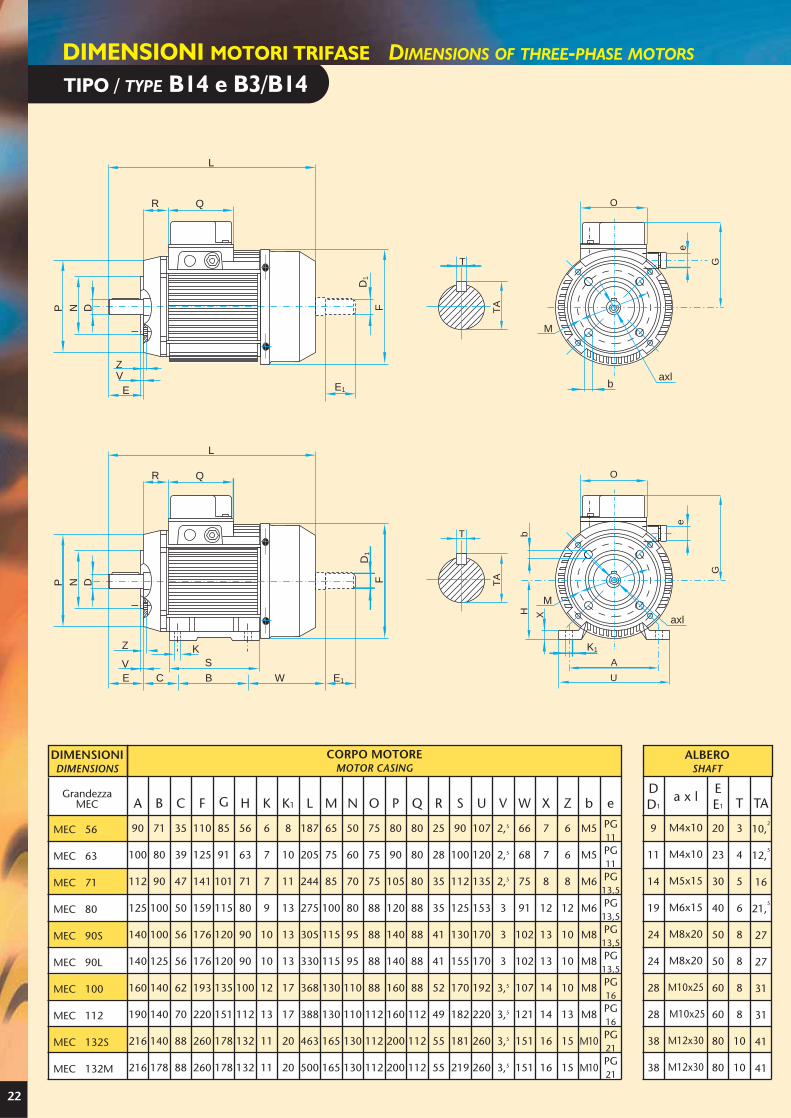
22
DIMENSIONI MOTORI TRIFASE DIMENSIONS OF THREE-PHASE MOTORS
K1
P N D FD
1
R
L
Q
Z
V SE C B W E1
K
T
TA
G
e
M
bH X
O
A
U
P N D F
D1
R
L
Q
ZV
E E1b
M
T
TA
G
e
O
M
axl
M
axl
TIPO / TYPE B14 e B3/B14
TATEE1
GrandezzaMEC
90
100
112
125
140
140
160
190
216
216
71
80
90
100
100
125
140
140
140
178
35
39
47
50
56
56
62
70
88
88
110
125
141
159
176
176
193
220
260
260
85
91
101
115
120
120
135
151
178
178
56
63
71
80
90
90
100
112
132
132
6
7
7
9
10
10
12
13
11
11
A B C F G H K K1 L M N O P Q R S U VDD1
a x l
8
10
11
13
13
13
17
17
20
20
187
205
244
275
305
330
368
388
463
500
65
75
85
100
115
115
130
130
165
165
50
60
70
80
95
95
110
110
130
130
75
75
75
88
88
88
88
112
112
112
80
90
105
120
140
140
160
160
200
200
80
80
80
88
88
88
88
112
112
112
25
28
35
35
41
41
52
49
55
55
90
100
112
125
130
155
170
182
181
219
107
120
135
153
170
170
192
220
260
260
2,5
2,5
2,5
3
3
3
3,5
3,5
3,5
3,5
W X Z b e
66
68
75
91
102
102
107
121
151
151
7
7
8
12
13
13
14
14
16
16
6
6
8
12
10
10
10
13
15
15
M5
M5
M6
M6
M8
M8
M8
M8
M10
M10
9
11
14
19
24
24
28
28
38
38
20
23
30
40
50
50
60
60
80
80
3
4
5
6
8
8
8
8
10
10
10,2
12,5
16
21,5
27
27
31
31
41
41
PG11PG11PG13,5PG13,5PG13,5PG13,5PG16PG16PG21PG21
M4x10
M4x10
M5x15
M6x15
M8x20
M8x20
M10x25
M10x25
M12x30
M12x30
MEC 56
MEC 63
MEC 71
MEC 80
MEC 90S
MEC 90L
MEC 100
MEC 112
MEC 132S
MEC 132M
DIMENSIONIDIMENSIONS
CORPO MOTOREMOTOR CASING
ALBEROSHAFT
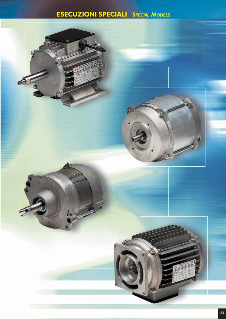
ESECUZIONI SPECIALI SPECIAL MODELS
23

TIPOTYPE
Giri/11
Rpmn1
In230V
A
Rend%
η Cos φ
Cn
Nm
IaIn
CaCn
Cond
µF
PesoWeight
KgKW
POTENZA - POWER
HP
TIPOTYPE
Giri/11
Rpmn1
In230V
A
Rend%
η Cos φ
Cn
Nm
IaIn
CaCn
Cond
µF
PesoWeight
KgKW
POTENZA - POWER
HP
TIPOTYPE
Giri/11
Rpmn1
In230V
A
Rend%
η Cos φ
Cn
Nm
IaIn
CaCn
Cond
µF
PesoWeight
KgKW
POTENZA - POWER
HP
24
serie/series MM MOTORI ASINCRONI MONOFASE ASYNCHRONOUS SINGLE-PHASE MOTORS
2 POLI 2 POLES 3000 Giri/11 3000 Rpm
4 POLI 4 POLES 1500 Giri/11 1500 Rpm
6 POLI 6 POLES 1000 Giri/11 1000 Rpm
3,2
4,2
4,5
6,2
6,8
8,8
9,6
11
14
15
MM 56 A2
MM 63 A2
MM B2
MM 71 A2
MM B2
MM 80 A2
MM B2
MM C2*
MM 90 SA2
MM LA2
0,2
0,25
0,35
0,5
0,75
1
1,5
2
2
3
0,15
0,18
0,25
0,37
0,55
0,75
1,1
1,5
1,5
2,2
2800
2850
2850
2850
2800
2800
2800
2800
2800
2800
1,6
1,8
2
3
4,5
5,7
7
10
11
14
52
67
68
70
71
72
72
70
69
75
0,78
0,65
0,80
0,77
0,75
0,79
0,95
0,93
0,86
0,91
0,51
0,60
0,84
1,24
1,88
2,56
3,75
5,12
5,12
7,50
3,1
3,0
2,9
3,3
3,3
3,1
3,2
3,3
3,1
3,0
0,45
0,46
0,5
0,53
0,47
0,55
0,46
0,5
0,55
0,65
5
10
12,5
12,5
16
25
31,5
31,5
35
45
7
9
9,5
10
12,5
16,5
20
MM 71 A6
MM 80 A6
MM B6
MM C6
MM 90 SA6
MM LA6
MM 100 A6
0,25
0,35
0,5
0,75
1
1,5
2
0,18
0,25
0,37
0,55
0,75
1,1
1,5
870
920
900
900
900
900
950
2
2
3
4,5
5
7,5
10,5
50
64
65
65
69
68
70
0,78
0,85
0,82
0,82
0,95
0,94
0,89
1,98
2,60
3,93
5,84
7,96
11,67
15,08
2,6
2,5
2,6
2,7
2,9
2,8
2,7
0,79
0,8
0,7
0,73
0,75
0,72
0,73
12,5
12,5
12,5
20
31,5
35
50
3
4,8
5,2
5,4
7,3
8,7
10,5
13,5
15,5
16,2
22
MM 56 A4
MM 63 A4
MM B4*
MM 71 A4
MM B4
MM 80 A4
MM B4
MM 90 SA4
MM LA4
MM LB4
MM 100 A4
0,12
0,25
0,35
0,35
0,5
0,75
1
1,5
2
2,5
3
0,09
0,18
0,25
0,25
0,37
0,55
0,75
1,1
1,5
1,85
2,2
1400
1350
1350
1400
1350
1400
1400
1400
1400
1350
1400
0,9
1,9
2,1
2,2
3,3
4,2
6
7,8
11
12,5
14
55
54
55
54
60
62
63
71
72
72
74
0,79
0,76
0,94
0,91
0,81
0,92
0,86
0,86
0,82
0,89
0,92
0,61
1,27
1,77
1,71
2,62
3,75
5,12
7,50
10,23
13,09
15,01
2,6
2,5
2,9
2,5
2,4
2,4
2,3
2,8
2,9
2,7
3,0
0,55
0,48
0,6
0,6
0,67
0,65
0,55
0,54
0,56
0,59
0,52
4
8
10
10
12,5
16
20
30
35
45
50
* Grandezza non unificata* not Standard sizeIn = corrente nominale; Ia = corrente avviamento; Cn = coppia nominale; Ca = coppia avviamento; Cm = coppia max; η = rendimentoIn = nominal current; Ia = starting current; Cn = nominal torque; Ca = starting torque; Cm = max. torque; η = output
PROTEZIONE “IP55” - ISOLAMENTO C1 “F” - TENSIONE V 230-50HZ
PROTECTION “IP55” - INSULATION C1 “F” - VOLTAGE V 230-50HZ

2 POLI 2 POLES 3000 Giri/11 3000 Rpm
9,8
11,2
14,3
15,5
17
FC 80 B2
FC C2
FC 90S A2
FC 90L A2
FC B2
1,5
2
2
2,5
3
1,1
1,5
1,5
1,85
2,2
2800
2800
2800
2800
2800
7
10
11
13
15
72
70
69
75
75
0,95
0,93
0,86
0,91
0,91
3,75
5,12
5,12
6,30
7,50
3,3
3,4
3,2
3,1
3,2
1,55
1,6
1,62
1,58
1,65
31,5+40
31,5+50
35+50
45+60
50+70
B5
E
D
N M P
E
D
N M P
56 63 71 80 90 100
9 11 14 19 24 28
20 23 30 40 50 60
80 95 110 130 130 180
100 115 130 165 165 215
120 140 160 200 200 250
50 60 70 80 95 110
65 75 85 100 115 130
80 90 105 120 140 160
B5
B14
B14
N Ø
M Ø
P Ø
N Ø
M Ø
P Ø
GRAND. MEC
Diam. D Ø
Lungh. E
Dimensioni di Accoppiamento Torque dimensions
Su specifica richiesta della clientela, tutti i motori monofase della serie “MM” (pag. 24) possono essere dotati diCONDENSATORE CON DISGIUNTORE ELETTRONICO con conseguente aumento del rapporto Ca/Cn da circa 0.5 a 1.5
On specific demand of the customer, all the single-phase motors of the series “MM” (page 24) can be fitted with aCONDENSER WITH ELECTRONIC CIRCUIT BREAKER with a consequent increase in Ca/Cn ratio from about 0.5 to 1.5.
25
MOTORI ASINCRONI MONOFASE ASYNCHRONOUS SINGLE-PHASE MOTORS serie/series FC
TIPOTYPE
Giri/11
Rpmn1
In230V
A
Rend%
η Cos
Cn
Nm
IaIn
CaCn
Cond
µF
PesoWeight
KgKW
POTENZA - POWER
HP
PROTEZIONE “IP55” - ISOLAMENTO C1 “F” - TENSIONE V 230-50 HZ
PROTECTION “IP55” - INSULATION C1 “F” - VOLTAGE V 230-50 HZ
FC=FORTE COPPIAFC=HIGH TORQUE
φ

TIPO / TYPE B3
26
DIMENSIONI MOTORI MONOFASE DIMENSIONS OF SINGLE-PHASE MOTORS
K1
E1
D1
F
G
H
X
O Q
L
B
K
axl
WCE
S
R
D
A
U
E
T
TA
MEC 56
MEC 63
MEC 71
MEC 80
MEC 90S
MEC 90L
MEC 100
GrandezzaMEC
90
100
112
125
140
140
160
71
80
90
100
100
125
140
35
39
47
50
56
56
62
110
125
141
159
176
176
193
172
185
203
228
243
243
270
56
63
71
80
90
90
100
6
7
7
9
10
10
12
8
10
11
13
13
13
17
187
205
244
275
305
330
368
115
115
115
125
125
125
125
130
130
130
175
175
175
175
5
7
15
11
15
15
24
91
100,5
112,5
125
130
155
171
107,5
120
135
153
170
170
192
66
68
75
91
102
102
107
6,5
7
8
11,5
13
13
14
9
11
14
19
24
24
28
20
23
30
40
50
50
60
3
4
5
6
8
8
8
10,2
12,5
16
21,5
27
27
31
M4x10
M4x10
M5x15
M6x15
M8x20
M8x20
M10x25
PG11PG11PG13,5PG13,5PG13,5PG13,5PG16
A B C F G H K K1 L O Q R S U W X eDD1 axl T TA
EE1
CON SCATOLA PORTA CONDENSATORE E INTERRUTTORE ROTATIVOWITH CONDENSER CARRIER BOX AND REVOLVING SWITCH
DIMENSIONIDIMENSIONS
CORPO MOTOREMOTOR CASING
ALBEROSHAFT

TIPO / TYPE B3DIMENSIONI MOTORI MONOFASE DIMENSIONS OF SINGLE-PHASE MOTORS
H
X
O
G
K1
A
U
E
E1
D1
F
Q
L
B
K
axl
WCE
S
R
D
T
TA
MEC 56
MEC 63
MEC 71
MEC 80
MEC 90S
MEC 90L
MEC 100
GrandezzaMEC
90
100
112
125
140
140
160
71
80
90
100
100
125
140
35
39
47
50
56
56
62
110
125
141
159
176
176
193
160
171
193
219
236
236
260
56
63
71
80
90
90
100
6
7
7
9
10
10
12
8
10
11
13
13
13
17
187
205
244
275
305
330
368
85
85
85
108
108
108
108
115
115
115
140
140
140
140
17
18
18
25
32
32
40
91
100,5
112,5
125
130
155
171
107,5
120
135
153
170
170
192
66
68
75
91
102
102
107
6,5
7
8
11,5
13
13
14
9
11
14
19
24
24
28
20
23
30
40
50
50
60
3
4
5
6
8
8
8
10,2
12,5
16
21,5
27
27
31
M4x10
M4x10
M5x15
M6x15
M8x20
M8x20
M10x25
PG11PG11PG13,5PG13,5PG13,5PG13,5PG16
A B C F G H K K1 L O Q R S U W X eDD1 axl T TA
EE1
27
CON SCATOLA PORTA CONDENSATOREWITH CONDENSER CARRIER BOX
DIMENSIONIDIMENSIONS
CORPO MOTOREMOTOR CASING
ALBEROSHAFT

L1W2
V1
V2
U1(U2)
U2(U1)L2
L1
Avvolgim.PRINCIPALEPRINCIPALWinding
Avvolgim.PRINCIPALEPRINCIPALWinding
Avvolgim.PRINCIPALEPRINCIPALWinding
Avvolgim.PRINCIPALEPRINCIPALWinding
COND.CONDENSER
COND.CONDENSER
COND.CONDENSER
Avvolgim.AUSILIARIOAUXILIARYWinding
Avvolgim.AUSILIARIOAUXILIARYWinding
Avvolgim.AUSILIARIOAUXILIARYWinding
1/2 Avvolg.AUSILIARIO1/2 AUXILIARYWinding
1/2 Avvolg.AUSILIARIO1/2 AUXILIARYWinding
1/2 Avvolg.AUSILIARIO1/2 AUXILIARYWinding
L2
W2
L1 L2
U1
U2
V1
V2
W1
W2L1
L2U1
U2
V1
V2
W1
W2
L1 L2
U1
U2
V1
V2
W1
W2L1
L2U1
U2
V1
V2
W1
L1
1/2 AUSIL.1/2 AUXIL.
COND.COND.
PRIN
CIP.
PRIN
CIP.
P
S
FL1 L2
a
b
F A C P
F
FS
R
L1 L2
L2
L1W2 V2
U2(U1)
U1(U2)
Cond.perm.Perm.condenser
Cond. dispuntoPickupcondenser
DisgiuntoreelettronicoElectroniccircuit breaker
L2
schemi di collegamento motori monofasesingle-phase motor connection circuit diagrams
1/2 AUSIL.1/2 AUXIL.
1 /2 A
USIL.
1 /2 A
UXIL.
1 /2 A
USIL
.1 /
2 AU
XIL.
PRINCIP.PRINCIP.
COND.
COND.
SCHEMA DI PRINCIPIOPRINCIPLE DIAGRAM
SCHEMA DI PRINCIPIOPRINCIPLE DIAGRAM
SCHEMA DI PRINCIPIOPRINCIPLE DIAGRAM
Condizione di marciaRunning condition
Condizione di avviamentoStarting condition
Per invertire il senso di rotazione scambiare tra loro i capi a con b.To invert rotation, interchange ends a with b.
SERIE MM CON SPUNTO MANUALE SERIES MM WITH MANUAL PICKUP
SERIE MM NORMALE SERIES MM NORMAL
SERIE FC CON SPUNTO AUTOMATICO SERIES FC WITH AUTOMATIC PICKUP
ROTAZIONE IN SENSO ORARIOCLOCKWISE ROTATION
ROTAZIONE IN SENSO ANTIORARIOANTI-CLOCKWISE ROTATION
ROTAZIONE IN SENSO ORARIOCLOCKWISE ROTATION
ROTAZIONE IN SENSO ANTIORARIOANTI-CLOCKWISE ROTATION
COLLEGAMENTO ALLA MORSETTIERA CONNECTION TO THE TERMINAL BOARD
COLLEGAMENTO ALLA MORSETTIERA CONNECTION TO THE TERMINAL BOARD
COLLEGAMENTO AINTERRUTTORESWITCH CONNECTION
COLLEGAMENTO AINVERTITOREINVERTER CONNECTION
28

29
TABELLA RIASSUNTIVA DELLE COMPATIBILITA’ E CARATTERISTICHECOMPATIBILITY AND CHARACTERISTIC SUMMARISING CHART
MEC 56 MEC 63 MEC 71 MEC 80S
MEC 90L
MEC 100 MEC 112S
MEC 132M
MMEC 160
L
MEC 56 MEC 63 MEC 71 MEC 80S
MEC 90L
MEC 100 MEC 112S
MEC 132M
MMEC 160
L
M 4x10Foro
FilettatoM 4x10 M 5x15 M 6x15 M 8x20 M 10x25 M 10x25 M 12x30 M 16x35
3x3x15DimensioniLinguetta
4x4x15 5x5x20 6x6x30 8x7x40 8x7x50 8x7x50 10x8x60 12x8x90
6201-2ZTipo
Cuscinetto6202-2Z 6202-2Z 6204-2Z 6205-2Z 6206-2Z 6207-2Z 6308-2Z 6309-2Z
Ø 9Alberi
NormaliØ 11 Ø 14 Ø 19 Ø 24 Ø 28 Ø 28 Ø 38 Ø 42
FlangiaB14 R
(ridotta)MEC 63 MEC 71 MEC 80 MEC 90
FlangiaB 5 R
(ridotta)MEC 63 MEC 71 MEC 71 MEC 90
FlangiaB 14
Alberiridotti
Ø 11 Ø 14 Ø 19 Ø 24
C.I. C.I. C.I. C.I.
FlangiaB 5
C.I. C.I. C.I. C.I. Ghisa
ScudoB 3
CassaB 5
CassaB3
(laterale)
CassaB 3
(superiore)
Threadedinlet port
Tab(tongue)
size
Type ofbearing
Normalshafts
FlangeB14 R
(reduced)
FlangeB 5 R
(reduced)
FlangeB 14
Reducedshafts
FlangeB 5
ShieldB 3
FrameB 5
FrameB3
(lateral)
FrameB 3
(top)
C.I. C.I. C.I. C.I. C.I.
C.I. C.I.= di serie sede cuscinetto
con inserto in acciaio= standard bearing housing
with insert in steel
= solo su richiesta sede cuscinettocon inserto in acciaio
= only on request bearing housing with insert in steel
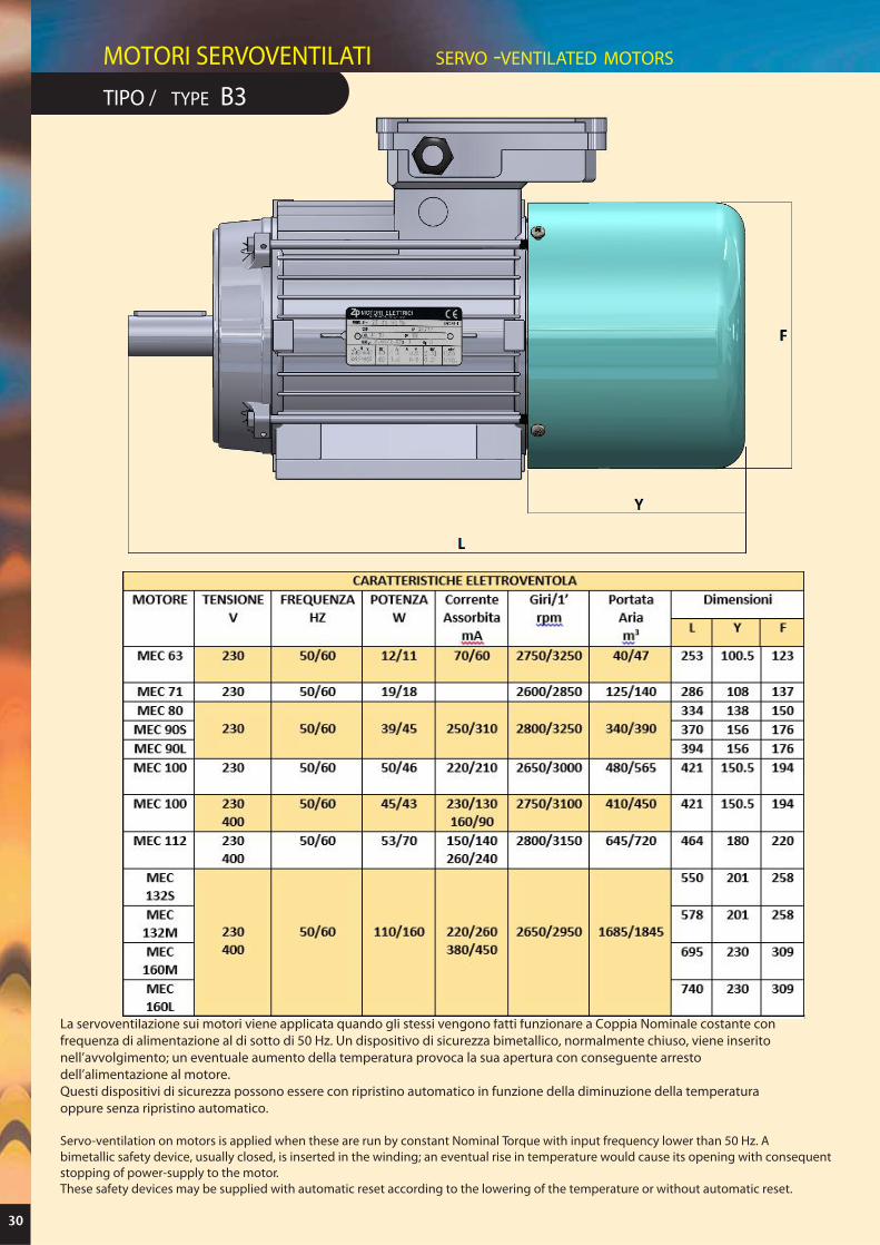
TIPO / TYPE B3
30
MOTORI SERVOVENTILATI SERVO -VENTILATED MOTORS
A
B
ØC
MotoreGrandez.
230
230
230
230
230
230
230/400
50/60
50/60
50/60
50/60
50/60
50/60
50/60
50/60
50/60
MonoVolt.
Freq.Hz
12/11
19/18
40/42
40/42
40/42
50/46
68/70
105/145
Poten.W
0,07/0,06
0,12/0,11
0,25/0,26
0,22/0,21
0,17/0,13
0,19/0,23
Corre. Ass. A
2750
2600/2950
2760/3030
2650/3000
2600/2800
2500/2650
Giri/11
rpm
40/45
125/140
350/295
500/590
940/1020
1785/1880
253
286
334
370
394
421
464
550
578
100,5
108
138
156
156
150,5
167,5
201
201
123
137
150
176
176
194
220
258
258
Port. Ariam3/h
Dimensioni
A B C
MEC 63
MEC 71
MEC 80
MEC 90S
MEC 90L
MEC 100
MEC 112
MEC 132S
MEC 132M
CARATTERISTICHE ELETTROVENTOLA DESCRIPTION OF ELECTRIC FAN
La servoventilazione sui motori viene applicata quando gli stessi vengono fatti funzionare a Coppia Nominale costante confrequenza di alimentazione al di sotto di 50 Hz. Un dispositivo di sicurezza bimetallico, normalmente chiuso, viene inseritonell’avvolgimento; un eventuale aumento della temperatura provoca la sua apertura con conseguente arrestodell’alimentazione al motore.Questi dispositivi di sicurezza possono essere con ripristino automatico in funzione della diminuzione della temperaturaoppure senza ripristino automatico.
Servo-ventilation on motors is applied when these are run by constant Nominal Torque with input frequency lower than 50 Hz. Abimetallic safety device, usually closed, is inserted in the winding; an eventual rise in temperature would cause its opening with consequentstopping of power-supply to the motor.These safety devices may be supplied with automatic reset according to the lowering of the temperature or without automatic reset.
230/400
230/400 105/145
0,25/0,26
0,25/0,26
0,19/0,23
2760/3030
2760/3030
2500/2650
350/295
350/295
1785/1880
Le descrizioni, i dati tecnici e le dimensioni riportate nel presente catalogo non sono impegnative.La ZP si riserva il diritto di modificare senza preavviso tanto i modelli quanto le loro caratteristiche.
The descriptions, technical data and dimensions shown in this catalogue are not binding.The ZP Company reserves the right to modify the models and the characteristics of the same without previous notice.