K OMPLETTDUSCHE SCHIEBET R - Duschmeister.de · on ne sera prise en consid ration ... ¥...
23
KOMPLETTDUSCHE SCHIEBETÜR KD/DSC ID-NR. 0040 D MONTAGEANLEITUNG GB ASSEMBLY INSTRUCTIONS F INSTRUCTIONS DE MONTAGE I ISTRUZIONI DI MONTAGGIO NL MONTAGEVOORSCHRIFTEN E INSTRUCCIONES DE MONTAJE PL INSTRUKCJA MONTAžU RUS CZ NÁVOD K MONTÁžI H SZERELÉSI UTASÍTÁS IDEEN FÜRS BAD IDEAS FOR THE BATHROOM
Transcript of K OMPLETTDUSCHE SCHIEBET R - Duschmeister.de · on ne sera prise en consid ration ... ¥...
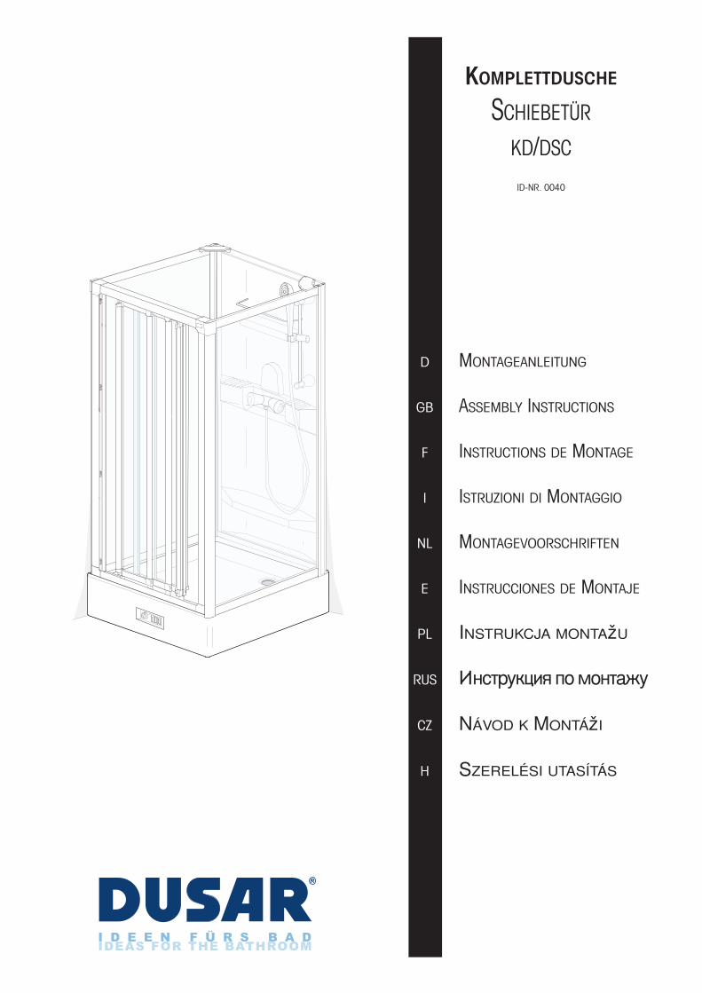
KOMPLETTDUSCHE
SCHIEBETÜR
KD/DSC
ID-NR. 0040
D MONTAGEANLEITUNG
GB ASSEMBLY INSTRUCTIONS
F INSTRUCTIONS DE MONTAGE
I ISTRUZIONI DI MONTAGGIO
NL MONTAGEVOORSCHRIFTEN
E INSTRUCCIONES DE MONTAJE
PL INSTRUKCJA MONTA!U
RUS !"#$%&'()* +, -,"$./&
CZ NÁVOD K MONTÁ!I
H SZERELÉSI UTASÍTÁS
I D E E N F Ü R S B A DIDEAS FOR THE BATHROOM

2Seite
WICHTIGE HINWEISE
• Vor der Montage bitte Montagean-leitung genauestens durchlesen und Produkt auf evtl. Transport-schäden überprüfen, da für Schäden an bereits montierten Produkten keine Haftung über-nommen werden kann.
• Für durch unsachgemäßen Transport und unsachgemäße Lagerung entstandene Schäden wird keine Haftung übernommen. Lagerungs-hinweise auf Verpa ckung beach-ten!
• Prüfen Sie vor dem Einbau, ob Typ, Maß und Farbe über-einstimmen.
• Empfehlung: Die Montage der Duschkabine sollte von 2 Personen durchgeführ werden.
• Benutzen Sie die Duschkabine erst24 Stunden nach dem Abdichten!
• Zum Reinigen verwenden Sie bitte nur vom Handel empfohlene Pflegemittel (keine Scheuer- oder Lösungsmittel).
• Auf Verschleißteile besteht nach Ablauf der gesetzlichen Garantie-zeit kein Garantieanspruch.
• Bei der Montage von Umbauten, Verkleidungen o. Ä. sollte bedacht werden, dass es notwendig werden kann, Reparaturarbeiten auf der Rückseite der Kabine durchzuführen. Für diesen Fall sollte die Kabine von der Rückseiteher zugänglich sein bzw. von der Wand abgerückt werden können.
• Änderungen der Konstruktion vor-behalten.
• Alle unsere Produkte werden vor Verlassen unseres Werkes einer vollständigen Funktionsprüfung unterzogen. Aus diesem Grund kann noch Restwasser im System enthalten sein. Eventuelle, sicht-bare Rückstände sind auf jene zurückzuführen.
• Dieses Produkt ist nicht dafür bestimmt, durch Personen (einschließlich Kinder) mit eingeschränkten physischen, sensorischen oder geistigen Fähigkeiten oder mangels Erfahrung und/oder mangels Wissen benutzt zu werden, es sei denn, sie werden durch eine für ihre Sicherheit zuständige Person beaufsichtigt oder erhielten von ihr Anweisungen, wie das Produkt zu benutzen ist. Kinder sollten beaufsichtigt werden, um sicherzustellen, dass sie nicht mit dem Produkt spielen.
• Schutzbereich: Die Duschkabine darf nur so aufgestellt werden, dass innerhalb des Schutz-bereiches keine elektr. Leitungen auf oder unter Putz verlegt sind und in diesem Bereich auch keine elektr. Geräte (Steckdosen) vorhanden sind.
IMPORTANT NOTES
• Before assembly, please read the assembly instructions very carefully and check the product for any damage that may have occurred in transit, since no liability can be accepted fordamage to products that have already been assembled.
• No liability can be accepted for damage caused by incorrect transport or improper storage.
• Follow the storage instructions on the packaging! Before assembly, check to make sure that the type, dimensions and colour are correct.
• Recommendation: The assemblyof the shower cubicle should beexecuted by two persons.
• After the sealing procedure, please wait 24 hours before thefirst use of the shower.
• For cleaning purposes, only useagents recommended by the trade(do not use scouring agents orsolvents).
• After the guarantee period has expired, no guarantee claims can be accepted for parts subject to wear and tear.
• When carrying out conversionwork, fitting panels and the like, it must be remembered that repairwork may be necessary at the rear of the cubicle. In this case, thecubicle must accessible from therear, or it must be possible to move the cubicle away from the wall.
• Subject to design alterations. • All our products are subjected to
a complete functional test beforethey leave our factory. For this reason, the system may still contain residual water. Any visibleresidues are attributable to this.
• This product is not intended to be used by persons (including children) with limited physical, sensory or psychological skills or a lack of experience and/or kno-wledge unless they are moni toredby a person responsible for their sa-fety or are given instructions on howthe product is to be used. Childrenshould be supervised to ensure thatthey do not play with the product.
• Safety area: The shower cubiclemust be installed such that no po-wer cables run within the safetyarea either on the surface or underthe plaster, and that no electricalappliances (sockets) are locatedin that area.
RECOMMANDATIONS IMPORTANTES
• Avant le montage, veuillez lire attentivement les instructions de montage et vérifiez si le produit n'a pas été endommagé pendant le transport ou si le produit n'a pas de défauts. Aucune réclamati-on ne sera prise en considérationsur des produits déjà montés.
• Aucune responsabilité ne sera assumée pour des dommages survenus lors d'un transport ou stockage incorrect. Veuillez tenir compte des recommandations de stockage notées sur l'emballage !
• Veuillez vérifier, avant le montage, si type, dimension et couleur correspondent.
• Recommandation: Le montage dela cabine de douche devrait être effectué par deux personnes.
• Après avoir réalisé l'étanchéité de la cabine de douche, attendre 24 heures avant la première utilisation.
• N’utilisez pour le nettoyage quedes produits d’entretien conseilléspar les distributeurs (les produitsabrasifs et les solvants sont interdits).
• Les pièces d’usure ne sauraient faire l’objet d’une demande de garantie après l'expiration de la garantie légale.
• Lors du montage d’éléments rapportés, d’habillages, etc., il faut garder à l'esprit que certaines réparations peuvent exiger des interventions sur l’arrière de la cabine. En prévision de ces réparations, il faut donc pouvoir accéder à la cabine par l’arrière ou l’éloigner du mur.
• Sous réserve de modifications de conception.
• Avant de quitter notre usine, tousnos produits subissent un essai defonctionnement complet. Les éven-tuels résidus visibles sont dus àl'eau qui peut encore rester dans lesystème.
• L’utilisation de ce produit est décommandée aux personnes (enfants inclus) disposant d’unhandicap physique, sensoriel et/oupsychique, ou ne disposant pas del’expérience ni des connaissancesrequises, à moins qu’elles nesoient, pour leur sécurité, sous lasurveillance d'une personne encharge ou qu’elles aient obtenu desinstructions sur la manière d'utiliserle produit. Les enfants doivent êtresous surveillance afin d’éviter qu’ilsne jouent avec le produit.
• Zone de sécurité: La cabine de douche doit uniquement être installée dans une zone de sécurité ne comportant aucuncâble électrique apparent ou encastré et aucun appareil électrique (prise de courant).
D GB F
min.0,6 m
(D) Schutzbereich (GB) Safety area (F) Zone de sécurité
3Seite
BELANGRIJKE RICHTLIJNEN
• Lees vóór de montage het montagevoorschrift goed door en controleer het product op evt. transportschade, omdat voor schade aan reeds gemonteerde producten geen aansprakelijkheid wordt aanvaard.
• Voor schade die is veroorzaakt door ondeskundig transport en ondeskundige opslag wordt geen aansprakelijkheid aanvaard. Let op de opslagaanwijzingen op de verpakking!
• Controleer vóór de montage of type, maat en kleur overeenkomen.
• Aanbeveling: De montage van dedouchecabine kan het beste mettwee personen uitgevoerd worden.
• Gebruik de douchecabine pas 24 uur na het afdichten.
• Gebruik voor het schoonmaken uitsluitend door de handel aanbevolen onderhoudsmiddelen (geen schuur- of oplosmiddelen).
• Op aan slijtage onderhevige on-derdelen bestaat na afloop van dewettelijke garantieperiode geenaanspraak op garantie.
• Bedenk bij de montage van om-bouwen, afwerkingen e.d. dat hetin voorkomende gevallen noodza-kelijk kan zijn om reparatiewerk-zaamheden aan de achterzijdevan de cabine uit te voeren. In der-gelijke gevallen dient de cabinevanaf de achterzijde toe gankelijk te zijn resp. van de muur te kunnen worden geschoven.
• Wijzigingen van de constructie vo-orbehouden.
• Al onze producten worden vóór hetverlaten van onze fabriek onder-worpen aan een volledige, functio-nele test. Om die reden kan het sy-steem nog restwater bevatten.Eventuele zichtbare resten zijnhieraan toe te schrijven.
• Dit product is niet bedoeld om teworden gebruikt door personen(waaronder kinderen) met beperktelichamelijke, sensorische of ver-standelijke vermogens of gebrekaan ervaring en/of gebrek aan kennis, tenzij ze onder toezichtstaan van een persoon die verant-woordelijk is voor hun veiligheid, of van deze persoon instructies ontvingen hoe het product moetworden gebruikt. Kinderen moetenonder toezicht staan, om er zekervan te zijn dat ze niet met het product spelen.
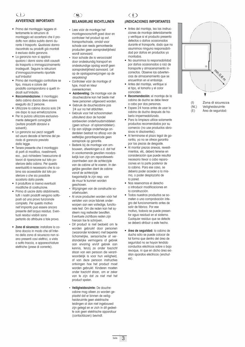
• Veiligheidsruimte: De douche -cabine mag alleen zo worden ge-plaatst dat er binnen de veilig-heidsruimte geen elektrische leidingen al dan niet ingebouwdzijn gelegd en er zich in dit gedeel-te ook geen elektrische apparatuur(contactdozen) bevindt.
NL
¡INDICACIONES IMPORTANTES
• Antes del montaje, lea las instruc-ciones de montaje detenidamentey verifique si el producto presentadefectos o daños ocasionadosdurante el transporte, dado que noasumimos ninguna responsabili-dad por daños en productos yamontados.
• No asumimos la responsabilidadpor daños ocasionados a raíz detransporte y almacenamiento in-correctos. Observe las adverten-cias de almacenamiento que seencuentran en el embalaje.
• Antes del montaje, verifique si el tipo, el tamaño y el color coinciden.
• Recomendación: el montaje de lacabina de ducha se debe llevar a cabo por dos personas.
• Espere 24 horas antes de usar lacabina de ducha después de ha-berla impermeabilizado.
• Para la limpieza utilice solamenteproductos recomendados por sucomercio (no use productos abra-sivos ni disolventes).
• Al terminarse el plazo legal de ga-rantía, ya no se ofrece garantíapor las piezas de desgaste.
• Al montar piezas anexas, revesti-mientos, etc, deberá tenerse enconsideración que puede resultarnecesario llevar a cabo repara -ciones en la parte posterior de la cabina. Para ese caso, sedebería poder acceder a la mis-ma, o poder desplazarla de la pared.
• Nos reservamos el derecho a introducir modificaciones en la construcción.
• Todos nuestros productos se so-meten a una comprobación ínte-gra del funcionamiento antes desalir de fábrica. Por ese motivo, todavía se puede presen-tar agua residual en el sistema.Cualquier residuo que se detectese deberá atribuir a este hecho.
• Área de seguridad: la cabina deducha sólo se puede colocar detal forma que dentro del área deseguridad no se hayan tendidoconductos eléctricos sobre o bajorevoque, ni que en dicho área exi-stan aparatos eléctricos (enchuf-es).
E
AVVERTENZE IMPORTANTI
• Prima del montaggio leggere at-tentamente le istruzioni di montaggio ed accertarsi che il pro-dotto non abbia subito danni du-rante il trasporto. Qualsiasi dannoriscontrato su prodotti già montatiè escluso dalla garanzia.
• La garanzia non si applica qualora i danni siano stati causatida trasporto o immagazzinamentoinadeguati. Seguire le istruzionid'immagazzinamento riportatesull'imballo!
• Prima del montaggio controllare setipo, misura e colore del prodotto corrispondono a quelli in-dicati sull'imballo.
• Raccomandazione: il montaggiodella cabina doccia deve essereeseguito da 2 persone.
• Utilizzare la cabina doccia solo 24ore dopo la sua ermetizza zione.
• Per la pulizia utilizzare esclusiva-mente detergenti consigliati (evitare prodotti abrasivi e solventi).
• La garanzia sui pezzi soggetti ad usura decade al termine del pe-riodo di garanzia previsto dalla legge.
• Tenere presente che il montaggiodi parti di modifica, rivestimenti,ecc., può richiedere l’esecuzione dilavori di riparazione sul lato po-steriore della cabina. Per questaeventualità è necessario che la ca-bina sia accessibile dal lato po-steriore o che sia possibile scostarla dalla parete.
• Il produttore si riserva eventualimodifiche di costruzione.
• Prima di uscire dallo stabilimento,tutti i nostri prodotti vengono sotto-posti ad una prova funzionalecompleta. Per questo motivo nell’impianto può essere ancorapresente dell’acqua residua. Even-tuali residui visibili sono pertanto da attribuire a tale prova.
• Zona di sicurezza: installare la ca-bina doccia in modo che all’inter-no della zona di sicurezza non si-ano presenti cavi elettrici, a vistao sotto traccia, e apparecchiatureelettriche (prese di corrente).
I
(I) Zona di sicurezza(NL) Veiligheidsruimte:(E) Área de seguridad:
min.0,6 m
D"LE#ITÉ POKYNY
• P$ed montá!í si pro%t&te prosím co nejpe%liv&ji Návod kmontá!i a p$ezkou'ejte v(ro-bek na event. dopravní po'ko-zení resp. na vady, jeliko! za 'kody na v(robcích, které ji! byly smon-továny, nem)!eme p$evzít!ádnou záruku.
• Za 'kody vzniklé neodbornou dopravou a neodborn(m skladováním nep$ejímáme !ádnou záruku. Dbejtepokyn) pro skladování na obalu!
• P$ed zabudovánímp$ezkou'ejte, zda souhlasí typ, rozm&r a barva.
• Doporu%ení: Montá! sprcho -vací kabiny by m&la b(t prove-dena 2 osobami.
• Sprchovací kabinu pou!ívejte teprve za 24 hodin po ut&sn&ní!
• K %ist&ní pou!ívejte prosím jen obchodem doporu%ené o'et$ovací prost$edky (!ádné prost$edky na drhnutí nebo rozpou't&dla).
• Na rychle opot$ebitelné sou%ásti není po uplynutí zákonné záru%ní doby nárok na záruku.
• P$i montá!i vybavení, oblo!ení nebo pod. se má pa-matovat na to, !e m)!e b(tpot$ebné provád&t na zadníst&n& kabiny opravá$ské prá-ce. Pro tento p$ípad má b(tkabina p$í stupná ze zadnístrany event. existovat mo!-nost odstavení kabiny ode zdi.
• Vyhra!ujeme si zm&ny konstrukce.
• V'echny na'e v(robky jsoup$ed opu't&ním na'eho závo-du podrobeny kompletnífunk%ní kontrole. Z tohotod)vodu m)!e b(t v systémuobsa!ena zbytková voda. S ní eventuáln& souvisí viditelné zbytky.
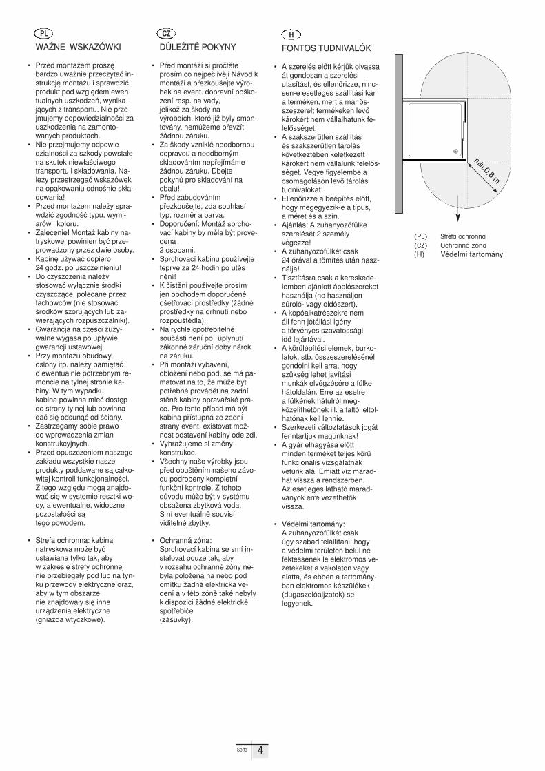
• Ochranná zóna:Sprchovací kabina se smí in-stalovat pouze tak, aby v rozsahu ochranné zóny ne-byla polo!ena na nebo podomítku !ádná elektrická ve-dení a v této zón& také nebylyk dispozici !ádné elektrickéspot$ebi%e (zásuvky).
CZ
FONTOS TUDNIVALÓK
• A szerelés el*tt kérjük olvassaát gondosan a szerelési utasítást, és ellen*rizze, ninc-sen-e esetleges szállítási kára terméken, mert a már ös-szeszerelt termékeken lev*károkért nem vállalhatunk fe-lel*sséget.
• A szakszer+tlen szállítás és szakszer+tlen tároláskövetkeztében keletkezettkárokért nem vállalunk felel*s-séget. Vegye figye lembe acsomagoláson lev* tárolásitudnivalókat!
• Ellen*rizze a beépítés el*tt,hogy megegyezik-e a típus, a méret és a szín.
• Ajánlás: A zuhanyozófülkeszerelését 2 személy végezze!
• A zuhanyozófülkét csak 24 órával a tömítés után hasz-nálja!
• Tisztításra csak a kereskede-lemben ajánlott ápolószerekethasználja (ne használjonsúroló- vagy oldószert).
• A kopóalkatrészekre nem áll fenn jótállási igény a törvényes szavatossági id* lejártával.
• A körülépítési elemek, burko-latok, stb. összeszerelésénélgondolni kell arra, hogyszükség lehet javítási munkák elvégzésére a fülkehátoldalán. Erre az esetre a fülkének hátulról meg -közelíthet*nek ill. a faltól eltol-hatónak kell lennie.
• Szerkezeti változtatások jogátfenntartjuk magunknak!
• A gyár elhagyása el*tt minden terméket teljes kör+funkcionális vizsgálatnakvetünk alá. Emiatt víz marad-hat vissza a rendszerben. Az esetleges látható marad-ványok erre vezethet*k vissza.
• Védelmi tartomány:A zuhanyozófülkét csak úgy szabad felállítani, hogy a védelmi területen belül nefektessenek le elektromos ve-zetékeket a vakolaton vagyalatta, és ebben a tarto mány -ban elektromos készülékek(dugaszolóaljzatok) se legyenek.
H
4Seite
min.0,6 m
WA,NE WSKAZÓWKI
• Przed monta-em prosz. bardzo uwa-nie przeczyta/ in-strukcj. monta-u i spraw dzi/produkt pod wzgl.dem ewen-tualnych uszkodze0, wynika-j1cych z transportu. Nie prze-jmujemy odpowie dzialno2ci zauszkodzenia na zamonto-wanych produktach.
• Nie przejmujemy odpowie -dzialno2ci za szkody powsta3ena skutek niew3a2ciwegotransportu i sk3adowania. Na-le-y przestrzega/ wskazówekna opakowaniu odno2nie sk3a-dowania!
• Przed monta-em nale-y spra-wdzi/ zgodno2/ typu, wymi-arów i koloru.
• Zalecenie! Monta- kabiny na-tryskowej powinien by/ prze-prowadzony przez dwie osoby.
• Kabin. u-ywa/ dopiero 24 godz. po uszczelnieniu!
• Do czyszczenia nale-y stosowa/ wy31cznie 2rodkiczyszcz1ce, polecane przezfachowców (nie stosowa/2rodków szoruj1cych lub za-wieraj1cych rozpuszczal niki).
• Gwarancja na cz.2ci zu-y -walne wygasa po up3ywiegwarancji ustawowej.
• Przy monta-u obudowy,os3ony itp. nale-y pami.ta/ o ewentualnie potrzebnym re-moncie na tylnej stronie ka-biny. W tym wypadku kabina powinna mie/ dost.pdo strony tylnej lub powinnada/ si. odsun1/ od 2ciany.
• Zastrzegamy sobie prawo do wprowadzenia zmian konstrukcyjnych.
• Przed opuszczeniem naszegozak3adu wszystkie nasze produkty poddawane s1 ca3ko-witej kontroli funkcjonalno2ci.Z tego wzgl.du mog1 znajdo-wa/ si. w systemie resztki wo-dy, a ewentualne, widocznepozosta3o2ci s1 tego powodem.
• Strefa ochronna: kabina natryskowa mo-e by/ ustawiana tylko tak, aby w zakresie strefy ochronnejnie przebiega3y pod lub na tyn-ku prze wody elektryczne oraz,aby w tym obszarze nie znajdowa3y si. inne urz1dzenia elektryczne (gniazda wtyczkowe).
PL
(PL) Strefa ochronna(CZ) Ochranná zóna(H) Védelmi tartomány
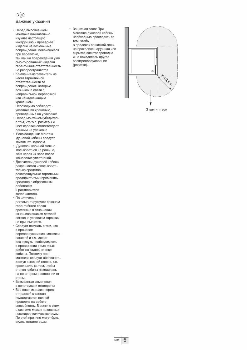
• 0.1)$".* 2,".: 3%)-,"$./4 5&647,8 '.9)":"4,9;,5)-, +%,#<45)$= 2.$4-, >$,9: 7 +%454<.; 2.1)$",8 2,": "4 +%,;,5)<. ".%&/".* )<)#'%:$.* ?<4'$%,+%,7,5'. ) "4 ".;,5)<,#= 5%&@,4?<4'$%,,9,%&5,7.")4(%,24$')).
A./":4 &'.2.")*
• 34%45 7:+,<"4")4--,"$./. 7")-.$4<=",)2&>)$4 ".#$,*1&B)"#$%&'()B ) +%,74%=$4)254<)4 ". 7,2-,/":4+,7%4/54")*, +,*7)76)4#*+%) +4%47,2'4, $.' '.' ". +,7%4/54")* &/4#-,"$)%,7."":; )254<)8@.%."$)8".* ,$74$#$74"",#$= "4 %.#+%,#$%."*4$#*.
• K,-+.")*-)2@,$,7)$4<= "4"4#4$ @.%."$)8",8,$74$#$74"",#$) 2.+,7%4/54")*, ',$,%:47,2")'<) 7 #7*2) #"4+%.7)<=",8 +4%47,2',8)<) "4".5<4/.1)-;%."4")4-. C4,9;,5)-, #,9<B5.$=&'.2.")* +, ;%."4")B,+%)7454"":4 ". &+.',7'4!
• 34%45 -,"$./,- &945)$4#= 7 $,-, >$, $)+, %.2-4%: )(74$ )254<)* #,,$74$#$7&B$5."":- ". &+.',7'4.
• D4',-4"5.()*: E,"$./5&647,8 '.9)": #<45&4$7:+,<"*$= 757,4-.
• F&647,8 '.9)",8 -,/",+,<=2,7.$=#* "4 %."=64,>4- >4%42 24 >.#. +,#<4"."4#4")* &+<,$"4")8.
• F<* >)#$') 5&647,8 '.9)":%.2%46.4$#* )#+,<=2,7.$= $,<=', #%45#$7.,%4',-4"5&4-:4 $,%@,7:-)+%45+%)*$)*-) (+%)-4"*$=#%45#$7. # .9%.2)7 ":-548#$7)4- ) %.#$7,%)$4<)2.+%41.4$#*).
• 3, )#$4>4"))%4@<.-4"$)%&4-,@, 2.',",-@.%."$)8",@, #%,'.+%4$4"2)) 7 ,$",64")))2".6) 7.B1);#* 54$.<48#,@<.#", &#<,7)*- @.%."$))"4 +%)")-.B$#*.
• G<45&4$ +,-")$= , $,-, >$, 7 +%,(4##4+4%4,9,%&5,7.")*, -,"$./.+."4<48 ) $.5. -,/4$7,2")'"&$= "4,9;,5)-,#$= 7 +%,7454")) %4-,"$":;%.9,$ ". 2.5"48 #$4"'4'.9)":. 3,?$,-& +%)-,"$./4 #<45&4$ ,94#+4>)$=5,#$&+ ' 2.5"48 #$4"'4, $.4.+%,#<45)$= 2. $4-, >$,9:#$4"'. '.9)": ".;,5)<.#=". "4',$,%,- %.##$,*")) ,$#$4":.
• A,2-,/":4 )2-4"4")* 7 ',"#$%&'()) ,@,7,%4":
• A#4 ".6) )254<)* +4%45,$+%.7',8 # 2.7,5.+,574%@.B$#* +,<",8+%,74%'4 ". %.9,$, -#+,#,9",#$=. A #7*2) # ?$)- 7 #)#$4-4 -,/4$ ".;,5)$=#*"4',$,%,4 ',<)>4#$7, 7,5:.3, ?$,8 +%)>)"4 -,@&$ 9:$=7)5": ,#$.$') 7,5:.
RUS
5Seite
min.0,6 m
! "#$% & '(%

3,5x9,5
2,9X9,5
M4X25
3,5x13
5,3 DIN9021
3,5x9,5
ø 18-32 mm
17
2
6
18
2021
1
2
3
5
7
9
10
15
16
4
11
12
13
8
17
17
3033
34
32
28
17
19
2223
19 3,5x19
29
24 25
26
27
14
31
Sw 7,Sw 17,Sw 30
ø 2,8
ø 4,0
EXPLOSION ZEICHNUNG EXPLOSION DESIGN EXPLOSION DESSIN
6Seite
KUNDENDIENST-TEL. 0 26 39 / 921 - 349 MONTAG BIS FREITAG VON 8.00 - 18.00 UHRKUNDENDIENST-FAX. 0 26 39 / 921 - 175 E-MAIL. [email protected]
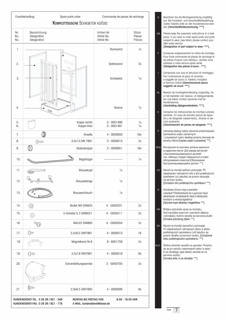
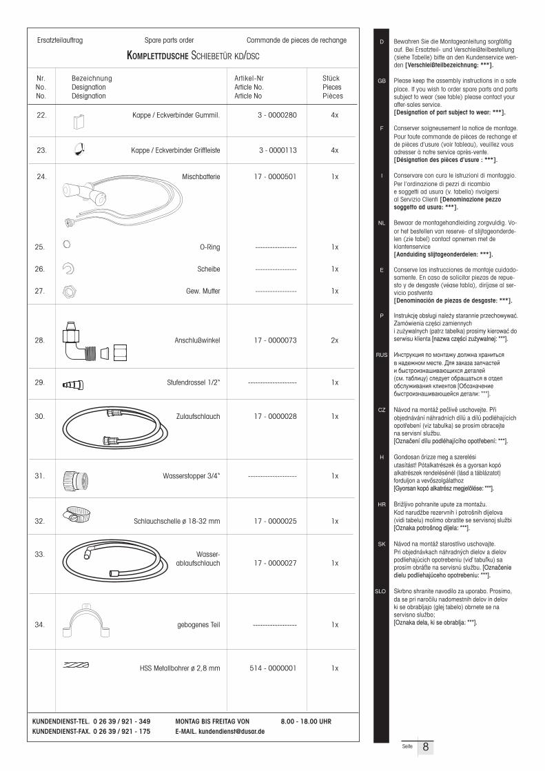
Ersatzteilauftrag Spare parts order Commande de pieces de rechange
KOMPLETTDUSCHE SCHIEBETÜR KD/DSC
Nr. Bezeichnung Artikel-Nr StückNo. Designation Article No. Pieces No. Désignation Article No Pièces
D Bewahren Sie die Montageanleitung sorgfältigauf. Bei Ersatzteil- und Verschleißteilbestellung(siehe Tabelle) bitte an den Kundenservice wen-den [Verschleißteilbezeichnung: ***].
GB Please keep the assembly instructions in a safeplace. If you wish to order spare parts and partssubject to wear (see table) please contact yourafter-sales service. [Designation of part subject to wear: ***].
F Conserver soigneusement la notice de montage.Pour toute commande de pièces de rechange etde pièces d'usure (voir tableau), veuillez vousadresser à notre service après-vente.[Désignation des pièces d'usure : ***].
I Conservare con cura le istruzioni di montaggio.Per l’ordinazione di pezzi di ricambio e soggetti ad usura (v. tabella) rivolgersi al Servizio Clienti [Denominazione pezzo soggetto ad usura: ***].
NL Bewaar de montagehandleiding zorg vuldig. Vo-or het bestellen van reserve- of slijtageonderde-len (zie tabel) contact opnemen met de klantenservice[Aanduiding slijtageonderdelen: ***].
E Conserve las instrucciones de montaje cuidado-samente. En caso de solicitar piezas de repue-sto y de desgaste (véase tabla), diríjase al ser-vicio postventa[Denominación de piezas de desgaste: ***].
P Instrukcj. obs3ugi nale-y starannie przechowywa/.Zamówienia cz.2ci zamiennych i zu-ywalnych (patrz tabelka) prosimy kierowa/ doserwisu klienta [nazwa cz.2ci zu-ywalnej: ***].
RUS !"#$%&'()* +, -,"$./& 5,</". ;%.")$=#* 7 ".54/",- -4#$4. F<* 2.'.2. 2.+>.#$48 ) 9:#$%,)2 ".6)7.B1);#* 54$.<48 (#-. $.9<)(&) #<45&4$ ,9%.1.$=#* 7 ,$54<,9#<&/)7.")* '<)4"$,7 [H9,2".>4")49:#$%,)2 ".6)7.B148#* 54$.<): ***].
CZ Návod na montá! pe%liv& uschovejte. P$i objednávání náhradních díl) a díl) podléhajícíchopot$ebení (viz tabulka) se prosím obracejte na servisní slu!bu.[Ozna%ení dílu podléhajícího opot$ebení: ***].
H Gondosan *rizze meg a szerelési utasítást! Pótalkatrészek és a gyorsan kopó alkatrészek rendelésénél (lásd a táblázatot) forduljon a vev*szolgálathoz[Gyorsan kopó alkatrész megjelölése: ***].
HR Bri!ljivo pohranite upute za monta!u. Kod narud!be rezervnih i potro'nih dijelova (vidi tabelu) molimo obratite se servisnoj slu!bi [Oznaka potro'nog dijela: ***].
SK Návod na montá! starostlivo uschovajte. Pri objednávkach náhradn(ch dielov a dielovpodliehajúcich opotrebeniu (vi4 tabu5ku) saprosím obrá6te na servisnú slu!bu. [Ozna%eniedielu podliehajúceho opotrebeniu: ***].
SLO Skrbno shranite navodilo za uporabo. Prosimo,da se pri naro%ilu nadomestnih delov in delov ki se obrabljajo (glej tabelo) obrnete se na servisno slu!bo; [Oznaka dela, ki se obrablja: ***].
7Seite
1. Rückwand 1x
2. -- Seitenwand 2x
3. Schiebetür 1x
4. Wanne 1x
5. Kappe rechts 3 - 0001480 1x6. Kappe links 3 - 0001481 1x
7. Rosette 4 - 0000850 18x
8. .3,5x13 DIN 7981 3 - 0000015 2x
9. .Abdeckkappe 3 - 0000851 18x
10. Regalbügel ------------------ 1x
11. Brausekopf 1x
12. Brausestange 1x
13. Brauseschlauch 1x
14. Mutter M4 DIN934 4 - 0000201 2x
15. U-Scheibe 5,3 DIN9021 4 - 0000411 2x
16. M4x25 DIN965 4 - 0000054 2x
17. 3,5x9,5 DIN7981 4 - 0000013 16
18. Magnetband Nr.6 9 - 6001758 2x
19. 3,5x19 DIN7981 4 - 0000018 8x
20. Eckverstärkungswinkel 3 - 0000705 2x
21 2,9x9,5 DIN7982 4 - 0000006 8x
KUNDENDIENST-TEL. 0 26 39 / 921 - 349 MONTAG BIS FREITAG VON 8.00 - 18.00 UHRKUNDENDIENST-FAX. 0 26 39 / 921 - 175 E-MAIL. [email protected]
Ersatzteilauftrag Spare parts order Commande de pieces de rechange
KOMPLETTDUSCHE SCHIEBETÜR KD/DSC
Nr. Bezeichnung Artikel-Nr StückNo. Designation Article No. Pieces No. Désignation Article No Pièces
D Bewahren Sie die Montageanleitung sorgfältigauf. Bei Ersatzteil- und Verschleißteilbestellung(siehe Tabelle) bitte an den Kundenservice wen-den [Verschleißteilbezeichnung: ***].
GB Please keep the assembly instructions in a safeplace. If you wish to order spare parts and partssubject to wear (see table) please contact yourafter-sales service. [Designation of part subject to wear: ***].
F Conserver soigneusement la notice de montage.Pour toute commande de pièces de rechange etde pièces d'usure (voir tableau), veuillez vousadresser à notre service après-vente.[Désignation des pièces d'usure : ***].
I Conservare con cura le istruzioni di montaggio.Per l’ordinazione di pezzi di ricambio e soggetti ad usura (v. tabella) rivolgersi al Servizio Clienti [Denominazione pezzo soggetto ad usura: ***].
NL Bewaar de montagehandleiding zorg vuldig. Vo-or het bestellen van reserve- of slijtageonderde-len (zie tabel) contact opnemen met de klantenservice[Aanduiding slijtageonderdelen: ***].
E Conserve las instrucciones de montaje cuidado-samente. En caso de solicitar piezas de repue-sto y de desgaste (véase tabla), diríjase al ser-vicio postventa[Denominación de piezas de desgaste: ***].
P Instrukcj. obs3ugi nale-y starannie przechowywa/.Zamówienia cz.2ci zamiennych i zu-ywalnych (patrz tabelka) prosimy kierowa/ doserwisu klienta [nazwa cz.2ci zu-ywalnej: ***].
RUS !"#$%&'()* +, -,"$./& 5,</". ;%.")$=#* 7 ".54/",- -4#$4. F<* 2.'.2. 2.+>.#$48 ) 9:#$%,)2 ".6)7.B1);#* 54$.<48 (#-. $.9<)(&) #<45&4$ ,9%.1.$=#* 7 ,$54<,9#<&/)7.")* '<)4"$,7 [H9,2".>4")49:#$%,)2 ".6)7.B148#* 54$.<): ***].
CZ Návod na montá! pe%liv& uschovejte. P$i objednávání náhradních díl) a díl) podléhajícíchopot$ebení (viz tabulka) se prosím obracejte na servisní slu!bu.[Ozna%ení dílu podléhajícího opot$ebení: ***].
H Gondosan *rizze meg a szerelési utasítást! Pótalkatrészek és a gyorsan kopó alkatrészek rendelésénél (lásd a táblázatot) forduljon a vev*szolgálathoz[Gyorsan kopó alkatrész megjelölése: ***].
HR Bri!ljivo pohranite upute za monta!u. Kod narud!be rezervnih i potro'nih dijelova (vidi tabelu) molimo obratite se servisnoj slu!bi [Oznaka potro'nog dijela: ***].
SK Návod na montá! starostlivo uschovajte. Pri objednávkach náhradn(ch dielov a dielovpodliehajúcich opotrebeniu (vi4 tabu5ku) saprosím obrá6te na servisnú slu!bu. [Ozna%eniedielu podliehajúceho opotrebeniu: ***].
SLO Skrbno shranite navodilo za uporabo. Prosimo,da se pri naro%ilu nadomestnih delov in delov ki se obrabljajo (glej tabelo) obrnete se na servisno slu!bo; [Oznaka dela, ki se obrablja: ***].
8Seite
22. Kappe / Eckverbinder Gummil. 3 - 0000280 4x
23. Kappe / Eckverbinder Griffleiste 3 - 0000113 4x
24. Mischbatterie 17 - 0000501 1x
20.2
25. O-Ring ----------------- 1x
26. Scheibe ----------------- 1x
27. Gew. Mutter ----------------- 1x
28. Anschlußwinkel 17 - 0000073 2x
29. Stufendrossel 1/2“ -------------------- 1x
30. Zulaufschlauch 17 - 0000028 1x
31. Wasserstopper 3/4“ -------------------- 1x
32. Schlauchschelle ø 18-32 mm 17 - 0000025 1x
33. Wasser-ablaufschlauch 17 - 0000027 1x
34. gebogenes Teil ------------------ 1x
HSS Metallbohrer ø 2,8 mm 514 - 0000001 1x
SW 7
M4
Ø 4
1
10
15
3,5x138
7
9
1.
a
b
a
3.
2.
b
c
SW 30
c
M4X2516
24.1
24.2 O-Ring 2,5 X 34,5
24
14
12
24.2
24.1
27
26
27
26
25
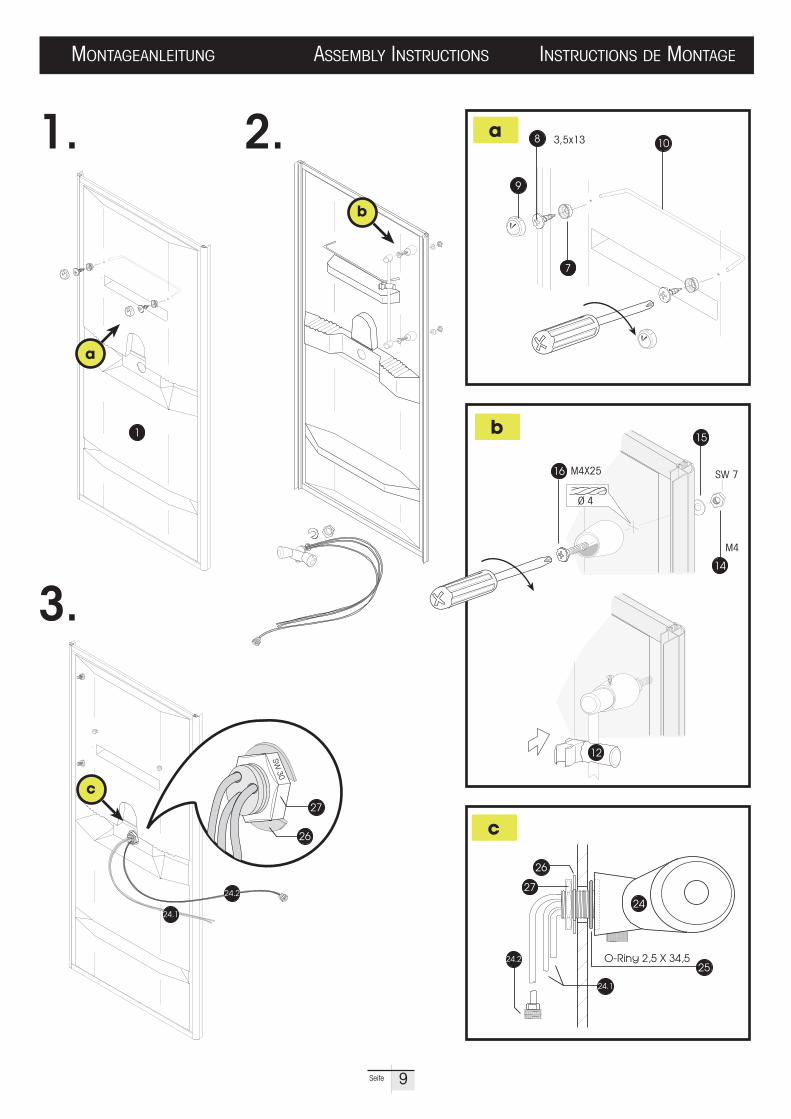
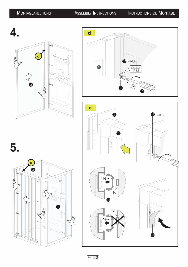
MONTAGEANLEITUNG ASSEMBLY INSTRUCTIONS INSTRUCTIONS DE MONTAGE
9Seite
MONTAGEANLEITUNG ASSEMBLY INSTRUCTIONS INSTRUCTIONS DE MONTAGE
10Seite
4.
5.
19
2
18
2
3
N
N
14
N
N
2
e
d
d
e
17
79
3,5x19
2
3,5x9,5
2
2

SILIKON
SILIKON
SILIKON
SILIKON
SILIKONSIL
IKON
SILIKON
SILIKON
6.
7.
Ø 2,8
Ø 2,8
2,9x9,5
22
21
20
23
7
22
23
3,5x9,5 17
ff
g
SILIKON
24 h
SILIKON
g
MONTAGEANLEITUNG ASSEMBLY INSTRUCTIONS INSTRUCTIONS DE MONTAGE
11Seite
DUSAR
DUSAR
26
32
ma
x.1,
5m
9
8.
h1
a1
h2 h3
a3U> U> e
PEL
NPE
MPE
a2
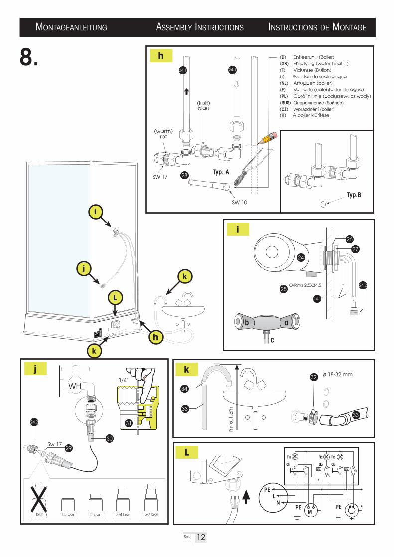
(D) Entleerung (Boiler)(GB) Emptying (water heater)(F) Vidange (Ballon)(i) Svuotare lo scaldacqua(NL) Aftappen (boiler)(E) Vaciado (calentador de agua)(PL) Opró˝nianie (podgrzewacz wody)(RUS) H+,%,/"4")4 (9,8<4%)(CZ) vyprázdn&ní (bojler)(H) A bojler kiürítése
Typ. ASW 17
(kalt)blau
(warm)rot
Typ.BSW 10
230 V
3/4"WH
Sw 17
b a
c
2 bar 3-4 bar 5-7 bar1.5 bar1 bar
h
i
k
L
j
k
j
L
i
29
3124.2
30
28
k
h
24.1
24.2
24
26
27
25
24.1 24.1
3333
34
O-Ring 2,5X34,5
MONTAGEANLEITUNG ASSEMBLY INSTRUCTIONS INSTRUCTIONS DE MONTAGE
12Seite

sich der Boiler füllen kann (Bei Modell KD/RD, Hebel auf “Heiß“ drehen und öffnen). Wasserhahn Nr.WH öffnen. Sobald Wasser aus der Handbrause läuft, istder Boiler gefüllt. Knebel ohne Markierung nach rechts drehen bis das Ventil geschlossen ist (bzw. Hebel schließen bei Modell KD/RD). Das Füllen des Boilers ist ein einmaliger Vorgang, da das Wasser bei Entnahme aus dem Boilerständig nachfließt.
6. BEDIENUNG DER SCHALTERBLENDE:Grüner Wippschalter [B.] wird auf Betrieb gestellt. Die einzelnen Funktionensind jetzt betriebs bereit. Drehschalter [T.] dient zu stufenlosen Einstellung derWassertemperatur. Heizt der Boiler bis zur gewünschten Temperatur auf, leuchtetdie grüne Kontrollampe [H.] Ist die gewählte Temperatur erreicht, schaltet derThermostat ab und die grüne Kontrolleuchte erlischt. Beim Absinken der Temp-eratur tritt die Heizung wieder selbsttätig in Funktion. Das bei dem Aufheizen ausdem Brausekopf austretende Wasser ist ein physikalisch bedingter Vorgang (Aus-dehnung des Wassers beim Aufheizen), der auch durch übermäßiges Schließendes Temperaturhahnes nicht verhindert werden kann. Achten Sie bitte darauf,dass der Brausekopf nicht zugehalten oder unter Wasser getaucht wird. DasWasser muß stets freien Fluß haben. Bei Duschen mit Niederdruck-Boiler darf nurdie mitgelieferte Brausegarnitur angeschlossen werden. Nichtbeachtung kann zuSchäden am Boiler führen. Der Wippschalter [P] dient zum Einschalten derPumpe, die das Schmutzwasser absaugt. Jede Duschkabine, die einen Boilerbesitzt, ist mit einem Sicherheitsthermostat ausgerüstet, der im Falle eines Defektes am Regelthermostat bei einer Aufheiztemperatur von 100° C = 4 ° ab-schaltet. Der Sicherheitsthermostat schaltet sich im Gegensatz zum Regel-thermostat nicht wieder selbstständig ein. Die Aufheizung des Boilers ist somitblockiert.
Achtung: Beim Auslösen des Sicherheitsthermostates kann dieses durch einfaches Hineindrücken des Stiftes [E.] entriegelt werden. Der Entriegelungsstift [E.] befindet sich oberhalb des Temperaturreglers.
7. NACH DUSCHBETRIEB SIND FOLGENDE DINGE ZU BEACHTEN:Wasserhahn der Duschkabine und der hauseigenen Wasserversorgungschließen. Ist das Duschbecken entleert, wird die Pumpe am Wippschalter [P.]ausgeschaltet. Anschließend Wippschalter [B.] auf “Aus“ stellen. Die Schalter-blende ist jetzt außer Funktion.
Besondere Hinweise! Vor Entleerung des Boilers sowie allen sonsti-gen Arbeiten am Unterteil der Duschkabine, muß diese von einem konzessionierten Elektriker vom Stromnetz getrennt weden.
8. ENTLEERUNG DES BOILERS: (Seite.12, pkt. h bzw. Typ.B )Schrauben Sie die beiden Eckwinkel Nr.28 von den aus dem Unterteil kommen-den Aschlußleitungen Nr.24.1 ab.
Achtung! Gegenkontern, um ein Verdrehen der Anschlußleitungen zu verhindern. Nun schließen Sie eine Saugpumpe an dem blau gekenn-zeichneten Anschluß an, und saugen das Wasser ab.
Leichtes Reinigen ist durch die ausschwenkbaren Türelemente problemlos
D INSTALLATION MIT WARMWASSERBOILER
ANSCHLUß AN DIE HAUSEIGENE WASSERVERSORGUNG: (Seite.12, pkt. j)Benötigt werden: absperrbarer 3/4“-Anschluß (mit Rückflußverhinderer DGVWgeprüft ) für Kaltwasser. Vorschriften des örtlichen Wasserwerkes beachten.
ANSCHLUß AN DIE HAUSEIGENE WASSERENTSORGUNG: (Seite.12, pkt.k)erfolgt mittels der eingebauten Absaugpumpe und dem anzuschließenden Ablauf-schlauch. Der Ablaufschlauch kann in ein Abflußbecken gehängt oder an einenbereits vorhandenen Abfluß angeschlossen werden. Der Ablaufschlauch darfnicht höher als 1,5 m aufgehängt bzw. angeschlossen werden.
1. INSTALLATION ARMATUR: (Seite.12, pkt. h)Anschlußwinkel Nr.28 am Unterteil anschließen. Leitungen gegen Verdrehen mit 17er Maulschlüssel kontern.Achtung! Auf Kennzeichnung “Kalt“ und “Warm“ achten!
2. WASSERZULAUF: (Seite.12, pkt. o)Beiliegende Stufendrossel Nr.29 schützt vor unzulässiger Druckbelastung. DieDrossel ist lt. Tabelle dem Wasserdruck am Verwendungsort anzupassen und bisan den Bund in das Kaltwasser-Zulaufrohr Nr.24.2 einzuschieben. WASSERSTOPPER (Wasserstopper Nr.31): stoppt den Wasserdurchfluß beiplatzenden oder abrutschenden Schläuchen. Wasserstopper handfest an Was-serhahn schrauben. Zulaufschlauch Nr.30 an den Wasserstopper schrauben.Wasserhahn ganz langsam vollständig öffnen. Zur Entlüftung der Schlauchlei-tung Gerät in Betrieb nehmen. Geschlossene Sicherung des Wasserstoppersnach Absperren des Wasserhahns 1/2 Drehung lösen (belüften) und anschließend anziehen. WARTUNG: Bitte überprüfen Sie den Wasserstopper Nr.31 zur eigenen Sicherheiteinmal jährlich. Schrauben Sie dazu den Wasserstopper von dem Wasserhahnund drücken Sie mit dem Finger von oben auf das Innenteil bis zum Anschlag.Sollte das Innenteil durch verkalken fest sitzen, so legen Sie bitte das kpl. Gerät inhandelsüblichen Kalklösser. Vor Montage gut spülen und Funktionsprüfung wiebeschrieben durch führen. Schieben Sie nun die Kabine an Ihren endgültigenPlatz. Brauseschlauch am Anschluß [C] der Armatur anschließen (Seite.12,pkt. i). Achtung! Der Wasserzulauf darf nur über einen DVGW geprüften
Rückflußverhinderer erfolgen, der durch einen kozessionierten In-stallateur installiert wird. Für den Wasserzulauf ist der mitgelieferte
3/4 Wasserzulaufschlauch Nr.30 und der Wasserstopper Nr.31 zu verwenden,andernfalls erlischt die Garantie! Vorschriften des örtlichen Wasserwerkes be-achten! Während der Aufheizung des Warmwasser tropft Ausdehnungswasseraus dem Brausekopf. Dies ist eine physikalisch bedingter Vorgang und läßt sichdaher auch nicht durch stärkeres Zudrehen der Mengenregulierung abstellen. Beieinem Wasserdruck kleiner als 1bar (auch kurzzeitig), ist die Funktionssicher-heit des Systems nicht gewährleistet und somit auch kein Reklamationsgrund.
3. WASSERABLAUF: (Seite.12, pkt.k)Die Schlauchklemme Nr.32 auf den Wasserablaufschlauch Nr.33 stecken, undmit Stutzen der Absaugpumpe verbinden. Schlauchklemme Nr.32 festziehen.Gebogenes Teil Nr.34 dient zum Einhängen in ein Abflußbecken. Verlängerungdes Schlauches bis 10 m bei waagerechter Verlegung möglich. Der Wasser-ablaufschlauch Nr.33 darf nicht höher als 1,5 m aufgehängt werden, da sonstdie Pumpe nicht das ganze Schmutzwasser absaugen kann. Knicken desSchlauches beim Verlegen vermeiden!
4. ELEKTROANSCHLUß: (Seite.12, pkt. L)Elektro-Anschluß des Unterteils: Der Elektro-Anschluß der Duschkabine ist un-bedingt von einem konzessionierten Elektro-Installateur vorzunehmen. Die In-stallation ist nach VDE 0100 als fester Anschluß durchzuführen. (Fehler-stromschalter 30mA. zwingend vorgeschrieben). Die Duschkabine muß mit einer beweglichen Leitung, die mindestens als mittlere Gummischlauchleitungausgeführt ist, über eine ortsfeste Geräteanschlußdose angeschlossen werden. Potentialausgleich: Die Potentialausgleichsleitung aller Duschkabinenmuß vorschriftsmäßig (nach VDE 0100) in den Potentialausgleich einbezogen werden (siehe Abb). Beachten Sie auch die technischen Daten und den Schalt-plan, sowie den Schutzbereich im Inneren (siehe Seite 2, Schutzbereich).
5. INBETRIEBNAHME: (Seite.12, pkt.i)Füllen des Boilers mit Wasser: Die erste Inbetriebnahme sollte zweckmäßiger-weise von der gleichen Person vorgenommen werden. Der Boiler muß vor Inbe-triebnahme mit Wasser gefüllt werden. Hierzu Knebel [a] zur Temperatur-regelung der Mischbatterie auf Heißwasser drehen. Knebel [b] aufdrehen, damit
Entsperrknopf
Temperatur Heizung PumpeBetrieb
E.
T.B. H. P.
13Seite

6. OPERATING THE SWITCHBOARD:The green rocker switch [B.] is set to "Operation". The individual functions arenow ready for operation. Rotary switch [T.] is for the stepless adjustment of watertemperature. The green indicator lamp [H.] lights up when the water has beenheated to the desired temperature. Once the selected temperature has been reached, the thermostat will switch off and the green indicator lamp goes out. Asthe temperature falls the heating is restarted automatically. Water coming out ofthe showerhead during heating up is the result of a physical process (water expansion during heating), which cannot be prevented, not even by excessivetightening of the temperature tap. Please take care that the showerhead is notheld closed or submerged under water. The water should always be given freeflow. For showers with low-pressure water heater only the shower gear includedin the supply must be connected. Failure to do this may cause damage to thewater heater. The rocker switch [P.] is for switching on the pump to pump off thewastewater. Every shower cubicle with a water heater is fitted with a safety ther-mostat, which switches off at a heating-up temperature of approx. 100° C = 4°,if there is a defect at the control thermostat. Contrary to the control thermostat, thesafety thermostat is not switched on automatically. This blocks heating-up of thewater heater !
Attention! Should the safety thermostat be triggered, this thermostat can be unlocked by simply pushing in the pin. [E.] Unlocking pin [E.] is located above the temperatureregulator.
7. THE FOLLOWING STEPS MUST BE TAKEN AFTER OPERATING THE SHOWER:To switch off, close the shower cubicle and domestic water supply system water taps. The pump is switched off at rocker switch [P.], when the showertray is empty. Then set rocker switch [B.] to "OFF". Now the switchboard is out ofoperation.
Special instructions! Please note! Before emptying the water heater and before doing any other work to the bottom part of the shower cubicle, an approved electrician must disconnect the cubicle fromthe power system.
8. EMPTYING THE WATER HEATER: (see Fig.12, point. h)Unscrew the two corner angles (28) from the connection pipes (24.1) coming from the bottom part.
Attention! Countercheck to avoid a distortion of connection pipes.Now connect a suction pump to the connection marked in blue, and pump out the water.
The door elements can be swung out for easy cleaning access.
ASSEMBLY WITH WATER HEATER
CONNECTION TO THE DOMESTIC WATER SUPPLY SYSTEM: (see Fig.12, point. j)You require: æ " connection with shut-off device (with non-return valve) for coldwater. Follow instructions given by the local Water Company.
CONNECTION TO THE DOMESTIC DRAINAGE SYSTEM: (see Fig.12, point. k)Provided by the built-in suction pump and the discharge hose to be connected.The discharge hose may be hung in a sink or connected to an existing drain.The discharge hose must not be suspended or connected at a level higher than1.5 m.
1. ASSEMBLING THE FITTING: (see Fig.12, point.h)Fasten connecting angle (28) to bottom part. Secure connection piping againstdistortion with open-end wrench size 17 mm.
Attention!Pay attention to the "Cold” and "Hot” markings !
2. WATER SUPPLY: (see Fig.12, point.o)The step regulator (29) supplied serves as protection against excessive pressure load. Adjust step regulator to water pressure at place of installation, asper the pressure table, and push into cold water feed pipe (24.2) down to thecollar. WATER STOPPER (hose safety connection Nr.31): stops the water flow ifhoses split or slip. Screw the water stopper onto the tap tightly, by hand. Screwthe feed hose (30) onto the water stopper. Turn the tap on very slowly, until it iscompletely open. Switch the machine on to bleed the hose. After turning off thetap, open the closed water stopper safety connection by ! a turn (bleeding) andthen tighten again.MAINTENANCE: Please check the water stopper (31) once a year for your ownsafety. To do this, unscrew the water stopper from the tap and apply pressure onthe inner piece with one finger and push as far as the stop. Should the inner piece be stuck due to lime scale, then lay the complete piece of equipment incommercial lime scale remover. Rinse well before assembly and carry out function test on the shower hose as described above.Now move cubicle into desired installation place. Connect shower hose to connection [C] of fitting. (see Fig.12, point.i)
Attention! The water supply must be fitted with a non-return valve, which has been installed by a recognised plumber. The æ” water supply hose (30) and the water stopper (31) must be used, otherwise
the guarantee is not valid! Follow instructions given by the local Water Com-pany! Expansion water will drip from the outlet whilst the water heater is heatingup. As this is due to a physical process, even turning the feed control even tightercannot stop the dripping. The functional safety of the system is not guaranteedat a water pressure of less than 1 bar (even for short periods) this is thereforenot acceptable as a complaint.
3. WATER DISCHARGE: (see Fig.12, point. k)Put hose clip (32) on water discharge hose (33) and connect with the supportof suction pump. Tighten hose clip (32).The bent part (34) of the water discharge hose is for hanging in a sink. Where assembly is carried out horizontally, the hose can be extended up to 10 m. The water discharge hose(33) must be hung up at a level not higher than 1.5 m, otherwise the pump cannot pump out all the wastewater. Avoid bending the hose during assembly!
4. ELECTRICAL CONNECTION: (see Fig.12, point. L)Connecting the bottom part: An approved electrician must under all circumstances carry out electrical connection of the shower cubicle. Installationis to be carried out to VDE 0100 as a fixed connection. (30 mA fault currentcircuit breaker is imperative). The shower cubicle is to be connected by meansof a movable cable, which is to be in at least medium rubber jacket cord, via astationary appliance coupler socket. Potential equalization: The potential equalization line for all shower cubicles must be included in the potential equalization as prescribed (to VDE 0100) (see Fig.Q). Please also follow thetechnical data and the circuit diagram, as well as the protective area in the interior (see side 2, Safety area).
5. INITIAL OPERATION: (see Fig.12, point. i)Filling the water heater with water: It is useful for the same person to carry outthe initial operation. The water heater should be filled with water prior to initialoperation. To do this, turn the mixing tap temperature control toggle switch [a]for temperature control to hot water. Open toggle switch [b] to fill the water heter.no. WH. The water heater is full, as soon as water runs out of the showerhead.Turn rotary switch without marking to the right until the valve is shut (or for theKD/RD model, close lever). The water heater needs only to be filled once as water taken from the boiler will continually be replaced.
GB
E.
T.B. H. P.
14Seite

lorsque l'eau s'écoule de la douchette. Manœuvrer ensuite le robinet sans repère versla droite jusqu'à ce que la vanne soit fermée (levier en position fermeture pour modèleKD/RD). Le remplissage du ballon est une démarche unique, car le ballon se remplitautomatiquement après chaque consommation d'eau.
6. MANIPULATION DU TABLEAU DE COMMANDE:Positionner le commutateur vert [B.] sur la position "en service". Chaque fonction estprête à être mise individuellement en service. Avec le commutateur rotatif [T.], vouspouvez régler continuellement la température de l'eau. Le voyant de contrôle vert [H.]est allumé tant que le ballon chauffe pour atteindre la température souhaitée. Le thermostat coupe le circuit et le voyant vert s'éteint dès que cette température est obtenue. Le chauffage se remet automatiquement en service lorsque la température del'eau baisse. L'eau qui s'écoule de la douchette, pendant le processus de chauffe, estun phénomène physique (dilatation de l'eau pendant un échauffement). Vous ne pourrez pas empêcher ce phénomène, même en fermant le robinet de température. L'écoulement d'eau de la douchette ne doit jamais être bloqué en posant par exemplela main dessus ou en la plongeant dans l'eau. L'eau doit toujours pouvoir s'écouler librement. Pour les cabines de douche équipées d'un ballon à basse pression, installeruniquement la douchette fournie. Le ballon pourrait être endommagé, si cette conditionn'est pas respectée. L'interrupteur [P.] sert pour la mise en service de la pompe quiaspire l'eau usée. Chaque cabine de douche, munie d'un ballon, est équipée d'un thermostat de sécurité, qui coupe le circuit en cas de défaut du thermostat de réglage,lors d'un échauffement d'environ 100°C +- 4. Contrairement au thermostat de réglage,le thermostat de sécurité ne se remet pas automatiquement en service. Pour cette raison, l'échauffement du ballon sera bloqué.
Attention! Si le thermostat de sécurité a disjoncté, vous pouvez le remettre en service en appuyant sur le bouton de déblocage [E]. Le bouton de déblocage [E] se trouve au dessus du régleur de température.
7. RESPECTER LES INDICATIONS SUIVANTES APRÈS L'UTILISATION DE LA DOUCHE:Fermer les robinets de la cabine de douche ainsi que le robinet d'alimentation eneau. Dès que le receveur de la douche est vide, mettre la pompe hors circuit en appuyant sur l'interrupteur [P.]. Finalement, positionner l'interrupteur [B.] sur la position "ARRET”. Maintenant, le tableau de commande est hors fonction.
Indications particulières ! Au cas où le ballon d'eau doit être vidé ou si d'autres travaux doivent être effectués sur la partie inférieure de la douche, la cabine de douche doit être déconnectée du réseau par un électricien agréé !
8. VIDANGE DU BALLON D'EAU: (voir fig.12, no. h, MODÈLE B)Pour vider le ballon d'eau, dévisser les raccords coudés (28) qui se trouvent sur lesconduites de raccordement provenant de la partie inférieure de la douche (24.1).
Attention! Maintenir les conduites avec une clé plate pour éviter qu'elles s'entortillent. Maintenant, raccorder une pompe aspirante sur la conduite repérée en bleu et aspirer l'eau.
Pour le nettoyage de la cabine de douche, veuillez utiliser des produits d'entretien recommandés dans le commerce (pas de récurants ou dissolvants).
INSTALLATION AVEC BALLON D’EAU CHAUDE
RACCORD À L'ALIMENTATION EN EAU DE VOTRE DOMICILE: (voir fig.12, no. j)Vous avez besoin d'un robinet de coupure avec raccord 3/4" (avec un clapet de DG-VW non-retour) pour l'eau froide. Veuillez respecter les consignes de la station de distribution d'eau locale.
RACCORD À L'ÉVACUATION D'EAU DU DOMICILE: (voir fig.12, no. k)L'évacuation d'eau est effectuée par la pompe aspirante déjà installée et avec le tuyaud'écoulement qui est à raccorder. Le tuyau d'écoulement peut être accroché sur le lavabo ou être raccordé directement à la canalisation d'évacuation. Le tuyau d'écoulement ne doit pas être accroché ou raccordé sur une hauteur supérieure à 1,5 m.
1. MONTAGE DE LA ROBINETTERIE: (voir fig.12, no. h)Ensuite, fixer la partie inférieure au raccord coudé (28). Pendant la fixation, maintenirles raccords avec une clé plate de 17 pour éviter que les conduites s'entortillent.
Attention! Tenir compte du repérage "Froid" et "Chaud"!
2. ALIMENTATION EN EAU: (voir fig.12, no. o)Le réducteur ci-joint (29) protège contre les charges de pression inadmissibles. Adapter le réducteur selon le tableau de pression d'eau ci-contre et l'introduire jusqu'àl'épaulement dans le tuyau d'alimentation en eau froide (24.2). Stoppeur de débit (sécurité du tuyau 31): Stoppe le débit d'eau en cas d'éclatement ou de défaut deraccordement du tuyau. Visser le stoppeur manuellement sur le robinet. Visser letuyau d'alimentation (30) sur le stoppeur. Ouvrir le robinet lentement et complètement. Mettre l'appareil en service pour évacuer l'air dans la tuyauterie. La sécurité du stoppeur d'eau rentre en fonction dès que le robinet d'alimentation est fermé, dévisser le stoppeur d'un ! tour (aérer) et le revisser. Entretien: Pour votre propre sécurité, vérifier le stoppeur (31) une fois par an. Pour cefaire, dévisser le stoppeur du robinet d'alimentation et avec le doigt, pousser la partie intérieure jusqu'à butée. Si le calcaire bloque cette pièce, déposer le stoppeurcomplet dans un produit détartrant. Rincer et vérifier le bon fonctionnement de la pièceavant de la remonter, voir ci-dessus. Placer la cabine dans sa position définitive. Raccorder ensuite le tuyau de la douchette sur le raccord [C] de la robinetterie (voir fig.12, no. i).
Attention! L'alimentation en eau doit seulement se produire à travers un raccord équipé d'un clapet de non-retour. Utiliser le tuyau d'alimentation æ (30) et le stoppeur d'eau (31) pour l'alimentation en eau. Dans un
cas contraire, aucune garantie ne sera assurée. Respecter les consignes de la station de distribution locale. L'eau qui s'écoule de la douchette pendant le processusde chauffe est un phénomène physique (dilatation de l'eau pendant un échauffement).Vous ne pourrez pas empêcher ce phénomène même en serrant le robinet de régulati-on. Lors d'une pression d'eau inférieure à 1 bar (même de courte durée), la sécuritéde fonctionnement du système n'est pas assurée et ne donne donc pas raison àune réclamation.
3. EVACUATION DE L'EAU: (voir fig.12, no. k)Placer le collier de serrage (32) sur le tuyau d'évacuation d'eau (33) et engager celui-ci sur le manchon de la pompe aspirante. Serrer le collier (32) fermement. Lapartie recourbée du tuyau (34) est à accrocher sur le lavabo. Il est possible de prolonger le tuyau jusqu'à une longueur de 10 m quand il est posé horizontalement.La hauteur entre la pompe et le crochet du tuyau d'évacuation (33) (lavabo) ne doitpas être supérieure à 1,5 m, dans le cas contraire, la pompe ne pourra pas aspirercomplètement l'eau usée. Eviter de plier le tuyau pendant la pose !
4. CONNEXION ÉLECTRIQUE: (voir fig.12, no. L)Connexion électrique de la partie inférieure. La connexion électrique de la cabine dedouche doit être impérativement effectuée par un électricien agréé. L'installationdoit être réalisée selon la norme VDE 0100 comme connexion fixe (pas de prise decourant). (Un disjoncteur à courant de défaut de 30 mA est obligatoire). La cabinede douche doit être raccordée à l'aide d'un câble souple sous caoutchouc de catégoriede protection moyenne et raccordée à une boite de jonction fixe (pas de fiche femelle,pas de prise de courant). La compensation de potentiel: Le conducteur d'équipotentialité de toutes les cabines de douche doit être raccordé conformémentà la norme (VDE 0100) dans la compensation de potentiel (voir schéma).Respecter également les données techniques et le schéma électrique, ainsi que la zone de sécurité (voir fig. 2, Zone de sécurité).
5. MISE EN SERVICE: (voir fig.12, no. i)Remplissage du ballon en eau: La première mise en service doit être entreprise parl'électricien qui a effectué la connexion électrique. Le ballon doit être rempli d'eauavant la mise en service. Pour ce faire, tourner le robinet [a] de réglage de température du mitigeur sur "eau chaude". Ensuite, manœuvrer le robinet [b], afin deremplir le ballon. (Pour modèle KD/RD tourner et ouvrir le levier sur la position"chaud"). Ouvrir le robinet d'alimentation Nr.WH d'eau. Le ballon est plein
F
15Seite
E.
T.B. H. P.
[ b ] in modo che lo scaldacqua possa riempirsi. (Per il modello KD/RD spostare laleva su “Caldo” ed aprire). Aprire il rubinetto WH. Lo scaldacqua è pieno non appenal’acqua inizierà a scorrere dal soffione della doccia. Girare la manetta senza marcaturaverso destra finché la valvola sarà completamente chiusa. (Per il modello KD/RD chiudere con la leva). Il riempimento dello scaldacqua va effettuato solo in occasionedella prima messa in funzione; successivamente l’acqua prelevata dallo scaldacquaverrà sostituita automaticamente.
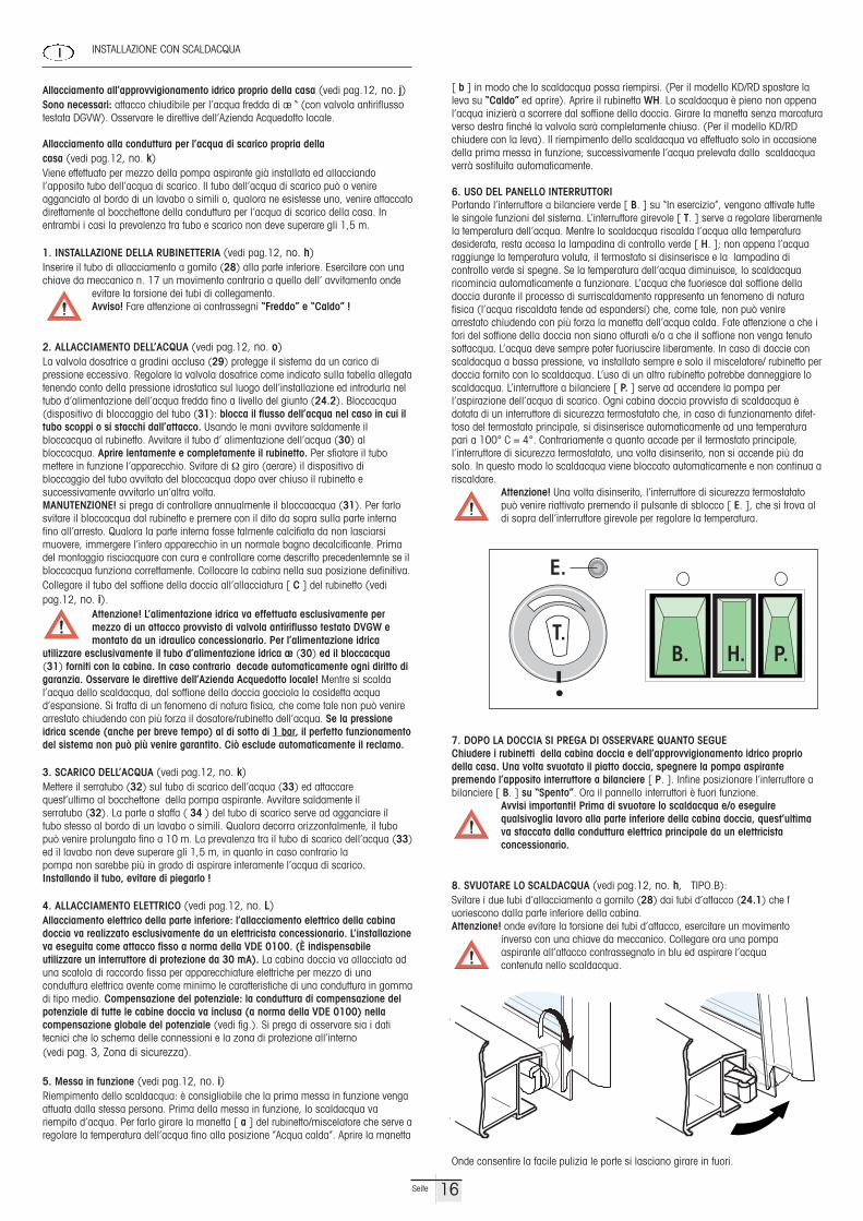
6. USO DEL PANELLO INTERRUTTORI Portando l’interruttore a bilanciere verde [ B. ] su “In esercizio”, vengono attivate tuttele singole funzioni del sistema. L’interruttore girevole [ T. ] serve a regolare liberamentela temperatura dell’acqua. Mentre lo scaldacqua riscalda l’acqua alla temperatura desiderata, resta accesa la lampadina di controllo verde [ H. ]; non appena l’acquaraggiunge la temperatura voluta, il termostato si disinserisce e la lampadina di controllo verde si spegne. Se la temperatura dell’acqua diminuisce, lo scaldacqua ricomincia automaticamente a funzionare. L’acqua che fuoriesce dal soffione delladoccia durante il processo di surriscaldamento rappresenta un fenomeno di natura fisica (l’acqua riscaldata tende ad espandersi) che, come tale, non può venire arrestato chiudendo con più forza la manetta dell’acqua calda. Fate attenzione a che ifori del soffione della doccia non siano otturati e/o a che il soffione non venga tenutosottacqua. L’acqua deve sempre poter fuoriuscire liberamente. In caso di doccie conscaldacqua a bassa pressione, va installato sempre e solo il miscelatore/ rubinetto perdoccia fornito con lo scaldacqua. L’uso di un altro rubinetto potrebbe danneggiare loscaldacqua. L’interruttore a bilanciere [ P. ] serve ad accendere la pompa per l’aspirazione dell’acqua di scarico. Ogni cabina doccia provvista di scaldacqua è dotata di un interruttore di sicurezza termostatato che, in caso di funzionamento difet-toso del termostato principale, si disinserisce automaticamente ad una temperaturapari a 100° C = 4°. Contrariamente a quanto accade per il termostato principale, l’interruttore di sicurezza termostatato, una volta disinserito, non si accende più da solo. In questo modo lo scaldacqua viene bloccato automaticamente e non continua a riscaldare.
Attenzione! Una volta disinserito, l’interruttore di sicurezza termostatato può venire riattivato premendo il pulsante di sblocco [ E. ], che si trova al di sopra dell’interruttore girevole per regolare la temperatura.
7. DOPO LA DOCCIA SI PREGA DI OSSERVARE QUANTO SEGUEChiudere i rubinetti della cabina doccia e dell’approvvigionamento idrico proprio della casa. Una volta svuotato il piatto doccia, spegnere la pompa aspirante premendo l’apposito interruttore a bilanciere [ P. ]. Infine posizionare l’interruttore abilanciere [ B. ] su “Spento”. Ora il pannello interruttori è fuori funzione.
Avvisi importanti! Prima di svuotare lo scaldacqua e/o eseguire qualsivoglia lavoro alla parte inferiore della cabina doccia, quest’ultima va staccata dalla conduttura elettrica principale da un elettricista concessionario.
8. SVUOTARE LO SCALDACQUA (vedi pag.12, no. h, TIPO.B):Svitare i due tubi d’allacciamento a gomito (28) dai tubi d’attacco (24.1) che fuoriescono dalla parte inferiore della cabina.Attenzione! onde evitare la torsione dei tubi d’attacco, esercitare un movimento
inverso con una chiave da meccanico. Collegare ora una pompa aspirante all’attacco contrassegnato in blu ed aspirare l’acqua contenuta nello scaldacqua.
Onde consentire la facile pulizia le porte si lasciano girare in fuori.
INSTALLAZIONE CON SCALDACQUA
Allacciamento all’approvvigionamento idrico proprio della casa (vedi pag.12, no. j)Sono necessari: attacco chiudibile per l’acqua fredda di æ “ (con valvola antiriflussotestata DGVW). Osservare le direttive dell’Azienda Acquedotto locale.
Allacciamento alla conduttura per l’acqua di scarico propria della casa (vedi pag.12, no. k)Viene effettuato per mezzo della pompa aspirante già installata ed allacciando l’apposito tubo dell’acqua di scarico. Il tubo dell’acqua di scarico può o venire agganciato al bordo di un lavabo o simili o, qualora ne esistesse uno, venire attaccatodirettamente al bocchettone della conduttura per l’acqua di scarico della casa. In entrambi i casi la prevalenza tra tubo e scarico non deve superare gli 1,5 m.
1. INSTALLAZIONE DELLA RUBINETTERIA (vedi pag.12, no. h)Inserire il tubo di allacciamento a gomito (28) alla parte inferiore. Esercitare con unachiave da meccanico n. 17 un movimento contrario a quello dell’ avvitamento onde
evitare la torsione dei tubi di collegamento. Avviso! Fare attenzione ai contrassegni “Freddo” e “Caldo” !
2. ALLACCIAMENTO DELL’ACQUA (vedi pag.12, no. o)La valvola dosatrice a gradini acclusa (29) protegge il sistema da un carico di pressione eccessivo. Regolare la valvola dosatrice come indicato sulla tabella allegatatenendo conto della pressione idrostatica sul luogo dell’installazione ed introdurla neltubo d’alimentazione dell’acqua fredda fino a livello del giunto (24.2). Bloccacqua(dispositivo di bloccaggio del tubo (31): blocca il flusso dell’acqua nel caso in cui iltubo scoppi o si stacchi dall’attacco. Usando le mani avvitare saldamente il bloccacqua al rubinetto. Avvitare il tubo d’ alimentazione dell’acqua (30) al bloccacqua. Aprire lentamente e completamente il rubinetto. Per sfiatare il tubo mettere in funzione l’apparecchio. Svitare di ! giro (aerare) il dispositivo di bloccaggio del tubo avvitato del bloccacqua dopo aver chiuso il rubinetto e successivamente avvitarlo un’altra volta. MANUTENZIONE! si prega di controllare annualmente il bloccaacqua (31). Per farlosvitare il bloccacqua dal rubinetto e premere con il dito da sopra sulla parte interna fino all’arresto. Qualora la parte interna fosse talmente calcifiata da non lasciarsi muovere, immergere l’intero apparecchio in un normale bagno decalcificante. Primadel montaggio risciacquare con cura e controllare come descritto precedentemnte se ilbloccacqua funziona correttamente. Collocare la cabina nella sua posizione definitiva.Collegare il tubo del soffione della doccia all’allacciatura [ C ] del rubinetto (vedipag.12, no. i).
Attenzione! L’alimentazione idrica va effettuata esclusivamente per mezzo di un attacco provvisto di valvola antiriflusso testato DVGW e montato da un idraulico concessionario. Per l’alimentazione idrica
utilizzare esclusivamente il tubo d’alimentazione idrica æ (30) ed il bloccacqua(31) forniti con la cabina. In caso contrario decade automaticamente ogni diritto digaranzia. Osservare le direttive dell’Azienda Acquedotto locale! Mentre si scalda l’acqua dello scaldacqua, dal soffione della doccia gocciola la cosidetta acqua d’espansione. Si tratta di un fenomeno di natura fisica, che come tale non può venirearrestato chiudendo con più forza il dosatore/rubinetto dell’acqua. Se la pressione idrica scende (anche per breve tempo) al di sotto di 1 bar, il perfetto funzionamentodel sistema non può più venire garantito. Ciò esclude automaticamente il reclamo.
3. SCARICO DELL’ACQUA (vedi pag.12, no. k)Mettere il serratubo (32) sul tubo di scarico dell’acqua (33) ed attaccare quest’ultimo al bocchettone della pompa aspirante. Avvitare saldamente il serratubo (32). La parte a staffa ( 34 ) del tubo di scarico serve ad agganciare il tubo stesso al bordo di un lavabo o simili. Qualora decorra orizzontalmente, il tubopuò venire prolungato fino a 10 m. La prevalenza tra il tubo di scarico dell’acqua (33)ed il lavabo non deve superare gli 1,5 m, in quanto in caso contrario la pompa non sarebbe più in grado di aspirare interamente l’acqua di scarico. Installando il tubo, evitare di piegarlo !
4. ALLACCIAMENTO ELETTRICO (vedi pag.12, no. L)Allacciamento elettrico della parte inferiore: l’allacciamento elettrico della cabinadoccia va realizzato esclusivamente da un elettricista concessionario. L’installazioneva eseguita come attacco fisso a norma della VDE 0100. (È indispensabile utilizzare un interruttore di protezione da 30 mA). La cabina doccia va allacciata aduna scatola di raccordo fissa per apparecchiature elettriche per mezzo di una conduttura elettrica avente come minimo le caratteristiche di una conduttura in gommadi tipo medio. Compensazione del potenziale: la conduttura di compensazione delpotenziale di tutte le cabine doccia va inclusa (a norma della VDE 0100) nella compensazione globale del potenziale (vedi fig.). Si prega di osservare sia i dati tecnici che lo schema delle connessioni e la zona di protezione all’interno (vedi pag. 3, Zona di sicurezza).
5. Messa in funzione (vedi pag.12, no. i)Riempimento dello scaldacqua: è consigliabile che la prima messa in funzione vengaattuata dalla stessa persona. Prima della messa in funzione, lo scaldacqua va riempito d’acqua. Per farlo girare la manetta [ a ] del rubinetto/miscelatore che serve aregolare la temperatura dell’acqua fino alla posizione ”Acqua calda”. Aprire la manetta
I
16Seite
E.
T.B. H. P.
open zodat de boiler zich kan vullen met water. (Bij model KD/RD de hendel op"heet" draaien en openzetten). Draai kraan WH open. Zodra er water uit de hand-douche loopt, is de boiler gevuld. Draai de knop zonder markering naar rechts totde kraan gesloten is (resp. de hendel dichtdrukken bij model KD/RD). Het vullenvan de boiler hoeft slechts één keer te gebeuren omdat de boiler bij het gebruikvan water uit de boiler vanzelf wordt bijgevuld.
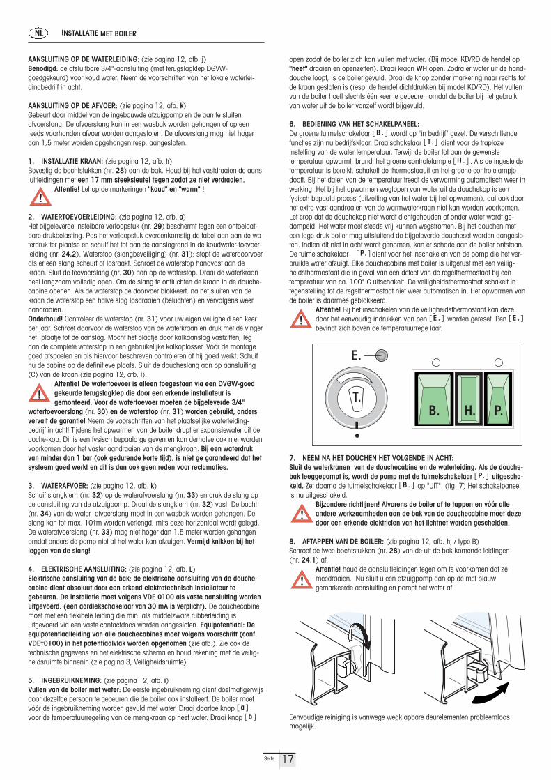
6. BEDIENING VAN HET SCHAKELPANEEL:De groene tuimelschakelaar [ B . ] wordt op "in bedrijf" gezet. De verschillendefuncties zijn nu bedrijfsklaar. Draaischakelaar [ T. ] dient voor de traploze instelling van de water temperatuur. Terwijl de boiler tot aan de gewenste temperatuur opwarmt, brandt het groene controlelampje [ H . ] . Als de ingesteldetemperatuur is bereikt, schakelt de thermostaauit en het groene controlelampjedooft. Bij het dalen van de temperatuur treedt de verwarming automatisch weer inwerking. Het bij het opwarmen weglopen van water uit de douchekop is een fysisch bepaald proces (uitzetting van het water bij het opwarmen), dat ook doorhet extra vast aandraaien van de warmwaterkraan niet kan worden voorkomen.Let erop dat de douchekop niet wordt dichtgehouden of onder water wordt ge-dompeld. Het water moet steeds vrij kunnen wegstromen. Bij het douchen meteen lage-druk boiler mag uitsluitend de bijgeleverde doucheset worden aangeslo-ten. Indien dit niet in acht wordt genomen, kan er schade aan de boiler ontstaan.De tuimelschakelaar [ P. ] dient voor het inschakelen van de pomp die het ver-bruikte water afzuigt. Elke douchecabine met boiler is uitgerust met een veilig-heidsthermostaat die in geval van een defect van de regelthermostaat bij een temperatuur van ca. 100° C uitschakelt. De veiligheidsthermostaat schakelt in tegenstelling tot de regelthermostaat niet weer automatisch in. Het opwarmen vande boiler is daarmee geblokkeerd.
Attentie! Bij het inschakelen van de veiligheidsthermostaat kan deze door het eenvoudig indrukken van pen [ E . ] worden gereset. Pen [ E . ]bevindt zich boven de temperatuurrege laar.
7. NEEM NA HET DOUCHEN HET VOLGENDE IN ACHT:Sluit de waterkranen van de douchecabine en de waterleiding. Als de douche-bak leeggepompt is, wordt de pomp met de tuimelschakelaar [ P. ] uitgescha-keld. Zet daarna de tuimelschakelaar [ B . ] op "UIT". (fig. 7) Het schakelpaneelis nu uitgeschakeld.
Bijzondere richtlijnen! Alvorens de boiler af te tappen en vóór alle andere werkzaamheden aan de bak van de douchecabine moet deze door een erkende elektricien van het lichtnet worden gescheiden.
8. AFTAPPEN VAN DE BOILER: (zie pagina 12, afb. h, / type B)Schroef de twee bochtstukken (nr. 28) van de uit de bak komende leidingen (nr. 24.1) af.
Attentie! houd de aansluitleidingen tegen om te voorkomen dat ze meedraaien. Nu sluit u een afzuigpomp aan op de met blauw gemarkeerde aansluiting en pompt het water af.
Eenvoudige reiniging is vanwege wegklapbare deurelementen probleemloos mogelijk.
INSTALLATIE MET BOILER
AANSLUITING OP DE WATERLEIDING: (zie pagina 12, afb. j)Benodigd: de afsluitbare 3/4"-aansluiting (met terugslagklep DGVW- goedgekeurd) voor koud water. Neem de voorschriften van het lokale waterlei-dingbedrijf in acht.
AANSLUITING OP DE AFVOER: (zie pagina 12, afb. k)Gebeurt door middel van de ingebouwde afzuigpomp en de aan te sluiten afvoerslang. De afvoerslang kan in een wasbak worden gehangen of op een reeds voorhanden afvoer worden aangesloten. De afvoerslang mag niet hogerdan 1,5 meter worden opgehangen resp. aangesloten.
1. INSTALLATIE KRAAN: (zie pagina 12, afb. h)Bevestig de bochtstukken (nr. 28) aan de bak. Houd bij het vastdraaien de aans-luitleidingen met een 17 mm steeksleutel tegen zodat ze niet verdraaien.
Attentie! Let op de markeringen "koud" en "warm" !
2. WATERTOEVOERLEIDING: (zie pagina 12, afb. o)Het bijgeleverde instelbare verloopstuk (nr. 29) beschermt tegen een ontoelaat-bare drukbelasting. Pas het verloopstuk overeenkomstig de tabel aan aan de wa-terdruk ter plaatse en schuif het tot aan de aanslagrand in de koudwater-toevoer-leiding (nr. 24.2). Waterstop (slangbeveiliging) (nr. 31): stopt de waterdoorvoerals er een slang scheurt of losraakt. Schroef de waterstop handvast aan dekraan. Sluit de toevoerslang (nr. 30) aan op de waterstop. Draai de waterkraanheel langzaam volledig open. Om de slang te ontluchten de kraan in de douche-cabine openen. Als de waterstop de doorvoer blokkeert, na het sluiten van dekraan de waterstop een halve slag losdraaien (beluchten) en vervolgens weeraandraaien. Onderhoud! Controleer de waterstop (nr. 31) voor uw eigen veiligheid een keerper jaar. Schroef daarvoor de waterstop van de waterkraan en druk met de vingerhet plaatje tot de aanslag. Mocht het plaatje door kalkaanslag vastzitten, legdan de complete waterstop in een gebruikelijke kalkoplosser. Vóór de montagegoed afspoelen en als hiervoor beschreven controleren of hij goed werkt. Schuifnu de cabine op de definitieve plaats. Sluit de doucheslang aan op aansluiting(C) van de kraan (zie pagina 12, afb. i).
Attentie! De watertoevoer is alleen toegestaan via een DVGW-goedgekeurde terugslagklep die door een erkende installateur is gemonteerd. Voor de watertoevoer moeten de bijgeleverde 3/4"
watertoevoerslang (nr. 30) en de waterstop (nr. 31) worden gebruikt, andersvervalt de garantie! Neem de voorschriften van het plaatselijke waterleiding-bedrijf in acht! Tijdens het opwarmen van de boiler drupt er expansiewater uit dedoche-kop. Dit is een fysisch bepaald ge geven en kan derhalve ook niet wordenvoorkomen door het vaster aandraaien van de mengkraan. Bij een waterdrukvan minder dan 1 bar (ook gedurende korte tijd), is niet ge garandeerd dat het systeem goed werkt en dit is dan ook geen reden voor reclamaties.
3. WATERAFVOER: (zie pagina 12, afb. k)Schuif slangklem (nr. 32) op de waterafvoerslang (nr. 33) en druk de slang opde aansluiting van de afzuigpomp. Draai de slangklem (nr. 32) vast. De bocht(nr. 34) van de water- afvoerslang moet in een wasbak worden gehangen. Deslang kan tot max. 10†m worden verlengd, mits deze horizontaal wordt gelegd.De waterafvoerslang (nr. 33) mag niet hoger dan 1,5 meter worden gehangenomdat anders de pomp niet al het water kan afzuigen. Vermijd knikken bij hetleggen van de slang!
4. ELEKTRISCHE AANSLUITING: (zie pagina 12, afb. L)Elektrische aansluiting van de bak: de elektrische aansluiting van de douche-cabine dient absoluut door een erkend elektrotechnisch installateur te gebeuren. De installatie moet volgens VDE 0100 als vaste aansluiting wordenuitgevoerd. (een aardlekschakelaar van 30 mA is verplicht). De douchecabinemoet met een flexibele leiding die min. als middelzware rubberleiding is uitgevoerd via een vaste contactdoos worden aangesloten. Equipotentiaal: Deequipotentiaalleiding van alle douchecabines moet volgens voorschrift (conf.VDE†0100) in het potentiaalvlak worden opgenomen (zie afb.). Zie ook detechnische gegevens en het elektrische schema en houd rekening met de veilig-heidsruimte binnenin (zie pagina 3, Veiligheidsruimte).
5. INGEBRUIKNEMING: (zie pagina 12, afb. i)Vullen van de boiler met water: De eerste ingebruikneming dient doelmatigerwijsdoor dezelfde persoon te gebeuren die de boiler ook installeert. De boiler moetvóór de ingebruikneming worden gevuld met water. Draai daartoe knop [ a ]voor de temperatuurregeling van de mengkraan op heet water. Draai knop [ b ]
NL
17Seite
E.
T.B. H. P.

5. PUESTA EN MARCHA: (véase pág 12, no. i)Llenado del calentador con agua: Resulta conveniente que la primera puesta enmarcha sea efectuada por la misma persona que haya instalado el equipo. Antesde la puesta en marcha el calentador deberá llenarse con agua. Para ello, gire lamanilla [a] para regulación de la temperatura del grifo mezclador a la posiciónde agua caliente. Abra la ma nilla [b] para permitir el llenado del calentador. (Enel modelo KD/RD se debe girar la palanca hacia "Heiß" [caliente] y abrir). Abrael grifo WH . En cuanto comience a salir agua de la ducha de mano, el calentador de agua está lleno. Gire ahora la manilla sin marcación hacia la derecha hasta que la válvula esté cerrada. (Respectivamente, cierre la palancaen el modelo KD/RD). El llenado del calentador de agua es un proceso únicoporque luego al extraer agua del calentador, éste vuelve a llenarse continuamente.
6. OPERACIÓN DEL PANEL DE CONMUTACIÓN:Coloque el pulsador verde [B.] en "Betrieb" [servicio]. Ahora las diversas funciones se encuentran listas para el servicio. El conmutador giratorio [T.] sirvepara el reglaje continuo de la temperatura del agua. Mientras el calentador calienta hasta alcanzar la temperatura deseada, se enciende la lámpara de control verde [H.]. Una vez alcanzada la temperatura seleccionada, el termostatose desconecta y la lámpara de control verde se apaga. Al reducirse la temperatura, la calefacción vuelve a entrar en funcionamiento automáticamente.El goteo de agua del pulverizador de la ducha se debe a un fenómeno físico (expansión del agua durante el calentamiento) y no se puede evitar tampoco cerrando con fuerza la llave de temperatura. No se debe tapar ni sumergir bajoagua el pulverizador de la ducha. El agua siempre deberá poder fluir libremente.En duchas con calentadores de agua de baja presión se deberá conectar exclusivamente el juego de ducha que forme parte del suministro. La no observancia de esta prescripción puede ocasionar daños en el calentador deagua. El pulsador [P.] sirve para conectar la bomba de aspiración del agua sucia. Cada cabina de ducha con calentador de agua está equipada con un termostato de seguridad que, en caso de producirse un defect
7. DESPUÉS DEL SERVICIO DE LA DUCHA HAY QUE OBSERVAR LO SIGUIENTE:Cerrar los grifos de la cabina de ducha y del abastecimiento de agua doméstico.Una vez que la pileta de la ducha se haya vaciada, desconecte la bomba con elpulsador [P.]. Lleve luego el pulsador [B.] a la posición "AUS" [apagado]. Elpanel de conmutación ahora está fuera de funcionamiento.
¡Indicaciones especiales! Antes de vaciar el calentador de agua o de efectuar cualquier trabajo en la parte inferior de la cabina de ducha, ésta deberá ser separada de la red eléctrica por un electricista autorizado.
8. VACIADO DEL CALENTADOR DE AGUA: (véase pág 12, no. h, / TYP.B)Destornille las dos rinconeras (28) de los conductos de unión (24.1) provenientes de la parte inferior.
Atención! Apriete la contratuerca para evitar una torsión de los conductos de unión. Ahora conecte una bomba de aspiración a la conexión marcada en azul y aspire el agua.
Los elementos de puerta basculables permiten una limpieza fácil.
INSTALACION CON CALENTADOR DE AGUA
Conexión al abastecimiento de agua doméstico: (véase pág 12, no. j)Hace falta: una conexión bloqueable de 3/4" (con inhibidor de reflujo comproba-do por la DGVW) para agua fría. Observar las prescripciones de la central aba-stecedora de agua local.
Conexión al desagüe doméstico: (véase pág 12, no. k)Se realiza mediante la bomba de aspiración instalada y la manguera de desagüe a conectar. La manguera de desagüe se puede colgar en una pileta dedesagüe o conectar a un desagüe ya existente. La manguera de desagüe no sedebe colgar o conectar a una altura superior a 1,5 m.
1. INSTALACIÓN GRIFO: (véase pág 12, no. h)Fije el codo de empalme (28) en la parte inferior. Al apretar, asegure los conductos de unión contra torsión con una contratuerca, utilizando para ello unallave de boca 17.
Atención!¡Tenga en cuenta la marcación "Kalt" [frío] y "Warm" [caliente] !
2. ENTRADA DE AGUA: (véase pág 12, no. o)El estrangulador graduado adjunto (29) protege contra carga por compresión inadmisible. Adapte el estrangulador graduado según la tabla a la presión deagua en el lugar de empleo e introdúzcalo hasta el borde en el tubo de entradade agua fría (24.2). DISPOSITIVO DE BLOQUEO DE AGUA (dispositivo de seguridad de la manguera 31): En caso de mangueras rotas o desplazadas,este dispositivo bloquea la circulación del agua. Enrosque con la mano el dispositivo de bloqueo de agua en el grifo. Enrosque la manguera de entrada deagua (30) en el dispositivo de bloqueo de agua. Abra poco a poco el grifo hasta al máximo. Para evacuar el aire de la manguera ponga el aparato en servicio. Después de haber cerrado el grifo, suelte el seguro cerrado del dispositivo de bloqueo de agua abriéndolo 1/2 vuelta (evacuar el aire) y apriételo luego de nuevo. MANTENIMIENTO: Por razones de seguridad compruebe el dispositivo de bloqueo de agua (31) una vez al año. Para ello, desenrosque el dispositivo debloqueo de agua del grifo y presione desde arriba con un dedo la parte interiorhasta dar tope. Si la parte interior estuviera inmovible debido a incrustacionescalcáreas, por favor, coloque el dispositivo completo dentro de un agente descalcificante comercial. Antes de montarlo de nuevo, enjuáguelo bien conagua y ejerza la comprobación del funcionamiento tal como está descrito. Ahoralleve la cabina a su lugar definitivo. Conecte la manguera de ducha en la conexión [C] del grifo (véase pág 12, no. i).
¡Atención! La entrada de agua solamente deberá efectuarse a travésde una conexión con inhibidor de reflujo comprobado por la DVGW einstalado por un fontanero autorizado. Para la entrada de agua se
deberá emplear únicamente la manguera (30) de entrada 3/4 incluida en elsuministro y el dispositivo de bloqueo de agua (31), de otra manera caducaría la garantía. Se deberán observar las prescripciones de la centralabastecedora de agua local. Durante el calentamiento del agua caliente goteaagua de expansión del pulverizador de la ducha. Se trata de un proceso físico y,por lo tanto, es inevitable aún cerrando más la regulación de volumen. A unapresión de agua inferior a 1 bar (también por poco tiempo), la seguridad defuncionamiento del sistema no está garantizada, lo que -por ende- no es unmotivo de reclamación.
3. DESAGÜE: (véase pág 12, no. k)Coloque la abrazadera (32) sobre la manguera de desagüe (33) y ésta a su vezsobre la tubuladura de la bomba de aspiración. Apriete la abrazadera (32). Laparte curvada (34) de la manguera de desagüe sirve para colgar ésta en una pileta de desagüe. En caso de colocación horizontal, la manguera se puede prolongar hasta 10 m. La manguera de desagüe (33) no se deberá colgar auna altura superior a 1,5 m, dado que entonces la bomba no podría aspirar toda el agua sucia. ¡Evitar dobladuras de la manguera durante la colocación!
4. CONEXIÓN ELÉCTRICA: (véase pág 12, no. L)Conexión eléctrica de la parte inferior: La conexión eléctrica de la cabina deducha deberá ser realizada sin falta por un electricista autorizado. La instalación deberá efectuarse según VDE 0100 como conexión fija. (Es obligatoria la instalación de un disyuntor de protección de 30 mA de corrientede desconexión). La cabina de ducha deberá conectarse a través de una caja tomacorriente fija mediante un conducto flexible realizado por lo menos comocable protegido por goma. Conexión equipotencial: El conducto de conexiónequipotencial de todas las cabinas de ducha deberá incluirse en la conexión equipotencial conforme a las instrucciones (según VDE 0100) (véase fig.).Sírvase observar también los datos técnicos y el esquema de conexiones así como el área de protección en el interior (véase pág 3, Área de seguridad).
E
18Seite
E.
T.B. H. P.

bojler jest pelen. Nieoznakowane pokretlo nalezy przekrecic w prawo, azzawór zostanie zamkniety (lub przy typie KD/RD zamknac dzwignie).Napelnianie bojlera woda jest czynnoscia jednorazowa, poniewaz wodapo kazdorazowym wybraniu jej, naplywa automatycznie.
6. OBSLUGA PRZELACZNIKÓW:zielony przelacznik sprezynowy [ B . ] nastawiamy na pozycje ”eksploatacja”. Poszczególne funkcje sa teraz gotowe do uruchamiania.Przelacznik obrotowy [ T. ] sluzy do bezstopniowego nastawienia temperatury wody. W trakcie podgrzewania wody do zadanej temperatury swieci sie zielona lampka kontrolna [ H . ] . Po ogrzaniu wody do wymaganej temperatury termostat wylacza sie samoczynnie igasnie zielona lampka. Gdy temperatura spadnie ogrzewanie wlaczaautomatycznie. Kapiaca z glowicy natryskowej woda to naturalne zjawisko fizyczne (rozszerzanie sie wody pod wplywem ogrzewania) inawet mocne dokrecanie pokretla temperaturowego nie moze temu zapobiec. Nalezy zwrócic uwage, by sitko prysznica nie bylo zatkane lubnie znajdowalo sie pod poziomem wody. Woda musi móc swobodnie wyplywac. W kabinach natryskowych z niskocisnieniowymi bojleremwolno montowac wylacznie armature nalezaca do wyposazenia. Nieprzestrzeganie tego moze prowadzic do awarii bojlera. Przelaczniksprezynowy [ P. ] sluzy do wlaczania pompy odsysajacej brudna wode.Kazda kabina natryskowa z bojlerem wyposazona jest w termostat bezpieczenstwa, który w przypadku awarii termostatu regulujacego przywzroscie temperatury do ok. 100°C automatycznie wylacza podgrzewacz. W przeciwienstwie do termostatu regulujacego termostatbezpieczenstwa nie wlacza sie samoczynnie. Tym samym zablokowanajest funkcja podgrzewania wody.
Uwaga! Wylaczony termostat bezpieczenstwa mozna ponownie zalaczyc poprzez wcisniecie styftu [ E . ] . Przycisk Sztyft odblokowujacy [ E . ] znajduje sie powyzej regulatora temperatury.
7. WYLACZANIE KABINY NATRYSKOWEJ:Zamykamy krany w kabinie natryskowej i kran doplywu wody z sieci wodociagowej. Po opróznieniu brodzika wylaczamy pompe przelacznikiem sprezynowym [ P. ] . Nastepnie przelacznik sprezynowy[ B . ] nastawiamy na pozycje ”AUS” czyli na wylaczenie. Wszystkie przelaczniki sa teraz wylaczone.
Wazne wskazówki! W celu opróznienienia bojlera oraz dokonania innych prac przy dolnej czesci kabiny musi ona zostac wylaczona z sieci elektrycznej przez koncesjonowanego elektryka.
8. OPRÓZNIANIE BOJLERA: (patrz strona 12, rys. h, / Typ B)Odkrecamy obydwa kolanka (nr 28) od wychodzacych z dolnej czesci przewodów przylaczeniowych (nr 24.1).
Uwaga: nie mozna dopuscic do skrecenia sie przewodów. Podlaczamy do oznakowanego na niebiesko przylacza pompe odsysajaca i odsysamy wode.
Bezproblemowe i 3atwe czyszczenie dzi.ki odchylanym elementomdrzwi.
INSTALACJA Z PODGRZEWACZEM WODY
Przylaczenie do domowej sieci wodociagowej: (patrz strona 12, rys. j)Do tego potrzebujemy: regulowane przylacze zimnej wody 3/4” z bloka-da zwrotna . Nalezy przestrzegac przepisów miejscowych zakladów wodociagowych.
Przylaczanie do domowej sieci kanalizacyjnej: (patrz strona 12, rys. k)dokonuje sie przy pomocy pompy odsysajacej i przez podlaczenie weza odplywowego. Waz odplywowy moze zostac zawieszony w wanience odplywowej lub podlaczony do juz istniejacego odplywu. Waz odplywo-wy nie moze byc zawieszany lub podlaczany na wysokosci wiekszej niz1,5 m.
1. INSTALACJA ARMATURY: (patrz strona 12, rys. h)Zlacze (nr 28) nalezy przymocowac do przewodów przylaczeniowych wdolnej czesci. Przylacze zabezpieczamy ostatecznie przed odkreceniemprzez dokrecenie kluczem szczekowym 17.
Uwaga! przestrzegac oznaczen ”zimna” i ”ciepla”
2. DOPLYW WODY: (patrz strona 12, rys. o)Zalaczony dlawik stopniowalny (nr 29) chroni przed nadmiernym cisnieniem. Dlawik nalezy dostosowac do lokalnego cisnienia wody iwsunac go az do kolnierza oporowego w rure doprowadzajaca zimnawode (nr 24.2). Zabezpieczenie weza (nr 31): zatrzymuje wode przy peknieciu lub poluznieniu sie wezy. Zabezpieczenie weza przykrecic dokranu. Przykrecic waz doprowadzajacy wode (nr 30) do zabezpieczenia.Odkrecic wolno kran. Aby odpowietrzyc weze nalezy uruchomic sprzet.Zamkniete zabezpieczenie mozna otworzyc po dokreceniu kranu o 7obrotu (odpowietrzenie) i przykrecenie do konca. Konserwacja: Prosze sprawdzac co najmniej raz w roku zabezpieczenie weza (nr 31). W tym celu nalezy odkrecic zabezpieczenie od kranu i wcisnac palcem z góry srodkowa czesc az doograniczenia. Srodkowa czesc musi byc odkamieniona, dlatego nalezyzanurzyc ja w odkamieniaczu. Przed montazem dobrze splukac i sprawdzic funkcjonowanie. Przesunac kabine na przeznaczone dla niejmiejsce. Waz od prysznica podlaczyc do armatury [C] (patrz strona 12,rys. i)
Uwaga! Doplyw wody winien zostac wykonany przez koncesjonowanego instalatora. Nalezy zastosowac dostarczony 5 waz doplywowy (nr 31) i zabezpieczenie weza
(nr 30), w przeciwnym wypadku wygasa gwarancja. Nalezy przestrzegac przepisów miejscowej sieci wodociagowej. Podczas ogrzewania wody z sluchawki prysznicowej kapie woda jest to zjawiskonaturalne i nie mozna mu zapobiec przez mocniejsze dokrecenie kranu.Przy cisnieniu wody mniejszym niz 1 bar nie gwarantujemy prawidlowego funkcjonowania systemu i nie jest to podstawa do reklamacji.
3. ODPLYW WODY (patrz strona 12, rys. k)Zaciskacz (nr 32) nalezy zalozyc na waz odplywowy (nr 33). Nastepnie zakladamy waz odplywowy na króciec pompy odsysajacej. Zaciskaczweza (nr 32) nalezy dokladnie dokrecic. Zagieta czesc (nr 34) weza odplywowego sluzy do zawieszania na wanience odplywowej. Przy poziomym polozeniu waz mozna przedluzyc do metrów. Weza odplywowego (nr 33) nie mozna wieszac wyzej niz 1,5 m, poniewaz inaczej pompa odsysaja ca nie bedzie mogla wypompowac brudnej wody. Weza odplywowego nie mozna zginac!
4. PRZYLACZENIE DO SIECI ELEKTRYCZNEJ: (patrz strona 12, rys. L)Przylaczenia czesci dolnej kabiny natryskowej moze dokonac wylacznie koncesjonowany elektryk. Podlaczenie musi byc wykonane zgodnie znorma PN -92/E-05009 jako przylaczenie trwale (obowiazkowo musibyc zamontowane zabezpieczenie róznicowo-pradowe 30 mA). Kabine prysznicowa nalezy przylaczyc przy pomocy ruchomego przewodu wykonanego przewodem o napieciu znamionowym 500V i czasie zadzialania 0,2 s do stalego przylacza. Wyrównanie potencjalów: In-stalacja wyrównujaca potencjaly musi byc zgodna z PN - 92/E-05009(patrz rys.). Prosimy o przestrzeganie danych technicznych i schematustrefy ochronnej we wnetrzu (patrz strona 4, Strefa ochronna ).
5. URUCHOMIENIE: (patrz strona 12, rys. i)Napelnianie bojlera woda: Pierwszego uruchomienia powinien dokonacten sam instalator. Przed uruchomieniem nalezy napelnic bojler woda.W tym celu nalezy przekrecic pokretlo [ a ] na pozycje ”goraca (heiß)”.Przekrecic pokretlo [ b ] , aby bojler mógl sie napelnic. (Przy modeluKD/RD przekrecic pokretlo na ”goraca” i otworzyc). Odkrecic kran nr WHod przylacza do wodociagu do którego podlaczony jest waz doprowadzajacy wode. Pojawienie sie wody w prysznicu oznacza, ze
E.
T.B. H. P.
19Seite
PL

Objeví-li se ve spr'e voda, znamená to, !e bojler je pln(. Neoznacen(kohoutek otácejte vpravo, a! bude ventil uzavren (nebo u typu KD/RDzavrete pácku). Naplnování bojleru vodou je jednorázová cinnost, proto!e poka!dé, kdy! je voda vypu'tena, automaticky natéká.
6. OBSLUHA PREPÍNACU:zelen( pru!inov( prepínac [ B. ] nastaven v poloze ”provoz”. Jednotlivéfunkce jsou nyní pripraveny ke spu'tení. Otocné tlacítko [ T. ] slou!í k plynulému nastavování teploty vody. Behem zahrívání vody na !ádoucíteplotu svítí zelená kontrolka [ H. ]. Po zahrátí vody na po !adovanou teplotu se termostat automaticky vypne a zelené svetlo zhasne. Kdy! teplota klesne, zahrívání se automaticky zapne. Kapající voda zesprchovací hlavy je prirozen(m fyzikálním jevem (rozpínání vody vlivemrustu jejího zahrívání) a ani silné dota!ení kohoutku teploty tomu nemu!e zabrátnit. Dávejte pozor na to, aby sítka sprchy nebyla ucpánanebo se nenacházela pod hladinou vody. Voda musí mít mo!nost bezpreká!ek vytékat.Ve sprchovacích kabinkách s nízkotlak(m bojleremmu!ete montovat pouze armaturu, která je cástí vybavení. Pokud to nebudete dodr!ovat, mu!e dojít k po'kození bojleru. Pru!inov( prepínac[ P. ] slou!í k zapínání cerpadla, které odsává 'pinavou vodu. Ka!dásprchovací kabina s bojlerem je vybavena bezpecnostním termostatem.kter( v prípade po'kození regulujícího termostatu pri teplote kolem100°C automaticky vypne ohrívac. Na rozdíl od termostatu, kter( reguluje bezpecnostní termostat, se bezpecnostní termostat nezapneautomaticky. Z tohoto duvodu je zablokována funkce ohrívání vody.
Pozor! Vypnut( bezpecnostní termostat mu!ete opet zapnout stisknutím kolíku [ E. ]. Kolík k odblokování [ E. ] se nachází nad regulátorem teploty.
7. ODPOJENÍ SPRCHOVACÍ KABINKYUzavrete kohoutky ve sprchovací kabince a kohoutek pro prítok vody zvodovodní síte. Po vypu'tení vody z brouzdali'te vypnete cerpadlopru!inov(m vypínacem [ P. ]. Pru!inov( vypínac [ B. ] pak nastavte do polohy AUS (vypnuto). V'echny prepínace jsou nyní vypnuty.
Dule!ité pokyny! K vypu'tení bojleru a provádení jin(ch prací udolní kabinky musí kabinku odpojit od elektrické síte elektrikár,kter( má koncesi.
8. VYPOU'TENÍ BOJLERU: (viz strana 12, obr. h, / Typ B)Od'roubujte obe kolena (c. 28) od spojovacích vodicu, které vycnívají vdolní cásti (c.24.1).
Pozor! nedopustte, aby se vodice splétaly. K modre oznacené prípojce pripojte odsávací cerpadlo a cerpejte vodu.
Lehké %ist&ní je bez problém) mo!né pomocí v(kyvn(ch díl) dve$í.
INSTALACE S BOJLEREM NA TEPLOU VODU
PRIPOJENÍ K DOMOVNÍ VODOVODNÍ SÍTI: (viz strana 12, obr. j)Je k tomu potreba: regulovateln( prípoj studené vody 3/4” se zpetnoublokádou. Dodr!ujte predpisy místních vodovodních podniku.
PRIPOJENÍ K DOMOVNÍ KANALIZACNÍ SÍTI: (viz strana 12, obr. k)provádí se pomocí odsávacího cerpadla a pripojení odtokové hadice.Odtoková hadice mu!e b(t zave'ena v odtokové nádobce nebo napojená na ji! existující odtok. Odtoková hadice nemu!e b(t zave'enanebo pripojena ve vet'í v('ce ne! 1,5 m.
1. INSTALACE ARMATURY: (viz strana 12, obr. h)Spoj (c. 28) pripevnete k prípojn(m vodicum v dolní cásti. Prípoj Aby nedo'lo k otevrení prípoje, dotáhneme jej otevren(m (ploch(m) klícem 17. Pozor! dodr!ujte oznacení ”studen(” a ”tepl(”
2. PRÍTOK VODY: (viz strana 12, obr. o)Prilo!ená stupnovatelná 'krtící klapka (c. 29) chrání pred nadmern(m tlakem. 8krtící klapku prizpusobte místnímu tlaku vody a vsunte ji a! koperné prírube do trubky, která privádí studenou vodu (c. 24.2). Ji'teníhadice (c. 31): zadr!uje vodu v prípade prasknutí nebo uvolnení hadic.Ji'tení hadice pri'roubujte ke kohoutku. Hadici, která privádí vodu,pri'roubujte k ji'tení. Opatrne od'roubujte kohoutek. Chcete-li hadiceodvzdu'nit, uvedte do provozu zarízení. Uzavrené ji'tení lze otevrít podota!ení kohoutku o (c. 30) otácky (odvzdu'není) a prita!ení zcela.Údr!ba! Alespon jednou za rok zkontrolujte ji'tení hadice (c. 31). Za tímto úcelem od'roubujte ji'tení od kohoutku a prstem vsunte shorastrední cást nadoraz. Strední cást musí b(t zbavena kamene, ponorte jiproto do roztoku, kter( odstranuje vodní kámen. Pred montá!í dobreopláchnete a zkontrolujte, zda funguje. Presunte kabinku na místo pro niurcené. Hadici od sprchy pripojte k armature. [ C ] (viz strana 12, obr. i)
Pozor! Prítok vody by mel pripojit instalatér, kter( má koncesi. Pou!ijte dodanou l prívodní hadici (c. 30) a ji'tení hadice (c. 31), v opacném prípade zanikne záruka. Dodr!ujte
predpisy místní vodovodní síte. Behem zahrívání vody kape ze sprchového sluchátka voda; je to prirozen( jev a nelze mu predejít silnej'ím prita!ením kohoutku. Pri tlaku vody men'ím ne! 1 barnezarucujeme správn( provoz systému a není to duvod pro reklamaci.
3. ODTOK VODY (viz strana 12, obr. k)Sverku (c. 32) vlo!te na odtokovou hadici (c. 33). Na hrdlo pak nasunte odtokovou hadici odsávacího cerpadla. Sverku hadice (c. 32) dobre pri'roubujte. Ohnutá cást (c. 34) odtokové hadice skou!í k zave'ení naodtokovou nádobku. Pri vodorovné poloze lze hadici prodlou!it a! na 10 metru. Odtokovou hadici (c. 33) nezave'ujte v('e ne! 1,5 m, proto!e odsávací cerpadlo nebude moci odcerpávat 'pinavou vodu. Odtokovou hadici neoh(bejte!
4. PRIPOJENÍ K ELEKTRICKÉ SÍTI: (viz strana 12, obr. L)Pripojení cásti dolní sprchovací kabinky k el. síti mu!e provádet v(hradne elektrikár, kter( má koncesi. Prípojka musí b(t provedena vsouladu s normou VDE 0100 jako stálá prípojka (je nutná montá!rozdílové ochrany proudu 30 mA). Sprchovací kabinku pripojte pomocípohyblivého vodice s jmenovit(m napetím 500 V a s casem, kdy zacnepusobit 0,2 s ke stálému prípoji. Vorovnání potenciálu: instalace vyrovnávající potenciály musejí b(t v souladu s VDE 0100 (viz obr.). Dodr!ujte technické údaje a schémata ochranného prostoru uvnitr (viz strana 4, Ochranná zóna).
5. UVEDENÍ DO PROVOZU: (viz strana 12, obr. i)Naplnování bojleru vodou: První spu'tení by mel provést sám instalatér.Pred uvedením do provozu naplnte bojler vodou. Za tímto úcelem pretocte kohoutek [ a ] do polohy ”horká (heiß)”. Otocte kohoutek [ b ],aby se mohl bojler naplnit. (U provedení KD/RD otocte tlacítko na ”horká” a otevrete). Otevrete (od'roubujte) kohoutek c. WH od prípoje k vodovodu, ke kterému je pripojena hadice, která privádí vodu.
cz
E.
T.B. H. P.
20Seite

SZERELÉS BOJLERREL
CSATLAKOZTATÁS AZ OTTHONI VÍZVEZETÉKRE: (12 ábra, j)Szükséges: szabályozható, visszafolyás-gátlóval ellátott 3/4”-es csatlakozó hideg vízhez. Vegyük figyelembe a helyi vízmuvek eloírásait.
CSATLAKOZTATÁS AZ OTTHONI CSATORNÁHOZ: (12 ábra, k)a szivattyúval és az arra csatlakoztatandó kifolyótömlovel történik. A kifolyótömlo a lefolyókagylóba akasztható, vagy már meglévo lefolyórakötheto rá. A lefolyótömlot nem szabad 1,5 m-nél magasabbra akasztani, ill. csatlakoztatni.
1. A SZERELVÉNY ÖSSZESZERELÉSE: (12 ábra, h)A csatlakozókönyököt (28 ábra) felerosítjük az alsó rész csatlakozócsöveire. A csatlakozót az elfordulás megakadályozása céljából 17-es franciakulccsal meghúzzuk.
Figyelmeztetés! ügyeljünk a “Kalt - hideg” és “Warm - meleg” jelölésre!
2. VÍZCSATLAKOZÁS: (12 ábra, o)A mellékelt szabályozható nyomáscsökkento (29 ábra) védelmet nyújt atúlzottan magas nyomással szemben. A nyomáscsökkentot a helyi víznyomáshoz kell beállítani és a hidegvizes csoben égészen az ütközoperemig fel kell tolni (24.2 ábra). A tömlo biztosítója (31 ábra) a tömlomeglazulása vagy megrepedése esetén visszatartja a vizet. A tömlo biztosítóját a csapra kell erosíteni. A tölto tömlot (30 ábra) a biztosítóhoz kell csavarozni. Óvatosan nyissuk meg a csapot. A tömloklégtelenítése céljából a készüléket üzembe kell helyezni. A zárt biztosítóa csaphoz ? fordulattal történo csavarozásával nyitható (légtelenítés);majd teljesen húzzuk meg. Karbantartás: évente legalább egyszer ellenorizni kell a tömlo biztosítóját (31 ábra). Ehhez a csapról le kell csavarni a biztosítót és felülrol ujjal ütközésig nyomjuk be a belso részt. A belso részen nem lehet vízko, annak eltávolításához az alkatrészt merítsük vízkooldó folyadékba. Összeszerelés elott alaposan öblítsük le és ellenorizzükmuködését. A kabint húzzuk eredeti helyére. A zuhany tömlojét csatlakoztassuk a szerelvényhez [C], (12 ábra, i)
Figyelmeztetés! A vízcsatlakozó szerelését csak iparengedéllyel rendelkezo szakember végezze. A szereléshez a mellékelt l-es csatlakozó tömlot (30 ábra) és tömlobiztosítót (31 ábra) kell
alkalmazni. Ellenkezo esetben a garanciális igény nem érvényesítheto.Be kell tartani a helyi vízmuvek eloírásait. Vízmelegítés közben a zuhanyrózsából csöpöghet a víz. Ez természetes jelenség és nem szüntethetjük meg a csap erosebb meghúzásával. 1 bar-nál alacsonyabb víznyomás esetén nem garantáljuk a rendszer hibátlanmuködését, így az nem képezheti reklamáció alapját.
3. A VÍZ ELVEZETÉSE (12 ábra, k)A szorítót (32 ábra) a lefolyótömlore (33 ábra) helyezzük, majd pedig atömlot a szivattyú kivezetéséhez csatlakoztatjuk. A tömlo szorítóbilincsét(32 ábra) jól húzzuk meg. A kifolyócso görbe része arra szolgál, hogyráakaszthassuk a lefolyóra. Vízszintes elhelyezés esetén a 10 m-igmeghosszabbíthatjuk. A kifolyócsövet (34 ábra) nem akaszthatjuk 1,5 m-nél magasabbra, mert a szivattyú képtelen lesz kiszivattyúzni azelhasznált vizet. A kifolyótömlot nem szabad meghajlítani!
4. ELEKTROMOS CSATLAKOZTATÁS (12 ábra, L)A zuhanyozó fülke alsó részének elektromos csatlakoztatását csak iparengedéllyel rendelkezo szakember végezheti. A szerelést a VDE0100 norma szerint, szilárd csatlakozásként kell kivitelezni. (30 mA értéku hiányáram-kapcsoló kötelezoen elo van írva.) A zuhanyozófülkétaz állandó csatlakozáshoz 500 V névleges feszültségu hajlékony vezetékkel és az üzembehelyezés pillanatában 0,2 sec-os csatlakozó aljzattal kell csatlakoztatni. Potenciálkiegyenlítés: a potenciálkiegyenlítoberendezésnek meg kell felelnie a VDE 0100 norma eloírásainak (lásdábra). Vegyük figyelembe a muszaki adatokat és a belso védelmi zónakapcsolási rajzá t (4. ábra, Védelmi tartomány).
5. ÜZEMBEHELYEZÉS: (12 ábra, i)A bojler vízzel való feltöltése: Az elso üzembe helyezést ugyanaz aszemély végezze, aki a szerelést. A bojlert az üzembehelyezés elott felkell tölteni vízzel. Ebbol a célból a kevero csaptelep hofokszabályozásraszolgáló (a) fogantyúját ”forró” állásba forgatjuk. A (b) fogantyút kinyitjuk, hogy a bojler megtelhessen vízzel. (A KD/RD modell esetébena kart “Heiß - forró” állásba forgatjuk és kinyitjuk). Megnyitjuk a vízvezeték csapját, amelyre a vízbevezeto tömlot csatlakoztattuk. Amikor víz folyik ki a kézi zuhanyból, a bojler megtelt. A jelölés nélküli
fogantyút jobbra forgatjuk, míg a szelep be nem zárul (ill. zárjuk a kart aKD/RD modell esetében). A bojler feltöltésére csak egyszer kerül sor,mert a víz kieresztésekor automatikusan folyamatosan feltöltodik.
6. A KAPCSOLÓTÁBLA KEZELÉSE:A zöld billenokapcsolót [ B. ] “Betrieb - üzem” helyzetbe állítjuk. Az egyes funkciók ekkor üzemkész állapotba kerülnek. A forgatókapcsoló[T.] a vízhomérséklet fokozatmentes beállítására szolgál. A víz felfutésének ideje alatt zöld ellenorzolámpa [ H. ] világít. A kívánt hofokelérésekor a termosztát automatikusan kikapcsol és a zöld ellenorzolámpa kialszik. A homérséklet csökkenésekor a futés önmuködoen ismét bekapcsol. A felfutéskor a zuhanyrózsából csöpög avíz. Ez fizikai törvényszeruség eredménye (melegedés közbeni hotágulás) és a csap túlzott elzárásával sem akadályozható meg. Ügyeljünk arra, hogy a zuhanyrózsa nem tömodhet el és nem kerülhet avíz szinte alá. A víz számára mindig biztosítani kell a szabad kifolyást. Akisnyomású bojlerrel felszerelt zuhanyozó fülkéhez csak a bojlerrelszállított csaptelepet szabad csatlakoztatni. Ennek be nem tartása a bojler megrongálódásához vezethet. A billenokapcsoló [ P. ] az elhasznált vizet elszívó szivattyú bekapcsolására szolgál. Minden bojlerrel ellátott zuhanyozófülkét biztonsági termosztáttal szereltek fel,amely a szabályozó termosztát meghibásodása esetén kb. 100 °Chomérséklet körül kikapcsolja a futotestet. A szabályozó termosztáttalellentétben a biztonsági termoszát nem kapcsol be önmuködoen. Így abojler felfutése szünetel.
Figyelem! A kikapcsolt biztonsági termosztátot az [E.] kapcsoló benyomásával hozhatjuk muködésbe. Az [E.] kireteszelo kapcsoló a hofokszabályozó fölött található.
7. A ZUHANYOZÓFÜLKE KIKAPCSOLÁSA:A zuhanyozófülke és a vízvezeték csapjait elzárjuk. A zuhanyozótálcakiürülése után, a szivattyút a [ P. ] billenokapcsolóval kikapcsoljuk.Utána a [ B. ] bille nokapcsolót “AUS - ki” helyzetbe állítjuk. A kapcsolótábla ekkor üzemen kívüli állapotba kerül.
Fontos figyelmeztetés! A bojler kiürítése valamint a zuhanyozófülke alsó részén végzett minden más munka megkezdése elott a zuhanyozófülkét iparengedéllyel rendelkezovillanyszerelonek kell lekapcsolnia az elektromos hálózatról.
8. A BOJLER KIÜRÍTÉSE: (12 ábra, m, / B típus)Csavarozzuk le mindkét könyökcsövet (28 ábra) az alsó részbol jövobekötovezetékekrol.
Figyelmeztetés! a vezetékek nem csavarodhatnak meg. Kössük rá a szivattyút a kék színnel jelölt csatlakozásra, és szívassuk lea vizet.
A kifordítható ajtóelemeknek köszönhet*en minden probléma nélkülkönnyen elvégezhet* a tisztítás.
H
E.
T.B. H. P.
21Seite

EHCIJK G!GILEM G NHOPLDHE
3,5'<B>4")4 ' 5,-.6"48 #)#$4-4 7,5,+%,7,5.. (#-. #$%.12, %)#. j)C4,9;,5)-:: %4@&<)%&4-:4 +.$%&9') 5<* ;,<,5",8 7,5: 3/45B8-. # 7,27%.$",8 9<,')%,7',8. G<45&4$ #,9<B5.$= ",%-:-4#$",@, +%45+%)*$)* 7,5,+%,7,5":; #4$48.
3,5'<B>4")4 ' 5,-.6"48 '.".<)2.()): (#-. #$%.12, %)#. k)+%,)27,5)$#* # +,-,1=B ,$'.>)7.B14@, ".#,#. ) +,5'<B>4")*#$,>",@, 6<."@.. G$,>":8 6<."@ -,/4$ 9:$= +,57464" ' #$,>",87."",>'4 )<) +,5'<B>4" ' &/4 #&14#$7&B14-& #$,'&. G$,>":86<."@ "4 -,/4$ 9:$= +,5'<B>4" )<) +,57464" ". 7:#,$4 9,<44 1,5 -.
1. Q#$.",7'. .%-.$&%: (#-. #$%.12, %)#. h)G,45)"4")4 (R 28) "4,9;,5)-, +%)'%4+)$= ' +%)#,45)")$4<=",-&$%&9,+%,7,5& 7 ")/"48 >.#$). 3.$%&9') +%45,;%."*$= ,$%.##,45)"4")* +,#%45#$7,- 2.$*/') %:>./":- '<B>,- 17.
A")-.")4!G,9<B5.$= ,9,2".>4")* ";,<,5",” ) "@,%*>,”
2. 3%)$,' 7,5: (#-. #$%.12, %)#. o)A;,5*1)8 7 ',-+<4'$ #4'(),")%,7."":8 5%,##4<= (R 29)+%45,;%."*4$ ,$ )29:$,>",@, 5.7<4")*. F%,##4<= "4,9;,5)-,+%)#+,#,9)$= ' -4#$",-& 5.7<4")B 7,5: ) 757)"&$= 4@, 7 $%&9&+%)$,'. ;,<,5",8 7,5: 5, &+,%",@, S<."(. (R 24.2). 0.1)$.6<."@. (R 31) 2.54%/)7.4$ 7,5& +%) +,*7<4")) $%41)" )<),#<.9<4")) #,45)"4")8 6<."@,7. 0.1)$& 6<."@. +%)7)"$)$= ''%."&. 3%)7)"$)$= +%)$,>":8 6<."@ (R 30) ' 2.1)$4. H$'%:$=-45<4"", '%.". F<* $,@,, >$,9: ,$7,25&6)$= 6<."@), "4,9;,5)-,7'<B>)$= ,9,%&5,7.")4. 0.'%:$&B 2.1)$& -,/", ,$'%:$=,,$'%:7.* '%." ". 1/2 ,9,%,$. (,$7,25&6)7.")4) ) 2.'%:7.* 5,',"(.. T,"#4%7.()*! C4,9;,5)-, +%,74%*$=, +, '%.8"48 -4%4, %.2 7 @,5 2.1)$& 6<."@. (R 31). G ?$,8 (4<=B "&/", ,$7)"$)$=2.1)$& ,$ '%.". ) 75.7)$= #74%;& +.<=(4- #%45"BB >.#$= 5,,@%.")>)$4<*. G, #%45"48 >.#$) 5,</4" 9:$= &5.<4" '.-4"=,+,?$,-& #<45&4$ +,@%&2)$= 44 7 #%45#$7,, &5.<*B144 '.-4"=.34%45 -,"$./,- $1.$4<=", +%,+,<,#'.$= ) +%,74%)$=%.9,$,#+,#,9",#$=. 34%457)"&$= '.9)"& ". +%45".2".>4"",4 5<*"44 -4#$,. F&647,8 6<."@ +,5'<B>)$= ' .%-.$&%4 [G] (#-. #$%.12,%)#. i). A")-.")4! 3%)$,>",4 +,5#,45)"4")4 7,5: 5,</", 9:$=
7:+,<"4", '7.<)S)()%,7."":- #."$4;")',-. C4,9;,5)-, )#+,<=2,7.$= 7;,5*1)8 7 ',-+<4'$ +%)$,>":8 6<."@ 3/4 5B8-. (R 30) ) 2.1)$& 6<."@.
(R 31) 7 +%,$)7",- #<&>.4 +%4'%.1.4$#* @.%."$)*. G<45&4$ $.'/4#,9<B5.$= ",%-: -4#$",@, +%45+%)*$)* 7,5,+%,7,5":; #4$48. A,7%4-* +,5,@%47. 7,5: )2 5&647,8 ".#.5') '.+.4$ 7,5., >$,*7<*4$#* 4#$4#$74"":- *7<4")4- ) ?$,@, "4<=2* )294/.$= 5./4#)<="44 2.'%&>)7.* '%.". 3%) 5.7<4")) 7,5: -4"44 1 9.%. "4@.%."$)%&4- +%.7)<=",8 %.9,$: #)#$4-: ) ?$, "4 *7<*4$#*,#",7.")4- 5<* %4'<.-.()).
3. G$,' 7,5: : (#-. #$%.12, %)#. k)0./)- (R 32) "4,9;,5)-, ".54$= ". #$,>":8 6<."@ (R 33) F.<44".54$= #$,>":8 6<."@ ". 6$&(4% ,$'.>)7.B14@, ".#,#.. 0./)-6<."@. (R 32) #<45&4$ $1.$4<=", 2.$*"&$=. 0.@"&$.* >.#$= (R 34) #$,>",@, 6<."@. #<&/)$ 5<* 2.'%4+<4")* 4@, ". #$,>",87."",>'4. 3%) @,%)2,"$.<=",- +,<,/4")) 6<."@ -,/4$ 9:$=&5<)<4" 5, 10 -. G$,>":8 6<."@ (R 33) "4 -,/4$ 9:$= +,57464"". 7:#,$4 9,<44 1,5 -, $.' '.' ,$'.>)7.B1)8 ".#,# "4 #-,/4$,$'.>.$= @%*2"&B 7,5&. G$,>":8 6<."@ "4<=2* #@)9.$=!
4. 3,5'<B>4")4 ' ?<4'$%,#4$): (#-. #$%.12, %)#. L)3,5'<B>4")4 ")/"48 >.#$) 5&647,8 '.9)": -,/4$ +%,)274#$)$,<=', '7.<)S)()%,7."":8 ?<4'$%)'. 3,5'<B>4")4 5,</", 9:$=7:+,<"4", #,@<.#", ",%-4 VDE 0100 7 '.>4#$74 +,#$,*"",@,#,45)"4")* (,9*2.$4<=". &#$.",7'. 5)SS4%4"().<=",-$,',7,82.1)$: 30 -J). F&647&B '.9)"& "4,9;,5)-, +,5#,45)")$= +%)+,-,1) +,57)/",@, +%,7,5., )#+,<=2&* 5<* ?$,@, +%,7,5 #",-)".<=":- ".+%*/4")4 500V ) 7%4-4"4- 7'<B>4")* 0,2 #4'.5<* +,#$,*"",@, +%)#,45)"4")*. A:%.7")7.")4 +,$4"().<,7:&#$%,8#$7,, 7:%.7")7.B144 +,$4"().<:, 5,</", #,,$74$#$7,7.$=VDE 0100 (#-. %)#.). G,9<B5.8$4 $4;")>4#')4 5."":4 ) #;4-&7"&$%4""48 2.1)$",8 2,": (#-. #$%. 5, 0.1)$".* 2,".).
5. 3%)7454")4 7 548#$7)4: (#-. #$%.12, %)#. i)C.+,<"4")4 9,8<4%. 7,5,8: 34%7,4 7'<B>4")4 5,</4" +%,)274#$)$,$ /4 #.-:8 #+4().<)#$. 34%45 7'<B>4")4- "4,9;,5)-,
RUS
E.
T.B. H. P.
22Seite
".+,<")$= 9,8<4% 7,5,8. F<* ?$,@, "&/", +,74%"&$= %&>'& [a] 7+,<,/4")4 "@,%*>,(heiss)”. 3,74%"&$= %&>'& [b], >$,9: 9,8<4% -,@".+,<")$=#* (7 -,54<) KD/RD +,74%"&$= %&>'& ". "@,%*>,” ),$'%:$=). H$'%:$= '%." R WH +,5'<B>4")* ' 7,5,+%7,5&, '',$,%,-& +,5'<B>4" +%)$,>":8 6<."@ 7,5: (%)#. 4). 3,*7<4")47,5: 7 5&64 ,2".>.4$, >$, 9,8<4% +,<,". C4,9,2".>4""&B %&>'&"4,9;,5)-, +,74%"&$= 7+%.7, 5, 2.'%:$)* '<.+.". ()<) 2.'%:$=%:>.@,- 7 -,54<) KD/RD). C.+,<"4")4 9,8<4%. 7,5,8+%,)27,5)$#* ,5)" %.2, +,$,-& >$, 7,5. +,#<4 44 )#+,<=2,7.")*+,#$&+.4$ #.-,#$,*$4<=",.
6. H9#<&/)7.")4 +4%4'<B>.$4<48 :04<4":8 +%&/)"":8 +4%4'<B>.$4<= [B.] &#$.",7)$= 7 +,<,/4")4"?'#+<&.$.()*”. G ?$,@, -,-4"$. ,$54<=":4 ?<4-4"$: &#$%,8#$7.@,$,7: ' %.9,$4. 3,7,%,$":8 +4%4'<B>.$4<= [T.] #<&/)$ 5<*+,#$4+4"",@, )2-4"4")* $4-+4%.$&%: 7,5:. A, 7%4-* +,5,@%47.7,5: 5, /4<.4-,8 $4-+4%.$&%: #74$)$#* 24<4".* ',"$%,<='. [H.]).3,#<4 +,5,@%47. 7,5: 5, $%49&4-,8 $4-+4%.$&%: $4%-,#$.$.7$,-.$)>4#') 7:'<B>)$#* ) 24<4".* ',"$%,<='. +,@.#"4$. L#<)$4-+4%.$&%. &+.54$, +,5,@%47 7'<B>.4$#* .7$,-.$)>4#'),'.+.B1.* )2 5&647,8 ".#.5') 7,5. - ?$, 4#$4#$74"",4 S)2)>4#',4*7<4")4 (%.#6)%4")4 7,5: +%) ".@%47."))) ) 5./4 #)<=",42.'%&>)7.")4 $4-+4%.$&%",8 %&>') "4 5.4$ 7,2-,/",#$) ?$,@,)294/.$=. G<45&4$ ,9%.$)$= 7")-.")4 ". $,, >$,9: #)$, 5&647,8".#.5') "4 9:<, 2.9)$, ) "4 ".;,5)<,#= ")/4 &%,7"* 7,5:. A,5.5,</". #7,9,5", 7:$4'.$=. A 5&647:; '.9)".; # 9,8<4%,- ")2',@,5.7<4")* -,/", -,"$)%,7.$= .%-.$&%&, $,<=', 7;,5*1&B 7',-+<4'$ ,9,%&5,7.")*. C4#,9<B54")4 ?$,@, $%49,7.")* -,/4$+%)74#$) ' .7.%)) 9,8<4%.. 3%&/)"":8 +4%4'<B>.$4<= [P.] #<&/)$5<* 7'<B>4")* ".#,#., ,$'.>)7.B14@, @%*2"&B 7,5&. T./5.*5&647.* '.9)". # 9,8<4%,- ,#".14". $4%-,#$.$,- 942,+.#",#$),',$,%:8 7 #<&>.4 .7.%)) %4@&<)%&B14@, $4%-,#$.$. +%)+,7:64")) $4-+4%.$&%: 5,, +%)9<)2)$4<=",, 1000 G.7$,-.$)>4#') 7:'<B>.4$ ".@%47.$4<=. A ,$<)>)4 ,$%4@&<)%&B14@, $4%-,#$.$. $4%-,#$.$ 942,+.#",#$) "4 7'<B>.4$#*#.-,#$,*$4<=",. I.')- ,9%.2,-, S&"'()* +,5,@%47. 7,5:2.9<,')%,7."..
A")-.")4! A:'<B>4"":8 $4%-,#$.$ 942,+.#",#$) -,/",#",7. 7'<B>)$=, "./)-.* ". 6+)<='& (L). T",+'. 6+)<=') %.29<,')%&B148 (L) ".;,5)$#* ".5 %4@&<*$,%,-$4-+4%.$&%:.
7. A:'<B>4")4 5&647,8 '.9)": :3,#<4 2.'%:$)* '%.",7 7 5&647,8 '.9)"4 2.'%:$= '%." +%)$,'.7,5: )2 7,5,+%,7,5",8 #4$). 3,#<4 ,+,%,/"4")* 5&647,@,+,55,". 7:'<B>)$= ".#,# +%&/)"":- +4%4'<B>.$4<4- [ D .]. 0.$4-+%&/)"":8 +4%4'<B>.$4<= [ B. ] &#$.",7)$= 7 +,<,/4")) "AUS”, $,4#$= ". "7:'<B>4",”. A#4 +4%4'<B>.$4<) 7 ?$,$ -,-4"$7:'<B>4":.
U$, 7./",! 3%) ,+,%,/"4")) 9,8<4%. ) 7:+,<"4")) 5%&@); %.9,$ 7 ")/"48 >.#$) '.9)":, ,". 5,</". 9:$= ,$'<B>4". ,$ ?<4'$%,#4$) '7.<)S)()%,7."":- ?<4'$%)',-.
8. H+%,/"4")4 9,8<4%. : (#-. #$%.12, %)#. h /$)+ A)H$7)"$)$= ,9. ',<4". (R 28) ,$ 7:;,5*14@, )2 ")/"48 >.#$)$%&9,+%,7,5. +,5'<B>4")* (R 24.1).
A")-.")4! C4<=2* 5,+&#$)$= #'%&>)7.")* $%&9. 3,5'<B>)$= ' ,9,2".>4"",-& @,<&9:- (74$,- +.$%&9'& ,$'.>)7.B1)8 ".#,# ) ,$'.>.$= 7,5&.
P4@'.* >)#$'. 9<.@,5.%* ,$')5",8 #)#$4-4 574%":; ?<4-4"$,7.

DUSAR GmbH, Buchenstraße 1, 56584 Anhausen
07
EN 14428
Duschabtrennung aus Einscheibensicherheitsglasoder Kunststoffglas
Reinigbarkeit: BestandenBrucheigenschaften: BestandenDauerhaftigkeit: Bestanden
Diese Duschabtrennung entspricht den Bestimmungen der EG-Richtlinien93/68/EWG und 89/106/EWG.Das Produkt ist mit einer Produkt-ID-Nr. versehen,
entweder:
Das Dusar-Emblem ist zweigeteilt. Hinter dem Deckel befindet sich die Produkt-ID-Nr.
oder
Auf dem Rahmen des Produktes, sowie in der Montageanleitung befindetsich die Produkt-ID-Nr.
Bei Rückfragen geben Sie bitte diese Nummer immer an.
DUSAR GmbHBuchenstraße 1
56584 AnhausenTel +49 (0) 2639 / 921-0
Fax +49 (0) 2639 / 921-170
INTERNET: www.dusar.deE-MAIL: [email protected]
Einer der führenden Hersteller von Duschabtrennungen, Duschwannen, Badezubehör, Badewannen,
Whirlpools und Vordächern.
I D E E N F Ü R S B A DIDEAS FOR THE BATHROOM
311
- 000
0407
- 95
1 - A
usg
ab
e 0
8/20
10 -
Vers
ion
03