IT VARIATORE ELETTRONICO DI FREQUENZA EN … · - Messa fuori servizio - Ricerca guasti - Cablaggi...
36
IT VARIATORE ELETTRONICO DI FREQUENZA EN VARIABLE FREQUENCY DRIVE DGFLOW srl Via Emilia, 5 - 46030 Bigarello (Mantova) Italy tel. +39 0376 340922 - fax. +39 0376 249525 info@dgflow.it - www.dgflow.it Made in Italy by 10011707A PUMP INVERTER
Transcript of IT VARIATORE ELETTRONICO DI FREQUENZA EN … · - Messa fuori servizio - Ricerca guasti - Cablaggi...
IT VARIATORE ELETTRONICODI FREQUENZA EN VARIABLE
FREQUENCY DRIVE
DGFLOW srl Via Emilia, 5 - 46030 Bigarello (Mantova) Italy tel. +39 0376 340922 - fax. +39 0376 249525 [email protected] - www.dgflow.it
Made in Italy by10011707A
PUMP INVERTER

2
3
Norme di sicurezza
Descrizione del prodotto
- Generalità
- Codice di identificazione del prodotto
- Dati tecnici generali
Campo di lavoro e funzionamento
- Requisiti EMC
- Condizioni operative e limiti di impiego
Dimensioni e pesi
Caratteristiche dell’impianto
- Installazioni caratteristiche
- Dimensionamento serbatoio autoclave
Installazione
- Controlli preliminari
- Collegamento idraulico
- Collegamento elettrico
- Adescamento
Configurazione dei parametri
- Descrizione della tastiera
- Configurazione parametri principali (SET1)
- Configurazione parametri avanzati (SET2)
- Impostazioni di fabbrica
Prima messa in marcia
- Test
- Funzionam. normale (NORMAL MODE)
Manutenzione
- Allarmi
- Messa fuori servizio
- Ricerca guasti
- Cablaggi e Connessioni
- Garanzia
Smaltimento
Dichiarazione di conformità
Esploso ricambi
Safety Standards
Product description
- General remarks
- Product identification code
- General technical data
Work and functioning range
- EMC requirements
- Operational conditions and working limits
Dimensions and weights
System features
- Installation features
- Surge tank dimensioning
Installation
- Preliminary checks
- Hydraulic connection
- Electric connection
- Priming
Parameters configuration
- Description of the keyboard
- Main parameters configuration (SET1)
- Advanced parameters configuration (SET2)
- Factory settings
Starting up
- Test
- Normal functioning (NORMAL MODE)
Maintenance
- Alarms
- Put out of service
- Troubleshooting
- Wiring and Connections
- Warranty
Disposal
Declaration of Conformity
Spare parts diagram
Pag. 4
Pag. 5
Pag. 6
Pag. 9
Pag. 10
Pag. 12
Pag. 15
Pag. 21
Pag. 26
Pag. 32
Pag. 33
Pag. 34
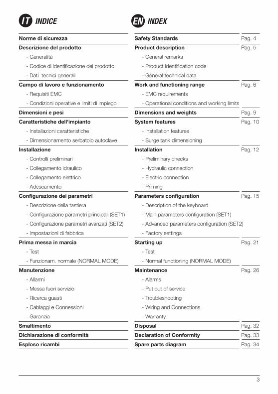
IT INDICE INDEXEN
4
Istruzioni importanti per la sicurezza.
Questo simbolo avverte che la mancata osser-vanza della prescrizione comporta un rischio di scosse elettriche.
Questo simbolo avverte che la mancata osser-vanza della prescrizione comporta un rischio di danno a persone o cose.
Prima di installare e utilizzare il prodotto leggere attentamente il presente manuale in tutte le sue parti. L’installazione e la manutenzione devono essere eseguite da personale qualificato , responsabile di eseguire i collegamenti idraulici e elettrici
secondo le applicabili norme vigenti. Il produttore declina ogni responsabilità per danni derivanti da uso improprio del prodotto e non è responsabile di danni causati da manutenzioni o riparazioni eseguite da personale non qualificato e/o con parti di ricambio non originali. L’utilizzo di ricambi non originali, manomissioni o usi impropri, fanno decadere la garanzia sul prodotto.
In fase di prima istallazione assicurarsi che:
- Non ci sia tensione sulla rete di alimentazione elettrica;
- La rete di alimentazione elettrica sia dotata di protezioni e di messa a terra conformi alle norme.
In caso di manutenzioneassicurarsi che:
- L’impianto non sia in pressione (aprire un rubinetto);
- Non ci sia tensione sulla rete di alimentazione elettrica;
- Prima di rimuovere il coperchio dell’inverter o iniziare interventi su di esso, è necessario
scollegare l’impianto dalla rete elettrica ed atten-dere almeno 5 Minuti affinchè i condensatori del circuito intermedio, che possono raggiungere ten-sioni fino ad 800V, abbiano il tempo di scaricarsi mediante i resistori di scarica incorporati.
Arresto di emergenzaMentre l’inverter è in funzione, è possibile ese-guire un arresto di emergenza, premendo il tasto START/STOP.
Safety important instructions.
This symbol warns that failure to comply with the prescription leads to a risk of electric shocks.
This symbol warns that failure to comply with the prescription leads to a risk of injury/dama-ge to persons/objects.
Before installation and use of the product, read this manual completely and thoroughly. Installation and maintenance must be carried out by qualified staff, responsible for performing the hydraulic and electric connections according to the applicable
Standards in force. The manufacturer declines all responsibility for damage deriving from improper use of the product and is not liable for damage caused by maintenance or repairs that are carried out by unqualified staff and/or using non-original spare parts. The use of non-original spare parts, tampering or improper use, make the product warranty null and void.
First installationmake sure that:
- the electric power supply network is not live;
- The electric power supply network is protected by ground connections in compliance with the Standards.
When carrying out maintenancemake sure that:
- the plant is not pressurised (open a tap);
- the electric power supply network is not live;
- Before removing the inverter cover or star-ting interventions on it, the system must be
disconnected from the mains electricity and you must wait for 5 mins until the intermediate circuit condensers, which can reach voltages of up to 800V, have the time to discharge via the built-in discharge resistors.
Emergency stopAn emergency stop can be performed while the inverter is running, by pressing the START/STOP key.
IT NORME DI SICUREZZA SAFETY STANDARDSEN
5
Generalità:STEADYPRES è un regolatore di velocità alimenta-to in monofase per motori elettrici a c.a. monofase e trifase.• Mantiene costante la pressione di impianto ad un valore definito dall’utenza, adeguando la prestazione della pompa alla richiesta istantanea, tramite variazione del numero di giri del motore.• Effettua continuamente controlli sui parametri elettrici e di funzionamento, garantendo la pro-tezione del gruppo di pompaggio da ogni tipo di comune anomalia (sovracorrenti, marcia a secco, etc)• Lavora in configurazione stand-alone oppure in parallelo con altri controlli elettronici (altri inverter, pressoflussostato elettronico) tramite connessione seriale (modulo opzionale).• Si adatta ad ogni tipologia di impianto, anche esistente, mentre semplifica la progettazione e la complessità dei nuovi impianti, riducendone i costi, poiche evita l’impiego di pressostati, vasi di espansione importanti, quadri elettrici di controllo, valvola di ritegno.• Aziona le elettropompe con rampe di avviamento a velocità progressiva che limitano le correnti di spunto, allungando la vita dei motori e consenten-do un notevole risparmio energetico.
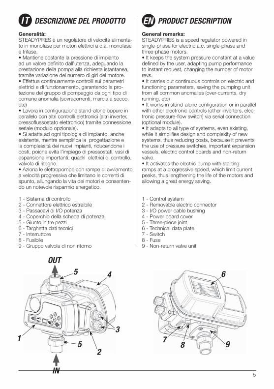
1 - Sistema di controllo2 - Connettore elettrico estraibile3 - Passacavi di I/O potenza4 - Coperchio della scheda di potenza5 - Giunto in tre pezzi6 - Targhetta dati tecnici7 - Interruttore8 - Fusibile9 - Gruppo valvola di non ritorno
General remarks:STEADYPRES is a speed regulator powered in single-phase for electric a.c. single-phase and three-phase motors.• It keeps the system pressure constant at a value defined by the user, adapting pump performance to instant request, changing the number of motor revs.• It carries out continuous controls on electric and functioning parameters, saving the pumping unit from all common anomalies (over-currents, dry running, etc)• It works in stand-alone configuration or in parallel with other electronic controls (other inverters, elec-tronic pressure-flow switch) via serial connection (optional module).• It adapts to all type of systems, even existing, while it simplifies design and complexity of new systems, thus reducing costs, because it prevents the use of pressure switches, important expansion vessels, electric control boards and non-return valve.• It activates the electric pump with starting ramps at a progressive speed, which limit current peaks, thus lengthening the life of the motors and allowing a great energy saving.
1 - Control system2 - Removable electric connector3 - I/O power cable bushing4 - Power board cover5 - Three-piece joint6 - Technical data plate7 - Switch8 - Fuse9 - Non-return valve unit
IT DESCRIZIONE DEL PRODOTTO PRODUCT DESCRIPTIONEN
31 7
85 9
5 4 6
OUT
IN
2
6
Codice di identificazione del prodottoSTEADYPRES viene identificato secondo il se-guente codice:
Dati tecnici generali- tensione di alimentazione 230Vac monofase.- frequenza 50-60 hz- grado di protezione IP65- Pressione massima di esercizio: 10 bar- Posizione di lavoro: in qualsiasi posizione; si consiglia di installarlo nella posizione normale (in-gresso del liquido dal basso, uscita dall’alto) per poter agevolmente leggere il display ed utilizzare la tastiera.- Per tutti i restanti dati tecnici specifici di ogni modello, fare riferimento alla scheda tecnica allegata ad ogni inverter. - Per le condizioni operative ed i limiti di impiego, fare riferimento al capitolo relativo, in questo manuale.
Product identification codeSTEADYPRES is identified by the following code:
General technical data- 230Vac power supply voltage.- frequency 50-60 hz- IP65 protection rating- maximum working pressure: 10 bar - Work position: in any position. It is recommen-ded to install it in a normal position (liquid inlet from below, outlet from above) in order to read the display easily and use the keyboard.- For the remaining specific technical data of every model, refer to the technical sheet attached to every inverter.- For the operational conditions and limits for use, refer to the relative chapter in this manual.
ST M / T 10
ENIT
Descrizione del prodotto Product description
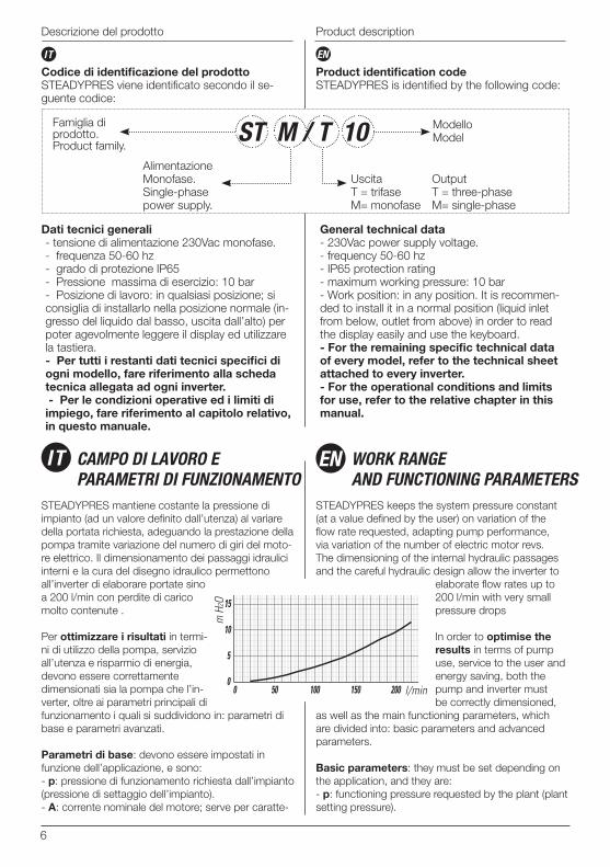
STEADYPRES mantiene costante la pressione di impianto (ad un valore definito dall’utenza) al variare della portata richiesta, adeguando la prestazione della pompa tramite variazione del numero di giri del moto-re elettrico. Il dimensionamento dei passaggi idraulici interni e la cura del disegno idraulico permettono all’inverter di elaborare portate sino a 200 l/min con perdite di carico molto contenute .
Per ottimizzare i risultati in termi-ni di utilizzo della pompa, servizio all’utenza e risparmio di energia, devono essere correttamente dimensionati sia la pompa che l’in-verter, oltre ai parametri principali di funzionamento i quali si suddividono in: parametri di base e parametri avanzati.
Parametri di base: devono essere impostati in funzione dell’applicazione, e sono:- p: pressione di funzionamento richiesta dall’impianto (pressione di settaggio dell’impianto).- A: corrente nominale del motore; serve per caratte-
STEADYPRES keeps the system pressure constant (at a value defined by the user) on variation of the flow rate requested, adapting pump performance, via variation of the number of electric motor revs. The dimensioning of the internal hydraulic passages and the careful hydraulic design allow the inverter to
elaborate flow rates up to 200 l/min with very small pressure drops
In order to optimise the results in terms of pump use, service to the user and energy saving, both the pump and inverter must be correctly dimensioned,
as well as the main functioning parameters, which are divided into: basic parameters and advanced parameters.
Basic parameters: they must be set depending on the application, and they are:- p: functioning pressure requested by the plant (plant setting pressure).
IT CAMPO DI LAVORO E PARAMETRI DI FUNZIONAMENTO
WORK RANGE AND FUNCTIONING PARAMETERS
EN
Famiglia di prodotto.Product family.
Alimentazione Monofase.Single-phase power supply.
UscitaT = trifaseM= monofase
Output T = three-phase M= single-phase
ModelloModel
7
Campo di lavoro Work and functioning range
ENIT
rizzare i parametri di funzionamento dell’inverter sulla tipologia di motore utilizzato.Questi due parametri si settano in modalità “SET 1” (v. pag.16).- Ro: senso di rotazione della pompa: permette di invertire il senso di rotazione della pompa in modo elettronico, senza la necessità di invertire i cavi in morsettiera.
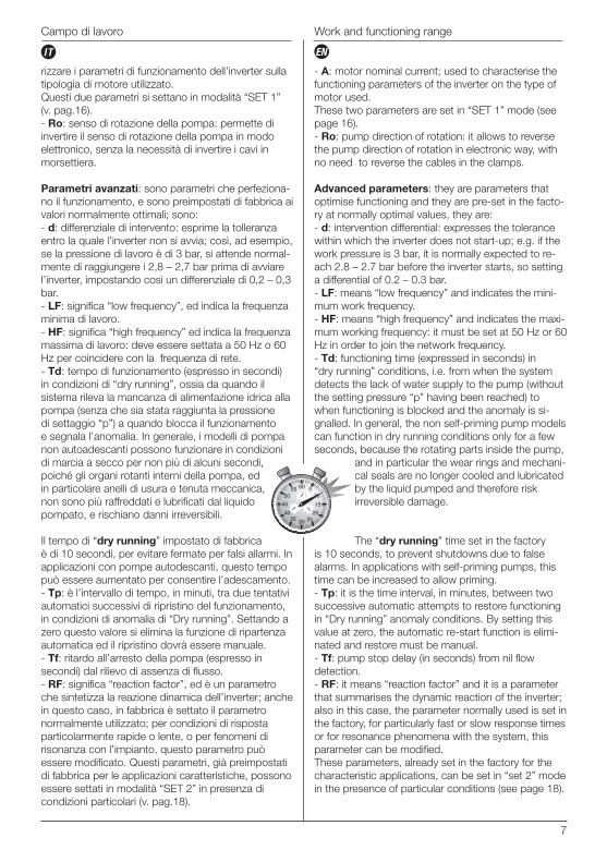
Parametri avanzati: sono parametri che perfeziona-no il funzionamento, e sono preimpostati di fabbrica ai valori normalmente ottimali; sono:- d: differenziale di intervento: esprime la tolleranza entro la quale l’inverter non si avvia; così, ad esempio, se la pressione di lavoro è di 3 bar, si attende normal-mente di raggiungere i 2,8 – 2,7 bar prima di avviare l’inverter, impostando così un differenziale di 0,2 – 0,3 bar.- LF: significa “low frequency”, ed indica la frequenza minima di lavoro.- HF: significa “high frequency” ed indica la frequenza massima di lavoro: deve essere settata a 50 Hz o 60 Hz per coincidere con la frequenza di rete.- Td: tempo di funzionamento (espresso in secondi) in condizioni di “dry running”, ossia da quando il sistema rileva la mancanza di alimentazione idrica alla pompa (senza che sia stata raggiunta la pressione di settaggio “p”) a quando blocca il funzionamento e segnala l’anomalia. In generale, i modelli di pompa non autoadescanti possono funzionare in condizioni di marcia a secco per non più di alcuni secondi, poiché gli organi rotanti interni della pompa, ed in particolare anelli di usura e tenuta meccanica, non sono più raffreddati e lubrificati dal liquido pompato, e rischiano danni irreversibili.
Il tempo di “dry running” impostato di fabbrica è di 10 secondi, per evitare fermate per falsi allarmi. In applicazioni con pompe autodescanti, questo tempo può essere aumentato per consentire l’adescamento.- Tp: è l’intervallo di tempo, in minuti, tra due tentativi automatici successivi di ripristino del funzionamento, in condizioni di anomalia di “Dry running”. Settando a zero questo valore si elimina la funzione di ripartenza automatica ed il ripristino dovrà essere manuale.- Tf: ritardo all’arresto della pompa (espresso in secondi) dal rilievo di assenza di flusso.- RF: significa “reaction factor”, ed è un parametro che sintetizza la reazione dinamica dell’inverter; anche in questo caso, in fabbrica è settato il parametro normalmente utilizzato; per condizioni di risposta particolarmente rapide o lente, o per fenomeni di risonanza con l’impianto, questo parametro può essere modificato. Questi parametri, già preimpostati di fabbrica per le applicazioni caratteristiche, possono essere settati in modalità “SET 2” in presenza di condizioni particolari (v. pag.18).
- A: motor nominal current; used to characterise the functioning parameters of the inverter on the type of motor used.These two parameters are set in “SET 1” mode (see page 16).- Ro: pump direction of rotation: it allows to reverse the pump direction of rotation in electronic way, with no need to reverse the cables in the clamps.
Advanced parameters: they are parameters that optimise functioning and they are pre-set in the facto-ry at normally optimal values, they are:- d: intervention differential: expresses the tolerance within which the inverter does not start-up; e.g. if the work pressure is 3 bar, it is normally expected to re-ach 2.8 – 2.7 bar before the inverter starts, so setting a differential of 0.2 – 0.3 bar.- LF: means “low frequency” and indicates the mini-mum work frequency.- HF: means “high frequency” and indicates the maxi-mum working frequency: it must be set at 50 Hz or 60 Hz in order to join the network frequency.- Td: functioning time (expressed in seconds) in “dry running” conditions, i.e. from when the system detects the lack of water supply to the pump (without the setting pressure “p” having been reached) to when functioning is blocked and the anomaly is si-gnalled. In general, the non self-priming pump models can function in dry running conditions only for a few seconds, because the rotating parts inside the pump,
and in particular the wear rings and mechani-cal seals are no longer cooled and lubricated by the liquid pumped and therefore risk irreversible damage.
The “dry running” time set in the factory is 10 seconds, to prevent shutdowns due to false alarms. In applications with self-priming pumps, this time can be increased to allow priming.- Tp: it is the time interval, in minutes, between two successive automatic attempts to restore functioning in “Dry running” anomaly conditions. By setting this value at zero, the automatic re-start function is elimi-nated and restore must be manual.- Tf: pump stop delay (in seconds) from nil flow detection.- RF: it means “reaction factor” and it is a parameter that summarises the dynamic reaction of the inverter;also in this case, the parameter normally used is set in the factory, for particularly fast or slow response times or for resonance phenomena with the system, this parameter can be modified.These parameters, already set in the factory for the characteristic applications, can be set in “set 2” mode in the presence of particular conditions (see page 18).
8
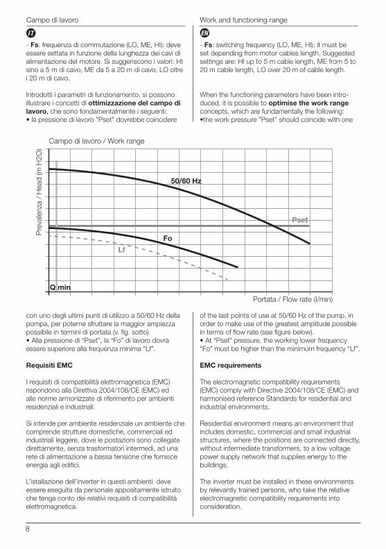
- Fs: frequenza di commutazione (LO, ME, HI): deve essere settata in funzione della lunghezza dei cavi di alimentazione del motore. Si suggeriscono i valori: HI sino a 5 m di cavo, ME da 5 a 20 m di cavo, LO oltre i 20 m di cavo.
Introdotti i parametri di funzionamento, si possono illustrare i concetti di ottimizzazione del campo di lavoro, che sono fondamentalmente i seguenti:• la pressione di lavoro ”Pset” dovrebbe coincidere
- Fs: switching frequency (LO, ME, HI): it must be set depending from motor cables length. Suggested settings are: HI up to 5 m cable length, ME from 5 to 20 m cable length, LO over 20 m of cable length.
When the functioning parameters have been intro-duced, it is possible to optimise the work range concepts, which are fundamentally the following:•the work pressure ”Pset” should coincide with one
Campo di lavoro Work and functioning range
ENIT
50/60 Hz
Pset
Q min
Portata / Flow rate (l/min)
Campo di lavoro / Work range
Pre
vale
nza
/ H
ead
(m H
2O)
con uno degli ultimi punti di utilizzo a 50/60 Hz della pompa, per poterne sfruttare la maggior ampiezza possibile in termini di portata (v. fig. sotto).• Alla pressione di “Pset”, la “Fo” di lavoro dovrà essere superiore alla frequenza minima “Lf”.
Requisiti EMC
I requisiti di compatibilità elettromagnetica (EMC) rispondono alla Direttiva 2004/108/CE (EMC) ed alle norme armonizzate di riferimento per ambienti residenziali e industriali.
Si intende per ambiente residenziale un ambiente che comprende strutture domestiche, commerciali ed industriali leggere, dove le postazioni sono collegate direttamente, senza trasformatori intermedi, ad una rete di alimentazione a bassa tensione che fornisce energia agli edifici.
L’istallazione dell’inverter in questi ambienti deve essere eseguita da personale appositamente istruito che tenga conto dei relativi requisiti di compatibilità elettromagnetica.
of the last points of use at 50/60 Hz of the pump, in order to make use of the greatest amplitude possible in terms of flow rate (see figure below).• At “Pset” pressure, the working lower frequency “Fo” must be higher than the minimum frequency “Lf”.
EMC requirements
The electromagnetic compatibility requirements (EMC) comply with Directive 2004/108/CE (EMC) and harmonised reference Standards for residential and industrial environments.
Residential environment means an environment that includes domestic, commercial and small industrial structures, where the positions are connected directly, without intermediate transformers, to a low voltage power supply network that supplies energy to the buildings.
The inverter must be installed in these environments by relevantly trained persons, who take the relative electromagnetic compatibility requirements into consideration.
Lf
Fo
9
Campo di lavoro - Dimensioni e pesi Work functioning range - Dimensions and weights
ENIT
Si intende per ambiente industriale un ambiente che comprende tutte le strutture che non siano direttamente collegate ad una rete di alimentazione a bassa tensione, ma alimentate da un trasforma-tore dedicato.
Condizioni operative e limiti di impiego
• Fluidi ammessi: gli inverter STEADYPRES sono utilizzabili con acqua pulita e liquidi chimicamente non aggressivi ; il loro utilizzo e’ subordinato alle direttive e legislazioni locali.Se nel liquido sono presenti impurità, installare un filtro a monte.• Pericolo di incendio/esplosione: gli inverter STEADYPRES non sono adatti al pompaggio di liquidi infiammabili o ad operare in ambienti con pericolo di esplosione.• Limiti di Esercizio:Pressione massima di esercizio: 10barTemperatura massima del liquido ammessa dalla normativa EN60335-2-41: +35°CTemperatura massima del liquido ammessa dai materiali: +40°CTemperatura ambiente massima: +40°CVariazione di tensione di alimentazione ammessa: +/- 10% rispetto ai dati di targa.
Industrial environment means an environment that includes all structures that are not directly connec-ted to a low voltage power supply network, but powered by a dedicated transformer.
Operational conditions and limits of use
• Fluids accepted: the STEADYPRES inverter can be used with clean water and non-aggressive chemical liquids. Their use is subject to the local legislation and Directives.If there are impurities inside the liquid, install a filter upstream.• Fire/explosion hazard: the STEADYPRES inver-ter is not suitable for pumping inflammable liquids or for use in environments with risk of explosion.• Working Limits:Maximum working pressure: 10barMaximum liquid temperature accepted by the EN60335-2-41 Standard: +35°CMaximum liquid temperature accepted by the materials: +40°CMaximum environment temperature: +40°CAccepted power supply voltage variation:+/- 10% with respect to plate data.
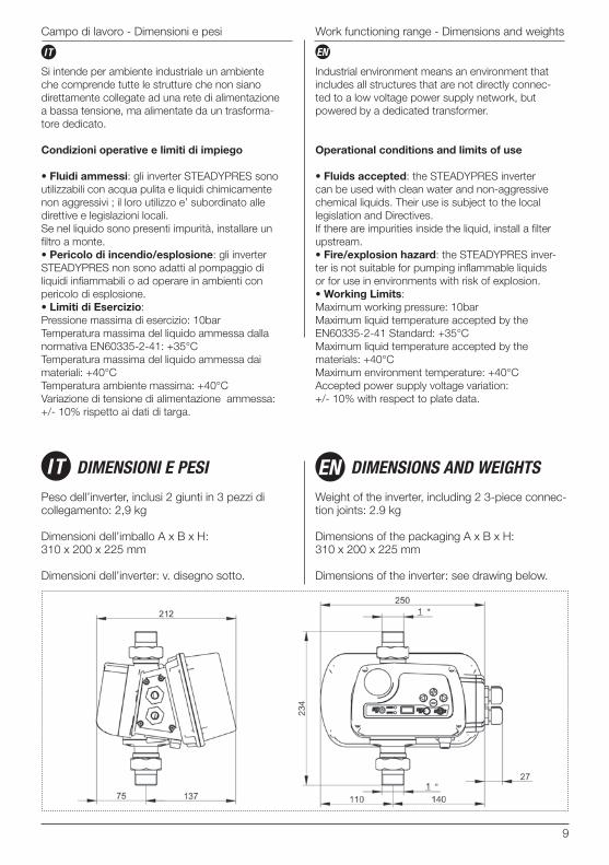
Peso dell’inverter, inclusi 2 giunti in 3 pezzi di collegamento: 2,9 kg
Dimensioni dell’imballo A x B x H: 310 x 200 x 225 mm
Dimensioni dell’inverter: v. disegno sotto.
Weight of the inverter, including 2 3-piece connec-tion joints: 2.9 kg
Dimensions of the packaging A x B x H:310 x 200 x 225 mm
Dimensions of the inverter: see drawing below.
IT DIMENSIONI E PESI DIMENSIONS AND WEIGHTSEN
10
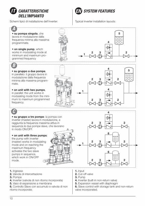
Schemi tipici di installazione dell’inverter: Typical inverter installation layouts:
• su pompa singola, che lavora in modulazione dalla frequenza minima alla massima programmate.
• on single pump, which works in modulating mode at minimum and maximum pro-grammed frequency
• su gruppo a due pompe, in parallelo: il gruppo lavora in modulazione dalla frequenza minima alla massima program-mate.
• on unit with two pumps, in parallel: the unit works in modulating mode from the mini-mum to maximum programmed frequency.
1. Ingresso2. Valvola di intercettazione3. Pompa4. Inverter (valvola di non ritorno incorporata)5. Vaso di espansione a membrana6. Controllo Slave con accumulo e valvola di non ritorno incorporate.
1. Input2. Cut-off valve3. Pump4. Inverter (built-in non-return valve)5. Expansion vessel with diaphragm6. Slave control with storage tank and non-return valve incorporated.
IT CARATTERISTICHE DELL’IMPIANTO
SYSTEM FEATURESEN
12 23
4
5
1
2 23
4
2 23
4
5
1
2 23
4
2
2
2
2
3
3
6
6
• su gruppo a tre pompe: la pompa con inverter (master) lavora in modulazione, e raggiunta la frequenza massima attiva in sequenza le due pompe slave, che lavorano in modo ON/OFF.
• on unit with three pumps: the pump with inverter (master) works in modulating mode and on reaching the maximum frequency activates the two slave pumps in sequence, which work in ON/OFF mode.
C
B
A
11
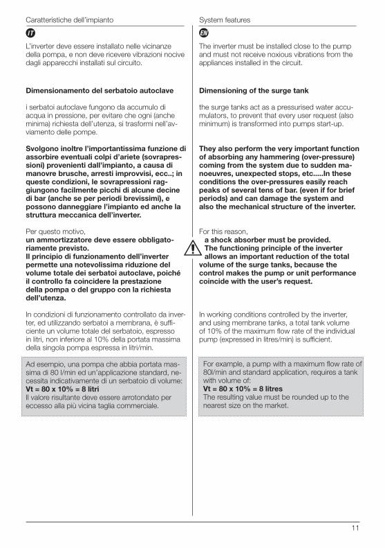
L’inverter deve essere installato nelle vicinanze della pompa, e non deve ricevere vibrazioni nocive dagli apparecchi installati sul circuito.
The inverter must be installed close to the pump and must not receive noxious vibrations from the appliances installed in the circuit.
Dimensionamento del serbatoio autoclave
i serbatoi autoclave fungono da accumulo di acqua in pressione, per evitare che ogni (anche minima) richiesta dell’utenza, si trasformi nell’av-viamento delle pompe.
Svolgono inoltre l’importantissima funzione di assorbire eventuali colpi d’ariete (sovrapres-sioni) provenienti dall’impianto, a causa di manovre brusche, arresti improvvisi, ecc..; in queste condizioni, le sovrapressioni rag-giungono facilmente picchi di alcune decine di bar (anche se per periodi brevissimi), e possono danneggiare l’impianto ed anche la struttura meccanica dell’inverter.
Per questo motivo, un ammortizzatore deve essere obbligato-riamente previsto.Il principio di funzionamento dell’inverter permette una notevolissima riduzione del volume totale dei serbatoi autoclave, poiché il controllo fa coincidere la prestazione della pompa o del gruppo con la richiesta dell’utenza.
In condizioni di funzionamento controllato da inver-ter, ed utilizzando serbatoi a membrana, è suffi-ciente un volume totale del serbatoio, espresso in litri, non inferiore al 10% della portata massima della singola pompa espressa in litri/min.
Ad esempio, una pompa che abbia portata mas-sima di 80 l/min ed un’applicazione standard, ne-cessita indicativamente di un serbatoio di volume:Vt = 80 x 10% = 8 litriIl valore risultante deve essere arrotondato per eccesso alla più vicina taglia commerciale.
Dimensioning of the surge tank
the surge tanks act as a pressurised water accu-mulators, to prevent that every user request (also minimum) is transformed into pumps start-up.
They also perform the very important function of absorbing any hammering (over-pressure) coming from the system due to sudden ma-noeuvres, unexpected stops, etc.....In these conditions the over-pressures easily reach peaks of several tens of bar. (even if for brief periods) and can damage the system and also the mechanical structure of the inverter.
For this reason, a shock absorber must be provided.The functioning principle of the inverter allows an important reduction of the total
volume of the surge tanks, because the control makes the pump or unit performance coincide with the user’s request.
In working conditions controlled by the inverter, and using membrane tanks, a total tank volume of 10% of the maximum flow rate of the individual pump (expressed in litres/min) is sufficient.
For example, a pump with a maximum flow rate of 80l/min and standard application, requires a tank with volume of:Vt = 80 x 10% = 8 litresThe resulting value must be rounded up to the nearest size on the market.
Caratteristiche dell’impianto System features
ENIT
12
Prima di installare ed utilizzare STEADYPRES, leggere attentamente il presente Manuale in tutte le sue parti e riferirsi alle norme di sicurezza descritte a pag. 4.Controlli preliminari: estrarre il prodotto dall’imballo e controllare:• che non abbia subito danni,• che i dati di targa siano quelli desiderati ed adeguati all’impianto,• che siano presenti tutti i componenti elen-cati nel presente Manuale,• che le bocche di ingresso ed uscita dell’in-verter siano pulite e libere da eventuali residui del materiale di imballo.
Collegamento idraulico.
l’installazione deve essere effettuata da installatori competenti ed autorizzati.Durante l’installazione applicare tutte le disposizio-ni di sicurezza emanate dagli organi competenti e dettate dal buon senso.Installare l’inverter in luogo asciutto e ben ventilato utilizzando il giunto in tre pezzi (in dotazione) per il collegamento rapido e sicuro all’impianto (vedi pag. 5).
Nota: NON applicare sigillanti all’interno del giunto in 3 pezzi perchè è già provvisto di o-ring interno di tenuta.
L’inverter può lavorare in qualsiasi posizione, anche capovolto (è però sconsigliabile perché la programmazione e la lettura dei parametri risulte-rebbero scomodi); in funzionamento non dovranno verificarsi vibrazioni.
Collegamento elettrico.
• Collegamento alla linea di alimentazione monofase.
Prima di effettuare i collegamenti assicurarsi che non vi sia tensione ai capi dei conduttori di linea. Assicurarsi inoltre che la rete di alimen-tazione elettrica sia dotata di protezioni e di messa a terra conformi alle norme.
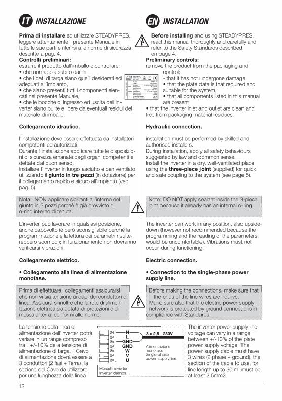
La tensione della linea di alimentazione dell’inverter potrà variare in un range compreso tra il +/-10% della tensione di alimentazione di targa. Il Cavo di alimentazione dovrà essere a 3 conduttori (2 fasi + Terra), la sezione del Cavo da utilizzare, per una lunghezza della linea
Before installing and using STEADYPRES, read this manual thoroughly and carefully and refer to the Safety Standards described on page 4.
Preliminary controls:remove the product from the packaging and
control:- that it has not undergone damage• that the plate data is that required and suitable for the system,• that all components listed in this manual are present
• that the inverter inlet and outlet are clean and free from packaging material residues.
Hydraulic connection.
installation must be performed by skilled and authorised installers.During installation, apply all safety behaviours suggested by law and common sense.Install the inverter in a dry, well-ventilated place using the three-piece joint (supplied) for quick and safe coupling to the system (see page 5).
Note: DO NOT apply sealant inside the 3-piece joint because it already has an internal o-ring.
The inverter can work in any position, also upside-down (however not recommended because the programming and the reading of the parameters would be uncomfortable). Vibrations must not occur during functioning.
Electric connection.
• Connection to the single-phase power supply line.
Before making the connections, make sure that the ends of the line wires are not live.Make sure also that the electric power supply network is protected by ground connections in
compliance with Standards.
The inverter power supply line voltage can vary in a range between +/-10% of the plate power supply voltage. The power supply cable must have 3 wires (2 phase + ground), the section of the cable to use, for line length up to 30 m, must be at least 2.5mm2.
IT INSTALLAZIONE INSTALLATIONEN
13
Installazione Installation
ENIT
fino a 30m, dovrà essere di almeno 2,5mm2.Il collegamento alla linea di alimentazione andrà effettuato sui morsetti L ,N e GND dell’inverter (vedi figura).
• Collegamento all’elettropompa.Versione con Inverter alimentato in monofase con output trifase.
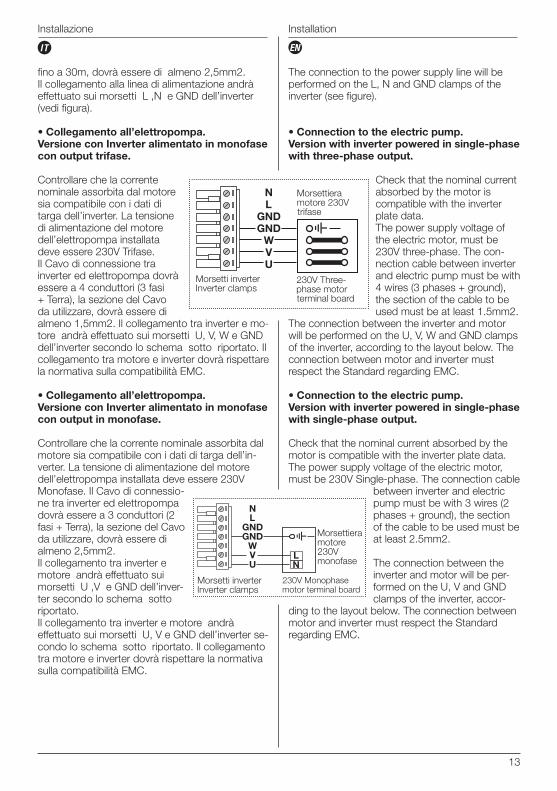
Controllare che la corrente nominale assorbita dal motore sia compatibile con i dati di targa dell’inverter. La tensione di alimentazione del motore dell’elettropompa installata deve essere 230V Trifase. Il Cavo di connessione tra inverter ed elettropompa dovrà essere a 4 conduttori (3 fasi + Terra), la sezione del Cavo da utilizzare, dovrà essere di almeno 1,5mm2. Il collegamento tra inverter e mo-tore andrà effettuato sui morsetti U, V, W e GND dell’inverter secondo lo schema sotto riportato. Il collegamento tra motore e inverter dovrà rispettare la normativa sulla compatibilità EMC.
• Collegamento all’elettropompa.Versione con Inverter alimentato in monofase con output in monofase.
Controllare che la corrente nominale assorbita dal motore sia compatibile con i dati di targa dell’in-verter. La tensione di alimentazione del motore dell’elettropompa installata deve essere 230V Monofase. Il Cavo di connessio-ne tra inverter ed elettropompa dovrà essere a 3 conduttori (2 fasi + Terra), la sezione del Cavo da utilizzare, dovrà essere di almeno 2,5mm2.Il collegamento tra inverter e motore andrà effettuato sui morsetti U ,V e GND dell’inver-ter secondo lo schema sotto riportato.Il collegamento tra inverter e motore andrà effettuato sui morsetti U, V e GND dell’inverter se-condo lo schema sotto riportato. Il collegamento tra motore e inverter dovrà rispettare la normativa sulla compatibilità EMC.
The connection to the power supply line will be performed on the L, N and GND clamps of the inverter (see figure).
• Connection to the electric pump.Version with inverter powered in single-phase with three-phase output.
Check that the nominal current absorbed by the motor is compatible with the inverter plate data.The power supply voltage of the electric motor, must be 230V three-phase. The con-nection cable between inverter and electric pump must be with 4 wires (3 phases + ground), the section of the cable to be used must be at least 1.5mm2.
The connection between the inverter and motor will be performed on the U, V, W and GND clamps of the inverter, according to the layout below. The connection between motor and inverter must respect the Standard regarding EMC.
• Connection to the electric pump.Version with inverter powered in single-phase with single-phase output.
Check that the nominal current absorbed by the motor is compatible with the inverter plate data. The power supply voltage of the electric motor, must be 230V Single-phase. The connection cable
between inverter and electric pump must be with 3 wires (2 phases + ground), the section of the cable to be used must be at least 2.5mm2.
The connection between the inverter and motor will be per-formed on the U, V and GND clamps of the inverter, accor-
ding to the layout below. The connection between motor and inverter must respect the Standard regarding EMC.
LN
14
Installazione Installation
ENIT
Adescamento
Un sistema di pompaggio non può per alcun mo-tivo essere avviato a secco; il funzionamento a secco delle pompe, anche per brevissimi periodi, causa danni irreversibili alla tenuta meccanica ed agli accoppiamenti rotanti interni.
Prima dell’avviamento del sistema è indispensa-bile effettuare l’adescamento di tutte le pompe, svitando il tappo di riempimento e riempiendo d’acqua il corpo pompa (e la tubazione di aspira-zione ad esso collegata); ad operazione com-pletata, riavvitare il tappo e far partire la pompa, con la valvola di intercettazione in mandata quasi completamente chiusa, con il sistema in modalità di funzionamento manuale (TEST).
Se dopo poche decine di secondi la pompa non si fosse adescata, spegnerla, verificare che l’aspi-razione sia libera, che non vi siano sacche d’aria a monte dell’imbocco, che il corpo sia pieno di acqua, e ripetere l’operazione.
Ripetere le operazioni sopra descritte per ogni pompa.
Priming
A pumping system must never be started dry for any reason. Dry running of the pumps, even for very brief periods, can cause irreversible dama-ge to mechanical sealing and internal rotating couplings.
All pumps must be primed before starting the system by unscrewing the filler cap and filling the pump body with water (and the intake piping connected to it). When the operation has been completed, tighten the cap and start the pump, with the cut-off valve in flow almost completely closed, with the system in manual functioning mode (TEST).
If, after a few tens of seconds, the pump is not primed, switch it off, check that the intake is free, that there are no air pockets upstream from the inlet, that the body is full of water and then repeat the operation.
Repeat the operations described above for every pump.
15
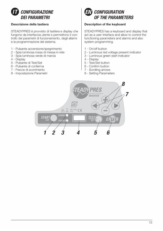
Descrizione della tastiera
STEADYPRES è provvisto di tastiera e display che fungono da interfaccia utente e permettono il con-trollo dei parametri di funzionamento, degli allarmi e la programmazione del sistema.
1 - Pulsante accensione/spegnimento2 - Spia luminosa rossa di messa in rete3 - Spia luminosa verde di marcia4 - Display5 - Pulsante di Test/Set6 - Pulsante di conferma7 - Frecce di scorrimento8 - Impostazione Parametri
Description of the keyboard
STEADYPRES has a keyboard and display that act as a user interface and allow to control the functioning parameters and alarms and also system programming.
1 - On/off button2 - Luminous red voltage present indicator 3 - Luminous green start indicator4 - Display5 - Test/Set button6 - Confirm button7 - Scrolling arrows8 - Setting Parameters
IT CONFIGURAZIONEDEI PARAMETRI
CONFIGURATION OF THE PARAMETERS
EN
1 2 3 5 6
8
7
4
16
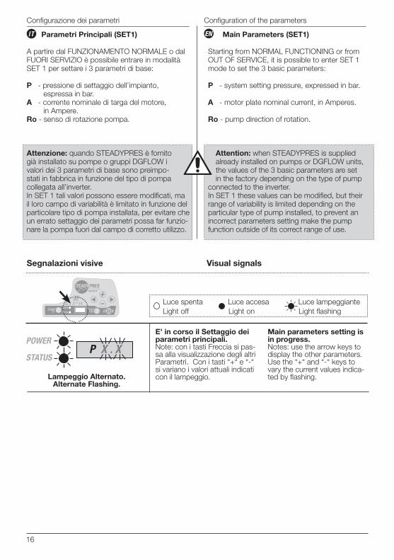
Parametri Principali (SET1)
A partire dal FUNZIONAMENTO NORMALE o dal FUORI SERVIZIO è possibile entrare in modalità SET 1 per settare i 3 parametri di base:
P - pressione di settaggio dell’impianto, espressa in bar.A - corrente nominale di targa del motore, in Ampere.Ro - senso di rotazione pompa.
Main Parameters (SET1)
Starting from NORMAL FUNCTIONING or from OUT OF SERVICE, it is possible to enter SET 1 mode to set the 3 basic parameters:
P - system setting pressure, expressed in bar.
A - motor plate nominal current, in Amperes.
Ro - pump direction of rotation.
Attenzione: quando STEADYPRES è fornito già installato su pompe o gruppi DGFLOW i valori dei 3 parametri di base sono preimpo-stati in fabbrica in funzione del tipo di pompa collegata all’inverter.In SET 1 tali valori possono essere modificati, ma il loro campo di variabilità è limitato in funzione del particolare tipo di pompa installata, per evitare che un errato settaggio dei parametri possa far funzio-nare la pompa fuori dal campo di corretto utilizzo.
Attention: when STEADYPRES is supplied already installed on pumps or DGFLOW units, the values of the 3 basic parameters are set in the factory depending on the type of pump
connected to the inverter.In SET 1 these values can be modified, but their range of variability is limited depending on the particular type of pump installed, to prevent an incorrect parameters setting make the pump function outside of its correct range of use.
Configurazione dei parametri Configuration of the parameters
ENIT
Segnalazioni visive Visual signals
E’ in corso il Settaggio dei parametri principali. Note: con i tasti Freccia si pas-sa alla visualizzazione degli altri Parametri. Con i tasti “+“ e “-“ si variano i valori attuali indicati con il lampeggio.
Main parameters setting is in progress. Notes: use the arrow keys to display the other parameters. Use the “+“ and “-“ keys to vary the current values indica-ted by flashing.
POWER
STATUS P X . X
Lampeggio Alternato.Alternate Flashing.
Luce spenta Luce accesa Luce lampeggianteLight off Light on Light flashing
17
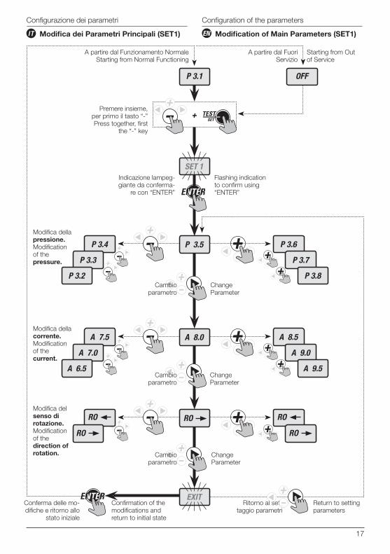
Modifica dei Parametri Principali (SET1) Modification of Main Parameters (SET1)
Configuration of the parametersConfigurazione dei parametri
A partire dal Funzionamento NormaleStarting from Normal Functioning
Conferma delle mo-difiche e ritorno allo
stato iniziale
Confirmation of the modifications and return to initial state
Ritorno al set-taggio parametri
Return to setting parameters
Premere insieme, per primo il tasto “-”Press together, first
the “-” key
Indicazione lampeg-giante da conferma-
re con “ENTER”
Flashing indication to confirm using “ENTER”
A partire dal Fuori Servizio
Starting from Out of Service
ENIT
P 3.1
+
OFF
P 3.5
A 8.0
SET 1
EXIT
P 3.4
P 3.3
P 3.2
A 7.5
A 7.0
A 6.5
P 3.6
P 3.7
P 3.8
A 8.5
A 9.0
A 9.5
Cambio parametro
Change Parameter
Cambio parametro
Change Parameter
Cambio parametro
Change Parameter
RO RO
RO
RO
RO
Modifica del senso di rotazione.Modification of the direction of rotation.
Modifica della corrente.Modification of the current.
Modifica della pressione.Modification of the pressure.
18
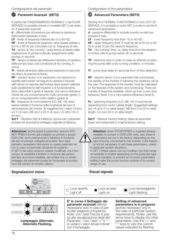
Parametri Avanzati (SET2)
A partire dal FUNZIONAMENTO NORMALE o dal FUORI SERVIZIO è possibile entrare in modalità SET 2 per setta-re i 6 parametri avanzati:d - differenziale di pressione per attivare la ripartenza dell’inverter (espresso in bar).LF - limite di frequenza inferiore (da 15 a 40 HZ).HF - limite di frequenza superiore: deve essere settata a 50 Hz o 60 Hz per coincidere con la frequenza di rete. Td - tempo di “dry running”, ossia tempo di ritardo dalla registrazione di portata nulla allo spegnimento della pompa, in secondi.TP - tempo di attesa per effettuare il tentativo di ripristino della pompa dopo una condizione di dry running, in minuti.Tf - ritardo all’arresto della pompa (espresso in secondi) dal rilievo di assenza di flusso.RF - reaction factor; è un parametro che riassume la rapidità dell’inverter nel seguire le variazioni imposte dall’utenza; la risposta dell’inverter deve essere calibrata sulle caratteristiche dell’impianto e di funzionamento. Sono disponibili 5 gradi di risposta, che vanno indicativa-mente da una comportamento molto smorzato (grado 1) ad un comportamento molto reattivo (grado 5).Fs - frequenza di commutazione (LO, ME, HI): deve essere settata in funzione della lunghezza dei cavi di alimentazione del motore. Si suggeriscono i valori: HI sino a 5 m di cavo, ME da 5 a 20 m di cavo, LO oltre i 20 m di cavo.Set F - Ripristino Set di Fabbrica: riporta tutti i parametri (di base ed avanzati) al settaggio originale di fabbrica.
Advanced Parameters (SET2)
Starting from NORMAL FUNCTIONING or from OUT OF SERVICE, it is possible to enter SET 2 mode to set the 6 advanced parameters:d - pressure differential to activate inverter re-start (ex-pressed in bar).LF - lower frequency limit (from 15 to 40 HZ).HF - upper frequency limit: it must be set at 50 Hz or 60 Hz in order to join the network frequency.Td - “dry running” time, i.e. delay time from the situation of nil flow rate to pump switch off, in seconds.
TP - Stand-by time in order to make an attempt at resto-ring the pump after a dry running condition, in minutes.
Tf - pump stop delay (in seconds) from nil flow detection.
RF - reaction factor; it is a parameter that summarises the rapidity of the inverter in following the variations set by the user. The response of the inverter must be calibrated on the features of the system and functioning. There are 5 levels of response available, which go from a very slow behaviour (level 1) to a very reactive behaviour (level 5).
Fs - switching frequency (LO, ME, HI): it must be set depending from motor cables length. Suggested settings are: HI up to 5 m cable length, ME from 5 to 20 m cable length, LO over 20 m of cable length.
Set F - Restore Factory Setting: takes all parameter (basic and advanced) to original factory setting.
Attenzione: anche questi 8 parametri, quando STE-ADY PRES è fornito già installato su pompe o gruppi DGFLOW, sono preimpostati in fabbrica in funzione del tipo di pompa collegata all’inverter. Non sarà pertanto necessario intervenire su questi parametri se non in caso di particolari situazioni di impianto.In SET 2 tali valori possono essere modificati, ma il loro campo di variabilità è limitato in funzione del partico-lare tipo di pompa installata, per evitare che un errato settaggio dei parametri possa far funzionare la pompa fuori dal campo di corretto utilizzo.
Attention: when STEADYPRES is supplied already installed on pumps or DGFLOW units, also these 8 parameters are set in the factory depending on the type of pump connected to the inverter. It will therefo-re not be necessary to set these parameters, unless
in particular system situations.In SET 2 these values can be modified, but their range of variability is limited depending on the particular type of pump installed, to prevent an incorrect parameters setting make the pump function outside of its correct range of use.
Configurazione dei parametri
ENIT
Segnalazioni visive
E’ in corso il Settaggio dei parametri avanzati (attività necessaria solo in caso di par-ticolari esigenze d’impianto). Note: con i tasti Freccia si pas-sa alla visualizzazione degli altri Parametri. Con i tasti “+“ e “-“ si variano i valori attuali indicati con il lampeggio.
Setting of advanced parameters is in progress (activity necessary only in the case of particular system requirements). Notes: use the arrow keys to display the other parameters. Use the “+“ and “-“ keys to vary the current values indicated by flashing.
POWER
STATUS d X . X
Visual signals
Lampeggio Alternato.Alternate Flashing.
Luce spenta Luce accesa Luce lampeggianteLight off Light on Light flashing
Configuration of the parameters
19
++P 3.1 OFF
SET 2
EXIT
Td 10Td 9Td 8
Td 11Td 12
SET. F
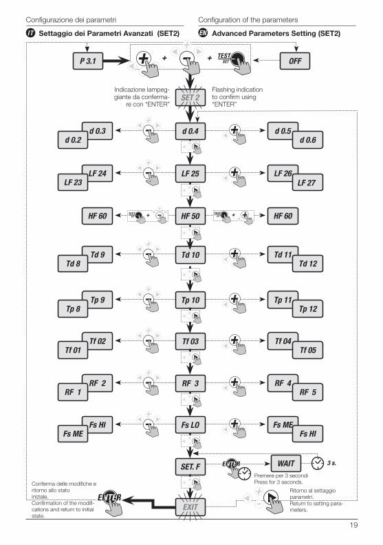
Configurazione dei parametri
ENIT Settaggio dei Parametri Avanzati (SET2) Advanced Parameters Setting (SET2)
WAIT 3 s.
Premere per 3 secondiPress for 3 seconds.
Tp 10Tp 9Tp 8
Tp 11Tp 12
Conferma delle modifiche e ritorno allo stato iniziale.Confirmation of the modifi-cations and return to initial state.
Ritorno al settaggio parametri.Return to setting para-meters.
Indicazione lampeg-giante da conferma-
re con “ENTER”
Flashing indication to confirm using “ENTER”
Configuration of the parameters
d 0.4d 0.3d 0.2
d 0.5d 0.6
LF 25LF 24LF 23
LF 26LF 27
HF 50HF 60 HF 60+ +
Tf 03Tf 02Tf 01
Tf 04Tf 05
RF 3RF 2RF 1
RF 4RF 5
Fs LOFs HIFs ME
Fs MEFs HI
20
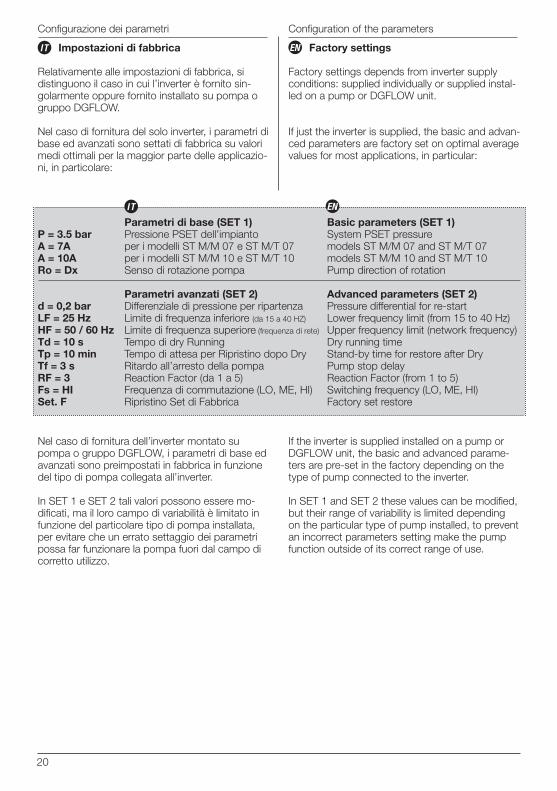
Impostazioni di fabbrica
Relativamente alle impostazioni di fabbrica, si distinguono il caso in cui l’inverter è fornito sin-golarmente oppure fornito installato su pompa o gruppo DGFLOW.
Nel caso di fornitura del solo inverter, i parametri di base ed avanzati sono settati di fabbrica su valori medi ottimali per la maggior parte delle applicazio-ni, in particolare:
Factory settings
Factory settings depends from inverter supply conditions: supplied individually or supplied instal-led on a pump or DGFLOW unit.
If just the inverter is supplied, the basic and advan-ced parameters are factory set on optimal average values for most applications, in particular:
Nel caso di fornitura dell’inverter montato su pompa o gruppo DGFLOW, i parametri di base ed avanzati sono preimpostati in fabbrica in funzione del tipo di pompa collegata all’inverter.
In SET 1 e SET 2 tali valori possono essere mo-dificati, ma il loro campo di variabilità è limitato in funzione del particolare tipo di pompa installata, per evitare che un errato settaggio dei parametri possa far funzionare la pompa fuori dal campo di corretto utilizzo.
If the inverter is supplied installed on a pump or DGFLOW unit, the basic and advanced parame-ters are pre-set in the factory depending on the type of pump connected to the inverter.
In SET 1 and SET 2 these values can be modified, but their range of variability is limited depending on the particular type of pump installed, to prevent an incorrect parameters setting make the pump function outside of its correct range of use.
Configurazione dei parametri
ENIT
P = 3.5 barA = 7AA = 10ARo = Dx
d = 0,2 barLF = 25 HzHF = 50 / 60 HzTd = 10 sTp = 10 minTf = 3 sRF = 3Fs = HISet. F
Parametri di base (SET 1)Pressione PSET dell’impiantoper i modelli ST M/M 07 e ST M/T 07per i modelli ST M/M 10 e ST M/T 10Senso di rotazione pompa
Parametri avanzati (SET 2)Differenziale di pressione per ripartenzaLimite di frequenza inferiore (da 15 a 40 HZ)
Limite di frequenza superiore (frequenza di rete)
Tempo di dry RunningTempo di attesa per Ripristino dopo DryRitardo all’arresto della pompaReaction Factor (da 1 a 5)Frequenza di commutazione (LO, ME, HI)Ripristino Set di Fabbrica
Basic parameters (SET 1)System PSET pressuremodels ST M/M 07 and ST M/T 07models ST M/M 10 and ST M/T 10Pump direction of rotation
Advanced parameters (SET 2)Pressure differential for re-startLower frequency limit (from 15 to 40 Hz)Upper frequency limit (network frequency)Dry running timeStand-by time for restore after DryPump stop delayReaction Factor (from 1 to 5)Switching frequency (LO, ME, HI)Factory set restore
ENIT
Configuration of the parameters
21
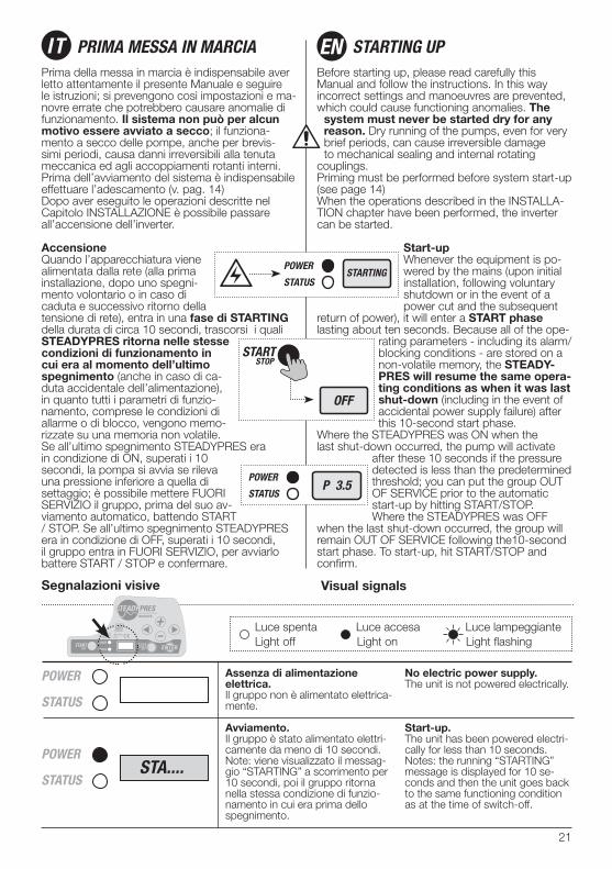
Prima della messa in marcia è indispensabile aver letto attentamente il presente Manuale e seguire le istruzioni; si prevengono così impostazioni e ma-novre errate che potrebbero causare anomalie di funzionamento. Il sistema non può per alcun motivo essere avviato a secco; il funziona-mento a secco delle pompe, anche per brevis-simi periodi, causa danni irreversibili alla tenuta meccanica ed agli accoppiamenti rotanti interni.Prima dell’avviamento del sistema è indispensabile effettuare l’adescamento (v. pag. 14)Dopo aver eseguito le operazioni descritte nel Capitolo INSTALLAZIONE è possibile passare all’accensione dell’inverter.
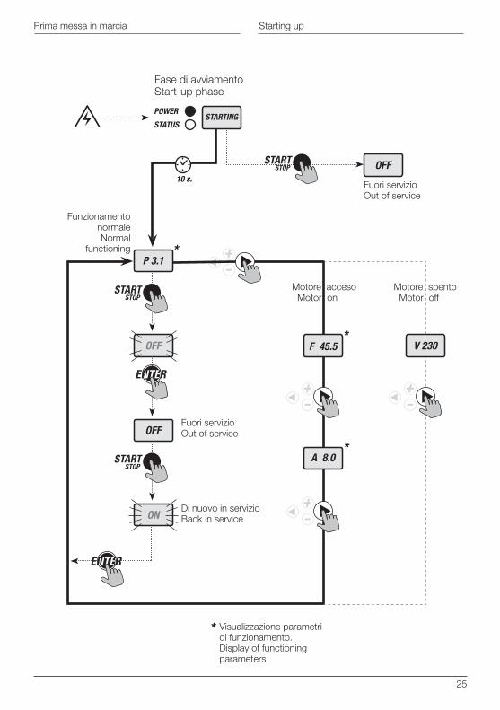
AccensioneQuando l’apparecchiatura viene alimentata dalla rete (alla prima installazione, dopo uno spegni-mento volontario o in caso di caduta e successivo ritorno della tensione di rete), entra in una fase di STARTING della durata di circa 10 secondi, trascorsi i quali STEADYPRES ritorna nelle stesse condizioni di funzionamento in cui era al momento dell’ultimo spegnimento (anche in caso di ca-duta accidentale dell’alimentazione), in quanto tutti i parametri di funzio-namento, comprese le condizioni di allarme o di blocco, vengono memo-rizzate su una memoria non volatile.Se all’ultimo spegnimento STEADYPRES era in condizione di ON, superati i 10 secondi, la pompa si avvia se rileva una pressione inferiore a quella di settaggio; è possibile mettere FUORI SERVIZIO il gruppo, prima del suo av-viamento automatico, battendo START / STOP. Se all’ultimo spegnimento STEADYPRES era in condizione di OFF, superati i 10 secondi, il gruppo entra in FUORI SERVIZIO, per avviarlo battere START / STOP e confermare.
Before starting up, please read carefully this Manual and follow the instructions. In this way incorrect settings and manoeuvres are prevented, which could cause functioning anomalies. The
system must never be started dry for any reason. Dry running of the pumps, even for very brief periods, can cause irreversible damage to mechanical sealing and internal rotating
couplings.Priming must be performed before system start-up (see page 14)When the operations described in the INSTALLA-TION chapter have been performed, the inverter can be started.
Start-upWhenever the equipment is po-wered by the mains (upon initial installation, following voluntary shutdown or in the event of a power cut and the subsequent
return of power), it will enter a START phase lasting about ten seconds. Because all of the ope-
rating parameters - including its alarm/blocking conditions - are stored on a non-volatile memory, the STEADY-PRES will resume the same opera-ting conditions as when it was last shut-down (including in the event of accidental power supply failure) after this 10-second start phase.
Where the STEADYPRES was ON when the last shut-down occurred, the pump will activate
after these 10 seconds if the pressure detected is less than the predetermined threshold; you can put the group OUT OF SERVICE prior to the automatic start-up by hitting START/STOP.Where the STEADYPRES was OFF
when the last shut-down occurred, the group will remain OUT OF SERVICE following the10-second start phase. To start-up, hit START/STOP and confirm.
IT PRIMA MESSA IN MARCIA STARTING UPEN
Segnalazioni visive
Assenza di alimentazione elettrica.Il gruppo non è alimentato elettrica-mente.
Avviamento.Il gruppo è stato alimentato elettri-camente da meno di 10 secondi.Note: viene visualizzato il messag-gio “STARTING” a scorrimento per 10 secondi, poi il gruppo ritorna nella stessa condizione di funzio-namento in cui era prima dello spegnimento.
No electric power supply.The unit is not powered electrically.
Start-up.The unit has been powered electri-cally for less than 10 seconds.Notes: the running “STARTING” message is displayed for 10 se-conds and then the unit goes back to the same functioning condition as at the time of switch-off.
POWER
STATUS
POWER
STATUSSTA....
Visual signals
Luce spenta Luce accesa Luce lampeggianteLight off Light on Light flashing
22
+ 100 rpm
- 100 rpm
A ...
+ 100 rpm
- 100 rpm
F ...
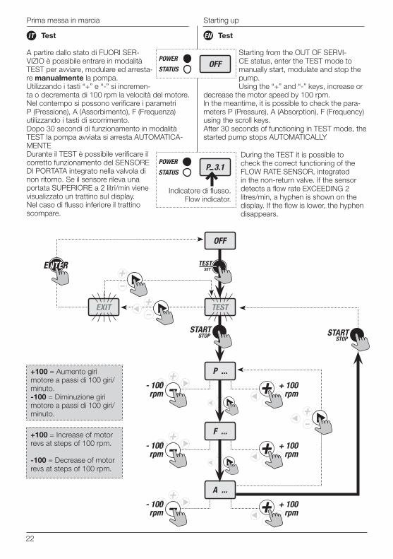
Test
A partire dallo stato di FUORI SER-VIZIO è possibile entrare in modalità TEST per avviare, modulare ed arresta-re manualmente la pompa.Utilizzando i tasti “+” e “-” si incremen-ta o decrementa di 100 rpm la velocità del motore.Nel contempo si possono verificare i parametri P (Pressione), A (Assorbimento), F (Frequenza) utilizzando i tasti di scorrimento.Dopo 30 secondi di funzionamento in modalità TEST la pompa avviata si arresta AUTOMATICA-MENTEDurante il TEST è possibile verificare il corretto funzionamento del SENSORE DI PORTATA integrato nella valvola di non ritorno. Se il sensore rileva una portata SUPERIORE a 2 litri/min viene visualizzato un trattino sul display. Nel caso di flusso inferiore il trattino scompare.
Test
Starting from the OUT OF SERVI-CE status, enter the TEST mode to manually start, modulate and stop the pump.Using the “+” and “-” keys, increase or
decrease the motor speed by 100 rpm.In the meantime, it is possible to check the para-meters P (Pressure), A (Absorption), F (Frequency) using the scroll keys.After 30 seconds of functioning in TEST mode, the started pump stops AUTOMATICALLY
During the TEST it is possible to check the correct functioning of the FLOW RATE SENSOR, integrated in the non-return valve. If the sensor detects a flow rate EXCEEDING 2 litres/min, a hyphen is shown on the display. If the flow is lower, the hyphen disappears.
ENIT
Prima messa in marcia Starting up
EXIT TEST
OFF
+ 100 rpm
- 100 rpm
P ...
Indicatore di flusso.Flow indicator.
+100 = Aumento giri motore a passi di 100 giri/minuto.-100 = Diminuzione giri motore a passi di 100 giri/minuto.
+100 = Increase of motor revs at steps of 100 rpm. -100 = Decrease of motor revs at steps of 100 rpm.
23
Starting upPrima messa in marcia
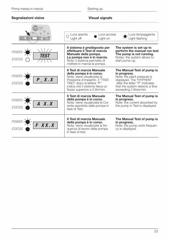
Segnalazioni visive
Il sistema è predisposto per effettuare il Test di marcia Manuale della pompa. La pompa non è in marcia.Note: il sistema permette di mettere in marcia la pompa.
Il Test di marcia Manuale della pompa è in corso.Nota: viene visualizzata la Pressione d’impianto. Il “TRAT-TINO“ dopo la lettera “P“ indica che il sistema rileva un flusso superiore a 2 litri/min.
Il Test di marcia Manuale della pompa è in corso.Nota: viene visualizzata la Cor-rente assorbita dalla pompa in fase di Test.
Il Test di marcia Manuale della pompa è in corso.Nota: viene visualizzata la fre-quenza di lavoro della pompa in fase di test.
The system is set-up to perform the manual run testThe pump is not running.Notes: the system allows to start pump up.
The Manual Test of pump is in progress.Note: the plant pressure is displayed. The “HYPHEN” after the letter “P” indicates that the system detects a flow exceeding 2 litres/min.
The Manual Test of pump is in progress.Note: the current absorbed by the pump in Test is displayed.
The Manual Test of pump is in progress.Note: the pump work frequen-cy is displayed.
POWER
STATUSP _ X . X
POWER
STATUSA X . X
POWER
STATUSF X X . X
POWER
STATUSTEST
Visual signals
Luce spenta Luce accesa Luce lampeggianteLight off Light on Light flashing
24
Segnalazioni visive
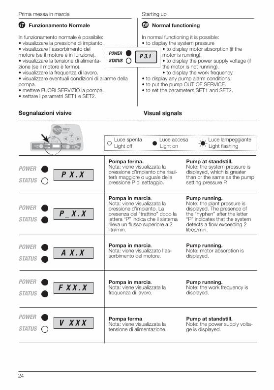
Pompa ferma.Nota: viene visualizzata la pressione d’impianto che risul-terà maggiore o uguale della pressione P di settaggio.
Pompa in marcia.Nota: viene visualizzata la pressione d’impianto. La presenza del “trattino” dopo la lettera “P” indica che il sistema rileva un flusso superiore a 2 litri/min.
Pompa in marcia.Nota: viene visualizzato l’as-sorbimento del motore.
Pompa in marcia.Nota: viene visualizzata la frequenza di lavoro.
Pompa ferma.Nota: viene visualizzata la tensione di alimentazione.
Pump at standstill.Note: the system pressure is displayed, which is greater than or the same as the pump setting pressure P.
Pump running.Note: the plant pressure is displayed. The presence of the “hyphen” after the letter “P” indicates that the system detects a flow exceeding 2 litres/min.
Pump running.Note: motor absorption is displayed.
Pump running.Note: the work frequency is displayed.
Pump at standstill.Note: the power supply volta-ge is displayed.
POWER
STATUSP _ X . X
POWER
STATUSA X . X
POWER
STATUSF X X . X
POWER
STATUSV X X X
POWER
STATUSP X . X
Funzionamento Normale
In funzionamento normale è possibile:• visualizzare la pressione di impianto.• visualizzare l’assorbimento del motore (se il motore è in funzione).• visualizzare la tensione di alimenta-zione (se il motore è fermo).• visualizzare la frequenza di lavoro.• visualizzare eventuali condizioni di allarme della pompa.• mettere FUORI SERVIZIO la pompa.• settare i parametri SET1 e SET2.
Normal functioning
In normal functioning it is possible:• to display the system pressure
• to display motor absorption (if the motor is running).• to display the power supply voltage (if the motor is not running).• to display the work frequency.
• to display any pump alarm conditions.• to put the pump OUT OF SERVICE.• to set the parameters SET1 and SET2.
ENIT
Prima messa in marcia
Visual signals
Luce spenta Luce accesa Luce lampeggianteLight off Light on Light flashing
Starting up
25
POWER
STATUSSTARTING
10 s.
P 3.1
A 8.0
V 230F 45.5OFF
ON
OFF
OFF
*
*
*
*
Fase di avviamentoStart-up phase
FunzionamentonormaleNormal
functioning
Fuori servizioOut of service
Fuori servizioOut of service
Motore acceso Motor on
Visualizzazione parametri di funzionamento.Display of functioning parameters
Motore spento Motor off
Di nuovo in servizioBack in service
Prima messa in marcia Starting up
26
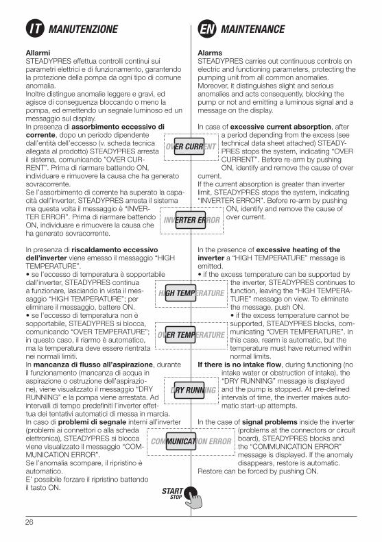
AllarmiSTEADYPRES effettua controlli continui sui parametri elettrici e di funzionamento, garantendo la protezione della pompa da ogni tipo di comune anomalia.Inoltre distingue anomalie leggere e gravi, ed agisce di conseguenza bloccando o meno la pompa, ed emettendo un segnale luminoso ed un messaggio sul display.In presenza di assorbimento eccessivo di corrente, dopo un periodo dipendente dall’entità dell’eccesso (v. scheda tecnica allegata al prodotto) STEADYPRES arresta il sistema, comunicando ”OVER CUR-RENT”. Prima di riarmare battendo ON, individuare e rimuovere la causa che ha generato sovracorrente.Se l’assorbimento di corrente ha superato la capa-cità dell’inverter, STEADYPRES arresta il sistema ma questa volta il messaggio è “INVER-TER ERROR”. Prima di riarmare battendo ON, individuare e rimuovere la causa che ha generato sovracorrente.
In presenza di riscaldamento eccessivo dell’inverter viene emesso il messaggio “HIGH TEMPERATURE”.• se l’eccesso di temperatura è sopportabile dall’inverter, STEADYPRES continua a funzionare, lasciando in vista il mes-saggio “HIGH TEMPERATURE”; per eliminare il messaggio, battere ON.• se l’eccesso di temperatura non è sopportabile, STEADYPRES si blocca, comunicando “OVER TEMPERATURE”; in questo caso, il riarmo è automatico, ma la temperatura deve essere rientrata nei normali limiti.In mancanza di flusso all’aspirazione, durante il funzionamento (mancanza di acqua in aspirazione o ostruzione dell’aspirazio-ne), viene visualizzato il messaggio “DRY RUNNING” e la pompa viene arrestata. Ad intervalli di tempo predefiniti l’inverter effet-tua dei tentativi automatici di messa in marcia.In caso di problemi di segnale interni all’inverter (problemi ai connettori o alla scheda elettronica), STEADYPRES si blocca viene visualizzato il messaggio “COM-MUNICATION ERROR”.Se l’anomalia scompare, il ripristino è automatico. E’ possibile forzare il ripristino battendo il tasto ON.
AlarmsSTEADYPRES carries out continuous controls on electric and functioning parameters, protecting the pumping unit from all common anomalies.Moreover, it distinguishes slight and serious anomalies and acts consequently, blocking the pump or not and emitting a luminous signal and a message on the display.
In case of excessive current absorption, after a period depending from the excess (see technical data sheet attached) STEADY-PRES stops the system, indicating “OVER CURRENT”. Before re-arm by pushing ON, identify and remove the cause of over
current.If the current absorption is greater than inverter limit, STEADYPRES stops the system, indicating “INVERTER ERROR”. Before re-arm by pushing
ON, identify and remove the cause of over current.
In the presence of excessive heating of the inverter a “HIGH TEMPERATURE” message is emitted.• if the excess temperature can be supported by
the inverter, STEADYPRES continues to function, leaving the “HIGH TEMPERA-TURE” message on view. To eliminate the message, push ON.• if the excess temperature cannot be supported, STEADYPRES blocks, com-municating “OVER TEMPERATURE”. In this case, rearm is automatic, but the temperature must have returned within normal limits.
If there is no intake flow, during functioning (no intake water or obstruction of intake), the “DRY RUNNING” message is displayed and the pump is stopped. At pre-defined intervals of time, the inverter makes auto-matic start-up attempts.
In the case of signal problems inside the inverter (problems at the connectors or circuit board), STEADYPRES blocks and the “COMMUNICATION ERROR” message is displayed. If the anomaly disappears, restore is automatic.
Restore can be forced by pushing ON.
IT MANUTENZIONE MAINTENANCEEN
27
Manutenzione Maintenance
Segnalazioni visive
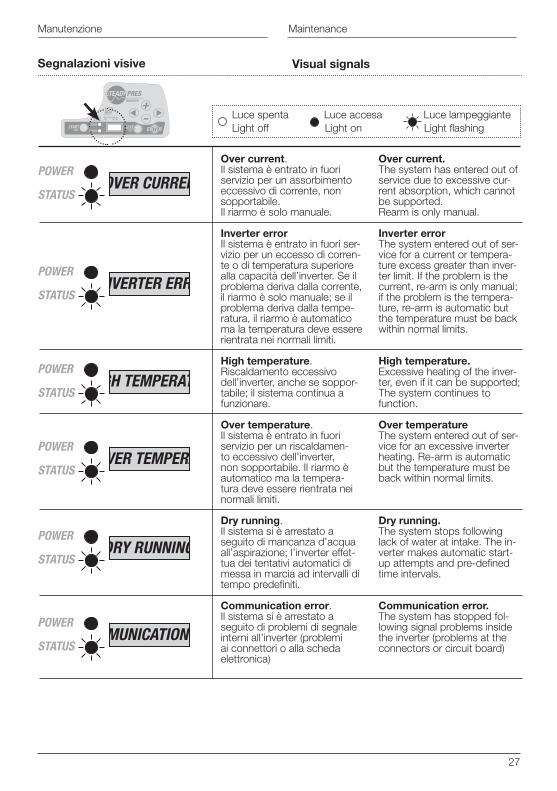
Over current.Il sistema è entrato in fuori servizio per un assorbimento eccessivo di corrente, non sopportabile. Il riarmo è solo manuale.
Inverter errorIl sistema è entrato in fuori ser-vizio per un eccesso di corren-te o di temperatura superiore alla capacità dell’inverter. Se il problema deriva dalla corrente, il riarmo è solo manuale; se il problema deriva dalla tempe-ratura, il riarmo è automatico ma la temperatura deve essere rientrata nei normali limiti.
High temperature.Riscaldamento eccessivo dell’inverter, anche se soppor-tabile; il sistema continua a funzionare.
Over temperature.Il sistema è entrato in fuori servizio per un riscaldamen-to eccessivo dell’inverter, non sopportabile. Il riarmo è automatico ma la tempera-tura deve essere rientrata nei normali limiti.
Dry running.Il sistema si è arrestato a seguito di mancanza d’acqua all’aspirazione; l’inverter effet-tua dei tentativi automatici di messa in marcia ad intervalli di tempo predefiniti.
Communication error.Il sistema si è arrestato a seguito di problemi di segnale interni all’inverter (problemi ai connettori o alla scheda elettronica)
Over current.The system has entered out of service due to excessive cur-rent absorption, which cannot be supported.Rearm is only manual.
Inverter errorThe system entered out of ser-vice for a current or tempera-ture excess greater than inver-ter limit. If the problem is the current, re-arm is only manual; if the problem is the tempera-ture, re-arm is automatic but the temperature must be back within normal limits.
High temperature.Excessive heating of the inver-ter, even if it can be supported;The system continues to function.
Over temperatureThe system entered out of ser-vice for an excessive inverter heating. Re-arm is automatic but the temperature must be back within normal limits.
Dry running.The system stops following lack of water at intake. The in-verter makes automatic start-up attempts and pre-defined time intervals.
Communication error.The system has stopped fol-lowing signal problems inside the inverter (problems at the connectors or circuit board)
POWER
STATUSOVER CURRENT
POWER
STATUSHIGH TEMPERATURE
POWER
STATUSOVER TEMPERATURE
POWER
STATUSINVERTER ERROR
POWER
STATUSDRY RUNNING
POWER
STATUSCOMMUNICATION ERROR
Visual signals
Luce spenta Luce accesa Luce lampeggianteLight off Light on Light flashing
28
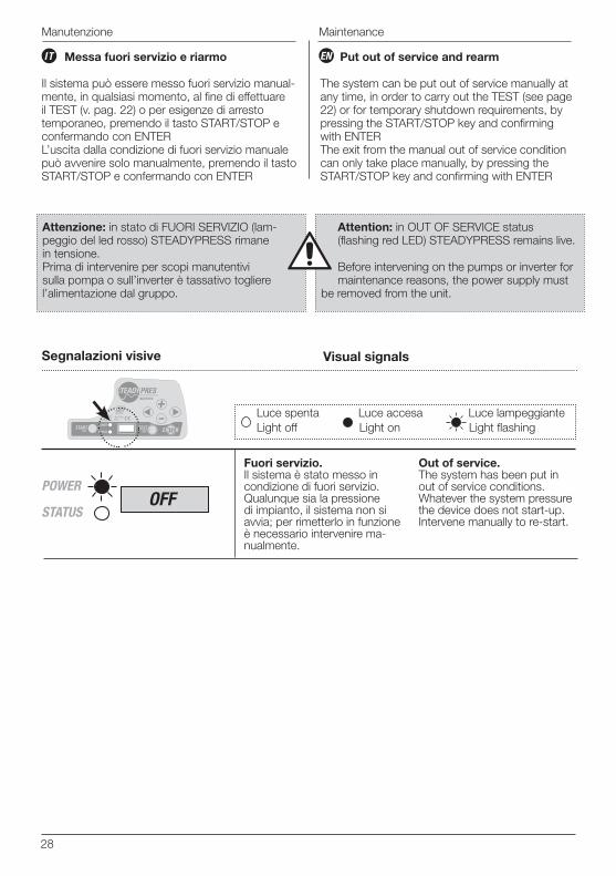
Messa fuori servizio e riarmo
Il sistema può essere messo fuori servizio manual-mente, in qualsiasi momento, al fine di effettuare il TEST (v. pag. 22) o per esigenze di arresto temporaneo, premendo il tasto START/STOP e confermando con ENTERL’uscita dalla condizione di fuori servizio manuale può avvenire solo manualmente, premendo il tasto START/STOP e confermando con ENTER
Put out of service and rearm
The system can be put out of service manually at any time, in order to carry out the TEST (see page 22) or for temporary shutdown requirements, by pressing the START/STOP key and confirming with ENTERThe exit from the manual out of service condition can only take place manually, by pressing the START/STOP key and confirming with ENTER
ENIT
Manutenzione
Attenzione: in stato di FUORI SERVIZIO (lam-peggio del led rosso) STEADYPRESS rimane in tensione.Prima di intervenire per scopi manutentivi sulla pompa o sull’inverter è tassativo togliere l’alimentazione dal gruppo.
Attention: in OUT OF SERVICE status (flashing red LED) STEADYPRESS remains live.
Before intervening on the pumps or inverter for maintenance reasons, the power supply must
be removed from the unit.
Segnalazioni visive
Fuori servizio.Il sistema è stato messo in condizione di fuori servizio.Qualunque sia la pressione di impianto, il sistema non si avvia; per rimetterlo in funzione è necessario intervenire ma-nualmente.
Out of service.The system has been put in out of service conditions.Whatever the system pressure the device does not start-up. Intervene manually to re-start.
POWER
STATUSOFF
Visual signals
Luce spenta Luce accesa Luce lampeggianteLight off Light on Light flashing
Maintenance
29
IT
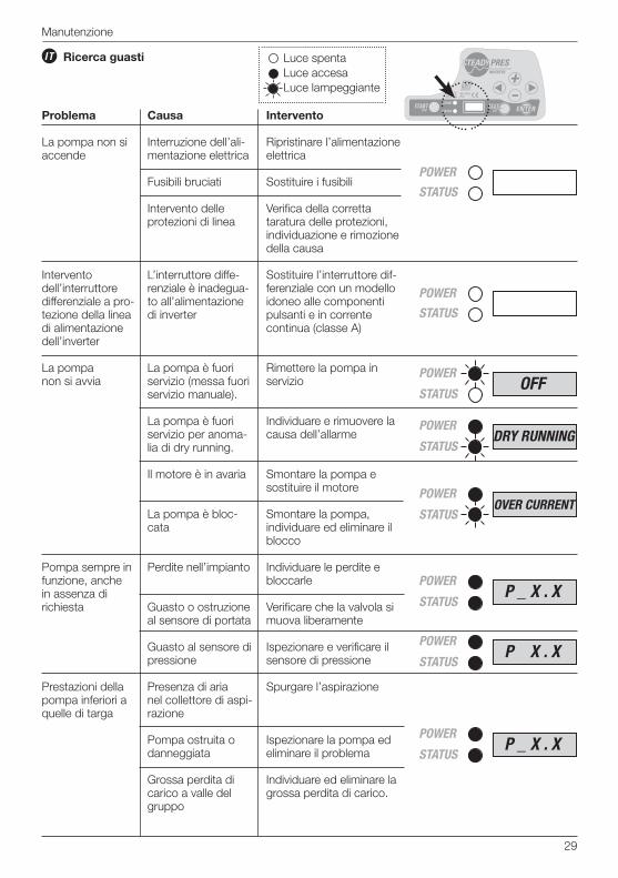
Problema
La pompa non si accende
Intervento dell’interruttore differenziale a pro-tezione della linea di alimentazione dell’inverter
La pompa non si avvia
Pompa sempre in funzione, anche in assenza di richiesta
Prestazioni della pompa inferiori a quelle di targa
Causa
Interruzione dell’ali-mentazione elettrica
Fusibili bruciati
Intervento delle protezioni di linea
L’interruttore diffe-renziale è inadegua-to all’alimentazione di inverter
La pompa è fuori servizio (messa fuori servizio manuale).
La pompa è fuori servizio per anoma-lia di dry running.
Il motore è in avaria
La pompa è bloc-cata
Perdite nell’impianto
Guasto o ostruzione al sensore di portata
Guasto al sensore di pressione
Presenza di aria nel collettore di aspi-razione
Pompa ostruita o danneggiata
Grossa perdita di carico a valle del gruppo
Intervento
Ripristinare l’alimentazione elettrica
Sostituire i fusibili
Verifica della corretta taratura delle protezioni, individuazione e rimozione della causa
Sostituire l’interruttore dif-ferenziale con un modello idoneo alle componenti pulsanti e in corrente continua (classe A)
Rimettere la pompa in servizio
Individuare e rimuovere la causa dell’allarme
Smontare la pompa e sostituire il motore
Smontare la pompa, individuare ed eliminare il blocco
Individuare le perdite e bloccarle
Verificare che la valvola si muova liberamente
Ispezionare e verificare il sensore di pressione
Spurgare l’aspirazione
Ispezionare la pompa ed eliminare il problema
Individuare ed eliminare la grossa perdita di carico.
Luce spentaLuce accesa Luce lampeggiante
POWER
STATUS
POWER
STATUS
POWER
STATUSP _ X . X
POWER
STATUSP X . X
POWER
STATUSP _ X . X
Ricerca guasti
Manutenzione
POWER
STATUSOFF
POWER
STATUSDRY RUNNING
POWER
STATUSOVER CURRENT
30
Maintenance
EN
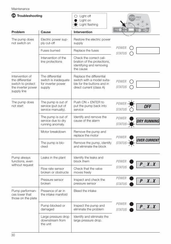
Problem
The pump does not switch on
Intervention of the differential switch to protect the inverter power supply line
The pump does not start
Pump always functions, even without request
Pump performan-ces lower that those on the plate
Cause
Electric power sup-ply cut-off
Fuses burned
Intervention of the line protections
The differential switch is inadequate for inverter power supply
The pump is out of service (put out of service manually).
The pump is out of service due to dry running anomaly.
Motor breakdown
The pump is blo-cked
Leaks in the plant
Flow rate sensor broken or obstructe
Pressure sensor broken
Presence of air in the intake manifold
Pump blocked or damaged
Large pressure drop downstream from the unit
Intervention
Restore the electric power supply
Replace the fuses
Check the correct cali-bration of the protections, identifying and removing the cause
Replace the differential switch with a model suita-ble for the buttons and in direct current (class A)
Push ON + ENTER to put the pump back into service
Identify and remove the cause of the alarm
Remove the pump and replace the motor
Remove the pump, identify and eliminate the block
Identify the leaks and block them
Check that the valve moves freely
Inspect and check the pressure sensor
Bleed the intake
Inspect the pump and eliminate the problem
Identify and eliminate the large pressure drop.
Light off Light on Light flashing
POWER
STATUS
POWER
STATUS
POWER
STATUSP _ X . X
POWER
STATUSP X . X
POWER
STATUSP _ X . X
Troubleshooting
POWER
STATUSOFF
POWER
STATUSDRY RUNNING
POWER
STATUSOVER CURRENT
31
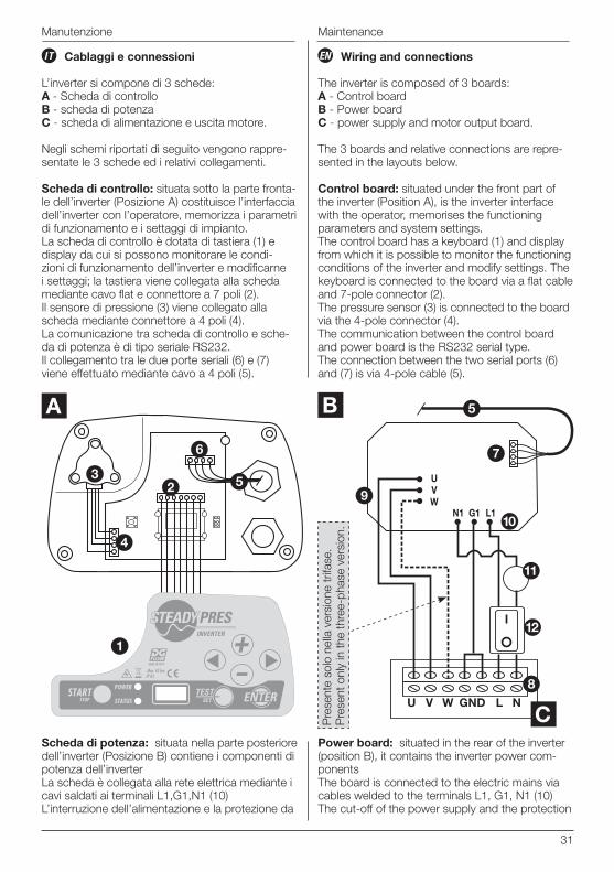
Wiring and connections
The inverter is composed of 3 boards:A - Control boardB - Power boardC - power supply and motor output board.
The 3 boards and relative connections are repre-sented in the layouts below.
Control board: situated under the front part of the inverter (Position A), is the inverter interface with the operator, memorises the functioning parameters and system settings.The control board has a keyboard (1) and display from which it is possible to monitor the functioning conditions of the inverter and modify settings. The keyboard is connected to the board via a flat cable and 7-pole connector (2).The pressure sensor (3) is connected to the board via the 4-pole connector (4).The communication between the control board and power board is the RS232 serial type.The connection between the two serial ports (6) and (7) is via 4-pole cable (5).
Power board: situated in the rear of the inverter (position B), it contains the inverter power com-ponentsThe board is connected to the electric mains via cables welded to the terminals L1, G1, N1 (10)The cut-off of the power supply and the protection
ENIT
Manutenzione
Cablaggi e connessioni
L’inverter si compone di 3 schede: A - Scheda di controlloB - scheda di potenzaC - scheda di alimentazione e uscita motore.
Negli schemi riportati di seguito vengono rappre-sentate le 3 schede ed i relativi collegamenti.
Scheda di controllo: situata sotto la parte fronta-le dell’inverter (Posizione A) costituisce l’interfaccia dell’inverter con l’operatore, memorizza i parametri di funzionamento e i settaggi di impianto. La scheda di controllo è dotata di tastiera (1) e display da cui si possono monitorare le condi-zioni di funzionamento dell’inverter e modificarne i settaggi; la tastiera viene collegata alla scheda mediante cavo flat e connettore a 7 poli (2). Il sensore di pressione (3) viene collegato alla scheda mediante connettore a 4 poli (4). La comunicazione tra scheda di controllo e sche-da di potenza è di tipo seriale RS232.Il collegamento tra le due porte seriali (6) e (7) viene effettuato mediante cavo a 4 poli (5).
Scheda di potenza: situata nella parte posteriore dell’inverter (Posizione B) contiene i componenti di potenza dell’inverter La scheda è collegata alla rete elettrica mediante i cavi saldati ai terminali L1,G1,N1 (10) L’interruzione dell’alimentazione e la protezione da
5
6
3
4
2
1
A
V W
7
8
9
11
10
12
N
L1G1N1
UVW
U GND L
5B
CPre
sent
e so
lo n
ella
ver
sion
e tr
ifase
.P
rese
nt o
nly
in th
e th
ree-
phas
e ve
rsio
n.
Maintenance
32
Manutenzione
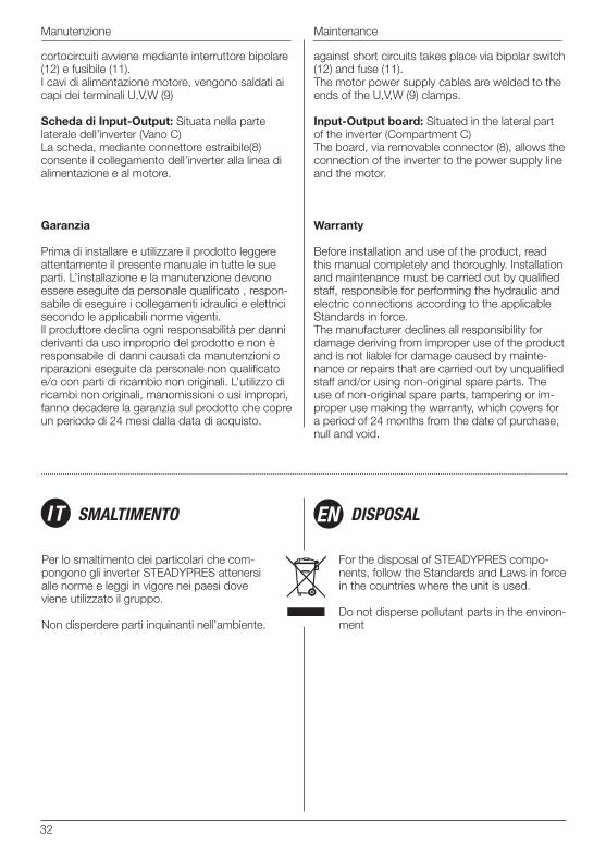
cortocircuiti avviene mediante interruttore bipolare (12) e fusibile (11). I cavi di alimentazione motore, vengono saldati ai capi dei terminali U,V,W (9) Scheda di Input-Output: Situata nella parte laterale dell’inverter (Vano C) La scheda, mediante connettore estraibile(8) consente il collegamento dell’inverter alla linea di alimentazione e al motore.
Garanzia
Prima di installare e utilizzare il prodotto leggere attentamente il presente manuale in tutte le sue parti. L’installazione e la manutenzione devono essere eseguite da personale qualificato , respon-sabile di eseguire i collegamenti idraulici e elettrici secondo le applicabili norme vigenti. Il produttore declina ogni responsabilità per danni derivanti da uso improprio del prodotto e non è responsabile di danni causati da manutenzioni o riparazioni eseguite da personale non qualificato e/o con parti di ricambio non originali. L’utilizzo di ricambi non originali, manomissioni o usi impropri, fanno decadere la garanzia sul prodotto che copre un periodo di 24 mesi dalla data di acquisto.
against short circuits takes place via bipolar switch (12) and fuse (11).The motor power supply cables are welded to the ends of the U,V,W (9) clamps.
Input-Output board: Situated in the lateral part of the inverter (Compartment C)The board, via removable connector (8), allows the connection of the inverter to the power supply line and the motor.
Warranty
Before installation and use of the product, read this manual completely and thoroughly. Installation and maintenance must be carried out by qualified staff, responsible for performing the hydraulic and electric connections according to the applicable Standards in force.The manufacturer declines all responsibility for damage deriving from improper use of the product and is not liable for damage caused by mainte-nance or repairs that are carried out by unqualified staff and/or using non-original spare parts. The use of non-original spare parts, tampering or im-proper use making the warranty, which covers for a period of 24 months from the date of purchase, null and void.
Per lo smaltimento dei particolari che com-pongono gli inverter STEADYPRES attenersi alle norme e leggi in vigore nei paesi dove viene utilizzato il gruppo.
Non disperdere parti inquinanti nell’ambiente.
For the disposal of STEADYPRES compo-nents, follow the Standards and Laws in force in the countries where the unit is used.
Do not disperse pollutant parts in the environ-ment
SMALTIMENTO DISPOSALIT EN
Maintenance
33
DICHIARAZIONE DI CONFORMITA’
DECLARATION OF CONFORMITY
Dichiariamo, sotto la nostra esclusiva responsa-bilità, che il prodotto in oggetto è conforme alle seguenti direttive europee e disposizioni nazionali di attuazione:
2006/95/CEE Direttiva Bassa Tensione2002/95/CEE Sostanze pericolose nelle apparecchiature elettroniche (RoHS)2002/96/CEE e 2003/108/ CEE Sostanze pericolose nelle apparecchiature elettroniche (RAEE)2004/108/CE Direttiva Compatibilità Elettroma-gnetica (EMC)
CEI EN 61000-6-1 Immunità per ambienti residenzialiCEI EN 61000-6-2 Immunità per ambienti industrialiCEI EN 61000-6-3 Emissione per ambienti residenzialiCEI EN 61000-6-4 Emissione per ambienti industriali
We declare, under our own responsibility, that the product in question is in compliance with the following European Directives and national implementation provisions.
2006/95/EEC Low Voltage Directive2002/95/EEC Dangerous substances in
electronic appliances (RoHS)2002/96/EEC and 2003/108/EEC,Dangerous substances in electronic appliances (WEEE)2004/108/CE Electromagnetic Compatibility Directive (EMC)
IEC EN 61000-6-1Immunity for residential environments IEC EN 61000-6-2Immunity for industrial environments IEC EN 61000-6-3Emission for residential environments IEC EN 61000-6-4Emission for industrial environments
DGFLOW S.r.l.President - Amministratore Unico
Stefano ConciniBigarello 09.09.09
IT EN
34
ENIT Esploso ricambi Spare parts diagram
7
7
KIT 3
KIT 1
KIT 2
6
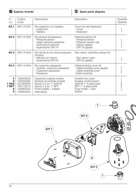
DR1141K01
DR1141K02
DR1141K03
DR1141K04
10004003A 10005006A00108300A10017201A100083030100084030
Kit 1
Kit 2
Kit 3
Kit 4
56
7 GAS7 NPT
89
11
1111
11
112
112211
Kit coperchio con tastiera- Coperchio - Tastiera
Kit sensore di pressione- Pressure sensor- Tappo sensore pressione- Guarnizione sensore- Guarnizione OR114
Kit valvola di non ritorno/sensore di flusso- Valvola non ritorno- Guarnizione OR153
Kit coperchio passacavi- Guarniz. coperchio passacavi- Coperchio passacavi- Passacavi
Coperchio scatola inverterScheda di controllo inverterGiunto a 3 pz 1” GAS MGiunto a 3 pz 1” NPTPorta fusibile + fusibileInterruttore
Cover kit with keyboard- Cover- Keyboard
Pressure sensor kit- Pressure sensor- Pressure sensor cap- Sensor gasket- OR114 gasket
Non-return valve/flow sensor kit
- Non-return valve- OR153 gasket
Cable-bushing cover kit- Cable-bushing cover gasket - Cable-bushing cover -Cable-bushing
Inverter box coverInverter control boardGAS M 1” 3-piece jointNPT 1” 3-piece jointFuse holder + fuseSwitch
Descrizione Descriptionn°.no.
CodiceCode
QuantitàQuantity
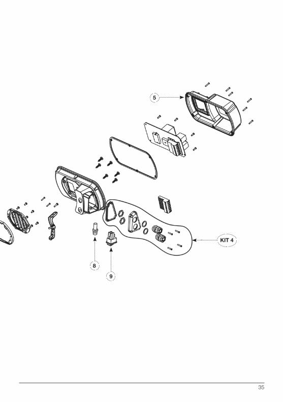
35
9
5
KIT 4
8

36