IPV11AGLS IPV12AGLS IPT08AGLS - farfisa.com · interface, which has the door lock release control...
32
1 Mi2526 Moduli posti esterni VoIP per applicazioni video citofoniche 1.1 INTRODUZIONE ED APPLICAZIONI La gamma delle pulsantiere Agorà IP comprende un modulo base (ad 1 o 2 tasti) nella versione audio/video. A questo modulo è possibile affiancare sino a 16 ulteriori moduli di espansione ad 8 tasti ciascuno che consentono di raggiungere una configurazione massima totale di 130 pulsanti. I prodotti possono essere collegati solo alla propria rete LAN Ethernet e consentono di chiamare direttamente videocitofoni ZHeroIP, telefoni VoIP, PC, smart phones o dispositivi dedicati. La segnalazione avviene su protocollo SIP standard, mentre la trasmissione audio/video attraverso protocollo RTP, quindi è possibile integrare queste pulsantiere con la maggior parte dei sistemi gestiti da PBX VoIP in commercio. 1.2 CARATTERISTICHE Possibilità di associare fino a 5 numeri da 25 caratteri o indirizzi IP a ciascun pulsante di chiamata. Chiamata dei numeri sequenziale, simultanea (di gruppo) o in funzione dell'intervallo temporale. Invio di e-mail automatico con immagini allegate nel caso in cui l'utente non sia raggiungibile. Configurazione di fino a 10 intervalli temporali con programmazione settimanale. Controllo di 2 relè interni e 2 remoti. Fino a 10 codici per apertura serratura per ciascun relè e codice personalizzato per ciascun utente tramite combinazione dei pulsanti di chiamata. Due ingressi per sensori di stato per ciascuna porta configurabili come pulsanti di apertura. Prolungamento del tempo di conversazione premendo il tasto * o #. Varie modalità di funzionamento dei relè per il controllo delle serrature (anche in combinazione). Possibilità di alimentazione a 12Vcc/ca esterna o tramite PoE. Illuminazione a LED dei cartellini e della telecamera programmabile e regolabile. Sincronizzazione dell'ora tramite server NTP. Telecamera a colori integrata. Interfaccia Ethernet 10/100Mb (10BaseT e 100BaseTx). Web server integrato per programmazione remota. Sistema operativo Linux. Video Streaming indipendenti JPEG/RTSP e H.263/H.264. Supporto protocollo SIP 2.0 (RFC 3261) in modalità P2P o SIP Proxy (con PBX di rete). Aggiornamento firmware via pagina web. Supporto multilingue. Interfaccia web per la programmazione dei parametri della pulsantiera. Door stations VoIP modules for video door entry applications 1.1 INTRODUCTION AND APPLICATIONS The AgoràIP door station series is composed by a base module (of 1 or 2 push buttons) in audio/video version. It is possible to add up to 16 expansion modules of 8 buttons each for a total maximum system capacity of 130 calls. The products can be connected only to the user’s LAN Ethernet network and allow to call directly ZHeroIP videointercoms, VoIP phones, PC based softphones or dedicated devices. The communication signalling is based on standard SIP, while the audio/video transmission on RTP protocol, then it is possible to integrate these door stations with most of the systems based VoIP PBX's available in the market. 1.2 FEATURES It is possible to store up to 5 numbers of up to 25 characters or IP address to each call button. Number call can be sequential, simultaneous (group calling) or according to time interval. Automatic e-mail with attached picture sending if the subscriber user is not available. Configuration of up to 10 time intervals with weekly programming for calls and relay activation . Control of up 2 internal and 2 remote relays. Up to 10 access codes can be programmed and also a personal code for each user for door opening by pressing combination of call buttons. Two input for door sensors which can be configured also as door release buttons. Call duration prolongation function by pressing * o # button on the phone's keypad. Various working modes for the relays and door locks controls (even combining both of them are possible). Power supply by external 12Vdc/ac or by PoE both supported. Led light for name plates and camera programmable and adjustable level. Internal clock synchronization by NTP server. Integrated colour camera. Ethernet 10/100Mb (10BaseT and 100BaseTX) interface. Web server for remote programming. Linux operating system. Independent video streaming JPEG/RTSP and H.263/H.264. SIP 2.0 (RFC 3261) protocol support on P2P mode or SIP Proxy mode (with network PBX). Firmware upgrade by web administration page. Multilanguage support for web page. Web interface for complete door station parameters programming. Mi2526 IPV11AGLS IPV12AGLS IPT08AGLS
Transcript of IPV11AGLS IPV12AGLS IPT08AGLS - farfisa.com · interface, which has the door lock release control...

1 Mi2526
Moduli posti esterni VoIP per applicazioni video citofoniche 1.1 INTRODUZIONE ED APPLICAZIONI La gamma delle pulsantiere Agorà IP comprende un modulo base (ad 1 o 2 tasti) nella versione audio/video. A questo modulo è possibile affiancare sino a 16 ulteriori moduli di espansione ad 8 tasti ciascuno che consentono di raggiungere una configurazione massima totale di 130 pulsanti. I prodotti possono essere collegati solo alla propria rete LAN Ethernet e consentono di chiamare direttamente videocitofoni ZHeroIP, telefoni VoIP, PC, smart phones o dispositivi dedicati. La segnalazione avviene su protocollo SIP standard, mentre la trasmissione audio/video attraverso protocollo RTP, quindi è possibile integrare queste pulsantiere con la maggior parte dei sistemi gestiti da PBX VoIP in commercio.
1.2 CARATTERISTICHE Possibilità di associare fino a 5 numeri da 25 caratteri o indirizzi
IP a ciascun pulsante di chiamata. Chiamata dei numeri sequenziale, simultanea (di gruppo) o in
funzione dell'intervallo temporale. Invio di e-mail automatico con immagini allegate nel caso in cui
l'utente non sia raggiungibile. Configurazione di fino a 10 intervalli temporali con
programmazione settimanale. Controllo di 2 relè interni e 2 remoti. Fino a 10 codici per apertura serratura per ciascun relè e codice
personalizzato per ciascun utente tramite combinazione dei pulsanti di chiamata.
Due ingressi per sensori di stato per ciascuna porta configurabili come pulsanti di apertura.
Prolungamento del tempo di conversazione premendo il tasto * o #.
Varie modalità di funzionamento dei relè per il controllo delle serrature (anche in combinazione).
Possibilità di alimentazione a 12Vcc/ca esterna o tramite PoE. Illuminazione a LED dei cartellini e della telecamera
programmabile e regolabile. Sincronizzazione dell'ora tramite server NTP. Telecamera a colori integrata. Interfaccia Ethernet 10/100Mb (10BaseT e 100BaseTx). Web server integrato per programmazione remota. Sistema operativo Linux. Video Streaming indipendenti JPEG/RTSP e H.263/H.264. Supporto protocollo SIP 2.0 (RFC 3261) in modalità P2P o SIP
Proxy (con PBX di rete). Aggiornamento firmware via pagina web. Supporto multilingue. Interfaccia web per la programmazione dei parametri della
pulsantiera.
Door stations VoIP modules for video door entry applications 1.1 INTRODUCTION AND APPLICATIONS The AgoràIP door station series is composed by a base module (of 1 or 2 push buttons) in audio/video version. It is possible to add up to 16 expansion modules of 8 buttons each for a total maximum system capacity of 130 calls. The products can be connected only to the user’s LAN Ethernet network and allow to call directly ZHeroIP videointercoms, VoIP phones, PC based softphones or dedicated devices. The communication signalling is based on standard SIP, while the audio/video transmission on RTP protocol, then it is possible to integrate these door stations with most of the systems based VoIP PBX's available in the market.
1.2 FEATURES It is possible to store up to 5 numbers of up to 25 characters
or IP address to each call button. Number call can be sequential, simultaneous (group calling)
or according to time interval. Automatic e-mail with attached picture sending if the
subscriber user is not available. Configuration of up to 10 time intervals with weekly
programming for calls and relay activation . Control of up 2 internal and 2 remote relays. Up to 10 access codes can be programmed and also a
personal code for each user for door opening by pressing combination of call buttons.
Two input for door sensors which can be configured also as door release buttons.
Call duration prolongation function by pressing * o # button on the phone's keypad.
Various working modes for the relays and door locks controls (even combining both of them are possible).
Power supply by external 12Vdc/ac or by PoE both supported.
Led light for name plates and camera programmable and adjustable level.
Internal clock synchronization by NTP server. Integrated colour camera. Ethernet 10/100Mb (10BaseT and 100BaseTX) interface. Web server for remote programming. Linux operating system. Independent video streaming JPEG/RTSP and H.263/H.264. SIP 2.0 (RFC 3261) protocol support on P2P mode or SIP
Proxy mode (with network PBX). Firmware upgrade by web administration page. Multilanguage support for web page. Web interface for complete door station parameters
programming.
Mi2526
IPV11AGLS IPV12AGLS IPT08AGLS
2 Mi2526
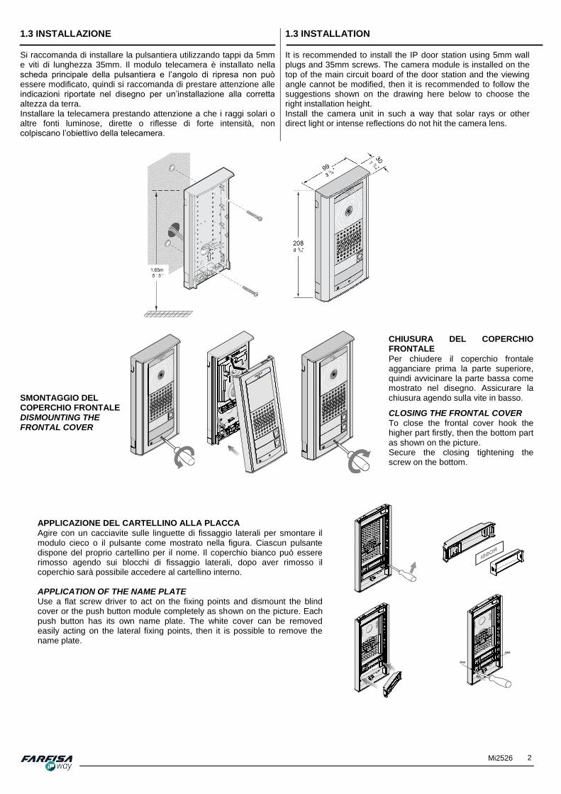
1.3 INSTALLAZIONE Si raccomanda di installare la pulsantiera utilizzando tappi da 5mm e viti di lunghezza 35mm. Il modulo telecamera è installato nella scheda principale della pulsantiera e l’angolo di ripresa non può essere modificato, quindi si raccomanda di prestare attenzione alle indicazioni riportate nel disegno per un’installazione alla corretta altezza da terra. Installare la telecamera prestando attenzione a che i raggi solari o altre fonti luminose, dirette o riflesse di forte intensità, non colpiscano l’obiettivo della telecamera.
1.3 INSTALLATION It is recommended to install the IP door station using 5mm wall plugs and 35mm screws. The camera module is installed on the top of the main circuit board of the door station and the viewing angle cannot be modified, then it is recommended to follow the suggestions shown on the drawing here below to choose the right installation height. Install the camera unit in such a way that solar rays or other direct light or intense reflections do not hit the camera lens.
CHIUSURA DEL COPERCHIO FRONTALE
Per chiudere il coperchio frontale agganciare prima la parte superiore, quindi avvicinare la parte bassa come mostrato nel disegno. Assicurare la chiusura agendo sulla vite in basso.
CLOSING THE FRONTAL COVER To close the frontal cover hook the higher part firstly, then the bottom part as shown on the picture. Secure the closing tightening the screw on the bottom.
SMONTAGGIO DEL COPERCHIO FRONTALE DISMOUNTING THE FRONTAL COVER
APPLICAZIONE DEL CARTELLINO ALLA PLACCA
Agire con un cacciavite sulle linguette di fissaggio laterali per smontare il modulo cieco o il pulsante come mostrato nella figura. Ciascun pulsante dispone del proprio cartellino per il nome. Il coperchio bianco può essere rimosso agendo sui blocchi di fissaggio laterali, dopo aver rimosso il coperchio sarà possibile accedere al cartellino interno. APPLICATION OF THE NAME PLATE Use a flat screw driver to act on the fixing points and dismount the blind cover or the push button module completely as shown on the picture. Each push button has its own name plate. The white cover can be removed easily acting on the lateral fixing points, then it is possible to remove the name plate.

3 Mi2526
2.1 SPECIFICHE TECNICHE Alimentazione 12Vcc/ca
PoE (IEEE802.3af A+B) Consumo di corrente massimo 300mA (a 12Vcc) Interfaccia di rete Ethernet 10BaseT, 100BaseTX Protocollo VoIP supportato SIP 2.0 (RFC3261) Compressione audio G.711u,G.711a, G.726-32b,
GSM, G.722, G.727 (opt.) Compressione video serie JPEG, MJPEG, H.263
(CIF), H.264 Risoluzione massima 640x480 Angolo visuale 80° (V) x 100° (O) Uscite relè 2 Capacità contatti relè 12Vca/1A Temperatura di funzionamento 0°C ~ +50°C Dimensioni (mm) 99x208x30 Grado di protezione IP34
2.1 TECHNICAL SPECIFICATIONS
Power supply 12Vdc/ac PoE (IEEE802.3af A / B
mode) Maximum current consumption 300mA (at 12Vdc) Network Interface Ethernet 10BaseT,
100BaseTX VoIP protocol SIP 2.0 (RFC3261) Audio Codec G.711u,G.711a, G.726-32b,
GSM, G.722, G.729 (opt.) Video Codec series JPEG, MJPEG, H.263
(CIF), H.264 Maximum resolution 640x480 Viewing angle 80° (V) x 100° (H) Relays outputs 2 Relays contact capacity 12Vac/1A Operating Temperature 0°C ~ +50°C Dimensions (mm) 99x208x30 Protection Degree IP34
INTERCONNESSIONE DI DUE MODULI
Spezzare i coperchi di plastica mostrati nella figura ed avvicinare le due pulsantiere come mostrato. Utilizzare i supporti in plastica in dotazione per accoppiare i due moduli. INTERCONNECTION OF TWO MODULES Remove the plastic covers shown on the picture and put the two door station modules side by side. Use the provided plastic parts to pair the modules aligned.

4 Mi2526
2.2 DESCRIZIONE DELLE PARTI 2.2 DESCRIPTION OF THE PARTS
Ingressi sensori porta (S1/C/S2).
Door sensor inputs (S1/C/S2).
LED rosso/verde per la segnalazione dello stato della pulsantiera.
Red/green LED for door station status signalling.
Dip switches per la selezione della modalità di funzionamento ed il ripristino delle impostazioni di fabbrica.
Dip switches to set the door station’s working mode and restore factory default values.
Connettore per i moduli di espansione a 8 pulsanti.
Connector for expansion modules push buttons panels.
Presa LAN: utilizzare questo connettore per il collegamento alla rete LAN tramite cavo cat5 e connettore RJ-45.
LAN connector: use this socket to connect the door station to the LAN by cat5 cable and RJ-45 plug.
Porta μSD per scheda di memoria esterna.
μSD port for external card memory.
Connettore Microfono.
Microphone connector.
Connettore uscita (VO+/VO-) per l’alimentazione di serrature in continua a basso assorbimento (max 300mA) nel caso di alimentazione tramite PoE. Attenzione! Questo è un connettore d’uscita, non collegare qui alcun alimentatore per evitare di danneggiare la pulsantiera.
Output connector (VO+/VO-) for low consumption DC door releases (max 300mA) in case of power supply by PoE. Warning! This is an output connection, please do not connect here any power supply unit to avoid damages to the door station's circuit.
Contatti relè di uscita.
Contacts for relay outputs.
Led verde che indica la presenza di una connessione LAN attiva; il led giallo indica la trasmissione dei dati da parte del modulo VoIP sulla rete.
When this green led is on it means that there is an active LAN connection; the yellow led means that the VoIP module is
transmitting data on the network.
Fotocellula per il controllo dell’accensione automatica dei led.
Photocell for automatic led’s
power on.
Led bianchi per l’illuminazione nel caso di riprese in condizioni di scarsa luminosità naturale o artificiale.
White led for camera illumination in
case of poor light conditions.
Connettore di alimentazione 12V/300mA, da utilizzare in alternativa all’alimentazione PoE.
12Vac/dc power connector (300mA max) to be used in case of no PoE.
Connettore altoparlante.
Speaker connector.
Modulo video telecamera con ottica grandangolare.
Video module camera with wide angle lens.
Modulo PoE.
PoE module.

5 Mi2526
2.3 COLLEGAMENTO Il modulo base è composto da un’interfaccia citofonica, che contiene i controlli per l’apertura della serratura e le regolazioni audio, un modulo telecamera e un modulo VoIP per la conversione in digitale dei segnali audio e video e la loro trasmissione. Utilizzare la presa Ethernet presente nella parte in basso a destra della scheda principale per il collegamento alla rete LAN tramite cavo twistato tipo cat.5 e relativo connettore RJ-45. La pulsantiera può essere alimentata attraverso un alimentatore esterno con uscita di 12Vcc/ca (connettore “12V” posizionato nella parte in basso a sinistra del circuito) oppure in modalità PoE, che consente di ricevere l’alimentazione attraverso il cavo di rete stesso. Il consumo di corrente massimo della pulsantiera è di circa 300mA. La connessione delle serrature ai contatti dei relè di uscita può essere realizzata facendo riferimento agli schemi riportati di seguito. La dicitura “NO” indica il contatto normalmente aperto, la dicitura “NC” il contatto normalmente chiuso mentre “COM” indica il contatto comune. I contatti di entrambi i relè sono isolati galvanicamente tra loro ed anche dal resto del circuito.
2.3 CONNECTION
The main door station module is composed by an intercom interface, which has the door lock release control circuits and the audio adjustments, a camera module and a VoIP module to convert audio and video signals into digital format and to transmit them over the network. Plug the Ethernet connector which is located on the low right part of the main circuit board to connect the door station to the LAN network using a twisted cable type cat.5 and a RJ-45 connector. The door station can be powered either by 12Vdc/ac (“12V” connector placed on the lower left part of the circuit) or by PoE mode, which allows to receive the power supply by the network cable itself. The maximum power consumption of the door station is about 300mA. The connection to the door lock releases can be done following the diagrams here below. The “NO” label means normally open contact, the “NC” means the normally closed contact, while, “COM” means the common contact. All the relay contacts are galvanically isolated between them and by the rest of the circuit.
Lo schema seguente mostra come sfruttare la tensione di uscita, disponibile sul connettore "Power Output 12Vdc", per l’alimentazione di serrature in corrente continua nel caso in cui la pulsantiera venga alimentata in modalità PoE. In questo caso l'assorbimento massimo della serratura non può superare i 300mA.
The following diagram shows how to use the voltage output, available on the terminals "Power Output 12Vdc", to power DC door release locks in case the Agorà IP door panel is powered in PoE mode. In this case the door release's maximum power consumption cannot be higher than 300mA.
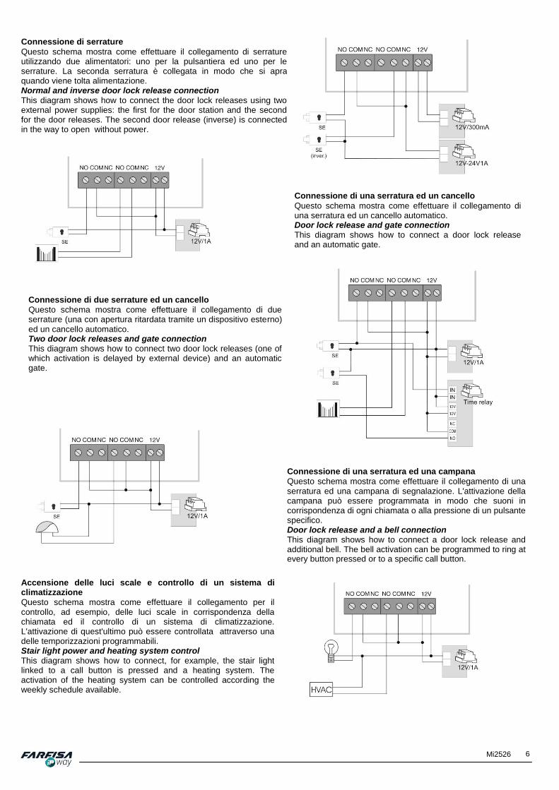
Connessione di serrature
Questo schema mostra come effettuare il collegamento di serrature utilizzando un unico alimentatore esterno per entrambe. Il dimensionamento dell'alimentatore dipende dall'assorbimento massimo delle serrature. Normal door lock release connection
This diagram shows how to connect the door lock releases using a single external power supply. The maximum current of the power supply depends on maximum consumption of the door releases.
6 Mi2526
Connessione di serrature
Questo schema mostra come effettuare il collegamento di serrature utilizzando due alimentatori: uno per la pulsantiera ed uno per le serrature. La seconda serratura è collegata in modo che si apra quando viene tolta alimentazione. Normal and inverse door lock release connection This diagram shows how to connect the door lock releases using two external power supplies: the first for the door station and the second for the door releases. The second door release (inverse) is connected in the way to open without power.
Connessione di una serratura ed un cancello
Questo schema mostra come effettuare il collegamento di una serratura ed un cancello automatico. Door lock release and gate connection This diagram shows how to connect a door lock release and an automatic gate.
Connessione di due serrature ed un cancello
Questo schema mostra come effettuare il collegamento di due serrature (una con apertura ritardata tramite un dispositivo esterno) ed un cancello automatico. Two door lock releases and gate connection This diagram shows how to connect two door lock releases (one of which activation is delayed by external device) and an automatic gate.
Connessione di una serratura ed una campana
Questo schema mostra come effettuare il collegamento di una serratura ed una campana di segnalazione. L'attivazione della campana può essere programmata in modo che suoni in corrispondenza di ogni chiamata o alla pressione di un pulsante specifico. Door lock release and a bell connection This diagram shows how to connect a door lock release and additional bell. The bell activation can be programmed to ring at every button pressed or to a specific call button.
Accensione delle luci scale e controllo di un sistema di climatizzazione
Questo schema mostra come effettuare il collegamento per il controllo, ad esempio, delle luci scale in corrispondenza della chiamata ed il controllo di un sistema di climatizzazione. L'attivazione di quest'ultimo può essere controllata attraverso una delle temporizzazioni programmabili. Stair light power and heating system control This diagram shows how to connect, for example, the stair light linked to a call button is pressed and a heating system. The activation of the heating system can be controlled according the weekly schedule available.

7 Mi2526
I contatti dei relè interni della pulsantiera AgoràIP non consentono il controllo diretto di carichi alimentati dalla tensione di rete 220Vca. In questo caso si raccomanda l'installazione di un relè aggiuntivo.
Collegamento di sensori porta o pulsante apertura
I terminali S1/C/S2 possono essere utilizzati per il collegamento di sensori per il rilevamento dello stato di apertura/chiusura della porta. I sensori possono essere del tipo integrato nella serratura o anche contatti magnetici indipendenti (porta chiusa = contatto chiuso; porta aperta = contatto aperto). Lo stato della porta verrà mostrato nella pagina home della pulsantiera o anche nell'applicazione IpWay per PC.
In alternativa gli stessi contatti possono essere configurati per la connessione di altrettanti pulsanti per l'apertura della relativa porta dall'interno.
2.4 PORTA MICRO SD E' possibile utilizzare la porta uSD per inserire una scheda contente file audio personalizzati per la segnalazione dello stato della pulsantiera (chiamata in corso, terminata, interno occupato, codice apertura inserito, apertura relè, errore, pressione di un tasto). Nel caso in cui vengano selezionati toni personalizzato ma non sia inserita alcuna uSD, verranno utilizzati i toni standard.
2.5 DIP-SWITCHES E FUNZIONAMENTO
I dip-swtiches presenti nella parte inferiore della scheda possono essere utilizzati principalmente per il ripristino dell'indirizzo IP di default della pulsantiera: 1. Riservato (lasciare in posizione ON). 2. Ripristino dell’indirizzo IP di fabbrica (192.168.1.250). Per il ripristino dell’indirizzo IP di fabbrica è necessario agire sul dip-switch 2, portandolo in posizione "ON" e successivamente spegnendo e riaccendendo la pulsantiera.
Una volta che la pulsantiera avrà completato la fase di avvio, è necessario riportare il dip-switch 2 in posizione “OFF” per evitare malfunzionamenti della pulsantiera. Con questa operazione verranno ripristinati anche i dati di accesso. Dopo il ripristino la pulsantiera sarà raggiungibile all'indirizzo IP: http://192.168.1.250 Utente: admin Password: 1234
2.5.1 Chiamata dall’esterno (uscente)
Premendo un pulsante la chiamata verrà inoltrata all’interno telefonico memorizzato (nel caso di modalità di funzionamento SIP) o all’indirizzo IP associato (nel caso di funzionamento P2P): la modalità di funzionamento può essere selezionata attraverso la pagina web nella sezione "Configurazione di rete" → "Parametri SIP" → "Modalità SIP", i successivi paragrafi illustrano in dettaglio le differenze tra le due modalità. La memoria dei numeri da chiamare è organizzata attraverso una Rubrica che consente di associare a ciascun pulsante uno o più numeri da chiamare in funzione di questi parametri: - Abilita: è possibile abilitare o disabilitare singolarmente ciascun
pulsante di chiamata. - Numero da chiamare: è possibile associare a ciascun pulsante
di chiamata da 1 a 5 numeri differenti (o indirizzi IP in modalità P2P).
- Intervalli temporali: la pulsantiera consente di definire fino a 10
pianificazioni temporali, ciascuna delle quali può contenere fino a 3 intervalli per ciascun giorno della settimana.
The internal relays contacts of the AgoràIP door station do not allow to directly switch loads powered by 220Vca mains voltage. In this case it is recommended to install an additional relay.
Door sensors or door button connection
The S1/C/S2 terminals can be used for connecting sensors to detect the open/close status of the door itself. The sensors can be either integrated in the electric lock or independent magnetic sensors (door closed = closed contact; door open = open contact). The status of the door will be displayed on the door station's home page or even on the PC IpWay application.
As alternative option the same contacts can be configured for the connection of the door buttons to allow door opening from inside.
2.4 MICRO SD PORT It is possible to use the uSD port to input a card containing personal audio files for door station's status signaling (call in progress, call ended, internal user busy, access code inserted, relay activation, button pressed). If personal tones are selected but uSD card is not available the standard tones will be used.
2.5 DIP-SWITCHES AND OPERATION
The dip-switches on the lower part of the main PCB board can be used mainly for restoring the factory default IP address: 1. Reserved (must be in ON position). 2. Reset the door station's IP address to default (192.168.1.250). To restore the factory default IP address it is required to move the dip-swtich 2 to "ON" position and then power off and on the door station.
Once the door station would have completed the next boot sequence, the dip-switch 2 must be moved to “OFF” position again to avoid undesirable behaviors. After this operation also the access data will be restored to default ones. Then the door station will be available at this address: http://192.168.1.250 User: admin Password: 1234 2.5.1 Call from outside (outgoing)
After a visitor presses a call button of the door station, it will pick up the line to send the call to the internal phone number stored (in case of SIP mode has been selected) or to the IP address (in case of P2P mode): the working mode can be selected by the configuration web page at "Network setting" → "SIP parameters" → "SIP mode", the next sections describe more details the differences between the two modes. The door station's number memory is organized by a Phone book which allows to set one or more numbers for each calling button, according to these parameters: - Enabled: it is possible to individually enable or disable each
call button. - Call number: it is possible to assign from 1 to 5 different
numbers (or IP addresses in P2P mode) to each call button. - Timetable: the door station allows to set up to 10 time
schedule schemes, each of them can be composed of up to 3 time intervals for each week days. Then it is possible to assign to every call button a specific schedule scheme. In

8 Mi2526
Successivamente è possibile associare a ciascun numero da chiamare uno di questi intervalli temporali. In questo modo il numero verrà effettivamente chiamato solo in corrispondenza delle fasce temporali specificate.
- Modalità chiamata: l'opzione Modalità chiamata consente di
stabilire se i numeri della rubrica debbano essere chiamati in modo "Sequenziale" o in gruppo "Inizio gruppo / Fine gruppo" e quindi in modo simultaneo. In questo caso il primo dispositivo che risponde entrerà in comunicazione con la pulsantiera mentre tutti gli altri smetteranno di suonare. Le differenti modalità di chiamata possono anche essere combinate tra loro in modo che ad esempio un numero specifico (3) venga chiamato dopo che nessuno degli utenti di un gruppo (1 - 2) hanno risposto.
La pulsantiera dispone anche di un controllo per l’apertura della serratura tramite inserimento di un codice, grazie alla possibilità di programmare combinazioni di pulsanti (code lock). Nel caso in cui il visitatore prema i pulsanti nella giusta combinazione il relè per l'apertura della serratura si attiverà. Sono disponibili sia codici di apertura dei relè condivisi tra tutti gli utenti che personali per ciascun utente.
- Il codice deve essere composto solo di numeri corrispondenti ai pulsanti disponibili (ad esempio per il modello IPV12AGLS è possibile utilizzare codici composti solo da "1" e "2". - Quando viene premuto per la chiamata il pulsante corrispondente al primo numero di un codice la chiamata verrà ritardata di un intervallo di tempo pari al valore specificato nel parametro "Time between key presses". - E' programmabile anche la funzione di attivazione del relè in corrispondenza della chiamata per un pulsante specifico, ad esempio per l'attivazione di una suoneria aggiuntiva. 2.5.2 Modalità Peer to Peer (P2P)
La modalità Peer to Peer (P2P) consente di effettuare chiamate attraverso indirizzi IP. Selezionare questa modalità nel caso in cui si vogliano effettuare chiamate ad un indirizzo IP specifico, che potrà essere, ad esempio, quello relativo ad un videocitofono ZHeroIP o un PC dotato di software apposito e di interfaccia audio con cuffie e microfono per poter interloquire con il visitatore. 2.5.3 Modalità SIP server
La modalità SIP server consente l’installazione in sistemi VoIP dove sia presente un centralino PBX SIP compatibile. In questo caso sarà necessario configurare la pulsantiera affinché all’accensione possa effettuare la registrazione presso il centralino SIP. Per i dettagli relativi ai parametri SIP, fare riferimento alla descrizione riportata nella sezione [2.6.3]. 2.5.4 Segnalazioni acustiche e visive
La pulsantiera emette una serie di segnalazioni per evidenziare acusticamente e visivamente, tramite il led rosso/verde posizionato vicino al modulo telecamera, lo stato di funzionamento. Nella descrizione che segue verranno spiegati alcuni dettagli sul significato di queste segnalazioni. 2.5.5 Ricezione di una chiamata
Il punto interno che riceve la chiamata dalla pulsantiera può essere un videocitofono ZHeroIP, un telefono VoIP, uno smart phone o un altro dispositivo registrato tramite server SIP oppure ancora un PC dotato di idonea interfaccia audio. Dopo che la pulsantiera ha chiamato un numero memorizzato, il dispositivo corrispondente squilla. Rispondendo sarà possibile parlare immediatamente con il visitatore (il led rosso sulla pulsantiera rimarrà acceso). Digitando un opportuno codice (55) sarà possibile attivare il relè relativo alla serratura. 10 secondi prima dello scadere del tempo fissato per la chiamata verrà emessa una segnalazione di avvertimento, premendo il tasto * o # sulla tastiera del telefono VoIP sarà possibile prolungare il tempo di chiamata. Riagganciando la chiamata verrà terminata automaticamente.
this way the number will be called only if included into the actual specified time intervals.
- Calling: the option "Calling" allows to set the way in which
the numbers in the phonebook are called. The door station supports call in "Sequential" mode or as a group "Group start / Group End" and simultaneously. in this case the first device which will pick up will also enable the communication with the door station while the other devices will stop ringing. The different calling modes can also be combined together so that, for example, a specific number (3) will be called after nobody of a group (1 and 2) have answered.
The door station has also an access control function to open the door by a code, thanks to the possibility to program buttons’ combination (code lock). If the visitor presses the buttons on the right combination the door release lock will activate. Codes shared among users and personal codes are even available.
- The code must be composed only by numbers related to physically available buttons (for example for model IPV12AGLS it is possible to use only codes composed by "1" and "2"). - When it is pressed a button which is also the first digit of a code the call will be delayed by the time specified in the parameter "Time between key presses". - It is possible to program the relay activation as soon as a specific button is pressed, for example for the activation of an additional bell. 2.5.2 Peer to Peer mode (P2P)
The Peer to Peer mode (P2P) allows to directly call the IP addresses by pressing each door station’s push button. Select this option if it is required to call a specific IP address, which would be, for example, that one related to a ZHeroIP video intercom or a PC equipped with the software and audio interface with microphone and speakers to talk to the visitor. 2.5.3 SIP server mode
The SIP server mode allows the installation of the door station in VoIP systems where a SIP compatible PBX is already installed. In this case it is required to program the door station module so that it will make the registration on the SIP server / PBX as soon as it is powered on. For more details about SIP configuration, please refer to the description on section [2.6.3]. 2.5.4 Acoustic and led signalling
The door station signals acoustically its working status. Moreover some other visual information are shown by the red/green led positioned near by the camera module. The following description will provide more in details about these signalling. 2.5.5 Receiving a call from outside
The internal station which receives the call from the door station can be a VoIP phone, a smart phone or another device registered on a SIP server or even a PC equipped with a suitable audio card. After the door station has called the stored number related to the button, the corresponding phone will ring. Answering it will be possible to talk to the visitor immediately (the red led on the door station will be on). Inputting a suitable code (55) it will be possible to activate the door release lock relay and finally to hang up. 10 seconds before the call duration ends, it will emit an alert tone, pressing * or # on the phone's keyboard it will be possible to longer the call duration. Hanging up the phone's handset the call will end.

9 Mi2526
Esistono due possibilità per l’invio di comandi dal punto interno alla pulsantiera: 1. Attraverso il canale RTP (RFC2833) 2. Attraverso SIP INFO 3. Attraverso toni DTMF in banda audio. 2.5.5.1 Ricezione di una chiamata tramite PC Installare il programma "IpWay" (ver 1.1.6 o superiore) nel PC da
utilizzare per la ricezione delle chiamate. Il programma è disponibile per il download dal sito www.farfisa.com.
Nella pagina "Rubrica" della pulsantiera assegnare al pulsante di chiamata l'indirizzo IP o il numero di interno SIP relativo al proprio PC. Sul PC il programma deve rimanere in esecuzione sulla barra del sistema. Alla ricezione della chiamata, verrà aperta automaticamente una finestra pop up per la visualizzazione delle immagini e si udrà uno squillo di chiamata. Inoltre saranno disponibili i pulsanti per l'apertura della conversazione, per l'apertura della serratura e alcune icone di stato. Per maggiori informazioni sul funzionamento del programma fare riferimento alla guida relativa che viene scaricata automaticamente insieme al programma. 2.5.5.2 Ricezione di una chiamata tramite smart phone o tablet
Per ricevere la chiamata audio/video tramite smart phone o tablet è necessario scaricare ed installare l'app "IpWay" disponibile
gratuitamente per sistemi Android su Google Play e per sistemi iOS (supporta solo la modalità SIP server) su iTunes. Nella pagina "Rubrica" è necessario assegnare al pulsante di chiamata l'indirizzo IP o il numero SIP del proprio dispositivo. Con questa configurazione sarà possibile ricevere chiamate all'interno della copertura della propria rete Wi-Fi, conversare con il visitatore ed aprire la serratura. 2.5.6 Chiamata verso la pulsantiera (entrante)
Un utente all’interno dell’appartamento può chiamare la pulsantiera ed effettuare un'accensione di controllo (autoaccensione). Per eseguire la chiamata è necessario configurare un dispositivo "Agorà" nella rubrica del monitor ZHeroIP o digitare sulla tastiera del telefono VoIP il numero di interno o l’indirizzo IP assegnato alla pulsantiera, la pulsantiera, risponderà automaticamente (il led sarà verde) rendendo possibile la comunicazione con l’esterno. Le possibilità di attivazione dei relè e/o l’invio di altri comandi sono le stesse del caso di una chiamata uscente dalla pulsantiera.
There are 2 ways for sending commands from the internal station (phone) to the door station: 1. By the RTP channel (RFC2833) 2. By the SIP INFO 3. By the DTMF tones in audio band. 2.5.5.1 Answering a call by PC Install the "IpWay" (version 1.1.6 or higher) software on the PC
to receive calls. This software is available for download from www.farfisa.com
web site. On "Phone book" page, set the related call button with the PC's IP address or internal SIP number. The software must run in PC background of the system tray. Once the call is active a window will pop up automatically to display the video signal of the active door station and a calling tone will be played. Moreover other buttons to enable the conversation, open the door and some status icon. For more information about software features and configuration please refer to the related guide which is automatically downloaded with the program. 2.5.5.2 Answering a call by smart phone or tablet
To receive an audio/video call by a smart phone or tablet it is required to download and install "IpWay" app. It is available
even for Android systems on Google Play or for iOS systems (in this case only SIP mode will be supported) on iTunes. On "Phone book" page set the IP address or the SIP number of of the mobile device to the related call button. With this configuration it will be possible to receive calls within the WiFi network, talk to the visitor and open the door. 2.5.6 Call the door station (incoming)
An incoming call is a call activated by an user inside the apartment to the door station to control outside (auto switch on). To call the door station it is required to configure an "Agorà" device on ZHeroIP address book or dial the door station's internal number by SIP phone or select the IP address assigned to the door station, then it will answer automatically (the green led will light) so that it will be possible even to talk to the visitor outside even being called. The chances about relay’s activation and/or the command’s sending are the same as described in the case of an outgoing call on the previous section.
2.6 PAGINA WEB DI CONFIGURAZIONE
La configurazione della maggior parte dei parametri della pulsantiera avviene attraverso la pagina web della pulsantiera stessa. Per accedere a questa pagina è sufficiente digitare sul proprio browser l’indirizzo IP assegnato alla pulsantiera (l’indirizzo di fabbrica è http://192.168.1.250). Nel caso in cui la propria rete utilizzi indirizzi IP appartenenti ad un segmento di rete differente (ad esempio le prime tre cifre degli indirizzi della propria rete siano differenti da quelle dell’indirizzo originale della pulsantiera), sarà necessario modificare temporaneamente la configurazione di rete del proprio PC (ad esempio assegnando un indirizzo del tipo 192.168.1.245). A questo punto sarà possibile accedere alla pagina web della pulsantiera e quindi alla finestra “Network settings” dove
poter modificare i parametri conformemente alla propria rete LAN. Per maggiori dettagli sui campi disponibili in questa pagina fare riferimento alla descrizione della sezione 2.6.2. Una volta assegnato alla pulsantiera il nuovo indirizzo IP sarà possibile ripristinare la configurazione di rete originale del PC. Digitando l’indirizzo IP della pulsantiera apparirà una schermata simile a quella mostrata di seguito con il video proveniente dalla telecamera.
2.6 CONFIGURATION WEB PAGE
Most of the door station’s configuration parameters can be set through the internal web page. To access this page it is required to click on door station IP address by a normal web browser (the factory default IP address is http://192.168.1.250). If the own LAN network has IP addresses from a different class range (i.e. the first three numbers are different from those of the default door station’s address), it is required to temporarily change the PC’s network configuration (for example using a free IP address from the same class such as 192.168.1.245). Then it will be possible to access the web page and change the parameters on “Network settings” page, according to the own network.
Please refer to the section 2.6.2 below for more details about the fields available on this page. Once the new IP address has been assigned to the door station, it will be possible to restore the original PC’s network configuration. Finally clicking on the door stations’ IP address, the browser will show a window similar to the following one, displaying the live video from the camera.
10 Mi2526
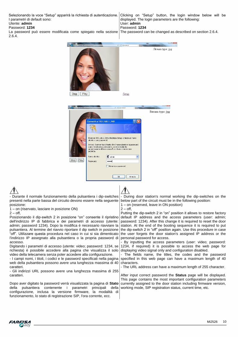
Selezionando la voce “Setup” apparirà la richiesta di autenticazione. I parametri di default sono: Utente: admin Password: 1234
La password può essere modificata come spiegato nella sezione 2.6.4.
Clicking on “Setup” button, the login window below will be displayed. The login parameters are the following: User: admin Password: 1234
The password can be changed as described on section 2.6.4.
- Durante il normale funzionamento della pulsantiera i dip-switches presenti nella parte bassa del circuito devono essere nella seguente posizione: 1 – on (riservato, lasciare in posizione ON) 2 – off, Posizionando il dip-switch 2 in posizione “on” consente il ripristino dell'indirizzo IP di fabbrica e dei parametri di accesso (utente: admin; password 1234). Dopo la modifica è necessario riavviare la pulsantiera. Al termine del riavvio riportare il dip switch in posizione “off”. Utilizzare questa procedura nel caso in cui si sia dimenticato l'indirizzo IP assegnato alla pulsantiera o la propria password di accesso. Digitando i parametri di accesso (utente: video; password: 1234, se richiesta) è possibile accedere alla pagina che visualizza il solo video della telecamera senza poter accedere alla configurazione. - I campi nomi, i titoli, i codici e le password specificati nella pagina web della pulsantiera possono avere una lunghezza massima di 40 caratteri. - Gli indirizzi URL possono avere una lunghezza massima di 255 caratteri. Dopo aver digitato la password verrà visualizzata la pagina di Stato
della pulsantiera contenente i parametri principali della configurazione, inclusa la versione firmware, la modalità di funzionamento, lo stato di registrazione SIP, l'ora corrente, ecc.
- During door station's normal working the dip-switches on the below part of the circuit must be in the following position: 1 – on (reserved, leave in ON position) 2 – off, Putting the dip-switch 2 in “on” position it allows to restore factory default IP address and the access parameters (user: admin; password: 1234). After this change it is required to reset the door station. At the end of the booting sequence it is required to put the dip-switch 2 in “off” position again. Use this procedure in case the user forgets the door station's assigned IP address or the personal password for access. - By inputting the access parameters (user: video; password: 1234, if required) it is possible to access the web page for displaying video signal only and configuration disabled. - The fields name, the titles, the codes and the password specified in this web page can have a maximum length of 40 characters. - The URL address can have a maximum length of 255 character. After input correct password the Status page will be displayed.
This page contains the most important configuration parameters currently assigned to the door station including firmware version, working mode, SIP registration status, current time, etc.

11 Mi2526
2.6.1 Configurazione lingua
La lingua di visualizzazione della pagina web può essere selezionata tra quelle disponibili utilizzando l'icona con la bandiera presente nell'angolo in alto a destra. Contattare il servizio tecnico di ACI FARFISA per l'aggiunta di lingue opzionali.
2.6.1 Language configuration
The language of the web configuration page can be changed amongst those available using the flag icon on the upper right corner. Please contact ACI FARFISA technical service for additional languages.
Dopo aver selezionato una lingua differente è necessario fare click su “Save” per rendere effettiva la modifica. 2.6.2 Configurazione di rete All’interno della pagina “Configurazione rete” è possibile
configurare i parametri di rete in funzione della propria LAN. La pulsantiera supporta sia l’assegnazione manuale degli indirizzi IP che quella automatica tramite DHCP.
Nel caso in cui nella propria rete venga utilizzata l’assegnazione automatica degli indirizzi IP tramite DHCP, è possibile che l’indirizzo assegnato alla pulsantiera cambi di volta in volta (ad esempio a causa di un ripristino di alimentazione dopo un black-out). In questo caso potrebbe non essere agevole accedere via browser alla pulsantiera per l’impossibilità di conoscere il nuovo indirizzo assegnato. Per questo motivo si consiglia, preferibilmente, di operare con l’assegnazione manuale dell’indirizzo IP. 2.6.2.1 Assegnazione manuale dell'indirizzo IP
Nel caso di assegnazione manuale dell’indirizzo IP lasciare la casella “DHCP” non selezionata. Utilizzare il campo “Indirizzo IP” per specificare l’indirizzo IP da
assegnare alla pulsantiera, tenendo conto di quanto riportato all’inizio di questo capitolo. Nei campi “Network mask”, “Network Gateway”, “DNS server 1 e 2” introdurre gli stessi valori utilizzati
nella propria rete. In caso di dubbio contattare il proprio amministratore di rete. Il parametro “Modalità NAT” consente di specificare l'eventuale tipologia di NAT utilizzata, il campo “Indirizzo NAT” di modificare la
trascrizione dell'indirizzo IP originale della pulsantiera o l'indirizzo di
After new language selection it is required to click on “Save” button to make it effective. 2.6.2 Network configuration The “Network setting” page allows to set the door station’s
network parameters according to the own LAN network. The door station allow IP address configuration even manually or automatically by DHCP.
In case of automatic IP address assignment via DHCP, it is possible that the door station’s IP will change from time to time (for example in case of resume after power failure). In this case it could not be easy to access the web page via browser since the new address is unknown. For this reason it is strongly recommended to use manual IP address assignment. 2.6.2.1 Manual IP address configuration In case of manual IP address assignment, leave the box “Setup via DHCP” unchecked. Use the “IP address” field to set the new door stations’ IP
address, keeping in consideration what described at the beginning of this chapter. Fill in the other fields “Network mask”, “Default Gateway”, “DNS server 1” and “DNS server 2”, with the
same values used on the devices of the network. In case of doubt please contact the network administrator. The parameter “NAT policy” allows to specify the eventual NAT type used, the field “NAT address” allows to modify the
transcription of the original IP address of the door station. The

12 Mi2526
destinazione. Il campo “Indirizzo STUN” consente invece di
specificare l'indirizzo del server STUN che consente alla pulsantiera di conoscere il proprio indirizzo IP pubblico. Selezionare il pulsante “Salva e riavvia” per salvare la
configurazione ed attendere il riavvio della pulsantiera. Attenzione: se non si seleziona il pulsante "Salva e riavvia" le modifiche andranno perdute. Selezionando il pulsante “Valori Default” i parametri descritti sopra saranno riportati ai valori di
fabbrica.
field “STUN address” allows instead to specify the address of the
STUN server which allows the door station to know its public IP address. Click on the “Save and restart” button to store the changes and wait until the door station will reset. If “Save and restart” button
will not be pressed, the changes will be discarded. The “Default values” button allows to restore all the above
parameters to the factory default values.
2.6.2.2 Assegnazione automatica (DHCP) dell'indirizzo IP
Nel caso si utilizzi l’assegnazione automatica dell’indirizzo IP mettere il segno di spunta in corrispondenza della casella “DHCP”.
I parametri di rete assegnati automaticamente via DHCP saranno visualizzati nei rispettivi campi. Il parametro “Modalità NAT” consente di specificare l'eventuale tipologia di NAT utilizzata, il campo “Indirizzo NAT” di modificare la
trascrizione dell'indirizzo IP originale della pulsantiera o l'indirizzo di destinazione. Il campo “Indirizzo STUN” consente invece di
specificare l'indirizzo del server STUN che consente alla pulsantiera di conoscere il proprio indirizzo IP pubblico. Selezionare il pulsante “Salva e riavvia” per salvare la
configurazione e riavviare. Attenzione: se non si seleziona il pulsante "Salva e riavvia" le modifiche andranno perdute. Selezionando il pulsante “Valori default” i parametri descritti sopra saranno riportati ai valori di
fabbrica.
2.6.2.2 Automatic IP assignment (DHCP)
In case of automatic IP address assignment, check the box “Setup via DHCP”.
The network parameters will be shown on the respective fields which will be in grey background (cannot be changed manually). The parameter “NAT policy” allows to specify the eventual NAT type used, the field “NAT address” allows to modify the
transcription of the original IP address of the door station. The field “STUN address” allows instead to specify the address of the
STUN server which allows the door station to know its public IP address. Click on the “Save and restart” button to store the changes and
to reset the door station. Warning: if “Save and restart” button is not pressed the changes will be discarded. “Default values” button allows to restore all
the above parameters to the factory default values.
2.6.3 Parametri SIP
L’aspetto di questa pagina dipende dalla modalità di funzionamento scelta, SIP server o P2P, attraverso la casella di selezione presente nella parte alta della pagina. 2.6.3.1 Modalità SIP server
Selezionando la modalità SIP server la finestra sarà simile a quella mostrata sotto. Compilare tutti i campi richiesti per la corretta registrazione della pulsantiera sul proprio server SIP.
2.6.3 SIP parameters
This page has 2 different appearances according to the selected working mode, SIP server or P2P, by the combo box available on the top of the web page. 2.6.3.1 SIP server mode
Selecting the SIP server mode the page will be similar to that one showed here below. Fill in all the fields required by the SIP server installed on the LAN network to make the registration.

13 Mi2526
Nome: inserire in questo campo un nome alfanumerico che consenta
di identificare più facilmente la pulsantiera all’interno della propria rete, soprattutto nel caso in cui siano presenti più pulsantiere in corrispondenza degli ingressi (es. Principale, Garage, Cancello...). SIP user agent: campo contiene un nome che consente di identificare
il dispositivo nelle chiamate SIP. Account: affinché la pulsantiera possa autenticarsi è necessario
creare precedentemente un interno (account) nel proprio centralino da assegnare alla pulsantiera. Utilizzare questo campo per inserire i valori di autenticazione per la pulsantiera sul server SIP. ID autenticazione: nome utente, solitamente coincide con il numero di
interno assegnato alla pulsantiera sul centralino. Password: password per la registrazione sul server SIP. Invia registro: quando il server richiede la registrazione (come nella
maggior parte dei casi) spuntare questa opzione. Server registrazione: indirizzo IP o nome del server attraverso il
quale saranno instradate le chiamate. Porta: porta (usualmente 5060/5061) del server SIP per la
registrazione. Scadenza registrazione [sec]: tempo di validità della registrazione
sul server SIP (intervallo di invio di richieste di registrazione). Registra dopo il riavvio: abilitare questa opzione per effettuare la
registrazione SIP all'avvio della pulsantiera. Server SIP: indirizzo IP o nome del server SIP dove viene effettuata la
registrazione. Se questo campo non è compilato, la registrazione verrà effettuata nello stesso server specificato in “Registration server” (in questo caso si raccomanda di selezionare l'opzione “Send register”). Porta: porta (usualmente 5060/5061) del server SIP per la
registrazione. Outbound proxy: indirizzo IP o nome del server proxy a cui la
pulsantiera invierà le richieste. Il server proxy viene utilizzato nel caso in cui la rete utilizzi il NAT, altrimenti non è richiesta la compilazione di questo campo. Porta: porta (usualmente 5060/5061) del server. Trasporto SIP: selezione del protocollo di trasmissione TCP o UDP o
automatico in funzione del server SIP utilizzato. Provisional code: consente di determinare se durante la chiamata
vengano inviati i codici SIP “180 Ringing” o “183 session progress”. Abilita RTP simmetrico: abilita la funzione RTP simmetrico (default
ON) affinché la pulsantiera non invii da sola audio ma solo quando richiesto dalla contro parte RTP. Dopo aver ricevuto la richiesta i dati verranno inviati allo stesso indirizzo:porta da cui il messaggio è stato ricevuto. Questa opzione viene utilizzata per aggirare il NAT. Per salvare le modifiche effettuate fare click sul pulsante “Salva ”. Per ripristinare i parametri originali fare click su “Valori default”.
Display name: input on this field an alphanumeric name which
allow to easily identify the door station within the network. This feature is mostly useful in the case of more than just one door station are connected on the same LAN network (i.e. Main, Garage, Gate...). SIP user agent: this field contains a name which allows to
identify the device within the SIP calls. Account: to allow the door station’s authentication, it is
required to create an extension (account) on the PBX previously. Use this field to input the door station's authentication values on the SIP server. Auth.ID: user name, usually it is the same of the SIP internal
number assigned to the door station. Password: password required for SIP registration. Send registration: if the server required the registration (as in
most of the cases) check this box. Registration server: IP address or domain name of the server
used for handling the SIP calls. Port: SIP server port (usually 5060 or 5061) for registration. Expiration [sec]: time validity of the registration on the SIP
server (registration requests interval). Registrate after restart: enable this option to allow the door
station to register on the SIP server during the boot sequence. SIP server: IP address or domain name of the SIP server
where the SIP registration will be done. If this field is not filled, the registration will be made on the same SIP server of the previous “Registration server” field (in this case it is recommended to check the option “Send register”). Port: SIP server port (usually 5060 or 5061) for registration. Outbound proxy: IP address or name of the proxy server to
which the door station will send requests. The proxy server is used mainly where the network uses NAT. Otherwise it is not required to fill. Port: SIP server port (usually 5060 or 5061) for registration. SIP transport: transmission protocol (TCP, UDP or automatic)
selection according to what require4d by the SIP server used. Provisional code: it determines if during call the SIP codes
“180 ringing” or “183 session progress” will be sent. Enable simmetric RTP: enable the symmetric RTP (default
ON) to allow the door station to do not send audio by itself but only when it will be required by the other RTP party. After receiving the request the data will be sent to the same address:port from where the message is received. This option is used mainly for NAT bridging. Please remind to click on “Save” button to store the parameters changed in this window. To restore factory default values, click on “Default values” button.

14 Mi2526
2.6.3.2 Modalità P2P
Selezionando la modalità P2P non è richiesta alcuna registrazione della pulsantiera su server SIP, di conseguenza alcune caselle della pagina SIP Parameters verranno disabilitate:
2.6.3.2 Peer-to-Peer mode Selecting the P2P mode it will not be required any registration on SIP server, then some the parameters of the SIP Parameters page will be disabled:
Nome: inserire in questo campo un nome alfanumerico che
consenta di identificare più facilmente la pulsantiera all’interno della propria rete, soprattutto nel caso in cui siano presenti più pulsantiere in corrispondenza degli ingressi (es. Principale, Garage, Cancello...). SIP user agent: campo contiene un nome che consente di
identificare il dispositivo nelle chiamate SIP. Account: numero di interno da assegnare all'unità necessario per il
corretto funzionamento della chiamata SIP. Per evitare malfunzionamenti si raccomanda di lasciare questo campo compilato. Outbound proxy: indirizzo IP o nome del server proxy a cui la
pulsantiera invierà le richieste. Il server proxy viene utilizzato nel caso in cui la rete utilizzi il NAT, altrimenti non è richiesta la compilazione di questo campo. Porta: porta (usualmente 5060/5061) del server. Trasporto SIP: selezione del protocollo di trasmissione TCP o UDP
o automatico in funzione del server SIP utilizzato. Provisional code: consente di determinare se durante la chiamata
vengano inviati i codici SIP “180 Ringing” o “183 session progress”. Abilita RTP simmetrico: abilita la funzione RTP simmetrico (default
ON) affinché la pulsantiera non invii da sola audio ma solo quando richiesto dalla contro parte RTP. Dopo aver ricevuto la richiesta i dati verranno inviati allo stesso indirizzo:porta da cui il messaggio è stato ricevuto. Questa opzione viene utilizzata per aggirare il NAT. - Per salvare le modifiche effettuate fare click sul pulsante “Salva ”. Per ripristinare i parametri originali fare click su “Valori default”.
La modalità P2P può essere utilizzata anche con dispositivi che richiedono la registrazione su server SIP per il loro funzionamento come ad esempio dispositivi iOS Apple. In questo caso è possibile configurare il dispositivo di ricezione delle chiamate in modalità SIP specificando come indirizzo IP del server lo stesso indirizzo IP della pulsantiera e come nome utente e password il numero di interno utilizzato. Ad esempio:
Indirizzo IP pulsantiera: 192.168.1.250, nome account: 250;
Indirizzo IP del primo telefono: 192.168.1.200, indirizzo IP server SIP: 192.168.1.250, nome account e password: 230;
Indirizzo IP del secondo telefono: 192.168.1.201, indirizzo IP server SIP: 192.168.1.250, nome account e password: 231.
Per chiamare il primo telefono configurare la chiamata all'interno 230, per il secondo telefono all'interno 231. Per chiamare la pulsantiera l'interno 250.
Display name: input on this field an alphanumeric name which
allow to easily identify the door station within the network. This feature is mostly useful in the case of more than just one door station are connected on the same LAN network (i.e. Main, Garage, Gate...). SIP user agent: this field contains a name which allows to
identify the device within the SIP calls. Account: extension number to be assigned to the door phone,
required for correct working of the SIP calling. It is recommended to keep it filled. Outbound proxy: IP address or name of the proxy server to
which the door station will send requests. The proxy server is used mainly where the network uses NAT. Otherwise it is not required to fill. Port: SIP server port (usually 5060 or 5061) for registration. SIP transport: transmission protocol (TCP, UDP or automatic)
selection according to what require4d by the SIP server used. Provisional code: it determines if during call the SIP codes “180
ringing” or “183 session progress” will be sent. Enable simmetric RTP: enable the symmetric RTP (default ON)
to allow the door station to do not send audio by itelf but only when it will be required by the other RTP party. After receiving the request the data will be sent to the same address:port from where the message is received. This option is used mainly for NAT bridging. Please remind to click on “Save” button to store the parameters changed in this window. To restore factory default values, click on “Default values” button.
The P2P mode can be used also for devices which require the registration on a SIP server for their function such as iOS Apple devices. In this case it is possible to configure the device used to answer in SIP mode and set the door station IP address as SIP server address, the user name and password will be the extension number used. For example:
Door station IP address: 192.168.1.250, account name: 250;
First phone IP address: 192.168.1.200, server SIP IP address: 192.168.1.250, account name and password: 230;
Second phone IP address: 192.168.1.201, server SIP IP address: 192.168.1.250, account name and password: 231.
Then to call the first phone configure the call to the extension number 230, while for the second phone the extension 231. To call the door station use the extension 250.
15 Mi2526
2.6.4 Web server 2.6.4 Web server
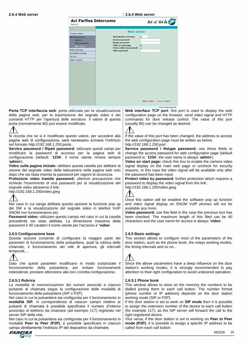
Porta TCP interfaccia web: porta utilizzata per la visualizzazione
della pagina web, per la trasmissione del segnale video e dei comandi HTTP per l'apertura delle serrature. Il valore di questa porta (normalmente 80) può essere modificato.
Si ricorda che se si è modificato questo valore, per accedere alla pagine web di configurazione, sarà necessario scrivere l’indirizzo nel formato http://192.168.1.250:porta . Service password / Ripeti password: utilizzare questi campi per
modificare la password di accesso per la pagina web di configurazione (default: '1234', il nome utente rimane sempre 'admin'). Video sulla pagina iniziale: abilitare questa casella per abilitare la
visione del segnale video della telecamera nella pagina web solo dopo che sia stata inserita la password per ragioni di sicurezza. Protezione video tramite password: ulteriore precauzione che
richiede l'inserimento di una password per la visualizzazione del segnale video attraverso il link: http://192.168.1.250/video.jpeg
Nel caso in cui vanga abilitata questa opzione la funzione pop up del SW e la visualizzazione del segnale video in telefoni VoIP SNOM non funzioneranno più. Password video: utilizzare questo campo nel caso in cui la casella
precedente sia stata abilitata. La dimensione massima della password è 40 caratteri il nome utente per l'accesso è 'video'.
Web interface TCP port: this port is used to display the web
configuration page on the browser, send video signal and HTTP commands for door release control. The value of this port (usually 80) can be changed as desired.
If the value of this port has been changed, the address to access the web configuration page must be written as below: http://192.168.1.250:port . Service password / Retype password: use these fields to
change the access password for web configuration page (default password is: '1234', the user name is always 'admin'). Video on start page: check this box to enable the camera video
signal display on the main web page or uncheck for security reasons. In this case the video signal will be available only after the password has been input. Protect video by password: further protection which requires a
password to display the video signal from the link: http://192.168.1.250/video.jpeg
Once this option will be enabled the software pop up function and video signal display on SNOM VoIP phones will not be available any more. Video password: use this field in the case the previous box has
been checked. The maximum length of this filed can be 40 characters and the user name for access is always 'video'.
2.6.5 Configurazione base
Questa sezione consente di configurare la maggior parte dei parametri di funzionamento della pulsantiera, quali la rubrica delle chiamate, il funzionamento dei relè di apertura, gli intervalli temporali,...
Dato che questi parametri modificano in modo sostanziale il funzionamento della pulsantiera, per evitare funzionamenti indesiderati, prestare attenzione alla loro corretta configurazione. 2.6.5.1 Rubrica
La modalità di memorizzazione dei numeri associati a ciascun pulsante di chiamata segue la configurazione delle modalità di funzionamento della pulsantiera (SIP o P2P). Nel caso in cui la pulsantiera sia configurata per il funzionamento in modalità SIP, in corrispondenza di ciascun campo relativo ai
pulsanti di chiamata è possibile specificare il numero d’interno associato al telefono da chiamare (ad esempio 117) registrato nel server SIP della rete. Nel caso in cui la pulsantiera sia configurata per il funzionamento in modalità Peer to Peer (P2P), è possibile specificare in ciascun
campo direttamente l’indirizzo IP del dispositivo da chiamare.
2.6.5 Basic settings This section allows to configure most of the parameters of the door station, such as the phone book, the relays working modes, the timing intervals and so on...
Since the above parameters have a deep influence on the door station's working modes, it is strongly recommended to pay attention to their right configuration to avoid undesired operation. 2.6.5.1 Phone book
This window allows to store on the memory the numbers to be dialled joining them to each call button. The number format (phone number or IP address) depends on the door station working mode (SIP or P2P). If the door station is set to work on SIP mode then it is possible
to assign the extension number of the device to each call button (for example 117), as the SIP server will forward the call to the right registered device. Vice versa, if the door station is set to working on Peer to Peer mode (P2P), it is possible to assign a specific IP address to be
called from each call button.

16 Mi2526
La pulsantiera consente di programmare sino a 130 chiamate, in funzione dei moduli tasti aggiuntivi installati. Selezionare il pulsante di chiamata da configurare tramite i numeri riportati nella parte alta della finestra. Per ciascun pulsante è possibile programmare sino a 5 numeri, eventualmente chiamati in gruppo o in sequenza. Titolazione: nome alfanumerico per il riconoscimento del pulsante
di chiamata. Email: nel caso in cui sia stato configurato l'invio di e-mail, in caso
di mancata risposta verrà inviato un messaggio, eventualmente con alcune immagini allegate a questo indirizzo. Abilita: consente di abilitare / disabilitare singolarmente ciascun
pulsante di chiamata. Numero da chiamare: numero chiamato alla pressione del tasto
(priorità più alta = 1, più bassa = 5 nel caso di chiamata sequenziale). Il numero verrà chiamato solamente se conforme alla pianificazione temporale corrispondente. Intervalli temporali: consente di assegnare al numero da
chiamare una specifica pianificazione temporale, se non specificata il numero viene sempre chiamato. Modalità chiamata: consente di specificare la modalità di chiamata
del numero (sequenziale o a gruppo). Attraverso questa configurazione è possibile programmare sino a 2 gruppi per ciascun pulsante di chiamata o sino a 5 numeri chiamati contemporaneamente.
Sequenziale: consente la chiamata in sequenza dei
numeri programmati, uno dopo l'altro in caso di mancata risposta.
Inizio gruppo: specifica il primo numero appartenente ad
un gruppo. Nella chiamata di gruppo tutti gli utenti verranno chiamati contemporaneamente, dopo che il primo risponde alla chiamata gli altri smetteranno di suonare.
Con il precedente: numero appartenente ad un gruppo
(differente dai numeri Inizio gruppo e Fine gruppo).
Fine gruppo: ultimo numero appartenente al gruppo di
chiamata. Codice esterno per il relè 1, 2, 3, 4: codice privato per l'apertura
della serratura relativo all'utente. Il codice deve essere digitato come combinazione di pulsanti di chiamata (ad esempio: 1-2-2-2-1) ed è sempre valido (non può essere associato ad alcun intervallo temporale).
The door station allows to program up to 130 button calls, according to the additional button modules installed. Select the call button to configure by using the numbers on the above part of the page. For each button it is possible to program up to 5 numbers, eventually arranged as a group or sequentially as described below. Title: alphanumeric title for an easier call button recognition. Email: if the email sending function has been enabled, a
message, eventually even with some pictures attached, will be sent to the subscriber in case of a missed call. Enabled: allows to enable / disable individually each call button.
It can be useful in case of hotels or other places where service personnel is not always available. 1. - 5. Call number: number to call when the button is pressed
(highest priority = 1, lowest priority = 5 in case of sequential call). The number will be called only if it complains with the programmed time table. Time table: allows to assign a specific time schedule to the
number to call, if not specified the number will be always called. Please refer to the section 2.6.5.5 for more details about setting. Calling: allows to set the calling mode of the users' numbers
(sequentially or as a group). By this configuration it is possible to program up to 2 groups for each call button or up to 5 numbers to call simultaneously.
Sequential: allows the call of all the subscriber's
numbers one by one starting from the first, the others will be called in case of busy or not available user.
Group start: first number in a group call. In a group call
all the subscribers will be called at the same time, after the first one picks up the line, the others will stop ringing.
With previous: next number included in a group
previously initiated (different from the numbers Group start and Group end).
Group end: last number included in a call group. External code for relay 1, 2, 3, 4: private code related to the
user which can be programmed for door opening without a call. The code must be input by pressing the related call buttons is the right sequence (for example 1-2-2-2-1) and it is always valid (it cannot be linked to a specific time table).

17 Mi2526
2.6.5.2 Relè
La pagina relè consente la configurazione del funzionamento dei relè per l'apertura della serratura e altri servizi.
2.6.5.2 Relays
The relay page allows the configuration of the working mode of the relays for door opening or other services.
La finestra consente la configurazione di 4 relè in totale: i primi due sono interni alla pulsantiera stessa, per i successivi (3 e 4) è possibile programmare l'attivazione di relè remoti IP per incrementare il livello di sicurezza del sistema. La selezione del relè da configurare viene effettuata tramite i numeri presenti nella parte alta della pagina, in modo analogo alla rubrica. Abilita: questo controllo consente di disabilitare / abilitare
temporaneamente l'attivazione di questo relè nel caso ad esempio si voglia inibire temporaneamente l'apertura di una porta di ingresso piuttosto che cancellare tutti i codici di apertura. Nel caso in cui si richieda l'attivazione e la disattivazione ad intervalli regolari (come ad esempio nel caso di una scuola) è possibile assegnare una specifica temporizzazione anche al relè come spiegato di seguito. Intervalli temporali: consente di assegnare una specifica
temporizzazione per l'attivazione di questo relè (ad esempio in funzione degli orari di un ufficio, scuole,...) in combinazione alle opzioni sotto "Modalità relè" e "Sorgente". Modalità relè: la modalità di funzionamento del relè può essere
scelta tra le seguenti opzioni:
Monostabile: in questo caso il relè si chiude per
l'intervallo di tempo specificato e poi si riapre.
Bistabile: in questo caso il relè si attiva al primo invio del
codice di apertura e poi si disattiva all'invio di un successivo comando.
Ritardo: consente di specificare un tempo tra la digitazione di un
codice per l'apertura della serratura e l'effettiva attivazione del relè. Usato in combinazione con la funzione "Sorgente" consente l'utilizzo in applicazioni particolari. Tempo attivazione [sec]: durata temporale (in secondi)
dell'attivazione del relè in modalità monostabile. Sorgente: permette di selezionare tra varie possibilità come segue:
Intervalli temporali: consente un diverso comportamento del relè in funzione della "Modalità relè" selezionata. Nel
caso "monostabile" il relè si attiverà una sola volta all'inizio dell'intervallo temporale. Nel caso "bistabile" il relè sarà chiuso (ON) all'interno degli intervalli temporali specificati, mentre sarà aperto (OFF) al di fuori degli intervalli temporali.
Relè 1 - 4: consente la sincronizzazione della chiusura di
un altro relè insieme o ritardato da questo. Sincronizza ritardo [sec]: tempo tra l'inizio della sincronizzazione
e la valutazione dello stato. Attivo su chiamata: le possibilità disponibili sono:
Ignora: la chiamata non ha influenza sullo stato del relè.
This window allows the configuration of up to 4 relays in total: the first two are internal to the door station itself, while for the followings (number 3 and 4) it is possible to program the activation of IP remote relays to increase the system security level. The selection of the relay to program can be done by the numbers on the upper part of the page, similarly to the button selection of the phone book. Enabled: this control allows to temporarily disable or enable the
activation of this relays, for example in the case it is required to inhibit a door opening instead of delete all the opening codes. In the case a regular activation or deactivation of the function is required (for example in case of school or hotel applications), then it is more convenient to program a specific time interval to each relay as described below. Time table: it allows to assign a specific time interval for this
relay activation (for example according to the opening time of the school or office,...) in combination of the below options "Relay mode" and "Source". Relay mode: the relay working mode can be chosen between
the following options:
Monostable: in this case the relay closes for a specific
duration time and the it opens automatically again.
Bistable: in this case the relay closes at the first
command sending and then opens again at the second command sending.
Delay: it allows to set the time between a code for relay
activation input and the effective relay activation. If used in combination with the "Source" function it allows the configuration for particular applications. Run time [sec]: time (in seconds) in which the relay will be
active in monostable mode. Source: it allows to select the triggering condition for the relays
among various choices as follows:
Timetable: it allows a different relay's behavior according to the selected "Relay mode". If Relay mode
is set as "Monostable" the relay will activate once only at the beginning of the selected interval time zones. While in case it has been set as "Bistable" the relay will be closed ("ON") within the selected interval time zones, while it will be open ("OFF") outside the time intervals.
Relay 1 - 4: it allows to synchronize the activation of
another relay together with this one or with a certain delay.
Synchronize delay [sec]: time between the begin of the

18 Mi2526
In arrivo: il relè si attiva automaticamente in
corrispondenza di una chiamata in arrivo. Nella modalità monostabile per il tempo programmato, nella modalità bistabile il relè è attivo per tutto il tempo della chiamata.
In uscita: il relè si attiva automaticamente in
corrispondenza di una chiamata in uscita. Nella modalità monostabile per il tempo programmato, nella modalità bistabile il relè è attivo per tutto il tempo della chiamata.
Entrambi: il relè si attiva automaticamente in
corrispondenza di una chiamata in arrivo o in uscita. Nella modalità monostabile per il tempo programmato, nella modalità bistabile il relè è attivo per tutto il tempo della chiamata.
Tono acustico: consente di attivare l'emissione sonora di un tono
in corrispondenza dell'attivazione del relè. Questa funzione può essere utile nel caso di alimentazione PoE serratura in DC alimentata dalla pulsantiera stessa, l'emissione di un tono simula il tipico ronzio dell'attivazione della serratura. Altre applicazioni possono essere l'utilizzo di un tono personalizzato per la segnalazione di apertura per persone cieche. Inoltre attivando questa funzione si avrà anche una ulteriore indicazione visiva tramite il led frontale rosso che diventa si accende anche in verde. Attivazione su HTTP: consente di abilitare la funzione di
attivazione del relè tramite comandi HTTP (richiesta GET) all'indirizzo IP della pulsantiera indipendentemente dalle temporizzazione (è possibile inviare il comando anche tramite web browser). La richiesta deve essere del tipo: http://192.168.1.250/relay_control?1=on (attivazione del relè) http://192.168.1.250/relay_control?1=off (disattivazione del relè nel caso di funzionamento bistabile) dove al posto di "1" è possibile indicare il numero del relè da utilizzare. Codice uscita di sicurezza: questo codice può essere utilizzato
per incrementare il livello di sicurezza del proprio sistema in abbinamento all'utilizzo di un relè codificato (COSW).
Si raccomanda di non inserire alcun codice in questo campo nel caso in cui non sia stato collegato il COSW per evitare danni al relè interno della pulsantiera. Pulsante ON diretto: specificando in questo campo il numero di un
pulsante di chiamata sarà possibile utilizzare l'uscita relè per aprire automaticamente la serratura in corrispondenza della chiamata (funzione ufficio), o eventualmente, per il collegamento di una suoneria esterna. Se per il pulsante è stato specificato anche un numero telefonico la chiamata verrà effettuata comunque. Comando RC su relè ON: abilita l'invio di un comando ad un
dispositivo esterno (ad esempio un relè IP) durante il tempo di chiusura del relè. Il comando viene inviato come comando HTTP (richiesta GET) e deve essere della forma http://indirizzoIP/comando. Fare riferimento alla specifica documentazione del relè IP per i dettagli del comando. Comando RC su relè OFF: abilita l'invio di un comando ad un
dispositivo esterno (ad esempio un relè IP) durante il tempo di apertura del relè. Il comando viene inviato come comando HTTP (richiesta GET) e deve essere della forma http://indirizzoIP/comando. Fare riferimento alla specifica documentazione del relè IP per i dettagli del comando. Codice per il controllo relè: è possibile definire fino a 10 codici
per l'attivazione del relè dalla tastiera del telefono (se configurato come DTMF) o come codice da pressione dei pulsanti di chiamata (se configurato come "Pulsante"). A ciascun codice può essere assegnata anche una specifica pianificazione per la sua abilitazione / disabilitazione temporale (Intervalli temporali). Esempio:
- Con riferimento alla figura il Codice 1., impostato sul valore '55' consente l'apertura della serratura digitando questo codice dalla tastiera del telefono, senza alcuna limitazione temporale. - Sempre con riferimento alla figura sopra il codice il Codice 2. consente l'apertura della serratura digitando la combinazione dei pulsanti di chiamata '1-1-2-2-1' in sequenza solo all'interno dell'intervallo temporale 1 - "Open time".
synchronization and the evaluation of the state. Active on call: there are various choices:
Ignore: the call has no influence of the relay status.
Incoming: the relay will activate automatically when an
incoming call happens. In monostable mode it will be on for the time set in the "Run time" option, in bistable mode the relay will be active for the whole call time.
Outgoing: the relay will activate automatically when an
outgoing call happens. In monostable mode for the time set in the "Run time" option, while in bistable mode for the whole call duration.
Both: the relay will activate automatically when an
outgoing or incoming call happens. In monostable mode for the time set in the "Run time" option, while in bistable mode for the whole call duration.
Acoustic tone: it allows to activate an acoustic tone emission as
soon as the relay is active. This function can be useful in case of PoE power supply and a DC door release powered by the door station itself: this acoustic tone simulates the typical noise of the door release. Other applications can be the use of a personal tone to advice door open condition to blind people. Moreover activating this function another visual advice will be done by the frontal led which will be red and green at the same time. Active by HTTP: it allows to enable the function to activate the
relay by HTTP commands (GET request) to the door station's IP address independently by the time intervals (it is even possible to send the command by web browser for testing purposes). The request must be as follows: http://192.168.1.250/relay_control?1=on (relay activation) http://192.168.1.250/relay_control?2=off (relay de-activation in case of bistable working mode). Where instead of "1" it can be used the number of another relay (physical or virtual) controlled by the door station. Security output code: this code can be used to increase the
security level of the system in combination with the installation of a code relay (COSW).
It is recommended to do not input any code in this field is a COSW is not connected to avoid damages to the door station's internal relay. Direct ON button: when set in this field the same number of a
call button it will be possible to use the relay output to automatically open a door release as soon as the button is pressed (office function) or, eventually, for the connection to an external ringer. If a number has been set for the button the call will be initiated as well. RC command at relay ON: enables the command sending to an
external device (such as an IP web relay) for the relay closing time long. The command must be sent as HTTP command (GET request) and it must be in the form: http://IPaddress/command. Please take reference of the web relay documentation for more information about the command syntax. RC command at relay OFF: enables the command sending to
an external device (such as an IP web relay) for the relay opening time long. The command must be sent as HTTP command (GET request) and it must be in the form: http://IPaddress/command. Please take reference of the web relay documentation for more information about the command syntax. Code for relay control: it is possible to set up to 10 codes for
relay activation from the phone keypad (if it is set as DTMF) or as access code using the door station's call buttons (if it is set as "Button"). For each code it is possible to assign also a specific timetable for automatic enabling or disabling (Time intervals). Example:
- with reference with the previous picture the "Code 1." set as value '55' allows the relay activation by pressing this code on the phone keypad, without any time limitation. - While the "Code 2." allows the door opening by pressing the call buttons in the sequence '1-1-2-2-1' only within the time
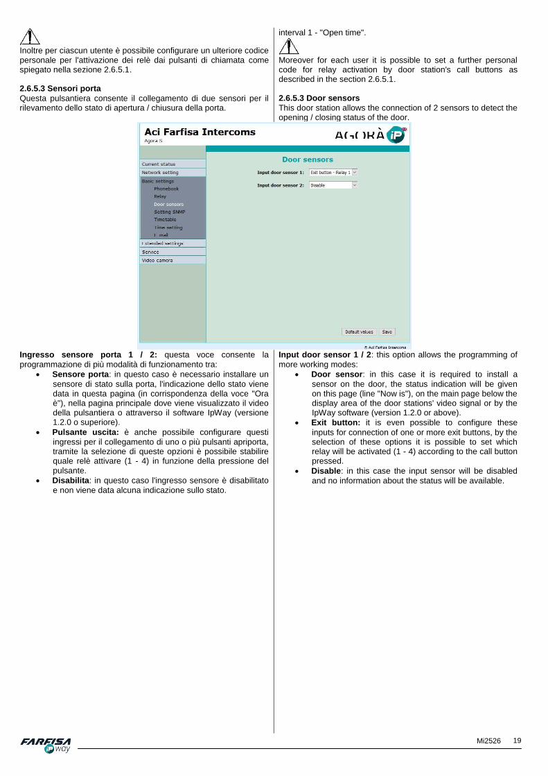
19 Mi2526
Inoltre per ciascun utente è possibile configurare un ulteriore codice personale per l'attivazione dei relè dai pulsanti di chiamata come spiegato nella sezione 2.6.5.1. 2.6.5.3 Sensori porta
Questa pulsantiera consente il collegamento di due sensori per il rilevamento dello stato di apertura / chiusura della porta.
interval 1 - "Open time".
Moreover for each user it is possible to set a further personal code for relay activation by door station's call buttons as described in the section 2.6.5.1. 2.6.5.3 Door sensors
This door station allows the connection of 2 sensors to detect the opening / closing status of the door.
Ingresso sensore porta 1 / 2: questa voce consente la
programmazione di più modalità di funzionamento tra:
Sensore porta: in questo caso è necessario installare un
sensore di stato sulla porta, l'indicazione dello stato viene data in questa pagina (in corrispondenza della voce "Ora è"), nella pagina principale dove viene visualizzato il video della pulsantiera o attraverso il software IpWay (versione 1.2.0 o superiore).
Pulsante uscita: è anche possibile configurare questi
ingressi per il collegamento di uno o più pulsanti apriporta, tramite la selezione di queste opzioni è possibile stabilire quale relè attivare (1 - 4) in funzione della pressione del pulsante.
Disabilita: in questo caso l'ingresso sensore è disabilitato
e non viene data alcuna indicazione sullo stato.
Input door sensor 1 / 2: this option allows the programming of
more working modes:
Door sensor: in this case it is required to install a
sensor on the door, the status indication will be given on this page (line "Now is"), on the main page below the display area of the door stations' video signal or by the IpWay software (version 1.2.0 or above).
Exit button: it is even possible to configure these
inputs for connection of one or more exit buttons, by the selection of these options it is possible to set which relay will be activated (1 - 4) according to the call button pressed.
Disable: in this case the input sensor will be disabled
and no information about the status will be available.

20 Mi2526
2.6.5.4 Intervalli temporali 2.6.5.4 Timetable
La programmazione delle temporizzazioni consente di configurare fino a 10 profili ciascuno composto da fino a 3 intervalli temporali per ciascun giorno della settimana. Ciascun profilo può poi essere assegnato a pulsanti di chiamata o all'attivazione di relè. Per selezionare il profilo da configurare fare click sul numero corrispondente nella parte alta della pagina, similarmente alla rubrica. Nome intervalli temporali: dopo aver selezionato l'intervallo
temporale da configurare è possibile assegnare a ciascuno di essi una titolazione personalizzata per un'identificazione più immediata. Intervallo 1-3: il profilo temporale è attivo all'interno delle fasce
orarie specificate in questi campi. Per ogni giorno della settimana è possibile specificare sino a 3 intervalli di attivazione; se non vengono specificati intervalli temporali e la casella "Attivo" è su "Si" si intenderà quel giorno sempre attivo (nell'esempio della figura il sabato). Inoltre è possibile disattivare completamente un giorno (casella "Attivo" su "No", nell'esempio della figura la Domenica). Codice per attivazione: eventuale codice da digitare attraverso un
telefono per l'attivazione manuale dell'intervallo temporale selezionato. Codice per disattivazione: eventuale codice da digitare attraverso
un telefono per la disattivazione manuale dell'intervallo temporale selezionato.
Per un corretto funzionamento si raccomanda di impostare il server temporale NTP per l’esatta sincronizzazione dell’orologio interno come descritto nella sezione successiva. Attivo: questa riga mostra con Si/No se al momento il profilo
temporale è attivo o no. Cambia: tramite questo pulsante è possibile cambiare
manualmente lo stato di attivazione del profilo.
The timetable programming allows to set up to 10 independent schedule profiles, each of them composed of up to 3 intervals for each day of the week. Each profile can then be assigned to the call buttons or for relays activation. To select the profile to configure click on the related number available on the upper part of the page, as described for the phone book setting. Timetable name: after selecting the time interval to set, it is
possible to assign a personal title to each of them for a more easier identification. Interval 1 - 3: the timing profile is active within the time interval
specified on these fields. For each day of the week it is possible to set up to 3 activation intervals; if no interval are specified and the box "Active" is set to "Yes" the whole day will be active (on the example picture the Saturday). Moreover it is possible to completely disable a whole day at once (box "Active" set to "No", on the example picture the Sunday). Code for activation: code for manual enabling of the selected
timetable schedule by phone. Code for deactivation: code for manual disabling of the
selected timetable schedule by phone.
To guarantee the door station's correct working, it is strongly recommended to set the NTP server to synchronize the internal clock with a reliable network server, as described on the next section. Active: this row shows with Yes / No if the temporal profile is
active at the moment or not. Switch: by this button it is possible to manually change the
activation of the profile status.

21 Mi2526
2.6.5.5 Regolazione ora
Questa sezione consente di configurare la sincronizzazione automatica dell'orologio interno della pulsantiera con un server NTP.
2.6.5.5 Time setting
This section allows to configure the synchronization of the internal clock of the door station with a NTP server.
Zona fuso orario: selezionare qui la zona di fuso orario di
installazione della pulsantiera. Server riferimento ora: questo campo consente di specificare
l’indirizzo del server temporale NTP per la sincronizzazione dell’orologio interno. Questa funzione è particolarmente importante nel caso in cui vengano utilizzati gli intervalli temporali per l'attivazione o la disattivazione delle chiamate o dei relè.
- Nel caso in cui non si conosca l’indirizzo di un server NTP valido, inserire in questo campo il carattere * ed il sistema troverà automaticamente l’indirizzo di un server valido. - Affinché il collegamento al server NTP funzioni correttamente è necessario che tutti i parametri della finestra “Network settings”
siano correttamente configurati (inclusi Gateway e DNS). 2.6.5.6 E-mail
Nel caso in cui si voglia informare uno o più utenti circa una chiamata non risposta è possibile configurare la funzione di invio di e-mail. La funzione consente di configurare a piacimento l'oggetto ed il testo del messaggio e-mail, inoltre è possibile configurare anche il numero di immagini, catturate dalle telecamera durante la chiamata, da allegare al messaggio. La pulsantiera invia e-mail a tutti gli utenti di cui è stato configurato un indirizzo e-mail valido per il corrispondente pulsante di chiamata. Nel caso in cui non sia stato configurato alcun indirizzo il messaggio verrà inviato al destinatario di default specificato in questa pagina.
Time zone: select here the time zone used in the location
where the door station is installed. Time server: this field allows to set the NTP server address for
the internal clock synchronization. This feature is very important in case the time intervals are used for automatic enabling or disabling of the calls or of the relays.
- In case the NTP time server is unknown, input here the character '*' in this field so that the door station will check automatically a suitable NTP server address. - The NTP synchronization works only if all the parameters on the window “Network settings” are correctly set (including
Gateway and DNS). 2.6.5.6 E-mail
If it is required to inform one or more users about missed calls it is possible to set the e-mail sending function. This function allows even to freely configure the e-mail message subject and text body according to own requirements, moreover it is possible to configure also the number of pictures, captured during call, to be attached to the message. The door station will send e-mail to all the subscriber who have set a valid e-mail address for each push button. In case the e-mail address has not been set for a button the e-mail will be sent to the default receiver set in this page.

22 Mi2526
Abilita: consente di abilitare la funzione di invio e-mail. Server SMTP: specificare qui il nome del server SMTP per l'invio di
e-mail. Porta SMTP: specificare qui il valore della porta utilizzato dal
proprio server SMTP per l'invio di e-mail. Solitamente il valore di questa porta può essere impostato su 25, altri valori comuni sono 465 o 587. Account SMTP: nel caso in cui il server richieda l'autenticazione è
necessario esprimere qui il nome dell'account e-mail che verrà utilizzato. Password SMTP: come per il campo precedente, specificare qui il
valore della password per l'autenticazione nel server SMTP. Messaggio da: utilizzare questo campo per specificare l'indirizzo e-
mail che si desidera che compaia come mittente dei messaggi. Destinatario messaggio default: destinatario di default a cui
verranno inviati i messaggi nel caso in cui per qualche pulsante di chiamata non sia stato specificato alcun indirizzo e-mail. Nel caso in cui anche in questo campo non viene specificato alcun indirizzo e-mail i messaggi non verranno inviati. Questo campo è utilizzabile anche come controllo insieme al pulsante "Invia messaggio di test" per verificare che la configurazione della funzione di invio di e-mail sia corretta. Scadenza invio: questo campo consente di esprimere un tempo (in
minuti) entro il quale la pulsantiera tenterà di inviare il messaggio e-mail nel caso in cui il server SMTP sia irraggiungibile. Allega immagini: mettere il segno di spunta in questa casella per
abilitare la funzione di invio immagini allegate al messaggio e-mail. Numero immagini: utilizzare questa casella per specificare il
numero di immagini da allegare a ciascun messaggio e-mail. Le immagini da allegare al messaggio vengono acquisite durante la fase di chiamata della pulsantiera. Intervallo immagini: intervallo di tempo tra l'acquisizione di
un'immagine ed un'altra. Per la corretta configurazione di queste opzioni tenere in considerazione che l'utente che sta chiamando potrebbe voltarsi una volta premuto il pulsante per cui può essere opportuno acquisire più immagini ad un certo intervallo di tempo l'una dall'altra per una migliore identificazione. Oggetto messaggio: oggetto del messaggio e-mail che verrà
inviato (ad esempio: "chiamata da pulsantiera" o "citofono cancello" e così via). Corpo del messaggio: è possibile utilizzare questo campo per
specificare un testo personalizzato per il messaggio e-mail che verrà inviato. E' possibile introdurre anche alcuni campi speciali che verranno sostituiti con i valori correnti: $Device$: nome identificativo del dispositivo $Date$: data corrente $Time$: ora corrente $User$: nome dell'account utilizzato per l'invio dell'e-mail $DialName": nome dell'utente chiamato come riportato nella Rubrica
Enable: it allows to enable or disable the e-mail sending
function. SMTP server: input here the name of the SMTP server used for
e-mail sending. SMT port: input here the number of the port required by the
used SMTP server for e-mail sending. Usually the value of this port can be set to 25, however other common values for this port are 465 or 587. SMTP account: usually the SMTP server requires authentication
to send e-mail, use this field to specify the account name that will be used. SMTP password: as in the previous field, set here the password
required for authentication of the account in the SMTP server. Message from: use this field to set the e-mail address which is
required to be showed as message sender. Default message to: this is the default receiver e-mail address
to whom the messages will be sent if some user has not specified any valid personal e-mail address. If even in this field any e-mail address is specified, then the e-mail sending function will not work at all. This field can be used also for setting control purpose together with the below button "Send test message" to check if the whole e-mail sending configuration is correct. Send timeout: this field allows to set a time (in minutes) within
the door station will try send e-mail message if the SMTP server is not reachable. Attach pictures: check this box in case the users wish to
receive some pictures attached to the message. Pictures count: use this field to set the number of pictures that
will be attached to each e-mail message. The pictures to attach to the message will be automatically captured during the calling time. Picture interval: time interval, in seconds, between the
acquisition of a picture and the following one. For correct configuration of these options please take in consideration that the calling user should turn back after button pressed and then it could be useful to store more pictures delayed of a certain interval for a better user's identification. Message subject: the message subject of the e-mail message
can be set according to personal requirements (for example: "door station calling" or "gate intercom" and so on). Message body: it is possible to use this box to set a personal
body text for the e-mail message to send. It is even possible to input some special fields which will be exchanged with the current values such as: $Device$: device identification name $Date$: current date $Time$: current time $User$: account user name for the e-mail sending $DialName$: name of the called user as specified in the

23 Mi2526
$DialNumber$: interno telefonico chiamato come riportato nella Rubrica. Invia messaggio di test: utilizzare questo pulsante per verificare la
corretta configurazione della funzione di invio e-mail.
Phonebook page. $DialNumber$: called extension number as specified in the Phonebook page. Send test message: use this button to send a test message to
check e-mail sending configuration is correct.
2.6.6 Configurazione estesa Questa sezione consente la configurazione di alcuni parametri da effettuare durante l'installazione o nel caso in cui sia richiesta la compatibilità con altri sistemi.
2.6.6 Extended setting This section is intended to be configured during installation or in case a compatibility with third party system is required.
2.6.6.1 Videocitofono Durata suoneria [sec]: tempo di chiamata impostabile tra 5 e 300
sec.. Nel caso in cui siano impostati più numeri da chiamare dopo aver chiamato il primo numero, al termine di questo intervallo di tempo, la pulsantiera passerà a chiamare il secondo numero e così via. Nel caso in cui non sia stato memorizzato un secondo numero la chiamata verrà terminata o verrà inviata una e-mail di notifica, se la funzione relativa è stata configurata. Attenzione: è possibile che in modalità SIP la durata della fase di chiamata venga influenzata dal altri parametri in funzione del server SIP (solitamente tra 2 e 5 min.). Durata massima chiamata [sec]: questo parametro indica la
durata massima della conversazione dopo lo sgancio del dispositivo di ricezione. Nel caso in cui questo campo venga lasciato vuoto non ci sono limiti nella conversazione. 10 secondi prima dello scadere della durata di conversazione verrà emesso un tono di avvertimento così che sia eventualmente possibile premere il tasto di prolungamento per proseguire la conversazione. Tasto prolungamento: questa opzione consente di scegliere tra il
carattere “*” o il carattere “#” da digitare sulla tastiera del proprio telefono VoIP per prolungare la durata della conversazione prima che scada il tempo stabilito per la chiamata. Rifiuta tutte le chiamate in ingresso: abilitando questa opzione la
pulsantiera non risponderà alle richieste di attivazione della conversazione da parte delle unità interne, ma sarà comunque possibile visualizzare il segnale video a scopo di controllo (autoaccensione). Conteggio cicli suoneria: questa opzione abilita la ripetizione
della chiamata (o di una chiamata sequenziale) ed il numero di ripetizioni. Se per un pulsante di chiamata vengono configurati due numeri da chiamare, questa opzione consente di specificare quante volte venga ripetuto il ciclo di chiamata. Ad esempio: nel caso in cui il primo sia occupato o non raggiungibile viene chiamato il secondo numero. Se si ha risposta da parte del secondo numero la chiamata va a buon fine, mentre se anche il secondo è occupato o non raggiungibile ed il valore di questo parametro è impostato su "2" il ciclo verrà ripetuto ancora una volta. Tasto premuto nuovamente: questa opzione consente di stabilire
il comportamento del sistema nel caso in cui lo stesso pulsante di chiamata venga premuto più volte, le possibilità sono:
2.6.6.1 Doorphone Ringing timeout [sec]: ringing time can be set between 5 and
300 seconds. If more numbers for each call button are setup, as soon as this time is expired after calling the first number, the door station will automatically call the second number and so on. If a second number is not set the call will end or an e-mail notification will be sent, if the function has been enabled previously. Warning: it is possible that in SIP mode the ringing time is differently limited due to other setting according to SIP server configuration (usually the ringing time is set between 2 and 5 minutes). Maximum call duration [sec]: this field allows to set the
maximum call duration (in seconds) once the answering device has picked up the line. If this field is left empty there will be no limit to conversation. Please remind that 10 seconds before this time is going to expire, the door station will give out a warning tone, so that it will be possible to press the right prolongation char to longer the call. Prolongation char: this option allows to choose between the
character “*” or “#” to be dialled on the VoIP phone, to extend the conversation time before the normal calling time is expired. Reject all incoming calls: enabling this function the door station
will never answer to audio activation requests coming from internal units, but it would be even possible to display the video signal for control purpose (auto power on). Ringing cycles count: this option enables the repeating of a call
(or even of a sequential call) and allows to set the number of cycles. If for example, two different numbers are set for a call button, this option allows to specify how many times the calling cycle will be repeated. Then: if the first user is busy or not available the second number will be called automatically. If the second one answers the call is successful, while if even the second number is busy or not available and the value of this option is set to "2" the cycle will be repeated since the beginning once again. Same key pressed again: this option allows to set the
behaviour of the door panel in the case the same call button is pressed more and more times, the choices are:
the call is cancelled;

24 Mi2526
la chiamata viene annullata;
la chiamata viene ripetuta;
non accade nulla. Attiva pulsante tramite HTTP: questa opzione consente di
abilitare la funzione di invio di una chiamata dalla pulsantiera attraverso un comando HTTP (senza una pressione del pulsante fisico). Ad esempio: http://IPaddress/button_control?btn=1 - attivazione remota del
pulsante 1. Questa funzione può essere utile in particolare in fase di installazione e test del sistema e non è collegabile ad alcun intervallo temporale.
Nel caso di utilizzo della pulsantiera con il monitor ZHeroIP si raccomanda di mantenere attiva questa opzione affinché l 'apertura della serratura abbia un funzionamento corretto. Durata composizione [sec]: questo tempo incide sull'intervallo di
tempo massimo entro il quale viene la pressione di più tasti in sequenza viene correttamente valutata come inserimento di un codice di apertura. La configurazione di questo parametro conseguentemente prolunga il tempo di attesa della pulsantiera prima dell'invio di una chiamata per i pulsanti corrispondenti al primo numero relativo al codice di apertura. Durata composizione DTMF [sec]: questo tempo influisce sulla
chiamata entrante proveniente da telefoni ed incide sulla corretta interpretazione del codice inserito. Il principio di funzionamento è simile a quello del parametro precedente. Modalità tastiera: funzione non attiva. Luce telecamera: la telecamera ad ampio angolo visuale è dotata
di un sistema di illuminazione a led bianchi per riprese in condizioni di scarsa illuminazione. Nel caso in cui il sito di installazione abbia illuminazione insufficiente è possibile operare le seguenti scelte:
OFF: i led sono sempre spenti;
durante la chiamata: i led si accendono solo durante la chiamata indipendentemente dalle condizioni di illuminazione ambientale;
di notte: i led si accendono solo quando il sensore interno rileva condizioni di scarsa illuminazione, indipendentemente dalla chiamata;
durante la chiamata notturna: i led si accendono solo durante la chiamata e quando il sensore rileva una condizione di scarsa illuminazione.
Intensità luminosa [%]: tramite questo parametro è possibile
impostare l'intensità luminosa dei led (in percentuale). Luce cartellini: questa opzione consente di impostare l'accensione
della retroilluminazione dei cartellini, sono possibili le seguenti scelte:
Mai: la retroilluminazione dei cartellini dei pulsanti è sempre spenta;
Notte: la retroilluminazione dei cartellini si accende in funzione dell'illuminazione rilevata dal sensore interno;
Sempre: la retroilluminazione è sempre attiva. Intensità luminosa [%]: intensità luminosa della retroilluminazione
dei cartellini (percentuale). Luce diurna inferiore alla soglia: consente di impostare il valore
di soglia inferiore relativamente al sensore della luce ambientale (tra 1 e 1021). Luce diurna superiore alla soglia: consente di impostare il valore
di soglia superiore relativamente al sensore della luce ambientale (tra 1 e 1021). Nota:
Il valore di soglia inferiore deve sempre essere minore del valore di soglia superiore. Numero di pulsanti nel modulo base: è necessario configurare
questa opzione nel caso in cui vengano installati uno o più moduli pulsanti aggiuntivi. Utilizzare questo campo per specificare il numero di pulsanti presente nel modulo base in funzione del modello di pulsantiera utilizzato IPV11AGLS o IPV12AGLS. Conteggio pulsanti espansione: utilizzare questo campo per
specificare il numero di pulsanti AGL21 presenti nei moduli aggiuntivi. Il numero corrispondente alla somma di queste due opzioni verrà
the same call is repeated;
nothing happens.
Active button by HTTP: this option allows to enable the
function to activate a call of the door station remotely by a HTTP command (then without pressing a physical button). For example: http://IPaddress/button_control?btn=1 - remote activation of the button 1. This function can be useful during installation for door station testing purpose and it cannot be linked to any time interval.
When door station is used with ZHeroIP it is recommended to enable this feature to get the door opening from video intercom working well. Dialling timeout [sec]: this time has influence on the maximum
time interval within the pressing of more buttons in sequence is correctly evaluated as an access code input for relay activation. As consequence of the configuration of this parameter the door station will automatically wait a longer time before sending a call for all the buttons related to the first digit of the access codes. DTMF dialling timeout: this time concerns incoming calls from
telephones and it affects on the right evaluation of an input code. The working principle is similar to the previous parameter. Keyboard mode: function not available in this version. Camera light: the wide angle camera is also equipped with an
illumination system with white led's for shouting in low lux conditions. If in the installation site the light is not enough it is possible to choose among the following options:
OFF: the led's are always off;
during conversation: the led's are on only during a call and independently by the surrounding light conditions;
during night: the led's are on only when the built-in sensor detects a low light condition, independently by the call status;
during night call: the led's are on when the built-in sensor detects a low light condition and only when a call is active.
Light intensity [%]: by this parameter it is possible to set the
light intensity emitted by the led (in percentage). Labels light: this option allows to set the powering condition of
the name plates light, the following choices are available:
OFF: the name plate backlight is always off;
In the night: the name plate backlight is automatically switched on by the built-in sensor;
Always: the name plate backlight is always on. Light intensity [%]: percentage of the light intensity of the name
plate backlighting. Daylight lower threshold: lower limit of the light comparator for
surrounding light condition (range 1-1021). Daylight upper threshold: upper limit of the light comparator for
the surrounding light condition (range 1-1021). Note
The value of the lower threshold must be lower and the value of the upper threshold. The number of buttons on basic module: it is required to set
this option only in the case that one or more additional button module are installed. Use this field to set the number of the buttons in the basic door panel module according to model IPV11AGLS or IPV12AGLS. Number of extension buttons: use this field to set the number
of AGL21 buttons available on the additional extension modules. The total number of buttons (buttons in the basic module + number of buttons on the additional modules) will be used to program the calls as described in the section 2.6.5.1.
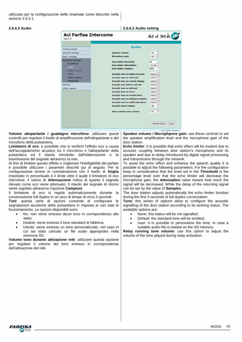
25 Mi2526
utilizzato per la configurazione delle chiamate come descritto nella sezione 2.6.5.1.
2.6.6.2 Audio 2.6.6.2 Audio setting
Volume altoparlante / guadagno microfono: utilizzare questi
controlli per regolare il livello di amplificazione dell'altoparlante e del microfono della pulsantiera. Limitatore di eco: è possibile che si verifichi l'effetto eco a causa
dell'accoppiamento acustico tra il microfono e l'altoparlante della pulsantiera ed il ritardo introdotto dall'elaborazione e la trasmissione del segnale attraverso la rete. Al fine di limitare questo effetto e migliorare l'intelligibilità del parlato è possibile utilizzare i parametri descritti qui di seguito. Per la configurazione tenere in considerazione che il livello di Soglia
impostato in percentuale è il limite oltre il quale il limitatore di eco interviene, il valore di Attenuazione indica di quanto il segnale
rilevato come eco viene attenuato. Il ritardo del segnale di ritorno viene regolato attraverso l'opzione Campioni.
Il limitatore di eco si regola automaticamente durante la conversazione full duplex in un arco di tempo di circa 3 secondi. Toni: questa serie di opzioni consente di configurare le
segnalazioni acustiche della pulsantiera in risposta ai vari stati di funzionamento. Le opzioni disponibili sono:
No: non viene emesso alcun tono in corrispondenza allo stato;
Deafult: viene emesso il tono standard di fabbrica;
Utente: viene emesso un tono personalizzato, nel caso in cui sia stato caricato un file audio appropriato nella memoria SD.
Volume tono durante attivazione relè: utilizzare questa opzione
per regolare il volume del tono emesso in corrispondenza dell'attivazione del relè.
Speaker volume / Microphpone gain: use these controls to set
the speaker amplification level and the microphone gain of the door station. Echo limiter: it is possible that echo effect will be evident due to
acoustic coupling between door station's microphone and its speaker and due to delay introduced by digital signal processing and transmission through the network. To avoid the echo effect and enhance the speech quality it is possible to adjust the following parameters. For the configuration keep in consideration that the level set in the Threshold is the
percentage level over that the echo limiter will decrease the microphone gain, the Attenuation value means how much the
signal will be decreased. While the delay of the returning signal can be set by the value of Samples.
The door station adjusts automatically the echo limiter function during the first 3 seconds of full duplex conversation. Tone: this series of options allow to configure the acoustic
signalling of the door station according to its working status. The available options are:
None: this status will be not signalled;
Default: the standard tone will be emitted;
User: it is possible to personalize the tone, in case a suitable audio file is loaded on the SD memory.
Relay running tone volume: use this option to adjust the
volume of the tone played during relay activation.
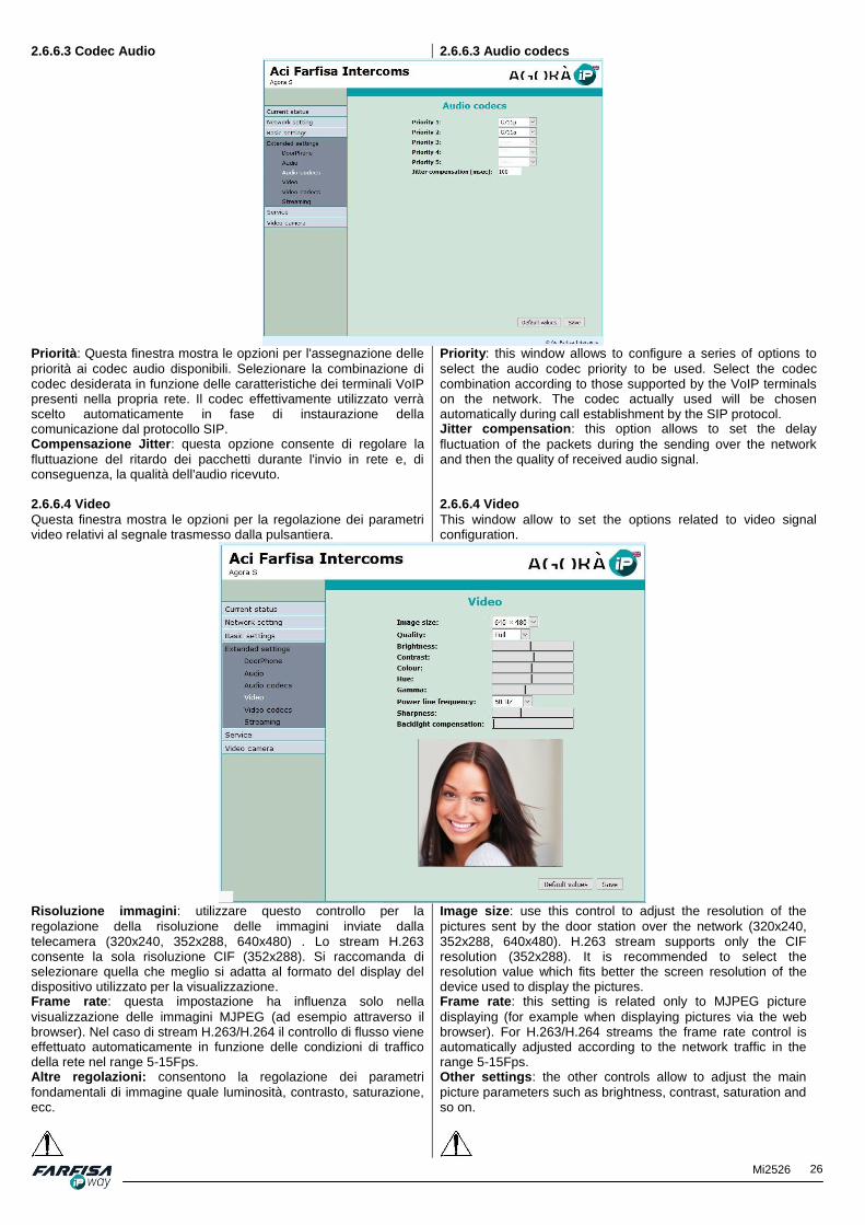
26 Mi2526
2.6.6.3 Codec Audio 2.6.6.3 Audio codecs
Priorità: Questa finestra mostra le opzioni per l'assegnazione delle
priorità ai codec audio disponibili. Selezionare la combinazione di codec desiderata in funzione delle caratteristiche dei terminali VoIP presenti nella propria rete. Il codec effettivamente utilizzato verrà scelto automaticamente in fase di instaurazione della comunicazione dal protocollo SIP. Compensazione Jitter: questa opzione consente di regolare la
fluttuazione del ritardo dei pacchetti durante l'invio in rete e, di conseguenza, la qualità dell'audio ricevuto.
Priority: this window allows to configure a series of options to
select the audio codec priority to be used. Select the codec combination according to those supported by the VoIP terminals on the network. The codec actually used will be chosen automatically during call establishment by the SIP protocol. Jitter compensation: this option allows to set the delay
fluctuation of the packets during the sending over the network and then the quality of received audio signal.
2.6.6.4 Video Questa finestra mostra le opzioni per la regolazione dei parametri video relativi al segnale trasmesso dalla pulsantiera.
2.6.6.4 Video This window allow to set the options related to video signal configuration.
Risoluzione immagini: utilizzare questo controllo per la
regolazione della risoluzione delle immagini inviate dalla telecamera (320x240, 352x288, 640x480) . Lo stream H.263 consente la sola risoluzione CIF (352x288). Si raccomanda di selezionare quella che meglio si adatta al formato del display del dispositivo utilizzato per la visualizzazione. Frame rate: questa impostazione ha influenza solo nella
visualizzazione delle immagini MJPEG (ad esempio attraverso il browser). Nel caso di stream H.263/H.264 il controllo di flusso viene effettuato automaticamente in funzione delle condizioni di traffico della rete nel range 5-15Fps. Altre regolazioni: consentono la regolazione dei parametri
fondamentali di immagine quale luminosità, contrasto, saturazione, ecc.
Image size: use this control to adjust the resolution of the
pictures sent by the door station over the network (320x240, 352x288, 640x480). H.263 stream supports only the CIF resolution (352x288). It is recommended to select the resolution value which fits better the screen resolution of the device used to display the pictures. Frame rate: this setting is related only to MJPEG picture
displaying (for example when displaying pictures via the web browser). For H.263/H.264 streams the frame rate control is automatically adjusted according to the network traffic in the range 5-15Fps. Other settings: the other controls allow to adjust the main
picture parameters such as brightness, contrast, saturation and so on.

27 Mi2526
Prima di procedere con la regolazione di questi parametri si raccomanda di richiamare la configurazione predefinita attraverso il pulsante "Valori default".
Before proceeding with these parameters adjustment it is recommended to load the default configuration by clicking the “Default values” button.
2.6.6.5 Codec Video 2.6.6.5 Video codecs
Priorità: utilizzare questi controlli per stabilire una priorità tra i
codec video H.263 e H.264 supportati dalla pulsantiera. Compatibilità: a causa di specifiche richieste di funzionamento di
alcuni telefoni VoIP è possibile abilitare queste funzioni per: - telefoni Yealink; - script specifico per la visualizzazione del video JPEG su telefoni SNOM.
Nel caso in cui non venga selezionato alcun codec, il segnale video non verrà trasmesso durante la chiamata.
Priority: use these controls to select the priority level for the
codecs H.263 and H.264 supported by the door station. Compatibility: because of some specific requests of some VoIP
phones it is possible to check these boxes to enable functions for: - Yealink phones; - Specific script for JPEG video display on SNOM phones.
If no codec is selected, the video signal will be not sent during the call.
2.6.6.6 Streaming 2.6.6.6 Streaming
Abilita streaming: consente di abilitare o disabilitare l'invio di uno
stream RTSP sulla porta 554 per il video con codifica H.263 e H.264. Per la visualizzazione di questo segnale video è necessario utilizzare software video players come MPlayer, VLC... Questo stream è sempre attivo, indipendentemente dalla chiamata. Client permesso: se questo campo non viene compilato il video
può essere visualizzato da tutti. Nel caso in cui viene specificato qui un indirizzo IP lo stream video potrà essere visualizzato solo dal
Enable streaming: it allows to enable or disable the RTSP
stream sending on the port 554 for the video with H.263 codec and H.264. To display this video stream it is possible to use a video player software such as MPlayer, VLC,… This stream is always running and it is not depending on the call. Permitted client: if this field is empty the video stream can be
displayed by everyone. If here is set a specific IP address the video stream could be displayed only by the device with that IP

28 Mi2526
client corrispondente a questo indirizzo. Tipo Stream: consente di selezionare il tipo di stream da
visualizzare: audio, video, audio/video. Indirizzo Multicast: consente di specificare l'indirizzo IP a cui
inviare pacchetti RTP per la trasmissione multicast. Qualità immagini JPEG: inserire qui la percentuale di qualità video
per le immagini JPEG (valori ammessi tra 50 e 85).
address. Stream media: it is allows to select the stream type to use: only
audio, only video or audio/video. Multicast address: it allows to set a specific IP address to send
RTP packets for a multi cast transmission. JPEG image quality: input here the percentage of video quality
for JPEG pictures (values between 50 and 85).
2.6.7 Servizio 2.6.7.1 Riavvia
2.6.7 Service 2.6.7.1 Restart
Fare click sul pulsante Restart per effettuare il reset della
pulsantiera.
Click on “Restart” button to reboot the door station.
2.6.7.2 Configurazione 2.6.7.2 Configuration
La pulsantiera consente di salvare la configurazione su PC. Il file di configurazione può essere successivamente ripristinato, anche a differenti livelli: ad esempio solo la rubrica o solo la configurazione SIP, ... Questa funzione è utile soprattutto nel caso di installazione di più pulsantiere nello stesso edificio. Salva configurazione: fare click sul pulsante Esegui per salvare la
configurazione corrente. Carica configurazione: fare click sulla casella vuota per poter
selezionare il file di configurazione dal proprio PC. Utilizzare le caselle di selezionare quali sezioni della configurazione devono essere ripristinate, infine fare click sul pulsante "Esegui" per
The door station allows to save its internal configuration on a PC file. The file can be used to restore the configuration settings even in different levels.: for example only the phonebook or only the SIP configuration,… This function is especially useful mainly in case of installation of more door stations in the same building. Save configuration: click on the button Make to save the
current configuration. Load configuration: click on the box to display the window to
select and open the configuration file from PC folder. Use the other boxes to select which section of the configuration must be restored and finally click on “Make” button to confirm.

29 Mi2526
confermare. Cancella rubrica: elimina tutti i dati dalla sezione Rubrica della
pulsantiera. Default rete e SIP: ripristina la configurazione di rete (indirizzo IP
192.168.1.250) e cancella tutti i dati relativi alla registrazione SIP. Default altri parametri: ripristina la configurazione degli altri parametri. Fare click su "Esegui" per confermare.
Clear phonebook: checking this box will erase all the contacts
of the door station Phonebook. Default network and SIP: it restores the network configuration
(the door station IP address will be 192.168.1.250) and erases all the data related to SIP configuration. Default others: it restores the configuration of all the other parameters. Click on “Make” button to confirm.
2.6.7.3 Stile e lingua 2.6.7.3 Style and language
Carica file stile: Fare click sulla casella di testo per selezionare un
file di stile per la pagina web. Successivamente fare click su "Esegui" per confermare. Carica file logo: fare click sulla casella di testo per selezionare un
file di logo (200x100 pixel, .jpg/.gif/.png/.bmp, con nome logo.*). Cancella lingue: consente di cancellare tutti i file di lingua
personalizzati eventualmente caricati nella pulsantiera (tranne inglese ed italiano). Carica file lingua: fare click sulla casella di testo per selezionare un file di lingua e quindi su "Esegui" per confermare. Salva file lingua: fare click sul pulsante "Esegui" per confermare.
Load style file: click on the text box to display the window to
select and open the style file for the web page. Then click on the “Make” button to confirm. Load logo file: click on the text box to display the window to
select and open the logo file (200x100 pixel, .jpg/.gif/.png/.bmp, with file name as logo.*). Clean languages: it allows to erase all the language file
eventually loaded on the door station (except English and Italian). Load language file: click on the text box to display the window to select and open the language file and then click on “Make” to
add the new language to the door station. Save language file: click on “Make” button to export language
file of the language selected at the moment.
2.6.7.4 Aggiornamento firmware 2.6.7.4 Firmware upgrade
Versione firmware: indica l'attuale versione FW della pulsantiera. Firmware version: it displays the actual firmware version of the

30 Mi2526
Scegli file firmware: fare click sulla casella di testo per selezionare
un file di aggiornamento del firmware (del tipo “apt.firmware”, file compressi . zip non sono ammessi). Fare click sul pulsante "Salva"
sotto per confermare. Il box al centro della pagina mostrerà l'avanzamento de processo. Nel caso in cui dovesse verificarsi una perdita di alimentazione o una disconnessione della rete durante il processo la pulsantiera dispone di una pagina web di ripristino. In caso di problemi di funzionamento quindi, si raccomanda di posizionare il dip-switch 2 in posizione ON, riavviare la pulsantiera per ripristinare la configurazione di default ed accedere con l'indirizzo IP 192.168.1.250 per visualizzare la pagina di ripristino e ripetere l'operazione di aggiornamento. Al termine non dimenticare di riportare il dip-switch in posizione OFF.
Dopo l'aggiornamento della pulsantiera è consigliabile riavviare la pulsantiera. 2.6.7.5 Logfile
door station. Choose firmware file: click on the text box to select the
firmware file for upgrade (the file must be as “apt.firmware”, . zip file are not allowed): Click on “Save” button below to confirm.
The box in the middle of the page will display the progress of the process. In case of power loss or network disconnection during upgrade operation the door station will automatically load a backup web interface for repeating the firmware operation again. In case of any problem, it is suggested to move the dip-switch 2 in ON position, reboot the door panel to restore the default configuration and access by the default IP address 192.168.1.250 to display the backup page and repeat the operation. At the end do not forget to put the dip switch 2 in OFF position again.
After firmware upgrade it is recommended to reboot the door station. 2.6.7.5 Logfile
Avvia log avanzato: fare click sul pulsante "Start" per abilitare la
funzione di memorizzazione del funzionamento della pulsantiera nella sua memoria interna a scopo di diagnostica. Prima di fare click su questo pulsante si raccomanda di riavviare la pulsantiera. Scarica log file: fare click su "Esegui" per scaricare su PC i file di
log per analisi. Mostra log registrazione / chiamate: mostra il risultato degli ultimi
tentativi di registrazione sul server SIP o delle ultime chiamate da parte della pulsantiera. Server syslog: indirizzo IP o nome del server a cui inviare i log di
funzionamento della pulsantiera (per questa funzione si raccomanda di impostare la data e l'ora correnti attraverso un server NTP altrimenti le voci verranno memorizzate con data ed ora non corrette).
Start enhanced log: click on the “Start” button to enable the
function to save all the working status of the door station in its internal memory for diagnostic purpose. Before clicking on this button it is recommended to reboot the door station. Download log file: click on “Make” button to download the data
on the PC for analysis. Show call log/VoIP log: click on “Make” button to display the
latest registration attempts on the SIP server of the door station. Syslog server: IP address or server name to send the door
station log information (for this function it is recommended to set the NTP server so that the data and hour will be automatically synchronized with the correct one otherwise the information could not be displayed with correct date and time).

31 Mi2526
2.6.7.6 Licenza 2.6.7.6 License
Questa finestra consente di ampliare le funzioni della pulsantiera attraverso l'introduzione di un ulteriore codec audio (ad esempio G729) disponibile solo a pagamento. 2.6.7.7 Toni utente
This door station allows to enlarge the functions by adding additional audio codec (for example G729) available after payment. 2.6.7.7 User acoustic tones
Questa finestra consente di caricare dal proprio PC alcuni toni personalizzati da abbinare ai vari stati di funzionamento della pulsantiera che verranno salvati nella memoria uSD. Facendo click sul pulsante "Play" il file attivo al momento per la funzione verrà eseguito. Rimuovendo la memoria uSD verranno automaticamente eseguiti i toni standard. I file audio devono essere di tipo .wav 8KHz - mono - 16 bit PCM.
This window allows to load from PC some personal tones to be assigned to various working status of the door station which will be stored on uSD memory. Clicking on the button “Play” it is possible to play the currently active sound file for that function. If the uSD memory is removed the standard tones will be used. The audio files must be of.wav type, 8KHz – mono – 16 bit PCM.

32 Mi2526
Per
ma
ggio
ri in
form
azio
ni sulla
gam
ma F
arf
isa IpW
ay v
isita la
pagin
a:
Fo
r m
ore
info
rma
tio
n a
bout
Fa
rfis
a I
pW
ay p
roducts
range
ple
ase v
isit:
MA
TR
ICO
LA
SE
RIA
L N
UM
BE
R
DA
TA
AC
QU
IST
O
DA
TE
OF
PU
RC
HA
SE
TIM
BR
O E
FIR
MA
DE
L R
IVE
ND
ITO
RE
DE
ALE
R'S
NA
ME
AN
D A
DD
RE
SS
La A
CI S
rl F
arf
isa Inte
rcom
s s
i riserv
a il diritto
di m
odific
are
in
quals
iasi
mo
me
nto
i p
rodotti qui ill
ustr
ati.
AC
I S
rl F
arf
isa Inte
rcom
s r
eserv
es t
he r
ight to
mo
dify the p
roducts
here
illu
str
ate
d a
t any tim
e.
AC
I srl
Fa
rfis
a In
terc
om
s
Via
E. V
anoni, 3
• 6
0027 O
sim
o (
AN
) •
Italy
T
el: +
39 0
71 7
202038 (
r.a.)
•
Fa
x: +
39 0
71 7
202037 •
info
@fa
rfis
a.c
om
•
ww
w.f
arf
isa.c
om
Sm
altir
e il dis
po
sitiv
o s
econ
do q
ua
nto
pre
scri
tto d
alle
no
rme p
er
la tu
tela
dell'
am
bie
nte
Dis
pose
of
the
devic
e a
cco
rdin
g t
o lo
cal ru
les f
or
en
viro
nm
en
t p
rote
ctio
n
M527055700
MA
TR
ICO
LA
SE
RIA
L N
UM
BE
R
CE
RT
IFIC
AT
O D
I G
AR
AN
ZIA
(co
nd
izio
ni valid
e s
olo
pe
r il T
err
ito
rio
Ita
lian
o)
La g
ara
nzia
ha d
ura
ta d
i 2
4 m
esi
dalla
data
di
acqu
isto
, accert
ata
o a
ccert
abile
, e v
ien
e
eserc
itata
da
lla D
itta
rive
nditri
ce e
, tr
am
ite q
uesta
, da
i C
entr
i d
i A
ssis
tenza
T
ecnic
a
Auto
rizzati F
AR
FIS
A.
La g
ara
nzia
deve e
ssere
eserc
itata
, p
ena l
a d
eca
de
nza,
entr
o o
tto
gio
rni
da
lla s
copert
a
del difetto
.
LA
GA
RA
NZ
IA N
ON
E' V
AL
ID S
E N
ON
DA
TA
TA
E V
IDIM
AT
A C
ON
TIM
BR
O E
FIR
MA
DE
L
RIV
EN
DIT
OR
E
ALL'A
TT
O
DE
LL'A
CQ
UIS
TO
. C
ER
TIF
ICA
TO
U
NIC
O
ED
INS
OS
TIT
UIB
ILE
.
No
tes
on
Us
ing
Op
en
So
urc
e S
oft
wa
re (
GP
L)
Th
is p
rodu
ct is
pa
rtly
fre
e s
oftw
are
dis
trib
ute
d u
nd
er
the
GN
U G
en
era
l P
ublic
Lic
ense
ve
rsio
n 1
, ve
rsio
n 2
an
d
ve
rsio
n 2
.1. F
ree
so
ftw
are
rele
ase
is "
as it
is"
WIT
HO
UT
AN
Y W
AR
RA
NT
Y a
nd
ou
r L
IAB
ILIT
Y.
Th
e
list o
f fr
ee
so
ftw
are
and
a c
opy o
f th
e lic
ense
th
at is
use
d in
th
is p
rod
uct
ca
n b
e d
ow
nlo
ade
d f
rom
ou
r
web
site
: h
ttp
://w
ww
.farf
isa
.com
at
the
pa
ge
re
late
d to
ea
ch p
rodu
ct.
We
pro
vid
e y
ou
with
a c
om
ple
te,
machin
e-r
ea
dab
le
co
py o
f th
e s
ou
rce
co
de
of fr
ee
so
ftw
are
at
no
extr
a
co
st. C
on
tact u
s a
t in
fo@
farf
isa
.com
Fo
r d
eta
iled
in
form
atio
n o
n a
cce
ss p
assw
ord
s to
th
e
so
urc
e c
od
e f
or
op
en
so
urc
e s
oft
ware
, see
als
o t
he
lin
k
ab
ove
.