INDICE - INDEX - dagmita.lt · Possibilità di assemblaggio / Assembling possibility pag. 2...
24
Premessa - Introduction pag. 1 Possibilità di assemblaggio / Assembling possibility pag. 2 Informazioni generali - General Information pag. 3 Carichi Radiali CR - Radial Loads CR pag. 5 Lubrificazione - Posizione di montaggio e posizione morsetteria Lubrification - Mounting position and terminal box orientation pag. 6 Rapporti e predisposizioni possibili - Ratio and iec motor adapters pag. 7 Tabella di selezione prestazioni - Gear unit selection tables pag. 9 Prestazioni / Performance parameter f · s = 1 pag. 15 Dimensioni - Dimension sheet CHC 16 - CHC 20 pag. 16 Dimensioni - Dimension sheet CHC 25 pag. 17 Dimensioni - Dimension sheet CHC 30 pag. 18 Dimensioni - Dimension sheet CHC 35 - CHC 40 pag. 19 Esploso e parti di ricambio - Exploded drawing and spare parts list pag. 20 Motori elettrici trifase - Three-phase electrical motors pag. 21 Kit servoventilato* serie monofase - Forced ventilation kit* single-phase models pag. 22 Istruzioni uso e manutenzione - Use and maintenance instructions pag. 23 Condizioni generali di vendita - General sales conditions pag. 24 INDICE - INDEX
Transcript of INDICE - INDEX - dagmita.lt · Possibilità di assemblaggio / Assembling possibility pag. 2...
Premessa - Introduction pag. 1
Possibilità di assemblaggio / Assembling possibility pag. 2
Informazioni generali - General Information pag. 3
Carichi Radiali CR - Radial Loads CR pag. 5
Lubrificazione - Posizione di montaggio e posizione morsetteriaLubrification - Mounting position and terminal box orientation pag. 6
Rapporti e predisposizioni possibili - Ratio and iec motor adapters pag. 7
Tabella di selezione prestazioni - Gear unit selection tables pag. 9
Prestazioni / Performance parameter f · s = 1 pag. 15
Dimensioni - Dimension sheet CHC 16 - CHC 20 pag. 16
Dimensioni - Dimension sheet CHC 25 pag. 17
Dimensioni - Dimension sheet CHC 30 pag. 18
Dimensioni - Dimension sheet CHC 35 - CHC 40 pag. 19
Esploso e parti di ricambio - Exploded drawing and spare parts list pag. 20
Motori elettrici trifase - Three-phase electrical motors pag. 21
Kit servoventilato* serie monofase - Forced ventilation kit* single-phase models pag. 22
Istruzioni uso e manutenzione - Use and maintenance instructions pag. 23
Condizioni generali di vendita - General sales conditions pag. 24
INDICE - INDEX
1
La nuova serie di riduttori coassiali denominata CHC è un prodotto che deve la sua innovazione alla modularità.Grazie alla predisposizione per motore IEC B5 e B14, può essere collegato a motori normali, autofrenanti edantideflagranti.Questo tipo di riduttore è largamente usato in campo tessile, alimentare, enologico, chimico, imballaggio, ecc...
Caratteristiche prodotto
· Modularità· Alto rendimento· Bassa rumorosità· Montaggio universale· Cassa in alluminio, peso ridotto· Ingranaggi cementati, rettificati· Lubrificazione permanente
I riduttori serie CHC sono prodotti in 5 grandezze (+ 1 a richiesta). Potenze 0,12-4 Kw rapporti da 5 a 46.Coppia max 120-500 Nm. Possono essere montati (a piedi o flangia) in tutte le posizioni secondo le richiestedei clienti.
PREMESSA
CHC series helical gear units is a new generation product, which designed basing on the modular system.Itcan be connected respectively with motors such as normal motor, brake motor, explosion-proof motor, IECmotorB5 - B14. This kind of product is widely used in drive fields such as textile, foodstuff, beverage, chemicalindustry, packaging and so on.
Products characteristics
· Modularity· High efficiency· Low noise· Universal mounting· Aluminum housing, light in weight· Gears in carbonize hard, grinded· Lubricant maintenance free
CHC Series helical gear units are manufactured in 5 sizes (+ 1 on request). Power 0.12-4KW; Ratio 5-46;Torque max 120-500Nm. It can be connected (foot, flange) discretionary and use multi-mounting positionsaccording to cutomers’ requirements.
INTRODUCTION
2
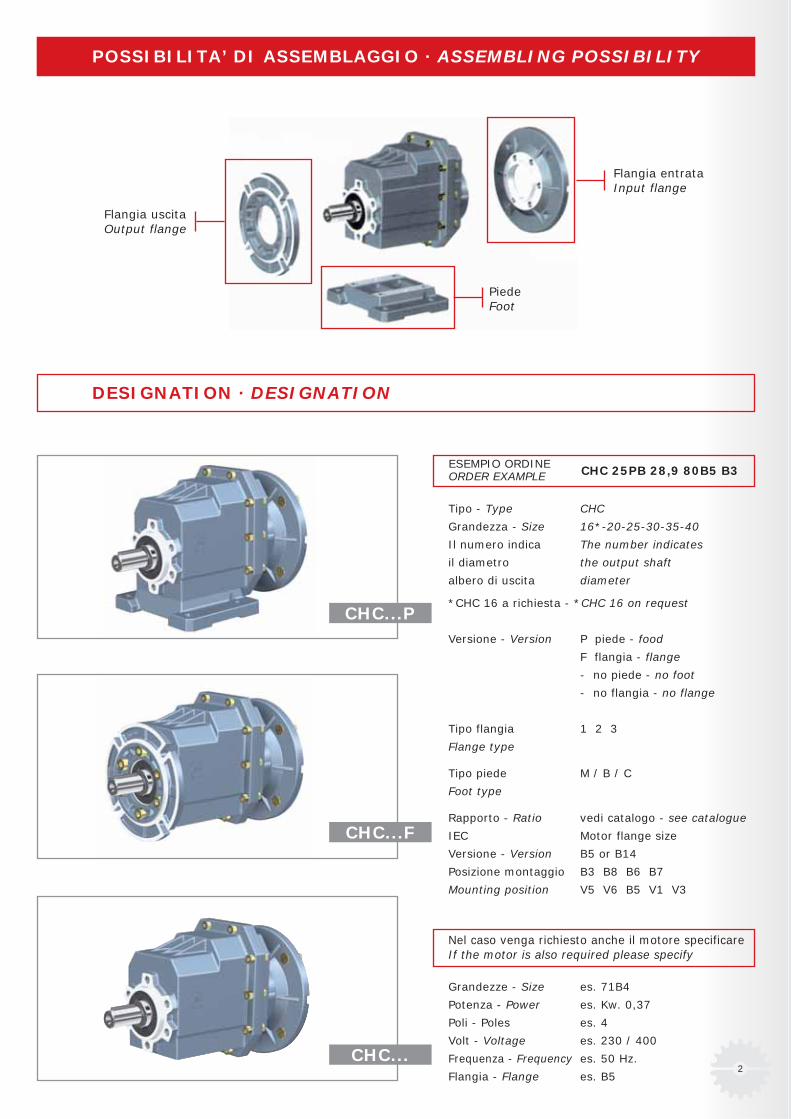
POSSIBILITA’ DI ASSEMBLAGGIO · ASSEMBLING POSSIBILITY
DESIGNATION · DESIGNATION
CHC...P
ESEMPIO ORDINEORDER EXAMPLE
CHC...F
CHC...
Tipo - Type CHC
Grandezza - Size 16*-20-25-30-35-40
Il numero indica The number indicates
il diametro the output shaft
albero di uscita diameter
*CHC 16 a richiesta - *CHC 16 on request
Versione - Version P piede - food
F flangia - flange
- no piede - no foot
- no flangia - no flange
Tipo flangia 1 2 3
Flange type
Tipo piede M / B / C
Foot type
Rapporto - Ratio vedi catalogo - see catalogue
IEC Motor flange size
Versione - Version B5 or B14
Posizione montaggio B3 B8 B6 B7
Mounting position V5 V6 B5 V1 V3
Nel caso venga richiesto anche il motore specificareIf the motor is also required please specify
Grandezze - Size es. 71B4
Potenza - Power es. Kw. 0,37
Poli - Poles es. 4
Volt - Voltage es. 230 / 400
Frequenza - Frequency es. 50 Hz.
Flangia - Flange es. B5
CHC 25PB 28,9 80B5 B3
Flangia uscitaOutput flange
Flangia entrataInput flange
PiedeFoot
3
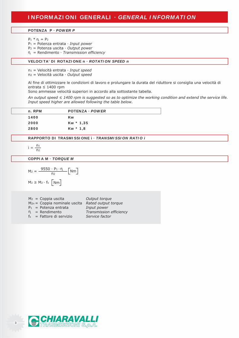
POTENZA P · POWER P
P1 * = P2
P1 = Potenza entrata · Input powerP2 = Potenza uscita · Output power = Rendimento · Transmission efficiency
VELOCITA’ DI ROTAZIONE n · ROTATION SPEED n
n1 = Velocità entrata · Input speedn2 = Velocità uscita · Output speed
Al fine di ottimizzare le condizioni di lavoro e prolungare la durata del riduttore si consiglia una velocità dientrata ≤ 1400 rpmSono ammesse velocità superiori in accordo alla sottostante tabella.
An output speed ≤ 1400 rpm is suggested so as to optimize the working condition and extend the service life.Input speed higher are allowed following the table below.
INFORMAZIONI GENERALI · GENERAL INFORMATION
n. RPM POTENZA · POWER
1400 Kw
2000 Kw * 1,35
2800 Kw * 1,8
RAPPORTO DI TRASMISSIONE i · TRANSMISSION RATIO i
i =n1
n2
COPPIA M · TORQUE M
M2 =9550 · P1 ·
n2Nm
M2 ≥ M2 · fs Nm
M2 = Coppia uscita Output torqueM2n = Coppia nominale uscita Rated output torqueP1 = Potenza entrata Input power
= Rendimento Transmission efficiencyfs = Fattore di servizio Service factor
4
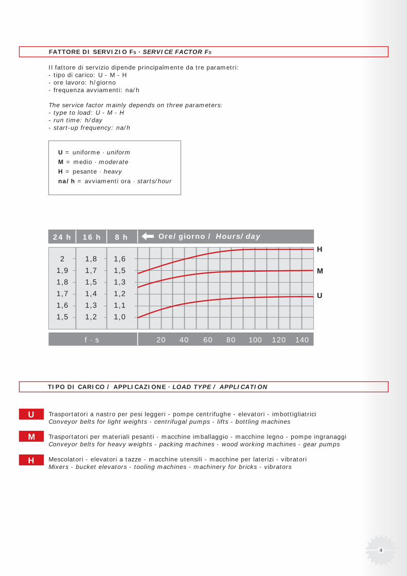
FATTORE DI SERVIZIO FS · SERVICE FACTOR FS
Il fattore di servizio dipende principalmente da tre parametri:- tipo di carico: U - M - H- ore lavoro: h/giorno- frequenza avviamenti: na/h
The service factor mainly depends on three parameters:- type to load: U - M - H- run time: h/day- start-up frequency: na/h
U = uniforme · uniform
M = medio · moderate
H = pesante · heavy
na/h = avviamenti ora · starts/hour
24 h 16 h 8 h Ore/giorno / Hours/day
f · s 20 40 60 80 100 120 140
2 1,8 1,6
1,9 1,7 1,5
1,8 1,5 1,3
1,7 1,4 1,2
1,6 1,3 1,1
1,5 1,2 1,0
H
M
U
TIPO DI CARICO / APPLICAZIONE · LOAD TYPE / APPLICATION
Trasportatori a nastro per pesi leggeri - pompe centrifughe - elevatori - imbottigliatriciConveyor belts for light weights - centrifugal pumps - lifts - bottling machines
Trasportatori per materiali pesanti - macchine imballaggio - macchine legno - pompe ingranaggiConveyor belts for heavy weights - packing machines - wood working machines - gear pumps
Mescolatori - elevatori a tazze - macchine utensili - macchine per laterizi - vibratoriMixers - bucket elevators - tooling machines - machinery for bricks - vibrators
U
M
H
5
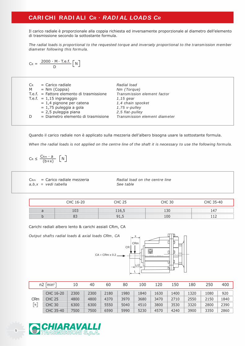
n2 10 40 60 80 100 120 150 180 250 400
CHC 16-20 2300 2300 2180 1980 1840 1630 1400 1320 1080 920
CHC 25 4800 4800 4370 3970 3680 3470 2710 2550 2150 1840
CHC 30 6300 6300 5550 5040 4510 3800 3530 3320 2800 2390
CHC 35-40 7500 7500 6590 5990 5230 4570 4240 3900 3350 2860
N
CRm
min1
CR = Carico radiale Radial loadM = Nm (Coppia) Nm (Torque)T.e.f. = Fattore elemento di trasmissione Transmission element factorT.e.f. = 1,15 ingranaggio 1,15 gear
= 1,4 pignone per catena 1,4 chain spocket= 1,75 puleggia a gola 1,75 v-pulley= 2,5 puleggia piana 2,5 flat-pulley
D = Diametro elemento di trasmisione Transmission element diameter
Il carico radiale è proporzionale alla coppia richiesta ed inversamente proporzionale al diametro dell’elementodi trasmissione secondo la sottostante formula.
The radial loads is proportional to the requested torque and inversely proportional to the transmission memberdiameter following this formula.
CARICHI RADIALI CR · RADIAL LOADS CR
CR =2000 · M · T.e.f.
DN
Quando il carico radiale non è applicato sulla mezzeria dell’albero bisogna usare la sottostante formula.
When the radial loads is not applied on the centre line of the shaft it is necessary to use the following formula.
CR ≤CRm · a(b+x)
N
CRm = Carico radiale mezzeria Radial load on the centre linea,b,x = vedi tabella See table
Carichi radiali albero lento & carichi assiali CRm, CA
Output shafts radial loads & axial loads CRm, CA
CHC 16-20 CHC 25 CHC 30 CHC 35-40
a 103 116,5 130 147
b 83 91,5 100 112
CA = CRm x 0.2
CRCRm
x
L/2
L
6
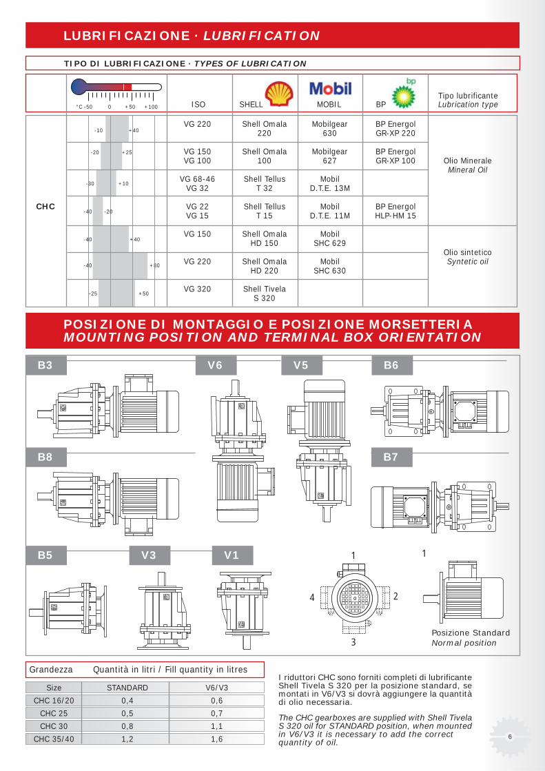
LUBRIFICAZIONE · LUBRIFICATION
TIPO DI LUBRIFICAZIONE · TYPES OF LUBRICATION
POSIZIONE DI MONTAGGIO E POSIZIONE MORSETTERIAMOUNTING POSITION AND TERMINAL BOX ORIENTATION
I riduttori CHC sono forniti completi di lubrificanteShell Tivela S 320 per la posizione standard, semontati in V6/V3 si dovrà aggiungere la quantitàdi olio necessaria.
The CHC gearboxes are supplied with Shell TivelaS 320 oil for STANDARD position, when mountedin V6/V3 it is necessary to add the correctquantity of oil.
Posizione StandardNormal position
V6 V5 B6
Grandezza Quantità in litri / Fill quantity in litres
Size STANDARD V6/V3
CHC 16/20 0,4 0,6
CHC 25 0,5 0,7
CHC 30 0,8 1,1
CHC 35/40 1,2 1,6
-40 +80
B5 V3 V1
B3
VG 220 Shell Omala Mobilgear BP Energol220 630 GR-XP 220
VG 150 Shell Omala Mobilgear BP EnergolVG 100 100 627 GR-XP 100 Olio Minerale
Mineral OilVG 68-46 Shell Tellus Mobil
VG 32 T 32 D.T.E. 13M
CHC VG 22 Shell Tellus Mobil BP EnergolVG 15 T 15 D.T.E. 11M HLP-HM 15
VG 150 Shell Omala MobilHD 150 SHC 629
Olio sinteticoVG 220 Shell Omala Mobil Syntetic oil
HD 220 SHC 630
VG 320 Shell TivelaS 320
+40-10
+25-20
-30 +10
-40 -20
-40 +40
-25 +50
4
3
2
1 1
B8 B7
Tipo lubrificanteISO SHELL MOBIL BP Lubrication type°C -50 0 +50 +100

7
CHC 20 (CHC16)* IEC
i63B5 71B5 80B5
71B14 80B1445,9 B
40,1 B
35,5 B
28,5 B
23,6 B
19,8 B
17,9 B
13,8 B
11,9 B
9,8 B
7,7 B
5,7 B
46,5 B
40,6 B
35,9 B
28,9 B
23,9 B
20,1 B
17,1 B
14,8 B
12,1 B
9,9 B
7,4 B
5,5 B
44,2 B
34,2 B
30,6 B
25,0 B
21,2 B
18,2 B B
15,3 B B
12,6 B
10,9 B
7,9 B
5,5 B
44,2 B
34,2 B B
30,6 B
25,0 B
21,2 B
18,2 B
15,3 B
12,6
10,9
7,9
5,5
IEC 63B5 71B5 71B14 80B5 80B14 90B5 90B14 100B5 100B14 112B5 112B14
DE8 11 14 19 24 28 28P 140 160 105 200 120 200 140 250 160 250 160M 115 130 85 165 100 165 115 215 130 215 130N 95 110 70 130 80 130 95 180 110 180 110
* CHC 16 Solo a richiesta - Only on request
I rapporti sono arrotondati - Ratios are rounded
B= con boccola di riduzione in acciaio - Metal reduction bushing
RAPPORTI E PREDISPOSIZIONI POSSIBILIRATIO AND IEC MOTOR ADAPTERS
CHC 25 IEC
i71B5 80B5 90B5
71B14 80B14 90B14
CHC 30 IEC
i80B5 90B5 100/112B5
80B14 90B14 100/112B14
CHC 35 CHC 40 IEC
i80B5 90B5 100/112B5
80B14 90B14 100/112B14
PMND
8

9
TABELLA DI SELEZIONE PRESTAZIONIGEAR UNIT SELECTION TABLES
P1n n2 M2n i fs page
kW r/min Nm
0.12 30.5 36 45.9 3.3 CHC20 63B5 63A4 16
34.9 32 40.1 3.8 (CHC16)
39.5 28 35.5 4.3
49.1 22 28.5 5.4
59.4 18.5 23.6 6.5
70.6 15.6 19.8 7.7
78.4 14.0 17.9 7.1
101 10.8 13.8 9.2
118 9.4 11.9 12.8
143 7.7 9.8 13.0
181 6.1 7.7 13.2
246 4.5 5.7 13.4
0.18 19.6 84 45.9 1.4 CHC20 71B5/B14 71A6 16
22.4 74 40.1 1.6 (CHC16)
25.4 65 35.5 1.8
31.6 52 28.5 2.3
30.5 54 45.9 2.2 CHC20 63B5 63B4 16
34.9 47 40.1 2.5 (CHC16)
39.5 42 35.5 2.9
49.1 34 28.5 3.6
59.4 28 23.6 4.3
70.6 23 19.8 5.1
78.4 21 17.9 4.8
101 16.3 13.8 6.1
118 14.0 11.9 8.6
143 11.6 9.8 8.6
181 9.1 7.7 8.8
246 6.7 5.7 8.9
19.4 85 46.5 2.3 CHC25 71B5/B14 71A6 17
22.2 74 40.6 2.7
25.1 66 35.9 3.0
31.2 53 28.9 3.8
30.1 55 46.5 3.7 CHC25 63B5 63B4 17
34.5 48 40.6 4.2
0.25 19.6 117 45.9 1.0 CHC20 71B5/B14 71B6 16
22.4 102 40.1 1.2 (CHC16)
25.4 90 35.5 1.3
31.6 73 28.5 1.7
30.5 75 45.9 1.6 CHC20 71B5/B14 71A4 16
34.9 66 40.1 1.8 (CHC16)
39.5 58 35.5 2.1
49.1 47 28.5 2.6
59.4 39 23.6 3.1
70.6 32 19.8 3.7
10
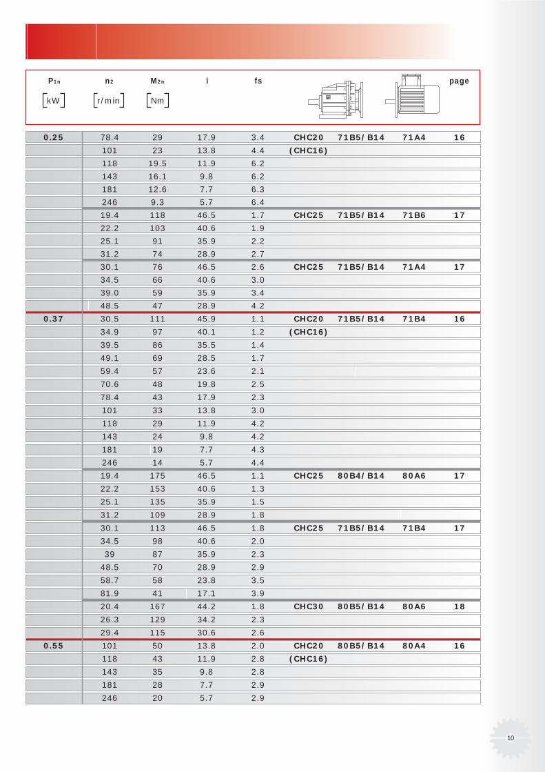
P1n n2 M2n i fs page
kW r/min Nm
0.25 78.4 29 17.9 3.4 CHC20 71B5/B14 71A4 16
101 23 13.8 4.4 (CHC16)
118 19.5 11.9 6.2
143 16.1 9.8 6.2
181 12.6 7.7 6.3
246 9.3 5.7 6.4
19.4 118 46.5 1.7 CHC25 71B5/B14 71B6 17
22.2 103 40.6 1.9
25.1 91 35.9 2.2
31.2 74 28.9 2.7
30.1 76 46.5 2.6 CHC25 71B5/B14 71A4 17
34.5 66 40.6 3.0
39.0 59 35.9 3.4
48.5 47 28.9 4.2
0.37 30.5 111 45.9 1.1 CHC20 71B5/B14 71B4 16
34.9 97 40.1 1.2 (CHC16)
39.5 86 35.5 1.4
49.1 69 28.5 1.7
59.4 57 23.6 2.1
70.6 48 19.8 2.5
78.4 43 17.9 2.3
101 33 13.8 3.0
118 29 11.9 4.2
143 24 9.8 4.2
181 19 7.7 4.3
246 14 5.7 4.4
19.4 175 46.5 1.1 CHC25 80B4/B14 80A6 17
22.2 153 40.6 1.3
25.1 135 35.9 1.5
31.2 109 28.9 1.8
30.1 113 46.5 1.8 CHC25 71B5/B14 71B4 17
34.5 98 40.6 2.0
39 87 35.9 2.3
48.5 70 28.9 2.9
58.7 58 23.8 3.5
81.9 41 17.1 3.9
20.4 167 44.2 1.8 CHC30 80B5/B14 80A6 18
26.3 129 34.2 2.3
29.4 115 30.6 2.6
0.55 101 50 13.8 2.0 CHC20 80B5/B14 80A4 16
118 43 11.9 2.8 (CHC16)
143 35 9.8 2.8
181 28 7.7 2.9
246 20 5.7 2.9
11
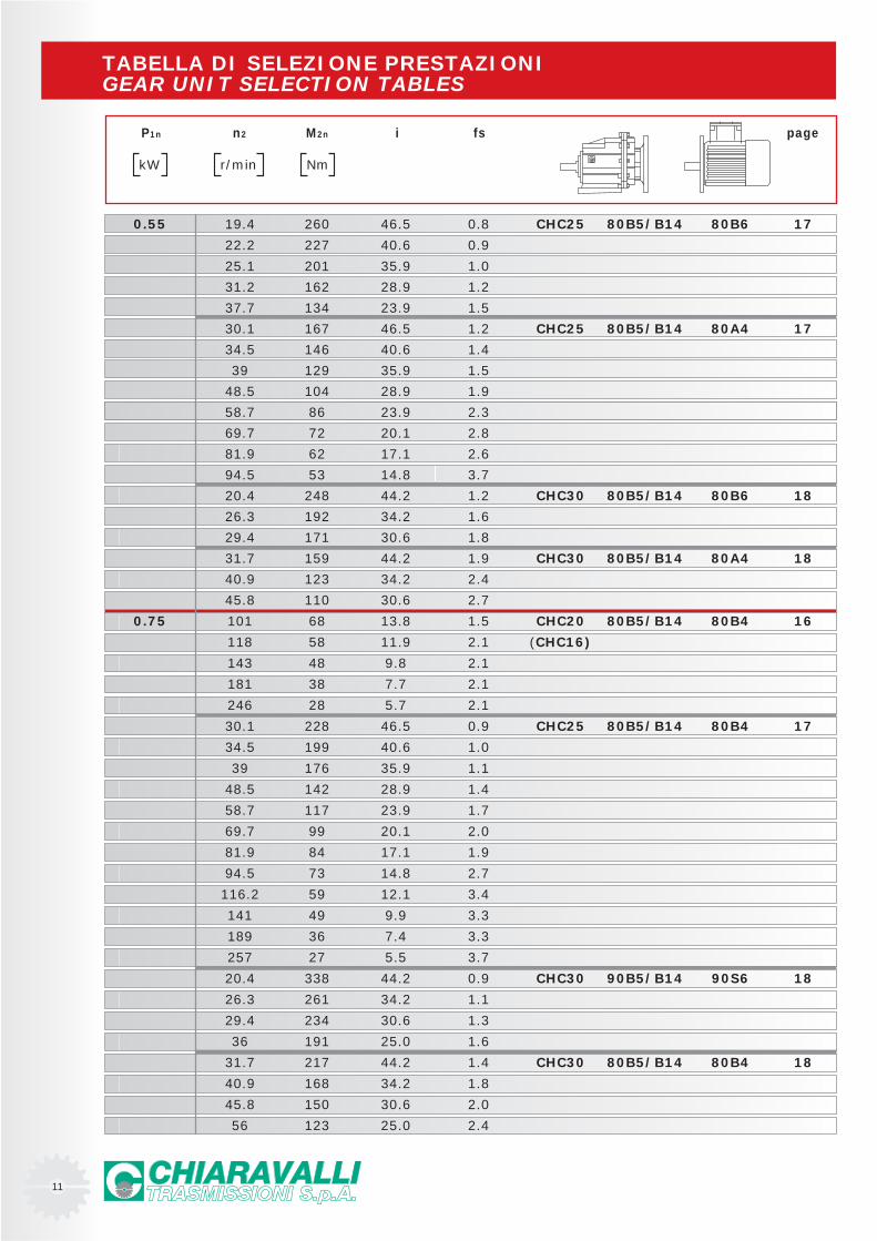
TABELLA DI SELEZIONE PRESTAZIONIGEAR UNIT SELECTION TABLES
P1n n2 M2n i fs page
kW r/min Nm
0.55 19.4 260 46.5 0.8 CHC25 80B5/B14 80B6 17
22.2 227 40.6 0.9
25.1 201 35.9 1.0
31.2 162 28.9 1.2
37.7 134 23.9 1.5
30.1 167 46.5 1.2 CHC25 80B5/B14 80A4 17
34.5 146 40.6 1.4
39 129 35.9 1.5
48.5 104 28.9 1.9
58.7 86 23.9 2.3
69.7 72 20.1 2.8
81.9 62 17.1 2.6
94.5 53 14.8 3.7
20.4 248 44.2 1.2 CHC30 80B5/B14 80B6 18
26.3 192 34.2 1.6
29.4 171 30.6 1.8
31.7 159 44.2 1.9 CHC30 80B5/B14 80A4 18
40.9 123 34.2 2.4
45.8 110 30.6 2.7
0.75 101 68 13.8 1.5 CHC20 80B5/B14 80B4 16
118 58 11.9 2.1 (CHC16)
143 48 9.8 2.1
181 38 7.7 2.1
246 28 5.7 2.1
30.1 228 46.5 0.9 CHC25 80B5/B14 80B4 17
34.5 199 40.6 1.0
39 176 35.9 1.1
48.5 142 28.9 1.4
58.7 117 23.9 1.7
69.7 99 20.1 2.0
81.9 84 17.1 1.9
94.5 73 14.8 2.7
116.2 59 12.1 3.4
141 49 9.9 3.3
189 36 7.4 3.3
257 27 5.5 3.7
20.4 338 44.2 0.9 CHC30 90B5/B14 90S6 18
26.3 261 34.2 1.1
29.4 234 30.6 1.3
36 191 25.0 1.6
31.7 217 44.2 1.4 CHC30 80B5/B14 80B4 18
40.9 168 34.2 1.8
45.8 150 30.6 2.0
56 123 25.0 2.4

12
P1n n2 M2n i fs page
kW r/min Nm
0.75 66.2 104 21.2 2.7 CHC30 80B5/B14 80B4 18
76.9 89 18.2 3.1
91.5 75 15.3 3.7
20.4 338 44.2 1.5 CHC35 90B5/B14 90S6 19
26.3 261 34.2 1.8 CHC40
29.4 234 30.6 2.1
31.7 217 44.2 2.3 CHC35 80B5/B14 80B4 19
40.9 168 34.2 2.9 CHC40
1.1 101 99 13.8 1.0 CHC20 80B5/B14 80C4 16
118 86 11.9 1.4 (CHC16)
143 71 9.8 1.4
181 56 7.7 1.4
246 41 5.7 1.5
48.5 208 28.9 1.0 CHC25 80B5/B14 80C4 17
58.7 172 23.9 1.2
69.7 145 20.1 1.4 CHC25 90B5/B14 90S4 17
81.9 123 17.1 1.3
94.5 107 14.8 1.9
116 87 12.1 2.3
141 72 9.9 2.2
189 53 7.4 2.3
257 39 5.5 2.5
31.7 318 44.2 0.9 CHC30 90B5/B14 90S4 18
40.9 246 34.2 1.2
45.8 220 30.6 1.4
56 180 25.0 1.7
66.2 152 21.2 1.8
76.9 131 18.2 2.1
91.5 110 15.3 2.5
31.7 318 44.2 1.6 CHC35 90B5/B14 90S4 19
40.9 246 34.2 1.9 CHC40
45.8 220 30.6 2.2
56 180 25.0 2.7
66.2 152 21.2 2.8
76.9 131 18.2 3.2
91.5 110 15.3 3.8
1.5 69.7 197 20.1 1.0 CHC25 90B5/B14 90L4 17
81.9 168 17.1 1.0
94.5 145 14.8 1.4
116 118 12.1 1.7
141 98 9.9 1.6
189 73 7.4 1.7
257 54 5.5 1.9
40.9 336 34.2 0.9 CHC30 90B5/B14 90L4 18
13
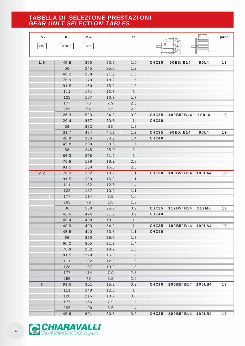
TABELLA DI SELEZIONE PRESTAZIONIGEAR UNIT SELECTION TABLES
P1n n2 M2n i fs page
kW r/min Nm
1.5 45.8 300 30.6 1.0 CHC30 90B5/B14 90L4 18
56 245 25.0 1.2
66.2 208 21.2 1.3
76.9 179 18.2 1.6
91.5 150 15.3 1.9
111 124 12.6 2
128 107 10.9 1.7
177 78 7.9 2.3
255 54 5.5 2.8
26.3 523 34.2 0.9 CHC35 100B5/B14 100L6 19
29.4 467 30.6 1 CHC40
36 382 25 1.3
31.7 434 44.2 1.2 CHC35 90B5/B14 90L4 19
40.9 336 34.2 1.4 CHC40
45.8 300 30.6 1.6
56 245 25.0 2
66.2 208 21.2 2
76.9 179 18.2 2.3
91.5 150 15.3 2.8
2.2 76.9 262 18.2 1.1 CHC30 100B5/B14 100LA4 18
91.5 220 15.3 1.1
111 182 12.6 1.4
128 157 10.9 1.1
177 114 7.9 1.6
255 79 5.5 1.9
36 560 25.0 0.9 CHC35 112B5/B14 112M6 19
42.6 474 21.2 0.9 CHC40
49.4 408 18.2 1
40.9 493 34.2 1 CHC35 100B5/B14 100LA4 19
45.8 440 30.6 1.1 CHC40
56 360 25.0 1.3
66.2 305 21.2 1.4
76.9 262 18.2 1.6
91.5 220 15.3 1.9
111 182 12.6 1.9
128 157 10.9 1.8
177 114 7.9 2.3
255 79 5.5 2.9
3 91.5 301 15.3 0.9 CHC30 100B5/B14 100LB4 18
111 248 12.6 1
128 215 10.9 0.8
177 156 7.9 1.2
255 108 5.5 1.4
45.8 601 30.6 0.8 CHC35 100B5/B14 100LB4 19
14
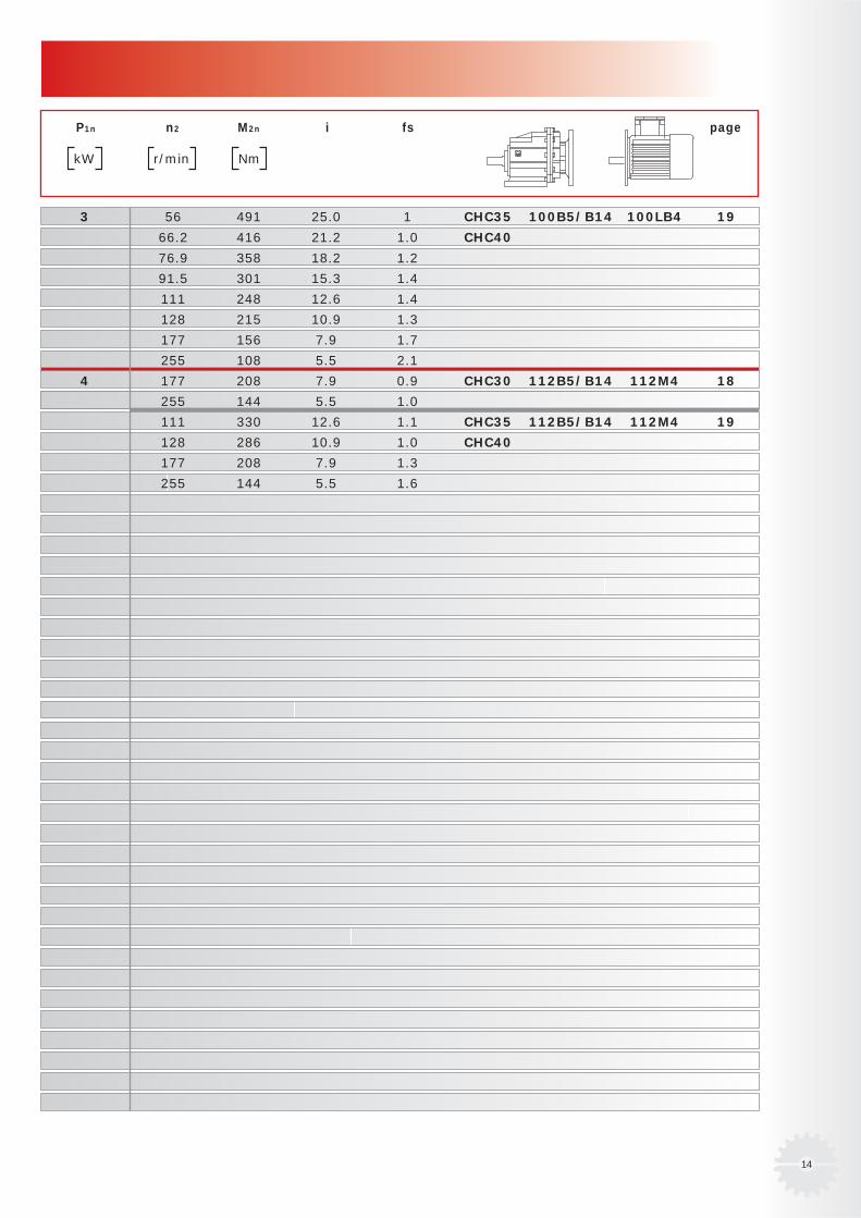
P1n n2 M2n i fs page
kW r/min Nm
3 56 491 25.0 1 CHC35 100B5/B14 100LB4 19
66.2 416 21.2 1.0 CHC40
76.9 358 18.2 1.2
91.5 301 15.3 1.4
111 248 12.6 1.4
128 215 10.9 1.3
177 156 7.9 1.7
255 108 5.5 2.1
4 177 208 7.9 0.9 CHC30 112B5/B14 112M4 18
255 144 5.5 1.0
111 330 12.6 1.1 CHC35 112B5/B14 112M4 19
128 286 10.9 1.0 CHC40
177 208 7.9 1.3
255 144 5.5 1.6
15
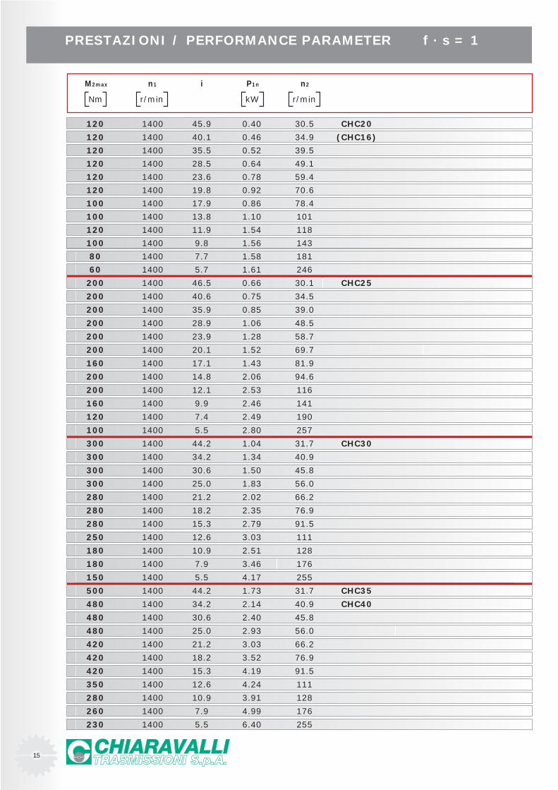
PRESTAZIONI / PERFORMANCE PARAMETER f · s = 1
M2max n1 i P1n n2
Nm r/min kW r/min
120 1400 45.9 0.40 30.5 CHC20
120 1400 40.1 0.46 34.9 (CHC16)
120 1400 35.5 0.52 39.5
120 1400 28.5 0.64 49.1
120 1400 23.6 0.78 59.4
120 1400 19.8 0.92 70.6
100 1400 17.9 0.86 78.4
100 1400 13.8 1.10 101
120 1400 11.9 1.54 118
100 1400 9.8 1.56 143
80 1400 7.7 1.58 181
60 1400 5.7 1.61 246
200 1400 46.5 0.66 30.1 CHC25
200 1400 40.6 0.75 34.5
200 1400 35.9 0.85 39.0
200 1400 28.9 1.06 48.5
200 1400 23.9 1.28 58.7
200 1400 20.1 1.52 69.7
160 1400 17.1 1.43 81.9
200 1400 14.8 2.06 94.6
200 1400 12.1 2.53 116
160 1400 9.9 2.46 141
120 1400 7.4 2.49 190
100 1400 5.5 2.80 257
300 1400 44.2 1.04 31.7 CHC30
300 1400 34.2 1.34 40.9
300 1400 30.6 1.50 45.8
300 1400 25.0 1.83 56.0
280 1400 21.2 2.02 66.2
280 1400 18.2 2.35 76.9
280 1400 15.3 2.79 91.5
250 1400 12.6 3.03 111
180 1400 10.9 2.51 128
180 1400 7.9 3.46 176
150 1400 5.5 4.17 255
500 1400 44.2 1.73 31.7 CHC35
480 1400 34.2 2.14 40.9 CHC40
480 1400 30.6 2.40 45.8
480 1400 25.0 2.93 56.0
420 1400 21.2 3.03 66.2
420 1400 18.2 3.52 76.9
420 1400 15.3 4.19 91.5
350 1400 12.6 4.24 111
280 1400 10.9 3.91 128
260 1400 7.9 4.99 176
230 1400 5.5 6.40 255
16
F
D
M
G
S
119
V2
V3
X1
Y95
.5
Z
6 (5)
M6 x 16
22.5
(18
)
119
62.5
95.5
40
3
Ø14
0
9
Ø95
j6
Ø115
Ø9
40
3
Ø12
0
8
Ø80
j6
Ø100
Ø7
119
158
Ø75
M8 x 15 65°
25°
25°
PN
6.5
19540
323.5 T
WV1
V
X
U
Ø20
h6
(16
h6)
PN
6.5
19540
323.5 T
Ø20
h6
(16
h6)
PN
6.5
19540
323.5 T
13
Ø60
g7
7
Ø20
h6
(16
h6)
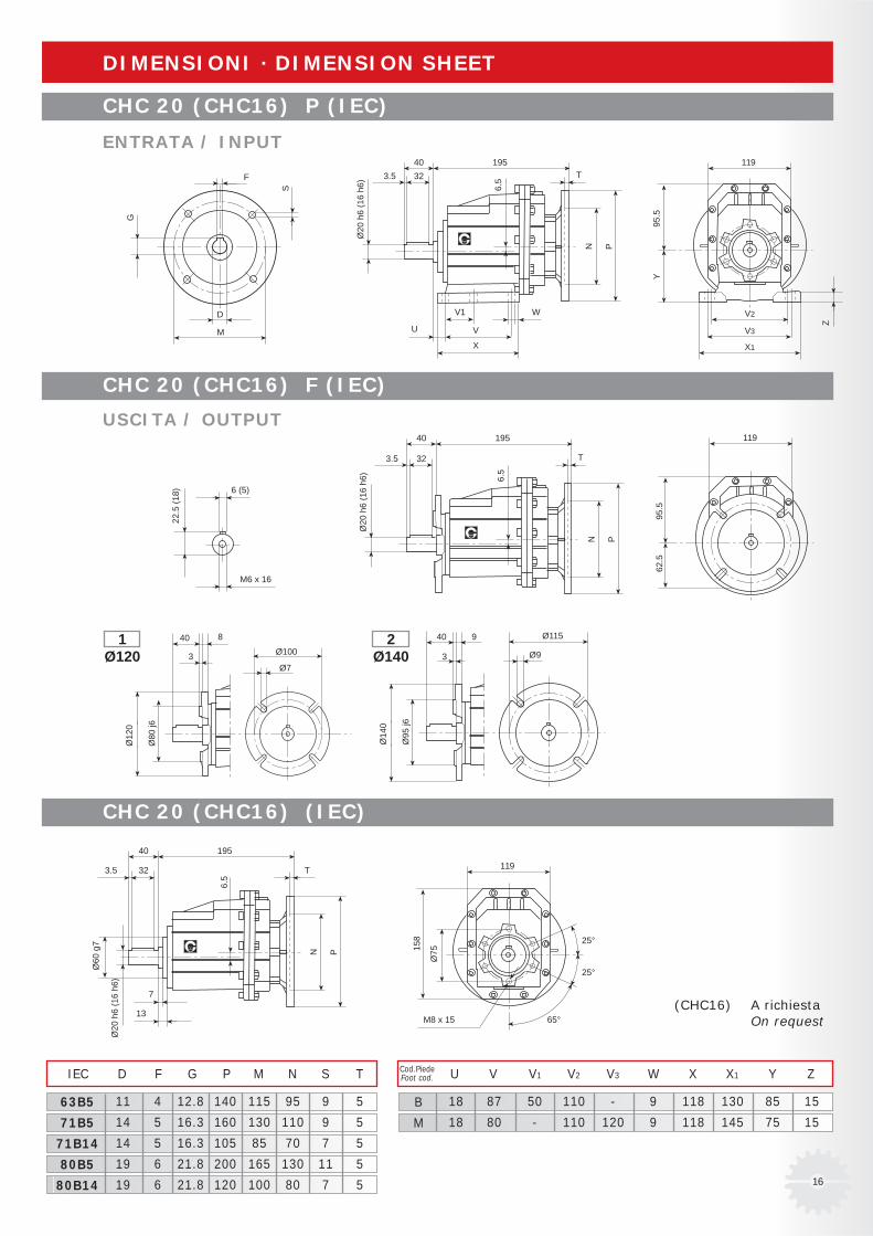
11 4 12.8 140 115 95 9 5
14 5 16.3 160 130 110 9 5
14 5 16.3 105 85 70 7 5
19 6 21.8 200 165 130 11 5
19 6 21.8 120 100 80 7 5
IEC D F G P M N S T
63B5
71B5
71B14
80B5
80B14
18 87 50 110 - 9 118 130 85 15
18 80 - 110 120 9 118 145 75 15
U V V1 V2 V3 W X X1 Y ZCod.PiedeFoot cod.
B
M
DIMENSIONI · DIMENSION SHEET
(CHC16) A richiesta On request
CHC 20 (CHC16) P (IEC)
CHC 20 (CHC16) F (IEC)
CHC 20 (CHC16) (IEC)
ENTRATA / INPUT
USCITA / OUTPUT
1Ø120
2Ø140
17
F
D
M
G
S
127
V2
V3
X1
Y10
0
Z
8
M10 x 22
28
127
6710
0
50
3.5
Ø16
0
10
Ø11
0 j6
Ø130
Ø9
50
3
Ø14
0
9
Ø95
j6
Ø115
Ø9
127
167
Ø85
M8 x 15 65°
25°
25°
PN
11.5
20550403.5 T
WV1
V
X
U
Ø25
h6
PN
11.5
20550
403.5 T
Ø25
h6
PN
11.5
20550
403.5 T
13
Ø72
g7
7
Ø25
h6
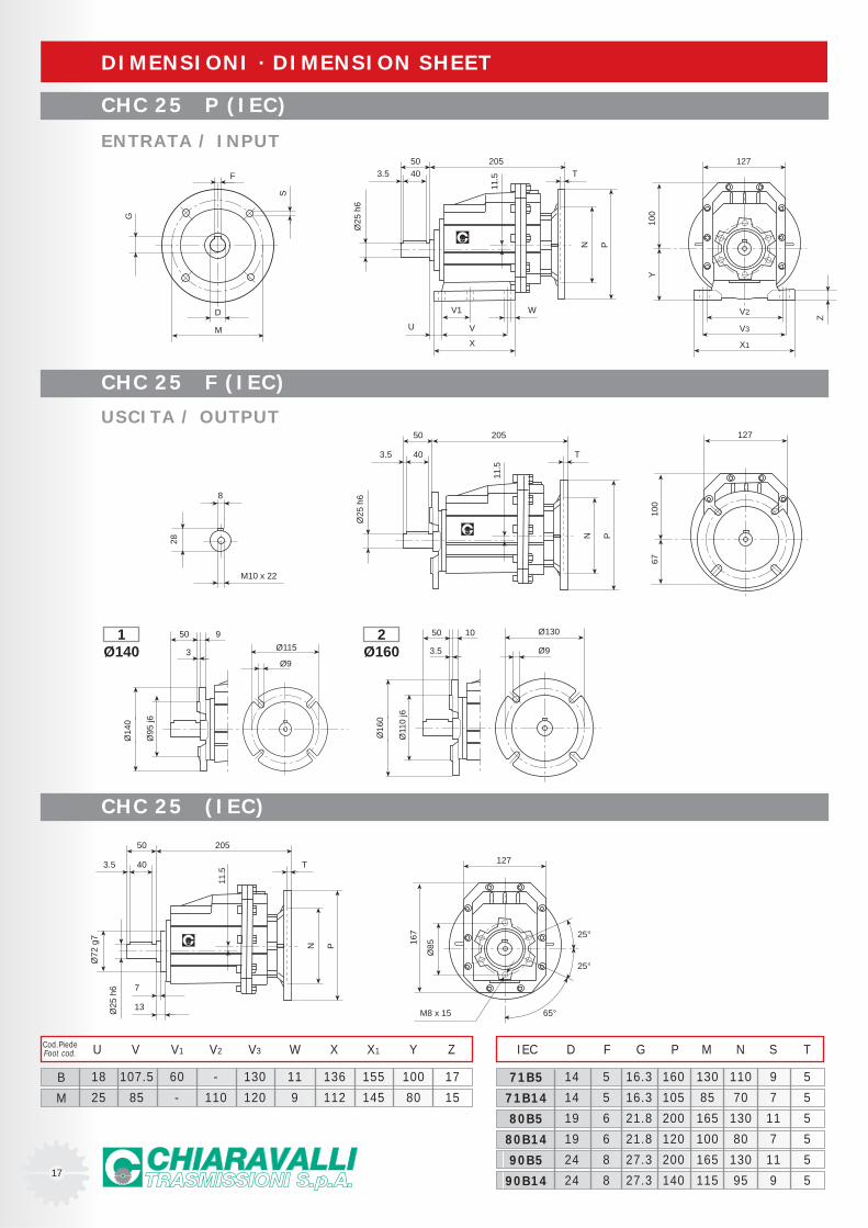
14 5 16.3 160 130 110 9 5
14 5 16.3 105 85 70 7 5
19 6 21.8 200 165 130 11 5
19 6 21.8 120 100 80 7 5
24 8 27.3 200 165 130 11 5
24 8 27.3 140 115 95 9 5
IEC D F G P M N S T
71B5
71B14
80B5
80B14
90B5
90B14
18 107.5 60 - 130 11 136 155 100 17
25 85 - 110 120 9 112 145 80 15
U V V1 V2 V3 W X X1 Y ZCod.PiedeFoot cod.
B
M
DIMENSIONI · DIMENSION SHEET
CHC 25 P (IEC)
CHC 25 F (IEC)
CHC 25 (IEC)
ENTRATA / INPUT
USCITA / OUTPUT
1Ø140
2Ø160
18
F
D
M
G
S
148
V2
V3
X1
Y11
9.5
Z
8
M10 x 22
33
148
80.5
119.
5
60
3.5
Ø20
0
11
Ø13
0 j6
Ø165
Ø11
60
3.5
Ø16
0
10
Ø11
0 j6
Ø130
Ø9
148
200
Ø10
0
M8 x 15 65°
25°
25°
PN
5
23760503.5 T
WV1
V
X
U
Ø30
h6
PN
5
23760
503.5 T
Ø30
h6
PN
5
23760
503.5 T
13.5
Ø85
g7
7.5
Ø30
h6
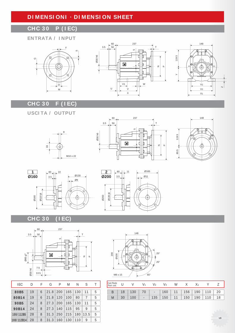
18 130 70 - 160 11 156 190 110 20
30 100 - 135 150 11 150 190 110 18
U V V1 V2 V3 W X X1 Y ZCod.PiedeFoot cod.
B
M
19 6 21.8 200 165 130 11 5
19 6 21.8 120 100 80 7 5
24 8 27.3 200 165 130 11 5
24 8 27.3 140 115 95 9 5
28 8 31.3 250 215 180 13.5 5
28 8 31.3 160 130 110 9 5
IEC D F G P M N S T
80B5
80B14
90B5
90B14
100/112B5
100/112B14
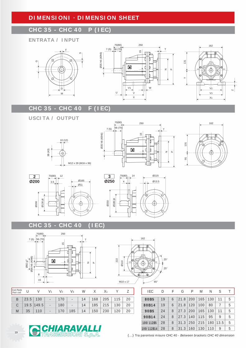
DIMENSIONI · DIMENSION SHEET
CHC 30 P (IEC)
CHC 30 F (IEC)
CHC 30 (IEC)
ENTRATA / INPUT
USCITA / OUTPUT
1Ø160
2Ø200
19
F
D
M
G
S
162
V2
V3
X1
Y13
1
Z
10 (12)
M12 x 28 (M16 x 36)
38 (
43)
162
9113
1
162
222
Ø11
0
M10 x 17 65°
25°
25°
PN
15
25070(80)
56 (70)7 (5) T
WV1
V
X
U
Ø35
h6
(40h
6)
PN
15
250
T
PN
15
25070(80)
7 (5) T
15
Ø92
g7
8
70(80)
56 (70)7 (5)
Ø35
h6
(40h
6)
3.5
Ø20
0
12
Ø13
0 j6
Ø165
Ø11
70(80)
4
Ø25
0
14
Ø18
0 j6
Ø215
Ø13.5
70(80)
56 (70)
Ø35
h6
(40h
6)
19 6 21.8 200 165 130 11 5
19 6 21.8 120 100 80 7 5
24 8 27.3 200 165 130 11 5
24 8 27.3 140 115 95 9 5
28 8 31.3 250 215 180 13.5 5
28 8 31.3 160 130 110 9 5
IEC D F G P M N S T
80B5
80B14
90B5
90B14
100/112B5
100/112B14
23.5 130 - 170 - 14 168 205 115 20
19.5 149.5 - 180 - 14 185 215 130 20
35 110 - 170 185 14 150 230 120 20
U V V1 V2 V3 W X X1 Y ZCod.PiedeFoot cod.
B
C
M
DIMENSIONI · DIMENSION SHEET
(...) Tra parentesi misure CHC 40 - Between brackets CHC 40 dimension
CHC 35 - CHC 40 P (IEC)
CHC 35 - CHC 40 F (IEC)
CHC 35 - CHC 40 (IEC)
ENTRATA / INPUT
USCITA / OUTPUT
2Ø200
3Ø250
20
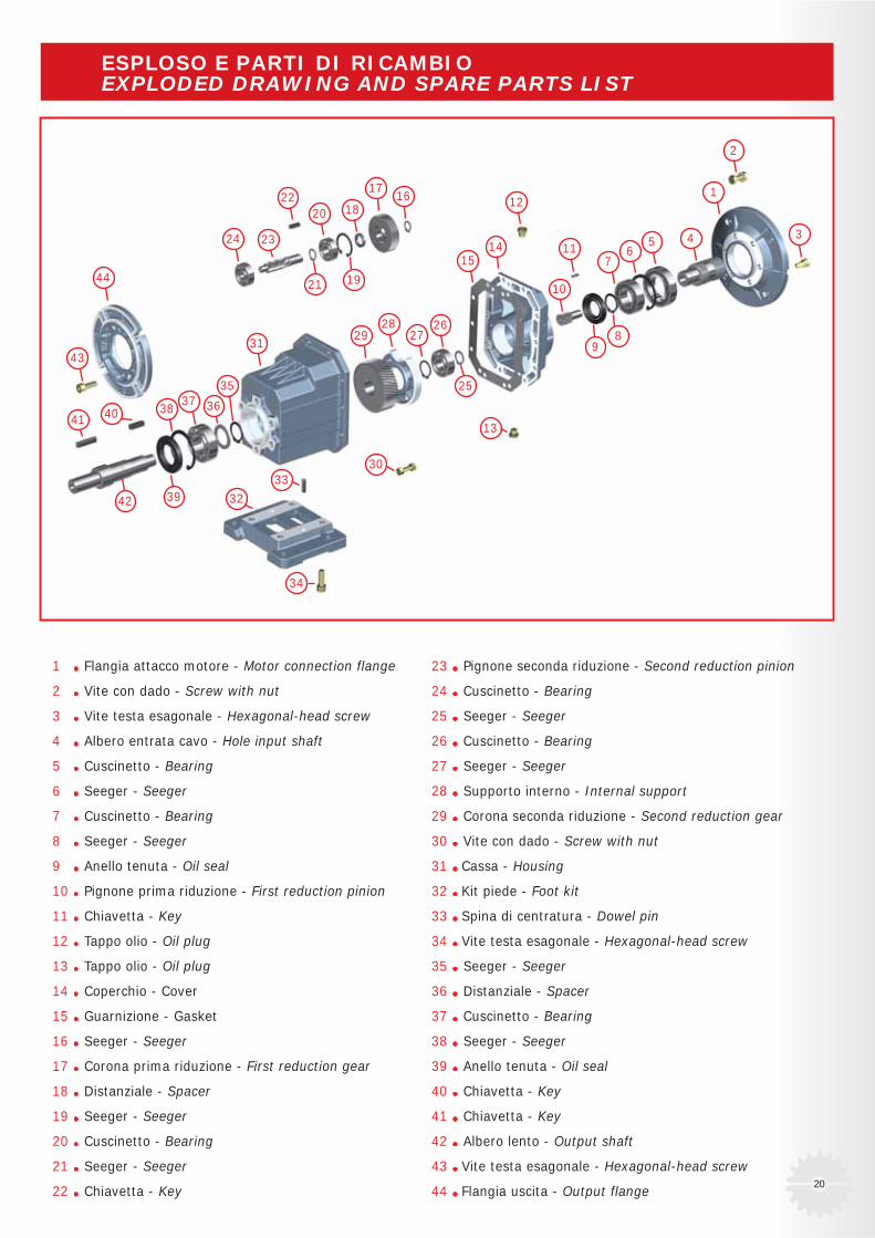
1 Flangia attacco motore - Motor connection flange
2 Vite con dado - Screw with nut
3 Vite testa esagonale - Hexagonal-head screw
4 Albero entrata cavo - Hole input shaft
5 Cuscinetto - Bearing
6 Seeger - Seeger
7 Cuscinetto - Bearing
8 Seeger - Seeger
9 Anello tenuta - Oil seal
10 Pignone prima riduzione - First reduction pinion
11 Chiavetta - Key
12 Tappo olio - Oil plug
13 Tappo olio - Oil plug
14 Coperchio - Cover
15 Guarnizione - Gasket
16 Seeger - Seeger
17 Corona prima riduzione - First reduction gear
18 Distanziale - Spacer
19 Seeger - Seeger
20 Cuscinetto - Bearing
21 Seeger - Seeger
22 Chiavetta - Key
23 Pignone seconda riduzione - Second reduction pinion
24 Cuscinetto - Bearing
25 Seeger - Seeger
26 Cuscinetto - Bearing
27 Seeger - Seeger
28 Supporto interno - Internal support
29 Corona seconda riduzione - Second reduction gear
30 Vite con dado - Screw with nut
31 Cassa - Housing
32 Kit piede - Foot kit
33 Spina di centratura - Dowel pin
34 Vite testa esagonale - Hexagonal-head screw
35 Seeger - Seeger
36 Distanziale - Spacer
37 Cuscinetto - Bearing
38 Seeger - Seeger
39 Anello tenuta - Oil seal
40 Chiavetta - Key
41 Chiavetta - Key
42 Albero lento - Output shaft
43 Vite testa esagonale - Hexagonal-head screw
44 Flangia uscita - Output flange
ESPLOSO E PARTI DI RICAMBIOEXPLODED DRAWING AND SPARE PARTS LIST
43
41 40
42 39
3837 36
35
31
32
33
34
30
13
2928
2726
25
1514
12
2
3
1
456
7
89
11
10
1617
18
19
2022
21
2324
44
21
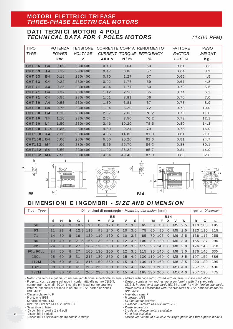
TIPO POTENZA TENSIONE CORRENTE COPPIA RENDIMENTO FATTORE PESOTYPE POWER VOLTAGE CURRENT TORQUE EFFICIENCY FACTOR WEIGHT
kW V 400 V N/m % COS. Ø Kg.
CHT 56 B4 0.09 230/400 0.43 0.64 50 0.61 3.2
CHT 63 A4 0.12 230/400 0.47 0.86 57 0.64 3.9
CHT 63 B4 0.18 230/400 0.70 1.27 57 0.65 4.5
CHT 63 C4 0.22 230/400 0.92 1.77 59 0.67 4.8
CHT 71 A4 0.25 230/400 0.84 1.77 60 0.72 5.6
CHT 71 B4 0.37 230/400 1.12 2.58 65 0.74 6.2
CHT 71 C4 0.55 230/400 1.61 3.81 66 0.75 7.0
CHT 80 A4 0.55 230/400 1.59 3.81 67 0.75 8.9
CHT 80 B4 0.75 230/400 1.94 5.20 72 0.78 10.0
CHT 80 D4 1.10 230/400 2.67 7.60 76.2 0.78 11.0
CHT 90 S4 1.10 230/400 2.64 7.50 76.2 0.79 12.1
CHT 90 L4 1.50 230/400 3.46 10.20 78.5 0.80 14.3
CHT 90 LL4 1.85 230/400 4.30 9.24 79 0.78 16.0
CHT100L A4 2.20 230/400 4.86 14.80 81.0 0.81 21.0
CHT100L B4 3.00 230/400 6.50 20.20 82.6 0.81 24.7
CHT112 M4 4.00 230/400 8.26 26.70 84.2 0.83 30.1
CHT132 S4 5.50 230/400 11.00 36.22 85.7 0.84 44.0
CHT132 M4 7.50 230/400 14.64 49.40 87.0 0.85 52.0
- Motori con rotore a gabbia, chiusi con ventilazione superficiale esterna- Progetto, costruzione e collaudo in conformità alle norme CEI2-3,norme internazionali IEC 34-1 ed alle principali norme straniere.
- Potenze-dimensioni secondo le norme IEC 72, norme nazionaliUNEL-MEC.
- Classe isolamento F- Protezione IP55- Servizio continuo S1- Direttiva Europea ROHS 2002/95/CE- Separatori di fase- Disponibili motori a 2 e 6 poli- Disponibili kit piedi- Disponibili kit servoventola monofase e trifase
(1400 RPM)
DIMENSIONI E INGOMBRI - SIZE AND DIMENSIONTipo - Type Dimensioni di montaggio - Mounting dimension (mm) Ingombri-Dimension
56 9 20 3 10.2 98 80 120 0 7 3.0 65 50 80 0 M5 2.5 110 100 195
63 11 23 4 12.5 115 95 140 0 10 3.0 75 60 90 0 M5 2.5 123 110 215
71 14 30 5 16 130 110 160 0 10 3.5 85 70 105 0 M6 2.5 138 117 255
80 19 40 6 21.5 165 130 200 0 12 3.5 100 80 120 0 M6 3.0 155 137 290
90S 24 50 8 27 165 130 200 0 12 3.5 115 95 140 0 M8 3.0 176 145 310
90L/90LL 24 50 8 27 165 130 200 0 12 3.5 115 95 140 0 M8 3.0 176 145 335
100L 28 60 8 31 215 180 250 0 15 4.0 130 110 160 0 M8 3.5 197 152 386
112M 28 60 8 31 215 150 250 0 15 4.0 130 110 160 0 M8 3.5 220 180 395
132S 38 80 10 41 265 230 300 0 15 4.0 165 130 200 0 M10 4.0 257 195 436
132M 38 80 10 41 265 230 300 0 15 4.0 165 130 200 0 M10 4.0 257 195 475
B5 B14d H b G I M F X V S I M F X V S B C L
B5 B14H
XS
L
BM
v
C
IF
G
d
b
XS
L
H
F M B
C
v
I
G
d
b
- Motors with cage rotor, closed with external surface ventilation.- Design, construction and testing in conformity with the standards CEI2-3, international standards IEC 34-1 and the main foreign standards.
- Power-sizes in accordance with the standards IEC 72, national standards UNEL-MEC.
- Insulation class F- Protection IP55- S1 Continuous service- European Directive ROHS 2002/95/CE- Phase separators- 2-pole and 6-pole motors available- Kit of feet available- Forced ventilation kit available for single-phase and three-phase models
MOTORI ELETTRICI TRIFASETHREE-PHASE ELECTRICAL MOTORS
DATI TECNICI MOTORI 4 POLITECHNICAL DATA FOR 4 POLES MOTORS
22
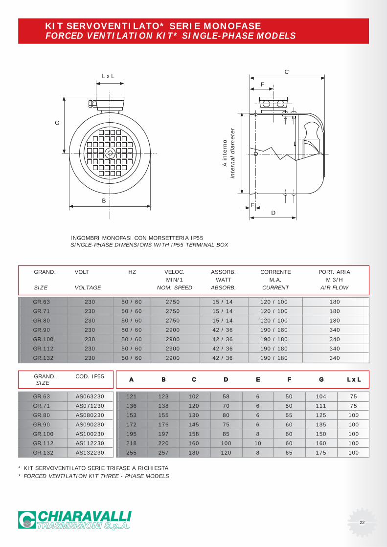
INGOMBRI MONOFASI CON MORSETTERIA IP55SINGLE-PHASE DIMENSIONS WITH IP55 TERMINAL BOX
GRAND. VOLT HZ VELOC. ASSORB. CORRENTE PORT. ARIAMIN/1 WATT M.A. M 3/H
SIZE VOLTAGE NOM. SPEED ABSORB. CURRENT AIR FLOW
GR.63 230 50 / 60 2750 15 / 14 120 / 100 180
GR.71 230 50 / 60 2750 15 / 14 120 / 100 180
GR.80 230 50 / 60 2750 15 / 14 120 / 100 180
GR.90 230 50 / 60 2900 42 / 36 190 / 180 340
GR.100 230 50 / 60 2900 42 / 36 190 / 180 340
GR.112 230 50 / 60 2900 42 / 36 190 / 180 340
GR.132 230 50 / 60 2900 42 / 36 190 / 180 340
GRAND. COD. IP55 SIZE
GR.63 AS063230
GR.71 AS071230
GR.80 AS080230
GR.90 AS090230
GR.100 AS100230
GR.112 AS112230
GR.132 AS132230
A B C D E F G L x L
121 123 102 58 6 50 104 75
136 138 120 70 6 50 111 75
153 155 130 80 6 55 125 100
172 176 145 75 6 60 135 100
195 197 158 85 8 60 150 100
218 220 160 100 10 60 160 100
255 257 180 120 8 65 175 100
* KIT SERVOVENTILATO SERIE TRIFASE A RICHIESTA
F
A inte
rno
inte
rnal
dia
met
er
DE
CL x L
B
G
FORCED VENTILATION KIT* SINGLE-PHASE MODELS
* FORCED VENTILATION KIT THREE - PHASE MODELS
KIT SERVOVENTILATO* SERIE MONOFASE

ISTRUZIONI USO E MANUTENZIONE - USE AND MAINTENANCE INSTRUCTIONS
INSTALLAZIONE
· I dati riportati sulla targhetta identificativa devono corrispondereal riduttore ordinato
· Il livello dell’olio dovrà corrispondere alla quantità prevista perla posizione di montaggio richiesta (vedi catalogo)
· Il fissaggio del riduttore deve avvenire su superfici piane e sufficientemente rigide in modo da evitare qualsiasi vibrazione
· Il riduttore e l’asse della macchina da movimentare devono essere in perfetto allineamento
· In caso si prevedano urti, sovraccarichi o blocchi della macchinail cliente dovrà provvedere all’istallazione di limitatori, giunti,salvamotori etc.
· Gli accoppiamenti con pignoni, giunti, pulegge ed altri organidevono essere fatti previa pulizia delle parti ed evitando urti nel montaggio poiché questo potrebbe danneggiare i cuscinettied altre parti interne
· Nel caso il motore sia di fornitura del cliente questi dovrà accertarsi che le tolleranze di flangia ed albero corrispondanoad una classe “normale”, i nostri motori rispondono a questa esigenza
· Verificare che le viti di fissaggio del riduttore e dei relativi accessori siano correttamente serrate
· Adottare gli opportuni accorgimenti per proteggere i gruppi da eventuali agenti atmosferici aggressivi
· Dove previsto proteggere le parti rotanti da possibili contatti con gli operatori
· Nel caso i riduttori vengano verniciati proteggere gli anelli di tenuta ed i piani lavorati
· Tutti i riduttori sono verniciati colore grigio RAL 9022
FUNZIONAMENTO E RODAGGIO
· Per ottenere le migliori prestazioni è necessario provvedere ad un adeguato rodaggio dei riduttori incrementando la potenza gradualmente nelle prime ore di funzionamento, in questa fase un aumento delle temperature è da considerarsi nella norma
· In caso di funzionamento difettoso, rumorosità, perdite olio etc. arrestare immediatamente il riduttore e, dove possibile, rimuovere la causa, in alternativa inviare il pezzo alla nostra sede per i controlli
MANUTENZIONE
· I riduttori ad ingranaggi sono lubrificati con oliosintetico permanente, pertanto non richiedono alcuna manutenzione.
CONSERVAZIONE A MAGAZZINO
· Nel caso di lunga conservazione a magazzino, superiore a tremesi, si consiglia di proteggere alberi e piani lavoratori con antiossidanti e di ingrassare gli anell i di tenuta
MOVIMENTAZIONE
· Nella movimentazione dei gruppi dovrà essere posta molta attenzione a non danneggiare gli anelli di tenuta ed i piani lavorati
SMALTIMENTO IMBALLI
· Gli imballi in cui vengono consegnati i nostri riduttori andrannoavviati, dove possibile, al riciclo degli stessi tramite le ditte preposte.
INSTALLATION
· The data shown on the identification name plate must correspond to the gearbox ordered
· The oil level must correspond to the quantity foreseen for theassembly position requested (see catalogue)
· All of the other gearboxes are supplied complete with permanentsynthetic oil in a quantity that is sufficient for any assembly position
· The gearbox must be fixed on a flat surface that is sufficientlyrigid in order to avoid any vibration
· The gearbox and the axis of the machine to be driven must beperfectly aligned o in the event that knocks, overloading or blockage of the machine are foreseen, the client must install a limiting device, joints, overload cut-out etc.
· Coupling with pinions, joints, pulleys and other parts must be done after the parts have been cleaned and knocks shouldbe avoided while assembling as they could damage the bearingsand other internal parts
· In the event that the motor is supplied by the client, he mustcheck that the flange and shaft tolerances correspond to a “normal” class; our motors satisfy this requirement
· Check that the fixing screws for the gear and the related accessories are correctly tightened
· Take suitable measures to protect the groups from any aggressive atmospheric agents
· Where foreseen, protect rotating parts from any possible contact with the operators
· If the gears are painted, protect the oil seals and the machinedsurfaces gearboxes
· All of the gears are painted RAL 9022 grey
OPERATION AND RUNNING-IN
· To obtain the best performance the gearboxes must first be run-in by gradually increasing the power in the first few hoursof operation, in this phase an increase in temperature is considered normal
· In the event of defective operation, noise, oil leakage, etc. stop the gear immediately and, when possible, remove the cause. Alternatively, send the piece to our factory to be controlled.
MAINTENANCE
· The helical gearboxes are lubricated with permanent syntheticoil and therefore do not require any maintenance
WAREHOUSE STORAGE
· If the warehouse storage will be for a long time, more than 3 months, the shafts and machined surfaces should be protected using antioxidants and the oil seals should be greased
HANDLING
· Care must be taken not to damage the oil seals and the machined surfaces when handling the groups
DISPOSAL OF PACKAGING
· The packaging in which our gears are delivered should be sent to specialised companies for recycling if possible.