I Bruciatori di gas ad aria soffiata - Schede tecniche · Bruciatori di gas ad aria soffiata...
48
Istruzioni per installazione, uso e manutenzione Montage und Bedienungs Anleitung Installation, use and maintenance instructions Manuel d’entretien Bruciatori di gas ad aria soffiata Gebläse - Gasbrenner Forced draught gas burners Brûleurs gaz à air soufflé 2915915 (2) - 11/2008 CODICE - CODE MODELLO - MODELL MODEL - MODELE TIPO - TYP TYPE 3751917 - 3751918 GAS 3 519 T1 3751617 GAS 4 516 T1 3751717 GAS 5 517 T1 3751817 GAS 6 518 T1 I D GB F Einstufig One stage operation Fonctionnement à 1 allure Funzionamento monostadio GAS
Transcript of I Bruciatori di gas ad aria soffiata - Schede tecniche · Bruciatori di gas ad aria soffiata...
Istruzioni per installazione, uso e manutenzioneMontage und Bedienungs AnleitungInstallation, use and maintenance instructionsManuel d’entretien
Bruciatori di gas ad aria soffiataGebläse - GasbrennerForced draught gas burnersBrûleurs gaz à air soufflé
2915915 (2) - 11/2008
CODICE - CODE MODELLO - MODELL MODEL - MODELE
TIPO - TYPTYPE
3751917 - 3751918 GAS 3 519 T1
3751617 GAS 4 516 T1
3751717 GAS 5 517 T1
3751817 GAS 6 518 T1
I
D
GB
F
EinstufigOne stage operationFonctionnement à 1 allure
Funzionamento monostadio
GAS

3
INDICE
DATI TECNICI . . . . . . . . . . . . . . . . . . . . . . . . . . . . . . . . . pagina 4Accessori . . . . . . . . . . . . . . . . . . . . . . . . . . . . . . . . . . . . . . . . . . . 8Descrizione bruciatore . . . . . . . . . . . . . . . . . . . . . . . . . . . . . . . . 10Imballo - Peso . . . . . . . . . . . . . . . . . . . . . . . . . . . . . . . . . . . . . . 10Ingombro . . . . . . . . . . . . . . . . . . . . . . . . . . . . . . . . . . . . . . . . . . 10Corredo . . . . . . . . . . . . . . . . . . . . . . . . . . . . . . . . . . . . . . . . . . . 10Campi di lavoro . . . . . . . . . . . . . . . . . . . . . . . . . . . . . . . . . . . . . 12Caldaia commerciali . . . . . . . . . . . . . . . . . . . . . . . . . . . . . . . . . . 12Caldaie di prova . . . . . . . . . . . . . . . . . . . . . . . . . . . . . . . . . . . . . 14Pressione gas. . . . . . . . . . . . . . . . . . . . . . . . . . . . . . . . . . . . . . . 14INSTALLAZIONE. . . . . . . . . . . . . . . . . . . . . . . . . . . . . . . . . . . . 16Piastra caldaia . . . . . . . . . . . . . . . . . . . . . . . . . . . . . . . . . . . . . . 16Lunghezza boccaglio . . . . . . . . . . . . . . . . . . . . . . . . . . . . . . . . . 16Fissaggio del bruciatore alla caldaia . . . . . . . . . . . . . . . . . . . . . 16Regolazione testa di combustione . . . . . . . . . . . . . . . . . . . . . . . 18Linea alimentazione gas. . . . . . . . . . . . . . . . . . . . . . . . . . . . . . . 20Impianto elettrico . . . . . . . . . . . . . . . . . . . . . . . . . . . . . . . . . . . . 22Regolazioni prima dell’accensione . . . . . . . . . . . . . . . . . . . . . . . 28Avviamento bruciatore . . . . . . . . . . . . . . . . . . . . . . . . . . . . . . . . 28Accensione bruciatore . . . . . . . . . . . . . . . . . . . . . . . . . . . . . . . . 28Regolazione bruciatore: . . . . . . . . . . . . . . . . . . . . . . . . . . . . . . . 301 - Potenza all’accensione . . . . . . . . . . . . . . . . . . . . . . . . . . . . . 302 - Potenza massima . . . . . . . . . . . . . . . . . . . . . . . . . . . . . . . . . 323 - Pressostato aria . . . . . . . . . . . . . . . . . . . . . . . . . . . . . . . . . . 324 - Pressostato gas di minima . . . . . . . . . . . . . . . . . . . . . . . . . . 32Controllo presenza fiamma . . . . . . . . . . . . . . . . . . . . . . . . . . . . 32Funzionamento bruciatore . . . . . . . . . . . . . . . . . . . . . . . . . . . . . 34Controlli finali . . . . . . . . . . . . . . . . . . . . . . . . . . . . . . . . . . . . . . . 36Manutenzione. . . . . . . . . . . . . . . . . . . . . . . . . . . . . . . . . . . . . . . 36Inconvenienti - Cause - Rimedi . . . . . . . . . . . . . . . . . . . . . . . . . 38Normale funzionamento / tempo di rilevazione fiamma . . . . . . . 42Diagnostica programma di avviamento . . . . . . . . . . . . . . . . . . . 44Diagnostica mal funzionamento . . . . . . . . . . . . . . . . . . . . . . . . . 44AvvertenzaLe figure richiamate nel testo sono così indicate:1)(A) =Particolare 1 della figura A nella stessa pagina del testo;1)(A)p.8 =Particolare 1 della figura A riportata a pagina 8.
NOTA: In conformità con la Direttiva Rendimento 92/42/CEE,l’applicazione del bruciatore alla caldaia, la regolazione e il col-laudo, devono essere eseguiti nell’osservanza del manualed’istruzione della caldaia stessa, compreso il controllo della con-centrazione di CO e CO2 nei fumi, della loro temperatura e diquella media dell’acqua della caldaia.
I INHALT
TECHNISCHE ANGABEN . . . . . . . . . . . . . . . . . . . . . . . . . Seite 5Zubehör. . . . . . . . . . . . . . . . . . . . . . . . . . . . . . . . . . . . . . . . . . . . . 9Brennerbeschreibung . . . . . . . . . . . . . . . . . . . . . . . . . . . . . . . . . 11Verpackung - Gewicht. . . . . . . . . . . . . . . . . . . . . . . . . . . . . . . . . 11Abmessungen . . . . . . . . . . . . . . . . . . . . . . . . . . . . . . . . . . . . . . . 11Ausstattung . . . . . . . . . . . . . . . . . . . . . . . . . . . . . . . . . . . . . . . . . 11Regelbereiche . . . . . . . . . . . . . . . . . . . . . . . . . . . . . . . . . . . . . . . 13Handelsübliche Kessel . . . . . . . . . . . . . . . . . . . . . . . . . . . . . . . . 13Prüfkessel . . . . . . . . . . . . . . . . . . . . . . . . . . . . . . . . . . . . . . . . . . 15Gasdruck. . . . . . . . . . . . . . . . . . . . . . . . . . . . . . . . . . . . . . . . . . . 15INSTALLATION . . . . . . . . . . . . . . . . . . . . . . . . . . . . . . . . . . . . . 17Kesselplatte. . . . . . . . . . . . . . . . . . . . . . . . . . . . . . . . . . . . . . . . . 17Flammrohrlänge . . . . . . . . . . . . . . . . . . . . . . . . . . . . . . . . . . . . . 17Befestigung des Brenners am Heizkessel . . . . . . . . . . . . . . . . . 17Einstellung des Flammkopfs . . . . . . . . . . . . . . . . . . . . . . . . . . . . 19Gaszuleitung . . . . . . . . . . . . . . . . . . . . . . . . . . . . . . . . . . . . . . . . 21Elektroanlage . . . . . . . . . . . . . . . . . . . . . . . . . . . . . . . . . . . . . . . 23Einstellungen vor der Zündung . . . . . . . . . . . . . . . . . . . . . . . . . . 29Anfahren des Brenners . . . . . . . . . . . . . . . . . . . . . . . . . . . . . . . . 29Zündung des Brenners . . . . . . . . . . . . . . . . . . . . . . . . . . . . . . . . 29Brennereinstellung: . . . . . . . . . . . . . . . . . . . . . . . . . . . . . . . . . . . 311 - Zündleistung . . . . . . . . . . . . . . . . . . . . . . . . . . . . . . . . . . . . . 312 - Höchstleistung . . . . . . . . . . . . . . . . . . . . . . . . . . . . . . . . . . . . 333 - Luft-Druckwächter . . . . . . . . . . . . . . . . . . . . . . . . . . . . . . . . . 334 - Gas-Mindestdruckwächter . . . . . . . . . . . . . . . . . . . . . . . . . . . 33Flammenüberwachung . . . . . . . . . . . . . . . . . . . . . . . . . . . . . . . . 33Brennerbetrieb . . . . . . . . . . . . . . . . . . . . . . . . . . . . . . . . . . . . . . 35Endkontrollen . . . . . . . . . . . . . . . . . . . . . . . . . . . . . . . . . . . . . . . 37Wartung. . . . . . . . . . . . . . . . . . . . . . . . . . . . . . . . . . . . . . . . . . . . 37Störungen - Ursachen - Abhilfen. . . . . . . . . . . . . . . . . . . . . . . . . 39Normaler Betrieb / Flammendetektionszeit . . . . . . . . . . . . . . . . . 42Diagnostik Betriebsablauf . . . . . . . . . . . . . . . . . . . . . . . . . . . . . . 45Diagnostik Betriebsstörungen . . . . . . . . . . . . . . . . . . . . . . . . . . . 45AnmerkungDie Zeichnungen, auf die im Text Bezug genommen wird, werdenfolgendermaßen bezeichnet:1)(A) =Detail 1 der Zeichnung A auf der gleichen Textseite;1)(A)S.8 =Detail 1 der Zeichnung A auf Seite 8.
MERKE: In Konformität mit der Wirkungsgradrichtlinie 92/42/EWG müssen die Anbringung des Brenners am Heizkessel, dieEinstellung und die Inbetriebnahme unter Beachtung derBetriebsanleitung der Heizkessels ausgeführt werden, ein-schließlich Kontrolle der Konzentration von CO und CO2 in denAbgasen, ihrer Temperatur und der mittlenen Kesseltemperatur.
D
CONTENTS
TECHNICAL DATA . . . . . . . . . . . . . . . . . . . . . . . . . . . . . . page 6Accessories . . . . . . . . . . . . . . . . . . . . . . . . . . . . . . . . . . . . . . . . . 9Burner description . . . . . . . . . . . . . . . . . . . . . . . . . . . . . . . . . . . 11Packaging - Weight . . . . . . . . . . . . . . . . . . . . . . . . . . . . . . . . . . 11Max. dimensions . . . . . . . . . . . . . . . . . . . . . . . . . . . . . . . . . . . . 11Standard equipment . . . . . . . . . . . . . . . . . . . . . . . . . . . . . . . . . . 11Firing rates . . . . . . . . . . . . . . . . . . . . . . . . . . . . . . . . . . . . . . . . . 13Commercial boilers. . . . . . . . . . . . . . . . . . . . . . . . . . . . . . . . . . . 13Test boiler. . . . . . . . . . . . . . . . . . . . . . . . . . . . . . . . . . . . . . . . . . 15Gas pressure . . . . . . . . . . . . . . . . . . . . . . . . . . . . . . . . . . . . . . . 15INSTALLATION . . . . . . . . . . . . . . . . . . . . . . . . . . . . . . . . . . . . . 17Boiler plate . . . . . . . . . . . . . . . . . . . . . . . . . . . . . . . . . . . . . . . . . 17Blast tube length . . . . . . . . . . . . . . . . . . . . . . . . . . . . . . . . . . . . 17Securing the burner to the boiler . . . . . . . . . . . . . . . . . . . . . . . . 17Combustion head setting . . . . . . . . . . . . . . . . . . . . . . . . . . . . . . 19Gas line . . . . . . . . . . . . . . . . . . . . . . . . . . . . . . . . . . . . . . . . . . . 21Electrical system . . . . . . . . . . . . . . . . . . . . . . . . . . . . . . . . . . . . 23Adjustments before firing . . . . . . . . . . . . . . . . . . . . . . . . . . . . . . 29Burner starting . . . . . . . . . . . . . . . . . . . . . . . . . . . . . . . . . . . . . . 29Burner firing . . . . . . . . . . . . . . . . . . . . . . . . . . . . . . . . . . . . . . . . 29Burner calibration: . . . . . . . . . . . . . . . . . . . . . . . . . . . . . . . . . . . 311 - Firing output . . . . . . . . . . . . . . . . . . . . . . . . . . . . . . . . . . . . . 312 - Maximum output . . . . . . . . . . . . . . . . . . . . . . . . . . . . . . . . . . 333 -Air pressure switch. . . . . . . . . . . . . . . . . . . . . . . . . . . . . . . . . 334 - Minimum gas pressure switch. . . . . . . . . . . . . . . . . . . . . . . . 33Flame present check . . . . . . . . . . . . . . . . . . . . . . . . . . . . . . . . . 33Burner operation. . . . . . . . . . . . . . . . . . . . . . . . . . . . . . . . . . . . . 35Final checks . . . . . . . . . . . . . . . . . . . . . . . . . . . . . . . . . . . . . . . . 37Maintenance. . . . . . . . . . . . . . . . . . . . . . . . . . . . . . . . . . . . . . . . 37Fault - Probable cause - Suggested remedy . . . . . . . . . . . . . . . 40Normal operation / flame detection time. . . . . . . . . . . . . . . . . . . 43Burner start-up cycle diagnostics . . . . . . . . . . . . . . . . . . . . . . . . 46Operating fault diagnostics. . . . . . . . . . . . . . . . . . . . . . . . . . . . . 46N.B.Figures mentioned in the text are identified as follows:1)(A) =part 1 of figure A, same page as text;1)(A)p.8 =part 1 of figure A, page number 8.
NOTE: In conformity with Efficiency Directive 92/42/EEC theapplication of the burner on the boiler, adjustment and testingmust be carried out observing the instruction manual of theboiler, including verification of the CO and CO2 concentration inthe flue gases, their temperatures and the average temperatureof the water in the boiler.
GB INDEX
DONNÉES TECHNIQUES . . . . . . . . . . . . . . . . . . . . . . . . . page 7Accesoires. . . . . . . . . . . . . . . . . . . . . . . . . . . . . . . . . . . . . . . . . . . 9Description brûleur . . . . . . . . . . . . . . . . . . . . . . . . . . . . . . . . . . . 11Emballage - Poids . . . . . . . . . . . . . . . . . . . . . . . . . . . . . . . . . . . . 11Encombrement . . . . . . . . . . . . . . . . . . . . . . . . . . . . . . . . . . . . . . 11Equipement standard . . . . . . . . . . . . . . . . . . . . . . . . . . . . . . . . . 11Plages de puissance . . . . . . . . . . . . . . . . . . . . . . . . . . . . . . . . . . 13Chaudière commerciales . . . . . . . . . . . . . . . . . . . . . . . . . . . . . . 13Chaudières d’essai . . . . . . . . . . . . . . . . . . . . . . . . . . . . . . . . . . . 15Pression du gaz . . . . . . . . . . . . . . . . . . . . . . . . . . . . . . . . . . . . . 15INSTALLATION . . . . . . . . . . . . . . . . . . . . . . . . . . . . . . . . . . . . . 17Plaque chaudière . . . . . . . . . . . . . . . . . . . . . . . . . . . . . . . . . . . . 17Longueur buse . . . . . . . . . . . . . . . . . . . . . . . . . . . . . . . . . . . . . . 17Fixation du brûleur à la chaudière. . . . . . . . . . . . . . . . . . . . . . . . 17Réglage tête de combustion . . . . . . . . . . . . . . . . . . . . . . . . . . . . 19Ligne alimentation gaz . . . . . . . . . . . . . . . . . . . . . . . . . . . . . . . . 21Installation électrique . . . . . . . . . . . . . . . . . . . . . . . . . . . . . . . . . 23Réglages avant l’allumage . . . . . . . . . . . . . . . . . . . . . . . . . . . . . 29Démarrage brûleur . . . . . . . . . . . . . . . . . . . . . . . . . . . . . . . . . . . 29Allumage brûleur . . . . . . . . . . . . . . . . . . . . . . . . . . . . . . . . . . . . . 29Réglage brûleur: . . . . . . . . . . . . . . . . . . . . . . . . . . . . . . . . . . . . . 311 - Puissance à l’allumage . . . . . . . . . . . . . . . . . . . . . . . . . . . . . 312 - Puissance maximum . . . . . . . . . . . . . . . . . . . . . . . . . . . . . . . 333 - Pressostat de l'air. . . . . . . . . . . . . . . . . . . . . . . . . . . . . . . . . . 334 - Pressostat gaz seuil minimum . . . . . . . . . . . . . . . . . . . . . . . . 33Contrôle présence flamme . . . . . . . . . . . . . . . . . . . . . . . . . . . . . 33Fonctionnement brûleur . . . . . . . . . . . . . . . . . . . . . . . . . . . . . . . 35Contrôles finaux . . . . . . . . . . . . . . . . . . . . . . . . . . . . . . . . . . . . . 37Entretien . . . . . . . . . . . . . . . . . . . . . . . . . . . . . . . . . . . . . . . . . . . 37Inconvénients - Causes - Rimèdes . . . . . . . . . . . . . . . . . . . . . . . 41Fonctionnement normal / temps de détection flamme . . . . . . . . 43Diagnostics cycle de démarrage . . . . . . . . . . . . . . . . . . . . . . . . . 47Diagnostics mauvais fonctionnement . . . . . . . . . . . . . . . . . . . . . 47AttentionLes figures rappelées dans le texte sont ainsi indiquées:1)(A) =Détail 1 de la figure A dans la même page du texte;1)(A)p.8 =Détail 1 de la figure A page 8.
NOTE: Conformément à la Directive rendement 92/42/CEE, sui-vre les indications du manuel de la chaudière pour monter le brû-leur, effectuer le réglage et l’essai, contrôler la concentration deCO et CO2, dans les fumées, leur température et celle moyennede l’eau de la chaudière.
F
4
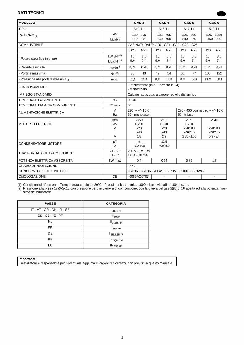
DATI TECNICI
(1) Condizioni di riferimento: Temperatura ambiente 20°C - Pressione barometrica 1000 mbar - Altitudine 100 m s.l.m.(2) Pressione alla presa 12)(A)p.10 con pressione zero in camera di combustione, con la ghiera del gas 2)(B)p. 18 aperta ed alla potenza mas-
sima del bruciatore.
MODELLO GAS 3 GAS 4 GAS 5 GAS 6
TIPO 519 T1 516 T1 517 T1 518 T1
POTENZA (1) kW 130 - 350112 - 301
185 - 465160 - 400
325 - 660280 - 570
525 - 1050450 - 900Mcal/h
COMBUSTIBILE GAS NATURALE: G20 - G21 - G22 - G23 - G25
G20 G25 G20 G25 G20 G25 G20 G25
- Potere calorifico inferiorekWh/Nm3
Mcal/Nm310 8,68,6 7,4
10 8,68,6 7,4
10 8,68,6 7,4
10 8,68,6 7,4
- Densità assoluta kg/Nm3 0,71 0,78 0,71 0,78 0,71 0,78 0,71 0,78
- Portata massima Nm3/h 35 43 47 54 66 77 105 122
- Pressione alla portata massima (2) mbar 11,1 16,4 9,8 14,5 9,8 14,5 12,3 18,2
FUNZIONAMENTO- Intermittente (min. 1 arresto in 24)- Monostadio
IMPIEGO STANDARD Caldaie: ad acqua, a vapore, ad olio diatermico
TEMPERATURA AMBIENTE °C 0 - 40
TEMPERATURA ARIA COMBURENTE °C max 60
ALIMENTAZIONE ELETTRICAV
Hz230 ~ +/- 10%50 - monofase
230 - 400 con neutro ~ +/- 10%50 - trifase
MOTORE ELETTRICOrpmkWV
A
27500,2502202401,8
28100,3702202402,9
28700,750
220/380240/415
2,85 - 1,65
28401,5
220/380240/4155,9 - 3,4
CONDENSATORE MOTOREµFV
8450/500
12,5400/450
TRASFORMATORE D’ACCENSIONEV1 - V2I1 - I2
230 V - 1x 8 kV1,8 A - 30 mA
POTENZA ELETTRICA ASSORBITA kW max 0,4 0,54 0,85 1,7
GRADO DI PROTEZIONE IP 40
CONFORMITA’ DIRETTIVE CEE 90/396 - 89/336 - 2004/108 - 73/23 - 2006/95 - 92/42
OMOLOGAZIONE CE 0085AQ0707 - - -
PAESE CATEGORIA
IT - AT - GR - DK - FI - SE II2H3B / P
ES - GB - IE - PT II2H3P
NL II2L3B / P
FR II2Er3P
DE II2ELL3B /P
BE I2E(R)B, I3P
LU II2E3B /P
Importante:L’installatore è responsabile per l’eventuale aggiunta di organi di sicurezza non previsti in questo manuale.
I
5
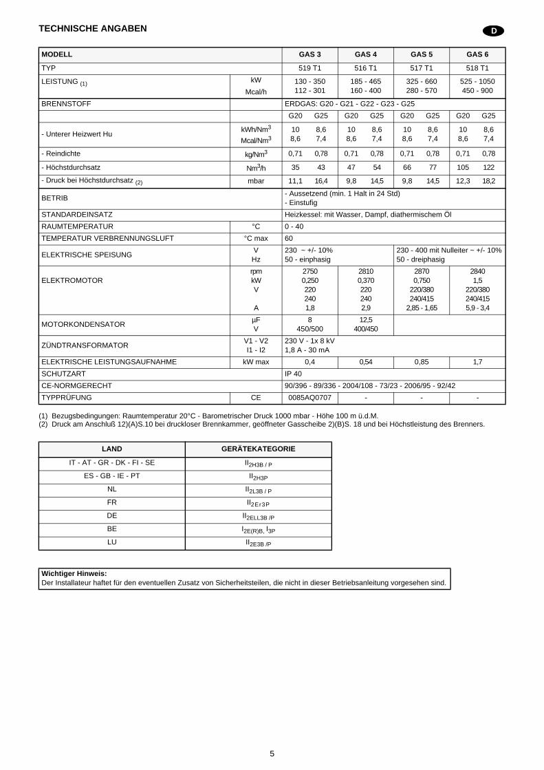
TECHNISCHE ANGABEN
(1) Bezugsbedingungen: Raumtemperatur 20°C - Barometrischer Druck 1000 mbar - Höhe 100 m ü.d.M.(2) Druck am Anschluß 12)(A)S.10 bei druckloser Brennkammer, geöffneter Gasscheibe 2)(B)S. 18 und bei Höchstleistung des Brenners.
MODELL GAS 3 GAS 4 GAS 5 GAS 6
TYP 519 T1 516 T1 517 T1 518 T1
LEISTUNG (1) kW 130 - 350112 - 301
185 - 465160 - 400
325 - 660280 - 570
525 - 1050450 - 900Mcal/h
BRENNSTOFF ERDGAS: G20 - G21 - G22 - G23 - G25
G20 G25 G20 G25 G20 G25 G20 G25
- Unterer Heizwert HukWh/Nm3
Mcal/Nm310 8,68,6 7,4
10 8,68,6 7,4
10 8,68,6 7,4
10 8,68,6 7,4
- Reindichte kg/Nm3 0,71 0,78 0,71 0,78 0,71 0,78 0,71 0,78
- Höchstdurchsatz Nm3/h 35 43 47 54 66 77 105 122
- Druck bei Höchstdurchsatz (2) mbar 11,1 16,4 9,8 14,5 9,8 14,5 12,3 18,2
BETRIB- Aussetzend (min. 1 Halt in 24 Std)- Einstufig
STANDARDEINSATZ Heizkessel: mit Wasser, Dampf, diathermischem Öl
RAUMTEMPERATUR °C 0 - 40
TEMPERATUR VERBRENNUNGSLUFT °C max 60
ELEKTRISCHE SPEISUNGV
Hz230 ~ +/- 10%50 - einphasig
230 - 400 mit Nulleiter ~ +/- 10%50 - dreiphasig
ELEKTROMOTORrpmkWV
A
27500,2502202401,8
28100,3702202402,9
28700,750
220/380240/415
2,85 - 1,65
28401,5
220/380240/4155,9 - 3,4
MOTORKONDENSATORµFV
8450/500
12,5400/450
ZÜNDTRANSFORMATORV1 - V2I1 - I2
230 V - 1x 8 kV1,8 A - 30 mA
ELEKTRISCHE LEISTUNGSAUFNAHME kW max 0,4 0,54 0,85 1,7
SCHUTZART IP 40
CE-NORMGERECHT 90/396 - 89/336 - 2004/108 - 73/23 - 2006/95 - 92/42
TYPPRÜFUNG CE 0085AQ0707 - - -
LAND GERÄTEKATEGORIE
IT - AT - GR - DK - FI - SE II2H3B / P
ES - GB - IE - PT II2H3P
NL II2L3B / P
FR II2Er3P
DE II2ELL3B /P
BE I2E(R)B, I3P
LU II2E3B /P
Wichtiger Hinweis:Der Installateur haftet für den eventuellen Zusatz von Sicherheitsteilen, die nicht in dieser Betriebsanleitung vorgesehen sind.
D
6
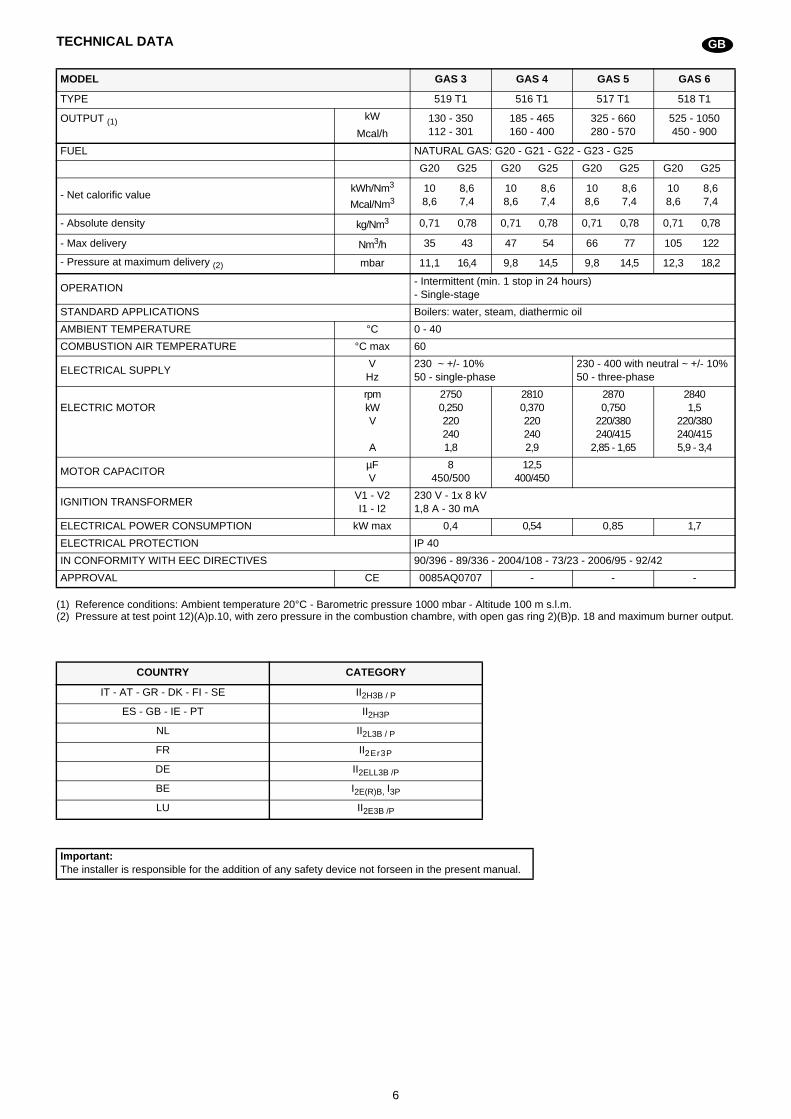
TECHNICAL DATA
(1) Reference conditions: Ambient temperature 20°C - Barometric pressure 1000 mbar - Altitude 100 m s.l.m.(2) Pressure at test point 12)(A)p.10, with zero pressure in the combustion chambre, with open gas ring 2)(B)p. 18 and maximum burner output.
MODEL GAS 3 GAS 4 GAS 5 GAS 6
TYPE 519 T1 516 T1 517 T1 518 T1
OUTPUT (1) kW 130 - 350112 - 301
185 - 465160 - 400
325 - 660280 - 570
525 - 1050450 - 900Mcal/h
FUEL NATURAL GAS: G20 - G21 - G22 - G23 - G25
G20 G25 G20 G25 G20 G25 G20 G25
- Net calorific valuekWh/Nm3
Mcal/Nm310 8,68,6 7,4
10 8,68,6 7,4
10 8,68,6 7,4
10 8,68,6 7,4
- Absolute density kg/Nm3 0,71 0,78 0,71 0,78 0,71 0,78 0,71 0,78
- Max delivery Nm3/h 35 43 47 54 66 77 105 122
- Pressure at maximum delivery (2) mbar 11,1 16,4 9,8 14,5 9,8 14,5 12,3 18,2
OPERATION- Intermittent (min. 1 stop in 24 hours)- Single-stage
STANDARD APPLICATIONS Boilers: water, steam, diathermic oil
AMBIENT TEMPERATURE °C 0 - 40
COMBUSTION AIR TEMPERATURE °C max 60
ELECTRICAL SUPPLYV
Hz230 ~ +/- 10%50 - single-phase
230 - 400 with neutral ~ +/- 10%50 - three-phase
ELECTRIC MOTORrpmkWV
A
27500,2502202401,8
28100,3702202402,9
28700,750
220/380240/415
2,85 - 1,65
28401,5
220/380240/4155,9 - 3,4
MOTOR CAPACITORµFV
8450/500
12,5400/450
IGNITION TRANSFORMERV1 - V2I1 - I2
230 V - 1x 8 kV1,8 A - 30 mA
ELECTRICAL POWER CONSUMPTION kW max 0,4 0,54 0,85 1,7
ELECTRICAL PROTECTION IP 40
IN CONFORMITY WITH EEC DIRECTIVES 90/396 - 89/336 - 2004/108 - 73/23 - 2006/95 - 92/42
APPROVAL CE 0085AQ0707 - - -
COUNTRY CATEGORY
IT - AT - GR - DK - FI - SE II2H3B / P
ES - GB - IE - PT II2H3P
NL II2L3B / P
FR II2Er3P
DE II2ELL3B /P
BE I2E(R)B, I3P
LU II2E3B /P
Important:The installer is responsible for the addition of any safety device not forseen in the present manual.
GB
7
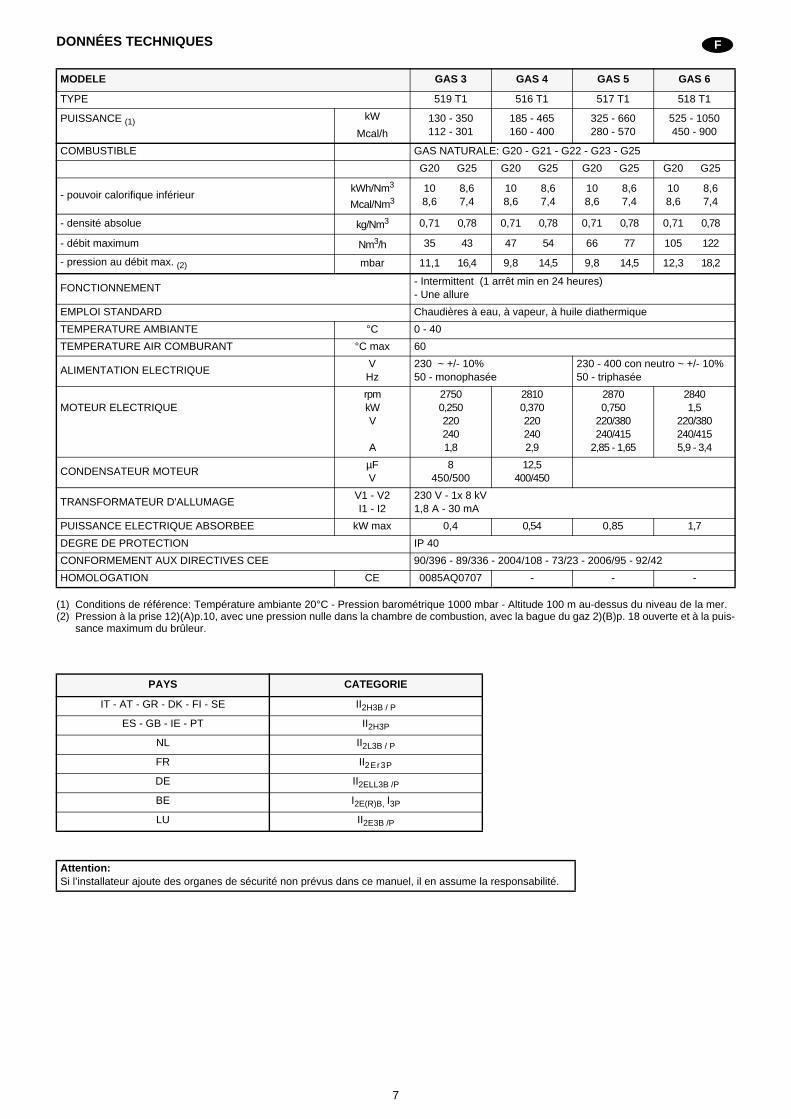
DONNÉES TECHNIQUES
(1) Conditions de référence: Température ambiante 20°C - Pression barométrique 1000 mbar - Altitude 100 m au-dessus du niveau de la mer.(2) Pression à la prise 12)(A)p.10, avec une pression nulle dans la chambre de combustion, avec la bague du gaz 2)(B)p. 18 ouverte et à la puis-
sance maximum du brûleur.
MODELE GAS 3 GAS 4 GAS 5 GAS 6
TYPE 519 T1 516 T1 517 T1 518 T1
PUISSANCE (1) kW 130 - 350112 - 301
185 - 465160 - 400
325 - 660280 - 570
525 - 1050450 - 900Mcal/h
COMBUSTIBLE GAS NATURALE: G20 - G21 - G22 - G23 - G25
G20 G25 G20 G25 G20 G25 G20 G25
- pouvoir calorifique inférieurkWh/Nm3
Mcal/Nm310 8,68,6 7,4
10 8,68,6 7,4
10 8,68,6 7,4
10 8,68,6 7,4
- densité absolue kg/Nm3 0,71 0,78 0,71 0,78 0,71 0,78 0,71 0,78
- débit maximum Nm3/h 35 43 47 54 66 77 105 122
- pression au débit max. (2) mbar 11,1 16,4 9,8 14,5 9,8 14,5 12,3 18,2
FONCTIONNEMENT- Intermittent (1 arrêt min en 24 heures)- Une allure
EMPLOI STANDARD Chaudières à eau, à vapeur, à huile diathermique
TEMPERATURE AMBIANTE °C 0 - 40
TEMPERATURE AIR COMBURANT °C max 60
ALIMENTATION ELECTRIQUEV
Hz230 ~ +/- 10%50 - monophasée
230 - 400 con neutro ~ +/- 10%50 - triphasée
MOTEUR ELECTRIQUErpmkWV
A
27500,2502202401,8
28100,3702202402,9
28700,750
220/380240/415
2,85 - 1,65
28401,5
220/380240/4155,9 - 3,4
CONDENSATEUR MOTEURµFV
8450/500
12,5400/450
TRANSFORMATEUR D'ALLUMAGEV1 - V2I1 - I2
230 V - 1x 8 kV1,8 A - 30 mA
PUISSANCE ELECTRIQUE ABSORBEE kW max 0,4 0,54 0,85 1,7
DEGRE DE PROTECTION IP 40
CONFORMEMENT AUX DIRECTIVES CEE 90/396 - 89/336 - 2004/108 - 73/23 - 2006/95 - 92/42
HOMOLOGATION CE 0085AQ0707 - - -
PAYS CATEGORIE
IT - AT - GR - DK - FI - SE II2H3B / P
ES - GB - IE - PT II2H3P
NL II2L3B / P
FR II2Er3P
DE II2ELL3B /P
BE I2E(R)B, I3P
LU II2E3B /P
Attention:Si l’installateur ajoute des organes de sécurité non prévus dans ce manuel, il en assume la responsabilité.
F
8
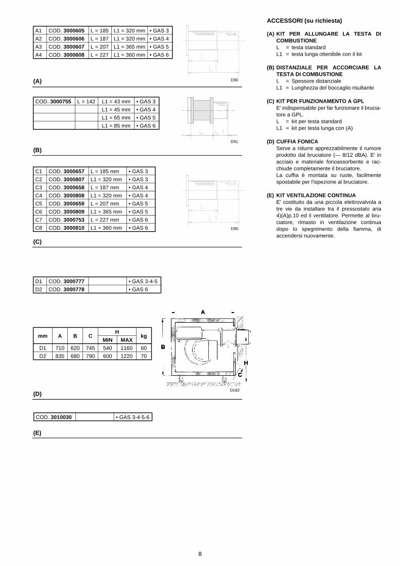
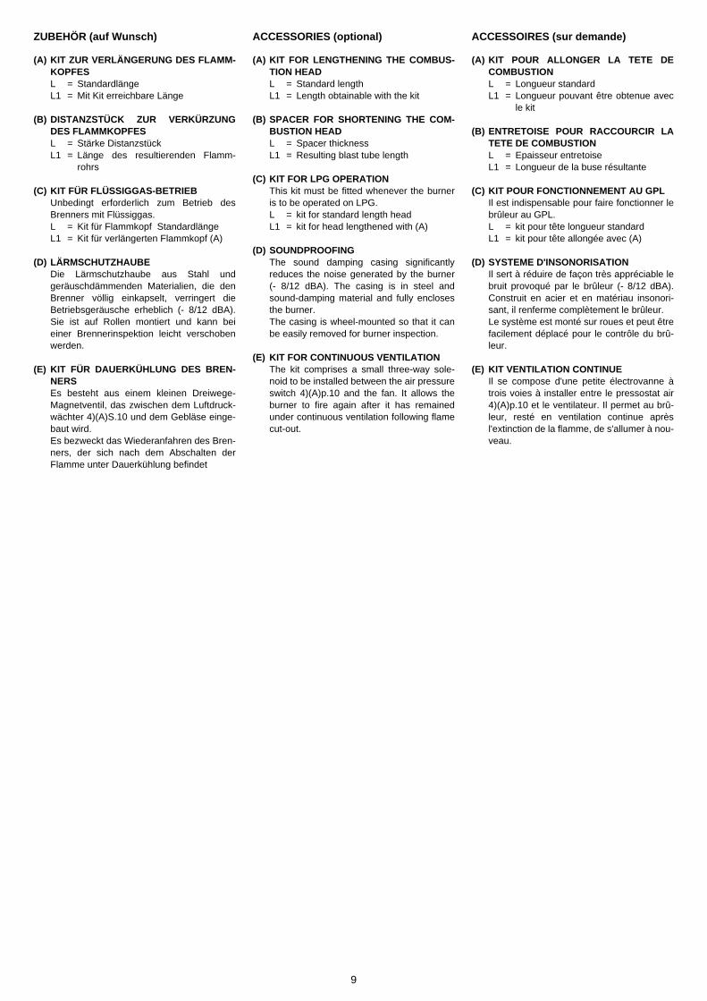
ACCESSORI (su richiesta)
(A) KIT PER ALLUNGARE LA TESTA DICOMBUSTIONEL = testa standardL1 = testa lunga ottenibile con il kit
(B) DISTANZIALE PER ACCORCIARE LATESTA DI COMBUSTIONEL = Spessore distanzialeL1 = Lunghezza del boccaglio risultante
(C) KIT PER FUNZIONAMENTO A GPLE' indispensabile per far funzionare il brucia-tore a GPL.L = kit per testa standardL1 = kit per testa lunga con (A)
(D) CUFFIA FONICAServe a ridurre apprezzabilmente il rumoreprodotto dal bruciatore (— 8/12 dBA). E' inacciaio e materiale fonoassorbente e rac-chiude completamente il bruciatore.La cuffia è montata su ruote, facilmentespostabile per l'ispezione al bruciatore.
(E) KIT VENTILAZIONE CONTINUAE' costituito da una piccola elettrovalvola atre vie da installare tra il pressostato aria4)(A)p.10 ed il ventilatore. Permette al bru-ciatore, rimasto in ventilazione continuadopo lo spegnimento della fiamma, diaccendersi nuovamente.
(A)
(B)
A1 COD. 3000605 L = 185 L1 = 320 mm • GAS 3
A2 COD. 3000606 L = 187 L1 = 320 mm • GAS 4
A3 COD. 3000607 L = 207 L1 = 365 mm • GAS 5
A4 COD. 3000608 L = 227 L1 = 360 mm • GAS 6
(C)
COD. 3000755 L = 142 L1 = 43 mm • GAS 3
L1 = 45 mm • GAS 4
L1 = 65 mm • GAS 5
L1 = 85 mm • GAS 6
C1 COD. 3000657 L = 185 mm • GAS 3
C2 COD. 3000807 L1 = 320 mm • GAS 3
C3 COD. 3000658 L = 187 mm • GAS 4
C4 COD. 3000808 L1 = 320 mm • GAS 4
C5 COD. 3000659 L = 207 mm • GAS 5
C6 COD. 3000809 L1 = 365 mm • GAS 5
C7 COD. 3000753 L = 227 mm • GAS 6
C8 COD. 3000810 L1 = 360 mm • GAS 6
(D)
D1 COD. 3000777 • GAS 3-4-5
D2 COD. 3000778 • GAS 6
mm A B CH
kgMIN MAX
D1 710 620 745 540 1160 60
D2 835 680 790 600 1220 70
COD. 3010030 • GAS 3-4-5-6
(E)
D90
D91
D182
D90
9
ZUBEHÖR (auf Wunsch)
(A) KIT ZUR VERLÄNGERUNG DES FLAMM-KOPFESL = StandardlängeL1 = Mit Kit erreichbare Länge
(B) DISTANZSTÜCK ZUR VERKÜRZUNGDES FLAMMKOPFESL = Stärke DistanzstückL1 = Länge des resultierenden Flamm-
rohrs
(C) KIT FÜR FLÜSSIGGAS-BETRIEBUnbedingt erforderlich zum Betrieb desBrenners mit Flüssiggas.L = Kit für Flammkopf StandardlängeL1 = Kit für verlängerten Flammkopf (A)
(D) LÄRMSCHUTZHAUBEDie Lärmschutzhaube aus Stahl undgeräuschdämmenden Materialien, die denBrenner völlig einkapselt, verringert dieBetriebsgeräusche erheblich (- 8/12 dBA).Sie ist auf Rollen montiert und kann beieiner Brennerinspektion leicht verschobenwerden.
(E) KIT FÜR DAUERKÜHLUNG DES BREN-NERSEs besteht aus einem kleinen Dreiwege-Magnetventil, das zwischen dem Luftdruck-wächter 4)(A)S.10 und dem Gebläse einge-baut wird.Es bezweckt das Wiederanfahren des Bren-ners, der sich nach dem Abschalten derFlamme unter Dauerkühlung befindet
ACCESSORIES (optional)
(A) KIT FOR LENGTHENING THE COMBUS-TION HEADL = Standard lengthL1 = Length obtainable with the kit
(B) SPACER FOR SHORTENING THE COM-BUSTION HEADL = Spacer thicknessL1 = Resulting blast tube length
(C) KIT FOR LPG OPERATIONThis kit must be fitted whenever the burneris to be operated on LPG.L = kit for standard length headL1 = kit for head lengthened with (A)
(D) SOUNDPROOFINGThe sound damping casing significantlyreduces the noise generated by the burner(- 8/12 dBA). The casing is in steel andsound-damping material and fully enclosesthe burner.The casing is wheel-mounted so that it canbe easily removed for burner inspection.
(E) KIT FOR CONTINUOUS VENTILATIONThe kit comprises a small three-way sole-noid to be installed between the air pressureswitch 4)(A)p.10 and the fan. It allows theburner to fire again after it has remainedunder continuous ventilation following flamecut-out.
ACCESSOIRES (sur demande)
(A) KIT POUR ALLONGER LA TETE DECOMBUSTIONL = Longueur standardL1 = Longueur pouvant être obtenue avec
le kit
(B) ENTRETOISE POUR RACCOURCIR LATETE DE COMBUSTIONL = Epaisseur entretoiseL1 = Longueur de la buse résultante
(C) KIT POUR FONCTIONNEMENT AU GPLIl est indispensable pour faire fonctionner lebrûleur au GPL.L = kit pour tête longueur standardL1 = kit pour tête allongée avec (A)
(D) SYSTEME D'INSONORISATIONIl sert à réduire de façon très appréciable lebruit provoqué par le brûleur (- 8/12 dBA).Construit en acier et en matériau insonori-sant, il renferme complètement le brûleur.Le système est monté sur roues et peut êtrefacilement déplacé pour le contrôle du brû-leur.
(E) KIT VENTILATION CONTINUEIl se compose d'une petite électrovanne àtrois voies à installer entre le pressostat air4)(A)p.10 et le ventilateur. Il permet au brû-leur, resté en ventilation continue aprèsl'extinction de la flamme, de s'allumer à nou-veau.

10
DESCRIZIONE BRUCIATORE (A)1 Guide per apertura bruciatore ed ispezione
alla testa di combustione2 Testa di combustione3 Serranda manuale per la regolazione
dell'aria4 Pressostato aria5 Condensatore (nei modelli GAS 3-4)6 Contattore motore e relè termico
(nei modelli GAS 5-6)7 Morsettiera8 Passacavi (per i collegamenti elettrici a cura
dell'installatore)9 Apparecchiatura elettrica con avvisatore
luminoso di blocco e pulsante di sblocco10 Settore per il comando e bloccaggio della
serranda aria11 Presa di pressione ventilatore12 Presa di pressione gas al manicotto13 Condotto arrivo gas14 Manicotto15 Spina-presa sul cavo della sonda di ionizza-
zione
IMBALLO - PESO (B) - misure indicative• I bruciatori vengono spediti in imballi di car-
tone con dimensioni di ingombro secondotabella (B).
• Il peso del bruciatore completo di imballo èindicato nella tabella (B).
INGOMBRO (C) - misure indicativeL'ingombro del bruciatore è riportato in fig. (C).Tener presente che per ispezionare la testa dicombustione il bruciatore deve essere apertoarretrandone la parte posteriore sulle guide.L'ingombro del bruciatore aperto è indicato dallaquota I.
CORREDO1 - Flangia per rampa gas1 - Guarnizione per flangia8 - Viti1 - Schermo termico1 - Istruzione1 - Catalogo ricambi
(A)
(B)
mm A B C kg
GAS 3 850 473 545 32
GAS 4 850 473 545 38
GAS 5 895 520 543 41
GAS 6 1045 555 543 58
mm A B C D E F G H I L M
GAS 3 205 205 292 140 Rp11/2 165 97 185 775 610 397
GAS 4 205 205 292 150 Rp11/2 165 97 187 775 610 397
GAS 5 226 205 332 155 Rp11/2 165 97 207 810 645 437
GAS 6 258 205 370 175 Rp2 195 131 227 966 770 485
(C)
D989
D990
D88
D231

11
BRENNERBESCHREIBUNG (A)1 Gleitschienen zur Öffnung des Brenners und
für die Kontrolle des Flammkopfs2 Flammkopf3 Manuelle Klappe zur Regelung der Luftzu-
fuhr4 Luftdruckwächter5 Kondensator (Modell GAS 3 - 4)6 Motorkontaktgeber und Wärmerelais
(Modell GAS 5 - 6)7 Klemmenbrett8 Kabeldurchgänge für Elektroanschluß
(vom Installateur auszuführen)9 Feuerungsautomat mit Kontrollampe für
Störabschaltung und Druckknopf zum Entrie-geln.
10 Bereich zur Steuerung und Verriegelung derLuftklappe
11 Gebläsedruck-Anschluß12 Gasdruck-Meßanschluß/Brennerdruck13 Gaszuleitung14 Gasanschluß-Muffe15 Steckanschluß am Kabel der Ionisations-
sonde
VERPACKUNG - GEWICHT (B) - Richt-werte• Der Brenner werden in Kartonverpackungen
geliefert, Abmessungen siehe Tabelle (B).• Das Gesamtgewicht des Brenners einschließ-
lich Verpackung wird aus Tabelle (B) ersicht-lich.
ABMESSUNGEN (C) - RichtwerteDie Brennerabmessungen sind in (C) angeführt. Beachten Sie, daß der Brenner für die Flamm-kopfinspektion geöffnet werden muß, indem seinrückwärtiger Teil auf den Gleitschienen nach hin-ten geschoben wird. Die Abmessungen des offenen Brenners sindunter I aufgeführt.
AUSSTATTUNG1 - Flansch für Gasarmaturen1 - Dichtung für Flansch8 - Schrauben1 - Wärmeschild1 - Anleitung1 - Ersatzteile Katalog
BURNER DESCRIPTION (A)1 Slide bars for opening the burner and
inspecting the combustion head2 Combustion head3 Manual air control gate valve4 Air pressure switch5 Capacitor (Models GAS 3 - 4)6 Motor contact-maker and thermal relay
(Models GAS 5 - 6)7 Terminal strip8 Fair lead (for electrical connections by
installer)9 Control box with lock out pilot light and lock
out reset button10 Sector for controlling and locking the air gate
valve11 Fan pressure test point12 Gas pressure test point to sleeve13 Gas input pipework14 Sleeve15 Plug-socket on ionisation probe cable
PACKAGING - WEIGHT (B) - Approximatemeasurements• The burners are shipped in cardboard boxes
with the maximum dimensions shown in table(B).
• The weight of the burner complete with pack-aging is indicated in table (B).
MAX. DIMENSIONS (C) - Approximate mea-surementsThe maximum dimensions of the burner aregiven in (C).Bear in mind that inspection of the combustionhead requires the burner to be opened by with-drawing the rear part on the slide bars.The maximum dimensions of the burner whenopen are given by measurement I.
STANDARD EQUIPMENT1 - Gas train flange1 - Flange gasket8 - Screws1 - Thermal insulation screen1 - Instruction booklet1 - Spare parts list
DESCRIPTION BRULEUR (A)1 Guides pour ouverture brûleur et inspection
de la tête de combustion2 Tête de combustion3 Volet manuel pour le réglage de l'air4 Pressostat air5 Condensateur (GAS 3 - 4)6 Contacteur moteur et relais thermique
(GAS 5 - 6)7 Porte-bornes8 Passe-câbles (pour les connexions électri-
ques à la charge de l'installateur)9 Boîtier de contrôle avec signal lumineux de
blocage et bouton de déblocage10 Secteur pour la commande et le blocage du
volet air11 Prise de pression ventilateur12 Prise de pression gaz au manchon13 Canalisation d'arrivée du gaz14 Manchon15 Fiche-prise sur câble sonde d'ionisation
EMBALLAGE - POIDS (B) - Mesures indica-tives• Le brûleur sont expédiés dans des emballa-
ges en carton dans les dimensions d’encom-brement indiquées dans le tableau (B).
• Le poids du brûleur avec son emballage estindiqué dans le tableau (B).
ENCOMBREMENT (C) - Mesures indicativesL'encombrement du brûleur est reporté dans letab. (C). Il faut tenir compte du fait que pour inspecter latête de combustion, le brûleur doit être ouvert etla partie arrière doit être reculée sur les guides.L'encombrement du brûleur ouvert est indiquépar la cote I.
EQUIPEMENT STANDARD1 - Bride pour rampe gaz1 - Joint pour bride8 - Vis1 - Ecran thermique1 - Instructions1 - Catalogue pièces détachées
12
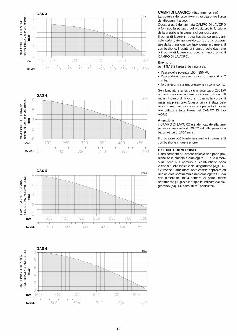
CAMPI DI LAVORO (diagrammi a lato)La potenza del bruciatore va scelta entro l'areadei diagrammi a lato.Quest' area è denominata CAMPO DI LAVOROe fornisce la potenza del bruciatore in funzionedella pressione in camera di combustione.Il punto di lavoro si trova tracciando una verti-cale dalla potenza desiderata ed una orizzon-tale dalla pressione corrispondente in camera dicombustione. Il punto di incontro delle due retteè il punto di lavoro che deve rimanere entro ilCAMPO DI LAVORO.
Esempio: per il GAS 3 l'area è delimitata da:
• l'asse delle potenze 150 - 350 kW• l'asse delle pressioni in cam. comb. 0 + 7
mbar• la curva di massima pressione in cam. comb.
Se il bruciatore sviluppa una potenza di 250 kWad una pressione in camera di combustione di 5mbar, il punto di lavoro si trova sulla curva dimassima pressione. Questa curva è stata defi-nita con margini di sicurezza e pertanto è possi-bile utilizzare tutta l'area del CAMPO DI LA-VORO.
Attenzione: il CAMPO DI LAVORO è stato ricavato alla tem-peratura ambiente di 20 °C ed alla pressionebarometrica di 1000 mbar.
Il bruciatore può funzionare anche in camere dicombustione in depressione.
CALDAIE COMMERCIALIL'abbinamento bruciatore-caldaia non pone pro-blemi se la caldaia è omologata CE e le dimen-sioni della sua camera di combustione sonovicine a quelle indicate dal diagramma (A)p.14.Se invece il bruciatore deve essere applicato aduna caldaia commerciale non omologata CE e/ocon dimensioni della camera di combustionenettamente più piccole di quelle indicate dal dia-gramma (A)p.14, consultare i costruttori.
GAS 3
GAS 4
GAS 5
GAS 6
D288
D289
D290
D291
KW
Mcal/h
KW
Mcal/h
KW
Mcal/h
CA
M. C
OM
B. /
FE
UE
RR
AU
M
CO
MB
. CH
AM
. / C
HA
MB
. CO
MB
.
KW
Mcal/h
mba
r
CA
M. C
OM
B. /
FE
UE
RR
AU
M
CO
MB
. CH
AM
. / C
HA
MB
. CO
MB
.m
bar
CA
M. C
OM
B. /
FE
UE
RR
AU
M
CO
MB
. CH
AM
. / C
HA
MB
. CO
MB
.m
bar
CA
M. C
OM
B. /
FE
UE
RR
AU
M
CO
MB
. CH
AM
. / C
HA
MB
. CO
MB
.m
bar

13
REGELBEREICHE (Diagramme nebenste-hend)Die Leistung des Brenners wird innerhalb desFeldes aus der nebenstehenden Diagrammegewählt.Es handelt sich hierbei um den REGELBE-REICH, der die Leistung des Brenners inAbhängigkeit vom Brennkammerdruck angibt.Den Arbeitswert findet man, indem man von dergewünschten Leistung eine vertikale Linie undvom entsprechenden Brennkammerdruck einehorizontale Linie zieht. Der Schnittpunkt der bei-den Geraden ist der Arbeitswert, der sich inner-halb des REGELBEREICHES befinden muß.
Beispiel: bei GAS 3 wird der Bereich begrenzt von:
• der Achse der Leistungen 130 - 350 kW• der Achse des Brennkammerdruckes 0 + 7
mbar• der Brennkammer-Höchstdruck-Kurve.
Wenn der Brenner bei einem Brennkammer-druck von 5 mbar eine Leistung von 250 kW ent-wickelt, befindet sich der Arbeitswert auf derHöchstdruck-Kurve. Bei der Definition dieserKurve wurde ein Sicherheitsspielraum belassen,daher kann der gesamte REGELBEREICHgenutzt werden.
Achtung: Der REGELBEREICH wurde bei 20 °C Raum-temperatur und 1000 mbar Luftdruck festgelegt.
Der Brenner ist auch in Brennkammern mitUnterdruck betriebsfähig.
HANDELSÜBLICHE KESSELDie Brenner-Kessel Kombination gibt keine Pro-bleme, falls der Kessel "CE" - typgeprüft ist unddie Abmessungen seiner Brennkammer sichden im Diagramm (A)S.14 angegebenennähern.Falls der Brenner dagegen an einem handels-üblichen Kessel angebracht werden muß, dernicht "CE"-typgeprüft ist und/oder mit Abmes-sungen der Brennkammer, die entschieden klei-ner als jene in Diagramm (A)S.14 angegebenensind, sollte der Hersteller zu Rate gezogen wer-den.
FIRING RATES (graphs to side)The burner delivery must be selected within thearea of the adjacent diagram.This range is referred to as the FIRING RATESand provides burner output as a function ofcombustion chamber pressure. The operatingpoint is given by plotting a vertical from therequired output and a horizontal from the corre-sponding combustion chamber pressure. Themeeting point between the two lines gives theoperating point, which must lie within the FIR-ING RATES.
Example: for GAS 3 the range is defined by:
• the 130 - 350 kW output axis• the 0 +7 mbar comb. chamber pressure axis• the maximum pressure in comb. chamber
curve.
If the burner generates an output of 250 kW at acombustion chamber pressure of 5 mbar, theoperating point is found on the maximum pres-sure curve. This curve incorporates margins ofsafety and therefore the entire FIRING RATErange may be used.
Important: the FIRING RATES have been obtained at anambient temperature of 20°C and a barometricpressure of 1000 mbar.
The burner can also operate when there is anegative pressure in the combustion chamber.
COMMERCIAL BOILERSThe burner/boiler combination does not pose anyproblems if the boiler is CE type-approved and itscombustion chamber dimensions are similar tothose indicated in the diagram (A)p.14.If the burner must be combined with a commer-cial boiler that has not been CE type-approvedand/or its combustion chamber dimensions areclearly smaller than those indicated in the dia-gram (A)p.14, consult the manufacturer.
PLAGES DE PUISSANCE (diagrammes ci-contre)Le débit du brûleur doit être choisi dans la plagedes diagrammes ci-contre.Cette aire est appelée PLAGE DE PUISSANCEet fournit la puissance du brûleur en fonction dela pression dans la chambre de combustion.On trouve le point de travail en traçant une verti-cale à partir de la puissance désirée et une hori-zontale au niveau de la pressioncorrespondante dans la chambre de combus-tion. Le point de rencontre des deux droites estle point de travail qui doit rester dans les limitesde la PLAGE DE PUISSANCE.
Exemple: pour le GAS 3 l'aire est délimitée par:
• l'axe des puissances 130 - 350 kW• l'axe des pressions dans la chambre de
comb. 0 +7 mbar• la courbe de pression max. dans la chambre
de combustion.
Si le brûleur développe une puissance de 250kW à une pression de 5 mbar dans la chambrede combustion, le point de travail se trouve surla courbe de pression maximum. Cette courbe aété définie avec des marges de sécurité, onpeut utiliser par conséquent toute l'aire de laPLAGE DE PUISSANCE.
Attention: la PLAGE DE PUISSANCE a été calculée à latempérature ambiante de 20 °C et à la pressionbarométrique de 1000 mbar.
Le brûleur peut également fonctionner avec unechambre de combustion en dépression.
CHAUDIERES COMMERCIALESL'accouplement brûleur-chaudière ne poseaucun problème si la chaudière est homologuéeCE et si les dimensions de sa chambre de com-bustion sont proches de celles indiquées dansle diagramme (A)p.14.Par contre, si le brûleur doit être accouplé àune chaudière commerciale non homologuéeCE, et/ou avec des dimensions de chambre decombustion plus petites que celles indiquéesdans le diagramme (A)p.14, consulter le cons-tructeur.
14
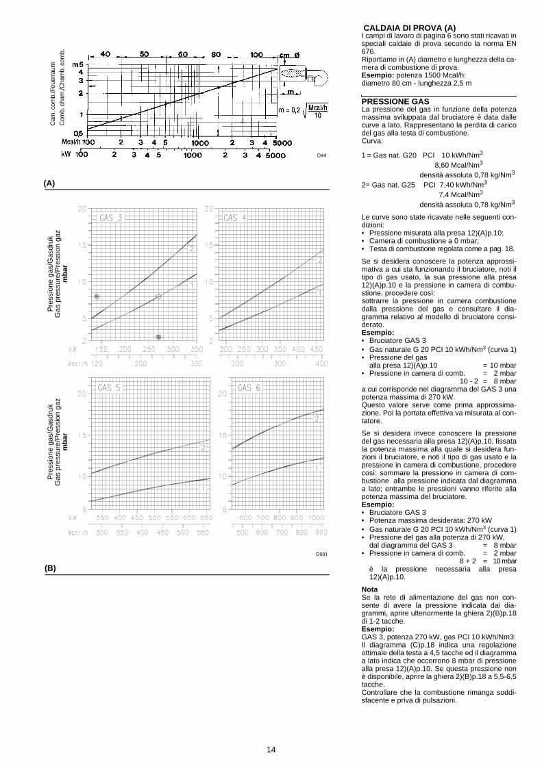
CALDAIA DI PROVA (A)I campi di lavoro di pagina 6 sono stati ricavati inspeciali caldaie di prova secondo la norma EN676.Riportiamo in (A) diametro e lunghezza della ca-mera di combustione di prova. Esempio: potenza 1500 Mcal/h:diametro 80 cm - lunghezza 2,5 m
PRESSIONE GASLa pressione del gas in funzione della potenzamassima sviluppata dal bruciatore è data dallecurve a lato. Rappresentano la perdita di caricodel gas alla testa di combustione. Curva:
1 = Gas nat. G20 PCI 10 kWh/Nm3
8,60 Mcal/Nm3
densità assoluta 0,78 kg/Nm3
2= Gas nat. G25 PCI 7,40 kWh/Nm3
7,4 Mcal/Nm3
densità assoluta 0,78 kg/Nm3
Le curve sono state ricavate nelle seguenti con-dizioni:• Pressione misurata alla presa 12)(A)p.10;• Camera di combustione a 0 mbar;• Testa di combustione regolata come a pag. 18.
Se si desidera conoscere la potenza approssi-mativa a cui sta funzionando il bruciatore, noti iltipo di gas usato, la sua pressione alla presa12)(A)p.10 e la pressione in camera di combu-stione, procedere così:sottrarre la pressione in camera combustionedalla pressione del gas e consultare il dia-gramma relativo al modello di bruciatore consi-derato.Esempio:• Bruciatore GAS 3• Gas naturale G 20 PCI 10 kWh/Nm3 (curva 1)• Pressione del gas
alla presa 12)(A)p.10 = 10 mbar• Pressione in camera di comb. = 2 mbar
10 - 2 = 8 mbara cui corrisponde nel diagramma del GAS 3 unapotenza massima di 270 kW.Questo valore serve come prima approssima-zione. Poi la portata effettiva va misurata al con-tatore.
Se si desidera invece conoscere la pressionedel gas necessaria alla presa 12)(A)p.10, fissatala potenza massima alla quale si desidera fun-zioni il bruciatore, e noti il tipo di gas usato e lapressione in camera di combustione, procederecosì: sommare la pressione in camera di com-bustione alla pressione indicata dal diagrammaa lato; entrambe le pressioni vanno riferite allapotenza massima del bruciatore.Esempio:• Bruciatore GAS 3• Potenza massima desiderata: 270 kW• Gas naturale G 20 PCI 10 kWh/Nm3 (curva 1)• Pressione del gas alla potenza di 270 kW,
dal diagramma del GAS 3 = 8 mbar• Pressione in camera di comb. = 2 mbar
8 + 2 = 10 mbarè la pressione necessaria alla presa12)(A)p.10.
NotaSe la rete di alimentazione del gas non con-sente di avere la pressione indicata dai dia-grammi, aprire ulteriormente la ghiera 2)(B)p.18di 1-2 tacche.Esempio:GAS 3, potenza 270 kW, gas PCI 10 kWh/Nm3:Il diagramma (C)p.18 indica una regolazioneottimale della testa a 4,5 tacche ed il diagrammaa lato indica che occorrono 8 mbar di pressionealla presa 12)(A)p.10. Se questa pressione nonè disponibile, aprire la ghiera 2)(B)p.18 a 5,5-6,5tacche.Controllare che la combustione rimanga soddi-sfacente e priva di pulsazioni.
(A)
(B)
Pre
ssio
ne g
as/G
asdr
ukG
as p
ress
ure/
Pre
ssio
n ga
zm
bar
Pre
ssio
ne g
as/G
asdr
ukG
as p
ress
ure/
Pre
ssio
n ga
zm
bar
Cam
. com
b./F
euer
raum
C
omb.
cha
m./C
ham
b. c
omb.
D44
D991

15
PRÜFKESSEL (A)Die Regelbereiche wurden an speziellen Prüf-kesseln entsprechend Norm EN 676 ermittelt.In (A) sind Durchmesser und Länge der Prüf-Brennkammer angegeben. Beispiel: Leistung 1500 Mcal/h:Durchmesser 80 cm - Länge 2,5 m
GASDRUCKDer Gasdruck in Abhängigkeit von der Brenner-leistung kann nebenstehenden Diagrammenentnommen werden. Die Kurven stellen denStrömungsverlust des Gases am Flammkopfesdar. Kurven:1 = Erdgas G20 Hu 10 kWh/Nm3
8,60 Mcal/Nm3
Reindichte 0,78 kg/Nm3
2= Erdgas G25 Hu 7,40 kWh/Nm3
7,4 Mcal/Nm3
Reindichte 0,78 kg/Nm3
Die Kurven wurden unter folgenden Bedingun-gen ermittelt:• An der Entnahmestelle 12)(A)S.10 ermittelter
Druck;• Feuerraum-Druck = 0 mbar;• Flammkopfregulierung wie auf Seite 19 auf-
geführt.
Will man die annähernde Leistung des arbeiten-den Brenners bei Kenntnis des verwendetenGases, des Gasdrucks an der Entnahmestelle12)(A)S.10 und des Brennkammerdrucks ermit-teln, wie folgt vorgehen: vom Gasdruck denBrennkammer-Druck abziehen und im Dia-gramm des entsprechenden Brenners ablesen.Beispiel:• Brenner GAS 3• Erdgas G 20 Hu 10 kWh/Nm3 (Kurve 1)• Gasdruck an der
Entnahmestelle 12)(A)p.10 = 10 mbar• Brennkammerdruck = 2 mbar
10 - 2 = 8 mbarDies entspricht im Diagramm des Brennermo-dells GAS 3 einer Höchstleistung von 270 kW.Dieser Wert dient als erste Näherung; der tat-sächliche Durchsatz wird am Zähler abgelesen.
Will man hingegen den an der Entnahmestelle12)(A)S.10 erforderlichen Gasdruck bei Kennt-nis der gewünschten Höchstleistung des Bren-ners, mit welcher der Brenner betrieben werdensoll, der Gasart und des Brennkammerdrucksermitteln, wie folgt vorgehen: den im nebenste-henden Diagramm aufgeführten Druck mit demBrennkammerdruck addieren. Beide Druckwertebeziehen sich auf die Höchstleistung des Bren-ners.Beispiel:• Brenner GAS 3• Gewünschte Höchstleistung: 270 kW• Erdgas G 20 Hu 10 kWh/Nm3 (Kurve 1)• Gasdruck bei Leistung von 270 kW,
aus dem Diagramm von GAS 3= 8 mbar• Brennkammerdruck = 2 mbar
8 + 2 = 10 mbarist der an der Entnahmestelle 12)(A)S.10erforderliche Druck.
MerkeWenn die Gaszuleitung es nicht gestattet, den inden Diagrammen angegebenen Gasdruck zuerhalten, so ist der Stellring 2)(B)S.18 um wei-tere 1-2 Kerben zu öffnen.Beispiel:GAS 3, Leistung 270 kW, Gas Hu 10 kWh/Nm3:das Diagramm (C)S.18 gibt als optimalen Ein-stellwert des Flammkopfes 4,5 Kerben an undaus dem nebenstehenden Diagramm geht her-vor, daß an der Gasentnahmestelle 12)(A)S.108 mbar Druck benötigt wird. Ist dieser Drucknicht verfügbar, so ist der Stellring 2)(B)S.18 auf5,5-6,5 Kerben zu öffnen.Die Verbrennung muß zufriedenstellend undohne Verpuffungen erfolgen.
TEST BOILER (A)The firing rates on page 6 were set in relation tospecial test boilers, according to regulation EN676.Figure (A) indicates the diameter and length ofthe test combustion chamber.Example: output 1500 Mcal/h: diameter = 80 cm; length = 2.5 m.
GAS PRESSURECurves (to side) show gas pressure as a func-tion of the output generated by the burner.Theyrepresent the drop in pressure of the combus-tion head. The curve:
1 = Natural gas G20PCI 10 kWh/Nm3
8,60 Mcal/Nm3
absolute density 0,78 kg/Nm3
2= Natural gas G25PCI 7,40 kWh/Nm3
7,4 Mcal/Nm3
absolute density 0,78 kg/Nm3
Curves were calculated under the following con-ditions:• Pressure measured at test point 12)(A)p.10;• Combustion chamber at 0 mbar;• Combustion head set as on page 19.
If the approximate output at which the burner isoperating must be known, record the type of gaswhich was used, its pressure at test point12)(A)p.10 and the pressure in the combustionchamber and then proceed as follows:subtract combustion chamber pressure fromgas pressure and then refer to the graph corre-sponding to the burner being considered.Example:• Burner GAS 3• Natural gas G 20 PCI 10 kWh/Nm3 (curve 1)• Gas pressure at
test point 12)(A)p.10 = 10 mbar• Pressure in combustion chamber = 2 mbar
10 - 2 = 8 mbarin the GAS 3 graph, this corresponds to a maxi-mum output of 270 kW.This reading is an initial approximation. Theeffective delivery is be read at the meter.
If instead the gas pressure required at test point12)(A)p.10 must be known, set the maximumoutput at which the burner is to operate, recordthe type of gas used and the chamber pressureand then proceed as follows: add the pressurein the combustion chamber to the pressure indi-cated in graph (to side); both pressures corre-spond to maximum burner output.Example:• Burner GAS 3• Maximum output required: 270 kW• Natural gas G 20 PCI 10 kWh/Nm3 (curve 1)• Gas pressure at output of 270 kW,
GAS 3 graph = 8 mbar• Pressure in combustion chamber = 2 mbar
8 + 2 = 10 mbaris the pressure required at test point12)(A)p.10.
N.B.If the gas mains does not permit the pressureindicated in the graphs, open ring nut 2)(B)p.18by a further 1-2 notches.Example:GAS 3, output 270 kW, gas PCI 10 kWh/Nm3:the graph (C)p.18 indicates that the optimumhead setting is 4,5 notches and the graph to theside indicates that 8 mbar of pressure arerequired at the test point 12)(A)p.10. If this pres-sure is not available, open the ring nut 2)(B)p.18to 5,5-6,5 notches.Check that combustion is satisfactory and freeof pulsations.
CHAUDIERE D'ESSAI (A)Les plages de puissance de la page 6 ont étéétablies sur des chaudières d'essai spéciales,selon la norme EN 676.Nous reportons sur fig (A) le diamètre et la lon-gueur de la chambre de combustion d'essai. Exemple: Puissance 1500 Mcal/h:diamètre = 80 cm; longueur = 2,5 m.
PRESSION DU GAZLa pression du gaz en fonction de la puissancedéveloppée par le brûleur est donnée par lescourbes ci-contre. Elles représentent la perte decharge de la tête de combustion. Courbe:1 = Gaz nat. G20 PCI 10 kWh/Nm3
8,60 Mcal/Nm3
densité absolue 0,78 kg/Nm3
2= Gaz nat. G25 PCI 7,40 kWh/Nm3
7,4 Mcal/Nm3
densité absolue 0,78 kg/Nm3
Les courbes sont établies d'après les conditionssuivantes:• Pression mesurée à la prise 12)(A)p.10;• Chambre de combustion à 0 mbar;• Tête de comb. réglée comme à la page 19.
Si l'on veut connaître la puissance approxima-tive à laquelle fonctionne le brûleur, connaissantle type de gaz employé, sa pression à la prise12)(A)p.10 et la pression dans la chambre decombustion, procéder comme suit:soustraire la pression dans la chambre de com-bustion de la pression du gaz et consulter le dia-gramme relatif au modèle du brûleur considéré.Exemple:• Brûleur GAS 3• Gaz naturel G 20 PCI 10 kWh/Nm3 (courbe 1)• Pression du gaz à la
prise 12)(A)p.10 = 10 mbar• Pression chambre de combustion = 2 mbar
10 - 2 = 8 mbarauxquels correspond, dans le cas d'un GAS 3,une puissance maximum de 270 kW.Cette valeur est une première valeur approxi-mative. Le débit effectif doit être mesuré aucompteur.
En revanche, si on désire connaître la pressiondu gaz nécessaire à la prise 12)(A)p.10 lorsquel'on connaît la puissance maximum à laquellefonctionnera le brûleur, le type de gaz utilisé etla pression dans la chambre de combustion, ilsuffit d'additionner la pression dans la chambrede combustion à la pression indiquée par le dia-gramme ci-contre (ces deux pressions corres-pondent à la puissance maximum du brûleur).Exemple:• Brûleur GAS 3• Puissance maximum désirée: 270 kW• Gaz naturel G 20 PCI 10 kWh/Nm3 (courbe 1)• Pression du gaz à la puissance de 270 kW,
diagramme du GAS 3 = 8 mbar• Pression chambre de combustion = 2 mbar
8 + 2 = 10 mbarest la pression nécessaire à la prise12)(A)p.10.
NoteSi le réseau d'alimentation du gaz ne permetpas d'avoir la pression indiquée par les dia-grammes, ouvrir encore la bride 2)(B)p.18 de 1ou 2 encoches.Exemple:GAS 3, puissance 270 kW, gaz PCI 10 kWh/Nm3:Le diagramme (C)p.18 indique un réglage idéalde la tête à 4,5 encoches et le diagramme sur lecôté indique qu'il faut 8 mbar de pression à laprise 12)(A)p.10. Si cette pression n'est pas dis-ponible, ouvrir la bride 2)(B)p.18 à 5,5-6,5 enco-ches).Contrôler que la combustion soit satisfaisante etsans à-coups.
16
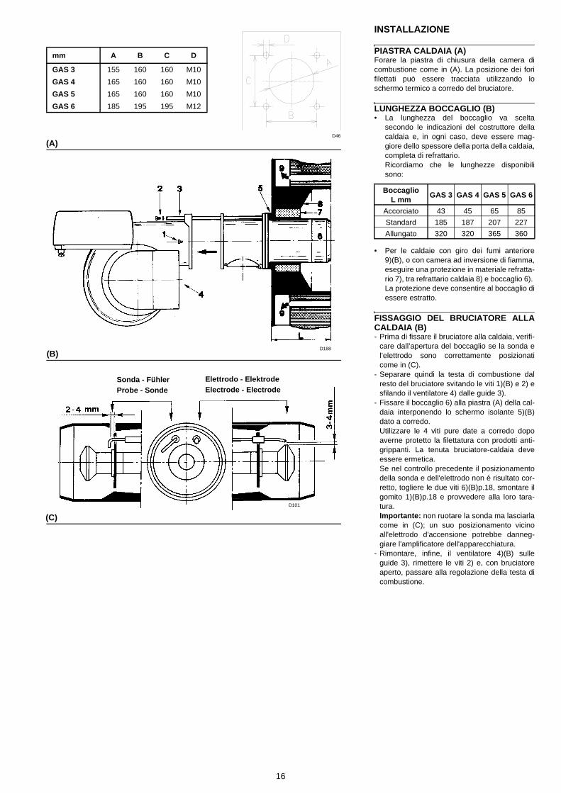
INSTALLAZIONE
PIASTRA CALDAIA (A) Forare la piastra di chiusura della camera dicombustione come in (A). La posizione dei forifilettati può essere tracciata utilizzando loschermo termico a corredo del bruciatore.
LUNGHEZZA BOCCAGLIO (B) • La lunghezza del boccaglio va scelta
secondo le indicazioni del costruttore dellacaldaia e, in ogni caso, deve essere mag-giore dello spessore della porta della caldaia,completa di refrattario.Ricordiamo che le lunghezze disponibilisono:
• Per le caldaie con giro dei fumi anteriore9)(B), o con camera ad inversione di fiamma,eseguire una protezione in materiale refratta-rio 7), tra refrattario caldaia 8) e boccaglio 6). La protezione deve consentire al boccaglio diessere estratto.
FISSAGGIO DEL BRUCIATORE ALLACALDAIA (B) - Prima di fissare il bruciatore alla caldaia, verifi-
care dall’apertura del boccaglio se la sonda el’elettrodo sono correttamente posizionaticome in (C).
- Separare quindi la testa di combustione dalresto del bruciatore svitando le viti 1)(B) e 2) esfilando il ventilatore 4) dalle guide 3).
- Fissare il boccaglio 6) alla piastra (A) della cal-daia interponendo lo schermo isolante 5)(B)dato a corredo.Utilizzare le 4 viti pure date a corredo dopoaverne protetto la filettatura con prodotti anti-grippanti. La tenuta bruciatore-caldaia deveessere ermetica.Se nel controllo precedente il posizionamentodella sonda e dell'elettrodo non è risultato cor-retto, togliere le due viti 6)(B)p.18, smontare ilgomito 1)(B)p.18 e provvedere alla loro tara-tura.Importante: non ruotare la sonda ma lasciarlacome in (C); un suo posizionamento vicinoall'elettrodo d'accensione potrebbe danneg-giare l'amplificatore dell'apparecchiatura.
- Rimontare, infine, il ventilatore 4)(B) sulleguide 3), rimettere le viti 2) e, con bruciatoreaperto, passare alla regolazione della testa dicombustione.
BoccaglioL mm GAS 3 GAS 4 GAS 5 GAS 6
Accorciato 43 45 65 85
Standard 185 187 207 227
Allungato 320 320 365 360
mm A B C D
GAS 3 155 160 160 M10
GAS 4 165 160 160 M10
GAS 5 165 160 160 M10
GAS 6 185 195 195 M12
(A)
(B)
(C)
Sonda - FühlerProbe - Sonde Electrode - Electrode
Elettrodo - Elektrode
D46
D188
D101

17
INSTALLATION
KESSELPLATTE (A) Die Abdeckplatte des Brennkammer wie in (A)gezeigt vorbohren. Die Position der Gewinde-bohrungen kann mit der zur Grundausstattunggehörenden Wärmeschild ermittelt werden.
FLAMMROHRLÄNGE (B) • Die Länge des Flammrohrs wird entspre-
chend der Angaben des Kesselherstellersgewählt und muß in jedem Fall größer als dieStärke der Kesseltür einschließlich feuerfe-stes Material sein. Die verfügbaren Längen,L (mm), sind:
• Für Heizkessel mit vorderem Abgasumlauf9)(B) oder mit Flammenumkehrkammer mußeine Schutzschicht aus feuerfestem Material7) zwischen feuerfestem Material des Kes-sels 8) und Flammrohr 6) ausgefüht werden.Diese Schutzschicht muß so angelegt sein,daß das Flammrohr ausbaubar ist.
BEFESTIGUNG DES BRENNERS AMHEIZKESSEL (B) - Vor der Befestigung des Brenners am Heiz-
kessel ist von der Öffnung des Flammrohrsaus zu überprüfen, ob der Fühler und die Elek-trode gemäß (C) in der richtigen Stellung sind.
- Dann den Flammkopf vom übrigen Brennerabtrennen, indem man die Schrauben 1)(B)und 2) löst und das Gebläse 4) aus den Gleit-schienen 3) zieht.
- Das Flammrohr 6) an der Kesselplatte (A)befestigen, dabei den zur Grundausstattunggehörenden Wärmeschild 5)(B) dazuwischen-legen.Die 4 ebenfalls beigepackten Schrauben nachAuftragung von Freßschutzmitteln verwen-den. Es muß die Dichtheit von Brenner-Kesselgewährleistet sein.Falls bei der vorhergehenden Prüfung diePositionierung des Fühlers oder der Elektrodesich als nicht richtig erweist, die zwei Schrau-ben 6)(B)S.18 lösen, das Winkelstück1)(B)S.18 abnehmen und eine neue Einstel-lung vornehmen.Wichtig: den Fühler nicht drehen, sondernwie in (C) lassen: seine Positionierung in derNähe der Zündelektrode könnte den Geräte-verstärker beschädigen.
- Schließlich das Gebläse 4)(B) wieder in dieGleitschienen 3) einführen, Schrauben 2) wie-der anbringen und bei geöffnetem Brenner dieEinstellung des Flammkopfes vornehmen.
FlammrohrL mm GAS 3 GAS 4 GAS 5 GAS 6
Kurz 43 45 65 85
Standard 185 187 207 227
Lang 320 320 365 360
INSTALLATION
BOILER PLATE (A) Drill the combustion chamber locking plate asshown in (A). The position of the threaded holescan be marked using the thermal screen sup-plied with the burner.
LUNGHEZZA BOCCAGLIO (B) • The length of the blast tube should be
selected in relation to indications provided bythe boiler manufacturer and, in any case,should be greater than the thickness of theboiler door complete with refractory material.Three different blast tube lengths are availa-ble:
• For boilers with front flue passes as shown in9)(B) or a flame inversion chamber, thespace between the front plate quarl 8) andthe burner blast tube 6) must be properlysealed with appropriate refractory material7). Afterwards, it must still be possible to pullout the blast tube.
SECURING THE BURNER TO THEBOILER (B) - Before securing the burner to the boiler, look
in the blast tube opening to see whether theprobe and electrode are correctly positionedas in (C).
- Then separate the combustion head from therest of the burner by unscrewing screws 1)(B)and 2) and drawing out the fan 4) on the slidebars 3).
- Secure the blast tube 6) to the boiler plate (A),installing the burner heat shield 5)(B) suppliedas standard equipment. To do this, use the four standard-issue screws,having first protected the thread with an anti-grip product.The burner-boiler installation must be hermeti-cally sealed.If the probe and electrode were not in the cor-rect position in the above control, unscrew thetwo screws 6)(B)p.18, remove the elbow1)(B)p.18 and calibrate them.Attention: do not rotate the probe but leave itin position as shown in (C); positioning theprobe near the firing electrode could damagethe control box amplifier.
- Lastly, reassemble the fan 4)(B) on the slidebars 3), replace the screws 2) and, with theburner open, set the combustion head.
Blast tubeL mm GAS 3 GAS 4 GAS 5 GAS 6
Shortened 43 45 65 85
Standard 185 187 207 227
Lengthened 320 320 365 360
INSTALLATION
PLAQUE CHAUDIERE (A) Percer la plaque de fermeture de la chambre decombustion comme sur la fig.(A). La positiondes trous filetés peut être tracée en utilisantl'écran thermique fourni avec le brûleur.
LONGUEUR BUSE (B) • La longueur de la buse est choisie selon les
indications du constructeur de la chaudièreet doit, de toutes façons, toujours être plusgrande que l'épaisseur de la porte de lachaudière réfractaire compris.Rappelons que les longueurs disponiblessont:
• Pour les chaudières avec circulation desfumées sur l'avant 9)(B), ou avec chambre àinversion de flamme, réaliser une protectionen matériau réfractaire 7), entre réfractairechaudière 8) et buse 6). La protection doit permettre l'extraction de labuse.
FIXATION DU BRULEUR A LA CHAU-DIERE (B) - Avant de fixer le brûleur à la chaudière, vérifier
par l'ouverture de la buse que la sonde etl'électrode soient correctement placés commeindiqué sur la figure (C).
- Séparer ensuite la tête de combustion du restedu brûleur en dévissant les vis 1)(B) et 2) et enretirant le ventilateur 4) des guides 3).
- Fixer la buse 6) à la plaque (A) de la chaudièreen intercalant le panneau isolant 5)(B) fourniavec le brûleur. Utiliser les 4 vis fournies aprèsen avoir protégé le filetage avec des produitsanti-grippants. Le joint brûleur-chaudière doitêtre hermétique.Si lors du contrôle précédent, le positionne-ment de la sonde de l'électrode s'avère incor-rect, enlever les deux vis 6)(B)p.18, démonterle coude 1)(B)p.18 et effectuer le réglage.Important: ne pas tourner la sonde mais lalaisser comme sur la fig. (C); le fait d'être pla-cée à proximité de l'électrode d'allumage pour-rait endommager l'amplificateur du boîtier decontrôle.
- Pour finir, remonter le ventilateur 4)(B) sur lesguides 3), remettre les vis 2) et, avec le brû-leur ouvert, passer au réglage de la tête decombustion.
BuseL mm GAS 3 GAS 4 GAS 5 GAS 6
Courte 43 45 65 85
Standard 185 187 207 227
Longue 320 320 365 360

18
REGOLAZIONE TESTA DI COMBU-STIONELa regolazione della testa di combustionedipende unicamente dalla potenza sviluppatadal bruciatore.Perciò, prima di regolare la testa di combu-stione, bisogna fissare questo valore.Sono previste due regolazioni della testa:quella del gas e quella dell'aria. Si effettuanocon bruciatore aperto (A), al momento del fis-saggio del bruciatore alla caldaia.
Regolazione gas— Allentare la vite 3)(B).— Ruotare la ghiera 2) in modo che l'indice 5)
coincida con la tacca desiderata 4).— Bloccare la vite 3).Regolazione aria— Allentare le due viti 6)(B).— Spostare il gomito 1) avanti o indietro in
modo che il suo piano posteriore 7) coincidacon la tacca desiderata della targhetta 8).
— Bloccare le viti 6).
AttenzioneIl numero di tacca per gas e aria è lo stesso e siricava dal diagramma (C) in funzione dellapotenza del bruciatore.
EsempioIl bruciatore GAS 3 è installato su una caldaiada 240 kW. Considerando un rendimento del89%, il bruciatore dovrà erogare circa 270 kW.Dal diagramma (C) risulta che per questa poten-zialità le regolazioni del gas e dell'aria vannoeffettuate sulla tacca 4,5.
NOTAIl diagramma indica la regolazione ottimale dellatesta. Se la pressione nella rete di alimenta-zione del gas è molto bassa e non consente ilraggiungimento della pressione (e quindi dellapotenza) desiderata, è possibile aprire ulterior-mente la ghiera 2)(B) di 1-2 tacche. Vedi anchenota a p. 14.
Infine chiudere il bruciatore:— Far scorrere il gruppo A sulle due guide
2)(A).— Rimettere le viti 1).
AttenzioneAll'atto della chiusura del bruciatore sulle dueguide, è opportuno tirare delicatamente versol'esterno il cavo d'alta tensione ed il cavettodella sonda di rivelazione fiamma, fino a metterliin leggera tensione.
(C)
Tacche sulla ghiera 2)(B) e sulla targhetta 8)(B) Scheiben-rasten Markierungen 2)(B) und Markierungen auf der Skala 8)(B)
(B)
(A) D202
Notches on ring nut 2)(B) and on information plate 8)(B)
Encoches sur la bague 2)(B) et sur la plaquette 8)(B)
D118
REGOLAZIONE TESTA DI COMBUSTIONEEINSTELLUNG DES FLAMMKOPFESSETTING THE COMBUSTION HEADREGLAGE TETE DE COMBUSTION
BRUCIATORE APERTOGEÖFFNETER BRENNERBURNER OPENBRÛLEUR OUVERT
D227
GAS

19
EINSTELLUNG DES FLAMMKOPFSDie Einstellung des Flammkopfs ist einzig vonder vom Brenner entwickelten Leistung abhän-gig.Daher muß vor der Einstellung des Flammkopfsdieser Wert festgelegt werden.Am Flammkopf sind zwei Einstellungen vorzu-nehmen:Gas und Luft. Dies erfolgt bei geöffnetem Bren-ner (Abb. A), wenn der Brenner am Kesselangebracht wird.
Gas-Einstellung— Schraube 3)(B) lockern.— Stellring 2) so drehen, bis die gefundene
Kerbe 4) mit dem Indexstift 5) zusammen-fällt.
— Schraube 3) festziehen.Luft-Einstellung— Die zwei Schrauben 6)(B) lockern.— Das Kniestück 1) nach vorne oder hinten
verschieben, so daß seine Hinterfläche 7)mit dem gewünschten Einstellwert auf derSkala 8) übereinstimmt.
— Schrauben 6) festziehen.
Achtungdie Kerbnummer für Gas und Luft sind gleichund kann aus dem Diagramm (C) abgelesenwerden, je nach der Leistung, auf die der Bren-ner eingestellt wird.
Beispielder Brenner GAS 3 ist an einem 240 kW-Kesselangebracht. Bei einem Wirkungsgrad von 89%muß der Brenner ca. 270 kW abgeben.Aus dem Diagramm (C) geht hervor, daß zu die-ser Leistung Gas und Luft auf Markierung 4,5eingestellt werden müssen.
MerkeDas Diagramm gibt die optimale Einstellung desFlammkopfes 2)(B) an. Falls der Gaszuleitungs-druck sehr niedrig ist und dadurch dergewünschte Druck (und folglich der gewünschteDurchsatz) nicht erreicht werden kann, kann derStellring um weitere 1-2 Kerben geöffnet wer-den. Siehe auch Anmerkung auf S. 15.
Nun den Brenner schließen:— die Einheit A auf den beiden Gleitschienen
2)(A) verschieben.— Schrauben 1) wieder anbringen.
Wichtiger HinweisBeim Schließen des Brenners ist es ratsam, dasHochspannungskabel und das Kabel des Flam-menfühlers vorsichtig nach außen zu ziehen, bissie leicht gespannt sind.
SETTING THE COMBUSTION HEADCombustion head adjustment depends exclu-sively on output generated by the burner. This value must therefore be set before adjust-ing the combustion head.Two head settings are available, i.e. the gas set-ting and the air setting. These are made with theburner open (fig. A), when securing the burnerto the boiler.
Gas adjustment— Loosen screw 3)(B).— Rotate the ring nut 2) so that indicator 5)
coincides with the required notch 4).— Fasten screw 3).Air adjustment— Loosen the two screws 6)(B).— Move the elbow 1) forwards or backwards so
that its rear surface 7) coincides with therequired notch on the plate 8).
— Fasten the screws 6).
Importantthe notch number is the same for gas and airand is taken from graph (C) according to theoutput at which the burner is set.
ExampleA GAS 3 burner is installed on a 240 kW boiler.If a 89% efficiency rate is considered, the burnershould deliver approximately 270 kW. Graph (C) indicates that for this capacity, thegas and air should be set on notch 4.5.
N.B.The graph indicates the optimum ring nut 2)(B)setting. If mains pressure is very low and doesnot permit the required pressure (and so therequired output), the ring nut may be opened bya further 1-2 notches. See also the note on page15.
Lastly, close the burner as follows:— Slide unit A along the two slide bars 2)(A).— Replace the screws 1).
ImportantWhen fitting the burner on the two slide bars, itis advisable to gently draw out the high tensioncable and flame detection probe cable until theyare slightly stretched.
REGLAGE TETE DE COMBUSTIONLe réglage de la tête de combustion dépend uni-quement de la puissance développée par le brû-leur.Par conséquent, avant de régler la tête de com-bustion, il faut déterminer cette valeur.On a prévu deux réglages de la tête:celui du gaz et celui de l'air. Ils s'effectuent avecle brûleur ouvert, fig. (A), au moment de la fixa-tion du brûleur à la chaudière.
Réglage gaz— Desserrer la vis 3)(B).— Tourner la bague 2) de façon à ce que l'index
5) coïncide avec l'encoche désirée 4).— Bloquer la vis 3).Réglage air— Desserrer les deux vis 6)(B).— Déplacer le coude 1) en avant ou en arrière
de façon à ce que son plan arrière 7) coïn-cide avec l'encoche désirée sur la plaquette8).
— Bloquer les vis 6).
Attentionle numéro de l'encoche pour le gaz et l'air est lemême et est déduit du diagramme (C) selon lapuissance à laquelle le brûleur est réglé.
ExempleLe brûleur GAS 3, installé sur une chaudière de240 kW avec un rendement de 89%, devra pro-duire environ 270 kW.Du diagramme (C) on déduit que pour cettepuissance les réglages du gaz et de l'air doiventêtre effectués sur l'encoche 4,5 environ.
NoteLe diagramme indique le réglage idéal de la tête2)(B). Si la pression dans le réseau d'alimenta-tion du gaz est très basse et ne permet pasd'atteindre la pression (et donc la puissance)désiré, il est possible d'ouvrir ultérieurement labride de 1 ou 2 encoches. Voir également lanote page 15.
Pour finir, fermer le brûleur:— Faire glisser le groupe A sur les deux guides
2)(A).— Remettre les vis 1).
AttentionAu moment de la fermeture du brûleur sur lesdeux guides, il faut tirer délicatement vers l'exté-rieur le câble de haute tension et le petit câblede la sonde de détection flamme, jusqu'à cequ'ils soient légèrement tendus.
20
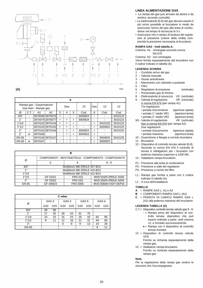
LINEA ALIMENTAZIONE GAS• La rampa del gas può arrivare da destra o da
sinistra, secondo comodità.• Le elettrovalvole 8)-9) del gas devono essere il
più vicino possibile al bruciatore in modo daassicurare l'arrivo del gas alla testa di combu-stione nel tempo di sicurezza di 3 s.
• Assicurarsi che il campo di taratura del regola-tore di pressione (colore della molla) com-prenda la pressione necessaria al bruciatore.
RAMPA GAS - Vedi tabella A:Colonna A1: omologata secondo norma
EN 676Colonna A2: non omologata.Viene fornita separatamente dal bruciatore conil codice indicato in tabella (A).
LEGENDA SCHEMA1 - Condotto arrivo del gas2 - Valvola manuale3 - Giunto antivibrante4 - Manometro con rubinetto a pulsante5 - Filtro6 - Regolatore di pressione (verticale)7 - Pressostato gas di minima8 - Elettrovalvola di sicurezza VS (verticale)9 - Valvola di regolazione VR (verticale)
A norma EN 676 (per rampa A1)Tre regolazioni:• portata d'accensione (apertura rapida)• portata 1° stadio VR1 (apertura lenta)• portata 2° stadio VR2 (apertura lenta)
9/1- Valvola di regolazione VR (verticale)Non a norma EN 676 (per rampa A2)Due regolazioni:• portata d'accensione (apertura rapida)• portata massima (apertura lenta)
10 - Guarnizione e flangia a corredo bruciatore11 - Bruciatore12 - Dispositivo di controllo tenuta valvole 8)-9).
Secondo la norma EN 676 il controllo ditenuta è obbligatorio per i bruciatori conpotenza massima superiore a 1200 kW.
13 - Adattatore rampa-bruciatore.
P1 - Pressione alla testa di combustioneP2 - Pressione a valle del regolatoreP3 - Pressione a monte del filtro
L1 - Rampa gas fornita a parte con il codiceindicato in tabella (A).
L1 - A cura dell'installatore
TABELLEA = RAMPE GAS L: A1 e A2B = COMPONENTI RAMPA GAS L (A1)C = PERDITA DI CARICO RAMPA GAS L
(A1) alla potenza massima del bruciatore
LEGENDA TABELLA (A)C.T.= Dispositivo controllo tenuta valvole gas 8 - 9:
- = Rampa priva del dispositivo di con-trollo tenuta; dispositivo che puòessere ordinato a parte, vedi colonna12, e montato successivamente.
♦= Rampa con il dispositivo di controllotenuta montato.
12 = Dispositivo di controllo tenuta valvoleVPS.Fornito su richiesta separatamente dallarampa gas.
13 = Adattatore rampa-bruciatore.Fornito su richiesta separatamente dallarampa gas.
NotaPer la regolazione della rampa gas vedere leistruzioni che l'accompagnano.
A
Rampa gas - Gasarmaturen Gas train - Rampe gaz
Gas 13 Gas 13 12
Ø C.T. A1 A2 3 4 5 Cod. 6 Cod. Cod.3/4” − 3970046 3970076 • - - 3000824 - - 30101231” − 3970079 3970077 • • • 3000824 - - 3010123
1”1/4 − 3970152 3970144 • • • - • 3010125 30101231”1/2 − 3970153 3970145 • • • - • 3000843 3010125
2” − 3970154 3970146 - • • 3000822 • - 30101252” ♦ 3970166 - - • • 3000822 • - -
DN 65 − 3970155 3970147 - - - - • 3000825 3010125DN 65 ♦ 3970167 - - - - - • 3000825 -
B
Ø COMPONENTI - BESTANDTEILE - COMPONENTS - COMPOSANTS
5 6 8 - 9
3/4” Multiblock MB ZRDLE 407 BO11” Multiblock MB ZRDLE 410 BO1
1”1/4 Multiblock MB ZRDLE 412 BO11”1/2 GF 515/1 FRS 515 MVD 515/5+ZRDLE 415/5
2” GF 520/2 FRS 520 MVD 520/5+ZRDLE 420/5DN 65 GF 4065/3 FRS 5065 MVD 5065/5+VGF+SKP10
C mbar
ØGAS 3 GAS 4 GAS 5 GAS 6
G20 G25 G20 G25 G20 G25 G20 G25
3/4” 39 581” 17 25 29 43 51 75
1”1/4 10 15 16 24 29 43 64 951”1/2 8 11 12 18 21 31 49 69
2” 6 8 9 13 19 28DN 65 8 11
(A) D992
21
GASZULEITUNG• Die Armatur kann je nach Bedarf von rechts
bzw. links zugeführt werden.• Die Gasmagnetventile 8)-9) sollen so nah wie
möglich am Brenner liegen, damit die Gaszu-fuhr zum Flammkopf innerhalb 3 Sekundensichergestellt ist.
• Überprüfen, ob der Einstellbereich des Druck-reglers (Farbe der Feder) die für den Brennererforderlichen Druckwerte vorsieht.
GASARMATUREN - S. Tab. A:Spalte A1: Nach Norm EN 676 typgeprüftSpalte A2: nicht typgeprüft.Gesondert mit dem in Tab. (A) angegebenenCode geliefert.
ZEICHENERKLÄRUNG SCHEMA1 - Gaszuleitung2 - Handbetätigtes Ventil3 - Kompensator4 - Manometer mit Druckknopfhahn5 - Filter6 - Druckregler (senkrecht)7 - Gas-Minimaldruckwächter8 - Sicherheitsmagnetventil VS (senkrecht)9 - Regelmagnetventil VR (senkrecht)
Nach Norm EN 676 (für Armaturen A1)Drei Einstellungen:• Zünddurchsatz (schnellöffnend)• Durchsatz 1° Stufe VR1 (langsamöffnend)• Durchsatz 2° Stufe VR2 (langsamöffnend)
9/1- Regelmagnetventil VR (senkrecht)Nicht nach Norm EN 676 (für Armaturen A2)Zwei Einstellungen:• Zünddurchsatz (schnellöffnend)• Höchstdurchsatz (langsamöffnend)
10 - Dichtung und Flansch Brennergrundaus-stattung
11 - Brenner12 - Dichtheitskontrolleinrichtung der Gasven-
tile 8)-9).Laut Norm EN 676 ist die Dichtheitskon-trolle für Brenner mit Höchstleistung über1200 kW Pflicht.
13 - Passtück Armatur-Brenner.
P1 - Druck am FlammkopfP2 - Druck nach dem ReglerP3 - Druck vor dem Filter
L1 - Gasarmatur gesondert mit dem in Tab. (A)angegebenen Code geliefert.
L1 - Vom Installateur auszuführen
TABELLENA = GASARMATUREN: A1 und A2B = BESTANDTEILE GASARMATUREN (A1)C = STRÖMUNGSVERLUST GASARMATUR
L (A1) bei Brennerhöchstleistung
ZEICHENERKLÄRUNG TABELLE (A)C.T.= Dichtheitskontrolleinrichtung der Gasven-
tile 8) - 9):- = Gasarmatur ohne Dichtheitskontroll-
einrichtung; die Einrichtung kanngesondert bestellt, siehe Spalte 12,und später eingebaut werden.
♦= Gasarmatur mit der eingebautenDichtheitskontrolleinrichtung VPS.
12 = Dichtheitskontrolleinrichtung VPS derGasventile.Auf Anfrage gesondert von der Gasarma-tur lieferbar.
13 = Passtück Armatur-Brenner.Auf Anfrage gesondert von der Gasarma-tur lieferbar.
MerkeZur Einstellung der Gasarmaturen siehe die bei-gelegten Anleitungen.
GAS LINE• The gas train can enter the burner from the
right or left side, depending on which is themost convenient.
• The gas solenoids 8)-9) must be as close aspossible to the burner to ensure gas reachesthe combustion head within the safety timerange of 3 s.
• Make sure that the pressure governor calibra-tion range (spring colour) comprises the pres-sure required by the burner.
GAS TRAIN - See table A:Column A1: Type-approved according to EN
676 StandardsColumn A2: Not type-approved according to
EN 676 Standards.It is supplied separately from the burner with thecode indicated in Table (A).
KEY TO LAYOUT1 - Gas input pipe2 - Manual valve3 - Vibration damping joint4 - Pressure gauge with pushbutton cock5 - Filter6 - Pressure governor (vertical)7 - Minimum gas pressure switch8 - Safety solenoid VS (vertical)9 - Adjustment solenoid VR (vertical)
Complying to EN 676 Standards (for A1gas train)Three adjustments:• ignition delivery (rapid opening)• 1st stage delivery (slow opening)• 2nd stage delivery (slow opening)
9/1- Adjustment solenoid VR (vertical)Not complying to EN 676 Standards (for A2gas train)Two adjustments:• ignition delivery (rapid opening)• maximum delivery (slow opening)
10 - Standard issue burner gasket with flange11 - Burner12 - Gas valve 8)-9) leak detection control
device.In accordance with EN 676 Standards, gasvalve leak detection control devices arecompulsory for burners with maximum out-puts of more than 1200 kW.
13 - Gas train/burner adaptor.
P1 - Pressure at combustion headP2 - Pressure down-line from the filterP3 - Pressure up-line from the filter
L1 - Gas train supplied separately with the codeindicated in Table (A).
L1 - The responsibility of the installer
TABLEA = GAS TRAINS: A1 and A2B = GAS TRAIN COMPONENTS (A1)C = GAS TRAIN PRESSURE LOSS L (A1) at
maximum burner output
KEY TO TABLE (A)C.T.= Gas valves 8) - 9) leak detection control
devices:- = Gas train without gas valve leak
detection control device; device thatcan be ordered separately andassembled subsequently (see Col-umn 12).
♦= Gas train with assembled VPS valveleak detection control device.
12 = PS valve leak detection control device.Supplied separately from gas train on re-quest.
13 = Gas train/burner adaptor.Supplied separately from gas train onrequest.
NoteSee the accompanying instructions for theadjustment of the gas train.
LIGNE ALIMENTATION GAZ• La rampe peut arriver par la droite ou par la
gauche selon les cas.• Les électrovannes 8)-9) du gaz doivent être le
plus près possible du brûleur de façon à assu-rer l'arrivée du gaz à la tête de combustion enun temps de sécurité de 3 s.
• Contrôler que la plage de réglage du régula-teur de pression (couleur du ressort) recouvrela pression nécessaire au brûleur.
RAMPE GAZ - Voir tableau AColonne A1: homologuée suivant la norme
EN 676Colonne A2: ne pas homologuée.Elle est fournie séparément du brûleur avec lecode indiqué dans le tableau (A).
LEGENDE SCHEMA1 - Canalisation d'arrivée du gaz2 - Vanne manuelle3 - Joint anti-vibrations4 - Manomètre avec robinet à bouton poussoir5 - Filtre6 - Régulateur de pression (vertical)7 - Pressostat gaz de seuil minimum8 - Electrovanne de sécurité VS (verticale)9 - Electrovanne de régulation VR (verticale)
Selon la norme EN 676 (pour rampe A1)Trois réglages:• débit d'allumage (ouverture rapide)• débit 1ère allure VR1 (ouverture lente)• débit 2ème allure VR2 (ouverture lente)
9/1- Electrovanne de régulation VR (verticale)Ne pas selon la norme EN 676 (pour rampe A2)Deux réglages:• débit d'allumage (ouverture rapide)• débit maximum (ouverture lente)
10 - Joint et bride fournis avec le brûleur11 - Brûleur12 - Dispositif de contrôle d'étanchéité vannes
8)-9).Selon la norme EN 676, le contrôle d'étan-chéité est obligatoire pour les brûleursayant une puissance maximale supérieureà 1200 kW.
13 - Adaptateur rampe-brûleur.
P1 - Pression à la tête de combustionP2 - Pression en aval du régulateurP3 - Pression en amont du filtre
L1 - La rampe gaz est fournie à part avec lecode indiqué dans le tab. (A).
L1 - A la charge de l'installateur
TABLEAUA = RAMPES GAZ: A1 - A2B = COMPOSANTS RAMPE GAZ (A1)C = PERTE DE CHARGE RAMPE GAZ L
(A1) à la puissance maximum du brûleur
LEGENDE TABLEAU (A)C.T.= Dispositif de contrôle d'étanchéité vannes
8)-9):- = Rampe sans dispositif de contrôle
d'étanchéité; dispositif qui peut êtrecommandé à part et monté par lasuite, voir colonne 12.
♦= Rampe avec dispositif de contrôled'étanchéité VPS monté.
12 = Dispositif VPS de contrôle d'étanchéitéde la vanne.Fourni sur demande séparément de larampe gaz.
13 = Adaptateur rampe-brûleur.Fourni sur demande séparément de larampe gaz.
NotePour le réglage de la rampe gaz voir les instruc-tions qui l'accompagnent.

22
IMPIANTO ELETTRICO eseguito in fabbrica
SCHEMA (A)Bruciatori GAS 3 - 4 (monofase)
SCHEMA (B)Bruciatori GAS 5 - 6 (trifase)• Questi modelli lasciano la fabbrica previsti per
alimentazione elettrica 400 V.• Se l'alimentazione è 230 V, cambiare il colle-
gamento del motore (da stella a triangolo) e lataratura del relè termico.
LEGENDA SCHEMA (A) - (B)C - CondensatoreCMV - Contattore motoreF1 - Filtro contro radiodisturbiK1 - RelèRMG - Apparecchiatura elettricaMB - Morsettiera bruciatoreMV - Motore ventilatorePA - Pressostato ariaRT - Relè termicoSO - Sonda di ionizzazioneSP - Spina-presaTA - Trasformatore d'accensioneTB - Terra bruciatore
ATTENZIONEIn caso di alimentazione fase/ fase, è necessarioeseguire un ponte nella morsettiera dell’appa-recchiatura tra il morsetto 6 e il morsetto di terra.
(A)
GAS 3 - 4IMPIANTO ELETTRICO ESEGUITO IN FABBRICAWERKSEITIG AUSGEFÜHRTE ELEKTROANLAGEELECTRICAL EQUIPMENT FACTORY-SETINSTALLATION ELECTRIQUE REALISEE EN USINE
GAS 5 - 6IMPIANTO ELETTRICO ESEGUITO IN FABBRICAWERKSEITIG AUSGEFÜHRTE ELEKTROANLAGEELECTRICAL EQUIPMENT FACTORY-SETINSTALLATION ELECTRIQUE REALISEE EN USINE
(B)
D2855
D2861
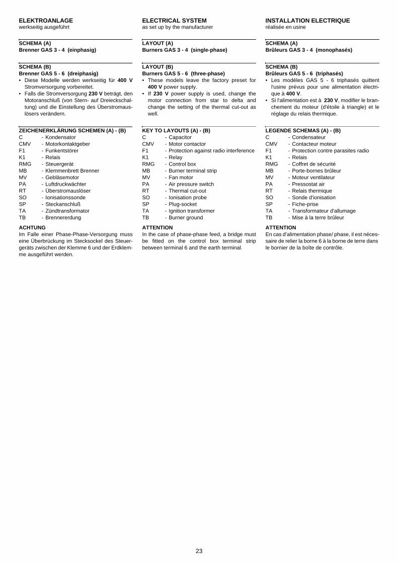
23
ELEKTROANLAGE werkseitig ausgeführt
SCHEMA (A)Brenner GAS 3 - 4 (einphasig)
SCHEMA (B)Brenner GAS 5 - 6 (dreiphasig)• Diese Modelle werden werkseitig für 400 V
Stromversorgung vorbereitet.• Falls die Stromversorgung 230 V beträgt, den
Motoranschluß (von Stern- auf Dreieckschal-tung) und die Einstellung des Überstromaus-lösers verändern.
ZEICHENERKLÄRUNG SCHEMEN (A) - (B)C - KondensatorCMV - MotorkontaktgeberF1 - FunkentstörerK1 - RelaisRMG - SteuergerätMB - Klemmenbrett BrennerMV - GebläsemotorPA - LuftdruckwächterRT - ÜberstromauslöserSO - IonisationssondeSP - SteckanschlußTA - ZündtransformatorTB - Brennererdung
ACHTUNGIm Falle einer Phase-Phase-Versorgung musseine Überbrückung im Stecksockel des Steuer-geräts zwischen der Klemme 6 und der Erdklem-me ausgeführt werden.
ELECTRICAL SYSTEM as set up by the manufacturer
LAYOUT (A)Burners GAS 3 - 4 (single-phase)
LAYOUT (B)Burners GAS 5 - 6 (three-phase)• These models leave the factory preset for
400 V power supply.• If 230 V power supply is used, change the
motor connection from star to delta andchange the setting of the thermal cut-out aswell.
KEY TO LAYOUTS (A) - (B)C - CapacitorCMV - Motor contactorF1 - Protection against radio interferenceK1 - RelayRMG - Control boxMB - Burner terminal stripMV - Fan motorPA - Air pressure switchRT - Thermal cut-outSO - Ionisation probeSP - Plug-socketTA - Ignition transformerTB - Burner ground
ATTENTIONIn the case of phase-phase feed, a bridge mustbe fitted on the control box terminal stripbetween terminal 6 and the earth terminal.
INSTALLATION ELECTRIQUE réalisée en usine
SCHEMA (A)Brûleurs GAS 3 - 4 (monophasés)
SCHEMA (B)Brûleurs GAS 5 - 6 (triphasés)• Les modèles GAS 5 - 6 triphasés quittent
l'usine prévus pour une alimentation électri-que à 400 V.
• Si l'alimentation est à 230 V, modifier le bran-chement du moteur (d'étoile à triangle) et leréglage du relais thermique.
LEGENDE SCHEMAS (A) - (B)C - CondensateurCMV - Contacteur moteurF1 - Protection contre parasites radioK1 - RelaisRMG - Coffret de sécuritéMB - Porte-bornes brûleurMV - Moteur ventilateurPA - Pressostat airRT - Relais thermiqueSO - Sonde d'ionisationSP - Fiche-priseTA - Transformateur d'allumageTB - Mise à la terre brûleur
ATTENTIONEn cas d’alimentation phase/ phase, il est néces-saire de relier la borne 6 à la borne de terre dans le bornier de la boîte de contrôle.

24
COLLEGAMENTI ELETTRICIEseguito dall'installatore.
Usare cavi flessibili secondo norma EN 60 335-1:• se sotto guaina di PVC almeno tipo H05 VV-F;• se sotto guaina di gomma almeno tipo H05
RR-F.
FISSAGGIO CAVI (A) - (B)Tutti i cavi da collegare alla morsettiera7)(A)p.10 del bruciatore vanno fatti passare daipassacavi 8)(A)p.10. L'utilizzo dei passacavi edei fori pretranciati può avvenire in vari modi; ascopo esemplificativo indichiamo il modoseguente:
GAS 3 - 4 (A)1- Pg 13,5 Alimentazione monofase2- Pg 13,5 Telecomando TL3- Pg 13,5 Valvole gas4- Pg 13,5 Pressostato gas o dispositivo per
il controllo di tenuta valvole5- Pg 13,5 Bocchettone disponibile6- Pg 13,5 Foro per eventuale bocchettone7- Pg 21 Foro per eventuale bocchettone8- Pg 11 Foro per eventuale bocchettone
GAS 5 (B)1- Pg 21 Alimentazione trifase2- Pg 13,5 Alimentazione monofase3- Pg 13,5 Telecomando TL4- Pg 13,5 Valvole gas5- Pg 13,5 Pressostato gas o dispositivo per
il controllo di tenuta valvole6- Pg 13,5 Bocchettone disponibile7- Pg 13,5 Foro per eventuale bocchettone8- Pg 11 Foro per eventuale bocchettone9- Pg 11 Foro per eventuale bocchettone
Per garantire il grado di protezione IP40,chiudere i fori dei bocchettoni inutilizzati.
SCHEMA (C) - Alimentazione monofaseAllacciamento elettrico bruciatori GAS 3 - 4senza controllo tenuta valvole gas.
SCHEMA (D) - Alimentazione monofaseAllacciamento elettrico bruciatori GAS 3 - 4con controllo tenuta valvole gas VPS.Il controllo tenuta valvole gas avviene subitoprima di ogni avviamento del bruciatore.
LEGENDA SCHEMI (C) - (D)IN - Interruttore elettrico per arresto manuale
bruciatoreMB - Morsettiera bruciatorePG - Pressostato gas di min.H - Segnalazione di blocco a distanzaH1 - Segnalazione di blocco del controllo di
tenuta a distanzaTL - Telecomando di limite:
ferma il bruciatore quando la tempera-tura o la pressione in caldaia raggiunge ilvalore prestabilito.
TS - Telecomando di sicurezza: interviene in caso di TL guasto.
VR1 - Valvola gas 1° stadioVR2 - Valvola gas 2° stadioVS - Valvola di sicurezzaXP - Spina per controllo tenuta
(A)
(C)
(D)
FISSAGGIO CAVI - KABELBEFESTIGUNG - CABLE SECURING - FIXATION BABLES
IMPIANTO ELETTRICO ESEGUITO DALL’INSTALLATOREVOM INSTALLATEUR AUSZUFÜHRENDE ELEKTROINSTALLATIONELECTRICAL CONNECTION OF BURNER BY INSTALLERRACCORDEMENT BRULEUR EFFECTUE PAR L’ INSTALLATEURGAS 3 - 4
(B)
GAS 3 - 4 GAS 5 - 6
IMPIANTO ELETTRICO ESEGUITO DALL’INSTALLATOREVOM INSTALLATEUR AUSZUFÜHRENDE ELEKTROINSTALLATIONELECTRICAL CONNECTION OF BURNER BY INSTALLERRACCORDEMENT BRULEUR EFFECTUE PAR L’ INSTALLATEURGAS 3 - 4
D995
D2851
D2852
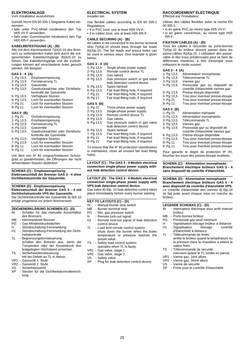
25
ELEKTROANLAGEVom Installateur auszuführen.
Gemäß Norm EN 60 335-1 biegsame Kabel ver-wenden:• falls unter PVC-Mntel mindestens den Typ
H05 VV-F verwerden;• falls unter Gummimantel mindestens den Typ
H05 RR-F verwerden.
KABELBEFESTIGUNG (A) - (B)Alle mit dem Klemmenbrett 7)(A)S.10 des Bren-ners zu verbindenden Kabel sind durch die ent-sprechenden Kabeldurchgänge 8)(A)S.10 zuführen. Die Kabeldurchgänge und die Vorboh-rungen können auf verschiedene Arten genutztwerden. Als Beispiel:
GAS 3 - 4 (A)1- Pg 13,5 Einphasenspeisung2- Pg 13,5 Fernsteuerung TL3- Pg 13,5 Gasventile4- Pg 13,5 Gasdruckwächter oder Dichtheits-
kontrolle der Gasventile5- Pg 13,5 Verfügbare Stutzen6- Pg 13,5 Loch für eventuellen Stutzen7- Pg 21 Loch für eventuellen Stutzen8- Pg 11 Loch für eventuellen Stutzen
GAS 5 (B)1- Pg 21 Drehstromspeisung2- Pg 13,5 Einphasenspeisung3- Pg 13,5 Fernsteuerung TL4- Pg 13,5 Gasventile5- Pg 13,5 Gasdruckwächter oder Dichtheits-
kontrolle der Gasventile6- Pg 13,5 Verfügbare Stutzen7- Pg 13,5 Loch für eventuellen Stutzen8- Pg 11 Loch für eventuellen Stutzen9- Pg 11 Loch für eventuellen Stutzen
Um dem von IP 40 vorgeschriebenen Schutz-grad zu gewährleisten, die Öffnungen der nichtverwendeten Stutzen abdecken
SCHEMA (C) - EinphasenspeisungElektroanschluß der Brenner GAS 3 - 4 ohneDichtheitskontrolle der Gasventile.
SCHEMA (D) - EinphasenspeisungElektroanschluß der Brenner GAS 3 - 4 mitDichtheitskontrolle VPS der Gasventile.Die Dichtheitskontrolle der Gasventile 8)-9)S.10erfolgt umgehend vor jedem Brennerstart.
ZEICHENERKLÄRUNG SCHEMEN (C) - (D)IN - Schalter für das manuelle Ausschalten
des BrennersMB - Klemmenbrett BrennerPG - Gas-MindestdruckwächterH - Störabschaltung-FernmeldungH1 - Störabschaltung-Fernmeldung der Dicht-
heitskontrolleTL - Begrenzungsfernsteuerung:
schaltet den Brenner aus, wenn dieTemperatur oder der Kesseldruck denfestgelegten Höchstwert erreichen.
TS - Sicherheitsfernsteuerung: tritt bei Defekt an TL in Aktion.
VR1 - Gasventil 1. StufeVR2 - Gasventil 2. StufeVS - SicherheitsventilXP - Stecker für die Dichtheitskontrolleinrich-
tung
ELECTRICAL SYSTEMInstaller-set.
Use flexible cables according to EN 60 335-1Regulations:• if in PVC boot, use at least H05 VV-F;• if in rubber boot, use at least H05 RR-F.
CABLE SECURING (A) - (B)All cables to be connected to the burner terminalstrip 7)(A)p.10 should pass through fair leads8)(A)p.10. The fair leads and precut holes canbe used in various ways. One example is givenbelow:
GAS 3 - 4 (A)1- Pg 13,5 Single-phase power supply2- Pg 13,5 Remote control device TL3- Pg 13,5 Gas valves4- Pg 13,5 Gas pressure switch or gas valve
leak detection control device5- Pg 13,5 Spare fairlead6- Pg 13,5 Fair lead fitting hole, if required7- Pg 21 Fair lead fitting hole, if required8- Pg 11 Fair lead fitting hole, if required
GAS 5 (B)1- Pg 21 Three-phase power supply2- Pg 13,5 Single-phase power supply3- Pg 13,5 Remote control device TL4- Pg 13,5 Gas valves5- Pg 13,5 Gas pressure switch or gas valve
leak detection control device6- Pg 13,5 Spare fairlead7- Pg 13,5 Fair lead fitting hole, if required8- Pg 11 Fair lead fitting hole, if required9- Pg 11 Fair lead fitting hole, if required
To ensure that the IP 40 protection classificationis maintained, close all unused fair lead fittingholes.
LAYOUT (C) - The GAS 3 - 4 Models electricalconnection single-phase power supply with-out leak detection control device.
LAYOUT (D) - The GAS 3 - 4 Models electricalconnection single-phase power supply withVPS leak detection control device.Gas valve 8)-9)p. 10 leak detection control takesplace immediately before every burner starting.
KEY TO LAYOUTS (C) - (D)IN - Manual burner stop switchMB - Burner terminal stripPG - Min. gas pressure switchH - Remote lock-out signalH1 - Remote lock-out signal of leak detection
control deviceTL - Load limit remote control system:
shuts down the burner when the boilertemperature or pressure reaches thepreset value.
TS - Safety load control system: operates when TL is faulty.
VR1 - Gas valve, stage 1VR2 - Gas valve, stage 2VS - Safety valveXP - Plug for leak detection control device
RACCORDEMENT ELECTRIQUEEffectué par l'installateur.
Utiliser des câbles flexibles selon la norme EN60 335-1:• si en gaine PVC,au moins type H05 VV-F;• si en gaine caoutchouc, au moins type H05
RR-F.
FIXATION CABLES (A) - (B)Tous les câbles à raccorder au porte-bornes7)(A)p.10 du brûleur doivent passer dans lespasse-câbles 8)(A)p.10. L'utilisation des passe-câble et des trous prédécoupés peut se faire dedifférentes manières: à titre d'exemple nousindiquons le mode suivant:
GAS 3 - 4 (A)1- Pg 13,5 Alimentation monophasée2- Pg 13,5 Télécommande TL3- Pg 13,5 Vannes gaz4- Pg 13,5 Pressostat gaz ou dispositif de
contrôle d'étanchéité vannes gaz5- Pg 13,5 Presse-étoupe disponible6- Pg 13,5 Trou pour éventuel presse-étoupe7- Pg 21 Trou pour éventuel presse-étoupe8- Pg 11 Trou pour éventuel presse-étoupe
GAS 5 (B)1- Pg 21 Alimentation triphasée2- Pg 13,5 Alimentation monophasée3- Pg 13,5 Télécommande TL4- Pg 13,5 Vannes gaz5- Pg 13,5 Pressostat gaz ou dispositif de
contrôle d'étanchéité vannes gaz6- Pg 13,5 Presse-étoupe disponible7- Pg 13,5 Trou pour éventuel presse-étoupe8- Pg 11 Trou pour éventuel presse-étoupe9- Pg 11 Trou pour éventuel presse-étoupe
Pour garantir le degré de protection IP 40,boucher les trous des presse-étoupe inutilisés.
SCHEMA (C) - Alimentation monophaséeBranchement électrique brûleurs GAS 3 - 4sans dispositif de contrôle d'étanchéité.
SCHEMA (D) - Alimentation monophaséeBranchement électrique brûleurs GAS 3 - 4avec dispositif de contrôle d'étanchéité VPS.Le contrôle d'étanchéité des vannes 8)-9)p.10se fait juste avant chaque mise en marche dubrûleur.
LEGENDE SCHEMAS (C) - (D)IN - Interrupteur électrique pour arrêt manuel
brûleurMB - Porte-bornes brûleurPG - Pressostat gaz seuil minimumH - Signalisation blocage brûleur à distanceH1 - Signalisation blocage contrôle
d'étanchéité à distanceTL - Télécommande de limite:
arrête le brûleur quand la température oula pression dans la chaudière a atteint lavaleur fixée.
TS - Télécommande de sécurité: intervient quand le TL tombe en panne.
VR1 - Vanne gaz, 1ère allureVR2 - Vanne gaz, 2ème allureVS - Vanne de sécuritéXP - Fiche pour le contrôle d'étanchéité
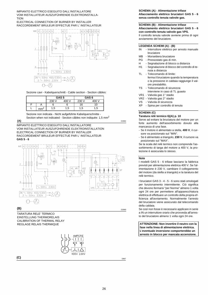
26
SCHEMA (A) - Alimentazione trifaseAllacciamento elettrico bruciatori GAS 5 - 6senza controllo tenuta valvole gas.
SCHEMA (B) - Alimentazione trifaseAllacciamento elettrico bruciatori GAS 5 - 6con controllo tenuta valvole gas VPS.Il controllo tenuta valvole avviene prima di ogniavviamento del bruciatore.
LEGENDA SCHEMI (A) - (B)IN - Interruttore elettrico per arresto manuale
bruciatoreMB - Morsettiera bruciatorePG - Pressostato gas di min.H - Segnalazione di blocco a distanzaH1 - Segnalazione di blocco del controllo di te-
nuta a distanzaTL - Telecomando di limite:
ferma il bruciatore quando la temperaturao la pressione in caldaia raggiunge il val-ore prestabilito.
TS - Telecomando di sicurezza:interviene in caso di TL guasto
VR1 - Valvola gas 1° stadioVR2 - Valvola gas 2° stadioVS - Valvola di sicurezzaXP - Spina per controllo di tenuta
SCHEMA (C)Taratura relè termico 6)(A) p. 10Serve ad evitare la bruciatura del motore per unforte aumento dell'assorbimento dovuto allamancanza di una fase.- Se il motore è alimentato a stella, 400 V, il cur-
sore va posizionato sul "MIN".- Se è alimentato a triangolo, 230 V, il cursore va
posizionato sul "MAX".Se la scala del relè termico non comprende l'as-sorbimento di targa del motore a 400 V, la pro-tezione è assicurata lo stesso.
NoteI modelli GAS 5 - 6 trifase lasciano la fabbricaprevisti per alimentazione elettrica 400 V. Se l'al-imentazione è 230 V, cambiare il collegamentodel motore (da stella a triangolo) e la taratura delrelè termico.
I bruciatori GAS 3 - 4 - 5 - 6 sono stati omologatiper funzionamento intermittente. Ciò significache devono fermarsi "per Norma" almeno 1 voltaogni 24 ore per permettere all'apparecchiaturaelettrica di effettuare un controllo della propria ef-ficienza all'avviamento. Normalmente l'arrestodel bruciatore viene assicurato dal telecomandodella caldaia.Se così non fosse è necessario applicare in seriea IN un interruttore orario che provveda all'arres-to del bruciatore almeno 1 volta ogni 24 ore.
ATTENZIONE: Non invertire il neutro con la fase nella linea di alimentazione elettrica. L'eventuale inversione comporterebbe un arresto in blocco per mancata accensione.
(C)
IMPIANTO ELETTRICO ESEGUITO DALL’INSTALLATOREVOM INSTALLATEUR AUSZUFÜHRENDE ELEKTROINSTALLA-TIONELECTRICAL CONNECTION OF BURNER BY INSTALLERRACCORDEMENT BRULEUR EFFECTUE PAR L’ INSTALLATEUR
IMPIANTO ELETTRICO ESEGUITO DALL’INSTALLATOREVOM INSTALLATEUR AUSZUFÜHRENDE ELEKTROINSTALLATIONELECTRICAL CONNECTION OF BURNER BY INSTALLERRACCORDEMENT BRULEUR EFFECTUE PAR L’ INSTALLATEURGAS 5 - 6
D867
Sezione cavi - Kabelquerschnitt - Cable section - Section câbles:
Sezione non indicata - Nicht aufgeführte Kabelquerschnitte - Section when not indicated - Section câbles non indiquée: 1,5 mm2
GAS 5 GAS 6230 V 400 V 230 V 400 V
F A 6 6 16 10L mm2 1,5 1,5 1,5 1,5
(A)
(B)
TARATURA RELE’ TERMICOEINSTELLUNG THERMORELAISCALIBRATION OF THERMAL RELAYREGLAGE RELAIS THERMIQUE
D2862
D2860

27
SCHEMA (A) - DreiphasenspeisungElektroanschluß der Brenner GAS 5 - 6 ohneDichtheitskontrolle der Gasventile.
SCHEMA (B) - DreiphasenspeisungElektroanschluß der Brenner GAS 5 - 6 mitDichtheitskontrolle VPS der Gasventile.Die Dichtheitskontrolle der Gasventile erfolgtumgehend vor jedem Brennerstart.
ZEICHENERKLÄRUNG SCHEMEN (A) - (B)IN - Schalter für das manuelle Ausschalten
des BrennersMB - Klemmleiste BrennerPG - Gas-MindestdruckwächterH - Störabschaltung-FernmeldungH1 - Störabschaltung-Fernmeldung der Dich-
theitskontrolleTL - Begrenzungsfernsteuerung:
schaltet den Brenner aus, wenn die Tem-peratur oder der Kesseldruck den festge-legten Höchstwert erreichen.
TS - Sicherheitsfernsteuerung:tritt bei Defekt an TL in Aktion.
VR1 - Gasventil 1. StufeVR2 - Gasventil 2. StufeVS - SicherheitsventilXP - Stecker für die Dichtheitskontrolleinrich-
tung
SCHEMA (C)Einstellung Überstromauslöser 6)(A) S.10Dieses schützt den Motor vor dem Durchbren-nen wegen erhöhter Stromaufnahme infolge desAusfallens einer Phase.- Wenn der Motor über eine Sternschaltung mit
400 V- gespeist wird, muß der Zeiger auf"MIN"- Stellung positioniert werden.
-Bei Dreieck-Schaltung mit 230 V- Spannung,muß der Zeiger auf "MAX" gestellt werden.
Obwohl die Skala des Überstromauslösers nichtdie Entnahmewerte vorsieht, die auf dem Typen-schild des 400 V-Motors angegeben sind, wirdder Schutz trotzdem gewährleistet.
MerkeDie Modelle GAS 5 - 6 dreiphasig werden werk-seitig für 400 V Stromversorgung vorbereitet.Falls die Stromversorgung 230 V beträgt, denMotoranschluß (Stern- oder Dreieck-schaltung)und die Einstellung des Überstromauslösersverändern.
Die Brenner GAS 3 - 4 - 5 - 6 sind für intermit-tierenden Betrieb typgeprüft. Das bedeutet, daßsie - laut Vorschrift - wenigstens einmal pro 24Stunden ausgeschaltet werden müssen, damitdie Steuergeräte eine Prüfung ihrer Funktion-stüchtigkeit bei Anfahren durchführen könnenDas Ausschalten erfolgt gewöhnlich über dieFernsteuerung des Kessels.Sollte dies nicht der Fall sein, muß an IN einZeitschalter reihengeschaltet werden, der einBrennerausschalten einmal in 24 Stundengewährleistet.
ACHTUNG: Den Nulleiter nicht mit dem Phasenleiter in der Leitung der Stromver-sorgung vertauschen. Die Folge einer sol-chen Vertauschung wäre eine Störabschaltung wegen nicht erfolgter Zündung.
LAYOUT (A) - The GAS 5 - 6 Models electricalconnection three-phase power supply with-out leak detection control device.
LAYOUT (B) - The GAS 5 - 6 Models electricalconnection three-phase power supply withVPS leak detection control device.Gas valve leak detection control takes placeimmediately before every burner starting.
KEY TO LAYOUTS (A) - (B)IN - Manual burner stop switchMB - Burner terminal stripPG - Min. gas pressure switchH - Remote lock-out signalH1 - Remote lock-out signal of leak detection
control deviceTL - Load limit remote control system:
shuts down the burner when the boilertemperature or pressure reaches the pre-set value.
TS - Safety load control system:operates when TL is faulty
VR1 - Gas valve, stage 1VR2 - Gas valve, stage 2VS - Safety valveXP - Plug for leak detection control device
LAYOUT (C)Calibration of thermal cut-out 6)(A) p. 10This is required to avoid motor burn-out in theevent of a significant increase in power absorp-tion caused by a missing phase.- If the motor is star-powered, 400 V, the cursor
should be positioned to "MIN". - If the motor is delta-powered, 230 V, the cursor
should be positioned to "MAX".Even if the scale of the thermal cut-out does notinclude rated motor absorption at 400 V, protec-tion is still ensured in any case.
N.B.Models GAS 5 - 6 three-phase leave the factorypreset for 400 V power supply. If 230 V powersupply is used, change the motor connectionfrom star to delta and change the setting of thethermal cut-out as well.
The GAS 3 - 4 - 5 - 6 burners have been type- ap-proved for intermittent operation. This meansthey should compulsorily be stopped at leastonce every 24 hours to enable the control box tocheck its own efficiency at start-up. Burner haltsare normally provided for automatically by theboiler load control system.If this is not the case, a time switch should be fit-ted in series to IN to provide for burner shut-down at least once every 24 hours.
WARNING: Do not invert the neutral with the phase wire in the electricity supply line. Inverting the wires will make the burner go into lock-out because of firing failure
SCHEMA (A) - Alimentation triphaséeBranchement électrique brûleurs GAS 5 - 6sans dispositif de contrôle d'étanchéité.
SCHEMA (B) - Alimentation triphaséeBranchement électrique brûleurs GAS 5 - 6avec dispositif de contrôle d'étanchéité VPS.Le contrôle d'étanchéité des vannes se fait justeavant chaque mise en marche du brûleur.
LEGENDE SCHEMAS (A) - (B)IN - Interrupteur électrique pour arrêt manuel
brûleurMB - Porte-bornes brûleurPG - Pressostat gaz seuil minimumH - Signalisation blocage brûleur à distanceH1 - Signalisation blocage contrôle
d'étanchéité à distanceTL - Télécommande de limite:
arrête le brûleur quand la température oula pression dans la chaudière a atteint lavaleur fixée.
TS - Télécommande de sécurité:intervient quand le TL tombe en panne
VR1 - Vanne gaz, 1ère allureVR2 - Vanne gaz, 2ème allureVS - Vanne gaz de sécuritéXP - Fiche pour le contrôle d'étanchéité
SCHEMA (C)Réglage relais thermique 6)(A) p. 10Sert à éviter que le moteur brûle a cause d'uneforte augmentation de l'absorption due à l'ab-sence d'une phase.- Si le moteur est alimenté en étoile, 400 V, le
curseur doit être placé sur "MIN".- S'il est alimenté en triangle, 230 V, le curseur
doit être placé sur "MAX".Si l'échelle du relais thermique ne comprend pasl'absorption indiquée sur la plaque du moteur à400 V, la protection est quand même assurée.
NoteLes modèles GAS 5 - 6 triphasés quittent l'usineprévus pour l'alimentation électrique à 400 V. Sil'alimentation est à 230 V, changer la connexiondu moteur (d'étoile à triangle) et le réglage durelais thermique.
Les modèles GAS 3 - 4 - 5 - 6 ont été homo-logués pour fonctionner de façon intermittente.Cela veut dire qu'ils doivent s'arrêter selon lesnormes au moins 1 fois toutes les 24 heurespour permettre au boîtier d'effectuer un contrôlede son efficacité au moment du démarrage. Nor-malement l'arrêt du brûleur est assuré par lethermostat de la chaudière. S'il n'en était pasainsi, il faudrait appliquer en série au IN un inter-rupteur horaire qui commanderait l'arrêt du brû-leur au moins 1 fois toutes les 24 heures.
ATTENTION: Dans la ligne d'alimentation électrique, ne pas inverser le neutre avec la phase. L'inversion éventuelle provoquerait un blocage dû à l'absence d'allumage.

28
REGOLAZIONI PRIMA DELL'ACCENSIONELa regolazione della testa di combustione, aria egas, è già stata descritta a pag. 18. Altre regolazioni da fare sono:- Aprire le valvole manuali poste a monte della
rampa del gas.- Regolare il pressostato aria all'inizio scala (A).- Regolare il pressostato gas di minima all'inizio
scala (B).- Sfiatare l'aria dalla tubazione del gas.
E' consigliabile portare all'esterno dell'edificiocon un tubo in plastica l'aria sfiatata fino adavvertire l'odore del gas.
- Montare un manometro a U (C) sulla presa dipressione del gas del manicotto.Serve a ricavare approssimativamente la po-tenza del bruciatore mediante i diagrammi dipag. 14.
- Collegare in parallelo alle due elettrovalvole delgas VR e VS due lampadine o tester per contr-ollare il momento dell'arrivo della tensione.Questa operazione non è necessaria se ognu-na delle due elettrovalvole è munita di una spialuminosa che segnala la tensione elettrica.
- Lasciare com'è la regolazione della serrandaaria (a circa metà della sua corsa).
Prima di accendere il bruciatore, è opportunoregolare la rampa del gas in modo che l'accen-sione avvenga nelle condizioni di massima sicu-rezza e cioè con una piccola portata di gas.
AVVIAMENTO BRUCIATOREChiudere i telecomandi.Appena il bruciatore si avvia controllare il sensodi rotazione del motore. Verificare che le lampadine o i tester collegatialle elettrovalvole, o le spie luminose sulle elet-trovalvole stesse, indichino assenza di tensione.Se segnalano tensione, fermare immediata-mente il bruciatore e controllare i collegamentielettrici.
ACCENSIONE BRUCIATOREDopo aver fatto quanto descritto al punto prece-dente, il bruciatore dovrebbe accendersi. Se in-vece il motore si avvia ma non compare lafiamma e l'apparecchiatura va in blocco, sbloc-care ed attendere un nuovo tentativo d'avvia-mento.Se l'accensione continua a mancare può essereche il gas non arrivi alla testa di combustione en-tro il tempo di sicurezza di 3s. Aumentare allorala portata del gas all'accensione.L'arrivo del gas al manicotto è evidenziato dalmanometro ad U (C). Ad accensione avvenuta, passare alla completaregolazione del bruciatore.
(A)
(B)
PRESSOSTATO ARIALUFT-DRUCKWÄCHTER AIR PRESSURE SWITCHPRESSOSTAT AIR
PRESSOSTATO GAS DI MINIMAGAS-MINDESTDRUCKWÄCHTERMIN. GAS PRESSURE SWITCH PRESSOSTAT GAZ MINIMUM
(C)
MANOMETRO A UU-ROHR-MANOMETERU-TYPE MANOMETER MANOMETRE EN U
D896
D68
D215
29
EINSTELLUNGEN VOR DER ZÜNDUNGDie Einstellung des Flammkopfs, von Luft undGas, ist bereits auf Seite 19 beschriebenworden.Weitere Einstellungen sind:- Handbetätigte Ventile vor der Gasarmatur öff-
nen.- Den Luft-Druckwächter auf den Skalenanfang-
swert (A) einstellen.- Den Gas-Mindestdruckwächter auf den Ska-
lenanfangswert (B) einstellen.- Die Luft aus der Gasleitung entlüften.
Es wird empfohlen, die abgelassene Luft übereinen Kunststoffschlauch ins Freie abzuführen,bis der Gasgeruch wahrnehmbar ist.
- Ein U Manometer (C) auf den Gasanschluß derMuffe einbauen.Hiermit wird die ungefähre Brennerleistung an-hand des Diagramms auf Seite 14 ermittelt.
- Parallel zu den beiden Gas-Magnetventilen VRund VS zwei Glühbirnen oder einen Tester an-schließen, um den Zeitpunkt der Spannungs-zufuhr zu überprüfen.Dieses Verfahren ist nicht notwendig, falls diebeiden Magnetventile mit einer Kontrollampeausgestattet sind, die die Elektrospannung an-zeigt.
- Luftklappenposition nicht ändern (ungefährmittlere Position).
Vor dem Zünden des Brenners sind die Gasar-maturen so einzustellen, daß die Zündung unterBedingungen höchster Sicherheit bei einem ger-ingen Gasdurchsatz erfolgt.
ANFAHREN DES BRENNERSDie Fernsteuerungen schließen.Sobald der Brenner anfährt, den Drehsinn desMotors kontrollieren. Kontrollieren, daß an den an die Magnetventileangeschlossenen Kontrollampen und Span-nungsmessern, oder an den Kontrollampen aufden Magnetventilen, keine Spannung anliegt.Wenn Spannung vorhanden ist, sofort den Bren-ner ausschalten und die Elektroanschlüsseüberprüfen.
ZÜNDUNG DES BRENNERSWenn alle vorab angeführten Anleitungenbeachtet worden sind, müßte der Brenner an-fahren. Wenn hingegen der Motor läuft, aber dieFlamme nicht erscheint und eine Geräte-Störab-schaltung erfolgt, entriegeln und das Anfahrenwiederholen.Sollte die Zündung immer noch nicht stattfinden,könnte dies davon abhängen, daß das Gas nichtinnerhalb der vorbestimmten Sicherheitszeit von3 s den Flammkopf erreicht. In diesem Fall denGasdurchsatz bei Zündung erhöhen. Das U-Rohr-Manometer (C) zeigt den Gaseintritt an derMuffe an. Nach erfolgter Zündung den Brenner vollständigeinstellen.
ADJUSTMENTS BEFORE FIRST FIRINGAdjustment of the combustion head, and air andgas deliveries has been illustrated on page 19. In addition, the following adjustments must alsobe made:- Open manual valves up-line from the gas train.- Adjust the air pressure switch to the zero posi-
tion of the scale (A).- Adjust the minimum gas pressure switch to the
start of the scale (B).- Purge the air from the gas line.
Continue to purge the air (we recommend us-ing a plastic tube routed outside the building)until gas is smelt.
- Fit a U-type manometer (C) to the gas pressuretest point on the sleeve.The manometer readings are used to calculatethe operation burner power using the graphson page 14.
- Connect two lamps or testers to the two gasline solenoid valves VR and VS to check theexact moment at which voltage is supplied.This operation is unnecessary if each of thetwo solenoid valves is equipped with a pilotlight that signals voltage passing through.
- Leave the air gate valve calibration as it is (i.e.about half way across its stroke).
Before starting up the burner it is good practiceto adjust the gas train so that ignition takesplace in conditions of maximum safety, i.e. withgas delivery at the minimum.
BURNER STARTINGClose the remote control devices.As soon as the burner starts check the directionof rotation of the motor. Make sure that the lamps or testers connected tothe solenoids, or pilot lights on the solenoidsthemselves, indicate that no voltage is present. Ifvoltage is present, then immediately stop theburner and check electrical connections.
BURNER FIRINGHaving completed the checks indicated in theprevious heading, the burner should fire. If themotor starts but the flame does not appear andthe control box goes into lock-out, reset and waitfor a new firing attempt.If firing is still not achieved, it may be that gas isnot reaching the combustion head within thesafety time period of 3 seconds.In this case increase gas firing delivery.The arrival of gas at the sleeve is indicated by theU-type manometer (C).Once the burner has fired, you can now proceedwith global calibration operations.
REGLAGES AVANT L'ALLUMAGELe réglage de la tête de combustion, air et gaz,a déjà été décrit page 19. Les autres réglages à effectuer sont les sui-vants:- Ouvrir les vannes manuelles situées en amont
de la rampe du gaz.- Régler le pressostat air en début d'échelle (A).- Régler le pressostat de seuil minimum gaz en
début d'échelle (B).- Purger le conduit gaz de l'air.
Il est conseillé d'évacuer l'air purgé en dehorsdes locaux par un tuyau en plastique jusqu'à ceque l'on sente l'odeur caractéristique du gaz.
- Monter un manomètre en U (C) sur la prise depression du gaz du manchon.Celui-ci servira à mesurer approximativementla puissance du brûleur à l'aide des dia-grammes de la page 14.
- Raccorder en parallèle aux deux électrovannesdu gaz VR et VS deux lampes ou testeurs pourcontrôler le moment de la mise sous tension.Cette opération n'est pas nécessaire si cha-cune des deux electrovannes est munie d'unvoyant lumineux signalant la tension élec-trique.
- Ne pas modifier l'étalonnage du volet air (à en-viron la moitié de sa course).
Avant d'allumer le brûleur, régler la rampe dugaz afin que l'allumage se fasse dans les condi-tions de sécurité maximum, c'est à dire avec undébit de gaz très faible.
DEMARRAGE BRULEURFermer les télécommandes.Dès que le brûleur démarre, contrôler le sens derotation du moteur. Vérifier que les ampoules ou les testeurs rac-cordés aux électrovannes, ou les voyants sur lesélectrovannes, indiquent une absence de ten-sion. S'ils signalent une tension, arrêter immédi-atement le brûleur et contrôler lesraccordements électriques.
ALLUMAGE BRULEURAprès avoir effectué les opérations décrites aupoint précédent, le brûleur devrait s'allumer. Si lemoteur démarre mais la flamme n'apparaît paset le boîtier de contrôle se bloque, réarmer etfaire une nouvelle tentative de démarrage.Si l'allumage ne se fait toujours pas, il se peutque le gaz n'arrive pas à la tête de combustiondans le temps de sécurité de 3 s. Dans ce cas,augmenter le débit du gaz à l'allumage. L'arrivéedu gaz au manchon est mise en évidence par lemanomètre en U (C). Quand l'allumage est fait, passer au réglagecomplet du brûleur.
30
REGOLAZIONE BRUCIATOREPer ottenere una regolazione ottimale del bruci-atore è necessario effettuare l'analisi dei gas discarico della combustione all'uscita dellacaldaia.
Regolare in successione:(con rampa gas secondo norma EN 676)1 - Potenza all'accensione2 - Potenza massima bruciatore3 - Pressostato aria4 - Pressostato gas di minima
1 - POTENZA ALL’ACCENSIONESecondo norma EN 676.
Bruciatori con potenza MAX fino a 120 kWL'accensione può avvenire alla potenza max difunzionamento. Esempio:• potenza max di funzionamento : 120 kW• potenza max all'accensione : 120 kW
Bruciatori con potenza MAX oltre i 120 kWL'accensione deve avvenire ad una potenzaridotta rispetto alla potenza max di funziona-mento.Se la potenza all'accensione non supera i 120kW, nessun calcolo è necessario. Se invece lapotenza all'accensione supera i 120 kW, lanorma stabilisce che il suo valore sia definito infunzione del tempo di sicurezza "ts" dell'appa-recchiatura elettrica:• per ts = 2s la potenza all'accensione deve
essere uguale o inferiore a 1/2 della potenzamassima di funzionamento;
• per ts = 3s la potenza all'accensione deveessere uguale o inferiore a 1/3 della potenzamassima di funzionamento.
Esempio: potenza MAX di funzionamento 600 kW.La potenza all'accensione deve essere uguale oinferiore a:• 300 kW con ts = 2 s;• 200 kW con ts = 3 s.
Per misurare la potenza all'accensione:- Scollegare la spina-presa 15)(A)p.10 sul cavo
della sonda di ionizzazione (il bruciatore siaccende e va in blocco dopo il tempo di sicu-rezza).
- Eseguire 10 accensioni con blocchi consecu-tivi.
- Leggere al contatore la quantità di gas bruci-ata.Questa quantità deve essere uguale o inferi-ore a quella data dalla formula:
Esempio per gas G 20 (10 kWh/Nm3):potenza max. di funzionamento, 600 kW
corrispondenti a 60 Nm3/h.Dopo 10 accensioni con blocco la portata lettaal contatore deve essere uguale o minore di:
60 : 360 = 0,166 Nm3.
Nm3/h (portata max. bruciatore)
360

31
BRENNEREINSTELLUNGFür die optimale Einstellung des Brenners soll-ten die Abgase am Kesselausgang analysiertwerden.
Nacheinander einstellen:(Gasarmaturen gemäß Norm EN 676)1 - Zündleistung2 - Höchstleistung des Brenners3 - Luft-Druckwächter4 - Gas-Mindestdruckwächter
1 - ZÜNDLEISTUNGNach Norm EN 676.
Brenner mit Höchstleistung bis 120 kWDie Zündung kann bei der höchsten Betriebslei-stung erfolgen. Beispiel:• höchste Betriebsleistung : 120 kW• höchste Zündleistung : 120 kW
Brenner mit Höchstleistung über 120 kWDie Zündung hat bei einer verringerten Leistungim Vergleich zur höchsten Betriebsleistung zuerfolgen. Falls die Zündleistung 120 kW nichtüberschreitet, ist keine Berechnung erforderlich.Falls die Zündleistung dagegen 120 kW über-schreitet, legt die Norm fest, daß ihr Wert inAbhängigkeit von der Sicherheitszeit "ts" desSteuergerätes definiert wird:• für ts = 2s muß die Zündleistung gleich oder
unter 1/2 der höchsten Betriebsleistung lie-gen;
• für ts = 3s muß die Zündleistung gleich oderunter 1/3 der höchsten Betriebsleistung lie-gen.
Beispiel: höchste Betriebsleistung 600 kW.Die Zündleistung muß gleich oder unter sein:• 300 kW bei ts = 2 s;• 200 kW bei ts = 3 s.
Zur Messung der Zündleistung:- Den Steckkontakt 15)(A)S.10 vom Kabel der
Ionisationssonde abtrennen (der Brennerschaltet ein und geht nach der Sicherheitszeitin Störabschaltung).
- 10 Zündungen mit darauffolgenden Störab-schaltungen durchführen.
- Am Zähler die verbrennte Gasmenge ablesen.Diese Menge muß gleich oder unter jener sein,die durch die Formel gegeben wird:
Beispiel für Gas G 20 (10 kWh/Nm3):höchste Betriebsleistung 600 kW
gleich 60 Nm3/h.Nach 10 Zündungen mit Störabschaltung mußder am Zähler abgelesene Durchsatz gleichoder unter:
60 : 360 = 0,166 Nm3.
Nm3/h (Höchstleistung des Brenners)
360
BURNER CALIBRATIONThe optimum calibration of the burner requiresan analysis of the flue gases at the boiler outlet.
Adjust successively(with gas train according to EN 676 Regulations )1 - First firing output2 - Maximum output of the burner3 - Air pressure switch4 - Minimum gas pressure switch
1 - FIRING OUTPUTAccording to EN 676 Regulations.
Burners with MAX output up to 120 kWFiring can be performed at the maximum opera-tion output level. Example:• max operation output : 120 kW• max firing output : 120 kW
Burners with MAX output above 120 kWFiring must be performed at a lower output thanthe max. operation output. If the firing outputdoes not exceed 120 kW, no calculations arerequired. If firing output exceeds 120 kW, theregulations prescribe that the value be definedaccording to the control box safety time "ts":• for "ts" = 2s, firing output must be equal to or
lower than 1/2 of max. operation output;• for "ts" = 3s, firing output must be equal to or
lower than 1/3 of max. operation output.
Example: MAX operation output of 600 kW.Firing output must be equal to or lower than:• 300 kW with ts = 2 s;• 200 kW with ts = 3 s.
In order to measure the firing output:- Disconnect the plug-socket 15)(A)p.10 on the
ionization probe cable (the burner will fire andthen go into lock-out after the safety time haselapsed).
- Perform 10 firings with consecutive lock-outs.- On the meter read the quantity of gas burned.
This quantity must be equal to or lower than thequantity given by the formula:
Example for G 20 gas (10 kWh/Nm3):Max. operation output: 600 kW corresponding to
60 Nm3/h.After 10 firings with lock-outs, the delivery readon the meter must be equal to or lower than:
60 : 360 = 0,166 Nm3.
Nm3/h (max. burner delivery)
360
REGLAGE BRULEURPour obtenir un réglage optimal du brûleur, ilfaut effectuer l'analyse des gaz d'échappementde la combustion à la sortie de la chaudière.
Régler en succession:(avec rampe gaz selon la norme EN 676)1 - Puissance à l'allumage:2 - Puissance maximum du brûleur3 - Pressostat air4 - Pressostat seuil minimum du gaz
1 - PUISSANCE A L'ALLUMAGESelon la norme EN 676.
Brûleurs avec puissance MAX jusqu'à 120 kWL'allumage peut se faire à la puissance maxi-mum de fonctionnement. Exemple:• puissance max de fonctionnement : 120 kW• puissance max à l'allumage : 120 kW
Brûleurs à puissance MAX au delà des 120 kWL'allumage doit se faire à une puissance réduitepar rapport à la puissance maximum de fonction-nement.Si la puissance à l'allumage ne dépasse pas 120kW, aucun calcul n'est nécessaire. Au contraire,si la puissance à l'allumage dépasse 120 kW, lanorme établit que sa valeur soit définie en fonc-tion du temps de sécurité "ts" du coffret de sécu-rité:• pour ts = 2s la puissance à l'allumage doit
être égale ou inférieure à 1/2 de la puissancemaximum de fonctionnement;
• pour ts = 3s la puissance à l'allumage doitêtre égale ou inférieure à 1/3 de la puissancemaximum de fonctionnement.
Exemple: puissance MAX de fonctionnement 600 kW.La puissance à l'allumage doit être égale ouinférieure à:• 300 kW avec ts = 2 s;• 200 kW avec ts = 3 s.
Pour mesurer la puissance à l'allumage:- Débrancher la fiche-prise 15)(A)p.10 sur le câ-
ble de la sonde d'ionisation (le brûleur s'allumeet se bloque après le temps de sécurité).
- Exécuter 10 allumages avec blocages con-sécutifs.
- Lire au compteur la quantité de gaz brûlée.Cette quantité doit être égale ou inférieure àcelle donnée par la formule:
Exemple pour du gaz G 20 (10 kWh/Nm3):puissance maximum de fonctionnement, 600 kW
correspondants à 60 Nm3/h.Après 10 allumages avec blocage le débit lu aucompteur doit être égal ou inférieur à:
60 : 360 = 0,166 Nm3.
Nm3/h (débit max. brûleur)
360
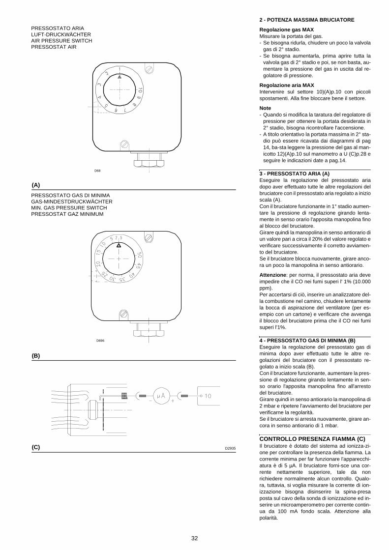
32
2 - POTENZA MASSIMA BRUCIATORE
Regolazione gas MAXMisurare la portata del gas.- Se bisogna ridurla, chiudere un poco la valvola
gas di 2° stadio. - Se bisogna aumentarla, prima aprire tutta la
valvola gas di 2° stadio e poi, se non basta, au-mentare la pressione del gas in uscita dal re-golatore di pressione.
Regolazione aria MAXIntervenire sul settore 10)(A)p.10 con piccolispostamenti. Alla fine bloccare bene il settore.
Note- Quando si modifica la taratura del regolatore di
pressione per ottenere la portata desiderata in2° stadio, bisogna ricontrollare l'accensione.
- A titolo orientativo la portata massima in 2° sta-dio può essere ricavata dai diagrammi di pag14, ba-sta leggere la pressione del gas al man-icotto 12)(A)p.10 sul manometro a U (C)p.28 eseguire le indicazioni date a pag.14.
3 - PRESSOSTATO ARIA (A)Eseguire la regolazione del pressostato ariadopo aver effettuato tutte le altre regolazioni delbruciatore con il pressostato aria regolato a inizioscala (A).Con il bruciatore funzionante in 1° stadio aumen-tare la pressione di regolazione girando lenta-mente in senso orario l'apposita manopolina finoal blocco del bruciatore.Girare quindi la manopolina in senso antiorario diun valore pari a circa il 20% del valore regolato everificare successivamente il corretto avviamen-to del bruciatore.Se il bruciatore blocca nuovamente, girare anco-ra un poco la manopolina in senso antiorario.
Attenzione: per norma, il pressostato aria deveimpedire che il CO nei fumi superi l' 1% (10.000ppm). Per accertarsi di ciò, inserire un analizzatore del-la combustione nel camino, chiudere lentamentela bocca di aspirazione del ventilatore (per es-empio con un cartone) e verificare che avvengail blocco del bruciatore prima che il CO nei fumisuperi l'1%.
4 - PRESSOSTATO GAS DI MINIMA (B)Eseguire la regolazione del pressostato gas diminima dopo aver effettuato tutte le altre re-golazioni del bruciatore con il pressostato re-golato a inizio scala (B).Con il bruciatore funzionante, aumentare la pres-sione di regolazione girando lentamente in sen-so orario l'apposita manopolina fino all'arrestodel bruciatore.Girare quindi in senso antiorario la manopolina di2 mbar e ripetere l'avviamento del bruciatore perverificarne la regolarità.Se il bruciatore si arresta nuovamente, girare an-cora in senso antiorario di 1 mbar.
CONTROLLO PRESENZA FIAMMA (C)Il bruciatore è dotato del sistema ad ionizza-zi-one per controllare la presenza della fiamma. Lacorrente minima per far funzionare l'apparecchi-atura è di 5 µA. Il bruciatore forni-sce una cor-rente nettamente superiore, tale da nonrichiedere normalmente alcun controllo. Qualo-ra, tuttavia, si voglia misurare la corrente di ion-izzazione bisogna disinserire la spina-presaposta sul cavo della sonda di ionizzazione ed in-serire un microamperometro per corrente contin-ua da 100 mA fondo scala. Attenzione allapolarità.
(A)
(B)
PRESSOSTATO ARIALUFT-DRUCKWÄCHTERAIR PRESSURE SWITCHPRESSOSTAT AIR
PRESSOSTATO GAS DI MINIMAGAS-MINDESTDRUCKWÄCHTER MIN. GAS PRESSURE SWITCHPRESSOSTAT GAZ MINIMUM
(C)
D68
D896
D2935
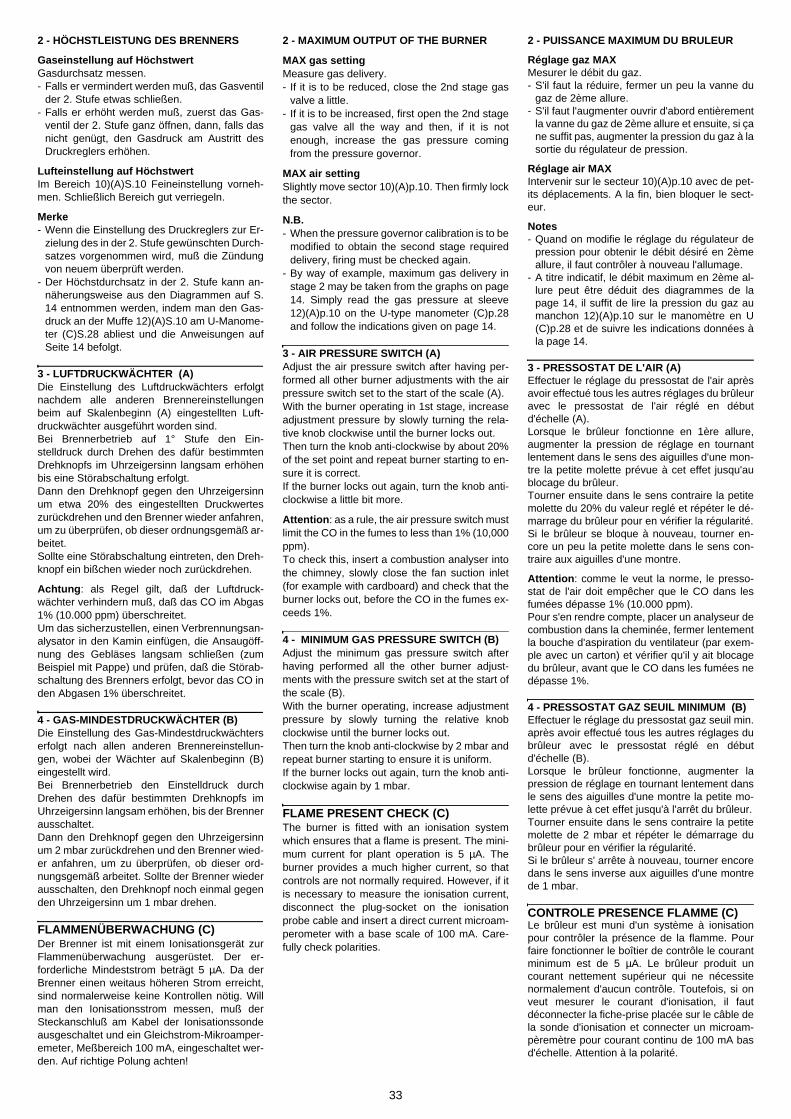
33
2 - MAXIMUM OUTPUT OF THE BURNER
MAX gas settingMeasure gas delivery.- If it is to be reduced, close the 2nd stage gas
valve a little.- If it is to be increased, first open the 2nd stage
gas valve all the way and then, if it is notenough, increase the gas pressure comingfrom the pressure governor.
MAX air settingSlightly move sector 10)(A)p.10. Then firmly lockthe sector.
N.B.- When the pressure governor calibration is to be
modified to obtain the second stage requireddelivery, firing must be checked again.
- By way of example, maximum gas delivery instage 2 may be taken from the graphs on page14. Simply read the gas pressure at sleeve12)(A)p.10 on the U-type manometer (C)p.28and follow the indications given on page 14.
3 - AIR PRESSURE SWITCH (A)Adjust the air pressure switch after having per-formed all other burner adjustments with the airpressure switch set to the start of the scale (A).With the burner operating in 1st stage, increaseadjustment pressure by slowly turning the rela-tive knob clockwise until the burner locks out.Then turn the knob anti-clockwise by about 20%of the set point and repeat burner starting to en-sure it is correct.If the burner locks out again, turn the knob anti-clockwise a little bit more.
Attention: as a rule, the air pressure switch mustlimit the CO in the fumes to less than 1% (10,000ppm).To check this, insert a combustion analyser intothe chimney, slowly close the fan suction inlet(for example with cardboard) and check that theburner locks out, before the CO in the fumes ex-ceeds 1%.
4 - MINIMUM GAS PRESSURE SWITCH (B)Adjust the minimum gas pressure switch afterhaving performed all the other burner adjust-ments with the pressure switch set at the start ofthe scale (B).With the burner operating, increase adjustmentpressure by slowly turning the relative knobclockwise until the burner locks out.Then turn the knob anti-clockwise by 2 mbar andrepeat burner starting to ensure it is uniform.If the burner locks out again, turn the knob anti-clockwise again by 1 mbar.
FLAME PRESENT CHECK (C)The burner is fitted with an ionisation systemwhich ensures that a flame is present. The mini-mum current for plant operation is 5 µA. Theburner provides a much higher current, so thatcontrols are not normally required. However, if itis necessary to measure the ionisation current,disconnect the plug-socket on the ionisationprobe cable and insert a direct current microam-perometer with a base scale of 100 mA. Care-fully check polarities.
2 - PUISSANCE MAXIMUM DU BRULEUR
Réglage gaz MAXMesurer le débit du gaz.- S'il faut la réduire, fermer un peu la vanne du
gaz de 2ème allure.- S'il faut l'augmenter ouvrir d'abord entièrement
la vanne du gaz de 2ème allure et ensuite, si çane suffit pas, augmenter la pression du gaz à lasortie du régulateur de pression.
Réglage air MAXIntervenir sur le secteur 10)(A)p.10 avec de pet-its déplacements. A la fin, bien bloquer le sect-eur.
Notes- Quand on modifie le réglage du régulateur de
pression pour obtenir le débit désiré en 2èmeallure, il faut contrôler à nouveau l'allumage.
- A titre indicatif, le débit maximum en 2ème al-lure peut être déduit des diagrammes de lapage 14, il suffit de lire la pression du gaz aumanchon 12)(A)p.10 sur le manomètre en U(C)p.28 et de suivre les indications données àla page 14.
3 - PRESSOSTAT DE L'AIR (A)Effectuer le réglage du pressostat de l'air aprèsavoir effectué tous les autres réglages du brûleuravec le pressostat de l'air réglé en débutd'échelle (A).Lorsque le brûleur fonctionne en 1ère allure,augmenter la pression de réglage en tournantlentement dans le sens des aiguilles d'une mon-tre la petite molette prévue à cet effet jusqu'aublocage du brûleur.Tourner ensuite dans le sens contraire la petitemolette du 20% du valeur reglé et répéter le dé-marrage du brûleur pour en vérifier la régularité.Si le brûleur se bloque à nouveau, tourner en-core un peu la petite molette dans le sens con-traire aux aiguilles d'une montre.
Attention: comme le veut la norme, le presso-stat de l'air doit empêcher que le CO dans lesfumées dépasse 1% (10.000 ppm). Pour s'en rendre compte, placer un analyseur decombustion dans la cheminée, fermer lentementla bouche d'aspiration du ventilateur (par exem-ple avec un carton) et vérifier qu'il y ait blocagedu brûleur, avant que le CO dans les fumées nedépasse 1%.
4 - PRESSOSTAT GAZ SEUIL MINIMUM (B)Effectuer le réglage du pressostat gaz seuil min.après avoir effectué tous les autres réglages dubrûleur avec le pressostat réglé en débutd'échelle (B).Lorsque le brûleur fonctionne, augmenter lapression de réglage en tournant lentement dansle sens des aiguilles d'une montre la petite mo-lette prévue à cet effet jusqu'à l'arrêt du brûleur.Tourner ensuite dans le sens contraire la petitemolette de 2 mbar et répéter le démarrage dubrûleur pour en vérifier la régularité.Si le brûleur s' arrête à nouveau, tourner encoredans le sens inverse aux aiguilles d'une montrede 1 mbar.
CONTROLE PRESENCE FLAMME (C)Le brûleur est muni d'un système à ionisationpour contrôler la présence de la flamme. Pourfaire fonctionner le boîtier de contrôle le courantminimum est de 5 µA. Le brûleur produit uncourant nettement supérieur qui ne nécessitenormalement d'aucun contrôle. Toutefois, si onveut mesurer le courant d'ionisation, il fautdéconnecter la fiche-prise placée sur le câble dela sonde d'ionisation et connecter un microam-pèremètre pour courant continu de 100 mA basd'échelle. Attention à la polarité.
2 - HÖCHSTLEISTUNG DES BRENNERS
Gaseinstellung auf HöchstwertGasdurchsatz messen.- Falls er vermindert werden muß, das Gasventil
der 2. Stufe etwas schließen.- Falls er erhöht werden muß, zuerst das Gas-
ventil der 2. Stufe ganz öffnen, dann, falls dasnicht genügt, den Gasdruck am Austritt desDruckreglers erhöhen.
Lufteinstellung auf HöchstwertIm Bereich 10)(A)S.10 Feineinstellung vorneh-men. Schließlich Bereich gut verriegeln.
Merke- Wenn die Einstellung des Druckreglers zur Er-
zielung des in der 2. Stufe gewünschten Durch-satzes vorgenommen wird, muß die Zündungvon neuem überprüft werden.
- Der Höchstdurchsatz in der 2. Stufe kann an-näherungsweise aus den Diagrammen auf S.14 entnommen werden, indem man den Gas-druck an der Muffe 12)(A)S.10 am U-Manome-ter (C)S.28 abliest und die Anweisungen aufSeite 14 befolgt.
3 - LUFTDRUCKWÄCHTER (A)Die Einstellung des Luftdruckwächters erfolgtnachdem alle anderen Brennereinstellungenbeim auf Skalenbeginn (A) eingestellten Luft-druckwächter ausgeführt worden sind.Bei Brennerbetrieb auf 1° Stufe den Ein-stelldruck durch Drehen des dafür bestimmtenDrehknopfs im Uhrzeigersinn langsam erhöhenbis eine Störabschaltung erfolgt.Dann den Drehknopf gegen den Uhrzeigersinnum etwa 20% des eingestellten Druckwerteszurückdrehen und den Brenner wieder anfahren,um zu überprüfen, ob dieser ordnungsgemäß ar-beitet.Sollte eine Störabschaltung eintreten, den Dreh-knopf ein bißchen wieder noch zurückdrehen.
Achtung: als Regel gilt, daß der Luftdruck-wächter verhindern muß, daß das CO im Abgas1% (10.000 ppm) überschreitet.Um das sicherzustellen, einen Verbrennungsan-alysator in den Kamin einfügen, die Ansaugöff-nung des Gebläses langsam schließen (zumBeispiel mit Pappe) und prüfen, daß die Störab-schaltung des Brenners erfolgt, bevor das CO inden Abgasen 1% überschreitet.
4 - GAS-MINDESTDRUCKWÄCHTER (B)Die Einstellung des Gas-Mindestdruckwächterserfolgt nach allen anderen Brennereinstellun-gen, wobei der Wächter auf Skalenbeginn (B)eingestellt wird.Bei Brennerbetrieb den Einstelldruck durchDrehen des dafür bestimmten Drehknopfs imUhrzeigersinn langsam erhöhen, bis der Brennerausschaltet.Dann den Drehknopf gegen den Uhrzeigersinnum 2 mbar zurückdrehen und den Brenner wied-er anfahren, um zu überprüfen, ob dieser ord-nungsgemäß arbeitet. Sollte der Brenner wiederausschalten, den Drehknopf noch einmal gegenden Uhrzeigersinn um 1 mbar drehen.
FLAMMENÜBERWACHUNG (C)Der Brenner ist mit einem Ionisationsgerät zurFlammenüberwachung ausgerüstet. Der er-forderliche Mindeststrom beträgt 5 µA. Da derBrenner einen weitaus höheren Strom erreicht,sind normalerweise keine Kontrollen nötig. Willman den Ionisationsstrom messen, muß derSteckanschluß am Kabel der Ionisationssondeausgeschaltet und ein Gleichstrom-Mikroamper-emeter, Meßbereich 100 mA, eingeschaltet wer-den. Auf richtige Polung achten!

34
FUNZIONAMENTO BRUCIATORE
AVVIAMENTO BRUCIATORE (A)(con rampa gas a norma EN 676)
• 0s: Chiusura telecomando TL.Inizia il programma dell'apparecchiatu-ra elettrica.
• 2s: Avvio motore ventilatore.La serranda aria è posizionata sullapotenza massima di regolazione.Segue fase di preventilazione: 38 s.
• 40s: Scocca la scintilla dall'elettrodo d'ac-censione.Si aprono la valvola di sicurezza VS ela valvola di regolazione VR , 1° stadio,apertura rapida. Si accende la fiammaad una piccola potenza, punto A.Segue un progressivo aumento dellapotenza, apertura lenta della valvola,fino alla potenza MIN., 1° stadio, puntoB.
• 42s: Si spegne la scintilla.• 50s: Si apre la valvola di regolazione VR, 2°
stadio. La potenza passa progressiva-mente dal 1° al 2° stadio, tratto C-D.Termina il programma dell'apparecchi-atura elettrica.
FUNZIONAMENTO A REGIME (A)Terminato il ciclo d'avviamento, l'apparecchiatu-ra elettrica continua a controllare la presenzadella fiamma e la corretta posizione del pres-sostato aria.
Il bruciatore permane in funzionamento a poten-za costante.Se la temperatura o la pressione in caldaia con-tinua a salire ed apre il telecomando TL, il bruci-atore si ferma, tratto F-G.
Se la fiamma si spegne accidentalmente in fun-zionamento si ha il blocco entro 1 s.
MANCATA ACCENSIONE (B)Se il bruciatore non si accende si ha il blocco en-tro 3 s dall'apertura della valvola del gas e 43 sdopo la chiusura del telecomando TL.
(A)
(B)
ACCENSIONE REGOLARE ORDNUNGSGEMÄSSES ZÜNDEN(n° = secondi dall’istante 0) (n° = Sekunden ab Zeitpunkt 0)
NORMAL FIRING ALLUMAGE REGULIER(n° = seconds from istant 0) (n° = secondes à partir de l’istant 0)
MANCATA ACCENSIONE NICHTZÜNDEN
NO FIRING LE BRULEUR NE S’ALLUME PAS
D2936
D2937
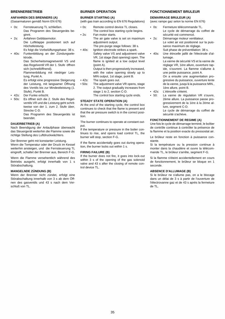
35
BURNER OPERATION
BURNER STARTING (A)(with gas train according to EN 676 Regulations)
• 0s: Remote control device TL closes.The control box starting cycle begins.
• 2s: Fan motor starts.The air gate valve is set on maximumadjustment output.The pre-purge stage follows: 38 s.
• 40s: Ignition electrode strikes a spark.Safety valve VS and adjustment valveVR, 1st stage (fast opening) open. Theflame is ignited at a low output level(point A).Output is then progressively increased,with the valve opening slowly up toMIN output, 1st stage, point B.
• 42s: The spark goes out.• 50s: The adjustment valve VR opens, stage
2. The output gradually increases fromstage 1 to 2, section C-D.The control box starting cycle ends.
STEADY STATE OPERATION (A)At the end of the starting cycle, the control boxcontinues to check that the flame is present andthat the air pressure switch is in the correct posi-tion.
The burner continues to operate at constant out-put.If the temperature or pressure in the boiler con-tinues to rise, and opens load control TL, theburner will stop, section F-G.
If the flame accidentally goes out during opera-tion, the burner locks out within 1 s.
FIRING FAILURE (B)If the burner does not fire, it goes into lock-outwithin 3 s of the opening of the gas solenoidvalve and 43 s after the closing of remote con-trol device TL.
FONCTIONNEMENT BRULEUR
DEMARRAGE BRULEUR (A)(avec rampe gaz selon la norme EN 676)
• 0s: Fermeture télécommande TL.Le cycle de démarrage du coffret desécurité est commencé.
• 2s: Démarrage moteur ventilateur.Le volet air est positionné sur la puis-sance maximum de réglage.Suit phase de préventilation: 38 s.
• 40s: Une étincelle jaillit de l'électrode d'al-lumage.La vanne de sécurité VS et la vanne deréglage VR, 1ère allure, ouverture rap-ide, s'ouvrent. La flamme s'allume àune petite puissance, point A.On a ensuite une augmentation pro-gressive du puissance, ouverture lentede la vanne, jusqu'à la puissance MIN.,1ère allure, point B.
• 42s: L'étincelle s'éteint.• 50: La vanne de régulation VR s'ouvre,
2ème allure. La puissance passe pro-gressivement de la 1ère à la 2ème al-lure, segment C-D.Le cycle de démarrage du coffret desécurité s'achève.
FONCTIONNEMENT DE REGIME (A)Une fois le cycle de démarrage terminé, le boîtierde contrôle continue à contrôler la présence dela flamme et la position exacte du pressostat air.
Le brûleur reste en fonction à puissance con-stante.Si la température ou la pression continue àmonter dans la chaudière et ouvre la télécom-mande TL, le brûleur s'arrête, segment F-G.
Si la flamme s'éteint accidentellement en coursde fonctionnement, le brûleur se bloque en 1seconde.
ABSENCE D'ALLUMAGE (B)Si le brûleur ne s'allume pas, on a le blocagedans un délai de 3 s à partir de l'ouverture del'électrovanne gaz et de 43 s après la fermeturede TL.
BRENNERBETRIEB
ANFAHREN DES BRENNERS (A)(Gasarmaturen gemäß Norm EN 676)
• 0s: Fernsteuerung TL schließen.Das Programm des Steuergeräts be-ginnt.
• 2s: Anfahren Gebläsemotor.Die Luftklappe positioniert sich aufHöchstleistung. Es folgt die Vorbelüftungsphase: 38 s.
• 40s: Funkenbildung an der Zündungsele-ktrode.Das Sicherheitsmagnetventil VS unddas Regelventil VR der 1. Stufe öffnensich (schnellöffnend).Flammenbildung mit niedriger Leis-tung, Punkt A. Es erfolgt eine progressive Steigerungder Leistung, mit langsamer Öffnungdes Ventils bis zur Mindestleistung (1.Stufe), Punkt B.
• 42s: Der Funke erlischt.• 50s: Es öffnet sich die 2. Stufe des Regel-
ventils VR und die Leistung geht schrit-tweise von der 1. zum 2. Stufe über,Strecke C-D.Das Programm des Steuergeräts istbeendet.
DAUERBETRIEB (A)Nach Beendigung der Anlaufphase überwachtdas Steuergerät weiterhin die Flamme sowie dierichtige Stellung des Luftdruckwächters.
Der Brenner geht mit konstanter Leistung.Wenn die Temperatur oder der Druck im Kesselweiterhin ansteigen, und die Fernsteuerung TLeingreift, schaltet der Brenner aus, Bereich F-G.
Wenn die Flamme versehentlich während desBetriebs ausgeht, erfolgt innerhalb von 1 sStörabschaltung.
MANGELNDE ZÜNDUNG (B)Wenn der Brenner nicht zündet, erfolgt eineStörabschaltung innerhalb von 3 s ab dem Öff-nen des gasventils und 43 s nach dem Ver-schluß von TL.
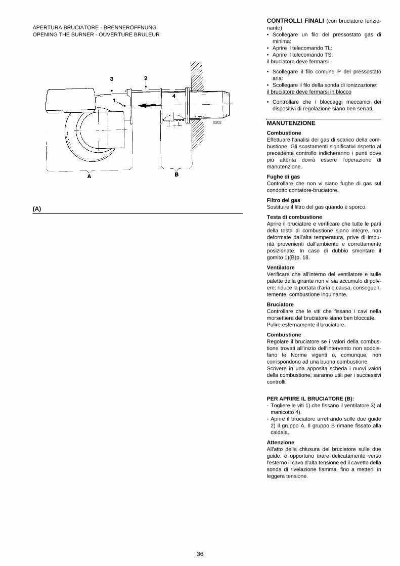
36
CONTROLLI FINALI (con bruciatore funzio-nante)• Scollegare un filo del pressostato gas di
minima: • Aprire il telecomando TL:• Aprire il telecomando TS:il bruciatore deve fermarsi
• Scollegare il filo comune P del pressostatoaria:
• Scollegare il filo della sonda di ionizzazione: il bruciatore deve fermarsi in blocco
• Controllare che i bloccaggi meccanici deidispositivi di regolazione siano ben serrati.
MANUTENZIONECombustioneEffettuare l'analisi dei gas di scarico della com-bustione. Gli scostamenti significativi rispetto alprecedente controllo indicheranno i punti dovepiù attenta dovrà essere l'operazione dimanutenzione.
Fughe di gasControllare che non vi siano fughe di gas sulcondotto contatore-bruciatore.
Filtro del gasSostituire il filtro del gas quando è sporco.
Testa di combustioneAprire il bruciatore e verificare che tutte le partidella testa di combustione siano integre, nondeformate dall'alta temperatura, prive di impu-rità provenienti dall'ambiente e correttamenteposizionate. In caso di dubbio smontare ilgomito 1)(B)p. 18.
VentilatoreVerificare che all'interno del ventilatore e sullepalette della girante non vi sia accumulo di polv-ere: riduce la portata d'aria e causa, conseguen-temente, combustione inquinante.
BruciatoreControllare che le viti che fissano i cavi nellamorsettiera del bruciatore siano ben bloccate.Pulire esternamente il bruciatore.
CombustioneRegolare il bruciatore se i valori della combus-tione trovati all'inizio dell'intervento non soddis-fano le Norme vigenti o, comunque, noncorrispondono ad una buona combustione.Scrivere in una apposita scheda i nuovi valoridella combustione, saranno utili per i successivicontrolli.
PER APRIRE IL BRUCIATORE (B):- Togliere le viti 1) che fissano il ventilatore 3) al
manicotto 4).- Aprire il bruciatore arretrando sulle due guide
2) il gruppo A. Il gruppo B rimane fissato allacaldaia.
AttenzioneAll'atto della chiusura del bruciatore sulle dueguide, è opportuno tirare delicatamente versol'esterno il cavo d'alta tensione ed il cavetto dellasonda di rivelazione fiamma, fino a metterli inleggera tensione.
(A)
APERTURA BRUCIATORE - BRENNERÖFFNUNGOPENING THE BURNER - OUVERTURE BRULEUR
D202
37
ENDKONTROLLEN (bei Brenner in Betrieb)• Einen Draht des Gas-Mindestdruckwächters
abtrennen: • Fernsteuerung TL öffnen:• Fernsteuerung TS öffnen:der Brenner muß anhalten
• Gemeinsamen Draht P des Luft-Druck-wächters abtrennen:
• Draht der Ionisationssonde abtrennen: der Brenner muß in Störabschaltung anhalten
• Überprüfen, ob die mechanischen Sperrender Einstellvorrichtungen richtig klemmen.
WARTUNG
CombustioneDie Abgase der Verbrennung analysieren.Bemerkenswerte Abweichungen im Vergleichzur vorherigen Überprüfung zeigen die Stellean, wo die Wartung aufmerksamer ausgeführtwerden soll.
GasundichtigkeitenDie Zähler-Brenner-Leitung auf Gasundichtig-keiten kontrollieren.
GasfilterVerschmutzten Gasfilter austauschen.
FlammkopfDen Brenner öffnen und überprüfen, ob alleFlammkopfteile unversehrt, nicht durch hoheTemperatur verformt, ohne Schmutzteile ausder Umgebung und richtig positioniert sind.. ImZweifelsfall den Schlitten 1)(B)S. 18 ausbauen.
GebläseÜberprüfen, ob sich im Gebläse oder auf denLaufradschaufeln Staub angehäuft hat: das hateine Minderung des Luftdurchsatzes zur Folgeund verursacht eine umweltbelastende Verbren-nung.
BrennerÜberprüfen, ob die Schrauben, die Kabel imKlemmenbrett des Brenners befestigen, richtigangezogen sind.Den Brenner außen reinigen.
VerbrennungFalls die anfänglich festgestellten Verbrennung-swerte nicht mit den geltenden Vorschriftenübereinstimmen, oder jedenfalls nicht einer kor-rekten Verbrennung entsprechen, muß derBrenner neu eingestellt werden.Tragen Sie auf einem geeigneten Formular dieneuen Verbrennungswerte ein, die für spätereKontrollen nützlich sind.
ÖFFNUNG DES BRENNERS:- Befestigungsschrauben 1) des Gebläses 3) an
der Muffe 4) entfernen.- Brenner öffnen, indem man die Einheit A auf
den beiden Gleitschienen 2) zurückschiebt. DieEinheit B bleibt am Kessel befestigt.
WICHTIGER HINWEISBeim Schließen des Brenners ist es ratsam, dasHochspannungskabel und das Kabel des Flam-menfühlers vorsichtig nach außen zu ziehen, bissie leicht gespannt sind.
FINAL CHECKS (with burner running)• Disconnect one of the wires on the minimum
gas pressure switch: • Open remote control device TL:• Open remote control device TS:the burner must stop
• Disconnect the common wire P from the airpressure switch:
• Disconnect the ionisation probe lead: the burner must lock out
• Make sure that the mechanical locking sys-tems on the various adjustment devices arefully tightened.
MAINTENANCE
CombustionThe optimum calibration of the burner requiresan analysis of the flue gases. Significant differ-ences with respect to the previous measure-ments indicate the points where more careshould be exercised during maintenance.
Gas leaksMake sure that there are no gas leaks on thepipework between the gas meter and the burner.
Gas filterChange the gas filter when it is dirty.
Combustion headOpen the burner and make sure that all compo-nents of the combustion head are in good condi-tion, not deformed by the high temperatures, freeof impurities from the surroundings and correctlypositioned. If in doubt, disassemble the elbow fit-ting 1)(B)p. 18.
FanCheck that dust has not accumulated inside thefan and on the impeller blades: this will reduceair delivery and, as a result, give rise to dirtycombustion.
BurnerCheck that the screws that secure the cables inthe terminal strip of the burner are tight.Clean the outside of the burner.
CombustionAdjust the burner if the combustion values foundat the beginning of the operation do not complywith the regulations in force, or at any rate, do notcorrespond to good combustion. Use the appro-priate card to record the new combustion values;they will be useful for subsequent controls.
OPENING THE BURNER- Remove the screws 1) which secure the fan 3)
to the sleeve 4). - Open the burner by moving unit A backwards
on the two slide bars 2). Unit B remains se-cured to the boiler.
Important When fitting the burner on the two slide bars, it isadvisable to gently draw out the high tension ca-ble and flame detection probe cable until theyare slightly stretched.
CONTROLES FINAUX (brûleur en fonction-nement)• Débrancher un fil du pressostat de seuil mini-
mum gaz: • Ouvrir la télécommande TL:• Ouvrir la télécommande TS:le brûleur doit s'arrêter
• Débrancher le fil commun P du pressostat del'air:
• Débrancher le fil de la sonde d'ionisation: le brûleur doit se bloquer
• Contrôler que les blocages mécaniques desdispositifs de réglage soient bien serrés.
ENTRETIEN
CombustionPour obtenir un réglage optimal du brûleur, il fauteffectuer l'analyse des gaz d'échappement de lacombustion à la sortie de la chaudière. Les dif-férences significatives par rapport au contrôleprécédent indiqueront les points où l'opérationd'entretien devra être plus approfondie.
Fuites de gazContrôler l'absence de fuites de gaz sur le con-duit compteur-brûleur.
Filtre du gazRemplacer le filtre du gaz lorsqu'il est encrassé.
Tête de combustionOuvrir le brûleur et contrôler que toutes les par-ties de la tête de combustion soient intactes, nesoient pas déformées par les températuresélevées, qu'elles soient exemptes d'impuretésprovenant du milieu ambiant et positionnées cor-rectement. En cas de doute, démonter le coude 1)(B)p. 18.
VentilateurVérifier qu'il n'y ait pas d'accumulation de pous-sière à l'intérieur du ventilateur et sur les ailettesde la turbine : elle réduirait le débit de l'air etprovoquerait par conséquent une combustionpolluante.
Brûleur Contrôler que les vis qui fixent les câbles dansla boîte à bornes du brûleur soient bloquées con-venablement.Nettoyer extérieurement le brûleur.
CombustionRégler le brûleur si les valeurs de la combustiontrouvées au début de l'intervention ne satisfontpas les normes en vigueur ou ne correspondentpas à une bonne combustion.Reporter sur une fiche spéciale les nouvelles va-leurs de la combustion; elles seront utiles pourles contrôles successifs.
POUR OUVRIR LE BRULEUR PROCEDERCOMME SUIT:- Enlever les vis 1) qui fixent le ventilateur 3) au
manchon 4).- Ouvrir le brûleur en reculant le groupe A sur les
deux guides 2). Le groupe B reste fixé à lachaudière.
AttentionAu moment de la fermeture du brûleur sur lesdeux guides il faut tirer délicatement vers l'ex-térieur le câble de haute tension et le petit câblede la sonde de détection flamme, jusqu'à cequ'ils soient légèrement tendus.
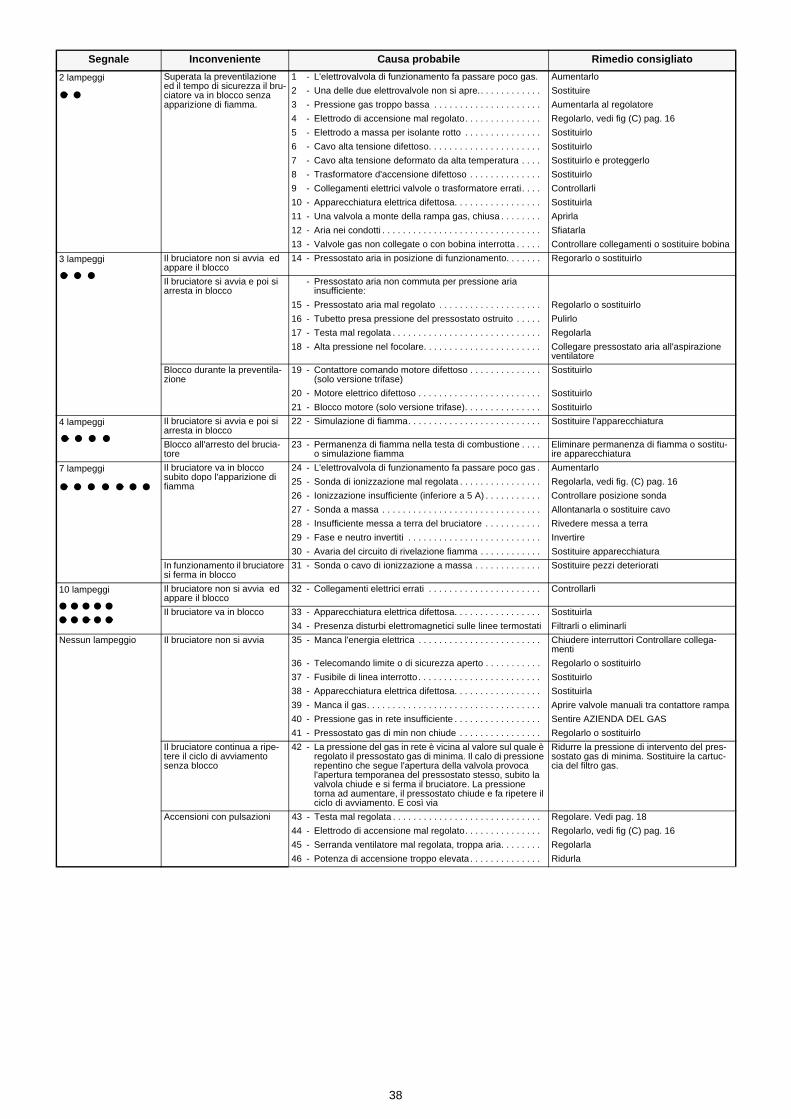
38
Segnale Inconveniente Causa probabile Rimedio consigliato
2 lampeggi Superata la preventilazione ed il tempo di sicurezza il bru-ciatore va in blocco senza apparizione di fiamma.
1 - L'elettrovalvola di funzionamento fa passare poco gas. Aumentarlo
2 - Una delle due elettrovalvole non si apre.. . . . . . . . . . . . Sostituire
3 - Pressione gas troppo bassa . . . . . . . . . . . . . . . . . . . . . Aumentarla al regolatore
4 - Elettrodo di accensione mal regolato. . . . . . . . . . . . . . . Regolarlo, vedi fig (C) pag. 16
5 - Elettrodo a massa per isolante rotto . . . . . . . . . . . . . . . Sostituirlo
6 - Cavo alta tensione difettoso. . . . . . . . . . . . . . . . . . . . . . Sostituirlo
7 - Cavo alta tensione deformato da alta temperatura . . . . Sostituirlo e proteggerlo
8 - Trasformatore d'accensione difettoso . . . . . . . . . . . . . . Sostituirlo
9 - Collegamenti elettrici valvole o trasformatore errati. . . . Controllarli
10 - Apparecchiatura elettrica difettosa. . . . . . . . . . . . . . . . . Sostituirla
11 - Una valvola a monte della rampa gas, chiusa . . . . . . . . Aprirla
12 - Aria nei condotti . . . . . . . . . . . . . . . . . . . . . . . . . . . . . . . Sfiatarla
13 - Valvole gas non collegate o con bobina interrotta . . . . . Controllare collegamenti o sostituire bobina
3 lampeggi Il bruciatore non si avvia ed appare il blocco
14 - Pressostato aria in posizione di funzionamento. . . . . . . Regorarlo o sostituirlo
Il bruciatore si avvia e poi si arresta in blocco
- Pressostato aria non commuta per pressione ariainsufficiente:
15 - Pressostato aria mal regolato . . . . . . . . . . . . . . . . . . . . Regolarlo o sostituirlo
16 - Tubetto presa pressione del pressostato ostruito . . . . . Pulirlo
17 - Testa mal regolata . . . . . . . . . . . . . . . . . . . . . . . . . . . . . Regolarla
18 - Alta pressione nel focolare. . . . . . . . . . . . . . . . . . . . . . . Collegare pressostato aria all'aspirazione ventilatore
Blocco durante la preventila-zione
19 - Contattore comando motore difettoso . . . . . . . . . . . . . . (solo versione trifase)
Sostituirlo
20 - Motore elettrico difettoso . . . . . . . . . . . . . . . . . . . . . . . . Sostituirlo
21 - Blocco motore (solo versione trifase). . . . . . . . . . . . . . . Sostituirlo
4 lampeggi Il bruciatore si avvia e poi si arresta in blocco
22 - Simulazione di fiamma. . . . . . . . . . . . . . . . . . . . . . . . . . Sostituire l'apparecchiatura
Blocco all'arresto del brucia-tore
23 - Permanenza di fiamma nella testa di combustione . . . . o simulazione fiamma
Eliminare permanenza di fiamma o sostitu-ire apparecchiatura
7 lampeggi Il bruciatore va in blocco subito dopo l'apparizione di fiamma
24 - L'elettrovalvola di funzionamento fa passare poco gas . Aumentarlo
25 - Sonda di ionizzazione mal regolata . . . . . . . . . . . . . . . . Regolarla, vedi fig. (C) pag. 16
26 - Ionizzazione insufficiente (inferiore a 5 A) . . . . . . . . . . . Controllare posizione sonda
27 - Sonda a massa . . . . . . . . . . . . . . . . . . . . . . . . . . . . . . . Allontanarla o sostituire cavo
28 - Insufficiente messa a terra del bruciatore . . . . . . . . . . . Rivedere messa a terra
29 - Fase e neutro invertiti . . . . . . . . . . . . . . . . . . . . . . . . . . Invertire
30 - Avaria del circuito di rivelazione fiamma . . . . . . . . . . . . Sostituire apparecchiatura
In funzionamento il bruciatore si ferma in blocco
31 - Sonda o cavo di ionizzazione a massa . . . . . . . . . . . . . Sostituire pezzi deteriorati
10 lampeggi Il bruciatore non si avvia ed appare il blocco
32 - Collegamenti elettrici errati . . . . . . . . . . . . . . . . . . . . . . Controllarli
Il bruciatore va in blocco 33 - Apparecchiatura elettrica difettosa. . . . . . . . . . . . . . . . . Sostituirla
34 - Presenza disturbi elettromagnetici sulle linee termostati Filtrarli o eliminarli
Nessun lampeggio Il bruciatore non si avvia 35 - Manca l'energia elettrica . . . . . . . . . . . . . . . . . . . . . . . . Chiudere interruttori Controllare collega-menti
36 - Telecomando limite o di sicurezza aperto . . . . . . . . . . . Regolarlo o sostituirlo
37 - Fusibile di linea interrotto . . . . . . . . . . . . . . . . . . . . . . . . Sostituirlo
38 - Apparecchiatura elettrica difettosa. . . . . . . . . . . . . . . . . Sostituirla
39 - Manca il gas. . . . . . . . . . . . . . . . . . . . . . . . . . . . . . . . . . Aprire valvole manuali tra contattore rampa
40 - Pressione gas in rete insufficiente . . . . . . . . . . . . . . . . . Sentire AZIENDA DEL GAS
41 - Pressostato gas di min non chiude . . . . . . . . . . . . . . . . Regolarlo o sostituirlo
Il bruciatore continua a ripe-tere il ciclo di avviamento senza blocco
42 - La pressione del gas in rete è vicina al valore sul quale è regolato il pressostato gas di minima. Il calo di pressione repentino che segue l'apertura della valvola provoca l'apertura temporanea del pressostato stesso, subito la valvola chiude e si ferma il bruciatore. La pressione torna ad aumentare, il pressostato chiude e fa ripetere il ciclo di avviamento. E così via
Ridurre la pressione di intervento del pres-sostato gas di minima. Sostituire la cartuc-cia del filtro gas.
Accensioni con pulsazioni 43 - Testa mal regolata . . . . . . . . . . . . . . . . . . . . . . . . . . . . . Regolare. Vedi pag. 18
44 - Elettrodo di accensione mal regolato. . . . . . . . . . . . . . . Regolarlo, vedi fig (C) pag. 16
45 - Serranda ventilatore mal regolata, troppa aria. . . . . . . . Regolarla
46 - Potenza di accensione troppo elevata . . . . . . . . . . . . . . Ridurla
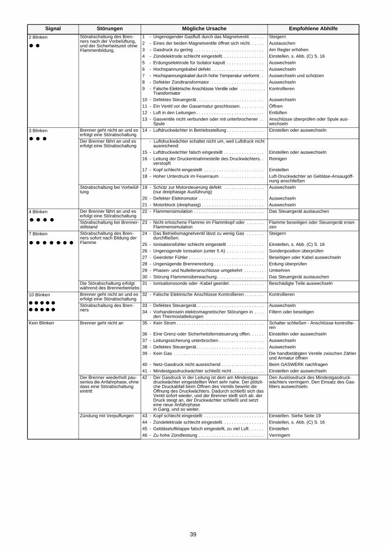
39
Signal Störungen Mögliche Ursache Empfohlene Abhilfe2 Blinken Störabschaltung des Bren-
ners nach der Vorbelüftung, und der Sicherheitszeit ohne Flammenbildung.
1 - Ungenügender Gasfluß durch das Magnetventil. . . . . . Steigern2 - Eines der beiden Magnetventile öffnet sich nicht. . . . . . Austauschen3 - Gasdruck zu gering . . . . . . . . . . . . . . . . . . . . . . . . . . . . Am Regler erhöhen4 - Zündelektrode schlecht eingestellt. . . . . . . . . . . . . . . . . Einstellen, s. Abb. (C) S. 165 - Erdungselektrode für Isolator kaputt . . . . . . . . . . . . . . . Auswechseln6 - Hochspannungskabel defekt . . . . . . . . . . . . . . . . . . . . . Auswechseln7 - Hochspannungskabel durch hohe Temperatur verformt . . Auswechseln und schützen8 - Defekter Zündtransformator. . . . . . . . . . . . . . . . . . . . . . Auswechseln9 - Falsche Elektrische Anschlüsse Ventile oder . . . . . . . . . . .
TransformatorKontrollieren
10 - Defektes Steuergerät . . . . . . . . . . . . . . . . . . . . . . . . . . . Auswechseln11 - Ein Ventil vor der Gasarmatur geschlossen. . . . . . . . . . Öffnen12 - Luft in den Leitungen . . . . . . . . . . . . . . . . . . . . . . . . . . . Entlüften13 - Gasventile nicht verbunden oder mit unterbrochener . .
SpuleAnschlüsse überprüfen oder Spule aus-wechseln
3 Blinken Brenner geht nicht an und es erfolgt eine Störabschaltung
14 - Luftdruckwächter in Betriebsstellung . . . . . . . . . . . . . . . Einstellen oder auswechseln
Der Brenner fährt an und es erfolgt eine Störabschaltung
- Luftdruckwächter schaltet nicht um, weil Luftdruck nicht ausreichend:
15 - Luftdruckwächter falsch eingestellt . . . . . . . . . . . . . . . . Einstellen oder auswechseln16 - Leitung der Druckentnahmestelle des Druckwächters. .
verstopftReinigen
17 - Kopf schlecht eingestellt . . . . . . . . . . . . . . . . . . . . . . . . Einstellen18 - Hoher Unterdruck im Feuerraum . . . . . . . . . . . . . . . . . . Luft-Druckwächter an Gebläse-Ansaugöff-
nung anschließenStörabschaltung bei Vorbelüf-tung
19 - Schütz zur Motorsteuerung defekt . . . . . . . . . . . . . . . . (nur dreiphasige Ausführung)
Auswechseln
20 - Defekter Elektromotor . . . . . . . . . . . . . . . . . . . . . . . . . . Auswechseln21 - Motorblock (dreiphasig) . . . . . . . . . . . . . . . . . . . . . . . . . Auswechseln
4 Blinken Der Brenner fährt an und es erfolgt eine Störabschaltung
22 - Flammensimulation . . . . . . . . . . . . . . . . . . . . . . . . . . . . Das Steuergerät austauschen
Störabschaltung bei Brenner-stillstand
23 - Nicht erloschene Flamme im Flammkopf oder . . . . . . . Flammensimulation
Flamme beseitigen oder Steuergerät erset-zen
7 Blinken Störabschaltung des Bren-ners sofort nach Bildung der Flamme
24 - Das Betriebsmagnetventil lässt zu wenig Gas . . . . . . . durchfließen.
Steigern
25 - Ionisationsfühler schlecht eingestellt . . . . . . . . . . . . . . . Einstellen, s. Abb. (C) S. 1626 - Ungenügende Ionisation (unter 5 A) . . . . . . . . . . . . . . . Sondenposition überprüfen27 - Geerdeter Fühler . . . . . . . . . . . . . . . . . . . . . . . . . . . . . . Beseitigen oder Kabel auswechseln28 - Ungenügende Brennererdung . . . . . . . . . . . . . . . . . . . . Erdung überprüfen29 - Phasen- und Nulleiteranschlüsse umgekehrt . . . . . . . . Umkehren30 - Störung Flammenüberwachung. . . . . . . . . . . . . . . . . . . Das Steuergerät austauschen
Die Störabschaltung erfolgt während des Brennerbetriebs
31 - Ionisationssonde oder -Kabel geerdet . . . . . . . . . . . . . . Beschädigte Teile auswechseln
10 Blinken Brenner geht nicht an und es erfolgt eine Störabschaltung
32 - Falsche Elektrische Anschlüsse Kontrollieren . . . . . . . . Kontrollieren
Störabschaltung des Bren-ners
33 - Defektes Steuergerät . . . . . . . . . . . . . . . . . . . . . . . . . . . Auswechseln34 - Vorhandensein elektromagnetischer Störungen in . . . .
den ThermostatleitungenFiltern oder beseitigen
Kein Blinken Brenner geht nicht an 35 - Kein Strom . . . . . . . . . . . . . . . . . . . . . . . . . . . . . . . . . . . Schalter schließen - Anschlüsse kontrollie-ren
36 - Eine Grenz-oder Sicherheitsfernsteuerung offen. . . . . . Einstellen oder auswechseln37 - Leitungssicherung unterbrochen . . . . . . . . . . . . . . . . . . Auswechseln38 - Defektes Steuergerät . . . . . . . . . . . . . . . . . . . . . . . . . . . Auswechseln39 - Kein Gas . . . . . . . . . . . . . . . . . . . . . . . . . . . . . . . . . . . . Die handbetätigten Ventile zwischen Zähler
und Armatur öffnen40 - Netz-Gasdruck nicht ausreichend . . . . . . . . . . . . . . . . . Beim GASWERK nachfragen41 - Mindestgasdruckwächter schließt nicht . . . . . . . . . . . . . Einstellen oder auswechseln
Der Brenner wiederholt pau-senlos die Anfahrphase, ohne dass eine Störabschaltung eintritt
42 - Der Gasdruck in der Leitung ist dem am Mindestgas-druckwächter eingestellten Wert sehr nahe. Der plötzli-che Druckabfall beim Öffnen des Ventils bewirkt die Öffnung des Druckwächters. Dadurch schließt sich das Ventil sofort wieder, und der Brenner stellt sich ab. der Druck steigt an, der Druckwächter schließt und setzt eine neue Anfahrphasein Gang, und so weiter.
Den Auslösedruck des Mindestgasdruck-wächters verringern. Den Einsatz des Gas-filters auswechseln.
Zündung mit Verpuffungen 43 - Kopf schlecht eingestellt . . . . . . . . . . . . . . . . . . . . . . . . Einstellen. Siehe Seite 1944 - Zündelektrode schlecht eingestellt. . . . . . . . . . . . . . . . . Einstellen, s. Abb. (C) S. 1645 - Gebläseluftklappe falsch eingestellt, zu viel Luft . . . . . . Einstellen46 - Zu hohe Zündleistung . . . . . . . . . . . . . . . . . . . . . . . . . . Verringern
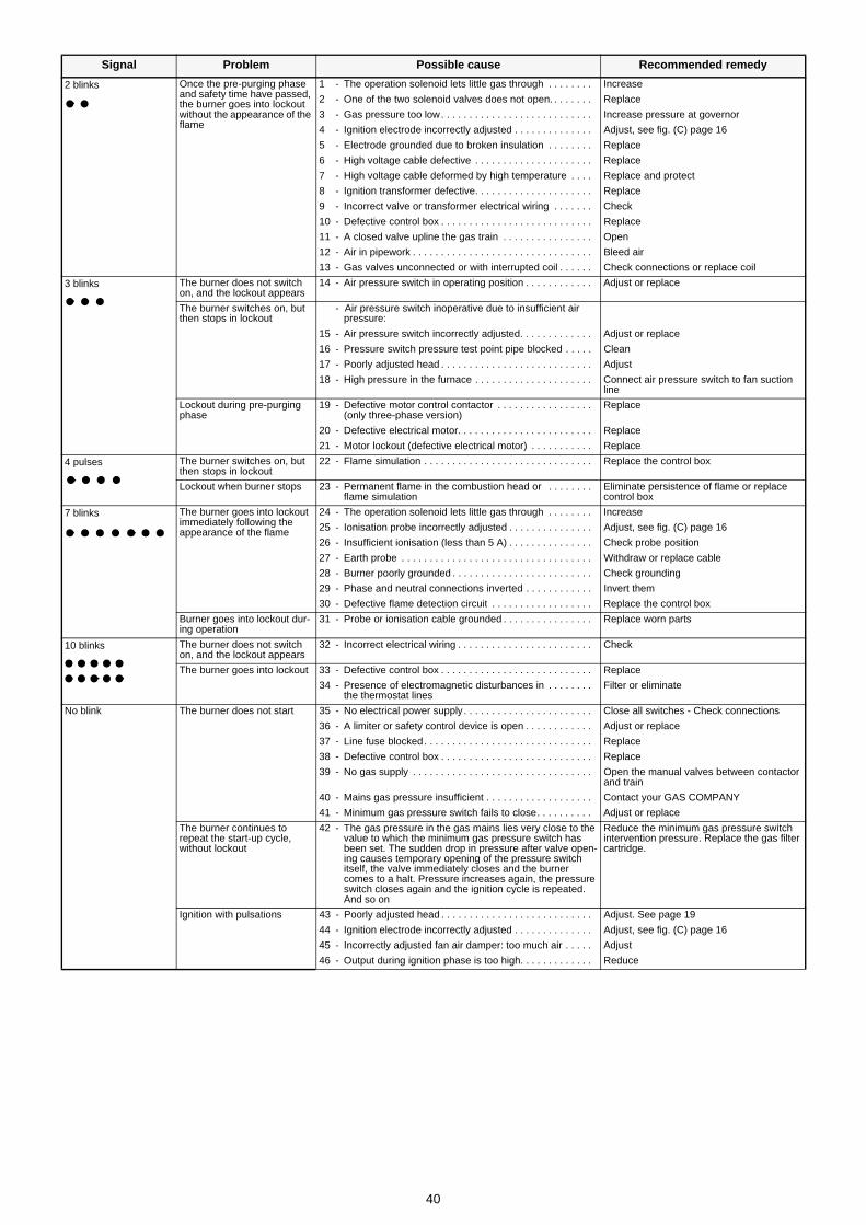
40
Signal Problem Possible cause Recommended remedy
2 blinks Once the pre-purging phase and safety time have passed, the burner goes into lockout without the appearance of the flame
1 - The operation solenoid lets little gas through . . . . . . . . Increase
2 - One of the two solenoid valves does not open. . . . . . . . Replace
3 - Gas pressure too low. . . . . . . . . . . . . . . . . . . . . . . . . . . Increase pressure at governor
4 - Ignition electrode incorrectly adjusted . . . . . . . . . . . . . . Adjust, see fig. (C) page 16
5 - Electrode grounded due to broken insulation . . . . . . . . Replace
6 - High voltage cable defective . . . . . . . . . . . . . . . . . . . . . Replace
7 - High voltage cable deformed by high temperature . . . . Replace and protect
8 - Ignition transformer defective. . . . . . . . . . . . . . . . . . . . . Replace
9 - Incorrect valve or transformer electrical wiring . . . . . . . Check
10 - Defective control box . . . . . . . . . . . . . . . . . . . . . . . . . . . Replace
11 - A closed valve upline the gas train . . . . . . . . . . . . . . . . Open
12 - Air in pipework . . . . . . . . . . . . . . . . . . . . . . . . . . . . . . . . Bleed air
13 - Gas valves unconnected or with interrupted coil . . . . . . Check connections or replace coil
3 blinks The burner does not switch on, and the lockout appears
14 - Air pressure switch in operating position . . . . . . . . . . . . Adjust or replace
The burner switches on, but then stops in lockout
- Air pressure switch inoperative due to insufficient air pressure:
15 - Air pressure switch incorrectly adjusted. . . . . . . . . . . . . Adjust or replace
16 - Pressure switch pressure test point pipe blocked . . . . . Clean
17 - Poorly adjusted head . . . . . . . . . . . . . . . . . . . . . . . . . . . Adjust
18 - High pressure in the furnace . . . . . . . . . . . . . . . . . . . . . Connect air pressure switch to fan suction line
Lockout during pre-purging phase
19 - Defective motor control contactor . . . . . . . . . . . . . . . . . (only three-phase version)
Replace
20 - Defective electrical motor. . . . . . . . . . . . . . . . . . . . . . . . Replace
21 - Motor lockout (defective electrical motor) . . . . . . . . . . . Replace
4 pulses The burner switches on, but then stops in lockout
22 - Flame simulation . . . . . . . . . . . . . . . . . . . . . . . . . . . . . . Replace the control box
Lockout when burner stops 23 - Permanent flame in the combustion head or . . . . . . . . flame simulation
Eliminate persistence of flame or replace control box
7 blinks The burner goes into lockout immediately following the appearance of the flame
24 - The operation solenoid lets little gas through . . . . . . . . Increase
25 - Ionisation probe incorrectly adjusted . . . . . . . . . . . . . . . Adjust, see fig. (C) page 16
26 - Insufficient ionisation (less than 5 A) . . . . . . . . . . . . . . . Check probe position
27 - Earth probe . . . . . . . . . . . . . . . . . . . . . . . . . . . . . . . . . . Withdraw or replace cable
28 - Burner poorly grounded . . . . . . . . . . . . . . . . . . . . . . . . . Check grounding
29 - Phase and neutral connections inverted . . . . . . . . . . . . Invert them
30 - Defective flame detection circuit . . . . . . . . . . . . . . . . . . Replace the control box
Burner goes into lockout dur-ing operation
31 - Probe or ionisation cable grounded . . . . . . . . . . . . . . . . Replace worn parts
10 blinks The burner does not switch on, and the lockout appears
32 - Incorrect electrical wiring . . . . . . . . . . . . . . . . . . . . . . . . Check
The burner goes into lockout 33 - Defective control box . . . . . . . . . . . . . . . . . . . . . . . . . . . Replace
34 - Presence of electromagnetic disturbances in . . . . . . . . the thermostat lines
Filter or eliminate
No blink The burner does not start 35 - No electrical power supply . . . . . . . . . . . . . . . . . . . . . . . Close all switches - Check connections
36 - A limiter or safety control device is open . . . . . . . . . . . . Adjust or replace
37 - Line fuse blocked. . . . . . . . . . . . . . . . . . . . . . . . . . . . . . Replace
38 - Defective control box . . . . . . . . . . . . . . . . . . . . . . . . . . . Replace
39 - No gas supply . . . . . . . . . . . . . . . . . . . . . . . . . . . . . . . . Open the manual valves between contactor and train
40 - Mains gas pressure insufficient . . . . . . . . . . . . . . . . . . . Contact your GAS COMPANY
41 - Minimum gas pressure switch fails to close. . . . . . . . . . Adjust or replace
The burner continues to repeat the start-up cycle, without lockout
42 - The gas pressure in the gas mains lies very close to the value to which the minimum gas pressure switch has been set. The sudden drop in pressure after valve open-ing causes temporary opening of the pressure switch itself, the valve immediately closes and the burner comes to a halt. Pressure increases again, the pressure switch closes again and the ignition cycle is repeated. And so on
Reduce the minimum gas pressure switch intervention pressure. Replace the gas filter cartridge.
Ignition with pulsations 43 - Poorly adjusted head . . . . . . . . . . . . . . . . . . . . . . . . . . . Adjust. See page 19
44 - Ignition electrode incorrectly adjusted . . . . . . . . . . . . . . Adjust, see fig. (C) page 16
45 - Incorrectly adjusted fan air damper: too much air . . . . . Adjust
46 - Output during ignition phase is too high. . . . . . . . . . . . . Reduce
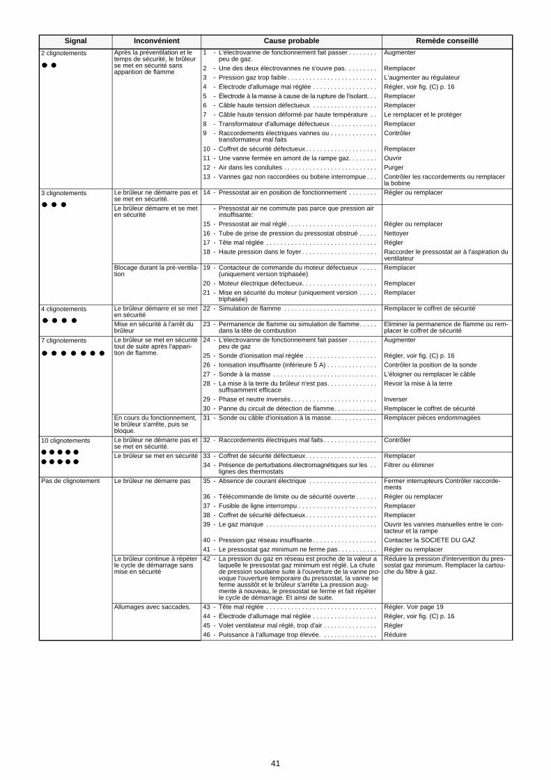
41
Signal Inconvénient Cause probable Remède conseillé2 clignotements Après la préventilation et le
temps de sécurité, le brûleur se met en sécurité sans apparition de flamme
1 - L'électrovanne de fonctionnement fait passer . . . . . . . . peu de gaz.
Augmenter
2 - Une des deux électrovannes ne s'ouvre pas. . . . . . . . . Remplacer3 - Pression gaz trop faible . . . . . . . . . . . . . . . . . . . . . . . . . L'augmenter au régulateur4 - Électrode d'allumage mal réglée . . . . . . . . . . . . . . . . . . Régler, voir fig. (C) p. 165 - Électrode à la masse à cause de la rupture de l'isolant. . . Remplacer6 - Câble haute tension défectueux . . . . . . . . . . . . . . . . . . Remplacer7 - Câble haute tension déformé par haute température . . Le remplacer et le protéger8 - Transformateur d'allumage défectueux . . . . . . . . . . . . . Remplacer9 - Raccordements électriques vannes ou . . . . . . . . . . . . .
transformateur mal faitsContrôler
10 - Coffret de sécurité défectueux . . . . . . . . . . . . . . . . . . . . Remplacer11 - Une vanne fermée en amont de la rampe gaz. . . . . . . . Ouvrir12 - Air dans les conduites . . . . . . . . . . . . . . . . . . . . . . . . . . Purger13 - Vannes gaz non raccordées ou bobine interrompue . . . Contrôler les raccordements ou remplacer
la bobine
3 clignotements Le brûleur ne démarre pas et se met en sécurité.
14 - Pressostat air en position de fonctionnement . . . . . . . . Régler ou remplacer
Le brûleur démarre et se met en sécurité
- Pressostat air ne commute pas parce que pression air insuffisante:
15 - Pressostat air mal réglé . . . . . . . . . . . . . . . . . . . . . . . . . Régler ou remplacer16 - Tube de prise de pression du pressostat obstrué . . . . . Nettoyer17 - Tête mal réglée . . . . . . . . . . . . . . . . . . . . . . . . . . . . . . . Régler18 - Haute pression dans le foyer . . . . . . . . . . . . . . . . . . . . . Raccorder le pressostat air à l'aspiration du
ventilateurBlocage durant la pré-ventila-tion
19 - Contacteur de commande du moteur défectueux . . . . . (uniquement version triphasée)
Remplacer
20 - Moteur électrique défectueux. . . . . . . . . . . . . . . . . . . . . Remplacer21 - Mise en sécurité du moteur (uniquement version . . . . .
triphasée)Remplacer
4 clignotements Le brûleur démarre et se met en sécurité
22 - Simulation de flamme . . . . . . . . . . . . . . . . . . . . . . . . . . Remplacer le coffret de sécurité
Mise en sécurité à l'arrêt du brûleur
23 - Permanence de flamme ou simulation de flamme. . . . . dans la tête de combustion
Eliminer la permanence de flamme ou rem-placer le coffret de sécurité
7 clignotements Le brûleur se met en sécurité tout de suite après l'appari-tion de flamme.
24 - L'électrovanne de fonctionnement fait passer . . . . . . . . peu de gaz
Augmenter
25 - Sonde d'ionisation mal réglée . . . . . . . . . . . . . . . . . . . . Régler, voir fig. (C) p. 1626 - Ionisation insuffisante (inférieure 5 A) . . . . . . . . . . . . . . Contrôler la position de la sonde27 - Sonde à la masse . . . . . . . . . . . . . . . . . . . . . . . . . . . . . L'éloigner ou remplacer le câble28 - La mise à la terre du brûleur n'est pas. . . . . . . . . . . . . .
suffisamment efficaceRevoir la mise à la terre
29 - Phase et neutre inversés . . . . . . . . . . . . . . . . . . . . . . . . Inverser30 - Panne du circuit de détection de flamme. . . . . . . . . . . . Remplacer le coffret de sécurité
En cours du fonctionnement, le brûleur s'arrête, puis se bloque.
31 - Sonde ou câble d'ionisation à la masse. . . . . . . . . . . . . Remplacer pièces endommagées
10 clignotements Le brûleur ne démarre pas et se met en sécurité.
32 - Raccordements électriques mal faits . . . . . . . . . . . . . . . Contrôler
Le brûleur se met en sécurité 33 - Coffret de sécurité défectueux . . . . . . . . . . . . . . . . . . . . Remplacer34 - Présence de perturbations électromagnétiques sur les . .
lignes des thermostatsFiltrer ou éliminer
Pas de clignotement Le brûleur ne démarre pas 35 - Absence de courant électrique . . . . . . . . . . . . . . . . . . . Fermer interrupteurs Contrôler raccorde-ments
36 - Télécommande de limite ou de sécurité ouverte . . . . . . Régler ou remplacer37 - Fusible de ligne interrompu . . . . . . . . . . . . . . . . . . . . . . Remplacer38 - Coffret de sécurité défectueux . . . . . . . . . . . . . . . . . . . . Remplacer39 - Le gaz manque . . . . . . . . . . . . . . . . . . . . . . . . . . . . . . . Ouvrir les vannes manuelles entre le con-
tacteur et la rampe40 - Pression gaz réseau insuffisante . . . . . . . . . . . . . . . . . . Contacter la SOCIETE DU GAZ41 - Le pressostat gaz minimum ne ferme pas . . . . . . . . . . . Régler ou remplacer
Le brûleur continue à répéter le cycle de démarrage sans mise en sécurité
42 - La pression du gaz en réseau est proche de la valeur a laquelle le pressostat gaz minimum est réglé. La chute de pression soudaine suite à l'ouverture de la vanne pro-voque l'ouverture temporaire du pressostat, la vanne se ferme aussitôt et le brûleur s'arrête La pression aug-mente à nouveau, le pressostat se ferme et fait répéter le cycle de démarrage. Et ainsi de suite.
Réduire la pression d'intervention du pres-sostat gaz minimum. Remplacer la cartou-che du filtre à gaz.
Allumages avec saccades. 43 - Tête mal réglée . . . . . . . . . . . . . . . . . . . . . . . . . . . . . . . Régler. Voir page 1944 - Électrode d'allumage mal réglée . . . . . . . . . . . . . . . . . . Régler, voir fig. (C) p. 1645 - Volet ventilateur mal réglé, trop d'air . . . . . . . . . . . . . . . Régler46 - Puissance à l’allumage trop élevée. . . . . . . . . . . . . . . . Réduire
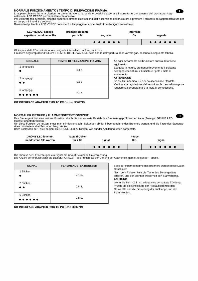
NORMALE FUNZIONAMENTO / TEMPO DI RILEVAZIONE FIAMMAL’ apparecchiatura ha una ulteriore funzione attraverso la quale è possibile accertare il corretto funzionamento del bruciatore (seg-nalazione: LED VERDE permanentemente acceso).Per utilizzare tale funzione, bisogna aspettare almeno dieci secondi dall’accensione del bruciatore e premere il pulsante dell’apparecchiatura perun tempo minimo di tre secondi.Rilasciato il pulsante il LED VERDE comincerà a lampeggiare, come illustrato nella figura sottostante.
Gli impulsi del LED costituiscono un segnale intervallato da 3 secondi circa.Il numero degli impulsi individuerà il TEMPO DI RILEVAZIONE della sonda dall’apertura delle valvole gas, secondo la seguente tabella.
KIT INTERFACE ADAPTER RMG TO PC Codice 3002719
NORMALER BETRIEB / FLAMMENDETEKTIONSZEITDas Steuergerät hat eine weitere Funktion, durch die der korrekte Betrieb des Brenners geprüft werden kann (Anzeige: GRÜNE LEDleuchtet ununterbrochen).Um diese Funktion zu nutzen, muss man mindestens zehn Sekunden ab der Inbetriebnahme des Brenners warten, und die Taste des Steuerge-rätes mindestens drei Sekunden lang drücken.Beim Loslassen der Taste beginnt die GRÜNE LED zu blinken, wie auf der Abbildung unten dargestellt.
Die Impulse der LED erzeugen ein Signal mit zirka 3 Sekunden Unterbrechung.Die Anzahl der Impulse zeigt die DETEKTIONSZEIT des Fühlers ab der Öffnung der Gasventile, gemäß folgender Tabelle.
KIT INTERFACE ADAPTER RMG TO PC Code 3002719
SEGNALE TEMPO DI RILEVAZIONE FIAMMA Ad ogni avviamento del bruciatore questo dato viene aggiornato.Eseguita la lettura, premendo brevemente il pulsante dell’apparecchiatura, il bruciatore ripete il ciclo di avviamento.ATTENZIONESe risulta un tempo > 2 s si ha accensione ritardata.Verificare la regolazione del freno idraulico su valvola gas e regolare la serranda aria e la testa di combustione.
1 lampeggio0.4 s
2 lampeggi0.8 s
6 lampeggi2.8 s
SIGNAL FLAMMENDETEKTIONSZEIT Bei jeder Inbetriebnahme des Brenners werden diese Daten aktualisiert.Nach dem Ablesen kurz die Taste des Steuergerätes drücken, und der Brenner wiederholt den Startvorgang.ACHTUNGWenn die Zeit > 2 S. ist, erfolgt eine verspätete Zündung.Prüfen Sie die Einstellung der Hydraulikbremse des Gasventils und die Einstellung der Luftklappe und des Flammkopfes.
1 Blinken0,4 S.
2 Blinken0,8 S.
6 Blinken2,8 S.
I
LED VERDE accesoaspettare per almeno 10s
premere pulsanteper > 3s segnale segnale
Intervallo3s
D
GRÜNE LED leuchtetmindestens 10s warten
Taste drückenfür > 3s signal signal
Pause3 S.
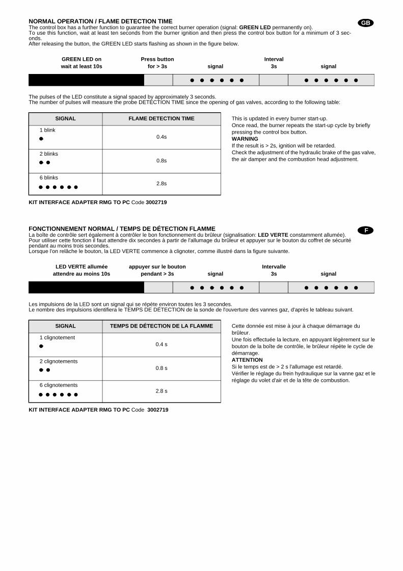
NORMAL OPERATION / FLAME DETECTION TIMEThe control box has a further function to guarantee the correct burner operation (signal: GREEN LED permanently on).To use this function, wait at least ten seconds from the burner ignition and then press the control box button for a minimum of 3 sec-onds.After releasing the button, the GREEN LED starts flashing as shown in the figure below.
The pulses of the LED constitute a signal spaced by approximately 3 seconds.The number of pulses will measure the probe DETECTION TIME since the opening of gas valves, according to the following table:
KIT INTERFACE ADAPTER RMG TO PC Code 3002719
FONCTIONNEMENT NORMAL / TEMPS DE DÉTECTION FLAMMELa boîte de contrôle sert également à contrôler le bon fonctionnement du brûleur (signalisation: LED VERTE constamment allumée).Pour utiliser cette fonction il faut attendre dix secondes à partir de l'allumage du brûleur et appuyer sur le bouton du coffret de sécuritépendant au moins trois secondes.Lorsque l'on relâche le bouton, la LED VERTE commence à clignoter, comme illustré dans la figure suivante.
Les impulsions de la LED sont un signal qui se répète environ toutes les 3 secondes.Le nombre des impulsions identifiera le TEMPS DE DÉTECTION de la sonde de l'ouverture des vannes gaz, d'après le tableau suivant.
KIT INTERFACE ADAPTER RMG TO PC Code 3002719
SIGNAL FLAME DETECTION TIME This is updated in every burner start-up.Once read, the burner repeats the start-up cycle by briefly pressing the control box button.WARNINGIf the result is > 2s, ignition will be retarded.Check the adjustment of the hydraulic brake of the gas valve, the air damper and the combustion head adjustment.
1 blink0.4s
2 blinks0.8s
6 blinks2.8s
SIGNAL TEMPS DE DÉTECTION DE LA FLAMME Cette donnée est mise à jour à chaque démarrage du brûleur.Une fois effectuée la lecture, en appuyant légèrement sur le bouton de la boîte de contrôle, le brûleur répète le cycle de démarrage.ATTENTIONSi le temps est de > 2 s l'allumage est retardé.Vérifier le réglage du frein hydraulique sur la vanne gaz et le réglage du volet d'air et de la tête de combustion.
1 clignotement 0.4 s
2 clignotements0.8 s
6 clignotements2.8 s
GB
GREEN LED onwait at least 10s
Press buttonfor > 3s signal signal
Interval3s
F
LED VERTE alluméeattendre au moins 10s
appuyer sur le boutonpendant > 3s signal signal
Intervalle3s

DIAGNOSTICA PROGRAMMA DI AVVIAMENTODurante il programma di avviamento, le indicazioni sono esplicate nella seguente tabella:
DIAGNOSTICA MAL FUNZIONAMENTOL’apparecchiatura in dotazione ha una sua funzione diagnostica attraverso la quale è possibile facilmente individuare lepossibili cause di mal funzionamento (segnalazione: LED ROSSO).Per utilizzare tale funzione, bisogna aspettare almeno dieci secondi dall’istante di messa in sicurezza dell’apparecchiaturae premere il pulsante di sblocco per un tempo minimo di tre secondi.Rilasciato il pulsante, il LED ROSSO comincerà a lampeggiare, come illustrato nella seguente figura.
Gli impulsi del LED costituiscono un segnale intervallato da 3 secondi circa.Il numero degli impulsi darà le informazioni sui possibili guasti, secondo la seguente tabella:
TABELLA CODICE COLORE
Sequenze Codice colore
Preventilazione
Fase di accensione
Funzionamento con fiamma ok
Funzionamento con fiamma debole
Alimentazione elettrica inferiore a ~ 170V
Blocco
Luce estranea
Legenda: Spento Giallo Verde Rosso
SEGNALE CAUSA PROBABILE
2 lampeggi Non viene rilevato un segnale stabile di fiamma nel tempo di sicurezza:
– guasto alla sonda di ionizzazione;
– guasto alla valvola gas;– inversione fase/neutro;
– guasto al trasformatore di accensione
– bruciatore non regolato (gas insufficiente).
3 lampeggi Il pressostato aria di minima non chiude:
– guasto al pressostato aria;
– pressostato aria non regolato;– intervento del pressostato aria di massima (se installato).
4 lampeggi Il pressostato aria di minima non commuta, oppure luce presente in camera prima dell’accensione:
– guasto al pressostato aria;
– pressostato aria non regolato.
7 lampeggi Sparizione della fiamma durante il funzionamento:
– bruciatore non regolato (gas insufficiente);
– guasto alla valvola gas;– cortocircuito tra la sonda di ionizzazione e la terra.
8 lampeggi – Non utilizzato.
10 lampeggi – Errore di collegamento o guasto interno.
LED ROSSO accesoaspettare per almeno 10 s
premere pulsanteper > 3 s segnale segnale
Intervallo3 s
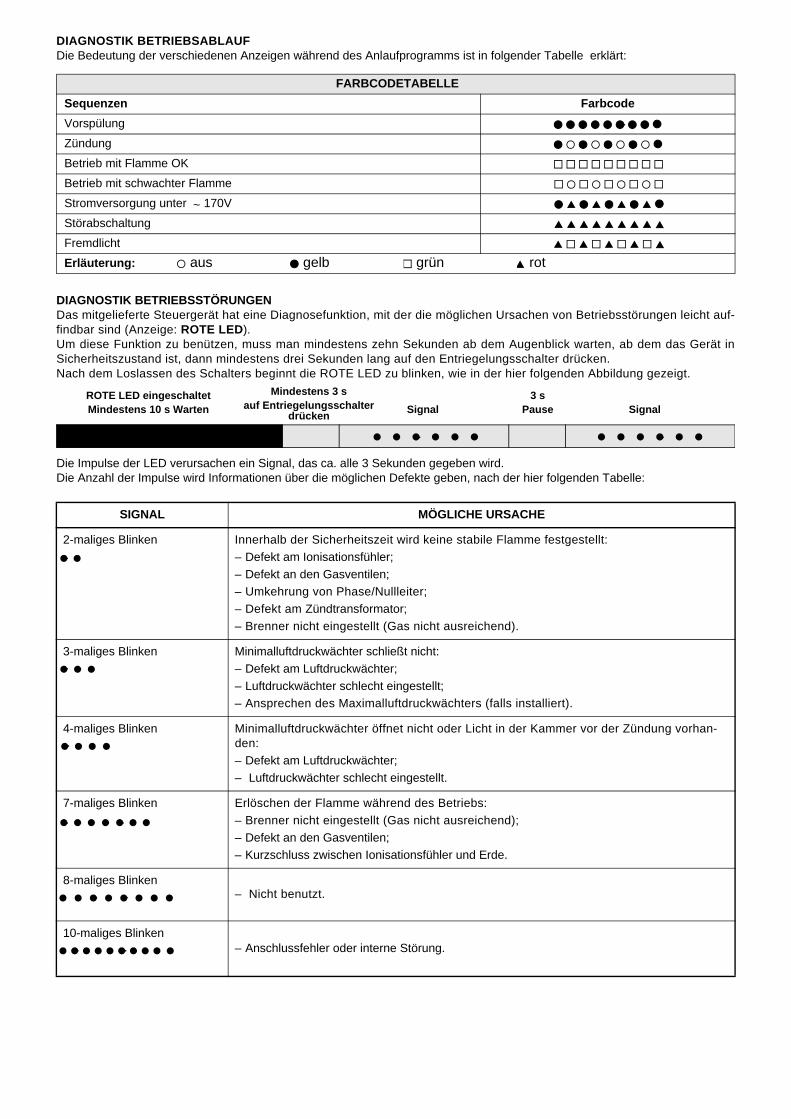
DIAGNOSTIK BETRIEBSABLAUFDie Bedeutung der verschiedenen Anzeigen während des Anlaufprogramms ist in folgender Tabelle erklärt:
DIAGNOSTIK BETRIEBSSTÖRUNGENDas mitgelieferte Steuergerät hat eine Diagnosefunktion, mit der die möglichen Ursachen von Betriebsstörungen leicht auf-findbar sind (Anzeige: ROTE LED).Um diese Funktion zu benützen, muss man mindestens zehn Sekunden ab dem Augenblick warten, ab dem das Gerät inSicherheitszustand ist, dann mindestens drei Sekunden lang auf den Entriegelungsschalter drücken.Nach dem Loslassen des Schalters beginnt die ROTE LED zu blinken, wie in der hier folgenden Abbildung gezeigt.
Die Impulse der LED verursachen ein Signal, das ca. alle 3 Sekunden gegeben wird.Die Anzahl der Impulse wird Informationen über die möglichen Defekte geben, nach der hier folgenden Tabelle:
FARBCODETABELLE
Sequenzen Farbcode
Vorspülung
Zündung
Betrieb mit Flamme OK
Betrieb mit schwachter Flamme
Stromversorgung unter ~ 170V
Störabschaltung
Fremdlicht
Erläuterung: aus gelb grün rot
SIGNAL MÖGLICHE URSACHE
2-maliges Blinken Innerhalb der Sicherheitszeit wird keine stabile Flamme festgestellt:
– Defekt am Ionisationsfühler;
– Defekt an den Gasventilen;– Umkehrung von Phase/Nullleiter;
– Defekt am Zündtransformator;
– Brenner nicht eingestellt (Gas nicht ausreichend).
3-maliges Blinken Minimalluftdruckwächter schließt nicht:
– Defekt am Luftdruckwächter;
– Luftdruckwächter schlecht eingestellt;– Ansprechen des Maximalluftdruckwächters (falls installiert).
4-maliges Blinken Minimalluftdruckwächter öffnet nicht oder Licht in der Kammer vor der Zündung vorhan-den:
– Defekt am Luftdruckwächter;
– Luftdruckwächter schlecht eingestellt.
7-maliges Blinken Erlöschen der Flamme während des Betriebs:
– Brenner nicht eingestellt (Gas nicht ausreichend);
– Defekt an den Gasventilen;– Kurzschluss zwischen Ionisationsfühler und Erde.
8-maliges Blinken – Nicht benutzt.
10-maliges Blinken – Anschlussfehler oder interne Störung.
ROTE LED eingeschaltetMindestens 10 s Warten
Mindestens 3 sauf Entriegelungsschalter Signal Signal
3 sPausedrücken

BURNER START-UP CYCLE DIAGNOSTICSDuring start-up, indication is according to the followin table:
OPERATING FAULT DIAGNOSTICSThe control box has a self-diagnostic system, which easily allows identifying the operating faults (RED LED signal).ITo use this function, wait at least ten seconds from the safety lock out, and then press the reset button for a minimum of 3 sec-onds.After releasing the button, the RED LED starts flashing as shown in the diagram below.
The pulses of the LED constitute a signal spaced by approximately 3 seconds.The number of pulses will provide the information on the possible faults, according to the table below:
COLOUR CODE TABLE
Sequences Colour code
Pre-purging
Ignition phase
Operation, flame ok
Operating with weak flame signal
Electrical supply lower than ~ 170V
Lock-out
Extraneous light
Key: Off Yellow Green Red
SIGNAL PROBABLE CAUSE
2 flashes The flame does not stabilise at the end of the safety time:– faulty ionisation probe;
– faulty or soiled gas valves;
– neutral/phase exchange;
– faulty ignition transformer– poor burner regulation (insufficient gas).
3 flashes Min. air pressure switch does not close:
– air pressure switch faulty;– air pressure switch incorrectly regulated;
– max. air pressure switch triggered (if installed).
4 flashes Min. air pressure switch does not open or light in the chamber before firing:– air pressure switch faulty;
– air pressure switch incorrectly regulated.
7 flashes Loss of flame during operations:– poor burner regulation (insufficient gas);
– faulty or soiled gas valves;
– short circuit between ionisation probe and earth.
8 flashes – Not used.
10 flashes – Wiring error or internal fault.
RED LED onwait at least 10 s
Press buttonfor > 3 s Signal Signal
Interval3 s
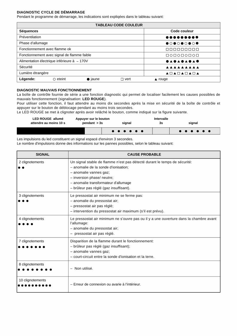
DIAGNOSTIC CYCLE DE DÉMARRAGEPendant le programme de démarrage, les indications sont expliqées dans le tableau suivant:
DIAGNOSTIC MAUVAIS FONCTIONNEMENTLa boîte de contrôle fournie de série a une fonction diagnostic qui permet de localiser facilement les causes possibles demauvais fonctionnement (signalisation: LED ROUGE).Pour utiliser cette fonction, il faut attendre au moins dix secondes après la mise en sécurité de la boîte de contrôle etappuyer sur le bouton de déblocage pendant au moins trois secondes.Le LED ROUGE se met à clignoter après avoir relâché le bouton, comme indiqué sur la figure suivante.
Les impulsions du led constituent un signal espacé d'environ 3 secondes.Le nombre d'impulsions donne des informations sur les pannes possibles, selon le tableau suivant:
TABLEAU CODE COULEUR
Séquences Code couleur
Préventilation
Phase d’allumage
Fonctionnement avec flamme ok
Fonctionnement avec signal de flamme faible
Alimentation électrique inférieure à ~ 170V
Sécurité
Lumière étrangère
Légende: eteint jaune vert rouge
SIGNAL CAUSE PROBABLE
2 clignotements Un signal stable de flamme n’est pas détecté durant le temps de sécurité:
– anomalie de la sonde d’ionisation;
– anomalie vannes gaz;– inversion phase/ neutre;
– anomalie transformateur d'allumage
– brûleur pas réglé (gaz insuffisant).
3 clignotements Le pressostat air minimum ne se ferme pas:
– anomalie du pressostat air;
– pressostat air pas réglé;– intervention du pressostat air maximum (s’il est prévu).
4 clignotements Le pressostat air minimum ne s’ouvre pas ou il y a une ouverture dans la chambre avant l’allumage:
– anomalie du pressostat air;
– pressostat air pas réglé.
7 clignotements Disparition de la flamme durant le fonctionnement:
– brûleur pas réglé (gaz insuffisant);
– anomalie vannes gaz;– court-circuit entre la sonde d’ionisation et la terre.
8 clignotements – Non utilisé.
10 clignotements – Erreur de connexion ou avarie à l’intérieur.
LED ROUGE alluméattendre au moins 10 s
Appuyer sur le boutonpendant > 3s signal signal
Intervalle3s

RIELLO S.p.A.
I-37045 Legnago (VR)
Tel.: +39.0442.630111
http:// www.riello.it
http:// www.rielloburners.com
Con riserva di modifiche - Änderungen vorbehalten! - Subject to modifications - Sous réserve de modifications