Hisense Corporations... · 2010-05-24 · consumatore potrà consegnare gli elettrodomestici...
34
CLIMATIZZATORE D’ARIA MULTI SPLIT DUAL SERIE CLASSICAL ON/OFF 9000+9000 9000+12000 Pompa di calore Hisense Corporation
Transcript of Hisense Corporations... · 2010-05-24 · consumatore potrà consegnare gli elettrodomestici...
CLIMATIZZATORE D’ARIA
MULTI SPLIT DUAL SERIE CLASSICAL ON/OFF9000+90009000+12000Pompa di calore
Hisense Corporation

Grazie per aver acquistato un climatizzatore d aria HISENSE, Le raccomandiamo di leggere attentamentequesto manuale d uso e di installazione prima di installare ed utilizzare questo apparecchio, e, di conservarequesto manuale in caso di eventuali future necessità.Le raccomandiamo inoltre di attivare la GARANZIA 3 anni HISENSE ITALY come riportato sul certificatodi garanzia unito al presente (a corredo dell unità interna).
Dismissione degli elettrodomestici
La direttiva europea 2002/96/CE sui rifiuti di apparecchiature elettriche ed elettroniche (RAEE), prevede chegli elettrodomestici non debbano essere smaltiti nel normale flusso dei rifiuti solidi urbani.Gli apparecchi dimessi devono essere raccolti separatamente per ottimizzare il recupero ed il riciclaggio deimateriali che li compongono, per ottenere un importante risparmio d energia ed impedire potenziali danni perla salute umana e per salvaguardare l ambiente.Il simbolo del cestino barrato è riportato su tutti i prodotti per ricordare gli obblighi di raccolta separata. Ilconsumatore potrà consegnare gli elettrodomestici dismessi al servizio di raccolta di raccolta, portarlipresso le apposite aree comunali o, se previsto dalla legge nazionale in materia, renderli ai rivenditoricontestualmente all acquisto di un nuovo prodotto.Tutti i principali produttori di elettrodomestici sono attivi nella creazione e gestione di raccolta e smaltimentodegli elettrodomestici dimessi, tramite appositi consorzi.
INDICE / INDEX1. Informazioni importanti / Important informations
1.1. Preparazione prima dell utilizzo / Preparation before use . . . . . . . . . . . . . . . . . . . . . 11.2. Informazioni sulla sicurezza / Important safety information . . . . . . . . . . . . . . . . . . . . 31.3. Consigli per il risparmio / Hints for economical operation . . . . . . . . . . . . . . . . . . . . . 4
2. Componenti / Components2.1. Schema globale / Global view . . . . . . . . . . . . . . . . . . . . . . . . . . . . . . . . . . . . . . . . . . 52.2. Indicatori dell unità interna / Indoor unit leds . . . . . . . . . . . . . . . . . . . . . . . . . . . . . . . 6
3. Telecomando / Remote control3.1. Pulsanti / Buttons . . . . . . . . . . . . . . . . . . . . . . . . . . . . . . . . . . . . . . . . . . . . . . . . . . . . 73.2. Utilizzo e funzionamento / Handling and operating modes . . . . . . . . . . . . . . . . . . . . 83.3. Controllo flusso aria / Air flow control . . . . . . . . . . . . . . . . . . . . . . . . . . . . . . . . . . . . . 93.4. Modalità SMART / SMART mode. . . . . . . . . . . . . . . . . . . . . . . . . . . . . . . . . . . . . . . 103.5. Tasto OROLOGIO / CLOCK button . . . . . . . . . . . . . . . . . . . . . . . . . . . . . . . . . . . . . 103.6. Modalità TIMER / TIMER mode . . . . . . . . . . . . . . . . . . . . . . . . . . . . . . . . . . . . . . . . 113.7. Modalità SLEEP / SLEEP mode . . . . . . . . . . . . . . . . . . . . . . . . . . . . . . . . . . . . . . . 123.8. Modalità SUPER / SUPER mode . . . . . . . . . . . . . . . . . . . . . . . . . . . . . . . . . . . . . . . 12
4. Manutenzione / Maintenance4.1. Generale / General. . . . . . . . . . . . . . . . . . . . . . . . . . . . . . . . . . . . . . . . . . . . . . . . . . 134.2. Pulizia del filtro / Filter cleaning . . . . . . . . . . . . . . . . . . . . . . . . . . . . . . . . . . . . . . . . 13
5. Operazioni e prestazioni / Operations and performances . . . . . . . . . . . . . . . . . . . . . . . . . . 14
6. Problemi e loro cause / Problems and causes6.1. Generale / General. . . . . . . . . . . . . . . . . . . . . . . . . . . . . . . . . . . . . . . . . . . . . . . . . . 156.2. Problemi relativi al telecomando / Concerning the remote control . . . . . . . . . . . . . . 17
7. Installazione / Installation7.1. Norme di sicurezza - Preliminari / Safety regulations - Preliminary . . . . . . . . . . . . . 187.2. Alimentazione elettrica - Locazione / Power supply - Installation site . . . . . . . . . . . 197.3. Locazione dell unità esterna / Outdoor unit installation site . . . . . . . . . . . . . . . . . . . 207.4. Posizione delle unità - Tubazioni / Units installation - Pipes . . . . . . . . . . . . . . . . . . 217.5. Installazione dell unità interna / Indoor unit installation . . . . . . . . . . . . . . . . . . . . . . 227.6. Connessioni elettriche / Wiring connections . . . . . . . . . . . . . . . . . . . . . . . . . . . . . . 237.7. Tubazioni - Collegamenti frigoriferi / Pipes - Refrigerant connections . . . . . . . . . . . 257.8. Spurgo aria / Air purging . . . . . . . . . . . . . . . . . . . . . . . . . . . . . . . . . . . . . . . . . . . . . 267.9. Svuotamento / Pump down . . . . . . . . . . . . . . . . . . . . . . . . . . . . . . . . . . . . . . . . . . . 287.10. Tubazioni di drenaggio / Drain pipes . . . . . . . . . . . . . . . . . . . . . . . . . . . . . . . . . . . 29
8. Caratteristiche tecniche / Technical characteristics
8.1. Dati tecnici / Technical data . . . . . . . . . . . . . . . . . . . . . . . . . . . . . . . . . . . . . . . . . . . 30
9. Schemi elettrici / Electrical layouts. . . . . . . . . . . . . . . . . . . . . . . . . . . . . . . . . . . . . . . . . . . . 31

1. INFORMAZIONI IMPORTANTI1. IMPORTANT INFORMATIONS
1.1. Preparazione prima dell utilizzo1.1. Preparation before use
Prima di utilizzare l condizionatore assicurarsi di effettuarele seguenti impostazioni e verifiche.
Preparazione del telecomando- Il telecomando non è preimpostato nè per il fuzionamentoin solo freddo nè per quello in pompa di calore.- Ogni qualvolta che si sostituiscono le batterie o viene atti-vato il telecomando per la prima volta, l indicatore di raffred-damento e di riscaldamento lampeggaiano alternati-vamente sul display.
utente deve impostare il telecomando a seconda delmodello di climatizzatore che ha aquistato, come segue:- premendo un pulsante qualsiasi quando lampeggia siimposta il funzionamento in solo raffreddamento.- premendo un pulsante qualsiasi quando lampeggia siimposta il funzionamento in pompa di calore.- se non si preme alcun pulsante entro 12 secondi il teleco-mando si imposta automaticamente in pompa di calore.
Note:Se impostate il telecomando per il funzionamento in solo freddo,la modalità riscaldamento viene esclusa dal telecomando.
Impostazioni di auto-restartSe desiderate la funzione di auto-restart , alimentate il climatiz-zatore e tenete premuto il pulsante di emergenza (ON/OFF)sull unità intera per più di 5 secondi, la funzione di auto-restart siattiva emettendo un suono e il climatizzatore rimane in stand-by.
Se è attivo l auto-restart, tenendo premuto il pulsante di emer-genza (ON/OFF) sull unità intera per più di 5 secondi, la funzionedi auto-restart viene disattivata, viene emesso un suono e il cli-matizzatore rimane in stand-by.
Before using the air conditioner, be sure to check and presetthe following.
Remote Controller presetting-The remote controller is NOT presetting as Cooling Only AirConditioner or Heat Pump by manufacturer.-Each time after the remote controller replaces batteries or isenergized, the Cooling indicator and Heating indicatorwill flashes alternately on LCD of the remote controller.- User can preset the remote controller type depending on theair conditioner type you have purchased as follows:- Press any button when flashes, Heat Pump is set.- Press any button when flashes, Cooling Only is set.- If you don't press any button within 12 seconds, the remotecontroller is preset as Heat Pump automatically.
Note:If the air conditioner you purchased is a Heat Pump one, andyou preset the remote controller as Cooling Only, then you CANNOT preset the Heating operation with the remote controller.
Auto Restart PresettingIf you want auto restart function, let the appliance is energized,hold down the Emergency button (ON/OFF) on the indoor unitfor over 5 seconds, auto restart function is set with buzz sound,air conditioner is on standby.
If auto restart has been set, hold down the Emergency button(ON/OFF) on the indoor unit for over 5 seconds, auto restartfunction is canceled with buzz sound, air conditioner is onstandby.
1
1. INFORMAZIONI IMPORTANTI1. IMPORTANT INFORMATIONS
1.2. Informazioni sulla sicurezza1.2. Important safety informations
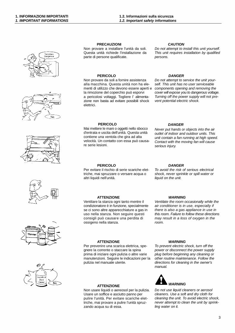
PRECAUZIONINon provare a installare l'unità da soli.Questa unità richiede l'installazione daparte di persone qualificate.
PERICOLONon provare da soli a fornire assistenzaalla macchina. Questa unità non ha ele-menti di utilizzo che devono essere aperti ela rimozione del coperchio può esporvia pericolosi voltaggi. Togliere l alimenta-zione non basta ad evitare possibili shockelettrici.
PERICOLOMai mettere le mani o oggetti nello sboccod'entrata e uscita dell'unità. Questa unitàcontiene una ventola che gira ad altavelocità. Un contatto con essa può causa-re serie lesioni.
PERICOLOPer evitare il rischio di serie scariche elet-triche, mai spruzzare o versare acqua oaltri liquidi nell'unità.
ATTENZIONEVentilare la stanza ogni tanto mentre ilcondizionatore è in funzione, specialmentese ci sono altre apparecchiature a gas inuso nella stanza. Non seguire questiconsigli può causare una perdita diossigeno nella stanza.
ATTENZIONEPer prevenire una scarica elettrica, spe-gnere la corrente o staccare la spinaprima di iniziare ogni pulizia o altre variemanutenzioni. Seguire le indicazioni per lapulizia nel manuale utente.
ATTENZIONENon usare liquidi o aereosol per la pulizia.Usare un soffice e asciutto panno perpulire l'unità. Per evitare scariche elet-triche, mai provare a pulire l'unità spruz-zando acqua su di essa.
CAUTIONDo not attempt to install this unit yourself.This unit requires installation by qualifiedpersons.
DANGERDo not attempt to service the unit your-self. This unit has no user serviceablecomponents opening and removing thecover will expose you to dangerous voltage.Turning off the power supply will not pre-vent potential electric shock.
DANGERNever put hands or objects into the airoutlet of indoor and outdoor units. Thisunit contain a fan running at high speed.Contact with the moving fan will causeserious injury.
DANGERTo avoid the risk of serious electricalshock, never sprinkle or spill water orliquid on the unit.
WARNINGVentilate the room occasionally while theair conditioner is in use, especially ifthere is also a gas appliance in use inthis room. Failure to follow these directionsmay result in a loss of oxygen in theroom.
WARNINGTo prevent electric shock, turn off thepower or disconnect the power supplyplug before beginning any cleaning orother routine maintenance. Follow thedirections for cleaning in the owner'smanual.
WARNINGDo not use liquid cleaners or aerosolcleaners. Use a soft and dry cloth forcleaning the unit. To avoid electric shock,never attempt to clean the unit by sprink-ling water on it.
3

1. INFORMAZIONI IMPORTANTI1. IMPORTANT INFORMATIONS
1.3. Consigli per il risparmio1.3. Hints for economical operation
PRECAUZIONINon usare detergenti nell'unità. I solventipossono velocemente distruggere gli ele-menti dell'unità (vaschetta di scarico e glielementi dello scambiatore di calore).
NOTEPer un'adeguata prestazione, utilizzarel'unità sotto la temperatura operativa e lecondizioni d'umidità indicate nel ManualeUtente. Se l'unità è utilizzata al di fuori diqueste indicazioni, questo può causaremalfunzionamenti dell'unità o gocciola-mento dall'unità interna.
Mantenere la temperatura della stanzaa un livello confortevole.
Pulizia del filtro dell'ariaUn filtro dell'aria intasato, riduce la poten-za di raffreddamento. Pulirlo ogni due set-timane.
Mai aprire porte e finestre oltre ciò cheè necessarioPer mantenere fresca o calda l'aria nellastanza, mai aprire porte e finestre oltreciò che è necessario.
TendeIn raffreddamento, chiudere le tende perevitare la luce solare diretta.
Usare regolarmente il timerRegolare il funzionamento per il tempo diutilizzo desiderati.
Rendere uniforme la circolazione del-l'aria nella stanzaSistemare la direzione del flusso d'ariaper ogni circolazione nella stanza.
4
CAUTIONDo not use caustic household dry clea-ners in the unit. Drain cleaners canquickly destroy the unit components(drain pan and heat-exchanger coil etc.).
NOTEFor proper performance, operate the unitunder the usable operating temperatureand humidity conditions indicated in thisowner's ma-nual. If the unit is operatedbeyond these condition, it may causemalfunctions of the unit or dew drippingfrom the unit.
Maintain room temperature at acomfortable level.
Clean air filterA clogged air filter reduce cooling effi-
ciency. Clean it once two weeks.
Never open doors and windows moreoften than necessaryTo keep cool or warm air in the room,never open doors and windows moreoften than necessary.
Windows curtainsIn cooling, close the curtain to avoid directsunlight.
Use the timer effectivelySet the timer for the desired operatingtime.
Get uniform circulation of room airAdjust airflow direction for ever circulationof room air.
2. COMPONENTI2. COMPONENTS
2.1. Schema globale - Selettori2.1. Global view - Switches
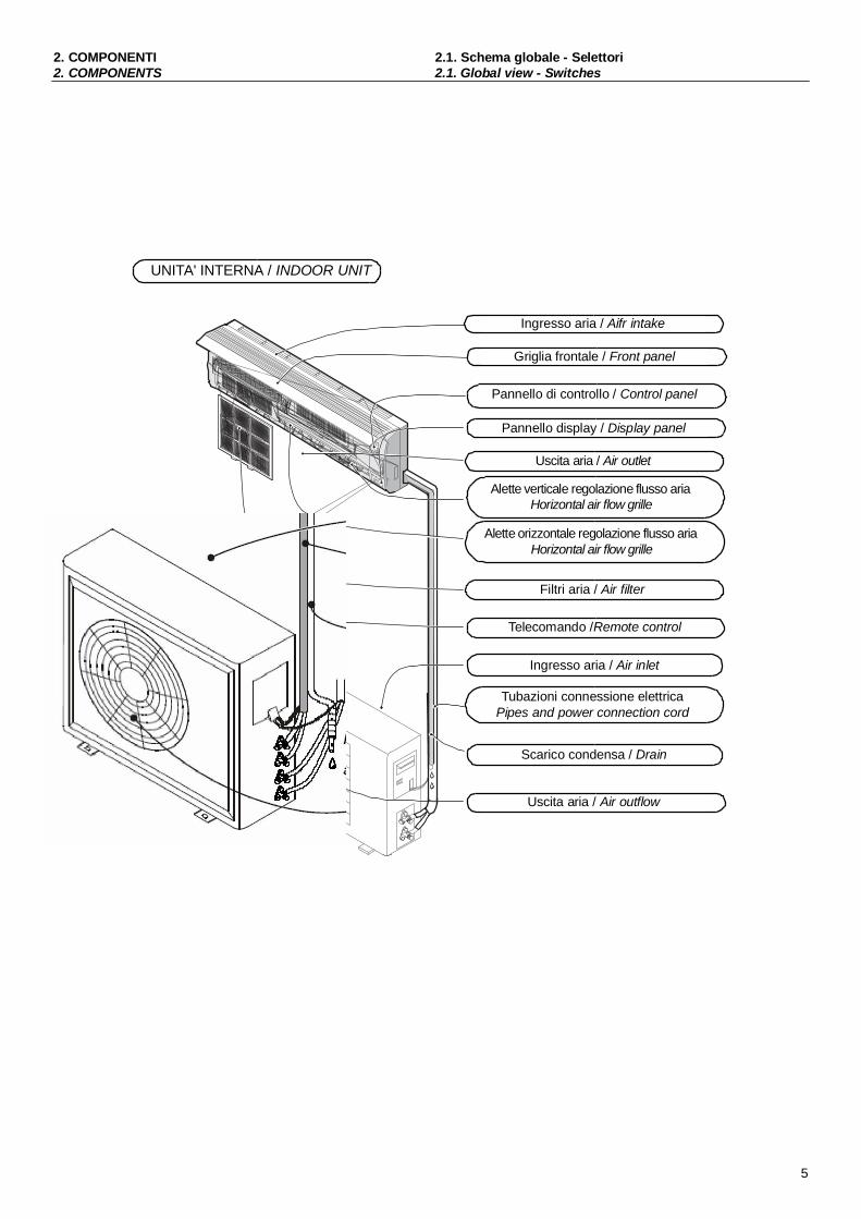
UNITA' INTERNA / INDOOR UNIT
Ingresso aria / Aifr intake
Griglia frontale / Front panel
Pannello di controllo / Control panel
Pannello display / Display panel
Uscita aria / Air outlet
Alette verticale regolazione flusso ariaHorizontal air flow grille
Alette orizzontale regolazione flusso ariaHorizontal air flow grille
Filtri aria / Air filter
Telecomando /Remote control
Ingresso aria / Air inlet
Tubazioni connessione elettricaPipes and power connection cord
Scarico condensa / Drain
Uscita aria / Air outflow
5
2. COMPONENTI2. COMPONENTS
2.2. Indicatori dell unità interna2.2. Indoor unit leds
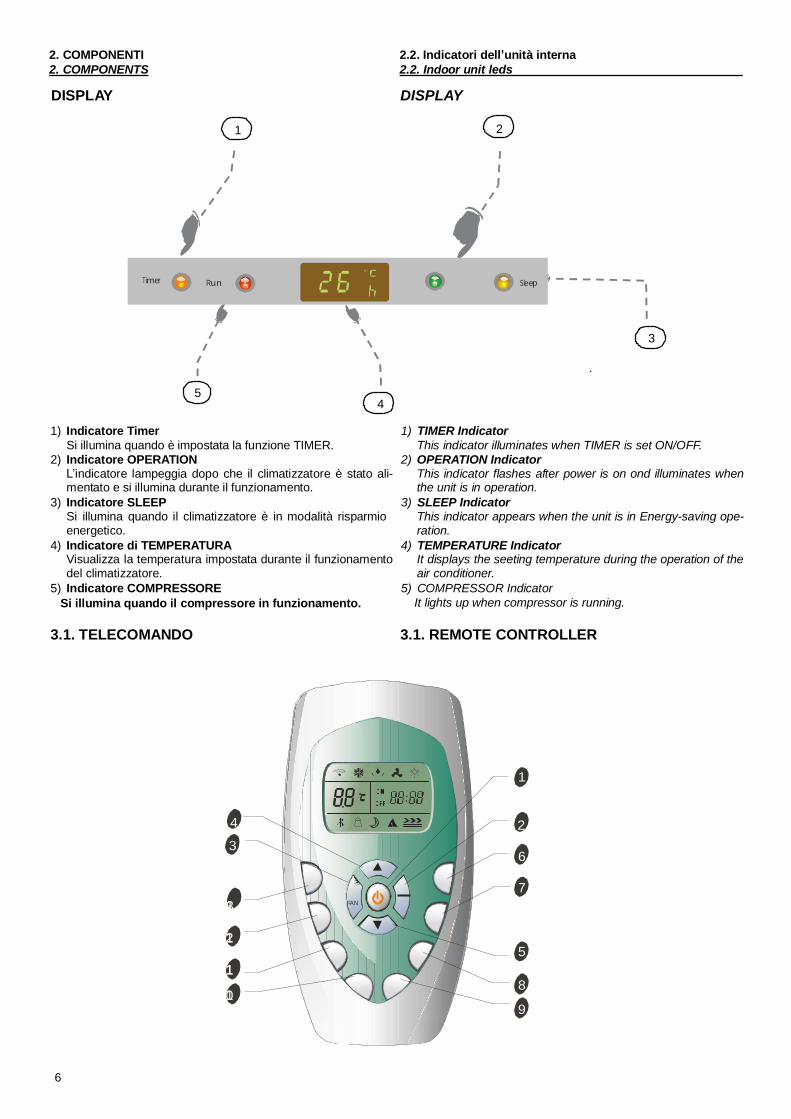
DISPLAY DISPLAY
1 2
Timer Run Sleep
3
.
54
1) Indicatore TimerSi illumina quando è impostata la funzione TIMER.
2) Indicatore OPERATIONindicatore lampeggia dopo che il climatizzatore è stato ali-
mentato e si illumina durante il funzionamento.3) Indicatore SLEEP
Si illumina quando il climatizzatore è in modalità risparmioenergetico.
4) Indicatore di TEMPERATURAVisualizza la temperatura impostata durante il funzionamentodel climatizzatore.
5) Indicatore COMPRESSORESi illumina quando il compressore in funzionamento.
1) TIMER IndicatorThis indicator illuminates when TIMER is set ON/OFF.
2) OPERATION IndicatorThis indicator flashes after power is on ond illuminates whenthe unit is in operation.
3) SLEEP IndicatorThis indicator appears when the unit is in Energy-saving ope-ration.
4) TEMPERATURE IndicatorIt displays the seeting temperature during the operation of theair conditioner.
5) COMPRESSOR IndicatorIt lights up when compressor is running.
3.1. TELECOMANDO 3.1. REMOTE CONTROLLER
1
4 23
6
731 FAN
215
118
019
6

3. TELECOMANDO3. REMOTE CONTROL
3.1. Pulsanti3.1. Buttons
(1) TASTO ON/OFFPremere il tasto per accendere il climatizzatore, premerenuovamente per fermare le opzioni.
(2) TASTO MODALITÀPremere questo tasto per selezionare la modalità di funzionamento
(3) Tastao ventilazioneQuesto tasto è usato per selezionare la velocità del ventilatore insequenza auto, high, medium or low.
(4) (5) Tasto di temperaturaQuesto tasto è usato per impostare la temperatura e anche il temporeale.
(6) TASTO SMARTÈ usato per entrare direttamente nel funzionamento di logicaincoerente, malgrado che l'unità sia accesa o spenta.
(7) TASTO SWINGÈ usato per arrestare o aggiustare l'aletta oscillante verticalee regolare il senso desiderato del flusso d'aria su/giù.
(8) TASTO SONNOÈ usato per impostare o annullare la modalità di funzionamento sonno.
(9) TASTO DI BLOCCAGGIOPremendo il tasto di bloccaggio, tutti i tasti sono disattivi. Pre-mendo di nuovo il tasto annullarlo.
(10) TASTO OROLOGIOÈ usto per impostare l ora corrente.
(11) (12) TASTO TIMERÈ usto per impostare il timer di funzionamento.
(13) TASTO SUPERÉ usato per inviare o arrestare il raffreddamento veloce.(il raffreddamento veloce funziona automaticamente ad altavelocità del ventilatore ed a temp. d impostatazione 18°C)
Indicatore di temperatuira
Indicatore deumidificazione
Indicatore ventilazione
Indicatore riscaldamento
Velocità ventilatore auto
Velocità ventilatore alta
Velocità ventilatore media
Velocità ventilatore bassa
Smart indicator
Indicatore di bloccaggio
Indicatore Super
Trasmissione segnale.
Display impostazione timer
(1) ON/OFF BUTTONThe appliance will be started when it is energized or will bestopped when it is in operation, if you press this button.
(2) MODE BUTTONPress this button to slect the operation mode
(3) Fan BUTTONUsed to select fan speed in sequence auto, high, medium orlow.
(4) (5) ROOM TEMPERATURE SETTING BUTTONSUsed to adjust the room temperature and the timer, also realtime.
(6) SMART BUTTONUsed to enter fuzzy logic operation directly, regardless of theunit is on or off.
(7) SWING BUTTONUsed to stop or start vertical adjustment louver swinging andset the desired up/down airflow direction.
(8) SLEEP BUTTONUsed to set or cancel Sleep Mode operation.
(9) LOCK BUTTONWhen you press this button, all the buttons are locked andnot available. Press again to cancel it.
(10) CLOCK BUTTONUsed to set the current time.
(11) (12) TIMER ON/OFF BUTTONUsed to set or cancel the timer operation.
(13) SUPER BUTTONUsed to start or stop the fast cooling.(Fast cooling operates at high fan speed with 18 C set tempautomatically)
Cooling indicator
Dry indicator
Fan only indicator
Heating indicator
Auto fan speed
High fan speed
Medium fan speed
Low fan speed
Smart indicator
Lock indicator
Super indicator
Signal transmit.
Display set timerON
OF F Display ora corrente
Display temperatura d impostazione
Display current time
Display set temperature
7
3. TELECOMANDO3. REMOTE CONTROL
3.2. Utilizzo e funzionamento3.2. Usage and operating modes
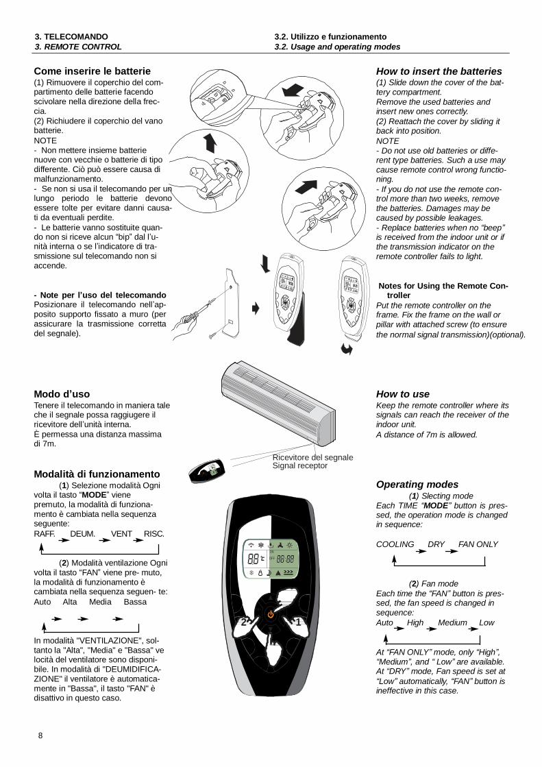
Come inserire le batterie(1) Rimuovere il coperchio del com-partimento delle batterie facendoscivolare nella direzione della frec-cia.(2) Richiudere il coperchio del vanobatterie.NOTE- Non mettere insieme batterienuove con vecchie o batterie di tipodifferente. Ciò può essere causa dimalfunzionamento.- Se non si usa il telecomando per unlungo periodo le batterie devonoessere tolte per evitare danni causa-ti da eventuali perdite.- Le batterie vanno sostituite quan-do non si riceve alcun bip dal l u-nità interna o se l indicatore di tra-smissione sul telecomando non siaccende.
- Note per l uso del telecomandoPosizionare il telecomando nell ap-posito supporto fissato a muro (perassicurare la trasmissione correttadel segnale).
How to insert the batteries(1) Slide down the cover of the bat-tery compartment.Remove the used batteries andinsert new ones correctly.(2) Reattach the cover by sliding itback into position.NOTE- Do not use old batteries or diffe-rent type batteries. Such a use maycause remote control wrong functio-ning.- If you do not use the remote con-trol more than two weeks, removethe batteries. Damages may becaused by possible leakages.- Replace batteries when no beepis received from the indoor unit or ifthe transmission indicator on theremote controller fails to light.
Notes for Using the Remote Con-troller
Put the remote controller on theframe. Fix the frame on the wall orpillar with attached screw (to ensurethe normal signal transmission)(optional).
Modo d usoTenere il telecomando in maniera taleche il segnale possa raggiugere ilricevitore dell unità interna.È permessa una distanza massimadi 7m.
Modalità di funzionamento(1) Selezione modalità Ogni
volta il tasto MODE vienepremuto, la modalità di funziona-mento è cambiata nella sequenzaseguente:RAFF. DEUM. VENT RISC.
(2) Modalità ventilazione Ognivolta il tasto FAN viene pre- muto,la modalità di funzionamento ècambiata nella sequenza seguen- te:Auto Alta Media Bassa
In modalità "VENTILAZIONE", sol-tanto la "Alta", "Media" e "Bassa" velocità del ventilatore sono disponi-bile. In modalità di "DEUMIDIFICA-ZIONE" il ventilatore è automatica-mente in "Bassa", il tasto "FAN" èdisattivo in questo caso.
Ricevitore del segnaleSignal receptor
ON
OFF
FAN MODE
2 1
How to useKeep the remote controller where itssignals can reach the receiver of theindoor unit.A distance of 7m is allowed.
Operating modes(1) Slecting mode
Each TIME MODE button is pres-sed, the operation mode is changedin sequence:
COOLING DRY FAN ONLY
(2) Fan modeEach time the FAN button is pres-sed, the fan speed is changed insequence:Auto High Medium Low
At FAN ONLY mode, only High ,Medium , and Low are available.
At DRY mode, Fan speed is set atLow automatically, FAN button is
ineffective in this case.
8

3. TELECOMANDO3. REMOTE CONTROL
3.3. Controllo flusso aria3.3. Air flow control
(3) Temperatura impostata
Ogni volta viene premuto il tasto la temperatura impostataaumenta di 1°C.Ogni volta viene premuto il tasto la temperatura impostatadiminuisce di 1°C.
Gamma temperatura d impostatzioneRiscaldamento, Raffreddamento 18°C - 32°CDeumidificazione No disponibileVentilazione No disponibile
(4) Accensione
Premere questo tasto, quando l'apparecchio riceve il segnale,l'indicatore di FUNZIONAMENTO dell'unità interna si illumina.
Note:- Cambiare modalità durante il funzionamento, a volte l'unità nonrisponde immediatamente. Tempo dattesa 3 minuti.- All'inizio del funzionamento in modalità di riscaldamento, il flusso d'aria non verrà scaricato immediatamente. Il flusso d'ariaverrà mandato fino a che la temperatura dello scambiatore dicalore dell'unità interna aumenta, dopo circa 2 o 5 minuti.- Aspettare 3 minuti prima dell'nuovo avviamento dell'apparecchio.
3.3. Controllo direzione flusso aria
Il flusso d'aria verticale è automaticamente regolato adun determinato angolo in conformità con la moda- lità difunzionamento dopo l'accensione dell'unità.
(3) Setting temperature
Press once to raise the setting temperature by 1°C.
Press once to decrease the setting temperature by 1°C.
Range of available set temperatureHEATING, COOLING 18°C - 32°CDRY Unable to setFAN ONLY Unable to set
(4) Turning on
Press this button, when the appliance receives the signal,the RUN indicator of the indoor unit lights up.
Notes:- Changing modes during operation, sometimes the unitdoes not response at once. Wait 3 minutes.- During heating operation, air flow is not discharged at thebeginning. After 2 or 5 minutes, the air flow will be discharged until temperature of indoor heat exchanger rises.- Wait 3 minutes before restarting the appliance.
3.3. Air flow direction control
Vertical ari flow automatically adjusted to a certainangle in accordance with the operation mode afterturning on the unit.
Nota:La direzione del flusso d'aria può anche essereregolata premendo il tasto "SWING" del teleco-mando.Modalità di funzionamento Direzione flussoRAFF. DEUM. Orizzontale* RISC. VENT. Verso il basso
* Controllo verticale del flusso d'aria (con il teleco-mando)
Usando il telecomando per regolare il flusso d'ariasu vari angoli o su un specifico angolo preferibile.
Oscillazione del flusso d'ariaPremendo il tasto "SWING" una volta, l'aletta diregolazione del flusso d'aria verticale oscillerà su egiù automaticamente.
Direzione desiderata del flusso d aria
ON
OFF
FAN MODE
Barre di regolazione oriz-zontale delle alette / Con-
NoteThe direction of airflow can be also adjusted bypressing the "SWING" button of the remote con-troller.
Operation mode Direction of airflowCOOLING, DRY Horizontal* HEATING, FAN ONLY Downward
* Vertical airflow control (with the remote con-troller)
Using remote controller to set various angles offlow or specific angle as you like.
Swing airflowPressing SWING button once, the vertical adjust-ment louver will swing up and down automatically.
Desired direction airflowPremere di nuovo il tasto "SWING" quando le alet- trol rods of horizontal adju- Pressing the SWING button again when the lou-te oscillano ad un angolo desiderato. stment louvers vers swing to a suitable angle as desired.
* Controllo orizzontale del flusso d'aria (con le mani)
Girando con le mani le barre di regolazione orizzontale dellealette per cambiare il flusso d'aria come indicato nella figura.
Nota:- La figura dell'unità può sembrare differente da quella del condi-zionatore che avete selezionato.- Non girare manualmente l'aletta di regolazione verticale per evitare mal-funzionamenti. Se quello accade, spegnere l'unità prima e staccare l'ali-mentazione, e ricollega di nuovo l'alimentazione.- È consigliabile non lasciare l'aletta verticale s'inclina verso ilbasso a lungo tempo in RAFFREDDAMENTO o in DEUMIDIFICAZIONE per impedire la formazione della condensata.
* Horizontal airflow control (with hands)
Turning the control rods of the horizontal adjustment louvers tochange horizontal air flow as shown.
Note:The shape of the unit may look different from that of the air con-ditioner you have selected.- Do not turn the vertical adjustment louvers manually, otherwisemalfunction may occur. If that happens, turn off the unit first andcut off the power supply, then restore power supply again.- It is better not to let the vertical adjustment louver tilt downwardfor a long time at COOLING or DRY mode to prevent condensedwater from dripping.
9
3. TELECOMANDO3. REMOTE CONTROL
Modalità SMART
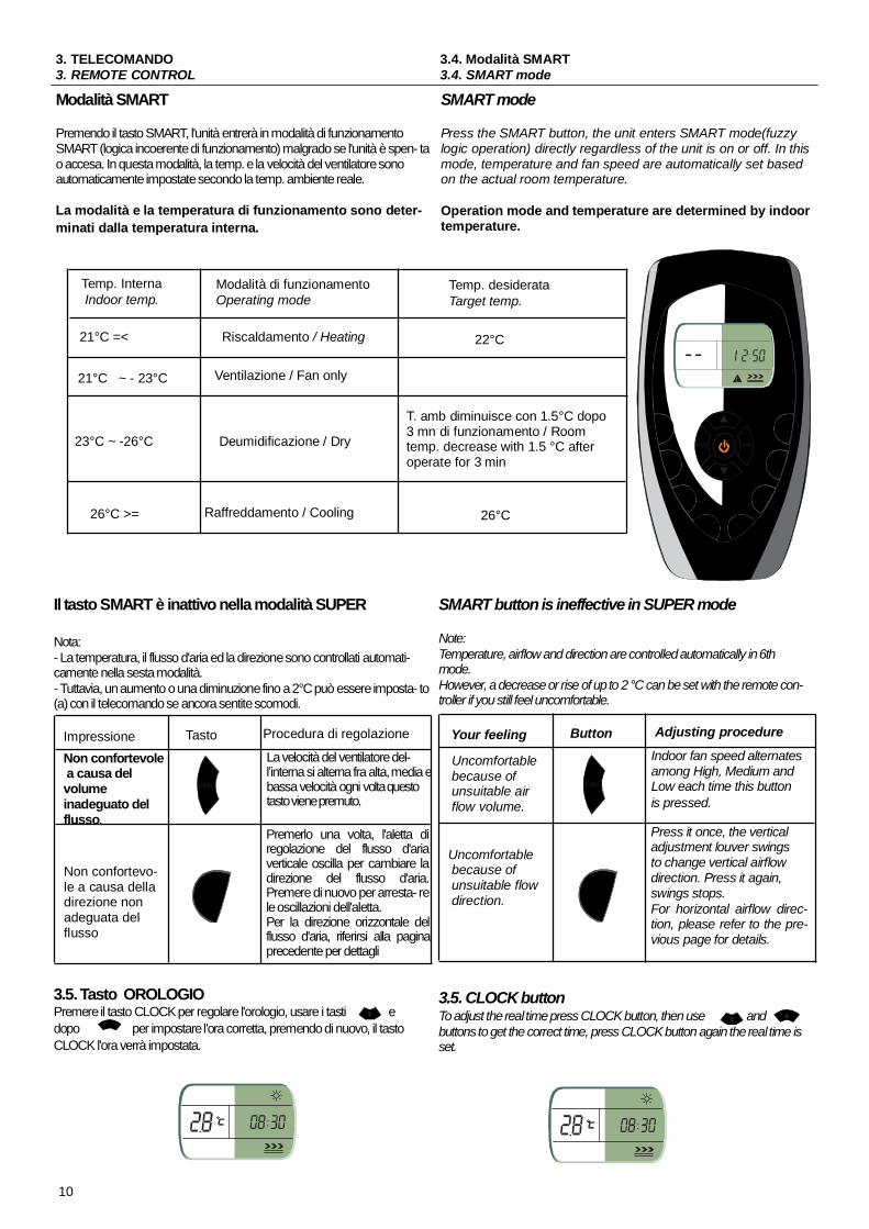
Premendo il tasto SMART, l'unità entrerà in modalità di funzionamentoSMART (logica incoerente di funzionamento) malgrado se l'unità è spen- tao accesa. In questa modalità, la temp. e la velocità del ventilatore sonoautomaticamente impostate secondo la temp. ambiente reale.
La modalità e la temperatura di funzionamento sono deter-minati dalla temperatura interna.
3.4. Modalità SMART3.4. SMART mode
SMART mode
Press the SMART button, the unit enters SMART mode(fuzzylogic operation) directly regardless of the unit is on or off. In thismode, temperature and fan speed are automatically set basedon the actual room temperature.
Operation mode and temperature are determined by indoortemperature.
Temp. InternaIndoor temp.
Modalità di funzionamentoOperating mode
Temp. desiderataTarget temp.
21°C =< Riscaldamento / Heating 22°C
21°C ~ - 23°C Ventilazione / Fan only
23°C ~ -26°C Deumidificazione / Dry
T. amb diminuisce con 1.5°C dopo3 mn di funzionamento / Roomtemp. decrease with 1.5 °C afteroperate for 3 min
FAN MODE
26°C >= Raffreddamento / Cooling 26°C
Il tasto SMART è inattivo nella modalità SUPER
Nota:- La temperatura, il flusso d'aria ed la direzione sono controllati automati-camente nella sesta modalità.- Tuttavia, un aumento o una diminuzione fino a 2°C può essere imposta- to(a) con il telecomando se ancora sentite scomodi.
Impressione Tasto Procedura di regolazione
SMART button is ineffective in SUPER mode
Note:Temperature, airflow and direction are controlled automatically in 6thmode.However, a decrease or rise of up to 2 °C can be set with the remote con-troller if you still feel uncomfortable.
Your feeling Button Adjusting procedure
Non confortevole a causa delvolumeinadeguato delflusso.
Non confortevo-le a causa delladirezione nonadeguata delflusso
FAN
La velocità del ventilatore del-interna si alterna fra alta, media e
bassa velocità ogni volta questotasto viene premuto.
Premerlo una volta, l'aletta diregolazione del flusso d'ariaverticale oscilla per cambiare ladirezione del flusso d'aria.Premere di nuovo per arresta- rele oscillazioni dell'aletta.Per la direzione orizzontale delflusso d'aria, riferirsi alla paginaprecedente per dettagli
Uncomfortablebecause ofunsuitable airflow volume.
Uncomfortablebecause ofunsuitable flowdirection.
FAN
Indoor fan speed alternatesamong High, Medium andLow each time this buttonis pressed.
Press it once, the verticaladjustment louver swingsto change vertical airflowdirection. Press it again,swings stops.For horizontal airflow direc-tion, please refer to the pre-vious page for details.
3.5. Tasto OROLOGIOPremere il tasto CLOCK per regolare l'orologio, usare i tasti e edopo per impostare l'ora corretta, premendo di nuovo, il tastoCLOCK l'ora verrà impostata.
3.5. CLOCK buttonTo adjust the real time press CLOCK button, then use andbuttons to get the correct time, press CLOCK button again the real time isset.
10

3. TELECOMANDO3. REMOTE CONTROL
Modalità TIMERPremere questi tasti Timer ON/OFF per impostare la programmazioneoraria e quindi laccensione e lo spegnemento del condizionatore. Comeimpostare TIMER ONPremere il tasto TIMER ON per impostare la programmazione oraria del-accensione del condizionatore.
i) Premere il tasto TIMER ON, ON 12:00 lampeggerà sul LCD, dopo diche usare i tasti o per impostare lora desiderata peraccensione programmata del condizionatore:
3.6. Modalità TIMER3.6. TIMER mode
TIMER modeTIMER ON/OFF push these buttons to set the timer programming aswished in order to switch on an off the air conditioner at the desired time.How to set TIMER ONTIMER ON button can be used to set the timer programming as wishedin order to switch on the appliance at your desired time.
i) Press TIMER ON button, "ON 12:00" flashes on the LCD, then youcan press the or buttons to select your desired time forappliance on
AvantiON
IndietroIncrease
ON
Decrease
- Premere il tasto o una volta per aumentare o diminuireorario di 1 minuto
- Se si preme il tasto o per 1. 5 secondi, lorario vieneaumentato o diminuito di 10 minuti.- Si si preme il tasto o per lungo tempo, lorario vieneaumentato o diminuito di 1 ora.
Nota: Se non regolate l'orario in 10 secondi dopo aver premuto iltasto TIMER ON, il telecomando abbandonerà automaticamente lamodalità TIMER ON.
ii) Quando l'orario desiderato è visualizzato su LCD, premere il tastoTIMER ON per confermarlo.
Un suono può essere sentito.ON arresta di lampeggiareL'indicatore del TIMER sull'unità interna si illumina.
iii) Dopo 5 secondi della visualizzazione dell'impostazione timer, l'orarioverrà visualisato sul LCD del telecomando anziché l'impostazione timer.
Come cancellare TIMER ONPremere di nuovo il tasto TIMER ON, "un suono" può essere sentito dopo diche l'indicatore sparisce, e la modalità TIMER ON verrà cancellata.
Nota: È analogo per impostare la modalità TIMER OFF per spegnereautomaticamente il condizionatore all'ora impostata.
AVVERTENZESe impostate la programmazione oraria il telecomando trasmette automa-ticamente il segnale di accensione o spegnimentoallunità interna agli orariprefissati.Pertanto mantenete il telecomando in una posizione dalla quale possa tra-smettere il segnale correttamente. Lorario possibile di programmazione èlimitato alle 24 ore.Inizialmente la funzione timer (ON/OFF) viene attivata vicino allora attuale. Iltimer non lavora se allo stesso tempo vengono attivate Timer ON e TimerOFF.Se si tiene il telecomando in una posizione dalla quale il segnale non puòessere trasmesso in modo corretto, può verificarsi un ritardo di 15 minuti.
- Press the or button once to increase or decrease thetime setting by 1 minute.- Press the or button one and a half seconds to increase ordecrease the time setting by 10 minute.- Press the or button for a longer time to increase ordecrease the time by 1 hour.
Note: If you don't set the time in 10 seconds after you press TIMERON button, the remote controller will exit the TIMER ON mode auto-matically.
ii) When your desired time displayed on LCD, press the TIMER ON but-ton and confirm it.
A "beep" can be heard."ON" stops flashing.The TIMER indicator on the indoor unit lights up.
iii) After the set timer displayed for 5 seconds the clock will be displayedon the LCD of the remote controller instead of set timer.
How to cancel TIMER ONPress the TIMER ON button again, a "beep" can be heard and the indi-cator disappears, the TIMER ON mode has been canceled.
Note: It is similar to set TIMER OFF, you can make the applianceswitch off automatically at your desired time.
CAUTIONSWhen you select the timer operation the remote control automaticallytransmits the timer signal to the indoor unit at the specified time. Thereforekeep the remote control in a location from which it can transmit the signal tothe indoor unit properly. The effective operation time setted by the remotecontrol is limited in 24 hours..The timer function (ON/OFF) which is the closest to the actual time willbe activated first.The timer will not work if ON and OFF timer are set at the same time.If you keep the remote controller in a position that hinders proper signaltransmission, at time lag of up to 15 minutes may occur.
11
3. TELECOMANDO3. REMOTE CONTROL3.7. Modalità SLEEP
3.7. Modalità SLEEP3.7. SLEEP mode
3.7. SLEEP mode
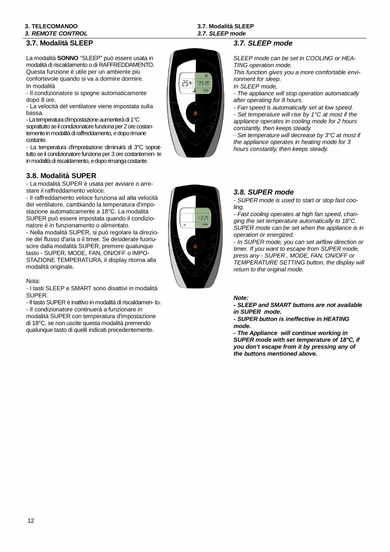
La modalità SONNO SLEEP può essere usata inmodalità di riscaldamento o di RAFFREDDAMENTO.Questa funzione è utile per un ambiente piùconfortevole quando si va a dormire dormire.In modalità- Il condizionatore si spegne automaticamentedopo 8 ore.- La velocità del ventilatore viene impostata sullabassa.- La temperatura d'impostazione aumenterà di 1°Csoprattutto se il condizionatore funziona per 2 ore costan-temente in modalità di raffreddamento, e dopo rimanecostante.- La temperatura d'impostazione diminuirà di 3°C soprat-tutto se il condizionatore funziona per 3 ore costantemen- tein modalità di riscaldamento, e dopo rimanga costante.
3.8. Modalità SUPER- La modalità SUPER è usata per avviare o arre-stare il raffreddamento veloce.- Il raffreddamento veloce funziona ad alta velocitàdel ventilatore, cambiando la temperatura d'impo-stazione automaticamente a 18°C. La modalitàSUPER può essere impostata quando il condizio-natore è in funzionamento o alimentato.- Nella modalità SUPER, si può regolare la direzio-ne del flusso d'aria o il timer. Se desiderate fuoriu-scire dalla modalità SUPER, premere qualunquetasto - SUPER, MODE, FAN, ON/OFF o IMPO-STAZIONE TEMPERATURA, il display ritorna allamodalità originale.
Nota:- I tasti SLEEP e SMART sono disattivi in modalitàSUPER.- Il tasto SUPER è inattivo in modalità di riscaldamen- to.- Il condizionatore continuerà a funzionare inmodalità SUPER con temperatura d'impostazionedi 18°C, se non uscite questa modalità premendoqualunque tasto di quelli indicati precedentemente.
12
ON
FAN MODE
FAN M O DE
SLEEP mode can be set in COOLING or HEA-TING operation mode.This function gives you a more comfortable envi-ronment for sleep.In SLEEP mode,- The appliance will stop operation automaticallyafter operating for 8 hours.- Fan speed is automatically set at low speed.- Set temperature will rise by 1°C at most if theappliance operates in cooling mode for 2 hoursconstantly, then keeps steady.- Set temperature will decrease by 3°C at most ifthe appliance operates in heating mode for 3hours constantly, then keeps steady.
3.8. SUPER mode- SUPER mode is used to start or stop fast coo-ling.- Fast cooling operates at high fan speed, chan-ging the set temperature automatically to 18°C.SUPER mode can be set when the appliance is inoperation or energized.- In SUPER mode, you can set airflow direction ortimer. If you want to escape from SUPER mode,press any - SUPER , MODE, FAN, ON/OFF orTEMPERATURE SETTING button, the display willreturn to the original mode.
Note:- SLEEP and SMART buttons are not availablein SUPER mode.- SUPER button is ineffective in HEATINGmode.- The Appliance will continue working inSUPER mode with set temperature of 18°C, ifyou don't escape from it by pressing any ofthe buttons mentioned above.
4. MANUTENZIONE4. MAINTENANCE
4.1. Generale4.1. General
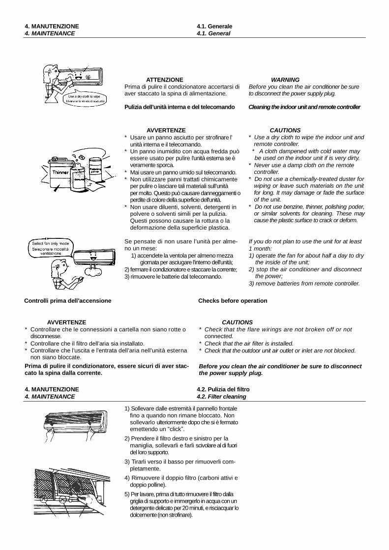
ATTENZIONEPrima di pulire il condizionatore accertarsi diaver staccato la spina di alimentazione.
WARNINGBefore you clean the air conditioner be sureto disconnect the power supply plug.
Pulizia dell'unità interna e del telecomando Cleaning the indoor unit and remote controller
AVVERTENZE* Usare un panno asciutto per strofinare l'
unità interna e il telecomando.* Un panno inumidito con acqua fredda può
essere usato per pulire l'unità esterna se èveramente sporca.
* Mai usare un panno umido sul telecomando.* Non utilizzare panni trattati chimicamente
per pulire o lasciare tali materiali sull'unitàper molto. Questo può causare danneggamenti operdite di colore della superficie dell'unità.
* Non usare diluenti, solventi, detergenti inpolvere o solventi simili per la pulizia.Questi possono causare la rottura o ladeformazione della superficie plastica.
Se pensate di non usare l'unità per alme-no un mese:
1) accendete la ventola per almeno mezzagiornata per asciugare l'interno dell'unità;
2) fermare il condizionatore e staccare la corrente;3) rimuovere le batterie dal telecomando.
CAUTIONS* Use a dry cloth to wipe the indoor unit and
remote controller.* A cloth dampened with cold water maybe used on the indoor unit if is very dirty.
* Never use a damp cloth on the remotecontroller.
* Do not use a chemically-treated duster forwiping or leave such materials on the unitfor long. It may damage or fade the surfaceof the unit.
* Do not use benzine, thinner, polishing poder,or similar solvents for cleaning. These maycause the plastic surface to crack or deform.
If you do not plan to use the unit for at least1 month:1) operate the fan for about half a day to dry
the inside of the unit;2) stop the air conditioner and disconnect
the power;3) remove batteries from remote controller.
Controlli prima dell'accensione Checks before operation
AVVERTENZE* Controllare che le connessioni a cartella non siano rotte o
disconnesse.* Controllare che il filtro dell'aria sia installato.* Controllare che l'uscita e l'entrata dell'aria nell'unità esterna
non siano bloccate.Prima di pulire il condizionatore, essere sicuri di aver stac-cato la spina dalla corrente.
CAUTIONS* Check that the flare wirings are not broken off or not
connected.* Check that the air filter is installed.* Check that the outdoor unit air outlet or inlet are not blocked.
Before you clean the air conditioner be sure to disconnectthe power supply plug.
4. MANUTENZIONE4. MAINTENANCE
4.2. Pulizia del filtro4.2. Filter cleaning
1) Sollevare dalle estremità il pannello frontalefino a quando non rimane bloccato. Nonsollevarlo ulteriormente dopo che si è fermatoemettendo un click .
2) Prendere il filtro destro e sinistro per lamaniglia, sollevarli e farli scivolare al di fuoridel loro supporto.
3) Tirarli verso il basso per rimuoverli com-pletamente.
4) Rimuovere il doppio filtro (carboni attivi edoppio polline).
5) Per lavare, prima di tutto rimuovere il filtro dallagriglia di supporto e immergerlo in acqua con undetergente delicato per 20 minuti, e risciacquar lodolcemente (non strofinare).

4. MANUTENZIONE4. MAINTENANCE
4.2. Pulizia del filtro4.2. Filter cleaning
Quindi esporlo per l'asciugatura alsole per almeno 3 ore (mettere il latonero in alto).
6) Mettere il tessuto del filtro nellacornice del filtro dell'aria echiudere il coperchio.
7) Mettere il filtro trattamento aria nelcondizionatore con il lato nero in alto.Nota: Pulire il filtro trattamento ariaalmeno una volta al mese e dopo 4-5operazioni di pulizia, il tessuto del fil-tro va sostituito.8) Usare un aspirapolvere per rimuoverela polvere o lavare il filtro dell'aria. Nota:Pulire il filtro dell'aria ogni due settimane,perché un filtro sporco può ridurre ilrendimento della macchina.9) Inserire la parte superiore del filtro con
trollando che alle estremità entrinonelle apposite corsie e spingere finoa quando non si blocca.
10) Posizionare la parte inferiore dei filtri nelloro alloggiamento e spingere i due fermidove c'è scritto PUSH per chiudere ilpannello frontale saldamente.
Then exposure it in the sun to dryout for more then 3 hours (put theblack side face-up).
6) Place the fabric net in the frame ofthe air filter and close the cover.
7) Put the air cleaner in the airconditioner with its black side face up.Note: Clean the air cleaner at leastonce a mouth and after 4-5 cleaningoperations, the fabric net must bechanged.8) Use a vacuum cleaner toremove the dust or wash the airfilter.Note: Clean the air filter once twoweek the dirt covered filter will affectthe cooling effective.9) Insert the upper portion of air filter
confirming to fit its right and left edgeson the indoor unit until it is firmly set.
10) Set the lower position of air filterin the filter holder, push the positionsmarked PUSH on both lower cornersof the front panel to close the frontpanel firmly.
5. OPERAZIONI E PRESTAZIONI5. OPERATIONS AND PERFORMANCES
Funzione protettiva dei tre minuti* Una funzione protettiva evita che il condizionatore si riattivi per
almeno 3 minuti se viene acceso subito dopo lo spegnimento.Questo proteggerà il climatizzatore.
* Caratteristiche di riscaldamento in fase di preriscaldamento Ilcondizionatore non darà aria calda subito dopo che è partito.Flussi d'aria calda usciranno dopo circa 5 minuti, quando sisurriscalderà lo scambiatore del calore dell'unità interna. (Lalampadina PRE.-DEF è accesa durante questi intervalliindicando l operazione di preriscaldamento)
* Controllo dell'aria caldaQuando la temperatura della stanza raggiunge il valorestabilito, la velocità della ventola si riduce automaticamenteper mantenere la temperatura raggiunta. Allora l'unitàesterna si fermerà.
* SbrinamentoSe l'unità esterna è coperta di brina, l'operazione di sbrinamento siattiverà automaticamente (per circa 5-10 minuti) per man-tenere gli effetti del riscaldamento, e il PRE.-DEF led è acceso.
* I ventilatori in entrambe le unità interna e esterna, sifermeranno durante l'operazione di sbrinamento.
* Durante l'operazione di sbrinamento, la condensa vieneconvogliata al piatto del fondo dell'unità esterna.
* Capacità di riscaldamento.Nell'operazione di riscaldamento, il calore è assorbitodall'esterno e rilasciato nella stanza. Questo vienechiamato sistema in pompa di calore. Quando la temperaturaesterna è troppo bassa, è raccomandato usare un altroapparato di riscaldamento in combinazione con il condizionatore.
14
Three-minutes protecting feature* A protection feature prevents the air conditioner from being
activated for approximately 3 minutes when it is restartedimmediately after operation.This will protect the machine.
* Heating characteristics preheating operation.The air conditioner will not deliver warm air immediately afterit is started. Warm air flows out after approximately 5 minuteswhen the indoor heat exchanger warm up. (The PRE.-DEF.lamp is on during this intervals indicating the preheatingoperation).
* Warm air controlWhen the room temperature reaches the set temperature,the fan speed is automatically reduced to prevent a colddraft. At this time, the outdoor unit will stop.
* DefrostingIf the outdoor unit is frosted during heating operationdefrosting is started automatically (for approximately 5 to 10minutes) to maintain the heating effect, and the PRE.-DEF.lamp is on.
* The fans in both the indoor and outdoor units stop during thedefrost operation.
* During defrost operation, defrosted water is drained from thebottom plate of the outdoor unit.
* Heating capacity.In the heating operation, heat is absorbed from outdoor andreleased into the room. That is so-called heat pump system.When the outdoor temperature is too low, you are recommended to use another heating apparatus in combinationwith the air conditioner.

5. OPERAZIONI E PRESTAZIONI5. OPERATIONS AND PERFORMANCES
Considerazioni per l'accumulo di neveScegliere la posizione per l'unità esterna dove non sarà sottopo- sta anevicate, accumulo di foglie o altri frammenti stagionali. E' importanteche il flusso d'aria per l'unità esterna non sia ostacola- to, poichèavrebbe come conseguenza la riduzione del potere di riscaldamentoe raffreddamento. Durante la modalità riscaldamen- to e atemperature sotto zero, stare attenti che il liquido risultante della faseautomatica di sbrinamento possa accumularsi e congelare. E' quindiimportante avere un adeguato drenaggio o via di scolo.
Problemi d'alimentazioneProblemi d'alimentazione durante il funzionamento, fermerannocompletamente il condizionatore.* Il led OPERATION sull'unità interna lampeggerà quando
l'alimentazione sarà tornata.* Per riavviare l'operazione, premere il tasto ON/OFF sul
telecomando.* L'illuminazione o l'uso di telefoni cellulari potrebbero causare
malfunzionamenti alla macchina.Togliere e ripristinare la corrente alla macchina. Premere iltasto ON/OFF sul telecomando per farla ripartire.
Condizioni del funzionamento del condizionatorePer un corretto funzionamento, accendere il condizionatore alleseguenti temperature:
Consideration for accumulated snowSelect the position for the outdoor unit where it will not besubjected to snow drifts, accumulation of leaves or other seaso-nal debris. It is important that the air flow for the outdoor unit isnot impeded as this will result in reduced heating or coolingperformance. During the heating mode and at sub-zero tempe-ratures, the ware drained off the outdoor unit as a result of theauto-matic defrost may accumulate and freeze. It is importantthat adequate drainage or a soak-way is provided.
Power failurePower failure during operation will stop the unit completely.* The OPERATION lamp on the indoor unit will start flashing
when power is restored.* To restart operation, push the ON/OFF button on the remote
controller.* Lighting or a car wireless telephone operating nearby may
cause the unit to malfunction.Disconnect the unit with the power and then connect the unitwith the power again. Push the ON/OFF button on theremote controller to restart.
Air conditioner operating conditionsFor proper performance, run the air conditioner under thefollowing temperature conditions:
RiscaldamentoHeating
RaffreddamentoCooling
DeumidificazioneDry
Temp. est.: sopra 18°C / Out. temp.: over 24°CTemp. aria.: sotto -7°C / Outdoor air temperature is below -7°C.Temp. amb. sopra 27°C / Room temp.: over 27°.
Temp. esterna sopra 43°C / Out. temp.: over 43°CTemp. amb. sotto 21°C / Room temp.: below 30°CATTENZIONE - Umidità relativa ambiente deve essere inferiore all'80%. Se il condizionatore lavorasopra a questo limite, la sua superficie può attirare la condensa.CAUTION - Room relative humidity less than 80%. If the air conditioner operates in excess ofthis figure, the surface of the air conditioner may attract condensation.
Temperatura interna: sotto 18°C / Room temperature: below 18
Se il condizionatore è utilizzato fuori da queste condizioni, leprotezioni di sicurezza potrebbero attivarsi.
If air conditioner is used outside of the above condition, safetyprotection features may come into operation.
6. PROBLEMI E LORO CAUSE6. TROUBLES AND CAUSES
6.1. Generale6.1. General
CONTATTARE IL SERVIZIO CLIENTI 800321999 se si verificano i Ask servicing or repairs if following problems ocur andseguenti problemi e fermare immeditamente il condizionatore stop immeditely the air conditioner.
Un indicatore lampeggia rapidamente - 5 volte al sec. - e non si rimedia togliendo e ridando tensione all u-nità / One of the indicators flashes rapidly - 5 times per sec. - and this flash can t be fixed by disconnectingand re-connecting the power.
ProblemaTrouble
Il fusibile o l interruttore saltano di frequente / Fuse or circuit breaker work frequently.
Acqua o oggetti estranei sono entrati nell unità / Foreing matter or water has fallen into the unit.Il telecomando o il pulsante di funzionamento forzato sono rotti / Remote control or switch are broken.Si notano altre condizioni inusuali / Any other unusual condition is observed.
15

6. PROBLEMI E LORO CAUSE6. TROUBLES AND CAUSES
6.1. Generale6.1. General
Prima di domandare assistenza o riparazione, controllare iseguenti punti.
Before you ask servicing or repairs, check the followingpoints.
Rumori minimiSi può udire del rumore tipo ss causato dal flusso di refrigerante. Sipuò udire del rumore tipo zz causato dalla dilatazione dellaplastica causata dalla variazione di temperatura.All accensione si nota un rumore dovuto all apertura delle alette.16
Low noise of the air conditionerMay be some ss sound caused by the flowing of refrigerant.May be some zz sound caused by the natural expansion orshrinkage of plastic parts caused by temperature change.At the starting may be some noise due to louvers turning.
6. PROBLEMI E LORO CAUSE6. TROUBLES AND CAUSES
6.2. Problemi relativi al telecomando6.2. Concerning the remote control
Prima di domandare assistenza o riparazione, controllare iseguenti punti.
Before you ask servicing or repairs, check the followingpoints.
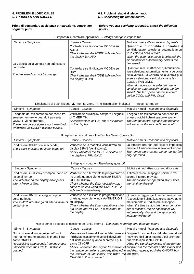
impossibile cambiare operazioni - Settings change is impossible
Sintomi - Symptoms Cause - Causes Motivi e rimedi -Reasons and disposals
La velocità della ventola non può esserecambiata.
The fan speed can not be changed
Controllare se l'indicatore MODE è suAUTOCheck whether the MODE indicated onthe display is AUTO
Controllare se l'indicatore MODE è suDRYCheck whether the MODE indicated onthe display is DRY
Quando è in modal i tà automatica ilcondizionatore seleziona automaticamen-te la velocità della ventolaWhen the automatic mode is selected, theair conditioner automatically selects thefan speed .Quando è in deumidificazione, il condiziona-tore seleziona automaticamente la velocitàdella ventola. La velocità della ventola puòessere selezionata solo durante le fasiCOOL e FAN ONLY.When dry operation is selected, the airconditioner automatically selects the fanspeed. The fan speed can be selectedduring COOL and FAN ONLY
L'indicatore di trasmissione " " non funziona - The Trasmission indicator " " never comes cn -
Sintomi - Symptoms Cause - Causes Motivi e rimedi -Reasons and disposals
Il segnale del telecomando non viene tra-smesso nemmeno quando il pulsanteON/OFF viene premuto.The remote control signal is not transmittedeven when the ON/OFF button is pushed.
Verificare se sul display compare il segnaledi TIMER ON.Check wheather the ON TIMER is indicatedon the display.
Il segnale da telecomando non viene tra-smesso poichè il climatizzatore è spento.The remote control signal is not transmit-ted, because the air conditioner is off.
Il display non visualizza - The Display Never Comes OnSintomi - Symptoms Cause - Causes Motivi e rimedi -Reasons and disposals
indicatore TEMP. non si accende.The TEMP. Indicator does not come on.
Verificare se la modalità visualizzata suldisplay è FAN (ventilazione).Check wheather the MODE indicated onthe display is FAN ONLY.
La temperatura non può essere impostatadurante il funzionamento in sola ventilazione.The temperature cannot be set during fanonly operation.
Il display si spegne - The display goes off
Sintomi - Symptoms Cause - Causes Motivi e rimedi -Reasons and disposalsindicatore sul display scompare dopo un Verificare se è terminata la programmazio- Il climatizzatore si spegne poichè è tra-
lasso di tempo.The indicator on the display disappearsafter a lapse of time.
indicatore TIMER si spegne dopo uncerto periodo.The TIMER indicator go off after a lapse ofcertain time.
ne oraria quando viene indicato TIMEROFF sul display.Check whether the timer operation hascome to an end when the TIMER OFF isindicated on the display.Verificare se è iniziata la programmazioneoraria quando viene indicato TIMER ONsul display.Check whether the timer operation is star-ted when the ON TIMER is indicated onthe display.
scorso il tempo previsto.The air conditioner operation stops sincethe set time elapsed.
Quando si raggiunge il tempo previsto peraccensione il climatizzatore si attiva auto-
maticamente e l indicatore si spegne.When the time set to start the air conditio-ner is reached, the air conditioner willautomatically start and the appropriateindicator will go off.
Non si sente il segnale di ricezione dell unità interna - The signal receiving tone does not sound
Sintomi - Symptoms Cause - Causes Motivi e rimedi -Reasons and disposalsNon si riceve alcun segnale dall unitàinterna nemmeno quando si preme il pul-sante ON/OFF.No receiving tone sounds from the indoorunit even when the ON/OFF button ispushed.
Verificare se il trasmettitore del telecomando èindirizzato esattamente verso il ricevitoredell unità interna quando si preme il pul-sante ON/OFF.Check wheather the signal transmitter ofthe remote controller is property directed tothe receiver of the indoor unit when theON/OFF button is pushed.
Dirigere il trasmettitore del telecomando alricevitore dell unità interna e poi premeredue volte il pulsante ON/OFF.Direct the signal transmitter of the remotecontroller to the receiver of the indoor unit,and then repeatly push the ON/OFF but-ton twice.
17

7. INSTALLAZIONE7. INSTALLATION
7.1. Norme di sicurezza - Preliminari7.1. Safety regulations - Preliminary
Norme di sicurezzaCONTIENE SOSTANZE CHE DANNEGGIANO L'OZONOATMOSFERICO.PER LO SMALTIMENTO ATTENERSI ALLE LEGGI VIGENTI.
Safety regulationsCONTAINS SUBSTANCES WHICH MAY DAMAGE ATMO-SPHERIC OZONE.DISPOSE OF IN COMPLIANCE WITH THE CURRENT LAWSABOUT IT.
La Ditta Costruttrice declina ogni e qualsiasi responsa-bilità per la mancata osservanza delle norme di sicurez-za e di prevenzione di seguito descritte.Declina inoltre ogni e qualsiasi responsabilità per dannicausati da un uso improprio del climatizzatore e/o damodifiche eseguite senza autorizzazione.L'installazione deve essere effettuata da personaleesperto e abilitato.* Nelle operazioni di installazione usare un abbigliamento
idoneo e anti-infortunistico, come ad esempio occhiali,guanti, ecc.. .
* Durante l'installazione operare in assoluta sicurezza, inambiente pulito e libero da impedimenti.
* Rispettare le leggi in vigore nel Paese in cui viene installato ilclimatizzatore, relativamente all'uso e allo smaltimento dell'imballo e dei prodotti impiegati per la pulizia e manutenzionedella macchina nonche` osservare le prescrizioni di tali prodotti.
* In caso di smantellamento del climatizzatore, attenersialle normative antinquinamento previste.
* Evitare assolutamente di toccare le parti in movimento o diinterporsi tra le stesse.
* Prima di mettere in funzione il climatizzatore, controllare laperfetta integrita` e sicurezza dei vari componenti edell'intero impianto.
* Le parti di ricambio devono corrispondere alle esigenzedefinite dal Costruttore. Usare esclusivamente ricambioriginali.
* E` assolutamente vietato rimuovere o manomettere idispositivi di sicurezza.
* La manutenzione del climatizzatore deve essere effettuatasolamente da personale qualificato e seguendo le indicazioniriportate in questo manuale.
* Non procedere con i lavori di manutenzione e di puliziase prima non e` stata disinserita la presa di corrente.
* Eseguire scrupolosamente la manutenzione come indicato inquesto opuscolo; far sostituire da personale autorizzato leparti danneggiate o usurate.
Il manuale delle istruzioni per l'uso deve essereletto, memorizzato e conservato per tutta la duratadel climatizzatore.
The Manufacturer declines all and every responsibility forfailure to comply with the below described safety and acci-dent prevention instructions.The Manufacturer also declines all responsibility fordamage caused by improper use of the air conditioner and/ormodifications to the appliance made without prior authorization.The air conditioner must be installed by expert andauthorized personnel.* When installing the air conditioner, wear suitable accident
preventing garments such as: goggIes, gauntIets, etc.* Work in absolute safety in clean surroundings free from
impediments when installing the air conditioner.* Comply with the Iaws in force in the country where the air
conditioner is installed in relation to use and disposal of pro-ducts used to clean and service the appliance. Also complywith the instructions given by the manufacturers of such pro-ducts.
* Comply with the anti-pollution provisions in merit if the airconditioner is dismantled.
* Never ever touch moving parts or others near to these.* Before operating the air conditioner, make sure that the various
components and the entire system are in a perfect andsafe condition.
* Spare parts must correspond to the Manufacturer s requirements. Only use genuine spare parts.
* It is absolutely fofbidden to remove or tamper with the safetydevices.
* The air conditioner must only be serviced by qualified personnel in compliance with the instructions in this manual.
* Never proceed with maintenance or cleaning work unIess thepower plug has been removed from the electricity source.
* Strictly comply with the maintenance instructions in this manual.Only authorized personnel must be allowed to replacedamaged or worn parts.
The instruction manual must be read, memorized andkept ready to hand throughout the working fife of theair conditioner.
Operazioni preliminari all installazione* Verificare la perfetta integrita` dei vari componenti del climatiz-
zatore.* Assicurarsi che la sezione non abbia subito danni durante il
trasporto; nel caso esporre immediatamente reclamo allospedizioniere. Controllare che nell'imballo siano contenuti gliaccessori per l'installazione e il telecomando.
* Trasportare la sezione imballata il piu` vicino possibile alluogo di installazione.
* Non sovrapporre attrezzi o pesi sull'imballo della sezione.18
Preliminary operations before installation* Make sure that the various parts of the air conditioner are in
perfect order.* Make sure that the section has not been damaged during the
transport. If this is the case, lodge an immediate complaintwith the haulage contractor. Make sure thata the pack containsthe installation accessories and the remote control.
* Carry the packed section as near to the installation site aspossible.
* Do not place tools or weights on top of the packed section.

7. INSTALLAZIONE7. INSTALLATION
7.2. Alimentazione elettrica - Locazione7.2. Power supply - Installation site
Requisiti dell alimentazione elettrica.* Utilizzare un circuito idoneo con sufficiente potenza.* Scegliere un fusibile adatto e combinarlo con una protezione
da perdite.* Il climatizzatore deve essere equipaggiato con un interruttore
speciale bipolare, spina e messa a terra.* Destinare una presa di alimentazione per il solo climatizzatore.* L'alimentazione deve avere un voltaggio di 220-240 V.
Electrical supply characteristics* Use a suitable circuit with sufficient power.* Choose a proper fuse and combine it with a loss protection.* The air conditioner must be equipped with a special bi-polar
switch, a plug and a ground.* A power socket should be dedicated to the air conditioner
along.* Power supply must be 220-240 V.
Locazione dell unità interna.* Installarla su un muro rigido e privo di vibrazioni e quindi
metterla a livello.* Rimuovere eventuali ostacoli davanti all'ingresso aria e alle
griglie di uscita.* Mantenere lontano da fonti di gas, da liquidi infiammabili
oppure da sostanze acide o alcaline.* Non esporre l'unità interna alla luce solare diretta.* Installare il un luogo dove sia agevole il collegamento con l'
unità esterna.* Fare in modo che l'acqua di condensa possa defluire
facilmente.* Avvicinare le tubazioni o il cavo di alimentazione.* Lasciare spazio sufficiente per una agevole manutenzione
(cfr. fig.1).* Posizionare l'unità interna lontana da fonti di calore o di
vapore.* Non installare il climatizzatore in ambienti ove sono presenti
vapori o gas oleosi pesanti.* Posizionare l'unità interna in un punto da cui l'aria fredda possa
essere diffusa in tutta la stanza.* Posizionare l'unità interna alla distanza di almeno un metroda
televisori, radio, apparecchi con telecomando e lampadefluorescenti.
Indoor unit installation site* Set the indoor unit on a solid surface that will not cause vibrations
and that is able to bear the indoor unit.* Position the unit well away from heat or steam sources and
where the air intake and the delivery parts are not obstructed.* Do not install the unit in rooms where inflammable gas or acid
or alkaline substances are present since these could irreparablydamage the copper-alluminium heat exchangers or theplastic components.
* Do not expose the indoor unit to direct sunlight.* Position the unit in a place where condensate can be easily
discharged and from whence the pipes can be easilyconnected to the outdoor unit.
* Position the unit in compliance with a minimum distance fromwalls, furniture or other (see fig.1).
* Do not install the unit in workshops or kitchens where oilvapours mixed with the treated air could settle on the heatexchanger batteries, thus reducing their performances, or onthe interior parts of the unit, causing them damage.
* Position the unit in a place where the treated air can distributethroughout the room.
* Position the unit at least one meter from televisions, radios,appliances with remote controls and fluorescent lamps.
Parte superiore
Minimo 50 cm
Upper side
50 cm minimum
FIG.1
Parte sinistraLeft side
Minimo 50 cm50 cm minimum
Parte destraRight side
Minimo 50 cm50 cm minimum
Unità interna Indoor unit
19

7. INSTALLAZIONE7. INSTALLATION
7.3. Locazione dell unità esterna7.3. Outdoor unit installation site
Locazione dell unità esterna Outdoor unit installation site
* Per garantire una buona ventilazione, e` necessario lasciare certimargini di spazio attorno all'unità esterna (cfr. fig.2).
* L'unità esterna deve essere installata su una rigida base diappoggio.
* Per evitare esposizione diretta alla luce solare e alla pioggia,é necessaria l'installazione su di una mensola.
* L'unità deve essere lontana da fonti di calore e da gasinfiammabili.
* Evitare di procurare fastidio ai vicini per l'aria calda o ilrumore.
* Le unità motocondensanti possono venire installate neiseguenti modi: al suolo, su tetto, su balcone, su parete esternamediante stafe dimontaggio (fig.3), in insiemi multipli situando leunità schiena a schiena (fig.4).* In presenza di venti prevalenti, orientare la parte posteriore
(batteria) dell'unità motocondensante controvento, non laparte anteriore con i ventilatori (fig.5).
* Il luogo di installazione deve essere libero da fogliame, polvere,filacce, ecc... che potrebbero intasare o coprire le batterie.
* Se l'installazione é al suolo, evitare le zone soggette a ristagno o acaduta d'acqua da grondaie, ecc... .
* Evitare altresì i punti soggetti ad accumuli di neve (es. in angoli diedifici con tetti spioventi). Soprattutto nelle zone soggette aprecipitazioni nevose, montare la macchina su un basamentosollevato dal suolo di 20-30 cm cosí da impedire la formazione diaccumuli di neve attorno alla macchina.* Una elevata protezione contro la trasmissione di vibrazioni si
ottiene fissando degli appositi tasselli in materiale resiliente(neoprene, ecc...) sotto i piedini di appoggio della macchina.
* Install the outdoor unit in a sufficient ventilated, shelteredplace, protected from the rain and direct sunlight.
* Make sure that the point in which the unit is positioned is ableto bearits weight and that vibrations and noise are not amplified.
* Position the unit so that the air flow and noise do not disturbthe neighbours.
* There should be a distance all round between the unit andwalls, furniture, etc. as shown in figure 2.
* Allow the necessary space around the unit for the air intakeand servicing . Do not throttle the air flows (see fig.2).
* The outdoor units can be installed in the following ways: onthe ground, on the roof, on the balcony, on the outside wall,by means of assembly brackets (fig.3), in multiple groups withthe units back to back (fig.4).
* The installation site must be free from leaves, dust, threadsand so forth, since these could clog or cover the batteries.
* If the unit is installed on the ground, avoid places wherewater could stagnate or drop from gutters, etc.
* Also avoid installation from places where snow couldaccumulate (eg.: in the corners of bouldings with gable roofs).When there are considerable snowfalls in the area or whenthe temperature remains below 0°C for long periods of time,mount the appliance on a cement base rised 20-30 cm fromthe ground to prevent snow from accumulating around themachine itself.
* High protection against the transmission of vibrations isobtained by placing blocks of resilient material (neoprene,etc.) between the support feet of the appliance and the floor.
FIG.2 15 cm
60 cm
15 cm60 cm
50 cm
FIG.3
20
7. INSTALLAZIONE7. INSTALLATION
7.4. Posizione delle unità - Tubazioni7.4. Units installation - Pipes
FIG.4
NOSI-YES SI - YES
SI - YES
SI - YESFIG.5
FIG.6
FIG.6
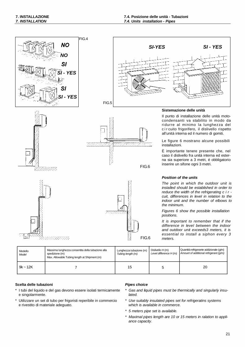
Sistemazione delle unitàIl punto di installazione delle unità moto-condensanti va stabilito in modo daridurre al minimo la lunghezza delc i r cuito frigorifero, il dislivello rispettoall'unità interna ed il numero di gomiti.
Le figure 6 mostrano alcune possibiliinstallazioni.È importante tenere presente che, nelcaso il dislivello fra unità interna ed ester-na sia superiore a 3 metri, é obbligatorioinserire un sifone ogni 3 metri.
Position of the unitsThe point in which the outdoor unit isinstalled should be established in order toreduce the width of the refrigerating c i r -cuit, differences in level in relation to theindoor unit and the number of elbows tothe minimum.Figures 6 show the possible installationpositions.It is important to remember that if thedifference in level between the indoorand outdoor unit exceeds3 meters, it isessent ial to install a siphon every 3meters.
ModelloModel
Massima lunghezza consentita della tubazione allaspedizione (m)Max. Allowable Tubing length at Shipment (m)
Lunghezza tubazione (m)Tubing length (m)
Dislivello H (m)Level difference H (m)
Quantità refrigerante addizionale (g/m)Amount of additional refrigerant (g/m)
9k ~ 12K 7 15 5 20
Scelta delle tubazioni* I tubi del liquido e del gas devono essere isolati termicamente
e singolarmente.* Utilizzare un set di tubo per frigoristi reperibile in commercio
e rivestito di materiale adeguato.
Pipes choice* Gas and liquid pipes must be thermically and singularly insu-
lated.* Use suitably insulated pipes set for refrigeratins systems
which is available in commerce.* 5 meters pipe set is available.* Maximal pipes length are 10 or 15 meters in ralation to appli-
ance capacity.
21

7. INSTALLAZIONE7. INSTALLATION
7.5. Installazione dell unità interna7.5. Indoor unit installation
Posizionamento delle tubazioniLe tubazioni (cfr. fig.7) possono uscire in certe direzioni. Senecessario si deve aprire un foro nella plastica pretranciatanelle direzioni destra, sinistra e in basso.
Pipes positioningPipes can exit in the desired direction (see fig.7).If needed a slot should be opened in the left, right, downwardssides of the plastic basement of the indoor unit.
FIG.7
DestraRight
RetroBack
BassoDownwards Retro sinistro
Back left
SinistraLeft
Ancoraggio della piastra di fissaggio.* La piastra di fissaggio deve essere ancorata e allineata sia
orizzontalmente che verticalmente per evitare che gocciolil'acqua di condensa.
* La piastra di fissaggio deve essere in grado di sostenere unpeso di 50 kg.
* La piastra di fissaggio deve essere installata direttamente sulmuro. Fissare un gancio sul muro nel centro della piastra,controllare il livellamento della piastra e fissarla quindi conalmeno 6 viti (cfr. fig.8).
Installation plate fixing* Installation plate should be fiexd both horizontally and verticallyor water will drop onto the floor.* The plate should be able to bear 50 kg weight.* The installation plate should be fixed directly to wall.
Drive a hook into the wall from the center of the plate, checkthe level of the plate and then fix it with six screws at least(see fig.8).
FIG.8
Foratura del muro per il passaggio tubazioni* Selezionare un luogo nella zona posta in ombra dal
climatizzatore per eseguire il foro e installare il manicotto.* Fare un foro nel muro di diametro 60 mm.* La parte esterna del foro deve essere più bassa di 5-10 mm
di quella interna.* Tagliare il manicotto a seconda dello spessore del muro e
quindi inserirlo, assieme alle guarnizioni terminali, nel foro sulmuro (fig. 9).
Wall hole for piping crossing* Select a position in the grammatic shadow area to drill a hole to
install a wall-hole sleeve.* Make a 60 mm diameter hole.* The outside end of the wall should be 5-10 mm lower than
inside.* Cut the wall hole sleeve in accordance with the thickness of
the wall, then put on the wall cap and insert the sleeve intothe wall (see fig.9).
FIG.9 Piastra di installazioneInstallation plate
Linea bordo unitàFrame line of the unit
Il foro nel muro deve essere eseguito in linea retta e indiscesa per permettere all acqua di condensa di dre-nare facilmente ed evitare gocciolamenti.
22
The wall hole must be done in streight direction andsloping so that water can easily drain and avoid dewdrop.

7. INSTALLAZIONE7. INSTALLATION
7.5. Installazione dell unità interna7.5. Indoor unit installation
Installazione di un tubo per il drenaggio* Installare le tubazioni con riferimento al foro nel muro e unirvi il
tubo di drenaggio come indicato in fig.10.* Quando lo si unisce, il tubo di drenaggio deve essere fissato
sotto le tubazioni del refrigerante.Note:1. Il tubo di drenaggio non deve essere installato prima che
siano connessi i circuiti dell'unità interna.2. Non riavvolgere le tubazioni sulla medesima sezione.3. Quando unite il tubo di drenaggio accertatevi che l'acqua dicondensa possa scorrere facilmente.Per controllare lo scarico:* Versare un bicchiere di acqua nell evaporatore.* Verificare che l acqua scorra attraverso il tubo flessibile di
scarico del gruppo interno senza perdite e che fuoriesca dal-uscita dello scarico.
4. Non togliere i tappi dalle tubazioni prima del collegamento.
Drain pipe installation* Install the pipe units according to the position of the wall hole,
bind the drain hose to the pipes of the indoor unit (see fig.10).* When binding the drain hose must set below the refrigerant
pipes.Notes:1. The drain hose should not be installed before the indoor unit
pipes are conneced.2. Do not rebend pipes on the same section.3. When binding the hose make sure that the water can flow freely.
To check the drainage:* Puor a glass of water on the evaporator.* Ensure the water flows through the drain hose of the indoor
unit without any leakage and goes out the drain exit.4. Never turn the nuts off from the pipe ends before linking the
pipe units.
FIG.10
Cavi elettrici dell'unità interna
UnireBind
Tubo di drenaggioDrain pipe
Indoor unit wiringsunità interna di alcuni modelli è dotata di cavi elettrici pre-
cablati , numerati e pronti per la connessione con l unitàesterna. Ove non previsti bisogna accedere alla morsettiera dicollegamento tramite apposito portellino oppure sganciando lastruttura frontale.
7.6. Connessioni elettricheUnità interna
Indoor unit of some models has a set of pre-cabled, numberedwirings ready to fit to outdoor unit. Where not forecast shouldget access to the cables terminal block through the relevantpanel or opening the indoor unit front structure.
7.6. Wiring connectionsIndoor unit:
Collegare i terminali del cavo di ali- Pannello frontale Morsettiera (all interno) Connect the power connecting cord to
mentazione nella morsettiera in accor-do i collegameni dell'esterna.Nota: Per alcuni modelli, è necessariorimuovere il FRONTALE per collegare icavi al terminale dell'unità intera. Unitàesterna:
* Far passare i cavi di alimentazione edi controllo tra unità interna ed esternaattraverso il foro nel muro.* Rimuovere il portello di accesso.* Inserire i cavi di alimentazione e dicontrollo tra unità interna ed esternaattraverso il portello di accesso.* Inserire i terminali del cavo di alimen-
Front panel
Unità internaIndoor unit
Terminal (inside)
FrontaleCabinet
BasamentoChassis
Portello di accesso
the indoor unit by connecting the wiresto the terminals on the control boardindividually in accordance with theoutdoor unit connection.Note: For some models, it is neces-sary to remove the cabinet to connectto indoor unit terminal.Outdoor unit:
* Remove the access door in the out-door unit.* Put the control and power wiresbetween indoor and outdoor unitsthrough the side panel hole.* Insert the wires end into the holes in
tazione nella morsettiera in accordo the terminal block according to corre-Morsettiera (all interno)
con i colori e i numeri corrispondenti efissare le viti. Il filo giallo/verde si colle-ga con la massa a terra.* Collegare il connettore del cavo dicontrollo al corrispondente connettorenumerato nell'unità esterna.* Fissare i cavi di collegamento e con-trollo con il fermacavo.* Installare il portello di accesso.
Unità esternaOutdoor unit
Access doorTerminal(inside)
sponding numbers and colours and fixthe screws. Green/yellow cable is tobe connected with ground.* Connect the control wire to the corre-sponding numbered connector on theoutdoor unit. * Fix the control andpower wires with the cable holder.* Install the access door.
23

7. INSTALLAZIONE7. INSTALLATION
7.6. Connessioni elettriche7.6. Wirings
ATTENZIONEAssicurare il corretto collegamento di terra. La Dittacostruttrice e i suoi Distributori non possono essere consideratiresponsabili per eventuali danni causati dalla mancanza di messa aterra.
24
ATTENZIONESi deve collegare il cavo rispettando lo schema elettrico.Se il cablaggio non viene effettuato correttamente, ilclimatizzatore si può danneggiare.
7. INSTALLAZIONE7. INSTALLATION
7.7. Tubazioni - Collegamenti frigoriferi7.7. Pipes - Refrigerant connections
Operazioni preliminari* Cartellinare le tubazioni.* Effettuare il percorso dei tubi frigoriferi secondo le necessità
di installazione.* Le tubazioni si devono piegare solo al momento della con-
nessione. Il raggio di curvatura deve essere superiore a 3,5volte il diametro del tubo. Si deve prestare attenzione a nonpiegare tubature aggrinzite.
* Una frequente piegatura o tensione delle tubature le rendepiù deboli. Fare pertanto attenzione a non piegare unatubatura più di tre volte nello stesso punto.
* A percorso concluso tagliare il tratto di tubazione eventual-mente in eccesso
Preliminary operations* Flare the pipes at both ends.* Form the refrigerant pipes route according to installation needs.* Make the elbows in compliance with the minimum tolerated
radius to prevent the pipes from being crushed.* Frequently bending or stretching the pipes will harden them,
so avoid to bend a pipes in the same section for 3 times ormore.
* Once the pipes have been installed cut off any excess pipe.
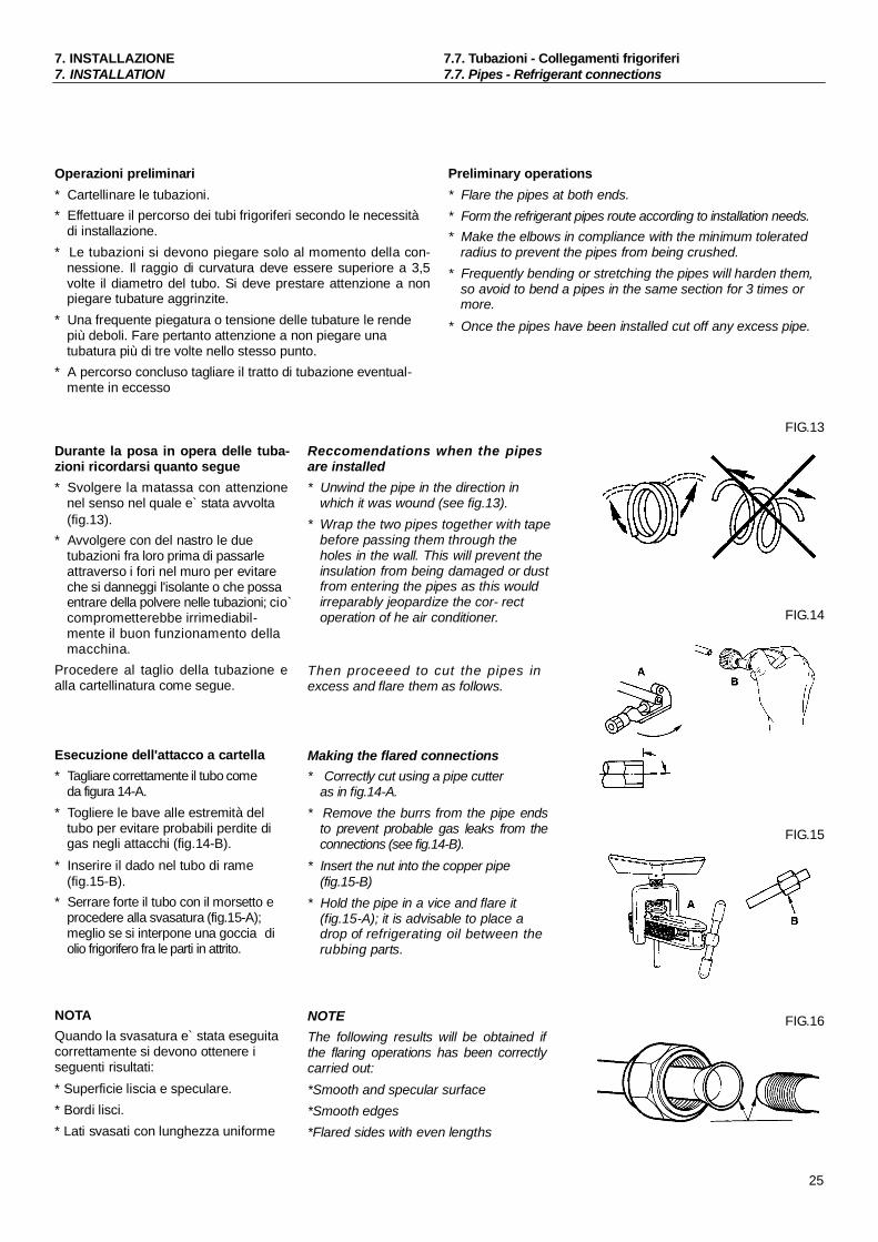
Durante la posa in opera delle tuba-zioni ricordarsi quanto segue* Svolgere la matassa con attenzione
nel senso nel quale e` stata avvolta(fig.13).
* Avvolgere con del nastro le duetubazioni fra loro prima di passarleattraverso i fori nel muro per evitareche si danneggi l'isolante o che possaentrare della polvere nelle tubazioni; cio`comprometterebbe irrimediabil-mente il buon funzionamento dellamacchina.
Procedere al taglio della tubazione ealla cartellinatura come segue.
Esecuzione dell'attacco a cartella* Tagliare correttamente il tubo come
da figura 14-A.* Togliere le bave alle estremità del
tubo per evitare probabili perdite digas negli attacchi (fig.14-B).
* Inserire il dado nel tubo di rame(fig.15-B).
* Serrare forte il tubo con il morsetto eprocedere alla svasatura (fig.15-A);meglio se si interpone una goccia diolio frigorifero fra le parti in attrito.
NOTAQuando la svasatura e` stata eseguitacorrettamente si devono ottenere iseguenti risultati:* Superficie liscia e speculare.* Bordi lisci.* Lati svasati con lunghezza uniforme
Reccomendations when the pipesare installed* Unwind the pipe in the direction in
which it was wound (see fig.13).* Wrap the two pipes together with tape
before passing them through theholes in the wall. This will prevent theinsulation from being damaged or dustfrom entering the pipes as this wouldirreparably jeopardize the cor- rectoperation of he air conditioner.
Then proceeed to cut the pipes inexcess and flare them as follows.
Making the flared connections* Correctly cut using a pipe cutter
as in fig.14-A.* Remove the burrs from the pipe ends
to prevent probable gas leaks from theconnections (see fig.14-B).
* Insert the nut into the copper pipe(fig.15-B)
* Hold the pipe in a vice and flare it(fig.15-A); it is advisable to place adrop of refrigerating oil between therubbing parts.
NOTEThe following results will be obtained ifthe flaring operations has been correctlycarried out:*Smooth and specular surface*Smooth edges*Flared sides with even lengths
FIG.13
FIG.14
FIG.15
FIG.16
25

7. INSTALLAZIONE7. INSTALLATION
7.8. Spurgo aria7.8. Air purging
ATTENZIONE - E` importante che non cadano all'inter-no dei tubi trucioli, polvere o altro perche` intasereb-bero il circuito frigorifero all'altezza del capillare cau-sando il blocco dell'impianto o il grippaggio delcompressore.
ATTENTION - It is important to prevent chips, dust orother foreign bodes from dropping inside the pipessince these would clog the refrigerating circuit at thecapillary causing the system to block or the compres-sor to seize.
Connessione con le valvole.* Rimuovere i dadi dalle tubazioni dell'unità interna.* Rimuovere i tappi da entrambe le estremità delle tubazioni di
collegamento.* Rimuovere i dadi dalle tubazioni dell'unità esterna.* Versare un po` di olio frigorifero sulle estremità cartellate
delle tubature, quindi allineare le estremità cartellate alleuscite e fissare bene i dadi.
Connection to valves* Remove nuts from the pipes of the indoor unit.* Remove plugs from both ends of the connecting pipes.* Remove nuts from the pipes of the oudoor unit.* Drop some refrigerating oil onto the flare fittings of both ends
of the pipes and tightly secure the nuts.
Spurgo aria
L'aria e l'umidità che rimangono all'interno delsistema di refrigerazione hanno i seguentieffetti indesiderabili.
Air purging
Air and moisture remaining in the refrigerantsystem have undesirable effects as indicatedbelow.
La pressione nel impianto aumenta. La corrente di esercizio aumenta. L'efficienza refrigerante (o di riscaldamento)
diminuisce. L'umidità nel circuito refrigerante può
gelare e bloccare i tubicini capillari. L'acqua può portare a fenomeni di corrosione
dei componenti nell'impianto refrigerante.
Di conseguenza il gruppo interno e i tubi postitra gruppo interno e gruppo esterno devonoessere collaudati per perdite e spurgati perrimuovere elementi non condensanti e umiditàdal sistema.
Spurgo aria con pompa a vuoto
Preparazione
Verificare che ciascun tubo (sia i tubi lateralidel gas che del liquido) tra gruppo interno egruppo esterno siano stati collegati nel modocorretto e che tutti i cablaggi necessari al col-laudo siano stati effettuati. Rimuovere i cap-pucci delle valvole di servizio sia dai lati gasche liquido sul gruppo esterno. Prendere notadel fatto che a questo punto che ambedue levalvole di servizio dei lati gas e liquido delgruppo interno vengono mantenute chiuse.
Test perdite Collegare la valvola manometro (con gli
indicatori di pressione) ed la bombola del gasazoto all'apertura di servizio con i tubi dicarica.
AttenzioneAccertarsi di usare una valvola manometro perlo spurgo d'aria. Se non è disponibile usareuna valvola di chiusura a questo scopo. Lamanopola "Hi" della valvola manometro
Pressure in the system rises. Operating current rises. Cooling(or heating) efficiency drops.
Moisture in the refrigerant circuit mayfreeze and block capillary tubing.
Water may lead to corrosion of parts inthe refrigeration system.
Therefore, the indoor unit and tubing betweenthe indoor and outdoor unit must be leaktested and evacuated to remove any non con-densable and moisture from the system.
Air purging with vacuum pump
Preparation
Check that each tube(both liquid and gas sidetubes) between the indoor and outdoor unitshave been properly connected and all wiringfor the test run has been completed. Removethe service valve caps from both the gas andthe liquid side on the outdoor unit. Note thatboth the liquid and the gas side service valveson the outdoor unit are kept closed at thisstage.
Leak test Connect the manifold valve(with pres-sure gauges) and dry nitrogen gascylinder to this service port with chargehoses.
CautionBe sure to use a manifold valve for air pur-ging. If it is not available, use a stop valve forthis purpose. The "Hi" knob of the manifoldvalve must always be kept close.
Unità esternaOutdoor unit
Valvola manometroManifold gauge
Indicatore di pressionePressure gauge
Unità internaIndoor unit
Tubo flessibile di caricaCharge hose
Bombola gas azoto(nella posizione verticale)
Nitrogen gas cylinder(in vertical position)
26
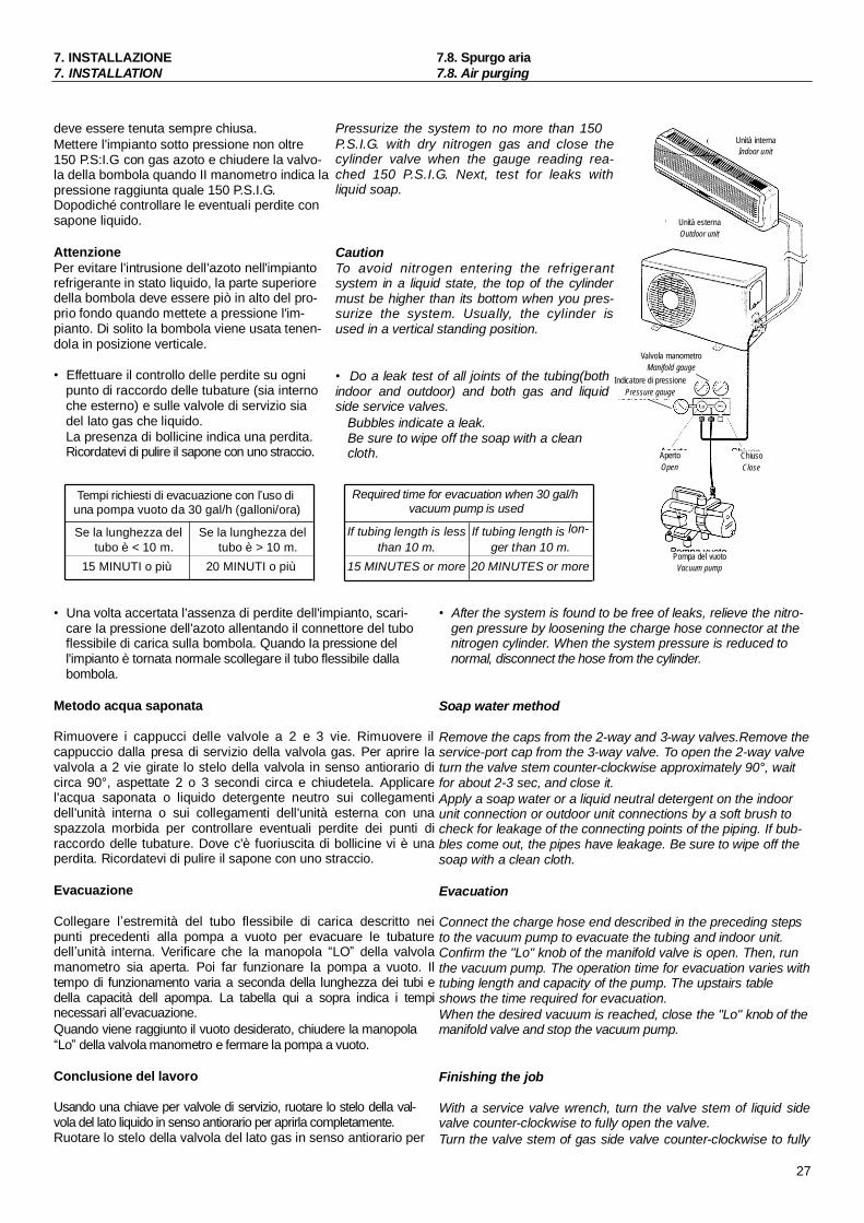
7. INSTALLAZIONE7. INSTALLATION
7.8. Spurgo aria7.8. Air purging
deve essere tenuta sempre chiusa.Mettere l'impianto sotto pressione non oltre150 P.S:I.G con gas azoto e chiudere la valvo-la della bombola quando II manometro indica lapressione raggiunta quale 150 P.S.I.G.Dopodiché controllare le eventuali perdite consapone liquido.
AttenzionePer evitare l'intrusione dell'azoto nell'impiantorefrigerante in stato liquido, la parte superioredella bombola deve essere piò in alto del pro-prio fondo quando mettete a pressione l'im-pianto. Di solito la bombola viene usata tenen-dola in posizione verticale.
Effettuare il controllo delle perdite su ognipunto di raccordo delle tubature (sia internoche esterno) e sulle valvole di servizio siadel lato gas che liquido.La presenza di bollicine indica una perdita.Ricordatevi di pulire il sapone con uno straccio.
Pressurize the system to no more than 150P.S.I.G. with dry nitrogen gas and close thecylinder valve when the gauge reading rea-ched 150 P.S.I.G. Next, test for leaks withliquid soap.
CautionTo avoid nitrogen entering the refrigerantsystem in a liquid state, the top of the cylindermust be higher than its bottom when you pres-surize the system. Usually, the cylinder isused in a vertical standing position.
Do a leak test of all joints of the tubing(bothindoor and outdoor) and both gas and liquidside service valves.
Bubbles indicate a leak.Be sure to wipe off the soap with a cleancloth.
Unità esternaOutdoor unit
Valvola manometroManifold gauge
Indicatore di pressionePressure gauge
ApertoOpen
Unità internaIndoor unit
ChiusoClose
Tempi richiesti di evacuazione con l uso diuna pompa vuoto da 30 gal/h (galloni/ora)
Required time for evacuation when 30 gal/hvacuum pump is used
Se la lunghezza del Se la lunghezza del If tubing length is less If tubing length is lon-tubo è < 10 m. tubo è > 10 m. than 10 m. ger than 10 m.
Pompa del vuoto15 MINUTI o più 20 MINUTI o più 15 MINUTES or more 20 MINUTES or more Vacuum pump
Una volta accertata l'assenza di perdite dell'impianto, scari-care Ia pressione dell'azoto allentando il connettore del tuboflessibile di carica sulla bombola. Quando Ia pressione dell'impianto è tornata normale scollegare il tubo flessibile dallabombola.
Metodo acqua saponata
Rimuovere i cappucci delle valvole a 2 e 3 vie. Rimuovere ilcappuccio dalla presa di servizio della valvola gas. Per aprire lavalvola a 2 vie girate lo stelo della valvola in senso antiorario dicirca 90°, aspettate 2 o 3 secondi circa e chiudetela. Applicarel'acqua saponata o liquido detergente neutro sui collegamentidell'unità interna o sui collegamenti dell'unità esterna con unaspazzola morbida per controllare eventuali perdite dei punti diraccordo delle tubature. Dove c'è fuoriuscita di bollicine vi è unaperdita. Ricordatevi di pulire il sapone con uno straccio.
Evacuazione
Collegare l estremità del tubo flessibile di carica descritto neipunti precedenti alla pompa a vuoto per evacuare le tubaturedell unità interna. Verificare che la manopola LO della valvolamanometro sia aperta. Poi far funzionare la pompa a vuoto. Iltempo di funzionamento varia a seconda della lunghezza dei tubi edella capacità dell apompa. La tabella qui a sopra indica i tempinecessari all evacuazione.Quando viene raggiunto il vuoto desiderato, chiudere la manopolaLo della valvola manometro e fermare la pompa a vuoto.
Conclusione del lavoro
Usando una chiave per valvole di servizio, ruotare lo stelo della val-vola del lato liquido in senso antiorario per aprirla completamente.Ruotare lo stelo della valvola del lato gas in senso antiorario per
After the system is found to be free of leaks, relieve the nitro-gen pressure by loosening the charge hose connector at thenitrogen cylinder. When the system pressure is reduced tonormal, disconnect the hose from the cylinder.
Soap water method
Remove the caps from the 2-way and 3-way valves.Remove theservice-port cap from the 3-way valve. To open the 2-way valveturn the valve stem counter-clockwise approximately 90°, waitfor about 2-3 sec, and close it.Apply a soap water or a liquid neutral detergent on the indoorunit connection or outdoor unit connections by a soft brush tocheck for leakage of the connecting points of the piping. If bub-bles come out, the pipes have leakage. Be sure to wipe off thesoap with a clean cloth.
Evacuation
Connect the charge hose end described in the preceding stepsto the vacuum pump to evacuate the tubing and indoor unit.Confirm the "Lo" knob of the manifold valve is open. Then, runthe vacuum pump. The operation time for evacuation varies withtubing length and capacity of the pump. The upstairs tableshows the time required for evacuation.When the desired vacuum is reached, close the "Lo" knob of themanifold valve and stop the vacuum pump.
Finishing the job
With a service valve wrench, turn the valve stem of liquid sidevalve counter-clockwise to fully open the valve.Turn the valve stem of gas side valve counter-clockwise to fully
27
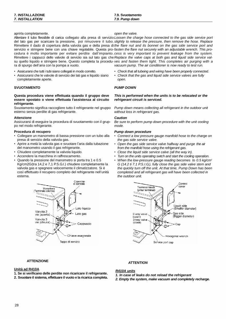
7. INSTALLAZIONE7. INSTALLATION
7.9. Svuotamento7.9. Pump down
aprirla completamente.Allentare il tubo flessibile di carica collegato alla presa di serviziodel lato gas per scaricare la pressione, poi rimuovere il tubo.Rimettere il dado di copertura della valvola gas e della presa diservizio e stringere bene con una chiave regolabile. Questa pro-cedura è molto importante per evitare perdite dall impianto.Rimettere i cappucci delle valvole di servizio sia sul lato gas chesu quello liquido e stringere bene. Questo completa la procedu-ra di spurgo dell aria con la pompa a vuoto.
Assicurarsi che tutti i tubi siano collegati in modo corretto. Assicurarsi che le valvole di servizio dei lati gas e liquido siano
completamente aperte.
SVUOTAMENTO
Questa procedura viene effettuata quando il gruppo deveessere spostato o viene effettuata I'assistenza al circuitorefrigerante.Svuotamento significa raccogliere tutto il refrigerante nel gruppoesterno senza perdite di gas refrigerante.
AttenzioneAssicurarsi di eseguire Ia procedura di svuotamento con il grup-po nel modo refrigerante.
Procedura di recupero Collegare un manometro di bassa pressione con un tubo alla
presa di servizio della valvola gas. Aprire a metà la valvola gas e svuotare l aria dalla tubazione
del manometro usando il gas refrigerante. Chiudere completamente la valvola liquido. Accendere la macchina in raffrescamento. Quando la pressione del manometro si porta tra 1 e 0.5
Kg/cm2G(tra 14,2 e 7,1 P.S.G.I.) chiudere completamente lavalvola gas e spegnere velocemente il climatizzatore. Si ècosì effettuato il recupero completo del refrigerante nell unitàesterna.
ATTENZIONE
Unità ad R410A1. Se si verificano delle perdite non ricaricare il refrigerante.2. Svuotare il sistema, effettuare il vuoto e la ricarica completa.
open the valve.Loosen the charge hose connected to the gas side service portslightly to release the pressure, then remove the hose. Replacethe flare nut and its bonnet on the gas side service port andfasten the flare nut securely with an adjustable wrench. This pro-cess is very important to prevent leakage from the system.Replace the valve caps at both gas and liquid side service val-ves and fasten them tight. This completes air purging with avacuum pump. The air conditioner is now ready to test run.
Check that all tubeing and wiring have been properly connected. Check that the gas and liquid side service valves are fully
open.
PUMP DOWN
This is performed when the units is to be relocated or therefrigerant circuit is serviced.
Pump down means collecting all refrigerant in the outdoor unitwithout loss in refrigerant gas.
CautionBe sure to perform pump down procedure with the unit coolingmode.
Pump down procedure Connect a low pressure gauge manifold hose to the charge on
the gas side service valve. Open the gas side service valve halfway and purge the air
from the manifold hose using the refrigerant gas. Close the liquid side service calve (all the way in). Turn on the units operating swtch and start the cooling operation. When the low-pressure gauge reading becomes to 0.5 kg/cm2
G (14.2 ti 7.1 P.S.I.G.), fully close the gas side valve stem andthe quickly turn off the unit. At that time, Pump Down has beencompleted and all refrigerant gas will have been collected inthe outdoor unit.
ATTENTION
R410A units1. In case of leaks do not reload the refrigerant2. Empty the system, make vacuum and completely recharge.
28

7. INSTALLAZIONE7. INSTALLATION
7.10. Tubazioni di drenaggio7.10. Drain pipes
Per fare in modo che il drenaggio segua un corso specifico,eseguire le seguenti istruzioni prima di installare l'unità esternasulla base di ancoraggio.1.Installare il raccordo di drenaggio (cfr. fig.17), incluso nella
macchina, dentro il foro di drenaggio nel basamento dell'unità esterna.
2. Installare la tubazione di drenaggio.
In order to let the unit draining properly, please perform chear-fully the following steps before installing the outside unit ontothe installation base.1. Install the drain pipe fitting (see fig.17), enclose into the unit,
into the drain hole of the outside unit bottom plate.2. Install the drain pipe.
FIG.17 raccordo tubodrenaggio
drain pipe fitting
fondo unita` esternaoutside unit bottom plate
tubo drenaggiodrain pipe
connettere in modo appropriato ilraccordo con il tubo di drenaggiojoin properly the drain pipe fitting
to the drain pipe
Finiture* Nascondere le tubazioni e icavi elettrici in una canalina.
* Unire e fissare con del nastro icavi elettrici di collegamento econtrollo alle tubature(fig.18).
* Tappare il foro nel muro constucco o cemento al fine dievitare l'infiltrazione di aria eacqua piovana nella stanza(fig.19).
* Fissare i tubi di drenaggio almuro esterno (cfr. fig.20).
Finishing* Hide the pipes and the
wirings in a canalization.* Using tape join and fix con-
necting cable and controllwires to pipes (See fig.18).
* Plug the hole in the wall withputty or cement in order toprevent from rainwater andwind blowing into the room(See fig.19).
* Fix the drain pipe to the out-side wall (See fig.20).
FIG.18 passacaviholder
stuccoputty
murowall
FIG.19
Controllo dell installazione etest di funzionamento* Collegamenti corretti dei
cavi e delle tubazioni?* Perdite di gas dai collega-
menti delle tubazioni?* Valvole aperte completa-
mente?* I cavi di collegamentotra
unità esterna ed interna sonoinseriti in modo efficacenei terminali delle morsettiere?
* Lo scarico è effettuato inmaniera corretta ?
Checking the installationand operating test.* Are cables and pipes properly
joint?* Are there gas leaks from the
pipes joints?* Are valves completely open?* The connection cables
between indoor and outdoorunit are properly inserted intothe terminal board termi nals.
* Has the drain part beenproperly installed?
unire insiemejoin togegher
tubo drenaggiodrain pipe
passacaviholder
FIG.20
* La linea di terra è collegata inmodo efficace?
* unità interna è fissata inmodo sicuro?
* Il voltaggio di alimentazione èconforme?
* Fa qualche rumore?* Le spie si accendono normal-
mente?
* Has the ground conductorbeen properly connected?
* Has the indoor unit beensafety fixed?
* Is the power rating conform?* Is there any abnormal noise?* Do the indication leds work
properly?
non formareuna gobbaverso l'alto donot make anupside bend
non piegaredo not bend
non scaricarenell'acquado not dichargeinto water
29
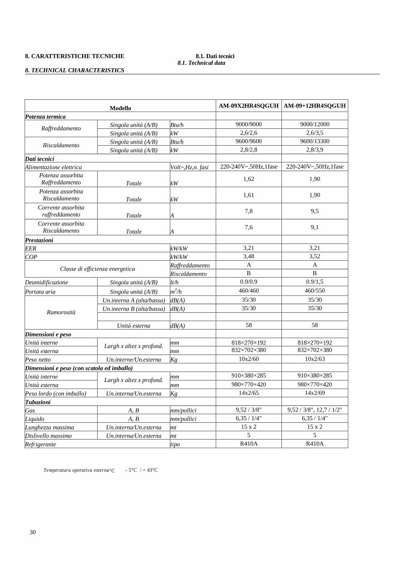
8. CARATTERISTICHE TECNICHE 8.1. Dati tecnici 8.1. Technical data
8. TECHNICAL CHARACTERISTICS
Modello AM-09X2HR4SQGUH AM-09+12HR4SQGUH
Potenza termicaSingola unità (A/B) Btu/h 9000/9000 9000/12000RaffreddamentoSingola unità (A/B) kW 2,6/2,6 2,6/3,5Singola unità (A/B) Btu/h 9600/9600 9600/13300RiscaldamentoSingola unità (A/B) kW 2,8/2,8 2,8/3,9
Dati tecniciAlimentazione elettrica Volt~,Hz,n. fasi 220-240V~,50Hz,1fase 220-240V~,50Hz,1fase
Potenza assorbitaRaffreddamento Totale kW
1,62 1,90
Potenza assorbitaRiscaldamento Totale kW
1,61 1,90
Corrente assorbitaraffreddamento Totale A
7,8 9,5
Corrente assorbitaRiscaldamento Totale A
7,6 9,1
PrestazioniEER kW/kW 3,21 3,21COP kW/kW 3,48 3,52
Raffreddamento A AClasse di efficienza energeticaRiscaldamento B B
Deumidificazione Singola unità (A/B) lt/h 0.9/0.9 0.9/1,5Portata aria Singola unità (A/B) m3/h 460/460 460/550
Un.interna A (alta/bassa) dB(A) 35/30 35/30Un.interna B (alta/bassa) dB(A) 35/30 35/30Rumorosità
Unità esterna dB(A) 58 58Dimensioni e pesoUnità interne mm 818×270×192 818×270×192Unità esterna
Largh x altez x profond.mm 832×702×380 832×702×380
Peso netto Un.interne/Un.esterna Kg 10x2/60 10x2/63Dimensioni e peso (con scatola ed imballo)Unità interne mm 910×380×285 910×380×285Unità esterna
Largh x altez x profond.mm 980×770×420 980×770×420
Peso lordo (con imballo) Un.interna/Un.esterna Kg 14x2/65 14x2/69TubazioniGas A, B mm/pollici 9,52 / 3/8" 9,52 / 3/8", 12,7 / 1/2"Liquido A, B mm/pollici 6,35 / 1/4" 6,35 / 1/4"Lunghezza massima Un.interna/Un.esterna mt 15 x 2 15 x 2Dislivello massimo Un.interna/Un.esterna mt 5 5Refrigerante tipo R410A R410A
Temperatura operativa esterna°C - 5°C / + 43°C
30
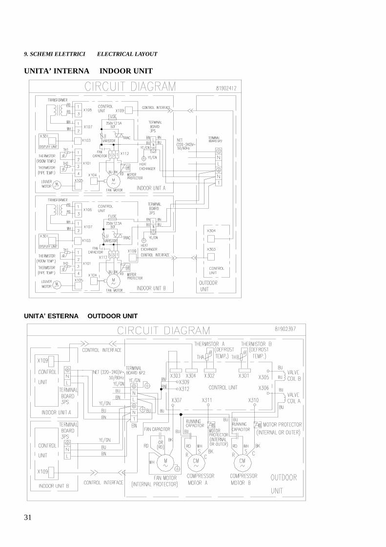
9. SCHEMI ELETTRICI ELECTRICAL LAYOUT
UNITA’ INTERNA INDOOR UNIT
UNITA ESTERNA OUTDOOR UNIT
31

Hisense Italy SrlCorso Sommeiller, 32 10128 Torino, Italy
Tel. +39 011 500916 Fax +39 011 5183200e-mail: [email protected] - www.hisenseitalia.it
C.F. - P.IVA 09403050017