
H OCEANO 15 23-28 2 - kamini-italia.com
133
- 1 - I Installazione, uso e manutenzione pag. 2 UK Installation, use and maintenance pag. 19 F Installation, usage et maintenance pag. 36 E Instalación, uso y mantenimiento pag. 53 D Installations-, Betriebs- und Wartungsanleitung pag. 70 NL Installatie, gebruik en onderhoud pag. 87 6L 9gradnMa, uporaba in YzdråeYanMe str . 10 H 2 OCEANO 15-23-28
Transcript of H OCEANO 15 23-28 2 - kamini-italia.com

- 1 -
I Installazione, uso e manutenzione pag. 2UK Installation, use and maintenance pag. 19F Installation, usage et maintenance pag. 36E Instalación, uso y mantenimiento pag. 53D Installations-, Betriebs- und Wartungsanleitung pag. 70NL Installatie, gebruik en onderhoud pag. 87
L gradn a, uporaba in zdr e an e str . 10
H2OCEANO 15-23-28

- 2 -
ITA
LIA
NO Gentile Signora / Egregio Signore
La ringraziamo e ci complimentiamo con Lei per aver scelto il nostro prodotto.-
rezza tutte le prestazioni.
www.edilkamin.com alla voce CENTRI ASSISTENZA TECNICA.
NOTA
di garanzia, guanto, CD/scheda tecnica).
-
-
dello stesso alle normative.
Presso il rivenditore, sul sito www.edilkamin.com o al numero verde può trovare il nominativo del Centro Assistenza più vicino.
-
Il termocaminetti a legna H

- 3 -
ITA
LIA
NO
CARATTERISTICHE TERMOTECNICHE
H2OCEANO è progettato per scaldare acqua attraverso una combustione di legna nel focolare.L’acqua contenuta nel termocaminetto si scalda e viene inviata nell’impianto di riscaldamento (termosifoni, scalda salviette, pannelli radianti a pavimento) ed inoltre scalda il locale nel quale si trova per irraggiamento e convezione naturale.Il termocaminetto NON DEVE MAI FUNZIONARE SENZA ACQUA NELL’IMPIANTO.L’acqua si riscalda, circolando nell’ intercapedine che lambisce tutta la parete semicircolare e la cupola del focolare. L’interca-pedine è realizzata con lamiera di acciaio di forte spessore.Il focolare è chiuso frontalmente da un portellone che si apre a saliscendi e ad anta per la pulizia del vetro.
INNOVATIVA GRIGLIA CENERE BREVETTATAConsente di distribuire l’aria primaria di combustione non solo dal basso verso l’alto, ma anche orizzontalmente per avere un’elevata ossigenazione della amma, una migliore combu-stione e più potenza.
PORTELLONE “SALVAGUARNIZIONI”Durante lo scorrimento, il portellone resta leggermente scostato dalla bocca del termocaminetto per proteggere le guarnizioni.In posizione di chiusura si accosta perfettamente per garantire la massima tenuta e quindi un ottimo rendimento. La maniglia è asportabile oppure pu essere ssata al portello-ne (vedi pag. 11)
BY-PASS FUMI AUTOMATICOIn fase di accensione, a bocca aperta, per agevolare l’avvio della combustione, la serranda fumi S resta in posizione di apertura in modo che i fumi possano direttamente e agevolmen-te raggiungere la canna fumaria ( g. a). Quando la combustione è ben avviata, chiudendo il portellonesi chiude automaticamente anche la serranda fumi S ( g. b). In questo assetto, i fumi prima di raggiungere la canna fumaria deviano in modo da lambire e cedere calore in maniera ef cace all’acqua. Il by-pass è comandato automaticamente dal movimento del portellone.
De ettori Cielini
Alloggiamento Motore Grill Post-Combustione Valvola automatica di regolazione presa aria esterna (optional)
Possibilitá applicazione piedini regolabili (optional)
Taratura per regolazione automatica dell’aria di combustione
Portellone saliscendi
Intercapedine avvolgente per contenimento acqua
Serpentina di sicurezza per scarico termico (versione CS)
Griglia cenere di distribuzione aria primaria di combustione
Serranda deviazione percorso fumi
A
B
C
D
E
F
G
H
I
L
S
(a)
(b)
s
s
AI
L
H
G
H
A
B
D
EF E
CS
- 4 -
ITA
LIA
NO
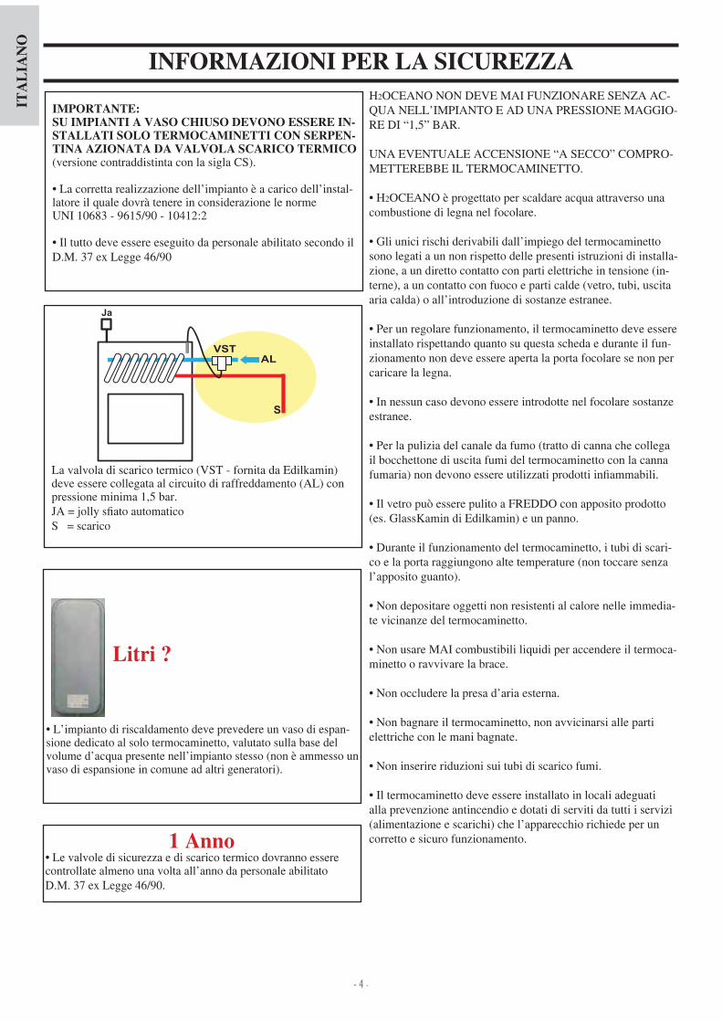
H2OCEANO NON DEVE MAI FUNZIONARE SENZA AC-QUA NELL’IMPIANTO E AD UNA PRESSIONE MAGGIO-RE DI “1,5” BAR.
UNA EVENTUALE ACCENSIONE “A SECCO” COMPRO-METTEREBBE IL TERMOCAMINETTO.
H2OCEANO è progettato per scaldare acqua attraverso una combustione di legna nel focolare.
Gli unici rischi derivabili dall’impiego del termocaminetto sono legati a un non rispetto delle presenti istruzioni di installa-zione, a un diretto contatto con parti elettriche in tensione (in-terne), a un contatto con fuoco e parti calde (vetro, tubi, uscita aria calda) o all’introduzione di sostanze estranee. Per un regolare funzionamento, il termocaminetto deve essere
installato rispettando quanto su questa scheda e durante il fun-zionamento non deve essere aperta la porta focolare se non per caricare la legna. In nessun caso devono essere introdotte nel focolare sostanze
estranee.
Per la pulizia del canale da fumo (tratto di canna che collega il bocchettone di uscita fumi del termocaminetto con la canna fumaria) non devono essere utilizzati prodotti in ammabili. Il vetro pu essere pulito a FREDDO con apposito prodotto
(es. GlassKamin di Edilkamin) e un panno.
Durante il funzionamento del termocaminetto, i tubi di scari-co e la porta raggiungono alte temperature (non toccare senza l’apposito guanto).
Non depositare oggetti non resistenti al calore nelle immedia-te vicinanze del termocaminetto.
Non usare MAI combustibili liquidi per accendere il termoca-minetto o ravvivare la brace.
Non occludere la presa d’aria esterna.
Non bagnare il termocaminetto, non avvicinarsi alle parti elettriche con le mani bagnate.
Non inserire riduzioni sui tubi di scarico fumi.
Il termocaminetto deve essere installato in locali adeguati alla prevenzione antincendio e dotati di serviti da tutti i servizi (alimentazione e scarichi) che l’apparecchio richiede per un corretto e sicuro funzionamento.
IMPORTANTE:SU IMPIANTI A VASO CHIUSO DEVONO ESSERE IN-STALLATI SOLO TERMOCAMINETTI CON SERPEN-TINA AZIONATA DA VALVOLA SCARICO TERMICO(versione contraddistinta con la sigla CS).
La corretta realizzazione dell’impianto è a carico dell’instal-latore il quale dovrà tenere in considerazione le norme UNI 1 - 15 - 1 12 2
Il tutto deve essere eseguito da personale abilitato secondo il D.M. e Legge
La valvola di scarico termico (VST - fornita da Edilkamin) deve essere collegata al circuito di raffreddamento (AL) con pressione minima 1,5 bar.A olly s ato automatico
S = scarico
1 Anno Le valvole di sicurezza e di scarico termico dovranno essere
controllate almeno una volta all’anno da personale abilitato D.M. e Legge .
L’impianto di riscaldamento deve prevedere un vaso di espan-sione dedicato al solo termocaminetto, valutato sulla base del volume d’acqua presente nell’impianto stesso (non è ammesso un vaso di espansione in comune ad altri generatori).
Litri ?
INFORMAZIONI PER LA SICUREZZA

- 5 -
ITA
LIA
NO
DISPOSIZIONI GENERALI SULLA SICUREZZAIN CASO DI INSTALLAZIONE SU IMPIANTI A VASO APERTO
Gli allacciamenti, la messa in servizio e la veri ca del buon funzionamento, devono essere eseguite da personale quali-
cato, in grado di effettuare i collegamenti secondo le leggi vigenti ed in particolare secondo D.M e Legge , nonché nel pieno rispetto delle presenti istruzioni.Per le installazioni all’estero fare riferimento alle speci che normative nazionali.Il riempimento del termocaminetto e dell’impianto deve avve-nire mediante il vaso di espansione aperto, per naturale caduta dell’acqua attraverso il tubo di carico (diametro non inferiore a 18 mm).
Durante questa fase devono essere aperti tutti gli s ati dei radiatori in modo da evitare la formazione di sacche d’aria nell’impianto che ostacolerebbero la circolazione dell’acqua.
NOTA BENEIl vaso aperto va posizionato ad un’altezza maggiore di 3 mt rispetto all’elemento più alto del circuito primario, ed inferio-re a 15 mt rispetto la mandata del termocaminetto.
L’altezza del vaso deve essere comunque tale da creare una pressione maggiore di quella prodotta dalla pompa (circola-tore). Non riempire mai l’impianto direttamente con la pressione
di rete in quanto questa potrebbe essere superiore a quella di targa del termocaminetto, con conseguente danneggiamento del termocaminetto stesso. Il tubo di sicurezza al vaso di espansione deve essere a sfogo
libero senza rubinetti di intercettazione ed opportunamente isolato per evitareil congelamento dell’acqua al suo interno, che ne comprometterebbe la giunzione. Il tubo di carico deve essere libero senza rubinetti e curvature. La pressione max di esercizio non deve superare 1,5 bar La pressione di collaudo è di 3 bar E’ opportuno additivare l’acqua contenuta nell’impianto con
liquido antigelo o attenersi alla norma UNI 8065. Non accendere mai il fuoco nel termocaminetto (nemmeno
per prova) se l’impianto non è riempito d’acqua; In tal caso il termocaminetto potrebbe rovinarsi irrimediabilmente. Collegare gli scarichi delle valvole di scarico termico (VST)
e di sicurezza (VSP) (schemi a pagine seguenti) Il collaudo di tenuta dell’impianto va eseguito a vaso di
espansione aperto Sul circuito acqua calda sanitaria è consigliabile installare
una valvola di sicurezza da 6 bar per scaricare l’eventuale eccessivo aumento di volume d’acqua contenuta nello scambiatore. Disporre tutti i componenti dell’impianto, (circolatore,
scambiatore, valvole ecc.) in zone facilmente accessibili per la manutenzione ordinaria e straordinaria.
TRATTAMENTO DELL’ACQUAPrevedere additivazione di sostanze antigelo, antincrostanti e anticorrosive. Nel caso l’acqua di riempimento e rabbocco abbia durezza superiore a 35°F, impiegare un addolcitore.
IN CASO DI INSTALLAZIONE SU IMPIANTI A VASO CHIUSO(disposizioni aggiuntive a quelle riportate per impianti a vaso aperto)
Il riempimento deve avvenire avendo cura di non superare 1,5 bar.
possibile collegare il termocaminetto ad un impianto a VASO CHIUSO solo nella versione con serpentina azionata da valvola di sicurezza per sovratemperatura (versione con-traddistinta con la sigla CS).
Nel caso di collegamento del termocaminetto ad un impian to esistente deve essere valutata la necessità di un ulteriore VASO CHIUSO sull’impianto.
La pressione a monte del circuito di raffredamento deve essere almeno 1,5 bar (UNI 10 12 2 p.to 6.2).
Fare riferimento alla norma UNI 8065-1989 (trattamento dell’acqua negli impianti termici ad uso civile).

- 6 -
ITA
LIA
NO
DIMENSIONI
FRONTE FIANCO
PIANTA
L
PH
ritorno serpentina scarico termico 1 2” M (versione a vaso chiuso)
mandata serpentina scarico termico 1 2” M(versione a vaso chiuso)
scarico
presa aria esternaritorno acqua all’impianto 1” M
mandata acqua all’impianto 1” M
PER IL CORRETTO FUNZIONAMENTO OCCORRE INCROCIARE I TUBI DI MANDATA E DI RITORNO
Y
X
pozzetto per sonda
H2OCEANO 15 - 15/CS H2OCEANO 23 - 23/CS H2OCEANO 28 - 28/CS
L 88 106 cm
P 62 68 83 cm
H135 senza piedini
(con piedini 1 cm)1 senza piedini
(con piedini 1 cm)1 senza piedini
(con piedini 1 cm)cm
X 3 3 51 cm
Y 36 37 50 cm
dimensioniinternefocolare
50x38 60x50 78x60 cm

- 7 -
ITA
LIA
NO
DATI TERMOTECNICI
N.B.: DATI DI PROGETTO (Riferimento norma EN 13229) * Il volume riscaldabile è calcolato considerando un isolamento della casa come da L 10 91 e successive modi che e una richiesta di calore di 33 Kcal m ora.E’ importante tenere in considerazione anche la collocazione del termocaminetto nell’ambiente da scaldare.* * temperatura in caldaia 70° - (DT=25K)
I dati sopra riportati sono indicativi.
PER IL CORRETTO FUNZIONAMENTO OCCORRE INCROCIARE I TUBI DI MANDATA E DI RITORNO
IL DIAMETRO DELLA CANNA FUMARIA DA UTILIZZARE, DOVRA’ ESSERE VALUTATO DALL’INSTALLA-TORE, IN RELAZIONE ALL’ALTEZZA DELLA STESSA CANNA FUMARIA.
15-15/CS 23-23/CS 28-28/CS
Potenza termica bruciata 18,5 27,8 3 ,8 kW
Potenza nominale 1 ,8 22,2 27,8 kW
Potenza nominale all’acqua 12,1 18,2 22,8 kW
Rendimento globale circa 80 80 80 %
Rendimento all’acqua circa 82 82 82 %
Classe di rendimento (EN 303-5) > 3 > 3 > 3 -
ø uscita fumi femmina 18 22 25 cm
Pressione massima d’esercizio 1,5 1,5 1,5 bar
Consumo combustibile ,5 7 8,5 kg h
Contenuto d’acqua 50 100 130 litri
Volume riscaldabile * 355 535 670 m
Peso con imballo 2 0 285 325 kg
Produzione acqua calda sanitaria (kit 1- 3 - N3 - N3bis)** 13-1 13-1 13-1 litri min
Diametro condotto presa aria 12,5 12,5 12,5 cm
Mandata all’impianto (maschio) 1” 1” 1” pollici
Ritorno dall’impianto (maschio) 1” 1” 1” pollici

- 8 -
ITA
LIA
NO
INSTALLAZIONEAVVERTENZE IMPORTANTI Oltre a quanto indicato nel presente documento, tenere in con-siderazione le norme UNI- n. 10683 - generatori di calore a legno requisiti di installazione- n. 9615/90 - calcolo delle dimensioni interne dei camini- n. 10412:2 - impianti di riscaldamento ad acqua calda. Requisiti di sicurezza, speci ci per impianti con apparecchi per il riscaldamento di tipo domestico con caldaia incorporata, alimentati a combusti bile solido, con potenza del focolare o comples siva dei focolari non superiore a 35 kW
In particolare- Prima di iniziare qualsiasi operazione di montaggio è importante veri care la compatibilità con l’impianto come stabilito dalla norma UNI 10683 ai paragra .1 .1.1 .1.2.- A montaggio ultimato, l’installatore dovrà provvedere alle operazioni di “messa in esercizio” ed a rilasciare documenta-zione come richiesto dalla norma UNI 10683 rispettivamente ai paragra .6 e 5.- funzionamento del termocaminetto devono essere eseguite da personale quali cato, in grado di effettuare i collegamenti elettrici ed idraulici come richiesto dalle norme UNI 10683 al paragrafo .5, e UNI 10 12 2, nonché nel pieno rispetto delle presenti istruzioni di montaggio.- Le veri che vanno eseguite a camino acceso ed a regime per alcune ore, prima di rivestire il monoblocco al ne di poter eventualmente intervenire.Quindi le operazioni di nitura quali ad esempio- costruzione della controcappa- montaggio del rivestimento- esecuzione di lesene, tinteggiature, ecc.vanno eseguite a collaudo ultimato con esito positivo.Edilkamin non risponde di conseguenza degli oneri derivati sia da interventi di demolizione che di ricostruzione anche se conseguenti a lavori di sostituzioni di eventuali pezzi difettosi.
PRESA D’ARIA ESTERNA Il collegamento con l’esterno, con una sezione passante pari a un diametro di cm 12,5 (vedi tabella tecnica), è assoluta-mente necessario per il buon funzionamento del termocami-netto; deve essere quindi inderogabilmente realizzato.Detto collegamento, deve raccordare direttamente con l’esterno il meccanismo di regolazione aria (E). Il meccanismo, conse-gnato separatamente, può essere montato sia a destra che a sini-stra del termocaminetto. Il collegamento può essere realizzato con tubo essibile di alluminio. Curare bene la sigillatura dei punti dai quali potrebbe veri carsi dispersione di aria. E’ consi-gliabile applicare all’esterno del condotto presa aria una griglia di protezione che comunque non deve ridurre la sezione utile passante. Per percorsi superiori a 3 m, o con curve, aumentare dal 10% al 20% la sezione indicata. L’aria esterna deve essere captata a livello pavimento (non può provenire dall’alto).
CANNA FUMARIA E COMIGNOLOL’uscita dei fumi dal termocaminetto è a sezione circolare. Essa è prevista per consentire l’utilizzo dei tubi in acciaio inox.Se l’imbocco della canna fumaria non si trova sulla verticale del termocaminetto, è necessario che il raccordo tra il termoca-minetto stesso e la canna, non presenti strozzature o inclinazio-ni superiori a 5° ( g.1-2-3- ).Per canne fumarie non di nuova realizzazione o troppo grandi si consiglia l’intubaggio mediante tubi in acciaio inox di oppor-tuno diametro e idonea coibentazione.Per canne fumarie poste all’esterno si consiglia l’utilizzo di quelle in acciaio inox a parete doppia coibentata. Le caratteristiche costruttive, in particolare per quanto riguarda resistenza meccanica, isolamento e tenuta ai gas, devono essere idonee a sopportare una temperatura fumi di almeno 50°C. Eseguire sigillatura con mastice ad alta temperatura, in cor-rispondenza del punto di imbocco della canna in acciaio sul bocchettone uscita fumi del termocaminetto. Caratteristiche fondamentali del comignolo sono:- sezione interna alla base uguale a quella della canna fumaria- sezione di uscita non minore del doppio di quella della canna fumaria- posizione in pieno vento, al di sopra del tetto ed al di fuori delle zone di re usso. Oltre a quanto sopra, tenere in considerazione le indicazio-ni di cui alla norma UNI 10683/2005 al paragrafo 4.2 “colle-
2
45°
45°
3
max.45°
1
NO
4
E
E

- 9 -
ITA
LIA
NO
INSTALLAZIONENel caso di abbinamento ad un rivestimento prefabbricato di Edilkamin, per de nire l’esatto posizionamento del termoca-minetto, è importante prendere in considerazione il modello di rivestimento prescelto.In base alla scelta del modello, la collocazione dovrà essere eseguita in modo differente (consultare le istruzioni di montag-gio contenute nella confezione di ciascun rivestimento).Durante l’installazione veri care sempre la messa in piano del termocaminetto.- Praticare nella parete o sul pavimento un foro per la presa d’aria esterna e collegarlo al meccanismo di regolazione aria del termocaminetto come descritto nel capitolo “presa d’aria esterna” - Collegare il termocaminetto alla canna fumaria con canna in acciaio inox, usando i diametri indicati nella tabella dati termo-tecnici e le indicazioni del capitolo “canne fumarie” - Veri care il comportamento di tutte le parti in movimento prima di applicare il rivestimento.- Effettuare il collaudo, e la prima accensione dell’impianto prima di montare il rivestimento.
RIVESTIMENTI, CONTROCAPPE E LORO AE-RAZIONE Lo zoccolo dei rivestimenti deve assolutamente consentire il passaggio aria di ricircolo all’interno dei rivestimenti stessi.Devono pertanto essere eseguite opportune feritoie o asole per il passaggio dell’aria.Le parti in marmo, pietra, mattoni, che compongono il rivesti-mento devono essere montate con un leggero interspazio dal termocaminetto in modo da evitare possibili rotture dovute a dilatazione ed eccessivi surriscaldamenti.
Consigli praticiSi consiglia di tenere chiusi i radiatori del locale dove è in-stallato il termocaminetto; Il calore irraggiato dalla bocca può essere suf ciente per riscaldare.Una combustione incompleta provoca eccessive incrostazioni; Per evitare è necessario- bruciare legna secca.- assicurarsi che il focolare contenga un buon letto di brace e carboni ardenti, prima di aggiungere altra legna.- accompagnare i ceppi di grande diametro ad altri di diametro minore.- controllare che la temperatura dell’acqua di ritorno sia di almeno 50 °C (utilizzare valvola di controllo temperatura).
Accensione- Assicurarsi che almeno un termosifone sia sempre aperto.- Attivare gli interruttori del regolatore elettronico- Caricare il termocaminetto con un carico di legna secca di pezzatura medio- ne ed accendere il fuoco.- Attendere qualche minuto no a che si è ottenuta una suf -ciente combustione.- Chiudere il portello- Impostare il termostato sul regolatore elettronico (*) ad una temperatura di 50÷70°C.N.B. Durante le prime accensioni si possono sviluppare legge-ri odori di vernice che scompariranno in breve tempo.
UTILIZZO
Le parti in legno devono essere protette da pannelli ignifughi, non presentare punti di contatto con il termocaminetto, ma essere opportunamente distanziate da quest’ultimo almeno 1 cm per consentire un usso di aria che impedisca accumulo di calore. La controcappa può essere realizzata con pannelli igni-fughi in cartongesso o lastre in gesso e comunque con materiali assolutamente non in ammabili. E’ bene areare l’interno della controcappa consentendo un ingresso d’aria dal basso (spazio tra il portello e la trave), che per moto convettivo uscirà attra-verso una griglia da installare in alto, ottenendo cosi recupero di calore e evitando eccessivi surriscaldamenti.La controcappa dovrà prevedere opportuni sportelli di manu-tenzione alla raccorderia.Oltre a quanto sopra, tenere in considerazione quanto
sicurezza.
Nel caso di utilizzo di Kit d’installazione, questi devono essere protetti dall’irraggiamento termico del termocami-netto mediante l’utilizzo di materassini isolanti.
CORNICE DI CONTORNO BOCCA (optional)Per agevolare l’accoppiamento con i componenti del rive-stimento, il termocaminetto può essere completato con una cornice (A) da applicare anteriormente alla bocca.
Valvola a 3 vie - In fase di accensione la valvola (*) a 3 vie devia il usso d’acqua facendola ritornare direttamente al termocaminetto; al superamento della temperatura impostata, la stessa valvola (*) devia il usso alla mandata dell’impianto (non dipende dal kit installato).
Serranda by-pass- Alla chiusura del portello, si chiude automaticamente devian-do il percorso dei fumi, migliorando il rendimento.- All’apertura del portello, la serranda by-pass si apre automa-ticamente, consentendo ai fumi di raggiungere direttamente la canna fumaria, evitandoil rischio di fuoriuscita dalla bocca.
Valvola di scarico termicoNel caso che la temperatura dell’acqua superi i 90°C (ad esem-pio a causa di un eccessivo carico di legna) entra in funzione la valvola di scarico termico e scatta la suoneria di allarme. In questa eventualità occorre procedere come segueEvitare assolutamente di caricare ulteriore combustibile e atten-dere che la temperatura si scesa sotto gli 80°C, veri cando le spie luminose sul regolatore elettronico.Per i termocaminetti dotati del KIT produzione acqua calda sanitaria, aprire il rubinetto dell’acqua calda per accellerare il processo di raffreddamento.
cartongesso
A
(*) componenti dell’impianto da prevedere a cura dell’installatore.
A
- 10 -
ITA
LIA
NO
UTILIZZO
E
g. 1
g. 2
g. 3
V
X Y
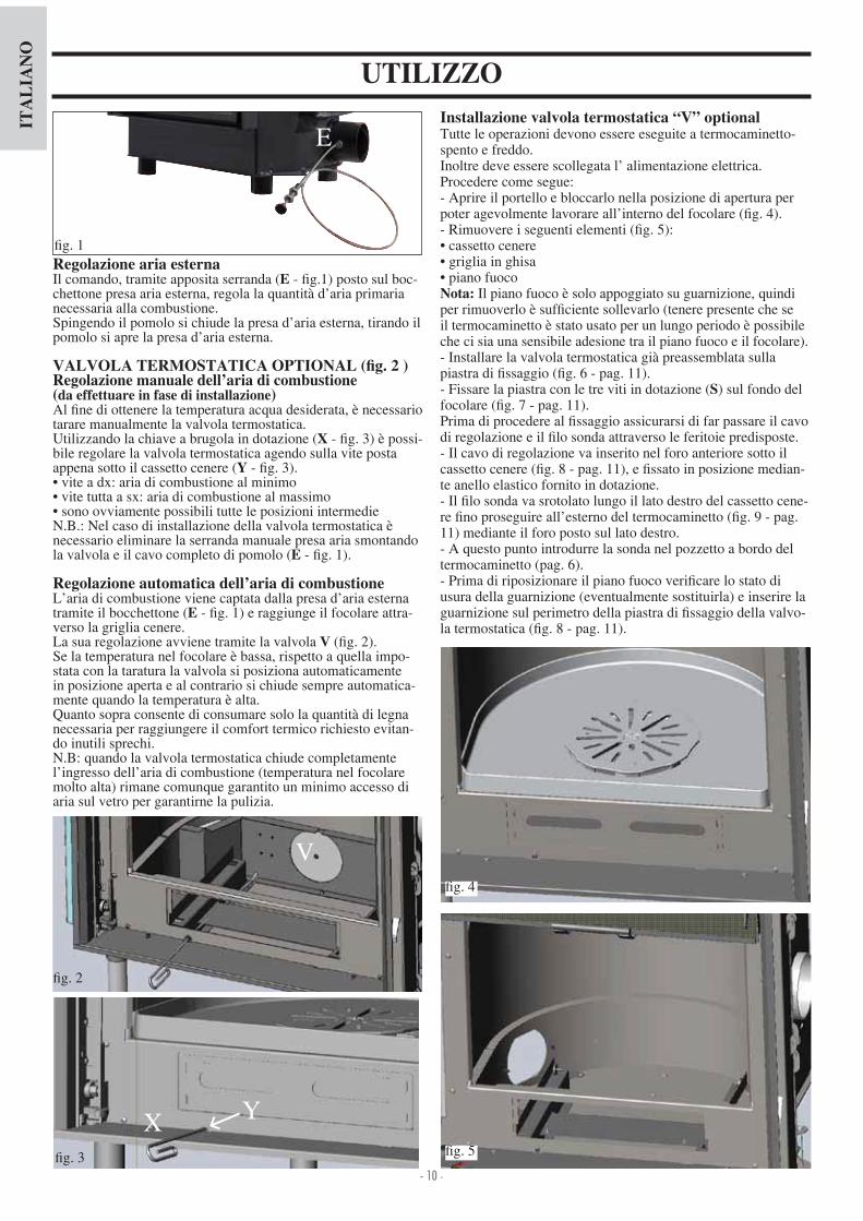
Installazione valvola termostatica “V” optional Tutte le operazioni devono essere eseguite a termocaminetto-spento e freddo.Inoltre deve essere scollegata l’ alimentazione elettrica.Procedere come segue- Aprire il portello e bloccarlo nella posizione di apertura per poter agevolmente lavorare all’interno del focolare ( g. ).- Rimuovere i seguenti elementi ( g. 5) cassetto cenere griglia in ghisa piano fuoco
Nota: Il piano fuoco è solo appoggiato su guarnizione, quindi per rimuoverlo è suf ciente sollevarlo (tenere presente che se il termocaminetto è stato usato per un lungo periodo è possibile che ci sia una sensibile adesione tra il piano fuoco e il focolare).- Installare la valvola termostatica già preassemblata sulla piastra di ssaggio ( g. 6 - pag. 11). - Fissare la piastra con le tre viti in dotazione (S) sul fondo del focolare ( g. 7 - pag. 11). Prima di procedere al ssaggio assicurarsi di far passare il cavo di regolazione e il lo sonda attraverso le feritoie predisposte.- Il cavo di regolazione va inserito nel foro anteriore sotto il cassetto cenere ( g. 8 - pag. 11), e ssato in posizione median-te anello elastico fornito in dotazione. - Il lo sonda va srotolato lungo il lato destro del cassetto cene-re no proseguire all’esterno del termocaminetto ( g. 9 - pag. 11) mediante il foro posto sul lato destro. - A questo punto introdurre la sonda nel pozzetto a bordo del termocaminetto (pag. 6).- Prima di riposizionare il piano fuoco veri care lo stato di usura della guarnizione (eventualmente sostituirla) e inserire la guarnizione sul perimetro della piastra di ssaggio della valvo-la termostatica ( g. 8 - pag. 11).
Regolazione aria esternaIl comando, tramite apposita serranda (E - g.1) posto sul boc-chettone presa aria esterna, regola la quantità d’aria primaria necessaria alla combustione. Spingendo il pomolo si chiude la presa d’aria esterna, tirando il pomolo si apre la presa d’aria esterna.
VALVOLA TERMOSTATICA OPTIONAL ( )Regolazione manuale dell’aria di combustione(da effettuare in fase di installazione)Al ne di ottenere la temperatura acqua desiderata, è necessario tarare manualmente la valvola termostatica.Utilizzando la chiave a brugola in dotazione (X - g. 3) è possi-bile regolare la valvola termostatica agendo sulla vite posta appena sotto il cassetto cenere (Y - g. 3). vite a dx aria di combustione al minimo vite tutta a sx aria di combustione al massimo sono ovviamente possibili tutte le posizioni intermedie
N.B. Nel caso di installazione della valvola termostatica è necessario eliminare la serranda manuale presa aria smontando la valvola e il cavo completo di pomolo (E - g. 1).
Regolazione automatica dell’aria di combustione L’aria di combustione viene captata dalla presa d’aria esterna tramite il bocchettone (E - g. 1) e raggiunge il focolare attra-verso la griglia cenere.La sua regolazione avviene tramite la valvola V ( g. 2).Se la temperatura nel focolare è bassa, rispetto a quella impo-stata con la taratura la valvola si posiziona automaticamente in posizione aperta e al contrario si chiude sempre automatica-mente quando la temperatura è alta.Quanto sopra consente di consumare solo la quantità di legna necessaria per raggiungere il comfort termico richiesto evitan-do inutili sprechi.N.B quando la valvola termostatica chiude completamente l’ingresso dell’aria di combustione (temperatura nel focolare molto alta) rimane comunque garantito un minimo accesso di aria sul vetro per garantirne la pulizia.
g.
g. 5

- 11 -
ITA
LIA
NO
MANUTENZIONEPulizia del focolare- Le incrostazioni che tendono a depositarsi sulle pareti interne del focolare, diminuiscono l’ef cienza dello scambio termico.- E’ necessario quindi effettuare una pulizia periodica, portan-do l’acqua ad una temperatura di 80÷85°C per ammorbidire le incrostazioni da asportare poi con una spatola d’acciaio.
Pulizia vetro- Per procedere alla pulizia utilizzare l’apposito pulitore per vetri ceramici (Glasskamin di Edilakmin). - La pulizia deve avvenire a vetro freddo.- L’apertura ad anta del portellone è possibile solo in posizione di totale chiusura.- Per aprire ad anta inserire la maniglia “mano fredda” sul not-tolino tra la struttura e il portellone e ruotare ( g. 12).
Apertura portellone- Per l’apertura del portellone utilizzare l’apposita maniglia asportabile in dotazione ( g. 10).- La stessa maniglia può essere ssata al portellone mediante l’utilizzo di n° 2 grani in dotazione.
ISTRUZIONI USO
g. 6
g. 7
g. 8
g. 9
g. 10
g. 12
VISTA POSTERIORE
lo sonda
cavo di regolazioneS
S S
SS
S
cavo di regolazione
cavo di regolazione
lo sonda
lo sonda
guarnizione
Installazione contrappesiIl portellone è dotato di un contrappeso tale da garantire una chiusura automatica. Nonostante il termocaminetto sia già correttamente regolato una ulteriore regolazione dell’azione di questo contrappeso può essere effettuata aggiungendo una o più piastrine (P - g. 11) in dotazione al termocaminetto.
g. 11
P

- 12 -
ITA
LIA
NO
ALLACCIAMENTI IDRAULICI VASO APERTOESEMPIO DI IMPIANTO IDRAULICO PER TERMOCAMINETTO CON PRODUZIONE DI ACQUA CALDA
SANITARIA CON UTILIZZO DI KIT 1ACS: Acqua Calda SanitariaAF: Acqua FreddaEV: Elettrovalvola a 3 vieF: FlussostatoMI: Mandata ImpiantoNA: Normalmente ApertaNC: Normalmente chiusaP: Pompa (circolatore)RA: RadiatoriRE: Regolatore ElettronicoRI: Ritorno ImpiantoS: ScaricoSc 20: Scambiatore 20 piastreST: Sonda di TemperaturaTC: Termocamino V: ValvolaVE: Vaso di Espansione ApertoVSP: Valvola di sicurezza a pressione 1,5 barVST: Valvola di scarico termicoJa: olly s ato automatico
Il Kit 1 è stato realizzato per facilitare il compito degli installatori; comprende infatti tutti quei componenti necessari ad una cor-retta installazione del prodotto.NB: le apparecchiature comprese nel kit devono essere opportunamente protette dall’irraggiamento termico del termoca-minetto, mediante l’utilizzo di materassini isolanti.
AZIONI SUL SELETTORESelettore OFF Tutto spentoSelettore MAN Circolatore forzato Valvola impostataSelettore AUTO Circolatore impostato Valvola impostataSelezione allarme In posizione OFF esclusa la segnalazione acustica
PER IL CORRETTO FUNZIONAMENTO OCCORRE INCROCIARE I TUBI DI MANDATA E DI RITORNO
ON
OFF
Collegamenti elettrici
AttivazioneDisattivazioneallarme acustico
Regolazione valvola 20-80°C
Visualizzazione
Circolatore
Valvola a 3 vie
Alimentazione 230Vac
Fusibile
KIT 1 cod. 261880
Regolazione Circolatore 20-80°C
Flussostato Attenzione collegare il contatto normalmente chiuso
Sonda (inserire nell’apposito pozzetto)
Circolatore attivo Allarme sovratemperatura Valvola a 3 vie
1. Collettore in ottone 1” M-F2. Valvola a sfera da 1” 3. Circolatore con attacchi da 1” ½(219660). Valvola di non ritorno 1” (261910)
5. Elettrovalvola a 3 vie 1” M-F (1 3330)6. Raccorderia in rame7. Scambiatore 30 piastre per scambio con
circuito della caldaia a gas (216620) 8. Scambiatore 20 piastre per produzione di
acqua calda sanitaria (205270)9. Valvola di scarico termico da ” (729 0)10. Valvola di sicurezza 1,5 bar da ” (1 3260)11. Flussostato (220830)12. Pozzetto per termometro ½” +
sonda(175960)13. Regolatore Elettronico (220780)A Mandata all’impianto ¾”B Ritorno dall’impianto ¾”C Ritorno al camino ¾”D Mandata del camino 1”E Acqua fredda sanitaria ½”F Acqua calda sanitaria ½”

- 13 -
ITA
LIA
NO
ALLACCIAMENTI IDRAULICI VASO APERTOESEMPIO DI IMPIANTO IDRAULICO PER TERMOCAMINETTO SENZA PRODUZIONE DI ACQUA CALDA SA-
NITARIA + CALDAIA MURALE CON UTILIZZO DI KIT 2AF: Acqua FreddaCA: Caldaia murale MI: Mandata ImpiantoP: Pompa (circolatore)RA: RadiatoriRE: Regolatore ElettronicoRI: Ritorno ImpiantoS: ScaricoJa: olly s ato automaticoSc 30: Scambiatore 30 piastreST: Sonda di TemperaturaTC: Termocamino V: ValvolaVR: Valvola di non ritornoVSP: Valvola di sicurezza a pressione 1,5 barVST: Valvola di scarico termico
Il Kit 2 è stato realizzato per facilitare il compito degli installatori; comprende infatti tutti quei componenti necessari ad una cor-retta installazione del prodotto.NB: le apparecchiature comprese nel kit devono essere opportunamente protette dall’irraggiamento termico del termoca-minetto, mediante l’utilizzo di materassini isolanti.
1. Collettore in ottone 1” M-F2. Valvola a sfera da 1” 3. Circolatore con attacchi da 1” ½(219660). Valvola di non ritorno 1” (261910)
5. Elettrovalvola a 3 vie 1” M-F (1 3330)6. Raccorderia in rame7. Scambiatore 30 piastre per scambio con
circuito della caldaia a gas (216620) 8. Scambiatore 20 piastre per produzione di
acqua calda sanitaria (205270)9. Valvola di scarico termico da ¾” (729 0)10. Valvola di sicurezza 1,5 bar da ¾” (1 3260)11. Flussostato (220830)12. Pozzetto per termometro ½” +
sonda(175960)13. Regolatore Elettronico (220780)A Mandata all’impianto ¾”B Ritorno dall’impianto ¾”C Ritorno al camino ¾”D Mandata del camino 1”E Acqua fredda sanitaria ½”F Acqua calda sanitaria ½”
AZIONI SUL SELETTORESelettore OFF Tutto spentoSelettore MAN Circolatore forzato Valvola impostataSelettore AUTO Circolatore impostato Valvola impostataSelezione allarme In posizione OFF esclusa la segnalazione acustica
PER IL CORRETTO FUNZIONAMENTO OCCORRE INCROCIARE I TUBI DI MANDATA E DI RITORNO
Collegamenti elettrici
Regolazione valvola 20-80°C
Visualizzazione
Circolatore A
Alimentazione 230Vac
KIT 2 cod. 261890
Sonda (inserire nell’apposito pozzetto)
Consenso circolatore Allarme sovratemperatura Reg. circolatori
ON
OFF
Fusibile
AttivazioneDisattivazioneallarme acustico
Circolatore B
Regolazione temp. min. di consenso avvio circolatori 20-80°C

- 14 -
ITA
LIA
NO
ALLACCIAMENTI IDRAULICI VASO APERTOESEMPIO DI IMPIANTO IDRAULICO PER TERMOCAMINETTO CON PRODUZIONE DI ACQUA CALDA SANI-
TARIA + CALDAIA MURALE CON UTILIZZO DI KIT 3ACS: Acqua Calda SanitariaAF: Acqua FreddaCA: Caldaia muraleEV: Elettrovalvola a 3 vieF: FlussostatoMI: Mandata ImpiantoNA: Normalmente ApertaNC: Normalmente chiusaP: Pompa (circolatore)RA: RadiatoriRE: Regolatore ElettronicoRI: Ritorno ImpiantoS: ScaricoSc 20: Scambiatore 20 piastreSc 30: Scambiatore 30 piastreTC: Termocamino V: ValvolaVE: Vaso di Espansione ApertoVR: Valvola di non ritornoVSP: Valvola di sicurezza a pressione 1,5 barVST: Valvola di scarico termicoJa: olly s ato automatico
Il Kit 3 è stato realizzato per facilitare il compito degli installatori; comprende infatti tutti quei componenti necessari ad una cor-retta installazione del prodotto.NB: le apparecchiature comprese nel kit devono essere opportunamente protette dall’irraggiamento termico del termoca-minetto, mediante l’utilizzo di materassini isolanti.
AZIONI SUL SELETTORESelettore OFF Tutto spentoSelettore MAN Circolatore forzato Valvola impostataSelettore AUTO Circolatore impostato Valvola impostataSelezione allarme In posizione OFF esclusa la segnalazione acustica
PER IL CORRETTO FUNZIONAMENTO OCCORRE INCROCIARE I TUBI DI MANDATA E DI RITORNO
Collegamenti elettrici
KIT 3 cod. 261900
1. Collettore in ottone 1” M-F2. Valvola a sfera da 1” 3. Circolatore con attacchi da 1” ½(219660). Valvola di non ritorno 1” (261910)
5. Elettrovalvola a 3 vie 1” M-F (1 3330)6. Raccorderia in rame7. Scambiatore 30 piastre per scambio con
circuito della caldaia a gas (216620) 8. Scambiatore 20 piastre per produzione di
acqua calda sanitaria (205270)9. Valvola di scarico termico da ¾” (729 0)10. Valvola di sicurezza 1,5 bar da ¾” (1 3260)11. Flussostato (220830)12. Pozzetto per termometro ½” +
sonda(175960)13. Regolatore Elettronico (220780)A Mandata all’impianto ¾”B Ritorno dall’impianto ¾”C Ritorno al camino ¾”D Mandata del camino 1”E Acqua fredda sanitaria ½”F Acqua calda sanitaria ½”
ON
OFF
AttivazioneDisattivazioneallarme acustico
Regolazione valvola 20-80°C
Visualizzazione
Valvola a 3 vie
Alimentazione 230Vac
Fusibile
Regolazione Circolatore 20-80°C
Flussostato Attenzione collegare il con-tatto normalmente chiuso
Sonda (inserire nell’apposito pozzetto)
Circolatore attivo Allarme sovratemperatura Valvola a 3 vie
Circolatore A Circolatore B
- 15 -
ITA
LIA
NO
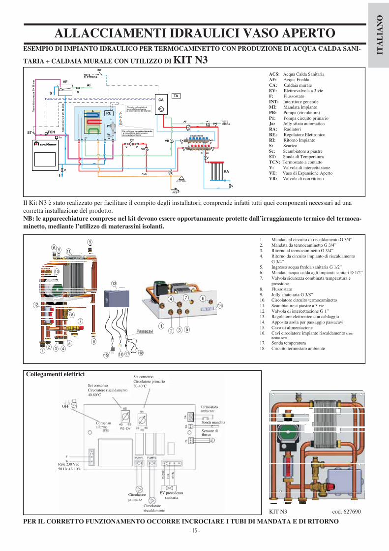
ALLACCIAMENTI IDRAULICI VASO APERTOESEMPIO DI IMPIANTO IDRAULICO PER TERMOCAMINETTO CON PRODUZIONE DI ACQUA CALDA SANI-
TARIA + CALDAIA MURALE CON UTILIZZO DI KIT N3ACS: Acqua Calda SanitariaAF: Acqua FreddaCA: Caldaia muraleEV: Elettrovalvola a 3 vieF: FlussostatoINT: Interrttore generaleMI: Mandata ImpiantoPR: Pompa (circolatore)P1: Pompa circuito primarioJa: olly s ato automaticoRA: RadiatoriRE: Regolatore ElettronicoRI: Ritorno ImpiantoS: ScaricoSc: Scambiatore a piastreST: Sonda di TemperaturaTCN: Termostato a contatto V: Valvola di intercettazioneVE: Vaso di Espansione ApertoVR: Valvola di non ritorno
Il Kit N3 è stato realizzato per facilitare il compito degli installatori; comprende infatti tutti quei componenti necessari ad una corretta installazione del prodotto.NB: le apparecchiature comprese nel kit devono essere opportunamente protette dall’irraggiamento termico del termoca-minetto, mediante l’utilizzo di materassini isolanti.
PER IL CORRETTO FUNZIONAMENTO OCCORRE INCROCIARE I TUBI DI MANDATA E DI RITORNO
KIT N3 cod. 627690
1. Mandata al circuito di riscaldamento G 3 ”2. Mandata da termocaminetto G 3 ”3. Ritorno al termocaminetto G 3 ”. Ritorno da circuito impianto di riscaldamento
G 3 ”5. Ingresso acqua fredda sanitaria G 1 2”6. Mandata acqua calda agli impianti sanitari D 1 2”7. Valvola sicurezza combinata temperatura e
pressione 8. Flussostato9. olly s ato aria G 3 8”10. Circolatore circuito termocaminetto11. Scambiatore a piastre a 3 vie12. Valvola di intercettazione G 1”13. Regolatore elettronico con cablaggio1 . Apposita asola per passaggio passacavi15. Cavo di alimentazione16. Cavi circolatore impianto riscaldamento (fase,
neutro, terra)
17. Sonda temperatura18. Circuito termostato ambiente
VEAF
S V
RE
RETE
ST
V
S
V
Tu
bo
di
cari
co
Ø>
18
mm
Tu
bo
di
sic
ure
zza
Ø>
28
mm
V
CA
ACS
PRF
ACS
AF
Ja
TA
P1
VVs
Sc
TCN
ELETTRICA
INT
VR V
VR
RETE
IDRICA
VR
VR
MI
RA
RI
V
COLLETTORE
VR
V
V
V
V
V
Circuito collegabile altermostato ambiente(a discrezione del cliente)
Da collegare necessariamenteal circolatore dell’impianto
di riscaldamento PR
12 3 4
56
7
8
9
10
119
9
12
13
12 3 5
4 67
14
15 16 17
Passacavi
18
Circolatore primario
OFF
Set consenso Circolatore primario30- 0°C
ON
Circolatore riscaldamento
EV precedenza sanitaria
Rete 230 Vac50 Hz + - 10%
Set consenso Circolatore riscaldamento0-80°C
Termostato ambiente
Sensore di usso
Sonda mandataConsenso allarme
Collegamenti elettrici

- 16 -
ITA
LIA
NO
ALLACCIAMENTI IDRAULICI VASO APERTOESEMPIO DI IMPIANTO IDRAULICO PER TERMOCAMINETTO CON PRODUZIONE DI ACQUA CALDA SANI-
TARIA + CALDAIA MURALE CON UTILIZZO DI KIT N3 BISACS: Acqua Calda SanitariaAF: Acqua FreddaCA: Caldaia muraleEV: Elettrovalvola a 3 vieF: FlussostatoINT: Interrttore generaleMI: Mandata ImpiantoPR: Pompa (circolatore)P1: Pompa circuito primarioJa: olly s ato automaticoRA: RadiatoriRE: Regolatore ElettronicoRI: Ritorno ImpiantoS: ScaricoSc: Scambiatore a piastreST: Sonda di TemperaturaTCN: Termostato a contatto V: Valvola di intercettazioneVE: Vaso di Espansione ApertoVR: Valvola di non ritorno
Il Kit N3 BIS è stato realizzato per facilitare il compito degli installatori; comprende infatti tutti quei componenti necessari ad una corretta installazione del prodotto.NB: le apparecchiature comprese nel kit devono essere opportunamente protette dall’irraggiamento termico del termoca-minetto, mediante l’utilizzo di materassini isolanti.
PER IL CORRETTO FUNZIONAMENTO OCCORRE INCROCIARE I TUBI DI MANDATA E DI RITORNO
KIT N3 BIS cod. 627860
1. Mandata al circuito impianto di riscaldamento G 3 ”2. Mandata da termocaminetto G 3 ”3. Ritorno al termocaminetto G 3 ”. Ritorno da circuito impianto di riscaldamento G 3 ”
5. Ingresso acqua fredda sanitaria G 1 2”6. Mandata acqua calda agli impianti sanitari G 1 2”7. Immissione acqua calda sanitaria G 1 2” dalla caldaia
abbinata8. Valvola di sicurezza combinata temperatura e pres-
sione (90°C - 3 bar)9. Flussostato10. Elettrovalvola deviatrice a 3 vie11. olly s ato aria G 3 8”12. Circolatore circuito termocaminetto13. Circolatore circuito impianto di riscaldamento1 . Valvola di intercettazione G 1”15. Scambiatore a piastre a 3 vie G 3 ”16. Regolatore elettronico con cablaggio17. Aposita asola per ssaggio passacavi18. Cavo alimentazione19. Sonda temperatura20. Circuito termostato ambiente
Circolatore primario
OFF
Set consenso Circolatore primario30- 0°C
ON
Circolatore riscaldamento
EV precedenza sanitaria
Rete 230 Vac50 Hz + - 10%
Set consenso Circolatore riscaldamento0-80°C
Termostato ambiente
Sensore di usso
Sonda mandataConsenso allarme
Collegamenti elettrici
VEAF
S V
RE
ST
S
V
Tu
bo
dicari
co
Ø>
18
mm
Tu
bo
disic
ure
zza
Ø>
28
mm
CA
ACS
VR
MI
RA
RI
V
ACS
AF
Ja
TA
EV
P2
P1
V
V
Sc
F
Vs
RETE
ELETTRICA
INT
VR V
TCN
V
V
V
By-p
ass
VR
Sc
RETE
IDRICA
COLLETTORE
VR
V
V
V
V
V
Circuito collegabile altermostato ambiente(a discrezione del cliente)
12 3 4
5 6 7
8
9
10
11
12
1314
14
15
111111
1111
1617
12 3
4
5
8
6
7
2019
Passacavi
17
18

- 17 -
ITA
LIA
NO
REGOLATORE ELETTRONICO FUNZIONAMENTO- Dispositivo di controllo: Termometro- Dispositivo di protezione (sistema allarme acustico): Allarme acustico (AA) Allarme sovratemperatura (SS)
Tale sistema interviene quando la temperatura dell’acqua supera il valore di 90°C ed avverte l’utilizzatore di sospendere l’alimentazione di combustibile. Il funzionamento dell’allarme acustico può essere escluso agendo sull’interruttore (AA); rimane comunque attiva la fun-zione di allarme data dalla spia di sovratemperatura (SS). Per ripristinare le condizioni iniziali, dopo aver ridotto la temperatura dell’acqua nel termocaminetto, bisogna riattivare l’interruttore (AA).
- Dispositivo di alimentazione (sistema circolazione): Selettore MAN-OFF-AUTO (S) Spia pompa (SP)
Nella funzione manuale la pompa funziona sempre, nella fun-zione OFF la pompa è spenta; nella funzione AUTO si attiva la pompa dell’impianto a una temperatura desiderata per mezzo della regolazione interna (RIC) da 20 a 80°C (il comando é pre-impostato a 20°C)
- Dispositivo di funzionamento (sistema di regolazione): Regolazione (R) per apertura valvola a 3 vie Spia (SV) di funzionamento valvola a 3 vie
Quando la temperatura del uido raggiunge il valore impostato col regolatore, la valvola a 3 vie commuta il uido ai termosifoni e la spia di funzionamento (SV) si accende. Nel momento in cui la temperatura del uido scende al di sotto del valore impostato, il sistema di regolazione apre il circuito elettrico, la valvola a 3 vie by-passa il uido direttamente al termocaminetto.Attenzione: Durante il funzionamento normale, controllare che le spie luminose (SV) e (SP) siano accese.
UBICAZIONEIl regolatore elettronico deve essere installato nelle vicinanze del termocaminetto. La sonda dei dispositivi di funzionamento, protezione e con-trollo deve essere collocata direttamente sul termocaminetto o al massimo sulla tubazione di mandata entro 5 cm di distanza dal termocaminetto e comunque prima di qualsiasi organo di intercettazione. La sonda deve essere immersa nel pozzetto.
INSTALLAZIONETutte queste operazioni devono essere fatte con l’alimen-tazione disinserita dalla rete elettrica e con il selettore (S) AUTO-OFF-MAN in posizione OFF.Per una corretta installazione del regolatore elettronico agire come segue allentare la vite di ssaggio quindi togliere la calotta, posizionare a muro e ssare con i tasselli in dotazione; eseguire quindi le connessioni come da schema (contenuto nel-la confezione) facendo la massima attenzione ai collegamenti, stendere i cavi usando delle canaline conformi alle normative vigenti; quindi riposizionare la calotta e serrare la vite di chiu-sura. Per la Valvola a 3 vie utilizzare il lo marrone (fase) e il lo blu (neutro) da collegare rispettivamente ai morsetti 5 e 6 del regolatore. Il lo giallo-verde va collegato alla terra.Per collegare correttamente il regolatore all’impianto, seguire le istruzioni di montaggio contenute nella confezione.
LEGENDAAA interruttore allarme acusticoR reg. apertura valvola 3 vie (KIT 1 - 3)R reg. funzionamento circolatori (KIT 2)RIC regolazione interna pompaS selettore MAN-OFF-AUTOSP spia pompaSS spia sovratemperaturaST scala temperaturaSV spia valvole 3 vie (KIT 1 - 3)SV reg. circolatori (KIT 2)
DATI TECNICI
Alimentazione (+15 - 10%) Vac 230
Grado di protezione IP 0
Temperatura min max ambiente °C 0÷+50
Lunghezza sonda mt 1,2
Termometro °C 30÷90
Portata contatti circolatore, massima W 00
Portata contatti valvola tre vie, massima W 250
Fusibile mA 500
AVVERTENZE IMPORTANTI PER L’INSTALLAZIONEGli allacciamenti, la messa in servizio e la veri ca del buon funzionamento, devono essere eseguite da personale quali ca-to, in grado di effettuare i collegamenti secondo le leggi vigenti ed in particolare secondo la Legge 6 90, nonché nel pieno rispetto delle presenti istruzioni.Il rispetto delle norme sulla messa a terra è determinante per la sicurezza delle persone.E’ obbligatorio inserire a monte del dispositivo e di tutto il circuito elettrico del termocaminetto un interruttore differen-ziale di linea, inoltre é obbligatorio collegare a terra le pompe, le valvole e tutti i componenti dell’impianto oltre alle parti metalliche del termocaminetto.
Il regolatore elettronico di controllo permette di monitorare le condizioni di funzionamento ed é dotato di- selettore MAN-OFF-AUTO (S)- scala temperatura (ST)- allarme acustico (AA)- reg. apertura valvola 3 vie (R) (KIT1-3) - reg. funzionamento circolatori (R) (KIT 2)- regolazione interna pompa (RIC)- spia valvola a 3 vie (SV) (KIT 1-3)- spia reg.circolatori (SV) (KIT 2)- spia sovratemperatura (SS)- spia pompa (SP)

- 18 -
ITA
LIA
NO
ACCESSORI OPTIONAL
Kit valvole ( 21600) composto da - valvola automatica sfogo aria - valvola sicurezza 1,5 bar, - scarico termico 90°CRegolatore elettronico (220780)
REGOLATORE ELETTRONICO (optional) permette di monitorare le condizioni di funzionamento ed è dotato di- selettore MAN-OFF-AUTO- scala temperatura- allarme acustico- regolatore apertura valvola 3 vie- regolazione interna pompa- spia pompa - spia valvola a 3 vie- spia sovratemperaturaIl regolatore elettronico è parte dei diversi tipi di Kit di installa-zione (forniti optional)
SCAMBIATORE 20 PIASTRE PER L’ACQUA SANITARIA (optional)Si tratta di un apparato semplice ed economico, che consente una produzione di acqua calda sanitaria pari a 13-1 litri al minuto a seconda della potenza dell’impianto. È facilmente installabile sul tubo di mandata ai termosifoni nella posizione più comoda, rispetto alle condizioni dell’impianto.Ha il grosso vantaggio di poter essere smontato per manuten-zione o sostituzione senza intervenire sul termocaminetto.
Lo scambiatore a 20 piastre è parte dei diversi tipi di kit d’installazione (forniti optional)
SCAMBIATORE A 3 VIE (optional)Produce acqua calda per il circuito sanitario e per il circuito secondario (termosifoni), escludendo rispetto al kit 3 l’utilizzo della valvola a 3 vie e di uno scambiatore a piastre.
acqua fredda dalla rete idrica
acqua di ritorno al termocaminetto
acqua calda dal termocaminetto
acqua caldaai sanitari
Valvola a 3 vie da 1” (1 3330)r e g o l a z i o n e
usso acqua all’impianto
Regolatore elettronico (220780)
Flussostato(220830)
CircolatoreUPS 25-50 cod. 219660UPS 25-60 cod. 238270
Scambiatore 30 piastreper impianto (216620)
Scambiatore a 3 vie cod. 627780
Scambiatore 20 piastreper sanitaria (262570)
acqua calda dal termocaminetto
acqua fredda impianto
acqua fredda sanitario
Kit idraulico V per versioni a VASO APERTO cod. 7 3 30 (installazione a destra)
Dispaly remotocod. 7 1180
Valvola termostatica H
2OCEANO 15 cod. 739 60
H2OCEANO 23 cod. 739 0
H2OCEANO 28 cod. 739 50
Cornice contorno bocca H
2OCEANO 15 cod. 739390 - dim. 63x63 cm
H2OCEANO 23 cod. 739370 - dim. 77x68 cm
H2OCEANO 28 cod. 739380 - dim. 95x68 cm
Supporto per kit idraulici A1-A2-B-C-D (installazione a destra) H
2OCEANO 15 cod. 739510
H2OCEANO 23 cod. 739 70
H2OCEANO 28 cod. 739 90
Girarrosto H
2OCEANO 15 cod. 750820
H2OCEANO 23 cod. 23 560
H2OCEANO 28 cod. 236710

- 19 -
EN
GL
ISH
www.edilkamin.com. and click on DEALERS.
NOTE
- Commissioning/ testing
The wood Thermo Fireplaces H
-

- 20 -
EN
GL
ISH
TECHNICALAND HEATING SPECIFICATIONS
H2OCEANO is designed to heat water by the combustion of wood in the hearth. The water contained in the thermo replace is heated and sent into the heating system (radiators, heated towel rails, under o-or heating panels) and also heats the room in which it is located via natural convection radiation.The thermo replace MUST NEVER FUNCTION WITHOUT WATER IN THE SYSTEM.The water heats up, circulating in the cavity that runs around the entire semi-circular wall and dome of the hearth.The hollow space is constructed in thick steel sheet.The hearth is closed in the front by a door that slides up and down and side to side for cleaning the glass.
INNOVATIVE PATENTED ASH GRILLEThis allows for the distribution of primary combustion air not only from the bottom up, but also horizontally to achieve high oxygenation of the ame, better combustion and increased power.
“GASKET-SAVING” DOORDuring sliding, the door remains slightly a ar from thermo re-place inlet in order to protect the gaskets. In the closed position the door is perfectly anked against the thermo replace to en-sure maximum sealing and therefore optimal performance. The handle is removable or it can be xed to the door (see pg. 28)
AUTOMATIC SMOKE BY-PASSWhen turning on with the frame open, to facilitate combustionstart-up, the smoke damper (S) remains in the opening position so that smoke can directly and easily reach the chimney ue.When combustion has been started up, the smoke damperalso closes automatically when the door is closed (S - g. b).In this mode, before reaching the chimney ue, the smoke deviates in such a way to lap and give off heat to the water in an ef cient manner.The by-pass is automatically controlled by the door’s move-ment.
De ectors Ceilings
Grill motor housing
Post-Combustion
Automatic external air inlet adjustment valve (optional)
Possibility of applying adjustable feet (optional)
Calibration for automatic adjustment of combustion air
Up down sliding door
Enveloping cavity for water containment
Safety coil for thermal relief (CS version)
Primary combustion air distribution ash grille
Smoke diversion damper
A
B
C
D
E
F
G
H
I
L
S
AI
L
H
G
H
A
B
D
EF E
CS
(a)
(b)
s
s

- 21 -
EN
GL
ISH
H2OCEANO MUST NEVER BE MADE TO OPERATE WI-THOUT WATER IN THE SYSTEM.MUST BE MADE WITH A PRESSURE OF ABOUT 1.5 BAR.
IT CAN BE DAMAGED IF IT IS IGNITED WITH NO WA-TER IN THE SYSTEM.
The thermo replace is designed to heat water by means of wood combustion in the hearth.
The only hazards that can derive from using the thermo re-place pertain to non-compliance with the installation instruc-tions, direct contact with live electrical parts (inside), contact made with the re and hot parts or foreign substances being put in the replace.
For the thermo replace to function properly installation must be carried out according to the instructions given in this booklet and the door must only be opened to re ll the hearth with wood.
Never put foreign substances in the hearth.
Whilst functioning, the door must never be opened. In fact, combustion is fully automatic and requires no manual interven-tion.
Do not use ammable products to clean the smoke channel(the ue section connecting the boiler- replace smoke outlet to the chimney ue).
The glass can be cleaned when COLD with a suitable product (e.g. GlassKamin) and a cloth. Do not clean when hot.
The exhaust pipes and the door become very hot when the thermo replace is used.
Do not place anything that is not heat resistant close to the thermo replace.
NEVER use liquid fuel to ignite the thermo replace or to rekindle the embers.
Do not obstruct the external air inlets in the room where the replace is installed or the air inlets of the thermo replace
itself.
Do not wet the thermo replace and do not go near the elec-trical parts of the system with wet hands.
Do not use reducers on the smoke exhaust pipes.
The thermo replace must be installed in a place that is sui-table against re hazards and equipped with all that is required (power and air inlets outlets) for it to function properly and safely.
SAFETY INFORMATION
IMPORTANT: ONLY THERMO FIREPLACES WITH COILS DRIVEN BY A THERMAL RELIEF VALVE SHOULD BE INSTALLED ON CLOSED TANK SY-STEMS (version marked with the abbreviation CS).
The installer is responsible for the correct installation of the system, which is to be compliant with UNI standards 10683 – 9615 90 – 10 12 2
All must be performed by quali ed personnel according to Ministerial Decree 37 ex Law 6 90
The thermal relief valve (TRV - provided by Edilkamin) must be connected to the cooling circuit (AL) with a minimum pressure of 1.5 bar. JA = automatic relief valve S = drain
1 Year The safety and thermal relief valves must be checked at least
once a year by quali ed personnel according to Ministerial De-cree 37 ex Law 6 90.
The heating system must include an expansion tank dedicated only to the thermo replace, evaluated based on the volume of water present in the system itself (an expansion tank shared with other generators is not allowed).
Litres ?

- 22 -
EN
GL
ISH
GENERAL SAFETY REGULATIONSIN CASE OF INSTALLATION ON OPEN TANK SYSTEMS
The connections, commissioning and veri cation of proper operation of the thermo replace must be carried out by quali-
ed personnel, who can implement all connections in accor-dance with the laws in force, particularly with Italian D.M 37 Law No. 6 90, apart from complying with these instructions.
For installations implemented outside Italy, please refer to the local regulations in the country of use.
The thermo replace and the system are lled with water that ows from the water inlet pipe (the diameter must not be less
than 18 mm) to the open expansion tank.
All the vents of the radiators must be opened during this phase so as to prevent air pockets from forming in the system, which would obstruct the circulation of water.
NB: The open tank should be positioned at a height greater than
3 m higher than the highest component of the primary circuitand less than 15 m from the edge of the thermo replace.
In any case, the tank must be high enough to create a greater pressure than that produced by the pump (circulator). The system must never be lled directly from the water
mains as the pressure may be greater than that stipulated on the data plate of the thermo replace, with resulting damage to the thermo replace itself. The safety pipe to the expansion tank must allow the water
to ow freely without shut-off valves and be appropriately insulated to prevent the water inside from freezing, which would compromise the connection. The water inlet pipe must not have taps nor curves. The maximum operating pressure must not exceed 1.5 bar The testing pressure is 3 bar. It is a good idea to add an anti-freeze liquid to the water
contained in the system or to observe standard UNI 8065. Never ignite the re in the thermo replace (not even as a
test) unless the system is lled with water as this could causeirreparable damage. Connect the drains of the thermal relief valve (TRV) and
the safety valve (SV) (diagrams are found on the following pages). The ow test of the system must be carried out with the
expansion tank open. It is recommended to install a 6 bar safety valve on the hot
sanitary water circuit so as to drain any excessive increase in the volume of the water in the heat exchanger. Place all the components of the system (circulator, heat
exchanger, valves, etc.) in easily accessible points for routine and special maintenance procedures.
WATER TREATMENTIf need be, antifreeze, descaling and anticorrosive solutions are to be added to the water. A softener must be used if the hardness of the water used to re ll and top-up the system exceeds 35°f (French degrees).
IN CASE OF INSTALLATION ON CLOSED TANK SYSTEMS(provisions in addition to those provided for open tank systems)
Be careful not to exceed 1.5 bar when lling the system.
Only if a thermal relief valve actuates the coil can the replace be installed on a CLOSED TANK system (version
marked with the abbreviation CS).
When connecting a thermo replace to an existing system, an assessment must be made regarding a need for another CLOSED TANK on the system.
- The upstream pressure of the cooling circuit must be at least 1.5 bar (UNI 10 12 2 point 6.2).
Please refer to UNI 8065-1989 standard (water treatment in domestic heating systems).

- 23 -
EN
GL
ISH
DIMENSIONS FRONT SIDE
SYSTEM
L
PH
thermal relief coil return 1 2” M (closed tank version)
thermal relief coil ow 1 2” M (closed tank version)
well for probe
combustion airwater return to system 1” M
water ow to system 1” M
THE INLET AND OUTLET PIPES MUST BE CROSSED FOR THIS TO FUNCTION PROPERLY
Y
X
drain
H2OCEANO 15 - 15/CS H2OCEANO 23 - 23/CS H2OCEANO 28 - 28/CS
L 7 88 106 cm
P 62 68 83 cm
H135 without feet
(with feet + 1 cm)
1 7 without feet
(with feet + 1 cm)
1 7 without feet
(with feet + 1 cm)cm
X 3 3 51 cm
Y 36 37 50 cm
internal hearth
dimensions50x38 60x50 78x60 cm
- 24 -
EN
GL
ISH
TECHNICALAND HEATING SPECIFICATIONS
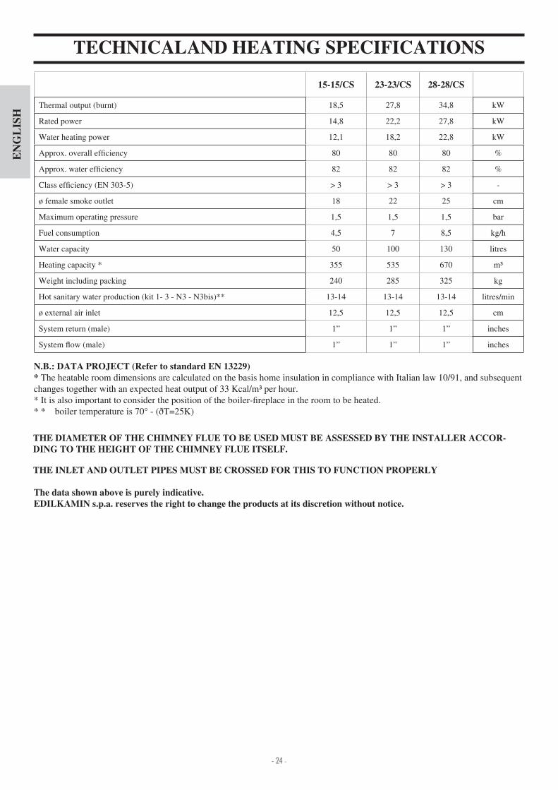
N.B.: DATA PROJECT (Refer to standard EN 13229)* The heatable room dimensions are calculated on the basis home insulation in compliance with Italian law 10 91, and subsequent changes together with an expected heat output of 33 Kcal m per hour.* It is also important to consider the position of the boiler- replace in the room to be heated.* * boiler temperature is 70° - (ðT=25K)
The data shown above is purely indicative. EDILKAMIN s.p.a. reserves the right to change the products at its discretion without notice.
THE INLET AND OUTLET PIPES MUST BE CROSSED FOR THIS TO FUNCTION PROPERLY
THE DIAMETER OF THE CHIMNEY FLUE TO BE USED MUST BE ASSESSED BY THE INSTALLER ACCOR-DING TO THE HEIGHT OF THE CHIMNEY FLUE ITSELF.
15-15/CS 23-23/CS 28-28/CS
Thermal output (burnt) 18,5 27,8 3 ,8 kW
Rated power 1 ,8 22,2 27,8 kW
Water heating power 12,1 18,2 22,8 kW
Approx. overall ef ciency 80 80 80 %
Approx. water ef ciency 82 82 82 %
Class ef ciency (EN 303-5) > 3 > 3 > 3 -
ø female smoke outlet 18 22 25 cm
Maximum operating pressure 1,5 1,5 1,5 bar
Fuel consumption ,5 7 8,5 kg h
Water capacity 50 100 130 litres
Heating capacity * 355 535 670 m
Weight including packing 2 0 285 325 kg
Hot sanitary water production (kit 1- 3 - N3 - N3bis)** 13-1 13-1 13-1 litres min
ø external air inlet 12,5 12,5 12,5 cm
System return (male) 1” 1” 1” inches
System ow (male) 1” 1” 1” inches

- 25 -
EN
GL
ISH
INSTALLATIONIMPORTANT ADVICE REGARDING THEINSTALLATIONOther than that described in this documentation, you are also asked to note the following UNI standards- No. 10683 - rewood heat generators installation requirements- No. 9615/90 - calculating the internal dimensions of replaces- No. 10412:2 - hot water heating systems. Speci c safety requirements for systems provi ded with residential solid fuel burning applian ces and combined boiler, not exceeding a total nominal heat input of 35 kW.
Particularly- Before carrying out any assembly it is important to verify compatibility of the appliance, as stipulated in UNI 10683 standard, paragraphs .1 .1.1 .1.2.- When assembly is completed, the installer must implement “start-up operations” and issue documentation as requiredby UNI 10683 standard in paragraphs .6 and 5, respectively.- -
must be carried out by quali ed personnel, who can implement the electrical and plumbing connections as required by UNI standards 10683, paragraph .5 and 10 12 2, apart from complying with these assembly instructions.- Veri cation must be carried out with the replace on and after having been on for a couple of hours, before covering the thermo replace, so that you can intervene if need be.After which, the nishing operations such as- setting-up the replace mantel- mounting the replace covering- pilasters, painting, etc.are carried out, once the tests are completed successfully. Consequently, EDILKAMIN does not accept responsibility for expenses deriving from demolition as well as construction even if either occurs as a result, after having replaced any damaged parts of the thermo replace.
EXTERNAL AIR INLETAn external connection with a 12,5 cm diameter crosssec-tion throughout (refer to the technical table) is absolutely
is therefore imperative for this to be implemented.This connection must link the air adjustment mechanism (E), delivered separately. The mechanism, delivered separately, can be assembled either right or left of the thermo repla-ce. Connection can be made with a exible aluminium pipe. Ensure that the points where there may be dispersion of air are sealed well. The air adjustment mechanism (E) can be remo-ved and mounted on the right side of the thermo replace. It is recommended to place a protection grille on the outer part of the air inlet channel, however, ensure that this does not reduce the cross-section. For distances longer than 3 m or with bends, increase the given cross-section by a minimum of 10% to a ma-ximum of 20%. The intake of external air must enter at oor level (it cannot enter from above).
CHIMNEY FLUES AND CHIMNEYPOTThe thermo replace smoke outlet has a circular crosssection so that stainless steel pipes can be used. If the chimney ue inlet is not vertically above the thermo replace, the connection from the replace to the ue must not have a narrowingsection or inclinations greater than 5° ( g. 1-2-3- ).If the chimney ue is not brand new or too big, it is recommen-ded to t in stainless tubes of an appropriate diameter and with suitable insulation.If the chimney ue is installed outside, it is recommended to use an insulated, double walled, stainless steel ue.The characteristics of the construction must be suitable to withstand a smoke temperature of at least 50° C, with parti-cular reference to the mechanical resistance, insulation and the gas tight sealing.The junction of the steel ue inlet and the smoke outlet of the
replace must be sealed with high temperature mastic.The fundamental characteristics of the chimneypot are:- an internal cross-section at the base, which is the same as that of the chimney ue.- an outlet cross-section which is no smaller than twice that of the chimney ue. - its position must be high enough to catch the wind and avoid downdraft areas in turbulent wind.
In addition to that mentioned above, please consider the indications stipulated in UNI 10683/2005 standard, para-graph 4.2: “connection to the smoke outlet system” and its subsections.
E
E
2
45°
45°
3
max.45°
1
NO
4

- 26 -
EN
GL
ISH
INSTALLATIONIf combining with a pre-fabricated Edilkamin covering, to de -ne the exact positioning of the thermo replace, it is important to take the chosen covering model into consideration. The positioning is implemented according to the model chosen (refer to the installation instructions found inside the packaging of each thermo replace covering).Always ensure the thermo replace is level during the installa-tion process.- Drill a hole into the wall or the ooring for the external air intake and connect the air adjustment mechanism to the hole as described in the chapter called “external air inlet”.- Use a stainless steel ue to connect the thermo replace to the chimney ue, adhering with the diameters indicated in the spe-ci cations table and the guidelines given in the chapter called“chimney ues”.- Verify that all moving parts function properly before setting the thermo replace covering in place.
before the covering is set in place.
INSTALLATION COVERING, FIREPLACE MAN-TEL AND VENTILATION OUTLETSThe base of the thermo replace covering must allow the internal air to be recycled. Therefore, suitable slots or apertures must be made for the air to pass through. Parts of the thermo
replace covering that are made of marble, stone and bricks must be mounted with a small gap between them and the re-place so as to prevent possible breakage due to expansion and excessive overheating.Wooden parts must be protected by re resistant panels and
Practical adviceIt is recommended to keep the radiators closed in the room where the thermo replace is installed; The heat emitted from the outlet may be suf cient to heat. - An incomplete combustion process causes excessive fouling on the heat exchanger pipe.To prevent this you must- burn dry wood.- ensure the hearth contains a bed of embers and burning car-bon before adding more wood.- place larger logs together with smaller ones.- make sure the temperature of the return water is at least 50 °C (use temperature control valve).
- Ensure that at least one radiator is always open.- Actuate the switches of the electronic regulator.- Place a pile of medium-thin dry wood in the thermo replace and ignite the re.- Wait a few minutes until it reaches suf cient combustion.- Close the door- Set the thermostat on the electronic regulator (*) at a tempera-ture between 50 and 70° C.NOTE There may be a slight smell of paint the rst few times it is ignited, however, this will disappear quickly.
no part must touch the thermo replace, on the contrary, there must be an appropriate distance of at least 1 cm to allow the air to ow, preventing heat accumulation. The replace mantel can be made of reproof plasterboard panels or gypsum board and, however, of completely reproof material. Air should be allowed to ow inside the replace mantel (through the gap between the door and the beam). Through convective motion, the air will ow out from the grille installed at the top, resulting in heat recovery and preventing excessive overheating. The replace mantel must have appropriate openings to carry out maintenance on the ttings.In addition to that mentioned above, please consider the in-dications stipulated in the UNI 10683 standard, paragraphs
safety recommendations”.
Insulating mats must be applied when using an installation KIT so as to protect it from the heat radiation emitted by
INLET FRAME (OPTIONAL)To facilitate coupling with the covering’s components, the ther-mo replace can be tted with a frame (A) to be applied on the front of the inlet.
INSTRUCTIONS FOR USE3-way valve- During ignition the 3-way valve (*) diverts the ow of water, forcing it to return directly to the thermo replace;when the set temperature is reached, the 3- way valve (*) diverts the ow to the system (does not depend on the kit installed).
By-pass damper- When the door is closed, the by-pass damper automatically diverts smoke, thus improving ef ciency.- When the door is opened, the damper bypass opens automa-tically, allowing the smoke to reach the smoke ue directly, preventing it from coming out of the inlet.
Thermal Relief ValveIf the water temperature exceeds 90° C (e.g. because of too much wood being placed in the hearth) the thermal relief valve will be activated and the acoustic signal triggered. In this case you must proceed as followsDo not load additional fuel and wait for the temperature to fall below 80°C checking the warning lights on the electronic regu-lator. The hot water tap can be opened to speed up the cooling process if the thermo replace is equipped with a hot sanitary water production KIT.
A
(*) these components of the system are to be provided by the installer.
Plasterboard
A
- 27 -
EN
GL
ISH
INSTRUCTIONS FOR USE
E
g. 1
g. 2
g. 3
V
X Y
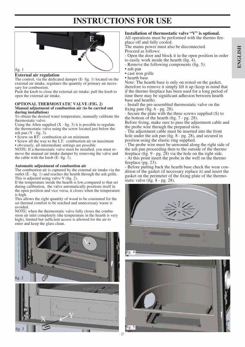
Installation of thermostatic valve “V” is optional. All operations must be performed with the thermo re-place off and fully cooled. The mains power must also be disconnected. Proceed as follows - Open the door and block it in the open position in order to easily work inside the hearth ( g. ).- Remove the following components ( g. 5) ash pan cast iron grille hearth base
Note The hearth base is only on rested on the gasket, therefore to remove it simply lift it up (keep in mind that if the thermo replace has been used for a long period of time there may be signi cant adhesion between hearth base and hearth).- Install the pre-assembled thermostatic valve on the
xing pate ( g. 6 - pg. 28).- Secure the plate with the three screws supplied (S) to the bottom of the hearth ( g. 7 - pg. 28).Before xing, make sure to pass the adjustment cable and the probe wire through the prepared slots. - The adjustment cable must be inserted into the front hole under the ash pan ( g. 8 - pg. 28), and secured in position using the elastic ring supplied.- The probe wire must be unwound along the right side of the ash pan proceeding then to the outside of the thermo
replace ( g. 9 - pg. 28) via the hole on the right side.- At this point insert the probe in the well on the thermo
replace (pg. 23).- Before putting back the hearth base check the wear con-dition of the gasket (if necessary replace it) and insert the gasket on the perimeter of the xing plate of the thermo-static valve ( g. 8 - pg. 28).
External air regulationThe control, via the dedicated damper (E- g. 1) located on the external air intake, regulates the quantity of primary air neces-sary for combustion. Push the knob to close the external air intake; pull the knob to open the external air intake.
OPTIONAL THERMOSTATIC VALVE (FIG. 2)Manual adjustment of combustion air (to be carried out during installation)To obtain the desired water temperature, manually calibrate the thermostatic valve. Using the Allen supplied (X - g. 3) it is possible to regulate the thermostatic valve using the screw located just below the ash pan (Y - g. 3). Screw on RT combustion air on minimum Screw all the way to the LT combustion air on maximum obviously, all intermediate settings are possible
NOTE If a thermostatic valve must be installed, you must re-move the manual air intake damper by removing the valve and the cable with the knob (E- g. 1).
Automatic adjustment of combustion airThe combustion air is captured by the external air intake via the outlet (E - g. 1) and reaches the hearth through the ash grille. This is adjusted using valve V ( g. 2).If the temperature inside the hearth is low,compared to that set during calibration, the valve automatically positions itself in the open position and vice versa, it closes when the temperature is high.This allows the right quantity of wood to be consumed for the set thermal comfort to be reached and unnecessary waste is avoided.NOTE when the thermostatic valve fully closes the combu-stion air inlet completely (the temperature in the hearth is very high), limited but suf cient access is allowed for the air to enter and keep the glass clean.
g.
g. 5

- 28 -
EN
GL
ISH
MAINTENANCECleaning the hearth- The soot deposits that tend to accumulate on the internal walls of the hearth decrease the ef ciency of heat transfer.- It is therefore necessary to clean the replace regularly, by bringing the water temperature to 80 85° C to soften the fou-ling and then remove this with a steel spatula.
Glass cleaning- Use an appropriate spray for ceramic glass to clean the glass (Glasskamin - Edilakmin)..- The glass must be cleaned when cold.- For the opening swing of the door it is necessary to bring it in the closed position.- Insert the “cold handle” door handle on the latch between the structure and the door and turn to open ( g. 12).
Door opening- Use the provided removable handle to open the door ( g. 10).- The same handle can be xed to the door using the 2 grub screws supplied.
INSTRUCTIONS FOR USE
g. 6
g. 7
g. 8
g. 9
REAR VIEW
probe wire
adjustment cableS
S S
SS
S
adjustment cable
adjustment cable
probe wire
probe wire
gasket
Installing counterbalancesThe latch door is equipped with counterbalances which ensure smooth movements as well as closure of the door.The counterbalances can be regulated by adding platte s (additional counterbalances) that are supplied with the thermo
replace (P - g. 11).
g. 10
g. 12
g. 11
P

- 29 -
EN
GL
ISH
SYSTEM FOR AN OPEN TANK INSTALLATIONAN EXAMPLE OF A HYDRAULIC SYSTEM FOR A THERMO FIREPLACE WITH HOT SANITARY WATER PRO-
DUCTION USING KIT 1ACS: Hot Sanitary WaterAF: Cold WaterEV: 3-way Solenoid ValveF: Flow SwitchMI: System FlowNA: Normally OpenNC: Normally ClosedP: Pump (circulator)RA: RadiatorsRE: Electronic RegulatorRI: System ReturnS: DrainSc 20: 20-plate Heat ExchangerST: Temperature SensorTC: Thermo FireplaceV: ValveVE: Open Expansion TankVSP: 1.5 bar Pressurized Safety ValveVST: Thermal Relief ValveJa: Automatic Relief Valve
Kit 1 is designed to facilitate the work carried out by the installers. In fact, it consists of all the necessary components for the product to be properly installed.NB: insulating mats must be applied so that the components of the kit are well-protected from the heat radiation emitted
SELECTOR FUNCTIONSSelector: OFF Everything is switched offSelector: MAN Driven Circulator Valve is setSelector: AUTO Circulator is set Valve is setAlarm selection No acoustic signal in the OFF position
THE INLET AND OUTLET PIPES MUST BE CROSSED FOR THIS TO FUNCTION PROPERLY
ON
OFF
Electrical Connections
EnableDisableAcousticAlarm
20 - 80° CValve Setting
Display
Circulator
3-way valve
Power Supply230 Vac
Fuse
KIT 1 code 261880
20 - 80° CCirculator Setting
Flow Switch Attention Connect the normally closed contact
Sensor (insert in the appropriate well)
Circulator enabled Overheating alarm 3-way valve
1. 1” Male-Female Brass Collector2. 1” Ball Valve3. Circulator with 1½” Fasteners (219660). 1” Check Valve (261910)
5. 1” Male-Female 3-way Solenoid Valve (1 3330)
6. Copper Fittings7. 30-plate Heat Exchanger for heat transfer
with the gas boiler circuit (216620)8. 20-plate Heat Exchanger for hot sanitary
water production (205270)9. ¾” Thermal Relief Valve (729 0)10. ¾” 1.5 bar Safety Valve (1 3260)11. Flussostato (220830)12. ½” Thermometer Well + Sensor (175960)13. Electronic Regulator (220780)A ¾” System ReturnB ¾” System FlowC ¾” Fireplace ReturnD 1” Fireplace FlowE ½” Cold Sanitary WaterF ½” Hot Sanitary Water
Safe
ty p
ipe
Ø>
28m
m
Inle
t pip
e Ø
> 18
mm
Col
lect
or
Regulator (included in the kit)
20-p
late
hea
tex
chan
ger
Elec-tricity Mains

- 30 -
EN
GL
ISH
SYSTEM FOR AN OPEN TANK INSTALLATIONAN EXAMPLE OF A HYDRAULIC SYSTEM FOR A THERMO FIREPLACE THAT DOES NOT PRODUCE HOT
SANITARY WATER BUT HAS A WALL MOUNTED BOILER USING KIT 2AF: Cold WaterCA: Wall Mounted BoilerMI: System FlowP: Pump (circulator)RA: RadiatorsRE: Electronic RegulatorRI: System ReturnS: DrainJa: Automatic Relief ValveSc 30: 30-plate Heat ExchangerST: Temperature SensorTC: Thermo FireplaceV: ValveVE: Open Expansion TankVR: Check ValveVSP: 1.5 bar Pressurized Safety ValveVST: Thermal Relief Valve
Kit 2 is designed to facilitate the work carried out by the installers. In fact, it consists of all the necessary components for the product to be properly installed.NB: insulating mats must be applied so that the components of the kit are well-protected from the heat radiation emitted
1. 1” Male-Female Brass Collector2. 1” Ball Valve3. Circulator with 1½” Fasteners (219660). 1” Check Valve (261910)
5. 1” Male-Female 3-way Solenoid Valve (1 3330)
6. Copper Fittings7. 30-plate Heat Exchanger for heat transfer
with the gas boiler circuit (216620) 8. 20-plate Heat Exchanger for hot sanitary
water production (205270)9. ¾” Thermal Relief Valve (729 0)10. ¾” 1.5 bar Safety Valve (1 3260)11. Flow Switch (220830)12. ½” Thermometer Well + Sensor (175960)13. Electronic Regulator (220780)A ¾” System ReturnB ¾” System FlowC ¾” Fireplace ReturnD 1” Fireplace FlowE ½” Cold Sanitary WaterF ½” Hot Sanitary Water”
KIT 2 code 261890
ON
OFF
Circulator B
SELECTOR FUNCTIONSSelector: OFF Everything is switched offSelector: MAN Driven Circulator Valve is setSelector: AUTO Circulator is set Valve is setAlarm selection No acoustic signal in the OFF position
THE INLET AND OUTLET PIPES MUST BE CROSSED FOR THIS TO FUNCTION PROPERLY
Electrical Connections
EnableDisableAcousticAlarm
20 - 80° CValve Setting
Display
Circulator A
Power Supply230 Vac
Fuse
Minimum temperature setting for circulators to be actuated 20 – 80° C
Sensor (insert in the appropriate well)
Circulator enabled Overheating alarm 3-way valve
Safe
ty p
ipe
Ø>
28m
m
Inle
t pip
e Ø
> 18
mm
Col
lect
or
Regulator (included in the kit)
30-p
late
hea
tex
chan
ger
Elec-tricity Mains

- 31 -
EN
GL
ISH
SYSTEM FOR AN OPEN TANK INSTALLATIONAN EXAMPLE OF A HYDRAULIC SYSTEM FOR A THERMO FIREPLACEITH HOT SANITARY WATER PRO-
DUCTION AND A WALL MOUNTED BOILER USING KIT 3ACS: Hot Sanitary WaterAF: Cold WaterCA: Wall Mounted BoilerEV: 3-way Solenoid ValveF: Flow SwitchMI: System FlowNA: Normally OpenNC: Normally ClosedP: Pump (circulator)RA: RadiatorsRE: Electronic RegulatorRI: System ReturnS: DrainSc 20: 20-plate Heat ExchangerSc 30: 30-plate Heat ExchangerTC: Thermo Fireplace V: ValveVE: Open Expansion TankVR: Check ValveVSP: 1.5 bar Pressurized Safety ValveVST: Thermal Relief ValveJa: Automatic Relief Valve
KIT 3 code 261900
1. 1” Male-Female Brass Collector2. 1” Ball Valve3. Circulator with 1½” Fasteners (219660). 1” Check Valve (261910)
5. 1” Male-Female 3-way Solenoid Valve (1 3330)
6. Copper Fittings7. 30-plate Heat Exchanger for heat transfer
with the gas boiler circuit (216620)8. 20-plate Heat Exchanger for hot sanitary
water production (205270)9. ¾” Thermal Relief Valve (729 0)10. ¾” 1.5 bar Safety Valve (1 3260)11. Flow Switch (220830)12. ½” Thermometer Well + Sensor (175960)13. Electronic Regulator (220780)A ¾” System ReturnB ¾” System FlowC ¾” Fireplace ReturnD 1” Fireplace FlowE ½” Cold Sanitary WaterF ½” Hot Sanitary Water
ON
OFF
3-way valve
Circulator Setting20 - 80° C
Flow SwitchAttention Connect the normally closed contact
Kit 3 is designed to facilitate the work carried out by the installers. In fact, it consists of all the necessary components for the product to be properly installed.NB: insulating mats must be applied so that the components of the kit are well-protected from the heat radiation emitted
Circulator B
SELECTOR FUNCTIONSSelector: OFF Everything is switched offSelector: MAN Driven Circulator Valve is setSelector: AUTO Circulator is set Valve is setAlarm selection No acoustic signal in the OFF position
THE INLET AND OUTLET PIPES MUST BE CROSSED FOR THIS TO FUNCTION PROPERLY
Electrical Connections
EnableDisableAcousticAlarm
20 - 80° CValve Setting
Display
Circulator A
Power Supply230 Vac
Fuse
Sensor (insert in the appropriate well)
Circulator enabled Overheating alarm 3-way valve
Safe
ty p
ipe
Ø>
28m
m
Inle
t pip
e Ø
> 18
mm
Col
lect
or
Regulator (included in the kit)
30-p
late
hea
tex
chan
ger
20-p
late
hea
tex
chan
ger
Elec-tricity Mains

- 32 -
EN
GL
ISH
SYSTEM FOR AN OPEN TANK INSTALLATIONAN EXAMPLE OF A HYDRAULIC SYSTEM FOR A THERMO FIREPLACEITH HOT SANITARY WATER PRO-
DUCTION AND A WALL MOUNTED BOILER USING KIT N3CA: Wall Mounted BoilerPR: Pump (circulator)P1: Primary circuit pumpRE: Electronic regulatorTA: Room thermostatVE: Expansion TankJa: Air re ef ValveV: Intercept valveVR: Retaining valveST: Temperature SensorF: Flow switchSc: Heat plate exchangerEV: 3-way solenoid valveRI: Heating system returnRA: RadiatorsMI: Heating system owAF: Cold waterACS: Hot sanitary waterS: Drain
KIT N3 code 627690
1. Heating system ow G 3 ”2. EDILKAMIN generator ow G 3 ”3. EDILKAMIN generator return G 3 ”. Heating system return G 3 ”
5. Cold sanitary water inlet G 1 2”6. Hot water return to the sanitary system G 1 2”7. Safety valve - temperature and pressure (90
°C - 3bar)8. Flow Switch9. Air relief valve G 3 8”10. EDILKAMIN generator circuit circulator11. 3-way heat exchanger12. Intercept valve G 1”13. Electronic regulator with wiring1 . Appropriate aperture for the cable duct to pass
through 15. Power cable 16. Cables for the heating system circulator (phase,
neutral, earth) 17. Temperature sensor18. Room thermostat circuit
VEAF
S V
RE
RETE
ST
V
S
V
Tu
bo
di
cari
co
Ø>
18
mm
Tu
bo
di
sic
ure
zza
Ø>
28
mm
V
CA
ACS
PRF
ACS
AF
Ja
TA
P1
VVs
Sc
TCN
ELETTRICA
INT
VR V
VR
RETE
IDRICA
VR
VR
MI
RA
RI
V
COLLETTORE
VR
V
V
V
V
V
Circuito collegabile altermostato ambiente(a discrezione del cliente)
Da collegare necessariamenteal circolatore dell’impianto
di riscaldamento PR
12 3 4
56
7
8
9
10
119
9
12
13
12 3 5
4 67
14
15 16 17
Passacavi
18
Primary cir-cuit pump
OFF
Primary circulator enabled setting30- 0°C
ON
Heating pump
EV
Electricity Mains 230 Vac50 Hz + - 10%
Sanitary-heating enabled setting0-80°C
Room thermostat
Flow sensor
sensorEnabled alarm
Electrical Connections
Safe
ty p
ipe
Ø>
28m
m
Inle
t pip
e Ø
> 18
mm circuit connected
to the room thermostat (implemented by the client)
must be connected to the heating system circulator
Water Mains
Collector
Electricity Mains
Kit N3 is designed to facilitate the work carried out by the installers. In fact, it consists of all the necessary components for the product to be properly installed.NB: insulating mats must be applied so that the components of the kit are well-protected from the heat radiation emitted
Cable duct
THE INLET AND OUTLET PIPES MUST BE CROSSED FOR THIS TO FUNCTION PROPERLY

- 33 -
EN
GL
ISH
SYSTEM FOR AN OPEN TANK INSTALLATIONAN EXAMPLE OF A HYDRAULIC SYSTEM FOR A THERMO FIREPLACE WITH HOT SANITARY WATER PRO-
DUCTION AND A WALL MOUNTED BOILER USING KIT N3 BISCA Wall Mounted BoilerP2 Pump (circulator)P1 Primary circuit pumpRE Electronic regulatorTA Room ThermostatVE Expansion TankJa Air Relief Valvev Intercept valveVR Retaining valveST Temperature SensorF Flow switchSc Heat Plate ExchangerEV 3-way Solenoid ValveRI Heating system returnRA RadiatorsMI Heating system owAF Cold WaterACS Hot Sanitary WaterS DrainINT Main switchTCN Contact Thermostat
KIT N3 BIS code 627860
1. Heating system ow G 3 ”2. EDILKAMIN generator ow G 3 ”3. EDILKAMIN generator return G 3 ”. Heating system return G 3 ”
5. Cold sanitary water inlet G 1 2”6. Hot water return to the sanitary system G 1 2”7. Sanitary hot water inlet to the gas boiler G 1 2”8. Safety valve - temperature and pressure (90 °C -
3bar)9. Flow Switch10. 3-way deviation solenoid valve11. Air relief valve G 3 8”12. EDILKAMIN generator circuit circulator13. Heating system circuit circulator1 . Intercept valve G 1”15. 3-way heat exchanger16. Electronic regulator with wiring17. Appropriate aperture for the cable duct to pass
through 18. Power cable 19. Temperature sensor20. Room thermostat circuit
OFF ON
VEAF
S V
RE
ST
S
V
Tu
bo
dicari
co
Ø>
18
mm
Tu
bo
disic
ure
zza
Ø>
28
mm
CA
ACS
VR
MI
RA
RI
V
ACS
AF
Ja
TA
EV
P2
P1
V
V
Sc
F
Vs
RETE
ELETTRICA
INT
VR V
TCN
V
V
V
By-p
ass
VR
Sc
RETE
IDRICA
COLLETTORE
VR
V
V
V
V
V
Circuito collegabile altermostato ambiente(a discrezione del cliente)
12 3 4
5 6 7
8
9
10
11
12
1314
14
15
111111
1111
1617
12 3
4
5
8
6
7
2019
Passacavi
17
18
Primary cir-cuit pump
Primary circulator enabled setting30- 0°C
Heating pump
EV
Electricity Mains 230 Vac50 Hz + - 10%
Sanitary-heating enabled setting0-80°C
Room thermostat
Flow sensor
sensorEnabled alarm
Electrical Connections
Safe
ty p
ipe
Ø>
28m
m
Inle
t pip
e Ø
> 18
mm
circuit connected to the room thermostat (implemented by the client)
Water Mains
Collector
Kit N3BIS is designed to facilitate the work carried out by the installers. In fact, it consists of all the necessary components for the product to be properly installed.NB: insulating mats must be applied so that the components of the kit are well-protected from the heat radiation emitted
Cable duct
THE INLET AND OUTLET PIPES MUST BE CROSSED FOR THIS TO FUNCTION PROPERLY
Water Mains

- 34 -
EN
GL
ISH
ELECTRONIC REGULATOR OPERATION- Control device: Thermometer
- Protection device (acoustic alarm system): Acoustic alarm (AA) Overheating alarm (SS)
This system intervenes when the water temperature exceeds 90° C and warns the user to stop adding fuel.The acoustic alarm can be disabled from the switch (AA).However, the alarm remains enabled by means of the overhe-ating light (SS). To restore the initial settings, the switch (AA) must be enabled after the water temperature in the thermo
replace has cooled down.
Power supply device (circulation system): MAN-OFF-AUTO selector (S) Pump light (SP)
The pump remains on when in manual mode and off when inOFF mode. When in AUTO mode, the pump is activated by the system when the desired temperature is reached, by means of the internal setting (RIC), which ranges from 20 to 80° C (this is pre-set at 20° C).
- Operation device (setting system): 3-way valve opening setting (R) 3-way valve operating light (SV)
When the uid reaches the temperature set through the regu-lator, the 3-way valve diverts the uid to the radiators and the operating light (SV) goes on.When the temperature of the uid drops below the set value, the system opens the electrical circuit and the 3-way valve bypasses the uid directly to the thermo replace.Attention: During normal operation check that the warning lights (SV) and (SP) are lit.
POSITIONINGThe electronic regulator must be installed close to the thermo
replace. The sensor of the operation, protection and control devices must be placed directly on the thermo replace or at most on the ow pipe, no more than 5 cm away from the ther-mo replace and in any case before any intercepting device.The sensor must be immersed in the well.
INSTALLATIONThe power supply must be disconnected from the mains and the AUTO-OFF-MAN selector (S) must be in the OFF position when all these operations are carried out.Follow this procedure to install the electronic regulator cor-rectly loosen the fastening screw, remove the cover and fasten it in place against the wall with the dowels supplied.Then make the connections, paying utmost attention to the wiring diagram and pass the wires through ducts that are in conformity with the regulations in force. Put the cover back in place and tighten the screw.Connect the brown wire (phase) and blue wire (neutral) of the 3-way Valve, respectively, to terminals 5 and 6 of the regula-tor. Connect the yellow green wire to the earth.Follow the assembly instructions contained in the package to connect the regulator to the system properly.
IMPORTANT ADVICE REGARDING THE INSTALLATIONThe connections, commissioning and veri cation of proper operation of the replace must be carried out by quali ed per-sonnel, who can implement all connections in accordance with the laws in force, particularly with Italian Law No. 6 90, apart from complying with these instructions.Compliance with regulations regarding the earth connec-tion is fundamental for the safety of people.It is obligatory to install a differential circuit breaker switch before the device and the entire electrical circuit of the thermo
replace.It is also obligatory to connect the pump, valve and metal parts of the thermo replace to an earthing system.
LEGENDAA acoustic alarm switchR way valve opening setting (KITS 1-3)R circulators operation setting (KIT 2)RIC internal pump settingS MAN-OFF-AUTO selectorSP pump lightSS overheating lightST temperature scaleSV 3-way valves light (KITS 1-3)SV circulators setting (KIT 2)
TECHNICAL DATA
Power Supply (+15 – 10%) Vac 230
Degree of protection IP 0
Min Max Room Temperature °C 0÷+50
Sensor range mt 1,2
Thermometer °C 30÷90
Maximum contact rating of the circulator W 00
Maximum contact rating of the 3-way valve W 250
Fuse mA 500
The electric control regulator allows you to monitor the opera-ting conditions and is equipped with- MAN-OFF-AUTO selector (S)- temperature scale (ST)- acoustic alarm (AA)- 3-way valve opening setting (R) (KIT1-3)- circulators operation setting (R) (KIT2)- internal pump setting (RIC)- 3-way valve light (SV) (KIT1-KIT3)- circulators setting light (SV) (KIT2)- overheating pump (SS)- pump light (SP)
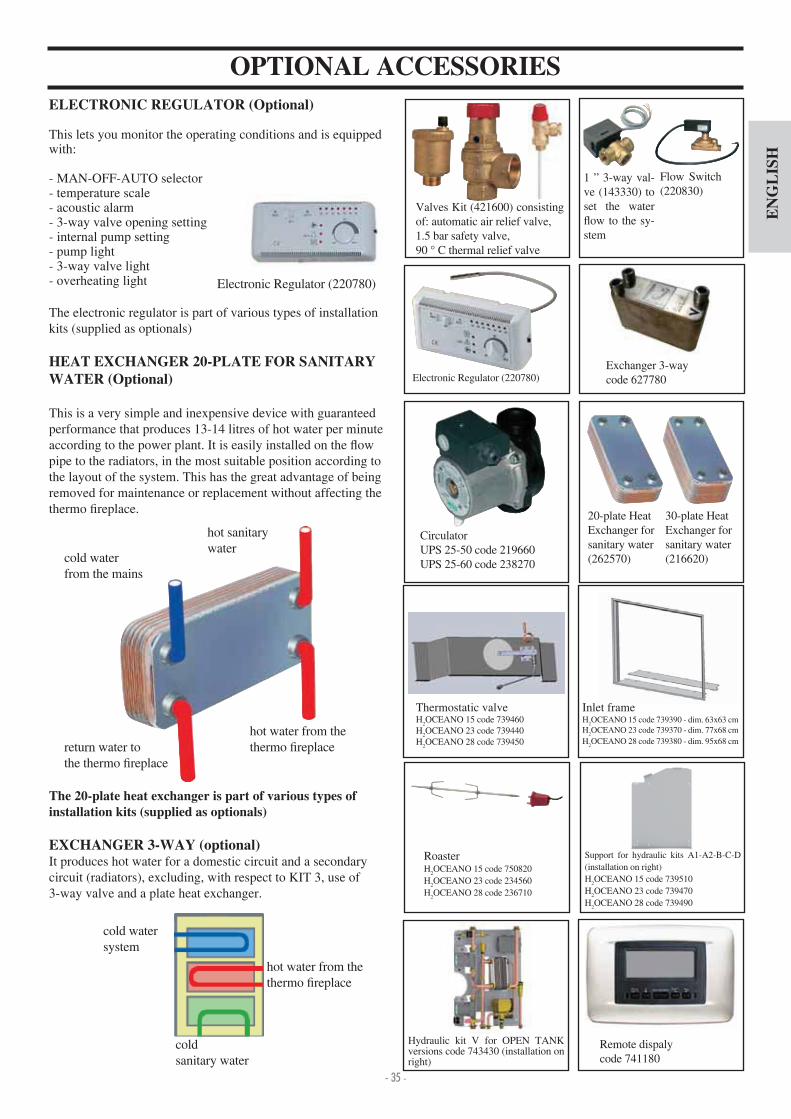
- 35 -
EN
GL
ISH
Electronic Regulator (220780)
ELECTRONIC REGULATOR (Optional)
This lets you monitor the operating conditions and is equippedwith
- MAN-OFF-AUTO selector- temperature scale- acoustic alarm- 3-way valve opening setting- internal pump setting- pump light- 3-way valve light- overheating light
The electronic regulator is part of various types of installation kits (supplied as optionals)
HEAT EXCHANGER 20-PLATE FOR SANITARY WATER (Optional)
This is a very simple and inexpensive device with guaranteedperformance that produces 13-1 litres of hot water per minute according to the power plant. It is easily installed on the ow pipe to the radiators, in the most suitable position according to the layout of the system. This has the great advantage of being removed for maintenance or replacement without affecting the thermo replace.
The 20-plate heat exchanger is part of various types of installation kits (supplied as optionals)
EXCHANGER 3-WAY (optional)It produces hot water for a domestic circuit and a secondary circuit (radiators), excluding, with respect to KIT 3, use of 3-way valve and a plate heat exchanger.
cold waterfrom the mains
return water tothe thermo replace
hot water from the thermo replace
hot sanitarywater
hot water from the thermo replace
cold watersystem
coldsanitary water
OPTIONAL ACCESSORIES
Valves Kit ( 21600) consisting of automatic air relief valve,1.5 bar safety valve,90 ° C thermal relief valve
1 ” 3-way val-ve (1 3330) to set the water
ow to the sy-stem
Electronic Regulator (220780)
Flow Switch (220830)
CirculatorUPS 25-50 code 219660UPS 25-60 code 238270
30-plate HeatExchanger for sanitary water (216620)
Exchanger 3-waycode 627780
20-plate HeatExchanger for sanitary water (262570)
Remote dispalycode 7 1180
Hydraulic kit V for OPEN TANK versions code 7 3 30 (installation on right)
Thermostatic valveH
2OCEANO 15 code 739 60
H2OCEANO 23 code 739 0
H2OCEANO 28 code 739 50
Inlet frameH
2OCEANO 15 code 739390 - dim. 63x63 cm
H2OCEANO 23 code 739370 - dim. 77x68 cm
H2OCEANO 28 code 739380 - dim. 95x68 cm
Support for hydraulic kits A1-A2-B-C-D (installation on right) H
2OCEANO 15 code 739510
H2OCEANO 23 code 739 70
H2OCEANO 28 code 739 90
RoasterH
2OCEANO 15 code 750820
H2OCEANO 23 code 23 560
H2OCEANO 28 code 236710

- 36 -
FR
AN
ÇA
IS
-
NOTE
-
-
-

- 37 -
FR
AN
ÇA
IS
CARACTERISTIQUES THERMOTECHNIQUES
H2OCEANO est conçu pour chauffer l’eau à travers une combustion de bois dans le foyer. L’eau contenue dans la thermo-cheminée chauffe puis est dirigée dans l’installation de chauffage (radiateurs, sèche-serviettes, panneaux rayonnants au sol), et elle chauffe en outre la pièce dans laquelle elle se trouve grâce au rayonnement à convection naturelle. La thermo-cheminée NE DOIT JAMAIS FONCTIONNER S’IL N’Y A PAS D’EAU DANS L’INSTALLATIONL’eau chauffe, en circulant dans l’interstice qui ef eure toute la paroi semi-circulaire et la voûte du foyer.L’interstice est réalisé avec de la tôle d’acier de grosse épaisseur. De face, le foyer est fermé par une porte à ouverture guillotine ou à ouverture latérale pour le nettoyage de la vitre.
NOUVELLE GRILLE CENDRES BREVETÉEElle permet de distribuer l’air primaire de combustion non seulement du bas vers le haut, amis aussi horizontalement pour avoir une oxygénation élevée de la amme, une meilleure com-bustion et une puissance majeure.
PORTE «PROTÈGE-JOINTS»Durant le coulissement, la porte reste légèrement à l’écart de la bouche de la thermo-cheminée a n protéger les joints.En position de fermeture, elle adhère parfaitement pour garantir une étanchéité maximale et donc un parfait rendement.La poignée est amovible ou bien elle peut tre xée à la porte (voir page 5)
BY-PASS FUMÉES AUTOMATIQUEEn phase d’allumage, quand l’ouverture est ouverte, pour faciliter le démarrage de la combustion, la trappe des fumées (S) reste en position d’ouverture de manière à ce que les fumées puissent atteindre le conduit de cheminée directement et aisément. Quand la combustion a bien démarré, si on ferme la porte on ferme également la trappe des fumées automati-quement (S - g. b). Dans cette direction, les fumées, avant de rejoindre le conduit de cheminée, dévient de façon à libérer la chaleur ef cacement à l’eau. Le by-pass est commandé auto-matiquement par le mouvement de la porte.
Dé ecteurs Plafonds
Logement Moteur Grill
Post-Combustion
Vanne automatique de réglage de la prise d’air externe (option)
Possibilité d’application des pieds réglables (option)
Tarage pour le réglage automatique de l’air de combustion
Porte coulissante
Interstice enveloppant pour la contenance de l’eau
Serpentin de sécurité pour la décharge thermique (version CS).
Grille cendres de distribution d’air primaire de combustion
Trappe de déviation du parcours des fumées
A
B
C
D
E
F
G
H
I
L
S
AI
L
H
G
H
A
B
D
EF E
CS
(a)
(b)
s
s
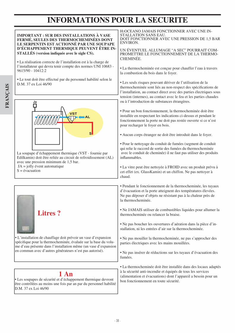
- 38 -
FR
AN
ÇA
IS
H2OCEANO JAMAIS FONCTIONNER AVEC UNE IN-STALLATION SANS EAU.DOIT FONCTIONNER AVEC UNE PRESSION DE 1,5 BAR ENVIRON.
UN VENTUEL ALLUMAGE “A SEC” POURRAIT COM-PROMETTRE LE FONCTIONNEMENT DE LA THERMO-CHEMIN E.
La thermocheminée est conçue pour chauffer l’eau à traversla combustion du bois dans le foyer.
Les seuls risques pouvant dériver de l’utilisation de la thermocheminée sont liés au non-respect des spéci cations de l’installation, au contact direct avec des parties électriques soustension (internes), au contact avec le feu et les parties chaudesou à l’introduction de substances étrangères.
Pour un bon fonctionnement, la thermocheminée doit tre installée en respectant les indications ci-dessus et pendant lefonctionnement la porte ne doit pas restée ouverte si ce n’estpour recharger le foyer en bois.
Aucun corps étranger ne doit tre introduit dans le foyer.
Pour le nettoyage du conduit de fumées (segment de conduitqui relie le raccord de sortie des fumées du thermocheminée avec le conduit de cheminée) il ne faut pas utiliser des produits in ammables.
La vitre peut tre nettoyée à FROID avec un produit prévu àcet effet (ex. GlassKamin) et un chiffon. Ne pas nettoyer àchaud.
Pendant le fonctionnement de la thermocheminée, les tuyauxd’évacuation et la porte atteignent des températures élevées.Ne pas déposer d’objets ne résistant pas à la chaleur près dela thermocheminée.
Ne JAMAIS utiliser de combustibles liquides pour allumer lathermocheminée ou relancer la braise.
Ne pas boucher les ouvertures d’aération dans la pièce d’in-stallation, ni les entrées d’air sur la thermocheminée.
Ne pas mouiller la thermocheminée, ne pas s’approcher desparties électriques avec les mains mouillées.
Ne pas insérer de réductions sur les tuyaux d’évacuation desfumées.
La thermocheminée doit tre installée dans des locaux adaptésà la sécurité anti-incendie et équipés de tous les services(alimentation et évacuations) dont l’appareil a besoin pour unbon fonctionnement en toute sécurité.
INFORMATIONS POUR LA SECURITE
IMPORTANT : SUR DES INSTALLATIONS À VASE FERMÉ, SEULES DES THERMOCHEMINÉES DONT LE SERPENTIN EST ACTIONNÉ PAR UNE SOUPAPE D’ÉCHAPPEMENT THERMIQUE PEUVENT ÊTRE IN-STALLÉS (version indiquée avec le sigle CS).
La réalisation correcte de l’installation est à la charge de l’installateur qui devra tenir compte des normes UNI 10683 - 9615 90 - 10 12 2
Le tout doit tre effectué par du personnel habilité selon le D.M. 37 ex Loi 6 90
La soupape d’échappement thermique (VST - fournie par Edilkamin) doit être reliée au circuit de refroidissement (AL) avec une pression minimum de 1,5 bar. JA = jolly évent automatique S = évacuation
1 An Les soupapes de sécurité et d’échappement thermique devront
être contrôlées au moins une fois par an par du personnel habilité D.M. 37 ex Loi 6 90
L’installation de chauffage doit prévoir un vase d’expansion spéci que pour la thermocheminée, évaluée sur la base du volu-me d’eau présente dans l’installation même (un vase d’expansion en commun avec d’autres générateurs n’est pas autorisé).
Litres ?

- 39 -
FR
AN
ÇA
IS
DISPOSITIONS GÉNÉRALES SUR LA SÉCURITÉEN CAS D’INSTALLATION SUR DES SYSTÈMES À VASE OUVERT
Les branchements, la mise en service et la véri cation du bon fonctionnement doiventêtre effectués par un personnel quali é, capable d’effectuer les branchements selon les lois en vigueur et notamment selon D.M. 37 Loi 6 90 ainsi quedans le respectde ces instructions.
Pour les installations à l’étranger, se référer aux normatives spéci ques nationales.
Le remplissage de la thermocheminée et de l’installation doi-vent se produire par le vase d’expansion ouvert par la chute naturelle de l’eau à travers le tuyau de charge (diamètre non inférieur à 18 mm).
Au cours de cette phase, ouvrir les reni ards des radiateurs de façon à éviter les poches d’air dans l’installation qui pourra-ient empêcher la circulation de l’eau.
REMARQUE Le vase ouvert doit être positionné à une hauteur de plus de 3 m par rapport à l’élément le plus haut du circuit primaire, et à moins de 15 m par rapport à la sortie de la thermocheminée.
La hauteur de vase doit de toute façon se présenter de ma-nière à créer une pression majeure par rapport à celle produite par la pompe (circulateur). Ne jamais remplir l’installation directement avec la pression
de réseau puisque elle pourrait être supérieure à celle de la thermocheminée avec par conséquent l’endommagement de la thermo-cheminée. Le tuyau de sécurité relié au vase d’expansion doit avoir
un passage libre sans robinet d’interception, et adéquatement isolé pour éviter que l’eau se gèle à l’intérieur, ce qui en com-promettrait la jonction. Le tuyau de charge doit être libre sans robinets ni courbes La pression maxi d’exercice ne doit pas dépasser 1,5 bar La pression d’essai est de 3 bar Il est conseillé d’ajouter un liquide antigel à l’eau contenue
dans l’installation ou de respecter la norme UNI 8065. Ne jamais allumer le feu dans la thermocheminée (pas
même pour un essai) si l’installation n’est pas pleine d’eau; cellecipourrait être irrémédiablement endommagée Connecter les évacuations de la soupape de décharge ther-
mique (SDT) et de sécurité (SSP)(schémas pages suivantes) L’essai d’étanchéité de l’installation doit être effectué lor-
sque le vase d’expansion est ouvert Sur le circuit d’eau chaude sanitaire, il est conseillé d’instal-
ler une soupape de sécurité de 6 bar pour évacuer l’excèséventuel d’augmentation du volume d’eau contenue dans l’échangeur. Disposer tous les composants de l’installation, (circulateur,
échangeur, soupape etc.) dans des zones facilement accessi-bles pour l’entretien ordinaire et extraordinaire.
TRAITEMENT DE L’EAUPrévoir l’ajout de substances antigel, antiincrustationset anticorrosion.Dans le cas où l’eau de remplissage et de remise à niveau soit supérieur à 35°F, utiliser un adoucisseur pour la réduire.
EN CAS D’INSTALLATION SUR DES SYSTÈMES À VASE FERMÉ(dispositions supplémentaires à celles prévues pour des installations à vase ouvert)
Le remplissage doit avoir lieu en prenant soin de ne pas dépasser les 1,5 bar.
Il est possible d’installer la cheminée sur un système à VASE FERM uniquement sur le version avec un serpentin actionné par une soupape de surchauffe (version indiquée avec le sigle CS).
Si la thermocheminée est branchée à une installation exi-stante, il faut évaluer la nécessité de mettre un autre VASE FERME sur l’installation.
La pression en amont du circuit de refroidissement doit être d’au moins 1,5 bar (UNI 10 12 2 point 6.2).
Se référer à la norme UNI 8065-1989 (traitement de l’eau dans les installations thermiques d’utilisation domestique).
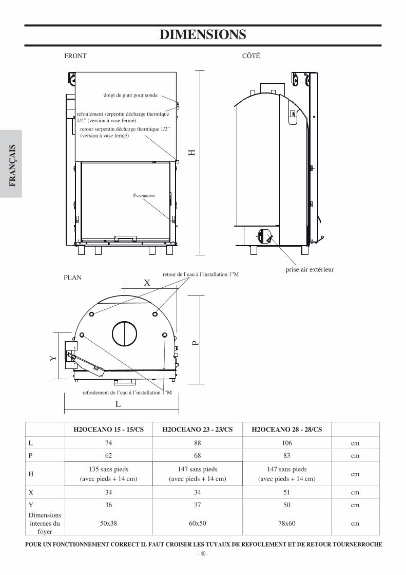
- 40 -
FR
AN
ÇA
IS
DIMENSIONS FRONT C T
PLANprise air extérieur
L
PH
retour serpentin décharge thermique 1 2” (version à vase fermé)
refoulement serpentin décharge thermique 1 2” (version à vase fermé)
doigt de gant pour sonde
retour de l’eau à l’installation 1”M
refoulement de l’eau à l’installation 1”M
POUR UN FONCTIONNEMENT CORRECT IL FAUT CROISER LES TUYAUX DE REFOULEMENT ET DE RETOUR TOURNEBROCHE
Y
X
vacuation
H2OCEANO 15 - 15/CS H2OCEANO 23 - 23/CS H2OCEANO 28 - 28/CS
L 7 88 106 cm
P 62 68 83 cm
H135 sans pieds
(avec pieds + 1 cm)
1 7 sans pieds
(avec pieds + 1 cm)
1 7 sans pieds
(avec pieds + 1 cm)cm
X 3 3 51 cm
Y 36 37 50 cm
Dimensions internes du
foyer50x38 60x50 78x60 cm

- 41 -
FR
AN
ÇA
IS
CARACTERISTIQUES THERMOTECHNIQUES
N.B.: LE PROJET DE DONNÉES (Référence norme EN 13229)* Le volume de chauffe est calculé compte tenu une isolation de la maison conforme à la Loi 10 91, et modi cations successives et une demande de chaleur de 33 kcal m par heure.* Il est important de tenir compte aussi de la position du thermocheminée dans la pièce.* * Température en chaudière 70° - (ðT=25K)
Les données reportées ci-dessus sont indicatives.
POUR UN FONCTIONNEMENT CORRECT IL FAUT CROISER LES TUYAUX DE REFOULEMENT ET DE RETOUR TOURNEBROCHE
LE DIAMÈTRE DU CONDUIT DE CHEMINÉE À UTILISER DEVRA ÊTRE ÉVALUÉ PAR L’INSTALLATEUR, EN FONCTION DE LA HAUTEUR DE CE MÊME CONDUIT DE CHEMINÉE.
15-15/CS 23-23/CS 28-28/CS
Puissance thermique brulée 18,5 27,8 3 ,8 kW
Puissance nominale 1 ,8 22,2 27,8 kW
Puissance nominale à l’eau 12,1 18,2 22,8 kW
Rendement global environ 80 80 80 %
Rendement à l’eau environ 82 82 82 %
Catégorie de rendement (EN 303-5) > 3 > 3 > 3 -
ø sorties des fumées femelle 18 22 25 cm
Pression maximum d’exercice 1,5 1,5 1,5 bar
Consommation combustible ,5 7 8,5 kg h
Capacité d’eau 50 100 130 litres
Volume chauffable * 355 535 670 m
Poids avec emballage 2 0 285 325 kg
Production d’eau chaude sanitaire (kit 1 - 3 - N3 - N3bis)** 13-1 13-1 13-1 litres min
ø prise d’air externe 12,5 12,5 12,5 cm
Alimentation à l’installation (male) 1” 1” 1” pouces
Retour de l’installation (male) 1” 1” 1” pouces

- 42 -
FR
AN
ÇA
IS
INSTALLATIONAVERTISSEMENTS IMPORTANTS POUR L’IN-STALLATIONOutre aux indications ci-dessus du présent document, tenir compte des normes UNI- n. 10683 - générateurs de chaleur à bois conditions d’installation.- n. 9615/90 - calcul des dimensions internes des cheminées- n. 10412:2 - installations de chauffage à eau chaude. Conditions de sécurité, spéci cations pour les installations avec des appareils pour le chauffage de type domestique avec chaudière incorporée, alimentés par un combustible solide, avec une puissance du foyer ou de l’ensemble des foyers non supérieure à 35 kW
Notamment - Avant de commencer toute opération de montage, il est im-portant de véri er la compatibilité de l’installation comme établi par la norme UNI 10683 aux paragraphes .1 .1.1 .1.2.- Lorsque le montage est terminé, l’installateur devra procéder aux opérations de “mise en exercice “ et relâcher une documen-tation selon la norme UNI 10683 aux paragraphes .6 et 5.
bon fonctionnement de la thermocheminée doivent être effectués par un personnel quali é, en mesure d’effectuer les branchements électriques et hydrauliques selon les normes UNI 10683 au paragraphe .5, UNI 10 12 2, ainsi qu’en respectantpleinement ces instructions de montage.- Les véri cations doivent être effectuées lorsque la cheminée est allumée et à régime pendant quelques heures, avant derevêtir le monobloc a n de pouvoir éventuellement intervenir.Donc, les opérations de nition telles que par exemple- construction de la contre-chape- montage du revêtement- exécution de pilastres, peintures, etc.doivent être effectuées après avoir terminé le contrôle et que le résultat se soit avéré positif. Par conséquent, EDILKAMIN nerépond pas des frais dérivant aussi bien des interventions de démolition que de reconstruction même si ils suivent les tra-vaux de remplacement d’éventuelles pièces défectueusesde la thermocheminée.
PRISE D’AIR EXTERNELe branchement avec l’extérieur, avec une section passante égale à un diamètre de 12,5 cm (voir tableau technique), est absolument nécessaire au bon fonctionnement de la ther-mocheminée; elle doit donc être absolument réalisée.Ce branchement doit être directement raccordé avec l’extérieur le mécanisme de réglage de l’air (E). Le mécanisme, livré séparément, peut être monté aussi bien à droite qu’à gauche de la thermocheminée. Le montage peut être réalisé avec un tuyau
exible en aluminium. Bien soigner le scellage des points où une dispersion d’air pourrait avoir lieu. Le mécanisme de réglage de l’air (E) peut être démonté et replacé à droite de la thermocheminée. Il est conseillé d’appliquer à l’extérieur duconduit de la prise d’air une grille de protection que de toute façon ne doit pas réduire la section utile passante. Pour des pas-sages supérieurs à 3 m, ou avec des courbes, augmenter de 10 à 20% la section indiquée. L’air externe doit être capté au niveau du sol (il ne peut provenir du haut).
CONDUITS D’ÉVACUATION DES FUMÉES ET POTLa sortie des fumées de la therrmocheminée est à section circu-laire. Elle est prévue a n de permettre l’utilisation des tuyaux en acier inox. Si l’entrée du conduit d’évacuation des fuméesn’est pas en position verticale par rapport à la thermocheminée, il faut que le raccord entre la thermocheminée et le conduit neprésente pas de rétrécissements ou d’inclinaisons supérieures à 5° ( g.1-2-3- ). Pour des conduits d’évacuation des fumées modernes réalisés récemment ou trop grands, il est conseillé le tubage au moyen de tubes en acier inox d’un diamètre adaptéet isolés correctement. Pour des conduits d’évacuation des fumées à l’extérieur, il est conseillé d’utiliser ceux en acier inox muraux avec une double isolation. Les caractéristiques de construction, notamment en ce qui concerne la résistance méca-nique, l’isolation et l’étanchéité par rapport aux gaz doivent être adaptés a n de supporter une température des fumées d’au moins 50°C. Effectuer l’étanchéisation avec du mastic àhaute température, au niveau du point de l’ entrée du conduit d’évacuation en acier sur la bouche de sortie des fumées de la thermocheminée.Caractéristiques fondamentales du pot sont:- section interne à la base égale à celle du conduit d’évacuation des fumées.- section de sortie doublement plus petite par rapport à celle du conduit d’évacuation des fumées.- position en plein vent, au-dessus du toit et en dehors des zones de re ux. Outre aux indications ci-dessus, tenir compte de celles de la norme UNI 10683 au paragraphe .2 “branchement au système d’évacuation des fumées” et ses sous-paragraphes
E
E
2
45°
45°
3
max.45°
1
NO
4
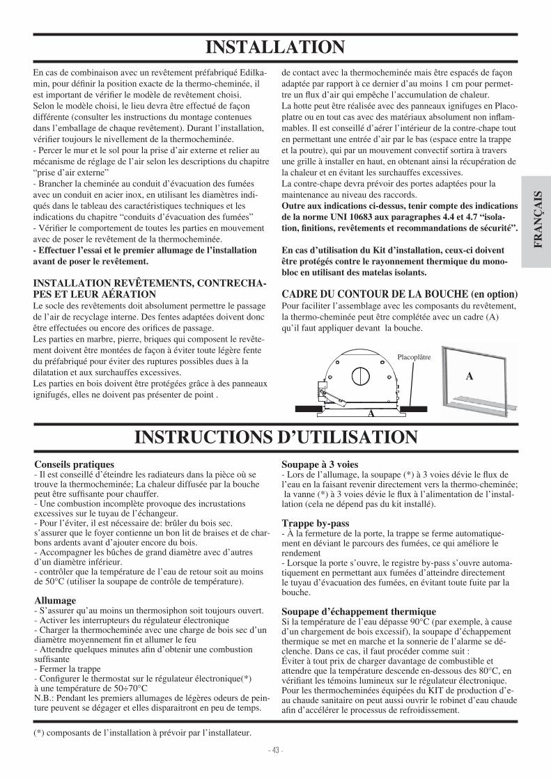
- 43 -
FR
AN
ÇA
IS
INSTALLATIONEn cas de combinaison avec un revêtement préfabriqué Edilka-min, pour dé nir la position exacte de la thermo-cheminée, il est important de véri er le modèle de revêtement choisi.Selon le modèle choisi, le lieu devra être effectué de façon différente (consulter les instructions du montage contenues dans l’emballage de chaque revêtement). Durant l’installation, véri er toujours le nivellement de la thermocheminée. - Percer le mur et le sol pour la prise d’air externe et relier au mécanisme de réglage de l’air selon les descriptions du chapitre “prise d’air externe”- Brancher la cheminée au conduit d’évacuation des fumées avec un conduit en acier inox, en utilisant les diamètres indi-qués dans le tableau des caractéristiques techniques et lesindications du chapitre “conduits d’évacuation des fumées”- Véri er le comportement de toutes les parties en mouvement avec de poser le revêtement de la thermocheminée.- Effectuer l’essai et le premier allumage de l’installation avant de poser le revêtement.
INSTALLATION REVÊTEMENTS, CONTRECHA-PES ET LEUR AÉRATIONLe socle des revêtements doit absolument permettre le passage de l’air de recyclage interne. Des fentes adaptées doivent donc être effectuées ou encore des ori ces de passage.Les parties en marbre, pierre, briques qui composent le revête-ment doivent être montées de façon à éviter toute légère fente du préfabriqué pour éviter des ruptures possibles dues à ladilatation et aux surchauffes excessives. Les parties en bois doivent être protégées grâce à des panneaux ignifugés, elles ne doivent pas présenter de point .
Conseils pratiques- Il est conseillé d’éteindre les radiateurs dans la pièce où se trouve la thermocheminée; La chaleur diffusée par la bouche peut être suf sante pour chauffer.- Une combustion incomplète provoque des incrustations excessives sur le tuyau de l’échangeur.- Pour l’éviter, il est nécessaire de brûler du bois sec.s’assurer que le foyer contienne un bon lit de braises et de char-bons ardents avant d’ajouter encore du bois. - Accompagner les bûches de grand diamètre avec d’autres d’un diamètre inférieur.- contrôler que la température de l’eau de retour soit au moins de 50°C (utiliser la soupape de contrôle de température).
Allumage- S’assurer qu’au moins un thermosiphon soit toujours ouvert.- Activer les interrupteurs du régulateur électronique- Charger la thermocheminée avec une charge de bois sec d’un diamètre moyennement n et allumer le feu- Attendre quelques minutes a n d’obtenir une combustion suf sante- Fermer la trappe- Con gurer le thermostat sur le régulateur électronique(*)à une température de 50÷70°CN.B. Pendant les premiers allumages de légères odeurs de pein-ture peuvent se dégager et elles disparaitront en peu de temps.
de contact avec la thermocheminée mais être espacés de façon adaptée par rapport à ce dernier d’au moins 1 cm pour permet-tre un ux d’air qui empêche l’accumulation de chaleur.La hotte peut être réalisée avec des panneaux ignifuges en Placo-platre ou en tout cas avec des matériaux absolument non in am-mables. Il est conseillé d’aérer l’intérieur de la contre-chape tout en permettant une entrée d’air par le bas (espace entre la trappe et la poutre), qui par un mouvement convectif sortira à travers une grille à installer en haut, en obtenant ainsi la récupération de la chaleur et en évitant les surchauffes excessives.La contre-chape devra prévoir des portes adaptées pour la maintenance au niveau des raccords.Outre aux indications ci-dessus, tenir compte des indications
-
En cas d’utilisation du Kit d’installation, ceux-ci doivent être protégés contre le rayonnement thermique du mono-bloc en utilisant des matelas isolants.
CADRE DU CONTOUR DE LA BOUCHE (en option)Pour faciliter l’assemblage avec les composants du revêtement, la thermo-cheminée peut être complétée avec un cadre (A) qu’il faut appliquer devant la bouche.
INSTRUCTIONS D’UTILISATIONSoupape à 3 voies- Lors de l’allumage, la soupape (*) à 3 voies dévie le ux de l’eau en la faisant revenir directement vers la thermo-cheminée; la vanne (*) à 3 voies dévie le ux à l’alimentation de l’instal-lation (cela ne dépend pas du kit installé).
Trappe by-pass- À la fermeture de la porte, la trappe se ferme automatique-ment en déviant le parcours des fumées, ce qui améliore le rendement- Lorsque la porte s’ouvre, le registre by-pass s’ouvre automa-tiquement en permettant aux fumées d’atteindre directement le tuyau d’évacuation des fumées, en évitant toute fuite par la bouche.
Soupape d’échappement thermiqueSi la température de l’eau dépasse 90°C (par exemple, à cause d’un chargement de bois excessif), la soupape d’échappement thermique se met en marche et la sonnerie de l’alarme se dé-clenche. Dans ce cas, il faut procéder comme suit
viter à tout prix de charger davantage de combustible et attendre que la température descende en-dessous des 80°C, en véri ant les témoins lumineux sur le régulateur électronique.Pour les thermocheminées équipées du KIT de production d’e-au chaude sanitaire on peut aussi ouvrir le robinet d’eau chaude a n d’accélérer le processus de refroidissement.
A
(*) composants de l’installation à prévoir par l’installateur.
Placoplâtre
A

- 44 -
FR
AN
ÇA
IS
INSTRUCTIONS D’UTILISATION
E
g. 1
g. 2
g. 3
V
X Y
Installation vanne thermostatique «V» en optionToutes les opérations doivent être effectuées avec la thermo-cheminée froide.De plus, l’alimentation électrique doit être coupée.Procéder ainsi - Ouvrir la porte et la bloquer dans la position d’ouvertu-re pour pouvoir facilement opérer à l’intérieur du foyer ( g. ).- Retirer les éléments suivants ( g. 5) tiroir à cendres grille en fonte dalle foyère
Remarque La dalle foyère est simplement posée sur le joint, il suf t donc de la soulever pour l’enlever (il faut savoir que si la thermo-cheminée n’a pas été utilisée pen-dant une certaine période, il est possible de trouver une légère adhérence entre la dalle foyère et le foyer).-Installer la vanne thermostatique déjà assemblée sur la plaque de xation ( g. 6 - page 5).- Fixer la plaque avec les 3 vis fournies (S) sur le fond du foyer ( g. 7 - page 5).Avant de procéder à la xation, s’assurer de faire passer le câble de réglage et le l de la sonde à travers les fentes prévues.- Le câble de réglage doit être inséré dans le trou avant situé sous le tiroir à cendres ( g. 8 - page 5), et xé au moyen de la bague élastique fournie.- Le l de la sonde doit être déroulé le long du côté droit du tiroir à cendres jusqu’à atteindre l’extérieur de la thermo-cheminée ( g.9-page 5) au moyen du trou situé sur le côté droit.- Il est alors possible d’introduire la sonde dans le doigt de gant au bord de la thermo-cheminée (page 0).- Avant de replacer la dalle foyère, véri er l’état d’usure du joint (la remplacer éventuellement) et insérer le joint sur le périmètre de la plaque de xation de la vanne ther-mostatique ( g. 8 - page 5).
Réglage air externeLa commande, au moyen de la trappe (E- g.1) située sur le raccord de la prise d’air externe, règle la quantité d’air primaire nécessaire à la combustion.En poussant le pommeau, la prise d’air externe se ferme, alors qu’en le tirant, la prise d’air externe s’ouvre.
VANNE THERMOSTATIQUE EN OPTION (FIG. 2 )Réglage manuel de l’air de combustion (à effectuer en phase d’installation)A n d’obtenir la température de l’eau souhaitée, il est nécessai-re de régler manuellement la vanne thermostatique.En utilisant la clé Allen fournie (X- g.3), il est possible de régler la vanne thermostatique en intervenant sur la vis située juste en-dessous du tiroir à cendres (Y- g.3). vis à droite air de combustion au minimum vis complètement à gauche air de combustion au maximum toutes les positions intermédiaires sont évidemment possibles
N.B. En cas d’installation de la vanne thermostatique, il est nécessaire d’éliminer la trappe manuelle de la prise d’air en démontant la vanne et le câble avec le pommeau (E- g.1).
Réglage automatique de l’air de combustionL’air de combustion est captée par la prise d’air externe au moyen du raccord (E- g.1) et atteint le foyer à travers la grille cendres.Il se règle au moyen de la vanne V ( g.2).Si la température dans le foyer est basse, par rapport à celle programmée lors du tarage, la vanne se met automatiquement en position ouverte et en revanche se ferme toujours automati-quement lorsque la température est élevée.Cela permet de consommer seulement la quantité de bois nécessaire pour atteindre le confort thermique souhaité, en évitant d’inutiles gaspillages.N.B quand la vanne thermostatique ferme complètement l’entrée de l’air de combustion (température dans le foyer très élevée), un minimum d’air accède toutefois sur la vitre a n de maintenir sa propreté.
g.
g. 5
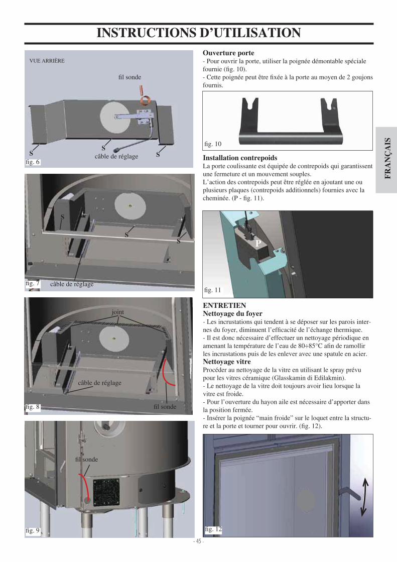
- 45 -
FR
AN
ÇA
IS
ENTRETIENNettoyage du foyer- Les incrustations qui tendent à se déposer sur les parois inter-nes du foyer, diminuent l’ef cacité de l’échange thermique.- Il est donc nécessaire d’effectuer un nettoyage périodique en amenant la température de l’eau de 80÷85°C a n de ramollir les incrustations puis de les enlever avec une spatule en acier.Nettoyage vitreProcéder au nettoyage de la vitre en utilisant le spray prévu pour les vitres céramique (Glasskamin di Edilakmin). - Le nettoyage de la vitre doit toujours avoir lieu lorsque la vitre est froide.- Pour l’ouverture du hayon aile est nécessaire d’apporter dans la position fermée.- Insérer la poignée “main froide” sur le loquet entre la structu-re et la porte et tourner pour ouvrir. ( g. 12).
Ouverture porte- Pour ouvrir la porte, utiliser la poignée démontable spéciale fournie ( g. 10).- Cette poignée peut être xée à la porte au moyen de 2 goujons fournis.
INSTRUCTIONS D’UTILISATION
g. 6
g. 7
g. 8
g. 9
VUE ARRIÈRE
l sonde
câble de réglageS
S S
SS
S
câble de réglage
câble de réglage
l sonde
l sonde
joint
Installation contrepoidsLa porte coulissante est équipée de contrepoids qui garantissent une fermeture et un mouvement souples.L’action des contrepoids peut être réglée en ajoutant une ou plusieurs plaques (contrepoids additionnels) fournies avec la cheminée. (P - g. 11).
g. 10
g. 12
g. 11
P

- 46 -
FR
AN
ÇA
IS
SYSTÈME POUR INSTALLATION À VASE OUVERT EXEMPLE DE SYSTÈME HYDRAULIQUE POUR THERMOCHEMINÉE AVEC PRODUCTION D’EAU CHAUDE
SANITAIRE AVEC UTILISATION DU KIT 1ACS: Eau Chaude SanitaireAF: Eau FroideEV: Electrovanne à 3 voiesF: FluxostatMI: Alimentation SystèmeNA: Normalement ouverteNC: Normalement FerméeP: Pompe (circulateur)RA: RadiateursRE: Régulateur ElectroniqueRI: Retour SystèmeS: vacuationSc 20: Echangeur 20 plaquesST: Sonde de TempératureTC: ThermocheminéeV: SoupapeVE: Vase d’Expansion OuvertVSP: Soupape de sécurité à pression 1,5 barVST: Soupape de décharge thermiqueJa: Purgeur d’air automatique
Le Kit 1 a été réalisé pour faciliter la tâche des installateurs; en effet, il comprend tous les composants nécessaires pour installer correctement le produit.NB: les appareils compris dans le kit doivent être correctement protégés contre le rayonnement thermique de la cheminée, grâce à l’utilisation de matelas isolants.
ACTIONS SUR LE SÉLECTEURSélecteur OFF Tout éteintSélecteur MAN Circulateur forcé Vanne con guréeSélecteur AUTO Circulateur con guré Vanne con guréeSélection alarme sur position OFF exclue la signalisation acoustique
POUR UN FONCTIONNEMENT CORRECT IL FAUT CROISER LES TUYAUX DE REFOULEMENT ET DE RETOUR TOURNEBROCHE
ON
OFF
Branchements électriques
ActivationDésactivationalarmeacoustique
Réglage vanne20-80° C
Af chage
Circulateur
Vanne à 3 voies
Alimentation230Vac
Fusible
KIT 1 code 261880
Réglage Circulateur20-80° C
FluxostatAttention connecter le contactnormalement fermé
Sonde (insérer dans le puits prévu)
Circulateur actif Alarme surchauffe Vanne à 3 voies
1. Collecteur en laiton 1” M-F2. Vanne à boule 1”3. Circulateur avec attaches 1” ½(219660). Clapet anti-retour 1” (261910)
5. Electrovanne à 3 voies 1” M-F (1 3330)6. Raccords en cuivre7. Echangeur 30 plaques pour échange avec
circuit de la chaudière à gaz (216620)8. Echangeur 20 plaques pour production
d’eau chaude sanitaire (205270)9. Soupape de décharge thermique ¾” (729 0)10. Soupape de sécurité 1,5 bar ¾” (1 3260)11. Fluxostat (220830)12. Doigt de gant pour thermostat ½” + son-
de(175960)13. Régulateur électronique (220780)A Alimentation à l’installation ¾”B Retour à l’installation ¾”C Retour à la cheminée ¾”D Alimentation de la cheminée 1”E Eau froide sanitaire ½”F Eau chaude sanitaire ½”
Tuy
au d
e sé
curi
té Ø
> 28
mm
Tuy
au d
e ch
arge
Ø>
18 m
m
Col
lect
eur
Réseau
Régulateur compris dans le kit

- 47 -
FR
AN
ÇA
IS
SYSTÈME POUR INSTALLATION À VASE OUVERT EXEMPLE DE SYSTÈME HYDRAULIQUE POUR THERMOCHEMINÉE SANS PRODUCTION D’EAU CHAUDE
SANITAIRE + CHAUDIÈRE MURALE AVEC UTILISATION DU KIT 2AF: Eau FroideCA: Chaudière muraleMI: Alimentation SystèmeP: Pompe (circulateur)RA: RadiateursRE: Régulateur ElectroniqueRI: Retour SystèmeS: vacuationJa: Purgeur d’air automatiqueSc 30: Echangeur 30 plaquesST: Sonde de TempératureTC: ThermocheminéeV: SoupapeVE: Vase d’Expansion OuvertVR: Clapet anti-retourVSP: Soupape de sécurité pression 1,5 barVST: Soupape de décharge thermique
Le Kit 2 a été réalisé pour faciliter la tâche des installateurs; en effet, il comprend tous les composants nécessaires pour installer correctement le produit.NB: les appareils compris dans le kit doivent être correctement protégés contre le rayonnement thermique de la cheminée, grâce à l’utilisation de matelas isolants.
1. Collecteur en laiton 1” M-F2. Vanne à boule 1”3. Circulateur avec attaches 1” ½ (219660). Clapet anti-retour 1” (261910)
5. Electrovanne à 3 voies 1” M-F (1 3330)6. Raccords en cuivre7. Echangeur 30 plaques pour échangeavec
circuit de la chaudière à gaz (216620)8. Echangeur 20 plaques pour production
d’eau chaude sanitaire (205270)9. Soupape de décharge thermique ¾” (729 0)10. Soupape de sécurité 1,5 bar ¾” (1 3260)11. Fluxostat (220830)12. Doigt de gant pour thermostat ½” + son-
de(175960)13. Régulateur électronique (220780)A Alimentation à l’installation ¾”B Retour à l’installation ¾”C Retour à la cheminée ¾”D Alimentation de la cheminée 1”E Eau froide sanitaire ½”F Eau chaude sanitaire ½”
POUR UN FONCTIONNEMENT CORRECT IL FAUT CROISER LES TUYAUX DE REFOULEMENT ET DE RETOUR TOURNEBROCHE
Réglage vanne20-80° C
Af chage
KIT 2 code 261890
ON
OFF
Fusible
Circulateur B
Réglage de la température minimum d’autorisation de démarrage des circulateurs 20-80°
ACTIONS SUR LE SÉLECTEURSélecteur OFF Tout éteintSélecteur MAN Circulateur forcé Vanne con guréeSélecteur AUTO Circulateur con guré Vanne con guréeSélection alarme sur position OFF exclue la signalisation acoustique
Tuy
au d
e sé
curi
té Ø
> 28
mm
Tuy
au d
e ch
arge
Ø>
18
mm
Col
lect
eur
Réseau
Régulateur compris dans le kit
Branchements électriques
Circulateur actif Alarme surchauffe Vanne à 3 voies
ActivationDésactivationalarmeacoustique
Circulateur A
Alimentation230Vac
Sonde (insérer dans le puits prévu)

- 48 -
FR
AN
ÇA
IS
SYSTÈME POUR INSTALLATION À VASE OUVERTEXEMPLE DE SYSTÈME HYDRAULIQUE POUR THERMOCHEMINÉE AVEC PRODUCTION D’EAU CHAUDE
SANITAIRE + CHAUDIÈRE MURALE AVEC UTILISATION DU KIT 3ACS: Eau Chaude SanitaireAF: Eau FroideCA: Chaudière muraleEV: Electrovanne à 3 voiesF: FluxostatMI: Alimentation SystèmeNA: Normalement ouverteNC: Normalement FerméeP: Pompe (circulateur)RA: RadiateursRE: Régulateur ElectroniqueRI: Retour SystèmeS: vacuationSc 20 : Echangeur 20 plaquesSc 30 : Echangeur 30 plaquesTC: ThermocheminéeV: SoupapeVE: Vase d’Expansion OuvertVR: Clapet anti-retourVSP: Soupape de sécurité pression 1,5 barVST: Soupape de décharge thermiqueJa: Purgeur d’air automatique
Le Kit 3 a été réalisé pour faciliter la tâche des installateurs; en effet, il comprend tous les composants nécessaires pour installer correctement le produit.NB: les appareils compris dans le kit doivent être correctement protégés contre le rayonnement thermique de la cheminée, grâce à l’utilisation de matelas isolants.
POUR UN FONCTIONNEMENT CORRECT IL FAUT CROISER LES TUYAUX DE REFOULEMENT ET DE RETOUR TOURNEBROCHE
KIT 3 code 261900
1. Collecteur en laiton 1” M-F2. Vanne à boule 1”3. Circulateur avec attaches 1” ½(219660). Clapet anti-retour 1” (261910)
5. Electrovanne à 3 voies 1” M-F (1 3330)6. Raccords en cuivre7. Echangeur 30 plaques pour échange avec
circuit de la chaudière à gaz (216620)8. Echangeur 20 plaques pour production
d’eau chaude sanitaire (205270)9. Soupape de décharge thermique ¾” (729 0)10. Soupape de sécurité 1,5 bar ¾” (1 3260)11. Fluxostat (220830)12. Doigt de gant pour thermostat ½” + sonde
(175960)13. Régulateur électronique (220780)A Alimentation à l’installation ¾”B Retour à l’installation ¾”C Retour à la cheminée ¾”D Alimentation de la cheminée 1”E Eau froide sanitaire ½”F Eau chaude sanitaire ½”
ON
OFF
Réglage vanne20-80° C
Af chageFusible
Circulateur A Circulateur B
ACTIONS SUR LE SÉLECTEURSélecteur OFF Tout éteintSélecteur MAN Circulateur forcé Vanne con guréeSélecteur AUTO Circulateur con guré Vanne con guréeSélection alarme sur position OFF exclue la signalisation acoustique
Tuy
au d
e sé
curi
té Ø
> 28
mm
Tuy
au d
e ch
arge
Ø>
18
mm
Col
lect
eur
Réseau
Régulateur compris dans le kit
Branchements électriques
Circulateur actif Alarme surchauffe Vanne à 3 voies Activation
Désactivationalarmeacoustique
Vanne à 3 voies
Alimentation230Vac
Réglage Circulateur20-80° C
FluxostatAttention connecter le contact normalement fermé
Sonde (insérer dans le puits prévu)

- 49 -
FR
AN
ÇA
IS
SYSTÈME POUR INSTALLATION À VASE OUVERTEXEMPLE DE SYSTÈME HYDRAULIQUE POUR THERMOCHEMINÉE AVEC PRODUCTION D’EAU CHAUDE
SANITAIRE + CHAUDIÈRE MURALE AVEC UTILISATION DU KIT N3CA: Chaudière muralePR: Pompe (circulateur)P1: Pompe circuit primaireRE: Régulateur électroniqueTA: Thermostat d’ambianceVE: Vase d’expansionJa: Purgeur d’air automatiqueV: Robinet d’arrêtVR: Clapet de retenueST: Sonde de températureF: FluxostatSc: changeur de chaleur à plaquesEV: lectrovanne à 3 voiesRI: Retour installation de chauffageRA: RadiateursMI: Refoulement installation de chauffageAF: Eau froideACS: Eau chaude sanitaireS: Purge
Le Kit N3 a été réalisé pour faciliter la tâche des installateurs; en effet, il comprend tous les composants nécessaires pour installer correctement le produit.NB: les appareils compris dans le kit doivent être correctement protégés contre le rayonnement thermique de la cheminée, grâce à l’utilisation de matelas isolants.
POUR UN FONCTIONNEMENT CORRECT IL FAUT CROISER LES TUYAUX DE REFOULEMENT ET DE RETOUR TOURNEBROCHE
KIT N3 code 627690
1. Refoulement dans le circuit de l’installation de chauffage G 3 ”2. Refoulement depuis le générateur EDILKAMIN G 3 ”3. Retour au générateur EDILKAMIN G 3 ”. Retour depuis le circuit de l’installation de chauffage G 3 ”
5. Entrée eau froide sanitaire G 1 2”6. Refoulement eau chaude aux installations sanitaires G 1 2”7. Vanne de sécurité combinée température et pression (90°C-3bars)8. Fluxostat9. Purgeur d’air automatique10. Circulateur circuit générateur EDILKAMIN11. changeur à plaques à 3 voies12. Vanne d’arrêt G 1”13. Régulateur électronique avec câbles1 . Fente spéciale pour passage passe- ls15. Cable d’alimentation16. Cables pour circulateur installation chauffage (phase, neutre,
terre)17. Sonde température18. Circuit thermostat ambiant
VEAF
S V
RE
RETE
ST
V
S
V
Tu
bo
di
cari
co
Ø>
18
mm
Tu
bo
di
sic
ure
zza
Ø>
28
mm
V
CA
ACS
PRF
ACS
AF
Ja
TA
P1
VVs
Sc
TCN
ELETTRICA
INT
VR V
VR
RETE
IDRICA
VR
VR
MI
RA
RI
V
COLLETTORE
VR
V
V
V
V
V
Circuito collegabile altermostato ambiente(a discrezione del cliente)
Da collegare necessariamenteal circolatore dell’impianto
di riscaldamento PR
12 3 4
56
7
8
9
10
119
9
12
13
12 3 5
4 67
14
15 16 17
Passacavi
18
Pompe circuit primaire
OFF
Set autorisation circulateur primaire30- 0°C
ON
Pompe chauffage
EV
Réseau électri-que 230 Vac50 Hz + - 10%
Set autorisation eau chaude - chauffage 0-80°C
thermostat ambiant
Capteur de ux
sondeAutorisation alarme
Branchements électriques
Tuy
au d
e sé
curi
té Ø
> 28
mm
Tuy
au d
e ch
arge
Ø>
18
mm
Collecteur
Réseau hydrique
Réseau
circuit raccordable au thermostat ambiant (au choix du client)
à raccorder nécessairement au circulateur de l’installation de chauffage
passe- ls
Pompe 1 Pompe 2
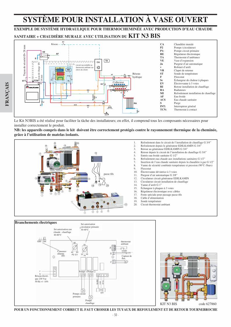
- 50 -
FR
AN
ÇA
IS
SYSTÈME POUR INSTALLATION À VASE OUVERTEXEMPLE DE SYSTÈME HYDRAULIQUE POUR THERMOCHEMINÉE AVEC PRODUCTION D’EAU CHAUDE
SANITAIRE + CHAUDIÈRE MURALE AVEC UTILISATION DU KIT N3 BISCA Chaudière muraleP2 Pompe (circulateur)P1: Pompe circuit primaireRE Régulateur électroniqueTA Thermostat d’ambianceVE Vase d’expansionJa Purgeur d’air automatiquev Robinet d’arrêtVR Clapet de retenueST Sonde de températureF FluxostatSc changeur de chaleur à plaquesEV lectrovanne à 3 voiesRI Retour installation de chauffageRA RadiateursMI Refoulement installation de chauffageAF Eau froideACS Eau chaude sanitaireS PurgeINT: Interrupteur généralTCN: Thermostat à contact
Le Kit N3BIS a été réalisé pour faciliter la tâche des installateurs; en effet, il comprend tous les composants nécessaires pour installer correctement le produit.NB: les appareils compris dans le kit doivent être correctement protégés contre le rayonnement thermique de la cheminée, grâce à l’utilisation de matelas isolants.
POUR UN FONCTIONNEMENT CORRECT IL FAUT CROISER LES TUYAUX DE REFOULEMENT ET DE RETOUR TOURNEBROCHE
KIT N3 BIS code 627860
1. Refoulement dans le circuit de l’installation de chauffage G 3 ”2. Refoulement depuis le générateur EDILKAMIN G 3 ”3. Retour au générateur EDILKAMIN G 3 ”. Retour depuis le circuit de l’installation de chauffage G 3 ”
5. Entrée eau froide sanitaire G 1 2”6. Refoulement eau chaude aux installations sanitaires G 1 2”7. Insertion de l’eau chaude sanitaire depuis la chaudière à gaz G 1 2”8. Vanne de sécurité combinée température et pression (90°C-3bars)9. Fluxostat10. lectrovanne déviatrice à 3 voies11. Purgeur d’air automatique G 3 8”12. Circulateur circuit générateur EDILKAMIN13. Circulateur circuit installation de chauffage1 . Vanne d’arrêt G 1”15. changeur à plaques à 3 voies16. Régulateur électronique avec câbles17. Fente spéciale pour passage passe- ls18. Cable d’alimentation19. Sonde température20. Circuit thermostat ambiant
OFF ON
EV
Consenso allarme
VEAF
S V
RE
ST
S
V
Tu
bo
dicari
co
Ø>
18
mm
Tu
bo
disic
ure
zza
Ø>
28
mm
CA
ACS
VR
MI
RA
RI
V
ACS
AF
Ja
TA
EV
P2
P1
V
V
Sc
F
Vs
RETE
ELETTRICA
INT
VR V
TCN
V
V
V
By-p
ass
VR
Sc
RETE
IDRICA
COLLETTORE
VR
V
V
V
V
V
Circuito collegabile altermostato ambiente(a discrezione del cliente)
12 3 4
5 6 7
8
9
10
11
12
1314
14
15
111111
1111
1617
12 3
4
5
8
6
7
2019
Passacavi
17
18
Branchements électriques
Pompe circuit primaire
Set autorisation circulateur primaire30- 0°C
Pompe chauffage
Réseau électri-que 230 Vac50 Hz + - 10%
Set autorisation eau chaude - chauffage 0-80°C
thermostat ambiant
Capteur de ux
sonde
Tuy
au d
e sé
curi
té Ø
> 28
mm
Tuy
au d
e ch
arge
Ø>
18
mm
Collecteur
Réseau hydrique
Réseau
circuit raccordable au thermostat ambiant (au choix du client)
passe- ls
Pompe 1 Pompe 2
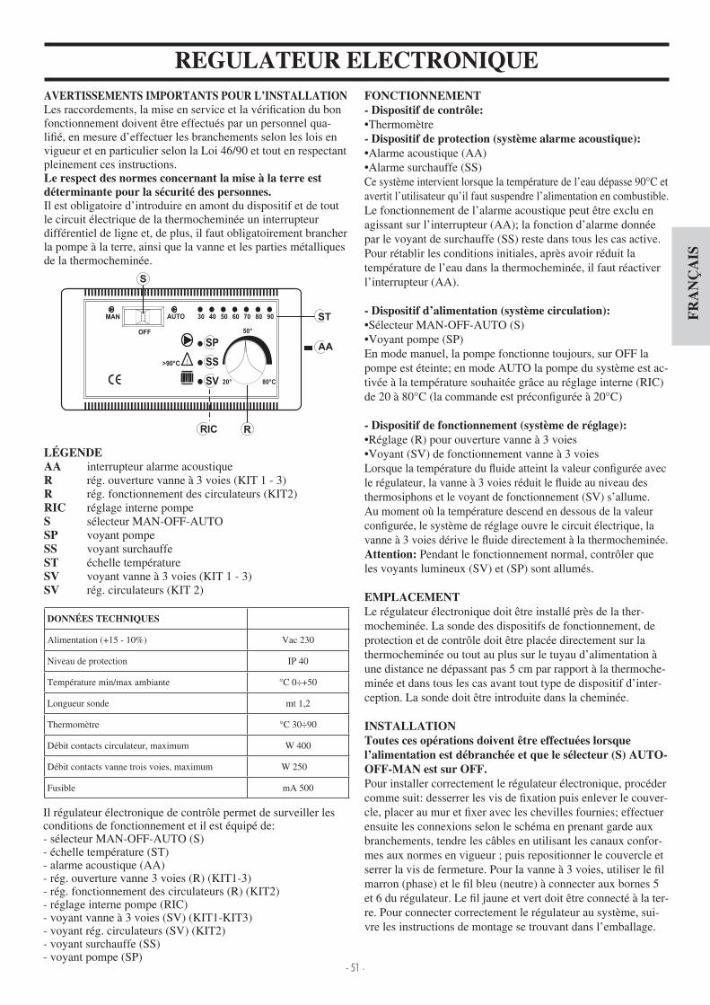
- 51 -
FR
AN
ÇA
IS
REGULATEUR ELECTRONIQUEFONCTIONNEMENT- Dispositif de contrôle:Thermomètre
- Dispositif de protection (système alarme acoustique):Alarme acoustique (AA)Alarme surchauffe (SS)
Ce système intervient lorsque la température de l’eau dépasse 90°C et avertit l’utilisateur qu’il faut suspendre l’alimentation en combustible.Le fonctionnement de l’alarme acoustique peut être exclu en agissant sur l’interrupteur (AA); la fonction d’alarme donnée par le voyant de surchauffe (SS) reste dans tous les cas active.Pour rétablir les conditions initiales, après avoir réduit la température de l’eau dans la thermocheminée, il faut réactiver l’interrupteur (AA).
- Dispositif d’alimentation (système circulation):Sélecteur MAN-OFF-AUTO (S)Voyant pompe (SP)
En mode manuel, la pompe fonctionne toujours, sur OFF la pompe est éteinte; en mode AUTO la pompe du système est ac-tivée à la température souhaitée grâce au réglage interne (RIC) de 20 à 80°C (la commande est précon gurée à 20°C)
- Dispositif de fonctionnement (système de réglage):Réglage (R) pour ouverture vanne à 3 voiesVoyant (SV) de fonctionnement vanne à 3 voies
Lorsque la température du uide atteint la valeur con gurée avec le régulateur, la vanne à 3 voies réduit le uide au niveau des thermosiphons et le voyant de fonctionnement (SV) s’allume. Au moment où la température descend en dessous de la valeur con gurée, le système de réglage ouvre le circuit électrique, la vanne à 3 voies dérive le uide directement à la thermocheminée. Attention: Pendant le fonctionnement normal, contrôler que les voyants lumineux (SV) et (SP) sont allumés.
EMPLACEMENTLe régulateur électronique doit être installé près de la ther-mocheminée. La sonde des dispositifs de fonctionnement, de protection et de contrôle doit être placée directement sur la thermocheminée ou tout au plus sur le tuyau d’alimentation à une distance ne dépassant pas 5 cm par rapport à la thermoche-minée et dans tous les cas avant tout type de dispositif d’inter-ception. La sonde doit être introduite dans la cheminée.
INSTALLATIONToutes ces opérations doivent être effectuées lorsquel’alimentation est débranchée et que le sélecteur (S) AUTO-OFF-MAN est sur OFF.Pour installer correctement le régulateur électronique, procéder comme suit desserrer les vis de xation puis enlever le couver-cle, placer au mur et xer avec les chevilles fournies; effectuer ensuite les connexions selon le schéma en prenant garde aux branchements, tendre les câbles en utilisant les canaux confor-mes aux normes en vigueur ; puis repositionner le couvercle et serrer la vis de fermeture. Pour la vanne à 3 voies, utiliser le l marron (phase) et le l bleu (neutre) à connecter aux bornes 5 et 6 du régulateur. Le l jaune et vert doit être connecté à la ter-re. Pour connecter correctement le régulateur au système, sui-vre les instructions de montage se trouvant dans l’emballage.
AVERTISSEMENTS IMPORTANTS POUR L’INSTALLATIONLes raccordements, la mise en service et la véri cation du bonfonctionnement doivent être effectués par un personnel qua-li é, en mesure d’effectuer les branchements selon les lois en vigueur et en particulier selon la Loi 6 90 et tout en respectant pleinement ces instructions.Le respect des normes concernant la mise à la terre est déterminante pour la sécurité des personnes.Il est obligatoire d’introduire en amont du dispositif et de tout le circuit électrique de la thermocheminée un interrupteur différentiel de ligne et, de plus, il faut obligatoirement brancher la pompe à la terre, ainsi que la vanne et les parties métalliques de la thermocheminée.
LÉGENDEAA interrupteur alarme acoustiqueR rég. ouverture vanne à 3 voies (KIT 1 - 3)R rég. fonctionnement des circulateurs (KIT2)RIC réglage interne pompeS sélecteur MAN-OFF-AUTOSP voyant pompeSS voyant surchauffeST échelle températureSV voyant vanne à 3 voies (KIT 1 - 3)SV rég. circulateurs (KIT 2)
DONNÉES TECHNIQUES
Alimentation (+15 - 10%) Vac 230
Niveau de protection IP 0
Température min max ambiante °C 0÷+50
Longueur sonde mt 1,2
Thermomètre °C 30÷90
Débit contacts circulateur, maximum W 00
Débit contacts vanne trois voies, maximum W 250
Fusible mA 500
Il régulateur électronique de contrôle permet de surveiller lesconditions de fonctionnement et il est équipé de- sélecteur MAN-OFF-AUTO (S)- échelle température (ST)- alarme acoustique (AA)- rég. ouverture vanne 3 voies (R) (KIT1-3)- rég. fonctionnement des circulateurs (R) (KIT2)- réglage interne pompe (RIC)- voyant vanne à 3 voies (SV) (KIT1-KIT3)- voyant rég. circulateurs (SV) (KIT2)- voyant surchauffe (SS)- voyant pompe (SP)

- 52 -
FR
AN
ÇA
IS
REGULATEUR ELECTRONIQUE (en option)
permet de surveiller les conditions de fonctionnement et il estéquipé de
- sélecteur MAN-OFF-AUTO- échelle température-alarme acoustique- régulateur ouverture vanne 3 voies- réglage interne pompe-voyant pompe-voyant vanne à 3 voies-voyant surchauffe
Le régulateur électronique est inclus dans tous les différents types de kit d’installation (fournis en option).
L’ECHANGEUR 20 PLAQUES POUR L’EAUSANITAIRE (options)
Il s’agit d’un appareil extrêmement simple et économique, quipermet une production d’eau chaude égale à 13-1 litres parminute en fonction de la centrale. Il est facilement installable sur le tuyau d’alimentation aux thermosiphons dans la position la plus pratique, par rapport aux conditions de l’installation. Il a l’avantage de pouvoir être démonté pour l’entretien ou le remplacement sans intervenir sur la thermocheminée.
Le régulateur à 20 plaques est inclus dans tous les différents types de kit d’installation (fournis en option).
L’ECHANGEUR À 3 VOIES (options)Produit de l’eau chaude pour le circuit sanitaire et pour le cir-cuit secondaire (radiateurs), et par rapport au KIT 3, exclut l’u-tilisation de la soupape à 3 voies et d’un échangeur à plaques.
eau chaude prove-nant de la thermo-cheminée
Régulateur électronique ( 220780)
eau froidedepuis le réseauhydraulique
eau de retour à lathermocheminée
eau chaude depuis lathermocheminée
eau chaudeaux sanitaires
eau froideinstallation
eau froidesanitaire
ACCESSOIRES EN OPTION
Kit vannes ( 21600) composé devanne automatique purge air,sûreté 1,5 bar,décharge thermique 90°C
Vanne à 3 vo-ies 1” (1 3330) pour régler le
ux de l’eau au niveau de l’in-stallation
Régulateur électronique (220780)
F l u x o s t a t (220830)
CirculateurUPS 25-50 code 219660UPS 25-60 code 238270
changeur à 3 voiescode 627780
Remote dispalycode 7 1180
Kit hydraulique V pour versions à VASE OUVERT code 7 3 30(installation à droite)
Vanne thermostatique H
2OCEANO 15 code 739 60
H2OCEANO 23 code 739 0
H2OCEANO 28 code 739 50
Cadre du contour de la boucheH
2OCEANO 15 code 739390 - dim. 63x63 cm
H2OCEANO 23 code 739370 - dim. 77x68 cm
H2OCEANO 28 code 739380 - dim. 95x68 cm
Support pour kits hydrauliques A1-A2-B-C-D (installation à droite) H
2OCEANO 15 code 739510
H2OCEANO 23 code 739 70
H2OCEANO 28 code 739 90
Echangeur 30 plaquespour installa-tion (216620)
Echangeur 20 plaquespour sanitaire(262570)
-D
TournebrocheH
2OCEANO 15 code 750820
H2OCEANO 23 code 23 560
H2OCEANO 28 code 236710
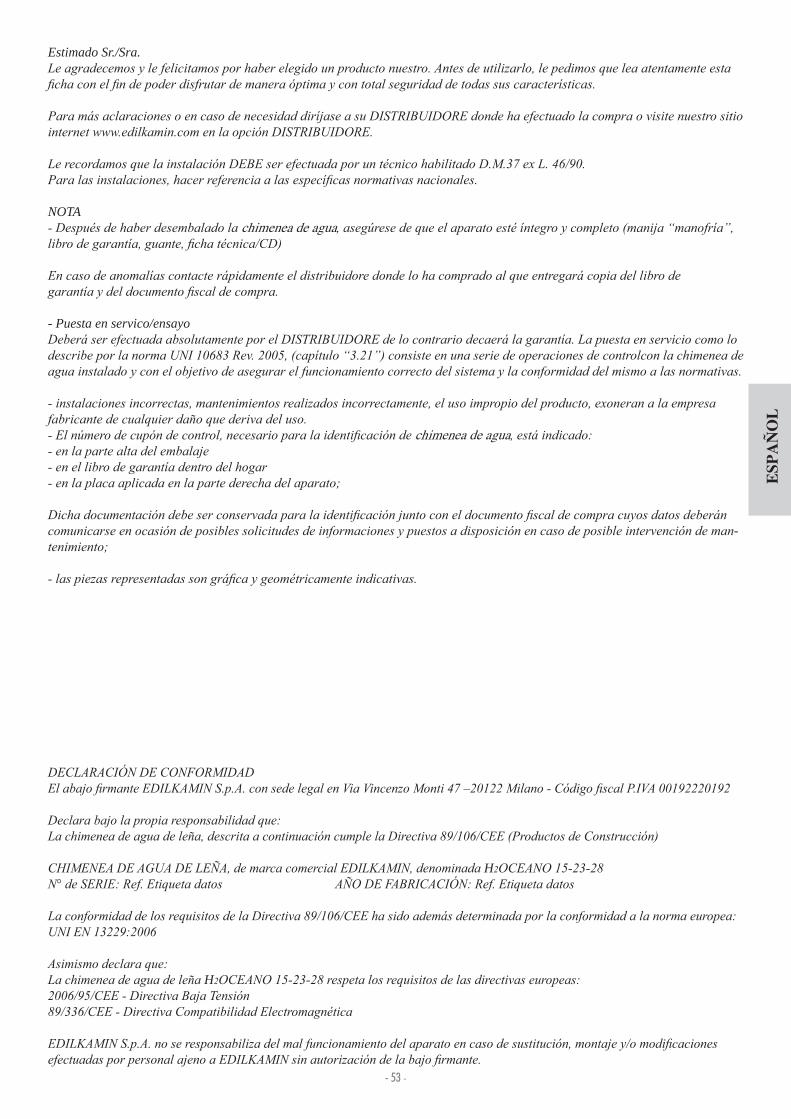
- 53 -
ESP
AÑ
OL
Estimado Sr./Sra.
NOTAchimenea de agua
- Puesta en servico/ensayo
chimenea de agua
-
H
H

- 54 -
ESP
AÑ
OL
CARACTERÍSTICAS TERMOTÉNCNICAS
H2OCEANO está proyectada para calentar agua por medio de una combustión de leña en el hogar.El agua contenida en la termoestufa se calienta y es enviada al sistema de calefacción (radiadores, calentadores de toallas, paneles radiantes de suelo) y además calienta el local en el que se encuentra a través de irradiación por convección natural.La termoestufa NO DEBE NUNCA FUNCIONAR SIN AGUA EN LA INSTALACIÓN.El agua se calienta circulando en la cámara de aire que recorre toda la pared semi circular y la cúpula del hogar.La cámara está realizada con chapa de acero de fuerte espesor.El hogar está cerrado fontalmente por una puerta de colanilla que se abre y por una puerta que sirve para limpiar el cristal.
INNOVADORA REJILLA PATENTADA PARA LAS CENIZAS Permite distribuir el aire primario de combustión no solo desde abajo hacia arriba, sino también horizontalmente para tener una elevada oxigenación de la llama, una mejor combustión y más potencia.
PUERTA “PROTEGE EMPAQUETADURAS”Durante el deslizamiento, la puerta queda separada ligeramente de la boca de la termochimenea para proteger las empaquetadu-ras.En posición de cierre se separa perfectamente para garanti-zar el máximo cierre y por lo tanto un óptimo rendimiento.La manija es extra ble o puede jarse a la puerta (ver pág. 62)
BY-PASS AUTOMÁTICO DE HUMOSEn fase de encendido, con boca abierta, para facilitar la puesta en marcha de la combustión, la compuerta de humos (S) permanece en posición de apertura de manera que los humos pueden alcanzar directa y fácilmente la tubería. Cuando la combustión está bien encendida, cerrando la puerta se cierra automáticamente también la compuerta de humos (S - g. b).En esta disposición, los humos antes de alcanzar el tubo de hu-mos se desvían tocando y cediendo calor al agua e cazmente.El by-pass es controlado automáticamente por el movimiento de la puerta.
De ectores Partes superiores
Alojamiento Motor Grill
Post-combustión
Válvula automática de regulación toma aire externo (opcional)
Posibilidad de aplicación pies regulables (opcional)
Calibrado para regulación automática del aire de combustión
Puerta picaportes
Cámara de aire envolvente para contención de agua
Serpentín de seguridad para descarga térmica 8versión CS)
Rejilla para cenizas de distribución de aire primario de combustión
Compuerta desviación recorrido de humos
A
B
C
D
E
F
G
H
I
L
S
AI
L
H
G
H
A
B
D
EF E
CS
(a)
(b)
s
s

- 55 -
ESP
AÑ
OL
H2OCEANO NO DEBE FUNCIONAR NUNCA SIN AGUA EN LA INSTALACIÓN.DEBE FUNCIONAR UNA PRESIÓN DE CERCA DE 1,5 BAR.
UN EVENTUAL ENCENDIDO “EN SECO” PODRÍA DAÑAR LA CHIMENEA DE AGUA.
La termochimenea está proyectada para calentar agua pormedio de una combustión de leña en el hogar.
Los únicos riesgos que derivan del uso de la termochimeneaestán unidos al incumplimiento de las especi caciones de insta-lación a una chimenea directa con partes eléctricas en tensión,(internas), a un contacto con fuego y partes calientes o a la introducción de sustancia extrañas.
Para un regular funcinamiento la temochimenea debe instalar-se respetando según lo indicado en esta documentación ydurante el funcionamiento no debe abrirse la puerta salvo pararecargar con leña el hogar.
En ningún caso han de introducirse en el hogar sustancias extrañas.
Para la limpieza del conducto de descarga de humos no debenutilizarse productos in amables.
El cristal puede ser limpiado en FRÍO con el producto ade-cuado (por ej. GlassKamin) y un paño. No limpie en caliente.
Durante el funcionamiento de la termochimenea, los tubos dedescarga y la puerta alcanzan altas temperaturas.
No deposite objetos no resistentes al calor en las inmediacio-nes de la termochimenea.
No utilice NUNCA combustibles líquidos para encender la chimenea o para reavivar las brasas.
No obstruya las aperturas de aireación del local de instala-ción, ni las entradas de aire de la propia termochimenea.
No moje la termochimenea, no se acerque a las partes eléctri-cas con las manos mojadas.
No introduzca reducciones en los tubos de descarga de hu-mos.
La termochimenea debe ser instalada en locales adecuadospara la seguridad contra incendios y dotados de todos los servi-cios (alimentación y descargas) que el aparato requiere paraun correcto y seguro funcionamiento.
INFORMACIONES DE SEGURIDAD
IMPORTANTE: EN INSTALACIONES DE VASO CERRADO DEBEN SER INSTALADOS SOLO TER-MOCHIMENEAS CON SERPENTÍN ACCIONADO POR VÁLVULA DE DESCARGA TÉRMICA (versión característica con la sigla CS).
La correcta realización del sistema es a cargo del instalador el cuál deberá tener en cuenta las normativas UNI 10683 - 9615 90 - 10 12 2
Todo debe ser efectuado por personal habilitado según el D.M. 37 ex Ley 6 90
La válvula de descarga térmica (VST – suministrada por Edilkamin) debe ser conectada al circuito de enfriamiento (AL) con presión mínima 1,5 bar.Já = jolly respiradero automáticoS = descarga
1 Año Las válvulas de seguridad y de descarga deberán ser controla-
das al menos una vez al año por personal habilitado D.M. 37 ex Ley 6 90.
La instalación de calentamiento debe prever un vaso de ex-pansión especí co para la termochimenea, considerado según el volumen de agua presente en la misma instalación (no se admite un vaso de expansión en común con otros generadores).
Litros ?

- 56 -
ESP
AÑ
OL
DISPOSICIONES GENERALES SOBRE LA SEGURIDADEN CASO DE INSTALACIÓN EN SISTEMAS DE VASO ABIERTO
Las conexiones, la puesta en servicio y la veri cación del buen funcionamiento, deben realizarse por personal cuali ca-do, capaz de realizar las conexiones según las leyes vigentes y especialmente según D.M. 37 Ley 6 90, respetando total-mente las presentes instrucciones.Para las instalaciones en el extranjero, hacer referencia a las especí cas normativas nacionales.El relleno de la termochimenea y del sistema se debe realizar a través del vaso de expansión abierto por caída natural del agua, a través del tubo de carga (diámetro no inferior a 18 mm).
Durante esta fase abrir todos los purgadores de los radiado-res de manera de evitar que se produzcan sacos de aire en el sistema que obstaculicen la circulación del agua
NOTA BIENEl vaso abierto se coloca a una altura mayor de 3 m con re-specto al elemento más alto del circuito primario, e inferiora 15 m con respecto a la salida de la termochimenea.
La altura del vaso debe de ser de todas formas tal que cree una presión mayor de aquella generada por la bomba (circu-lador). No rellenar nunca el sistema directamente con la presión de
red en ya que esta podría ser superior a aquella de la placa de la termo chimenea, con consiguiente daño de la misma termochimenea. El tubo de seguridad del vaso de expansión debe ser de ven-
tilación libre sin grifos de interceptación y aislado oportuna-mente para evitar la congelación del agua en su interior, que dañaría la junta. El tubo de carga debe estar libre sin grifos y curvaturas La presión máx de ejercicio no debe superar 1,5 bar La presión de ensayo es de 3 bar. Es conveniente añadir al agua que se encuentra contenida
en el sistema líquido anticongelante cumpliendo con la norma UNI 8065. No encender nunca el fuego en la termochimenea (ni en
caso de prueba) si el sistema no está relleno de agua; lo mismo ya que podría arruinarse irremediablemente. Conectar las descargas de la válvula de descarga térmica (VST) y de seguridad (VSP) (esquemas en la página siguiente) La prueba de mantenimiento del sistema es realizado con el
vaso de expansión abierto Sobre el circuito de agua caliente sanitaria es aconsejable
instalar una válvula de seguridad de 6 bar para descargar el excesivo aumento de volumen de agua contenido en elintercambiador. Colocar a todos los componentes del sistema, (circulador,
intercambiador, válvulas etc.) en zonas de fácil accesopara el mantenimiento ordinario y extraordinario.
TRATAMIENTO DEL AGUARealizar la aditivación de sustancias antihielo, anticostras y anticorrosivas. En el caso de que el agua de relleno y aba-stecimiento tenga una duración superior a 35°F, utilizar un ablandante para reducirla.
EN CASO DE INSTALACIÓN EN SISTEMAS DE VASO CERRADO(disposiciones adicionales a las indicadas para instalacio-nes de vaso abierto).
El relleno debe realizarse teniendo cuidado de no debe supe-rar los 1,5 bar.
Es posible instalar la chimenea sobre un sistema con VASO CERRADO sólo en la versión con serpentina accionada desdela válvula de exceso de temperatura (versión característica con la sigla CS).
En el caso de conexión de la termochimenea a una instala-ción existente se deberá examinar la necesidad de otroVASO CERRADO en la instalación.
La presión encima del circuito de enfriamiento debe ser de alme
Remitirse a la normativa UNI 8065-1989 (tratamiento del agua en los sistemas térmicos de uso civil).

- 57 -
ESP
AÑ
OL
DIMENSIONES
FRENTE LADO
PLANTA
Toma aire externa
L
PH
retorno serpentín descarga térmica 1 2” M (versión de vaso cerrado)
envío serpentín descarga térmica 1 2” M (versión de vaso cerrado)
pozo para sonda
retorno agua a la instalación 1” M
envío agua a la instalación 1” M
Y
X
PARA EL CORRECTO FUNCIONAMIENTO ES NECESARIO CRUZAR LOS TUBOS DE ENVÍO Y DE RETORNO
descarga
H2OCEANO 15 - 15/CS H2OCEANO 23 - 23/CS H2OCEANO 28 - 28/CS
L 7 88 106 cm
P 62 68 83 cm
H135 sin pies
(con pies + 1 cm)
1 7 sin pies
(con pies + 1 cm)
1 7 sin pies
(con pies + 1 cm)cm
X 3 3 51 cm
Y 36 37 50 cm
Dimensiones internas
del hogar50x38 60x50 78x60 cm

- 58 -
ESP
AÑ
OL
CARACTERÍSTICAS TERMOTÉNCNICAS
Nota: DATOS DEL PROYECTO (Referencia norma EN 13229)* El volumen calentable se calcula considerando un aislamiento de la casa tal y como establece la L 10 91, y sucesivas modi ca-ciones y una solicitación de calor de 33 Kcal m hora* Es importante tomar en consideración también la colocación de la chimenea de agua en el ambiente a calentar.* * Temperatura en la caldera 70° - (ðT=25K)
Los datos indicados arriba son indicativos.
PARA EL CORRECTO FUNCIONAMIENTO ES NECESARIO CRUZAR LOS TUBOS DE ENVÍO Y DE RETORNO
EL DIÁMETRO DEL TUBO DE HUMOS QUE DEBE UTILIZARSE, DEBERÁ SER VALORADO POR EL TÉCNICO INSTALADOR, EN RELACIÓN CON LA ALTURA DEL MISMO.
15-15/CS 23-23/CS 28-28/CS
Potencia térmica quemada 18,5 27,8 3 ,8 kW
Potencia nominal 1 ,8 22,2 27,8 kW
Puissance nominale à l’eau 12,1 18,2 22,8 kW
Rendimiento global aprox 80 80 80 %
Rendimiento al agua aprox 82 82 82 %
Clase de rendimiento (EN 303-5) > 3 > 3 > 3 -
ø salida de humos hembra 18 22 25 cm
Presión máxima de ejercicio 1,5 1,5 1,5 bar
Consumo combustible ,5 7 8,5 kg h
Contenido de agua 50 100 130 litros
Volumen calentable * 355 535 670 m
Peso con embalaje 2 0 285 325 kg
Producción de agua caliente sanitaria (kit 1- 3 - N3 - N3bis)** 13-1 13-1 13-1 litros min
ø toma aire externa 12,5 12,5 12,5 cm
Envío a la instalación (macho) 1” 1” 1” pulgadas
Retorno de la instalación (macho) 1” 1” 1” pulgadas

- 59 -
ESP
AÑ
OL
INSTALACIÓNADVERTENCIAS IMPORTANTES PARA LA INSTALACIÓNAdemás de lo que se indica sobre el presente documento, tener en cuenta las normativas UNI- n. 10683 - generadores de calor a leña requisitos de instalación- n. 9615/90 - cálculo de las dimensiones internas de las chimeneas- n. 10412:2 - sistemas generadores de calor de agua caliente. Requisitos de seguridad, especí cos para siste mas con equipos para el calentamiento de tipo doméstico con calde-ra incorporada, alimentados a combustible sólido, con potencia del hogar o total de los hogares no superior a 35 kW
En particolar- Antes de iniciar cualquier operación de montaje es im-portante comprobar la compatibilidad del sistema como está establecido de la normativa UNI 10683 en los apartados.1 .1.1 .1.2.
el instalador deberá realizar las operaciones de “puesta en funcionamiento” y expedir ladocumentación como se requiere por la normativa UNI 10683 respectivamente en los apartados .6 y 5.- Las conexiones, la puesta en servicio y la comprobación del buen funcionamiento de la termochimenea deben realizarse por personal cuali cado, capaz de realizar las conexiones eléc-tricas e hidraúlicas tal y como se señalan en las normativas UNI 10683 en el apartado .5, UNI 10 12 2, además de manteniendo un total respeto por las presentes instrucciones de montaje.- Las veri caciones se realizan con la chimenea encendida y en régimen durante algunas horas, antes de revestir el monobloque para poder intervenir eventualmente. Por lo tanto, las operacio-nes de acabado como por ejemplo- construcción de la contra campana- montaje del revestimiento- ejecución de pilastras, pinturas, etc.vse efectúan con el ensayo terminado con resultado positivo.EDILKAMIN no risponde en consecuencia de las cargas deri-vadas sea de intervenciones de demolición que de reconstruc-ción también si se trata de consecuencia de trabejos de sustitu-ción de eventuales piezas de la termochimenea defectuosas
TOMA DE AIRE EXTERNALa conexión con el exterior, con una sección pasante equiva-lente a un diámetro de cm 12,5 (ver tabla técnica), es absolu-tamente necesario para un buen funcionamiento de la termo-chimenea; por lo tanto debe ser obligatoriamente realizado.Dicha conexión, debe enganchar directamente con el mecani-smo exterior de regulación de aire (E). El mecanismo, entrega-do por separado, puede ser montado tanto a la derecha como a la izquierda de la termochimenea. La conexión puede ser realizada con tubo exible de aluminio. Proteger bien el sellado de los puntos de los que podría veri carse dispersión de aire. El mecanismo de regulación de aire (E), puede desmontarse y volver a colocarse a la derecha de la termochimenea. Se acon-seja aplicar fuera del conducto de toma de aire una rejilla de protección que de todos modos no debe reducir la secciónútil pasante. Para recorridos superiores a 3 m, o con curvas, aumentar del 10% al 20% la sección indicada. El aire externo debe advertirse a nivel del suelo (no puede venir de arriba).
TUBO DE HUMOS Y CHIMENEALa salida de los humos de la chimenea es de sección circular.Esta está prevista para permitir el uso de los tubos de acero inoxidable. Si la salida del tubo de humos no se encuentra en vertical de la termochimenea, es necesario que la unión entre la termochimenea misma y el tubo, no presente estrangulamientoso inclinaciones superiores a 5° ( g.1-2-3- ).Para tuberías no de nueva realización o demasiado grandes se aconseja la entubación por medio de tubos de acero inoxidablede diámetro oportuno y de idóneo aislamiento.Para tubos de humos colocados en el exterior se aconseja el uso de los de acero inoxidable de pared doble aislados.Las características constructivas, en particular por lo que respecta a la resistencia mecánica, aislamiento y estanqueidad a los gases, deben ser idóneas para soportar una temperaturade humos de al menos 50°C.Realizar el sellado con mástique de elevada temperatura, al ni-vel del punto de entrada del tubo de acero en la boca de salida de humos de la termochimenea.Las características fundamentales de la chimenea son:- sección interna en la base igual que la del tubo de humos- sección de salida no menor que el doble de la del tubo de humos- posición a todo viento, por encima del techo y fuera de las zonas de re ujo.
Además de lo indicado anteriormente, tener en conside-ración las indicaciones según la normativa UNI 10683 en el parágrafo 4.2 “conexión al sistema de evacuación de humos” y subparágrafos.
E
E
2
45°
45°
3
max.45°
1
NO
4

- 60 -
ESP
AÑ
OL
INSTALACIÓNEn el caso de combinación con un revestimiento prefabricado de Edilkamin, para de nir la exacta posición de la termochi-menea, es importante tomar en consideración el modelo de revestimiento seleccionado.Según el modelo seleccionado, la colocación deberá ser realiza-da de manera diferente (consultar las presentes instrucciones de montaje contenidas en el embalaje de cada revestimiento).Durante la instalación veri car siempre la puesta en super cie de la termochimenea.- Realizar en la pared o sobre el suelo un ori cio para la toma de aire externa y unirlo al mecanismo de regulación de aire tal y como se describe en el capítulo de “toma de aire externo”.- Conectar la chimenea al tubo de humos con tubo de acero inoxi-dable, usando los diámetros indicados en la tabla de característi-cas técnicas y las indicaciones del capítulo “tubo de humos”- Comprobar el funcionamiento de todas las partes en movi-miento antes de revestir la termochimenea.- Realizar la prueba, y el primer encendido del sistema antes de montar el revestimiento.
REVESTIMIENTOS, CONTRACAMPANAS Y SU VENTILACIÓNEl zócalo de los revestimientos debe permitir absolutamente el paso de aire de recírculo interno. Por lo tanto deben realizarse oportunos caneles u ori cios de paso. Las partes de mármol, piedra, ladrillos que componen el revestimiento deben ser mon-tadas con una ligera separación del prefabricado para evitar posible roturas debidas a a dilatación y excesivos sobrecalen-tamientos. Las partes en madera deben estar protegidas por paneles ignífugos, y no deben presentar puntos de contacto con la termochimenea, sino estar distanciadas oportunamente por
Consejos prácticos- Se aconseja tener cerrados los radiadores del local donde está instalada la termochimenea; El calor irradiado por la boca puede ser su ciente para calentar.- Una combustión incompleta provoca excesivas incrustaciones en el tubo intercambiador.- Para evitarlo es necesario quemar leña seca.- asegurarse que el hogar contenga una buena capa de brasas y carbones ardientes antes de añadir más leña.- juntar cepas de gran diámetro a otras de diámetro menor.- controlar que la temperatura del agua de retorno sea de al menos 50°C (utilizar una válvula de control de la temperatura).
Encendido- Asegurarse que al menos un termosifón esté siempre abierto.- Activar los interruptores del regulador electrónico- Cargar la termochimenea con una carga de leña seca de ta-maño medio- na y encender el fuego.- Esperar algún minuto hasta que se obtenga una combustión su ciente.- Cerrar el portillo- Con gurar el termostato en el regulador electrónico(*) a una temperatura de 50÷70°CN.B. Durante los primeros encendidos se pueden apreciar lige-ros olores a pintura que desaparecerán en breve tiempo.
este último al menos 1 cm para permitir un ujo de aire que impida la acumulación de calor. La contra campana puede ser realizada con paneles ignífugos de cartón yeso y con materiales no in amables. Conviene airear el interior de la contracampana permitiendo una entrada de aire desde abajo (espacio entre el portillo y la viga), que por movimiento de convección saldrá a través de una rejilla de para instalar arriba, obteniendo así la re-cuperación de calor y evitando excesivos sobrecalentamientos.La contra campana deberá preveer oportunas ventanillas de mantenimiento de las uniones.Además de lo indicado anteriormente, tener en considera-ción todo lo indicado por la la normativa UNI 10683/2005
revestimientos y recomendaciones de seguridad.
En caso de uso de un Kit de instalación, estos deben de estar protegidos de la irradiación térmica del monobloquemediante el uso de revestimientos aislantes.
MARCO DE CONTORNO BOCA (opcional)Para facilitar el acoplamiento con los componentes del revesti-miento, la termochimenea puede completarse con un marco (A) que aplicar a la boca anteriormente.
ISTRUCCIONES DE USOVálvula de 3 vías- En fase de encendido la válvula (*) de 3 vías desvía el ujo de agua haciéndola volver directamente a la termochimenea; al superar la temperatura con gurada, la válvula(*) a 3 vías desvía el ujo al envío de la instalación (no depende del kit instalado).
Compuerta by-pass- Cuando se cierra la puerta, se cierra automáticamente desvian-do el recorrido de los humos, mejorando el rendimiento.- Al abrir la puerta, el registro de humos by-pass se abre au-tomáticamente, permitiendo a los humos alcanzar directamente el conducto de humos, evitando que sobresalgan de la boca.
Compuerta by-passSi la temperatura del agua supera los 90°C (por ejemplo a causa de una excesiva carga de leña) entra en funcionamiento la válvula de descarga térmica y salta el dispositivo sonoro de alarma. En esta eventualidad es necesario proceder de la siguiente maneraEvitar cargar otro combustible y esperar que la temperatura haya descendido por debajo de los 80°C, veri cando los indica-dores luminosos en el regulador electrónico. Para las termochimeneas equipadas con el KIT de producción de agua caliente sanitaria también se puede abrir el grifo del agua caliente para acelerar el proceso de enfriamiento.
Cartón-yeso
A
(*) componentes del sistema deben ser a cargo del instalador.
A
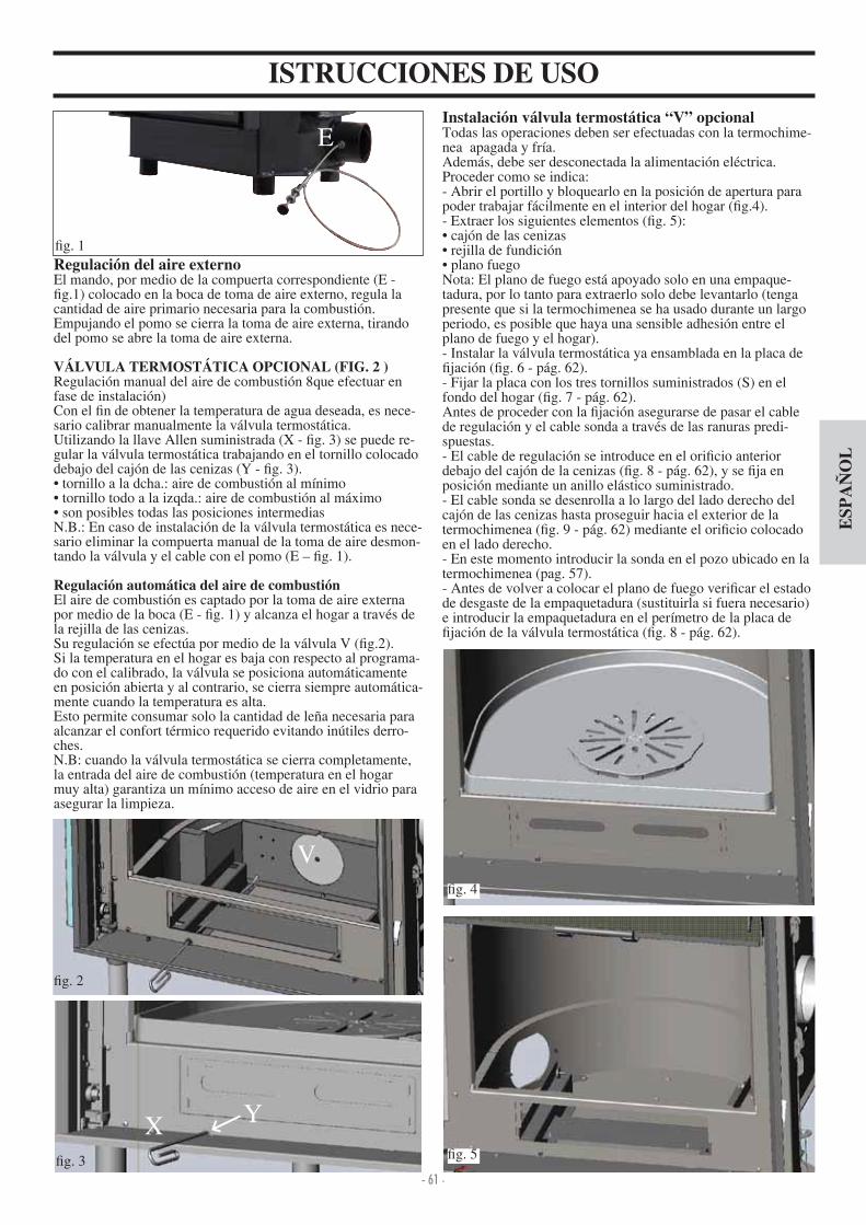
- 61 -
ESP
AÑ
OL
ISTRUCCIONES DE USO
E
g. 1
g. 2
g. 3
V
X Y
Instalación válvula termostática “V” opcionalTodas las operaciones deben ser efectuadas con la termochime-nea apagada y fría.Además, debe ser desconectada la alimentación eléctrica.Proceder como se indica- Abrir el portillo y bloquearlo en la posición de apertura para poder trabajar fácilmente en el interior del hogar ( g. ).- Extraer los siguientes elementos ( g. 5) cajón de las cenizas rejilla de fundición plano fuego
Nota El plano de fuego está apoyado solo en una empaque-tadura, por lo tanto para extraerlo solo debe levantarlo (tenga presente que si la termochimenea se ha usado durante un largo periodo, es posible que haya una sensible adhesión entre el plano de fuego y el hogar).- Instalar la válvula termostática ya ensamblada en la placa de
jación ( g. 6 - pág. 62).- Fijar la placa con los tres tornillos suministrados (S) en el fondo del hogar ( g. 7 - pág. 62).Antes de proceder con la jación asegurarse de pasar el cable de regulación y el cable sonda a través de las ranuras predi-spuestas.- El cable de regulación se introduce en el ori cio anterior debajo del cajón de la cenizas ( g. 8 - pág. 62), y se ja en posición mediante un anillo elástico suministrado.- El cable sonda se desenrolla a lo largo del lado derecho del cajón de las cenizas hasta proseguir hacia el exterior de la termochimenea ( g. 9 - pág. 62) mediante el ori cio colocado en el lado derecho.- En este momento introducir la sonda en el pozo ubicado en la termochimenea (pag. 57).- Antes de volver a colocar el plano de fuego veri car el estado de desgaste de la empaquetadura (sustituirla si fuera necesario) e introducir la empaquetadura en el perímetro de la placa de
jación de la válvula termostática ( g. 8 - pág. 62).
Regulación del aire externoEl mando, por medio de la compuerta correspondiente (E -
g.1) colocado en la boca de toma de aire externo, regula la cantidad de aire primario necesaria para la combustión.Empujando el pomo se cierra la toma de aire externa, tirando del pomo se abre la toma de aire externa.
VÁLVULA TERMOSTÁTICA OPCIONAL (FIG. 2 )Regulación manual del aire de combustión 8que efectuar en fase de instalación)Con el n de obtener la temperatura de agua deseada, es nece-sario calibrar manualmente la válvula termostática.Utilizando la llave Allen suministrada (X - g. 3) se puede re-gular la válvula termostática trabajando en el tornillo colocado debajo del cajón de las cenizas (Y - g. 3). tornillo a la dcha. aire de combustión al mínimo tornillo todo a la izqda. aire de combustión al máximo son posibles todas las posiciones intermedias
N.B. En caso de instalación de la válvula termostática es nece-sario eliminar la compuerta manual de la toma de aire desmon-tando la válvula y el cable con el pomo (E – g. 1).
Regulación automática del aire de combustiónEl aire de combustión es captado por la toma de aire externa por medio de la boca (E - g. 1) y alcanza el hogar a través de la rejilla de las cenizas.Su regulación se efectúa por medio de la válvula V ( g.2).Si la temperatura en el hogar es baja con respecto al programa-do con el calibrado, la válvula se posiciona automáticamente en posición abierta y al contrario, se cierra siempre automática-mente cuando la temperatura es alta.Esto permite consumar solo la cantidad de leña necesaria para alcanzar el confort térmico requerido evitando inútiles derro-ches.N.B cuando la válvula termostática se cierra completamente, la entrada del aire de combustión (temperatura en el hogar muy alta) garantiza un mínimo acceso de aire en el vidrio para asegurar la limpieza.
g.
g. 5

- 62 -
ESP
AÑ
OL
MANTENIMIENTOLimpieza del hogar- Las incrustaciones que tienden a depositarse en las paredes internas del hogar, disminuyen la e ciencia del intercambio térmico.Es necesario realizar una limpieza periódica, llevando agua a una temperatura de 80÷85°C para ablandar las incrustaciones ydespués retirarlas con una espátula de acero.
Limpieza del vidrioRealizar la limpieza del vidrio utilizando un spray adecuado para vídrios cerámicos (Glasskamin di Edilakmin). - La limpieza del vidrio se efectúa con el vidrio fríoPara la apertura del ala de la puerta trasera es necesario poner en la posición cerrada.- Introducir la manija “mano fría” en el tope entre la estructura y la puerta y girar para abrir ( g. 12).
Apertura puerta- Para la apertura de la puerta utilizar la manija correspondiente extraíble incluida en el suministro ( g. 10).- La misma manija puede ser jada a la puerta mediante el uso de 2 pernos suministrados.
ISTRUCCIONES DE USO
g. 6
g. 7
g. 8
g. 9
VISTA TRASERA
cable sonda
cable de regulaciónS
S S
SS
S
cable de regulación
cable de regulación
empaquetadura
cable sonda
cable sonda
Instalación contrapesosLa puerta guillotina está dotada de contrapesos que garantizan tanto el cierre como un movimiento ligero. La acción de los contrapesos puede ser regulada añadiendo una o más placas (contrapesos adicionales) suministrados con la termochimenea (P - g. 11).
g. 10
g. 12
g. 11
P

- 63 -
ESP
AÑ
OL
SISTEMA PARA LA INSTALACIÓN CON EL VASO ABIERTOEJEMPLO DE INSTALACIÓN HIDRÁULICA PARA TERMOCHIMENEA CON PRODUCCIÓN DE AGUA CALIEN-
TE SANITARIA CON EL USO DE KIT 1ACS: Agua caliente SanitariaAF: Agua fríaEV: Electroválvula de 3 víasF: FluxostatoMI: Envío InstalaciónNA: Normalmente AbiertaNC: Normalmente cerradaP: Bomba (circulador)RA: RadiadoresRE: Regulador electrónicoRI: Retorno instalaciónS: DescargaSc 20: Intercambiador 20 placasST: Sonda de TemperaturaTC: TermochimeneaV: VálvulaVE: Vaso de Expansión abiertoVSP: Válvula de seguridad a presión 1,5 barVST: Válvula de descarga térmicaJa: Jolly respiradero automático
El kit 1 está realizado para facilitar la tarea de los instaladores, de hecho comprende todos los componentes necesarios para una correcta instalación del producto.Nota: los equipos incluidos en el kit deben estar protegidos oportunamente de la irradiación térmica de la chimenea, me-diante el uso de revestimientos aislantes.
ACCIONES EN EL SELECTORSelector OFF Todo apagadoSelector MAN Circulador forzado Válvula programadaSelector AUTO Circulador con gurado Válvula programadaSelección alarma En posición OFF excluída el aviso acústico
PARA EL CORRECTO FUNCIONAMIENTO ES NECESARIO CRUZAR LOS TUBOS DE ENVÍO Y DE RETORNO
ON
OFF
Conexiones eléctricas
ActivaciónDesactivaciónalarmaacústica
Regulación de la válvula 20-80° C
Visualización
Circulador
Válvula de 3 vías
Alimentación230Vac
Fusible
KIT 1 cod. 261880
Regulación Circula-dor 20-80° C
FluxostatoAtención conectar el contacto normalmente cerrado
Sonda (introduciren el correspondientepozo)
Circulador activo Alarma exceso temperatura Válvula de 3 vías
1. Colector de latón 1” M-F2. Válvulas de esfera de 1”3. Circulador con uniones de 1” ½(219660). Válvula de no retorno 1” (261910)
5. Electroválvula de 3 vías 1” M-F (1 3330)6. Uniones en cobre7. Intercambiador 30 placas para intercambio-
con circuito de la caldera de gas (216620)8. Intercambiador 20 placas para la producción
de agua caldera sanitaria (205270)9. Válvula de descarga térmica de ¾” (729 0)10. Válvula de seguridad 1,5 bar de ¾” (1 3260)11. Fluxostato (220830)12. Pozo para termómetro ½” + sonda (175960)13. Regulador electrónico (220780)A Envío a la instalación ¾”B Retorno de la instalación ¾”C Retorno a la chimenea ¾”D Envío de la chimenea 1”E Agua fría sanitaria ½”F Agua caliente sanitaria ½”
Red
Tub
o de
seg
urid
ad Ø
> 28
mm
Tub
o de
car
ga Ø
> 18
mm
Col
ecto
r
Regulador incluido en el KIT

- 64 -
ESP
AÑ
OL
EJEMPLO DE INSTALACIÓN HIDRÁULICA PARA TERMOCHIMENEA SIN PRODUCCIÓN DE AGUA CALIEN-
TE SANITARIA + CALDERA MURAL CON EL USO DE KIT 2AF: Agua fríaCA: Caldera muralMI: Envío InstalaciónP: Bomba (circulador)RA: RadiadoresRE: Regulador electrónicoRI: Retorno instalaciónS: DescargaJa: Jolly respiradero automáticoSc 30: Intercambiador 30 placasST: Sonda de TemperaturaTC: TermochimeneaV: VálvulaVE: Vaso de Expansión abiertoVR: Válvula de no retornoVSP: Válvula de seguridad a presión 1,5 barVST: Válvula de descarga térmica
El kit 2 está realizado para facilitar la tarea de los instaladores, de hecho comprende todos los componentes necesarios para una correcta instalación del producto.Nota: los equipos incluidos en el kit deben estar protegidos oportunamente de la irradiación térmica de la chimenea, me-diante el uso de revestimientos aislantes.
1. Colector de latón 1” M-F2. Válvula de esfera de 1”3. Circulador con uniones de 1” ½(219660). Válvula de no retorno 1” (261910)
5. Electroválvula de 3 vías 1” M-F (1 3330)6. Uniones de cobre7. Intercambiador 30 placas para intercambio-
con circuito de la caldera de gas (216620)8. Intercambiador 20 placas para la producción
de agua caldera sanitaria (205270)9. Válvula de descarga térmica de ¾” (729 0)10. Válvula de seguridad 1,5 bar de ¾”
(1 3260)11. Fluxostato (220830)12. Pozo para termómetro ½” + sonda(175960)13. Regulador electrónico (220780)A Envío a la instalación ¾”B Retorno de la instalación ¾”C Retorno a la chimenea ¾”D Envío de la chimenea 1”E Agua fría sanitaria ½”F Agua caliente sanitaria ½”
PARA EL CORRECTO FUNCIONAMIENTO ES NECESARIO CRUZAR LOS TUBOS DE ENVÍO Y DE RETORNO
Circulador A
KIT 2 cod. 261890
ON
OFF
Circulador B
Regulación de la temperatura mínima de consentimiento de arranque circuladores 20-80°
SISTEMA PARA LA INSTALACIÓN CON EL VASO ABIERTO
Red Tub
o de
seg
urid
ad Ø
> 28
mm
Tub
o de
car
ga Ø
> 18
mm
Col
ecto
r
Regulador incluido en el KIT
ACCIONES EN EL SELECTORSelector OFF Todo apagadoSelector MAN Circulador forzado Válvula programadaSelector AUTO Circulador con gurado Válvula programadaSelección alarma En posición OFF excluída el aviso acústico
Conexiones eléctricas
ActivaciónDesactivaciónalarmaacústica
Regulación de la válvula 20-80° C
Alimentación230Vac
Fusible
Sonda (introduciren el correspondientepozo)
Circulador activo Alarma exceso temperatura Válvula de 3 vías
Visualización

- 65 -
ESP
AÑ
OL
EJEMPLO DE INSTALACIÓN HIDRÁULICA PARA TERMOCHIMENEA CON PRODUCCIÓN DE AGUA CALIEN-
TE SANITARIA + CALDERA MURAL CON EL USO DE KIT 3ACS: Agua caliente SanitariaAF: Agua fríaCA: Caldera muralEV: Electroválvula de 3 víasF: FluxostatoMI: Envío InstalaciónNA: Normalmente AbiertaNC: Normalmente cerradaP: Bomba (circulador)RA: RadiadoresRE: Regulador electrónicoRI: Retorno instalaciónS: DescargaSc 20: Intercambiador 20 placasSc 30: Intercambiador 30 placasTC: TermochimeneaV: VálvulaVE: Vaso de Expansión abiertoVR: Válvula de no retornoVSP: Válvula de seguridad a presión 1,5 barVST: Válvula de descarga térmicaJa: Jolly respiradero automático
El kit 3 está realizado para facilitar la tarea de los instaladores, de hecho comprende todos los componentes necesarios para una correcta instalación del producto.Nota: los equipos incluidos en el kit deben estar protegidos oportunamente de la irradiación térmica de la chimenea, me-diante el uso de revestimientos aislantes.
PARA EL CORRECTO FUNCIONAMIENTO ES NECESARIO CRUZAR LOS TUBOS DE ENVÍO Y DE RETORNO
KIT 3 cod. 261900
1. Colector de latón 1” M-F2. Válvula de esfera de 1”3. Circulador con uniones de 1” ½(219660). Válvula de no retorno 1” (261910)
5. Electroválvula de 3 vías 1” M-F (1 3330)6. Uniones de cobre7. Intercambiador 30 placas para intercambio-
con circuito de la caldera de gas (216620)8. Intercambiador 20 placas para la producción
de agua caldera sanitaria (205270)9. Válvula de descarga térmica de ¾” (729 0)10. Válvula de seguridad 1,5 bar de ¾”
(1 3260)11. Fluxostato (220830)12. Pozo para termómetro ½” + sonda(175960)13. Regulador electrónico (220780)A Envío a la instalación ¾”B Retorno de la instalación ¾”C Retorno a la chimenea ¾”D Envío de la chimenea 1”E Agua fría sanitaria ½”F Agua caliente sanitaria ½”
ON
OFF
Válvula de 3 vías
FluxostatoAtención conectar el contac-to normalmente cerrado
Circulador A Circulador B
SISTEMA PARA LA INSTALACIÓN CON EL VASO ABIERTO
Red Tub
o de
seg
urid
ad Ø
> 28
mm
Tub
o de
car
ga Ø
> 18
mm
Col
ecto
r
Regulador incluido en el KIT
ACCIONES EN EL SELECTORSelector OFF Todo apagadoSelector MAN Circulador forzado Válvula programadaSelector AUTO Circulador con gurado Válvula programadaSelección alarma En posición OFF excluída el aviso acústico
Conexiones eléctricas
ActivaciónDesactivaciónalarmaacústica
Regulación de la válvula 20-80° C
Visualización
Alimentación230Vac
Fusible
Regulación Circula-dor 20-80° C
Sonda (introduciren el correspondientepozo)
Circulador activo Alarma exceso temperatura Válvula de 3 vías

- 66 -
ESP
AÑ
OL
EJEMPLO DE INSTALACIÓN HIDRÁULICA PARA TERMOCHIMENEA CON PRODUCCIÓN DE AGUA CALIEN-
TE SANITARIA + CALDERA MURAL CON EL USO DE KIT N3CA: Caldera muralPR: Bomba (circulador)P1: Bomba circuito primarioRE: Regulador electrónicoTA: Termostato ambienteVE: Vaso de expansiónJa: Jolly aireaciónV: Válvula de interceptaciónVR: Válvula de retenciónST: Sonda de temperaturaF: FlujostatoSc: Intercambiador de calor de placasEV: Electroválvula de 3 víasRI: Retorno instalación de calefacciónRA: RadiadoresMI: Envío instalación de calefacciónAF: Agua fríaACS: Agua caldera sanitariaS: Descarga
El kit N3 está realizado para facilitar la tarea de los instaladores, de hecho comprende todos los componentes necesarios para una correcta instalación del producto.Nota: los equipos incluidos en el kit deben estar protegidos oportunamente de la irradiación térmica de la chimenea, me-diante el uso de revestimientos aislantes.
PARA EL CORRECTO FUNCIONAMIENTO ES NECESARIO CRUZAR LOS TUBOS DE ENVÍO Y DE RETORNO
KIT N3 cod. 627690
1. Envío al circuito de instalación de calefacción G 3 ”2. Envío desde generador EDILKAMIN G 3 ”3. Retorno a generador EDILKAMIN G 3 ”. Retorno del circuito de instalación de calefacción G 3 ”
5. Entrada agua fría sanitaria G 1 2”6. Envío del agua caliente a las instalaciones sanitarias G
1 2”7. Válvula de seguridad combinada temperatura y presión
(90°C-3 bar)8. Flujostato9. Jolly aireación G 3 8”10. Circulador circuito generador EDILKAMIN11. Intercambiador de placas de 3 vías12. Válvula de interceptación G 1”13. Regulador electrónico con cableado1 . Ori cio para el paso de los pasacables15. Cable de alimentación16. Cables para circulador de instalación de calefacción
(fase, neutro, tierra)17. Sonda temperatura18. Circuito termostato ambiente
VEAF
S V
RE
RETE
ST
V
S
V
Tu
bo
di
cari
co
Ø>
18
mm
Tu
bo
di
sic
ure
zza
Ø>
28
mm
V
CA
ACS
PRF
ACS
AF
Ja
TA
P1
VVs
Sc
TCN
ELETTRICA
INT
VR V
VR
RETE
IDRICA
VR
VR
MI
RA
RI
V
COLLETTORE
VR
V
V
V
V
V
Circuito collegabile altermostato ambiente(a discrezione del cliente)
Da collegare necessariamenteal circolatore dell’impianto
di riscaldamento PR
12 3 4
56
7
8
9
10
119
9
12
13
12 3 5
4 67
14
15 16 17
Passacavi
18
Bomba circuito primario
OFF
Set permiso circulador primario30- 0°C
ON
Bomba de calefacción
EV
Red eléctrica 230 Vac50 Hz + - 10%
Set permisosanitario-calefacción0-80°C
termostato ambiente
Sensor de ujo
SondaPermiso alarmas
Conexiones eléctricas
SISTEMA PARA LA INSTALACIÓN CON EL VASO ABIERTO
Red
Tub
o de
seg
urid
ad Ø
> 28
mm
Tubo
de
carg
a Ø
> 18
mm
Colector
Red hídrica
circuito que se puede conectar al termostato ambiente (a voluntad del cliente)
que conectar siempre al circulador de la instalación de calefacción
pasacables
Bomba 1 Bomba 2
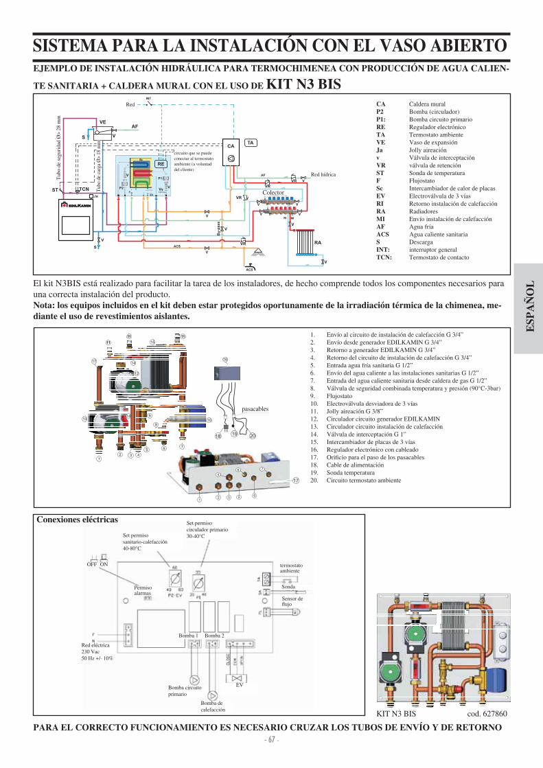
- 67 -
ESP
AÑ
OL
EJEMPLO DE INSTALACIÓN HIDRÁULICA PARA TERMOCHIMENEA CON PRODUCCIÓN DE AGUA CALIEN-
TE SANITARIA + CALDERA MURAL CON EL USO DE KIT N3 BISCA Caldera muralP2 Bomba (circulador)P1: Bomba circuito primarioRE Regulador electrónicoTA Termostato ambienteVE Vaso de expansiónJa Jolly aireaciónv Válvula de interceptaciónVR válvula de retenciónST Sonda de temperaturaF FlujostatoSc Intercambiador de calor de placasEV Electroválvula de 3 víasRI Retorno instalación de calefacciónRA RadiadoresMI Envío instalación de calefacciónAF Agua fríaACS Agua caliente sanitariaS DescargaINT: interruptor generalTCN: Termostato de contacto
El kit N3BIS está realizado para facilitar la tarea de los instaladores, de hecho comprende todos los componentes necesarios para una correcta instalación del producto.Nota: los equipos incluidos en el kit deben estar protegidos oportunamente de la irradiación térmica de la chimenea, me-diante el uso de revestimientos aislantes.
PARA EL CORRECTO FUNCIONAMIENTO ES NECESARIO CRUZAR LOS TUBOS DE ENVÍO Y DE RETORNO
KIT N3 BIS cod. 627860
1. Envío al circuito de instalación de calefacción G 3 ”2. Envío desde generador EDILKAMIN G 3 ”3. Retorno a generador EDILKAMIN G 3 ”. Retorno del circuito de instalación de calefacción G 3 ”
5. Entrada agua fría sanitaria G 1 2”6. Envío del agua caliente a las instalaciones sanitarias G 1 2”7. Entrada del agua caliente sanitaria desde caldera de gas G 1 2”8. Válvula de seguridad combinada temperatura y presión (90°C-3bar)9. Flujostato10. Electroválvula desviadora de 3 vías11. Jolly aireación G 3 8”12. Circulador circuito generador EDILKAMIN13. Circulador circuito instalación de calefacción1 . Válvula de interceptación G 1”15. Intercambiador de placas de 3 vías16. Regulador electrónico con cableado17. Ori cio para el paso de los pasacables18. Cable de alimentación19. Sonda temperatura20. Circuito termostato ambiente
VEAF
S V
RE
ST
S
V
Tu
bo
dicari
co
Ø>
18
mm
Tu
bo
disic
ure
zza
Ø>
28
mm
CA
ACS
VR
MI
RA
RI
V
ACS
AF
Ja
TA
EV
P2
P1
V
V
Sc
F
Vs
RETE
ELETTRICA
INT
VR V
TCN
V
V
V
By-p
ass
VR
Sc
RETE
IDRICA
COLLETTORE
VR
V
V
V
V
V
Circuito collegabile altermostato ambiente(a discrezione del cliente)
12 3 4
5 6 7
8
9
10
11
12
1314
14
15
111111
1111
1617
12 3
4
5
8
6
7
2019
Passacavi
17
18
SISTEMA PARA LA INSTALACIÓN CON EL VASO ABIERTO
Bomba circuito primario
OFF
Set permiso circulador primario30- 0°C
ON
Bomba de calefacción
EV
Red eléctrica 230 Vac50 Hz + - 10%
Set permisosanitario-calefacción0-80°C
termostato ambiente
Sensor de ujo
SondaPermiso alarmas
Conexiones eléctricas
Bomba 1 Bomba 2
Red
Tub
o de
seg
urid
ad Ø
> 28
mm
Tubo
de
carg
a Ø
> 18
mm
Colector
Red hídrica
circuito que se puede conectar al termostato ambiente (a voluntad del cliente)
pasacables

- 68 -
ESP
AÑ
OL
REGULADOR ELECTRÓNICOFUNCIONAMIENTO- Dispositivo de control: Termómetro
- Dispositivo de protección (sistema alarme acústica): Alarma acústica (AA) Alarma exceso de temperatura (SS)
Dicho sistema interviene cuando la temperatura del agua supera el valor de 90 °C y advierte al usuario que suspenda la alimen-tación de combustible. El funcionamiento de la alarma acústica puede escluirse trabajando en el interruptor (AA); de todas formas sigue activa la función de alarma dada por el indicador luminoso de temperatura (SS). Para restablecer las condiciones iniciales, después de haber reducido la temperatura del agua en la termochimenea, es necesario reactivar el interruptor (AA).
Dispositivo de alimentación (sistema circulación): Selector MAN-OFF-AUTO (S) Indicador luminoso pompa (SP)
En la función manual ala bomba funciona siempre, en la función OFF la bomba está apagada; en la función AUTO se activa la bomba de la instalación a una temperatura deseada por medio de la regulación interna (RIC) de 20 a 80°C (el mando está preprogramado a 20°C)
- Dispositivo de funcionamiento (sistema de regulación): Regulación (R) para apertura válvula de3 vías Indicador luminoso (SV) de funcionamiento válvula de 3 vías
Cuando la temperatura del uido alcanza el valor programado con el reguladro, la válvula de 3 vías conmuta el uido a los termosifones y el indicador luminoso de funcinamiento (SV) se enciende. En el momento que la temepratura del uido descien-de por debajo del valor programado, el sistema de regulación abre el circuito, la válvula de 3 vías desvía el uido directa-mente a la termochimenea. Atención: Durante el funcionamiento normal, controlar que los indicadores luminosos (SV) y (SP) estén encendidos.
UBICACIÓNEl regulador electrónico debe estar instalado cerca de la ter-mochimenea. La sonda de los dispositivos de funcionamiento, protección y control debe ser colocada directamente en la termo-schimenea o al máximo en la tubería de envío a 5 cm de distacia de la termoschimenea y de todas formas antes de cualquier órga-no de interceptación La sona debe estar sumergida en el pozo.
INSTALACIÓNTodas estas operaciones deben ser efectuadas con la ali-mentación desconectada de la red eléctrica y con el selector(S) AUTO-OFF-MAN en posición OFF.Para una correcta instalación del regulador electrónico traba-jar de la siguiente manera a ojar el tornillo de jación luego extraer la tapa, posicionar en la pared y jar con tacos sumi-nistrados, luego realizar las conexiones como se indica en el esquema prestando atención a las conexiones, extender los cables utilizando los conductos para cables conformes a las no-mas vigentes, colocar la tapa y apretar el tornillo de cierre. Para la válvula de 3 vías utilizar el cable marrón (fase) y el cable azul (neutro) que conectar respectivamente a los bornes 5 y 6 del regulador. El cable amarillo-verde se conecta a tierra. Para conectar correctamente el regulador a la instalación, seguir las instrucciones de montaje contenidas en el embalaje.
ADVERTENCIAS IMPORTANTES PARA LA INSTALACIÓNLas conexiones, la puesta en servicio y el control del buenfuncionamiento, deben ser efectuados por personal cuali cado,capaz de efectuar las conexiones según las leyes vigentes y enparticular según la Ley 6 90, y respetando las presentes in-strucciones.El respeto de las normas sobre la puesta a tierra es deter-minante para la seguridad de las personas.Es obligatorio la conexión aguas arriba del dispositivo y de todo el circuito eléctrico de la termochimenea un interruptor diferencial de línea, además, es obligatorio conectar a tierra la bomba, la válvula y las partes mecánicas de la termoschimenea
LEYENDAAA interruptor alarma acústicaR reg. apertura válvula de 3 vías (KIT 1 - 3)R reg. funcionamiento circuladores (KIT2)RIC regulación interna bombaS selector MAN-OFF-AUTOSP indicador luminoso bombaSS indicador exceso de temperaturaST escala temperaturaSV indicador luminoso válvula de 3 vías (KIT 1 - 3)SV reg. circuladores (Kit 2)
DATOS TÉCNICOS
Alimentación (+15 - 10%) Vac 230
Grado de protección IP 0
Temperatura mín máx ambiente °C 0÷+50
Longitud sonda mt 1,2
Termómetro °C 30÷90
Capacidad contactos circulador, máxima W 00
Capacidad contactos válvula tres vías, máxima W 250
Fusible mA 500
El regulador electrónico de control permite monitorizar las condiciones de funcinamiento y está dotado de- selector MAN-OFF-AUTO(S)- escala temperatura(ST)- alarma acústica (AA)- reg. apertura válvula de 3 vías (R) (KIT1-3)- reg. funcionamiento de circuladores (R) (KIT2)- regulación interna bomba (RIC)- reg. válvula de 3 vías (SV) (KIT1-KIT3)- indicador reg. circuladores (SV) (KIT2)- indicador exceso de temperatura (SS)- indicador luminoso bomba (SP)

- 69 -
ESP
AÑ
OL
REGULADOR ELECTRÓNICO (opcional)
permite monitorizar las condiciones de funcionamiento y estádotado de
- selector MAN-OFF-AUTO- escala temperatura- alarma acústica- regulador de apertura válvula 3 vías- regulación interna bomba- indicador luminoso bomba- válvula de 3 vías- indicador exceso de temperatura
El regulador electrónico es parte de los diferentes tipos de Kit de instalación (suministros opcionales)
EL INTERCAMBIADOR 20 PLACAS PARA EL AGUA SANITARIA (opcional)Se trata de un aparato extremadamente simple y económico,que permite una producción de agua caliente equivalente a13- 1 litros al minuto según el poder de la hidráulica. Se insta-la fácilmente en el tubo de envío a las chimeneas en la posición más cómoda, respecto a las condiciones de la instalación. Tiene la gran ventaja de poder desmontarse para mantenimiento o sustitución sin intervenir en la termochimenea.
El intercambiador de 20 placas es parte de los diferentes tipos de kit de instalación (suministros opcionales)
INTERCAMBIADOR DE 3 VÍAS (opcional)Produce agua caliente para el circuito sanitario y para el circui-to secundario (termosifones), excluyendo con respecto al KIT 3el uso de la válvula de 3 vías y un intercambiador de placas.
agua caliente de la termochimenea
Regulador electrónico ( 220780)
agua fríade la red hídrica
agua de retorno a latermochimenea
agua caliente de latermochimenea
agua calientea los sanitarios
agua fríainstalación
agua fríasanitaria
ACCESORIOS OPCIONALES
Válvula de 3 vías de 1” (1 3330) para r e g u l a c i ó n
ujo agua a la instalación
Regulador electrónico (220780)
Fluxosta to (220830)
CirculadorUPS 25-50 (219660)UPS 25-60 (238270)
Intercambiador de 3 vías(627780)
Remote dispalycód 7 1180
Kit hidráulico V para versiones con VASO ABIERTO cód. 7 3 30(instalación a la derecha)
Válvula termostáticaH
2OCEANO 15 cód. 739 60
H2OCEANO 23 cód. 739 0
H2OCEANO 28 cód. 739 50
Marco de contorno boca H
2OCEANO 15 cód. 739390 - dim. 63x63 cm
H2OCEANO 23 cód. 739370 - dim. 77x68 cm
H2OCEANO 28 cód. 739380 - dim. 95x68 cm
Soporte para kit hidráulicos A1-A2-B-C-D (instalación a la derecha) H
2OCEANO 15 cód. 739510
H2OCEANO 23 cód. 739 70
H2OCEANO 28 cód. 739 90
Intercam-biador 30 placas para instalación(216620)
Intercambia-dor 20 placas para sanitaria(262570)
Kit válvulas ( 21600) compuesto de válvula automática ventila-ción de aire, seguridad 1,5 bar.descarga térmica 90°C
Rustidor H
2OCEANO 15 cód. 750820
H2OCEANO 23 cód. 23 560
H2OCEANO 28 cód. 236710

- 70 -- 70 -
DE
UT
SCH
Sehr geehrte Kundin, sehr geehrter Kunde,
und in völliger Sicherheit auszunutzen.
HINWEIS
der
Wassergeführter-Kamin
-
H
H
-

- 71 -- 71 -
DE
UT
SCH
WÄRMETECHNISCHE MERKMALE
H2OCEANO wurde entworfen, um Wasser durch eine automa-tische Verbrennung von Holz im Brennraum zu erhitzen.Das Wasser im Heizkamin wird erwärmt und an die Hei-zanlage geschickt (Heizkörper, beheizte Handtuchhalter, Strahlungsplatten am Fußboden), er beheizt außerdem den Raum, in dem er sich be ndet, durch Abstrahlung mit nat rli-cher Konvektion.Der Heizkamin DARF NIEMALS OHNE WASSER IN DER ANLAGE BETRIEBEN WERDEN.Das Wasser wird erwärmt, indem es im Zwischenraum zirku-liert, der die gesamte halbrunde Wand und die Wölbung des Feuerraums umsp lt.Der Hohlraum ist aus Stahlblech von großer Stärke gefertigt.Der Feuerraum ist vorne durch eine T r geschlossen, die f r die Reinigung der Scheibe nach oben geschoben wird.
INNOVATIVES PATENTIERTES ASCHENROSTErlaubt die Verteilung der primären Verbrennungsluft, nicht nur von unten nach oben, sondern auch in horizontaler Richtung, um eine hohe Sauerstoffversorgung der Flamme, eine bessere Verbrennung und mehr Leistung zu ermöglichen.
TÜR MIT “DICHTUNGSSCHUTZ”Während der Gleitbewegung bleibt die T r zum Schutz der Dichtungen, leicht von der ffnung des Heizkamins abger ckt.In geschlossener Position schließt sie perfekt, um die höch-ste Dichtigkeit und damit einen optimalen Wirkungsgrad zu gewährleisten. Der Griff ist abnehmbar, kann aber auch an der T r befestigt werden (siehe S. 79)
AUTOMATISCHE RAUCHGASUMLEITUNGUm den Beginn der Verbrennung bei offener T r in derZ ndphase zu erleichtern, bleibt die Rauchgasklappe (S) in offener Stellung stehen, damit die Rauchgase unmittelbar und leicht den Rauchgasabzug erreichen können.Wenn die Verbrennung gut fortgeschritten ist, schließt sichbeim Schließen der T r auch automatisch die Rauchgasklappe (S - g. b).In dieser Position wird der Rauch, bevor er das Abzugsrohr erreicht, abgelenkt, um das Wasser zu umsp len und seine Wärme auf wirkungsvolle Weise abzugeben.Der Bypass wird automatisch durch die T rbewegung ge-steuert.
Leitbleche Deckenplatten
Gehäuse Motor Grill
Nachverbrennung
Automatisches Regelventil f r die externe Luftzufuhr (optional)
Mögliche Anwendung von verstellbaren F ßen (optional)
Kalibrierung der automatischen Verbrennungslufteinstellung
Schiebet r
Umh llender Zwischenraum f r die Aufnahme von Wasser
Sicherheitsrohrschlange f r den Wärmeablass (CS-Version)
Aschenrost f r die Verteilung der primären Verbrennungsluft
Durchheize
A
B
C
D
E
F
G
H
I
L
S
AI
L
H
G
H
A
B
D
EF E
CS
(a)
(b)
s
s
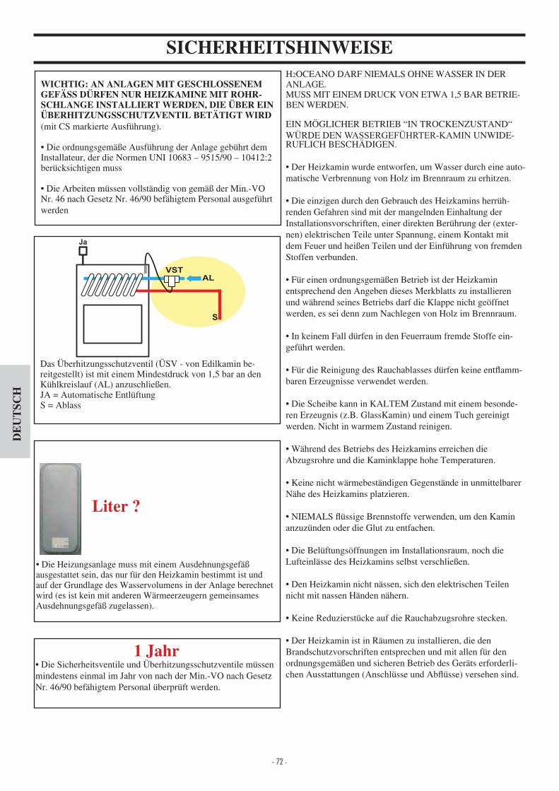
- 72 -- 72 -
DE
UT
SCH
H2OCEANO DARF NIEMALS OHNE WASSER IN DER ANLAGE.MUSS MIT EINEM DRUCK VON ETWA 1,5 BAR BETRIE-BEN WERDEN.
EIN MÖGLICHER BETRIEB “IN TROCKENZUSTAND“ WÜRDE DEN WASSERGEFÜHRTER-KAMIN UNWIDE-RUFLICH BESCHÄDIGEN.
Der Heizkamin wurde entworfen, um Wasser durch eine auto-matische Verbrennung von Holz im Brennraum zu erhitzen.
Die einzigen durch den Gebrauch des Heizkamins herr h-renden Gefahren sind mit der mangelnden Einhaltung der Installationsvorschriften, einer direkten Ber hrung der (exter-nen) elektrischen Teile unter Spannung, einem Kontakt mit dem Feuer und heißen Teilen und der Einf hrung von fremden Stoffen verbunden.
F r einen ordnungsgemäßen Betrieb ist der Heizkamin entsprechend den Angeben dieses Merkblatts zu installieren und während seines Betriebs darf die Klappe nicht geöffnet werden, es sei denn zum Nachlegen von Holz im Brennraum.
In keinem Fall d rfen in den Feuerraum fremde Stoffe ein-gef hrt werden.
F r die Reinigung des Rauchablasses d rfen keine ent amm-baren Erzeugnisse verwendet werden.
Die Scheibe kann in KALTEM Zustand mit einem besonde-ren Erzeugnis (z.B. GlassKamin) und einem Tuch gereinigt werden. Nicht in warmem Zustand reinigen.
Während des Betriebs des Heizkamins erreichen die Abzugsrohre und die Kaminklappe hohe Temperaturen.
Keine nicht wärmebeständigen Gegenstände in unmittelbarer Nähe des Heizkamins platzieren.
NIEMALS ssige Brennstoffe verwenden, um den Kamin anzuz nden oder die Glut zu entfachen.
Die Bel ftungsöffnungen im Installationsraum, noch die Lufteinlässe des Heizkamins selbst verschließen.
Den Heizkamin nicht nässen, sich den elektrischen Teilen nicht mit nassen Händen nähern.
Keine Reduzierst cke auf die Rauchabzugsrohre stecken.
Der Heizkamin ist in Räumen zu installieren, die den Brandschutzvorschriften entsprechen und mit allen f r den ordnungsgemäßen und sicheren Betrieb des Geräts erforderli-chen Ausstattungen (Anschl sse und Ab sse) versehen sind.
SICHERHEITSHINWEISE
WICHTIG: AN ANLAGEN MIT GESCHLOSSENEM GEFÄSS DÜRFEN NUR HEIZKAMINE MIT ROHR-SCHLANGE INSTALLIERT WERDEN, DIE ÜBER EIN ÜBERHITZUNGSSCHUTZVENTIL BETÄTIGT WIRD(mit CS markierte Ausf hrung).
Die ordnungsgemäße Ausf hrung der Anlage geb hrt dem Installateur, der die Normen UNI 10683 – 9515 90 – 10 12 2 ber cksichtigen muss
Die Arbeiten m ssen vollständig von gemäß der Min.-VO Nr. 6 nach Gesetz Nr. 6 90 befähigtem Personal ausgef hrt werden
Das Überhitzungsschutzventil (ÜSV - von Edilkamin be-reitgestellt) ist mit einem Mindestdruck von 1,5 bar an den K hlkreislauf (AL) anzuschließen.JA = Automatische Entl ftung S = Ablass
1 Jahr Die Sicherheitsventile und Überhitzungsschutzventile m ssen
mindestens einmal im Jahr von nach der Min.-VO nach Gesetz Nr. 6 90 befähigtem Personal berpr ft werden.
Die Heizungsanlage muss mit einem Ausdehnungsgefäß ausgestattet sein, das nur f r den Heizkamin bestimmt ist und auf der Grundlage des Wasservolumens in der Anlage berechnet wird (es ist kein mit anderen Wärmeerzeugern gemeinsames Ausdehnungsgefäß zugelassen).
Liter ?
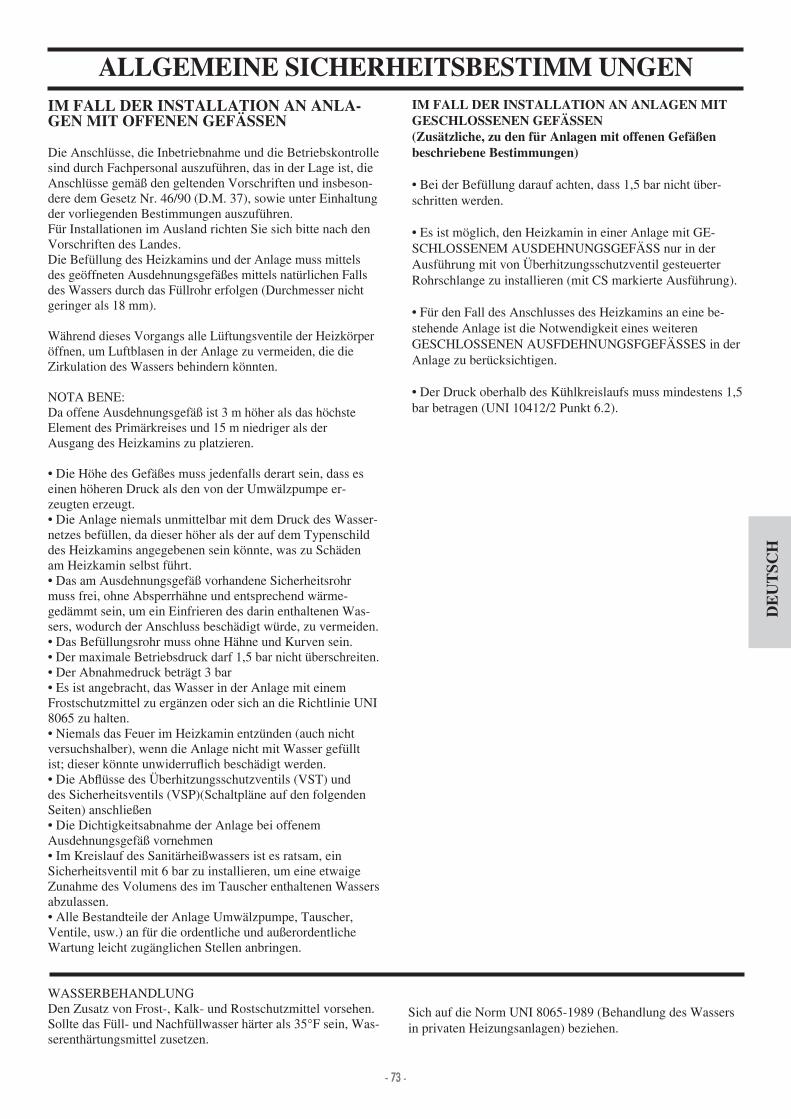
- 73 -- 73 -
DE
UT
SCH
ALLGEMEINE SICHERHEITSBESTIMM UNGENIM FALL DER INSTALLATION AN ANLA-GEN MIT OFFENEN GEFÄSSEN
Die Anschl sse, die Inbetriebnahme und die Betriebskontrolle sind durch Fachpersonal auszuf hren, das in der Lage ist, dieAnschl sse gemäß den geltenden Vorschriften und insbeson-dere dem Gesetz Nr. 6 90 (D.M. 37), sowie unter Einhaltung der vorliegenden Bestimmungen auszuf hren.F r Installationen im Ausland richten Sie sich bitte nach den Vorschriften des Landes.Die Bef llung des Heizkamins und der Anlage muss mittels des geöffneten Ausdehnungsgefäßes mittels nat rlichen Falls des Wassers durch das F llrohr erfolgen (Durchmesser nicht geringer als 18 mm).
Während dieses Vorgangs alle L ftungsventile der Heizkörper öffnen, um Luftblasen in der Anlage zu vermeiden, die die Zirkulation des Wassers behindern könnten.
NOTA BENEDa offene Ausdehnungsgefäß ist 3 m höher als das höchste Element des Primärkreises und 15 m niedriger als derAusgang des Heizkamins zu platzieren.
Die Höhe des Gefäßes muss jedenfalls derart sein, dass es einen höheren Druck als den von der Umwälzpumpe er-zeugten erzeugt. Die Anlage niemals unmittelbar mit dem Druck des Wasser-
netzes bef llen, da dieser höher als der auf dem Typenschild des Heizkamins angegebenen sein könnte, was zu Schäden am Heizkamin selbst f hrt. Das am Ausdehnungsgefäß vorhandene Sicherheitsrohr
muss frei, ohne Absperrhähne und entsprechend wärme-gedämmt sein, um ein Einfrieren des darin enthaltenen Was-sers, wodurch der Anschluss beschädigt w rde, zu vermeiden. Das Bef llungsrohr muss ohne Hähne und Kurven sein. Der maximale Betriebsdruck darf 1,5 bar nicht berschreiten. Der Abnahmedruck beträgt 3 bar Es ist angebracht, das Wasser in der Anlage mit einem
Frostschutzmittel zu ergänzen oder sich an die Richtlinie UNI 8065 zu halten. Niemals das Feuer im Heizkamin entz nden (auch nicht
versuchshalber), wenn die Anlage nicht mit Wasser gef llt ist; dieser könnte unwiderru ich beschädigt werden. Die Ab sse des Überhitzungsschutzventils (VST) und
des Sicherheitsventils (VSP)(Schaltpläne auf den folgenden Seiten) anschließen Die Dichtigkeitsabnahme der Anlage bei offenem
Ausdehnungsgefäß vornehmen Im Kreislauf des Sanitärheißwassers ist es ratsam, ein
Sicherheitsventil mit 6 bar zu installieren, um eine etwaige Zunahme des Volumens des im Tauscher enthaltenen Wassers abzulassen. Alle Bestandteile der Anlage Umwälzpumpe, Tauscher,
Ventile, usw.) an f r die ordentliche und außerordentlicheWartung leicht zugänglichen Stellen anbringen.
WASSERBEHANDLUNGDen Zusatz von Frost-, Kalk- und Rostschutzmittel vorsehen.Sollte das F ll- und Nachf llwasser härter als 35°F sein, Was-serenthärtungsmittel zusetzen.
IM FALL DER INSTALLATION AN ANLAGEN MIT GESCHLOSSENEN GEFÄSSEN(Zusätzliche, zu den für Anlagen mit offenen Gefäßen beschriebene Bestimmungen)
Bei der Bef llung darauf achten, dass 1,5 bar nicht ber-schritten werden.
Es ist möglich, den Heizkamin in einer Anlage mit GE-SCHLOSSENEM AUSDEHNUNGSGEFÄSS nur in der Ausf hrung mit von Überhitzungsschutzventil gesteuerterRohrschlange zu installieren (mit CS markierte Ausf hrung).
F r den Fall des Anschlusses des Heizkamins an eine be-stehende Anlage ist die Notwendigkeit eines weiterenGESCHLOSSENEN AUSFDEHNUNGSFGEFÄSSES in derAnlage zu ber cksichtigen.
Der Druck oberhalb des K hlkreislaufs muss mindestens 1,5 bar betragen (UNI 10 12 2 Punkt 6.2).
Sich auf die Norm UNI 8065-1989 (Behandlung des Wassers in privaten Heizungsanlagen) beziehen.

- 74 -- 74 -
DE
UT
SCH
ABMESSUNGEN
FRONT SEITE
GRUNDISSVerbrennungsluft
L
PH
R cklauf Rohrschlange Überhitzungsschutz 1 2” M (Ausf hrung mit geschlossenem Gefäß)
Vorlauf Rohrschlange Überhitzungsschutz 1 2” M (Ausf hrung mit geschlossenem Gefäß)
Sondenschacht
Wasserr cklauf an Anlage 1” M
Wasservorlauf an Anlage 1” M
Y
X
FÜR EINEN ORDNUNGSGEMÄSSEN BETRIEB MÜSSEN DIE VORLAUF- UND RÜCKLAUFROHRE GEKREUZT WERDEN
Ab uss
H2OCEANO 15 - 15/CS H2OCEANO 23 - 23/CS H2OCEANO 28 - 28/CS
L 7 88 106 cm
P 62 68 83 cm
H135 ohne F ße
(mit F ßen + 1 cm)
1 7 ohne F ße
(mit F ßen + 1 cm)
1 7 ohne F ße
(mit F ßen + 1 cm)cm
X 3 3 51 cm
Y 36 37 50 cm
Innenabmes-sungen
Feuerraum50x38 60x50 78x60 cm

- 75 -- 75 -
DE
UT
SCH
WÄRMETECHNISCHE MERKMALE
NB: DATA PROJECT (Verweis auf EN 13229)* Das Beheizbare Raumvolumen ist berechnet bei einer Isolation nach den neuesten aurichtlinien, und anschließenden Änderun-gen und aufgrund einer Wärmeanforderung con 33 Kcal m pro Stunde.* Die Wahl des richtigen Standortes der Wassergeführter-Kamin ist sehr wichtig.* * Temperatur im Heizkessel 70° - (ðT=25K)
Die oben aufgeführten Angaben sind Richtwerte. EDILKAMIN s.p.a. behält sich das Recht vor, die Produkte ohne Vorankündigung und ausschließlich nach eigenem Er-messen zu ändern.
FÜR EINEN ORDNUNGSGEMÄSSEN BETRIEB MÜSSEN DIE VORLAUF- UND RÜCKLAUFROHRE GEKREUZT WERDEN
DER DURCHMESSER DES RAUCHABZUGSROHRS MUSS VON EINEM INSTALLATEUR IN BEZUG AUF SEINE HÖHE BEWERTET WERDEN.
15-15/CS 23-23/CS 28-28/CS
Nutzheizleistung 18,5 27,8 3 ,8 kW
Nennleistung 1 ,8 22,2 27,8 kW
Nennleistung wasserseitig 12,1 18,2 22,8 kW
Gesamt-Wirkungsgrad (zirka) 80 80 80 %
Wasser-Wirkungsgrad (zirka) 82 82 82 %
Ausbeute Klasse (EN 303-5) > 3 > 3 > 3 -
ø Steck- Rauchabzug 18 22 25 cm
Höchster Betriebsdruck 1,5 1,5 1,5 bar
Brennstoffverbrauch ,5 7 8,5 kg h
Wasserinhalt 50 100 130 Liter
Beheizbares Raumvolumen * 355 535 670 m
Gewicht inkl. Verpackung 2 0 285 325 kg
Sanitärheißwasser-Erzeugung (kit 1- 3 - N3 - N3bis)** 13-1 13-1 13-1 Liter min
ø Außenlufteinlass 12,5 12,5 12,5 cm
Anlagenvorlauf (male) 1” 1” 1” zoll
Anlagenr cklauf (male) 1” 1” 1” zoll

- 76 -- 76 -
DE
UT
SCH
INSTALLATIONWICHTIGE HINWEISE ZUR INSTALLATIONAußer den im vorliegenden Dokument enthaltenen Angaben, die UNI-Normen beachten- n. 10683/2005 - Wärmeerzeuger mit Holzbefeuerung Installationsanforderungen.- n. 9615/90 - Berechnung der Innenabmessungen von Kaminen.- n. 10412:2 - Heizungsanlagen mit Heißwasser. Spezi sche Sicherheitsanforderungen f r Anla gen mit Haushaltsheizgeräten mit eingebautem Heizkessel, Befeuerung mit festem Brennstoff, mit Leistung des Feuerraums oder Gesamtlei stung der Feuerräume nicht höher als 35 kW.Insbesondere- Vor jeder Einbautätigkeit ist wichtig, die Übereinstimmung der Anlage gemäß der Norm UNI 10683, Abs. .1 .1.1 .1.2 zu berpr fen.- Nach erfolgtem Einbau, muss der Installateur die Inbe-triebnahme vornehmen und die Bescheinigungen gemäß der Norm UNI 10683 Abs. .6 und 5 ausstellen.- Der Anschluss, die Inbetriebnahme und die Be-triebsprüfung des Heizkamins muss von Fachpersonal ausgef hrt werden, das in der Lage ist, die Elektro- und Wasseranschl sse gemäß der Norm UNI 10683 Abs. .5, UNI 10 1 2, sowie unter völliger Einhaltung der vorliegenden Mon-tageanleitungen vorzunehmen.- Die Überpr fung muss bei brennendem und seit einigen Stun-den voll betriebenem Kamin erfolgen, um gegebenenfalls Ein-griffe vornehmen zu können, bevor der Kamin verkleidet wird.Die Ausbauarbeiten wie beispielsweise- Bau der Rauchfangverkleidung- Montage der Kaminverkleidung- Ausf hrung von Lisenen, Anstrichen, usw. sind nach erfolgter erfolgreicher Abnahme auszuf hren.EDILKAMIN haftet folglich nicht f r Kosten von Abriss- und Wiederherstellungseingriffen, selbst wenn diese auf Austau-scharbeiten von möglicherweise fehlerhaften Kaminteilen zur ckzuf hren sind.
AUSSENLUFTZUFUHRDie Verbindung nach außen, mit einem Leitungsquerschnitt von mindestens 12,5 cm Durchmesser (siehe technische Ta-belle), ist für den guten Betrieb des Heizkamins unerlässlich,diese muss daher unweigerlich erstellt werden. Dieser Anschluss muss den Mechanismus der Luftregelung (E). Der separat gelieferte Mechanismus kann es sowohl rechts wie links vom Heizkamin montiert werden.Der Anschluss kann mit einem Aluminiumschlauch hergestellt werden.Die Abdichtung an den Stellen, an denen ein Luftaustritt möglich ist, sorgfältig ausf hren.Der Luftregelungsmechanismus (E) kann abgebaut und auf der rechten Seite des Heizkamins wieder angebracht werden.Es wird empfohlen, außen am Lufteinlass ein Schutzgitter anzubringen, das jedoch nicht den Nutzquerschnitt verringern darf. F r einen Leitungsverlauf von mehr als 3 m o der mit Kurven, ist der angegebene Querschnitt um 10% bis 20% zu erhöhen.Die Außenluft muss auf der Höhe des Bodens eingefangen werden (sie darf nicht von oben kommen).
RAUCHFANG UND SCHORNSTEINDer Rauchabzug des Heizkamins besitzt einen kreisförmi-gen Querschnitt. Er ist f r die Verwendung von Rauchga-sabzugsrohren aus Edelstahl vorgesehen. Be ndet sich der Zugang zum Rauchabzug nicht in der Senkrechten des Heizkamins, ist erforderlich, dass die Verbindung zwischen dem Heizkamin und dem Abzug keine Verengungen oder Winkel ber 5° (Abb.1-2-3- ) aufweist. F r alte oder zu große Rauchfänge wird die Verrohrung mittels Edelstahlrohren von geeignetem Durchmesser und mit entsprechender Dämmung empfohlen. F r außen liegende Rauchfänge wird die Verwen-dung von denen aus doppelwandigem Edelstahl mit Wär-medämmung empfohlen. Die Baumerkmale, insbesondere, was die mechanische Festigkeit, die Isolierung und die Gasdich-tigkeit betrifft, m ssen geeignet sein, eine Rauchgastemperatur von mindestens 50°C zu ertragen. Auf der Höhe des Einste-ckens des Stahlrohrs in den Rauchabzugstutzen des Heizka-mins eine Abdichtung mit Hochtemperaturkitt vornehmen.Grundlegende Eigenschaften des Schornsteins sind:- Innenquerschnitt an der Basis gleich dem des Rauchfangs- Ausgangsquerschnitt nicht weniger als der doppelte Quersch-nitt des Rauchfangs- Voll dem Wind ausgesetzte Lage, oberhalb des Daches und außerhalb der R ckschlagsbereiche.
Außerdem sind die Anweisungen der Norm UNI 10683 Abs. 4.2 Anschluss an das Rauchgasabzugssystem“ und der Unterabsätze zu berücksichtigen. * Die in Merkblatt beschriebene Abgasführung von 45° bzw.Verbot von 90° gilt nicht für Deutschland. Hier sind die entspre-chenden Richtlinien und Normen für Abgasanlagen zu beachten!
E
E
*
2
45°
45°
3
max.45°
1
NO
4
NEIN

- 77 -- 77 -
DE
UT
SCH
INSTALLATIONIm Fall der Verwendung einer vorgefertigten Verkleidung von Edilkamin, um die genaue Lage des Heizkamins zu bestimmen, ist es wichtig, das Modell der Verkleidung zu ber cksichtigen.Je nach gewähltem Modell muss die Platzierung unter-schiedlich erfolgen (die in der Verpackung einer jeden Verklei-dung enthaltenen Montageanleitungen zu Rate ziehen).Während des Einbaus stets die waagerechte Ausrichtung des Kamins berpr fen.- In die Wand oder in den Fußboden ein Loch f r den Außen-lufteinlass bohren und diesen mit dem Luftregelungsmechani-smus gemäß der Beschreibung im Absatz „Außenlufteinlass“verbinden.- Den Kamin mit dem Rauchfang mittels eines Edelstahlrohrs verbinden, wobei die in der Tabelle der technischen Merkmale angegebenen Querschnitte verwendet und die Angabendes Absatzes „Rauchabzug“ befolgt werden.- Das Verhalten aller beweglichen Teile berpr fen, bevor der Kamin verkleidet wird.-Die Abnahme und das erste Befeuern der Anlage vor-nehmen, bevor die Verkleidung montiert wird.
VERKLEIDUNGEN, DER RAUCHFANGABDE-CKUNG UND DEREN BELÜFTUNGDer Sockel der Verkleidungen muss unbedingt den Durchlass der Innenumluft ermöglichen. Es m ssen daher entsprechende Schlitze oder Öffnungen f r den Durchlass geschaffen werden. Die Teile aus Marmor, Stein, Ziegeln, die die Verkleidung bilden, m ssen mit einem kleinem Abstand vom Fertigbaue-lement montiert werden, um einen möglichen Bruch wegen Wärmeausdehnung und bermäßiger Erhitzung zu vermeiden. Die Teile aus Holz m ssen durch feuerfeste Platten gesch tzt werden, sie d rfen keine Ber hrungspunkte mit dem Heizka-min aufweisen, sondern m ssen von diesem mindestens 1 cm
Praktische Hinweise- Es wird empfohlen, die Heizkörper des Raums, in dem der Heizkamin installiert ist, abzustellen, Die aus der Kaminöffnung abgestrahlte Wärme kann zum Heizen ausreichend sein.- Eine unvollständige Verbrennung erzeugt bermäßige Verkrustungen auf dem Tauscherrohr. Um dies zu vermeiden, ist-Trockenes Holz zu verbrennen,-Sicherstellen, dass der Brennraum eine guteLage von Glut und gl hender Kohle enthält, bevor weiteres Holz nachgelegt wird-Holzscheite mit großem Durchschnitt mit anderen mit kleine-rem Durchmesser mischen.- berpr fen, ob die Temperatur des Wasserr cklaufs min-destens 50 °C beträgt (Ventil f r die Temperaturkontrolle verwenden).
Einschaltung- Sicherstellen, dass mindestens ein Heizkörper immer geöffnet ist.- Die Schalter des elektronischen Reglers aktivieren.- Den Heizkamin mit einer Ladung trockenen Holzes von mit-telgroßer St ckgröße bef llen und das Feuer anz nden.- Einige Minuten warten, bis eine ausreichende Verbrennung erreicht wird.- Die T r schließen.- Den Thermostat auf dem elektronischen Regler (*) auf eine Temperatur von 50-70°C einstellen.N.B. Während der ersten Brennvorgänge können sich leichteFarbger che entwickeln, die nach kurzer Zeit verschwinden.
entfernt sein, um einen Luftstrom zur Vermeidung von Hitzeansammlung zu ermöglichen. Die Rauchabzugshauben-verkleidung kann aus feuerfesten Gipskarton- oder Gipsplatten hergestellt werden, jedenfalls jedoch aus absolut unbrennbarem Material. Es ist gut, das Innere der Rauchfangabdeckung zu bel ften, indem eine Luftzufuhr von unten (Zwischenraum zwischen T r und Balken) geschaffen wird, die durch Kon-vektion aus einem oben anzubringendem Luftgitter entweicht und so Wärmer ckgewinnung ermöglicht und Überhitzung verhindert.Die Rauchfangabdeckung muss entsprechende Instandhal-tungst ren d r die Anschl sse vorsehen.Außer dem oben Gesagten, die Angaben der Norm UNI
Ausbauten, Verkleidungen und Sicherheitshinweise“) berücksichtigen.
Für den Fall der Verwendung von Installationsbausätzen, müssen diese mittels Isoliermatten vor der Wärmeab-strahlung des Heizkamins geschützt werden.
RAHMEN DER KAMINÖFFNUNG (auf wunsch)Um die Anpassung an die Komponenten der Verkleidung zu vereinfachen, kann der Heizkamin mit einem Rahmen (A) vervollständigt werden, der vorne an der Kaminöffnung ange-bracht wird.
GEBRAUCHSANWEISUNGEN3-Wege-Ventil- In der Z ndphase lenkt das 3-Wege-Ventil (*) den Wasser-
uss ab und leitet das Wasser direkt in den Heizkamin zur ck; bei Überschreiten der eingegebenen Temperatur leitet das Dreiwegeventil (*) das Wasser zum Vorlauf der Anlage (nicht vom installierten Kit abhängig).
Bypass-Klappe- Bei Schließen der Ofent r werden die Verbrennungsrau-chgase automatisch umgeleitet, um so den Wirkungsgrad zu verbessern.- Bei Öffnen der T r öffnet sich die Klappe automatisch und ermöglicht so den Rauchgasen, direkt den Rauchabzug zuerreichen und verhindert so das Entweichen aus der Brennraumöffnung.
ÜberhitzungsschutzventilSollte die Temperatur des Wassers 90°C berschreiten (bei-spielsweise wegen einer bermäßigen Holzladung), tritt das Überhitzungsschutzventil in Funktion und es wird ein Alarmton ausgelöst. In diesem Fall wie folgt vorgehenAuf keinen Fall weiteren Brennstoff nachladen und warten, bis die Temperatur unter 80°C sinkt, dazu die Kontrollleuchten auf dem elektronischen Regler berpr fen.Bei mit Sanitärheißwassersatz ausger steten Heizkaminen kann auch der Warmwasserhahn geöffnet werden, um den Abk hlungsprozess zu beschleunigen.
Rehgips
A
(*) Teile der Anlage, die vom Installateur vorzusehen sind.
A

- 78 -- 78 -
DE
UT
SCH
Abb. 1
GEBRAUCHSANWEISUNGEN
E
V
X Y
Installation des “V” Thermostatventils, auf WunschAlle Maßnahmen m ssen bei ausgeschaltetem und kaltem Heizkamin durchgef hrt werden.Dar ber hinaus muss die Stromversorgung getrennt werden.Wie folgt vorgehen- Die T r öffnen und in dieser Position blockieren, um im Innern des Feuerraums bequem arbeiten zu können (Abb. ).- Die folgenden Komponenten entfernen (Abb. 5) Aschenlade Rost aus Gusseisen Feuerboden
Anmerkung Der Feuerboden liegt nur auf einer Dichtung auf, d.h. um ihn zu entfernen braucht er nur angehoben zu werden (bedenken Sie, das bei Anwendung des Heizo-fens ber lange Zeit der Feuerboden und der Feuerraum fest aneinander haften).- Das bereits zusammengebaute Thermostatventil auf der Befestigungsplatte installieren (Abb. 6 - S. 79).- Die Platte mit den drei mitgelieferten Schrauben (S) am Boden des Feuerraums befestigen (Abb. 7 - S. 79).Vor der Befestigung sicherstellen, dass das Einstellkabel und das Sondenkabel durch die entsprechenden Schlitze hindurch gef hrt werden.- Das Einstellkabel muss ist in das vordere Loch unter der Aschenlade (Abb. 8 - Seite 79) eingef gt und mit dem mitgelieferten Sprengring in seiner Position befestigt werden.- Das Sondenkabel wird entlang der rechten Seite der Aschenlade und ber das Loch auf der rechten Seite, bis außerhalb des Heizkamins (Abb. 9 - S. 79) ausgerollt.- An dieser Stelle wird die Sonde in den Schacht am Heizkamin (S. 7 ) eingef hrt.- Bevor der Feuerboden wieder eingesetzt wird, den Ver-schleißzustand der Dichtungen berpr fen (ggf. ersetzen) und die Dichtung auf den Umfang der Befestigungsplatte des Thermostatventils (Abb. 8 - S. 79) einsetzen.
Einstellung AußenluftDer Befehl ber die entsprechende Klappe (E - Abb.1), die sich auf dem Stutzen f r die Außenluftzufuhr be ndet, regelt die f r die Verbrennung erforderliche Primärluftmenge.Durch Eindr cken des Knopfes schließt die Außenluftklappe, durch Ziehen des Knopfes öffnet sie.
THERMOSTATVENTIL AUF WUNSCH (ABB. 2 )Manuelle Einstellung der Verbrennungsluft (ist während der Installation durchzuf hren)Um die gew nschte Wassertemperatur zu erhalten, ist es notwendig, eine manuelle Kalibrierung des Thermostatventils vorzunehmen.Durch Verwendung des mitgelieferten Inbusschl ssels (X - Abb. 3) kann das Thermostatventil eingestellt werden. Dazu die Schraube, die sich direkt unter der Aschenlade be ndet, betätigen (Y - Abb. 3). Schraube rechts Verbrennungsluft auf Minimum Schraube ganz rechts Verbrennungsluft auf Maximum Nat rlich sind sämtliche Zwischenpositionen möglich
N.B. Bei der Installation des Thermostatventils muss die Klap-pe f r die manuelle Luftzufuhr entfernt werden. Dazu das Ven-til und das Kabel komplett mit Knopf ausbauen (E - Abb. 1).
Automatische Einstellung der VerbrennungsluftDie Verbrennungsluft wird durch Außenluftzufuhr ber den Stutzen eingefangen (E - Abb. 1) und gelangt ber den Aschen-rost in den Feuerraum.Sie wird ber das V-Ventil (Abb. 2) eingestellt.Ist die Temperatur im Feuerraum , im Vergleich zu der mit der Kalibrierung eingestellten niedrig, bringt sich das Ventil automatisch in die offene Position und ist die Temperatur umgekehrt zu hoch, wird es automatisch geschlossen.Auf diese Weise ist es möglich, nur die Holzmenge zu verbrau-chen, die erforderlich ist, um den gew nschten Wärmekomfort zu erreichen, und eine unnötige Verschwendung zu vermeiden.N.B Wenn das Thermostatventil den Verbrennungslufteingang vollständig schließt (sehr hohe Temperatur im Feuerraum), wird stets ein Mindestzugang von Luft f r die Reinigung der Scheibe gewährleistet.
Abb.
Abb. 5
Abb. 2
Abb. 3

- 79 -- 79 -
DE
UT
SCH
INSTANDHALTUNGReinigung des Brennraums- Die Verkrustungen, die sich an den Innenwänden des Feuer-raums bilden, verringern die Wirksamkeit des Wärmeaustauschs.- Es ist daher erforderlich, eine regelmäßige Reinigung auszuf hren, indem das Wasser auf eine Temperatur von 80- 85°C erhitzt wird, um die Verkrustungen aufzuweichen und sieanschließend mit einem Stahlspachtel zu entfernen.
Reinigung der ScheibeDie Reinigung der Scheibe mit dem besonderen Spr hmittel f r Glaskeramik vornehmen (Glasskamin di Edilakmin). - Die Reinigung der Scheibe muss bei kalter Scheibe erfolgenF r die Fl gel Öffnen der Heckklappe ist notwendig, um in der geschlossenen Position zu bringen.- Den “Kalthandgriff” in die Knagge zwischen dem Gestell und der Klappe stecken und zum Öffnen drehen (Abb. 12).
Öffnen der Tür- F r das Öffnen der T r den abnehmbaren mitgelieferten Griff verwenden (Abb. 10).- Auch der Griff kann mithilfe der 2 mitgelieferten Zapfen an der T r befestigt werden.
GEBRAUCHSANWEISUNGEN
Abb. 6
Abb. 7
Abb. 8
Abb. 9
RÜCKANSICHT
Sondenkabel
EinstellkabelS
S S
SS
S
Einstellkabel
Einstellkabel
Dichtung
Sondenkabel
Sondenkabel
Installation der gegengewichteDie Schiebet r des Kamins ist mit Gegengewichten versehen, die weichen Verschluss und eine weiche Bewegung gewährlei-sten. Die Wirkung der Gegengewichte kann durch Hinzuf gen einer oder mehrerer, dem Heizkamin beigef gter Platte (zusätzliche Gegengewichte) reguliert werden (P - Abb. 11).
P
Abb.10
Abb. 11
Abb. 12

- 80 -- 80 -
DE
UT
SCH
ANLAGE FÜR INSTALLATION MIT OFFENEM AUSDEHNUNGSGEFÄSS BEISPIEL EINER HYDRAULIKANLAGE FÜR HEIZKAMIN MIT SANITÄRHEISSWASSERERZEUGUNG UNTER
VERWENDUNG DES BAUSATZES KIT 1ACS: SanitärheißwasserAF: KaltwasserEV: 3-Wege-ElektroventilF: Durch usswächterMI: AnlagenvorlaufNA: Stromlos offener KontaktNC: Stromlos geschlossener KontaktP: UmwälzpumpeRA: HeizkörperRE: Elektronischer ReglerRI: Anlagenr cklaufS: Ab ussSc 20: 20-Platten-WärmetauscherST: TemperatursondeTC: Heizkamin V: VentilVE: Offenes AusdehnungsgefäßVSP: Sicherheits-Druckventil 1,5 barVST: ÜberhitzungsschutzventilJa: Automatische Entl ftung
Der Bausatz Kit 1 wurde geschaffen, um die Aufgabe der Installateure zu erleichtern; er enthält nämlich alle f r eine ordnungsgemäße Installation des Produkts erforderlichen Bestandteile.NB: Die im Bausatz enthaltenen Geräte müssen vor der Wärmeabstrahlung des Heizkamins mittels Wärmeisolierung-smatten entsprechend geschützt werden.
SCHALTSTELLUNGENSchalter OFF Alles ausgeschaltetSchalter MAN Zwangsbetrieb Umwälzpumpe Ventil eingestelltSchalter AUTO Umwälzpumpe eingestellt Ventil eingestelltSchalter Alarm In Stellung OFF Alarmglocke ausgeschlossen
FÜR EINEN ORDNUNGSGEMÄSSEN BETRIEB MÜSSEN DIE VORLAUF- UND RÜCKLAUFROHRE GEKREUZT WERDEN
ON
OFF
Elektroanschlüsse
EinschaltenAusschaltenakustischerAlarm
Ventilregelung20-80° C
Anzeige
Umwälzpumpe
3-Wege-Ventil
Stromversorgung230V WS
Sicherung
KIT 1 Art.-Nr. 261880
Regelung Umwälzpumpe20-80° C
Durch usswächterAchtung Stromlos geschlossenenKontakt anschließen
Sonde (in denentsprechenden Schachteinf hren)
1. Sammelleitung aus Messing zu 1“ m. Außengew.2. Kugelhahn zu 1“ 3. Umwälzpumpe mit Anschl ssen zu 1“ ½ (219660). R ckschlagventil 1” (261910)
5. 3-Wege-Elektroventil zu 1“ m. Innengew. (1 3330)
6. Rohre und Anschlussteile aus Kupfer7. 30-Platten-Wärmetauscher f r Austauschmit
Kreislauf der Gasheizung (216620)8. 20-Platten-Wärmetauscher f r Sanitärheißwasse-
rerzeugung (205270)9. Überhitzungsschutzventil zu ¾” (729 0)10. Sicherheitsventil zu 1,5 bar (1 3260)11. Durch usswächter (220830)12. Schacht f r Thermometer ½”13. Elektronischer Regler (220780)A Anlagenvorlauf ¾”B Anlagenr cklauf ¾”C R cklauf zum Heizofen ¾”D Vorlauf des Heizofens 1“E Sanitärkaltwasser ½”F Sanitärheißwasser ½”
Stro
mne
tz Ø
28 c
m
Sich
erhe
itsle
itung
Ø18
cm
Sam
mel
leitu
ng
Regler im Bausatz enthalten
Umwälzpumpe Ein Alarm Übertemperatur 3-Wege-Ventil
Stromnetz

- 81 -- 81 -
DE
UT
SCH
ANLAGE FÜR INSTALLATION MIT OFFENEM AUSDEHNUNGSGEFÄSSBEISPIEL EINER HYDRAULIKANLAGE FÜR HEIZKAMIN OHNE SANITÄRHEISSWASSERERZEUGUNG +
WANDHEIZKESSEL UNTER VERWENDUNG DES BAUSATZES KIT 2AF: KaltwasserCA: WandheizkesselMI: AnlagenvorlaufP: UmwälzpumpeRA: HeizkörperRE: Elektronischer ReglerRI: Anlagenr cklaufS: Ab ussJa: Automatische Entl ftungSc 30: 30-Platten-WärmetauscherST: TemperatursondeTC: Heizkamin V: VentilVE: Offenes AusdehnungsgefäßVR: R ckschlagventilVSP: Sicherheits-Druckventil 1,5 barVST: Überhitzungsschutzventil
Der Bausatz Kit 2 wurde geschaffen, um die Aufgabe der Installateure zu erleichtern; er enthält nämlich alle f r eine ordnungsgemäße Installation des Produkts erforderlichen Bestandteile.NB: Die im Bausatz enthaltenen Geräte müssen vor der Wärmeabstrahlung des Heizkamins mittels Wärmeisolierung-smatten entsprechend geschützt werden.
1. Sammelleitung aus Messing zu 1“ m. Außengew.2. Kugelhahn zu 1“3. Umwälzpumpe mit Anschl ssen zu 1“ ½ (219660). R ckschlagventil 1” (261910)
5. 3-Wege-Elektroventil zu 1“ m. Innengew. (1 3330)6. Anschlussleitungen aus Kupfer7. 30-Platten-Wärmetauscher f r Austausch mit
Kreislauf der Gasheizung (216620)8. 20-Platten-Wärmetauscher f r Sanitärheißwasserer-
zeugung (205270)9. Überhitzungsschutzventil zu ¾” (729 0)10. Sicherheitsventil zu 1,5 bar (1 3260)11. Durch usswächter (220830)12. Schacht f r Thermometer ½”13. Elektronischer Regler (220780)A Anlagenvorlauf ¾”B Anlagenr cklauf ¾”C R cklauf zum Heizofen ¾”D Vorlauf des Heizofens 1“E Sanitärkaltwasser ½”F Sanitärheißwasser ½”
Umwälzpumpe A
KIT 2 Art.-Nr. 261890
ON
OFF
Umwälzpumpe B
FÜR EINEN ORDNUNGSGEMÄSSEN BETRIEB MÜSSEN DIE VORLAUF- UND RÜCKLAUFROHRE GEKREUZT WERDEN
Regler im Bausatz enthalten
Stro
mne
tz Ø
28 c
m
Sich
erhe
itsle
itung
Ø18
cm
Sam
mel
leitu
ng
SCHALTSTELLUNGENSchalter OFF Alles ausgeschaltetSchalter MAN Zwangsbetrieb Umwälzpumpe Ventil eingestelltSchalter AUTO Umwälzpumpe eingestellt Ventil eingestelltSchalter Alarm In Stellung OFF Alarmglocke ausgeschlossen
Elektroanschlüsse
EinschaltenAusschaltenakustischerAlarm
Ventilregelung20-80° C
Anzeige
Stromversorgung230V WS
Sicherung
Sonde (in denentsprechenden Schachteinf hren)
Umwälzpumpe Ein Alarm Übertemperatur 3-Wege-Ventil
Einstellung der Mindesttem-peratur f r den Betrieb der Umwälzpumpen 20-80°
Stromnetz

- 82 -- 82 -
DE
UT
SCH
ANLAGE FÜR INSTALLATION MIT OFFENEM AUSDEHNUNGSGEFÄSSBEISPIEL EINER HYDRAULIKANLAGE FÜR HEIZKAMIN MIT SANITÄRHEISSWASSERERZEUGUNG + WAN-
DHEIZKESSEL UNTER VERWENDUNG DES BAUSATZES KIT 3ACS: SanitärheißwasserAF: KaltwasserCA: WandheizkesselEV: 3-Wege-ElektroventilF: Durch usswächterMI: AnlagenvorlaufNA: Stromlos offener KontaktNC: Stromlos geschlossener KontaktP: UmwälzpumpeRA: HeizkörperRE: Elektronischer ReglerRI: Anlagenr cklaufS: Ab ussSc 20: 20-Platten-WärmetauscherSc 30: 30-Platten-WärmetauscherTC: Heizkamin V: VentilVE: Offenes AusdehnungsgefäßVR: R ckschlagventilVSP: Sicherheits-Druckventil 1,5 barVST: ÜberhitzungsschutzventilJa: Automatische Entl ftung
Der Bausatz Kit 3 wurde geschaffen, um die Aufgabe der Installateure zu erleichtern; er enthält nämlich alle f r eine ordnungsgemäße Installation des Produkts erforderlichen Bestandteile.NB: Die im Bausatz enthaltenen Geräte müssen vor der Wärmeabstrahlung des Heizkamins mittels Wärmeisolierung-smatten entsprechend geschützt werden.
KIT 3 Art.-Nr. 261900
1. Sammelleitung aus Messing zu 1“ m. Außengew.2. Kugelhahn zu 1“3. Umwälzpumpe mit Anschl ssen zu 1“ ½ (219660). R ckschlagventil 1” (261910)
5. 3-Wege-Elektroventil zu 1“ m. Innengew. (1 3330)6. Anschlussleitungen aus Kupfer7. 30-Platten-Wärmetauscher f r Austauschmit Krei-
slauf der Gasheizung (216620)8. 20-Platten-Wärmetauscher f rSanitärheißwasserer-
zeugung (205270)9. Überhitzungsschutzventil zu ¾” (729 0)10. Sicherheitsventil zu 1,5 bar (1 3260)11. Durch usswächter (220830)12. Schacht f r Thermometer ½”13. Elektronischer Regler (220780)A Anlagenvorlauf ¾”B Anlagenr cklauf ¾”C R cklauf zum Heizofen ¾”D Vorlauf des Heizofens 1“E Sanitärkaltwasser ½”F Sanitärheißwasser ½”
ON
OFF
FÜR EINEN ORDNUNGSGEMÄSSEN BETRIEB MÜSSEN DIE VORLAUF- UND RÜCKLAUFROHRE GEKREUZT WERDEN
Regler im Bausatz enthalten
Stro
mne
tz Ø
28 c
m
Sich
erhe
itsle
itung
Ø18
cm
Sam
mel
leitu
ng
SCHALTSTELLUNGENSchalter OFF Alles ausgeschaltetSchalter MAN Zwangsbetrieb Umwälzpumpe Ventil eingestelltSchalter AUTO Umwälzpumpe eingestellt Ventil eingestelltSchalter Alarm In Stellung OFF Alarmglocke ausgeschlossen
Elektroanschlüsse
EinschaltenAusschaltenakustischerAlarm
Ventilregelung20-80° C
Anzeige
3-Wege-Ventil
Stromversorgung230V WS
Sicherung
Regelung Umwälzpumpe20-80° C
Sonde (in denentsprechenden Schachteinf hren)
Umwälzpumpe Ein Alarm Übertemperatur 3-Wege-Ventil
Umwälzpumpe A Umwälzpumpe B
Durch usswächterAchtung Stromlos geschlossenenKontakt anschließen
Stromnetz

- 83 -- 83 -
DE
UT
SCH
ANLAGE FÜR INSTALLATION MIT OFFENEM AUSDEHNUNGSGEFÄSSBEISPIEL EINER HYDRAULIKANLAGE FÜR HEIZKAMIN MIT SANITÄRHEISSWASSERERZEUGUNG + WAN-
DHEIZKESSEL UNTER VERWENDUNG DES BAUSATZES KIT N3CA: WandheizkesselPR: UmwälzpumpeP1: Pumpe PrimärkreislaufRE: Elektronischer ReglerTA: RaumthermostatVE: AusdehnungsgefäßJa: Handentl ftungV: AbsperrventilVR: R ckschlagventilST: TemperatursondeF: Durch usswächterSc: Platten-WärmetauscherEV: ElektroventilRI: R cklauf der HeizungsanlageRA: HeizkörperMI: Vorlauf der HeizungsanlageAF: KaltwasserACS: SanitärheißwasserS: Ab uss
Der Bausatz Kit N3 wurde geschaffen, um die Aufgabe der Installateure zu erleichtern; er enthält nämlich alle f r eine ordnungsgemäße Installation des Produkts erforderlichen Bestandteile.NB: Die im Bausatz enthaltenen Geräte müssen vor der Wärmeabstrahlung des Heizkamins mittels Wärmeisolierung-smatten entsprechend geschützt werden.
KIT N3 Art.-Nr. 627690
1. Vorlauf zum Kreislauf der Heizungsanlage G 3 ”2. Vorlauf vom Wärmerzeuger EDILKAMIN G 3 ”3. R cklauf zum Wärmeerzeuger EDILKAMIN G 3 ”. R cklauf vom Kreislauf der Heizungsanlage G 3 ”
5. Sanitär-Kaltwasser-Eingang G 1 2”6. Warmwasservorlauf zu den Sanitäranlagen G 1 2”7. Kombiniertes Temperatur- und Druck-Si-
cherheitsventil (90°C-3bar)8. Durch usswächter9. Handentl ftung G 3 8“10. Umwälzpumpe des Kreislaufs des Wärmeerzeugers
EDILKAMIN11. 3-Wege-Platten-Wärmetauscher12. Absperrventil13. Elektronischer Regler mit Verkabelung1 . Öse f r Kabeldurchf hrung15. Versorgungskabel16. Kabel des Zirkulators der Heizungsanlage (Pha-
senleiter, Nullleiter, Schutzleiter)17. Temperatursonde18. Kreislauf Raumthermostat
VEAF
S V
RE
RETE
ST
V
S
V
Tu
bo
di
cari
co
Ø>
18
mm
Tu
bo
di
sic
ure
zza
Ø>
28
mm
V
CA
ACS
PRF
ACS
AF
Ja
TA
P1
VVs
Sc
TCN
ELETTRICA
INT
VR V
VR
RETE
IDRICA
VR
VR
MI
RA
RI
V
COLLETTORE
VR
V
V
V
V
V
Circuito collegabile altermostato ambiente(a discrezione del cliente)
Da collegare necessariamenteal circolatore dell’impianto
di riscaldamento PR
12 3 4
56
7
8
9
10
119
9
12
13
12 3 5
4 67
14
15 16 17
Passacavi
18
Pumpe Primärkreislauf
OFF
Freigabe Primärkrei-slauf 30- 0°C
ON
Heizpumpe
EV
Stromnetz 230 Vac50 Hz + - 10%
Set Freigabe Sanitär-Heizung 0-80°C
Raumther-mostat
Strömungs-sensor
SondeFreigabe Alarm
Elektroanschlüsse
FÜR EINEN ORDNUNGSGEMÄSSEN BETRIEB MÜSSEN DIE VORLAUF- UND RÜCKLAUFROHRE GEKREUZT WERDEN
Stro
mne
tz Ø
28 c
m
Sich
erhe
itsle
itung
Ø18
cm
Sammelleitung
Kreislauf an das Raumthermostat anschließbar (nach Ermessen des Kunden)
muss an den Kreislauf der Heizungsanlage angeschlossen werden
Wasserlei-tungsnetz
Stromnetz
Kabeldurchf hrung
Pumpe 1 Pumpe 2

- 84 -- 84 -
DE
UT
SCH
ANLAGE FÜR INSTALLATION MIT OFFENEM AUSDEHNUNGSGEFÄSSBEISPIEL EINER HYDRAULIKANLAGE FÜR HEIZKAMIN MIT SANITÄRHEISSWASSERERZEUGUNG + WAN-
DHEIZKESSEL UNTER VERWENDUNG DES BAUSATZES KIT N3 BISCA WandheizkesselP2 UmwälzpumpeP1 Pumpe PrimärkreislaufRE Elektronischer ReglerTA RaumthermostatVE AusdehnungsgefäßJa Handentl ftungv AbsperrventilVR R ckschlagventilST TemperatursondeF Durch usswächterSc Platten-WärmetauscherEV 3-Wege-ElektroventilRI R cklauf der HeizungsanlageRA HeizkörperMI Vorlauf der HeizungsanlageAF KaltwasserACS SanitärheißwasserS Ab ussINT: HauptschalterTCN: Kontakt-Thermostat
Der Bausatz Kit N3 BIS wurde geschaffen, um die Aufgabe der Installateure zu erleichtern; er enthält nämlich alle f r eine ordnungsgemäße Installation des Produkts erforderlichen Bestandteile.NB: Die im Bausatz enthaltenen Geräte müssen vor der Wärmeabstrahlung des Heizkamins mittels Wärmeisolierung-smatten entsprechend geschützt werden.
KIT N3 BIS Art.-Nr. 627860
1. Vorlauf zum Kreislauf der Heizungsanlage G 3 ”2. Vorlauf vom Wärmerzeuger EDILKAMIN G 3 ”3. R cklauf zum Wärmeerzeuger EDILKAMIN G 3 ”
. R cklauf vom Kreislauf der Heizungsanlage G 3 ”5. Sanitär-Kaltwasser-Eingang G 1 2”6. Warmwasservorlauf zu den Sanitäranlagen G 1 2”7. Sanitär-Warmwasser-Einleitung vom Gasheizkessel G 1 2”8. Kombiniertes Temperatur- und Druck-Sicherheitsventil
(90°C-3bar)9. Durch usswächter10. 3-Wege-Elektroventil11. Handentl ftung G 3 8”12. Umwälzpumpe des Kreislaufs des Wärmeerzeugers
EDILKAMIN13. Umwälzpumpe des Kreislaufs der Heizungsanlage1 . Absperrventil15. 3-Wege-Platten-Wärmetauscher16. Elektronischer Regler mit Verkabelung17. Öse f r Kabeldurchf hrung18. Versorgungskabel19. Temperatursonde20. Kreislauf Raumthermostat
VEAF
S V
RE
ST
S
V
Tu
bo
dicari
co
Ø>
18
mm
Tu
bo
disic
ure
zza
Ø>
28
mm
CA
ACS
VR
MI
RA
RI
V
ACS
AF
Ja
TA
EV
P2
P1
V
V
Sc
F
Vs
RETE
ELETTRICA
INT
VR V
TCN
V
V
V
By-p
ass
VR
Sc
RETE
IDRICA
COLLETTORE
VR
V
V
V
V
V
Circuito collegabile altermostato ambiente(a discrezione del cliente)
12 3 4
5 6 7
8
9
10
11
12
1314
14
15
111111
1111
1617
12 3
4
5
8
6
7
2019
Passacavi
17
18
FÜR EINEN ORDNUNGSGEMÄSSEN BETRIEB MÜSSEN DIE VORLAUF- UND RÜCKLAUFROHRE GEKREUZT WERDEN
Pumpe Primärkreislauf
OFF
Freigabe Primärkrei-slauf 30- 0°C
ON
Heizpumpe
EV
Stromnetz 230 Vac50 Hz + - 10%
Set Freigabe Sanitär-Heizung 0-80°C
Raumther-mostat
Strömungs-sensor
SondeFreigabe Alarm
Elektroanschlüsse
Stro
mne
tz Ø
28 c
m
Sich
erhe
itsle
itung
Ø18
cm
Sammelleitung
Kreislauf an das Raumthermostat anschließbar (nach Ermessen des Kunden)
Wasserlei-tungsnetz
Stromnetz
Kabeldurchf hrung
Pumpe 1 Pumpe 2

- 85 -- 85 -
DE
UT
SCH
ELEKTRONISCHER REGLER FUNKTIONSWEISE- Steuerung: Thermometer
- Schutzvorrichtung (Akustisches Alarmsystem): Akustischer Alarm (AA) Alarm Übertemperatur (SS)
Dieses System greift ein, wenn die Wassertemperatur den Wert von 90°C bersteigt und meldet dem Benutzer, die Brenn-stoffzufuhr zu unterbrechen. Der Betrieb des akustischen Alarms kann mit dem Schalter (AA) ausgeschlossen werden; die Alarmfunktion mittels der Kontrollleuchte der Übertemperatur (SS) bleibt jedoch be-stehen. Um die urspr nglichen Bedingungen wiederherzustel-len, muss der Schalter (AA) erneut aktiviert werden, nachdem man das Wasser im Heizkamin abgek hlt hat.
- Versorgungsvorrichtung (Umwälzsystem): Wahlschalter MAN-OFF-AUTO (S) Kontrollleuchte Pumpe (SP)
Im Handbetrieb läuft die Pumpe immer, in der Stellung OFF ist die Pumpe abgeschaltet; in der Stellung AUTO springt die Pumpe der Anlage beieiner mittels der internen Umwälzpum-penregelung (RIC) gew nschten Temperatur zwischen 20 und 80°C an (voreingestellt sind 20°C).
- Betriebsvorrichtung (Regelungssystem): Öffnungsregelung (R) f r 3-Wege-Ventil Kontrollleuchte (SV) Betriebsanzeige 3-Wege-Ventil Wenn
die Temperatur der Fl ssigkeit den mit dem Regler eingestell-ten Wert erreicht, leitet das 3-Wege-Ventil das Wasser in die Heizkörper und die Kontrollleuchte (SV) geht an.In dem Augenblick, in dem die Temperatur der Fl ssigkeit un-ter den eingestellten Wert absinkt, öffnet das Regelungssystem den Stromkreislauf und das 3-Wege-Ventil leitet das Wasser direkt in den Heizkamin.Achtung: Während des gewöhnlichen Betriebs pr fen, ob die Kontrollleuchten (SV) und (SP) leuchten.
ANORDNUNGDer elektronische Regler ist in der Nähe des Heizkamins zu installieren. Die Sonde der Betriebs-, Schutz- und Kontrollvor-richtungen muss unmittelbar am Heizkamin oder höchstens auf dem Vorlaufrohr in 5 cm Abstand vom Heizkamin und jeden-falls vor jedem Ventil bzw. Hahn angebracht werden.Die Sonde muss im Schacht versenkt werden.
INSTALLATIONAlle diese Arbeiten müssen bei getrenntem Stromnetz und mit dem Wahlschalter (S) AUTO-MAN-OFF in der Stel-lung OFF ausgeführt werden.F r eine ordnungsgemäße Installation des elektronischen Re-glers wir folgt vorgehen Die Befestigungsschraube lösen und das Gehäuse abnehmen, an der Wand platzieren und mit den beigef gten D beln befestigen; anschließend die Anschl sse gemäß dem Schaltplan herstellen, wobei höchste Vorsicht ge-boten ist, die Kabel in den geltenden Vorschriften entsprechen-den Kabelkanälen verlegen, das Gehäuse wieder aufsetzenund die Befestigungsschraube anziehen. F r das 3-Wege-Ventil das braune Kabel (Phase) und das blaue Kabel (Nullleiter) verwenden, die jeweils an die Klemmen 5 und 6 des Reglers anzuschließen sind. Das gelb-gr ne Kabel ist an die Erde anzu-schließen. F r die ordnungsgemäße Verbindung des Reglers an die Anlage, die in der Packung enthaltenen Montageanweisun-gen befolgen.
WICHTIGE HINWEISE ZUR INSTALLATIONDie Anschl sse, die Inbetriebnahme und die Betriebskontrolle sind durch Fachpersonal auszuf hren, das in der Lage ist, die Anschl sse gemäß den geltenden Vorschriften und insbesonde-re dem Gesetz Nr. 6 90, sowie unter Einhaltung der vorliegen-den Bestimmungen auszuf hren.Die Einhaltung der Vorschriften über die Erdung ist für die Sicherheit der Personen wesentlich.Vor dem Gerät und dem gesamten Stromkreislauf des Heizka-mins ist ein Differenzialschalter auf der Leitung einzubauen; weiterhin sind die Umwälzpumpe, das Ventil und die Metalltei-le des Heizkamins zu erden.
LEGENDEAA Schalter akustischer AlarmR Regelung Öffnung 3-Wege-Ventil (KIT 1 - 3)R Regelung Betrieb Umwälzpumpen (KIT 2)RIC Interne UmwälzpumpenregelungS Wahlschalter MAN-OFF-AUTOSP Kontrollleuchte PumpeSS Kontrollleuchte ÜbertemperaturST TemperaturskalaSV Kontrollleuchte Öffnung 3-Wege-Ventil (KIT 1 - 3)SV Kontrollleuchte Umwälzpumpen (KIT 2)
TECHNISCHE DATEN
Stromversorgung (+ 15 – 10%) Vac 230
Schutzgrad IP 0
Mindest- Höchst-Raumtemperatur °C 0÷+50
Sondenlänge mt 1,2
Thermometer °C 30÷90
Höchst-Stromfestigkeit Kontakte Umwälzpumpe W 00
Höchst-Stromfestigkeit 3-Wege-Ventil W 250
Sicherung mA 500
Der elektronische Steuerregler ermöglicht die Überwachung der Betriebsbedingungen und ist ausgestattet mit- Wahlschalter MAN-OFF-AUTO (S)- Temperaturskala (ST)- Akustischer Alarm (AA)- Regler f r 3-Wege-Ventil (R) (KIT 1-3)- Regelung Betrieb Umwälzpumpen (R) (KIT 2)- Interne Umwälzpumpenregelung (RIC)- Kontrollleuchte 3-Wege-Ventil (SV) (KIT 1 – KIT 3)- Kontrollleuchte Umwälzpumpenregelung (SV) (KIT 2)- Kontrollleuchte Übertemperatur (SS)- Kontrollleuchte Pumpe (SP)

- 86 -- 86 -
DE
UT
SCH
ELEKTRONISCHER REGLER (optional)
Ermöglicht die Überwachung der Betriebsbedingungenund ist ausgestattet mit
- Wahlschalter MAN-OFF-AUTO- Temperaturskala- Akustischer Alarm- Öffnungsregler f r 3-Wege-Ventil- Interne Umwälzpumpenregelung- Kontrollleuchte Pumpe- Kontrollleuchte 3-Wege-Ventil- Kontrollleuchte Übertemperatur
Der elektronische Regler ist in den verschiedenen Installa-tionskits enthalten (sie werden auf Wunsch geliefert)
20-PLATTEN WÄRMETAUSCHER FÜRSANITÄRWASSER (optional)Es handelt sich um ein äußerst einfaches und kosteng nstigesGerät mit garantierter Leistung, das eine Heißwasserproduktionvon 13-1 Liter pro Minute ermöglicht Abhängig von derGeschwindigkeit Plumbing. Es kann leicht auf dem Vorlau-frohr zu den Heizkörpern je nach den Anlagenbedingungen.Es besitzt den großen Vorteil, zur Wartung und zum Austauschausgebaut werden zu können, ohne am Heizkamin eingreifen zu m ssen.
Der 20-Platten-Wärmetauscher ist in den verschiedenen In-stallationskits enthalten (sie werden auf Wunsch geliefert)
3-WEGE WÄRMETAUSCHER (optional)Erzeugt Warmwasser f r den Sanitärkreislauf und f r den Zweit-Kreislauf (Heizkörper), wobei es gegen ber dem KIT 3 die Verwendung des 3-Wege-Ventils und eines Platten-Wärmetauschers ausschließt.
Heißwasser vom Heizkamin
Elektronischer Regler ( 220780)
Kaltwasser vomLeitungsnetz
R cklauf zum Heizkamin
Heißwasser vomHeizkamin
Heißwasser zu den Sanitäreinrichtungen
KaltwasserAnlage
KaltwasserSanitärheißwasser
OPTIONALES ZUBEHÖR
3-Wege-Ventil zu 1“ (1 3330)zur Regelung des Wasser-
usses zur An-lage
Elektronischer Regler (220780)
Durchflus-s w ä c h t e r (220830)
UmwälzpumpeUPS 25-50 Art.-Nr. 219660UPS 25-60 Art.-Nr. 238270
3-Wege WärmetauscherArt.-Nr. 627780
Remote dispalyArt.-Nr. 7 1180
Hydraulik-Kit V f r Versionen mit OFFENEM GEFÄSS Art.-Nr. 7 3 30 (Installation rechts)
ThermostatventilsH
2OCEANO 15 Art.-Nr. 739 60
H2OCEANO 23 Art.-Nr. 739 0
H2OCEANO 28 Art.-Nr. 739 50
Rahmen der kaminöffnungH
2OCEANO 15 Art.-Nr. 739390 - cm. 63x63
H2OCEANO 23 Art.-Nr. 739370 - cm. 77x68
H2OCEANO 28 Art.-Nr. 739380 - cm. 95x68
Halterung f r Hydraulik-Kits A1-A2-B-C-D (Installation rechts) H
2OCEANO 15 Art.-Nr. 739510
H2OCEANO 23 Art.-Nr. 739 70
H2OCEANO 28 Art.-Nr. 739 90
30-Platten-Wärmetau-scherf r Anlage(216620)
20-Platten-Wärmetau-scher f r Sanitärheißwa-sser (262570)
Satz Ventile ( 21600), bestehend aus Automatisches Entl ftungsven-til, Sicherheitsventil 1,5 bar, Überhitzungsschutzventil 90°C
BratspießH
2OCEANO 15 Art.-Nr. 750820
H2OCEANO 23 Art.-Nr. 23 560
H2OCEANO 28 Art.-Nr. 236710

- 87 -- 87 -
NE
DE
RL
AN
DS
-
-
systeem en de overeenstemming ervan met de wetgeving vaststellen.
H genaamd
Verwarmingsketels op hout, H

- 88 -- 88 -
NE
DE
RL
AN
DS
TECHNISCHE EIGENSCHAPPEN
H2OCEANO is ontworpen om water te verwarmen door mid-del van de verbranding van hout in de vuurhaard.Het water in de thermokachel warmt op en wordt naar de verwarmingsinstallatie (radiatoren, sierradiatoren, vloerverwar-ming) gestuurd. De thermokachel verwarmt bovendien de installatieruimte door de uitstraling van warmte aan de hand van normale convectie.De thermokachel MAG NOOIT ZONDER WATER IN DE INSTALLATIE IN WERKING WORDEN GESTELD.Het water in de verwarmingselementen stroomt door de ruimte tussen de halfronde wand en de koepel van de vuurhaard en warmt op. De tussenruimte is gemaakt van staalplaten met een grote dikte. De vuurhaard wordt aan de voorkant afgesloten door een deur die omhoog geschoven of, voor de reiniging van het glas, opengeklapt kan worden.
GEOCTROOIEERD INNOVATIEF ASROOSTERVerdeelt de primaire verbrandingslucht niet alleen van beneden naar boven, maar ook horizontaal voor een grotere zuurstoftoe-voer aan de vlam, een betere verbranding en meer vermogen.
DEUR MET “BESCHERMENDE PAKKINGEN”Tijdens de beweging wordt de deur ter bescherming van de pakkingen op een kleine afstand van de opening van de ther-mokachel gehouden. In de gesloten stand past de deur echter perfect op de haard, sluit uitstekend af en garandeert een opti-maal rendement. Het handvat is afneembaar of kan aan de deur worden vastgezet (zie pag. 96)
AUTOMATISCHE BYPASS ROOKOm de opstart van de verbranding te bevorderen blijft tijdensde ontstekingsfase met geopende opening het rookluik(S) open staan om zodat de rook direct en op eenvoudigewijze het rookkanaal kan bereiken. Als de verbrandingopgestart is, zal de rookklep automatisch afgeslotenworden zodra u de deur sluit (S - g. b).In deze opstelling wordt de rook eerst omgeleid zodat de warmte ervan aan het water wordt afgegeven en vervolgens bereikt de rook de schoorsteen.De bypass wordt automatisch aangestuurd door de beweging van de deur.
Keerschot Bovenkanten
Ruimte Motor Rooster
Post-verbranding
Automatische stelklep aanzuiging externe lucht (optie)
De installatie van stelpootjes is mogelijk (optie)
IJking voor de automatische afstelling van de verbrandingslucht
Schuifdeur
Omringende tussenruimte voor water
Veiligheidsspiraal voor de thermische afvoer (versie CS)
Asrooster voor de verspreiding van primaire verbrandingslucht
Rook keerklep
A
B
C
D
E
F
G
H
I
L
S
AI
L
H
G
H
A
B
D
EF E
CS
(a)
(b)
s
s

- 89 -- 89 -
NE
DE
RL
AN
DS
H2OCEANO NOOIT WERKEN ZONDER WATER IN DE INSTALLATIE.MOET WERKEN MET EEN DRUK VAN ONGEVEER 1,5 BAR.
EEN EVENTUELE “DROGE” ONTSTEKING KAN DE VERWARMINGSKETEL IN GEVAAR BRENGEN.
Deze inbouwhaard werd ontworpen om water te verwarmenmiddels verbranding van hout in de vuurhaard.
De enige risico’s afgeleid uit het gebruik van de inbouwhaardzijn te wijten aan het niet in acht nemen van de installatienor-men, een rechtstreeks contact met onder spanning staandeinterne elektrische onderdelen, contact met het vuur en heteonderdelen of het invoegen van vreemde stoffen in de haard.
Voor een regelmatige werking moet de inbouwhaard ge nstal-leerd worden met inachtneming van de indicaties op deze che en gedurende het branden mag de deur niet geopend worden tenzij hout in de vuurhaard moet geladenworden.
Om geen enkele reden is het invoeren van vreemde voorwer-pen in de kachel of in de tank verboden.
F r die Reinigung des Rauchablasses d rfen keine ent amm-baren Erzeugnisse verwendet werden.
Het glas moet KOUD schoongemaakt worden met eendaarvoor bestemd product (bv. GlassKamin) en een doek. Reinig niet warm.
Wanneer de inbouwhaard brandt, zullen de rookafvoerkana-len en de deur hoge temperaturen bereiken.
Plaats voorwerpen die geen weerstand kunnen bieden aanwarmte niet in de nabijheid van de inbouwhaard.
Gebruik NOOIT vloeibare brandstof om de haard teontsteken of aan te wakkeren.
Verstop de luchtgaten in het vertrek niet, noch de luchtingan-gen van de inbouwhaard.
Maak de inbouwhaard niet nat en benader de elektrischeonderdelen niet met natte handen.
Gebruik geen verloopstukken op het rookgaskanaal.
De inbouwhaard moet ge nstalleerd worden in lokalen waarbrand kan voorkomen worden, voorzien van alle installaties(toevoer en afvoer) noodzakelijk voor een correcte en veiligewerking.
VEILIGHEIDSINFORMATIE
BELANGRIJK: UITSLUITEND THERMOKACHELS MET EEN SPIRAAL AANGESTUURD DOOR EEN THERMISCHE AFVOERKLEP MOGEN IN INSTAL-LATIES MET EEN GESLOTEN VAT WORDEN GEÏN-STALLEERD (versie met de toevoeging CS).
De correcte uitvoering van de installatie valt ten laste van de installatietechnicus die de normen UNI 10683 - 9615 90 -10 12 2 in acht zal moeten nemen.
Dit alles moet door ervaren personeel verricht worden in overeenstemming met het Italiaanse Ministerieel Besluit 37, voorheen Wet 6 90
De thermische afvoerklep (VST - geleverd door Edilkamin) dient op het koelcircuit (AL) met een minimum druk van 1,5 bar te worden aangesloten.JA = Jolly automatische luchtafvoer S = afvoer
1 Jaar De veiligheidskleppen en de thermische afvoer moeten min-
stens eenmaal per jaar door ervaren personeel verricht worden in overeenstemming met het Italiaanse Ministerieel Besluit 37, voorheen Wet 6 90
De verwarmingsinstallatie moet uitgerust zijn met een expan-sievat dat uitsluitend door de thermokachel gebruikt wordt. De inhoud van het expansievat moet bepaald zijn aan de hand van de hoeveelheid water die de installatie bevat (een expansievat gedeeld met andere generatoren is dus niet toegestaan).
Liter ?
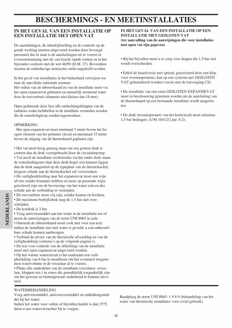
- 90 -- 90 -
NE
DE
RL
AN
DS
BESCHERMINGS - EN MEETINSTALLATIESIN HET GEVAL VAN EEN INSTALLATIE OP EEN INSTALLATIE MET OPEN VAT
De aansluitingen, de inbedrijfstelling en de controle op de goede werking moeten uitgevoerd worden door bevoegdpersoneel dat in staat is de aansluitingen uit te voeren in overeenstemming met de van kracht zijnde wetten en in het bijzonder conform met de wet 6 90 (D.M. 37). Bovendien moeten de onderhavige instructies strikt nageleefd worden.
In het geval van installaties in het buitenland verwijzen we naar de speci eke nationale normen.Het vullen van de inbouwhaard en van de installatie moet via het open expansievat gebeuren en natuurlijk stromend waterdoor de toevoerbuis (diameter niet kleiner dan 18 mm).
Open gedurende deze fase alle ontluchtingskleppen van de radiators zodat luchtbellen in de installatie vermeden wordendie de waterkringloop zouden tegenwerken.
OPMERKING- Het open expansievat moet minimaal 3 meter boven het ho-ogste element van het primaire circuit en maximaal 15 meterboven de uitgang van de thermohaard geplaatst zijn.
Het vat moet hoog genoeg staan om een grotere druk te creëren dan de druk voortgebracht door de circulatiepomp. Vul nooit de installatie rechtstreeks via het onder druk staan-
de waterleidingsnet daar deze druk hoger zou kunnen liggen dan de druk aangeduid op de typeplaat van de thermokachel, hetgeen schade aan de thermokachel zal veroorzaken. De veiligheidsleiding naar het expansievat moet een vrije
afvoer zonder kraantjes hebben en moet op passende wijze ge soleerd zijn om de bevriezing van het water erin en dus schade aan de verbinding te vermijden. De toevoerbuis moet vrij zijn, zonder kranen en bochten. De maximum bedrijfsdruk mag de 1,5 bar niet over-
schrijden. De testdruk is 3 bar Voeg antivriesmiddel aan het water in de installatie toe of
neem de aanwijzingen van de norm UNI 8065 in acht. Ontsteek de inbouwhaard nooit (ook niet voor een test)
indien de installatie niet met water is gevuld; u zou onherstel-bare schade kunnen aanbrengen. Verbind de afvoer van de thermische afvoerklep en van de
veiligheidsklep (schema’s op de volgende pagina’s) De test voor controle van de afdichting van de installatie
moet met open expansievat uitgevoerd worden. Op het warme watercircuit is het raadzaam een veili-
gheidsklep van 6 bar te installeren om het eventueel toegeno-men watervolume in de wisselaar af te voeren. Plaats alle onderdelen van de installatie (circulator, wisse-
laar, kleppen enz.) in zones die gemakkelijk toegankelijk zijnom het gewone en buitengewone onderhoud te kunnen uitvo-eren.
WATERBEHANDELINGVoeg antivriesmiddel, anticorrosiemiddel en ontkalkingsmid-del bij het water.Indien het water voor vullen of bijvullen harder is dan 35°F, dient u een waterverzachter bij te voegen.
IN HET GEVAL VAN EEN INSTALLATIE OP EEN INSTALLATIE MET GESLOTEN VAT(ter aanvulling van de aanwijzingen die voor installaties met open vat zijn gegeven)
Bij het bijvullen moet u er zorg voor dragen dat 1,5 bar niet wordt overschreden.
Enkel de haardversie met spiraal, geactiveerd door een klep voor overtemperatuur, kan op een systeem met GESLOTEN VAT ge nstalleerd worden (versie met de toevoeging CS).
De installatie van een extra GESLOTEN EXPANSIEVAT moet in beschouwing genomen worden als de aansluiting van de thermohaard op een bestaande installatie wordt aangeslo-ten.
De druk stroomopwaarts van het koelcircuit moet minstens 1,5 bar bedragen. (UNI 10 12 2 par. 6.2).
Raadpleeg de norm UNI 8065- 1 9 8 9 (behandeling van het water van thermische installaties voor civiel gebruik).

- 91 -- 91 -
NE
DE
RL
AN
DS
AFMETINGEN
FRONT KANT
PLANVerbrandingslucht
L
PH
terugvoer spiraal thermische afvoer 1 2” M (versie met gesloten vat)
toevoer spiraal thermische afvoer 1 2” M (versie met gesloten vat)
holte voor meter
terugvoer water naar installatie 1” M
toevoer water naar installatie 1” M
Y
X
VOOR EEN CORRECTE FUNCTIONERING MOET U DE TOEVOER- EN TERUGVOERLEIDINGEN LATEN KRUISEN
Afvoer
H2OCEANO 15 - 15/CS H2OCEANO 23 - 23/CS H2OCEANO 28 - 28/CS
L 7 88 106 cm
P 62 68 83 cm
H135 zonder pootjes
(met pootjes + 1 cm)
1 7 zonder pootjes
(met pootjes + 1 cm)
1 7 zonder pootjes
(met pootjes + 1 cm)cm
X 3 3 51 cm
Y 36 37 50 cm
Binne-nafmeting vuurhaard
50x38 60x50 78x60 cm

- 92 -- 92 -
NE
DE
RL
AN
DS
TECHNISCHE EIGENSCHAPPEN
NB: De cijfers PROJECT (Referentie norm EN 13229)* Het verwarmingsvolume is berekend een isolatie van het huis conform de Italiaanse wet 10 91, en verdere wijzigingen en met een warmteaanvraag van 33 Kcal m per uur.* Het is belangrijk ook rekening te houden met de plaats van de Verwarmingsketels in de te verwarmen ruimte.* * temperatuur in ketel 70° - (ðT=25K)
De hierboven vermelde gegevens zijn indicatief. EDILKAMIN s.p.a. behoudt zich het recht voor zonder mededeling en naar onherroepelijk oordeel de producten te kun-nen wijzigen.
VOOR EEN CORRECTE FUNCTIONERING MOET U DE TOEVOER- EN TERUGVOERLEIDINGEN LATEN KRUISEN
DE INSTALLATEUR MOET AAN DE HAND VAN DE HOOGTE DE DOORSNEDE VAN DE TE GEBRUIKEN SCHOORSTEEN BEPALEN.
15-15/CS 23-23/CS 28-28/CS
Verbrand thermisch vermogen 18,5 27,8 3 ,8 kW
Nominaal vermogen 1 ,8 22,2 27,8 kW
Nominaal vermogen aan water 12,1 18,2 22,8 kW
Globaal rendement ongeveer 80 80 80 %
Rendement water ongeveer 82 82 82 %
Opbrengstklassen (EN 303-5) > 3 > 3 > 3 -
ø vrouwelijke rookuitlaat 18 22 25 cm
Maximum bedrijfsdruk 1,5 1,5 1,5 bar
Verbruik brandstof ,5 7 8,5 kg h
Waterinhoud 50 100 130 liter
Verwarmbaar volume * 355 535 670 m
Gewicht met verpakking 2 0 285 325 kg
Productie warm water voor sanitair gebruik (kit 1 - 3 - N3 - N3bis)** 13-1 13-1 13-1 liter min
ø externe luchtinlaat 12,5 12,5 12,5 cm
Toevoer naar installatie (mannelijke) 1” 1” 1” inches
Retour van installatie (mannelijke) 1” 1” 1” inches

- 93 -- 93 -
NE
DE
RL
AN
DS
INSTALLATIEBELANGRIJK ADVIES VOOR DE INSTALLATIEBehalve de indicaties in dit document moet u tevens rekening houden met de Italiaanse normen UNI- n. 10683 - verwarmingstoestellen op hout installatievereisten.- n. 9615/90 - berekening van de interne afmetingen vande haarden.- n. 10412:2 - cv-installaties met warm water. Speci eke veiligheidsvereisten voor installaties met huishoudelijke verwarmingsapparaten en ingebouwde ketel op vaste brandstof en met een vermogen of totaal vermogen dat de 35 kW niet overschrijdt.
In het bijzonder- Alvorens met het monteren te beginnen is het van belang de compatibiliteit van de installatie te controleren, zoals bepa-ald in de paragrafen .1 .1.1 .1.2 van de Italiaanse norm UNI 10683.- Na de montage, moet de installatietechnicus het systeem in bedrijf stellen en de documentatie leveren, zoals vereist door deItaliaanse norm UNI 10683 paragraaf .6 en 5.- De aansluiting, inbedrijfstelling en controle over de goede werking van de inbouwhaard moet uitgevoerd worden door bevoegd personeel dat in staat is de elektrische en hydraulischeaansluitingen uit te voeren, zoals vereist door de normen UNI 10683 paragraaf .5, UNI 10 12 2. Tevens moeten de onderha-vige montageinstructies strikt in acht genomen worden.- De controles moeten uitgevoerd worden met brandende haard. Voor het monoblok te bekleden, moet de haard sinds enkele uren goed doorbranden zodat eventueel eerst kan ingegrepen worden. Nadat de testen een positief resultaat hebben opgele-verd, kunnen de afwerkingen uitgevoerd worden, bij voorbeeld- bouw van een beschermkap- montage van de bekleding- uitvoering van lisenen, verven, etc.EDILKAMIN kan dus niet aansprakelijk gesteld worden voor de kosten van afbraak en herbouw ten gevolge van vervangingvan eventuele defecte onderdelen van de inbouwhaard.
EXTERNE LUCHTINLAATEen buitenaansluiting met een sectie of diameter van 12,5 cm (zie technische tabel) is absoluut noodzakelijk voor de goede werking van de inbouwhaard; zijn realisatie is dus verplicht.De aansluiting moet het mechanisme voor luchtregeling (E).Het mechanisme, afzonderlijk geleverd, kan zowel links als rechts van de thermohaard gemonteerd worden. De aansluiting kan verricht worden met een exibele aluminium leiding.Verzorg goed de afdichting van de punten waar luchtverlies mogelijk is. Het mechanisme voor luchtregeling (E), kangedemonteerd worden en op de rechterzijde van de in-bouwhaard geplaatst worden. Het is aangeraden aan de buiten-zijde van de luchtinlaat een beschermend rooster te plaatsen. Het rooster mag hoe dan ook de nuttige sectie voor luchtdoor-gang niet beperken.De aangeduide sectie moet 10% tot 20% groter zijn voor buizen langer dan 3 m of met bochten.De buitenlucht moet op het niveau van de vloer opgevangen worden (mag niet van boven komen).
ROOKGASKANALEN EN SCHOORSTEENVoor de inbouwhaard is de uitgang voor de rookgassen rond.De uitgang werd voorzien op het gebruik van buizen in ro-estvrij staal. Indien de inlaat van het rookkanaal zich niet verticaal op de inbouwhaard bevindt, mag de buisverbinding tussen in-bouwhaard en rookkanaal geen vernauwingen of hellingen groter dan 5° vertonen (Afb .1-2-3- ). Voor reeds bestaande rookkanalen of te grote rookkanalen adviseren we buizen in roestvrij staal met een geschikte diame-ter en isolering. Voor rookkanalen die aan de buitenzijde wordengeplaatst, raden wij buizen aan in roestvrij staal met dubbele wandisole-ring. De bouweigenschappen, in het bijzonder de mechanische resi-stentie, de isolering en gasafdichting, moeten geschikt zijn om een rookgastemperatuur van minstens 50° te verdragen.Dicht het ingangspunt van het stalen rookkanaal op de mond van de rookgasuitlaat van de inbouwhaard af met zeer warme mastiek.De fundamentele eigenschappen van de schoorsteen zijn:- de interne sectie op de basis stemt overeen met dievan het rookkanaal - de uitgangsectie is niet kleiner dan twee keer de sectie van het rookkanaal- de schoorsteen is op het dak geplaatst in de volle wind, buiten de terugstroomzones.
moet u tevens rekening houden met de indicaties in de pa-ragraaf 4.2 “aansluiting met het systeem voor rookgasafvo-er” van de Italiaanse norm UNI 10683.
E
E
2
45°
45°
3
max.45°
1
NO
4
NEEN

- 94 -- 94 -
NE
DE
RL
AN
DS
INSTALLATIEAls u een kant-en-klare bekleding van Edilkamin gebruikt, houd dan tijdens het plaatsen van de thermokachel rekening met het gekozen model.De plaats zal verschillen op grond van het gekozen model (raadpleeg de montageinstructies aanwezig in de verpakking van elke bekleding). Controleer gedurende de installatie dat de inbouwhaard vlak geplaatst wordt. - Maak een opening in de muur of op de vloer voor de externe luchtinlaat en sluit aan met het mechanisme voor luchtregeling, zoals beschreven in het hoofdstuk “externe luchtinlaat “.- Sluit de inbouwhaard aan met het rookkanaal in roestvrij staal. Neem hiervoor de diameters aangeduid in de tabel met technische eigenschappen in acht en de indicaties in hethoofdstuk “rookkanalen”.- Controleer de goede werking van alle bewegende onderdelen alvorens de inbouwhaard te bekleden.- Voer een test uit en een eerste ontsteking alvorens de bekle-ding te monteren.
MONTAGE VAN DE BEKLEDING, BESCHERMKAP EN HUN VENTILATIEHet is strikt noodzakelijk dat de basis van de bekleding lucht doorlaat voor een interne luchtcirculatie. Dit is de reden waa-rom spleten of openingen voor luchtdoorgang moeten uitgevo-erd worden. Bij de montage moet tussen de delen in marmer, steen, bak-steen die de bekleding samenstellen en het prefab element een kleine tussenruimte gelaten worden zodat wordt vermeden dat ze door overmatige oververhitting of uitzetting breken.De delen in hout moeten door onbrandbare panelen beschermd zijn en in geen enkel punt in contact komen met de haard.
Om luchtstroming mogelijk te maken en warmteaccumulatie te vermijden moeten ze minimum op een afstand van 1 cm van de haard staan. De bekleding kan gemaakt worden van onbrandba-re gipsplaten of -panelen en van absoluut onbrandbaar materia-al. De binnenzijde van de beschermkap moet geventileerdworden. De lucht moet onderaan binnendringen (ruimte tussen de deur en de balk) en zal door convectie doorheen een rooster dat bovenaan gemonteerd moet worden weer naar buitenstromen. Hierdoor wordt warmte teruggewonnen en oververhit-ting vermeden. De beschermkap moet voorzien zijn van luikenvoor het onderhoud van de verbindingen.Behalve de bovenstaande aanwijzingen, moet u tevens
van de Italiaanse norm UNI 10683 “isolering, afwerking, bekleding en veiligheidsadvies”.
Indien een installatiepakket wordt gebruikt, moet het mid-dels een isolerend deken beschermd worden tegen dethermische bestraling van het monoblok.
LIJST OM OPENING (optie)Om de aansluiting van de verschillende onderdelen van de bekleding te bevorderen kunt u de thermokachel voorzien van een lijst (A) die u aan de voorkant van de opening aanbrengt.
GEBRUIKSAANWIJZINGEN3-wegsklep- Tijdens de ontsteking zal de 3-wegsklep (*) de stroom water om-leiden en direct naar de thermokachel laten terugkeren; wanneer de ingestelde temperatuur wordt overschreden, zal de driewegklep (*) het water doen terugstromen (niet afhankelijk van de ge nstalle-erde kit).
Bypassklep- De bypassklep wijzigt automatisch het rooktraject en verbe-tert het rendement als de deur gesloten wordt.- Wanneer de deur wordt geopend zal de bypass klep auto-matisch open gaan waardoor de rookgassen rechtstreeks het rookkanaal bereiken en vermeden wordt dat ze langsheende haardopening ontsnappen.
Thermische afvoerklepAls de temperatuur van het water (bijv. als gevolg van een te grote lading hout) de 90°C overschrijdt, worden de thermische afvoerklep en een geluidssignaal geactiveerd. Vul geen extra brandstof bij en wacht tot de temperatuur onder de 80°C is gedaald door de lampjes op de elektronische rege-laar te controleren.- In het geval van thermohaarden voorzien van de KIT voor de productie van warm water voor sanitair gebruik kunt u tevens de warmwaterkraan openen om het afkoelen te bevorderen.
Praktisch advies- We raden u aan om de radiatoren van de ruimte waar de thermohaard ge nstalleerd is gesloten te houden, De warmte die door de opening wordt uitgestraald kan voldoende zijn om te verwarmen.Onvolledige verbranding veroorzaakt overmatige afzet op de buis van de wisselaar.Om dit te vermijden is het noodzakelijk- droog hout te verbranden.- er zich van te verzekeren dat er smeulende, gloeiende kolen aanwezig zijn alvorens ander hout toe te voegen.- meng blokken brandhout met grote en kleine doorsnede.- controleer of het teruggevoerde water een temperatuur van minstens 50°C heeft (gebruik de temperatuur controleklep).
Ontsteking- Verzeker u ervan dat minstens één radiator steeds open is.- Activeer de schakelaars van de elektronische regelaar.- Laad de inbouwhaard met middelmatige kleine stukken droog hout en ontsteek.- Wacht enkele minuten tot het voldoende brandt.- Sluit de deur- Regel de verbranding middels de klepbediening op de voorzijde.- Stel de thermostaat op de elektronische regelaar in (*) op 50÷70°C.N.B. Tijdens de eerste ontstekingen is het mogelijk dat u een lichte ver ucht ruikt. Dit zal binnen korte tijd verdwijnen.
Gips
A
(*) onderdelen van de installatie te voorzien door de installatietechnicus.
A

- 95 -- 95 -
NE
DE
RL
AN
DS
Afb. 1
GEBRUIKSAANWIJZINGEN
E
V
X Y
Installatie optionele thermostaatklep “V”Verricht deze handelingen als de thermokachel uitgedoofd en afgekoeld is. Haal bovendien de stekker van de kachel uit het stopcontact.Pas de volgende procedure toe- Open de deur en zet hem in de geopende stand vast om eenvoudig de werkzaamheden in de haard te kunnen verrichten (Afb. ).- Demonteer de volgende onderdelen (afb 5) aslade gietijzeren rooster vuurplaat
Opmerking De vuurplaat steunt uitsluitend op pakkingen. U kunt hem dus verwijderen door hem op te pakken (houd er rekening mee dat de vuurplaat aan de haard kan vastkleven als u de thermokachel een lange tijd heeft gebruikt).- Installeer de al gemonteerde thermostaatklep op de bevesti-gingsplaat (afb. 6 - pag. 96).- Bevestig de plaat met de drie meegeleverde schroeven (S) aan de bodem van de haard (afb. 7 - pag. 96).Controleer of u de kabel en de draad van de meter in de daarvo-or bestemde goten heeft aangebracht alvorens u plaat vastzet.- Breng de kabel aan in de opening aan de voorkant onder de aslade (afb. 8 - pag. 96) en zet hem vast met behulp van de meegeleverde elastische ring.- Laat de draad van de meter langs de rechterzijde van de asla-de lopen en voer hem door de opening aan de rechterkant de thermokachel uit (afb. 9 - pag. 96).- Plaats de meter in de holte aan de rand van de thermokachel (pag. 91).- Controleer de staat van de pakking alvorens u de vuurplaat aanbrengt (vervang de pakking als dit nodig is). Bedek de omtrek van de bevestigingsplaat van de thermostaatklep met de pakking (afb. 8 - pag. 96).
Afstelling uitwendige luchtDe bediening regelt samen met de klep (E - afb.1) op de exter-ne lucht aanzuigopening de juiste hoeveelheid primaire lucht die voor de verbranding nodig is. Door de knop in te drukken wordt de aanzuiging van externe lucht gesloten. Door aan de knop te trekken wordt deze geopend.
OPTIONELE THERMOSTAATKLEP (AFB. 2 )Handmatige bediening van de verbrandingslucht (verricht deze handeling tijdens de installatie). Voor de gewenste temperatuur moet u de thermostaatklep met de hand afstellen.Met behulp van de meegeleverde inbussleutel (X - afb. 3) kunt u de thermostaatklep afstellen door aan de schroef onder de aslade (Y - afb. 3) te draaien. schroef rechtsom verbrandingslucht afgesteld op een minimum schroef linksom verbrandingslucht afgesteld op een maximum natuurlijk kunt u de schroef ook op een stand tussen de twee
uitersten plaatsenN.B. Als de thermostaatklep ge nstalleerd is, moet u de handbediende lucht toevoerklep verwijderen door de klep en de kabel met knop te demonteren (E - afb. 1).
Automatische afstelling van de verbrandingsluchtDe verbrandingslucht wordt door de opening (E - afb. 1) van buitenaf aangezogen en stroomt door het asrooster de haard in.U kunt de verbrandingslucht afstellen met behulp van de klep V (afb. 2).De klep zal automatisch geopend worden als de temperatuur in de haard lager is dan de temperatuur die tijdens de ijking is ingesteld. De klep wordt echter automatisch gesloten als de temperatuur hoger is dan is ingesteld.Op deze manier verbrandt de kachel uitsluitend het hout dat voor het vereiste thermische comfort is vereist. Er wordt dus geen hout verspilt.N.B. om het glas schoon te houden zal altijd een minimum hoeveelheid lucht blijven stromen, ook als de gesloten thermo-staatklep de toevoer van verbrandingslucht onderbreekt (als de temperatuur in de haard erg hoog is).
Afb.
Afb. 5
Afb. 2
Afb. 3

- 96 -- 96 -
NE
DE
RL
AN
DS
ONDERHOUDSchoonmaak van de haard-Afzettingen op de interne wanden van de vuurhaard verhinde-ren uitwisseling van warmte.- Het is dus noodzakelijk een regelmatige schoonmaak uit te vo-eren door het water op een temperatuur van 80÷85°C te brengen om de afzet te verzachten en vervolgens met behulp van een stalen spatel te verwijderen.GlasreinigingMaak het glas schoon met een spray voor keramisch glas.- Het glas moet schoongemaakt worden wanneer het koud is (Glasskamin di Edilakmin). - Voor de vleugel opening van de achterlader noodzakelijk om in de gesloten stand.- Breng het handvat op de pal tussen de structuur en de deur aan en open hem door eraan te draaien. (Afb. 12).
Deur openen- Maak voor het openen van de deur gebruik van de bijgesloten verwijderbare handgreep (Afb. 10).-U kunt het handvat echter ook met behulp van de 2 meegele-verde moeren aan de deur bevestigen.
GEBRUIKSAANWIJZINGEN
Afb. 6
Afb. 7
Afb. 8
Afb. 9
ACHTERAANZICHT
draad meter
kabelS
S S
SS
S
kabel
kabel
pakking
draad meter
draad meter
Installatie van de tegengewichtenDe roldeur is voorzien van tegengewichten die garanderen dat de sluiting in een vlotte beweging gebeurt.De werking van de tegengewichten kan geregeld worden door toevoeging van een of meer plaatjes (extra tegengewichten), geleverd samen met de thermohaard (P - Afb. 11).
P
Afb.10
Afb. 11
Abb. 12

- 97 -- 97 -
NE
DE
RL
AN
DS
INSTALLATIE VOOR MONTAGE MET OPEN VAT VOORBEELD VAN EEN HYDRAULISCHE INSTALLATIE VOOR INBOUWHAARDEN MET PRODUCTIE VAN
WARM TAPWATER MET GEBRUIK VAN KIT 1ACS: Warm tapwaterAF: Koud waterEV: Drieweg elektroklepF: DebietregelaarMI: Toevoer InstallatieNA: Normaal OpenNC: Normaal geslotenP: Pomp (circulatiepomp)RA: RadiatorsRE: Elektronische regelaarRI: Retour InstallatieS: AfvoerSc 20: Wisselaar 20 platenST: TemperatuursondeTC: Inbouwhaard V: KlepVE: Open ExpansievatVSP: Veiligheidsklep op 1,5 barVST: Thermische afvoerklepJa: Joker automatische ontluchting
Het pakket 1 werd gerealiseerd om de taak van de installatietechnici te vereenvoudigen; het bevat inderdaad alle onderdelen die nodig zijn voor een correcte installatie van het product.NB: de apparatuur die in het pakket is inbegrepen moet op geschikte wijze tegen de thermische straling van de haard beschermd worden middels isolerende dekens.
BEDIENING KEUZESCHAKELAARKeuzeschakelaar op OFF Alles uitKeuzeschakelaar op MAN Circulator geforceerd Klep ingesteldKeuzeschakelaar op AUTO Circulator ingesteld Klep ingesteldKeuze van alarm In OFF-stand is de geluidsignalering uitgesloten
VOOR EEN CORRECTE FUNCTIONERING MOET U DE TOEVOER- EN TERUGVOERLEIDINGEN LATEN KRUISEN
ON
OFF
Elektrische aansluitingen
ActiveringDeactiveringakoestisch alarm
Afstelling klep20-80° C
Visualisering
Circulator
Driewegklep
Voeding230Vac
Zekering
KIT 1 cod. 261880
Afstelling Circulator20-80° C
DebietregelaarOpgelet verbind hetnormaal gesloten contact
Sonde (voeg in de hiervo-or bestemde put)
Circulator actief Alarm overtemperatuur Driewegklep
1. Geelkoperen collector 1” M-V2. Kogelklep van 1”3. Circulator met bevestigingen van 1”½
(219660). Terugslagklep 1” (261910)
5. Drieweg Elektroklep 1” M-V (1 3330)6. Koperen koppelingen7. Wisselaar met 30 platen voor wisseling met
het circuit van de gasketel (216620)8. Wisselaar 20 platen voor productie van
warm tapwater (205270)9. Thermische afvoerklep van ¾” (729 0)10. Veiligheidsklep 1,5 bar van ¾” (1 3260)11. Debietregelaar (220830)12. Put voor thermometer ½” + sonde (175960)13. Elektronische regelaar (220780)A Toevoer naar installatie ¾”B Retour van installatie ¾”C Retour naar haard ¾”D Toevoer van haard 1”E Koud tapwater ½”F Warm tapwater ½”
Vei
lighe
idsb
uis
Ø28
cm
Toe
voer
buis
Ø18
cm
Col
lect
or
Regelaar inbegrepen in het pakket
Elektrisch netwerk

- 98 -- 98 -
NE
DE
RL
AN
DS
INSTALLATIE VOOR MONTAGE MET OPEN VATVOORBEELD VAN EEN HYDRAULISCHE INSTALLATIE VOOR INBOUWHAARD ZONDER PRODUCTIE VAN
WARM TAPWATER+WANDKETEL MET GEBRUIK VAN KIT 2AF: Koud waterCA: WandketelMI: Toevoer InstallatieP: Pomp (circulator)RA: RadiatorsRE: Elektronische regelaarRI: Retour InstallatieS: AfvoerJa: Joker automatische ontluchtingSc 30: Wisselaar 30 platenST: TemperatuursondeTC: Inbouwhaard V: KlepVE: Open ExpansievatVR: TerugslagklepVSP: Veiligheidsklep op 1,5 barVST: Thermische afvoerklep
Het pakket 2 werd gerealiseerd om de taak van de installatietechnici te vereenvoudigen; het bevat inderdaad alle onderdelen die nodig zijn voor een correcte installatie van het product.NB: de apparatuur die in het pakket is inbegrepen moet op geschikte wijze tegen de thermische straling van de haard beschermd worden middels isolerende dekens.
1. Geelkoperen collector 1” M-V2. Kogelklep van 1”3. Circulator met bevestigingen van 1” ½
(219660). Terugslagklep 1” (261910)
5. Drieweg elektroklep “ M-V (1 3330)6. Koperen koppelingen7. Wisselaar met 30 platen voor wisseling met
het circuit van de gasketel (216620)8. Wisselaar 20 platen voor productie van
warm tapwater (205270)9. Thermische afvoerklep van ¾” (729 0)10. Veiligheidsklep 1,5 bar van ¾” (1 3260)11. Debietregelaar (220830)12. Put voor thermometer ½” + sonde (175960)13. Elektronische regelaar (220780)A Toevoer naar installatie ¾”B Retour van installatie ¾”C Retour naar haard ¾”D Toevoer van haard 1”E Koud tapwater ½”F Warm tapwater ½”
Circulator A
KIT 2 cod. 261890
ON
OFF
Circulator B
VOOR EEN CORRECTE FUNCTIONERING MOET U DE TOEVOER- EN TERUGVOERLEIDINGEN LATEN KRUISEN
BEDIENING KEUZESCHAKELAARKeuzeschakelaar op OFF Alles uitKeuzeschakelaar op MAN Circulator geforceerd Klep ingesteldKeuzeschakelaar op AUTO Circulator ingesteld Klep ingesteldKeuze van alarm In OFF-stand is de geluidsignalering uitgesloten
Elektrische aansluitingen
ActiveringDeactiveringakoestisch alarm
Afstelling klep20-80° C
Visualisering
Voeding230Vac
Zekering
Afstelling van de minimumtemperatuur voor het opstartenvan de circulators 20-80°
Sonde (voeg in de hiervo-or bestemde put)
Circulator actief Alarm overtemperatuur Driewegklep
Vei
lighe
idsb
uis
Ø28
cm
Toe
voer
buis
Ø18
cm
Col
lect
or
Regelaar inbegrepen in het pakket
Elektrisch netwerk

- 99 -- 99 -
NE
DE
RL
AN
DS
INSTALLATIE VOOR MONTAGE MET OPEN VATVOORBEELD VAN EEN HYDRAULISCHE INSTALLATIE VOOR INBOUWHAARD MET PRODUCTIE VAN
WARM TAPWATER+WANDKETEL MET GEBRUIK VAN KIT 3ACS: Warm tapwaterAF: Koud waterCA: WandketelEV: Drieweg elektroklepF: DebietregelaarMI: Toevoer InstallatieNA: Normaal OpenNC: Normaal geslotenP: Pomp (circulator)RA: RadiatorsRE: Elektronische regelaarRI: Retour InstallatieS: AfvoerSc 20: Wisselaar 20 platenSc 30: Wisselaar 30 platenTC: Inbouwhaard V: KlepVE: Open ExpansievatVR: TerugslagklepVSP: Veiligheidsklep op 1,5 barVST: Thermische afvoerklepJa: Joker automatische ontluchting
Het pakket 3 werd gerealiseerd om de taak van de installatietechnici te vereenvoudigen; het bevat inderdaad alle onderdelen die nodig zijn voor een correcte installatie van het product.NB: de apparatuur die in het pakket is inbegrepen moet op geschikte wijze tegen de thermische straling van de haard beschermd worden middels isolerende dekens.
KIT 3 cod. 261900
1. Geelkoperen collector 1” M-V2. Kogelklep van 1”3. Circulator met bevestigingen van 1”
½(219660). Terugslagklep 1” (261910)
5. Drieweg Elektroklep 1” M-V (1 3330)6. Koperen koppelingen7. Wisselaar met 30 platen voor wisselingmet
het circuit van de gasketel (216620)8. Wisselaar 20 platen voor productie van
warm tapwater (205270)9. Thermische afvoerklep van ¾” (729 0)10. Veiligheidsklep 1,5 bar van ¾” (1 3260)11. Debietregelaar (220830)12. Put voor thermometer ½” + sonde(175960)13. Elektronische regelaar (220780)A Toevoer naar installatie ¾”B Retour van installatie ¾”C Retour naar haard ¾”D Toevoer van haard 1”E Koud tapwater ½”F Warm tapwater ½”
ON
OFF
VOOR EEN CORRECTE FUNCTIONERING MOET U DE TOEVOER- EN TERUGVOERLEIDINGEN LATEN KRUISEN
BEDIENING KEUZESCHAKELAARKeuzeschakelaar op OFF Alles uitKeuzeschakelaar op MAN Circulator geforceerd Klep ingesteldKeuzeschakelaar op AUTO Circulator ingesteld Klep ingesteldKeuze van alarm In OFF-stand is de geluidsignalering uitgesloten
Elektrische aansluitingen
ActiveringDeactiveringakoestisch alarm
Afstelling klep20-80° C
Visualisering
Voeding230Vac
Zekering
Afstelling Circulator20-80° C
DebietregelaarOpgelet verbind hetnormaal gesloten contact
Sonde (voeg in de hiervo-or bestemde put)
Circulator actief Alarm overtemperatuur Driewegklep
Vei
lighe
idsb
uis
Ø28
cm
Toe
voer
buis
Ø18
cm
Col
lect
or
Regelaar inbegrepen in het pakket
Elektrisch netwerk
Driewegklep
Circulator A Circulator B

- 100 -- 100 -
NE
DE
RL
AN
DS
INSTALLATIE VOOR MONTAGE MET OPEN VATVOORBEELD VAN EEN HYDRAULISCHE INSTALLATIE VOOR INBOUWHAARD MET PRODUCTIE VAN
WARM TAPWATER+WANDKETEL MET GEBRUIK VAN KIT N3CA: MuurketelPR: Pomp (circulator)P1: Pomp primair circuitRE: Elektronische schakelaarTA: Thermostaat omgevingVE: ExpansievatJa: Jolly ontluchtingV: AfsluitschuifVR: AfsluitschuifST: TemperatuurmeterF: DebietregelaarSc: Warmteuitwisselaar met platenEV: 3-wegs elektroklepRI: Terugvoer naar verwarmingsinstallatieRA: RadiatorenMI: Toevoer naar verwarmingsinstallatieAF: Koud WaterACS: Warm Water voor Sanitair GebruikS: Afvoer
Het pakket N3 werd gerealiseerd om de taak van de installatietechnici te vereenvoudigen; het bevat inderdaad alle onderdelen die nodig zijn voor een correcte installatie van het product.NB: de apparatuur die in het pakket is inbegrepen moet op geschikte wijze tegen de thermische straling van de haard beschermd worden middels isolerende dekens.
KIT N3 cod. 627690
1. Toevoer naar verwarmingscircuit G 3 ”2. Toevoer vanaf EDILKAMIN generator G 3 ”3. Terugvoer naar EDILKAMIN generator G 3 ”. Terugvoer vanaf verwarmingscircuit G 3 ”
5. Aanvoer koud water voor sanitair gebruik G 1 2”6. Toevoer warm water naar sanitaire installaties
G 1 2”7. Gecombineerde veiligheidsklep temperatuur en
druk (90°C-3bar)8. Debietregelaar9. Jolly ontluchting G 3 8”10. Circulator circuit EDILKAMIN generator11. 3-wegs warmteuitwisselaar met platen12. Afsluitschuif G 1”13. Elektronische schakelaar met kabels1 . Speciale opening voor passage kabelgeleider15. Voedingskabel16. Kabel voor circulator verwarmingsinstallatie
(fase, neutraal, aarde)17. Temperatuurmeter18. Circuit thermostaat omgevingstemperatuur
VEAF
S V
RE
RETE
ST
V
S
V
Tu
bo
di
cari
co
Ø>
18
mm
Tu
bo
di
sic
ure
zza
Ø>
28
mm
V
CA
ACS
PRF
ACS
AF
Ja
TA
P1
VVs
Sc
TCN
ELETTRICA
INT
VR V
VR
RETE
IDRICA
VR
VR
MI
RA
RI
V
COLLETTORE
VR
V
V
V
V
V
Circuito collegabile altermostato ambiente(a discrezione del cliente)
Da collegare necessariamenteal circolatore dell’impianto
di riscaldamento PR
12 3 4
56
7
8
9
10
119
9
12
13
12 3 5
4 67
14
15 16 17
Passacavi
18
Pomp primair circuit
OFF
Set consensus primaire circulator30- 0°C
ON
Pomp verwarming
EV
Elektrisch netwerk 230 Vac50 Hz + - 10%
Set consensus sanitair-verwarming0-80°C
thermostaatomgevingstemperatuur
Debietsensor
SondeConsensus alarm
Elektrische aansluitingen
VOOR EEN CORRECTE FUNCTIONERING MOET U DE TOEVOER- EN TERUGVOERLEIDINGEN LATEN KRUISEN
Vei
lighe
idsb
uis
Ø28
cm
Toe
voer
buis
Ø18
cm
Collector
Circuit aansluitbaar op thermostaat omgevingstempe-ratuur (naar wens cliënt)
verplicht aan te sluiten op cir-culator verwarmingsinstallatie
Waternet
Elektrisch netwerk
Kabelgeleider
Pomp 1 Pomp 2

- 101 -- 101 -
NE
DE
RL
AN
DS
INSTALLATIE VOOR MONTAGE MET OPEN VATVOORBEELD VAN EEN HYDRAULISCHE INSTALLATIE VOOR INBOUWHAARD MET PRODUCTIE VAN
WARM TAPWATER+WANDKETEL MET GEBRUIK VAN KIT N3 BISCA MuurketelP2 Pomp (circulator)P1: Pomp primair circuitRE Elektronische SchakelaarTA Thermostaat omgevingVE Thermostaat omgevingJa Jolly ontluchtingv AfsluitschuifVR TerugslagklepST TemperatuurmeterF DebietregelaarSc Warmteuitwisselaar met platenEV 3-wegs ElektroklepRI Terugvoer naar verwarmingsinstallatieRA RadiatorenMI Toevoer naar verwarmingsinstallatieAF Koud WaterACS Warm water voor sanitair gebruikS AfvoerINT: HoofdschakelaarTCN: Contactthermostaat
Het pakket N3BIS werd gerealiseerd om de taak van de installatietechnici te vereenvoudigen; het bevat inderdaad alle onderdelen die nodig zijn voor een correcte installatie van het product.NB: de apparatuur die in het pakket is inbegrepen moet op geschikte wijze tegen de thermische straling van de haard beschermd worden middels isolerende dekens.
KIT N3 BIS cod. 627860
1. Toevoer naar verwarmingscircuit G 3 ”2. Toevoer vanaf EDILKAMIN generator G 3 ”3. Terugvoer naar EDILKAMIN generator G 3 ”. Terugvoer vanaf verwarmingscircuit G 3 ”
5. Aanvoer koud water voor sanitair gebruik G 1 2”6. Toevoer warm water naar sanitaire installaties G 1 2”7. Invoer warm water voor sanitair gebruik door
gasketel G 1 2”8. Gecombineerde veiligheidsklep temperatuur en druk
(90°C-3 bar)9. Debietregelaar10. 3-wegs elektroklep11. Jolly ontluchting G 3 8”12. Circulator circuit EDILKAMIN generator13. Circulator circuit verwarmingsinstallatie1 . Afsluitschuif D 1”15. 3-wegs warmteuitwisselaar met platen16. Elektronische schakelaar met kabels17. Speciale opening voor passage kabelgeleider18. Voedingskabel19. Temperatuurmeter20. Circuit thermostaat omgevingstemperatuur
VEAF
S V
RE
ST
S
V
Tu
bo
dicari
co
Ø>
18
mm
Tu
bo
disic
ure
zza
Ø>
28
mm
CA
ACS
VR
MI
RA
RI
V
ACS
AF
Ja
TA
EV
P2
P1
V
V
Sc
F
Vs
RETE
ELETTRICA
INT
VR V
TCN
V
V
V
By-p
ass
VR
Sc
RETE
IDRICA
COLLETTORE
VR
V
V
V
V
V
Circuito collegabile altermostato ambiente(a discrezione del cliente)
12 3 4
5 6 7
8
9
10
11
12
1314
14
15
111111
1111
1617
12 3
4
5
8
6
7
2019
Passacavi
17
18
VOOR EEN CORRECTE FUNCTIONERING MOET U DE TOEVOER- EN TERUGVOERLEIDINGEN LATEN KRUISEN
Pomp primair circuit
OFF
Set consensus primaire circulator30- 0°C
ON
Pomp verwarming
EV
Elektrisch netwerk 230 Vac50 Hz + - 10%
Set consensus sanitair-verwarming0-80°C
thermostaatomgevingstemperatuur
Debietsensor
SondeConsensus alarm
Elektrische aansluitingen
Vei
lighe
idsb
uis
Ø28
cm
Toe
voer
buis
Ø18
cm
Collector
Circuit aansluitbaar op thermostaat omgevingstempe-ratuur (naar wens cliënt)
Waternet
Elektrisch netwerk
Kabelgeleider
Pomp 1 Pomp 2

- 102 -- 102 -
NE
DE
RL
AN
DS
ELEKTRONISCHE REGELAAR WERKING- Controle-inrichting: Thermometer
- Beschermende inrichting (akoestisch alarmsysteem): Akoestisch alarm (AA)Alarm overtemperatuur (SS)
Dit systeem grijpt in wanneer de watertemperatuur 90°C over-schrijdt en verwittigt de gebruiker zodat hij de brandstoftoevo-er kan onderbreken.De werking van het akoestisch alarm kan via de schakelaar (AA) uitgesloten worden; de alarmfunctie van de controlelamp voor overtemperatuur (SS) blijft hoe dan ook actief. Om de oorspronkelijke condities te herstellen nadat de watertempera-tuur in de inbouwhaard werd beperkt, moet de schakelaar (AA) opnieuw geactiveerd worden. - Toevoerinrichting (circulatiesysteem): Keuzeschakelaar MAN-OFF-AUTO (S)Controlelamp pomp (SP)
Op manueel werkt de pomp altijd, op OFF is de pomp uit; op AUTO wordt de pomp van de installatie via de interne afstel-ling (RIC) op de gewenste temperatuur geactiveerd van 20 tot 80°C (de besturing is vooringesteld op 20°C).
- Inrichting voor de werking (regelsysteem): Regeling (R) voor opening van de driewegklep Controlelamp (SV) voor werking van de driewegklep Wan-
neer de vloeistoftemperatuur de waarde bereikt, ingesteld met de regelaar, zal de driewegklep de vloeistof naar de radiators voeren en de controlelamp van de werking (SV) gaat aan.Wanneer de vloeistoftemperatuur onder de ingestelde waarde daalt, zal het regelsysteem het elektrisch circuit openen en de driewegklep zorgt ervoor dat de vloeistof rechtstreeks naar de inbouwhaard wordt gevoerd.Let op: Controleer gedurende de normale werking of de con-trolelampen (SV) en (SP) aan zijn.
PLAATSDe elektronische regelaar moet in de nabijheid van de in-bouwhaard ge nstalleerd worden.De sonde van de inrichtingen voor werking, bescherming en controle moet rechtstreeks op de inbouwhaard geplaatst worden of op de toevoerbuizen niet verder dan 5 cm van de inbouwhaard. Plaats de sonde hoe dan ook voor het onderschep-pingsorgaan. De sonde moet in de put geplaatst worden.
INSTALLATIEDeze werkzaamheden moeten uitgevoerd worden met devoeding afgesloten van het elektrisch net en met dekeuzeschakelaar (S) AUTO-OFF-MAN in de stand OFF.Ga voor een correcte installatie van de elektronische regelaar als volgt te werk draai de bevestigende schroef los en ver-wijder de kap. Plaats tegen de wand en bevestig met de bijgele-verde pluggen; voer de aansluitingen zeer aandachtig uit zoals aangeduid op het schema. Gebruik kabelgoten om de kabels te installeren, conform met de van kracht zijnde normen; zetde kap weer op zijn plaats en draai de schroeven dicht.Gebruik voor de driewegklep de bruine (fase) en blauwe draad (neutraal) die respectievelijk met de klemmen 5 en 6 van de regelaar moeten verbonden worden.De geel-groene draad moet met de aarde verbonden worden. Volg de montage-instructies ingehouden in de verpakking op voor de correcte aansluiting van de regelaar met de installatie.
BELANGRIJK ADVIES VOOR DE INSTALLATIEDe aansluitingen, de inbedrijfstelling en de controle op de goede werking moeten uitgevoerd worden door bevoegd per-soneel dat in staat is de aansluitingen uit te voeren in overeen-stemming met de van kracht zijnde wetten en in het bijzonder conform met de wet 6 90. Bovendien moeten de onderhavige instructies strikt nageleefd worden.De inachtneming van de normen betreffende de aarding is doorslaggevend voor de veiligheid van de personen.Het is verplicht stroomopwaarts van de inrichting en van hetvolledige elektrische circuit van de inbouwhaard een differen-tiële lijnschakelaar in te voegen. Bovendien is het verplicht de pomp, de klep en de metalen onderdelen van de inbouwhaard te aarden.
LEGENDAAA schakelaar akoestisch alarmR reg. opening driewegklep (KIT 1 - 3)R reg. werking circulators (KIT 2)RIC interne afstelling pompS keuzeschakelaar MAN-OFF-AUTOSP controlelamp pompSS controlelamp overtemperatuurST temperatuurschaalSV controlelamp driewegkleppen (KIT 1 - 3)SV reg. circulators (KIT 2)
TECHNISCHE GEGEVENS
Voeding (+15 - 10%) Vac 230
Beschermgraad IP 0
min max kamertemperatuur °C 0÷+50
Lengte sonde mt 1,2
Thermometer °C 30÷90
Maximum vermogen contacten circulators W 00
Maximum vermogen contacten driewegkleppen W 250
Zekering mA 500
Met de elektronische regelaar kunnen de werkcondities gecon-troleerd worden. Hij is van het volgende voorzien- keuzeschakelaar MAN-OFF-AUTO (S)- temperatuurschaal (ST)- akoestisch alarm (AA)- reg. opening driewegklep (R) (KIT 1-3)- reg. werking circulators (R) (KIT 2)- interne afstelling pomp (RIC)- controlelamp driewegklep (SV) (KIT 1-KIT 3)- controlelamp reg.circulators (SV) (KIT 2)- controlelamp overtemperatuur (SS)- controlelamp pomp (SP)
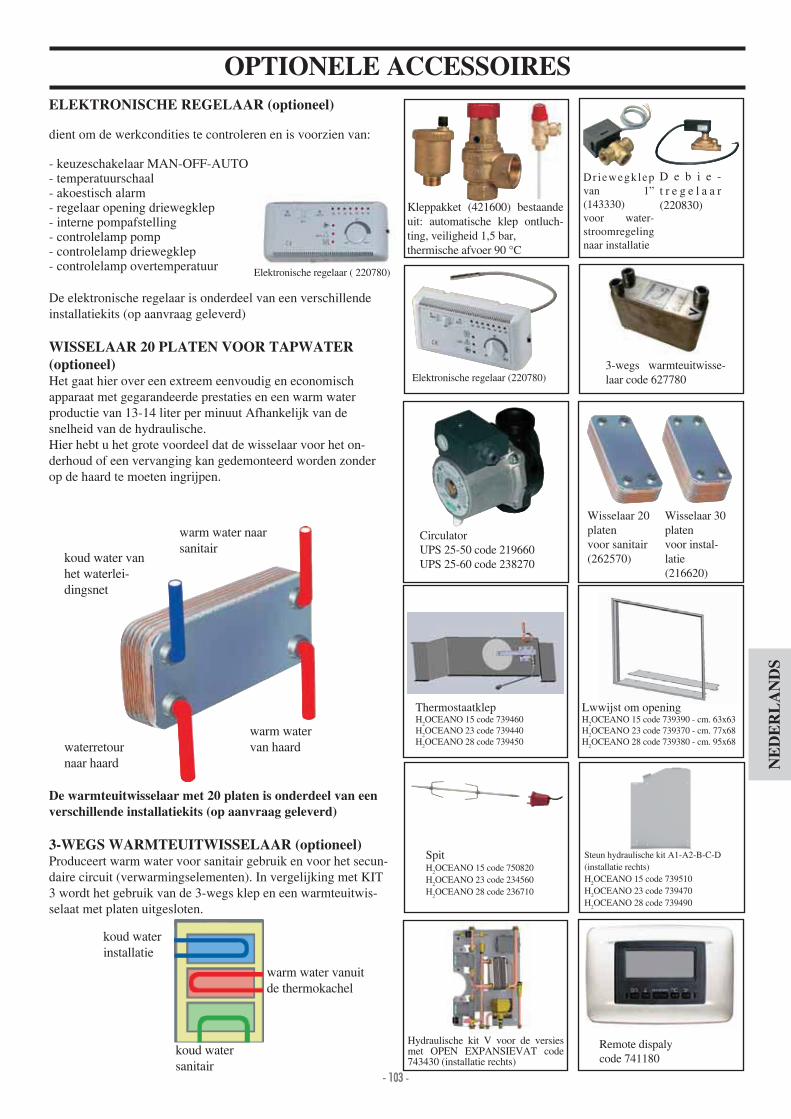
- 103 -- 103 -
NE
DE
RL
AN
DS
ELEKTRONISCHE REGELAAR (optioneel)
dient om de werkcondities te controleren en is voorzien van
- keuzeschakelaar MAN-OFF-AUTO- temperatuurschaal- akoestisch alarm- regelaar opening driewegklep- interne pompafstelling- controlelamp pomp- controlelamp driewegklep- controlelamp overtemperatuur
De elektronische regelaar is onderdeel van een verschillende installatiekits (op aanvraag geleverd)
WISSELAAR 20 PLATEN VOOR TAPWATER(optioneel)Het gaat hier over een extreem eenvoudig en economischapparaat met gegarandeerde prestaties en een warm waterproductie van 13-1 liter per minuut Afhankelijk van de snelheid van de hydraulische.Hier hebt u het grote voordeel dat de wisselaar voor het on-derhoud of een vervanging kan gedemonteerd worden zonder op de haard te moeten ingrijpen.
De warmteuitwisselaar met 20 platen is onderdeel van een verschillende installatiekits (op aanvraag geleverd)
3-WEGS WARMTEUITWISSELAAR (optioneel)Produceert warm water voor sanitair gebruik en voor het secun-daire circuit (verwarmingselementen). In vergelijking met KIT 3 wordt het gebruik van de 3-wegs klep en een warmteuitwis-selaat met platen uitgesloten.
warm water vanuit de thermokachel
Elektronische regelaar ( 220780)
koud water van het waterlei-dingsnet
waterretournaar haard
warm watervan haard
warm water naar sanitair
koud waterinstallatie
koud watersanitair
OPTIONELE ACCESSOIRES
Driewegklep van 1” (1 3330)voor water-stroomregeling naar installatie
Elektronische regelaar (220780)
D e b i e -t r e g e l a a r (220830)
CirculatorUPS 25-50 code 219660UPS 25-60 code 238270
3-wegs warmteuitwisse-laar code 627780
Remote dispalycode 7 1180
Hydraulische kit V voor de versies met OPEN EXPANSIEVAT code 7 3 30 (installatie rechts)
ThermostaatklepH
2OCEANO 15 code 739 60
H2OCEANO 23 code 739 0
H2OCEANO 28 code 739 50
Lwwijst om openingH
2OCEANO 15 code 739390 - cm. 63x63
H2OCEANO 23 code 739370 - cm. 77x68
H2OCEANO 28 code 739380 - cm. 95x68
Steun hydraulische kit A1-A2-B-C-D (installatie rechts) H
2OCEANO 15 code 739510
H2OCEANO 23 code 739 70
H2OCEANO 28 code 739 90
Wisselaar 30 platenvoor instal-latie(216620)
Wisselaar 20 platenvoor sanitair(262570)
Kleppakket ( 21600) bestaande uit automatische klep ontluch-ting, veiligheid 1,5 bar,thermische afvoer 90 °C
SpitH
2OCEANO 15 code 750820
H2OCEANO 23 code 23 560
H2OCEANO 28 code 236710

- 104 -- 104 -
Spoštovani Gospod /Spoštovana Gospa,

- 105 -- 105 -
H2OCEANO je izdelan za ogrevanje vode z izgorevanjemdrvi v kuri u. Voda v termo kaminu se ogreje in dose e ogrevalne naprave (radiatorje, kopalni ke radiatorje, toplotne plo e za talno gretje) ter s konvekcijo oziroma z izpihovanjem toplega zraka ogreva prostor, v katerem se nahaja. Termokamin NE SME NIKOLI DELOVATI BREZ VODE.Voda se ogreje in kro i skozi vmesni prostor, ki se dotika polkro ne stene in kupole kuri a. Vmesni prostor je iz iroke jeklene plo evine. Kuri e zapirajo dvi na vrata, ki se odpirajo in zapirajo verti-kalno ali stransko (zaradi i enja stekla).
INOVATIVNA PATENTIRANA REŠETKA ZA PEPELRešetka dovoljuje izpihovanje toplega zraku od spodaj navzgor in tudi vodoravno, kar omogo a ve je okisi enje plamena, boljše izgorevanje in ve jo delovno mo .
Med dvigovanjem spuš anjem so vrata odmaknjena od glavne odprtine termokamina, kar omogo a zaš ito tesnil. Ko so vrata zaprta, se natan no prilegajo, kar zagotavljapopolno zatesnitev in torej optimalno u inkovitost zgorevanja. Ro ica je snemljiva oziroma jo lahko privijete na vrata (glej str. 113).
SAMODEJNI VEZNI KANAL (BY-PASS). Med v igom, pri odprti odprtini zaradi la jega v iga ostane loputa dimnih plinov S odprta tako, da lahko dimni plini ne-posredno dose ejo dimno cev (slika a).Potem, ko pe e nekaj asa deluje, se loputa dimnih plinov S samodejno zapre, ko zaprete vrata (slika B). Na tak na in, dimni plini preden dose ejo dimno cevlahko u inkovito ogrejejo vodo. Vezni kanal samodejno upravlja odpiranje zapiranje lopute.
De ektorji Stropne obloge
Odprtina za motor gril Zrak po izgorevanju Samodejni ventil za nastavitev zunanjega zra nega priklju ka (opcija)
Mo nost vgradnje nastavljivih nog (opcija)
Uravnavanje za samodejno nastavitev zgorevalnega zraka
Dvi na vrata
Vmesni prostor za shrambo vode
Varnostna vija na cev za izpuste toplote (verzija CS)
Rešetka pepela za distribucijo primarnega zgorevalnega zraka
Loputa za preusmeritev dimnih plinov
A
B
C
D
E
F
G
H
I
L
S
(a)
(b)
s
s
AI
L
H
G
H
A
B
D
EF E
CS

- 106 -- 106 -
H2OCEANO NE SME NIKOLI DELOVATI BREZVODE IN Z VIŠJIM TLAKOM OD “1,5” BAR.
VKLOP “NA SUHO” LAHKO POVZRO INEDELOVANJE TERMOKAMINA.
H2OCEANO je izdelan za ogrevanje vode z zgorevanjemdrvi v kuriš u
Tveganja pri uporabi termo kamina izhajajo iz nespoštovanja navodil za vgradnjo, zaradi neposrednega stika z elektri nimi deli pod napetostjo Notranje), zaradi stika z ognjem in toplih delov (steklo, cevi, odtok toplega zraka) oziroma vnosa tujih snovi.
Za brezhibno delovanje je potrebno zagotoviti, da so bila upoštevana vsa navodila opisana v tem priro niku in da meddelovanjem ne odpirate vrat oziroma le takrat, ko je potrebnonalo iti drva.
Nikoli ne vnašajte v kuriš e neprimernih snovi.
Pri iš enju dimnega kanala (to je del cevi od priklopa za odvod dimnih plinov z dimno cevjo) ne uporabite vnetljivih istilnih sredstev.
Tudi steklo lahko o istite le, e je OHLAJENO, z ustreznimistilnim sredstvom (na primer GlasKamin Edilamin) in s krpo.
Med delovanjem termokamina, dose ejo cevi za odvod dim-nih plinov in vrata visoko temperaturo (ne dotikaj te se jihbrez ustrezne zaš itne rokavice).
Ne puš ajte predmetov, ki niso odporni na toploto v ne-posredni bli ini termope i.
Nikoli ne uporabite teko a goriva za v ig termokamina oziroma za razpihovanje ara.
Zra ni priklju ek ne sme biti zamašen.
Ne vgradite redukcijskih nastavkov na cevi za odvod dimnih plinov.
Termo kamin mora biti vgrajen v primernem prostoru, opremljen s protipo arno opremo in z ostalimi priklju ki(napajanje in odvod) za neopore no in varno obratovanje termo kamina.
POMEMBNO:NA NAPRAVAH Z ZAPRTO EKSPANZIJSKO POSO-
TOPLOTE (tip z oznako CS).
Za pravilno vgradnjo naprave poskrbi inštalater, ki mora upoštevati standarde UNI 1- 15- 1 12 2
Vgradnjo izvaja le usposobljeno osebje v skladu z M. O. in veljavno zakonodajo.
Izpustni ventil za toploto (VTI - del opreme Edilkamina)je potrebno priklopiti na hladilno napravo (AL) z najni jimtlakom od 1,5 bar. Samodejni izpustni ventil O=Odvod
1 Leto Pregled varnostnih in izpustnih ventilov izvedejo za-to uspo-
sobljeni tehniki vsaj enkrat letno v skladu z M.O. in z veljavno zakonodajo.
ekspanzijsko posodo, na podlagi prostornine vode v sami napravi (ni dovoljena posoda, ki slu i tudi drugim podobnim napravam).
Litrov ?
INFORMACIJE O VARNOSTI

- 107 -- 107 -
ZA NAPRAVE Z ODPRTO EKSPANZIJSKO POSODO
Priklop, prvi v ig in preverjanje delovanja pe i izvedejo uspo-sobljeni tehniki, v skladu z veljavno zakonodajo in z M. O. ter na podlagi teh navodil za uporabo. Za vgradnjo v tuji dr avi je potrebno upoštevati lokalno dr avno zakonodajo. Polnitev termokamina in naprave se izvaja pri odprti ekspan-zijski posodi, skozi vodno cev za vodo (premer ne sme biti manjši od 18 mm).
Med polnitvijo morajo biti vsi ventili na radiatorjih odprti, da ne bi nastajal suhi zrak, ki prepre uje kro enje vode.
PAZITEOdprto ekspanzijsko posodo postavite na višino vsaj 3 mtnad najvišjim elementom primarne inštalacije, in ni je od15 mt pod dvi nim vodom termo kamina. .
Višina posode mora biti torej taka, da je tlak ve ji kot tisti, ki ga proizvaja rpalka (cirku-lator). Napravo ne napolnite z omre nim tlakom, ker je lahko
slednji višji od tistega, ki ga potrebuje termo kamin in bi setako poškodoval. Varnostna cev ekspanzijske posode mora imeti prost odtok,
ne sme imeti zapornih pip in mora biti primerno izolirana, da ne bi notranjost cevi zmrzovala ter da se prepre i obraba spojev. olnilna cev mora biti prav tako prosta, brez pip in cevnih
lokov. Najvišji tlak delovanja ne sme presegati 1,5 bar-ov. Tlak ob prvem v igu mora biti vsaj 3 bar-ov. Vodi dodajte še teko ino proti zmrzovanju oz. upoštevajte
standard UNI 8065. Nikoli ne pri gite ognja v termo kaminu (niti v primeru
preizkusa), e ni napolnjen z vodo; v tem primeru lahko pride do nepopravljive okvare. Priklopite izpustne ventile za izpust toplote (VIT) in varno-
stne ventile (VSP) (tabele v naslednjih straneh). Prvi tehni ni preizkus o neprepustnosti naprave izvedete pri
odprti ekspanzijski posodi. Na inštalaciji za sanitarno toplo vodo vgradite varnostni
ventil 6 bar-ov za izpust morebitne prese ne koli ine vode, ki je v izmenjevalniku. Sestavni deli naprave ( rpalka, izmenjevalnik, ventili itd.)
vgradite na lahko dostopnem mestu za posege rednega in izrednega vzdr evanja.
OBDELAVA VODEV vodo dodajte sredstva proti zmrzovanju, proti inkrustacijam in razjedanju.
e je trdota polnilne vode ve ja kot 35°F, uporabite meh alec za vodo.
ZA NAPRAVE ZZ ZAPRTO EKSPANZIJSKO POSODO(odprto ekspanzijsko posodo).
Polnitev izvedite pri 1,5 bar-ih .
mo en je priklop termo kamina na napravo z ZAPRTO PO-SODO le pri tipu z vija no cevjo, ki jo spro i varnostni ventil za prese no temperaturo (tip z oznako CS).
V primeru priklopa termo kamina na obstoje o napravo, je potrebno na napravo vgraditi dodatno ZAPRTO POSODO..
Tlak na zunanji strani hladilnega sistema mora biti vsaj 1,5 bar-ov (UNI 10 12 2 p.to 6.2).
Upoštevajte standard UNI 8065-1989 (Obdelava vode v toplotnih napravah za gospodinjstva).

- 108 -- 108 -
DIMENZIJE
PREDNJA STRAN BOK
NA RT
L
PH
povratni vod vija ne cevi za izpust toplote 1 2” M (tip z zaprto ekspanzijsko posodo)
dotok vija ne cevi za izpust toplote 1 2” M(tip z zaprto ekspanzijsko posodo)
Izpust
Zunanji zra ni priklju ekpovratni vod vode v napravo 1” M
dovod vode v napravo 1” M
Y
X
odprtina za tipalo
H2OCEANO 15 - 15/CS H2OCEANO 23 - 23/CS H2OCEANO 28 - 28/CS
L 7 88 106 cm
P 62 68 83 cm
H135 brez nog
(z nogami)1 7 brez nog (z nogami)
1 7 brez nog (z nogami)
cm
X 3 3 51 cm
Y 36 37 50 cm
Dimenzijenotranjekuriš a
50x38 60x50 78x60 cm

- 109 -- 109 -
Opomba: PODATKI PROJEKTA (Sklic na standard EN 13229)* Pri izra unu ogrevalne prostornine se upošteva izolacija po zk. 10 91 in njegove dopolnitve terpotrebe ogrevanja 33 Kcal m uro.Pomembno je, da upoštevate tudi polo aj vgradnje termokamina v prostoru, ki ga je potrebno ogrevati. .* * temperatura v kotlu 70° - (DT=25K)
PREMER DIMNE CEVI MORA IZMERITI TEHNIK GLEDE NA VIŠINO ISTE DIMNE CEVI.
15-15/CS 23-23/CS 28-28/CS
Kurilna termi na mo 18,5 27,8 3 ,8 kW
Nazivna mo 1 ,8 22,2 27,8 kW
Nazivna mo vode 12,1 18,2 22,8 kW
Globalni u inek (pribli no) 80 80 80 %
U inek vode (pribli no) 82 82 82 %
Razred u inkovitosti (En 303-5) > 3 > 3 > 3 -
ø izhod dimnih plinov( enski priklju ek) 18 22 25 cm
Najvišji tlak delovanja 1,5 1,5 1,5 bar
Poraba goriva ,5 7 8,5 kg h
Vsebina vode 50 100 130 litrov
Ogrevalna prostornina * 355 535 670 m
Te a z embala o 2 0 285 325 kg
Proizvajanje sanitarne tople vode 13-1 13-1 13-1 min litrov
Premer voda zra nega priklju ka (moški priklju ek) 12,5 12,5 12,5 cm
Dovod v napravo (moški priklju ek) 1” 1” 1” palcev
Povratni vod v napravo (moški priklju ek) 1” 1” 1” palcev
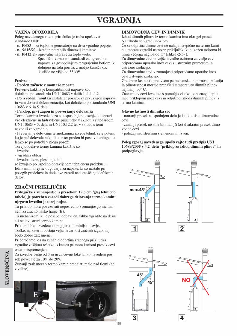
- 110 -- 110 -
VGRADNJA
Poleg navedenega v tem priro niku je treba upoštevatistandarde UNI- n. 10683 - za toplotne generatorje na drva vgradne pogoje. - n. 9615/90 - izra un notranjih dimenzij kaminov- n. 10412:2 - ogrevalne naprave za toplo vodo. Speci ni varnostni standardi za ogrevalne naprave za gospodinjstev z vgrajenim kotlom, ki delujejo na trda goriva, z mo jo kuriš a oz. kuriš e ne višje od 35 kW
Predvsem- Preverite kakšna je kompatibilnost naprave kotdolo eno po standardu UNI 10683 v delih 1 .1.1 .1.2.- inštalater poskrbi za prvi zagon naprave in vam dostavi dokumentacijo, kot dolo eno po standardu UNI 10683 v 6. in 5. delu. - Priklop, prvi zagon in preverjanje delovanjaTermo kamina izvede le za-to usposobljeno osebje, ki opravi vse elektri ne in hidravli ne priklju ke v skladu s standardom UNI 10683 v 5. delu in UNI 10.12.2 ter v skladu s teminavodili za vgradnjo. - Preverjanje delovanje termokamina izvede tehnik šele potem, ko je pe delovala nekoliko ur ter preden bi postavil obloge, da lahko še po potrebi v njega pose e. Torej dodelave termo kamina kakršne so- izvedba - vgradnja oblog- izvedba lizen, pleskanja, itd.se izvajajo po uspešno opravljenem tehni nem preizkusu. Edilkamin torej ne odgovarja za napake, ki so nastale pri posegih predelave in dodelave zaradi nadomeš anja defektnih delov.
tabelo) je potreben zaradi dobrega delovanja termo kamin;njegova izvedba je torej nujna.Ta priklop mora povezovati neposredno z zunanjostjo mehani-zem za zra no nastavljanje (E). Ta mehanizem, ki je posebej dobavljen, lahko vgradite na desni ali na levi strani termo kamina.Priklop lahko izvedete z upogljivo aluminijsko cevjo.To ke, na katerih obstaja velja nevarnost zra nih izgub, naj bodo dobro zatesnjene. Priporo amo, da na zunanjo odprtina zra nega priklju ka vgradite zaš itno rešetko, s katero pa mora koristni presek cevi ostati nespremenjen. Za izvedbe ve je od 3 m in za cevne loke lahko navedeni pre-sek pove ate za 10% do 20%.Zunanji zrak mora v termo kamin prehajati malo nad tlemi (ne z višine).
DIMOVODNA CEV IN DIMNIKIzhod dimnih plinov iz termo kamina ima okrogel presek. Na izhodu se vgradi inox cev.
e se odprtina dimne cevi ne nahaja navpi no na termo kami-nu, morate vgraditi ustrezen priklju ek, ki ni zo en oziroma ki nima ve jega nagiba od 5° (slike1-2-3- ).Za dimovodne cevi novejše izvedbe oziroma za ve je cevi priporo amo uporabo inox cevi z ustreznim premerom in ustrezno izolacijo. Za dimovodne cevi v zunanjosti priporo amo uporabo inox cevi z dvojno izolacijo. Gradbene lastnosti, predvsem pa mehanska odpornost, izolacija in plinotestnost morajo prenašati temperaturo dimnih plinov najmanj 50° C.Zatestnitev cevi izvedete s pomo jo visoko-odpornega lepila med priklopom inox cevi in odprtino izhoda dimnih plinov iz termo kamina.
Glavne lastnosti dimnika so: - notranji presek na spodnjem delu je isti kot tisti dimovodne cevi- zunanji presek ne sme biti manjši kot dvakratni presek dimo-vodne cevi- polo aj nad strešnim slemenom in izven. Poleg zgoraj navedenega upoštevajte tudi predpis UNI 10683/2005 v 4.2 delu “priklop za izhod dimnih plinov” in podpoglavja.
2
45°
45°
3
max.45°
1
NO
4
E
E

- 111 -- 111 -
VGRADNJAe se s termo kaminom vgradi še obloga Edilkamin je potrebno
najprej to no dolo iti namestitev termo pe i in upoštevati tipizbrane obloge. Na osnovi izbrane obloge je namestitev razli na (seznanite se tudi z navodili za vgradnjo, ki so prilo ene embala i za oblogo). Med vgradnjo zagotovite, da bo termo kamin postavljen vodo-ravno. - V steno ali na tla izvrtajte luknjo za zunanjizra ni priklju ek in ga priklopite na mehanizem za nastavljanje zraku termo kamina kot opisano v poglavju “zunanji zra nipriklju ek”. - Priklopite termo kamin na inox dimovodno cev, s takšnim premerom kot je navedeno v tabela termo-tehni nih podatkov in po navodilih iz poglavja “dimovodne cevi”. - Preverite delovanje vseh premikajo ih delov preden vgradite oblogo.
vgradite obloge.
Podzidek obloge mora dovoliti pretok zraka znotraj samih oblog. Zato je potrebno izdelati ustrezne odprtine za pretok zraka. Marmorne, kamnite ali ope ne obloge morajo biti vgrajene tako, da je med njimi in termo kaminom vmesni prostor, da ne bi prišlo do razpok zaradi dilatacije ali prevelikega pregrevanja.
Priporo ljivo je, da radiatorji ne delujejo v prostorih, v katerihje termo kamin vgrajen; topota, ki jo kamin oddaja, je namre dovolj, da ogreva prostor. Nepopolno zgorevanje povzro a zamašitve; Da se temu izognete- uporabljajte le suha polena. - zagotovite, da je v kuriš u ve ja plast gore e erjavice, pre-den dodate druga polena. - ve ja polena vstavite z manjšimi poleni v kuriš e. - preverite, da je temperatura v povratnemu vodu za vodo vsaj 50 °C (uporabite ventil za nadzor temperature).
- Zagotovite, da bo vsaj en radiator deloval.- Spro ite stikala elektronskega regulatorja- Nalo ite termo kamin s suhimi poleni srednje velikosti in pri gite ogenj.- Po akajte nekaj minut dokler je Zgorevanje e dobro spro eno. - Zaprite vrata- Nastavite termo pe na elektronski napravi za nastavljanje (*) pri temperaturi 50÷7 0°C.Opomba Pri prvem v igu lahko nastane vonj po petroleju oziroma plastiki, ki pa mora v kratkem izginit.
UPORABA
Lesene dele zaš itite s protipo arnimi ploš ami.Ti se ne smejo dotikati termo kamina, temve morajo biti primerno oddaljeni vsaj 1 cm, kar omogo a pretok zraka in prepre uje akumulacijo toplote. Dimniško kapo lahko izvedete s protipo arnimi paneli iz mav nih ploš ali podobnega nevnet-ljivega izolirnega materiala. Primerno je, da ima notranjostdimniške kape zra ni priklju ek spodaj (med vrati in gredo) za boljše zra enje, ki bo s konvekcijo prehajalo skozi rešetko zgoraj in na tak na ina pridobivalo toploto in prepre evalo prevelika pregrevanja. Dimniška kapa mora biti opremljena z ustreznimi vrati za vzdr evanje vseh spojnih delov.
Poleg zgoraj navedenih navodil, upoštevajte tudi standard UNI 10683 v poglavjih 4.4 in 4 “izolacije, dodelave, obloge in varnostni napotki”.
-nicami.
OKVIR ZA (opcija)Za la je prilaganje med oblogami in termokaminom lahko vgradite okvir (A) na kaminsko odprtino.
3-vodni elektroventil- V fazi v iga 3 vodni ventil (*) a 3 preusmeri tok vode ne-posredno v termo kamin; ko je prese ena nastavljena tempe-ratura, ta ventil (*) preusmeri tok dovoda v napravo (kar ni odvisno od vgrajene opreme).
Loputa by-pass kanala- Ko zaprete vrata, se loputa samodejno zapre in preusmeri tok dimnih plinov, kar izboljša u inkovitost termo kamina. - Ko odprete vrata, se by-pass loputa samodejno odpre, dimni plini neposredno dose ejo dimno cev, tako da ne prehajajo skozi glavne odprtine termo kamina.
Ventil za izpust toplotee temperatura vode prekora i 90°C (na primer e ste nalo ili
preve polen), se spro i ventil za izpust toplote in hkrati tudi alarm. V tem primeru postopajte tako-ne nalagajte dodatnih polen in po akajte, da se temperatu-ra zni a pod 80°C; preverite svetlobne lu ke na napravi za elektronsko nastavljanje. Za termo kamine z opremo za proizvajanje sanitarne tople vode odprite pipo za toplo vodo, da se naprava hitreje ohladi.
mav ne ploš e
A
(*) sestavni deli naprave, ki jih priskrbi inštalater.
A
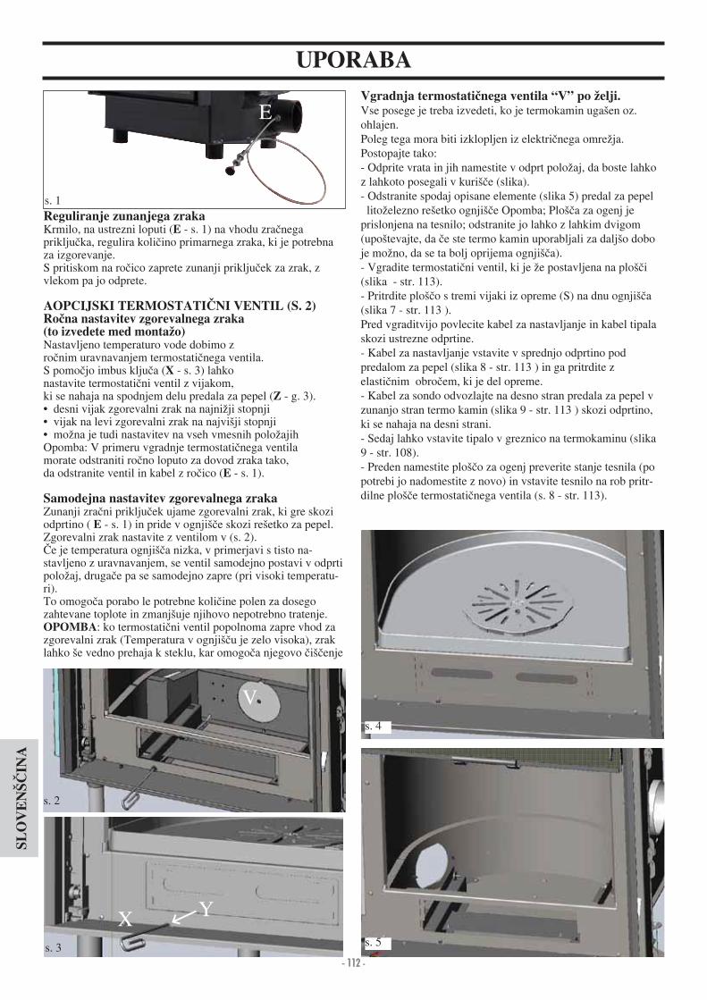
- 112 -- 112 -
UPORABA
E
s. 1
s. 2
s. 3
V
X Y
Vse posege je treba izvedeti, ko je termokamin ugašen oz. ohlajen. Poleg tega mora biti izklopljen iz elektri nega omre ja. Postopajte tako- Odprite vrata in jih namestite v odprt polo aj, da boste lahko z lahkoto posegali v kuriš e (slika). - Odstranite spodaj opisane elemente (slika 5) predal za pepel lito elezno rešetko ognjiš e Opomba; Ploš a za ogenj je prislonjena na tesnilo; odstranite jo lahko z lahkim dvigom (upoštevajte, da e ste termo kamin uporabljali za daljšo dobo je mo no, da se ta bolj oprijema ognjiš a).- Vgradite termostati ni ventil, ki je e postavljena na ploš i (slika - str. 113). - Pritrdite ploš o s tremi vijaki iz opreme (S) na dnu ognjiš a (slika 7 - str. 113 ). Pred vgraditvijo povlecite kabel za nastavljanje in kabel tipala skozi ustrezne odprtine. - Kabel za nastavljanje vstavite v sprednjo odprtino podpredalom za pepel (slika 8 - str. 113 ) in ga pritrdite z elasti nim obro em, ki je del opreme. - Kabel za sondo odvozlajte na desno stran predala za pepel v zunanjo stran termo kamin (slika 9 - str. 113 ) skozi odprtino, ki se nahaja na desni strani. - Sedaj lahko vstavite tipalo v greznico na termokaminu (slika 9 - str. 108). - Preden namestite ploš o za ogenj preverite stanje tesnila (po potrebi jo nadomestite z novo) in vstavite tesnilo na rob pritr-dilne ploš e termostati nega ventila (s. 8 - str. 113).
Reguliranje zunanjega zrakaKrmilo, na ustrezni loputi (E - s. 1) na vhodu zra nega priklju ka, regulira koli ino primarnega zraka, ki je potrebna za izgorevanje. S pritiskom na ro ico zaprete zunanji priklju ek za zrak, z vlekom pa jo odprete.
Nastavljeno temperaturo vode dobimo z ro nim uravnavanjem termostati nega ventila.S pomo jo imbus klju a (X - s. 3) lahko nastavite termostati ni ventil z vijakom, ki se nahaja na spodnjem delu predala za pepel (Z - g. 3). desni vijak zgorevalni zrak na najni ji stopnji vijak na levi zgorevalni zrak na najvišji stopnji mo na je tudi nastavitev na vseh vmesnih polo ajih
Opomba V primeru vgradnje termostati nega ventilamorate odstraniti ro no loputo za dovod zraka tako, da odstranite ventil in kabel z ro ico (E - s. 1).
Samodejna nastavitev zgorevalnega zrakaZunanji zra ni priklju ek ujame zgorevalni zrak, ki gre skozi odprtino ( E - s. 1) in pride v ognjiš e skozi rešetko za pepel. Zgorevalni zrak nastavite z ventilom v (s. 2).
e je temperatura ognjiš a nizka, v primerjavi s tisto na-stavljeno z uravnavanjem, se ventil samodejno postavi v odprti polo aj, druga e pa se samodejno zapre (pri visoki temperatu-ri). To omogo a porabo le potrebne koli ine polen za dosego zahtevane toplote in zmanjšuje njihovo nepotrebno tratenje. OPOMBA ko termostati ni ventil popolnoma zapre vhod za zgorevalni zrak (Temperatura v ognjiš u je zelo visoka), zrak lahko še vedno prehaja k steklu, kar omogo a njegovo iš enje
s.
s. 5

- 113 -- 113 -
- Saje, ki se usedajo na notranje stene ognjiš a, zmanjšujejo u inkovitost toplotne izmenjave. - Torej je potrebno termo kamin periodi no o istiti, vodo nasta-vite na i 80÷85°C, da se saje zmeh ajo in jih nato odstranite z jekleno š etko.
- iš enje opravite s istilnim sredstvom za kerami na stekla (Glasskamin Edilkamina). - iš enje izvedite pri ohlajeni pe i. - Odpiranje vrat navzven je mo no le, ko je v popolnoma zapr-tem polo aju. - Za odpiranje vrat navzven vstavite ro aj na zati med kon-strukcijo in vrati in ga zavrtite (s. 12).
Odpiranje vrat- Vrata odprite s pomo jo ustreznega snemljivega ro aja iz opreme (s. 10)- Isti ro aj lahko pritrdite na vrata s pomo jo št. 2 manjših vijakov.
NAVODILA ZA UPORABO
s. 6
s. 7
s. 8
s. 9
POGLED ZADNJE STRANI
Io tipalo
kabel za nastavljanjeS
S S
SS
S
kabel za nastavljanje
kabel za nastavljanje
Io tipalo
Io tipalo
Tesnilo
Vrata so opremljena s protiute mi, ki zagotavljajo njihovo samodejno zapiranje. eprav je termo kamin e nastavljen, lahko ute znova nastavite tako, da vstavite eno ali ve ploš ic (P – slika 11), ki jih dobite z opremo.
P
s.10
s. 11
s. 12

- 114 -- 114 -
VOD Z UPORABO KIT 1ACS: Topla sanitarna vodaAF: Mrzla vodaEV: 3-vodni elektroventilF: Merilec tokaMI: Dvi ni vod v napravoNA: Normalno odprtaNC: Normalno zaprtaP: rpalka (cirkulator)RA: RadiatorjiRE: Elektronskia naprava za nastavljanjeRI: Povratni vodS: IzpustSc 20: 20-PLOŠ NI IZMENJEVALECST: Tipalo za temperaturoTC: Termo kamin V: VentilVE: Odprta ekspanzijska posodaVSP: Termi ni varnostni ventilVST: Ventil za izpust toploteJa: Samodejni izpustni ventil
Kit 1 olajša delo inštalaterjem; zajema vse dele, ki so potrebni za pravilno vgradnjo naprave.
blazinic.
FUNKCIJE STIKALAStikalo OFF vse zaprto
prisiljena rpalka Nastavljeni ventilStikalo AUTOC nastavljena rpalka Nastavljeni ventilIzbira alarma OFF polo aj izklju en akusti ni signal
ON
OFF
VklopIzklopakusti nialarm
Nastavitevventil 20-80°C
Prikaz
rpalka
3-vodni elektroventil
Napajanje230Vac
varovalka
KIT 1 koda 261880
Nastavitevrpalka 20-80°C
Merilnik pretoka teko inePriklopite kontaktnormalno zaprt
Tipalo (vstavitev ustrezen jašek)
Spro ena rpalkaAlarrm prekora itve temperature 3-vodni elektroventil
1. Kolektor iz medenine 1” M-F2. Krogli asti ventil 1”3. rpalka z vpregami1” ½(219660). Ne povratni ventil 1” (261910)
5. 3-vodni elektroventil ” M-F (1 3330)6. Spojni deli iz medenine7. 30-ploš ni izmenjevalec za izmenjavos
sistemom plinskega kotla (216620)8. 20 -ploš ni izmenjevalec za proizvajanjeto-
ple sanitarne vode (205270)9. Ventil za izpust toplote “ (729 0)10. Varnostni ventil 1,5 bar od” (1 3260)11. Merinik pretoka teko in (220830)12. Jašek za termometer ½” +Tipalo(175960)13. Elektronska naprava za nastavljanje
(220780)A Dvii ni vod v napravo ¾”B Povratni vod ¾”C Povratni vod v termokamin ¾”D Dovod v kamin 1”E Mrzla sanitarna voda ½”F Topla sanitarna voda ½”
Var
nost
na c
ev Ø
> 2
8 m
m
20-
ploš
ni
izm
enje
vale
c
Regulator oprema kita
Poln
ilni v
od Ø
> 1
8 m
m
elektr. omre je
kole
ktor

- 115 -- 115 -
STENSKI KOTEL Z UPORABO KIT 2
Kit 2 olajša inštalaterjem delo vgradnje; vsebuje vse dele, ki so potrebni za pravilno vgradnjo izdelka. -
nih blazinic.
1. Kolektor iz medenine 1” M-F2. Krogli asti ventil 1”3. rpalka z vpregami1” ½(219660). Ne povratni ventil 1” (261910)
5. 3-vodni elektroventil ” M-F (1 3330)6. Spojni deli iz medenine7. 30-ploš ni izmenjevalec za izmenjavos
sistemom plinskega kotla (216620)8. 20 -ploš ni izmenjevalec za proizvajanjeto-
ple sanitarne vode (205270)9. Ventil za izpust toplote ¾” (729 0)10. Varnostni vetnil 1,5 bar od ¾” (1 3260)11. Merinik pretoka teko ine (220830)12. Jašek za termometer ½”+Tipalo(175960)13. Elektronska naprava za nastavljanje
(220780)A Dvii ni vod v napravo ¾”B Povratni vod ¾”C Povratni vod v termokamin ¾”D Dovod v kamin 1”E Mrzla sanitarna voda ½”F Topla sanitarna voda ½”
rpalka A
KIT 2 koda 261890
Spro ena rpalkaAlarrm prekora itve temperature 3-vodni elektroventil
ON
OFF
rpalka B
Nastavitev temperaturemin. odobritev zagona
rpalkae20-80°C
FUNKCIJE STIKALAStikalo OFF vse zaprto
prisiljena rpalka Nastavljeni ventilStikalo AUTOC nastavljena rpalka Nastavljeni ventilIzbira alarma OFF polo aj izklju en akusti ni signal
AF: Mrzla vodaCA: Stenski kotelMI: Dvi ni vod v napravoP: rpalka (cirkulator)RA: RadiatorjiRE: Elektronskia naprava za nastavljanjeRI: Povratni vodS: IzpustJa: Samodejni izpustni ventil Sc 30: 30-PLOŠ NI IZMENJEVALECST: Tipalo za temperaturoTC: Termo kamin V: VentilVR: Ne povratni ventilVSP: Termi ni varnostni ventilVST: Ventil za izpust toplote
VklopIzklopakusti nialarm
Nastavitevventil 20-80°C
Prikaz
Napajanje230Vac
varovalka
Var
nost
na c
ev Ø
> 2
8 m
m30
- pl
ošni
izm
enje
-va
lec
Regulator oprema kita
Poln
ilni v
od Ø
> 1
8 m
m
elektr. omre je
kole
ktor

- 116 -- 116 -
STENSKI KOTEL Z UPORABO KIT 3
Kit 3 olajša inštalaterjem delo vgradnje; vsebuje vse dele, ki so potrebni za pravilno vgradnjo izdelka.-
nih blazinic.
KIT 3 koda 261900
1. Kolektor iz medenine 1” M-F2. Krogli asti ventil 1”3. rpalka z vpregami1” ½(219660). Ne povratni ventil 1” (261910)
5. 3-vodni elektroventil ” M-F (1 3330)6. Spojni deli iz medenine7. 30-ploš ni izmenjevalec za izmenjavos
sistemom plinskega kotla (216620)8. 20 -ploš ni izmenjevalec za proizvajanjeto-
ple sanitarne vode (205270)9. Ventil za izpust toplote ¾” (729 0)10. Varnostni vetnil 1,5 bar od ¾” (1 3260)11. Merinik pretoka teko ine (220830)12. Jašek za termometer ½” + Tipalo(175960)13. Elektronska naprava za nastavljanje
(220780)A Dvii ni vod v napravo ¾”B Povratni vod ¾”C Povratni vod v termokamin ¾”D Dovod v kamin 1”E Mrzla sanitarna voda ½”F Topla sanitarna voda ½”
ON
OFF
3-vodni elektroventil
Nastavitevrpalka 20-80°C
Merilnik pretoka teko inePriklopite kontaktnormalno zaprt
FUNKCIJE STIKALAStikalo OFF vse zaprto
prisiljena rpalka Nastavljeni ventilStikalo AUTOC nastavljena rpalka Nastavljeni ventilIzbira alarma OFF polo aj izklju en akusti ni signal
ACS: Topla sanitarna vodaAF: Mrzla vodaCA: Stenski kotelEV: 3-vodni elektroventilF: Merilec tokaMI: Dvi ni vod v napravoNA: Normalno odprtaNC: Normalno zaprtaP: rpalka (cirkulator)RA: RadiatorjiRE: Elektronskia naprava za nastavljanjeRI: Povratni vodS: IzpustSc 20: 20-PLOŠ NI IZMENJEVALECSc 30: 30-PLOŠ NI IZMENJEVALECTC: Termo kamin V: VentilVE: Odprta ekspanzijska posodaVR: Termi ni varnostni ventilVSP: Termi ni varnostni ventilVST: Ventil za izpust toploteJa: Samodejni izpustni ventil
rpalka Arpalka B
Nastavitevventil 20-80°C
Prikaz
Napajanje230Vac
varovalka
Var
nost
na c
ev Ø
> 2
8 m
m
30-
ploš
ni iz
men
je-
vale
c
Regulator oprema kita
Poln
ilni v
od Ø
> 1
8 m
m
20-
ploš
ni
izm
enje
vale
c
elektr. omre je
kole
ktor

- 117 -- 117 -
STENSKI KOTEL Z UPORABO KIT N3
Kit N3 olajša inštalaterjem delo vgradnje; vsebuje vse dele, ki so potrebni za pravilno vgradnjo izdelka.-
nih blazinic.
KIT N3 koda 627690
1. Dovod v ogrevalni sistem G 3”2. Dovod iz termokamina G 3 ”3. Povratni vod v termokamin G 3 ”. Povratni vod iz ogrevalnega telesa G3 ”
5. Vhod mrzel sanitarne vode G 1 2”6. Dovod tople vode v sanitarne naprave D 1 2”7. Kombinrani varnostni ventil temperature in tlaka8. Merilnik pretoka teko ine Zra ni izpustni ventil G 3 8”
rpalka tokokroga termo kamina9. 3-vodni ploš ati izmenjevalec 10. Zaporni ventil G 1”11. Elektronska naprava za nastavljanje s kabli12. Ustrezna odprtina za prehod kablov 13. Napajalni kabel1 . Odprtina za prehod kablov15. Napajalni kabel16. Kabli rpalke ogrevalne naprave (faza, nevtralni vod,
ozemljitev)17. Tipalo za temperaturo18. Tokokrog termostata okolja
VEAF
S V
RE
RETE
ST
V
S
V
Tu
bo
di
cari
co
Ø>
18
mm
Tu
bo
di
sic
ure
zza
Ø>
28
mm
V
CA
ACS
PRF
ACS
AF
Ja
TA
P1
VVs
Sc
TCN
ELETTRICA
INT
VR V
VR
RETE
IDRICA
VR
VR
MI
RA
RI
V
COLLETTORE
VR
V
V
V
V
V
Circuito collegabile altermostato ambiente(a discrezione del cliente)
Da collegare necessariamenteal circolatore dell’impianto
di riscaldamento PR
12 3 4
56
7
8
9
10
119
9
12
13
12 3 5
4 67
14
15 16 17
Passacavi
18
rpalkaprimarna
OFF
Set privolitvePrimarna rpalka30 - Bat.
ON
rpalkaogrevanje
EV prednost sanitarna
Mre a 230 Vac50 Hz + - 10%
Set privolitverpalka ogrevanja
0-80°C
Termostatokolja
Senzor pretoka pretok
Tipalo za dvi ni vodPrivolitevalarm
ACS: Topla sanitarna vodaAF: Mrzla vodaCA: Stenski kotelEV: 3-vodni elektroventilF: Merilec tokaINT: Glavnio stikaloMI: Dvi ni vod v napravoPR: rpalka (cirkulator)P1: rpalka za primarni hidravli ni tokokrogJa: Samodejni izpustni ventilRA: RadiatorjiRE: Elektronskia naprava za nastavljanjeRI: Povratni vodS: IzpustSc: PLOŠ NI IZMENJEVALECST: Tipalo za temperaturoTCN: Termostat z zaslonom na dotikV: Varnostni ventilVE: Odprta ekspanzijska posodaVR: Termi ni varnostni ventil
Zaš ita za kable
Var
nost
na c
ev Ø
> 2
8 m
m
Poln
ilni v
od Ø
> 1
8 m
m
elektr. omre je
sistem lahko priklopite na sobni termostat (na eljo stanke)
Obvezno priklopite na cirkulator ogrevalne naprave PR
hidravli no omre je
kolektor

- 118 -- 118 -
STENSKI KOTEL Z UPORABO KIT N3 BIS
Kit N3 BIS olajša inštalaterjem delo vgradnje; vsebuje vse dele, ki so potrebni za pravilno vgradnjo izdelka.-
nih blazinic.
KIT N3 BIS koda 627860
1. Dovod v ogrevalni sistem G 3 ”2. Dovod iz termo kamina G 3 ”3. Povratni vod v termo kamin G 3 ”. Povratni vod iz ogrevalne naprave G 3 ”
5. Vhod mrzle sanitarne vode G 1 2”6. Dovod tople vode v sanitarne naprave D 1 2”7. Dovod tople sanitarne vode G 1 2* iz priklju enega
kotla8. Kombinirani varnostni ventil temperature intlaka
(90°C - 3 bar)9. Merilec toka10. 3-vodni preusmerjevalni elektroventil11. Zra ni izpustni ventil G 3 8”12. rpalka tokokroga termo kamina13. rpalka za tokokrog ogrevalne naprave1 . Zaporni ventil G 1”15. 3-vodni ploš ati izmenjevalec G 3 ”16. Elektronska naprava za nastavljanje s kabli17. Ustrezna odprtina za prehod kablov18. Napajalni kabel19. Tipalo za temperaturo20. Tokokrog termostata okolja
VEAF
S V
RE
ST
S
V
Tu
bo
dicari
co
Ø>
18
mm
Tu
bo
disic
ure
zza
Ø>
28
mm
CA
ACS
VR
MI
RA
RI
V
ACS
AF
Ja
TA
EV
P2
P1
V
V
Sc
F
Vs
RETE
ELETTRICA
INT
VR V
TCN
V
V
V
By-p
ass
VR
Sc
RETE
IDRICA
COLLETTORE
VR
V
V
V
V
V
Circuito collegabile altermostato ambiente(a discrezione del cliente)
12 3 4
5 6 7
8
9
10
11
12
1314
14
15
111111
1111
1617
12 3
4
5
8
6
7
2019
Passacavi
17
18
rpalkaprimarna
OFF
Set privolitvePrimarna rpalka30 - Bat.
ON
rpalkaogrevanje
EV prednost sanitarna
Mre a 230 Vac50 Hz + - 10%
Set privolitverpalka ogrevanja
0-80°C
Termostatokolja
Senzor pretoka pretok
Tipalo za dvi ni vodPrivolitevalarm
Zaš ita za kable
ACS: Topla sanitarna vodaAF: Mrzla vodaCA: Stenski kotelEV: 3-vodni elektroventilF: Merilec tokaINT: Glavnio stikaloMI: Dvi ni vod v napravoPR: rpalka (cirkulator)P1: rpalka za primarni hidravli ni tokokrogJa: Samodejni izpustni ventilRA: RadiatorjiRE: Elektronskia naprava za nastavljanjeRI: Povratni vodS: IzpustSc: PLOŠ NI IZMENJEVALECST: Tipalo za temperaturoTCN: Termostat z zaslonom na dotikV: Varnostni ventilVE: Odprta ekspanzijska posodaVR: Termi ni varnostni ventil
Var
nost
na c
ev Ø
> 2
8 m
m
Poln
ilni v
od Ø
> 1
8 m
melektr. omre je
sistem lahko priklopite na sobni termostat (na eljo stanke) hidravli no
omre je
kolektor

- 119 -- 119 -
ELEKTRONSKI REGULATORDELOVANJE- Nadzorna naprava: termometer- Akusti ni alarm (AA) Alarm prekora itve temperature (SS)
Ta alarm se vklopi, ko temperatura vode prese e 90°C in opo-zori uporabnika, da takoj prekine z napajanjem goriva. Delovanje akusti nega alarma lahko izklopite s stikalom (AA); funkcija alarma ostaja vseeno aktivna, kot ka e tudi svetlobna lu ka o prekora eni temperaturi (SS). Za ponovno vzpostavitev za etnih vrednosti, morate najprejzni ati temperaturo vode v termo kaminu, nato ponovnospro ite stikalo (AA). .
- Naprava za napajanje (sistema tokokroga): stikalo MAN-OFF-AUTO (S) Kontrolna lu rpalke (SP)
V ro nem na inu rpalka vedno deluje, v OFF na inu je rpalka izklopljena; v AUTO na inu spro ite rpalko naprave
z eleno temperaturo z notranjim nastavljanjem (RIC) od 20 a 80°C (vrednost je e nastavljena na 20°C)
- Naprava za delovanje (sistem za nastavljanje): Nastavljanje (R) za odpiranje 3-vodnega ventila Svetlobna lu (SV) delovanje 3-vodnega ventila
Ko temperatura teko ine dose e nastavljeno vrednost z regula-torjem, 3-vodni ventil preusmerja teko ine k radiatorjem in se pri ge svetlobna lu delovanje (sv). ko se temperatura teko ine spusti pod nastavljeno vrednost, sistem nastavljanja odpre elektri ni tokokrog, 3-vodni ventil “posreduje” teko ino neposredno v postavljen vodoravno.pozor med navadnim delovanjem, preverite, da so vse svetlobne lu i (sv) in (sp) pri gane.
NAMESTITEVElektronski regulator vgradite v neposredni bli ini termo kamina. Tipalo naprav za delovanje, zaš ito in preverjanje morate vgra-diti neposredno na termo kamin oziroma na dovode do najve 5 cm razdalje od termo kamina oziroma pred kateri koli zapor-nim elementom. Tipalo morate vstaviti v ustrezen jašek.
VGRADNJA
stikalo (S) AUTO-OFF-MAN mora biti na OFF. Za primerno vgradnjo elektronskega regulatorja odvijte vijak in snemite udarno glavo, pritrdite ga na steno z vlo ki iz opreme; izvedite vse priklope kot prikazano v shemi (ki je prilo enaembala i), pri tem pa bodite pozorni pri izvajanju priklju kov;odvijte kable in jih vstavite v ustrezne kanale, ki ustrezajo veljavnim standardom; potem ponovno vstavite udarno glavo in zavijte zapiralni vijak. Za 3-vodni ventil uporabite rjavi IO (faza) in plavi IO (nevtral-ni vod), ki ju morate priklopiti na sponki 5 in 6 regulatorja. Za rumeno-zeleni IO je potrebna ozemljitev. Za pravilni priklop regulatorja z napravo, sledite navodilom vgradnje, ki so prilo ene embala i.
LEGENDAAA stikalo za akusti ni alarmR nast. odpiranje 3-vodnega ventila (KIT 1 - 3)R nast. delovanje rpalk (KIT 2)RIC nastavitev notranje rpalkeS stikalo MAN-OFF-AUTOSP svetlobna lu rpalkeSS svetlobna lu prese ka temperatureTT Tipalo temperatureSV svetlobna lu 3-vodnih ventilov (KIT 1-3)SV nast. rpalk (KIT 2)
Napajanje (+15 - 10%) Vac 230
Zaš itna stopnja IP 0
min max temperatura prostora °C 0÷+50
Dol ina tipala mt 1,2
termometer °C 30÷90
Nosilnost kontaktov rpalk, najve ja W 00
Nosilnost kontaktov 3-vodnega ventila, najve ja W 250
VAROVALKA mA 500
Priklop, prvi v ig in preverjanje lahko izvedejo le za-to uspo-sobljeni tehniki, ki opravijo ves priklju ke v skladu z veljavno zakonodajo in predvsem z zk. 6 90 ter ob upoštevanju vseh navodil, ki so navedene v tem priro niku.
za varnost oseb. Na napravo in na elektri ni tokokrog je potrebno vgraditi diferencialno stikalo, poleg tega morajo imeti rpalke, ventili in ostali deli naprave skupaj s kovinskimi deli termokamina ustrezno ozemljitev.
Elektronski regulator za nadzor omogo a spremljanjedelovnih pogojev in je opremljen s- stikalom MAN-OFF-AUTO (S)- z lestvico temperature (ST)- z akusti nim alarmom (AA)- z regulatorjem za odpiranje 3-vodnega ventila (RO (KIT1-3)- z regulatorjem za delovanje rpalk (R) (KIT 2)- z nastavkom za nastavitev rpalke (RIC)- svetlobna lu 3 -vodnega ventila (SV) (KIT 1-3)- svetlobna lu regulatorjev rpalk (SV) (KIT 2)- svetlobna lu prese ka temperature (SS)- svetlobna lu rpalke (SP)

- 120 -- 120 -
DODATNA OPREMA
Kit ventilov (21600) sestavljajo-samodejni ventil z zra nim izpustom-varnostni ventil 1,5 bar-0b, -izpust toplote 90°C
Elektronski regulator (220780)
ELEKTRONSKI REGULATOR (dodatna oprema) omogo a nadzor nad delovnimi pogoji in je opremljen- s stikalom MAN-OFF.AUTO- z lestvica temperature- z akusti nim alarmom- z regulatorjem za odpiranje 3-vodnega ventila- z nastavkom za notranjo nastavitev rpalke- s svetlobno lu ko rpalke- svetlobna lu 3-vodnega ventila- svetlobna lu za prese ek temperatureElektronski regulator je del opreme razli nih monta nih kitov (kot dodatna oprema)
VODO (kot dodatna oprema)Gre za enostavno in cenovno ugodno napravo, ki proizvaja to-plo sanitarno vodo od 13-1 litrov na minuto, glede na nastavlje-no mo naprave. Izmenjevalnik se lahko vgradi na dovodno cev radiatorjev, na najprimernejši polo aj glede na pogoje naprave. Njegova velika prednost je v tem, da ga lahko odstra-nite za dela vzdr evanja ali nadomeš anja, ne da bi posegali v termo kamin.
kito-ov (dodatna oprema)
3-VODNI IZMENJEVALNIK (dodatna oprema)Proizvaja toplo vod za sanitarni sistem in za sekundarni sistem (radiatorje) in izklopi (v primerjavi s 3 kitom) delovanje 3-vodnega ventila in enega izmenjevalnika z orebreno ploš o.
Mrzla vodaiz vodovodnega omre ja
povratna voda vtermo kamin
Topla voda izTermo kamina
topla vodav sanitarne naprave
3 - v o d n i elektroventil 1” (1 3330)za nastavitev vodnega dotokav napravo
Elektronski regulator (220780)
Merilnik pre-toka teko ine (220830)
rpalkaUPS 25-50 koda 219660UPS 25-60 koda 238270
izmenjevalnik30-ploš ni izmenjevalnikza napravo216620)
Scambiatore a 3 vie cod. 627780
Ra enjH
2OCEANO 15 koda 750820
H2OCEANO 23 koda 23 560
H2OCEANO 28 koda 236710
izmenjevalnik20-ploš ni izmenjevalnik za sanitarno262570)
topla vodaiz termo kamina
Mrzla vodanaprave
Mrzla voda zaSanitarne naprave
Hidravli ni kit V za modele z ODPRTO EKSPANZIJSKO POSODO koda 7 3 30 (monta a na desno)
Daljinski zaslonkoda 7 1180
Termostati ni ventilH
2OCEANO 15 koda 739 60
H2OCEANO 23 koda 739 0
H2OCEANO 28 koda 739 50
Okvir za glavno odprtinoH
2OCEANO 15 koda 739390 - cm. 63x63
H2OCEANO 23 koda 739370 - cm. 77x68
H2OCEANO 28 koda 739380 - cm. 95x68
Nosilec za hidravli ne kite A1-A2-B-C-D(monta a na desni strani)H
2OCEANO 15 koda 739510
H2OCEANO 23 koda 739 70
H2OCEANO 28 koda 739 90

- 121 -
H2OCEANO 15

- 122 -
ITA
LIA
NO
ENG
LISH
FRA
NÇ
AIS
ESPA
ÑO
LD
EUTS
CH
NED
ERLA
ND
Sco
dpz
.
1S
truttu
ra s
alda
ta V
AB
olie
r stru
ctur
e op
en ta
nkS
truct
ure
chau
dièr
e va
se o
uver
tE
stru
ctur
a de
la c
alde
ra v
aso
abie
rtoH
eizk
esse
lkör
per o
ffene
sau
sdeh
nung
sgef
äss
Ket
elst
ruct
uur o
pen
vat
7392
401
1* S
truttu
ra s
alda
ta V
C* B
olie
r stru
ctur
e cl
osed
tank
* Stru
ctur
e ch
audi
ère
vase
ferm
é* E
stru
ctur
a de
la c
alde
ra v
aso
cerr
ado
* Heiz
kess
elkör
per g
esch
losse
nes a
usde
hnun
gsge
fäss
* Ket
elst
ruct
uur g
eslo
ten
vat
7361
801
2P
iano
fuoc
o in
ghi
saH
earth
mad
e of
cas
t iro
nP
lan
feu
en fo
nte
Pla
no d
el fu
ego
en h
ierr
o fu
ndid
oB
renn
raum
bode
n au
s G
usse
isen
Vuur
oppe
rvla
k in
gie
tijze
r62
6780
1
3A
ssie
me
front
ale
Fron
t ass
embl
y E
nsem
ble
front
al
Gru
po fr
onta
l Fr
onta
le E
inhe
it Vo
orka
nt
7362
501
4A
ssie
me
anta
mon
tata
Mou
nted
doo
r ass
embl
yE
nsem
ble
porte
mon
tée
Gru
po p
uerta
mon
tada
Bau
grup
pe m
ontie
rter
rge
lG
emon
teer
de d
eur
7364
401
5A
ssie
me
scor
rimen
to S
xLe
ft sl
ider
Cou
lisse
gau
che
Des
plaz
amie
nto
izqd
o.K
nagg
eA
fvoe
r lin
ks73
6690
1
6G
uide
sco
rrim
ento
Slid
er g
uide
Gui
des
de c
oulis
sage
Guí
as d
e de
spla
zam
ient
oW
ärm
esch
utzg
riff z
ur T
üröf
fnun
gG
elei
ders
afv
oer
2153
001
7C
usci
netto
Bea
ring
Cou
ssin
et
Coj
inet
e La
ger
Dem
pertj
e68
9160
2
8A
ssie
me
porta
sco
rrev
ole
sxLT
slid
ing
door
ass
embl
yE
nsem
ble
porte
cou
lissa
nte
gauc
heG
rupo
pue
rta c
orre
dera
izq.
Bau
grup
pe S
chie
betü
r lin
ksS
chui
fdeu
r l73
7010
1
9M
olla
spi
nta
anta
Doo
r pus
h sp
ring
Res
sort
de p
ouss
ée p
orte
Mue
lle e
mpu
je p
uerta
Dru
ckfe
der T
ürüg
elD
uwve
er d
eur
7383
902
10P
rolo
giu
nizi
one
scor
rimen
ti S
lide
coup
ling
pro
le P
rol d
e jo
nctio
n co
ulis
sem
ents
Per
l uni
n de
sliz
amie
ntos
Ver
bind
ungs
pro
l Gle
itlau
f P
roel
ver
bind
ing
schu
iven
7369
001
11G
omm
ino
Pad
Bou
chon
Tap
n de
gom
a G
umm
i P
akki
ng23
4420
2
12Le
va s
icur
ezza
per
chi
usur
aS
afet
y le
ver f
or c
losu
re
Levi
er s
écur
ité p
our f
erm
etur
e P
alan
ca d
e se
gurid
ad p
ara
cier
re
Sic
herh
eits
hebe
l für
Ver
riege
lung
Ve
iligh
eids
hend
el v
oor a
fslu
iting
73
6990
2
13A
ssie
me
scor
rimen
to D
xR
ight
slid
erC
oulis
se d
roite
Des
plaz
amie
nto
dcho
Stif
t für
Tür
aufh
ängu
ngA
fvoe
r rec
hts
7367
401
14A
ssie
me
porta
sco
rrev
ole
dxR
T sl
idin
g do
or a
ssem
bly
Ens
embl
e po
rte c
oulis
sant
e dr
oite
Gru
po p
uerta
cor
rede
ra d
ch.
Bau
grup
pe S
chie
betü
r rec
hts
Sch
uifd
eur r
7367
701
15A
ssie
me
pern
o se
rrat
ura
Lock
pin
ass
embl
y E
nsem
ble
gouj
on s
erru
reG
rupo
per
no c
erra
dura
B
augr
uppe
Ver
riege
lung
sstif
tP
en s
lot
7368
002
16A
ssie
me
porta
pul
eggi
eP
ulle
y ho
lder
ass
embl
yE
nsem
ble
porte
pou
lies
Gru
po p
orta
pol
eas
Einh
eit T
ür R
iem
ensc
heib
enD
eur m
et k
atro
llen
7368
301
17P
uleg
gia
con
bocc
ola
Pul
ley
with
bus
hing
Pou
lie a
vec
doui
lleP
olea
con
cas
quill
o S
eils
chei
be m
it La
ger
Kat
rol m
et b
us21
2050
2
18A
ssie
me
cont
rapp
eso
Cou
nter
bala
nce
Con
trepo
ids
Con
trape
soG
egen
gew
icht
Con
trage
wic
ht73
9800
1
19Fu
ne L
.100
0 m
mC
ount
erba
lanc
e ro
pe L
.100
0 m
mC
âble
con
trepo
ids
L.10
00 m
mC
able
con
trape
so L
.100
0 m
mG
egen
gew
icht
-Sei
l L.1
000
mm
Kab
el c
ontra
gew
icht
L.1
000
mm
1537
601
20C
arte
r con
trapp
eso
Inte
rcha
ngea
ble
coun
terb
alan
ce c
asin
gC
arte
r con
trepo
ids
Cár
ter c
ontra
peso
B
eids
eitig
es G
egen
gew
icht
-Geh
äuse
Bek
ledi
ng c
ontra
gew
icht
73
7000
1
21Fe
rmo
silic
one
D15
Sili
cone
sto
p D
15C
roch
et s
ilico
ne D
15
Tope
sili
cona
D15
Sili
kons
iche
rung
D15
S
ilico
nen
pal D
15
2311
202
22B
usso
la
letta
ta
ssag
gio
sicu
rezz
eTh
read
ed s
afet
y de
vice
xi
ng b
ush
Dou
ille
leté
e xa
tion
sécu
rités
Cas
quill
o ro
scad
o ja
cin
prot
ecci
ones
Gew
inde
hülse
Bef
estig
ung
Sich
erhe
itsei
nrich
tung
enB
us s
chro
efdr
aad
beve
stig
ing
bev.
7369
803
23La
mie
ra b
ase
Bas
e sh
eet
Tôle
bas
e C
hapa
bas
e S
ocke
lble
ch
Bas
ispl
aat
7370
501
24A
ssie
me
cass
etto
cen
ere
Ash
pan
ass
embl
yE
nsem
ble
tiroi
r cen
dres
Gru
po c
ajn
ceni
zas
Asc
henl
aden
-Ein
heit
Asl
ade
7369
601
25S
uppo
rto c
asse
tto c
ener
e de
stro
RT
Ash
pan
sup
port
Sup
port
tiroi
r à c
endr
es d
roite
S
opor
te c
ajn
ceni
zas
dch.
Hal
teru
ng A
sche
nlad
e re
chts
Ste
un a
slad
e re
chts
7370
301
26S
uppo
rto c
asse
tto c
ener
e si
nist
roLT
Ash
pan
sup
port
Sup
port
tiroi
r à c
endr
es g
auch
eS
opor
te c
ajn
ceni
zas
izq.
Hal
teru
ng A
sche
nlad
e lin
ksS
teun
asl
ade
links
7370
401
27G
riglia
cen
ere
Ash
gril
lG
rille
cen
dres
Par
rilla
cen
izas
Asc
henb
ehäl
ter
Asl
a73
5970
1
28La
mie
rino
chiu
sura
pas
sagg
io s
onda
Pro
be p
assa
ge c
losu
re p
late
T
ôle
ne p
our f
erm
etur
e du
pas
sage
son
de C
hapa
de
cier
re p
aso
sond
a V
errie
gelu
ngsb
lech
für S
onde
ndur
chga
ng S
luitp
laat
je d
oorg
ang
met
er73
7210
1
29Tu
bo p
ost-c
ombu
stio
ne d
xR
T po
st-c
ombu
stio
n tu
beTu
yau
post
-com
bust
ion
droi
tTu
bo p
ost-c
ombu
sti
n dc
h.N
achv
erbr
ennu
ngsr
ohr r
echt
sLe
idin
g po
st-v
erbr
andi
ng r
7374
301
30C
oper
tura
ent
rata
aria
Air i
nlet
cov
erin
g R
evêt
emen
t ent
rée
air
Cub
ierta
ent
rada
de
aire
A
bdec
kung
Luf
tein
lass
A
fdek
plaa
t luc
htin
voer
62
8720
1
31M
anof
redd
aC
old
hand
Mai
n fro
ide
Man
ofría
Kal
than
dgrif
fK
oude
7365
801
32P
erno
rego
lazi
one
M10
M10
adj
ustm
ent p
inA
xe d
e ré
glag
e M
10
Per
no re
gula
cin
M10
Ei
nste
llstif
t M10
St
elpe
n M
10
2705
601
33Tu
bo p
ost-c
ombu
stio
ne s
x L
T po
st-c
ombu
stio
n tu
be T
uyau
pos
t-com
bust
ion
gauc
he T
ubo
post
-com
bust
in
izq.
Nac
hver
bren
nung
sroh
r lin
ks L
eidi
ng p
ost-v
erbr
andi
ng l
7374
401
34M
anic
otto
giu
nzio
ne tu
bo p
ost-c
omb.
Pos
t-com
bust
ion
conn
ectio
n sl
eeve
Man
chon
join
t tuy
au p
ost-c
omb.
Man
guito
uni
n tu
bo p
ost-c
omb.
Verb
indu
ngss
tutz
en N
achv
erbr
ennu
ngsr
ohr
Verb
indi
ngsm
of le
idin
g po
st-v
erb.
7374
501
35C
ielin
o ba
sso
Low
cei
ling
P
lafo
nd b
as
Par
te s
uper
ior b
aja
Nie
drig
e D
ecke
La
ge b
oven
kant
73
7690
1
36C
ontro
ciel
ino
Dro
p ce
iling
Fa
ux-p
lafo
ndC
ontra
par
te s
uper
ior
Zwis
chen
deck
e B
oven
kant
73
7710
1
37A
ssie
me
ciel
ino
con
valv
ola
Cei
ling
asse
mbl
y w
ith v
alve
Ens
embl
e pl
afon
d av
ec v
anne
Gru
po p
arte
sup
erio
r con
vál
vula
Bau
grup
pe D
ecke
mit
Vent
il B
oven
kant
met
kle
p73
9600
1
38M
anig
lia a
ntin
a as
porta
bile
Rem
ovab
le d
oor h
andl
eP
oign
ée p
orte
am
ovib
leM
anija
pue
rta p
eque
ña e
xtra
íble
Abn
ehm
bare
r Tür
griff
Afn
eem
baar
han
dvat
deu
rtje
2802
401
39D
eet
tore
sup
erio
re fu
mo
pper
sm
oke
deec
tor
Dé
ecte
ur s
upér
ieur
fum
éeD
eec
tor s
uper
ior h
umo
Obe
res
Rauc
hlei
tble
chR
ook
keer
scho
t bov
en73
9630
1
40M
olla
di r
itegn
o R
etai
ning
spr
ing
Res
sort
de re
tenu
e M
uelle
de
rete
nci
n H
alte
fede
r T
erug
slag
veer
13
1130
1
41P
erno
blo
ccag
gio
Lock
ing
pin
Gou
jon
de b
loca
geP
erno
blo
queo
Blo
ckie
rstif
tVe
rgre
ndel
pal
7387
201
42C
arte
r fro
ntal
eFr
ont c
asin
g C
arte
r fro
ntal
C
árte
r fro
ntal
Fr
onta
bdec
kung
B
ekle
ding
voo
rkan
t 73
9650
1
43Le
va c
oman
do fa
rfalla
fum
i S
mok
e bu
tter
y va
lve
cont
rol l
ever
Lev
ier c
omm
ande
pap
illon
des
fum
ées
Pal
anca
de
man
do d
e m
arip
osa
para
hum
os B
edie
nung
sheb
el R
auch
dros
sel
Bed
ieni
ngsh
ende
l roo
kkle
p73
9640
1
44E
ccen
trico
by
pass
By-
pass
ecc
entri
cC
ame
by-p
ass
Exc
éntri
co b
y pa
ssE
xzen
ter B
ypas
sE
xcen
trisc
he b
ypas
s73
9260
1
45Vi
te T
.E. M
14 x
20
Scr
ews
T.E
. M14
x 2
0Vi
s T.
E. M
14 x
20
Torn
illo
T.E
. M14
x 2
0S
chra
ube
T.E
. M14
x 2
0S
chro
ef T
.E. M
14 x
20
4691
111
46D
ado
M10
Nut
M10
Écr
ou M
10
Tuer
ca M
10M
utte
r M10
Moe
r M10
1200
02
47Vi
te T
.E. M
10x4
0S
crew
s T.
E. M
10x4
0Vi
s T.
E. M
10x4
0To
rnill
o T.
E. M
10x4
0S
chra
ube
T.E
. M10
x40
Sch
roef
T.E
. M10
x40
1542
01
48Vi
te T
.E. M
4X8
Scr
ews
T.E
. M4X
8Vi
s T.
E. M
4X8
Torn
illo
T.E
. M4X
8S
chra
ube
T.E
. M4X
8S
chro
ef T
.E. M
4X8
9171
392

- 123 -
ITA
LIA
NO
ENG
LISH
FRA
NÇ
AIS
ESPA
ÑO
LD
EUTS
CH
NED
ERLA
ND
Sco
dpz
.
49R
onde
lla p
iana
D4
Flat
was
her D
4R
onde
lle p
late
D4
Ara
ndel
a pl
ana
D4
Flac
he U
nter
legs
chei
be D
4P
latte
ring
D4
7042
01
50Vi
te z
inc
nera
t.t.b
omb.
ei in
t. M
5x8
T.T.
B in
tern
al h
exag
scr
ew M
5x8
Vis
tête
rond
e bo
mbé
e he
xago
nale
inté
rieur
M5x
8To
rnill
oT.T
.B h
exag
inte
rno
M5x
8Sc
hrau
be m
itRun
dkop
f und
Inne
nsec
hska
nt M
5x8
Sch
roef
T.T.
B z
esk.
inte
rn M
8x25
9173
062
51Vi
te a
ut-tc
l-tcr
s/p
u 4,
2x6,
5 S
crew
s TC
L-TC
R 4
,2x6
,5
Vis
TCL-
TCR
4,2
x6,5
To
rnill
o TC
L-TC
R 4
,2x6
,5
Sch
raub
e TC
L-TC
R 4
,2x6
,5
Schr
oef T
CL-
TCR
4,2
x6,5
23
5990
2
52D
ado
bass
o M
10M
10 lo
w n
utÉ
crou
bas
M10
Tuer
ca b
aja
M10
Mut
ter n
iedr
ig M
10La
ge m
oer M
1091
6953
4
53Vi
te ts
p -c
ava
esag
. M6X
12TS
P al
len
head
scr
ew M
6X12
Vis
TSP
tête
cyl
indr
ique
pan
s M
6X12
Torn
illo
TSP
cab
hexá
gono
M6X
12Zy
l.-K
opf-I
nbus
schr
aube
TS
P M
6X12
Sch
roef
TS
P ca
v ze
skan
t M6X
1268
9060
2
54Vi
te T
.E. C
.C. M
5x8
Scr
ewsT
.E. C
.C. M
5x8
VisT
.E. C
.C. M
5x8
Torn
illoT
.E. C
.C. M
5x8
Sch
raub
eT.E
. C.C
. M5x
8Sc
hroe
f T.E
. C.C
. M5x
868
9050
4
55Vi
te T
SP
cava
es
M10
x30
TSP
alle
n he
ad s
crew
M10
x30
Vis
TSP
tête
cyl
indr
ique
pan
s M
10x3
0To
rnill
o TS
P ca
b he
xágo
no M
10x3
0 Z
yl.-K
opf-I
nbus
schr
aube
TS
P M
10x3
0S
chro
ef T
SP
cav
zesk
ant M
10x3
068
9130
2
56R
onde
lla D
5W
ashe
r D5
Ron
delle
D5
Ara
ndel
a D
5U
nter
legs
chei
be D
5R
ing
D5
2511
02
57P
aral
egna
Log
reta
iner
Par
e-bu
che
Pro
tecc
in
leña
Hol
zsch
utzl
eist
eH
outs
cher
m73
9670
1
58La
mie
ra a
umen
to c
ontra
ppes
oB
alan
ce s
heet
gro
wth
Cro
issa
nce
du b
ilan
Bal
ance
de
crec
imie
nto
de la
hoj
aB
ilanz
entw
ickl
ung
Bal
ans
groe
i73
6890
1
59*V
alvo
la s
caric
o si
cure
zza
term
ica
con
pozz
etto
*Saf
ety
ther
mal
relie
f val
ve w
ith w
ell
*Sou
pape
déc
harg
e sé
curit
é th
erm
ique
ave
c lo
gem
*Vál
vula
de
desc
arga
de
segu
ridad
térm
ica c
on p
ozo
*Übe
rhitz
ungs
schu
tzve
ntil
mit
Sch
acht
*Afv
oerk
lep
ther
mis
che
veilig
heid
met
put
2762
801
60G
uarn
izio
ne c
arta
cer
amic
a gi
rrar
osto
Rot
isse
rie c
eram
ic p
aper
gas
ket
Joi
nt p
apie
r cér
amiq
ue p
our t
ourn
ebro
che
Em
paqu
etad
ura
pape
l cer
ámic
a ru
stid
or K
eram
ikpa
pier
dich
tung
Bra
tspi
eß P
apie
ren
pakk
ing
kera
mie
k sp
it23
5640
1
61S
uppo
rto g
irarr
osto
Rot
isse
rie s
uppo
rt S
uppo
rt to
urne
broc
he
Sop
orte
rust
idor
H
alte
r für
Bra
tspi
eß
Ste
un s
pit
2642
101
62M
ecca
nism
o pr
esa
aria
Ext
erna
l air
inle
t mec
hani
smM
écan
ism
e pr
ise
d’ai
r ext
erne
Mec
anis
mo
tom
a de
aire
ext
erno
Auß
enlu
ftein
lass
mec
hani
smus
Mec
hani
sme
exte
rne
luch
tinla
at73
9850
1
63Vi
te a
ut t.
e.br
un 6
.3x2
5S
crew
sT.E
. M 6
.3x2
5Vi
sT.E
. M6.
3x25
Torn
illoT
.E. M
6.3x
25S
chra
ubeT
.E. M
6.3x
25Sc
hroe
f T.E
. M6.
3x25
7343
411
64R
onde
lla D
5W
ashe
r D5
Ron
delle
D5
Ara
ndel
a D
5U
nter
legs
chei
be D
5R
ing
D5
1196
08
65R
uota
bat
tuta
su
by p
ass
Sto
p w
heel
on
by-p
ass
Rou
e bu
tée
sur b
y-pa
ss
Rue
da to
pe e
n by
pas
s A
nsch
lagr
ad a
uf B
ypas
s W
ieltj
e op
byp
ass
7369
701
66P
iede
di r
ipor
toR
etur
n fo
otP
ied
de s
outie
nP
ie d
e re
cubr
imie
nto
Aufb
aufu
ßP
oot
7410
404
67O
giva
per
son
deO
give
for p
robe
sO
give
pou
r son
deC
aper
uza
para
son
das
Dic
htke
gel f
ür S
onde
Met
erho
uder
7389
901
68G
uant
o G
love
Gan
t G
uant
e S
chut
zhan
dsch
uh H
ands
choe
n66
301
69A
ssie
me
anta
sal
data
Wel
ded
door
ass
embl
y E
nsem
ble
porte
sou
dée
Gru
po p
uerta
sol
dada
B
augr
uppe
ges
chw
eißt
er T
ürüg
el
Gel
aste
deu
r 73
6260
1
70Ve
tro
Gla
ss
Vitre
Vi
drio
S
chei
ibe
Gla
s 73
6460
1
71C
hiav
iste
lloB
olt
Verr
ouP
estil
loR
iege
lS
lot
7365
301
72C
oman
do c
hiav
iste
lloB
olt c
ontro
lC
omm
ande
ver
rou
Man
do p
estil
loR
iege
l Bed
iene
lem
ent
Bed
ieni
ng k
lik73
6540
1
73B
usoo
la s
erra
tura
Lock
bus
hing
Dou
ille
serr
ure
Cas
quill
o ce
rrad
ura
Verr
iege
lung
sbuc
hse
Bus
slo
t73
7520
2
74B
usso
la g
uida
ser
ratu
raLo
ck g
uide
bus
hing
Dou
ille
guid
e se
rrur
eC
asqu
illo
guía
cer
radu
raFü
hrun
gsbu
chse
Ver
riege
lung
Bus
gel
eide
r slo
t73
7480
2
75C
oper
tura
com
.do
chia
vist
ello
Bol
t con
trol c
over
Cou
vertu
re c
omm
ande
ver
rou
Cub
ierta
man
do p
estil
loA
bdec
kung
Rie
gel B
edie
nele
men
tA
fdek
king
bed
ieni
ng s
lot
7365
701
76Fe
rmav
etro
sup
erio
re H
olde
r gla
ss h
olde
rs
Par
e-cl
oses
sup
èrie
ur S
ujet
a vi
drio
s su
perio
r O
bere
Gla
shal
tele
iste
n G
lash
oude
r ond
erst
e73
6590
1
77Fe
rmav
etro
infe
riore
Low
er g
lass
hol
ders
P
are-
clos
es in
fèrie
ur S
ujet
a vi
drio
s in
ferio
r L
inke
Gla
shal
tele
iste
n G
lash
oude
r bon
vest
e73
6600
1
78Fe
rmag
uarn
izio
ne ii
nfer
iore
Low
er g
aske
t sto
pA
rrêt
join
t inf
érie
urTo
pe e
mpa
quet
adur
a in
ferio
rB
efes
tigun
g fü
r unt
ere
Dic
htun
gP
al p
akki
ng o
nder
7366
101
79Fe
rmag
uarn
izio
ne s
uper
iore
Low
er g
aske
t sto
pA
rrêt
join
t inf
érie
urTo
pe e
mpa
quet
adur
a in
ferio
rB
efes
tigun
g fü
r unt
ere
Dic
htun
gP
al p
akki
ng o
nder
7366
201
80S
erra
nda
aria
Air
dam
per
Trap
pe a
irC
ompu
erta
de
aire
Luftk
lapp
eLu
chtk
lep
7366
301
81Fe
rmag
uarn
izio
ne la
tera
leSi
de g
aske
t sto
pB
loc-
join
t lat
éral
Pro
tecc
in
empa
quet
adur
a la
tera
lS
eitli
che
Dic
htun
gssp
erru
ngK
lem
pak
king
zijk
ant
7366
402
82C
onvo
glia
tore
aria
ant
a D
oor a
ir co
nvey
or C
onvo
yeur
air
porte
Tra
nspo
rtado
r aire
pue
rta L
ufta
blei
tble
ch T
ürüg
el R
ookg
elei
der d
eur
7366
501
83G
uarn
izio
neG
aske
tG
arni
ture
Junt
aD
icht
unA
fslu
iting
6155
801
84A
ttuat
ore
by p
ass
fum
iS
mok
e by
-pas
s ac
tuat
or
Act
ionn
eur b
y-pa
ss fu
mée
s A
ctua
dor b
y pa
ss d
e hu
mos
S
tella
ntrie
b R
auch
-Byp
ass
Act
uato
r byp
ass
rook
73
8590
1
85P
iast
ra b
attu
ta v
etro
Pla
te g
lass
joke
Bla
gue
Verr
e pl
atP
laca
de
vidr
io d
e br
oma
Flac
hgla
s W
itzS
pieg
elgl
as g
rap
7418
202
86P
iast
rina
dx fe
rmav
etro
Rig
ht b
ead
plat
eD
roit
plaq
ue d
e ta
lon
Pla
ca d
e co
rdn
dere
cho
Rec
hts
Wul
stpl
atte
Rec
hts
kraa
l pla
at74
1830
2
87A
ssie
me
corn
ice
rast
rem
ata
Tape
red
fram
e as
sem
bly
Ens
embl
e ca
dre
fuse
lé
Gru
po m
arco
ahu
sado
B
augr
uppe
ver
jüng
ter R
ahm
en
Gel
aste
deu
r 73
9390
1
88K
it id
raul
ico
supp
orto
Sup
port
hydr
aulic
kit
Kit
hydr
auliq
ue s
uppo
rt K
it hi
dráu
lico
sopo
rte
Hal
teru
ng H
ydra
ulik
-Kit
Con
isch
e st
eun
7394
701
89K
it re
gola
zion
e ar
ia a
utom
atic
aA
utom
atic
air
regu
latio
n ki
tK
it de
régl
age
air a
utom
atiq
ueK
it re
gula
cin
de a
ire a
utom
átic
aK
it fü
r aut
omat
isch
en L
uftre
gler
Aut
omat
isch
e re
gelin
g lu
cht
7394
601
90P
iede
rial
zo K
ITK
it lif
ting
foot
Pie
d de
réha
usse
men
t KIT
Pie
ele
vaci
n K
ITK
IT F
ußer
höhu
ngP
ootje
KIT
7395
101
91A
sta
gira
rros
to (o
ptio
nal)
Spi
t rod
(opt
iona
l)Ti
ge b
roch
e (o
ptio
nal)
Varil
la e
spet
n (o
pcio
nal)
Bra
tspi
eß (o
ptio
nal)
Spi
tsta
af (o
ptio
neel
)23
4550
1
92P
rolu
nga
asta
gira
rros
to (o
ptio
nal)
Roa
ster
rod
exte
nsio
n (o
ptio
nal)
Ral
long
e tig
e to
urne
broc
he (o
ptio
nal)
Ext
ensi
n va
rilla
rust
idor
(opc
iona
l)B
rats
pieß
verlä
nger
ung
(opt
iona
l)Ve
rleng
ing
spits
taaf
(opt
ione
el)
1551
701
93M
otor
ino
elet
trico
gira
rros
to (o
ptio
nal)
Roa
ster
ele
ctric
mot
or (o
ptio
nal)
Mot
eur é
lect
rique
tour
nebr
oche
(opt
iona
l)E
xten
sin
varil
la ru
stid
or (o
pcio
nal)
Ele
ktro
mot
or B
rats
pieß
(opt
iona
l)E
lekt
rom
otor
tje s
pit (
optio
neel
)86
460
1
94R
egol
ator
e el
ettro
nico
(opt
iona
l)E
lect
roni
c re
gula
tor (
optio
nal)
Rég
ulat
eur é
lect
roni
que
(opt
iona
l)R
egul
ador
ele
ctr
nico
(opc
iona
l)E
lekt
roni
sche
r Reg
ler (
optio
nal)
Ele
ktro
nisc
he re
gela
ar (o
ptio
neel
)22
0780
1
95G
riglia
usc
ita a
ria in
tern
a co
ntro
capp
a (o
ptio
nal)
Man
tel a
ir ou
tlet g
rille
(opt
iona
l)G
rille
sor
tie a
ir co
ntre
-hot
te (e
n op
tion)
Rej
illa
salid
a de
l aire
con
tra c
ampa
na (o
pcio
nal)
Lufta
usla
ssgi
tter R
auch
fang
abde
ckun
g (a
uf W
unsc
h)R
oost
er ro
okaf
voer
bes
cher
mla
ag (o
ptie
)83
590
1
96G
riglia
pre
sa a
ria e
ster
na (o
ptio
nal)
Ext
erna
l air
inle
t gril
le (o
ptio
nal)
Gril
le p
rise
d’ai
r ext
erne
(opt
iona
l)R
ejill
a to
ma
aire
ext
erna
(opc
iona
l)G
itter
für A
ußen
lufte
inla
ss (o
ptio
nal)
Roo
ster
ext
erne
luch
tinla
at (o
ptio
neel
)83
060
1
- *
solo
per
ver
sion
e co
n se
rpen
tina
(in
stal
lazi
one
a Va
so C
hius
o)
* onl
y fo
r ver
sion
s w
ith a
coi
l (
clos
ed T
ank
inst
alla
tion)
* seu
lem
ent p
our v
ersi
on a
vec
serp
entin
(inst
alla
tion
à va
se fe
rmé)
* sol
o pa
ra v
ersi
ón c
on s
erpe
ntín
(inst
alac
ión
con
vaso
cer
rado
* nur
für A
usfü
hrun
g m
it Ro
hrsc
hlan
ge (I
nsta
llatio
n
mit
gesc
hlos
sene
m A
usde
hnun
gsge
fäß)
* Uits
luite
nd in
het
gev
al v
an d
e ve
rsie
met
spira
al (i
nsta
llatie
met
ges
lote
n ex
pans
ieva
t)-
-

- 124 -
SLOVEN INA cod pz.
1 Zavarjeno ogrodje VA 739240 1
1 * Zavarjeno ogrodje VC 736180 1
2 Ognji e iz lito eleza 626780 1
3 Sklop sprednjih delov 736250 1
4 Sklop vgrajenih delov 736440 1
5 Levi drsnik 736690 1
6 Vodila drsnika 215300 1
7 Le aj 689160 2
8 Sklop levih drsnih vrat 737010 1
9 Vzmet za potisk vrat 738390 2
10 Pro l sklopa drsnikov 736900 1
11 Gumijasti zamašek 234420 2
12 Varnostni zapiralni ro aj 736990 2
13 Desni drsnik 736740 1
14 Desna drsna vrata 736770 1
15 Zapiralni zati 736800 2
16 Nosilec škripcev 736830 1
17 Škripec s pestnico 212050 2
18 Protiute 739800 1
19 Kabel 1000 mm dol . 153760 1
20 Ohišje protiute i 737000 1
21 Zaustavitveni silikon D15 231120 2
22 Navojni vlo ek za pritrditev varnostnih elementov
736980 3
23 Temeljna plo evina 737050 1
24 Sklop predala za pepel 736960 1
25 Nosilec desnega predala za pepel 737030 1
26 Nosilec levega predala za pepel 737040 1
27 Rešetka za pepel 735970 1
28 Zapiralna plo evina za prehod tipala 737210 1
29 Desna cev po izgorevanju 737430 1
30 Pokrivalo zra nega pretoka 628720 1
31 Mrzla ro ica 736580 1
32 Regulacijski zati M 10 270560 1
33 Leva cev po izgorevanju 737440 1
34 Sklopni ro aj cevi 737450 1
35 Spodnja medkrovje 737690 1
36 Medkrovje 737710 1
37 Sklop medkrovja z ventilom 739600 1
38 Ro ica snemljivih vrat 280240 1
39 Zgornja dimna loputa 739630 1
40 Varnostna vzmet 131130 1
41 Zaustavljalni klin 738720 1
42 Sprednje ohišje 739650 1
43 Krmilna ro ica za dimno loputo 739640 1
44 By pass ekscentra 739260 1
45 Vijak T.E. M14 x 20 469111 1
46 Matica M 10 12000 2
47 Vijak T.E. M 10x40 15420 1
48 Vijak T.E. M4X8 917139 2
SLOVEN INA cod pz.
49 Ploš ata podlo ka D4 70420 1
50 Pocink. rni vijak t.t. bomb. ei int. M5x8 917306 2
51 Vijak aut-tct-tcr s/pu 4,2x6,5 235990 2
52 Kratka matica M10 916953 4
53 Vijak tsp - vdolb. šest. M6 X 12 689060 2
54 Vijak T.E. C.C. M5x8 689050 4
55 Vijak TSP vdolb. šest. M10x30 689130 2
56 Podlo ka D5 25110 2
57 Varovalo lesa 739670 1
58 Plo evina pospešitev protiute i 736890 1
59 Izpustni ventil termi nega stikala z jaškom 276280 1
60 Tesnilo kerami nega ra nja 235640 1
61 Nosilec ra nja 264210 1
62 Sistem zra nika 739850 1
63 Vijak aut t. e. brun. 6.3x25 734341 1
64 Podlo ke D5 11960 8
65 By pass kolesce 736970 1
66 Podstavek 741040 4
67 Tesnilni sto ec 738990 1
68 Rokavica 6630 1
69 Sklop zavarjenih vrat 736260 1
70 Steklo 736460 1
71 Klju avnica 736530 1
72 Krmilo klju avnice 736540 1
73 Nastavek klju avnice 737520 2
74 Nastavek vodila za klju avnico 737480 2
75 Pokrivalo krm. klju avnice 736570 1
76 Zgornji nosilec stekla 736590 1
77 Spodnji nosilec stekla 736600 1
78 Spodnji nosilec tesnila 736610 1
79 Zgornji nosilec tesnila 736620 1
80 Loputa za zrak 736630 1
81 Bo ni nosilec tesnila 736640 2
82 Usmerjevalec zraka 736650 1
83 Tesnilo 615580 1
84 Element dimnih plinov 738590 1
85 Ploš a za steklo 741820 2
86 Des. ploš ica za steklo 741830 2
87 Sklop okvirja 739390 1
88 Hidravli ni nosilni kit 739470 1
89 Kit za samodejno reguliranje zraka 739460 1
90 Nastavek za dvig KITA 739510 1
91 Drog ra nja (opcija) 234550 1
92 Dodatni rog ra nja (opcija) 155170 1
93 Elektri ni motor za ra enj (opcija) 86460 1
94 Elektronski regulator (opcija) 220780 1
95 Rešetka za izhod zraka iz dimnike kape 83590 1
96 Rešetka za zra nik (vhod zraka) opcija 83060 1
- * le za model z vi a no cev o (monta a z zaprto eksp. posodo)
- -

- 125 -
H2OCEANO 23

- 126 -
ITA
LIA
NO
ENG
LISH
FRA
NÇ
AIS
ESPA
ÑO
LD
EUTS
CH
NED
ERLA
ND
Sco
dpz
.
1S
truttu
ra v
aso
aper
toB
olie
r stru
ctur
e op
en ta
nkS
truct
ure
chau
dièr
e va
se o
uver
tE
stru
ctur
a de
la c
alde
ra v
aso
abie
rtoH
eizk
esse
lkör
per o
ffene
sau
sdeh
nung
sgef
äss
Ket
elst
ruct
uur o
pen
vat
7392
801
1* S
truttu
ra v
aso
chiu
so* B
olie
r stru
ctur
e cl
osed
tank
* Stru
ctur
e ch
audi
ère
vase
ferm
é* E
stru
ctur
a de
la c
alde
ra v
aso
cerr
ado
* Heiz
kess
elkör
per g
esch
losse
nes a
usde
hnun
gsge
fäss
* Ket
elst
ruct
uur g
eslo
ten
vat
7370
801
2A
ssie
me
front
ale
Fron
t ass
embl
y E
nsem
ble
front
al
Gru
po fr
onta
l Fr
onta
le E
inhe
it Vo
orka
nt
7371
401
3Fu
ne L
.115
0mm
Cou
nter
bala
nce
rope
L.1
150m
mC
âble
con
trepo
ids
L.11
50m
mC
able
con
trape
so L
.115
0mm
Geg
enge
wic
ht-S
eil L
.115
0mm
Kab
el c
ontra
gew
icht
L.1
150m
m73
9120
1
4P
uleg
gia
con
bocc
ola
Pul
ley
with
bus
hing
Pou
lie a
vec
doui
lleP
olea
con
cas
quill
o S
eils
chei
be m
it La
ger
Kat
rol m
et b
us21
2050
2
5A
ssie
me
porta
pul
eggi
eP
ulle
y ho
lder
ass
embl
yE
nsem
ble
porte
pou
lies
Gru
po p
orta
pol
eas
Einh
eit T
ür R
iem
ensc
heib
enD
eur m
et k
atro
llen
7376
401
6P
erno
blo
ccag
gio
Lock
ing
pin
Gou
jon
de b
loca
geP
erno
blo
queo
Blo
ckie
rstif
tVe
rgre
ndel
pal
7387
201
7A
ssie
me
cont
rapp
eso
Cou
nter
bala
nce
Con
trepo
ids
Con
trape
soG
egen
gew
icht
Con
trage
wic
ht73
9270
1
8C
arte
r con
trapp
eso
Inte
rcha
ngea
ble
coun
terb
alan
ce c
asin
gC
arte
r con
trepo
ids
Cár
ter c
ontra
peso
B
eids
eitig
es G
egen
gew
icht
-Geh
äuse
Bek
ledi
ng c
ontra
gew
icht
73
7610
1
9M
ecca
nism
o pr
esa
aria
Ext
erna
l air
inle
t mec
hani
smM
écan
ism
e pr
ise
d’ai
r ext
erne
Mec
anis
mo
tom
a de
aire
ext
erno
Auß
enlu
ftein
lass
mec
hani
smus
Mec
hani
sme
exte
rne
luch
tinla
at60
8850
1
10La
mie
ra b
ase
Bas
e sh
eet
Tôle
bas
e C
hapa
bas
e S
ocke
lble
ch
Bas
ispl
aat
7375
701
11P
iede
di r
ipor
toR
etur
n fo
otP
ied
de s
outie
nP
ie d
e re
cubr
imie
nto
Aufb
aufu
ßP
oot
7410
404
12O
giva
per
son
deO
give
for p
robe
sO
give
pou
r son
deC
aper
uza
para
son
das
Dic
htke
gel f
ür S
onde
Met
erho
uder
7389
901
13Vi
te T
.E. M
14 x
25
Scr
ews
T.E
. M14
x 2
5Vi
s T.
E. M
14 x
25
Torn
illo
T.E
. M14
x 2
5S
chra
ube
T.E
. M14
x 2
5S
chro
ef T
.E. M
14 x
25
2733
201
14S
uppo
rto g
irarr
osto
Rot
isse
rie s
uppo
rt S
uppo
rt to
urne
broc
he
Sop
orte
rust
idor
H
alte
r für
Bra
tspi
eß
Ste
un s
pit
2642
101
15G
uarn
izio
ne c
arta
cer
amic
a gi
rrar
osto
Rot
isse
rie c
eram
ic p
aper
gas
ket
Joi
nt p
apie
r cér
amiq
ue p
our t
ourn
ebro
che
Em
paqu
etad
ura
pape
l cer
ámic
a ru
stid
or K
eram
ikpa
pier
dich
tung
Bra
tspi
eß P
apie
ren
pakk
ing
kera
mie
k sp
it23
5640
1
16C
oper
tura
ent
rata
aria
Air i
nlet
cov
erin
g R
evêt
emen
t ent
rée
air
Cub
ierta
ent
rada
de
aire
A
bdec
kung
Luf
tein
lass
A
fdek
plaa
t luc
htin
voer
73
7550
1
17La
mie
rino
chiu
sura
pas
sagg
io s
onda
Pro
be p
assa
ge c
losu
re p
late
T
ôle
ne p
our f
erm
etur
e du
pas
sage
son
de C
hapa
de
cier
re p
aso
sond
a V
errie
gelu
ngsb
lech
für S
onde
ndur
chga
ng S
luitp
laat
je d
oorg
ang
met
er73
7530
1
18C
ontro
ciel
ino
Dro
p ce
iling
Fa
ux-p
lafo
ndC
ontra
par
te s
uper
ior
Zwis
chen
deck
e B
oven
kant
73
7580
1
19A
ssie
me
ciel
ino
con
valv
ola
Cei
ling
asse
mbl
y w
ith v
alve
Ens
embl
e pl
afon
d av
ec v
anne
Gru
po p
arte
sup
erio
r con
vál
vula
Bau
grup
pe D
ecke
mit
Vent
il B
oven
kant
met
kle
p73
8370
1
20C
ielin
o ba
sso
Low
cei
ling
P
lafo
nd b
as
Par
te s
uper
ior b
aja
Nie
drig
e D
ecke
La
ge b
oven
kant
73
7600
1
21Tu
bo p
ost-c
ombu
stio
ne s
x L
T po
st-c
ombu
stio
n tu
be T
uyau
pos
t-com
bust
ion
gauc
he T
ubo
post
-com
bust
in
izq.
Nac
hver
bren
nung
sroh
r lin
ks L
eidi
ng p
ost-v
erbr
andi
ng l
7387
001
22M
anic
otto
giu
nzio
ne tu
bo p
ost-c
omb.
Pos
t-com
bust
ion
conn
ectio
n sl
eeve
Man
chon
join
t tuy
au p
ost-c
omb.
Man
guito
uni
n tu
bo p
ost-c
omb.
Verb
indu
ngss
tutz
en N
achv
erbr
ennu
ngsr
ohr
Verb
indi
ngsm
of le
idin
g po
st-v
erb.
7387
101
23Tu
bo p
ost-c
ombu
stio
ne d
xR
T po
st-c
ombu
stio
n tu
beTu
yau
post
-com
bust
ion
droi
tTu
bo p
ost-c
ombu
sti
n dc
h.N
achv
erbr
ennu
ngsr
ohr r
echt
sLe
idin
g po
st-v
erbr
andi
ng r
7375
601
24G
riglia
cen
ere
Ash
gril
lG
rille
cen
dres
Par
rilla
cen
izas
Asc
henb
ehäl
ter
Asl
a73
5970
1
25P
iano
fuoc
o in
ghi
saH
earth
mad
e of
cas
t iro
nP
lan
feu
en fo
nte
Pla
no d
el fu
ego
en h
ierr
o fu
ndid
oB
renn
raum
bode
n au
s G
usse
isen
Vuur
oppe
rvla
k in
gie
tijze
r73
5960
1
26A
ssie
me
cass
etto
cen
ere
Ash
pan
ass
embl
yE
nsem
ble
tiroi
r cen
dres
Gru
po c
ajn
ceni
zas
Asc
henl
aden
-Ein
heit
Asl
ade
7383
601
27S
uppo
rto c
asse
tto c
ener
eA
sh p
an s
uppo
rt S
uppo
rt tir
oir à
cen
dres
S
opor
te c
ajn
ceni
zas
Hal
teru
ng A
sche
nlad
e S
teun
asl
ade
7386
902
28La
mie
ra c
hius
ura
pied
i F
oot c
losi
ng p
late
T
ôle
ferm
etur
e pi
eds
Cha
pa c
ierr
e pi
es
Ver
schl
ussb
lech
Füß
e S
luitp
laat
pot
en
7391
302
29Le
va c
oman
do fa
rfalla
fum
i S
mok
e bu
tter
y va
lve
cont
rol l
ever
Lev
ier c
omm
ande
pap
illon
des
fum
ées
Pal
anca
de
man
do d
e m
arip
osa
para
hum
os B
edie
nung
sheb
el R
auch
dros
sel
Bed
ieni
ngsh
ende
l roo
kkle
p73
8500
1
30R
uota
bat
tuta
su
by p
ass
Sto
p w
heel
on
by-p
ass
Rou
e bu
tée
sur b
y-pa
ss
Rue
da to
pe e
n by
pas
s A
nsch
lagr
ad a
uf B
ypas
s W
ieltj
e op
byp
ass
7408
791
31B
usso
la
letta
ta
ssag
gio
sicu
rezz
eTh
read
ed s
afet
y de
vice
xi
ng b
ush
Dou
ille
leté
e xa
tion
sécu
rités
Cas
quill
o ro
scad
o ja
cin
prot
ecci
ones
Gew
inde
hülse
Bef
estig
ung
Sich
erhe
itsei
nrich
tung
enB
us s
chro
efdr
aad
beve
stig
ing
bev.
7369
801
32D
ado
M10
Nut
M10
Écr
ou M
10
Tuer
ca M
10M
utte
r M10
Moe
r M10
1200
01
33Vi
te T
.E. M
10 x
30
Scr
ews
T.E
. M10
x 3
0Vi
s T.
E. M
10 x
30
Torn
illo
T.E
. M10
x 3
0S
chra
ube
T.E
. M10
x 3
0S
chro
ef T
.E. M
10 x
30
3054
01
34E
ccen
trico
by
pass
By-
pass
ecc
entri
cC
ame
by-p
ass
Exc
éntri
co b
y pa
ssE
xzen
ter B
ypas
sE
xcen
trisc
he b
ypas
s73
9260
1
35R
onde
lla p
iana
D4
Flat
was
her D
4R
onde
lle p
late
D4
Ara
ndel
a pl
ana
D4
Flac
he U
nter
legs
chei
be D
4P
latte
ring
D4
7042
01
36Vi
te T
.E. M
4x8
Scr
ews
T.E
. M4x
8Vi
s T.
E. M
4x8
Torn
illo
T.E
. M4x
8S
chra
ube
T.E
. M4x
8S
chro
ef T
.E. M
4x8
1858
502
37C
arte
r fro
ntal
eFr
ont c
asin
g C
arte
r fro
ntal
C
árte
r fro
ntal
Fr
onta
bdec
kung
B
ekle
ding
voo
rkan
t 73
8570
1
38A
ssie
me
porta
sco
rrev
ole
sxLT
slid
ing
door
ass
embl
yE
nsem
ble
porte
cou
lissa
nte
gauc
heG
rupo
pue
rta c
orre
dera
izq.
Bau
grup
pe S
chie
betü
r lin
ksS
chui
fdeu
r l73
7170
1
39G
uide
sco
rrim
ento
Slid
er g
uide
Gui
des
de c
oulis
sage
Guí
as d
e de
spla
zam
ient
oW
ärm
esch
utzg
riff z
ur T
üröf
fnun
gG
elei
ders
afv
oer
2153
002
40A
ssie
me
porta
sco
rrev
ole
dxR
T sl
idin
g do
or a
ssem
bly
Ens
embl
e po
rte c
oulis
sant
e dr
oite
Gru
po p
uerta
cor
rede
ra d
ch.
Bau
grup
pe S
chie
betü
r rec
hts
Sch
uifd
eur r
7372
201
41Fe
rmo
silic
one
D15
Sili
cone
sto
p D
15C
roch
et s
ilico
ne D
15
Tope
sili
cona
D15
Sili
kons
iche
rung
D15
S
ilico
nen
pal D
15
2311
202
42M
olla
di r
itegn
o R
etai
ning
spr
ing
Res
sort
de re
tenu
e M
uelle
de
rete
nci
n H
alte
fede
r T
erug
slag
veer
13
1130
1
43P
rolo
giu
nizi
one
scor
rimen
ti S
lide
coup
ling
pro
le P
rol d
e jo
nctio
n co
ulis
sem
ents
Per
l uni
n de
sliz
amie
ntos
Ver
bind
ungs
pro
l Gle
itlau
f P
roel
ver
bind
ing
schu
iven
7401
301
44A
ssie
me
scor
rimen
to S
xLe
ft sl
ider
Cou
lisse
gau
che
Des
plaz
amie
nto
izqd
o.K
nagg
eA
fvoe
r lin
ks73
7270
1
45A
ssie
me
scor
rimen
to D
xR
ight
slid
erC
oulis
se d
roite
Des
plaz
amie
nto
dcho
Stif
t für
Tür
aufh
ängu
ngA
fvoe
r rec
hts
7376
301
46A
ssie
me
pern
o se
rrat
ura
Lock
pin
ass
embl
y E
nsem
ble
gouj
on s
erru
reG
rupo
per
no c
erra
dura
B
augr
uppe
Ver
riege
lung
sstif
tP
en s
lot
7383
402
47Vi
te T
SP
cava
es
M10
x30
TSP
alle
n he
ad s
crew
M10
x30
Vis
TSP
tête
cyl
indr
ique
pan
s M
10x3
0To
rnill
o TS
P ca
b he
xágo
no M
10x3
0 Z
yl.-K
opf-I
nbus
schr
aube
TS
P M
10x3
0S
chro
ef T
SP
cav
zesk
ant M
10x3
068
9130
2
48R
onde
lla D
10W
ashe
r D10
Ron
delle
D10
Ara
ndel
a D
10U
nter
legs
chei
be D
10R
ing
D10
2511
02

- 127 -
ITA
LIA
NO
ENG
LISH
FRA
NÇ
AIS
ESPA
ÑO
LD
EUTS
CH
NED
ERLA
ND
Sco
dpz
.
49C
usci
netto
Bea
ring
Cou
ssin
et
Coj
inet
e La
ger
Dem
pertj
e68
9160
2
50D
ado
bass
o M
10M
10 lo
w n
utÉ
crou
bas
M10
Tuer
ca b
aja
M10
Mut
ter n
iedr
ig M
10La
ge m
oer M
1091
6953
4
51Vi
te T
SP
-cav
a es
ag. M
6X12
TSP
alle
n he
ad s
crew
M6X
12Vi
s TS
P tê
te c
ylin
driq
ue p
ans
M6X
12To
rnill
o TS
P ca
b he
xágo
no M
6X12
Zyl.-
Kop
f-Inb
ussc
hrau
be T
SP
M6X
12S
chro
ef T
SP
cav
zesk
ant M
6X12
6890
602
52Vi
te a
ut-T
CL-
TCR
4,2
x6,5
S
crew
s TC
L-TC
R 4
,2x6
,5
Vis
TCL-
TCR
4,2
x6,5
To
rnill
o TC
L-TC
R 4
,2x6
,5
Sch
raub
e TC
L-TC
R 4
,2x6
,5
Schr
oef T
CL-
TCR
4,2
x6,5
23
5990
2
53Le
va s
icur
ezza
per
chi
usur
aS
afet
y le
ver f
or c
losu
re
Levi
er s
écur
ité p
our f
erm
etur
e P
alan
ca d
e se
gurid
ad p
ara
cier
re
Sic
herh
eits
hebe
l für
Ver
riege
lung
Ve
iligh
eids
hend
el v
oor a
fslu
iting
73
8450
2
54B
usso
la
letta
ta
ssag
gio
sicu
rezz
e T
hrea
ded
safe
ty d
evic
e xi
ng b
ush
Dou
ille
leté
e xa
tion
sécu
rités
Cas
quill
o ro
scad
o ja
cin
prot
ecci
ones
Gew
inde
hülse
Bef
estig
ung
Sich
erhe
itsei
nrich
tung
en B
us s
chro
efdr
aad
bev.
bes
cher
min
gen
7369
802
55G
omm
ino
Pad
Bou
chon
Tap
n de
gom
a G
umm
i P
akki
ng23
4420
2
56M
olla
spi
nta
anta
Doo
r pus
h sp
ring
Res
sort
de p
ouss
ée p
orte
Mue
lle e
mpu
je p
uerta
Dru
ckfe
der T
ürüg
elD
uwve
er d
eur
7383
902
57R
onde
lla D
5W
ashe
r D5
Ron
delle
D5
Ara
ndel
a D
5U
nter
legs
chei
be D
5R
ing
D5
1196
04
58Vi
te T
.E. C
.C. M
5x8
Scr
ewsT
.E. C
.C. M
5x8
VisT
.E. C
.C. M
5x8
Torn
illoT
.E. C
.C. M
5x8
Sch
raub
eT.E
. C.C
. M5x
8Sc
hroe
f T.E
. C.C
. M5x
868
9050
2
59Vi
te T
.E. C
.C. M
5x12
Scr
ewsT
.E. C
.C. M
5x12
VisT
.E. C
.C. M
5x12
Torn
illoT
.E. C
.C. M
5x12
Sch
raub
eT.E
. C.C
. M5x
12Sc
hroe
f T.E
. C.C
. M5x
1273
9210
2
60B
usso
la D
10D
.10
bush
D
ouill
e D
.10
Cas
quill
o D
.10
Buc
hse
D. 1
0 B
US
D.1
0 68
5593
2
61P
erno
rego
lazi
one
M10
M10
adj
ustm
ent p
inA
xe d
e ré
glag
e M
10
Per
no re
gula
cin
M10
Ei
nste
llstif
t M10
St
elpe
n M
10
2705
601
62D
eet
tore
sup
erio
re fu
mo
Uppe
r sm
oke
deec
tor
Dé
ecte
ur s
upér
ieur
fum
éeD
eec
tor s
uper
ior h
umo
Obe
res
Rauc
hlei
tble
chR
ook
keer
scho
t bov
en73
8580
1
63M
anof
redd
aC
old
hand
Mai
n fro
ide
Man
ofría
Kal
than
dgrif
fK
oude
7365
801
64M
anig
lia a
ntin
a as
porta
bile
Rem
ovab
le d
oor h
andl
eP
oign
ée p
orte
am
ovib
leM
anija
pue
rta p
eque
ña e
xtra
íble
Abn
ehm
bare
r Tür
griff
Afn
eem
baar
han
dvat
deu
rtje
2802
401
65G
uant
o G
love
Gan
t G
uant
e S
chut
zhan
dsch
uh H
ands
choe
n66
301
66A
ssie
me
anta
mon
tata
Mou
nted
doo
r ass
embl
yE
nsem
ble
porte
mon
tée
Gru
po p
uerta
mon
tada
Bau
grup
pe m
ontie
rter T
ürüg
elG
emon
teer
de d
eur
7374
701
67Ve
tro
Gla
ss
Vitre
Vi
drio
S
chei
ibe
Gla
s 73
5950
1
68A
ssie
me
anta
sal
data
Wel
ded
door
ass
embl
y E
nsem
ble
porte
sou
dée
Gru
po p
uerta
sol
dada
B
augr
uppe
ges
chw
eißt
er T
ürüg
el
Gel
aste
deu
r 73
7370
1
69Fe
rmag
uarn
izio
ne la
tera
leSi
de g
aske
t sto
pB
loc-
join
t lat
éral
Pro
tecc
in
empa
quet
adur
a la
tera
lS
eitli
che
Dic
htun
gssp
erru
ngK
lem
pak
king
zijk
ant
7374
202
70Fe
rmav
etro
infe
riore
Low
er g
lass
hol
ders
P
are-
clos
es in
fèrie
ur S
ujet
a vi
drio
s in
ferio
r L
inke
Gla
shal
tele
iste
n G
lash
oude
r bon
vest
e73
7400
1
71Fe
rmav
etro
sup
erio
re H
olde
r gla
ss h
olde
rs
Par
e-cl
oses
sup
èrie
ur S
ujet
a vi
drio
s su
perio
r O
bere
Gla
shal
tele
iste
n G
lash
oude
r ond
erst
e73
7380
1
72Fe
rmag
uarn
izio
ne in
ferio
reLo
wer
gas
ket s
top
Arr
êt jo
int i
nfér
ieur
Tope
em
paqu
etad
ura
infe
rior
Bef
estig
ung
für u
nter
e D
icht
ung
Pal
pak
king
ond
er73
7410
1
73B
usso
la g
uida
ser
ratu
raLo
ck g
uide
bus
hing
Dou
ille
guid
e se
rrur
eC
asqu
illo
guía
cer
radu
raFü
hrun
gsbu
chse
Ver
riege
lung
Bus
gel
eide
r slo
t73
7480
2
74C
hiav
iste
lloB
olt
Verr
ouP
estil
loR
iege
lS
lot
7375
101
75B
usso
la s
erra
tura
Lock
bus
hing
Dou
ille
serr
ure
Cas
quill
o ce
rrad
ura
Verr
iege
lung
sbuc
hse
Bus
slo
t73
7520
2
76Vi
te T
.T.b
om.e
s in
t M8x
25T.
T.B
inte
rnal
hex
ag s
crew
M8x
25Vi
s tê
te ro
nde
bom
bée
hexa
gona
le in
térie
ur M
8x25
Torn
illoT
.T.B
hex
ag in
tern
o M
8x25
Schr
aube
mitR
undk
opf u
ndIn
nens
echs
kant
M8x
25S
chro
efT.
T.B
zes
k. in
tern
M8x
2511
7660
2
77C
oman
do c
hiav
iste
lloB
olt c
ontro
lC
omm
ande
ver
rou
Man
do p
estil
loR
iege
l Bed
iene
lem
ent
Bed
ieni
ng k
lik74
0110
1
78Fe
rmag
uarn
izio
ne s
uper
iore
Low
er g
aske
t sto
pA
rrêt
join
t inf
érie
urTo
pe e
mpa
quet
adur
a in
ferio
rB
efes
tigun
g fü
r unt
ere
Dic
htun
gP
al p
akki
ng o
nder
7373
901
79S
erra
nda
aria
Air
dam
per
Trap
pe a
irC
ompu
erta
de
aire
Luftk
lapp
eLu
chtk
lep
7374
601
80A
ttuat
ore
by p
ass
fum
iS
mok
e by
-pas
s ac
tuat
or
Act
ionn
eur b
y-pa
ss fu
mée
s A
ctua
dor b
y pa
ss d
e hu
mos
S
tella
ntrie
b R
auch
-Byp
ass
Act
uato
r byp
ass
rook
73
8590
1
81C
onvo
glia
tore
aria
ant
a D
oor a
ir co
nvey
or C
onvo
yeur
air
porte
Tra
nspo
rtado
r aire
pue
rta L
ufta
blei
tble
ch T
ürüg
el R
ookg
elei
der d
eur
7374
901
82G
uarn
izio
neG
aske
tG
arni
ture
Junt
aD
icht
unA
fslu
iting
6155
802,
5 m
83P
iast
rina
dx fe
rmav
etro
Rig
ht b
ead
plat
eD
roit
plaq
ue d
e ta
lon
Pla
ca d
e co
rdn
dere
cho
Rec
hts
Wul
stpl
atte
Rec
hts
kraa
l pla
at74
1830
2
84P
iast
ra b
attu
ta v
etro
Pla
te g
lass
joke
Bla
gue
Verr
e pl
atP
laca
de
vidr
io d
e br
oma
Flac
hgla
s W
itzS
pieg
elgl
as g
rap
7418
202
85La
mie
ra a
umen
to c
ontra
ppes
oB
alan
ce s
heet
gro
wth
Cro
issa
nce
du b
ilan
Bal
ance
de
crec
imie
nto
de la
hoj
aB
ilanz
entw
ickl
ung
Bal
ans
groe
i74
1870
-
86*V
alvo
la s
caric
o si
cure
zza
term
ica
con
pozz
etto
*Saf
ety
ther
mal
relie
f val
ve w
ith w
ell
*Sou
pape
déc
harg
e sé
curit
é th
erm
ique
ave
c lo
gem
*Vál
vula
de
desc
arga
de
segu
ridad
térm
ica c
on p
ozo
*Übe
rhitz
ungs
schu
tzve
ntil
mit
Sch
acht
*Afv
oerk
lep
ther
mis
che
veilig
heid
met
put
7409
701
87A
ssie
me
corn
ice
rast
rem
ata
Tape
red
fram
e as
sem
bly
Ens
embl
e ca
dre
fuse
lé
Gru
po m
arco
ahu
sado
B
augr
uppe
ver
jüng
ter R
ahm
en
Gel
aste
deu
r 73
9370
1
88K
it id
raul
ico
supp
orto
Sup
port
hydr
aulic
kit
Kit
hydr
auliq
ue s
uppo
rt K
it hi
dráu
lico
sopo
rte
Hal
teru
ng H
ydra
ulik
-Kit
Con
isch
e st
eun
7394
701
89K
it re
gola
zion
e ar
ia a
utom
atic
aA
utom
atic
air
regu
latio
n ki
tK
it de
régl
age
air a
utom
atiq
ueK
it re
gula
cin
de a
ire a
utom
átic
aK
it fü
r aut
omat
isch
en L
uftre
gler
Aut
omat
isch
e re
gelin
g lu
cht
7394
401
90P
iede
rial
zo K
ITK
it lif
ting
foot
Pie
d de
réha
usse
men
t KIT
Pie
ele
vaci
n K
ITK
IT F
ußer
höhu
ngP
ootje
KIT
7393
401
91A
sta
gira
rros
to (o
ptio
nal)
Spi
t rod
(opt
iona
l)Ti
ge b
roch
e (o
ptio
nal)
Varil
la e
spet
n (o
pcio
nal)
Bra
tspi
eß (o
ptio
nal)
Spi
tsta
af (o
ptio
neel
)23
4550
1
92P
rolu
nga
asta
gira
rros
to (o
ptio
nal)
Roa
ster
rod
exte
nsio
n (o
ptio
nal)
Ral
long
e tig
e to
urne
broc
he (o
ptio
nal)
Ext
ensi
n va
rilla
rust
idor
(opc
iona
l)B
rats
pieß
verlä
nger
ung
(opt
iona
l)Ve
rleng
ing
spits
taaf
(opt
ione
el)
1551
701
93M
otor
ino
elet
trico
gira
rros
to (o
ptio
nal)
Roa
ster
ele
ctric
mot
or (o
ptio
nal)
Mot
eur é
lect
rique
tour
nebr
oche
(opt
iona
l)E
xten
sin
varil
la ru
stid
or (o
pcio
nal)
Ele
ktro
mot
or B
rats
pieß
(opt
iona
l)E
lekt
rom
otor
tje s
pit (
optio
neel
)86
460
1
94R
egol
ator
e el
ettro
nico
(opt
iona
l)E
lect
roni
c re
gula
tor (
optio
nal)
Rég
ulat
eur é
lect
roni
que
(opt
iona
l)R
egul
ador
ele
ctr
nico
(opc
iona
l)E
lekt
roni
sche
r Reg
ler (
optio
nal)
Ele
ktro
nisc
he re
gela
ar (o
ptio
neel
)22
0780
1
95G
riglia
usc
ita a
ria c
ontro
capp
a (o
ptio
nal)
Man
tel a
ir ou
tlet g
rille
(opt
iona
l)G
rille
sor
tie a
ir co
ntre
-hot
te (e
n op
tion)
Rej
illa
salid
a de
l aire
con
tra c
ampa
na (o
pcio
nal)
Lufta
usla
ssgi
tter R
auch
fang
abde
ckun
g (a
uf W
unsc
h)R
oost
er ro
okaf
voer
bes
cher
mla
ag (o
ptie
)83
590
1
96G
riglia
pre
sa a
ria e
ster
na (o
ptio
nal)
Ext
erna
l air
inle
t gril
le (o
ptio
nal)
Gril
le p
rise
d’ai
r ext
erne
(opt
iona
l)R
ejill
a to
ma
aire
ext
erna
(opc
iona
l)G
itter
für A
ußen
lufte
inla
ss (o
ptio
nal)
Roo
ster
ext
erne
luch
tinla
at (o
ptio
neel
)83
060
1
- *s
olo
per v
ersi
one
con
serp
entin
a
(inst
alla
zion
e a
Vaso
Chi
uso)
* o
nly
for v
ersi
ons
with
a c
oil
(clo
sed
Tank
inst
alla
tion)
*seu
lem
ent p
our v
ersi
on a
vec
serp
entin
(in
stal
latio
n à
vase
ferm
é)* s
olo
para
ver
sión
con
ser
pent
ín
(inst
alac
ión
con
vaso
cer
rado
* nur
für A
usfü
hrun
g m
it Ro
hrsc
hlan
ge (I
nsta
llatio
n m
it ge
schl
osse
nem
Aus
dehn
ungs
gefä
ß)* U
itslu
itend
in h
et g
eval
van
de
vers
ie m
et
spira
al (i
nsta
llatie
met
ges
lote
n ex
pans
ieva
t)-
-

- 128 -
SLOVEN INA cod pz.
1 Struktura z odprto ekspanzijsko posodo 739280 1
1 * Struktura z zaprto ekspanzijsko posodo 737080 1
2 Sprednji del 737140 1
3 Vrv dol . 1150mm 739120 1
4 Škripec s pestnico 212050 2
5 Nosilni del škripca 737640 1
6 Zati za zaustavitev 738720 1
7 Protiute 739270 1
8 Ohišje protiute i 737610 1
9 Sistem za zra ni priklju ek 608850 1
10 Temeljna plo evina 737570 1
11 Dvi na stopalka 741040 4
12 Tesnilni sto ec za tipalo 738990 1
13 Vijak T.E. M12 x 25 273320 1
14 Nosilec za ra enj 264210 1
15 Tesnilo iz kerami nega papirja za ra enj 235640 1
16 Pokrivalo za zra ni dovod 737550 1
17 Plo evina za zapiranje prehoda tipala 737530 1
18 Medkrovje 737580 1
19 Sklop stropa z ventilom 738370 1
20 Ni ji strop 737600 1
21 Leva cev za naknadno izgorevanje 738700 1
22 Sklepna puša cevi za naknadno izgorevanje 738710 1
23 Desna cev za naknadno izgorevanje 737560 1
24 Rešetka za pepel 735970 1
25 Lito elezno dno zgorevalne komore 735960 1
26 Sklop predala za pepel 738360 1
27 Nosilec predala za pepel 738690 2
28 Plo evina za zapiranje nog 739130 2
29 Krmilna ro ica induktorja dimnih plinov 738500 1
30 Zaustavitveno kolo na by-passu (veznem kanalu) 740879 1
31 Navojni kompas za pritrditev varnostnih naprav 736980 1
32 Matica M10 12000 1
33 Vijak T.E. M 10x 30 30540 1
34 Ekscentri en by-pass 739260 1
35 Ploš ata podlo ka 70420 1
36 Vijak T.E. M4X8 185850 2
37 Prednje ohišje 738570 1
38 Sklop levih drsnih vrat 737170 1
39 Tirna vodila 215300 2
40 Sklop desnih drsnih vrat 737220 1
41 Stop-vijaka za silikon D15 231120 2
42 Varnostna vzmet 131130 1
43 Pro l sklepa drsnikov 740130 1
44 Sklop levega drsnika 737270 1
45 Sklop desnega drsnika 737630 1
46 Sklop zati a klju avnice 738340 2
47 Inbus vijak TSp M10x30 s cilindri no glavo 689130 2
48 Podlo ka D 10 25110 2
SLOVEN INA cod pz.
49 Le aj 689160 2
50 Nizka matica M10 916953 4
51 Inbus vijak M6X12 s cilindri no glavo 689060 2
52 Vijak TCL-TCR 4,2X6,5 235990 2
53 Varnostna ro ica za zapiranje 738450 2
54 Navojni kompas za pritrditev varnostnih naprav 736980 2
55 Gumica 234420 2
56 Vzmet za potiskanje vrat 738390 2
57 Podlo ka D5 11960 4
58 Vijak T.E.C.C. M5X8 689050 2
59 Vijak T.E.C.C. M5X12 739210 2
60 Kompas D10 685593 2
61 Nastavitveni zati M10 270560 1
62 Zgornja dimna loputa 738580 1
63 Mrzel ro aj 736580 1
64 Ro aj za snemljiva vrata 280240 1
65 Rokavica 6630 1
66 Sklop vgrajenih vrat 737470 1
67 Steklo 735950 1
68 Sklop deli zavarjenih vrat 737370 1
69 Stranski nosilec tesnila 737420 2
70 Spodnji nosilec stekla 737400 1
71 Zgornji nosilec stekla 737380 1
72 Spodnji nosilec tesnila 737410 1
73 Kompas vodila klju avnice 737480 2
74 Zapah 737510 1
75 Kompas klju avnice 737520 2
76 Vijak z notranjim šesterok. M8X25 117660 2
77 Ro ica zapaha 740110 1
78 Zgornji nosilec tesnila 737390 1
79 Loputa za zrak 737460 1
80 Naprava za aktiviranje by pass dimni plinov 738590 1
81 Trak za pretok zraka skozi vrata 737490 1
82 Tesnilo 615580 2,5 m
83 Desna nosilna ploš ica stekla 741830 2
84 Zaustavitvena ploš ica stekla 741820 2
85 Plo evina za pospešitev protiute i 741870 -
86 Izpustni ventil za toplotno varnostno napravo z jaškom
740970 1
87 Sklop razstavljenega okvirja 739370 1
88 Nosilec za hidravli ni kit 739470 1
89 Kit za nastavljanje samodejnega zraka 739440 1
90 Dvi na noga KIT 739340 1
91 Palica za ra enj (izbirna oprema) 234550 1
92 Nastavek palice za ra enj (izbirna oprema) 155170 1
93 Elektri ni motor za ra enj (izbirna oprema) 86460 1
94 Elektronski regulator (izbirna oprema) 220780 1
95 Rešetka za odvod zraka iz stropne obloge (izbirna oprema)
83590 1
96 Rešetka za dovod zraka iz zunanjosti (izbirna oprema)
83060 1
- * le za model z vi a no cev o (vgradn a z zaprto ekspanzijsko posodo)
- -

- 129 -
Op
tio
na
ls
35
34
87
90
91
92
88
89
93
94
95
96
9
61
38
21
381
71062
860
25
5512
54
53
72
69
18
48
6370
126
22
23
67
2
71
43
68
33
34
35
51
31
2732
29
30
28
42
10
45
50
46
49
20
19
64
44
39
41
40
66
7
53
15
16
15
14
5
13
6
13
55
54
24
4
37
11
21
38
9
62 1
0817
36
612
62
73
74
79
75
77 78
80
83
84
101
102
103
104
105
106
107
108
109
10611
0 110
109
111
112
11211
3
H2OCEANO 28

- 130 -
ITA
LIA
NO
ENG
LISH
FRA
NÇ
AIS
ESPA
ÑO
LD
EUTS
CH
NED
ERLA
ND
Sco
dpz
.
1* S
truttu
ra v
aso
chiu
so* B
olie
r stru
ctur
e cl
osed
tank
* Stru
ctur
e ch
audi
ère
vase
ferm
é* E
stru
ctur
a de
la c
alde
ra v
aso
cerr
ado
* Heiz
kess
elkör
per g
esch
losse
nes a
usde
hnun
gsge
fäss
* Ket
elst
ruct
uur g
eslo
ten
vat
7460
901
2A
ssie
me
front
ale
Fron
t ass
embl
y E
nsem
ble
front
al
Gru
po fr
onta
l Fr
onta
le E
inhe
it Vo
orka
nt
7466
401
3La
mie
ra b
ase
Bas
e sh
eet
Tôle
bas
e C
hapa
bas
e S
ocke
lble
ch
Bas
ispl
aat
7470
401
4A
ssie
me
anta
sal
data
Wel
ded
door
ass
embl
y E
nsem
ble
porte
sou
dée
Gru
po p
uerta
sol
dada
B
augr
uppe
ges
chw
eißt
er T
ürüg
el
Gel
aste
deu
r 74
6390
1
5A
ssie
me
scor
rimen
to S
xLe
ft sl
ider
Cou
lisse
gau
che
Des
plaz
amie
nto
izqd
o.K
nagg
eA
fvoe
r lin
ks74
6680
1
6G
uide
sco
rrim
ento
Slid
er g
uide
Gui
des
de c
oulis
sage
Guí
as d
e de
spla
zam
ient
oW
ärm
esch
utzg
riff z
ur T
üröf
fnun
gG
elei
ders
afv
oer
2153
002
7A
ssie
me
porta
sco
rrev
ole
sxLT
slid
ing
door
ass
embl
yE
nsem
ble
porte
cou
lissa
nte
gauc
heG
rupo
pue
rta c
orre
dera
izq.
Bau
grup
pe S
chie
betü
r lin
ksS
chui
fdeu
r l74
6870
1
8C
usci
netto
Bea
ring
Cou
ssin
et
Coj
inet
e La
ger
Dem
pertj
e68
9160
2
9Le
va s
icur
ezza
per
chi
usur
aS
afet
y le
ver f
or c
losu
re
Levi
er s
écur
ité p
our f
erm
etur
e P
alan
ca d
e se
gurid
ad p
ara
cier
re
Sic
herh
eits
hebe
l für
Ver
riege
lung
Ve
iligh
eids
hend
el v
oor a
fslu
iting
73
6990
2
10B
usso
laB
ush
Dou
ille
Cas
quill
o B
uchs
e B
us73
6980
3
11A
ssie
me
scor
rimen
to D
xR
ight
slid
erC
oulis
se d
roite
Des
plaz
amie
nto
dcho
Stif
t für
Tür
aufh
ängu
ngA
fvoe
r rec
hts
7467
701
12A
ssie
me
porta
sco
rrev
ole
dxR
T sl
idin
g do
or a
ssem
bly
Ens
embl
e po
rte c
oulis
sant
e dr
oite
Gru
po p
uerta
cor
rede
ra d
ch.
Bau
grup
pe S
chie
betü
r rec
hts
Sch
uifd
eur r
7467
001
13A
ssie
me
pern
o se
rrat
ura
Lock
pin
ass
embl
y E
nsem
ble
gouj
on s
erru
reG
rupo
per
no c
erra
dura
B
augr
uppe
Ver
riege
lung
sstif
tP
en s
lot
7368
002
14P
rolo
giu
nizi
one
scor
rimen
ti S
lide
coup
ling
pro
le P
rol d
e jo
nctio
n co
ulis
sem
ents
Per
l uni
n de
sliz
amie
ntos
Ver
bind
ungs
pro
l Gle
itlau
f P
roel
ver
bind
ing
schu
iven
7467
501
15Fe
rmo
silic
one
D15
Sili
cone
sto
p D
15C
roch
et s
ilico
ne D
15
Tope
sili
cona
D15
Sili
kons
iche
rung
D15
S
ilico
nen
pal D
15
2311
202
16M
olla
di r
itegn
o R
etai
ning
spr
ing
Res
sort
de re
tenu
e M
uelle
de
rete
nci
n H
alte
fede
r T
erug
slag
veer
13
1130
1
17Vi
te a
ut-T
CL-
TCR
4,2
x6,5
S
crew
s TC
L-TC
R 4
,2x6
,5
Vis
TCL-
TCR
4,2
x6,5
To
rnill
o TC
L-TC
R 4
,2x6
,5
Sch
raub
e TC
L-TC
R 4
,2x6
,5
Schr
oef T
CL-
TCR
4,2
x6,5
23
5990
3
18Vi
te T
.E. M
6,3
x 2
5S
crew
s T.
E. M
6,3
x 2
5 Vi
s T.
E. M
6,3
x 2
5 To
rnill
o T.
E. M
6,3
x 2
5 S
chra
ube
T.E
. M 6
,3 x
25
Sch
roef
T.E
. M 6
,3 x
25
7343
401
19R
onde
lla p
iana
D4
Flat
was
her D
4R
onde
lle p
late
D4
Ara
ndel
a pl
ana
D4
Flac
he U
nter
legs
chei
be D
4P
latte
ring
D4
7042
01
20Vi
te T
.E. M
4x8
Scr
ews
T.E
. M4x
8Vi
s T.
E. M
4x8
Torn
illo
T.E
. M4x
8S
chra
ube
T.E
. M4x
8S
chro
ef T
.E. M
4x8
9171
302
21Vi
te T
SP
-cav
a es
ag. M
6X12
TSP
alle
n he
ad s
crew
M6X
12Vi
s TS
P tê
te c
ylin
driq
ue p
ans
M6X
12To
rnill
o TS
P ca
b he
xágo
no M
6X12
Zyl.-
Kop
f-Inb
ussc
hrau
be T
SP
M6X
12S
chro
ef T
SP
cav
zesk
ant M
6X12
6890
602
22P
uleg
gia
con
bocc
ola
Pul
ley
with
bus
hing
Pou
lie a
vec
doui
lleP
olea
con
cas
quill
o S
eils
chei
be m
it La
ger
Kat
rol m
et b
us21
2050
2
23P
erno
blo
ccag
gio
Lock
ing
pin
Gou
jon
de b
loca
geP
erno
blo
queo
Blo
ckie
rstif
tVe
rgre
ndel
pal
7387
201
24P
erno
rego
lazi
one
M10
M10
adj
ustm
ent p
inA
xe d
e ré
glag
e M
10
Per
no re
gula
cin
M10
Ei
nste
llstif
t M10
St
elpe
n M
10
2705
601
25M
olla
spi
nta
anta
Doo
r pus
h sp
ring
Res
sort
de p
ouss
ée p
orte
Mue
lle e
mpu
je p
uerta
Dru
ckfe
der T
ürüg
elD
uwve
er d
eur
7383
902
26A
ssie
me
porta
pul
eggi
eP
ulle
y ho
lder
ass
embl
yE
nsem
ble
porte
pou
lies
Gru
po p
orta
pol
eas
Einh
eit T
ür R
iem
ensc
heib
enD
eur m
et k
atro
llen
7467
301
27S
uppo
rto c
asse
tto c
ener
e de
stro
RT
Ash
pan
sup
port
Sup
port
tiroi
r à c
endr
es d
roite
S
opor
te c
ajn
ceni
zas
dch.
Hal
teru
ng A
sche
nlad
e re
chts
Ste
un a
slad
e re
chts
7470
501
28G
riglia
cen
ere
Ash
gril
lG
rille
cen
dres
Par
rilla
cen
izas
Asc
henb
ehäl
ter
Asl
a73
5970
1
29P
iano
fuoc
o in
ghi
saH
earth
mad
e of
cas
t iro
nP
lan
feu
en fo
nte
Pla
no d
el fu
ego
en h
ierr
o fu
ndid
oB
renn
raum
bode
n au
s G
usse
isen
Vuur
oppe
rvla
k in
gie
tijze
r74
6130
1
30P
iano
fuoc
o in
ghi
sa c
entra
leH
earth
mad
e of
cas
t iro
n ce
nter
Pla
n fe
u en
font
e ce
ntre
Pla
no d
el fu
ego
en h
ierr
o fu
ndid
o ce
ntra
lB
renn
raum
bode
n au
s G
usse
isen
zen
trum
Vuur
oppe
rvla
k in
gie
tijze
r cen
trum
7461
401
31S
uppo
rto c
asse
tto c
ener
e si
nist
roLT
Ash
pan
sup
port
Sup
port
tiroi
r à c
endr
es g
auch
eS
opor
te c
ajn
ceni
zas
izq.
Hal
teru
ng A
sche
nlad
e lin
ksS
teun
asl
ade
links
7470
601
32C
asse
tto c
ener
eA
sh p
an
Tiro
ir ce
ndre
sC
ajn
ceni
zas
Asc
henl
aden
-Ein
heit
Asl
ade
7468
501
33La
mie
rino
chiu
sura
pas
sagg
io s
onda
Pro
be p
assa
ge c
losu
re p
late
T
ôle
ne p
our f
erm
etur
e du
pas
sage
son
de C
hapa
de
cier
re p
aso
sond
a V
errie
gelu
ngsb
lech
für S
onde
ndur
chga
ng S
luitp
laat
je d
oorg
ang
met
er73
7210
1
34G
uarn
izio
ne c
arta
cer
amic
a gi
rrar
osto
Rot
isse
rie c
eram
ic p
aper
gas
ket
Joi
nt p
apie
r cér
amiq
ue p
our t
ourn
ebro
che
Em
paqu
etad
ura
pape
l cer
ámic
a ru
stid
or K
eram
ikpa
pier
dich
tung
Bra
tspi
eß P
apie
ren
pakk
ing
kera
mie
k sp
it23
5640
1
35S
uppo
rto g
irarr
osto
Rot
isse
rie s
uppo
rt S
uppo
rt to
urne
broc
he
Sop
orte
rust
idor
H
alte
r für
Bra
tspi
eß
Ste
un s
pit
2642
101
36M
anof
redd
aC
old
hand
Mai
n fro
ide
Man
ofría
Kal
than
dgrif
fK
oude
7365
801
37M
anig
lia a
ntin
a as
porta
bile
Rem
ovab
le d
oor h
andl
eP
oign
ée p
orte
am
ovib
leM
anija
pue
rta p
eque
ña e
xtra
íble
Abn
ehm
bare
r Tür
griff
Afn
eem
baar
han
dvat
deu
rtje
2802
401
38G
omm
ino
Pad
Bou
chon
Tap
n de
gom
a G
umm
i P
akki
ng23
4420
2
39C
ielin
o ba
sso
Low
cei
ling
P
lafo
nd b
as
Par
te s
uper
ior b
aja
Nie
drig
e D
ecke
La
ge b
oven
kant
74
7090
1
40C
ontro
ciel
ino
Dro
p ce
iling
Fa
ux-p
lafo
ndC
ontra
par
te s
uper
ior
Zwis
chen
deck
e B
oven
kant
74
7080
1
41A
ssie
me
ciel
ino
con
valv
ola
Cei
ling
asse
mbl
y w
ith v
alve
Ens
embl
e pl
afon
d av
ec v
anne
Gru
po p
arte
sup
erio
r con
vál
vula
Bau
grup
pe D
ecke
mit
Vent
il B
oven
kant
met
kle
p74
6900
1
42Tu
bo p
ost-c
ombu
stio
ne d
xR
T po
st-c
ombu
stio
n tu
beTu
yau
post
-com
bust
ion
droi
tTu
bo p
ost-c
ombu
sti
n dc
h.N
achv
erbr
ennu
ngsr
ohr r
echt
sLe
idin
g po
st-v
erbr
andi
ng r
7461
801
43Tu
bo p
ost-c
ombu
stio
ne s
x L
T po
st-c
ombu
stio
n tu
be T
uyau
pos
t-com
bust
ion
gauc
he T
ubo
post
-com
bust
in
izq.
Nac
hver
bren
nung
sroh
r lin
ks L
eidi
ng p
ost-v
erbr
andi
ng l
7461
901
44M
anic
otto
giu
nzio
ne tu
bo p
ost-c
omb.
Pos
t-com
bust
ion
conn
ectio
n sl
eeve
Man
chon
join
t tuy
au p
ost-c
omb.
Man
guito
uni
n tu
bo p
ost-c
omb.
Verb
indu
ngss
tutz
en N
achv
erbr
ennu
ngsr
ohr
Verb
indi
ngsm
of le
idin
g po
st-v
erb.
7462
001
45Le
va c
oman
do fa
rfalla
fum
i S
mok
e bu
tter
y va
lve
cont
rol l
ever
Lev
ier c
omm
ande
pap
illon
des
fum
ées
Pal
anca
de
man
do d
e m
arip
osa
para
hum
os B
edie
nung
sheb
el R
auch
dros
sel
Bed
ieni
ngsh
ende
l roo
kkle
p74
7180
1
46R
uota
bat
tuta
su
by p
ass
Sto
p w
heel
on
by-p
ass
Rou
e bu
tée
sur b
y-pa
ss
Rue
da to
pe e
n by
pas
s A
nsch
lagr
ad a
uf B
ypas
s W
ieltj
e op
byp
ass
7369
701
47R
ubin
etto
sat
o ar
ia
Wel
lP
uisa
rd
Poz
o E
inla
ufsc
hach
t O
verlo
op
2879
401
48C
arte
r con
trapp
eso
Inte
rcha
ngea
ble
coun
terb
alan
ce c
asin
gC
arte
r con
trepo
ids
Cár
ter c
ontra
peso
B
eids
eitig
es G
egen
gew
icht
-Geh
äuse
Bek
ledi
ng c
ontra
gew
icht
74
7190
1
49D
ado
M10
M10
nut
Écr
ou M
10Tu
erca
M10
Mut
ter M
10M
oer M
1012
000
2
50Vi
te T
.E. M
10 x
40
Scr
ews
T.E
. M10
x 4
0Vi
s T.
E. M
10 x
40
Torn
illo
T.E
. M10
x 4
0S
chra
ube
T.E
. M10
x 4
0S
chro
ef T
.E. M
10 x
40
1542
01
51Vi
te T
.E. M
14 x
20
Scr
ews
T.E
. M14
x 2
0Vi
s T.
E. M
14 x
20
Torn
illo
T.E
. M14
x 2
0S
chra
ube
T.E
. M14
x 2
0S
chro
ef T
.E. M
14 x
20
4691
101
52D
ado
trilo
bato
M6
M6
trilo
bal n
utÉ
crou
trilo
bé M
6Tu
erca
Tril
obul
ada
M6
Dre
ipaß
-Mut
ter M
6Dr
ielo
bbig
e m
oer M
621
4930
4
53R
onde
lla D
5W
ashe
r D5
Ron
delle
D5
Ara
ndel
a D
5U
nter
legs
chei
be D
5R
ing
D5
1196
08

- 131 -
ITA
LIA
NO
ENG
LISH
FRA
NÇ
AIS
ESPA
ÑO
LD
EUTS
CH
NED
ERLA
ND
Sco
dpz
.
54Vi
te T
.E. C
.C. M
5x8
Scr
ewsT
.E. C
.C. M
5x8
VisT
.E. C
.C. M
5x8
Torn
illoT
.E. C
.C. M
5x8
Sch
raub
eT.E
. C.C
. M5x
8Sc
hroe
f T.E
. C.C
. M5x
868
9050
4
55Vi
te T
.T.b
om.e
s in
t M8x
25T.
T.B
inte
rnal
hex
ag s
crew
M8x
25Vi
s tê
te ro
nde
bom
bée
hexa
gona
le in
térie
ur M
8x25
Torn
illoT
.T.B
hex
ag in
tern
o M
8x25
Schr
aube
mitR
undk
opf u
ndIn
nens
echs
kant
M8x
25S
chro
efT.
T.B
zes
k. in
tern
M8x
2591
7300
2
56R
onde
lla D
8W
ashe
r D8
Ron
delle
D8
Ara
ndel
a D
8U
nter
legs
chei
be D
8R
ing
D8
9172
104
57D
ado
bass
o M
8M
8 lo
w n
utÉ
crou
bas
M8
Tuer
ca b
aja
M8
Mut
ter n
iedr
ig M
8La
ge m
oer M
891
6260
2
58D
ado
trilo
bato
M8
M8
trilo
bal n
utÉ
crou
trilo
bé M
8Tu
erca
Tril
obul
ada
M8
Dre
ipaß
-Mut
ter M
8Dr
ielo
bbig
e m
oer M
891
7160
2
59Vi
te T
.E. M
6x16
Scr
ews
T.E
. M6x
16Vi
s T.
E. M
6x16
Torn
illo
T.E
. M6x
16S
chra
ube
T.E
. M6x
16Sc
hroe
f T.E
. M6x
1618
650
4
60R
onde
lla D
10W
ashe
r D10
Ron
delle
D10
Ara
ndel
a D
10U
nter
legs
chei
be D
10R
ing
D10
2511
02
61Vi
te T
SP
cava
es
M10
x30
TSP
alle
n he
ad s
crew
M10
x30
Vis
TSP
tête
cyl
indr
ique
pan
s M
10x3
0To
rnill
o TS
P ca
b he
xágo
no M
10x3
0 Z
yl.-K
opf-I
nbus
schr
aube
TS
P M
10x3
0S
chro
ef T
SP
cav
zesk
ant M
10x3
068
9130
2
62D
ado
bass
o M
10M
10 lo
w n
utÉ
crou
bas
M10
Tuer
ca b
aja
M10
Mut
ter n
iedr
ig M
10La
ge m
oer M
1091
6953
4
63C
ontra
ppes
oC
ount
erba
lanc
eC
ontre
poid
sC
ontra
peso
Geg
enge
wic
htC
ontra
gew
icht
7469
901
64E
ccen
trico
by
pass
By-
pass
ecc
entri
cC
ame
by-p
ass
Exc
éntri
co b
y pa
ssE
xzen
ter B
ypas
sE
xcen
trisc
he b
ypas
s73
9260
1
65C
arte
r C
asin
g C
arte
r C
árte
r D
ecku
ng
Bek
ledi
ng
7471
001
66C
arte
r fro
ntal
eFr
ont c
asin
g C
arte
r fro
ntal
C
árte
r fro
ntal
Fr
onta
bdec
kung
B
ekle
ding
voo
rkan
t 74
7110
1
67Fu
ne L
.115
0mm
Cou
nter
bala
nce
rope
L.1
150m
mC
âble
con
trepo
ids
L.11
50m
mC
able
con
trape
so L
.115
0mm
Geg
enge
wic
ht-S
eil L
.115
0mm
Kab
el c
ontra
gew
icht
L.1
150m
m73
9120
1
68C
oper
tura
ent
rata
aria
Air i
nlet
cov
erin
g R
evêt
emen
t ent
rée
air
Cub
ierta
ent
rada
de
aire
A
bdec
kung
Luf
tein
lass
A
fdek
plaa
t luc
htin
voer
73
7550
1
69La
mie
ra c
hius
ura
pied
i F
oot c
losi
ng p
late
T
ôle
ferm
etur
e pi
eds
Cha
pa c
ierr
e pi
es
Ver
schl
ussb
lech
Füß
e S
luitp
laat
pot
en
7391
302
70La
mie
ra a
umen
to c
ontra
ppes
oB
alan
ce s
heet
gro
wth
Cro
issa
nce
du b
ilan
Bal
ance
de
crec
imie
nto
de la
hoj
aB
ilanz
entw
ickl
ung
Bal
ans
groe
i74
7220
5
71*V
alvo
la s
caric
o si
cure
zza
term
ica
con
pozz
etto
*Saf
ety
ther
mal
relie
f val
ve w
ith w
ell
*Sou
pape
déc
harg
e sé
curit
é th
erm
ique
ave
c lo
gem
*Vál
vula
de
desc
arga
de
segu
ridad
térm
ica c
on p
ozo
*Übe
rhitz
ungs
schu
tzve
ntil
mit
Sch
acht
*Afv
oerk
lep
ther
mis
che
veilig
heid
met
put
2762
801
72P
iede
di r
ipor
toR
etur
n fo
otP
ied
de s
outie
nP
ie d
e re
cubr
imie
nto
Aufb
aufu
ßP
oot
7410
404
73A
ssie
me
anta
sal
data
Wel
ded
door
ass
embl
y E
nsem
ble
porte
sou
dée
Gru
po p
uerta
sol
dada
B
augr
uppe
ges
chw
eißt
er T
ürüg
el
Gel
aste
deu
r 74
6280
1
74Ve
tro
Gla
ss
Vitre
Vi
drio
S
chei
ibe
Gla
s 74
6100
1
75C
hiav
iste
lloB
olt
Verr
ouP
estil
loR
iege
lS
lot
7463
101
77C
oman
do c
hiav
iste
lloB
olt c
ontro
lC
omm
ande
ver
rou
Man
do p
estil
loR
iege
l Bed
iene
lem
ent
Bed
ieni
ng k
lik73
6540
1
78C
oper
tura
com
.do
chia
vist
ello
Bol
t con
trol c
over
Cou
vertu
re c
omm
ande
ver
rou
Cub
ierta
man
do p
estil
loA
bdec
kung
Rie
gel B
edie
nele
men
tA
fdek
king
bed
ieni
ng s
lot
7365
701
79Vi
te T
.T.b
om.e
s in
t M5x
5T.
T.B
inte
rnal
hex
ag s
crew
M5x
5Vi
s tê
te ro
nde
bom
bée
hexa
gona
le in
térie
ur M
5x5
Torn
illoT
.T.B
hex
ag in
tern
o M
5x5
Schr
aube
mitR
undk
opf u
ndIn
nens
echs
kant
M5x
5S
chro
efT.
T.B
zes
k. in
tern
M5x
569
2250
30
80Vi
te T
.T.b
om.e
s in
t M5x
16T.
T.B
inte
rnal
hex
ag s
crew
M5x
16Vi
s tê
te ro
nde
bom
bée
hexa
gona
le in
térie
ur M
5x16
Torn
illoT
.T.B
hex
ag in
tern
o M
5x16
Schr
aube
mitR
undk
opf u
ndIn
nens
echs
kant
M5x
16S
chro
efT.
T.B
zes
k. in
tern
M5x
1691
7860
7
83Vi
te T
.T.b
om.e
s in
t M5x
8T.
T.B
inte
rnal
hex
ag s
crew
M5x
8Vi
s tê
te ro
nde
bom
bée
hexa
gona
le in
térie
ur M
5x8
Torn
illoT
.T.B
hex
ag in
tern
o M
5x8
Schr
aube
mitR
undk
opf u
ndIn
nens
echs
kant
M5x
8S
chro
efT.
T.B
zes
k. in
tern
M5x
860
9540
2
84Vi
te T
.T.b
om.e
s in
t M8x
25T.
T.B
inte
rnal
hex
ag s
crew
M8x
25Vi
s tê
te ro
nde
bom
bée
hexa
gona
le in
térie
ur M
8x25
Torn
illoT
.T.B
hex
ag in
tern
o M
8x25
Schr
aube
mitR
undk
opf u
ndIn
nens
echs
kant
M8x
25S
chro
efT.
T.B
zes
k. in
tern
M8x
2511
7660
2
87A
ssie
me
corn
ice
rast
rem
ata
Tape
red
fram
e as
sem
bly
Ens
embl
e ca
dre
fuse
lé
Gru
po m
arco
ahu
sado
B
augr
uppe
ver
jüng
ter R
ahm
en
Gel
aste
deu
r 73
9370
1
88K
it id
raul
ico
supp
orto
Sup
port
hydr
aulic
kit
Kit
hydr
auliq
ue s
uppo
rt K
it hi
dráu
lico
sopo
rte
Hal
teru
ng H
ydra
ulik
-Kit
Con
isch
e st
eun
7394
701
89K
it re
gola
zion
e ar
ia a
utom
atic
aA
utom
atic
air
regu
latio
n ki
tK
it de
régl
age
air a
utom
atiq
ueK
it re
gula
cin
de a
ire a
utom
átic
aK
it fü
r aut
omat
isch
en L
uftre
gler
Aut
omat
isch
e re
gelin
g lu
cht
7394
401
90P
iede
rial
zo K
ITK
it lif
ting
foot
Pie
d de
réha
usse
men
t KIT
Pie
ele
vaci
n K
ITK
IT F
ußer
höhu
ngP
ootje
KIT
7393
401
91A
sta
gira
rros
to (o
ptio
nal)
Spi
t rod
(opt
iona
l)Ti
ge b
roch
e (o
ptio
nal)
Varil
la e
spet
n (o
pcio
nal)
Bra
tspi
eß (o
ptio
nal)
Spi
tsta
af (o
ptio
neel
)23
4550
1
92P
rolu
nga
asta
gira
rros
to (o
ptio
nal)
Roa
ster
rod
exte
nsio
n (o
ptio
nal)
Ral
long
e tig
e to
urne
broc
he (o
ptio
nal)
Ext
ensi
n va
rilla
rust
idor
(opc
iona
l)B
rats
pieß
verlä
nger
ung
(opt
iona
l)Ve
rleng
ing
spits
taaf
(opt
ione
el)
1551
701
93M
otor
ino
elet
trico
gira
rros
to (o
ptio
nal)
Roa
ster
ele
ctric
mot
or (o
ptio
nal)
Mot
eur é
lect
rique
tour
nebr
oche
(opt
iona
l)E
xten
sin
varil
la ru
stid
or (o
pcio
nal)
Ele
ktro
mot
or B
rats
pieß
(opt
iona
l)E
lekt
rom
otor
tje s
pit (
optio
neel
)86
460
1
94R
egol
ator
e el
ettro
nico
(opt
iona
l)E
lect
roni
c re
gula
tor (
optio
nal)
Rég
ulat
eur é
lect
roni
que
(opt
iona
l)R
egul
ador
ele
ctr
nico
(opc
iona
l)E
lekt
roni
sche
r Reg
ler (
optio
nal)
Ele
ktro
nisc
he re
gela
ar (o
ptio
neel
)22
0780
1
95G
riglia
usc
ita a
ria c
ontro
capp
a (o
ptio
nal)
Man
tel a
ir ou
tlet g
rille
(opt
iona
l)G
rille
sor
tie a
ir co
ntre
-hot
te (e
n op
tion)
Rej
illa
salid
a de
l aire
con
tra c
ampa
na (o
pcio
nal)
Lufta
usla
ssgi
tter R
auch
fang
abde
ckun
g (a
uf W
unsc
h)R
oost
er ro
okaf
voer
bes
cher
mla
ag (o
ptie
)83
590
1
96G
riglia
pre
sa a
ria e
ster
na (o
ptio
nal)
Ext
erna
l air
inle
t gril
le (o
ptio
nal)
Gril
le p
rise
d’ai
r ext
erne
(opt
iona
l)R
ejill
a to
ma
aire
ext
erna
(opc
iona
l)G
itter
für A
ußen
lufte
inla
ss (o
ptio
nal)
Roo
ster
ext
erne
luch
tinla
at (o
ptio
neel
)83
060
1
101
Ferm
avet
ro s
uper
iore
Hol
der g
lass
hol
ders
P
are-
clos
es s
upèr
ieur
Suj
eta
vidr
ios
supe
rior
Obe
re G
lash
alte
leis
ten
Gla
shou
der o
nder
ste
7463
201
102
Ferm
avet
ro in
ferio
re L
ower
gla
ss h
olde
rs
Par
e-cl
oses
infè
rieur
Suj
eta
vidr
ios
infe
rior
Lin
ke G
lash
alte
leis
ten
Gla
shou
der b
onve
ste
7463
301
103
Ferm
agua
rniz
ione
iinf
erio
reLo
wer
gas
ket s
top
Arr
êt jo
int i
nfér
ieur
Tope
em
paqu
etad
ura
infe
rior
Bef
estig
ung
für u
nter
e D
icht
ung
Pal
pak
king
ond
er74
6340
1
104
Ferm
agua
rniz
ione
sup
erio
reLo
wer
gas
ket s
top
Arr
êt jo
int i
nfér
ieur
Tope
em
paqu
etad
ura
infe
rior
Bef
estig
ung
für u
nter
e D
icht
ung
Pal
pak
king
ond
er74
6350
1
105
Ser
rand
a ar
iaA
ir da
mpe
rTr
appe
air
Com
puer
ta d
e ai
reLu
ftkla
ppe
Luch
tkle
p73
7460
1
106
Ferm
agua
rniz
ione
late
rale
Sid
e ga
sket
sto
pB
loc-
join
t lat
éral
Pro
tecc
in
empa
quet
adur
a la
tera
lS
eitli
che
Dic
htun
gssp
erru
ngK
lem
pak
king
zijk
ant
7463
702
107
Con
vogl
iato
re a
ria a
nta
Doo
r air
conv
eyor
Con
voye
ur a
ir po
rte T
rans
porta
dor a
ire p
uerta
Luf
tabl
eitb
lech
Tür
ügel
Roo
kgel
eide
r deu
r74
6380
1
108
Attu
ator
e by
pas
s fu
mi
Sm
oke
by-p
ass
actu
ator
A
ctio
nneu
r by-
pass
fum
ées
Act
uado
r by
pass
de
hum
os
Ste
llant
rieb
Rau
ch-B
ypas
s A
ctua
tor b
ypas
s ro
ok
7385
901
109
Pia
stra
bat
tuta
vet
roP
late
gla
ss jo
keB
lagu
e Ve
rre
plat
Pla
ca d
e vi
drio
de
brom
aFl
achg
las
Witz
Spi
egel
glas
gra
p74
1820
2
110
Pia
strin
a dx
ferm
avet
roR
ight
bea
d pl
ate
Dro
it pl
aque
de
talo
nP
laca
de
cord
n de
rech
oR
echt
s W
ulst
plat
teR
echt
s kr
aal p
laat
7413
802
111
Gua
rniz
ione
Gas
ket
Gar
nitu
reJu
nta
Dic
htun
Afs
luiti
ng-
L= 2
,1 m
t
112
Gua
rniz
ione
16x
1G
aske
t 16
x 1
Join
t 16
x 1
Em
paqu
etad
ura
16 x
1U
-förm
ige
Dic
htun
g 16
x 1
Pak
king
16
x 1
6207
90L=
1,8
mt
113
Gua
rniz
ione
8x1
Gas
ket 8
x 1
Join
t 8 x
1E
mpa
quet
adur
a 8
x 1
U-fö
rmig
e D
icht
ung
8 x
1P
akki
ng 8
x 1
1881
40L=
1,6
mt
- *s
olo
per v
ersi
one
con
serp
entin
a
(inst
alla
zion
e a
Vaso
Chi
uso)
* o
nly
for v
ersi
ons
with
a c
oil
(clo
sed
Tank
inst
alla
tion)
*seu
lem
ent p
our v
ersi
on a
vec
serp
entin
(in
stal
latio
n à
vase
ferm
é)* s
olo
para
ver
sión
con
ser
pent
ín
(inst
alac
ión
con
vaso
cer
rado
* nur
für A
usfü
hrun
g m
it Ro
hrsc
hlan
ge (I
nsta
llatio
n m
it ge
schl
osse
nem
Aus
dehn
ungs
gefä
ß)* U
itslu
itend
in h
et g
eval
van
de
vers
ie m
et
spira
al (i
nsta
llatie
met
ges
lote
n ex
pans
ieva
t)-
-
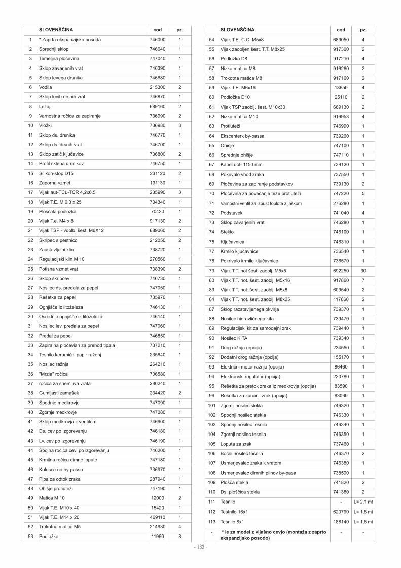
- 132 -
SLOVEN INA cod pz.
1 * Zaprta ekspanzijska posoda 746090 1
2 Sprednji sklop 746640 1
3 Temeljna plo evina 747040 1
4 Sklop zavarjenih vrat 746390 1
5 Sklop levega drsnika 746680 1
6 Vodila 215300 2
7 Sklop levih drsnih vrat 746870 1
8 Le aj 689160 2
9 Varnostna ro ica za zapiranje 736990 2
10 Vlo ki 736980 3
11 Sklop ds. drsnika 746770 1
12 Sklop ds. drsnih vrat 746700 1
13 Sklop zati klju avice 736800 2
14 Pro l sklepa drsnikov 746750 1
15 Silikon-stop D15 231120 2
16 Zaporna vzmet 131130 1
17 Vijak aut-TCL-TCR 4,2x6,5 235990 3
18 Vijak T.E. M 6,3 x 25 734340 1
19 Ploš ata podlo ka 70420 1
20 Vijak T.e. M4 x 8 917130 2
21 Vijak TSP - vdolb. šest. M6X12 689060 2
22 Škripec s pestnico 212050 2
23 Zaustavljalni klin 738720 1
24 Regulacijski klin M 10 270560 1
25 Potisna vzmet vrat 738390 2
26 Sklop škripcev 746730 1
27 Nosilec ds. predala za pepel 747050 1
28 Rešetka za pepel 735970 1
29 Ognjiš e iz lito eleza 746130 1
30 Osrednje ognjiš e iz lito eleza 746140 1
31 Nosilec lev. predala za pepel 747060 1
32 Predal za pepel 746850 1
33 Zapiralna plo evian za prehod tipala 737210 1
34 Tesnilo kerami ni papir ra enj 235640 1
35 Nosilec ra nja 264210 1
36 Mrzla ro ica 736580 1
37 ro ica za snemljiva vrata 280240 1
38 Gumijasti zamašek 234420 2
39 Spodnje medkrovje 747090 1
40 Zgornje medkrovje 747080 1
41 Sklop medkrovja z ventilom 746900 1
42 Ds. cev po izgorevanju 746180 1
43 Lv. cev po izgorevanju 746190 1
44 Spojna ro ica cevi po izgorevanju 746200 1
45 Krmilna ro ica dimne lopute 747180 1
46 Kolesce na by-passu 736970 1
47 Pipa za odtok zraka 287940 1
48 Ohišje protiute i 747190 1
49 Matica M 10 12000 2
50 Vijak T.E. M10 x 40 15420 1
51 Vijak T.E. M14 x 20 469110 1
52 Trokotna matica M5 214930 4
53 Podlo ka 11960 8
SLOVEN INA cod pz.
54 Vijak T.E. C.C. M5x8 689050 4
55 Vijak zaobljen šest. T.T. M8x25 917300 2
56 Podlo ka D8 917210 4
57 Nizka matica M8 916260 2
58 Trokotna matica M8 917160 2
59 Vijak T.E. M6x16 18650 4
60 Podlo ka D10 25110 2
61 Vijak TSP zaoblj. šest. M10x30 689130 2
62 Nizka matica M10 916953 4
63 Protiute i 746990 1
64 Ekscenterk by-passa 739260 1
65 Ohišje 747100 1
66 Sprednje ohišje 747110 1
67 Kabel dol- 1150 mm 739120 1
68 Pokrivalo vhod zraka 737550 1
69 Plo evina za zapiranje podstavkov 739130 2
70 Plo evina za pove anje te e protiute i 747220 5
71 Varnostni ventil za izpust toplote z jaškom 276280 1
72 Podstavek 741040 4
73 Sklop zavarjenih vrat 746280 1
74 Steklo 746100 1
75 Klju avnica 746310 1
77 Krmilo klju avnice 736540 1
78 Pokrivalo krmila klju avnice 736570 1
79 Vijak T.T. not šest. zaoblj. M5x5 692250 30
80 Vijak T.T. not. šest. zaoblj. M5x16 917860 7
83 Vijak T.T. not. šest. zaoblj. M5x8 609540 2
84 Vijak T.T. not. šest. zaoblj. M8x25 117660 2
87 Sklop razstavljenega okvirja 739370 1
88 Nosilec hidravli nega kita 739470 1
89 Regulacijski kit za samodejni zrak 739440 1
90 Nosilec KITA 739340 1
91 Drog ra nja (opcija) 234550 1
92 Dodatni drog ra nja (opcija) 155170 1
93 Elektri ni motor ra nja (opcija) 86460 1
94 Elektronski regulator (opcija) 220780 1
95 Rešetka za pretok zraka iz medkrovja (opcija) 83590 1
96 Rešetka za zunanji zrak (opcija) 83060 1
101 Zgornji nosilec stekla 746320 1
102 Spodnji nosilec stekla 746330 1
103 Spodnji nosilec tesnila 746340 1
104 Zgornji nosilec tesnila 746350 1
105 Loputa za zrak 737460 1
106 Bo ni nosilec tesnila 746370 2
107 Usmerjevalec zraka k vratom 746380 1
108 Usmerjevalec dimnih plinov by-pasa 738590 1
109 Ploš a stekla 741820 2
110 Ds. ploš ica stekla 741380 2
111 Tesnilo - L= 2,1 mt
112 Testnilo 16x1 620790 L= 1,8 mt
113 Tesnilo 8x1 188140 L= 1,6 mt
- * le za model z vija no cevjo (monta a z zaprto ekspanzijsko posodo)
- -

- 133 -cod. 9 1000 02.13 Cw w w . e d i l k a m i n . c o m