Grazie per la fiducia accordata e buon divertimento. Con ... · ALP 200 Grazie per la fiducia...
320
1 I ALP 200 Grazie per la fiducia accordata e buon divertimento. Con questo libretto abbiamo voluto darLe le informazioni necessarie per un corretto uso e una buona manutenzione della Sua moto. I dati e le caratteristiche indicate sul presente manuale non impegnano la BETAMOTOR S.p.A che si riserva il diritto di apportare modifiche e miglio- ramenti ai propri modelli in qualsiasi momento e senza preavviso. Cod. 017440090 000
Transcript of Grazie per la fiducia accordata e buon divertimento. Con ... · ALP 200 Grazie per la fiducia...

1 I
ALP 200
Grazie per la fiducia accordata e buon divertimento. Con questo libretto abbiamo voluto darLe le informazioni necessarie per un corretto uso e una buona manutenzione della Sua moto.
I dati e le caratteristiche indicate sul presente manuale non impegnano la BETAMOTOR S.p.A che si riserva il diritto di apportare modifiche e miglio-ramenti ai propri modelli in qualsiasi momento e senza preavviso.
Cod. 017440090 000
2I
AVVERTENZA
Si raccomanda, dopo la prima o seconda ora di utilizzo in fuori-strada, di controllare tutti i serraggi con particolare attenzione a:
• corona• supporti pedane• pinza freno anteriore• supporto parafango• bulloneria motore• bulloneria ammortizzatore• raggi ruota• telaietto posteriore
AVVERTENZA
In caso di interventi da eseguire sulla moto rivolgersi alla catena di assistenza autorizzata Betamotor.
IND
ICE
3 I
INDICE DEI CAPITOLI
Avvertenze sull’uso del veicolo .................................................................5Guida ecologica ....................................................................................5Guida sicura .........................................................................................6
CAP. 1 INFORMAZIONI GENERALI ...................................................7Dati identificazione veicolo .....................................................................8Conoscenza del veicolo ..........................................................................9Dati tecnici ..........................................................................................10Motore ...............................................................................................12Impianto elettrico .................................................................................14Lubrificanti e liquidi consigliati ...............................................................16
CAP. 2 UTILIZZO DEL VEICOLO .......................................................17Elementi principali ................................................................................18Chiavi ................................................................................................21Bloccasterzo ........................................................................................21Serratura casco ...................................................................................21Istruzioni di funzionamento tachimetro digitale ........................................22Verifiche prima e dopo l’utilizzo.............................................................28Rodaggio ............................................................................................28Rifornimento carburante ........................................................................28Avviamento motore ..............................................................................29Arresto motore .....................................................................................29Predisposizione per assetto da trial ........................................................30
CAP. 3 REGOLAZIONI ......................................................................31Legenda simboli ...................................................................................32Freni ...................................................................................................32Regime di minimo ...............................................................................33Manubrio ............................................................................................33Regolazione ammortizzatore .................................................................33Faro anteriore ......................................................................................34
CAP. 4 CONTROLLI E MANUTENZIONE ..........................................35Olio motore .........................................................................................36Tubo raccolta fumi ................................................................................37FIltro aria ............................................................................................38Candela .............................................................................................40
IND
ICE
4I
Svuotamento vaschetta carburatore ........................................................40Freno anteriore ...................................................................................41Freno posteriore ...................................................................................43Comando frizione ................................................................................44Controllo gioco sterzo ..........................................................................45Pneumatici ..........................................................................................46Olio forcella ........................................................................................46Catena ...............................................................................................47Faro anteriore ......................................................................................48Indicatori di direzione ..........................................................................49Faro posteriore ....................................................................................49Sostituzione lampada luce targa ............................................................49Batteria ...............................................................................................49Pulizia del veicolo ................................................................................53Lunga inattività del veicolo ....................................................................54Manutenzione programmata ................................................................55
CAP. 5 SMONTAGGIO E MONTAGGIO CARROZZERIA .................57Smontaggio e rimontaggio sella.............................................................58Smontaggio e rimontaggio carenatura serbatoio ......................................58Smontaggio e rimontaggio maniglie passeggero .....................................58Smontaggio e rimontaggio plastica sottosella ..........................................59
CAP. 6 COSA FARE IN CASO DI EMERGENZA ................................61Ricerca del guasto ................................................................................62
5 I
AVVERTENZE SULL’USO DEL VEICOLO
• Il veicolo deve essere obbligatoriamente corredato di: targa, libretto di circolazione, bollo ed assicurazione.
• È vietato il trasporto di animali e oggetti non resi solidali al veicolo, che possono uscire dall’ingombro del veicolo stesso.
• Il casco è obbligatorio.• Viaggiare sempre con luci anabbaglianti accese.• Modifiche al motore o altri organi che possano determinare un aumento di poten-za e quindi di velocità, è punita dalla legge con severe sanzioni, tra le quali la confisca del mezzo.
• Per salvaguardare la tua vita e quella degli altri guidare con prudenza, indossare sempre il casco di sicurezza e tenere sempre le luci anabbaglianti accese.
ATTENZIONE:Modifiche e manomissioni durante il periodo di garanzia, esimono il Costruttore da qualsiasi responsabilità e fanno decadere la garanzia stessa.
GUIDA ECOLOGICA
• Ogni veicolo con motore a scoppio produce più o meno rumore (inquinamento acustico) e più o meno inquinamento atmosferico, a seconda del tipo di guida adottato.
• L’abbattimento, per quanto più possibile, di queste condizioni è oggi un dovere per tutti, quindi evitare partenze a tutto gas, improvvise ed inutili accelerazioni ed improvvise ed altrettanto inutili frenate, limitando così la rumorosità, l’usura precoce dei pneumatici e delle parti meccaniche del veicolo e risparmiando notevolmente sui consumi di carburante.
6I
GUIDA SICURA
• Rispettare il Codice Stradale• Indossare sempre casco omologato ed allacciato• Viaggiare sempre con luci anabbaglianti accese• Mantenere sempre pulita la visiera protettiva• Indossare indumenti senza estremità penzolanti• Non viaggiare con in tasca oggetti acuminati o fragili• Regolare correttamente gli specchietti retrovisori• Guidare sempre seduti e con entrambe le mani sul manubrio ed i piedi sulle pedane• Mai distrarsi o farsi distrarre durante la guida• Non mangiare, bere, fumare, usare il cellulare, ecc... durante la guida• Non ascoltare musica in “cuffia” durante la guida• Non viaggiare mai appaiato ad altri veicoli• Non trainare o farsi trainare da altri veicoli• Mantenere sempre le distanze di sicurezza• Non sostare seduti sul veicolo sul cavalletto• Non partire con il veicolo sul cavalletto• Non estrarre il cavalletto con il fronte/marcia del veicolo in discesa• Impennate, serpentine, ondeggiamenti, sono pericolosissimi per Te, per gli altri e per il Tuo veicolo
• Su strada asciutta e senza ghiaia o sabbia, usare entrambi i freni, uno solo può causare slittamenti pericolosi ed incontrollabili
• In caso di frenata utilizzare entrambi i freni, ottenendo così un arresto del veicolo in spazi più brevi
• Su strada bagnata e nel fuoristrada, guidare con prudenza ed a velocità moderata: usare i freni con maggior sensibilità
• Non avviare il motore in ambienti chiusi.
1
INFO
RM
AZ
ION
I GEN
ERA
LI
7 I
CAP. 1 INFORMAZIONI GENERALI
INDICE ARGOMENTIDati identificazione veicolo .....................................................................8
Identificazione telaio ..........................................................................8Identificazione motore ........................................................................8Fornitura ..........................................................................................8
Conoscenza del veicolo ..........................................................................9Dati tecnici ..........................................................................................10
Pesi ...............................................................................................10Dimensioni veicolo ..........................................................................10Pneumatici ......................................................................................10Capacità di riempimento ..................................................................10Sospensione anteriore ......................................................................11Sospensione posteriore ....................................................................11Freno anteriore ...............................................................................11Freno posteriore ..............................................................................11
Motore ...............................................................................................12Carburatore ....................................................................................12Cambio .........................................................................................13
Impianto elettrico .................................................................................14Schema elettrico ..............................................................................14Legenda schema elettrico .................................................................15
Lubrificanti e liquidi consigliati ...............................................................16
1IN
FORM
AZ
ION
I GEN
ERA
LI
8I
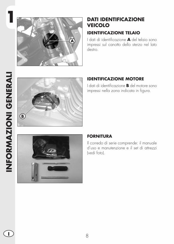
DATI IDENTIFICAZIONE VEICOLOIDENTIFICAZIONE TELAIOI dati di identificazione A del telaio sono impressi sul canotto dello sterzo nel lato destro.
IDENTIFICAZIONE MOTOREI dati di identificazione B del motore sono impressi nella zona indicata in figura.
FORNITURAIl corredo di serie comprende: il manuale d’uso e manutenzione e il set di attrezzi (vedi foto).
A
B

1
INFO
RM
AZ
ION
I GEN
ERA
LI
9 I
Elementi principali: 1 - Filtro aria 2 - Serbatoio carburante 3 - Tappo carburante 4 - Silenziatore 5 - Ammortizzatore po -
ste riore 6 - Faro anteriore 7 - Indicatori di direzio-
ne anteriori
1
2113
14
CONOSCENZA DEL VEICOLO
8 - Fanale posteriore 9 - Indicatori di direzio-
ne posteriori 10 - Cavalletto laterale 11 - Specchi retrovisori 12 - Pedane passeggero 13 - Forcella 14 - Pedane pilota
15 - Protezione motore 16 - Sella 17 - Motore18 - Parafango anteriore19 - Portatarga20 - Leva messa in mo to21 - Serratura casco
2
34
5
7
8
9
20
10
15
16
17
191218
11
11
6
1IN
FORM
AZ
ION
I GEN
ERA
LI
10I
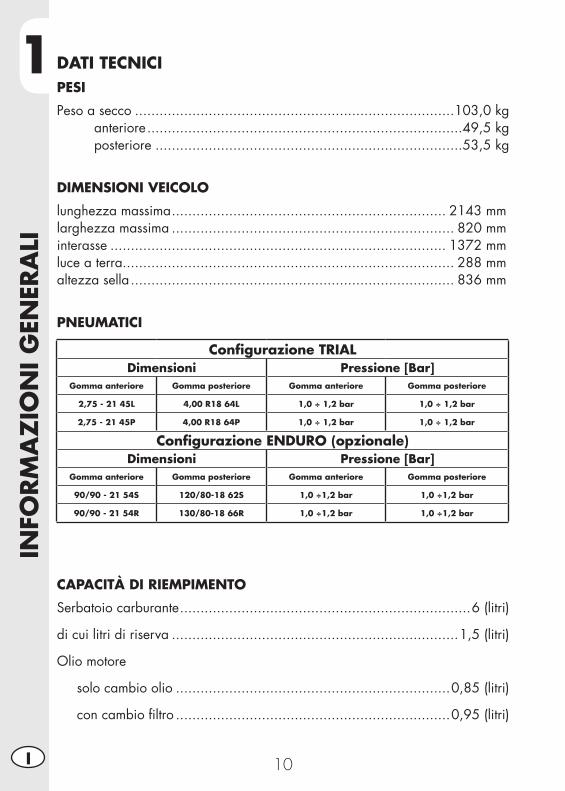
DATI TECNICIPESI
Peso a secco ..............................................................................103,0 kg anteriore .............................................................................49,5 kg posteriore ...........................................................................53,5 kg
DIMENSIONI VEICOLO
lunghezza massima ................................................................... 2143 mmlarghezza massima ..................................................................... 820 mminterasse .................................................................................. 1372 mmluce a terra................................................................................. 288 mmaltezza sella ............................................................................... 836 mm
PNEUMATICI
CAPACITÀ DI RIEMPIMENTO
Serbatoio carburante .......................................................................6 (litri)
di cui litri di riserva ......................................................................1,5 (litri)
Olio motore
solo cambio olio ...................................................................0,85 (litri)
con cambio filtro ...................................................................0,95 (litri)
Configurazione TRIALDimensioni Pressione [Bar]
Gomma anteriore Gomma posteriore Gomma anteriore Gomma posteriore
2,75 - 21 45L 4,00 R18 64L 1,0 ÷ 1,2 bar 1,0 ÷ 1,2 bar
2,75 - 21 45P 4,00 R18 64P 1,0 ÷ 1,2 bar 1,0 ÷ 1,2 bar
Configurazione ENDURO (opzionale)Dimensioni Pressione [Bar]
Gomma anteriore Gomma posteriore Gomma anteriore Gomma posteriore
90/90 - 21 54S 120/80-18 62S 1,0 ÷1,2 bar 1,0 ÷1,2 bar
90/90 - 21 54R 130/80-18 66R 1,0 ÷1,2 bar 1,0 ÷1,2 bar
1
INFO
RM
AZ
ION
I GEN
ERA
LI
11 I
SOSPENSIONE ANTERIORE
Diametro steli ............................................................................. ∅ 37mm
Tipo olio .................................................................. AGIP ARNICA SA 32
Quantità olio .............................................................................. 0,552Kg
SOSPENSIONE POSTERIORE
K Molla ....................................................................................... K12,5
Precarica ..................................................................................... 139mm
FRENO ANTERIORE
a disco Ø 245 mm con comando idraulico
FRENO POSTERIORE
a disco Ø 160 mm con comando idraulico
1IN
FORM
AZ
ION
I GEN
ERA
LI
12I
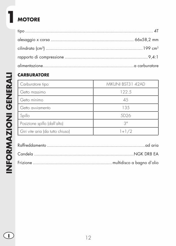
MOTORE
tipo .................................................................................................... 4T
alesaggio x corsa ................................................................. 66x58,2 mm
cilindrata (cm3) ............................................................................199 cm3
rapporto di compressione .................................................................9,4:1
alimentazione .......................................................................a carburatore
CARBURATORE
Carburatore tipo MIKUNI BST31 42AD
Getto massimo 122.5
Getto minimo 45
Getto avviamento 135
Spillo 5D26
Posizione spillo (dall’alto) 3°
Giri vite aria (da tutto chiuso) 1+1/2
Raffreddamento .............................................................................ad aria
Candela ..............................................................................NGK DR8 EA
Frizione ..............................................................multidisco a bagno d’olio
1
INFO
RM
AZ
ION
I GEN
ERA
LI
13 I
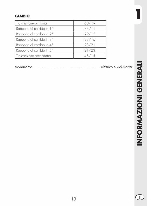
CAMBIO
Trasmissione primaria 60/19Rapporto al cambio in 1° 33/11Rapporto al cambio in 2° 29/15Rapporto al cambio in 3° 23/16Rapporto al cambio in 4° 23/21Rapporto al cambio in 5° 21/23Trasmissione secondaria 48/15
Avviamento ................................................................elettrico e kick-starter
1IN
FORM
AZ
ION
I GEN
ERA
LI
14I
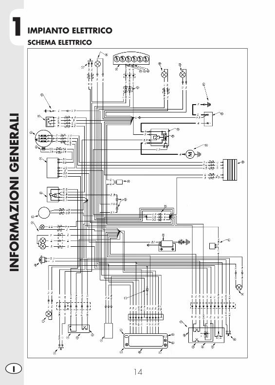
IMPIANTO ELETTRICOSCHEMA ELETTRICO
1
INFO
RM
AZ
ION
I GEN
ERA
LI
15 I
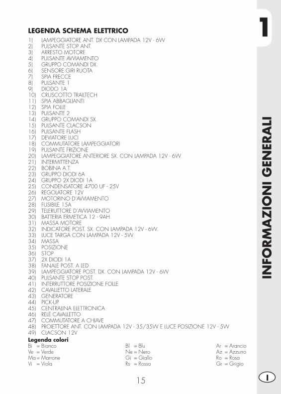
Legenda coloriBi = BiancoVe = VerdeMa = MarroneVi = Viola
Bl = BluNe = NeroGi = GialloRs = Rosso
Ar = ArancioAz = AzzurroRo = RosaGr = Grigio
LEGENDA SCHEMA ELETTRICO1) LAMPEGGIATORE ANT. DX CON LAMPADA 12V - 6W2) PULSANTE STOP ANT.3) ARRESTO MOTORE4) PULSANTE AVVIAMENTO5) GRUPPO COMANDI DX.6) SENSORE GIRI RUOTA7) SPIA FRECCE8) PULSANTE 19) DIODO 1A10) CRUSCOTTO TRAILTECH11) SPIA ABBAGLIANTI12) SPIA FOLLE13) PULSANTE 214) GRUPPO COMANDI SX.15) PULSANTE CLACSON16) PULSANTE FLASH17) DEVIATORE LUCI18) COMMUTATORE LAMPEGGIATORI19) PULSANTE FRIZIONE20) LAMPEGGIATORE ANTERIORE SX. CON LAMPADA 12V - 6W21) INTERMITTENZA22) BOBINA A.T.23) GRUPPO DIODI 6A24) GRUPPO 2X DIODI 1A25) CONDENSATORE 4700 UF - 25V26) REGOLATORE 12V27) MOTORINO D’AVVIAMENTO28) FUSIBILE 15A29) TELERUTTORE D’AVVIAMENTO30) BATTERIA ERMETICA 12 - 9AH31) MASSA MOTORE32) INDICATORE POST. SX. CON LAMPADA 12V - 6W.33) LUCE TARGA CON LAMPADA 12V - 5W34) MASSA35) POSIZIONE36) STOP37) 2X DIODI 1A38) FANALE POST. A LED39) LAMPEGGIATORE POST. DX. CON LAMPADA 12V - 6W40) PULSANTE STOP POST.41) INTERRUTTORE POSIZIONE FOLLE42) CAVALLETTO LATERALE43) GENERATORE44) PICK-UP45) CENTRALINA ELETTRONICA46) RELË CAVALLETTO47) COMMUTATORE A CHIAVE48) PROIETTORE ANT. CON LAMPADA 12V - 35/35W E LUCE POSIZIONE 12V - 5W49) CLACSON 12V
1IN
FORM
AZ
ION
I GEN
ERA
LI
16I
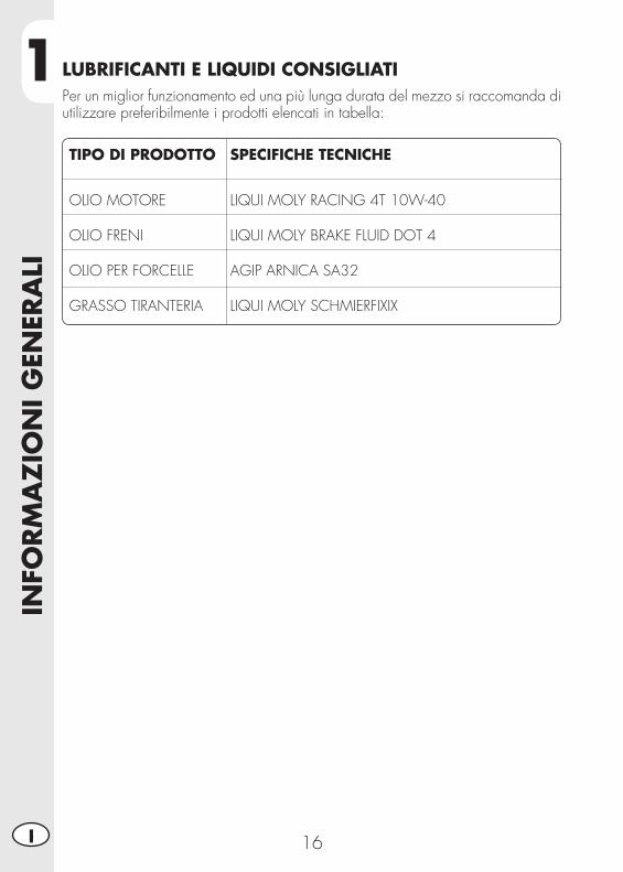
TIPO DI PRODOTTO SPECIFICHE TECNICHE
OLIO MOTORE LIQUI MOLY RACING 4T 10W-40 OLIO FRENI LIQUI MOLY BRAKE FLUID DOT 4 OLIO PER FORCELLE AGIP ARNICA SA32 GRASSO TIRANTERIA LIQUI MOLY SCHMIERFIXIX
LUBRIFICANTI E LIQUIDI CONSIGLIATIPer un miglior funzionamento ed una più lunga durata del mezzo si raccomanda di utilizzare preferibilmente i prodotti elencati in tabella:
2
UTI
LIZ
ZO
DEL
VEI
COLO
17 I
CAP. 2 UTILIZZO DEL VEICOLO
INDICE ARGOMENTIElementi principali ................................................................................18
Rubinetto carburante ........................................................................18Starter ............................................................................................18Leva frizione ...................................................................................18Commutatore sinistro .......................................................................19Commutatore destro .........................................................................19Leva freno anteriore e comando gas ..................................................19Leva cambio ...................................................................................20Pedale freno ...................................................................................20Pedale avviamento ..........................................................................20Cavalletto laterale ...........................................................................20
Chiavi ................................................................................................21Bloccasterzo ........................................................................................21Serratura casco ...................................................................................21Istruzioni di funzionamento tachimetro digitale ........................................22Verifiche prima e dopo l’utilizzo.............................................................28Rodaggio ............................................................................................28Rifornimento carburante ........................................................................28Avviamento motore ..............................................................................29Arresto motore .....................................................................................29Predisposizione per assetto da trial ........................................................30
2U
TILI
ZZ
O D
EL V
EICO
LO
18I
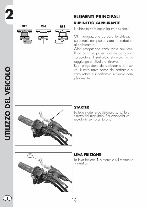
ELEMENTI PRINCIPALIRUBINETTO CARBURANTEIl rubinetto carburante ha tre posizioni:
OFF: erogazione carburante chiusa. Il carburante non può passare dal serbatoio al carburatore.ON: erogazione carburante abilitata. Il carburante passa dal serbatoio al carburatore. Il serbatoio si svuota fino a raggiungere il livello di riserva.RES: erogazione del carburante di riser-va. Il carburante passa dal serbatoio al carburatore e il serbatoio si svuota com-pletamente.
STARTERLa leva starter è posizionata su sul latosinistro del manubrio. Per azionarla varuotata in senso antiorario.
LEVA FRIZIONELa leva frizione 1 è montata sul manubrioa sinistra.
OFF ON RES
1
2
UTI
LIZ
ZO
DEL
VEI
COLO
19 I
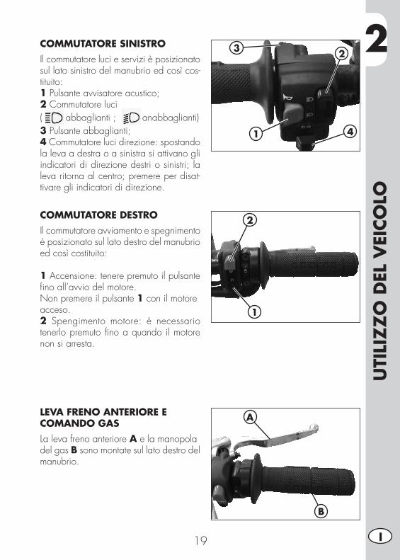
COMMUTATORE SINISTROIl commutatore luci e servizi è posizionato sul lato sinistro del manubrio ed così cos-tituito:1 Pulsante avvisatore acustico;2 Commutatore luci( abbaglianti ; anabbaglianti)3 Pulsante abbaglianti;4 Commutatore luci direzione: spostando la leva a destra o a sinistra si attivano gli indicatori di direzione destri o sinistri; la leva ritorna al centro; premere per disat-tivare gli indicatori di direzione.
1
23
4
COMMUTATORE DESTROIl commutatore avviamento e spegnimento è posizionato sul lato destro del manubrio ed così costituito:
1 Accensione: tenere premuto il pulsante fino all’avvio del motore.Non premere il pulsante 1 con il motoreacceso.2 Spengimento motore: è necessario tenerlo premuto fino a quando il motore non si arresta.
LEVA FRENO ANTERIORE E COMANDO GASLa leva freno anteriore A e la manopoladel gas B sono montate sul lato destro delmanubrio.
2
1
A
B
2U
TILI
ZZ
O D
EL V
EICO
LO
20I
1
234
5
NA
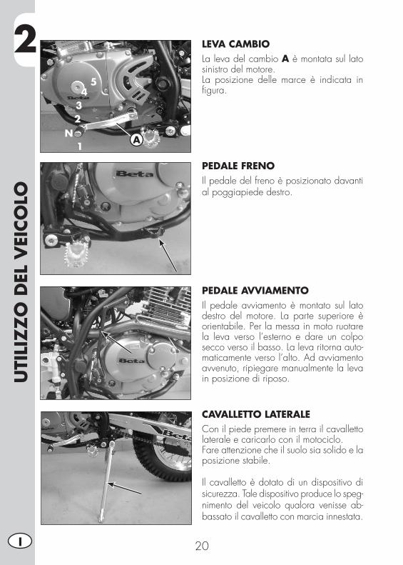
LEVA CAMBIOLa leva del cambio A è montata sul lato sinistro del motore.La posizione delle marce è indicata in figura.
PEDALE FRENOIl pedale del freno è posizionato davanti al poggiapiede destro.
PEDALE AVVIAMENTOIl pedale avviamento è montato sul lato destro del motore. La parte superiore è orientabile. Per la messa in moto ruotare la leva verso l’esterno e dare un colpo secco verso il basso. La leva ritorna auto-maticamente verso l’alto. Ad avviamento avvenuto, ripiegare manualmente la leva in posizione di riposo.
CAVALLETTO LATERALECon il piede premere in terra il cavallettolaterale e caricarlo con il motociclo.Fare attenzione che il suolo sia solido e laposizione stabile.
Il cavalletto è dotato di un dispositivo di sicurezza. Tale dispositivo produce lo speg-nimento del veicolo qualora venisse ab-bassato il cavalletto con marcia innestata.
2
UTI
LIZ
ZO
DEL
VEI
COLO
21 I
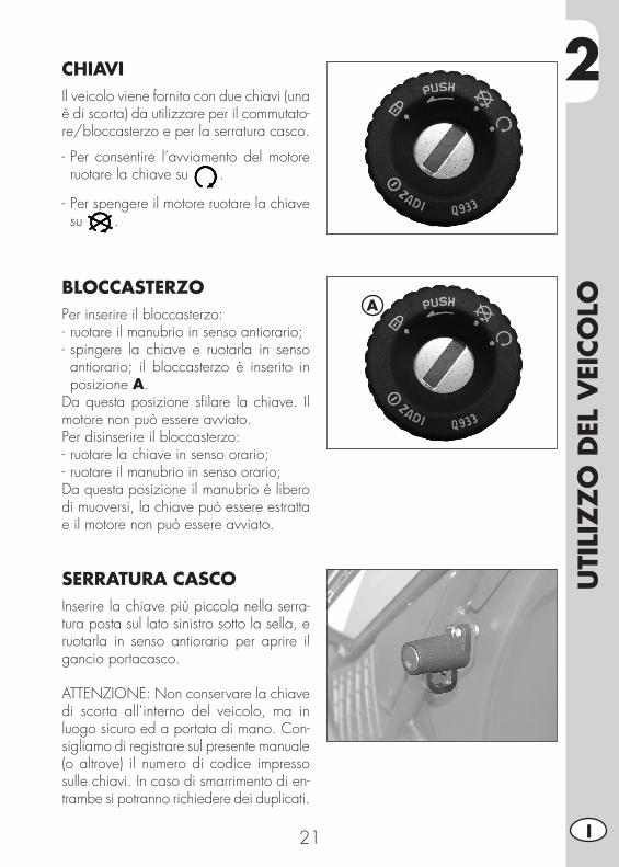
CHIAVIIl veicolo viene fornito con due chiavi (una è di scorta) da utilizzare per il commutato-re/bloccasterzo e per la serratura casco.
- Per consentire l’avviamento del motore ruotare la chiave su .
- Per spengere il motore ruotare la chiave su .
BLOCCASTERZOPer inserire il bloccasterzo:- ruotare il manubrio in senso antiorario;- spingere la chiave e ruotarla in senso antiorario; il bloccasterzo è inserito in posizione A.
Da questa posizione sfilare la chiave. Il motore non può essere avviato.Per disinserire il bloccasterzo:- ruotare la chiave in senso orario;- ruotare il manubrio in senso orario;Da questa posizione il manubrio è libero di muoversi, la chiave può essere estratta e il motore non può essere avviato.
SERRATURA CASCOInserire la chiave più piccola nella serra-tura posta sul lato sinistro sotto la sella, e ruotarla in senso antiorario per aprire il gancio portacasco.
ATTENZIONE: Non conservare la chiave di scorta all’interno del veicolo, ma in luogo sicuro ed a portata di mano. Con-sigliamo di registrare sul presente manuale (o altrove) il numero di codice impresso sulle chiavi. In caso di smarrimento di en-trambe si potranno richiedere dei duplicati.
A
2U
TILI
ZZ
O D
EL V
EICO
LO
22I
ISTRUZIONI DI FUNZIONAMENTO TACHIMETRO DIGITALEIndice degli argomenti1 SPECIFICHE GENERALI E GENERALITÀ 1.1 Specifiche generali 1.2 Generalità2 SETTAGGIO PARAMETRI 2.1 Sequenza setup 2.1.1 Selezione dell’unità di misura 2.1.2 Selezione della dimensione della ruota 2.1.3 Selezionare il formato orario 2.1.4 Settaggio Ora 2.1.5 Selezione promemoria manutenzione3 SCHERMATE4 CARATTERISTICHE5 TACHIMETRO6 REGOLAZIONI MISURATORE DISTANZA PERCORSO7 SPIE DI SEGNALAZIONE
1 SPECIFICHE GENERALI E GENERALITÀ1.1 SPECIFICHE GENERALI
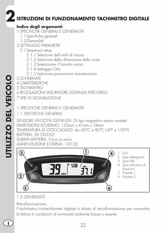
SENSORE VELOCITÀ/DISTANZA: Di tipo magnetico senza contattoDIMENSIONI SCHERMO: 125mm x 41mm x 34mmTEMPERATURA DI STOCCAGGIO: da -20°C a 80°C (-4°F a 176°F)BATTERIA: 3V CR2032DURATA BATTERIA: Circa un annoALIMENTAZIONE ESTERNA: 12V DC
1.2 GENERALITÀ
Retroilluminazione:Il tachimetro/contachilometri digitale è dotato di retroilluminazione per consentire la lettura in condizioni di luminosità ambiente bassa o assente.
12
3
5
4
6
1 LCD 2 Spia abbaglianti 3 Spia folle 4 Spia indicatore di direzione 5 Pulsante 1 6 Pulsante 2
2
UTI
LIZ
ZO
DEL
VEI
COLO
23 I
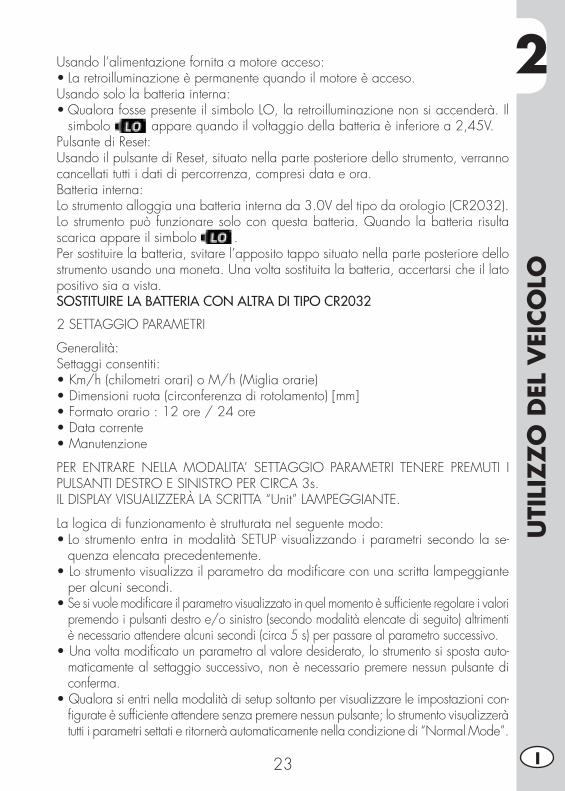
Usando l’alimentazione fornita a motore acceso:•Laretroilluminazioneèpermanentequandoilmotoreèacceso.Usando solo la batteria interna:•QualorafossepresenteilsimboloLO,laretroilluminazionenonsiaccenderà.Il
simbolo appare quando il voltaggio della batteria è inferiore a 2,45V.Pulsante di Reset:Usando il pulsante di Reset, situato nella parte posteriore dello strumento, verranno cancellati tutti i dati di percorrenza, compresi data e ora.Batteria interna:Lo strumento alloggia una batteria interna da 3.0V del tipo da orologio (CR2032). Lo strumento può funzionare solo con questa batteria. Quando la batteria risulta scarica appare il simbolo .Per sostituire la batteria, svitare l’apposito tappo situato nella parte posteriore dello strumento usando una moneta. Una volta sostituita la batteria, accertarsi che il lato positivo sia a vista.SOSTITUIRE LA BATTERIA CON ALTRA DI TIPO CR2032
2 SETTAGGIO PARAMETRI
Generalità:Settaggi consentiti:•Km/h(chilometriorari)oM/h(Migliaorarie)•Dimensioniruota(circonferenzadirotolamento)[mm]•Formatoorario:12ore/24ore•Datacorrente•Manutenzione
PER ENTRARE NELLA MODALITA’ SETTAGGIO PARAMETRI TENERE PREMUTI I PULSANTI DESTRO E SINISTRO PER CIRCA 3s.IL DISPLAY VISUALIZZERÀ LA SCRITTA “Unit” LAMPEGGIANTE.
La logica di funzionamento è strutturata nel seguente modo:•LostrumentoentrainmodalitàSETUPvisualizzandoiparametrisecondolase-
quenza elencata precedentemente.•Lostrumentovisualizzailparametrodamodificareconunascrittalampeggiante
per alcuni secondi.•Se si vuole modificare il parametro visualizzato in quel momento è sufficiente regolare i valori
premendo i pulsanti destro e/o sinistro (secondo modalità elencate di seguito) altrimenti è necessario attendere alcuni secondi (circa 5 s) per passare al parametro successivo.
•Una volta modificato un parametro al valore desiderato, lo strumento si sposta auto-maticamente al settaggio successivo, non è necessario premere nessun pulsante di conferma.
•Qualora si entri nella modalità di setup soltanto per visualizzare le impostazioni con-figurate è sufficiente attendere senza premere nessun pulsante; lo strumento visualizzerà tutti i parametri settati e ritornerà automaticamente nella condizione di “Normal Mode”.
2U
TILI
ZZ
O D
EL V
EICO
LO
24I
2.1 SEQUENZA SETUP
Scelta unità di misuraDimensione ruotaFormato orarioSettaggio oraPromemoria manutenzione
2.1.1 Selezione dell’unità di misura (Km/h o M/h):PER SELEZIONARE L’UNITÀ DI MISURA (Km/h o M/h), PREMERE IL PULSANTE DESTRO O SINISTRO.ATTENDERE 5 SECONDI PER PASSARE AL SETTAGGIO SUCCESSIVO.NON PREMERE NESSUN PULSANTE.
2.1.2 Selezione della dimensione della ruota (circonferenza di rotolamento):Lo strumento ha programmate due misure di circonferenza di rotolamento della ruota anteriore: dimensione maggiore (pneumatico ENDURO) o dimensione minore (pneumatico TRIAL).PREMERE IL PULSANTE SINISTRO PER SELEZIONARE UNA DELLE DUE OPZIONI.ATTENDERE 5 SECONDI PER PASSARE AL SETTAGGIO SUCCESSIVO. NON PREMERE NESSUN PULSANTE.
2.1.3 Selezionare il formato orario (12 o 24 ore):Lo strumento è impostato di default nel formato 12h.PER SELEZIONARE IL FORMATO 12h O 24h, PREMERE IL PULSANTE DESTRO O SINISTRO.ATTENDERE 5 SECONDI PER PASSARE AL SETTAGGIO SUCCESSIVO. NON PREMERE NESSUN PULSANTE.
2.1.4 Settaggio Ora:Si regola l’ora aumentando o diminuendo a passi di 1 minuto.PREMERE IL PULSANTE SINISTRO PER DIMINUIRE L’ORARIO.PREMERE IL PULSANTE DESTRO PER AUMENTARLO.ATTENDERE 5 SECONDI PER PASSARE AL SETTAGGIO SUCCESSIVO. NON PREMERE NESSUN PULSANTE.
2.1.5 Selezione promemoria manutenzioneLo strumento mostra il conto alla rovescia per gli interventi di manutenzione basato sul dato inserito dall’utente. Il dato si basa sui chilometri o le miglia percorse in funzione dell’unità di misura scelta dall’utente. Di fabbrica è impostato su “OFF”.PREMERE IL PULSANTE SINISTRO PER RIDURRE LA CIFRA. PREMERE IL PULSANTE DESTRO PER AUMENTARLA (valore max 10.000km).ATTENDERE 5 SECONDI PER LASCIARE LA MODALITÀ DI SETUP.NON PREMERE NESSUN PULSANTE.
2
UTI
LIZ
ZO
DEL
VEI
COLO
25 I
3 SCHERMATE
Passaggio tra 3 modalità normaliTutte le informazioni che lo strumento è in grado di fornire vengono visualizzate in una di queste 3 schermate.Lo strumento resterà sulla schermata impostata finché verrà premuto un pulsante per passare ad un’altra schermata.PER PASSARE DA UNA SCHERMATA AD UN’ ALTRA, PREMERE BREVEMENTE O IL PULSANTE DESTRO O IL SINISTRO.Schermata 1:•Velocità•Distanza1(DST)•OraSchermata 2:•Velocità•Distanza2(DST2)•OraSchermata 3:•Velocitàmassima(MAX)•Velocitàmedia(AVG)•Tempodipercorrenzaaccumulato(ART)•Odometro(ODO)*Nota: Le velocità massima e media vengono aggiornate automaticamente quando l’utente accede alla schermata 3.
4 CARATTERISTICHE
Generalità:Lo strumento, nell’uso normale è in modalità “Normal”.Funzionalità disponibili:•SleepMode•Sceltatra3schermate“Normal”•AzzeramentoDistanza1(DST1)•AzzeramentoDistanza2(DST2)•AzzeramentoVelocitàMassima/Media(MAX/AVG)Sleep Mode:Se lo strumento non riceve input per 5 minuti (o dal movimento della ruota o da un pulsante), questo entrerà in modalità “Sleep Mode”. In modalità “Sleep Mode” sul display compare solo l’ora.Per uscire dalla modalità “Sleep Mode” è sufficiente che lo strumento riceva un input o dal movimento del sensore o dalla pressione di un pulsante.
2U
TILI
ZZ
O D
EL V
EICO
LO
26I
5 TACHIMETRO
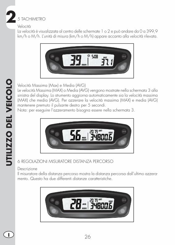
VelocitàLa velocità è visualizzata al centro delle schermate 1 o 2 e può andare da 0 a 399,9 km/h o M/h. L’unità di misura (km/h o M/h) appare accanto alla velocità rilevata.
Velocità Massima (Max) e Media (AVG)Le velocità Massima (MAX) o Media (AVG) vengono mostrate nella schermata 3 alla sinistra del display. Lo strumento aggiorna automaticamente sia la velocità massima(MAX) che media (AVG). Per azzerare la velocità massima (MAX) e media (AVG) mantenere premuto il pulsante destro per 5 secondi.Nota: per eseguire l’azzeramento bisogna essere nella schermata 3.
6 REGOLAZIONI MISURATORE DISTANZA PERCORSO
DescrizioneIl misuratore della distanza percorso mostra la distanza percorsa dall’ultimo azzera-mento. Questo ha due differenti distanze caratteristiche.

2
UTI
LIZ
ZO
DEL
VEI
COLO
27 I
Percorrenza (DST) La percorrenza può andare da 0 a 9999.9 miglia o chilometri e compare nel lato destro della schermata 1. Per azzerare la percorrenza, mantenere premuto il pulsante destro per 5 secondi.Nota: per eseguire l’azzeramento bisogna essere nella schermata 1.
Percorrenza 2 (DST 2)La percorrenza 2 può andare da 0 a 9999.9 miglia o chilometri e compare nel lato destro della schermata 2. Per azzerare la percorrenza, mantenere premuto il pulsante destro per 5 secondi.Nota: per eseguire l’azzeramento bisogna essere nella schermata 2.
7 SPIE DI SEGNALAZIONE
7.1 Spia Abbaglianti 1Il sistema attiva la spia in sincronia con l’attivazione dei proiettori abbaglianti.
7.2 Spia Indicatori di direzione 2Il sistema attiva la spia in sincronia con l’attivazione degli indicatori di direzione.
7.3 Spia Neutral 3Indica il posizionamento della leva del cambio in posizione neutral.
1
3
2
2U
TILI
ZZ
O D
EL V
EICO
LO
28I
VERIFICHE PRIMA E DOPO L’UTILIZZOPer una guida sicura ed una vita duratura del veicolo si consiglia di:•Verificaretuttiilivellideiliquidi.•Verificareilcorrettofunzionamentodeifreniel’usurapasticche(pag.42).•Verificarelapressione,lostatogeneraleelospessoredelbattistrada(pag.10).•Verificareilcorrettotensionamentodeiraggi.•Verificareiltensionamentodellacatena(pag.47).•Verificarelaregolazioneeilfunzionamentoregolaredituttiicomandiacavo
flessibile.•Verificageneraledellabulloneria.•Controllareamotoreaccesoilfunzionamentodeifari,dellaluceposteriore,della
luce di arresto, dei luci di direzione, delle spie di controllo e dell’avvisatore acustico.
•Lavareaccuratamenteilveicolodopol’usoinfuoristrada(pag.53).
RODAGGIOIl rodaggio ha una durata di circa 1000 km. Durante questo periodo si consiglia di: •Evitare di viaggiare a velocità costante. •Evitare di ruotare la manopola del gas per più di 3/4.
ATTENZIONE: Raggiunti 1000km provvedere alla sostituzione dell’olio e a far eseguire tutti i controlli riportati a pag. 55.
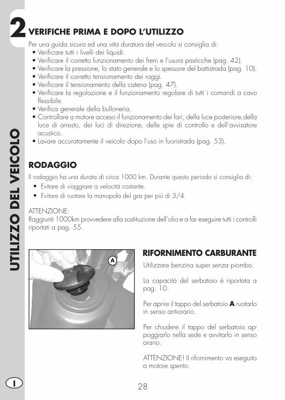
RIFORNIMENTO CARBURANTEUtilizzare benzina super senza piombo.
La capacità del serbatoio è riportata a pag. 10.
Per aprire il tappo del serbatoio A ruotarlo in senso antiorario.
Per chiudere il tappo del serbatoio ap-poggiarlo nella sede e avvitarlo in senso orario.
ATTENZIONE! Il rifornimento va eseguito a motore spento.
A
2
UTI
LIZ
ZO
DEL
VEI
COLO
29 I
AVVIAMENTO MOTOREPosizionare il rubinetto del serbatoio carburante su ON o su RES (vedere pag. 18).
- Posizionare la chiave su (vedere pag. 21).
- Controllare che il cambio sia in folle (pag. 20).
- Tirare la leva frizione (pag. 18).
ATTENZIONE!Se non viene tirata la leva frizione il veicolo non si avvia.
- Chiudere il cavalletto (pag. 20).
ATTENZIONE!Se non si chiude il cavalletto, quando si innesta la marcia il motore si arresta.
CON LEVA AVVIAMENTO (pag. 20):intervenire sulla leva della messa in moto affondando con il piede un colpo deciso.
ATTENZIONE!Una volta affondato il pedale, rilasciarlo immediatamente. Ciò evita contraccolpi all’intero gruppo di avviamento e al piede.
CON AVVIAMENTO ELETTRICO (pag. 19):tenere premuto il pulsante fino a che il motore non si avvia. Non premere il pulsante con il motore acceso.
A MOTORE FREDDO:azionare lo starter (pag. 18), avviare il veicolo, attendere alcuni istanti, quindi riportare lo starter nella posizione iniziale.
ARRESTO MOTOREPer spengere il motore procedere in uno dei seguenti modi:- ruotare la chiave su (vedi pag. 21).- premere il pulsante presente sul gruppo commutatori (vedi pag. 19).
NOTA: A motore fermo posizionare sempre il rubinetto carburante su OFF (pag. 18).
2U
TILI
ZZ
O D
EL V
EICO
LO
30I
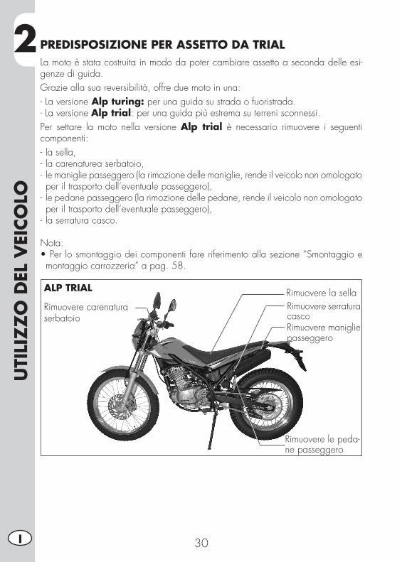
PREDISPOSIZIONE PER ASSETTO DA TRIALLa moto è stata costruita in modo da poter cambiare assetto a seconda delle esi-genze di guida.Grazie alla sua reversibilità, offre due moto in una:- La versione Alp turing: per una guida su strada o fuoristrada.- La versione Alp trial: per una guida più estrema su terreni sconnessi.Per settare la moto nella versione Alp trial è necessario rimuovere i seguenti componenti:- la sella,- la carenaturea serbatoio,- le maniglie passeggero (la rimozione delle maniglie, rende il veicolo non omologato per il trasporto dell’eventuale passeggero),
- le pedane passeggero (la rimozione delle pedane, rende il veicolo non omologato per il trasporto dell’eventuale passeggero),
- la serratura casco.
Nota:•Perlosmontaggiodeicomponentifareriferimentoallasezione“Smontaggioemontaggio carrozzeria” a pag. 58.
Rimuovere la sellaRimuovere carenaturaserbatoio
Rimuovere le peda-ne passeggero
Rimuovere serraturacascoRimuovere maniglie passeggero
ALP TRIAL
3
REG
OLA
ZIO
NI
31 I
CAP. 3 REGOLAZIONI
INDICE ARGOMENTILegenda simboli ...................................................................................32Freni ...................................................................................................32
Freno anteriore ...............................................................................32Gioco comando gas .......................................................................32
Regime di minimo ...............................................................................33Manubrio ............................................................................................33Regolazione ammortizzatore .................................................................33
Regolazione precarico molla ............................................................33Faro anteriore ......................................................................................34
REG
OLA
ZIO
NI
32I
3 LEGENDA SIMBOLI
Coppia di serraggio
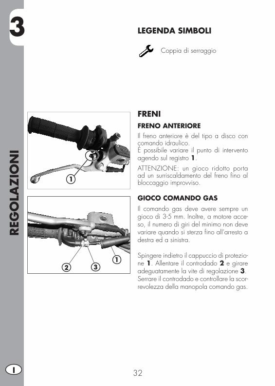
FRENIFRENO ANTERIOREIl freno anteriore è del tipo a disco con comando idraulico.È possibile variare il punto di intervento agendo sul registro 1.ATTENZIONE: un gioco ridotto porta ad un surriscaldamento del freno fino al bloccaggio improvviso.
GIOCO COMANDO GAS Il comando gas deve avere sempre un gioco di 3-5 mm. Inoltre, a motore acce-so, il numero di giri del minimo non deve variare quando si sterza fino all’arresto a destra ed a sinistra.
Spingere indietro il cappuccio di protezio-ne 1. Allentare il controdado 2 e girare adeguatamente la vite di regolazione 3.Serrare il controdado e controllare la scor-revolezza della manopola comando gas.
1
21
3
3
REG
OLA
ZIO
NI
33 I
1
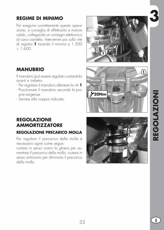
REGIME DI MINIMO Per eseguire correttamente questa opera-zione, si consiglia di effettuarla a motore caldo, collegando un contagiri elettronico al cavo candela. Intervenire poi sulla vite di registro 1 tarando il minimo a 1.500 ÷ 1.600.
MANUBRIOIl manubrio può essere regolato ruotandolo avanti e indietro.- Per regolare il manubrio allentare le viti 1- Posizionare il manubrio secondo le pro-prie esigenze
- Serrare alla coppia indicata.
REGOLAZIONE AMMORTIZZATOREREGOLAZIONE PRECARICO MOLLAPer regolare il precarico della molla è necessario agire come segue:ruotare in senso orario la ghiera per au-mentare il precarico della molla, ruotare in senso antiorario per diminuire il precarico della molla.
1
20Nm
REG
OLA
ZIO
NI
34I
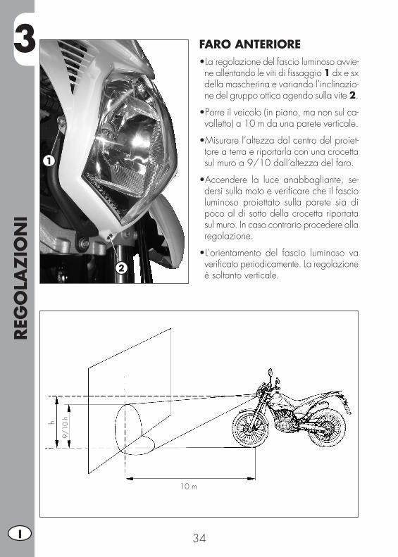
3 FARO ANTERIORE•La regolazione del fascio luminoso avvie-ne allentando le viti di fissaggio 1 dx e sx della mascherina e variando l’inclinazio-ne del gruppo ottico agendo sulla vite 2.
•Porreilveicolo(inpiano,manonsulca-valletto) a 10 m da una parete verticale.
•Misurarel’altezzadalcentrodelproiet-tore a terra e riportarla con una crocetta sul muro a 9/10 dall’altezza del faro.
•Accendere la luce anabbagliante, se-dersi sulla moto e verificare che il fascio luminoso proiettato sulla parete sia di poco al di sotto della crocetta riportata sul muro. In caso contrario procedere alla regolazione.
•L’orientamento del fascio luminoso vaverificato periodicamente. La regolazione è soltanto verticale.
1
2
9/10
h
10 m
h
4
CON
TRO
LLI E
MA
NU
TEN
ZIO
NE
35 I
CAP. 4 CONTROLLI E MANUTENZIONE
INDICE ARGOMENTIOlio motore .........................................................................................36
Controllo livello ...............................................................................36Sostituzione ....................................................................................36
Tubo raccolta fumi ................................................................................37FIltro aria ............................................................................................38
Rimozione e montaggio filtro aria ......................................................38Pulizia filtro aria ..............................................................................39
Candela .............................................................................................40Svuotamento vaschetta carburatore ........................................................40Freno anteriore ...................................................................................41
Controllo livello liquido freno anteriore ...............................................41Spurgo freno anteriore .....................................................................42Pasticche freno anteriore ..................................................................42
Freno posteriore ...................................................................................43Controllo livello liquido freno posteriore .............................................43Rabbocco liquido freno posteriore .....................................................43Spurgo freno posteriore ....................................................................43Pasticche freno posteriore .................................................................44
Comando frizione ................................................................................44Controllo gioco sterzo ..........................................................................45Pneumatici ..........................................................................................46Olio forcella ........................................................................................46Catena ...............................................................................................47
Verifica e regolazione tensionamento catena ......................................47Faro anteriore ......................................................................................48
Sostituzioni lampade anteriori ..........................................................48Indicatori di direzione ..........................................................................49Faro posteriore ....................................................................................49Sostituzione lampada luce targa ............................................................49Batteria ...............................................................................................49
Smontaggio ....................................................................................50Inattività .........................................................................................51Carica della batteria ........................................................................51Fusibile ..........................................................................................52
Pulizia del veicolo ................................................................................53Lunga inattività del veicolo ....................................................................54Manutenzione programmata ................................................................55

4CO
NTR
OLL
I E M
AN
UTE
NZ
ION
E
36I
OLIO MOTORECONTROLLO LIVELLOQuando il motore è freddo controllare, attraverso l’oblò 1 la presenza dell’olio. Il livello dell’olio deve essere sempre visibile dall’oblò, in caso contrario pro-cedere al rabboccoattraverso il tappo di carico 2.Utilizzare liquido indicato a pag. 16 nella tabella “Lubrificanti e liquidi con-sigliati”.
SOSTITUZIONEEseguire sempre la sostituzione a motore caldo:- Posteggiare la moto su fondo piano e
in modo stabile.- Posizionare un contenitore sotto al mo-
tore.- Svitare il tappo di carico 1 e quello di
scarico 2.- Svuotare completamente il carter.- Chiudere il tappo 2 .
- Togliere il coperchio del filtro olio svi-tando i 3 dadi di fi ssaggio 3.
- Rimuovere il filtro olio ed inserirne uno nuovo.
- Applicare un velo d’olio motore sull’O-Ring del coperchio filtro prima dell’in-serimento.
- Inserire il coperchio filtro olio, dopo aver montato molla ed O-Ring e serrare i tre dadi di fissaggio 3.
2
1
2
1
3
4
CON
TRO
LLI E
MA
NU
TEN
ZIO
NE
37 I
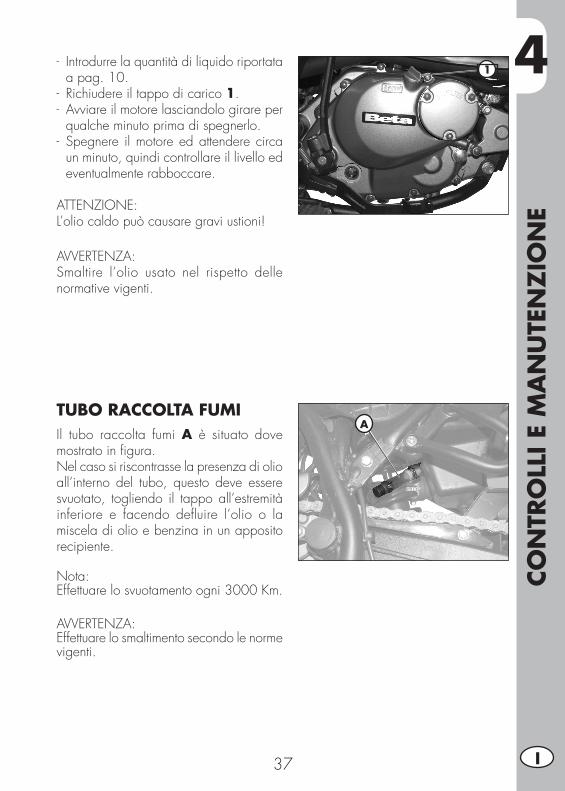
- Introdurre la quantità di liquido riportata a pag. 10.
- Richiudere il tappo di carico 1.- Avviare il motore lasciandolo girare per
qualche minuto prima di spegnerlo.- Spegnere il motore ed attendere circa
un minuto, quindi controllare il livello ed eventualmente rabboccare.
ATTENZIONE:L’olio caldo può causare gravi ustioni!
AVVERTENZA:Smaltire l’olio usato nel rispetto delle norma tive vigenti.
TUBO RACCOLTA FUMIIl tubo raccolta fumi A è situato dove mostrato in figura.Nel caso si riscontrasse la presenza di olio all’interno del tubo, questo deve essere svuotato, togliendo il tappo all’estremità inferiore e facendo defluire l’olio o la miscela di olio e benzina in un apposito recipiente.
Nota:Effettuare lo svuotamento ogni 3000 Km.
AVVERTENZA:Effettuare lo smaltimento secondo le norme vigenti.
1
A
4CO
NTR
OLL
I E M
AN
UTE
NZ
ION
E
38I
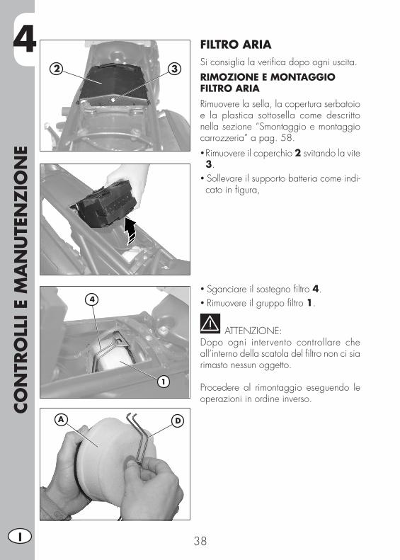
FILTRO ARIASi consiglia la verifica dopo ogni uscita.RIMOZIONE E MONTAGGIO FILTRO ARIARimuovere la sella, la copertura serbatoio e la plastica sottosella come descritto nella sezione “Smontaggio e montaggio carrozzeria” a pag. 58.• Rimuovere il coperchio 2 svitando la vite 3.
• Sollevare il supporto batteria come indi-cato in figura,
• Sganciare il sostegno filtro 4.• Rimuovere il gruppo filtro 1.
ATTENZIONE:Dopo ogni intervento controllare che all’interno della scatola del filtro non ci sia rimasto nessun oggetto.
Procedere al rimontaggio eseguendo le operazioni in ordine inverso.
4
1
2 3
DA
4
CON
TRO
LLI E
MA
NU
TEN
ZIO
NE
39 I
PULIZIA FILTRO ARIA• Lavare con cura il filtro con acqua e sapone.
• Fare asciugare il filtro.• Bagnare il filtro con olio specifico, elimi-nandone poi l’eccedenza in modo che non goccioli.
• Se necessario pulire anche l’interno della scatola filtro.
ATTENZIONE:Non pulire il filtro con benzina o petrolio.
NOTA:se il filtro è danneggiato procedere imme-diatamente alla sua sostituzione.Per la sostituzione rivolgersi presso un servizio assistenza autorizzato Betamotor.
ATTENZIONE:Non mettere mai in funzione la moto senza filtro aria. L’infiltrazione di polvere e sporco può causare danni ed un’elevata usura.
4CO
NTR
OLL
I E M
AN
UTE
NZ
ION
E
40I
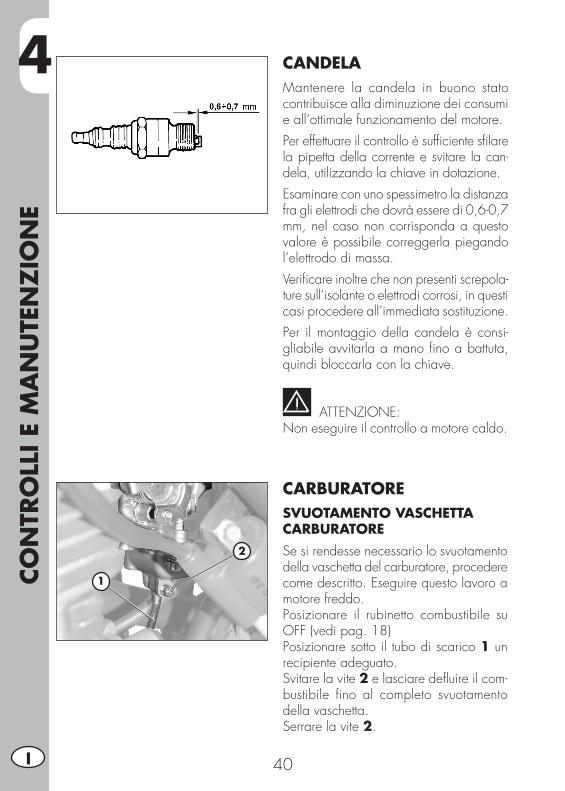
CANDELAMantenere la candela in buono stato contribuisce alla diminuzione dei consumi e all’ottimale funzionamento del motore.Per effettuare il controllo è sufficiente sfilare la pipetta della corrente e svitare la can-dela, utilizzando la chiave in dotazione.Esaminare con uno spessimetro la distanza fra gli elettrodi che dovrà essere di 0,6-0,7 mm, nel caso non corrisponda a questo valore è possibile correggerla piegando l’elettrodo di massa.Verificare inoltre che non presenti screpola-ture sull’isolante o elettrodi corrosi, in questi casi procedere all’immediata sostituzione.Per il montaggio della candela è consi-gliabile avvitarla a mano fino a battuta, quindi bloccarla con la chiave.
ATTENZIONE:Non eseguire il controllo a motore caldo.
CARBURATORESVUOTAMENTO VASCHETTA CARBURATORESe si rendesse necessario lo svuotamento della vaschetta del carburatore, procedere come descritto. Eseguire questo lavoro a motore freddo.Posizionare il rubinetto combustibile su OFF (vedi pag. 18)Posizionare sotto il tubo di scarico 1 un recipiente adeguato.Svitare la vite 2 e lasciare defluire il com-bustibile fino al completo svuotamento della vaschetta.Serrare la vite 2.
2
1
4
CON
TRO
LLI E
MA
NU
TEN
ZIO
NE
41 I
ATTENZIONE:Il carburante è facilmente infiammabile e tossico. Maneggiare quindi il carburante con tutte le precauzioni del caso. Mai eseguire lavori all’impianto del carburante vicino a fonti di calore e fiamme libere. Far sempre raffreddare prima il motore. Con uno straccio pulire eventuali eccedenze. Anche materiali impregnati di carburante sono facilmente infiammabili. In caso di ingestione o contatto con parti sensibili del corpo consultare subito un medico. Provvedere ad uno smaltimento regolare.
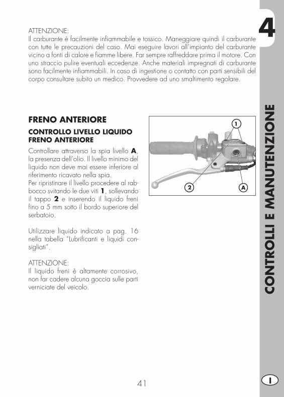
FRENO ANTERIORE CONTROLLO LIVELLO LIQUIDO FRENO ANTERIOREControllare attraverso la spia livello A, la presenza dell’olio. Il livello minimo del liquido non deve mai essere inferiore al riferimento ricavato nella spia.Per ripristinare il livello procedere al rab-bocco svitando le due viti 1, sollevando il tappo 2 e inserendo il liquido freni fino a 5 mm sotto il bordo superiore del serbatoio.
Utilizzare liquido indicato a pag. 16 nella tabella “Lubrificanti e liquidi con-sigliati”.
ATTENZIONE:Il liquido freni è altamente corrosivo, non far cadere alcuna goccia sulle parti verniciate del veicolo.
2
1
A
4CO
NTR
OLL
I E M
AN
UTE
NZ
ION
E
42I
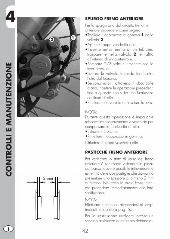
SPURGO FRENO ANTERIOREPer lo spurgo aria dal circuito frenanteanteriore procedere come segue:•Togliereilcappucciodigomma1 dalla valvola 2.•Aprireiltappovaschettaolio.•Inserire un’estremità di un tubicinotrasparente nella valvola 2, e l’altra all’interno di un contenitore.•Pompare2/3volte e rimanere con laleva premuta.•Svitare la valvola facendo fuoriuscirel’olio dal tubicino.•Sesonovisibili,attraversoiltubo,bolled’aria, ripetere le operazioni precedenti fino a quando non si ha una fuoriuscita continua di olio.•Richiuderelavalvolaerilasciarelaleva.
NOTA: Durante questa operazione è importante rabboccare continuamente la vaschetta per compensare la fuoriuscita di olio.•Estrarreiltubicino.•Rimettereilcappuccioingomma.Chiudere il tappo vaschetta olio.
PASTICCHE FRENO ANTERIOREPer verificare lo stato di usura del freno anteriore è sufficiente visionare la pinza dal basso, dove è possibile intravedere le estremità delle due pastiglie che dovranno presentare uno spessore di almeno 2 mm di ferodo. Nel caso lo strato fosse inferi-ore procedere immediatamente alla loro sostituzione.
NOTA:Effettuare il controllo attenendosi ai tempi indicati in tabella a pag. 55.Per la sostituzione rivolgersi presso un servizio assistenza autorizzato Betamotor.
2 mm
12
4
CON
TRO
LLI E
MA
NU
TEN
ZIO
NE
43 I
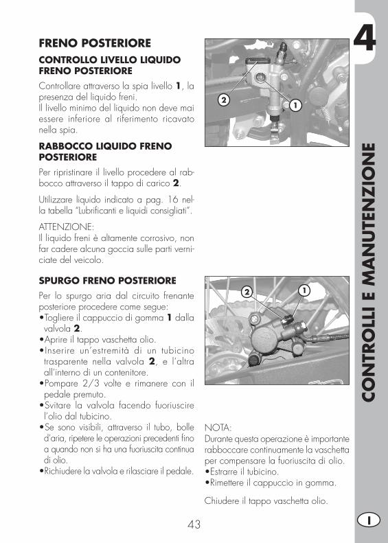
FRENO POSTERIORECONTROLLO LIVELLO LIQUIDO FRENO POSTERIOREControllare attraverso la spia livello 1, la presenza del liquido freni.Il livello minimo del liquido non deve mai essere inferiore al riferimento ricavato nella spia.
RABBOCCO LIQUIDO FRENO POSTERIOREPer ripristinare il livello procedere al rab-bocco attraverso il tappo di carico 2.
Utilizzare liquido indicato a pag. 16 nel-la tabella “Lubrificanti e liquidi consigliati”.
ATTENZIONE:Il liquido freni è altamente corrosivo, non far cadere alcuna goccia sulle parti verni-ciate del veicolo.
SPURGO FRENO POSTERIOREPer lo spurgo aria dal circuito frenante posteriore procedere come segue:•Togliereilcappucciodigomma1 dalla valvola 2.•Aprireiltappovaschettaolio.•Inserire un’estremità di un tubicinotrasparente nella valvola 2, e l’altra all’interno di un contenitore.•Pompare 2/3 volte e rimanere con ilpedale premuto.•Svitare la valvola facendo fuoriuscirel’olio dal tubicino.•Se sono visibili, attraverso il tubo, bolle d’aria, ripetere le operazioni precedenti fino a quando non si ha una fuoriuscita continua di olio.•Richiudere la valvola e rilasciare il pedale.
NOTA: Durante questa operazione è importante rabboccare continuamente la vaschetta per compensare la fuoriuscita di olio.•Estrarreiltubicino.•Rimettereilcappuccioingomma.
Chiudere il tappo vaschetta olio.
21
12
4CO
NTR
OLL
I E M
AN
UTE
NZ
ION
E
44I
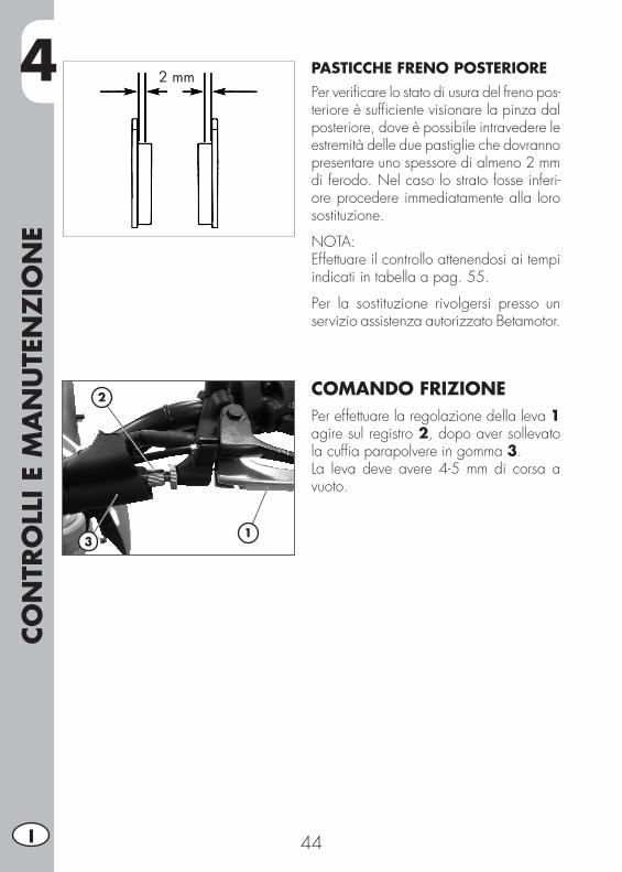
PASTICCHE FRENO POSTERIOREPer verificare lo stato di usura del freno pos-teriore è sufficiente visionare la pinza dal posteriore, dove è possibile intravedere le estremità delle due pastiglie che dovranno presentare uno spessore di almeno 2 mm di ferodo. Nel caso lo strato fosse inferi-ore procedere immediatamente alla loro sostituzione.
NOTA:Effettuare il controllo attenendosi ai tempi indicati in tabella a pag. 55.
Per la sostituzione rivolgersi presso un servizio assistenza autorizzato Betamotor.
COMANDO FRIZIONEPer effettuare la regolazione della leva 1 agire sul registro 2, dopo aver sollevato la cuffia parapolvere in gomma 3.La leva deve avere 4-5 mm di corsa a vuoto.
2 mm
1
2
3
4
CON
TRO
LLI E
MA
NU
TEN
ZIO
NE
45 I
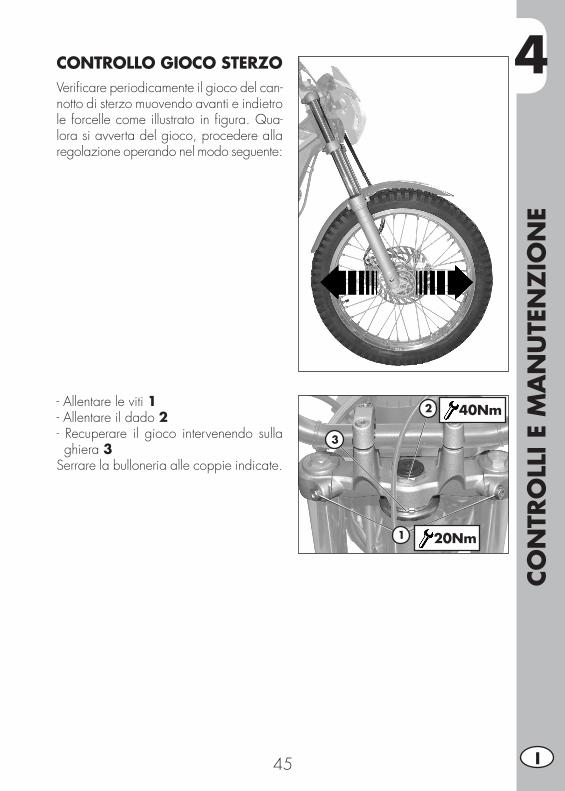
CONTROLLO GIOCO STERZOVerificare periodicamente il gioco del can-notto di sterzo muovendo avanti e indietro le forcelle come illustrato in figura. Qua-lora si avverta del gioco, procedere alla regolazione operando nel modo seguente:
- Allentare le viti 1- Allentare il dado 2- Recuperare il gioco intervenendo sulla ghiera 3
Serrare la bulloneria alle coppie indicate.
1
2
3
40Nm
20Nm
4CO
NTR
OLL
I E M
AN
UTE
NZ
ION
E
46I
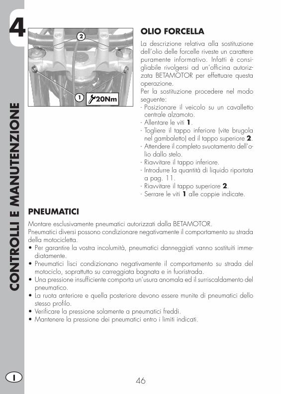
OLIO FORCELLALa descrizione relativa alla sostituzione dell’olio delle forcelle riveste un carattere puramente informativo. Infatti è consi-gliabile rivolgersi ad un’officina autoriz-zata BETAMOTOR per effettuare questa operazione.Per la sostituzione procedere nel modo seguente:- Posizionare il veicolo su un cavalletto centrale alzamoto.
- Allentare le viti 1.- Togliere il tappo inferiore (vite brugola nel gambaletto) ed il tappo superiore 2.
- Attendere il completo svuotamento dell’o-lio dallo stelo.
- Riavvitare il tappo inferiore.- Introdurre la quantità di liquido riportata a pag. 11.
- Riavvitare il tappo superiore 2.- Serrare le viti 1 alle coppie indicate.
1
2
20Nm
PNEUMATICIMontare esclusivamente pneumatici autorizzati dalla BETAMOTOR.Pneumatici diversi possono condizionare negativamente il comportamento su strada della motocicletta.•Pergarantirelavostraincolumità,pneumaticidanneggiativannosostituitiimme-
diatamente.•Pneumatici lisci condizionano negativamente il comportamento su strada del
motociclo, soprattutto su carreggiata bagnata e in fuoristrada.•Unapressioneinsufficientecomportaun’usuraanomalaedilsurriscaldamentodel
pneumatico.•Laruotaanterioreequellaposterioredevonoesseremunitedipneumaticidello
stesso profilo.•Verificarelapressionesolamenteapneumaticifreddi.•Mantenerelapressionedeipneumaticientroilimitiindicati.
4
CON
TRO
LLI E
MA
NU
TEN
ZIO
NE
47 I
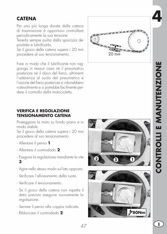
CATENAPer una più lunga durata della catena di trasmissione è opportuno controllare periodicamente la sua tensione.Tenerla sempre pulita dalla sporcizia de-positata e lubrificarla.Se il gioco della catena supera i 20 mm procedere al suo tensionamento.
Fare in modo che il lubrificante non rag-giunga in nessun caso né il pneumatico posteriore né il disco del freno, altrimenti l’aderenza al suolo del pneumatico e l’azione del freno posteriore si ridurrebbero notevolmente e si potrebbe facilmente per-dere il controllo della motocicletta.
VERIFICA E REGOLAZIONE TENSIONAMENTO CATENAPosteggiare la moto su fondo piano e in modo stabile.Se il gioco della catena supera i 20 mm procedere al suo tensionamento.
- Allentare il perno 1
- Allentare il controdado 2
- Eseguire la regolazione mendiante la vite 3
- Agire nello stesso modo sul lato opposto.
- Verificare l’allineamento della ruota.
- Verificare il tensionamento.
- Se il gioco della catena non rispetta il dato previsto eseguire nuovamente la regolazione.
- Serrare il perno alla coppia indicata.- Ribloccare il controdado 2.
20 mm
2 3 1
80Nm

4CO
NTR
OLL
I E M
AN
UTE
NZ
ION
E
48I
FARO ANTERIOREMantenere il vetro del proiettore sempre pulito (vedi pag. 53).Verificare periodicamente la corretta dire-zione del fascio luminoso (cap. 3).
SOSTITUZIONI LAMPADE ANTERIORI • Smontare la mascherina faro rimuovendo le due viti di fissaggio 1 e di regolazione 2 indicate in figura.
• Per la sostituzione della lampada di posizione sfilare il portalampada 3.
Per la sostituzione della lampada anabba-gliante/abbagliante:
• Scollegare il connettore elettrico 4.• Sollevare la cuffia in gomma 5.• Sganciare la molla 6.• Sfilare la lampada dal portalampada e procedere alla sostituzione.
Per il rimontaggio eseguire le operazioni sopra in ordine inverso.
Eseguita la sostituzione eseguire la rego-lazione (pag. 34).
11
3
2
4
5
5
6
4
CON
TRO
LLI E
MA
NU
TEN
ZIO
NE
49 I
A
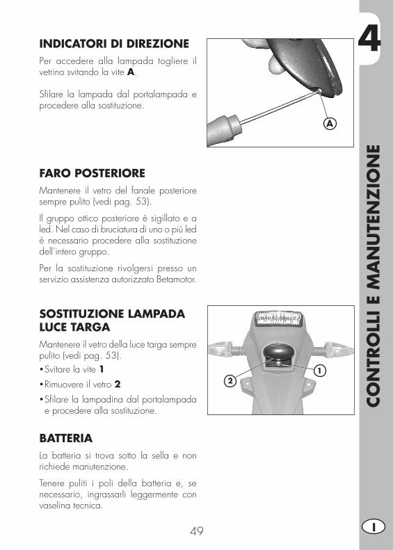
INDICATORI DI DIREZIONEPer accedere alla lampada togliere il vetrino svitando la vite A.
Sfilare la lampada dal portalampada e procedere alla sostituzione.
FARO POSTERIOREMantenere il vetro del fanale posteriore sempre pulito (vedi pag. 53).
Il gruppo ottico posteriore è sigillato e a led. Nel caso di bruciatura di uno o più led è necessario procedere alla sostituzione dell’intero gruppo.
Per la sostituzione rivolgersi presso un servizio assistenza autorizzato Betamotor.
SOSTITUZIONE LAMPADA LUCE TARGAMantenere il vetro della luce targa sempre pulito (vedi pag. 53).• Svitare la vite 1• Rimuovere il vetro 2• Sfilare la lampadina dal portalampada e procedere alla sostituzione.
BATTERIALa batteria si trova sotto la sella e non richiede manutenzione.
Tenere puliti i poli della batteria e, se necessario, ingrassarli leggermente con vaselina tecnica.
12
4CO
NTR
OLL
I E M
AN
UTE
NZ
ION
E
50I
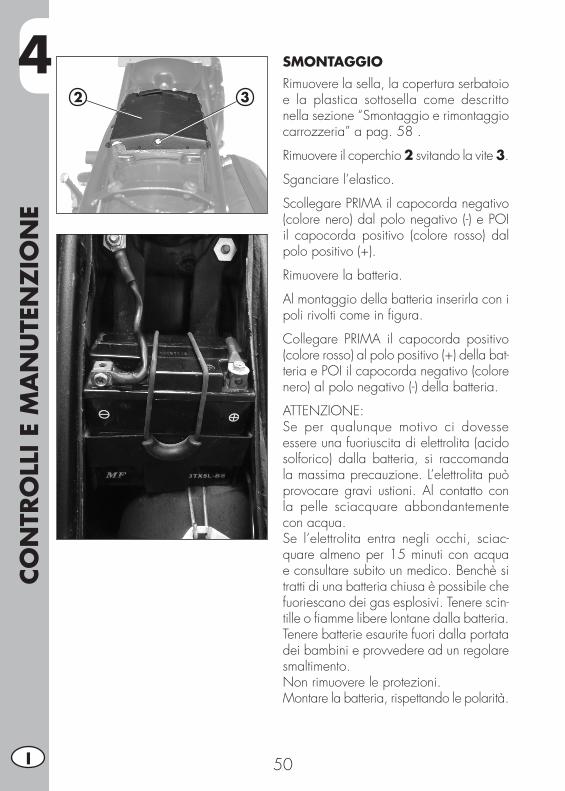
SMONTAGGIORimuovere la sella, la copertura serbatoio e la plastica sottosella come descritto nella sezione “Smontaggio e rimontaggio carrozzeria” a pag. 58 .
Rimuovere il coperchio 2 svitando la vite 3.
Sganciare l’elastico.
Scollegare PRIMA il capocorda negativo (colore nero) dal polo negativo (-) e POI il capocorda positivo (colore rosso) dal polo positivo (+).
Rimuovere la batteria.
Al montaggio della batteria inserirla con ipoli rivolti come in figura.
Collegare PRIMA il capocorda positivo (colore rosso) al polo positivo (+) della bat-teria e POI il capocorda negativo (colore nero) al polo negativo (-) della batteria.
ATTENZIONE:Se per qualunque motivo ci dovesse essere una fuoriuscita di elettrolita (acido solforico) dalla batteria, si raccomanda la massima precauzione. L’elettrolita può provocare gravi ustioni. Al contatto con la pelle sciacquare abbondantemente con acqua.Se l’elettrolita entra negli occhi, sciac-quare almeno per 15 minuti con acqua e consultare subito un medico. Benchè si tratti di una batteria chiusa è possibile che fuoriescano dei gas esplosivi. Tenere scin-tille o fiamme libere lontane dalla batteria. Tenere batterie esaurite fuori dalla portata dei bambini e provvedere ad un regolare smaltimento.Non rimuovere le protezioni.Montare la batteria, rispettando le polarità.
2 3
4
CON
TRO
LLI E
MA
NU
TEN
ZIO
NE
51 I
INATTIVITÀIn caso di prolungata inattività del veicolo, caricare, con carica batterie adeguato, ogni 15 gg o mediante manutentore di carica.La batteria deve essere tenuta in ambiente asciutto, a temperatura 5-35°C e fuori dalla portata dei bambini.
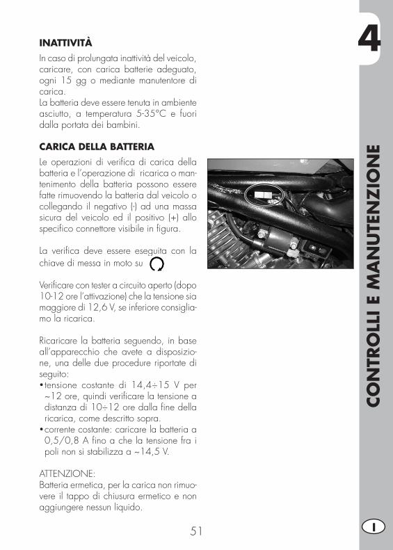
CARICA DELLA BATTERIALe operazioni di verifica di carica della batteria e l’operazione di ricarica o man-tenimento della batteria possono essere fatte rimuovendo la batteria dal veicolo o collegando il negativo (-) ad una massa sicura del veicolo ed il positivo (+) allo specifico connettore visibile in figura.
La verifica deve essere eseguita con la chiave di messa in moto su
Verificare con tester a circuito aperto (dopo 10-12 ore l’attivazione) che la tensione sia maggiore di 12,6 V, se inferiore consiglia-mo la ricarica.
Ricaricare la batteria seguendo, in base all’apparecchio che avete a disposizio-ne, una delle due procedure riportate di seguito:• tensione costante di 14,4÷15 V per ~12 ore, quindi verificare la tensione a distanza di 10÷12 ore dalla fine della ricarica, come descritto sopra.
• corrente costante: caricare la batteria a 0,5/0,8 A fino a che la tensione fra i poli non si stabilizza a ~14,5 V.
ATTENZIONE:Batteria ermetica, per la carica non rimuo-vere il tappo di chiusura ermetico e non aggiungere nessun liquido.
4CO
NTR
OLL
I E M
AN
UTE
NZ
ION
E
52I
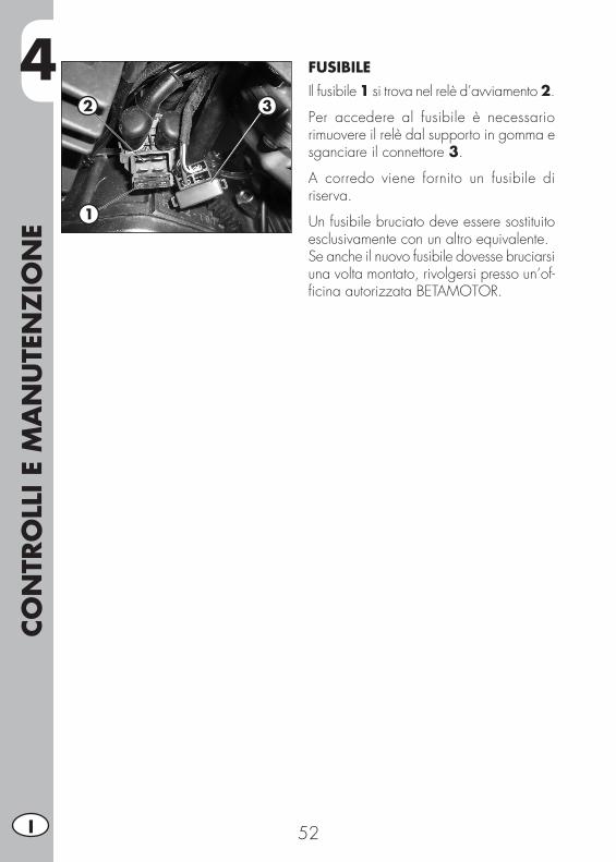
FUSIBILEIl fusibile 1 si trova nel relè d’avviamento 2.
Per accedere al fusibile è necessario rimuovere il relè dal supporto in gomma e sganciare il connettore 3.
A corredo viene fornito un fusibile di riserva.
Un fusibile bruciato deve essere sostituito esclusivamente con un altro equivalente.Se anche il nuovo fusibile dovesse bruciarsi una volta montato, rivolgersi presso un’of-ficina autorizzata BETAMOTOR.
2 3
1
4
CON
TRO
LLI E
MA
NU
TEN
ZIO
NE
53 I
PULIZIA DEL VEICOLOATTENZIONE: non pulire mai il veicolo con un apparecchio ad alta pressione con un forte getto d’acqua. L’eccessiva pressione può raggiungere componenti elettrici, connettori, cavi flessibili, cuscinetti ecc. e danneggiarli o distruggerli.
ATTENZIONE: lavare frequentemente i veicoli che operano in prossimità del mare (salmastro) e su strade soggette a spargimento sale nei periodi invernali. Coprire con un velo d’olio o silicone spray le parti non verniciate e quelle maggiormente esposte come cerchi, forcella e forcellone. Non trattare le parti in gomma ed i freni.
Durante la pulizia evitare l’esposizione diretta ai raggi solari.
Chiudere l’impianto di scarico, in modo da evitare che vi penetri acqua.
Per ammorbidire lo sporco e il fango depositato sulle superfici verniciate usare un getto di acqua. Una volta ammorbiditi, fango e sporcizia sono asportabili con una spugna soffice per carrozzeria imbevuta di molta acqua e “shampoo”. Successiva-mente sciacquare abbondantemente con acqua, ed asciugare con soffio di aria e panno o pelle scamosciata.
Procedere allo scarico della scatola filtro mediante l’apposito sfiato ed alla asci-ugatura.
I detersivi inquinano le acque. Pertanto il lavaggio del veicolo va effettuato in zone attrezzate per la raccolta e la depurazione dei liquidi impiegati per il lavaggio stesso.
Terminata la pulizia guidare per un breve tratto finché il motore non raggiunge la temperatura di esercizio.
ATTENZIONE: con freni bagnati si ha ridotto effetto frenante. Azionare prudentemente i freni in modo da farli asciugare.
Spingere indietro le protezioni dei comandi manubrio, affinché l’acqua penetrata possa evaporare.
Quando la moto sarà completamente asciutta e raffreddata, lubrificare tutti i punti di scorrimento e lavoro.
Trattare tutti i componenti in plastica e verniciati con detergenti o prodotto non ag-gressivi e specifici per la cura del veicolo.
Per prevenire anomalie alla parte elettrica, trattare i contatti elettrici ed interruttori con spray per contatti elettrici.
4CO
NTR
OLL
I E M
AN
UTE
NZ
ION
E
54I
LUNGA INATTIVITÀ DEL VEICOLOIn previsione di un lungo periodo di inattività del veicolo, ad esempio durante la stagione invernale, è necessario adottare alcuni semplici accorgimenti a garanzia di un buon mantenimento:• Eseguire un’accurata pulizia del veicolo in tutte le sue parti.• Ridurre la pressione dei pneumatici di circa il 30%, mantenendoli possibilmente sollevati da terra.
• Rimuovere la candela ed immettere dal foro qualche goccia di olio motore. Far compiere qualche giro al motore, azionando la leva di avviamento a pedale. Riavvitare la candela.
• Coprire con un velo d’olio o silicone spray le parti non verniciate, tranne le parti in gomma ed i freni.
• Tenere in carica la batteria.• Coprire il veicolo con un telo a protezione della polvere.• Scaricare la vaschetta del carburatore come descritto a pag. 40.
DOPO UN LUNGO PERIODO DI INATTIVITÀ
• Ripristinare la pressione dei pneumatici.• Controllare il serraggio di tutte le viti di una certa importanza meccanica.• Effettuare il primo avviamento con il sistema a ped ale: (“kick-starter”).
4
CON
TRO
LLI E
MA
NU
TEN
ZIO
NE
55 I
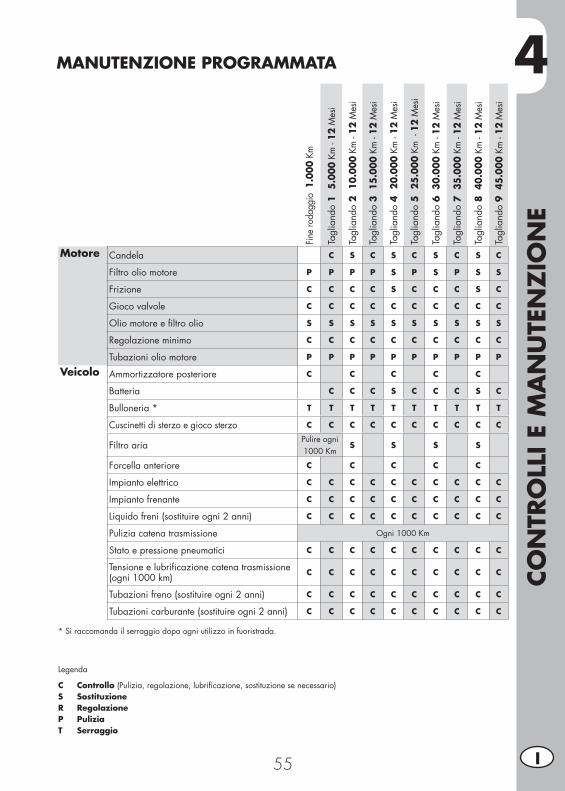
MANUTENZIONE PROGRAMMATA
Fine
roda
ggio
1.0
00 K
m
Tagl
iand
o 1
5.
000
Km -
12 M
esi
Tagl
iand
o 2
10
.000
Km
- 12
Mes
i
Tagl
iand
o 3
15.
000
Km -
12 M
esi
Tagl
iand
o 4
20
.000
Km
- 12
Mes
i
Tagl
iand
o 5
25
.000
Km
- 1
2 M
esi
Tagl
iand
o 6
30.
000
Km -
12 M
esi
Tagl
iand
o 7
35.
000
Km -
12 M
esi
Tagl
iand
o 8
40.
000
Km -
12 M
esi
Tagl
iand
o 9
45.
000
Km -
12 M
esi
Motore Candela C S C S C S C S C
Filtro olio motore P P P P S P S P S S
Frizione C C C C S C C C S C
Gioco valvole C C C C C C C C C C
Olio motore e filtro olio S S S S S S S S S S
Regolazione minimo C C C C C C C C C C
Tubazioni olio motore P P P P P P P P P P
Veicolo Ammortizzatore posteriore C C C C C
Batteria C C C S C C C S C
Bulloneria * T T T T T T T T T T
Cuscinetti di sterzo e gioco sterzo C C C C C C C C C C
Filtro ariaPulire ogni 1000 Km
S S S S
Forcella anteriore C C C C C
Impianto elettrico C C C C C C C C C C
Impianto frenante C C C C C C C C C C
Liquido freni (sostituire ogni 2 anni) C C C C C C C C C C
Pulizia catena trasmissione Ogni 1000 Km
Stato e pressione pneumatici C C C C C C C C C C
Tensione e lubrificazione catena trasmissione(ogni 1000 km) C C C C C C C C C C
Tubazioni freno (sostituire ogni 2 anni) C C C C C C C C C C
Tubazioni carburante (sostituire ogni 2 anni) C C C C C C C C C C
* Si raccomanda il serraggio dopo ogni utilizzo in fuoristrada.
Legenda
C Controllo (Pulizia, regolazione, lubrificazione, sostituzione se necessario)S SostituzioneR RegolazioneP PuliziaT Serraggio

56
5
SMO
NTA
GG
IO E
MO
NTA
GG
IO C
ARRO
ZZ
ERIA
57 I
CAP. 5 SMONTAGGIO E MONTAGGIO CARROZZERIA
INDICE ARGOMENTISmontaggio e rimontaggio sella.............................................................58Smontaggio e rimontaggio carenatura serbatoio ......................................58Smontaggio e rimontaggio maniglie passeggero .....................................58Smontaggio e rimontaggio plastica sottosella ..........................................59
5SM
ON
TAG
GIO
E M
ON
TAG
GIO
CA
RRO
ZZ
ERIA
58I
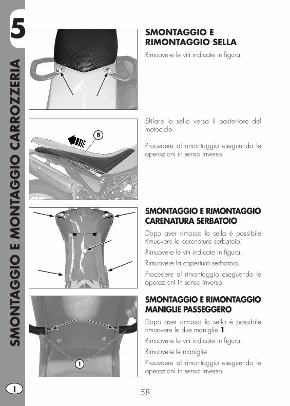
SMONTAGGIO E RIMONTAGGIO SELLARimuovere le viti indicate in figura.
Sfilare la sella verso il posteriore del motociclo.
Procedere al rimontaggio eseguendo le operazioni in senso inverso.
SMONTAGGIO E RIMONTAGGIO CARENATURA SERBATOIODopo aver rimosso la sella è possibile rimuovere la carenatura serbatoio.Rimuovere le viti indicate in figura.Rimuovere la copertura serbatoio.Procedere al rimontaggio eseguendo le operazioni in senso inverso.
SMONTAGGIO E RIMONTAGGIO MANIGLIE PASSEGGERODopo aver rimosso la sella è possibile rimuovere le due maniglie 1.Rimuovere le viti indicate in figura.Rimuovere le maniglie.Procedere al rimontaggio eseguendo le operazioni in senso inverso.
B
1
5
SMO
NTA
GG
IO E
MO
NTA
GG
IO C
ARRO
ZZ
ERIA
59 I
1
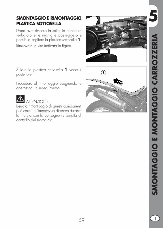
SMONTAGGIO E RIMONTAGGIO PLASTICA SOTTOSELLADopo aver rimosso la sella, la copertura serbatoio e le maniglie passeggero è possibile togliere la plastica sottosella 1.Rimuovere la vite indicata in figura.
Sfilare la plastica sottosella 1 verso il posteriore.
Procedere al rimontaggio eseguendo le operazioni in senso inverso.
ATTENZIONE:L’errato rimontaggio di questi componenti può causare l’improvviso distacco durante la marcia con la conseguente perdita di controllo del motociclo.

60
6
COSA
FA
RE
IN C
ASO
DI EM
ERG
ENZ
A
61 I
CAP. 6 COSA FARE IN CASO DI EMERGENZA
INDICE ARGOMENTIRicerca del guasto ................................................................................62Indice alfabetico ..................................................................................63
6CO
SA F
ARE
IN C
ASO
DI EM
ERG
ENZ
A
62I
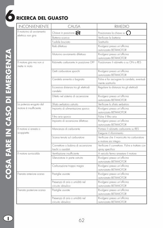
INCONVENIENTE CAUSA RIMEDIOIl motorino di avviamento elettrico non gira
Chiave in posizione Posizionare la chiave su
Batteria scarica Verificare la batteriaFusibile bruciato SostituirloRelè difettoso Rivolgersi presso un’officina
autorizzata BETAMOTOR Motorino avviamento difettoso Rivolgersi presso un’officina
autorizzata BETAMOTOR Il motore gira ma non si mette in moto
Rubinetto carburante in posizione OFF Posizionare il rubinetto o su ON o RES
Getti carburatore sporchi Rivolgersi presso un’officinaautorizzata BETAMOTOR
Candela annerita o bagnata Pulire e far asciugare la candela, eventual-mente sostituirla
Eccessiva distanza tra gli elettrodi candela
Regolare la distanza tra gli elettrodi
Difetto nel sistema di accensione Rivolgersi presso un’officinaautorizzata BETAMOTOR
La potenza erogata dal motore è insufficiente
Sfiato serbatoio ostruito Verificare lo sfiato serbatoioImpianto di alimentazione sporco Rivolgersi presso un’officina
autorizzata BETAMOTORFiltro aria sporco Pulire il filtro ariaImpianto di accensione difettoso Rivolgersi presso un’officina
autorizzata BETAMOTORIl motore si arresta o scoppietta
Mancanza di carburante Portare il rubinetto carburante su RESEseguire il rifornimento
Scarsa tenuta sul carburatore Verificare che il manicotto tra carburatore e motore sia integro
Connettore o bobina di accensione laschi o ossidati
Verificare il connettore. Pulire e trattare con spray specifico
Il motore surriscalda Ventilazione insufficiente A veicolo fermo arrestare il motoreSilenziatore in parte ostruito Rivolgersi presso un’officina
autorizzata BETAMOTORCarburazione troppo magra Rivolgersi presso un’officina
autorizzata BETAMOTORFrenata anteriore scarsa Pastiglie usurate Rivolgersi presso un’officina
autorizzata BETAMOTORPresenza di aria o umidità nelcircuito idraulico
Rivolgersi presso un’officinaautorizzata BETAMOTOR
Frenata posteriore scarsa Pastiglie usurate Rivolgersi presso un’officinaautorizzata BETAMOTOR
Presenza di aria o umidità nelcircuito idraulico
Rivolgersi presso un’officinaautorizzata BETAMOTOR
RICERCA DEL GUASTO
IND
ICE
ALF
ABET
ICO
63 I
INDICE ALFABETICOArresto motore .....................................................................................29Avviamento motore ..............................................................................29
Batteria ...............................................................................................49Bloccasterzo ........................................................................................21
Candela .............................................................................................40Catena ...............................................................................................47Chiavi ................................................................................................21Comando frizione ................................................................................44Conoscenza del veicolo ..........................................................................9Controllo gioco sterzo ..........................................................................45
Dati identificazione veicolo .....................................................................8Dati tecnici ..........................................................................................10
Elementi principali ................................................................................18
Faro anteriore ......................................................................................34Faro anteriore ......................................................................................48Faro posteriore ....................................................................................49FIltro aria ............................................................................................38Freni ...................................................................................................32Freno anteriore ...................................................................................41Freno posteriore ...................................................................................43
Impianto elettrico .................................................................................14Indicatori di direzione ..........................................................................49Istruzioni di funzionamento tachimetro digitale ........................................22
Legenda simboli ...................................................................................32Lubrificanti e liquidi consigliati ...............................................................16Lunga inattività del veicolo ....................................................................54
Manubrio ............................................................................................33Manutenzione programmata ................................................................55Motore ...............................................................................................12
IND
ICE
ALF
ABET
ICO
64I
Olio forcella ........................................................................................46Olio motore .........................................................................................36
Pneumatici ..........................................................................................46Predisposizione per assetto da trial ........................................................30Pulizia del veicolo ................................................................................53
Regime di minimo ...............................................................................33Regolazione ammortizzatore .................................................................33Ricerca del guasto ................................................................................62Rifornimento carburante ........................................................................28Rodaggio ............................................................................................28
Serratura casco ...................................................................................21Smontaggio e rimontaggio carenatura serbatoio ......................................58Smontaggio e rimontaggio maniglie passeggero .....................................58Smontaggio e rimontaggio plastica sottosella ..........................................59Smontaggio e rimontaggio sella.............................................................58Sostituzione lampada luce targa ............................................................49Svuotamento vaschetta carburatore ........................................................40
Tubo raccolta fumi ................................................................................37
Verifiche prima e dopo l’utilizzo.............................................................28

1 GB
ALP 200
Thanks for you preference, and have a good time! This hand-book contains the information you need to properly operate and maintain your motorcycle.
The data and specifications provided in this manual does not constitute an engagement on the part of BETAMOTOR S.p.A. BETAMOTOR reserves the right to make any changes and improvements to its models at any moment and without notice.
Code 017440090 000
2GB
IMPORTANT
We recommend checking all the tightenings after the first one or two hours’ ride over rough ground. Special attention should be paid to the following parts:
• rear sprocket• footrest supports• front brake caliper• mudguard bracket• engine bolts• shock absorber bolts• wheel spokes• rear frame
IMPORTANT
For any servicing requirements, please contact Betamotor’s author-ized service network.
CON
TEN
TS
3 GB
TABLE OF CONTENTS
Operating instructions .............................................................................5Ecologic guide .......................................................................................5Riding safety .........................................................................................6
CHAPTER 1 GENERAL INFORMATION ..............................................7Vehicle identification data .......................................................................8Familiarizing with the vehicle...................................................................9Specifications ......................................................................................10Engine ................................................................................................12Electrical system ...................................................................................14Recommended lubricants and liquids ......................................................16
CHAPTER 2 OPERATION ..................................................................17Main parts ..........................................................................................18Keys ...................................................................................................21Steering lock .......................................................................................21Helmet lock .........................................................................................21Digital rpm indicator operating instructions ..............................................22Checks before and after use ..................................................................28Breaking in..........................................................................................28Fuelling ...............................................................................................28Startup ................................................................................................29Engine shut-down .................................................................................29Trial trim option....................................................................................30
CHAPTER 3 ADJUSTMENTS ..............................................................31Key to symbols.....................................................................................32Brakes ................................................................................................32Adjusting the idle speed .......................................................................33Handlebar ..........................................................................................33Rear shock absorber .............................................................................33Headlight ............................................................................................34
CHAPTER 4 CHECKS AND MAINTENANCE .....................................35Engine oil ............................................................................................36Fume collecting tube .............................................................................37Air filter ..............................................................................................38
CON
TEN
TS
4GB
Spark plug ..........................................................................................40Carburettor .........................................................................................40Front brake..........................................................................................41Rear brake ..........................................................................................43Clutch control ......................................................................................44Ckeck of steering play ..........................................................................45Tyres...................................................................................................46Fork oil ...............................................................................................46Chain .................................................................................................47Headlight ............................................................................................48Turn indicators .....................................................................................49Tail light ..............................................................................................49Replacing the plate number light ............................................................49Battery ................................................................................................49Cleaning the vehicle .............................................................................53Prolonged inactivity ..............................................................................54Scheduled maintenance vehicle ............................................................55
CHAPTER 5 BODY DISASSEMBLY AND REASSEMBLY .....................57Removal and refitting of the saddle.........................................................58Removal and refitting of the tank fairing ..................................................58Removal and refitting of the passenger handles .................................................58Removal and refitting of the under-saddle plastic shield .............................59
CHAPTER 6 TROUBLESHOOTING ....................................................61Troubleshooting ...................................................................................62
5 GB
OPERATING INSTRUCTIONS
• The vehicle must be accompanied by: number-plate, registration document, tax disc and insurance.
• Do not carry animals, pets or loose objects that can stick out from the vehicle.• Riding without a crash helmet is forbidden.• Always ride with the low beam on.• Any modifications of the engine or other parts resulting in a power and/or speed increase are punishable by severe sanctions including the confiscation of the vehicle.
• To protect your safety and that of others, always drive carefully and with your helmet on.
WARNINGAny modifications and tampering with the vehicle during the warranty period exempt the manufacturer from all responsibility and invalidate warranty.
ECOLOGIC GUIDE
• Every vehicle powered by an internal combustion engine produces an amount of noise (noise pollution) and gases (air pollution) which varies with the riding style.
• The abatement of noise and air pollution levels is the duty of everybody. Avoid full-throttle starts, sudden acceleration and abrupt braking. This will reduce noise emission as well as the wear and tear of the tyres and mechanical parts, and will also allow a considerable reduction in fuel consumption.
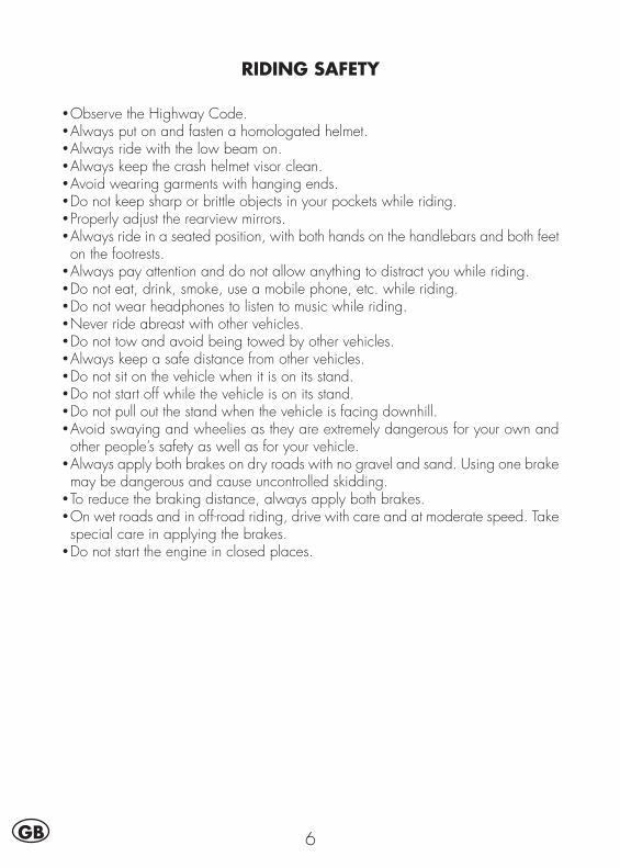
6GB
RIDING SAFETY
• Observe the Highway Code.• Always put on and fasten a homologated helmet.• Always ride with the low beam on.• Always keep the crash helmet visor clean.• Avoid wearing garments with hanging ends.• Do not keep sharp or brittle objects in your pockets while riding.• Properly adjust the rearview mirrors.• Always ride in a seated position, with both hands on the handlebars and both feet on the footrests.
• Always pay attention and do not allow anything to distract you while riding.• Do not eat, drink, smoke, use a mobile phone, etc. while riding.• Do not wear headphones to listen to music while riding.• Never ride abreast with other vehicles.• Do not tow and avoid being towed by other vehicles.• Always keep a safe distance from other vehicles.• Do not sit on the vehicle when it is on its stand.• Do not start off while the vehicle is on its stand.• Do not pull out the stand when the vehicle is facing downhill.• Avoid swaying and wheelies as they are extremely dangerous for your own and other people’s safety as well as for your vehicle.
• Always apply both brakes on dry roads with no gravel and sand. Using one brake may be dangerous and cause uncontrolled skidding.
• To reduce the braking distance, always apply both brakes.• On wet roads and in off-road riding, drive with care and at moderate speed. Take special care in applying the brakes.
• Do not start the engine in closed places.
1
GEN
ERA
L IN
FORM
ATI
ON
7 GB
CHAPTER 1 GENERAL INFORMATION
CONTENTSVehicle identification data .......................................................................8
Frame identification ...........................................................................8Engine identification ..........................................................................8Toolkit ..............................................................................................8
Familiarizing with the vehicle...................................................................9Specifications ......................................................................................10
Weigth ...........................................................................................10Vehicle dimensions ..........................................................................10Tyres ..............................................................................................10Capacities ......................................................................................10Front suspension ..............................................................................11Rear suspension ..............................................................................11Front brake .....................................................................................11Rear brake .....................................................................................11
Engine ................................................................................................12Carburetor ......................................................................................12Transmission ..................................................................................13
Electrical system ...................................................................................14Electrical diagram ...........................................................................14Legend electrical diagram ................................................................15
Recommended lubricants and liquids ......................................................16
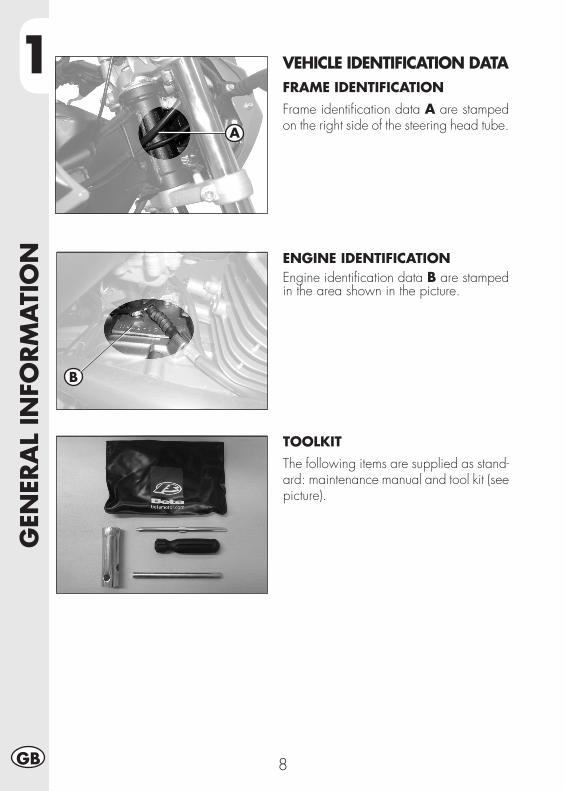
1G
ENER
AL
INFO
RM
ATI
ON
8GB
VEHICLE IDENTIFICATION DATAFRAME IDENTIFICATIONFrame identification data A are stamped on the right side of the steering head tube.
ENGINE IDENTIFICATIONEngine identification data B are stamped in the area shown in the picture.
TOOLKITThe following items are supplied as stand-ard: maintenance manual and tool kit (see picture).
A
B
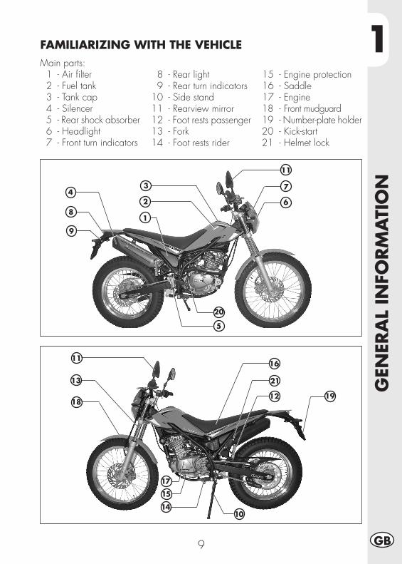
1
GEN
ERA
L IN
FORM
ATI
ON
9 GB
Main parts: 1 - Air filter 2 - Fuel tank 3 - Tank cap 4 - Silencer 5 - Rear shock absorber 6 - Headlight 7 - Front turn indicators
1
2113
14
FAMILIARIZING WITH THE VEHICLE
8 - Rear light 9 - Rear turn indicators 10 - Side stand 11 - Rearview mirror 12 - Foot rests passenger 13 - Fork 14 - Foot rests rider
15 - Engine protection 16 - Saddle 17 - Engine18 - Front mudguard19 - Number-plate holder20 - Kick-start21 - Helmet lock
2
34
5
7
8
9
20
10
15
16
17
191218
11
11
6
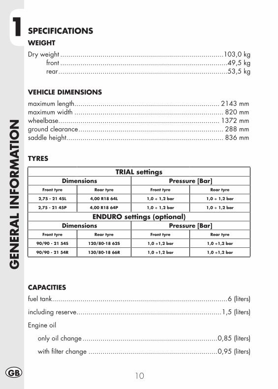
1G
ENER
AL
INFO
RM
ATI
ON
10GB
SPECIFICATIONSWEIGHT
Dry weight .................................................................................103,0 kg front ...................................................................................49,5 kg rear ....................................................................................53,5 kg
VEHICLE DIMENSIONS
maximum length ........................................................................ 2143 mmmaximum width .......................................................................... 820 mmwheelbase................................................................................ 1372 mmground clearance ........................................................................ 288 mmsaddle height .............................................................................. 836 mm
TYRES
CAPACITIES
fuel tank .......................................................................................6 (liters)
including reserve ........................................................................1,5 (liters)
Engine oil
only oil change ...................................................................0,85 (liters)
with filter change ................................................................0,95 (liters)
TRIAL settingsDimensions Pressure [Bar]
Front tyre Rear tyre Front tyre Rear tyre
2,75 - 21 45L 4,00 R18 64L 1,0 ÷ 1,2 bar 1,0 ÷ 1,2 bar
2,75 - 21 45P 4,00 R18 64P 1,0 ÷ 1,2 bar 1,0 ÷ 1,2 bar
ENDURO settings (optional)Dimensions Pressure [Bar]
Front tyre Rear tyre Front tyre Rear tyre
90/90 - 21 54S 120/80-18 62S 1,0 ÷1,2 bar 1,0 ÷1,2 bar
90/90 - 21 54R 130/80-18 66R 1,0 ÷1,2 bar 1,0 ÷1,2 bar
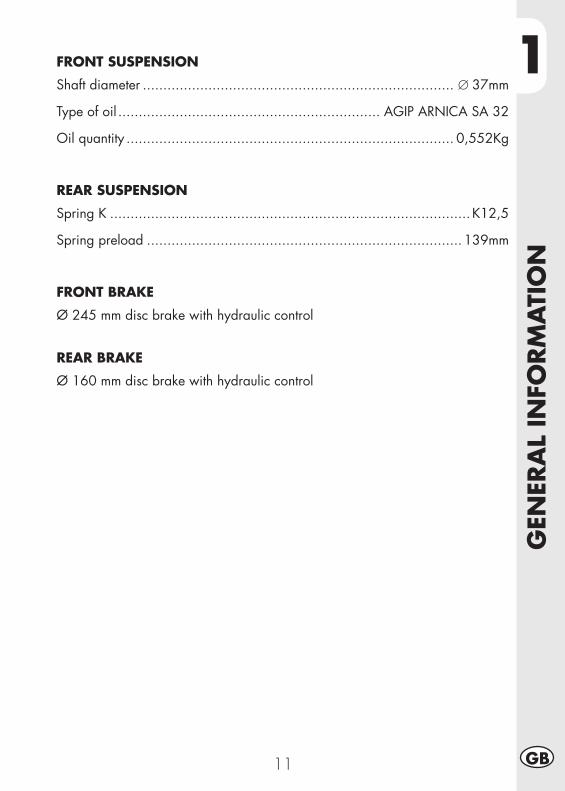
1
GEN
ERA
L IN
FORM
ATI
ON
11 GB
FRONT SUSPENSION
Shaft diameter ............................................................................ ∅ 37mm
Type of oil ................................................................ AGIP ARNICA SA 32
Oil quantity ................................................................................ 0,552Kg
REAR SUSPENSION
Spring K ........................................................................................ K12,5
Spring preload ............................................................................. 139mm
FRONT BRAKE
Ø 245 mm disc brake with hydraulic control
REAR BRAKE
Ø 160 mm disc brake with hydraulic control
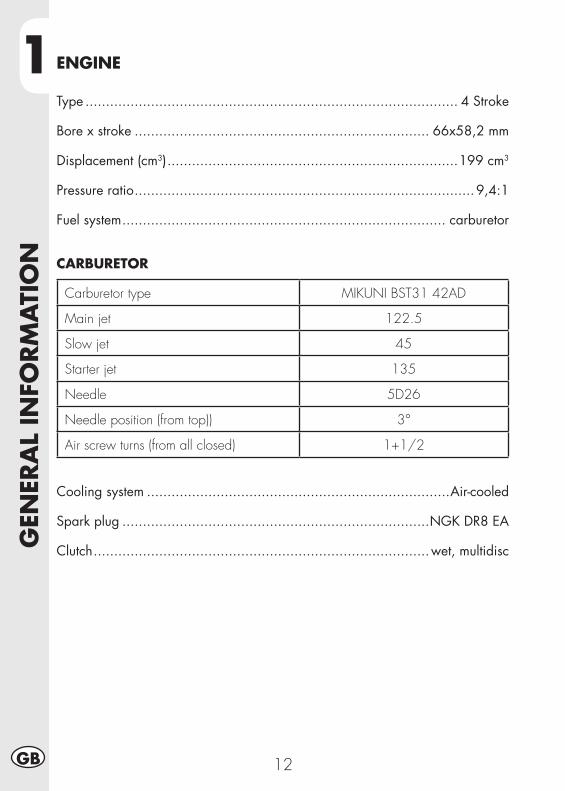
1G
ENER
AL
INFO
RM
ATI
ON
12GB
ENGINE
Type ........................................................................................... 4 Stroke
Bore x stroke ........................................................................ 66x58,2 mm
Displacement (cm3) .......................................................................199 cm3
Pressure ratio ...................................................................................9,4:1
Fuel system ............................................................................... carburetor
CARBURETOR
Carburetor type MIKUNI BST31 42AD
Main jet 122.5
Slow jet 45
Starter jet 135
Needle 5D26
Needle position (from top)) 3°
Air screw turns (from all closed) 1+1/2
Cooling system ..........................................................................Air-cooled
Spark plug ...........................................................................NGK DR8 EA
Clutch ..................................................................................wet, multidisc
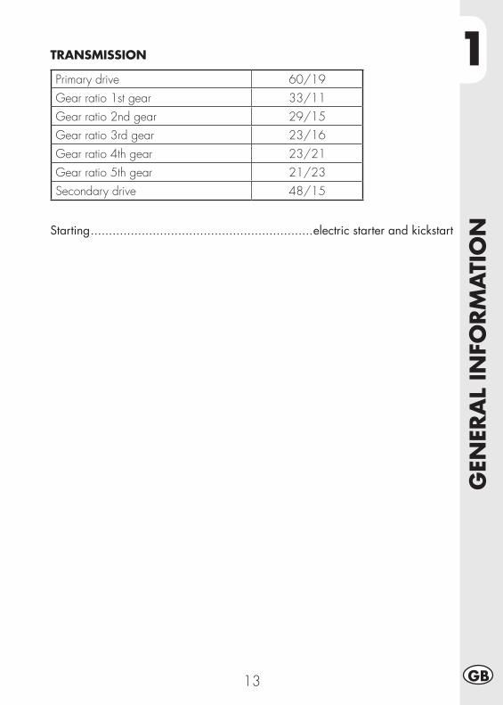
1
GEN
ERA
L IN
FORM
ATI
ON
13 GB
TRANSMISSION
Primary drive 60/19Gear ratio 1st gear 33/11Gear ratio 2nd gear 29/15Gear ratio 3rd gear 23/16Gear ratio 4th gear 23/21Gear ratio 5th gear 21/23Secondary drive 48/15
Starting .............................................................electric starter and kickstart
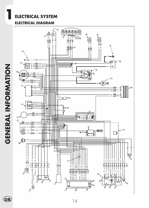
1G
ENER
AL
INFO
RM
ATI
ON
14GB
ELECTRICAL SYSTEMELECTRICAL DIAGRAM
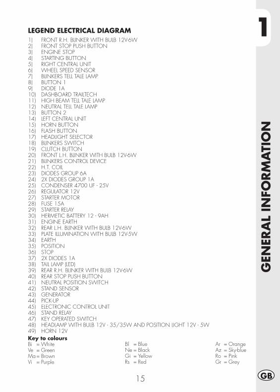
1
GEN
ERA
L IN
FORM
ATI
ON
15 GB
Key to coloursBi = WhiteVe = GreenMa = BrownVi = Purple
Bl = BlueNe = BlackGi = YellowRs = Red
Ar = OrangeAz = Sky-blueRo = PinkGr = Grey
LEGEND ELECTRICAL DIAGRAM1) FRONT R.H. BLINKER WITH BULB 12V-6W2) FRONT STOP PUSH BUTTON3) ENGINE STOP4) STARTING BUTTON5) RIGHT CENTRAL UNIT6) WHEEL SPEED SENSOR7) BLINKERS TELL TALE LAMP8) BUTTON 19) DIODE 1A10) DASHBOARD TRAILTECH11) HIGH BEAM TELL TALE LAMP12) NEUTRAL TELL TALE LAMP13) BUTTON 214) LEFT CENTRAL UNIT15) HORN BUTTON16) FLASH BUTTON17) HEADLIGHT SELECTOR18) BLINKERS SWITCH19) CLUTCH BUTTON20) FRONT L.H. BLINKER WITH BULB 12V-6W21) BLINKERS CONTROL DEVICE22) H.T. COIL23) DIODES GROUP 6A24) 2X DIODES GROUP 1A25) CONDENSER 4700 UF - 25V26) REGULATOR 12V27) STARTER MOTOR28) FUSE 15A29) STARTER RELAY30) HERMETIC BATTERY 12 - 9AH31) ENGINE EARTH32) REAR L.H. BLINKER WITH BULB 12V-6W33) PLATE ILLUMINATION WITH BULB 12V-5W34) EARTH35) POSITION36) STOP37) 2X DIODES 1A38) TAIL LAMP (LED)39) REAR R.H. BLINKER WITH BULB 12V-6W40) REAR STOP PUSH BUTTON41) NEUTRAL POSITION SWITCH42) STAND SENSOR43) GENERATOR44) PICK-UP45) ELECTRONIC CONTROL UNIT46) STAND RELAY47) KEY OPERATED SWITCH48) HEADLAMP WITH BULB 12V - 35/35W AND POSITION LIGHT 12V - 5W49) HORN 12V
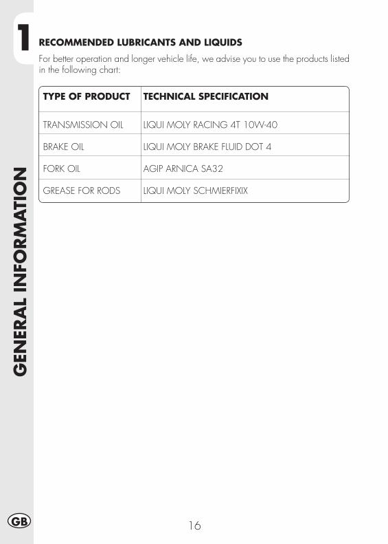
1G
ENER
AL
INFO
RM
ATI
ON
16GB
TYPE OF PRODUCT TECHNICAL SPECIFICATION
TRANSMISSION OIL LIQUI MOLY RACING 4T 10W-40 BRAKE OIL LIQUI MOLY BRAKE FLUID DOT 4 FORK OIL AGIP ARNICA SA32 GREASE FOR RODS LIQUI MOLY SCHMIERFIXIX
RECOMMENDED LUBRICANTS AND LIQUIDS
For better operation and longer vehicle life, we advise you to use the products listed in the following chart:
2
OPE
RA
TIO
N
17 GB
CHAPTER 2 OPERATION
CONTENTSMain parts ..........................................................................................18
Fuel cock ........................................................................................18Starter ............................................................................................18Clutch lever ....................................................................................18Lh switch ........................................................................................19Rh switch ........................................................................................19Front brake lever and gas control ......................................................19Gearchange lever............................................................................20Brake pedal ....................................................................................20Kickstart .........................................................................................20Side stand ......................................................................................20
Keys ...................................................................................................21Steering lock .......................................................................................21Helmet lock .........................................................................................21Digital rpm indicator operating instructions ..............................................22Checks before and after use ..................................................................28Breaking in..........................................................................................28Fuelling ...............................................................................................28Startup ................................................................................................29Engine shut-down .................................................................................29Trial trim option....................................................................................30
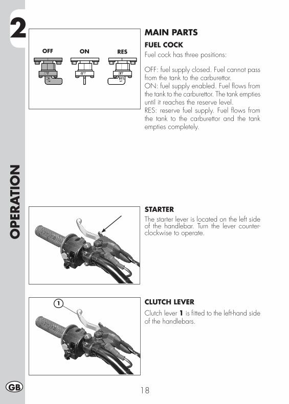
2O
PERA
TIO
N
18GB
MAIN PARTSFUEL COCKFuel cock has three positions:
OFF: fuel supply closed. Fuel cannot pass from the tank to the carburettor.ON: fuel supply enabled. Fuel flows from the tank to the carburettor. The tank empties until it reaches the reserve level.RES: reserve fuel supply. Fuel flows from the tank to the carburettor and the tank empties completely.
STARTERThe starter lever is located on the left side of the handlebar. Turn the lever counter-clockwise to operate.
CLUTCH LEVERClutch lever 1 is fitted to the left-hand side of the handlebars.
OFF ON RES
1
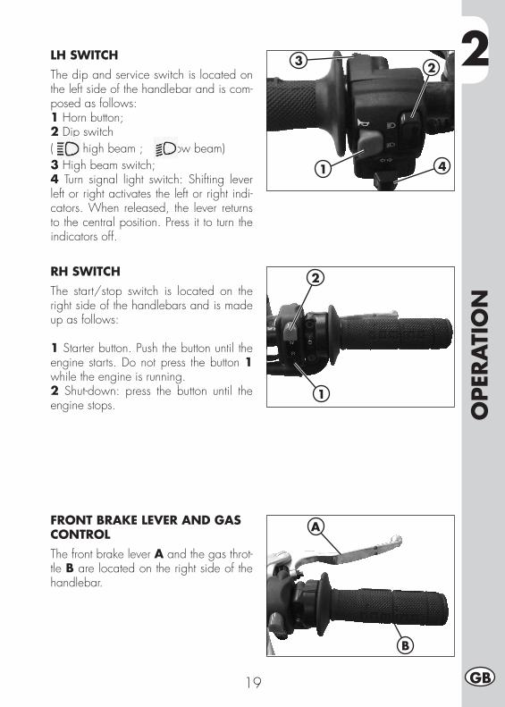
2
OPE
RA
TIO
N
19 GB
LH SWITCHThe dip and service switch is located on the left side of the handlebar and is com-posed as follows:1 Horn button;2 Dip switch( high beam ; low beam)3 High beam switch;4 Turn signal light switch: Shifting lever left or right activates the left or right indi-cators. When released, the lever returns to the central position. Press it to turn the indicators off.
1
23
4
RH SWITCHThe start/stop switch is located on the right side of the handlebars and is made up as follows:
1 Starter button. Push the button until the engine starts. Do not press the button 1 while the engine is running.2 Shut-down: press the button until the engine stops.
FRONT BRAKE LEVER AND GAS CONTROLThe front brake lever A and the gas throt-tle B are located on the right side of the handlebar.
2
1
A
B
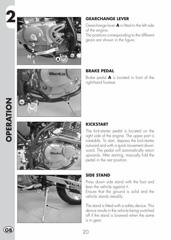
2O
PERA
TIO
N
20GB
1
234
5
NA
GEARCHANGE LEVERGearchange lever A is fitted to the left side of the engine.The positions corresponding to the different gears are shown in the figure.
BRAKE PEDALBrake pedal A is located in front of the right-hand footrest.
KICKSTARTThe kick-starter pedal is located on the right side of the engine. The upper part is rotatable. To start, depress the kick-starter outward and with a quick movement down-ward. The pedal will automatically return upwards. After starting, manually fold the pedal in the rest position.
SIDE STANDPress down side stand with the foot and lean the vehicle against it.Ensure that the ground is solid and the vehicle stands steadily.
The stand is fitted with a safety device. This device results in the vehicle being switched off if the stand is lowered when the same is in gear.
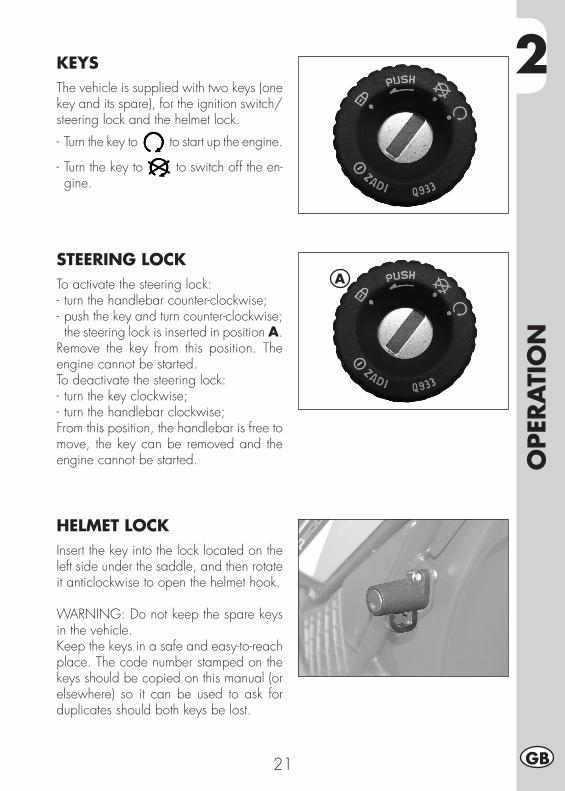
2
OPE
RA
TIO
N
21 GB
KEYSThe vehicle is supplied with two keys (one key and its spare), for the ignition switch/steering lock and the helmet lock.
- Turn the key to to start up the engine.
- Turn the key to to switch off the en-gine.
STEERING LOCKTo activate the steering lock:- turn the handlebar counter-clockwise;- push the key and turn counter-clockwise; the steering lock is inserted in position A.
Remove the key from this position. The engine cannot be started.To deactivate the steering lock:- turn the key clockwise;- turn the handlebar clockwise;From this position, the handlebar is free to move, the key can be removed and the engine cannot be started.
HELMET LOCKInsert the key into the lock located on the left side under the saddle, and then rotate it anticlockwise to open the helmet hook.
WARNING: Do not keep the spare keys in the vehicle.Keep the keys in a safe and easy-to-reach place. The code number stamped on the keys should be copied on this manual (or elsewhere) so it can be used to ask for duplicates should both keys be lost.
A
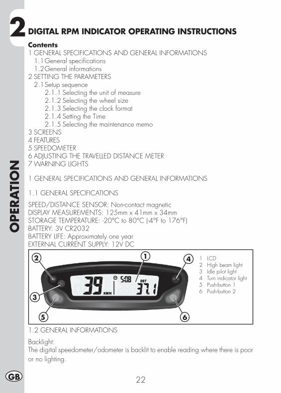
2O
PERA
TIO
N
22GB
DIGITAL RPM INDICATOR OPERATING INSTRUCTIONSContents1 GENERAL SPECIFICATIONS AND GENERAL INFORMATIONS 1.1 General specifications 1.2 General informations2 SETTING THE PARAMETERS 2.1 Setup sequence 2.1.1 Selecting the unit of measure 2.1.2 Selecting the wheel size 2.1.3 Selecting the clock format 2.1.4 Setting the Time 2.1.5 Selecting the maintenance memo3 SCREENS4 FEATURES5 SPEEDOMETER6 ADJUSTING THE TRAVELLED DISTANCE METER7 WARNING LIGHTS
1 GENERAL SPECIFICATIONS AND GENERAL INFORMATIONS
1.1 GENERAL SPECIFICATIONS
SPEED/DISTANCE SENSOR: Non-contact magneticDISPLAY MEASUREMENTS: 125mm x 41mm x 34mmSTORAGE TEMPERATURE: -20°C to 80°C (-4°F to 176°F)BATTERY: 3V CR2032BATTERY LIFE: Approximately one yearEXTERNAL CURRENT SUPPLY: 12V DC
1.2 GENERAL INFORMATIONS
Backlight:The digital speedometer/odometer is backlit to enable reading where there is poor or no lighting.
12
3
5
4
6
1 LCD 2 High beam light 3 Idle pilot light 4 Turn indicator light 5 Push-button 1 6 Push-button 2
2
OPE
RA
TIO
N
23 GB
When using supplied power with the engine on:•Theback-lightingisonpermanentlywhentheengineisrunning.Using only the internal battery:•WiththeLOsymbol,thebacklightingwillnotswitchon.Thesymbolappears
when the battery voltage is lower than 2.45V.Reset Button:Using the Reset button, located on the back of the instrument, all travel data will be deleted, including date and time.Internal battery:The instrument houses a 3.0V internal button cell battery (CR2032). The instrument can only work with this battery. The symbol appears when the battery is running low. To change the battery, unscrew the cap located on the back of the instrument using a coin.Once the battery has been changed, make sure that the positive side is facing outwards.REPLACE THE BATTERY WITH ANOTHER CR2032-TYPE BATTERY.
2 SETTING THE PARAMETERS
General information:Allowed settings:•Km/h(kilometresperhour)orM/h(Milesperhour)•Wheelsize(rollingcircumference)[mm]•Clockformat:12-hour/24-hour•Currentdate•Maintenance
TO ENTER THE PARAMETER SETTINGS MODE HOLD DOWN THE RIGHT AND LEFTBUTTONS FOR APPROX. 3s.THE WORD “Unit” WILL FLASH ON THE DISPLAY.
The operational logic is structured as follows:•TheinstrumententersSETUPmodedisplaying theparametersaccording to the
sequence listed above.•Theinstrumentdisplaystheparametertobechangedforafewsecondsinflash
mode.• If youwish to change theparameterdisplayed for those few seconds simply
edit the values by pressing the right and/or left buttons (according to the modes listed below), otherwise wait a few seconds (approx. 5 s) to proceed to the next parameter.
•When theparameterhasbeenedited to thedesiredvalue, the instrumentau-tomatically moves onto the next setting, there is no need to press any button of confirmation.
•Ifyouonlywishtoenterthesetupmodetoviewtheconfiguredsettings,simplywaitwithout pressing any buttons; the instrument will display all of the set parameters and will then automatically go back to “Normal Mode”.
2O
PERA
TIO
N
24GB
2.1 SETUP SEQUENCE
Select unit of measureWheel sizeClock formatSetting the TimeMaintenance reminder
2.1.1 Selecting the unit of measure (Km/h or M/h):TO SELECT THE UNIT OF MEASURE (Km/h or M/h), PRESS THE RIGHT OR LEFT BUTTON.WAIT 5 SECONDS TO PROCEED TO THE NEXT SETTING.DO NOT PRESS ANY BUTTONS.
2.1.2 Selecting the wheel size (rolling circumference):The instrument has programmed two rolling circumference measurements for the front wheel: larger size (ENDURO tyre) or smaller size (TRIAL tyre).PRESS THE LEFT BUTTON TO SELECT ONE OF THE TWO OPTIONS.WAIT 5 SECONDS TO PROCEED TO THE NEXT SETTING. DO NOT PRESS ANY BUTTONS.
2.1.3 Selecting the clock format (12- or 24-hour):The default setting on the instrument is the 12-hour clock.TO SELECT THE 12- OR 24-HOUR CLOCK, PRESS THE RIGHT OR LEFT BUTTON.WAIT 5 SECONDS TO PROCEED TO THE NEXT SETTING. DO NOT PRESS ANY BUTTONS.
2.1.4 Setting the Time:The time is set by increasing or decreasing it by 1 minute steps.PRESS THE LEFT BUTTON TO DECREASE THE TIME.PRESS THE RIGHT BUTTON TO INCREASE IT.WAIT 5 SECONDS TO PROCEED TO THE NEXT SETTING. DO NOT PRESS ANY BUTTONS.
2.1.5 Selecting the maintenance reminderThe instrument displays the countdown to maintenance operations based on the data entered by the user. The data is based on the kilometres and miles travelled according to the unit of measure selected by the user. The factory setting is on “OFF”.PRESS THE LEFT BUTTON TO LOWER THE NUMBER. PRESS THE RIGHT BUTTONTO RAISE IT (max value 10000Km).WAIT 5 SECONDS TO EXIT SETUP MODE.DO NOT PRESS ANY BUTTONS.
2
OPE
RA
TIO
N
25 GB
3 SCREENS
Switching between 3 normal modesAll of the information that the instrument is capable of providing is displayed on one of these 3 screens.The instrument will stay on the set screen until a button is pressed to switch to another screen.TO SWITCH FROM ONE SCREEN TO ANOTHER, PRESS EITHER THE RIGHT ORLEFT BUTTON BRIEFLY.Screen 1:•Speed•Distance1(DST)•TimeScreen 2:•Speed•Distance2(DST2)•TimeScreen 3:•Maximumspeed(MAX)•Averagespeed(AVG)•Accumulatedrunningtime(ART)•Odometer(ODO)* Note: The maximum and average speeds are updated automatically when the
user accesses screen 3.
4 FEATURES
General information:During normal use the instrument is in “Normal” mode.Available modes:•SleepMode•Choosefrom3“Normal”screens•ClearDistance1(DST1)•ClearDistance2(DST2)•ClearMaximum/AverageSpeed(MAX/AVG)
Sleep Mode:If the instrument does not receive any input for 5 minutes (either from the movement of the wheel or a button), it will go into “Sleep Mode”. In “Sleep Mode” only the time appears on the screen.To exit “Sleep Mode” all the instrument requires is an input, either from the movement of the sensor or by pressing a button.
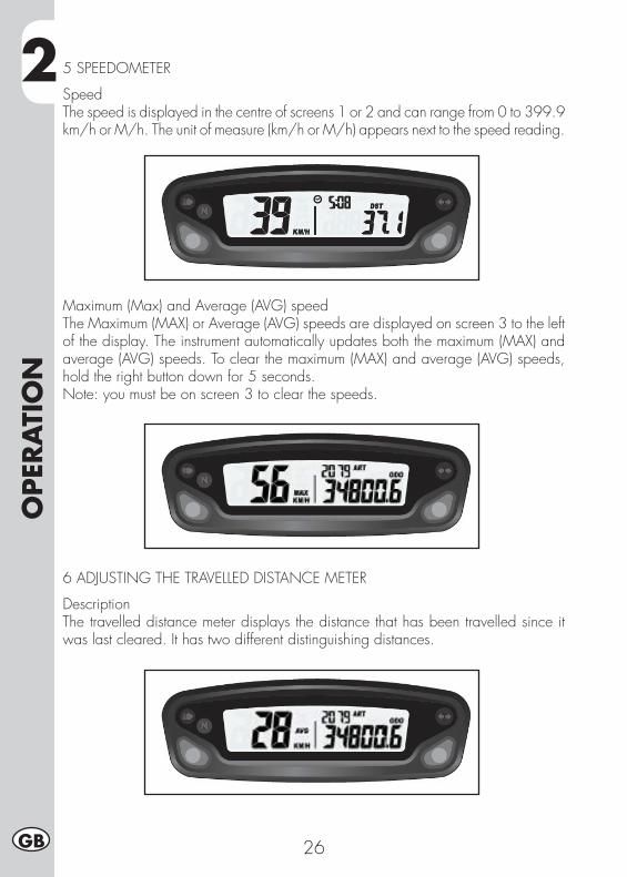
2O
PERA
TIO
N
26GB
5 SPEEDOMETER
SpeedThe speed is displayed in the centre of screens 1 or 2 and can range from 0 to 399.9 km/h or M/h. The unit of measure (km/h or M/h) appears next to the speed reading.
Maximum (Max) and Average (AVG) speedThe Maximum (MAX) or Average (AVG) speeds are displayed on screen 3 to the left of the display. The instrument automatically updates both the maximum (MAX) and average (AVG) speeds. To clear the maximum (MAX) and average (AVG) speeds, hold the right button down for 5 seconds.Note: you must be on screen 3 to clear the speeds.
6 ADJUSTING THE TRAVELLED DISTANCE METER
DescriptionThe travelled distance meter displays the distance that has been travelled since it was last cleared. It has two different distinguishing distances.
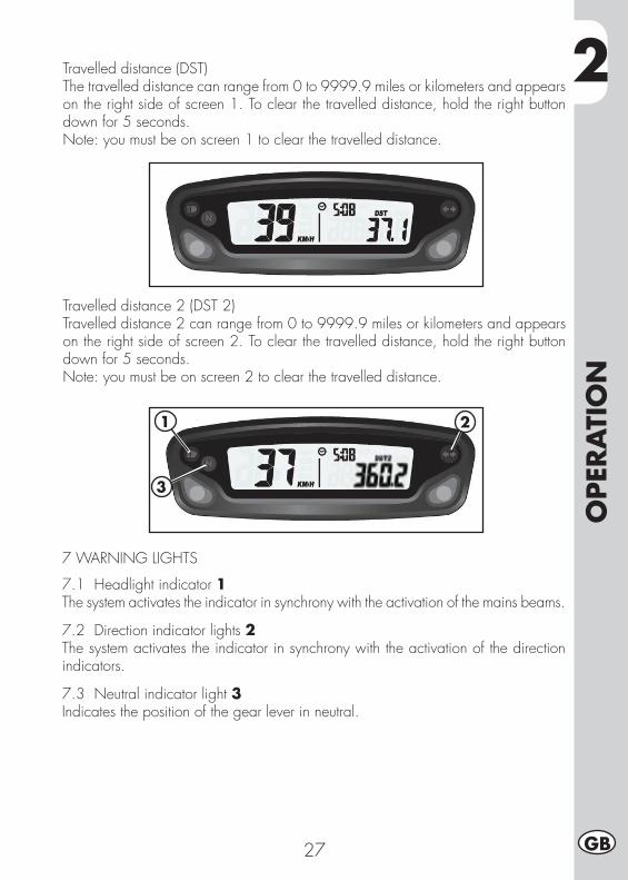
2
OPE
RA
TIO
N
27 GB
Travelled distance (DST)The travelled distance can range from 0 to 9999.9 miles or kilometers and appears on the right side of screen 1. To clear the travelled distance, hold the right button down for 5 seconds.Note: you must be on screen 1 to clear the travelled distance.
Travelled distance 2 (DST 2)Travelled distance 2 can range from 0 to 9999.9 miles or kilometers and appears on the right side of screen 2. To clear the travelled distance, hold the right button down for 5 seconds.Note: you must be on screen 2 to clear the travelled distance.
7 WARNING LIGHTS
7.1 Headlight indicator 1The system activates the indicator in synchrony with the activation of the mains beams.
7.2 Direction indicator lights 2The system activates the indicator in synchrony with the activation of the direction indicators.
7.3 Neutral indicator light 3Indicates the position of the gear lever in neutral.
1
3
2
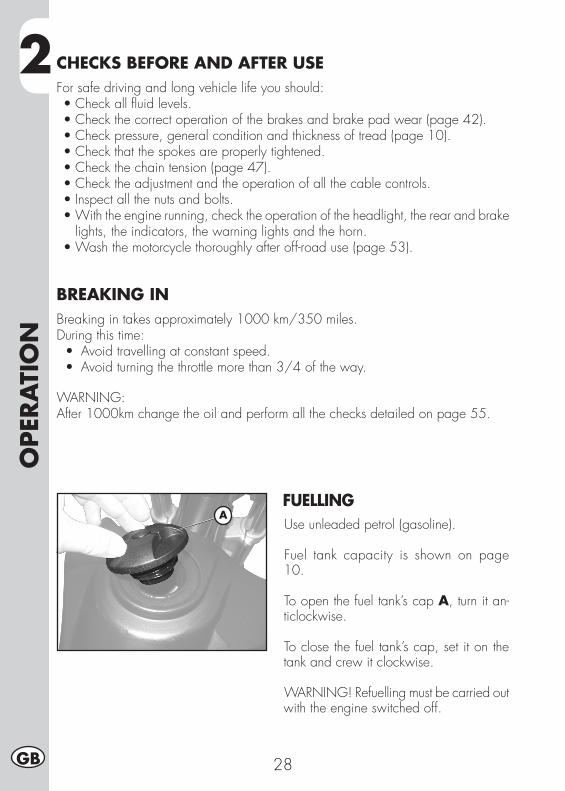
2O
PERA
TIO
N
28GB
CHECKS BEFORE AND AFTER USEFor safe driving and long vehicle life you should:•Checkallfluidlevels.•Checkthecorrectoperationofthebrakesandbrakepadwear(page42).•Checkpressure,generalconditionandthicknessoftread(page10).•Checkthatthespokesareproperlytightened.•Checkthechaintension(page47).•Checktheadjustmentandtheoperationofallthecablecontrols.•Inspectallthenutsandbolts.•Withtheenginerunning,checktheoperationoftheheadlight,therearandbrake
lights, the indicators, the warning lights and the horn.•Washthemotorcyclethoroughlyafteroff-roaduse(page53).
BREAKING INBreaking in takes approximately 1000 km/350 miles.During this time: •Avoidtravellingatconstantspeed. •Avoidturningthethrottlemorethan3/4oftheway.
WARNING: After 1000km change the oil and perform all the checks detailed on page 55.
FUELLINGUse unleaded petrol (gasoline).
Fuel tank capacity is shown on page 10.
To open the fuel tank’s cap A, turn it an-ticlockwise.
To close the fuel tank’s cap, set it on the tank and crew it clockwise.
WARNING! Refuelling must be carried out with the engine switched off.
A
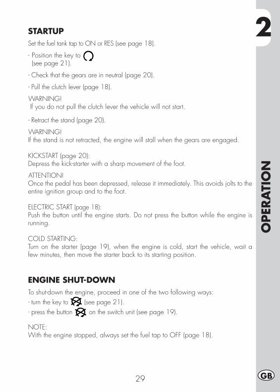
2
OPE
RA
TIO
N
29 GB
STARTUPSet the fuel tank tap to ON or RES (see page 18).
- Position the key to (see page 21).
- Check that the gears are in neutral (page 20).
- Pull the clutch lever (page 18).
WARNING! If you do not pull the clutch lever the vehicle will not start.
- Retract the stand (page 20).
WARNING!If the stand is not retracted, the engine will stall when the gears are engaged.
KICKSTART (page 20):Depress the kick-starter with a sharp movement of the foot.
ATTENTION!Once the pedal has been depressed, release it immediately. This avoids jolts to the entire ignition group and to the foot.
ELECTRIC START (page 18):Push the button until the engine starts. Do not press the button while the engine is running.
COLD STARTING:Turn on the starter (page 19), when the engine is cold, start the vehicle, wait a few minutes, then move the starter back to its starting position.
ENGINE SHUT-DOWNTo shut-down the engine, proceed in one of the two following ways:- turn the key to (see page 21).- press the button on the switch unit (see page 19).
NOTE: With the engine stopped, always set the fuel tap to OFF (page 18).
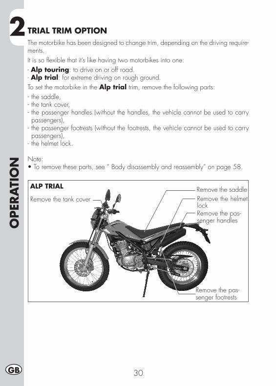
2O
PERA
TIO
N
30GB
TRIAL TRIM OPTIONThe motorbike has been designed to change trim, depending on the driving require-ments.It is so flexible that it’s like having two motorbikes into one:- Alp touring: to drive on or off road.- Alp trial: for extreme driving on rough ground.To set the motorbike in the Alp trial trim, remove the following parts:- the saddle,- the tank cover,- the passenger handles (without the handles, the vehicle cannot be used to carry passengers),
- the passenger footrests (without the footrests, the vehicle cannot be used to carry passengers),
- the helmet lock.
Note:•To remove these parts, see “ Body disassembly and reassembly” on page 58.
Remove the saddleRemove the tank cover
Remove the pas-senger footrests
Remove the helmet lockRemove the pas-senger handles
ALP TRIAL
3
AD
JUST
MEN
TS
31 GB
CHAPTER 3 ADJUSTMENTS
CONTENTSKey to symbols.....................................................................................32Brakes ................................................................................................32
Front brake .....................................................................................32Adjustment of gas clearance ..............................................................32
Adjusting the idle speed .......................................................................33Handlebar ..........................................................................................33Rear shock absorber .............................................................................33
Adjusting the spring preload .............................................................33Headlight ............................................................................................34
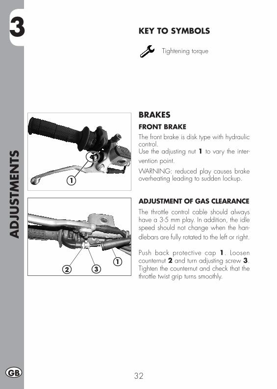
AD
JUST
MEN
TS
32GB
3 KEY TO SYMBOLS
Tightening torque
BRAKESFRONT BRAKEThe front brake is disk type with hydraulic control.Use the adjusting nut 1 to vary the inter-vention point.WARNING: reduced play causes brake overheating leading to sudden lockup.
ADJUSTMENT OF GAS CLEARANCE The throttle control cable should always have a 3-5 mm play. In addition, the idle speed should not change when the han-dlebars are fully rotated to the left or right.
Push back protective cap 1. Loosen counternut 2 and turn adjusting screw 3. Tighten the counternut and check that the throttle twist grip turns smoothly.
1
21
3
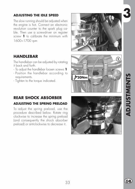
3
AD
JUST
MEN
TS
33 GB
1
ADJUSTING THE IDLE SPEED The slow running should be adjusted when the engine is hot. Connect an electronic revolution counter to the spark plug ca-ble. Then use a screwdriver on register screw 1 to calibrate the minimum with 1600÷1700 rpm
HANDLEBARThe handlebar can be adjusted by rotating it back and forth.- To adjust the handlebar loosen screws 1- Position the handlebar according to requirements.
- Tighten to the torque indicated.
REAR SHOCK ABSORBERADJUSTING THE SPRING PRELOADTo adjust the spring preload, use the procedure described below. Rotate ring clockwise to increase the spring preload (and consequently the shock absorber preload) or anticlockwise to decrease it.
1
20Nm

AD
JUST
MEN
TS
34GB
3 HEADLIGHT•Thebeamisadjustedbylooseningtheleft and right fixing screws 1 of the mask and changing the inclination of the opti-cal unit by turning the screws 2.•Place the vehicle on level ground (butnot on the stand) 10 metres from a verti-cal wall.
•Measuretheheightoftheheadlightcen-tre above the ground and then draw a cross on the wall at 9/10 of the height of the headlight centre.
•Turnonthelowbeam,getonthemotor-bike and check that the headlight beam on the wall is slightly lower than the cross drawn previously. Where this is not the case, proceed to adjustment.
•Periodically check the direction of thebeam. The beam can only be adjusted vertically.
1
2
9/10
h
10 m
h
4
CHEC
KS
AN
D M
AIN
TEN
AN
CE
35 GB
CHAPTER 4 CHECKS AND MAINTENANCECONTENTSEngine oil ............................................................................................36
Check the level ................................................................................36Replacement ...................................................................................36
Fume collecting tube .............................................................................37Air filter ..............................................................................................38
Removing and fitting air filter ............................................................38Air filter cleaning .............................................................................39
Spark plug ..........................................................................................40Carburettor .........................................................................................40
Draining the carburettor float chamber ...............................................40Front brake..........................................................................................41
Check the level of the front brake fluid ...............................................41Bleeding the front brake ...................................................................42Front brake lining control ..................................................................42
Rear brake ..........................................................................................43Check the level of the rear brake fluid ................................................43Restoring the level of the rear brake fluid ............................................43Bleeding the rear brake ....................................................................43Rear brake lining control ..................................................................44
Clutch control ......................................................................................44Check of steering play ..........................................................................45Tyres...................................................................................................46Fork oil ...............................................................................................46Chain .................................................................................................47
Check and adjust tightening chain .....................................................47Headlight ............................................................................................48
Replacing the headlight bulbs ..........................................................48Turn indicators .....................................................................................49Tail light ..............................................................................................49Replacing the plate number light ............................................................49Battery ................................................................................................49
Removal .........................................................................................50Inactivity .........................................................................................51Charging the battery ........................................................................51Fuse ...............................................................................................52
Cleaning the vehicle .............................................................................53Prolonged inactivity ..............................................................................54Scheduled maintenance vehicle ............................................................55
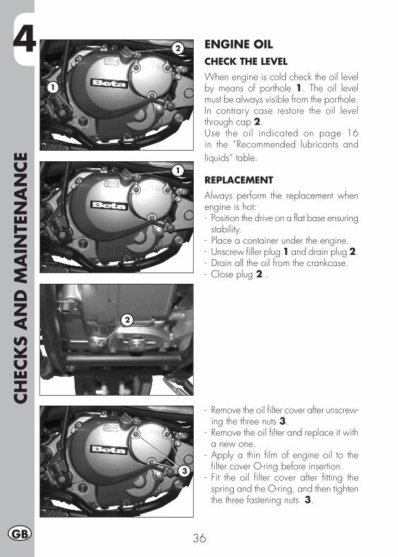
4CH
ECK
S A
ND
MA
INTE
NA
NCE
36GB
ENGINE OILCHECK THE LEVELWhen engine is cold check the oil level by means of porthole 1. The oil level must be always visible from the porthole.In contrary case restore the oil level through cap 2.Use the oil indicated on page 16 in the “Recommended lubricants and liquids” table.
REPLACEMENTAlways perform the replacement when engine is hot:- Position the drive on a flat base ensuring
stability.- Place a container under the engine.- Unscrew filler plug 1 and drain plug 2.- Drain all the oil from the crankcase.- Close plug 2 .
- Remove the oil filter cover after unscrew-ing the three nuts 3.
- Remove the oil filter and replace it with a new one.
- Apply a thin film of engine oil to the filter cover O-ring before insertion.
- Fit the oil filter cover after fitting the spring and the O-ring, and then tighten the three fastening nuts 3.
2
1
2
1
3
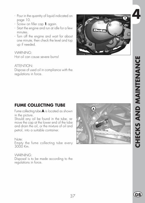
4
CHEC
KS
AN
D M
AIN
TEN
AN
CE
37 GB
- Pour in the quantity of liquid indicated on page 10.
- Screw on filler cap 1 again.- Start the engine and run at idle for a few
minutes.- Turn off the engine and wait for about
one minute, then check the level and top up if needed.
WARNING:Hot oil can cause severe burns!
ATTENTION:Dispose of used oil in compliance with the regulations in force.
FUME COLLECTING TUBEFume collecting tube A is located as shown in the picture.Should any oil be found in the tube, re-move the cap at the lower end of the tube and drain the oil, or the mixture of oil and petrol, into a suitable container.
Note:Empty the fume collecting tube every 3000 Km.
WARNING:Disposal is to be made according to the regulations in force.
1
A
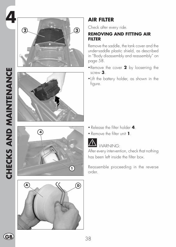
4CH
ECK
S A
ND
MA
INTE
NA
NCE
38GB
AIR FILTERCheck after every ride.REMOVING AND FITTING AIR FILTERRemove the saddle, the tank cover and the under-saddle plastic shield, as described in “Body disassembly and reassembly” on page 58.• Remove the cover 2 by loosening the screw 3.
• Lift the battery holder, as shown in the figure.
• Release the filter holder 4.• Remove the filter unit 1.
WARNING:After every intervention, check that nothing has been left inside the filter box.
Reassemble proceeding in the reverse order.
4
1
2 3
DA
4
CHEC
KS
AN
D M
AIN
TEN
AN
CE
39 GB
AIR FILTER CLEANING• Thoroughly wash the filter with water and soap.
• Dry the filter.• Wet the filter with filter oil and then remove the excess oil to prevent it from dripping.
• If necessary also clean the interior of the filter box.
WARNING:Do not clean the filter with gasoline or petrol.
NOTE:If the filter is damaged, replace it imme-diately.To replace, contact authorised Betamotor customer service.
WARNING:Never use the vehicle if the air filter is not in place. The infiltration of dust and dirt can cause damage and considerable wear.
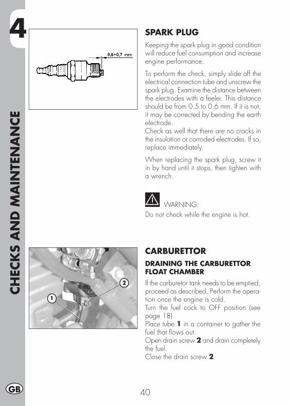
4CH
ECK
S A
ND
MA
INTE
NA
NCE
40GB
SPARK PLUGKeeping the spark plug in good condition will reduce fuel consumption and increase engine performance.
To perform the check, simply slide off the electrical connection tube and unscrew the spark plug. Examine the distance between the electrodes with a feeler. This distance should be from 0.5 to 0.6 mm. If it is not, it may be corrected by bending the earth electrode.Check as well that there are no cracks in the insulation or corroded electrodes. If so, replace immediately.
When replacing the spark plug, screw it in by hand until it stops, then tighten with a wrench.
WARNING:Do not check while the engine is hot.
CARBURETTORDRAINING THE CARBURETTOR FLOAT CHAMBERIf the carburetor tank needs to be emptied, proceed as described. Perform the opera-tion once the engine is cold.Turn the fuel cock to OFF position (see page 18)Place tube 1 in a container to gather the fuel that flows out.Open drain screw 2 and drain completely the fuel.Close the drain screw 2.
2
1
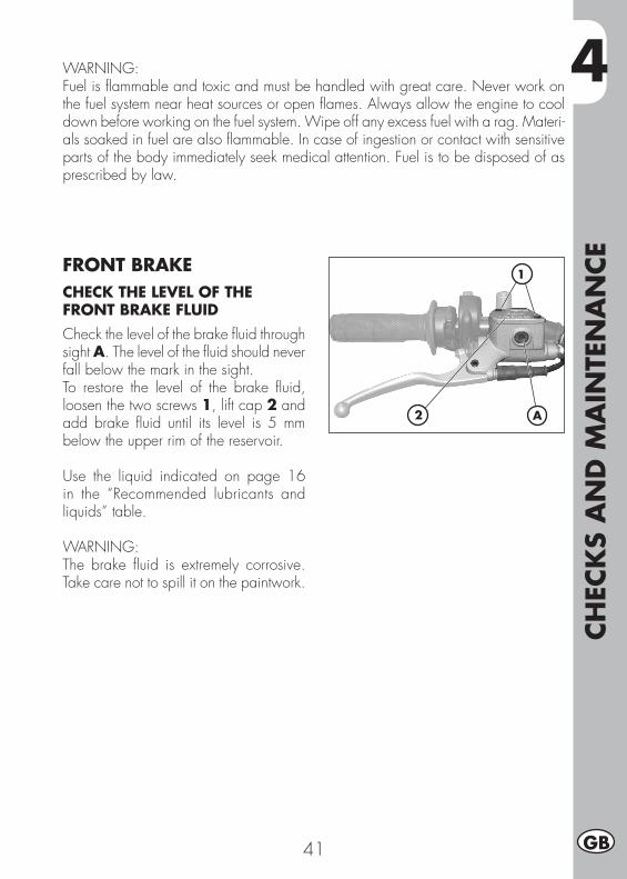
4
CHEC
KS
AN
D M
AIN
TEN
AN
CE
41 GB
WARNING:Fuel is flammable and toxic and must be handled with great care. Never work on the fuel system near heat sources or open flames. Always allow the engine to cool down before working on the fuel system. Wipe off any excess fuel with a rag. Materi-als soaked in fuel are also flammable. In case of ingestion or contact with sensitive parts of the body immediately seek medical attention. Fuel is to be disposed of as prescribed by law.
FRONT BRAKECHECK THE LEVEL OF THE FRONT BRAKE FLUIDCheck the level of the brake fluid through sight A. The level of the fluid should never fall below the mark in the sight.To restore the level of the brake fluid, loosen the two screws 1, lift cap 2 and add brake fluid until its level is 5 mm below the upper rim of the reservoir.
Use the liquid indicated on page 16 in the “Recommended lubricants and liquids” table. WARNING:The brake fluid is extremely corrosive. Take care not to spill it on the paintwork.
2
1
A
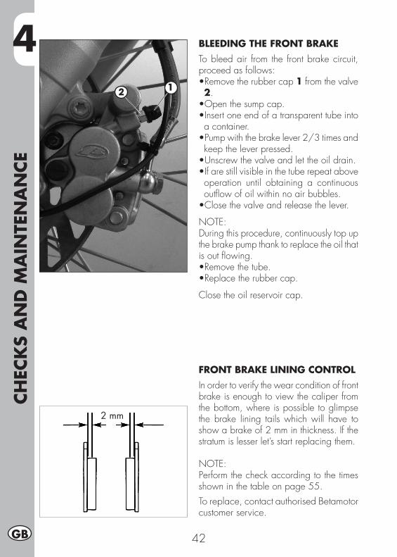
4CH
ECK
S A
ND
MA
INTE
NA
NCE
42GB
BLEEDING THE FRONT BRAKETo bleed air from the front brake circuit, proceed as follows:•Removetherubbercap1 from the valve 2.•Openthesumpcap.•Insertoneendofatransparenttubeintoa container.•Pumpwiththebrakelever2/3timesandkeep the lever pressed.•Unscrewthevalveandlettheoildrain.•Ifarestillvisibleinthetuberepeataboveoperation until obtaining a continuous outflow of oil within no air bubbles.•Closethevalveandreleasethelever.
NOTE: During this procedure, continuously top up the brake pump thank to replace the oil that is out flowing.•Removethetube.•Replacetherubbercap.
Close the oil reservoir cap.
FRONT BRAKE LINING CONTROLIn order to verify the wear condition of front brake is enough to view the caliper from the bottom, where is possible to glimpse the brake lining tails which will have to show a brake of 2 mm in thickness. If the stratum is lesser let’s start replacing them.
NOTE:Perform the check according to the times shown in the table on page 55.To replace, contact authorised Betamotor customer service.
2 mm
12
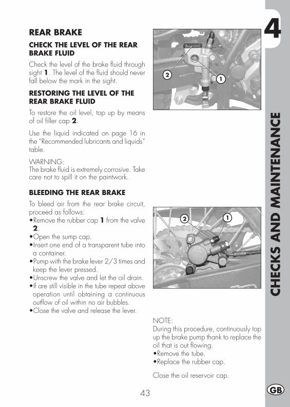
4
CHEC
KS
AN
D M
AIN
TEN
AN
CE
43 GB
REAR BRAKECHECK THE LEVEL OF THE REAR BRAKE FLUIDCheck the level of the brake fluid through sight 1. The level of the fluid should never fall below the mark in the sight.
RESTORING THE LEVEL OF THE REAR BRAKE FLUIDTo restore the oil level, top up by means of oil filler cap 2.
Use the liquid indicated on page 16 in the “Recommended lubricants and liquids” table.
WARNING:The brake fluid is extremely corrosive. Take care not to spill it on the paintwork.
BLEEDING THE REAR BRAKETo bleed air from the rear brake circuit, proceed as follows:•Removetherubbercap1 from the valve 2.•Openthesumpcap.•Insertoneendofatransparenttubeintoa container.•Pumpwiththebrakelever2/3timesandkeep the lever pressed.•Unscrewthevalveandlettheoildrain.•If are still visible in the tube repeat above operation until obtaining a continuous outflow of oil within no air bubbles.•Close the valve and release the lever.
NOTE: During this procedure, continuously top up the brake pump thank to replace the oil that is out flowing.•Removethetube.•Replacetherubbercap.
Close the oil reservoir cap.
21
12
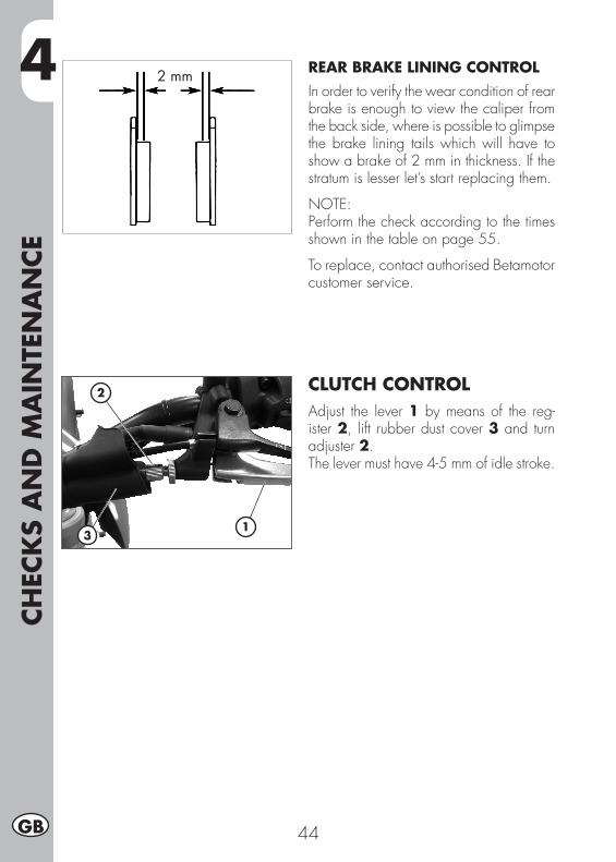
4CH
ECK
S A
ND
MA
INTE
NA
NCE
44GB
REAR BRAKE LINING CONTROLIn order to verify the wear condition of rear brake is enough to view the caliper from the back side, where is possible to glimpse the brake lining tails which will have to show a brake of 2 mm in thickness. If the stratum is lesser let’s start replacing them.
NOTE:Perform the check according to the times shown in the table on page 55.
To replace, contact authorised Betamotor customer service.
CLUTCH CONTROLAdjust the lever 1 by means of the reg-ister 2, lift rubber dust cover 3 and turn adjuster 2.The lever must have 4-5 mm of idle stroke.
2 mm
1
2
3
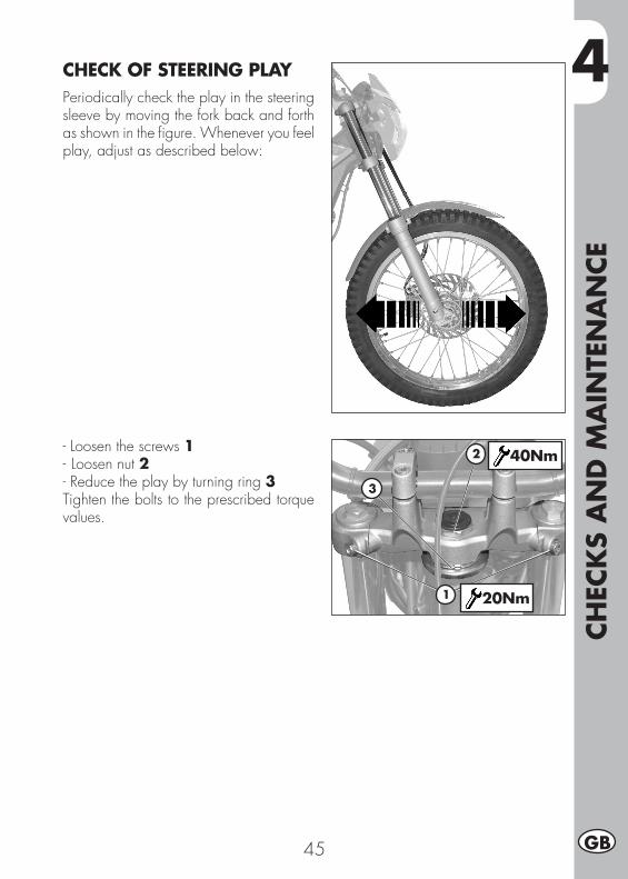
4
CHEC
KS
AN
D M
AIN
TEN
AN
CE
45 GB
CHECK OF STEERING PLAYPeriodically check the play in the steering sleeve by moving the fork back and forth as shown in the figure. Whenever you feel play, adjust as described below:
- Loosen the screws 1- Loosen nut 2- Reduce the play by turning ring 3Tighten the bolts to the prescribed torque values.
1
2
3
40Nm
20Nm
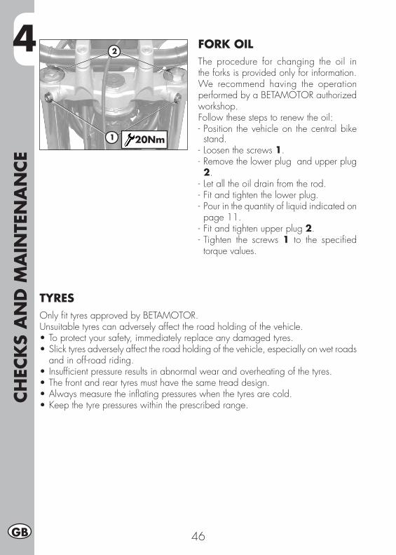
4CH
ECK
S A
ND
MA
INTE
NA
NCE
46GB
FORK OILThe procedure for changing the oil in the forks is provided only for information. We recommend having the operation performed by a BETAMOTOR authorized workshop.Follow these steps to renew the oil:- Position the vehicle on the central bike stand.
- Loosen the screws 1.- Remove the lower plug and upper plug 2.
- Let all the oil drain from the rod.- Fit and tighten the lower plug.- Pour in the quantity of liquid indicated on page 11.
- Fit and tighten upper plug 2.- Tighten the screws 1 to the specified torque values.
1
2
20Nm
TYRESOnly fit tyres approved by BETAMOTOR.Unsuitable tyres can adversely affect the road holding of the vehicle.•Toprotectyoursafety,immediatelyreplaceanydamagedtyres.•Slicktyresadverselyaffecttheroadholdingofthevehicle,especiallyonwetroads
and in off-road riding.•Insufficientpressureresultsinabnormalwearandoverheatingofthetyres.•Thefrontandreartyresmusthavethesametreaddesign.•Alwaysmeasuretheinflatingpressureswhenthetyresarecold.•Keepthetyrepressureswithintheprescribedrange.
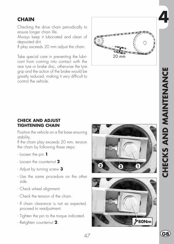
4
CHEC
KS
AN
D M
AIN
TEN
AN
CE
47 GB
CHAINChecking the drive chain periodically to ensure longer chain life.Always keep it lubricated and clean of deposited dirt.If play exceeds 20 mm adjust the chain.
Take special care in preventing the lubri-cant from coming into contact with the rear tyre or brake disc, otherwise the tyre grip and the action of the brake would be greatly reduced, making it very difficult to control the vehicle.
CHECK AND ADJUST TIGHTENING CHAINPosition the vehicle on a flat base ensuring stability.If the chain play exceeds 20 mm, tension the chain by following these steps:
- Loosen the pin 1
- Loosen the counternut 2
- Adjust by turning screw 3
- Use the same procedure on the other side.
- Check wheel alignment.
- Check the tension of the chain.
- If chain clearance is not as expected, proceed to readjustment.
- Tighten the pin to the torque indicated.- Retighten counternut 2.
20 mm
2 3 1
80Nm
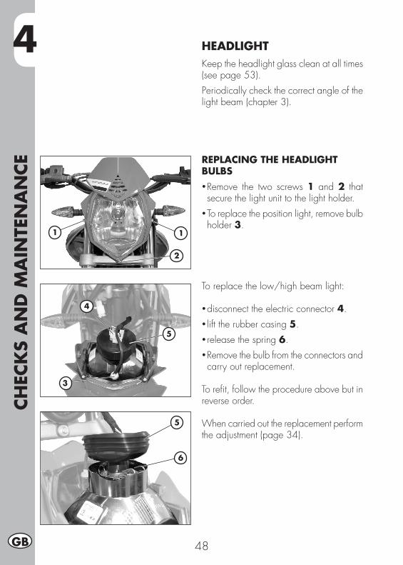
4CH
ECK
S A
ND
MA
INTE
NA
NCE
48GB
HEADLIGHTKeep the headlight glass clean at all times (see page 53).Periodically check the correct angle of the light beam (chapter 3).
REPLACING THE HEADLIGHT BULBS • Remove the two screws 1 and 2 that secure the light unit to the light holder.
• To replace the position light, remove bulb holder 3.
To replace the low/high beam light:
• disconnect the electric connector 4.• lift the rubber casing 5.• release the spring 6.• Remove the bulb from the connectors and carry out replacement.
To refit, follow the procedure above but in reverse order.
When carried out the replacement perform the adjustment (page 34).
11
3
2
4
5
5
6
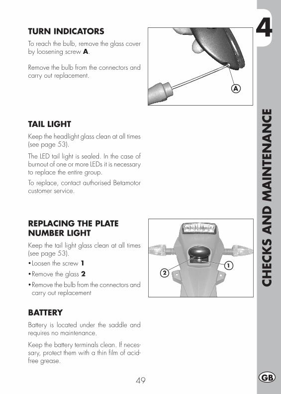
4
CHEC
KS
AN
D M
AIN
TEN
AN
CE
49 GB
A
TURN INDICATORSTo reach the bulb, remove the glass cover by loosening screw A.
Remove the bulb from the connectors and carry out replacement.
TAIL LIGHTKeep the headlight glass clean at all times (see page 53).
The LED tail light is sealed. In the case of burnout of one or more LEDs it is necessary to replace the entire group.To replace, contact authorised Betamotor customer service.
REPLACING THE PLATE NUMBER LIGHTKeep the tail light glass clean at all times (see page 53).• Loosen the screw 1• Remove the glass 2• Remove the bulb from the connectors and carry out replacement
BATTERYBattery is located under the saddle and requires no maintenance.
Keep the battery terminals clean. If neces-sary, protect them with a thin film of acid-free grease.
12
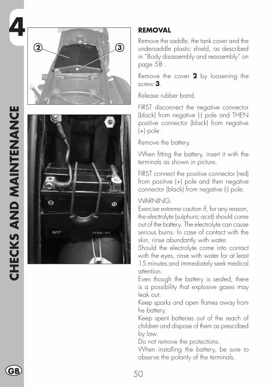
4CH
ECK
S A
ND
MA
INTE
NA
NCE
50GB
REMOVALRemove the saddle, the tank cover and the undersaddle plastic shield, as described in “Body disassembly and reassembly” on page 58 .
Remove the cover 2 by loosening the screw 3.
Release rubber band.
FIRST disconnect the negative connector (black) from negative (-) pole and THEN positive connector (black) from negative (+) pole.
Remove the battery.
When fitting the battery, insert it with the terminals as shown in picture.
FIRST connect the positive connector (red) from positive (+) pole and then negative connector (black) from negative (-) pole.
WARNING:Exercise extreme caution if, for any reason, the electrolyte (sulphuric acid) should come out of the battery. The electrolyte can cause serious burns. In case of contact with the skin, rinse abundantly with water.Should the electrolyte come into contact with the eyes, rinse with water for at least 15 minutes and immediately seek medical attention.Even though the battery is sealed, there is a possibility that explosive gases may leak out.Keep sparks and open flames away from he battery.Keep spent batteries out of the reach of children and dispose of them as prescribed by law.Do not remove the protections.When installing the battery, be sure to observe the polarity of the terminals.
2 3
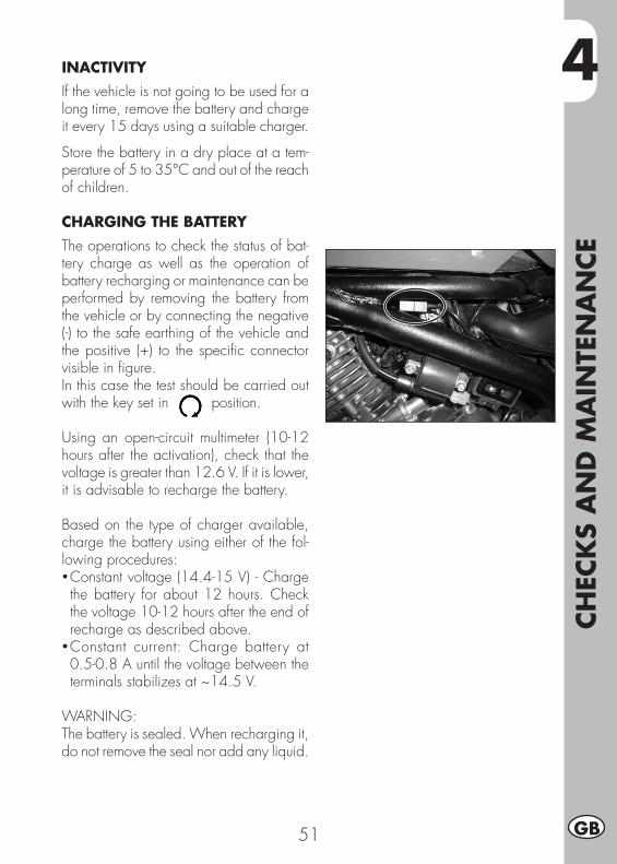
4
CHEC
KS
AN
D M
AIN
TEN
AN
CE
51 GB
INACTIVITYIf the vehicle is not going to be used for a long time, remove the battery and charge it every 15 days using a suitable charger.
Store the battery in a dry place at a tem-perature of 5 to 35°C and out of the reach of children.
CHARGING THE BATTERYThe operations to check the status of bat-tery charge as well as the operation of battery recharging or maintenance can be performed by removing the battery from the vehicle or by connecting the negative (-) to the safe earthing of the vehicle and the positive (+) to the specific connector visible in figure.In this case the test should be carried out with the key set in position.
Using an open-circuit multimeter (10-12 hours after the activation), check that the voltage is greater than 12.6 V. If it is lower, it is advisable to recharge the battery.
Based on the type of charger available, charge the battery using either of the fol-lowing procedures:• Constant voltage (14.4-15 V) - Charge the battery for about 12 hours. Check the voltage 10-12 hours after the end of recharge as described above.
• Constant current: Charge battery at 0.5-0.8 A until the voltage between the terminals stabilizes at ~14.5 V.
WARNING:The battery is sealed. When recharging it, do not remove the seal nor add any liquid.
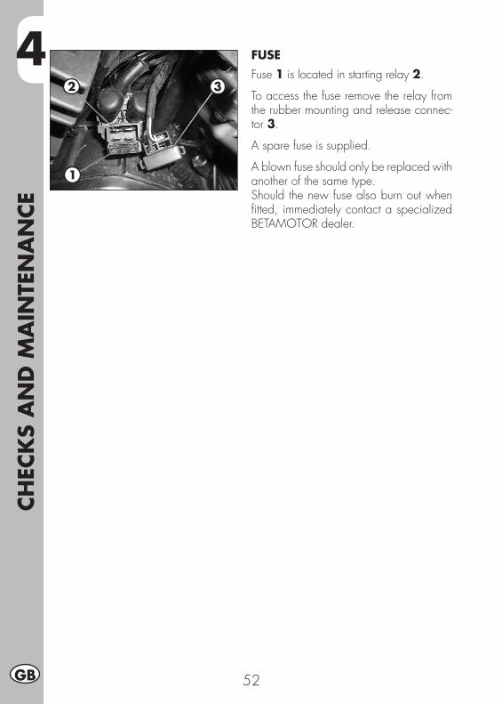
4CH
ECK
S A
ND
MA
INTE
NA
NCE
52GB
FUSEFuse 1 is located in starting relay 2.
To access the fuse remove the relay from the rubber mounting and release connec-tor 3.
A spare fuse is supplied.
A blown fuse should only be replaced with another of the same type.Should the new fuse also burn out when fitted, immediately contact a specialized BETAMOTOR dealer.
2 3
1
4
CHEC
KS
AN
D M
AIN
TEN
AN
CE
53 GB
CLEANING THE VEHICLEWARNING: Do not clean your vehicle with a high-pressure device with a strong jet of water. Excessive pressure can reach electrical components, connectors, flexible cables, bearings, etc and can damage or destroy them.
WARNING: Wash motorbikes frequently that are used near the sea (salty air) and on roads subject to salt spreading in winter. Cover with a film of oil or silicone spray unpainted parts and the most exposed parts such as wheels, forks and swingarm. Do not treat rubber parts and brakes.
When cleaning, avoid direct exposure to sunlight.
Close off the exhaust system to prevent water from entering.
Avoid directing the jet of water onto the air filter box cover.
Use water jet to soften the dirt and mud accumulated on the paintwork, then remove them with a soft bodywork sponge soaked in water and shampoo. Subsequently rinse well with water, and dry with air and cloth or suede leather.
Proceed to the emptying of the filter box using the appropriate ventilation and drying.
Detergents pollute water. Always wash the vehicle in areas equipped for collection and purification of the washing liquids.
After cleaning, ride a short distance until the engine reaches operating temperature.
WARNING: braking effect is reduced with wet brakes. Operate the brakes cau-tiously to allow them to dry.
Push back the handlebar control covers, so that water can evaporate.
When the bike is completely dry and cooled down, lubricate all moving parts.
Treat all plastic and painted components with non-aggressive detergents or products that are specific for the care of the motorcycle.
To prevent malfunction of the electrical system, treat electric contacts and switches with electrical contact spray.
4CH
ECK
S A
ND
MA
INTE
NA
NCE
54GB
PROLONGED INACTIVITYA few simple operations should be performed to keep the vehicle in good condition whenever it is to remain inactive for a long period (e.g. during the winter):• Thoroughly clean the vehicle.• Reduce the tyre pressures by approximately 30 percent, and if possible raise the tyres off the ground.
• Remove the spark plug and pour a few drops of engine oil into the spark plug hole. Make the engine turn a few times by operating the kick-start (where available) and then replace the spark plug.
• Cover the unpainted parts, excepting the brakes and the rubber parts, with a film of oil or spray silicone.
• Ensure the battery is always charged.• Protect the vehicle with a dust cover.•Drain the carburetor tank as described on page 40.
AFTER PROLONGED INACTIVITY
• Restore the tyre inflating pressures.• Check the tightening of all the screws having an important mechanical function.• Start the vehicle for the first time by means of the (kick-start).

4
CHEC
KS
AN
D M
AIN
TEN
AN
CE
55 GB
SCHEDULED MAINTENANCE VEHICLE
End
of ru
nnin
g-in
1.0
00 K
m
Cou
pon
1
5.00
0 Km
- 12
mon
ths
Cou
pon
2
10.0
00 K
m -
12 m
onth
s
Cou
pon
3 1
5.00
0 Km
- 12
mon
ths
Cou
pon
4
20.0
00 K
m -
12 m
onth
s
Cou
pon
5
25.0
00 K
m -
12
mon
ths
Cou
pon
6 3
0.00
0 Km
- 12
mon
ths
Cou
pon
7 3
5.00
0 Km
- 12
mon
ths
Cou
pon
8 4
0.00
0 Km
- 12
mon
ths
Cou
pon
9 4
5.00
0 Km
- 12
mon
ths
Engine Spark plug C S C S C S C S C
Engine oil filter P P P P S P S P S S
Clutch C C C C S C C C S C
Valve clearance C C C C C C C C C C
Engine oil and oil filter S S S S S S S S S S
Idling setting C C C C C C C C C C
Engine oil pipes P P P P P P P P P P
Vehicle Rear shock absorber C C C C C
Battery C C C S C C C S C
Nuts and bolts T T T T T T T T T T
Steering bearings and steering play C C C C C C C C C C
Air filter (paper)Clean every 1000 Km
S S S S
Front fork C C C C C
Electrical system C C C C C C C C C C
Braking system C C C C C C C C C C
Brake fluid (renew every 2 years) C C C C C C C C C C
Cleaning drive chain Every 1000 Km
Tyre condition and pressure C C C C C C C C C C
Drive chain tension and lubrication(every 1000 km) C C C C C C C C C C
Brake piping (replace every 2 years) C C C C C C C C C C
Fuel piping (replace every 2 years) C C C C C C C C C C
* Tightening recommended after each off-road ride.
Key
C Check (Clean, adjust, lubricate, replace as necessary)S Replace/renewR AdjustP CleanT Tighten

56
5
BO
DY
DIS
ASS
EMBLY
AN
D R
EASS
EMBLY
57 GB
CHAPTER 5 BODY DISASSEMBLY AND REASSEMBLY
CONTENTSRemoval and refitting of the saddle.........................................................58Removal and refitting of the tank fairing ..................................................58Removal and refitting of the passenger handles .................................................58Removal and refitting of the under-saddle plastic shield .............................59
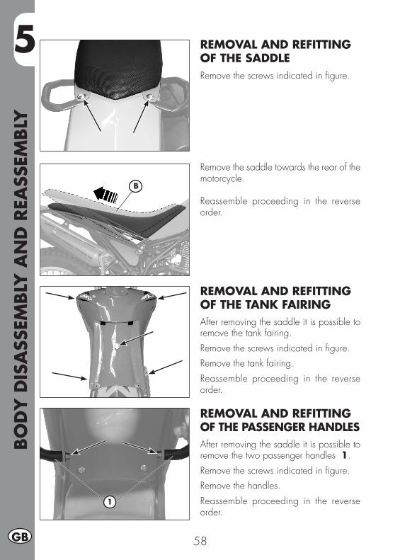
5BO
DY
DIS
ASS
EMBLY
AN
D R
EASS
EMBLY
58GB
REMOVAL AND REFITTING OF THE SADDLERemove the screws indicated in figure.
Remove the saddle towards the rear of the motorcycle.
Reassemble proceeding in the reverse order.
REMOVAL AND REFITTING OF THE TANK FAIRINGAfter removing the saddle it is possible to remove the tank fairing.Remove the screws indicated in figure.Remove the tank fairing.Reassemble proceeding in the reverse order.
REMOVAL AND REFITTING OF THE PASSENGER HANDLESAfter removing the saddle it is possible to remove the two passenger handles 1.Remove the screws indicated in figure.Remove the handles.Reassemble proceeding in the reverse order.
B
1
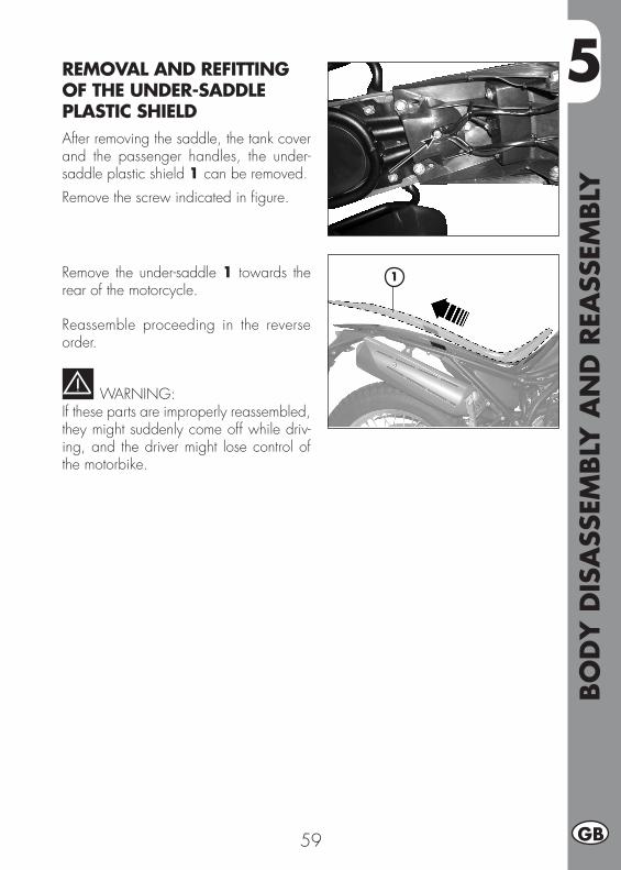
5
BO
DY
DIS
ASS
EMBLY
AN
D R
EASS
EMBLY
59 GB
1
REMOVAL AND REFITTING OF THE UNDER-SADDLE PLASTIC SHIELDAfter removing the saddle, the tank cover and the passenger handles, the under-saddle plastic shield 1 can be removed.Remove the screw indicated in figure.
Remove the under-saddle 1 towards the rear of the motorcycle.
Reassemble proceeding in the reverse order.
WARNING:If these parts are improperly reassembled, they might suddenly come off while driv-ing, and the driver might lose control of the motorbike.

60
6
TRO
UBLE
SHO
OTI
NG
61 GB
CHAPTER 6 TROUBLESHOOTING
CONTENTSTroubleshooting ...................................................................................62Alphabetical index ...............................................................................63
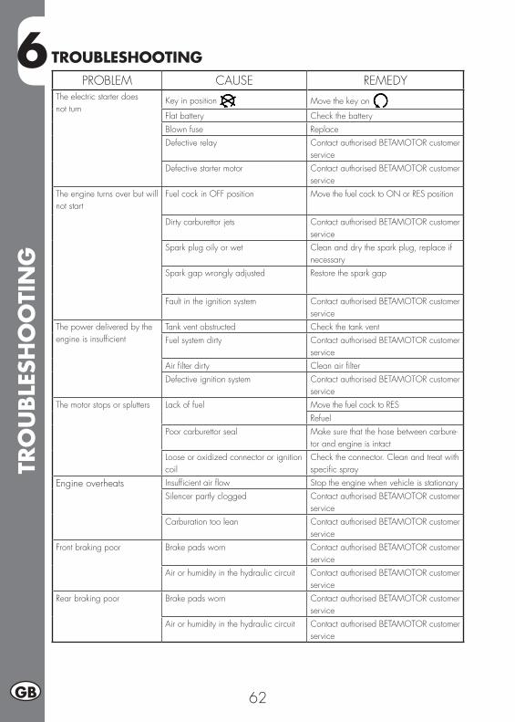
6TR
OU
BLE
SHO
OTI
NG
62GB
TROUBLESHOOTINGPROBLEM CAUSE REMEDY
The electric starter does not turn
Key in position Move the key on
Flat battery Check the batteryBlown fuse ReplaceDefective relay Contact authorised BETAMOTOR customer
service Defective starter motor Contact authorised BETAMOTOR customer
service The engine turns over but will not start
Fuel cock in OFF position Move the fuel cock to ON or RES position
Dirty carburettor jets Contact authorised BETAMOTOR customer service
Spark plug oily or wet Clean and dry the spark plug, replace if necessary
Spark gap wrongly adjusted Restore the spark gap
Fault in the ignition system Contact authorised BETAMOTOR customer service
The power delivered by the engine is insufficient
Tank vent obstructed Check the tank ventFuel system dirty Contact authorised BETAMOTOR customer
serviceAir filter dirty Clean air filterDefective ignition system Contact authorised BETAMOTOR customer
serviceThe motor stops or splutters Lack of fuel Move the fuel cock to RES
RefuelPoor carburettor seal Make sure that the hose between carbure-
tor and engine is intactLoose or oxidized connector or ignition coil
Check the connector. Clean and treat with specific spray
Engine overheats Insufficient air flow Stop the engine when vehicle is stationarySilencer partly clogged Contact authorised BETAMOTOR customer
serviceCarburation too lean Contact authorised BETAMOTOR customer
serviceFront braking poor Brake pads worn Contact authorised BETAMOTOR customer
serviceAir or humidity in the hydraulic circuit Contact authorised BETAMOTOR customer
serviceRear braking poor Brake pads worn Contact authorised BETAMOTOR customer
serviceAir or humidity in the hydraulic circuit Contact authorised BETAMOTOR customer
service
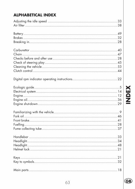
IND
EX
63 GB
ALPHABETICAL INDEXAdjusting the idle speed .......................................................................33Air filter ..............................................................................................38
Battery ................................................................................................49Brakes ................................................................................................32Breaking in..........................................................................................28
Carburettor .........................................................................................40Chain .................................................................................................47Checks before and after use ..................................................................28Check of steering play ..........................................................................45Cleaning the vehicle .............................................................................53Clutch control ......................................................................................44
Digital rpm indicator operating instructions ..............................................22
Ecologic guide .......................................................................................5Electrical system ...................................................................................14Engine ................................................................................................12Engine oil ............................................................................................36Engine shut-down .................................................................................29
Familiarizing with the vehicle...................................................................9Fork oil ...............................................................................................46Front brake..........................................................................................41Fuelling ...............................................................................................28Fume collecting tube .............................................................................37
Handlebar ..........................................................................................33Headlight ............................................................................................34Headlight ............................................................................................48Helmet lock .........................................................................................21
Keys ...................................................................................................21Key to symbols.....................................................................................32
Main parts ..........................................................................................18
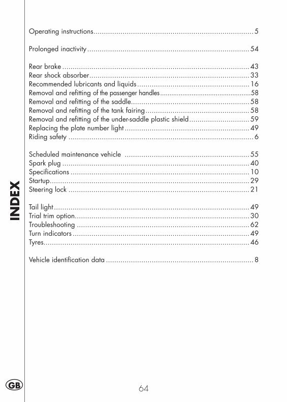
IND
EX
64GB
Operating instructions .............................................................................5
Prolonged inactivity ..............................................................................54
Rear brake ..........................................................................................43Rear shock absorber .............................................................................33Recommended lubricants and liquids ......................................................16Removal and refitting of the passenger handles .................................................58Removal and refitting of the saddle.........................................................58Removal and refitting of the tank fairing ..................................................58Removal and refitting of the under-saddle plastic shield .............................59Replacing the plate number light ............................................................49Riding safety .........................................................................................6
Scheduled maintenance vehicle ............................................................55Spark plug ..........................................................................................40Specifications ......................................................................................10Startup ................................................................................................29Steering lock .......................................................................................21
Tail light ..............................................................................................49Trial trim option....................................................................................30Troubleshooting ...................................................................................62Turn indicators .....................................................................................49Tyres...................................................................................................46
Vehicle identification data .......................................................................8

1 F
ALP 200
Merci de votre confiance et bon divertissement. Ce livret vous donnera les informations nécessaires pour une utilisation correcte et un bon entretien de votre moto.
Les informations et les caractéristiques indiquées dans ce manuel n’engagent pas BETAMOTOR S.p.A. qui se réserve le droit d’apporter des modifications et des améliorations à ses modèles à tout moment et sans préavis.
Code 017440090 000
2F
AVERTISSEMENT
Il est recommandé, au bout de la première ou de la seconde heure d’utilisation en tout-terrain, de contrôler tous les serrages avec une attention particulière pour:
• Couronne• Supports de cale-pieds• Étrier de frein avant• Support de garde-boue• Boulonnerie moteur• Boulonnerie amortisseur.• Rayons roue• Cadre arrière
AVERTISSEMENT
En cas d’intervention à effectuer sur la moto, s’adresser au réseau d’assistance agréé Betamotor.
TABLE
DES
MA
TIÈR
ES
3 F
SOMMAIRE DES CHAPITRES
Conseils pour l’utilisation du véhicule ........................................................5Conduite écologique ..............................................................................5Conduire en sécurité...............................................................................6
CHAP. 1 GÉNÉRALITÉS .......................................................................7Données d’identification du véhicule ..........................................................8Connaissance du véhicule .......................................................................9Données techniques ..............................................................................10Moteur ................................................................................................12Système électrique ................................................................................14Lubrifiants et liquides conseillés ..............................................................16
CHAP. 2 UTILISATION DU VÉHICULE ...............................................17Éléments principaux .............................................................................18Clés ...................................................................................................21Bloc de direction ..................................................................................21Serrure pour casque .............................................................................21Mode d’emploi compteur de vitesse digital..............................................22Contrôles avant et après usage ..............................................................28Rodage ...............................................................................................28Approvisionnement carburant ................................................................28Démarrage moteur ...............................................................................29Arrêt du moteur ....................................................................................29Prédisposition pour la configuration trial .................................................30
CHAP. 3 RÉGLAGES ..........................................................................31Légende symboles ................................................................................32Freins .................................................................................................32Réglage du minimum ...........................................................................33Guidon ...............................................................................................33Réglage amortisseur .............................................................................33Projecteur ............................................................................................34
CHAP. 4 CONTRÔLES ET ENTRETIEN ...............................................35Huile moteur ........................................................................................36Tuyau de récupération des fumées ..........................................................37Filtre à air ...........................................................................................38Bougie ................................................................................................40
TABLE
DES
MA
TIÈR
ES
4F
Carburateur .........................................................................................40Frein avant ..........................................................................................41Frein arrière ........................................................................................43Commande embrayage ........................................................................44Contrôle et réglage jeu direction ............................................................45Pneumatiques ......................................................................................46Huile de fourche ..................................................................................46Chaîne ...............................................................................................47Projecteur ............................................................................................48Feux clignotants ...................................................................................49Feu arrière ..........................................................................................49Remplacement de l’ampoule pour feu plaque ..........................................49Batterie ...............................................................................................49Nettoyage du véhicule ..........................................................................53Longue inactivité du véhicule .................................................................54Entretien programmé ...........................................................................55
CHAP. 5 DÉMONTAGE ET REMONTAGE DES CARÉNAGES .............57Démontage et remontage de la selle .......................................................58Démontage et remontage de la couverture du réservoir ............................58Démontage et remontage des poignées passager ....................................58Démontage et remontage plastique sous selle ..........................................59
CHAP. 6 QUE FAIRE EN CAS D’URGENCE ? ....................................61Recherche de la panne .........................................................................62
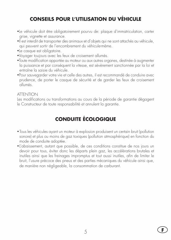
5 F
CONSEILS POUR L’UTILISATION DU VÉHICULE
•Le véhicule doit être obligatoirement pourvu de: plaque d’immatriculation, carter grise, vignette et assurance.
•Il est interdit de transporter des animaux et d’objets qui ne sont attachés au véhicule, qui peuvent sortir de l’encombrement du véhicule-même.
•Le casque est obligatoire.•Voyager toujours avec les feux de croisement allumés.•Toute modification apportée au moteur ou aux autres organes, destinée à augmenter la puissance et par conséquent la vitesse, est sévèrement sanctionnée par la loi et entraîne la saisie du véhicule.
•Pour sauvegarder votre vie et celle des autres, il est recommandé de conduire avec prudence, de porter le casque de sécurité et de garder les feux de croisement allumés.
ATTENTIONLes modifications ou transformations au cours de la période de garantie dégagent le Constructeur de toute responsabilité et annulent la garantie.
CONDUITE ÉCOLOGIQUE
•Tous les véhicules ayant un moteur à explosion produisent un certain bruit (pollution sonore) et plus ou moins de gaz toxiques (pollution atmosphérique) en fonction du mode de conduite adoptée.
•L’abaissement, autant que possible, de ces conditions constitue de nos jours un devoir pour tous, éviter donc les départs plein gaz, les accélérations brutales et inutiles ainsi que les freinages impromptus et tout aussi inutiles, afin de limiter le bruit, l’usure précoce des pneus et des parties mécaniques du véhicule ainsi que, de manière non négligeable, la consommation de carburant.
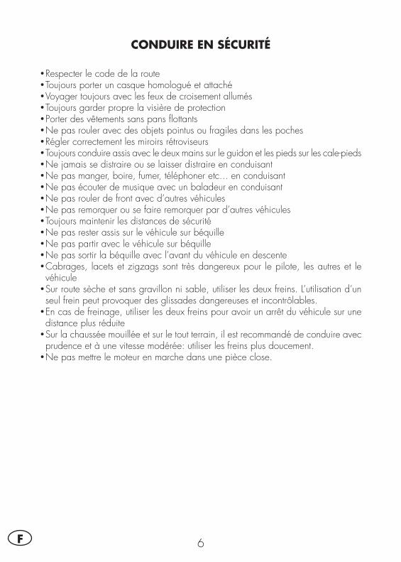
6F
CONDUIRE EN SÉCURITÉ
•Respecter le code de la route•Toujours porter un casque homologué et attaché•Voyager toujours avec les feux de croisement allumés•Toujours garder propre la visière de protection•Porter des vêtements sans pans flottants•Ne pas rouler avec des objets pointus ou fragiles dans les poches•Régler correctement les miroirs rétroviseurs•Toujours conduire assis avec le deux mains sur le guidon et les pieds sur les cale-pieds•Ne jamais se distraire ou se laisser distraire en conduisant•Ne pas manger, boire, fumer, téléphoner etc... en conduisant•Ne pas écouter de musique avec un baladeur en conduisant•Ne pas rouler de front avec d’autres véhicules•Ne pas remorquer ou se faire remorquer par d’autres véhicules•Toujours maintenir les distances de sécurité•Ne pas rester assis sur le véhicule sur béquille•Ne pas partir avec le véhicule sur béquille•Ne pas sortir la béquille avec l’avant du véhicule en descente•Cabrages, lacets et zigzags sont très dangereux pour le pilote, les autres et le véhicule
•Sur route sèche et sans gravillon ni sable, utiliser les deux freins. L’utilisation d’un seul frein peut provoquer des glissades dangereuses et incontrôlables.
•En cas de freinage, utiliser les deux freins pour avoir un arrêt du véhicule sur une distance plus réduite
•Sur la chaussée mouillée et sur le tout terrain, il est recommandé de conduire avec prudence et à une vitesse modérée: utiliser les freins plus doucement.
•Ne pas mettre le moteur en marche dans une pièce close.
1
GÉN
ÉRA
LITÉ
S
7 F
CHAP. 1 GÉNÉRALITÉS
TABLE DES MATIÈRESDonnées d’identification du véhicule ..........................................................8
Identification du cadre .......................................................................8Identification du moteur ......................................................................8Équipement .......................................................................................8
Connaissance du véhicule .......................................................................9Données techniques ..............................................................................10
Poids .............................................................................................10Dimensions du véhicule ....................................................................10Pneus .............................................................................................10Contenances ...................................................................................10Suspension avant ............................................................................11Suspension arrière ...........................................................................11Frein avant .....................................................................................11Frein arrière ....................................................................................11
Moteur ................................................................................................12Carburateur ....................................................................................12Boîte de vitesses .............................................................................13
Système électrique ................................................................................14Schéma électrique ...........................................................................14Légende schéma électrique ...............................................................15
Lubrifiants et liquides conseillés ..............................................................16
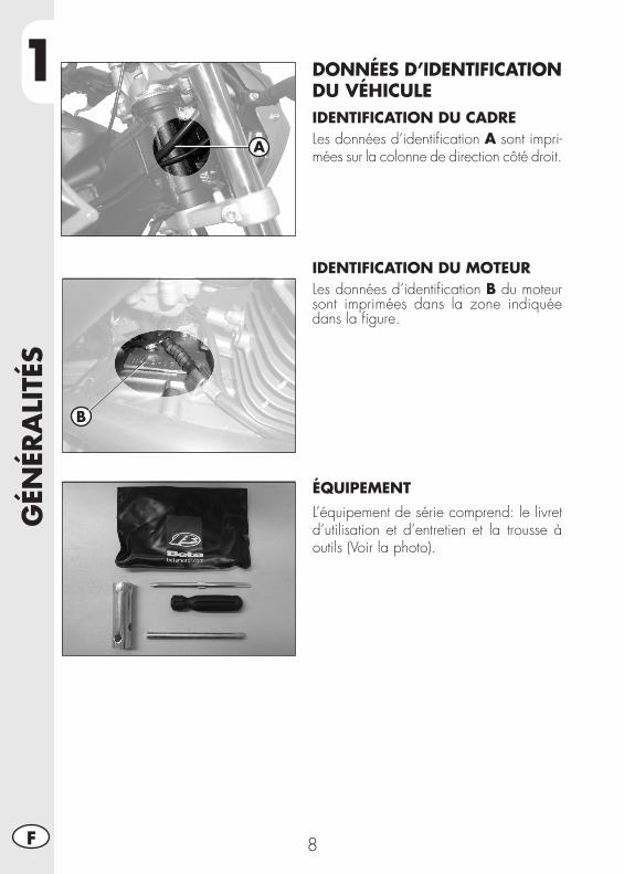
1G
ÉNÉR
ALI
TÉS
8F
DONNÉES D’IDENTIFICATION DU VÉHICULEIDENTIFICATION DU CADRELes données d’identification A sont impri-mées sur la colonne de direction côté droit.
IDENTIFICATION DU MOTEURLes données d’identification B du moteur sont imprimées dans la zone indiquée dans la figure.
ÉQUIPEMENTL’équipement de série comprend: le livret d’utilisation et d’entretien et la trousse à outils (Voir la photo).
A
B
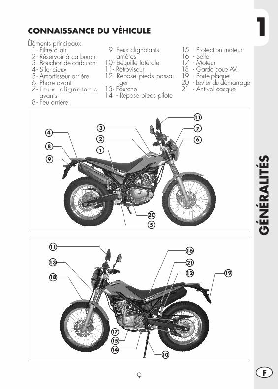
1
GÉN
ÉRA
LITÉ
S
9 F
Éléments principaux: 1 - Filtre à air 2 - Réservoir à carburant 3 - Bouchon de carburant 4 - Silencieux 5 - Amortisseur arrière 6 - Phare avant 7 - Feux c l i gno tan t s
avants 8 - Feu arrière
1
2113
14
CONNAISSANCE DU VÉHICULE
9 - Feux clignotants arrières 10 - Béquille latérale 11 - Rétroviseur 12 - Repose pieds passa-
ger 13 - Fourche 14 - Repose pieds pilote
15 - Protection moteur 16 - Selle 17 - Moteur18 - Garde boue AV.19 - Porte-plaque20 - Levier du démarrage21 - Antivol casque
2
34
5
7
8
9
20
10
15
16
17
191218
11
11
6
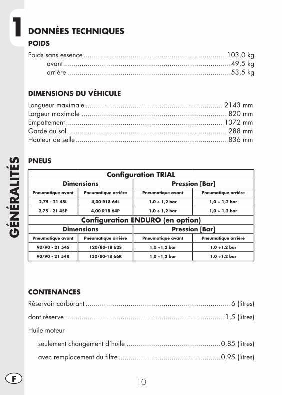
1G
ÉNÉR
ALI
TÉS
10F
DONNÉES TECHNIQUESPOIDS
Poids sans essence ......................................................................103,0 kg avant ..................................................................................49,5 kg arrière ................................................................................53,5 kg
DIMENSIONS DU VÉHICULE
Longueur maximale ................................................................... 2143 mmLargeur maximale ....................................................................... 820 mmEmpattement ............................................................................. 1372 mmGarde au sol .............................................................................. 288 mmHauteur de selle .......................................................................... 836 mm
PNEUS
CONTENANCES
Réservoir carburant .......................................................................6 (litres)
dont réserve ..............................................................................1,5 (litres)
Huile moteur
seulement changement d’huile ..............................................0,85 (litres)
avec remplacement du filtre ..................................................0,95 (litres)
Configuration TRIALDimensions Pression [Bar]
Pneumatique avant Pneumatique arrière Pneumatique avant Pneumatique arrière
2,75 - 21 45L 4,00 R18 64L 1,0 ÷ 1,2 bar 1,0 ÷ 1,2 bar
2,75 - 21 45P 4,00 R18 64P 1,0 ÷ 1,2 bar 1,0 ÷ 1,2 bar
Configuration ENDURO (en option)Dimensions Pression [Bar]
Pneumatique avant Pneumatique arrière Pneumatique avant Pneumatique arrière
90/90 - 21 54S 120/80-18 62S 1,0 ÷1,2 bar 1,0 ÷1,2 bar
90/90 - 21 54R 130/80-18 66R 1,0 ÷1,2 bar 1,0 ÷1,2 bar
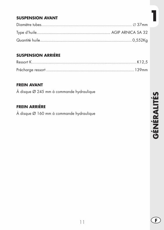
1
GÉN
ÉRA
LITÉ
S
11 F
SUSPENSION AVANT
Diamètre tubes ............................................................................ ∅37mm
Type d’huile .............................................................. AGIP ARNICA SA 32
Quantité huile ............................................................................. 0,552Kg
SUSPENSION ARRIÈRE
Ressort K ........................................................................................ K12,5
Précharge ressort .......................................................................... 139mm
FREIN AVANT
À disque Ø 245 mm à commande hydraulique
FREIN ARRIÈRE
À disque Ø 160 mm à commande hydraulique
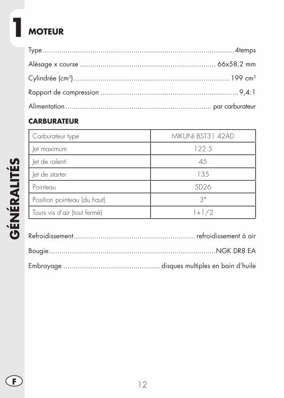
1G
ÉNÉR
ALI
TÉS
12F
MOTEUR
Type .............................................................................................4temps
Alésage x course .................................................................. 66x58,2 mm
Cylindrée (cm3) ............................................................................199 cm3
Rapport de compression ...................................................................9,4:1
Alimentation ....................................................................... par carburateur
CARBURATEUR
Carburateur type MIKUNI BST31 42AD
Jet maximum 122.5
Jet de ralenti 45
Jet de starter 135
Pointeau 5D26
Position pointeau (du haut) 3°
Tours vis d’air (tout fermé) 1+1/2
Refroidissement ........................................................... refroidissement à air
Bougie .................................................................................NGK DR8 EA
Embrayage ............................................... disques multiples en bain d’huile
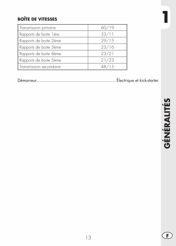
1
GÉN
ÉRA
LITÉ
S
13 F
BOÎTE DE VITESSES
Transmission primaire 60/19Rapports de boite 1ère 33/11Rapports de boite 2ème 29/15Rapports de boite 3ème 23/16Rapports de boite 4ème 23/21Rapports de boite 5ème 21/23Transmission secondaire 48/15
Démarreur .............................................................. Électrique et kick-starter
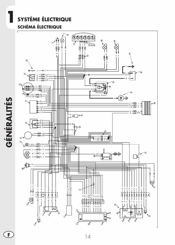
1G
ÉNÉR
ALI
TÉS
14F
SYSTÈME ÉLECTRIQUESCHÉMA ÉLECTRIQUE
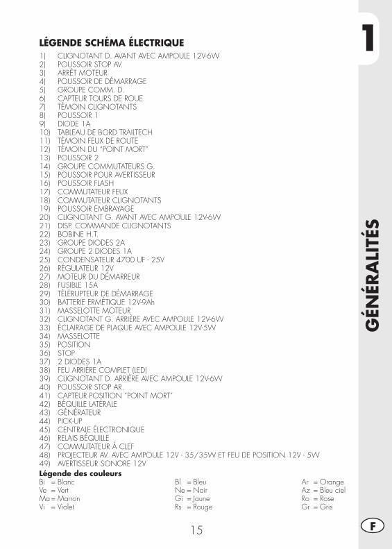
1
GÉN
ÉRA
LITÉ
S
15 F
Légende des couleursBi = BlancVe = VertMa = MarronVi = Violet
Bl = BleuNe = NoirGi = JauneRs = Rouge
Ar = OrangeAz = Bleu cielRo = RoseGr = Gris
LÉGENDE SCHÉMA ÉLECTRIQUE1) CLIGNOTANT D. AVANT AVEC AMPOULE 12V-6W2) POUSSOIR STOP AV.3) ARRÊT MOTEUR4) POUSSOIR DE DÉMARRAGE5) GROUPE COMM. D.6) CAPTEUR TOURS DE ROUE7) TÉMOIN CLIGNOTANTS8) POUSSOIR 19) DIODE 1A10) TABLEAU DE BORD TRAILTECH11) TÉMOIN FEUX DE ROUTE12) TÉMOIN DU “POINT MORT”13) POUSSOIR 214) GROUPE COMMUTATEURS G.15) POUSSOIR POUR AVERTISSEUR16) POUSSOIR FLASH17) COMMUTATEUR FEUX18) COMMUTATEUR CLIGNOTANTS19) POUSSOIR EMBRAYAGE20) CLIGNOTANT G. AVANT AVEC AMPOULE 12V-6W21) DISP. COMMANDE CLIGNOTANTS22) BOBINE H.T.23) GROUPE DIODES 2A24) GROUPE 2 DIODES 1A25) CONDENSATEUR 4700 UF - 25V26) RÉGULATEUR 12V27) MOTEUR DU DÉMARREUR28) FUSIBLE 15A29) TÉLÉRUPTEUR DE DÉMARRAGE30) BATTERIE ERMÉTIQUE 12V-9Ah31) MASSELOTTE MOTEUR32) CLIGNOTANT G. ARRIÈRE AVEC AMPOULE 12V-6W33) ÉCLAIRAGE DE PLAQUE AVEC AMPOULE 12V-5W34) MASSELOTTE35) POSITION36) STOP37) 2 DIODES 1A38) FEU ARRIÈRE COMPLET (LED)39) CLIGNOTANT D. ARRIÈRE AVEC AMPOULE 12V-6W40) POUSSOIR STOP AR.41) CAPTEUR POSITION “POINT MORT”42) BÉQUILLE LATÉRALE43) GÉNÉRATEUR44) PICK-UP45) CENTRALE ÉLECTRONIQUE46) RELAIS BÉQUILLE47) COMMUTATEUR À CLEF48) PROJECTEUR AV. AVEC AMPOULE 12V - 35/35W ET FEU DE POSITION 12V - 5W49) AVERTISSEUR SONORE 12V
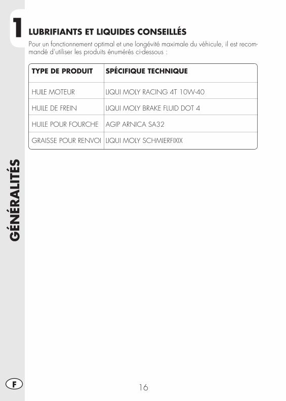
1G
ÉNÉR
ALI
TÉS
16F
TYPE DE PRODUIT SPÉCIFIQUE TECHNIQUE
HUILE MOTEUR LIQUI MOLY RACING 4T 10W-40 HUILE DE FREIN LIQUI MOLY BRAKE FLUID DOT 4 HUILE POUR FOURCHE AGIP ARNICA SA32 GRAISSE POUR RENVOI LIQUI MOLY SCHMIERFIXIX
LUBRIFIANTS ET LIQUIDES CONSEILLÉSPour un fonctionnement optimal et une longévité maximale du véhicule, il est recom-mandé d’utiliser les produits énumérés ci-dessous :
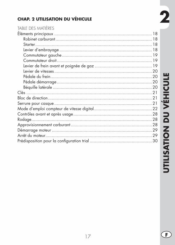
2
UTI
LISA
TIO
N D
U V
ÉHIC
ULE
17 F
CHAP. 2 UTILISATION DU VÉHICULE
TABLE DES MATIÈRESÉléments principaux .............................................................................18
Robinet carburant ............................................................................18Starter ............................................................................................18Levier d’embrayage .........................................................................18Commutateur gauche .......................................................................19Commutateur droit ...........................................................................19Levier de frein avant et poignée de gaz .............................................19Levier de vitesses .............................................................................20Pédale du frein ................................................................................20Pédale démarrage ...........................................................................20Béquille latérale ..............................................................................20
Clés ...................................................................................................21Bloc de direction ..................................................................................21Serrure pour casque .............................................................................21Mode d’emploi compteur de vitesse digital..............................................22Contrôles avant et après usage ..............................................................28Rodage ...............................................................................................28Approvisionnement carburant ................................................................28Démarrage moteur ...............................................................................29Arrêt du moteur ....................................................................................29Prédisposition pour la configuration trial .................................................30
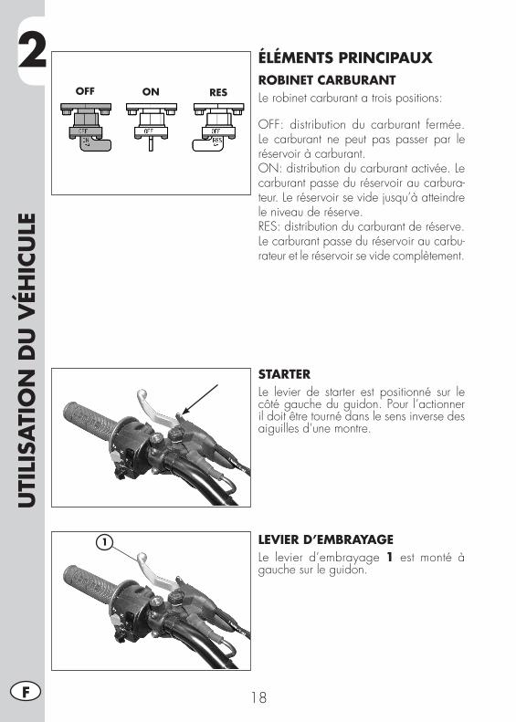
2U
TILI
SATI
ON
DU
VÉH
ICU
LE
18F
ÉLÉMENTS PRINCIPAUXROBINET CARBURANTLe robinet carburant a trois positions:
OFF: distribution du carburant fermée. Le carburant ne peut pas passer par le réservoir à carburant.ON: distribution du carburant activée. Le carburant passe du réservoir au carbura-teur. Le réservoir se vide jusqu’à atteindre le niveau de réserve.RES: distribution du carburant de réserve. Le carburant passe du réservoir au carbu-rateur et le réservoir se vide complètement.
STARTERLe levier de starter est positionné sur le côté gauche du guidon. Pour l’actionner il doit être tourné dans le sens inverse des aiguilles d’une montre.
LEVIER D’EMBRAYAGELe levier d’embrayage 1 est monté à gauche sur le guidon.
OFF ON RES
1
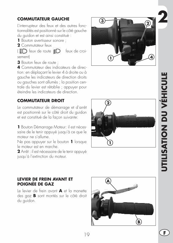
2
UTI
LISA
TIO
N D
U V
ÉHIC
ULE
19 F
COMMUTATEUR GAUCHEL’interrupteur des feux et des autres fonc-tionnalités est positionné sur le côté gauche du guidon et est ainsi constitué :1 Bouton avertisseur sonore ; 2 Commutateur feux( feux de route ; feux de croi-sement)3 Bouton feux de route ;4 Commutateur des indicateurs de direc-tion: en déplaçant le levier 4 à droite ou à gauche les indicateurs de direction droits ou gauches sont allumés ; la position cen-trale du levier est rétablie ; appuyer pour éteindre les indicateurs de direction.
1
23
4
COMMUTATEUR DROITLe commutateur de démarrage et d’arrêt est positionné sur le côté droit du guidon et est constitué de la façon suivante:
1 Bouton Démarrage Moteur: il est néces-saire de le tenir appuyé jusqu’à ce que le moteur ne s’allume.Ne pas appuyer sur le bouton 1 lorsque le moteur est en marche.2 Arrêt : il est nécessaire de le tenir appuyé jusqu’à l’extinction du moteur.
LEVIER DE FREIN AVANT ET POIGNÉE DE GAZLe levier de frein avant A et la manette des gaz B sont montés sur le côté droit du guidon.
2
1
A
B
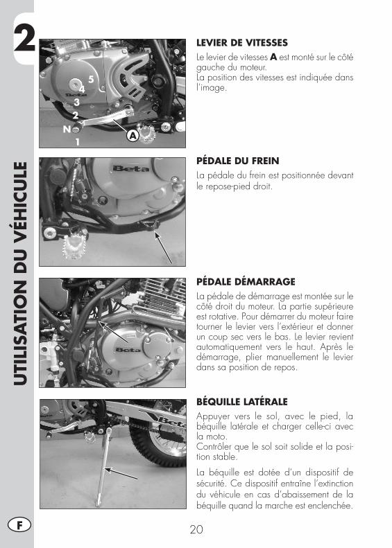
2U
TILI
SATI
ON
DU
VÉH
ICU
LE
20F
1
234
5
NA
LEVIER DE VITESSESLe levier de vitesses A est monté sur le côté gauche du moteur.La position des vitesses est indiquée dans l’image.
PÉDALE DU FREINLa pédale du frein est positionnée devant le repose-pied droit.
PÉDALE DÉMARRAGELa pédale de démarrage est montée sur le côté droit du moteur. La partie supérieure est rotative. Pour démarrer du moteur faire tourner le levier vers l’extérieur et donner un coup sec vers le bas. Le levier revient automatiquement vers le haut. Après le démarrage, plier manuellement le levier dans sa position de repos.
BÉQUILLE LATÉRALEAppuyer vers le sol, avec le pied, la béquille latérale et charger celle-ci avec la moto.Contrôler que le sol soit solide et la posi-tion stable.
La béquille est dotée d’un dispositif de sécurité. Ce dispositif entraîne l’extinction du véhicule en cas d’abaissement de la béquille quand la marche est enclenchée.
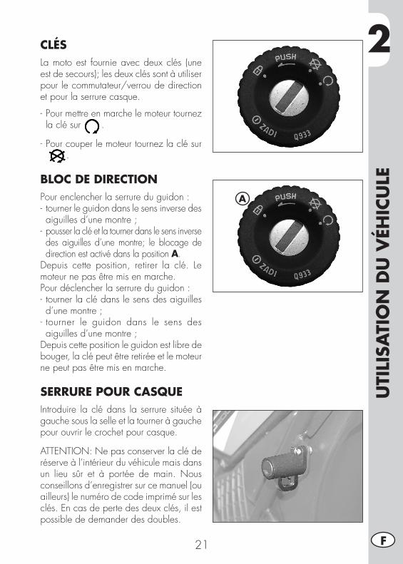
2
UTI
LISA
TIO
N D
U V
ÉHIC
ULE
21 F
CLÉSLa moto est fournie avec deux clés (une est de secours); les deux clés sont à utiliser pour le commutateur/verrou de direction et pour la serrure casque.
- Pour mettre en marche le moteur tournez la clé sur .
- Pour couper le moteur tournez la clé sur.
BLOC DE DIRECTIONPour enclencher la serrure du guidon :- tourner le guidon dans le sens inverse des aiguilles d’une montre ;
- pousser la clé et la tourner dans le sens inverse des aiguilles d’une montre; le blocage de direction est activé dans la position A.
Depuis cette position, retirer la clé. Le moteur ne pas être mis en marche. Pour déclencher la serrure du guidon : - tourner la clé dans le sens des aiguilles d’une montre ;
- tourner le guidon dans le sens des aiguilles d’une montre ;
Depuis cette position le guidon est libre de bouger, la clé peut être retirée et le moteur ne peut pas être mis en marche.
SERRURE POUR CASQUEIntroduire la clé dans la serrure située à gauche sous la selle et la tourner à gauche pour ouvrir le crochet pour casque.
ATTENTION: Ne pas conserver la clé de réserve à l’intérieur du véhicule mais dans un lieu sûr et à portée de main. Nous conseillons d’enregistrer sur ce manuel (ou ailleurs) le numéro de code imprimé sur les clés. En cas de perte des deux clés, il est possible de demander des doubles.
A
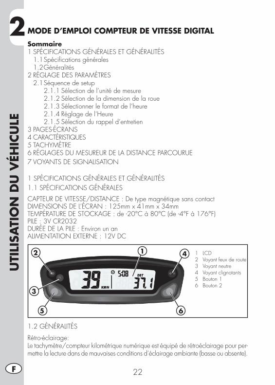
2U
TILI
SATI
ON
DU
VÉH
ICU
LE
22F
MODE D’EMPLOI COMPTEUR DE VITESSE DIGITALSommaire1 SPÉCIFICATIONS GÉNÉRALES ET GÉNÉRALITÉS 1.1 Spécifications générales 1.2 Généralités2 RÉGLAGE DES PARAMÈTRES 2.1 Séquence de setup 2.1.1 Sélection de l’unité de mesure 2.1.2 Sélection de la dimension de la roue 2.1.3 Sélectionner le format de l’heure 2.1.4 Réglage de l’Heure 2.1.5 Sélection du rappel d’entretien3 PAGES-ÉCRANS4 CARACTÉRISTIQUES5 TACHYMÈTRE6 RÉGLAGES DU MESUREUR DE LA DISTANCE PARCOURUE7 VOYANTS DE SIGNALISATION
1 SPÉCIFICATIONS GÉNÉRALES ET GÉNÉRALITÉS1.1 SPÉCIFICATIONS GÉNÉRALES
CAPTEUR DE VITESSE/DISTANCE : De type magnétique sans contactDIMENSIONS DE L’ÉCRAN : 125mm x 41mm x 34mmTEMPÉRATURE DE STOCKAGE : de -20°C à 80°C (de -4°F à 176°F)PILE : 3V CR2032DURÉE DE LA PILE : Environ un anALIMENTATION EXTERNE : 12V DC
1.2 GÉNÉRALITÉS
Rétro-éclairage:Le tachymètre/compteur kilométrique numérique est équipé de rétroéclairage pour per-mettre la lecture dans de mauvaises conditions d’éclairage ambiante (basse ou absente).
12
3
5
4
6
1 LCD 2 Voyant feux de route 3 Voyant neutre 4 Voyant clignotants 5 Bouton 1 6 Bouton 2
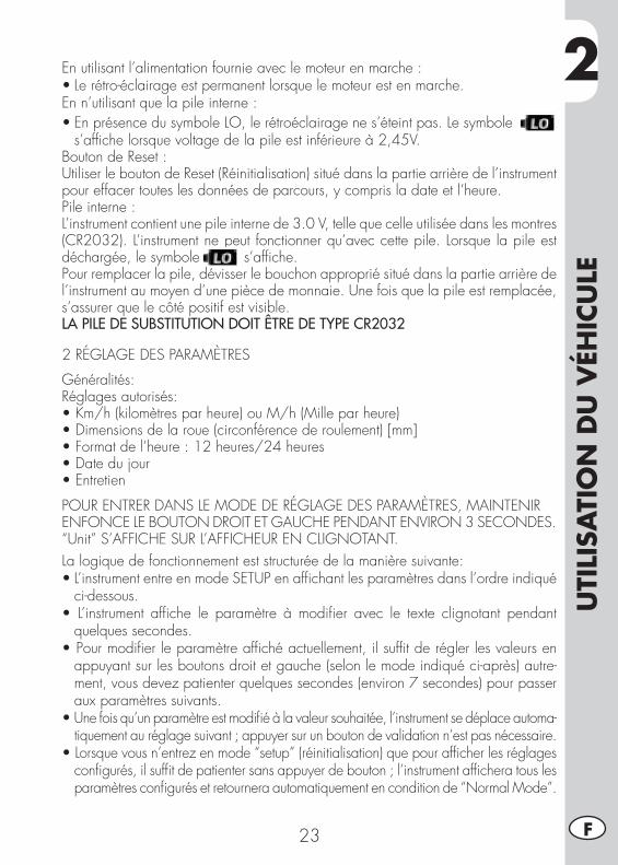
2
UTI
LISA
TIO
N D
U V
ÉHIC
ULE
23 F
En utilisant l’alimentation fournie avec le moteur en marche :•Lerétro-éclairageestpermanentlorsquelemoteurestenmarche.En n’utilisant que la pile interne :•EnprésencedusymboleLO,lerétroéclairagenes’éteintpas.Lesymbole
s’affiche lorsque voltage de la pile est inférieure à 2,45V.Bouton de Reset :Utiliser le bouton de Reset (Réinitialisation) situé dans la partie arrière de l’instrument pour effacer toutes les données de parcours, y compris la date et l’heure.Pile interne :L’instrument contient une pile interne de 3.0 V, telle que celle utilisée dans les montres(CR2032). L’instrument ne peut fonctionner qu’avec cette pile. Lorsque la pile est déchargée, le symbole s’affiche.Pour remplacer la pile, dévisser le bouchon approprié situé dans la partie arrière de l’instrument au moyen d’une pièce de monnaie. Une fois que la pile est remplacée, s’assurer que le côté positif est visible.LA PILE DE SUBSTITUTION DOIT ÊTRE DE TYPE CR2032
2 RÉGLAGE DES PARAMÈTRES
Généralités:Réglages autorisés:•Km/h(kilomètresparheure)ouM/h(Milleparheure)•Dimensionsdelaroue(circonférencederoulement)[mm]•Formatdel’heure:12heures/24heures•Datedujour•Entretien
POUR ENTRER DANS LE MODE DE RÉGLAGE DES PARAMÈTRES, MAINTENIRENFONCE LE BOUTON DROIT ET GAUCHE PENDANT ENVIRON 3 SECONDES.“Unit” S’AFFICHE SUR L’AFFICHEUR EN CLIGNOTANT.La logique de fonctionnement est structurée de la manière suivante:• L’instrument entre en mode SETUP en affichant les paramètres dans l’ordre indiqué
ci-dessous.• L’instrument affiche le paramètre à modifier avec le texte clignotant pendant
quelques secondes.• Pour modifier le paramètre affiché actuellement, il suffit de régler les valeurs en
appuyant sur les boutons droit et gauche (selon le mode indiqué ci-après) autre-ment, vous devez patienter quelques secondes (environ 7 secondes) pour passer aux paramètres suivants.
• Une fois qu’un paramètre est modifié à la valeur souhaitée, l’instrument se déplace automa-tiquement au réglage suivant ; appuyer sur un bouton de validation n’est pas nécessaire.
• Lorsque vous n’entrez en mode “setup” (réinitialisation) que pour afficher les réglages configurés, il suffit de patienter sans appuyer de bouton ; l’instrument affichera tous les paramètres configurés et retournera automatiquement en condition de “Normal Mode”.
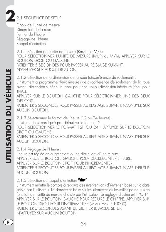
2U
TILI
SATI
ON
DU
VÉH
ICU
LE
24F
2.1 SÉQUENCE DE SETUP
Choix de l’unité de mesureDimension de la roueFormat de l’heureRéglage de l’HeureRappel d’entretien
2.1.1 Sélection de l’unité de mesure (Km/h ou M/h):POUR SÉLECTIONNER L’UNITÉ DE MESURE (Km/h ou M/h), APPUYER SUR LE BOUTON DROIT OU GAUCHE.PATIENTER 5 SECONDES POUR PASSER AU RÉGLAGE SUIVANT.N’APPUYER SUR AUCUN BOUTON.
2.1.2 Sélection de la dimension de la roue (circonférence de roulement) :L’instrument a programmé deux mesures de circonférence de roulement de la roue avant : dimension supérieure (Pneu pour Enduro) ou dimension inférieure (Pneu pour TRIAL).APPUYER SUR LE BOUTON GAUCHE POUR SÉLECTIONNER UNE DES DEUX OPTIONS.PATIENTER 5 SECONDES POUR PASSER AU RÉGLAGE SUIVANT. N’APPUYER SUR AUCUN BOUTON.
2.1.3 Sélectionner le format de l’heure (12 ou 24 heures) :L’instrument est configuré par défaut sur le format 12h.POUR SÉLECTIONNER LE FORMAT 12h OU 24h, APPUYER SUR LE BOUTON DROIT OU GAUCHE.PATIENTER 5 SECONDES POUR PASSER AU RÉGLAGE SUIVANT. N’APPUYER SUR AUCUN BOUTON.
2.1.4 Réglage de l’Heure :L’heure est réglée en augmentant ou en diminuant d’une minute.APPUYER SUR LE BOUTON GAUCHE POUR DECREMENTER L’HEURE.APPUYER SUR LE BOUTON DROIT POUR L’INCREMENTER.PATIENTER 5 SECONDES POUR PASSER AU RÉGLAGE SUIVANT. N’APPUYER SUR AUCUN BOUTON.
2.1.5 Sélection du rappel d’entretienL’instrument montre le compte à rebours des interventions d’entretien basé sur la date saisie par l’utilisateur. La donnée se base sur les kilomètres ou les milles parcourus en fonction de l’unité de mesure choisie par l’utilisateur. Le réglage d’usine est : “OFF”.APPUYER SUR LE BOUTON GAUCHE POUR REDUIRE LE CHIFFRE. APPUYER SURLE BOUTON DROIT POUR L’INCREMENTER (valeur max. : 10000).PATIENTER 5 SECONDES AVANT DE QUITTER LE MODE SETUP.N’APPUYER SUR AUCUN BOUTON.
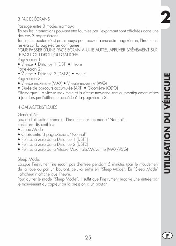
2
UTI
LISA
TIO
N D
U V
ÉHIC
ULE
25 F
3 PAGES-ÉCRANS
Passage entre 3 modes normauxToutes les informations pouvant être fournies par l’exprimant sont affichées dans une des ces 3 pages-écrans.Tant qu’un bouton n’est pas appuyé pour passer à une autre page-écran, l’instrument restera sur la page-écran configurée.POUR PASSER D’UNE PAGE-ECRAN A UNE AUTRE, APPUYER BRIÈVEMENT SURLE BOUTON DROIT OU GAUCHE.Page-écran 1:•Vitesse•Distance1(DST)•HeurePage-écran 2:•Vitesse•Distance2(DST2)•HeurePage-écran 3:•Vitessemaximale(MAX)•Vitessemoyenne(AVG)•Duréedeparcoursaccumulée(ART)•Odomètre(ODO)*Remarque : La vitesse maximale et la vitesse moyenne sont automatiquement mises à jour lorsque l’utilisateur accède à la page-écran 3.
4 CARACTÉRISTIQUES
Généralités:Lors de l’utilisation normale, l’instrument est en mode “Normal”.Fonctions disponibles:•SleepMode•Choixentre3pages-écrans“Normal”•RemiseàzérodelaDistance1(DST1)•RemiseàzérodelaDistance2(DST2)•RemiseàzérodelaVitesseMaximale/Moyenne(MAX/AVG)
Sleep Mode:Lorsque l’instrument ne reçoit pas d’entrée pendant 5 minutes (par le mouvement de la roue ou par un bouton), celui-ci entre en “Sleep Mode”. En “Sleep Mode” l’afficheur n’affiche que l’heure.Pour quitter le mode “Sleep Mode”, il suffit que l’instrument reçoive une entrée par le mouvement du capteur ou la pression d’un bouton.
2U
TILI
SATI
ON
DU
VÉH
ICU
LE
26F
5 TACHYMÈTRE
VitesseLa vitesse s’affiche au centre des pages-écrans 1 ou 2 ; elle va de 0 à 399,9 km/h ou M/h. L’unité de mesure (km/h ou M/h) s’affiche à côté de la vitesse relevée.
Vitesse Maximale (Max) et Moyenne (AVG)Les vitesses Maximale (MAX) ou Moyenne (AVG) s’affichent sur la page écran 3, à la gauche de l’afficheur. L’instrument met automatiquement à jour la vitesse maximale (MAX) et moyenne (AVG). Pour remettre à zéro la vitesse maximale (MAX) et la vitesse moyenne (AVG), maintenir enfoncé le bouton droit pendant 5 secondes.Remarque : pour effectuer la remise à zéro, vous devez vous trouver sur la page-écran 3.
6 RÉGLAGES DU MESUREUR DE LA DISTANCE PARCOURUE
DescriptionLe mesureur de la distance parcourue montre la distance parcourue à partir de la dernière remise à zéro. Celui-ci possède deux types de distances caractéristiques.
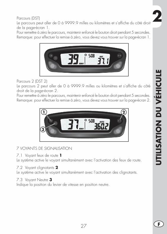
2
UTI
LISA
TIO
N D
U V
ÉHIC
ULE
27 F
Parcours (DST) Le parcours peut aller de 0 à 9999.9 milles ou kilomètres et s’affiche du côté droit de la page-écran 1.Pour remettre à zéro le parcours, maintenir enfoncé le bouton droit pendant 5 secondes.Remarque: pour effectuer la remise à zéro, vous devez vous trouver sur la page-écran 1.
Parcours 2 (DST 2)Le parcours 2 peut aller de 0 à 9999.9 milles ou kilomètres et s’affiche du côté droit de la page-écran 2.Pour remettre à zéro le parcours, maintenir enfoncé le bouton droit pendant 5 secondes.Remarque: pour effectuer la remise à zéro, vous devez vous trouver sur la page-écran 2.
7 VOYANTS DE SIGNALISATION
7.1 Voyant feux de route 1Le système active le voyant simultanément avec l’activation des feux de route.
7.2 Voyant clignotants 2Le système active le voyant simultanément avec l’activation des clignotants.
7.3 Voyant Neutre 3Indique la position du levier de vitesse en position neutre.
1
3
2
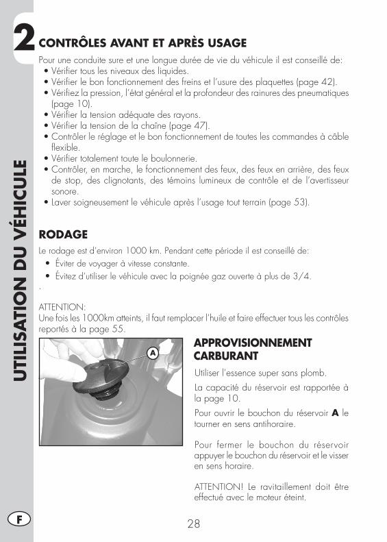
2U
TILI
SATI
ON
DU
VÉH
ICU
LE
28F
CONTRÔLES AVANT ET APRÈS USAGEPour une conduite sure et une longue durée de vie du véhicule il est conseillé de:•Vérifiertouslesniveauxdesliquides.•Vérifierlebonfonctionnementdesfreinsetl’usuredesplaquettes(page42).•Vérifiezlapression,l’étatgénéraletlaprofondeurdesrainuresdespneumatiques
(page 10).•Vérifierlatensionadéquatedesrayons.•Vérifierlatensiondelachaîne(page47).•Contrôlerleréglageetlebonfonctionnementdetouteslescommandesàcâble
flexible.•Vérifiertotalementtouteleboulonnerie.•Contrôler,enmarche,lefonctionnementdesfeux,desfeuxenarrière,desfeux
de stop, des clignotants, des témoins lumineux de contrôle et de l’avertisseur sonore.
•Laversoigneusementlevéhiculeaprèsl’usagetoutterrain(page53).
RODAGELe rodage est d’environ 1000 km. Pendant cette période il est conseillé de: •Éviter de voyager à vitesse constante. •Évitez d’utiliser le véhicule avec la poignée gaz ouverte à plus de 3/4..
ATTENTION: Une fois les 1000km atteints, il faut remplacer l’huile et faire effectuer tous les contrôles reportés à la page 55.
APPROVISIONNEMENT CARBURANTUtiliser l’essence super sans plomb.La capacité du réservoir est rapportée à la page 10.Pour ouvrir le bouchon du réservoir A le tourner en sens antihoraire.
Pour fermer le bouchon du réservoir appuyer le bouchon du réservoir et le visser en sens horaire.
ATTENTION! Le ravitaillement doit être effectué avec le moteur éteint.
A
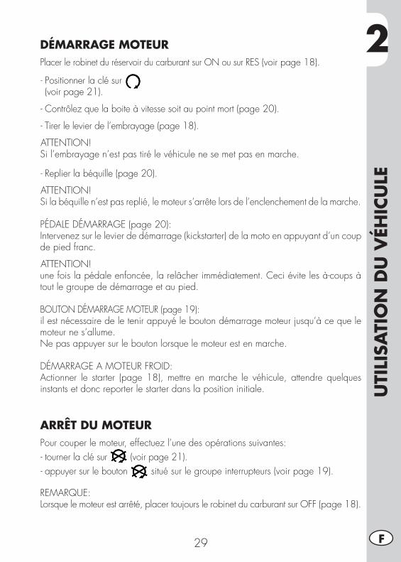
2
UTI
LISA
TIO
N D
U V
ÉHIC
ULE
29 F
DÉMARRAGE MOTEURPlacer le robinet du réservoir du carburant sur ON ou sur RES (voir page 18).
- Positionner la clé sur (voir page 21).
- Contrôlez que la boite à vitesse soit au point mort (page 20).
- Tirer le levier de l’embrayage (page 18).
ATTENTION!Si l’embrayage n’est pas tiré le véhicule ne se met pas en marche.
- Replier la béquille (page 20).
ATTENTION!Si la béquille n’est pas replié, le moteur s’arrête lors de l’enclenchement de la marche.
PÉDALE DÉMARRAGE (page 20):Intervenez sur le levier de démarrage (kickstarter) de la moto en appuyant d’un coup de pied franc.
ATTENTION!unefoislapédaleenfoncée,larelâcherimmédiatement.Ceciévitelesà-coupsàtout le groupe de démarrage et au pied.
BOUTON DÉMARRAGE MOTEUR (page 19):il est nécessaire de le tenir appuyé le bouton démarrage moteur jusqu’à ce que le moteur ne s’allume.Ne pas appuyer sur le bouton lorsque le moteur est en marche.
DÉMARRAGE A MOTEUR FROID:Actionner le starter (page 18), mettre en marche le véhicule, attendre quelques instants et donc reporter le starter dans la position initiale.
ARRÊT DU MOTEURPour couper le moteur, effectuez l’une des opérations suivantes:- tourner la clé sur (voir page 21).- appuyer sur le bouton situé sur le groupe interrupteurs (voir page 19).
REMARQUE: Lorsque le moteur est arrêté, placer toujours le robinet du carburant sur OFF (page 18).
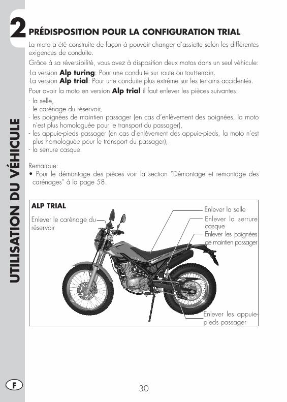
2U
TILI
SATI
ON
DU
VÉH
ICU
LE
30F
PRÉDISPOSITION POUR LA CONFIGURATION TRIALLa moto a été construite de façon à pouvoir changer d’assiette selon les différentes exigences de conduite.Grâceàsaréversibilité,vousavezàdispositiondeuxmotosdansunseulvéhicule:-La version Alp turing: Pour une conduite sur route ou tout-terrain.-La version Alp trial: Pour une conduite plus extrême sur les terrains accidentés.Pour avoir la moto en version Alp trial il faut enlever les pièces suivantes:- la selle,- le carénage du réservoir,- les poignées de maintien passager (en cas d’enlèvement des poignées, la moto n’est plus homologuée pour le transport du passager),
- les appuie-pieds passager (en cas d’enlèvement des appuie-pieds, la moto n’est plus homologuée pour le transport du passager),
- la serrure casque.
Remarque:•Pour le démontage des pièces voir la section “Démontage et remontage des carénages” à la page 58.
Enlever la selleEnlever le carénage du réservoir
Enlever les appuie-pieds passager
Enlever la serrure casqueEnlever les poignées de maintien passager
ALP TRIAL
3
RÉG
LAG
ES
31 F
CHAP. 3 RÉGLAGES
TABLE DES MATIÈRESLégende symboles ................................................................................32Freins .................................................................................................32
Frein avant .....................................................................................32Réglage jeu gaz .............................................................................32
Réglage du minimum ...........................................................................33Guidon ...............................................................................................33Réglage amortisseur .............................................................................33
Réglage pré-chargement du ressort ....................................................33Projecteur ............................................................................................34
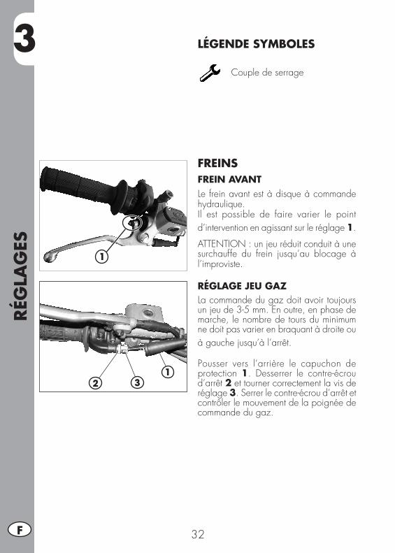
RÉG
LAG
ES
32F
3 LÉGENDE SYMBOLES
Couple de serrage
FREINSFREIN AVANTLe frein avant est à disque à commande hydraulique.Il est possible de faire varier le point d’intervention en agissant sur le réglage 1.
ATTENTION : un jeu réduit conduit à une surchauffe du frein jusqu’au blocage à l’improviste.
RÉGLAGE JEU GAZ La commande du gaz doit avoir toujours un jeu de 3-5 mm. En outre, en phase de marche, le nombre de tours du minimum ne doit pas varier en braquant à droite ou à gauche jusqu’à l’arrêt.
Pousser vers l’arrière le capuchon de protection 1. Desserrer le contre-écrou d’arrêt 2 et tourner correctement la vis de réglage 3. Serrer le contre-écrou d’arrêt et contrôler le mouvement de la poignée de commande du gaz.
1
21
3
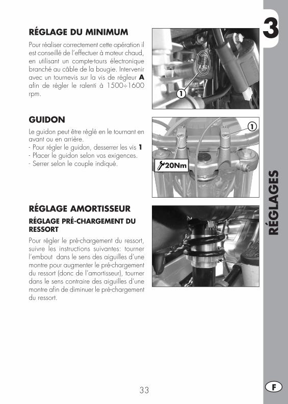
3
RÉG
LAG
ES
33 F
1
RÉGLAGE DU MINIMUM Pour réaliser correctement cette opération il est conseillé de l’effectuer à moteur chaud, en utilisant un compte-tours électronique branchéaucâbledelabougie.Interveniravec un tournevis sur la vis de régleur A afin de régler le ralenti à 1500÷1600 rpm.
GUIDONLe guidon peut être réglé en le tournant en avant ou en arrière.- Pour régler le guidon, desserrer les vis 1- Placer le guidon selon vos exigences.- Serrer selon le couple indiqué.
RÉGLAGE AMORTISSEURRÉGLAGE PRÉ-CHARGEMENT DU RESSORTPour régler le pré-chargement du ressort, suivre les instructions suivantes: tourner l’embout dans le sens des aiguilles d’une montre pour augmenter le pré-chargement du ressort (donc de l’amortisseur), tourner dans le sens contraire des aiguilles d’une montre afin de diminuer le pré-chargement du ressort.
1
20Nm
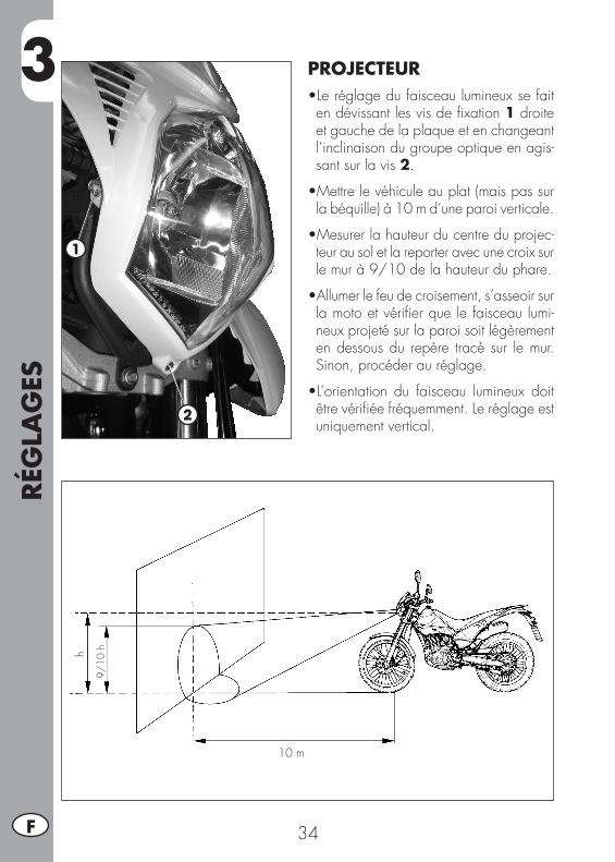
RÉG
LAG
ES
34F
3 PROJECTEUR•Leréglagedufaisceaulumineuxsefaiten dévissant les vis de fixation 1 droite et gauche de la plaque et en changeant l’inclinaison du groupe optique en agis-sant sur la vis 2.
•Mettrelevéhiculeauplat(maispassurla béquille) à 10 m d’une paroi verticale.
•Mesurerlahauteurducentreduprojec-teur au sol et la reporter avec une croix sur le mur à 9/10 de la hauteur du phare.
•Allumerlefeudecroisement,s’asseoirsurla moto et vérifier que le faisceau lumi-neux projeté sur la paroi soit légèrement en dessous du repère tracé sur le mur. Sinon, procéder au réglage.
•L’orientation du faisceau lumineux doitêtre vérifiée fréquemment. Le réglage est uniquement vertical.
1
2
9/10
h
10 m
h
4
CON
TRÔ
LES
ET E
NTR
ETIE
N
35 F
CHAP. 4 CONTRÔLES ET ENTRETIEN
TABLE DES MATIÈRESHuile moteur ........................................................................................36
Contrôle niveau ...............................................................................36Remplacement .................................................................................36
Tuyau de récupération des fumées ..........................................................37Filtre à air ...........................................................................................38
Retrait et installation du filtre à air .....................................................38Nettoyage du filtre à air ...................................................................39
Bougie ................................................................................................40Carburateur .........................................................................................40
Vidange du bac carburateur .............................................................40Frein avant ..........................................................................................41
Contrôle du niveau du liquide du frein avant .......................................41Vidange du frein avant .....................................................................42Contrôle des pastilles du frein avant ..................................................42
Frein arrière ........................................................................................43Contrôle du niveau du liquide du frein arrière .....................................43Remplissage niveau liquide du frein arrière .........................................43Vidange du frein arrière ..................................................................43Contrôle des pastilles du frein arrière .................................................44
Commande embrayage ........................................................................44Contrôle et réglage jeu direction ............................................................45Pneumatiques ......................................................................................46Huile de fourche ..................................................................................46Chaîne ...............................................................................................47
Contrôle et régulation tension de la chaîne .........................................47Projecteur ............................................................................................48
Remplacement ampoules projecteur ...................................................48Feux clignotants ...................................................................................49Feu arrière ..........................................................................................49Remplacement de l’ampoule pour feu plaque ..........................................49Batterie ...............................................................................................49
Démontage de la batterie .................................................................50Inactivité .........................................................................................51Recharge de la batterie ....................................................................51Fusible ...........................................................................................52
Nettoyage du véhicule ..........................................................................53Longue inactivité du véhicule .................................................................54Entretien programmé ...........................................................................55
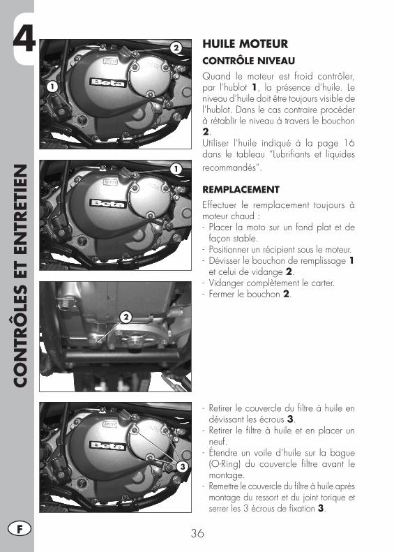
4CO
NTR
ÔLE
S ET
EN
TRET
IEN
36F
HUILE MOTEURCONTRÔLE NIVEAUQuand le moteur est froid contrôler, par l’hublot 1, la présence d’huile. Le niveau d’huile doit être toujours visible de l’hublot. Dans le cas contraire procéder à rétablir le niveau à travers le bouchon2.Utiliser l’huile indiqué à la page 16 dans le tableau “Lubrifiants et liquides recommandés”.
REMPLACEMENTEffectuer le remplacement toujours à moteur chaud :- Placer la moto sur un fond plat et de
façon stable.- Positionner un récipient sous le moteur.- Dévisser le bouchon de remplissage 1
et celui de vidange 2.- Vidanger complètement le carter.- Fermer le bouchon 2.
- Retirer le couvercle du filtre à huile en dévissant les écrous 3.
- Retirer le filtre à huile et en placer un neuf.
- Étendre un voile d’huile sur la bague (O-Ring) du couvercle filtre avant le montage.
- Remettre le couvercle du filtre à huile après montage du ressort et du joint torique et serrer les 3 écrous de fixation 3.
2
1
2
1
3
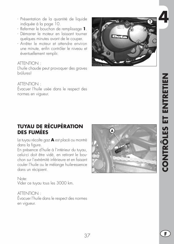
4
CON
TRÔ
LES
ET E
NTR
ETIE
N
37 F
- Présentation de la quantité de liquide indiquée à la page 10.
- Refermer le bouchon de remplissage 1.- Démarrer le moteur en laissant tourner
quelques minutes avant de le couper.- Arrêter le moteur et attendre environ
une minute, enfin contrôler le niveau et éventuellement remplir.
ATTENTION :L’huile chaude peut provoquer des graves brûlures!
ATTENTION :Évacuer l’huile usée dans le respect des normes en vigueur.
TUYAU DE RÉCUPÉRATION DES FUMÉESLe tuyau récolte gaz A est placé ou montré dans la figure.En présence d’huile à l’intérieur du tuyau, celui-ci doit être vidé, en retirant le bou-chon sur l’extrémité inférieure et en faisant couler l’huile ou le mélange huile-essence dans un récipient.
Note:Vider ce tuyau tous les 3000 km.
ATTENTION :Évacuer l’huile dans le respect des normes en vigueur.
1
A
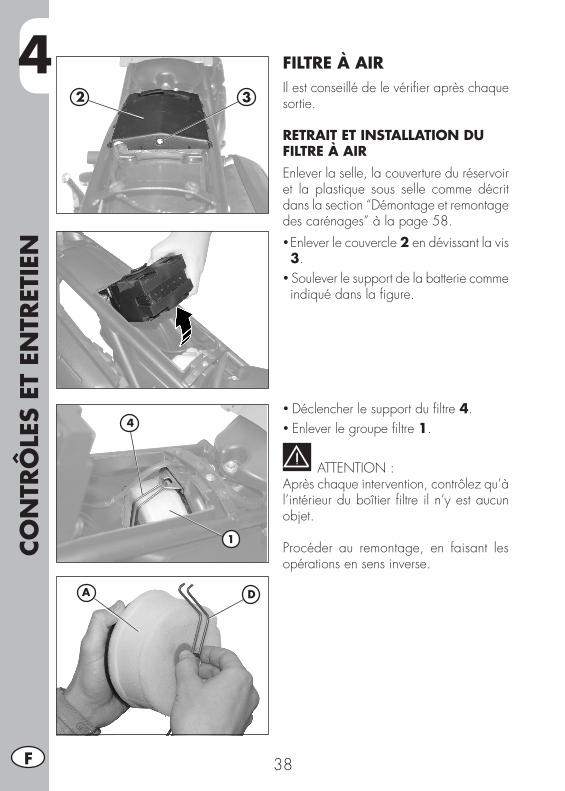
4CO
NTR
ÔLE
S ET
EN
TRET
IEN
38F
FILTRE À AIRIl est conseillé de le vérifier après chaque sortie.
RETRAIT ET INSTALLATION DU FILTRE À AIREnlever la selle, la couverture du réservoir et la plastique sous selle comme décrit dans la section “Démontage et remontage des carénages” à la page 58.• Enlever le couvercle 2 en dévissant la vis 3.
•Soulever le support de la batterie comme indiqué dans la figure.
•Déclencher le support du filtre 4.•Enlever le groupe filtre 1.
ATTENTION :Après chaque intervention, contrôlez qu’à l’intérieur du boîtier filtre il n’y est aucun objet.
Procéder au remontage, en faisant les opérations en sens inverse.
4
1
2 3
DA
4
CON
TRÔ
LES
ET E
NTR
ETIE
N
39 F
NETTOYAGE DU FILTRE À AIR• Laver soigneusement le filtre à l’eau et au savon.
• Laissez sécher le filtre.• L’humecter d’huile pour filtre, en éliminant l’excédent de manière à ce qu’il ne goutte pas.
• Si nécessaire nettoyer l’intérieur du boîtier filtre.
ATTENTION :Ne pas nettoyer le filtre à l’essence ou au pétrole.
NOTE:si le filtre est endommagé, remplacez-le immédiatement.Pour le remplacement, contacter un centre de service autorisé Betamotor.
ATTENTION :Ne mettre jamais en marche la moto sans filtre de l’air. L’infiltration de poussière et de saletés peut provoquer des dommages ainsi qu’une usure précoce.
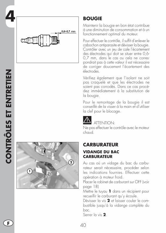
4CO
NTR
ÔLE
S ET
EN
TRET
IEN
40F
BOUGIEMaintenir la bougie en bon état contribue à une diminution de consommation et à un fonctionnement optimal du moteur.
Pour effectuer le contrôle, il suffit d’enlever le cabochon antiparasite et dévisser la bougie.Contrôler avec un jeu de cale l’écartement des électrodes qui doit se situer entre 0,6-0,7 mm, dans le cas ou cela ne corres-pondrait pas à cette valeur il est nécessaire de corriger doucement l’écartement des électrodes.
Vérifiez également que l’isolant ne soit pas craquelé et que les électrodes ne soient pas corrodés. Dans ce cas procé-dez immédiatement à la substitution de la bougie.
Pour le remontage de la bougie il est conseillé de la visser à la main et d’utiliser la clef pour le blocage.
ATTENTION:Ne pas effectuer le contrôle avec le moteur chaud.
CARBURATEURVIDANGE DU BAC CARBURATEURAu cas où un vidage du bac du carbu-rateur serait nécessaire, procéder selon les indications fournies. Effectuer cette opération à moteur froid.Placer le robinet de carburant sur OFF (voir page 18)Mettre le tuyau 1 dans un récipient pour recueillir le carburant qu’y écoule.Dévisser la vis 2 et laisser couler le com-bustible jusqu’à la vidange complète du bac.Serrer la vis 2.
2
1
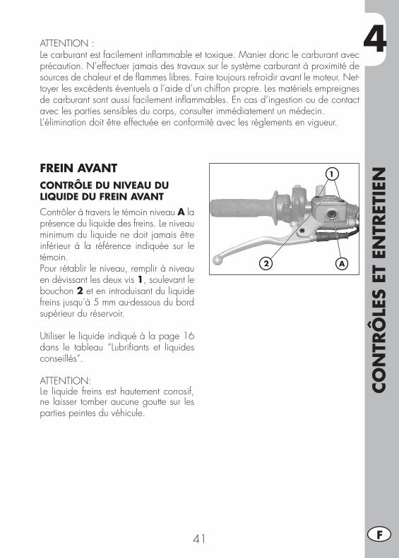
4
CON
TRÔ
LES
ET E
NTR
ETIE
N
41 F
ATTENTION :Le carburant est facilement inflammable et toxique. Manier donc le carburant avec précaution. N’effectuer jamais des travaux sur le système carburant à proximité de sources de chaleur et de flammes libres. Faire toujours refroidir avant le moteur. Net-toyer les excédents éventuels a l’aide d’un chiffon propre. Les matériels empreignes de carburant sont aussi facilement inflammables. En cas d’ingestion ou de contact avec les parties sensibles du corps, consulter immédiatement un médecin.L’élimination doit être effectuée en conformité avec les règlements en vigueur.
FREIN AVANTCONTRÔLE DU NIVEAU DU LIQUIDE DU FREIN AVANTContrôler à travers le témoin niveau A la présence du liquide des freins. Le niveau minimum du liquide ne doit jamais être inférieur à la référence indiquée sur le témoin.Pour rétablir le niveau, remplir à niveau en dévissant les deux vis 1, soulevant le bouchon 2 et en introduisant du liquide freins jusqu’à 5 mm au-dessous du bord supérieur du réservoir.
Utiliser le liquide indiqué à la page 16 dans le tableau “Lubrifiants et liquides conseillés”.
ATTENTION:Le liquide freins est hautement corrosif, ne laisser tomber aucune goutte sur les parties peintes du véhicule.
2
1
A
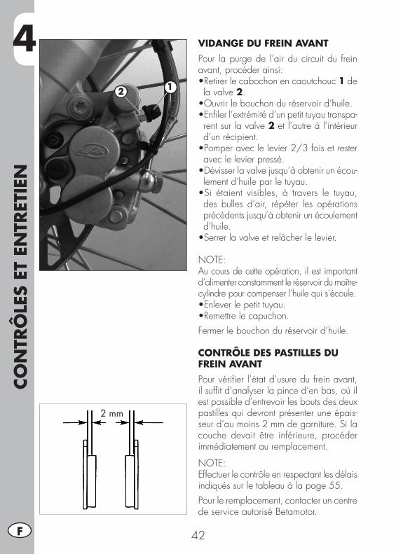
4CO
NTR
ÔLE
S ET
EN
TRET
IEN
42F
VIDANGE DU FREIN AVANTPour la purge de l’air du circuit du frein avant, procéder ainsi:•Retirerlecabochonencaoutchouc1 de la valve 2.•Ouvrirlebouchonduréservoird’huile.•Enfilerl’extrémitéd’unpetittuyautranspa-rent sur la valve 2 et l’autre à l’intérieur d’un récipient.•Pomperaveclelevier2/3foisetresteravec le levier pressé.•Dévisserlavalvejusqu’àobtenirunécou-lement d’huile par le tuyau.•Si étaient visibles, à travers le tuyau,des bulles d’air, répéter les opérations précédents jusqu’à obtenir un écoulement d’huile.•Serrerlavalveetrelâcherlelevier.
NOTE: Au cours de cette opération, il est important d’alimenter constamment le réservoir du maître-cylindre pour compenser l’huile qui s’écoule.•Enleverlepetittuyau.•Remettrelecapuchon.Fermer le bouchon du réservoir d’huile.
CONTRÔLE DES PASTILLES DU FREIN AVANTPour vérifier l’état d’usure du frein avant, il suffit d’analyser la pince d’en bas, où il est possible d’entrevoir les bouts des deux pastilles qui devront présenter une épais-seur d’au moins 2 mm de garniture. Si la couche devait être inférieure, procéder immédiatement au remplacement.
NOTE:Effectuer le contrôle en respectant les délais indiqués sur le tableau à la page 55.Pour le remplacement, contacter un centre de service autorisé Betamotor.
2 mm
12
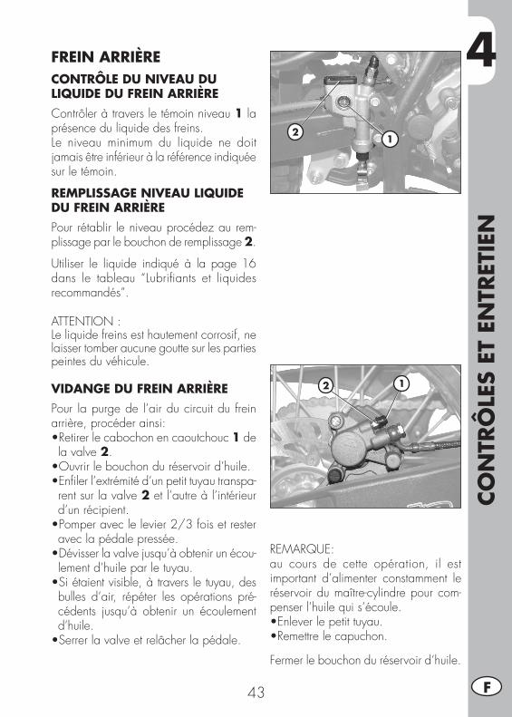
4
CON
TRÔ
LES
ET E
NTR
ETIE
N
43 F
FREIN ARRIÈRECONTRÔLE DU NIVEAU DU LIQUIDE DU FREIN ARRIÈREContrôler à travers le témoin niveau 1 la présence du liquide des freins. Le niveau minimum du liquide ne doit jamais être inférieur à la référence indiquée sur le témoin.
REMPLISSAGE NIVEAU LIQUIDE DU FREIN ARRIÈREPour rétablir le niveau procédez au rem-plissage par le bouchon de remplissage 2.
Utiliser le liquide indiqué à la page 16 dans le tableau “Lubrifiants et liquides recommandés”.
ATTENTION :Le liquide freins est hautement corrosif, ne laisser tomber aucune goutte sur les parties peintes du véhicule.
VIDANGE DU FREIN ARRIÈRE Pour la purge de l’air du circuit du frein arrière, procéder ainsi:•Retirerlecabochonencaoutchouc1 de la valve 2.•Ouvrirlebouchonduréservoird’huile.•Enfilerl’extrémitéd’unpetittuyautranspa-rent sur la valve 2 et l’autre à l’intérieur d’un récipient.•Pomperaveclelevier2/3foisetresteravec la pédale pressée.•Dévisserlavalvejusqu’àobtenirunécou-lement d’huile par le tuyau.•Siétaientvisible,àtraversletuyau,desbulles d’air, répéter les opérations pré-cédents jusqu’à obtenir un écoulement d’huile.•Serrerlavalveetrelâcherlapédale.
REMARQUE: au cours de cette opération, il est important d’alimenter constamment le réservoir du maître-cylindre pour com-penser l’huile qui s’écoule.•Enleverlepetittuyau.•Remettrelecapuchon.
Fermer le bouchon du réservoir d’huile.
21
12
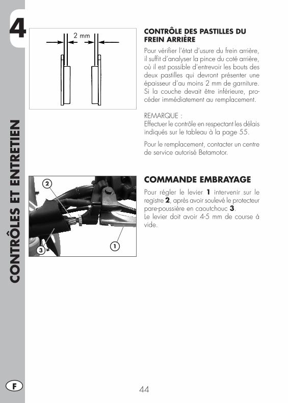
4CO
NTR
ÔLE
S ET
EN
TRET
IEN
44F
CONTRÔLE DES PASTILLES DU FREIN ARRIÈREPour vérifier l’état d’usure du frein arrière, il suffit d’analyser la pince du coté arrière, où il est possible d’entrevoir les bouts des deux pastilles qui devront présenter une épaisseur d’au moins 2 mm de garniture. Si la couche devait être inférieure, pro-céder immédiatement au remplacement.
REMARQUE :Effectuer le contrôle en respectant les délais indiqués sur le tableau à la page 55.
Pour le remplacement, contacter un centre de service autorisé Betamotor.
COMMANDE EMBRAYAGEPour régler le levier 1 intervenir sur le registre 2, après avoir soulevé le protecteur pare-poussière en caoutchouc 3.Le levier doit avoir 4-5 mm de course à vide.
2 mm
1
2
3
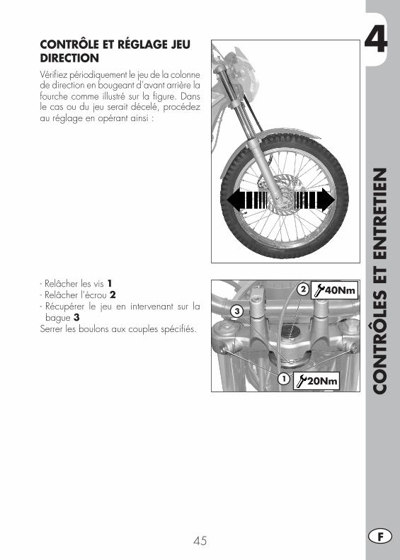
4
CON
TRÔ
LES
ET E
NTR
ETIE
N
45 F
CONTRÔLE ET RÉGLAGE JEU DIRECTIONVérifiez périodiquement le jeu de la colonne de direction en bougeant d’avant arrière la fourche comme illustré sur la figure. Dans le cas ou du jeu serait décelé, procédez au réglage en opérant ainsi :
-Relâcherlesvis1-Relâcherl’écrou2- Récupérer le jeu en intervenant sur la bague 3
Serrer les boulons aux couples spécifiés.
1
2
3
40Nm
20Nm
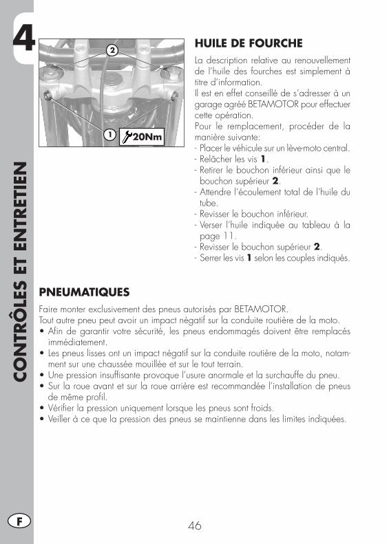
4CO
NTR
ÔLE
S ET
EN
TRET
IEN
46F
HUILE DE FOURCHELa description relative au renouvellement de l’huile des fourches est simplement à titre d’information.Il est en effet conseillé de s’adresser à un garage agréé BETAMOTOR pour effectuer cette opération.Pour le remplacement, procéder de la manière suivante:- Placer le véhicule sur un lève-moto central.-Relâcherlesvis 1.- Retirer le bouchon inférieur ainsi que le bouchon supérieur 2.
- Attendre l’écoulement total de l’huile du tube.
- Revisser le bouchon inférieur.- Verser l’huile indiquée au tableau à la page 11.
- Revisser le bouchon supérieur 2.- Serrer les vis 1 selon les couples indiqués.
1
2
20Nm
PNEUMATIQUESFaire monter exclusivement des pneus autorisés par BETAMOTOR.Tout autre pneu peut avoir un impact négatif sur la conduite routière de la moto.•Afindegarantirvotresécurité, lespneusendommagésdoiventêtre remplacés
immédiatement.•Lespneuslissesontunimpactnégatifsurlaconduiteroutièredelamoto,notam-
ment sur une chaussée mouillée et sur le tout terrain.•Unepressioninsuffisanteprovoquel’usureanormaleetlasurchauffedupneu.•Surlaroueavantetsurlarouearrièreestrecommandéel’installationdepneus
de même profil.•Vérifierlapressionuniquementlorsquelespneussontfroids.•Veilleràcequelapressiondespneussemaintiennedansleslimitesindiquées.
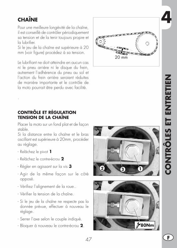
4
CON
TRÔ
LES
ET E
NTR
ETIE
N
47 F
CHAÎNEPour une meilleure longévité de la chaîne, il est conseillé de contrôler périodiquement sa tension et de la tenir toujours propre et la lubrifier.Si le jeu de la chaîne est supérieure à 20mm (voir figure) procédez à sa tension.
Le lubrifiant ne doit atteindre en aucun cas ni le pneu arrière ni le disque du frein, autrement l’adhérence du pneu au sol et l’action du frein arrière seraient réduites de manière importante et le contrôle de la moto pourrait être perdu avec facilité.
.
CONTRÔLE ET RÉGULATION TENSION DE LA CHAÎNEPlacer la moto sur un fond plat et de façon stable.Si la distance entre la chaîne et le bras oscillant est supérieure à 20mm, procéder au réglage.
- Relâchezlepivot 1
- Relâchezlecontre-écrou 2
- Régler en agissant sur la vis 3
- Agir de la même façon sur le côté opposé.
- Vérifiez l’alignement de la roue..
- Vérifier la tension de la chaîne.
- Si le jeu de la chaîne ne respecte pas la donnée prévue, effectuer à nouveau le réglage.
- Serrer l’axe selon le couple indiqué.- Bloquer à nouveau le contre-écrou 2.
20 mm
2 3 1
80Nm
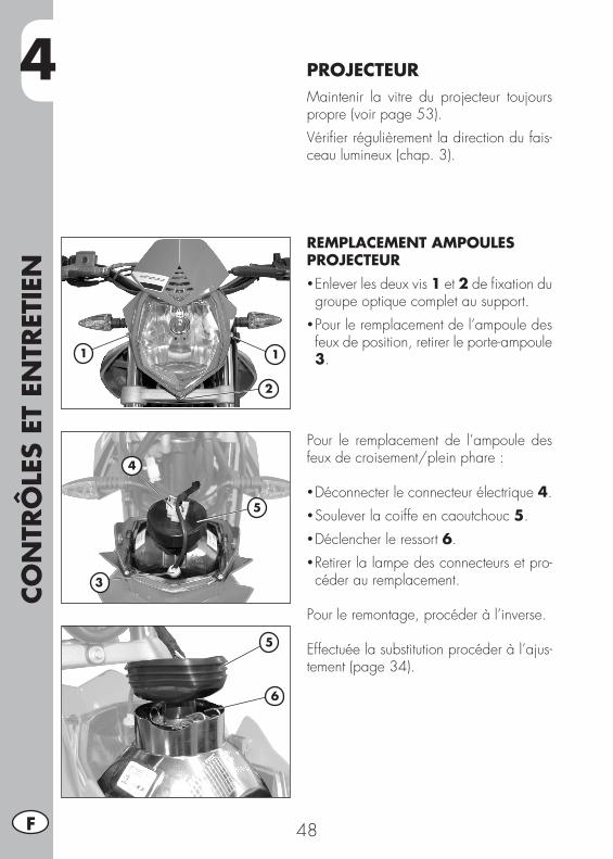
4CO
NTR
ÔLE
S ET
EN
TRET
IEN
48F
PROJECTEURMaintenir la vitre du projecteur toujours propre (voir page 53).Vérifier régulièrement la direction du fais-ceau lumineux (chap. 3).
REMPLACEMENT AMPOULES PROJECTEUR• Enlever les deux vis 1 et 2 de fixation du groupe optique complet au support.
• Pour le remplacement de l’ampoule des feux de position, retirer le porte-ampoule 3.
Pour le remplacement de l’ampoule des feux de croisement/plein phare :
• Déconnecter le connecteur électrique 4.• Soulever la coiffe en caoutchouc 5.• Déclencher le ressort 6.• Retirer la lampe des connecteurs et pro-céder au remplacement.
Pour le remontage, procéder à l’inverse.
Effectuée la substitution procéder à l’ajus-tement (page 34).
11
3
2
4
5
5
6
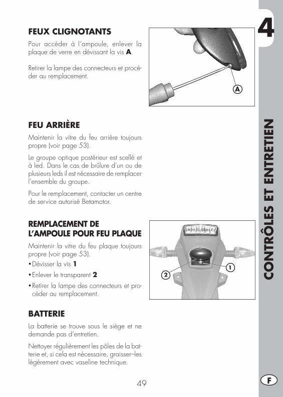
4
CON
TRÔ
LES
ET E
NTR
ETIE
N
49 F
A
FEUX CLIGNOTANTSPour accéder à l’ampoule, enlever la plaque de verre en dévissant la vis A.
Retirer la lampe des connecteurs et procé-der au remplacement.
FEU ARRIÈREMaintenir la vitre du feu arrière toujours propre (voir page 53).
Le groupe optique postérieur est scellé et à led. Dans le cas de brûlure d’un ou de plusieurs leds il est nécessaire de remplacer l’ensemble du groupe.
Pour le remplacement, contacter un centre de service autorisé Betamotor.
REMPLACEMENT DE L’AMPOULE POUR FEU PLAQUEMaintenir la vitre du feu plaque toujours propre (voir page 53).• Dévisser la vis 1• Enlever le transparent 2• Retirer la lampe des connecteurs et pro-céder au remplacement.
BATTERIELa batterie se trouve sous le siège et ne demande pas d’entretien.
Nettoyer régulièrement les pôles de la bat-terie et, si cela est nécessaire, graisser–les légèrement avec vaseline technique.
12
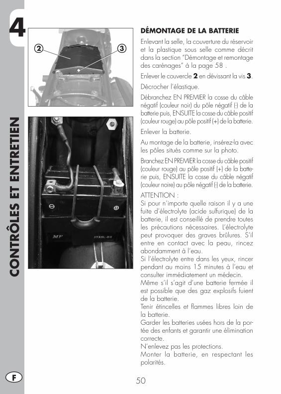
4CO
NTR
ÔLE
S ET
EN
TRET
IEN
50F
DÉMONTAGE DE LA BATTERIEEnlevant la selle, la couverture du réservoir et la plastique sous selle comme décrit dans la section “Démontage et remontage des carénages” à la page 58 .Enlever le couvercle 2 en dévissant la vis 3.Décrocher l’élastique.DébranchezENPREMIERlacosseducâblenégatif (couleur noir) du pôle négatif (-) de la batteriepuis,ENSUITElacosseducâblepositif(couleur rouge) au pôle positif (+) de la batterie.Enlever la batterie.Au montage de la batterie, insérez-la avec les pôles situés comme sur la photo.BranchezENPREMIERlacosseducâblepositif(couleur rouge) au pôle positif (+) de la batte-riepuis,ENSUITElacosseducâblenégatif(couleur noire) au pôle négatif (-) de la batterie.ATTENTION :Si pour n’importe quelle raison il y a une fuite d’électrolyte (acide sulfurique) de la batterie, il est conseillé de prendre toutes les précautions nécessaires. L’électrolyte peut provoquer des graves brûlures. S’il entre en contact avec la peau, rincez abondamment à l’eau.Si l’électrolyte entre dans les yeux, rincer pendant au moins 15 minutes à l’eau et consulter immédiatement un médecin.Même s’il s’agit d’une batterie fermée il est possible que des gaz explosifs fuient de la batterie.Tenir étincelles et flammes libres loin de la batterie.Garder les batteries usées hors de la por-tée des enfants et garantir une élimination correcte.N’enlevez pas les protections.Monter la batterie, en respectant les polarités.
2 3
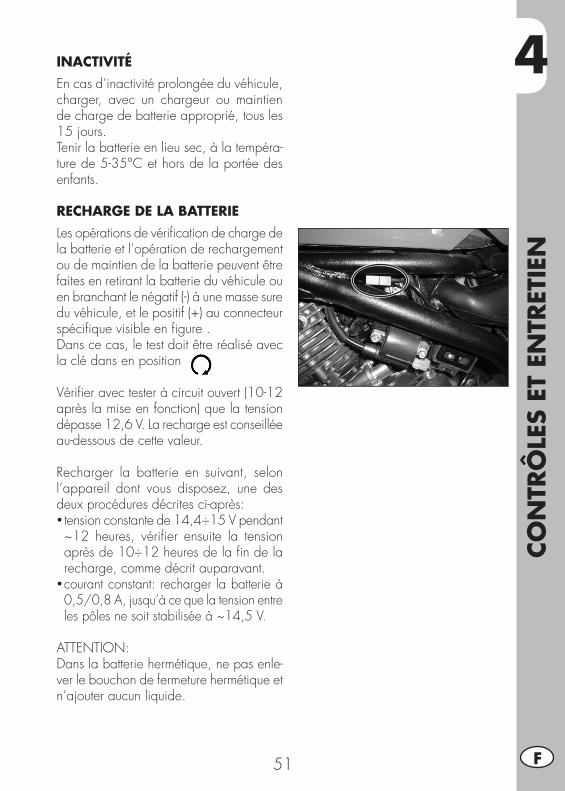
4
CON
TRÔ
LES
ET E
NTR
ETIE
N
51 F
INACTIVITÉEn cas d’inactivité prolongée du véhicule, charger, avec un chargeur ou maintien de charge de batterie approprié, tous les 15 jours. Tenir la batterie en lieu sec, à la tempéra-ture de 5-35°C et hors de la portée des enfants.
RECHARGE DE LA BATTERIELes opérations de vérification de charge de la batterie et l’opération de rechargement ou de maintien de la batterie peuvent être faites en retirant la batterie du véhicule ou en branchant le négatif (-) à une masse sure du véhicule, et le positif (+) au connecteur spécifique visible en figure .Dans ce cas, le test doit être réalisé avec la clé dans en position
Vérifier avec tester à circuit ouvert (10-12 après la mise en fonction) que la tension dépasse 12,6 V. La recharge est conseillée au-dessous de cette valeur.
Recharger la batterie en suivant, selon l’appareil dont vous disposez, une des deux procédures décrites ci-après:•tension constante de 14,4÷15 V pendant ~12 heures, vérifier ensuite la tension après de 10÷12 heures de la fin de la recharge, comme décrit auparavant.
•courant constant: recharger la batterie à 0,5/0,8 A, jusqu’à ce que la tension entre les pôles ne soit stabilisée à ~14,5 V.
ATTENTION:Dans la batterie hermétique, ne pas enle-ver le bouchon de fermeture hermétique et n’ajouter aucun liquide.
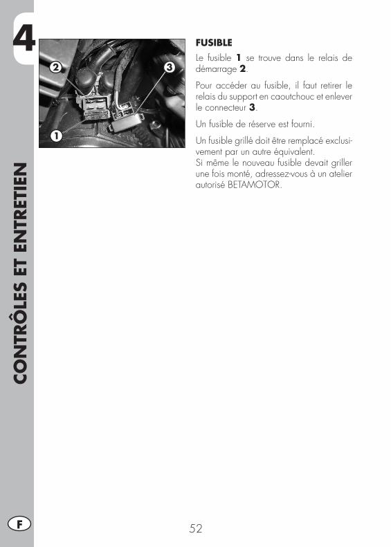
4CO
NTR
ÔLE
S ET
EN
TRET
IEN
52F
FUSIBLELe fusible 1 se trouve dans le relais de démarrage 2.
Pour accéder au fusible, il faut retirer le relais du support en caoutchouc et enlever le connecteur 3.
Un fusible de réserve est fourni.
Un fusible grillé doit être remplacé exclusi-vement par un autre équivalent.Si même le nouveau fusible devait griller une fois monté, adressez-vous à un atelier autorisé BETAMOTOR.
2 3
1
4
CON
TRÔ
LES
ET E
NTR
ETIE
N
53 F
NETTOYAGE DU VÉHICULEATTENTION: Ne jamais nettoyer le véhicule avec un appareil à haute pression muni d’un fort jet d’eau. La pression excessive peut rejoindre les composantes électriques, connecteurs,câblesflexibles,coussinetsetc.etlesendommageroulesdétruire.
ATTENTION: Laver fréquemment les véhicules circulant près de la mer (sel) et des axes routiers soumis à l’épandage de sel en hiver. Recouvrir avec une couche d’huile ou une pulvérisation en silicone les parties les plus exposé ou non peintes comme les cercles, fourche et le bras oscillant. Ne pas traiter les parties en caoutchouc et les freins.
Lors du nettoyage, éviter l’exposition directe au soleil.
Fermez le système d’échappement, pour empêcher l’eau d’y pénétrer.
Éviter de diriger le jet d’eau sur le couvercle de la caisse du filtre à air.
Pour ramollir la saleté et la boue accumulées sur les peintures, utiliser un jet d’eau. Une fois ramollis, la boue et la saleté doivent être enlevées avec une éponge douce pour carrosserie imprégnée de beaucoup d’eau et shampooing (2-4% de shampooing dans l’eau). Rincer ensuite abondamment à l’eau et essuyer avec un jet d’air comprimée et un linge ou une peau de chamois.
Procéder au déchargement de la boîte à filtre au moyen du reniflard spécial et au séchage.
Les détergents polluent les eaux. Aussi, le lavage du véhicule doit s’effectuer dans un endroit équipé pour la récupération et l’épuration des liquides de lavage.
Après le nettoyage, rouler sur une courte distance jusqu’à ce que le moteur atteigne sa température de fonctionnement.
ATTENTION: avec des freins mouillés l’effet de freinage est réduit. Actionner les freins avec prudence afin de leur permettre de sécher.
Pousser vers l’arrière la protection des commandes au guidon, pour que l’eau s’évapore.
Lorsque la moto sera complètement sèche et refroidie, lubrifier tous les points cou-lissants et de travail.
Manipulez tous les composants en plastique et peints avec des détergents ou produits non agressifs et spécifique aux soins du véhicule.
Pour éviter tout dysfonctionnement dans la partie électrique, traiter les contacts élec-triques et les interrupteurs avec un aérosol pour les contacts électriques.
4CO
NTR
ÔLE
S ET
EN
TRET
IEN
54F
LONGUE INACTIVITÉ DU VÉHICULEEn prévision d’une longue période d’inactivité du véhicule, par exemple durant la saison d’hiver, il est nécessaire de prendre quelques mesures simples qui garantissent un bon maintien :• Effectuer un nettoyage soigné de toutes les parties du véhicule.• Réduire la pression des pneumatiques d’environ 30% en les maintenant si possible soulevés du sol.
• Retirer la bougie et verser dans l’orifice quelques gouttes d’huile moteur. Faire tourner le moteur de quelques tours avec le levier de kick (si prévu), revisser la bougie.
• Couvrir d’un voile d’huile ou de silicone spray, les parties non peintes, à l’exception des parties en caoutchouc et des freins.
• Garder la batterie en charge.•Couvrirlevéhiculeavecunebâchepourlapoussière.• Vidanger le bac du carburateur comme décrit à la page 40.
APRÈS UNE LONGUE PÉRIODE D’INACTIVITÉ
• Rétablir la pression des pneus.• Contrôler le serrage de toutes les vis ayant une certaine importance du point de vue mécanique.
• Effectuer le premier démarrage avec le kick-starter.
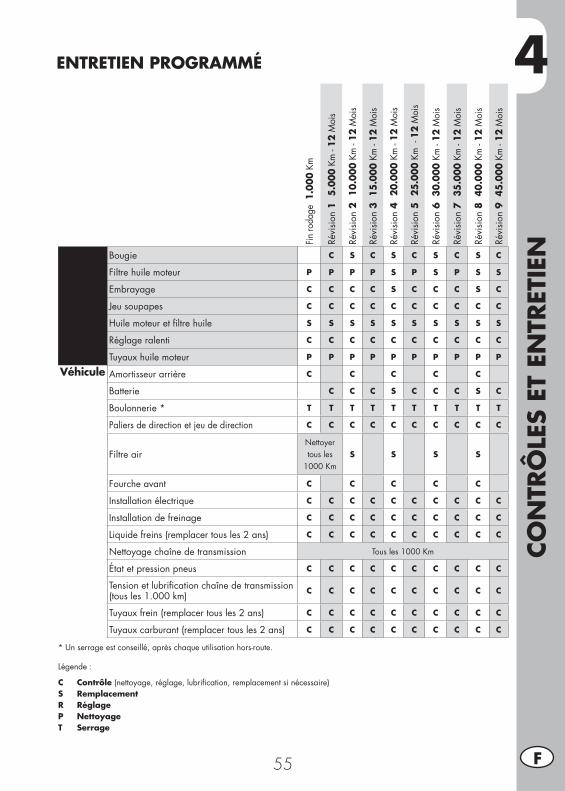
4
CON
TRÔ
LES
ET E
NTR
ETIE
N
55 F
ENTRETIEN PROGRAMMÉ
Fin ro
dage
1.0
00 K
m
Révi
sion
1
5.00
0 Km
- 12
Moi
s
Révi
sion
2
10.0
00 K
m -
12 M
ois
Révi
sion
3 1
5.00
0 Km
- 12
Moi
s
Révi
sion
4
20.0
00 K
m -
12 M
ois
Révi
sion
5
25.0
00 K
m -
12
Moi
s
Révi
sion
6 3
0.00
0 Km
- 12
Moi
s
Révi
sion
7 3
5.00
0 Km
- 12
Moi
s
Révi
sion
8 4
0.00
0 Km
- 12
Moi
s
Révi
sion
9 4
5.00
0 Km
- 12
Moi
s
Moteur Bougie C S C S C S C S C
Filtre huile moteur P P P P S P S P S S
Embrayage C C C C S C C C S C
Jeu soupapes C C C C C C C C C C
Huile moteur et filtre huile S S S S S S S S S S
Réglage ralenti C C C C C C C C C C
Tuyaux huile moteur P P P P P P P P P P
Véhicule Amortisseur arrière C C C C C
Batterie C C C S C C C S C
Boulonnerie * T T T T T T T T T T
Paliers de direction et jeu de direction C C C C C C C C C C
Filtre airNettoyer tous les
1000 KmS S S S
Fourche avant C C C C C
Installation électrique C C C C C C C C C C
Installation de freinage C C C C C C C C C C
Liquide freins (remplacer tous les 2 ans) C C C C C C C C C C
Nettoyage chaîne de transmission Tous les 1000 Km
État et pression pneus C C C C C C C C C C
Tension et lubrification chaîne de transmission(tous les 1.000 km) C C C C C C C C C C
Tuyaux frein (remplacer tous les 2 ans) C C C C C C C C C C
Tuyaux carburant (remplacer tous les 2 ans) C C C C C C C C C C
* Un serrage est conseillé, après chaque utilisation hors-route.
Légende :
C Contrôle (nettoyage, réglage, lubrification, remplacement si nécessaire)S RemplacementR RéglageP NettoyageT Serrage

56
5
DÉM
ON
TAG
E ET
REM
ON
TAG
E D
ES C
ARÉN
AG
ES
57 F
CHAP. 5 DÉMONTAGE ET REMONTAGE DES CARÉNAGES
TABLE DES MATIÈRESDémontage et remontage de la selle .......................................................58Démontage et remontage de la couverture du réservoir ............................58Démontage et remontage des poignées passager ....................................58Démontage et remontage plastique sous selle ..........................................59
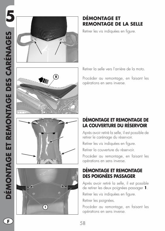
5D
ÉMO
NTA
GE
ET R
EMO
NTA
GE
DES
CA
RÉN
AG
ES
58F
DÉMONTAGE ET REMONTAGE DE LA SELLERetirer les vis indiquées en figure.
Retirer la selle vers l’arrière de la moto.
Procéder au remontage, en faisant les opérations en sens inverse.
DÉMONTAGE ET REMONTAGE DE LA COUVERTURE DU RÉSERVOIRAprès avoir retiré la selle, il est possible de retirer le carénage du réservoir.Retirer les vis indiquées en figure.Retirer la couverture du réservoir.Procéder au remontage, en faisant les opérations en sens inverse.
DÉMONTAGE ET REMONTAGE DES POIGNÉES PASSAGERAprès avoir retiré la selle, il est possible de retirer les deux poignées passager 1.Retirer les vis indiquées en figure.Retirer les poignées.Procéder au remontage, en faisant les opérations en sens inverse.
B
1

5
DÉM
ON
TAG
E ET
REM
ON
TAG
E D
ES C
ARÉN
AG
ES
59 F
1
DÉMONTAGE ET REMONTAGE PLASTIQUE SOUS SELLEAprès avoir enlevé la selle, la couverture du réservoir et les poignées de maintien passager il est possible d’ôter la plastique sous selle 1.Retirer la vis indiquée en figure.
Retirer la plastique sous selle 1 vers l’arrière de la moto.
Procéder au remontage, en faisant les opérations en sens inverse.
ATTENTION:Le remontage erroné de ces pièces peut causer leur détachement soudain pendant la marche ce qui entraîne la perte de contrôle de la moto.

60
6
QU
E FA
IRE
EN C
AS
D’U
RG
ENCE
?
61 F
CHAP. 6 QUE FAIRE EN CAS D’URGENCE ?
TABLE DES MATIÈRESRecherche de la panne .........................................................................62Index alphabétique ..............................................................................63
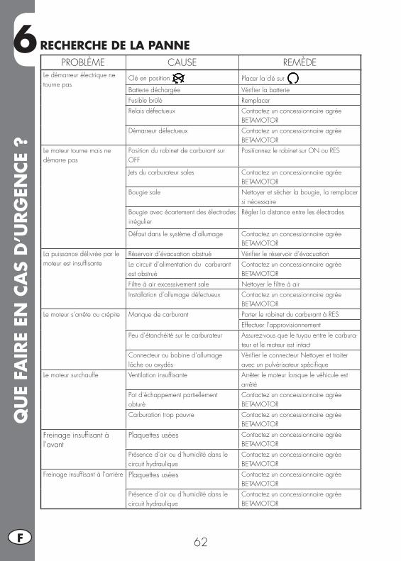
6Q
UE
FAIR
E EN
CA
S D
’URG
ENCE
?
62F
PROBLÈME CAUSE REMÈDELe démarreur électrique ne tourne pas
Clé en position Placer la clé sur
Batterie déchargée Vérifier la batterieFusible brûlé RemplacerRelais défectueux Contactez un concessionnaire agrée
BETAMOTOR Démarreur défectueux Contactez un concessionnaire agrée
BETAMOTOR Le moteur tourne mais ne démarre pas
Position du robinet de carburant sur OFF
Positionnez le robinet sur ON ou RES
Jets du carburateur sales Contactez un concessionnaire agrée BETAMOTOR
Bougie sale Nettoyer et sécher la bougie, la remplacer si nécessaire
Bougie avec écartement des électrodes irrégulier
Régler la distance entre les électrodes
Défaut dans le système d’allumage Contactez un concessionnaire agrée BETAMOTOR
La puissance délivrée par le moteur est insuffisante
Réservoir d’évacuation obstrué Vérifier le réservoir d’évacuationLe circuit d’alimentation du carburant est obstrué
Contactez un concessionnaire agrée BETAMOTOR
Filtre à air excessivement sale Nettoyer le filtre à airInstallation d’allumage défectueux Contactez un concessionnaire agrée
BETAMOTORLe moteur s’arrête ou crépite Manque de carburant Porter le robinet du carburant à RES
Effectuer l’approvisionnementPeu d’étanchéité sur le carburateur Assurez-vous que le tuyau entre le carbura-
teur et le moteur est intactConnecteur ou bobine d’allumage lâcheouoxydés
Vérifier le connecteur Nettoyer et traiter avec un pulvérisateur spécifique
Le moteur surchauffe Ventilation insuffisante Arrêter le moteur lorsque le véhicule est arrêté
Pot d’échappement partiellement obturé
Contactez un concessionnaire agrée BETAMOTOR
Carburation trop pauvre Contactez un concessionnaire agrée BETAMOTOR
Freinage insuffisant à l’avant
Plaquettes usées Contactez un concessionnaire agrée BETAMOTOR
Présence d’air ou d’humidité dans le circuit hydraulique
Contactez un concessionnaire agrée BETAMOTOR
Freinage insuffisant à l’arrière Plaquettes usées Contactez un concessionnaire agrée BETAMOTOR
Présence d’air ou d’humidité dans le circuit hydraulique
Contactez un concessionnaire agrée BETAMOTOR
RECHERCHE DE LA PANNE
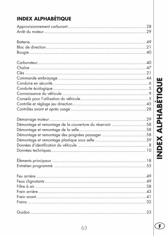
IND
EX A
LPH
ABÉT
IQU
E
63 F
INDEX ALPHABÉTIQUEApprovisionnement carburant ................................................................28Arrêt du moteur ....................................................................................29
Batterie ...............................................................................................49Bloc de direction ..................................................................................21Bougie ................................................................................................40
Carburateur .........................................................................................40Chaîne ...............................................................................................47Clés ...................................................................................................21Commande embrayage ........................................................................44Conduire en sécurité...............................................................................6Conduite écologique ..............................................................................5Connaissance du véhicule .......................................................................9Conseils pour l’utilisation du véhicule ........................................................5Contrôle et réglage jeu direction ............................................................45Contrôles avant et après usage ..............................................................28
Démarrage moteur ...............................................................................29Démontage et remontage de la couverture du réservoir ............................58Démontage et remontage de la selle .......................................................58Démontage et remontage des poignées passager ....................................58Démontage et remontage plastique sous selle ..........................................59Données d’identification du véhicule ..........................................................8Données techniques ..............................................................................10
Éléments principaux .............................................................................18Entretien programmé ...........................................................................55
Feu arrière ..........................................................................................49Feux clignotants ...................................................................................49Filtre à air ...........................................................................................38Frein arrière ........................................................................................43Frein avant ..........................................................................................41Freins .................................................................................................32
Guidon ...............................................................................................33
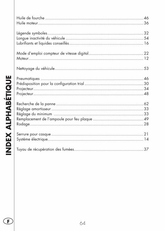
IND
EX A
LPH
ABÉT
IQU
E
64F
Huile de fourche ..................................................................................46Huile moteur ........................................................................................36
Légende symboles ................................................................................32Longue inactivité du véhicule .................................................................54Lubrifiants et liquides conseillés ..............................................................16
Mode d’emploi compteur de vitesse digital..............................................22Moteur ................................................................................................12
Nettoyage du véhicule ..........................................................................53
Pneumatiques ......................................................................................46Prédisposition pour la configuration trial .................................................30Projecteur ............................................................................................34Projecteur ............................................................................................48
Recherche de la panne .........................................................................62Réglage amortisseur .............................................................................33Réglage du minimum ...........................................................................33Remplacement de l’ampoule pour feu plaque ..........................................49Rodage ...............................................................................................28
Serrure pour casque .............................................................................21Système électrique ................................................................................14
Tuyau de récupération des fumées ..........................................................37

1 D
ALP 200
Vielen Dank für Ihr Vertrauen und viel Spaß.Mit dieser Bedienungsanleitung möchten wir Ihnen die notwen-digen Informationen für einen richtigen Gebrauch und eine gute Wartung Ihres Motorrads geben.
Alle Angaben zu Technik und Ausstattung sind unverbindlich. Die BETAMO-TOR S.p.A. behält sich das Recht vor an ihren Fahrzeugmodellen jederzeit und ohne Vorankündigung Änderungen und Verbesserungen vorzunehmen.
Code 017440090 000
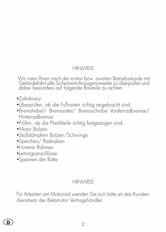
2D
HINWEIS
Wir raten lhnen nach der ersten bzw. zweiten Betriebsstunde mit Geländefahrt alle Sicherheits-Anzugsmomente zu überprüfen und dabei besonders auf folgende Bauteile zu achten:
•Zahnkranz•Überprüfen, ob die Fußrasten richtig angebracht sind.•Bremshebel/ Bremssattel/ Bremsscheibe Vorderradbremse/ Hinterradbremse•Prüfen, ob die Plastikteile richtig festgezogen sind.•Motor Bolzen•Stoßdämpfern Bolzen/Schwinge•Speichen/ Radnaben•Hinterer Rahmen•Leitungsanschlüsse•Spannen der Kette
HINWEIS
Für Arbeiten am Motorrad wenden Sie sich bitte an das Kunden-dienstnetz der Betamotor Vertragshändler.
INH
ALT
SVER
ZEI
CHN
IS
3 D
INHALTSVERZEICHNIS
Hinweise zum gebrauch des Fahrzeugs ....................................................5Umweltfreundliches fahren ......................................................................5Sicheres fahren ......................................................................................6
KAPITEL 1 ALLGEMEINE ANGABEN ..................................................7Rahmen und motornummer ......................................................................8Wichtigste Fahrzeugteile .........................................................................9Technische daten ..................................................................................10Motor .................................................................................................12Elektrische Anlage ................................................................................14Empfohlene Schmiermittel und Flüssigkeiten .............................................16
KAPITEL 2 BEDIENUNGSVORSCHRIFTEN ........................................17Wichtigste Fahrzeugteile .......................................................................18Schlüssel .............................................................................................21Lenkradschloss .....................................................................................21Helmschloss .........................................................................................21Bedienungsanleitung Kilometerzähler......................................................22Kontrollen vor und nach dem Einsatz ......................................................28Einfahren ............................................................................................28Auftanken ...........................................................................................28Starten ................................................................................................29Abschalten des Motors .........................................................................29Vorbereitung für TRIAL-Lage ...................................................................30
KAPITEL 3 EINSTELLUNGEN .............................................................31Legende der Symbole ...........................................................................32Bremsen ..............................................................................................32Leerlaufeinstellung ...............................................................................33Lenker .................................................................................................33Stoßdämpfer .......................................................................................33Scheinwerfer .......................................................................................34
KAPITEL 4 WARTUNG UND KONTROLLEN .....................................35Motoröl ...............................................................................................36Öldampf-Sammelleitung ........................................................................37Luftfilter ...............................................................................................38Zündkerze ...........................................................................................40
INH
ALT
SVER
ZEI
CHN
IS
4D
Vergaser .............................................................................................40Vorderradbremse .................................................................................41Hinterradbremse ..................................................................................43Kupplungssteuerung .............................................................................44Kontrolle lenkungspiel ...........................................................................45Reifen .................................................................................................46Gabelöl ..............................................................................................46Kette ...................................................................................................47Scheinwerfer .......................................................................................48Blinkern ..............................................................................................49Rücklicht .............................................................................................49Auswechseln Nummernschildbeleuchtung ................................................49Batterie ...............................................................................................49Fahrzeugpflege ....................................................................................53Längeres stillegen des fahrzeugs ............................................................54Wartungsprogramm .............................................................................55
KAPITEL 5 AUSBAU UND EINBAU DER KAROSSERIE .....................57Ausbau und Einbau des Sattels ..............................................................58Ausbau und Einbau Tankverkleidung ......................................................58Ausbau und einbau der Beifahrer-Handgriffe ...........................................58Ausbau und eninbau des Plastikteils unter der Sitzbank .............................59
KAPITEL 6 WAS IST IM NOTFALL ZU TUN.......................................61Fehlersuche .........................................................................................62
5 D
HINWEISE ZUM GEBRAUCH DES FAHRZEUGS
• Das Fahrzeug muß vorschriftsmäßig mit folgendem ausgestattet sein: Nummernschild, Fahrzeugschein, Fahrzeugsteuer- und Versicherungsmarke.
•Der Transport von Tieren und Gegenständen, die nicht fest am Fahrzeug befestigt sind, und die über das Fahrzeug herausstehen, ist verboten.
• Es besteht Helmpflicht.•Stets mit eingeschaltetem Abblendlicht fahren.•Veränderungen am Motor oder anderen Fahrzeugteilen, die Fahrzeugleistung und damit die Geschwindigkeit erhöhen, ist gesetzlich verboten und wird, u. a. mit Beschlagnahmung des Fahrzeugs, bestraft.
•Für die eigene Sicherheit und die Sicherheit anderer, stets vorsichtig fahren, immer einen Sturzhelm tragen und immer das Abblendlicht eingeschaltet lassen.
ACHTUNG:Bei Änderungen am Fahrzeug während der Garantiezeit haftet der Hersteller nicht und es verfallen sämtliche Garantieansprüche.
UMWELTFREUNDLICHES FAHREN
• Jedes Fahrzeug mit Verbrennungsmotor ist mehr oder weniger laut (Geräuschbela-stung) und belastet je nach Fahrstil mehr oder weniger die Umwelt (Luftverschmut-zung).
• Die Verringerung dieser Umweltbelastungen ist heute für alle zur Pflicht gewor-den. Vermeiden Sie daher ein Anfahren mit Vollgas sowie unnötiges plötzliches Beschleunigen und Abbremsen des Fahrzeugs. Die Geräuschbelastung ist dann geringer, die Reifen und die mechanischen Fahrzeugteile verschleißen langsamer, der Benzinverbrauch kann deutlich gesenkt werden.
6D
SICHERES FAHREN
• Die Straßenverkehrsordnung beachten.• Stets einen zugelassenen Sturzhelm tragen und diesen festschnallen.•Stets mit eingeschaltetem Abblendlicht fahren.• Das Schutzvisier am Helm immer sauber halten.• Enganliegende Kleidung tragen.• Niemals mit spitzen oder zerbrechlichen Gegenständen in den Taschen fahren.•Die Rückspiegel richtig einstellen.• Nur im Sitzen fahren, beide Hände am Lenker halten und die Füße auf das Trittbrett/ die Fußrasten stellen.
• Stets aufmerksam fahren und sich nie ablenken lassen.• Beim Fahren nie essen, trinken, rauchen, telefonieren usw…• Beim Fahren niemals über Kopfhörer Musik hören.• Nie neben anderen Fahrzeugen fahren.• Nie andere Fahrzeuge abschleppen oder sich abschleppen lassen.• Immer den Sicherheitsabstand einhalten.• Nicht auf das Fahrzeug setzen, solange dieses auf dem Ständer steht.• Nicht mit dem Motorroller anfahren, wenn dieses auf dem Ständer steht.• Den Ständer nicht benutzen, wenn das Fahrzeug in Fahrtrichtung auf abschüssiger Straße steht.
• Fahren mit angehobenem Vorderrad, Schlangenfahren, Wippen ist gefährlich für Dich, für die anderen und für den Motorroller.
• Auf trockener, sand- und kiesfreier Straße stets mit beiden Bremsen gleichzeitig bremsen, um ein gefährliches und nicht kontrollierbares Rutschen oder Ausbrechen des Fahrzeugs zu vermeiden.
• Stets mit beiden Bremsen gleichzeitig bremsen, der Bremsweg wird kürzer.•Auf nasser Fahrbahn und im Gelände vorsichtig und langsam fahren: die Bremsen mit mehr Gefühl betätigen.
• Den Motor niemals in geschlossenen Räumen laufen lassen.
1
ALL
GEM
EIN
E A
NG
ABEN
7 D
KAPITEL 1 ALLGEMEINE ANGABEN
INHALTSVERZEICHNISRahmen und motornummer ......................................................................8
Rahmennummer .................................................................................8Motornummer ...................................................................................8Auslieferung......................................................................................8
Wichtigste Fahrzeugteile .........................................................................9Technische daten ..................................................................................10
Fahrzeuggewicht .............................................................................10Fahrzeugmaße ................................................................................10Reifen ............................................................................................10Fassungsvermögen ..........................................................................10Vorderradaufhängung ......................................................................11Hinterradaufhängung .......................................................................11Vorderradbremse .............................................................................11Hinterradbremse ..............................................................................11
Motor .................................................................................................12Vergaser .........................................................................................12Getriebe ........................................................................................13
Elektrische Anlage ................................................................................14Schaltplan ......................................................................................14Legende Schaltplan..........................................................................15
Empfohlene Schmiermittel und Flüssigkeiten .............................................16
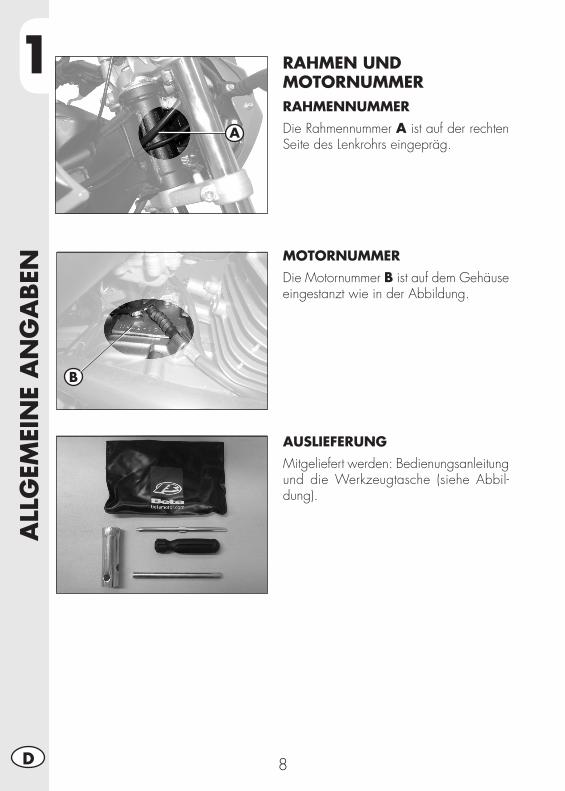
1A
LLG
EMEI
NE
AN
GA
BEN
8D
RAHMEN UND MOTORNUMMERRAHMENNUMMERDie Rahmennummer A ist auf der rechten Seite des Lenkrohrs eingepräg.
MOTORNUMMERDie Motornummer B ist auf dem Gehäuse eingestanzt wie in der Abbildung.
AUSLIEFERUNGMitgeliefert werden: Bedienungsanleitung und die Werkzeugtasche (siehe Abbil-dung).
A
B
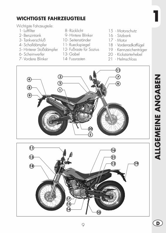
1
ALL
GEM
EIN
E A
NG
ABEN
9 D
Wichtigste Fahrzeugteile: 1 - Luftfilter 2 - Benzintank 3 - Tankverschluß 4 - Schalldämpfer 5 - Hinterer Stoßdämpfer 6 - Scheinwerfer 7 - Vordere Blinker
1
2113
14
WICHTIGSTE FAHRZEUGTEILE
8 - Rücklicht 9 - Hintere Blinker 10 - Seitenständer 11 - Rueckspiegel 12 - Fußraste für Sozius 13 - Gabel 14 - Fussrasten
15 - Motorschutz 16 - Sitzbank 17 - Motor18 - Vorderradkotflügel19 - Kennzeichenträger20 - Kickstarterhebel21 - Helmschloss
2
34
5
7
8
9
20
10
15
16
17
191218
11
11
6
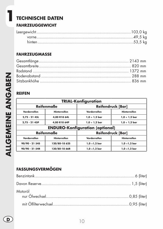
1A
LLG
EMEI
NE
AN
GA
BEN
10D
TECHNISCHE DATENFAHRZEUGGEWICHT
Leergewicht ................................................................................103,0 kg vorne ..................................................................................49,5 kg hinten .................................................................................53,5 kg
FAHRZEUGMASSE
Gesamtlänge ............................................................................ 2143 mmGesamtbreite .............................................................................. 820 mmRadstand ................................................................................. 1372 mmBodenabstand ............................................................................ 288 mmSitzbankhöhe ............................................................................. 836 mm
REIFEN
FASSUNGSVERMÖGEN
Benzintank ....................................................................................6 (liter)
Davon Reserve ............................................................................1,5 (liter)
Motoröl nur Ölwechsel ......................................................................0,85 (liter)
mit Ölfilterwechsel ................................................................0,95 (liter)
TRIAL-KonfigurationReifenmaße Reifendruck [Bar]
Vorderreifen Hinterreifen Vorderreifen Hinterreifen
2,75 - 21 45L 4,00 R18 64L 1,0 ÷ 1,2 bar 1,0 ÷ 1,2 bar
2,75 - 21 45P 4,00 R18 64P 1,0 ÷ 1,2 bar 1,0 ÷ 1,2 bar
ENDURO-Konfiguration (optional)Reifenmaße Reifendruck [Bar]
Vorderreifen Hinterreifen Vorderreifen Hinterreifen
90/90 - 21 54S 120/80-18 62S 1,0 ÷1,2 bar 1,0 ÷1,2 bar
90/90 - 21 54R 130/80-18 66R 1,0 ÷1,2 bar 1,0 ÷1,2 bar
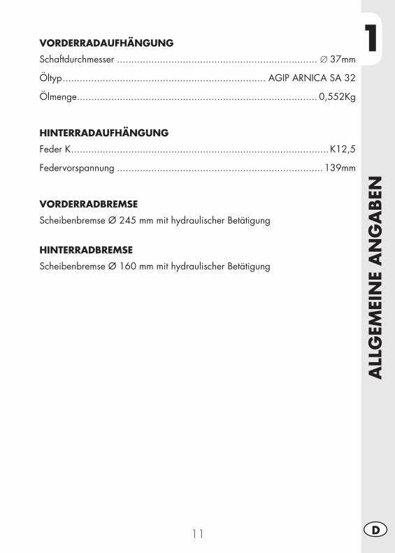
1
ALL
GEM
EIN
E A
NG
ABEN
11 D
VORDERRADAUFHÄNGUNG
Schaftdurchmesser ...................................................................... ∅37mm
Öltyp ....................................................................... AGIP ARNICA SA 32
Ölmenge .................................................................................... 0,552Kg
HINTERRADAUFHÄNGUNG
Feder K .......................................................................................... K12,5
Federvorspannung ........................................................................ 139mm
VORDERRADBREMSE
Scheibenbremse Ø 245 mm mit hydraulischer Betätigung
HINTERRADBREMSE
Scheibenbremse Ø 160 mm mit hydraulischer Betätigung
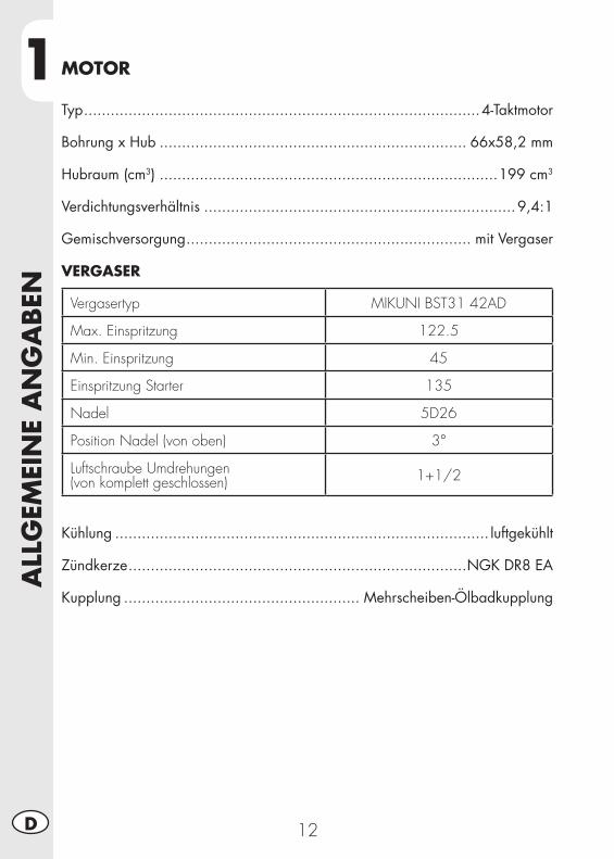
1A
LLG
EMEI
NE
AN
GA
BEN
12D
MOTOR
Typ .........................................................................................4-Taktmotor
Bohrung x Hub ..................................................................... 66x58,2 mm
Hubraum (cm3) ............................................................................199 cm3
Verdichtungsverhältnis ......................................................................9,4:1
Gemischversorgung ................................................................ mit Vergaser
VERGASER
Vergasertyp MIKUNI BST31 42AD
Max. Einspritzung 122.5
Min. Einspritzung 45
Einspritzung Starter 135
Nadel 5D26
Position Nadel (von oben) 3°
Luftschraube Umdrehungen(von komplett geschlossen) 1+1/2
Kühlung .................................................................................... luftgekühlt
Zündkerze ............................................................................NGK DR8 EA
Kupplung ..................................................... Mehrscheiben-Ölbadkupplung
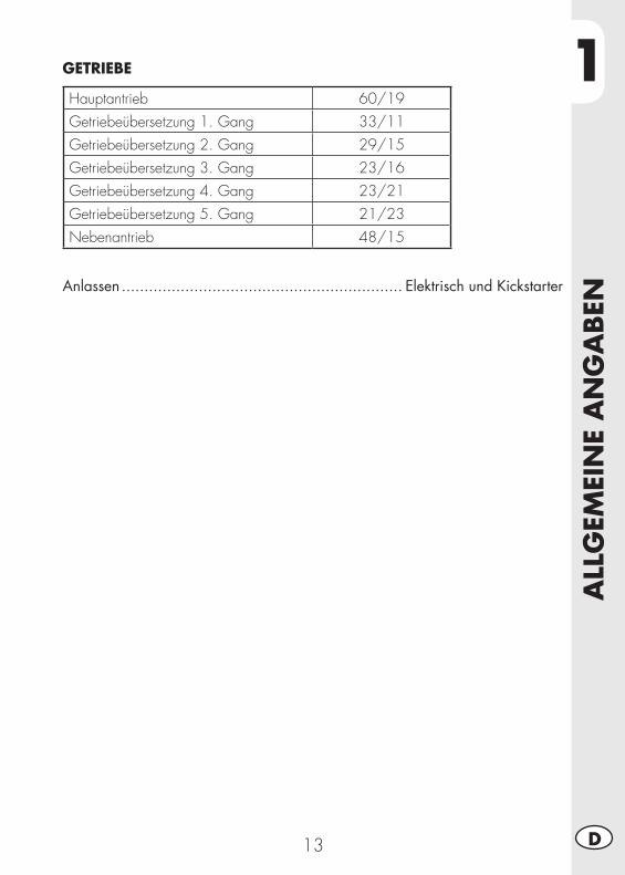
1
ALL
GEM
EIN
E A
NG
ABEN
13 D
GETRIEBE
Hauptantrieb 60/19Getriebeübersetzung 1. Gang 33/11Getriebeübersetzung 2. Gang 29/15Getriebeübersetzung 3. Gang 23/16Getriebeübersetzung 4. Gang 23/21Getriebeübersetzung 5. Gang 21/23Nebenantrieb 48/15
Anlassen .............................................................. Elektrisch und Kickstarter
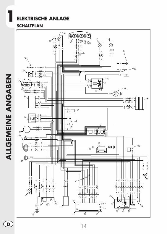
1A
LLG
EMEI
NE
AN
GA
BEN
14D
ELEKTRISCHE ANLAGESCHALTPLAN
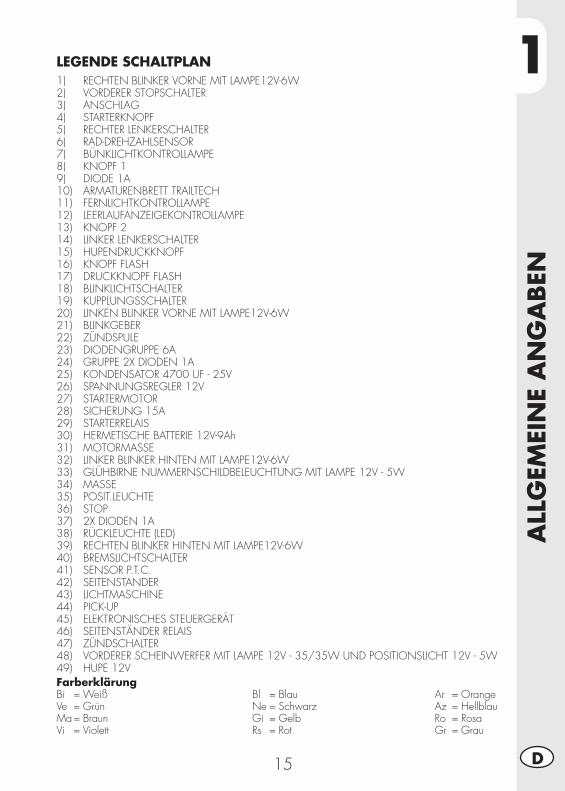
1
ALL
GEM
EIN
E A
NG
ABEN
15 D
FarberklärungBi = WeißVe = GrünMa = BraunVi = Violett
Bl = BlauNe = SchwarzGi = GelbRs = Rot
Ar = OrangeAz = HellblauRo = RosaGr = Grau
LEGENDE SCHALTPLAN1) RECHTEN BLINKER VORNE MIT LAMPE12V-6W2) VORDERER STOPSCHALTER3) ANSCHLAG4) STARTERKNOPF5) RECHTER LENKERSCHALTER6) RAD-DREHZAHLSENSOR7) BÜNKLICHTKONTROLLAMPE8) KNOPF 19) DIODE 1A10) ARMATURENBRETT TRAILTECH11) FERNLICHTKONTROLLAMPE12) LEERLAUFANZEIGEKONTROLLAMPE13) KNOPF 214) LINKER LENKERSCHALTER15) HUPENDRUCKKNOPF16) KNOPF FLASH17) DRUCKKNOPF FLASH18) BLINKLICHTSCHALTER19) KUPPLUNGSSCHALTER20) LINKEN BLINKER VORNE MIT LAMPE12V-6W21) BLINKGEBER22) ZÜNDSPULE23) DIODENGRUPPE 6A24) GRUPPE 2X DIODEN 1A25) KONDENSATOR 4700 UF - 25V26) SPANNUNGSREGLER 12V27) STARTERMOTOR28) SICHERUNG 15A29) STARTERRELAIS30) HERMETISCHE BATTERIE 12V-9Ah31) MOTORMASSE32) LINKER BLINKER HINTEN MIT LAMPE12V-6W33) GLÜHBIRNE NUMMERNSCHILDBELEUCHTUNG MIT LAMPE 12V - 5W34) MASSE35) POSIT.LEUCHTE36) STOP37) 2X DIODEN 1A38) RÜCKLEUCHTE (LED)39) RECHTEN BLINKER HINTEN MIT LAMPE12V-6W40) BREMSLICHTSCHALTER41) SENSOR P.T.C.42) SEITENSTANDER43) LICHTMASCHINE44) PICK-UP45) ELEKTRONISCHES STEUERGERÄT46) SEITENSTÄNDER RELAIS47) ZÜNDSCHALTER48) VORDERER SCHEINWERFER MIT LAMPE 12V - 35/35W UND POSITIONSLICHT 12V - 5W49) HUPE 12V
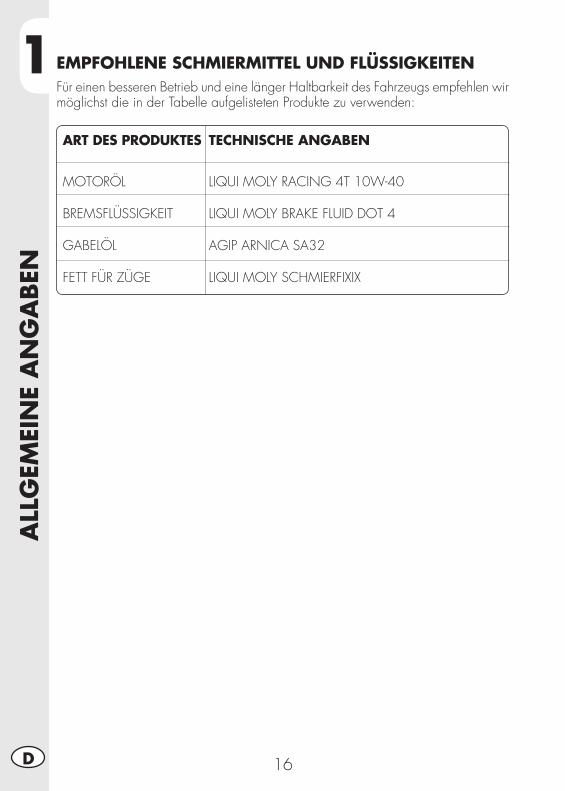
1A
LLG
EMEI
NE
AN
GA
BEN
16D
ART DES PRODUKTES TECHNISCHE ANGABEN
MOTORÖL LIQUI MOLY RACING 4T 10W-40 BREMSFLÜSSIGKEIT LIQUI MOLY BRAKE FLUID DOT 4 GABELÖL AGIP ARNICA SA32 FETT FÜR ZÜGE LIQUI MOLY SCHMIERFIXIX
EMPFOHLENE SCHMIERMITTEL UND FLÜSSIGKEITENFür einen besseren Betrieb und eine länger Haltbarkeit des Fahrzeugs empfehlen wir möglichst die in der Tabelle aufgelisteten Produkte zu verwenden:
2
BED
IEN
UN
GSV
ORSC
HRIF
TEN
17 D
KAPITEL 2 BEDIENUNGSVORSCHRIFTEN
INHALTSVERZEICHNISWichtigste Fahrzeugteile .......................................................................18
Kraftstoffhahn ..................................................................................18Starter ............................................................................................18Kupplungshebel ...............................................................................18Elektrische Steuerungen links .............................................................19Elektrische Steuerungen rechts ...........................................................19Vorderbremse Hebel und Gasgriff......................................................19Schalthebel .....................................................................................20Bremspedal ....................................................................................20Anlasserpedal .................................................................................20Seitenständer ..................................................................................20
Schlüssel .............................................................................................21Lenkradschloss .....................................................................................21Helmschloss .........................................................................................21Bedienungsanleitung Kilometerzähler......................................................22Kontrollen vor und nach dem Einsatz ......................................................28Einfahren ............................................................................................28Auftanken ...........................................................................................28Starten ................................................................................................29Abschalten des Motors .........................................................................29Vorbereitung für TRIAL-Lage ...................................................................30
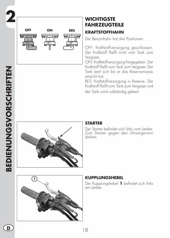
2BED
IEN
UN
GSV
ORSC
HRIF
TEN
18D
WICHTIGSTE FAHRZEUGTEILEKRAFTSTOFFHAHNDer Benzinhahn hat drei Positionen:
OFF: Kraftstoffversorgung geschlossen. Der Kraftstoff fließt nicht vom Tank zum Vergaser.ON: Kraftstoffversorgung freigegeben. Der Kraftstoff fließt vom Tank zum Vergaser. Der Tank leert sich bis er das Reserveniveau erreicht hat.RES: Kraftstoffversorgung in Reserve. Der Kraftstoff fließt vom Tank zum Vergaser und der Tank wird vollständig geleert.
STARTERDer Starter befindet sich links vom Lenker.Zum Starten gegen den Uhrzeigersinn drehen.
KUPPLUNGSHEBELDer Kupplungshebel 1 befindet sich links am Lenker.
OFF ON RES
1
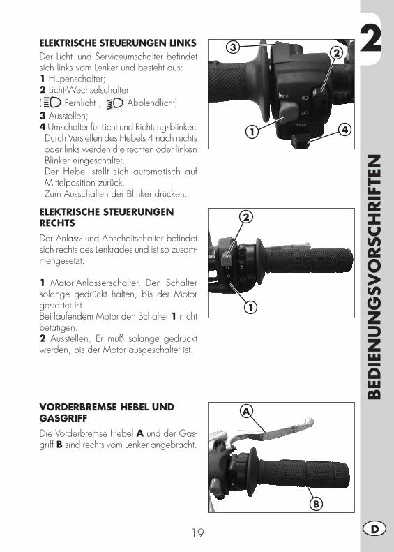
2
BED
IEN
UN
GSV
ORSC
HRIF
TEN
19 D
ELEKTRISCHE STEUERUNGEN LINKSDer Licht- und Serviceumschalter befindet sich links vom Lenker und besteht aus:1 Hupenschalter;2 Licht-Wechselschalter( Fernlicht ; Abblendlicht)3 Ausstellen;4 Umschalter für Licht und Richtungsblinker: Durch Verstellen des Hebels 4 nach rechts oder links werden die rechten oder linken Blinker eingeschaltet.
Der Hebel stellt sich automatisch auf Mittelposition zurück.
Zum Ausschalten der Blinker drücken.
1
23
4
ELEKTRISCHE STEUERUNGEN RECHTSDer Anlass- und Abschaltschalter befindet sich rechts des Lenkrades und ist so zusam-mengesetzt:
1 Motor-Anlasserschalter. Den Schalter solange gedrückt halten, bis der Motor gestartet ist.Bei laufendem Motor den Schalter 1 nicht betätigen.2 Ausstellen. Er muß solange gedrückt werden, bis der Motor ausgeschaltet ist.
VORDERBREMSE HEBEL UND GASGRIFFDie Vorderbremse Hebel A und der Gas-griff B sind rechts vom Lenker angebracht.
2
1
A
B
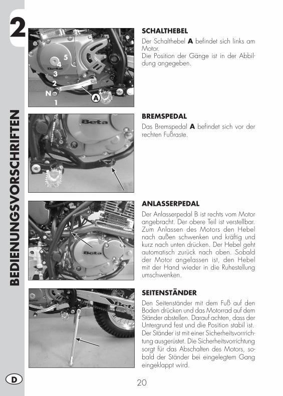
2BED
IEN
UN
GSV
ORSC
HRIF
TEN
20D
1
234
5
NA
SCHALTHEBELDer Schalthebel A befindet sich links am Motor.Die Position der Gänge ist in der Abbil-dung angegeben.
BREMSPEDALDas Bremspedal A befindet sich vor der rechten Fußraste.
ANLASSERPEDALDer Anlasserpedal B ist rechts vom Motor angebracht. Der obere Teil ist verstellbar. Zum Anlassen des Motors den Hebel nach außen schwenken und kräftig und kurz nach unten drücken. Der Hebel geht automatisch zurück nach oben. Sobald der Motor angelassen ist, den Hebel mit der Hand wieder in die Ruhestellung umschwenken.
SEITENSTÄNDERDen Seitenständer mit dem Fuß auf den Boden drücken und das Motorrad auf dem Ständer abstellen. Darauf achten, dass der Untergrund fest und die Position stabil ist.Der Ständer ist mit einer Sicherheitsvorrrich-tung ausgerüstet. Die Sicherheitsvorrichtung sorgt für das Abschalten des Motors, so-bald der Ständer bei eingelegtem Gang eingeklappt wird.
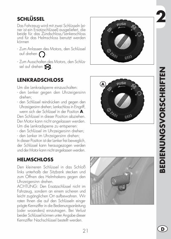
2
BED
IEN
UN
GSV
ORSC
HRIF
TEN
21 D
SCHLÜSSELDas Fahrzeug wird mit zwei Schlüsseln (ei-ner ist ein Ersatzschlüssel) ausgeliefert, die beide für das Zündschloss/Lenkerschloss und für das Helmschloss benutzt werden können
- Zum Anlassen des Motors, den Schlüssel auf drehen .
- Zum Ausschalten des Motors, den Schlüs-sel auf drehen .
LENKRADSCHLOSSUm die Lenkradsperre einzuschalten:- den Lenker gegen den Uhrzeigersinn drehen;
- den Schlüssel reindrücken und gegen den Uhrzeigersinn drehen; Lenkschloss in Eingriff, wenn sich der Schlüssel in der Position A.
Den Schlüssel in dieser Position abziehen. Der Motor kann nicht angelassen werden. Um die Lenkradsperre zu entsperren:- den Schlüssel im Uhrzeigersinn drehen;- den Lenker im Uhrzeigersinn drehen;In dieser Position ist der Lenker frei beweglich, der Schlüssel kann herausgezogen werden und der Motor kann nicht angelassen werden.
HELMSCHLOSSDen kleineren Schlüssel in das Schloß links unterhalb der Sitzbank stecken und zum Öffnen des Helmhakens gegen den Uhrzeigersinn drehen.ACHTUNG: Den Ersatzschlüssel nicht im Fahrzeug, sondern an einem sicheren und leicht zugänglichen Ort aufbewahren. Wir raten Ihnen die auf den Schlüsseln einge-prägte Kennziffer in die Bedienungsanleitung (oder woanders) einzutragen. Bei Verlust beider Schlüssel können unter Angabe dieser Kennziffer Nachschlüssel bestellt werden.
A
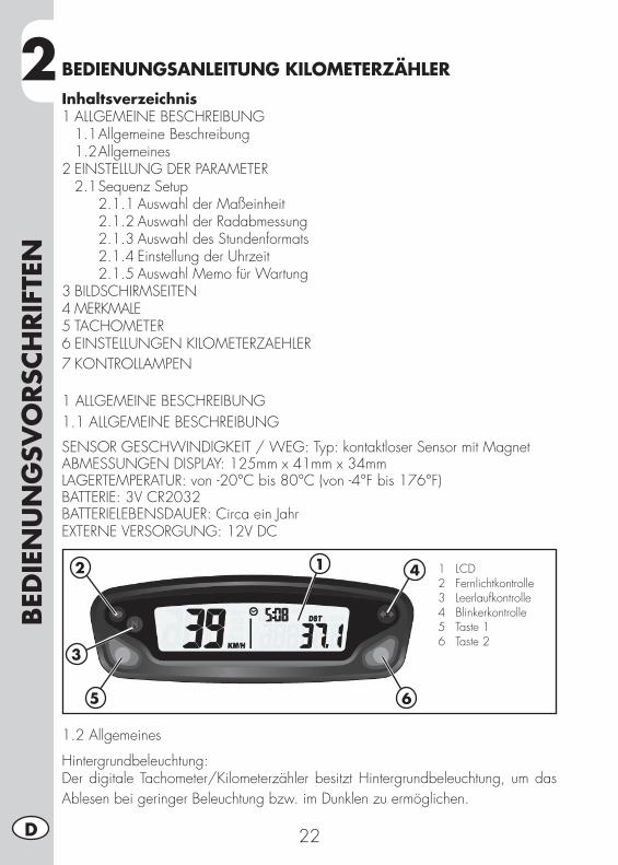
2BED
IEN
UN
GSV
ORSC
HRIF
TEN
22D
BEDIENUNGSANLEITUNG KILOMETERZÄHLERInhaltsverzeichnis1 ALLGEMEINE BESCHREIBUNG 1.1 Allgemeine Beschreibung 1.2 Allgemeines2 EINSTELLUNG DER PARAMETER 2.1 Sequenz Setup 2.1.1 Auswahl der Maßeinheit 2.1.2 Auswahl der Radabmessung 2.1.3 Auswahl des Stundenformats 2.1.4 Einstellung der Uhrzeit 2.1.5 Auswahl Memo für Wartung3 BILDSCHIRMSEITEN4 MERKMALE5 TACHOMETER6 EINSTELLUNGEN KILOMETERZAEHLER7 KONTROLLAMPEN
1 ALLGEMEINE BESCHREIBUNG1.1 ALLGEMEINE BESCHREIBUNG
SENSOR GESCHWINDIGKEIT / WEG: Typ: kontaktloser Sensor mit MagnetABMESSUNGEN DISPLAY: 125mm x 41mm x 34mmLAGERTEMPERATUR: von -20°C bis 80°C (von -4°F bis 176°F)BATTERIE: 3V CR2032BATTERIELEBENSDAUER: Circa ein JahrEXTERNE VERSORGUNG: 12V DC
1.2 Allgemeines
Hintergrundbeleuchtung:Der digitale Tachometer/Kilometerzähler besitzt Hintergrundbeleuchtung, um das Ablesen bei geringer Beleuchtung bzw. im Dunklen zu ermöglichen.
12
3
5
4
6
1 LCD 2 Fernlichtkontrolle 3 Leerlaufkontrolle 4 Blinkerkontrolle 5 Taste 1 6 Taste 2
2
BED
IEN
UN
GSV
ORSC
HRIF
TEN
23 D
Stromnutzung bei laufendem Motor:•DieRückbeleuchtungistbeilaufendemMotorimmeran.Wenn man nur die interne Batterie verwendet:•Wenn das Symbol LO vorhanden ist, schaltet sich die Hintergrundbeleuchtung nicht ein.Das Symbol erscheint, wenn die Batteriespannung unter 2,45V liegt.Reset-Taste:Mit der Reset-Taste hinten am Gerät werden alle Fahrdaten, einschließlich Datum undUhrzeit, gelöscht.Interne Batterie:Das Instrument hat in seinem Inneren eine Batterie 3.0V (Typ Uhrenbatterie) (CR2032).Das Instrument kann nur mit dieser Batterie funktionieren. Wenn die Batterie leer seinsollte, erscheint das Symbol .Zum Auswechseln der Batterie schraubt man mithilfe einer Münze den Verschluss hintenam Instrument ab. Nach dem Auswechseln der Batterie muss sichergestellt werden, dass die positive Seite nach vorn zeigt.AUSWECHSELN DER BATTERIE DURCH EINE ANDERE DES TYPS CR2032
2 EINSTELLUNG DER PARAMETER
Allgemeines:Moegliche Einstellungen:•Km/h(Stundenkilometer)odermph(MeilenproStunde)•AbmessungenRad(Rollkreis)[mm]•Stundenformat:12Stunden/24Stunden•AktuellesDatum•Wartung
UM IN DAS MENUE PARAMETEREINSTELLUNG ZU GELANGEN HÄLT MAN DIETASTEN RECHTS UND LINKS CIRCA 3s LANG GEDRÜCKT.AUF DEM DISPLAY BLINKT DIE SCHRIFT “Unit”.
Die Betriebslogik ist wie folgt strukturiert:•DasInstrumenttrittindenModusSETUPundvisualisiertdieParameterinderzuvor
beschriebenen Reihenfolge.•DasInstrumentvisualisiertdieParameter,dieverändertwerdensollen,miteiner
Schrift, die einige Sekunden lang blinkt.•Wennmanden,indiesemMomentvisualisiertenParameterverändernwill,istes
ausreichend, die Werte zu verändern, indem man die Tasten rechts und/oder links drückt (je nach Modus, die nachfolgend aufgezählt werden), anderenfalls muß man einige Sekunden abwarten (circa 5 s), um auf den nächsten Parameter überzugehen.
•Nachdem der Parameter wie gewünscht verändert wurde, stellt sich das Instrument automa-tisch auf die nächste Einstellung; es ist nicht nötig, eine Taste zu drücken, um zu bestätigen.
•WennmanindenModusSetupnureintritt,umdiekonfiguriertenEinstellungenzu visualisieren, ist es ausreichend abzuwarten, ohne eine Taste zu drücken; das Instrument wird dann alle eingestellten Parameter visualisieren und kehrt dann automatisch in den Zustand “Normal Mode” zurück.
2BED
IEN
UN
GSV
ORSC
HRIF
TEN
24D
2.1 SEQUENZ SETUP
Auswahl MaßeinheitAbmessung RadStundenformatEinstellung UhrzeitErinnerungen Wartung
2.1.1 Auswahl der Maßeinheit (Km/h oder mph):UM DIE MASSEINHEIT AUSZUWÄHLEN (Km/h oder mph), DRÜCKT MAN DIE RECHTE ODER LINKE TASTE5 S ABWARTEN, UM AUF DIE NÄCHSTE EINSTELLUNG ÜBERZUGEHEN.KEINE TASTE DRÜCKEN.
2.1.2 Auswahl der Radabmessung (Rollkreis):Das Instrument hat zwei Rollkreis-Maße des Vorderrades programmiert: Große Ab-messung (reifen ENDURO) oder Kleine Abmessung (reifen TRIAL).MAN DRÜCKT DIE LINKE TASTE, UM EINE DER BEIDEN OPTIONEN AUSZUWÄH-LEN. 5 S ABWARTEN, UM AUF DIE NÄCHSTE EINSTELLUNG ÜBERZUGEHEN. KEINE TASTE DRÜCKEN.
2.1.3 Auswahl des Stundenformats (12 oder 24 Stunden):Das Instrument ist standardmäßig auf ein Format von 12h eingestellt.UM DAS FORMAT 12h ODER 24h AUSZUWÄHLEN, DRÜCKT MAN DIE RECHTE ODER LINKE TASTE.5 S ABWARTEN, UM AUF DIE NÄCHSTE EINSTELLUNG ÜBERZUGEHEN. KEINE TASTE DRÜCKEN.
2.1.4 Einstellung der Uhrzeit:Die Uhrzeit kann eingestellt werden, indem man schrittweise um 1 Minute vor- bzw. zurückstellt.DIE LINKE TASTE DRÜCKEN, UM DIE UHRZEIT ZURÜCKZUSTELLEN.DIE RECHTE TASTE DRÜCKEN, UM DIE UHRZEIT VORANZUSTELLEN.5 S ABWARTEN, UM AUF DIE NÄCHSTE EINSTELLUNG ÜBERZUGEHEN. KEINE TASTE DRÜCKEN.
2.1.5 Auswahl Memo für WartungDas Instrument zeigt den Count-down für die Wartungseingriffe, gemäß des vom Benutzer eingegebenen Datums. Das Datum basiert auf den zurückgelegten Kilome-tern oder Meilen, je nach der vom Benutzer ausgewählten Maßeinheit. Werkseitig eingestellt auf “OFF”.DIE LINKE TASTE DRÜCKEN, UM DIE ZIFFER HERABZUSETZEN. DIE RECHTE TASTE DRÜCKEN, UM SIE HERAUFZUSETZEN (Wert max. 10000km).5 SEKUNDEN LANG WARTEN, UM DIE MODALITÄT IN SETUP ZU LASSEN.KEINE TASTE DRÜCKEN.
2
BED
IEN
UN
GSV
ORSC
HRIF
TEN
25 D
3 BILDSCHIRMSEITEN
Umschalten zwischen drei Einstellungen:Alle Informationen, die das Instrument liefern kann, werden auf einer dieser dreiBildschirmseiten visualisiert.Das Instrument bleibt auf der eingestellten Bildschirmseite, bis eine Taste gedrückt wird, um auf eine andere Bildschirmseite überzugehen.UM VON EINER BILDSCHIRMSEITE AUF EINE ANDERE ÜBERZUGEHEN, DRÜCKTMAN KURZ DIE RECHTE ODER DIE LINKE TASTE.Bildschirmseite 1:•Geschwindigkeit•Distanz1(DST)•UhrzeitBildschirmseite 2:•Geschwindigkeit•Distanz1(DST)•UhrzeitBildschirmseite 3:•Max.Geschwindigkeit(MAX)•DurchschnittlicheGeschwindigkeit(AVG)•ZeitzurückgelegteStrecke(ART)•Hodometer(ODO)*Anmerkung: Die maximale und die durchschnittliche Geschwindigkeit werden automatisch aktualisiert, wenn der Benutzer die Bildschirmseite 3 öffnet.
4 MERKMALE
Allgemeines:Beim normalen Gebrauch ist das Instrument im Modus “Normal”.Verfügbare Funktionen:•SleepMode•Wahlzwischen3Bildschirmseiten“Normal”•ResetDistanz1(DST1)•ResetDistanz2(DST2)•Resetmaximale/durchschnittlicheGeschwindigkeit(MAX/AVG)Sleep Mode:Wenn das Instrument 5 min lang keinen Input empfängt (weder von der Radbewe-gung noch über eine Taste), tritt es in den “Sleep Mode”. Im Modus “Sleep Mode” wird auf demDisplay nur die Uhrzeit visualisiert.Um aus dem “Sleep Mode” auszutreten ist es ausreichend, dass das Instrument einenInput empfängt, entweder durch die Sensorbewegung oder durch den Druck einer Taste.
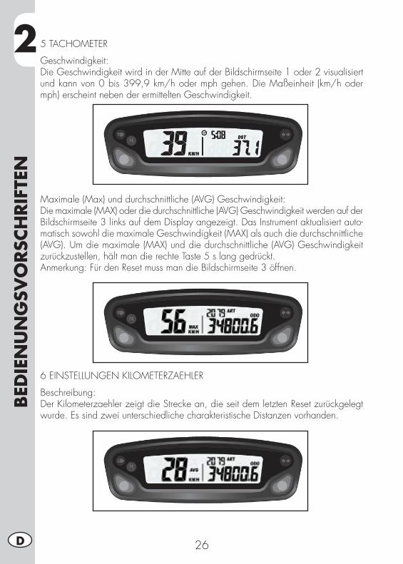
2BED
IEN
UN
GSV
ORSC
HRIF
TEN
26D
5 TACHOMETER
Geschwindigkeit:Die Geschwindigkeit wird in der Mitte auf der Bildschirmseite 1 oder 2 visualisiert und kann von 0 bis 399,9 km/h oder mph gehen. Die Maßeinheit (km/h oder mph) erscheint neben der ermittelten Geschwindigkeit.
Maximale (Max) und durchschnittliche (AVG) Geschwindigkeit:Die maximale (MAX) oder die durchschnittliche (AVG) Geschwindigkeit werden auf derBildschirmseite 3 links auf dem Display angezeigt. Das Instrument aktualisiert auto-matisch sowohl die maximale Geschwindigkeit (MAX) als auch die durchschnittliche (AVG). Um die maximale (MAX) und die durchschnittliche (AVG) Geschwindigkeit zurückzustellen, hält man die rechte Taste 5 s lang gedrückt.Anmerkung: Für den Reset muss man die Bildschirmseite 3 öffnen.
6 EINSTELLUNGEN KILOMETERZAEHLER
Beschreibung:Der Kilometerzaehler zeigt die Strecke an, die seit dem letzten Reset zurückgelegt wurde. Es sind zwei unterschiedliche charakteristische Distanzen vorhanden.
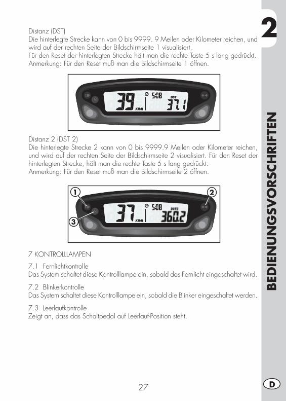
2
BED
IEN
UN
GSV
ORSC
HRIF
TEN
27 D
Distanz (DST) Die hinterlegte Strecke kann von 0 bis 9999. 9 Meilen oder Kilometer reichen, und wird auf der rechten Seite der Bildschirmseite 1 visualisiert.Für den Reset der hinterlegten Strecke hält man die rechte Taste 5 s lang gedrückt.Anmerkung: Für den Reset muß man die Bildschirmseite 1 öffnen.
Distanz 2 (DST 2)Die hinterlegte Strecke 2 kann von 0 bis 9999.9 Meilen oder Kilometer reichen, und wird auf der rechten Seite der Bildschirmseite 2 visualisiert. Für den Reset der hinterlegten Strecke, hält man die rechte Taste 5 s lang gedrückt.Anmerkung: Für den Reset muß man die Bildschirmseite 2 öffnen.
7 KONTROLLLAMPEN
7.1 FernlichtkontrolleDas System schaltet diese Kontrolllampe ein, sobald das Fernlicht eingeschaltet wird.
7.2 BlinkerkontrolleDas System schaltet diese Kontrolllampe ein, sobald die Blinker eingeschaltet werden.
7.3 LeerlaufkontrolleZeigt an, dass das Schaltpedal auf Leerlauf-Position steht.
1
3
2
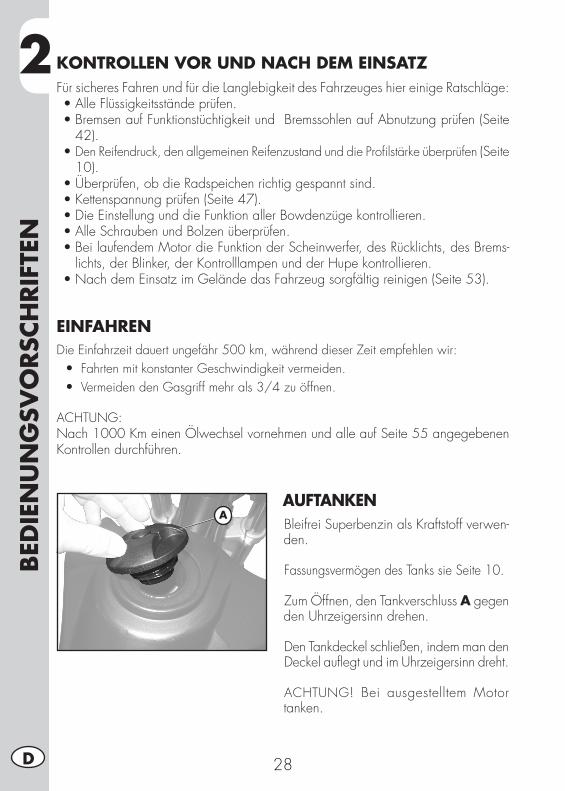
2BED
IEN
UN
GSV
ORSC
HRIF
TEN
28D
KONTROLLEN VOR UND NACH DEM EINSATZFür sicheres Fahren und für die Langlebigkeit des Fahrzeuges hier einige Ratschläge: •AlleFlüssigkeitsständeprüfen.•BremsenaufFunktionstüchtigkeitundBremssohlenaufAbnutzungprüfen(Seite
42).•Den Reifendruck, den allgemeinen Reifenzustand und die Profilstärke überprüfen (Seite
10).•Überprüfen,obdieRadspeichenrichtiggespanntsind.•Kettenspannungprüfen(Seite47).•DieEinstellungunddieFunktionallerBowdenzügekontrollieren.•AlleSchraubenundBolzenüberprüfen.•BeilaufendemMotordieFunktionderScheinwerfer,desRücklichts,desBrems-
lichts, der Blinker, der Kontrolllampen und der Hupe kontrollieren.•NachdemEinsatzimGeländedasFahrzeugsorgfältigreinigen(Seite53).
EINFAHRENDie Einfahrzeit dauert ungefähr 500 km, während dieser Zeit empfehlen wir: •Fahrten mit konstanter Geschwindigkeit vermeiden. •Vermeiden den Gasgriff mehr als 3/4 zu öffnen.
ACHTUNG: Nach 1000 Km einen Ölwechsel vornehmen und alle auf Seite 55 angegebenen Kontrollen durchführen.
AUFTANKENBleifrei Superbenzin als Kraftstoff verwen-den.
Fassungsvermögen des Tanks sie Seite 10.
Zum Öffnen, den Tankverschluss A gegen den Uhrzeigersinn drehen.
Den Tankdeckel schließen, indem man denDeckel auflegt und im Uhrzeigersinn dreht.
ACHTUNG! Bei ausgestelltem Motor tanken.
A
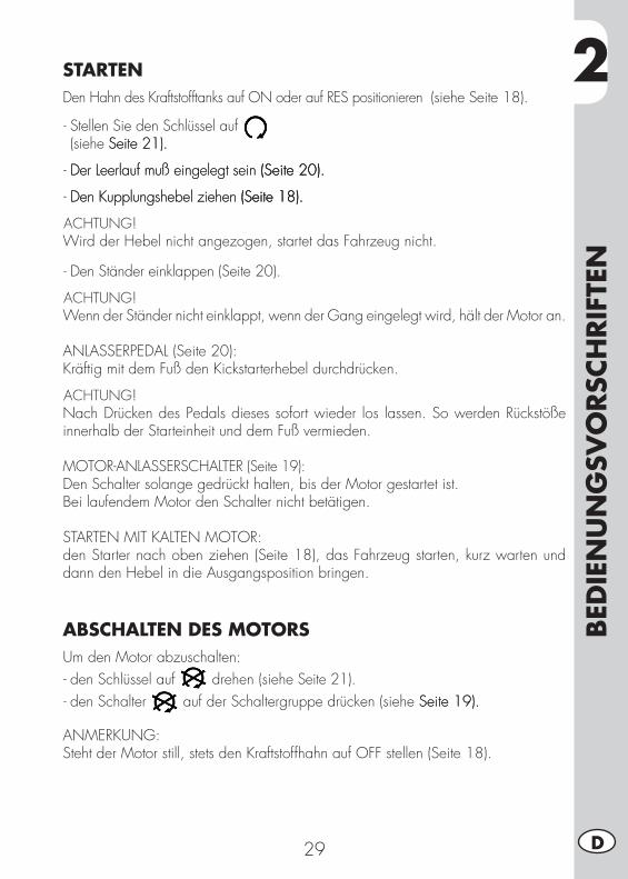
2
BED
IEN
UN
GSV
ORSC
HRIF
TEN
29 D
STARTENDen Hahn des Kraftstofftanks auf ON oder auf RES positionieren (siehe Seite 18).
- Stellen Sie den Schlüssel auf (siehe Seite 21). Seite 21).
- Der Leerlauf muß eingelegt sein (Seite 20).Der Leerlauf muß eingelegt sein (Seite 20). (Seite 20).
- Den Kupplungshebel ziehen (Seite 18).Den Kupplungshebel ziehen (Seite 18). (Seite 18).
ACHTUNG!Wird der Hebel nicht angezogen, startet das Fahrzeug nicht.
- Den Ständer einklappen (Seite 20).
ACHTUNG!Wenn der Ständer nicht einklappt, wenn der Gang eingelegt wird, hält der Motor an.
ANLASSERPEDAL (Seite 20):Kräftig mit dem Fuß den Kickstarterhebel durchdrücken.
ACHTUNG!Nach Drücken des Pedals dieses sofort wieder los lassen. So werden Rückstöße innerhalb der Starteinheit und dem Fuß vermieden.
MOTOR-ANLASSERSCHALTER (Seite 19):Den Schalter solange gedrückt halten, bis der Motor gestartet ist.Bei laufendem Motor den Schalter nicht betätigen.
STARTEN MIT KALTEN MOTOR:den Starter nach oben ziehen (Seite 18), das Fahrzeug starten, kurz warten und dann den Hebel in die Ausgangsposition bringen.
ABSCHALTEN DES MOTORSUm den Motor abzuschalten:- den Schlüssel auf drehen (siehe Seite 21).- den Schalter auf der Schaltergruppe drücken (siehe Seite 19). Seite 19).
ANMERKUNG: Steht der Motor still, stets den Kraftstoffhahn auf OFF stellen (Seite 18).
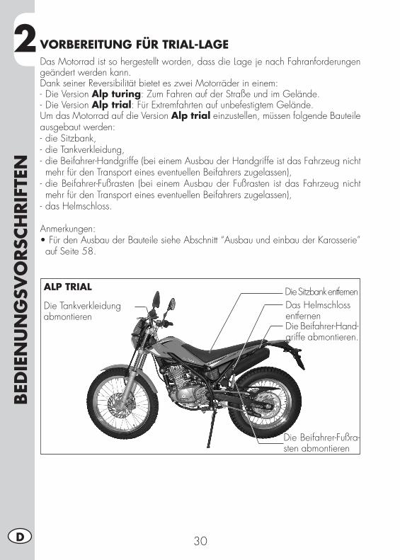
2BED
IEN
UN
GSV
ORSC
HRIF
TEN
30D
VORBEREITUNG FÜR TRIAL-LAGEDas Motorrad ist so hergestellt worden, dass die Lage je nach Fahranforderungen geändert werden kann.Dank seiner Reversibilität bietet es zwei Motorräder in einem:- Die Version Alp turing: Zum Fahren auf der Straße und im Gelände.- Die Version Alp trial: Für Extremfahrten auf unbefestigtem Gelände.Um das Motorrad auf die Version Alp trial einzustellen, müssen folgende Bauteile ausgebaut werden:- die Sitzbank,- die Tankverkleidung,- die Beifahrer-Handgriffe (bei einem Ausbau der Handgriffe ist das Fahrzeug nicht mehr für den Transport eines eventuellen Beifahrers zugelassen),
- die Beifahrer-Fußrasten (bei einem Ausbau der Fußrasten ist das Fahrzeug nicht mehr für den Transport eines eventuellen Beifahrers zugelassen),
- das Helmschloss.
Anmerkungen:•Für den Ausbau der Bauteile siehe Abschnitt “Ausbau und einbau der Karosserie” auf Seite 58.
Die Sitzbank entfernenDie Tankverkleidung abmontieren
Die Beifahrer-Fußra-sten abmontieren
Das Helmschloss entfernenDie Beifahrer-Hand-griffe abmontieren.
ALP TRIAL
3
EIN
STEL
LUN
GEN
31 D
KAPITEL 3 EINSTELLUNGEN
INHALTSVERZEICHNISLegende der Symbole ...........................................................................32Bremsen ..............................................................................................32
Vorderradbremse .............................................................................32Einstellung Gaszugspiel ...................................................................32
Leerlaufeinstellung ...............................................................................33Lenker .................................................................................................33Stoßdämpfer .......................................................................................33
Einstellung der Federvorspannung .....................................................33Scheinwerfer .......................................................................................34
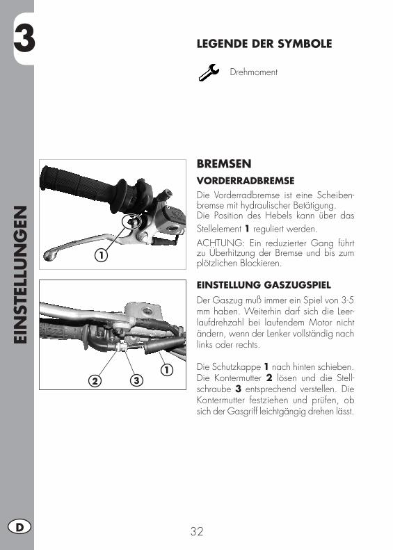
EIN
STEL
LUN
GEN
32D
3 LEGENDE DER SYMBOLE
Drehmoment
BREMSENVORDERRADBREMSEDie Vorderradbremse ist eine Scheiben-bremse mit hydraulischer Betätigung.Die Position des Hebels kann über das Stellelement 1 reguliert werden.ACHTUNG: Ein reduzierter Gang führt zu Überhitzung der Bremse und bis zum plötzlichen Blockieren.
EINSTELLUNG GASZUGSPIEL Der Gaszug muß immer ein Spiel von 3-5 mm haben. Weiterhin darf sich die Leer-laufdrehzahl bei laufendem Motor nicht ändern, wenn der Lenker vollständig nach links oder rechts.
Die Schutzkappe 1 nach hinten schieben.Die Kontermutter 2 lösen und die Stell-schraube 3 entsprechend verstellen. Die Kontermutter festziehen und prüfen, ob sich der Gasgriff leichtgängig drehen lässt.
1
21
3
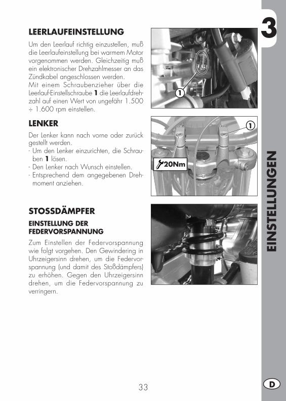
3
EIN
STEL
LUN
GEN
33 D
1
LEERLAUFEINSTELLUNG Um den Leerlauf richtig einzustellen, muß die Leerlaufeinstellung bei warmem Motor vorgenommen werden. Gleichzeitig muß ein elektronischer Drehzahlmesser an das Zündkabel angeschlossen werden.Mit einem Schraubenzieher über die Leerlauf-Einstellschraube 1 die Leerlaufdreh-zahl auf einen Wert von ungefähr 1.500 ÷ 1.600 rpm einstellen.
LENKERDer Lenker kann nach vorne oder zurück gestellt werden.- Um den Lenker einzurichten, die Schrau-ben 1 lösen.
- Den Lenker nach Wunsch einstellen.- Entsprechend dem angegebenen Dreh-moment anziehen.
STOSSDÄMPFEREINSTELLUNG DER FEDERVORSPANNUNGZum Einstellen der Federvorspannung wie folgt vorgehen. Den Gewindering in Uhrzeigersinn drehen, um die Federvor-spannung (und damit des Stoßdämpfers) zu erhöhen. Gegen den Uhrzeigersinn drehen, um die Federvorspannung zu verringern.
1
20Nm

EIN
STEL
LUN
GEN
34D
3 SCHEINWERFER•Zum Einstellen des Scheinwerferstrahls die Befestigungsschrauben 1 rechts und links an der Maske lösen, und durch Variieren des Winkels der Scheinwerferanordnung durch Drehen der Schraube 2.•Das Fahrzeug in einem Abstand von 10 auf einem ebenen Untergrund vor eine Wand stellen (nicht auf den Ständer stellen).•DenAbstandderScheinwerfermittevomBoden messen und die Wand in einem Abstand von 9/10 des gemessenen Wertes markieren.•Das Fahrlicht einschalten, sichauf dasMotorrad setzen und überprüfen, dass sich der Scheinwerferstrahl knapp unter-halb der Wandmarkierung befindet. Ist dies nicht er Fall muß eine neue Einstel-lung vorgenommen werden.•Der Scheinwerfer muß in regelmäßigen Ab-ständen eingestellt werden. Der Scheinwer-fer kann nur in der Höhe verstellt werden.
1
2
9/10
h
10 m
h
4
WA
RTU
NG
UN
D K
ON
TRO
LLEN
35 D
KAPITEL 4 WARTUNG UND KONTROLLEN
INHALTSVERZEICHNISMotoröl ...............................................................................................36
Ölstand überprüfen ..........................................................................36Ölwechsel ......................................................................................36
Öldampf-Sammelleitung ........................................................................37Luftfilter ...............................................................................................38
Luftfilter aus- und einbauen ................................................................38Reinigung des Luftfilters ....................................................................39
Zündkerze ...........................................................................................40Vergaser .............................................................................................40
Entleeren der VergaserWanne ...........................................................40Vorderradbremse .................................................................................41
Kontrolle bremsflüssigketsstand vorderradbremse .................................41Entlueften der vorderradbremse .........................................................42bremsbeläge Vorderradbremse .........................................................42
Hinterradbremse ..................................................................................43Kontrolle bremsflüssigketsstand hinterradbremse ..................................43Entlüften der Hinterradbremse ...........................................................43Entlüften der Hinterradbremse ...........................................................43bremsbeläge Hinterradbremse ..........................................................44
Kupplungssteuerung .............................................................................44Kontrolle lenkungspiel ...........................................................................45Reifen .................................................................................................46Gabelöl ..............................................................................................46Kette ...................................................................................................47
Kontrolle und Einstellung Spannen der Kette ........................................47Scheinwerfer .......................................................................................48
Wechseln der Rücklichtlampe ...........................................................48Blinkern ..............................................................................................49Rücklicht .............................................................................................49Auswechseln Nummernschildbeleuchtung ................................................49Batterie ...............................................................................................49
Entfernen ........................................................................................50Inaktivität ........................................................................................51Laden der batterie ...........................................................................51Sicherung .......................................................................................52
Fahrzeugpflege ....................................................................................53Längeres stillegen des fahrzeugs ............................................................54Wartungsprogramm .............................................................................55
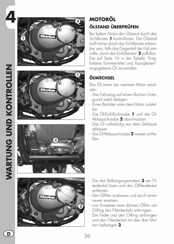
4W
ARTU
NG
UN
D K
ON
TRO
LLEN
36D
MOTORÖLÖLSTAND ÜBERPRÜFENBei kaltem Motor den Ölstand durch das Sichtfenster 1 kontrollieren. Der Ölstand muß immer durch das Sichtfenster erkenn-bar sein, falls das Gegenteil der Fall sein sollte, durch den Einfüllstutzen 2 auffüllen.Die auf Seite 16 in der Tabelle “Emp-fohlene Schmiermittel und Flüssigkeiten” angegebene Öl verwenden.
ÖLWECHSELDas Öl immer bei warmem Motor wech-seln:- Das Fahrzeug auf einem flachen Unter-
grund stabil ablegen.- Einen Behälter unter dem Motor aufstel-
len.- Die Öl-Einfüllschraube 1 und die Öl-
Ablassschraube 2 abschrauben.- Das Öl vollständig aus dem Gehäuse
ablassen.- Die Öl-Ablassschraube 2 wieder schlie-
ßen .
- Die drei Befestigungsmuttern 3 am Fil-terdeckel lösen und den Ölfilterdeckel entfernen.
- Den Ölfilter ausbauen und durch einen neuen ersetzen.
- orm Einsetzen eine dünnen Ölfilm am O-Ring des Filterdeckels anbringen.
- Die Feder und den O-Ring anbringen und den Filterdeckel mit den drei Mut-tern befestigen 3.
2
1
2
1
3
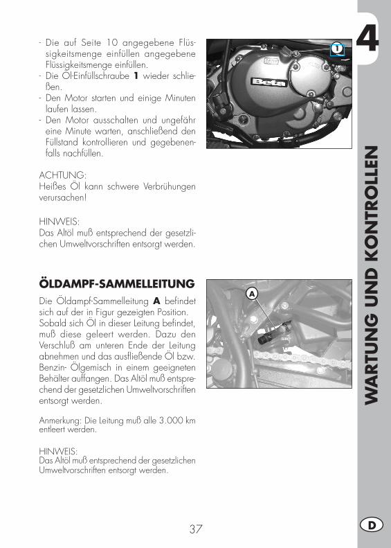
4
WA
RTU
NG
UN
D K
ON
TRO
LLEN
37 D
- Die auf Seite 10 angegebene Flüs-sigkeitsmenge einfüllen angegebene Flüssigkeitsmenge einfüllen.
- Die Öl-Einfüllschraube 1 wieder schlie-ßen.
- Den Motor starten und einige Minuten laufen lassen.
- Den Motor ausschalten und ungefähr eine Minute warten, anschließend den Füllstand kontrollieren und gegebenen-falls nachfüllen.
ACHTUNG:Heißes Öl kann schwere Verbrühungen verursachen!
HINWEIS:Das Altöl muß entsprechend der gesetzli-chen Umweltvorschriften entsorgt werden.
ÖLDAMPF-SAMMELLEITUNGDie Öldampf-Sammelleitung A befindet sich auf der in Figur gezeigten Position.Sobald sich Öl in dieser Leitung befindet, muß diese geleert werden. Dazu den Verschluß am unteren Ende der Leitung abnehmen und das ausfließende Öl bzw. Benzin- Ölgemisch in einem geeigneten Behälter auffangen. Das Altöl muß entspre-chend der gesetzlichen Umweltvorschriften entsorgt werden.
Anmerkung: Die Leitung muß alle 3.000 km entleert werden.
HINWEIS:Das Altöl muß entsprechend der gesetzlichen Umweltvorschriften entsorgt werden.
1
A
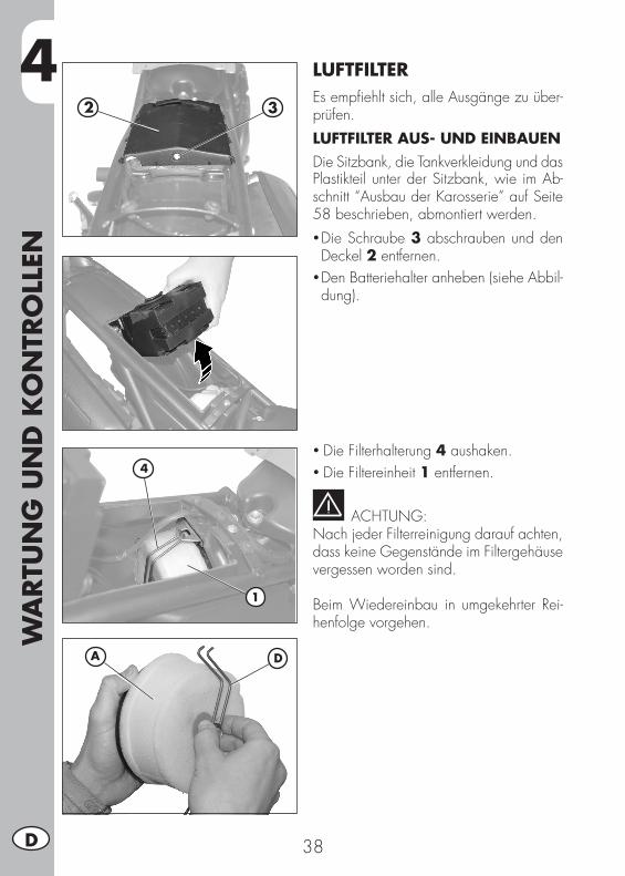
4W
ARTU
NG
UN
D K
ON
TRO
LLEN
38D
LUFTFILTEREs empfiehlt sich, alle Ausgänge zu über-prüfen.LUFTFILTER AUS- UND EINBAUENDie Sitzbank, die Tankverkleidung und das Plastikteil unter der Sitzbank, wie im Ab-schnitt “Ausbau der Karosserie” auf Seite 58 beschrieben, abmontiert werden.• Die Schraube 3 abschrauben und den Deckel 2 entfernen.
•Den Batteriehalter anheben (siehe Abbil-dung).
•Die Filterhalterung 4 aushaken.•Die Filtereinheit 1 entfernen.
ACHTUNG:Nach jeder Filterreinigung darauf achten, dass keine Gegenstände im Filtergehäuse vergessen worden sind.
Beim Wiedereinbau in umgekehrter Rei-henfolge vorgehen.
4
1
2 3
DA
4
WA
RTU
NG
UN
D K
ON
TRO
LLEN
39 D
REINIGUNG DES LUFTFILTERS• Den Filter sorgfältig mit Wasser und Seife reinigen.
• Lassen Sie den Filter trocknen.• Mit Filteröl tränken und überschüssiges Öl ausdrücken.
• Gegebenenfalls das Filtergehäuse auch innen reinigen.
ACHTUNG:Den Filter nicht mit Benzin oder Petroleum reinigen.
ANMERKUNG:Ist der Filter beschädigt, muß er sofort ausgewechselt werden.Zum Wechseln wenden Sie sich an einen autorisierten Kundendienst von Betamotor.
ACHTUNG:Den Motor nie ohne Luftfilter anlassen. Ein Eindringen von Staub und Schmutz können Schäden oder einen übermäßigen Verschleiß verursachen.
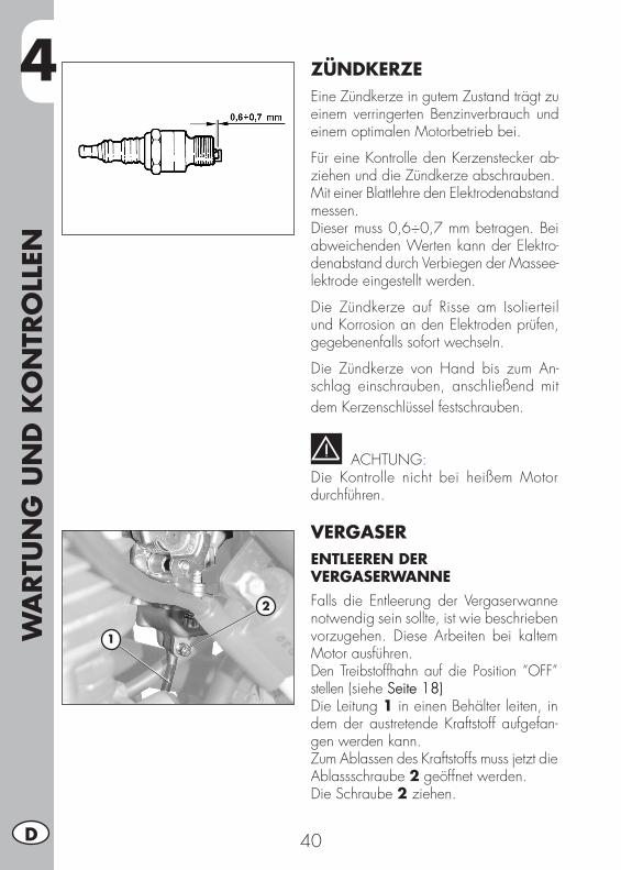
4W
ARTU
NG
UN
D K
ON
TRO
LLEN
40D
ZÜNDKERZEEine Zündkerze in gutem Zustand trägt zu einem verringerten Benzinverbrauch und einem optimalen Motorbetrieb bei.
Für eine Kontrolle den Kerzenstecker ab-ziehen und die Zündkerze abschrauben.Mit einer Blattlehre den Elektrodenabstand messen.Dieser muss 0,6÷0,7 mm betragen. Bei abweichenden Werten kann der Elektro-denabstand durch Verbiegen der Massee-lektrode eingestellt werden.
Die Zündkerze auf Risse am Isolierteil und Korrosion an den Elektroden prüfen, gegebenenfalls sofort wechseln.
Die Zündkerze von Hand bis zum An-schlag einschrauben, anschließend mit dem Kerzenschlüssel festschrauben.
ACHTUNG:Die Kontrolle nicht bei heißem Motor durchführen.
VERGASERENTLEEREN DER VERGASERWANNEFalls die Entleerung der Vergaserwanne notwendig sein sollte, ist wie beschrieben vorzugehen. Diese Arbeiten bei kaltem Motor ausführen. Den Treibstoffhahn auf die Position “OFF” stellen (siehe Seite 18) Seite 18)Die Leitung 1 in einen Behälter leiten, in dem der austretende Kraftstoff aufgefan-gen werden kann.Zum Ablassen des Kraftstoffs muss jetzt die Ablassschraube 2 geöffnet werden.Die Schraube 2 ziehen.
2
1
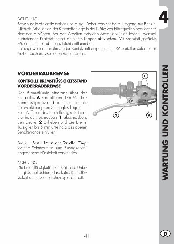
4
WA
RTU
NG
UN
D K
ON
TRO
LLEN
41 D
ACHTUNG:Benzin ist leicht entflammbar und giftig. Daher Vorsicht beim Umgang mit Benzin. Niemals Arbeiten an der Kraftstoffanlage in der Nähe von Hitzequellen oder offenen Flammen ausführen. Vor den Arbeiten stets den Motor abkühlen lassen. Eventuell austretenden Kraftstoff sofort mit einem Lappen abwischen. Mit Kraftstoff getränkte Materialien sind ebenfalls leicht entflammbar.Bei ungewollter Einnahme oder Kontakt mit empfindlichen Körperteilen sofort einen Arzt aufsuchen. Gesetzmäßig entsorgen.
VORDERRADBREMSEKONTROLLE BREMSFLÜSSIGKETSSTAND VORDERRADBREMSEDen Bremsflüssigkeitsstand über das Schauglas A kontrollieren. Der Mindest- Bremsflüssigkeitsstand darf nie unterhalb der Markierung am Schauglas liegen.Zum Auffüllen des Bremsflüssigkeitsstands die beiden Schrauben 1 abschrauben, den Deckel 2 anheben und die Brems-flüssigkeit bis 5 mm unterhalb des oberen Behälterrands einfüllen.
Die auf Seite 16 in der Tabelle “Emp- Seite 16 in der Tabelle “Emp-in der Tabelle “Emp-fohlene Schmiermittel und Flüssigkeiten” angegebene Flüssigkeit verwenden.
ACHTUNG:Die Bremsflüssigkeit ist stark ätzend. Unbe-dingt darauf achten, dass keine Bremsflüs-sigkeit auf lackierte Fahrzeugteile tropft.
2
1
A
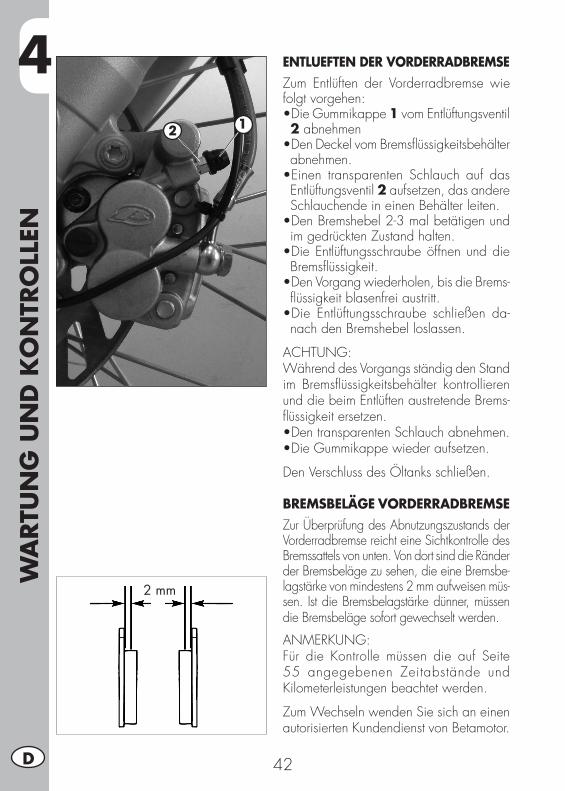
4W
ARTU
NG
UN
D K
ON
TRO
LLEN
42D
ENTLUEFTEN DER VORDERRADBREMSEZum Entlüften der Vorderradbremse wie folgt vorgehen:•DieGummikappe1 vom Entlüftungsventil 2 abnehmen•DenDeckelvomBremsflüssigkeitsbehälterabnehmen.•Einen transparenten Schlauch auf dasEntlüftungsventil 2 aufsetzen, das andere Schlauchende in einen Behälter leiten.•DenBremshebel2-3malbetätigenundim gedrückten Zustand halten.•DieEntlüftungsschraubeöffnenunddieBremsflüssigkeit.•DenVorgangwiederholen,bisdieBrems-flüssigkeit blasenfrei austritt.•Die Entlüftungsschraube schließen da-nach den Bremshebel loslassen.
ACHTUNG: Während des Vorgangs ständig den Stand im Bremsflüssigkeitsbehälter kontrollieren und die beim Entlüften austretende Brems-flüssigkeit ersetzen.•DentransparentenSchlauchabnehmen.•DieGummikappewiederaufsetzen.
Den Verschluss des Öltanks schließen.
BREMSBELÄGE VORDERRADBREMSEZur Überprüfung des Abnutzungszustands der Vorderradbremse reicht eine Sichtkontrolle des Bremssattels von unten. Von dort sind die Ränder der Bremsbeläge zu sehen, die eine Bremsbe-lagstärke von mindestens 2 mm aufweisen müs-sen. Ist die Bremsbelagstärke dünner, müssen die Bremsbeläge sofort gewechselt werden.
ANMERKUNG:Für die Kontrolle müssen die auf Seite 55 angegebenen Zeitabstände und Kilometerleistungen beachtet werden.
Zum Wechseln wenden Sie sich an einen autorisierten Kundendienst von Betamotor.
2 mm
12
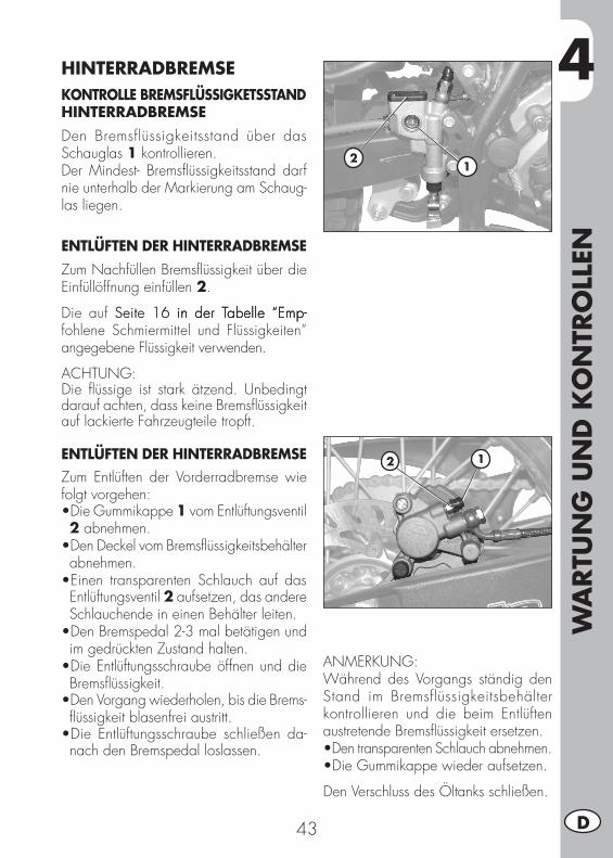
4
WA
RTU
NG
UN
D K
ON
TRO
LLEN
43 D
HINTERRADBREMSEKONTROLLE BREMSFLÜSSIGKETSSTAND HINTERRADBREMSEDen Bremsflüssigkeitsstand über das Schauglas 1 kontrollieren. Der Mindest- Bremsflüssigkeitsstand darf nie unterhalb der Markierung am Schaug-las liegen.
ENTLÜFTEN DER HINTERRADBREMSEZum Nachfüllen Bremsflüssigkeit über die Einfüllöffnung einfüllen 2.
Die auf Seite 16 in der Tabelle “Emp-Seite 16 in der Tabelle “Emp-in der Tabelle “Emp-fohlene Schmiermittel und Flüssigkeiten” angegebene Flüssigkeit verwenden.
ACHTUNG:Die flüssige ist stark ätzend. Unbedingt darauf achten, dass keine Bremsflüssigkeit auf lackierte Fahrzeugteile tropft.
ENTLÜFTEN DER HINTERRADBREMSEZum Entlüften der Vorderradbremse wie folgt vorgehen:•DieGummikappe1 vom Entlüftungsventil 2 abnehmen.•Den Deckel vom Bremsflüssigkeitsbehälter abnehmen.•Einen transparenten Schlauch auf das Entlüftungsventil 2 aufsetzen, das andere Schlauchende in einen Behälter leiten.•Den Bremspedal 2-3 mal betätigen und im gedrückten Zustand halten.•Die Entlüftungsschraube öffnen und die Bremsflüssigkeit.•DenVorgangwiederholen,bisdieBrems-flüssigkeit blasenfrei austritt.•Die Entlüftungsschraube schließen da-nach den Bremspedal loslassen.
ANMERKUNG: Während des Vorgangs ständig den Stand im Bremsflüssigkeitsbehälter kontrollieren und die beim Entlüften austretende Bremsflüssigkeit ersetzen.•Den transparenten Schlauch abnehmen.•DieGummikappewiederaufsetzen.
Den Verschluss des Öltanks schließen.
21
12
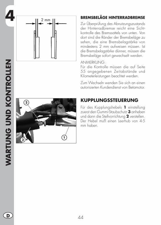
4W
ARTU
NG
UN
D K
ON
TRO
LLEN
44D
BREMSBELÄGE HINTERRADBREMSEZur Überprüfung des Abnutzungszustands der Hinterradbremse reicht eine Sicht-kontrolle des Bremssattels von unten. Von dort sind die Ränder der Bremsbeläge zu sehen, die eine Bremsbelagstärke von mindestens 2 mm aufweisen müssen. Ist die Bremsbelagstärke dünner, müssen die Bremsbeläge sofort gewechselt werden.
ANMERKUNG:Für die Kontrolle müssen die auf Seite 55 angegebenen Zeitabstände und Kilometerleistungen beachtet werden.
Zum Wechseln wenden Sie sich an einen autorisierten Kundendienst von Betamotor.
KUPPLUNGSSTEUERUNGFür des Kupplungshebels 1 einstellung zuerst den Gummi-Staubschutz 3 anhebenund dann die Stellvorrichtung 2 verstellen.Der Hebel muß einen Leerhub von 4-5 mm haben.
2 mm
1
2
3
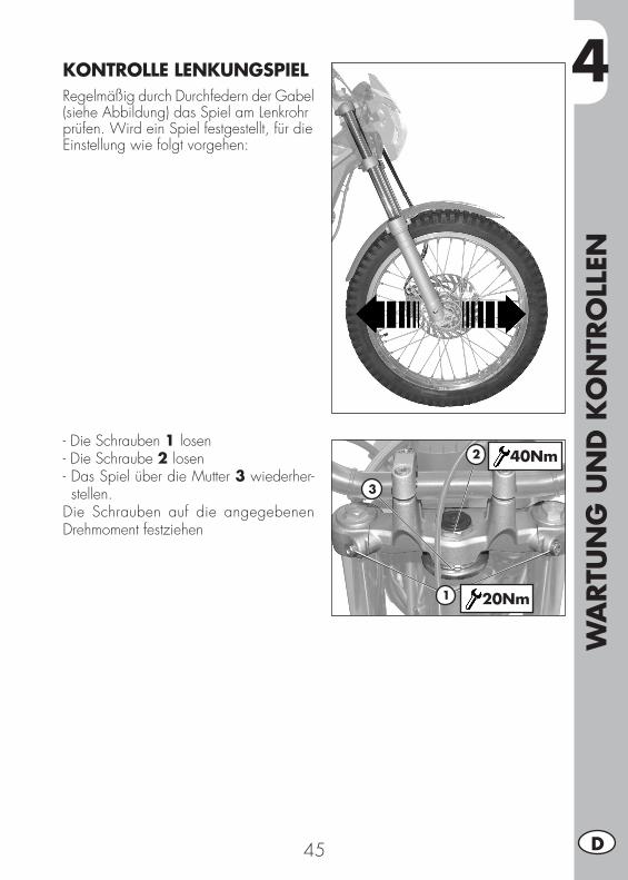
4
WA
RTU
NG
UN
D K
ON
TRO
LLEN
45 D
KONTROLLE LENKUNGSPIELRegelmäßig durch Durchfedern der Gabel(siehe Abbildung) das Spiel am Lenkrohrprüfen. Wird ein Spiel festgestellt, für dieEinstellung wie folgt vorgehen:
- Die Schrauben 1 losen- Die Schraube 2 losen- Das Spiel über die Mutter 3 wiederher-stellen.
Die Schrauben auf die angegebenen Drehmoment festziehen
1
2
3
40Nm
20Nm
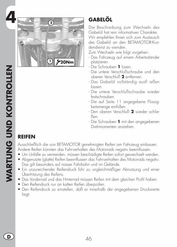
4W
ARTU
NG
UN
D K
ON
TRO
LLEN
46D
GABELÖLDie Beschreibung zum Wechseln des Gabelöl hat rein informativen Charakter.Wir empfehlen Ihnen sich zum Austausch des Gabelöl an den BETAMOTOR-Kun-dendienst zu wenden.Zum Wechseln wie folgt vorgehen:- Das Fahrzeug auf einem Arbeitsständer platzieren.
- Die Schrauben 1 losen.- Die untere Verschlußschraube und den oberen Verschluß 2 entfernen.
- Das Gabelöl vollständig ausfl ießen lassen.
- Die untere Verschlußschraube wieder festschrauben.
- Die auf Seite 11 angegebene Flüssig-keitsmenge einfüllen.
- Den oberen Verschluß 2 wieder schlie-ßen.
- Die Schrauben 1 mit den angegebenen Drehmomenten anziehen.
1
2
20Nm
REIFENAusschließlich die von BETAMOTOR genehmigten Reifen am Fahrzeug einbauen.Andere Reifen könnten das Fahrverhalten des Motorrads negativ beeinflussen.•UmUnfällezuvermeiden,müssenbeschädigteReifensofortgewechseltwerden.•Abgenutzte(glatte)ReifenbeeinflussendasFahrverhaltendesMotorradsnegativ.
Das gilt besonders auf nasser Fahrbahn und im Gelände.•Ein unzureichender Reifendruck führ zu ungleichmäßigerAbnutzung und einer
Überhitzung des Reifens.•DasVorderradunddasHinterradmüssenReifenmitdemgleichenProfilhaben.•DenReifendrucknurankaltenReifenüberprüfen.•DenReifendrucksoeinstellen,daßer innerhalbderangegebenenDruckwerte
liegt.
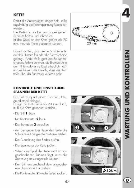
4
WA
RTU
NG
UN
D K
ON
TRO
LLEN
47 D
KETTEDamit die Antriebskette länger hält, sollte regelmäßig die Kettenspannung kontrolliertwerden.Die Ketten im sauber von abgelagertem Schmutz halten und schmieren.Ist das Spiel an der Kette größer als 20 mm, muß die Kette gespannt werden.
Darauf achten, dass keine Schmiermittel auf den Hinterreifen oder die Bremsscheibegelangt. Andernfalls geht die Bodenhaf-tung des Reifens verloren, die Bremsleistungder Hinterradbremse lässt erheblich nach und es besteht die Gefahr, dass die Kon-trolle über da Fahrzeug verloren geht.
KONTROLLE UND EINSTELLUNG SPANNEN DER KETTEDas Fahrzeug auf einem fl achen Unter-grund stabil ablegen.Hängt die Kette mehr als 20 mm durch, muß die Kette gespannt werden.
- Die Stift 1 lösen
- Die Kontermutter 2 lösen
- Die Schraube 3 verstellen
- Auf der gegenüber liegenden Seite die Schraube auf die gleiche Position einstellen.
- Die Ausrichtung des Rades prüfen.
- Die Spannung der Kette prüfen.
- Wenn das Spiel der Kette nicht im vor-geschriebenen Rahmen liegt, muss die Spannung neu eingestellt werden.
- Den Stift entsprechend dem angegebe-nen Drehmoment anziehen.
- Die Kontermutter 2 wieder festschrauben.
20 mm
2 3 1
80Nm
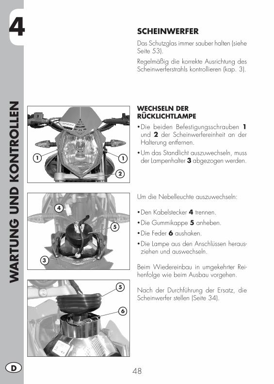
4W
ARTU
NG
UN
D K
ON
TRO
LLEN
48D
SCHEINWERFERDas Schutzglas immer sauber halten (siehe Seite 53).Regelmäßig die korrekte Ausrichtung des Scheinwerferstrahls kontrollieren (kap. 3).
WECHSELN DER RÜCKLICHTLAMPE • Die beiden Befestigungsschrauben 1 und 2 der Scheinwerfereinheit an der Halterung entfernen.
• Um das Standlicht auszuwechseln, muss der Lampenhalter 3 abgezogen werden.
Um die Nebelleuchte auszuwechseln:
• Den Kabelstecker 4 trennen.• Die Gummikappe 5 anheben.• Die Feder 6 aushaken.• Die Lampe aus den Anschlüssen heraus-ziehen und auswechseln.
Beim Wiedereinbau in umgekehrter Rei-henfolge wie beim Ausbau vorgehen.
Nach der Durchführung der Ersatz, die Scheinwerfer stellen (Seite 34).
11
3
2
4
5
5
6
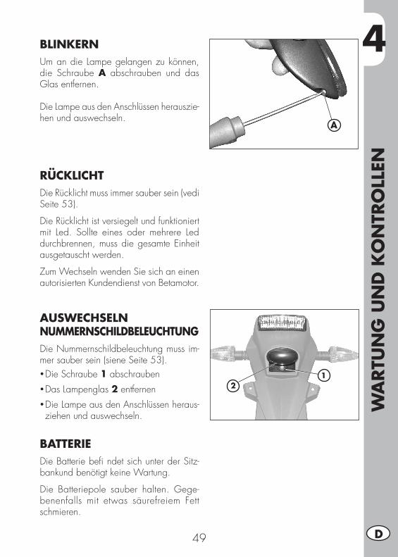
4
WA
RTU
NG
UN
D K
ON
TRO
LLEN
49 D
A
BLINKERNUm an die Lampe gelangen zu können, die Schraube A abschrauben und das Glas entfernen.
Die Lampe aus den Anschlüssen herauszie-hen und auswechseln.
RÜCKLICHTDie Rücklicht muss immer sauber sein (vedi Seite 53).
Die Rücklicht ist versiegelt und funktioniert mit Led. Sollte eines oder mehrere Led durchbrennen, muss die gesamte Einheit ausgetauscht werden.
Zum Wechseln wenden Sie sich an einen autorisierten Kundendienst von Betamotor.
AUSWECHSELN NUMMERNSCHILDBELEUCHTUNGDie Nummernschildbeleuchtung muss im-mer sauber sein (siene Seite 53).• Die Schraube 1 abschrauben• Das Lampenglas 2 entfernen• Die Lampe aus den Anschlüssen heraus-ziehen und auswechseln.
BATTERIEDie Batterie befi ndet sich unter der Sitz-bankund benötigt keine Wartung.
Die Batteriepole sauber halten. Gege-benenfalls mit etwas säurefreiem Fett schmieren.
12

4W
ARTU
NG
UN
D K
ON
TRO
LLEN
50D
ENTFERNENDie Batterie A ist zugänglich, wenn die Sitzbank, die Tankverkleidung und das Plastikteil unter der Sitzbank, wie im Ab-schnitt “Ausbau und einbau der Karosserie” auf Seite 58 beschrieben, abmontiert werden.Die Schraube 3 abschrauben und den Deckel 2 entfernen.Das Gummiband aushaken.VOHRER die negative Kabelklemme (schwarz) trennen vom dem negativen Pol (-) der Batterie und dann positive Kabelklemme (rot) vom dem Pluspol (+) der Batterie.Die Batterie ausbauen.Die Batterie zusammenbauen, indem die Pole wie in der Foto gerichtet sind.Verbinden Sie vorher die positive Kabelklem-me (rot) mit dem Pluspol (+) der Batterie und dann negative Kabelklemme schwarz) mit dem negativen Pol (-) der Batterie.ACHTUNG:Sollte aus irgendeinem Grund Batteriefl üssigkeit (Schwefelsäure) aus der Batterie austreten, muß sehr vorsichtig vorgegangen werden. Das Elektrolyt kann schwere Verät-zungen verursachen. Bei Hautkontakt sofort unter reichlich fließendem Wasser abspülen.Bei Kontakt mit den Augen sofort für inde-stens 15 Minuten mit Wasser spülen und umgehend einen Arzt aufsuchen.Obwohl es sich um eine versiegelte Batterie handelt, können explosive Gase austreten.Funkenbildung vermeiden und offene Flam-men von der Batterie fernhalten.Altbatterien von Kindern fernhalten und gesetzesmäßig entsorgen.Nie die Schutzabdeckung entfernen.Beim Einbau der Batterie auf die richtigen Polanschlüsse achten.
2 3
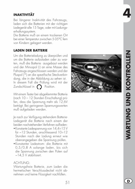
4
WA
RTU
NG
UN
D K
ON
TRO
LLEN
51 D
INAKTIVITÄTBei längerer Inaktivität des Fahrzeugs, laden sich die Batterien mit der richtigen Ladegerät alle 15 Tage, oder mit Ladungs-erhaltungssystem.Die Batterie muß an einem trockenen Ort bei einer Temperatur zwischen 5-35°C fern von Kindern gelagert werden.
LADEN DER BATTERIEUm die Batterieladung zu überprüfen und um die Batterie aufzuladen oder zu war-ten, muß die Batterie ausgebaut werden und der Minuspol (-) an eine Masse des Fahrzeugs angeschlossen werden und der Pluspol (*) an die spezifische Steckverbin-dung, die in der Abbildung zu sehen ist. In diesem Fall die Prüfung wird mit der Zundschlüssel in Position.
Mit einem Tester bei abgeklemmter Batterie (nach 10 – 12 Stunden Einschaltung) prü-fen, dass die Spannung mehr als 12,6V beträgt. Bei geringeren Spannungswerten muß aufgeladen werden.
Je nach zur Verfügung stehendem Batterie-Ladegerät die Batterie nach einem der beiden nachstehenden Verfahren aufladen:•Konstante Ladespannung von 14,4÷15 V für ~12 Stunden, anschliessend 10÷12 Stunden nach der Ladung erneut wie obenangegeben die Spannung prüfen.
•Konstanter Ladestrom: die Batterie mit 0,5/0,8 A solange laden, bis sich die Spannung zwischen den Polen auf ~14,5 V stabilisiert.
ACHTUNG:Wartungsfreie Batterie, zum Laden die hermetischen Verschlussdeckel nicht ab-nehmen und keine Flüssigkeit nachfüllen.
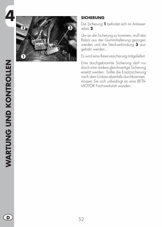
4W
ARTU
NG
UN
D K
ON
TRO
LLEN
52D
SICHERUNGDie Sicherung 1 befindet sich im Anlasser-relais 2.
Um an die Sicherung zu kommen, muß das Relais aus der Gummihalterung gezogen werden und die Steckverbindung 3 aus-gehakt werden..
Es wird eine Reservesicherung mitgeliefert.
Eine durchgebrannte Sicherung darf nur durch eine andere gleichwertige Sicherung ersetzt werden. Sollte die Ersatzsicherung nach dem Einbau ebenfalls durchbrennen, müssen Sie sich unbedingt an eine BETA-MOTOR Fachwerkstatt wenden.
2 3
1
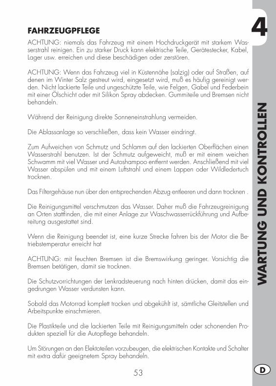
4
WA
RTU
NG
UN
D K
ON
TRO
LLEN
53 D
FAHRZEUGPFLEGEACHTUNG: niemals das Fahrzeug mit einem Hochdruckgerät mit starkem Was-serstrahl reinigen. Ein zu starker Druck kann elektrische Teile, Gerätestecker, Kabel, Lager usw. erreichen und diese beschädigen oder zerstören.
ACHTUNG: Wenn das Fahrzeug viel in Küstennähe (salzig) oder auf Straßen, auf denen im Winter Salz gestreut wird, eingesetzt wird, muß es häufig gereinigt wer-den. Nicht lackierte Teile und ungeschützte Teile, wie Felgen, Gabel und Federbein mit einer Ölschicht oder mit Silikon Spray abdecken. Gummiteile und Bremsen nicht behandeln.
Während der Reinigung direkte Sonneneinstrahlung vermeiden.
Die Ablassanlage so verschließen, dass kein Wasser eindringt.
Zum Aufweichen von Schmutz und Schlamm auf den lackierten Oberflächen einen Wasserstrahl benutzen. Ist der Schmutz aufgeweicht, muß er mit einem weichen Schwamm mit viel Wasser und Autoshampoo entfernt werden. Anschließend mit viel Wasser abspülen und mit einem Luftstrahl und einem Lappen oder Wildledertuch trocknen.
Das Filtergehäuse nun über den entsprechenden Abzug entleeren und dann trocknen .
Die Reinigungsmittel verschmutzen das Wasser. Daher muß die Fahrzeugreinigung an Orten stattfinden, die mit einer Anlage zur Waschwasserrückführung und Aufbe-reitung ausgestattet sind.
Wenn die Reinigung beendet ist, eine kurze Strecke fahren bis der Motor die Be-triebstemperatur erreicht hat
ACHTUNG: mit feuchten Bremsen ist die Bremswirkung geringer. Vorsichtig die Bremsen betätigen, damit sie trocknen.
Die Schutzvorrichtungen der Lenkradsteuerung nach hinten drücken, damit das ein-gedrungen Wasser verdunsten kann.
Sobald das Motorrad komplett trocken und abgekühlt ist, sämtliche Gleitstellen und Arbeitspunkte einschmieren.
Die Plastikteile und die lackierten Teile mit Reinigungsmitteln oder schonenden Pro-dukten speziell für die Autopflege behandeln.
Um Störungen an den Elektoteilen vorzubeugen, die elektrischen Kontakte und Schalter mit extra dafür geeignetem Spray behandeln.
4W
ARTU
NG
UN
D K
ON
TRO
LLEN
54D
LÄNGERES STILLEGEN DES FAHRZEUGSSoll der Motorroller längere Zeit stillgelegt werden, z. B. während des Winters, müssen zur richtigen Aufbewahrung einige einfache Vorkehrungen getroffen werden:• Das Fahrzeug und alle Fahrzeugteile gründlich reinigen.• Den Reifendruck um ungefähr 30% senken, die Räder möglichst vom Boden anhe-ben.
• Die Zündkerze ausbauen und einige Tropfen Motoröl in die Kerzenöffnung geben. Den Kickstarter (wo vorhanden) betätigen und den Motor einige Umdrehungen ausführen lassen. Die Zündkerze wieder einschrauben.
• Außer an Gummiteilen und Bremsen auf alle nicht lackierten Fahrzeugteile eine dünne Schicht Silikonöl auftragen..
• Batterie am Ladegerät angeschlossen lassen.• Zum Schutz gegen Staub den Motorroller mit einer Schutzplane bedecken.• Die Vergaserwanne auslassen, wie auf Seite 40 beschrieben.
NACH LÄNGEREM STILLEGEN DES FAHRZEUGS
• Den Reifendruck wieder herstellen.• Den Anzug aller wichtigen Schrauben überprüfen.• Das erstmalige Starten muß mit dem (Kickstarter) (wo vorhanden) erfolgen.
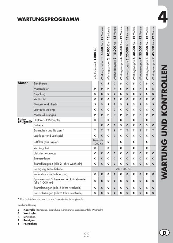
4
WA
RTU
NG
UN
D K
ON
TRO
LLEN
55 D
WARTUNGSPROGRAMM
Ende
Ein
fahr
zeit
1.0
00 K
m
War
tung
scou
pon
1 5
.000
Km
- 12
Mon
ate
War
tung
scou
pon
2 1
0.00
0 Km
- 12
Mon
ate
War
tung
scou
pon
3 1
5.00
0 Km
- 12
Mon
ate
War
tung
scou
pon
4 2
0.00
0 Km
- 12
Mon
ate
War
tungs
coup
on 5
25.
000
Km -
12
Mon
ate
War
tung
scou
pon
6 3
0.00
0 Km
- 12
Mon
ate
War
tung
scou
pon
7 3
5.00
0 Km
- 12
Mon
ate
War
tung
scou
pon
8 4
0.00
0 Km
- 12
Mon
ate
War
tung
scou
pon
9 4
5.00
0 Km
- 12
Mon
ate
Motor Zündkerze C S C S C S C S C
Motorölfilter P P P P S P S P S S
Kupplung C C C C S C C C S C
Ventilspiel C C C C C C C C C C
Motoröl und filteröl S S S S S S S S S S
Leerlaufeistellung C C C C C C C C C C
Motor-Ölleitungen P P P P P P P P P P
Fahr-zeugteile Hinterer Stoßdämpfer C C C C C
Batterie C C C S C C C S C
Schrauben und Bolzen * T T T T T T T T T T
Lenklager und Lenkspiel C C C C C C C C C C
Luftfilter (aus Papier)Blase alle 1000 Km
S S S S
Vordergabel C C C C C
Elektrische anlage C C C C C C C C C C
Bremsanlage C C C C C C C C C C
Bremsflüssigkeit (alle 2 Jahre wechseln) C C C C C C C C C C
Reinigung Antreibskette Alle 1000 Km
Reifendruck und abnutzung C C C C C C C C C C
Spannen und Schmieren der Antriebskette(alle 1.000 km) C C C C C C C C C C
Bremsleitungen (alle 2 Jahre wechseln) C C C C C C C C C C
Benzinleitungen (alle 2 Jahre wechseln) C C C C C C C C C C
* Das Festziehen wird nach jeden Geländeeinsatz empfoheln.
Zeichenerklärung
C Kontrolle (Reinigung, Einstellung, Schmierung, gegebenenfalls Wechseln)S WechselnR EinstellenP ReinigenT Festziehen

56
5
AU
SBA
U U
ND
EIN
BA
U D
ER K
ARO
SSER
IE
57 D
KAPITEL 5 AUSBAU UND EINBAU DER KAROSSERIE
INHALTSVERZEICHNISAusbau und Einbau des Sattels ..............................................................58Ausbau und Einbau Tankverkleidung ......................................................58Ausbau und Einbau der Beifahrer-Handgriffe ...........................................58Ausbau und Einbau des Plastikteils unter der Sitzbank ..............................59
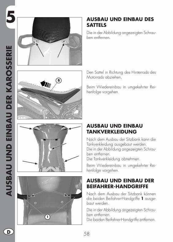
5A
USB
AU
UN
D E
INBA
U D
ER K
ARO
SSER
IE
58D
AUSBAU UND EINBAU DES SATTELSDie in der Abbildung angezeigten Schrau-ben entfernen.
Den Sattel in Richtung des Hinterrads des Motorrads abziehen.
Beim Wiedereinbau in umgekehrter Rei-henfolge vorgehen.
AUSBAU UND EINBAU TANKVERKLEIDUNGNach dem Ausbau der Sitzbank kann die Tankverkleidung ausgebaut werden.Die in der Abbildung angezeigten Schrau-ben entfernen.Die Tankverkleidung abnehmen.Beim Wiedereinbau in umgekehrter Rei-henfolge vorgehen.
AUSBAU UND EINBAU DER BEIFAHRER-HANDGRIFFENach dem Ausbau der Sitzbank können die beiden Beifahrer-Handgriffe 1 ausge-baut werden.Die in der Abbildung angezeigten Schrau-ben entfernen.Die beiden Beifahrer-Handgriffe entfernen.
B
1
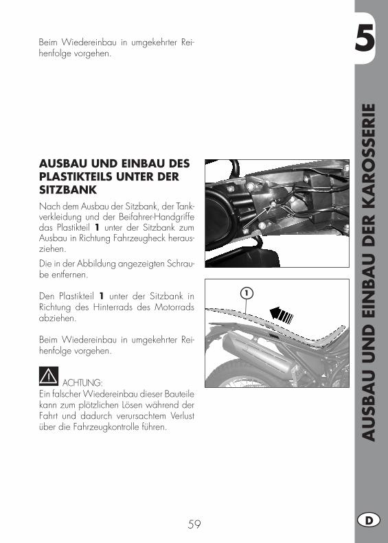
5
AU
SBA
U U
ND
EIN
BA
U D
ER K
ARO
SSER
IE
59 D
1
AUSBAU UND EINBAU DES PLASTIKTEILS UNTER DER SITZBANKNach dem Ausbau der Sitzbank, der Tank-verkleidung und der Beifahrer-Handgriffe das Plastikteil 1 unter der Sitzbank zum Ausbau in Richtung Fahrzeugheck heraus-ziehen.Die in der Abbildung angezeigten Schrau-be entfernen.
Den Plastikteil 1 unter der Sitzbank in Richtung des Hinterrads des Motorrads abziehen.
Beim Wiedereinbau in umgekehrter Rei-henfolge vorgehen.
ACHTUNG:Ein falscher Wiedereinbau dieser Bauteile kann zum plötzlichen Lösen während der Fahrt und dadurch verursachtem Verlust über die Fahrzeugkontrolle führen.
Beim Wiedereinbau in umgekehrter Rei-henfolge vorgehen.

60

6
WA
S IS
T IM
NO
TFA
LL Z
U T
UN
61 D
KAPITEL 6 WAS IST IM NOTFALL ZU TUN
INHALTSVERZEICHNISFehlersuche .........................................................................................62Alphabetisches inhaltsverzeichnis ...........................................................63
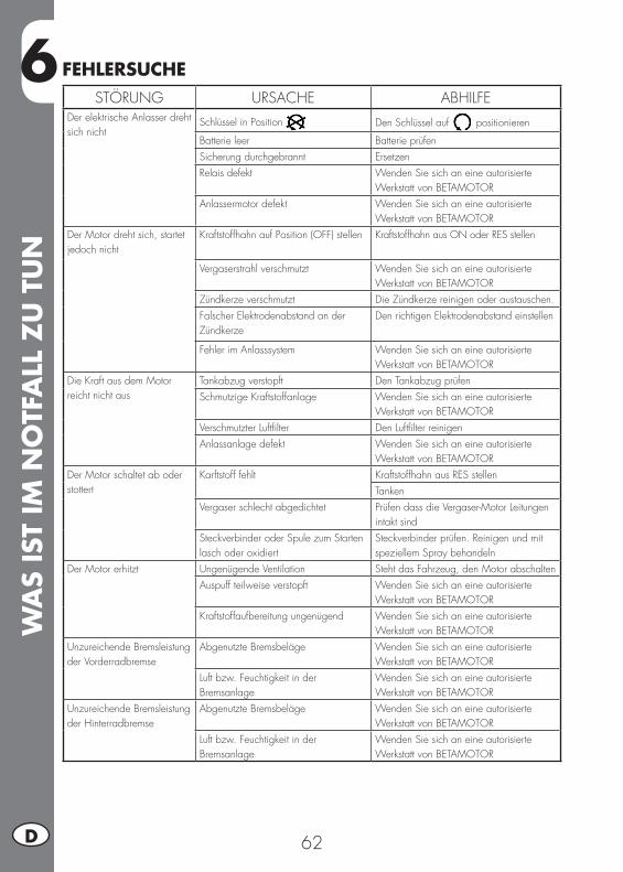
6W
AS
IST
IM N
OTF
ALL
ZU
TU
N
62D
STÖRUNG URSACHE ABHILFEDer elektrische Anlasser dreht sich nicht
Schlüssel in Position Den Schlüssel auf positionieren
Batterie leer Batterie prüfenSicherung durchgebrannt ErsetzenRelais defekt Wenden Sie sich an eine autorisierte
Werkstatt von BETAMOTOR Anlassermotor defekt Wenden Sie sich an eine autorisierte
Werkstatt von BETAMOTOR Der Motor dreht sich, startet jedoch nicht
Kraftstoffhahn auf Position (OFF) stellen Kraftstoffhahn aus ON oder RES stellen
Vergaserstrahl verschmutzt Wenden Sie sich an eine autorisierteWerkstatt von BETAMOTOR
Zündkerze verschmutzt Die Zündkerze reinigen oder austauschen.Falscher Elektrodenabstand an der Zündkerze
Den richtigen Elektrodenabstand einstellen
Fehler im Anlasssystem Wenden Sie sich an eine autorisierteWerkstatt von BETAMOTOR
Die Kraft aus dem Motor reicht nicht aus
Tankabzug verstopft Den Tankabzug prüfenSchmutzige Kraftstoffanlage Wenden Sie sich an eine autorisierte
Werkstatt von BETAMOTORVerschmutzter Luftfilter Den Luftfilter reinigenAnlassanlage defekt Wenden Sie sich an eine autorisierte
Werkstatt von BETAMOTORDer Motor schaltet ab oder stottert
Karftstoff fehlt Kraftstoffhahn aus RES stellenTanken
Vergaser schlecht abgedichtet Prüfen dass die Vergaser-Motor Leitungen intakt sind
Steckverbinder oder Spule zum Starten lasch oder oxidiert
Steckverbinder prüfen. Reinigen und mit speziellem Spray behandeln
Der Motor erhitzt Ungenügende Ventilation Steht das Fahrzeug, den Motor abschaltenAuspuff teilweise verstopft Wenden Sie sich an eine autorisierte
Werkstatt von BETAMOTORKraftstoffaufbereitung ungenügend Wenden Sie sich an eine autorisierte
Werkstatt von BETAMOTORUnzureichende Bremsleistung der Vorderradbremse
Abgenutzte Bremsbeläge Wenden Sie sich an eine autorisierteWerkstatt von BETAMOTOR
Luft bzw. Feuchtigkeit in derBremsanlage
Wenden Sie sich an eine autorisierteWerkstatt von BETAMOTOR
Unzureichende Bremsleistung der Hinterradbremse
Abgenutzte Bremsbeläge Wenden Sie sich an eine autorisierteWerkstatt von BETAMOTOR
Luft bzw. Feuchtigkeit in derBremsanlage
Wenden Sie sich an eine autorisierteWerkstatt von BETAMOTOR
FEHLERSUCHE
ALP
HA
BET
ISCH
ES IN
HA
LTSV
ERZ
EICH
NIS
63 D
ALPHABETISCHES INHALTSVERZEICHNISAbschalten des Motors .........................................................................29Auftanken ...........................................................................................28Ausbau und Einbau der Beifahrer-Handgriffe ...........................................58Ausbau und Einbau des Sattels ..............................................................58Ausbau und Einbau Tankverkleidung ......................................................58Ausbau und Einbau des Plastikteils unter der Sitzbank ..............................59Auswechseln Nummernschildbeleuchtung .......................................................................49
Batterie ...............................................................................................49Bedienungsanleitung Kilometerzähler......................................................22Blinkern ..............................................................................................49Bremsen ..............................................................................................32
Einfahren ............................................................................................28Elektrische Anlage ................................................................................14Empfohlene Schmiermittel und Flüssigkeiten .............................................16
Fahrzeugpflege ....................................................................................53Fehlersuche .........................................................................................62
Gabelöl ..............................................................................................46
Helmschloss .........................................................................................21Hinterradbremse ..................................................................................43Hinweise zum gebrauch des Fahrzeugs ....................................................5
Kette ...................................................................................................47Kontrolle lenkungspiel ...........................................................................45Kontrollen vor und nach dem Einsatz ......................................................28Kupplungssteuerung .............................................................................44
Längeres stillegen des Fahrzeugs ...........................................................54Leerlaufeinstellung ...............................................................................33Legende der Symbole ...........................................................................32Lenker .................................................................................................33Lenkradschloss .....................................................................................21Luftfilter ...............................................................................................38
ALP
HA
BET
ISCH
ES IN
HA
LTSV
ERZ
EICH
NIS
64D
Motor .................................................................................................12Motoröl ...............................................................................................36
Öldampf-Sammelleitung ........................................................................37
Rahmen und motornummer ......................................................................8Reifen .................................................................................................46Rücklicht .............................................................................................49
Scheinwerfer .......................................................................................34Scheinwerfer .......................................................................................48Schlüssel .............................................................................................21Sicheres fahren ......................................................................................6Starten ................................................................................................29Stoßdämpfer .......................................................................................33
Technische Daten .................................................................................10
Umweltfreundliches fahren ......................................................................5
Vergaser .............................................................................................40Vorbereitung für TRIAL-Lage ...................................................................30Vorderradbremse .................................................................................41
Wartungsprogramm .............................................................................55Wichtigste Fahrzeugteile .........................................................................9Wichtigste Fahrzeugteile .......................................................................18
Zündkerze ...........................................................................................40
1 E
ALP 200
Gracias por la confianza que nos han concedido y buena di-versión. Con este libro hemos querido darle las informaciones necesarias para un uso correcto y un buen mantenimiento de Su moto.
Los datos y las características indicadas en éste manual no comprometen BETAMOTOR S.p.A que se reserva los derechos a realizar modificaciones y mejoras a sus propios modelos en cualquier momento sin previo aviso.
Cod. 017440090 000
2E
ADVERTENCIA
Recomendamos después de la primera o segunda hora de utilización en todo terreno, de controlar todos los aprietes espe-cialmente a los siguientes:
• corona• comprobar la correcta fijación de los estribos reposapiés• palancas/pinzas/disco freno delantero/trasero• comprobar el correcto apriete de los plásticos• tornillos del motor• tornillos amortiguador/brazo oscilante• rayos/cubos rueda• chasis trasero• uniones de tubos• tensionamiento cadena
ADVERTENCIA
En el caso de intervenciones en la moto, dirigirse a la cadena de asistencia autorizada Betamotor.
IND
ICE
3 E
ÍNDICE CAPITULOS
Advertencias sobre el uso del vehículo......................................................5Conducción ecológica ............................................................................5Conducción segura ................................................................................6
CAP. 1 INFORMACIONES GENERALES .............................................7Datos identificación vehículo ...................................................................8Conocimiento del vehículo ......................................................................9Datos técnicos .....................................................................................10Motor .................................................................................................12Sistema eléctrico ..................................................................................14Lubricantes y líquidos aconsejados .........................................................16
CAP. 2 USO DEL VEHÍCULO .............................................................17Elementos principales ...........................................................................18Llaves .................................................................................................21Bloque manillar ....................................................................................21Cerradura casco ..................................................................................21Instrucciones para el funcionamiento tacómetro digital .............................22Comprobaciones antes y después de la puesta en función ........................28Rodaje ................................................................................................28Abastecimiento combustible ..................................................................28Arranque motor ...................................................................................29Parada motor ......................................................................................29Preinstalación para ajuste de TRIAL ........................................................30
CAP. 3 REGULACIONES ...................................................................31Explicación de los símbolos ...................................................................32Frenos ................................................................................................32Ajuste del ralentí .................................................................................33Manillar ..............................................................................................33Regulación Amortiguador .....................................................................33Faro delantero .....................................................................................34
CAP. 4 CONTROLES Y MANTENIMIENTO .......................................35Aceite motor ........................................................................................36Tubo recolección humo .........................................................................37Filtro aire ............................................................................................38Bujía ..................................................................................................40
IND
ICE
4E
Carburador .........................................................................................40Freno delantero ...................................................................................41Freno trasero .......................................................................................43Mando embrague ................................................................................44Control del juego dirección ...................................................................45Neumáticos .........................................................................................46Aceite horquilla ...................................................................................46Cadena ..............................................................................................47Faro delantero .....................................................................................48Indicador de dirección ..........................................................................49Grupo óptico trasero ............................................................................49Sustitución lámpara alumbrado matrícula ................................................49Batería ................................................................................................49Limpieza del vehículo ...........................................................................53Larga inactividad del vehículo ...............................................................54Mantenimiento programado .................................................................55
CAP. 5 DESMONTAJE Y REMONTAJE DE LA CARROCERÍA .............57Desmontaje y remontaje del sillín ...........................................................58Desmontaje y remontaje carenado del depósito .......................................58Desmontaje y remontaje empuñaduras de agarre pasajero .......................58Desmontaje y remontaje del plástico debajo del sillín ...................................................... 59
CAP. 6 QUE HACER EN CASO DE EMERGENCIA .............................61Búsqueda de la avería ..........................................................................62
5 E
ADVERTENCIAS SOBRE EL USO DEL VEHÍCULO
• El vehículo debe ser obligatoriamente provisto de: placa, libreto de identificación, impuesto y seguro.
• Está prohibido transportar animales y objetos que no sean componentes del vehí-culo, que puedan sobresalir del volumen del mismo vehículo.
• Es obligatorio el uso del casco.• Viajar siempre con las luces de cruce encendidas.• Modificaciones al motor o a otros órganos que puedan determinar un aumento de potencia y por consiguiente aumento de velocidad, es castigado por la ley con severas sanciones, entre las cuales el secuestro del vehículo.
• Para proteger su vida y la de los demás, conduzca con prudencia, colóquese siempre el casco y deje siempre las luces de cruce encendidas.
ATENCIÓN:Modificaciones o intervenciones durante la garantía, liberan al Constructor de cualquier responsabilidad y hacen decaer la misma garantía.
CONDUCCIÓN ECOLÓGICA
• Cada vehículo con motor a explosión produce mas o menos ruido (contaminación de sonido) y mas o menos (contaminación atmosférica) según el tipo de conducción adoptada.
• La mayor reducción posible de estas condiciones es hoy un deber para todos, por lo tanto evitar salidas a todo gas, improvisas e inútiles aceleraciones e improvisas igualmente inútiles frenadas, limitando así la rumorosidad, el desgaste precoz de los neumáticos y de las partes mecánicas del vehículo y ahorrando en el gasto de gasolina.
6E
CONDUCCIÓN SEGURA
• Respetar el código de la circulación• Ponerse siempre el casco homologado y enganchado•Viajar siempre con las luces de cruce encendidas.•Tener siempre limpia la visera protectiva• Ponerse siempre ropa sin extremos colgando• No viajar teniendo en el bolsillo objetos con punta o frágiles•Ajustar correctamente los espejos retrovisores• Conducir siempre sentados, con las dos manos en el manillar y los pies sobre los estribos
• No distraerse nunca durante la conducción • No comer, beber, fumar, usar el celular, etc…. mientras conduce• No escuchar música con auriculares mientras conduce• No viajar nunca en pareja con otros vehículos • No remolcar o dejarse remolcar por otros vehículos• Tener siempre una distancia de seguridad• No estar sentados cuando el vehículo se encuentra sobre el caballete• No salir con el vehículo sobre el caballete• No extraer el caballete cuando el vehículo se encuentra con su parte anterior en bajada
• Empinadas, serpentinas, oscilaciones, son peligrosas para Ti, para los demás y para tu vehículo
• En calle seca y sin grava o arena, usar ambos frenos, un solo freno puede provocar deslizamientos peligrosos e incontrolables.
• En caso de frenada utilizar ambos frenos, se obtendrá una parada del vehículo en un espacio mas corto
•Con la carretera mojada o en todoterreno, conducir con prudencia y a una velo-cidad moderada: usar los frenos con mayor sensibilidad
• No arrancar el motor en locales cerrados.
1
INFO
RM
ACI
ON
ES G
ENER
ALE
S
7 E
CAP. 1 INFORMACIONES GENERALES
INDICE DE LOS ARGUMENTOSDatos identificación vehículo ...................................................................8
Identificación chasis ...........................................................................8Identificación motor ...........................................................................8Dotación ..........................................................................................8
Conocimiento del vehículo ......................................................................9Datos técnicos .....................................................................................10
Peso ..............................................................................................10Dimensiones vehículo .......................................................................10Neumáticos ....................................................................................10Capacidad de Llenado ....................................................................10Suspension delantera .......................................................................11Suspensión trasera...........................................................................11Freno delantero ...............................................................................11Freno trasero ..................................................................................11
Motor .................................................................................................12Carburador ....................................................................................12Cambio .........................................................................................13
Sistema eléctrico ..................................................................................14Esquema eléctrico ............................................................................14Leyenda esquema eléctrico ...............................................................15
Lubricantes y líquidos aconsejados .........................................................16
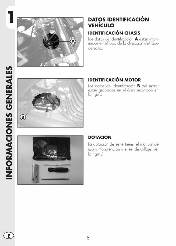
1IN
FORM
ACI
ON
ES G
ENER
ALE
S
8E
DATOS IDENTIFICACIÓN VEHÍCULOIDENTIFICACIÓN CHASISLos datos de identificación A están impri-midos en el tubo de la dirección del lado derecho.
IDENTIFICACIÓN MOTORLos datos de identificación B del motor están grabados en el área mostrada en la figura.
DOTACIÓNLa dotación de serie tiene: el manual de uso y manutención y el set de utillaje (ver la figura).
A
B
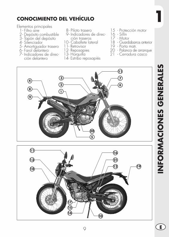
1
INFO
RM
ACI
ON
ES G
ENER
ALE
S
9 E
Elementos principales 1 - Filtro aire 2 - Depósito combustible 3 - Tapón del depósito 4 - Silenciador 5 - Amortiguador trasero 6 - Farol delantero 7 - Indicadores de direc-
ción delantero
1
2113
14
CONOCIMIENTO DEL VEHÍCULO
8 - Piloto trasero 9 - Indicadores de direc-
ción traseros 10 - Caballete lateral 11 - Retrovisor 12 - Reposapies 13 - Horquilla 14 - Estribo reposapiés
15 - Protección motor 16 - Sillín 17 - Motor18 - Guardabarros anterior19 - Porta matr.20 - Palanca de arranque21 - Cerradura casco
2
34
5
7
8
9
20
10
15
16
17
191218
11
11
6
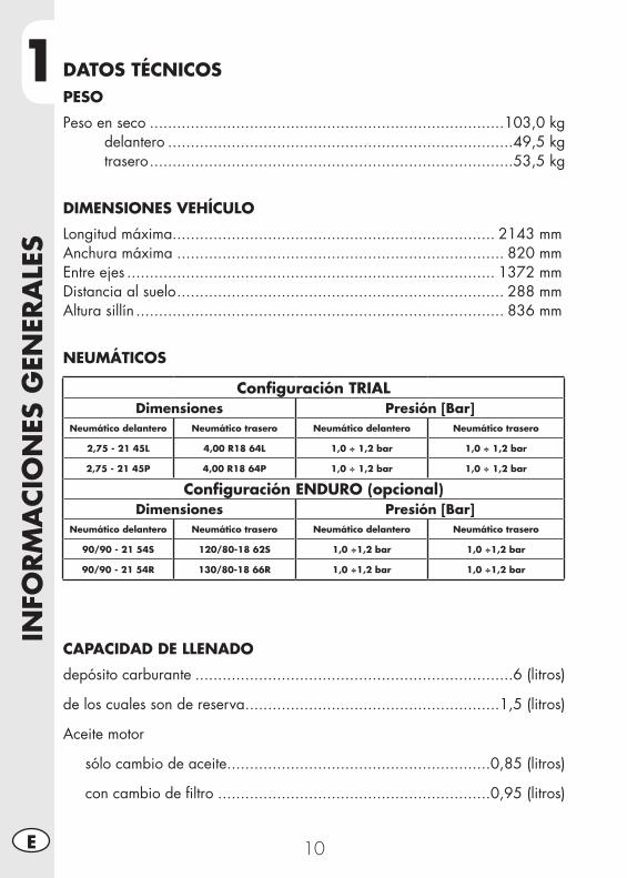
1IN
FORM
ACI
ON
ES G
ENER
ALE
S
10E
DATOS TÉCNICOSPESO
Peso en seco ..............................................................................103,0 kg delantero ............................................................................49,5 kg trasero ................................................................................53,5 kg
DIMENSIONES VEHÍCULO
Longitud máxima....................................................................... 2143 mmAnchura máxima ........................................................................ 820 mmEntre ejes ................................................................................. 1372 mmDistancia al suelo ........................................................................ 288 mmAltura sillín ................................................................................. 836 mm
NEUMÁTICOS
CAPACIDAD DE LLENADO
depósito carburante ......................................................................6 (litros)
de los cuales son de reserva ........................................................1,5 (litros)
Aceite motor
sólo cambio de aceite ..........................................................0,85 (litros)
con cambio de filtro ............................................................0,95 (litros)
Configuración TRIALDimensiones Presión [Bar]
Neumático delantero Neumático trasero Neumático delantero Neumático trasero
2,75 - 21 45L 4,00 R18 64L 1,0 ÷ 1,2 bar 1,0 ÷ 1,2 bar
2,75 - 21 45P 4,00 R18 64P 1,0 ÷ 1,2 bar 1,0 ÷ 1,2 bar
Configuración ENDURO (opcional)Dimensiones Presión [Bar]
Neumático delantero Neumático trasero Neumático delantero Neumático trasero
90/90 - 21 54S 120/80-18 62S 1,0 ÷1,2 bar 1,0 ÷1,2 bar
90/90 - 21 54R 130/80-18 66R 1,0 ÷1,2 bar 1,0 ÷1,2 bar
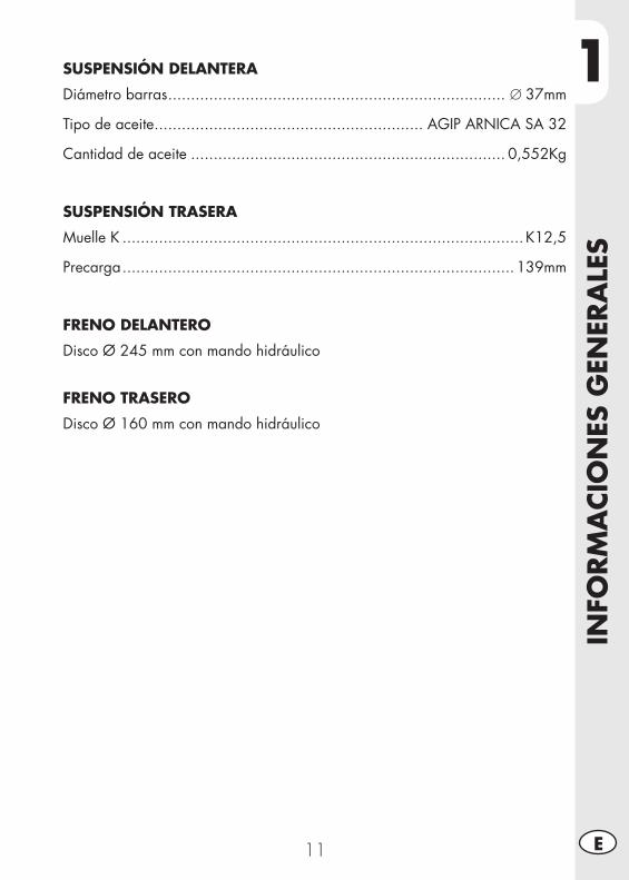
1
INFO
RM
ACI
ON
ES G
ENER
ALE
S
11 E
SUSPENSIÓN DELANTERA
Diámetro barras .......................................................................... ∅ 37mm
Tipo de aceite ........................................................... AGIP ARNICA SA 32
Cantidad de aceite ..................................................................... 0,552Kg
SUSPENSIÓN TRASERA
Muelle K ........................................................................................ K12,5
Precarga ...................................................................................... 139mm
FRENO DELANTERO
Disco Ø 245 mm con mando hidráulico
FRENO TRASERO
Disco Ø 160 mm con mando hidráulico
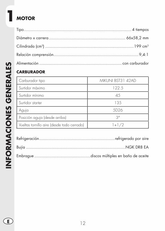
1IN
FORM
ACI
ON
ES G
ENER
ALE
S
12E
MOTOR
Tipo .......................................................................................... 4 tiempos
Diámetro x carrera ................................................................ 66x58,2 mm
Cilindrada (cm3) ..........................................................................199 cm3
Relación comprensión .......................................................................9,4:1
Alimentación ..................................................................... con carburador
CARBURADOR
Carburador tipo MIKUNI BST31 42AD
Surtidor máximo 122.5
Surtidor mínimo 45
Surtidor starter 135
Aguja 5D26
Posición aguja (desde arriba) 3°
Vueltas tornillo aire (desde todo cerrado) 1+1/2
Refrigeración ............................................................... refrigerado por aire
Bujía ...................................................................................NGK DR8 EA
Embrague ...............................................discos múltiples en baño de aceite
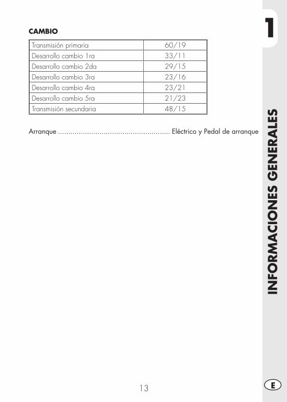
1
INFO
RM
ACI
ON
ES G
ENER
ALE
S
13 E
CAMBIO
Transmisión primaria 60/19Desarrollo cambio 1ra 33/11Desarrollo cambio 2da 29/15Desarrollo cambio 3ra 23/16Desarrollo cambio 4ra 23/21Desarrollo cambio 5ra 21/23Transmisión secundaria 48/15
Arranque ...................................................... Eléctrico y Pedal de arranque
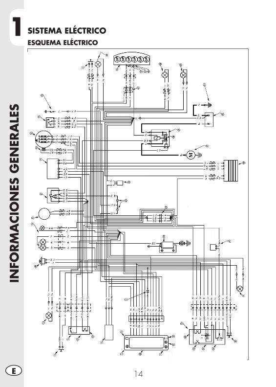
1IN
FORM
ACI
ON
ES G
ENER
ALE
S
14E
SISTEMA ELÉCTRICOESQUEMA ELÉCTRICO
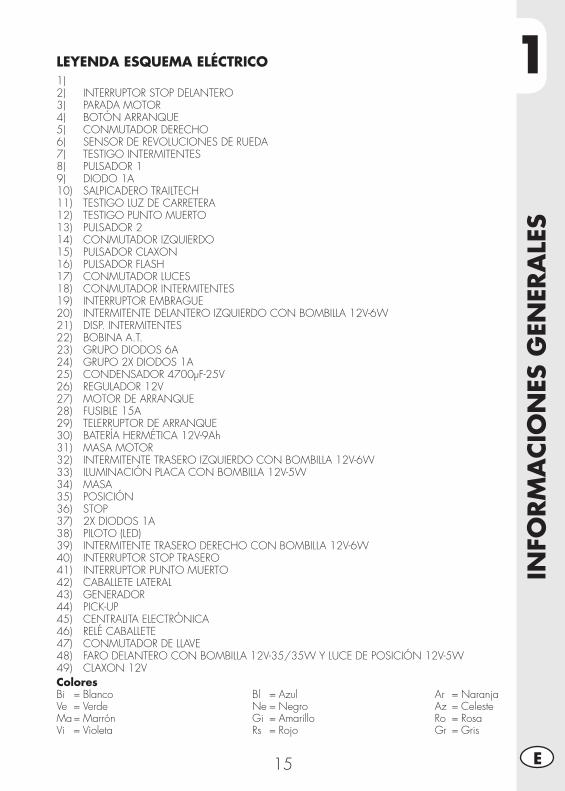
1
INFO
RM
ACI
ON
ES G
ENER
ALE
S
15 E
ColoresBi = BlancoVe = VerdeMa = MarrónVi = Violeta
Bl = AzulNe = NegroGi = AmarilloRs = Rojo
Ar = NaranjaAz = CelesteRo = RosaGr = Gris
LEYENDA ESQUEMA ELÉCTRICO1) 2) INTERRUPTOR STOP DELANTERO3) PARADA MOTOR4) BOTÓN ARRANQUE5) CONMUTADOR DERECHO6) SENSOR DE REVOLUCIONES DE RUEDA7) TESTIGO INTERMITENTES8) PULSADOR 19) DIODO 1A10) SALPICADERO TRAILTECH11) TESTIGO LUZ DE CARRETERA12) TESTIGO PUNTO MUERTO13) PULSADOR 214) CONMUTADOR IZQUIERDO15) PULSADOR CLAXON16) PULSADOR FLASH17) CONMUTADOR LUCES18) CONMUTADOR INTERMITENTES19) INTERRUPTOR EMBRAGUE20) INTERMITENTE DELANTERO IZQUIERDO CON BOMBILLA 12V-6W21) DISP. INTERMITENTES22) BOBINA A.T.23) GRUPO DIODOS 6A24) GRUPO 2X DIODOS 1A25) CONDENSADOR 4700µF-25V26) REGULADOR 12V27) MOTOR DE ARRANQUE28) FUSIBLE 15A29) TELERRUPTOR DE ARRANQUE30) BATERÍA HERMÉTICA 12V-9Ah31) MASA MOTOR32) INTERMITENTE TRASERO IZQUIERDO CON BOMBILLA 12V-6W33) ILUMINACIÓN PLACA CON BOMBILLA 12V-5W34) MASA35) POSICIÓN36) STOP37) 2X DIODOS 1A38) PILOTO (LED)39) INTERMITENTE TRASERO DERECHO CON BOMBILLA 12V-6W40) INTERRUPTOR STOP TRASERO41) INTERRUPTOR PUNTO MUERTO42) CABALLETE LATERAL43) GENERADOR44) PICK-UP45) CENTRALITA ELECTRÓNICA46) RELÉ CABALLETE47) CONMUTADOR DE LLAVE48) FARO DELANTERO CON BOMBILLA 12V-35/35W Y LUCE DE POSICIÓN 12V-5W49) CLAXON 12V
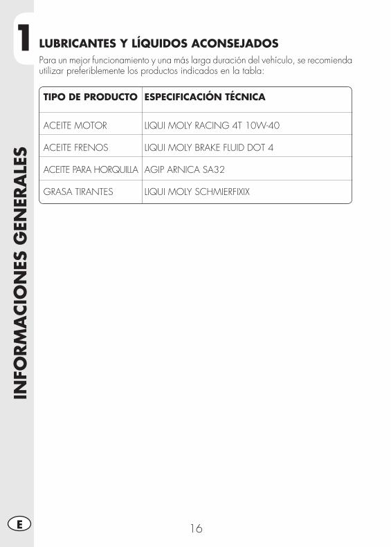
1IN
FORM
ACI
ON
ES G
ENER
ALE
S
16E
TIPO DE PRODUCTO ESPECIFICACIÓN TÉCNICA
ACEITE MOTOR LIQUI MOLY RACING 4T 10W-40 ACEITE FRENOS LIQUI MOLY BRAKE FLUID DOT 4 ACEITE PARA HORQUILLA AGIP ARNICA SA32 GRASA TIRANTES LIQUI MOLY SCHMIERFIXIX
LUBRICANTES Y LÍQUIDOS ACONSEJADOSPara un mejor funcionamiento y una más larga duración del vehículo, se recomienda utilizar preferiblemente los productos indicados en la tabla:
2
USO
DEL
VEH
ÍCU
LO
17 E
CAP. 2 USO DEL VEHÍCULO
ÍNDICE DE LOS ARGUMENTOSElementos principales ...........................................................................18
Grifo gasolina .................................................................................18Starter ............................................................................................18Palanca del embrague .....................................................................18Conmutador izquierdo .....................................................................19Conmutador derecho .......................................................................19Palanca del freno delantero y mando de gas .......................................19Palanca del cambio .........................................................................20Pedal del freno ................................................................................20Pedal de arranque ...........................................................................20Caballete lateral ..............................................................................20
Llaves .................................................................................................21Bloque manillar ....................................................................................21Cerradura casco ..................................................................................21Instrucciones para el funcionamiento tacómetro digital .............................22Comprobaciones antes y después de la puesta en función ........................28Rodaje ................................................................................................28Abastecimiento combustible ..................................................................28Arranque motor ...................................................................................29Parada motor ......................................................................................29Preinstalación para ajuste de TRIAL ........................................................30
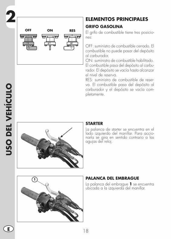
2U
SO D
EL V
EHÍC
ULO
18E
ELEMENTOS PRINCIPALESGRIFO GASOLINAEl grifo de combustible tiene tres posicio-nes:
OFF: suministro de combustible cerrado. El combustible no puede pasar del depósito al carburador.ON: suministro de combustible habilitado. El combustible pasa del depósito al carbu-rador. El depósito se vacía hasta alcanzar el nivel de reserva.RES: suministro de combustible de reser-va. El combustible pasa del depósito al carburador y el depósito se vacía com-pletamente.
STARTERLa palanca de starter se encuentra en el lado izquierdo del manillar. Para accio-narla se gira en sentido contrario a las agujas del reloj.
PALANCA DEL EMBRAGUELa palanca del embrague 1 se encuentra ubicada a la izquierda del manillar.
OFF ON RES
1
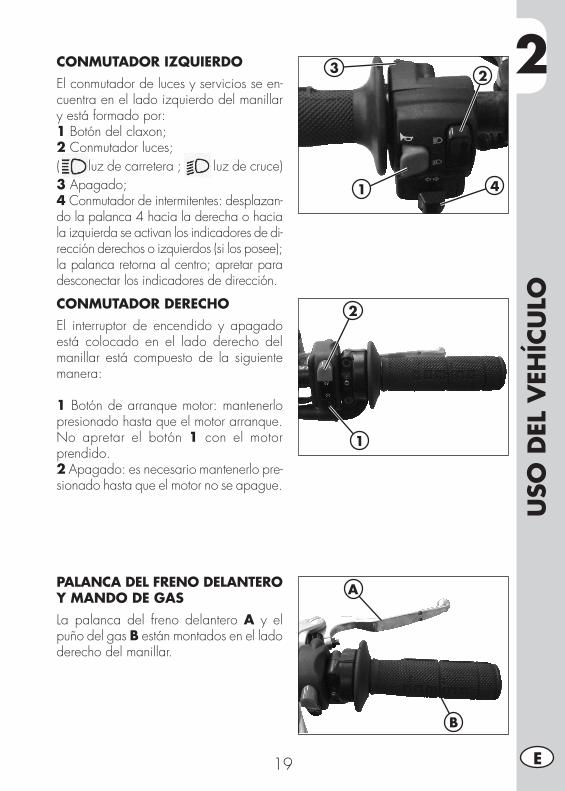
2
USO
DEL
VEH
ÍCU
LO
19 E
CONMUTADOR IZQUIERDOEl conmutador de luces y servicios se en-cuentra en el lado izquierdo del manillar y está formado por:1 Botón del claxon;2 Conmutador luces;( luz de carretera ; luz de cruce)3 Apagado;4 Conmutador de intermitentes: desplazan-do la palanca 4 hacia la derecha o hacia la izquierda se activan los indicadores de di-rección derechos o izquierdos (si los posee); la palanca retorna al centro; apretar para desconectar los indicadores de dirección.
1
23
4
CONMUTADOR DERECHOEl interruptor de encendido y apagado está colocado en el lado derecho del manillar está compuesto de la siguiente manera:
1 Botón de arranque motor: mantenerlo presionado hasta que el motor arranque. No apretar el botón 1 con el motor prendido.2 Apagado: es necesario mantenerlo pre-sionado hasta que el motor no se apague.
PALANCA DEL FRENO DELANTERO Y MANDO DE GASLa palanca del freno delantero A y el puño del gas B están montados en el lado derecho del manillar.
2
1
A
B
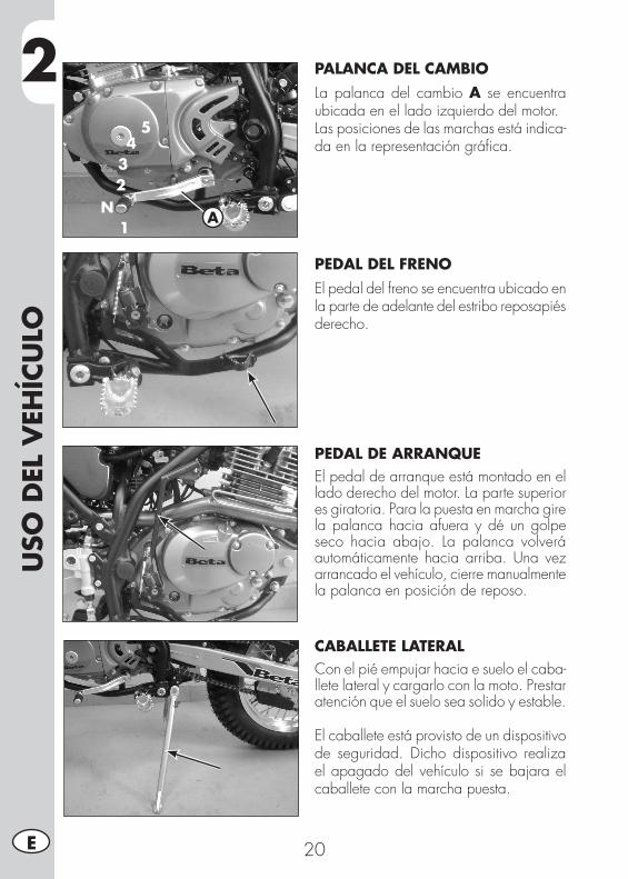
2U
SO D
EL V
EHÍC
ULO
20E
1
234
5
NA
PALANCA DEL CAMBIOLa palanca del cambio A se encuentra ubicada en el lado izquierdo del motor.Las posiciones de las marchas está indica-da en la representación gráfica.
PEDAL DEL FRENOEl pedal del freno se encuentra ubicado en la parte de adelante del estribo reposapiés derecho.
PEDAL DE ARRANQUEEl pedal de arranque está montado en el lado derecho del motor. La parte superior es giratoria. Para la puesta en marcha gire la palanca hacia afuera y dé un golpe seco hacia abajo. La palanca volverá automáticamente hacia arriba. Una vez arrancado el vehículo, cierre manualmente la palanca en posición de reposo.
CABALLETE LATERALCon el pié empujar hacia e suelo el caba-llete lateral y cargarlo con la moto. Prestar atención que el suelo sea solido y estable.
El caballete está provisto de un dispositivo de seguridad. Dicho dispositivo realiza el apagado del vehículo si se bajara el caballete con la marcha puesta.
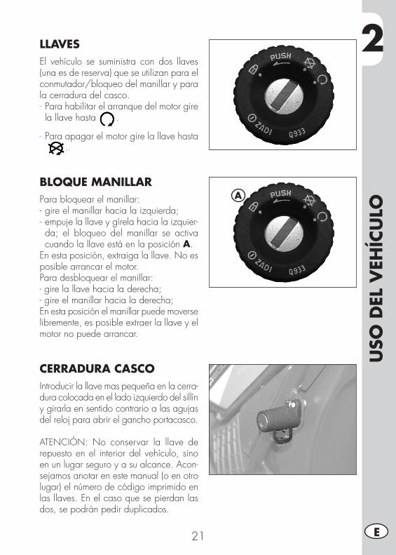
2
USO
DEL
VEH
ÍCU
LO
21 E
LLAVESEl vehículo se suministra con dos llaves (una es de reserva) que se utilizan para el conmutador/bloqueo del manillar y para la cerradura del casco.- Para habilitar el arranque del motor gire la llave hasta .
- Para apagar el motor gire la llave hasta..
BLOQUE MANILLARPara bloquear el manillar:- gire el manillar hacia la izquierda;- empuje la llave y gírela hacia la izquier-da; el bloqueo del manillar se activa cuando la llave está en la posición A.
En esta posición, extraiga la llave. No es posible arrancar el motor.Para desbloquear el manillar:- gire la llave hacia la derecha;- gire el manillar hacia la derecha;En esta posición el manillar puede moverse libremente, es posible extraer la llave y el motor no puede arrancar.
CERRADURA CASCOIntroducir la llave mas pequeña en la cerra-dura colocada en el lado izquierdo del sillín y girarla en sentido contrario a las agujas del reloj para abrir el gancho portacasco.
ATENCIÓN: No conservar la llave de repuesto en el interior del vehículo, sino en un lugar seguro y a su alcance. Acon-sejamos anotar en este manual (o en otro lugar) el número de código imprimido en las llaves. En el caso que se pierdan las dos, se podrán pedir duplicados.
A
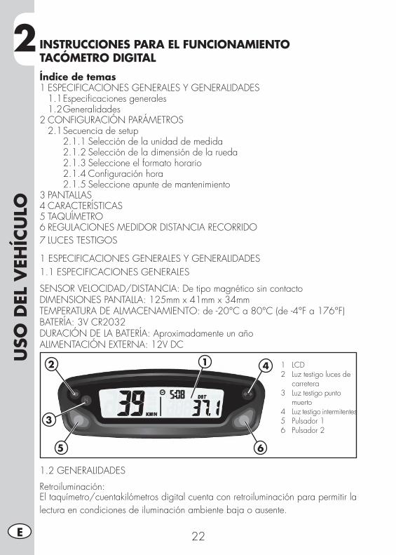
2U
SO D
EL V
EHÍC
ULO
22E
INSTRUCCIONES PARA EL FUNCIONAMIENTO TACÓMETRO DIGITALÍndice de temas1 ESPECIFICACIONES GENERALES Y GENERALIDADES 1.1 Especificaciones generales 1.2 Generalidades2 CONFIGURACIÓN PARÁMETROS 2.1 Secuencia de setup 2.1.1 Selección de la unidad de medida 2.1.2 Selección de la dimensión de la rueda 2.1.3 Seleccione el formato horario 2.1.4 Configuración hora 2.1.5 Seleccione apunte de mantenimiento3 PANTALLAS4 CARACTERÍSTICAS5 TAQUÍMETRO6 REGULACIONES MEDIDOR DISTANCIA RECORRIDO7 LUCES TESTIGOS
1 ESPECIFICACIONES GENERALES Y GENERALIDADES1.1 ESPECIFICACIONES GENERALES
SENSOR VELOCIDAD/DISTANCIA: De tipo magnético sin contactoDIMENSIONES PANTALLA: 125mm x 41mm x 34mmTEMPERATURA DE ALMACENAMIENTO: de -20°C a 80°C (de -4°F a 176°F)BATERÍA: 3V CR2032DURACIÓN DE LA BATERÍA: Aproximadamente un añoALIMENTACIÓN EXTERNA: 12V DC
1.2 GENERALIDADES
Retroiluminación:El taquímetro/cuentakilómetros digital cuenta con retroiluminación para permitir la lectura en condiciones de iluminación ambiente baja o ausente.
12
3
5
4
6
1 LCD 2 Luz testigo luces de carretera 3 Luz testigo punto muerto 4 Luz testigo intermitentes 5 Pulsador 1 6 Pulsador 2
2
USO
DEL
VEH
ÍCU
LO
23 E
Cuando se usa la alimentación eléctrica generada por el motor encendido:•Laretroiluminaciónespermanentecuandoelmotorestáencendido.Si solo usa la batería interna:•SiapareceelsímboloLO,laretroiluminaciónnoseencenderá. El símbolo aparece cuando el voltaje de la batería es inferior a 2,45 V.Botón de Reset:Con el botón Reset, ubicado en la parte posterior del instrumento, se cancelarán todos los datos de recorrido, incluidos la fecha y la hora.Batería interna:El instrumento aloja una batería interna de 3.0V de tipo reloj (CR2032). El instrumento puede funcionar solo con esta batería. Cuando la batería se descarga aparece el símbolo .Para sustituir la batería, desatornille el tapón correspondiente ubicado en la parte posterior del instrumento con una moneda. Luego de sustituir la batería, asegúrese de que el lado positivo esté a la vista.SUSTITUYA LA BATERÍA CON OTRA DE TIPO CR2032
2 CONFIGURACIÓN PARÁMETROS
Generalidades:Configuraciones admitidas:•Km/h(kilómetrosporhora)oM/h(Millasporhora)•Dimensionesrueda(circunferenciaderodamiento)[mm]•Formatohorario:12horas/24horas•Fechaactual•Mantenimiento
PARA ENTRAR EN EL MODO DE CONFIGURACIÓN DE PARÁMETROS MAN-TENGA PRESIONADOS LOS BOTONES DERECHO E IZQUIERDO DURANTE APROXIMADAMENTE 3s.LA PANTALLA MOSTRARÁ EL MENSAJE “Unidad” INTERMITENTE.
La lógica de funcionamiento está estructurada de la siguiente forma:• El instrumento entra en modo SETUP y muestra los parámetros según la secuencia
enumerada con anterioridad.• El instrumento muestra el parámetro que se debe modificar con un mensaje inter-
mitente durante unos segundos.• Si desea modificar el parámetro que se ve en ese momento, debe regular los valores con los
botones derecho o izquierdo (según el modo enumerado a continuación); de lo contrario; es necesario esperar unos minutos (aproximadamente 5 s) para pasar al parámetro siguiente.
• Luego de modificar un parámetro al valor deseado, el instrumento se desplaza de forma automática a la siguiente configuración, no es necesario presionar ningún botón de confirmación.
• Si ingresa en el modo de setup solo para ver las configuraciones realizadas, espere sin presionar ningún botón; el instrumento mostrará todos los parámetros configurados y regresará de forma automática a la condición de “Normal Mode”.
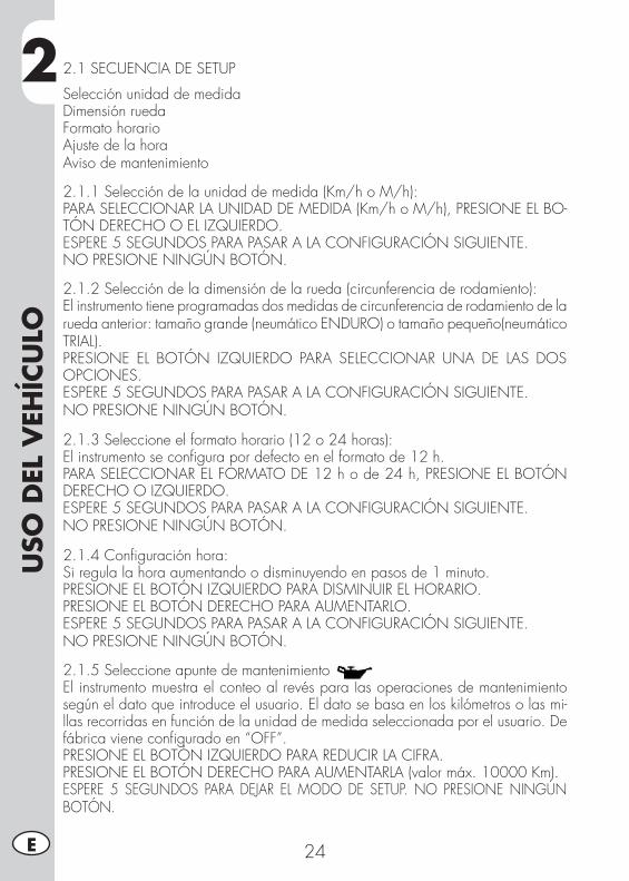
2U
SO D
EL V
EHÍC
ULO
24E
2.1 SECUENCIA DE SETUP
Selección unidad de medidaDimensión ruedaFormato horarioAjuste de la horaAviso de mantenimiento
2.1.1 Selección de la unidad de medida (Km/h o M/h):PARA SELECCIONAR LA UNIDAD DE MEDIDA (Km/h o M/h), PRESIONE EL BO-TÓN DERECHO O EL IZQUIERDO.ESPERE 5 SEGUNDOS PARA PASAR A LA CONFIGURACIÓN SIGUIENTE.NO PRESIONE NINGÚN BOTÓN.
2.1.2 Selección de la dimensión de la rueda (circunferencia de rodamiento):El instrumento tiene programadas dos medidas de circunferencia de rodamiento de la rueda anterior: tamaño grande (neumático ENDURO) o tamaño pequeño(neumático TRIAL).PRESIONE EL BOTÓN IZQUIERDO PARA SELECCIONAR UNA DE LAS DOS OPCIONES.ESPERE 5 SEGUNDOS PARA PASAR A LA CONFIGURACIÓN SIGUIENTE. NO PRESIONE NINGÚN BOTÓN.
2.1.3 Seleccione el formato horario (12 o 24 horas):El instrumento se configura por defecto en el formato de 12 h.PARA SELECCIONAR EL FORMATO DE 12 h o de 24 h, PRESIONE EL BOTÓN DERECHO O IZQUIERDO.ESPERE 5 SEGUNDOS PARA PASAR A LA CONFIGURACIÓN SIGUIENTE. NO PRESIONE NINGÚN BOTÓN.
2.1.4 Configuración hora:Si regula la hora aumentando o disminuyendo en pasos de 1 minuto.PRESIONE EL BOTÓN IZQUIERDO PARA DISMINUIR EL HORARIO.PRESIONE EL BOTÓN DERECHO PARA AUMENTARLO.ESPERE 5 SEGUNDOS PARA PASAR A LA CONFIGURACIÓN SIGUIENTE. NO PRESIONE NINGÚN BOTÓN.
2.1.5 Seleccione apunte de mantenimientoEl instrumento muestra el conteo al revés para las operaciones de mantenimiento según el dato que introduce el usuario. El dato se basa en los kilómetros o las mi-llas recorridas en función de la unidad de medida seleccionada por el usuario. De fábrica viene configurado en “OFF”.PRESIONE EL BOTÓN IZQUIERDO PARA REDUCIR LA CIFRA. PRESIONE EL BOTÓN DERECHO PARA AUMENTARLA (valor máx. 10000 Km). ESPERE 5 SEGUNDOS PARA DEJAR EL MODO DE SETUP. NO PRESIONE NINGÚN BOTÓN.
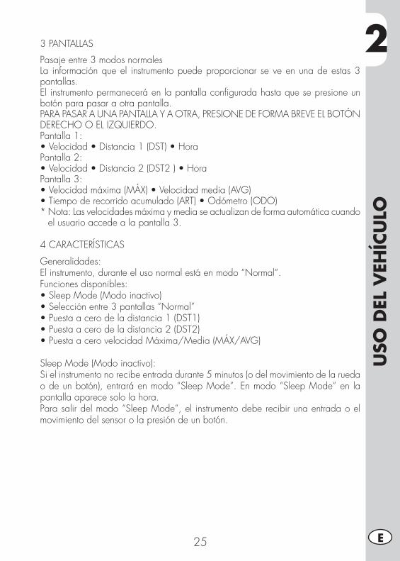
2
USO
DEL
VEH
ÍCU
LO
25 E
3 PANTALLAS
Pasaje entre 3 modos normalesLa información que el instrumento puede proporcionar se ve en una de estas 3 pantallas.El instrumento permanecerá en la pantalla configurada hasta que se presione un botón para pasar a otra pantalla.PARA PASAR A UNA PANTALLA Y A OTRA, PRESIONE DE FORMA BREVE EL BOTÓN DERECHO O EL IZQUIERDO.Pantalla 1:•Velocidad•Distancia1(DST)•HoraPantalla 2:•Velocidad•Distancia2(DST2)•HoraPantalla 3:•Velocidadmáxima(MÁX)•Velocidadmedia(AVG)•Tiempoderecorridoacumulado(ART)•Odómetro(ODO)* Nota: Las velocidades máxima y media se actualizan de forma automática cuando
el usuario accede a la pantalla 3.
4 CARACTERÍSTICAS
Generalidades:El instrumento, durante el uso normal está en modo “Normal”.Funciones disponibles:•SleepMode(Modoinactivo)•Selecciónentre3pantallas“Normal”•Puestaacerodeladistancia1(DST1)•Puestaacerodeladistancia2(DST2)•PuestaacerovelocidadMáxima/Media(MÁX/AVG)
Sleep Mode (Modo inactivo):Si el instrumento no recibe entrada durante 5 minutos (o del movimiento de la rueda o de un botón), entrará en modo “Sleep Mode”. En modo “Sleep Mode” en la pantalla aparece solo la hora.Para salir del modo “Sleep Mode”, el instrumento debe recibir una entrada o el movimiento del sensor o la presión de un botón.
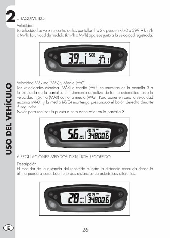
2U
SO D
EL V
EHÍC
ULO
26E
5 TAQUÍMETRO
VelocidadLa velocidad se ve en el centro de las pantallas 1 o 2 y puede ir de 0 a 399,9 km/h o M/h. La unidad de medida (km/h o M/h) aparece junto a la velocidad registrada.
Velocidad Máxima (Máx) y Media (AVG)Las velocidades Máxima (MÁX) o Media (AVG) se muestran en la pantalla 3 a la izquierda de la pantalla. El instrumento actualiza de forma automática tanto la velocidad máxima (MÁX) como la media (AVG). Para poner en cero la velocidad máxima (MÁX) y la media (AVG) mantenga presionado el botón derecho durante 5 segundos.Nota: para realizar la puesta a cero debe estar en la pantalla 3.
6 REGULACIONES MEDIDOR DISTANCIA RECORRIDO
DescripciónEl medidor de la distancia del recorrido muestra la distancia recorrida desde la última puesta a cero. Esto tiene dos distancias características diferentes.
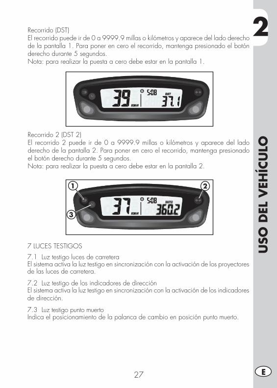
2
USO
DEL
VEH
ÍCU
LO
27 E
Recorrido (DST)El recorrido puede ir de 0 a 9999.9 millas o kilómetros y aparece del lado derecho de la pantalla 1. Para poner en cero el recorrido, mantenga presionado el botón derecho durante 5 segundos.Nota: para realizar la puesta a cero debe estar en la pantalla 1.
Recorrido 2 (DST 2)El recorrido 2 puede ir de 0 a 9999.9 millas o kilómetros y aparece del lado derecho de la pantalla 2. Para poner en cero el recorrido, mantenga presionado el botón derecho durante 5 segundos. Nota: para realizar la puesta a cero debe estar en la pantalla 2.
7 LUCES TESTIGOS
7.1 Luz testigo luces de carreteraEl sistema activa la luz testigo en sincronización con la activación de los proyectores de las luces de carretera.
7.2 Luz testigo de los indicadores de direcciónEl sistema activa la luz testigo en sincronización con la activación de los indicadores de dirección.
7.3 Luz testigo punto muertoIndica el posicionamiento de la palanca de cambio en posición punto muerto.
1
3
2
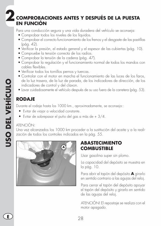
2U
SO D
EL V
EHÍC
ULO
28E
COMPROBACIONES ANTES Y DESPUÉS DE LA PUESTA EN FUNCIÓNPara una conducción segura y una vida duradera del vehículo se aconseja:•Comprobartodoslosnivelesdeloslíquidos.•Comprobarelcorrectofuncionamientodelosfrenosyeldesgastedelaspastillas
(pág. 42).•Verificarlapresión,elestadogeneralyelespesordelascubiertas(pág.10).•Compruebelatensióncorrectadelosradios.•Comprobarlatensióndelacadena(pág.47).•Comprobarlaregulaciónyelfuncionamientonormaldetodoslosmandoscon
cables flexibles.•Verificartodoslostornillospernosytuercas.•Controlarconelmotorenmarchaelfuncionamientodelaslucesdelosfaros,
de la luz trasera, de la luz de parada, de los indicadores de dirección, de los indicadores de control y del claxon.
•Lavar cuidadosamente el vehículo después de su uso fuera de la carretera (pág. 53).
RODAJEDurante el rodaje hasta los 1000 km., aproximadamente, se aconseja:: •Evitar de viajar a velocidad constante. •Evitar de sobrepasar el puño del gas a más de + 3/4.
ATENCIÓN: Una vez alcanzados los 1000 km proceder a la sustitución del aceite y a la reali-zación de todos los controles indicados en la pág. 55.
ABASTECIMIENTO COMBUSTIBLEUsar gasolina super sin plomo.
La capacidad del depósito se muestra en la pág. 10.
Para abrir el tapón del depósito A girarlo en sentido contrario a las agujas del reloj.
Para cerrar el tapón del depósito apoyar el tapón del depósito y girarlo en sentido de las agujas del reloj.
ATENCIÓN! El repostaje se realiza con el motor apagado.
A
2
USO
DEL
VEH
ÍCU
LO
29 E
ARRANQUE MOTORColocar el grifo del depósito de combustible en ON o en RES (ver pág. 18).
- Coloque la llave en la posición (ver pág. 21).
- Controlar que el cambio este en punto muerto (pág. 20).
- Tirar la palanca de embrague (pág. 18).
¡ATENCIÓN!Si no se tira del embrague, el vehículo no arranca.
- Cerrar el caballete (pág. 20).
¡ATENCIÓN!Si no se cierra el caballete cuando se pone la marcha el motor se para.
PEDAL DE ARRANQUE (pág. 18):Actuar sobre la palanca de puesta en marcha, apoyando el pie en la misma y descargar una presión decidida.
¡ATENCIÓN!tras apretar el pedal a fondo, soltarlo inmediatamente después. Esto impide contra-golpes al grupo de arranque y al pie.
BOTÓN DE ARRANQUE MOTOR (pág. 19):mantenerlo presionado hasta que el motor arranque. No apretar el botón con el motor prendido.
ARRANQUE CON MOTOR FRÍO:accionar el estrangulador (pág. 18), arrancar el vehículo, esperar unos minutos, y luego llevar el starter a la posición inicial.
PARADA MOTORPara apagar el motor:- gire la llave hasta (ver pág. 21).- pulse el botón situado en el grupo conmutadores (ver pág. 19).
NOTA: Con el motor parado colocar siempre el grifo del combustible en OFF (pág. 18).
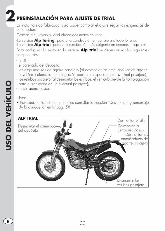
2U
SO D
EL V
EHÍC
ULO
30E
PREINSTALACIÓN PARA AJUSTE DE TRIALLa moto ha sido fabricada para poder cambiar el ajuste según las exigencias de conducción.Gracias a su reversibilidad ofrece dos motos en una:-La versión Alp turing: para una conducción en carretera o todo terreno.-La versión Alp trial: para una conducción más exigente en terrenos irregulares.Para configurar la moto en la versión Alp trial se deben retirar los siguientes componentes:- el sillín,- el carenado del depósito,- las empuñaduras de agarre pasajero (al desmontar las empuñaduras de agarre, el vehículo pierde la homologación para el transporte de un eventual pasajero),
- los estribos pasajero (al desmontar los estribos, el vehículo pierde la homologación para el transporte de un eventual pasajero),
- la cerradura casco.
Notas:•Para desmontar los componentes consultar la sección “Desmontaje y remontaje de la carrocería” en la pág. 58.
Desmontar el sillínDesmontar el carenado del depósito
Desmontar los estribos pasajero
Desmontar la cerradura casco
Desmontar las empuñaduras de agarre pasajero
ALP TRIAL
3
REG
ULA
CIO
NES
31 E
CAP. 3 REGULACIONES
ÍNDICE ARGUMENTOSExplicación de los símbolos ...................................................................32Frenos ................................................................................................32
Freno delantero ...............................................................................32Regulación juego gas .....................................................................32
Ajuste del ralentí .................................................................................33Manillar ..............................................................................................33Regulación Amortiguador .....................................................................33
Regulación precarga del muelle ........................................................33Faro delantero .....................................................................................34
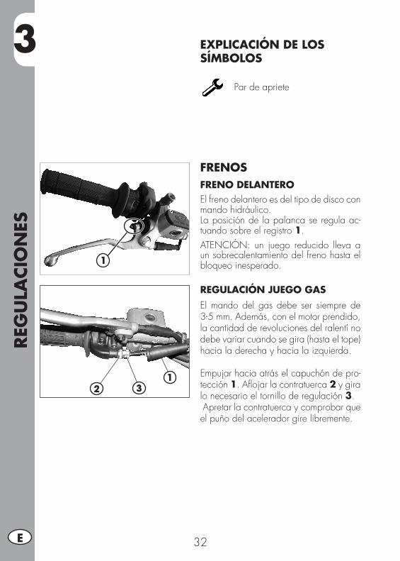
REG
ULA
CIO
NES
32E
3 EXPLICACIÓN DE LOS SÍMBOLOS
Par de apriete
FRENOSFRENO DELANTEROEl freno delantero es del tipo de disco con mando hidráulico.La posición de la palanca se regula ac-tuando sobre el registro 1.ATENCIÓN: un juego reducido lleva a un sobrecalentamiento del freno hasta el bloqueo inesperado.
REGULACIÓN JUEGO GAS El mando del gas debe ser siempre de 3-5 mm. Además, con el motor prendido, la cantidad de revoluciones del ralentí no debe variar cuando se gira (hasta el tope) hacia la derecha y hacia la izquierda.
Empujar hacia atrás el capuchón de pro-tección 1. Aflojar la contratuerca 2 y gira lo necesario el tornillo de regulación 3. Apretar la contratuerca y comprobar que el puño del acelerador gire libremente.
1
21
3
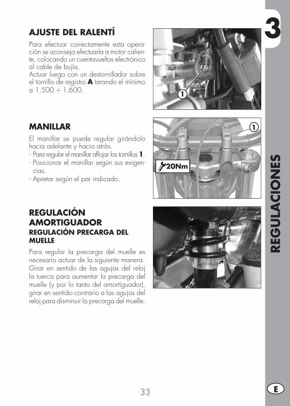
3
REG
ULA
CIO
NES
33 E
1
AJUSTE DEL RALENTÍ Para efectuar correctamente esta opera-ción se aconseja efectuarla a motor calien-te, colocando un cuentavueltas electrónico al cable de bujía. Actuar luego con un destornillador sobre el tornillo de registro A tarando el mínimo a 1.500 ÷ 1.600.
MANILLAREl manillar se puede regular girándolo hacia adelante y hacia atrás.- Para regular el manillar aflojar los tornillos 1.- Posicionar el manillar según sus exigen-cias.
- Apretar según el par indicado.
REGULACIÓN AMORTIGUADORREGULACIÓN PRECARGA DEL MUELLEPara regular la precarga del muelle es necesario actuar de la siguiente manera.Girar en sentido de las agujas del reloj la tuerca para aumentar la precarga del muelle (y por lo tanto del amortiguador), girar en sentido contrario a las agujas del reloj para disminuir la precarga del muelle.
1
20Nm
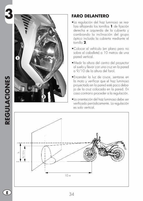
REG
ULA
CIO
NES
34E
3 FARO DELANTERO•Laregulacióndelhazluminososerea-liza aflojando los tornillos 1 de fijación derecha e izquierda de la cubierta y cambiando la inclinación del grupo óptico incluida la cubierta mediante el tornillo 2.
•Colocarelvehículo (enplanoperonosobre el caballete) a 10 metros de una pared vertical.
•Medirlaalturadelcentrodelproyectoral suelo y llevar con una cruz en la pared a 9/10 de la altura del farol.
•Encender la luz de cruce, sentarse enla moto y verificar que el haz luminoso proyectado en la pared esté poco deba-jo de la cruz colocada en la pared. En caso contrario proceder a la regulación.
•Laorientacióndelhazluminosodebeserverificado periódicamente. La regulación es solo vertical.
1
2
9/10
h
10 m
h
4
CON
TRO
LES
Y M
AN
TEN
IMIE
NTO
35 E
CAP. 4 CONTROLES Y MANTENIMIENTO
ÍNDICE ARGUMENTOSAceite motor ........................................................................................36
Control nivel ...................................................................................36Sustitución ......................................................................................36
Tubo recolección humo .........................................................................37Filtro aire ............................................................................................38
Desmontaje y montaje de filtro de aire ...............................................38Limpieza del filtro de aire .................................................................39
Bujía ..................................................................................................40Carburador .........................................................................................40
Vaciado de la cubeta del carburador .................................................40Freno delantero ...................................................................................41
Comprobar el nivel del líquido del freno delantero ..............................41Espurgación freno delantero .............................................................42Pastillas freno delantero ...................................................................42
Freno trasero .......................................................................................43Comprobar el nivel del líquido del freno Trasero .................................43Llenado líquido del freno trasero .......................................................43Expurgación freno trasero ................................................................43Pastillas freno trasero .......................................................................44
Mando embrague ................................................................................44Control del juego dirección ...................................................................45Neumáticos .........................................................................................46Aceite horquilla ...................................................................................46Cadena ..............................................................................................47
Comprobación y regulación tensión cadena .......................................47Faro delantero .....................................................................................48
Sustitución bombillas del faro delantero .............................................48Indicador de dirección ..........................................................................49Grupo óptico trasero ............................................................................49Sustitución lámpara alumbrado matrícula ................................................49Batería ................................................................................................49
Desmontaje.....................................................................................50Inactividad .....................................................................................51Carga de la batería .........................................................................51Fusible ...........................................................................................52
Limpieza del vehículo ...........................................................................53Larga inactividad del vehículo ...............................................................54Mantenimiento programado .................................................................55
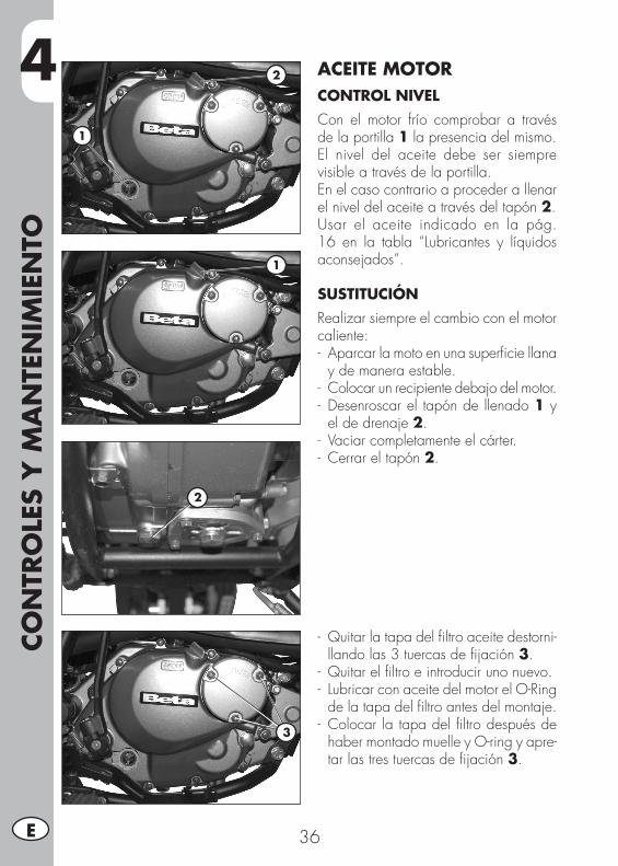
4CO
NTR
OLE
S Y
MA
NTE
NIM
IEN
TO
36E
ACEITE MOTORCONTROL NIVELCon el motor frío comprobar a través de la portilla 1 la presencia del mismo.El nivel del aceite debe ser siempre visible a través de la portilla.En el caso contrario a proceder a llenar el nivel del aceite a través del tapón 2.Usar el aceite indicado en la pág. 16 en la tabla “Lubricantes y líquidos aconsejados”.
SUSTITUCIÓNRealizar siempre el cambio con el motor caliente:- Aparcar la moto en una superficie llana
y de manera estable.- Colocar un recipiente debajo del motor.- Desenroscar el tapón de llenado 1 y
el de drenaje 2.- Vaciar completamente el cárter.- Cerrar el tapón 2.
- Quitar la tapa del filtro aceite destorni-llando las 3 tuercas de fijación 3.
- Quitar el filtro e introducir uno nuevo.- Lubricar con aceite del motor el O-Ring
de la tapa del filtro antes del montaje.- Colocar la tapa del filtro después de
haber montado muelle y O-ring y apre-tar las tres tuercas de fijación 3.
2
1
2
1
3
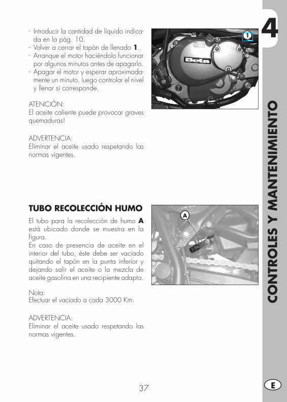
4
CON
TRO
LES
Y M
AN
TEN
IMIE
NTO
37 E
- Introducir la cantidad de líquido indica-da en la pág. 10.
- Volver a cerrar el tapón de llenado 1.- Arranque el motor haciéndolo funcionar
por algunos minutos antes de apagarlo.- Apagar el motor y esperar aproximada-
mente un minuto, luego controlar el nivel y llenar si corresponde.
ATENCIÓN:El aceite caliente puede provocar graves quemaduras!
ADVERTENCIA:Eliminar el aceite usado respetando las normas vigentes.
TUBO RECOLECCIÓN HUMOEl tubo para la recolección de humo A está ubicado donde se muestra en la figura.En caso de presencia de aceite en el interior del tubo, éste debe ser vaciado quitando el tapón en la punta inferior y dejando salir el aceite o la mezcla de aceite gasolina en una recipiente adapto.
Nota:Efectuar el vaciado a cada 3000 Km.
ADVERTENCIA:Eliminar el aceite usado respetando las normas vigentes.
1
A
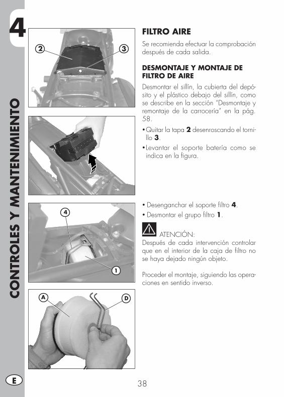
4CO
NTR
OLE
S Y
MA
NTE
NIM
IEN
TO
38E
FILTRO AIRESe recomienda efectuar la comprobación después de cada salida.
DESMONTAJE Y MONTAJE DE FILTRO DE AIREDesmontar el sillín, la cubierta del depó-sito y el plástico debajo del sillín, como se describe en la sección “Desmontaje y remontaje de la carrocería” en la pág. 58.• Quitar la tapa 2 desenroscando el torni-llo 3.
• Levantar el soporte batería como se indica en la figura.
• Desenganchar el soporte filtro 4.• Desmontar el grupo filtro 1.
ATENCIÓN:Después de cada intervención controlar que en el interior de la caja de filtro no se haya dejado ningún objeto.
Proceder el montaje, siguiendo las opera-ciones en sentido inverso.
4
1
2 3
DA
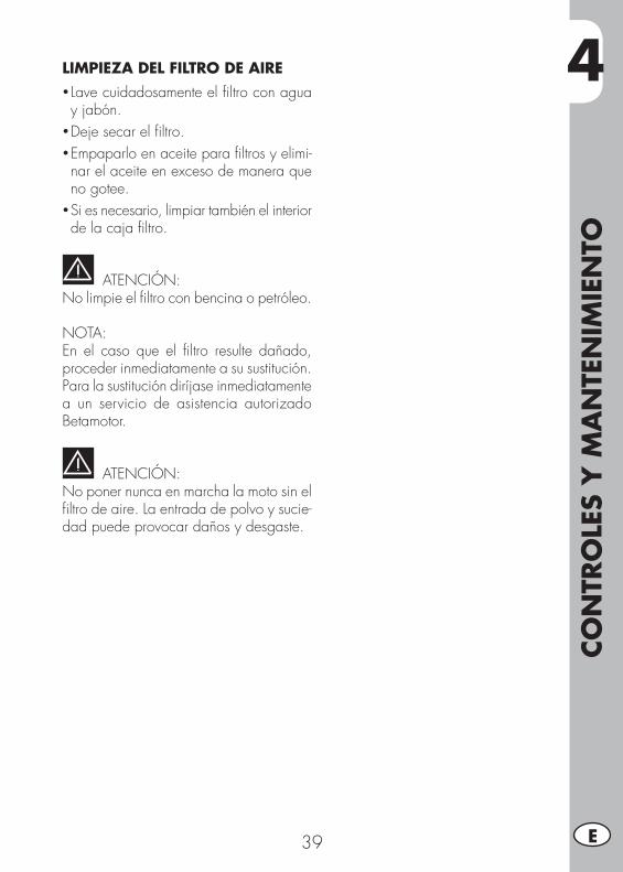
4
CON
TRO
LES
Y M
AN
TEN
IMIE
NTO
39 E
LIMPIEZA DEL FILTRO DE AIRE• Lave cuidadosamente el filtro con agua y jabón.
• Deje secar el filtro.• Empaparlo en aceite para filtros y elimi-nar el aceite en exceso de manera que no gotee.
• Si es necesario, limpiar también el interior de la caja filtro.
ATENCIÓN:No limpie el filtro con bencina o petróleo.
NOTA:En el caso que el filtro resulte dañado, proceder inmediatamente a su sustitución.Para la sustitución diríjase inmediatamente a un servicio de asistencia autorizado Betamotor.
ATENCIÓN:No poner nunca en marcha la moto sin el filtro de aire. La entrada de polvo y sucie-dad puede provocar daños y desgaste.
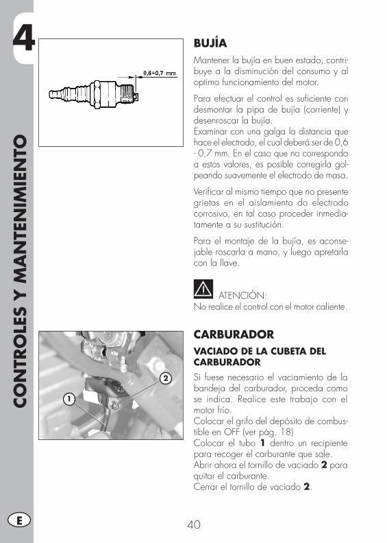
4CO
NTR
OLE
S Y
MA
NTE
NIM
IEN
TO
40E
BUJÍAMantener la bujía en buen estado, contri-buye a la disminución del consumo y al optimo funcionamiento del motor.
Para efectuar el control es suficiente con desmontar la pipa de bujía (corriente) y desenroscar la bujía.Examinar con una galga la distancia que hace el electrodo, el cual deberá ser de 0,6 - 0,7 mm. En el caso que no corresponda a estos valores, es posible corregirla gol-peando suavemente el electrodo de masa.
Verificar al mismo tiempo que no presente grietas en el aislamiento do electrodo corrosivo, en tal caso proceder inmedia-tamente a su sustitución.
Para el montaje de la bujía, es aconse-jable roscarla a mano, y luego apretarla con la llave.
ATENCIÓN:No realice el control con el motor caliente.
CARBURADORVACIADO DE LA CUBETA DEL CARBURADORSi fuese necesario el vaciamiento de la bandeja del carburador, proceda como se indica. Realice este trabajo con el motor frío.Colocar el grifo del depósito de combus-tible en OFF (ver pág. 18)Colocar el tubo 1 dentro un recipiente para recoger el carburante que sale.Abrir ahora el tornillo de vaciado 2 para quitar el carburante.Cerrar el tornillo de vaciado 2.
2
1
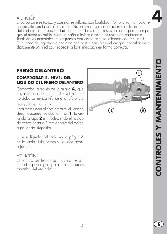
4
CON
TRO
LES
Y M
AN
TEN
IMIE
NTO
41 E
ATENCIÓN:El carburante es tóxico y además se inflama con facilidad. Por lo tanto manipular el carburante con la debida cautela. No realizar nunca operaciones en la instalación del carburante en proximidad de llamas libres o fuentes de calor. Esperar siempre que el motor se enfríe. Con un paño eliminar eventuales restos de carburante.También los materiales impregnados con carburante se inflaman con facilidad.En el caso de ingestión o contacto con partes sensibles del cuerpo, consultar inme-diatamente un médico. Proceder a la eliminación en forma correcta.
FRENO DELANTEROCOMPROBAR EL NIVEL DEL LÍQUIDO DEL FRENO DELANTEROComprobar a través de la mirilla A, que haya líquido de frenos. El nivel mínimo no debe ser nunca inferior a la referencia realizada en la mirilla.Para restablecer el nivel efectuar el llenado desenroscando los dos tornillos 1, levan-tando la tapa 2 e introduciendo el líquido de frenos hasta a 5 mm debajo del borde superior del deposito.
Usar el líquido indicado en la pág. 16 en la tabla “Lubricantes y líquidos acon-sejados”.
ATENCIÓN:El líquido de frenos es muy corrosivo, impedir que caigan gotas en las partes pintadas del vehículo.
2
1
A
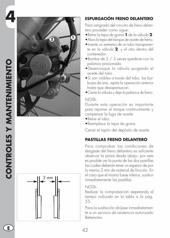
4CO
NTR
OLE
S Y
MA
NTE
NIM
IEN
TO
42E
ESPURGACIÓN FRENO DELANTEROPara sangrado del circuito de freno delan-tero proceder como sigue:•Retirelatapadegoma1 de la válvula 2.•Abra la tapa del tanque de aceite de freno.•Inserteunextremodeuntubotransparen-te en la válvula 2, y el otro dentro del contenedor.•Bombade2/3vecesquede-seconlapalanca presionada.•Desenrosque la válvula purgando elaceite del tubo.•Sisonvisiblesatravésdeltubo,lasbur-bujas de aire, repita la operación anterior hasta que desaparezcan.•Cierre la válvula y deje la palanca de freno.
NOTA: Durante esta operación es importante para reponer el tanque continuamente y compensar la fuga de aceite.•Retireeltubo.•Reemplacelatapadegoma.Cerrar el tapón del depósito de aceite.
PASTILLAS FRENO DELANTEROPara comprobar las condiciones de desgaste del freno delantero es suficiente observar la pinza desde abajo, por este es posible ver la punta de las dos pastillas las cuales deberán tener un espesor de por lo menos 2 mm de material de fricción. En el caso que el mismo fuese inferior, sustituir inmediatamente las pastillas.
NOTA:Realizar la comprobación respetando el tiempo indicado en la tabla a la pág. 55.Para la sustitución diríjase inmediatamen-te a un servicio de asistencia autorizadoBetamotor.
2 mm
12
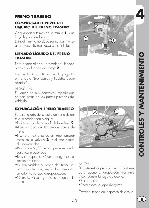
4
CON
TRO
LES
Y M
AN
TEN
IMIE
NTO
43 E
FRENO TRASEROCOMPROBAR EL NIVEL DEL LÍQUIDO DEL FRENO TRASEROComprobar a través de la mirilla 1, que haya líquido de frenos. El nivel mínimo no debe ser nunca inferior a la referencia realizada en la mirilla.
LLENADO LÍQUIDO DEL FRENO TRASEROPara añadir al nivel, proceder al llenadoa través del tapón de carga 2.
Usar el líquido indicado en la pág. 16 en la tabla “Lubricantes y líquidos acon-sejados”.
ATENCIÓN:El líquido es muy corrosivo, impedir que caigan gotas en las partes pintadas del vehículo.
EXPURGACIÓN FRENO TRASEROPara sangrado del circuito de freno delan-tero proceder como sigue:•Retirelatapadegoma1 de la válvula 2.•Abra la tapadel tanquedeaceitedefreno.•Inserteunextremodeun tubo transpa-rente en la válvula 2, y el otro dentro del contenedor.•Bombade2/3vecesquede-seconlapalanca presionada.•Desenrosque la válvula purgando elaceite del tubo.•Si son visibles a través del tubo, lasburbujas de aire, repita la operación anterior hasta que desaparezcan.•Cierrelaválvulaydejelapalancadefreno.
NOTA: Durante esta operación es importante para reponer el tanque continuamente y compensar la fuga de aceite.•Retireeltubo.•Reemplacelatapadegoma.
Cerrar el tapón del depósito de aceite.
21
12
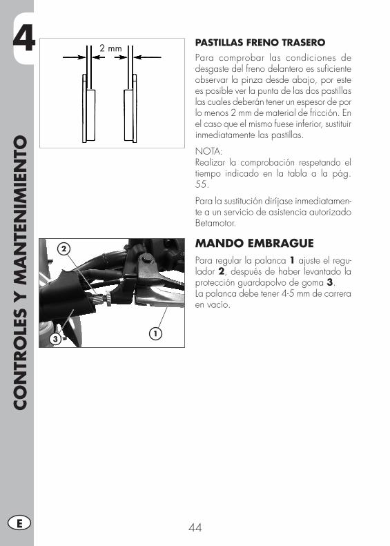
4CO
NTR
OLE
S Y
MA
NTE
NIM
IEN
TO
44E
PASTILLAS FRENO TRASEROPara comprobar las condiciones de desgaste del freno delantero es suficiente observar la pinza desde abajo, por este es posible ver la punta de las dos pastillas las cuales deberán tener un espesor de por lo menos 2 mm de material de fricción. En el caso que el mismo fuese inferior, sustituir inmediatamente las pastillas.
NOTA:Realizar la comprobación respetando el tiempo indicado en la tabla a la pág. 55.
Para la sustitución diríjase inmediatamen-te a un servicio de asistencia autorizado Betamotor.
MANDO EMBRAGUEPara regular la palanca 1 ajuste el regu-lador 2, después de haber levantado la protección guardapolvo de goma 3.La palanca debe tener 4-5 mm de carrera en vacío.
2 mm
1
2
3
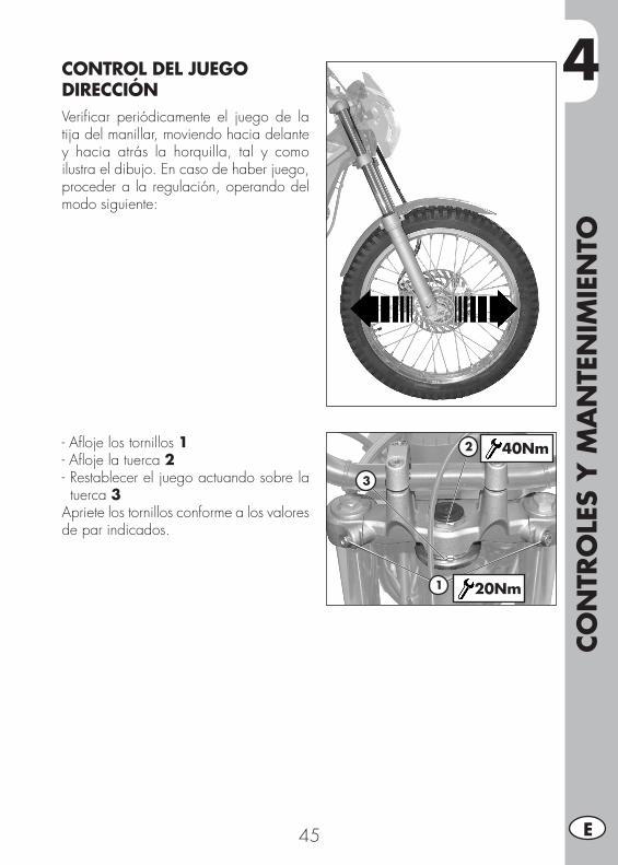
4
CON
TRO
LES
Y M
AN
TEN
IMIE
NTO
45 E
CONTROL DEL JUEGO DIRECCIÓNVerificar periódicamente el juego de la tija del manillar, moviendo hacia delante y hacia atrás la horquilla, tal y como ilustra el dibujo. En caso de haber juego, proceder a la regulación, operando del modo siguiente:
- Afloje los tornillos 1- Afloje la tuerca 2- Restablecer el juego actuando sobre la tuerca 3
Apriete los tornillos conforme a los valores de par indicados.
1
2
3
40Nm
20Nm
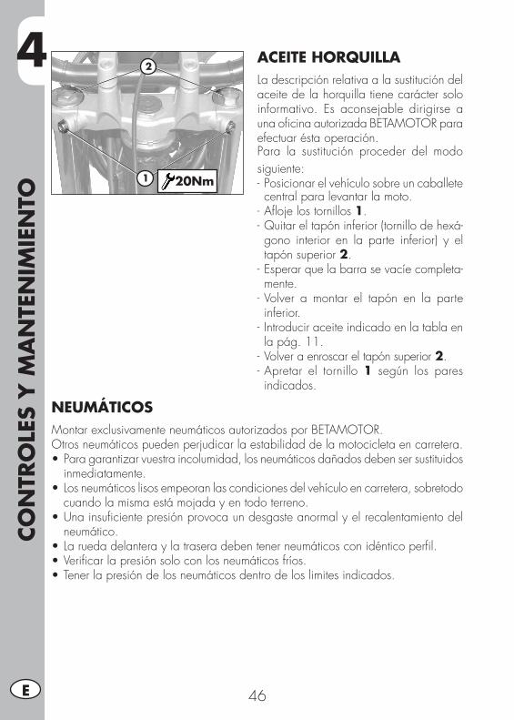
4CO
NTR
OLE
S Y
MA
NTE
NIM
IEN
TO
46E
ACEITE HORQUILLALa descripción relativa a la sustitución del aceite de la horquilla tiene carácter solo informativo. Es aconsejable dirigirse a una oficina autorizada BETAMOTOR para efectuar ésta operación.Para la sustitución proceder del modo siguiente:- Posicionar el vehículo sobre un caballete central para levantar la moto.
- Afloje los tornillos 1.- Quitar el tapón inferior (tornillo de hexá-gono interior en la parte inferior) y el tapón superior 2.
- Esperar que la barra se vacíe completa-mente.
- Volver a montar el tapón en la parte inferior.
- Introducir aceite indicado en la tabla en la pág. 11.
- Volver a enroscar el tapón superior 2.- Apretar el tornillo 1 según los pares indicados.
1
2
20Nm
NEUMÁTICOSMontar exclusivamente neumáticos autorizados por BETAMOTOR.Otros neumáticos pueden perjudicar la estabilidad de la motocicleta en carretera.•Paragarantizarvuestraincolumidad,losneumáticosdañadosdebensersustituidos
inmediatamente.•Losneumáticoslisosempeoranlascondicionesdelvehículoencarretera,sobretodo
cuando la misma está mojada y en todo terreno.•Unainsuficientepresiónprovocaundesgasteanormalyelrecalentamientodel
neumático.•Laruedadelanteraylatraseradebentenerneumáticosconidénticoperfil.•Verificarlapresiónsoloconlosneumáticosfríos.•Tenerlapresióndelosneumáticosdentrodeloslimitesindicados.
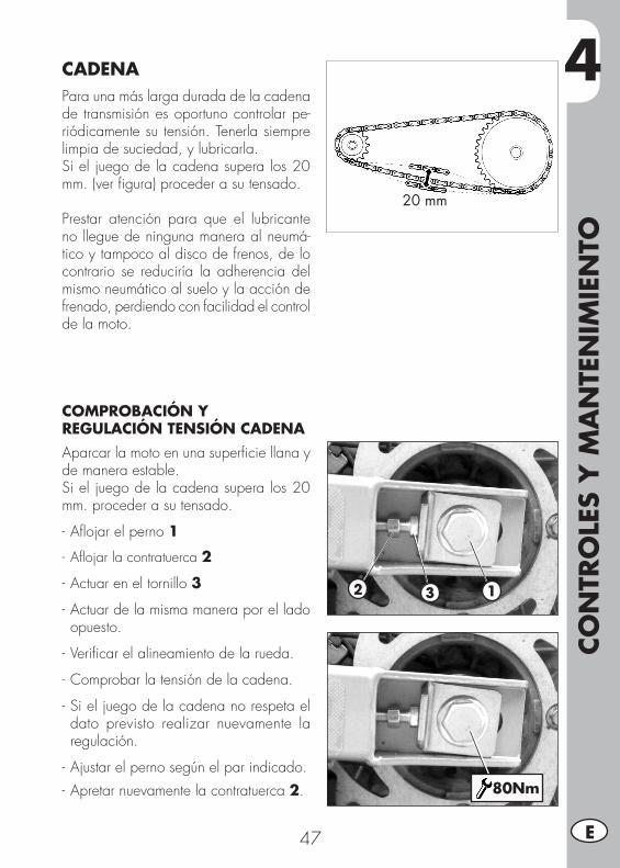
4
CON
TRO
LES
Y M
AN
TEN
IMIE
NTO
47 E
CADENAPara una más larga durada de la cadena de transmisión es oportuno controlar pe-riódicamente su tensión. Tenerla siempre limpia de suciedad, y lubricarla.Si el juego de la cadena supera los 20 mm. (ver figura) proceder a su tensado.
Prestar atención para que el lubricante no llegue de ninguna manera al neumá-tico y tampoco al disco de frenos, de lo contrario se reduciría la adherencia del mismo neumático al suelo y la acción de frenado, perdiendo con facilidad el control de la moto.
COMPROBACIÓN Y REGULACIÓN TENSIÓN CADENAAparcar la moto en una superficie llana y de manera estable.Si el juego de la cadena supera los 20 mm. proceder a su tensado.
- Aflojar el perno 1
- Aflojar la contratuerca 2
- Actuar en el tornillo 3
- Actuar de la misma manera por el lado opuesto.
- Verificar el alineamiento de la rueda.
- Comprobar la tensión de la cadena.
- Si el juego de la cadena no respeta el dato previsto realizar nuevamente la regulación.
- Ajustar el perno según el par indicado.- Apretar nuevamente la contratuerca 2.
20 mm
2 3 1
80Nm
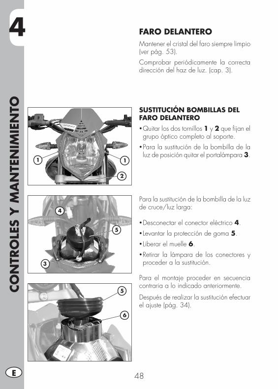
4CO
NTR
OLE
S Y
MA
NTE
NIM
IEN
TO
48E
FARO DELANTEROMantener el cristal del faro siempre limpio (ver pág. 53).Comprobar periódicamente la correcta dirección del haz de luz. (cap. 3).
SUSTITUCIÓN BOMBILLAS DEL FARO DELANTERO• Quitar los dos tornillos 1 y 2 que fijan el grupo óptico completo al soporte.
• Para la sustitución de la bombilla de la luz de posición quitar el portalámpara 3.
Para la sustitución de la bombilla de la luz de cruce/luz larga:
• Desconectar el conector eléctrico 4.• Levantar la protección de goma 5.• Liberar el muelle 6.• Retirar la lámpara de los conectores y proceder a la sustitución.
Para el montaje proceder en secuencia contraria a lo indicado anteriormente.
Después de realizar la sustitución efectuar el ajuste (pág. 34).
11
3
2
4
5
5
6
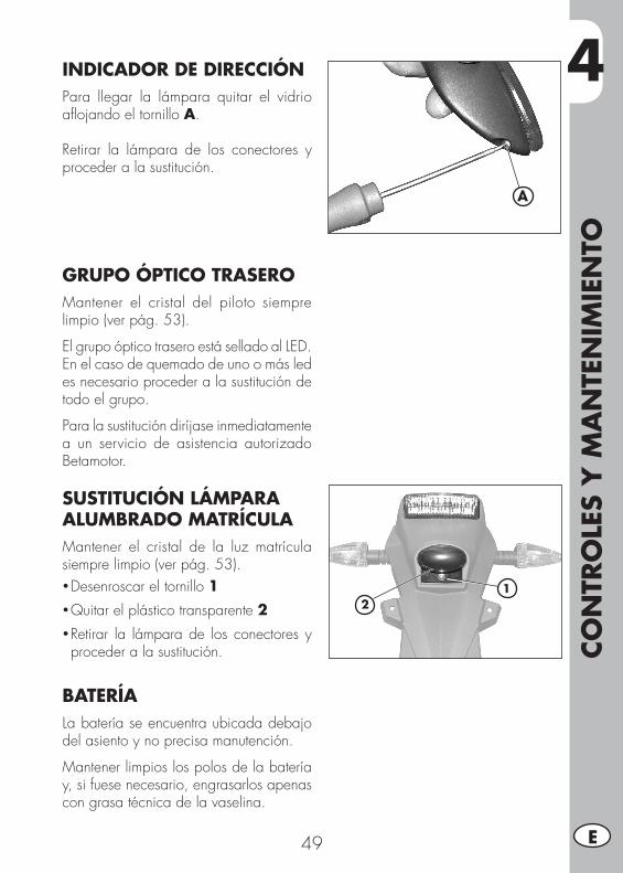
4
CON
TRO
LES
Y M
AN
TEN
IMIE
NTO
49 E
A
INDICADOR DE DIRECCIÓNPara llegar la lámpara quitar el vidrio aflojando el tornillo A.
Retirar la lámpara de los conectores y proceder a la sustitución.
GRUPO ÓPTICO TRASEROMantener el cristal del piloto siempre limpio (ver pág. 53).
El grupo óptico trasero está sellado al LED. En el caso de quemado de uno o más led es necesario proceder a la sustitución de todo el grupo.
Para la sustitución diríjase inmediatamente a un servicio de asistencia autorizado Betamotor.
SUSTITUCIÓN LÁMPARA ALUMBRADO MATRÍCULAMantener el cristal de la luz matrícula siempre limpio (ver pág. 53).• Desenroscar el tornillo 1• Quitar el plástico transparente 2• Retirar la lámpara de los conectores y proceder a la sustitución.
BATERÍALa batería se encuentra ubicada debajo del asiento y no precisa manutención.
Mantener limpios los polos de la batería y, si fuese necesario, engrasarlos apenas con grasa técnica de la vaselina.
12
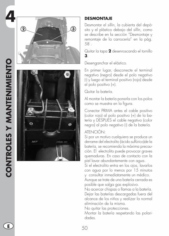
4CO
NTR
OLE
S Y
MA
NTE
NIM
IEN
TO
50E
DESMONTAJEDesmontar el sillín, la cubierta del depó-sito y el plástico debajo del sillín, como se describe en la sección “Desmontaje y remontaje de la carrocería” en la pág. 58 .
Quitar la tapa 2 desenroscando el tornillo 3.
Desenganchar el elástico.
En primer lugar, desconecte el terminal negativo (negro) desde el polo negativo (-) y luego el terminal positivo (rojo) desde el polo positivo (+).
Quitar la batería.
Al montar la batería ponerla con los polos como se muestra en la figura.
Conectar PRIMA antes el cable positivo (color rojo) al polo positivo (+) de la ba-tería y DESPUES el cable negativo (color negro) al polo negativo (-) de la batería.
ATENCIÓN:Si por un motivo cualquiera se produce un derrame del electrolito (ácido sulfúrico)de la batería, se recomienda la máxima precau-ción. El electrolito puede provocar graves quemaduras. En caso de contacto con la piel lavar abundantemente con agua.Si el electrolito entra en los ojos, lavarlos con agua por lo menos por 15 minutos y consultar inmediatamente un médico.Aunque se trate de una batería cerrada es posible que salga gas explosivo.No acercar chispas o llamas a la batería.Dejar las baterías descargadas fuera del alcance de los niños y realizar la normal eliminación de la misma.No quitar las protecciones.Montar la batería respetando las polari-dades.
2 3

4
CON
TRO
LES
Y M
AN
TEN
IMIE
NTO
51 E
INACTIVIDADEn caso de larga inactividad del vehículo, quitar la batería y cargarla, con un carga-dor de baterías adecuado, cada 15 días o con sistema de mantenimiento de carga.La batería debe ser guardada en un am-biente seco, a temperatura entre 5- 35°C y fuera del alcance de los niños.
CARGA DE LA BATERÍALas operaciones de carga de la batería y la operación de recarga o mantenimiento de la batería pueden realizarse quitando la batería del vehículo o conectando el negativo (-) a una masa segura del vehí-culo y el positivo (+) al conectar específico visible en la figura.La verificación debe ser realizada con el conjunto de claves en la posición
Comprobar con el tester y con el circuito abierto (después de 10-12 horas de la activación) que la tensión sea superior a los 12,6 V, si es inferior aconsejamos realizar la recarga.
Recargar la batería siguiendo, de acuerdo al aparato que tenemos disponible, uno de los dos procedimientos indicados a continuación:• tensión constante de 14,4÷15 Voltios por ~12 horas, luego comprobar la tensión después de 10÷12 horas de acabada la recarga, como indicado arriba.
• corriente constante: cargar la batería a 0,5/0,8 A hasta que la tensión entre los polos se estabilice a ~14,5 V.
ATENCIÓN:Batería hermética, para cargarla no quitar la tapa que cierra herméticamente la ba-tería y tampoco añadir líquido.
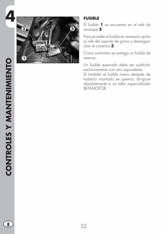
4CO
NTR
OLE
S Y
MA
NTE
NIM
IEN
TO
52E
FUSIBLEEl fusible 1 se encuentra en el relé de arranque 2.
Para acceder al fusible es necesario quitar el relé del soporte de goma y desengan-char el conector 3.
Como suministro se entrega un fusible de reserva.
Un fusible quemado debe ser sustituido exclusivamente con otro equivalente.Si también el fusible nuevo después de haberlo montado se quema, dirigirse absolutamente a un taller especializado BETAMOTOR.
2 3
1
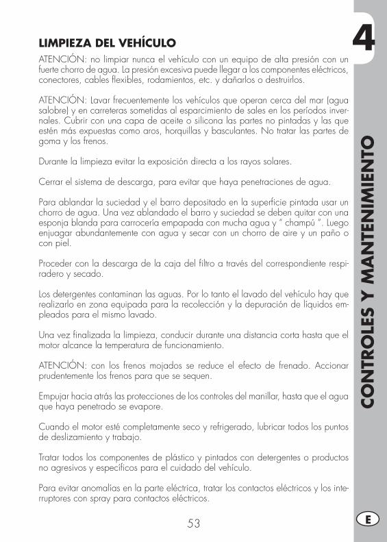
4
CON
TRO
LES
Y M
AN
TEN
IMIE
NTO
53 E
LIMPIEZA DEL VEHÍCULOATENCIÓN: no limpiar nunca el vehículo con un equipo de alta presión con un fuerte chorro de agua. La presión excesiva puede llegar a los componentes eléctricos, conectores, cables flexibles, rodamientos, etc. y dañarlos o destruirlos.
ATENCIÓN: Lavar frecuentemente los vehículos que operan cerca del mar (agua salobre) y en carreteras sometidas al esparcimiento de sales en los períodos inver-nales. Cubrir con una capa de aceite o silicona las partes no pintadas y las que estén más expuestas como aros, horquillas y basculantes. No tratar las partes de goma y los frenos.
Durante la limpieza evitar la exposición directa a los rayos solares.
Cerrar el sistema de descarga, para evitar que haya penetraciones de agua.
Para ablandar la suciedad y el barro depositado en la superficie pintada usar un chorro de agua. Una vez ablandado el barro y suciedad se deben quitar con una esponja blanda para carrocería empapada con mucha agua y “ champú “. Luego enjuagar abundantemente con agua y secar con un chorro de aire y un paño o con piel.
Proceder con la descarga de la caja del filtro a través del correspondiente respi-radero y secado.
Los detergentes contaminan las aguas. Por lo tanto el lavado del vehículo hay que realizarlo en zona equipada para la recolección y la depuración de líquidos em-pleados para el mismo lavado.
Una vez finalizada la limpieza, conducir durante una distancia corta hasta que el motor alcance la temperatura de funcionamiento.
ATENCIÓN: con los frenos mojados se reduce el efecto de frenado. Accionar prudentemente los frenos para que se sequen.
Empujar hacia atrás las protecciones de los controles del manillar, hasta que el agua que haya penetrado se evapore.
Cuando el motor esté completamente seco y refrigerado, lubricar todos los puntos de deslizamiento y trabajo.
Tratar todos los componentes de plástico y pintados con detergentes o productos no agresivos y específicos para el cuidado del vehículo.
Para evitar anomalías en la parte eléctrica, tratar los contactos eléctricos y los inte-rruptores con spray para contactos eléctricos.
4CO
NTR
OLE
S Y
MA
NTE
NIM
IEN
TO
54E
LARGA INACTIVIDAD DEL VEHÍCULOEn previsión de una larga inactividad del vehículo, por ejemplo durante el invier-no, es necesario adoptar algunas simples precauciones para garantizar un buen mantenimiento:• Efectuar una completa limpieza del vehículo en todas sus partes.• Reducir la presión de los neumáticos de un 30 % teniéndolos posiblemente no apoyados a la tierra.
• Quitar la bujía e introducir por el agujero algunas gotas de aceite para motor. Hacer gira el motor por algunas vueltas, accionando la palanca arranque a pedal (donde prevista) . Volver a enroscar la bujía.
• Cubrir con un película de aceite o silicona en aerosol las partes sin pintar, menos las partes de goma y los frenos.
• Mantener cargada la batería.• Tapar el vehículo con un telón para protegerlo del polvo.• Descargue la bandeja carburador como se describe en la pág. 40.
DESPUÉS DE UN LARGO PERIODO DE INACTIVIDAD
• Restablecer la presión de los neumáticos.• Verificar el apriete de todos los tornillos de levada importancia mecánica.• Efectuar el primer arranque con el sistema de pedal (“kick starter“) (donde previsto).
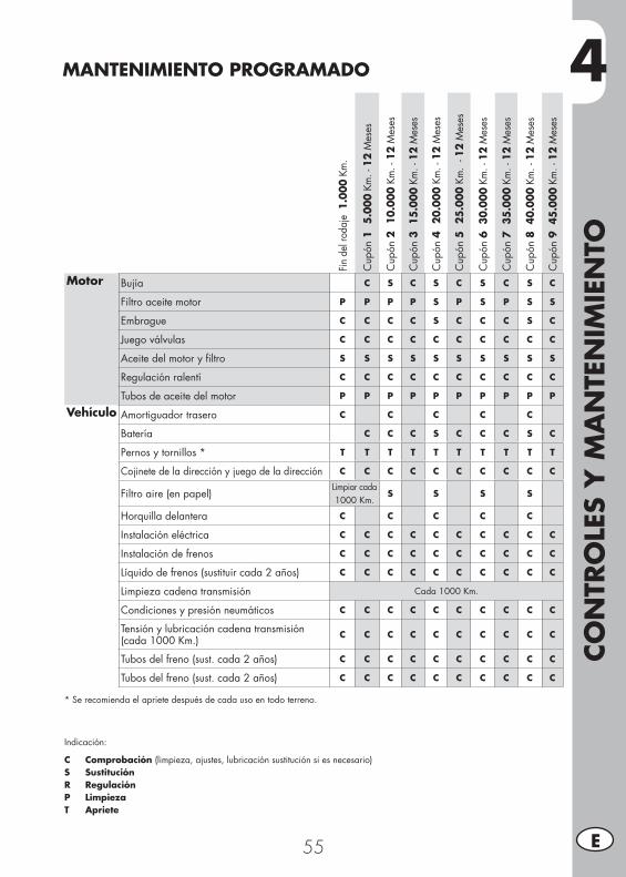
4
CON
TRO
LES
Y M
AN
TEN
IMIE
NTO
55 E
MANTENIMIENTO PROGRAMADO
Fin d
el ro
daje
1.0
00 K
m.
Cup
ón 1
5.
000
Km. -
12
Mes
es
Cup
ón 2
10
.000
Km
. - 1
2 M
eses
Cup
ón 3
15.
000
Km. -
12
Mes
es
Cup
ón 4
20
.000
Km
. - 1
2 M
eses
Cup
ón 5
25
.000
Km
. - 1
2 M
eses
Cup
ón 6
30.
000
Km. -
12
Mes
es
Cup
ón 7
35.
000
Km. -
12
Mes
es
Cup
ón 8
40.
000
Km. -
12
Mes
es
Cup
ón 9
45.
000
Km. -
12
Mes
es
Motor Bujía C S C S C S C S C
Filtro aceite motor P P P P S P S P S S
Embrague C C C C S C C C S C
Juego válvulas C C C C C C C C C C
Aceite del motor y filtro S S S S S S S S S S
Regulación ralentí C C C C C C C C C C
Tubos de aceite del motor P P P P P P P P P P
Vehículo Amortiguador trasero C C C C C
Batería C C C S C C C S C
Pernos y tornillos * T T T T T T T T T T
Cojinete de la dirección y juego de la dirección C C C C C C C C C C
Filtro aire (en papel)Limpiar cada 1000 Km.
S S S S
Horquilla delantera C C C C C
Instalación eléctrica C C C C C C C C C C
Instalación de frenos C C C C C C C C C C
Líquido de frenos (sustituir cada 2 años) C C C C C C C C C C
Limpieza cadena transmisión Cada 1000 Km.
Condiciones y presión neumáticos C C C C C C C C C C
Tensión y lubricación cadena transmisión(cada 1000 Km.) C C C C C C C C C C
Tubos del freno (sust. cada 2 años) C C C C C C C C C C
Tubos del freno (sust. cada 2 años) C C C C C C C C C C
* Se recomienda el apriete después de cada uso en todo terreno.
Indicación:
C Comprobación (limpieza, ajustes, lubricación sustitución si es necesario)S SustituciónR RegulaciónP LimpiezaT Apriete

56
5
DES
MO
NTA
JE Y
REM
ON
TAJE
DE
LA C
ARRO
CERÍA
57 E
CAP. 5 DESMONTAJE Y REMONTAJE DE LA CARROCERÍA
ÍNDICE ARGUMENTOSDesmontaje y remontaje del sillín ...........................................................58Desmontaje y remontaje carenado del depósito .......................................58Desmontaje y remontaje empuñaduras de agarre pasajero .......................58Desmontaje y remontaje del plástico debajo del sillín ........................................ 59
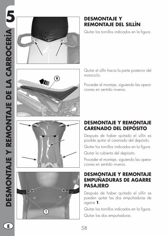
5D
ESM
ON
TAJE
Y R
EMO
NTA
JE D
E LA
CA
RRO
CERÍA
58E
DESMONTAJE Y REMONTAJE DEL SILLÍNQuitar los tornillos indicados en la figura.
Quitar el sillín hacia la parte posterior del motociclo.
Proceder el montaje, siguiendo las opera-ciones en sentido inverso.
DESMONTAJE Y REMONTAJE CARENADO DEL DEPÓSITODespués de haber quitado el sillín es posible quitar el carenado del depósito.Quitar los tornillos indicados en la figura.Quitar la cubierta del depósito.Proceder el montaje, siguiendo las opera-ciones en sentido inverso.
DESMONTAJE Y REMONTAJE EMPUÑADURAS DE AGARRE PASAJERODespués de haber quitado el sillín se pueden quitar las dos empuñaduras de agarre 1.Quitar los tornillos indicados en la figura.Quitar las dos empuñaduras.
B
1
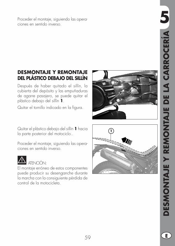
5
DES
MO
NTA
JE Y
REM
ON
TAJE
DE
LA C
ARRO
CERÍA
59 E
1
DESMONTAJE Y REMONTAJE DEL PLÁSTICO DEBAJO DEL SILLÍNDespués de haber quitado el sillín, la cubierta del depósito y las empuñaduras de agarre pasajero, se puede quitar el plástico debajo del sillín 1.Quitar el tornillo indicado en la figura.
Quitar el plástico debajo del sillín 1 hacia la parte posterior del motociclo..
Proceder el montaje, siguiendo las opera-ciones en sentido inverso.
ATENCIÓN:El montaje erróneo de estos componentes puede producir su desenganche durante la marcha con la consiguiente pérdida de control de la motocicleta.
Proceder el montaje, siguiendo las opera-ciones en sentido inverso.

60
6
QU
E H
ACE
R E
N C
ASO
DE
EMER
GEN
CIA
61 E
CAP. 6 QUE HACER EN CASO DE EMERGENCIA
ÍNDICE ARGUMENTOSBúsqueda de la avería ..........................................................................62Índice alfabético ..................................................................................63
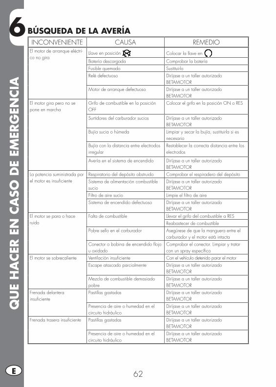
6Q
UE
HA
CER E
N C
ASO
DE
EMER
GEN
CIA
62E
INCONVENIENTE CAUSA REMEDIOEl motor de arranque eléctri-co no gira
Llave en posición Colocar la llave en
Batería descargada Comprobar la bateríaFusible quemado SustituirloRelé defectuoso Diríjase a un taller autorizado
BETAMOTORMotor de arranque defectuoso Diríjase a un taller autorizado
BETAMOTOR El motor gira pero no se pone en marcha
Grifo de combustible en la posición OFF
Colocar el grifo en la posición ON o RES
Surtidores del carburador sucios Diríjase a un taller autorizadoBETAMOTOR
Bujía sucia o húmeda Limpiar y secar la bujía, sustituirla si es necesario
Bujía con la distancia entre electrodos irregular
Restablecer la correcta distancia entre los electrodos
Avería en el sistema de encendido Diríjase a un taller autorizadoBETAMOTOR
La potencia suministrada por el motor es insuficiente
Respiratorio del depósito obstruido Comprobar el respiradero del depósitoSistema de alimentación combustible sucio
Diríjase a un taller autorizadoBETAMOTOR
Filtro de aire sucio Limpie el filtro de aireSistema de encendido defectuoso Diríjase a un taller autorizado
BETAMOTOREl motor se para o hace ruido
Falta de combustible Llevar el grifo del combustible a RESReabastecer de combustible
Pobre sello en el carburador Asegúrese de que la manguera entre el carburador y el motor está intacta
Conector o bobina de encendido flojo u oxidado
Comprobar el conector. Limpiar y tratar con un spray específico
El motor se sobrecaliente Ventilación insuficiente Con el vehículo detenido parar el motorEscape atascado parcialmente Diríjase a un taller autorizado
BETAMOTORMezcla de combustible demasiado pobre
Diríjase a un taller autorizadoBETAMOTOR
Frenada delanterainsuficiente
Pastillas gastadas Diríjase a un taller autorizadoBETAMOTOR
Presencia de aire o humedad en el circuito hidráulico
Diríjase a un taller autorizadoBETAMOTOR
Frenada trasera insuficiente Pastillas gastadas Diríjase a un taller autorizadoBETAMOTOR
Presencia de aire o humedad en el circuito hidráulico
Diríjase a un taller autorizadoBETAMOTOR
BÚSQUEDA DE LA AVERÍA
ÍND
ICE
ALF
ABÉT
ICO
63 E
ÍNDICE ALFABÉTICOAbastecimiento combustible ..................................................................28Aceite horquilla ...................................................................................46Aceite motor ........................................................................................36Advertencias sobre el uso del vehículo......................................................5Ajuste del ralentí .................................................................................33Arranque motor ...................................................................................29
Batería ................................................................................................49Bloque manillar ....................................................................................21Bujía ..................................................................................................40Búsqueda de la avería ..........................................................................62
Cadena ..............................................................................................47Carburador .........................................................................................40Cerradura casco ..................................................................................21Comprobaciones antes y después de la puesta en función ........................28Conducción ecológica ............................................................................5Conducción segura ................................................................................6Conocimiento del vehículo ......................................................................9Control del juego dirección ...................................................................45
Datos identificación vehículo ...................................................................8Datos técnicos .....................................................................................10Desmontaje y remontaje carenado del depósito .......................................58Desmontaje y remontaje del plástico debajo del sillín ...................................................... 59Desmontaje y remontaje del sillín ...........................................................58Desmontaje y remontaje empuñaduras de agarre pasajero .......................58
Elementos principales ...........................................................................18Explicación de los símbolos ...................................................................32
Faro delantero .....................................................................................34Faro delantero .....................................................................................48Filtro aire ............................................................................................38Freno delantero ...................................................................................41Frenos ................................................................................................32Freno trasero .......................................................................................43
ÍND
ICE
ALF
ABÉT
ICO
64E
Grupo óptico trasero ............................................................................49
Indicador de dirección ..........................................................................49Instrucciones para el funcionamiento tacómetro digital .............................22
Larga inactividad del vehículo ...............................................................54Limpieza del vehículo ...........................................................................53Llaves .................................................................................................21Lubricantes y líquidos aconsejados .........................................................16
Mando embrague ................................................................................44Manillar ..............................................................................................33Mantenimiento programado .................................................................55Motor .................................................................................................12
Neumáticos .........................................................................................46
Parada motor ......................................................................................29Preinstalación para ajuste de TRIAL ........................................................30Regulación Amortiguador .....................................................................33Rodaje ................................................................................................28
Sistema eléctrico ..................................................................................14Sustitución lámpara alumbrado matrícula ................................................49
Tubo recolección humo .........................................................................37