GB STRUMENTI ELETTRONICI DI MISURA E CONTROLLO
56
STRUMENTI ELETTRONICI DI MISURA E CONTROLLO ELECTRONIC MEASURE AND CONTROL INSTRUMENTS ELEKTRONISCHE MESS- UND KONTROLLGERÄTE GB D
Transcript of GB STRUMENTI ELETTRONICI DI MISURA E CONTROLLO

STRUMENTI ELETTRONICI DI MISURA E CONTROLLOELECTRONIC MEASURE AND CONTROL INSTRUMENTSELEKTRONISCHE MESS- UND KONTROLLGERÄTE
GB
D
2

3
INDICATORI DI POSIZIONE ELETTRONICI - ELECTRONIC POSITION INDICATORS - ELEKTRONISCHEPOSITIONSANZEIGEN
EP20-EP25
EP.RS.MAN
EP25L
SERVO.D
SERVO.M
P3.S
SIMPLEX-E F20R-F18R
F20-F18/EN20M-EFB
P2X-P1X-P3X
V3P-V4P
V3V-V3I-V4V-V4I
F3X-F1X-F2X-A3X
CG4-G1X
pag. 6
pag. 8
pag. 10
pag. 12
pag. 14
pag. 16
pag. 18-21
pag. 22-25
pag. 26-31
pag. 32-35
pag. 36-39
pag. 42-49
pag. 50-53
Index
UNITA ̓DI POSIZIONAMENTO - POSITIONING UNITS - POSITIONSEINHEIT
SISTEMI A BANDA MAGNETICA - MAGNETIC DEVICES - MAGNETSYSTEME
SISTEMI CON TRASDUTTORI MAGNETICI - MAGNETIC TRANSDUCER DEVICES -MAGNETGEBER SYSTEME
POSIZIONATORI - POSITIONING DEVICES - POSITIONSEINHEITEN
VISUALIZZATORI - DISPLAY MESSANZEIGE
INGRESSO CON POTENZIOMETRO, TENSIONE E CORRENTE - POTENTIOMETER, VOLTAGE, CURRENT INPUT - MIT POTENTIOMETER, SPANNUNGS-, STROM EINGANG
QUOTE, CONTAIMPULSI - DIMENSION DISPLAY, PULSES COUNTER - MESSWERTANZEIGE, IMPULSZÄHLER
TACHIMETRI DIGITALI - DIGITAL TACHOMETERS - DIGITALE TACHOMETER
VIR-VIS.SP pag. 54
VISUALIZZATORI PER IRRIGATORI - DIPSLAY FOR IRRIGATORS - MESSANZEIGE FÜR BEWÄSSERUNGSSYSTEME
INGRESSO DA POTENZIOMETRO - POTENTIOMETER INPUT MIT POTENTIOMETEREINGANG
EP7 pag. 4
VE6 pag. 40-41
INGRESSO IN TENSIONE, CORRENTE - VOLTAGE, CURRENT INPUT - MITSPANNUNGS-, STROM EINGANG

4
EP7
INDICATORE DI POSIZIONE ELETTRONICO AD ALBERO PASSANTE, ALIMENTAZIONE A BATTERIA
ELECTRONIC HOLLOW SHAFT POSITION INDICATOR, BATTERY SUPPLIED
ELEKTRONISCHE POSITIONSANZEIGE MIT DURCHGEHENDER HOHLWELLE, BATTERIESPANNUNG
L’indicatore di posizione elettronico EP7, alimentato con batteria interna, integra nello stesso contenitore il trasduttore di posizione e l’unitàdi visualizzazione costituendo un dispositivo utilizzato per la misura di spostamenti lineari o angolari compatto, facile da montare, applicabile a svariate tipologie di macchine industriali (packaging, lavorazione del legno, alluminio, lamiera ecc.).Il display ha cinque cifre più segno (scala di lettura -99999 +99999) con cifre di altezza 7,5 mm che consentono un’ottima leggibilità anche a distanza.Con tre tasti sul frontale è possibile programmare il valore da visualizzare sul display per ogni giro di albero cavo, la direzione di conteggio, ilnumero di cifre decimali da visualizzare ed attivare le funzioni di reset/preset della quota, quota assoluta/relativa e conversione mm/pollici e scaladi lettura in gradi. Sono inoltre disponibili 3 origini distinte per la correzione della quota quando si utilizzano utensili diversi e la funzione di offset perla compensazione dellʼusura utensile. Sul display sono visualizzate con appositi simboli tutte le funzioni abilitate.L’elettronica é alloggiata in un elegante e robusto contenitore in materiale plastico antiurto autoestinguente. L’albero di comando è in acciaio inox. L’alimentazione è interna a batteria con pila in formato ½ AA da 3,6V della durata di circa 4 anni. L’indicazione di batteria appare quando è necessaria la sostituzione della batteria, tale sostituzione viene effettuata con facilità senza perdita della quota e dei parametri di configurazione, incondizione di albero fermo.
The EP7 electronic indicator, which is supplied with an internal battery and includes in the same case the position sensor and the display unit,measures linear or angular movements: it is compact, easy to install, and applicable to many types of industrial machinery (packaging, woodworking,aluminium, coil etc). The display has 5 digits and sign with range from -99999 to 99999 and the 7,5mm-high-digits allow excellent readability also from a distance.With the 3 front buttons it is possible to program the value shown on the display for every turn of the hollow shaft and activate the following functions:reference reset/preset, absolute/relative reference, mm/inches conversion and display in degrees. There are also 3 distinct origins for the correction of the reference when using different tools and the offset function for the compensation of tool wear. On the display all activated functionsare shown by a symbol.The electronic section is protected inside an elegant and robust case made of self-extinguishing and shock-proof plastic material.The drive shaft is made of stainless steel.The power supply is internal with a ½ AA 3,6V battery which has a four-year-life. The low battery level icon is shown when it is necessary to replacethe battery, which is very easy and the reference is maintained when the shaft remains stationary.
Die Elektronische Positionsanzeige EP7 Positionsgeber und Anzeigedisplay integriert in einem Gehäuse, ist eine praktische Einrichthilfe zurMessung und Einstellung von Weg- und Winkelverstellungen im Maschinenbau. Die kompakte Bauform und einfache Montage direkt auf die Verstellwelle ermöglicht zahlreiche Anwendungsmöglichkeiten im gesamten Maschinenbau.Das Display hat Ziffern mit Vorzeichen und Ablesebereich von -99999 bis 99999. 7,5mm Ziffernhöhe bieten eine sehr gute Ablesbarkeit, auch bei größeren Entfernungen. Über 3 Funktionstasten ist es möglich, ohne externe Hilfsmittel, sämtliche Geräteparameter einfach und verständlich zu programmieren, wie Reset/Preset,Ist- und Sollwert, Inch/mm Anzeige, Winkelanzeige, außerdem 3 Nullpunkte für Maßkorrektur und Offset. Alle aktivierten Funktionen sind auf dem Displaymit Symbolen angezeigt. Die Elektronik ist in ein elegantes und stabiles Kunststoffgehäuse eingebaut. Die Antriebswelle ist in Nirosta. Der Batteriewechsel 1x½ AA 3,6V (4 Jahre Lebensdauer) ist auch im eingebauten Zustand schnell und bequem realisiert, während die Welle steht, bleibt der Wertgespeichert. Die Entladung der Batterie wird mit Blinken angezeigt, wenn Austausch nötig ist.

5
CARATTERISTICHE TECNICHE EP7-TECHNICAL FEATURES EP7-
TECHNISCHE MERKMALE EP7-
48
24
66
36
6,5
30
6Ø
40
3,5
Ø20
Ø26
N°3
M4 A
120°
6
25°
36,5
Dimensioni d’ingombro - Dimensions - Abmessungen
Alimentazione - Power supply - Spannung batteria formato ½ AA, tensione 3,6Volts (litio-cloruro di tionile)battery ½ AA 3,6V (Lithium-thionyl chloride)
Durata batteria - Battery life - Batterielebensdauer 4 anni di funzionamento continuo - 4 years of continuous use - 4 Jahre DauerbetriebPeso - Weight - Gewicht 110 grDiametro albero cavo - Hollow shaft - Hohwellendurchmesser 14mm - 20mmMas. velocità di rotazione - Max. revolution speed - Max Drehzahl 400 RPM in continuo - in continuous - in Dauerbetrieb
1000 RPM per brevi periodi - for a short time - für kurze ZeitRisoluzione - Accuracy - Auflösung 4000 impulsi/giro - impulses/revolution - Impulse/UmdrehungScala di lettura - Range - Anzeigebereich -99999; 99999Display LCD altezza cifre 7,5 mm., LCD height 7,5 mm, LCD 7,5mm ZiffernhöheTastiera - Keyboard - Tastatur 3 tasti per programmazione ed attivazione funzioni - 3 buttons for programming
and functions - 3 FunktionstastenFunzioni disponibili - Available functions - Lieferbare Funktionen Reset/preset, quota assoluta/incrementale, conversione mm/pollici, visualizzazione
in gradi, 3 origini distinte per cambio utensile. Reset/preset, absolute/incremental measurement, mm/inch conversion, visualisation in degrees, 3 distinct origins for tool changing.Reset/preset, absolute/inkrementale Quote, Konversion mm/Inch, Anzeige in Grad, 3 verschiedene Nullpunkte für Masskorrektur.
Temperatura di impiego - Working temperature - Betriebstemperatur 0-50°C Umidità relativa - Relative humidity - Relative Feuchtigkeit 35-85% Protezione - Protection degree - Gehäuse Schutzart IP54Compatibilità elettromagnetica - Electromagnetic compatibility 2004/108/ECElektromagnetische Kompatibilität
Colore della scatola - Case colour - Gehäusefarbe
G = Nero - Black - Schwarz; R = Arancione - Orange - Orange
Posizione di montaggio - Assembly position - Einbaulage
A Vista inclinata a 25° - View inclined 25° - Schräg Ansicht 25° *B Vista inclinata a 25° - View inclined 25° - Schräg Ansicht 25°
Tipo - Type - Typ EP7
Sigla di ordinazione - Order code - BestellmusterEP7
B
Ø 40
48
66
Ø 6
48
18 18
25
19,5
60
24
42
66
15
51
24
42
66
9
15
51
Vano batteriaBattery compartmentBatteriefach
Incasso EmbeddingFreiraumØ40x3,5
Display inclinato 25°Inclined display 25°Schräg Display 25°
Albero cavo inoxStainless steel hollow shaftNirosta Hohlwelle
Tast
ierin
o di
sel
ezio
neK
aypa
d K
aypa
d
Display altezza cifre 7,5mmDigit height 7,5mmZiffernhöhe 7,5mm
Flangia Blocco con maniglia - Block flange with handle - Klemmflansche mit Hebel
Flangia Distanziale - Spacer flange - Flansch-Adapter
A
Vista - View - Ansicht*
Foro dell’albero - Shaft diameter - Bohrung
F14 - Diametro albero cavo - Hollow shaft - Hohwellendurchmesser: 14 mm
F20 - Diametro albero cavo - Hollow shaft - Hohwellendurchmesser: 20 mm
F20
OPZIONALE - OPTIONAL
Flangia di blocco - Fixing flange - BefestigungsflanscheFL-B
FL-B
Distanziale - Spacer flange - Flansch - AdapterFL
FLA R
6
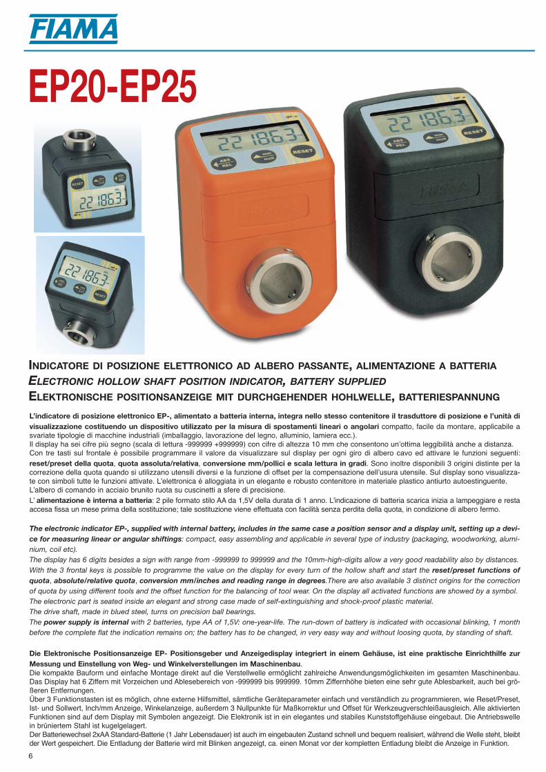
INDICATORE DI POSIZIONE ELETTRONICO AD ALBERO PASSANTE, ALIMENTAZIONE A BATTERIA
ELECTRONIC HOLLOW SHAFT POSITION INDICATOR, BATTERY SUPPLIED
ELEKTRONISCHE POSITIONSANZEIGE MIT DURCHGEHENDER HOHLWELLE, BATTERIESPANNUNG
EP20-EP25
L’indicatore di posizione elettronico EP-, alimentato a batteria interna, integra nello stesso contenitore il trasduttore di posizione e l’unità divisualizzazione costituendo un dispositivo utilizzato per la misura di spostamenti lineari o angolari compatto, facile da montare, applicabile asvariate tipologie di macchine industriali (imballaggio, lavorazione del legno, alluminio, lamiera ecc.). Il display ha sei cifre più segno (scala di lettura -999999 +999999) con cifre di altezza 10 mm che consentono unʼottima leggibilità anche a distanza.Con tre tasti sul frontale è possibile programmare il valore da visualizzare sul display per ogni giro di albero cavo ed attivare le funzioni seguenti:reset/preset della quota, quota assoluta/relativa, conversione mm/pollici e scala lettura in gradi. Sono inoltre disponibili 3 origini distinte per lacorrezione della quota quando si utilizzano utensili diversi e la funzione di offset per la compensazione dellʼusura utensile. Sul display sono visualizza-te con simboli tutte le funzioni attivate. Lʼelettronica é alloggiata in un elegante e robusto contenitore in materiale plastico antiurto autoestinguente.Lʼalbero di comando in acciaio brunito ruota su cuscinetti a sfere di precisione. L ̓alimentazione è interna a batteria: 2 pile formato stilo AA da 1,5V della durata di 1 anno. Lʼindicazione di batteria scarica inizia a lampeggiare e restaaccesa fissa un mese prima della sostituzione; tale sostituzione viene effettuata con facilità senza perdita della quota, in condizione di albero fermo.
The electronic indicator EP-, supplied with internal battery, includes in the same case a position sensor and a display unit, setting up a devi-ce for measuring linear or angular shiftings: compact, easy assembling and applicable in several type of industry (packaging, woodworking, alumi-nium, coil etc). The display has 6 digits besides a sign with range from -999999 to 999999 and the 10mm-high-digits allow a very good readability also by distances.With the 3 frontal keys is possible to programme the value on the display for every turn of the hollow shaft and start the reset/preset functions ofquota, absolute/relative quota, conversion mm/inches and reading range in degrees.There are also available 3 distinct origins for the correctionof quota by using different tools and the offset function for the balancing of tool wear. On the display all activated functions are showed by a symbol.The electronic part is seated inside an elegant and strong case made of self-extinguishing and shock-proof plastic material. The drive shaft, made in blued steel, turns on precision ball bearings.The power supply is internal with 2 batteries, type AA of 1,5V: one-year-life. The run-down of battery is indicated with occasional blinking, 1 monthbefore the complete flat the indication remains on; the battery has to be changed, in very easy way and without loosing quota, by standing of shaft.
Die Elektronische Positionsanzeige EP- Positionsgeber und Anzeigedisplay integriert in einem Gehäuse, ist eine praktische Einrichthilfe zurMessung und Einstellung von Weg- und Winkelverstellungen im Maschinenbau. Die kompakte Bauform und einfache Montage direkt auf die Verstellwelle ermöglicht zahlreiche Anwendungsmöglichkeiten im gesamten Maschinenbau.Das Display hat 6 Ziffern mit Vorzeichen und Ablesebereich von -999999 bis 999999. 10mm Ziffernhöhe bieten eine sehr gute Ablesbarkeit, auch bei grö-ßeren Entfernungen. Über 3 Funktionstasten ist es möglich, ohne externe Hilfsmittel, sämtliche Geräteparameter einfach und verständlich zu programmieren, wie Reset/Preset,Ist- und Sollwert, Inch/mm Anzeige, Winkelanzeige, außerdem 3 Nullpunkte für Maßkorrektur und Offset für Werkzeugverschleißausgleich. Alle aktiviertenFunktionen sind auf dem Display mit Symbolen angezeigt. Die Elektronik ist in ein elegantes und stabiles Kunststoffgehäuse eingebaut. Die Antriebswellein brüniertem Stahl ist kugelgelagert. Der Batteriewechsel 2xAA Standard-Batterie (1 Jahr Lebensdauer) ist auch im eingebauten Zustand schnell und bequem realisiert, während die Welle steht, bleibtder Wert gespeichert. Die Entladung der Batterie wird mit Blinken angezeigt, ca. einen Monat vor der kompletten Entladung bleibt die Anzeige in Funktion.

7
CARATTERISTICHE TECNICHE EP-TECHNICAL FEATURES EP-
TECHNISCHE MERKMALE EP-
OP_e
ABS
REL
mm
inchRESET
97
3265
64
56,5
9,5
47
24 24
M4 x 10
6
Ø 2
5 H
7Ø
20
H7
Ø 3
5Ø
30
M5
°
Ø
I 30
Ø 4
06
I 40
14
6
18
2
Dimensioni d’ingombro - Dimensions - Abmessungen
Alimentazione - Power supply - Versorgung 2 batterie stilo 1,5V - 2 batteries 1,5 V - 2 Batterien 1,5 V Diametro albero cavo - Hollow shaft - Hohwellendurchmesser EP20: 20 mm H7 - EP25: 25 mm H7Mas. velocità di rotazione - Max. revolution speed - Max Drehzahl 1000 RPMRisoluzione - Accuracy - Auflösung 4000 impulsi/giro - impulses/revolution - Impulse/UmdrehungScala di lettura - Range - Anzeigebereich -999999 +999999Display LCD altezza cifre 10 mm., LCD height 10 mm, LCD 10mm ZiffernhöheTastiera - Keyboard - Tastatur 3 tasti per programmazione ed attivazione funzioni - 3 keys for programming
and start of functions - 3 FunktionstastenFunzioni disponibili - Available functions - Lieferbare Funktionen Reset/preset, quota assoluta/incrementale, conversione mm/pollici, visualizzazione
in gradi, 3 origini distinte per cambio utensile, compensazione usura utensile. Reset/preset, absolute/incremental quota, conversion mm/inch, visualisation in degrees, 3 distinct origin for tool changing, balancing of tool wearReset/preset, absolute/inkrementale Quote, Konversion mm/Inch, Anzeige in Grad, 3 verschiedene Nullpunkte für Masskorrektur, Werkzeugverschleiß Ausgleichung
Temperatura di impiego - Working temperature - Betriebstemperatur 0-50°C Umidità relativa - Relative humidity - Relative Feuchtigkeit 30-90% Protezione - Protection degree - Gehäuse Schutzart IP54Compatibilità elettromagnetica - Electromagnetic compatibility 2004/108/ECElektromagnetische Kompatibilität
Posizioni di montaggio Assembling position Einbaulage
VISTA - VIEW - ANSICHT A B
Colore della scatola - Box colour - Gehäusefarbe
G Nero - Black - Schwarz
R Arancione - Orange - Orange
Posizione di montaggio - Assembling position - Einbaulage
A Albero di comando orizzontale - Horizontal shaft - Waagerechte Welle
B Albero di comando verticale - Vertical shaft - Senkrechte Welle
Tipo - Type - Typ
EP20- Diametro albero cavo - Hollow shaft - Hohwellendurchmesser: 20 mm H7
EP25- Diametro albero cavo - Hollow shaft - Hohwellendurchmesser: 25 mm H
Sigla di ordinazione - Order outline - Bestellmuster
Esempi di applicazioniApplication examplesAnwendungsbeispiele
Unità di spostamentoAdjustment unit
Verstelleinheit
Piolino di fermo ø6: I40 (I30)Lock pin ø6: I40 (I30)Drehmomentstütze ø6: I40 (I30)
Albero cavo foro ø20 o ø25ø20 or ø25 hollow shaftHohlwelle ø20 oder ø25
Guarnizione antipolvereDust sealStaubschutzdichtung
Tavola rotanteRotating table - Drehtafel
Vano batteriaBattery compartmentBatteriefach
EP20 A R
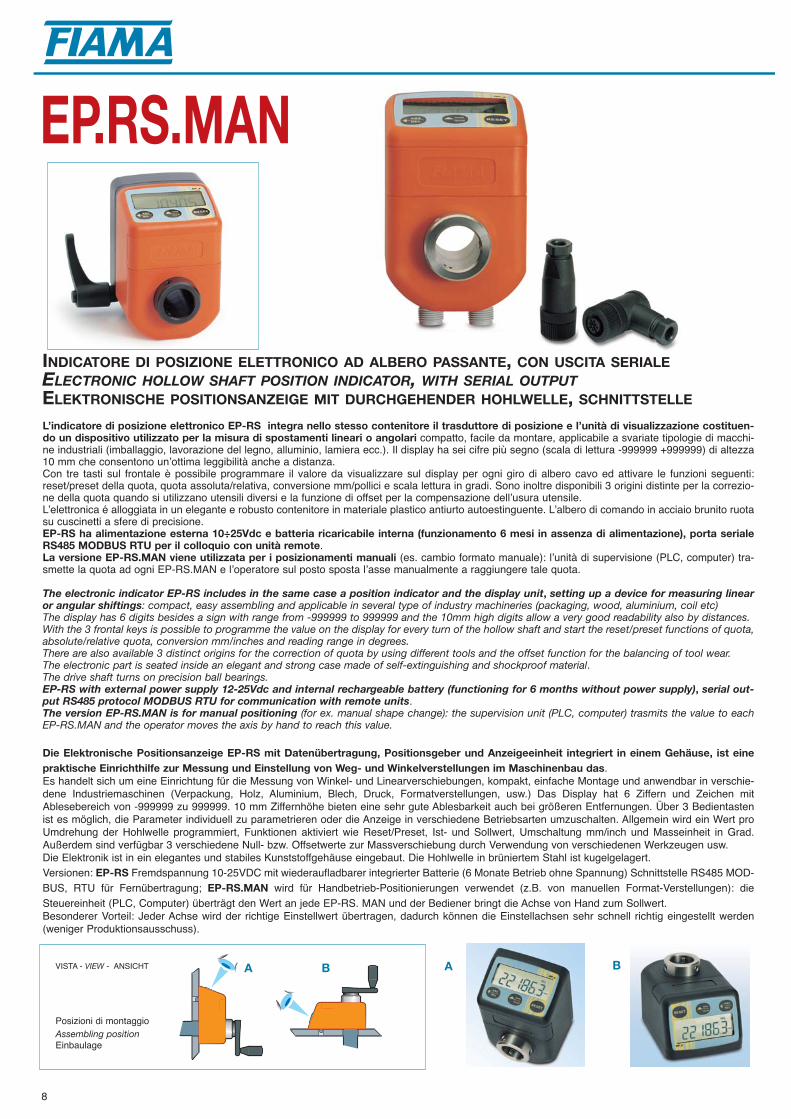
INDICATORE DI POSIZIONE ELETTRONICO AD ALBERO PASSANTE, CON USCITA SERIALEELECTRONIC HOLLOW SHAFT POSITION INDICATOR, WITH SERIAL OUTPUTELEKTRONISCHE POSITIONSANZEIGE MIT DURCHGEHENDER HOHLWELLE, SCHNITTSTELLE
EP.RS.MAN
L’indicatore di posizione elettronico EP-RS integra nello stesso contenitore il trasduttore di posizione e l’unità di visualizzazione costituen-do un dispositivo utilizzato per la misura di spostamenti lineari o angolari compatto, facile da montare, applicabile a svariate tipologie di macchi-ne industriali (imballaggio, lavorazione del legno, alluminio, lamiera ecc.). Il display ha sei cifre più segno (scala di lettura -999999 +999999) di altezza10 mm che consentono unʼottima leggibilità anche a distanza.Con tre tasti sul frontale è possibile programmare il valore da visualizzare sul display per ogni giro di albero cavo ed attivare le funzioni seguenti:reset/preset della quota, quota assoluta/relativa, conversione mm/pollici e scala lettura in gradi. Sono inoltre disponibili 3 origini distinte per la correzio-ne della quota quando si utilizzano utensili diversi e la funzione di offset per la compensazione dellʼusura utensile.Lʼelettronica é alloggiata in un elegante e robusto contenitore in materiale plastico antiurto autoestinguente. Lʼalbero di comando in acciaio brunito ruotasu cuscinetti a sfere di precisione. EP-RS ha alimentazione esterna 10÷25Vdc e batteria ricaricabile interna (funzionamento 6 mesi in assenza di alimentazione), porta serialeRS485 MODBUS RTU per il colloquio con unità remote.La versione EP-RS.MAN viene utilizzata per i posizionamenti manuali (es. cambio formato manuale): lʼunità di supervisione (PLC, computer) tra-smette la quota ad ogni EP-RS.MAN e lʼoperatore sul posto sposta lʼasse manualmente a raggiungere tale quota.
The electronic indicator EP-RS includes in the same case a position indicator and the display unit, setting up a device for measuring linearor angular shiftings: compact, easy assembling and applicable in several type of industry machineries (packaging, wood, aluminium, coil etc)The display has 6 digits besides a sign with range from -999999 to 999999 and the 10mm high digits allow a very good readability also by distances.With the 3 frontal keys is possible to programme the value on the display for every turn of the hollow shaft and start the reset/preset functions of quota,absolute/relative quota, conversion mm/inches and reading range in degrees. There are also available 3 distinct origins for the correction of quota by using different tools and the offset function for the balancing of tool wear.The electronic part is seated inside an elegant and strong case made of self-extinguishing and shockproof material.The drive shaft turns on precision ball bearings. EP-RS with external power supply 12-25Vdc and internal rechargeable battery (functioning for 6 months without power supply), serial out-put RS485 protocol MODBUS RTU for communication with remote units.The version EP-RS.MAN is for manual positioning (for ex. manual shape change): the supervision unit (PLC, computer) trasmits the value to eachEP-RS.MAN and the operator moves the axis by hand to reach this value.
Die Elektronische Positionsanzeige EP-RS mit Datenübertragung, Positionsgeber und Anzeigeeinheit integriert in einem Gehäuse, ist einepraktische Einrichthilfe zur Messung und Einstellung von Weg- und Winkelverstellungen im Maschinenbau das. Es handelt sich um eine Einrichtung für die Messung von Winkel- und Linearverschiebungen, kompakt, einfache Montage und anwendbar in verschie-dene Industriemaschinen (Verpackung, Holz, Aluminium, Blech, Druck, Formatverstellungen, usw.) Das Display hat 6 Ziffern und Zeichen mitAblesebereich von -999999 zu 999999. 10 mm Ziffernhöhe bieten eine sehr gute Ablesbarkeit auch bei größeren Entfernungen. Über 3 Bedientastenist es möglich, die Parameter individuell zu parametrieren oder die Anzeige in verschiedene Betriebsarten umzuschalten. Allgemein wird ein Wert proUmdrehung der Hohlwelle programmiert, Funktionen aktiviert wie Reset/Preset, Ist- und Sollwert, Umschaltung mm/inch und Masseinheit in Grad.Außerdem sind verfügbar 3 verschiedene Null- bzw. Offsetwerte zur Massverschiebung durch Verwendung von verschiedenen Werkzeugen usw.Die Elektronik ist in ein elegantes und stabiles Kunststoffgehäuse eingebaut. Die Hohlwelle in brüniertem Stahl ist kugelgelagert. Versionen: EP-RS Fremdspannung 10-25VDC mit wiederaufladbarer integrierter Batterie (6 Monate Betrieb ohne Spannung) Schnittstelle RS485 MOD-BUS, RTU für Fernübertragung; EP-RS.MAN wird für Handbetrieb-Positionierungen verwendet (z.B. von manuellen Format-Verstellungen): dieSteuereinheit (PLC, Computer) überträgt den Wert an jede EP-RS. MAN und der Bediener bringt die Achse von Hand zum Sollwert.Besonderer Vorteil: Jeder Achse wird der richtige Einstellwert übertragen, dadurch können die Einstellachsen sehr schnell richtig eingestellt werden(weniger Produktionsausschuss).
Posizioni di montaggio Assembling position Einbaulage
VISTA - VIEW - ANSICHT A B BA
8

CARATTERISTICHE TECNICHE EP-RSTECHNICAL FEATURES EP-RS
TECHNISCHE MERKMALE EP-RS
OP_e
ABS
REL
mm
inchRESET
97
3265
64
56,5
9,547
24 24
M4 x 10
626 12
Ø 2
5 H
7Ø
20
H7
Ø 3
5Ø
30
M5
°
Ø
I 30
Ø 4
06
I 40
14
6
18
2
Alimentazione - Power supply - Versorgung EP-RS, EP-RS.MAN : 10-25 VdcDiametro albero cavo - Hollow shaft - Hohwellendurchmesser EP20RS, EP20RS.MAN: 20 mm H7 - EP25RS, EP25RS.MAN: 25 mm H7Massima velocità di rotazione - Max. revolution speed - Max Drehzahl 1000 RPMRisoluzione - Accuracy - Auflösung 4000 impulsi/giro - impulses/revolution - Impulse/UmdrehungScala di lettura - Range - Anzeigebereich -999999 +999999Display LCD altezza cifre 10 mm- LCD height 10 mm - LCD 10 mm ZiffernhöheTastiera - Keyboard - Tastatur 3 tasti per programmazione ed attivazione funzioni - 3 keys for programming
3 FunktionstastenFunzioni disponibili - Available functions - Lieferbare Funktionen Reset/preset, quota assoluta/incrementale, conversione mm/pollici, visualizzatore
in gradi, 3 origini distinte per cambio utensile, compensazione usura utensile. Reset/preset, absolute/incremental quota, conversion mm/inch, visualisation in degrees, 3 distinct origin for tool changing, balancing of tool wearReset/preset, absolute/inkrementale Quote, Konversion mm/Inch, Anzeige inGrad, 3 verschiedene Nullpunkte für den Werkzeugwechsel, Werkzeugverschleiß, Ausgleichung
Porta seriale - Serial port - Schnittstelle RS485 MODBUS RTUTemperatura di impiego - Working temperature - Betriebstemperatur 0-50°C Umidità relativa - Relative humidity - Relative Feuchtigkeit 30-90% Protezione - Protection degree - Gehäuse Schutzart IP54Compatibilità elettromagnetica - Electromagnetic compatibility 2004/108/ECElektromagnetische Kompatibilität
Dimensioni d’ingombro - Dimensions - Abmessungen
Guarnizione antipolvereDust sealStaubschutzdichtung
Piolino di fermo ø6: I40 (I30)Lock pin ø6: I40 (I30)Drehmomentstütze ø6: I40 (I30)
ConnettoriConnectors
Konnektoren
Albero cavo foro ø20 o ø25ø20 or ø25 hollow shaftHohlwelle ø20 oder ø25
Tipo - Type - TypEP20RS, EP20RS.MAN- Diametro albero cavo - Hollow shaft - Hohwellendurchmesser: 20 mmH7EP25RS, EP25RS.MAN- Diametro albero cavo - Hollow shaft - Hohwellendurchmesser: 25 mmH7
Posizione di montaggio - Assembling position - EinbaulageA Albero di comando orizzontale - Horizontal shaft - Waagerechte WelleB Albero di comando verticale - Vertical shaft - Senkrechte Welle
Colore della scatola - Box colour - Gehäusefarbe G = Nero - Black - Schwarz; R = Arancione - Orange - Orange; GR = Grigio - Grey - Grau
Connettori - Connectors - Steckeranschluss D9 Connettore 4 poli 90°- Connector 4 poles 90° - Steckeranschluss 4 Polig 90°D10 Connettore 4 poli diritto - Straight connector 4 poles - Gerader Stecker 4 Polig
Sigla di ordinazione - Order outline - Bestellmuster
Esempio di applicazioneApplication exampleAnwendungsbeispiel
Trasmissione dei datiData transmissionDatenübertragung
9
A R D10EP20RS
OPZIONALE - OPTIONAL
A B
64
9732
65
18 18
25ø
4,5 ø
6
3040
43,5
ø 20
64 3218
Flangia di fissaggio con maniglia - Fixing flange with handle- Befestigungsflansche mit GriffFL-B
Flangia con maniglia per il bloccaggio dell’albero di comandoFlange with handle for drive shaft fixingKlemmflansch zur Spindelklemmung
FL-B

10
INDICATORE DI POSIZIONE ELETTRONICO AD ALBERO PASSANTE LATERALE, ALIMENTAZIONE A BATTERIA
ELECTRONIC SIDE HOLLOW SHAFT POSITION INDICATOR, BATTERY SUPPLIED
ELEKTRONISCHE POSITIONSANZEIGE MIT SEITEN-DURCHGEHENDER HOHLWELLE, BATTERIESPANNUNG
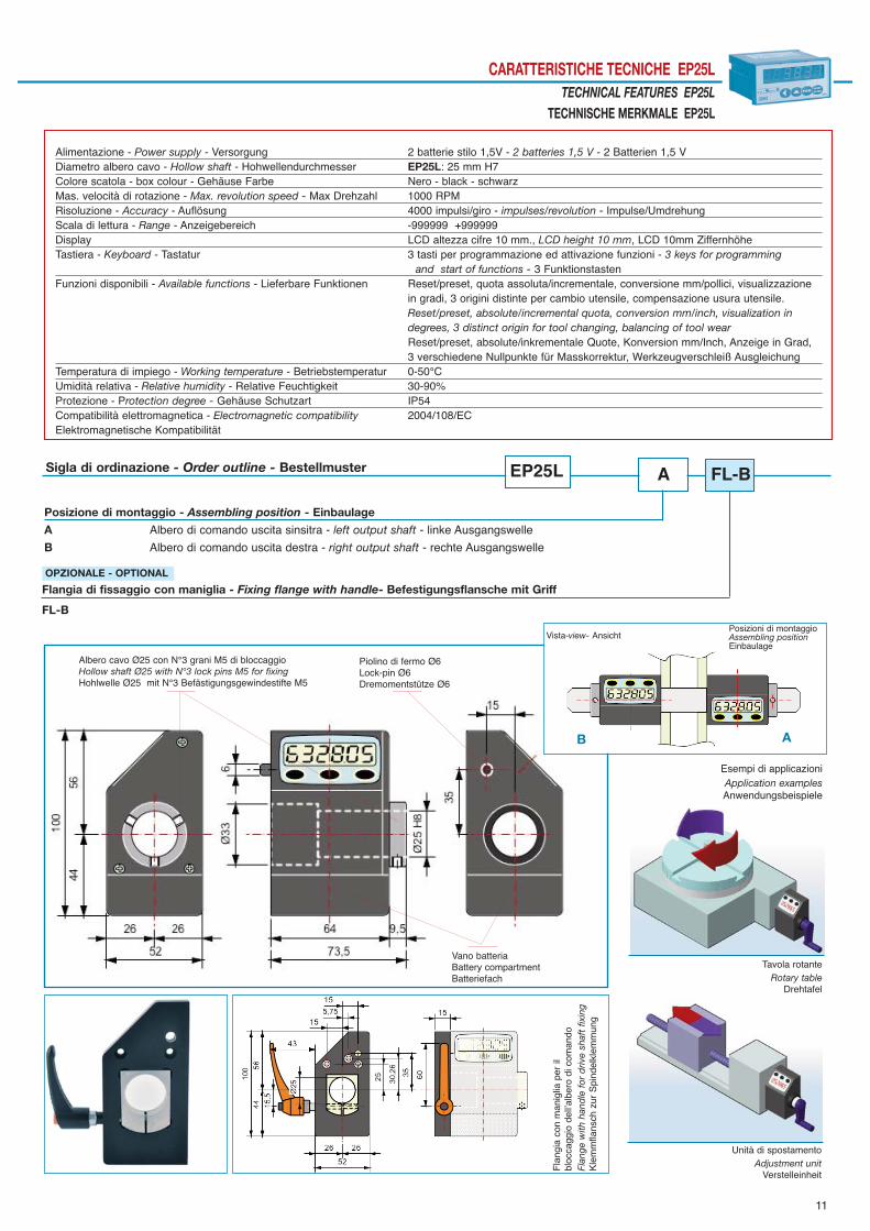
EP25L
L’indicatore di posizione elettronico EP25L, alimentato a batteria interna, integra nello stesso contenitore il trasduttore di posizione e l’unitàdi visualizzazione costituendo un dispositivo utilizzato per la misura di spostamenti lineari o angolari compatto, facile da montare, applicabile asvariate tipologie di macchine industriali (imballaggio, lavorazione del legno, alluminio, lamiera ecc.). La sua caratteristica è l’albero cavo laterale per ottimizzare la manovra e la visualizzazione anche in situazioni poco agevoli. Il display ha sei cifre più segno (scala di lettura -999999 +999999) di altezza 10 mm che consentono unʼottima leggibilità anche a distanza.Con tre tasti sul frontale è possibile programmare il valore da visualizzare sul display per ogni giro di albero cavo ed attivare le funzioni seguenti:reset/preset della quota, quota assoluta/relativa, conversione mm/pollici e scala lettura in gradi. Sono inoltre disponibili 3 origini distinte per la correzio-ne della quota quando si utilizzano utensili diversi e la funzione di offset per la compensazione dellʼusura utensile. Sul display sono visualizzate consimboli tutte le funzioni attivate. Lʼelettronica é alloggiata in un elegante e robusto contenitore in materiale plastico antiurto autoestinguente.Lʼalbero di comando in acciaio brunito ruota su cuscinetti a sfere di precisione. Lʼ alimentazione è interna a batteria: 2 pile formato stilo AA da 1,5V della durata di 1 anno. Lʼindicazione di batteria scarica inizia a lampeggiare e restaaccesa fissa un mese prima della sostituzione; tale sostituzione viene effettuata con facilità senza perdita della quota, in condizione di albero fermo.
The electronic indicator EP25L, supplied with internal battery, includes in the same case a position sensor and a display unit, setting up adevice for measuring linear or angular shiftings: compact, easy assembling and applicable in several type of industry (packaging, woodworking, alu-minium, coil etc). It is charachterized by a side hollow shaft that allows handlings and visualizations, even in uncomfortable positions.The display has 6 digits besides a sign with range from -999999 to 999999 and the 10mm-high-digits allow a very good readability also by distances.With the 3 frontal keys is possible to programme the value on the display for every turn of the hollow shaft and start the reset/preset functions of quota,absolute/relative quota, conversion mm/inches and reading range in degrees.There are also available 3 distinct origins for the correction of quota byusing different tools and the offset function for the balancing of tool wear. On the display all activated functions are showed by a symbol.The electronic part is seated inside an elegant and strong case made of self-extinguishing and shock-proof plastic material. The drive shaft, made in blued steel, turns on precision ball bearings.The power supply is internal with 2 batteries, type AA of 1,5V: one-year-life. The run-down of battery is indicated with occasional blinking, 1 monthbefore the complete flat the indication remains on; the battery has to be changed, in very easy way and without loosing quota, by standing of shaft.
Die Elektronische Positionsanzeige EP- Positionsgeber und Anzeigedisplay integriert in einem Gehäuse, ist eine praktische Einrichthilfe zurMessung und Einstellung von Weg- und Winkelverstellungen im Maschinenbau. Die kompakte Bauform und einfache Montage direkt auf die Verstellwelle ermöglicht zahlreiche Anwendungsmöglichkeiten im gesamten Maschinenbau.Seine Eingenschaft ist die seitlich-durchgehende Hohlwelle um Verstellungen und Visualisierungen auch in unbequemen Positionen zu erlau-ben. Das Display hat 6 Ziffern mit Vorzeichen und Ablesebereich von -999999 bis 999999. 10mm Ziffernhöhe bieten eine sehr gute Ablesbarkeit, auch bei grö-ßeren Entfernungen. Über 3 Funktionstasten ist es möglich, ohne externe Hilfsmittel, sämtliche Geräteparameter einfach und verständlich zu programmieren, wie Reset/Preset,Ist- und Sollwert, Inch/mm Anzeige, Winkelanzeige, außerdem 3 Nullpunkte für Maßkorrektur und Offset für Werkzeugverschleißausgleich. Alle aktiviertenFunktionen sind auf dem Display mit Symbolen angezeigt. Die Elektronik ist in ein elegantes und stabiles Kunststoffgehäuse eingebaut. Die Antriebswellein brüniertem Stahl ist kugelgelagert. Der Batteriewechsel 2xAA Standard-Batterie (1 Jahr Lebensdauer) ist auch im eingebauten Zustand schnell und bequem realisiert, während die Wellesteht, bleibt der Wert gespeichert. Die Entladung der Batterie wird mit Blinken angezeigt, ca. einen Monat vor der kompletten Entladung bleibt die Anzeigein Funktion.
11
CARATTERISTICHE TECNICHE EP25LTECHNICAL FEATURES EP25L
TECHNISCHE MERKMALE EP25L
Alimentazione - Power supply - Versorgung 2 batterie stilo 1,5V - 2 batteries 1,5 V - 2 Batterien 1,5 V Diametro albero cavo - Hollow shaft - Hohwellendurchmesser EP25L: 25 mm H7Colore scatola - box colour - Gehäuse Farbe Nero - black - schwarzMas. velocità di rotazione - Max. revolution speed - Max Drehzahl 1000 RPMRisoluzione - Accuracy - Auflösung 4000 impulsi/giro - impulses/revolution - Impulse/UmdrehungScala di lettura - Range - Anzeigebereich -999999 +999999Display LCD altezza cifre 10 mm., LCD height 10 mm, LCD 10mm ZiffernhöheTastiera - Keyboard - Tastatur 3 tasti per programmazione ed attivazione funzioni - 3 keys for programming
and start of functions - 3 FunktionstastenFunzioni disponibili - Available functions - Lieferbare Funktionen Reset/preset, quota assoluta/incrementale, conversione mm/pollici, visualizzazione
in gradi, 3 origini distinte per cambio utensile, compensazione usura utensile. Reset/preset, absolute/incremental quota, conversion mm/inch, visualization in degrees, 3 distinct origin for tool changing, balancing of tool wearReset/preset, absolute/inkrementale Quote, Konversion mm/Inch, Anzeige in Grad, 3 verschiedene Nullpunkte für Masskorrektur, Werkzeugverschleiß Ausgleichung
Temperatura di impiego - Working temperature - Betriebstemperatur 0-50°C Umidità relativa - Relative humidity - Relative Feuchtigkeit 30-90% Protezione - Protection degree - Gehäuse Schutzart IP54Compatibilità elettromagnetica - Electromagnetic compatibility 2004/108/ECElektromagnetische Kompatibilität
Posizione di montaggio - Assembling position - Einbaulage
A Albero di comando uscita sinsitra - left output shaft - linke Ausgangswelle
B Albero di comando uscita destra - right output shaft - rechte Ausgangswelle
Sigla di ordinazione - Order outline - Bestellmuster
Esempi di applicazioniApplication examplesAnwendungsbeispiele
Unità di spostamentoAdjustment unit
Verstelleinheit
Tavola rotanteRotary table
Drehtafel
Fla
ngia
con
man
iglia
per
il
bloc
cagg
io d
ellʼa
lber
o di
com
ando
Flan
ge w
ith h
and
le f
or d
rive
shaf
t fix
ing
Kle
mm
flans
ch z
ur S
pind
elkl
emm
ung
Flangia di fissaggio con maniglia - Fixing flange with handle- Befestigungsflansche mit Griff
FL-BPosizioni di montaggio Assembling position Einbaulage
Vista-view- Ansicht
AB
Albero cavo Ø25 con N°3 grani M5 di bloccaggioHollow shaft Ø25 with N°3 lock pins M5 for fixingHohlwelle Ø25 mit N°3 Befästigungsgewindestifte M5
Piolino di fermo Ø6Lock-pin Ø6Dremomentstütze Ø6
Vano batteriaBattery compartmentBatteriefach
EP25L A FL-B
OPZIONALE - OPTIONAL
12
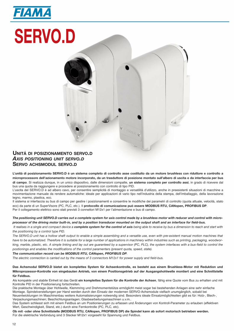
SERVO.D
UNITÁ DI POSIZIONAMENTO SERVO.DAXIS POSITIONING UNIT SERVO.DSERVO ACHSMODUL SERVO.D
L’unità di posizionamento SERVO.D è un sistema completo di controllo asse costituito da un motore brushless con riduttore e controllo amicroprocessore dell’azionamento motore incorporato, da un trasduttore di posizione montato sull’albero di uscita e da interfaccia per busdi campo. Si realizza dunque, in un unico dispositivo, dalle dimensioni compatte, un sistema completo per controllo assi, in grado di ricevere dalbus una quota da raggiungere e procedere al posizionamento con controllo di tipo PID. Lʼuscita del SERVO.D è ad albero cavo, per consentire semplicità di montaggio e versatilità dʼutilizzo, anche in preesistenti situazioni di macchine amovimentazione manuale da rendere automatiche: ideale per applicazioni di vario tipo nellʼindustria della stampa, dellʼimballaggio, della lavorazionelegno, marmo, plastica, ecc. Il sistema si interfaccia su bus di campo per gestire i posizionamenti e consentire le modifiche dei parametri di controllo (quota attuale, velocità, statoecc) da parte di un SuperVisore (PC, PLC, etc.). Il protocollo di comunicazione può essere MODBUS RTU, CANopen, PROFIBUS DP.Per il collegamento elettrico sono stati previsti 3 connettori M12x1 per lʼalimentazione e bus di campo.
The positioning unit SERVO.D carries out a complete system for axis control made by a brushless motor with reducer and control with micro-processor of the driving motor built-in, and by a position transducer mounted on the output shaft and an interface for field-bus. It realises in a single and compact device a complete system for the control of axis being able to receive by bus a dimension to reach and start withthe positioning by a control type PID. The SERVO.D unit has a hollow shaft output to enable a simple assembling and a versatile use, even with pre-existent manual motion machines thathave to be automatized. Therefore it is suitable for a large number of applications in machinery within industries such as printing, packaging, woodwor-king, marble, plastic, etc. A simple linking and lay out are guaranteed by a supervisor (PC, PLC), the system interfaces with a bus-field to control thepostionings and enables the modifications of the control paramenters (present quota, speed, state).The communication record can be MODBUS RTU, CANopen, PROFIBUS DP.The electric connection is carried out by the means of 3 connectors M12x1 for power supply and field-bus.
Das Achsmodul SERVO.D bietet ein komplettes System für Achsenkontrolle, es besteht aus einem Brushless-Motor mit Reduktion undMikroprozessor-Kontrolle von eingebauten Antrieb, von einem Positionsgetrieb auf der Ausgangshohlwelle montiert und eine Schnittstellefür Feldbus.Als kompakte und stabile Einheit ist das Gerät ein komplettes System für die Kontrolle der Achsen, fähig eine Quote vom Bus zu erhalten und mitKontrolle PID in der Positionierung fortschreiten.Die praktische Montage über Hohlwelle, Klemmring und Drehmomentstütze ermöglicht meist sogar bei bestehenden Anlagen eine sehr einfacheMontage. Spindelverstellungen per Hand werden durch den Einsatz der modernen SERVO-Achsmodule vielfach unumgänglich, sobald beiNeuentwicklungen im Maschinenbau weitere Automatisierungen notwendig sind. Besonders ideale Einsatzmöglichkeiten gibt es für: Holz-, Blech-,Verpackungsmaschinen; Beschichtungsanlagen; Glasbearbeitungsmaschinen u.v.m..Das System schliesst sich mit einem Feldbus an um Positionierungen zu erfassen und Änderungen von Kontroll-Parameter zu erlauben (effektivenWert, Geschwindigkeit, Stand, etc.) durch eine Fernkontrolle (PC, PLC, etc). Ob mit -oder ohne Schnittstelle (MODBUS RTU, CANopen, PROFIBUS DP) die Spindel kann ab sofort motorisch betrieben werden. Für die elektrische Verbindung sind 3 Stecker M12x1 vorgeseht für Spannung und Feldbus.

Alimentazione - Power supply - Versorgung 24Vdc+-20%, max. 4APotenza nominale - Nominal power - Nominale Leistung 60WAlbero cavo - Hollow shaft - Hohlwelle Foro 14 mm - Bore 14 mm -Bohrung 14mmVelocità e coppia uso non continuo - not constant use - nicht EinschaltdauerSpeed and torque max 100rpm: 4Nm 80 rpm Geschwindigkeit und DrehmomentRisoluzione encoder - Encoder resolution - Auflösung 1000 imp/giro - 1000 imp/turn - 1000 Imp/Umdr.Risoluzione potenziometro - Potentiometer resolution 16000: punti sulla corsa totale - point on the total strokePotenziometer Auflösung Punkte im GesamtwegRapporti di trasmissione potenziometro 2-4-6-12-18-36-54-108-162, in riduzione Potentiometer transmission ratios 2-4-6-12-18-36-54-108-162, reducingPotenziometer Übersetzungen 2-4-6-12-18-36-54-108-162, UntersetzungPotenziometro (giri) - potentiometer (rev.) - Wendel (Umdr.) nP: 1 (340°) - 3 (1080°) - 5 (1800°) - 10 (3600°) Bus di campo - Field bus interface - Feldbus Interface CANopen DS301, MODBUS RTU RS485, PROFIBUS DPTemperatura di impiego - Working temperature - Betriebstemperatur 0-60°CUmidità relativa - Relative humidity - Relative Feuchtigkeit 10-85%Grado di protezione - Protection degree - Schutzart IP54 oppure - or - oder IP66Contenitore antiurto autoestinguente - Self-extinguishible shock-proof case SERVO.D 112x45x135Selbstlöschendes stossfestes GehäuseCompatibilità elettromagnetica - Electromagnetic compatibility 2004/108/ECElektromagnetische Kompatibilität
Versione - Versions - AusführungenI motoriduttore con encoder - geared motor with encoder - Getriebe A motoriduttore con potenziometro - geared motor with potentiometer - Getriebe mit PotentiometerB motoriduttore: potenziometro, uscita analogica - geared motor: potentiometer, analogue output - Getriebe: Poti, Analogausgang E motoriduttore: encoder, azionamento - geared motor: encoder and driving - Getriebe: Enkoder und AntriebP motoriduttore: potenziometro, azionamento - geared motor: potentiometer and driving - Getriebe: Poti und Antrieb
Uscite - Outputs - AusgängeRS485 uscita seriale - serial output - Schnittstelle MODBUS RTU RS485 CAN uscita seriale - serial output - Schnittstelle CANopenPROFI uscita seriale - serial output - Schnittstelle PROFIBUS DP
Grado di protezione - protection degree - Schutzart 1 IP542 IP66
13
CARATTERISTICHE TECNICHE SERVO.DTECHNICAL FEATURES SERVO.D
TECHNISCHE MERKMALE SERVO.D
Sigla di ordinazione - Order outline - Bestellmuster
ConnettoriConnectorsStecker
Connettori volanti M12 - IP67Free connectors M12 - IP67FreieStecker M12 - IP67
SERVO.D
Impostazione indirizzoAddress settingAdresse Einstellung
Albero cavo Hollow shaft Hohlwelle
Fori di fissaggioFixing boresBefestigungs-bohrungen
Foro per fissaggio Fixing bore Befestigungs-bohrung
ConnettoriConnectorsKonnektor
Giri pot. e rapp. di trasmissione - Pot. rev. and red. ratio - Pot. Umdr. und UntersetzungnP: potenziometro, R: rapporto di trasmissione - nP: potentiometer, R: transmission ratio - nP: Potentiometer, R: Übersetzung
D
C
B
A
P 18/1 PROFI IP54
Connettori - Connectors - Steckeranschluss D9 Connettore 4 poli 90°- Connector 4 poles 90° - Steckeranschluss 4 Polig 90°D10 Connettore 4 poli diritto - Straight connector 4 poles - Gerader Stecker 4 Polig
OPZIONALE - OPTIONAL
D10
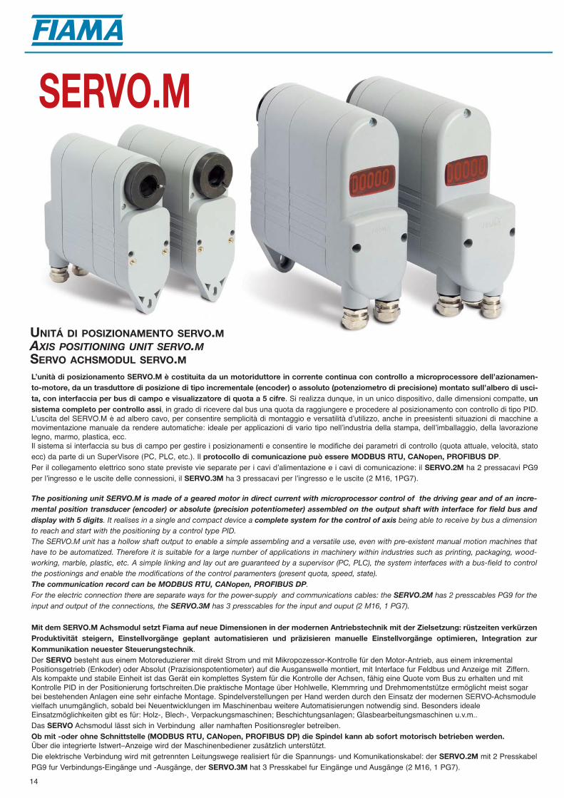
L’unità di posizionamento SERVO.M è costituita da un motoriduttore in corrente continua con controllo a microprocessore dell’azionamen-to-motore, da un trasduttore di posizione di tipo incrementale (encoder) o assoluto (potenziometro di precisione) montato sull’albero di usci-ta, con interfaccia per bus di campo e visualizzatore di quota a 5 cifre. Si realizza dunque, in un unico dispositivo, dalle dimensioni compatte, unsistema completo per controllo assi, in grado di ricevere dal bus una quota da raggiungere e procedere al posizionamento con controllo di tipo PID. Lʼuscita del SERVO.M è ad albero cavo, per consentire semplicità di montaggio e versatilità dʼutilizzo, anche in preesistenti situazioni di macchine amovimentazione manuale da rendere automatiche: ideale per applicazioni di vario tipo nellʼindustria della stampa, dellʼimballaggio, della lavorazionelegno, marmo, plastica, ecc. Il sistema si interfaccia su bus di campo per gestire i posizionamenti e consentire le modifiche dei parametri di controllo (quota attuale, velocità, statoecc) da parte di un SuperVisore (PC, PLC, etc.). Il protocollo di comunicazione può essere MODBUS RTU, CANopen, PROFIBUS DP.Per il collegamento elettrico sono state previste vie separate per i cavi dʼalimentazione e i cavi di comunicazione: il SERVO.2M ha 2 pressacavi PG9per lʼingresso e le uscite delle connessioni, il SERVO.3M ha 3 pressacavi per lʼingresso e le uscite (2 M16, 1PG7).
The positioning unit SERVO.M is made of a geared motor in direct current with microprocessor control of the driving gear and of an incre-mental position transducer (encoder) or absolute (precision potentiometer) assembled on the output shaft with interface for field bus anddisplay with 5 digits. It realises in a single and compact device a complete system for the control of axis being able to receive by bus a dimensionto reach and start with the positioning by a control type PID. The SERVO.M unit has a hollow shaft output to enable a simple assembling and a versatile use, even with pre-existent manual motion machines thathave to be automatized. Therefore it is suitable for a large number of applications in machinery within industries such as printing, packaging, wood-working, marble, plastic, etc. A simple linking and lay out are guaranteed by a supervisor (PC, PLC), the system interfaces with a bus-field to controlthe postionings and enable the modifications of the control paramenters (present quota, speed, state).The communication record can be MODBUS RTU, CANopen, PROFIBUS DP.For the electric connection there are separate ways for the power-supply and communications cables: the SERVO.2M has 2 presscables PG9 for theinput and output of the connections, the SERVO.3M has 3 presscables for the input and ouput (2 M16, 1 PG7).
Mit dem SERVO.M Achsmodul setzt Fiama auf neue Dimensionen in der modernen Antriebstechnik mit der Zielsetzung: rüstzeiten verkürzenProduktivität steigern, Einstellvorgänge geplant automatisieren und präzisieren manuelle Einstellvorgänge optimieren, Integration zurKommunikation neuester Steuerungstechnik.Der SERVO besteht aus einem Motoreduzierer mit direkt Strom und mit Mikropozessor-Kontrolle für den Motor-Antrieb, aus einem inkrementalPositionsgetrieb (Enkoder) oder Absolut (Prazisionspotentiometer) auf die Ausganswelle montiert, mit Interface fur Feldbus und Anzeige mit Ziffern.Als kompakte und stabile Einheit ist das Gerät ein komplettes System für die Kontrolle der Achsen, fähig eine Quote vom Bus zu erhalten und mitKontrolle PID in der Positionierung fortschreiten.Die praktische Montage über Hohlwelle, Klemmring und Drehmomentstütze ermöglicht meist sogarbei bestehenden Anlagen eine sehr einfache Montage. Spindelverstellungen per Hand werden durch den Einsatz der modernen SERVO-Achsmodulevielfach unumgänglich, sobald bei Neuentwicklungen im Maschinenbau weitere Automatisierungen notwendig sind. Besonders idealeEinsatzmöglichkeiten gibt es für: Holz-, Blech-, Verpackungsmaschinen; Beschichtungsanlagen; Glasbearbeitungsmaschinen u.v.m..Das SERVO Achsmodul lässt sich in Verbindung aller namhaften Positionsregler betreiben. Ob mit -oder ohne Schnittstelle (MODBUS RTU, CANopen, PROFIBUS DP) die Spindel kann ab sofort motorisch betrieben werden. Über die integrierte Istwert–Anzeige wird der Maschinenbediener zusätzlich unterstützt. Die elektrische Verbindung wird mit getrennten Leitungswege realisiert für die Spannungs- und Komunikationskabel: der SERVO.2M mit 2 PresskabelPG9 fur Verbindungs-Eingänge und -Ausgänge, der SERVO.3M hat 3 Presskabel fur Eingänge und Ausgänge (2 M16, 1 PG7).
SERVO.M
UNITÁ DI POSIZIONAMENTO SERVO.MAXIS POSITIONING UNIT SERVO.MSERVO ACHSMODUL SERVO.M
14

CARATTERISTICHE TECNICHE SERVO.MTECHNICAL FEATURES SERVO.M
TECHNISCHE MERKMALE SERVO.M
Versione - Versions - AusführungenI motoriduttore con encoder - geared motor with encoder - Getriebe
A motoriduttore con potenziometro - geared motor with potentiometer - Getriebe mit Potentiometer
B motoriduttore: potenziometro, uscita analogica - geared motor: potentiometer, analogue output - Getriebe: Potentiometer, Analogausgang
E motoriduttore: encoder, azionamento - geared motor: encoder and driving - Getriebe: Enkoder und Antrieb
P motoriduttore: potenziometro, azionamento - geared motor: potentiometer and driving - Getriebe: Potentiometer und Antrieb
Alimentazione - Power supply - Versorgung 24Vdc+-20%Visualizzazione - Display - Anzeige -19999 +99999Potenza nominale - Nominal power - Nominale Leistung 70WAlbero cavo - Hollow shaft - Hohlwelle Foro 20 mm prof. 50 - Bore 20 mm depth 50 - Borhung 20 mm tiefe 50Rapporti di riduzione e coppia uso non continuo - not constant use - nicht EinschaltdauerReducing ratio and torque 50/1 max 115 rpm: 8 Nm 70 rpm Reduktionübersetzung und Drehmoment uso non continuo - not constant use - nicht Einschaltdauer
75/1 max 75 rpm: 12 Nm 45 rpm Risoluzione encoder - Encoder resolution - Auflösung 1000 imp/giro - imp/tour - imp/vueltaRisoluzione potenziometro - Potentiometer resolution 16000: punti sulla corsa totale - point on the total strokePotenziometer Auflösung Punkte im GesamtwegRapporti di trasmissione potenziometro 1/1, 3,3/1, 10/1, 24/1, 30/1, 90/1, in riduzione Potentiometer transmission ratios 1/1 et 3.3/1, 10/1, 24/1, 30/1, 90/1, reducingPotenziometer Übersetzungen 1/1 y 3.3/1, 10/1, 24/1, 30/1, 90/1, UntersetzungBus di campo - Field bus interface - Feldbus Interface CANopen DS301, MODBUS RTU RS485, PROFIBUS DPTemperatura di impiego - Working temperature - Betriebstemperatur 0-60°CUmidità relativa - Relative humidity - Relative Feuchtigkeit 10-85%Contenitore antiurto autoestinguente - Self-extinguishible shock-proof case SERVO.2M 140x52x150 - SERVO.3M 158x52x150 - IP54Selbstlöschendes stoßfestes GehäuseCompatibilità elettromagnetica - Electromagnetic compatibility 2004/108/ECElektromagnetische Kompatibilitä
Sigla di ordinazione - Order outline - Bestellmuster
Rapporto di riduzione - Reducing ratio - Getriebeübersetzungen 1 50/1: 115 RPM
2 75/1: 75 RPM
Uscite - Outputs - AusgängeRS485 uscita seriale - serial output - Schnittstelle MODBUS RTU RS485 CAN uscita seriale - serial output - Schnittstelle CANopenPROFI uscita seriale - serial output - Schnittstelle PROFIBUS DP
SERVO.3MSERVO.2M
SERVO.2MPressacavi e foro fissaggioPresscables and fixing boreKabelverschraubungund Bohrung fürBefestigung
SERVO.3MPressacavi e foro fissaggioPresscables and fixing boreKabelverschraubungund Bohrung fürBefestigung
20
1252
48,5
128,5
140
11,5
70M
426
24
4
5,5
136
20
ø20
H7
50
120
116
20
1252
48,5
128,5
148,5
158
11,5
70M
426
24
4
5,5
136
20
ø20
H7
50
120
116
128
128
B
D
A
C
B
D
E
A
C
A Albero cavo ø20 x50Hollow shaft ø20 x 50Hollwelle ø20 x 50
B Foro per fissaggio (vite M5)Bore for fixing (screw M5)Bohrung für Befestigung (Schraube M5)
C Fori di fissaggio M4x12Fixing screw M4x12Gewindestift M4x12
D Pressacavi M16Presscables M16Kabelverschraubung M16
E Pressacavo PG7Presscable PG7Kabelverschraubung PG7
15
P 1 RS485

16
POSIZIONATORE PER LA GESTIONE DELL’UNITÀ SERVO
POSITION CONTROLLER FOR DRIVING OF SERVO UNIT
ACHS POSITIONIERSTEUERUNG FÜR SERVO ACHSMODUL
P3.S
Il controllo P3.S, in abbinamento all’unità di posizionamento SERVO, costituisce un sistema particolarmente indicato per l’automazione dmacchine che richiedono la gestione di assi motorizzati.Gli ingressi del posizionatore start, emergenza sono optoisolati.La visualizzazione dei dati avviene su un display ad alta luminosità a 5 cifre (scala -9999, +99999) mentre un display ausiliario a due cifre mostra ipasso del programma in esecuzione o una indicazione delle costanti di lavoro. La tastiera a 16 tasti con 6 indicatori di funzione rendono semplice ed immediato l'uso e la configurazione del posizionatore.Il P3.S può essere collegato fino a 32 unità SERVO in rete ed è in grado di memorizzare fino a 99 programmi di posizionamento. Per ottimizzare l'accuratezza del posizionamento, sono previsti alcuni parametri in grado di compensare l'inerzia del sistema, i giochi e l'usura deglaccoppiamenti meccanici. Le modalità di lavoro sono: automatica, manuale, posizionamento singolo.Un’uscita a relé segnala lʼavvenuto posizionamento di tutti gli assi, una seconda uscita a relé segnala eventuali errori di connessione.Il collegamento con il SERVO è via seriale RS485 con protocollo MODBUS RTU.Il mantenimento dei dati a macchina spenta è garantito da una memoria non volatile EEPROM.Applicazioni tipiche sono il cambio formato automatico, le regolazione motorizzate di riferimenti, battute, riscontri per il taglio e la piegatura ecc.
The controller P3.S combined to the SERVO positioning unit carries out a particular suitable system for the automation of machines thatrequire driving of motorized axes.The inputs of the position controller start, and emergency are opto-insulated.The values are displayed on a high-brightness 5-digit display (range -9999 +99999) while an auxiliary 2-digit display shows the program step duringexecution or the working constants.The keyboard with 16 keys and 6 function indicators make the use and setting up of the positioning unit very easy and immediate. The positioning unit can be linked up to 32 Servo units in network and can store up to 99 positioning program. In order to optimize the positioning accuracy there are some parameters that can balance the system inertia, clearances, wear and tear of mechanicacouplings. Available working modes are: automatic, manual, single positioning.A relays-output signals the positioning of all axes, a second possible connection error.Serial connection to SERVO is RS485 with MODBUS RTU protocol.The keeping of data during machine off is guaranteed by a non-volatile EEPROM memory.Suitable applications are in automatic size change, motorized adjusting of reference marks, end strokes for cutting and bending.
Die Positionssteuerung P3.S im Verbund mit dem Achsmodul SERVO bietet ein besonders geeignetes System zur Automatisierung von moto-risch zu verstellenden Einrichtachsen an Maschinen.Die Eingänge der Positionssteuerung Start, Stop sind optoisoliert. Die Mass-Position der Achse wird auf einem LCD-Display mit 5-Ziffern (Messbereich -9999 +99999) angezeigt, während ein Hilfsdisplay mit 2 Ziffern den aktuellen Programmstand und die Betriebs-Zustände während des Betriebs anzeigt. Über die 16-Tasten Tastatur mit 6 Statusanzeigen wird die Positionssteuerung einfach und schnell konfiguriert. Die Positionssteuerung kann bis zu 32 SERVO Achsmodule im Netz ansteuern und bis zu 99 Positionierprogramme speichern. Zur Positionsoptimierung sind einige Parameter vorgesehen, welche die Systemträgheit beeinflussen, dies auch um die mechanische Belastung auf dieAntriebswelle optimiert abzustimmen bzw. auszugleichen. Ein Relais-Ausgang meldet die korrekte Positionierung aller Achsen, ein zweiter Ausgang mögliche Verbindungsfehler. Die Kommunikation zwischen der Positionssteuerung und dem SERVO erfolgt mittels Schnittstelle RS485 mit MODBUS RTU Protokoll. DieSicherung der Daten wird von einem nicht-flüchtigen EEPROM Speicher garantiert. Ideale Einsatzmöglichkeiten sind, automatische Format-Wechsel, motorische Verstellungen von Spindelachsen, welche für verschiedene Positionen vonmechanischen Anschlägen oder definierten Positionen im Maschinenbau und allgemeinen Anlagenbau präzise zu positionieren sind.

17
CARATTERISTICHE TECNICHE P3.STECHNICAL FEATURES P3.S
TECHNISCHE MERKMALE P3.S96
96 120 92
92
Dimensioni d’ingombro - Dimensions - Abmessungen Foratura - Panel cut-out - Aussparung
Alimentazioni - Power supply - Versorgung 115Vac, 230Vac, 24Vac, 15÷30Vdc, +-10%Potenza assorbita - Absorbed power - Leistungsaufnahme 7 VAVisualizzazione - Display - Anzeige 5 cifre - 9999 + 99999 per visualizzazione - 2 cifre per programmazione
5 digits -9999 +99999 for display - 2 digits for programming5 Zahlen -9999 +99999 für Anzeige - 2 Zahlen für Programmierung
Modo di funzionamento Semiautomatico - Assoluto - Manuale - Posizionamento singolo Operating mode Semiautomatic - Assoluto - Manual - Single positioning Betriebsart Halbautomatisch - Assoluto - Manuell - Einzelpositionerung Possibilità di creare programmi di lavoro Memorizzazione di 99 programmiPossibility to create working programmes Memorization of 99 programMöglichkeit Arbeitsprogramme zu Erwirklichen Speicherung von 99 Programme2 uscite relè 250Vac 5A 1 Fine posizionamento - 1 Errore2 relay outputs 250Vac 5A 1 End of positioning - 1 Error2 Relaisausgänge 250 Vac 5A 1 Positionierungsende - 1 Fehler3 ingressi ON-OFF optoisolati 12Vdc Emergenza - Start - Azzeramento3 optoinsulated ON-OFF inputs 12Vdc Emercency - Start - Zero setting3 Eingänge ON-OFF optoisoliert 24 Vdc Notschalter - Start - NulleinstellungPorta seriale - Serial output - Serieller Ausgang RS485 MODBUS RTU: Comunicazione - Comunication - Komunication SERVOTemperatura di impiego - Working temperature 0-50°CBetriebstemperaturUmidità relativa - Relative Humidity - Relative Feuchtigkeit 30-90%Contenitore antiurto autoestinguente 96x96x120 DIN 43700 - IP54Self-extinguishible shock-proof caseSelbstlöschendes stoßfestes GehäuseCompatibilità elettromagnetica - Electromagnetic compatibility 2004/108/ECElektromagnetische Kompatibilitä
Alimentazione - Power supply - Versorgung
0 115 Vac
1 230 Vac
2 24 Vac
3 15÷30 Vdc
P3.SSigla di ordinazione - Order outline - Bestellmuster
Versione - Versions - Versionen
I SERVO.E.MODBUS RS485 con encoder - SERVO.E.MODBUS RS485 with encoder - SERVO.E.MODBUS RS485 mit Getrieb
P SERVO.P.MODBUS RS485 con potenziometro - SERVO.P.MODBUS RS485 with potentiometer - SERVO.P.MODBUS RS485 mit Potentiometer
1 P

18
VISUALIZZATORE ELETTRONICO PER MISURE LINEARI CON ALIMENTAZIONE A BATTERIA
ELECTRONIC DISPLAY FOR LINEAR MEASUREMENT, BATTERY-OPERATED
ELEKTRONISCHE ANZEIGE FÜR LINEAR MESSUNGEN, BATTERIESPANNUNG
SIMPLEX-E
Il Simplex Elettronico è un visualizzatore di quote per la misura di spostamenti lineari che integra nello stesso contenitore il trasduttore di posizionemagnetico, lʼunità di visualizzazione e le batterie di alimentazione. Il visualizzatore scorre su una barra di alluminio in cui viene alloggiata la bandamagnetica.Lʼunità di visualizzazione scorrendo sullʼasta di misura rileva il reale spostamento effettuato, eliminando possibili giochi e disallineamenti.Il display a cristalli liquidi ha sei cifre più segno (scala di lettura da –999999 a 999999), con altezza di 10mm che ne consente unʼottima leggibilità anche a distan-za.Con tre tasti sul frontale è possibile adattare il valore da visualizzare sul display per un dato spostamento ed attivare le funzioni di reset/preset della quota, quotaassoluta/relativa e conversione mm/pollici.Lʼalimentazione è a batteria con 2 pile a stilo, interne al visualizzatore, della durata di 1 anno con indicatore di batteria scarica, che semplifica lʼinstallazione evi-tando la posa dei cavi.Sono disponibili 3 origini distinte per la correzione della quota quando si utilizzano utensili diversi e la funzione di offset per la compensazione dellʼusura utensile.Il display può essere ruotato di 90° per la vista parallela oppure ortogonale allʼasta di misura.La facilità di installazione e lʼaccuratezza di misura rendono il Simplex applicabile a svariate tipologie di macchine industriali (imballaggio, lavorazione del legno,alluminio, lamiera, serigrafia, ecc.).•Disponibile la versione con uscita seriale RS485, con protocollo MODBUS-RTU, ed alimentazione a 24Vdc e batteria ricaricabile interna con funzionamento di 5mesi in assenza di alimentazione, per il collegamento in rete con unità remote.
The Electronic Simplex is a dimension display for the measure of linear shifting that combines in the same case the magnetic position transducer, thedisplay and the battery supply. The display-unit runs on an aluminium bar in which is seated a magnetic band.The display-unit running on the bar measures the real shifting carried out, removing clearances and misalignments. The LCD-display has 6 digits plus sign (range from -999999 to 999999); the digit height is 10mm that allows a very good readability also by distances.With 3 frontal keys is possible to adapt the value that has be showed for a given shifting and switch on the functions of reset/preset of quota, absolute/relativequota and conversion mm/Inch.
Battery-operated with 2 batteries 1,5V, 1-year-life with low-battery indicator, which simplify the assembling avoiding the laying of cables.There are also available 3 distinct origins for the correction of quota by using different tools and the offset function for the balancing of tool wear.The display can be rotated at 90° for a parallel or orthogonal view to the measure bar.The easy assembling, and the measure accuracy make the SIMPLEX-E suitable for a large number of applications within industry machinery (packaging, wood-,aluminium-, sheet-working, silk-screen printing. etc.).• .Available version with serial output RS485, with MODBUS-RTU protocol, and power supply 24Vdc.and inner rechargeable battery (5 months functioning withoutpower supply) for connection with remote units.
Die elektronische Messanzeige Simplex für Linearverschiebungen, ist als kompakte Messeinheit inkl. Magnetsensor und Batteriebetrieben lieferbar.Die Messanzeige läuft auf einer Aluminium Stange die ein Magnetband enthält.Die Anzeige-Einheit, während der Gleitung, messt die reale Verschiebung, schließt Spiele und Fehlanreihungen aus.Die LCD-Anzeige hat 6 mit Vorzeichen (Ablesebereich von -999999 zu 999999), 10mm Ziffernhöhe bieten eine sehr gute Ablesbarkeit, auch bei größerenEntfernungen.Über 3 Funktionstasten ist es möglich das Maß an eine bestimmte Verschiebung anzupassen und die Funktionen Reset/Preset, Ist-und Sollwert, Inch/mm Anzeigeins Betrieb setzen.Batteriebetrieben mit 2xAA Standard-Batterien (1-Jahr-Lebensdauer) im eingebauten Zustand mit Entladungsanzeige die erspart aufwändige Verkabelung.3 Nullpunkte für Maßkorrektur und Offset für Werkzeugverschleißausgleich.Das Display kann sich 90° drehen für parallel order orthogonal Ansicht von Messstange.Die einfache Montage und Genauigkeit der Messung gesamten Maschinenbau.• Lieferbar Version mit Schnittstelle RS485 MODBUS-RTU, und Spannung 24Vdc mit wiederaufladbarer integrierter Batterie (5 Monate Betrieb ohne Spannung)für Fernübertragung.
19
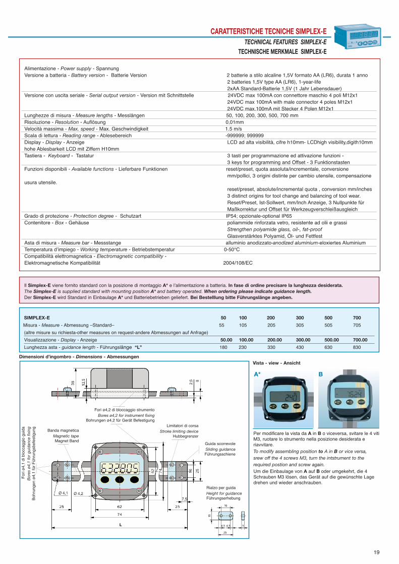
CARATTERISTICHE TECNICHE SIMPLEX-ETECHNICAL FEATURES SIMPLEX-E
TECHNISCHE MERKMALE SIMPLEX-E
Dimensioni d’ingombro - Dimensions - Abmessungen
Alimentazione - Power supply - SpannungVersione a batteria - Battery version - Batterie Version 2 batterie a stilo alcaline 1,5V formato AA (LR6), durata 1 anno
2 batteries 1,5V type AA (LR6), 1-year-life 2xAA Standard-Batterie 1,5V (1 Jahr Lebensdauer)
Versione con uscita seriale - Serial output version - Version mit Schnittstelle 24VDC max 100mA con connettore maschio 4 poli M12x124VDC max 100mA with male connector 4 poles M12x124VDC max.100mA mit Stecker 4 Polen M12x1
Lunghezze di misura - Measure lengths - Messlängen 50, 100, 200, 300, 500, 700 mmRisoluzione - Resolution - Auflösung 0,01mmVelocità massima - Max. speed - Max. Geschwindigkeit 1.5 m/sScala di lettura - Reading range - Ablesebereich -999999; 999999Display - Display - Anzeige LCD ad alta visibilità, cifre h10mm- LCDhigh visibility,digith10mm hohe Ablesbarkeit LCD mit Ziffern H10mmTastiera - Keyboard - Tastatur 3 tasti per programmazione ed attivazione funzioni -
3 keys for programming and Offset - 3 FunktionstastenFunzioni disponibili - Available functions - Lieferbare Funktionen reset/preset, quota assoluta/incrementale, conversione
mm/pollici, 3 origini distinte per cambio utensile, compensazione usura utensile.
reset/preset, absolute/incremental quota , conversion mm/inches 3 distinct origins for tool change and balancing of tool wear.Reset/Preset, Ist-Sollwert, mm/Inch Anzeige, 3 Nullpunkte für Maßkorrektur und Offset für Werkzeugverschleißausgleich
Grado di protezione - Protection degree - Schutzart IP54; opzionale-optional IP65Contenitore - Box - Gehäuse poliammide rinforzata vetro, resistente ad olii e grassi
Strengthen polyamide glass, oil-, fat-proof Glasverstärktes Polyamid, Öl- und Fettfest
Asta di misura - Measure bar - Messstange alluminio anodizzato-anodized aluminium-eloxiertes AluminiumTemperatura dʼimpiego - Working temperature - Betriebstemperatur 0-50°CCompatibilità elettromagnetica - Electromagnetic compatibility -Elektromagnetische Kompatibilität 2004/108/EC
Vista - view - Ansicht
A* B
SIMPLEX-E 50 100 200 300 500 700
Misura - Measure - Abmessung –Standard– 55 105 205 305 505 705
(altre misure su richiesta-other measures on request-andere Abmessungen auf Anfrage)
Visualizzazione - Display - Anzeige 50.00 100.00 200.00 300.00 500.00 700.00
Lunghezza asta - guidance length - Führungslänge “L” 180 230 330 430 630 830
Il Simplex-E viene fornito standard con la posizione di montaggio A* e lʼalimentazione a batteria. In fase di ordine precisare la lunghezza desiderata.The Simplex-E is supplied standard with mounting position A* and battery operated. When ordering please indicate guidance length.Der Simplex-E wird Standard in Einbaulage A* und Batteriebetrieben geliefert. Bei Bestelllung bitte Führungslänge angeben.
For
i ø4,
1 di
blo
ccag
gio
guid
aB
ores
ø4,
1 fo
r gu
idan
ce f
ixin
g
Boh
rung
en ø
4,1
für
Füh
rung
sbef
estig
ung
Banda magneticaMagnetic tapeMagnet Band
Fori ø4,2 di bloccaggio strumentoBores ø4,2 for instrument fixing
Bohrungen ø4,2 für Gerät BefestigungLimitatori di corsa
Stroke limiting deviceHubbegrenzer
Guida scorrevoleSliding guidanceFührungsschiene
Per modificare la vista da A in B o viceversa, svitare le 4 vitiM3, ruotare lo strumento nella posizione desiderata e riavvitare.To modify assembling position to A in B or vice versa,srew off the 4 screws M3, turn the intstrument to the required postion and screw again.Um die Einbaulage von A auf B oder umgekehrt, die 4Schrauben M3 lösen, das Gerät auf die gewünschte Lagedrehen und wieder anschrauben.
Rialzo per guida Height for guidanceFührungserhebung

20
VISUALIZZATORI DI QUOTE E BANDA MAGNETICA
DIMENSIONS DISPLAY AND MAGNETIC BAND
MESSANZEIGEN UND MAGNETBAND
F20F20RF18F18R
Sono visualizzatori di quote con sensore di posizione integrato da abbinare alla banda magnetica, per realizzare un sistema completo per lamisura di spostamenti lineari o angolari.Eʼ possibile selezionare il senso di conteggio, la posizione del punto decimale e lʼunità di misura (mm o pollici, gradi). La quota visualizzata può essere corretta da un fattore moltiplicativo programmabile, con valori compresi fra 0,00001 e 999999. La visualizzazione della quota può avvenire in modalità assoluta o incrementale premendo lʼapposito tasto; in questo modo si consente di effettuaremisure relative allʼinterno del campo di misura. Eʼ possibile impostare una quota di preset richiamabile con lʼapposito tasto. Sono disponibili origini distin-te per la correzione quota quando si utilizzano utensili diversi e la funzione di offset per la compensazione dell’usura utensile. In modo sempli-ce si possono inibire i tasti di richiamo quota di preset e di passaggio quota assoluta/quota relativa. Sul display sono visualizzate con simboli tutte le funzioni attivate. Lʼindicazione di batteria scarica inizia a lampeggiare e resta accesa fissa un meseprima della sostituzione; tale sostituzione viene effettuata con facilità senza perdita della quota, a macchina ferma.• Versioni:F20 con alimentazione interna con 4 pile da 1,5V AA stilo LR6 (durata media di 24 mesi); F18 con alimentazione interna con 2 pile da 1,5VAA stilo LR6 (durata media di 12 mesi); F20R, F18R con alimentazione esterna 10÷25Vdc e batteria ricaricabile interna (funzionamento 5 mesi inassenza di alimentazione), porta seriale RS485 MODBUS RTU per il colloquio con unità remote.
These are dimensions display with integrated position sensor to be combined to the magnetic band in order to carry out a complete devicefor measuring linear or angular shiftings. It is possible to select the count direction, the position of the decimal point on the displayed dimension,and the measure unit (mm or inches, degrees). The displayed dimension may be corrected through a programmable factor with values ranging from0,00001 and 999999. The dimension display may be carried out either in absolute or in incremental mode by simply pressing the suitable key; thisrelative measures within the measuring field may be carried out. It is also possible to set a preset dimension that may be recalled through the suitablekey. There are also available distinct origins for the correction of quota by using different tools and the offset function for the balancing of toolwear. The keys enabling to recall the preset dimension and the absolute dimension/relative dimension switch may be inhibited in a very simple way. On the display all activated functions are showed by a symbol. The run-down of battery is indicated with occasional blinking, 1 month before the com-plete flat the indication remains on; changing of battery is carried out in very easy way and without loosing quota, by standing machine.• Versions: F20 with internal power supply (4 batteries type AA of 1,5V: two-year-life); F18 with internal power supply (2 batteries type AA of 1,5V:one-year-life); F20R,F18R with external power supply 10-25Vdc and internal rechargeable battery (functioning for 5 months without power supply),serial output RS485 protocol MODBUS RTU for communication with remote units.
Die batteriebetriebenen Messanzeigen sind als kompakte Messeinheiten inkl. Magnetsensor und Magnetband lieferbar. Sämtliche Parameter wie: Zählrichtung, Auflösung, Skalierungsfaktor (0,0001 – 9,9999) und Messeinheit (mm/Inch) sind frei wählbar.Wichtige Funktionen wie absolut/relativ Mass, Reset/Preset, Offsetwert, freie und einfache Parametrierung verleihen dem Einsatz in Maschinen undIndustrieanlagen besondere Unterstützung zur exakten und rationellen Produktion.Durch den Batteriebetrieb kann in zahlreichen Anwendungen die Messanzeige mit dem Magnetsensor zusammen verfahren werden. Dies erspart auf-wändige Verkabelungsaufwand.Der Batteriezustand wird angezeigt, und bei Batteriewechsel bleiben sämtliche Daten und Messwerte erhalten.• Versionen: F20 batteriebetrieben, eingebaut (4 Batterien Typ AA von 1,5V (Batterielebensdauer ca. 2 Jahre); F18 batteriebetrieben, eingebaut (2Batterien Typ AA von 1,5V (Batterielebensdauer ca. 1 Jahr); F20R, F18R mit Fremdspannung 10-25 VDC mit wiederaufladbarer Batterie (5 MonateBetrieb ohne Fremdspannung) Schnittstelle RS485 Protokoll MODBUS RTU für Datenübertragung.

21
CARATTERISTICHE TECNICHE F20 - F18TECHNICAL FEATURES F20 - F18
TECHNISCHE MERKMALE F20 - F18
1,6
0,3
10,
3
A
B
C
14,5
3,5
30
417
3,5
10
9,5
5
PGMRESET
ENTER
ABS
REL
mm
inch
F18
92
6672
5596
48
72
66
44
F20F 18
Dimensioni d’ingombro - Dimensions - Abmessungen Foratura - Panel cut-out - Aussparung
Sensore - Sensor - Sensor S25
Banda magnetica - Magnetic Band Magnet Band P25
Alimentazione - Power supply - Versorgung F20: 4 batterie AA 1,5V - 4 batteries AA 1,5V - 4 Batterien AA 1,5V F20R: esterna 10-25 Vdc - external 10-25 Vdc - 10-25VdcF18: 2 batterie AA 1,5V - 2 batteries AA 1,5V - 2 Batterien AA 1,5V F18R: esterna 10-25 Vdc - external 10-25 Vdc - 10-25Vdc Fremdspannung
Visualizzazione - Display - Anzeige F20: -9999999 +9999999 - F18: -999999 +999999 - LCD Risoluzione - Resolution - Auflösung 0,1 mmPorta seriale - Serial port - Schnittstelle F20R - F18R: RS485 MODBUS RTUTastiera - Keyboard - Tastatur 4 F20, 3 F18 tasti per programmazione ed attivazione funzioni - 4 F20, 3 F18 keys
for programming and start of functions - 4 F20, 3 F18 FunktionstastenFunzioni - Available functions - Lieferbare Funktionen Reset/preset, quota assoluta/incrementale, conversione mm/pollici, visualizzazione
in gradi, origini distinte per cambio utensile: 5 per F20 3 per F18, compensazione usura utensile - Reset/preset, absolute/incremental quota, conversion mm/inch, visualisation in degrees, distinct origin for tool changing: 5 for F20 3 for F18, balancing of tool wear - reset/preset; absolut/inkremental Umschaltung; mm/inch/Grad wählbar; verschiedene Nullpunkte für Masskorrektur 5 für F203 für F18; Wekzeugverschleiss Ausgleichung
Temperatura di impiego - Working temperature - Betriebstemperatur 0 +50°CUmidità relativa - Relative humidity - Relative Feuchtigkeit 30 - 90%Compatibilità elettromagnetica - Electromagnetic compatibility 2004/108/ECElektromagnetische Kompatibilität Dati tecnici sensore S25 - Sensor technical data S25 - Sensor technische Daten S25Lunghezza cavo - Cable length - Kabellänge 0,5 m - 1,0 m - 3,0 m - 5,0 m.Materiale - Material - Material metallo - metal - MetallTemperatura di lavoro - Working temperature - Betriebstemperatur 0° + 50°CDistanza sensore/banda - Sensor/band distance - Entfernung Sensor/Band max. 0.8 mmVelocità massima sensore - Sensor max. speed - Sensor Höchstgeschwindigkeit max. 2,5 m/secDati tecnici banda magnetica P25 - Magnetic band technical data P25 - Magnet Band Technische Daten P25Larghezza/spessore/lunghezza - Width/thickness/length - Breite/Höhe/Länge 10 mm - 1,6 mm - 25 m. max.Temperatura di lavoro - Working temperature - Betriebstemperatur -20° +80°CPrecisione - Precision - Auflösung 0,1 mm/mDilatazione termica - Thermic expansion - Thermische Ausdehnung 11 ppm/KRaggio di curvatura - Bending radius - Biegungsradius 7,5 cm.
Sensore integrato tipo S25 e banda magnetica tipo P25Nel sensore sono inseriti ponti magnetoresistivi che inviano il segnale letto sulla banda magnetica allaelettronica di conversione.La banda P25 con polo magnetico da 2.5 mm è realizzata con lʼuso di tre componenti:
A Nastro in plastoferrite magnetizzato flessibile B Banda metallica che serve come protezione da sporco e da eventuali attriti meccanici.
Da montare a cura del cliente.C Nastro metallico in inox premontato in fabbrica da incollare sul lato macchina.
Integrated sensor type S25 and magnetic Band Type P25The sensor fits magneto-resistive bridges that send the signal read on the magnetic band to the conver-sion electronics.The P25 band with 2.5 mm magnetic pole is realised with the use of three components:A Ribbon in magnetized resilient plastic ferriteB Metal plate used as protection against dirt and possible mechanical frictions.
To be installed by the customer.C Strip in stainless steel Factory preassembled to be glued on the machine side.
Magnetsensor S25 mit integrierter Auswerte-Elektronik / P25 MagnetbandDer Sensor S25 tastet die +/- Pole wechselseitig ab und sendet die Signale richtungserkennend an dieMessanzeige. Das Magnetband P25 ist in 2,5 mm Teilung magnetisiert und besteht aus 3 Schichten:A Magnetisierte Schicht (Plastoferrit).B Edelstahl – Abdeckband inkl. Doppelklebeband als mech. Schutz.C Trägerband, nichtrostend, inkl. Doppelklebeband, vorbereitet zum Aufkleben auf den
Maschinenkörper.
Elemento di letturaReading partAblesungselement

22
VISUALIZZATORE DI QUOTE CON TRASDUTTORE MAGNETICO A FILODIMENSIONS DISPLAY WITH MAGNETIC WIRE TRANSDUCERMESSANZEIGEN MIT MAGNETISCHEM SEILZUGEBER
F20 - F18 - EFB
Sono visualizzatori da abbinare al trasduttore magnetico a filo EFB, per realizzare un sistema completo per la misura di spostamenti linearicaratterizzati dalla facilità di applicazione grazie all’alimentazione a batteria ed all’intrinseca semplicità di messa in opera del trasduttore afilo. La visualizzazione della quota può avvenire in modalità assoluta o incrementale premendo lʼapposito tasto; in questo modo si consente di effet-tuare misure relative allʼinterno del campo di misura. Eʼ possibile selezionare il senso di conteggio, la posizione del punto decimale e lʼunità di misura(mm o pollici, gradi). La quota visualizzata può essere corretta da un fattore moltiplicativo programmabile, con valori compresi fra 0,00001 e 999999. Si può impostare una quota di preset richiamabile. Sono disponibili origini distinte per la correzione quota quando si utilizzano utensili diversi e la funzione di offset (compensazione dell’usurautensile). Si possono inibire i tasti di richiamo quota di preset e di passaggio quota assoluta/quota relativa. Sul display sono visualizzate con simboli tutte le funzioni attivate. I dati impostati sono memorizzati nella memoria interna e non vengono mai persi.Cartteristica peculiare é il mantenimento della quota visualizzata, con funzionamento in modo assoluto per tutto il tempo di durata delle batterie.• Modelli: F20 con alimentazione interna con 4 pile da 1,5V AA stilo LR6 (durata media di 24 mesi). Modello: F18 con alimentazione interna con 2pile da 1,5V AA stilo LR6 (durata media di 12 mesi). Lʼindicazione di batteria scarica inizia a lampeggiare e resta accesa fissa un mese prima della sosti-tuzione; tale sostituzione viene effettuata con facilità senza perdita della quota, a macchina ferma.• Modelli: F20R, F18R con alimentazione esterna 10÷25Vdc e batteria ricaricabile interna (funzionamento 5 mesi in assenza di alimentazione), portaseriale RS485 MODBUS RTU per il colloquio con unità remote.
F20- and F18- are dimensions display to be combined to the magnetic transducer EFB in order to carry out a complete device for measuringlinear shiftings characterized by an easy applicaton by the means of the battery-supply, and by an easy installation of the wire transducer.The dimension display may be carried out either in absolute or in incremental mode by simply pressing the suitable key; this relative measures withinthe measuring field may be carried out. It is possible to select the count direction, the position of the decimal point on the displayed dimension, andthe measure unit (mm or inches, degrees). The displayed dimension may be corrected through a programmable factor with values ranging from 0,00001and 999999. It is possible to set a preset dimension that may be recalled through the suitable key. There are also available distinct origins for the correction of quota by using different tools and the offset function for the balancing of tool wear.The keys enabling to recall the preset dimension and the absolute dimension/relative dimension switch may be inhibited in a very simple way. The set data are stored in the inner memory and they cannot never get lost. The most important characteristic is the keeping of the displayed quota inabsolute mode functioning all through battery life. On the display all activated functions are showed by a symbol.• Types: F20 with internal power supply (4 batteries type AA of 1,5V: two-year-life). Type: F18 with internal power supply (2 batteries type AA of1,5V: one-year-life). The run-down of battery is indicated with occasional blinking, 1 month before the complete flat the indication remains on; chan-ging of battery is carried out in very easy way and without loosing quota, by standing machine.• Types: F20R, F18R with external power supply 10-25Vdc and internal rechargeable battery (functioning for 5 months without power supply), serialoutput RS485 protocol MODBUS RTU for communication with remote units.
Die batteriebetriebenen Messanzeigen sind als kompakte Messeinheiten inkl. Magnetsensor / Seilzugeber, magnetisch lieferbar. Dieses System bie-tet eine ideale und komplette Lösung für Messung von Linearverschiebungen. Praktische Anwendung durch Batterie-Spannung und einfacheEinrichtung von Seilzugeber. Sämtliche Parameter wie: Zählrichtung, Auflösung, Skalierungsfaktor (0,0001 – 9,9999) und Messeinheit (mm/Inch) sind frei andie jeweiligen Spindelsteigungen wählbar.Wichtige Funktionen wie absolut/relativ Mass, Reset/Preset, Offsetwert, freie und einfache Parametrierung verleihen dem Einsatz in Maschinen undIndustrieanlagen besondere Unterstützung zur exakten und rationellen Produktion.Durch den Batteriebetrieb kann in zahlreichen Anwendungen die Messanzeige mit dem Magnetischem Hohlwellengeber zusammen betrieben werden. Dieserspart aufwändige Verkabelungsaufwand.Der Batteriezustand wird angezeigt, und bei Batteriewechsel bleiben sämtliche Daten und Messwerte erhalten.• Versionen: F20 batteriebetrieben, eingebaut 4 Batterien Typ AA von 1,5V (Batterielebensdauer ca. 2 Jahre); F18 batteriebetrieben, eingebaut (2 Batterien TypAA von 1,5V (Batterielebensdauer ca. 1 Jahr) • Versionen: F20R, F18R mit Fremdspannung 10-25 VDC mit wiederaufladbarer Batterie (5 Monate Betrieb ohne Fremdspannung) Schnittstelle RS485Protokoll MODBUS RTU für Datenübertragung.

23
CARATTERISTICHE TECNICHE F20 - F18 - EFBTECHNICAL FEATURES F20 - F18 - EFB
TECHNISCHE MERKMALE F20 - F18 - EFB
48
20
20
16
55
48
20
20
ø 4
ø 4 2,5
48
23
M6
13,5
5,5
PGMRESET
ENTER
ABS
REL
mm
inch
F18
92
6672
55 9096
48
72
66
44
F20F 18
Alimentazione - Power supply - Versorgung F20: 4 batterie AA 1,5V - 4 batteries AA 1,5V - 4 Batterien AA 1,5V F20R: esterna 10-25 Vdc - external 10-25 Vdc - 10-25Vdc FremdspannungF18: 2 batterie AA 1,5V - 2 batteries AA 1,5V - 2 Batterien AA 1,5V F18R: esterna 10-25 Vdc - external 10-25 Vdc - 10-25Vdc Fremdspannung
Visualizzazione - Display - Anzeige F20: -9999999 +9999999 - F18: -999999 +999999 - LCD Porta seriale - Serial port - Schnittstelle F20R - F18R: RS485 MODBUS RTUTastiera - Keyboard - Tastatur 4 F20, 3 F18 tasti per programmazione ed attivazione funzioni - 4 F20, 3 F18 keys
for programming and start of functions - 4 F20, 3 F18 FunktionstastenFunzioni - Available functions - Lieferbare Funktionen Reset/preset, quota assoluta/incrementale, conversione mm/pollici, visualizzazione
in gradi, origini distinte per cambio utensile: 5 per F20 3 per F18, compensazione usura utensile - Reset/preset, absolute/incremental quota, conversion mm/inch, visualisation in degrees, distinct origin for tool changing: 5 for F20 3 for F18, balancing of tool wear - reset/preset; absolut/inkremental Umschaltung; mm/inch/Grad wählbar; verschiedene Nullpunkte für Masskorrektur 5 für F203 für F18; Wekzeugverschleiss Ausgleichung
Grado di protezione - protection degree - Schutzart IP54Temperatura di impiego - Working temperature - Betriebstemperatur 0°- +50°CUmidità relativa - Relative humidity - Relative Feuchtigkeit 30 -90%Compatibilità elettromagnetica - Electromagnetic compatibility 2004/108/ECElektromagnetische Kompatibilität
Dati tecnici trasduttore - Transducer technical data - Auflösung technische Daten EFB
Modelli - Versions - Ausführungen EFB500 corsa - stroke - Messweg 500mm;EFB700 corsa - stroke - Messweg 700mm;EFB900 corsa - stroke - Messweg 900mm;
Collegamento - Connection - Anschluss F20,F18-EFB Cavo diretto - Direct cable - Direkt KabelConnettore orientabile - Adjustable connector - Richtbarer VerbinderLunghezza cavo diretto- Cable length - Kabellänge 1,0 m - 2,0 m - 5,0 m
Risoluzione - Resolution - Auflösung 0,05mmVelocità massima - Max. speed - Höchstgeschwindigkeit 0,5m/sGrado di protezione - protection degree - Schutzart IP54Temperatura di lavoro - Working temperature - Betriebstemperatur 0° +50°CCompatibilità elettromagnetica - Electromagnetic compatibility 2004/108/ECElektromagnetische Kompatibilität
Collegamento diretto strumento-trasduttore con cavo Connection instrument-transducer direct with cableDirekt Anschluss Gerät-Geber mit Kabel
Collegamento strumento-trasduttore con connettoreorientabileConnection instrument-transducer with adjustableconnectorAnschluss Gerät-Geber mit richtbarem Stecker
Dimensioni d’ingombro - Dimensions - Abmessungen
EFB
Dimensioni d’ingombro - Dimensions - Abmessungen Foratura - Panel cut-out - Aussparung

VISUALIZZATORE DI QUOTE CON TRASDUTTORE MAGNETICO AD ALBERO PASSANTEDIMENSIONS DISPLAY WITH MAGNETIC TRANSDUCER, HOLLOW SHAFTMESSANZEIGEN MIT MAGNETISCHEM HOHLWELLENGEBER
F20 - F18 - EN20M
Sono visualizzatori da abbinare al trasduttore magnetico EN20M, per realizzare un sistema completo per la misura di spostamenti lineari oangolari. La visualizzazione della quota può avvenire in modalità assoluta o incrementale premendo lʼapposito tasto; in questo modo si consente dieffettuare misure relative allʼinterno del campo di misura. Eʼ possibile selezionare il senso di conteggio, la posizione del punto decimale e lʼunità di misu-ra (mm o pollici, gradi). La quota visualizzata può essere corretta da un fattore moltiplicativo programmabile, con valori compresi fra 0,00001 e 999999. Si può impostare una quota di preset richiamabile. Sono disponibili origini distinte per la correzione quota quando si utilizzano utensili diversi e la funzione di offset (compensazione dell’usurautensile). Si possono inibire i tasti di richiamo quota di preset e di passaggio quota assoluta/quota relativa. Sul display sono visualizzate con simboli tutte le funzioni attivate. I dati impostati sono memorizzati nella memoria interna e non vengono mai persi.Cartteristica peculiare é il mantenimento della quota visualizzata, con funzionamento in modo assoluto per tutto il tempo di durata delle batterie.• Modelli: F20 con alimentazione interna con 4 pile da 1,5V AA stilo LR6 (durata media di 24 mesi). Modello: F18 con alimentazione interna con 2pile da 1,5V AA stilo LR6 (durata media di 12 mesi). Lʼindicazione di batteria scarica inizia a lampeggiare e resta accesa fissa un mese prima della sosti-tuzione; tale sostituzione viene effettuata con facilità senza perdita della quota, a macchina ferma.• Modelli: F20R, F18R con alimentazione esterna 10÷25Vdc e batteria ricaricabile interna (funzionamento 5 mesi in assenza di alimentazione), portaseriale RS485 MODBUS RTU per il colloquio con unità remote.
F20- and F18- are dimensions display to be combined to the magnetic transducer EN20M in order to carry out a complete device for measu-ring linear or angular shiftings. The dimension display may be carried out either in absolute or in incremental mode by simply pressing the suita-ble key; this relative measures within the measuring field may be carried out. It is possible to select the count direction, the position of the decimal pointon the displayed dimension, and the measure unit (mm or inches, degrees). The displayed dimension may be corrected through a programmable fac-tor with values ranging from 0,00001 and 999999. It is possible to set a preset dimension that may be recalled through the suitable key. There are also available distinct origins for the correction of quota by using different tools and the offset function for the balancing of tool wear.The keys enabling to recall the preset dimension and the absolute dimension/relative dimension switch may be inhibited in a very simple way. The set data are stored in the inner memory and they cannot never get lost. The most important characteristic is the keeping of the displayed quota inabsolute mode functioning all through battery life. On the display all activated functions are showed by a symbol.• Types: F20 with internal power supply (4 batteries type AA of 1,5V: two-year-life). Type: F18 with internal power supply (2 batteries type AA of 1,5V:one-year-life). The run-down of battery is indicated with occasional blinking, 1 month before the complete flat the indication remains on; changing ofbattery is carried out in very easy way and without loosing quota, by standing machine.• Types: F20R, F18R with external power supply 10-25Vdc and internal rechargeable battery (functioning for 5 months without power supply), serialoutput RS485 protocol MODBUS RTU for communication with remote units.
Die batteriebetriebenen Messanzeigen sind als kompakte Messeinheiten inkl. Magnetsensor / Hohlwellengeber, magnetisch lieferbar. Sämtliche Parameter wie: Zählrichtung, Auflösung, Skalierungsfaktor (0,0001 – 9,9999) und Messeinheit (mm/Inch) sind frei an die jeweiligen Spindelsteigungenwählbar.Wichtige Funktionen wie absolut/relativ Mass, Reset/Preset, Offsetwert, freie und einfache Parametrierung verleihen dem Einsatz in Maschinen undIndustrieanlagen besondere Unterstützung zur exakten und rationellen Produktion.Durch den Batteriebetrieb kann in zahlreichen Anwendungen die Messanzeige mit dem Magnetischem Hohlwellengeber zusammen betrieben werden. Dieserspart aufwändige Verkabelungsaufwand.Der Batteriezustand wird angezeigt, und bei Batteriewechsel bleiben sämtliche Daten und Messwerte erhalten.• Versionen: F20 batteriebetrieben, eingebaut 4 Batterien Typ AA von 1,5V (Batterielebensdauer ca. 2 Jahre); F18 batteriebetrieben, eingebaut (2 Batterien TypAA von 1,5V (Batterielebensdauer ca. 1 Jahr) • Versionen: F20R, F18R mit Fremdspannung 10-25 VDC mit wiederaufladbarer Batterie (5 Monate Betrieb ohne Fremdspannung) Schnittstelle RS485 ProtokollMODBUS RTU für Datenübertragung.
24

CARATTERISTICHE TECNICHE F20 - F18 - EN20M TECHNICAL FEATURES F20 - F18 - EN20M
TECHNISCHE MERKMALE F20 - F18 - EN20M
48
15
66
24
M 3
30
ø 3
8
ø 6
12
8
M. 4
8
30 6
ø 2
0
ø 2
5 H
7
17,5
20
17,5 2
EN20M
PGMRESET
ENTER
ABS
REL
mm
inch
F18
92
6672
55 9096
48
72
66
44
F20F 18
Dimensioni d’ingombro - Dimensions - Abmessungen
Dimensioni d’ingombro - Dimensions - Abmessungen
Foratura - Panel cut-out - Aussparung
Alimentazione - Power supply - Versorgung F20: 4 batterie AA 1,5V - 4 batteries AA 1,5V - 4 Batterien AA 1,5V F20R: esterna 10-25 Vdc - external 10-25 Vdc - 10-25VdcF18: 2 batterie AA 1,5V - 2 batteries AA 1,5V - 2 Batterien AA 1,5V F18R: esterna 10-25 Vdc - external 10-25 Vdc - 10-25Vdc Fremdspannung
Visualizzazione - Display - Anzeige F20: -9999999 +9999999 - F18: -999999 +999999 - LCD Porta seriale - Serial port - Schnittstelle F20R - F18R: RS485 MODBUS RTUTastiera - Keyboard - Tastatur 4 F20, 3 F18 tasti per programmazione ed attivazione funzioni - 4 F20, 3 F18 keys
for programming and start of functions - 4 F20, 3 F18 FunktionstastenFunzioni - Available functions - Lieferbare Funktionen Reset/preset, quota assoluta/incrementale, conversione mm/pollici, visualizzazione
in gradi, origini distinte per cambio utensile: 5 per F20 3 per F18, compensazione usura utensile - Reset/preset, absolute/incremental quota, conversion mm/inch, visualisation in degrees, distinct origin for tool changing: 5 for F20 3 for F18, balancing of tool wear - reset/preset; absolut/inkremental Umschaltung; mm/inch/Grad wählbar; verschiedene Nullpunkte für Masskorrektur 5 für F203 für F18; Wekzeugverschleiss Ausgleichung
Temperatura di impiego - Working temperature - Betriebstemperatur 0°- +50°CUmidità relativa - Relative humidity - Relative Feuchtigkeit 30 -90%Compatibilità elettromagnetica - Electromagnetic compatibility 2004/108/ECElektromagnetische Kompatibilität
Dati tecnici trasduttore - Transducer technical data - Auflösung technische Daten EN20M
Collegamento F20,F18-EN20M - Connection F20,F18-EN20M Cavo diretto - Direct cable - Direkt KabelAnschluss F20,F18-EN20M Connettore orientabile - Adjustable connector - Richtbarer VerbinderLunghezza cavo diretto- Cable length - Kabellänge 1,0 m - 2,0 m - 5,0 m Risoluzione - Resolution - Auflösung 4000 i/g - p/r - I/UVelocità massima - Max. speed - Höchstgeschwindigkeit 1000 rpmTemperatura di lavoro - Working temperature - Betriebstemperatur 0° +50°CCompatibilità elettromagnetica - Electromagnetic compatibility 2004/108/ECElektromagnetische Kompatibilität
Collegamento diretto strumento-trasduttore con cavo Connection instrument-transducer direct with cableSteckeranschluss drehbar Kabelanschluss
Collegamento strumento-trasduttore con connettoreorientabileConnection instrument-transducer with adjustableconnectorSteckeranschluss drehbar mit richtbaren Verbinder
25

26
POSIZIONATORE MONOASSE
SINGLE-AXIS POSITIONER
EINACHS-POSITIONIERANZEIGE
P2X
Lo strumento P2X è un posizionatore a microprocessore (scala di lettura -99999 +999999) monoasse programmabile con uscita a relé o ana-logica che elabora segnali forniti da trasduttori incrementali quali encoder e righe ottiche, banda magnetica. La programmazione avviene con grande facilità mediante quattro tasti posti sul pannello frontale; un display ausiliario a due caratteri permette una pro-grammazione guidata oltre a visualizzare alcuni parametri durante la lavorazione. La possibilità di creare programmi di lavoro personalizzati, rende il P2X estremamente versatile (macchine da taglio, piegatrici, ecc.).Per ottimizzare lʼaccuratezza del posizionamento, il P2X prevede lʼintroduzione di alcuni parametri in grado di compensare lʼinerzia del sistema, i giochie lʼusura degli accoppiamenti meccanici.Il posizionamento è gestito dalle uscite a relé Start/Stop, Avanti/Indietro, Lento/Veloce, Fine Posizionamento. Eʼ possibile disporre di unʼuscita ana-logica in tensione configurabile come -10 +10V oppure 0 +10V o lʼuscita in corrente 4÷20mA per il controllo di inverter o azionamenti.Gli ingressi del posizionatore Start, Emergenza, Preset, Contapezzi ed ingressi di conteggio sono tutti optoisolati.Altre caratteristiche dello strumento sono: modalità di lavoro automatica/semiautomatica, manuale, assoluta/linea, memorizzazione di 99 quotedi posizionamento con possibilità di programmare il numero di pezzi da eseguire in successione e il numero di ripetizioni del ciclo; funzionedi test per la verifica di ingressi e uscite; collegamento via seriale RS232 o RS485 MODBUS RTU.Le dimensioni contenute e lʼottimo rapporto prezzo/prestazioni, pongono il P2X allʼapice dei posizionatori monoasse.
P2X is a programmable microprocessor single-axis positioner (reading scale -99999 +999999) with relay or analogue outputs that processessignals supplied by incremental transducers such as encoders, optical lines, and magnetic band. The programming may be easily carried out through the four keys that are located on the front panel; a two-character auxiliary display enables a gui-ded programming and displays some parameters during the processing.The opportunity to create customized working programmes makes P2X extremely versatile (cutting machines, bending machines, etc.). In order to optimise the accuracy of positioning P2X offers the possibility to enter some parameters that are able to counterbalance system inertia, clea-rances, and wear of mechanical couplings.Positioning is managed through the Start/Stop, Onward/Backward, Slow/Quick, End of Positioning relay outputs. A voltage analogue output is alsoavailable that may be set up as -10 +10V or 0+10V as well as the 4÷20mA current output for the control of inverters or actuators.All of the positioner inputs Start, Emergency, Preset, Piece-counter, and counting inputs are optoinsulated.The tool also features: automatic/semiautomatic, manual, absolute/line working mode, memorization of 99 positioning dimensions with thepossibility of programming the number of pieces to be worked in sequence and the number of cycle repetitions; test function to check inputsand outputs; RS232 or RS485 MODBUS RTU serial connection.The moderate size and the excellent cost-efficiency ratio put P2X at the top of the existing single-axis positioners.
Das Positionieranzeige P2X ist eine Mikroprozessor gesteuerte 1-Achs Positioniereinrichtung mit Relais- oder Analogausgang. Als Weg – undWinkelgeber bietet Fiama Inkrementalgeber oder Magnetsensoren mit zwei um 90° versetzten Rechtecksignale. Der max. Anzeigebereich ist –99999 +999999. Ein zweites Display unterstützt die Bedienung und den Anzeigekomfort. Die Programmierung erfolgt ganzeinfach über die vier frontseitige Tasten. Durch die Möglichkeit, individuelle Arbeitsprogramme zu gestalten, macht P2X höchst vielseitig in den Bereichen Schneide-, Biegemaschinen, usw.Um die Genauigkeit des Positionierens zu optimieren, verfügt die Serie P2X ebenfalls die Möglichkeit über die Verrechnung zum Spindelspielausgleich.Die Ausgänge Start/Stop, Vorwärts/Rückwärts, Langsam/Schnell, Ende Positionieren werden mit Relais gesteuert. Zusätzlich kann ein Analogausgang Spannung -10 +10V oder 0 +10V bzw. Ausgang in Strom 4÷20mA konfiguriert werden zur Auswertung weitererInverter oder Steuer-Schaltungen. Die Eingänge der Positioniereinrichtung Start, Not-Aus, Preset, Stückzähler und Zähleingänge sind alle optoisoliert.Weitere Eigenschaften der Positionieranzeige sind: Arbeitsweise automatisch/halbautomatisch, manuell, absolut/relativ, Speicherung von 99Messwerten. Vorgegebene Stückzahlen können entsprechend in Reihefolge nach ausgeführt werden und zyklisch wiederholt werden. Funktion Testfür die Überprüfung von Ein- und Ausgängen; serielle Schnittstelle RS232 oder RS485 MODBUS RTU. Durch die geringe Abmessung und das sehr gute Preis/Leistungsverhältnis bietet P2X eine attraktive Lösung im Bereich der Einachs-Positioniertechnik.

27
CARATTERISTICHE TECNICHE P2XTECHNICAL FEATURES P2X
TECHNISCHE MERKMALE P2X
92
4548
11696
Dimensioni d’ingombro - Dimensions - Abmessungen Foratura - Panel cut-out - Aussparung
Alimentazione - Power supply - Versorgung 115Vac, 230Vac, 24Vac, 15÷30Vdc, ±10%Visualizzazione - Display - Anzeige 6 cifre -99999 +999999 per visualizzazione - 2 cifre per programmazione
6 digits -99999 +999999 for display - 2 digits for programming6 Zahlen -99999 +999999 für Anzeige - 2 Zahlen für Programmierung
Potenza assorbita - Absorbed power - Leistungsaufnahme 4 VATipo di ingressi - Type of inputs - Eingangsarten Optoisolati - Optoinsulated - OptoisoliertAlimentazione encoder e sensori - Encoder and sensors supply 12Vdc (max 60mA)Encoder und Sensoren Versorgung Ingresso encoder e sensori - Encoder and sensors inputs Open collector NPN/PNP - Push-pull - Line driverEncoder und Sensoren Eingang Massima frequenza - Maximum frequency - Max. Frequenz 100 KHzModo di funzionamento Semiautomatico/automatico - Assoluto/relativo - Linea - ManualeOperating modes Semiautomatic/automatic - Absolute/relative - Line - ManualBetriebsart Halbautomatisch/automatisch - Absolut/relativ - Linie - ManuellTest automatico - Automatic Test - Automatischer Test Input/output Possibilità di creare programmi di lavoro Memorizzazione di 99 quote - Numero di pezzi - Ripetizioni Possibility of creating working programmes Memorization of 99 dimensions - Number of pieces - RepetitionsMöglichkeit Arbeitsprogramme zu erwirklichen Speicherung von 99 Höhen - Stückzahl - Wiederholungen4 uscite relè 120Vac 0,5A - 24Vdc 1A Start-stop - Avanti-indietro - Lento-veloce - Fine posizionamento4 relay outputs 120Vac 0.5A - 24Vdc 1A Start-stop - Onward-backward - Slow-quick - End of positioning4 Relaisausgänge 120 Vac 0,5A - 24Vdc 1A Start-stop - vor-/rückwärts- schnell-langsam - Positionierungsende 4 ingressi ON-OFF optoisolati 12Vdc Preset - Emergenza - Contapezzi - Start4 optoinsulated ON-OFF inputs 12Vdc Preset - Emergency - Piece-counter - Start4 Eingänge ON-OFF optoisoliert 24 Vdc Preset - Notschalter - Stückzähler - Start Uscita analogica - Analogue output - Analogausgang 4÷20 mA, 0÷10 Vdc, -10 +10 VdcPorta seriale - Serial output - Serieller Ausgang RS232, RS 485 MODBUS RTUContenitore antiurto autoestinguente - Self-extinguishible shock-proof case 48x96x116 DIN 43700 - IP54Selbstlöschendes stoßfestes GehäuseCompatibilità elettromagnetica - Electromagnetic compatibility 2004/108/ECElektromagnetische Kompatibilität
Alimentazione - Power supply - Versorgung
0 115 Vac
1 230 Vac
2 24 Vac
3 15-30 Vdc
P2XSigla di ordinazione - Order outline - Bestellmuster
Interventi - Interventions - Eingriffe
2 2 relé in scambio - switch relays - Umschaltrelais + 2 relé on-off - relays on-off - Relais on-off
1 2
OPZIONALE - OPTIONAL
Uscite - Outputs - Ausgänge
RS232 uscita seriale - serial output - serieller Ausgang + 4 relè - relays - Relais
RS485 uscita seriale - serial output - serieller Ausgang + 4 relè - relays - Relais
T uscita analogica - analogue output - Analogausgang + 2 relè - relays - Relais
TRS485 uscita analogica, uscita seriale - analogue output, serial output - Analogausgang, serieller Ausgang + 2 relè - relays - Relais
T
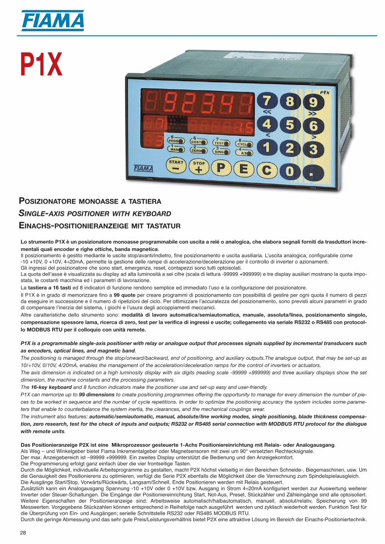
28
POSIZIONATORE MONOASSE A TASTIERA
SINGLE-AXIS POSITIONER WITH KEYBOARD
EINACHS-POSITIONIERANZEIGE MIT TASTATUR
P1X
Lo strumento P1X è un posizionatore monoasse programmabile con uscita a relé o analogica, che elabora segnali forniti da trasduttori incre-mentali quali encoder e righe ottiche, banda magnetica. Il posizionamento è gestito mediante le uscite stop/avanti/indietro, fine posizionamento e uscita ausiliaria. Lʼuscita analogica, configurabile come -10 +10V, 0 +10V, 4÷20mA, permette la gestione delle rampe di accelerazione/decelerazione per il controllo di inverter o azionamenti.Gli ingressi del posizionatore che sono start, emergenza, reset, contapezzi sono tutti optoisolati.La quota dellʼasse è visualizzata su display ad alta luminosità a sei cifre (scala di lettura -99999 +999999) e tre display ausiliari mostrano la quota impo-stata, le costanti macchina ed i parametri di lavorazione.La tastiera a 16 tasti ed 8 indicatori di funzione rendono semplice ed immediato lʼuso e la configurazione del posizionatore.Il P1X è in grado di memorizzare fino a 99 quote per creare programmi di posizionamento con possibilità di gestire per ogni quota il numero di pezzida eseguire in successione e il numero di ripetizioni del ciclo. Per ottimizzare lʼaccuratezza del posizionamento, sono previsti alcuni parametri in gradodi compensare lʼinerzia del sistema, i giochi e lʼusura degli accoppiamenti meccanici.Altre caratteristiche dello strumento sono: modalità di lavoro automatica/semiautomatica, manuale, assoluta/linea, posizionamento singolo,compensazione spessore lama, ricerca di zero, test per la verifica di ingressi e uscite; collegamento via seriale RS232 o RS485 con protocol-lo MODBUS RTU per il colloquio con unità remote.
P1X is a programmable single-axis positioner with relay or analogue output that processes signals supplied by incremental transducers suchas encoders, optical lines, and magnetic band. The positioning is managed through the stop/onward/backward, end of positioning, and auxiliary outputs.The analogue output, that may be set-up as10/+10V, 0/10V, 4/20mA, enables the management of the acceleration/deceleration ramps for the control of inverters or actuators.The axis dimension is indicated on a high luminosity display with six digits (reading scale -99999 +999999) and three auxiliary displays show the setdimension, the machine constants and the processing parameters.The 16-key keyboard and 8 function indicators make the positioner use and set-up easy and user-friendly.P1X can memorize up to 99 dimensions to create positioning programmes offering the opportunity to manage for every dimension the number of pie-ces to be worked in sequence and the number of cycle repetitions. In order to optimize the positioning accuracy the system includes some parame-ters that enable to counterbalance the system inertia, the clearances, and the mechanical couplings wear.The instrument also features: automatic/semiautomatic, manual, absolute/line working modes, single positioning, blade thickness compensa-tion, zero research, test for the check of inputs and outputs; RS232 or RS485 serial connection with MODBUS RTU protocol for the dialoguewith remote units.
Das Positionieranzeige P2X ist eine Mikroprozessor gesteuerte 1-Achs Positioniereinrichtung mit Relais- oder Analogausgang. Als Weg – und Winkelgeber bietet Fiama Inkrementalgeber oder Magnetsensoren mit zwei um 90° versetzten Rechtecksignale. Der max. Anzeigebereich ist –99999 +999999. Ein zweites Display unterstützt die Bedienung und den Anzeigekomfort. Die Programmierung erfolgt ganz einfach über die vier frontseitige Tasten. Durch die Möglichkeit, individuelle Arbeitsprogramme zu gestalten, macht P2X höchst vielseitig in den Bereichen Schneide-, Biegemaschinen, usw. Umdie Genauigkeit des Positionierens zu optimieren, verfügt die Serie P2X ebenfalls die Möglichkeit über die Verrechnung zum Spindelspielausgleich.Die Ausgänge Start/Stop, Vorwärts/Rückwärts, Langsam/Schnell, Ende Positionieren werden mit Relais gesteuert. Zusätzlich kann ein Analogausgang Spannung -10 +10V oder 0 +10V bzw. Ausgang in Strom 4÷20mA konfiguriert werden zur Auswertung weitererInverter oder Steuer-Schaltungen. Die Eingänge der Positioniereinrichtung Start, Not-Aus, Preset, Stückzähler und Zähleingänge sind alle optoisoliert.Weitere Eigenschaften der Positionieranzeige sind: Arbeitsweise automatisch/halbautomatisch, manuell, absolut/relativ, Speicherung von 99Messwerten. Vorgegebene Stückzahlen können entsprechend in Reihefolge nach ausgeführt werden und zyklisch wiederholt werden. Funktion Test fürdie Überprüfung von Ein- und Ausgängen; serielle Schnittstelle RS232 oder RS485 MODBUS RTU. Durch die geringe Abmessung und das sehr gute Preis/Leistungsverhältnis bietet P2X eine attraktive Lösung im Bereich der Einachs-Positioniertechnik.

29
CARATTERISTICHE TECNICHE P1XTECHNICAL FEATURES P1X
TECHNISCHE MERKMALE P1X
140
6872
162144
Dimensioni - Dimensions - Abmessungen Foratura - Panel cut-out - Aussparung
Alimentazione - Power supply - Versorgung 115Vac, 230Vac, 24Vac, 15-30Vdc, ±10%, 7VAVisualizzazione - Display - Anzeige 6 cifre -99999 +999999 per visualizzazione - 3 cifre per programmazione
6 digits -99999 +999999 for display - 3 digits for programming6 Zahlen -99999 +999999 für Anzeige - 3 Zahlen für Programmierung
Tipo di ingressi - Type of inputs - Eingangsarten Optoisolati - Optoinsulated - OptoisoliertAlimentazione encoder e sensori - Encoder and sensors supply 12Vdc (max 60mA)Encoder und Sensoren Versorgung Ingresso encoder e sensori - Encoder and sensors inputs Open collector NPN/PNP - Push-pull - Line driverEncoder und Sensoren Eingang Massima frequenza - Maximum frequency - Max. Frequenz 100 KHzModo di funzionamento Semiautomatico/automatico - Assoluto/relativo - Linea - ManualeOperating modes Semiautomatic/automatic - Absolute/relative - Line - ManualBetriebsart Halbautomatisch/automatisch - Absolut/relativ - Linie - ManuellTest automatico - Automatic Test - Automatischer Test Input/output Possibilità di creare programmi di lavoro Memorizzazione di 99 quote - Numero di pezzi - Ripetizioni Possibility of creating working programmes Memorization of 99 dimensions - Number of pieces - RepetitionsMöglichkeit Arbeitsprogramme zu erwirklichen Speicherung von 99 Höhen - Stückzahl - Wiederholungen 5 uscite relè 250 Vac 5A Start-stop - Avanti-indietro - Lento-veloce - Fine posizionamento - Fine ciclo 5 relay outputs 250 Vac 5A Start-stop - Onward-backward - Slow-quick - End of positioning - Cycle end5 Relaisausgänge 250 Vac 5A Start-stop-vor-/rückwärts- schnell-langsam-Positionierungsende-Endzyklus4 ingressi ON-OFF optoisolati 12Vdc Preset - Emergenza - Contapezzi - Start4 optoinsulated ON-OFF inputs 12Vdc Preset - Emergency - Piece-counter - Start4 Eingänge ON-OFF optoisoliert 12 Vdc Preset - Notschalter - Stückzähler - Start Uscita analogica - Analogue output - Analogausgang 4÷20 mA, 0÷10 Vdc, -10 +10 VdcPorta seriale - Serial output - Serieller Ausgang RS232, RS 485 MODBUS RTUUmidità relativa - Relative Humidity - Relative Feuchtigkeit 30-90%Contenitore antiurto autoestinguente - Self-extinguishible shock-proof case 72x144x162 DIN 43700Selbstlöschendes stoßfestes GehäuseGrado di protezione (frontale) del contenitore IP 54(Front) protection degree of the case - (Frontaler) Gehäuse SchutzartCompatibilità elettromagnetica - Electromagnetic compatibility 2004/108/Elektromagnetische Kompatibilität
Alimentazione - Power supply - Versorgung
0 115 Vac
1 230 Vac
2 24 Vac
3 15-30 Vdc
P1XSigla di ordinazione - Order outline - Bestellmuster
Interventi - Interventions - Eingriffe
2 2 relé in scambio - switch relays - Umschaltrelais + 3 relé on-off - relays on-off - Relais on-off
Uscite - Outputs - Ausgänge
RS232 uscita seriale - serial output - serieller Ausgang + 5 relè - relays - Relais
RS485 uscita seriale - serial output - serieller Ausgang + 5 relè - relays - Relais
T uscita analogica - analogue output - Analogausgang + 2 relè - relays - Relais
TRS485 uscita analogica, uscita seriale - analogue output, serial output - Analogausgang, serieller Ausgang + 2 relè - relays - Relais
OPZIONALE - OPTIONAL
1 2 T

30
POSIZIONATORE MONOASSE CON INGRESSO POTENZIOMETRO
SINGLE-AXIS POSITIONER WITH POTENTIOMETER INPUT
EINACHS-POSITIONIERANZEIGE MIT POTENTIOMETEREINGANG
P3X
Lo strumento P3X è un posizionatore monoasse programmabile a microprocessore con uscite a relé o analogica che elabora segnali fornitida trasduttori di posizione potenziometrici lineari o rotativi.Il posizionamento è gestito mediante le uscite a relé stop/avanti/indietro, lento/veloce, fine posizionamento e uscita ausiliaria. L'uscita analogica, confi-gurabile come 0÷10V, -10 +10V, 4÷20mA, permette la gestione delle rampe di accelerazione/decelerazione per il controllo di inverter o azionamenti. Gli ingressi del posizionatore start, emergenza e contapezzi sono tutti optoisolati.La quota dell'asse è visualizzata su display ad alta luminosità a 5 cifre (scala di lettura -9999 +99999) mentre un display ausiliario a due cifre mostra ilpasso del programma in esecuzione e le costanti di lavoro. La tastiera a 16 tasti con 6 indicatori di funzione rendono semplice ed immediato l'uso e la configurazione del posizionatore.Il P3X è in grado di memorizzare fino a 99 quote per creare programmi di posizionamento con possibilità di gestire per ogni quota il numero di pezzi daeseguire in successione e il numero di ripetizioni del ciclo. Per ottimizzare l'accuratezza del posizionamento, sono previsti alcuni parametri in grado dicompensare l'inerzia del sistema, i giochi e l'usura degli accoppiamenti meccanici.Altre caratteristiche dello strumento sono: modalità di lavoro automatica/semiautomatica, manuale, assoluta/linea, posizionamento singolo, com-pensazione spessore lama; collegamento via seriale RS485 con protocollo MODBUS RTU per il colloquio con unità remote.Il mantenimento dei dati a macchina spenta è garantito da una memoria non volatile EEPROM.
The P3X is a programmable single-axis positioning unit with microprocessor with relay outputs that processes signals supplied by linear orrotating potentiometer position transducer. Positioning is managed through the relay outputs, stop/onward/backward, slow/fast, end of positioning, and auxiliary output. The analogue output, madeout as 0÷10V, -10 +10V, 4÷20mA, allows the control of acceleration/deceleration ramps, for the control of inverters or workings. The inputs, start, emergency, and work counter are optoinsulated. The axis value is visualized on a high-brightness 5-digit display (range -9999 +99999) while an auxiliary 2-digit display shows the steps of program duringthe execution, and the working constants. The keyboard with 16 keys and 6 function indicators make the use and setting up of the positioning unit very easy and immediate.The P3X can memorize up to 99 dimensions to positioning programmes giving the possibility to manage for every dimension the number of pieces thathave to be processed in sequence as well as the number of cycle repetitions. In order to optimize the positioning accuracy there are some parametersthat can balance the system inertia, clearances, wear and tear of mechanical couplings. Other features of the instrument are: working mode in automatic/semiautomatic, manual, absolute/line, single positioning, blade thicknessbalancing; serial connection RS458 with protocol MODBUS RTU for dialogue with remote units. The keeping of data when is no power supply is guaranteed by a non volatile EEPROM memory.
Das Positionieranzeige P3X ist eine einstellbare Mikroprozessor gesteuerte 1-Achs Positioniereinrichtung mit Relais- oder Analogausgang. Als Weg – und Winkelgeber bieten wir Getriebepotentiometer, Linearpotentiometer oder potentiometrische Seilzuggeber. Der max. Anzeigebereich ist–99999 +999999. Ein zusätzliches Displays visualisiert den Programmstatus und die Betriebskonstante während des Betriebes. Die Programmierungerfolgt ganz einfach über 16 frontseitige Bedientasten und 6 Statusanzeigen. Die Möglichkeit, individuelle Arbeitsprogramme zu gestalten, macht P3Xhöchst vielseitig in sämtlichen Produktions– und Bearbeitungsmaschinen, usw.). Um die Genauigkeit des Positionierens zu optimieren, verfügt die SerieP1X ebenfalls die Möglichkeit über die Verrechnung zum Spindelspielausgleich.Die Ausgänge Start, Not-Aus, Stückzähler sid optoisoliert. Zusätzlich kann ein Analogausgang Spannung -10 +10V oder 0 +10V bzw. Ausgang in Strom 4÷20mA konfiguriert werden zur Auswertung weitererInverter oder Steuer-Schaltungen und ermöglicht zusätzlich die Verwaltung von Beschleunigung / Bremskurve Rampen. Die Eingänge der Positioniereinrichtung Start, Not-Aus, Preset, Stückzähler und Zähleingänge sind alle optoisoliert. Weitere Eigenschaften derPositionieranzeige sind: Arbeitsweise automatisch/halbautomatisch, manuell, absolut/relativ, Rampenfahrt und Speicherung von 99 Messwerten.Vorgegebene Stückzahlen können entsprechend in Reihefolge nach ausgeführt werden und zyklisch wiederholt werden. Funktion Test für die Überprüfung von Ein- und Ausgängen; serielle Schnittstelle RS232 oder RS485 MODBUS RTU. Die Daten werden durch einen nichtflüchtigen EEPROM Speicher gehalten.
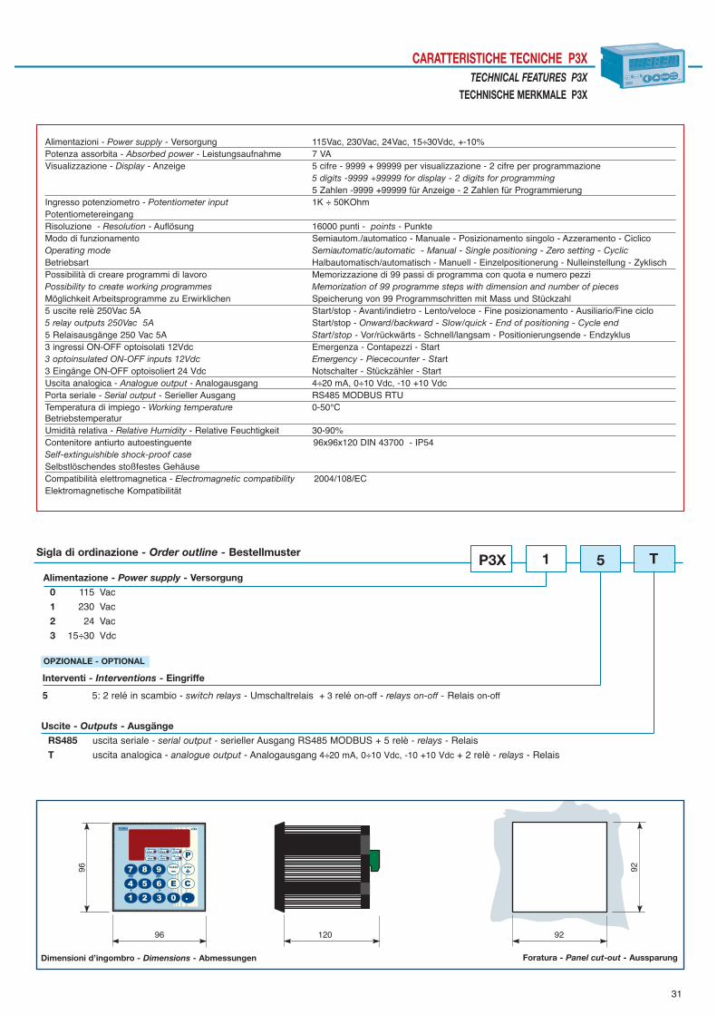
31
CARATTERISTICHE TECNICHE P3XTECHNICAL FEATURES P3X
TECHNISCHE MERKMALE P3X96
96 120 92
92
Dimensioni d’ingombro - Dimensions - Abmessungen Foratura - Panel cut-out - Aussparung
Alimentazioni - Power supply - Versorgung 115Vac, 230Vac, 24Vac, 15÷30Vdc, +-10%Potenza assorbita - Absorbed power - Leistungsaufnahme 7 VAVisualizzazione - Display - Anzeige 5 cifre - 9999 + 99999 per visualizzazione - 2 cifre per programmazione
5 digits -9999 +99999 for display - 2 digits for programming5 Zahlen -9999 +99999 für Anzeige - 2 Zahlen für Programmierung
Ingresso potenziometro - Potentiometer input 1K ÷ 50KOhmPotentiometereingangRisoluzione - Resolution - Auflösung 16000 punti - points - PunkteModo di funzionamento Semiautom./automatico - Manuale - Posizionamento singolo - Azzeramento - CiclicoOperating mode Semiautomatic/automatic - Manual - Single positioning - Zero setting - CyclicBetriebsart Halbautomatisch/automatisch - Manuell - Einzelpositionerung - Nulleinstellung - ZyklischPossibilità di creare programmi di lavoro Memorizzazione di 99 passi di programma con quota e numero pezziPossibility to create working programmes Memorization of 99 programme steps with dimension and number of piecesMöglichkeit Arbeitsprogramme zu Erwirklichen Speicherung von 99 Programmschritten mit Mass und Stückzahl5 uscite relè 250Vac 5A Start/stop - Avanti/indietro - Lento/veloce - Fine posizionamento - Ausiliario/Fine ciclo5 relay outputs 250Vac 5A Start/stop - Onward/backward - Slow/quick - End of positioning - Cycle end5 Relaisausgänge 250 Vac 5A Start/stop - Vor/rückwärts - Schnell/langsam - Positionierungsende - Endzyklus3 ingressi ON-OFF optoisolati 12Vdc Emergenza - Contapezzi - Start3 optoinsulated ON-OFF inputs 12Vdc Emergency - Piececounter - Start3 Eingänge ON-OFF optoisoliert 24 Vdc Notschalter - Stückzähler - Start Uscita analogica - Analogue output - Analogausgang 4÷20 mA, 0÷10 Vdc, -10 +10 VdcPorta seriale - Serial output - Serieller Ausgang RS485 MODBUS RTUTemperatura di impiego - Working temperature 0-50°CBetriebstemperaturUmidità relativa - Relative Humidity - Relative Feuchtigkeit 30-90%Contenitore antiurto autoestinguente 96x96x120 DIN 43700 - IP54Self-extinguishible shock-proof caseSelbstlöschendes stoßfestes GehäuseCompatibilità elettromagnetica - Electromagnetic compatibility 2004/108/ECElektromagnetische Kompatibilität
Alimentazione - Power supply - Versorgung
0 115 Vac
1 230 Vac
2 24 Vac
3 15÷30 Vdc
P3XSigla di ordinazione - Order outline - Bestellmuster
Interventi - Interventions - Eingriffe
5 5: 2 relé in scambio - switch relays - Umschaltrelais + 3 relé on-off - relays on-off - Relais on-off
Uscite - Outputs - Ausgänge
RS485 uscita seriale - serial output - serieller Ausgang RS485 MODBUS + 5 relè - relays - Relais
T uscita analogica - analogue output - Analogausgang 4÷20 mA, 0÷10 Vdc, -10 +10 Vdc + 2 relè - relays - Relais
OPZIONALE - OPTIONAL
1 5 T

32
VISUALIZZATORI CON INGRESSO DA POTENZIOMETRO
DISPLAY WITH POTENTIOMETRIC INPUT
ANZEIGE MIT POTENTIOMETEREINGANG
V3P
Gli strumenti della serie V3P sono visualizzatori multifunzione a microprocessore con ingresso da trasduttore potenziometrico, particolarmen-te indicati per la rilevazione di quote lineari ed angolari su una scala di lettura -1999 +9999 (risoluzione 8000 punti). La realizzazione a microprocessore e lʼimpiego di moderne tecniche di conversione analogico-digitali consentono di ottenere eccellenti prestazioni in ter-mini di facilità di taratura, risoluzione, stabilità, velocità di conversione, costo, permettendo lʼimplementazione di alcune funzioni di particolare interessenelle applicazioni industriali (quota assoluta/relativa, compensazione diametro utensile, ecc.).La quota misurata può essere confrontata con 3 soglie di intervento per lʼattivazione di altrettanti relé, il cui stato é visualizzato mediante led.La taratura e la programmazione si effettuano con grande facilità mediante quattro tasti posti sul pannello frontale.Mediante calibrazione in autoapprendimento è possibile adattare lʼescursione della variabile di ingresso alla scala di lettura desiderata.• Modelli: V3P- visualizzati, V3P-3 visualizzati con 3 interventi ON/0FF.
The instruments of the VE3P series are multifunction microprocessor display units with input from potentiometric transducer that are parti-cularly indicated for the measurement of linear and angular dimensions on a -1999 +9999 reading scale (resolution 8000 points). The carrying out with microprocessor and the use of modern analogue-to-digital conversion techniques enable to obtain excellent performances in termsof calibration easiness, resolution, stability, conversion speed, and cost by enabling the implementation of some functions of interest for the industrialapplications (ex. absolute/relative dimension, tool diameter compensation, etc.).The measured dimension may be compared with 3 intervention thresholds that may be set for the enabling of as many relays, the status of which isdisplayed through a led.The instrument set-up and calibration operations are easily carried out with the four keys positioned on the front panel.Through self-learning calibration it is possible to adapt the input variable amplitude to the wished reading scale.• Models: V3P- displayed, V3P-3 displayed with 3 ON/0FF interventions.
Die Messanzeigen der Serie V3P sind Mikroprozessor gesteuerte Universalanzeigen mit Potentiometereingang zur Weg- und Winkelmessung. Der Anzeigebereich reicht von -1999 - +9999 (Auflösung 8000 Punkte). Die Eichung und die Programmierung erfolgen ganz einfach frontseitig über vierTasten. Durch Verwendung eines Mikroprozessors und dem Einsatz moderner Techniken zur Umwandlung analog-digital werden mit diesem Gerät präziseMessergebnisse hinsichtlich Eichung, Auflösung, Stabilität, Messgeschwindigkeit erreicht. Wichtige Funktionen wie absolut/relativ Mass, Offsetwert, freieund einfache Parametrierung verleihen dem Einsatz in Maschinen und Industrieanlagen besondere Unterstützung zur exakten und rationellen Produktion.Der Messwert kann mit bis zu 3 Grenzwertkontakte über Relais und LED´s visualisiert und überwacht werden.Modelle: V3P – Anzeige; V3P-3 – Anzeige + 3 ON/OFF Schaltausgänge.

33
CARATTERISTICHE TECNICHE V3PTECHNICAL FEATURES V3P
TECHNISCHE MERKMALE V3P
45
4548
9548
Dimensioni d’ingombro - Dimensions - Abmessungen Foratura - Panel cut-out - Aussparung
Alimentazioni - Power supply - Versorgung 115Vac, 230Vac, 24Vac, 12÷30Vdc, ±10%Frequenza di rete - Line frequency - Netzfrequenz 50/60 HzPotenza assorbita - Absorbed power - Leistungsaufnahme 3VAIngresso potenziometro - Potentiometer input - Potentiometereingang 1K ÷ 50KOhmVisualizzazione - Display - Anzeige -1999 +9999Risoluzione convertitore A/D - A/D converter resolution - Auflösung A/D-Wandler 8000 punti -points - Punkte Precisione - Accuracy - Auflösung ±0,1% fondo scala - full scale - VollausschlagLinearità - Linearity - Linearität ±0,025% Numero di letture/secondo - Number of readings per second - Zahl der Lesungen pro Sekunde 8Numero di soglie di intervento - Number of intervention thresholds 3 on/offGrenzwerkontakten Anzahl Isteresi di intervento - Intervention hysteresis - Schalthysterese programmabile - programmable - einstellbarPortata dei contatti relè - Capacity of relay contacts - Leistung der Relais Kontakte 120Vac 0,5 A - 24Vdc 1AStabilità termica - Thermic stability - Thermische Stabilität 60 ppm/°C max.Temperatura di impiego - Working temperature - Betriebstemperatur 0-50°CUmidità relativa - Relative humidity - Relative Feuchtigkeit 30-90%Contenitore antiurto autoestinguente - Self-extinguishible shock-proof case 48x48 - DIN 43700Selbstlöschendes stoßfestes GehäuseGrado di protezione (frontale) del contenitore - (Front) protection degree of the case IP54(Frontaler) Gehäuse SchutzartCompatibilità elettromagnetica - Electromagnetic compatibility - Elektromagnetische Kompatibilität 2004/108/EC
Alimentazione - Power supply - Versorgung0 115 Vac
1 230 Vac
2 24 Vac
3 12-30 Vdc
V3PSigla di ordinazione - Order outline - Bestellmuster
Interventi - Interventions - Schaltausgang
3 3 relè on/off - 3 on/off relays - 3 Relais on/off
31
OPZIONALE - OPTIONAL
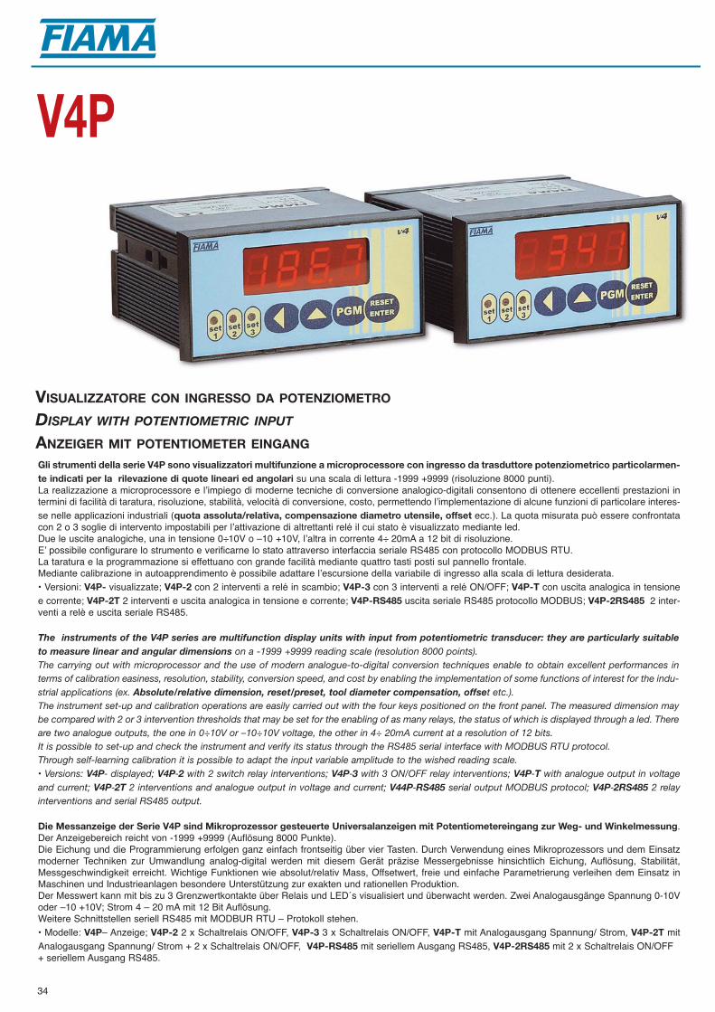
34
VISUALIZZATORE CON INGRESSO DA POTENZIOMETRO
DISPLAY WITH POTENTIOMETRIC INPUT
ANZEIGER MIT POTENTIOMETER EINGANG
V4P
Gli strumenti della serie V4P sono visualizzatori multifunzione a microprocessore con ingresso da trasduttore potenziometrico particolarmen-te indicati per la rilevazione di quote lineari ed angolari su una scala di lettura -1999 +9999 (risoluzione 8000 punti). La realizzazione a microprocessore e lʼimpiego di moderne tecniche di conversione analogico-digitali consentono di ottenere eccellenti prestazioni intermini di facilità di taratura, risoluzione, stabilità, velocità di conversione, costo, permettendo lʼimplementazione di alcune funzioni di particolare interes-se nelle applicazioni industriali (quota assoluta/relativa, compensazione diametro utensile, offset ecc.). La quota misurata può essere confrontatacon 2 o 3 soglie di intervento impostabili per lʼattivazione di altrettanti relé il cui stato è visualizzato mediante led.Due le uscite analogiche, una in tensione 0÷10V o –10 +10V, lʼaltra in corrente 4÷ 20mA a 12 bit di risoluzione.Eʼ possibile configurare lo strumento e verificarne lo stato attraverso interfaccia seriale RS485 con protocollo MODBUS RTU.La taratura e la programmazione si effettuano con grande facilità mediante quattro tasti posti sul pannello frontale.Mediante calibrazione in autoapprendimento è possibile adattare lʼescursione della variabile di ingresso alla scala di lettura desiderata.• Versioni: V4P- visualizzate; V4P-2 con 2 interventi a relé in scambio; V4P-3 con 3 interventi a relé ON/OFF; V4P-T con uscita analogica in tensionee corrente; V4P-2T 2 interventi e uscita analogica in tensione e corrente; V4P-RS485 uscita seriale RS485 protocollo MODBUS; V4P-2RS485 2 inter-venti a relè e uscita seriale RS485.
The instruments of the V4P series are multifunction display units with input from potentiometric transducer: they are particularly suitableto measure linear and angular dimensions on a -1999 +9999 reading scale (resolution 8000 points). The carrying out with microprocessor and the use of modern analogue-to-digital conversion techniques enable to obtain excellent performances interms of calibration easiness, resolution, stability, conversion speed, and cost by enabling the implementation of some functions of interest for the indu-strial applications (ex. Absolute/relative dimension, reset/preset, tool diameter compensation, offset etc.). The instrument set-up and calibration operations are easily carried out with the four keys positioned on the front panel. The measured dimension maybe compared with 2 or 3 intervention thresholds that may be set for the enabling of as many relays, the status of which is displayed through a led. Thereare two analogue outputs, the one in 0÷10V or –10÷10V voltage, the other in 4÷ 20mA current at a resolution of 12 bits.It is possible to set-up and check the instrument and verify its status through the RS485 serial interface with MODBUS RTU protocol.Through self-learning calibration it is possible to adapt the input variable amplitude to the wished reading scale.• Versions: V4P- displayed; V4P-2 with 2 switch relay interventions; V4P-3 with 3 ON/OFF relay interventions; V4P-T with analogue output in voltageand current; V4P-2T 2 interventions and analogue output in voltage and current; V44P-RS485 serial output MODBUS protocol; V4P-2RS485 2 relayinterventions and serial RS485 output.
Die Messanzeige der Serie V4P sind Mikroprozessor gesteuerte Universalanzeigen mit Potentiometereingang zur Weg- und Winkelmessung. Der Anzeigebereich reicht von -1999 +9999 (Auflösung 8000 Punkte). Die Eichung und die Programmierung erfolgen ganz einfach frontseitig über vier Tasten. Durch Verwendung eines Mikroprozessors und dem Einsatzmoderner Techniken zur Umwandlung analog-digital werden mit diesem Gerät präzise Messergebnisse hinsichtlich Eichung, Auflösung, Stabilität,Messgeschwindigkeit erreicht. Wichtige Funktionen wie absolut/relativ Mass, Offsetwert, freie und einfache Parametrierung verleihen dem Einsatz inMaschinen und Industrieanlagen besondere Unterstützung zur exakten und rationellen Produktion.Der Messwert kann mit bis zu 3 Grenzwertkontakte über Relais und LED´s visualisiert und überwacht werden. Zwei Analogausgänge Spannung 0-10Voder –10 +10V; Strom 4 – 20 mA mit 12 Bit Auflösung.Weitere Schnittstellen seriell RS485 mit MODBUR RTU – Protokoll stehen.• Modelle: V4P– Anzeige; V4P-2 2 x Schaltrelais ON/OFF, V4P-3 3 x Schaltrelais ON/OFF, V4P-T mit Analogausgang Spannung/ Strom, V4P-2T mitAnalogausgang Spannung/ Strom + 2 x Schaltrelais ON/OFF, V4P-RS485 mit seriellem Ausgang RS485, V4P-2RS485 mit 2 x Schaltrelais ON/OFF + seriellem Ausgang RS485.

35
CARATTERISTICHE TECNICHE V4PTECHNICAL FEATURES V4P
TECHNISCHE MERKMALE V4P
92
4548
9596
Dimensioni d’ingombro - Dimensions - Abmessungen Foratura - Panel cut-out - Aussparung
Alimentazioni - Power supply - Versorgung 115Vac, 230Vac, 24Vac, 12÷30Vdc, ±10%Frequenza di rete - Line frequency - Netzfrequenz 50/60 HzPotenza assorbita - Absorbed power - Leistungsaufnahme 4VAIngresso potenziometro - Potentiometer input - Potentiometereingang 1K ÷ 50KOhmVisualizzazione - Display - Anzeige -1999 +9999Risoluzione convertitore A/D - A/D converter resolution - Auflösung A/D-Wandler 8000 punti - points - PunktePrecisione - Accuracy - Auflösung ±0,1% fondo scala - full scale - VollausschlagLinearità - Linearity - Linearität ±0,025% Numero di letture per secondo - Number of readings per second - Zykluszeit 8Soglie di intervento - Number of intervention thresholds 2 scambio - Switch - UmschaltungGrenzwertkontakte Anzahl 3 on/offIsteresi di intervento - Intervention hysteresis - Schalthysterese programmabile - programmable - einstellbarPortata dei contatti relè - Capacity of relays contacts - Leistung der Relais Kontakte 120Vac 0,5 A - 24Vdc 1A Max
Uscita analogica - Analogue output - Analogausgang 4÷20 mA, 0÷10 Vdc, -10 +10 VdcUscita seriale - Serial output - Serieller Ausgang RS485 MODBUS RTUTemperatura di impiego - Working temperature - Betriebstemperatur 0-50°CUmidità relativa - Relative Humidity - Relative Feuchtigkeit 30-90%Contenitore antiurto autoestinguente - Self-extinguishible shock-proof case 48x96x95 - DIN 43700Selbstlöschendes stoßfestes GehäuseGrado di protezione (frontale) del contenitore - (Front) protection degree of the case IP54(Frontaler) Gehäuse SchutzartCompatibilità elettromagnetica - Electromagnetic compatibility - Elektromagnetische Kompatibilität 2004/108/EC
Alimentazione - Power supply - Versorgung
0 115 Vac
1 230 Vac
2 24 Vac
3 12-30 Vdc
V4PSigla di ordinazione - Order outline - Bestellmuster
Interventi - Interventions - Eingriffe - Uscite - Outputs - Ausgänge
2 2 relé in scambio - 2 switch relays - 2 Umschaltrelais
3 3 relè on/off - 3 on/off relays - 3 Relais on/off (non disponibile con uscita seriale e analogica -not available with serial and analogue output -nicht lieferbar mit Schnittstelle und Analogausgang)
Uscita - output - Ausgang
RS485 uscita seriale - serial output - Schnittstelle
T uscita analogica - analogue output - Analogausgang 4÷20 mA, 0 ÷10 Vdc, -10 +10 Vdc
2 2 T
OPZIONALE - OPTIONAL

36
VISUALIZZATORI CON INGRESSO IN TENSIONE O CORRENTE
DISPLAY WITH VOLTAGE OR CURRENT INPUT
ANZEIGE MIT SPANNUNGS- ODER STROM EINGANG
V3V - V3I
Gli strumenti della serie V3V, V3I sono visualizzatori multifunzione a microprocessore che accettano in ingresso segnali in tensione o correntecontinua. Sono particolarmente adatti alla indicazione di valori di forza, pressione, peso, variabili di processo, alla visualizzazione di uscite ana-logiche di inverter e azionamenti, ecc. Scala di lettura -1999 +9999 (risoluzione 8000 punti). La realizzazione a microprocessore e lʼimpiego di moderne tecniche di conversione analogico-digitali consentono di ottenere eccellenti prestazioni in ter-mini di facilità di taratura, risoluzione, stabilità, velocità di conversione, costo, permettendo lʼimplementazione di alcune funzioni di particolare interessenelle applicazioni industriali (misura assoluta/relativa, offset programmabile, ecc.)La taratura e la programmazione si effettuano con grande facilità mediante quattro tasti posti sul pannello frontale. Mediante calibrazione in autoapprendimento è possibile adattare lʼescursione della variabile di ingresso alla scala di lettura desiderata. La quota misura-ta può essere confrontata con 3 soglie di intervento impostabili per lʼattivazione di altrettanti relé, il cui stato é visualizzato mediante led.• Modelli: V3V- visualizzati, V3V-3 visualizzati con 3 interventi ON/0FF.• Modelli: V3I- visualizzati, V3I-3 visualizzaticon 3 interventi ON/0FF.
The instruments of the V3V, V3I series are multifunction microprocessor display units accepting both voltage or direct current input signals.They are particularly suitable to display force, pressure, weight values for process variables, analogue outputs of inverters and actuators, etc. Reading scale -1999 +9999 (resolution 8000 points). The carrying out with microprocessor and the use of modern analogue-to-digital conversion techniques enable to obtain excellent performances in termsof calibration easiness, resolution, stability, conversion speed, and cost by enabling the implementation of some functions of interest for the industrialapplications (absolute/relative measures, programmable offset, etc.)The measured dimension may be compared with 3 intervention thresholds that may be set for the enabling of as many relays, the status of which is displa-yed through a led. The instrument set-up and calibration operations are easily carried out with the four keys positioned on the front panel.Through self-learning calibration it is possible to adapt the input variable amplitude to the wished reading scale.• Models: V3V- displayed, V3V-3 displayed with 3 ON/0FF interventions.• Models: V3I- displayed, V3I-3 displayed with 3 ON/0FF interventions.
Die Messanzeigen der Serie V3V – V3I sind Mikroprozessor gesteuerte Universalanzeigen mit Spannung- oder Stromeingang zur Weg- undWinkelmessung. Der Anzeigebereich reicht von -1999 +9999 (Auflösung 8000 Punkte). Die Eichung und die Programmierung erfolgen ganz einfach frontseitig über vier Tasten. Durch Verwendung eines Mikroprozessors und dem Einsatzmoderner Techniken zur Umwandlung analog-digital werden mit diesem Gerät präzise Messergebnisse hinsichtlich Eichung, Auflösung, Stabilität,Messgeschwindigkeit erreicht. Wichtige Funktionen wie absolut/relativ Mass, Offsetwert, freie und einfache Parametrierung verleihen dem Einsatz inMaschinen und Industrieanlagen besondere Unterstützung zur exakten und rationellen Produktion.Zusätzliche Anwendung zur Anzeige von Kraft, Druck, Gewicht, Inverter, Antriebe u.v.m.Der Messwert kann mit bis zu 3 Grenzwertkontakte über Relais und LED´s visualisiert und überwacht werden.• Modelle: V3V – Anzeige; V3V-3 – Anzeige + 3 ON/OFF Schaltausgänge.• Modelle: V3I – Anzeige; V3I-3 – Anzeige + 3 ON/OFF Schaltausgänge.
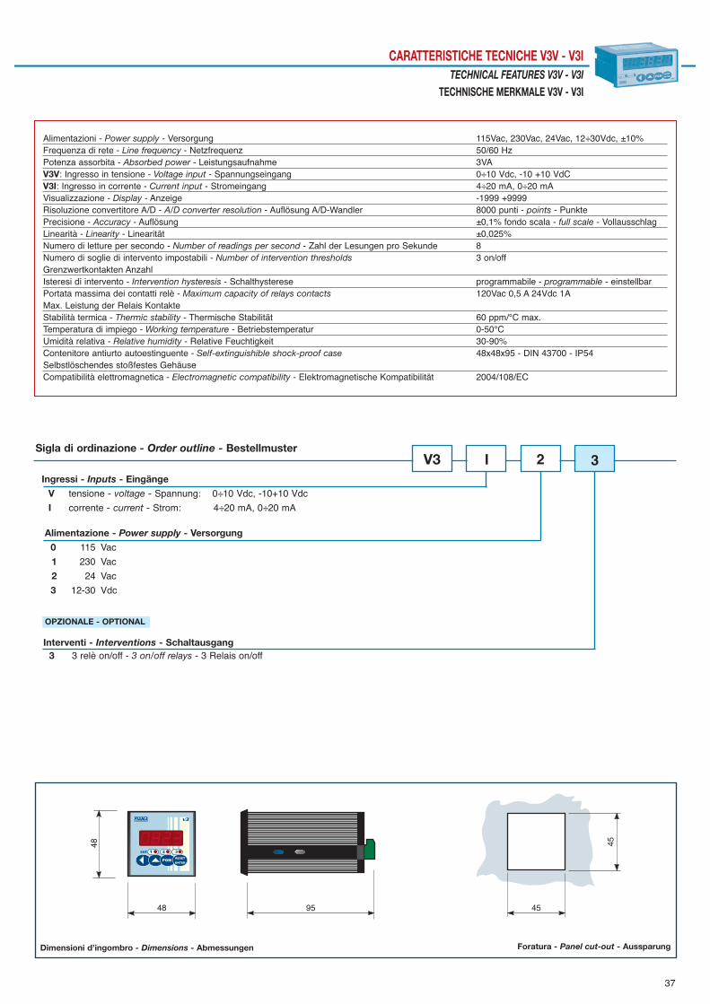
37
CARATTERISTICHE TECNICHE V3V - V3ITECHNICAL FEATURES V3V - V3I
TECHNISCHE MERKMALE V3V - V3I
45
4548
9548
Dimensioni d’ingombro - Dimensions - Abmessungen Foratura - Panel cut-out - Aussparung
Alimentazioni - Power supply - Versorgung 115Vac, 230Vac, 24Vac, 12÷30Vdc, ±10%Frequenza di rete - Line frequency - Netzfrequenz 50/60 HzPotenza assorbita - Absorbed power - Leistungsaufnahme 3VAV3V: Ingresso in tensione - Voltage input - Spannungseingang 0÷10 Vdc, -10 +10 VdCV3I: Ingresso in corrente - Current input - Stromeingang 4÷20 mA, 0÷20 mAVisualizzazione - Display - Anzeige -1999 +9999Risoluzione convertitore A/D - A/D converter resolution - Auflösung A/D-Wandler 8000 punti - points - PunktePrecisione - Accuracy - Auflösung ±0,1% fondo scala - full scale - VollausschlagLinearità - Linearity - Linearität ±0,025% Numero di letture per secondo - Number of readings per second - Zahl der Lesungen pro Sekunde 8Numero di soglie di intervento impostabili - Number of intervention thresholds 3 on/offGrenzwertkontakten AnzahlIsteresi di intervento - Intervention hysteresis - Schalthysterese programmabile - programmable - einstellbarPortata massima dei contatti relè - Maximum capacity of relays contacts 120Vac 0,5 A 24Vdc 1AMax. Leistung der Relais KontakteStabilità termica - Thermic stability - Thermische Stabilität 60 ppm/°C max.Temperatura di impiego - Working temperature - Betriebstemperatur 0-50°CUmidità relativa - Relative humidity - Relative Feuchtigkeit 30-90%Contenitore antiurto autoestinguente - Self-extinguishible shock-proof case 48x48x95 - DIN 43700 - IP54Selbstlöschendes stoßfestes GehäuseCompatibilità elettromagnetica - Electromagnetic compatibility - Elektromagnetische Kompatibilität 2004/108/EC
Alimentazione - Power supply - Versorgung
0 115 Vac
1 230 Vac
2 24 Vac
3 12-30 Vdc
Ingressi - Inputs - Eingänge
V tensione - voltage - Spannung: 0÷10 Vdc, -10+10 Vdc
I corrente - current - Strom: 4÷20 mA, 0÷20 mA
V3Sigla di ordinazione - Order outline - Bestellmuster
Interventi - Interventions - Schaltausgang3 3 relè on/off - 3 on/off relays - 3 Relais on/off
I 2 3
OPZIONALE - OPTIONAL

38
VISUALIZZATORE CON INGRESSO IN TENSIONE O CORRENTE
DISPLAY WITH VOLTAGE OR CURRENT INPUT
ANZEIGER SPANNUNGS- ODER STROM EINGANG
V4V - V4I
Gli strumenti della serie V4V, V4I sono visualizzatori multifunzione a microprocessore che accettano in ingresso segnali in tensione o corren-te continua. Sono particolarmente adatti all’indicazione di valori di forza, pressione, peso, variabili di processo, alla visualizzazione di usciteanalogiche di inverter e azionamenti, ecc. su una scala di lettura -1999 +9999 (risoluzione 8000 punti). La taratura e la programmazione si effettua-no con grande facilità mediante quattro tasti posti sul pannello frontale. La realizzazione a microprocessore e lʼimpiego di moderne tecniche di conver-sione analogico-digitali consentono di ottenere eccellenti prestazioni in termini di facilità di taratura, risoluzione, stabilità, velocità di conversione, costo,permettendo lʼimplementazione di alcune funzioni di particolare interesse nelle applicazioni industriali (quota assoluta/relativa, compensazione dia-metro utensile ecc.). La quota misurata può essere confrontata con 2 o 3 soglie impostabili per lʼattivazione di altrettanti relé il cui stato è visualizza-to mediante led. Due le uscite analogiche, una in tensione 0÷10V o –10 +10V, lʼaltra in corrente 4÷ 20mA a 12 bit di risoluzione. Mediante calibrazionein autoapprendimento è possibile adattare lʼescursione della variabile di ingresso alla scala di lettura desiderata.• Versioni: V4V- solo visualizzate; V4V-2 con 2 interventi a relé in scambio; V4V-3 con 3 interventi a relé ON/OFF; V4V-T con uscita analogica in ten-sione e corrente; V4V-2T 2 interventi e uscita analogica in tensione e corrente; V4V-RS485 uscita seriale RS485 protocollo MODBUS; V4V-2RS485 2interventi a relè e uscita seriale RS485.• Versioni: V4I- solo visualizzate; V4I-2 con 2 interventi ia relé in scambio; V4I-3 con 3 relé ON/OFF; V4I-T con uscita analogica in tensione e corren-te; V4I-2T 2 relé e uscita analogica in tensione e corrente; V4I-RS485 uscita seriale RS485 MODBUS; V4I-2RS485 2 relè e uscita seriale RS485.
The instruments of the V4V, V4I series are multifunction display units accepting either voltage or direct current input signals. They are par-ticularly suitable to display force, pressure, and weight values for process variables and to display analogue outputs of inverters and actua-tors, etc. Reading scale -1999 +9999 (resolution 8000 points). The instrument set-up and calibration operations are easily carried out with the four keyspositioned on the front panel. The carrying out with microprocessor and the use of modern analogue-to-digital conversion techniques enable to obtainexcellent performances in terms of calibration easiness, resolution, stability, conversion speed, and cost by enabling the implementation of some fun-ctions of interest for the industrial applications (ex. absolute/relative dimension, tool diameter compensation, etc.). The measured dimension may becompared with 2 or 3 intervention thresholds that may be set, the status of which is displayed through a led. There are two analogue outputs, the onein 0÷10V or –10 +10V voltage, the other in 4÷ 20mA current at a resolution of 12 bits.Through self-learning calibration it is possible to adapt the input variable amplitude to the wished reading scale.• Versions: V4V-, only displayed; V4V-2,with 2 switch relay interventions; V4V-3,with 3 ON/OFF relay interventions; V4V-T, with voltage and current ana-logue output; V4V-2T, 2 interventions and voltage and current analogue output; V4V-RS485, serial output RS485 MODBUS; V4V-2RS485, 2 relay inter-ventions and RS485 serial output.• Versions: V4I-, only displayed; V4I-2 with 2 switch relay interventions; V4I-3 with 3 ON/OFF relay interventions; V4I-T with voltage and current analo-gue output; V4I-2T, 2 interventions and voltage and current analogue output; V4I-RS485, serial output RS485 MODBUS; V4I-2RS485, 2 relay interven-tions and RS485 serial output.
Die Messanzeigen der Serie V4V – V4I sind Mikroprozessor gesteuerte Universalanzeigen mit Spannung- oder Stromeingang zur Weg- undWinkelmessung. Der Anzeigebereich reicht von -1999 - +9999 (Auflösung 8000 Punkte). Die Eichung und die Programmierung erfolgen ganz einfach frontseitig über vier Tasten. Durch Verwendung eines Mikroprozessors und dem Einsatzmoderner Techniken zur Umwandlung analog-digital werden mit diesem Gerät präzise Messergebnisse hinsichtlich Eichung, Auflösung, Stabilität,Messgeschwindigkeit erreicht. Wichtige Funktionen wie absolut/relativ Mass, Offsetwert, freie und einfache Parametrierung verleihen dem Einsatz inMaschinen und Industrieanlagen besondere Unterstützung zur exakten und rationellen Produktion.Zusätzliche Anwendung zur Anzeige von Kraft, Druck, Gewicht, Inverter, Antriebe u.v.m.Der Messwert kann mit bis zu 3 Grenzwertkontakte über Relais und LED´s visualisiert und überwacht werden. Zwei Analogausgänge Spannung 0-10Voder –10 +10V; Strom 4 – 20 mA mit 12 Bit Auflösung. Weitere Schnittstellen seriell RS485 mit MODBUS RTU – Protokoll stehen zur Verfügung.• Modelle: V4V – Anzeige; V4V-2 2 x Schaltrelais ON/OFF, V4V-3 3 x Schaltrelais ON/OFF, V4V-2 2 x Schaltrelais ON/OFF Schaltausgänge, V4V-T mitAnalogausgang Spannung / Strom, V4V-2T mit Analogausgang Spannung / Strom + 2 x Schaltrelais ON/OFF, V4V-RS485 mit seriellem Ausgang RS485,V4V-2RS485 mit 2 x Schaltrelais ON/OFF + seriellem Ausgang RS485.• Modelle: V4I – Anzeige; V4I-2 2 x Schaltrelais ON/OFF, V4I-3 3 x Schaltrelais ON/OFF, V4I-T mit Analogausgang Spannung/ Strom, V4I-2T mitAnalogausgang Spannung / Strom + 2 x Schaltrelais ON/OFF, V4I-RS485 mit seriellem Ausgang RS485, V4I-2RS485 mit 2 x Schaltrelais ON/OFF +seriellem Ausgang RS485.

39
CARATTERISTICHE TECNICHE V4V - V4ITECHNICAL FEATURES V4V - V4I
TECHNISCHE MERKMALE V4V - V4I
92
4548
9596
Dimensioni d’ingombro - Dimensions - Abmessungen Foratura - Panel cut-out - Aussparung
Alimentazioni - Power supply - Versorgung 115Vac, 230Vac, 24Vac, 12÷30Vdc, ±10%Frequenza di rete - Line frequency - Netzfrequenz 50/60 HzPotenza assorbita - Absorbed power - Leistungsaufnahme 4VAV4V: Ingresso in tensione - Voltage input - Spannungseingang 0÷10 Vdc, -10 +10 VdCV4I: Ingresso in corrente - Current input - Stromeingang 4÷20 mA, 0÷20 mAVisualizzazione - Display - Anzeige -1999 +9999Risoluzione convertitore A/D - A/D converter resolution - Auflösung A/D-Wandler 8000 punti - points - PunktePrecisione - Accuracy - Auflösung ±0,1% fondo scala - full scale - VollausschlagLinearità - Linearity - Linearität ±0,025% Numero di letture per secondo - Number of readings per second - Zykluszeit 8Numero di soglie di intervento - Number of thresholds - Grenzwertkontakte 2 scambio - switched - Umschaltung
3 on/offIsteresi di intervento - Intervention hysteresis - Schalthysterese programmabile - programmable - einstellbarPortata massima dei contatti relè - Maximum capacity of relays contacts 120Vac 0,5 A - 24Vdc 1AMax. Leistung der Relais Kontakte Uscita analogica - Analogue output - Analogausgang 4÷20 mA, 0÷10 Vdc, -10 +10 VdcUscita seriale - Serial output - Serieller Ausgang RS485 MODBUS RTUTemperatura di impiego - Working temperature - Betriebstemperatur 0-50°CUmidità relativa - Relative humidity - Relative Feuchtigkeit 30-90%Contenitore - Self-extinguishible shock-proof case 48x96x95 DIN 43700 - IP54 Selbstlöschendes stoßfestes GehäuseCompatibilità elettromagnetica - Electromagnetic compatibility - Elektromagnetische Kompatibilität 2004/108/EC
Alimentazione - Power supply - Versorgung
0 115 Vac
1 230 Vac
2 24 Vac
3 12-30 Vdc
Ingressi - Inputs - Eingänge
V tensione - voltage - Spannung 0-10 Vdc, -10+10 Vdc
I corrente - current - Strom 0-20 mA, 4-20 mA
V4Sigla di ordinazione - Order outline - Bestellmuster
Interventi - Interventions - Eingriffe - Uscite - Outputs - Ausgänge
2 2 relé in scambio - 2 switch relays - 2 Umschaltrelais
3 3 relè on/off - 3 on/off relays - 3 Relais on/off (non disponibile con uscita seriale e analogica -not available with serial and analogue output -nicht lieferbar mit Schnittstelle und Analogausgang)
Uscita - output - Ausgang
RS485 uscita seriale - serial output - Schnittstelle
T uscita analogica - analogue output - Analogausgang 4÷20 mA, 0 ÷10 Vdc, -10 +10 Vdc
2 2 TI
OPZIONALE - OPTIONAL

40
VISUALIZZATORI CON INGRESSO POTENZIOMETRO, TENSIONE E CORRENTE
DISPLAY WITH POTENTIOMETER, VOLTAGE AND CURRENT INPUT
ANZEIGE MIT POTENTIOMETER-, SPANNUNG-, UND STROMEINGANG
VE6
Gli strumenti VE6 sono visualizzatori multifunzione che accettano in ingresso segnali in tensione 0-40Vdc, in corrente 0-20mAdc e da trasdut-tore potenziometrico 1K ÷ 50KOhm, su una scala di lettura -99999 + 99999 (risoluzione 16 bit, 65536 punti).La realizzazione a microprocessore e lʼimpiego di moderne tecniche di conversione analogico-digitali consentono di ottenere eccellenti prestazioni intermini di facilità di taratura, risoluzione, stabilità, velocità di conversione,costo, permettendo lʼimplementazione di alcune funzioni di particolare interes-se nelle applicazioni industriali (reset/preset, quota assoluta/relativa, compensazione diametro utensile, ecc). Le operazioni di configurazione e taratura dello strumento avvengono con facilità con i quattro tasti posti sul pannello frontale. Mediante calibrazione in autoapprendimento è possibile adattare lʼescursione della variabile di ingresso alla scala di lettura desiderata.• La quota misurata può essere confrontata con 2 soglie impostabili per lʼattivazione di altrettanti relé il cui stato è visualizzato mediante led.• Disponibile in morsettiera ingresso logico optoisolato per lʼimpostazione del reset-preset.• Versioni: VE6- solo visualizzate; VE6-2 con 2 interventi a relé in scambio.- A richiesta personalizzazioni software.
The instruments of the VE6 series are multifunction microprocessor display units accepting 0-40Vdc voltage, 0-20mAdc current input andsignals from potentiometric transducer 1K ÷ 50KOhm. Reading scale -99999 +99999 (resolution 16 bits, 65536 points).Excellent performances in terms of calibration easiness, resolution, stability, conversion speed and cost; some functions are really interesting for theindustrial applications (ex. reset/preset, absolute/relative dimensions, tool diameter compensation, etc.). Through self-learning calibration it is possible to adapt the input variable amplitude to the wished reading scale.The measured dimension may be compared with 2 intervention thresholds that may be set for the enabling of as many relays, the status of which isdisplayed through a led.An optoinsulated logic input is available in the terminal case for the reset-preset setting.The instrument set-up and calibration operations are easily carried out with the four keys positioned on the front panel. •Versions: VE6- only displayed; VE6-2 with 2 switch relay interventions.•Customized Software on request.
Die Messanzeige der Serie VE6 ist eine Mikroprozessor gesteuerte Universalanzeige mit Spannungseingang 0 – 40 VDC oder Stromeingang0-20 mA und Potentiometereingang 1K – 50K-Ohm zur Weg- und Winkelmessung. Der Anzeigebereich reicht von -99999 - +99999 (Auflösung 16 Bit / 65536 Punkte). Die Eichung und die Programmierung erfolgen ganz einfach fron-tseitig über vier Tasten. Durch Verwendung eines Mikroprozessors und dem Einsatz moderner Techniken zur Umwandlung analog-digital werden mitdiesem Gerät präzise Messergebnisse hinsichtlich Eichung, Auflösung, Stabilität, Messgeschwindigkeit erreicht. Wichtige Funktionen wie absolut/relativ Mass, Reset/Preset, Offsetwert, freie und einfache Parametrierung verleihen dem Einsatz in Maschinen undIndustrieanlagen besondere Unterstützung zur exakten und rationellen Produktion.Der Messwert kann über 2 Grenzwerte überwacht werden, angezeigt über 2 integrierte LED.Externer Eingang über Klemmleiste für RESET/PRESET.Modelle: VE6 – Anzeige; VE6-2 – Anzeige + 2 x Schaltrelais ON/OFF.Auf Anfrage Kundenspezifische Software.

41
CARATTERISTICHE TECNICHE VE6TECHNICAL FEATURES VE6
TECHNISCHE MERKMALE VE6
92
4548
9596
Dimensioni d’ingombro - Dimensions - Abmessungen Foratura - Panel cut-out - Aussparung
Alimentazioni - Power supply - Versorgung 115Vac, 230Vac, 24Vac, 12÷30Vdc, ±10%Frequenza di rete - Line frequency - Netzfrequenz 50/60 HzPotenza assorbita - Absorbed power - Leistungsaufnahme 4VAIngresso potenziometro - Potentiometer input - Potentiometereingang 1K ÷ 50KOhmIngresso in tensione - Voltage input - Spannungseingang 0 ÷ 40 VdcIngresso in corrente - Current input - Stromeingang 0 ÷ 20 mAdcVisualizzazione - Display - Anzeige ± 99999Risoluzione - Resolution - Auflösung 16 bit, 65536 punti - points - PunktePrecisione - Accuracy - Präzizion ±0,1% ±1 digitLinearità - Linearity - Linearität ±0,01% ±1 digit Letture per secondo - Number of readings per second - Zykluszeit 15Soglie di intervento - Number of intervention thresholds 2 in scambio - switched - Umschaltung Grenzwertkontakte Portata massima dei contatti relè - Maximum capacity of relays contacts 120Vac 0,5 A - 24Vdc 1AMax. Leistung der Relais Kontakte Isteresi di intervento - Intervention hysteresis - Schalthysterese programmabile - programmable - einstellbarTemperatura di impiego - Working temperature - Betriebstemperatur 0-50°CUmidità relativa - Relative humidity - Relative Feuchtigkeit 30-90%Contenitore antiurto autoestinguente - Self-extinguishible shock-proof case 48x96 - DIN 43700Selbstlöschendes stoßfestes GehäuseGrado di protezione (frontale) del contenitore - (Front) protection degree of the case IP54(Frontal) Gehäuse SchutzartCompatibilità elettromagnetica - Electromagnetic compatibility - Elektromagnetische Kompatibilität 2004/108/EC
Alimentazione - Power supply - Versorgung0 115 Vac
1 230 Vac
2 24 Vac
3 12-30 Vdc
VE6Sigla di ordinazione - Order outline - Bestellmuster
Interventi - Interventions - Eingriffe - Uscite - Outputs - Ausgänge
2 2 relé in scambio - 2 switch relays - 2 Umschaltrelais
2 2
OPZIONALE - OPTIONAL

42
VISUALIZZATORI DI QUOTE, CONTAIMPULSI
DIMENSION DISPLAY, PULSES-COUNTER
MESSWERTANZEIGE, IMPULSZÄHLER
F3X
Lo strumento F3X è un visualizzatore mono-bidirezionale a microprocessore con display a cinque cifre più segno (scala di lettura ± 99.999),particolarmente indicato per la rilevazione di quote lineari ed angolari con segnali forniti da trasduttori incrementali quali encoder e righe otti-che, banda magnetica, sensori di prossimità, ecc.Lʼimpostazione di tutti i parametri che regolano il funzionamento dello strumento, avviene mediante quattro tasti disposti sul frontale.Altre caratteristiche: fattore di correzione degli impulsi in ingresso, attivazione di 2 relè, reset/preset della quota da tastiera e da morsettiera.Tali peculiarità, unite ad un costo contenuto, rendono il visualizzatore F3X estremamente versatile e adatto a numerose applicazioni.• Modelli: F3X- solo visualizzati, F3X- 2 con 2 interventi ON/OFF.
The F3X instrument is a mono-bidirectional display unit with microprocessor with five-digit with sign display (reading scale ± 99.999). It is particularly suitable for the measurement of linear and angular dimensions with signals supplied by incremental transducers such asencoder and optical lines, magnetic band, proximity sensor, etc.The setting of all the parameters that regulate the instrument functioning is carried out through four keys placed on the front panel.Other features: input pulses correction factor, enabling of 2 relays, reset/preset of the dimension from keyboard and from terminal box.These features, together with a low cost, make the F3X display unit extremely versatile and suitable to many different applications.• Models: F3X- only displayed, F3X- 2 with 2 ON/0FF interventions.
Das Gerät F3X ist ein ein-zweiseitiger Mikroprozessor-Anzeiger, mit 5-Zahlen Display Plus Zeichen (Messwertskala ± 99.999), der insbeson-dere für die Messung der Linear- und Winkelmaße mit Signalen aus Inkrementalwandlern, wie Encoder und optischen Linien, magnetischemBand, kontaktlosen Sensoren, usw. geeignet sind.Die Einstellung von allen Parametern, die die Funktion des Geräts regeln, erfolgt über vier Tasten, die sich an der Vordertafel befinden.Andere Eigenschaften: Verbesserungsfaktor der Eingangsimpulse, Aktivierung von 2 Relais, Rest/Preset der Höhe über Tastatur undKlemmlinie.Diese Eigenschaften, zusammen mit dem geringen Kostenaufwand, machen das Anzeigegerät F3X ganz vielseitig und für zahlreiche Anwendungengeeignet.• Modelle: F3X- nur angezeigt, F3X- 2 mit 2 ON/0FF-Eingriffen.

43
CARATTERISTICHE TECNICHE F3XTECHNICAL FEATURES F3X
TECHNISCHE MERKMALE F3X
V3v
45
4548
9548
Dimensioni d’ingombro - Dimensions - Abmessungen Foratura - Panel cut-out - Aussparung
Alimentazioni - Power supply - Versorgung 115Vac, 230Vac, 24Vac, 12÷30Vdc, ±10%Frequenza di rete - Line frequency - Netzfrequenz 50/60 HzPotenza assorbita - Absorbed power - Leistungsaufnahme 3VAVisualizzazione - Display - Anzeige ± 99.999Tipo di ingressi - Type of inputs - Eingangsarten Optoisolati - Optoinsulated - Optoisoliert
Contatto meccanico - Mechanical contact - Mechanischer KontaktIngresso esterno - Outside output - Äußerer Eingang RESET/PRESETAlimentazione encoder e sensori - Encoders and sensors power supply 12Vdc (max 50mA) Encoder und Sensoren VersorgungIngresso sensori - Encoder and sensors input - Encoder und Sensoren Eingang Open collector NPN/PNP - Push-pull - Line driverFrequenza in ingresso - Input frequency - Eingangsfrequenz 8 KHz Max.Possibilità di funzionamento - Functioning possibilities - Betriebsmöglichkeiten Monodirezionale - Monodirectional - Einseitig
Bidirezionale - Bidirectional - Zweiseitig Numero di soglie di intervento - Number of intervention thresholds 2 ON/OFFGrenzwertkontakten Anzahl Portata massima dei contatti relè - Maximum capacity of relay contact 120Vac 0,5 A - 24Vdc 1AMax. Leistung der Relais Kontakte Temperatura di impiego - Working temperature - Betriebstemperatur 0÷50°CUmidità relativa - Relative humidity - Relative Feuchtigkeit 30÷90%Contenitore antiurto autoestinguente - Self-extinguishible shock-proof case 48x48x95 DIN 43700Stoßfestes selbstlöschendes GehäuseGrado di protezione (frontale) del contenitore - (Front) protection degree of the case IP54(Frontaler) Gehäuse Schutzart Compatibilità elettromagnetica - Electromagnetic compatibility 2004/108/ECElektromagnetische Kompatibilität
Alimentazione - Power supply - Versorgung
0 115 Vac
1 230 Vac
2 24 Vac
3 12-30 Vdc
F3XSigla di ordinazione - Order outline - Bestellmuster
Interventi - Interventions - Eingriffe
2 2 relè on/off - 2 on/off relays - 2 Relais on/off
2 2
OPZIONALE - OPTIONAL
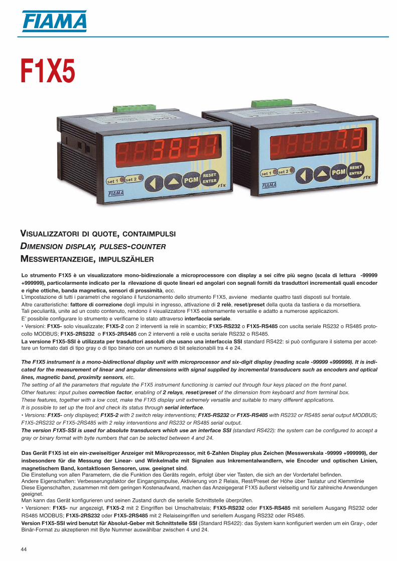
44
VISUALIZZATORI DI QUOTE, CONTAIMPULSI
DIMENSION DISPLAY, PULSES-COUNTER
MESSWERTANZEIGE, IMPULSZÄHLER
F1X5
Lo strumento F1X5 è un visualizzatore mono-bidirezionale a microprocessore con display a sei cifre più segno (scala di lettura -99999+999999), particolarmente indicato per la rilevazione di quote lineari ed angolari con segnali forniti da trasduttori incrementali quali encodere righe ottiche, banda magnetica, sensori di prossimità, ecc.Lʼimpostazione di tutti i parametri che regolano il funzionamento dello strumento F1X5, avviene mediante quattro tasti disposti sul frontale.Altre caratteristiche: fattore di correzione degli impulsi in ingresso, attivazione di 2 relè, reset/preset della quota da tastiera e da morsettiera.Tali peculiarità, unite ad un costo contenuto, rendono il visualizzatore F1X5 estremamente versatile e adatto a numerose applicazioni.Eʼ possibile configurare lo strumento e verificarne lo stato attraverso interfaccia seriale.• Versioni: F1X5- solo visualizzate; F1X5-2 con 2 interventi ia relé in scambio; F1X5-RS232 o F1X5-RS485 con uscita seriale RS232 o RS485 proto-collo MODBUS; F1X5-2RS232 o F1X5-2RS485 con 2 interventi a relè e uscita seriale RS232 o RS485.La versione F1X5-SSI è utilizzata per trasduttori assoluti che usano una interfaccia SSI standard RS422: si può configurare il sistema per accet-tare un formato dati di tipo gray o di tipo binario con un numero di bit selezionabili tra 4 e 24.
The F1X5 instrument is a mono-bidirectional display unit with microprocessor and six-digit display (reading scale -99999 +999999). It is indi-cated for the measurement of linear and angular dimensions with signal supplied by incremental transducers such as encoders and opticallines, magnetic band, proximity sensors, etc.The setting of all the parameters that regulate the F1X5 instrument functioning is carried out through four keys placed on the front panel.Other features: input pulses correction factor, enabling of 2 relays, reset/preset of the dimension from keyboard and from terminal box.These features, together with a low cost, make the F1X5 display unit extremely versatile and suitable to many different applications.It is possible to set up the tool and check its status through serial interface.• Versions: F1X5- only displayed; F1X5-2 with 2 switch relay interventions; F1X5-RS232 or F1X5-RS485 with RS232 or RS485 serial output MODBUS;F1X5-2RS232 or F1X5-2RS485 with 2 relay interventions and RS232 or RS485 serial output.The version F1X5-SSI is used for absolute transducers which use an interface SSI (standard RS422): the system can be configured to accept agray or binary format with byte numbers that can be selected between 4 and 24.
Das Gerät F1X5 ist ein ein-zweiseitiger Anzeiger mit Mikroprozessor, mit 6-Zahlen Display plus Zeichen (Messwerskala -99999 +999999), derinsbesondere für die Messung der Linear- und Winkelmaße mit Signalen aus Inkrementalwandlern, wie Encoder und optischen Linien,magnetischem Band, kontaktlosen Sensoren, usw. geeignet sind.Die Einstellung von allen Parametern, die die Funktion des Geräts regeln, erfolgt über vier Tasten, die sich an der Vordertafel befinden.Andere Eigenschaften: Verbesserungsfaktor der Eingangsimpulse, Aktivierung von 2 Relais, Rest/Preset der Höhe über Tastatur und KlemmlinieDiese Eigenschaften, zusammen mit dem geringen Kostenaufwand, machen das Anzeigegerat F1X5 äußerst vielseitig und für zahlreiche Anwendungengeeignet.Man kann das Gerät konfigurieren und seinen Zustand durch die serielle Schnittstelle überprüfen.• Versionen: F1X5- nur angezeigt, F1X5-2 mit 2 Eingriffen bei Umschaltrelais; F1X5-RS232 oder F1X5-RS485 mit seriellem Ausgang RS232 oderRS485 MODBUS; F1X5-2RS232 oder F1X5-2RS485 mit 2 Relaiseingriffen und seriellem Ausgang RS232 oder RS485.Version F1X5-SSI wird benutzt für Absolut-Geber mit Schnittstelle SSI (Standard RS422): das System kann konfiguriert werden um ein Gray-, oderBinär-Format zu akzeptieren mit Byte Nummer auswählbar zwischen 4 und 24.

45
CARATTERISTICHE TECNICHE F1X5TECHNICAL FEATURES F1X5
TECHNISCHE MERKMALE F1X5
92
4548
9596
Dimensioni d’ingombro - Dimensions - Abmessungen Foratura - Panel cut-out - Aussparung
Alimentazioni- Power supply - Versorgung 115Vac, 230Vac, 24Vac, 12÷30Vdc, ±10%Frequenza di rete - Line frequency - Netzfrequenz 50/60 HzPotenza assorbita - Absorbed power - Leistungsaufnahme 4VAVisualizzazione - Display - Anzeige -99999 + 999999 Tipo di ingressi - Type of inputs - Eingangsarten Optoisolati - Optoinsulated - Optoisoliert
Contatto meccanico - Mechanical contact - Mechanischer KontaktIngresso esterno - Outside output - Äußerer Eingang RESET/PRESETAlimentazione encoder e sensori - Encoder and sensors power supply 12Vdc (max 60mA)Encoder und Sensoren Versorgung Ingresso sensori - Encoder and sensors input - Encoder und Sensoren Eingang Open collector NPN/PNP - Push-pull - Line driverMassima frequenza in ingresso - Max. input frequency 8 KHzMax. EingangsfrequenzPossibilità di funzionamento - Operating possibilities - Betriebsart Monodirezionale - Monodirectional - Einseitig
Bidirezionale - Bidirectional - Zweiseitig Soglie di intervento - Intervention thresholds - Grenzwertkontakten Anzahl 2 in scambio - 2 switched - 2 UmschaltungPortata massima dei contatti relè - Maximum capacity of relay contacts 120Vac 0,5 A - 24Vdc 1AMax. Leistung der Relais Kontakte Uscita seriale - Serial output - Serieller Ausgang RS232 - RS485 MODBUS RTU - SSI RS422Temperatura di impiego - Working temperature - Betriebstemperatur 0÷50°CUmidità relativa - Relative humidity - Relative Feuchtigkeit 30÷90%Contenitore antiurto autoestinguente - Self-extinguishible shock-proof case 48x96x95 DIN 43700Selbstlöschendes stoßfestes GehäuseProtezione (frontale) del contenitore - Protection degree of the case IP54(Frontaler) Gehäuse Schutzart Compatibilità elettromagnetica - Electromagnetic compatibility 2004/108/ECElektromagnetische Kompatibilität
Alimentazione - Power supply - Versorgung
0 115 Vac
1 230 Vac
2 24 Vac
3 12-30 Vdc
F1X5Sigla di ordinazione - Order outline - Bestellmuster
Interventi - Interventions - Eingriffe
2 relé in scambio - switch relays - Umschaltrelais
OPZIONALE - OPTIONAL
Uscite - Outputs - Ausgänge
RS232 uscita seriale - serial output - serieller Ausgang
RS485 uscita seriale - serial output - serieller Ausgang
2RS232 uscita seriale - serial output - serieller Ausgang + 2 relé in scambio - 2 switch relays - 2 Umschaltrelais
2RS485 uscita seriale - serial output - serieller Ausgang + 2 relé in scambio - 2 switch relays - 2 Umschaltrelais
SSI interfaccia SSI - interface SSI - Schnittstelle SSI
2SSI interfaccia SSI - interface SSI - Schnittstelle SSI + 2 relé in scambio - 2 switch relays - 2 Umschaltrelais
SSIRS232 interfaccia SSI - interface SSI - Schnittstelle SSI + uscita seriale - serial output - serieller Ausgang RS232
SSIRS485 interfaccia SSI - interface SSI - Schnittstelle SSI + 0,uscita seriale - serial output - serieller Ausgang RS485
1 2 RS485

46
VISUALIZZATORE MULTIFUNZIONE, CONTAIMPULSI
MULTIFUNCTION DISPLAY, PULSES-COUNTER
MESSWERTANZEIGE, IMPULSZÄHLER
F2X
Lo strumento F2X è un contatore a microprocessore multifunzione mono-bidirezionale, utilizzato come visualizzatore di quote per segnaliprovenienti da trasduttori incrementali (encoders, righe ottiche, banda magnetica), o come contaimpulsi per segnali forniti da sensori di pros-simità, contatti meccanici, fotocellule, su display a 6 cifre con segno (scala di lettura -99999 +999999). Lʼimpostazione delle quote di intervento, della modalità di attivazione dei relé, del fattore di correzione degli impulsi in ingresso e di tutti i parametri cheregolano il funzionamento dello strumento, avviene mediante quattro tasti disposti sul frontale. Un display ausiliario a due caratteri consente una programmazione guidata del visualizzatore. Lʼattivazione dei relé segnala eventi (fine corsa, quota raggiunta, ecc.) che consentono la realizzazione di semplici automatismi.Altre caratteristiche del F2X sono lʼelevata frequenza di ingresso, modalità di conteggio totale/parziale e assoluto/relativo, doppio ingresso di conteggio,reset/preset della quota, conversione millimetri/pollici ecc. Collegamento seriale RS232 o RS485 MODBUS RTU per lʼinterfacciamento con computer e PLC . Peculiarità che, unite ad un ottimo rapporto prezzo-prestazioni, rendono il visualizzatore F2X estremamente versatile e adatto a numerose applicazioni.• Versioni: F2X- solo visualizzato; F2X-2 con 2 interventi a relé in scambio; F2X-4 4 interventi a relé; F2X-RS232, F2X-RS485 con uscita seriale;F2X-2RS232, F2X-2RS485, con 2 interventi a relé e uscita seriale; F2X-T con uscita analogica.; F2X-2T, con 2 interventi a relé e uscita analogica.
The F2X instrument is a mono-bidirectional multifunction microprocessor counter used as display unit of dimensions for signals coming fromincremental transducers (encoders, optical lines, and magnetic band), or as pulse-counter for signals supplied by proximity sensors, mecha-nical contacts, and photocells on 6-digit with sign display (reading scale: -99999 +999999). The setting of intervention dimensions, of the relays enabling mode, of the input pulses correction factor, and of all the parameters regulating tool ope-rating may be carried out through four keys that are located on the front panel. An auxiliary display with two characters enables the guided programming of the display unit. The enabling of relays signals events (end of travel, dimension reached, etc.) that in turn enable the carrying out of simple automatisms.Also features of the F2X are high input frequency, total/partial and absolute/relative counting mode, double counting input, dimension reset/preset, mil-limeters/inches conversion, etc. These features, together with an excellent cost-efficiency ratio, make the F2X display extremely versatile and suitable to many different applications.• Versions: F2X- only displayed; F2X-2 with 2 switch relay interventions ; F2X-4 4 relay interventions; F2X-RS232, F2X-RS485 with serial output; F2X-2RS232, F2X-2RS485 with 2 relay interventions and serial output; F2X-T with analogue output.; F2X-2T with 2 relay interventions and analogue output.
Die Messanzeige der Serie F2X ist eine Mikroprozessor gesteuerte Universalanzeige mit Inkrementaleingang ( Impulsgeber, Magnetsensoren,Näherungsinitiatoren...) zur Weg- und Winkelmessung. Der max. Anzeigebereich ist -99.999 +999999. Die Eichung und die Programmierung erfolgen ganz einfach frontseitig über vier Tasten. Durch Verwendung eines Mikroprozessors und dem Einsatz moderner Techniken zur Zählung der Impulse werden mit diesem Gerät präziseMessergebnisse hinsichtlich Eichung, Auflösung, Stabilität, hohe Zählfrequenz erreicht. Wichtige Funktionen wie absolut/relativ Mass, Offsetwert, Reset/Preset, doppelter Zähleingang freie und einfache Parametrierung verleihen dem Einsatzin Maschinen und Industrieanlagen besondere Unterstützung zur exakten und rationellen Produktion.Der Messwert kann mit bis zu 2 Grenzwertkontakte über Relais und LED´s visualisiert und überwacht werden. • Modelle: F2X – Anzeige; F2X-2 – Anzeige + 2 ON/OFF Schaltausgänge, F2X-4 – Anzeige + 4 ON/OFF Schaltausgänge, F2X-RS232 oder F2X-RS485mit seriellem Ausgang RS232 oder RS485 MODBUS, F2X-2RS232 oder F2X-2RS485 mit 2 x Schaltrelais ON/OFF + seriellem Ausgang RS232 oderRS485 MODBUS, F2X-T mit Analogausgang, F2X-2T mit Analogausgang + 2 ON/OFF Schaltausgänge.
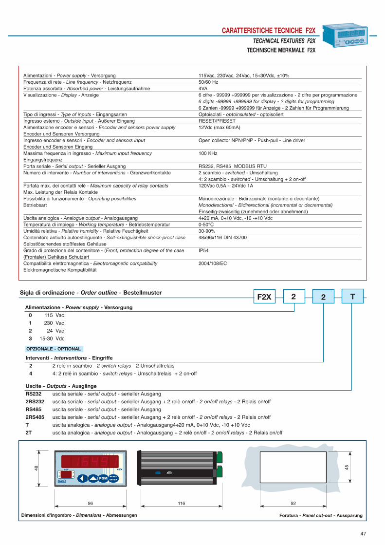
47
CARATTERISTICHE TECNICHE F2XTECHNICAL FEATURES F2X
TECHNISCHE MERKMALE F2X
92
4548
11696
Dimensioni d’ingombro - Dimensions - Abmessungen Foratura - Panel cut-out - Aussparung
Alimentazioni - Power supply - Versorgung 115Vac, 230Vac, 24Vac, 15÷30Vdc, ±10%Frequenza di rete - Line frequency - Netzfrequenz 50/60 HzPotenza assorbita - Absorbed power - Leistungsaufnahme 4VAVisualizzazione - Display - Anzeige 6 cifre - 99999 +999999 per visualizzazione - 2 cifre per programmazione
6 digits -99999 +999999 for display - 2 digits for programming6 Zahlen -99999 +999999 für Anzeige - 2 Zahlen für Programmierung
Tipo di ingressi - Type of inputs - Eingangsarten Optoisolati - optoinsulated - optoisoliertIngresso esterno - Outside input - Äußerer Eingang RESET/PRESETAlimentazione encoder e sensori - Encoder and sensors power supply 12Vdc (max 60mA)Encoder und Sensoren Versorgung Ingresso encoder e sensori - Encoder and sensors input Open collector NPN/PNP - Push-pull - Line driverEncoder und Sensoren Eingang Massima frequenza in ingresso - Maximum input frequency 100 KHzEingangsfrequenzPorta seriale - Serial output - Serieller Ausgang RS232, RS485 MODBUS RTUNumero di intervento - Number of interventions - Grenzwertkontakte 2 scambio - switched - Umschaltung
4: 2 scambio - switched - Umschaltung + 2 on-offPortata max. dei contatti relè - Maximum capacity of relay contacts 120Vac 0,5A - 24Vdc 1AMax. Leistung der Relais Kontakte Possibilità di funzionamento - Operating possibilities Monodirezionale - Bidirezionale (contante o decontante)Betriebsart Monodirectional - Bidirerectional (incremental or decremental)
Einseitig-zweiseitig (zunehmend oder abnehmend)Uscita analogica - Analogue output - Analogausgang 4÷20 mA, 0÷10 Vdc, -10 -+10 VdcTemperatura di impiego - Working temperature - Betriebstemperatur 0-50°CUmidità relativa - Relative humidity - Relative Feuchtigkeit 30-90%Contenitore antiurto autoestinguente - Self-extinguishible shock-proof case 48x96x116 DIN 43700Selbstlöschendes stoßfestes GehäuseGrado di protezione del contenitore - (Front) protection degree of the case IP54(Frontaler) Gehäuse Schutzart Compatibilità elettromagnetica - Electromagnetic compatibility 2004/108/ECElektromagnetische Kompatibilität
Alimentazione - Power supply - Versorgung
0 115 Vac
1 230 Vac
2 24 Vac
3 15-30 Vdc
F2XSigla di ordinazione - Order outline - Bestellmuster
Interventi - Interventions - Eingriffe
2 2 relé in scambio - 2 switch relays - 2 Umschaltrelais
4 4: 2 relé in scambio - switch relays - Umschaltrelais + 2 on-off
OPZIONALE - OPTIONAL
Uscite - Outputs - Ausgänge
RS232 uscita seriale - serial output - serieller Ausgang
2RS232 uscita seriale - serial output - serieller Ausgang + 2 relè on/off - 2 on/off relays - 2 Relais on/off
RS485 uscita seriale - serial output - serieller Ausgang
2RS485 uscita seriale - serial output - serieller Ausgang + 2 relè on/off - 2 on/off relays - 2 Relais on/off
T uscita analogica - analogue output - Analogausgang4÷20 mA, 0÷10 Vdc, -10 +10 Vdc
2T uscita analogica - analogue output - Analogausgang + 2 relè on/off - 2 on/off relays - 2 Relais on/off
2 2 T
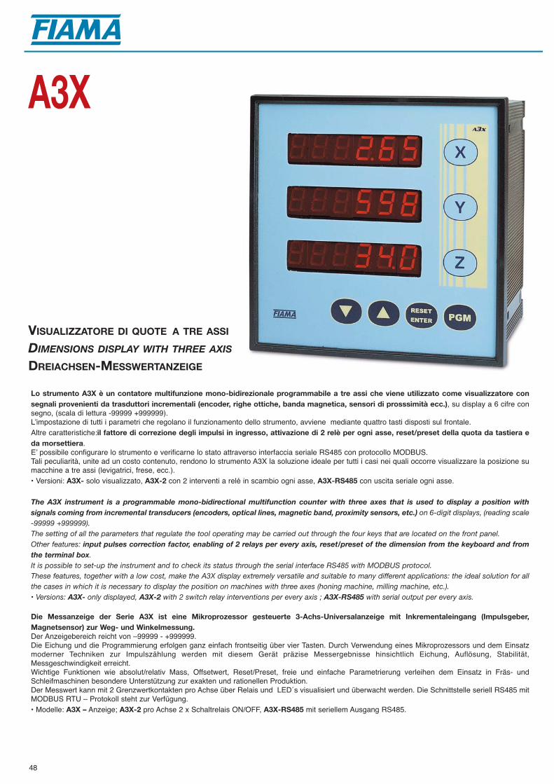
48
VISUALIZZATORE DI QUOTE A TRE ASSI
DIMENSIONS DISPLAY WITH THREE AXIS
DREIACHSEN-MESSWERTANZEIGE
A3X
Lo strumento A3X è un contatore multifunzione mono-bidirezionale programmabile a tre assi che viene utilizzato come visualizzatore consegnali provenienti da trasduttori incrementali (encoder, righe ottiche, banda magnetica, sensori di prosssimità ecc.), su display a 6 cifre consegno, (scala di lettura -99999 +999999).Lʼimpostazione di tutti i parametri che regolano il funzionamento dello strumento, avviene mediante quattro tasti disposti sul frontale.Altre caratteristiche:il fattore di correzione degli impulsi in ingresso, attivazione di 2 relè per ogni asse, reset/preset della quota da tastiera eda morsettiera.Eʼ possibile configurare lo strumento e verificarne lo stato attraverso interfaccia seriale RS485 con protocollo MODBUS.Tali peculiarità, unite ad un costo contenuto, rendono lo strumento A3X la soluzione ideale per tutti i casi nei quali occorre visualizzare la posizione sumacchine a tre assi (levigatrici, frese, ecc.).• Versioni: A3X- solo visualizzato, A3X-2 con 2 interventi a relé in scambio ogni asse, A3X-RS485 con uscita seriale ogni asse.
The A3X instrument is a programmable mono-bidirectional multifunction counter with three axes that is used to display a position withsignals coming from incremental transducers (encoders, optical lines, magnetic band, proximity sensors, etc.) on 6-digit displays, (reading scale-99999 +999999).The setting of all the parameters that regulate the tool operating may be carried out through the four keys that are located on the front panel.Other features: input pulses correction factor, enabling of 2 relays per every axis, reset/preset of the dimension from the keyboard and fromthe terminal box.It is possible to set-up the instrument and to check its status through the serial interface RS485 with MODBUS protocol.These features, together with a low cost, make the A3X display extremely versatile and suitable to many different applications: the ideal solution for allthe cases in which it is necessary to display the position on machines with three axes (honing machine, milling machine, etc.).• Versions: A3X- only displayed, A3X-2 with 2 switch relay interventions per every axis ; A3X-RS485 with serial output per every axis.
Die Messanzeige der Serie A3X ist eine Mikroprozessor gesteuerte 3-Achs-Universalanzeige mit Inkrementaleingang (Impulsgeber,Magnetsensor) zur Weg- und Winkelmessung.Der Anzeigebereich reicht von –99999 - +999999. Die Eichung und die Programmierung erfolgen ganz einfach frontseitig über vier Tasten. Durch Verwendung eines Mikroprozessors und dem Einsatzmoderner Techniken zur Impulszählung werden mit diesem Gerät präzise Messergebnisse hinsichtlich Eichung, Auflösung, Stabilität,Messgeschwindigkeit erreicht. Wichtige Funktionen wie absolut/relativ Mass, Offsetwert, Reset/Preset, freie und einfache Parametrierung verleihen dem Einsatz in Fräs- undSchleifmaschinen besondere Unterstützung zur exakten und rationellen Produktion.Der Messwert kann mit 2 Grenzwertkontakten pro Achse über Relais und LED´s visualisiert und überwacht werden. Die Schnittstelle seriell RS485 mitMODBUS RTU – Protokoll steht zur Verfügung.• Modelle: A3X – Anzeige; A3X-2 pro Achse 2 x Schaltrelais ON/OFF, A3X-RS485 mit seriellem Ausgang RS485.
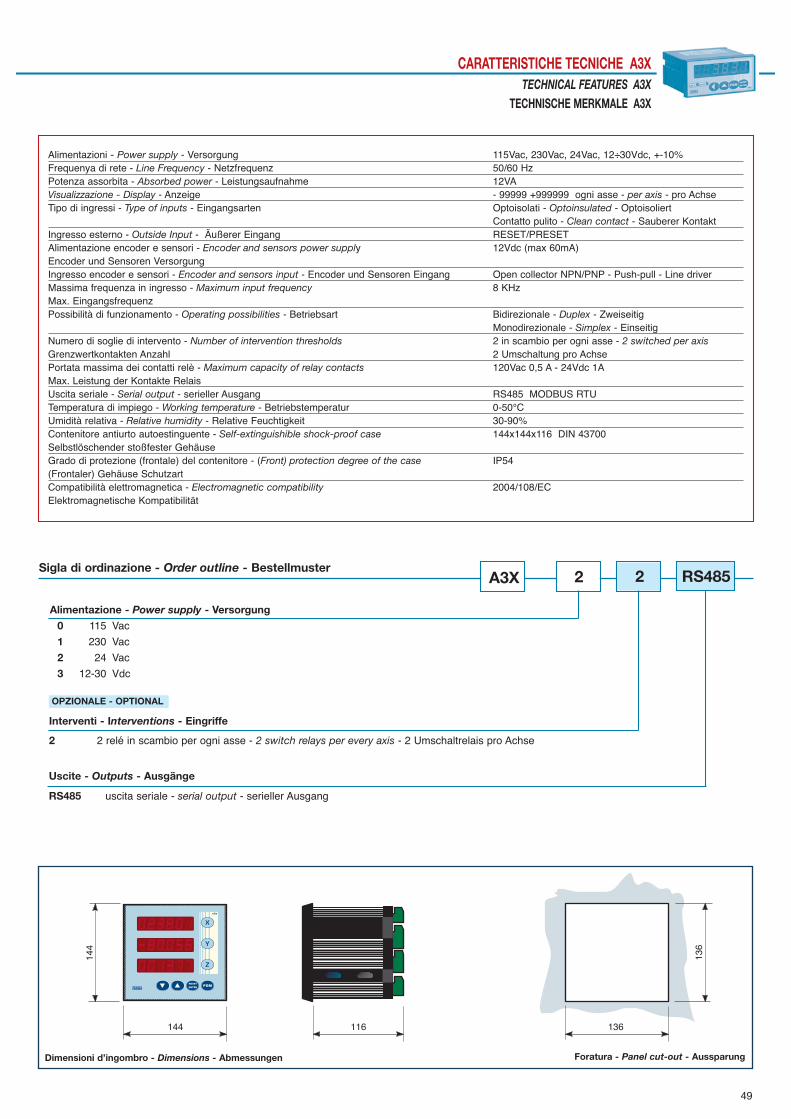
49
CARATTERISTICHE TECNICHE A3XTECHNICAL FEATURES A3X
TECHNISCHE MERKMALE A3X14
4
144 116 136
136
Dimensioni d’ingombro - Dimensions - Abmessungen Foratura - Panel cut-out - Aussparung
Alimentazioni - Power supply - Versorgung 115Vac, 230Vac, 24Vac, 12÷30Vdc, +-10%Frequenya di rete - Line Frequency - Netzfrequenz 50/60 HzPotenza assorbita - Absorbed power - Leistungsaufnahme 12VAVisualizzazione - Display - Anzeige - 99999 +999999 ogni asse - per axis - pro AchseTipo di ingressi - Type of inputs - Eingangsarten Optoisolati - Optoinsulated - Optoisoliert
Contatto pulito - Clean contact - Sauberer KontaktIngresso esterno - Outside Input - Äußerer Eingang RESET/PRESETAlimentazione encoder e sensori - Encoder and sensors power supply 12Vdc (max 60mA)Encoder und Sensoren Versorgung Ingresso encoder e sensori - Encoder and sensors input - Encoder und Sensoren Eingang Open collector NPN/PNP - Push-pull - Line driverMassima frequenza in ingresso - Maximum input frequency 8 KHzMax. EingangsfrequenzPossibilità di funzionamento - Operating possibilities - Betriebsart Bidirezionale - Duplex - Zweiseitig
Monodirezionale - Simplex - EinseitigNumero di soglie di intervento - Number of intervention thresholds 2 in scambio per ogni asse - 2 switched per axisGrenzwertkontakten Anzahl 2 Umschaltung pro AchsePortata massima dei contatti relè - Maximum capacity of relay contacts 120Vac 0,5 A - 24Vdc 1AMax. Leistung der Kontakte RelaisUscita seriale - Serial output - serieller Ausgang RS485 MODBUS RTUTemperatura di impiego - Working temperature - Betriebstemperatur 0-50°CUmidità relativa - Relative humidity - Relative Feuchtigkeit 30-90%Contenitore antiurto autoestinguente - Self-extinguishible shock-proof case 144x144x116 DIN 43700Selbstlöschender stoßfester GehäuseGrado di protezione (frontale) del contenitore - (Front) protection degree of the case IP54(Frontaler) Gehäuse Schutzart Compatibilità elettromagnetica - Electromagnetic compatibility 2004/108/ECElektromagnetische Kompatibilität
Alimentazione - Power supply - Versorgung
0 115 Vac
1 230 Vac
2 24 Vac
3 12-30 Vdc
A3XSigla di ordinazione - Order outline - Bestellmuster
Interventi - Interventions - Eingriffe
2 2 relé in scambio per ogni asse - 2 switch relays per every axis - 2 Umschaltrelais pro Achse
OPZIONALE - OPTIONAL
2
Uscite - Outputs - Ausgänge
RS485 uscita seriale - serial output - serieller Ausgang
2 RS485

50
TACHIMETRO DIGITALE
DIGITAL TACHOMETER
DIGITAL TACHOMETER
CG4
Lo strumento CG4 è un tachimetro programmabile a 4 cifre (scala 0-9999), che elabora segnali forniti da sensori con uscita in frequenza.La programmazione del microprocessore, che avviene mediante la tastiera posta dietro il pannello frontale, consente lʼimpostazione di tutti i parametriche regolano il funzionamento del tachimetro.Il tipo di sensore in ingresso è selezionabile da tastiera tra: NPN, PNP, namur, pick-up e contatto meccanico. Lʼesteso campo di frequenze in ingresso (0,01Hz÷10KHz), la base dei tempi impostabile tra 0,01÷99,99 secondi e la modalità di funzionamento comefrequenzimetro o periodimetro, rendono il CG4 un tachimetro completo e adatto a numerose applicazioni. Altre caratteristiche dello strumento: la pos-sibilità di impostare la posizione del punto decimale e la disponibilità di un filtro software antirimbalzo per lʼingresso da contatti meccanici.La scala di lettura dello strumento può essere impostata in giri/minuto, metri/minuto, metri/ora o come frequenzimetro.La versione CG4-2 dispone di due interventi a relé con soglie programmabili.
The CG4 instrument is a microprocessor tachometer with a 4-digit display (0-9999) that processes signals supplied by sensors with frequen-cy output. The microprocessor programming which is carried out by the means of the keyboard behind the front panel, allows setting all the parame-ters governing the working of the tachometer. The kind of input sensor can be selected between the keyboard from: NPN, PNP, namur, pick-up and mechanical contact. The wide range of input frequencies (0.01Hz-10KHz), the times that can be programmed on the basis of a range from 0.01÷99.99 seconds and the wor-king mode as a frequency meter or period meter, make the CG4 a complete tachometer suitable for many applications.Other features of the instrument are: the possibility of setting the position of the decimal point and a software filter for input from mechanical contacts.Data storage with the machine switched off is ensured by EEPROM memory.The instrument’s reading scale can be set in r.p.m., meters/minute, meters/hour, and it’s possible to work with it as a frequency meter.The CG4-2 version has two relay devices with programming thresholds. The instrument is set into a vertical panel case 48x96 according to DIN 43700 standards.
Der Digital-Tachometer CG4 ist ein programmierbarer Tachometer mit 4-stelligem Display der Signale von Sensoren mit Frequenzausgang verar-beitet. Die Programmierung des Mikroprozessors anhand der Tastatur hinter der Frontblende ermöglicht die Einstellung der Parameter des Tachometers. Es könnenfolgende Typen von Eingangssensoren verwendet werden: NPN, PNP, Namur, Pick-up und mechanische Kontaktgeber. Der zulässige Frequenzbereich am Eingang (0,01 Hz-10KHz), die zwischen 0,01÷99,99 Sekunden einstellbare Zeitbasis und die Einsatzmöglichkeit alsFrequenzmesser oder Zeitmesser machen den CG4 zu einem kompletten und für viele Anwendungen universellen Tachometer. Zu den weiteren Eigenschaften des Gerätes gehören die Möglichkeit der Einstellung der Dezimalpunktstelle und das Vorhandensein eines Software-Filters fürden Eingang aus mechanischen Kontakten. Ein EEPROM-Speicher garantiert bei ausgeschaltetem Gerät die Datenspeicherung. Als Anzeigeeinheit kann Umdrehungen/Minute, Meter/Minute, Meter/Stunde eingestellt werden, mit der Möglichkeit als Frequenzmesser. Die Ausführung CG4-2 hat zwei programmierbare Relais-Grenzwerte.

51
CARATTERISTICHE TECNICHE CG4TECHNICAL FEATURES CG4
TECHNISCHE MERKMALE CG4
92
4548
11696
Dimensioni d’ingombro - Dimensions - Abmessungen Foratura - Panel cut-out - Aussparung
Alimentazioni - Power supply - Versorgung 115Vac, 230Vac, 24Vac, 12÷30Vdc, ±10%Frequenza di rete - Line frequency - Netzfrequenz 50/60 HzPotenza assorbita - Power absorbtion - Leistungsaufnahme 3VAVisualizzazione - Display - Anzeige 0 - 9999Tipo di ingresso - Input type - Eingangsarten Optoisolati - Opto-insulated - OptoisoliertAlimentazione encoder - Encoder power supply - Enkoder Versorgung 12Vdc (max 60mA)Ingressi - Input sensor - Sensoren Eingang Namur, Open collector NPN/PNP, Pick-up, Push PullFrequenza in ingresso - Input frequency - Frequenzabstand am Eingang 0,01 Hz ÷ 10 KHz Portata relais - Capacity of relays contacts - Schaltrelais 120Vac 0,5 A - 24Vdc 1ATemperatura di impiego - Working temperature - Betriebstemperatur 0-50°CUmidità relativa - Relative humidity - Relative Feuchtigkeit 10-90%Contenitore antiurto autoestinguente - Self-extinguishing shock-proof case DIN 43700Stoßfestes selbstlöschendes GehäuseDimensioni (con morsettiera) - Dimensions - Abmessungen 48x96x116 mmGrado di protezione (frontale) del contenitore - (Front) protection degree of the case IP54(Frontaler) Gehäuse Schutzart Compatibilità elettromagnetica - Electromagnetic compatibility - Elektromagnetische Kompatibilität 2004/108/EC
Alimentazione - Power supply - Versorgung
0 115 Vac
1 230 Vac
2 24 Vac
3 12-30 Vdc
CG4Sigla di ordinazione - Order outline - Bestellmuster
Interventi - Interventions - Eingriffe
2 2 relé in scambio - 2 switch relays - 2 Umschaltrelais
OPZIONALE - OPTIONAL
1 2

52
TACHIMETRO, CONTAPRODUZIONE, CONTAMETRI, CONTAORE, FREQUENZIMETRO
TACHOMETER, PRODUCTION-, HOURS-, METERS-, FREQUENCIES COUNTERS
TACHOMETER, PRODUKTIONSZÄHLER, METERZÄHLER, FREQUENZMESSER
G1X
Il G1X è uno strumento programmabile a microprocessore con visualizzazione a 6 cifre, che può essere impiegato come contagiri, contapro-duzione, contametri, frequenzimetro, periodimetro e contaore.Lo strumento elabora segnali forniti da sensori ottici, sensori induttivi, contatti meccanici.Nella modalità di funzionamento contaproduzione, lo strumento é in grado di gestire due ingressi con conteggio pezzi totale e parziale, con visualizza-zione della produzione oraria o al minuto e del tempo di lavoro.La programmazione del microprocessore avviene mediante 4 tasti disposti sul pannello frontale e consente lʼimpostazione di tutti i parametri che rego-lano il funzionamento dello strumento: ciò espande la possibilità di impiego e rende il G1X versatile e adatto a numerose applicazioni.• Versioni: G1X- solo visualizzate; G1X-2, G1X-4 dispongono di due, quattro interventi a relé con soglie programmabili; le versioni G1X-RS232, GIX-RS485 sono predisposte con porta seriale RS232 o RS485 per lʼinterfacciamento con computer o PLC; le versioni G1X-RS232, GIX-2RS485 con portaseriale RS232 o RS485 e due interventi a relé; le versioni G1X-T uscita analogica 0-10Vdc, 4-20mA; GIX2T uscita analogica 0-10Vdc, 4-20mA e dueinterventi a relé.
The GX1 instrument is a programmable microprocessor instrument with a 6 digit display which can be used as a counter of frequencies,periods, revolutions, pieces and meters. The counter elaborates signals supplied from linear sensors, amplified and not amplified inductive sensors, mechanical contacts.On production counter working mode, the instrument is in order to govern two inputs with total pieces counting and the partial one, with the hour pro-duction and working time display. The microprocessor programming, by the means of 4 keys set on the front panel, allows the setting of all parameters that govern the working of theinstrument: that spreads the possibilities of employment and makes the GX1 instrument versatile and available for different employments.• Versions: G1X- only displayed; G1X-2 with 2 switch relay interventions; G1X-4 4 relay interventions; G1X-RS232, G1X-RS485 with serial outputRS232 o RS485; G1X-2RS232, G1X-2RS485 with 2 relay interventions and serial output; G1X-T with analogue output.; G1X-2T with 2 relay interven-tions and analogue output.
Der universelle Digital-Tachometer Gerät G1X ist ausgestattet mit einem Mikroprozessor und einer 6-stelligen Ziffernanzeige, der alsDrehzahlmesser, Produktionszähler, Meterzähler, Frequenzmesser und Periodenzähler verwendet werden kann. Das Gerät verarbeitet Signale, die von optischen Sensoren, von induktiven verstärkten und nicht verstärkten Sensoren oder mechanischen Kontaktenübertragen werden. In der Betriebsmodalität als Produktionszähler, ist das Gerät imstande 2 Eingänge mit totaler oder einzelner Stückzählung zu führen, mit der 2. Anzeigedie Produktionszeit in Stunden- oder Minuten und die gesamte Arbeitsdauer. Die Programmierung des Mikroprozessors ist durch 4 frontseitige Bedientasten einfach möglich. Die Anwendungsmöglichkeiten mit dem G1X bieten vielseitige und zahlreiche Möglichkeiten im gesamten Maschinenbau oder bei wichtigenProduktionsüberwachungen.• Versionen: G1X- Anzeige; G1X-2 mit 2 Ausgangsrelais; G1X-2RS485 mit 2 Ausgangsrelais und seriellem Ausgang; G1X-T mit Analogausgang; G1X-2T mit 2 Ausgangsrelais und Analogausgang.

53
CARATTERISTICHE TECNICHE G1XTECHNICAL FEATURES G1X
TECHNISCHE MERKMALE G1X
92
4548
11696
Dimensioni d’ingombro - Dimensions - Abmessungen Foratura - Panel cut-out - Aussparung
Alimentazioni - Power supply - Versorgung 115Vac, 230Vac, 24Vac,15÷30Vdc, +-10%, 4VAVisualizzazione - Display - Anzeige 6 cifre -99999 +999999 per visualizzazione - 2 cifre per programmazione
6 digits -99999 +999999 for displaying - 2 for programming6 Ziffern -99999 +999999 für Anzeige - 2 Ziffern für Programmierung
Tipo di ingressi - Inputs type - Eingangsart Optoisolati - Optoinsulated - OptoisoliertAlimentazione encoder e sensori - Encoder and sensor power supply 12Vdc (max 60mA)Enkoder und Sensoren Versorgung Ingresso encoder e sensori Open collector NPN/PNP - Push-pull - Line driver differenzialeEncoder and sensor input Open collector NPN/PNP - Push-pull - Differential line driver Enkoder und Sensoren Eingang Open collector NPN/PNP - Push-pull - Differenzial-Line-DriverIntervallo di frequenza in ingresso - Input frequency range 0,1 Hz ÷ 10 kHzEingangsfrequenzenModo di funzionamento Contagiri, Contaproduzione, Contametri, Frequenziometro, PeriodimetroOperating mode Frequencies, Periods, Revolutions, Pieces, Meters countersBetriebssart Drehzähler, Produktzähler, Meterzähler, Frequenzmesser, Periodenzähler Temperatura dʼimpiego - Working temperature - Betriebstemperatur 0÷50 °CUmidità relativa - Relative humidity - Relative Feuchtigkeit 30-90%Numero di soglie di intervento - Number of intervention thresholds 2 relé in scambio - switched - UmschaltungGrenzwertkontakten Anzahl 4: 2 relé in scambio - switched - Umschaltung + 2 on/offUscita analogica - Analogue output - Analogausgang 4÷20 mA, 0÷10 VdcPorta seriale - Serial port - Schnittstelle RS232, RS485 MODBUS RTUContenitore - Case - Gehäuse 48x96x116 DIN 43700Protezione (frontale) del contenitore - Protection degree of the case IP54(Frontaler) Gehäuse Schutzart Compatibilità elettromagnetica - Electromagnetic compatibility 2004/108/ECElektromagnetische Kompatibilität
Alimentazione - Power supply - Versorgung
0 115 Vac
1 230 Vac
2 24 Vac
3 15÷30 Vdc
G1XSigla di ordinazione - Order outline - Bestellmuster
Interventi - Interventions - Eingriffe - Uscite - Outputs - Ausgänge
2 2 relé in scambio - switch relays - Umschaltrelais
4 4: 2 relé in scambio - switch relays - Umschaltrelais + 2 on-off
OPZIONALE - OPTIONAL
Uscite - Outputs - Ausgänge
RS232 uscita seriale - serial output - serieller Ausgang
2RS232 uscita seriale - serial output - serieller Ausgang + 2 relè on/off - on/off relays - Relais on/off
RS485 uscita seriale - serial output - serieller Ausgang
2RS485 uscita seriale - serial output - serieller Ausgang + 2 relè on/off - on/off relays - Relais on/off
T uscita analogica - analogue output - Analogausgang
2T uscita analogica - analogue output - Analogausgang + 2 relè on/off - on/off relays - Relais on/off
1 2 T

54
Il visualizzatore multifunzione VIR é uno strumento appositamente ideato per gli irrigatori automatici a naspo. Si applica sulla macchina con facilità e fornisce le seguenti indicazioni: misura della velocità di irrigazione in metri/ora, misura del tubo svol-to in metri, tempo mancante a fine irrigazione in ore e minuti alla velocità corrente.La consultazione dei parametri avviene in modo semplice ed immediato con i tre tasti disposti sul frontale: le informazioni sono visualizzate su ampiodisplay a cristalli liquidi ad alta visibilità con cifre di altezza 13 mm .Lo strumento è alimentato con 3 pile a stilo da 1,5V (le comuni AA LR6) che presentano una durata superiore a 3000 ore di funzionamento. Lo strumento VIR è abbinato al trasduttore a rullo TR da appoggiare direttamente sul tubo: il trasduttore è collegato allo strumento con cavo econnettore tipo K a norme DIN43650 con grado di protezione IP65. Lo strumento VIR-SP é abbinato al sensore magnetico bidirezionale SM: Il trasduttore magnetico è alloggiato in un contenitore cilindrico filettatoM12x1 con cavo lungo 2 metri e lavora insieme ad un magnete che deve essere montato su una parte rotante dell'irrigatore
The VIR multifunction display is an instrument that was specifically conceived for automatic hose irrigators. It can be easily applied to the machine and it supplies the following indications: instant irrigation speed in metres/hour, measure of unwoundhose in metres, time remaining to the end of irrigation in hours and minutes at the current speed. The parameters can be easily and immediately consulted through the three keys located on the front panel: information is displayed on a large highvisibility liquid crystals display with digits being 13 mm high. The instrument is supplied with 3 batteries lasting more than 3000 hours of functioning.The VIR instrument is available with TR roller transducer to be applied directly into the hose: the transducer is connected to the instrument withcable and K type connector complying with the DIN43650 standards with IP65 protection degree. The display VIR-SP together with the bi-directional magnetic sensor SM: the magnetic transducer is seated in a cylindrical case threaded M12x1with a 2m long cable, and it works with a magnet, which has to be mounted on the rotating part of the irrigator.
Die Messanzeige VIR ist ein Messgerät, das entsprechend für die automatische Schlauch-Bewässerungssysteme entwickelt wurde. Das Messsystem VIR wird einfach auf die Bewässerungsanlage montiert und liefert folgende Informationen: aktuelle Bewässerungsgeschwindigkeit inMeter/Stunde, Messwert vom abgewickelten Schlauch in Meter, Restzeit zum Ende der Bewässerung in Stunden und Minuten anhand der laufendenGeschwindigkeit. Die Versorgung erfolgt mit 3 x 1,5V Batterie (R6A) , die Batterielebensdauer beträgt mindestens 3000 Betriebsstunden.Die Parametrierung der 13mm - Flüssigkristall Anzeige erfolgt ganz einfach über die drei frontseitige Bedientasten. Die Messanzeige VIR wird komplett mit Messwalze TR geliefert. Die Messwalze wird zum Antrieb direkt über dem Schlauch montiert. Mit Kabel und Steckverbinder des Typs K nach der Richtlinie DIN43650 mit Schutzart IP65 wird die Messanzeige angeschlossen.Das Messsystem VIR-SP wird mit einem bi-direktionalem Magnetsensor betrieben: das Magnetsensor ist in ein Zylinder- Gehäuse mit Gewinde M12x1ein-gebaut und mit 2m Kabel arbeitet es mit eine Magnet der auf die drehende seite von dem G erät montiert werden soll.
Display LCD 13 mm: 3÷4 cifre - digits - ZahlenVisualizzazione velocità - Speed display - Geschwindigkeit Anzeige 0 - 999÷0 - 9999 metri/ora - metres/hour - Meter/Stunde Visualizzazione lunghezze - Lengths display - Längenanzeige 0 - 999÷0 - 9999 metri - meters - MeterVisualizzazione tempi -Time display - Zeitanzeige ore e minuti - hours and minutes - Stunden und MinutenAlimentazione - Power supply - Versorgung 3 pile - 3 penlight batteries - 3 Elemente (Stilo)1,5V -R6A
Durata pile - Batteries life - Batterie Dauer 3000 ore - hours - Stunden Temperatura di impiego - Working temperature - Einsatztemperatur 0 ÷ 70 °CUmidità relativa - Relative humidity - Relative Feuchtigkeit 10-90%Dimensioni (mm) - Size (mm) -Abmessungen (mm) 72x72x 56 - IP65
VIRVIR.SP
VISUALIZZATORI PER IRRIGATORI
DISPLAY FOR IRRIGATORS
MESSANZEIGE FÜR BEWÄSSERUNGSSYSTEME

55
A B CTR140 184 160 138TR190 234 210 188Lunghezza cavo - Cable length - Kabellänge m 5 + m 1 spiralato - coil - SpiralartigSM: dimensioni sensore - sensor dimensions - Sensor Abmessungen ø12X40, M12x1Lunghezza cavo - Cable length - Kabellänge 2 m.Temperatura di impiego - Working temperature - Betriebstemperatur 0 - 60°CCompatibilità elettromagnetica - Electromagnetic compatibility - Elektromagnetische Kompatibilität 2004/108/EC
TRASDUTTORE A RULLO TR ROLLER TRANSDUCER TR
ROLLENWANDLER TR
Il trasduttore a rullo TR per irrigatori automatici viene utilizzato per la misura diretta della velocità in metri/ora e della lunghezza di tubo avvolto o svolto. Si compone di un braccio basculante sul quale è montato un rullo in materiale zigrinato antiscivolo. Il braccio è applicato sullʼirrigatore in modo che il rullo appog-gi sul tubo e sia in grado di seguirne le oscillazioni. The TR roller transducer for automatic irrigators is used for the direct measurement of speed in meters/hour and of the length of wound or unwound hose. It ismade of a tilting arm on which a roller made in antiskid knurled material is mounted. The arm is applied on the irrigator so that the roller leans on the hose and isable to follow its oscillations. .Der Rollenwandler TR für automatische Bewässerungseinrichtungen wird für die direkte Abmessung der Geschwindigkeit in Meter/Stunden und der Länge vomgewickelten und abgewickelten Schlauch angewendet. Er besteht aus einem schwingenden Arm, auf dem eine Rolle aus rutschfestem Rändelstoff montiert ist.
CARATTERISTICHE TECNICHE VIR TECHNICAL FEATURES VIR
TECHNISCHE MERKMALE VIR
METERMETERTIMETIME
72
72 88
Dimensioni d’ingombro - Dimensions - Abmessungen
140
Ø60
C
BA
1060
5515
Posizione di montaggio TRAssembling position TREinbaulage TR
Tubo Hose
Trasduttore a rullo - Roller transducerRollenwandler
min. 1max. 5
min. 0,6 RPMmax. 1000 RPM
TRASDUTTOREA MAGNETICO SMMAGNETIC TRANSDUCER SMMAGNET-SENSOR SM
Il trasduttore magnetico SM rileva la rotazione del magnete che ruota sulla parte rotante: ogni volta che il magnete transita davanti al trasduttore si genera unimpulso che viene elaborato dallo strumento per visualizzare i parametri desiderati. La corretta installazione del trasduttore prevede che il magnete sia montatosu un albero che ruota solidale, anche se rapportato, con la bobina su cui è avvolto il tubo. The SM magnetic transducer measures the movement of the magnet which rotates on the revolving part: every time that the magnet passes by the transducerit creates an impulse which will be worked out of the instrument to visualize the required parameters. The correct assembling of the transducer provides that themagnet is mounted on the shaft that turns, even if compared, together with the coil on which is wound the tube. Der Magnetische Geber SM zählt die Umdrehungen des am rotierenden Teiles ( Drehachse / Spule) angebrachten Magneten. Jedes mal, wenn der Magnet amGeber vorbei dreht, wird ein Impuls erzeugt. Im Anzeigegerät werden die Impulse verarbeitet.
40
M12
x 1
CH 17
40
M8
CH 13
SMTrasduttoreTransducerSensor
MagneteMagnetMagnet

FIAMA s.r.l.Via G. Di Vittorio n. 5/A, 43126 San Pancrazio (Parma) - Italytel.: (39) 0521.672.341, fax: (39) 0521.672.537E-mail: [email protected] www.fiama.it
3
IndexEP7 4EP20-EP25 6EP-RS-MAN 8EP25L 10SERVO.D 10 SERVO.M 14P3.S 16SIMPLEX-E 18F20-F20R-F18-F18R 20 F20-F18-EFB 22F20-F18-EN20M 24P2X 26P1X 28P3X 30V3P 32V4P 34V3V - V3I 36V4V - V4I 38VE6 40F3X 42F1X5 44F2X 46A3X 48CG4 50G1X 52VIR-VIR.SP 54
© January 2012Copyright by FiamaSan Pancrazio - Parma - Italy
Total or partial reproduction of the present docu-ment can only be made under written permissionby FIAMA.Part of technology presented in this brochure ispatented.FIAMA, whose policy is to continuously improveits products, reserves the right to discontinue orchange specifications, models or design withoutnotice and without incurring any obligation.
cod. 21-03028