FT-IPH - Tognella · FT-IPH-035 6-35 bar < ± 1% della taratura < ± 1% of setting 0.35 kg...
12
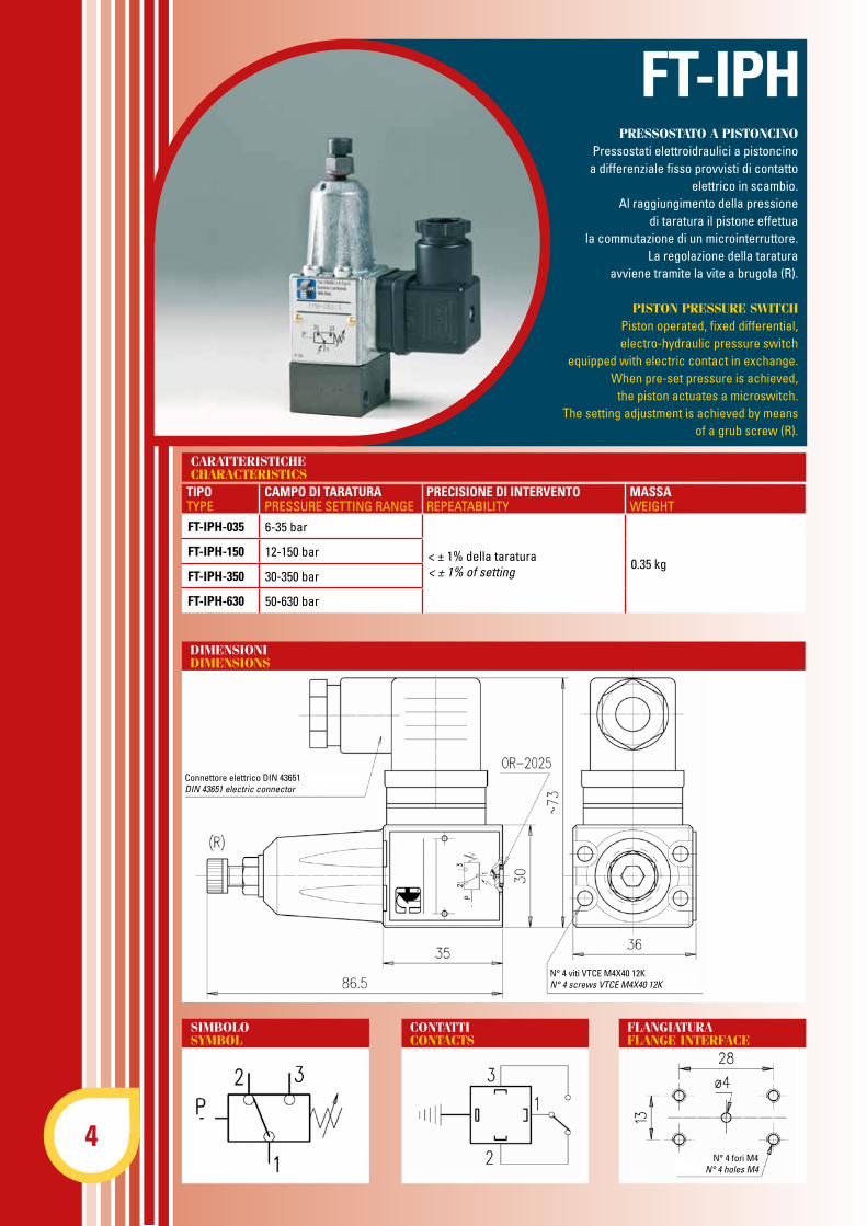
4 FT-IPH-035 6-35 bar < ± 1% della taratura < ± 1% of setting 0.35 kg FT-IPH-150 12-150 bar FT-IPH-350 30-350 bar FT-IPH-630 50-630 bar PRESSOSTATO A PISTONCINO Pressostati elettroidraulici a pistoncino a differenziale fisso provvisti di contatto elettrico in scambio. Al raggiungimento della pressione di taratura il pistone effettua la commutazione di un microinterruttore. La regolazione della taratura avviene tramite la vite a brugola (R). PISTON PRESSURE SWITCH Piston operated, fixed differential, electro-hydraulic pressure switch equipped with electric contact in exchange. When pre-set pressure is achieved, the piston actuates a microswitch. The setting adjustment is achieved by means of a grub screw (R). CONTATTI CONTACTS FLANGIATURA FLANGE INTERFACE TIPO TYPE CAMPO DI TARATURA PRESSURE SETTING RANGE PRECISIONE DI INTERVENTO REPEATABILITY MASSA WEIGHT N° 4 viti VTCE M4X40 12K N° 4 screws VTCE M4X40 12K Connettore elettrico DIN 43651 DIN 43651 electric connector N° 4 fori M4 N° 4 holes M4 FT-IPH CARATTERISTICHE CHARACTERISTICS DIMENSIONI DIMENSIONS SIMBOLO SYMBOL
-
Upload
hoangduong -
Category
Documents
-
view
231 -
download
0
Transcript of FT-IPH - Tognella · FT-IPH-035 6-35 bar < ± 1% della taratura < ± 1% of setting 0.35 kg...
4
FT-IPH-035 6-35 bar
< ± 1% della taratura< ± 1% of setting 0.35 kg
FT-IPH-150 12-150 bar
FT-IPH-350 30-350 bar
FT-IPH-630 50-630 bar
PRESSOSTATO A PISTONCINOPressostati elettroidraulici a pistoncinoa differenziale fisso provvisti di contatto
elettrico in scambio.Al raggiungimento della pressione
di taratura il pistone effettuala commutazione di un microinterruttore.
La regolazione della taraturaavviene tramite la vite a brugola (R).
PISTON PRESSURE SWITCHPiston operated, fixed differential,electro-hydraulic pressure switch
equipped with electric contact in exchange. When pre-set pressure is achieved,
the piston actuates a microswitch.The setting adjustment is achieved by means
of a grub screw (R).
CONTATTICONTACTS
FLANGIATURAFLANGE INTERFACE
TIPOTYPE
CAMPO DI TARATURAPRESSURE SETTING RANGE
PRECISIONE DI INTERVENTOREPEATABILITY
MASSAWEIGHT
N° 4 viti VTCE M4X40 12KN° 4 screws VTCE M4X40 12K
Connettore elettrico DIN 43651DIN 43651 electric connector
N° 4 fori M4N° 4 holes M4
FT-IPH
CARATTERISTICHECHARACTERISTICS
DIMENSIONIDIMENSIONS
SIMBOLOSYMBOL
5
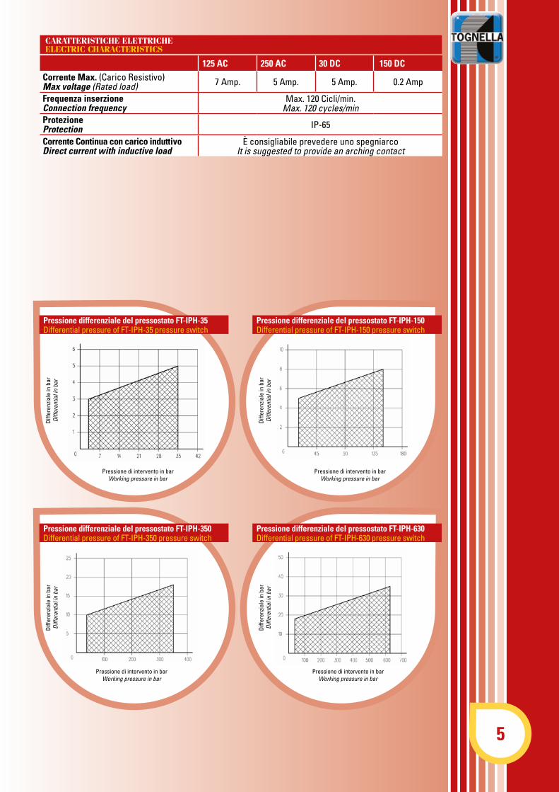
125 AC 250 AC 30 DC 150 DC Corrente Max. (Carico Resistivo)Max voltage (Rated load) 7 Amp. 5 Amp. 5 Amp. 0.2 Amp
Frequenza inserzioneConnection frequency
Max. 120 Cicli/min.Max. 120 cycles/min
ProtezioneProtection IP-65
Corrente Continua con carico induttivoDirect current with inductive load
è consigliabile prevedere uno spegniarcoIt is suggested to provide an arching contact
Pressione differenziale del pressostato FT-IPH-35Differential pressure of FT-IPH-35 pressure switch
Pressione differenziale del pressostato FT-IPH-150Differential pressure of FT-IPH-150 pressure switch
Pressione differenziale del pressostato FT-IPH-350Differential pressure of FT-IPH-350 pressure switch
Pressione differenziale del pressostato FT-IPH-630Differential pressure of FT-IPH-630 pressure switch
Pressione di intervento in barWorking pressure in bar
Diff
eren
zial
e in
bar
Diff
eren
tial i
n ba
r
Diff
eren
zial
e in
bar
Diff
eren
tial i
n ba
r
Pressione di intervento in barWorking pressure in bar
Diff
eren
zial
e in
bar
Diff
eren
tial i
n ba
r
Pressione di intervento in barWorking pressure in bar
Pressione di intervento in barWorking pressure in bar
Diff
eren
zial
e in
bar
Diff
eren
tial i
n ba
r
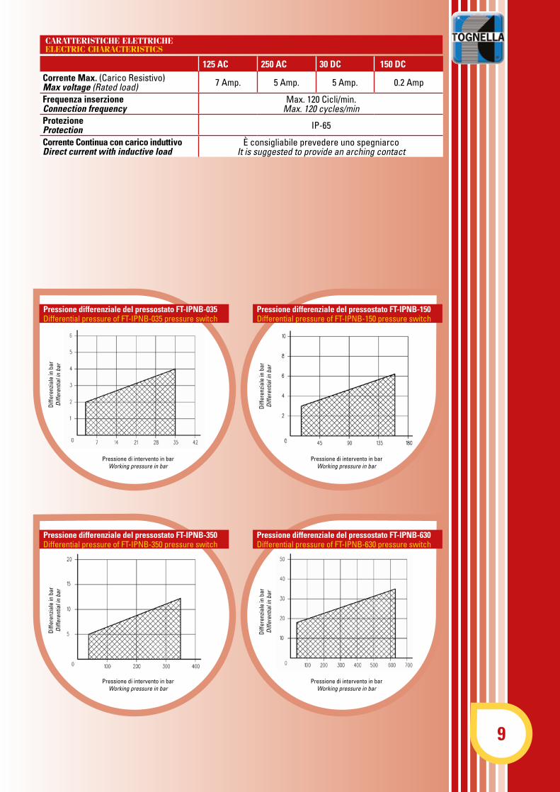
CARATTERISTICHE ELETTRICHEELECTRIC CHARACTERISTICS
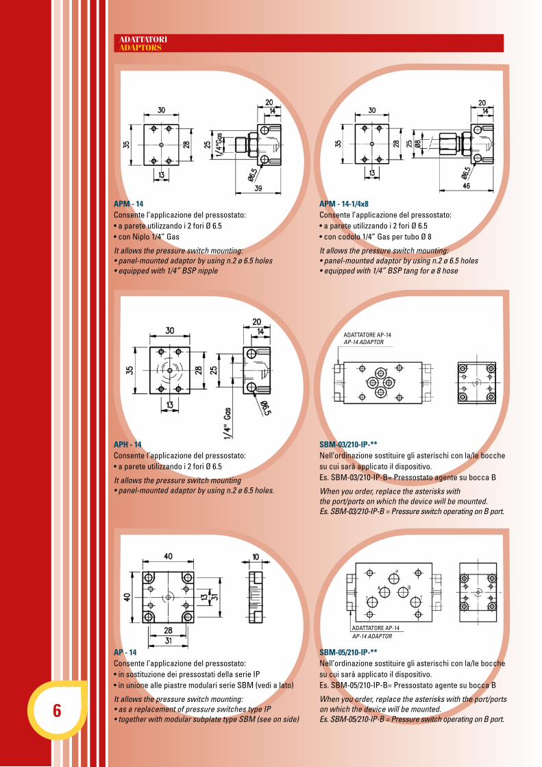
APM - 14Consente l’applicazione del pressostato:• a parete utilizzando i 2 fori Ø 6.5• con Niplo 1/4” Gas
It allows the pressure switch mounting:• panel-mounted adaptor by using n.2 ø 6.5 holes• equipped with 1/4” BSP nipple
APM - 14-1/4x8Consente l’applicazione del pressostato:• a parete utilizzando i 2 fori Ø 6.5• con codolo 1/4” Gas per tubo Ø 8
It allows the pressure switch mounting: • panel-mounted adaptor by using n.2 ø 6.5 holes • equipped with 1/4” BSP tang for ø 8 hose
APH - 14Consente l’applicazione del pressostato:• a parete utilizzando i 2 fori Ø 6.5
It allows the pressure switch mounting• panel-mounted adaptor by using n.2 ø 6.5 holes.
SBM-03/210-IP-**Nell’ordinazione sostituire gli asterischi con la/le bocchesu cui sarà applicato il dispositivo.Es. SBM-03/210-IP-B= Pressostato agente su bocca B
When you order, replace the asterisks with the port/ports on which the device will be mounted. Es. SBM-03/210-IP-B = Pressure switch operating on B port.
AP - 14Consente l’applicazione del pressostato:• in sostituzione dei pressostati della serie IP• in unione alle piastre modulari serie SBM (vedi a lato)
It allows the pressure switch mounting:• as a replacement of pressure switches type IP• together with modular subplate type SBM (see on side)
SBM-05/210-IP-**Nell’ordinazione sostituire gli asterischi con la/le bocchesu cui sarà applicato il dispositivo.Es. SBM-05/210-IP-B= Pressostato agente su bocca B
When you order, replace the asterisks with the port/portson which the device will be mounted.Es. SBM-05/210-IP-B = Pressure switch operating on B port.
ADATTATORE AP-14AP-14 ADAPTOR
ADATTATORE AP-14AP-14 ADAPTOR
ADATTATORIADAPTORS
6
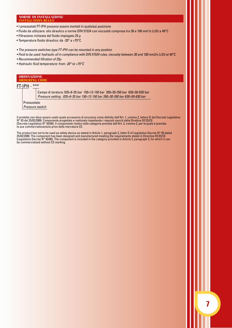
• I pressostati FT-IPH possono essere montati in qualsiasi posizione• Fluido da utilizzare: olio idraulico a norme DIN 51524 con viscosità compresa tra 30 e 100 mm2/s (cSt) a 40°C• Filtrazione richiesta del fluido impiegato 25 µ• Temperatura fluido idraulico: da -20° a +75°C
• The pressure switches type FT-IPH can be mounted in any position • Fluid to be used: hydraulic oil in compliance with DIN 51524 rules, viscosity between 30 and 100 mm2/s (cSt) at 40°C • Recommended filtration of 25μ • Hydraulic fluid temperature: from -20° to +75°C
Il prodotto non deve essere usato quale accessorio di sicurezza come definito dall’Art. 1, comma 2, lettera D del Decreto Legislativo N° 93 del 25/02/2000. Componente progettato e realizzato rispettando i requisiti sanciti dalla Direttiva 97/23/CE (Decreto Legislativo N° 93/00). Il componente rientra nella categoria prevista dall’Art. 3, comma 3, per la quale è previstala sua commercializzazione privo della marcatura CE.
The product has not to be used as safety device as stated in Article 1, paragraph 2, letter D of Legislative Decree N° 93 dated 25/02/2000. The component has been designed and manufactured meeting the requirements stated in Directive 97/23/CE (Legislative Decree N° 93/00). The component is included in the category provided in Article 3, paragraph 3, for which it canbe commercialized without CE marking.
NORME DI INSTALLAZIONEINSTALLATION RULES
ORDINAZIONEORDERING CODE
FT-IPH - *** Campo di taratura: 035=6-35 bar 150=12-150 bar 350=30-350 bar 630=50-630 bar Pressure setting : 035=6-35 bar 150=12-150 bar 350=30-350 bar 630=50-630 bar
PressostatoPressure switch
7
8
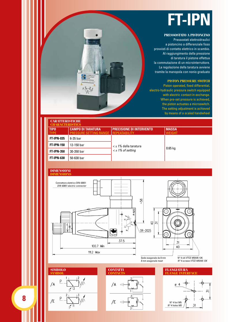
FT-IPN-035 6-35 bar
< ± 1% della taratura< ± 1% of setting 0.65 kg
FT-IPN-150 12-150 bar
FT-IPN-350 30-350 bar
FT-IPN-630 50-630 bar
CARATTERISTICHECHARACTERISTICS
TIPOTYPE
CAMPO DI TARATURAPRESSURE SETTING RANGE
PRECISIONE DI INTERVENTOREPEATABILITY
MASSAWEIGHT
N° 4 fori M5N° 4 holes M5
SIMBOLOSYMBOL
CONTATTICONTACTS
FLANGIATURAFLANGE INTERFACE
DIMENSIONIDIMENSIONS
Connettore elettrico DIN 43651DIN 43651 electric connector
N° 4 viti VTCE M5X45 12KN° 4 screws VTCE M5X45 12K
Sede esagonale da 8 mm8 mm exagonale meat
PRESSOSTATO A PISTONCINOPressostati elettroidraulici
a pistoncino a differenziale fissoprovvisti di contatto elettrico in scambio.
Al raggiungimento della pressionedi taratura il pistone effettua
la commutazione di un microinterruttore.La regolazione della taratura avviene
tramite la manopola con nonio graduato
PISTON PRESSURE SWITCHPiston operated, fixed differential,
electro-hydraulic pressure switch equipped with electric contact in exchange.
When pre-set pressure is achieved,the piston actuates a microswitch.The setting adjustment is achieved
by means of a scaled handwheel
FT-IPN
9
CARATTERISTICHE ELETTRICHEELECTRIC CHARACTERISTICS
125 AC 250 AC 30 DC 150 DC Corrente Max. (Carico Resistivo)Max voltage (Rated load) 7 Amp. 5 Amp. 5 Amp. 0.2 Amp
Frequenza inserzioneConnection frequency
Max. 120 Cicli/min.Max. 120 cycles/min
ProtezioneProtection IP-65
Corrente Continua con carico induttivoDirect current with inductive load
è consigliabile prevedere uno spegniarcoIt is suggested to provide an arching contact
Pressione di intervento in barWorking pressure in bar
Pressione di intervento in barWorking pressure in bar
Diff
eren
zial
e in
bar
Diff
eren
tial i
n ba
r
Diff
eren
zial
e in
bar
Diff
eren
tial i
n ba
r
Pressione differenziale del pressostato FT-IPNB-350Differential pressure of FT-IPNB-350 pressure switch
Pressione differenziale del pressostato FT-IPNB-630Differential pressure of FT-IPNB-630 pressure switch
Pressione di intervento in barWorking pressure in bar
Pressione di intervento in barWorking pressure in bar
Diff
eren
zial
e in
bar
Diff
eren
tial i
n ba
r
Diff
eren
zial
e in
bar
Diff
eren
tial i
n ba
r
Pressione differenziale del pressostato FT-IPNB-035Differential pressure of FT-IPNB-035 pressure switch
Pressione differenziale del pressostato FT-IPNB-150Differential pressure of FT-IPNB-150 pressure switch

SBM-03/210-IP-**Nell’ordinazione sostituire gli asterischi con la/le bocchesu cui sarà applicato il dispositivo.
Es. SBM-03/210-IP-B= Pressostato agente su bocca B
SBM-05/210-IP-**Nell’ordinazione sostituire gli asterischi con la/le bocchesu cui sarà applicato il dispositivo.
Es. SBM-05/210-IP-B= Pressostato agente su bocca B
ADATTATORIADAPTORS
SBM-03/210-IP-**When your order, replace the asterisks with the port/ports on which the device will be mounted.
Es. SBM-03/210-IP-B = Pressure switch operating on B port
SBM-05/210-IP-**When your order, replace the asterisks with the port/ports on which the device will be mounted.
Es. SBM-05/210-IP-B = Pressure switches operating on B port
Versione ABVersion AB
Versione AVersion A
Versione BVersion B
Versione P1Version P1
Versione P2Version P2
Versione P3Version P3
Versione ABVersion AB
Versione AVersion A
Versione BVersion B
Versione P1Version P1
Versione P2Version P2
Versione P3Version P3
10

• I pressostati IPN possono essere montati in qualsiasi posizione• Fluido da utilizzare: olio idraulico a norme DIN 51524 con viscosità compresa tra 30 e 100 mm2/s (cSt) a 40°C• Filtrazione richiesta del fluido impiegato 25 µ• Temperatura fluido idraulico: da -20° a +75°C
• The pressure switches type IPN can be mounted in any position• Fluid to be used: hydraulic oil in compliance with DIN 51524 rules, viscosity between 30 and 100 mm2/s (cSt) at 40°C• Recommended filtration of 25μ• Hydraulic fluid temperature: from -20° to +75°C
FT-IPN - *** - *
Il prodotto non deve essere usato quale accessorio di sicurezza come definito dall’Art. 1, comma 2, lettera D del Decreto Legislativo N° 93 del 25/02/2000. Componente progettato e realizzato rispettando i requisiti sanciti dalla Direttiva 97/23/CE (Decreto Legislativo N° 93/00). Il componente rientra nella categoria prevista dall’Art. 3, comma 3, per la quale è previstala sua commercializzazione privo della marcatura CE.
The product has not to be used as safety device as stated in Article 1, paragraph 2, letter D of Legislative Decree N° 93 dated 25/02/2000. The component has been designed and manufactured meeting the requirements stated in Directive 97/23/CE (Legislative Decree N° 93/00). The component is included in the category provided in Article 3, paragraph 3, for which it canbe commercialized without CE marking.
Campo di taratura: 035=6-35 bar 150=12-150 bar 350=30-350 bar 630=50-630 bar Pressure setting : 035=6-35 bar 160=12-160 bar 350=30-350 bar 630=50-630 bar
PressostatoPressure switch
/A = contatti elettrici tipo A /E = contatti elettrici tipo E /A = electric contacts type A /E = electric contacts type E
Consente l’applicazione del pressostato:• a parete utilizzando i 2 fori Ø 6.5• con codolo 1/4” Gas per tubo Ø 8
It allows the pressure switch mounting:• wall-type by using 2 ø 6.5 holes• equipped with 1/4” BSP tang for ø 8 hose
BFU - 14 (Adattatore femmina)BFU - 14 (Female adaptor)
BMM-**BMM-**
BFM-**BFM-**
BT-1/4X8BT-1/4X8
NORME DI INSTALLAZIONEINSTALLATION RULES
ORDINAZIONEORDERING CODE
BMM-14 1/4” Gas 41
0.3BMM-38 3/8” Gas 45
BMM-12 1/2” Gas 46
TIPOTYPE
AA
BB
MASSAWEIGHT
BFM-14 1/4” Gas
0.6 kgBFM-38 3/8” Gas
BFM-12 1/2” Gas
TIPOTYPE
AA
MASSAWEIGHT
N° 4 fori M5N° 4 holes M5
N° 4 fori M5N° 4 holes M5
N° 4 fori M5N° 4 holes M5
N° 4 fori M5N° 4 holes M5
0.3
MASSAWEIGHT
11
12
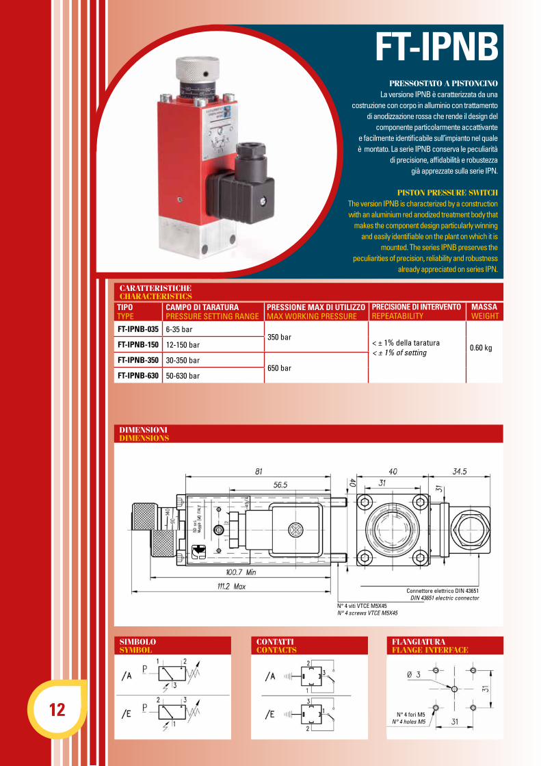
FT-IPNB-035 6-35 bar350 bar
< ± 1% della taratura< ± 1% of setting 0.60 kgFT-IPNB-150 12-150 bar
FT-IPNB-350 30-350 bar650 bar
FT-IPNB-630 50-630 bar
CARATTERISTICHECHARACTERISTICS
TIPOTYPE
CAMPO DI TARATURAPRESSURE SETTING RANGE
PRESSIONE MAX DI UTIlIzzOMAX WORKING PRESSURE
MASSAWEIGHT
SIMBOLOSYMBOL
CONTATTICONTACTS
FLANGIATURAFLANGE INTERFACE
DIMENSIONIDIMENSIONS
Connettore elettrico DIN 43651DIN 43651 electric connector
N° 4 viti VTCE M5X45N° 4 screws VTCE M5X45
PRESSOSTATO A PISTONCINOLa versione IPNB è caratterizzata da una
costruzione con corpo in alluminio con trattamento di anodizzazione rossa che rende il design del
componente particolarmente accattivante e facilmente identificabile sull’impianto nel quale è montato. La serie IPNB conserva le peculiarità
di precisione, affidabilità e robustezza già apprezzate sulla serie IPN.
PISTON PRESSURE SWITCHThe version IPNB is characterized by a construction with an aluminium red anodized treatment body that
makes the component design particularly winning and easily identifiable on the plant on which it is
mounted. The series IPNB preserves the peculiarities of precision, reliability and robustness
already appreciated on series IPN.
FT-IPNB
PRECISIONE DI INTERVENTOREPEATABILITY
N° 4 fori M5N° 4 holes M5
13
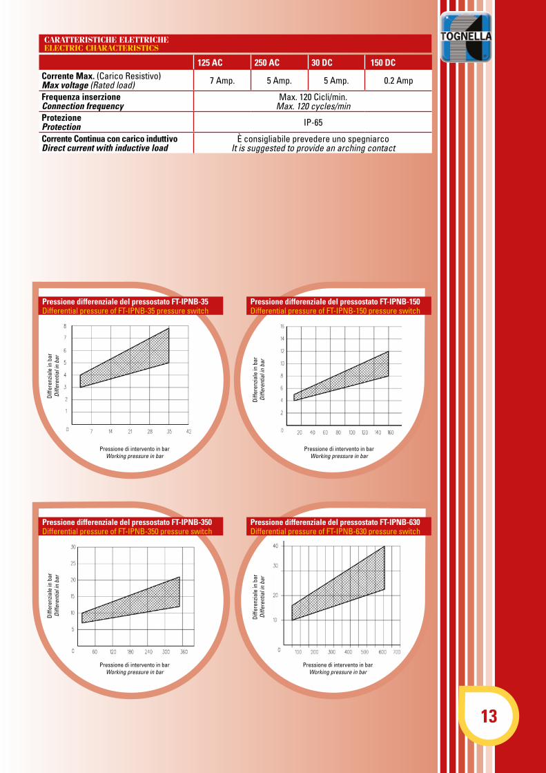
CARATTERISTICHE ELETTRICHEELECTRIC CHARACTERISTICS
Pressione differenziale del pressostato FT-IPNB-35Differential pressure of FT-IPNB-35 pressure switch
Pressione differenziale del pressostato FT-IPNB-150Differential pressure of FT-IPNB-150 pressure switch
Pressione di intervento in barWorking pressure in bar
Diff
eren
zial
e in
bar
Diff
eren
tial i
n ba
r
Diff
eren
zial
e in
bar
Diff
eren
tial i
n ba
r
Pressione di intervento in barWorking pressure in bar
125 AC 250 AC 30 DC 150 DC Corrente Max. (Carico Resistivo)Max voltage (Rated load) 7 Amp. 5 Amp. 5 Amp. 0.2 Amp
Frequenza inserzioneConnection frequency
Max. 120 Cicli/min.Max. 120 cycles/min
ProtezioneProtection IP-65
Corrente Continua con carico induttivoDirect current with inductive load
è consigliabile prevedere uno spegniarcoIt is suggested to provide an arching contact
Pressione differenziale del pressostato FT-IPNB-350Differential pressure of FT-IPNB-350 pressure switch
Pressione differenziale del pressostato FT-IPNB-630Differential pressure of FT-IPNB-630 pressure switch
Pressione di intervento in barWorking pressure in bar
Pressione di intervento in barWorking pressure in bar
Diff
eren
zial
e in
bar
Diff
eren
tial i
n ba
r
Diff
eren
zial
e in
bar
Diff
eren
tial i
n ba
r
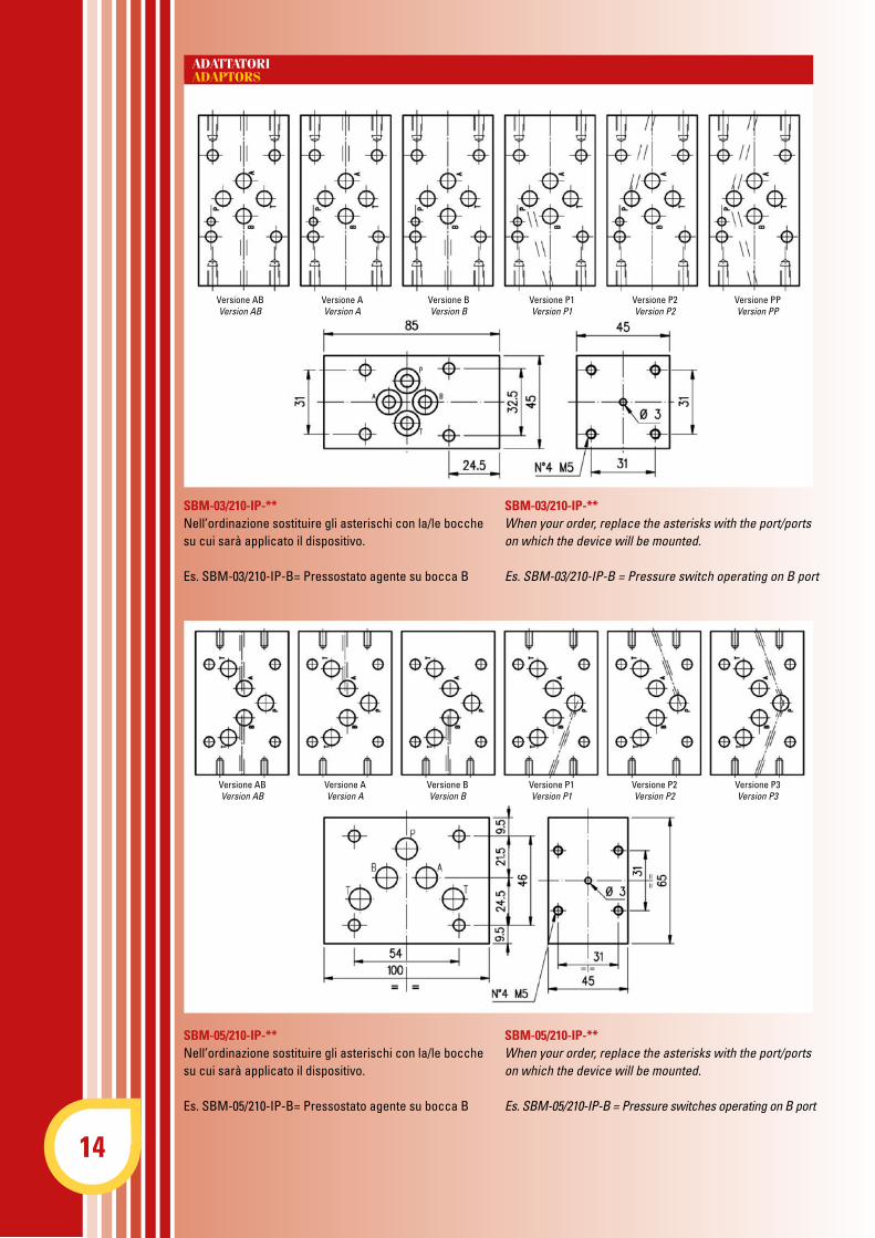
SBM-03/210-IP-**Nell’ordinazione sostituire gli asterischi con la/le bocchesu cui sarà applicato il dispositivo.
Es. SBM-03/210-IP-B= Pressostato agente su bocca B
SBM-05/210-IP-**Nell’ordinazione sostituire gli asterischi con la/le bocchesu cui sarà applicato il dispositivo.
Es. SBM-05/210-IP-B= Pressostato agente su bocca B
ADATTATORIADAPTORS
SBM-03/210-IP-**When your order, replace the asterisks with the port/ports on which the device will be mounted.
Es. SBM-03/210-IP-B = Pressure switch operating on B port
SBM-05/210-IP-**When your order, replace the asterisks with the port/ports on which the device will be mounted.
Es. SBM-05/210-IP-B = Pressure switches operating on B port
Versione ABVersion AB
Versione AVersion A
Versione BVersion B
Versione P1Version P1
Versione P2Version P2
Versione PPVersion PP
Versione ABVersion AB
Versione AVersion A
Versione BVersion B
Versione P1Version P1
Versione P2Version P2
Versione P3Version P3
14

15
• I pressostati IPNB possono essere montati in qualsiasi posizione• Fluido da utilizzare: olio idraulico a norme DIN 51524 con viscosità compresa tra 30 e 100 mm2/s (cSt) a 40°C• Filtrazione richiesta del fluido impiegato 25 µ• Temperatura fluido idraulico: da -20° a +75°C
• The pressure switches type IPNB can be mounted in any position• Fluid to be used: hydraulic oil in compliance with DIN 51524 rules, viscosity between 30 and 100 mm2/s (cSt) at 40°C• Recommended filtration of 25μ• Hydraulic fluid temperature: from -20° to +75°C
FT-IPNB - *** - *
Il prodotto non deve essere usato quale accessorio di sicurezza come definito dall’Art. 1, comma 2, lettera D del DecretoLegislativo N° 93 del 25/02/2000. Componente progettato e realizzato rispettando i requisiti sanciti dalla Direttiva 97/23/CE ( Decreto Legislativo N° 93/00). Il componente rientra nella categoria prevista dall’Art. 3, comma 3, per la quale è prevista la sua commercializ-zazione privo della marcatura CE.
The product has not to be used as safety device as stated in Article 1, paragraph 2, letter D of Legislative Decree N° 93 dated 25/02/2000. The component has been designed and manufactured meeting the requirements stated in Directive 97/23/CE ( Legislative Decree N° 93/00 ). The component is included in the category provided in Article 3, paragraph 3, for which it can be commercialized without CE marking.
Campo di taratura: 035=6-35 bar 150=12-150 bar 350=30-350 bar 630=50-630 bar Pressure setting : 035=6-35 bar 160=12-160 bar 350=30-350 bar 630=50-630 bar
PressostatoPressure switch
/A = contatti elettrici tipo A /E = contatti elettrici tipo E /A = electric contacts type A /E = electric contacts type E
Consente l’applicazione del pressostato:• a parete utilizzando i 2 fori Ø 6.5• con codolo 1/4” Gas per tubo Ø 8
It allows the pressure switch mounting:• wall-type by using 2 ø 6.5 holes• equipped with 1/4” BSP tang for ø 8 hose
BFU - 14 (Adattatore femmina)BFU - 14 (Female adaptor)
BMM-**BMM-**
BFM-**BFM-**
BT-1/4X8BT-1/4X8
NORME DI INSTALLAZIONEINSTALLATION RULES
ORDINAZIONEORDERING CODE
BMM-14 1/4” Gas 41
0.3BMM-38 3/8” Gas 45
BMM-12 1/2” Gas 46
TIPOTYPE
AA
BB
MASSAWEIGHT
BFM-14 1/4” Gas
0.6 kgBFM-38 3/8” Gas
BFM-12 1/2” Gas
TIPOTYPE
AA
MASSAWEIGHT
N° 4 fori M5N° 4 holes M5
N° 4 fori M5N° 4 holes M5
N° 4 fori M5N° 4 holes M5
N° 4 fori M5N° 4 holes M5
0.3
MASSAWEIGHT
![VALVOLE DIREZIONALI27 [1.06] _ 398SCV0013A00 - 10-03-16 13 15 45 1.5 bar 4.5 bar N H NBR HNBR SVH10300 35-38 Nm / 26-28 lb•ft 0.10 kg / 0.22 lb N S BESTELLANLEITUNG Ventil …](https://static.fdocumenti.com/doc/165x107/6096cec548c7de2c47586d50/valvole-direzionali-27-106-398scv0013a00-10-03-16-13-15-45-15-bar-45-bar.jpg)