FRENI C Ita-Eng - industrialclutch.com · prodotta e lavarsi accuratamente le mani prima di...
24
F F F R R R E E E N N N O O O A A A P P P I I I N N N Z Z Z A A A CALIPER BRAKES C C C 3 3 3 0 0 0 0 0 0 C C C 6 6 6 0 0 0 0 0 0 C C C 1 1 1 2 2 2 0 0 0 0 0 0 * GENERALITA’ GENERAL INFORMATION * INSTALLAZIONE INSTALLATION * MANUTENZIONE MAINTENANCE AND CARE * VERIFICHE PERIODICHE PERIODIC INSPECTION * RICAMBI SPARE PARTS
Transcript of FRENI C Ita-Eng - industrialclutch.com · prodotta e lavarsi accuratamente le mani prima di...

FFFRRREEENNNOOO AAA PPPIIINNNZZZAAA CALIPER BRAKES
CCC 333000000 CCC 666000000 CCC 111222000000
∗ GENERALITA’ GENERAL INFORMATION ∗ INSTALLAZIONE INSTALLATION ∗ MANUTENZIONE MAINTENANCE AND CARE ∗ VERIFICHE PERIODICHE PERIODIC INSPECTION ∗ RICAMBI SPARE PARTS

2

3
INDICE
GENERALITA’ pag. 4
INSTALLAZIONE pag. 6
MANUTENZIONE pag. 8
VERIFICHE PERIODICHE pag. 11
RICAMBI pag. 11
DISEGNI: C300 pag. 20
DISEGNI: C600 pag. 21
DISEGNI: C1200 pag. 22
CONTENTS
GENERAL INFORMATION page 12
INSTALLATION page 14
MAINTENANCE AND CARE page 16
PERIODIC INSPECTION page 19
SPARE PARTS page 19
DRAWINGS: C300 page 20
DRAWINGS: C600 page 21
DRAWINGS: C1200 page 22

4
GENERALITA’
Corretto utilizzo del prodotto
In ottemperanza al DPR 224/88 DIRETTIVA CEE N. 85/374 definiamo i limiti di impiego per il perfetto utilizzo del nostro prodotto garantendo la salvaguardia degli aspetti di sicurezza. Caratteristiche di progetto
I freni a pinza della COREMO OCMEA sono stati progettati per operare in conformità delle prestazioni e condizioni previste dal catalogo e dalle relative specifiche tecniche. E’ fatta in ogni caso raccomandazione perché tali limiti non vengano superati. Selezione di applicazione
Premessa di fondamentale importanza è una corretta selezione dell’unita da impiegare perché tali limiti vengano osservati e rispettati. L’Ufficio tecnico della COREMO OCMEA è a disposizione per informazioni, suggerimenti e collaborazioni per una corretta applicazione ed impiego. Impiego
Il rispetto delle Istruzioni di Montaggio e Manutenzione oltre ad evitare costose soste improduttive previene incidenti dovuti alla non completa conoscenza del prodotto. Precauzioni al montaggio ed alla manutenzione
Agli addetti a tale funzione si consiglia l’impiego di equipaggiamenti idonei, guanti, occhiali od altro per la protezione adeguata da carichi e/o pesi.
Parti rotanti
I freni a pinza sono prevalentemente abbinati a parti rotanti. In questo caso le parti in movimento devono essere protette in conformità a quanto prescritto dalle

5
Direttive 89/398/CEE, 93/44/CEE e 93/68/CEE o dalle equivalenti norme vigenti nei Paesi in cui vengono utilizzati. Freni Negativi a molle
I freni negativi a molle devono essere trattati con particolare attenzione perché contengono molle meccanicamente precaricate. Al fine di evitare rischi di incidenti durante la fase di manutenzione, è necessario rispettare i consigli evidenziati in rosso sull’etichetta posta sul freno. Materiali di attrito
Tutti i freni a pinza della COREMO OCMEA sono equipaggiati con materiale di attrito assolutamente esente da amianto e nel pieno rispetto delle Normative e Leggi in vigore per la tutela della salute ed il rispetto dell’ambiente.
Oli, grassi, componenti lubrificanti
Vengono impiegati in quantità estremamente limitate. Per eventuali allergie a queste sostanze si consiglia l’utilizzo di guanti o creme protettive da asportare con accurato lavaggio delle mani prima di ingerire cibi o bevande. Immagazzinamento
Nell’immagazzinamento dei freni a pinza si deve tenere conto di una consistente concentrazione di peso in poco spazio. Si consiglia un equipaggiamento idoneo agli addetti tale funzione (scarpe di sicurezza, caschi guanti, ecc) al fine di prevenire il rischio di incidenti.
Smaltimento
Le pastiglie di attrito usurate e gli altri materiali di cui i freni sono composti sono classificati come prodotti NON Tossico-Nocivi, pertanto devono essere smaltiti in conformità e nel rispetto delle leggi vigenti nei Paesi in cui vengono utilizzati. Stoccaggio
Alcuni tipi di freni contengono membrane in silicone od in gomma ed in caso di incendio possono generare gas tossici. Agli addetti allo smaltimento, in ambienti di piccole dimensioni, si consiglia l’uso della maschera antigas.

6
1.0 INSTALLAZIONE
1.1 Montare il freno su di un piano rigido della macchina o su di un supporto adatto a sopportare la forza tangenziale del freno: F=5400N per C 300, F=13200 N per C 600, F=22500 N per il C 1200.
1.2 Il freno può essere montato in qualsiasi posizione in quanto è dotato di
sistema di bilanciamento delle leve ed allineamento dei pattini. 1.3 Fissare il freno sulla base di appoggio con n° 3 viti da M12 classe 8.8.
Coppia di serraggio: 85 Nm. 1.4 Regolare le viti C 61208 e C 61401, utilizzando una CH 13 e CH BR 6
(fig. 1), fino a che non si sia ottenuto il completo bilanciamento del pistone. Figura 1:
1.5 Se necessario regolare il gioco fra i pattini, 0.8 mm tra ogni ferodo e
disco agendo, a seconda del tipo di freno sui regolatori di gioco C 61077 utilizzando la chiave CH 19, C 61080 utilizzando la chiave CH 22
7
e C 61123 utilizzando la chiave CH 24, posti all’estremità dello stelo di ogni pistone. Figura 2 :
1.6 Regolare i pattini tramite il dado C61345 ruotandolo in modo opportuno con una chiave CH 8; i ferodi devono essere paralleli al disco (fig. 3). Figura 3 :
1.7 Collegare il pistone di spinta del freno, alla linea di alimentazione dell’aria tramite un raccordo 1/4” gas per i freni C 300 e C 600 e 1/2” gas per il freno C 1200 con un tubo flessibile di lunghezza tale da consentire al pistone un’ampia possibilità di movimento.
1.8 La pressione di comando non deve essere superiore a 6 bar . L’aria non deve essere contaminata da olio od acqua. Usare quindi un filtro da 25 micron con scarico automatico della condensa.
NOTA : Non azionare il freno senza che il disco sia inserito tra i ferodi. Il mancato rispetto di questa raccomandazione può comportare il rischio di schiacciamento delle dita.
8
2.0 MANUTENZIONE TUTTI I TIPI DI INTERVENTO SUL FRENO DEVONO ESSERE EFFETTUATI A MACCHINA FERMA
2.1 RIPRISTINO DEL GIOCO
2.1.1 La corsa del pistone è sufficiente a compensare la massima usura dei ferodi.
2.1.2 Eventuali piccoli aggiustamenti possono essere effettuati agendo come descritto al punto 1.5
2.2 SOSTITUZIONE DELLE PASTIGLIE DI FERODO
2.2.1 Togliere la pressione dell’aria, i dadi C 61346, le viti C 61172 ed il
sistema di allineamento pattini composto dai particolari Z 50009, C61630, C 61079, C 61073 e C 61345 senza smontarlo.
2.2.2 Togliere l’anello sieger C61276, sfilare il perno C 61076 e dopo aver tolto dal freno il pattino E 80571, togliere le viti C 61170 che fissano i ferodi al pattino.
2.2.3 Sostituire i ferodi e rimontare procedendo in senso inverso ai punti
2.2.2 e 2.2.1.
2.2.4 Se necessario ripristinare il gioco tra disco e ferodi e riallineare i pattini come descritto al punto 1.5 e 1.6.
NOTA: Le pastiglie di attrito usurate e gli altri materiali di cui i freni sono composti sono classificati come prodotti NON Tossico–Nocivi, pertanto devono essere smaltiti in conformità e nel rispetto delle leggi vigenti nei Paesi in cui vengono utilizzati.
9
2.3 PULITURA DELLE SUPERFICI DI ATTRITO
Procedere allo smontaggio dei ferodi, come descritto al punto 2.2.
2.3.1 Rimuovere eventuali presenze di olio o grasso dalla superficie del disco usando un prodotto detergente e non inquinante. NOTA: Per eventuali allergie a queste sostanze si consiglia l’utilizzo di
guanti o creme protettive da asportare con accurato lavaggio delle mani prima di ingerire cibi o bevande.
2.3.2 Se i ferodi risultassero imbrattati solo superficialmente è bene
provvedere alla loro pulitura con tela smeriglio a grana fine. In caso di contaminazione profonda dei ferodi è bene provvedere alla loro sostituzione come descritto al punto 2.2.
NOTA: Tutti i freni della COREMO OCMEA sono equipaggiati con
materiale di attrito assolutamente esente da amianto e nel pieno rispetto delle Normative e leggi in vigore per la tutela della salute ed il rispetto dell’ambiente.
E’ comunque buona cosa non inalare la polvere da essi prodotta e lavarsi accuratamente le mani prima di ingerire cibi o bevande.
2.4 SOSTITUZIONE DELLA MEMBRANA 2.4.1 Togliere la pressione dell’aria e scollegare il tubo di alimentazione.
2.4.2 Togliere il pistone dal freno.
2.4.3 Togliere i dadi, le viti e le rondelle che uniscono il coperchio al corpo del
pistone.
2.4.4 Sfilare il pistone interno completo di membrana.
2.4.5 Togliere le viti, le rondelle ed il piattello di fissaggio della membrana e sostituire la stessa.
2.4.6 Dopo aver ingrassato lo stelo del pistone interno, rimontare procedendo in senso inverso: dal punto 2.4.5 al punto 2.4.1 .
2.4.7 Azionare più volte il freno per constatare il perfetto scorrimento del pistone interno e/o eventuali perdite d’aria.
10
2.5 SOSTITUZIONE DELLA MOLLA DEL PISTONE 2.5.1 Togliere la pressione dell’aria e per sicurezza scollegare il tubo di
alimentazione.
2.5.2 Procedere come descritto dal punto 2.4.1 al punto 2.4.4.
2.5.3 Rimuovere la molla danneggiata e sostituirla con una nuova.
2.5.4 Dopo aver ingrassato lo stelo del pistone interno, rimontare procedendo in senso inverso: dal punto2.4.4 al punto 2.4.1.
2.5.5 Azionare più volte il freno per constatare il perfetto scorrimento del pistone interno e/o eventuali perdite di aria 1.

11
3.0 VERIFICHE PERIODICHE
E’ BENE EFFETTUARE OGNI 3 MESI, A MACCHINA FERMA, LE SEGUENTI VERIFICHE DI CONTROLLO. LA PERIODICITA’ DI QUESTE VERIFICHE DIPENDE DALLA FREQUENZA DI USO DEL FRENO..
3.1 Verificare che la superficie dei ferodi e del disco siano esenti da grassi,
olii o sostanze analoghe perché esse impediscono il buon funzionamento del freno.
3.2 Verificare che le viti di fissaggio del freno e delle unità di frenatura siano
correttamente serrate. 3.3 Verificare l’integrità dei tubi flessibili. 3.4 Azionare ripetutamente il freno per verificare l’integrità dell’anello di
tenuta e della membrana all’interno del pistone, la funzionalità delle molle ed il corretto scorrimento dello stelo.
4.0 RICAMBI 4.1 Per evitare costose soste forzate, consigliamo di tenere in magazzino
una quantità adeguata al numero di freni in servizio, di: Ferodi: cod. N° Z50048 Molle pistoni: cod. N° C61146 per il freno C 300 cod. N° C61150 per il freno C 600 cod. N° C61643 per il freno C 1200 Molla pattini: cod. N° C61079 Molle di richiamo leve: cod. N° C61078 Membrana cod. N° D 70941 per il freno C 300 cod. N° D 70943 per il freno C 600 cod. N° D 70989 per il freno C 1200 4.2 Questi ricambi devono essere conservati in luogo possibilmente buio e
fresco e lontano da sostanze che possano danneggiare la loro funzionalità.
12
GENERAL INFORMATION Proper use of the product
According to the EEC norm No. 85/374 the application field boundaries are hereby defined to guarantee a safe and correct use of the product. Design parameters
COREMO OCMEA caliper brakes are designed to operate according to the application, performance and environment conditions as specified in the data sheet included in the catalogue. Application selection
A correct selection of the proper brake is essential to assure that performance limits are not exceeded. The COREMO OCMEA technical department is available for any enquiry. Safe use of the product
To prevent accidents and unwanted stops of your production line, the mounting and maintenance instructions must be absolutely respected. Mounting and maintenance precautions
Engineers are advised to wear safety gloves, protective glasses and whatever necessary to perform a safe installation. Rotating parts
The caliper brakes are mainly linked to rotating and moving parts that must be shielded according to EEC regulations no. 89/398, 93/44 and 93/68 or according to the local rules effective in the country of use.
13
Spring applied failsafe brakes
Special attention must be used in handling failsafe brakes, due to the strongly pre-tensioned springs included. To avoid accidents, the red highlighted notes must be respected during the maintenance procedures. Friction parts
COREMO OCMEA brakes are fully manufactured with asbestos free materials according to the safety and health regulations and in full respect of the environment. Oil, grease and lubricating components
The lubricating materials are employed in very low quantity on our products. Anyway the use of gloves or protective creams to prevent skin allergies is highly recommended. Remember to carefully wash your hands before handle any food or beverages. Storage
To prevent accidents during lifting and storage operations, all the safety precautions must be observed. To wear helmets, safety gloves and shoes is highly recommended. Considering the heaviness of materials, insure to use a proper lift machine during lift operations. Displacing
All our products are manufactured with non-toxic/harmful materials. Therefore the displacement must be performed according with the industrial rules and local regulation of the country of employment. Case of fire
Some type of brakes may contain silicon or rubber diaphragm that may generate toxic gasses in case of fire. Fire fighters are advised to wear proper gas masks during extinguishing operation.

14
1.0 INSTALLATION 1.1 For a correct mounting of the brake, chose a suitable place on your
machine that can withstand the tangential force generated during the phase: F=5.400 N for the brake C300, F = 13.200 N for the brake C600, F = 22.500 N for the brake C1200.
1.2 The COREMO OCMEA brakes can be mounted into any position, thanks
to a thruster weight balancing and brake pad alignment system.
1.3 Fasten the brake’s body on the chosen base using three M12 bolts, 8.8 class. Tie up the bolts with a torque of 85 Nm.
1.4 To balance the thruster weight, act on the screws C61208 and C61401
by using 13 mm and 6 mm allen keys (picture 1) until the complete adjustment is done.
PICTURE 1 :
Adjust the gap between the linings pads and the disc up to 0,8 mm on each side (see picture 2) acting on the backlash regulators C61077 with a 19 mm allen key, C61080 with 22 mm allen key and C61123 with a 24 mm allen key depending on brake model. These backlash regulators are positioned at the end of the pushrod.
PICTURE 2 :
15
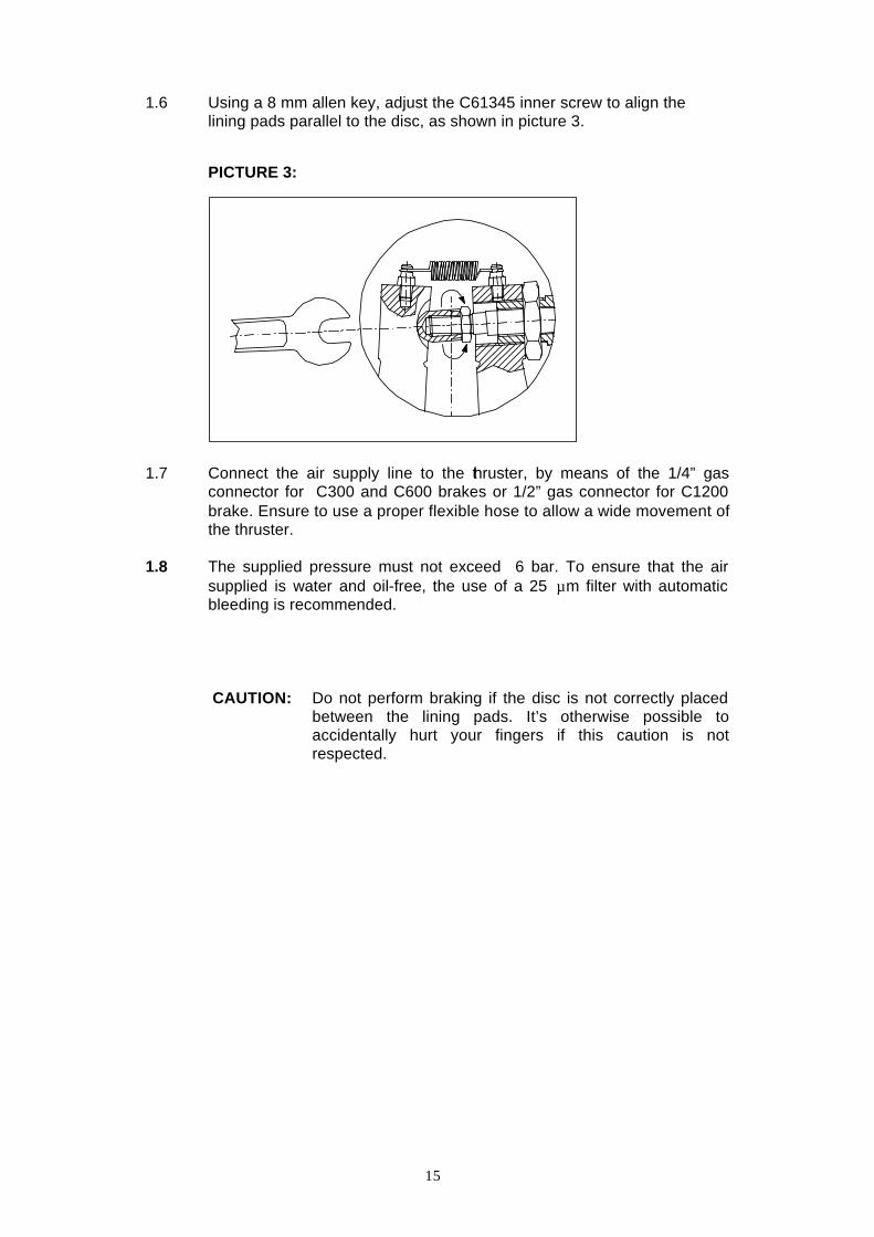
1.6 Using a 8 mm allen key, adjust the C61345 inner screw to align the lining pads parallel to the disc, as shown in picture 3.
PICTURE 3:
1.7 Connect the air supply line to the thruster, by means of the 1/4” gas
connector for C300 and C600 brakes or 1/2” gas connector for C1200 brake. Ensure to use a proper flexible hose to allow a wide movement of the thruster.
1.8 The supplied pressure must not exceed 6 bar. To ensure that the air
supplied is water and oil-free, the use of a 25 µm filter with automatic bleeding is recommended.
CAUTION: Do not perform braking if the disc is not correctly placed
between the lining pads. It’s otherwise possible to accidentally hurt your fingers if this caution is not respected.

16
2.0 MAINTENANCE AND CARE ALL MAINTENANCE OPERATIONS MUST BE PERFORMED ONLY WHEN THE MACHINE IS STOPPED.
2.1 GAP ADJUSTMENT
2.1.1 The piston stroke is long enough to compensate the maximum wear limti
of the linings.
2.1.2 Small adjustment can be performed through acting like described at point 1.5.
2.2 LINING PADS REPLACEMENT 2.2.1 Switch off the air pressure. Remove the nut C61346, the screws C61172
and the pads alignment system (parts Z50009, C61630, C61709, C61073 and C61345) without disassembly it.
2.2.2 Remove the snapring C61276 and the pin C61076. Remove the pad
E80571 and then remove the screws C61170 that fix the lining to the pad.
2.2.3 Change the linings and re-assembly them following the points 2.2.2 and
2.2.1 backward.
2.2.4 If necessary, adjust the gap and realign the lining pads as explained at the points 1.5 and 1.6.
NOTE: The friction pads used in this product are asbestos free and
non-toxic/harmful ; they have to be displaced according to your local regulation.

17
2.3 FRICTION SURFACE CLEANING
Remove lining pads as already explained at the point 2.2.
2.3.1 Use a non-polluting cleaning product to remove oil and grease traces from the disc surface.
NOTE: To avoid skin allergies use of gloves or protective creams.
Remember to carefully wash your hands before handle any food or beverage.
2.3.2 In case of shallow contamination of linings by any lubricant agent, the
surface may be cleaned wrapping it with an medium abrasive emery sheet. In case of deep contamination the full replacement of linings is suggested.
NOTE: According to the European health and environment regulation
all COREMO OCMEA products are asbestos free, and only non-toxic materials are used. Anyway the inhalation of produced exhausted dust should be absolutely avoided.
2.4 DIAPHRAGM REPLACEMENT 2.4.1 Switch off the air supply and disconnect the air hose. 2.4.2 Remove the thruster 2.4.3 Remove all the nuts, screws and washers that fix the cover on the
thruster body. 2.4.4 Remove the internal piston with its diaphragm. 2.4.5 Remove the screws, the washers and the fixing plate of the diaphragm;
change the diaphragm with a new one. 2.4.6 After greasing the pushrod, reassembly the thruster by following
backward the points from 2.4.5 to 2.4.1. 2.4.7 Operate the brake for several times to ensure that it has no air leakage
and the piston is moving correctly.

18
2.5 REPLACEMENT OF THRUSTER SPRING. 2.5.1 Switch off the air supply and disconnect the air hose. 2.5.2 Follow the points from 2.4.1 to 2.4.4.
2.5.3 Replace the damaged spring with a new one. 2.5.4 After greasing the pushrod, reassembly the thruster by following
backward the points from 2.4.4 to 2.4.1. 2.5.5 Operate the brake for several times to ensure that it has no air leakage
and the piston is moving correctly.

19
3.0 PERIODIC INSPECTIONS WE RECOMMEND TO PERFORM THE FOLLOWING TESTS EVERY THREE MONTS.
3.1 Verify that no lubricant traces are found on the disc or lining surfaces. 3.2 Check out that all the locking screws are properly tightened. 3.3 Check out integrity of the flexible hoses. 3.4 Switch on and off the air supply several times to check the seal or the
diaphragm integrity, the springs functionality, and the proper sliding of the pushrod.
4.0 SPARE PARTS
4.1 To avoid unnecessary stops of your production line, a suitable quantity
of spare parts should be kept at store, according to the number of brakes in use. Here below the suggested parts are reported: Linings: code No. Z50048 Thrusters Springs: code No. C61146 for C300 code No. C61150 for C600 code No. C61643 for C1200 Pads spring: code No. C61079 Caliper release spring: code No. C61078
Diaphragm code No. D70941 for C300 code No. D70943 for C600
code No. D70989 for C1200 4.2 Those spare parts shall be stored in cool and dark place, and far away
from any agent that could damage them or reduce their life and efficiency.

20

21

22

23
24
I.T. 020529
ISO 9001 - Certificazione N°0238
COREMO OCMEA S.r.l. - VIA GALILEI 12 - 20090 ASSAGO (MI) ITALY
TEL. 0039.02.4880697 - FAX 0039.02.4881940 - P.O. BOX 8 ASSAGO
INTERNET: www.coremo.ocmea.it