Esame di Stato di abilitazione alla professione di Ingegnere · Esame di Stato di abilitazione alla...
19
Esame di Stato di abilitazione alla professione di Ingegnere Sezione A Settore dell’Informazione Prova pratica: Classe 32/S Tema n. 1 II sessione 2009 Il Candidato supponga di agire come consulente di un laboratorio di Taratura accreditato SIT, quindi operante in conformità ai requisiti della norma internazionale ISO-IEC 17025. Il Laboratorio dispone dei dispositivi di regolazione della tensione di alimentazione e delle grandezze ambientali e dei consueti dispositivi elettronici ed informatici presenti in un laboratorio sperimentale. I dispositivi, quando necessario ed opportuno, sono collegabili fra loro mediante il BUS IEEE 488-2. Il Laboratorio opera in condizioni di elevata automazione, in modo da minimizzare l’intervento degli operatori specializzati. Infine il Laboratorio è provvisto di un insieme di dispositivi campione come illustrato nel seguito. Si vuole sottoporre a verifica di taratura un wattmetro digitale monofase, le cui principali caratteristiche sono: Portate in tensione: 60 V; 120 V; 240 V; 600 V Portate in corrente: 0,1 A; 0,5 A; 1 A; 2 A; 5 A; 10 A Risoluzione: 0,001 W per le portate minori Risoluzione: 0,01 W per le portate in grassetto Stabilità a breve termine: 1·10 -4 per la potenza apparente V·I Incertezza dichiarata dal costruttore: Accuracy: All accuracy values are expressed as a percentage of rated power at full scale voltage and current at Unity Power Factor. Accuracy specifications apply to any power factor, lead or lag. Accuracy: Voltage Range Current Range Accuracy 60V 100mA 500mA 1A 2A 5A 10A 0.10% 0.05% 0.05% 0.05% 0.10% 0.20% 120V 100mA 500mA 1A 0.10% 0.05% 0.05%
-
Upload
hoangnguyet -
Category
Documents
-
view
224 -
download
0
Transcript of Esame di Stato di abilitazione alla professione di Ingegnere · Esame di Stato di abilitazione alla...
Esame di Stato di abilitazione alla professione di Ingegnere
Sezione A Settore dell’Informazione Prova pratica: Classe 32/S
Tema n. 1 II sessione 2009
Il Candidato supponga di agire come consulente di un laboratorio di Taratura accreditato SIT, quindi operante in conformità ai requisiti della norma internazionale ISO-IEC 17025. Il Laboratorio dispone dei dispositivi di regolazione della tensione di alimentazione e delle grandezze ambientali e dei consueti dispositivi elettronici ed informatici presenti in un laboratorio sperimentale. I dispositivi, quando necessario ed opportuno, sono collegabili fra loro mediante il BUS IEEE 488-2. Il Laboratorio opera in condizioni di elevata automazione, in modo da minimizzare l’intervento degli operatori specializzati. Infine il Laboratorio è provvisto di un insieme di dispositivi campione come illustrato nel seguito.
Si vuole sottoporre a verifica di taratura un wattmetro digitale monofase, le cui principali caratteristiche sono:
Portate in tensione: 60 V; 120 V; 240 V; 600 V Portate in corrente: 0,1 A; 0,5 A; 1 A; 2 A; 5 A; 10 A Risoluzione: 0,001 W per le portate minori Risoluzione: 0,01 W per le portate in grassetto Stabilità a breve termine: 1·10-4 per la potenza apparente V·I Incertezza dichiarata dal costruttore:
Accuracy: All accuracy values are expressed as a percentage of rated power at full scale voltage and current at Unity Power Factor. Accuracy specifications apply to any power factor, lead or lag. Accuracy: Voltage Range
Current Range
Accuracy
60V 100mA 500mA 1A 2A 5A 10A
0.10% 0.05% 0.05% 0.05% 0.10% 0.20%
120V 100mA 500mA 1A
0.10% 0.05% 0.05%
2A 5A 10A
0.05% 0.10% 0.20%
240V 100mA 500mA 1A 2A 5A 10A
0.10% 0.07% 0.07% 0.07% 0.12% 0.22%
600V 100mA 500mA 1A 2A 5A 10A
0.10% 0.10% 0.10% 0.10% 0.15% 0.25%
Si vuole eseguire il controllo di taratura nei punti indicati nella tabella seguente:
Punti di controllo Frequenza [Hz] Sfasamento (cos φ)
50 V; 0,1 A 50 1; 0
100 V; 1 A 50; 1000 1; 0
230 V; 10 A 50 1; 0,5; 0
Tra le apparecchiature a disposizione si ha un calibratore Fluke 5520A, le cui principali caratteristiche sono riportate in Appendice A), che però risulta essere in condizioni di non riferibilità, per cui può essere utilizzato solo come generatore dei segnali in tensione ed in corrente.
Si devono perciò utilizzare i dispositivi seguenti, che si trovano in condizioni di riferibilità:
a) Shunt per corrente in AC. Portata: 10 A; valore di resistenza: 100 mΩ; Incertezza complessiva: 1·10-4 ; comportamento resistivo fino a frequenza di 10 kHz.
b) Digital Multimeter (DMM) Hewlett Packard 3458A, le cui principali caratteristiche sono riportate in Appendice B Si hanno a disposizione tre DMM.
c) Contatore digitale a due canali. Campo di tensione: ± 10 V; risoluzione temporale: 100 ns; massimo ritardo nella misura sui due canali: 20 ns; deriva temporale: 3·10-7/anno; deriva termica: 1·10-7/K
d) Cavi vari per collegamenti
Il candidato progetti un procedimento che permetta di eseguire la verifica di taratura del dispositivo indicato, ed in particolare:
1. Individui le principali condizioni operative ed ambientali per poter eseguire correttamente la verifica.
2. Indichi il procedimento di misura suggerito per eseguire la verifica, progettato in modo da utilizzare al meglio le apparecchiature disponibili, ottenere una elevata automazione delle procedure e una minimizzazione degli operatori specializzati impegnati nella prova. Il procedimento dovrà essere descritto in modo da fornire la base per la stesura della corrispondente procedura tecnica.
3. Esegua una stima dell’incertezza di taratura seguendo le linee guida della norma UNI CEI ENV 13005 (Guida all’espressione dell’incertezza di misura)
4. Indichi le informazioni essenziali che devono essere riportate nel certificato di taratura
5. Individui i principali procedimenti software che permettono l’esecuzione automatizzata della verifica e di uno di questi è invitato a presentare il diagramma di flusso dettagliato
6. Indichi passo per passo l’insieme degli atti che l’operatore dovrà eseguire per l’esecuzione della verifica, mettendo in evidenza gli accorgimenti previsti per individuare/evitare sbagli banali e per salvaguardare la sicurezza degli operatori.
Nel caso in cui siano necessari ulteriori dispositivi, se ne indichino le principali caratteristiche in vista di un acquisto da parte del Laboratorio, giustificando la scelta.
Introduction and SpecificationsSpecifications 1
1-9
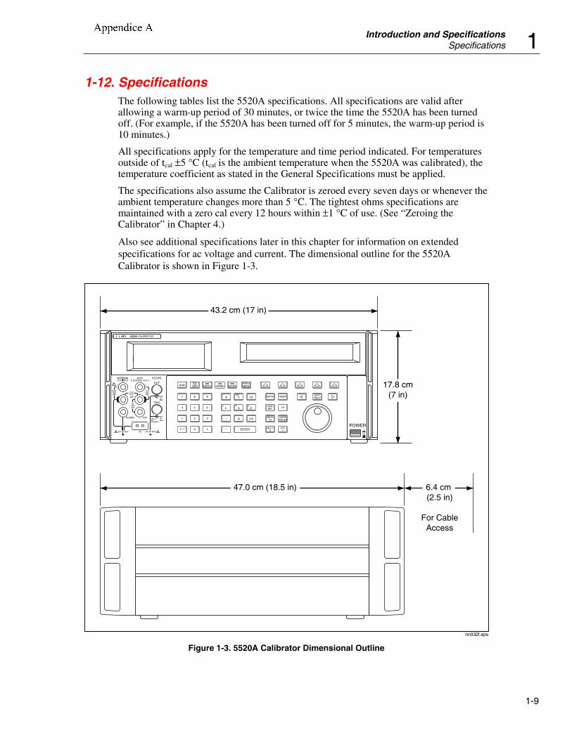
1-12. SpecificationsThe following tables list the 5520A specifications. All specifications are valid afterallowing a warm-up period of 30 minutes, or twice the time the 5520A has been turnedoff. (For example, if the 5520A has been turned off for 5 minutes, the warm-up period is10 minutes.)
All specifications apply for the temperature and time period indicated. For temperaturesoutside of tcal ±5 °C (tcal is the ambient temperature when the 5520A was calibrated), thetemperature coefficient as stated in the General Specifications must be applied.
The specifications also assume the Calibrator is zeroed every seven days or whenever theambient temperature changes more than 5 °C. The tightest ohms specifications aremaintained with a zero cal every 12 hours within ±1 °C of use. (See “Zeroing theCalibrator” in Chapter 4.)
Also see additional specifications later in this chapter for information on extendedspecifications for ac voltage and current. The dimensional outline for the 5520ACalibrator is shown in Figure 1-3.
POWERI
O
0 •
1 2 3
4 5 6
7 8 9
ENTER
M
k
m V Hz FIELDEDIT
/+
F
OPR EARTH EXGRD SCOPE MENUPREV
SHIFT
RESET
CE
SETUP
REFNEW
TCMEAS
¡F
μ
n
p
W
dBm sec
¡CA
MULTx
DIV÷
MODESMORE
STBY
43.2 cm (17 in)
47.0 cm (18.5 in) 6.4 cm (2.5 in)
For CableAccess
17.8 cm(7 in)
HI
LO
TRIG
GUARD
TC
20A
NORMAL AUX
5520A CALIBRATOR
SCOPE
OUTV, , ,RTD A, -SENSE, AUX V
20V PK MAX20V PK MAX
nn032f.eps
Figure 1-3. 5520A Calibrator Dimensional Outline
d000422
Casella di testo
CALIBRATORE FLUKE 5520A
Pezzetta
Appendice A
5520AOperators Manual
1-10
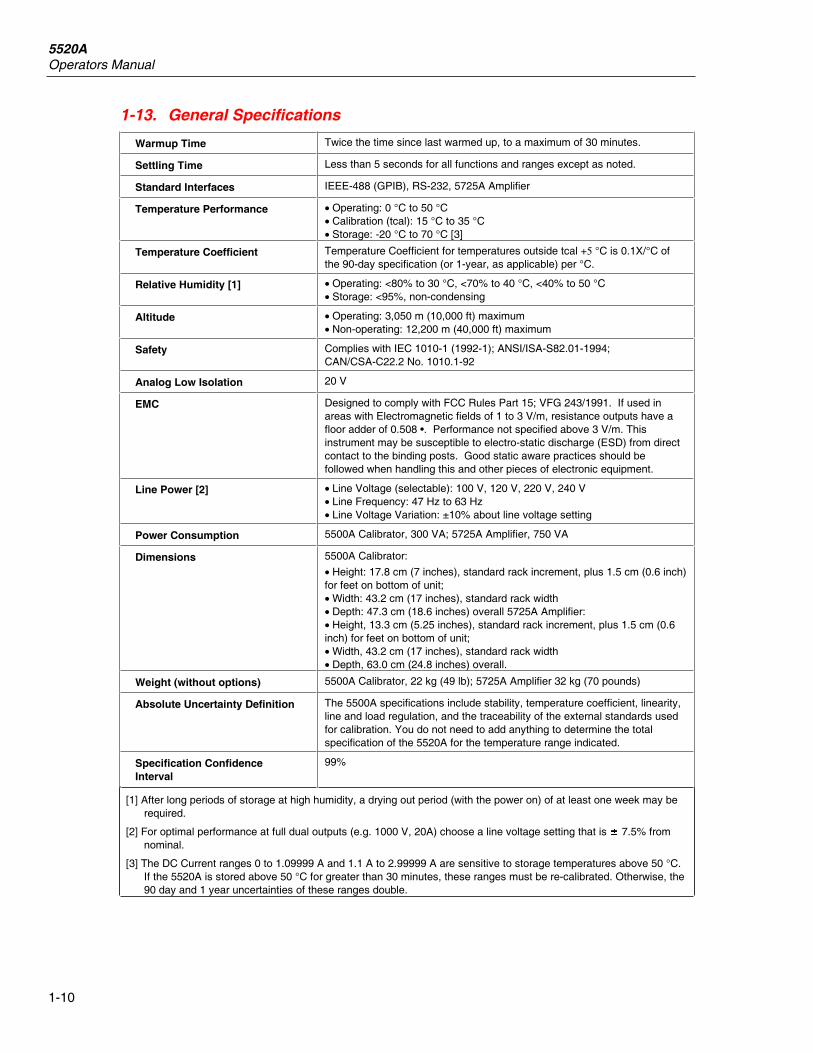
1-13. General Specifications
Warmup Time Twice the time since last warmed up, to a maximum of 30 minutes.
Settling Time Less than 5 seconds for all functions and ranges except as noted.
Standard Interfaces IEEE-488 (GPIB), RS-232, 5725A Amplifier
Temperature Performance • Operating: 0 °C to 50 °C• Calibration (tcal): 15 °C to 35 °C• Storage: -20 °C to 70 °C [3]
Temperature Coefficient Temperature Coefficient for temperatures outside tcal +5 °C is 0.1X/°C ofthe 90-day specification (or 1-year, as applicable) per °C.
Relative Humidity [1] • Operating: <80% to 30 °C, <70% to 40 °C, <40% to 50 °C• Storage: <95%, non-condensing
Altitude • Operating: 3,050 m (10,000 ft) maximum• Non-operating: 12,200 m (40,000 ft) maximum
Safety Complies with IEC 1010-1 (1992-1); ANSI/ISA-S82.01-1994;CAN/CSA-C22.2 No. 1010.1-92
Analog Low Isolation 20 V
EMC Designed to comply with FCC Rules Part 15; VFG 243/1991. If used inareas with Electromagnetic fields of 1 to 3 V/m, resistance outputs have afloor adder of 0.508 •. Performance not specified above 3 V/m. Thisinstrument may be susceptible to electro-static discharge (ESD) from directcontact to the binding posts. Good static aware practices should befollowed when handling this and other pieces of electronic equipment.
Line Power [2] • Line Voltage (selectable): 100 V, 120 V, 220 V, 240 V• Line Frequency: 47 Hz to 63 Hz• Line Voltage Variation: ±10% about line voltage setting
Power Consumption 5500A Calibrator, 300 VA; 5725A Amplifier, 750 VA
Dimensions 5500A Calibrator:
• Height: 17.8 cm (7 inches), standard rack increment, plus 1.5 cm (0.6 inch)for feet on bottom of unit;• Width: 43.2 cm (17 inches), standard rack width• Depth: 47.3 cm (18.6 inches) overall 5725A Amplifier:• Height, 13.3 cm (5.25 inches), standard rack increment, plus 1.5 cm (0.6inch) for feet on bottom of unit;• Width, 43.2 cm (17 inches), standard rack width• Depth, 63.0 cm (24.8 inches) overall.
Weight (without options) 5500A Calibrator, 22 kg (49 lb); 5725A Amplifier 32 kg (70 pounds)
Absolute Uncertainty Definition The 5500A specifications include stability, temperature coefficient, linearity,line and load regulation, and the traceability of the external standards usedfor calibration. You do not need to add anything to determine the totalspecification of the 5520A for the temperature range indicated.
Specification ConfidenceInterval
99%
[1] After long periods of storage at high humidity, a drying out period (with the power on) of at least one week may berequired.
[2] For optimal performance at full dual outputs (e.g. 1000 V, 20A) choose a line voltage setting that is 7.5% fromnominal.
[3] The DC Current ranges 0 to 1.09999 A and 1.1 A to 2.99999 A are sensitive to storage temperatures above 50 °C.If the 5520A is stored above 50 °C for greater than 30 minutes, these ranges must be re-calibrated. Otherwise, the90 day and 1 year uncertainties of these ranges double.
Introduction and SpecificationsSpecifications 1
1-15
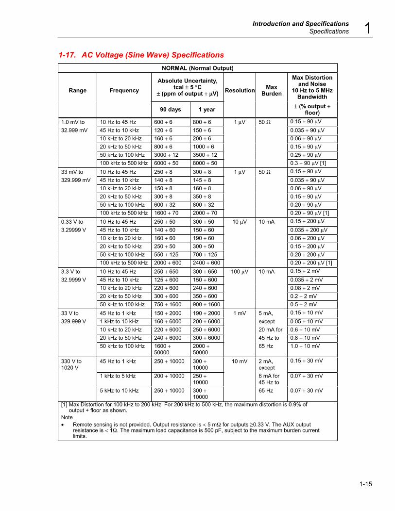
1-17. AC Voltage (Sine Wave) SpecificationsNORMAL (Normal Output)
Range FrequencyAbsolute Uncertainty,
tcal ± 5 °C± (ppm of output + μV) Resolution Max
Burden
Max Distortionand Noise
10 Hz to 5 MHzBandwidth
90 days 1 year ± (% output +floor)
1.0 mV to 10 Hz to 45 Hz 600 + 6 800 + 6 1 μV 50 Ω 0.15 + 90 μV32.999 mV 45 Hz to 10 kHz 120 + 6 150 + 6 0.035 + 90 μV
10 kHz to 20 kHz 160 + 6 200 + 6 0.06 + 90 μV20 kHz to 50 kHz 800 + 6 1000 + 6 0.15 + 90 μV50 kHz to 100 kHz 3000 + 12 3500 + 12 0.25 + 90 μV100 kHz to 500 kHz 6000 + 50 8000 + 50 0.3 + 90 μV [1]
33 mV to 10 Hz to 45 Hz 250 + 8 300 + 8 1 μV 50 Ω 0.15 + 90 μV329.999 mV 45 Hz to 10 kHz 140 + 8 145 + 8 0.035 + 90 μV
10 kHz to 20 kHz 150 + 8 160 + 8 0.06 + 90 μV20 kHz to 50 kHz 300 + 8 350 + 8 0.15 + 90 μV50 kHz to 100 kHz 600 + 32 800 + 32 0.20 + 90 μV100 kHz to 500 kHz 1600 + 70 2000 + 70 0.20 + 90 μV [1]
0.33 V to 10 Hz to 45 Hz 250 + 50 300 + 50 10 μV 10 mA 0.15 + 200 μV3.29999 V 45 Hz to 10 kHz 140 + 60 150 + 60 0.035 + 200 μV
10 kHz to 20 kHz 160 + 60 190 + 60 0.06 + 200 μV20 kHz to 50 kHz 250 + 50 300 + 50 0.15 + 200 μV50 kHz to 100 kHz 550 + 125 700 + 125 0.20 + 200 μV100 kHz to 500 kHz 2000 + 600 2400 + 600 0.20 + 200 μV [1]
3.3 V to 10 Hz to 45 Hz 250 + 650 300 + 650 100 μV 10 mA 0.15 + 2 mV32.9999 V 45 Hz to 10 kHz 125 + 600 150 + 600 0.035 + 2 mV
10 kHz to 20 kHz 220 + 600 240 + 600 0.08 + 2 mV20 kHz to 50 kHz 300 + 600 350 + 600 0.2 + 2 mV50 kHz to 100 kHz 750 + 1600 900 + 1600 0.5 + 2 mV
33 V to 45 Hz to 1 kHz 150 + 2000 190 + 2000 1 mV 5 mA, 0.15 + 10 mV329.999 V 1 kHz to 10 kHz 160 + 6000 200 + 6000 except 0.05 + 10 mV
10 kHz to 20 kHz 220 + 6000 250 + 6000 20 mA for 0.6 + 10 mV20 kHz to 50 kHz 240 + 6000 300 + 6000 45 Hz to 0.8 + 10 mV50 kHz to 100 kHz 1600 +
500002000 +50000
65 Hz 1.0 + 10 mV
330 V to1020 V
45 Hz to 1 kHz 250 + 10000 300 +10000
10 mV 2 mA,except
0.15 + 30 mV
1 kHz to 5 kHz 200 + 10000 250 +10000
6 mA for45 Hz to
0.07 + 30 mV
5 kHz to 10 kHz 250 + 10000 300 +10000
65 Hz 0.07 + 30 mV
[1] Max Distortion for 100 kHz to 200 kHz. For 200 kHz to 500 kHz, the maximum distortion is 0.9% of output + floor as shown.Note• Remote sensing is not provided. Output resistance is < 5 mΩ for outputs ≥0.33 V. The AUX output
resistance is < 1Ω. The maximum load capacitance is 500 pF, subject to the maximum burden currentlimits.
5520AOperators Manual
1-16
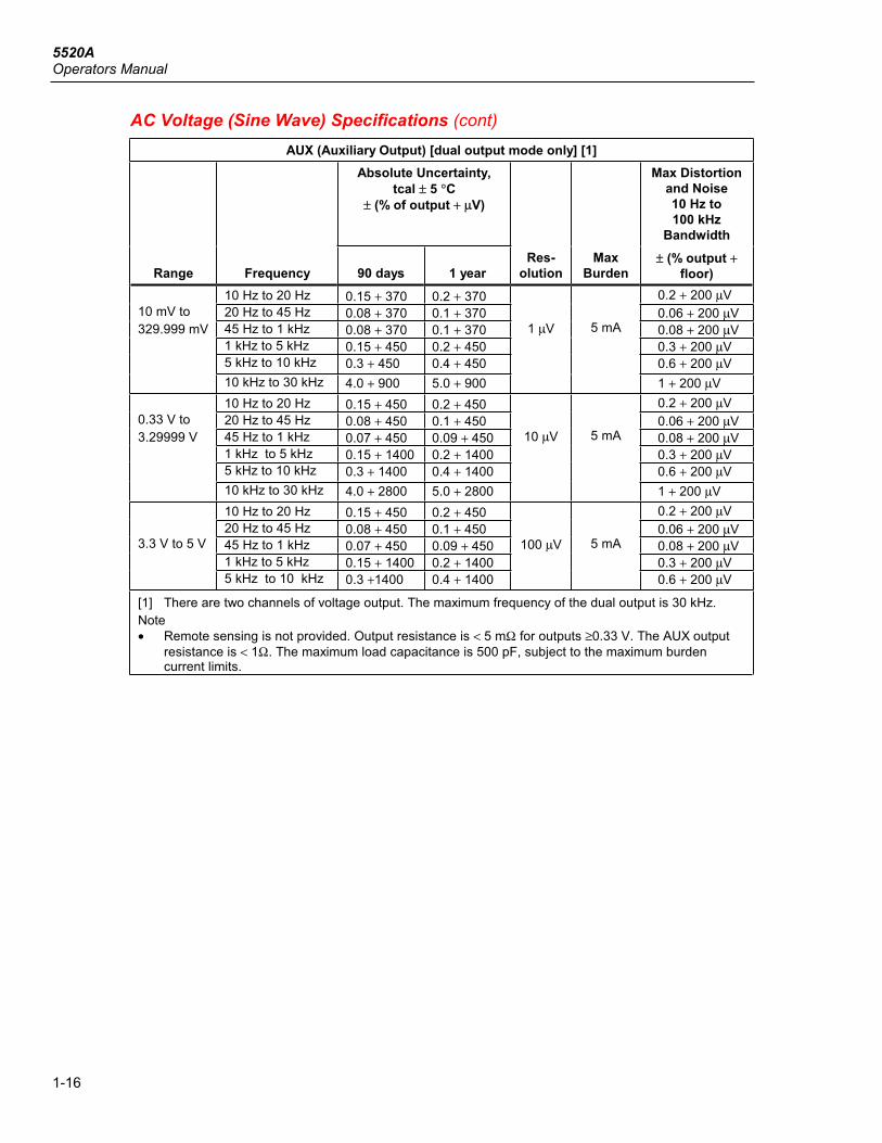
AC Voltage (Sine Wave) Specifications (cont)AUX (Auxiliary Output) [dual output mode only] [1]
Absolute Uncertainty,tcal ± 5 °C
± (% of output + μV)
Max Distortionand Noise10 Hz to100 kHz
Bandwidth
Range Frequency 90 days 1 yearRes-
olutionMax
Burden± (% output +
floor)10 Hz to 20 Hz 0.15 + 370 0.2 + 370 0.2 + 200 μV20 Hz to 45 Hz 0.08 + 370 0.1 + 370 0.06 + 200 μV45 Hz to 1 kHz 0.08 + 370 0.1 + 370 0.08 + 200 μV1 kHz to 5 kHz 0.15 + 450 0.2 + 450 0.3 + 200 μV5 kHz to 10 kHz 0.3 + 450 0.4 + 450 0.6 + 200 μV
10 mV to329.999 mV
10 kHz to 30 kHz 4.0 + 900 5.0 + 900
1 μV 5 mA
1 + 200 μV10 Hz to 20 Hz 0.15 + 450 0.2 + 450 0.2 + 200 μV20 Hz to 45 Hz 0.08 + 450 0.1 + 450 0.06 + 200 μV45 Hz to 1 kHz 0.07 + 450 0.09 + 450 0.08 + 200 μV1 kHz to 5 kHz 0.15 + 1400 0.2 + 1400 0.3 + 200 μV5 kHz to 10 kHz 0.3 + 1400 0.4 + 1400 0.6 + 200 μV
0.33 V to3.29999 V
10 kHz to 30 kHz 4.0 + 2800 5.0 + 2800
10 μV 5 mA
1 + 200 μV10 Hz to 20 Hz 0.15 + 450 0.2 + 450 0.2 + 200 μV20 Hz to 45 Hz 0.08 + 450 0.1 + 450 0.06 + 200 μV45 Hz to 1 kHz 0.07 + 450 0.09 + 450 0.08 + 200 μV1 kHz to 5 kHz 0.15 + 1400 0.2 + 1400 0.3 + 200 μV
3.3 V to 5 V
5 kHz to 10 kHz 0.3 +1400 0.4 + 1400
100 μV 5 mA
0.6 + 200 μV
[1] There are two channels of voltage output. The maximum frequency of the dual output is 30 kHz.Note• Remote sensing is not provided. Output resistance is < 5 mΩ for outputs ≥0.33 V. The AUX output
resistance is < 1Ω. The maximum load capacitance is 500 pF, subject to the maximum burdencurrent limits.
Introduction and SpecificationsSpecifications 1
1-17
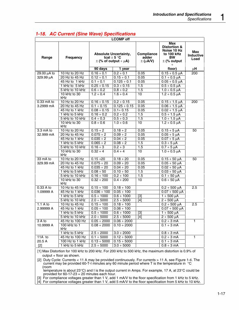
1-18. AC Current (Sine Wave) SpecificationsLCOMP off
MaxInductive
LoadRange FrequencyAbsolute Uncertainty,
tcal ± 5 °C± (% of output + μA)
Complianceadder
± (μA/V)
MaxDistortion &Noise 10 Hzto 100 kHz
BW± (% output
+90 days 1 year floor) μH
29.00 μA to 10 Hz to 20 Hz 0.16 + 0.1 0.2 + 0.1 0.05 0.15 + 0.5 μA 200329.99 μA 20 Hz to 45 Hz 0.12 + 0.1 0.15 + 0.1 0.05 0.1 + 0.5 μA
45 Hz to 1 kHz 0.1 + 0.1 0.125 + 0.1 0.05 0.05 + 0.5 μA1 kHz to 5 kHz 0.25 + 0.15 0.3 + 0.15 1.5 0.5 + 0.5 μA5 kHz to 10 kHz 0.6 + 0.2 0.8 + 0.2 1.5 1.0 + 0.5 μA10 kHz to 30kHz
1.2 + 0.4 1.6 + 0.4 10 1.2 + 0.5 μA
0.33 mA to 10 Hz to 20 Hz 0.16 + 0.15 0.2 + 0.15 0.05 0.15 + 1.5 μA 2003.2999 mA 20 Hz to 45 Hz 0.1 + 0.15 0.125 + 0.15 0.05 0.06 + 1.5 μA
45 Hz to 1 kHz 0.08 + 0.15 0.1+ 0.15 0.05 0.02 + 1.5 μA1 kHz to 5 kHz 0.16 + 0.2 0.2 + 0.2 1.5 0.5 + 1.5 μA5 kHz to 10 kHz 0.4 + 0.3 0.5 + 0.3 1.5 1.0 + 1.5 μA10 kHz to 30kHz
0.8 + 0.6 1.0 + 0.6 10 1.2 + 0.5 μA
3.3 mA to 10 Hz to 20 Hz 0.15 + 2 0.18 + 2 0.05 0.15 + 5 μA 5032.999 mA 20 Hz to 45 Hz 0.075 + 2 0.09 + 2 0.05 0.05 + 5 μA
45 Hz to 1 kHz 0.035 + 2 0.04 + 2 0.05 0.07 + 5 μA1 kHz to 5 kHz 0.065 + 2 0.08 + 2 1.5 0.3 + 5 μA5 kHz to 10 kHz 0.16 + 3 0.2 + 3 1.5 0.7 + 5 μA10 kHz to 30kHz
0.32 + 4 0.4 + 4 10 1.0 + 0.5 μA
33 mA to 10 Hz to 20 Hz 0.15 +20 0.18 + 20 0.05 0.15 + 50 μA 50329.99 mA 20 Hz to 45 Hz 0.075 + 20 0.09 + 20 0.05 0.05 + 50 μA
45 Hz to 1 kHz 0.035 + 20 0.04 + 20 0.05 0.02 + 50 μA1 kHz to 5 kHz 0.08 + 50 0.10 + 50 1.5 0.03 + 50 μA5 kHz to 10 kHz 0.16 + 100 0.2 + 100 1.5 0.1 + 50 μA10 kHz to 30kHz
0.32 + 200 0.4 + 200 10 0.6 + 50 μA
0.33 A to 10 Hz to 45 Hz 0.15 + 100 0.18 + 100 0.2 + 500 μA 2.51.09999 A 45 Hz to 1 kHz 0.036 + 100 0.05 + 100 0.07 + 500 μA
1 kHz to 5 kHz 0.5 + 1000 0.6 + 1000 [3] 1 + 500 μA5 kHz to 10 kHz 2.0 + 5000 2.5 + 5000 [4] 2 + 500 μA
1.1 A to 10 Hz to 45 Hz 0.15 + 100 0.18 + 100 0.2 + 500 μA 2.52.99999 A 45 Hz to 1 kHz 0.05 + 100 0.06 + 100 0.07 + 500 μA
1 kHz to 5 kHz 0.5 + 1000 0.6 + 1000 [3] 1 + 500 μA5 kHz to 10 kHz 2.0 + 5000 2.5 + 5000 [4] 2 + 500 μA
3 A to 45 Hz to 100 Hz 0.05 + 2000 0.06 + 2000 0.2 + 3 mA 110.9999 A 100 kHz to 1
kHz0.08 + 2000 0.10 + 2000 0.1 + 3 mA
1 kHz to 5 kHz 2.5 + 2000 3.0 + 2000 0.8 + 3 mA11A to 45 Hz to 100 Hz 0.1 + 5000 0.12 + 5000 0.2 + 3 mA 120.5 A 100 Hz to 1 kHz 0.13 + 5000 0.15 + 5000 0.1 + 3 mA [2] 1 kHz to 5 kHz 2.5 + 5000 3.0 + 5000 0.8 + 3 mA
[1] Max Distortion for 100 kHz to 200 kHz. For 200 kHz to 500 kHz, the maximum distortion is 0.9% of output + floor as shown.[2] Duty Cycle: Currents < 11 A may be provided continuously. For currents > 11 A, see Figure 1-4. The current may be provided 60-T-I minutes any 60 minute period where T is the temperature in °C (room temperature is about 23°C) and I is the output current in Amps. For example, 17 A, at 23°C could be provided for 60-17-23 = 20 minutes each hour.[3] For compliance voltages greater than 1 V, add 1 mA/V to the floor specification from 1 kHz to 5 kHz.[4] For compliance voltages greater than 1 V, add 5 mA/V to the floor specification from 5 kHz to 10 kHz.

5520AOperators Manual
1-18
AC Current (Sine Wave) Specifications (cont)
LCOMP on
Range FrequencyAbsolute Uncertainty, tcal ± 5
°C± (% of output + μA)
Max Distortion& Noise, 10 Hzto 100 kHz BW
MaxInductiv
e Load
90 days 1 year± (% output +
μA)μH
29.00 μA to 10 Hz to 100 Hz 0.2 + 0.2 0.25 + 0.2 0.1 + 1.0
329.99 μA 100 Hz to 1 kHz 0.5 + 0.5 0.6 + 0.5 0.05 + 1.0
0.33 mA to 10 Hz to 100 Hz 0.2 + 0.3 0.25 + 0.3 0.15 + 1.5
3.2999 mA 100 Hz to 1 kHz 0.5 + 0.8 0.6 + 0.8 0.06 + 1.5
3.3 mA to 10 Hz to 100 Hz 0.07 + 4 0.08 + 4 0.15 + 5 400
32.999 mA 100 Hz to 1 kHz 0.18 + 10 0.2 + 10 0.05 + 5
33 mA to 10 Hz to 100 Hz 0.07 + 40 0.08 + 40 0.15 + 50
329.99 mA 100 Hz to 1 kHz 0.18 + 100 0.2 + 100 0.05 + 50
0.33 A to 10 Hz to 100 Hz 0.1 + 200 0.12 + 200 0.2 + 500
2.99999 A 100 to 440 Hz 0.25 + 1000 0.3 + 1000 0.25 + 500
3 A to 20.5 A 10 Hz to 100 Hz 0.1 + 2000 [2] 0.12 + 2000[2]
0.1 + 0 400 [4]
[1] 100 Hz to 1 kHz 0.8 + 5000 [3] 1.0 + 5000 [3] 0.5 + 0
[1] Duty Cycle: Currents < 11 A may be provided continuously. For currents >11 A, see Figure 1-4. Thecurrent may be provided 60-T-I minutes any 60 minute period where T is the temperature in °C (roomtemperature is about 23 °C) and I is the output current in amperes. For example, 17 A, at 23 °Ccould be provided for 60-17-23 = 20 minutes each hour.
[2] For currents >11 A, Floor specification is 4000 μA within 30 seconds of selecting operate. Foroperating times >30 seconds, the floor specification is 2000 μA.
[3] For currents >11 A, Floor specification is 1000 μA within 30 seconds of selecting operate. Foroperating times >30 seconds, the floor specification is 5000 μA.
[4] Subject to compliance voltages limits.
RangeResolution
μAMax Compliance Voltage
V rms
0.029 mA to 0.32999 mA 0.01 7
0.33 mA to 3.29999 mA 0.01 7
3.3 mA to 32.9999 mA 0.1 5
33 mA to 329.999 mA 1 5
0.33 A to 2.99999 A 10 4
3 A to 20.5 A 100 3
[1] Subject to specification adder for compliance voltages greater than 1 V rms.

5520AOperators Manual
1-24
1-25. Phase Specifications
1-Year Absolute Uncertainty, tcal ± 5 °C, (Δ Φ °)
10 Hz to65 Hz
65 Hz to500 Hz
500 Hz to1 kHz
1 kHz to5 kHz
5 kHz to10 kHz
10 kHz to30 kHz
0.10° 0.25° 0.5° 2.5° 5° 10°
Power Uncertainty Adder due to Phase ErrorPhase(Φ)
Watts
Phase(Φ)
VARs PF10 Hz to
65 Hz65 Hz to500 Hz
500 Hz to1 kHz
1 kHz to5 kHz
5 kHz to10 kHz
10 kHz to30 kHz
0° 90° 1.000 0.00% 0.00% 0.00% 0.10% 0.38% 1.52%
10° 80° 0.985 0.03% 0.08% 0.16% 0.86% 1.92% 4.58%
20° 70° 0.940 0.06% 0.16% 0.32% 1.68% 3.55% 7.84%
30° 60° 0.866 0.10% 0.25% 0.51% 2.61% 5.41% 11.54%
40° 50° 0.766 0.15% 0.37% 0.74% 3.76% 7.69% 16.09%
50° 40° 0.643 0.21% 0.52% 1.04% 5.29% 10.77% 22.21%
60° 30° 0.500 0.30% 0.76% 1.52% 7.65% 15.48% 31.60%
70° 20° 0.342 0.48% 1.20% 2.40% 12.08% 24.33% 49.23%
80° 10° 0.174 0.99% 2.48% 4.95% 24.83% 49.81% 100.00%
90° 0° 0.000 ⎯ ⎯ ⎯ ⎯ ⎯ ⎯
Note
1. To calculate exact ac watts power adders due to phase uncertainty for values not
shown, use the following formula: ( ) ( )Adder
Cos
Cos% (
( )= − +100 1
Φ ΔΦΦ
) . For example:
for a PF of .9205 (Φ = 23) and a phase uncertainty of ΔΦ = 0.15, the ac watts power
adder is: ( ) ( )Adder
Cos
Cos% (
(23 )= − + =100 115
230 11%
.) .

Appendix A Specifications 283
Appendice B Specifications
IntroductionThe 3458A accuracy is specified as a part per million (ppm) of the reading plus a ppm of range for dcV, Ohms, and dcl. In acV and acl, the specification is percent of reading plus percent of range. Range means the name of the scale, e.g. 1 V, 10 V, etc.; range does not mean the full scale reading, e.g. 1.2 V, 12 V, etc. These accuracies are valid for a specific time from the last calibration.
Absolute versus Relative AccuracyAll 3458A accuracy specifications are relative to the calibration standards. Absolute accuracy of the 3458A is determined by adding these relative accuracies to the traceability of your calibration standard. For dcV, 2 ppm is the traceability error from the Agilent factory. That means that the absolute error relative to the U.S. National Institute of Standards and Technology (NIST) is 2 ppm in addition to the dcV accuracy specifications. When you recalibrate the 3458A, your actual traceability error will depend upon the errors from your calibration standards. These errors will likely be different from the Agilent error of 2 ppm.
Example 1: Relative Accuracy; 24 Hour Operating temperature is Tcal ± 1°CAssume that the ambient temperature for the measurement is within ± 1°C of the temperature of calibration (Tcal). The 24 hour accuracy specification for a 10 V dc measurement on the 10 V range is 0.5 ppm ± 0.05 ppm. That accuracy specification means:
0.5 ppm of Reading + 0.05 ppm of Range
For relative accuracy, the error associated with the measurement is:(0.5/1,000,000 x 10 V) + (0.05/1,000,000 x 10 V) =
± 5.5 μV or 0.55 ppm of 10 V
Errors from temperature changesThe optimum technical specifications of the 3458A are based on auto-calibration (ACAL) of the instrument within the previous 24 hours and following ambient temperature changes of less than ±1°C. The 3458A's ACAL capability corrects for measurement errors resulting from the drift of critical components from time and temperature.
The following examples illustrate the error correction of auto-calibration by computing the relative measurement error of the 3458A for various temperature conditions. Constant conditions for each example are:
10 V DC input10 V DC range
Tcal = 23°C90 day accuracy specifications
Example 2: Operating temperature is 28°C;With ACALThis example shows basic accuracy of the 3458A using auto-calibration with an operating temperature of 28°C. Results are rounded to 2 digits.
(4.1 ppm x 10 V) + (0.05 ppm x 10 V) = 42 μV
Total relative error = 42 μV
Example 3: Operating temperature is 38°C;Without ACALThe operating temperature of the 3458A is 38°C, 14°C beyond the range of Tcal ±1°C. Additional measurement errors result because of the added temperature coefficient without using ACAL.
(4.1 ppm x 10 V) + (0.05 ppm x 10 V) = 42 μV
Temperature Coefficient (specification is per °C):(0.5ppm x 10V + 0.01 ppm x 10V) x 14°C = 71 μV
Total error = 113 μV
Example 4: Operating temperature is 38°C;With ACALAssuming the same conditions as Example 3, but using ACAL significantly reduces the error due to temperature difference from calibration temperature. Operating temperature is 10°C beyond the standard range of Tcal ±5°C.
(4.1 ppm x 10 V) + (0.05 ppm x 10 V) = 42 μV
Temperature Coefficient (specification is per °C):(0.15ppm x 10V + 0.01ppm x 10V) x 10°C = 16μV
Total error = 58 μV
Example 5: Absolute Accuracy; 90 DayAssuming the same conditions as Example 4, but now add the traceability error to establish absolute accuracy.
(4.1 ppm x 10 V) + (0.05 ppm x 10 V) = 42 μV
Temperature Coefficient (specification is per °C):(0.15ppm x 10V + 0.01ppm x 10V) x 10°C = 16μV
Agilent factory traceability error of 2 ppm:(2 ppm x 10 V) = 20 μV
Total absolute error = 78 μV
Additional errorsWhen the 3458A is operated at power line cycles below 100, additional errors due to noise and gain become significant. Example 6 illustrates the error correction at 0.1 PLC.
Example 6: operating temperature is 28×C; 0.1 PLCAssuming the same conditions as Example 2, but now add additional error.
(4.1 ppm x 10 V) t (0.05 ppm x 10 V) = 42 μV
Referring to the Additional Errors chart and RMS Noise Multiplier table, additional error at 0.1 PLC is:(2 ppm x 10 V) + (0.4 ppm x 1 x 3 x 10 V) = 32 μV
Total relative error = 74 μV
288 Appendix A Specifications
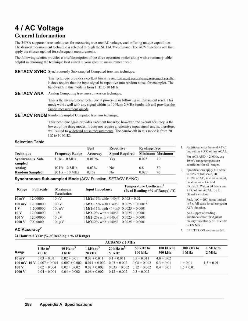
4 / AC VoltageGeneral InformationThe 3458A supports three techniques for measuring true rms AC voltage, each offering unique capabilities. The desired measurement technique is selected through the SETACV command. The ACV functions will then apply the chosen method for subsequent measurements.
The following section provides a brief description of the three operation modes along with a summary table helpful in choosing the technique best suited to your specific measurement need.
Selection Table
Synchronous Sub-sampled Mode (ACV Function, SETACV SYNC)
AC Accuracy2
24 Hour to 2 Year (% of Reading + % of Range)
SETACV SYNC Synchronously Sub-sampled Computed true rms technique.
This technique provides excellent linearity and the most accurate measurement results.It does require that the input signal be repetitive (not random noise, for example). The bandwidth in this mode is from 1 Hz to 10 MHz.
SETACV ANA Analog Computing true rms conversion technique.
This is the measurement technique at power-up or following an instrument reset. This mode works well with any signal within its 10 Hz to 2 MHz bandwidth and provides the fastest measurement speeds.
SETACV RNDM Random Sampled Computed true rms technique.
This technique again provides excellent linearity; however, the overall accuracy is the lowest of the three modes. It does not require a repetitive input signal and is, therefore, well suited to wideband noise measurements. The bandwidth in this mode is from 20 HZ to 10 MHZ.
Best Repetitive Readings /SecTechnique Frequency Range Accuracy Signal Required Minimum MaximumSynchronous Sub-sampled
1 Hz –10 MHz 0.010% Yes 0.025 10
Analog 10 Hz – 2 MHz 0.03% No 0.8 50Random Sampled 20 Hz – 10 MHz 0.1% No 0.025 45
Range Full Scale Maximum Resolution
Input ImpedanceTemperature Coefficient1
(% of Reading +% of Range) /C
10 mV 12.00000 10 nV 1 M±15% with<140pF 0.003 + 0.02100 mV 120.00000 10 nV 1 M±15% with<140pF 0.0025 + 0.00012
1 V 1.2000000 100 nV 1 M±15% with <140pF 0.0025 + 0.000110 V 12.000000 1 μV 1 M±2% with <140pF 0.0025 + 0.0001100 V 120.00000 10 μV 1 M±2% with <140pF 0.0025 + 0.00011000 V 700.0000 100 μV 1 M±2% with <140pF 0.0025 + 0.0001
ACBAND 2 MHz
Range 1 Hz to3
40 Hz40 Hz to3
1 kHz1 kHz to3
20 kHz20 kHz to3
50 kHz50 kHz to 100 kHz
100 kHz to 300 kHz
300 kHz to 1 MHz
1 MHz to 2 MHz
10 mV 0.03 + 0.03 0.02 + 0.011 0.03 + 0.011 0.1 + 0.011 0.5 + 0.011 4.0 + 0.02100 mV–10 V 0.007 + 0.004 0.007 + 0.002 0.014 + 0.002 0.03 + 0.002 0.08 + 0.002 0.3 + 0.01 1 + 0.01 1.5 + 0.01100 V 0.02 + 0.004 0.02 + 0.002 0.02 + 0.002 0.035 + 0.002 0.12 + 0.002 0.4 + 0.01 1.5 + 0.011000 V 0.04 + 0.004 0.04 + 0.002 0.06 + 0.002 0.12 + 0.002 0.3 + 0.002
1. Additional error beyond ±1C, but within + 5C of last ACAL.For ACBAND > 2 MHz, use10 mV range temperature coefficient for all ranges.
2. Specifications apply full scale to 10% of full scale, DC < 10% of AC, sine wave input, crest factor = 1.4, and PRESET. Within 24 hours and ±1C of last ACAL. Lo to Guard Switch on.
Peak (AC + DC) input limited to 5 x full scale for all ranges in ACV function.
Add 2 ppm of reading additional error for Agilent factory traceability of 10 V DC to US NIST.
3. LFILTER ON recommended.
Appendix A Specifications 289
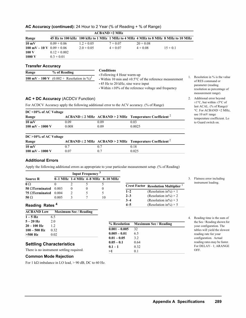
AC Accuracy (continued): 24 Hour to 2 Year (% of Reading + % of Range)
Transfer Accuracy
AC + DC Accuracy (ACDCV Function)For ACDCV Accuracy apply the following additional error to the ACV accuracy. (% of Range)
Additional ErrorsApply the following additional errors as appropriate to your particular measurement setup. (% of Reading)
Reading Rates 4
Settling CharacteristicsThere is no instrument settling required.
Common Mode RejectionFor 1 kimbalance in LO lead, > 90 dB, DC to 60 Hz.
ACBAND >2 MHzRange 45 Hz to 100 kHz 100 kHz to 1 MHz 1 MHz to 4 MHz 4 MHz to 8 MHz 8 MHz to 10 MHz10 mV 0.09 + 0.06 1.2 + 0.05 7 + 0.07 20 + 0.08100 mV – 10 V 0.09 + 0.06 2.0 + 0.05 4 + 0.07 4 + 0.08 15 + 0.1100 V 0.12 + 0.0021000 V 0.3 + 0.01
Range % of Reading
100 mV – 100 V (0.002 + Resolution in %)1
DC <10% of AC VoltageRange ACBAND 2 MHz ACBAND > 2 MHz Temperature Coefficient 2
10 mV 0.09 0.09 0.03100 mV – 1000 V 0.008 0.09 0.0025
DC >10% of AC VoltageRange ACBAND 2 MHz ACBAND > 2 MHz Temperature Coefficient 2
10 mV 0.7 0.7 0.18100 mV – 1000 V 0.07 0.7 0.025
Input Frequency 3
Source R 0–1 MHz 1-4 MHz 4–8 MHz 8–10 MHz0 0 2 5 550 Terminated 0.003 0 0 075 Terminated 0.004 2 5 550 0.005 3 7 10
ACBAND Low Maximum Sec / Reading1 – 5 Hz 6.55 – 20 Hz 2.020 – 100 Hz 1.2100 – 500 Hz 0.32>500 Hz 0.02
Conditions• Following 4 Hour warm-up• Within 10 min and ±0.5C of the reference measurement• 45 Hz to 20 kHz, sine wave input• Within ±10% of the reference voltage and frequency
Crest Factor Resolution Multiplier 1
1–2 (Resolution in%) × 12–3 (Resolution in%) × 23–4 (Resolution in%) × 34–5 (Resolution in%) × 5
% Resolution Maximum Sec / Reading0.001 – 0.005 320.005 – 0.01 6.50.01 – 0.05 3.20.05 – 0.1 0.640.1 – 1 0.32>1 0.1
1. Resolution in % is the value of RES command or parameter (reading resolution as percentage of measurement range).
2. Additional error beyond ±1C, but within ±5C of last ACAL. (% of Range)/C. For ACBAND >2 MHz, use 10 mV range temperature coefficient. Lo to Guard switch on.
3. Flatness error including instrument loading.
4. Reading time is the sum of the Sec / Reading shown for your configuration. The tables will yield the slowest reading rate for your configuration. Actual reading rates may be faster. For DELAY– 1; ARANGE OFF.
290 Appendix A Specifications
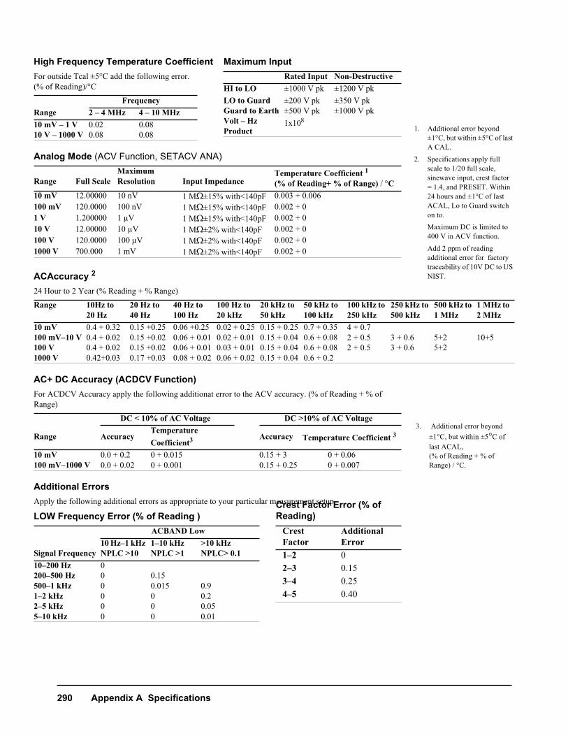
High Frequency Temperature CoefficientFor outside Tcal ±5°C add the following error.(% of Reading)/°C
Analog Mode (ACV Function, SETACV ANA)
ACAccuracy 2
24 Hour to 2 Year (% Reading + % Range)
AC+ DC Accuracy (ACDCV Function)For ACDCV Accuracy apply the following additionat error to the ACV accuracy. (% of Reading + % of Range)
Additional ErrorsApply the following additional errors as appropriate to your particular measurement setup.
LOW Frequency Error (% of Reading )
FrequencyRange 2 – 4 MHz 4 – 10 MHz10 mV – 1 V 0.02 0.0810 V – 1000 V 0.08 0.08
Range Full ScaleMaximum Resolution Input Impedance
Temperature Coefficient 1(% of Reading+ % of Range) C
10 mV 12.00000 10 nV 1 M±15% with<140pF 0.003 + 0.006100 mV 120.0000 100 nV 1 M±15% with<140pF 0.002 + 01 V 1.200000 1 μV 1 M±15% with<140pF 0.002 + 010 V 12.00000 10 μV 1 M±2% with<140pF 0.002 + 0100 V 120.0000 100 μV 1 M±2% with<140pF 0.002 + 01000 V 700.000 1 mV 1 M±2% with<140pF 0.002 + 0
Range 10Hz to 20 Hz
20 Hz to 40 Hz
40 Hz to100 Hz
100 Hz to 20 kHz
20 kHz to 50 kHz
50 kHz to 100 kHz
100 kHz to 250 kHz
250 kHz to 500 kHz
500 kHz to 1 MHz
1 MHz to 2 MHz
10 mV 0.4 + 0.32 0.15 +0.25 0.06 +0.25 0.02 + 0.25 0.15 + 0.25 0.7 + 0.35 4 + 0.7100 mV–10 V 0.4 + 0.02 0.15 +0.02 0.06 + 0.01 0.02 + 0.01 0.15 + 0.04 0.6 + 0.08 2 + 0.5 3 + 0.6 5+2 10+5100 V 0.4 + 0.02 0.15 +0.02 0.06 + 0.01 0.03 + 0.01 0.15 + 0.04 0.6 + 0.08 2 + 0.5 3 + 0.6 5+21000 V 0.42+0.03 0.17 +0.03 0.08 + 0.02 0.06 + 0.02 0.15 + 0.04 0.6 + 0.2
DC < 10% of AC Voltage DC >10% of AC Voltage
Range AccuracyTemperature Coefficient3 Accuracy Temperature Coefficient 3
10 mV 0.0 + 0.2 0 + 0.015 0.15 + 3 0 + 0.06100 mV–1000 V 0.0 + 0.02 0 + 0.001 0.15 + 0.25 0 + 0.007
ACBAND Low
Signal Frequency10 Hz–1 kHz NPLC >10
1–10 kHzNPLC >1
>10 kHz NPLC> 0.1
10–200 Hz 0200–500 Hz 0 0.15500–1 kHz 0 0.015 0.91–2 kHz 0 0 0.22–5 kHz 0 0 0.055–10 kHz 0 0 0.01
Maximum InputRated Input Non-Destructive
HI to LO ±1000 V pk ±1200 V pk LO to Guard ±200 V pk ±350 V pkGuard to Earth ±500 V pk ±1000 V pk Volt – Hz Product
1x10⁸
Crest Factor Error (% of Reading)
Crest Factor
Additional Error
1–2 02–3 0.153–4 0.254–5 0.40
1. Additional error beyond ±1°C, but within ±5C of last A CAL.
2. Specifications apply full scale to 1/20 full scale, sinewave input, crest factor = 1.4, and PRESET. Within 24 hours and ±1°C of Iast ACAL, Lo to Guard switch on to.Maximum DC is limited to 400 V in ACV function.
Add 2 ppm of reading additional error for factory traceability of 10V DC to US NIST.
3. Additional error beyond ±1°C, but within ±5C of last ACAL,(% of Reading + % of Range) / °C.
Appendix A Specifications 291
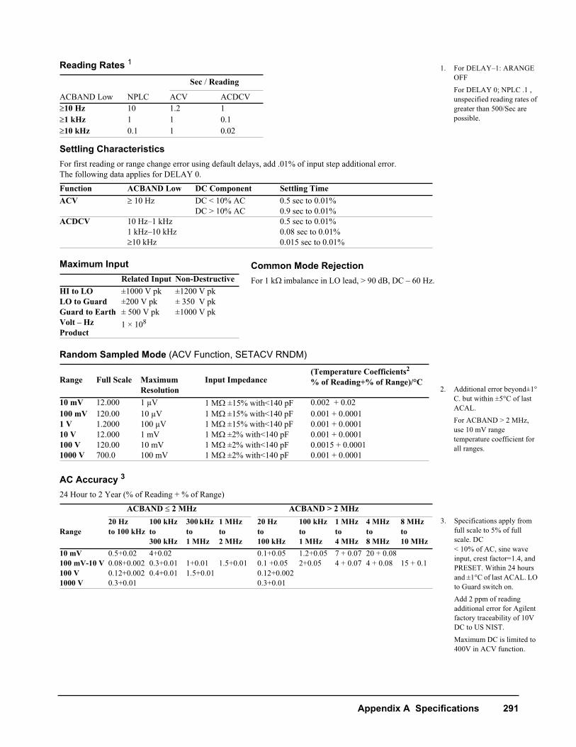
Reading Rates 1
Settling CharacteristicsFor first reading or range change error using default delays, add .01% of input step additional error.The following data applies for DELAY 0.
Maximum Input
Random Sampled Mode (ACV Function, SETACV RNDM)
AC Accuracy 3
24 Hour to 2 Year (% of Reading + % of Range)
Sec Reading
ACBAND Low NPLC ACV ACDCV10 Hz 10 1.2 11 kHz 1 1 0.110 kHz 0.1 1 0.02
Function ACBAND Low DC Component Settling TimeACV 10 Hz DC < 10% AC 0.5 sec to 0.01%
DC > 10% AC 0.9 sec to 0.01%ACDCV 10 Hz–1 kHz 0.5 sec to 0.01%
1 kHz–10 kHz 0.08 sec to 0.01%10 kHz 0.015 sec to 0.01%
Related Input Non-DestructiveHI to LO ±1000 V pk ±1200 V pkLO to Guard ±200 V pk ± 350 V pkGuard to Earth ± 500 V pk ±1000 V pkVolt – Hz Product
1 × 10⁸
Range Full Scale Maximum Resolution
Input Impedance(Temperature Coefficients2
% of Reading+% of Range)/°C
10 mV 12.000 1 μV 1 M±15% with<140 pF 0.002 + 0.02100 mV 120.00 10 μV 1 M±15% with<140 pF 0.001 + 0.00011 V 1.2000 100 μV 1 M±15% with<140 pF 0.001 + 0.000110 V 12.000 1 mV 1 M±2% with<140 pF 0.001 + 0.0001100 V 120.00 10 mV 1 M±2% with<140 pF 0.0015 + 0.00011000 V 700.0 100 mV 1 M±2% with<140 pF 0.001 + 0.0001
ACBAND 2 MHz ACBAND > 2 MHz
Range20 Hzto 100 kHz
100 kHz to 300 kHz
300 kHz to 1 MHz
1 MHz to 2 MHz
20 Hzto 100 kHz
100 kHz to 1 MHz
1 MHz to 4 MHz
4 MHz to8 MHz
8 MHz to10 MHz
10 mV 0.5+0.02 4+0.02 0.1+0.05 1.2+0.05 7 + 0.07 20 + 0.08100 mV-10 V 0.08+0.002 0.3+0.01 1+0.01 1.5+0.01 0.1 +0.05 2+0.05 4 + 0.07 4 + 0.08 15 + 0.1100 V 0.12+0.002 0.4+0.01 1.5+0.01 0.12+0.0021000 V 0.3+0.01 0.3+0.01
1. For DELAY–1: ARANGE OFF
For DELAY 0; NPLC .1 , unspecified reading rates of greater than 500/Sec are possible.
2. Additional error beyond±1C. but within ±5C of last ACAL. For ACBAND > 2 MHz, use 10 mV range temperature coefficient for all ranges.
3. Specifications apply from full scale to 5% of full scale. DC < 10% of AC, sine wave input, crest factor=1.4, and PRESET. Within 24 hours and ±1C of last ACAL. LO to Guard switch on.Add 2 ppm of reading additional error for Agilent factory traceability of 10V DC to US NIST.
Maximum DC is limited to 400V in ACV function.
Common Mode RejectionFor 1 k imbalance in LO lead, > 90 dB, DC – 60 Hz.
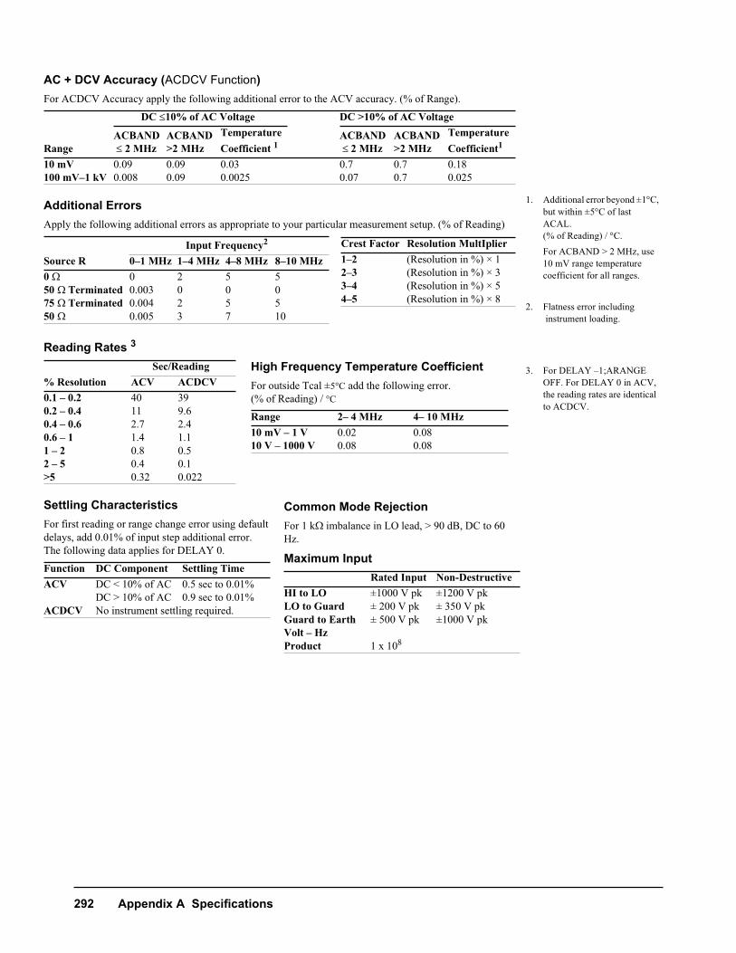
292 Appendix A Specifications
AC + DCV Accuracy (ACDCV Function)For ACDCV Accuracy apply the following additional error to the ACV accuracy. (% of Range).
Additional ErrorsApply the following additional errors as appropriate to your particular measurement setup. (% of Reading)
Reading Rates 3
Settling CharacteristicsFor first reading or range change error using default delays, add 0.01% of input step additional error. The following data applies for DELAY 0.
DC 10% of AC Voltage DC >10% of AC Voltage
Range ACBAND 2 MHz
ACBAND>2 MHz
Temperature Coefficient 1
ACBAND 2 MHz
ACBAND>2 MHz
Temperature Coefficient1
10 mV 0.09 0.09 0.03 0.7 0.7 0.18100 mV–1 kV 0.008 0.09 0.0025 0.07 0.7 0.025
Input Frequency2
Source R 0–1 MHz 1–4 MHz 4–8 MHz 8–10 MHz0 0 2 5 550 Terminated 0.003 0 0 075 Terminated 0.004 2 5 550 0.005 3 7 10
Sec/Reading% Resolution ACV ACDCV0.1 – 0.2 40 390.2 – 0.4 11 9.60.4 – 0.6 2.7 2.40.6 – 1 1.4 1.11 – 2 0.8 0.52 – 5 0.4 0.1>5 0.32 0.022
Function DC Component Settling TimeACV DC < 10% of AC 0.5 sec to 0.01%
DC > 10% of AC 0.9 sec to 0.01%ACDCV No instrument settling required.
Crest Factor Resolution MultIplier 1–2 (Resolution in %) × 12–3 (Resolution in %) × 33–4 (Resolution in %) × 54–5 (Resolution in %) × 8
High Frequency Temperature CoefficientFor outside Tcal ±5C add the following error.(% of Reading) C
Range 2– 4 MHz 4– 10 MHz10 mV – 1 V 0.02 0.0810 V – 1000 V 0.08 0.08
1. Additional error beyond ±1C, but within ±5C of last ACAL. (% of Reading) / C.
For ACBAND > 2 MHz, use 10 mV range temperature coefficient for all ranges.
2. Flatness error including instrument loading.
3. For DELAY –1;ARANGE OFF. For DELAY 0 in ACV, the reading rates are identical to ACDCV.
Common Mode RejectionFor 1 k imbalance in LO lead, > 90 dB, DC to 60 Hz.
Maximum InputRated Input Non-Destructive
HI to LO ±1000 V pk ±1200 V pkLO to Guard ± 200 V pk ± 350 V pkGuard to Earth ± 500 V pk ±1000 V pkVolt – Hz Product 1 x 10⁸
Appendix A Specifications 293
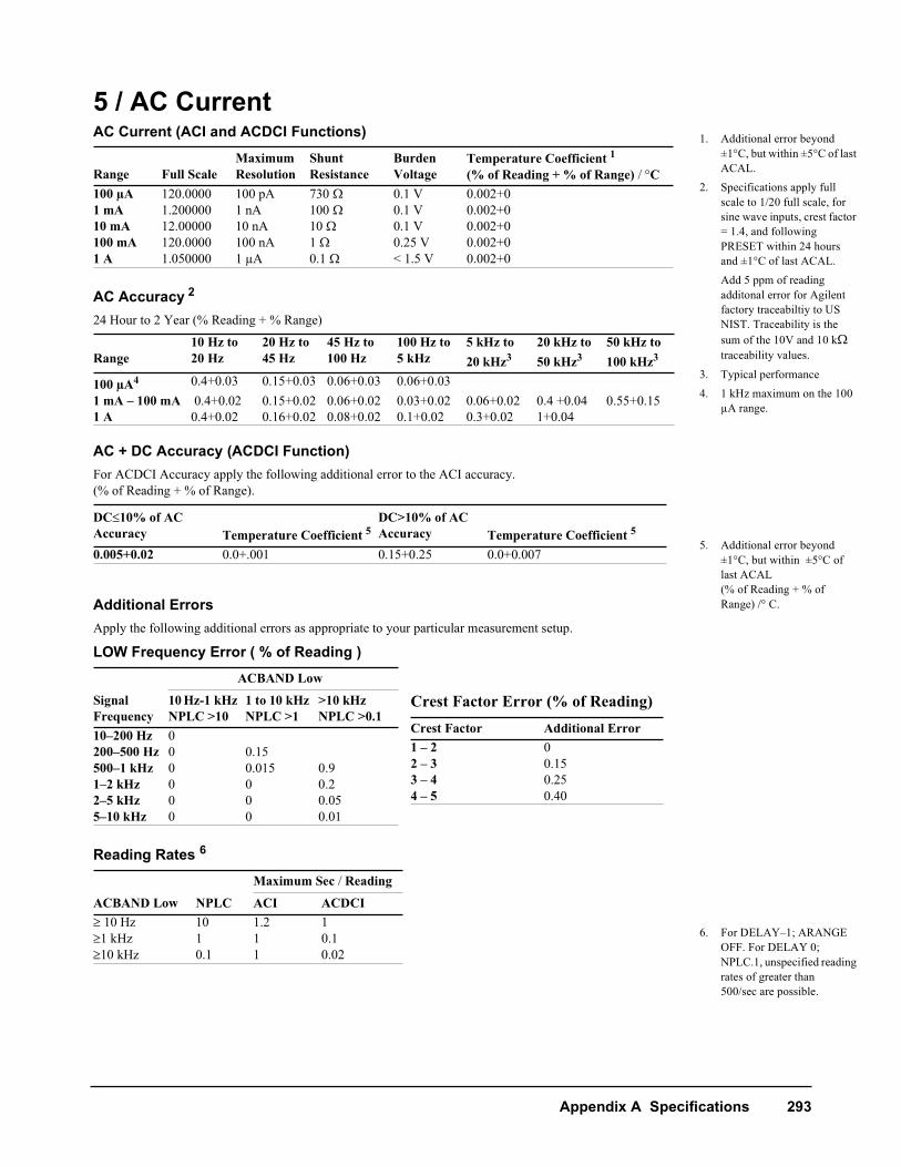
5 / AC CurrentAC Current (ACI and ACDCI Functions)
AC Accuracy 2
24 Hour to 2 Year (% Reading + % Range)
AC + DC Accuracy (ACDCI Function)For ACDCI Accuracy apply the following additional error to the ACI accuracy.(% of Reading + % of Range).
Additional ErrorsApply the following additional errors as appropriate to your particular measurement setup.
LOW Frequency Error ( % of Reading )
Reading Rates 6
Range Full ScaleMaximum Resolution
Shunt Resistance
Burden Voltage
Temperature Coefficient 1(% of Reading + % of Range) C
100 μA 120.0000 100 pA 730 0.1 V 0.002+01 mA 1.200000 1 nA 100 0.1 V 0.002+010 mA 12.00000 10 nA 10 0.1 V 0.002+0100 mA 120.0000 100 nA 1 0.25 V 0.002+01 A 1.050000 1 μA 0.1 < 1.5 V 0.002+0
Range10 Hz to 20 Hz
20 Hz to 45 Hz
45 Hz to 100 Hz
100 Hz to 5 kHz
5 kHz to 20 kHz3
20 kHz to 50 kHz3
50 kHz to 100 kHz3
100 μA4 0.4+0.03 0.15+0.03 0.06+0.03 0.06+0.031 mA – 100 mA 0.4+0.02 0.15+0.02 0.06+0.02 0.03+0.02 0.06+0.02 0.4 +0.04 0.55+0.151 A 0.4+0.02 0.16+0.02 0.08+0.02 0.1+0.02 0.3+0.02 1+0.04
DC10% of AC Accuracy Temperature Coefficient 5
DC>10% of AC Accuracy Temperature Coefficient 5
0.005+0.02 0.0+.001 0.15+0.25 0.0+0.007
ACBAND Low
Signal Frequency
10 Hz-1 kHz NPLC >10
1 to 10 kHz NPLC >1
>10 kHz NPLC >0.1
10–200 Hz 0200–500 Hz 0 0.15500–1 kHz 0 0.015 0.91–2 kHz 0 0 0.22–5 kHz 0 0 0.055–10 kHz 0 0 0.01
Maximum Sec Reading
ACBAND Low NPLC ACI ACDCI10 Hz 10 1.2 11 kHz 1 1 0.110 kHz 0.1 1 0.02
1. Additional error beyond ±1°C, but within ±5°C of last ACAL.
2. Specifications apply full scale to 1/20 full scale, for sine wave inputs, crest factor = 1.4, and following PRESET within 24 hours and ±1°C of last ACAL.Add 5 ppm of reading additonal error for Agilent factory traceabiltiy to US NIST. Traceability is the sum of the 10V and 10 ktraceability values.
3. Typical performance4. 1 kHz maximum on the 100
μA range.
5. Additional error beyond ±1°C, but within ±5°C of last ACAL(% of Reading + % of Range) C.
6. For DELAY–1; ARANGE OFF. For DELAY 0; NPLC.1, unspecified reading rates of greater than 500/sec are possible.
Crest Factor Error (% of Reading)Crest Factor Additional Error1 – 2 02 – 3 0.153 – 4 0.254 – 5 0.40
294 Appendix A Specifications
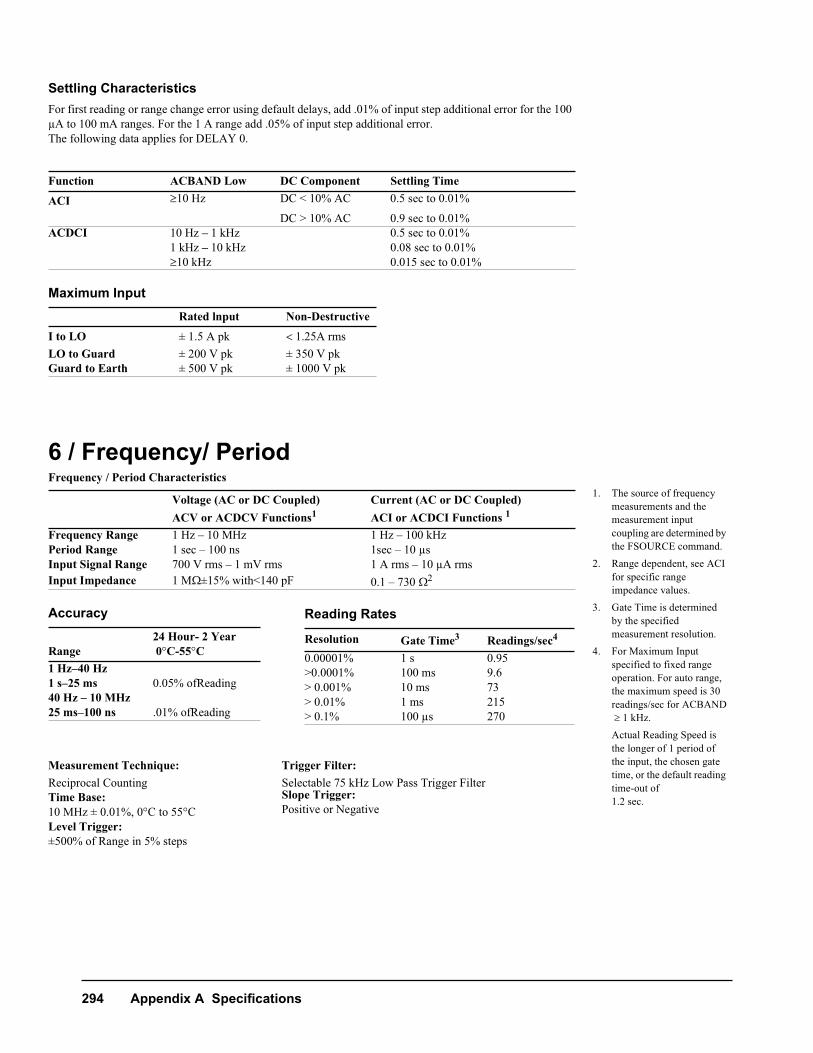
Settling CharacteristicsFor first reading or range change error using default delays, add .01% of input step additional error for the 100 μA to 100 mA ranges. For the 1 A range add .05% of input step additional error.The following data applies for DELAY 0.
Maximum Input
6 / Frequency/ PeriodFrequency / Period Characteristics
Accuracy
Function ACBAND Low DC Component Settling Time
ACI 10 Hz DC < 10% AC 0.5 sec to 0.01%
DC > 10% AC 0.9 sec to 0.01%ACDCI 10 Hz – 1 kHz 0.5 sec to 0.01%
1 kHz – 10 kHz 0.08 sec to 0.01%10 kHz 0.015 sec to 0.01%
Rated lnput Non-Destructive
I to LO ± 1.5 A pk 1.25A rmsLO to Guard ± 200 V pk ± 350 V pkGuard to Earth ± 500 V pk ± 1000 V pk
Voltage (AC or DC Coupled)ACV or ACDCV Functions1
Current (AC or DC Coupled)ACI or ACDCI Functions 1
Frequency Range 1 Hz – 10 MHz 1 Hz – 100 kHzPeriod Range 1 sec – 100 ns 1sec – 10 μsInput Signal Range 700 V rms – 1 mV rms 1 A rms – 10 μA rmsInput Impedance 1 M±15% with<140 pF 0.1 – 730 2
Range24 Hour- 2 Year 0C-55C
1 Hz–40 Hz 1 s–25 ms 0.05% ofReading40 Hz – 10 MHz25 ms–100 ns .01% ofReading
Measurement Technique: Trigger Filter:Reciprocal Counting Selectable 75 kHz Low Pass Trigger FilterTime Base: Slope Trigger:10 MHz ± 0.01%, 0C to 55C Positive or NegativeLevel Trigger:±500% of Range in 5% steps
Reading Rates
Resolution Gate Time3 Readings/sec4
0.00001% 1 s 0.95 >0.0001% 100 ms 9.6> 0.001% 10 ms 73> 0.01% 1 ms 215> 0.1% 100 μs 270
1. The source of frequency measurements and the measurement input coupling are determined by the FSOURCE command.
2. Range dependent, see ACI for specific range impedance values.
3. Gate Time is determined by the specified measurement resolution.
4. For Maximum Input specified to fixed range operation. For auto range, the maximum speed is 30 readings/sec for ACBAND 1 kHz.Actual Reading Speed is the longer of 1 period of the input, the chosen gate time, or the default reading time-out of 1.2 sec.
Appendix A Specifications 299
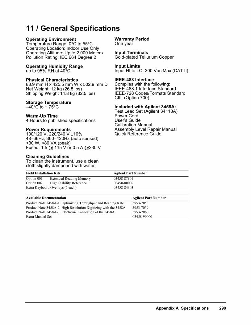
11 / General SpecificationsOperating EnvironmentTemperature Range: 0C to 55COperating Location: Indoor Use OnlyOperating Altitude: Up to 2,000 MetersPollution Rating: IEC 664 Degree 2
Operating Humidity Rangeup to 95% RH at 40C
Physical Characteristics88.9 mm H x 425.5 mm W x 502.9 mm DNet Weight: 12 kg (26.5 lbs)Shipping Weight 14.8 kg (32.5 lbs)
Storage Temperature–40C to + 75C
Warm-Up Time4 Hours to published specifications
Power Requirements100/120 V, 220/240 V ±10%48–66Hz, 360–420Hz (auto sensed)<30 W, <80 VA (peak)Fused: 1.5 @ 115 V or 0.5 A @230 V
Cleaning GuidelinesTo clean the instrument, use a cleancloth slightly dampened with water.Field Installation Kits Agilent Part NumberOption 001 Extended Reading Memory 03458-87901 Option 002 High Stability Reference 03458-80002Extra Keyboard Overlays (5 each) 03458-84303
Available Documentation Agilent Part NumberProduct Note 3458A-1: Optimizing Throughput and Reading Rate 5953-7058Product Note 3458A-2: High Resolution Digitizing with the 3458A 5953-7059Product Note 3458A-3: Electronic Calibration of the 3458A 5953-7060Extra Manual Set 03458-90000
Warranty PeriodOne year
Input TerminalsGold-plated Tellurium Copper
Input LimitsInput HI to LO: 300 Vac Max (CAT II)
IEEE-488 InterfaceComplies with the following:IEEE-488.1 Interface StandardIEEE-728 Codes/Formats StandardCIIL (Option 700)
Included with Agilent 3458A:Test Lead Set (Agilent 34118A)Power CordUser’s GuideCalibration ManualAssembly Level Repair ManualQuick Reference Guide