EGIS PREMIUM - Schede tecniche caldaie · Table summarising error codes ... - 2004/108/EC -...
40
Istruzioni tecniche per l’istallazione e al manutenzione Installation and Servicing Instructions CALDAIA MURALE ISTANTANEA A CONDENSAZIONE CONDENSING WALL-HUNH GAS BOILER EGIS PREMIUM EGIS PREMIUM 24 EGIS PREMIUM 30 V01
-
Upload
phungquynh -
Category
Documents
-
view
223 -
download
0
Transcript of EGIS PREMIUM - Schede tecniche caldaie · Table summarising error codes ... - 2004/108/EC -...
Istruzioni tecniche per l’istallazione e al manutenzione Installation and Servicing Instructions
CALDAIA MURALE ISTANTANEAA CONDENSAZIONE
CONDENSING WALL-HUNH GAS BOILER
EGIS PREMIUM
EGIS PREMIUM 24EGIS PREMIUM 30
V0
1
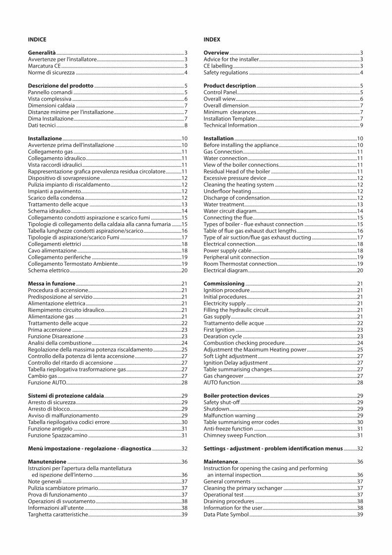
INDICE
Generalità ........................................................................................................3Avvertenze per l’installatore .......................................................................3Marcatura CE ....................................................................................................3Norme di sicurezza ........................................................................................4
Descrizione del prodotto .........................................................................5Pannello comandi ..........................................................................................5Vista complessiva ...........................................................................................6Dimensioni caldaia ........................................................................................7Distanze minime per l’installazione .........................................................7Dima Installazione..........................................................................................7Dati tecnici ........................................................................................................8
Installazione .................................................................................................10Avvertenze prima dell’installazione ......................................................10Collegamento gas ........................................................................................11Collegamento idraulico ..............................................................................11Vista raccordi idraulici .................................................................................11Rappresentazione grafi ca prevalenza residua circolatore .............11Dispositivo di sovrapressione ..................................................................12Pulizia impianto di riscaldamento ..........................................................12Impianti a pavimento..................................................................................12Scarico della condensa ...............................................................................12Trattamento delle acque ...........................................................................13Schema idraulico ..........................................................................................14Collegamento condotti aspirazione e scarico fumi .........................15Tipologie di collegamento della caldaia alla canna fumaria ........15Tabella lunghezze condotti aspirazione/scarico ...............................16Tipologie di aspirazione/scarico Fumi ..................................................17Collegamenti elettrici .................................................................................18Cavo alimentazione .....................................................................................18C ollegamento periferiche .........................................................................19Collegamento Termostato Ambiente....................................................19Schema elettrico ...........................................................................................20
Messa in funzione ......................................................................................21Procedura di accensione ............................................................................21Predisposizione al servizio ........................................................................21 Alimentazione elettrica ..............................................................................21Riempimento circuito idraulico ...............................................................21Alimentazione gas .......................................................................................21Trattamento delle acque ...........................................................................22Prima accensione .........................................................................................23Funzione Disareazione ...............................................................................23Analisi della combustione .........................................................................24Regolazione della massima potenza riscaldamento .......................25Controllo della potenza di lenta accensione ......................................27Controllo del ritardo di accensione .......................................................27Tabella riepilogativa trasformazione gas .............................................27Cambio gas .....................................................................................................27Funzione AUTO..............................................................................................28
Sistemi di protezione caldaia ...............................................................29Arresto di sicurezza ......................................................................................29Arresto di blocco ...........................................................................................29Avviso di malfunzionamento ...................................................................29Tabella riepilogativa codici errore ..........................................................30Funzione antigelo ........................................................................................31Funzione Spazzacamino ............................................................................31
Menù impostazione - regolazione - diagnostica ........................32
Manutenzione .............................................................................................36Istruzioni per l’apertura della mantellatura ed ispezione dell’interno ........................................................................36Note generali .................................................................................................37Pulizia scambiatore primario....................................................................37Prova di funzionamento ............................................................................37Operazioni di svuotamento ......................................................................38Informazioni all’utente ...............................................................................38Targhetta caratteristiche ............................................................................39
INDEX
Overview ..........................................................................................................3 Advice for the installer ..................................................................................3CE labelling .......................................................................................................3Safety regulations ..........................................................................................4
Product description ....................................................................................5Control Panel....................................................................................................5Overall wiew .....................................................................................................6Overall dimension ..........................................................................................7Minimum clearances ....................................................................................7Installation Template .....................................................................................7Technical Information ...................................................................................9
Installation ....................................................................................................10Before installing the appliance ................................................................10Gas Connection .............................................................................................11Water connection .........................................................................................11View of the boiler connections................................................................11Residual Head of the boiler ......................................................................11Excessive pressure device .........................................................................12Cleaning the heating system ...................................................................12Underfl oor heating ......................................................................................12Discharge of condensation .......................................................................12Water treatment............................................................................................13Water circuit diagram..................................................................................14Connecting the fl ue .....................................................................................15Types of boiler - fl ue exhaust connection ...........................................15Table of fl ue gas exhaust duct lengths .................................................16Type of air suction/fl ue gas exhaust ducting .....................................17Electrical connection...................................................................................18Power supply cable ......................................................................................18Peripheral unit connection .......................................................................19Room Thermostat connection .................................................................19Electrical diagram .........................................................................................20
Commissioning ...........................................................................................21Ignition procedure .......................................................................................21Initial procedures ..........................................................................................21Electricity supply ..........................................................................................21Filling the hydraulic circuit ........................................................................21Gas supply .......................................................................................................21Trattamento delle acque ...........................................................................22First Ignition ...................................................................................................23Dearation cycle .............................................................................................23Combustion checking procedure ...........................................................24Adjustment the Maximum Heating power .........................................25Soft Light adjustment .................................................................................27Ignition Delay adjustment ........................................................................27Table summarising changes .....................................................................27Gas changeover ............................................................................................27AUTO function ...............................................................................................28
Boiler protection devices .......................................................................29Safety shut-off ...............................................................................................29Shutdown ........................................................................................................29Malfunction warning ..................................................................................29Table summarising error codes ...............................................................30Anti-freeze function ....................................................................................31Chimney sweep Function ..........................................................................31
Settings - adjustment - problem identifi cation menus ...........32
Maintenance .................................................................................................36Instruction for opening the casing and performing an internal inspection ..............................................................................36General comments ......................................................................................37Cleaning the primary sxchanger ............................................................37Operational test ............................................................................................37Draining procedures ...................................................................................38Information for the user .............................................................................38Data Plate Symbol ........................................................................................39
3
generalità overview
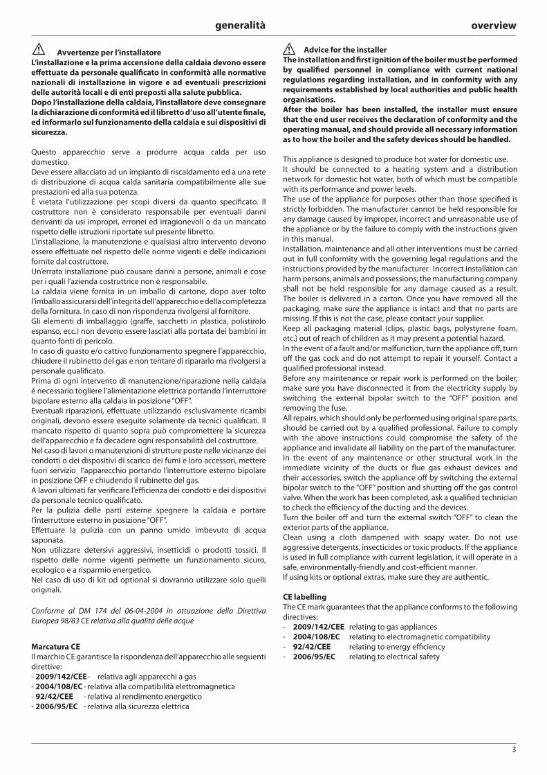
Avvertenze per l’installatore
L’installazione e la prima accensione della caldaia devono essere
eff ettuate da personale qualifi cato in conformità alle normative
nazionali di installazione in vigore e ad eventuali prescrizioni
delle autorità locali e di enti preposti alla salute pubblica.
Dopo l’installazione della caldaia, l’installatore deve consegnare
la dichiarazione di conformità ed il libretto d’uso all’utente fi nale,
ed informarlo sul funzionamento della caldaia e sui dispositivi di
sicurezza.
Questo apparecchio serve a produrre acqua calda per uso
domestico.
Deve essere allacciato ad un impianto di riscaldamento ed a una rete
di distribuzione di acqua calda sanitaria compatibilmente alle sue
prestazioni ed alla sua potenza.
È vietata l’utilizzazione per scopi diversi da quanto specifi cato. Il
costruttore non è considerato responsabile per eventuali danni
derivanti da usi impropri, erronei ed irragionevoli o da un mancato
rispetto delle istruzioni riportate sul presente libretto.
L’installazione, la manutenzione e qualsiasi altro intervento devono
essere eff ettuate nel rispetto delle norme vigenti e delle indicazioni
fornite dal costruttore.
Un’errata installazione può causare danni a persone, animali e cose
per i quali l’azienda costruttrice non è responsabile.
La caldaia viene fornita in un imballo di cartone, dopo aver tolto
l’imballo assicurarsi dell’integrità dell’apparecchio e della completezza
della fornitura. In caso di non rispondenza rivolgersi al fornitore.
Gli elementi di imballaggio (graff e, sacchetti in plastica, polistirolo
espanso, ecc.) non devono essere lasciati alla portata dei bambini in
quanto fonti di pericolo.
In caso di guasto e/o cattivo funzionamento spegnere l’apparecchio,
chiudere il rubinetto del gas e non tentare di ripararlo ma rivolgersi a
personale qualifi cato.
Prima di ogni intervento di manutenzione/riparazione nella caldaia
è necessario togliere l’alimentazione elettrica portando l’interruttore
bipolare esterno alla caldaia in posizione “OFF”.
Eventuali riparazioni, eff ettuate utilizzando esclusivamente ricambi
originali, devono essere eseguite solamente da tecnici qualifi cati. Il
mancato rispetto di quanto sopra può compromettere la sicurezza
dell’apparecchio e fa decadere ogni responsabilità del costruttore.
Nel caso di lavori o manutenzioni di strutture poste nelle vicinanze dei
condotti o dei dispositivi di scarico dei fumi e loro accessori, mettere
fuori servizio l’apparecchio portando l’interruttore esterno bipolare
in posizione OFF e chiudendo il rubinetto del gas.
A lavori ultimati far verifi care l’effi cienza dei condotti e dei dispositivi
da personale tecnico qualifi cato.
Per la pulizia delle parti esterne spegnere la caldaia e portare
l’interruttore esterno in posizione “OFF”.
Eff ettuare la pulizia con un panno umido imbevuto di acqua
saponata.
Non utilizzare detersivi aggressivi, insetticidi o prodotti tossici. Il
rispetto delle norme vigenti permette un funzionamento sicuro,
ecologico e a risparmio energetico.
Nel caso di uso di kit od optional si dovranno utilizzare solo quelli
originali.
Conforme al DM 174 del 06-04-2004 in attuazione della Direttiva
Europea 98/83 CE relativa alla qualità delle acque
Advice for the installer
The installation and fi rst ignition of the boiler must be performed
by qualifi ed personnel in compliance with current national
regulations regarding installation, and in conformity with any
requirements established by local authorities and public health
organisations.
After the boiler has been installed, the installer must ensure
that the end user receives the declaration of conformity and the
operating manual, and should provide all necessary information
as to how the boiler and the safety devices should be handled.
This appliance is designed to produce hot water for domestic use.
It should be connected to a heating system and a distribution
network for domestic hot water, both of which must be compatible
with its performance and power levels.
The use of the appliance for purposes other than those specifi ed is
strictly forbidden. The manufacturer cannot be held responsible for
any damage caused by improper, incorrect and unreasonable use of
the appliance or by the failure to comply with the instructions given
in this manual.
Installation, maintenance and all other interventions must be carried
out in full conformity with the governing legal regulations and the
instructions provided by the manufacturer. Incorrect installation can
harm persons, animals and possessions; the manufacturing company
shall not be held responsible for any damage caused as a result.
The boiler is delivered in a carton. Once you have removed all the
packaging, make sure the appliance is intact and that no parts are
missing. If this is not the case, please contact your supplier.
Keep all packaging material (clips, plastic bags, polystyrene foam,
etc.) out of reach of children as it may present a potential hazard.
In the event of a fault and/or malfunction, turn the appliance off , turn
off the gas cock and do not attempt to repair it yourself. Contact a
qualifi ed professional instead.
Before any maintenance or repair work is performed on the boiler,
make sure you have disconnected it from the electricity supply by
switching the external bipolar switch to the “OFF” position and
removing the fuse.
All repairs, which should only be performed using original spare parts,
should be carried out by a qualifi ed professional. Failure to comply
with the above instructions could compromise the safety of the
appliance and invalidate all liability on the part of the manufacturer.
In the event of any maintenance or other structural work in the
immediate vicinity of the ducts or fl ue gas exhaust devices and
their accessories, switch the appliance off by switching the external
bipolar switch to the “OFF” position and shutting off the gas control
valve. When the work has been completed, ask a qualifi ed technician
to check the effi ciency of the ducting and the devices.
Turn the boiler off and turn the external switch “OFF” to clean the
exterior parts of the appliance.
Clean using a cloth dampened with soapy water. Do not use
aggressive detergents, insecticides or toxic products. If the appliance
is used in full compliance with current legislation, it will operate in a
safe, environmentally-friendly and cost-effi cient manner.
If using kits or optional extras, make sure they are authentic.
CE labelling
The CE mark guarantees that the appliance conforms to the following
directives:
- 2009/142/CEE relating to gas appliances
- 2004/108/EC relating to electromagnetic compatibility
- 92/42/CEE relating to energy effi ciency
- 2006/95/EC relating to electrical safety
Marcatura CE
Il marchio CE garantisce la rispondenza dell’apparecchio alle seguenti
direttive:
- 2009/142/CEE - relativa agli apparecchi a gas
- 2004/108/EC - relativa alla compatibilità elettromagnetica
- 92/42/CEE - relativa al rendimento energetico
- 2006/95/EC - relativa alla sicurezza elettrica
4
generalità overview
Norme di sicurezza
Legenda simboli:Il mancato rispetto dell’avvertenza comporta rischio di lesioni, in determinate circostanze anche mortali, per le personeIl mancato rispetto dell’avvertenza comporta rischio di danneggiamenti, in determinate circostanze anche gravi, per oggetti, piante o animali
Installare l’apparecchio su parete solida, non soggetta a vibrazioni.Rumorosità durante il funzionamento.Non danneggiare, nel forare la parete, cavi elettrici o tubazioni preesistenti.Folgorazione per contatto con conduttori sotto tensione. Esplosioni, incendi o intossicazioni per perdita gas dalle tubazioni danneggiate. Danneggiamento impianti preesistenti. Allagamenti per perdita acqua dalle tubazioni danneggiate.Eseguire i collegamenti elettrici con conduttori di sezione adeguata.Incendio per surriscaldamento dovuto al passaggio di corrente elettrica in cavi sottodimensionati.Proteggere tubi e cavi di collegamento in modo da evitare il loro danneggiamento.Folgorazione per contatto con conduttori sotto tensione. Esplosioni, incendi o intossicazioni per perdita gas dalle tubazioni danneggiate. Allagamenti per perdita acqua dalle tubazioni danneggiate.Assicurarsi che l’ambiente di installazione e gli impianti a cui deve connettersi l’apparecchiatura siano conformi alle normative vigenti.Folgorazione per contatto con conduttori sotto tensione incorrettamente installati. Danneggiamento dell’apparecchio per condizioni di funzionamento improprie.Adoperare utensili ed attrezzature manuali adeguati all’uso (in particolare assicurarsi che l’utensile non sia deteriorato e che il manico sia integro e correttamente fi ssato), utilizzarli correttamente, assicurarli da eventuale caduta dall’alto, riporli dopo l’uso.Lesioni personali per proiezione di schegge o frammenti, inalazione polveri, urti, tagli, punture, abrasioni. Danneggiamento dell’apparecchio o di oggetti circostanti per proiezione di schegge, colpi, incisioni.Adoperare attrezzature elettriche adeguate all’uso (in particolare assicurarsi che il cavo e la spina di alimentazione siano integri e che le parti dotate di moto rotativo o alternativo siano correttamente fi ssate), utilizzarle correttamente, non intralciare i passaggi con il cavo di alimentazione, assicurarle da eventuale caduta dall’alto, scollegare e riporle dopo l’uso.Lesioni personali per proiezione di schegge o frammenti, inalazione polveri, urti, tagli, punture, abrasioni, rumore, vibrazioni. Danneggiamento dell’apparecchio o di oggetti circostanti per proiezione di schegge, colpi, incisioni.Assicurarsi che le scale portatili siano stabilmente appoggiate, che siano appropriatamente resistenti, che i gradini siano integri e non scivolosi, che non vengano spostate con qualcuno sopra, che qualcuno vigili.Lesioni personali per la caduta dall’alto o per cesoiamento (scale doppie).Assicurarsi che le scale a castello siano stabilmente appoggiate, che siano appropriatamente resistenti, che i gradini siano integri e non scivolosi, che abbiano mancorrenti lungo la rampa e parapetti sul pianerottolo.Lesioni personali per la caduta dall’alto.Assicurarsi, durante i lavori eseguiti in quota (in genere con dislivello superiore a due metri), che siano adottati parapetti perimetrali nella zona di lavoro o imbragature individuali atti a prevenire la caduta, che lo spazio percorso durante l’eventuale caduta sia libero da ostacoli pericolosi, che l’eventuale impatto sia attutito da superfi ci di arresto semirigide o deformabili.Lesioni personali per la caduta dall’alto.Assicurarsi che il luogo di lavoro abbia adeguate condizioni igienico sanitarie in riferimento all’illuminazione, all’aerazione, alla solidità.Lesioni personali per urti, inciampi, ecc.Proteggere con adeguato materiale l’apparecchio e le aree in prossimità del luogo di lavoro.Danneggiamento dell’apparecchio o di oggetti circostanti per proiezione di schegge, colpi, incisioni.Movimentare l’apparecchio con le dovute protezioni e con la dovuta cautela.Danneggiamento dell’apparecchio o di oggetti circostanti per urti, colpi, incisioni, schiacciamento. Indossare, durante le lavorazioni, gli indumenti e gli equipaggiamenti protettivi individuali.Lesioni personali per folgorazione, proiezione di schegge o frammenti, inalazioni polveri, urti, tagli, punture, abrasioni, rumore, vibrazioni.Organizzare la dislocazione del materiale e delle attrezzature in modo da rendere agevole e sicura la movimentazione, evitando cataste che possano essere soggette a cedimenti o crolli.Danneggiamento dell’apparecchio o di oggetti circostanti per urti, colpi, incisioni, schiacciamento.Le operazioni all’interno dell’apparecchio devono essere eseguite con la cautela necessaria ad evitare bruschi contatti con parti acuminate.Lesioni personali per tagli, punture, abrasioni.Ripristinare tutte le funzioni di sicurezza e controllo interessate da un intervento sull’apparecchio ed accertarne la funzionalità prima della rimessa in servizio.Esplosioni, incendi o intossicazioni per perdita gas o per incorretto scarico fumi. Danneggiamento o blocco dell’apparecchio per funzionamento fuori controllo.Svuotare i componenti che potrebbero contenere acqua calda, attivando eventuali sfi ati, prima della loro manipolazione.Lesioni personali per ustioni.Eff ettuare la disincrostazione da calcare di componenti attenendosi a quanto specifi cato nella scheda di sicurezza del prodotto usato, aerando l’ambiente, indossando indumenti protettivi, evitando miscelazioni di prodotti diversi, proteggendo l’apparecchio e gli oggetti circostanti.Lesioni personali per contatto di pelle o occhi con sostanze acide, inalazione o ingestione di agenti chimici nocivi. Danneggiamento dell’apparecchio o di oggetti circostanti per corrosione da sostanze acide.Nel caso si avverta odore di bruciato o si veda del fumo fuoriuscire dall’apparecchio, togliere l’alimentazione elettrica, aprire le fi nestre ed avvisare il tecnico.Lesioni personali per ustioni, inalazione fumi, intossicazione.
Safety regulations
Key to symbols:Failure to comply with this warning implies the risk of personal injury, in some circumstances even fatalFailure to comply with this warning implies the risk of damage, in
some circumstances even serious, to property, plants or animals.
Install the appliance on a solid wall which is not subject to vibration.Noisiness during operation.When drilling holes in the wall for installation purposes, take care not to damage any electrical wiring or existing piping.Electrocution caused by contact with live wires. Explosions, fi res or asphyxiation caused by gas leaking from damaged piping. Damage to existing installations. Flooding caused by water leaking from damaged piping.Perform all electrical connections using wires which have a suitable section.Fire caused by overheating due to electrical current passing through undersized cables.Protect all connection pipes and wires in order to prevent them from being damaged.Electrocution caused by contact with live wires. Explosions, fi res or asphyxiation caused by gas leaking from damaged piping. Flooding caused by water leaking from damaged piping.Make sure the installation site and any systems to which the appliance must be connected comply with the applicable norms in force.Electrocution caused by contact with live wires which have been installed incorrectly. Damage to the appliance caused by improper operating conditions.Use suitable manual tools and equipment (make sure in particular that the tool is not worn out and that its handle is fi xed properly); use them correctly and make sure they do not fall from a height. Replace them once you have fi nished using them.Personal injury from the falling splinters or fragments, inhalation of dust, shocks, cuts, pricks and abrasions. Damage to the appliance or surrounding objects caused by falling splinters, knocks and incisions.Use electrical equipment suitable for its intended use (in particular, make sure that the power supply cable and plug are intact and that the parts featuring rotary or reciprocating motions are fastened correctly); use this equipment correctly; do not obstruct passageways with the power supply cable, make sure no equipment could fall from a height. Disconnect it and replace it safely after use.Personal injury caused by falling splinters or fragments, inhalation of dust, knocks, cuts, puncture wounds, abrasions, noise and vibration. Damage to the appliance or surrounding objects caused by falling splinters, knocks and incisions.Make sure any portable ladders are positioned securely, that they are suitably strong and that the steps are intact and not slippery and do not wobble when someone climbs them. Ensure someone provides supervision at all times.Personal injury caused by falling from a height or cuts (stepladders shutting accidentally).Make sure any rolling ladders are positioned securely, that they are suitably strong, that the steps are intact and not slippery and that the ladders are fi tted with handrails on either side of the ladder and parapets on the landing.Personal injury caused by falling from a height.During all work carried out at a certain height (generally with a diff erence in height of more than two metres), make sure that parapets are used to surround the work area or that individual harnesses are used to prevent falls. The space where any accidental fall may occur should be free from dangerous obstacles, and any impact upon falling should be cushioned by semi-rigid or deformable surfaces.Personal injury caused by falling from a height.Make sure the workplace has suitable hygiene and sanitary conditions in terms of lighting, ventilation and solidity of the structures.Personal injury caused by knocks, stumbling etc.Protect the appliance and all areas in the vicinity of the work place using suitable material.Damage to the appliance or surrounding objects caused by falling splinters, knocks and incisions.Handle the appliance with suitable protection and with care.Damage to the appliance or surrounding objects from shocks, knocks, incisions and squashing. During all work procedures, wear individual protective clothing and equipment.Personal injury caused by electrocution, falling splinters or fragments, inhalation of dust, shocks, cuts, puncture wounds, abrasions, noise and vibration.Place all debris and equipment in such a way as to make movement easy and safe, avoiding the formation of any piles which could yield or collapse.Damage to the appliance or surrounding objects from shocks, knocks, incisions and squashing.All operations inside the appliance must be performed with the necessary caution in order to avoid abrupt contact with sharp parts.Personal injury caused by cuts, puncture wounds and abrasions.Reset all the safety and control functions aff ected by any work performed on the appliance and make sure they operate correctly before restarting the appliance.Explosions, fi res or asphyxiation caused by gas leaks or an incorrect fl ue gas exhaust. Damage or shutdown of the appliance caused by out-of-control operation.Before handling, empty all components that may contain hot water, carrying out any bleeding if necessary.Personal injury caused by burns.Descale the components, in accordance with the instructions provided on the safety data sheet of the product used, airing the room, wearing protective clothing, avoid mixing diff erent products, and protect the appliance and surrounding objects.Personal injury caused by acidic substances coming into contact with skin or eyes; inhaling or swallowing harmful chemical agents. Damage to the appliance or surrounding objects due to corrosion caused by acidic substances.If you detect a smell of burning or smoke, keep clear of the appliance, disconnect it from the electricity supply, open all windows and contact the technician.Personal injury caused by burns, smoke inhalation, asphyxiation.
5
descrizione del prodotto product description
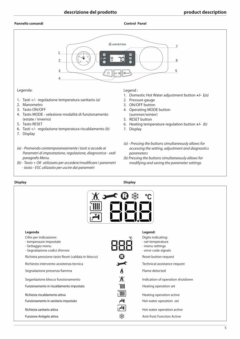
Pannello comandi Control Panel
OK
ESC
1
2
3
4
6
7
5
Legend :
1. Domestic Hot Water adjustment button +/- ((a)
2. Pressure gauge
3. ON/OFF button
4. Operating MODE button
(summer/winter)
5. RESET button
6. Heating temperature regulation button +/- (b)
7. Display
(a) - Pressing the buttons simultaneously allows for
accessing the setting, adjustment and diagnostics
parameters
(b) Pressing the buttons simultaneously allows for
modifying and saving the parameter settings
Legenda:
1. Tasti +/- regolazione temperatura sanitario (a)
2. Manometro
3. Tasto ON/OFF
4. Tasto MODE - selezione modalità di funzionamento
(estate / inverno)
5. Tasto RESET
6. Tasti +/- regolazione temperatura riscaldamento (b)
7. Display
(a) - Premendo contemporaneamente i tasti si accede ai
Parametri di impostazione, regolazione, diagnostica - vedi
paragrafo Menu.
(b) - Tasto + OK utilizzato per accedere/modifi care i parametri
- tasto - ESC utlizzato per uscire dai parametri
Display Display
Legenda Legend:
Cifre per indicazione:
- temperaure impostate
- Settaggio menu
- Segnalazione codici d’errore
Digits indicating:
- set temperature
- menu settings
- error code signals
Richieta pressione tasto Reset (caldaia in blocco) Reset button request
Richiesto intervento assistenza tecnica Technical assistance request
Segnalazione presenza fi amma
Seganlazione blocco funzionamento
Flame detected
Indication of operation shutdown
Funzionamento in riscaldamento impostato
Richiesta riscaldamento attiva
Heating operation set
Heating operation active
Funzionamento in sanitario impostato
Richiesta sanitario attiva
Hot water operation set
Hot water operation active
Funzione Antigelo attiva Anti-frost Function Active
6
descrizione del prodotto product description
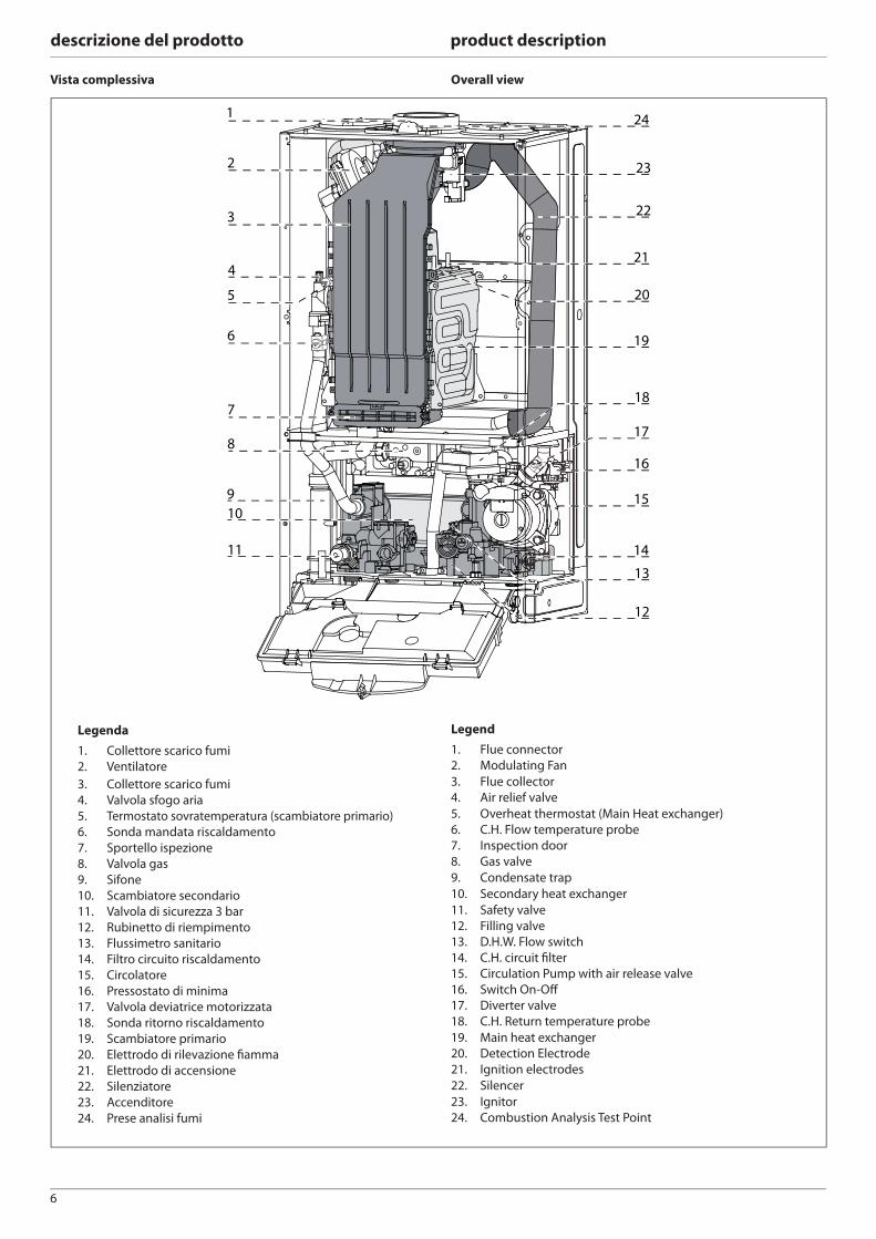
Vista complessiva Overall view
1
2
3
4
6
5
7
8
910
11
24
22
23
19
21
15
16
14
17
13
12
18
20
Legenda
1. Collettore scarico fumi
2. Ventilatore
3. Collettore scarico fumi
4. Valvola sfogo aria
5. Termostato sovratemperatura (scambiatore primario)
6. Sonda mandata riscaldamento
7. Sportello ispezione
8. Valvola gas
9. Sifone
10. Scambiatore secondario
11. Valvola di sicurezza 3 bar
12. Rubinetto di riempimento
13. Flussimetro sanitario
14. Filtro circuito riscaldamento
15. Circolatore
16. Pressostato di minima
17. Valvola deviatrice motorizzata
18. Sonda ritorno riscaldamento
19. Scambiatore primario
20. Elettrodo di rilevazione fi amma
21. Elettrodo di accensione
22. Silenziatore
23. Accenditore
24. Prese analisi fumi
Legend
1. Flue connector
2. Modulating Fan
3. Flue collector
4. Air relief valve
5. Overheat thermostat (Main Heat exchanger)
6. C.H. Flow temperature probe
7. Inspection door
8. Gas valve
9. Condensate trap
10. Secondary heat exchanger
11. Safety valve
12. Filling valve
13. D.H.W. Flow switch
14. C.H. circuit fi lter
15. Circulation Pump with air release valve
16. Switch On-Off
17. Diverter valve
18. C.H. Return temperature probe
19. Main heat exchanger
20. Detection Electrode
21. Ignition electrodes
22. Silencer
23. Ignitor
24. Combustion Analysis Test Point
7
descrizione del prodotto product description
4200
2002
1002
30
60
320
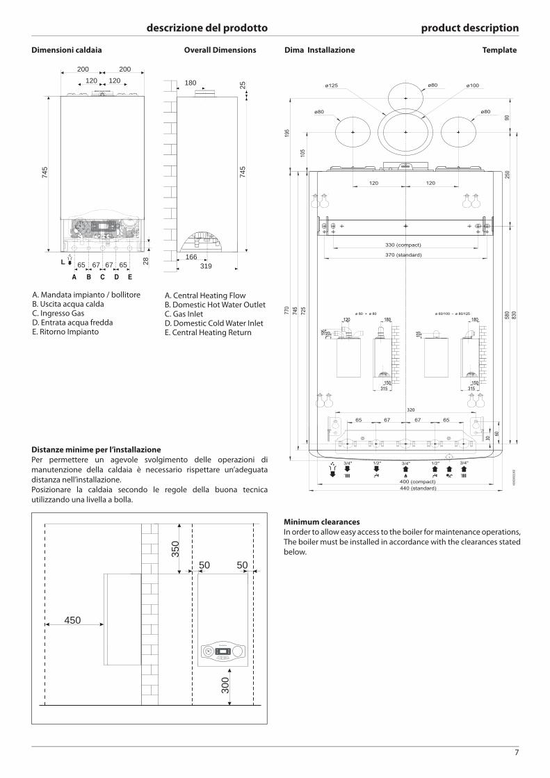
Distanze minime per l’installazione
Per permettere un agevole svolgimento delle operazioni di
manutenzione della caldaia è necessario rispettare un’adeguata
distanza nell’installazione.
Posizionare la caldaia secondo le regole della buona tecnica
utilizzando una livella a bolla.
Dima Installazione TemplateOverall Dimensions
A. Central Heating Flow B. Domestic Hot Water OutletC. Gas InletD. Domestic Cold Water InletE. Central Heating Return
Minimum clearances
In order to allow easy access to the boiler for maintenance operations,
The boiler must be installed in accordance with the clearances stated
below.
Dimensioni caldaia
A. Mandata impianto / bollitoreB. Uscita acqua caldaC. Ingresso GasD. Entrata acqua freddaE. Ritorno Impianto
450
053
0 0 3
50 50
OK
ESC
166319
180 2574
5
28
745
200 120 120
200
65 L 65 67 67
8
descrizione del prodotto product description
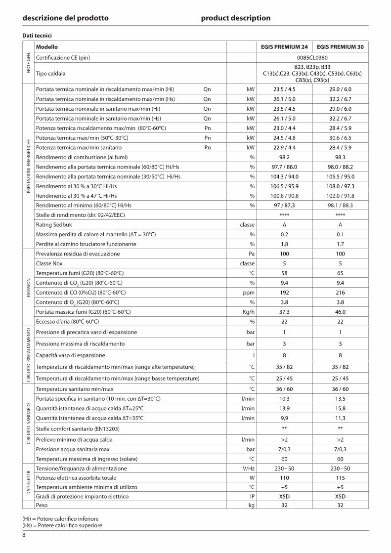
Dati tecnici
NO
TE
GE
N.
Modello EGIS PREMIUM 24 EGIS PREMIUM 30
Certifi cazione CE (pin) 0085CL0380
Tipo caldaiaB23, B23p, B33
C13(x),C23, C33(x), C43(x), C53(x), C63(x)C83(x), C93(x)
PR
ES
TAZ
ION
I E
NE
RG
ET
ICH
E
Portata termica nominale in riscaldamento max/min (Hi) Qn kW 23.5 / 4.5 29.0 / 6.0
Portata termica nominale in riscaldamento max/min (Hs) Qn kW 26.1 / 5.0 32.2 / 6.7
Portata termica nominale in sanitario max/min (Hi) Qn kW 23.5 / 4.5 29.0 / 6.0
Portata termica nominale in sanitario max/min (Hs) Qn kW 26.1 / 5.0 32.2 / 6.7
Potenza termica riscaldamento max/min (80°C-60°C) Pn kW 23.0 / 4.4 28.4 / 5.9
Potenza termica max/min (50°C-30°C) Pn kW 24.5 / 4.8 30.6 / 6.5
Potenza termica max/min sanitario Pn kW 22.9 / 4.4 28.4 / 5.9
Rendimento di combustione (ai fumi) % 98.2 98.3
Rendimento alla portata termica nominale (60/80°C) Hi/Hs % 97.7 / 88.0 98.0 / 88.2
Rendimento alla portata termica nominale (30/50°C) Hi/Hs % 104,3 / 94.0 105.5 / 95.0
Rendimento al 30 % a 30°C Hi/Hs % 106.5 / 95.9 108.0 / 97.3
Rendimento al 30 % a 47°C Hi/Hs % 100.8 / 90.8 102.0 / 91.8
Rendimento al minimo (60/80°C) Hi/Hs % 97 / 87,3 98.1 / 88.3
Stelle di rendimento (dir. 92/42/EEC) **** ****
Rating Sedbuk classe A A
Massima perdita di calore al mantello (ΔT = 30°C) % 0.2 0.1
Perdite al camino bruciatore funzionante % 1.8 1.7
EM
ISS
ION
I
Prevalenza residua di evacuazione Pa 100 100
Classe Nox classe 5 5
Temperatura fumi (G20) (80°C-60°C) °C 58 65
Contenuto di CO2 (G20) (80°C-60°C) % 9.4 9.4
Contenuto di CO (0%O2) (80°C-60°C) ppm 192 216
Contenuto di O2 (G20) (80°C-60°C) % 3.8 3.8
Portata massica fumi (G20) (80°C-60°C) Kg/h 37,3 46.0
Eccesso d’aria (80°C-60°C) % 22 22
CIR
CU
ITO
RIS
CA
LDA
ME
NTO Pressione di precarica vaso di espansione bar 1 1
Pressione massima di riscaldamento bar 3 3
Capacità vaso di espansione l 8 8
Temperatura di riscaldamento min/max (range alte temperature) °C 35 / 82 35 / 82
Temperatura di riscaldamento min/max (range basse temperature) °C 25 / 45 25 / 45
CIR
CU
ITO
SA
NIT
AR
IO
Temperatura sanitario min/max °C 36 / 60 36 / 60
Portata specifi ca in sanitario (10 min. con ΔT=30°C) l/min 10,3 13,5
Quantità istantanea di acqua calda ΔT=25°C l/min 13,9 15,8
Quantità istantanea di acqua calda ΔT=35°C l/min 9,9 11,3
Stelle comfort sanitario (EN13203) ** **
Prelievo minimo di acqua calda l/min >2 >2
Pressione acqua sanitaria max bar 7/0,3 7/0,3
Temperatura massima di ingresso (solare) °C 60 60
DA
TI E
LET
TR
. Tensione/frequanza di alimentazione V/Hz 230 - 50 230 - 50
Potenza elettrica assorbita totale W 110 115
Temperatura ambiente minima di utilizzo °C +5 +5
Gradi di protezione impianto elettrico IP X5D X5D
Peso kg 32 32
(Hi) = Potere calorifi co inferiore(Hs) = Potere calorifi co superiore
9
descrizione del prodotto product description
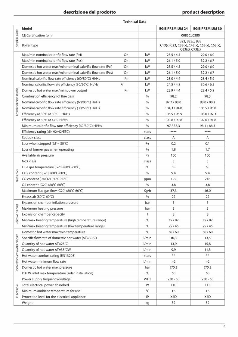
Technical Data
GE
NE
RA
L N
OT
E Model EGIS PREMIUM 24 EGIS PREMIUM 30
CE Certifi cation (pin) 0085CL0380
Boiler typeB23, B23p, B33
C13(x),C23, C33(x), C43(x), C53(x), C63(x), C83(x), C93(x)
PO
WE
R S
PE
CIF
ICA
TIO
NS
Max/min nominal calorifi c fl ow rate (Pci) Qn kW 23.5 / 4.5 29.0 / 6.0
Max/min nominal calorifi c fl ow rate (Pcs) Qn kW 26.1 / 5.0 32.2 / 6.7
Domestic hot water max/min nominal calorifi c fl ow rate (Pci) Qn kW 23.5 / 4.5 29.0 / 6.0
Domestic hot water max/min nominal calorifi c fl ow rate (Pcs) Qn kW 26.1 / 5.0 32.2 / 6.7
Nominal calorifi c fl ow rate effi ciency (60/80°C) Hi/Hs Pn kW 23.0 / 4.4 28.4 / 5.9
Nominal calorifi c fl ow rate effi ciency (30/50°C) Hi/Hs Pn kW 24.5 / 4.8 30.6 / 6.5
Domestic hot water max/min power output Pn kW 22.9 / 4.4 28.4 / 5.9
Combustion effi ciency (of fl ue gas) % 98.2 98.3
Nominal calorifi c fl ow rate effi ciency (60/80°C) Hi/Hs % 97.7 / 88.0 98.0 / 88.2
Nominal calorifi c fl ow rate effi ciency (30/50°C) Hi/Hs % 104,3 / 94.0 105.5 / 95.0
Effi ciency at 30% at 30°C Hi/Hs % 106.5 / 95.9 108.0 / 97.3
Effi ciency at 30% at 47°C Hi/Hs % 100.8 / 90.8 102.0 / 91.8
Minimum calorifi c fl ow rate effi ciency (60/80°C) Hi/Hs % 97 / 87,3 98.1 / 88.3
Effi ciency rating (dir. 92/42/EEC) stars **** ****
Sedbuk class class A A
Loss when stopped (ΔT = 30°C) % 0.2 0.1
Loss of burner gas when operating % 1.8 1.7
EM
ISS
ION
S
Available air pressure Pa 100 100
NoX class class 5 5
Flue gas temperature (G20) (80°C-60°C) °C 58 65
CO2 content (G20) (80°C-60°C) % 9.4 9.4
CO content (0%O2) (80°C-60°C) ppm 192 216
O2 content (G20) (80°C-60°C) % 3.8 3.8
Maximum fl ue gas fl ow (G20) (80°C-60°C) Kg/h 37,3 46.0
Excess air (80°C-60°C) % 22 22
HE
AT
ING
CIR
CU
IT
Expansion chamber infl ation pressure bar 1 1
Maximum heating pressure bar 3 3
Expansion chamber capacity l 8 8
Min/max heating temperature (high temperature range) °C 35 / 82 35 / 82
Min/max heating temperature (low temperature range) °C 25 / 45 25 / 45
DO
ME
ST
IC H
OT
WA
TE
R C
IRC
UIT
Domestic hot water max/min temperature °C 36 / 60 36 / 60
Specifi c fl ow rate of domestic hot water (ΔT=30°C) l/min 10,3 13,5
Quantity of hot water ΔT=25°C l/min 13,9 15,8
Quantity of hot water ΔT=35°CW l/min 9,9 11,3
Hot water comfort rating (EN13203) stars ** **
Hot water minimum fl ow rate l/min >2 >2
Domestic hot water max pressure bar 7/0,3 7/0,3
D.H.W. inlet max temperature (solar installation) °C 60 60
ELE
CT
RIC
AL
Power supply frequency/voltage V/Hz 230 - 50 230 - 50
Total electrical power absorbed W 110 115
Minimum ambient temperature for use °C +5 +5
Protection level for the electrical appliance IP X5D X5D
Weight kg 32 32
10
installazione installation
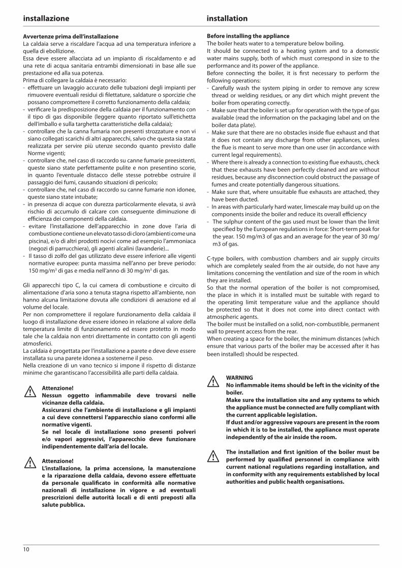
Avvertenze prima dell’installazione
La caldaia serve a riscaldare l’acqua ad una temperatura inferiore a
quella di ebollizione.
Essa deve essere allacciata ad un impianto di riscaldamento e ad
una rete di acqua sanitaria entrambi dimensionati in base alle sue
prestazione ed alla sua potenza.
Prima di collegare la caldaia è necessario:
- eff ettuare un lavaggio accurato delle tubazioni degli impianti per
rimuovere eventuali residui di fi lettature, saldature o sporcizie che
possano compromettere il corretto funzionamento della caldaia;
- verifi care la predisposizione della caldaia per il funzionamento con
il tipo di gas disponibile (leggere quanto riportato sull’etichetta
dell’imballo e sulla targhetta caratteristiche della caldaia);
- controllare che la canna fumaria non presenti strozzature e non vi
siano collegati scarichi di altri apparecchi, salvo che questa sia stata
realizzata per servire più utenze secondo quanto previsto dalle
Norme vigenti;
- controllare che, nel caso di raccordo su canne fumarie preesistenti,
queste siano state perfettamente pulite e non presentino scorie,
in quanto l’eventuale distacco delle stesse potrebbe ostruire il
passaggio dei fumi, causando situazioni di pericolo;
- controllare che, nel caso di raccordo su canne fumarie non idonee,
queste siano state intubate;
- in presenza di acque con durezza particolarmente elevata, si avrà
rischio di accumulo di calcare con conseguente diminuzione di
effi cienza dei componenti della caldaia.
- evitare l’installazione dell’apparecchio in zone dove l’aria di
combustione contiene un elevato tasso di cloro (ambienti come una
piscina), e/o di altri prodotti nocivi come ad esempio l’ammoniaca
(negozi di parrucchiera), gli agenti alcalini (lavanderie)...
- Il tasso di zolfo del gas utilizzato deve essere inferiore alle vigenti
normative europee: punta massima nell’anno per breve periodo:
150 mg/m3 di gas e media nell’anno di 30 mg/m3 di gas.
Gli apparecchi tipo C, la cui camera di combustione e circuito di
alimentazione d’aria sono a tenuta stagna rispetto all’ambiente, non
hanno alcuna limitazione dovuta alle condizioni di aerazione ed al
volume del locale.
Per non compromettere il regolare funzionamento della caldaia il
luogo di installazione deve essere idoneo in relazione al valore della
temperatura limite di funzionamento ed essere protetto in modo
tale che la caldaia non entri direttamente in contatto con gli agenti
atmosferici.
La caldaia è progettata per l’installazione a parete e deve deve essere
installata su una parete idonea a sostenerne il peso.
Nella creazione di un vano tecnico si impone il rispetto di distanze
minime che garantiscano l’accessibilità alle parti della caldaia.
Attenzione!
Nessun oggetto infi ammabile deve trovarsi nelle
vicinanze della caldaia.
Assicurarsi che l’ambiente di installazione e gli impianti
a cui deve connettersi l’apparecchio siano conformi alle
normative vigenti.
Se nel locale di installazione sono presenti polveri
e/o vapori aggressivi, l’apparecchio deve funzionare
indipendentemente dall’aria del locale.
Attenzione!
L’installazione, la prima accensione, la manutenzione
e la riparazione della caldaia, devono essere eff ettuate
da personale qualifi cato in conformità alle normative
nazionali di installazione in vigore e ad eventuali
prescrizioni delle autorità locali e di enti preposti alla
salute pubblica.
Before installing the appliance
The boiler heats water to a temperature below boiling.
It should be connected to a heating system and to a domestic
water mains supply, both of which must correspond in size to the
performance and its power of the appliance.
Before connecting the boiler, it is fi rst necessary to perform the
following operations:
- Carefully wash the system piping in order to remove any screw
thread or welding residues, or any dirt which might prevent the
boiler from operating correctly.
- Make sure that the boiler is set up for operation with the type of gas
available (read the information on the packaging label and on the
boiler data plate).
- Make sure that there are no obstacles inside fl ue exhaust and that
it does not contain any discharge from other appliances, unless
the fl ue is meant to serve more than one user (in accordance with
current legal requirements).
- Where there is already a connection to existing fl ue exhausts, check
that these exhausts have been perfectly cleaned and are without
residues, because any disconnection could obstruct the passage of
fumes and create potentially dangerous situations.
- Make sure that, where unsuitable fl ue exhausts are attached, they
have been ducted.
- In areas with particularly hard water, limescale may build up on the
components inside the boiler and reduce its overall effi ciency
- The sulphur content of the gas used must be lower than the limit
specifi ed by the European regulations in force: Short-term peak for
the year. 150 mg/m3 of gas and an average for the year of 30 mg/
m3 of gas.
C-type boilers, with combustion chambers and air supply circuits
which are completely sealed from the air outside, do not have any
limitations concerning the ventilation and size of the room in which
they are installed.
So that the normal operation of the boiler is not compromised,
the place in which it is installed must be suitable with regard to
the operating limit temperature value and the appliance should
be protected so that it does not come into direct contact with
atmospheric agents.
The boiler must be installed on a solid, non-combustible, permanent
wall to prevent access from the rear.
When creating a space for the boiler, the minimum distances (which
ensure that various parts of the boiler may be accessed after it has
been installed) should be respected.
WARNING
No infl ammable items should be left in the vicinity of the
boiler.
Make sure the installation site and any systems to which
the appliance must be connected are fully compliant with
the current applicable legislation.
If dust and/or aggressive vapours are present in the room
in which it is to be installed, the appliance must operate
independently of the air inside the room.
The installation and fi rst ignition of the boiler must be
performed by qualifi ed personnel in compliance with
current national regulations regarding installation, and
in conformity with any requirements established by local
authorities and public health organisations.
11
installazione installation
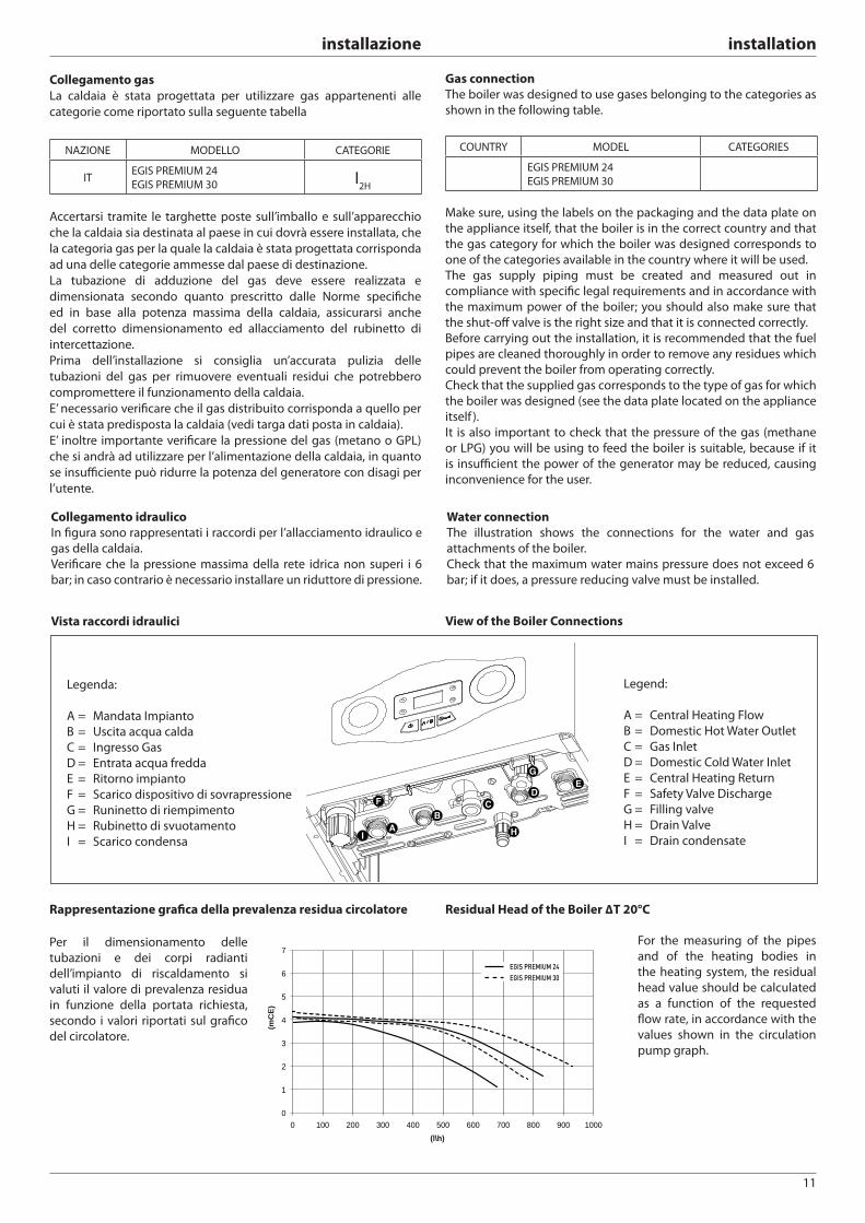
Collegamento gas
La caldaia è stata progettata per utilizzare gas appartenenti alle
categorie come riportato sulla seguente tabella
NAZIONE MODELLO CATEGORIE
IT EGIS PREMIUM 24
EGIS PREMIUM 30 I2H
Accertarsi tramite le targhette poste sull’imballo e sull’apparecchio
che la caldaia sia destinata al paese in cui dovrà essere installata, che
la categoria gas per la quale la caldaia è stata progettata corrisponda
ad una delle categorie ammesse dal paese di destinazione.
La tubazione di adduzione del gas deve essere realizzata e
dimensionata secondo quanto prescritto dalle Norme specifi che
ed in base alla potenza massima della caldaia, assicurarsi anche
del corretto dimensionamento ed allacciamento del rubinetto di
intercettazione.
Prima dell’installazione si consiglia un’accurata pulizia delle
tubazioni del gas per rimuovere eventuali residui che potrebbero
compromettere il funzionamento della caldaia.
E’ necessario verifi care che il gas distribuito corrisponda a quello per
cui è stata predisposta la caldaia (vedi targa dati posta in caldaia).
E’ inoltre importante verifi care la pressione del gas (metano o GPL)
che si andrà ad utilizzare per l’alimentazione della caldaia, in quanto
se insuffi ciente può ridurre la potenza del generatore con disagi per
l’utente.
Gas connection
The boiler was designed to use gases belonging to the categories as
shown in the following table.
COUNTRY MODEL CATEGORIES
EGIS PREMIUM 24
EGIS PREMIUM 30
Make sure, using the labels on the packaging and the data plate on
the appliance itself, that the boiler is in the correct country and that
the gas category for which the boiler was designed corresponds to
one of the categories available in the country where it will be used.
The gas supply piping must be created and measured out in
compliance with specifi c legal requirements and in accordance with
the maximum power of the boiler; you should also make sure that
the shut-off valve is the right size and that it is connected correctly.
Before carrying out the installation, it is recommended that the fuel
pipes are cleaned thoroughly in order to remove any residues which
could prevent the boiler from operating correctly.
Check that the supplied gas corresponds to the type of gas for which
the boiler was designed (see the data plate located on the appliance
itself ).
It is also important to check that the pressure of the gas (methane
or LPG) you will be using to feed the boiler is suitable, because if it
is insuffi cient the power of the generator may be reduced, causing
inconvenience for the user.
Collegamento idraulico
In fi gura sono rappresentati i raccordi per l’allacciamento idraulico e
gas della caldaia.
Verifi care che la pressione massima della rete idrica non superi i 6
bar; in caso contrario è necessario installare un riduttore di pressione.
Vista raccordi idraulici
Per il dimensionamento delle
tubazioni e dei corpi radianti
dell’impianto di riscaldamento si
valuti il valore di prevalenza residua
in funzione della portata richiesta,
secondo i valori riportati sul grafi co
del circolatore.
Water connection
The illustration shows the connections for the water and gas
attachments of the boiler.
Check that the maximum water mains pressure does not exceed 6
bar; if it does, a pressure reducing valve must be installed.
For the measuring of the pipes
and of the heating bodies in
the heating system, the residual
head value should be calculated
as a function of the requested
fl ow rate, in accordance with the
values shown in the circulation
pump graph.
View of the Boiler Connections
Legenda:
A = Mandata Impianto
B = Uscita acqua calda
C = Ingresso Gas
D = Entrata acqua fredda
E = Ritorno impianto
F = Scarico dispositivo di sovrapressione
G = Runinetto di riempimento
H = Rubinetto di svuotamento
I = Scarico condensa
F
AB
CD
E
I
G
H
Legend:
A = Central Heating Flow
B = Domestic Hot Water Outlet
C = Gas Inlet
D = Domestic Cold Water Inlet
E = Central Heating Return
F = Safety Valve Discharge
G = Filling valve
H = Drain Valve
I = Drain condensate
Rappresentazione grafi ca della prevalenza residua circolatore
Residual Head of the Boiler ΔT 20°C
0
1
2
3
4
5
6
7
0 100 200 300 400 500 600 700 800 900 1000
(mC
E)
(l\h)
EGIS PREMIUM 24EGIS PREMIUM 30
12
installazione installation
Dispositivo di sovrapressione
Provvedere al montaggio del tubo di scarico della valvola di sicurezza
“F” presente nella confezione documenti.
Lo scarico del dispositivo di sovrapressione deve essere collegato
ad un sifone di scarico con possibilità di controllo visivo per evitare
che in caso di intervento dello stesso si provochino danni a persone,
animali e cose, dei quali il costruttore non è responsabile.
Excessive pressure device
Fit the drain pipe for safety valve “F”, included in the hydraulic kit.
The excessive pressure device outlet (see Figure) must be connected
to a drainage siphon which can be checked visually in order to
prevent maintenance procedures causing harm to people, animals
or property (the manufacturer shall not be held responsible for any
such damage).
Pulizia impianto di riscaldamento
In caso di installazione su vecchi impianti si rileva spesso la
presenza di sostanze e additivi nell’acqua che potrebbero infl uire
negativamente sul funzionamento e sulla durata della nuova caldaia.
Prima della sostituzione bisogna provvedere ad un accurato lavaggio
dell’impianto per eliminare eventuali residui o sporcizie che possono
comprometterne il buon funzionamento. Verifi care che il vaso di
espansione abbia una capacità adeguata al contenuto d’acqua
dell’impianto.
Impianti a pavimento
Negli impianti di riscaldamento a pavimento, installare un termostato
di sicurezza sulla mandata della caldaia (vedere Schema Elettrico).
Tale termostato deve essere collocato ad una distanza dalla caldaia
suffi ciente a garantirne il corretto funzionamento. Se posto troppo
vicino, in seguito ad un prelievo di acqua calda sanitaria, l’acqua
che rimane nella caldaia, fatta fl uire nell’impianto, potrebbe causare
l’apertura del contatto del termostato senza che vi sia un reale
pericolo di danneggiamento dell’impianto.
Questo comporta il blocco del funzionamento della caldaia sia in
modo sanitario che riscaldamento e a display compare il codice di
errore “116”; il ripristino del funzionamento si avrà in automatico
quando il contatto del termostato , raff reddandosi, si chiude.
Nel caso in cui il termostato non possa essere installato come
indicato, l’impianto a pavimento dovrà essere protetto installando, a
monte del termostato, una valvola termostatica per impedire il fl usso
di acqua troppo calda verso l’impianto.
Cleaning the heating system
Where the boiler is used in conjunction with an older system, various
substances and additives may be present in the water and these
could have an adverse eff ect on the operation and durability of the
new boiler. Before replacing the old boiler, you must arrange for the
system to be cleaned thoroughly in order to eliminate any residue
or dirt which could compromise the correct operation of the water
heater. Make sure the capacity of the expansion vessel is suited to the
amount of water contained in the system.
Underfl oor heating
For appliances with underfl oor heating, fi t a safety thermostat onto
the underfl oor heating outlet. For the electrical connection of the
thermostat see the section on “Electrical connections”.
If the outlet temperature is too high, the boiler will stop both do-
mestic hot water and the heating production and the error code
1 16 “fl oor thermostat contact open” will appear on the display. The
boiler will restart when the thermostat is closed during automatic
resetting.
If the thermostat cannot be installed, the underfl oor heating equip-
ment must be protected by a thermostatic valve, or by a by-pass to
prevent the fl oor from reaching too high a temperature.
Water treatment
The abovementioned boiler is equipped with an aluminium primary
heat exchanger, therefore several primary heating circuit water
treatment measures are necessary for optimal operation.
A few general warnings are provided below.
If the boiler is installed as part of an existing system, we recommend
all unsuitable additives are removed.
We recommend the appliance is only switched on after the system
has been fl ushed out correctly.
For correct cleaning, use chemical products suited to the metals
applied in the system (including aluminium alloys), as these are
designed to dissolve and eliminate all impurities within the circuit.
The cleaning product prepares the circuit for the addition of an
inhibitor, which ensures that no impurities accumulate on the heat
exchanger, thus preventing the effi ciency of the heat exchange
process from being diminished.
Fernox Restorer, available in 3 versions (Superconcentrate Gel, MB-1
Liquid or 500 ml) and GE Betz X300/X400 products are compatible
with this boiler.
We recommend protecting the exchanger from scale build-up,
corrosion and sediment formation by adding suitable chemical
products such as Fernox Protector or GE Betz Sentinel X100.
Protecting the heat exchanger from scale build-up and corrosion
is of primary importance. All water is subject to the infi ltration
of impurities, and in some cases more than others, depending
on geographical location. Premature scale build-up on the heat
exchanger may cause the heat exchange process to become less
effi cient; the resulting scales may jam circuit components and reduce
the estimated lifespan of the entire system.
If antifreeze products are used in the circuit, make sure they are
compatible with aluminium. We especially advise against using
widely available ethylene glycol which, besides being corrosive to
aluminium and its alloys, can also become toxic.
Trattamento delle acque
La caldaia in oggetto è dotata di uno scambiatore di calore primario
in alluminio, di conseguenza alcuni accorgimenti inerenti al
trattamento delle acque del circuito primario di riscaldamento sono
necessari per un suo migliore utilizzo.
Di seguito vengono riportate alcune avvertenze di carattere generale.
Se la caldaia è installata in un impianto esistente, si raccomanda di
rimuovere ogni additivo inadatto.
Si raccomanda di accendere l’apparecchio solo dopo un corretto
lavaggio dell’impianto.
Si raccomanda di utilizzare per un corretto lavaggio prodotti chimici
idonei ai metalli che vengono usati nell’impianto, comprese le leghe
d’alluminio, atti a sciogliere e rimuovere ogni impurità presente
nel circuito. Il prodotto di pulizia prepara il circuito all’aggiunta di
un inibitore che ha il compito di assicurare che nessuna impurità si
depositi sullo scambiatore di calore e quindi di evitare che diminuisca
l’effi cienza dello scambio termico.
Fernox Restorer, disponibile in 3 versioni ( Superconcentrate Gel,
MB-1 Liquid o 500ML) e GE Betz X300/X400 sono prodotti compatibili
con l’utilizzo di questa caldaia.
Si raccomanda di proteggere lo scambiatore dalle incrostazioni, dalla
corrosione e dalla formazione di sedimenti mediante additivazione
di appositi prodotti chimici quali Fernox Protector o GE Betz Sentinel
X100.
Proteggere lo scambiatore di calore dalle incrostazioni e dalla
corrosione è di primaria importanza. Tutte le acque sono soggette
alla precipitazione diimpurezze, ed alcune più di altre a seconda delle
zone geografi che. Una prematura incrostazione dello scambiatore
primario può ineffi ciare lo scambio termico e le scaglie associate
possono sia bloccare componenti del circuito che ridurre l’aspettativa
di durata dell’intero impianto.
13
installazione installation
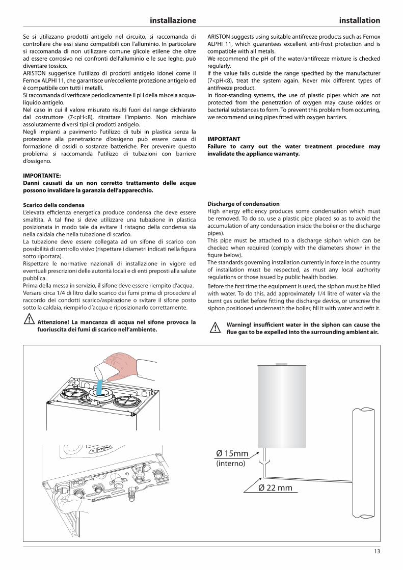
I
Ø 15mm (interno)
Ø 22 mm
Se si utilizzano prodotti antigelo nel circuito, si raccomanda di
controllare che essi siano compatibili con l’alluminio. In particolare
si raccomanda di non utilizzare comune glicole etilene che oltre
ad essere corrosivo nei confronti dell’alluminio e le sue leghe, può
diventare tossico.
ARISTON suggerisce l’utilizzo di prodotti antigelo idonei come il
Fernox ALPHI 11, che garantisce un’eccellente protezione antigelo ed
è compatibile con tutti i metalli.
Si raccomanda di verifi care periodicamente il pH della miscela acqua-
liquido antigelo.
Nel caso in cui il valore misurato risulti fuori del range dichiarato
dal costruttore (7<pH<8), ritrattare l’impianto. Non mischiare
assolutamente diversi tipi di prodotti antigelo.
Negli impianti a pavimento l’utilizzo di tubi in plastica senza la
protezione alla penetrazione d’ossigeno può essere causa di
formazione di ossidi o sostanze batteriche. Per prevenire questo
problema si raccomanda l’utilizzo di tubazioni con barriere
d’ossigeno.
IMPORTANTE:
Danni causati da un non corretto trattamento delle acque
possono invalidare la garanzia dell’apparecchio.
Scarico della condensa
L’elevata effi cienza energetica produce condensa che deve essere
smaltita. A tal fi ne si deve utilizzare una tubazione in plastica
posizionata in modo tale da evitare il ristagno della condensa sia
nella caldaia che nella tubazione di scarico.
La tubazione deve essere collegata ad un sifone di scarico con
possibilità di controllo visivo (rispettare i diametri indicati nella fi gura
sotto riportata).
Rispettare le normative nazionali di installazione in vigore ed
eventuali prescrizioni delle autorità locali e di enti preposti alla salute
pubblica.
Prima della messa in servizio, il sifone deve essere riempito d’acqua.
Versare circa 1/4 di litro dallo scarico dei fumi prima di procedere al
raccordo dei condotti scarico/aspirazione o svitare il sifone posto
sotto la caldaia, riempirlo d’acqua e riposizionarlo correttamente.
Attenzione! La mancanza di acqua nel sifone provoca la
fuoriuscita dei fumi di scarico nell’ambiente.
ARISTON suggests using suitable antifreeze products such as Fernox
ALPHI 11, which guarantees excellent anti-frost protection and is
compatible with all metals.
We recommend the pH of the water/antifreeze mixture is checked
regularly.
If the value falls outside the range specifi ed by the manufacturer
(7<pH<8), treat the system again. Never mix diff erent types of
antifreeze product.
In fl oor-standing systems, the use of plastic pipes which are not
protected from the penetration of oxygen may cause oxides or
bacterial substances to form. To prevent this problem from occurring,
we recommend using pipes fi tted with oxygen barriers.
IMPORTANT
Failure to carry out the water treatment procedure may
invalidate the appliance warranty.
Discharge of condensation
High energy effi ciency produces some condensation which must
be removed. To do so, use a plastic pipe placed so as to avoid the
accumulation of any condensation inside the boiler or the discharge
pipes).
This pipe must be attached to a discharge siphon which can be
checked when required (comply with the diameters shown in the
fi gure below).
The standards governing installation currently in force in the country
of installation must be respected, as must any local authority
regulations or those issued by public health bodies.
Before the fi rst time the equipment is used, the siphon must be fi lled
with water. To do this, add approximately 1/4 litre of water via the
burnt gas outlet before fi tting the discharge device, or unscrew the
siphon positioned underneath the boiler, fi ll it with water and refi t it.
Warning! insuffi cient water in the siphon can cause the
fl ue gas to be expelled into the surrounding ambient air.
14
installazione installation
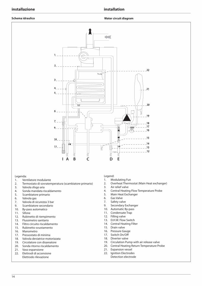
Schema idraulico Water circuit diagram
AI B C D E
1
2
3
5
4
6
7
11
9
10
12
16
1718
19
20
21
22
13
15
14
Legenda:
1. Ventilatore modulante
2. Termostato di sovratemperatura (scambiatore primario)
3. Valvola sfogo aria
4. Sonda mandata riscaldamento
5. Scambiatore primario
6. Valvola gas
7. Valvola di sicurezza 3 bar
9. Scambiatore secondario
10. By-pass automatico
11. Sifone
12. Rubinetto di riempimento
13. Flussimetro sanitario
14. Filtro circuito riscaldamento
15. Rubinetto svuotamento
16. Manometro
17. Pressostato di minima
18. Valvola deviatrice motorizzata
19. Circolatore con disareatore
20. Sonda ritorno riscaldamento
21. Vaso espansione
22. Elettrodi di accensione
Elettrodo rilevazione
Legend:
1. Modulating Fun
2. Overheat Thermostat (Main Heat exchanger)
3. Air relief valve
4. Central Heating Flow Temperature Probe
5. Main Heat Exchanger
6. Gas Valve
7. Safety valve
9. Secondary Exchanger
10. Automatic By-pass
11. Condensate Trap
12. Filling valve
13. D.H.W. Flow Switch
14. Central Heating Filter
15. Drain valve
16. Pressure Gauge
17. Switch On/Off
18. Diverter valve
19. Circulation Pump with air release valve
20. Central Heating Return Temperature Probe
21. Expansion vessel
22. Ignition Electrodes
Detection electrode
15
installazione installation
Collegamento condotti aspirazione e scarico fumi
La caldaia è idonea a funzionare in modalità B prelevando aria
dall’ambiente e in modalità C prelevando aria dall’esterno.
Nell’installazione di un sistema di scarico fare attenzione alle tenute
per evitare infi ltrazioni di fumi nel circuito aria.
Le tubazioni installate orizzontalmente devono avere una pendenza
discendente (3%) verso l’apparecchio per evitare ristagni di condensa.
Nel caso di installazione di tipo B il locale in cui la caldaia viene
installata deve essere ventilato da una adeguata presa d’aria
conforme alle norme vigenti.
Nei locali con rischio di vapori corrosivi (esempio lavanderie, saloni
per parrucchiere, ambienti per processi galvanici ecc.) è molto
importante utilizzare l’installazione di tipo C con prelievo di aria per
la combustione dall’esterno. In questo modo si preserva la caldaia
dagli eff etti della corrosione.
Per la realizzazione di sistemi di aspirazione/scarico di tipo coassiale
è obbligatorio l’utilizzo di accessori originali.
I condotti scarico fumi non devono essere a contatto o nelle vicinanze
di materiali infi ammabili e non devono attraversare strutture edili o
pareti di materiale infi ammabile.
Nel caso di installazione per sostituzione di una vecchia caldaia il
sistema di aspirazione e scarico fumi andrà sempre sostituito.
La giunzione dei tubi scarico fumi viene realizzata con innesto
maschio/femmina e guarnizione di tenuta.
Gli innesti devono essere disposti sempre contro il senso di
scorrimento della condensa.
Tipologie di collegamento della caldaia alla canna fumaria
- collegamento coassiale della caldaia alla canna fumaria di
aspirazione/scarico,
- collegamento sdoppiato della caldaia alla canna fumaria di scarico
con aspirazione aria dall’esterno,
- collegamento sdoppiato della caldaia alla canna fumaria di scarico
con aspirazione aria dall’ambiente.
Nel collegamento tra caldaia e canna fumaria debbono essere
impiegati prodotti resistenti alla condensa. Per le lunghezze e cambi
di direzione dei collegamenti consultare la tabella tipologie di scarico.
I kit di collegamento aspirazione/scarico fumi vengono forniti
separatamente dall’apparecchio in base alle diverse soluzioni di
installazione.
Il collegamento dalla caldaia alla canna fumaria è eseguito in tutti gli
apparecchi con tubazioni coassiali ø60/100 o tubazioni sdoppiate ø
80/80.
Per le perdite di carico dei condotti fare riferimento al catalogo
fumisteria. La resistenza supplementare deve essere tenuta in
considerazione nel suddetto dimensionamento.
Per il metodo di calcolo, i valori delle lunghezze equivalenti e gli
esempi installativi far riferimento al catalogo fumi
Utiliizare eslusivamente Kit scarico fumi per caldaie a
condensazione
ATTENZIONE
Assicurarsi che i passaggi di scarico e ventilazione non
siano ostruiti.
Assicurarsi che i condotti di scarico fumi non abbiano
perdite
Connecting the Flue
The boiler is designed to operate in B mode (by drawing air from the
room) and in C mode (by drawing air from outside).
When installing an exhaust system be careful when handling the
seals, in order to avoid fl ue gas leaking into the air circuit.
Horizontally-installed piping must have a downward incline of 3% so
as to avoid the build-up of condensate.
Nel caso di installazione di tipo B il locale in cui
When type B installation is used, the room in which the coiler is
installed must be ventilated using a suitable air inlet which complies
with current legislation.
In rooms where corrosive vapours may be present (for example,
laundry rooms, hair studios, rooms where galvanic processes take
place, etc.) it is important that type C installation is used, with air for
combustion drawn from outside. In this way the boiler is protected
from the eff ects of corrosion.
When implementing coaxial suction/exhaust systems the use of
authentic accessories is obligatory.
The fl ue gas exhaust ducting must not be in contact with or placed
near fl ammable materials, and must not cross building structures or
walls made using fl ammable material.
When replacing an old boiler, the ventilation and fl ue gas exhaust
system must always be replaced.
The fl ue gas exhaust ducting joint should be created using a male/
female coupling and a seal. Couplings should always be arranged so
that they go against the direction of the condensate fl ow.
Types of boiler - fl ue exhaust connection
- coaxial connection of the boiler to the suction/exhaust ducting
- split connection of the boiler to the exhaust ducting with air
suction from outside
- split connection of the boiler to the exhaust ducting with air
suction from the room.
Products which are resistant to condensate must be used in the
connection between the boiler and the fl ue gas exhaust. For details
relating to connection lengths and direction changes, please consult
the “exhaust types” table.
The suction/exhaust ducting connection kits are supplied separately
from the appliance, according to diff erent installation solutions.
The boiler is set up for connection to a coaxial suction and fl ue gas
exhaust ducting system.
If there is any loss of pressure in the piping, please refer to the gas
fl ue accessories catalogue. Supplementary resistance must be borne
in mind during the sizing process mentioned above.
For the calculation method, equivalent length values and installation
examplesplease refer to the gas fl ue accessories catalogue.
WARNING
Make sure that the fl ue gas exhaust and ventilation
ducting are not obstructed.
Make sure that there are no leaks along the fl ue gas
exhaust ducting.
16
installazione installation
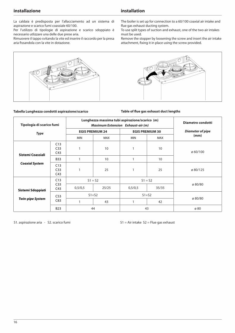
Tipologia di scarico fumi
Type
Lunghezza massima tubi aspirazione/scarico (m)
Maximum Extension Exhaust-air (m)Diametro condotti
Diameter of pipe
(mm)EGIS PREMIUM 24 EGIS PREMIUM 30
MIN MAX MIN MAX
Sistemi Coassiali
Coaxial System
C13
C33
C43
1 10 1 10ø 60/100
B33 1 10 1 10
C13
C33
C43
1 25 1 25 ø 80/125
Sistemi Sdoppiati
Twin-pipe System
C13
C33
C43
S1 = S2 S1 = S2ø 80/80
0,5/0,5 25/25 0,5/0,5 35/35
C53
C83
S1+S2 S1+S2ø 80/80
1 43 1 42
B23 44 43 ø 80
Tabella Lunghezza condotti aspirazione/scarico
S1. aspirazione aria - S2. scarico fumi
Table of fl ue gas exhaust duct lengths
S1 = Air intake S2 = Flue gas exhaust
La caldaia è predisposta per l’allacciamento ad un sistema di
aspirazione e scarico fumi coassiale 60/100.
Per l’utilizzo di tipologie di aspirazione e scarico sdoppiato è
necessario utlizzare una delle due prese aria.
Rimuovere il tappo svitando la vite ed inserire il raccordo per la presa
aria fi ssandola con la vite in dotazione.
The boiler is set up for connection to a 60/100 coaxial air intake and
fl ue gas exhaust ducting system.
To use split types of suction and exhaust, one of the two air intakes
must be used.
Remove the stopper by loosening the screw and insert the air intake
attachment, fi xing it in place using the screw provided.
17
installazione installation
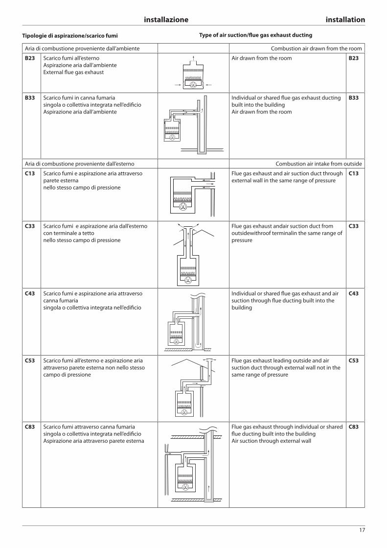
Tipologie di aspirazione/scarico fumi Type of air suction/fl ue gas exhaust ducting
Aria di combustione proveniente dall’ambiente Combustion air drawn from the room
B23 Scarico fumi all’esterno
Aspirazione aria dall’ambiente
External fl ue gas exhaust
Air drawn from the room B23
B33 Scarico fumi in canna fumaria
singola o collettiva integrata nell’edifi cio
Aspirazione aria dall’ambiente
Individual or shared fl ue gas exhaust ducting
built into the building
Air drawn from the room
B33
Aria di combustione proveniente dall’esterno Combustion air intake from outside
C13 Scarico fumi e aspirazione aria attraverso
parete esterna
nello stesso campo di pressione
Flue gas exhaust and air suction duct through
external wall in the same range of pressure
C13
C33 Scarico fumi e aspirazione aria dall’esterno
con terminale a tetto
nello stesso campo di pressione
Flue gas exhaust andair suction duct from
outsidewithroof terminalin the same range of
pressure
C33
C43 Scarico fumi e aspirazione aria attraverso
canna fumaria
singola o collettiva integrata nell’edifi cio
Individual or shared fl ue gas exhaust and air
suction through fl ue ducting built into the
building
C43
C53 Scarico fumi all’esterno e aspirazione aria
attraverso parete esterna non nello stesso
campo di pressione
Flue gas exhaust leading outside and air
suction duct through external wall not in the
same range of pressure
C53
C83 Scarico fumi attraverso canna fumaria
singola o collettiva integrata nell’edifi cio
Aspirazione aria attraverso parete esterna
Flue gas exhaust through individual or shared
fl ue ducting built into the building
Air suction through external wall
C83
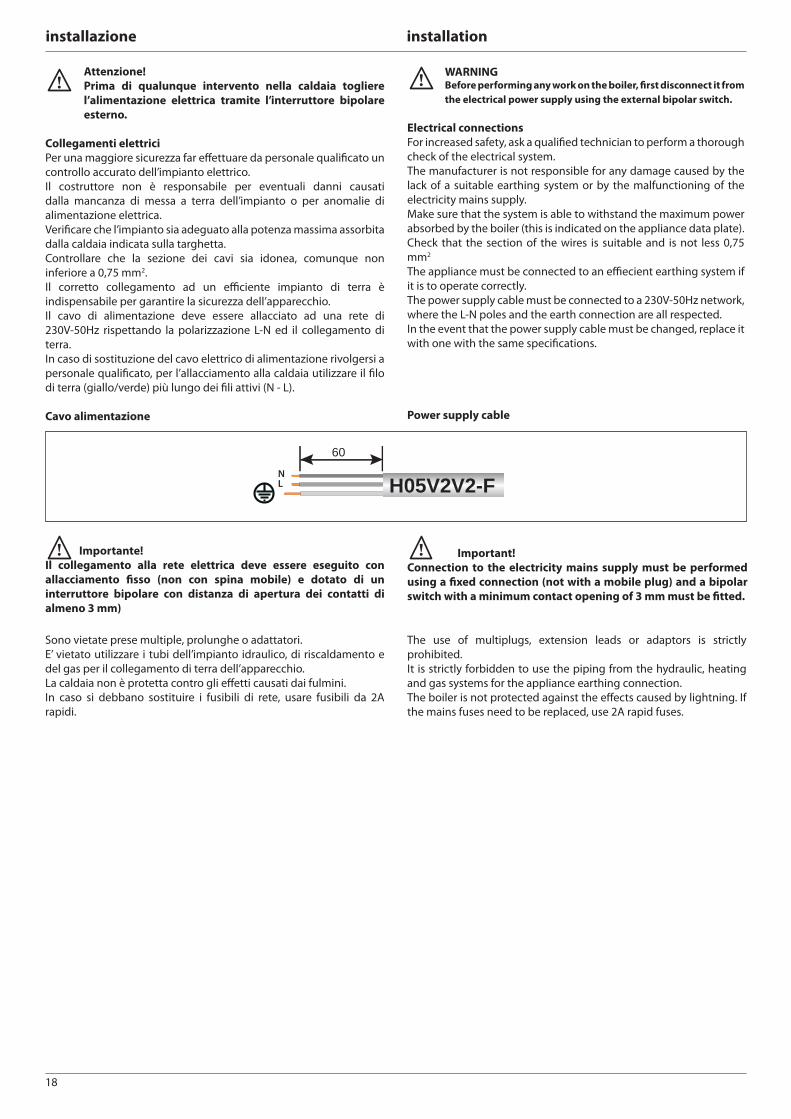
18
installazione installation
WARNING Before performing any work on the boiler, fi rst disconnect it from
the electrical power supply using the external bipolar switch.
Electrical connections
For increased safety, ask a qualifi ed technician to perform a thorough
check of the electrical system.
The manufacturer is not responsible for any damage caused by the
lack of a suitable earthing system or by the malfunctioning of the
electricity mains supply.
Make sure that the system is able to withstand the maximum power
absorbed by the boiler (this is indicated on the appliance data plate).
Check that the section of the wires is suitable and is not less 0,75
mm2
The appliance must be connected to an effi ecient earthing system if
it is to operate correctly.
The power supply cable must be connected to a 230V-50Hz network,
where the L-N poles and the earth connection are all respected.
In the event that the power supply cable must be changed, replace it
with one with the same specifi cations.
Power supply cable
Sono vietate prese multiple, prolunghe o adattatori.
E’ vietato utilizzare i tubi dell’impianto idraulico, di riscaldamento e
del gas per il collegamento di terra dell’apparecchio.
La caldaia non è protetta contro gli eff etti causati dai fulmini.
In caso si debbano sostituire i fusibili di rete, usare fusibili da 2A
rapidi.
Attenzione!
Prima di qualunque intervento nella caldaia togliere
l’alimentazione elettrica tramite l’interruttore bipolare
esterno.
Collegamenti elettrici
Per una maggiore sicurezza far eff ettuare da personale qualifi cato un
controllo accurato dell’impianto elettrico.
Il costruttore non è responsabile per eventuali danni causati
dalla mancanza di messa a terra dell’impianto o per anomalie di
alimentazione elettrica.
Verifi care che l’impianto sia adeguato alla potenza massima assorbita
dalla caldaia indicata sulla targhetta.
Controllare che la sezione dei cavi sia idonea, comunque non
inferiore a 0,75 mm2.
Il corretto collegamento ad un effi ciente impianto di terra è
indispensabile per garantire la sicurezza dell’apparecchio.
Il cavo di alimentazione deve essere allacciato ad una rete di
230V-50Hz rispettando la polarizzazione L-N ed il collegamento di
terra.
In caso di sostituzione del cavo elettrico di alimentazione rivolgersi a
personale qualifi cato, per l’allacciamento alla caldaia utilizzare il fi lo
di terra (giallo/verde) più lungo dei fi li attivi (N - L).
Cavo alimentazione
H05V2V2-F
60
NL
The use of multiplugs, extension leads or adaptors is strictly
prohibited.
It is strictly forbidden to use the piping from the hydraulic, heating
and gas systems for the appliance earthing connection.
The boiler is not protected against the eff ects caused by lightning. If
the mains fuses need to be replaced, use 2A rapid fuses.
Importante!
Il collegamento alla rete elettrica deve essere eseguito con
allacciamento fi sso (non con spina mobile) e dotato di un
interruttore bipolare con distanza di apertura dei contatti di
almeno 3 mm)
Important!
Connection to the electricity mains supply must be performed
using a fi xed connection (not with a mobile plug) and a bipolar
switch with a minimum contact opening of 3 mm must be fi tted.
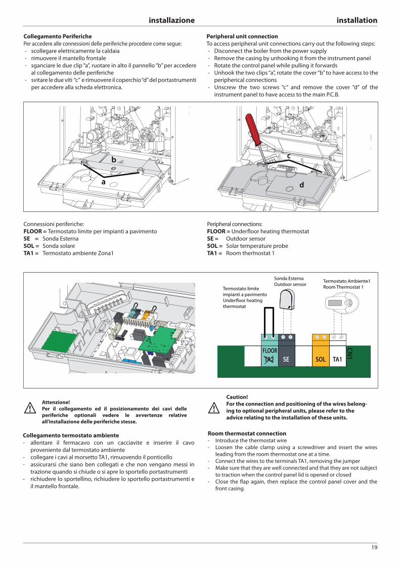
19
installazione installation
Collegamento Periferiche
Per accedere alle connessioni delle periferiche procedere come segue:
- scollegare elettricamente la caldaia
- rimuovere il mantello frontale
- sganciare le due clip “a”, ruotare in alto il pannello “b” per accedere
al collegamento delle periferiche
- svitare le due viti “c” e rimuovere il coperchio “d” del portastrumenti
per accedere alla scheda elettronica.
Peripheral unit connection
To access peripheral unit connections carry out the following steps:
- Disconnect the boiler from the power supply
- Remove the casing by unhooking it from the instrument panel
- Rotate the control panel while pulling it forwards
- Unhook the two clips “a”, rotate the cover “b” to have access to the
peripherical connections
- Unscrew the two screws “c” and remove the cover “d” of the
instrument panel to have access to the main P.C.B.
a
b c
d
Connessioni periferiche:
FLOOR = Termostato limite per impianti a pavimento
SE = Sonda Esterna
SOL = Sonda solare
TA1 = Termostato ambiente Zona1
Peripheral connections:
FLOOR = Underfl oor heating thermostat
SE = Outdoor sensor
SOL = Solar temperature probe
TA1 = Room thermostat 1
Collegamento termostato ambiente
- allentare il fermacavo con un cacciavite e inserire il cavo
proveniente dal termostato ambiente
- collegare i cavi al morsetto TA1, rimuovendo il ponticello
- assicurarsi che siano ben collegati e che non vengano messi in
trazione quando si chiude o si apre lo sportello portastrumenti
- richiudere lo sportellino, richiudere lo sportello portastrumenti e
il mantello frontale.
Attenzione!
Per il collegamento ed il posizionamento dei cavi delle
periferiche optionali vedere le avvertenze relative
all’installazione delle periferiche stesse.
Room thermostat connection- Introduce the thermostat wire
- Loosen the cable clamp using a screwdriver and insert the wires
leading from the room thermostat one at a time.
- Connect the wires to the terminals TA1, removing the jumper
- Make sure that they are well connected and that they are not subject
to traction when the control panel lid is opened or closed
- Close the fl ap again, then replace the control panel cover and the
front casing.
Caution!
For the connection and positioning of the wires belong-
ing to optional peripheral units, please refer to the
advice relating to the installation of these units.
TA2FLOOR
SESOL TA1
T B
TA2FLOOR
SE SOL TA1
CN
1
Sonda Esterna
Outdoor sensorTermostato limite
impianti a pavimento
Underfloor heating
thermostat
Termostato Ambiente1
Room Thermostat 1
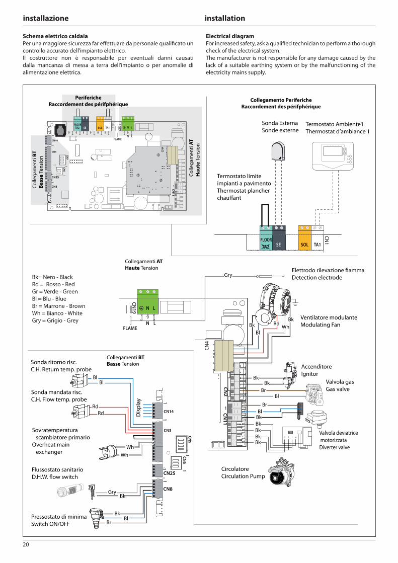
20
installazione installation
Schema elettrico caldaia
Per una maggiore sicurezza far eff ettuare da personale qualifi cato un
controllo accurato dell’impianto elettrico.
Il costruttore non è responsabile per eventuali danni causati
dalla mancanza di messa a terra dell’impianto o per anomalie di
alimentazione elettrica.
TA2FLOOR
SE SOL TA1
CN
1
1
CN14
CN3
11
CN8
CN9
1
1
CN25
1
Disp
lay
RdRd
BlBl
Br
Bk
GryBk
Bl
1CN
6
N
NFLAME
L
L
CN
19
CN
4
Gry
BkBr
Bl
CN2
CN11
1
1
Bk
Bl
RdWh
Bk
BkBl
Br
Bk
Wh
Wh
Collegamento Periferiche
Raccordement des périfphérique
Sonda Esterna
Sonde externe
Termostato limite
impianti a pavimento
Thermostat plancher
chauffant
Termostato Ambiente1
Thermostat d’ambiance 1
Collegamenti AT
Haute Tension
Ventilatore modulante
Modulating Fan
Elettrodo rilevazione fiamma
Detection electrode
Valvola gas
Gas valve
Accenditore
Ignitor
Valvola deviatrice
motorizzata
Diverter valve
Circolatore
Circulation Pump
Collegamenti BT
Basse TensionSonda ritorno risc.
C.H. Return temp. probe
Sonda mandata risc.
C.H. Flow temp. probe
Sovratemperatura
scambiatore primario
Overheat main
exchanger
Flussostato sanitario
D.H.W. flow switch
Pressostato di minima
Switch ON/OFF
BkBkBk
Bk
3 12 4
1 2 3 4 5 6 7
N
NFLAME
L
L
TA2FLOOR
SE SOL TA1
CN
19
CN
1
CN
4
1
CN14
CN3
11
CN8
CN9
1
1
CN25
1 1CN
6
CN11
1
1
Periferiche
Raccordement des périfphérique
Co
llega
me
nti
BT
Ba
sse
Te
nsi
on
Co
llega
me
nti
AT
Ha
ute
Te
nsi
on
Electrical diagram
For increased safety, ask a qualifi ed technician to perform a thorough
check of the electrical system.
The manufacturer is not responsible for any damage caused by the
lack of a suitable earthing system or by the malfunctioning of the
electricity mains supply.
Bk= Nero - Black
Rd = Rosso - Red
Gr = Verde - Green
Bl = Blu - Blue
Br = Marrone - Brown
Wh = Bianco - White
Gry = Grigio - Grey
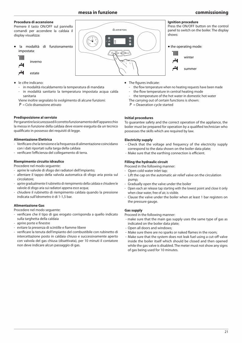
21
messa in funzione commissioning
Procedura di accensione
Premere il tasto ON/OFF sul pannello
comandi per accendere la caldaia il
display visualizza:
● la modalità di funzionamento
impostata:
inverno
estate
● le cifre indicano:
- in modalità riscaldamento la temperatura di mandata
- in modalità sanitario la temperatura impostata acqua calda
sanitaria
Viene inoltre segnalato lo svolgimento di alcune funzioni:
P P = Ciclo disareazione attivato
● the operating mode:
winter
summer
● The fi gures indicate:
- the fl ow temperature when no heating requests have been made
- the fl ow temperature in central heating mode
- the temperature of the hot water in domestic hot water
The carrying out of certain functions is shown:
P = Deaeration cycle started
Predisposizione al servizio
Per garantire la sicurezza ed il corretto funzionamento dell’apparecchio
la messa in funzione della caldaia deve essere eseguita da un tecnico
qualifi cato in possesso dei requisiti di legge.
Alimentazione Elettrica
- Verifi care che la tensione e la frequenza di alimentazione coincidano
con i dati riportati sulla targa della caldaia
- verifi care l’effi cienza del collegamento di terra.
Riempimento circuito idraulico
Procedere nel modo seguente:
- aprire le valvole di sfogo dei radiatori dell’impianto;
- allentare il tappo della valvola automatica di sfogo aria posta sul
circolatore;
- aprire gradualmente il rubinetto di riempimento della caldaia e chiudere le
valvole di sfogo aria sui radiatori appena esce acqua;
- chiudere il rubinetto di riempimento caldaia quando la pressione
indicata sull’idrometro è di 1-1,5 bar.
Alimentazione Gas
Procedere nel modo seguente:
- verifi care che il tipo di gas erogato corrisponda a quello indicato
sulla targhetta della caldaia
- aprire porte e fi nestre
- evitare la presenza di scintille e fi amme libere
- verifi care la tenuta dell’impianto del combustibile con rubinetto di
intercettazione posto in caldaia chiuso e successivamente aperto
con valvola del gas chiusa (disattivata), per 10 minuti il contatore
non deve indicare alcun passaggio di gas.
Ignition procedurePress the ON/OFF button on the control panel to switch on the boiler. The display
shows:
Initial procedures
To guarantee safety and the correct operation of the appliance, the
boiler must be prepared for operation by a qualifi ed technician who
possesses the skills which are required by law.
Electricity supply
- Check that the voltage and frequency of the electricity supply
correspond to the data shown on the boiler data plate;
- Make sure that the earthing connection is effi cient.
Filling the hydraulic circuit
Proceed in the following manner:
- Open cold water inlet tap;
- Lift the cap on the automatic air relief valve on the circulation
pump;
- Gradually open the valve under the boiler
- Open each air release tap starting with the lowest point and close it only
when clear water, free of air, is visible.
- Clause the valve under the boiler when at least 1 bar registers on
the pressure gauge.
Gas supply
Proceed in the following manner:
- make sure that the main gas supply uses the same type of gas as
indicated on the boiler data plate;
- Open all doors and windows;
- Make sure there are no sparks or naked fl ames in the room;
- Make sure that the system does not leak fuel using a cut-off valve
inside the boiler itself which should be closed and then opened
while the gas valve is disabled. The meter must not show any signs
of gas being used for 10 minutes.
OK
ESC
22
messa in funzione commissioning
Water treatment
The abovementioned boiler is equipped with an aluminium primary
heat exchanger, therefore several primary heating circuit water
treatment measures are necessary for optimal operation.
A few general warnings are provided below.
If the boiler is installed as part of an existing system, we recommend
all unsuitable additives are removed.
We recommend the appliance is only switched on after the system
has been fl ushed out correctly.
For correct cleaning, use chemical products suited to the metals
applied in the system (including aluminium alloys), as these are
designed to dissolve and eliminate all impurities within the circuit.
The cleaning product prepares the circuit for the addition of an
inhibitor, which ensures that no impurities accumulate on the heat
exchanger, thus preventing the effi ciency of the heat exchange
process from being diminished.
Fernox Restorer, available in 3 versions (Superconcentrate Gel, MB-1
Liquid or 500 ml) and GE Betz X300/X400 products are compatible
with this boiler.
We recommend protecting the exchanger from scale build-up,
corrosion and sediment formation by adding suitable chemical
products such as Fernox Protector or GE Betz Sentinel X100.
Protecting the heat exchanger from scale build-up and corrosion
is of primary importance. All water is subject to the infi ltration
of impurities, and in some cases more than others, depending
on geographical location. Premature scale build-up on the heat
exchanger may cause the heat exchange process to become less
effi cient; the resulting scales may jam circuit components and reduce
the estimated lifespan of the entire system.
If antifreeze products are used in the circuit, make sure they are
compatible with aluminium. We especially advise against using
widely available ethylene glycol which, besides being corrosive to
aluminium and its alloys, can also become toxic.
ARISTON suggests using suitable antifreeze products such as Fernox
ALPHI 11, which guarantees excellent anti-frost protection and is
compatible with all metals.
We recommend the pH of the water/antifreeze mixture is checked
regularly.
If the value falls outside the range specifi ed by the manufacturer
(7<pH<8), treat the system again. Never mix diff erent types of
antifreeze product.
In fl oor-standing systems, the use of plastic pipes which are not
protected from the penetration of oxygen may cause oxides or
bacterial substances to form. To prevent this problem from occurring,
we recommend using pipes fi tted with oxygen barriers.
IMPORTANT
Failure to carry out the water treatment procedure may
invalidate the appliance warranty.
Trattamento delle acque
La caldaia in oggetto è dotata di uno scambiatore di calore primario
in alluminio, di conseguenza alcuni accorgimenti inerenti al
trattamento delle acque del circuito primario di riscaldamento sono
necessari per un suo migliore utilizzo.
Di seguito vengono riportate alcune avvertenze di carattere generale.
Se la caldaia è installata in un impianto esistente, si raccomanda di
rimuovere ogni additivo inadatto.
Si raccomanda di accendere l’apparecchio solo dopo un corretto
lavaggio dell’impianto.
Si raccomanda di utilizzare per un corretto lavaggio prodotti chimici
idonei ai metalli che vengono usati nell’impianto, comprese le leghe
d’alluminio, atti a sciogliere e rimuovere ogni impurità presente
nel circuito. Il prodotto di pulizia prepara il circuito all’aggiunta di
un inibitore che ha il compito di assicurare che nessuna impurità si
depositi sullo scambiatore di calore e quindi di evitare che diminuisca
l’effi cienza dello scambio termico.
Fernox Restorer, disponibile in 3 versioni ( Superconcentrate Gel,
MB-1 Liquid o 500ML) e GE Betz X300/X400 sono prodotti compatibili
con l’utilizzo di questa caldaia.
Si raccomanda di proteggere lo scambiatore dalle incrostazioni, dalla
corrosione e dalla formazione di sedimenti mediante additivazione
di appositi prodotti chimici quali Fernox Protector o GE Betz Sentinel
X100.
Proteggere lo scambiatore di calore dalle incrostazioni e dalla
corrosione è di primaria importanza. Tutte le acque sono soggette
alla precipitazione diimpurezze, ed alcune più di altre a seconda delle
zone geografi che. Una prematura incrostazione dello scambiatore
primario può ineffi ciare lo scambio termico e le scaglie associate
possono sia bloccare componenti del circuito che ridurre l’aspettativa
di durata dell’intero impianto.
Se si utilizzano prodotti antigelo nel circuito, si raccomanda di
controllare che essi siano compatibili con l’alluminio. In particolare
si raccomanda di non utilizzare comune glicole etilene che oltre
ad essere corrosivo nei confronti dell’alluminio e le sue leghe, può
diventare tossico.
ARISTON suggerisce l’utilizzo di prodotti antigelo idonei come il
Fernox ALPHI 11, che garantisce un’eccellente protezione antigelo ed
è compatibile con tutti i metalli.
Si raccomanda di verifi care periodicamente il pH della miscela acqua-
liquido antigelo.
Nel caso in cui il valore misurato risulti fuori del range dichiarato
dal costruttore (7<pH<8), ritrattare l’impianto. Non mischiare
assolutamente diversi tipi di prodotti antigelo.
Negli impianti a pavimento l’utilizzo di tubi in plastica senza la
protezione alla penetrazione d’ossigeno può essere causa di
formazione di ossidi o sostanze batteriche. Per prevenire questo
problema si raccomanda l’utilizzo di tubazioni con barriere
d’ossigeno.
IMPORTANTE:
Danni causati da un non corretto trattamento delle acque
possono invalidare la garanzia dell’apparecchio.
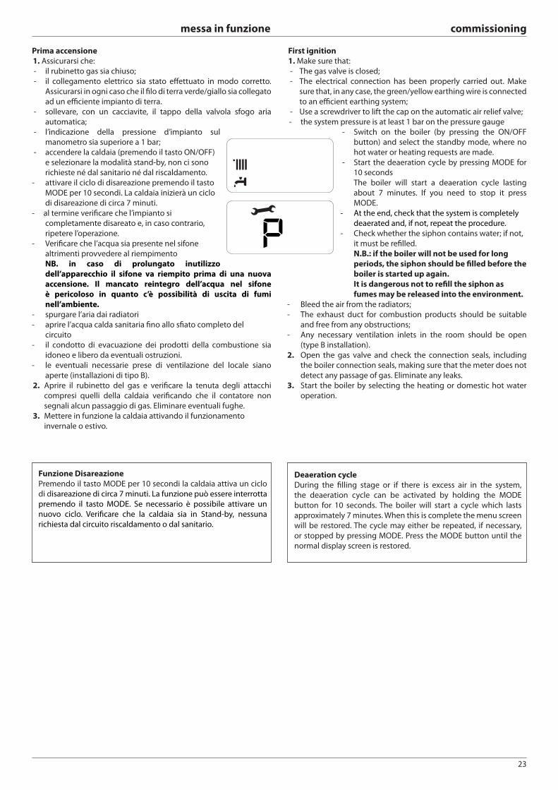
23
messa in funzione commissioning
Deaeration cycle
During the fi lling stage or if there is excess air in the system,
the deaeration cycle can be activated by holding the MODE
button for 10 seconds. The boiler will start a cycle which lasts
approximately 7 minutes. When this is complete the menu screen
will be restored. The cycle may either be repeated, if necessary,
or stopped by pressing MODE. Press the MODE button until the
normal display screen is restored.
Funzione Disareazione
Premendo il tasto MODE per 10 secondi la caldaia attiva un ciclo
di disareazione di circa 7 minuti. La funzione può essere interrotta
premendo il tasto MODE. Se necessario è possibile attivare un
nuovo ciclo. Verifi care che la caldaia sia in Stand-by, nessuna
richiesta dal circuito riscaldamento o dal sanitario.
Prima accensione
1. Assicurarsi che:
- il rubinetto gas sia chiuso;
- il collegamento elettrico sia stato eff ettuato in modo corretto.
Assicurarsi in ogni caso che il fi lo di terra verde/giallo sia collegato
ad un effi ciente impianto di terra.
- sollevare, con un cacciavite, il tappo della valvola sfogo aria
automatica;
- l’indicazione della pressione d’impianto sul
manometro sia superiore a 1 bar;
- accendere la caldaia (premendo il tasto ON/OFF)
e selezionare la modalità stand-by, non ci sono
richieste né dal sanitario né dal riscaldamento.
- attivare il ciclo di disareazione premendo il tasto
MODE per 10 secondi. La caldaia inizierà un ciclo
di disareazione di circa 7 minuti.
- al termine verifi care che l’impianto si
completamente disareato e, in caso contrario,
ripetere l’operazione.
- Verificare che l’acqua sia presente nel sifone
altrimenti provvedere al riempimento
NB. in caso di prolungato inutilizzo
dell’apparecchio il sifone va riempito prima di una nuova
accensione. Il mancato reintegro dell’acqua nel sifone
è pericoloso in quanto c’è possibilità di uscita di fumi
nell’ambiente.
- spurgare l’aria dai radiatori
- aprire l’acqua calda sanitaria fi no allo sfi ato completo del
circuito
- il condotto di evacuazione dei prodotti della combustione sia
idoneo e libero da eventuali ostruzioni.
- le eventuali necessarie prese di ventilazione del locale siano
aperte (installazioni di tipo B).
2. Aprire il rubinetto del gas e verifi care la tenuta degli attacchi
compresi quelli della caldaia verifi cando che il contatore non
segnali alcun passaggio di gas. Eliminare eventuali fughe.
3. Mettere in funzione la caldaia attivando il funzionamento
invernale o estivo.
First ignition
1. Make sure that:
- The gas valve is closed;
- The electrical connection has been properly carried out. Make
sure that, in any case, the green/yellow earthing wire is connected
to an effi cient earthing system;
- Use a screwdriver to lift the cap on the automatic air relief valve;
- the system pressure is at least 1 bar on the pressure gauge
- Switch on the boiler (by pressing the ON/OFF
button) and select the standby mode, where no
hot water or heating requests are made.
- Start the deaeration cycle by pressing MODE for
10 seconds
The boiler will start a deaeration cycle lasting
about 7 minutes. If you need to stop it press
MODE.
- At the end, check that the system is completely
deaerated and, if not, repeat the procedure.
- Check whether the siphon contains water; if not,
it must be refi lled.
N.B.: if the boiler will not be used for long
periods, the siphon should be fi lled before the
boiler is started up again.
It is dangerous not to refi ll the siphon as
fumes may be released into the environment.
- Bleed the air from the radiators;
- The exhaust duct for combustion products should be suitable
and free from any obstructions;
- Any necessary ventilation inlets in the room should be open
(type B installation).
2. Open the gas valve and check the connection seals, including
the boiler connection seals, making sure that the meter does not
detect any passage of gas. Eliminate any leaks.
3. Start the boiler by selecting the heating or domestic hot water
operation.
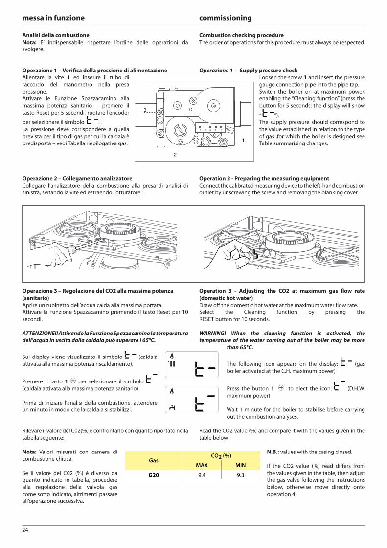
24
messa in funzione commissioning
Combustion checking procedure
The order of operations for this procedure must always be respected.
Operazione 1 - Supply pressure check
Loosen the screw 1 and insert the pressure
gauge connection pipe into the pipe tap.
Switch the boiler on at maximum power,
enabling the “Cleaning function” (press the
button for 5 seconds; the display will show
“ “).
The supply pressure should correspond to
the value established in relation to the type
of gas ,for which the boiler is designed see
Table summarising changes.
Operation 2 - Preparing the measuring equipment
Connect the calibrated measuring device to the left-hand combustion
outlet by unscrewing the screw and removing the blanking cover.
Operation 3 - Adjusting the CO2 at maximum gas fl ow rate
(domestic hot water)
Draw off the domestic hot water at the maximum water fl ow rate.
Select the Cleaning function by pressing the
RESET button for 10 seconds.
WARNING! When the cleaning function is activated, the
temperature of the water coming out of the boiler may be more
than 65°C.
The following icon appears on the display: (gas
boiler activated at the C.H. maximum power)
Press the button 1 to elect the icon: (D.H.W.
maximum power)
Wait 1 minute for the boiler to stabilise before carrying
out the combustion analyses.
Read the CO2 value (%) and compare it with the values given in the
table below
N.B.: values with the casing closed.
If the CO2 value (%) read diff ers from
the values given in the table, then adjust
the gas valve following the instructions
below, otherwise move directly onto
operation 4.
Analisi della combustione
Nota: E’ indispensabile rispettare l’ordine delle operazioni da
svolgere.
Operazione 1 - Verifi ca della pressione di alimentazione
Allentare la vite 1 ed inserire il tubo di
raccordo del manometro nella presa
pressione.
Attivare le Funzione Spazzacamino alla
massima potenza sanitario – premere il
tasto Reset per 5 secondi, ruotare l’encoder
per selezionare il simbolo .
La pressione deve corrispondere a quella
prevista per il tipo di gas per cui la caldaia è
predisposta – vedi Tabella riepilogativa gas.
Operazione 2 – Collegamento analizzatore
Collegare l’analizzatore della combustione alla presa di analisi di
sinistra, svitando la vite ed estraendo l’otturatore.
Operazione 3 – Regolazione del CO2 alla massima potenza
(sanitario)
Aprire un rubinetto dell’acqua calda alla massima portata.
Attivare la Funzione Spazzacamino premendo il tasto Reset per 10
secondi.
ATTENZIONE!! Attivando la Funzione Spazzacamino la temperatura
dell’acqua in uscita dalla caldaia può superare i 65°C.
Sul display viene visualizzato il simbolo (caldaia
attivata alla massima potenza riscaldamento).
Premere il tasto 1 per selezionare il simbolo
(caldaia attivata alla massima potenza sanitario)
Prima di iniziare l’analisi della combustione, attendere
un minuto in modo che la caldaia si stabilizzi.
Rilevare il valore del C02(%) e confrontarlo con quanto riportato nella
tabella seguente:
Nota: Valori misurati con camera di
combustione chiusa.
Se il valore del C02 (%) è diverso da
quanto indicato in tabella, procedere
alla regolazione della valvola gas
come sotto indicato, altrimenti passare
all’operazione successiva.
GasCO2 (%)
MAX MIN
G20 9,4 9,3
1 32 4
2
3
1
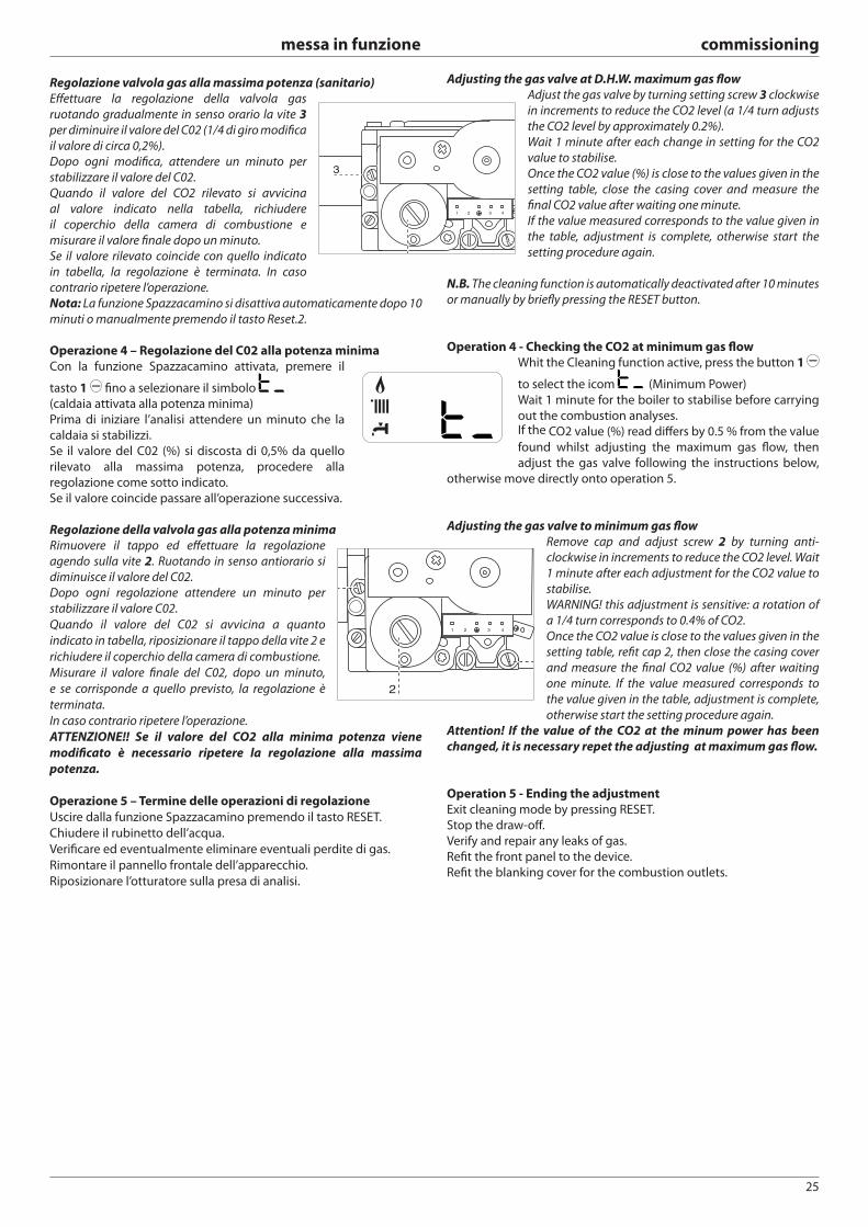
25
messa in funzione commissioning
Regolazione valvola gas alla massima potenza (sanitario)
Eff ettuare la regolazione della valvola gas
ruotando gradualmente in senso orario la vite 3
per diminuire il valore del C02 (1/4 di giro modifi ca
il valore di circa 0,2%).
Dopo ogni modifi ca, attendere un minuto per
stabilizzare il valore del C02.
Quando il valore del CO2 rilevato si avvicina
al valore indicato nella tabella, richiudere
il coperchio della camera di combustione e
misurare il valore fi nale dopo un minuto.
Se il valore rilevato coincide con quello indicato
in tabella, la regolazione è terminata. In caso
contrario ripetere l’operazione.
Nota: La funzione Spazzacamino si disattiva automaticamente dopo 10
minuti o manualmente premendo il tasto Reset.2.
Operazione 4 – Regolazione del C02 alla potenza minima
Con la funzione Spazzacamino attivata, premere il
tasto 1 fi no a selezionare il simbolo
(caldaia attivata alla potenza minima)
Prima di iniziare l’analisi attendere un minuto che la
caldaia si stabilizzi.
Se il valore del C02 (%) si discosta di 0,5% da quello
rilevato alla massima potenza, procedere alla
regolazione come sotto indicato.
Se il valore coincide passare all’operazione successiva.
Regolazione della valvola gas alla potenza minima
Rimuovere il tappo ed eff ettuare la regolazione
agendo sulla vite 2. Ruotando in senso antiorario si
diminuisce il valore del C02.
Dopo ogni regolazione attendere un minuto per
stabilizzare il valore C02.
Quando il valore del C02 si avvicina a quanto
indicato in tabella, riposizionare il tappo della vite 2 e
richiudere il coperchio della camera di combustione.
Misurare il valore fi nale del C02, dopo un minuto,
e se corrisponde a quello previsto, la regolazione è
terminata.
In caso contrario ripetere l’operazione.
ATTENZIONE!! Se il valore del CO2 alla minima potenza viene
modifi cato è necessario ripetere la regolazione alla massima
potenza.
Operazione 5 – Termine delle operazioni di regolazione
Uscire dalla funzione Spazzacamino premendo il tasto RESET.
Chiudere il rubinetto dell’acqua.
Verifi care ed eventualmente eliminare eventuali perdite di gas.
Rimontare il pannello frontale dell’apparecchio.
Riposizionare l’otturatore sulla presa di analisi.
Adjusting the gas valve at D.H.W. maximum gas fl ow
Adjust the gas valve by turning setting screw 3 clockwise
in increments to reduce the CO2 level (a 1/4 turn adjusts
the CO2 level by approximately 0.2%).
Wait 1 minute after each change in setting for the CO2
value to stabilise.
Once the CO2 value (%) is close to the values given in the
setting table, close the casing cover and measure the
fi nal CO2 value after waiting one minute.
If the value measured corresponds to the value given in
the table, adjustment is complete, otherwise start the
setting procedure again.
N.B. The cleaning function is automatically deactivated after 10 minutes
or manually by briefl y pressing the RESET button.
Operation 4 - Checking the CO2 at minimum gas fl ow
Whit the Cleaning function active, press the button 1
to select the icom (Minimum Power)
Wait 1 minute for the boiler to stabilise before carrying
out the combustion analyses.If the CO2 value (%) read diff ers by 0.5 % from the value
found whilst adjusting the maximum gas fl ow, then
adjust the gas valve following the instructions below,
otherwise move directly onto operation 5.
Adjusting the gas valve to minimum gas fl ow
Remove cap and adjust screw 2 by turning anti-
clockwise in increments to reduce the CO2 level. Wait
1 minute after each adjustment for the CO2 value to
stabilise.
WARNING! this adjustment is sensitive: a rotation of
a 1/4 turn corresponds to 0.4% of CO2.
Once the CO2 value is close to the values given in the
setting table, refi t cap 2, then close the casing cover
and measure the fi nal CO2 value (%) after waiting
one minute. If the value measured corresponds to
the value given in the table, adjustment is complete,
otherwise start the setting procedure again.
Attention! If the value of the CO2 at the minum power has been
changed, it is necessary repet the adjusting at maximum gas fl ow.
Operation 5 - Ending the adjustment
Exit cleaning mode by pressing RESET.
Stop the draw-off .
Verify and repair any leaks of gas.
Refi t the front panel to the device.
Refi t the blanking cover for the combustion outlets.
1 32 4
3
1 32 4
2
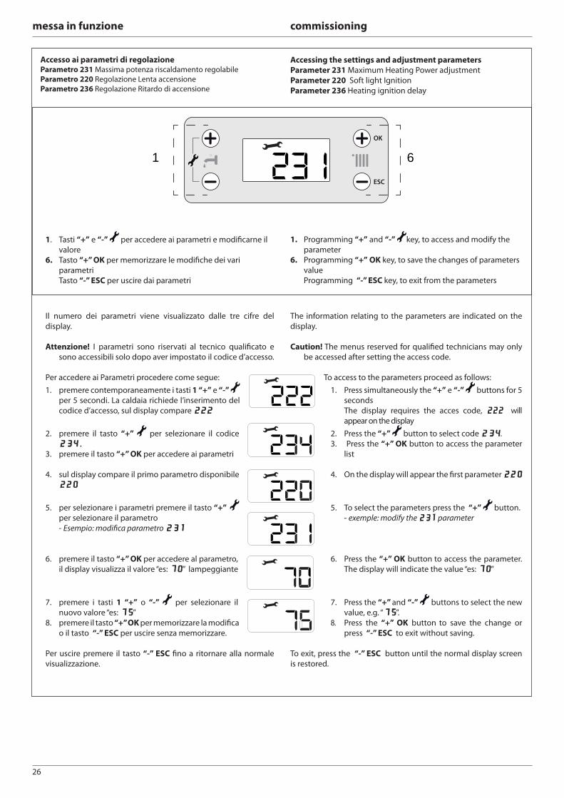
26
messa in funzione commissioning
Accesso ai parametri di regolazione Parametro 231 Massima potenza riscaldamento regolabile
Parametro 220 Regolazione Lenta accensione
Parametro 236 Regolazione Ritardo di accensione
Accessing the settings and adjustment parameters
Parameter 231 Maximum Heating Power adjustment
Parameter 220 Soft light Ignition
Parameter 236 Heating ignition delay
OK
ESC
1 6
1. Tasti “+” e “-” per accedere ai parametri e modifi carne il
valore
6. Tasto “+” OK per memorizzare le modifi che dei vari
parametri
Tasto “-” ESC per uscire dai parametri
1. Programming “+” and “-” key, to access and modify the
parameter
6. Programming “+” OK key, to save the changes of parameters
value
Programming “-” ESC key, to exit from the parameters
Il numero dei parametri viene visualizzato dalle tre cifre del
display.
Attenzione! I parametri sono riservati al tecnico qualifi cato e
sono accessibili solo dopo aver impostato il codice d’accesso.
Per accedere ai Parametri procedere come segue:
1. premere contemporaneamente i tasti 1 “+” e “-”
per 5 secondi. La caldaia richiede l’inserimento del
codice d’accesso, sul display compare 222222
2. premere il tasto “+” per selezionare il codice
234234..3. premere il tasto “+” OK per accedere ai parametri
4. sul display compare il primo parametro disponibile
220220
5. per selezionare i parametri premere il tasto “+”
per selezionare il parametro
- Esempio: modifi ca parametro 231231
6. premere il tasto “+” OK per accedere al parametro,
il display visualizza il valore “es: 7070” lampeggiante
7. premere i tasti 1 “+” o “-” per selezionare il
nuovo valore “es: 7575”
8. premere il tasto “+” OK per memorizzare la modifi ca
o il tasto “-” ESC per uscire senza memorizzare.
Per uscire premere il tasto “-” ESC fi no a ritornare alla normale
visualizzazione.
The information relating to the parameters are indicated on the
display.
Caution! The menus reserved for qualifi ed technicians may only
be accessed after setting the access code.
To access to the parameters proceed as follows:
1. Press simultaneously the “+” e “-” buttons for 5
seconds
The display requires the acces code, 222 222 will
appear on the display
2. Press the “+” button to select code 234234.
3. Press the “+” OK button to access the parameter
list
4. On the display will appear the fi rst parameter 220220
5. To select the parameters press the “+” button.
- exemple: modify the 231231 parameter
6. Press the “+” OK button to access the parameter.
The display will indicate the value “es: 7070”
7. Press the “+” and “-” buttons to select the new
value, e.g. “7575”.
8. Press the “+” OK button to save the change or
press “-” ESC to exit without saving.
To exit, press the “-” ESC button until the normal display screen
is restored.
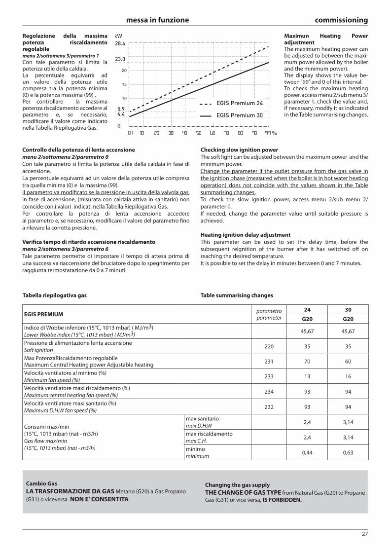
27
messa in funzione commissioning
Tabella riepilogativa gas Table summarising changes
EGIS PREMIUMparametroparameter
24 30
G20 G20
Indice di Wobbe inferiore (15°C, 1013 mbar) ( MJ/m3)
Lower Wobbe index (15°C, 1013 mbar) ( MJ/m3)45,67 45,67
Pressione di alimentazione lenta accensione
Soft ignition220 35 35
Max PotenzaRiscaldamento regolabileMaximum Central Heating power Adjustable heating
231 70 60
Velocità ventilatore al minimo (%)
Minimum fan speed (%)233 13 16
Velocità ventilatore maxi riscaldamento (%)
Maximum central heating fan speed (%)234 93 94
Velocità ventilatore maxi sanitario (%)
Maximum D.H.W fan speed (%)232 93 94
Consumi max/min
(15°C, 1013 mbar) (nat - m3/h)
Gas fl ow max/min
(15°C, 1013 mbar) (nat - m3/h)
max sanitario
max D.H.W2,4 3,14
max riscaldamento
max C.H.2,4 3,14
minimo
minimum0,44 0,63
Controllo della potenza di lenta accensione
menu 2/sottomenu 2/parametro 0
Con tale parametro si limita la potenza utile della caldaia in fase di
accensione.
La percentuale equivarrà ad un valore della potenza utile compresa
tra quella minima (0) e la massima (99).
Il parametro va modifi cato se la pressione in uscita della valvola gas,
in fase di accensione, (misurata con caldaia attiva in sanitario) non
coincide con i valori indicati nella Tabella Riepilogativa Gas.
Per controllare la potenza di lenta accensione accedere
al parametro e, se necessario, modifi care il valore del parametro fi no
a rilevare la corretta pressione.
Verifi ca tempo di ritardo accensione riscaldamento
menu 2/sottomenu 3/parametro 6
Tale parametro permette di impostare il tempo di attesa prima di
una successiva riaccensione del bruciatore dopo lo spegnimento per
raggiunta termostatazione da 0 a 7 minuti.
Checking slow ignition power
The soft light can be adjusted between the maximum power and the
minimum power.
Change the parameter if the outlet pressure from the gas valve in
the ignition phase (measured when the boiler is in hot water heating
operation) does not coincide with the values shown in the Table
summarising changes.
To check the slow ignition power, access menu 2/sub menu 2/
parameter 0.
If needed, change the parameter value until suitable pressure is
achieved.
Heating ignition delay adjustment
This parameter can be used to set the delay time, before the
subsequent reignition of the burner after it has switched off on
reaching the desired temperature.
It is possible to set the delay in minutes between 0 and 7 minutes.
Regolazione della massima potenza riscaldamento regolabile menu 2/sottomenu 3/parametro 1
Con tale parametro si limita la potenza utile della caldaia.La percentuale equivarrà ad un valore della potenza utile compresa tra la potenza minima (0) e la potenza massima (99) . Per controllare la massima potenza riscaldamento accedere al parametro e, se necessario, modifi care il valore come indicato nella Tabella Riepilogativa Gas.
Maximun Heating Power adjustment The maximum heating power can be adjusted to between the maxi-mum power allowed by the boiler and the minimum power). The display shows the value be-tween “99” and 0 of this interval.To check the maximum heating power, access menu 2/sub menu 3/parameter 1, check the value and, if necessary, modify it as indicated in the Table summarising changes.4.4
5.9
23.0
28.4
EGIS Premium 24
EGIS Premium 30
Cambio Gas
LA TRASFORMAZIONE DA GAS Metano (G20) a Gas Propano
(G31) o viceversa NON E’ CONSENTITA
Changing the gas supply
THE CHANGE OF GAS TYPE from Natural Gas (G20) to Propane
Gas (G31) or vice versa, IS FORBIDDEN.
28
messa in funzione commissioning
Funzione Auto
Funzione che permette alla caldaia di adattare autonomamente
il proprio regime di funzionamento (temperatura degli elementi
scaldanti) alle condizioni esterne per raggiungere e mantenere le
condizioni di temperatura ambiente richieste.
A seconda delle periferiche connesse la caldaia regola
autonomamente la temperatura di mandata.
Provvedere quindi al settaggio dei vari parametri interessati (vedi
menu regolazioni).
La Funzione Auto si attiva tramite il parametro 224.
Per maggiori informazioni consultare il Manuale di
Termoregolazione di ARISTON.
Esempio 1:
IMPIANTO SINGOLA ZONA (ALTA TEMPERATURA) CON TERMOSTATO AMBIENTE ON/OFF.
In questo caso è necessario impostare i seguenti parametri:
4 2 1 - Attivazione Termoregolazione tramite sensori
- selezionare 01 = Dispositivi On/Off
Auto function
This is a function which enables the boiler to automatically adapt its
operation routine (the temperature of the heating elements) in line
with the outdoor conditions, in order to achieve and maintain the
requested room temperature conditions.
Depending on the peripheral units connected the boiler adjusts its
fl ow temperature automatically.
The various corresponding parameters should therefore be set (see
adjustments menu).
To activate the function modify the parameter 224
For further information please refer to the ARISTON temperature
adjustment manual.
Example 1:
SINGLE ZONE SYSTEM (HIGH-TEMPERATURE) WITH ON/OFF ROOM THERMOSTAT:
In this case the following parameters must be set:
4 21 - Activation of temperature adjustment using sensors
- Select 04 = Basic temperature adjustment
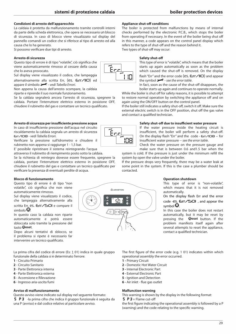
29
sistemi di protezione caldaia boiler protection devices
Condizioni di arresto dell’apparecchio
La caldaia è protetta da malfunzionamento tramite controlli interni
da parte della scheda elettronica, che opera se necessario blocco
di sicurezza. In caso di blocco viene visualizzato sul display del
pannello comandi un codice che si riferisce al tipo di arresto ed alla
causa che lo ha generato.
Si possono verifi care due tipi di arresto.
Arresto di sicurezza
Questo tipo di errore è di tipo “volatile”, ciò signifi ca che
viene automaticamente rimosso al cessare della causa
che lo aveva provocato.
Sul display viene visualizzato il codice, che lampeggia
alternativamente alla scritta Err, (es. Err/110) ed
appare il simbolo - vedi Tabella Errori.
Non appena la causa dell’arresto scompare, la caldaia
riparte e riprende il suo normale funzionamento.
Se la caldaia segnalerà ancora l’arresto di sicurezza, spegnere la
caldaia. Portare l’interruttore elettrico esterno in posizione OFF,
chiudere il rubinetto del gas e contattare un tecnico qualifi cato.
Arresto di sicurezza per insuffi ciente pressione acqua
In caso di insuffi ciente pressione dell’acqua nel circuito
riscaldamento la caldaia segnala un arresto di sicurezza
Err/108 - vedi Tabella Errori.
Verifi care la pressione sull’idrometro e chiudere il
rubinetto non appena si raggiunge 1 - 1,5 bar.
E’ possibile ripristinare il sistema reintegrando l’acqua
attraverso il rubinetto di riempimento posto sotto la caldaia.
Se la richiesta di reintegro dovesse essere frequente, spegnere la
caldaia, portare l’interruttore elettrico esterno in posizione OFF,
chiudere il rubinetto del gas e contattare un tecnico qualifi cato per
verifi care la presenza di eventuali perdite di acqua.
Blocco di funzionamento
Questo tipo di errore è di tipo “non
volatile”, ciò signifi ca che non viene
automaticamente rimosso.
Sul display viene visualizzato il codice,
che lampeggia alternativamente alla
scritta Err, es. Err/501 e compare il
simbolo .
In questo caso la caldaia non riparte
automaticamente e potrà essere
sbloccata solo tramite la pressione del
tasto .
Dopo alcuni tentativi di sblocco, se
il problema si ripete è necessario far
intervenire un tecnico qualifi cato.
OK
ESC
Appliance shut-off conditions
The boiler is protected from malfunctions by means of internal
checks performed by the electronic P.C.B., which stops the boiler
from operating if necessary. In the event of the boiler being shut off
in this manner, a code appears on the control panel display which
refers to the type of shut-off and the reason behind it.
Two types of shut-off may occur:
Safety shut-off
This type of error is “volatile”, which means that the boiler
starts up again automatically as soon as the problem
which caused the shut-off is removed. On the display
fl ash “Err” and the error code (es. Err/110) and appear
the symbol - see the error table.
In fact, soon as the cause of the shut-off disappears, the
boiler starts up again and continues to operate normally.
While the boiler is shut off for safety reasons, it is possible to attempt
to restore normal operation by switching the appliance off and on
again using the ON/OFF button on the control panel.
If the boiler still indicates a safety shut-off , switch it off . Make sure the
external electric switch is in the OFF position, shut off the gas valve
and contact a qualifi ed technician.
Safety shut-off due to insuffi cient water pressure
If the water pressure inside the heating circuit is
insuffi cient, the boiler will perform a safety shut-off .
On the display fl ash “Err” and the code - Err/108 - for
Insuffi cient water pressure -- see the error table.
Check the water pressure on the pressure gauge and
make sure that is between 0.6 and1.5 bar when the
system is cold. If the pressure is just under the minimum refi ll the
system by open the valve under the boiler.
If the pressure drops very frequently, there may be a water leak at
some point in the system. If this is the case a plumber should be
contacted.
Operation shutdown
This type of error is “non-volatile”,
which means that it is not removed
automatically.
On the display fl ash Err and the error
code -es. Err/501 , and appear the
symbol .
In this case the boiler does not restart
automatically, but it may be reset by
pressing the button. If the
problem manifests itself again after
several attempts to reset the appliance,
contact a qualifi ed technician.
La prima cifra del codice di errore (Es: 1 01) indica in quale gruppo
funzionale della caldaia si è determinato l’errore:
1 - Circuito Primario
2 - Circuito Sanitario
3 - Parte Elettronica interna
4 - Parte Elettronica esterna
5 - Accensione e Rilevazione
6 - Ingresso aria-uscita fumi
Avviso di malfunzionamento
Questo avviso viene indicato sul display nel seguente formato:
5 P3 5 P3 -la prima cifra che indica il gruppo funzionale è seguita da
una P (avviso) e dal codice relativo al particolare avviso.
The fi rst fi gure of the error code (e.g. 1 01) indicates within which
operational assembly the error occurred.
1 - Primary Circuit
2 - Domestic Hot Water Circuit
3 - Internal Electronic Part
4 - External Electronic Part
5 - Ignition and Detection
6 - Air inlet - fl ue gas outlet
Malfunction warning
This warning is shown by the display in the following format:
5 P35 P3 = Flame cut-off
the fi rst fi gure indicating the operational assembly is followed by a P
(warning) and the code relating to the specifi c warning.
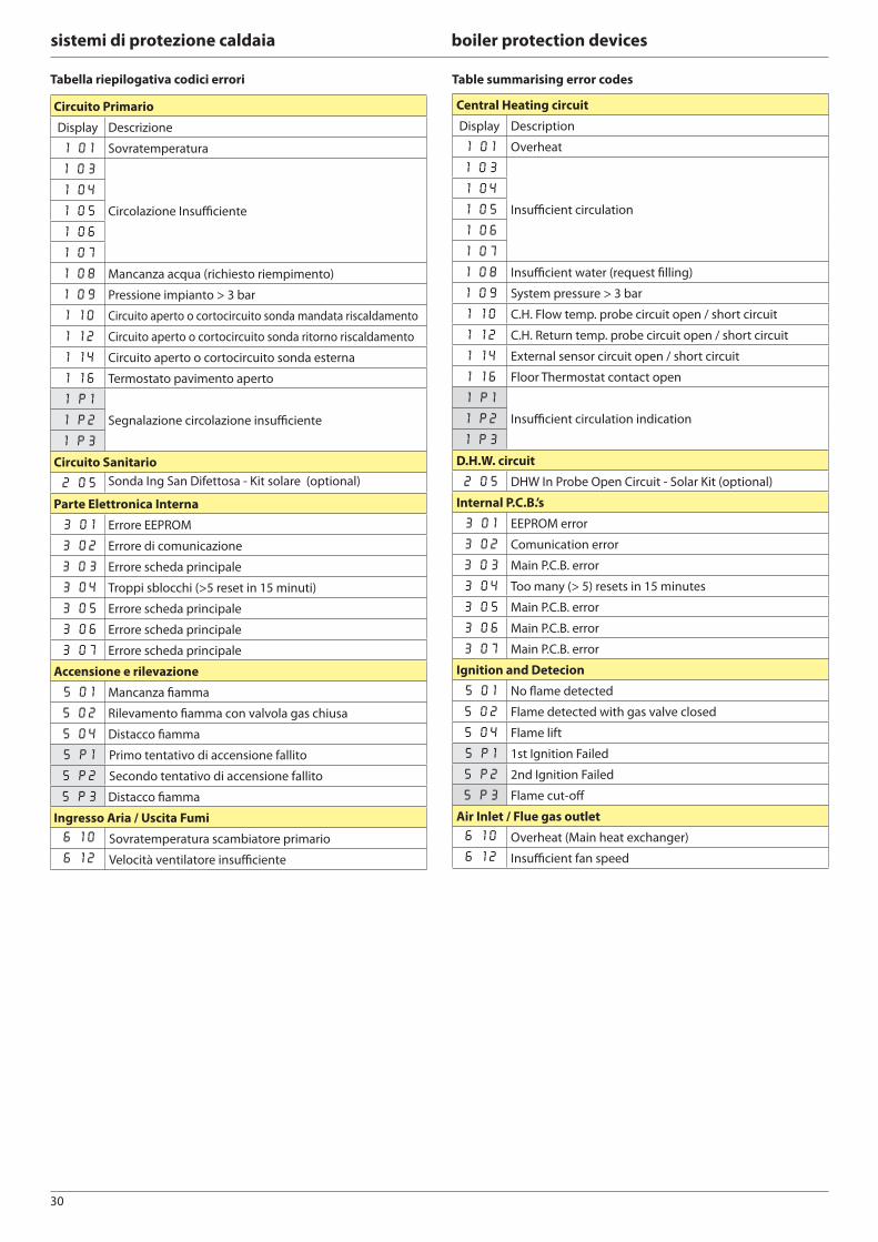
30
sistemi di protezione caldaia boiler protection devices
Central Heating circuit
Display Description
1 01 Overheat
1 03
Insuffi cient circulation
1 04
1 05
1 06
1 07
1 08 Insuffi cient water (request fi lling)
1 09 System pressure > 3 bar
1 10 C.H. Flow temp. probe circuit open / short circuit
1 12 C.H. Return temp. probe circuit open / short circuit
1 14 External sensor circuit open / short circuit
1 16 Floor Thermostat contact open
1 P1
Insuffi cient circulation indication1 P2
1 P3
D.H.W. circuit
2 05 DHW In Probe Open Circuit - Solar Kit (optional)
Internal P.C.B.’s
3 01 EEPROM error
3 02 Comunication error
3 03 Main P.C.B. error
3 04 Too many (> 5) resets in 15 minutes
3 05 Main P.C.B. error
3 06 Main P.C.B. error
3 07 Main P.C.B. error
Ignition and Detecion
5 01 No fl ame detected
5 02 Flame detected with gas valve closed
5 04 Flame lift
5 P1 1st Ignition Failed
5 P2 2nd Ignition Failed
5 P3 Flame cut-off
Air Inlet / Flue gas outlet
6 10 Overheat (Main heat exchanger)
6 12 Insuffi cient fan speed
Circuito Primario
Display Descrizione
1 01 Sovratemperatura
1 03
Circolazione Insuffi ciente
1 04
1 05
1 06
1 07
1 08 Mancanza acqua (richiesto riempimento)
1 09 Pressione impianto > 3 bar
1 10 Circuito aperto o cortocircuito sonda mandata riscaldamento
1 12 Circuito aperto o cortocircuito sonda ritorno riscaldamento
1 14 Circuito aperto o cortocircuito sonda esterna
1 16 Termostato pavimento aperto
1 P1
Segnalazione circolazione insuffi ciente1 P2
1 P3
Circuito Sanitario
2 05 Sonda Ing San Difettosa - Kit solare (optional)
Parte Elettronica Interna
3 01 Errore EEPROM
3 02 Errore di comunicazione
3 03 Errore scheda principale
3 04 Troppi sblocchi (>5 reset in 15 minuti)
3 05 Errore scheda principale
3 06 Errore scheda principale
3 07 Errore scheda principale
Accensione e rilevazione
5 01 Mancanza fi amma
5 02 Rilevamento fi amma con valvola gas chiusa
5 04 Distacco fi amma
5 P1 Primo tentativo di accensione fallito
5 P2 Secondo tentativo di accensione fallito
5 P3 Distacco fi amma
Ingresso Aria / Uscita Fumi
6 10 Sovratemperatura scambiatore primario
6 12 Velocità ventilatore insuffi ciente
Tabella riepilogativa codici errori Table summarising error codes
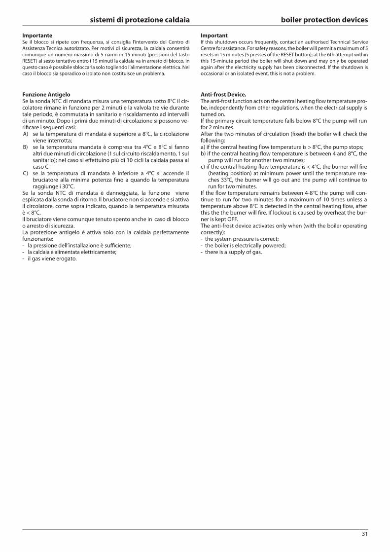
31
sistemi di protezione caldaia boiler protection devices
Funzione AntigeloSe la sonda NTC di mandata misura una temperatura sotto 8°C il cir-colatore rimane in funzione per 2 minuti e la valvola tre vie durante tale periodo, è commutata in sanitario e riscaldamento ad intervalli di un minuto. Dopo i primi due minuti di circolazione si possono ve-rifi care i seguenti casi:A) se la temperatura di mandata è superiore a 8°C, la circolazione
viene interrotta;B) se la temperatura mandata è compresa tra 4°C e 8°C si fanno
altri due minuti di circolazione (1 sul circuito riscaldamento, 1 sul sanitario); nel caso si eff ettuino più di 10 cicli la caldaia passa al caso C
C) se la temperatura di mandata è inferiore a 4°C si accende il bruciatore alla minima potenza fi no a quando la temperatura raggiunge i 30°C.
Se la sonda NTC di mandata è danneggiata, la funzione viene esplicata dalla sonda di ritorno. Il bruciatore non si accende e si attiva il circolatore, come sopra indicato, quando la temperatura misurata è < 8°C.Il bruciatore viene comunque tenuto spento anche in caso di blocco o arresto di sicurezza.La protezione antigelo è attiva solo con la caldaia perfettamente funzionante:- la pressione dell’installazione è suffi ciente;- la caldaia è alimentata elettricamente;- il gas viene erogato.
Anti-frost Device. The anti-frost function acts on the central heating fl ow temperature pro-be, independently from other regulations, when the electrical supply is turned on.If the primary circuit temperature falls below 8°C the pump will run for 2 minutes.After the two minutes of circulation (fi xed) the boiler will check the following:a) if the central heating fl ow temperature is > 8°C, the pump stops;b) if the central heating fl ow temperature is between 4 and 8°C, the
pump will run for another two minutes;c) if the central heating fl ow temperature is < 4°C, the burner will fi re
(heating position) at minimum power until the temperature rea-ches 33°C, the burner will go out and the pump will continue to run for two minutes.
If the fl ow temperature remains between 4-8°C the pump will con-tinue to run for two minutes for a maximum of 10 times unless a temperature above 8°C is detected in the central heating fl ow, after this the the burner will fi re. If lockout is caused by overheat the bur-ner is kept OFF. The anti-frost device activates only when (with the boiler operating correctly):- the system pressure is correct;- the boiler is electrically powered;- there is a supply of gas.
ImportanteSe il blocco si ripete con frequenza, si consiglia l’intervento del Centro di
Assistenza Tecnica autorizzato. Per motivi di sicurezza, la caldaia consentirà
comunque un numero massimo di 5 riarmi in 15 minuti (pressioni del tasto
RESET) al sesto tentativo entro i 15 minuti la caldaia va in arresto di blocco, in
questo caso è possibile sbloccarla solo togliendo l’alimentazione elettrica. Nel
caso il blocco sia sporadico o isolato non costituisce un problema.
ImportantIf this shutdown occurs frequently, contact an authorised Technical Service
Centre for assistance. For safety reasons, the boiler will permit a maximum of 5
resets in 15 minutes (5 presses of the RESET button); at the 6th attempt within
this 15-minute period the boiler will shut down and may only be operated
again after the electricity supply has been disconnected. If the shutdown is
occasional or an isolated event, this is not a problem.
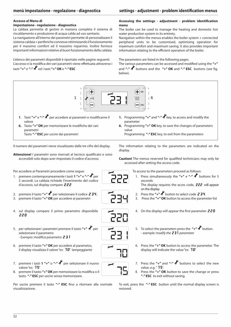
32
menù impostazione - regolazione - diagnostica settings - adjustment - problem identifi cation menus
Accesso al Menu di
impostazione - regolazione - diagnostica
La caldaia permette di gestire in maniera completa il sistema di
riscaldamento e produzione di acqua calda ad uso sanitario.
La navigazione all’interno dei parametri permette di personalizzare il
sistema caldaia + periferiche connesse ottimizzando il funzionamento
per il massimo comfort ed il massimo risparmio. Inoltre fornisce
importanti informazioni relative al buon funzionamento della caldaia.
Accessing the settings - adjustment - problem identifi cation
menu
The boiler can be used to manage the heating and domestic hot
water production system in its entirety.
Navigation within the menus enables the boiler system + connected
peripheral units to be customised, optimising operation for
maximum comfort and maximum saving. It also provides important
information relating to the effi cient operation of the boiler.
L’elenco dei parametri disponibili è riportato nelle pagine seguenti.
L’accesso e la modifi ca dei vari parametri viene eff ettuata attraverso i
tasti “+” e “-” ed i tasti “+” OK e “-” ESC
The parameters are listed in the following pages.
The various parameters can be accessed and modifi ed using the “+”
and “-” buttons and the “+” OK and “-” ESC buttons (see fi g.
below).
OK
ESC
1 6
1. Tasti “+” e “-” per accedere ai parametri e modifi carne il
valore
6. Tasto “+” OK per memorizzare le modifi che dei vari
parametri
Tasto “-” ESC per uscire dai parametri
1. Programming “+” and “-” key, to access and modify the
parameter
6. Programming “+” OK key, to save the changes of parameters
value
Programming “-” ESC key, to exit from the parameters
Il numero dei parametri viene visualizzato dalle tre cifre del display.
Attenzione! I parametri sono riservati al tecnico qualifi cato e sono
accessibili solo dopo aver impostato il codice d’accesso.
Per accedere ai Parametri procedere come segue:
1. premere contemporaneamente i tasti 1 “+” e “-” per
5 secondi. La caldaia richiede l’inserimento del codice
d’accesso, sul display compare 222222
2. premere il tasto “+” per selezionare il codice 234234..3. premere il tasto “+” OK per accedere ai parametri
4. sul display compare il primo parametro disponibile
220220
5. per selezionare i parametri premere il tasto “+” per
selezionare il parametro
- Esempio: modifi ca parametro 231231
6. premere il tasto “+” OK per accedere al parametro,
il display visualizza il valore “es: 7070” lampeggiante
7. premere i tasti 1 “+” o “-” per selezionare il nuovo
valore “es: 7575”
8. premere il tasto “+” OK per memorizzare la modifi ca o il
tasto “-” ESC per uscire senza memorizzare.
Per uscire premere il tasto “-” ESC fi no a ritornare alla normale
visualizzazione.
The information relating to the parameters are indicated on the
display.
Caution! The menus reserved for qualifi ed technicians may only be
accessed after setting the access code.
To access to the parameters proceed as follows:
1. Press simultaneously the “+” e “-” buttons for 5
seconds
The display requires the acces code, 222 222 will appear
on the display
2. Press the “+” button to select code 234234.
3. Press the “+” OK button to access the parameter list
4. On the display will appear the fi rst parameter 220220
5. To select the parameters press the “+” button.
- exemple: modify the 231231 parameter
6. Press the “+” OK button to access the parameter. The
display will indicate the value “es: 7070”
7. Press the “+” and “-” buttons to select the new
value, e.g. “7575”.
8. Press the “+” OK button to save the change or press
“-” ESC to exit without saving.
To exit, press the “-” ESC button until the normal display screen is
restored.
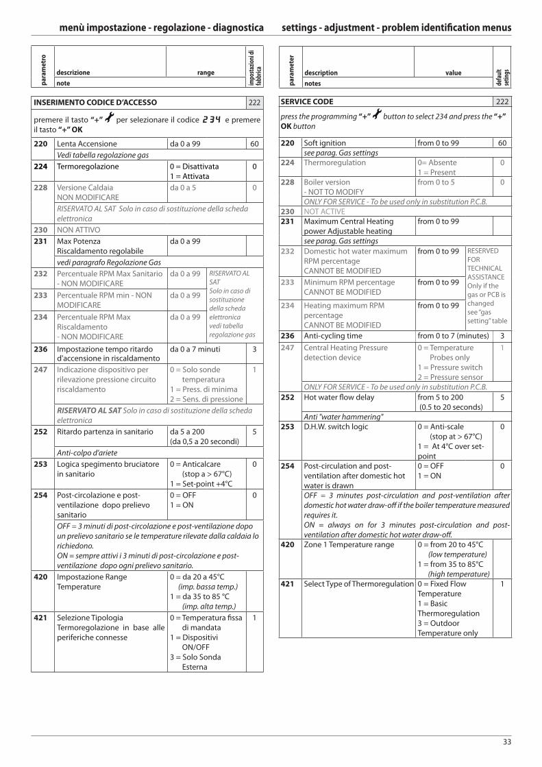
33
menù impostazione - regolazione - diagnostica settings - adjustment - problem identifi cation menus
INSERIMENTO CODICE D’ACCESSO 222
premere il tasto “+” per selezionare il codice 234 234 e premere
il tasto “+” OK
220 Lenta Accensione da 0 a 99 60
Vedi tabella regolazione gas
224 Termoregolazione 0 = Disattivata
1 = Attivata
0
228 Versione Caldaia
NON MODIFICARE
da 0 a 5 0
RISERVATO AL SAT Solo in caso di sostituzione della scheda
elettronica
230 NON ATTIVO
231 Max Potenza
Riscaldamento regolabile
da 0 a 99
vedi paragrafo Regolazione Gas
232 Percentuale RPM Max Sanitario
- NON MODIFICARE
da 0 a 99 RISERVATO AL
SAT
Solo in caso di
sostituzione
della scheda
elettronica
vedi tabella
regolazione gas
233 Percentuale RPM min - NON
MODIFICARE
da 0 a 99
234 Percentuale RPM Max
Riscaldamento
- NON MODIFICARE
da 0 a 99
236 Impostazione tempo ritardo d'accensione in riscaldamento
da 0 a 7 minuti 3
247 Indicazione dispositivo per
rilevazione pressione circuito
riscaldamento
0 = Solo sonde
temperatura
1 = Press. di minima
2 = Sens. di pressione
1
RISERVATO AL SAT Solo in caso di sostituzione della scheda
elettronica
252 Ritardo partenza in sanitario da 5 a 200
(da 0,5 a 20 secondi)
5
Anti-colpo d’ariete
253 Logica spegimento bruciatore
in sanitario
0 = Anticalcare
(stop a > 67°C)
1 = Set-point +4°C
0
254 Post-circolazione e post-
ventilazione dopo prelievo
sanitario
0 = OFF
1 = ON
0
OFF = 3 minuti di post-circolazione e post-ventilazione dopo
un prelievo sanitario se le temperature rilevate dalla caldaia lo
richiedono.
ON = sempre attivi i 3 minuti di post-circolazione e post-
ventilazione dopo ogni prelievo sanitario.
420 Impostazione Range
Temperature
0 = da 20 a 45°C
(imp. bassa temp.)
1 = da 35 to 85 °C
(imp. alta temp.)
421 Selezione Tipologia
Termoregolazione in base alle
periferiche connesse
0 = Temperatura fi ssa
di mandata
1 = Dispositivi
ON/OFF
3 = Solo Sonda
Esterna
1
pa
ram
etr
o
descrizione range
impo
staz
ioni
di
fabb
rica
note
SERVICE CODE 222
press the programming “+” button to select 234 and press the “+”
OK button
220 Soft ignition from 0 to 99 60see parag. Gas settings
224 Thermoregulation 0= Absente
1 = Present
0
228 Boiler version
- NOT TO MODIFY
from 0 to 5 0
ONLY FOR SERVICE - To be used only in substitution P.C.B.230 NOT ACTIVE231 Maximum Central Heating
power Adjustable heating
from 0 to 99
see parag. Gas settings
232 Domestic hot water maximum
RPM percentage
CANNOT BE MODIFIED
from 0 to 99 RESERVED
FOR
TECHNICAL
ASSISTANCE
Only if the
gas or PCB is
changed
see “gas
setting” table
233 Minimum RPM percentage
CANNOT BE MODIFIED
from 0 to 99
234 Heating maximum RPM
percentage
CANNOT BE MODIFIED
from 0 to 99
236 Anti-cycling time from 0 to 7 (minutes) 3
247 Central Heating Pressure
detection device
0 = Temperature
Probes only
1 = Pressure switch
2 = Pressure sensor
1
ONLY FOR SERVICE - To be used only in substitution P.C.B.
252 Hot water fl ow delay from 5 to 200
(0.5 to 20 seconds)
5
Anti "water hammering"253 D.H.W. switch logic 0 = Anti-scale
(stop at > 67°C)
1 = At 4°C over set-
point
0
254 Post-circulation and post-
ventilation after domestic hot
water is drawn
0 = OFF
1 = ON
0
OFF = 3 minutes post-circulation and post-ventilation after
domestic hot water draw-off if the boiler temperature measured
requires it.
ON = always on for 3 minutes post-circulation and post-
ventilation after domestic hot water draw-off .420 Zone 1 Temperature range 0 = from 20 to 45°C
(low temperature)
1 = from 35 to 85°C
(high temperature)421 Select Type of Thermoregulation 0 = Fixed Flow
Temperature
1 = Basic
Thermoregulation
3 = Outdoor
Temperature only
1
pa
ram
ete
r
description value
defa
ult
setin
gs
notes
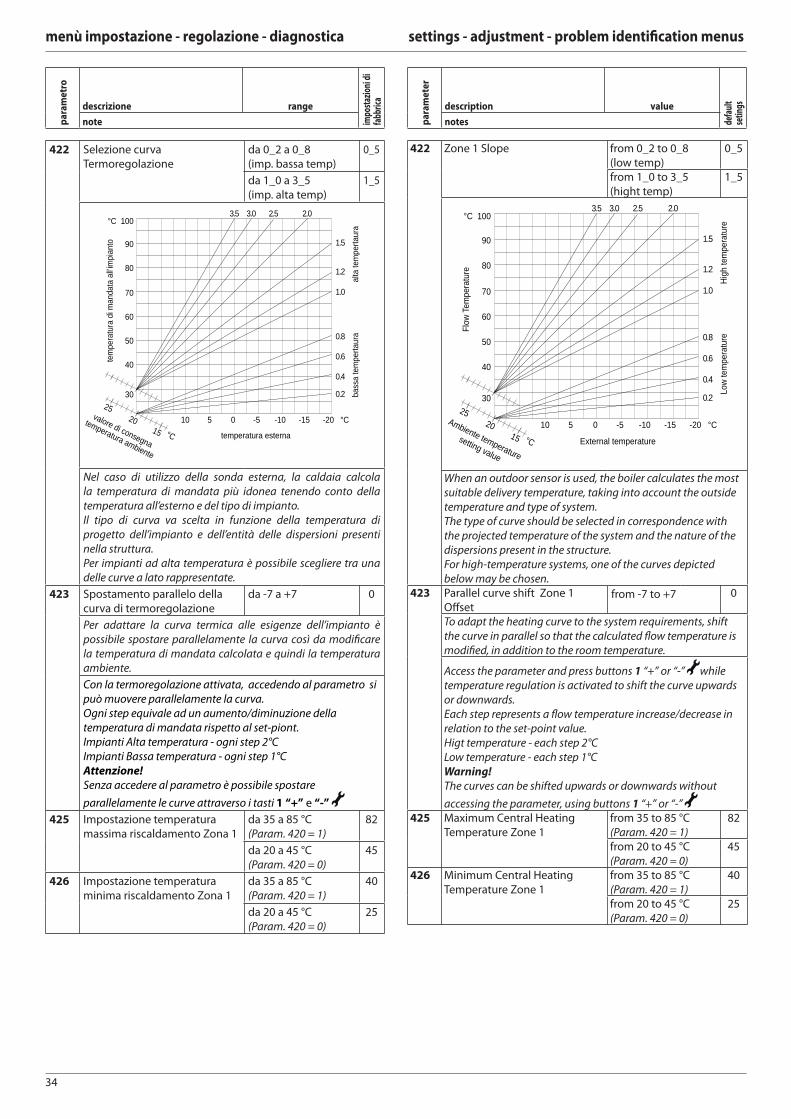
34
menù impostazione - regolazione - diagnostica settings - adjustment - problem identifi cation menus
422 Selezione curva
Termoregolazione
da 0_2 a 0_8
(imp. bassa temp)
0_5
da 1_0 a 3_5
(imp. alta temp)
1_5
tem
pera
tura
di m
anda
ta a
ll’im
pian
to
bass
a te
mpe
rtaur
a al
ta te
mpe
rtaur
a
temperatura esterna
valore di consegna
temperatura ambiente
°C
20
25
15
30
40
50
60
70
80
90
100 °C
10
2.5 3.0 3.5 2.0
1.5
1.2
1.0
0.8
0.6
0.4
0.2
5 0 -5 -10 -15 -20 °C
Nel caso di utilizzo della sonda esterna, la caldaia calcola
la temperatura di mandata più idonea tenendo conto della
temperatura all’esterno e del tipo di impianto.
Il tipo di curva va scelta in funzione della temperatura di
progetto dell’impianto e dell’entità delle dispersioni presenti
nella struttura.
Per impianti ad alta temperatura è possibile scegliere tra una
delle curve a lato rappresentate.
423 Spostamento parallelo della
curva di termoregolazione
da -7 a +7 0
Per adattare la curva termica alle esigenze dell’impianto è
possibile spostare parallelamente la curva così da modifi care
la temperatura di mandata calcolata e quindi la temperatura
ambiente.
Con la termoregolazione attivata, accedendo al parametro si
può muovere parallelamente la curva.
Ogni step equivale ad un aumento/diminuzione della
temperatura di mandata rispetto al set-piont.
Impianti Alta temperatura - ogni step 2°C
Impianti Bassa temperatura - ogni step 1°C
Attenzione!
Senza accedere al parametro è possibile spostare
parallelamente le curve attraverso i tasti 1 “+” e “-”
425 Impostazione temperatura
massima riscaldamento Zona 1
da 35 a 85 °C
(Param. 420 = 1)
82
da 20 a 45 °C
(Param. 420 = 0)
45
426 Impostazione temperatura
minima riscaldamento Zona 1
da 35 a 85 °C
(Param. 420 = 1)
40
da 20 a 45 °C
(Param. 420 = 0)
25
422 Zone 1 Slope from 0_2 to 0_8
(low temp)
0_5
from 1_0 to 3_5
(hight temp)
1_5
Flow
Tem
pera
ture
Low
tem
pera
ture
High
tem
pera
ture
External temperature
Ambiente temperature
setting value
°C
20
25
15
30
40
50
60
70
80
90
100 °C
10
2.5 3.0 3.5 2.0
1.5
1.2
1.0
0.8
0.6
0.4
0.2
5 0 -5 -10 -15 -20 °C
When an outdoor sensor is used, the boiler calculates the most
suitable delivery temperature, taking into account the outside
temperature and type of system.
The type of curve should be selected in correspondence with
the projected temperature of the system and the nature of the
dispersions present in the structure.
For high-temperature systems, one of the curves depicted
below may be chosen.423 Parallel curve shift Zone 1
Off setfrom -7 to +7 0
To adapt the heating curve to the system requirements, shift
the curve in parallel so that the calculated fl ow temperature is
modifi ed, in addition to the room temperature.
Access the parameter and press buttons 1 “+” or “-” while
temperature regulation is activated to shift the curve upwards
or downwards.
Each step represents a fl ow temperature increase/decrease in
relation to the set-point value.
Higt temperature - each step 2°C
Low temperature - each step 1°C
Warning!
The curves can be shifted upwards or downwards without
accessing the parameter, using buttons 1 “+” or “-” 425 Maximum Central Heating
Temperature Zone 1
from 35 to 85 °C
(Param. 420 = 1)
82
from 20 to 45 °C
(Param. 420 = 0)
45
426 Minimum Central Heating
Temperature Zone 1
from 35 to 85 °C
(Param. 420 = 1)
40
from 20 to 45 °C
(Param. 420 = 0)
25
pa
ram
etr
o
descrizione range
impo
staz
ioni
di
fabb
rica
note pa
ram
ete
r
description value
defa
ult
setin
gs
notes
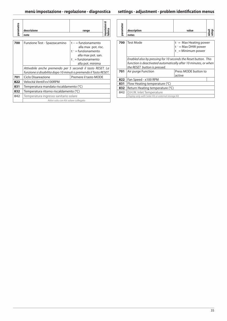
35
menù impostazione - regolazione - diagnostica settings - adjustment - problem identifi cation menus
700 Funzione Test - Spazzacamino t -- = funzionamento
alla max pot. risc.
t -- = funzionamento
alla max pot. san.
t --
= funzionamento
alla pot. minima
Attivabile anche premendo per 5 secondi il tasto RESET. La
funzione si disabilita dopo 10 minuti o premendo il Tasto RESET.
701 Ciclo Disareazione Premere il tasto MODE
822 Velocità Ventil\rx100RPM
831 Temperatura mandata riscaldamento (°C)
832 Temperatura ritorno riscaldamento (°C)
842 Temperatura ingresso sanitario solare
Attivi solo con Kit solare collegato
700 Test Mode t - = Max Heating power
t -- = Max DHW power
t --
= Minimum power
Enabled also by pressing for 10 seconds the Reset button. This
function is deactivated automatically after 10 minutes, or when
the RESET button is pressed.701 Air purge Function Press MODE button to
active 822 Fan Speed - x100 RPM831 Flow Heating temperature (°C)
832 Return Heating temperature (°C)
842 D.H.W. Inlet TemperatureDisplay only with Solar Kit or external storage Kit
pa
ram
ete
r
description value
defa
ult
setin
gs
notespa
ram
etr
o
descrizione range
impo
staz
ioni
di
fabb
rica
note
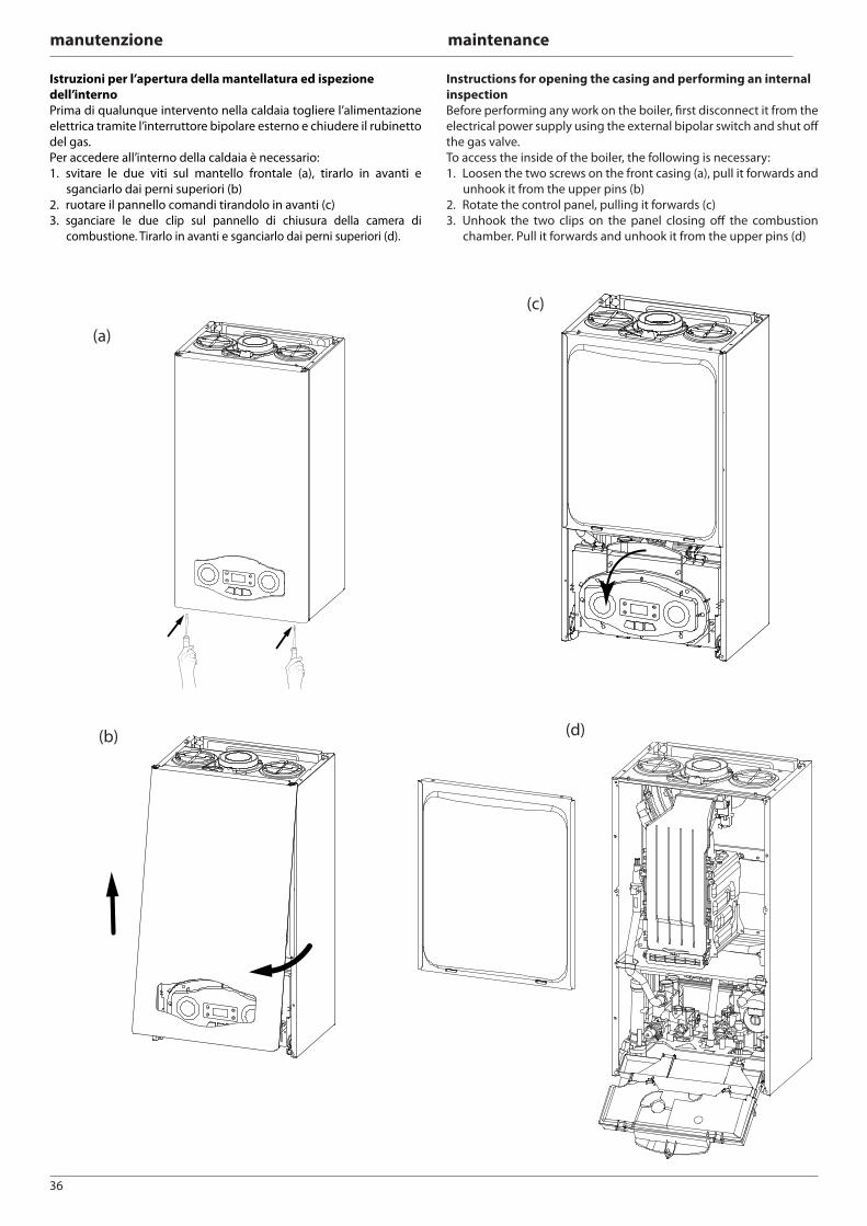
36
manutenzione maintenance
Istruzioni per l’apertura della mantellatura ed ispezione
dell’interno
Prima di qualunque intervento nella caldaia togliere l’alimentazione
elettrica tramite l’interruttore bipolare esterno e chiudere il rubinetto
del gas.
Per accedere all’interno della caldaia è necessario:
1. svitare le due viti sul mantello frontale (a), tirarlo in avanti e
sganciarlo dai perni superiori (b)
2. ruotare il pannello comandi tirandolo in avanti (c)
3. sganciare le due clip sul pannello di chiusura della camera di
combustione. Tirarlo in avanti e sganciarlo dai perni superiori (d).
Instructions for opening the casing and performing an internal
inspection
Before performing any work on the boiler, fi rst disconnect it from the
electrical power supply using the external bipolar switch and shut off
the gas valve.
To access the inside of the boiler, the following is necessary:
1. Loosen the two screws on the front casing (a), pull it forwards and
unhook it from the upper pins (b)
2. Rotate the control panel, pulling it forwards (c)
3. Unhook the two clips on the panel closing off the combustion
chamber. Pull it forwards and unhook it from the upper pins (d)
(a)
(c)
(d) (b)
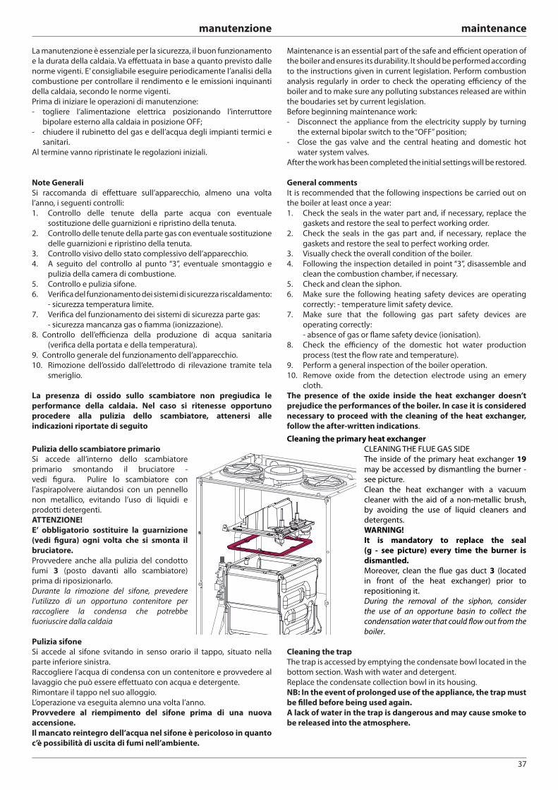
37
manutenzione maintenance
La manutenzione è essenziale per la sicurezza, il buon funzionamento
e la durata della caldaia. Va eff ettuata in base a quanto previsto dalle
norme vigenti. E’ consigliabile eseguire periodicamente l’analisi della
combustione per controllare il rendimento e le emissioni inquinanti
della caldaia, secondo le norme vigenti.
Prima di iniziare le operazioni di manutenzione:
- togliere l’alimentazione elettrica posizionando l’interruttore
bipolare esterno alla caldaia in posizione OFF;
- chiudere il rubinetto del gas e dell’acqua degli impianti termici e
sanitari.
Al termine vanno ripristinate le regolazioni iniziali.
Note Generali
Si raccomanda di eff ettuare sull’apparecchio, almeno una volta
l’anno, i seguenti controlli:
1. Controllo delle tenute della parte acqua con eventuale
sostituzione delle guarnizioni e ripristino della tenuta.
2. Controllo delle tenute della parte gas con eventuale sostituzione
delle guarnizioni e ripristino della tenuta.
3. Controllo visivo dello stato complessivo dell’apparecchio.
4. A seguito del controllo al punto “3”, eventuale smontaggio e
pulizia della camera di combustione.
5. Controllo e pulizia sifone.
6. Verifi ca del funzionamento dei sistemi di sicurezza riscaldamento:
- sicurezza temperatura limite.
7. Verifi ca del funzionamento dei sistemi di sicurezza parte gas:
- sicurezza mancanza gas o fi amma (ionizzazione).
8. Controllo dell’effi cienza della produzione di acqua sanitaria
(verifi ca della portata e della temperatura).
9. Controllo generale del funzionamento dell’apparecchio.
10. Rimozione dell’ossido dall’elettrodo di rilevazione tramite tela
smeriglio.
La presenza di ossido sullo scambiatore non pregiudica le
performance della caldaia. Nel caso si ritenesse opportuno
procedere alla pulizia dello scambiatore, attenersi alle
indicazioni riportate di seguito
Pulizia dello scambiatore primario
Si accede all’interno dello scambiatore
primario smontando il bruciatore -
vedi fi gura. Pulire lo scambiatore con
l’aspirapolvere aiutandosi con un pennello
non metallico, evitando l’uso di liquidi e
prodotti detergenti.
ATTENZIONE!
E’ obbligatorio sostituire la guarnizione
(vedi fi gura) ogni volta che si smonta il
bruciatore.
Provvedere anche alla pulizia del condotto
fumi 3 (posto davanti allo scambiatore)
prima di riposizionarlo.
Durante la rimozione del sifone, prevedere
l’utilizzo di un opportuno contenitore per
raccogliere la condensa che potrebbe
fuoriuscire dalla caldaia
Pulizia sifone
Si accede al sifone svitando in senso orario il tappo, situato nella
parte inferiore sinistra.
Raccogliere l’acqua di condensa con un contenitore e provvedere al
lavaggio che può essere effettuato con acqua e detergente.
Rimontare il tappo nel suo alloggio.
L’operazione va eseguita alemno una volta l’anno.
Provvedere al riempimento del sifone prima di una nuova
accensione.
Il mancato reintegro dell’acqua nel sifone è pericoloso in quanto
c’è possibilità di uscita di fumi nell’ambiente.
Maintenance is an essential part of the safe and effi cient operation of
the boiler and ensures its durability. It should be performed according
to the instructions given in current legislation. Perform combustion
analysis regularly in order to check the operating effi ciency of the
boiler and to make sure any polluting substances released are within
the boudaries set by current legislation.
Before beginning maintenance work:
- Disconnect the appliance from the electricity supply by turning
the external bipolar switch to the “OFF” position;
- Close the gas valve and the central heating and domestic hot
water system valves.
After the work has been completed the initial settings will be restored.
General comments
It is recommended that the following inspections be carried out on
the boiler at least once a year:
1. Check the seals in the water part and, if necessary, replace the
gaskets and restore the seal to perfect working order.
2. Check the seals in the gas part and, if necessary, replace the
gaskets and restore the seal to perfect working order.
3. Visually check the overall condition of the boiler.
4. Following the inspection detailed in point “3”, disassemble and
clean the combustion chamber, if necessary.
5. Check and clean the siphon.
6. Make sure the following heating safety devices are operating
correctly: - temperature limit safety device.
7. Make sure that the following gas part safety devices are
operating correctly:
- absence of gas or fl ame safety device (ionisation).
8. Check the effi ciency of the domestic hot water production
process (test the fl ow rate and temperature).
9. Perform a general inspection of the boiler operation.
10. Remove oxide from the detection electrode using an emery
cloth.
The presence of the oxide inside the heat exchanger doesn’t
prejudice the performances of the boiler. In case it is considered
necessary to proceed with the cleaning of the heat exchanger,
follow the after-written indications.
Cleaning the primary heat exchanger
CLEANING THE FLUE GAS SIDE
The inside of the primary heat exchanger 19
may be accessed by dismantling the burner -
see picture.
Clean the heat exchanger with a vacuum
cleaner with the aid of a non-metallic brush,
by avoiding the use of liquid cleaners and
detergents.
WARNING!
It is mandatory to replace the seal
(g - see picture) every time the burner is
dismantled.
Moreover, clean the fl ue gas duct 3 (located
in front of the heat exchanger) prior to
repositioning it.
During the removal of the siphon, consider
the use of an opportune basin to collect the
condensation water that could fl ow out from the
boiler.
Cleaning the trap
The trap is accessed by emptying the condensate bowl located in the
bottom section. Wash with water and detergent.
Replace the condensate collection bowl in its housing.
NB: In the event of prolonged use of the appliance, the trap must
be fi lled before being used again.
A lack of water in the trap is dangerous and may cause smoke to
be released into the atmosphere.
38
manutenzione maintenance
Prova di funzionamento
Dopo aver eff ettuato le operazioni di manutenzione, riempire il
circuito di riscaldamento alla pressione di circa 1,2 bar e sfi atare
l’impianto.
Riempire anche l’impianto sanitario.
- Mettere in funzione l’apparecchio.
- Se è necessario sfi atare nuovamente l’impianto di riscaldamento.
- Verifi care le impostazioni e il buon funzionamento di tutti gli
organi di comando, regolazione e controllo.
- Verifi care la tenuta e il buon funzionamento dell’impianto di
evecuazione fumi/prelievo aria comburente.
Operazioni di svuotamento
Lo svuotamento dell’impianto di riscaldamento deve essere eseguito
nel seguente modo:
- spegnere la caldaia e portare l’interruttore bipolare esterno in
posizione OFF e chiudere il rubinetto del gas;
- allentare la valvola automatica di sfogo aria;
- aprire il rubinetto di scarico dell’impianto raccogliendo in un
contenitore l’acqua che fuoriesce;
- svuotare dai punti più bassi dell’impianto (dove previsti).
Se si prevede di tenere l’impianto fermo nelle zone dove la temperatura
ambiente può scendere nel periodo invernale al di sotto di 0°C, si
consiglia di aggiungere liquido antigelo all’acqua dell’impianto di
riscaldamento per evitare ripetuti svuotamenti; in caso di impiego
di tale liquido, verifi carne attentamente la compatibilità con l’acciaio
inox costituente il corpo caldaia.
Si suggerisce l’impiego di prodotti antigelo contenenti GLICOLE
di tipo PROPILENICO inibito alla corrosione (come ad esempio il
CILLICHEMIE CILLIT CC 45, il quale è atossico e svolge una funzione
contemporanea di antigelo, antincrostante ed anticorrosione) nelle
dosi prescritte dal produttore, in funzione della temperatura minima
prevista.
Controllare periodicamente il pH della miscela acqua-antigelo del
circuito caldaia e sostituirla quando il valore misurato è inferiore al
limite prescritto dal produttore dell’antigelo.
NON MESCOLARE TIPI DIFFERENTI DI ANTIGELO.
Il costruttore non risponde dei danni causati all’apparecchio o
all’impianto dovuti all’utilizzo di sostanze antigelo o additivi non
appropriati.
Svuotamento impianto sanitario
Ogni qualvolta esista pericolo di gelo, deve essere svuotato l’impianto
sanitario nel seguente modo:
- chiudere il rubinetto della rete idrica;
- aprire tutti i rubinetti dell’acqua calda e fredda;
- svuotare dai punti più bassi (dove previsti).
ATTENZIONE
Svuotare i componenti che potrebbero contenere acqua calda,
attivando eventuali sfi ati, prima della loro manipolazione.
Eff ettuare la disincrostazione da calcare di componenti attenendosi
a quanto specifi cato nella scheda di sicurezza del prodotto usato,
aerando l’ambiente, indossando indumenti protettivi, evitando
miscelazioni di prodotti diversi, proteggendo l’apparecchio e gli
oggetti circostanti.
Richiudere ermeticamente le aperture utilizzate per eff ettuare letture
di pressione gas o regolazioni gas.
Accertarsi che gli ugelli siano compatibili con il gas di alimentazione.
Nel caso si avverta odore di bruciato o si veda del fumo fuoriuscire
dall’apparecchio o si avverta forte odore di gas, togliere
l’alimentazione elettrica, chiudere il rubinetto del gas,
aprire le fi nestre ed avvisare il tecnico.
Operational test
After having carried out the maintenance operations, fi ll the heating
circuit at a pressure of approximately 1.2 bar and release the air from
the system.
Fill the domestic hot water system at the same time.
- Begin operating the boiler.
- If necessary, release the air from the heating system again.
- Check the settings and make sure all the command, adjustment
and monitoring parts are working correctly.
- Check the fl ue system is sealed and operating correctly.
Draining procedures
The heating system must be drained using the following procedure:
- Switch off the boiler, make sure the external bipolar switch is in the
OFF position and shut off the gas valve;
- Loosen the automatic air relief valve;
- Open the system drain off cock and collect the escaping water in a
container;
- Empty the water from the lowest points of the system (where
applicable).
If the system is to be left inactive in areas where the room temperature
may fall below 0°C during winter, we recommend that anti-freeze
liquid is added to the water in the heating system in order to avoid
the need for repeated draining; when this liquid is used make sure it
is compatible with the stainless steel used for the bodywork of the
boiler.
We recommend the use of anti-freeze products which contain
PROPYLENE GLYCOLS as these inhibit corrosion and that they are
used in conjunction with the anti-scaling and anti-corrosion function,
in the quantities suggested by the manufacturer, at the mimimum
temperature.
Regularly check the pH level of the water/anti-freeze mix in the boiler
circuit and replace it when the value measured is lower than the limit
prescribed by the manufacturer.
DO NOT MIX DIFFERENT TYPES OF ANTI-FREEZE.
The manufacturer will not be held liable for any damage caused by
the appliance or the system due to the use of inappropriate anti-
freeze substances or additives.
Draining the domestic hot water system and indirect cylinder
Every time there is a danger of freezing, the domestic hot water
system must be drained as follows:
- Shut off the water mains inlet valve;
- Open all the hot and cold water taps;
- Empty the water from the lowest points of the system (where
applicable).
WARNING
Before handling, empty all components which may contain hot
water, performing bleeding where necessary.
Descale the components in accordance with the instructions
provided on the safety data leafl et supplied with the product used,
make sure the room is well ventilated, wear protective clothing,
avoid mixing diff erent products, and protect the appliance and
surrounding objects.
Seal all openings used to take a gas pressure reading or to make any
gas adjustments.
Make sure that the nozzle is compatible with the supplied gas.
If a smell of burning is detected or smoke is seen leaking from the
appliance, or there is a smell of gas, disconnect it from the electricity
supply, shut off the gas valve, open the windows and call for technical
assistance.
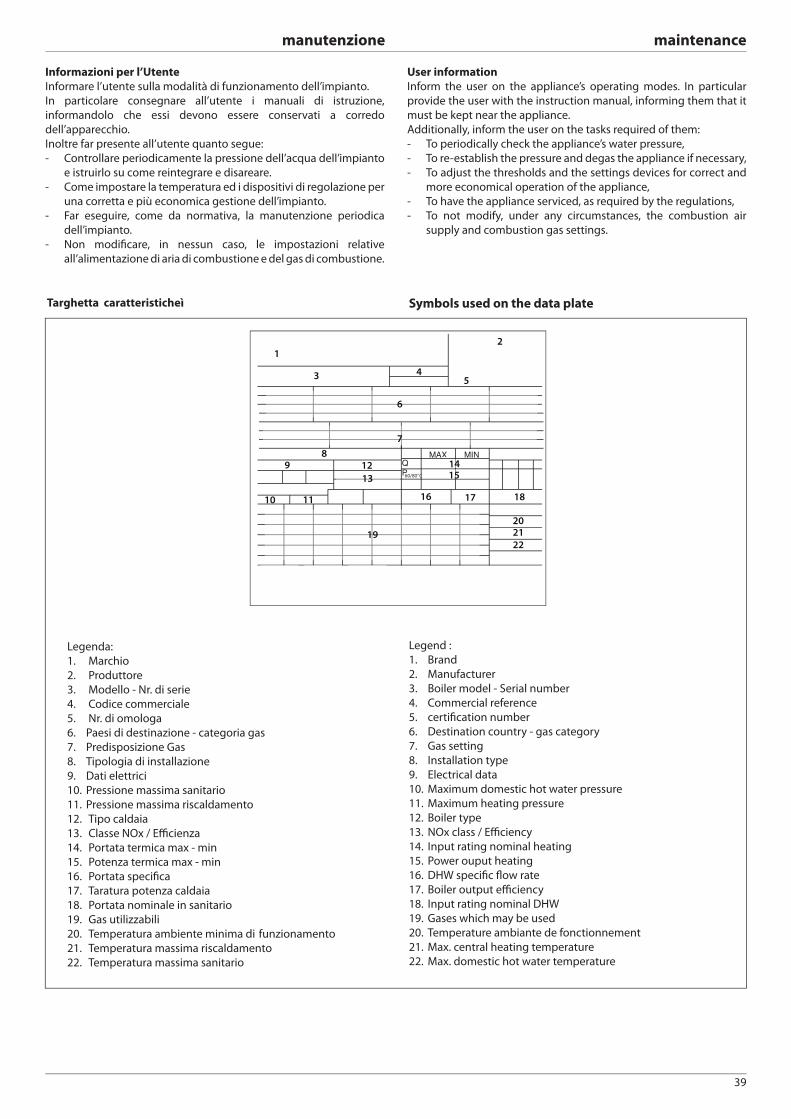
39
manutenzione maintenance
MINQ
MAX
P60/80°C
12
543
6
7
19
89
10 11
12 1415
16 17 18
13
202122
Legenda:
1. Marchio
2. Produttore
3. Modello - Nr. di serie
4. Codice commerciale
5. Nr. di omologa
6. Paesi di destinazione - categoria gas
7. Predisposizione Gas
8. Tipologia di installazione
9. Dati elettrici
10. Pressione massima sanitario
11. Pressione massima riscaldamento
12. Tipo caldaia
13. Classe NOx / Effi cienza
14. Portata termica max - min
15. Potenza termica max - min
16. Portata specifi ca
17. Taratura potenza caldaia
18. Portata nominale in sanitario
19. Gas utilizzabili
20. Temperatura ambiente minima di funzionamento
21. Temperatura massima riscaldamento
22. Temperatura massima sanitario
Symbols used on the data plateTarghetta caratteristicheì
Legend :
1. Brand
2. Manufacturer
3. Boiler model - Serial number
4. Commercial reference
5. certifi cation number
6. Destination country - gas category
7. Gas setting
8. Installation type
9. Electrical data
10. Maximum domestic hot water pressure
11. Maximum heating pressure
12. Boiler type
13. NOx class / Effi ciency
14. Input rating nominal heating
15. Power ouput heating
16. DHW specifi c fl ow rate
17. Boiler output effi ciency
18. Input rating nominal DHW
19. Gases which may be used
20. Temperature ambiante de fonctionnement
21. Max. central heating temperature
22. Max. domestic hot water temperature
Informazioni per l’Utente
Informare l’utente sulla modalità di funzionamento dell’impianto.
In particolare consegnare all’utente i manuali di istruzione,
informandolo che essi devono essere conservati a corredo
dell’apparecchio.
Inoltre far presente all’utente quanto segue:
- Controllare periodicamente la pressione dell’acqua dell’impianto
e istruirlo su come reintegrare e disareare.
- Come impostare la temperatura ed i dispositivi di regolazione per
una corretta e più economica gestione dell’impianto.
- Far eseguire, come da normativa, la manutenzione periodica
dell’impianto.
- Non modifi care, in nessun caso, le impostazioni relative
all’alimentazione di aria di combustione e del gas di combustione.
User information
Inform the user on the appliance’s operating modes. In particular
provide the user with the instruction manual, informing them that it
must be kept near the appliance.
Additionally, inform the user on the tasks required of them:
- To periodically check the appliance’s water pressure,
- To re-establish the pressure and degas the appliance if necessary,
- To adjust the thresholds and the settings devices for correct and
more economical operation of the appliance,
- To have the appliance serviced, as required by the regulations,
- To not modify, under any circumstances, the combustion air
supply and combustion gas settings.

420010328102
Ariston Thermo SpAViale A. Merloni, 45
60044 Fabriano (AN)
www.aristonthermo.it
Servizio clienti 199 111 222Costo della chiamata al telefono fisso: 0,143 Euro al minuto in fascia oraria intera e 0,056 Euro in fascia oraraia ridotta (IVA inclusa)