DS 1332-107D LBT 8367 · I citotelefono Urmet e i telefoni Director2 facilitano le funzioni...
32
DS 1332-107D LBT 8367 Mod. 1332 INTERFACCIA TELEFONICA TELEPHONE INTERFACE Sch./Ref. 1332/40 MANUALE D’USO, PROGRAMMAZIONE E INSTALLAZIONE USER, PROGRAMMING AND INSTALLATION MANUAL
Transcript of DS 1332-107D LBT 8367 · I citotelefono Urmet e i telefoni Director2 facilitano le funzioni...

DS 1332-107D LBT 8367
Mod.1332
INTERFACCIA TELEFONICATELEPHONE INTERFACE
Sch./Ref. 1332/40
MANUALE D’USO, PROGRAMMAZIONE E INSTALLAZIONEUSER, PROGRAMMING AND INSTALLATION MANUAL

2 DS1332-107D
ITALIANOUSO PER CUI IL DISPOSITIVO È DESTINATOIl presente dispositivo è stato progettato per essere usato in connessione alla rete analogica PSTN nazionale.
EMERGENZAIn assenza di rete elettrica si spegne il LED POWER e i servizi dell’interfaccia telefonica sono disattivati. Comunque è possibile effettuare e ricevere telefonate poiché l’apparecchio telefonico, in questa condizione, si trova collegato direttamente alla linea urbana. In questo caso non occorre comporre lo “0”, anche se l’Interfaccia telefonica è predisposta in Modo B. Una volta ripristinato il collegamento alla rete elettrica, l’impianto torna a funzionare nel Modo predisposto.
DESCRIZIONEL’interfaccia telefonica Sch. 1332/40, consente di utilizzare un terminale telefonico generico (telefono BCA a tastiera, segreteria telefonica, cordless, fax etc.) come elemento di conversazione di tipo telefonico. Inoltre l’apparecchio collegato all’interfaccia, può svolgere le comuni operazioni di un citofono se collegato ad un impianto 4+n, consentendo sia la conversazione con uno dei due posti esterni collegabili sia l’apertura della serratura elettrica. È disponibile nel colore grigio. L’interfaccia si installa su una guida DIN all’interno di un quadro elettrico.
L’interfaccia telefonica può essere utilizzata per eseguire impianti generici con colonna montante citofonica 4+n.
Si elencano le principali prestazioni e caratteristiche dell’interfaccia:Collegamento del telefono alla linea telefonica.Collegamento del telefono a due distinti posti esterni citofonici.Risposta ad una chiamata telefonica.Risposta ad una chiamata citofonica proveniente dai due distinti posti esterni citofonici.Segnalazione sul posto esterno dell’inoltro della chiamata citofonica mediante un tono.Messa in attesa della conversazione telefonica.Apertura della porta 1.Apertura della porta 2.Chiamata a centralino di portineria (sistemi HRB).Connessione fi no a 5 telefoni in serie (impianto entra/esci).Segnalazione presenza rete elettrica tramite il led POWER.Installazione su una guida DIN all’interno di un quadro elettrico.
••••••••••••
3DS1332-107D
GENERALITÀCONFIGURAZIONELa capacità del sistema è defi nita con:
1 linea urbana.1 linea interna.2 linee citofoniche 4+n.
TIPI DI APPARECCHI L’interfaccia telefonica può funzionare sia con i citotelefoni dedicati Urmet Mod. 1332 o telefoni Director2 con modalità di funzionamento “citotelefono”, che con telefoni BCA a tastiera (con selezione multifrequenza) o terminali equivalenti (fax, segreteria, etc.) con modalità di funzionamento “BCA”. I citotelefono Urmet e i telefoni Director2 facilitano le funzioni citofoniche in quanto prevedono dei tasti dedicati, ad esempio si può aprire la porta con la semplice pressione di un tasto. Si possono collegare fi no ad un massimo di 5 telefoni in serie in un impianto a spina entra esci (riferirsi agli schemi allegati).
TIPI DI IMPIANTO L’Interfaccia telefonica Sch. 1332/40 può essere utilizzata nei seguenti impianti citofonici Urmet:
Impianti citofonici con Sistema di chiamata elettronica (deviatore settato su 1A).Impianti citofonici con Sistema di chiamata tradizionale (citofoni Mod. 1130 il deviatore interfaccia settato su 1).
Non può essere collegata nei seguenti impianti:Impianti citofonici con segreto di conversazione.Impianti citofonici con centralino di portineria Mod. 604.
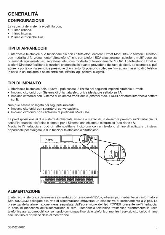
La predisposizione ai due sistemi di chiamata avviene a mezzo di un deviatore previsto sull’interfaccia. Di serie l’Interfaccia telefonica è settata per il Sistema con chiamata elettronica (posizione 1A).Mediante l’interfaccia si può di fatto sostituire il citofono con un telefono al fi ne di utilizzare gli stessi apparecchi per svolgere le due funzioni telefoniche e citofoniche.
ALIMENTAZIONEL’interfaccia telefonica deve essere alimentata con tensione di 12Vca, ad esempio, mediante un trasformatore Sch. 9000/230 collegato alla rete di alimentazione attraverso un dispositivo di sezionamento a 2 poli. La presenza della alimentazione viene segnalata dall’accensione del led POWER presente nell’interfaccia. In caso di mancanza dell’alimentazione di rete, l’interfaccia telefonica trasferisce direttamente la linea telefonica agli apparecchi, consentendo comunque il servizio telefonico, mentre il servizio citofonico rimane escluso fi no al ripristino della alimentazione.
•••
••
••
4 DS1332-107D
MODI DI FUNZIONAMENTOL’interfaccia telefonica prevede due possibili modi di funzionamento selezionabili attraverso una programmazione (vedi paragrafo 3.9) inserita tramite il telefono:
Modo A Sollevando il microtelefono l’utente è immediatamente collegato alla linea telefonica (non è necessario comporre alcuna cifra per accedere alla linea telefonica).
Modo B A seguito dello sgancio del microtelefono, si sente un tono di invito alla selezione ed il telefono non risulta collegato alla linea telefonica né a quella citofonica.L’utente può quindi inserirsi sulla linea telefonica o su quella citofonica digitando dei codici.
L’interfaccia viene fornita in modalità operativa A.
1 SERVIZI TELEFONICI SU LINEE ESTERNE E UTILIZZO1.1 CHIAMATA SU LINEA ESTERNAÈ prevista sull’interfaccia la sola modalità di selezione multifrequenza (MF).
Per effettuare una chiamata su linea esterna con l’interfaccia settata in modalità A (la linea è già presente sul telefono):1. Sollevare il microtelefono ed attendere il tono di invito a selezionare.2. Selezionare il numero desiderato.
Per effettuare una chiamata su linea esterna con l’interfaccia settata in modalità B:1. Sollevare il microtelefono ed attendere il tono di invito a selezionare.2. Selezionare la cifra per impegnare la linea telefonica, digitando il codice che è stato programmato (Italia
0 o estero 9).
MODALITÀ ITALIA ESTERO
CODICE DA DIGITARE 0 9
3. Attendere il segnale di linea.4. Quando si sente il tono di libero comporre il numero da chiamare iniziando a digitare entro 10
secondi.
1.2 RISPOSTA AD UNA CHIAMATA ESTERNAUna chiamata proveniente da una linea esterna viene segnalata con la cadenza propria della chiamata esterna.
Per rispondere:1. Sollevare il microtelefono ed entrare in conversazione.
1.3 INCAPSULAMENTOIl telefono viene isolato (incapsulato) se, trascorsi 20 secondi dopo aver sganciato il microtelefono di uno degli apparecchi, non si effettua alcuna operazione, o si effettua una manovra errata o non consentita, indipendentemente dalla modalità operativa prescelta (A o B). Se è stata scelta la modalità B, l’interfaccia dopo 10 secondi invia un tono di dissuasione. Per riattivare il telefono è necessario riagganciare il microtelefono.
1.4 EMETTERE UN FLASH (R) SULLA LINEA ESTERNA Alcuni servizi telefonici richiedono di emettere un FLASH sulla linea esterna. Per fare ciò è suffi ciente premere due volte R oppure due volte la sequenza # #. Si emetterà il fl ash in linea e si tornerà in conversazione con la stessa.

5DS1332-107D
MODALITÀ MODO BCA MODO CITOTELEFONO
CODICE DA DIGITARE R RR
1.5 MESSA IN ATTESA DI UNA CONVERSAZIONE TELEFONICA ESTERNAÈ possibile mettere in attesa una conversazione telefonica in corso, senza abbattere la connessione, per poterla riprendere in seguito.
Per mettere in attesa una conversazione esterna digitare R oppure # #, l’utente esterno riceve un tono di attesa.
MODALITÀ MODO BCA MODO CITOTELEFONO
CODICE DA DIGITARE # # R
Per riprendere la conversazione esterna digitare R oppure # # a seconda di come è stata programmata l’interfaccia.
Se durante l’attesa si riaggancia il microtelefono, si ha una chiamata di ritorno dalla linea in attesa per un tempo fi sso massimo di 3 minuti, dopo di che la chiamata viene svincolata. Fino a quel momento la linea esterna viene tenuta in attesa.
2 SERVIZI TELEFONICI LEGATI AL MONTANTE CITOFONICONel presente capitolo sono descritti i servizi citofonici possibili da un qualsiasi telefono a tastiera (interfaccia settata in modo BCA) , da un citotelefono Urmet o da un telefono Director2 (interfaccia settata in modo Citotelefono).
L’utilizzo di tali servizi viene semplifi cato se si usa un citotelefono Urmet o un telefono Director2 perché sono previsti dei tasti dedicati per le seguenti funzioni citofoniche:
Descrizione Codice Sch. 1332/1 Sch. 4091/1 Sch. 4091/5 Sch. 4099/45
Connessione al posto esterno R34
Azionamento relè apri porta ATT1 R35
Azionamento relè apri porta ATT2 R37 - - - -Chiamata al centralino di portineria sistema HRB R36 - - - - - -
Per la corrispondenza dei codici con i rispettivi tasti dedicati vedere i libretti forniti a corredo dei vari citotelefoni o telefoni.
Le chiamate citofoniche vengono segnalate sul posto esterno mediante un tono acustico di riscontro chiamata. Questo tono è inviato dalla interfaccia telefonica e, volendo, è disattivabile mediante una programmazione inserita dal telefono (fare riferimento al capitolo delle programmazioni).
2.1 CONNESSIONE AL POSTO ESTERNO CITOFONICO SENZA CHIAMATA (DA RIPOSO)
Per collegarsi con il posto esterno citofonico, senza avere ricevuto una chiamata dal citofono, occorre:1. Sollevare il microtelefono e digitare uno dei codici indicati in tabella a seconda della modalità
programmata (BCA o Citotelefono) e della funzione desiderata.
MODALITÀ MODO BCA MODO CITOTELEFONO
Connessione al posto esterno 1 senza chiamata
# # 4 R34+1
Connessione al posto esterno 2 senza chiamata
# # 5 R34+2
§

6 DS1332-107D
2.2 CHIAMATA AL CENTRALINO DEL SISTEMA HRBPer chiamare il posto operatore del sistema HRB occorre:1. Sollevare il microtelefono e digitare il codice indicato in tabella, a seconda della modalità programmata
(BCA o Citotelefono).
MODALITÀ MODO BCA MODO CITOTELEFONO
Chiamata al sistema HRB o a centralino # # 6 R36
2.3 RISPOSTA ALLE CHIAMATE CITOFONICHE PROVENIENTI DA PE1 O PE2La chiamata citofonica viene segnalata, sui telefoni da una diversa cadenza di suoneria a seconda che essa provenga dal posto esterno 1 o 2. Il primo utente che risponde viene messo in comunicazione con la postazione citofonica, mentre tutti gli altri derivati smettono di suonare. La chiamata proveniente dal PE1 verrà segnalata da 2 squilli e una pausa ripetuti per il tempo programmato. La chiamata proveniente dal secondo posto esterno verrà segnalata da 4 squilli e una pausa per il tempo programmato (riferirsi alle tabelle a pagina 11).
Per rispondere ad una chiamata citofonica da un telefono:1. Sollevare il microtelefono ed entrare in conversazione.
2.4 RISPOSTA A CHIAMATA CITOFONICA DURANTE CONVERSAZIONE SU LINEA URBANA
Se durante una conversazione in corso con la linea telefonica urbana arriva una chiamata citofonica, segnalata dal tono di avviso, si può mettere in attesa la prima chiamata e rispondere alla seconda. È possibile inoltre ritornare da una comunicazione all’altra, ovvero sono presenti due comunicazioni contemporanee di cui una attiva e l’altra in attesa.
Per mettere in attesa una conversazione sulla linea urbana e rispondere ad una chiamata citofonica in arrivo, digitare:
MODALITÀ MODO BCA MODO CITOTELEFONO
CODICE DA DIGITARE # # 3 R34
L’utente sulla linea urbana viene messo in attesa e riceve il tono di attesa.La conversazione passa sul citofono.
Per scollegarsi dal posto citofonico esterno e riprendere la comunicazione in attesa, digitare:
MODALITÀ MODO BCA MODO CITOTELEFONO
CODICE DA DIGITARE # # 3 R34
Riagganciando il microtelefono durante la comunicazione citofonica si ha una chiamata di ritorno proveniente dalla linea esterna in attesa.
2.5 SEGRETERIA SU CHIAMATA CITOFONICAIl servizio consente di registrare in segreteria chiamate citofoniche, nel caso in cui una chiamata citofonica non riceva risposta entro un tempo massimo prestabilito. La segreteria invia il messaggio di registrazione al citofono e registra il messaggio per un tempo massimo predefi nito, oltre il quale abbatte la comunicazione.Collegare la segreteria su un interno; impostare l’intervento della stessa con un tempo inferiore al tempo della chiamata citofonica; in questo modo se non avviene una risposta da parte di un interno, questa entrerà in azione inviando il messaggio al posto esterno citofonico.Attenzione: la segreteria deve prevedere una durata massima del messaggio registrabile, e non attendere un eventuale tono di dissuasione o silenzio per liberare la linea citofonica. Se non si desidera che la segreteria telefonica entri in funzione con le chiamate citofoniche collegarla direttamente sulla linea telefonica prima della interfaccia telefonica, in modo che non riceva le chiamate provenienti dal citofono.
7DS1332-107D
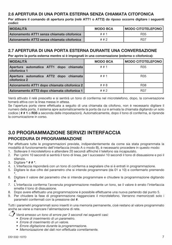
2.6 APERTURA DI UNA PORTA ESTERNA SENZA CHIAMATA CITOFONICAPer attivare il comando di apertura porta (relè ATT1 o ATT2) da riposo occorre digitare i seguenti codici:
MODALITÀ MODO BCA MODO CITOTELEFONO
Azionamento ATT1 senza chiamata citofonica # # 1 R35
Azionamento ATT2 senza chiamata citofonica # # 2 R37
2.7 APERTURA DI UNA PORTA ESTERNA DURANTE UNA CONVERSAZIONEPer aprire la porta esterna mentre si è impegnati in una conversazione (esterna o citofonica):
MODALITÀ MODO BCA MODO CITOTELEFONO
Apertura automatica ATT1 dopo chiamata citofonica 1
# # 1 R35
Apertura automatica ATT2 dopo chiamata citofonica 2
# # 1 R35
Azionamento ATT1 dopo chiamata citofonica 2 # # 8 R38
Azionamento ATT2 dopo chiamata citofonica 1 # # 2 R37
Verrà attivato il relè prescelto e si sentirà un tono di conferma nel microtelefono, dopo, la conversazione tornerà attiva con la linea messa in attesa.Se l’apertura porta viene effettuata a seguito di una chiamata da citofono, non è necessario digitare il numero della porta, il sistema apre automaticamente la porta da cui è arrivata la chiamata digitando un solo codice ( # # 1 o R35 a seconda delle impostazioni). Automaticamente, dopo il tono di conferma, si riprende la comunicazione in corso.
3.0 PROGRAMMAZIONE SERVIZI INTERFACCIAPROCEDURA DI PROGRAMMAZIONEPer effettuare tutte le programmazioni previste, indipendentemente da come sia stata programmata la modalità di funzionamento dell’interfaccia (modo A o modo B), è necessario procedere in questo modo:1. Sollevare il microtelefono e attendere 20 secondi affi nché il telefono sia incapsulato.2. Per i primi 10 secondi si sentirà il tono di linea, per I successivi 10 secondi il tono di dissuasione e poi il
silenzio.3. Digitare * # # *.4. L’interfaccia risponderà con un tono di conferma a segnalare che si è entrati in programmazione.5. Digitare le due cifre del parametro che si intende programmare (da 01 a 10) e confermarlo premendo
*.6. Digitare il valore del parametro che si intende programmare e chiudere la programmazione digitando
#.7. L’interfaccia conferma l’avvenuta programmazione mediante un tono, se il valore è errato l’interfaccia
emette il tono di dissuasione.8. Dopo avere effettuato una programmazione è possibile effettuarne una nuova partendo dal punto 5.9. Per chiudere la fase di programmazione riagganciare il microtelefono. Verranno memorizzati solo i
parametri confermati con la pressione del #.
Tutti i parametri programmati sono inseriti in una memoria permanente, cioè restano al valore programmato anche se viene a mancare l’alimentazione di rete.
Verrà emesso un tono di errore per 3 secondi nei seguenti casi:Errore di inserimento di un parametro.Errore di inserimento di un valore.Errore digitazione durante la programmazione.Memorizzazione dei dati non effettuata correttamente.
§••••
8 DS1332-107D
Esempio di programmazione:Si vuole programmare il tempo di chiusura del contatto del relè attuatore ATT1 portandolo a 10 secondi. Il parametro del relè attuatore 1 è 03 e il valore relativo a 10 secondi è 4. La sequenza di programmazione quindi sarà:
Sollevare il microtelefono, attendere 20 secondi (fi no al silenzio in cornetta) e digitare: * # # * 03 * 4 #
Dopo il tono di conferma riagganciare il microtelefono.
3.1 CODICE RESET PROGRAMMAZIONIPer effettuare un reset totale delle programmazioni, riportandole ai valori di fabbrica per la versione Italia (parametro 08 valore 1 della tabella riassuntiva), bisogna sollevare il microtelefono, e digitare il codice di RESET.* * * # # # * #
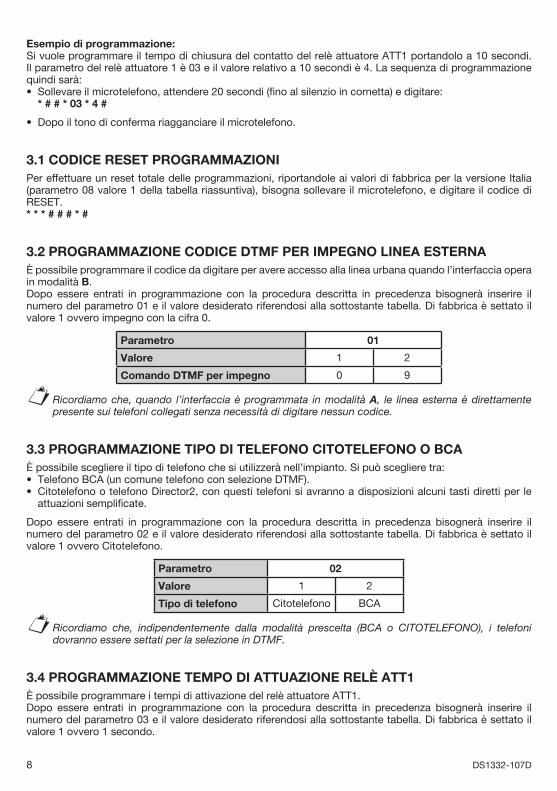
3.2 PROGRAMMAZIONE CODICE DTMF PER IMPEGNO LINEA ESTERNAÈ possibile programmare il codice da digitare per avere accesso alla linea urbana quando l’interfaccia opera in modalità B.Dopo essere entrati in programmazione con la procedura descritta in precedenza bisognerà inserire il numero del parametro 01 e il valore desiderato riferendosi alla sottostante tabella. Di fabbrica è settato il valore 1 ovvero impegno con la cifra 0.
Parametro 01
Valore 1 2
Comando DTMF per impegno 0 9
Ricordiamo che, quando l’interfaccia è programmata in modalità A, le linea esterna è direttamente presente sui telefoni collegati senza necessità di digitare nessun codice.
3.3 PROGRAMMAZIONE TIPO DI TELEFONO CITOTELEFONO O BCAÈ possibile scegliere il tipo di telefono che si utilizzerà nell’impianto. Si può scegliere tra:
Telefono BCA (un comune telefono con selezione DTMF).Citotelefono o telefono Director2, con questi telefoni si avranno a disposizioni alcuni tasti diretti per le attuazioni semplifi cate.
Dopo essere entrati in programmazione con la procedura descritta in precedenza bisognerà inserire il numero del parametro 02 e il valore desiderato riferendosi alla sottostante tabella. Di fabbrica è settato il valore 1 ovvero Citotelefono.
Parametro 02
Valore 1 2
Tipo di telefono Citotelefono BCA
Ricordiamo che, indipendentemente dalla modalità prescelta (BCA o CITOTELEFONO), i telefoni dovranno essere settati per la selezione in DTMF.
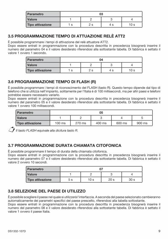
3.4 PROGRAMMAZIONE TEMPO DI ATTUAZIONE RELÈ ATT1È possibile programmare i tempi di attivazione del relè attuatore ATT1.Dopo essere entrati in programmazione con la procedura descritta in precedenza bisognerà inserire il numero del parametro 03 e il valore desiderato riferendosi alla sottostante tabella. Di fabbrica è settato il valore 1 ovvero 1 secondo.
•
•
§
••
§
9DS1332-107D
Parametro 03
Valore 1 2 3 4
Tipo attivazione 1 s 2 s 4 s 10 s
3.5 PROGRAMMAZIONE TEMPO DI ATTUAZIONE RELÈ ATT2È possibile programmare i tempi di attivazione del relè attuatore ATT2.Dopo essere entrati in programmazione con la procedura descritta in precedenza bisognerà inserire il numero del parametro 04 e il valore desiderato riferendosi alla sottostante tabella. Di fabbrica è settato il valore 1 ovvero 1 secondo.
Parametro 04
Valore 1 2 3 4
Tipo attivazione 1 s 2 s 4 s 10 s
3.6 PROGRAMMAZIONE TEMPO DI FLASH (R)È possibile programmare i tempi di riconoscimento del FLASH (tasto R). Questo tempo dipende dal tipo di telefono che si utilizza nell’impianto, solitamente per l’Italia è di 100 millisecondi, ma per altri paesi e telefoni potrebbe essere necessario variarlo.Dopo essere entrati in programmazione con la procedura descritta in precedenza bisognerà inserire il numero del parametro 05 e il valore desiderato riferendosi alla sottostante tabella. Di fabbrica è settato il valore 1 ovvero 100 millisecondi.
Parametro 05
Valore 1 2 3 4 5
Tipo attivazione 100 ms 270 ms 400 ms 600 ms 900 ms
Il tasto FLASH equivale alla dicitura tasto R.
3.7 PROGRAMMAZIONE DURATA CHIAMATA CITOFONICAÈ possibile programmare il tempo di durata della chiamata citofonica.Dopo essere entrati in programmazione con la procedura descritta in precedenza bisognerà inserire il numero del parametro 07 e il valore desiderato riferendosi alla sottostante tabella. Di fabbrica è settato il valore 2 ovvero 10 secondi.
Parametro 07
Valore 1 2 3 4
Tipo attivazione 5 s 10 s 20 s 30 s
3.8 SELEZIONE DEL PAESE DI UTILIZZOÈ possibile scegliere il paese nel quale si utilizzerà l’interfaccia. A seconda del paese selezionato cambieranno automaticamente dei parametri specifi ci del paese prescelto, riferendosi alla tabella sottostante.Dopo essere entrati in programmazione con la procedura descritta in precedenza bisognerà inserire il numero del parametro 08 e il valore desiderato riferendosi alla sottostante tabella. Di fabbrica è settato il valore 1 ovvero il paese Italia.
§

10 DS1332-107D
Parametro 08
Valore 1 2 3 4 5 6 7 8 9
Tempoattivazione
Italia Francia Belgio Israele Olanda Irlanda Rep. Ceca
Ungheria Inghilterra
Tabella dei valori di fabbrica. All’accensione vengono caricati i parametri qui indicati, se non modifi cati, per il paese Italia.Nel caso di paese diverso individuare le caratteristiche più vicine a quelle desiderate.
Impegno linea
Citotelefono BCA
RelèATT1
RelèATT2
FLASH ChiamataCitofono
Paese Modo A/B
TONO
Parametro 01 02 03 04 05 07 08 09 10
Italia (default) 1 1 1 1 1 2 1 1 1
Francia 1 1 4 4 3 2 2 1 1
Belgio 1 1 1 1 1 2 3 1 1
Israele 2 2 3 3 4 3 4 1 1
Olanda 1 1 1 1 1 2 5 1 1
Irlanda 1 1 1 1 1 2 6 1 1
RepubblicaCeca
1 1 1 1 1 2 7 1 1
Ungheria 1 1 1 1 1 2 8 1 1
Inghilterra 1 1 1 1 1 2 9 1 1
3.9 PROGRAMMAZIONE MODALITÀ OPERATIVA A O BÈ possibile programmare la modalità operativa dell’interfaccia in modalità A o modalità B.Dopo essere entrati in programmazione con la procedura descritta in precedenza bisognerà inserire il numero del parametro 09 e il valore desiderato riferendosi alla sottostante tabella . Di fabbrica è settato il valore 1 ovvero modalità operativa A.
Parametro 09
Valore 1 2
Modalità operativa A B
Nella modalità A la linea telefonica esterna è direttamente collegata al telefono non appena si solleva il microtelefono.
Nella modalità B la linea telefonica esterna non è collegata direttamente al telefono e, per ottenerla, occorre digitare un codice.
3.10 PROGRAMMAZIONE TONO DI RISCONTRO CHIAMATA SU POSTO ESTERNO
È possibile abilitare un tono di riscontro di chiamata sul posto esterno, ovvero dopo la pressione del pulsante di chiamata l’utente esterno sentirà un tono che segnala l’inoltro della chiamata verso l’abitazione.Dopo essere entrati in programmazione, con la procedura descritta in precedenza, bisognerà inserire il numero del parametro 10 e il valore desiderato riferendosi alla sottostante tabella. Di fabbrica è settato il valore 1 ovvero il tono di riscontro è abilitato.
Parametro 10
Valore 1 2
TONO chiamata su PE ON OFF
§
11DS1332-107D
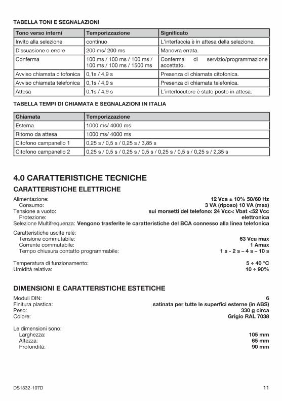
TABELLA TONI E SEGNALAZIONI
Tono verso interni Temporizzazione Significato
Invito alla selezione continuo L’interfaccia è in attesa della selezione.
Dissuasione o errore 200 ms/ 200 ms Manovra errata.
Conferma 100 ms / 100 ms / 100 ms / 100 ms / 100 ms / 1500 ms
Conferma di servizio/programmazione accettato.
Avviso chiamata citofonica 0,1s / 4,9 s Presenza di chiamata citofonica.
Avviso chiamata telefonica 0,1s / 4,9 s Presenza di chiamata telefonica.
Attesa 0,1s / 4,9 s L’interlocutore è stato posto in attesa.
TABELLA TEMPI DI CHIAMATA E SEGNALAZIONI IN ITALIA
Chiamata Temporizzazione
Esterna 1000 ms/ 4000 ms
Ritorno da attesa 1000 ms/ 4000 ms
Citofono campanello 1 0,25 s / 0,5 s / 0,25 s / 3,85 s
Citofono campanello 2 0,25 s / 0,5 s / 0,25 s / 0,5 s / 0,25 s / 0,5 s / 0,25 s / 2,35 s
4.0 CARATTERISTICHE TECNICHECARATTERISTICHE ELETTRICHE Alimentazione: 12 Vca ± 10% 50/60 Hz Consumo: 3 VA (riposo) 10 VA (max) Tensione a vuoto: sui morsetti del telefono: 24 Vcc< Vbat <52 Vcc Protezione: elettronicaSelezione Multifrequenza: Vengono trasferite le caratteristiche del BCA connesso alla linea telefonica
Caratteristiche uscite relè: Tensione commutabile: 63 Vca max Corrente commutabile: 1 Amax Tempo chiusura contatto programmabile: 1 s - 2 s – 4 s – 10 s
Temperatura di funzionamento: 5 ÷ 40 °CUmidità relativa: 10 ÷ 90%
DIMENSIONI E CARATTERISTICHE ESTETICHEModuli DIN: 6Finitura plastica: satinata per tutte le superfici esterne (in ABS)Peso: 330 g circaColore: Grigio RAL 7038
Le dimensioni sono: Larghezza: 105 mm Altezza: 65 mm Profondità: 90 mm

12 DS1332-107D
TABELLE RIASSUNTIVA PROGRAMMAZIONICODICE PER IMPEGNO LINEA TELEFONICA
PARAMETRO VALORE
01 1 2
FUNZIONE 0 9
TIPO DI TELEFONO CITOTELEFONO/BCAPARAMETRO VALORE
02 1 2
FUNZIONE Citotelefono BCA
TEMPO DI ATTIVAZIONE RELÈ ATT1PARAMETRO VALORE
03 1 2 3 4
FUNZIONE 1 s 2 s 4 s 10 s
TEMPO DI ATTIVAZIONE RELÈ ATT2PARAMETRO VALORE
04 1 2 3 4
FUNZIONE 1 s 2 s 4 s 10 s
TEMPO RICONOSCIMENTO TASTO FLASH (R)PARAMETRO VALORE
05 1 2 3 4 5
FUNZIONE 100 ms 270 ms 400 ms 600 ms 900 ms
DURATA CHIAMATA CITOFONICAPARAMETRO VALORE
07 1 2 3 4
FUNZIONE 5 s 10 s 20 s 30 s
PAESE DI UTILIZZOPARAMETRO VALORE
08 1 2 3 4 5 6 7 8 9
FUNZIONE Italia Francia Belgio Israele Olanda Irlanda Rep. Ceca
Ungheria Inghilterra
MODALITÀ DI FUNZIONAMENTO A/BPARAMETRO VALORE
09 1 2
FUNZIONE A B
TONO RISCONTRO DI CHIAMATA CITOFONICO SU PEPARAMETRO VALORE
10 1 2
FUNZIONE ON OFF

13DS1332-107D
5 INSTALLAZIONEFissare l’interfaccia sulla barra DIN all’interno del quadro elettrico e procedere con i collegamenti seguendo gli schemi riportati nelle pagine seguenti.
DESCRIZIONE DEI MORSETTI2A Uscita fonia verso PE 12B Uscita fonia verso PE 2
Ae } Ingresso linea telefonica urbanaBe Au } Uscita linea telefonica verso impianto internoBu
ATT2 Morsetti relé 2ATT1 Morsetti relé 1-CA Comune chiamate citofonicheCA2 Ingresso chiamata da PE 2CA1 Ingresso chiamata da PE 1+6B Uscita alimentazione verso PE 2+6A Uscita alimentazione verso PE 1-6 Comune PE1A Ingresso fonia da PE 1 e PE 20~12 Alimentazione 12V~
REALIZZAZIONE DELL’IMPIANTOI collegamenti telefonici devono essere realizzati utilizzando il cavo telefonico intrecciato, con guaina, ad una coppia. Nel caso di utilizzo, verso gli apparecchi interni, del cavo multicoppia, non è consentito che vengano utilizzate eventuali coppie libere per altri servizi quali: energia, segnali video, trasmissione dati. Infatti, come da normativa CEI, cavi appartenenti a sistemi tra loro incompatibili, come quelli specifi cati, devono avere tubi protettivi e scatole di derivazione diverse. La lunghezza massima prevista per il collegamento dei telefoni all’interfaccia telefonica è di 300mt. Al massimo si possono collegare 5 telefoni collegati in un impianto serie a norma. Per il collegamento dell’impianto citofonico, attenersi alle sezioni dei conduttori specifi cate nelle tabelle dell’impianto. La realizzazione di impianti telefonici interni dovrebbe essere eseguita da personale specializzato. Non sono consentiti l’installazione e l’allacciamento alla rete di telecomunicazione di terminali telefonici non omologati.
ATTENZIONESI RACCOMANDA L’INSTALLAZIONE DELL’INTERFACCIA TELEFONICA ALL’INTERNO DI IMPIANTI DOTATI DI APPOSITE PROTEZIONI DI LINEA TELEFONICA ED ELETTRICA. Le principali cause di disturbi sulle linee telefoniche e sulle reti di alimentazione elettrica (che possono provocare malfunzionamenti o danneggiamenti all’Interfaccia telefonica) sono attribuibili a:
Contatti accidentali con linee a tensioni più elevate (cortocircuito).Accoppiamenti elettromagnetici con altri conduttori posti nelle vicinanze.Brusche variazioni di carico, specie per le linee elettriche di alimentazione (motori elettrici, etc.).Perturbazioni transitorie generate da eventi atmosferici (fulmini).
PROTEZIONI PER LINEE TELEFONICHE Le protezioni vanno inserite non solo sulla linea urbana che entra nell’Interfaccia telefonica, ma anche sulla linea derivata con un percorso esterno al fabbricato o alla quale siano collegati apparecchi con alimentazione a 230V, come Fax, Modem, Segreterie, Cordless.
•
•••
••
••••

14 DS1332-107D
PROTEZIONE PER LINEE DI ALIMENTAZIONE Deve essere collegata all’ingresso della linea di alimentazione a 230V sull’alimentatore connesso alla interfaccia telefonica.
IMPORTANTE Il morsetto di terra delle Protezioni, per ottenere un effi cace funzionamento dei dispositivi, deve essere collegato alla terra dell’impianto.
Nei collegamenti della Protezione di linea di alimentazione, occorre inoltre fare attenzione a connettere correttamente il conduttore di fase e il neutro ai rispettivi morsetti.
15DS1332-107D
ENGLISHPRODUCT’S INTENDED USEThis device has been designed to be used in connection to the national PSTN analogic network.
EMERGENCYIn case of mains fail, the POWER LED turns off and the telephone interface services are deactivated. However, it is possible to make and receive telephone calls, because in this condition the telephone equipment is directly connected to the trunk line. In this case, it is not necessary to dial “0”, even if the telephone interface is set in Mode B. When mains returns, the system goes back to operate in the preset mode.
DESCRIPTIONThe Ref. 1332/40 telephone interface allows to use a generic telephone terminal (BCA keypad telephone, answering machine, cordless phone, fax, etc.) as telephone type conversation element. Besides, the telephone connected to the interface can execute the common operations of a door phone, if it is connected to a 4+n system, allowing the conversation with one of the two apartment stations that can be connected and the electric lock opening. It is available in grey colour.The interface is installed on a DIN rail in a service panel.
The telephone interface can be used to build generic systems with door phone riser column 4+n.
The main interface performances and characteristics are listed below:Telephone connection to the telephone line. Telephone connection to two different door phone units. Answer to a telephone call. Answer to a door phone call coming from two different door phone units. On the door unit, signalling of the door phone call forwarding by a tone. Telephone conversation hold mode. Door 1 opening. Door 2 opening. Call to concierge switchboard (HRB systems). Connection up to 5 telephones in serie (in-out system). Signalling of mains presence with the POWER led.Installation on a DIN rail in a service panel.
••••••••••••

16 DS1332-107D
GENERIC INFORMATIONCONFIGURATION The system capacity is defi ned by:
1 trunk line. 1 extension line. 2 door phone lines 4+n.
TYPES OF DEVICESThe telephone interface can operate either with Urmet Ref.1332 dedicated combiphones and Director2 telephones (combiphone operating mode), or with keypad BCA telephones (with DTMF) or equivalent terminals (fax, answering machine, etc.) with BCA operating mode. Urmet combiphones and Director2 telephones make door phone functions easier, because they are provided with dedicated buttons; for example, it is possible to open the door simply by pressing a button. Up to 5 telephones max. can be connected in series in a system with in/out sockets (refer to enclosed diagrams).
TYPES OF SYSTEM The Ref. 1332/40 telephone interface can be used in the following Urmet door phone systems:
Door phone systems with electronic call system (switch set on 1A).Door phone systems with traditional call system (door phones Mod. 1130, the interface switch set on 1).
It cannot be connected in the following systems: Door phone systems with conversation privacy function. Door phone systems with concierge switchboard Mod. 604.
The two calling modes are selected by means of a switch present on the interface. By default, the telephone interface is set for the electronic call system (position 1A). Actually, with the interface it is possible to replace the door phone with a telephone, in order to use the same devices to perform both the telephone and door phone functions.
POWER SUPPLYThe telephone interface must be powered by a voltage of 12Vac, for example by a Ref. 9000/230 transformer connected to the mains by a 2-pole circuit breaker. The mains presence is signalled by the POWER led present on the interface, that turns on. In case of mains fail, the interface directly transfers the telephone line to the devices, allowing, in any case, the telephone service, while the door phone service is not active until the mains returns.
•••
••
••
17DS1332-107D
OPERATING MODES The telephone interface may work in two operating modes, that can be selected by a programming procedure performed with the telephone (paragraph 3.9):
Mode A By picking the handset up, the user is immediately connected to the telephone line (no number needs to be dialled to access the telephone line).
Mode B When the handset is picked up, a dial tone is heard: the telephone is not connected to the telephone line or to the door phone line. So the user can access the telephone or door phone line by entering codes.
By default, the interface is preset in mode A.
1 TELEPHONE SERVICES ON TRUNK LINES AND USE1.1 CALL ON TRUNK LINEThe interface uses only the multi-frequency dialling mode (MF).
To perform a call on trunk line with the interface in mode A (the line is already present on the telephone):1. Pick the handset up and wait for the dialling tone.2. Select the desired number.
To perform a call on trunk line with the interface in mode B: 1. Pick the handset up and wait for the dialling tone.2. Select the number to seize the telephone line, by entering the programmed code (Italy 0 or foreign
countries 9).
MODE ITALY FOREIGN COUNTRIES
CODE TO BE ENTERED 0 9
3. Wait for the dialling tone.4. When the dialling tone is heard, dial the number to be called; start dialling within 10 seconds.
1.2 ANSWER TO AN EXTERNAL CALLA call coming from a trunk line is signalled by the external call ringing cadence.
To answer:1. Pick the handset up and start with conversation.
1.3 DISABLINGThe telephone is disabled if, 20 seconds after picking up the handset of one of the devices, no operation is performed or a wrong or not allowed operation is performed, regardless of the selected operating mode (A or B). If the mode B has been selected, after 10 seconds the interface sends an alert tone. To activate again the telephone, hang the handset up.
1.4 EMIT A FLASH (R) ON THE TRUNK LINESome telephone services require to emit a FLASH on the trunk line. To do this, press twice R or twice the sequence # #. The fl ash will be emitted on the line and it will be possible to go back in conversation with the same.

18 DS1332-107D
MODE BCA MODE COMBIPHONE MODE
CODE TO BE ENTERED R RR
1.5 PUT IN HOLD MODE AN EXTERNAL TELEPHONE CONVERSATIONIt is possible to put in hold mode a telephone conversation in progress, without stopping the connection, in order to reactivate it after.
To put an external conversation in hold mode, enter R or # #, the external user receives a waiting tone.
MODE BCA MODE COMBIPHONE MODE
CODE TO BE ENTERED # # R
To reactivate the external conversation, enter R or # #, according to the interface programming. If, during the hold time, the handset is hung up, will be received a return call from the line in hold state, for a maximum time of 3 minutes, after which the call is closed. Until that moment, the external line stays in hold mode.
2 TELEPHONE SERVICES CONNECTED TO THE DOOR PHONE RAISER
In this chapter are described the door phone services available with any keypad telephone (interface set in BCA mode), with a Urmet combiphone or with a Director2 telephone (interface set in Combiphone mode). The use of these services becomes easier if is used an Urmet combiphone or a Director2 telephone, because there are dedicated buttons for the following door phone functions:
Description Code Ref. 1332/1 Ref. 4091/1 Ref. 4091/5 Ref. 4099/45
Connection to door unit R34
ATT1 door opener relay activation R35
ATT2 door opener relay activation R37 - - - -Call to HRB system concierge switchboard R36 - - - - - -
For association of codes with respective dedicated buttons, see the booklets provided with combiphones or telephones.
Door phone calls are signalled on the door unit by an acoustic tone of call confi rmation. This tone is sent from the telephone interface and, if desired, it can be deactivated by a programming procedure with the telephone (refer to programming chapter).
2.1 CONNECTION TO DOOR PHONE UNIT WITHOUT CALL (IN STANDBY) To connect to the door phone unit without receiving a call from the door phone, it is needed:1. Pick the handset up and enter one of the codes indicated in the table, according to the programmed
mode (BCA or combiphone) and the desired function.
MODE BCA MODE COMBIPHONE MODE
Connection to door unit 1 without call # # 4 R34+1
Connection to door unit 2 without call # # 5 R34+2
§
19DS1332-107D
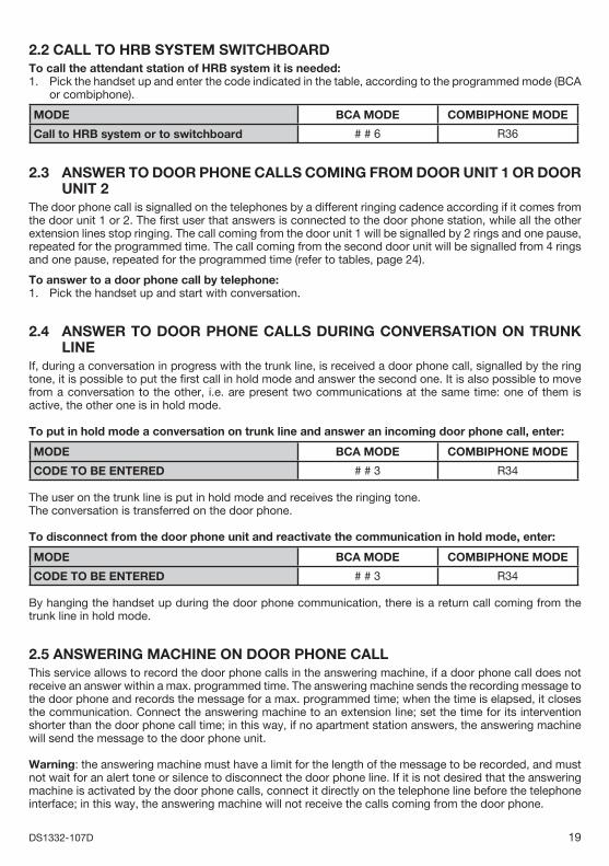
2.2 CALL TO HRB SYSTEM SWITCHBOARDTo call the attendant station of HRB system it is needed:1. Pick the handset up and enter the code indicated in the table, according to the programmed mode (BCA
or combiphone).
MODE BCA MODE COMBIPHONE MODE
Call to HRB system or to switchboard # # 6 R36
2.3 ANSWER TO DOOR PHONE CALLS COMING FROM DOOR UNIT 1 OR DOOR UNIT 2The door phone call is signalled on the telephones by a different ringing cadence according if it comes from the door unit 1 or 2. The fi rst user that answers is connected to the door phone station, while all the other extension lines stop ringing. The call coming from the door unit 1 will be signalled by 2 rings and one pause, repeated for the programmed time. The call coming from the second door unit will be signalled from 4 rings and one pause, repeated for the programmed time (refer to tables, page 24).
To answer to a door phone call by telephone:1. Pick the handset up and start with conversation.
2.4 ANSWER TO DOOR PHONE CALLS DURING CONVERSATION ON TRUNK LINEIf, during a conversation in progress with the trunk line, is received a door phone call, signalled by the ring tone, it is possible to put the fi rst call in hold mode and answer the second one. It is also possible to move from a conversation to the other, i.e. are present two communications at the same time: one of them is active, the other one is in hold mode.
To put in hold mode a conversation on trunk line and answer an incoming door phone call, enter:
MODE BCA MODE COMBIPHONE MODE
CODE TO BE ENTERED # # 3 R34
The user on the trunk line is put in hold mode and receives the ringing tone.The conversation is transferred on the door phone.
To disconnect from the door phone unit and reactivate the communication in hold mode, enter:
MODE BCA MODE COMBIPHONE MODE
CODE TO BE ENTERED # # 3 R34
By hanging the handset up during the door phone communication, there is a return call coming from the trunk line in hold mode.
2.5 ANSWERING MACHINE ON DOOR PHONE CALLThis service allows to record the door phone calls in the answering machine, if a door phone call does not receive an answer within a max. programmed time. The answering machine sends the recording message to the door phone and records the message for a max. programmed time; when the time is elapsed, it closes the communication. Connect the answering machine to an extension line; set the time for its intervention shorter than the door phone call time; in this way, if no apartment station answers, the answering machine will send the message to the door phone unit.
Warning: the answering machine must have a limit for the length of the message to be recorded, and must not wait for an alert tone or silence to disconnect the door phone line. If it is not desired that the answering machine is activated by the door phone calls, connect it directly on the telephone line before the telephone interface; in this way, the answering machine will not receive the calls coming from the door phone.
20 DS1332-107D
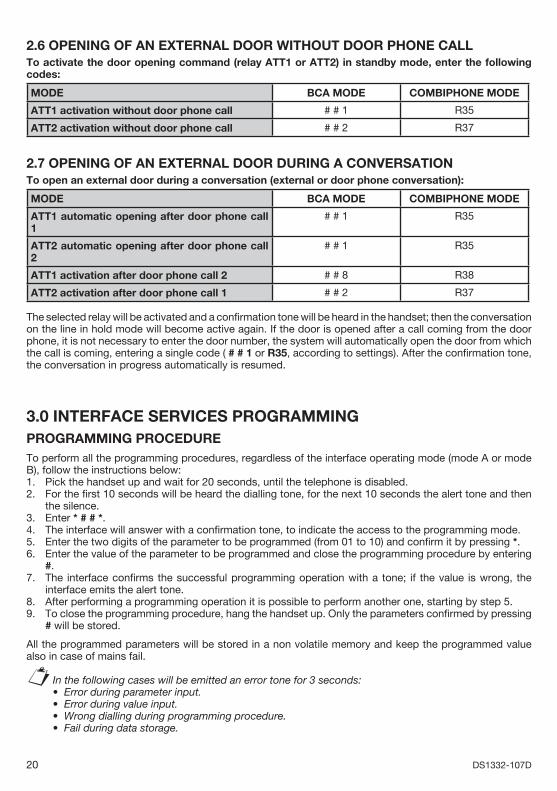
2.6 OPENING OF AN EXTERNAL DOOR WITHOUT DOOR PHONE CALLTo activate the door opening command (relay ATT1 or ATT2) in standby mode, enter the following codes:
MODE BCA MODE COMBIPHONE MODE
ATT1 activation without door phone call # # 1 R35
ATT2 activation without door phone call # # 2 R37
2.7 OPENING OF AN EXTERNAL DOOR DURING A CONVERSATIONTo open an external door during a conversation (external or door phone conversation):
MODE BCA MODE COMBIPHONE MODE
ATT1 automatic opening after door phone call 1
# # 1 R35
ATT2 automatic opening after door phone call 2
# # 1 R35
ATT1 activation after door phone call 2 # # 8 R38
ATT2 activation after door phone call 1 # # 2 R37
The selected relay will be activated and a confi rmation tone will be heard in the handset; then the conversation on the line in hold mode will become active again. If the door is opened after a call coming from the door phone, it is not necessary to enter the door number, the system will automatically open the door from which the call is coming, entering a single code ( # # 1 or R35, according to settings). After the confi rmation tone, the conversation in progress automatically is resumed.
3.0 INTERFACE SERVICES PROGRAMMINGPROGRAMMING PROCEDURE To perform all the programming procedures, regardless of the interface operating mode (mode A or mode B), follow the instructions below:1. Pick the handset up and wait for 20 seconds, until the telephone is disabled.2. For the fi rst 10 seconds will be heard the dialling tone, for the next 10 seconds the alert tone and then
the silence.3. Enter * # # *.4. The interface will answer with a confi rmation tone, to indicate the access to the programming mode.5. Enter the two digits of the parameter to be programmed (from 01 to 10) and confi rm it by pressing *.6. Enter the value of the parameter to be programmed and close the programming procedure by entering
#.7. The interface confi rms the successful programming operation with a tone; if the value is wrong, the
interface emits the alert tone.8. After performing a programming operation it is possible to perform another one, starting by step 5.9. To close the programming procedure, hang the handset up. Only the parameters confi rmed by pressing
# will be stored.
All the programmed parameters will be stored in a non volatile memory and keep the programmed value also in case of mains fail.
In the following cases will be emitted an error tone for 3 seconds:Error during parameter input.Error during value input.Wrong dialling during programming procedure.Fail during data storage.
§••••

21DS1332-107D
Programming example:It is needed to program the closing time of the ATT1 actuator relay contact and set it to 10 seconds. The parameter of the actuator relay 1 is 03 and the value used for 10 seconds is 4. The programming sequence will be the following:
Pick the handset up, wait for 20 seconds (until no tone in the handset) and enter: * # # * 03 * 4 #
After the confi rmation tone, hang the handset up.
3.1 CODE FOR PARAMETERS RESET In order to perform a complete reset of the parameters and set them to factory values for Italian version (parameter 08 value 1 of the summarizing table), pick the handset up and enter the RESET code.* * * # # # * #
3.2 DTMF CODE PROGRAMMING FOR TRUNK LINE ENGAGEMENTIt is possible to program the code to be entered to access the trunk line, when the interface operates in mode B. After entering in the programming procedure following the previously described steps, enter the number of parameter 01 and the desired value, according to the table below. By default, is set the value 1, i.e. engagement with digit 0.
Parameter 01
Value 1 2
DTMF command for engagement 0 9
When the interface is programmed in mode A, remember that the trunk line is directly present on the connected telephones, without entering any code.
3.3 TELEPHONE TYPE PROGRAMMING: COMBIPHONE OR BCAIt is possible to select the telephone type used in the system. Select between:
BCA telephone (a common telephone with DTMF dialling) Combiphone or Director2 telephone: with these telephones will be available some buttons for simplifi ed functions.
After entering in the programming procedure following the previously described steps, enter the number of parameter 02 and the desired value, according to the table below. By default, is set the value 1, i.e. Combiphone.
Parameter 02
Value 1 2
Telephone type Combiphone BCA
Remember that, regardless of the selected mode (BCA or COMBIPHONE), telephones must be set for DTMF dialling.
3.4 PROGRAMMING PROCEDURE OF ATT1 RELAY ACTIVATION TIMEIt is possible to program activation times of the ATT1 actuator relay. After entering in the programming procedure following the previously described steps, enter the number of parameter 03 and the desired value, according to the table below. By default, is set the value 1, i.e. 1 second.
Parameter 03
Value 1 2 3 4
Activation type 1 s 2 s 4 s 10 s
•
•
§
••
§
22 DS1332-107D
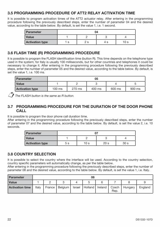
3.5 PROGRAMMING PROCEDURE OF ATT2 RELAY ACTIVATION TIME It is possible to program activation times of the ATT2 actuator relay. After entering in the programming procedure following the previously described steps, enter the number of parameter 04 and the desired value, according to the table below. By default, is set the value 1, i.e. 1 second.
Parameter 04
Value 1 2 3 4
Activation type 1 s 2 s 4 s 10 s
3.6 FLASH TIME (R) PROGRAMMING PROCEDURE It is possible to program the FLASH identifi cation time (button R). This time depends on the telephone type used in the system; for Italy is usually 100 milliseconds, but for other countries and telephones it could be necessary to change it. After entering in the programming procedure following the previously described steps, enter the number of parameter 05 and the desired value, according to the table below. By default, is set the value 1, i.e. 100 ms.
Parameter 05
Value 1 2 3 4 5
Activation type 100 ms 270 ms 400 ms 600 ms 900 ms
The FLASH button is the same as R button.
3.7 PROGRAMMING PROCEDURE FOR THE DURATION OF THE DOOR PHONE CALLIt is possible to program the door phone call duration time. After entering in the programming procedure following the previously described steps, enter the number of parameter 07 and the desired value, according to the table below. By default, is set the value 2, i.e. 10 seconds.
Parameter 07
Value 1 2 3 4
Activation type 5 s 10 s 20 s 30 s
3.8 COUNTRY SELECTIONIt is possible to select the country where the interface will be used. According to the country selection, country specifi c parameters will automatically change, as per the table below. After entering in the programming procedure following the previously described steps, enter the number of parameter 08 and the desired value, according to the table below. By default, is set the value 1, i.e. Italy.
Parameter 08
Value 1 2 3 4 5 6 7 8 9
Activation time Italy France Belgium Israel Holland Ireland Czech Rep.
Hungary England
§

23DS1332-107D
Factory values table. At the power-up, are loaded the following parameters used for Italy, if they have not been changed.In case of a different country, identify the most similar characteristics among the desired ones.
Line engagement
Combiphone BCA
ATT1 relay
ATT2 relay
FLASH Door phone
call
Country ModeA/B
TONE
Parameter 01 02 03 04 05 07 08 09 10
Italy(default)
1 1 1 1 1 2 1 1 1
France 1 1 4 4 3 2 2 1 1
Belgium 1 1 1 1 1 2 3 1 1
Israel 2 2 3 3 4 3 4 1 1
Holland 1 1 1 1 1 2 5 1 1
Ireland 1 1 1 1 1 2 6 1 1
CzechRepublic
1 1 1 1 1 2 7 1 1
Hungary 1 1 1 1 1 2 8 1 1
England 1 1 1 1 1 2 9 1 1
3.9 A OR B MODE PROGRAMMING PROCEDUREIt is possible to program the interface mode in mode A or mode B. After entering in the programming procedure following the previously described steps, enter the number of parameter 09 and the desired value, according to the table below. By default, is set the value 1, i.e. mode A.
Parameter 09
Value 1 2
Operating mode A B
In mode A, the trunk line is directly connected to the telephone as soon as the handset is picked up. In mode B, the trunk line is not directly connected to the telephone and it is necessary to enter a code, in order to seize it.
3.10 PROGRAMMING PROCEDURE FOR CONFIRMATION TONE OF A DOOR UNIT CALLIt is possible to enable a confi rmation tone for a call coming from the door unit, i.e. after pressing the call button, the external user will heard a tone that signals the call forwarding to the apartment. After entering in the programming procedure following the previously described steps, enter the number of parameter 10 and the desired value, according to the table below. By default, is set the value 1, i.e. the confi rmation tone is enabled.
Parameter 10
Value 1 2
Call tone on door unit ON OFF
§
24 DS1332-107D
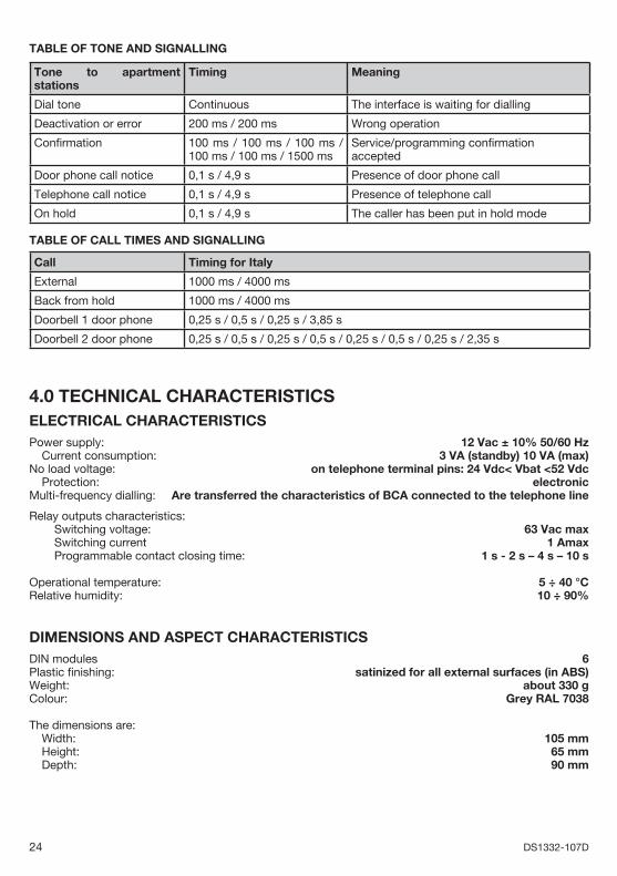
TABLE OF TONE AND SIGNALLING
Tone to apartment stations
Timing Meaning
Dial tone Continuous The interface is waiting for dialling
Deactivation or error 200 ms / 200 ms Wrong operation
Confi rmation 100 ms / 100 ms / 100 ms / 100 ms / 100 ms / 1500 ms
Service/programming confi rmation accepted
Door phone call notice 0,1 s / 4,9 s Presence of door phone call
Telephone call notice 0,1 s / 4,9 s Presence of telephone call
On hold 0,1 s / 4,9 s The caller has been put in hold mode
TABLE OF CALL TIMES AND SIGNALLING
Call Timing for Italy
External 1000 ms / 4000 ms
Back from hold 1000 ms / 4000 ms
Doorbell 1 door phone 0,25 s / 0,5 s / 0,25 s / 3,85 s
Doorbell 2 door phone 0,25 s / 0,5 s / 0,25 s / 0,5 s / 0,25 s / 0,5 s / 0,25 s / 2,35 s
4.0 TECHNICAL CHARACTERISTICS ELECTRICAL CHARACTERISTICS Power supply: 12 Vac ± 10% 50/60 Hz
Current consumption: 3 VA (standby) 10 VA (max) No load voltage: on telephone terminal pins: 24 Vdc< Vbat <52 Vdc Protection: electronicMulti-frequency dialling: Are transferred the characteristics of BCA connected to the telephone line
Relay outputs characteristics: Switching voltage: 63 Vac max Switching current 1 Amax Programmable contact closing time: 1 s - 2 s – 4 s – 10 s
Operational temperature: 5 ÷ 40 °CRelative humidity: 10 ÷ 90%
DIMENSIONS AND ASPECT CHARACTERISTICSDIN modules 6Plastic fi nishing: satinized for all external surfaces (in ABS)Weight: about 330 gColour: Grey RAL 7038
The dimensions are: Width: 105 mm Height: 65 mm Depth: 90 mm

25DS1332-107D
SUMMARIZING TABLE FOR PROGRAMMINGCODE FOR TELEPHONE LINE ENGAGEMENT
PARAMETER VALUE
01 1 2
FUNCTION 0 9
TELEPHONE TYPE COMBIPHONE/BCAPARAMETER VALUE
02 1 2
FUNCTION Combiphone BCA
ATT1 RELAY ACTIVATION TIMEPARAMETER VALUE
03 1 2 3 4
FUNCTION 1 s 2 s 4 s 10 s
ATT2 RELAY ACTIVATION TIMEPARAMETER VALUE
04 1 2 3 4
FUNCTION 1 s 2 s 4 s 10 s
FLASH BUTTON (R) IDENTIFICATION TIMEPARAMETER VALUE
05 1 2 3 4 5
FUNCTION 100 ms 270 ms 400 ms 600 ms 900 ms
DOOR PHONE CALL DURATIONPARAMETER VALUE
07 1 2 3 4
FUNCTION 5 s 10 s 20 s 30 s
COUNTRY OF USEPARAMETER VALUE
08 1 2 3 4 5 6 7 8 9
FUNCTION Italy France Belgium Israel Holland Ireland CzechRepublic
Hungary England
OPERATING MODE A/BPARAMETER VALUE
09 1 2
FUNCTION A B
CONFIRMATION TONE FOR A DOOR PHONEPARAMETER VALUE
10 1 2
FUNCTION ON OFF

26 DS1332-107D
5 INSTALLATIONFix the interface on the DIN bar in the service panel and then make the connections following the diagrams shown in the next pages.
TERMINAL PINS DESCRIPTION2A Audio output to door unit 12B Audio output to door unit 2
Ae } Trunk line inputBe Au } Telephone line output to indoor systemBu
ATT2 Relay 2 terminal pinsATT1 Relay 1 terminal pins-CA Common and door phone callsCA2 Call input from door unit 2CA1 Call input from door unit 1+6B Power supply output to door unit 2+6A Power supply output to door unit 1-6 Door unit common1A Audio input from door unit 1 and 20~12 12V~ power supply
SYSTEM REALIZATIONThe telephone connections must be done using the sheathed telephone twisted cable. If is used a multi-pair cable to internal devices, it is not allowed to use free pairs, if present, for other services, such as: energy, video signals, data transmission. Therefore, according to CEI regulations, cables belonging to incompatible systems, such as those specifi ed, must have different protection tubes and junction boxes. The maximum connection length between telephones and the telephone interface is 300m. It is possible to connect 5 telephones max. connected in series in a system compliant with the regulations. For the connection of the door phone system, use wire sections specifi ed in the system tables. The realization of internal telephone systems should be performed by a skilled technical staff. Installation and connection to telecommunication network of telephone not approved are not allowed.
WARNINGIT IS RECOMMENDED TO INSTALL THE TELEPHONE INTERFACE IN SYSTEMS PROVIDED WITH TELEPHONE AND ELECTRIC LINE SURGE PROTECTOR. The main causes of noise on telephone lines and electric power supply networks (that can induce malfunctions or damages to the telephone interface) are referred to:
Accidental contacts with higher voltage lines (short circuit).Electromagnetic coupling with other wires located close to the line.Fast load changes, especially for power supply electric lines (electric motors, etc.).Transient noise generated by atmospheric events (lightnings).
TELEPHONE LINES SURGE PROTECTORSProtectors must be put not only on the trunk line entering in the telephone interface, but also on the extension line with an outdoor path or on the extension line to which are connected devices with 230V power supply, such as fax, modem, answering machines, cordless phones.
POWER SUPPLY LINES SURGE PROTECTORS It must be connected to the input of the 230V power supply line, on the power supply unit connected to the telephone interface.
•
••
•••
••••
27DS1332-107D
IMPORTANT NOTEThe protectors ground terminal pin must be connected to the system ground, in order to obtain the correct operation of the devices.
For connections to the power supply line surge protector, pay also attention to connect correctly the phase conductor and the neutral to the respective terminal pins.
28 DS1332-107D
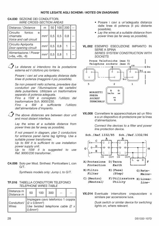
NOTE LEGATE AGLI SCHEMI / NOTES ON DIAGRAMS
C4.030 SEZIONE DEI CONDUTTORI. WIRE CROSS-SECTION AREAS
Distanza / Distance m 50 100 200 --
Circuito fonico e chiamataVoice and call circuit
mm2 0,5 0,5 0,8 --
Circuito ApriportaDoor opening circuit mm2 0,5 0,8 1 --
Alimentazione / Power(+6a, +6b, -6) mm2 0,5 0,8 1 --
Le distanze si intendono tra la postazione esterna ed il citofono più lontano.
Posare i cavi ad una adeguata distanza dalle linee di potenza (maggiore il più possibile).
Se non presenti nello schema, prevedere due conduttori per l’illuminazione dei cartellini della pulsantiera. Utilizzare un trasformatore separato di potenza adeguata.
Fino a 15W è consigliato l’utilizzo del trasformatore Sch. 9000/230.
Fino a 6W è suffi ciente l’utilizzo dell’alimentatore d’impianto.
The above distances are between door unit and most distant interface.
Lay the wires at a suitable distance from
power lines (as far away as possible).
If not present in diagram, plan 2 conductors for entrance panel name tag lighting. Use a suitable power transformer.
Up to 6W it is suffi cient to use installation power supply unit.
Up to 15W it is suggested to useRef. 9000/230 transformer.
C4.006 Solo per Mod. Sinthesi: Ponticellare L con G/T.
Synthesis models only: Jump L to G/T.
TF.016 TABELLA CONDUTTORI TELEFONICI TELEPHONE WIRES TABLE
Distanza mDistance m 50 100 300 -- --
Conduttori/Wires
Impiegare cavo telefonico 1 coppia (2 x 0,6mm2)Use twisted telephone cable (2 x 0,6mm2)
§
§
Posare i cavi a un’adeguata distanza dalle linee di potenza (il più distante possibile). Lay the wires at a suitable distance from power lines (as far away as possible).
VL.002 ESEMPIO ESECUZIONE IMPIANTO IN SERIE A SPINA
SERIES SYSTEM CONSTRUCTION WITH SOCKETS
2
Prese Telefoniche (max 5)Telephone sockets (max 5)
bi
rs
15
bi
au
bu
be/bu ae
au
MORSETTIPRESASOCKETTERMINALS
VX.008 Connettere le apparecchiature ad un fi ltro e a un dispositivo di protezione per la linea d’alimentazione.
Connect the devices to a fi lter and power line protection device.
1
2
IN OUT
2
1
Sch./Ref.1332/85
2
1
Sch./Ref.1332/86
IN OUT
2
1
NL
N
L
A BC
D
E
F
G H
A) ProtezioneProtection
B) FiltroFilter
C) (Neutro) (Neutral)
D) TerraEarth
E)(Fase) (Step)
F) UtilizzatoreUtility
G) Rete~ Mains~
H) Linea~ Line~
VX.014 Eventuale interruttore crepuscolare o similare per accensione luce.
Dusk switch or similar device for switching lights on, where relevant.
•
•
29DS1332-107D
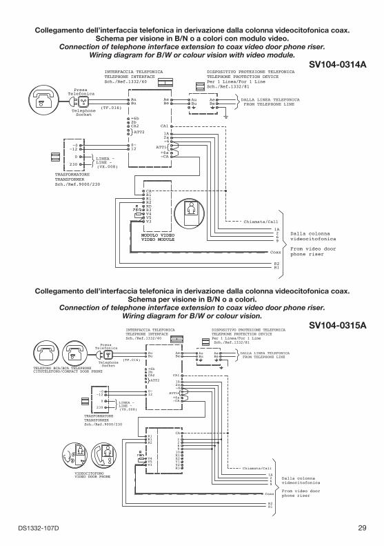
Collegamento dell’interfaccia telefonica in derivazione dalla colonna videocitofonica coax.Schema per visione in B/N o a colori con modulo video.
Connection of telephone interface extension to coax video door phone riser.Wiring diagram for B/W or colour vision with video module.
SV104-0314A
MODULO VIDEOVIDEO MODULE
Collegamento dell’interfaccia telefonica in derivazione dalla colonna videocitofonica coax.Schema per visione in B/N o a colori.
Connection of telephone interface extension to coax video door phone riser.Wiring diagram for B/W or colour vision.
SV104-0315A

30 DS1332-107D
Collegamento dell’interfaccia telefonica a 2 portieri elettrici (PE).Due chiamate provenienti dai PE.
Soluzione con commutazione tramite scatola a relè.Connection of the telephone interface to 2 entrance panels (door unit).
Two calls coming from door units. Solution based on relay switching box.
SC104-0193A
31DS1332-107D
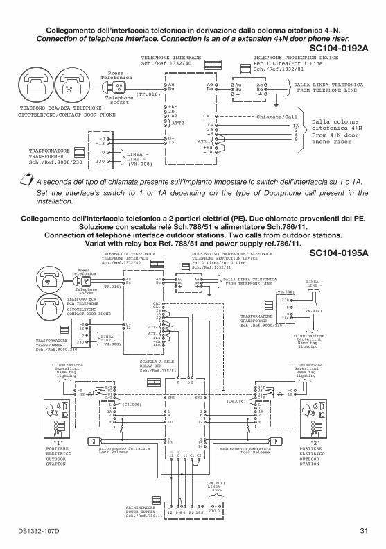
Collegamento dell’interfaccia telefonica in derivazione dalla colonna citofonica 4+N.Connection of telephone interface. Connection is an of a extension 4+N door phone riser.
SC104-0192A
Collegamento dell’interfaccia telefonica a 2 portieri elettrici (PE). Due chiamate provenienti dai PE.Soluzione con scatola relé Sch.788/51 e alimentatore Sch.786/11.
Connection of telephone interface outdoor stations. Two calls from outdoor stations.Variat with relay box Ref. 788/51 and power supply ref.786/11.
SC104-0195A
A seconda del tipo di chiamata presente sull’impianto impostare lo switch dell’interfaccia su 1 o 1A.
Set the interface’s switch to 1 or 1A depending on the type of Doorphone call present in the installation.
§

DS 1332-107D LBT 8367
Area tecnicaservizio clienti +39 011.23.39.810http://www.urmet.come-mail: [email protected] da Urmet Electronics Limited(azienda del gruppo Urmet) - Made in P.R.C.Manufactured by Urmet Electronics Limited(an Urmet group company) - Made in P.R.C.
URMET S.p.A.10154 TORINO (ITALY)VIA BOLOGNA 188/CTelef. +39 011.24.00.000 (RIC. AUT.)Fax +39 011.24.00.300 - 323
Collegamento dell’interfaccia telefonica a 2 portieri elettrici (PE).Chiamata singola e distinta dai PE.
Connection of the telephone interface to 2 entrance panels (door unit).Single and separate call from door units.
SC104-0163A