De Santis Ingegneria Informatica Automatica
102
Agostino De Santis Modelling and Control for Human–Robot Interaction Research Doctorate Thesis Advisor: Prof. Bruno Siciliano Scuola di Dottorato in Ingegneria dell’Informazione Dottorato di Ricerca in Ingegneria Informatica ed Automatica (XX ciclo) Coordinator : Prof. Luigi Pietro Cordella Dipartimento di Informatica e Sistemistica Universit ` a degli Studi di Napoli Federico II November 2007
-
Upload
sanchez-resendiz-bonifacio -
Category
Documents
-
view
223 -
download
0
description
Human Robot Interaction
Transcript of De Santis Ingegneria Informatica Automatica
7/21/2019 De Santis Ingegneria Informatica Automatica
http://slidepdf.com/reader/full/de-santis-ingegneria-informatica-automatica 1/102
Agostino De Santis
Modelling and Control for
Human–Robot Interaction
Research Doctorate Thesis
Advisor: Prof. Bruno Siciliano
Scuola di Dottorato in Ingegneria dell’Informazione
Dottorato di Ricerca in Ingegneria Informatica ed Automatica (XX ciclo)
Coordinator: Prof. Luigi Pietro Cordella
Dipartimento di Informatica e Sistemistica
Universita degli Studi di Napoli Federico II
November 2007
7/21/2019 De Santis Ingegneria Informatica Automatica
http://slidepdf.com/reader/full/de-santis-ingegneria-informatica-automatica 2/102
Contents
Acknowledgments . . . . . . . . . . . . . . . . . . . . . . . . . . . . . . . . . . . . . . . . . . . . . . . . . . iii
Summary . . . . . . . . . . . . . . . . . . . . . . . . . . . . . . . . . . . . . . . . . . . . . . . . . . . . . . . . . . v
1 Introduction . . . . . . . . . . . . . . . . . . . . . . . . . . . . . . . . . . . . . . . . . . . . . . . . . . . 1
1.1 Human–robot interaction in service robotics . . . . . . . . . . . . . . . . . . . . 1
1.2 European research projects and physical HRI . . . . . . . . . . . . . . . . . . . 3
1.2.1 PHRIDOM . . . . . . . . . . . . . . . . . . . . . . . . . . . . . . . . . . . . . . . . . 4
1.2.2 PHRIENDS . . . . . . . . . . . . . . . . . . . . . . . . . . . . . . . . . . . . . . . . . 5
2 A review of human–robot interaction themes for anthropic domains . 9
2.1 An atlas for physical HRI . . . . . . . . . . . . . . . . . . . . . . . . . . . . . . . . . . . . 9
2.1.1 General aspects on safety and dependability in
human-centered robotics . . . . . . . . . . . . . . . . . . . . . . . . . . . . . . 11
2.1.2 Mechanics and control issues for a safe pHRI. . . . . . . . . . . . . 15
2.1.3 Dependability in pHRI . . . . . . . . . . . . . . . . . . . . . . . . . . . . . . . . 202.2 Some possible contributions from a planning/control viewpoint . . . . 30
3 Multiple-point control . . . . . . . . . . . . . . . . . . . . . . . . . . . . . . . . . . . . . . . . . . 33
3.1 Kinematic control of multiple points. . . . . . . . . . . . . . . . . . . . . . . . . . . 33
3.1.1 Inverse kinematics and redundancy . . . . . . . . . . . . . . . . . . . . . 34
3.2 The multiple VEEs approach . . . . . . . . . . . . . . . . . . . . . . . . . . . . . . . . . 35
3.2.1 Nested closed-loop inverse kinematics. . . . . . . . . . . . . . . . . . . 36
3.2.2 Trajectory planning . . . . . . . . . . . . . . . . . . . . . . . . . . . . . . . . . . 39
3.2.3 An interesting biomimetic example . . . . . . . . . . . . . . . . . . . . . 40
3.3 Whole-body modelling and multiple control point . . . . . . . . . . . . . . . 47
3.3.1 Need for multiple control points . . . . . . . . . . . . . . . . . . . . . . . 47
3.3.2 Skeleton-based modelling . . . . . . . . . . . . . . . . . . . . . . . . . . . . . 47
3.3.3 Finding the possible collision points . . . . . . . . . . . . . . . . . . . . 50
3.3.4 Generating repulsion trajectories . . . . . . . . . . . . . . . . . . . . . . . 52
3.3.5 Computing avoidance joint commands . . . . . . . . . . . . . . . . . . 53

7/21/2019 De Santis Ingegneria Informatica Automatica
http://slidepdf.com/reader/full/de-santis-ingegneria-informatica-automatica 3/102
ii Contents
3.4 Torque-based and velocity-based control . . . . . . . . . . . . . . . . . . . . . . . 54
3.4.1 Modular Jacobian . . . . . . . . . . . . . . . . . . . . . . . . . . . . . . . . . . . . 55
3.4.2 Inverse kinematics with moving control points . . . . . . . . . . . . 55
3.4.3 Continuity of moving control points . . . . . . . . . . . . . . . . . . . . 56
4 Reactive motion and specifications for HRI . . . . . . . . . . . . . . . . . . . . . . . 59
4.1 Reactive motion control . . . . . . . . . . . . . . . . . . . . . . . . . . . . . . . . . . . . . 59
4.2 Collision avoidance trajectories . . . . . . . . . . . . . . . . . . . . . . . . . . . . . . . 61
4.2.1 Notes on collisions . . . . . . . . . . . . . . . . . . . . . . . . . . . . . . . . . . . 61
4.2.2 Multiple-point control resulting from potential fields. . . . . . . 61
4.3 Additional modelling for real-time whole-body control . . . . . . . . . . . 63
4.3.1 Environment and interacting persons . . . . . . . . . . . . . . . . . . . . 63
4.3.2 Limit distances and object shaping . . . . . . . . . . . . . . . . . . . . . . 66
4.3.3 Attractive and repulsive trajectories . . . . . . . . . . . . . . . . . . . . . 68
4.3.4 Skeleton-based whole-arm grasping . . . . . . . . . . . . . . . . . . . . . 69
4.4 Multiple tasks and cognitive aspects in HRI. . . . . . . . . . . . . . . . . . . . . 70
4.4.1 Priority and mobility distribution . . . . . . . . . . . . . . . . . . . . . . . 704.4.2 Legibility of motion and smoothness of movements . . . . . . . 71
4.4.3 Rules based on proxemics . . . . . . . . . . . . . . . . . . . . . . . . . . . . . 72
5 Applications . . . . . . . . . . . . . . . . . . . . . . . . . . . . . . . . . . . . . . . . . . . . . . . . . . . 73
5.1 Application to a human-friendly humanoid manipulator . . . . . . . . . . 73
5.1.1 Safety concepts and experimental setup at DLR . . . . . . . . . . . 73
5.1.2 Application of the skeleton algorithm for the Justin
manipulator . . . . . . . . . . . . . . . . . . . . . . . . . . . . . . . . . . . . . . . . . 74
5.2 Application to small industrial domains . . . . . . . . . . . . . . . . . . . . . . . . 78
5.2.1 Experimental setup at PRISMA Lab . . . . . . . . . . . . . . . . . . . . 79
5.2.2 An application with exteroception . . . . . . . . . . . . . . . . . . . . . . 79
5.3 Application to rehabilitation robotics in Virtual Reality . . . . . . . . . . . 82
5.3.1 Rehabilitation robotics and Virtual Reality . . . . . . . . . . . . . . . 825.3.2 Experiments at TEST Lab . . . . . . . . . . . . . . . . . . . . . . . . . . . . . 84
6 Conclusion and future research directions . . . . . . . . . . . . . . . . . . . . . . . . 87
6.1 Summary of tools for robotics in anthropic domains. . . . . . . . . . . . . . 87
6.1.1 Planning and control tools . . . . . . . . . . . . . . . . . . . . . . . . . . . . . 87
6.1.2 Real-time operation . . . . . . . . . . . . . . . . . . . . . . . . . . . . . . . . . . 88
6.1.3 Cognitive aspects . . . . . . . . . . . . . . . . . . . . . . . . . . . . . . . . . . . . 88
6.2 Developments . . . . . . . . . . . . . . . . . . . . . . . . . . . . . . . . . . . . . . . . . . . . . 88
References . . . . . . . . . . . . . . . . . . . . . . . . . . . . . . . . . . . . . . . . . . . . . . . . . . . . . . . . . 91

7/21/2019 De Santis Ingegneria Informatica Automatica
http://slidepdf.com/reader/full/de-santis-ingegneria-informatica-automatica 4/102
Acknowledgments
I deeply thank Prof. Bruno Siciliano for his invaluable support to the development of
the research activities which constitute the basis for this thesis and, more in general,
for his outstanding advising during these last three years. I have known him sinceI was an undergraduate student at the University of Salerno, and I have always ap-
preciated his scientific rigour, as well as his kindness. Since I began the Doctorate
School, I had the opportunity of experiencing also his loyalty, helpfulness, scientific
intuition, and managerial attitude. I also have to mention Prof. Luigi Villani, whose
support and advise always provided ground for deeper reflections and considerations.
I thank Dr. Vincenzo Lippiello for support in the experimental sessions and useful
discussions.
During these years, I have had the opportunity of travelling, due to my research
activity, for conferences, schools and periods spent overseas aimed at studying the
broad area of human–robot interaction (HRI). I have profitted from the possibility of
sharing ideas and discussion with the world robotics community. I have also bene-
fitted from the participation to the activities of the IEEE Robotics and Automation
Society.
A turning point has been represented by the semester that I spent at the Institute
of Robotics and Mechatronics of the German Aerospace Agency (DLR), directed
by Prof. Gerd Hirzinger in Oberpfaffenhofen, near Munich, in the framework of a
starting European cooperation in the field of physical HRI. This experience has been
rewarding for the extremely high qualifications of all the staff members of DLR.
Moreover, I had to manage all the daily duties of the life in Munich. My stay at DLR
has had a deep influence on my research, especially related to experimental activity,
organisation of the work, collaboration with colleagues.
Among the people met during my stay, Dr. Alin Albu-Schaffer deserves a spe-
cial mention. The quality of the research work performed by him and his group is
amazing. He has been extremely helpful and constructive in advising my activity. I
hope to continue our fruitful collaboration in next years. At DLR I have had also theopportunity of meeting Prof. Alessandro De Luca, in sabbatical leave there, who has
been very important for me not only for his scientific excellence and the interesting
discussions about robot control, but also for the constant friendly support.

7/21/2019 De Santis Ingegneria Informatica Automatica
http://slidepdf.com/reader/full/de-santis-ingegneria-informatica-automatica 5/102
iv Contents
I acknowledge the importance of the research carried out in the European projects
PHRIDOM and PHRIENDS, coordinated by Prof. Antonio Bicchi, which constitute
the framework of my activity: the multidisciplinary expertise of the involved research
centers is a key issue for the complexity of HRI.
At the local level, my advisor encouraged me also towards cooperation with re-search groups in our University. I want to mention the research done with the group of
Prof. Ernesto Burattini, related to cognitive robotics and roboethics. Recently, a joint
work on sensory-motor coordination with the young researchers of that group has
been started. Moreover, another explored interesting research track is related to the
use of Virtual Reality, thanks to the collaboration with the group of Prof. Francesco
Caputo, with the important support of Dr. Giuseppe Di Gironimo and young cowork-
ers.
I am also grateful to my Doctorate School, in the person of Prof. Luigi Pietro
Cordella, for the interesting courses provided. I thank the young colleagues met dur-
ing these years in Napoli, at DLR, during the summer schools and in the robotics
conferences: mentioning them all in few lines is impossible.
I gratefully acknowledge the contributions of coauthors of my research papers,both those used for this thesis, and those related to complementary research themes.
The final “important” dedication is for my family and for Manuela. Moreover, I
express my gratitude to my loved ones who passed away during these years. Finally,
a special mention is deserved by my teachers, both of Humanities and Science, from
the primary school up to the end of the Doctorate.
This work was supported by the PHRIENDS Specific Targeted Research Project,
funded under the 6 th Framework Programme of the European Community under Con-
tract IST-045359. The author is solely responsible for its content. It does not repre-
sent the opinion of the European Community and the Community is not responsible
for any use that might be made of the information contained therein
Napoli, November 2007
Ago
7/21/2019 De Santis Ingegneria Informatica Automatica
http://slidepdf.com/reader/full/de-santis-ingegneria-informatica-automatica 6/102
Summary
In the growing area of human-centered application for robotic manipulators, human–
robot interaction (HRI) poses new challenges for researchers and manufacturers in
robotics. Physical HRI (pHRI) can be accepted only when safety and dependabilityissues are addressed as the central criteria for all the phases of design and control
of robots for anthropic environments, while cognitive HRI (cHRI) is also relevant,
due to the relationships that different people can have with robots. The contributions
collected in this thesis are aimed at modelling and controlling robot manipulators for
HRI. The framework is provided by the research activities carried out in two Euro-
pean projects related to pHRI. The most notable results of the work include proper
modelling for simple geometric computation and real-time multiple-point control.
In detail, the contents of the thesis are organised as follows.
• Chapter 1 is an introduction which presents the relevance of human-centered ro-
botics for service applications. The framework of the research work in the next
section is introduced, i.e., the activities in the European projects PHRIDOM and
PHRIENDS. The distinction between cHRI and pHRI is emphasised.
• Chapter 2 contains a discussion about the many aspects arising from pHRI. While
traditional optimality for industrial robotics is related to speed and precision for
maximizing production, the presence of a person in the robot’s workspace asks
for new optimality criteria such as safety and dependability. The need for cooper-
ation neutralises the idea of enforcing safety by segregating machines and human
users. After a review of tools for guaranteeing safety, ranging from robot design
to sensors and actuators, a number of planning/control solutions are suggested.
• Chapter 3 presents the implementation of an approach to robot control with mul-
tiple control points, allowing desired motion trajectories in the workspace to such
points. The Virtual-End-Effectors (VEEs) approach is introduced, which consti-tutes the base for an algorithm for choosing an arbitrary control point of the robot,
namely, the so-called “skeleton algorithm”. Force and velocity implementations

7/21/2019 De Santis Ingegneria Informatica Automatica
http://slidepdf.com/reader/full/de-santis-ingegneria-informatica-automatica 7/102
vi Contents
for the multiple-point control approaches are discussed.
• Chapter 4 discusses both reactive motion, which is necessary in HRI due to the
difficulty of modelling the unstructured human environments, and evaluations
which are proper of cHRI. Issues are addressed which are complementary tothose introduced in the previous sections, together with issues arising form cog-
nitive evaluation on HRI tasks.
• Chapter 5 is aimed at showing how the presented algorithms and HRI-centered
strategies have been used for implementations on real robot manipulators, both
industrial and advanced, for real-time operation. A discussion on the use of Vir-
tual Reality (VR) for facing HRI from a cognitive point of view is addressed too.
The “comfort” of the user, which is an important aspect from a cognitive view-
point, provides an additional indicator for the evaluation of HRI system.
• Chapter 6 contains concluding remarks and proposals for possible developments.

7/21/2019 De Santis Ingegneria Informatica Automatica
http://slidepdf.com/reader/full/de-santis-ingegneria-informatica-automatica 8/102
1
Introduction
1.1 Human–robot interaction in service robotics
A robot can be a useful tool for the humanity: in a Western approach it is a ser-vant, more than a companion, according to its ethimology (the czech world “robota”
means “forced work”). It should help or substitute people in dangerous, repetitive,
or boring tasks, enhance human possibilities, and be able to cooperate with humans
in shared everyday environment. The extension of application domains for robotics,
from factories to human environments, is due to the elderly-dominated scenario of
most industrialised countries, the desire of automatizing common daily tasks, and
the lack or high cost of local human expertise.
Teleassistance and the use of computers and devices for remote medical care
are already paving the way to the future use of robots in domestic environments.
Suggested applications in service robotics include not only medical, domestic, per-
sonal assistance and home care domains, but also public-oriented service, cooper-
ative material-handling, power extenders and rehabilitation devices for welfare ap-plications, physical training, entertainment, warfare operations, while the inclusion
of the last in “service” application of robotics is controversial. An analysis of ap-
plication domain shows that service robotics is a growing market [1], and the most
important point is the intrinsic need for direct human–robot interaction (HRI) in hu-
man environments (see, e.g., [2] and bibliography therein).
In the last 20 years, with the growing interest applications of artificial intelli-
gence, autonomy and intelligence for robots has resulted interesting from an aca-
demic perspective. On the other hand, from an industry point of view, it has been
clear that the robots were perfect without any autonomy: the brute force provided by
manipulators was the key issue for automation applications. Industrial robotics is a
developing area since more than 30 years, also without direct cooperation in HRI.
Of course robots are not leaving industry, but better human–robot cooperation will
certainly affect the industrial domain, where users are also more skilled in managingmachines with reference to people who ask for robotic helpers or entertainers based
on the easiness of interface and amusement for autonomous mobile robots.

7/21/2019 De Santis Ingegneria Informatica Automatica
http://slidepdf.com/reader/full/de-santis-ingegneria-informatica-automatica 9/102
2 1 Introduction
In any case, close human–robot interaction and cooperation require robot which
are “intelligent”, with reference to “human-centered” properties more than to auton-
omy and classical AI reasoning capabilities. These properties are mainly related to
the guarantees of safety and dependability [3] for the persons interacting with the
robots. Therefore, performance of new robots is based on novel criteria, which focusboth on the user and the robot, and not only on industry-derived objective precision
metrics.
An “intelligent” robot is the one which mitigates fatigue and stress for human
workers, and industrial domains present the necessity of integrating human experts
in robotic cells. In this approach, supervision and cooperation of complex tasks can
be accomplished by humans while, at the same time, robots increase human capa-
bilities in terms of force, speed, and precision. In some applications which are not
fully automatised, human–robot cooperation is rewarding, since the human can bring
experience, global knowledge, and understanding for a correct execution of tasks.
Summarizing, the next generation of robots, both for service or cooperative work,
is expected to interact with people more directly than today [4]. Human–Robot In-
teraction will certainly happen at the cognitive level (cHRI), fundamentally due tomental models of HRI, and concerning communication between human and robot
through the many available channels of, e.g., video displays, sounds, mutual obser-
vation and imitation, speech, gaze direction tracking, facial expressions and hands’
gestures.
However, robots are distinct from computers or other machines: they physically
embody the link between perception and action, whose “intelligent connection” is a
definition for robotics, and often have an anthropomorphic appearance. At the same
time, they generate force and have a “body”: hence, the most revolutionary and chal-
lenging feature of the next generation of robots will be physical Human–Robot In-
teraction (pHRI). In pHRI, humans and robots share the same workspace, come in
touch with each other, exchange forces, and cooperate in doing actions on the envi-
ronment. This approach is affordable if robots can be considered service tools which
guarantee human safety and autonomy.
An effort is keeping the “physical viewpoint” while considering the importance
of inferences and evaluation on unstructured environments. This viewpoint influ-
ences the new paradigms for the design and control of robot manipulators. Robots
designed to cooperate with humans must fulfill different requirements from those
typically met in conventional industrial applications. Typical conventional robot sys-
tems and applications require fast motions and absolute accuracy in positioning and
path following and avoid using additional external sensing, provided that the appli-
cation is performed in perfectly known designed and modeled environments.
The most important change of perspective is related to the optimality criteria for
the considered manipulators: safety and dependability are the keys to a successful in-
troduction of robots into human environments. Only dependable robot architectures
can be accepted for supporting “human-in-the-loop” conditions and human–robotteams, and the safety of humans cooperating with robotic systems is the main need
for allowing pHRI [2].

7/21/2019 De Santis Ingegneria Informatica Automatica
http://slidepdf.com/reader/full/de-santis-ingegneria-informatica-automatica 10/102
1.2 European research projects and physical HRI 3
Given such a discrepancy in requirements between old industrial manipulators
and the next generation of service robots, robot design and control has to change to
enable applications that require intrinsically safe pHRI.
Modelling of unstructured domain is a key issue for robotics in interaction with
humans: the listed future application areas have to use sensory systems and tradein certain performance characteristics of the robot system to drastically increase de-
pendability and overall safety in unpredictable dynamically changing environments.
Notice also that, right now, a sort of Descartes “duality” leads to accepting a di-
chotomy: the “brain” of robotic systems is usually studied by computer scientists and
neuroscientists, whereas the study of mechanisms and their control is assigned to cy-
bernetics, electronic, and mechanical engineers. Cognitive and physical interaction,
however, are not independent: physical interaction can help in setting rules for cogni-
tive evaluations of the environment during interaction tasks, while cognitive aspects
may improve the physical interaction by setting suitable control interaction parame-
ters. As a simple example, haptics can be used to “understand” the characteristics of
an environment (soft or rigid), while cognitive-based inference rules can be consid-
ered for compliance control of manipulators physically interacting with humans (if the person is a child, then the compliance should be high).
This thesis is meant to provide contributions from planning/control viewpoints,
exploiting both cHRI- and pHRI-related aspects. Such contributions have been made
possible thanks to the current research activity on safety and dependability in pHRI,
performed under European projects featuring collaboration between academic, re-
search and industrial institutions.
1.2 European research projects and physical HRI
Research for analysis and possible standardisation of HRI applications is fastly grow-
ing in the last few years all around the world: the importance of international stan-
dards and their continuous revision, and the relevance of service application of ro-
botics have lead to a discussion on safety design for human-centered robotics.
European research centers and industry are providing both technical tools and
discussion about these issues, as better stressed in Section 2.1. The European Ma-
chine Directive 98/37/EC states that all appropriate measures shall be taken to en-
sure that machinery or safety components may be placed on the market and put into
service only if they do no endanger the health or safety of persons and, where appro-
priate, domestic animals or property.
In general, industrial robot safety is enforced by strictly segregating the work-
spaces of humans and moving robotics and automation systems. This is clearly un-
desired when humans and robots need to share their workspaces for collaborative
tasks.
It becomes evident that research has to focus on the possible introduction of ro-bots for collaborative task in a way such to guarantee safety and dependability as
central criteria for pHRI modelling and control. Focusing on the activity which con-
stitutes the framework for this thesis, two research projects have been proposed for

7/21/2019 De Santis Ingegneria Informatica Automatica
http://slidepdf.com/reader/full/de-santis-ingegneria-informatica-automatica 11/102
4 1 Introduction
facing the complexity of these topics, and for providing significant advances and
insight in the territory of pHRI: the Prospective Research Project “Physical Human–
Robot Interaction in anthropic DOMains (PHRIDOM)” [3], and the Specific Tar-
geted Research Project (STReP) “Physical Human–Robot Interaction: depENDabil-
ity and Safety (PHRIENDS)” [4], funded in the 6th European Research Framework Programme.
Recently, the 7th EU Research Framework Programme [5] has been introduced,
and it addresses robotics and cognitive systems as a relevant track: results of the on-
going cited project PHRIENDS are expected to give benefits to the next generation
research projects.
1.2.1 PHRIDOM
The Prospective Research Project PHRIDOM, funded by the European Robotics
Network of Excellence EURON, represents an exploratory work in analyzing safety
and dependability issues in human-centered robotics, where machines have to closely
interact with humans.The PHRIDOM project has investigated needs, related to tech-nology and requirements, for safe and dependable robots in pHRI, by emphasizing
the difference of human environments with respect to industrial applications. It is
often the case, for instance, that accuracy requirements are less demanding.
On the other hand, a concern of paramount importance is safety of the robot sys-
tem: under no circumstances should a robot cause harm to people in its surroundings,
directly nor indirectly, in regular operation nor in failures. This suggest that standards
of reliability must be rethought. From a system viewpoint, however, a pHRI machine
must be considered as part of unpredictably changing anthropic environments. From
this point of view, “failures” are events (e.g., contacts with a person, unexpected
changes of mind or mistakes by the user) that cannot be ruled out in principle, and
must rather be faced by suitable policies. The need hence arises for fault detection,
and for fault management and recovery.
One important point to stress is the expertise of the user: unskilled users are
expected to use robot assistant or prothesis, therefore they will have physical contact
and interaction with the robot without clear awareness of risk and possible robot’s
behaviour.
In general, pHRI applications also raise critical questions of communication and
operational robustness. These aspects can be captured by the concept of dependabil-
ity, a crucial focus of PHRIDOM. Of course, user’s safety is not one attribute like
others for dependability. The next most crucial requirement for pHRI systems after
dependability remains with their performance, meeting some of the old performance
criteria, like accuracy, speed, repeatability.
To be useful, however, requirements must be quantified and/or formalised. The
PHRIDOM Consortium started providing unambiguous definitions of concepts such
as safety, fault robustness, dependability, performance, in relation with the differentapplication domains. One result of the studies in PHRIDOM has been the preparation
of a guide to the main topics for pHRI, which is the base for Section 2.1 of this
thesis. The effort has been to consider together safety and dependability as the unified

7/21/2019 De Santis Ingegneria Informatica Automatica
http://slidepdf.com/reader/full/de-santis-ingegneria-informatica-automatica 12/102
1.2 European research projects and physical HRI 5
optimality criteria for future technical challenges in the design of robots for human
environments [6].
This analysis follows the idea of a geographic atlas [7], showing contact points
and overlapping interests. In the PHRIDOM project issues and discussions resulting
from different research groups about possible metrics for the evaluation of safety,dependability, and performance in pHRI lead to a huge preparatory work, which has
been inherited by the PHRIENDS project.
1.2.2 PHRIENDS
There is a change in perspective for the role of control systems: they can add safety
to heavy robots or give performance to intrinsically safe robots. While in the present
this still depends on the available robots, in the future the approach suggested in the
PHRIENDS project is quite novel and revolutionary.
In fact, the proposed integrated approach to the co-design of robots for safe phys-
ical interaction with humans revolutionises the classical approach for designing in-
dustrial robots —rigid design for accuracy, active control for safety— by creating anew paradigm: design robots that are intrinsically safe, and control them to deliver
performance. In addition, control for safety on existing robots is addressed too.
In the framework of the PHRIENDS project, the involved research crew has the
mission of developing key components of the next generation of robots, including
industrial and service manipulators, whose application domains are, e.g., assistance,
health care, and entertainment, designed to share the environment and to physically
interact with people. Such machines have to meet the strictest safety standards, yet
also to deliver useful performance: this poses new challenges to the design of all
components of the robot, including mechanics, control, planning algorithms and su-
pervision systems, sensing.
Although a single project cannot encompass the integration of a complete ro-
bot system, new actuator concepts and prototypes, new dependable algorithms for
supervision and planning, new control algorithms for handling safe pHRI and for
fault-tolerant behaviour will be explored. Moreover, meaningful subsystems will be
integrated, also for contributing to the effort of international bodies towards the es-
tablishment of new standards for collaborative human–robot operation.
These ambitious objectives will be achieved through the presence in the consor-
tium [4] of academic groups, research laboratories, and an industrial partner who has
specific competence in HRI. The effort in modelling, design, and control, resulting
by the complementary expertise provided by the involved team is meant lo lead to
advance the state-of-the-art in two complementary directions:
1. integrate new algorithms in existing manipulators, and allow new paradigms for
pHRI in service and industrial environments;
2. design, implement, test, and optimize the core components of the next-generation,intrinsically safer robot arms.
The first section of the project will lead to an experimental platform that is
based on a revolutionary robot for pHRI both in industrial and service domains:

7/21/2019 De Santis Ingegneria Informatica Automatica
http://slidepdf.com/reader/full/de-santis-ingegneria-informatica-automatica 13/102
6 1 Introduction
the KUKA light-weight robot arm (LWR, see Fig. 1.1), based on the third generation
of the Lightweight Robot (LWR-III) [8], developed by the Institute for Robotics and
Mechatronics of the German Aerospace Agency (DLR). Its controller will integrate
in a prototypical fashion the newly developed algorithms.
Fig. 1.1. The KUKA LightWeight Robot (LWR) is a result of technology transfer by DLR
The second complementary part of the project will lead to test beds that will beused to evaluate and optimise safety and performance characteristics of a new gener-
ation of intrinsically safe robot arms. Eventually, all project activities will culminate
in experimental platforms and test-beds.
Safe and dependable human-centered robotics has of course ethical motiva-
tions [9], but it also pays off. Results of the PHRIENDS project are expected to
deeply impact applications where successful task completion requires people and ro-
bots to collaborate directly in a shared workspace. In fact, market pressures are about
to reduce the separation between robots and people. New standards will deeply af-
fect the robotics market. Current safety solutions are done by each robot producer in
an individual way, under their responsibility with respect to legislation. The interest
and involvement of robot manufacturers in the developments concerning standards
is therefore even more important with the constant growth of application scenarios.According to preliminary results and discussion in the PHRIENDS consortium, the
process of revising and creating new standards is expected to influence quantitative
safety measures, risk assessment procedures, and collaborative assist devices. This

7/21/2019 De Santis Ingegneria Informatica Automatica
http://slidepdf.com/reader/full/de-santis-ingegneria-informatica-automatica 14/102
1.2 European research projects and physical HRI 7
flow of information and contributions is planned to happen through active partic-
ipation to specialised conferences and participation in the International Standards
Organisation committees, summarizing the project’s views and recommendations in
a series of reports.
The approaches to modelling and control of robot manipulator for interactionwith people presented in this thesis are collocated in the framework of PHRIENDS,
and preliminary remarks are discussed in Chapter 2.

7/21/2019 De Santis Ingegneria Informatica Automatica
http://slidepdf.com/reader/full/de-santis-ingegneria-informatica-automatica 15/102

7/21/2019 De Santis Ingegneria Informatica Automatica
http://slidepdf.com/reader/full/de-santis-ingegneria-informatica-automatica 16/102
2
A review of human–robot interaction themes for
anthropic domains
While traditional optimality criteria for industrial robotics were meant to maximize
production, the presence of a person in the robot’s workspace neutralises the idea
of enforcing safety by segregating machines and human users, like in present in-dustrial robotics workspaces. The PHRIDOM and PHRIENDS consortia provided
proposals and collected needs and starting points for solutions to contemplate the
presence of human beings in robot’s workspace. The problem of objective evalua-
tion of safety and dependability is not yet solved: a review about the many aspects
arising from physical interaction with robots is provided for presenting relevant is-
sues which claim for a complete rethinking in all the phases of robot design and
control approaches, in order to address the novel optimality criteria. Possible contri-
butions from a planning/control viewpoint are suggested, which will be developed in
the next chapters.
2.1 An atlas for physical HRIResearchers worldwide are studying the social factors related to the introduction of
robots in human environments and often their attention is focused on the cognitive
interaction with machines. Since it is impossible to model every action in an unstruc-
tured anthropic environment, the “intelligent connection of perception with action”
of robots implies the presence of autonomous behaviour, which is interesting per se
and needed to solve real problems. However, this can result in dangerous situations
for humans co-existing in the robot operational domain.
In order to spread the presence of robots in everyday life, personal robots just
like personal computers, safety and dependability issues must be solved first [2].
However, it must be pointed out that safety standards for pHRI are still not well
defined in the scientific community, and research evidences confirm the need for a
renewed standardisation activity. In the next chapters, some contributions will bepresented to address some of these issues.
Many crucial points for robots in human environments can result in danger, such
as natural motion, unexpected behaviours caused by the necessary autonomy, faults.

7/21/2019 De Santis Ingegneria Informatica Automatica
http://slidepdf.com/reader/full/de-santis-ingegneria-informatica-automatica 17/102
10 2 A review of human–robot interaction themes for anthropic domains
It is worth noticing that, while robots should make “independent decisions”, their de-
signers must consider physical, social and ethical implications of such autonomy [2].
Efficient communication systems are crucial to have “wearable robots” analogous to
“wearable” PCs, and their dependability is also relevant. While computers are no
longer perceived as strange machines also because they do not pose evident threatsto user’s safety, current robots are still heavy and unsafe.
Moreover, the crucial point is to consider the current mechanical structure of the
robots available on the market. It is clear how physical issues are crucial, since “nat-
ural” or unexpected behaviour of people during interaction with robots can result
in very severe injuries caused by accidental collisions. Especially in Europe, atten-
tion has recently been devoted to ethical issues, considering not only robotic/neural
implants in human bodies, but also consequences of robot actions in an anthropic
domain (see [9]).
One crucial capability of a robot for pHRI is the generation of supplementary
forces to overcome human physical limits. In anthropic domains, a robot may sub-
stitute the complex infrastructure needed for environments equipped with sensory
systems capable of “intelligent” monitoring or telesurveillance. In these cases, in-stead of equipping the environment with many sensors and devices, a single robot
could behave both as a sensor and as an actuator, able to navigate through different
rooms, sense the environment, and perform the requested task.
Therefore, an improved analysis of the problems related to the physical in-
teraction with robots becomes necessary. This topic must be addressed consider-
ing together the design of mechanism, sensors, actuators and control architecture
in the special perspective for the interaction with humans. When determining the
differences between computers and robots from a user point of view, one should
also deeply consider the key problem of embodiment. People seem to perceive au-
tonomous robots differently than they do with most other computer technologies:
mental models are more anthropomorphic, and people attribute to robots human-like
qualities and capabilities. During a physical interaction, if human-like robotic arms
are used, motion capabilities can be simpler to understand (“legible”). In general,
the user response to such an interactive system is always dominated by a specific
mental model about how the robot behaves. If the robot looks like a living creature,
the mental model of its behaviour may approach the mental model of humans or
of pets, and there may also be unexpected social interactions [10]. A user mental
model may result in a faked perceived robot “dependability”: its zoomorphism or
the human posture of a humanoid robot could give a wrong idea about the aware-
ness of the robot, since it looks like a living creature. Indeed, mental models can
be changed with experience, but anthropomorphism is still a forced consequence of
our nature, especially for non-skilled users, because “our imagination cannot be any-
thing but anthropomorphic” [11]. These mental models depend strongly on cultural
approaches [12]: a robot can be a companion or a servant. Safety issues are usually
considered more relevant for robot servants, while robot companions have typicallya simpler mechanical design because the focus is on cognitive interaction and not on
task execution.

7/21/2019 De Santis Ingegneria Informatica Automatica
http://slidepdf.com/reader/full/de-santis-ingegneria-informatica-automatica 18/102
2.1 An atlas for physical HRI 11
Fig. 2.1. This “map” of robotics for anthropic domains includes the main issues and superpo-
sitions for pHRI
Effective communication between a person and a robot may depend on whether
there exists a common domain of understanding: HRI, which focuses on a complex
combination of the user and the robot, including the relationship with the “body” of
the robot, is different with respect to a simple human–computer interaction. More-
over, different roles of interaction with robots are possible since different people
interact in different ways with the same robot, and the robot in turn reacts differently
based on its perception of the world.
In addition, there are failure modes of the robot that can degrade the quality of the
interaction and not only the safety. The interface design is crucial to let the human be
aware of the robot possibilities and to provide her/him with a natural way to keep the
robot under control at every time. With reference to Figure 2.1, it is worth noticing
how numerous are research and development domains identified for a comprehensive
approach to solutions for dependable robots in human environments.
2.1.1 General aspects on safety and dependability in human-centered robotics
In the complexity of a HRI, the physical viewpoint is mainly focused on the risks
of collisions occurring between the robot and its user: too high energy/power may
be transferred by the robot, resulting in serious human damages. Severity indices of

7/21/2019 De Santis Ingegneria Informatica Automatica
http://slidepdf.com/reader/full/de-santis-ingegneria-informatica-automatica 19/102
12 2 A review of human–robot interaction themes for anthropic domains
injuries may be used to evaluate the safety of robots in pHRI. These should take into
account the possible damages occurring when a manipulator collides with a human
head, neck, chest or arm.
In order to increase robot safety, among the numerous aspects of manipulator
design to be considered, the elimination of sharp edges can reduce the potential forlacerations. The main solution for reducing the instantaneous severity of impacts is
to pursue a mechanical design that reduces manipulator link inertia and weight by
using lightweight but stiff materials, complemented by the presence of compliant
components in the structure. Compliance can be introduced at the contact point by
a soft covering of the whole arm with visco-elastic materials or by adopting com-
pliant transmissions at the robot joints. The latter allow the actuators rotor inertia
to be dynamically decoupled from the links, whenever an impact occurs. The safety
tactics involve mechanics (see Section 2.1.2), electronics, and software. Improve-
ments for anticipating and reacting to collisions can be achieved through the use of
combinations of external/internal robot sensing, electronic hardware and software
safety procedures, which intelligently monitor, supervise, and control manipulator
operation.Indeed, the problem of blending the requirements for safety while keeping “tra-
ditional” robot performance (speed and accuracy) high remains an open challenge
for the designers of human-centered robotic manipulators [13]. As clear from the
previous discussion, safety metrics that consider only the brain” of the robot as an
intelligent machine are inappropriate in this context. Asimov’s famous “three laws of
robotics” are mainly science fiction, since the “will” of the robots cannot be clearly
mapped into motion behaviours, so that it is difficult for a robot to be aware of the
potential damages.
The dependability of the system must be also understood. The “passive” safety
is easy to understand: springs, rubber coverings, artificial skin, which have of course
a real effect on reduction of damages, have also the additional property of being
present in everyday life for the same purposes. The most obvious relation between
cognitive “fear” related to physical injuries is the scary appearance of a robot, while
the awareness of implemented safety systems could help. As an example of safety
tools which are not visible, consider ABS, ESP and the other systems for safety in the
cars. These safety devices are hidden, but they add dependability and people know
that they can trust on them: “ubiquitous robotics” as well as ubiquitous computing
can be guaranteed if safety and dependability are both guaranteed and understood.
Moreover, consider that humanity came from a monster approach to the car and the
train, present in lyrics and books of the first period of last century, to the human-
like relation with this “everyday” ubiquitous machines, thanks to their (perceived)
dependability.
The research in pHRI must consider any issue which could lead to define bet-
ter evaluation criteria for the safety and dependability, considering “scores” or even
“cost functions” to include the impact of different issues related to design and controlof pHRI.
7/21/2019 De Santis Ingegneria Informatica Automatica
http://slidepdf.com/reader/full/de-santis-ingegneria-informatica-automatica 20/102
2.1 An atlas for physical HRI 13
Safety standards and injury criteria
This section cannot be exhaustive: it will just point out some aspects of physical in-
teraction with robots which claim for risk assessment procedures which complement
the undergoing revolution of standards.An important example of standard for robot safety in factories is the ANSI/RIA
R15.06-1999 (American National Standard for Industrial Robots and Robot Sys-
tems – Safety Requirements). This standard addresses the requirements for person-
nel safety in industrial environments where robotic manipulators are employed. The
complementary design standard ANSI/UL 1740 states hardware requirements and
specifications, harmonised with R15.06: if the hardware is built in compliance with
UL 1740, the safeguarding requirements in R15.06 are met. Other standards are
present worldwide, as the European standard EN 775, and their international equiv-
alent is the ISO 10218.
This standard has been revised in 2006, while the modifications are not already
effective. The modifications allow cooperation with prescribed limits for speed and
power. It must be pointed out, however, that the case when robots and people haveto share the operational space is not clearly discussed. Actually, the standard poses
human–robot segregation in the workplace as the way to obtain safety. Work has
been ongoing since, gradually turning what started as a simple harmonisation effort
into a genuine development effort introducing new concepts to the world of industrial
robot safety.
The revised ISO 10218 (“Robots for Industrial Environment - Safety”) will be
a two part document. Part 1, entitled “Design, Construction and Installation”, is in-
tended to be fully compliant with the European Machinery Directive and expected
to replace the existing EN775 in due course. Part 2, work on which has recntly be-
gun, has a working title of “Application and Use of Robots in the Work Place” and
is intended to address work place safety requirements and is directed more to the
end-user than the manufacturer. Most salient changes under consideration involve
the following issues.
• Control Reliability: revised standards will allow safety-related control circuitry
to use state-of-the-art electronic, programmable, and network based technology
(including wireless).
• Safeguarding and Clearance: minor changes in clearance requirements are ex-
pected (from 18 inches to 0.5 meters), while attention is devoted towards com-
pletely removing the requirement for safeguarding in the presence of enhanced
capabilities and features of the robot control system.
• New modes of operation: the committee is developing requirements for “syn-
chronised” robot control, “mobile” robots mounted on Automated Guided Vehi-
cles (AGV), and “assisting” robots which work in a “collaborative workspace”
with the operator [4] .
It is worth pointing out that the ISO Technical Committee (TC 184/Subcommitee
2) dealing with standardisation activities on robotics is still working also on “Robots
in Personal Care”. For unstructured anthropic domains, available standards, before
7/21/2019 De Santis Ingegneria Informatica Automatica
http://slidepdf.com/reader/full/de-santis-ingegneria-informatica-automatica 21/102
14 2 A review of human–robot interaction themes for anthropic domains
their possible revision, are not very useful. Criteria for defining safety levels in HRI
(inside and outside factories) are strictly related to the possible injuries caused by ro-
bots. Note that recently some European robot manufacturers (ABB, KUKA Roboter,
Reis Robotics) have included software modules that monitor through external sens-
ing the Cartesian space around the robot and stop operations in case of danger. Inparticular, the PHRIENDS partner KUKA Roboter GmbH is leading these changes,
having developed a safety system for industrial robots incorporating a safety-related
fieldbus, (SafetyBUS) in a car production line.
Several standard indices of injury severity exist in other, non-robotic, domains.
For evident reasons, the automotive industry was the first to define quantitative mea-
sures, indices and criteria for evaluating injuries due to impacts. These sets of studies
have been suggested as a starting point for safety evaluation in robotics [14], [15],
using the automotive crash testing which considers two distinct types of loading con-
cerning head injuries. The first type is a “direct interaction”, i.e., a collision of the
head with another solid object at appreciable velocity. The second type is an “indirect
interaction”, i.e., a sudden head motion without direct contact. The load is generally
transmitted through the head-neck junction upon sudden changes in the motion of thetorso. In order to quantify the injury severity produced by the impact with a robot, a
scaling is needed. A definition of injury scaling developed by the automotive industry
is the Abbreviated Injury Scale (AIS). If more than one part of the body is involved,
the one with maximum injury severity is considered as the overall injury severity,
which is indicated as Maximum AIS (MAIS). The type of injuries are divided in a
classification, reported in [16], which relates the type of injury (“Minor”, “Moder-
ate”, up to “Critical”), to its consequences (“Superficial”, “Recoverable”, “Not fully
recoverable with care” and so forth), and gives a number in a scale from 0 to 6 (for
fatal injuries) in the injury scale.
Such a qualitative scaling gives does not give any indication on ways to measure
injury. This is provided by the so-called severity indices. Biomechanically motivated
severity indices evaluated by impact tests are discussed in [14]. Briefly, among the
theoretical basements of these criteria, there are the Vienna Institute Index and the
so-called Wayne State Tolerance Curve (WSTC), which relates accelerations to skull
fractures. The plot of the WSTC curve in log–log coordinates by Gadd [17] resulted
in a straight line of slope −2.5, and the according severity index (Gadd Severity
Index) is the integral of the head acceleration to the power of 2.5 during the rele-
vant duration of collision. For the head quite many criteria are available for the first
type of loading (direct interaction). In the various interpretations of the WSTC, a
model of the head is usually assumed in the form of a mass–spring–damper system.
The mostly used head severity index is the head injury criterion (HIC) [18], which
considers together the effects of the impact duration δt and of the head acceleration
during the specified time interval. Fixed values for δt define specific HIC criteria,
i.e., limits to the maximum head acceleration without harm for pulses not exceeding
a duration of δt.The HIC focuses on the head acceleration and indicates that very intense ac-
celeration is quite tolerable if very brief, while potentially harmful for pulse dura-
tion exceeding 10 or 15 ms (as time exposure to cranial pressure pulses increases,
7/21/2019 De Santis Ingegneria Informatica Automatica
http://slidepdf.com/reader/full/de-santis-ingegneria-informatica-automatica 22/102
2.1 An atlas for physical HRI 15
the tolerable intensity decreases). The maximum power index (MPI) is instead the
weighted change of kinetic energy of the human head before and after impacts, with
the weighting carried out by two sensitivity coefficients in each direction. This in-
jury criterion is suggested as alternative to the HIC since it is derived from the same
underlying type of data (accelerations) but has physically relevant units. In the maxi-mum mean strain criterion (MSC), a mass–spring–damper model of the head is used
and expanded by the presence of a second mass; the average length of the head
is considered as a parameter too. For torso injuries, the available criteria can be
generally divided into four groups: acceleration-based criteria, force-based criteria,
compression-based criteria, and soft-tissue-based criteria. For neck injuries, frontal
and rear impacts have different effects and thus they are addressed separately. In
general, the mechanisms of injury of the human neck are potentially related to the
forces and bending moments acting on the spinal column. Two severity indices for
the neck were often considered: the neck injury criterion for frontal impacts and the
neck injury criterion for rear impacts (for details, please refer to [16]).
For coping with the conversion of severity indices to the probability of MAIS
level, the National Highway Traffic Safety Administration specified empirical equa-tions for converting e.g. HIC values to the probability of MAIS level. These conver-
sions provide a scaling of injury severity. Recent evidences suggested by DLR [16]
show that values of severity indices from automotive industry computed for colli-
sion on the the DLR LWR-III are not very adequate for robotics: the robot does not
case serious harms according to the scaling, since operating velocities in pHRI are
low with respect to those considered in setting severity indices for automobile crash-
tests. PHRIENDS partners DLR and KUKA are leading experimental assessment for
definition of novel injury criteria in pHRI. The new indices are expected to take into
account improvements both in active and passive safety mechanisms.
2.1.2 Mechanics and control issues for a safe pHRI
The discussed novel additional optimality criteria for pHRI lead to redesign robots
starting from the mechanics. The intrinsic or passive safety cannot be underesti-
mated: “Rocks don’t fly” synthesises the driving force in the mechanical design of
lightweight robots.
The simple addition of a passive compliant covering in order to reduce impact
loading is impractical and does not address the root cause of high impact loads due
to the large effective inertia of most robotic manipulators. Finally, protective skins
or helmets for humans are normal only in industrial domains, and not natural in
anthropic domains.
Modern actuation strategies, as well as force/impedance control schemes, seem to
be anyway crucial in humanrobot interaction. On the other hand, a more complete set
of external sensory devices can be used to monitor task execution and reduce the risks
of unexpected impacts. However, even the most robust architecture is endangered bysystem faults and human unpredictable behaviour. This suggests to improve both
passive and active safety for robots in anthropic domains.

7/21/2019 De Santis Ingegneria Informatica Automatica
http://slidepdf.com/reader/full/de-santis-ingegneria-informatica-automatica 23/102
16 2 A review of human–robot interaction themes for anthropic domains
An important point which is a base for his thesis is the complementarity of the
work in modelling and control for improved safety. Safety tactics can be classified
into intrinsic or mediated by control. The reduction of the possible effect of impacts
depends on the minimisation both of the risk of collision and of consequences of
collisions.In particular, also planning/control approaches can have different strategies based
on their role: very precise modelling of people and robot is precise and improves the
task performance, reducing the limitations in robot’s motion for collision avoidance.
However, it can be time-consuming; on the other hand, simple modelling can be too
conservative, but very fast and possibly integrated into a variety of already imple-
mented control systems, such force or impedance control for close interaction.
Mechanics and actuation for pHRI
Relevant service robots for pHRI
The first important criterion to limit injuries due to collisions is to reduce the weightof the moving parts of the robot. Moreover, the reduction of robot’s apparent inertia
has been realised though different elastic actuation/transmission arrangements which
include:
• relocation of actuators close to the robot base
• transmission of motion through steel cables and pulleys
• combination of harmonic drives and lightweight link design
• use of parallel and distributed macro-mini actuation with elastic couplings
A prototypical example of lightweight design is the DLR LWR-III [8], which is
capable of operating a payload equal to its own weight (13.5 kg). Advanced light but
stiff materials were used for the moving links, while motor transmission/reduction
is based on harmonic drives, which display high reduction ratio and efficient power
transmission capability.
In addition, there is the possibility of relocating all the relevant weights (mostly,
the motors), at the robot base, like it has been done for the Whole Arm Manipula-
tor (WAM) [19], manifactured by Barrett Technology [20]. This is a very interesting
cable-actuated robot, which is also backdrivable, i.e., by pushing on the links, it is
possible to force motion of all mechanical transmission components, including the
motors’ rotors. In the case of a collision, the lighter links display lower inertia and
thus lower energy is transferred during the impact. On the other hand, compliant
transmissions tend to decouple mechanically the larger inertias of the motors from
those of the links. The presence of compliant elements may thus be useful as a pro-
tection against unexpected contacts during pHRI.
More in general, a lightweight design and/or the use of compliant transmissions
introduce link [21] and, respectively, joint [22] elasticity. In order to preserve per-formance while exploiting the potential offered by lightweight robot arms, one must
consider the effects of structural link flexibility. Distributed link deformation in ro-
bot manipulators arises in the presence of very long and slender arm design (without
7/21/2019 De Santis Ingegneria Informatica Automatica
http://slidepdf.com/reader/full/de-santis-ingegneria-informatica-automatica 24/102
2.1 An atlas for physical HRI 17
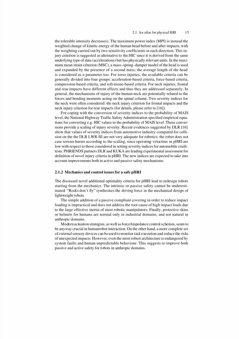
Fig. 2.2. The DLR humanoid manipulator Justin has an articulated torso, two DLR LWR–III
arms, articulated head with vision system, two DLR–II Hands
special care on materials); notice that “link rigidity” is always an ideal assumption
and may fail when increasing payload-to-weight ratio.
On the other hand, in the presence of compliant transmissions, deformation can
be assumed to be instead concentrated at the joints of the manipulator. Neglected
joint elasticity or link flexibility limits static (steady-state error) or dynamic (vibra-
tions, poor tracking) task performance. Problems related to motion speed and control
bandwidth must be also considered. Flexible modes of compliant systems prevent
control bandwidths greater than a limit; in addition, attenuation/suppression of vi-
brations excited by disturbances can be difficult to achieve. Intuitively, compliant
transmissions tends to respond slowly to torque inputs on the actuator and to oscil-
late around the goal position, so that it can be expected that the promptness of an
elastically actuated arm is severely reduced if compliance is high enough to be ef-fective on safety. From the control point of view, there is a basic difference between
link and joint elasticity. In the first case, we have non-colocation between input com-
mands and typical outputs to be controlled; for flexible joint robots, the co-location
of input commands and structural flexibility suggests to treat this case separately.
Variable-impedance actuation
Very compliant transmissions may ensure safe interaction but be inefficient in trans-
ferring energy from actuators to the links for their fast motion. An approach to gain
performance for guaranteed safety joint actuation is to allow the passive compliance
of transmission to vary during the execution of tasks.
The variable impedance approach (VIA) [23] is a mechanical/control co-design
that allows varying rapidly and continuously during task execution the value of me-chanical components such as stiffness, damping, and gear-ratio, guaranteeing low
levels of injury risk and minimizing negative effects on control performance. In this
approach the best possible trade-off between safety and performance is desired. For
7/21/2019 De Santis Ingegneria Informatica Automatica
http://slidepdf.com/reader/full/de-santis-ingegneria-informatica-automatica 25/102
18 2 A review of human–robot interaction themes for anthropic domains
a mechanism with given total inertia and actuator limits, one can formulate an opti-
mal control problem to be used for comparing mechanical/actuation alternatives at
their best control performance. One interesting formulation is the following: find the
minimum time necessary to move between two given configurations (with associated
motion and impedance profiles), such that an unexpected impact at any instant duringmotion produces an injury severity index below a given safety level. This is called
the Safe Brachistochrone problem [24]. The optimal solution obtained analytically
and numerically for single-dimensional systems shows that low stiffness is required
at high speed and vice versa. This matches with intuition since most of the motion
energy transfer from the motor should occur during the initial and final accelera-
tion/deceleration phases. This ideal solution provides guidelines to be used also for
multidimensional systems. Please refer to [23], [24], for design and implementation
details.
Distributed macro-mini actuation
Another approach to reduce manipulators arm inertia for safety, while preserving
performance, is the methodology of distributed macro-mini actuation DM2 [25]. For
each degree of freedom (joint), a pair of actuators are employed, connected in parallel
and located in different parts on the manipulator.
The first part of the DM2 actuation approach is to divide the torque generation
into separate low and high frequency actuators whose torques sum in parallel. Grav-
ity and other large but slowly time-varying torques are generated by heavy low-
frequency actuators located at the base of the manipulator. For the high-frequency
torque actuation, small motors collocated at the joints are used, guaranteeing high-
performance motion while not significantly increasing the combined impedance of
the manipulator-actuator system. Finally, low impedance is achieved by using a se-
ries elastic actuator (SEA) [26] . It is important to notice that often high-frequency
torques are almost exclusively used for disturbance rejection. The effective inertia of
the overall manipulator is reduced by isolating the reflected inertia of the actuatorswhile reducing the overall weight of the manipulator.
Control techniques for pHRI
Operational tactics can also actively contribute to safety, by means of suitable control
laws, and more sophisticated software architectures may overcome some limitations
of mechanical structure. Indeed, control methods cannot fully compensate for a poor
mechanical design, but they are relevant for performance improvement, reduced sen-
sitivity to uncertainties, and better reliability.
Typically, current industrial robots are position-controlled. However, managing
the interaction of a robot with the environment by adopting a purely motion control
strategy turns out to be inadequate; in this case, a successful execution of an inter-action task is obtained only if the task can be accurately planned. For unstructured
anthropic domains, such a detailed description of the environment is very difficult,
if not impossible, to obtain. As a result, pure motion control may cause the rise of

7/21/2019 De Santis Ingegneria Informatica Automatica
http://slidepdf.com/reader/full/de-santis-ingegneria-informatica-automatica 26/102
2.1 An atlas for physical HRI 19
undesired contact forces. On the other hand, force/impedance control [27] is impor-
tant in pHRI because a compliant behaviour of a manipulator leads to a more natural
physical interaction and reduces the risks of damages in case of unwanted collisions.
Similarly, the capability of sensing and controlling exchanged forces is relevant for
cooperating tasks between humans and robots. Interaction control strategies can begrouped in two categories; those performing indirect force control and those per-
forming direct force control. The main difference between the two categories is that
the former achieve force control indirectly via a motion control loop, while the latter
offer the possibility of controlling the contact force to a desired value, thanks to the
closure of a force feedback loop. To the category of indirect force control belongs
impedance control, where the position error is related to the contact force through a
mechanical impedance of adjustable parameters.
A robot manipulator under impedance control is described by an equivalent mass-
spring-damper system, with the contact force as input (impedance may vary in the
various task space directions, typically in a nonlinear and coupled way). The interac-
tion between the robot and a human results then in a dynamic balance between these
two “systems”. This balance is influenced by the mutual weight of the human and therobot compliant features. In principle, it is possible to decrease the robot compliance
so that it dominates in the pHRI and vice versa.
Cognitive information could be used for dynamically setting the parameters of
robot impedance, considering task-dependent safety issues. Certain interaction tasks,
however, do require the fulfilment of a precise value of the contact force. This would
be possible, in theory, by tuning the active compliance control action and by selecting
a proper reference location for the robot. If force measurements are available (typi-
cally through a robot wrist sensor), a direct force control loop could be also designed.
Note that a possible way to measure contact forces occurring in any part of a serial
robot manipulator is to provide the robot with joint torque sensors. The integration
of joint torque control with high performance actuation and lightweight composite
structure, like for the DLR LWR-III, can help merging the competing requirements
of safety and performance.
In all cases, the control design should prevent introducing in the robot system
more energy than strictly needed to complete the task. This rough requirement is
related to the intuitive consideration that robots with large kinetic and potential en-
ergy are eventually more dangerous for a human in case of collision. An elegant
mathematical concept satisfying this requirement is passivity. Passivity-based con-
trol laws [28], besides guaranteeing robust performance in the face of uncertainties,
have thus promising features for a safe pHRI. As already mentioned, compliant trans-
missions can negatively affect performance during normal robot operation in free
space, in terms of increased oscillations and settling times. However, more advanced
motion control laws can be designed which take joint elasticity of the robot into ac-
count. For example, assuming that the full robot state (position and velocity of the
motors and links) is measurable, a nonlinear model-based feedback can be designedthat mimics the result of the well-known “computed torque” method for rigid robots,
i.e., imposing a decoupled and exactly linearised closed-loop dynamics [29].

7/21/2019 De Santis Ingegneria Informatica Automatica
http://slidepdf.com/reader/full/de-santis-ingegneria-informatica-automatica 27/102
20 2 A review of human–robot interaction themes for anthropic domains
Moreover, in robots with variable impedance actuation, the simultaneous and
decoupled control of both the link motion and the joint stiffness is also possible in
principle, reaching a trade-off between performance and safety requirements.
Almost the totality of these issues are addressed in PHRIENDS: tools for mod-
elling the scene and giving, in general, additional commands to the control algo-rithms for considering motion control of an arbitrary point of the manipulator will be
presented in Chapters 3 and 4.
Real-time motion planning
Conventional robot motion planning is a typical off-line process that determines a
feasible path (and a dynamically feasible timing), if one exists, connecting an initial
and a final arbitrary robot configuration while avoiding obstacles. Complete knowl-
edge of the geometry of the static environment is assumed. For high-dimensional
configuration spaces, i.e., for robots with many degrees of freedom (DOF’s) in
crowded environments, the search for a feasible path is very complex and time-
consuming; recently, probabilistic and randomised approaches have been developedto tackle this problem of the dimensionality [30].
When dealing with trajectory (path + timing) planning in anthropic domains, the
additional features of intelligibility and acceptability of robot motion should be con-
sidered. The planner should produce robot trajectories which are easily recognised
by the user and “natural” for the task to be executed, in the sense that they are similar
to the motion that would be performed by a human. In particular, they should not gen-
erate a sense of fear due to unexpected appearance, overly fast speeds/accelerations,
and lack of visibility. Within the context of off-line planning, one should include
also an optimal or suboptimal definition of time variation for the stiffness properties
of variable impedance actuation. Indeed, the intrinsic nature of service robotics is
to deal with unstructured, time-varying environments, for which a model is hardly
available. The major part of dynamicity is typically due to the unpredictable motion
of a human user, and planning needs reactive techniques as well [31], [32].
Summarizing, a planner for HRI has to model the presence of humans for
reasoning-based planning, but it also needs strategies for coping with situations
where real-time emergency escape paths or stops must be considered. In this the-
sis, it will be emphasised the need for controlling multiple points whose motion can
result in a collision, along proper paths.
2.1.3 Dependability in pHRI
One major problem for the introduction of robots (in particular with mobile bases)
in unstructured environments is the possibility to rely on dependable sensors. Sensor
data are needed for reactive planning, motion/ force control, visual servoing, fault di-
agnosis, and monitoring of safety levels. Due to the unstructured nature of anthropicdomains and to the rather unpredictable movements of persons, a robot should be
equipped with a complete set of sensors, including: range, proximity, touch, vision,
sound, temperature, and so on.
7/21/2019 De Santis Ingegneria Informatica Automatica
http://slidepdf.com/reader/full/de-santis-ingegneria-informatica-automatica 28/102
2.1 An atlas for physical HRI 21
This section addresses the relevant dependability issues in pHRI, with empha-
sis on the robot side, where the key problems are caused by sensor capabilities and
data fusion for inferring a correct characterisation of the scene and of the people in
the robot environment. Dependability of complex robotic systems in anthropic do-
mains during normal operation is threatened by different kinds of potential failures orunmodeled aspects in sensors, control/actuation systems, and software architecture,
which may result in undesirable behaviours. Due to the critical nature of pHRI, de-
pendability must be enforced not only for each single component, but for the whole
operational robot. Dependability is an integrated concept that encompasses the fol-
lowing attributes [33].
• Safety: absence of catastrophic consequences on the user(s) and the environment.
• Availability: readiness for correct service.
• Reliability: continuity of correct service, i.e., of completing tasks in a satisfactory
manner.
• Integrity: absence of improper system alterations.
• Maintainability: ability to undergo modifications over time and repairs in case of
failures.
There are, indeed, strict relationships among these concepts. In all pHRI situa-
tions, safety of robot operation is essential, given the presence of humans in contact
with or in the vicinity of the robots. In this context, safety can be rephrased as “ab-
sence of injury to humans in the robots environment”. Safety needs to be ensured
both during nominal operation of the robot and in the presence of faults. In partic-
ular, it should be accepted that, in order to enforce a robot operation which is safe
for the human, the completion of a programmed task may even be abandoned (this
is also named survivability). To be useful, a robot must also be always ready to carry
out its intended tasks, and able to complete those tasks successfully.
This is encapsulated in the dependability requirements of availability and relia-
bility. There is evidently a trade-off between reliability/maintainability on one side,
and safety on the other, since, in many applications, the safest robot would be one
that never does anything. In some applications, however, the well being of humans
requires robot availability and reliability. This is the case, for example, of robots used
for surgery or for rescue operations. Robot integrity is a pre-requisite for safety, reli-
ability, and availability. Integrity relates to the robots physical and logical resources,
and requires appropriate mechanisms for protecting the robot against accidental and
malicious physical damage, or corruption of its software and data. Finally, avail-
ability cannot be achieved without due attention to maintainability aspects. These
concern again both the physical and logical resources of the robot, which should be
easy to repair and to upgrade.
Sensors and dependability
The selection, arrangement, and number of sensors (as well as their single reliabil-
ity) contribute to the measure of dependability of a manipulator for interaction tasks.
Intelligent environments can be considered as dual to a robot equipped with multiple

7/21/2019 De Santis Ingegneria Informatica Automatica
http://slidepdf.com/reader/full/de-santis-ingegneria-informatica-automatica 29/102
22 2 A review of human–robot interaction themes for anthropic domains
sensors. On one hand, a properly sensorised environment incorporates the tools to
perceive and understand what is happening, providing useful data to people and ro-
bots present in the environment. In this way, many robots can share the same sensory
system. However, the large work needed for setting up such a global sensory system
makes this approach unpractical (or cost-ineffective) for anthropic environments.On the other hand, robots with built-in sensors provide a versatile platform, since
their operation is not limited to a specific area. The construction of a good model
of humans interacting with the robot is certainly one of the main purposes of a sen-
sory system for pHRI: vision and other proximity sensors must be able to map the
position of critical actors in the scene. These sensors must be robust to changing of
environmental conditions like lighting, dust and other sources of uncertainty.
Sensor-based modeling of a person has a very common interpretation in cHRI as
a tool for obtaining information about human intentions, by tracking and decoding
movements and gestures. For pHRI, the focus is more on a robust modelling and
creation and labelling of volumes in the workspace where the manipulator has dif-
ferent possibilities in terms of maximum speed, selected control algorithm, choice of
control point (see Chapters 3 and 4).For this, vision is the main sensory modality and stereo cameras can provide also
depth information. Active exploration and selectivity of features are two important
characteristics of the human vision which should be replicated in robot vision. With
an on-board camera, robot motion can be used for active acquisition of data on hu-
manrobot interaction. Basic capabilities include locating people in the operational
space, predicting their incipient motion (based on a kinematic/dynamic model of the
human) and detecting faces. Anticipated perception and anticipatory movements can
help the robot to keep adequate postures during the interaction with human beings.
An articulated human model should be considered, using at least simple skeletons
of body components (neck, shoulders, torso, arms, forearms, hip, legs, see also Sec-
tion 3.3).
As a minimum, a localisation/detection module should evaluate direction and
distance of people present in the workspace. “Safety volumes” [34] can be generated
so as to constrain the behaviour of the robot, in terms of speed and compliance, and
depending on the specific phase of the interaction. In particular, this is relevant in
the case of mobile service robots approaching humans (e.g., encountering them in
a corridor). The selective visual tracking of the head is crucial [35], considering the
presented injury criteria, but also monitoring arm positions is important, due to the
possibility of dangerous collisions during cooperative tasks
A more precise localisation system can be built using additional sensing with
markers, or radio frequency identification tags (RFID). For closer HRI, such as
supporting people, handing over objects or shaking hands-all “physical” events,
force/torque sensors and small “tactile” sensors distributed along the structure may
be needed (just like in dextrous robotic hands). Of course, it is necessary to distin-
guish between intentional contacts and accidental collisions with human body andhead.
Fusion of the information coming from multiple sensors may help in providing
a coherent and reliable description of the world surrounding the robot. In general, it
7/21/2019 De Santis Ingegneria Informatica Automatica
http://slidepdf.com/reader/full/de-santis-ingegneria-informatica-automatica 30/102
2.1 An atlas for physical HRI 23
is required to integrate sensor information based only on approximate models of the
environment. Data fusion is particularly important when monitoring contacts, e.g.,
for selecting impedance parameters or for determining the most dangerous “control
points” on the robot to be driven away from a human with higher priority. Unfortu-
nately, there has been little work on achieving the fusion of contact and visual infor-mation. Taking as an example the problem of simultaneous localisation and mapping
(SLAM) for a mobile service robot, the input from different sensors (laser scan, ultra-
sonic, vision) may be combined in order to drive prediction algorithms. The latter are
based on Bayesian estimation, Kalman filtering, particle filters and so on, and cope
with the occasional and systematic uncertainties of the observations. Artificial intel-
ligence (AI) techniques can also be adopted for data fusion, e.g., fuzzy sets, neural
networks, or first order logics. For the use of AI systems, there is often the need to
define “symbolic” quantities that capture some relevant state of the HRI and/or of
the environment to be used for high-level reasoning. Finally, inference systems may
organize sensory sources and data taking into account the information about the spe-
cific phases of an interaction task. Indeed, only AI methods complying with real-time
constraints are of interest for pHRI.
Fault handling and dependability
The possibility of conferring a proper degree of autonomy and safety to robots
strongly depends on the capability to properly manage the possible occurrence of un-
expected events, such as failures or abrupt changes of the environment. To preserve
the safety of humans cooperating with robots during the execution of interaction
tasks, fault handling and fault tolerant control have to be considered as fundamental
functionalities [36].
Dependability is related on the ability of the system to cope with failures. As an
example, a model of failure taxonomy has been presented in [37] with reference to
field robots. Reliability of the system is evaluated in terms of physical failures (of
the effectors, sensors, power source, control system, and so on) and human commu-nication failures.
It must be pointed out, however, that for application domains with pHRI, the
picture is even more complex. To ensure acceptable levels of robot dependability
attributes in pHRI, it is useful to define explicitly the types of faults that can affect
the robot, and that need to be taken into account during development and deployment.
These can be very broadly described in terms of three non-disjoint fault classes:
• physical (or internal) faults, including both natural hardware faults and physi-
cal effects due to the environment (damage of mechanical parts, actuators and/or
sensors faults, power supply failures, control unit hardware/software faults, radi-
ation, electromagnetic interference, heat, etc.);
• interaction (or external) faults, including issues related to human-to-robot and
robot-to-robot cooperation, robustness issues with respect to operation in anopen, unstructured environment (such as sudden environmental changes and dis-
turbances not usually acting during the normal system operation or exceeding
their normal limits), and malicious interference with the robots operation;

7/21/2019 De Santis Ingegneria Informatica Automatica
http://slidepdf.com/reader/full/de-santis-ingegneria-informatica-automatica 31/102
24 2 A review of human–robot interaction themes for anthropic domains
• development faults, which may be introduced, usually accidentally, during the
design or implementation of the hardware and software components of the robot.
All three faults classes need to be considered, with more or less emphasis de-
pending on the application. One particularly delicate aspect in the context of robot-ics is that of development faults affecting the domain-specific knowledge embod-
ied in robots world models and the heuristics in decisional mechanisms. Achieving
dependability requires the application of a sequence of activities for dealing with
faults [33] [36]:
• fault prevention, which aims at preventing the occurrence or introduction of
faults;
• fault removal, which aims at reducing the number and severity of faults;
• fault detection and isolation, which aims at recognizing the occurrence of a fault
and characterizing its type;
• fault tolerance, which aims at avoiding service failures in the presence of faults;
• fault forecasting, which aims at estimating the present number, the future inci-
dence, and the likely consequences of faults.
Fault prevention and fault removal are collectively referred to as fault avoidance,
i.e., how to build a system that is fault-free. With respect to development faults, fault
avoidance requires a rigorous approach to design through proven software engineer-
ing principles and the application of verification and validation procedures, such as
formal verification and testing. Fault detection and isolation are parts of fault diag-
nosis. An early diagnosis allows an appropriate response of the system and prevents
the propagation of the fault effects to critical components in the system. The robotic
system has to be monitored during its normal working conditions so as to detect
the occurrence of failures (fault detection), recognize their location and type (fault
isolation), as well as their time evolution (fault identification).
Fault diagnosis methodologies are based on hardware redundancy, in the case
of duplicating sensors, or on analytic redundancy, in the case that functional rela-
tionships between the variables of the system (usually obtained from the available
mathematical model) are exploited. Usually, the output of a fault diagnosis algo-
rithm is a set of variables sensitive to the occurrence of a failure (residuals), affected
by a signature in the presence of a fault (fault signature). Then, the information from
the signatures is processed to identify the magnitude and the location of the fault.
Sometimes it is also possible to achieve a one-to-one relation between faults and
residuals (decoupling), so that fault isolation is obtained, without further processing,
after detection.
Existing analytical fault diagnosis techniques include observer-based approaches,
parameter estimation techniques, and algorithms based on adaptive learning tech-
niques or on soft computing methodologies. In practice, avoiding all possible faults
is never fully achievable. Fault tolerance and fault forecasting are collectively re-
ferred to as fault acceptance, i.e., how to live with the fact that the robotic systemmay contain or is actually affected by faults.
In pHRI, fault acceptance requires tolerance (or robustness) with respect to ad-
verse environmental situations and other interaction faults, and incorporation of re-

7/21/2019 De Santis Ingegneria Informatica Automatica
http://slidepdf.com/reader/full/de-santis-ingegneria-informatica-automatica 32/102
2.1 An atlas for physical HRI 25
dundancy to tolerate faults affecting robotic hardware or software. The concept of
redundancy may be cast into a modular design philosophy, both hardware and soft-
ware, that may guarantee that the effects of local faults remain internal to the mod-
ules, and also permits the reconfiguration of the system. In particular, fault toler-
ant control strategies can be separated into passive and active methods (possibly, tobe combined). The passive approaches are based on the adoption of robust control
techniques to ensure that the controlled system remains insensitive to certain fault
categories, considered as modelling errors and disturbances.
In the active approaches, when a failure occurs and is diagnosed (the fault has
been isolated and possibly identified), the controller is reconfigured in order to pre-
serve some properties of the controlled system, even though with degraded perfor-
mance (adaptive control approaches belong to this class). Another important aspect
in the development of fault tolerant systems relies on the adoption of critical com-
ponents redundancy. For robotic systems, redundancy can be introduced by adopting
additional actuators, as in the case of duplicating joint actuators in spatial robots, or
multiple sensory devices. Additionally, one may exploit kinematic redundancy of a
manipulator; in such a case, a failed joint can be braked and the task accomplishedby suitably modifying the trajectories of the healthy joints.
In the case of robotic systems interacting with humans, an intrinsically safe in-
teraction and high tolerance to unexpected collisions can be guaranteed by imposing
a suitable programmable compliant behaviour of the robotic system, e.g., via im-
pedance control strategies. When a failure occurs, the robotic system should reach
a configuration maximally safe for the humans. To judge whether the adopted ro-
bustness and tolerance techniques are necessary and sufficient, the achieved depend-
ability needs to be assessed by an appropriate combination of analysis, e.g., failure
modes, effects, and criticality analysis (FMECA), hazard analysis, and evaluation,
e.g., through stochastic modeling or experimental fault injection.
Control architecture and dependability
Dependability of the robot control software for pHRI calls for a modular and hier-
archical architecture, which is also advantageous for testing the single components
and isolating possible faults so as to achieve operating robustness (availability, re-
liability, and maintainability [38]). Due to the need for continuous monitoring the
environment and robot operation, as well as for on-line changes in planning Carte-
sian (and stiffness) trajectories, the operating system of a control architecture for
pHRI must run in “real-time”.
Since tasks need to be executed within a specified time constraint, multitask-
ing, prioritised process threads, and multiple interrupt levels are to be considered.
Deploying a control architecture for pHRI requires the proper organisation of the
various software components. The type of onboard software for such robots will be
very diverse, from low-level control loops up to high-level planners. Nonetheless,the expected overall properties of such an architecture are as follows.

7/21/2019 De Santis Ingegneria Informatica Automatica
http://slidepdf.com/reader/full/de-santis-ingegneria-informatica-automatica 33/102
26 2 A review of human–robot interaction themes for anthropic domains
• Programmability: the robot should be able to achieve multiple tasks described
at an abstract level. Its basic functionalities should therefore be easily combined
according to the task to be executed.
• Autonomy and adaptability: the robot should be able to carry out its actions and
to refine or modify the task and its own behaviour according to the current goaland execution context as it perceives it.
• Reactivity: the robot has to take into account events with time bounds compatible
with the correct and efficient achievement of its goals (including its own safety)
and the dynamics of the environment.
• Consistent behaviours: the reactions of the robot to events must be guided by the
objectives of its task.
• Robustness: the control architecture should be able to cope with failures, in par-
ticular by exploiting the redundancy of the processing functions and subsystems.
Robustness will require the control to be decentralised to some extent.
The above requirements imply the coexistence of both deliberative and reactive
behaviours in the system. The architecture should therefore embed interacting sub-
systems that perform according to different temporal properties. In general, the im-plementation of several task-oriented and event-oriented closed loops for achieving
both anticipation capacities and real-time behaviour cannot be done on a single sys-
tem with homogeneous processes, due to their different computational requirements.
A global architecture is needed, that enables the integration of processes with
different temporal properties and different representations.
The PHRIENDS partner Laboratoire d’Automatique et d’Analyse des Systemes
(LAAS), proposed an architecture [39], which can be considered a good starting
point for the work in PHRIENDS, composed by two hierarchical levels. The lowest
level, namely the functional level, contains all the basic built-in functionalities of
the system. Processing functions and control loops (e.g., image processing, obstacle
avoidance, motion control, etc.) are encapsulated into controllable communicating
modules. To make this level as hardware-independent as possible, and hence portablefrom one robot to another, it is interfaced with the sensors and effectors through a
logical robot level. The modules are activated by the next level according to the
task. The highest level is the decision layer, composed of a supervisor and a planner,
which constitutes the main software component for autonomy. This level includes the
capabilities for producing the task plan and supervising its execution, while being
at the same time reactive to events from the functional level. The coexistence of
these two features, a time-consuming planning process and a time bounded reactive
execution process, poses the key problem of their interaction and their integration to
balance deliberation and reaction at the decisional level.
Moreover, a solution to guarantee the safety properties is to integrate in the archi-
tecture a module that formally checks the validity of the low-level commands sent
to the physical system and prevents the robot from entering an unsafe state. This
check must verify consistency during execution without affecting the system basic
functionalities: this mechanism is part of an execution control layer. Despite its clear
role in the architecture, the execution control layer can actually be embedded in the
7/21/2019 De Santis Ingegneria Informatica Automatica
http://slidepdf.com/reader/full/de-santis-ingegneria-informatica-automatica 34/102
2.1 An atlas for physical HRI 27
functional level, given its intricate interaction with its components. This results in an
overall two-level architecture.
Case studies for benchmarking pHRI
In this section, simple case studies from [2] are reported, to highlight how safety is-
sues are taken into account in practice. Incidentally, notice that some service robots
either address the safety issues with simple solutions (bumpers in robotic vacuum
cleaners) or present small intrinsic risks (such as small entertainment or pet robots).
The definition of benchmarks is a general problem which becomes even more crucial
in service robotics, where novel metrics are introduced without a clear standardisa-
tion. Robotic vacuum cleaners, soccer playing, general service or entertainment ro-
bots are compared on the basis of the fulfillment of a task: being anthropic domains
quite different, it is difficult at this stage to propose a unique environment to assess
dependability and performance of robots.
An example of physically interacting robot providing power augmentation to hu-
mans workers is Cobot [40]. In one of its basic implementations, it is a wheeledrobotic platform that supports (typically heavy) parts to be manipulated by an opera-
tor. Virtual guiding surfaces are created, directing the constrained motion toward the
appropriate environment location. The virtual guiding surfaces can be programmed
in space and time and blended one into another. An assembly assist tool is made up
of a guidance unit (the cobot) as well as conventional task-dependent tooling (e.g.,
a door loader). Ergonomics is the performance criterion, with an improved inertia
management leading to smaller operator applied forces. Safety is addressed via the
intrinsic passivity of the cobot: the maximum energy in the system is limited by the
human’s capability. Also cobots with power assist have been developed: although
these robots are not fully passive, safety is still preserved by appropriately limiting
the power of the assisting motor. In this case study, the safety problem was solved en-
forcing a “human-in-the-loop” strategy. Another example of application where safety
is considered as a primary task are exoskeletons [41].
Related to dependability and robustness of safe robots, the possible failure modes
of a simple robot with a Variable Impedance Actuation, based on antagonistic
arrangement on nonlinear elastic elements, have been analysed in [42] under possible
failures of some of its components. The ability of the system to remain safe in spite of
failures has been compared with that of other possible safe-oriented actuation struc-
tures, namely, the SEA and the DM2 actuation scheme. In order to obtain a mean-
ingful comparison, optimised SEA and DM2 implementations have been considered,
with equal rotor and link inertias, yielding the same minimum-time motion perfor-
mance for the considered task. Under the same failure modes, both SEA and DM2
lead to higher HIC values. An explanation of the apparently superior fail-safety char-
acteristics of the antagonistic VIA is that such scheme achieves comparable nominal
performance by employing two motors each of much smaller size than what nec-essary in the SEA and DM2. The basic stiff-and-slow/fast-and-soft idea of the VIA
approach seems therefore to be more effective for realistic models of antagonistic
actuation.

7/21/2019 De Santis Ingegneria Informatica Automatica
http://slidepdf.com/reader/full/de-santis-ingegneria-informatica-automatica 35/102
28 2 A review of human–robot interaction themes for anthropic domains
Notice again that the problem of collisions is a central topic for research and
experiment in pHRI, both for collision avoidance and for robot reconfiguration after
collisions. Related to the second case, collision detection in the absence of external
sensing devices can be realised in different ways by suitably comparing commanded
motor torques and measured proprioceptive signals [43] [44]. A particularly efficientalgorithm that uses only encoder positions is based on the monitoring of the gener-
alised momentum of the mechanical system [45], [46], which also allows identifying
(isolating) the colliding link on the robot. Once the collision has been detected (more
or less as a system fault), the robot may simply be stopped by braking or applying
high-gain position feedback on the current joint position. However, the robot will
remain in the vicinity of the collision zone with the human, producing thus a sen-
sation of permanent danger. In [47], a different strategy has been implemented on
a lightweight robot arm, by determining a direction of safe post-impact motion for
the robot from the same signal used for collision detection. Finally, note that, if the
collision is assumed to occur at the end-effector level (say, between the robot tool
and the human user) kinematic redundancy of the arm may be used to minimize the
instantaneous effect of an impact [48]. In fact, while executing a desired end-effectortrajectory, the arm may continuously change its internal kinematic configuration in
order to minimize the inertia seen at the end-effector.
Based on the previous discussion and on considered applications, it is clear that
an assessment of the safety level for physical human–robot collisions is mandatory.
Revising safety metrics
Revised safety criteria, including the effects of the adopted reaction strategies on
the reduction of risk, should be considered [49]. Examples have been recognised in
some estimation of the danger depending on design or control parameters in [50],
and [51], with reference to trajectory modifications for safer operations based on
distances, inertia seen at possible collision instants, comfort.In general, the common injury indices briefly cited in Section 2.1.1 originate
in fact from fields other than robotics (e.g. automotive crash test, development of
protection helmets) and were developed and tailored for those specific applications.
Although they constitute a useful basis for starting the development and evaluation
of safe robotic concepts, special attention has to be paid to the question whether the
conditions under which these indices were formulated are indeed satisfied (and are
general enough) in their robotic application.
As an example, consider the case of the head injury criterion (HIC). This widely
adopted index in automotive crash tests was also successfully used so far in the pio-
neering pHRI literature in order to evaluate various hardware concepts for inherent
safety mechanical design (VIA and DM 2 ). This index is based on the evaluation of
the time profile of the head acceleration. In the case of a car crash, the main source of
injury for the head is the acceleration transmitted from the vehicle, through the bodyof the person, to its head. It is very likely that no direct impact of the head occurs
during an accident and consequently the acceleration is the only quantity which can

7/21/2019 De Santis Ingegneria Informatica Automatica
http://slidepdf.com/reader/full/de-santis-ingegneria-informatica-automatica 36/102
2.1 An atlas for physical HRI 29
always be reliably measured (e.g. by a test dummy). Nevertheless, the index applies
also for impacts, if the head can freely move (accelerate) after the impact.
In robotics, however, the most dangerous injury would probably be produced al-
ways by a direct impact of the robot with the humans head. Moreover, it is possible
that the head (or another part of the body) is even squeezed between robot and en-vironment or between parts of the robot, leading to only reduced accelerations (and
hence to an uncritical value of the HIC), but nevertheless constituting a high injury
risk. This observation suggests that an index related, e.g., to the impact force or to the
transmitted energy could describe more precisely the various types of injury which
can arise in pHRI. This punctual example is given as a motivation for the need of
further research for establishing a set of indices and measures that quantify as com-
pletely as possible the potential danger emanating from a robot.
One obvious possibility is to evaluate various existing indices (and possibly
proposing new ones) based on simulation studies using existing models of the hu-
man body and of test robotic scenarios. Of course, the validation of the criteria is
very problematic, one still has to rely here on empirical data (relating forces, accel-
erations, impact energy to real human injury) available from other fields. It is theimplicit goal of the safe robotics research activities, to prevent the emergence of
such a database of eerie accidents in robotics. The availability of standardised, well
founded, and reliable criteria will considerably pave the way for making HRI safe
and hence feasible and attractive from a practical point of view. Although some HRI
taxonomies were proposed (see, e.g., [52]), the main issues considered (autonomy,
human/robot presence ratio, level of shared interaction, available sensors and their
fusion, task criticality) do not include safety in physical interaction. Very recently,
researches from the Institute of Robotics and Mechatronics of the German Aerospace
Research Center (DLR) have shown the need for taxonomy and criteria peculiar for
the field [16]. A taxonomy for the evaluation of pHRI, with emphasis on safety and
dependability issues, is still missing, and it is an expected outputs of PHRIENDS.
According to the discussion in this section, one may provide “scores” to the
safety/dependability of the following robot components and functionalities: light-
weight mechanical design, passive soft covering, (variable) compliant actuation and
transmission, complete sensor suite/fusion, human-oriented off-line planning, reac-
tive on-line planning, stable force/impedance control, motion control performance,
fault diagnosis and tolerance, collision avoidance or detection, collision reaction tac-
tics, modular control architecture. These individual scores should be combined with
suitable weights and evaluated on a large sets of consistent experiments. A check-
list associated to a typical robotic task involving pHRI should be considered. The
scenario may include a robot manipulator mounted on a mobile base, used as an as-
sistant for collecting an object in a large environment and handing it over to a human
without damages or harm to humans present in the workspace.
Investigation and contributions come not only from academic institutions. The
complexity of HRI fascinates also research centers and world-leading industrial com-panies. They are starting new research and application tracks in robotics for human
environments which intrinsically need a study of safety and dependability in pHRI,
since the novel proposed applications are in close vicinity with humans.

7/21/2019 De Santis Ingegneria Informatica Automatica
http://slidepdf.com/reader/full/de-santis-ingegneria-informatica-automatica 37/102
30 2 A review of human–robot interaction themes for anthropic domains
The cited work of KUKA Roboter in the PHRIENDS consortium is very impor-
tant; at the same time, big names of technology like Toyota Motor company [53],
interested in pHRI for the “Partner Robot” project, as well as Microsoft Co., with
their robotics software platform, are addressing the field.
In addition to aspects mentioned in Section 2.1.1, notice that the American Na-tional Standards Institute (ANSI) has established a committee, T-15, that published
a draft safety standard for Intelligent Assist Devices (IADs). The committee has
defined as “single- or multiple-axis devices that employ a hybrid, programmable,
computer-human control system to provide human strength amplification, guiding
surfaces or both” and aims at directly assessing pHRI.
Main points here are:
• risk assessments in place of fixed rules;
• safety-critical software, to lead to the shutdown of the system in a safe state;
• dynamic limits, also determined via risk assessment;
• emergency stops;
• man-machine interface, for which the T15 committee found that “mode misun-
derstanding” was a possible cause of safety problems.
These point are often very close to those addressed in the PHRIDOM analysis [2]
and in this thesis, and, to the best of our knowledge, no integrated initiative like
PHRIENDS, which will address standardisation activities, focusing on both human
and robot [4], has been started yet.
2.2 Some possible contributions from a planning/control
viewpoint
The role of planning and control is evident both in cHRI and pHRI: while legible
motion and smoothness of movements have also cognitive relevance, the possibilityof having a very fast modelling and control of the interaction environment is a key
issue for quickly detecting and moving interacting robots, giving control to different
interfaces and control approaches at the same time.
Summarizing, safety has many levels: compliance of the robot in case of contact,
fast monitoring of the scene, precise collision checks with emergency stops. We can
therefore consider 3 steps for safety tactics: those related to intrinsic safety, those
which can prevent collisions, and those which are activated in the event of a crash.
The DLR-III manipulator can provide solutions for all the considered steps.
These points have been already partially verified for such robot, where the second
aspect, mediated by modelling and control, needs proper sensing during interaction
tasks. It has been pointed out that safety-critical collisions can be avoided very pre-
cisely with detailed models of the environment, while, at the same time, complexity
of mesh-based modelling and of the algorithms for managing their calculation posethreats to dependability and to reactivity of the robot. Moreover, a person can move
more quickly than expected for the sampling time of such algorithms.

7/21/2019 De Santis Ingegneria Informatica Automatica
http://slidepdf.com/reader/full/de-santis-ingegneria-informatica-automatica 38/102
2.2 Some possible contributions from a planning/control viewpoint 31
The second step in the proposed approach to safety is the one addressed in this
thesis, providing a manipulator’s and world’s model for fast deliberative/reactive mo-
tion, with arbitrary control points on the robot and the possibility of combining dif-
ferent trajectories for the fulfillment of different tasks, to be specified at an higher
level.For the purpose of a pHRI in a dynamic domain, the integration of a sensor-based
on-line reactivity component into an off-line motion plan (needed for a global analy-
sis of the scene) seems mandatory. Sensors can be used to acquire local information
about the relative position of a manipulator arm (or a navigating mobile robot) with
respect to the human user (or with respect to other arms or robots, in which case
proprioceptive sensing may be enough). Based on this, the planner should locally
modify a nominal path so to achieve at least collision avoidance or, in more sophisti-
cated strictly cooperating tasks, keep contact between end-effector and human. The
simplest modification of a nominal path in the proximity of an expected collision is
to stop the robot. Even when a local correction is able to recover the original path,
there is no guarantee, in general, that a purely reactive strategy may preserve task
completion. For this, a global replanning based on the acquired sensory informationmay be needed.
Moreover, if the modification to the trajectories are given in the operational
space, there is the need for an appropriate inverse kinematics system to give the
reference values for the velocity/force controllers of the manipulator, possibly con-
sidering kinematic redundancy and/or dynamic issues.
An approach to reactive planning could consider the on-line generation of the
Cartesian path of multiple “control points” on the manipulator, possibly the closest
one to obstacles. In this framework, it is useful to encompass the entire physical
structure of the robot and of the obstacles (human or not) with basic geometrical
shapes, which simplify distance computations.
Going on, the representation of the whole world with simple geometric primitives
useful for distance computation and trajectory shaping seems to be an interesting
resource for a quicker control, and then a safer interaction.
The spaces found in the interaction region, and possibly avoided during the mo-
tion, are considered “Safe (repelling) volumes” or “Goal (attractive) volumes” : their
implementation is in the framework of modelling of the workspace with simple geo-
metrical primitives, such as points, lines (segments), planes (limited regions), for
computing distances and giving reference trajectories to manipulators, which are
considered sequences of segments as well.
In detail, since pHRI has the two complementary directions of intrinsically safe
(future) robots and safe by control (current) robots, the proposed contribution can
be considered useful for completing the safety tactics for a service manipulator, and
constitute a modelling base for multiple-point control.
In particular, it is worth noticing that the multiple control points modelled as
introduced in Section 3.3, can move on the structure and require proper tools forcomputing corresponding joint motion (see Section 3.4).
Among the main aspects, the necessity of controlling multiple point of a robot in
pHRI is central, both for multiple input channels to a robotic assistant (impedance

7/21/2019 De Santis Ingegneria Informatica Automatica
http://slidepdf.com/reader/full/de-santis-ingegneria-informatica-automatica 39/102
32 2 A review of human–robot interaction themes for anthropic domains
control, safety tactics, teleoperation, emergency paths), and for the presence of mul-
tiple possible colliding parts, e.g., of an humanoid. Humanoids are a special case
because they intrinsically present multiple control points for grasping, moving the
head for perception, assuming postures, walking, balancing, and so on.
Finally, whole-robot motion behaviour via multiple point control and reactivemotion has to be cast into a task management policy, in order to complete a robot
model for interaction.
Summarizing, a collection for suggested contributions addressing the listed prob-
lems will be reported in next chapters, with emphasis on:
• environment modelling for simple geometric computation,
• multiple-point approach both for multiple inputs and multiple outputs of the ro-
bot,
• arbitrary selection of the control points on the robot,
• reactive real-time control for safety,
• integration with deliberative tasks and other safety tactics.
On the basis of the contents provided in this chapter, the above points will bedeveloped in the next chapters, according to the scheme sketched in the summary.

7/21/2019 De Santis Ingegneria Informatica Automatica
http://slidepdf.com/reader/full/de-santis-ingegneria-informatica-automatica 40/102
3
Multiple-point control
A central idea in HRI is the possibility of interacting with multiple control points of
the robot via direct touch or remote operation. At the same time, every point on the
robot can collide with the user. The goal of this chapter is to present tools which allowmultiple-point control of robots for pHRI, by means of suitable motion trajectories
in the workspace to be specified for such points.
3.1 Kinematic control of multiple points
As presented in the previous discussion, the motion of a robot manipulator can result
in (even severe) damages to people present in the workspace. With respect to simple
mobile robot control, articulated robot manipulators have to be controlled in different
points in order to take into account the different postures that they can assume during
their motion. These postures can pose threats in case of collision and scare the user,
leading to unexpected movements and forcing the robot control architecture to reactproperly to unexpected behaviours.
The approach presented in [54] takes into account the following issues, which
are thought to be relevant in kinematic control of an articulated robot which has to
interact with a dynamic anthropic domain, and which constitute the base for devel-
opments presented in this chapter:
• multiple-point control,
• desired path for every control point,
• nesting of the desired motion behaviours.
The first point depends on the possibility of having multiple possible input com-
mands and, especially, multiple possible collisions. This means that the possible user
has both to be able to control at the same time the motion of different parts of the ro-bots (and not only the end-effector carrying objects or tools), and to be safe in case of
multiple mechanical parts of an articulated manipulators approaching her/him (e.g.,
an hyper-redundant humanoid).

7/21/2019 De Santis Ingegneria Informatica Automatica
http://slidepdf.com/reader/full/de-santis-ingegneria-informatica-automatica 41/102
34 3 Multiple-point control
Moreover, the second point addresses the need for accomplishing different track-
ing tasks and legible and safe motion for parts of the robot which are not directly
involved in the physical interaction or contactless collaborative task.
Finally, the third aspect is needed for giving importance and relevance to different
tasks, whose priority can be managed according to the fact that cognitive aspects canhave an influence on control parameters.
The implementation for giving the joint commands to the robotic system can be
considered both in velocity or torque control, properly nesting other commands to
the controller (e.g., a command coming from direct human touch at the end-effector
in impedance control), in order to give priority to the path following.
The virtual end-effectors (VEEs) which have been introduced in [54] are parts
of the manipulator structure, whose positions are to be controlled in addition to the
control of the end-effector of the mobile robot manipulator. Since the focus is on re-
dundant robots, the VEEs approach to inverse kinematics for multiple control points
addresses this point first.
3.1.1 Inverse kinematics and redundancy
Redundancy resolution
Redundancy resolution is related to the problem of finding movements of available
joints that respect the desired motion of the end-effector, while satisfying some addi-
tional task. The solution of the problem can be found on the basis of the well-known
differential mapping
˙ p = J (q)q (3.1)
where
p = x y z T
q =
q 1 q 2 ... q nT
are respectively the end-effector position vector and the joint position vector of an
n-DOF mobile robot manipulator, and J denotes the usual Jacobian matrix.
Some assumptions are now introduced: for the purpose of obstacle-avoidance
motion, the end-effector orientation is not considered. Of course, this can pose prob-
lem in case of carrying grasped objects. By focussing on a general case of a manipu-
lator mounted on a mobile robot, we can consider n = 8, i.e. 2 DOF’s for the mobile
base and 6 DOF’s for the manipulator.
Since the robot is redundant (n > 3), the simplest way to invert the mapping (3.1)
is to use the pseudo–inverse of the Jacobian matrix, which corresponds to the min-
imisation of the joint velocities in a least-square sense [55]. Because of the different
characteristics of the available DOF’s, it could be required to modify the velocity dis-tribution. This might be achieved classically by adopting a weighted pseudo–inverse
J †W
J †W = W −1J T(JW −1J T)−1 (3.2)

7/21/2019 De Santis Ingegneria Informatica Automatica
http://slidepdf.com/reader/full/de-santis-ingegneria-informatica-automatica 42/102
3.2 The multiple VEEs approach 35
with the (n × n) matrix W −1 = diag{β 1, β 2,...,β n}, where β i is a weight factor
belonging to the interval [0, 1] such that β i = 1 corresponds to full motion for the i-
th degree of mobility and β i = 0 corresponds to freeze the corresponding joint [56].
These equations show that mobility distribution is a first tool which can be adopted
for exploiting the available DOF’s in a legible way for the user interacting with therobot.
Moreover, redundancy of the system can be further exploited by using a task–
priority strategy [57], [58] corresponding to a solution to (3.1) of the form
q = J †W (q)v +
I n − J
†W (q)J (q)
qa (3.3)
where I n is the (n × n) identity matrix, qa is an arbitrary joint velocity vector and
the operatorI n − J
†W J
projects the joint velocity vector in the null space of the
Jacobian matrix. Also in (3.3), v = ˙ pd + k( pd − p) which provides a feedback
correction term of p to the desired position pd, according to the well-known closed-
loop inverse kinematics (CLIK) algorithm, being k > 0 a suitable gain [59]. This
solution generates an internal motion of the robotic system (secondary task) which
does not affect the motion of the end-effector while fulfilling the primary task [60].
For the purpose of multiple-point control, the kind of secondary tasks employed
in the VEES approach algorithm are also task-space desired velocities for points of
the robot itself, i.e., the secondary arbitrary joint velocity vector are based on the
inverse kinematics of a reduced part of the structure. This is the way of controlling at
the same time different points, provided that the nesting of the tasks and the number
of DOF’s allow the multiple desired paths: the policy for such a priority distribution
will be discussed in next sections, and, more in general, it constitutes a base for
discussion in Chapter 4.
As an example of positioning of different parts of manipulator (rather than only
the actual end-effector), consider the human arm: the structure is redundant for the
positioning of the hand, and thus it is possible to position the elbow (which canbe considered a first VEE); the so-computed joint values can then be used as ref-
erences for the positioning of the wrist (second VEE), and so far for the hand
(real end-effector): please refer to Section 3.2.3, which is maninly based on [61]
and [62]. Therefore, a hierarchical solution of redundancy is achieved, where the
various lower-priority tasks are to be selected according to some suitable criteria.
3.2 The multiple VEEs approach
The multiple VEEs approach is hereby introduced in a general fashion, by adopting
a multiple task priority strategy for specifying secondary tasks, along with a proper
trajectory planning technique for the desired motion of each VEE.In detail, let q i denote the vector of the ni joint variables which determine the
position pi of the i-th VEE. Therefore, the differential kinematics mapping for a
generic VEE is
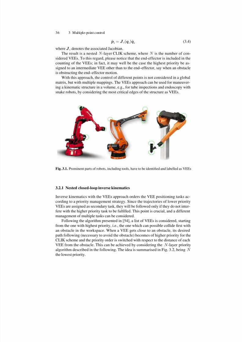
7/21/2019 De Santis Ingegneria Informatica Automatica
http://slidepdf.com/reader/full/de-santis-ingegneria-informatica-automatica 43/102
36 3 Multiple-point control
˙ pi = J i(qi)qi (3.4)
where J i denotes the associated Jacobian.
The result is a nested N -layer CLIK scheme, where N is the number of con-
sidered VEEs. To this regard, please notice that the end-effector is included in thecounting of the VEEs; in fact, it may well be the case the highest priority be as-
signed to an intermediate VEE other than to the end–effector, say when an obstacle
is obstructing the end–effector motion.
With this approach, the control of different points is not considered in a global
matrix, but with multiple mappings. The VEEs approach can be used for maneuver-
ing a kinematic structure in a volume, e.g., for tube inspections and endoscopy with
snake robots, by considering the most critical edges of the structure as VEEs.
Fig. 3.1. Prominent parts of robots, including tools, have to be identified and labelled as VEEs
3.2.1 Nested closed-loop inverse kinematics
Inverse kinematics with the VEEs approach orders the VEE positioning tasks ac-
cording to a priority management strategy. Since the trajectories of lower priority
VEEs are assigned as secondary task, they will be followed only if they do not inter-
fere with the higher priority task to be fulfilled. This point is crucial, and a different
management of multiple tasks can be considered.
Following the algorithm presented in [54], a list of VEEs is considered, starting
from the one with highest priority, i.e., the one which can possible collide first with
an obstacle in the workspace. When a VEE gets close to an obstacle, its desired
path following (necessary to avoid the obstacle) becomes of higher priority for the
CLIK scheme and the priority order is switched with respect to the distance of eachVEE from the obstacle. This can be achieved by considering the N -layer priority
algorithm described in the following. The idea is summarised in Fig. 3.2, being N the lowest priority.

7/21/2019 De Santis Ingegneria Informatica Automatica
http://slidepdf.com/reader/full/de-santis-ingegneria-informatica-automatica 44/102
3.2 The multiple VEEs approach 37
Fig. 3.2. Scheme of nested CLIK with VEEs
At the lowest layer, the differential mapping corresponding to the velocity of the
VEE with lowest priority is considered, i.e. (3.4) with i = N . Hence, a CLIK algo-
rithm with weighted pseudo-inverse is adopted to compute the inverse kinematics:
qN = J †N (qN )vN , (3.5)
with vN = ˙ pNd + kN ( pNd − pN ), being pNd the desired position for the VEE with
lowest priority and kN > 0. The pseudo-inverse matrix is substantially weighted as
in (3.2).
At the generic i-th layer of the nested scheme, with i = N − 1, . . . , 1, the inverse
kinematics is computed as in (3.3), i.e.
qi = J †iW (qi)vi +
I ni
− J †iW (qi)J i(q)
qia (3.6)
where
J †iW = W −1i J
Ti (J iW −1i J
Ti )
−1 (3.7)
with W −1i = diag{β i1, β i2,...,β ini} and v i = ˙ pid + ki( pid − pi), being pid the
desired position for the VEE with priority i, and ki > 0. Further, qia is the gradient
of the objective function:
Gi = − 1
ni
nij=1
q i,j − q i+1,jq i,jM − q i,jm
where q i,jM (q i,jm) is the maximum (minimum) value of the joint variable q i,j , i.e.the j-th component of the joint vector qi. The above choice corresponds to achieving
a joint motion for the joint variables as close as possible to that computed in the
previous layer q i+1, which are fed as secondary reference values to the next layer,

7/21/2019 De Santis Ingegneria Informatica Automatica
http://slidepdf.com/reader/full/de-santis-ingegneria-informatica-automatica 45/102
38 3 Multiple-point control
providing a way to fulfill the desired inverse kinematics of different parts of the
structure, with different priorities.
Going on, the nested CLIK algorithm computes the inverse kinematics for the
structures ending with each of the considered VEEs. It is worth emphasizing that the
order of priorities is dynamically changed during task execution.The continuity of reference trajectories can be accomplished via proper modifica-
tion of starting velocities for the novel selected higher-priority VEEs. As illustrated
in Fig. 3.2, the scheme takes the desired positions for the ordered VEEs at time t;
then, the output of the CLIK algorithms at the N levels are input to a trajectory plan-
ning block which re-evaluates the priority order among the various VEEs according
to the positions of the goals and the obstacles in the environment, and thus generates
the new ordered sequence of desired positions for the VEEs at time t + ∆t, where ∆tis the sampling time at which the CLIK algorithm is discretised for practical imple-
mentation; the planning aspects are discussed in the following section. The weights
β ij of the matrices W i can be chosen according to the criterion described in [56].
In particular, with reference to the example cited in [54], the joints of the mobile
base have a higher weight with the respect to the joints of the manipulator.Consider a task where a mobile manipulator carries a 6-DOF anthropomorphic
robot arm, reported in [54] and depicted in Fig. 3.3. It is clear that such a robot is
unfit for HRI: it is considered because the VEEs approach can be used in industrial
domains, where both the vehicle and the anthropomorphic manipulator are common.
However, usually heavy robots are not carried by mobile carts. This comment is
relevant in the perspective where control is an additional tool for safety, which has
to be guaranteed starting from the design.
In Fig. 3.3 it is possible to see how trajectories are followed for various VEEs
with different priorities. It is easy to recognize that planned trajectories for VEEs
with lower priorities are abandoned when they interfere with the higher priority
planned trajectories. With the priority strategy, which ranks the VEEs, it is possi-
ble to fulfill the most critical positioning problems on line.
The time history of a joint variable is also reported in Fig. 3.4; movements
planned in the task space are abandoned if they interfere with higher-priority tasks,
resulting in joint motions which can be different and, e.g., not legible by an interact-
ing user.
The priority management strategy which gives preference to the closet point to
obstacles is crucial: if a mobile robot manipulator is considered, which avoids the
head of a person in a room with the end-effector, it is difficult to predict the possibility
of hitting him/her with other parts of the structure, because a possible avoidance
movement can be incompatible with the path of the real end-effector or of a VEE
with higher priority. See Fig. 3.3(d) for an example of changing priority order for
the considered manipulator, whose VEEs are labelled as in Fig. 3.3(a) . Multiple
switching can be reduced if a filter is considered for changing smoothly the control
VEE.

7/21/2019 De Santis Ingegneria Informatica Automatica
http://slidepdf.com/reader/full/de-santis-ingegneria-informatica-automatica 46/102
3.2 The multiple VEEs approach 39
(a) (b)
(c) (d)
Fig. 3.3. Chosen robot model (a) and planned (gray) and actual (black) trajectory for the VEElabelled with A (b), and B (c), with resulting priority order in an HRI task (d)
3.2.2 Trajectory planning
For each VEE it should be possible to plan a complete trajectory off-line, but this
approach is not satisfying, since the trajectories imposed to the VEEs, if planned a
priori, do not have realistic application (most obstacles are moving and their trajec-
tories are not known a priori).
Furthermore, the positioning of VEEs in task space is only a secondary task for
the positioning of other VEEs with higher priority. On-line trajectory planning is
needed: potential fields methods [31] can be used for such a planning: the manipu-
lator moves in a field of forces; the position to be reached is an attractive pole forthe end-effector, and obstacles are repulsive surfaces for the manipulator parts. The
field of artificial forces F is produced by a differentiable potential function, with

7/21/2019 De Santis Ingegneria Informatica Automatica
http://slidepdf.com/reader/full/de-santis-ingegneria-informatica-automatica 47/102
40 3 Multiple-point control
Fig. 3.4. Simulation results: planned (dashed) and actual (solid) trajectory for the position of
the second joint of the considered manipulator
F ( pi) = −∇(U ( pi)), where ∇(U ( pi)) is the gradient vector of U at pi, that is the
position of the VEE under the field effect.This basic principle and its evolution, with possible consequences on control
and physical interpretation of the resulting trajectory is discussed more in depth in
Chapter 4. In a basic implementation, the potential U is constructed as the sum of
two elementary potential functions: U ( pi) = U att( pi) + U rep( pi) In this relation
U att is the attractive potential and depends only on the final position, whereas U repis the repulsive function and depends only on the obstacles position.
During the simulations shown in the figures of this section, the attractive poten-
tial field is chosen to be a parabolic well, centered in the goal positions, whereas
a repulsive field is related to a distance of influence from obstacles. So, the goal is
a source of an attractive potential field; obstacles are sources of repulsive potential
fields.
Notice again the importance of the priority management in the CLIK schemes,as discussed above: even with on-line path planning, a desired path could be not exe-
cutable, so it is necessary to switch the priority order, as emphasised by the trajectory
planning block in Fig. 3.2. In addition, reactive motion can benefit of more com-
plex potential functions. Additional considerations about the VEEs and some criti-
cisms related to the limited number of VEEs, to be selected a priori by hand, lead to
the skeleton approach, introduced in Section 3.3, where a more general whole-body
modelling is considered.
3.2.3 An interesting biomimetic example
As an example of application of the VEEs approach, consider the multiple tasks,
and the different joint involvement, performed by the human arm while drawing or
writing.
Many anthropic tasks involve force and position constraints for the human arm.
The inverse kinematics and the trajectory planning for human arm positioning may

7/21/2019 De Santis Ingegneria Informatica Automatica
http://slidepdf.com/reader/full/de-santis-ingegneria-informatica-automatica 48/102
3.2 The multiple VEEs approach 41
depend on these constraints. The well-known manipulability ellipsoids may be used
to study the relations between dexterity and efforts during handwriting, painting and
other tasks where the human arm has to perform a precise motion while balancing
forces acting on it. Moreover, the motion of the arm can be interpreted as a motion
of different points, like elbow, and wrist.This example is proposed according to the following analogies:
• drawing corresponds generically to moving the end-effector,
• leaning the elbow corresponds generically to an internal motion of a VEE,
• different mobility of articulations correspond generically to joints’ weighing,
• plans for trajectory are based on relevance of the points to be reached ,
• foci of attention during writing correspond to crucial points as heuristics for the
sensors.
Notice that for many tasks such as writing on a surface, only three DOF’s are
required. In some cases, also orientation is important; however, the human arm is
redundant to perform such tasks, even though a simplified 7-DOF kinematic model
(not considering the hand articulated structure) is adopted (See Fig. 3.5). Using thissimplified model, the lengths of the links have been set on the basis of anatomic
evaluations: 0.3 m for the first link, 0.25 m for the forearm and 0.15 m for the hand-
pencil link.
The solution to the inverse kinematics for a human-like arm during drawing tasks
can be evaluated and compared with arm movements of human experimenters.
Fig. 3.5. Human-like 7-DOF robot arm
Biologically-motivated computer vision techniques are to be considered for tra-
jectory planning in robotic systems whose aim is to execute draws in human-like
fashion, also to infer mobility distribution in the human arm among available joints.
The direction of gazes when a picture to be reproduced is observed is crucial fortrajectory planning, and the postures assumed while executing an assigned task are
strictly related to optimisations performed by the human evolution. Therefore, it is
interesting to investigate human and animals’ behaviours to infer laws for biomimetic
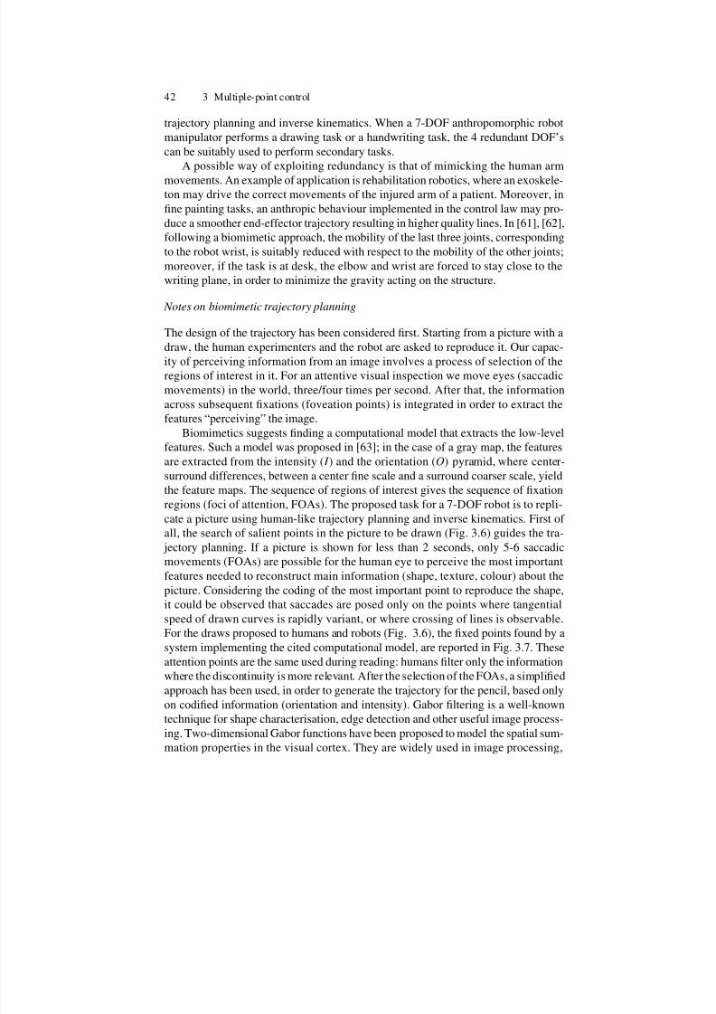
7/21/2019 De Santis Ingegneria Informatica Automatica
http://slidepdf.com/reader/full/de-santis-ingegneria-informatica-automatica 49/102
42 3 Multiple-point control
trajectory planning and inverse kinematics. When a 7-DOF anthropomorphic robot
manipulator performs a drawing task or a handwriting task, the 4 redundant DOF’s
can be suitably used to perform secondary tasks.
A possible way of exploiting redundancy is that of mimicking the human arm
movements. An example of application is rehabilitation robotics, where an exoskele-ton may drive the correct movements of the injured arm of a patient. Moreover, in
fine painting tasks, an anthropic behaviour implemented in the control law may pro-
duce a smoother end-effector trajectory resulting in higher quality lines. In [61], [62],
following a biomimetic approach, the mobility of the last three joints, corresponding
to the robot wrist, is suitably reduced with respect to the mobility of the other joints;
moreover, if the task is at desk, the elbow and wrist are forced to stay close to the
writing plane, in order to minimize the gravity acting on the structure.
Notes on biomimetic trajectory planning
The design of the trajectory has been considered first. Starting from a picture with a
draw, the human experimenters and the robot are asked to reproduce it. Our capac-
ity of perceiving information from an image involves a process of selection of the
regions of interest in it. For an attentive visual inspection we move eyes (saccadic
movements) in the world, three/four times per second. After that, the information
across subsequent fixations (foveation points) is integrated in order to extract the
features “perceiving” the image.
Biomimetics suggests finding a computational model that extracts the low-level
features. Such a model was proposed in [63]; in the case of a gray map, the features
are extracted from the intensity ( I ) and the orientation (O) pyramid, where center-
surround differences, between a center fine scale and a surround coarser scale, yield
the feature maps. The sequence of regions of interest gives the sequence of fixation
regions (foci of attention, FOAs). The proposed task for a 7-DOF robot is to repli-
cate a picture using human-like trajectory planning and inverse kinematics. First of
all, the search of salient points in the picture to be drawn (Fig. 3.6) guides the tra- jectory planning. If a picture is shown for less than 2 seconds, only 5-6 saccadic
movements (FOAs) are possible for the human eye to perceive the most important
features needed to reconstruct main information (shape, texture, colour) about the
picture. Considering the coding of the most important point to reproduce the shape,
it could be observed that saccades are posed only on the points where tangential
speed of drawn curves is rapidly variant, or where crossing of lines is observable.
For the draws proposed to humans and robots (Fig. 3.6), the fixed points found by a
system implementing the cited computational model, are reported in Fig. 3.7. These
attention points are the same used during reading: humans filter only the information
where the discontinuity is more relevant. After the selection of the FOAs, a simplified
approach has been used, in order to generate the trajectory for the pencil, based only
on codified information (orientation and intensity). Gabor filtering is a well-knowntechnique for shape characterisation, edge detection and other useful image process-
ing. Two-dimensional Gabor functions have been proposed to model the spatial sum-
mation properties in the visual cortex. They are widely used in image processing,
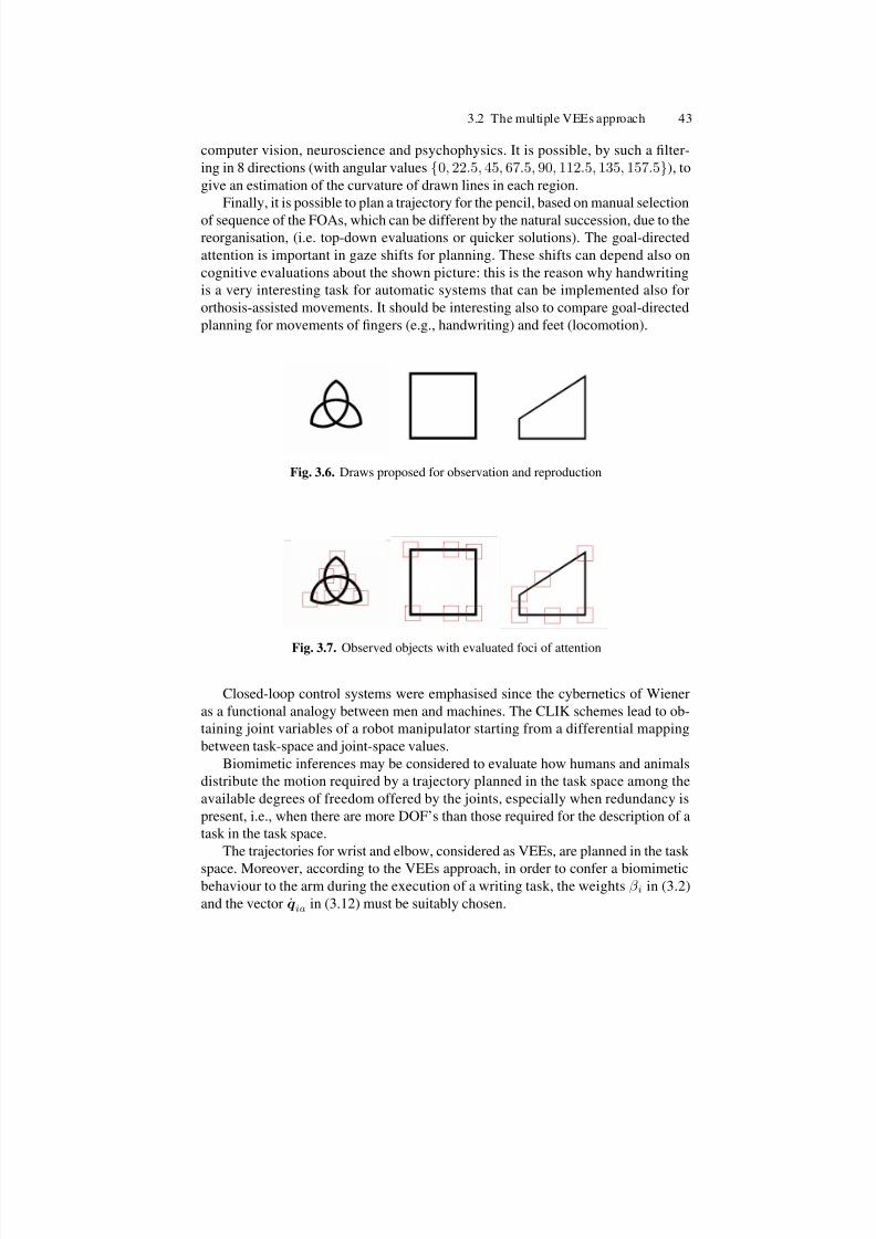
7/21/2019 De Santis Ingegneria Informatica Automatica
http://slidepdf.com/reader/full/de-santis-ingegneria-informatica-automatica 50/102
3.2 The multiple VEEs approach 43
computer vision, neuroscience and psychophysics. It is possible, by such a filter-
ing in 8 directions (with angular values {0, 22.5, 45, 67.5, 90, 112.5, 135, 157.5}), to
give an estimation of the curvature of drawn lines in each region.
Finally, it is possible to plan a trajectory for the pencil, based on manual selection
of sequence of the FOAs, which can be different by the natural succession, due to thereorganisation, (i.e. top-down evaluations or quicker solutions). The goal-directed
attention is important in gaze shifts for planning. These shifts can depend also on
cognitive evaluations about the shown picture: this is the reason why handwriting
is a very interesting task for automatic systems that can be implemented also for
orthosis-assisted movements. It should be interesting also to compare goal-directed
planning for movements of fingers (e.g., handwriting) and feet (locomotion).
Fig. 3.6. Draws proposed for observation and reproduction
Fig. 3.7. Observed objects with evaluated foci of attention
Closed-loop control systems were emphasised since the cybernetics of Wiener
as a functional analogy between men and machines. The CLIK schemes lead to ob-
taining joint variables of a robot manipulator starting from a differential mapping
between task-space and joint-space values.
Biomimetic inferences may be considered to evaluate how humans and animals
distribute the motion required by a trajectory planned in the task space among the
available degrees of freedom offered by the joints, especially when redundancy is
present, i.e., when there are more DOF’s than those required for the description of a
task in the task space.
The trajectories for wrist and elbow, considered as VEEs, are planned in the task
space. Moreover, according to the VEEs approach, in order to confer a biomimeticbehaviour to the arm during the execution of a writing task, the weights β i in (3.2)
and the vector qia in (3.12) must be suitably chosen.

7/21/2019 De Santis Ingegneria Informatica Automatica
http://slidepdf.com/reader/full/de-santis-ingegneria-informatica-automatica 51/102
44 3 Multiple-point control
Observing a human writer, it can be recognised that the joints of the shoulder
and of the elbow shall have higher mobility with respect to the joints of the wrist.
This can be easily obtained by choosing the weights β i close to 1, for i = 1, 2, 3, 4and close to 0 for i = 5, 6, 7. These values could be modified during task execution
using, e.g., soft computing techniques [56].Moreover, during the action of writing at a desk, the elbow and the wrist are usu-
ally taken close to the desk, in order to minimize the effects of the gravity on the arm.
This behaviour can be enforced to the arm by assigning to the elbow and the wrist
a position close to the writing plane without modifying the trajectory of the pencil:
these positions are planned in the task space, based on dynamics considerations. The
desired behaviour can be achieved by considering the three-layer priority algorithm,
described in the following
At the low layer, the differential mapping corresponding to the velocity of the
elbow along the y axis is considered, i.e.,
ye = e(qe)qe (3.8)
where qe = [ q 1 q 2 q 3 ]T and e(qe) is a (1×3) row vector. Hence, a CLIK algorithmwith weighted pseudo-inverse is adopted to compute the inverse kinematics:
qe = †We(qe)ve, (3.9)
with ve = yde + ke(yde − ye), being yde the desired elbow position and ke > 0. The
pseudo-inverse matrix in (3.9) is
†We = W −1e
Te ( eW −1e
Te )−1 (3.10)
with W −1e = diag{β 1, β 2, β 3}.
At the middle layer, the differential mapping corresponding to the velocity of the
wrist along the y axis is considered, i.e.,
yw = Ww(qw)qw (3.11)
where qw = [ q 1 q 2 q 3 q 4 ]T and Ww(qw) is a (1 × 3) row vector. Again, a CLIK
algorithm with weighted pseudo-inverse and secondary task is adopted to compute
the inverse kinematics:
qw = †Ww(qw)vw +
I 4 −
†Ww(qw) w(qw)
qaw, (3.12)
The pseudo-inverse matrix in (3.12) is
†Ww = W
−1w
Tw( wW
−1w
Tw)−1 (3.13)
with W −1w = diag{β 1, β 2, β 3 β 4} and vw = ydw + kw(ydw − yw), being ydw the
desired wrist position, kw > 0; qaw is the gradient of the objective function:
G = −1
6
3i=1
q i − q eiq iM − q im

7/21/2019 De Santis Ingegneria Informatica Automatica
http://slidepdf.com/reader/full/de-santis-ingegneria-informatica-automatica 52/102
3.2 The multiple VEEs approach 45
where q iM (q im) is the maximum (minimum) value of the joint variable q i. The above
choice corresponds to achieve a joint motion for the first 3 joint variables close to that
computed in the first step. This is imposed as a secondary task, hence it is fulfilled
only if it does not interfere with the primary task.
Finally, at the high layer, the complete manipulation structure with the CLIKalgorithm is considered, where qa is chosen as the gradient of the objective function:
G = −1
8
4i=1
q i − q wiq iM − q im
,
corresponding to a motion for the first 4 joints close to that computed in the second
step.
Notice that the weights β i of the matrix W , and thus of W e, W w, are chosen
according to the criterion described above.
When the task is performed on a vertical plane, the secondary task of minimizing
the gravity torques on the joints are to be transformed to the joint space, where ref-
erence values for the joint positions are provided to fulfill this requirement. Usuallythis constraint leads the arm to keep a posture attached to the body. Notice that, in
order to seek for suitable kinematics postures to optimize the movements, informa-
tion on the force acting on the end effector should be provided; as an example, the
manual use of a camcorder is a typical task where positioning on a plane might be
helpful; in such a task, in order to minimize the torques on the human arm, usually
the forearm is kept close to the arm.
0
0.2−0.4
−0.3−0.2
−0.10
0.1
0
0.1
0.2
pencil
wrist
shoulder
elbow
Fig. 3.8. Position of elbow, wrist and pencil for the robot during a drawing task at a desk
In order to better show the effectiveness of the CLIK scheme, also the joint an-
gular positions can be evaluated via simple trigonometric calculations [61]. As an
example, the angle between the arm and forearm can be evaluated from Carnot’s
cosine theorem knowing the positions of the arm and forearm and the distance be-tween the wrist and the shoulder. The automatic system, in order to reproduce the
first picture in Fig. 3.6, inferred a trajectory, based on active vision, and results of
simulations for the positioning of the robot in the task space are shown in Fig. 3.9.
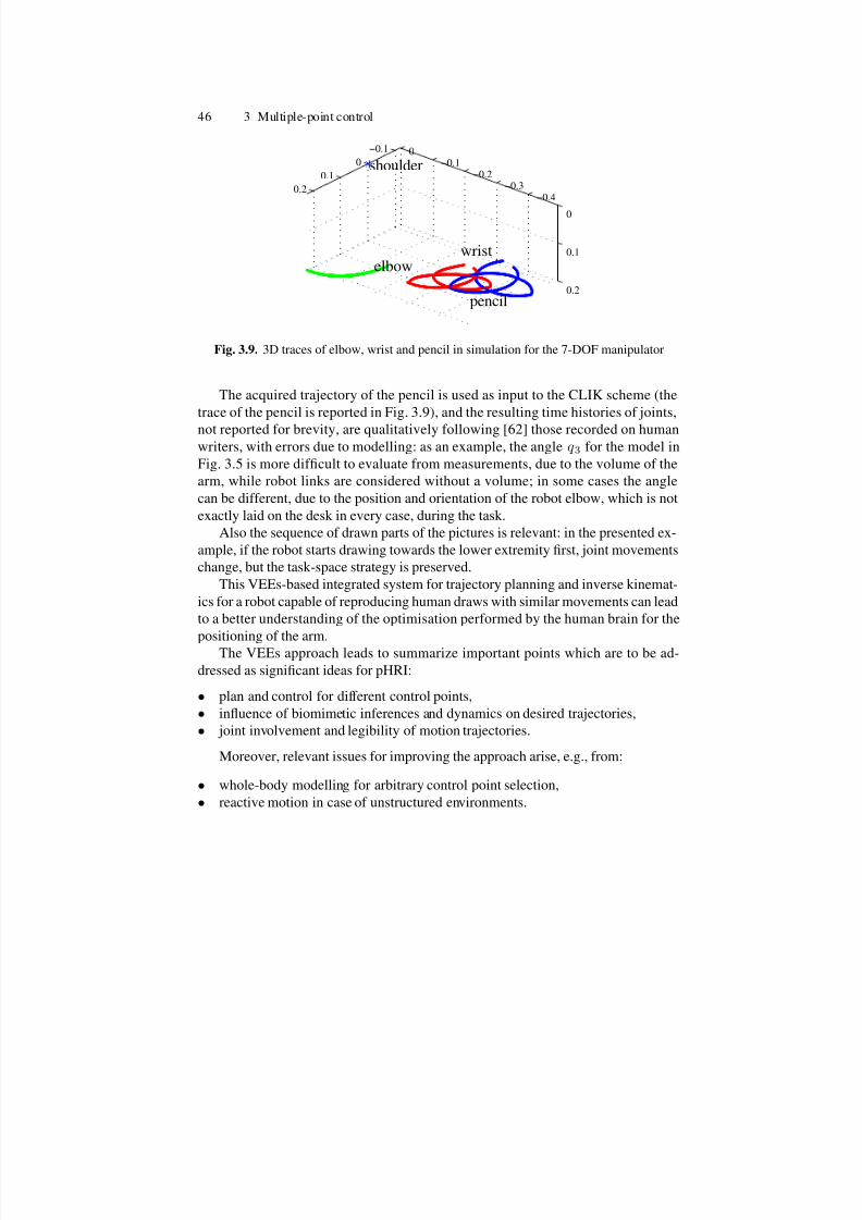
7/21/2019 De Santis Ingegneria Informatica Automatica
http://slidepdf.com/reader/full/de-santis-ingegneria-informatica-automatica 53/102
46 3 Multiple-point control
−0.1
0
0.1
0.2−0.4
−0.3−0.2
−0.10
0
0.1
0.2
pencil
wristelbow
shoulder
Fig. 3.9. 3D traces of elbow, wrist and pencil in simulation for the 7-DOF manipulator
The acquired trajectory of the pencil is used as input to the CLIK scheme (the
trace of the pencil is reported in Fig. 3.9), and the resulting time histories of joints,
not reported for brevity, are qualitatively following [62] those recorded on humanwriters, with errors due to modelling: as an example, the angle q 3 for the model in
Fig. 3.5 is more difficult to evaluate from measurements, due to the volume of the
arm, while robot links are considered without a volume; in some cases the angle
can be different, due to the position and orientation of the robot elbow, which is not
exactly laid on the desk in every case, during the task.
Also the sequence of drawn parts of the pictures is relevant: in the presented ex-
ample, if the robot starts drawing towards the lower extremity first, joint movements
change, but the task-space strategy is preserved.
This VEEs-based integrated system for trajectory planning and inverse kinemat-
ics for a robot capable of reproducing human draws with similar movements can lead
to a better understanding of the optimisation performed by the human brain for the
positioning of the arm.The VEEs approach leads to summarize important points which are to be ad-
dressed as significant ideas for pHRI:
• plan and control for different control points,
• influence of biomimetic inferences and dynamics on desired trajectories,
• joint involvement and legibility of motion trajectories.
Moreover, relevant issues for improving the approach arise, e.g., from:
• whole-body modelling for arbitrary control point selection,
• reactive motion in case of unstructured environments.

7/21/2019 De Santis Ingegneria Informatica Automatica
http://slidepdf.com/reader/full/de-santis-ingegneria-informatica-automatica 54/102
3.3 Whole-body modelling and multiple control point 47
3.3 Whole-body modelling and multiple control point
3.3.1 Need for multiple control points
The idea of separated control points for the same robot presents a serious drawback:control points have to be chosen manually before the experiments.
An approach which automatically selects a control point on a whole kinematic
structure, based on sensor information, could result more effective for pHRI applica-
tions. In addition, these control points should be computed fast, based on a model of
the environment which leads to simple distance computation and trajectory determi-
nation.
With focus on the model of the robot for fast multiple-point control, these con-
siderations lead to the so-called “skeleton algorithm” [64], which can be considered
as an extension of the Virtual End-Effectors approach, composed of these four steps:
• build a proper model of the robot, namely the skeleton, useful for analytical com-
putation;
• find the closest points to a possible collision along the skeleton, namely the col-lision points;
• generate repulsion forces;
• compute avoidance torque commands to be summed to the nominal torques for
the controller.
These steps are illustrated in the following, with reference to the problem of self-
collision avoidance of a robot, which is simple since the involved model uses only
segments, and the sensory data can be considered absolutely dependable (proprio-
ceptive), with respect to interaction with external objects, tracked with slower and
less dependable exteroceptive sensors.
Related works include researches on self-collision avoidance for a humanoid ro-
bot with fixed control points [65], external object avoidance for a 7-DOF arm [66],
adopting elastic forces for the repulsion fulfilled via perturbations of desired positionand inverse kinematics for completing the task. Discretisation of the robot structure
has been proposed for self-collision avoidance also related to humanoid leg [67] mo-
tions, where polyhedral models have been adopted.
3.3.2 Skeleton-based modelling
In order to have a real reference manipulator designed for interaction with humans,
this presentation is referred to the DLR Justin manipulator [68] (see Fig. 2.2), and is
mainly based on [64], while implementation on industrial robots is possible too [34].
The setup and details on experiments will be presented in Chapter 5.
In order to avoid collisions between the arms and the torso of a humanoid manip-
ulator like Justin, one should consider all the points of the articulated structure whichmay collide (and injure people in pHRI). The problem of analyzing the whole volume
of the parts of a manipulator is simplified by considering a skeleton of the structure
(Fig. 3.10), and proper volumes surrounding this skeleton. The adopted geometrical

7/21/2019 De Santis Ingegneria Informatica Automatica
http://slidepdf.com/reader/full/de-santis-ingegneria-informatica-automatica 55/102
48 3 Multiple-point control
model leads to using a very simple and fast computation rule for distance evaluation
and modification of the trajectories for each point of the manipulator.
In general, one could derive the skeleton automatically from a proper kinematic
description, e.g. via a Denavit–Hartenberg (D–H) table. This point will be considered
in the following.However, it is more efficient, and also intuitive and straightforward, to set up the
skeleton by hand, as done below: let us consider the design of a skeleton by focusing
on Justin, it is easy to notice that such a skeleton can be composed by considering
segments lying on the links of the arms and the torso.
In this way, segments are built that “span” the whole kinematic structure of the
manipulator. In Fig. 3.10 it is possible to observe ten segments in which the manipu-
lator is decomposed, where the segment ends located at the Cartesian positions of the
joints are computed via simple direct kinematics. Notice that, due to the kinematics
of the DLR LWR-III, the joint motion in the roll axes of the arms does not affect the
position of the shoulder-elbow and elbow-wrist segments.
Moreover, depending on how the control point on the segments produce attract or
repelling forces/velocities, some segments could be discarded if they already benefit(going away from obstacles) of the resulting motion caused by other segments.
Automatic skeleton building form D–H parameters is a point which emphasises
how the approach can be considered general for an articulated robot. The underlying
idea is that a solid of revolution can express the shape of a link, but this can be
partially modified using properly the repulsion functions from every point of the
link, which in a sense create a safe volume around the point, and the result of these
multiple volumes for the whole robot creates a safe region which has to approach the
real volume of the considered part of a manipulator.
In other words, if it possible to control every point on the skeleton, at the same
time repulsion forces from such points with respect to any object in the task space
for collision avoidance have to reflect the shape of the mechanical structure around
that point.
A general D–H table gives the possibility of computing the Cartesian position of
each joint . These positions can constitute the ends of the segments of the skeleton
(nodes), and some of this possible nodes will be discarded if they coincide with other
nodes already present in the skeleton.
Moreover, the possibility of having robot where D–H parameters are variable
has to be considered carefully, in order to understand what this means in terms of the
skeleton building. Depending on whether such value change together or sequentially
while moving on the spine of the links from the Cartesian position of a joint to the
next, it is possible to approximate a link which has a “square wave” shape or another
which is a straight segment between two successive nodes.
Of course, it is important to consider segments which cover the spine of all the
mechanical parts: this has a reflex on D–H tables when manipulator links have parts
on both sides of a revolute joint as, e.g., for counterbalances or for allocating motors(see Fig. 3.1 and 5.6).
Summarizing, in general, after the definition of the nodes by hand for Justin,
application of the following sequence is expected for automatic skeleton building:

7/21/2019 De Santis Ingegneria Informatica Automatica
http://slidepdf.com/reader/full/de-santis-ingegneria-informatica-automatica 56/102
3.3 Whole-body modelling and multiple control point 49
(a)
−0.20
0.2 −1 −0.5 0 0.5 1
0
0.5
1
1.5
y
L
T
R z
x
(b)
Fig. 3.10. For the DLR Justin (a), a skeleton can be found (b) by considering the axes of the
arms and the spine of the torso. Segments are drawn between the Cartesian positions of some
crucial joints
• compute the Cartesian position of each joint;• compute the Cartesian position of each mechanical end of the robot;
• select nodes discarding coincident points;
• build segment between adjacent nodes.
Built the skeleton, the focus is then on distance evaluation on the robot for self-
collision avoidance, which is the base for motion in an unstructured domain, with
computation of distance from geometric figures.
With an analytical technique, it is always possible to find the two closest points
for each pair of segments of the structure. This information can be used in order
to avoid a collision between these two points, e.g., by pushing the closest points
whenever their distance becomes lower than a threshold.
If hysotropic repelling functions are used for every control point, spheres cen-
tered at these collision points can be considered as protective volumes, where re-pulsion has to start. Since the closest point can vary between the two ends of the
segment, on the assumption of a fixed radius, the resulting protective volume will
be a cylinder with two half spheres at both ends (see Fig. 3.11(a)). Of course, this

7/21/2019 De Santis Ingegneria Informatica Automatica
http://slidepdf.com/reader/full/de-santis-ingegneria-informatica-automatica 57/102
50 3 Multiple-point control
a special case: in general, by varying the radiuses of the spheres centered in arbi-
trary points of the skeleton, any solid of revolution can be obtained from a segment,
provided that there is a law to specify the intensity or the starting distance of forces
which mimic the effect of collisions, or the presence of virtual elastic elements on
the surface of such a solid.With reference to the structure in Fig. 3.10, the volumes constructed around the
torso point T and the points L and R for the left and the right arm, respectively,
encompass the two segments from T to L and T to R which thus can be discarded,
leading to consideration of a total of eight segments, i.e. two for the torso and three
for each arm.
Again, in the design of the skeleton, some heuristics can help in discarding use-
less computation; nevertheless, the general case of computing all possible distances
between simple objects like segments, regions of a plane (circles, rectangles) or
points has the only limit of the time complexity for modelling the interaction en-
vironment.
(a) (b)
Fig. 3.11. Segments are protected by spheres centered in the collision points (a); a simple
case of distance evaluation on a plane is reported (b)
3.3.3 Finding the possible collision points
A modelling of the scene for pHRI should take into account the necessity for com-
puting distances between possible colliding bodies. This implies that simple models
like the skeleton can be used for speeding up the analysis of the scene for navigation
and interaction. With reference to an explanation of the skeleton algorithm, the con-
sidered world model is composed by segments, e.g., for self-collision avoidance of
the manipulator.As anticipated above, the collision points move along the segments of the skele-
ton designed on the spine of the robot links. Hence, the direct kinematics compu-
tation can be carried out in a parametric way for a generic point on each segment

7/21/2019 De Santis Ingegneria Informatica Automatica
http://slidepdf.com/reader/full/de-santis-ingegneria-informatica-automatica 58/102
3.3 Whole-body modelling and multiple control point 51
by simply replacing the link length in the homogeneous transformation relating two
subsequent frames with the distance of the collision point from the origin of the
previous frame.
For each segment in which the structure is decomposed, the distance to all the
other segments is calculated with a simple formula. Let pa and pb denote the posi-tions of the generic points along the two segments, whose extremal points are pa1,
pa2 and pb1, pb2, respectively. One has:
pa = pa1 + taua (3.14)
pb = pb1 + tbub (3.15)
where the unit vectors ua and ub for the two segments are evaluated as follows:
ua = 1
|| pa2 − pa1||( pa2 − pa1) (3.16)
ub = 1
|| pb2 − pb1||
( pb2 − pb1) (3.17)
and {ta,tb} are scalar values, with
ta|| pa2 − pa1||
∈ {0, 1} tb|| pb2 − pb1||
∈ {0, 1}.
The collision points pa,c and pb,c are found by computing the minimum distance
between the two segments (see, e.g., Fig. 3.11(b)). If the common normal between
the lines of the two segments intersects either of them, then the values ta,c and tb,cfor the parameters ta and tb can be computed as follows:
ta,c = ( pb1 − pa1)T (ua − kub)
(1 − k2) (3.18)
tb,c = ta,c − uT a ( pb1 − pa1)
k (3.19)
with
k = uT aub. (3.20)
It is understood that in the case the common normal does not intersect either of
the two segments, i.e. ta/(|| pa2 − pa1||) and tb/(|| pb2 − pb1||) are both outside the
interval {0,1}, then the distance between the closest extremal points becomes the
minimum distance. Simple modifications have to be adopted for taking into account
parallel or orthogonal segments, and a continuous motion of the control point in
such situations has to be enforced via proper techniques (see, e.g., the suitability of
techniques proposed in Section 3.4.3).
This analytical approach leads to computing in real-time the collision points pa,cand pb,c for each pair of segments, and the related distance
dmin = || pa,c − pb,c||. (3.21)

7/21/2019 De Santis Ingegneria Informatica Automatica
http://slidepdf.com/reader/full/de-santis-ingegneria-informatica-automatica 59/102
52 3 Multiple-point control
Obviously, the technique is suitable for point-to-segment distance, with minor mod-
ifications.
For later computation of the avoidance torques, it is necessary to compute the
Jacobians associated with the collision points, i.e. the matrices J a,c and J b,c de-
scribing the differential mapping of ˙ pa,c and ˙ pb,c with the joint velocities q of thewhole structure, i.e. in compact form
˙ pa,c˙ pb,c
=
J a,cJ b,c
q. (3.22)
It is worth noticing that the positions of pc,a and pc,b vary along the segments as the
manipulator is moving. Hence, the associated Jacobians depend on the positions of
the two pairs of segment ends, i.e. pa1, pa2, pb1, pb2, through (3.19). Thus, Eq. (3.22)
can be rewritten as
˙ pa,c˙ pb,c = J t
˙ pa1˙ pa2˙ pb1˙ pb2
= J t
J a1J a2J b1
J b2
q (3.23)
where J a1, J a2, J b1, J b2 obviously relate the joint velocities to the velocities of the
two pairs of segment ends, and
J t =
∂ pa,c∂ pa1
∂ pa,c∂ pa2
∂ pa,c∂ pb1
∂ pa,c∂ pb2
∂ pb,c∂ pa1
∂ pb,c∂ pa2
∂ pb,c∂ pb1
∂ pb,c∂ pb2
(3.24)
whose terms can be computed by suitable differentiations of (3.15) through (3.19).
These equations are based on the known mutual influence of the segments, based
on the presented distance model. In general, this can be extended to a more com-
plete modelling, based on the idea that the environment can be described by simplegeometry, based on the use of points, segments and planar delimited regions.
3.3.4 Generating repulsion trajectories
The third point of the approach is related to generate proper reference motion for the
control points. A more comprehensive discussion on trajectories will be presented in
Chapter 4. However, in general, potential fields or different optimisation techniques
can be used in order to generate the forces which will produce the self-collision
avoidance motions.
The two opposite forces acting on the two possibly colliding closest points pa,cand pb,c can be chosen as follows:
f a,c = h(dmin, d0, dstart)dmin
( pa,c − pb,c) (3.25)
f b,c = h(dmin, d0, dstart)
dmin( pb,c − pa,c) = −f a,c (3.26)

7/21/2019 De Santis Ingegneria Informatica Automatica
http://slidepdf.com/reader/full/de-santis-ingegneria-informatica-automatica 60/102
3.3 Whole-body modelling and multiple control point 53
where h is a nonlinear function of the arguments; dmin is the minimum distance
computed as in (3.21), dstart is the starting distance where the force has to act: points
farther than dstart are not subject to any repulsion. Moreover, d0 is the limit distance
around the skeleton where a collision may occur: in the case of cylindrical links, d0can be fixed as the radius of the section of the link. Notice that h > 0 gives theamplitude of the force along the direction between the two collision points.
Further, in order to properly smoothen the manipulator motion upon the action
of the repulsion forces, it is appropriate to add damping terms as follows:
f a,c = h(dmin, d0, dstart)
dmin( pa,c − pb,c) − Da ˙ pa,c (3.27)
f b,c = h(dmin, d0, dstart)
dmin( pb,c − pa,c) − Db ˙ pb,c (3.28)
where Da and Db are suitable positive definite matrices. Notice that, if damping is
the same for the two segments, the forces have the same intensity in two opposite
directions.
It is worth pointing out, indeed, that multiple collision points on the same seg-ment have to be considered, whenever more segments are close to a possible colli-
sion. Nevertheless, since the computation is very fast, considering all segments with-
out using any heuristics for reducing the number of involved parts is not mandatory,
and it depends only on limits on the computation time.
In next chapter it will be shown that repulsion forces can be derived from a po-
tential function. These forces can be naturally used to compute avoidance torques at
the manipulator joints via the Jacobian transpose. Nevertheless, it should be pointed
out that suitable repulsion velocities could be likewise generated in lieu of repulsion
forces (see Section 3.4). In such a case, these velocities could be used to compute
avoidance joint velocities via a pseudo-inverse of the Jacobian.
This alternative solution has not been considered since Justin is endowed with
a torque controller which naturally allows summing the avoidance torques to thoseneeded to execute a given task.
However, the interesting implementation in velocity control will be presented,
since the differential kinematics equation has an important modification, due to the
fact that not only the joint angles, but also other kinematics parameter on the D–H
table change during the task.
3.3.5 Computing avoidance joint commands
As introduced, desired trajectories can be transformed in joint velocities or torques,
also according to some rule for considering multiple tasks. In view of the kineto-
statics duality for robotic systems with holonomic constraints, it is straightforward
to compute the avoidance torques corresponding to the repulsion forces via the trans-
pose of the Jacobian matrices defined in (3.22), leading to
τ c =J T a,c J
T b,c
f a,cf b,c
. (3.29)

7/21/2019 De Santis Ingegneria Informatica Automatica
http://slidepdf.com/reader/full/de-santis-ingegneria-informatica-automatica 61/102
54 3 Multiple-point control
The use of the transpose of the Jacobian matrix for the evaluation of the avoidance
torques does not allow a weighing of the joint involvement for the generation of
the avoidance motions. A posture behaviour, e.g., can be enforced only via proper
null-space projection [32].
Null-space techniques can be used to enforce master-slave behaviours for the twoarms of the humanoid manipulator, e.g., the “master” arm can have the goal reaching
as primary task, and the collision avoidance is in its null-space, while the “slave”
arm must guarantee the collision avoidance (main task), while trying to follow a
prescribed trajectory (the slave is not trajectory task-preserving, meaning that its
main task is safety). This approach is suitable for pHRI: both arms are “slave” with
respect to the position of the arm of a human operator.
3.4 Torque-based and velocity-based control
In general, the approach can be used not only for reactive motion, but also for goal-
directed trajectory planning, as indicated by an higher level planner. In every case,the quasi-static approach discussed before must be implemented including the full
dynamics of the system.
It is worth pointing out that the control of points on the same robots can benefit
of an important tool: the symbolic computation of the forward kinematics equation,
and the corresponding differential kinematics equation. If this approach is adopted,
the position and the Jacobian of every point can be computed by feeding to these
symbolic objects the values of the D–H parameters for the specified point, and setting
to 0 the other parameters after that point in the kinematic structure.
Summarizing, the suggested tools for velocity implementation are:
• modular Jacobian,
• moving control point,
• legible and safe desired motion.
The last point benefits of the first two tools and has of course cognitive aspects,
related to the notion of “legibility”. The need for a modular Jacobian comes from
the number of matrix multiplication which are necessary for an arbitrary number of
DOF’s. The possibility of varying the control point has been considered right now
via automatic distance computation. Nevertheless, effects on differential kinematics
for the control point of such a motion affects velocity-based implementations.
Experiments showing good results with the presented quasi-static implementa-
tion of motion command in the presence of moving control point using the skeleton
approach will be shown in Chapter 5. The avoidance torques corresponding to the
repulsion forces via the transpose of the Jacobian matrices, discussed in the previous
sections, are just summed to other nominal torques for the controller.
Moreover, the tools for coping with moving control points in velocity-level im-
plementation will be provided below, and have been tested in simulation.
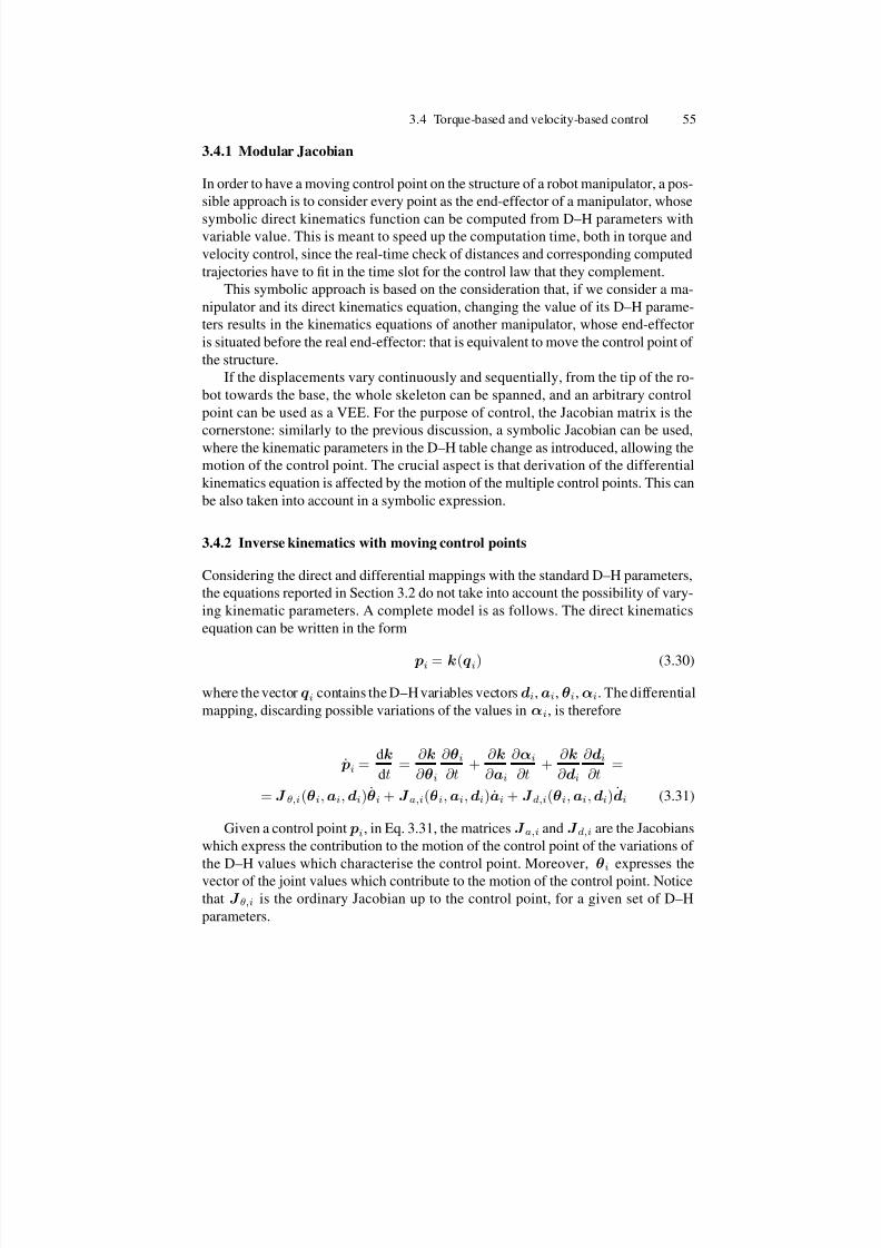
7/21/2019 De Santis Ingegneria Informatica Automatica
http://slidepdf.com/reader/full/de-santis-ingegneria-informatica-automatica 62/102
3.4 Torque-based and velocity-based control 55
3.4.1 Modular Jacobian
In order to have a moving control point on the structure of a robot manipulator, a pos-
sible approach is to consider every point as the end-effector of a manipulator, whose
symbolic direct kinematics function can be computed from D–H parameters withvariable value. This is meant to speed up the computation time, both in torque and
velocity control, since the real-time check of distances and corresponding computed
trajectories have to fit in the time slot for the control law that they complement.
This symbolic approach is based on the consideration that, if we consider a ma-
nipulator and its direct kinematics equation, changing the value of its D–H parame-
ters results in the kinematics equations of another manipulator, whose end-effector
is situated before the real end-effector: that is equivalent to move the control point of
the structure.
If the displacements vary continuously and sequentially, from the tip of the ro-
bot towards the base, the whole skeleton can be spanned, and an arbitrary control
point can be used as a VEE. For the purpose of control, the Jacobian matrix is the
cornerstone: similarly to the previous discussion, a symbolic Jacobian can be used,where the kinematic parameters in the D–H table change as introduced, allowing the
motion of the control point. The crucial aspect is that derivation of the differential
kinematics equation is affected by the motion of the multiple control points. This can
be also taken into account in a symbolic expression.
3.4.2 Inverse kinematics with moving control points
Considering the direct and differential mappings with the standard D–H parameters,
the equations reported in Section 3.2 do not take into account the possibility of vary-
ing kinematic parameters. A complete model is as follows. The direct kinematics
equation can be written in the form
pi = k(qi) (3.30)
where the vector qi contains the D–H variables vectors di,ai, θi,αi. The differential
mapping, discarding possible variations of the values in αi, is therefore
˙ pi = dk
dt =
∂ k
∂ θi
∂ θi∂t
+ ∂ k
∂ ai
∂ αi
∂t +
∂ k
∂ di
∂ di∂t
=
= J θ,i(θi,ai,di)θi + J a,i(θi,ai,di)ai + J d,i(θi,ai,di)di (3.31)
Given a control point pi, in Eq. 3.31, the matrices J a,i and J d,i are the Jacobians
which express the contribution to the motion of the control point of the variations of
the D–H values which characterise the control point. Moreover, θi expresses the
vector of the joint values which contribute to the motion of the control point. Notice
that J θ,i is the ordinary Jacobian up to the control point, for a given set of D–H
parameters.

7/21/2019 De Santis Ingegneria Informatica Automatica
http://slidepdf.com/reader/full/de-santis-ingegneria-informatica-automatica 63/102
56 3 Multiple-point control
There are proper ways [55] for reducing the number of nonnull values in the
di and ai vectors of D–H parameters. Often, this is intrinsically forced by the ma-
nipulator’s design. As a simple case, consider a manipulator kinematics where only
some values in the vector di change. In this situation, the way to compute the joint
variables starting for a moving point on the skeleton of the robot is the following:
θi = J †θ,W,i( ˙ pi − J d,i(θi,ai,di)di) (3.32)
where the subscript W is referred to possible joint involvement weighing. Based on
these simple modifications, multiple-point control, which has shown to be central
in interaction with robots, can be accomplished easily both in force and velocity
control, with some additional notes for the second approach, which are discussed
below.
The main point is that the control points, with the associated Jacobian, move on
the robot, e.g, depending on automatic distance computation: therefore, this motion
is taken into account in the differential kinematics.
3.4.3 Continuity of moving control points
While a control point is computed automatically based, e.g., on the distance from the
closest obstacle to the skeleton of the manipulator, there is the possibility that, due to
multiple obstacle and articulation of the robot, its position changes in a discontinuous
fashion.
If every segment is monitored with respect to all other segments, this problem has
an intrinsic solution if multiple torque commands result from contemporary multiple
“pushing”, considering all the combination of segments (see [64]). However, some
heuristics or the need for a reduced number of control points can result in some
sudden change of control point, and therefore of the corresponding D–H values.
In order to avoid this problem, the D–H values for the control point have to be
forced to vary with continuity and in the right sequence: this corresponds to move to
next control point always lying on the skeleton. This can achieved, e.g., via spline in-
terpolation between the current control point and next node of the skeleton, and then
from there to the new control point, via sequent Cartesian position of the joints, i.e.,
nodes of the skeleton. The sequence of variation of the D–H parameters is important
for simulating such a motion on the spine of the links, and the use of spline interpola-
tion is suggested for specifying values of the higher-order derivatives of D–H values.
The time specifications for reaching the new control point via interpolation have to
be related to the maximum acceptable delay before reaching the new desired set of
D–H values.
Second-order inverse kinematics schemes [69] can be easily modified in the way
introduced in Section 3.32 for taking into account the presence of the moving control
point with variable kinematic parameters.
This tool is useful also for forcing the motion of the control point on the skeletonin case of distance computation between parallel segments, where the closest point
computed according to Section 3.3.3 can move from an end to the other of the seg-
ment of the skeleton, in case of motion of an obstacle segment passing through a
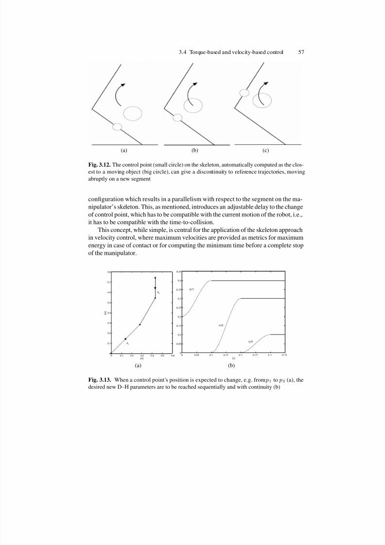
7/21/2019 De Santis Ingegneria Informatica Automatica
http://slidepdf.com/reader/full/de-santis-ingegneria-informatica-automatica 64/102
3.4 Torque-based and velocity-based control 57
(a) (b) (c)
Fig. 3.12. The control point (small circle) on the skeleton, automatically computed as the clos-
est to a moving object (big circle), can give a discontinuity to reference trajectories, moving
abruptly on a new segment
configuration which results in a parallelism with respect to the segment on the ma-
nipulator’s skeleton. This, as mentioned, introduces an adjustable delay to the change
of control point, which has to be compatible with the current motion of the robot, i.e.,
it has to be compatible with the time-to-collision.
This concept, while simple, is central for the application of the skeleton approach
in velocity control, where maximum velocities are provided as metrics for maximum
energy in case of contact or for computing the minimum time before a complete stop
of the manipulator.
0 0.1 0.2 0.3 0.4 0.5 0.60
0.1
0.2
0.3
0.4
0.5
0.6
0.7
0.8
[m]
[ m ]
p1
p2
(a)
0 0.05 0.1 0.15 0.2 0.25 0.3 0.350
0.05
0.1
0.15
0.2
0.25
0.3
0.35
0.4
0.45
[s]
ai(1)
ai(2)
ai(3)
(b)
Fig. 3.13. When a control point’s position is expected to change, e.g. from p1 to p2 (a), thedesired new D–H parameters are to be reached sequentially and with continuity (b)

7/21/2019 De Santis Ingegneria Informatica Automatica
http://slidepdf.com/reader/full/de-santis-ingegneria-informatica-automatica 65/102
58 3 Multiple-point control
With reference to Figure 3.12, it can be seen that a single control point which is
automatically computed based on environment modelling, can move abruptly on the
articulated structure. The use of different filters for the motion on the control point
depends on the control algorithm too: if the control uses higher order derivatives of
the position, motion has to be smooth enough to ensure continuity of these data.Figure 3.13 shows an example of variation of the D–H parameters which identify
the control point for a three-link planar manipulator, whose lengths are 0.4 m, 0.3m, 0.2 m. In such a manipulator, only the values in the vector ai, i.e., ai(1), ai(2),
ai(3), change for a control point pi on the skeleton. If the control points moves from
the middle of the first link ( p1) to the middle of the third link ( p2), the resulting
continuous and sequential change in the D–H parameters, obtained via cubic spline
interpolation, is reported. The time for reaching the desired final value for each pa-
rameter has been set always equal to 0.1 s. This means that the new desired control
point is reached in 0.3 s. In the meanwhile, the control point is moving on the skele-
ton and its motion is taken into account as described above.

7/21/2019 De Santis Ingegneria Informatica Automatica
http://slidepdf.com/reader/full/de-santis-ingegneria-informatica-automatica 66/102
4
Reactive motion and specifications for HRI
Reactive motion is necessary in HRI due to the difficulty of modelling the unstruc-
tured human environments; a simple and fast model is used for the crucial aspect of
relative distance computation of the robot from the interaction environment. Reactivetrajectories based on potential fields will be introduced, useful for collision avoid-
ance. Moreover, rules for fulfilling tasks in anthropic environments have to benefit of
evaluations which are proper of cHRI. Issues are addressed in this chapter, which are
complementary to those introduced in previous sections, together with suggestions
coming form cognitive evaluation on HRI tasks.
4.1 Reactive motion control
Among the possible contributions to safety and dependability of robots for pHRI,
it is worth noticing that a central point is the design of the trajectories. They have
to provide escape paths in short time from dangerous situations, or reconfiguration
paths for letting the manipulator assume postures which are less dangerous in the
event of an impact.
Some desired paths can be unfeasible for a given manipulator, and also dynamic
limits can modify the trajectory tracking. It is intended that nonholonomic constraints
are managed separately, and also other aspects as workspace and joint limits deserve
special attention and modifications, e.g., for wheeled mobile bases. Therefore, the
planning system should take into account such limitations, including them via proper
modifications of desired trajectories. Reactive motion control is meant to provide an
additional tool to off-line planning, able to cope with changes in the environment
through fast operations: simple modelling for inferences about the environment is
therefore necessary. Following the discussion in the above chapters, motion control
can benefit of the idea of modelling the whole body of the robot with simple geom-
etry and of giving the possibility of designing an arbitrary trajectory for any givencontrol point.
Several reactive approaches to planning are used in robotics, mostly based on
artificial potential fields and their algorithmic or heuristic variations, and have been

7/21/2019 De Santis Ingegneria Informatica Automatica
http://slidepdf.com/reader/full/de-santis-ingegneria-informatica-automatica 67/102
60 4 Reactive motion and specifications for HRI
applied both to mobile and articulated robots navigation [32]. It is natural to express
the motion of the robot during interaction as a combination of task-dependent trajec-
tories and effects of a potential field (see also Chapter 3) influencing forces pushing
the manipulator or desired velocities for a control point. It has been shown that the
skeleton approach leads to computation of forces for any given control points: thecontroller has then to properly merge the effects of forces coming from potential
fields with other desired motion/force behaviours. The possibility of an energetically
passive behaviour is an important aspect from the control viewpoint for improved
safety of an interacting human.
Collisions constitute one of the major source of risk for safety in pHRI. While the
discussed recent promising researches, which are going to be merged in the frame-
work of the PHRIENDS project, show that a lightweight robot could be safe also
in the presence of collisions [14], [47], a complete scheme for safe pHRI should
also consider that the use of highly redundant multi-arm robotic manipulators (like
humanoids) cannot be faced only via deliberative planning/control schemes.
Reactive collision avoidance is therefore necessary in both robot–robot and
human–robot interaction. The first is simpler, because of the high reliability of sen-sory data. For reactive collision avoidance in human–robot interaction, tracking of
important parts of the human body is necessary, while a reactive control system acts
on the interacting robot for forcing it to move away from possible collisions. Sen-
sor dependability and integrated planning/control become central in order to safely
interact with people and environment.
For the purpose of fast real-time collision-free motion, reactive control is re-
quired for an arbitrary control point, which is possible to identify from D–H para-
meters, as seen in Section 3.4. It will be considered the case of controlling, e.g., the
closest points to a collision or to a goal, letting them move continuously on the ma-
nipulator and allowing different control modalities, exploiting also a computationally
effective symbolic Jacobian, and possibly also heuristics on the interaction scenario.
This gives emphasis also to the electronic hardware and software safety proce-
dures, to monitor, supervise, and control robot operation. Moreover, by focusing on
the collision avoidance trajectories, variable kinematic configurations may be used to
minimise the instantaneous effect of an impact for a redundant robot, where changes
in the internal kinematic configuration are aimed at minimizing the inertia seen at
the end-effector [48], via null-space techniques and additional potential functions.
In general, one can summarise a list of needed tools for reactive motion in pHRI,
with emphasis on collision prediction for generting avoidance motion, as follows:
• geometric models of the environment,
• proper prediction of collisions,
• vectorial fields for reactive motion.

7/21/2019 De Santis Ingegneria Informatica Automatica
http://slidepdf.com/reader/full/de-santis-ingegneria-informatica-automatica 68/102
4.2 Collision avoidance trajectories 61
4.2 Collision avoidance trajectories
4.2.1 Notes on collisions
Models for collisions between arbitrary bodies can be very complex, taking into ac-count partially plastic or elastic impacts. With reference to a simple skeleton model,
collision avoidance is performed by considering anticipated virtual elastic impacts
occurring in the direction connecting the two closest point on each pair of segments,
considering the possible combinations. This means that a force command propor-
tional to the distance of two approaching parts is commanded to a control point on
the robot before the real collision between the robot and the environment. Complex
behaviours as multiple rebounds due to multiple collisions has to be considered also,
and the possibility of merging additional trajectories in order to escape from local
minima deserves special attention.
Rigid collisions have to be modelled with impulsive forces, while simple springs
(linear o non linear) allow rendering the effect of the virtual collision as rebounds
with continuity. The selected direction for repulsive motion, as introduced, is meantto push the robot away from the path which eventually results in an impact.
In brief, the repelling forces are computed on orthogonal directions and, when
summed, they result in a contribution to motion in that direction. The effect of virtual
springs, even nonlinear spring, have been considered with reference to continuous
reference commands. Rendering of rigid contacts, which has to be faced carefully
for avoiding discontinuities, as often needed in haptics, is not necessary: compliant
impacts are simulated with the potential functions.
4.2.2 Multiple-point control resulting from potential fields
As introduced above, force or velocity fields are to be used instead of specified timed
paths (trajectories) for facing unstructured or only partially known environments, and
collisions have to be avoided between modelled parts in the environment.
As briefly mentioned in Section 3.3, it is not difficult to show that the introduced
repulsion forces for collision avoidance on the skeleton may be derived from a po-
tential function
U c = −
∞dmin
h(δ, d0, dstart)dδ (4.1)
by differentiation with respect to pa,c and pb,c, i.e.
f a,c = − ∂U
∂ pa,cf b,c = −
∂U
∂ pb,c, (4.2)
leading to the expressions in (3.25),(3.26).
In the case of a linear function
h =
k (dstart + d0 − dmin) if dmin < d0 + dstart
0 elsewhere(4.3)

7/21/2019 De Santis Ingegneria Informatica Automatica
http://slidepdf.com/reader/full/de-santis-ingegneria-informatica-automatica 69/102
62 4 Reactive motion and specifications for HRI
with k > 0, the repulsion potential becomes
U c = 1
2k (dstart + d0 − dmin)
2if dmin < d0 + dstart
0 elsewhere(4.4)
and the expressions of the repulsion forces follow simply.
In Fig. (4.1), three choices for h are proposed, where the amplitude of the force
can:
• grow to infinity when the distance to a possibly colliding point approaches zero
(hyperbolic function, solid line), or
• be limited to a finite value (linear function as in (4.3), dashed line), provided that
this value causes an avoidance motion faster than any other planned motion for
the manipulator, or else
• be piece-wise: exponential (dotted line) up to a given distance d1, and from there
linear.
0 0.1 0.2 0.30
100
200
300
dmin
h
Fig. 4.1. Examples of varying amplitude for the repulsion force (for simplicity, d0=0)
The function h can be shaped according to many considerations: maximum al-
lowable speed, implementation of linear springs for providing towards the user a
repulsive motion which is easy to understand and anticipate: this can be a definition
of “legible” trajectory for a human. In general, these considerations can be related
both on cHRI-based rules or on quantitative evaluations in pHRI, as discussed below.
Going on with the reference to the application to self-collision avoidance for
the Justin manipulator, since in the proposed approach the repulsion forces for a
generic segment have been derived from a potential as in (4.2), a torque-based colli-
sion avoidance strategy fits within the passivity-based control framework developed
at DLR for the LWR–III [71, 72].Within this framework, a joint torque feedback (using the torque signal sensed
by the torque sensor after the gear-box in each joint) is used to reduce the friction

7/21/2019 De Santis Ingegneria Informatica Automatica
http://slidepdf.com/reader/full/de-santis-ingegneria-informatica-automatica 70/102
4.3 Additional modelling for real-time whole-body control 63
as well as the apparent inertia of the actuator. The inputs to the controller are the
interaction torques τ i generated by, e.g., an impedance controller.
By assuming a flexible joint model for the manipulator, the entire control struc-
ture can be put into the passivity framework, allowing also a Lyapunov-based con-
vergence analysis [71, 72]. Such controller can incorporate the collision avoidanceby just adding the proper avoidance torques to the interaction torques, i.e.
τ i,c = τ i + τ c =J T J T a,c J
T b,c
f TCPf a,cf b,c
. (4.5)
These torques need to be summed to the gravity (and inertial) torques generated
by the motion controller. In (4.5), J is the Jacobian related to the positions of the
end-effectors arms, while f TCP is the force generated by the impedance controller
at the tool-center point (TCP). It should be clear that both the case of a single TCP
—when only one arm is in contact with a human or the environment— and the case
of two TCP’s can be considered with reference to (4.5).
In order to show passivity of the controller including collision avoidance, the
sum of all repulsion potentials U c,tot =
i U ci (for all pairs of segments involved in
possible collisions) has to be added to the storage function related to the manipulator
and the controller, leading to
V (q, q) = T (q, q) + U (q) + U c,tot.
Herein T (q, q) is the kinetic energy of the manipulator and the virtual energy of
the torque controlled actuator, U (q) contains the potential energy of the arm (gravity,
elasticity) and of the controller and q describes the configuration of the manipulator.
The function V (q, q) can be also used as a Lyapunov function for showing stability
or asymptotic stability, depending on the choice of either a task-space or a joint-space
controller. The derivative of V (q, q) along the system trajectories is namely
V = −qT Dq −i
˙ pT a,cDa ˙ pa,c + ˙ pT b,cDb ˙ pb,c
i
and contains all dissipative elements of the manipulator, the controller and the colli-
sion avoidance. Energetically-passive interaction is therefore achieved. Details about
the control adopted for Justin are reported in [68].
4.3 Additional modelling for real-time whole-body control
4.3.1 Environment and interacting persons
A more complete model of the environment is necessary for real-time computation of
corresponding joint commands, namely, a model able to generalise the skeleton for
a robot manipulator, where planes, segments and points are considered in a limited

7/21/2019 De Santis Ingegneria Informatica Automatica
http://slidepdf.com/reader/full/de-santis-ingegneria-informatica-automatica 71/102
64 4 Reactive motion and specifications for HRI
region, based on sensory information. Moreover, adjustable parameters in the poten-
tial field shaping also result in a more accurate modelling. The complexity of such
world modelling is affected by the possibility of exploiting heuristics for reducing
computation and checks.
For anticipating a collision and for reactive avoidance motion, in general, objectsin the environment can be delimited by volumes which, in turn, can be expressed
as points, lines, planes.
For the purpose of generating continuous reference trajectories, mutual distance
computation between the geometric quantities in the world model has to be per-
formed fast. The distance computation for couples of segments presented in Sec-
tion 3.3 and point-to-segment distances have to be complemented with analytical
formulas for the distance from planes. This is a straightforward generalisation which
can be easily obtained considering a point on a plane. Consider the equation of a
plane in the form:
ax + by + cz + d = 0. (4.6)
The distances between the extremal points of a segment on the robot and such aplane are then considered on the direction orthogonal to the plane, which is actually
colinear to the vector [a,b,c]T. The repelling force will act on one of the ends of
the robot’s segment. If the closest point on the plane is outside from the considered
polygonal regions, distances from the sides of the polygon are computed.
In addition, the tools for the continuous motion on the skeleton avoiding jumps
(see Section 3.4) have to be implemented also, for discarding abrupt changes of clos-
est points in the case of parallel segments, or segments parallel to a plane.
In order to keep the repelling regions limited, the closest point on a plane can be
discarded if it is not inside a user-defined polygon, which can coincide with surfaces
in the workspace. Then, such a polygon becomes the limit for a repelling (or at-
tracting) region. These simple but powerful tools for real-time distance computation
result in the computation of points as summarised in Figs. 4.2, 4.3. With referenceto Fig. 4.2, the closest points to a rectangular regions from the segments of a skele-
ton are shown. Another simple solution is to adopt circular regions. considering only
the distance from the center of the computed closest point on the plane. Figure 4.3
shows how the closest points on a plane (gray dots) are found. If one of these points
is not inside the circular region, i.e., its distance from the center is bigger than the
radius, the intersection (black dot) between the circumference and a line connecting
the point with the center (dashed black line) is considered as the closest point to the
considered segment.
Similarly to the case with segments, note that a point in the considered regions
can then be protected with volumes whose shape results from the parameters in the
cited function h, as discussed in Section 4.3.2 .
Two additional points are then important: the resulting possible multiple re-
bounds coming from local specifications about reactive motion (see Section 4.3.3),
and the use of heuristics both for giving different amplitudes to the forces and for
discarding some computation, as discussed above.

7/21/2019 De Santis Ingegneria Informatica Automatica
http://slidepdf.com/reader/full/de-santis-ingegneria-informatica-automatica 72/102
4.3 Additional modelling for real-time whole-body control 65
0
2
4
6
8
−2−1
0
1
2
3
4
−2
−1.5
−1
−0.5
0
0.5
1
Fig. 4.2. The distances from segments (gray) to a rectangular regions (black) are computed
as a straightforward extension with respect to the introduced distance formulas for segments
−4
−2
0
2
4
6
8 −4
−3
−2
−1
0
1
2
3
4
−3
−2
−1
0
1
Fig. 4.3. Distances from a circular regions are computed by considering distances to a plane,
and then from there to the center of the considered region
Heuristics can be used for discarding points which cannot collide due to me-
chanical limits of the robot. For scene monitoring, distances have to be computed in
any case. However, the computation of joint commands can be skipped for segments
which are not likely to collide, due to high distances and low speed.
As heuristics for reducing the number of contemporary segments which push arobot segment, one may also fictitiously increase the values in the associated damp-
ing matrices for all those points but the closest one, so as to obtain one collision point

7/21/2019 De Santis Ingegneria Informatica Automatica
http://slidepdf.com/reader/full/de-santis-ingegneria-informatica-automatica 73/102
66 4 Reactive motion and specifications for HRI
per segment and thus one repulsion force. As seen before, more general solution is
to consider all the possible combinations of segments.
The amplitude of the forces depends on design choices about the intensity of the
repulsion between the arms, which affect the values of the amplitude of h and Da,
Db. Inference systems can be helpful in order to dynamically modify the startingand limit distances and the shaping of the function h. In pHRI, the tuning of these
parameters may depend on the part of the human body that is close to the manipula-
tor.
Consider the model of an interacting person present in the workspace. According
to the steps of the skeleton algorithm, the Cartesian position of human joints have
to be identified (elbow, neck, knees, ...), in order to compute distances on segments
which connect these points. For this purpose, face and hand detection algorithm have
to be implemented (see Section 5.2).
After this phase, choices of h are feasible, e.g. on the basis of performance cri-
teria like the Head Injury Criterion, where accelerations and velocities of the arms
during the avoidance motions can be kept under a threshold in order to reduce the
risk of injury for the body of a human user present in the workspace of the manip-ulator. If the focus is only on self-collision avoidance, such real-time inferences are
not necessary, while collisions with the user are considered only in “after-impact”
strategies.
For the purpose of world modelling, the use of exteroception is a central point.
Reliability of cameras, proximity and touch sensors is relevant for assessing the po-
sitions of points used for modelling complex figures. This is the case, for instance,
of the important model of an interacting person. The human head has to be protected
at least, and sensory systems have to be able to detect the head and the hands, distin-
guishing them from the faces, for creating safe protecting regions, as seen above.
Additional heuristics can drive such evaluations: skin detection can help in find-
ing head and hands, information about the maximum reach of used robot can also be
used for skipping some computation. It is worth noticing that ordinary exteroception
is much slower with respect to proprioception.
For a very precise model of the robot, the idea of using detailled meshes with
polygons has the limitation of the computation time needed for all the checks: the
skeleton approach has however to be refined for allowing less conservative region
“wrapping”. Therefore, it is worth noticing that the attracting or repelling force which
originate from any point of these areas (which can be indeed goals or forbidden
regions) can be shaped according to additional information on the environment, such
as level of danger of specified collision, level of intrinsic safety additional tactics
(robot’s edges wrapping, post-collision management, and so on).
4.3.2 Limit distances and object shaping
The way for obtaining complex shapes for objects in pHRI scenarios can be based onthe properties of the reactive force which attracts or repels the control points. With
reference to the h function describing a repulsion force, the shape of an object to
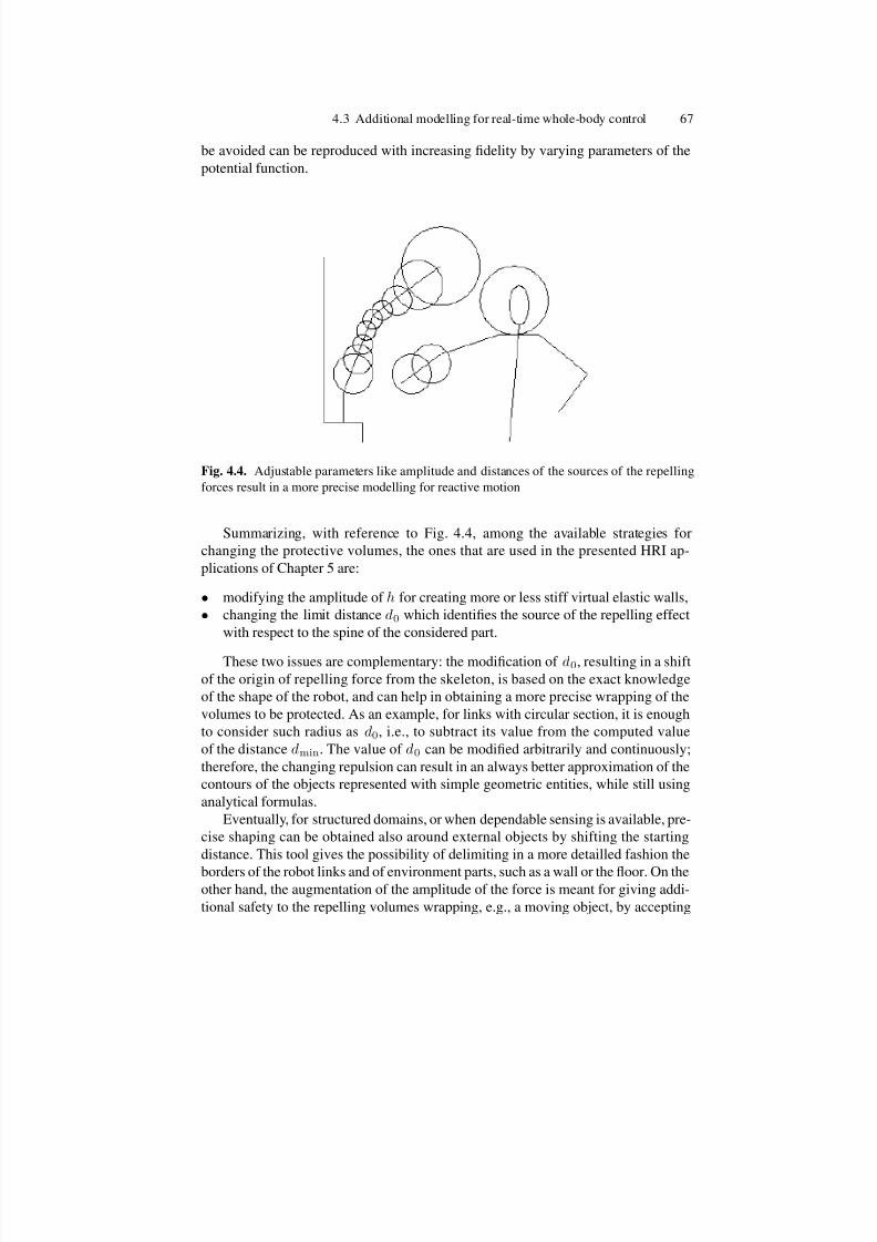
7/21/2019 De Santis Ingegneria Informatica Automatica
http://slidepdf.com/reader/full/de-santis-ingegneria-informatica-automatica 74/102
4.3 Additional modelling for real-time whole-body control 67
be avoided can be reproduced with increasing fidelity by varying parameters of the
potential function.
Fig. 4.4. Adjustable parameters like amplitude and distances of the sources of the repelling
forces result in a more precise modelling for reactive motion
Summarizing, with reference to Fig. 4.4, among the available strategies for
changing the protective volumes, the ones that are used in the presented HRI ap-
plications of Chapter 5 are:
• modifying the amplitude of h for creating more or less stiff virtual elastic walls,
• changing the limit distance d0 which identifies the source of the repelling effect
with respect to the spine of the considered part.
These two issues are complementary: the modification of d0, resulting in a shift
of the origin of repelling force from the skeleton, is based on the exact knowledge
of the shape of the robot, and can help in obtaining a more precise wrapping of the
volumes to be protected. As an example, for links with circular section, it is enough
to consider such radius as d0, i.e., to subtract its value from the computed value
of the distance dmin. The value of d0 can be modified arbitrarily and continuously;
therefore, the changing repulsion can result in an always better approximation of the
contours of the objects represented with simple geometric entities, while still using
analytical formulas.
Eventually, for structured domains, or when dependable sensing is available, pre-
cise shaping can be obtained also around external objects by shifting the starting
distance. This tool gives the possibility of delimiting in a more detailled fashion the
borders of the robot links and of environment parts, such as a wall or the floor. On theother hand, the augmentation of the amplitude of the force is meant for giving addi-
tional safety to the repelling volumes wrapping, e.g., a moving object, by accepting

7/21/2019 De Santis Ingegneria Informatica Automatica
http://slidepdf.com/reader/full/de-santis-ingegneria-informatica-automatica 75/102
68 4 Reactive motion and specifications for HRI
a persistent presence of reactive movements due to the covering of wider areas by
the effects of the potential fields.
In turn, the variation of the amplitude of the repelling function can be directly
related to possible danger which can be caused by approaching objects whose shape
is not perfectly known. For instance, the intensity could increase when a sharp edgeis approaching the user if only centroids of user’s head and body are extracted by
sensors. This tool is thought to be more conservative than the previous one (isotropic
spherical regions are created), and directly related to some safety danger criterion
during the interaction. Again, this is related to the reliability of sensory data and to
availability of meaningful safety criteria.
In principle, also the starting distance dstart is an available parameter for discard-
ing some sources for object motion. Since the motion on the skeleton is continuous,
also such variations give continuous reference to the controllers.
Summarizing, the manipulator is a skeleton of segments, the world is composed
of segments and planar regions; the distance between segments and the distance from
segments to rectangle or circles on the plane are the main indicator of an approaching
collision. The precision during motion can be increased via proper shifting repulsionsources or decreasing the size of forbidden regions. The important point is the suit-
ability for real-time operation, since the distances are computed in any case from the
skeleton, using analytical formulas.
Note that forces/velocities can be related also explicitly to the variation of the
parameters in Eqs. (3.25),(3.26)), giving
f a,c = h(dmin, dmin, d0, d0, dstart, dstart)
dmin( pa,c − pb,c) (4.7)
f b,c = h(dmin, dmin, d0, d0, dstart, dstart)
dmin( pb,c − pa,c) = −f a,c (4.8)
The suitability for inverse kinematics benefit of the modifications to the differen-tial kinematics equation described in Section 3.4.
4.3.3 Attractive and repulsive trajectories
The collision avoidance paths can also be seen as general paths among attracting and
repelling objects, which can constitute a base for gross motion of interacting robots,
while fine motion can be accomplished after checks on possible impacts.
Deliberative/reactive motion can therefore be accomplished using models where
selected regions of the environments are labelled as attracting or repelling volumes
One tool for this purpose, which is also a solution for avoiding local minima due
to motion among multiple goals and obstacles, is the moving virtual target , which
represents a fictitious target to be introduced in the workspace for letting the robotleave some postures: it could be, e.g., the hand of the user, possibly wearing a glove
with markers, which allows the robot to reach some posture where local minima
problems are abandoned.

7/21/2019 De Santis Ingegneria Informatica Automatica
http://slidepdf.com/reader/full/de-santis-ingegneria-informatica-automatica 76/102
4.3 Additional modelling for real-time whole-body control 69
This approach has been considered for experiments (see Section 5.2). The use of
a virtual target corresponds to situations where manual guidance in torque control is
used for moving the robot towards a desired posture.
4.3.4 Skeleton-based whole-arm grasping
The idea of grasping big objects with the arms instead that the hands, depending on
dynamic limit or balancing of a manipulator, can be afforded with the introduced
tools. It is based on a simple approach where grasping is performed using a virtual
attractive target on the object, which corresponds to virtual springs put in proper po-
sitions on object and manipulator. The skeleton approach allow locating everywhere
these control points. Of course, theory about grasping, including closure and friction
properties of the grasp has to be properly considered for defining such control points.
After this stage, however, the steps of the skeleton algorithm apply, using both at-
tractive repulsive force around the object, for approaching the grasp position and for
aligning with the desired control point configuration, before removing the repulsive
force and grasping the object via attraction of control points.With reference to Fig. 4.5, a repelling area (indicated by the big circle) can be
created around the object to be grasped (small circle), while the manipulator is at-
tracted so as to preshape around the object. Finally, repulsion is removed and the
grasp can be performed.
Fig. 4.5. Whole-arm grasping can be performed via multiple-point control and potential fields
It is worth noticing that also internal stress on an held object can be reduced using
the repulsive forces on the control points, balancing the attraction which can result
in squeezing the grasped object.

7/21/2019 De Santis Ingegneria Informatica Automatica
http://slidepdf.com/reader/full/de-santis-ingegneria-informatica-automatica 77/102
70 4 Reactive motion and specifications for HRI
4.4 Multiple tasks and cognitive aspects in HRI
Safety tactics have different abstraction levels, from passively safe robots to intel-
ligent procedures for safety by means of control. Cognitive evaluation is mainly
related to pre-collision phases in pHRI, for managing multiple tasks, anticipatingimpacts, and providing legible motion behaviours.
4.4.1 Priority and mobility distribution
In the presence of redundant DOF’s, the importance of automatic adjusting the pri-
ority order for multiple tasks has widely been addressed in robotics, as discussed
above (see Section 3.2). In human environments, some tasks have to be fulfilled with
an adjustable priority order which is related to the possible consequences of motion
on a human users.
The number of available DOF’s also defines whether the manipulator is func-
tionally redundant for a given task. For a given sequence of tasks, a way for stacking
them in an order which allows a “global” task fulfillment “at the best” depends on theconsidered optimality criterion, i.e., the definition of safety/performance trade-off for
the considered HRI application.
Moreover, the main idea of reactive control is to give priority to some emerging
task, possibly discarding the others or summing them with minor modification to the
main trajectory. With reference to previous sections, redundancy can be solved for
allowing multiple tasks, based on projection in the null-space, or not considered, by
just summing concurrent motion commands.
Rules have to be chosen for trying to accommodate concurrent needs in joint
motion generation. A purely reactive strategy presents the problem of local minima
and no guarantees for task completion in some configurations of goals and obstacles.
An additional tool which can be used in velocity control is the weighting of joint
involvement already introduced in Section 3.2. The involvement of motors in a task
can vary according to specifications which freeze the motion of some joints, and in-
crement the contribution of other joints. Dynamical limits for the joints, reduction
of the inertia seen at the link and cognitive evaluation on the sense of fear of robot
motion can drive this decision process. In [56], [70], fuzzy sets are used for translat-
ing linguistic concepts in weights which influence priority order, trajectory scaling,
or joint involvement.
Another important aspect, from the examples with VEEs and whole-body control
on a skeleton, is the choice of the control points. The solution of considering more
relevant the point nearest to a collision can be exploited for automatically giving
priority to that point, provided that the closest point tracking preserves continuity of
commands for the control system. Moreover, such tracking has to be fast enough for
allowing motion commands to be in time for avoiding collisions. This behaviour has
to be complemented with evaluation of the effect of the motion of the control point(see Section 3.4).
More in general, task nesting can be related to the kinematics and dynamics of
the robot: indicators of proximity to singularities, nonholonomic constraints and so

7/21/2019 De Santis Ingegneria Informatica Automatica
http://slidepdf.com/reader/full/de-santis-ingegneria-informatica-automatica 78/102
4.4 Multiple tasks and cognitive aspects in HRI 71
on can be used not only for scaling trajectories, but also for abandoning paths which
are not feasible from a safety viewpoint.
In the presence of singular configuration of the manipulator, the inertia seen in
case of an an impact can be very high, and redundancy resolution has to be used for
avoiding singularities instead of accommodating different positioning task. More-over, joint limits also can result in forces absorbed by the structure.
In such cases, the robot has to stop and ask for a global replanning from the
planning system.
4.4.2 Legibility of motion and smoothness of movements
Smoothness and anticipation of the motion of a collaborative colleague increase the
sense of comfort during cooperative operations. This intuition can be proposed as a
desired criterion for motion trajectories of robots in the presence of humans. Sudden
motion can lead the user to react as a reflex, moving in such a way to hit objects
in the environment and cause that the exteroceptive sensory systems, which maps
human positions for the robot controller, possibly loose the tracking of the user.If the robot’s trajectories can be anticipated , i.e., the user can understand where
the robot is going, for a task-driven operation, comfort augments. This is one of the
aspects which define a “mental” safety [73]. According to the presented models, re-
action forces implemented as virtual springs can be easy to understand and anticipate
(see also Chapter 5).
The listed cognitive aspects are meant to emphasise that, for human environ-
ments, the notion of safety includes also psychological effects on the user coming
from the robot’s motion. It is understood that fault management strategies are meant
to limit consequences of faults also in terms of “strange” motions which results in
high forces and in discontinuous motion and scare on the user.
An application where some kind of perceived safety is more relevant is rehabili-
tation robotics: Virtual Reality-based simulation has been considered in Section 5.3for coping with the perceived safety, after experiments on collision anticipation ac-
cording to the presented models.
The understandability of robot motion during HRI is necessary for addressing the
property of legibility of trajectories. In the pHRI scenario, the presence of humans
suggest some biomimetic solutions for operations. Human-like motion can be easy
to understand, and also bimanual operation is natural for cooperation: this allows the
user to better understand what is going on during the cooperation with the robot, and
allows a simpler human supervision.
Humanoid shapes for robots in HRI appear therefore natural, both for allow-
ing more natural cooperation, and for to the possibility of using tools designed for
humans. Learning algorithms are then to be considered for forcing human-like pos-
tures in collaborative tasks between humans and humanoid robots. A gesture-based
communication and intuitive interfaces are another important point. Moreover, thephysical viewpoint addressed in PHRIENDS can be helpful for avoiding postures
which are unsafe due to inertia seen at possible impact points.
7/21/2019 De Santis Ingegneria Informatica Automatica
http://slidepdf.com/reader/full/de-santis-ingegneria-informatica-automatica 79/102
72 4 Reactive motion and specifications for HRI
4.4.3 Rules based on proxemics
Control of pHRI tasks has to focus on the user as well as on the robot: among the
main points for robot control, risk assessment has to consider both objective and
perceived safety, both depending on the proximity to the robot. A user can start be-coming familiar with the interacting robot and trust it, and this can result in closer
approach to the robot, like in human–human interaction. According to previous dis-
cussion, some repelling functions can be discarded for allowing close cooperation.
However, this poses of course bigger threats, especially for users with reduced mo-
bility, who could be slow to exit from the robot’s workspace.
The framework of proxemics [74] is interesting: it addresses change in behaviour
related to the spacing with respect to another person.
Like for potential fields encompassing the collision points in the skeleton ap-
proach, area can be found and labelled based on intimate distance, personal distance,
social distance and public distance. While in human–human relations these distances
depend on cultural aspects, in HRI these can be related to safety, both intrinsic and
mediated by control.It is worth noticing that the amplitude of repelling force and maximum allowed
joint speed can vary in the different zones, while these limitations can be removed
for skilled users: going on with the proxemics metaphor, the personal distance in
Europe and in Asia is set at different numeric values. This corresponds, in HRI,
to let professional users go at less than 0.5 m from the robot while it keeps higher
average speeds, while the same distance corresponds to almost frozen joints for tasks
aimed at contactless human–robot cooperation, e.g., for assembling. Social effects in
crowded environment have to be taken into account for mobile manipulators, whose
navigation has not to scare people.
A classification of the human–robot collaborative workspace is expected also
in the standard definition. Right now, the defined robot control modality related to
higher or lower sharing of the workspace (far, close, touching, supporting, invasive)
correspond of course to different safety levels.A central problem for pHRI is the phase where users and robots are in touch. The
tools presented in previous chapter for multiple-point reactive motion during HRI
are based on objective indicators of proximity for close cooperation. They can be
complemented with comfort measures which have to be estimated via experiments
with users.

7/21/2019 De Santis Ingegneria Informatica Automatica
http://slidepdf.com/reader/full/de-santis-ingegneria-informatica-automatica 80/102
5
Applications
This chapter is aimed at showing how the presented algorithms and HRI-centered
strategies have been used for real implementations on both a standard, industrial
manipulator, and an advanced service robot. With reference to interaction with in-trinsically unsafe robots, it has to be pointed out that dependability of sensory data is
crucial to cope with unpredictable user’s motion. Moreover, there will be also a dis-
cussion on the use of Virtual Reality (VR) for facing HRI from a cognitive point of
view while implementing the proposed control algorithms and considering the con-
sequent reactive motion of the manipulator. While real experiments help in giving
quantitative warrantees about the use of reactive multiple-point control with the pro-
posed simple modelling, Virtual Reality allows the verification of possible system
faults and unexpected user behaviours without the risk of real collisions and injuries,
as results from preliminary experiments in an immersive environment. The “com-
fort” of the user, which is an important aspect from a cognitive viewpoint, provides
an additional indicator for the evaluation of HRI system. This results in an additional
useful criterion for interface design and choice of some control parameters.
5.1 Application to a human-friendly humanoid manipulator
5.1.1 Safety concepts and experimental setup at DLR
Experiments for evaluation of the proposed multiple-point control, considering self-
collision avoidance of a humanoid manipulator as a benchmark, have been performed
at the Institute of Robotics and Mechatronics of the German Aerospace Agency Re-
search Center (DLR). Self-collision avoidance allow testing the algorithms assuming
perfect sensing about the position of the possibly colliding parts.
Moreover, this set of experiments benefits of “Safe Robotics” concepts and in-
tegration developed by DLR. The choice of the DLR LWR-III (and its equivalentKUKA LWR, see Fig. 1.1), as the reference robot for pHRI, confirmed by the re-
search activity in the framework of PHRIENDS, depends on its lightweight design,
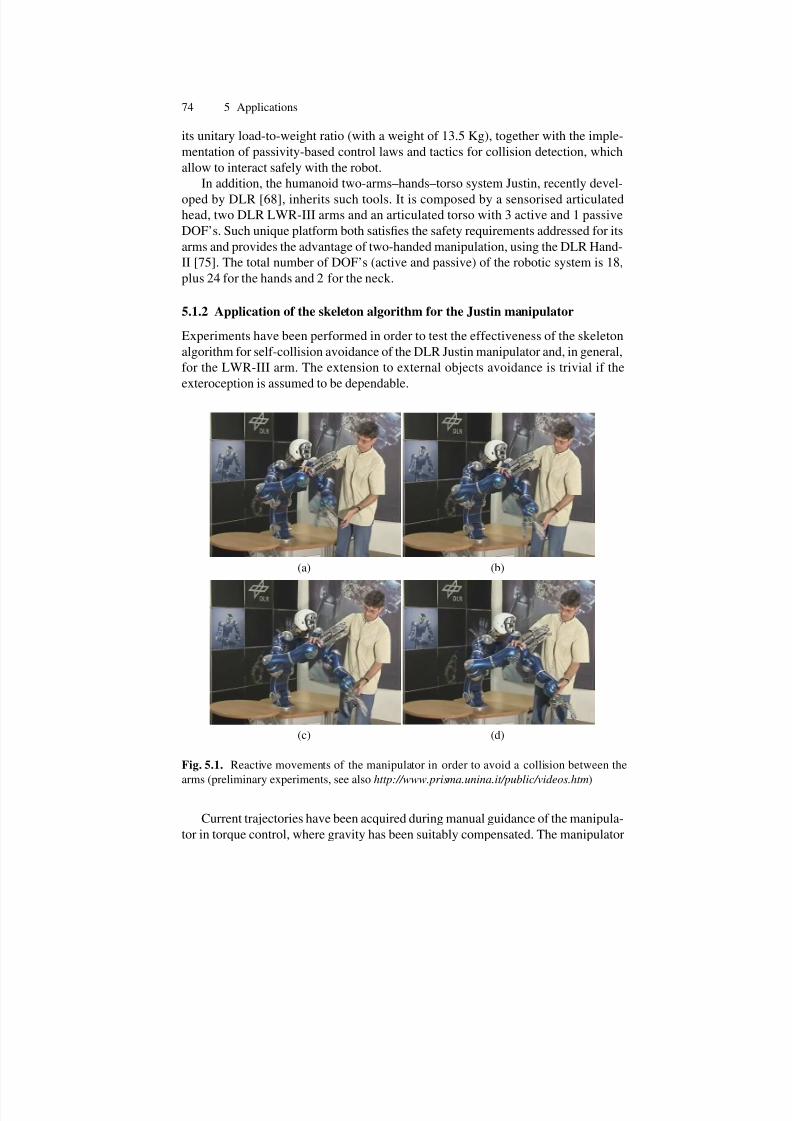
7/21/2019 De Santis Ingegneria Informatica Automatica
http://slidepdf.com/reader/full/de-santis-ingegneria-informatica-automatica 81/102
74 5 Applications
its unitary load-to-weight ratio (with a weight of 13.5 Kg), together with the imple-
mentation of passivity-based control laws and tactics for collision detection, which
allow to interact safely with the robot.
In addition, the humanoid two-arms–hands–torso system Justin, recently devel-
oped by DLR [68], inherits such tools. It is composed by a sensorised articulatedhead, two DLR LWR-III arms and an articulated torso with 3 active and 1 passive
DOF’s. Such unique platform both satisfies the safety requirements addressed for its
arms and provides the advantage of two-handed manipulation, using the DLR Hand-
II [75]. The total number of DOF’s (active and passive) of the robotic system is 18,
plus 24 for the hands and 2 for the neck.
5.1.2 Application of the skeleton algorithm for the Justin manipulator
Experiments have been performed in order to test the effectiveness of the skeleton
algorithm for self-collision avoidance of the DLR Justin manipulator and, in general,
for the LWR-III arm. The extension to external objects avoidance is trivial if the
exteroception is assumed to be dependable.
(a) (b)
(c) (d)
Fig. 5.1. Reactive movements of the manipulator in order to avoid a collision between the
arms (preliminary experiments, see also http://www.prisma.unina.it/public/videos.htm)
Current trajectories have been acquired during manual guidance of the manipula-
tor in torque control, where gravity has been suitably compensated. The manipulator
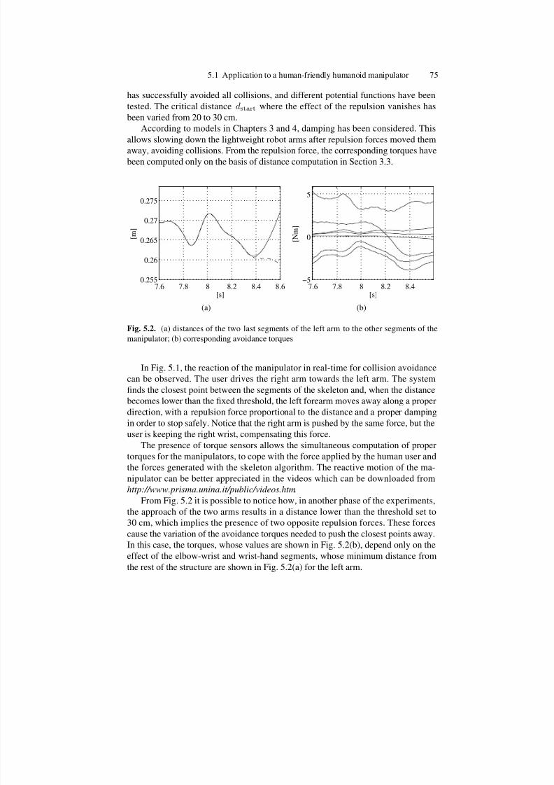
7/21/2019 De Santis Ingegneria Informatica Automatica
http://slidepdf.com/reader/full/de-santis-ingegneria-informatica-automatica 82/102
5.1 Application to a human-friendly humanoid manipulator 75
has successfully avoided all collisions, and different potential functions have been
tested. The critical distance dstart where the effect of the repulsion vanishes has
been varied from 20 to 30 cm.
According to models in Chapters 3 and 4, damping has been considered. This
allows slowing down the lightweight robot arms after repulsion forces moved themaway, avoiding collisions. From the repulsion force, the corresponding torques have
been computed only on the basis of distance computation in Section 3.3.
7.6 7.8 8 8.2 8.4 8.60.255
0.26
0.265
0.27
0.275
[s]
[ m ]
(a)
7.6 7.8 8 8.2 8.4−5
0
5
[s]
[ N m ]
(b)
Fig. 5.2. (a) distances of the two last segments of the left arm to the other segments of the
manipulator; (b) corresponding avoidance torques
In Fig. 5.1, the reaction of the manipulator in real-time for collision avoidance
can be observed. The user drives the right arm towards the left arm. The system
finds the closest point between the segments of the skeleton and, when the distance
becomes lower than the fixed threshold, the left forearm moves away along a proper
direction, with a repulsion force proportional to the distance and a proper dampingin order to stop safely. Notice that the right arm is pushed by the same force, but the
user is keeping the right wrist, compensating this force.
The presence of torque sensors allows the simultaneous computation of proper
torques for the manipulators, to cope with the force applied by the human user and
the forces generated with the skeleton algorithm. The reactive motion of the ma-
nipulator can be better appreciated in the videos which can be downloaded from
http://www.prisma.unina.it/public/videos.htm.
From Fig. 5.2 it is possible to notice how, in another phase of the experiments,
the approach of the two arms results in a distance lower than the threshold set to
30 cm, which implies the presence of two opposite repulsion forces. These forces
cause the variation of the avoidance torques needed to push the closest points away.
In this case, the torques, whose values are shown in Fig. 5.2(b), depend only on the
effect of the elbow-wrist and wrist-hand segments, whose minimum distance from
the rest of the structure are shown in Fig. 5.2(a) for the left arm.

7/21/2019 De Santis Ingegneria Informatica Automatica
http://slidepdf.com/reader/full/de-santis-ingegneria-informatica-automatica 83/102
76 5 Applications
It is possible to see how the reactive effect remains activated, since it happens that
the users applies forces on the hands, keeping them closer then the distance where
the force starts to act, namely, dstart.
A good point to notice is the symmetry of the structure, leading to cancellation of
equivalent movements in different directions caused by the double repulsion of thepairs of collision points which are considered by the control system. For instance,
if the two hands are going to collide, the involvement of the joints of the torso is
significantly reduced with respect to the arms’ joints.
Different repulsion functions and different values in the damping matrices have
been adopted, leading to faster or slower reaction of the manipulator when approach-
ing the starting distance for the repulsion effects, but the results are not reported
here for brevity. The shape of such a function is important for studying the initial
distance and velocity which are to be adopted for different avoidance tasks, from
self-avoidance to object avoidance, up to human body avoidance.
As introduced in Chapter 3, an alternative to the presented technique, the skeleton
algorithm could be applied also for a velocity control based implementation, i.e. by
generating repulsion velocities for the collision points, and thus computing the jointvelocities via proper inverse kinematics [34].
Notice again that tracking of interacting people, e.g., via markers in elbow and
wrist [62] can be used for building a robust skeleton-based model for human avoid-
ance. Nevertheless, as already introduced, additional tools based on [45] are available
for detecting collisions with users.
Multiple interaction is shown in the snapshots from experimental activity in
Fig. 5.3. Multiple touches and multiple repulsion result in a comfortable interaction
without robot self-collision. Exteroception is not present in the interaction shown in
Fig. 5.3: torque control is in charge of accomodating forces applied on the arms.
The world model can be arbitrarely complicated, according to suggestions in
Chapter 4. Computation time has to preserve real-time constraints: for the presented
experiments at DLR with torque control, the complete monitoring of the scene, with
Jacobian computation, torque command calculation, and sum to nominal torque fit
in the controller sampling time (1 ms), providing real-time operations.
In detail, the implemented blocks, with a modular approach, are:
• direct kinematics for skeleton building,
• distance and force computation in the collision prediction phase,
• modular Jacobian.
To be more general, the Jacobian is not specialised for different regions of the
structure: as an improvement from the computational viewpoint, the Jacobian for
segments closer to the skeleton could already contain, in the symbolic form, the
simplifications due to the null value of the D–H parameters beyond the control point.
The starting distance for the repulsion force in the experiments in Fig. 5.3 is set
to 0.25 m: again, protecting volumes which follow the shape of the arms can beobtained by varying the limit distance d0.
As a final example of applications with the DLR Justin humanoid in the pres-
ence of external obstacles, consider experiments in Fig. 5.4, where the left arm of the

7/21/2019 De Santis Ingegneria Informatica Automatica
http://slidepdf.com/reader/full/de-santis-ingegneria-informatica-automatica 84/102
5.1 Application to a human-friendly humanoid manipulator 77
Fig. 5.3. Multiple interaction with the robot in the presence of self-collision avoidance (please
refer also to http://www.prisma.unina.it/public/videos.htm)
humanoid manipulator approaches to the can (a), modelled as a segment. Then, the
repelling force lets the arm bounce towards the chest (b), and from there again out-
wards (c), until the system is stopped by the interacting user (d) or due to damping.
The touch by the user can actually be detected with proper techniques developed by
DLR. Notice that users can leave the robot arms freely move, because they anticipate
the bouncing effect and wait for the arm to come back.
It is just the case to stress again how the integration in PHRIENDS allows merg-ing multiple tactics to cope with collisions, leading to a safer and more dependable
HRI. In fact, strategies include:

7/21/2019 De Santis Ingegneria Informatica Automatica
http://slidepdf.com/reader/full/de-santis-ingegneria-informatica-automatica 85/102
78 5 Applications
(a) (b)
(c) (d)
Fig. 5.4. In this sequence the can is an obstacle, modelled as a segment
• pre-impact models (addressed in this thesis),
• impact effect reduction by lightweight design,
• post-impact management, i.e., reaction to collisions.
5.2 Application to small industrial domains
The idea of a simple world model based on points, lines and planes has been tested
in an industrial robotics scenario, where it can be enforced by the partially known
structure of the environment. In fact, with a classical industrial layout, the skeleton
can be built perfectly, knowing the position of all the equipment; moreover, in inter-
action with human co-workers, the robot can use exteroception to build a model of
the interacting persons.
Unfortunately, the complex strategies available for previous experiments are not
present in current industrial domains. Therefore, a proposed velocity-based imple-
mentation has to cope with the inherent limitations of heavy and unsafe used manip-
ulatorsAccording to previous sections, safety in pHRI is more than a generic attribute
of the wider concept of dependability with the same importance, e.g., than main-
tainability. The skeleton approach does not take into account intrinsically the full

7/21/2019 De Santis Ingegneria Informatica Automatica
http://slidepdf.com/reader/full/de-santis-ingegneria-informatica-automatica 86/102
5.2 Application to small industrial domains 79
dynamics of the robot, while this can be faced via modification of the potential fields
used for shaping the amplitude of the repelling force. The approach is suitable for a
wide class of robot manipulators, but the risk of harm during reactive motion is more
acceptable where dependability for the system is guaranteed by the human compati-
ble safety levels at the possible collision instant, resulting from the lightweight link design, compliant transmissions, post-collision tactics. In the following, the reac-
tive algorithm will be considered in its implementation on a heavy industrial robot.
Again, it will be clear that models and controls for HRI cannot be considered without
additional specifications on manipulator’s design and actuation.
5.2.1 Experimental setup at PRISMA Lab
The setup in the PRISMA Lab consists of two industrial robots Comau SMART-3 S
(see Fig. 3). This manipulator has a six-revolute-joint anthropomorphic geometry
with nonnull shoulder and elbow offsets and non-spherical wrist. One of the two
robots has an additional DOF provided by a base prismatic joint.
The robot is controlled by the C3G 9000 control unit which has a VME-basedarchitecture with two processing boards (Servo CPU and Robot CPU) both based on
a Motorola 68020/68882. Upon request, COMAU supplies the proprietary controller
unit with a BIT3 bus adapter board, which allows the connection of the VME bus of
the C3G 9000 unit to the ISA bus of a standard PC with MS-DOS operating system,
so that the PC and C3G controller communicate via the shared memory available in
the Robot CPU. In this way the PC can be used to implement control algorithms,
and time synchronisation is achieved by means of a flag set by he C3G and read by
the PC. A closed proprietary C library (PCC3Link produced by Tecnospazio SpA) is
available to perform communication tasks.
In the new open controller available at the PRISMA Lab, named RePLiCS [76],
the software running on the PC has been completely replaced by a real-time con-
trol environment based on RTAI–Linux operating system. RePLiCS allows advanced
control schemes to be designed and tested, including force control and visual servo-
ing. An advanced user interface and a simulation environment have been also devel-
oped, which permit fast, safe and reliable prototyping of planning and control algo-
rithms. A noticeable feature of RePLiCS, which is an enhancement of the existing
industrial multi-robot controllers, is that it allows not only the time synchronisation
of the sequence of operations executed by each robot, but also real cooperation be-
tween the robots.
5.2.2 An application with exteroception
As presented in the central chapters, a reactive technique for collision avoidance,
where repulsion forces can be shaped arbitrarily and the Jacobian matrices for com-
putation of the corresponding joint motions/torques is a useful tool for completing ahuman/robot dependable interaction scheme. Nevertheless, better results depend on
sensor dependability for locating the position of human beings with respect to the
robot.

7/21/2019 De Santis Ingegneria Informatica Automatica
http://slidepdf.com/reader/full/de-santis-ingegneria-informatica-automatica 87/102
80 5 Applications
In order to use the skeleton algorithm, simple fixed cameras have been employed
to detect the positions of face and hands of an operator in the operational space of
the robot. In assembly tasks in cooperation with the robot, the operator does not
move fast, simplifying the tracking by means of cameras. In preliminary experi-
ments, markers have been used to help the detection and tracking. The detected po-sitions of the human operator are tracked in order to keep a safety volume around
him/her, repelling the robot when it approaches too much. Safety by means of con-
trol is translated in scaling trajectories and stopping the robot when the face detection
fails.
The frame rate for the preliminary experiments in the PRISMA lab is quite low,
and therefore errors on distance computation can be important if the robot is fast as in
automatic operations. The time which is necessary to complete a task is an objective
indicator of performance; therefore, a trade-off between maximum allowable speed
and safety level has to be reached. An estimation of the time to a possible collision,
given the current speed and acceleration of the robot, can be used for limiting the
control point’s speed or, possibly, to stop the robot if the distance is decreasing too
fast for a possible recovery.In the experiments in the PRISMA Lab, users interacting with the industrial ma-
nipulators used for experiments, even skilled, were however not fully confident while
the robot moved towards the goal point and reconfigured itself in order to comply
with the planned repulsion strategy. Due to the quality of exteroception, risk assess-
ment is move at the sensing level. Errors in sensing cannot be tolerated like for a
lightweight robot. Also the dependability of the computation of the control point
(and the corresponding planned torques or velocities) may be affected by a wrong
evaluation of the closest point to a collision. Sensor fusion algorithms are therefore
to be considered together with a model of their accuracy.
Anticipation of robot movement by the user is a good feature for improving
safety. The repelling force can be identified as a virtual spring from the user, who
can anticipate the forthcoming motion of the robot, provided that she/he has an idea
of the type of “bouncing” behaviours implemented on the robot (e.g., linear spring).
Figure 5.5 shows how face detection debug has been performed with printed
pictures: according to standards, users are not allowed to enter in the workspace
during automatic robot operation. Real face tracking in the manipulator’s workspace
has been then performed with reduce maximum operating velocity.
With reference to Fig. 5.6, the skeleton which contains the possible control points
goes also over the spine of the links: in fact, motors are present, which can result in
impacts. The inclusion of additional parts (like, e.g., tools handled by the manipula-
tor) in the skeleton, can be related to the volume of the repelling region wrapping a
control point on the skeleton (see Fig. 5.6 and Section 4.3.2).
Experiments performed for self-collision avoidance of a manipulator correspond
to an ideal case where positions of the possibly colliding bodies are known almost
exactly. This is the case of the presented results with the Justin manipulator. Soft-ware and communication dependability are to be guaranteed for approaching this
ideal case. Experiments at PRISMA Lab show how effective the technique can be
also with traditional robots. In fact, head avoidance and gola-directed movements

7/21/2019 De Santis Ingegneria Informatica Automatica
http://slidepdf.com/reader/full/de-santis-ingegneria-informatica-automatica 88/102
5.2 Application to small industrial domains 81
(a) (b)
(c) (d)
Fig. 5.5. Face detection for the creation of a safe volume (a), which results in manipulator’s
avoidance motion (a–d)
were fulfilled; however, a trade-off with performance is needed (e.g., slowing down
the maximum repulsion motions), since the intrinsic nature of heavy industrial ma-
nipulators gives less robustness with respect to consequences of sudden motions incase of malfunctioning (which has to be related with probabilistic aspects).
These concepts can be explicitly captured via cost functions, including the injury
level. However, an implementation of such indicators will be more effective after the
ongoing revision of safety criteria for collaborative HRI.
Comparing the results of experiments with advanced and ordinary robots, from
the dependability viewpoint, it is clear that the proposed technique is intended to
offer an additional tool for safety in pHRI, but cannot be the only safety procedure.
The simple software implementation for the skeleton algorithm does not pose addi-
tional software dependability problems, but can be inadequate when intrinsic safety
is poor.
If a vision system (e.g., the one considered for the experiments at PRISMA Lab
based on [35]) is adopted, dependable estimation of the head position must cope with
issues related to: vision hardware speed and synchronisation, camera calibration,model of the face detection, maximum allowable errors and delays in the considered
probabilistic framework. These issues are under investigation for a more quantitative

7/21/2019 De Santis Ingegneria Informatica Automatica
http://slidepdf.com/reader/full/de-santis-ingegneria-informatica-automatica 89/102
82 5 Applications
Fig. 5.6. Skeleton including dangerous appendices (e.g., point labelled with “e”)
evaluation of the safety in the proposed approach. In order for a robot to be perceivedas safe, cognitive aspects as the appearance can play an important role. However, a
friendly appearance can result in an illusory sense of dependability.
Summarizing, also partially unstructured domains can benefit of the proposed
modelling approach. The application with industrial robots shifts the attention on
the dependability of many components like sensors and software procedures. The
algorithm is robust, modular and with the possibility of adapting different shapes of
the repelling functions (also on-line and based on cognitive evaluation).
For risk assessment, not only sensors, but also communication and the applica-
tion domain strongly affect possible dangers for interacting people. Possible fault
detection and dependability assessment of sensors become central before reasonable
acceptance of such a reactive approach in everyday industrial and service environ-
ment.Despite the importance of active control, it is not possible to understand all the
possible movement and reaction of a user. This becomes more relevant for manipula-
tors designed for special users, like impaired persons. A reactive approach, even ro-
bust, has to be accompanied by an architecture where also the possible post-collision
phase is managed in order to reduce the exposure of a user to a crash.
5.3 Application to rehabilitation robotics in Virtual Reality
5.3.1 Rehabilitation robotics and Virtual Reality
Cognitive evaluation of HRI applications can be performed with the help of Virtual
Reality (VR) tools. In addition to ergonomics evaluation and user-friendly design in
the presence of dynamic events [77], VR allows subjective comfort measures related
to the use of a robotic manipulator.

7/21/2019 De Santis Ingegneria Informatica Automatica
http://slidepdf.com/reader/full/de-santis-ingegneria-informatica-automatica 90/102
5.3 Application to rehabilitation robotics in Virtual Reality 83
For human-centered applications, these evaluations complement the objective
physical metrics that are investigated, e.g., in the PHRIENDS framework. Both cog-
nitive and physical parameters can be chosen for comparing physical HRI solutions:
moreover, experiments with real candidate users can help to set the perceived impor-
tance of such indicators.The performed research activity in HRI using Virtual Reality (VR) tools is related
to a possible rehabilitation robotics application.
Fig. 5.7. The immersivity is a key issue for capturing subjective evaluation about the virtual
model, which can be useful for the design of a physical prototype
The considered application is a wheelchair-mounted manipulator, using a stan-
dard motorised wheelchair, available in the VR laboratory. The real wheelchair ismeant to let the potential user sitting while superimposing virtual models of manip-
ulators in the immersive VR scenario (see Fig. 5.7. In this way, operating conditions
are better simulated.
Assistive robots can be divided in fixed structures and moving platforms. While
the first solution often requires modifications of the infrastructures in order to pro-
vide a known environment, manipulators mounted on mobile vehicles or on wheel-
chairs offer higher flexibility. A good discussion of these issues has been addressed
in [78]. It is worth noticing that often disabled people with upper-limb limitations
also present mobility impairments which force them to use wheelchairs. Wheelchair-
mounted robotic arms (WMRA) [79], [80] can be effective helpers but, on the other
hand, realistic simulations of the environment and extensive experimental activities
have to be conducted for testing the effectiveness of their applications in unstructureddomains. Moreover, safety issues have to be addressed in depth.

7/21/2019 De Santis Ingegneria Informatica Automatica
http://slidepdf.com/reader/full/de-santis-ingegneria-informatica-automatica 91/102
84 5 Applications
5.3.2 Experiments at TEST Lab
Experiments have been carried out using the facilities in the VR–TEST (Technol-
ogy, Environment, Safety and Transport) laboratory of the Competence Centre for
the Qualification of Transportation Systems, set up by the Regional Authority of Campania in Caserta. VR–TEST is a semi-immersive VR laboratory, which is en-
dowed with a powerwall (Fig. 5.7), three Digital Light Processing (DLP) projectors
and shutter glasses for active stereoscopic view. The Simulation Manager software
is Virtual Design 2, by vrcom. This application provides a user-friendly interface to
handle all VR devices used in the laboratory. Moreover, the availability of a software
development kit allows enhancing and customizing the basic functionalities of the
Simulation Manager with new software modules, that are fully integrated with the
underlying VR framework. In order to simulate the movement of a kinematic chain
in VR, a new module has been developed [81].
The use of Virtual Reality (VR) could speed up the design of such robotics so-
lutions, because it is possible to set systems parameters based on feedback from ex-
perimenters, involving also cognitive aspects of the interaction with the robots. Suchinstrument can be used for a fast comparison of interface, appearance, kinematic pa-
rameters. VR technolgy can been adopted for evaluating the perceived safety during
robot motion, depending on robot’s shape, speed and posture [73].
Two stages can be emphasised, namely, a concept stage in which the functional
parameters of the wheelchair and the robotic arm have been defined, and an evalu-
ation stage in which a VR architecture has been developed in order to analyze the
safety issues and to evaluate the usability of the system.
These tools allow a comparison of manipulators for pHRI, based not only on
the central physical viewpoint, which has been emphasised in previous discussion.
A cognitive viewpoint is useful in order to understand the possible fallacy of the
perceived dependability. It happens that some manipulators can be judged favorably
only based on their friendly appearance. It is important to note that there are crucial
ethical aspects related to the fact that users want to keep control of robotic extenders.In the considered application in Virtual Reality, the evaluation of the comfort for
the users plays a complementary role to the quantitative safety assessment, and con-
stitutes an additional criterion for the performance of robots physically interacting
with humans. For the purpose of user’s centered simulation, different manipulators
have been considered as candidate wheelchair-mounted robotic arm, with a velocity-
level implementation, according to the approach discussed in Chapter 3. Only light-
weight manipulators have been considered, with a kinematic structure similar to the
KUKA LWR, which represents the reference manipulator for PHRIENDS.
A key point for wheelchair-mounted manipulators is the possibility for the robot
of moving around the seat, and extending this way its workspace around the user,
without passing trough the front part of the wheelchair [82]. In order to obtain a
wider workspace for the robotic arm mounted on the wheelchair, a sliding rail hasbeen considered around the powered wheelchair (see Fig. 5.8), with proper kinematic
modelling of such a joint for exploiting it as an additional degree of freedom available
for the control of the robot. Moreover, the rail is able to rotate around an horizontal

7/21/2019 De Santis Ingegneria Informatica Automatica
http://slidepdf.com/reader/full/de-santis-ingegneria-informatica-automatica 92/102
5.3 Application to rehabilitation robotics in Virtual Reality 85
(a) (b)
(c) (d)
Fig. 5.8. The base rail allows the robot to extend its workspace for reaching different points
in the virtual environments
axis, providing a way to change its inclination, for adapting the workspace to user’s
needs (e.g., better dexterity on the ground).
With reference to Fig. 5.8, note that the base joint is modelled as a prismatic
joint on the left, right and rear side of the wheelchair, while the sections between
these segments are modelled as rotary joints. Smooth transitions between differentsegments have been considered. User and environment are modelled as in Chapter 4.
For environment modelling and motion control of every point of the robotic sys-
tems, the skeleton algorithm has been adopted. The user (or an automatic module for
safety procedures) can control the position not only of the end-effector, but also of an
arbitrary point on the articulated structure of the manipulator, moving on the robot.
For instance, a control point can be the point of the robot which is closest to
a collision (monitored with exteroception), or a point (e.g., the “elbow”) that it is
wished to move away from its current position. The control interface gives reference
directions, which are interpreted as desired velocities, and a CLIK scheme is adopted
for computing the reference joint values.
With reference to the control of the end-effector, the differential kinematics map-
ping may be inverted using the pseudo-inverse of the control point’s Jacobian matrix.As introduced in Section 3.4, if a moving control point is considered, other parame-
ters besides the joint value change during motion. Therefore, a Jacobian for taking
into account the motion of the control point on the structure has to be considered.

7/21/2019 De Santis Ingegneria Informatica Automatica
http://slidepdf.com/reader/full/de-santis-ingegneria-informatica-automatica 93/102
86 5 Applications
Looking at the D–H kinematics parameters of the considered manipulators, only the
di parameters may change while the control point moves. Therefore, in this case
Eq. 3.32 holds.
In past experimental sessions, only the control of the end-effector position has
been considered. Notice that the Jacobian matrix has to be computed for every possi-ble control point. Therefore, a symbolic expression for the matrix has been provided,
where one must substitute the kinematic parameters corresponding to the consid-
ered control point for getting the particular solution needed, while simulations have
been completed for modelling the whole interaction scenario and implementing a
skeleton-based collision avoidance between manipulator and the sitting user, encap-
sulated in a safety volume.
Some properties for the evaluation of the considered robots can be described
via objective indicators such as the well-known manipulability measure [55], which
gives an indication of the ability of the robot to change posture and, therefore, of its
ability in manipulation from the current position (and orientation). With a dynamic
model of the arms, it is also possible to compute a dynamic version of such indicator
and additional safety measures [48].However, the main point for the use of virtual reality is the evaluation of user’s
sense of comfort during HRI. The implementation of the presented planning/control
strategies was meant to verify how safety is perceived by potential users. In the case
of rehabilitation robotics, safety procedures are relevant but, at the same time, users
could prefer to take control via the interface device in order not to be bypassed by
a control system, even safe. It has been noticed during experiments related to the
presented applications that users can underestimate the importance of intrinsic safety.
Users’ feedback about the importance that they give to proposed possible evalua-
tion criteria (like, e.g., usability, design, maximum allowed payload, or safety) can be
used for modifications to manipulator design for pHRI. Notice that the autonomy of
the user is a clear indicator of the perceived comfort, while automatic safety policies
seem to subtract autonomy. This is an additional aspect which helps in understanding
how much interdisciplinary is the field of design and control of HRI solutions, from
modelling of robotic systems to evaluation of users’ behaviours.

7/21/2019 De Santis Ingegneria Informatica Automatica
http://slidepdf.com/reader/full/de-santis-ingegneria-informatica-automatica 94/102
6
Conclusion and future research directions
The research themes at issue in this thesis concern with the framework of human-
centered robotics. The scientific foundations for pHRI and cHRI have been studied
and exploited for defining collaborative tasks, models and techniques for human-robot cooperation. The proposed modelling and control tools have been tested in real
HRI applications, and they pave the way for interesting future developments.
6.1 Summary of tools for robotics in anthropic domains
This thesis has been conceived for providing planning/control tools with reference
to real applications of HRI both for service and industrial domains. Contributions
range, according to the metaphor in [7], from charting the territory of pHRI, up to
models and experiments for robot motion in the presence of humans.
A central need is to have multiple control points, possibly arbitrarily changing
and moving towards directions which can be planned in different fashions (timedtrajectories, force/velocity fields). Presented contributions are listed, with brief addi-
tional notes, in the following sections.
6.1.1 Planning and control tools
For the purpose of moving a robot manipulator away from possible collisions, or
driving it towards a desired goal, the need for controlling all the parts of the articu-
lated structure has been faced via multiple point control in Chapter 3. An arbitrary
control point can be selected, according to the introduced skeleton algorithm. The
trajectories, resulting from timed paths or potential fields, can be scaled according
to distances. Of course, other indicators such as inertia and danger from sharp edges
can be considered. New insights about injury criteria are expected to identify cost-
functions for such purpose.

7/21/2019 De Santis Ingegneria Informatica Automatica
http://slidepdf.com/reader/full/de-santis-ingegneria-informatica-automatica 95/102
88 6 Conclusion and future research directions
6.1.2 Real-time operation
The need for real application of proposed tools suggests resorting to a computa-
tionally effective implementation of the model for distance evaluation and trajectory
generation for pHRI. Symbolic implementations of the direct and differential kine-matics functions have then been considered for speeding up the computation and
allowing real-time operation with the considered tools, as shown in Chapter 5. Every
control point is represented via its D–H values, as if it were the end-effector of a
smaller manipulator. The importance of keeping in short time slots the environment
modelling and monitoring results crucial; in fact, if the monitoring procedures are to
be integrated in control frameworks, a central requirement is to keep the computation
time in the limits imposed by the sampling period of the main controller.
6.1.3 Cognitive aspects
The presence of a human in the robot’s workspace poses problems related to unpre-
dictability of his/her motion and to ethical evaluation about the acceptable level of risk for HRI. The legibility of trajectories is a point which allows a more natural in-
teraction, and user’s comfort has to be estimated also via simulation tools like Virtual
Reality environments.
6.2 Developments
The proposed work allows integration in:
• collision management tactics,
• higher level task/path planning,
• evaluation of objective and perceived safety.
Such integrations are expected to be simple and natural, since all the design tools
have been explicitly provided (see Chapters 3, 4). The theoretical foundations have
been complemented by the experiments presented in Chapter 5, showing their poten-
tial impact and their limitations.
Among the expected developments of the introduced tools, the most relevant in
the next future is the integration with the safety tactics and the human-aware planner
which are ongoing activities in PHRIENDS.
For the definition of planning/control parameters, both collision prevention strate-
gies and cognitive evaluation of the environment will be used. In the presence of
novel danger criteria, trajectories will be designed on the basis of the presented ap-
proaches.
Sensor dependability is expected to be characterised for taking into account un-
certainty in sensing for reliable user’s tracking, and more complex task management
will be addressed in new experiments.

7/21/2019 De Santis Ingegneria Informatica Automatica
http://slidepdf.com/reader/full/de-santis-ingegneria-informatica-automatica 96/102
6.2 Developments 89
The perceived safety during robot motion, based on shape and size, will be deeply
invesigated with the help of Virtual Reality, where modelling will be completed with
second-order CLIK schemes, already tested in numerical simulations.
The possible application to mobile manipulators and legged humanoid is a fasci-
nating challenge.

7/21/2019 De Santis Ingegneria Informatica Automatica
http://slidepdf.com/reader/full/de-santis-ingegneria-informatica-automatica 97/102

7/21/2019 De Santis Ingegneria Informatica Automatica
http://slidepdf.com/reader/full/de-santis-ingegneria-informatica-automatica 98/102
References
1. International Federation of Robotics – Statistical Department, 2007 World Robotics Sur-
vey, http://www.ifrstat.org/ .
2. A. De Santis, B. Siciliano, A. De Luca, A. Bicchi, “An atlas of physical Human–RobotInteraction”, Mechanism and Machine Theory, Elsevier, in press.
3. PHRIDOM Research Project Home Page, http://www.piaggio.ccii.unipi.it/phridom/-
index.htm.
4. PHRIENDS Research Project Home Page, http://www.phriends.eu.
5. European Seventh Framework Programme for Research and Technology Development
(FP7), http://cordis.europa.eu/fp7 .
6. Proceedings of the IARP/IEEE RAS Joint Workshop on Technical Challenges for Depend-
able Robots in Human Environments, G. Giralt, P. Corke (Eds.), Seoul, Korea, 2001.
7. A. Albu-Schaffer, A. Bicchi, G. Boccadamo, R. Chatila, A. De Luca, A. De Santis, G.
Giralt, G. Hirzinger, V. Lippiello, R. Mattone, R. Schiavi, B. Siciliano, G. Tonietti, L. Vil-
lani, “Physical Human–Robot Interaction in Anthropic Domains: Safety and Dependabil-
ity”, 4th IARP/IEEE-EURON Workshop on Technical Challenges for Dependable Robots
in Human Environments, Nagoya, J, 2005.
8. G. Hirzinger, A. Albu-Schaffer, M. Hahnle, I. Schafer, N. Sporer, “On a new genera-tion of torque controlled light-weight robots”, 2001 IEEE International Conference on
Robotics and Automation, Seoul, K, 2001.
9. ETHICBOTS Research Project Home Page, http://ethicbots.na.infn.it .
10. K. Severinson–Eklundh, A. Green, H. Huettenrauch, “Social and collaborative aspects
of interaction with a service robot”, Workshop on ”Robot as Partner: An Exploration
of Social Robot”, 2002 IEEE/RSJ International Conference on Intelligent Robots and
Systems, Lausanne, CH, 2002.
11. I. Calvino, “Six Memos for The Next Millennium”, Harvard University Press, 1988.
12. Proceedings of the Italy–Japan 2005 Workshop “The Man and the Robot: Ital-
ian and Japanese Approaches”, http://www.robocasa.net/workshop2005/index.php?
page=program.
13. O. Khatib, K. Yokoi, O. Brock, K. Chang, A. Casal, “Robots in human environments:
Basic autonomous capabilities”, International Journal of Robotics Research, vol. 18,
pp. 684–696, 1999.
14. S. Haddadin, A. Albu-Schaffer, G. Hirzinger, “Dummy crashtests for evaluation fo rigid
human–robot impacts”, 5th IARP/IEEE RAS/EURON Workshop on Technical Challenges
for Dependable Robots in Human environments, Rome, I, 2007.

7/21/2019 De Santis Ingegneria Informatica Automatica
http://slidepdf.com/reader/full/de-santis-ingegneria-informatica-automatica 99/102
92 References
15. A. Bicchi, G. Tonietti “Fast and ‘soft-arm’ tactics”, IEEE Robotics and Automation Mag-
azine, vol. 11(2), pp.22–33, 2004.
16. S. Haddadin, A. Albu-Schaffer, G. Hirzinger, “Safe physical human–robot interaction:
Measurements, analysis & new insights ”, 13th International Symposium of Robotics
Research, Hiroshima, J, 2007.17. C.W. Gadd, “Use of weighted impulse criterion for estimating injury hazard,” 10th Stapp
Car Crash Conference, New York, 1966.
18. J. Versace, “A review of the severity index”, 15th Stapp Car Crash Conference, New
York, 1971.
19. K. Salisbury, “Whole arm manipulation”, 4th International Symposium of Robotics Re-
search, Santa Cruz, CA, 1987.
20. Barrett Technology, WAM, http://www.barretttechnology.com/robot/products/arm/arm-
fram.htm.
21. A. De Luca, “Feedforward/feedback laws for the control of flexible robots”, 2000 IEEE
International Conference on Robotics and Automation, San Francisco, CA, 2000.
22. A. De Luca, P. Lucibello, “A general algorithm for dynamic feedback linearization of
robots with elastic joints”, 1998 IEEE International Conference on Robotics and Au-
tomation, Leuven, B, 1998.
23. A. Bicchi, G. Tonietti, M. Bavaro, M. Piccigallo, “Variable stiffness actuators for fastand safe motion control”, 11th International Symposium of Robotics Research, Siena, I,
2003.
24. A. Bicchi, S. Lodi Rizzini, G. Tonietti, “Compliant design for intrinsic safety: General
issues and preliminary design”, 2001 IEEE/RSJ International Conference on Intelligent
Robots and Systems, Maui, HI, 2001.
25. M. Zinn, O. Khatib, B. Roth, J.K. Salisbury, “A new actuation approach for human-
friendly robot design”, 8th International Symposium on Experimental Robotics, S. An-
gelo d’Ischia, I, 2002.
26. G. Pratt, M. Williamson, “Series elastic actuators”, 1995 IEEE/RSJ International Con-
ference on Intelligent Robots and Systems , Pittsburgh, PA, 1995.
27. B. Siciliano, L. Villani, Robot Force Control, Kluwer Academic Publishers, Boston, MA,
1999.
28. A. Albu-Schaffer, C. Ott, G. Hirzinger, “A unified passivity based control framework
for position, torque and impedance control of flexible joint robots”, 12th InternationalSymposium of Robotics Research, San Francisco, CA, 2005.
29. M.W. Spong, “Modeling and control of elastic joint robots”, ASME Journal of Dynamic
Systems, Measurement, and Control, vol. 109, pp. 310–319, 1987.
30. S.R. Lindemann, S. M. LaValle, “Current issues in sampling-based motion planning”,
11th International Symposium of Robotics Research, Siena, I, 2003.
31. O. Khatib, “Real-time obstacle avoidance for robot manipulators and mobile robots”,
International Journal of Robotics Research, vol. 5(1), pp. 90–98, 1986.
32. O. Brock, O. Khatib, “Elastic strips: A framework for motion generation in human envi-
ronments”, International Journal of Robotics Research, vol. 21, pp. 1031–1052, 2002.
33. A. Avizienis, J.-C. Laprie, B. Randell, C. Landwehr, ”Basic concepts and taxonomy of
dependable and secure computing”, IEEE Transactions on Dependable and Secure Com-
puting, vol. 1, pp. 11–33, 2004.
34. A. De Santis, B. Siciliano, “Reactive collision avoidance for safer human–robot interac-
tion”, 5th IARP/IEEE RAS/EURON Workshop on Technical Challenges for Dependable
Robots in Human Environments, Roma, I, 2007.
35. P. Viola, M. Jones, “Robust real-time face detection”, International Journal of Computer
Vision, vol. 57, pp. 137–154, 2004.

7/21/2019 De Santis Ingegneria Informatica Automatica
http://slidepdf.com/reader/full/de-santis-ingegneria-informatica-automatica 100/102
References 93
36. F. Caccavale, L. Villani, Fault Diagnosis and Fault Tolerance for Mechatronic Systems:
Recent Advances”, Springer Tracts in Advanced Robotics, vol. 1, Heidelberg, D, 2003.
37. J. Carlson, R. R. Murphy, A. Nelson, “Follow-up analysis of mobile robot failures”, 2004
IEEE International Conference on Robotics and Automation, New Orleans, LA, 2004.
38. “Safely among us”, IEEE Robotics and Automation Magazine, vol. 11(2), Special Issueon Dependability of Human-Friendly Robots, 2004.
39. R. Alami, R. Chatila, S. Fleury, M. Ghallab, F. Ingrand “An architecture for autonomy”,
International Journal of Robotics Research, vol. 17, pp. 315–337, 1998.
40. R.B. Gillespie, J.E. Colgate, M.A. Peshkin, “A general framework for cobot control”,
IEEE Transactions on Robotics and Automation, vol. 17, pp. 391–401, 2001.
41. H. Kazerooni, A. Chu, R. Steger, “That which does Not stabilize, Will only make us
stronger”, International Journal of Robotics Research, vol. 26, pp. 75–89, 2007.
42. G. Boccadamo, R. Schiavi, S. Sen, G. Tonietti, A. Bicchi, ”Optimization and fail-
safety analysis of antagonistic actuation for pHRI”, First European Robotics Symposium,
Palermo, I, 2006.
43. K. Suita, Y. Yamada, N. Tsuchida, K. Imai, H. Ikeda, N. Sugimoto, “A failure-to-safety
‘kyozon’ system with simple contact detection and stop capabilities for safe human-
autonomous robot coexistence”, 1995 IEEE Internationl Conference on Robotics and
Automation, Nagoya, J, 1995.44. Y. Yamada, Y. Hirasawa, S. Huang, Y. Uematsu, K. Suita, “Human–robot contact in the
safeguarding space”, IEEE/ASME Transactions on Mechatronics, vol. 2, pp. 230–236,
1997.
45. A. De Luca, R. Mattone, “Sensorless robot collision detection and hybrid force/motion
control”, 2005 IEEE International Conference on Robotics and Automation, Barcelona,
E, 2005.
46. H.B. Kuntze, C.W. Frey, K. Giesen, G. Milighetti, “Fault tolerant supervisory control of
human interactive robots”, IFAC Workshop on Advanced Control and Diagnosis, Duis-
burg, D, 2003.
47. A. De Luca, A. Albu-Schaffer, S. Haddadin, G. Hirzinger, “Collision detection and safe
reaction with the DLR-III lightweight manipulator arm”, 2006 IEEE/RSJ International
Conference on Intelligent Robots and Systems, Beijing, PRC, 2006.
48. I.D. Walker, “Impact configurations and measures for kinematically redundant and mul-
tiple armed robot systems”, IEEE Transactions on Robotics and Automation, vol. 10,pp. 670–683, 1994.
49. J. Heinzmann, A. Zelinsky, “Quantitative safety guarantees for physical human–robot
interaction”, International Journal of Robotics Research, vol. 22, pp. 479–504, 2003.
50. K. Ikuta, H. Ishii, M. Nokata, “Safety evaluation method of design and control for human-
care robots”, International Journal of Robotics Research, vol. 22, pp. 281–297, 2003.
51. D. Kulic, E.A. Croft, “Real-time safety for human–robot interaction”, 12th IEEE Inter-
national Conference on Advanced Robotics, Seattle, WA, 2005.
52. H. Yanco, J.L. Drury, “A taxonomy for human–robot interaction”, AAAI Fall Symposium
on Human–Robot Interaction, Falmouth, MA, 2002.
53. Y. Ota, T. Yamamoto, “Standardization activity for service robotics”, 5th IARP/IEEE
RAS/EURON IARP International Workshop on Technical Challenges for Dependable Ro-
bots in Human environments, Rome, I, 2007.
54. A. De Santis, P. Pierro, B. Siciliano, “The virtual end-effectors approach for human–robot
interaction”, in Advances in Robot Kinematics, J. Lenarcic and B. Roth (Eds.), Kluwer
Academic Publishers, Dordrecht, NL, pp. 133–144, 2006.
55. L. Sciavicco, B. Siciliano, Modelling and Control of Robot Manipulators, 2nd Ed.,
Springer-Verlag, London, UK, 2000.

7/21/2019 De Santis Ingegneria Informatica Automatica
http://slidepdf.com/reader/full/de-santis-ingegneria-informatica-automatica 101/102
94 References
56. A. De Santis, B. Siciliano, L. Villani, “Fuzzy trajectory planning and redundancy resolu-
tion for a fire fighting robot operating in tunnels”, 2005 IEEE International Conference
on Robotics and Automation, Barcelona, E, April 2005.
57. Y. Nakamura, Advanced Robotics: Redundancy and Optimization, Addison-Wesley,
Reading, MA, 1991.58. B. Siciliano, J.J. E. Slotine, “A general framework for managing multiple tasks in highly
redundant robotic systems, 5th International Conference on Advanced Robotics, Pisa, I,
1991.
59. B. Siciliano, “A closed-loop inverse kinematic scheme for on-line joint-based robot con-
trol”, Robotica, vol. 8, pp. 231–243, 1990.
60. S. Chiaverini, B. Siciliano, O. Egeland, “Redundancy resolution for the human-arm-like
manipulator”, Robotics and Autonomous Systems, vol. 8, pp. 239–250, 1991.
61. A. De Santis, V. Caggiano, B. Siciliano, L. Villani, G. Boccignone, “Anthropic inverse
kinematics of robot manipulators in handwriting tasks”, 12th Conference of the Interna-
tional Graphonomics Society, Fisciano, Italy, 2005.
62. V. Caggiano, A. De Santis, B. Siciliano, A. Chianese, “A biomimetic approach to mo-
bility distribution for a human-like redundant arm”, 1st IEEE RAS/EMBS International
Conference on Biomedical Robotics and Biomechatronics, Pisa, I, 2006.
63. L. Itti, C. Koch, E. Niebur, “A model of saliency based visual attention for rapid scene
analysis”, IEEE Transactions on Pattern Analysis and Machine Intelligence, vol. 20,
pp. 1254–1259, 1998.
64. A. De Santis, A. Albu-Schaffer, C. Ott, B. Siciliano, G. Hirzinger, “The skeleton al-
gorithm for self-collision avoidance of a humanoid manipulators”, 2007 IEEE/ASME
International Conference on Advanced Intelligent Mechatronics , Zurich, CH, 2007.
65. F. Seto, K. Kosuge, R. Suda, H. Hirata, “Real-time control of self-collision avoidance
for robot using RoBE”, 2003 IEEE International Conference on Humanoid Robots,
Karslruhe–Munchen, D, 2003.
66. B. Bon, H. Seraji, “On-line collision avoidance for the Ranger telerobotic flight experi-
ment,” 1996 IEEE International Conference on Robotics and Automation, Minneapolis,
MN, 1996.
67. J. Kuffner, K. Nishiwaki, S. Kagami, Y. Kuniyoshi, M. Inaba, H. Inoue, “Self-collision
detection and prevention for humanoid robots”, 2002 IEEE International Conference on Robotics and Automation, Washington, DC, 2002.
68. C. Ott, O. Eiberger, W. Friedl, B. Bauml, U. Hillenbrand, C. Borst, A. Albu-Schaffer,
B. Brunner, H. Hirschmuller, S. Kiehlofer, R. Konietschke, M. Suppa, T. Wimbock,
F. Zacharias, G. Hirzinger, “A humanoid two-arm system for dexterous manipulation”,
2006 IEEE International Conference on Humanoid Robots , Genova, I, 2006.
69. F. Caccavale, S. Chiaverini, B. Siciliano, “Second-order kinematic control of robot
manipulators with Jacobian damped least-square inverse: Theory and experiments”,
IEEE/ASME Transactions on Mechatronics, vol. 2, pp. 188–194, 1997.
70. G. Antonelli, S. Chiaverini, “Fuzzy redundancy resolution and motion coordination for
underwater vehicle–manipulator systems”, IEEE Transactions on Fuzzy Systems, vol. 11,
pp. 109–120, 2003.
71. C. Ott, A. Albu-Schaffer, G. Hirzinger, “A passivity based Cartesian impedance con-
troller for flexible joint robots — Part I: Torque feedback and gravity compensation”,
2004 IEEE International Conference on Robotics and Automation, New Orleans, LA,2004.
72. A. Albu-Schaffer, C. Ott, G. Hirzinger, “A passivity based Cartesian impedance con-
troller for flexible joint robots – Part II: Full state feedback, impedance design and exper-

7/21/2019 De Santis Ingegneria Informatica Automatica
http://slidepdf.com/reader/full/de-santis-ingegneria-informatica-automatica 102/102
References 95
iments, 2004 IEEE International Conference on Robotics and Automation , New Orleans,
LA, 2004.
73. S. Nonaka, K. Inoue, T. Arai, Y. Mae, “Evaluation of human sense of security for co-
existing robots using Virtual Reality”, 2004 IEEE International Conference on Robotics
and Automation, New Orleans, LA, 2004.74. E.T. Hall, The Hidden Dimension, 4th Ed., Anchor Books, New York, 1990.
75. C. Borst, M. Fischer, S. Haidacher, H. Liu, G. Hirzinger, “DLR Hand II: Experiments
and Experiences with an Anthropomorphic Hand”, 2003 IEEE International Conference
on Robotics and Automation, Taipei, TW, 2003.
76. F. Caccavale, V. Lippiello, B. Siciliano, L. Villani, “RePLiCS: An environment for
open real-time control of a dual-arm industrial robotic cell based on RTAI-Linux”, 2005
IEEE/RSJ International Conference on Intelligent Robots and Systems , Edmonton, CND,
2005.
77. G. Burdea, P. Coiffet, “Virtual reality and robotics,” in Handbook of Industrial Robotics,
2nd Ed., pp. 325–333, Wiley, New York, 1999.
78. A. Gimenez, C. Balaguer, A. Sabatini, V. Genovese, “The MATS system to assist dis-
abled people in their home environments”, 2003 IEEE/RSJ International Conference on
Intelligent Robots and Systems, Las Vegas, NV, 2003.
79. H. Eftring, K. Boschian, “Technical results from Manus user trials”, 1999 International
Conference on Rehabilitation Robotics, Stanford, CA, 1999.
80. M. Hillman, A. Gammie, “The Bath institute of medical engineering assistive robot”,
1994 International Conference on Rehabilitation Robotics, Wilmington, DE, 1994.
81. G. Di Gironimo, A. Marzano, A. Tarallo, “Human robot interaction in Virtual Reality”,
5th EUROGRAPHICS Italian Chapter Conference, Trento, I, 2007.
82. C. Balaguer, A. Gimenez, A. Jardon Huete, A.M. Sabatini, M. Topping, G. Bolmsjo “The
MATS robot. Service climbing robot for personal assistance”, IEEE Robotics and Au-
tomation Magazine, vol. 13(1), pp. 51–58, 2006.


![Laboratorio di Fondamenti di Automatica Ingegneria Elettrica ...Laboratorio di Fondamenti di Automatica Ingegneria Elettrica Sessione 3/3 Danilo Caporale [caporale@elet.polimi.it]](https://static.fdocumenti.com/doc/165x107/60beba1ec24c1377aa582d58/laboratorio-di-fondamenti-di-automatica-ingegneria-elettrica-laboratorio-di.jpg)