ANTIBIOTICI DELLA PARETE. STRUTTURA DELLA PARETE DEI BATTERI.
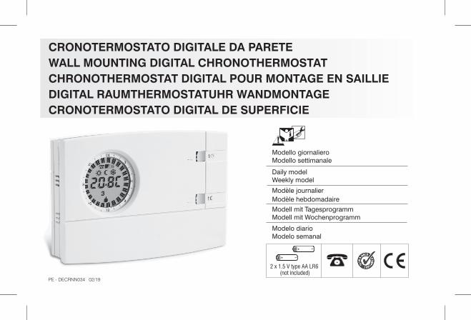
CRONOTERMOSTATO DIGITALE DA PARETEWALL MOUNTING DIGITAL CHRONOTHERMOSTATCHRONOTHERMOSTAT DIGITAL POUR MONTAGE EN SAILLIEDIGITAL RAUMTHERMOSTATUHR WANDMONTAGECRONOTERMOSTATO DIGITAL DE SUPERFICIE
Modello giornalieroModello settimanale
Daily modelWeekly model
Modèle journalierModèle hebdomadaire
Modell mit TagesprogrammModell mit Wochenprogramm
Modelo diarioModelo semanal
PE - DECRNN034 02/19(not included)
2 x 1.5 V type AA LR6
2
- Français
- Espa olñ
DONNÉES TECHNIQUES - NORMES D’INSTALLATIONMODE D’EMPLOI - AVERTISSEMENTS
DATOS TÉCNICOS - NORMAS DE INSTALACIÓNINSTRUCCIONES PARA EL USUARIO - ADVERTENCIAS
Page 25
Seite 36
Página 47
DATI TECNICI - ISTRUZIONI PER L’INSTALLAZIONEMODO D’IMPIEGO - AVVERTENZE
- English TECHNICAL DATA - INSTALLATION GUIDELINESUSER INSTRUCTIONS - WARNINGS
- Deutsch TECHNISCHE DATEN - NORMEN FÜR DIE INSTALLATIONBEDIENUNGSANLEITUNG - HINWEISE
Page 14
Pagina 3- Italiano
GB
D
F
ITE
NFR
DE
ES

n° 2 pile alcaline Stilo 1,5 V tipo AA LR6 (consigliate pile DURACELL o ENERGIZER)
2 anni1 mese1 / BU / Elettronicoclasse A4 kVa relè con contatto in scambio NA / COM / NClibero da potenziale - max 5(3)A / 250 Vac0,75 ÷ 2,5 mm2
per contatto NA libero da potenziale0,5 ÷ 1,5 mm2
classe IIIP 3048½ hnormale
+5 ÷ +30 °C (default +20 °C) / +41 ÷ +86 °F (default +68 °F)+5 ÷ +30 °C (default +17 °C) / +41 ÷ +86 °F (default +62,6 °F)Step 0,1°C / 0 ,1 °F+5 °C / 41 °F (fissa non regolabile)± 0,1 °C / ± 0,1 °F0 ÷ +50 °C / +32 ÷ +122 °F± 0,5 °C / ± 0,9 °F0 ÷ +50 °C / +32 ÷ +122 °F-20 ÷ +65 °C / -4 ÷ +149 °Fmax 1K / 15 min.funzionamento ON-OFF con differenziale impostabile a 0,3 - 0,5 - 0,7 - 0,9 °Cfunzionamento proporzionale con cicli di tempo impostabili 7-10-15-20 minuti
ERP Class I 1%ERP Class IV 2%± 1 sec/ggLVD e EMC EN60730-2-7 EN60730-2-9
Tensione di alimentazione:Autonomia:Autonomia dall’accensione del simbolo pile scariche:Tipo di azione, disconnessione ed apparecchio:Software:Tensione impulsiva nominale:Tipo di uscita:
Sezione dei fili ai morsetti relè:Ingresso per programmatore telefonico:Sezione dei fili ai morsetti programmatore telefonico:Tipo di isolamento:Grado di protezione:N° indici programmabili sulla corona dell’orologio:Tempo minimo programmabile con tasti “cavaliere”:Grado inquinamento:Scala regolazione temperatura tramite manopole:- Comfortt- Riduzione (risparmio)tLimitazione di temperatura (blocco set t max.):Temperatura antigelo ( ):tPrecisione di regolazione della temperatura:Scala di visualizzazione temperatura ambiente:Tolleranza lettura della temperatura ambiente:Limiti della temperatura di funzionamento:Limiti della temperatura di stoccaggio:Gradiente termico:Tipo di regolazione della temperatura:
Classificazione energetica ERP Reg. EU 811/2013:- in modalità Differenziale ON/OFF- in modalità Proporzionale modulantePrecisione dell’orologio:Normative di riferimento per marcatura CE:
3
1 - DATI TECNICI IT

2 - DIMENSIONI D’INGOMBRO
3 - NORME PER L’INSTALLAZIONEInstallazione del cronotermostato: indipendente - fisso
A parete - su scatola tonda - a semincasso su scatola rettangolare 3moduli.Installare il dispositivo a circa 1,5 ÷ 1,6 m da terra lontano da fonti dicalore, finestre e quant’altro possa influenzare il normale stato operativo.
121,5
82
31,5 26
Disattivare la tensione di rete del dispositivo da pilotareFissare con le viti la base: a muro, alla scatola da incasso tonda orettangolare utilizzando le opportune coppie di fori .AQualora la parete dove fissare la base del cronotermostato fossemetallica, inserire nelle due viti le apposite rondelle isolanti.
4 - FISSAGGIO DELLA BASE A PARETE
A - fori di fissaggioB - passaggio fili da scatola tonda, rettangolareC - dentini di fissaggio del cronotermostato
Per assicurare un corretto montaggio delcronotermostato alla base a parete, la stessa non devepresentare incurvature dovute all’eccessivo serraggiodelle viti di fissaggio alla scatola rettangolare o tondaincassata a muro.
C
C
B
3 2 1
6 7 8 945
4
A
IT
h 1,5 m�
A
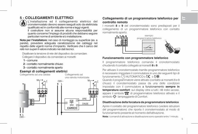
L’installazione ed il collegamento elettrico delcronotermostato devono essere eseguiti solo da elettricistaqualificato ed in conformità alle norme e leggi vigenti.Il costruttore non si assume alcuna responsabilità perquanto concerne l’impiego di prodotti che debbano seguireparticolari norme di ambiente e/o installazione.
Nota per l’installatore: nel caso di montaggio su superficie (es. aparete), prevedere adeguata canalizzazione dei cablaggi nelrispetto delle vigenti norme d’impianto. Verificare che il carico delrelè non superi il valore indicato nei dati tecnici.
Esempi di collegamenti elettrici
5 - COLLEGAMENTI ELETTRICI
Disattivare la tensione di rete del dispositivo da comandare.Collegare il dispositivo da comandare ai morsetti:1 - comune2 - contatto normalmente chiuso3 - contatto normalmente aperto
Funzionamento con programmatore telefonicoIl programmatore telefonico comanda il cronotermostatochiudendo il contatto collegato ai morsetti e .8 9
23 1
CNA
NC
23 1
CN
NC
CHIUDE
APRE
L230V~ NA
Collegamento di un programmatore telefonico percontrollo remotoI morsetti e del cronotermostato sono predisposti per il8 9collegamento di un programmatore telefonico con contattonormalmente aperto.
Per attivare il cronotermostato tramite programmatore telefonicoè necessario impostare il commutatore in uno dei seguenti tipi difunzionamento: AUTOMATICO o o .Quando il programmatore viene attivato (contatto ai morsetti 8 e 9chiuso) il cronotermostato passa da una delle condizioniimpostate con il commutatore a funzionamento sempre intemperatura comfort: sul display oltre a tutti i 48 indici accesi,appare il simbolo di programmatore telefonico attivato e ilsimbolo lampeggiante di Comfort.
Disattivazione della forzatura da programmatore telefonicoAprire il contatto del programmatore telefonico (vedere istruzionidel programmatore) che riporta il cronotermostato al modo difunzionamento presente al momento dell'attivazione.Nota: i comandi di attivazione e disattivazione sono operativi entro 1 minuto.
tt
5
Collegamento ad una caldaia Collegamento aduna valvola motorizzata
CARICO
M
IT
CALDAIACALDAIA
N L230V~
6 7 8 9 esempio:programmatore telefonico
Contatto

6 - FISSAGGIO O RIMOZIONE DEL CRONOTERMOSTATO DALLA BASE
Applicare il coperchietto copri cavi inserendo il dentino Dnell’apposita cava della base, quindi fissarlo con unaEleggera pressione nei ganci .FPer rimuovere il coperchietto utilizzare un piccolo cacciavitefacendo leva in successione su ciascun gancio .F
Agganciare il cronotermostato alla base avendo cura diinserire correttamente i contatti, quindi esercitare unaleggera pressione sino ad udire lo scatto dei dentini difissaggio.
Per rimuovere il cronotermostatodalla base a parete, afferrarlocome in figura, q estrarlouindifacendolo ruotare sul lato destro.
7- INSERIMENTO O SOSTITUZIONE PILE
Sostituire le pile esaurite con due pile 1,5 V tipo AAStilo alcaline(LR6) prestando attenzione alle polarità.
6
Smaltire le pile esausteg e t t a n d o l e n e g l iappositi contenitori.
E
D
F
IT
La comparsa del simbolo indica che le pile si stannolampeggianteesaurendo; da questo momento si hanno circa 30 giorni di tempo pereffettuare la sostituzione.Se non si sostituiscono le pile quasi scariche nei tempi dichiarati sispegnerà il displayvisualizzando solo il simbolo fisso.
Ogni attività di termoregolazione viene sospesa e tutte le impostazionivengono memorizzate per essere ripristinate all’inserimento delle nuovepile.
ATTENZIONE: nel caso di sostituzione delle pile, il tempo adisposizione per l’operazione senzaperdere i dati è di circa1 minuto.

R
4
21
2
9
2
6
3
18
1
15
Day
copy
R
tt t
/
t
t
t
4
21
2
9
2
6
3
18
1
15
1234567
Tasto impostazione: ore-minutio visual. Temperatura ambiente
Commutatore - tipo modalità di funzionamento(vedere dettaglio nel riquadro sotto)
Vano pile
8 - VISTA GENERALE, LEGENDA DISPLAY E FUNZIONI TASTI
Tasto selezione giorno(solo mod. settimanale)
t
Manopola reg.temperatura diSet riduzione t
TIPO DI FUNZIONAMENTOSELEZIONABILE TRAMITECOMMUTATORE
AUTOMATICO - Comfort o Riduzione regolabili da 5 a 30 °C;
secondo programmazione degli indici con tasti cavaliere
Sempre ,Riduzione regolabile da 5 a 30 °C i 48 spenti(tutti indici )
Sempre ,Antigelo temperatura fissa a 5 °C (tutti i 48 indici spenti)
Sempre ,Comfort regolabile da 5 a 30 °C (tutti i 48 indici accesi)t
tt
Tasto “cavaliere”
Ora corrente otemperaturaambiente rilevata/ set temperaturain impostazione
Indice 1/2h correntelampeggiante
Visualizzazione del tipodi funzionamento in corso:
Attivazione tramiteprogrammatore telefonico(con indicatore lampeggiante)
Indicatore pile:- quasi scariche (lampeggiante)- scariche (fisso)
Reset
Giorno(mod. Settimanale)es. 5 = Venerdì
ComfortRiduzione
Indicatore stato utenzalampeggiante = relè attivatospento = relè disattivato
Antigelo
7
ttt
Visualizzazione delprogramma inseritoIndice acceso = t comfortIndice spento = t riduzione
IT
t
+
+
Nota: ulteriori particolari funzioni dei tasti sonodescritte negli specifici paragrafi di utilizzo.
Tasto“cavaliere”
Manopola reg.temperatura diSet comfort
(risparmio)
(5 ÷ 30 °C)
(5 ÷ 30 °C)
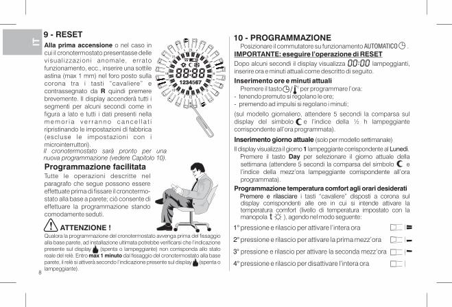
Alla prima accensione o nel caso incui il cronotermostato presentasse dellevisual izzazioni anomale, erratofunzionamento, ecc., inserire una sottileastina (max 1 mm) nel foro posto sullacorona tra i tasti “cavaliere” econtrassegnato da quindi premereRbrevemente. Il display accenderà tutti isegmenti per alcuni secondi come infigura a lato e tutti i dati presenti nellam e m o r i a v e r r a n n o c a n c e l l a t iripristinando le impostazioni di fabbrica(escluse le impostazioni con imicrointerruttori).
Programmazione facilitataTutte le operazioni descritte nelparagrafo che segue possono essereeffettuate prima di fissare il cronotermo-stato alla base a parete; ciò consente dieffettuare la programmazione standocomodamente seduti.
Qualora la programmazione del cronotermostato avvenga prima del fissaggioalla base parete, ad installazione ultimata potrebbe verificarsi che l’indicazionepresente sul display (spenta o lampeggiante) non corrisponda allo statoreale del relè. Entro dal fissaggio del cronotermostato alla basemax 1 minutoparete, il relè si attiverà secondo l’indicazione presente sul display (spenta olampeggiante).
ATTENZIONE !
8
R
4
21
2
9
2
6
3
18
1
15
1234 6751234 67
IT9 - RESET 10 - PROGRAMMAZIONE
1° pressione e rilascio per attivare l’intera ora
2° pressione e rilascio per attivare la prima mezz’ora
3° pressione e rilascio per attivare la seconda mezz’ora
4° pressione e rilascio per disattivare l’intera ora
Posizionare il commutatore su funzionamento .AUTOMATICOIMPORTANTE: eseguire l’operazione di RESETDopo alcuni secondi il display visualizza lampeggianti,inserire ora e minuti attuali come descritto di seguito.
Inserimento ore e minuti attualiPremere il tasto per programmare l’ora:
- tenendo premuto si regolano le ore;- premendo ad impulsi si regolano i minuti;
(sul modello giornaliero, attendere 5 secondi la comparsa suldisplay del simbolo e l’indice della ½ h lampeggiantecorrispondente all’ora programmata).
Inserimento giorno attuale (solo per modello settimanale)Il display visualizza il giorno lampeggiante corrispondente al .1 Lunedì
Premere il tasto per selezionare il giorno attuale dellaDaysettimana (attendere 5 secondi la comparsa del simbolo el’indice della mezz’ora lampeggiante corrispondente all’oraprogrammata).
Programmazione temperatura comfort agli orari desideratiPremere e rilasciare i tasti “cavaliere” disposti a corona suldisplay corrispondenti alle ore in cui si intende attivare latemperatura comfort (livello di temperatura impostato con lamanopola ), agendo nel modo seguente:t
/
Il cronotermostato sarà pronto per unanuova programmazione (vedere Capitolo 10).
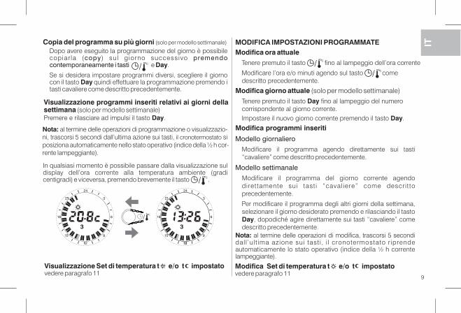
Copia del programma su più giorni (solo per modello settimanale)
Dopo avere eseguito la programmazione del giorno è possibilecopiar la ( ) sul giorno successivocopy premendocontemporaneamente i tasti e .Day
Se si desidera impostare programmi diversi, scegliere il giornocon il tasto quindi effettuare la programmazione premendo iDaytasti cavaliere come descritto precedentemente.
9
/
Nota: al termine delle operazioni di programmazione o visualizzazio-ni, trascorsi 5 secondi dall’ultima azione sui tasti, siil cronotermostatoposiziona automaticamente nello stato operativo (indice della ½ h cor-rente lampeggiante).
In qualsiasi momento è possibile passare dalla visualizzazione suldisplay dell’ora corrente alla temperatura ambiente (gradicentigradi) e viceversa, premendo brevemente il tasto ./
Visualizzazione programmi inseriti relativi ai giorni dellasettimana (solo per modello settimanale)Premere e rilasciare ad impulsi il tasto .Day
IT
Nota: al termine delle operazioni di modifica, trascorsi 5 secondidall ’ult ima azione sui tasti, i l cronotermostato riprendeautomaticamente lo stato operativo (indice della ½ h correntelampeggiante).
MODIFICA IMPOSTAZIONI PROGRAMMATEModifica ora attuale
Tenere premuto il tasto fino al lampeggio dell’ora corrente
Modificare l’ora e/o minuti agendo sul tasto comedescritto precedentemente.
//
Modifica giorno attuale (solo per modello settimanale)Tenere premuto il tasto fino al lampeggio del numeroDaycorrispondente al giorno corrente.Impostare il nuovo giorno corrente premendo il tasto .Day
Modifica programmi inseriti
Modello giornaliero
Modificare il programma agendo direttamente sui tasti“cavaliere” come descritto precedentemente.
Modello settimanale
Modificare il programma del giorno corrente agendodirettamente sui tasti “cavaliere” come descrittoprecedentemente.
Per modificare il programma degli altri giorni della settimana,selezionare il giorno desiderato premendo e rilasciando il tastoDay, dopodiché agire direttamente sui tasti “cavaliere” comedescritto precedentemente.
4
21
2
9
2
6
3
18
1
15
3
1
1
/
4
21
2
9
2
6
3
18
1
15
3
21
Modifica Set di temperatura t e/o t impostatovedere paragrafo 11
Visualizzazione Set di temperatura t e/o t impostatovedere paragrafo 11
10
IT
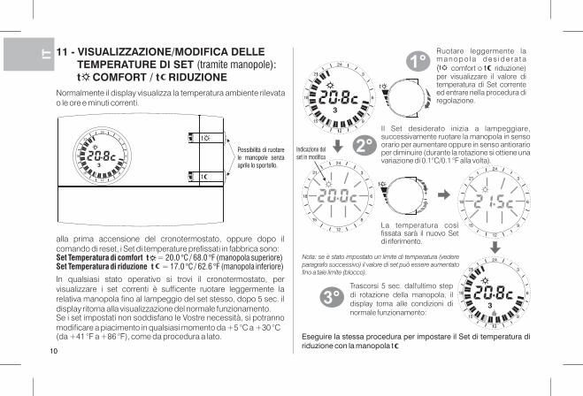
Il Set desiderato inizia a lampeggiare,successivamente ruotare la manopola in sensoorario per aumentare oppure in senso antiorarioper diminuire (durante la rotazione si ottiene unavariazione di 0.1°C/0.1 °F alla volta).
10
11 - VISUALIZZAZIONE/MODIFICA DELLETEMPERATURE DI SET (tramite manopole):t COMFORT / t RIDUZIONE
alla prima accensione del cronotermostato, oppure dopo ilcomando di reset, i Set di temperature prefissati in fabbrica sono:Set Temperatura di comfort t = 20.0 °C / 68.0 °F (manopola superiore)Set Temperatura di riduzione t = 17.0 °C / 62.6 °F (manopola inferiore)
In qualsiasi stato operativo si trovi il cronotermostato, pervisualizzare i set correnti è sufficente ruotare leggermente larelativa manopola fino al lampeggio del set stesso, dopo 5 sec. ildisplay ritorna alla visualizzazione del normale funzionamento.Se i set impostati non soddisfano le Vostre necessità, si potrannomodificare a piacimento in qualsiasi momento da +5 °C a +30 °C(da +41 °F a +86 °F), come da procedura a lato.
Normalmente il display visualizza la temperatura ambiente rilevatao le ore e minuti correnti.
t
4
21
2
9
2
6
3
18
1
15
3
4
21
2
9
2
6
3
18
1
15
3
1
1
Ruotare leggermente lam a n o p o l a d e s i d e r a t a( comfort o riduzione)per visualizzare il valore ditemperatura di Set correnteed entrare nella procedura diregolazione.
t
+
4
21
2
9
2
6
3
18
1
15
4
21
2
9
2
6
3
18
1
15
4
21
2
9
2
6
3
18
1
15
3
1
1
1°
2°
3°Trascorsi 5 sec. dall'ultimo stepdi rotazione della manopola, ildisplay torna alle condizioni dinormale funzionamento:
Nota: se è stato impostato un limite di temperatura (vedereparagrafo successivo) il valore di set può essere aumentatofino a tale limite (blocco).
Eseguire la stessa procedura per impostare il Set di temperatura diriduzione con la manopola t
Indicazione delset in modifica
Possibilità di ruotarele manopole senzaaprile lo sportello.
La temperatura cosìfissata sarà il nuovo Setdi riferimento.
11
IT12 - LIMITAZIONE (BLOCCO) DEL SET MAX DI TEMPERATURA COMFORT E/O RIDUZIONE
4
21
2
9
2
6
3
18
1
15
4
21
2
9
2
6
3
18
1
15
+
4
21
2
9
2
6
3
18
1
15
+
t
4
21
2
9
2
6
3
18
1
15
t
4
21
2
9
2
6
3
18
1
15
e/o
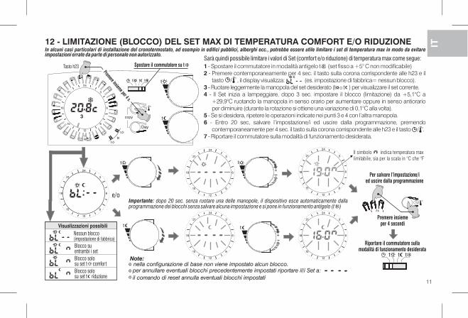
Visualizzazioni possibiliNessun blocco(impostazione di fabbrica)Blocco suentrambi i setBlocco solosu set t comfortBlocco solosu set t riduzione
Premere insiemeper 4 secondi
Riportare il commutatore sullamodalità di funzionamento desiderata
Per salvare l’impostazione/ied uscire dalla programmazione
per annullare eventuali blocchi precedentemente impostati riportare il/i Set a:
il comando di reset annulla eventuali blocchi impostati
In alcuni casi particolari di installazione del cronotermostato, ad esempio in edifici pubblici, alberghi ecc., potrebbe essere utile limitare i set di temperatura max in modo da evitareimpostazioni errate da parte di personale non autorizzato.
Sarà quindi possibile limitare i valori di Set (comfort e/o riduzione) di temperatura max come segue:1 - Spostare il commutatore in modalità antigelo t (set fisso a +5° C non modificabile)2 - Premere contemporaneamente per 4 sec. il tasto sulla corona corrispondente alle h23 e il
tasto , il display visualizza: (es. impostazione di fabbrica= nessun blocco).3 - Ruotare leggermente la manopola del set desiderato (t t ) per visualizzare il set corrente.o
4 - Il Set inizia a lampeggiare, dopo 3 sec. impostare il blocco (limitazione) da +5,1°C a+29,9°C ruotando la manopola in senso orario per aumentare oppure in senso antiorarioper diminuire (durante la rotazione si ottiene una variazione di 0,1°C alla volta).
5 - Se si desidera, ripetere le operazioni indicate nei punti 3 e 4 con l’altra manopola.6 - Entro 20 sec, salvare l’impostazione/i ed uscire dalla programmazione, premendo
contemporaneamente per 4 sec. il tasto sulla corona corrispondente alle h23 e il tasto .7 - Riportare il commutatore sulla modalità di funzionamento desiderata.
/
Note:
Importante: dopo 20 sec. senza ruotare una delle manopole, il dispositivo esce automaticamente dallaprogrammazione dei blocchi senza salvare alcuna impostazione e si pone in funzionamento antigelo (t )
/
nella configurazione di base non viene impostato alcun blocco.
Day
copy
R
tt t
/
t
t
t
4
21
2
9
2
6
3
18
1
15
12 45673 t
Spostare il commutatore su t
Premere insieme per 4 s.
Il simbolo indica temperatura max
limitabile, sia per la scala in °C che °F
Tasto h23
tt t
42
/
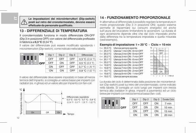
Il cronotermostato funziona in modo differenziale ON-OFF(Dip 3 in posizione OFF) con valore del differenziale prefissatoin fabbrica a (0,54 °F).0,3 °CIl valore del differenziale può essere modificato spostando imicrointerruttori (Dip-switch), come indicato nella tabella.
13 - DIFFERENZIALE DI TEMPERATURA
Tempo
°C
OffOn On
Dip 1 Dip 2 Dip 3 Differenziale
ON ON OFF 0,9 °C (1,62 °F)
ON OFF OFF 0,7 °C (1,26 °F)
OFF ON OFF 0,5 °C (0,9 °F)
OFF OFF OFF 0,3 °C (0,54 °F)
ON
32 OFF1
ON
Tem
per
atur
a m
isur
ata
Il valore del differenziale deve essere impostato in base all’inerziatermica dell’impianto; si consiglia un valore basso per impianti conradiatori (es. in ghisa) ed un valore alto per impianto con fan-coil.
ON
32 OFF1
ON
In alternativa al differenziale è possibile regolare la temperatura inmodo proporzionale (Dip 3 in posizione ON); questo sistemapermette di risparmiare sui consumi energetici ed anchesull’usura del bruciatore limitandone le accensioni. La durata diogni accensione dipende oltre che dal ciclo impostato anchedalla differenza tra la temperatura impostata e quella misurata(vedi esempio).
14 - FUNZIONAMENTO PROPORZIONALE
Esempio di impostazione t = 20 °C - Ciclo = 10 mint = 20,5 °C Utenza sempre spentat = 20,4 °C Utenza 1 min ON - 9 min OFFt = 20,3 °C Utenza 2 min ON - 8 min OFFt = 20,2 °C Utenza 3 min ON - 7 min OFFt = 20,1 °C Utenza 4 min ON - 6 min OFFt = 20,0 °C Utenza 5 min ON - 5 min OFFt = 19,9 °C Utenza 6 min ON - 4 min OFFt = 19,8 °C Utenza 7 min ON - 3 min OFFt = 19,7 °C Utenza 8 min ON - 2 min OFFt = 19,6 °C Utenza 9 min ON - 1 min OFFt = 19,5 °C Utenza sempre accesa
Dip 1 Dip 2 Dip 3 Durata Ciclo
ON ON ON 20 min
ON OFF ON 15 min
OFF ON ON 10 min
OFF OFF ON 7 min
ON
32 OFF1
ON
La durata del ciclo è determinata dalla posizione dei microinterrut-tori (Dip-switch) posti sul retro del cronotermostato, come indicatonella tabella. Si consiglia un ciclo lungo per impianti con inerziatermica alta (radiatori in ghisa, impianti a pavimento) ed un ciclobreve per impianti con inerzia termica bassa (fan- coil).
20,8
20,6
20,4
20,2
20,0
19,8
19,6
19,4
19,2
°C
0 102 4 6 8 Minuti
Le impostazioni dei microinterruttori (Dip-switch)posti sul retro del cronotermostato, devono essereeffettuate da personale qualificato.
Differenziale regolabile0,3 °C - 0,5 °C - 0,7 °C - 0,9 °C
UtenzaOFF
UtenzaON
4
4
(0,54 °F - 0,9 °F - 1,26 °F - 1.62 °F)
12
IT
IT
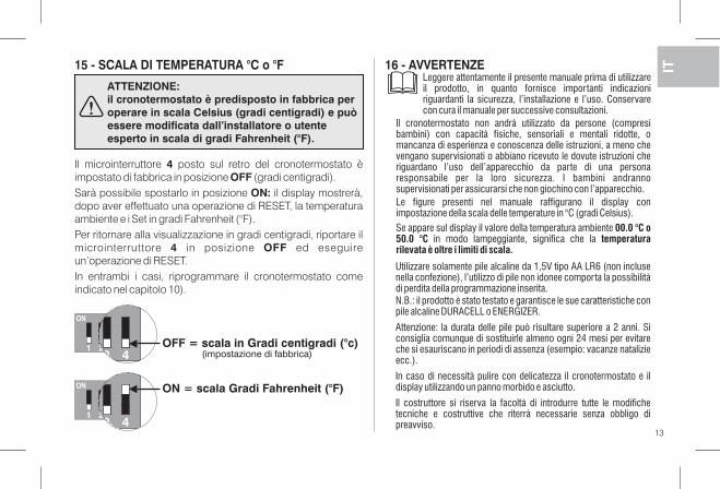
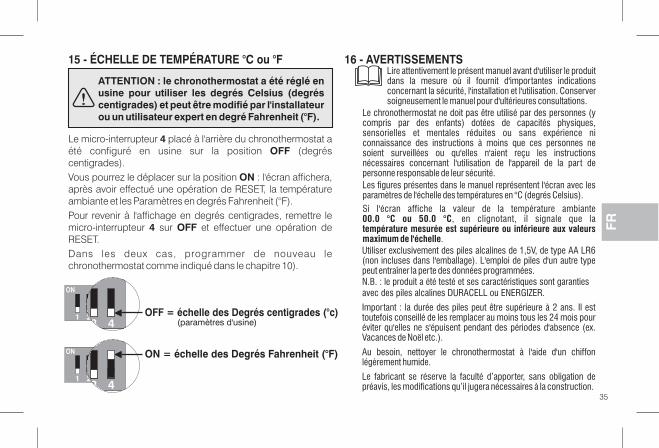
Il microinterruttore posto sul retro del cronotermostato è4impostato di fabbrica in posizione (gradi centigradi).OFFSarà possibile spostarlo in posizione il display mostrerà,ON:dopo aver effettuato una operazione di RESET, la temperaturaambiente e i Set in gradi Fahrenheit (°F).Per ritornare alla visualizzazione in gradi centigradi, riportare ilmicrointerruttore in posizione ed eseguire4 OFFun’operazione di RESET.In entrambi i casi, riprogrammare il cronotermostato comeindicato nel capitolo 10).
15 - SCALA DI TEMPERATURA °C o °F 16 - AVVERTENZE
Se appare sul display il valore della temperatura ambiente 00.0 °C o50.0 °C temperaturain modo lampeggiante, significa che larilevata è oltre i limiti di scala.
ATTENZIONE:il cronotermostato è predisposto in fabbrica peroperare in scala Celsius (gradi centigradi) e puòessere modificata dall’installatore o utenteesperto in scala di gradi Fahrenheit (°F).
432 OFF = scala in Gradi centigradi (°c)1
ON
Utilizzare solamente pile alcaline da 1,5V tipo AA LR6 (non inclusenella confezione), l’utilizzo di pile non idonee comporta la possibilitàdi perdita della programmazione inserita.N.B.: il prodotto è stato testato e garantisce le sue caratteristiche conpile alcaline DURACELL o ENERGIZER.
Attenzione: la durata delle pile può risultare superiore a 2 anni. Siconsiglia comunque di sostituirle almeno ogni 24 mesi per evitareche si esauriscano in periodi di assenza (esempio: vacanze natalizieecc.).
In caso di necessità pulire con delicatezza il cronotermostato e ildisplay utilizzando un panno morbido e asciutto.
Il costruttore si riserva la facoltà di introdurre tutte le modifichetecniche e costruttive che riterrà necessarie senza obbligo dipreavviso.
Leggere attentamente il presente manuale prima di utilizzareil prodotto, in quanto fornisce importanti indicazioniriguardanti la sicurezza, l’installazione e l’uso. Conservarecon cura il manuale per successive consultazioni.
432
ON = scala Gradi Fahrenheit (°F)
1
ON
(impostazione di fabbrica)
Le figure presenti nel manuale raffigurano il display conimpostazione della scala delle temperature in °C (gradi Celsius).
13
Il cronotermostato non andrà utilizzato da persone (compresibambini) con capacità fisiche, sensoriali e mentali ridotte, omancanza di esperienza e conoscenza delle istruzioni, a meno chevengano supervisionati o abbiano ricevuto le dovute istruzioni cheriguardano l’uso dell’apparecchio da parte di una personaresponsabile per la loro sicurezza. I bambini andrannosupervisionati per assicurarsi che non giochino con l’apparecchio.
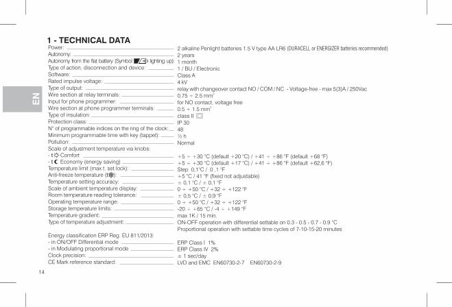
2 alkaline Penlight batteries 1.5 V type AA LR6 (DURACELL or ENERGIZER batteries recommended)
2 years1 month1 / BU / ElectronicClass A4 kVrelay with changeover contact NO / COM / NC Voltage-free - max 5(3)A / 250Vac-0.75 ÷ 2.5 mm2
for NO contact, voltage free0.5 ÷ 1.5 mm2
class IIIP 3048½ hNormal
+5 ÷ +30 °C (default +20 °C) / +41 ÷ +86 °F (default +68 °F)+5 ÷ +30 °C (default +17 °C) / +41 ÷ +86 °F (default +62,6 °F)Step 0,1°C / 0 ,1 °F+5 °C / 41 °F (fixed not adjustable)± 0,1 °C / ± 0,1 °F0 ÷ +50 °C / +32 ÷ +122 °F± 0,5 °C / ± 0,9 °F0 ÷ +50 °C / +32 ÷ +122 °F-20 ÷ +65 °C / -4 ÷ +149 °Fmax 1K / 15 min.ON-OFF operation with differential settable on 0.3 - 0.5 - 0.7 - 0.9 °CProportional operation with settable time cycles of 7-10-15-20 minutes
ERP Class I 1%ERP Class IV 2%± 1 sec/dayLVD EMC EN60730-2-7 EN60730-2-9and
Power:Autonomy:Autonomy from the flat battery (Symbol lighting up):Type of action, disconnection and device:Software:Rated impulse voltage:Type of output:Wire section at relay terminals:Input for phone programmer:Wire section at phone programmer terminals:Type of insulation:Protection class:N° of programmable indices on the ring of the clock:Minimum programmable time with key (tappet):Pollution:Scale of adjustment temperature via knobs:- Comfortt- Economy (energy saving)tTemperature limit (max t. set lock):Anti-freeze temperature ( ):tTemperature setting accuracy:Scale of ambient temperature display:Room temperature reading tolerance:Operating temperature range:Storage temperature limits:Temperature gradient:Type of temperature adjustment:
Energy classification ERP Reg. EU 811/2013:- in ON/OFF Differential mode- in Modulating p moderoportionalClock precision:CE Mark reference standard:
1 - TECHNICAL DATA
GBFE
N
14
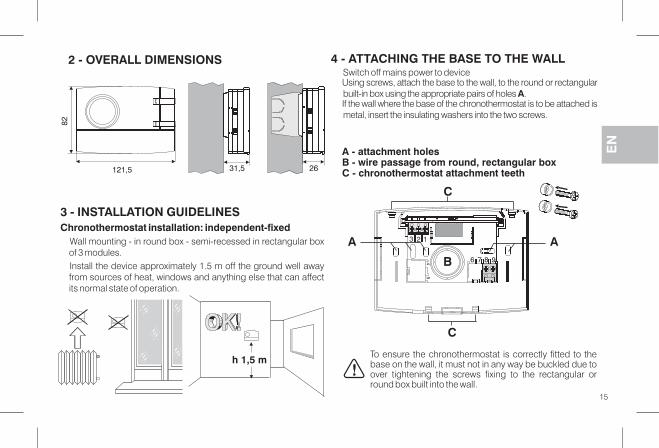
2 - OVERALL DIMENSIONS
3 - INSTALLATION GUIDELINESChronothermostat installation: independent-fixed
Wall mounting - in round box - semi-recessed in rectangular boxof 3 modules.Install the device approximately 1.5 m off the ground well awayfrom sources of heat, windows and anything else that can affectits normal state of operation.
121,5
82
31,5 26
Switch off mains power to deviceUsing screws, attach the base to the wall, to the round or rectangularbuilt-in box using the appropriate pairs of holes .AIf the wall where the base of the chronothermostat is to be attached ismetal, insert the insulating washers into the two screws.
4 - ATTACHING THE BASE TO THE WALL
A - attachment holesB - wire passage from round, rectangular boxC - chronothermostat attachment teeth
To ensure the chronothermostat is correctly fitted to thebase on the wall, it must not in any way be buckled due toover tightening the screws fixing to the rectangular orround box built into the wall.
15
h 1,5 m�
EN
C
C
B
3 2 1
6 7 8 945
A A
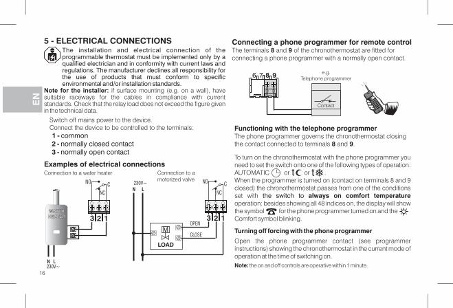
The installation and electrical connection of theprogrammable thermostat must be implemented byonly aqualified electrician and in conformity with current laws andregulations. The manufacturer declines all responsibility forthe use of products that must conform to specificenvironmental and/or installation standards.
Note for the installer: if surface mounting (e.g. on a wall), havesuitable raceways for the cables in compliance with currentstandards. Check that the relay load does not exceed the figure givenin the technical data.
Examples of electrical connections
5 - ELECTRICAL CONNECTIONS
Switch off mains power to the device.Connect the device to be controlled to the terminals:1 - common2 - normally closed contact3 - normally open contact
Functioning with the telephone programmerThe phone programmer governs the chronothermostat closingthe contact connected to terminals and .8 9
Connecting a phone programmer for remote controlThe terminals and of the chronothermostat are fitted for8 9
connecting a phone programmer with a normally open contact.
To turn on the chronothermostat with the phone programmer youneed to set the switch onto one of the following types of operation:AUTOMATIC or or .When the programmer is turned on (contact on terminals 8 and 9closed) the chronothermostat passes from one of the conditionsset with the switch to always on comfort temperatureoperation: besides showing all 48 indices on, the display will showthe symbol for the phone programmer turned on and theComfort symbol blinking.
Turning off forcing with the phone programmer
Open the phone programmer contact (see programmerinstructions) showing the chronothermostat in the current mode ofoperation at the time of switching on.Note: the on and off controls are operative within 1 minute.
ttConnection to amotorized valve
Connection to a water heater
16
23 1
CNO
NC
23 1
CN
NC
CLOSE
OPEN
L230V~ NO
LOAD
M
WATERHEATERWATERHEATER
N L230V~
6 7 8 9 e.g.Telephone programmer
ContactGBFE
N
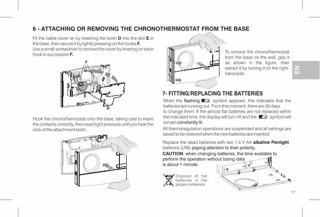
6 - ATTACHING OR REMOVING THE CHRONOTHERMOSTAT FROM THE BASE
Fit the cable cover on by inserting the tooth into the slot inD Ethe base, then secure it by lightly pressing on the hooks F.Use a small screwdriver to remove the cover by levering on eachhook in succession F.
Hook the chronothermostat onto the base, taking care to insertthe contacts correctly, then exert light pressure until you hear theclick of the attachment teeth.
To remove the chronothermostatfrom the base on the wall, grip itas shown in the figure, thenextract it by turning it on the right-hand side.
7- FITTING/REPLACING THE BATTERIES
Dispose of flatbatteries in theproper containers.
E
D
F
17
Replace the dead batteries with two 1.5 V AA alkaline Penlightbatteries (LR6) paying attention to their polarity.
When the symbol appears, this indicates that theflashingbatteries are running out. From this moment, there are 30 daysto change them. If the almost flat batteries are not replaced withinthe indicated time, the display will turn off and the symbol willremain constantly lit.All thermoregulation operations are suspended and all settings aresaved to be restored when the new batteries are inserted.
EN
CAUTION: when changing batteries, the time available toperform the operation without losing data
.is about 1 minute
Key (tappet)
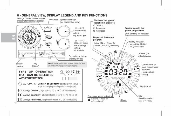
Current 1/2hindex blinking
Display of the type of:operation in progress
Turning on with thephone programmer
Day(Weekly mode)E.g. 5 = Friday
ComfortEconomy
Consumer status indicatorblinking = relay onoff = relay off
Antifreeze
Display of the currentprogram
Index ON = t comfortIndex OFF = t economy
R
4
21
2
9
2
6
3
18
1
15
Current hour orroom temperaturedetected/ temperaturesetting
(with blinking indicator)
Battery indicator:- almost flat (blinking)- flat (constantly lit)
Reset
8 - GENERAL VIEW, DISPLAY LEGEND AND KEY FUNCTIONS
18
TYPE OF OPERATIONTHAT CAN BE SELECTEDWITH THE SWITCH
AUTOMATIC - Comfort or Economy adjustable from 5 to 30 °C;
as per indices programming with the key (tappet)
Always ,Economy adjustable from 5 to 30 °C (all 48 indices off)
Always ,Antifreeze temperature fixed on 5 °C (all 48 indices off)
Always ,Comfort adjustable from 5 to 30 °C (all 48 indices on)t
tt
ttt
Batteryhousing
Day selector button(weekly model)
Day
copy
R
tt t
/
t
t
t
4
21
2
9
2
6
3
18
1
15
1234567
Settings button: hours-minutesor Room temperature display
Switch - operation mode type(see details in box below)
t
Economy temp.(energy saving)settingadj.knob t
t
+
+
Note: more particular button functions aredescribed in the specific paragraphs.
Comfort temp.settingadj. KnobG
BFE
N
Keytappet“ ”
(5 ÷ 30 °C)
(5 ÷ 30 °C)
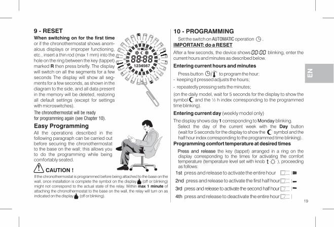
When switching on for the first timeor if the chronothermostat shows anom-alous displays or improper functioning,etc., insert a thin rod (max 1 mm) into thehole on the ring between the key (tappet)marked then press briefly. The displayRwill switch on all the segments for a fewseconds The display will show all seg-ments for a few seconds, as shown in thediagram to the side, and all data presentin the memory will be deleted, restoringall default settings (except for settingswith microswitches).
Easy ProgrammingAll the operations described in thefollowing paragraph can be carried outbefore securing the chronothermostatto the base on the wall; this allows youto do the programming while beingcomfortably seated.
CAUTION !
R
4
21
2
9
2
6
3
18
1
15
123 5674
The chronothermostat will be readyfor programming again (see Chapter 10).
9 - RESET
If the chronothermostat is programmed before being attached to the base on thewall, once installation is complete the symbol on the display (off or blinking)might not correspond to the actual state of the relay. Within ofmax 1 minuteattaching the chronothermostat to the base on the wall, the relay will turn on asindicated on the display (off or blinking).
Set the switch on operationAUTOMATIC .IMPORTANT: do a RESETAfter a few seconds, the device shows blinking, enter thecurrent hours and minutes as described below.
Entering current hours and minutes
Press button to program the hour:- keeping it pressed adjusts the hours;
- repeatedly pressing sets the minutes;
(on the daily model, wait for 5 seconds for the display to show thesymbol and the ½ h index corresponding to the programmedtime blinking).
Entering current day (weekly model only)The display shows day corresponding to blinking.1 Monday
Select the day of the current week with the buttonDay(wait for 5 seconds for the display to show the symbol and thehalf hour index corresponding to the programmed time blinking).
Programming comfort temperature at desired timesPress and release the key (tappet) arranged in a ring on thedisplay corresponding to the times for activating the comforttemperature (temperature level set with knob ), proceedingas follows:
1 - PROGRAMMING0
t
/
1st press and release to activate the entire hour
2nd press and release to activate the first half hour
3rd press and release to activate the second half hour
4th press and release to deactivate the entire hour
EN
19
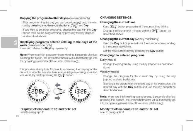
Copying the program to other days (weekly model only)
After programming the day you can copy it onto the next(copy)day by and .pressing simultaneously buttons Day
If you want to set other programs, choose the day with the Daybutton then do the programming by pressing the key (tappet)as described above.
/
Note: When you finish programming or viewing, 5 seconds after lastpressing the button, the chronothermostat will automatically go intothe operating state (index of the current ½ h blinking).
It is possible at any time to pass from viewing the display of thecurrent time to the ambient temperature (degrees centigrade) andvice versa, by briefly pressing the button./
Displaying programs entered relating to the days of theweek (weekly model only)Press and release the key repeatedly.Day
20
4
21
2
9
2
6
3
18
1
15
3
1
1
/
4
21
2
9
2
6
3
18
1
15
3
21
Display Set temperature and/or sett trefer to paragraph 11
Note: when you finish making your changes, 5 seconds after lastpressing the buttons, the chronothermostat will automatically gointo the operating state (index of the current ½ h blinking).
CHANGING SETTINGS
Changing the current timeKeep button pressed until the current time blinks
Change the hour and/or minutes with the button asdescribed above.
//
Changing the current day (weekly model only)Keep the button pressed until the number correspondingDayto the current day blinks.
Set the new current day by pressing the buttonDay
Changing the entered programs
Daily model
Change the program by using the key (tappet) as describedabove
Weekly model
Change the program for the current day by using the key(tappet) as described above
To change the program for the others day of the week select thedesired day with the button and use the key (tappet) asDaydescribed above
Modify T Set temperature and/or sett trefer to paragraph 11
GBFE
N
21
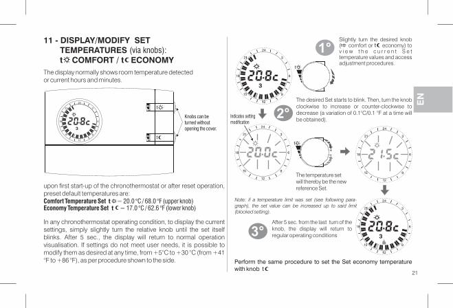
11 - DISPLAY/MODIFY SETSTEMPERATURE (via knobs):
t COMFORT / t ECONOMY
upon first start-up of the chronothermostat or after reset o ,perationpreset default temperatures are:Comfort Temperature Set t = 20.0 °C / 68.0 °F ( )upper knobEconomy Temperature Set t = 17.0 °C / 62.6 °F ( )lower knob
In any chronothermostat operating condition, to display the currentsettings, simply slightly turn the relative knob until the set itselfblinks. After 5 sec., the display will return to normal operationvisualisation. If settings do not meet user needs, it is possible tomodify them as desired at any time, from +5°C to +30 °C (from +41°F to +86 °F), as per procedure shown to the side.
The display normally shows room temperature detectedor current hours and minutes.
t
4
21
2
9
2
6
3
18
1
15
3
4
21
2
9
2
6
3
18
1
15
3
1
1
Slightly turn the desired knob( comfort or economy) tov i e w t h e c u r r e n t S e ttemperature values and accessadjustment procedures.
t
+
4
21
2
9
2
6
3
18
1
15
4
21
2
9
2
6
3
18
1
15
4
21
2
9
2
6
3
18
1
15
3
1
1
1°
2°
The desired Set starts to blink. Then, turn the knobclockwise to increase or counter-clockwise todecrease (a variation of 0.1°C/0.1 °F at a time willbe obtained).
3°After 5 sec. from the last turn of theknob, the display will return toregular operating conditions
Note: if a temperature limit was set (see following para-graph), the set value can be increased up to said limit(blocked setting).
Perform the same procedure to set the Set economy temperaturewith knob t
Indicates settingmodification
Knobs can beturned withoutopening the cover.
The temperature setwill thereby be the newreference Set.
EN
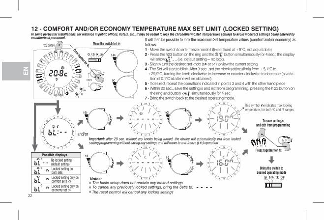
12 - COMFORT AND/OR ECONOMY TEMPERATURE MAX SET LIMIT (LOCKED SETTING)
4
21
2
9
2
6
3
18
1
15
t
and/or
Possible displaysNo locked setting(default setting)Locked setting onboth setsLocked setting only oncomfort set tLocked setting only oneconomy set t
42
/
Press together for 4s
Bring the switch todesired operating mode
tt t
To save setting/sand exit from programming
To cancel any previously locked settings, bring the Set/s to:
The reset control will cancel any locked settings
In some particular installations, for instance in public offices, hotels, etc., it may be useful to the chronothermostat temperature settings to avoid incorrect settings being entered bylockunauthorised personnel. It will then be possible to l the maximum Set temperature values (comfort and/or economy) asock
follows:1 - Move the switch to anti-freeze mode t (set fixed at +5°C, not adjustable)2 - Press the h23 button on the ring and the button simultaneously for 4 sec.; the display
will show: (i.e. default setting= no lock).3 - orSlightly turn the desired set knob (t t ) to view the current setting.4 - The Set will start to blink. After 3 sec., set the block setting (limit) from +5,1°C to
+29,9°C, turning the knob clockwise to increase or counter-clockwise to decrease (a varia-tion of 0.1°C at a time will be obtained).
5 - If desired, repeat the operations indicated in points 3 and 4 with the other hand piece.6 - Within 20 sec., save the setting/s and exit from programming, pressing the h 23 button on
the ring and button simultaneously for 4 sec.7 - Bring the switch back to the desired operating mode.
/
Notes:
Important: after 20 sec. without any knobs being turned, the device will automatically exit from lockedsetting programming without saving any settings and will move to anti-freeze (t ) operation
/
The basic setup does not contain any locked settings.
4
21
2
9
2
6
3
18
1
15
+
4
21
2
9
2
6
3
18
1
15
+
t
4
21
2
9
2
6
3
18
1
15
4
21
2
9
2
6
3
18
1
15
Day
copy
R
tt t
/
t
t
t
4
21
2
9
2
6
3
18
1
15
12 45673 t
Move the switch to t
Press together for 4s.
This symbol indicates max locking
temperature, for both °C and °F ranges
GBFE
N
22
h23 button
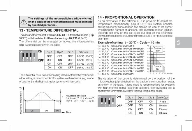
The chronothermostat works in ON-OFF differential mode (Dip3 OFF) with the default differential setting of (0,54 °F)0,3°C .The differential can be changed by moving the microswitches(dip-switches) as shown in the table.
13 - TEMPERATURE DIFFERENTIAL
Time
°C
OffOn On
Mea
sure
d te
mp
erat
ure
The differential must be set according to the system's thermal inertia;a low setting is recommended for systems with radiators (e.g. madeof cast iron) and a high setting for systems with fan-coils.
As an alternative to the differential, it is possible to adjust thetemperature proportionally (Dip 3 ON); this system enablessaving on energy consumption and also on the wear of the burnerby limiting the number of ignitions. The duration of each ignitiondepends not only on the set cycle but also on the differencebetween the set temperature and the measured temperature (seeexample).
14 - PROPORTIONAL OPERATION
Example of setting t = 20 °C - Cycle = 10 mint = 20,5 °C Consumer always OFFt = 20,4 °C Consumer 1 min ON - 9 min OFFt = 20,3 °C Consumer 2 min ON - 8 min OFFt = 20,2 °C Consumer 3 min ON - 7 min OFFt = 20,1 °C Consumer 4 min ON - 6 min OFFt = 20,0 °C Consumer 5 min ON - 5 min OFFt = 19,9 °C Consumer 6 min ON - 4 min OFFt = 19,8 °C Consumer 7 min ON - 3 min OFFt = 19,7 °C Consumer 8 min ON - 2 min OFFt = 19,6 °C Consumer 9 min ON - 1 min OFFt = 19,5 °C Consumer always ON
Dip 1 Dip 2 Dip 3 Duration Cycle
ON ON ON 20 min
ON OFF ON 15 min
OFF ON ON 10 min
OFF OFF ON 7 min
ON
32 OFF1
ON
The duration of the cycle is determined by the position of themicroswitches (dip-switches) on the back of the chronothermostat,as shown in the table. A long cycle is recommended for systemswith high thermal inertia (cast-iron radiators floor systems) and a,short cycle for systems with low thermal inertia (fan-coils).
20,8
20,6
20,4
20,2
20,0
19,8
19,6
19,4
19,2
°C
0 102 4 6 8 Minutes
The settings of the microswitches (dip-switches)on the back of the chronothermostat must be madeby qualified personnel.
Adjustable differential0,3 °C - 0,5 °C - 0,7 °C - 0,9 °C(0,54 °F - 0,9 °F - 1,26 °F - 1.62 °F)
ConsumerOFF
ConsumerON
4
EN
EN
23
Dip 1 Dip 2 Dip 3 Differential
ON ON OFF 0,9 °C (1,62 °F)
ON OFF OFF 0,7 °C (1,26 °F)
OFF ON OFF 0,5 °C (0,9 °F)
OFF OFF OFF 0,3 °C (0,54 °F)
ON
32 OFF1
ON ON
32 OFF1
ON
4
15 - °C or °FTEMPERATURE SCALE 16 - WARNINGS
GBFE
N
24
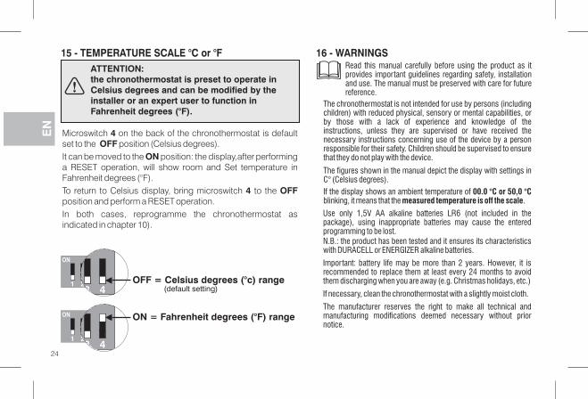
ATTENTION:the chronothermostat is preset to operate inCelsius degrees and can be modified by theinstaller or an expert user to function inFahrenheit degrees (°F).
Microswitch on the back of the chronothermostat is default4set to the position (Celsius degrees).OFFIt can be moved to the position: the display,after performingONa RESET operation, will show room and Set temperature inFahrenheit degrees (°F).To return to Celsius display, bring microswitch to the4 OFFposition and perform a RESET operation.In both cases, reprogramme the chronothermostat asindicated in chapter 10).
432 OFF = cCelsius degrees (° ) range1
ON
432
ON = Fahrenheit degrees (°F) range
1
ON
(default setting)
If the display shows an ambient temperature of 00.0 °C or 50,0 °Cblinking, it means that the .measured temperature is off the scale
Use only 1,5V AA alkaline batteries LR6 (not included in thepackage), using inappropriate batteries may cause the enteredprogramming to be lost.N.B.: he product has been tested and it ensures its characteristicstwith DURACELL or ENERGIZER alkaline batteries.
Important: battery life may be more than 2 years. However, it isrecommended to replace them at least every 24 months to avoidthem discharging when you are away (e.g. Christmas holidays, etc.)
If necessary, clean the chronothermostat with a slightly moist cloth.
The manufacturer reserves the right to make all technical andmanufacturing modifications deemed necessary without priornotice.
Read this manual carefully before using the product as itprovides important guidelines regarding safety, installationand use. The manual must be preserved with care for futurereference.
The figures shown in the manual depict the display with settings inC° (Celsius degrees).
The thermostat is not intended for use by persons (includingchronochildren) with reduced physical, sensory or mental capabilities, orby those with a lack of experience and knowledge of theinstructions, unless they are supervised or have received thenecessary instructions concerning use of the device by a personresponsible for their safety. Children should be supervised to ensurethat they do not play with the device.
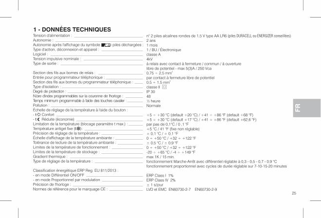
n° 2 piles alcalines rondes de 1,5 V type AA LR6 (piles DURACELL ou ENERGIZER conseillées)
2 ans1 mois1 / BU / Électroniqueclasse A4kVà relais avec contact à fermeture / commun / à ouverturelibre de potentiel - max 5(3)A / 250 Vca0,75 ÷ 2,5 mm2
par contact à fermeture libre de potentiel0,5 ÷ 1,5 mm2
classe IIIP 3048½ heureNormale
+5 ÷ +30 °C (default +20 °C) / +41 ÷ +86 °F (default +68 °F)+5 ÷ +30 °C (default +17 °C) / +41 ÷ +86 °F (default +62,6 °F)par pas de 0,1°C / 0 ,1 °F+5 °C / 41 °F (fixe non réglable)± 0,1 °C / ± 0,1 °F0 ÷ +50 °C / +32 ÷ +122 °F± 0,5 °C / ± 0,9 °F0 ÷ +50 °C / +32 ÷ +122 °F-20 ÷ +65 °C / -4 ÷ +149 °Fmax 1K / 15 min.fonctionnement Marche-Arrêt avec différentiel réglable à 0,3 - 0,5 - 0,7 - 0,9 °Cfonctionnement proportionnel avec cycles de durée réglable sur 7-10-15-20 minutes
ERP Class I 1%ERP Class IV 2%± 1 s/jourLVD et EMC EN60730-2-7 EN60730-2-9
Tension d'alimentation :Autonomie :Autonomie après l'affichage du symbole piles déchargées :Type d'action, déconnexion et appareil :Logiciel :Tension impulsive nominale :Type de sortie :
Section des fils aux bornes de relais :Entrée pour programmateur téléphonique :Section des fils aux bornes du programmateur téléphonique :Type d'isolation :Degré de protection :N.bre d'index programmables sur la couronne de l'horloge :Temps minimum programmable à l'aide des touches cavalier :Pollution :Échelle de réglage de la température à l'aide du bouton :- Confortt- Réduite (économie)tLimitation de la température (blocage paramètre t max.) :Température antigel fixe ( ):tPrécision de réglage de la température :Échelle d'affichage de la température ambiante :Tolérance de lecture de la température ambiante :Limites de la température de fonctionnement :Limites de la température de stockage :Gradient thermique :Type de réglage de la température :
Classification énergétique ERP Reg. EU 811/2013 :- en mode Différentiel ON/OFF- en mode Proportionnel par modulationPrécision de l'horloge :Normes de référence pour le marquage CE :
1 - DONNÉES TECHNIQUES
FR
25
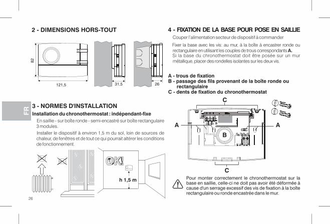
2 - DIMENSIONS HORS-TOUT
3 - NORMES D'INSTALLATIONInstallation du chronothermostat : indépendant-fixe
En saillie - sur boîte ronde - semi-encastré sur boîte rectangulaire3 modules.Installer le dispositif à environ 1,5 m du sol, loin de sources dechaleur, de fenêtres et de tout ce qui pourrait altérer les conditionsde fonctionnement.
121,5
82
31,5 26
Couper l’alimentation secteur de dispositif à commander
Fixer la base avec les vis: au mur, à la boîte à encastrer ronde ourectangulaire en utilisant les couples de trous correspondants A.Si la base du chronothermostat doit être posée sur un murmétallique, placer des rondelles isolantes sur les deux vis.
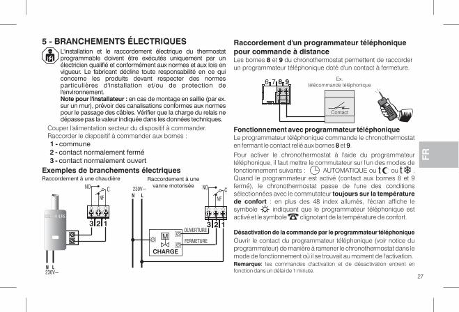
4 - FIXATION DE LA BASE POUR POSE EN SAILLIE
A - trous de fixationB - passage des fils provenant de la boîte ronde ou
rectangulaireC - dents de fixation du chronothermostat
Pour monter correctement le chronothermostat sur labase en saillie, celle-ci ne doit pas avoir été déformée àcause d'un serrage excessif des vis de fixation à la boîterectangulaire ou ronde encastrée dans le mur.
h 1,5 m�
DFR
26
C
C
B
3 2 1
6 7 8 945
A A
L'installation et le raccordement électrique du thermostatprogrammable doivent être exécutés uniquement par unélectricien qualifié et conformément aux normes et aux lois envigueur. Le fabricant décline toute responsabilité en ce quiconcerne les produits devant respecter des normesparticulières d'installation et/ou de protection del'environnement.Note pour l'installateur : en cas de montage en saillie (par ex.sur un mur), prévoir des canalisations conformes aux normespour le passage des câbles. Vérifier que la charge du relais nedépasse pas la valeur indiquée dans les données techniques.
Exemples de branchements électriques
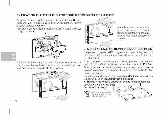
5 - BRANCHEMENTS ÉLECTRIQUES
Couper l'alimentation secteur du dispositif à commander.Raccorder le dispositif à commander aux bornes :1 - commune2 - contact normalement fermé3 - contact normalement ouvert
Fonctionnement avec programmateur téléphoniqueLe programmateur téléphonique commande le chronothermostaten fermant le contact relié aux bornes et .8 9
Raccordement d'un programmateur téléphoniquepour commande à distanceLes bornes et du chronothermostat permettent de raccorder8 9un programmateur téléphonique doté d'un contact à fermeture.
Pour activer le chronothermostat à l'aide du programmateurtéléphonique, il faut mettre le commutateur sur l'un modes dedesfonctionnement suivants : AUTOMATIQUE ou ou .Quand le programmateur est activé (contact aux bornes 8 et 9fermé), le chronothermostat passe de l'une des conditionssélectionnées avec le commutateur toujours sur la températurede confort : en plus des 48 index allumés, l'écran affiche lesymbole indiquant que le programmateur téléphonique estactivé et le symbole clignotant de la température de confort.
Désactivation de la commande par le programmateur téléphoniqueOuvrir le contact du programmateur téléphonique (voir notice duprogrammateur) de manière à ramener le chronothermostat dans lemode de fonctionnement où il se trouvait au moment de l'activation.Remarque: les commandes d'activation et de désactivation entrent enfonction dans un délai de 1 minute.
ttRaccordement à une chaudière Raccordement à une
vanne motorisée
27
23 1
CNO
NF
23 1
CN
NF
OUVERTURE
L230V~ NO
CHARGE
M
CHAUDIÈRE
N L230V~
FERMETURE
6 7 8 9 Ex.télécommande téléphonique
Contact
FR
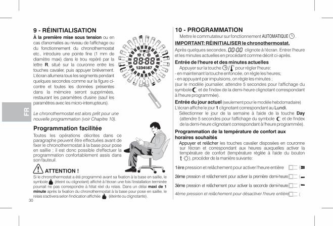
6 - FIXATION OU RETRAIT DU CHRONOTHERMOSTAT DE LA BASE
Appliquer le cache sur les câbles en insérant la dent dansDl'encoche de la base, puis le fixer en exerçant une légèreEpression dans les crochets F.Pour ôter le cache, utiliser un petit tournevis en faisant levier surchaque crochet .F
Accrocher le chronothermostat à la base en veillant à introduirecorrectement les contacts, puis exercer une légère pressionjusqu'à entendre le déclic des dents de fixation.
Pour retirer le chronothermostatde la base en saillie, le saisircomme le montre la figure, puisl'extraire en le faisant pivoter versla droite.
Jeter les piles uséesdans un conteneurprévu à cet usage.
E
D
F
DFR
28
7- MISE EN PLACE OU REMPLACEMENT DES PILES
Remplacer les piles usées par deux rondes de 1,5piles alcalinesV, type AA (LR6) en faisant attention à la polarité.
L'apparition du symbole indique que les piles sontclignotantpresque épuisées ; il vous reste alors 30 jours pour effectuer leurremplacement.Si les piles presque vides ne sont pas remplacées dans le tempsindiqué, l'écran s'éteindra affichant uniquement le symbole fixe.Chaque activité de thermorégulation est suspendue et tous lesparamètres sont enregistrés pour être restaurés lors de l'installationdes nouvelles piles.
ATTENTION : le temps à disposition pour le remplacement despiles sans perdre les donnéesest d'environ 1 minute.

8 - VUE GÉNÉRALE LÉGENDE DES INDICATIONS AFFICHÉES ET FONCTIONS DES TOUCHES
FR
29
R
4
21
2
9
2
6
3
18
1
15
Day
copy
R
tt t
/
t
t
t
4
21
2
9
2
6
3
18
1
15
1234567
Bouton de paramétrage :heures-minutes ou visuel.Température ambiante
Commutateur (voir les détails dans lecadre ci-dessous)
t
Bouton rotatifde régl. destempératuresdes Paramètresréduction t
Heure couranteou températureambiante relevée /affichagetempératureen réglage
(avec indicateur clignotant)
Indicateur des piles :(clignotant)- presque déchargées
(fixe)- déchargées
Reset
ConfortRéductionAntigel
t
+
+
Nota: d'autres fonctions particulières destouches sont décrites dans les paragraphesspécifiques d'utilisation.
ttt
Bouton rotatifde régl. destempératuresdes Paramètresconfort
(Économie)
AUTOMATIQUE - Confort ou Température réduite réglable de 5 à 30 °C;
selon la programmation des index avec les touches cavalier
Logementdes piles
TYPE DE FONCTIONNEMENTSÉLECTIONNABLE À L'AIDEDU COMMUTATEUR
Toujours, Température réduite réglable de 5 à 30 °C
(les 48 index sont tous éteints)
Toujours, température fixe à 5 °C (les 48 index sont tous éteints)Antigel
Toujours, Confort réglable de 5 à 30 °C (les 48 index sont tous allumés)t
t
t
Affichage du type defonctionnement en cours :
Affichage du programmesélectionnéIndex allumé = t ConfortIndex éteint = t Réduction
Indicateur d'état du récepteurclignotant = relais activééteint = relais désactivé
Jour(mod. Hebdomadaire)ex. 5 = vendredi
Touche cavalier“ ”
Index ½ heurecourante clignotant
Activation à l'aide duprogrammateur téléphonique
Touchecavalier“ ”
Touche de sélection du jour(mode hebdomadaire)
(5 ÷ 30 °C)
(5 ÷ 30 °C)
1ère pression et relâchement pour activer l'heure entière
3ème pression et relâchement pour activer la seconde demi-heure
4ème pression et relâchement pour désactiver l'heure entière
À la première mise sous tension ou encas d'anomalies au niveau de l'affichage oudu fonctionnement du chronothermostatetc., introduire une pointe fine (1 mm dediamètre maxi) dans le trou repéré par lalettre , situé sur la couronne entre lesRtouches cavalier, puis appuyer brièvement.L'écran allumera tous les segments pendantquelques secondes comme sur la figure ci-contre et toutes les données présentesdans la mémoire seront supprimées,restaurant les paramètres d'usine (sauf lesparamètres avec les micro-interrupteurs).
Programmation facilitéeToutes les opérations décrites dans ceparagraphe peuvent être effectuées avant defixer le chronothermostat à la base pour poseen saillie ; il est donc possible d'effectuer laprogrammation confortablement assis dansson fauteuil.
9 - RÉINITIALISATION
ATTENTION !Si le chronothermostat a été programmé avant sa fixation à la base en saillie, lesymbole (éteint ou clignotant) affiché à l'écran une fois l'installation terminéepourrait ne pas correspondre à l'état réel du relais. Dans un délai maxi de 1minute après la fixation du chronothermostat à la base pour pose en saillie, lerelais s'activera selon l'indication affichée (éteinte ou clignotante).
DFR Le chronothermostat est alors prêt pour unenouvelle programmation (voir Chapitre 10).
R
4
21
2
9
2
6
3
18
1
15
1234 6751234 67
10 - PROGRAMMATIONMettre le commutateur sur fonctionnement .AUTOMATIQUE
IMPORTANT: RÉINITIALISER le chronothermostat.Après quelques secondes, clignote à l'écran. Entrer l'heureet les minutes actuelles en procédant comme décrit ci-après.
Entrée de l'heure et des minutes actuellesAppuyer sur la touche pour régler l'heure:
- en maintenant la touche enfoncée, on règle les heures;- en appuyant par impulsions, on règle les minutes ;(sur le modèle journalier, attendre 5 secondes pour l'affichage dusymbole et de l'index de la demi-heure clignotant correspondantà l'heure programmée).
Entrée du jour actuel (seulement pour le modèle hebdomadaire)L'écran affiche le jour clignotant correspondant au1 Lundi.
Sélectionner le jour de la semaine à l'aide de la touche Day(attendre 5 secondes pour l'affichage du symbole et de l'indexde la demi-heure clignotant correspondant à l'heure programmée).
Programmation de la température de confort auxhoraires souhaités
Appuyer et relâcher les touches cavalier disposées en couronnesur l'écran et correspondant aux heures auxquelles activer latempérature de confort (température réglée à l'aide du bouton
), procéder de la manière suivante:
/
t
30
2ème pression et relâchement pour activer la première demi-heure
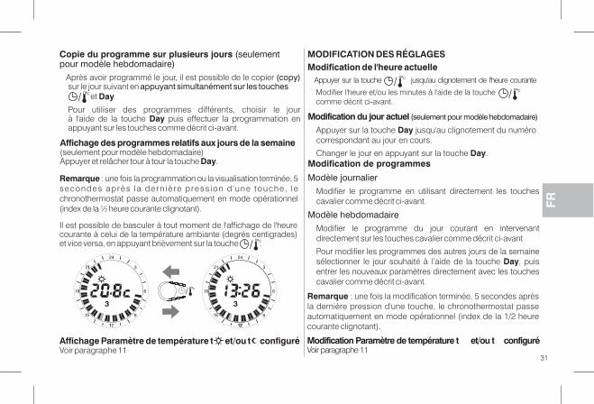
Remarque : une fois la programmation ou la visualisation terminée, 5secondes après la dern iè re press ion d 'une touche, lechronothermostat passe automatiquement en mode opérationnel(index de la ½ heure courante clignotant).
Il est possible de basculer à tout moment de l'affichage de l'heurecourante à celui de la température ambiante (degrés centigrades)et vice versa, en appuyant brièvement sur la touche ./
Affichage des programmes relatifs aux jours de la semaine(seulement pour modèle hebdomadaire)Appuyer et relâcher tour à tour la touche .Day
Copie du programme sur plusieurs jours (seulementpour modèle hebdomadaire)
Après avoir programmé le jour, il est possible de le copier (copy)sur le jour suivant en appuyant simultanément sur les touches
.Day
Pour utiliser des programmes différents, choisir le jourà l'aide de la touche puis effectuer la programmation enDayappuyant sur les touches comme décrit ci-avant.
/
FR
Modification Paramètre de température t et/ou t configuréVoir paragraphe 11
Affichage Paramètre de température t et/ou t configuréVoir paragraphe 11
4
21
2
9
2
6
3
18
1
15
3
1
1
/
4
21
2
9
2
6
3
18
1
15
3
21
Remarque : une fois la modification terminée, 5 secondes aprèsla dernière pression d'une touche, le chronothermostat passeautomatiquement en mode opérationnel (index de la 1/2 heurecourante clignotant).
MODIFICATION DES RÉGLAGESModification de l'heure actuelle
Appuyer sur la touche jusqu'au clignotement de l'heure courante
Modifier l'heure et/ou les minutes à l'aide de la touchecomme décrit ci-avant.
//
Modification du jour actuel (seulement pour modèle hebdomadaire)
Appuyer sur la touche jusqu'au clignotement du numéroDaycorrespondant au jour en cours.
Changer le jour en appuyant sur la touche .DayModification de programmes
Modèle journalier
Modifier le programme en utilisant directement les touchescavalier comme décrit ci-avant.
Modèle hebdomadaire
Modifier le programme du jour courant en intervenantdirectement sur les touches cavalier comme décrit ci-avant
Po r modifier les programmes des autres jours de la semaineusélectionner le jour souhaité à l’aide de la touche , puisDayentrer les nouveaux paramètres directement avec les touchescavalier comme décrit ci-avant.
31
DFR
32
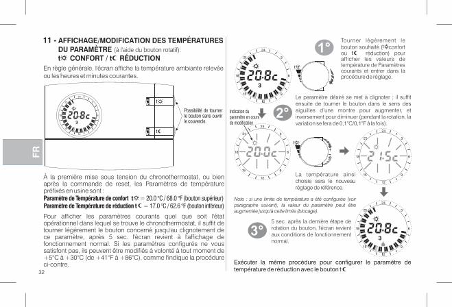
11 - AFFICHAGE/MODIFICATION DES TEMPÉRATURESDU PARAMÈTRE (à l'aide du bouton rotatif):t CONFORT / t RÉDUCTION
À la première mise sous tension du chronothermostat, ou bienaprès la commande de reset, les Paramètres de températurepréfixés en usine sont :Paramètre de Température de confort t = 20.0 °C / 68.0 °F (bouton supérieur)Paramètre de Température de réduction 17.0 °C / 62.6 °F (bouton inférieur)t =
Pour afficher les paramètres courants quel que soit l'étatopérationnel dans lequel se trouve le chronothermostat, il suffit detourner légèrement le bouton concerné jusqu'au clignotement dece paramètre, après 5 sec. l'écran revient à l'affichage defonctionnement normal. Si les paramètres configurés ne voussatisfont pas, ils peuvent être modifiés à volonté à tout moment de+5°C à +30°C (de +41°F à +86°C), comme l'indique la procédureci-contre.
En règle générale, l'écran affiche la température ambiante relevéeou les heures et minutes courantes.
t
4
21
2
9
2
6
3
18
1
15
3
4
21
2
9
2
6
3
18
1
15
3
1
1
Tourner légèrement lebouton souhaité ( confortou réduction) pourafficher les valeurs detempérature de Paramètrescourants et entrer dans laprocédure de réglage.
t
+
4
21
2
9
2
6
3
18
1
15
4
21
2
9
2
6
3
18
1
15
4
21
2
9
2
6
3
18
1
15
3
1
1
1°
2°
Le aramètre désiré se met à clignoter ; il suffitpensuite de tourner le bouton dans le sens desaiguilles d’une montre pour augmenter, etinversement pour diminuer (pendant la rotation, lavariation se fera de 0,1°C/0,1°F à la fois).
3°5 sec. après la dernière étape derotation du bouton, l'écran revientaux conditions de fonctionnementnormal.
Note : si une limite de température a été configurée (voirparagraphe suivant), la valeur du paramètre peut êtreaugmentée jusqu'à cette limite (blocage).
Exécuter la même procédure pour configurer le aramètre deptempérature de réduction avec le bouton t
Indication duparamètre en coursde modification
Possibilité de tournerle bouton sans ouvrirle couvercle.
La température ainsichoisie sera le nouveauréglage de référence.
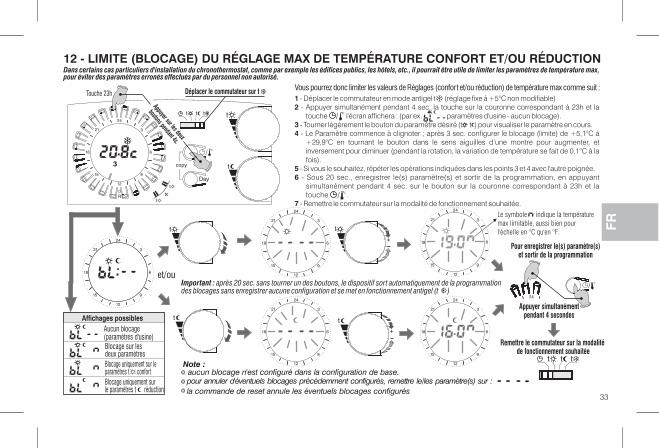
12 - LIMITE (BLOCAGE) DU RÉGLAGE MAX DE TEMPÉRATURE CONFORT ET/OU RÉDUCTION
4
21
2
9
2
6
3
18
1
15
4
21
2
9
2
6
3
18
1
15
+
4
21
2
9
2
6
3
18
1
15
+
t
4
21
2
9
2
6
3
18
1
15
t
4
21
2
9
2
6
3
18
1
15
et/ou
Affichages possiblesAucun blocage(paramètres d'usine)Blocage sur lesdeux paramètresBlocage uniquement sur leparamètres t confortBlocage uniquement surle paramètres t réduction
Appuyer simultanémentpendant 4 secondes
Remettre le commutateur sur la modalitéde fonctionnement souhaitée
Pour enregistrer le(s) paramètre(s)et sortir de la programmation
pour annuler d'éventuels blocages précédemment configurés, remettre le/les paramètre(s) sur :
la commande de reset annule les éventuels blocages configurés
Dans certains cas particuliers d'installation du chronothermostat, comme par exemple les édifices publics, les hôtels, etc., il pourrait être utile de limiter les paramètres de température max,pour éviter des paramètres erronés effectués par du personnel non autorisé.
Vous pourrez donc limiter les valeurs de Réglages (confort et/ou réduction) de température max comme suit :1 - Déplacer le commutateur en mode antigel t (réglage fixe à +5°C non modifiable)2 - Appuyer simultanément pendant 4 sec. la touche sur la couronne correspondant à 23h et la
touche l'écran affichera : (par ex. paramètres d'usine - aucun blocage).3 - Tourner légèrement le bouton du paramètre désiré (t t ) pour visualiser le paramètre en cours.4 - Le Paramètre commence à clignoter ; après 3 sec. configurer le blocage (limite) de +5,1°C à
+29,9°C en tournant le bouton dans le sens aiguilles d’une montre pour augmenter, etinversement pour diminuer (pendant la rotation, la variation de température se fait de 0,1°C à lafois).
5 - Si vous le souhaitez, répéter les opérations indiquées dans les points 3 et 4 avec l'autre poignée.6 - Sous 20 sec., enregistrer le(s) paramètre(s) et sortir de la programmation, en appuyant
simultanément pendant 4 sec. sur le bouton sur la couronne correspondant à 23h et latouche .
7 - Remettre le commutateur sur la modalité de fonctionnement souhaitée.
/
Note :
Important : après 20 sec. sans tourner un des boutons, le dispositif sort automatiquement de la programmationdes blocages sans enregistrer aucune configuration et se met en fonctionnement antigel (t )
/
aucun blocage n'est configuré dans la configuration de base.
Day
copy
R
tt t
/
t
t
t
4
21
2
9
2
6
3
18
1
15
12 45673 t
Déplacer le commutateur sur t
Appuyer sur les deux
boutons pendant 4s.
Le symbole indique la température
max limitable, aussi bien pour
l'échelle en °C qu'en °F.
33
FR
Touche 23h
tt t
42
/
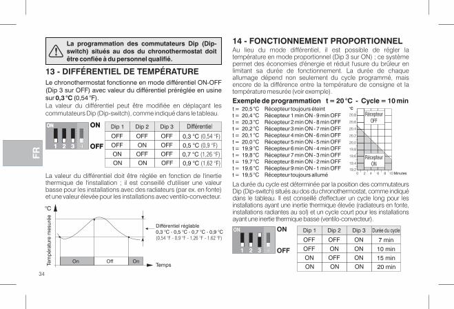
Le chronothermostat fonctionne en mode différentiel ON-OFF(Dip 3 sur OFF) avec valeur du différentiel préréglée en usinesur (0,54 °F).0,3 °CLa valeur du différentiel peut être modifiée en déplaçant lescommutateurs Dip (Dip-switch), comme indiqué dans le tableau.
13 - DIFFÉRENTIEL DE TEMPÉRATURE
Temps
°C
OffOn OnTem
pér
atur
e m
esur
ée
La valeur du différentiel doit être réglée en fonction de l'inertiethermique de l'installation ; il est conseillé d'utiliser une valeurbasse pour les installations avec des radiateurs (par ex. en fonte)et une valeur élevée pour les installations avec ventilo-convecteur.
Au lieu du mode différentiel, il est possible de régler latempérature en mode proportionnel (Dip 3 sur ON) ; ce systèmepermet des économies d'énergie et réduit l'usure du brûleur enlimitant sa durée de fonctionnement. La durée de chaqueallumage dépend non seulement du cycle programmé, maisencore de la différence entre la température de consigne et latempérature mesurée (voir exemple).
14 - FONCTIONNEMENT PROPORTIONNEL
Exemple de programmation t = 20 °C - Cycle = 10 mint = 20,5 °C Récepteur toujours éteintt = 20,4 °C Récepteur 1 min ON - 9 min OFFt = 20,3 °C Récepteur 2 min ON - 8 min OFFt = 20,2 °C Récepteur 3 min ON - 7 min OFFt = 20,1 °C Récepteur 4 min ON - 6 min OFFt = 20,0 °C Récepteur 5 min ON - 5 min OFFt = 19,9 °C Récepteur 6 min ON - 4 min OFFt = 19,8 °C Récepteur 7 min ON - 3 min OFFt = 19,7 °C Récepteur 8 min ON - 2 min OFFt = 19,6 °C Récepteur 9 min ON - 1 min OFFt = 19,5 °C Récepteur toujours allumé
Dip 1 Dip 2 Dip 3 Durée du cycle
ON ON ON 20 min
ON OFF ON 15 min
OFF ON ON 10 min
OFF OFF ON 7 min
ON
32 OFF1
ON
La durée du cycle est déterminée par la position des commutateursDip (Dip-switch) situés au dos du chronothermostat, comme indiquédans le tableau. Il est conseillé d'effectuer un cycle long pour lesinstallations ayant une inertie thermique élevée (radiateurs en fonte,installations radiantes au sol) et un cycle court pour les installationsayant une inertie thermique basse (ventilo-convecteur).
20,8
20,6
20,4
20,2
20,0
19,8
19,6
19,4
19,2
°C
0 102 4 6 8 Minutes
La programmation des commutateurs Dip (Dip-switch) situés au dos du chronothermostat doitêtre confiée à du personnel qualifié.
Différentiel réglable0,3 °C - 0,5 °C - 0,7 °C - 0,9 °C(0,54 °F - 0,9 °F - 1,26 °F - 1.62 °F)
RécepteurON
4
RécepteurOFF
Dip 1 Dip 2 Dip 3 Différentiel
ON ON OFF 0,9 °C (1,62 °F)
ON OFF OFF 0,7 °C (1,26 °F)
OFF ON OFF 0,5 °C (0,9 °F)
OFF OFF OFF 0,3 °C (0,54 °F)
ON
32 OFF1
ON ON
32 OFF1
ON
4
DFR
34
15 - ÉCHELLE DE TEMPÉRATURE °C o °Fu 16 - AVERTISSEMENTS
ATTENTION : le chronothermostat a été réglé enusine pour utiliser les degrés Celsius (degréscentigrades) et peut être modifié par l'installateurou un utilisateur expert en degré Fahrenheit (°F).
35
Le micro-interrupteur placé à l'arrière du chronothermostat a4été configuré en usine sur la position (degrésOFFcentigrades).Vous pourrez le déplacer sur la position : 'écran affichera,ON laprès avoir effectué une opération de RESET, la températureambiante et les Paramètres en degrés Fahrenheit (°F).Pour revenir à l'affichage en degrés centigrades, remettre lemicro-interrupteur sur et effectuer une opération de4 OFFRESET.Dans les deux cas, programmer de nouveau lechronothermostat comme indiqué dans le chapitre 10).
432 OFF = (°c)échelle des Degrés centigrades1
ON
432
ON = (°F)échelle des Degrés Fahrenheit
1
ON
(paramètres d'usine)
FR
Si l'écran affiche la valeur de la température ambiante, en clignotant, il signale que la00.0 °C ou 50.0 °C
température mesurée est supérieure ou inférieure aux valeursmaximum de l'échelle.Utiliser exclusivement des piles alcalines de 1,5V, de type AA LR6(non incluses dans l'emballage). L'emploi de piles d'un autre typepeut entraîner la perte des données programmées.N.B. : le produit a été testé et ses caractéristiques sont garantiesavec des piles alcalines DURACELL ou ENERGIZER.
Important : la durée des piles peut être supérieure à an . Il est2 stoutefois conseillé de les remplacer au moins tous les 2 mois pour4éviter qu'elles ne s'épuisent pendant des périodes d'absence (ex.Vacances de Noël etc.).
Au besoin, nettoyer le chronothermostat à l'aide d'un chiffonlégèrement humide.
Le fabricant se réserve la faculté d’apporter, sans obligation depréavis, les modifications qu’il jugera nécessaires à la construction.
Lire attentivement le présent manuel avant d'utiliser le produitdans la mesure où il fournit d'importantes indicationsconcernant la sécurité, l'installation et l'utilisation. Conserversoigneusement le manuel pour d'ultérieures consultations.
Les figures présentes dans le manuel représentent l'écran avec lesparamètres de l'échelle des températures en °C (degrés Celsius).
Le thermostat ne doit pas être utilisé par des personnes (ychronocompris par des enfants) dotées de capacités physiques,sensorielles et mentales réduites ou sans expérience niconnaissance des instructions à moins que ces personnes nesoient surveillées ou qu'elles n'aient reçu les instructionsnécessaires concernant l'utilisation de l'appareil de la part depersonne responsable de leur sécurité.
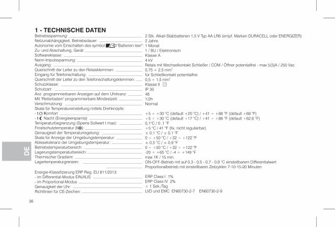
Betriebsspannung:Netzunabhängigkeit, Betriebsdauer:Autonomie vom Einschalten des symbol :''Batterien leer''Zu- und Abschaltung, Gerät:Softwareklasse:Nenn-Impulsspannung:Ausgang:Querschnitt der Leiter zu den Relaisklemmen:Eingang für Telefonschaltung:Querschnitt der Leiter zu den Telefonschaltungsklemmen:Schutzklasse:Schutzart:Anz. programmierbaren Anzeigen auf dem Uhrkranz:Mit "Reitertasten" programmierbare Mindestzeit:Verschmutzung:Skala für Temperatureinstellung mittels Drehknöpfe:- omfortt K- Nacht (Energieersparnis)tTemperaturbegrenzung (Sperre Sollwert t max):Frostschutztemperatur ( ):tGenauigkeit der Temperaturregelung:Skala für Anzeige der Umgebungstemperatur:Ablesetoleranz der Umgebungstemperatur:Betriebstemperaturbereich:Lagerungstemperaturbereich:Thermischer Gradient:Lagertemperaturgrenzen:
Energie-Klassifizierung ERP Reg. EU 811/2013:- im Differential-Modus EIN/AUS- im Proportional-ModusGenauigkeit der Uhr:Richtlinien für CE-Zeichen:
1 - TECHNISCHE DATEN2 Stk. Alkali-Stabbatterien 1,5 V Typ AA LR6 ( mpf. Marken DURACELL oder ENERGIZER)e2 Jahre1 Monat1 / BU / ElektronischKlasse A4 kVRelais mit Wechselkontakt Schließer / COM / Öffner potentialfrei - max 5(3)A / 250 Vac0,75 + 2,5 mm2
für Schließkontakt potentialfrei0,5 ÷ 1,5 mm2
Klasse IIIP 30481/2hNormal
+5 ÷ +30 °C (default +20 °C) / +41 ÷ +86 °F (default +68 °F)+5 ÷ +30 °C (default +17 °C) / +41 ÷ +86 °F (default +62,6 °F)0,1°C / 0 ,1 °F+5 °C / 41 °F (fix, nicht regulierbar)± 0,1 °C / ± 0,1 °F0 ÷ +50 °C / +32 ÷ +122 °F± 0,5 °C / ± 0,9 °F0 ÷ +50 °C / +32 ÷ +122 °F-20 ÷ +65 °C / -4 ÷ +149 °Fmax 1K / 15 min.ON-OFF-Betrieb mit auf 0,3 - 0,5 - 0,7 - 0,9 °C einstellbarem DifferentialwertProportionalbetrieb mit einstellbaren Zeitzyklen 7-10-15-20 Minuten
ERP Class I 1%ERP Class IV 2%± 1 Sek./TagLVD und EMC EN60730-2-7 EN60730-2-9
36
DE
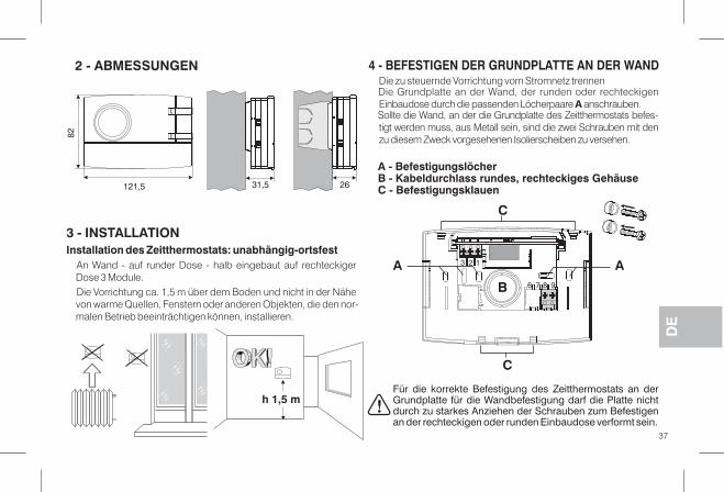
2 - ABMESSUNGEN
3 - INSTALLATIONInstallation des Zeitthermostats: unabhängig-ortsfest
An Wand - auf runder Dose - halb eingebaut auf rechteckigerDose 3 Module.Die Vorrichtung ca. 1,5 m über dem Boden und nicht in der Nähevon warme Quellen, Fenstern oder anderen Objekten, die den nor-malen Betrieb beeinträchtigen können, installieren.
121,5
82
31,5 26
Die zu steuernde Vorrichtung vom Stromnetz trennenDie Grundplatte an der Wand, der runden oder rechteckigenEinbaudose durch die passenden Löcherpaare anschrauben.ASollte die Wand, an der die Grundplatte des Zeitthermostats befes-tigt werden muss, aus Metall sein, sind die zwei Schrauben mit denzu diesem Zweck vorgesehenen Isolierscheiben zu versehen.
4 - BEFESTIGEN DER GRUNDPLATTE AN DER WAND
A - BefestigungslöcherB - Kabeldurchlass rundes, rechteckiges GehäuseC - Befestigungsklauen
Für die korrekte Befestigung des Zeitthermostats an derGrundplatte für die Wandbefestigung darf die Platte nichtdurch zu starkes Anziehen der Schrauben zum Befestigenan der rechteckigen oder runden Einbaudose verformt sein.
37
h 1,5 m�
DE
C
C
B
3 2 1
6 7 8 945
A A
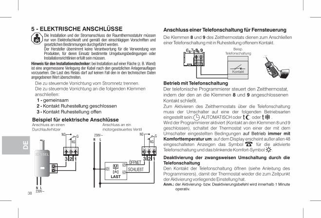
Die Installation und der Stromanschluss der Raumthermostatuhr müssennur von Elektrofachkraft und gemäß den einschlägigen Vorschriften undgesetzlichen Bestimmungen durchgeführt werden.Der Hersteller übernimmt keine Verantwortung für die Verwendung vonProdukten, für deren Einsatz bestimmte Umgebungsbedingungen oderInstallationsrichtlinien erfüllt sein müssen.
Hinweis für den Installationstechniker: ei Installation auf einer Fläche (z. B. Wand)bist eine angemessene Verlegung der Kabel nach den gesetzlichen Anlagenauflagenvorzusehen. Die Last des Relais darf auf keinen Fall den in den technischen Datenangegebenen Wert überschreiten.
Beispiel für elektrische Anschlüsse
5 - ELEKTRISCHE ANSCHLÜSSE
Die zu steuernde Vorrichtung vom Stromnetz trennen.Die zu steuernde Vorrichtung an die folgenden Klemmenanschließen:1 - gemeinsam2 - Kontakt Ruhestellung geschlossen3 - Kontakt Ruhestellung offen
Betrieb mit TelefonschaltungDer telefonische Programmierer steuert den Zeitthermostat,indem der den an die Klemmen und angeschlossenen8 9Kontakt schließt.
Anschluss einer Telefonschaltung für FernsteuerungDie Klemmen und des Zeitthermostats dienen zum Anschließen8 9einer Telefonschaltung mit in Ruhestellung offenem Kontakt.
Zum Aktivieren des Zeitthermostats über die Telefonschaltungmuss der Umschalter auf eine der folgenden Betriebsarteneingestellt sein: AUTOMATISCH oder oder .Wird der Programmierer aktiviert (Kontakt an den Klemmen 8 und 9geschlossen), schaltet der Thermostat von einer der mit demUmschalter eingestellten Bedingungen auf Betrieb immer mitKomforttemperatur um: auf dem Display erscheint außer allen 48eingeschalteten Anzeigen das Symbol für die aktivierteTelefonschaltung und das blinkende Komfort-Symbol .
Deaktivierung der zwangsweisen Umschaltung durch dieTelefonschaltungDen Kontakt der Telefonschaltung öffnen (siehe Anleitung desProgrammierers), damit der Thermostat wieder die zum Zeitpunktder Aktivierung vorliegende Einstellung hat.Anm.: der Aktivierung- bzw. Deaktivierungsbefehl wird innerhalb 1 Minute
operativ.
tt
38
DE
23 1
GNO
NG
23 1
GN
NGL
230V~ NO
LAST
M
KESSEL
N L230V~
Anschluss an einenDurchlauferhitzer
Anschluss an einmotorgesteuertes Ventil
ÖFFNET
SCHLIEßT
6 7 8 9 Beisp.Telefonschaltung
Kontakt
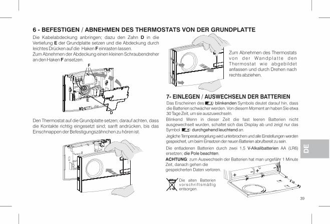
6 - BEFESTIGEN / ABNEHMEN DES THERMOSTATS VON DER GRUNDPLATTEDie Kabelabdeckung anbringen; dazu den Zahn in dieDVertiefung der Grundplatte setzen und die Abdeckung durchEleichtes Drücken auf die Haken einrasten lassen.FZum Abnehmen der Abdeckung einen kleinen Schraubendreheran den Haken ansetzen.F
Den Thermostat auf die Grundplatte setzen; darauf achten, dassdie Kontakte richtig eingesetzt sind; sanft andrücken, bis dasEinschnappen der Befestigungszähnchen zu hören ist.
Zum Abnehmen des Thermostatsv o n d e r Wa n d p l a t t e d e nThermostat wie abgebi ldetanfassen und durch Drehen nachrechts abziehen.
7- EINLEGEN / AUSWECHSELN DER BATTERIEN
Die alten Batterienv o r s c h r i f t s m ä ß i gentsorgen.
E
D
F
39
DEDie entladenen Batterien durch zwei 1,5 AA (LR6)V-Alkalibatterien
ersetzen; .die Pole beachten
Das Erscheinen des Symbols deutet darauf hin, dassblinkendendie Batterien schwächer werden. Von diesem Moment an haben Sie etwa30 Tage Zeit, um sie auszuwechseln.Blinkend Wenn in dieser Zeit die fast leeren Batterien nichtausgewechselt wurden, schaltet sich das Display ab und zeigt nur dasSymbol an.durchgehend leuchtend
Jegliche Temperaturregelung wird unterbrochen und alle Einstellungen werdengespeichert, um beim Einsetzen der neuen Batterien abrufbereit zu sein.
ACHTUNG: zum Auswechseln der Batterien hat man ungefähr 1 MinuteZeit, danach gehen diegespeicherten Daten verloren.
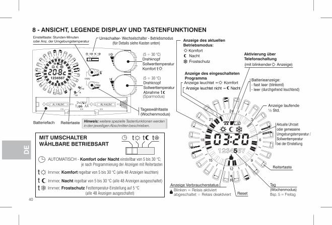
Batteriefach
8 - ANSICHT, LEGENDE DISPLAY UND TASTENFUNKTIONEN
Tageswähltaste(Wochenmodus)
40
DE
R
4
21
2
9
2
6
3
18
1
15
Day
copy
R
tt t
/
t
t
t
4
21
2
9
2
6
3
18
1
15
1234567
Einstelltaste: Stunden-Minutenoder Anz. der Umgebungstemperatur
Umschalter- Wechselschalter - Betriebsmodus(für Details siehe Kasten unten)
t
DrehknopfSollwerttemperaturAbnahme t
Aktuelle Uhrzeitoder gemesseneUmgebungstemperatur /Sollwerttemperaturbei der Einstellung
Aktivierung überTelefonschaltung(mit blinkender Anzeige)
Batterieanzeige:- (blinkend)fast leer- (durchgehend leuchtend)leer
Reset
t
+
+
Hinweis: weitere spezielle Tastenfunktionen werdenin den jeweiligen Abschnitten beschrieben.
tttMIT UMSCHALTERWÄHLBARE BETRIEBSART
AUTOMATISCH - einstellbar von 5 bis 30 °C;Komfort oder Nachtje nach Programmierung der Anzeigen mit Reitertasten
Immer, regelbar von 5 bis 30 °C (alle 48 Anzeigen ausgeschaltet)Nacht
Immer, Frostschutz Festtemperatur-Einstellung auf 5 °C
(alle 48 Anzeigen ausgeschaltet)
Immer, regelbar von 5 bis 30 °C (alle 48 Anzeigen leuchten)Komfortt
tt
DrehknopfSollwerttemperaturKomfort
(Sparmodus)
Reitertaste
Anzeige des aktuellenBetriebsmodus:
KomfortNachtFrostschutz
Anzeige laufende½ Std.
Reitertaste
Tag(Wochenmodus)Bsp. 5 = Freitag
Anzeige VerbraucherstatusBlinken = Relais aktiviertabgeschaltet = Relais deaktiviert
Anzeige des eingeschaltetenProgramms
Anzeige leuchtet nicht = NachtAnzeige leuchtet = Komfort
(5 ÷ 30 °C)
(5 ÷ 30 °C)
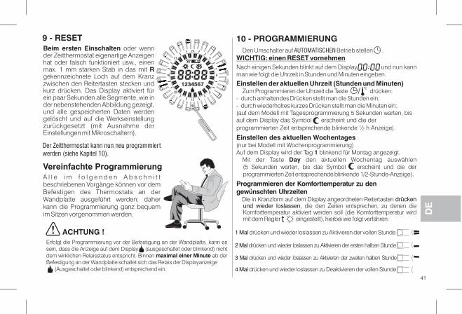
41
DE
Beim ersten Einschalten oder wennder Zeitthermostat eigenartige Anzeigenhat oder falsch funktioniert usw., einenmax. 1 mm starken Stab in das mit Rgekennzeichnete Loch auf dem Kranzzwischen den Reitertasten stecken undkurz drücken. Das Display aktiviert fürein paar Sekunden alle Segmente, wie inder nebenstehenden Abbildung gezeigt,und alle gespeicherten Daten werdengelöscht und auf die Werkseinstellungzurückgesetzt (mit Ausnahme derEinstellungen mit Mikroschaltern).
R
4
21
2
9
2
6
3
18
1
15
123 5674
9 - RESET 10 - PROGRAMMIERUNGDen Umschalter auf Betrieb stellen .AUTOMATISCHEN
WICHTIG: einen RESET vornehmenNach einigen Sekunden blinkt auf dem Display und nun kannman wie folgt die Uhrzeit in Stunden und Minuten eingeben.
Einstellen der aktuellen Uhrzeit (Stunden und Minuten)Zum Programmieren der Uhrzeit die Taste drücken:
- durch anhaltendes Drücken stellt man die Stunden ein;- durch wiederholtes kurzes Drücken stellt man die Minuten ein;(auf dem Modell mit Tagesprogrammierung 5 Sekunden warten, bisauf dem Display das Symbol erscheint und die derprogrammierten Zeit entsprechende blinkende h Anzeige).½
Einstellen des aktuellen Wochentages(nur bei Modell mit Wochenprogrammierung)Auf dem Display wird der Tag blinkend für Montag angezeigt.1
Mit der Taste den aktuellen Wochentag auswählenDay(5 Sekunden warten, bis das Symbol erscheint und die derprogrammierten Zeit entsprechende blinkende 1/2-Stunde-Anzeige).
Programmieren der Komforttemperatur zu dengewünschten Uhrzeiten
Die in Kranzform auf dem Display angeordneten Reitertasten drückenund wieder loslassen, die den Zeiten entsprechen, zu denen dieKomforttemperatur aktiviert werden soll (die Komforttemperatur wirdmit dem Regler eingestellt), hierbei wie folgt verfahren:t
/
Der Zeitthermostat kann nun neu programmiertwerden (siehe Kapitel 10).
Vereinfachte ProgrammierungA l l e i m f o l g e n d e n A b s c h n i t tbeschriebenen Vorgänge können vor demBefestigen des Thermostats an derWandplatte ausgeführt werden; daherkann die Programmierung ganz bequemim Sitzen vorgenommen werden.
Erfolgt die Programmierung vor der Befestigung an der Wandplatte, kann essein, dass die Anzeige auf dem Display (ausgeschaltet oder blinkend) nichtdem wirklichen Relaisstatus entspricht. Binnen ab dermaximal einer MinuteBefestigung an der Wandplatte schaltet sich das Relais der Displayanzeige
(Ausgeschaltet oder blinkend) entsprechend ein.
ACHTUNG ! 1 Mal drücken und wieder loslassen zu Aktivieren der vollen Stunde
2 Mal drücken und wieder loslassen zu Aktivieren der ersten halben Stunde
3 Mal drücken und wieder loslassen zu Aktivieren der zweiten halben Stunde
4 Mal drücken und wieder loslassen zu Deaktivieren der vollen Stunde
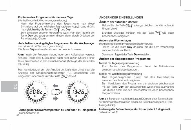
42
DE
4
21
2
9
2
6
3
18
1
15
3
1
1
/
4
21
2
9
2
6
3
18
1
15
3
21
Änderung der Sollwerttemperatur t und/oder t eingestelltSiehe Abschnitt 11
Anzeige der Sollwerttemperatur t und/oder t eingestelltSiehe Abschnitt 11
Kopieren des Programms für mehrere Tage(Nur bei Modell mit Wochenprogrammierung)
Nach der Programmierung des Tages kann man dieseEinstellung auf den nächsten Tag kopieren (copy): dazu drücktman gleichzeitig die Tasten und .DayZum Einstellen anderer Programme wählt man den Tag mit derTaste und programmiert diesen dann durch Drücken derDayReitertasten (s. Oben).
/
Anm.: ach der Programmierung oder dem Aufschalten versetztnsich der Thermostat 5 Sekunden nach dem letzten Drücken einerTaste automatisch in den Betriebsmodus (Anzeige der laufenden½h blinkt).
Man kann jederzeit von der Anzeige der laufenden Uhrzeit auf dieAnzeige der Umgebungstemperatur (°C) umschalten undumgekehrt, indem man kurz die Taste drückt./
Aufschalten von eingefügten Programmen für die Wochentage(nur bei Modell mit Wochenprogrammierung)Die Taste mehrmals drücken und wieder loslassen.Day
Anm.: 5 Sekunden nach dem letzten Drücken einer Taste schaltetder Thermostat automatisch wieder auf Betrieb um (laufende h -1/2Anzeige blinkt).
ÄNDERN DER EINSTELLUNGEN
Ändern der aktuellen UhrzeitHalten Sie die Taste solange drücken, bis die laufendeUhrzeit blinkt.
Stunden und/oder Minuten mit der Taste wie obenbeschrieben korrigieren.
/
/
Ändern des Wochentages(nur bei Modellen mit Wochenprogrammierung)
Halten Sie die Taste drücken, bis die dem WochentagDayentsprechende Zahl blinkt.
Den neuen Tag mit der Taste einstellen.Day
Ändern der eingegebenen ProgrammeModell mit Tagesprogrammierung
Zum Ändern des Programms direkt die Reitertastenwie oben beschrieben benutzen.
Modell mit WochenprogrammierungDas Tagesprogramm direkt mit den Reitertastenwie oben beschrieben korrigieren.Zum Korrigieren des Programms der anderen Wochentagemit der Taste den gewünschten Wochentag auswählenDayund diesen direkt mit den Reitertasten wie oben beschriebenProgrammieren.

43
DE
11 - ANZEIGE/ÄNDERUNG DERSOLLWERTTEMPERATUREN (mittels Drehknopf):t KOMFORT / t ABNAHME
Beim ersten Einschalten der Raumthermostatuhr oder nach deinemReset, gelten die im Werk voreingestellten Sollwerttemperaturen:Sollwerttemperatur Komfort t = 20.0 °C / 68.0 °F (oberer Drehknopf)Sollwerttemperatur Abnahme t = 17.0 °C / 62.6 °F (oberer Drehknopf)
Zum Anzeigen der aktuellen Sollwerte ist es, unabhängig vommomentanen Betriebszustand der Raumthermostatuhr,ausreichend, den entsprechenden Drehknopf leicht zu drehen, bisder Sollwert blinkt; nach 5 Sek. kehrt das Display zu den normalenBetriebsbedingungen zurück. Wenn die eingestellten Sollwertenicht Ihren Anforderungen entsprechen, können sie zu jedemZeitpunkt nach Belieben zwischen +5°C und +30 °C (+41 °F und+86 °F) verändert werden, wie nebenstehend beschrieben.
Normalerweise ze igt das Display die gemesseneUmgebungstemperatur oder die aktuellen Uhrzeit an.
t
4
21
2
9
2
6
3
18
1
15
3
4
21
2
9
2
6
3
18
1
15
3
1
1
Den gewünschten Drehknopf( Komfort oder Abnahme)leicht drehen, um den aktuellenTemperatursollwert anzeigenz u l a s s e n u n d d e nEinstellvorgang zu beginnen.
t
+
4
21
2
9
2
6
3
18
1
15
4
21
2
9
2
6
3
18
1
15
4
21
2
9
2
6
3
18
1
15
3
1
1
1°
2°
Der gewünschte Sollwert beginnt zu blinken, dannden Drehknopf im Uhrzeigersinn zum Erhöhenbzw. entgegen dem Uhrzeigesinn zum Verringerndes Wertes drehen (die Variation erfolgt inSchritten von 0,1°C/0,1 °F).
3°Nach Verstreichen von etwa 5 Sek.nach dem Drehen des Drehknopfeskehrt das Display zu den normalenBetriebsbedingungen zurück:
Hinweis: wenn eine Temperaturgrenze eingestellt wurde(siehe nächster Abschnitt) kann der Sollwert nur bis zudiesem erhöht werden (Sperre).
Zum Einstellen des Temperatursollwertes Abnahme genauso, abermit dem Drehknopf t verfahren.
Anzeige des zuveränderndenSollwertes
D i e D r e h k n ö p f ek ö n n e n g e d r e h twerden, ohne dassdazu die Klappegeöf fne t werdenmuss.
Die so festgelegteTemperatur wird derneue Bezugssollwert.
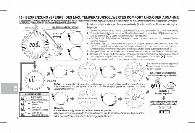
12 - BEGRENZUNG (SPERRE) DES MAX. TEMPERATURSOLLWERTES KOMFORT UND/ODER ABNAHME
4
21
2
9
2
6
3
18
1
15
4
21
2
9
2
6
3
18
1
15
+
4
21
2
9
2
6
3
18
1
15
+
t
4
21
2
9
2
6
3
18
1
15
t
4
21
2
9
2
6
3
18
1
15
und/oder
Mögliche AnzeigenKeine Sperre(Werkseinstellung)Sperre für beideSollwerteSperre nur fürSollwert t KomfortSperre nur fürSollwert t Abnahme
42
/
Gleichzeitig 4Sekunden lang drücken
Den Wechselschalter wieder auf dengewünschten Betriebsmodus stellen
tt t
Zum Speichern der Einstellung(en)und Verlassen des Programmiermodus
Um eventuell zuvor eingestellte Sperren aufzuheben, die Temperatursollwerte wie folgt einstellen:
Der Resetbefehl annulliert eventuell eingestellte Sperren
In besonderen Fällen der Installation der Raumthermostatuhr, z.B. in öffentlichen Gebäuden, Hotels, usw., könnte es nützlich sein, die max. Temperatursollwerte zu begrenzen, um falscheEinstellungen von Seiten nicht autorisierten Personals zu verhindern.
Es ist nun möglich, die max. Temperatursollwerte (Komfort und/oder Abnahme) wie folgt zubegrenzen.1 - Den Wechselschalter auf den Frostschutzmodus t stellen (fixer Sollwert bei +5°C, nicht veränderbar)2 - Für 4 s gleichzeitig die Taste, die auf dem Kreis 23 Uhr entspricht, und die Taste drücken; auf dem
Display erscheint: (z.B. Werkseinstellung = keine Sperre).3 - Den Drehknopf des gewünschten Sollwertes (t oder t ) leicht drehen, um den aktuellen Sollwert
anzeigen zu lassen.4 - Der Sollwert beginnt zu blinken und nach 3 Sek. kann die Sperre (Begrenzung) zwischen +5,1°C und
+29,9°C eingestellt werden; dazu den Drehknopf im Uhrzeigersinn zum Erhöhen bzw. entgegen demUhrzeigersinn zum Verringern des Wertes drehen (die Variation erfolgt dabei in Schritten von 0,1.
5 - Wenn gewünscht, die unter 3 und 4 beschriebenen Schritte mit dem anderen Drehknopf wiederholen.6 - Innerhalb von 20 Sek. die Einstellung(en) speichern und den Programmiermodus verlassen; dazu 4
Sek. lang gleichzeitig die Taste, die auf dem Kreis 23 Uhr entspricht, und die Taste drücken.7 - Den Wechselschalter wieder auf den gewünschten Betriebsmodus stellen.
/
Hinweis:
Wichtig: Verstreichen 20 Sek., ohne dass der Drehknopf gedreht wird, verlässt das Gerät automatisch denProgrammiermodus für die Sperre, ohne dass die Einstellungen gespeichert werden, und kehrtFrostschutzmodus (t )
/
In der Basiskonfiguration ist keinerlei Sperre eingestellt.
Day
copy
R
tt t
/
t
t
t
4
21
2
9
2
6
3
18
1
15
12 45673 t
Den Wechselschalter auf t stellen
4 s lang gleichzeitig drücken
Das Symbol zeigt die max. begrenzbare
Temperatur sowohl für die °C- als auch
für die °F-Skala an.
44
DE
Taste 23 Uhr

Der Zeitthermostat funktioniert nach einem DifferentialmodusON-OFF (Dip 3 in Stellung OFF), wobei der Differentialwertwerkseitig auf (0,54 °F) festgelegt ist.0,3 °CDer Differentialwert kann mit den Mikroschaltern (Dip-switch) wie inder Tabelle angegeben geändert werden.
13 - TEMPERATURDIFFERENTIAL
Zeit
°C
OffOn On
Gem
esse
ne T
emp
erat
ur
Der Differentialwert richtet sich nach der thermischen Trägheit derAnlage; für Anlagen mit Heizkörpern (z. B. aus Gusseisen) sollte derWert niedrig, für Anlagen mit Gebläse sollte er hoch eingestelltwerden.
Als Alternative zum Differentialmodus kann die Temperatur auchproportional geregelt werden (Dip 3 in Stellung ON); mit diesemSystem kann man den Energieverbrauch reduzieren und auch denVerschleiß des Brenners durch selteneres Einschalten optimieren. DieDauer der einzelnen Einschaltungen hängt nicht nur vom eingestelltenZyklus ab, sondern auch vom Unterschied zwischen derSolltemperatur und der Isttemperatur (siehe Beispiel).
14 - PROPORTIONALBETRIEB
Einstellungsbeispiel t = 20 °C - Zyklus = 10 mint = 20,5 °C Verbraucher immer ausgeschaltett = 20,4 °C Verbraucher 1 min ON - 9 min OFFt = 20,3 °C Verbraucher 2 min ON - 8 min OFFt = 20,2 °C Verbraucher 3 min ON - 7 min OFFt = 20,1 °C Verbraucher 4 min ON - 6 min OFFt = 20,0 °C Verbraucher 5 min ON - 5 min OFFt = 19,9 °C Verbraucher 6 min ON - 4 min OFFt = 19,8 °C Verbraucher 7 min ON - 3 min OFFt = 19,7 °C Verbraucher 8 min ON - 2 min OFFt = 19,6 °C Verbraucher 9 min ON - 1 min OFFt = 19,5 °C Verbraucher immer eingeschaltet
Die Zyklusdauer wird von der Stellung der Mikroschalter (Dip-switch)auf der Geräterückseite wie in der Tabelle angegeben bestimmt.Für thermisch träge Anlagen (z. B. mit Gusseisen-Heizkörpern,Fußbodenheizungen) sollte der Zyklus lang sein, für Anlagen mitgeringer thermischer Trägheit (Gebläse) sollte er kurz sein.
20,8
20,6
20,4
20,2
20,0
19,8
19,6
19,4
19,2
°C
0 102 4 6 8 Minuten
Die Einstellungen der Mikroschalter (Dip-switch) aufder Geräterückseite dürfen nur von einem Fachmannvorgenommen werden.
Einstellbares Differential0,3 °C - 0,5 °C - 0,7 °C - 0,9 °C(0,54 °F - 0,9 °F - 1,26 °F - 1.62 °F)
VerbraucherOFF
VerbraucherON
Dip 1 Dip 2 Dip 3 Zyklusdauer
ON ON ON 20 min
ON OFF ON 15 min
OFF ON ON 10 min
OFF OFF ON 7 min
ON
32 OFF1
ON
4
DE
45
Dip 1 Dip 2 Dip 3 Differential
ON ON OFF 0,9 °C (1,62 °F)
ON OFF OFF 0,7 °C (1,26 °F)
OFF ON OFF 0,5 °C (0,9 °F)
OFF OFF OFF 0,3 °C (0,54 °F)
ON
32 OFF1
ON ON
32 OFF1
ON
4
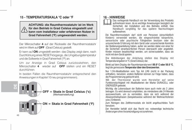
15 - TEMPERATURSKALA °C o °Fder 16 - HINWEISE
ACHTUNG: die Raumthermostatuhr ist im Werkfür den Betrieb in Grad Celsius eingestellt undkann vom Installateur oder erfahrenen Nutzer inGrad Fahrenheit (°F) umgewandelt werden.
DE
46
Der Mikroschalter auf der Rückseite der Raumthermostatuhr4wird im Werk auf (Grad Celsius) gestellt.OFFEr kann auf umgestellt werden: das Display zeigt dann, nachONDurchführung eines RESET-Vorgangs, die Umgebungstemperaturund die Sollwerte in Grad Fahrenheit (°F) an.Um zur Anzeige in Grad Celsius zurückzukehren, denMikroschalter wieder auf stellen und ein RESET4 OFFdurchführen.In beiden Fällen die Raumthermostatuhr entsprechend denAnweisungen in Kapitel 10 neu programmieren).
432 OFF = (°c)Skala in Grad Celsius1
ON
432
ON = (°F)Skala in Grad Fahrenheit
1
ON
(Werkseinstellung)
Blinkt auf dem Display der Raumtemperaturwert ,00.0° C oder 50.0 °Cliegt die gemessene .Temperatur über den Grenzwerten
Nur 1,5V-Alkalibatterien vom Typ AA LR6 (nicht in der Packungenthalten), benutzen; andere Batterien können zur Folge haben, dassdie Programmierung gelöscht wird.NB: der Thermostat wurde vom Herstel ler auf seineFunktionstüchtigkeit mit Alkalibatterien der Marke DURACELL oderENERGIZER getestet.Wichtig: die Lebensdauer der Batterien kann auch mehr als 2 Jahrebetragen. Es wird dennoch empfohlen, sie mindestens alle 24 Monateauszuwechseln, um zu vermeiden, dass sie sich während derAbwesenheitsphasen beispielsweise während der Weihnachtsferien(usw.) Entleeren.Zum Reinigen des Zeitthermostats ein leicht angefeuchtetes Tuchbenutzen.Der Hersteller behält sich das Recht vor, notwendige technischeÄnderungen ohne Vorankündigung vorzunehmen.
Das vorliegende Handbuch vor der Verwendung des Produktsaufmerksam lesen, da es wichtige Anweisungen bezüglich derSicherheit, der Installation und des Betriebs enthält. DasHandbuch sorgfältig für das spätere Nachschlagenaufbewahren.
Die Abbildungen der Anleitung stellen das Display mitTemperaturangaben in °C (Grad Celsius) dar.
Die Raumthermostatuhr darf nicht von Personen (einschließlichKindern) verwendet werden, die eingeschränkte körperliche,sensorische oder psychische Fähigkeiten besitzen oder dieunzureichende Erfahrung mit dem Gerät oder unzureichende Kenntnisder Bedienungsanleitung haben, außer sie werden dabei von einer fürdie Sicherheit verantwortlichen Person überwacht oder angeleitet.Kinder müssen beaufsichtigt werden, um sicherzustellen, dass sienicht mit dem Gerät spielen.

2 pilas alcalinas de 1,5 V tipo AA LR6 ( )se recomiendan pilas DURACELL o ENERGIZER
2 años1 mes1 / BU / Electrónicode Clase A4 kVrelé con contacto en intercambio NA / COM / NClibre de potencial - máx ( )A / 250 Vac5 30,75 + 2,5 mm2
para contacto NA libre de potencial0,5 + 1,5 mm2
clase IIIP 3048½ hnormal
+5 ÷ +30 °C (default +20 °C) / +41 ÷ +86 °F (default +68 °F)+5 ÷ +30 °C (default +17 °C) / +41 ÷ +86 °F (default +62,6 °F)Step 0,1°C / 0 ,1 °F+5 °C / 41 °F (fija no regulable)± 0,1 °C / ± 0,1 °F0 ÷ +50 °C / +32 ÷ +122 °F± 0,5 °C / ± 0,9 °F0 ÷ +50 °C / +32 ÷ +122 °F-20 ÷ +65 °C / -4 ÷ +149 °Fmáx 1K / 15 min.funcionamiento ON-OFF con diferencial programable a 0,3 - 0,5 - 0,7 - 0,9 °Cfuncionamiento proporcional con ciclos de tiempo programable 7-10-15-20 minutos
ERP Class I 1%ERP Class IV 2%± 1 seg./díaLVD y EMC EN60730-2-7 EN60730-2-9
Tensión de alimentación:Autonomía:Autonomía desde el encendido del símbolo pilas agotadas:Tipo de acción, desconexión y aparato:Software:Tensión de impulso nominal:Tipo de salida:
Sección de los cables a los bornes:Entrada para programador telefónico:Sección de los cables a los bornes del programador telefónico:Tipo de aislamiento:Grado de protección:N° de índices programables sobre la corona del reloj:Tiempo mínimo programable con las teclas "caballete":Contaminación:Escala de regulación de la temperatura con ruedas:- Confortt- Reducción (ahorro)tLimitación de temperatura (bloqueo set. t. máx.):Temperatura antihielo ( ):tPrecisión de regulación de la temperatura:Escala de visualización de la temperatura ambiente:Tolerancia lectura de la temperatura ambiente:Límites de la temperatura de funcionamiento:Límites de la temperatura de almacenaje:Gradiente térmico:Tipo de regulación de la temperatura:
Clasificación energética ERP Reg. EU 811/2013:- en modo Diferencial ON/OFF- en modo Proporcional modulador
Precisión del reloj:Normas de referencia para la marca CE:
1 - DATOS TÉCNICOS
47
ES

2 - DIMENSIONES MÁXIMAS
3 - NORMAS PARA LA INSTALACIÓNInstalación del cronotermostato: independiente-fijo
De pared, en caja redonda, semiempotrable en caja rectangularde 3 módulos.Instale el dispositivo a 1,5 m del suelo, lejos de fuentes de calor,ventanas y de aquello que pueda influir en el funcionamientoNormal.
121,5
82
31,5 26
Desactive la tensión de red del dispositivo que desea controlar.
Fije con los tornillos la base: a la pared, a la caja empotrable redon-da o rectangular utilizando los pares de orificios .A
Si la pared donde se va a fijar la base del cronotermostato esmetálica, inserte las arandelas aislantes en los dos tornillos.
4 - FIJACIÓN DE LA BASE DE PARED
A - orificios de fijaciónB - paso de cables desde la caja redonda, rectangularC - pestañas de fijación del cronotermostato
Para asegurar el montaje correcto del cronotermostato enla base, la pared no debe presentar curvaturas porque sehan apretado en exceso los tornillos de fijación a la cajarectangular o redonda empotrada en la pared.
h 1,5 m�
48
ES
C
C
B
3 2 1
6 7 8 945
A A
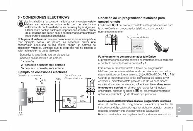
La instalación y la conexión eléctrica del cronotermostatodeben ser realizadas únicamente por un electricistacalificado, de conformidad con las normas y leyes vigentes.El fabricante declina cualquier responsabilidad sobre el usode productos que deben seguir normas medioambientales yrequieren instalaciones especiales.
Nota para el instalador: en caso de montaje sobre una superficie(por ejemplo, sobre una pared), es necesario prever unacanalización adecuada de los cables, según las normas deinstalación vigentes. Verifique que la carga del relé no exceda elvalor indicado en los datos técnicos.
Ejemplo de conexiones eléctricas
5 - CONEXIONES ELÉCTRICAS
Desactive la tensión de red del dispositivoConecte el dispositivo a los bornes:1 - común2 - contacto normalmente cerrado3 - contacto normalmente abierto
Conexión de un programador telefónico paracontrol remotoLos bornes y del cronotermostato están predispuestos para8 9la conexión de un programador telefónico con contactonormalmente abierto.
Desactivación del forzamiento desde el programador telefónicoAbra el contacto del programador telefónico (consulte lasinstrucciones del programador) que restablece el cronotermostato almodo de funcionamiento en el momento de la activación.Nota: los mandos de activación y desactivación vuelven a operar al minuto.
Conexión a una caldera Conexión a unaválvula motorizada
Funcionamiento con programador telefónicoEl programador telefónico controla el cronotermostato cerrandoel contacto conectado a los bornes y .8 9
Para activar el cronotermostato a través del programadortelefónico, es necesario establecer el conmutador en uno de lossiguientes tipos de funcionamiento: AUTOMÁTICO o oCuando el programador se activa (contacto a los bornes 8 y 9cerrado), el cronotermostato pasa de una de las condicionesestablecidos con el conmutador, a funcionamiento siempre entemperatura confort: en el visor además de los 48 índicesencendidos, aparece el símbolo del programador telefónicoactivado y el símbolo de Confort que parpadea.
�t
ES
49
23 1
CNA
NC
23 1
CN
NCL
230V~ NA
M
CALDERA
N L230V~
6 7 8 9 ej.Programador telefónico
Contacto
CIERRA
ABRE
CARGA
t
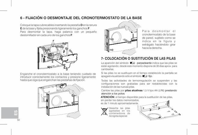
6 - FIJACIÓN O DESMONTAJE DEL CRONOTERMOSTATO DE LA BASE
Coloque la tapa cubrecables insertando la pestaña en la ranuraDE Fde la base y fíjela presionando ligeramente los ganchos .Para desmontar la tapa, haga palanca con un pequeñodestornillador en cada uno de los ganchos .F
Enganche el cronotermostato a la base teniendo cuidado deintroducir correctamente los contactos y presione ligeramentehasta que oiga que enganchan las pestañas de fijación.
P a r a d e s m o n t a r e lcronotermostato de la basede pared, sujételo como seindica en la f igura yextráigalo haciéndolo girarhacia la derecha.
7- COLOCACIÓN O SUSTITUCIÓN DE LAS PILAS
Deseche las pilasagotadas en loscontenedores derecogida especial.
E
D
F
ES
Cambie las pilas por 1,5 V tipo AA (LR6)pilas alcalinas prestandoatención a los polos.
La aparición del símbolo indica que las pilas separpadeanteestán agotando; desde este momento dispone de 30 días aprox. paracambiarlas.Si las pilas no se sustituyen en el tiempo establecido la pantalla seapagará visualizando sólo el símbolo fijo.
Todas las actividades de termorregulación se suspenden y lasconfiguraciones son grabadas para ser restablecidas con lainstalación de las nuevas pilas.
50
ATENCIÓN: el tiempo disponible para la sustitución de las pilas,sin perder los datos memorizados,es de 1 minuto aproximadamente.
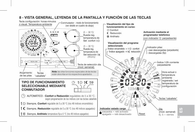
ES
51
R
4
21
2
9
2
6
3
18
1
15
Day
copy
R
tt t
/
t
t
t
4
21
2
9
2
6
3
18
1
15
1234567
Tecla configuración: horas-minutoso visual. Temperatura ambiente
Conmutador - modo de funcionamiento(ver detalle en cuadro de abajo)
8 - VISTA GENERAL, LEYENDA DE LA PANTALLA Y FUNCIÓN DE LAS TECLAS
t
Rueda reg.temperatura deSet reducción t
(con indicador parpadeante)
Indicador pilas:- casi descargadas (parpadeante)
(fijo)- descargadas
Reset
t
+
+
Nota: las otras funciones especiales de las teclasestán descritas en los respectivos apartados.
ttt
Rueda reg.temperatura deSet confort
(Ahorro)
Teclas“caballete”
Alojamientode las pilas
Tecla de selección día(mod. semanal)
TIPO DE FUNCIONAMIENTOSELECCIONABLE MEDIANTECONMUTADOR
AUTOMÁTICO - regulables de 5 a 30 °C;Confort o Reducciónsegún programación de los índices con las teclas caballete
Siempre, Reducción regulable de 5 a 30 °C (los 48 índices apagados)
Siempre, Antihielo temperatura fija a 5 °C (los 48 índices apagados)
Siempre, Confort regulable de 5 a 30 °C (los 48 índices encendidos)t
tt
Visualización del tipo defuncionamiento en curso:
ComfortReducciónAntihielo
Visualización del programaseleccionadoÍndice encendido = conforttÍndice apagado = reducciónt
Activación mediante elprogramador telefónico
Índice 1/2h corrienteparpadeante
Indicador estado cargaparpadea = relé activadoapagado = relé desactivado
Día(mod. semanal)Ej. 5 = viernes
Teclas "caballete”
(5 ÷ 30 °C)
(5 ÷ 30 °C)
Hora actual otemperaturaambienteregistrada / settemperatura deconfiguración
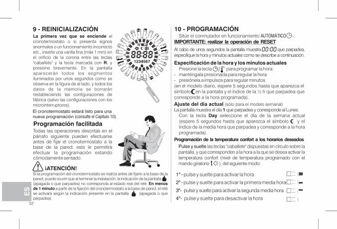
Programación facilitada
ES
52
La primera vez que se enciende elcronotermostato o si presenta signosanormales o un funcionamiento incorrectoetc., inserte una varilla fina (máx 1 mm) enel orificio de la corona entre las teclas"caballete" y la tecla marcada con , yRpresione brevemente. En la pantallaaparecerán todos los segmentosiluminados por unos segundos como seobserva en la figura de al lado, y todos losdatos de la memoria se borraránrestableciendo las configuraciones defábrica (salvo las configuraciones con losmicrointerruptores).
Todas las operaciones descritas en elpárrafo siguiente pueden efectuarseantes de fijar el cronotermostato a labase de la pared; esto le permitiráefectuar la programación estandocómodamente sentado.
Si la programación del cronotermostato se realiza antes de fijarlo a la base de lapared, puede ocurrir que al terminar la instalación, la indicación de la pantalla(apagada o que parpadea) no corresponda al estado real del relé. En menosde 1 minuto a partir de la fijación del cronotermostato a la base de pared, el relése activará según la indicación presente en la pantalla (apagada o queparpadea).
¡ATENCIÓN!
R
4
21
2
9
2
6
3
18
1
15
123 5674
9 - REINICIALIZACIÓN
El cronotermostato estará listo para unanueva programación (consulte el Capítulo 10).
10 - PROGRAMACIÓNSitúe el conmutador en funcionamiento AUTOMÁTICO .
IMPORTANTE: realizar l operación de RESETaAl cabo de unos segundos la pantalla muestra que parpadea,especifique la hora y minutos actuales como se describe a continuación.
Especificación de la hora y los minutos actualesPresione la tecla para programar la hora:
- manténgala presionada para regular la hora- presiónela a impulsos para regular minutos(en el modelo diario, espere 5 segundos hasta que aparezca elsímbolo en la pantalla y el índice de la ½ h que parpadea quecorresponde a la hora programada).Ajuste del día actual (sólo para el modelo semanal)La pantalla muestra el día que parpadea y corresponde al Lunes.1
Con la tecla seleccione el día de la semana actualDay(espere 5 segundos hasta que aparezca el símbolo y elíndice de la media hora que parpadea y corresponde a la horaprogramada).
Programación de la temperatura confort a los horarios deseadosPulse y suelte las teclas "caballete" dispuestas en círculo sobre lapantalla, y que corresponden a la hora a la que se desea activar latemperatura confort (nivel de temperatura programado con elmando giratorio ), del siguiente modo:
/
°1 - pulse y suelte para activar la hora
°2 - pulse y suelte para activar la primera media hora
°3 - pulse y suelte para activar la segunda media hora
°4 - pulse y suelte para desactivar la hora
t
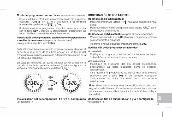
Copia del programa en varios días (sólo para el modelo semanal)
Después de haber efectuado la programación del día, es posiblecopiar la en el día sucesivo(Copy) presionandoal mismo tiempo las teclas y .Day
Si desea establecer programas diferentes, seleccione el díacon la tecla y efectúe la programación presionando lasDayteclas caballete como se describe anteriormente.
/
Nota: al terminar las operaciones de programación o visualización, alcabo de 5 segundos de la última acción en las teclas delcronotermostato se pone en marcha automáticamente (índice de la½ h actual que parpadea).
En cualquier momento, se puede cambiar de ver la hora en lapantalla a ver la temperatura ambiente (grados centígrados) yviceversa, presionando brevemente la tecla ./
Visualización de los programas establecidos correspondientesa los días de la semana (sólo para modelo semanal).Pulse y suelte a impulsos la tecla .Day
ES
53
Visualización Set de temperatura t y/o configuradover apartado 11
4
21
2
9
2
6
3
18
1
15
3
1
1
/
4
21
2
9
2
6
3
18
1
15
3
21
Nota: al terminar las operaciones de modificación, al cabo de 5segundos de la última acción en las teclas, el cronotermostato sepone en marcha automáticamente (índice de la Vz h actual queparpadea).
MODIFICACIÓN DE LOS AJUSTESModificación de la hora actual
Mantener presionada la tecla hasta que parpadee la horaactual.Modifique la hora y/o minutos presionando la tecla comose ha descrito anteriormente.
/
/
Modificación del día actual (sólo para el modelo semanal)Mantener presionada la tecla hasta que parpadee el númeroDaycorrespondiente al día actual.
Programe el nuevo día actual, presionando la tecla .Day
Modificación de los programas establecidos
Modelo diarioModifique el programa presionando directamente las teclas"caballete" como se ha descrito anteriormente.
Modelo semanalModifique el programa del día actual presionandodirectamente las teclas "caballete" como se describeanteriormente.Para modificar el programa de los demás días de la semanaseleccione con la tecla el día deseado y presioneDaydirectamente las teclas "caballete" como se describeanteriormente.
Modificación Set de temperatura t y/o configuradover apartado 11
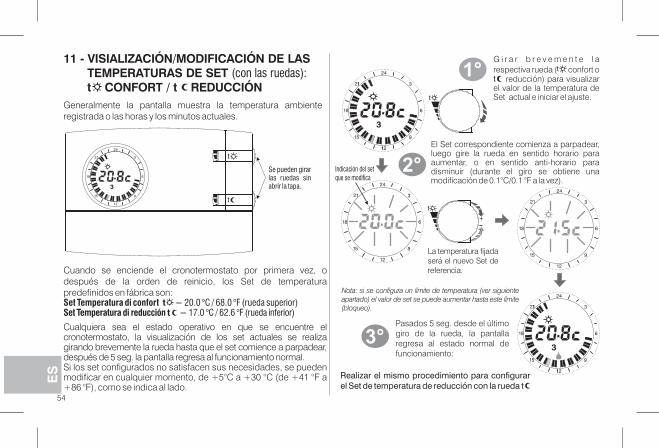
ES
54
11 - VISIALIZACIÓN/MODIFICACIÓN DE LASTEMPERATURAS DE SET (con las ruedas):t CONFORT / t REDUCCIÓN
Cuando se enciende el cronotermostato por primera vez, odespués de la orden de reinicio, los Set de temperaturapredefinidos en fábrica son:Set Temperatura di confort t = 20.0 °C / 68.0 °F (rueda superior)Set Temperatura di reducción t = 17.0 °C / 62.6 °F (rueda inferior)
Cualquiera sea el estado operativo en que se encuentre elcronotermostato, la visualización de los set actuales se realizagirando brevemente la rueda hasta que el set comience a parpadear,después de 5 seg. la pantalla regresa al funcionamiento normal.Si los set configurados no satisfacen sus necesidades, se puedenmodificar en cualquier momento, de +5°C a +30 °C (de +41 °F a+86 °F), como se indica al lado.
Generalmente la pantalla muestra la temperatura ambienteregistrada o las horas y los minutos actuales.
t
4
21
2
9
2
6
3
18
1
15
3
4
21
2
9
2
6
3
18
1
15
3
1
1
G i r a r b r e v e m e n t e l arespectiva rueda ( confort o
reducción) para visualizarel valor de la temperatura deSet actual e iniciar el ajuste.
t
+
4
21
2
9
2
6
3
18
1
15
4
21
2
9
2
6
3
18
1
15
4
21
2
9
2
6
3
18
1
15
3
1
1
1°
2°
El Set correspondiente comienza a parpadear,luego gire la rueda en sentido horario paraaumentar, o en sentido anti-horario paradisminuir (durante el giro se obtiene unamodificación de 0.1°C/0.1 °F a la vez).
3°Pasados 5 seg. desde el últimogiro de la rueda, la pantallaregresa al estado normal defuncionamiento:
Nota: si se configura un límite de temperatura (ver siguienteapartado) el valor de set se puede aumentar hasta este límite(bloqueo).
Realizar el mismo procedimiento para configurarel Set de temperatura de reducción con la rueda t
Indicación del setque se modifica
Se pueden girarlas ruedas sinabrir la tapa.
La temperatura fijadaserá el nuevo Set dereferencia.
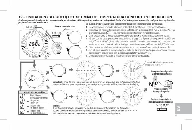
12 - LIMITACIÓN (BLOQUEO) DEL SET MÁX DE TEMPERATURA CONFORT Y/O REDUCCIÓN
4
21
2
9
2
6
3
18
1
15
4
21
2
9
2
6
3
18
1
15
+
4
21
2
9
2
6
3
18
1
15
+
t
4
21
2
9
2
6
3
18
1
15
t
4
21
2
9
2
6
3
18
1
15
y/o
Visualizaciones posiblesNingún bloqueo(configuración de fábrica)Bloqueo enambos setBloqueo sóloen el set confortBloqueo sóloen el set reducción
42
/
Presionar al mismotiempo por 4 segundos
Desplazar el conmutador almodo de funcionamiento deseado
tt t
Para grabar la configuracióny salir de la programación
para cancelar bloqueos configuradas con anterioridad, mover los set a:
El mando de reinicio cancela los posibles bloqueos configurados
En algunos casos de instalación del cronotermostato, por ejemplo en edificios públicos, hoteles, etc., es importante limitar el set de temperatura para evitar configuraciones equivocadaspor parte de personal no autorizado.
Se pueden limitar los valores de Set (confort / reducción) de temperatura como sigue:1 - Desplazar el conmutador al modo antihielo t (set fijo en+5°C no modificable)2 - Presionar al mismo tiempo por 4 seg. la tecla con la corona de la h23 y la tecla , la
pantalla visualiza : (ej. configuración de fábrica= ningún bloqueo).3 - Girar brevemente la rueda del set correspondiente (t o t ) para visualizar el set actual.4 - El set comienza a parpadear después de 3 seg. Configurar el bloqueo (limitación de
+5,1°C a +29,9°C girando la rueda en sentido horario para aumentar, o en sentidoantihorario para disminuir (durante el giro se obtiene una modificación de 0,1°C a la vez).
5 - Si se desea, repetir las operaciones indicadas en los puntos 3 y 4 con la otra manopla.6 - En 20 seg. grabar la configuración y salir de la programación presionando al mismo
tiempo por 4 seg. la tecla con la corona de la h23 y la tecla .7 - Desplazar el conmutador al modo de funcionamiento deseado.
/
Notas:
Importante: si en 20 seg. no se gira una de las ruedas, el dispositivo sale automáticamente de laprogramación de bloqueo sin grabar ninguna configuración y se coloca al funcionamiento antihielo (t )
/
En la programación de base no se fija ninguna configuración de bloqueo.
Day
copy
R
tt t
/
t
t
t
4
21
2
9
2
6
3
18
1
15
12 45673 t
Mover el conmutador a t
Presionar al mismo
tiempo por 4 s.
El símbolo indica temperatura máx.
limitable, en °C o en °F
55
ES
Tecla h23

EI cronotermostato funciona en modo diferencial ON-OFF (Dip3 en posición OFF) con el valor del diferencial prefijado enfábrica a (0,54 °F).0,3 °CEl valor del diferencial se puede modificar desplazando losmicrointerruptores (Dip-switch), como se indica en la tabla.
13 - DIFERENCIAL DE TEMPERATURA
El valor del diferencial debe establecerse en base a la inerciatérmica de la instalación; se aconseja un valor bajo parainstalaciones con radiadores (por ejemplo en hierro fundido) y unvalor alto para instalaciones con fan-coils.
Como alternativa al diferencial, la temperatura se puede regularen modo proporcional (Dip 3 en la posición ON); este sistemapermite ahorrar energía y también previene el desgaste delquemador, limitando sus encendidos. La duración de cadaencendido depende del ciclo programado y de la diferencia entrela temperatura programada y medida (ver ejemplo).
14 - FUNCIONAMIENTO PROPORCIONAL
Ejemplo de programación t = 20 °C - Ciclo = 10 mint = 20,5 °C Modo siempre apagadot = 20,4 °C Modo 1 min ON - 9 min OFFt = 20,3 °C Modo 2 min ON - 8 min OFFt = 20,2 °C Modo 3 min ON - 7 min OFFt = 20,1 °C Modo 4 min ON - 6 min OFFt = 20,0 °C Modo 5 min ON - 5 min OFFt = 19,9 °C Modo 6 min ON - 4 min OFFt = 19,8 °C Modo 7 min ON - 3 min OFFt = 19,7 °C Modo 8 min ON - 2 min OFFt = 19,6 °C Modo 9 min ON - 1 min OFFt = 19,5 °C Modo siempre encendido
La posición de los microinterruptores (Dip-switch), situados en la parteposterior del cronotermostato, determina la duración del ciclo como seindica en la tabla. Se aconseja un ciclo largo para instalaciones coninercia térmica alta (radiadores de hierro fundido, sistemas de suelo) y unciclo breve para instalaciones con inercia térmica baja (fan- coil).
20,8
20,6
20,4
20,2
20,0
19,8
19,6
19,4
19,2
°C
0 102 4 6 8 Minutos
La configuración de los microinterruptores (Dip-switch) situados en la parte posterior delcronotermostato, debe llevarla a cabo personalcualificado.
T empoi
°C
OffOn OnTem
per
atur
a m
edid
a
Diferencial regulable0,3 °C - 0,5 °C - 0,7 °C - 0,9 °C(0,54 °F - 0,9 °F - 1,26 °F - 1.62 °F)
ServicioOFF
ServicioON
Dip 1 Dip 2 Dip 3 Duración ciclo
ON ON ON 20 min
ON OFF ON 15 min
OFF ON ON 10 min
OFF OFF ON 7 min
ON
32 OFF1
ON
4
56
ES
Dip 1 Dip 2 Dip 3 Diferencial
ON ON OFF 0,9 °C (1,62 °F)
ON OFF OFF 0,7 °C (1,26 °F)
OFF ON OFF 0,5 °C (0,9 °F)
OFF OFF OFF 0,3 °C (0,54 °F)
ON
32 OFF1
ON ON
32 OFF1
ON
4
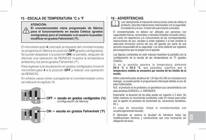
15 - ESCALA DE TEMPERATURA °C o °F 16 - ADVERTENCIAS
57
ES
El microinterruptor colocado al respaldo del cronotermostato4se programa en fábrica en posición (grados centígrados).OFFSe puede desplazar a la posición la pantalla, después deON:efectuar una operación de REINICIO muestra la temperaturaambiente y los set en grados Fahrenheit (°F).Para regresar a la visualización en grados centígrados mover elmicrointerruptor a la posición y realizar una operación4 OFFde REINICIO.En ambos casos volver a programar el cronotermostato comose indica en el capítulo 10.
ATENCIÓN:El cronotermostato viene programado de fábricapara el funcionamiento en escala Celsius (gradoscentígrados) pero el instalador o el usuario la puedenmodificar en grados Fahrenheit (°F).
432 OFF = escala en grados centígrados (°c)1
ON
432
ON = (°F)escala en grados Fahrenheit
1
ON
(configuración de fábrica)
Si en la panta l la aparece la temperatura ambiente, que parpadea, signif ica que la00.0 °C o 50.0 °C
temperatura medida se encuentra por encima de los límites de laescala.
Utilice solamente pilas alcalinas de 1,5V tipo AA LR6 (no incluidas en laentrega), se puede perder la programación efectuada debido al uso depilas inadecuadas.N.B.: el producto se ha probado y se garantizan sus características conpilas alcalinas DURACELL o ENERGIZER.Importante: la duración de las pilas puede ser superior a 2 años. Detodas maneras se recomienda sustituirlas cada 24 meses para evitarque se agoten en períodos de inactividad (ej. vacaciones navideñas,etc.).En caso de necesidad, limpie el cronotermostato conun paño ligeramente húmedo.El fabricante se reserva la facultad de introducir todas lasmodificaciones técnicas y constructivas que crea necesarias sinobligación de aviso.
Leer atentamente el manual de instrucciones antes de utilizar elproducto, describe indicaciones relacionadas con la seguridad,la instalación y el uso. Consérvelo para futuras consultas.
Las figuras contenidas en este manual muestran la pantalla con laconfiguración de la escala de las temperaturas en ºC (gradosCelsius).
El cronotermostato no deberá ser utilizado por personas concapacidades físicas, sensoriales y mentales limitadas (incluido niños),así como sin experiencia y/o conocimiento de las correspondientesinstrucciones de uso, excepto si están vigilados o si han recibido laadecuada formación acerca del uso del aparato por parte de unapersona responsable de su seguridad. Los niños deberán ser vigiladospara asegurarse que no juegan con el aparato.
58
ITSMALTIMENTO DI VECCHI APPARECCHI ELETTRICI ED ELETTRONICIQuesto simbolo sul prodotto o sul suo imballo indica che questo prodotto non può essere trattato come rifiuto domestico.Al contrario, dovrà essere portato ad un punto di raccolta determinato per il riciclaggio degli apparecchi elettrici ed elettronici, come ad esempio:- punti vendita, nel caso si acquisti un prodotto nuovo simile a quello da smaltire;- punti di raccolta locali (centri di raccolta rifiuti, centri locali di riciclaggio, ecc...).AssicurandoVi che il prodotto sia smaltito correttamente, aiuterete a prevenire potenziali conseguenze negative per l'ambiente e la salute, chepotrebbero essere causate da un inadeguato smaltimento di questo prodotto.Il riciclaggio dei materiali aiuterà a conservare le risorse naturali.Per informazioni più dettagliate riguardo il riciclaggio di questo prodotto, contattate per cortesia il Vs. ufficio locale, il Vs. servizio di smaltimento rifiutidomestici o il negozio dove avete acquistato questo prodotto.
DISPOSAL OF OLD ELECTRICAL AND ELECTRONIC EQUIPMENTWhen this symbol is found on the product or on its packaging, it indicates that this product cannot be disposed of as household waste.It must be delivered to a specific collection point where electrical and electronic equipment is recycled, such as:- retail outlets, if a new product is bought, similar to that being disposed of- local collection points (waste collection centres, local recycling centres, etc).By ensuring that the product is disposed of correctly, you will help prevent potential negative consequences for the environment and health, whichcan be caused by this product being disposed of inappropriately.Recycling the materials will help conserve natural resources.For more detailed information about recycling this product, please contact your Local Council, household waste disposal service or the shop whereyou purchased the product.
FRTRAITEMENT DES APPAREILS ÉLECTRIQUES ET ÉLECTRONIQUES EN FIN DE VIECe symbole, apposé sur le produit ou sur son emballage, indique que ce produit ne doit pas être traité avec les déchets ménagers. Il doit être remis àun point de collecte approprié pour le recyclage des équipements électriques et électroniques:- dans les points de distribution en cas d'achat d'un équipement équivalent.- dans le points de collecte mis à votre disposition localement (déchetterie, collecte sélective, etc...).En s'assurant que ce produit est bien mis au rebut de manière appropriée, vous aiderez à prévenir les conséquences négatives potentielles pourl'environnement et la santé humaine.Le recyclage des matériaux aidera à conserver les ressources naturelles.Pour toute information supplémentaire au sujet du recyclage de ce produit, vous pouvez contacter votre municipalité, votre déchetterie ou lemagasin où vous avez acheté le produit.
EN
59
ENTSORGUNG VON ELEKTRO- UND ELEKTRONIK-ALTGERÄTENDieses Symbol auf dem Produkt oder auf seiner Verpackung weist darauf hin, dass das Produkt am Ende seiner Lebensdauer getrennt von denanderen Abfällen zu entsorgen ist.Das Gerät muss am Ende seiner Lebensdauer einer geeigneten Sammelstelle für elektrische und elektronische Abfälle zugeführt werden, wie zumBeispiel:- Verkaufsstellen, beim Kauf eines neuen Geräts, das dem Altgerät entspricht.- örtliche Sammelstellen (Abfallsammelzentren, örtliche Recyclingstellen, etc...).Eine entsprechende Behandlung und Entsorgung im Sinne des Umweltschutzes trägt zur Vermeidung etwaiger negativer Auswirkungen auf dieUmwelt und die Gesundheit bei, die durch eine unangemessene Entsorgung des Produktes verursacht werden können.Die Wiederverwertung der Materialien trägt zur Erhaltung der natürlichen Ressourcen bei.Für detailliertere Informationen in Bezug auf die Wiederverwertung dieses Produkts wenden Sie sich bitte an die entsprechende lokale Behörde, IhreEntsorgungsstelle für Hausmüll oder das Geschäft, in dem Sie dieses Produkt erworben haben.
ELIMINACIÓN DE APARATOS ELÉCTRICOS Y ELECTRÓNICOS USADOSEste símbolo sobre el producto y el embalaje, indica que no puede ser tratado como desecho doméstico. Debe llevarse a un punto de reciclajeespecial para aparatos eléctricos y electrónicos, como por ejemplo:- puntos de venta, en el caso en que se adquiera un producto nuevo similar- puntos de recolección locales (centros de recolección de desechos y de reciclaje, etc.).Si el producto se elimina correctamente, ayudamos a prevenir las consecuencias negativas que se generan para el ambiente y para la salud.El reciclaje de los materiales ayudará a conservar los recursos naturales. Para más información sobre el reciclaje de este producto, ponerse encontacto con la oficina local, con el servicio de eliminación de desechos o con el negocio donde el aparato fue adquirido.Atención: en algunos países de la Unión Europea no se ha transpuesto la directiva 2002/96/CE, por lo tanto no es obligación realizar la recogidadiferenciada al final de la vida útil.
DE
ES