CORAL-PLUS - secpoint.it · CIAS Elettronica S.r.l. Ed. 1.4 Manuale di Installazione Pagina 3 di 57...
64
CORAL-PLUS Barriera a Microonde per protezioni esterne Manuale di Installazione External Microwave Protection Barrier Installation Handbook Edizione / Edition 1.4
Transcript of CORAL-PLUS - secpoint.it · CIAS Elettronica S.r.l. Ed. 1.4 Manuale di Installazione Pagina 3 di 57...

CORAL-PLUS
Barriera a Microonde
per protezioni esterne
Manuale di Installazione
External Microwave Protection
Barrier
Installation Handbook
Edizione / Edition 1.4

CIAS Elettronica S.r.l. Ed. 1.4
Manuale di Installazione Pagina 1 di 57 CORAL-PLUS
INDICE
1. DESCRIZIONE ....................................................................................................................................................................... 3
1.1 DESCRIZIONE ...................................................................................................................................................................... 3
2 INSTALLAZIONE ................................................................................................................................................................... 4
2.1 MONTAGGIO DELLE UNITÀ ................................................................................................................................................... 4 2.2 NUMERO DI TRATTE ............................................................................................................................................................ 4 2.3 CONDIZIONI DEL TERRENO .................................................................................................................................................. 5 2.4 PRESENZA DI OSTACOLI ...................................................................................................................................................... 5 2.5 AMPIEZZA DEI FASCI SENSIBILI ........................................................................................................................................... 6 2.6 LUNGHEZZA DELLE ZONE MORTE IN PROSSIMITÀ DEGLI APPARATI ..................................................................................... 7
3. COLLEGAMENTI ................................................................................................................................................................. 9
3.1 MORSETTIERE, CONNETTORI E FUNZIONALITÀ DEI CIRCUITI ............................................................................................... 9 3.1.1 Circuito Trasmettitore ............................................................................................................................................... 9 3.1.2 Circuito Ricevitore ........................................................................................................................................... 11 3.1.3 Circuito Alimentatore e Carica Batteria .......................................................................................................... 14
3.2 COLLEGAMENTO ALL’ALIMENTAZIONE PRINCIPALE ......................................................................................................... 16 3.2.1 Collegamento all’Alimentazione di Rete ................................................................................................................. 16 3.2.2 Collegamento all’Alimentazione di Riserva (Batteria) ........................................................................................... 16
3.3 COLLEGAMENTO ALLA CENTRALE .................................................................................................................................... 17 3.3.1 Contatti di allarme: Allarme, Manomissione, Guasto ............................................................................................ 17 3.3.2 Connessioni per Sincronismo .................................................................................................................................. 18 3.3.3 Connessioni per Stand-by ....................................................................................................................................... 18 3.3.4 Connessioni per Test ............................................................................................................................................... 18
3.4 LINEA SERIALE RS-485 .................................................................................................................................................... 19 3.4.1 Interfaccia Linea Seriale RS-485 / 232 ................................................................................................................... 19 3.4.2 Connessioni per Linea Seriale RS-485 .................................................................................................................... 19 3.4.3 Configurazione Rete e Rigeneratori di segnale ...................................................................................................... 19
3.5 COLLEGAMENTO DA ACCESSO REMOTO ........................................................................................................................... 20
4. ALLINEAMENTO E VERIFICA........................................................................................................................................ 21
4.1 ALLINEAMENTO E VERIFICA...................................................................................................................................... 21
4.1.1 Operazioni sul Trasmettitore................................................................................................................................... 21 4.1.2 Operazioni sul Ricevitore ........................................................................................................................................ 22
4.2 ALLINEAMENTO E VERIFICA CON SOFTWARE ..................................................................................................................... 26
5. MANUTENZIONE E ASSISTENZA .................................................................................................................................. 27
5.1 RICERCA GUASTI .............................................................................................................................................................. 27 5.2 KIT ASSISTENZA ............................................................................................................................................................... 27
6. CARATTERISTICHE .......................................................................................................................................................... 28
6.1 CARATTERISTICHE TECNICHE ........................................................................................................................................... 28 CARATTERISTICHE FUNZIONALI .............................................................................................................................................. 29

CIAS Elettronica S.r.l. Ed. 1.4
Manuale di Installazione Pagina 2 di 57 CORAL-PLUS
INDEX
1. DESCRIPTION ..................................................................................................................................................................... 30
1.1 DESCRIPTION .................................................................................................................................................................... 30
2. INSTALLATION .................................................................................................................................................................. 31
2.1 BARRIER ASSEMBLY.......................................................................................................................................................... 31 2.2 NUMBER OF SECTIONS ...................................................................................................................................................... 32 2.3 GROUND CONDITIONS ....................................................................................................................................................... 33 2.4 PRESENCE OF OBSTACLES ................................................................................................................................................. 33 2.5 AMPLITUDE OF THE SENSITIVE BEAM ............................................................................................................................... 34 2.6 LENGTH OF DEAD ZONES NEAR THE EQUIPMENT............................................................................................................... 35
3. CONNECTIONS ................................................................................................................................................................... 37
3.1 TERMINAL BLOCKS, CONNECTORS AND CIRCUITS FUNCTIONS ......................................................................................... 37 3.1.1 Transmitter Circuit .................................................................................................................................................. 37 3.1.2 Receiver Circuit ...................................................................................................................................................... 39 3.3.3 Power supply and Battery charger circuit ............................................................................................................... 42
3.2 EQUIPMENT CONNECTION TO THE POWER SUPPLY ............................................................................................................ 44 3.2.1 Connection to the Power Supply ............................................................................................................................. 44 3.2.2 Connection of stand-by Battery ............................................................................................................................... 44
3.3 CONNECTION TO THE CONTROL PANEL ............................................................................................................................. 45 3.3.1 Alarm contacts: Alarm, Tamper, Fault ................................................................................................................... 45 3.3.2 Synchronism connection.......................................................................................................................................... 46 3.3.3 Stand-by connection ................................................................................................................................................ 46 3.3.4 Test connection ....................................................................................................................................................... 46
3.4 SERIAL LINE RS-485 ......................................................................................................................................................... 46 3.4.1 RS - 485 / 232 Network Connection Interface ......................................................................................................... 46 3.4.2 RS -485 Serial Line connections ............................................................................................................................. 47 3.4.3 Network Configuration and Signal Repeaters ......................................................................................................... 47
3.5 REMOTE CONNECTION ...................................................................................................................................................... 48
4. ADJUSTMENT AND TESTING ......................................................................................................................................... 49
4.1 ADJUSTMENT AND TESTING .............................................................................................................................................. 49 4.1.1 Transmitter Setting up ............................................................................................................................................. 49 4.1.2 Receiver setting up .................................................................................................................................................. 50
4.2 ALIGNMENT AND MONITORING WITH SOFTWARE ............................................................................................................... 54
5. MAINTENANCE AND ASSISTANCE ............................................................................................................................... 55
5.1 TROUBLESHOOTING .......................................................................................................................................................... 55 5.2 MAINTENANCE KITS .......................................................................................................................................................... 55
6. CHARACTERISTICS .......................................................................................................................................................... 56
6.1 TECHNICAL CHARACTERISTICS .......................................................................................................................................... 56 6.2 FUNCTIONAL CHARACTERISTICS ....................................................................................................................................... 57
SCHEDA DI COLLAUDO – TEST SHEET .............................................................................................................................. 0
SCHEDA DI COLLAUDO – TEST SHEET .............................................................................................................................. 1

CIAS Elettronica S.r.l. Ed. 1.4
Manuale di Installazione Pagina 3 di 57 CORAL-PLUS
1. DESCRIZIONE
1.1 Descrizione
CORAL-PLUS è una barriera a microonde per protezioni volumetriche perimetrali esterne. CORAL-PLUS è in grado di rilevare la presenza di un corpo che si muove all‟interno di un campo sensibile instauratosi tra il Trasmettitore (TX) e il Ricevitore (RX). Il segnale ricevuto viene analizzato in modo assai sofisticato, permettendo di raggiungere eccellenti prestazioni nella rilevazione, un numero molto limitato di Falsi Allarmi ed una enorme semplicità di installazione e di manutenzione.
CORAL-PLUS è disponibile con le seguenti portate e colori:
- CORALPLUS100G Portata 100 metri Colore Verde - CORALPLUS220G Portata 220 metri Colore Verde - CORALPLUS100A Portata 100 metri Colore Alluminio - CORALPLUS220A Portata 220 metri Colore Alluminio

CIAS Elettronica S.r.l. Ed. 1.4
Manuale di Installazione Pagina 4 di 57 CORAL-PLUS
2 INSTALLAZIONE
2.1 Montaggio delle unità
Fissare le unità ricevente (Rx) e trasmittente (Tx) al palo “CORAL-SP” (opzionale) o ad un palo che abbia le caratteristiche riportate nella figura seguente:
300m m
630m m
250m m
170m m
50m m
Ø 60 m mØ 60 m m
TU BAZIONE PER INGRESSOCAVI DA IM PIANTO
FO RO PER USCITACAVI DA IM PIANTO
BASAM ENTO INTERR ATOIN CEM ENTO
TR ONCHETTI RADIALIANTIRO TAZIO NE PALO
AL
TE
ZZ
A D
AL
SU
OL
O C
ON
SIG
LIA
TA
80
0 m
m (
da
71
0 a
89
0m
m)
300m m
Per il montaggio della ganascia alla testa Coral:
- Inserire il passacavo nell‟apposita sede della ganascia - Inserire la guarnizione nel passacavo - Inserire il tutto nell‟apposita sede del fondo Coral - Inserire la rondella in acciaio ed avvitare la ghiera.
2.2 Numero di Tratte
Dovendo progettare la protezione con barriere volumetriche di un perimetro chiuso, oltre alle normali considerazioni di suddivisione del perimetro in un certo numero di tratte che tengano conto delle necessità gestionali dell'intero impianto, occorre ricordare che è sempre preferibile installare un numero di tratte pari. Questo perché in un perimetro chiuso formato da un numero di tratte dispari si forma un incrocio dove sono presenti un trasmettitore ed un ricevitore i quali potrebbero interferire tra di loro. Nella figura 1a l‟angolo tra le due teste Tx ed Rx è corretto, ma le due teste sono molto vicine ed il trasmettitore corrispondente al ricevitore posto in questo angolo è molto lontano. Nel caso di figura 1c le due teste Tx ed Rx vicine formano un angolo maggiore di 90° e ciò non è corretto, queste due teste inoltre sono molto vicine l‟una all‟altra.

CIAS Elettronica S.r.l. Ed. 1.4
Manuale di Installazione Pagina 5 di 57 CORAL-PLUS
C O R R E TTO C O R R E TTO
E R R ATO E R R ATO
C O R R E TTO C O R R E TTO
Figura 1
2.3 Condizioni del Terreno
E' sconsigliabile installare l'apparato lungo tratti dove vi siano: erba alta (maggiore di 10 cm), stagni, corsi d'acqua in senso longitudinale ed in generale tutti quei tipi di terreni la cui conformazione sia rapidamente variabile. In caso di installazione su asfalto, cemento armato, porfido ed in generale tutte quelle pavimentazioni riflettenti, per installazioni superiori a 50m, sostituire la parabola “butterfly” con parabola 20cm special.
2.4 Presenza di Ostacoli
Le recinzioni, se metalliche e pertanto molto riflettenti, possono causare diversi problemi di riflessione della microonda, è quindi necessario adottare alcuni accorgimenti:
- la recinzione deve essere accuratamente fissata, in modo che il vento non ne provochi il movimento;
- dove possibile la tratta non deve essere installata in parallelo alla recinzione, è necessario creare un angolo rispetto ad essa;
- nel caso in cui il fascio sensibile debba essere delimitato lateralmente da due reti metalliche, è consigliabile che il corridoio tra esse non sia inferiore ai 5 m. in quanto il loro movimento potrebbe creare dei disturbi, inoltre evitare di utilizzare la barriera per più della metà della sua portata massima.
- recinzioni metalliche poste dietro gli apparati possono provocare talvolta distorsioni del fascio sensibile e quindi dare luogo a falsi allarmi.
Gli alberi, le siepi, i cespugli, la vegetazione in genere richiede una grande attenzione qualora ve ne sia in prossimità o entro i fasci di protezione. Questi ostacoli sono elementi variabili sia come dimensione che come posizione, possono infatti crescere ed essere mossi dal vento.
Fig.1a
Fig.1f
Fig.1e
Fig.1d
Fig.1c
Fig.1b

CIAS Elettronica S.r.l. Ed. 1.4
Manuale di Installazione Pagina 6 di 57 CORAL-PLUS
Figura 2
Pertanto è sconsigliabile tollerare la presenza di detti ostacoli entro le tratte di protezione. E‟ possibile tollerarne la presenza solo a patto che la loro crescita venga limitata mediante una metodica manutenzione e che il loro movimento venga inibito mediante barriere di contenimento. All‟interno del fascio di protezione, è altresì tollerabile la presenza di tubi, pali ed ostacoli vari (illuminazione, camini, ecc) purché non presentino dimensioni eccessive all‟interno
dei lobi di protezione. Questi infatti sono la causa di Zone d’Ombra non protette e di Zone di
Ipersensibilità, fonti di falsi allarmi.
2.5 Ampiezza dei Fasci Sensibili
L'ampiezza del Campo Sensibile è in funzione sia del tipo di antenna impiegata, sia della distanza tra Trasmettitore e Ricevitore, sia dalla regolazione di sensibilità impostata. Le figure seguenti ci forniscono la dimensione a metà tratta del Fascio Sensibile, in funzione della lunghezza della tratta, nel caso di sensibilità massima e minima per i diversi modelli di apparecchio impiegati. CORAL PLUS100 grazie all‟antenna “Butterfly” ha un fascio non simmetrico, l‟altezza è maggiore della larghezza.
1
2
3
4
5
6
7
8
9
10
10 20 30 40 50 60 70 80 90 100
Larghezza zona
sensibile
a m età tratta [m ]
Sensib ilità
M assim a (”F”)
Lunghezza
della tratta [m ]
Sensib ilità
m inim a (”0”)
Figura 3 Larghezza della zona sensibile a metà tratta per CORAL PLUS 100 sul piano
orizzontale (campo libero)
CIAS Elettronica S.r.l. Ed. 1.4
Manuale di Installazione Pagina 7 di 57 CORAL-PLUS
3
6
9
12
15
10 20 30 40 50 60 70 80 90 100
A ltezza zona
sensib ile
a m età tratta [m ]
Sensib ilità
M assim a (”F”)
Lunghezza
della tratta [m ]
Sensib ilità
m inim a (”0”)
Figura 3a Altezza della zona sensibile a metà tratta per CORAL PLUS 100 sul piano verticale
(campo libero)
2
4
6
8
10
12
14
16
18
20
20 40 60 80 100 120 140 160 180 200 220
Diam etro zona
sensib ile
a m età tratta [m ]
Sensib ilità
M assim a (”F”)
Lunghezza
della tratta [m ]
Sensib ilità
m inim a (”0”)
Figura 4 Diametro della zona sensibile a metà tratta per CORAL PLUS 220 (campo libero)
2.6 Lunghezza delle Zone Morte in prossimità degli apparati
La lunghezza delle Zone Morte in prossimità degli apparati è in funzione sia della distanza dell'apparato stesso dal suolo, sia della sensibilità impostata sul Ricevitore, sia del tipo di antenna impiegata (figure 5-6). L’Altezza consigliata per installazioni standard è di 80 cm
circa (85/90cm circa per CORAL-100), compatibilmente con le esigenze impiantistiche. La
misura è da considerarsi tra il suolo e il centro dell'antenna. Con una sensibilità media, la
distanza minima consigliata per effettuare l’Incrocio è di 5 m per le barriere CORAL-
PLUS220 e di 3,5 m per le barriere CORAL-PLUS100.

CIAS Elettronica S.r.l. Ed. 1.4
Manuale di Installazione Pagina 8 di 57 CORAL-PLUS
20
30
10
40
50
60
70
80
90
100
20
30
10
40
50
60
70
80
90
100
1 2 3 4 5 6 7 8 9 10
A ltezza dal suolo
al centro
antenna [cm ]
Sensib ilità
M assim a
Lunghezza
zona m orta [m ]
Sensib ilità
m in im a
Figura 5 Lunghezza della zona morta in prossimità degli apparati in funzione dell’altezza dal
centro dell’antenna al suolo per CORAL PLUS 100
20
30
10
40
50
60
70
80
90
100
20
30
10
40
50
60
70
80
90
100
1 2 3 4 5 6 7 8 9 10
A ltezza dal suolo
al centro
antenna [cm ]
Sensib ilità
M assim a
Lunghezza
zona m orta [m ]
Sensib ilità
m in im a
Figura 6 Lunghezza della zona morta in prossimità degli apparati in funzione dell’altezza dal
centro dell’antenna al suolo per CORAL- PLUS 220
5 M
80
-85
cm
Figura 7 - Sovrapposizione di due fasci sensibili in un incrocio-

CIAS Elettronica S.r.l. Ed. 1.4
Manuale di Installazione Pagina 9 di 57 CORAL-PLUS
3. COLLEGAMENTI
3.1 Morsettiere, connettori e Funzionalità dei Circuiti
3.1.1 Circuito Trasmettitore
JP 2 L ED
ON O FF
S YN C
Jp1
TE R M IN A ZIO N E
D I LIN E A R S 485
ON
J 4P
OF F
OU T IN
13,8V
GN D
M P R
1
2
3
10
00
uF
M S1
J3
J2
J4
S1
FL
T
ST
BY
TE
ST
GN
D
SY
NC
FL
T
TM
P
TM
P
L0
LH
GN
D
13
,8V
M S2M S3
SW 2 SW 1 SW 3LE D
GU A STO
LE D
TA M P E R
Figura 8 Disposizione topografica dei componenti nel circuito Tx Nelle seguenti tabelle sono indicate le funzioni delle morsettiere presenti sulla scheda CORAL-PLUS TX:
MORSETTIERA MS1 TRASMETTITORE
Mors Simbolo Funzione
1 13,8V Positivo per alimentazione circuito (+13,8V )
2 GND Negativo per alimentazione circuito
3 MPR Positivo Presenza Rete (+14,6V = Rete e Alimentatore OK)
MORSETTIERA MS 2 TRASMETTITORE
Mors. Simbolo Funzione
1 TMP Contatto Relè di Manomissione + Ampolla AMP1 (NC)
2 TMP Contatto Relè di Manomissione + Ampolla AMP1 (NC)
3 FLT Contatto Relè di Guasto (NC)
4 FLT Contatto Relè di Guasto (NC)
5 STBY Ingresso per Comando Stand-By (Norm. Aperto da GND)
6 TEST Ingresso per Comando TEST (Norm. Aperto da GND)
7 GND Uscita Ausiliaria di Massa
8 SYNC Uscita (Ingresso) del Segnale di Sincronismo, verso (da) Tx Slave (Master)
JP3 MOD
50% - 10%

CIAS Elettronica S.r.l. Ed. 1.4
Manuale di Installazione Pagina 10 di 57 CORAL-PLUS
MORSETTIERA MS 3 TRASMETTITORE
Mors. Simbolo Funzione
1 13,8V Positivo di alimentazione Convertitore RS 485/232 (+13,8V )
2 GND Negativo di alimentazione Convertitore RS 485/232 e riferim. dati
3 LH Linea Alta Dati (+ RS 485)
4 LO Linea Bassa Dati (-RS 485)
CONNETTORE J2 TRASMETTITORE
Pin Simbolo Funzione
1 GND Massa per Oscillatore a MW
2 DRO Collegamento per Oscillatore a MW
3 GND Massa per Oscillatore a MW
CONNETTORE J3 TRASMETTITORE
Pin Simbolo Funzione
1-2-3-5-8-9-10-11-14-15 N.C. Non Connesso 4 GND Massa
6 +13,8 Tensione di Alimentazione (13,8 V )
7 GND Massa
12 +5V Tensione di Alimentazione interna (5 V )
13 OSC Misura Funzionamento Oscillatore (+4V = OK, 0 o 8V = NON OK)
16 +8V Tensione di Alimentazione interna (8 V )
CONNETTORE J4 TRASMETTITORE
Pin Simbolo Funzione
1 GND Collegamento di Massa al Microinterruttore di Manomissione
2 ING Ingresso Microinterruttore di manomissione
3 GND Collegamento di Massa al Microinterruttore di Manomissione
SELETTORI DEL TRASMETTITORE
Simbolo Funzione
SW3 Commutatore esadecimale per la Selezione dei Canali di Modulazione da 0 a F
SW2 Commutatore di selezione del numero di tratta (decine)
SW1 Commutatore di selezione del numero di tratta (unità)
JUMPERS DEL TRASMETTITORE
Simbolo Funzione Default
Jp1 OUT = Modulazione Interna (Tx è Master sinc.esce) IN = Modulazione Esterna (il Tx è Slave sinc. entra)
OUT
Jp2 Esclusione leds di guasto e manomissione ON
Jp3 Selezione tipo modulazione 50% - 10%
Non modificare 50%
Jp4 Terminazione Linea Seriale - Jp posizione 1-2 (OFF fig.8) = terminazione non inserita
OFF
LEDS DEL TRASMETTITORE
Simbolo Indicazione Default
D7 Guasto ON
D3 Manomissione ON

CIAS Elettronica S.r.l. Ed. 1.4
Manuale di Installazione Pagina 11 di 57 CORAL-PLUS
3.1.2 Circuito Ricevitore
LE D
TA M P E R
LE D
GU A STO
LE D
A LL A R M E
ON
OF F Jp1
13,8V
GN D
M P R
1
2
3
10
00
uF
M S1
J2
J4
S1
FL
T
FL
T
TM
P
AL
L
AL
L
TM
P
SW 5SW 4 SW 1
B Z1
SW 6
Tp
M S2M S3
13
,8V
GN
D
LH
LO
ON OF F
Jp2
SW 2SW 3
Figura 9 Disposizione topografica dei componenti nel circuito Rx
Nelle seguenti tabelle sono indicate le funzioni delle morsettiere presenti sulla scheda CORAL-PLUS RX:
MORSETTIERA MS1 RICEVITORE
Mors Simbolo Funzione
1 13,8V Positivo per alimentazione circuito (+13,8V )
2 GND Negativo per alimentazione circuito
3 MPR Positivo Presenza Rete (+14,6V = Rete e Alimentatore OK)
MORSETTIERA MS2 RICEVITORE
Mors Simbolo Funzione
1 ALL Contatto Relè di Allarme (NC)
2 ALL Contatto Relè di Allarme (NC)
3 TMP Contatto Relè di Manomissione + Ampolla AMP1 (NC)
4 TMP Contatto Relè di Manomissione + Ampolla AMP1 (NC)
5 FLT Contatto Relè di Guasto (NC)
6 FLT Contatto Relè di Guasto (NC)

CIAS Elettronica S.r.l. Ed. 1.4
Manuale di Installazione Pagina 12 di 57 CORAL-PLUS
MORSETTIERA MS 3 RICEVITORE
Mors. Simbolo Funzione
1 13,8V Positivo di alimentazione Convertitore RS 485/232 (+13,8V )
2 GND Negativo di alimentazione Convertitore RS 485/232 e riferim. dati
3 LH Linea Alta Dati (+ RS 485)
4 LO Linea Bassa Dati (-RS 485)
CONNETTORE J1 RICEVITORE
Pin Simbolo Funzione
1 GND Massa per Rivelatore a Microonde
2 DET Collegamento per Rivelatore a Microonde (Detector)
3 GND Massa per Rivelatore a Microonde
CONNETTORE J3 RICEVITORE
Pin Simbolo Funzione
1-2-3-5-8-10-11-13-15-16 N.C. Non Connesso
4 GND Massa
6 +13,8 Tensione di Alimentazione (13,8 V )
7 GND Massa
9 0,2V Segnale Ricevuto 200 mVpp
12 +5V Tensione di Alimentazione Interna (5 V )
14 VRAG Tensione del Regolatore Automatico di Guadagno
CONNETTORE J4 RICEVITORE
Pin Simbolo Funzione
1 GND Collegamento di Massa al Microinterruttore di Manomissione
2 ING Ingresso Microinterruttore di manomissione
3 GND Collegamento di Massa al Microinterruttore di Manomissione
JUMPERS DEL RICEVITORE
Simbolo Funzione Default
Jp1 Esclusione leds di indicazione Allarme, Manomissione e Guasto (D6, D5, D4)
ON
Jp2 Terminazione Linea Seriale - Jp posizione 1-2 (OFF fig.9) = terminazione non inserita
OFF
LEDS DEL RICEVITORE
Simbolo Indicazione Default
D4 Guasto + Allineamento ON
D5 Manomissione + Allineamento ON
D6 Allarme + Allineamento ON
TEST POINTS DEL RICEVITORE
Simbolo Funzione
Tp 3 Misura del Segnale di campo 200 mVpp (Oscilloscopio)
Tp 4 Misura del Valore di tensione del Regolatore Automatico di Guadagno (VRAG)
Tp 10 Massa per strumenti di misura

CIAS Elettronica S.r.l. Ed. 1.4
Manuale di Installazione Pagina 13 di 57 CORAL-PLUS
SELETTORE DI FUNZIONI SUL RICEVITORE
Simbolo Funzione
SW1 Posizione 1 = Allineamento Barriera Posizione 2 = Acquisizione Canale, Valore di Campo e Indicazione della Qualità dell‟Allineamento Posizione 3 = Impostazione parametri (lettura e modifica) Posizione 4 = Normale operatività, Walk Test e verifica della Qualità dell‟Allineamento.
SELETTORI IMPOSTAZIONE PARAMETRI DI LAVORO DEL RICEVITORE
Simbolo Funzione
SW4 Regolazione della sensibilità del controllo di mascheramento (“0” = Poco sensibile, “F” = Molto sensibile, Default = “8”)
SW5 Regolazione della sensibilità della barriera all‟intrusione (“0” = Poco sensibile, “F” = Molto sensibile , Default = “7”)
SW6 Regolazione del tipo di risposta della barriera all‟intrusione (Default = “5”)
0 = Fortissima Diminuzione di Sensibilità per Bersagli Grandi o molto vicini alle teste Tx e Rx (Grossi Volatili, Gatti che saltano davanti alle teste ecc.)
1 = Forte Diminuzione di Sensibilità per Bersagli Grandi o molto vicini alle teste Tx e Rx
2 = Media Diminuzione di Sensibilità per Bersagli Grandi o molto vicini alle teste Tx e Rx
3 = Diminuzione di Sensibilità per Bersagli Grandi o molto vicini alle teste Tx e Rx
4 = Decremento di Sensibilità Uguale per tutti i Bersagli
5 = Standard
6 = Incremento di sensibilità Uguale per tutti i Bersagli
7 = Incremento di Sensibilità per Piccoli Bersagli (intruso che striscia o rotola)
8 = Medio Incremento di Sensibilità per Piccoli Bersagli
9 = Alto Incremento di Sensibilità per Piccoli Bersagli
SELETTORI NUMERO DI TRATTA DEL RICEVITORE
Simbolo Funzione
SW3 Commutatore di selezione del numero di tratta (decine)
SW2 Commutatore di selezione del numero di tratta (unità)

CIAS Elettronica S.r.l. Ed. 1.4
Manuale di Installazione Pagina 14 di 57 CORAL-PLUS
3.1.3 Circuito Alimentatore e Carica Batteria
M S 1 M S 2
21
Cn1
GN D
M P R
13,8V
M S 3
GN D
M P R
13,8V1
2
3
1 2
MORSETTIERA MS1 ALIMENTATORE
Mors Simbolo Funzione
1 19 V~ Ingresso Tensione di Alimentazione Alternata (19-24 V~) o (24V )
2 19 V~ Ingresso Tensione di Alimentazione Alternata (19-24 V~) o (24V )
MORSETTIERA MS2 ALIMENTATORE
Mors Simbolo Funzione
1 13,8V Positivo per Ricarica Batteria (+13,8V ) limitato a 600 mA
2 GND Negativo per Ricarica Batteria
MORSETTIERA MS3 ALIMENTATORE
Mors Simbolo Funzione
1 13,8V Positivo per alimentazione circuito (+13,8V )
2 GND Negativo per alimentazione circuito
3 MPR Positivo per presenza rete (+14,6V )

CIAS Elettronica S.r.l. Ed. 1.4
Manuale di Installazione Pagina 15 di 57 CORAL-PLUS
CONNETTORE CN1 ALIMENTATORE
Mors Simbolo Funzione
1 13,8V Positivo per alimentazione circuito (+13,8V )
2 GND Negativo per alimentazione circuito
3 MPR Positivo per presenza rete (+14,6V )
LED DELL’ALIMENTATORE
Simbolo Funzione Default
D2 Indicazione Presenza Rete ON
FUSIBILE DELL’ALIMENTATORE
Simbolo Funzione
F1 Fusibile protezione per 19 V~ (T2A-250V ritardato)

CIAS Elettronica S.r.l. Ed. 1.4
Manuale di Installazione Pagina 16 di 57 CORAL-PLUS
3.2 Collegamento all’Alimentazione Principale
Gli apparati pur funzionando perfettamente in Corrente Continua a 13,8 V , è preferibile che siano alimentati in Corrente Alternata alla tensione di 19 o 24 V~ oppure 24 V attraverso
l‟alimentatore carica batteria in dotazione.
3.2.1 Collegamento all’Alimentazione di Rete
Il collegamento tra il trasformatore opzionale (montato esternamente) e la rete a 230 V~ dovrà essere effettuato con conduttori la cui sezione sia di almeno 1,5 mm². Il cavo che porta
l‟alimentazione dal trasformatore all‟apparecchiatura deve risultare il più breve possibile, deve essere schermato e lo schermo deve essere collegato a terra. I due conduttori devono essere collegati ai morsetti 1 e 2 della morsettiera MS1 del circuito alimentatore caricabatteria sia per il ricevitore che per il trasmettitore. Il fusibile di protezione F1 è del tipo ritardato con una portata di 2 A (T2A)
Il trasformatore da utilizzare deve avere le seguenti caratteristiche:
tensione primaria: 230 V~
tensione secondaria: 19 V~
potenza minima: 30 VA
N.B. utilizzare esclusivamente trasformatori di sicurezza certificati secondo le norme vigenti, ad esempio EN 60950. Deve essere assicurato un ottimo collegamento a terra
della carcassa del trasformatore. Il collegamento del trasformatore alla rete 230 V~ deve essere effettuato attraverso un idoneo dispositivo di sezionamento che abbia le seguenti caratteristiche:
bipolare con distanza minima tra i contatti di 3 mm
previsto nell‟impianto fisso
facilmente accessibile È possibile utilizzare il trasformatore di sicurezza Toroidale mod. TRTOR montato all‟interno delle teste Tx e Rx di CORAL-PLUS.
In ogni caso occorre attenersi scrupolosamente alle prescrizioni contenute nelle
leggi e normative vigenti in materia di installazioni fisse di apparati collegati
permanentemente alla rete di alimentazione come la Legge 46/90 e la Normativa
CEI 64-8.
3.2.2 Collegamento all’Alimentazione di Riserva (Batteria)
All‟interno di ciascuna testa è previsto lo spazio per alloggiare una Batteria ricaricabile al piombo da 12 V 2Ah (opzionale). La batteria è normalmente ricaricata dall‟alimentatore interno per mezzo dei due conduttori che devono essere collegati ai morsetti della morsettiera MS2 del circuito alimentatore caricabatteria in entrambe le teste Rx e Tx. Il Fusibile di protezione, contro i sovraccarichi e/o la inversione della batteria, è del tipo auto ripristinabile con una portata nominale di 300 mA Questa batteria, in condizioni d‟assenza rete, consente un‟autonomia superiore a 24 ore (Attivazione del Guasto per assenza di Rete dopo 3 ore di assenza rete consecutive).
N.B. gli involucri delle batterie tampone utilizzate, devono avere una classe di autoestinguenza HB o migliore ( Standard UL 94 ).

CIAS Elettronica S.r.l. Ed. 1.4
Manuale di Installazione Pagina 17 di 57 CORAL-PLUS
3.3 Collegamento alla Centrale
Le connessioni alla Centrale di elaborazione devono essere effettuate mediante cavi schermati.
3.3.1 Contatti di allarme: Allarme, Manomissione, Guasto
Le uscite degli apparati sono costituite: sul ricevitore da 3 contatti normalmente chiusi liberi da potenziale, per la segnalazione dei seguenti stati:
ALLARME, MANOMISSIONE, GUASTO sul Trasmettitore da 2 contatti normalmente chiusi liberi da potenziale, per la segnalazione dei seguenti stati:
MANOMISSIONE, GUASTO Sono inoltre presenti sul trasmettitore 3 Ingressi per attuare le seguenti funzioni:
Test
Stand-by
Sincronismo (Ingresso o Uscita) I contatti di uscita per allarme, manomissione e guasto sia sul Trasmettitore sia sul Ricevitore, sono costituiti da Relè statici con una portata di 100 mA max.
N.B. i contatti di Allarme, Manomissione e Guasto presentano, in stato di Vigilanza (contatto
chiuso), una resistenza di circa 40 Ohm. I contatti d‟allarme, sono attivati, per i seguenti motivi:
- RELE’ di ALLARME 1- Allarme Intrusione su Ricevitore 2- Allarme mascheramento su Ricevitore 3- Risultato Positivo dell‟esecuzione di una procedura di Test 4- Segnale ricevuto insufficiente (V RAG >6,99V) 5- Allarme canale
- RELE’ di MANOMISSIONE 1- Rimozione del coperchio (Radome) 2- Sposizionamento Ampolla (Tilt Bulb)
- RELE’ di GUASTO 1- Tensione di Batteria Bassa (< +11V ) 2- Tensione di Batteria Alta (> +14.8V ) 3- Guasto oscillatore BF (bassa frequenza) o RF (radio frequenza) circuito TX 4- Guasto alimentatore o Assenza rete per più di 3 ore continuative

CIAS Elettronica S.r.l. Ed. 1.4
Manuale di Installazione Pagina 18 di 57 CORAL-PLUS
3.3.2 Connessioni per Sincronismo
Per effettuare il Sincronismo tra due Trasmettitori occorre connettere tra loro i morsetti 8
“SYNC” ed i morsetti 7 “GND” della morsettiera MS2 dei due Trasmettitori. È Inoltre necessario selezionare un Trasmettitore come “Master” e l‟altro come “Slave”
mediante il ponticello Jp1.
Con Jp1 in posizione “IN” il morsetto 8 di MS2 è il morsetto di ingresso per un sincronismo che proviene dall‟esterno, pertanto il Trasmettitore così predisposto è
“Slave”.
Con Jp1 in posizione “OUT” il morsetto 8 di MS2 è il morsetto di uscita del segnale di sincronismo che viene prodotto all‟interno, pertanto il Trasmettitore così predisposto è
“Master”.
N.B. il cavo di connessione tra un trasmettitore e l‟altro, deve essere il più breve possibile (< 10 metri) e deve essere schermato con schermo collegato a terra. Per lunghezze del cavo di sincronismo maggiori di 10 metri occorre utilizzare un circuito di ripetizione del sincronismo (mod. SYNC 01).
3.3.3 Connessioni per Stand-by
Per attivare la funzione di Stand-by è necessario collegare a GND il morsetto 5 “STBY” di MS2 sul Trasmettitore.
N.B. il comando di Stand-by inibisce la emissione della radiofrequenza da parte del trasmettitore, pertanto l‟utilizzo di questo comando produce una segnalazione di allarme sul ricevitore.
3.3.4 Connessioni per Test
La funzione di test viene attivata connettendo il morsetto 6 “TEST” della morsettiera MS2 del circuito Trasmettitore a GND. Se la procedura di test è andata a buon fine dopo 10 sec si attiverà il relè di allarme sul circuito Ricevitore.
N.B. nelle protezioni ad Alto Rischio è indispensabile che i rivelatori siano sottoposti con adeguata periodicità al Test operativo. In questo modo la centrale di allarme sarà in grado di riconoscere i tentativi di elusione dei rivelatori.

CIAS Elettronica S.r.l. Ed. 1.4
Manuale di Installazione Pagina 19 di 57 CORAL-PLUS
3.4 Linea Seriale RS-485
3.4.1 Interfaccia Linea Seriale RS-485 / 232
Sia il ricevitore che il trasmettitore della barriera CORAL-PLUS, sono dotati, ciascuno, di una interfaccia seriale standard RS-485. I parametri di comunicazione sono i seguenti: Modo: Asincrono Half-Duplex Velocità: 9600 b/s Lunghezza del carattere: 8bit Controllo di parità: Nessuno Bit di Stop: 1
3.4.2 Connessioni per Linea Seriale RS-485
Il collegamento può essere di tipo “multidrop”, possono cioè essere collegate più barriere in parallelo alla stessa linea seriale (configurazione Bus). Tale connessione si effettua collegando, sulla morsettiera MS3 del Ricevitore e del Trasmettitore, il conduttore relativo ai dati della linea RS-485 negativi (RS-485 - ) al morsetto 4 “LO”, il conduttore relativo ai dati della linea RS-485 positivi (RS-485 + ) al morsetto 3 “LH”, il conduttore relativo al riferimento di massa dei dati al morsetto 2 “GND”. Per collegare a questa linea Seriale un PC, dotato di interfaccia seriale RS 232, occorre utilizzare un Convertitore di interfaccia RS 485/232, se dotato di porta USB, occorre utilizzare la conversione USB-485 in dotazione con il SW Wave-Test. L‟alimentazione del convertitore RS485/232, può essere prelevata dai morsetti 1 (+13,8V ) e 2 (GND) di MS4 (Rx) o MS5 (Tx).
Cavo per connettere i circuiti di tutte le teste Rx e Tx
al P.C. di manutenzione con SW WAVE TEST Morsettiera
interfaccia
MS4(Tx),
MS5(Rx)
Connettore 25
pin (D Type)
del
convertitore
Morsettiera
convertitore
USB-RS485
N° N° N° Simbolo Funzione
1 12 +13,8 Alimentazione (13,8 V ) per convertitore 485/232
2 9 1 GND Massa dati e alim. per convertitore 485/232
3 10 2 LH 485 Linea dati Alta per RS 485
4 11 3 LO 485 Linea dati Bassa per RS 485
3.4.3 Configurazione Rete e Rigeneratori di segnale
La connessione seriale tra le varie teste di tutte le barriere installate, deve essere effettuata
mediante cavo schermato, intrecciato ed a bassa capacità (< 70 pF/m) es. “Belden 9842”. L‟architettura della rete deve essere di tipo a “BUS”, con una lunghezza massima del bus pari a 1200 m. Qualora fosse necessario utilizzare una architettura stellare, o la lunghezza massima del bus fosse superiore a 1200 m, occorre utilizzare uno o più ripetitori di linea modello “BUS-REP”. Si possono realizzare stesure di cavo con configurazioni diverse: - completamente stellari, - miste, a bus e stellare utilizzando ripetitori/rigeneratori e moltiplicatori di interfaccia (BUS REP) fig. 11. ll numero totale di dispositivi (Tx o RX) che possono essere connessi sulla linea è di 32, per un numero maggiore di dispositivi è necessario utilizzare uno o più rigeneratori di linea RS-485, anche se la lunghezza del cavo è inferiore a 1200 m. Per un‟efficace protezione dai disturbi indotti su tale linea occorre assicurare la continuità della connessione dello schermo, il quale deve essere connesso a TERRA solo in un punto, per esempio in prossimità dell‟alimentatore. Quando vi sono più barriere connesse sul bus seriale RS-485, la tensione d‟alimentazione per il convertitore d‟interfaccia da RS-485 a RS-232 deve essere fornita mediante un alimentatore locale, collocato vicino al convertitore stesso e quindi al PC.

CIAS Elettronica S.r.l. Ed. 1.4
Manuale di Installazione Pagina 20 di 57 CORAL-PLUS
ARCHITETTURA DI LINEA “STELLARE” IMPIEGANDO “BUSREP” COME MOLTIPLICATORE
Linea RS- 485max 1200 mt.
L1
L4
BUSREP 1
L3
L2
Dispositividi Campo
32
2
1
1
13 31
Barriere
Linea RS- 485max 1200 mt.
2 3 32
Linea RS- 485max 1200 mt.
Barriere
2 3 32
Barriere
2 3 32
Nella figura è rappresentato un impianto che richiede una linea seriale RS - 485 a più rami (Architettura Stellare)Questa architettura è realizzabile utilizzando un BUSREP come moltiplicatore. Le 4 tratte risultanti possono essere
lunghe, ciascuna, fino a 1200 mt e ad ognuna possono essere collegati un numero massimo didispositivi pari a 32 compreso il BUSREP, e nella prima tratta compreso il convertitore di linea seriale
1
13,8 Vcc
0 Vcc
ALIMENTATORELOCALE
CONVERTITOREDI LINEA SERIALE
RS-485/RS-232
RS-485RS232
13
1 11
ESTENSIONE DELLA DISTANZA IMPIEGANDO “BUSREP” COME RIGENERATORE
Nella figura è rappresentato un impianto che richiede una linea seriale RS - 485 di lunghezza superiore a 1200 mt.Essa è stata spezzata, utilizzando due BUSREP come rigeneratori, in 3 tratte ciascuna di lunghezza inferiore.
In questo caso i dispositivi di campo, sono meno di 32 ma possono essere dislocati su una linea lunga 3600 mt.
Linea RS- 485max 1200 mt.
Linea RS- 485max 1200 mt.
Linea RS- 485max 1200 mt.
L1
L4
BUSREP 1
L3
L2
L1
L4
BUSREP 2
L3
L2
Barriere Barriere Barriere
2
1
3 10
11
13
12
14 20
21
23
22
24 29
RS-485RS232
13
1 11
13,8 Vcc
0 Vcc
ALIMENTATORELOCALE
CONVERTITOREDI LINEA SERIALE
RS-485/RS-232
3.5 Collegamento da Accesso Remoto
Per interfacciare il modem (per linea telefonica commutata con velocità di 9600 b/s) alle
barriere CORAL-PLUS oltre alla conversione RS485/RS232 occorre la conversione cross mostrata di seguito:

CIAS Elettronica S.r.l. Ed. 1.4
Manuale di Installazione Pagina 21 di 57 CORAL-PLUS
4. ALLINEAMENTO E VERIFICA
4.1 Allineamento e Verifica
Le barriere CORAL-PLUS sono dotate di un sistema di allineamento elettronico, di un sistema di regolazione dei parametri di lavoro e di un sistema di test, che rendono particolarmente semplici ed efficaci sia le operazioni di installazione che di manutenzione periodica, senza la necessità di utilizzare particolari strumenti.
4.1.1 Operazioni sul Trasmettitore
Per togliere il radome (coperchio frontale) svitare le 6 viti (3 sul retro e 3 sul fronte) fintanto che esse non girano a vuoto. L‟apertura del radome provocherà l‟apertura del
microinterruttore “Tamper” collegato al connettore J4.
1. Connettere i fili di alimentazione alternata (19 o 24 V~) o continua (24 V ) ai morsetti 1 e 2 di MS1 del circuito alimentatore e carica batteria.
2. Verificare sui “fastons” connessi alla morsettiera MS2 la
presenza della tensione di alimentazione continua (13,8V ). 3. Collegare i “fastons” alla batteria rispettando le polarità, cioè filo rosso, (Morsetto 1 di MS2)
al positivo di batteria, filo nero (Morsetto 2 di MS2) al negativo di batteria.
Attenzione: l‟eventuale inversione di polarità della batteria provoca l‟interruzione del fusibile autoripristinabile. Posizionando correttamente i “faston” il fusibile si
ripristinerà automaticamente e l‟apparecchiatura funzionerà regolarmente.
4. Predisporre uno dei 16 canali di modulazione disponibili ruotando il commutatore
esadecimale “SW3” in una posizione compresa tra 0 e F. L‟utilizzo di un canale di modulazione piuttosto di un altro non altera il funzionamento della barriera, è però buona norma predisporre canali differenti per le differenti barriere di un impianto, in modo da accrescerne le doti di insabotabilità.
N.B. qualora vi fosse la probabilità che due barriere si interferiscano reciprocamente, perché i segnali a MW dell‟una possono, per ragioni impiantistiche, essere intercettati dall‟altra, si renderà necessario sincronizzare gli apparati trasmittenti, facendo in modo che uno dei due (Master) fornisca all‟altro (Slave) il segnale di sincronismo. In questo caso la frequenza di modulazione del Trasmettitore Slave, non dipenderà dalla posizione del proprio commutatore, ma solo dal segnale di sincronismo.

CIAS Elettronica S.r.l. Ed. 1.4
Manuale di Installazione Pagina 22 di 57 CORAL-PLUS
5. Poiché l‟allineamento verticale richiede di operare sullo snodo
passacavo interno alla testa, attendere, prima di richiudere la testa, il termine delle operazioni di allineamento.
6. Alla fine delle operazioni, richiudere la testa a MW, accostando il radome al fondo ,quindi avvitare le 6 viti.
NB: Assicurarsi che l‟ampolla anti-sposizionamento “Amp 1” risulti in posizione tale da fornire un contatto chiuso (Perpendicolare rispetto al suolo).
4.1.2 Operazioni sul Ricevitore
Per togliere il radome (coperchio frontale) svitare le 6 viti (3 sul retro e 3 sul fronte) fintanto che esse non girano a vuoto. L‟apertura del radome provocherà l‟apertura del
microinterruttore “Tamper” collegato al connettore J4.
1. Connettere i fili di alimentazione alternata (19 o 24 V~) o continua (24 V ) ai morsetti 1 e 2 di MS1 del circuito alimentatore e carica batteria.
2. Verificare sui “fastons” connessi alla morsettiera MS2 la presenza della tensione di
alimentazione continua (13,8V ). 3. Collegare i “fastons” alla batteria rispettando le polarità, cioè filo rosso, (Morsetto 1 di MS2)
al positivo di batteria, filo nero (Morsetto 2 di MS2) al negativo di batteria.
Attenzione: l‟eventuale inversione di polarità della batteria provoca l‟interruzione del fusibile autoripristinabile. Posizionando correttamente i “faston” il fusibile si
ripristinerà automaticamente e l‟apparecchiatura funzionerà regolarmente.
4. Per ottimizzare l‟allineamento della barriera ed impostare i parametri senza l‟ausilio di alcuno strumento, utilizzando il sistema elettronico integrato, dopo un primo allineamento ottico, procedere nel seguente modo:
a. Assicurarsi che il microinterruttore di controllo apertura del coperchio collegato al connettore J4 sia aperto.
b. Ruotare il commutatore di funzione SW1 in posizione 1. Questa operazione attiva la fase di installazione della barriera.
c. Premere il pulsante S1. Tale operazione attiverà il sistema di regolazione rapida del segnale ricevuto ed attiverà, con suono intermittente il buzzer che in questa fase indica il livello del segnale ricevuto.
d. Allentare le viti di fissaggio al palo, agire sull‟orientamento orizzontale della testa
ricevente, in modo da ricercare il valore massimo di segnale.

CIAS Elettronica S.r.l. Ed. 1.4
Manuale di Installazione Pagina 23 di 57 CORAL-PLUS
e. Se durante l‟orientamento, si verifica un incremento della frequenza dell‟intermittenza
del suono del Buzzer, significa che il segnale ricevuto è aumentato rispetto alla situazione precedente. Se l‟incremento del segnale ricevuto, durante questa operazione, è sostanzioso, il suono del buzzer può diventare continuo. Premere nuovamente il pulsante S1 e quando il suono del buzzer torna ad avere una frequenza di intermittenza più bassa e stabile (per l‟avvenuto recupero del segnale), procedere nuovamente ad orientare la testa. Qualora durante l‟orientamento, anziché aumentare, diminuisce la frequenza del suono intermittente, significa che il segnale ricevuto dopo il movimento della testa è diminuito, occorre quindi ruotare nella direzione opposta la testa e ricercare un eventuale nuovo massimo. Se non si trovano altre posizioni migliori, significa che l‟orientamento attuale fornisce il massimo del segnale.
f. Allentare le viti di fissaggio al palo, per effettuare l‟orientamento sul piano orizzontale
della testa trasmittente e ripetere le operazioni descritte al punto “e”. NB: durante l‟orientamento della testa trasmittente, per riattivare il recupero del segnale, invece di premere il pulsante S1 del ricevitore, oscurare momentaneamente l‟emissione di radiofrequenza (per esempio passando una mano davanti all‟antenna del trasmettitore), in questo modo una sola persona potrà facilmente ed efficacemente effettuare l‟allineamento delle barriere CORAL-PLUS.
g. Ottenuto il miglior allineamento (quindi il massimo segnale disponibile) bloccare il movimento orizzontale sia sul Ricevitore sia sul Trasmettitore.
h. Sbloccare il movimento verticale della testa ricevente (Rx) ed orientarla verso l‟alto.
Premere quindi il pulsante S1 ed attendere che il suono intermittente si stabilizzi, Ruotare lentamente verso il basso ricercando il massimo segnale come descritto precedentemente al punto “e”.
i. Sbloccare il movimento verticale della testa trasmittente (Tx) ed effettuare le operazioni descritte per l‟orientamento verticale del Ricevitore, invece di premere il pulsante S1 del ricevitore oscurare momentaneamente l‟emissione di radiofrequenza del trasmettitore. Al termine delle operazioni, bloccare il movimento verticale sia sul Ricevitore sia sul Trasmettitore.
j. Portare il commutatore di funzioni SW1 in posizione 2, assicurandosi che durante questa operazione non vi siano ostacoli o alterazioni del campo a microonde, ad esempio che gli stessi operatori non entrino nel campo. Questo fatto riveste una notevole importanza, in quanto in questa fase, la barriera acquisisce sia il valore del canale di modulazione, sia il valore di campo presenti, un‟alterazione del campo in questo momento condurrebbe quindi ad un‟acquisizione scorretta. L‟acquisizione di questi parametri da parte del ricevitore avviene dopo alcuni secondi che è stato premuto il pulsante S1. Dopo aver acquisito i parametri, il Buzzer BZ1 emetterà un certo numero di suoni per indicare la qualità dell‟allineamento, e più precisamente:
1 Beep = Qualità Ottima
2 beep = Qualità Buona
3 Beep = Qualità Scarsa
4 Beep = Qualità Insufficiente
5 o più Beep = Qualità Pessima

CIAS Elettronica S.r.l. Ed. 1.4
Manuale di Installazione Pagina 24 di 57 CORAL-PLUS
Qualora la qualità dell‟allineamento risulti scarsa o peggio, ripetere tutta la procedura di allineamento accertandosi che non vi siano ostacoli o disturbi nel campo di protezione ritornare quindi in questa fase e premere nuovamente il pulsante S1.
k. Portando il commutatore di funzioni SW1 in posizione 3, è possibile leggere e/o
modificare il valore dei parametri di lavoro della barriera, Mascheramento, Sensibilità,
Tipo di Risposta. I led di Allarme, Manomissione e Guasto in questa fase cambieranno funzione ed indicheranno il valore dei parametri memorizzati nella barriera. Le soglie per l‟allarme ed il mascheramento sono poste una sopra il valore di riposo del segnale ricevuto, ed una sotto. Esse servono a determinare se alla fine del processo di analisi, la variazione del segnale ricevuto è di entità sufficiente a determinare l‟allarme
Lettura del valore attuale dei parametri:
ruotare il commutatore SW4 (MASK) fino a che il primo led Verde (D6) sia acceso.
ruotare il commutatore SW5 (SENS) fino a che il secondo led verde (D5) sia acceso.
ruotare il commutatore SW6 (RSP) fino a che il terzo led verde (D4) sia acceso. Il valore letto su questi tre commutatori indica il valore dei parametri attualmente utilizzati dalla barriera.
Modifica del valore attuale delle soglie di allarme:
ruotare i commutatori SW4 (MASK), SW5 (SENS) SW6 (RSP) sul valore desiderato.
premere S1 per memorizzare le nuove soglie.
Le soglie di mascheramento sono poste una sopra ed una sotto il valore di campo memorizzato durante la fase di Acquisizione Parametri di lavoro (SW1 in posizione 2 fase “j”). Esse verificano se avvengono variazioni del campo ricevuto, che possano provocare una alterazione della capacità di protezione della barriera. Questo genere di alterazioni possono essere provocate, per esempio, dal progressivo accumularsi di uno strato di neve lungo la tratta, oppure potrebbero essere prodotte dolosamente, per cercare di superare la protezione. La sensibilità della barriera per la rivelazione di queste
variazioni è impostata in fabbrica mediante il commutatore SW4 al valore di default
“8”. Qualora si desideri diminuire tale sensibilità regolare mediante il software Wave
Test2 o il commutatore SW4 un valore inferiore, cioè: “7”, “6”, “5”, “4”, “3”, “2”, “1”,
“0”. NB. L‟impostazione del valore “0” equivale in pratica alla esclusione di tale funzione. Qualora si desideri aumentare la sensibilità al mascheramento regolare mediante il
commutatore SW4 un valore superiore, cioè: “9”, “A”, “B”, “C”, “D”, “E”, “F”. NB. L‟impostazione di valori di sensibilità troppo alti, potrebbe provocare la produzione di allarmi impropri
È possibile impostare la sensibilità della barriera, agendo sul commutatore SW5. La
regolazione di default è “7” e rappresenta la regolazione ottimale nella maggior parte
dei casi. Volendo aumentare la sensibilità, occorre regolare questo commutatore a
valori maggiori, cioè: “8”, “9”, “A”, “B”, “C”, “D”, “E”, “F”. volendo diminuire la
sensibilità, occorre regolare questo commutatore a valori minori, cioè: “6”, “5”, “4”,
“3”, “2”, “1”, “0”.Il cambio di sensibilità che si effettua con il commutatore SW5,
ha effetto sulla dimensione del fascio sensibile, pertanto un aumento eccessivo della sensibilità, può portare ad un aumento di allarmi impropri, mentre una diminuzione eccessiva di sensibilità può portare ad una minore capacità di rivelazione delle reali intrusioni.
La risposta della barriera è regolata in fabbrica al valore”5” (default) impostato sul
commutatore SW6. questa regolazione è quella ottimale per la maggior parte dei casi. Volendo ottenere una modifica della risposta, agire sul commutatore SW6 per conseguire le risposte riportate nella seguente tabella:

CIAS Elettronica S.r.l. Ed. 1.4
Manuale di Installazione Pagina 25 di 57 CORAL-PLUS
SELETTORE PER IMPOSTAZIONE DELLA RISPOSTA SW6
Regolazione Funzione
0 Fortissima Diminuzione di Sensibilità per Bersagli Grandi o molto vicini alle teste Tx e Rx (Grossi Volatili, Gatti che saltano davanti alle teste ecc.)
1 Forte Diminuzione di Sensibilità per Bersagli Grandi o molto vicini alle teste Tx e Rx
2 Media Diminuzione di Sensibilità per Bersagli Grandi o molto vicini alle teste Tx e Rx
3 Diminuzione di Sensibilità per Bersagli Grandi o molto vicini alle teste Tx e Rx
4 Decremento di Sensibilità Uguale per tutti i Bersagli
5 Standard
6 Incremento di sensibilità Uguale per tutti i Bersagli
7 Incremento di Sensibilità per Piccoli Bersagli (intruso che striscia o rotola)
8 Medio Incremento di Sensibilità per Piccoli Bersagli
9 Alto Incremento di Sensibilità per Piccoli Bersagli
l. Portando il commutatore di funzione SW1 in posizione 4, si ripristina la normale operatività della barriera CORAL-PLUS. La normale operatività, è ripristinata anche quando si chiude il radome, qualunque sia la posizione del commutatore SW1.
Premendo il pulsante S1, si ottiene l‟indicazione sonora relativa alla qualità
dell‟allineamento, come descritta al punto “j” e si attiva la funzione Walk-Test, infatti, la barriera funziona con i parametri impostati mediante il software o mediante i
commutatori di sensibilità SW5 e di risposta SW6, ed ogni perturbazione (variazione) del segnale a microonde (Fascio sensibile), dà luogo all‟attivazione del Buzzer che si trova a bordo della scheda del ricevitore. Il suono del buzzer è intermittente, la frequenza dell‟intermittenza dipende dalla intensità del segnale perturbante, se la frequenza cresce, significa che il segnale perturbante è cresciuto, (quindi indica una maggiore penetrazione dell‟intruso nel campo di protezione), se il segnale perturbante, raggiunge le condizioni per determinare un evento di allarme, il buzzer verrà attivato con un suono continuo. In questo modo è possibile valutare la reale consistenza del fascio sensibile ed anche verificare se presunte fonti di disturbo (Per esempio recinzioni non ben fissate o altro), influiscono realmente sulla protezione ed in che misura. Qualora il risultato del walk-test, non soddisfi i requisiti di protezione richiesti per quella tratta, regolare la sensibilità della barriera CORAL-PLUS come indicato al punto “k”)

CIAS Elettronica S.r.l. Ed. 1.4
Manuale di Installazione Pagina 26 di 57 CORAL-PLUS
4.2 Allineamento e verifica con software
Per visualizzare e gestire i parametri software della barriera Coral Plus, compresi i livelli analogici delle soglie e del segnale ricevuto, la segnalazione degli stati di allarme e lo storico, è
possibile utilizzare un PC con il programma Wave-Test2 CIAS; riferirsi alla documentazione tecnica del programma per le procedure di connessione e/o gestione delle funzionalità software.
CIAS Elettronica S.r.l. Ed. 1.4
Manuale di Installazione Pagina 27 di 57 CORAL-PLUS
5. MANUTENZIONE E ASSISTENZA
5.1 Ricerca Guasti
In caso di falsi allarmi, verificare i parametri riscontrati durante l’Installazione che saranno stati registrati nell‟apposita Scheda di Collaudo allegata e se si riscontrano delle variazioni che eccedono i limiti indicati, rivedere i relativi punti nel capitolo “ Allineamento e Verifica “ (4).
Difetto
Possibile Causa
Possibile Soluzione
Led presenza Rete spento Tx e/o Rx
Tensione 19 V~ o 24 V
mancante Verifica alimentazione primaria e secondaria del trasformatore
Fusibile F2 dell‟alimentatore interrotto
Sostituire il fusibile
Connessioni interrotte Ripristinare connessioni
Alimentatore guasto Sostituire circuito
Led Guasto spento Tensione alta e/o bassa Verificare la tensione di batteria e l‟alimentatore
Guasto oscillatore BF Tx Sostituire circuito Tx
Guasto oscillatore MW Sostituire Cavità Tx
Tx o Rx guasti Sostituire il circuito
Led Allarme spento Movimento od ostacoli nel campo protetto
Assicurarsi che il campo protetto sia libero da ostacoli e non vi siano oggetti e/o persone in movimento
Teste disallineate Rifare il puntamento come descritto nel capitolo 4.1.2 punti a,b,c,d,e,f,g,h,i,j
Selezione canale errata Effettuare nuovamente l‟acquisizione
del canale, capitolo 4.1.2 punto j
VRag elevato Teste disallineate Eseguire il puntamento come descritto nel capitolo 4.1.2 punti a,b,c,d,e,f,g,h,i,j
Ostacoli nel campo protetto Rimuovere gli ostacoli
Segnale trasmesso insufficiente Controllare il Trasmettitore
Circuito guasto Sostituire il Ricevitore
Ricevitore a microonde guasto Sostituire il Rilevatore a microonde
Led Manomissione spento Microinterruttore aperto Verificare chiusura microinterruttore
Ampolla in posizione errata Verificare la posizione dell‟ampolla
5.2 Kit Assistenza
I Kit di Assistenza sono costituiti dalla parte di elaborazione circuitale, completi di parte a microonde. L‟operazione di sostituzione è molto semplice Un dato importante da tenere presente è che il kit d‟assistenza è sempre tarato per la massima prestazione, cioè 220 metri di portata. Ciò per facilitare il compito di chi è chiamato ad effettuare l‟assistenza evitandogli l‟onere di disporre di 2 diversi kit secondo le portate. In questo modo con un solo kit d‟assistenza l‟installatore non ha più l‟onere di acquistare delle barriere complete per l‟assistenza ed inoltre rende più semplice e rapida tale operazione.
La sostituzione della parte circuitale e della cavità sia sul Trasmettitore sia sul Ricevitore
non altera l’orientamento della barriera e quindi non obbliga ad effettuare un nuovo
allineamento meccanico. Poiché è necessario acquisire il valore di campo ed il numero
di canale, eseguire le relative operazioni indicate nel capitolo 4.1.2

CIAS Elettronica S.r.l. Ed. 1.4
Manuale di Installazione Pagina 28 di 57 CORAL-PLUS
6. CARATTERISTICHE
6.1 Caratteristiche Tecniche
CARATTERISTICHE TECNICHE Min Nom Max Note
Frequenza di lavoro F1 10.58 GHz
Frequenza di lavoro F2 9.9 GHz
Frequenza di lavoro F3 9.46 GHz
Frequenza di lavoro F4 10.525 GHz
Potenza 20mW 500 mW e.i.r.p
Modulazione Pulsato On/off
Duty-cycle - 50/50 - -
Numero di canali - - 16 -
Portata CORAL-PLUS100 - 100 m -
Portata CORAL-PLUS220 - 220 m -
Tensione d'alimentazione (19 V ) : 17 V 19 V 24 V -
Corrente d'alimentazione TX in vigilanza ( mA ) : - 150 - -
Corrente d'alimentazione RX in vigilanza ( mA ) : - 140 - -
Corrente d'alimentazione RX in allarme ( mA ) : - 130 - -
Tensione d'alimentazione ( 13.8 V ) : 11,5 V 13,8 V 14,8 V -
Corrente d'alimentazione TX in vigilanza ( mA ): - 65 - -
Corrente d'alimentazione RX in vigilanza ( mA ): - 60 - -
Corrente d'alimentazione RX in allarme ( mA ): - 54 - -
Tensione d‟alimentazione ( 24 V ) : 20 24 30 -
Corrente d'alimentazione TX in vigilanza ( mA ): - 76 - -
Corrente d'alimentazione RX in vigilanza ( mA ): - 66 - -
Corrente d'alimentazione RX in allarme ( mA ): - 60 - -
Alloggiamento per batteria: - - - 12Vn/2Ah
Contatto allarme intrusione (RX) - 100mA NC
Contatto manomissione (TX+RX) - 100mA NC
Contatto di guasto (TX+RX) 100mA NC
Allarme intrusione (RX ) Led verde acceso - - - A riposo
Manomissione (TX+RX) Led verde acceso - - - A riposo
Guasto (TX+RX) Led verde acceso - - - A riposo
Presenza rete (alimentatore) Led verde acceso - - - A riposo
Regolazione dei Parametri di lavoro - - - A bordo
Peso senza batteria (TX) - 2930 g - -
Peso senza batteria (RX) - 2990 g - -
Larghezza - - 300 mm -
Altezza 390 mm
Profondità comprese le ganasce - - 270 mm -
Temperatura di lavoro -25 °C - +55 °C -
Livello di prestazione: III Livello
Grado di protezione dell'involucro: IP55

CIAS Elettronica S.r.l. Ed. 1.4
Manuale di Installazione Pagina 29 di 57 CORAL-PLUS
Caratteristiche Funzionali
1 Analisi della Frequenza del Canale di Modulazione impiegato (16 canali)
2 Analisi del Valore Assoluto del Segnale ricevuto per garantire un buon rapporto segnale/rumore. (Segnale Basso)
3 Analisi del Valore Assoluto del Segnale ricevuto per segnalare guasti, deterioramenti, mascheramenti.
4 Analisi dell‟andamento del segnale, al fine di differenziare, per i vari casi, il comportamento del Controllo Automatico di Guadagno.
5 Analisi della Tensione di alimentazione in corrente continua (Carica Batteria), Alta o Bassa.
6 Analisi della tensione di alimentazione primaria in corrente alternata, presente o non presente.
7 Analisi dell‟apertura della testa ricevente e della testa trasmittente.
8 Disponibilità di un ingresso di comando di Stand-by nel trasmettitore per l‟inibizione della emissione a radiofrequenza.
9 Disponibilità di un ingresso per il comando di Test, sul Tx che provoca sul ricevitore l‟attivazione del relè di allarme in caso di risultato positivo.
10 Attivazione sul ricevitore di tre uscite a relè statico per allarme, manomissione e guasto, e sul trasmettitore di due uscite a relè statico per manomissione e guasto
11 Attivazione sul ricevitore di tre leds di segnalazione allarme, manomissione, guasto (escludibili). e sul trasmettitore di due leds di segnalazione, manomissione, guasto (escludibili)
12 Disponibilità sul trasmettitore di un segnale di uscita con funzione di sincronismo per altri trasmettitori che possano interferire tra loro.
13 Disponibilità sul trasmettitore di un ingresso di sincronismo proveniente da un altro trasmettitore che possa interferire.
14 Disponibilità Sul circuito di alimentazione e carica batteria di un‟uscita per collegare una batteria 12 V/2 Ah per l‟alimentazione in assenza di rete.
15 Disponibilità sul trasmettitore di un commutatore a 16 posizioni, che consente di stabilire quale canale di modulazione utilizzare. Il ricevitore, durante la fase di installazione, riconosce e memorizza automaticamente, quale canale deve essere utilizzato, durante la fase di lavoro.
16 Disponibilità Sul ricevitore di un sistema acustico per effettuare le fasi di allineamento elettronico, acquisizione valori di allineamento, qualifica dell‟allineamento, walk-test, senza ausilio di altri strumenti esterni
17 Disponibilità sia sul ricevitore sia sul trasmettitore di un connettore per le misure con strumentazione esterna.

CIAS Elettronica S.r.l. Ed. 1.4
Installation Handbook page 30 of 57 CORAL-PLUS
1. DESCRIPTION
1.1 Description
CORAL-PLUS is a microwave barrier specifically designed to external volumetric protection. CORAL-PLUS detects something which is moving between the Transmitter (TX) and the Receiver (RX). CORAL-PLUS analyze the received signal and processed in order to obtain the maximum performance, therefore less false alarms rate and more security. Furthermore CORAL-PLUS is very easy to install and maintain. CORAL-PLUS is available in the following models :
- CORALPLUS100G Range 100 meters Colour Green - CORALPLUS220G Range 220 meters Colour Green - CORALPLUS100A Range 100 meters Colour Aluminium - CORALPLUS220A Range 220 meters Colour Aluminium
CIAS Elettronica S.r.l. Ed. 1.4
Installation Handbook page 31 of 57 CORAL-PLUS
2. INSTALLATION
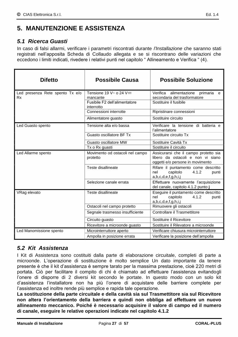
2.1 Barrier assembly
To install the CORAL-PLUS barrier fix the Tx head on one pole, and the Rx head on another pole. Is available (Optional) the “CORAL-SP” which is specifically designed to be used to install CORAL-PLUS. If you prefer to use another pole, it has to have the characteristics showed in the following picture.
300m m
630m m
250m m
170m m
50m m
Ø 60 m mØ 60 m m
CO NDUIT FOR CABLESENTRA NCE
HO LE FORCABLES EXIT
CO NCRETE B URIEDBASE
POLE ANTIROTATIONRADIAL STEEL
ELEM ENTS
SU
GG
ES
TE
D H
EIG
HT
FR
OM
GR
OU
ND
80
0 m
m (
fro
m 7
10
to
89
0m
m)
300m m
Instruction for assembling of Coral head:
- Insert the fairlead into the dedicated bracket hole - Insert the gasket in the fairlead - Put all in the prearranged housing in the bottom of
Coral - Insert the steel washer and screw the ring nut.

CIAS Elettronica S.r.l. Ed. 1.4
Installation Handbook page 32 of 57 CORAL-PLUS
2.2 Number of Sections
Before the installation, we have to think about how to install the system. Therefore, remember that it‟s always preferable to install a even number of section. This because in a close perimeter which is made of an odd number of sections it‟s present one corner where there are one Transmitter and one Receiver which can produce an interference between themselves. In figure 1a the angle between the two heads Tx and Rx is correct, but the two heads are too closed one to the other, and the Transmitter in front to this Rx head is too far, so the spurious signal coming from the close transmitter may be high compared to the its own. In fig 1c the angle between the two heads Tx and Rx is more than 90° and this is wrong. In addition these two heads are too close one to the other.
C O R R E C T C O R R E C T
W R O N G W R O N G
C O R R E C T C O R R E C T
Figure 1
GOOD GOOD
BEST BEST
WRONG
Fig.1a
WRONG
Fig.1f
Fig.1e
Fig.1d
Fig.1c
Fig.1b

CIAS Elettronica S.r.l. Ed. 1.4
Installation Handbook page 33 of 57 CORAL-PLUS
2.3 Ground conditions
It‟s advise against to install the equipment along sections where are present high grass (more than 10 cm), ponds, longitudinal stream, and all those types of grounds which its conformation is rapidly changeable. Use “20cm Special Antenna” for installation on concrete, asphalt and all those reflective pavements with distance longer than 50m.
2.4 Presence of Obstacles
The fences, are generally metallic therefore highly reflective. For this reason some precautions are suggested:
- Make sure that the fence has been properly fixed in order to avoid that the wind moves it;
- when it‟s possible the microwave beam shouldn‟t installed in parallel to a metallic fence; - if it‟s necessary to install the microwave barrier between two fences, make sure that the
distance between those two isn‟t less then 5 mt. In addition, in this case avoid to use the barriers for more than half their maximum range.
- when there‟s a metallic fences behind the barrier‟s head, it can be a problem due to the fact that it could generate some false alarm rates
- Trees, hedges, bushes in general, need very great attention if they‟re near or within the protection beams. These obstacles vary in size and position, in fact they grow and they can be moved by the wind. So, it‟s absolutely advise against tolerate the presence of the cited obstacles within the protection sections.
Figure 2
It‟s possible to tolerate the presence of these elements near the protection sections only if their growth is limited through routine maintenance, and if their movement is stopped using
containment barriers. Various Obstacles might be present along the protection sections. For them there is the necessity to make the same considerations and take the same precautions
adopted for the above cases. This cause of Dead zones not protected and Hypersensitive
zones which cause false alarm.

CIAS Elettronica S.r.l. Ed. 1.4
Installation Handbook page 34 of 57 CORAL-PLUS
2.5 Amplitude of the Sensitive Beam
The amplitude of the Sensitive Beam depends on the distance between the transmitter and
the receiver, on the antenna type and on the sensitivity adjustment set. The pictures below show the dimension half-range of the sensitive beam section (based on the length of the section) in case of maximum and minimum sensitivity (see next picture ).
1
2
3
4
5
6
7
8
9
10
10 20 30 40 50 60 70 80 90 100
Half range
sensitive zone
d im ension [m ]
M axim um
sensitiv ity (”F”)
Range [m ]
M inim um
sensitiv ity (”0”)
Figure 3 Horizontal plane Half range sensitive zone dimension for CORAL-PLUS 100
(free space)
3
6
9
12
15
10 20 30 40 50 60 70 80 90 100
M axim um
sensitivity (”F”)
Half range
sensitive zone
d im ension [m ]
Range [m ]
M inim um
sensitivity (”0”)
Figure 3a Vertical plane Half range sensitive zone dimension for CORAL 100 (free space)

CIAS Elettronica S.r.l. Ed. 1.4
Installation Handbook page 35 of 57 CORAL-PLUS
2
4
6
8
10
12
14
16
18
20
20 40 60 80 100 120 140 160 180 200 220
M axim um
sensitivity (”F”)
Half range
sensitive zone
diam eter [m ]
Range [m ]
M inim um
sensitivity (”0”)
Figure 4 Half range sensitive zone diameter for CORAL-PLUS 220 (free space)
2.6 Length of Dead Zones near the equipment
The length of the Dead Zones near the equipment is based on the distance of the equipment from ground, on the sensitivity set on the receiver and on the type of antenna used.
The suggested height, for standard installations, should be about 80 cm. (85/90cm for
100m barriers) from the ground and the centre of the equipment. With medium sensitivity
setting, the suggested crossing overlap is at least 5 m., for CORAL-PLUS-220 model and
at least 3,5 m. for CORAL-PLUS100 model.
20
30
10
40
50
60
70
80
90
100
20
30
10
40
50
60
70
80
90
100
1 2 3 4 5 6 7 8 9 10
A ntenna
centre height
from ground [cm ]
D ead Zone
lenght [m ]
M axim um
sensitiv ity
M inim um
sensitiv ity
Figure 5 CORAL-PLUS 100 Dead zone length near the equipment versus
antenna centre height from ground.

CIAS Elettronica S.r.l. Ed. 1.4
Installation Handbook page 36 of 57 CORAL-PLUS
20
30
10
40
50
60
70
80
90
100
20
30
10
40
50
60
70
80
90
100
1 2 3 4 5 6 7 8 9 10
A ntenna
centre height
from ground [cm ]
D ead Zone
lenght [m ]
M axim um
sensitiv ity
M inim um
sensitiv ity
Figure 6 CORAL-PLUS 220: Dead zone length near the equipment versus
antenna centre height from ground.
5 M
80
-85
cm
Dead Zone
Dead Zone

CIAS Elettronica S.r.l. Ed. 1.4
Installation Handbook page 37 of 57 CORAL-PLUS
3. CONNECTIONS
3.1 Terminal Blocks, Connectors and Circuits Functions
3.1.1 Transmitter Circuit
LE D
FA U LT
LE D
TA M P E R
JP 2 L ED
ON O FF
S YN C
Jp1
R S 485 L IN E
TE R M IN ATIO N
ON
J 4P
OF F
OU T IN
13,8V
GN D
M PR
1
2
3
10
00
uF
M S1
J3
J2
J4
S1
FL
T
ST
BY
TE
ST
GN
D
SY
NC
FL
T
TM
P
TM
P
L0
LH
GN
D
13
,8V
M S2M S3
SW 2 SW 1 SW 3
Figure 8 Layout of connectors, jumpers, LEDs and presetting in transmitter board
The following tables show the connector pin functions present on the CORAL-PLUS Transmitter PCB
TRANSMITTER TERMINAL BLOCK MS1
Term Symbol Function
1 13,8V Positive Supply Voltage (+13,8V )
2 GND Negative Supply Voltage (0V )
3 MPR Main Presence Voltage (+14,6V = main and Power Supply OK)
TRANSMITTER TERMINAL BLOCK MS2
Term Symbol Function
1 TMP Tamper relay contact + Tilt Bulb Switch AMP1 (NC)
2 TMP Tamper relay contact + Tilt Bulb Switch AMP1 (NC)
3 FLT Fault relay contact (NC)
4 FLT Fault relay contact (NC)
5 STBY Input for Stand-By command (Norm. Open from GND)
6 TEST Input for Test command (Norm. Open from GND)
7 GND Auxiliary Ground connection
8 SYNC Output (Input) Synchronism signal, to (From) Tx Slave (Master)
JP3 MOD
50% - 10%

CIAS Elettronica S.r.l. Ed. 1.4
Installation Handbook page 38 of 57 CORAL-PLUS
TRANSMITTER TERMINAL BLOCK MS3
Term. Symbol Funzione
1 13,8V Supply Voltage for 485/232 converter (+13,8V )
2 GND Ground for RS 485/232 converter and data reference (0V )
3 LH High Data Line (+ RS 485)
4 LO Low Data Line (-RS 485)
TRANSMITTER CONNECTOR J2
Pin Symbol Function
1 GND Ground to MW oscillator
2 DRO Connection for MW oscillator
3 GND Ground to MW oscillator
TRANSMITTER CONNECTOR J3
Pin Symbol Function
1-2-3-5-8-9-10-11-14-15 N.C. Not connected
4 GND Ground
6 +13,8 V Supply Voltage (13,8 V )
7 GND Ground
12 +5 V Internal Supply Voltage (5 V )
13 OSC Measure for working Oscillator (+4V = OK, 0 or 8V = NOT OK)
16 +8 V Internal Supply Voltage (8 V )
TRANSMITTER CONNECTOR J4
Pin Symbol Function
1 GND Ground to Tamper Switch
2 ING Tamper Switch Input
3 GND Ground to Tamper Switch
TRANSMITTER SWITCHES SW3 SW2 SW1
Symbol Function
SW3 Hexadecimal switch for modulation channel selection from 0 to F
SW2 Barrier Number selector (tens column)
SW1 Barrier Number selector (units column)
TRANSMITTER LEDS
Symbol Indication Default
D7 Fault ON D3 Tamper ON
TRANSMITTER JUMPERS
Symbol Function Default
Jp1 OUT = Internal Modulation (Tx is “Master” Sync is outgoing) IN = External Modulation (Tx is “Slave” Sync is ingoing)
OUT
Jp2 Enable or disable the Fault and Tamper Leds ON
Jp3 Modulation Selection type 50% - 10% Don’t change 50%
Jp4 RS485 Line termination - Jp4 (left) line not terminated OFF

CIAS Elettronica S.r.l. Ed. 1.4
Installation Handbook page 39 of 57 CORAL-PLUS
3.1.2 Receiver Circuit
TA M P E R
LE D
FA U LT
LE D
A LA R M
LE D
ON
OF F Jp1
13,8V
GN D
M P R
1
2
3
10
00
uF
M S1
J2
J4
S1
FL
T
FL
T
TM
P
AL
L
AL
L
TM
P
M S2
SW 5SW 4 SW 1
B Z1
SW 6
Tp
M S3
13
,8V
GN
D
LH
LO
ON OF F
Jp2
SW 2SW 3
Figure 9 Layout of connectors, jumpers, LED and presetting in receiver board
The following tables shows the connector pin functions present on CORAL-PLUS Receiver board.
RECEIVER TERMINAL BLOCK MS1
Tem Symbol Function
1 13,8V Positive Supply Voltage (+13,8V )
2 GND Negative Supply Voltage (0V )
3 MPR Main Presence Voltage (+14,6V = main and Power Supply OK)
RECEIVER TERMINAL BLOCK MS2
Term Symbol Function
1 ALL Alarm relay contact (N.C.)
2 ALL Alarm relay contact (N.C.)
3 TMP Tamper relay contact + Tilt Bulb Switch AMP1 (NC)
4 TMP Tamper relay contact + Tilt Bulb Switch AMP1 (NC)
5 FLT Fault relay contact (N.C.)
6 FLT Fault relay contact (N.C.)

CIAS Elettronica S.r.l. Ed. 1.4
Installation Handbook page 40 of 57 CORAL-PLUS
RECEIVER TERMINAL BLOCK MS3
Term. Symbol Funzione
1 13,8V Supply Voltage for 485/232 converter (+13,8V )
2 GND Ground for RS 485/232 converter and data reference (0V )
3 LH High Data Line (+ RS 485)
4 LO Low Data Line (-RS 485)
RECEIVER CONNECTOR J2
Pin Symbol Function
1 GND Ground to MW detector
2 DET Connection for MW Detector
3 GND Ground to MW detector
RECEIVER CONNECTOR J3
Pin Symbol Function
1-2-3-5-8-10-11-13-15-
16
N.C. Not connected
4 GND Ground
6 +13,8 V Supply Voltage (13,8 V )
7 GND Ground
9 0,2V Received signal 200 mVpp
12 +5 V Internal Supply Voltage (5 V )
14 VRAG “Automatic Gain Regulator” Voltage
RECEIVER CONNECTOR J4
Term Symbol Function
1 GND Ground to Tamper Switch
2 ING Tamper Switch Input
3 GND Ground to Tamper Switch
RECEIVER JUMPER
Symbol Function Default
Jp1 Enable or disable the Alarm, Tamper and Fault Leds (D6, D5, D4)
ON
Jp2 RS485 Line termination – Jp2 (left) line not terminated OFF
RECEIVER LEDS
Symbol Indication Default
D4 Fault + alignment ON
D5 Tamper + alignment ON
D6 Alarm + alignment ON
RECEIVER PUSH BUTTON FOR FUNCTIONS ACTIVATION
Symbol Function
S1 - Acquisition of received signal during the alignment (SW1 in position 1) - Acquisition of: Channel Number, Value of Received Field and Indication of Alignment Quality (SW1 in position 2) - Indication of the alignment quality (SW1 in position 3)

CIAS Elettronica S.r.l. Ed. 1.4
Installation Handbook page 41 of 57 CORAL-PLUS
RECEIVER TEST POINTS
Symbol Function
Tp 3 Measure of field signal 200 mVpp (Oscilloscope)
Tp 4 Measure of the Automatic Gain Regulator Voltage Value (V RAG)
Tp 10 Ground reference for instruments
RECEIVER FUNCTION SELECTION SWITCH
Symbol Function
SW1 Position 1 = Barrier Alignment Position 2 = Acquisition of: Channel Number, Value of Received Field and indication of Alignment Quality Position 3 = Acquisition and section parameters (thresholds Read/write) Position 4 = Normal Functionality, Walk-Test and indication of alignment quality
RECEIVER SWITCHES TO SET THE WORKING-PARAMETERS
Symbol Function
SW4 Regulation of the anti-masking control sensitivity (“0” = Low sensitivity, “F” = High sensitivity, Default “8”)
SW5 Barrier Sensitivity regulation (“0” = Low sensitivity, F High Sensitivity, Default “7”)
SW6 Type of answer of the barrier intrusion (Default = “5”)
0 = Very High Decrease of Sensitivity Use this for targets that are very big or very close to the Tx and Rx heads. (Big birds, cats that can jump near the heads ect.)
1 =High Decrease of Sensitivity Targets that are big or very close to the Tx and Rx heads
2 = Medium Decrease of Sensibility Targets that are big or very near to the heads Tx and Rx
3 = Decrease of Sensitivity Targets that are big or very near to the heads Tx and Rx
4 = Decrease of Sensitivity Equal for every target
5 = Standard
6 = Increase of Sensitivity Equal for every target
7 = Increase of Sensitivity for small targets (crawling/rolling intruder)
8 = Medium increase of sensitivity for small targets
9 = High increase of Sensitivity for small targets
RECEIVER NUMBER OF BARRIER SWITCHES SW2 SW3
N° Symbol Function
2 SW2 Barrier Number selector (units column)
3 SW3 Barrier Number selector (tens column)

CIAS Elettronica S.r.l. Ed. 1.4
Installation Handbook page 42 of 57 CORAL-PLUS
3.3.3 Power supply and Battery charger circuit
M S 1 M S 2
21
Cn1
GN D
M P R
13,8V
M S 3
GN D
M P R
13,8V1
2
3
1 2
POWER SUPPLY TERMINAL BLOCK MS1
Term Symbol Function
1 19 V~ Main AC Supply Voltage (19-24 V~) or (24V )
2 19 V~ Main AC Supply Voltage (19-24 V~) or (24V )
POWER SUPPLY TERMINAL BLOCK MS2
Term Symbol Function
1 13,8V Positive Supply Voltage for Battery Charge (+13,8V ) limitation 600 mA
2 GND Negative Supply Voltage for Battery Charge
POWER SUPPLY TERMINAL BLOCK MS3
Term Symbol Function
1 13,8V Positive Supply Voltage (+13,8V )
2 GND Negative Supply Voltage (0V )
3 MPR Main Presence Voltage (+14,6V = main and Power Supply OK)

CIAS Elettronica S.r.l. Ed. 1.4
Installation Handbook page 43 of 57 CORAL-PLUS
POWER SUPPLY CONNECTOR CN1
Term Symbol Function
1 13,8V Positive Supply Voltage (+13,8V )
2 GND Negative Supply Voltage (0V )
3 MPR Main Presence Voltage (+14,6V = main and Power Supply OK)
POWER SUPPLY LED
Symbol Function Default
D2 Main presence indication ON
POWER SUPPLY FUSE
Symbol Function
F1 Main Supply Voltage Protection fuse (T2A-250V)

CIAS Elettronica S.r.l. Ed. 1.4
Installation Handbook page 44 of 57 CORAL-PLUS
3.2 Equipment Connection to the Power Supply
Even when the equipment is DC powered ( 13,8 V ), it still operates properly, but it is advisable to power it by Alternating Current ( 19 or 24 V~ ) or (24 V ) using the power supply and battery charger included.
3.2.1 Connection to the Power Supply
The connection from the equipment to the optional transformer must be as short as possible (less then 4 meters), and the section of the conductor must not be less than 1.5 mm². The connection from the transformer to the 230 V~ mains, must have the same characteristics. The power supply cables connecting transformer with equipment, must be electrically shielded and the shield must be connected to earth tap. The low voltage conductors (19 or 24 V~) have to be connected to the terminal block MS1 (1 and 2) of the power supply and battery charger circuit. The protection fuse F1 is 2 A (T2A) slow-blow type. The transformer characteristics are following:
primary voltage: 230 V~
secondary voltage 19 V~
minimum power 30 VA
Note: use only safety transformers (example Certified EN 60950) Make sure to connect the body of the transformer to hearth tap. The transformer connection to the main (230 V~), must be carried out through one circuit breaker having the following characteristics:
bipolar with minimum distance between contacts equal to 3 mm
provided in the fix part of cabling
easily accessible It is possible to use the toroidal safety transformer mod. TRTOR installed inside the Tx e Rx CORAL-PLUS heads.
However laws and standards concerning installations of devices permanently connected
to the main (230 V~), must be strictly respected (in Italy Law 46/90 and standard CEI 64-
8).
3.2.2 Connection of stand-by Battery
Into each equipment head there‟s the housing for an optional rechargeable back-up lead Battery 12 V 2 Ah (optional). The battery is charged by the internal power supply, through the red and black fastons and wires connected to the terminal block MS2 of the power supply an battery charger circuit (both Rx and Tx heads). The protection against overload and/or battery polarity inversion, is provided by an auto resettable fuse (300 mA) The back-up lead battery allows more than 24 hours of perfect working to the barrier head (TX or RX), in case of mains supply missing. A fault condition is activated if continuously for 3 hours the mains supply is missed.
Note: package, of the optional standby battery, must have a flame class equal or better than HB ( UL 94 Standard ).

CIAS Elettronica S.r.l. Ed. 1.4
Installation Handbook page 45 of 57 CORAL-PLUS
3.3 Connection to the Control Panel
Electrically shielded cables must be used to make the connections to the Control Panel.
3.3.1 Alarm contacts: Alarm, Tamper, Fault
On receiver PCB are present 3 static relays with dry contacts normally closed. By means of these contacts it‟s possible to communicate to the control panel the following conditions:
ALARM, TAMPER, FAULT On transmitter PCB are present 2 static relays with dry contacts normally closed. By means of these contacts it‟s possible to communicate to the control panel the following conditions:
TAMPER, FAULT On the transmitter PCB are provided also 3 inputs to activate the following functions:
Test
Stand-by
Synchronism (Input or Output)
The output contacts for alarm, tamper and fault, both on transmitter and receiver, are made by Static Relays with maximum current of 100 mA.
Remark: in closed condition the resistance of these contacts is about 40 ohm. The connections to control panel must be made by means of shielded cables. The relays are activated for the following reasons:
- ALARM RELAY 1- Intrusion alarm on receiver 2- Receiver masking condition alarm 3- Successful result of test procedure operation 4- Insufficient received signal (V RAG >6,99V) 5- Channel alarm.
- TAMPER RELAYS 1- Cover removing (radome) (TX and RX) 2- Tilt Bulb position (TX and RX)
- FAULT RELAYS 1- Battery voltage low (< +11V ) 2- Battery voltage high (> +14.8V ) 3- RF (radio frequency) or LF (low frequency) Oscillator fault on Transmitter 4- Power supply circuit fault or mains supply voltage missing (more then 3 hours)

CIAS Elettronica S.r.l. Ed. 1.4
Installation Handbook page 46 of 57 CORAL-PLUS
3.3.2 Synchronism connection
For the Synchronism operation between two Transmitters, it is necessary to interconnect the
terminals 8 “SYNC” and 7 “GND” of terminal block MS2 of both Transmitters.
It is also necessary to select one Transmitter as “Master” and the other as “Slave”, by means of jumper Jp1.
Jp1 = “IN” position, the terminal 8 of MS2 is the input for an external synchronism
signal, so the Transmitter is “Slave”.
Jp1 = “OUT” position, the terminal 8 of MS2 is the output for the synchronism signal
internally produced, so the Transmitter is “Master”
Remark: the cable connecting the two transmitters, must be shielded with the shield connected to the hearth tap, and must be as short as possible (not more than 10 meters). If cables longer than 10 meters are required, it is necessary to use the synchronism repetition circuit mod. SYNC 01.
3.3.3 Stand-by connection
For the Stand-by function activation, it is necessary connect to ground the terminal 5 “STBY” of MS2 terminal block of the transmitter circuit.
Remark: the Stand-by command, inhibits the MW emission of the Tx head, then an alarm is activated on the receiver head.
3.3.4 Test connection
The Test function will be activated connecting to ground the terminal 6 “TEST” of the terminal block MS2 on Transmitter circuit. If the test procedure is successful done, the alarm relays on Receiver circuit will be activated later 10 second.
Remark: for high risk protections it‟s necessary to perform a Periodic Test of the detectors. In this way the control panel will be able to detect elusion actions against detectors.
3.4 Serial Line RS-485
3.4.1 RS - 485 / 232 Network Connection Interface
A standard RS 485 serial interface is provided on both transmitter and receiver heads of the CORAL-PLUS barrier. The communication parameters are the following: Mode: Asynchronous - Half-Duplex Baud rate: 9600 b/s Character length: 8bit Parity control: No Parity Stop bit: 1
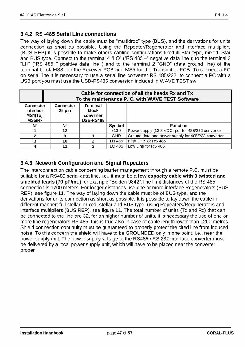
CIAS Elettronica S.r.l. Ed. 1.4
Installation Handbook page 47 of 57 CORAL-PLUS
3.4.2 RS -485 Serial Line connections
The way of laying down the cable must be “multidrop” type (BUS), and the derivations for units connection as short as possible. Using the Repeater/Regenerator and interface multipliers (BUS REP) it is possible to make others cabling configurations like:full Star type, mixed, Star and BUS type. Connect to the terminal 4 “LO” (“RS 485 –“ negative data line ); to the terminal 3 “LH” (“RS 485+” positive data line ) and to the terminal 2 “GND” (data ground line) of the terminal block MS3 for the Receiver PCB and MS5 for the Transmitter PCB. To connect a PC on serial line it is necessary to use a serial line converter RS 485/232, to connect a PC with a USB port you mast use the USB-RS485 conversion included in WAVE TEST sw.
Cable for connection of all the heads Rx and Tx
To the maintenance P. C. with WAVE TEST Software Connector
interface
MS4(Tx),
MS5(Rx
Connector
25 pin
Terminal
block
converter
USB-RS485
N° N° Symbol Function
1 12 +13,8 Power supply (13,8 VDC) per for 485/232 converter
2 9 1 GND Ground data and power supply for 485/232 converter
3 10 2 LH 485 High Line for RS 485
4 11 3 LO 485 Low Line for RS 485
3.4.3 Network Configuration and Signal Repeaters
The interconnection cable concerning barrier management through a remote P.C. must be
suitable for a RS485 serial data line, i.e., it must be a low capacity cable with 3 twisted and
shielded leads (70 pF/mt.) for example “Belden 9842”.The limit distances of the RS 485 connection is 1200 meters. For longer distances use one or more interface Regenerators (BUS REP), see figure 11. The way of laying down the cable must be of BUS type, and the derivations for units connection as short as possible. It is possible to lay down the cable in different manner: full stellar; mixed, stellar and BUS type, using Repeaters/Regenerators and interface multipliers (BUS REP), see figure 11. The total number of units (Tx and Rx) that can be connected to the line are 32, for an higher number of units, it is necessary the use of one or more line regenerators RS 485, this is true also in case of cable length lower than 1200 metres. Shield connection continuity must be guaranteed to properly protect the cited line from induced noise. To this concern the shield will have to be GROUNDED only in one point, i.e., near the power supply unit. The power supply voltage to the RS485 / RS 232 interface converter must be delivered by a local power supply unit, which will have to be placed near the converter proper

CIAS Elettronica S.r.l. Ed. 1.4
Installation Handbook page 48 of 57 CORAL-PLUS
The figure show s a system w hich requ ires a R S 485 seria l line w ith several b ranch loops(“Star”
netw ork architecture) This architecture is created using a B U SR EP as a m ultiplier.The 4 resu lting
sections can be up to 1 ,200 m t. long each and a m axim um of 32 devices,inc lud ing the B U SR EP,
can be connected to each one. The first section inc ludes the seria le line converter
“STAR” NETW O RK ARCHITECTURE U SING “BUSR EP” AS A M ULTIPLIER
Line RS- 485
m ax 1200 m t.
L1
L4
BUS REP 1
L3
L2
F ield
Devices
32
213,8 Vcc
0 Vcc
LOCAL
POW ER-SUPPLY
SERIAL LINE
CO NVERTER
RS-485/RS-232
R S-485R S232
13
1 11
1
1
13 31
F ield
Devices
L ine RS- 485
m ax 1200 m t.
2 3 32
L ine RS- 485
m ax 1200 m t.
F ie ld
Devices
2 3 32
F ield
Devices
2 3 32
1
The figure show s a system w hich requires a R S 485 seria l line that is longer than 1,200 m etres .
U s ing tw o B U SR EPs as regenerators , it w as divided up in to 3 sections each o f w hich w as shorter in length .
In this case there are less than 32 field devices , but they can be d is tributed on 3,600 m etres-long line .
Field
Devices
F ield
Devices
F ield
D evices
L1
L4
B US R EP 1
L3
L2
L1
L4
B US REP 2
L3
L2
3 10
11
13
12
14 20
21
23
22
24 2913,8 Vcc
0 Vcc
LOCAL
POW ER-SUPPLY
SERIAL LINE
CO NVERTER
RS-485/RS-232
R S-485R S232
13
1 11
1
3.5 Remote Connection
To interface CORAL-PLUS barrier to PSTN modem (9600 b/s) it is necessary the conversion
RS485 to RS232 and also the cross conversion shown below.

CIAS Elettronica S.r.l. Ed. 1.4
Installation Handbook page 49 of 57 CORAL-PLUS
4. ADJUSTMENT AND TESTING
4.1 Adjustment and Testing
A built in electronic alignment, parameter set and test tool, is provided in the receiver head of the CORAL-PLUS barriers. This is a very useful system both for installation and periodical maintenance without any other instrument.
4.1.1 Transmitter Setting up
To remove the radome (frontal cover), screw off the 6 screws (3 in front and 3 on the back). After that open the radome, remember, when you open the radome, the contact on the connector J4 will be open (Tamper).
1. Connect the Alternating Current cables (19 or 24 V~) or Direct Current (24V ) to the terminals 1 and 2 of the terminal block MS1 present on the Power supply and battery charger circuit.
2. Check, on the “fastons” connected to the terminal block MS2, the
presence of the DC supply voltage (13,8 V ). 3. Connect the “fastons” to the battery and remember to respect the
polarity that means, red wire (Terminal 1 of MS2) to the positive of the battery and black wire (Terminal 2 MS2) to the negative of the battery.
Attention : The wrong connection of the battery, will cause the interruption of the resettable fuse. Change the connections to re-establish the normal functionality.
4. Select one of the 16 available modulation channels using the hexadecimal switch (SW3) in one of the 16 available positions (from 0 to F). The utilization of one of these channels won‟t modify the correct functionality of the barrier, however it‟s always better select different channel for each barrier in order to be more safe.
N.B. In the event that the signal of one barrier is intercepted by another barrier there will be interference between them and will be necessary synchronize the two transmitters. To synchronize two barriers, set one of them as master (it generate the synchronism signal) and the other as slave (it receive the synchronism signal), furthermore, set on the slave transmitter, the same channel as the master one.

CIAS Elettronica S.r.l. Ed. 1.4
Installation Handbook page 50 of 57 CORAL-PLUS
5. Since to execute the vertical alignment is necessary to operate on the junction inside the head, is advisable to wait until the end of the alignment operation to close the head.
6. Finally close the MW head using the 6 screws to fix the radome. N.B. Make sure that the tilt bulb (“Amp 1) is in the correct position in order to keep the tamper contact close (perpendicular as the ground).
4.1.2 Receiver setting up
To remove the radome (frontal cover) screw off the 6 screws (3 in front and 3 on the back). The opening of the radome will cause the opening of the tamper contact (J4).
1. Connect the Alternating Current cables (19 or 24 V~) or Direct Current (24V ) to the
terminals 1 and 2 of the terminal block MS1 present on the power supply circuit. 2. Check on the “fastons”, connected to the terminal block MS2, the presence of the direct
current (13,8 V ). 3. Connect the “fastons” to the battery and remember to respect the polarity that means, red
wire (Terminal 1 of MS2) to the positive of the battery and black wire (Terminal 2 of MS2) to the negative of the battery.
Attention : The wrong connection of the battery, will cause the interruption of the resettable fuse. Change the connections to re-establish the normal functionality.
4. To optimize the alignment of the barrier and set the parameters without any other instrument, use the integrated electronic system. To use the integrated electronic system in the correct way carry out the followings operations: a. Make sure that the micro-switch which is connected to the connector J4 is open.
b. Turn the functions‟ switch SW1 in the position 1. This operation enables the barrier installation procedure.
c. Press the button S1. This operation sets the “fast regulation system” of the received signal, it generates an intermittent sound which indicates the signal level.
d. Slacken the bracket‟s screws, change the horizontal orientation on the receiver head in order to find the maximum signal.
e. If during the orientation operation the sound„s frequency increase, it means that the
received signal is higher than the previous. If the signal is much more the sound can be continuous.

CIAS Elettronica S.r.l. Ed. 1.4
Installation Handbook page 51 of 57 CORAL-PLUS
Press again the button S1, the sound will has a lower intermittent frequency. Now change again the horizontal orientation. In the event that during the orientation operation, the frequency of the intermittent sound decreases, means that the received signal is decreased, therefore move the head in the opposite direction. The operation of horizontal alignment will be finish when the maximum signal will be found.
f. Slacken the bracket‟s screws to orientate the transmitter horizontally, repeat the operations explained in the “e” point.
N.B. The transmitter head doesn‟t have the S1 button, therefore to activate the “fast regulation system”, cover temporarily the radiofrequency emission ( for example, pass an hand in front of the transmitter‟s antenna) so that the alignment operation will be easy to execute alone.
g. When the best alignment will be found (the maximum signal available) lock the
movement on the receiver and on the transmitter.
h. Unlock the vertical movement of the receiver head (Rx) and move it up. Press the button S1 or cover temporally the radiofrequency emission, and wait the stabilization of the intermittent sound. Move down slowly the head and find the maximum signal (see point “e”).
i. Unlock the vertical movement of the transmitter head (Tx) and carry out the same
operations than the receiver. Finally lock the movement of the transmitter and the receiver.
j. Turn the functions switch SW1 in the position 2, make sure that during this operation nothing is within the microwave beam, for example the operators don‟t walk between the transmitter and the receiver. Remember that this operation is very important because now the barrier acquire the value of the modulation channel and the value of the microwave signal. An alteration of the microwave beam in this moment will make incorrect the installation therefore it will be NOT safe. The acquisition operation starts some seconds after that the button S1 is pressed. When the acquisition operation will finish the 3 leds will turn on together and the buzzer will make some sounds (Beep) which indicate the quality of the alignment:
1 Beep = Excellent Quality
2 Beeps = Good Quality
3 Beeps = Poor Quality
4 Beeps = Insufficient Quality
5 or more Beeps = Very bad Quality
In the event that the alignment quality is poor or less, verify that nothing, fix or moving, is within the microwave beam and than repeat the alignment operations.

CIAS Elettronica S.r.l. Ed. 1.4
Installation Handbook page 52 of 57 CORAL-PLUS
k. By setting function switch SW1 to position 3, it is possible to read or modify the barrier
operating parameters, Masking, Sensitivity, type of Response. The Alarm, tamper and Fault led change function in this mode and indicate the values of the parameters stored in the barrier. The alarm and masking thresholds are set with values one higher than the quiescent value of the received signal and one lower. They then determine if, at the end of the signal processing, the variation in received signal is sufficient to create an alarm.
To Read the actual value of the parameter:
Rotate switch SW4 (MASK) until the first Green led (D6) comes on.
Rotate switch SW5 (SENS) until the second Green led (D5) comes on.
Rotate switch SW6 (RSP) until the third Green led (D4) comes on. The values read on these three switches indicate the values of the parameters in use by the barrier.
To Modify the actual alarm threshold values:
Rotate the SW4 (MASK), SW5 (SENS) SW6 (RSP) switches to the required values.
Push S3 to memorise the new threshold values.
The Masking thresholds are above and below the field value, which is stored during Parameter Acquisition (SW1 in position 2, see point “j”). They monitor slow changes in the received signal to see if they are big enough to change the detection performance of the barrier. These changes can be caused, for example, by snow accumulation along the protected area or by attempts to circumvent the barrier operation. Adjustment of the
sensitivity of this function is via switch SW4 (default = “8”). To decrease the sensitivity set
a lower value: “7”, “6”, “5”, “4”, “3”, “2”, “1”, “0” The value “0” will disable this
function. To increase the sensitivity set a higher value: “9”, “A”, “B”, “C”, “D”, “E”,
“F”. Values that are too high can generate false alarms.
It is possible to set the Sensitivity of the barrier using switch SW5. The default setting is
“7” and represents the optimum setting for most situations. To increase the sensitivity
set this switch to a higher value, such as: “8”, “9”, “A”, “B”, “C”, “D”, “E”, “F”. To
decrease the sensitivity set this switch to a lower value, such as: “6”, “5”, “4”, “3”,
“2”, “1”, “0”. Changes made to the sensitivity using SW5 have an effect on the
dimensions of the sensitive area, therefore an excessive increase in the sensitivity can lead to an increase in unwanted alarms, while an excessive decrease in sensitivity can reduce the ability of the barrier to detect real intrusions.
The Response of the barrier is set during manufacture to ”5” (default) set on switch
SW6. This setting is optimum for most situations. To obtain a different response adjust SW6 for the required response, based on the following table:

CIAS Elettronica S.r.l. Ed. 1.4
Installation Handbook page 53 of 57 CORAL-PLUS
RESPONSE MODIFICATION
SW6 Setting Response
0 Very High Decrease of Sensitivity Use this for targets that are very big or very close to the Tx and Rx heads. (Big birds, cats that can jump close to the heads etc.)
1 High Decrease of Sensitivity Targets that are big or very close to the heads Tx and Rx
2 Medium Decrease of Sensibility Targets that are big or very close to the heads Tx and Rx
3 Decrease of Sensitivity Targets that are big or very near to the heads Tx and Rx
4 Decrease of Sensitivity Equal for every target
5 Standard
6 Increase of Sensitivity Equal for every target
7 Increase of Sensitivity for small target (crawling/rolling intruder)
8 Medium increase of sensitivity for small targets
9 High increase of Sensitivity for small targets
5. Turn the function switch SW1 to position 4, and the barrier will return to normal operation.
The normal operation is also restored when the radome is closed, independent of the position of SW1.
Pushing S1 push button, will give an audible indication related to the quality of the
alignment, as described in point ”j” and activates the Walk Test function. The barrier will
operate with the parameters set using the software or using the Sensitivity SW5 and
Response SW6 switches and every variation in the microwave signal in the sensitive zone will activate the buzzer found on the receiver board. The buzzer sounds intermittently, the frequency of which is dependent on the intensity of the disturbance signal, and if the frequency increases it means that the disturbance has increased (which indicates a deeper penetration into the protected area). If the disturbing signal is sufficient to generate an alarm condition the buzzer will give a continuous tone. In this way it is possible to evaluate the real consistency of the sensitive zone and also to check if there are any sources of interference present (badly fixed fences, etc.), affecting the protection. If the walk test results do not satisfy the protection requirements of the zone, adjust the sensitivity of the CORAL-PLUS barrier as shown in point “k”)

CIAS Elettronica S.r.l. Ed. 1.4
Installation Handbook page 54 of 57 CORAL-PLUS
4.2 Alignment and monitoring with software
To display and manage the software parameters of the Coral Plus, comprising the analogue threshold and received signal values, alarm status indication and the history, it is possible to
use a PC running the CIAS Wave-Test2 program; Refer to the program technical documentation for connection procedures and/or management of the software functions.

CIAS Elettronica S.r.l. Ed. 1.4
Installation Handbook page 55 of 57 CORAL-PLUS
5. MAINTENANCE AND ASSISTANCE
5.1 Troubleshooting
In case of false alarm, check the parameters recorded during the Installation phase (on
attached Test Sheet), if there are divergences with permitted limits check again the related points in chapter "Adjustment and Testing (4)"
Defect Possible Cause Possible Solution
Main Power supply LED off Tx and/or Rx
Power Supply 19 V~ or 24V
missing Check out the Primary and Secondary power supply of the Transformer
F2 Fuse of Power Supply Circuit broken
Change the fuse
Connections broken Ad just the connections
Power Supply circuit broken Change the Electronic board
Fault Led OFF Supply Voltage too high or too low
Check the battery voltage and the power supply circuit
Tx Low Frequency Oscillator Change the Tx Electronic board
Tx MW Oscillator Fault Change the MW Oscillator
Tx or Rx failures Change the Electronic board (Tx or Rx)
Alarm Led OFF Movement or obstacles in the protected field
Check out that the protected field is free from obstacles and free from objects and/or people moving.
Barrier not properly aligned Re do the alignment procedure as described in points: a,b,c,d,e,f,g,h,I,j of chapter 4.1.2
Wrong channel selections Do again the Channel acknowledge procedure as described in point j of chapter 4.1.2
High AGC Voltage Barrier not properly aligned Re do the alignment procedure as described in points: a,b,c,d,e,f,g,h,I,j of chapter 4.1.2
Obstacles within the MW beam Remove obstacles
Too low signal transmitted Check the transmitter
Rx circuit fault Change the Rx circuit
Rx MW detector fault Change the RX MW detector
Tamper Led OFF Micro switch open Check the micro switch position
Tilt bulb in wrong position Check the position of the tilt bulb
5.2 Maintenance kits
The Maintenance Kits are composed by circuits equipped with microwave cavities, always for 220 m. range, their substitution is very easy: Unlock the fixing screws and install the new circuits and cavities.
The circuit and cavity substitution on boot transmitter and receiver heads doesn’t
changes the heads alignment, and so no new mechanical alignment is required, but it is
necessary the acquisition of the field value and of the channel number see chapter 4.1.2

CIAS Elettronica S.r.l. Ed. 1.4
Installation Handbook page 56 of 57 CORAL-PLUS
6. CHARACTERISTICS
6.1 Technical characteristics
TECHNICAL CARACTERISTICS Min Nom Max Note
Working Frequency F1 10.58 GHz
Working Frequency F2 9.9 GHz
Working Frequency F3 9.46 GHz
Working Frequency F4 10.525 GHz
Maximum power 20mW 500 mW e.i.r.p.
Modulation Pulsed on/off
Duty-cycle - 50/50 - -
Number of channels - - 16 -
Range:
CORAL-PLUS100 - 100 m - -
CORAL-PLUS220 - 220 m - -
Power supply ( 19V ) 17 V 19 V 24 V -
Current absorption TX in surveillance ( mA ) - 150 - -
Current absorption RX in surveillance ( mA ) - 140 - -
Current absorption RX in alarm ( mA ) - 130 - -
Power supply ( 13.8V ) 11,5 V 13,8 V 14,8 V -
Current absorption TX in surveillance ( mA ) - 65 - -
Current absorption RX in surveillance ( mA ) - 60 - -
Current absorption RX in alarm ( mA ) - 54 - -
Power supply ( 24V ) 20 V 24 V 30V -
Current absorption TX in surveillance ( mA ) - 76 - -
Current absorption RX in surveillance ( mA ) - 66 - -
Current absorption RX in alarm ( mA ) - 60 - -
Housing for battery - - - 12Vn/2Ah
Intrusion alarm contact (TX+RX) - - 100mA NC
Radome removal contact (TX+RX) - - 100mA NC
Fault contact (TX+RX) - - 100mA NC
Intrusion alarm (TX+RX) Green LED ON - - - Not active
Radome removal (TX+RX) Green LED ON - - - Not active
Fault alarm (TX+RX) Green LED ON - Not active
Threshold adjustment - - - On board
Weight without battery (TX) - 2930 g - -
Weight without battery (RX) - 2990 g - -
Width 300 mm
Height - - 390 mm -
Deep, brackets included - - 270 mm -
Working temperature -25 °C - +55 °C -
Performance Level III Livello
Box protection level IP55
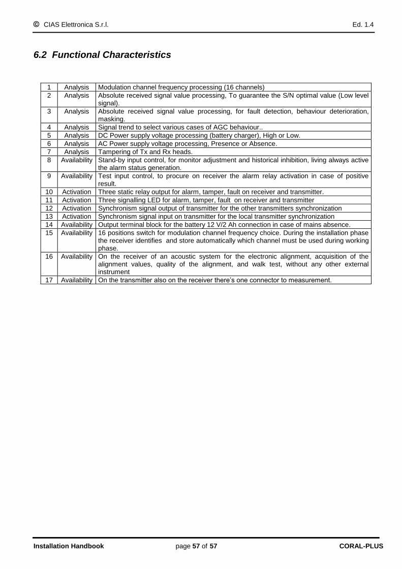
CIAS Elettronica S.r.l. Ed. 1.4
Installation Handbook page 57 of 57 CORAL-PLUS
6.2 Functional Characteristics
1 Analysis Modulation channel frequency processing (16 channels)
2 Analysis Absolute received signal value processing, To guarantee the S/N optimal value (Low level signal).
3 Analysis Absolute received signal value processing, for fault detection, behaviour deterioration, masking.
4 Analysis Signal trend to select various cases of AGC behaviour..
5 Analysis DC Power supply voltage processing (battery charger), High or Low.
6 Analysis AC Power supply voltage processing, Presence or Absence.
7 Analysis Tampering of Tx and Rx heads.
8 Availability Stand-by input control, for monitor adjustment and historical inhibition, living always active the alarm status generation.
9 Availability Test input control, to procure on receiver the alarm relay activation in case of positive result.
10 Activation Three static relay output for alarm, tamper, fault on receiver and transmitter.
11 Activation Three signalling LED for alarm, tamper, fault on receiver and transmitter
12 Activation Synchronism signal output of transmitter for the other transmitters synchronization
13 Activation Synchronism signal input on transmitter for the local transmitter synchronization
14 Availability Output terminal block for the battery 12 V/2 Ah connection in case of mains absence.
15 Availability 16 positions switch for modulation channel frequency choice. During the installation phase the receiver identifies and store automatically which channel must be used during working phase.
16 Availability On the receiver of an acoustic system for the electronic alignment, acquisition of the alignment values, quality of the alignment, and walk test, without any other external instrument
17 Availability On the transmitter also on the receiver there‟s one connector to measurement.

SCHEDA DI COLLAUDO – TEST SHEET
CORAL-PLUS TX NUMERO DI SERIE
SERIAL NUMBER:
Cliente/Customer
Indirizzo/Address
Barriera /Barrier N°
(*) misura può essere effettuata anche con lo strumento STC 95
(*) It is possible to make the measure also by the STC 95
OSSERVAZIONI DELL’INSTALLATORE – INSTALLER COMMENTS
Data installazione/Installation date Firma Installatore/Installer Signature
VALORI MISURATI SUL TRASMETTITORE – MEASURED VALUES ON THE TRASMITTER
MISURE
MEASUREMENTS
VALORI TIPICI
STANDARD
VALUES
VALORI MISURATI
MEASURED VALUES
INSTALLAZIONE
INSTALLATION
MANUTENZIONE
MAINTENANCE
1
TENSIONE DI ALIMENTAZIONE, MISURATA TRA I PIN 1-2 DI MS1, CON BATTERIA SCOLLEGATA. (*) SUPPLY VOLTAGE, MEASURED BETWEEN PINS 1-2 OF MS1 WITH BATTERY DISCONNECTED. (*)
13,8 V 10%
2
TENSIONE DI ALIMENTAZIONE INTERNA MISURATA TRA IL PIN 16 DI J3 E GND. (*) INSIDE SUPPLY VOLTAGE MEASURED BETWEEN PIN 16 OF J3 AND GND. (*)
8 V 10%
3
TENSIONE DI ALIMENTAZIONE INTERNA, MISURATA TRA IL PIN 12 DI J3 E GND. (*) INSIDE SUPPLY VOLTAGE MEASURED BETWEEN PIN 12 OF J3 AND GND. (*)
5 V 10%
4
TENSIONE OSCILLATORE FUNZIONANTE MISURATA TRA IL PIN 13 DI J3 E GND. (*) OSCILLATOR OK VOLTAGE MEASURED BETWEEN PIN 13 OF J3 AND GND. (*)
4 V 10%
5
SELEZIONE MASTER/SLAVE MASTER/SLAVE SELECTION
-
□ MASTER
□ SLAVE
□ MASTER
□ SLAVE
6
CANALE DI MODULAZIONE SELEZIONATO MODULATION CHANNEL SELECTED
-
□ Ch 0 □ Ch 8
□ Ch 1 □ Ch 9
□ Ch 2 □ Ch A
□ Ch 3 □ Ch B
□ Ch 4 □ Ch C
□ Ch 5 □ Ch D
□ Ch 6 □ Ch E
□ Ch 7 □ Ch F
□ Ch 0 □ Ch 8
□ Ch 1 □ Ch 9
□ Ch 2 □ Ch A
□ Ch 3 □ Ch B
□ Ch 4 □ Ch C
□ Ch 5 □ Ch D
□ Ch 6 □ Ch E
□ Ch 7 □ Ch F
TA
GLIA
RE
QU
I /
CU
T H
ER
E

SCHEDA DI COLLAUDO – TEST SHEET
CORAL-PLUS RX NUMERO DI SERIE
SERIAL NUMBER:
Cliente/Customer Indirizzo/Address Barriera /Barrier N°
(*) misura che può essere effettuata anche con lo strumento STC 95
(*) It is possible to make the measure also by the STC 95
OSSERVAZIONI DELL’INSTALLATORE – INSTALLER COMMENTS
Data installazione/Installation date
Firma Installatore/Installer Signature
VALORI MISURATI SUL RICEVITORE – MEASURED VALUES ON THE RECEIVER
MISURE
MEASUREMENTS
VALORI TIPICI
STANDARD
VALUES
VALORI MISURATI
MEASURED VALUES
INSTALLAZIONE
INSTALLATION
MANUTENZIONE
MAINTENANCE
1
TENSIONE DI ALIMENTAZIONE, MISURATA TRA I PIN 1-2 DI MS1, CON BATTERIA SCOLLEGATA. (*) SUPPLY VOLTAGE, MEASURED BETWEEN PINS 1-2 OF MS1 WITH BATTERY DISCONNECTED. (*)
13,8 V 10%
2
TENSIONE DI ALIMENTAZIONE INTERNA, MISURATA TRA IL PIN 12 DI J3 E GND. (*) INSIDE SUPPLY VOLTAGE MEASURED BETWEEN PIN 12 OF J3 AND GND. (*)
5 V 10%
3
TENSIONE DI RAG, MISURATA TRA IL PIN 14 DI J3 E GND. (*) AGC VOLTAGE MEASURED BETWEEN PIN 14 OF J3 AND GND. (*)
2,5 6 V
4
VERIFICA SEGNALE RIVELATO, MISURATA CON LO STRUMENTO STC 95. SIGNAL DETECTED VOLTAGE MEASURED BY STC 95.
6 V 10% STABILE STEADY
5
CANALE DI MODULAZIONE UTILIZZATO MODULATION CHANNEL USED
-
□ Ch 0 □ Ch 8
□ Ch 1 □ Ch 9
□ Ch 2 □ Ch A
□ Ch 3 □ Ch B
□ Ch 4 □ Ch C
□ Ch 5 □ Ch D
□ Ch 6 □ Ch E
□ Ch 7 □ Ch F
□ Ch 0 □ Ch 8
□ Ch 1 □ Ch 9
□ Ch 2 □ Ch A
□ Ch 3 □ Ch B
□ Ch 4 □ Ch C
□ Ch 5 □ Ch D
□ Ch 6 □ Ch E
□ Ch 7 □ Ch F
TA
GLIA
RE
QU
I /
CU
T H
ER
E

NOTE:

NOTE:

NOTE:

Con la presente, CIAS Elettronica, dichiara che questo rivelatore di intrusione “CORAL-PLUS ” è conforme ai requisiti essenziali ed alle altre disposizioni rilevanti della Direttiva 1999/5/CE (Art.3.1a-3.1b-3.2) Hereby, CIAS Elettronica, declares that this movement detector “CORAL-PLUS ” is in compliance with the essential requirement and other relevant provisions of Directive 1999/5/EC (Art.3.1a-3.1b-3.2)
IMQ: III° livello
CEI 79-2 Questo apparecchio è contrassegnato in conformità alla Direttiva Europea 2002/96/EC, Waste Electrical and Electronic Equipment (WEEE) Assicurandosi che questo prodotto sia smaltito in modo corretto, l’utente contribuisce a prevenire le potenziali conseguenze negative per l’ambiente e la salute.
Il simbolo sul prodotto o sulla documentazione d’accompagnamento indica che questo prodotto non deve essere trattato come rifiuto domestico ma deve essere consegnato presso l’idoneo punto di raccolta per il riciclaggio d’apparecchiature elettriche ed elettroniche. Disfarsene seguendo le normative locali per lo smaltimento rifiuti. Lo smaltimento abusivo è punito con le sanzioni previste dalla legislazione nazionale vigente Il prodotto può essere riconsegnato al distributore/installatore a fine vita in occasione di un nuovo acquisto.
This product is marked in compliance with the European Directive 2002/96/EC, Waste Electrical and Electronic Equipment (WEEE). The correct disposal of the product will prevent potential negative consequences for the environment and the human health.
The symbol on the product or into the annexed documentation indicates that this product does not have to be dealt like domestic refusal but must be delivered near the suitable point of collection for the recycling of electrical and electronic equipment. The illicit disposal will be endorsed according to local l regulations. At the end of operative life the product can be given back to the vendor/installation organization in occasion of a new purchase.
Copyright CIAS Elettronica S.r.l.
Stampato in Italia / Printed in Italy
CIAS Elettronica S.r.l. Direzione, Ufficio Amministrativo, Ufficio Commerciale, Laboratorio di Ricerca e Sviluppo Direction, Administrative Office, Sales Office, Laboratory of Research and Development 20158 Milano, via Durando n. 38 Tel. +39 02 376716.1 Fax +39 02 39311225 Web-site: www.cias.it E-mail: [email protected] Stabilimento / Factory 23887 Olgiate Molgora (LC), Via Don Sturzo n. 17