Condensatori monofase Single-phase Capacitors - ELESUD · sistemi di rifasamento Ducati Energia...
75
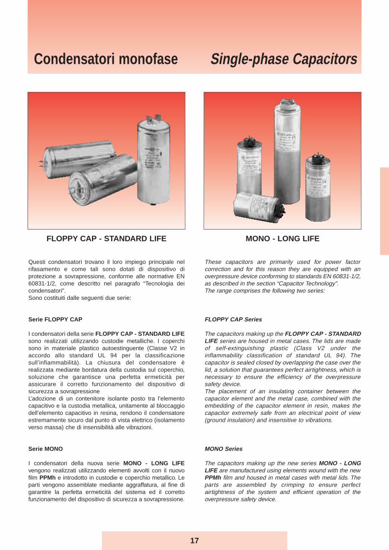
17 Questi condensatori trovano il loro impiego principale nel rifasamento e come tali sono dotati di dispositivo di protezione a sovrapressione, conforme alle normative EN 60831-1/2, come descritto nel paragrafo “Tecnologia dei condensatori”. Sono costituiti dalle seguenti due serie: Serie FLOPPY CAP I condensatori della serie FLOPPY CAP - STANDARD LIFE sono realizzati utilizzando custodie metalliche. I coperchi sono in materiale plastico autoestinguente (Classe V2 in accordo allo standard UL 94 per la classificazione sull’infiammabilità). La chiusura del condensatore è realizzata mediante bordatura della custodia sul coperchio, soluzione che garantisce una perfetta ermeticità per assicurare il corretto funzionamento del dispositivo di sicurezza a sovrapressione L’adozione di un contenitore isolante posto tra l’elemento capacitivo e la custodia metallica, unitamente al bloccaggio dell’elemento capacitivo in resina, rendono il condensatore estremamente sicuro dal punto di vista elettrico (isolamento verso massa) che di insensibilità alle vibrazioni. Serie MONO I condensatori della nuova serie MONO - LONG LIFE vengono realizzati utilizzando elementi avvolti con il nuovo film PPMh e introdotto in custodie e coperchio metallico. Le parti vengono assemblate mediante aggraffatura, al fine di garantire la perfetta ermeticità del sistema ed il corretto funzionamento del dispositivo di sicurezza a sovrapressione. These capacitors are primarily used for power factor correction and for this reason they are equipped with an overpressure device conforming to standards EN 60831-1/2, as described in the section “Capacitor Technology”. The range comprises the following two series: FLOPPY CAP Series The capacitors making up the FLOPPY CAP - STANDARD LIFE series are housed in metal cases. The lids are made of self-extinguishing plastic (Class V2 under the inflammability classification of standard UL 94). The capacitor is sealed closed by overlapping the case over the lid, a solution that guarantees perfect airtightness, which is necessary to ensure the efficiency of the overpressure safety device. The placement of an insulating container between the capacitor element and the metal case, combined with the embedding of the capacitor element in resin, makes the capacitor extremely safe from an electrical point of view (ground insulation) and insensitive to vibrations. MONO Series The capacitors making up the new series MONO - LONG LIFE are manufactured using elements wound with the new PPMh film and housed in metal cases with metal lids. The parts are assembled by crimping to ensure perfect airtightness of the system and efficient operation of the overpressure safety device. Condensatori monofase Single-phase Capacitors FLOPPY CAP - STANDARD LIFE MONO - LONG LIFE
Transcript of Condensatori monofase Single-phase Capacitors - ELESUD · sistemi di rifasamento Ducati Energia...
17
Questi condensatori trovano il loro impiego principale nelrifasamento e come tali sono dotati di dispositivo diprotezione a sovrapressione, conforme alle normative EN60831-1/2, come descritto nel paragrafo “Tecnologia deicondensatori”.Sono costituiti dalle seguenti due serie:
Serie FLOPPY CAP
I condensatori della serie FLOPPY CAP - STANDARD LIFEsono realizzati utilizzando custodie metalliche. I coperchisono in materiale plastico autoestinguente (Classe V2 inaccordo allo standard UL 94 per la classificazionesull’infiammabilità). La chiusura del condensatore èrealizzata mediante bordatura della custodia sul coperchio,soluzione che garantisce una perfetta ermeticità perassicurare il corretto funzionamento del dispositivo disicurezza a sovrapressioneL’adozione di un contenitore isolante posto tra l’elementocapacitivo e la custodia metallica, unitamente al bloccaggiodell’elemento capacitivo in resina, rendono il condensatoreestremamente sicuro dal punto di vista elettrico (isolamentoverso massa) che di insensibilità alle vibrazioni.
Serie MONO
I condensatori della nuova serie MONO - LONG LIFEvengono realizzati utilizzando elementi avvolti con il nuovofilm PPMh e introdotto in custodie e coperchio metallico. Leparti vengono assemblate mediante aggraffatura, al fine digarantire la perfetta ermeticità del sistema ed il correttofunzionamento del dispositivo di sicurezza a sovrapressione.
These capacitors are primarily used for power factorcorrection and for this reason they are equipped with anoverpressure device conforming to standards EN 60831-1/2,as described in the section “Capacitor Technology”.The range comprises the following two series:
FLOPPY CAP Series
The capacitors making up the FLOPPY CAP - STANDARDLIFE series are housed in metal cases. The lids are madeof self-extinguishing plastic (Class V2 under theinflammability classification of standard UL 94). Thecapacitor is sealed closed by overlapping the case over thelid, a solution that guarantees perfect airtightness, which isnecessary to ensure the efficiency of the overpressuresafety device.The placement of an insulating container between thecapacitor element and the metal case, combined with theembedding of the capacitor element in resin, makes thecapacitor extremely safe from an electrical point of view(ground insulation) and insensitive to vibrations.
MONO Series
The capacitors making up the new series MONO - LONGLIFE are manufactured using elements wound with the newPPMh film and housed in metal cases with metal lids. Theparts are assembled by crimping to ensure perfectairtightness of the system and efficient operation of theoverpressure safety device.
Condensatori monofase Single-phase Capacitors
FLOPPY CAP - STANDARD LIFE MONO - LONG LIFE
18
SERIE FLOPPY CAP MONO
SERIES 416.30. 416.53.
Frequenza nominale 50 Hz (utilizzabile su rete a 60 Hz) 50 Hz (utilizzabile su rete a 60 Hz)Rated frequency 50 Hz (suitable for 60 Hz network) 50 Hz (suitable for 60 Hz network)
Tolleranza di capacità -5 +10% -5 +10%Capacitance tolerance
Perdite dielettriche ≤ 0.3 W/kVAr ≤ 0.2 W/kVArDielectric losses
Altitudine ≤ 2000m s.l.m. ≤ 2000m s.l.m.Altitude ≤ 2000m a.s.l. ≤ 2000m a.s.l.
Servizio Continuo ContinuoDuty Continuous Continuous
Gamma di tensione 230 ÷ 550V 400 ÷ 525VVoltage range
Grado di protezione IP 00 IP 00Protection rating
Tensione di prova (AC) tra terminali 2.15 Un x 2 s 2.15 Un x 2 sest voltage (AC) between terminals
Tensione di prova tra terminali e custodia 3kV x 10 s 3kV x 10 sTest voltage (AC) between terminals and case
Resistenza di scarica NO NODiscarge resistence
Classe di temperatura -25/D -25/DTemperature class
Terminali Doppio faston Doppio faston(perno M5 per Q ≥ 8.33 kVAr)
Terminals Double faston Double faston(M5 bolt for Q ≥ 8.33 kVAr)
Massima corrente di piccoammessa all’inserzione 100 In 200 In
Max inrush current
Sovraccarico max In 2 x In 4 x InMax overload In
Vita attesa ≥ 60000h – 25/D ≥ 110000h – 25/DLife expectancy ≥ 80000h – 25/C ≥ 130000h – 25/C
Max dV/dt ≤ 25 V / μs ≤ 100 V / μsMax dV/dt
NormeIEC 831 – 1/2 IEC 831 – 1/2
Standards
ApprovazioniApprovals
(escluse le versioni a 500-550V)(excluding 500-550V models)
(escluse le versioni Un >440V)(excluding Un >440V models)
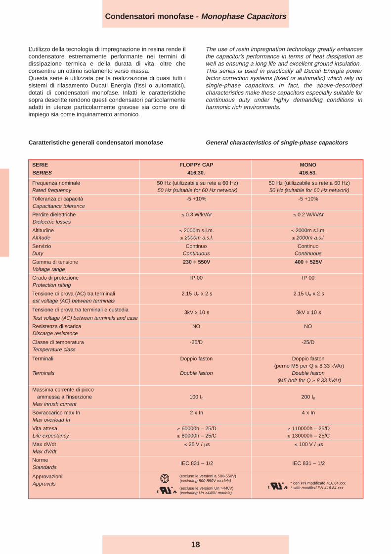
General characteristics of single-phase capacitorsCaratteristiche generali condensatori monofase
L’utilizzo della tecnologia di impregnazione in resina rende ilcondensatore estremamente performante nei termini didissipazione termica e della durata di vita, oltre checonsentire un ottimo isolamento verso massa.Questa serie è utilizzata per la realizzazione di quasi tutti isistemi di rifasamento Ducati Energia (fissi o automatici),dotati di condensatori monofase. Infatti le caratteristichesopra descritte rendono questi condensatori particolarmenteadatti in utenze particolarmente gravose sia come ore diimpiego sia come inquinamento armonico.
The use of resin impregnation technology greatly enhancesthe capacitor’s performance in terms of heat dissipation aswell as ensuring a long life and excellent ground insulation.This series is used in practically all Ducati Energia powerfactor correction systems (fixed or automatic) which rely onsingle-phase capacitors. In fact, the above-describedcharacteristics make these capacitors especially suitable forcontinuous duty under highly demanding conditions inharmonic rich environments.
Condensatori monofase - Monophase Capacitors
* con PN modificato 416.84.xxx* with modified PN 416.84.xxx
19
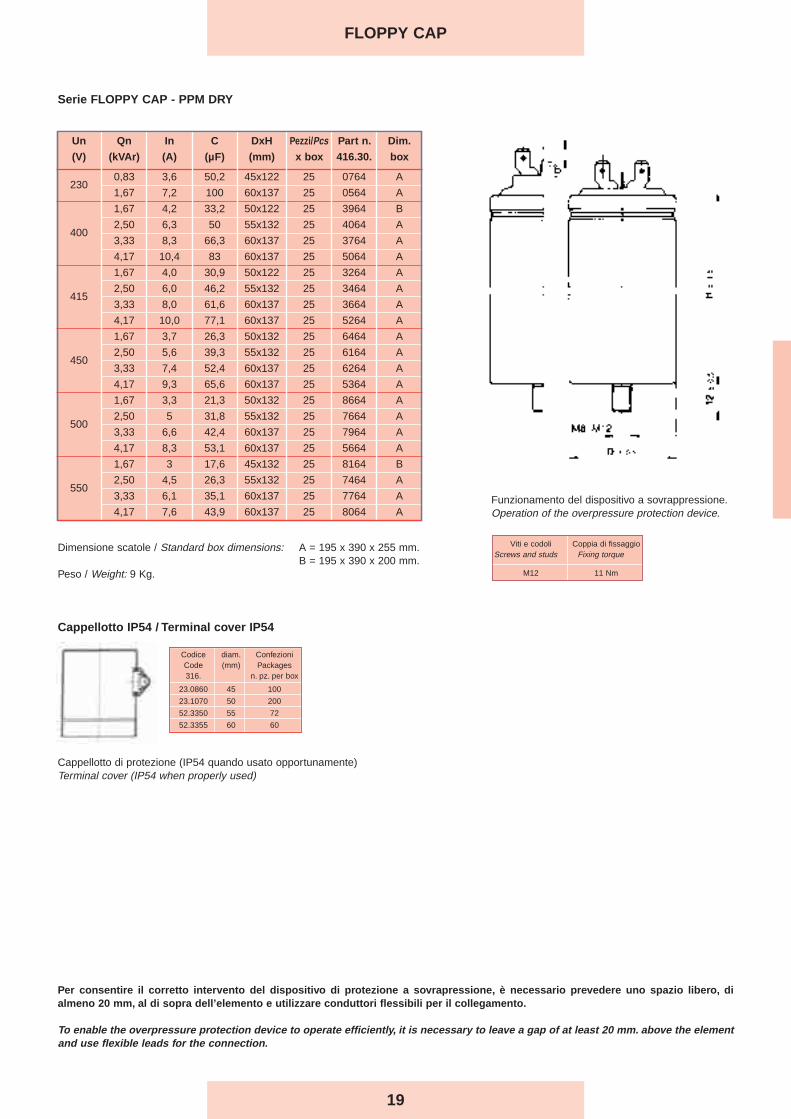
Un Qn In C DxH Pezzi/Pcs Part n. Dim.
(V) (kVAr) (A) (µF) (mm) x box 416.30. box
2300,83 3,6 50,2 45x122 25 0764 A
1,67 7,2 100 60x137 25 0564 A
1,67 4,2 33,2 50x122 25 3964 B
4002,50 6,3 50 55x132 25 4064 A
3,33 8,3 66,3 60x137 25 3764 A
4,17 10,4 83 60x137 25 5064 A
1,67 4,0 30,9 50x122 25 3264 A
4152,50 6,0 46,2 55x132 25 3464 A
3,33 8,0 61,6 60x137 25 3664 A
4,17 10,0 77,1 60x137 25 5264 A
1,67 3,7 26,3 50x132 25 6464 A
4502,50 5,6 39,3 55x132 25 6164 A
3,33 7,4 52,4 60x137 25 6264 A
4,17 9,3 65,6 60x137 25 5364 A
1,67 3,3 21,3 50x132 25 8664 A
5002,50 5 31,8 55x132 25 7664 A
3,33 6,6 42,4 60x137 25 7964 A
4,17 8,3 53,1 60x137 25 5664 A
1,67 3 17,6 45x132 25 8164 B
5502,50 4,5 26,3 55x132 25 7464 A
3,33 6,1 35,1 60x137 25 7764 A
4,17 7,6 43,9 60x137 25 8064 A
Serie FLOPPY CAP - PPM DRY
Per consentire il corretto intervento del dispositivo di protezione a sovrapressione, è necessario prevedere uno spazio libero, dialmeno 20 mm, al di sopra dell’elemento e utilizzare conduttori flessibili per il collegamento.
To enable the overpressure protection device to operate efficiently, it is necessary to leave a gap of at least 20 mm. above the elementand use flexible leads for the connection.
FLOPPY CAP
Dimensione scatole / Standard box dimensions: A = 195 x 390 x 255 mm.B = 195 x 390 x 200 mm.
Peso / Weight: 9 Kg.
Funzionamento del dispositivo a sovrappressione.Operation of the overpressure protection device.
Viti e codoli Coppia di fissaggioScrews and studs Fixing torque
M12 11 Nm
Codice diam. ConfezioniCode (mm) Packages316. n. pz. per box
23.0860 45 100
23.1070 50 200
52.3350 55 72
52.3355 60 60
Cappellotto IP54 / Terminal cover IP54
Cappellotto di protezione (IP54 quando usato opportunamente)Terminal cover (IP54 when properly used)
20
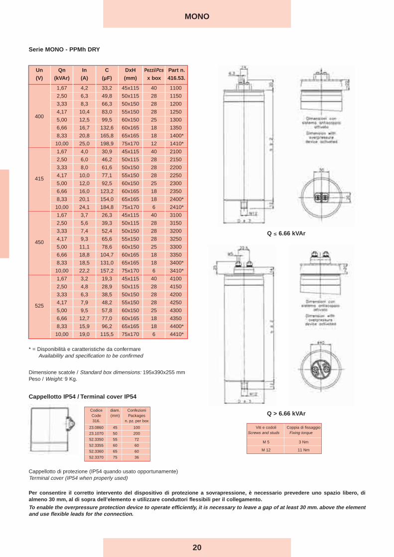
Serie MONO - PPMh DRY
Per consentire il corretto intervento del dispositivo di protezione a sovrapressione, è necessario prevedere uno spazio libero, dialmeno 30 mm, al di sopra dell’elemento e utilizzare conduttori flessibili per il collegamento.
To enable the overpressure protection device to operate efficiently, it is necessary to leave a gap of at least 30 mm. above the elementand use flexible leads for the connection.
Q > 6.66 kVAr
Q ≤ 6.66 kVAr
Un Qn In C DxH Pezzi/Pcs Part n.
(V) (kVAr) (A) (µF) (mm) x box 416.53.
1,67 4,2 33,2 45x115 40 1100
2,50 6,3 49,8 50x115 28 1150
3,33 8,3 66,3 50x150 28 1200
4,17 10,4 83,0 55x150 28 1250400
5,00 12,5 99,5 60x150 25 1300
6,66 16,7 132,6 60x165 18 1350
8,33 20,8 165,8 65x165 18 1400*
10,00 25,0 198,9 75x170 12 1410*
1,67 4,0 30,9 45x115 40 2100
2,50 6,0 46,2 50x115 28 2150
3,33 8,0 61,6 50x150 28 2200
4154,17 10,0 77,1 55x150 28 2250
5,00 12,0 92,5 60x150 25 2300
6,66 16,0 123,2 60x165 18 2350
8,33 20,1 154,0 65x165 18 2400*
10,00 24,1 184,8 75x170 6 2410*
1,67 3,7 26,3 45x115 40 3100
2,50 5,6 39,3 50x115 28 3150
3,33 7,4 52,4 50x150 28 3200
4504,17 9,3 65,6 55x150 28 3250
5,00 11,1 78,6 60x150 25 3300
6,66 18,8 104,7 60x165 18 3350
8,33 18,5 131,0 65x165 18 3400*
10,00 22,2 157,2 75x170 6 3410*
1,67 3,2 19,3 45x115 40 4100
2,50 4,8 28,9 50x115 28 4150
3,33 6,3 38,5 50x150 28 4200
5254,17 7,9 48,2 55x150 28 4250
5,00 9,5 57,8 60x150 25 4300
6,66 12,7 77,0 60x165 18 4350
8,33 15,9 96,2 65x165 18 4400*
10,00 19,0 115,5 75x170 6 4410*
* = Disponibilità e caratteristiche da confermareAvailability and specification to be confirmed
Dimensione scatole / Standard box dimensions: 195x390x255 mmPeso / Weight: 9 Kg.
MONO
Viti e codoli Coppia di fissaggioScrews and studs Fixing torque
M 5 3 Nm
M 12 11 Nm
Codice diam. ConfezioniCode (mm) Packages316. n. pz. per box
23.0860 45 100
23.1070 50 200
52.3350 55 72
52.3355 60 60
52.3360 65 60
52.3370 75 36
Cappellotto IP54 / Terminal cover IP54
Cappellotto di protezione (IP54 quando usato opportunamente)Terminal cover (IP54 when properly used)
21
Three-phase Capacitors
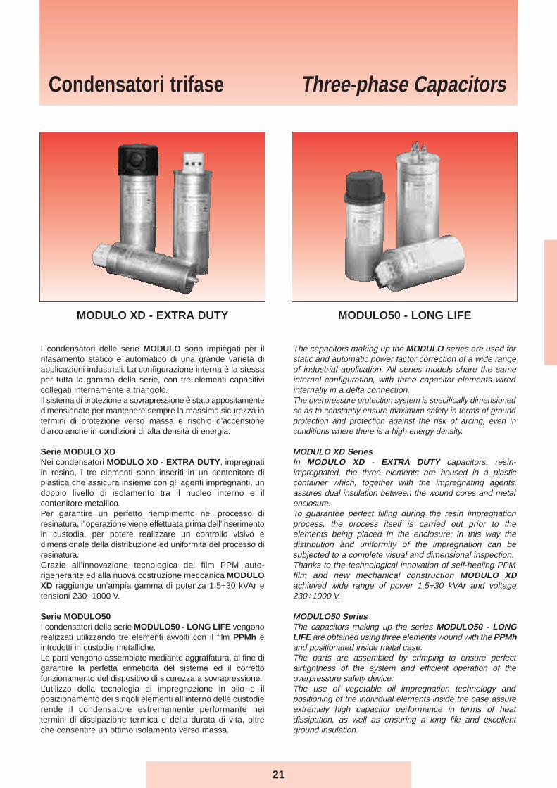
I condensatori delle serie MODULO sono impiegati per ilrifasamento statico e automatico di una grande varietà diapplicazioni industriali. La configurazione interna è la stessaper tutta la gamma della serie, con tre elementi capacitivicollegati internamente a triangolo.Il sistema di protezione a sovrapressione è stato appositamentedimensionato per mantenere sempre la massima sicurezza intermini di protezione verso massa e rischio d’accensioned’arco anche in condizioni di alta densità di energia.
Serie MODULO XDNei condensatori MODULO XD - EXTRA DUTY, impregnatiin resina, i tre elementi sono inseriti in un contenitore diplastica che assicura insieme con gli agenti impregnanti, undoppio livello di isolamento tra il nucleo interno e ilcontenitore metallico.Per garantire un perfetto riempimento nel processo diresinatura, l’ operazione viene effettuata prima dell’inserimentoin custodia, per potere realizzare un controllo visivo edimensionale della distribuzione ed uniformità del processo diresinatura.Grazie all’innovazione tecnologica del film PPM auto-rigenerante ed alla nuova costruzione meccanica MODULOXD raggiunge un’ampia gamma di potenza 1,5÷30 kVAr etensioni 230÷1000 V.
Serie MODULO50I condensatori della serie MODULO50 - LONG LIFE vengonorealizzati utilizzando tre elementi avvolti con il film PPMh eintrodotti in custodie metalliche.Le parti vengono assemblate mediante aggraffatura, al fine digarantire la perfetta ermeticità del sistema ed il correttofunzionamento del dispositivo di sicurezza a sovrapressione.L’utilizzo della tecnologia di impregnazione in olio e ilposizionamento dei singoli elementi all’interno delle custodierende il condensatore estremamente performante neitermini di dissipazione termica e della durata di vita, oltreche consentire un ottimo isolamento verso massa.
The capacitors making up the MODULO series are used forstatic and automatic power factor correction of a wide rangeof industrial application. All series models share the sameinternal configuration, with three capacitor elements wiredinternally in a delta connection.The overpressure protection system is specifically dimensionedso as to constantly ensure maximum safety in terms of groundprotection and protection against the risk of arcing, even inconditions where there is a high energy density.
MODULO XD SeriesIn MODULO XD - EXTRA DUTY capacitors, resin-impregnated, the three elements are housed in a plasticcontainer which, together with the impregnating agents,assures dual insulation between the wound cores and metalenclosure.To guarantee perfect filling during the resin impregnationprocess, the process itself is carried out prior to theelements being placed in the enclosure; in this way thedistribution and uniformity of the impregnation can besubjected to a complete visual and dimensional inspection.Thanks to the technological innovation of self-healing PPMfilm and new mechanical construction MODULO XDachieved wide range of power 1,5÷30 kVAr and voltage230÷1000 V.
MODULO50 SeriesThe capacitors making up the series MODULO50 - LONGLIFE are obtained using three elements wound with the PPMhand positionated inside metal case.The parts are assembled by crimping to ensure perfectairtightness of the system and efficient operation of theoverpressure safety device.The use of vegetable oil impregnation technology andpositioning of the individual elements inside the case assureextremely high capacitor performance in terms of heatdissipation, as well as ensuring a long life and excellentground insulation.
Condensatori trifase
MODULO XD - EXTRA DUTY MODULO50 - LONG LIFE
SERIE MODULO XD MODULO50
SERIES 416.46. 416.47.
Frequenza nominale 50 Hz (utilizzabile su rete a 60 Hz) 50 Hz (utilizzabile su rete a 60 Hz)
Rated frequency 50 Hz (suitable for 60 Hz network) 50 Hz (suitable for 60 Hz network)
Tolleranza di capacità –5+10% -5 +10%Capacitance tolerance
Perdite dielettriche ≤ 0.2W/kVAr ≤ 0.2W/kVArDielectric losses
Altitudine ≤ 2000m s.l.m ≤ 2000m s.l.m.Altitude ≤ 2000m a.s.l. ≤ 2000m a.s.l.
Servizio Continuo ContinuoDuty Continuous Continuous
Gamma di tensione 230 ÷ 1000V 400 ÷ 690VVoltage range
Grado di protezione IP20 (IP54 su richiesta) IP 20 (IP 54 su richiesta)Protection rating IP 20 (IP 54 on request) IP 20 (IP 54 on request)
Tensione di prova (AC) tra terminali 2.15 Un x 2” 2.15 Un x 2”Test voltage (AC) between terminals
Resistenza di scarica (escluso 690÷1000 V) Esterna (50V dopo 60”) Esterna (50V dopo 60’’)Discarge resistance (excluded 690÷1000 V) External (50V after 60”) External (50V after 60’’)
Tensione di prova tra terminali e Custodia 3kV x 10” (Un ≤ 660V) 3kV x 10” (Un ≤ 660V)
Test voltage between terminals and case 6kV x 10” (Un > 660V) 6kV x 10” (Un > 660V)
Classe di temperatura -25/D -25/DTemperature class
Terminali Terminali a vite Terminali a viteTerminals Screw terminals Screw terminals
Massima corrente di piccoammessa all’inserzione 200 In 200 In
Max inrush current
Sovraccarico max In 4 x In 4 x InMax overload In
Vita attesa ≥ 110000 – 25/D ≥ 110000 – 25/DLife expectancy ≥ 130000 – 25/C ≥ 130000 – 25/C
Max dV/dt 100 V / μs 100 V / μsMax dV/dt
Norme IEC 831 – 1/2 IEC 831 – 1/2StandardsApprovazioniApprovals
22
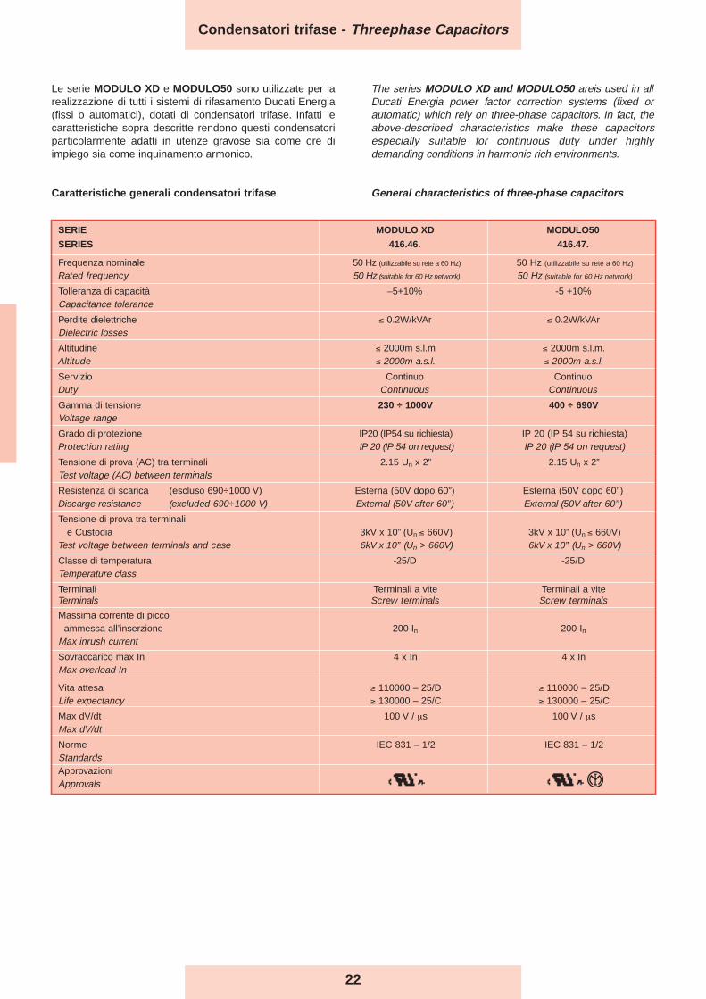
Caratteristiche generali condensatori trifase General characteristics of three-phase capacitors
Le serie MODULO XD e MODULO50 sono utilizzate per larealizzazione di tutti i sistemi di rifasamento Ducati Energia(fissi o automatici), dotati di condensatori trifase. Infatti lecaratteristiche sopra descritte rendono questi condensatoriparticolarmente adatti in utenze gravose sia come ore diimpiego sia come inquinamento armonico.
The series MODULO XD and MODULO50 areis used in allDucati Energia power factor correction systems (fixed orautomatic) which rely on three-phase capacitors. In fact, theabove-described characteristics make these capacitorsespecially suitable for continuous duty under highlydemanding conditions in harmonic rich environments.
Condensatori trifase - Threephase Capacitors
23
Codice diam. ConfezioniCode (mm) Packages
316.52 n. pz. per box
.3360 65 60
.3370 75 36
.3338 85 30
.3339 90 30
.3340 100 30
.3341 116 30
CONDENSATORECAPACITOR
CAPPELLOTTOTERMINAL COVER
Cappellotto IP54 / Terminal cover IP54
Cappellotto di protezione (IP54 quando usato opportunamente)Terminal cover (IP54 when properly used)
MODULO XD
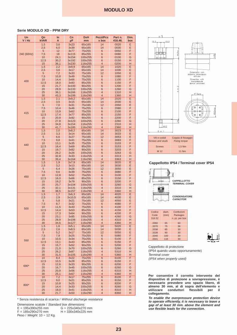
Serie MODULO XD - PPM DRY
Per consentire il corretto intervento deldispositivo di protezione a sovrapressione, ènecessario prevedere uno spazio libero, dialmeno 30 mm, al di sopra dell’elemento eutilizzare conduttori flessibili per ilcollegamento.To enable the overpressure protection deviceto operate efficiently, it is necessary to leave agap of at least 30 mm. above the element anduse flexible leads for the connection.
Viti e codoli Coppia di fissaggioScrews and studs Fixing torque
Screws 1,5 Nm
M 12 11 Nm
* Senza resistenza di scarica / Without discharge resistance
Dimensione scatole / Standard box dimensions:E = 195x390x255 mm G = 225x340x270 mmF = 185x290x270 mm H = 330x340x225 mmPeso / Weight: 10 ÷ 12 Kg.
Un Qn In Cn DxH Pezzi/Pcs Part n. Dim.V / Hz kVAR A µF mm x box 416.46. box
1,5 3,6 3x23 65x165 14 0020 E2,5 6,0 3x39 65x165 14 0030 E5 12 3x77 75x255 6 0050 F
240 (60Hz) 7,5 18 3x115 85x255 6 0080 F10 24,1 3x154 100x255 6 0100 G
12,5 30,2 3x192 100x255 6 0150 H15 36,1 3x230 116x255 4 0200 H1,5 2,2 3x9,9 65x165 14 1020 E2,5 3,6 3x17 65x165 14 1030 E5 7,2 3x33 75x165 12 1050 E
7,5 10,8 3x49 75x255 6 1080 F
400 10 14,4 3x66 75x255 6 1100 F12,5 18,0 3x83 85x255 6 1150 F15 21,7 3x100 90x255 6 1200 F20 28,9 3x133 100x255 6 1260 G25 36,1 3x166 116x255 4 1310 H30 43,3 3x199 116x290 4 1360 H1,5 2,1 3x9,2 65x165 14 2020 E2,5 3,5 3x15 65x165 14 2030 E5 7,0 3x31 75x165 12 2050 E
7,5 10,4 3x46 75x255 6 2080 F
415 10 13,9 3x62 75x255 6 2100 F12,5 17,4 3x77 85x255 6 2150 F15 20,9 3x92 90x255 6 2200 F20 27,8 3x123 100x255 6 2260 G25 34,8 3x154 116x255 4 2310 H30 41,7 3x185 116x290 4 2360 H1,5 2,0 3x8,2 65x165 14 3023 E2,5 3,3 3x14 65x165 14 3033 E5 6,6 3x27 75x165 12 3053 E
7,5 9,8 3x41 75x255 6 3083 F
440 10 13,1 3x35 75x255 6 3103 F12,5 16,4 3x69 85x255 6 3153 F15 19,7 3x82 90x255 6 3203 F20 26,2 3x26 100x255 6 3263 G25 32,8 3x33 116x255 4 3313 H30 39,4 3x164 116x290 4 3363 H1,5 1,9 3x7,9 65x165 14 3020 E2,5 3,2 3x13 65x165 14 3030 E5 6,4 3x26 75x165 12 3050 E
7,5 9,6 3x39 75x255 6 3080 F
450 10 12,8 3x52 75x255 6 3100 F12,5 16,0 3x66 85x255 6 3150 F15 19,2 3x79 90x255 6 3200 F20 25,7 3x10⁴ 100x255 6 3260 G25 32,1 3x131 116x255 4 3310 H30 38,5 3x157 116x290 4 3360 H1,5 1,7 3x6,3 65x165 14 4020 E2,5 2,9 3x10,5 65x165 14 4030 E5 5,8 3x21 75x165 12 4050 E
7,5 8,7 3x32 75x255 6 4080 F
500 10 11,5 3x43 75x255 6 4100 F12,5 14,4 3x53 85x255 6 4150 F15 17,3 3x64 90x255 6 4200 F20 23,1 3x85 100x255 6 4260 G25 28,9 3x10⁶ 116x255 4 4310 H30 34,6 3x127 116x290 4 4360 H1,5 1,6 3x5,1 65x165 14 5020 E2,5 2,6 3x8,5 65x165 14 5030 E5 5,2 3x17 75x165 12 5050 E
7,5 7,9 3x25 75x255 6 5080 F
550 10 10,5 3x34 75x255 6 5100 F12,5 13,1 3x43 85x255 6 5150 F15 15,7 3x52 90x255 6 5200 F20 21,0 3x70 100x255 6 5260 G25 26,2 3x87 116x255 4 5310 H30 31,5 3x10⁵ 116x290 4 5360 H10 8,4 3x22 75x255 6 6100 F
12,5 10,5 3x28 85x255 6 6150 F
690* 15 12,6 3x33 90x255 6 6200 F20 16,7 3x45 100x255 6 6260 G25 20,9 3x56 116x255 4 6310 H30 25,1 3x67 116x290 4 6360 H10 7,2 3x17 75x255 6 8100 F
12,5 9,0 3x21 85x255 6 8150 F
800* 15 10,8 3x25 90x255 6 8200 F20 14,4 3x33 100x255 6 8260 G25 18,0 3x41 116x255 4 8310 H30 21,7 3x50 116x290 4 8360 H

24
MODULO XD 60Hz Ratings
Tabella condensatori trifase per reti a 60Hz / Three-phase cylindrical capacitors 60 Hz Network Table
SERIE MODULO XD - PPM DRY - 60 Hz RATINGS
* Senza resistenza di scarica / Without discharge resistance
Dimensione scatole / Standard box dimensions:E = 195x390x255 mm G = 225x340x270 mmF = 185x290x270 mm H = 330x340x225 mmPeso / Weight: 10 ÷ 12 Kg.
Un Qn In Cn DxH Pcs Part n. Dim.(V) (kVAr) (A) (µF) (mm) x box 416.46. box
1,5 3,6 3x23,1 65x165 14 0020 E2,5 6,0 3x38,5 65x165 14 0030 E5 12,0 3x77 75x255 6 0050 F
240 7,5 18,0 3x115 85x255 6 0080 F10 24,1 3x154 100x255 6 0100 G
12,5 30,2 3x192 100x255 6 0150 H15 36,1 3x230 116x255 4 0200 H1,8 2,6 3x9,9 65x165 14 1020 E3 4,3 3x17 65x165 14 1030 E6 8,7 3x33 75x165 12 1050 F9 13,0 3x49 75x255 6 1080 F
400 12 17,3 3x66 75x255 6 1100 F15 21,7 3x83 85x255 6 1150 F18 26,0 3x100 90x255 6 1200 F24 34,6 3x133 100x255 6 1260 G30 43,3 3x166 116x255 4 1310 H1,8 2,5 3x9,2 65x165 14 2020 E3 4,2 3x15 65x165 14 2030 E6 8,3 3x31 75x165 12 2050 F9 12,5 3x46 75x255 6 2080 F
415 12 16,7 3x62 75x255 6 2100 F15 20,9 3x77 85x255 6 2150 F18 25,0 3x92 90x255 6 2200 F24 33,4 3x123 100x255 6 2260 G30 41,7 3x154 116x255 4 2310 H1,8 2,4 3x8,2 65x165 14 3023 E3 3,9 3x14 65x165 14 3033 E6 7,9 3x27 75x165 12 3053 F9 11,8 3x41 75x255 6 3083 F
440 12 15,7 3x55 75x255 6 3103 F15 19,7 3x69 85x255 6 3153 F18 23,6 3x82 90x255 6 3203 F24 31,5 3x26 100x255 6 3283 G30 39,4 3x33 116x255 4 3313 H1,8 2,3 3x7,9 65x165 14 3020 E3 3,8 3x13 65x165 14 3030 E6 7,7 3x26 75x165 12 3050 F9 11,5 3x39 75x255 6 3080 F
450 12 15,4 3x52 75x255 6 3100 F15 19,2 3x66 85x255 6 3150 F18 23,1 3x79 90x255 6 3200 F24 30,8 3x10⁴ 100x255 6 3260 G30 38,5 3x131 116x255 4 3310 H1,7 2,0 3x6,3 65x165 14 4020 E2,8 3,4 3x10,5 65x165 14 4030 E5,5 6,6 3x21 75x165 12 4050 E8,3 10,0 3x32 75x255 6 4080 F
480 11 13,2 3x43 75x255 6 4100 F13,8 16,6 3x53 85x255 6 4150 F16,6 20,0 3x64 90x255 6 4200 F22,1 26,6 3x85 100x255 6 4260 G27,6 33,2 3x10⁶ 116x255 4 4310 H33,2 39,9 3x127 116x290 4 4360 H1,6 1,8 3x5,1 65x165 14 5020 E2,7 3,0 3x8,5 65x165 14 5030 E5,5 6,0 3x17 75x165 12 5050 E8,2 9,0 3x25 75x255 6 5080 F
525 11 12,1 3x34 75x255 6 5100 F13,7 15,1 3x43 85x255 6 5150 F16,4 18,0 3x52 90x255 6 5200 F21,9 24,1 3x70 100x255 6 5260 G27,3 30,0 3x87 116x255 4 5310 H32,8 36,1 3x10⁵ 116x290 4 5360 H12 10,0 3x22 75x255 6 6100 F15 12,6 3x28 85x255 6 6150 F
690* 18 15,1 3x33 90x255 6 6200 F24 20,1 3x45 100x255 6 6260 G30 25,1 3x56 116x255 4 6310 H12 8,7 3x17 75x255 6 8100 F15 10,8 3x21 85x255 6 8150 F
800* 18 13,0 3x25 90x255 6 8200 F24 17,3 3x33 100x255 6 8260 G30 21,7 3x41 116x255 4 8310 H
Codice diam. ConfezioniCode (mm) Packages
316.52 n. pz. per box
.3360 65 60
.3370 75 36
.3338 85 30
.3339 90 30
.3340 100 30
.3341 116 30
CONDENSATORECAPACITOR
CAPPELLOTTOTERMINAL COVER
Cappellotto IP54 / Terminal cover IP54
Cappellotto di protezione (IP54 quando usato opportunamente)Terminal cover (IP54 when properly used)
Per consentire il corretto intervento deldispositivo di protezione a sovrapressione, ènecessario prevedere uno spazio libero, dialmeno 30 mm, al di sopra dell’elemento eutilizzare conduttori flessibili per ilcollegamento.To enable the overpressure protection deviceto operate efficiently, it is necessary to leave agap of at least 30 mm. above the element anduse flexible leads for the connection.
Viti e codoli Coppia di fissaggioScrews and studs Fixing torque
Screws 1,5 Nm
M 12 11 Nm

25
MODULO50
Un Qn In C DxH Pezzi/Pcs Part n. Dim.
(V) (kVAr) (A) (µF) (mm) x box 416.47. box
5 7,2 3x33 65x200 14 1050 E
7.5 10,8 3x50 65x200 14 1080 E
10 14,4 3x66 75x200 6 1100 F
40012,5 18,0 3x83 75x200 6 1150 F
15 21,6 3x100 85x200 6 1200 F
20 28,8 3x133 90x240 6 1260 F
25 36,0 3x166 100x240 6 1310 G
30 43,3 3x199 116x240 4 1360 H
5 6,9 3x31 65x200 14 2050 E
7.5 10,4 3x46 65x200 14 2080 E
10 13,9 3x62 75x200 6 2100 F
41512,5 17,3 3x77 75x200 6 2150 F
15 20,8 3x92 85x200 6 2200 F
20 27,8 3x123 90x240 6 2260 F
25 34,7 3x154 100x240 6 2310 G
30 41,7 3x185 116x240 4 2360 H
5 6,6 3x27 65x200 14 3053 E
7.5 9,8 3x41 65x200 14 3083 E
10 13,1 3x55 75x200 6 3103 F
44012,5 16,4 3x69 75x200 6 3153 F
15 19,7 3x82 85x200 6 3203 F
20 26,2 3x110 90x240 6 3263 F
25 32,8 3x137 100x240 6 3313 G
30 39,4 3x164 116x240 4 3363 H
5 6,4 3x26 65x200 14 3050 E
7.5 9,6 3x39 65x200 14 3080 E
10 12,8 3x52 75x200 6 3100 F
45012,5 16,0 3x66 75x200 6 3150 F
15 19,2 3x79 85x200 6 3200 F
20 25,6 3x10⁵ 90x240 6 3260 F
25 32,0 3x131 100x240 6 3310 G
30 38,4 3x157 116x240 4 3360 H
5 5,5 3x19 65x200 14 4050 E
7.5 8,2 3x29 65x200 14 4080 E
10 11,0 3x39 75x200 6 4100 F
52512,5 13,7 3x48 75x200 6 4150 F
15 16,5 3x58 85x200 6 4200 F
20 21,9 3x77 90x240 6 4260 F
25 27,4 3x96 100x240 6 4310 G
30 32,9 3x116 116x240 4 4360 H
10 8,3 3x22 75x200 6 6100 F
690*
12,5 10,4 3x28 75x200 6 6150 F
15 12,5 3x33 85x200 6 6200 F
20 16,7 3x45 90x240 6 6260 F
25 20,9 3x56 100x240 6 6310 G
30 25,1 3x67 116x240 4 6360 H
Serie MODULO50 - PPMh OIL
* Senza resistenza di scarica / Without discharge resistance
Dimensione scatole / Standard box dimensions:E = 195x390x255 mm G = 225x340x270 mmF = 185x290x270 mm H = 330x340x225 mmPeso / Weight: 10 ÷ 12 Kg.
Codice diam. ConfezioniCode (mm) Packages
316.52 n. pz. per box
.3360 65 60
.3370 75 36
.3338 85 30
.3339 90 30
.3340 100 30
.3341 116 30
CONDENSATORECAPACITOR
CAPPELLOTTOTERMINAL COVER
Cappellotto IP54 / Terminal cover IP54
Cappellotto di protezione (IP54 quando usato opportunamente)Terminal cover (IP54 when properly used)
Per consentire il corretto intervento deldispositivo di protezione a sovrapressione, ènecessario prevedere uno spazio libero, dialmeno 30 mm, al di sopra dell’elemento eutilizzare conduttori flessibili per ilcollegamento.To enable the overpressure protection deviceto operate efficiently, it is necessary to leave agap of at least 30 mm. above the element anduse flexible leads for the connection.
Viti e codoli Coppia di fissaggioScrews and studs Fixing torque
Screws 1,5 Nm
M 12 11 Nm
26
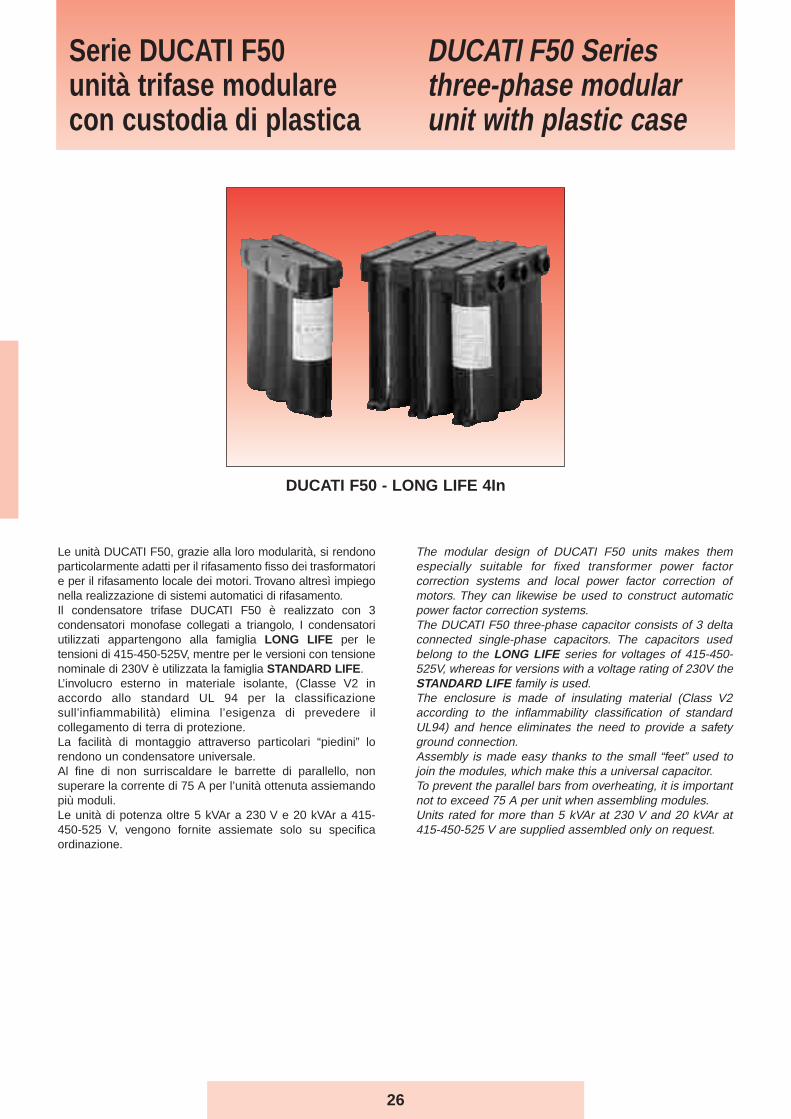
The modular design of DUCATI F50 units makes themespecially suitable for fixed transformer power factorcorrection systems and local power factor correction ofmotors. They can likewise be used to construct automaticpower factor correction systems.The DUCATI F50 three-phase capacitor consists of 3 deltaconnected single-phase capacitors. The capacitors usedbelong to the LONG LIFE series for voltages of 415-450-525V, whereas for versions with a voltage rating of 230V theSTANDARD LIFE family is used.The enclosure is made of insulating material (Class V2according to the inflammability classification of standardUL94) and hence eliminates the need to provide a safetyground connection.Assembly is made easy thanks to the small “feet” used tojoin the modules, which make this a universal capacitor.To prevent the parallel bars from overheating, it is importantnot to exceed 75 A per unit when assembling modules.Units rated for more than 5 kVAr at 230 V and 20 kVAr at415-450-525 V are supplied assembled only on request.
Le unità DUCATI F50, grazie alla loro modularità, si rendonoparticolarmente adatti per il rifasamento fisso dei trasformatorie per il rifasamento locale dei motori. Trovano altresì impiegonella realizzazione di sistemi automatici di rifasamento.Il condensatore trifase DUCATI F50 è realizzato con 3condensatori monofase collegati a triangolo, I condensatoriutilizzati appartengono alla famiglia LONG LIFE per letensioni di 415-450-525V, mentre per le versioni con tensionenominale di 230V è utilizzata la famiglia STANDARD LIFE.L’involucro esterno in materiale isolante, (Classe V2 inaccordo allo standard UL 94 per la classificazionesull’infiammabilità) elimina l’esigenza di prevedere ilcollegamento di terra di protezione.La facilità di montaggio attraverso particolari “piedini” lorendono un condensatore universale.Al fine di non surriscaldare le barrette di parallello, nonsuperare la corrente di 75 A per l’unità ottenuta assiemandopiù moduli.Le unità di potenza oltre 5 kVAr a 230 V e 20 kVAr a 415-450-525 V, vengono fornite assiemate solo su specificaordinazione.
Serie DUCATI F50unità trifase modularecon custodia di plastica
DUCATI F50 Seriesthree-phase modularunit with plastic case
DUCATI F50 - LONG LIFE 4In
27
DUCATI F50
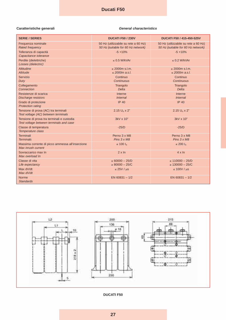
SERIE / SERIES DUCATI F50 / 230V DUCATI F50 / 415-450-525V
Frequenza nominale 50 Hz (utilizzabile su rete a 60 Hz) 50 Hz (utilizzabile su rete a 60 Hz)Rated frequency 50 Hz (suitable for 60 Hz network) 50 Hz (suitable for 60 Hz network)
Tolleranza di capacità -5 +10% -5 +10%Capacitance tolerance
Perdite (dielettriche) ≤ 0.5 W/kVAr ≤ 0.2 W/kVArLosses (dielectric)
Altitudine ≤ 2000m s.l.m. ≤ 2000m s.l.m.Altitude ≤ 2000m a.s.l. ≤ 2000m a.s.l.
Servizio Continuo ContinuoDuty Continuous Continuous
Collegamento Triangolo TriangoloConnection Delta Delta
Resistenze di scarica Interne InterneDischarge resistors Internal Internal
Grado di protezione IP 40 IP 40Protection rating
Tensione di prova (AC) tra terminali 2.15 Un x 2” 2.15 Un x 2”Test voltage (AC) between terminals
Tensione di prova tra terminali e custodia 3kV x 10” 3kV x 10”Test voltage between terminals and case
Classe di temperatura -25/D -25/DTemperature class
Terminali Perno 3 x M8 Perno 3 x M8Terminals Pins 3 x M8 Pins 3 x M8
Massima corrente di picco ammessa all’inserzione ≤ 100 In ≤ 200 InMax inrush current
Sovraccarico max In 2 x In 4 x InMax overload In
Classe di vita ≥ 60000 – 25/D ≥ 110000 – 25/DLife expectancy ≥ 80000 – 25/C ≥ 130000 – 25/C
Max dV/dt ≤ 25V / μs ≤ 100V / μsMax dV/dt
Norme EN 60831 – 1/2 EN 60831 – 1/2Standards
General characteristics Caratteristiche generali
Ducati F50
28
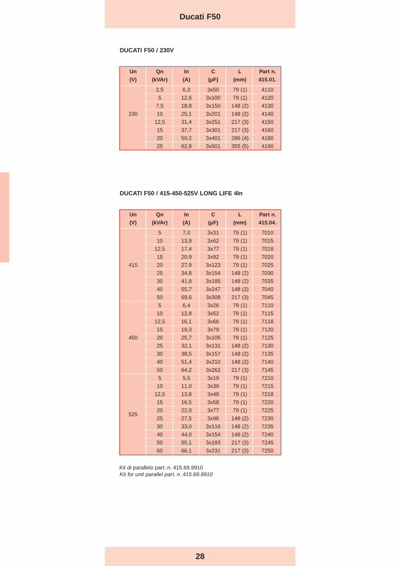
Un Qn In C L Part n.
(V) (kVAr) (A) (µF) (mm) 415.01.
2,5 6,3 3x50 79 (1) 4110
5 12,6 3x100 79 (1) 4120
7,5 18,8 3x150 148 (2) 4130
230 10 25,1 3x201 148 (2) 4140
12,5 31,4 3x251 217 (3) 4150
15 37,7 3x301 217 (3) 4160
20 50,2 3x401 286 (4) 4180
25 62,8 3x501 355 (5) 4190
DUCATI F50 / 230V
DUCATI F50 / 415-450-525V LONG LIFE 4In
Un Qn In C L Part n.
(V) (kVAr) (A) (µF) (mm) 415.04.
5 7,0 3x31 79 (1) 7010
10 13,9 3x62 79 (1) 7015
12,5 17,4 3x77 79 (1) 7018
15 20,9 3x92 79 (1) 7020
415 20 27,9 3x123 79 (1) 7025
25 34,8 3x154 148 (2) 7030
30 41,8 3x185 148 (2) 7035
40 55,7 3x247 148 (2) 7040
50 69,6 3x308 217 (3) 7045
5 6,4 3x26 79 (1) 7110
10 12,8 3x52 79 (1) 7115
12,5 16,1 3x66 79 (1) 7118
15 19,3 3x79 79 (1) 7120
450 20 25,7 3x10⁵ 79 (1) 7125
25 32,1 3x131 148 (2) 7130
30 38,5 3x157 148 (2) 7135
40 51,4 3x210 148 (2) 7140
50 64,2 3x262 217 (3) 7145
5 5,5 3x19 79 (1) 7210
10 11,0 3x39 79 (1) 7215
12,5 13,8 3x48 79 (1) 7218
15 16,5 3x58 79 (1) 7220
52520 22,0 3x77 79 (1) 7225
25 27,5 3x96 148 (2) 7230
30 33,0 3x116 148 (2) 7235
40 44,0 3x154 148 (2) 7240
50 55,1 3x193 217 (3) 7245
60 66,1 3x231 217 (3) 7250
Ducati F50
Kit di parallelo part. n. 415.69.9910Kit for unit parallel part. n. 415.69.9910

29
I regolatori automatici di potenza reattiva sono sistemi amicroprocessore che gestiscono automaticamente lebatterie di condensatori per compensare la potenza reattivaassorbita dal carico.La nuova serie REGO digitale, oltre ad una elevataaffidabilità e precisione nella compensazione della potenzareattiva, si presenta con un’interfaccia utente, per laconfigurazione e la programmazione, estremamente intuitivae adatta a tutte le applicazioni. Il nuovo microprocessoreconsente inoltre una migliore gestione delle innovativefunzioni implementate, tra cui la facilità di installazione, inquanto viene richiesto come unico parametro il valoredel rapporto del TA.
Le versioni disponibili sono:- con 5 relè di uscita nelle dimensioni 96 x 96 mm- con 7 oppure 12 relè di uscita dimensioni 144 x 144 mm- con 12 transistor di uscita (fast switching), dimensioni
144x144 mm
L’inserzione e la disinserzione delle batterie di condensatoriavviene quando la potenza reattiva capacitiva necessaria adelevare il cosϕ del carico al valore impostato sul regolatore,supera il 70% della potenza della prima batteria per il tempocorrispondente al ritardo programmato.
Questi regolatori, oltre alle funzioni classiche assolvonoanche funzioni di misura, protezione e acquisizione dati pertrasmissione e memorizzazione sul PC (solo per i modelliREGO7-12 e RAPID).I modelli REGO 7-12 e RAPID possono inoltre scambiaredati in rete con altri strumenti prodotti da DUCATI ENERGIA.
Automatic reactive power control relays are microprocessorcontrolled systems that automatically manage capacitorbanks to compensate for the reactive power absorbed by theload.The new digital REGO series not only offers high reliabilityand accuracy in reactive power compensation but also auser interface for configuration and programming, which isextremely intuitive and suitable for all applications.The new microprocessor also permits a bettermanagement of the innovative functions implemented,including easy installation, as just the CT valueparameter is requested.
The following versions are available:- with 5 output relays, dimensions 96 x 96 mm- with 7 or 12 output relays, dimensions 144 x 144 mm- with 12 output transistor (fast switching), dimensions
144x144 mm
Capacitor banks are switched on and off when the capacitivereactive power required to raise the load cosj to the value seton the controller exceeds 70% of the power of the first bankfor a time corresponding to the set delay.
In addition to the standard functions, these control relaysalso perform measurement and protection functions andacquire data to be transmitted and stored in a PC (onlymodels REGO7-12 and RAPID). The REGO 7-12 andRAPID models can also exchange data with other network-connected DUCATI ENERGIA instruments.
REGOregolatori di potenza reattiva
REGOreactivepower controllers
30
Le caratteristiche più innovative del REGO sono:- Unico parametro da impostare in fase di installazione:rapporto del TA (esempio 1000/5: impostare 200).- Verso di corrente del TA automaticamente adattato ai rife-rimenti interni del regolatore.- Regolazione lineare del cosϕ da 0,8 induttivo a 0,8 capa-citivo.- Regolazione automatica C/k.- Comando Manuale delle batterie in totale indipendenzadella misura effettuata in linea.- Inibizione dei relè di uscita non impiegati.- Impostazione per rifasamento di generatori asincroni.- Impostazione dei tempi di intervento da 0,5 a 300 sec.
Impostazione del tempo di scarica da 5 a 255 sec.- REGO RAPID: tempo di intervento da 100 ms a 5 sec.
Tempo di scarica non necessario.
- Nr. 3 logiche di inserzione/disinserzione batterie, con rico-noscimento automatico:- Logica Universale Geometrica (1:2:4), permette di ottene-re un numero elevato di gradini minimizzando il numero dibatterie;- Logica Lineare Circolare (1:1:1), utilizzabile quando le bat-terie sono tutte uguali, il comando dei relè di uscita avvienecon sequenza circolare, ottenendo una distribuzione più uni-forme delle manovre sui contattori;- Logica Lineare Semicircolare (1:2:2), intermedie fra le pre-cedenti consente di ottenere un numero di gradini più eleva-to rispetto alla logica (1:1:1).
I modelli REGO tramite il display sul frontale visualizza-no:- Cosϕ di linea;- Corrente di linea;- Tensione di rete;- Potenza attiva in linea;- Potenza reattiva in linea;- Distorsione della corrente del TA (THDI);- n. di manovre effettuate da ogni contattore;- n. di interventi degli allarmi;- Potenze dei singoli gradini;- Temperatura interna quadro nella zona vicina al rego-latore.
Il SISTEMA DI PROTEZIONE a salvaguardia delrifasamento comprende:- Allarme da sovratensione, attiva anche quando nessuna
batteria è inserita, protegge il regolatore da sovratensionimaggiori di quelle ammesse, di durata superiore ai 30secondi;
- Protezione da sovratemperatura, attiva anche quandonessuna batteria è inserita, interviene quando latemperatura in prossimità del regolatore supera il limiteimpostato per almeno 15 secondi;
- Protezione da sovraccarico armonico, protegge icondensatori da sovraccarico armonico eccessivo;
- Allarme per mancato rifasamento, segnala che il cosj èstato inferiore a quello impostato per un tempo maggiore didue ore con tutte le batterie inserite;
- Protezione da mancanza di tensione, diseccita i relèquando la tensione manca per più di due periodi. Al suoritorno il regolatore riprenderà a funzionare sotto il controlloautomatico.
A meno dell’ultima protezione, l’intervento delle protezionipuò essere riportato a distanza per mezzo di un contattopulito. Tutte le protezioni (tranne l'ultima) sono di defaultautoripristinabili (il regolatore riprende il funzionamentodopo 30 minuti di standby in condizione di allarme), epossono essere eventualmente inibite.
The most innovative features of REGO are:- Sole parameter to be set up during installation: CTratio (i.e 1000/5 : set 200).- CT circulation direction is automatically adjusted to controlrelay internal data.- Cosϕ linear setting from 0.8 IND to 0.8 CAP.- C/k automatic setting.- Banks manual control, regardless of the line value mea-sured. - Inhibition of the unused output relays.- Setting for power factor correction of asynchronous gene-rators.- Operating time setting from 0.5 to 300 sec.
Discharge time setting from 5 to 255 sec.- REGO RAPID: operating time from 100 ms to 5 sec.
Discharge time not needed
- 3 logics to connect/disconnect banks, with automaticdetection:- Universal geometric logic (1:2:4), in which it is possible toobtain a high number of steps, while minimising the numberof banks;- Circular and linear logic (1:1:1), in which the output relaysare controlled in a circular sequence, thus allowing a moreeven distribution of operations on contacts and considerablyreducing maintenance required;- Semicircular and linear logic (1:2:2), in which it is possibleto obtain a higher number of steps than the logic (1:1:1).
The REGO family shows on its front display:- Line Cosϕ;- Line current;- Mains voltage;- Line active power;- Line reactive power;- CT current crest factor (THDI);- Counter of operations performed by each outputrelay;- Number of alarm conditions;- Powers of individual steps;- Internal panel inside temperature, in the area aroundthe power control relay.
The PROTECTION SYSTEM of the power factor correctionsystem includes:- Overvoltage alarm activated even when no capacitor
bank is switched on; it protects the control relay from morethan 30 seconds’ exposure to overvoltages exceeding theallowed limit;
- Overtemperature protection which is active even whenno capacitor bank is switched on; it is tripped when the airtemperature around the control relay exceeds the set limitfor at least 15 seconds;
- Harmonic overload protection, which protects thecapacitors from excessive harmonic overloads;
- Power factor correction fault alarm, which signals thatthe cosj has remained below the set value for more thantwo hours with all banks switched on;
- No voltage protection, which cuts out relays when thereis no voltage for more than two periods. When power isrestored, the controller will resume operation underautomatic control.
All protections with the exception of the latter can beremotely controlled through a clean contact.All protections (except the last one) are default self-resettable (the controller will start again after 30 minutes’ standby in a status of alert), and can beinhibited.
REGO
31
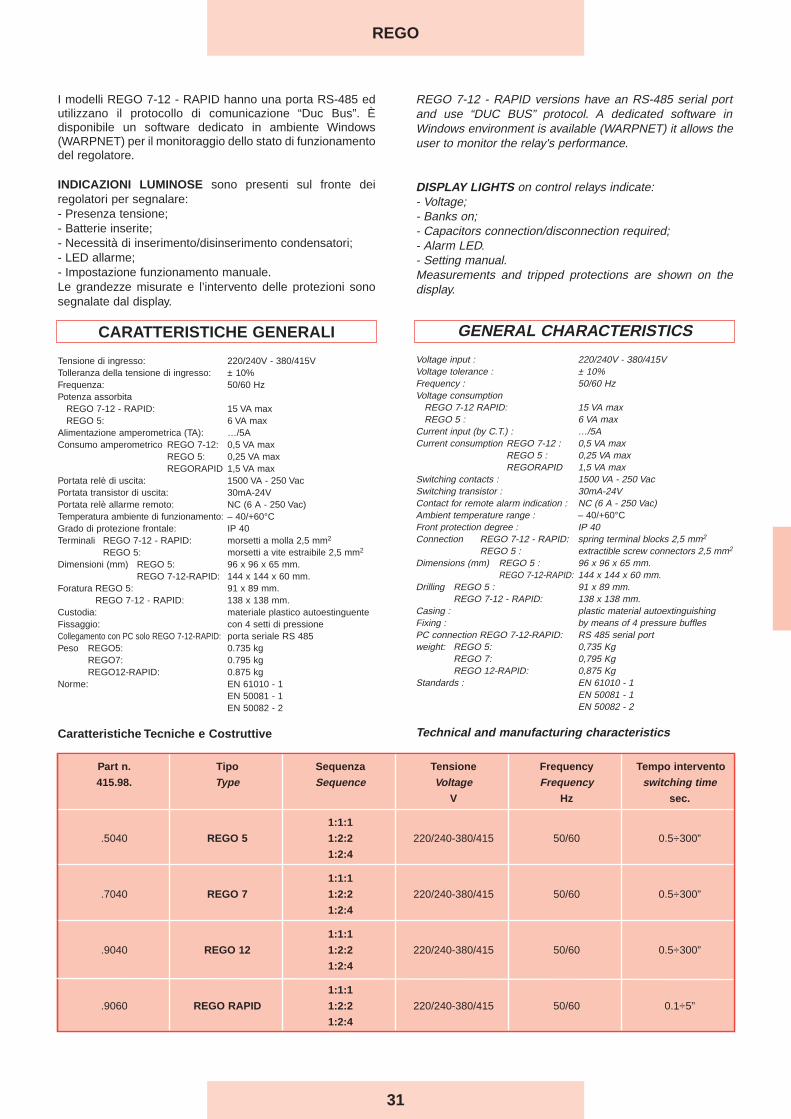
Part n. Tipo Sequenza Tensione Frequency Tempo intervento
415.98. Type Sequence Voltage Frequency switching timeV Hz sec.
1:1:1
.5040 REGO 5 1:2:2 220/240-380/415 50/60 0.5÷300”
1:2:4
1:1:1
.7040 REGO 7 1:2:2 220/240-380/415 50/60 0.5÷300”
1:2:4
1:1:1
.9040 REGO 12 1:2:2 220/240-380/415 50/60 0.5÷300”
1:2:4
1:1:1
.9060 REGO RAPID 1:2:2 220/240-380/415 50/60 0.1÷5”
1:2:4
I modelli REGO 7-12 - RAPID hanno una porta RS-485 edutilizzano il protocollo di comunicazione “Duc Bus”. Èdisponibile un software dedicato in ambiente Windows(WARPNET) per il monitoraggio dello stato di funzionamentodel regolatore.
INDICAZIONI LUMINOSE sono presenti sul fronte deiregolatori per segnalare:- Presenza tensione;- Batterie inserite;- Necessità di inserimento/disinserimento condensatori;- LED allarme;- Impostazione funzionamento manuale.Le grandezze misurate e l’intervento delle protezioni sonosegnalate dal display.
CARATTERISTICHE GENERALI
Tensione di ingresso: 220/240V - 380/415VTolleranza della tensione di ingresso: ± 10%Frequenza: 50/60 HzPotenza assorbita
REGO 7-12 - RAPID: 15 VA maxREGO 5: 6 VA max
Alimentazione amperometrica (TA): …/5AConsumo amperometrico REGO 7-12: 0,5 VA max
REGO 5: 0,25 VA maxREGORAPID 1,5 VA max
Portata relè di uscita: 1500 VA - 250 VacPortata transistor di uscita: 30mA-24VPortata relè allarme remoto: NC (6 A - 250 Vac)Temperatura ambiente di funzionamento: – 40/+60°CGrado di protezione frontale: IP 40Terminali REGO 7-12 - RAPID: morsetti a molla 2,5 mm2
REGO 5: morsetti a vite estraibile 2,5 mm2
Dimensioni (mm) REGO 5: 96 x 96 x 65 mm.REGO 7-12-RAPID: 144 x 144 x 60 mm.
Foratura REGO 5: 91 x 89 mm.REGO 7-12 - RAPID: 138 x 138 mm.
Custodia: materiale plastico autoestinguenteFissaggio: con 4 setti di pressioneCollegamento con PC solo REGO 7-12-RAPID: porta seriale RS 485Peso REGO5: 0.735 kg
REGO7: 0.795 kgREGO12-RAPID: 0.875 kg
Norme: EN 61010 - 1EN 50081 - 1EN 50082 - 2
Caratteristiche Tecniche e Costruttive
REGO 7-12 - RAPID versions have an RS-485 serial portand use “DUC BUS” protocol. A dedicated software inWindows environment is available (WARPNET) it allows theuser to monitor the relay's performance.
DISPLAY LIGHTS on control relays indicate: - Voltage;- Banks on;- Capacitors connection/disconnection required;- Alarm LED.- Setting manual.Measurements and tripped protections are shown on thedisplay.
GENERAL CHARACTERISTICS
Voltage input : 220/240V - 380/415VVoltage tolerance : ± 10%Frequency : 50/60 HzVoltage consumption
REGO 7-12 RAPID: 15 VA maxREGO 5 : 6 VA max
Current input (by C.T.) : …/5ACurrent consumption REGO 7-12 : 0,5 VA max
REGO 5 : 0,25 VA maxREGORAPID 1,5 VA max
Switching contacts : 1500 VA - 250 VacSwitching transistor : 30mA-24VContact for remote alarm indication : NC (6 A - 250 Vac)Ambient temperature range : – 40/+60°CFront protection degree : IP 40Connection REGO 7-12 - RAPID: spring terminal blocks 2,5 mm2
REGO 5 : extractible screw connectors 2,5 mm2
Dimensions (mm) REGO 5 : 96 x 96 x 65 mm.REGO 7-12-RAPID: 144 x 144 x 60 mm.
Drilling REGO 5 : 91 x 89 mm.REGO 7-12 - RAPID: 138 x 138 mm.
Casing : plastic material autoextinguishingFixing : by means of 4 pressure bufflesPC connection REGO 7-12-RAPID: RS 485 serial portweight: REGO 5: 0,735 Kg
REGO 7: 0,795 KgREGO 12-RAPID: 0,875 Kg
Standards : EN 61010 - 1EN 50081 - 1EN 50082 - 2
Technical and manufacturing characteristics
REGO
32
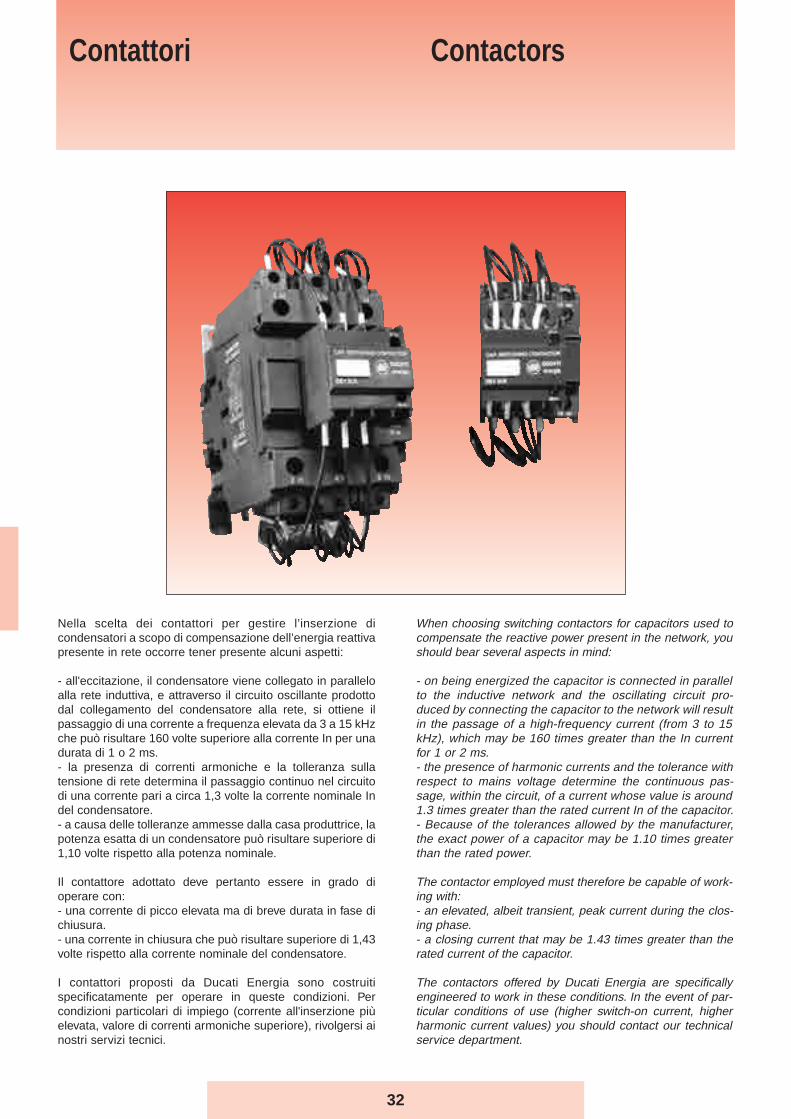
Nella scelta dei contattori per gestire l’inserzione dicondensatori a scopo di compensazione dell’energia reattivapresente in rete occorre tener presente alcuni aspetti:
- all'eccitazione, il condensatore viene collegato in paralleloalla rete induttiva, e attraverso il circuito oscillante prodottodal collegamento del condensatore alla rete, si ottiene ilpassaggio di una corrente a frequenza elevata da 3 a 15 kHzche può risultare 160 volte superiore alla corrente In per unadurata di 1 o 2 ms. - la presenza di correnti armoniche e la tolleranza sullatensione di rete determina il passaggio continuo nel circuitodi una corrente pari a circa 1,3 volte la corrente nominale Indel condensatore.- a causa delle tolleranze ammesse dalla casa produttrice, lapotenza esatta di un condensatore può risultare superiore di1,10 volte rispetto alla potenza nominale.
Il contattore adottato deve pertanto essere in grado dioperare con:- una corrente di picco elevata ma di breve durata in fase dichiusura. - una corrente in chiusura che può risultare superiore di 1,43volte rispetto alla corrente nominale del condensatore.
I contattori proposti da Ducati Energia sono costruitispecificatamente per operare in queste condizioni. Percondizioni particolari di impiego (corrente all'inserzione piùelevata, valore di correnti armoniche superiore), rivolgersi ainostri servizi tecnici.
When choosing switching contactors for capacitors used tocompensate the reactive power present in the network, youshould bear several aspects in mind:
- on being energized the capacitor is connected in parallelto the inductive network and the oscillating circuit pro-duced by connecting the capacitor to the network will resultin the passage of a high-frequency current (from 3 to 15kHz), which may be 160 times greater than the In currentfor 1 or 2 ms. - the presence of harmonic currents and the tolerance withrespect to mains voltage determine the continuous pas-sage, within the circuit, of a current whose value is around1.3 times greater than the rated current In of the capacitor.- Because of the tolerances allowed by the manufacturer,the exact power of a capacitor may be 1.10 times greaterthan the rated power.
The contactor employed must therefore be capable of work-ing with:- an elevated, albeit transient, peak current during the clos-ing phase. - a closing current that may be 1.43 times greater than therated current of the capacitor.
The contactors offered by Ducati Energia are specificallyengineered to work in these conditions. In the event of par-ticular conditions of use (higher switch-on current, higherharmonic current values) you should contact our technicalservice department.
Contattori Contactors
33
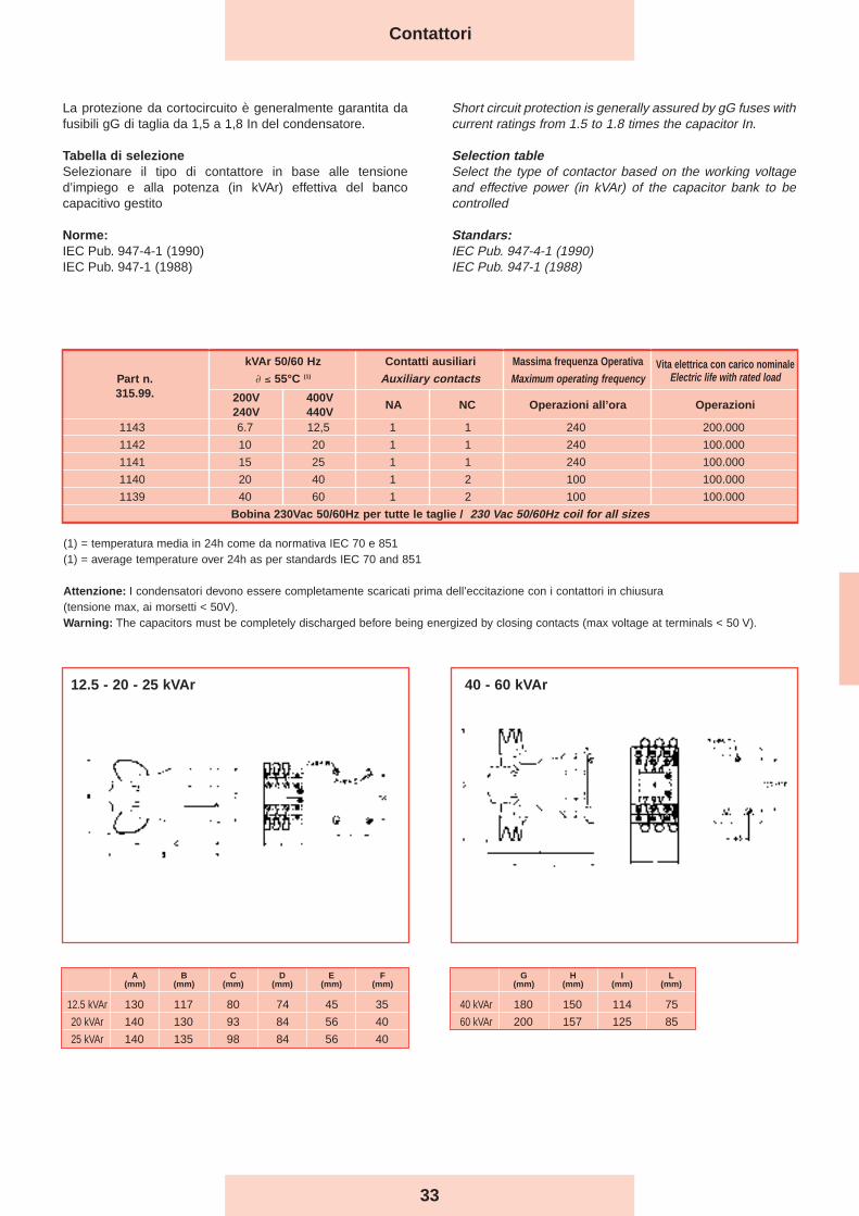
La protezione da cortocircuito è generalmente garantita dafusibili gG di taglia da 1,5 a 1,8 In del condensatore.
Tabella di selezioneSelezionare il tipo di contattore in base alle tensioned’impiego e alla potenza (in kVAr) effettiva del bancocapacitivo gestito
Norme:IEC Pub. 947-4-1 (1990)IEC Pub. 947-1 (1988)
Short circuit protection is generally assured by gG fuses withcurrent ratings from 1.5 to 1.8 times the capacitor In.
Selection tableSelect the type of contactor based on the working voltageand effective power (in kVAr) of the capacitor bank to becontrolled
Standars:IEC Pub. 947-4-1 (1990)IEC Pub. 947-1 (1988)
Contattori
1143 6.7 12,5 1 1 240 200.000
1142 10 20 1 1 240 100.000
1141 15 25 1 1 240 100.000
1140 20 40 1 2 100 100.000
1139 40 60 1 2 100 100.000
Bobina 230Vac 50/60Hz per tutte le taglie / 230 Vac 50/60Hz coil for all sizes
kVAr 50/60 Hz
∂ ≤ 55°C (1)
200V240V
400V440V
NA NC Operazioni all’ora Operazioni
Part n.315.99.
Contatti ausiliari
Auxiliary contactsMassima frequenza Operativa
Maximum operating frequencyVita elettrica con carico nominale
Electric life with rated load
(1) = temperatura media in 24h come da normativa IEC 70 e 851(1) = average temperature over 24h as per standards IEC 70 and 851
Attenzione: I condensatori devono essere completamente scaricati prima dell’eccitazione con i contattori in chiusura (tensione max, ai morsetti < 50V).Warning: The capacitors must be completely discharged before being energized by closing contacts (max voltage at terminals < 50 V).
12.5 - 20 - 25 kVAr 40 - 60 kVAr
A(mm)
B(mm)
C(mm)
D(mm)
E(mm)
F(mm)
12.5 kVAr 130 117 80 74 45 35
20 kVAr 140 130 93 84 56 40
25 kVAr 140 135 98 84 56 40
G(mm)
H(mm)
I(mm)
L(mm)
40 kVAr 180 150 114 75
60 kVAr 200 157 125 85
34
Sezionatori Isolating switches
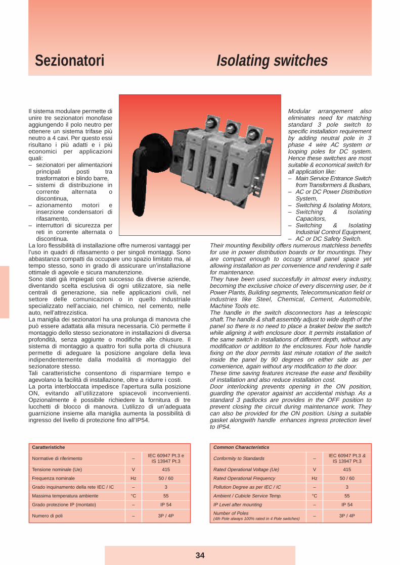
Il sistema modulare permette diunire tre sezionatori monofaseaggiungendo il polo neutro perottenere un sistema trifase piùneutro a 4 cavi. Per questo essirisultano i più adatti e i piùeconomici per applicazioniquali:– sezionatori per alimentazioni
principali posti tratrasformatori e blindo barre,
– sistemi di distribuzione incorrente alternata odiscontinua,
– azionamento motori einserzione condensatori dirifasamento,
– interruttori di sicurezza perreti in corrente alternata odiscontinua.
La loro flessibilità di installazione offre numerosi vantaggi perl’uso in quadri di rifasamento o per singoli montaggi. Sonoabbastanza compatti da occupare uno spazio limitato ma, altempo stesso, sono in grado di assicurare un’installazioneottimale di agevole e sicura manutenzione.Sono stati già impiegati con successo da diverse aziende,diventando scelta esclusiva di ogni utilizzatore, sia nellecentrali di generazione, sia nelle applicazioni civili, nelsettore delle comunicazioni o in quello industrialespecializzato nell’acciaio, nel chimico, nel cemento, nelleauto, nell’attrezzistica.La maniglia dei sezionatori ha una prolunga di manovra chepuò essere adattata alla misura necessaria. Ciò permette ilmontaggio dello stesso sezionatore in installazioni di diversaprofondità, senza aggiunte o modifiche alle chiusure. Ilsistema di montaggio a quattro fori sulla porta di chiusurapermette di adeguare la posizione angolare della levaindipendentemente dalla modalità di montaggio delsezionatore stesso.Tali caratteristiche consentono di risparmiare tempo eagevolano la facilità di installazione, oltre a ridurre i costi.La porta interbloccata impedisce l’apertura sulla posizioneON, evitando all’utilizzatore spiacevoli inconvenienti.Opzionalmente è possibile richiedere la fornitura di trelucchetti di blocco di manovra. L’utilizzo di un’adeguataguarnizione insieme alla maniglia aumenta la possibilità diingresso del livello di protezione fino all’IP54.
Modular arrangement alsoeliminates need for matchingstandard 3 pole switch tospecific installation requirementby adding neutral pole in 3phase 4 wire AC system orlooping poles for DC system.Hence these switches are mostsuitable & economical switch forall application like:– Main Service Entrance Switch
from Transformers & Busbars,– AC or DC Power Distribution
System,– Switching & Isolating Motors,– Switching & Isolating
Capacitors,– Switching & Isolating
Industrial Control Equipment,– AC or DC Safety Switch.
Their mounting flexibility offers numerous matchless benefitsfor use in power distribution boards or for mountings. Theyare compact enough to occupy small panel space yetallowing installation as per convenience and rendering it safefor maintenance.They have been used succesfully in almost every industry,becoming the exclusive choice of every discerning user, be itPower Plants, Building segments, Telecommunication field orindustries like Steel, Chemical, Cement, Automobile,Machine Tools etc.The handle in the switch disconnectors has a telescopicshaft. The handle & shaft assembly adjust to wide depth of thepanel so there is no need to place a braket below the switchwhile aligning it with enclosure door. It permits installation ofthe same switch in installations of different depth, without anymodification or addition to the enclosures. Four hole handlefixing on the door permits last minute rotation of the switchinside the panel by 90 degrees on either side as perconvenience, again without any modification to the door.These time saving features increase the ease and flexibilityof installation and also reduce installation cost.Door interlocking prevents opening in the ON position,guarding the operator againist an accidental mishap. As astandard 3 padlocks are provides in the OFF position toprevent closing the circuit during maintenance work. Theycan also be provided for the ON position. Using a suitablegasket alongwith handle enhances ingress protection levelto IP54.
Common Characteristics
Conformity to Standards –IEC 60947 Pt.3 &
IS 13947 Pt.3
Rated Operational Voltage (Ue) V 415
Rated Operational Frequency Hz 50 / 60
Pollution Degree as per IEC / IC – 3
Ambient / Cubicle Service Temp. °C 55
IP Level after mounting – IP 54
Number of Poles(4th Pole always 100% rated in 4 Pole switches)
– 3P / 4P
Caratteristiche
Normative di riferimento –IEC 60947 Pt.3 e
IS 13947 Pt.3
Tensione nominale (Ue) V 415
Frequenza nominale Hz 50 / 60
Grado inquinamento della rete IEC / IC – 3
Massima temperatura ambiente °C 55
Grado protezione IP (montato) – IP 54
Numero di poli – 3P / 4P
35
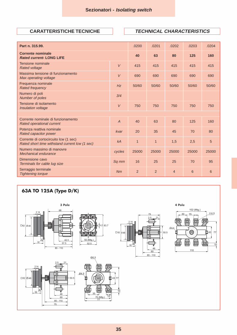
Part n. 315.99. .0200 .0201 .0202 .0203 .0204
Corrente nominaleRated current- LONG LIFE
40 63 80 125 160
Tensione nominaleRated voltage
V 415 415 415 415 415
Massima tensione di funzionamentoMax operating voltage
V 690 690 690 690 690
Frequenza nominaleRated frequency
Hz 50/60 50/60 50/60 50/60 50/60
Numero di poliNumber of poles
3/4
Tensione di isolamentoInsulation voltage
V 750 750 750 750 750
Corrente nominale di funzionamentoRated operational current
A 40 63 80 125 160
Potenza reattiva nominaleRated capacitor power
kvar 20 35 45 70 80
Corrente di cortocircuito lcw (1 sec)Rated short time withstand current lcw (1 sec)
kA 1 1 1,5 2,5 5
Numero massimo di manovreMechanical endurance
cycles 25000 25000 25000 25000 25000
Dimensione cavoTerminals for cable lug size
Sq mm 16 25 25 70 95
Serraggio terminaleTightening torque
Nm 2 2 4 6 6
Sezionatori - Isolating switch
CARATTERISTICHE TECNICHE TECHNICAL CHARACTERISTICS
36
Sezionatori - Isolating switch
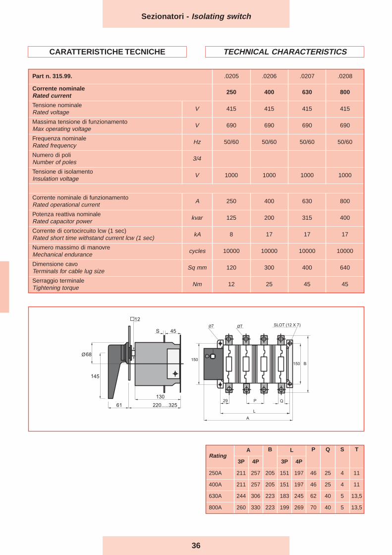
Part n. 315.99. .0205 .0206 .0207 .0208
Corrente nominaleRated current 250 400 630 800
Tensione nominaleRated voltage
V 415 415 415 415
Massima tensione di funzionamentoMax operating voltage
V 690 690 690 690
Frequenza nominaleRated frequency
Hz 50/60 50/60 50/60 50/60
Numero di poliNumber of poles
3/4
Tensione di isolamentoInsulation voltage
V 1000 1000 1000 1000
Corrente nominale di funzionamentoRated operational current
A 250 400 630 800
Potenza reattiva nominaleRated capacitor power
kvar 125 200 315 400
Corrente di cortocircuito lcw (1 sec)Rated short time withstand current lcw (1 sec)
kA 8 17 17 17
Numero massimo di manovreMechanical endurance
cycles 10000 10000 10000 10000
Dimensione cavoTerminals for cable lug size
Sq mm 120 300 400 640
Serraggio terminaleTightening torque
Nm 12 25 45 45
CARATTERISTICHE TECNICHE TECHNICAL CHARACTERISTICS
RatingA B L P Q S T
3P 4P 3P 4P
250A 211 257 205 151 197 46 25 4 11
400A 211 257 205 151 197 46 25 4 11
630A 244 306 223 183 245 62 40 5 13,5
800A 260 330 223 199 269 70 40 5 13,5
37
Sezionatori - Isolating switch
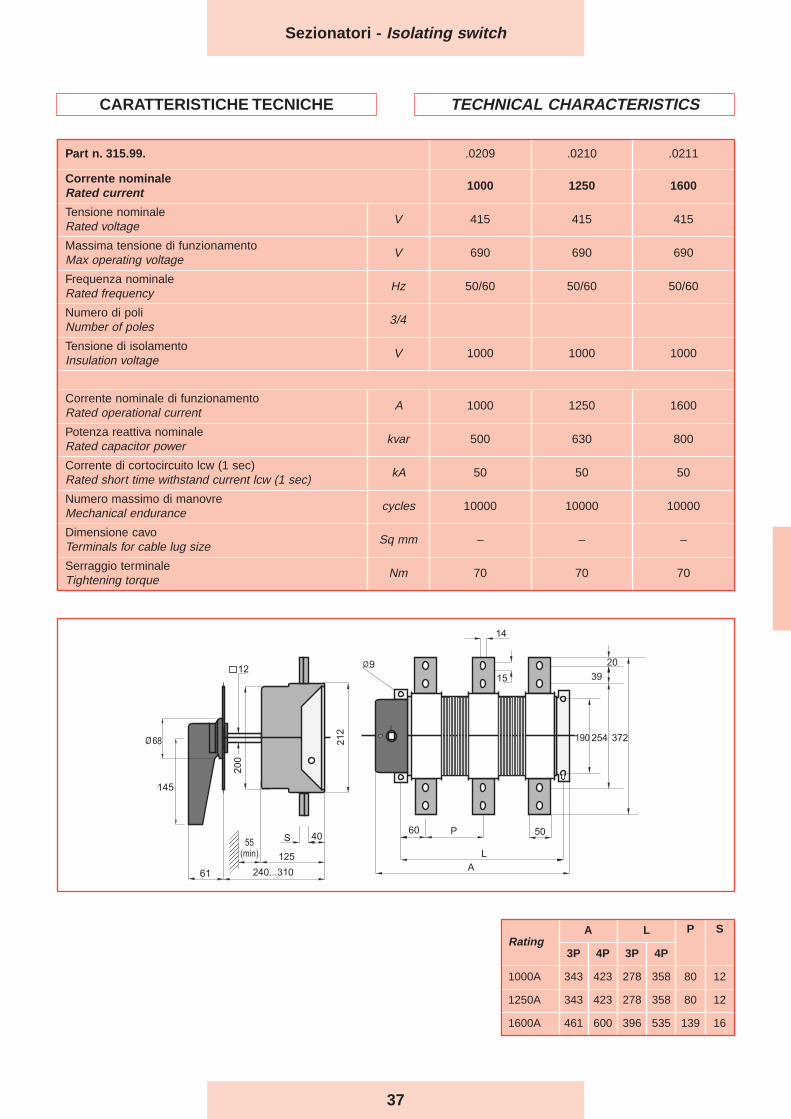
Part n. 315.99. .0209 .0210 .0211
Corrente nominaleRated current 1000 1250 1600
Tensione nominaleRated voltage
V 415 415 415
Massima tensione di funzionamentoMax operating voltage
V 690 690 690
Frequenza nominaleRated frequency
Hz 50/60 50/60 50/60
Numero di poliNumber of poles
3/4
Tensione di isolamentoInsulation voltage
V 1000 1000 1000
Corrente nominale di funzionamentoRated operational current
A 1000 1250 1600
Potenza reattiva nominaleRated capacitor power
kvar 500 630 800
Corrente di cortocircuito lcw (1 sec)Rated short time withstand current lcw (1 sec)
kA 50 50 50
Numero massimo di manovreMechanical endurance
cycles 10000 10000 10000
Dimensione cavoTerminals for cable lug size
Sq mm – – –
Serraggio terminaleTightening torque
Nm 70 70 70
CARATTERISTICHE TECNICHE TECHNICAL CHARACTERISTICS
RatingA L P S
3P 4P 3P 4P
1000A 343 423 278 358 80 12
1250A 343 423 278 358 80 12
1600A 461 600 396 535 139 16
38
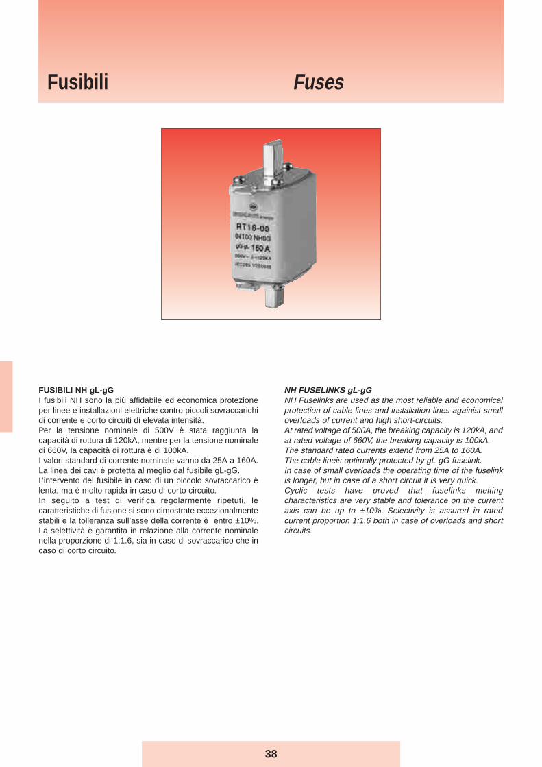
FUSIBILI NH gL-gGI fusibili NH sono la più affidabile ed economica protezioneper linee e installazioni elettriche contro piccoli sovraccarichidi corrente e corto circuiti di elevata intensità. Per la tensione nominale di 500V è stata raggiunta lacapacità di rottura di 120kA, mentre per la tensione nominaledi 660V, la capacità di rottura è di 100kA. I valori standard di corrente nominale vanno da 25A a 160A.La linea dei cavi è protetta al meglio dal fusibile gL-gG.L’intervento del fusibile in caso di un piccolo sovraccarico èlenta, ma è molto rapida in caso di corto circuito. In seguito a test di verifica regolarmente ripetuti, lecaratteristiche di fusione si sono dimostrate eccezionalmentestabili e la tolleranza sull’asse della corrente è entro ±10%.La selettività è garantita in relazione alla corrente nominalenella proporzione di 1:1.6, sia in caso di sovraccarico che incaso di corto circuito.
NH FUSELINKS gL-gGNH Fuselinks are used as the most reliable and economicalprotection of cable lines and installation lines againist smalloverloads of current and high short-circuits. At rated voltage of 500A, the breaking capacity is 120kA, andat rated voltage of 660V, the breaking capacity is 100kA. The standard rated currents extend from 25A to 160A. The cable lineis optimally protected by gL-gG fuselink. In case of small overloads the operating time of the fuselinkis longer, but in case of a short circuit it is very quick. Cyclic tests have proved that fuselinks meltingcharacteristics are very stable and tolerance on the currentaxis can be up to ±10%. Selectivity is assured in ratedcurrent proportion 1:1.6 both in case of overloads and shortcircuits.
Fusibili Fuses
39
Fusibili - Fuses
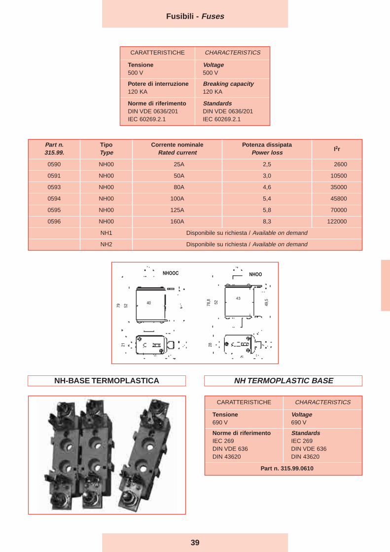
Part n.315.99.
TipoType
Corrente nominaleRated current
Potenza dissipataPower loss
I2r
0590 NH00 25A 2,5 2600
0591 NH00 50A 3,0 10500
0593 NH00 80A 4,6 35000
0594 NH00 100A 5,4 45800
0595 NH00 125A 5,8 70000
0596 NH00 160A 8,3 122000
NH1 Disponibile su richiesta / Available on demand
NH2 Disponibile su richiesta / Available on demand
CARATTERISTICHE CHARACTERISTICS
Tensione500 V
Voltage500 V
Potere di interruzione120 KA
Breaking capacity120 KA
Norme di riferimentoDIN VDE 0636/201IEC 60269.2.1
StandardsDIN VDE 0636/201IEC 60269.2.1
CARATTERISTICHE CHARACTERISTICS
Tensione690 V
Voltage690 V
Norme di riferimentoIEC 269DIN VDE 636DIN 43620
StandardsIEC 269DIN VDE 636DIN 43620
Part n. 315.99.0610
40
7921
52 78,8 52
28
43
49,5
NHOOC NHOO
NH-BASE TERMOPLASTICA NH TERMOPLASTIC BASE
40
Reattanze di sbarramento
Blocking reactors
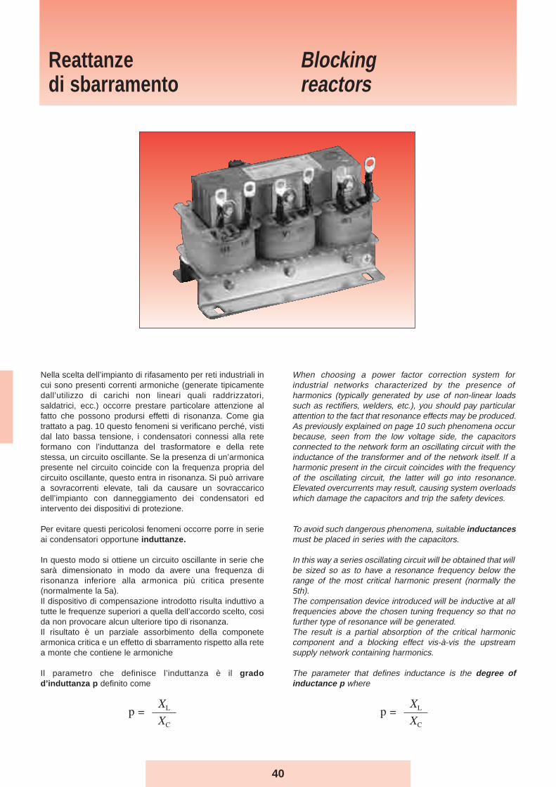
Nella scelta dell’impianto di rifasamento per reti industriali incui sono presenti correnti armoniche (generate tipicamentedall’utilizzo di carichi non lineari quali raddrizzatori,saldatrici, ecc.) occorre prestare particolare attenzione alfatto che possono prodursi effetti di risonanza. Come giatrattato a pag. 10 questo fenomeni si verificano perché, vistidal lato bassa tensione, i condensatori connessi alla reteformano con l’induttanza del trasformatore e della retestessa, un circuito oscillante. Se la presenza di un’armonicapresente nel circuito coincide con la frequenza propria delcircuito oscillante, questo entra in risonanza. Si può arrivarea sovracorrenti elevate, tali da causare un sovraccaricodell’impianto con danneggiamento dei condensatori edintervento dei dispositivi di protezione.
Per evitare questi pericolosi fenomeni occorre porre in serieai condensatori opportune induttanze.
In questo modo si ottiene un circuito oscillante in serie chesarà dimensionato in modo da avere una frequenza dirisonanza inferiore alla armonica più critica presente(normalmente la 5a).Il dispositivo di compensazione introdotto risulta induttivo atutte le frequenze superiori a quella dell’accordo scelto, cosida non provocare alcun ulteriore tipo di risonanza.Il risultato è un parziale assorbimento della componetearmonica critica e un effetto di sbarramento rispetto alla retea monte che contiene le armoniche
Il parametro che definisce l’induttanza è il gradod’induttanza p definito come
When choosing a power factor correction system forindustrial networks characterized by the presence ofharmonics (typically generated by use of non-linear loadssuch as rectifiers, welders, etc.), you should pay particularattention to the fact that resonance effects may be produced.As previously explained on page 10 such phenomena occurbecause, seen from the low voltage side, the capacitorsconnected to the network form an oscillating circuit with theinductance of the transformer and of the network itself. If aharmonic present in the circuit coincides with the frequencyof the oscillating circuit, the latter will go into resonance.Elevated overcurrents may result, causing system overloadswhich damage the capacitors and trip the safety devices.
To avoid such dangerous phenomena, suitable inductancesmust be placed in series with the capacitors.
In this way a series oscillating circuit will be obtained that willbe sized so as to have a resonance frequency below therange of the most critical harmonic present (normally the5th).The compensation device introduced will be inductive at allfrequencies above the chosen tuning frequency so that nofurther type of resonance will be generated.The result is a partial absorption of the critical harmoniccomponent and a blocking effect vis-à-vis the upstreamsupply network containing harmonics.
The parameter that defines inductance is the degree ofinductance p where
41
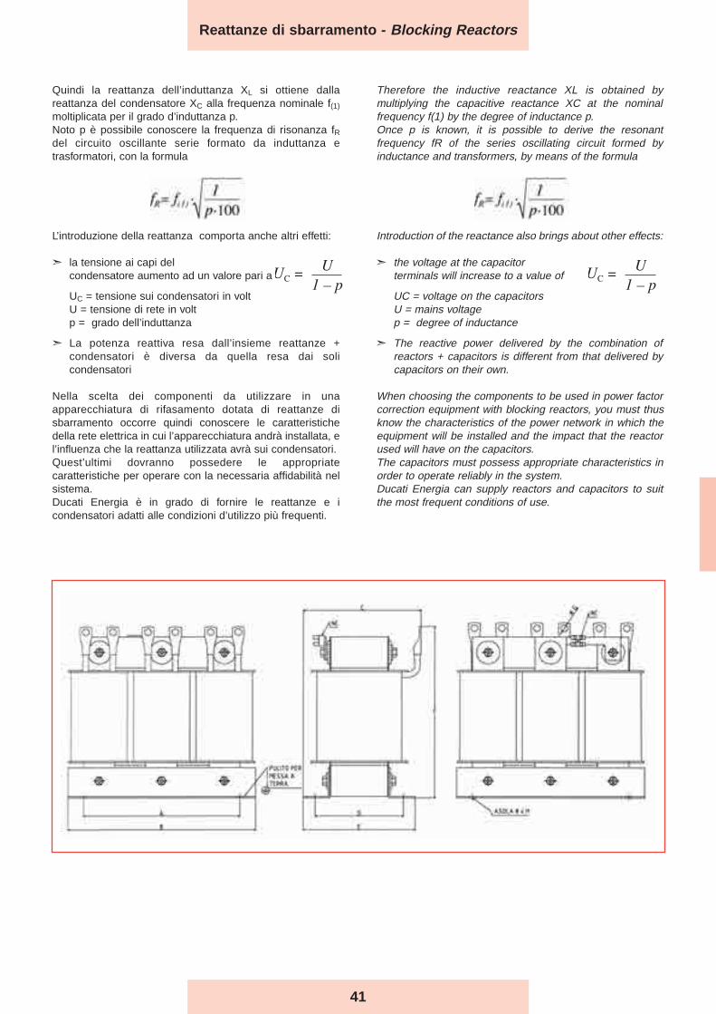
Quindi la reattanza dell’induttanza XL si ottiene dallareattanza del condensatore XC alla frequenza nominale f(1)
moltiplicata per il grado d’induttanza p.Noto p è possibile conoscere la frequenza di risonanza fRdel circuito oscillante serie formato da induttanza etrasformatori, con la formula
L’introduzione della reattanza comporta anche altri effetti:
➣ la tensione ai capi del condensatore aumento ad un valore pari a
UC = tensione sui condensatori in voltU = tensione di rete in voltp = grado dell’induttanza
➣ La potenza reattiva resa dall’insieme reattanze +condensatori è diversa da quella resa dai solicondensatori
Nella scelta dei componenti da utilizzare in unaapparecchiatura di rifasamento dotata di reattanze disbarramento occorre quindi conoscere le caratteristichedella rete elettrica in cui l’apparecchiatura andrà installata, el’influenza che la reattanza utilizzata avrà sui condensatori.Quest’ultimi dovranno possedere le appropriatecaratteristiche per operare con la necessaria affidabilità nelsistema.Ducati Energia è in grado di fornire le reattanze e icondensatori adatti alle condizioni d’utilizzo più frequenti.
Therefore the inductive reactance XL is obtained bymultiplying the capacitive reactance XC at the nominalfrequency f(1) by the degree of inductance p.Once p is known, it is possible to derive the resonantfrequency fR of the series oscillating circuit formed byinductance and transformers, by means of the formula
Introduction of the reactance also brings about other effects:
➣ the voltage at the capacitor terminals will increase to a value of
UC = voltage on the capacitorsU = mains voltagep = degree of inductance
➣ The reactive power delivered by the combination ofreactors + capacitors is different from that delivered bycapacitors on their own.
When choosing the components to be used in power factorcorrection equipment with blocking reactors, you must thusknow the characteristics of the power network in which theequipment will be installed and the impact that the reactorused will have on the capacitors.The capacitors must possess appropriate characteristics inorder to operate reliably in the system.Ducati Energia can supply reactors and capacitors to suitthe most frequent conditions of use.
1fR= f(1) .
p%
Reattanze di sbarramento - Blocking Reactors
42
1005 10 3 x 3,84 16,3 150 180 110 82 110 180 M* 20 9.5 3 x 62 4200
1010 12,5 3 x 3,07 20,4 150 180 120 92 120 180 M* 20 11 3 x 77 4080+4100
1012 15 3 x 2.55 26.8 200 240 130 85 118 166 9 20 13 3 x 94 4100+4150
1015 20 3 x 1,91 32,7 200 240 130 88 118 165 9 20 13 3 x 123 4100+4260
1020 25 3 x 1,53 40,8 200 240 140 98 128 165 9 20 15 3 x 154 4200+4260
1025 40 3 x 0,96 65,2 200 240 140 98 128 205 9 20 21 3 x 247 3x4260
1030 50 3 x 0,77 81,6 200 240 150 113 143 220 9 20 25 3 x 308 3x4310
A B C D E F G H
PesoWeight
(Kg)
Part n.315.99.
Potenza resaPower output
(kVAr)
InduttanzaInductance
(mH)
I RMS
(A)
Dimensioni (mm)Size (mm)
C teorica
theorical
(µF)
Condensatoriproposti
Proposedcapacitors
416.46.xxxx
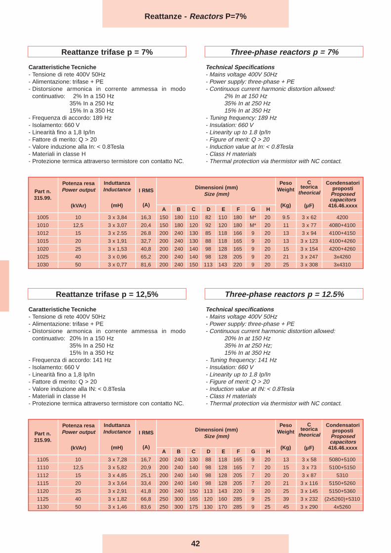
Reattanze trifase p = 7%
Caratteristiche Tecniche- Tensione di rete 400V 50Hz- Alimentazione: trifase + PE- Distorsione armonica in corrente ammessa in modo
continuativo: 2% In a 150 Hz35% In a 250 Hz15% In a 350 Hz
- Frequenza di accordo: 189 Hz- Isolamento: 660 V- Linearità fino a 1,8 Ip/In- Fattore di merito: Q > 20- Valore induzione alla In: < 0.8Tesla- Materiali in classe H- Protezione termica attraverso termistore con contatto NC.
Three-phase reactors p = 7%
Technical Specifications- Mains voltage 400V 50Hz- Power supply: three-phase + PE- Continuous current harmonic distortion allowed:
2% In at 150 Hz35% In at 250 Hz15% In at 350 Hz
- Tuning frequency: 189 Hz- Insulation: 660 V- Linearity up to 1.8 Ip/In- Figure of merit: Q > 20- Induction value at In: < 0.8Tesla- Class H materials- Thermal protection via thermistor with NC contact.
Reattanze - Reactors P=7%
Reattanze trifase p = 12,5%
Caratteristiche Tecniche- Tensione di rete 400V 50Hz- Alimentazione: trifase + PE- Distorsione armonica in corrente ammessa in modo
continuativo: 20% In a 150 Hz35% In a 250 Hz15% In a 350 Hz
- Frequenza di accordo: 141 Hz- Isolamento: 660 V- Linearità fino a 1,8 Ip/In- Fattore di merito: Q > 20- Valore induzione alla IN: < 0.8Tesla- Materiali in classe H- Protezione termica attraverso termistore con contatto NC.
Three-phase reactors p = 12.5%
Technical specifications- Mains voltage 400V 50Hz- Power supply: three-phase + PE- Continuous current harmonic distortion allowed:
20% In at 150 Hz35% In at 250 Hz;15% In at 350 Hz
- Tuning frequency: 141 Hz- Insulation: 660 V- Linearity up to 1.8 Ip/In- Figure of merit: Q > 20- Induction value at IN: < 0.8Tesla- Class H materials- Thermal protection via thermistor with NC contact.
1105 10 3 x 7,28 16,7 200 240 130 88 118 165 9 20 13 3 x 58 5080+5100
1110 12,5 3 x 5,82 20,9 200 240 140 98 128 165 7 20 15 3 x 73 5100+5150
1112 15 3 x 4,85 25,1 200 240 140 98 128 205 7 20 20 3 x 87 5310
1115 20 3 x 3,64 33,4 200 240 140 98 128 205 7 20 21 3 x 116 5150+5260
1120 25 3 x 2,91 41,8 200 240 150 113 143 220 9 20 25 3 x 145 5150+5360
1125 40 3 x 1,82 66,8 250 300 165 120 160 285 9 25 39 3 x 232 (2x5260)+5310
1130 50 3 x 1,46 83,6 250 300 175 130 170 285 9 25 45 3 x 290 4x5260
A B C D E F G H
PesoWeight
(Kg)
Part n.315.99.
Potenza resaPower output
(kVAr)
InduttanzaInductance
(mH)
I RMS
(A)
Dimensioni (mm)Size (mm)
C teorica
theorical
(µF)
Condensatoriproposti
Proposedcapacitors
416.46.xxxx
43
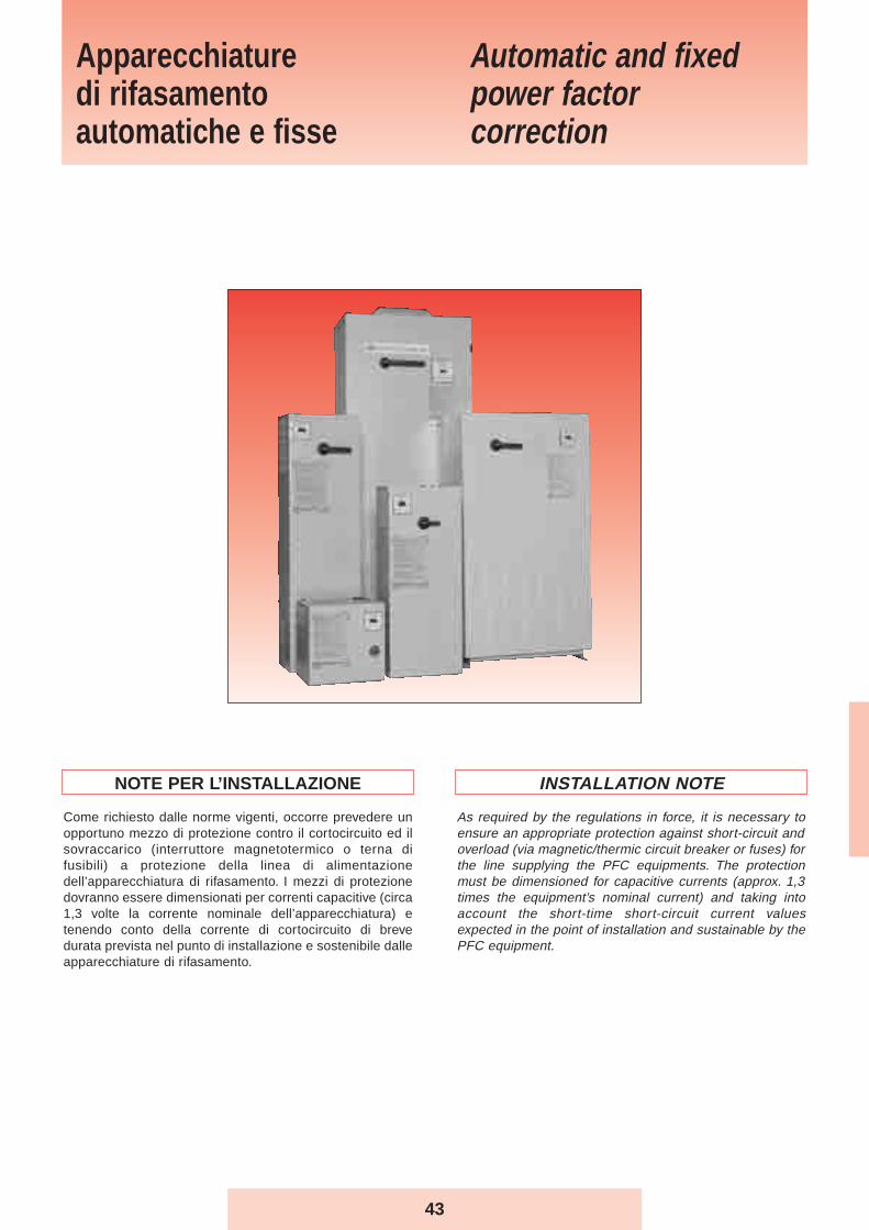
NOTE PER L’INSTALLAZIONE
Come richiesto dalle norme vigenti, occorre prevedere unopportuno mezzo di protezione contro il cortocircuito ed ilsovraccarico (interruttore magnetotermico o terna difusibili) a protezione della linea di alimentazionedell’apparecchiatura di rifasamento. I mezzi di protezionedovranno essere dimensionati per correnti capacitive (circa1,3 volte la corrente nominale dell’apparecchiatura) etenendo conto della corrente di cortocircuito di brevedurata prevista nel punto di installazione e sostenibile dalleapparecchiature di rifasamento.
INSTALLATION NOTE
As required by the regulations in force, it is necessary toensure an appropriate protection against short-circuit andoverload (via magnetic/thermic circuit breaker or fuses) forthe line supplying the PFC equipments. The protectionmust be dimensioned for capacitive currents (approx. 1,3times the equipment’s nominal current) and taking intoaccount the short-time short-circuit current valuesexpected in the point of installation and sustainable by thePFC equipment.
Automatic and fixedpower factor correction
Apparecchiaturedi rifasamentoautomatiche e fisse
44
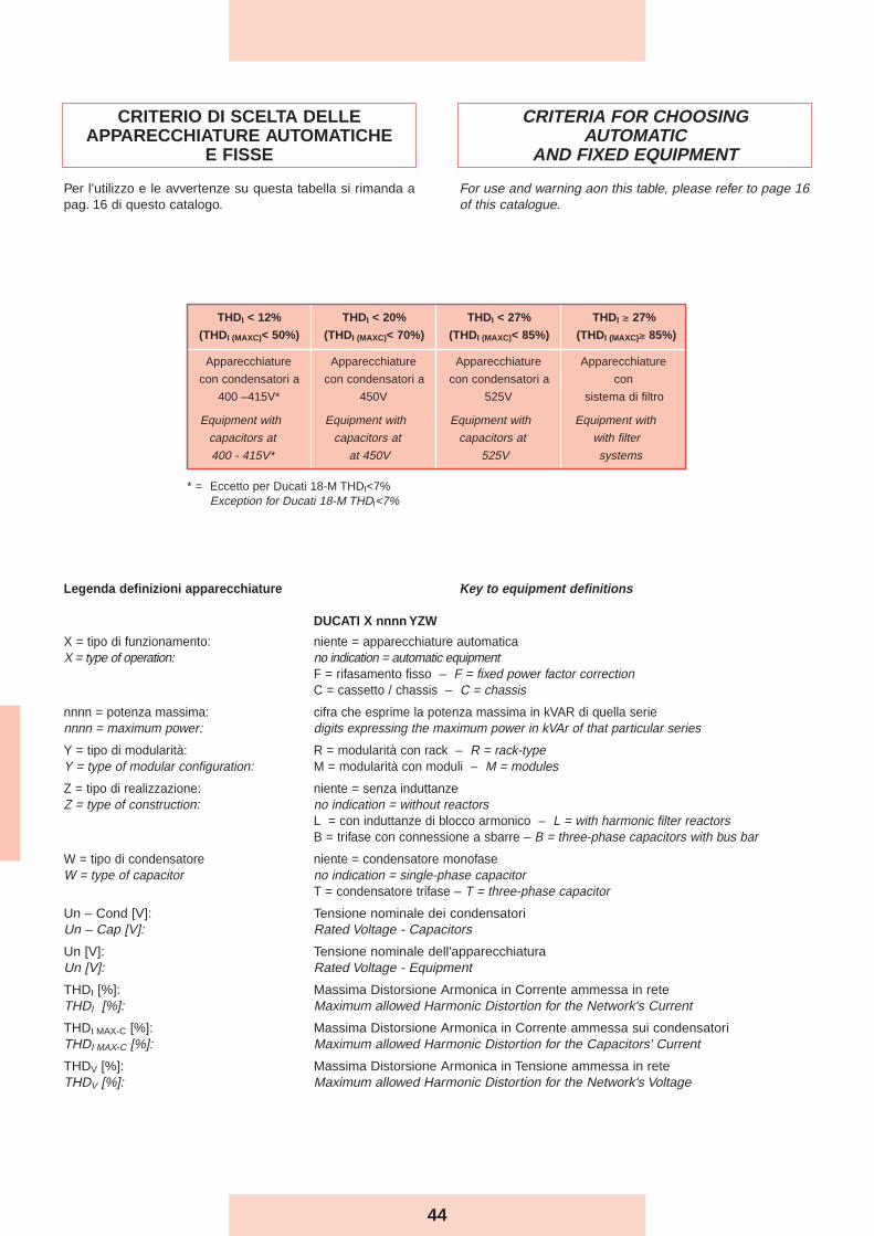
CRITERIA FOR CHOOSINGAUTOMATIC
AND FIXED EQUIPMENT
For use and warning aon this table, please refer to page 16of this catalogue.
CRITERIO DI SCELTA DELLEAPPARECCHIATURE AUTOMATICHE
E FISSE
Per l’utilizzo e le avvertenze su questa tabella si rimanda apag. 16 di questo catalogo.
Legenda definizioni apparecchiature Key to equipment definitions
DUCATI X nnnn YZW
X = tipo di funzionamento: niente = apparecchiature automaticaX = type of operation: no indication = automatic equipment
F = rifasamento fisso – F = fixed power factor correction C = cassetto / chassis – C = chassis
nnnn = potenza massima: cifra che esprime la potenza massima in kVAR di quella seriennnn = maximum power: digits expressing the maximum power in kVAr of that particular series
Y = tipo di modularità: R = modularità con rack – R = rack-typeY = type of modular configuration: M = modularità con moduli – M = modules
Z = tipo di realizzazione: niente = senza induttanzeZ = type of construction: no indication = without reactors
L = con induttanze di blocco armonico – L = with harmonic filter reactorsB = trifase con connessione a sbarre – B = three-phase capacitors with bus bar
W = tipo di condensatore niente = condensatore monofaseW = type of capacitor no indication = single-phase capacitor
T = condensatore trifase – T = three-phase capacitor
Un – Cond [V]: Tensione nominale dei condensatoriUn – Cap [V]: Rated Voltage - Capacitors
Un [V]: Tensione nominale dell'apparecchiaturaUn [V]: Rated Voltage - Equipment
THDI [%]: Massima Distorsione Armonica in Corrente ammessa in reteTHDI [%]: Maximum allowed Harmonic Distortion for the Network's Current
THDI MAX-C [%]: Massima Distorsione Armonica in Corrente ammessa sui condensatoriTHDI MAX-C [%]: Maximum allowed Harmonic Distortion for the Capacitors' Current
THDV [%]: Massima Distorsione Armonica in Tensione ammessa in reteTHDV [%]: Maximum allowed Harmonic Distortion for the Network's Voltage
THDI < 12% THDI < 20% THDI < 27% THDI ≥ 27%
(THDI (MAXC)< 50%) (THDI (MAXC)< 70%) (THDI (MAXC)< 85%) (THDI (MAXC)≥ 85%)
Apparecchiature Apparecchiature Apparecchiature Apparecchiature
con condensatori a con condensatori a con condensatori a con
400 –415V* 450V 525V sistema di filtro
Equipment with Equipment with Equipment with Equipment with
capacitors at capacitors at capacitors at with filter
400 - 415V* at 450V 525V systems
* = Eccetto per Ducati 18-M THDI<7%Exception for Ducati 18-M THDI<7%

45
DUCATI F120 Seriesfixed power factorcorrection unit
Le unità DUCATI F120 sono progettate e realizzate per ilrifasamento fisso di utenze ad assorbimento costante.
Caratteristiche Generali- Tensione nominale della rete di alimentazione: 400V 50Hz
(altri valori a richiesta)- Alimentazione: trifase + PE- Corrente di cortocircuito (1s): 8÷13kA
(80kA condizionati da fusibile a monte)- Classe di temperatura: -15 +40 °C
- 0 +55 °C su richiesta (IP30)- Umidità relativa: 70% max. a 20 °C- Ingresso cavi dall’alto direttamente sui morsetti del
sezionatore generale- Norme: CEI EN 61921
Struttura Meccanica- La struttura di base è realizzata in lamiera di acciaio
zincata bianco dello spessore di 15/10; le piastre difissaggio dei componenti hanno spessore di 12/10.
- I componenti interni sono accessibili a mezzo involucrointerbloccato con il sezionatore generale.
- La struttura esterna in carpenteria di lamiera d’acciaio èverniciata con trattamento di pulitura , sgrassaggio , ciclo difosfatazione , vernice dello spessore di 50 µm a base dipolveri epossidiche colore RAL 7032.
- Nella parte inferiore e superiore sono presenti appositeferitoie per agevolare e consentire una facile ventilazionenaturale. Il grado di protezione di tali aperture è IP30.
Modalità d’installazione- Per interno, a muro, in ambiente ventilato e non polveroso,
al riparo dalla luce diretta del sole.- Ingresso cavi dall’alto.
Sezionatore Generale- Sezionatore omnipolare, con blocco porta e del tipo a
velocità indipendente da quella di manovra dell’operatore.- Corrente nominale del sezionatore 1,43 volte la corrente di
esercizio a 400 V.
Collegamenti Interni- Cablaggi realizzati con cavi tipo N07VK.
DUCATI F120 units are designed and built for fixed powerfactor improvement in situations where user loads arepractically constant.
General Characteristics- Rated voltage of power mains: 400V 50Hz (other values on
request)- Power supply: three-phase + ground- Short circuit current (1s): 8÷13kA
(80kA fused condional)- Temperature class: -15 +40 °C
- 0 +55 °C on request (IP30)- Relative humidity: 70% max at 20 °C- Cable inlet from top directly to main disconnecting switch
terminals- Standards: CEI EN 61921
Mechanical Structure- The basic structure is made of white galvanized steel sheet
with thickness 15/10; the component fastening plates havethickness 12/10.
- The internal components are accessible through the shellinterlocked with the main disconnecting switch.
- The outer steel structural work is painted with cleaningtreatment, degreasing, phosphating, 50 µm thickness paintwith epoxy powder colour RAL 7032.
- Special slits at the top and bottom assist natural ventilation.The protection rating of these openings is IP30.
Installation- Indoors, wall-mounted, in ventilated, non-dusty
environment, away from direct sunlight.- Cable inlet from top.
Main Disconnecting Switch- Unipolar disconnecting switch, with door lock, speed
independent of operator manoeuvring speed.- Rated current of disconnecting switch 1.43 times the 400V
operating current.
Internal Connections - Wired with N07VK type cables.
Serie DUCATI F120unità trifase con sezionatoree struttura metallica
DUCATI F120 - LONG LIFE 4In

46
Fusibili- A valle del sezionatore sono presenti una o più terne di
fusibili, posti a protezione delle batterie di condensatori.- I fusibili sono del tipo NH-00 con caratteristica GL.
Condensatori- Elementi monofase serie MONO - LONG LIFE collegati a
triangolo.- Tensione nominale 415-450-525V
Dispositivi di protezione- Ogni batteria di condensatori é dotata di dispositivi di scarica
atti a ridurre la tensione residua al di sotto del 10% dellatensione nominale del condensatore in circa 30 secondi.
Collaudo 100%Su ogni apparecchiatura prodotta sono effettuate le seguentiprove e controlli:- Controllo visivo e dimensionale.- Controllo funzionamento meccanico.- Prova di tensione applicata verso massa sui circuiti di
potenza: 3kV per 1 minuto.- Controllo funzionamento elettrico a 400V.
Fuses- Downstream of the disconnecting switch are one or more
triads of fuses, installed to protect the capacitor banks.- The fuses are NH-00 type with GL characteristic.
Capacitors- Single-phase elements series MONO - LONG LIFE in
delta connection.- Rated voltage 415-450-525V.
Safety devices- Each capacitor bank is equipped with discharge devices
for reducing the residual voltage to less than 10% of therated voltage of the capacitor in approximately 30 seconds.
100% TestingThe following tests and checks are run on every automaticdevice manufactured:- Visual and dimensional check.- Mechanical operation check.- Applied voltage test to earth on power circuits: 3kV for 1
minute.- Electrical operation check at 400V.
Part n. Qn Q (400V) In In sez. LxPxH Peso
415.04. (kVAr) (kVAr) (A) (A) (mm) (kg)
8005 5 4,6 7 40 400x270x400 15
8007 10 9,3 13 40 400x270x400 15
8010 20 18,6 27 40 400x270x400 17
8015 40 37,2 54 80 400x270x400 17
8020 60 55,7 80 160 400x270x400 21
8025 80 74,3 107 160 400x270x600 30
8030 100 92,9 134 250 400x270x1000 32
8035 120 111,5 161 250 400x270x1000 33
DUCATI F120 Un cond = 415V DUCATI F120 Un cap = 415V
Part n. Qn Q (400V) In In sez. LxPxH Peso
415.04. (kVAr) (kVAr) (A) (A) (mm) (kg)
8105 5 4,0 6 40 400x270x400 15
8107 10 7,9 11 40 400x270x400 15
8110 20 15,8 23 40 400x270x400 17
8115 40 31,6 46 80 400x270x400 17
8120 60 47,4 68 160 400x270x400 21
8125 80 63,2 91 160 400x270x600 30
8130 100 79,0 114 250 400x270x1000 32
8135 120 94,8 137 250 400x270x1000 33
DUCATI F120 Un cond = 450V DUCATI F120 Un cap = 450V
Part n. Qn Q (400V) In In sez. LxPxH Peso
415.04. (kVAr) (kVAr) (A) (A) (mm) (kg)
8205 5 2,9 4 40 400x270x400 15
8207 10 5,8 8 40 400x270x400 15
8210 20 11,6 17 40 400x270x400 17
8215 40 23,2 34 80 400x270x400 17
8220 60 34,8 50 160 400x270x400 21
8225 80 46,4 67 160 400x270x600 30
8230 100 58,0 84 250 400x270x1000 32
8235 120 69,7 101 250 400x270x1000 33
DUCATI F120 Un cond = 525V DUCATI F120 Un cap = 525V
Ducati F120
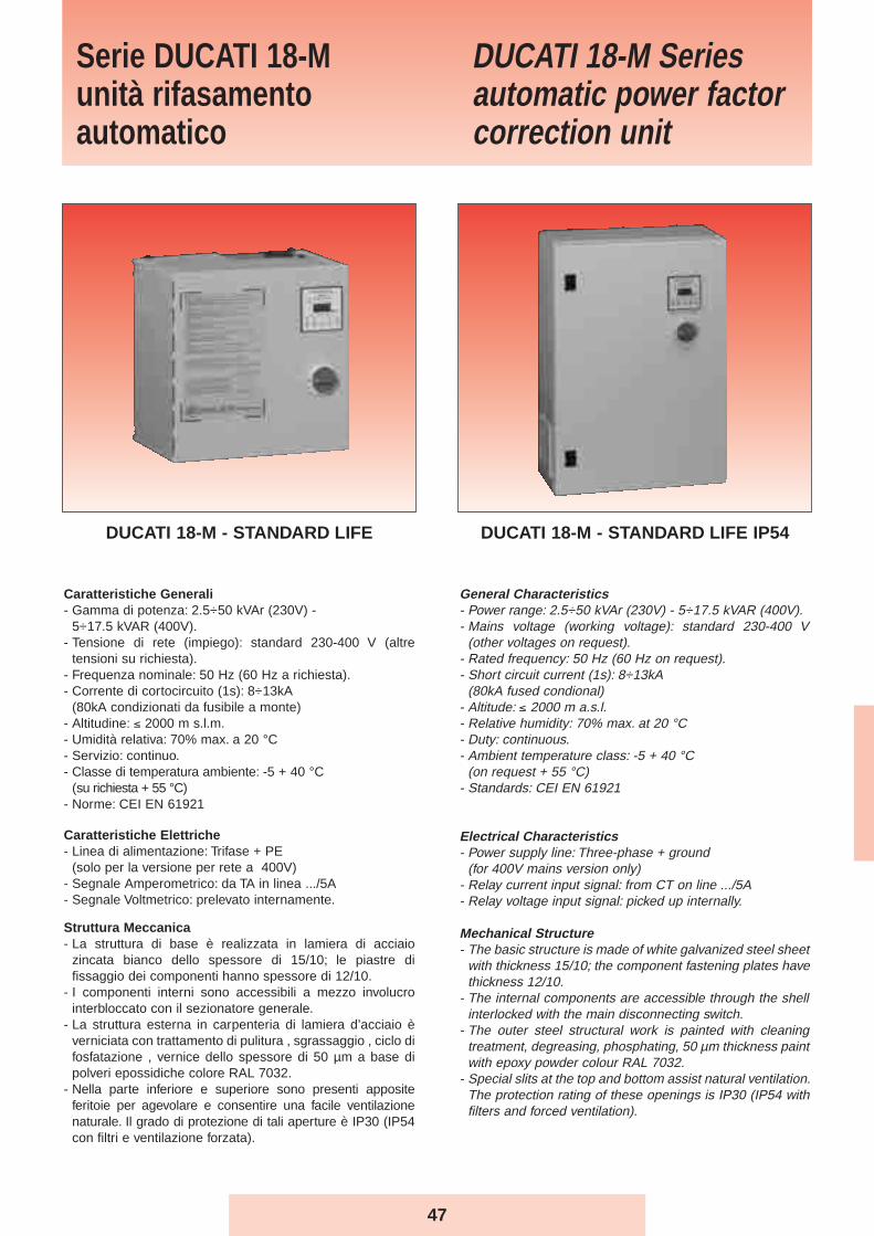
47
General Characteristics- Power range: 2.5÷50 kVAr (230V) - 5÷17.5 kVAR (400V).- Mains voltage (working voltage): standard 230-400 V
(other voltages on request).- Rated frequency: 50 Hz (60 Hz on request).- Short circuit current (1s): 8÷13kA
(80kA fused condional)- Altitude: ≤ 2000 m a.s.l.- Relative humidity: 70% max. at 20 °C- Duty: continuous.- Ambient temperature class: -5 + 40 °C
(on request + 55 °C)- Standards: CEI EN 61921
Electrical Characteristics- Power supply line: Three-phase + ground
(for 400V mains version only)- Relay current input signal: from CT on line .../5A- Relay voltage input signal: picked up internally.
Mechanical Structure- The basic structure is made of white galvanized steel sheet
with thickness 15/10; the component fastening plates havethickness 12/10.
- The internal components are accessible through the shellinterlocked with the main disconnecting switch.
- The outer steel structural work is painted with cleaningtreatment, degreasing, phosphating, 50 µm thickness paintwith epoxy powder colour RAL 7032.
- Special slits at the top and bottom assist natural ventilation.The protection rating of these openings is IP30 (IP54 withfilters and forced ventilation).
DUCATI 18-M Seriesautomatic power factor correction unit
Caratteristiche Generali- Gamma di potenza: 2.5÷50 kVAr (230V) -
5÷17.5 kVAR (400V).- Tensione di rete (impiego): standard 230-400 V (altre
tensioni su richiesta).- Frequenza nominale: 50 Hz (60 Hz a richiesta).- Corrente di cortocircuito (1s): 8÷13kA
(80kA condizionati da fusibile a monte)- Altitudine: ≤ 2000 m s.l.m.- Umidità relativa: 70% max. a 20 °C- Servizio: continuo.- Classe di temperatura ambiente: -5 + 40 °C
(su richiesta + 55 °C)- Norme: CEI EN 61921
Caratteristiche Elettriche- Linea di alimentazione: Trifase + PE
(solo per la versione per rete a 400V)- Segnale Amperometrico: da TA in linea .../5A- Segnale Voltmetrico: prelevato internamente.
Struttura Meccanica- La struttura di base è realizzata in lamiera di acciaio
zincata bianco dello spessore di 15/10; le piastre difissaggio dei componenti hanno spessore di 12/10.
- I componenti interni sono accessibili a mezzo involucrointerbloccato con il sezionatore generale.
- La struttura esterna in carpenteria di lamiera d’acciaio èverniciata con trattamento di pulitura , sgrassaggio , ciclo difosfatazione , vernice dello spessore di 50 µm a base dipolveri epossidiche colore RAL 7032.
- Nella parte inferiore e superiore sono presenti appositeferitoie per agevolare e consentire una facile ventilazionenaturale. Il grado di protezione di tali aperture è IP30 (IP54con filtri e ventilazione forzata).
Serie DUCATI 18-Munità rifasamentoautomatico
DUCATI 18-M - STANDARD LIFE DUCATI 18-M - STANDARD LIFE IP54
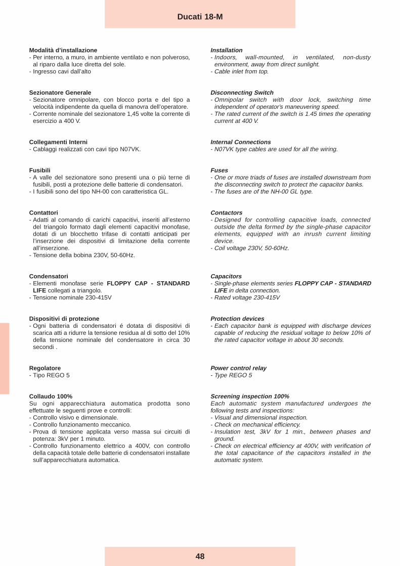
48
Modalità d’installazione- Per interno, a muro, in ambiente ventilato e non polveroso,
al riparo dalla luce diretta del sole.- Ingresso cavi dall’alto
Sezionatore Generale- Sezionatore omnipolare, con blocco porta e del tipo a
velocità indipendente da quella di manovra dell’operatore.- Corrente nominale del sezionatore 1,45 volte la corrente di
esercizio a 400 V.
Collegamenti Interni- Cablaggi realizzati con cavi tipo N07VK.
Fusibili- A valle del sezionatore sono presenti una o più terne di
fusibili, posti a protezione delle batterie di condensatori.- I fusibili sono del tipo NH-00 con caratteristica GL.
Contattori- Adatti al comando di carichi capacitivi, inseriti all’esterno
del triangolo formato dagli elementi capacitivi monofase,dotati di un blocchetto trifase di contatti anticipati perl’inserzione dei dispositivi di limitazione della correnteall’inserzione.
- Tensione della bobina 230V, 50-60Hz.
Condensatori- Elementi monofase serie FLOPPY CAP - STANDARD
LIFE collegati a triangolo.- Tensione nominale 230-415V
Dispositivi di protezione- Ogni batteria di condensatori é dotata di dispositivi di
scarica atti a ridurre la tensione residua al di sotto del 10%della tensione nominale del condensatore in circa 30secondi .
Regolatore- Tipo REGO 5
Collaudo 100%Su ogni apparecchiatura automatica prodotta sonoeffettuate le seguenti prove e controlli:- Controllo visivo e dimensionale.- Controllo funzionamento meccanico.- Prova di tensione applicata verso massa sui circuiti di
potenza: 3kV per 1 minuto.- Controllo funzionamento elettrico a 400V, con controllo
della capacità totale delle batterie di condensatori installatesull’apparecchiatura automatica.
Installation- Indoors, wall-mounted, in ventilated, non-dusty
environment, away from direct sunlight.- Cable inlet from top.
Disconnecting Switch- Omnipolar switch with door lock, switching time
independent of operator’s maneuvering speed.- The rated current of the switch is 1.45 times the operating
current at 400 V.
Internal Connections- N07VK type cables are used for all the wiring.
Fuses- One or more triads of fuses are installed downstream from
the disconnecting switch to protect the capacitor banks.- The fuses are of the NH-00 GL type.
Contactors- Designed for controlling capacitive loads, connected
outside the delta formed by the single-phase capacitorelements, equipped with an inrush current limitingdevice.
- Coil voltage 230V, 50-60Hz.
Capacitors- Single-phase elements series FLOPPY CAP - STANDARD
LIFE in delta connection.- Rated voltage 230-415V
Protection devices- Each capacitor bank is equipped with discharge devices
capable of reducing the residual voltage to below 10% ofthe rated capacitor voltage in about 30 seconds.
Power control relay- Type REGO 5
Screening inspection 100%Each automatic system manufactured undergoes thefollowing tests and inspections:- Visual and dimensional inspection.- Check on mechanical efficiency.- Insulation test, 3kV for 1 min., between phases and
ground.- Check on electrical efficiency at 400V, with verification of
the total capacitance of the capacitors installed in theautomatic system.
Ducati 18-M
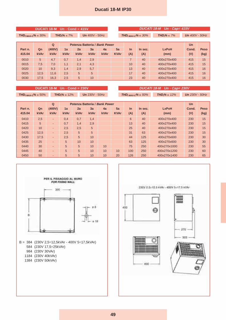
49
Q Potenza Batteria / Bank Power Un
Part n. Qn (400V) 1a 2a 3a 4a 5a In In sez. LxPxH Cond. Peso
415.04 kVAr kVAr kVAr kVAr kVAr kVAr KVAr (A) (A) (mm) (V) (kg)
0410 2,5 - 0,4 0,7 1,4 6 40 400x270x400 230 15
0415 5 - 0,7 1,4 2,9 13 40 400x270x400 230 15
0420 10 - 2,5 2,5 5 25 40 400x270x400 230 15
0425 12,5 - 2,5 5 5 31 63 400x270x400 230 15
0430 17,5 - 2,5 5 10 44 125 400x270x600 230 30
0435 25 - 5 10 10 63 125 400x270x600 230 30
0440 30 - 5 5 10 10 75 250 400x270x1000 230 55
0445 40 - 5 5 10 10 10 100 250 400x270x1200 230 60
0450 50 - 5 5 10 10 20 126 250 400x270x1400 230 65
Ducati 18-M IP30
Q Potenza Batteria / Bank Power Un
Part n. Qn (400V) 1a 2a 3a 4a 5a In In sez. LxPxH Cond. Peso
415.04 kVAr kVAr kVAr kVAr kVAr kVAr KVAr (A) (A) (mm) (V) (kg)
0010 5 4,7 0,7 1,4 2,9 7 40 400x270x400 415 15
0015 7,5 7,0 1,1 2,1 4,3 10 40 400x270x400 415 15
0020 10 9,3 1,4 2,9 5,7 13 40 400x270x400 415 16
0025 12,5 11,6 2,5 5 5 17 40 400x270x400 415 16
0030 17,5 16,3 2,5 5 10 23 40 400x270x400 415 16
B = 384 (230V 2,5÷12,5kVAr - 400V 5÷17,5kVAr)584 (230V 17,5÷25kVAr)984 (230V 30VAr)
1184 (230V 40kVAr)1384 (230V 50kVAr)
DUCATI 18-M Un - Cond = 230V
THDI MAX-C% ≤ 50% THDI% ≤ 12% Un 230V - 50Hz
DUCATI 18-M Un - Cap= 230V
THDI MAX-C% ≤ 50% THDI% ≤ 12% Un 230V - 50Hz
THDI MAX-C% ≤ 30% THDI% ≤ 7% Un 400V - 50Hz
DUCATI 18-M Un - Cond = 415V
THDI MAX-C% ≤ 30% THDI% ≤ 7% Un 400V - 50Hz
DUCATI 18-M Un - Cap= 415V
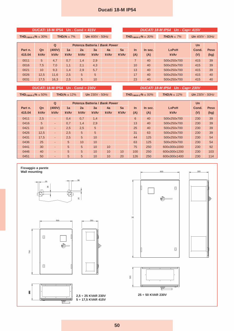
50
Ducati 18-M IP54
Q Potenza Batteria / Bank Power Un
Part n. Qn (400V) 1a 2a 3a 4a 5a In In sez. LxPxH Cond. Peso
415.04 kVAr kVAr kVAr kVAr kVAr kVAr KVAr (A) (A) kVAr (V) (kg)
0011 5 4,7 0,7 1,4 2,9 7 40 500x250x700 415 39
0016 7,5 7,0 1,1 2,1 4,3 10 40 500x250x700 415 39
0021 10 9,3 1,4 2,9 5,7 13 40 500x250x700 415 39
0026 12,5 11,6 2,5 5 5 17 40 500x250x700 415 40
0031 17,5 16,3 2,5 5 10 23 40 500x250x700 415 40
Q Potenza Batteria / Bank Power Un
Part n. Qn (400V) 1a 2a 3a 4a 5a In In sez. LxPxH Cond. Peso
415.04 kVAr kVAr kVAr kVAr kVAr kVAr KVAr (A) (A) kVAr (V) (kg)
0411 2,5 - 0,4 0,7 1,4 6 40 500x250x700 230 39
0416 5 - 0,7 1,4 2,9 13 40 500x250x700 230 39
0421 10 - 2,5 2,5 5 25 40 500x250x700 230 39
0426 12,5 - 2,5 5 5 31 63 500x250x700 230 39
0431 17,5 - 2,5 5 10 44 125 500x250x700 230 54
0436 25 - 5 10 10 63 125 500x250x700 230 54
0441 30 - 5 5 10 10 75 250 600x300x1000 230 92
0446 40 - 5 5 10 10 10 100 250 600x300x1200 230 103
0451 50 - 5 5 10 10 20 126 250 600x300x1400 230 114
Fissaggio a pareteWall mounting
H
25 ÷ 50 KVAR 230V2,5 ÷ 25 KVAR 230V5 ÷ 17,5 KVAR 415V
DUCATI 18-M IP54 Un - Cap= 415V
THDI MAX-C% ≤ 30% THDI% ≤ 7% Un 400V - 50Hz
DUCATI 18-M IP54 Un - Cap= 230V
THDI MAX-C% ≤ 50% THDI% ≤ 12% Un 230V - 50Hz
DUCATI 18-M IP54 Un - Cond = 415V
THDI MAX-C% ≤ 30% THDI% ≤ 7% Un 400V - 50Hz
DUCATI 18-M IP54 Un - Cond = 230V
THDI MAX-C% ≤ 50% THDI% ≤ 12% Un 230V - 50Hz
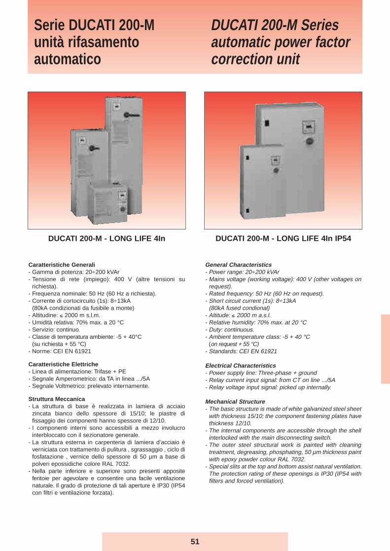
51
General Characteristics- Power range: 20÷200 kVAr - Mains voltage (working voltage): 400 V (other voltages on
request).- Rated frequency: 50 Hz (60 Hz on request).- Short circuit current (1s): 8÷13kA
(80kA fused condional)- Altitude: ≤ 2000 m a.s.l.- Relative humidity: 70% max. at 20 °C- Duty: continuous.- Ambient temperature class: -5 + 40 °C
(on request + 55 °C)- Standards: CEI EN 61921
Electrical Characteristics- Power supply line: Three-phase + ground- Relay current input signal: from CT on line .../5A- Relay voltage input signal: picked up internally.
Mechanical Structure- The basic structure is made of white galvanized steel sheet
with thickness 15/10; the component fastening plates havethickness 12/10.
- The internal components are accessible through the shellinterlocked with the main disconnecting switch.
- The outer steel structural work is painted with cleaningtreatment, degreasing, phosphating, 50 µm thickness paintwith epoxy powder colour RAL 7032.
- Special slits at the top and bottom assist natural ventilation.The protection rating of these openings is IP30 (IP54 withfilters and forced ventilation).
Caratteristiche Generali- Gamma di potenza: 20÷200 kVAr- Tensione di rete (impiego): 400 V (altre tensioni su
richiesta).- Frequenza nominale: 50 Hz (60 Hz a richiesta).- Corrente di cortocircuito (1s): 8÷13kA
(80kA condizionati da fusibile a monte)- Altitudine: ≤ 2000 m s.l.m.- Umidità relativa: 70% max. a 20 °C- Servizio: continuo.- Classe di temperatura ambiente: -5 + 40°C
(su richiesta + 55 °C)- Norme: CEI EN 61921
Caratteristiche Elettriche- Linea di alimentazione: Trifase + PE- Segnale Amperometrico: da TA in linea .../5A- Segnale Voltmetrico: prelevato internamente.
Struttura Meccanica- La struttura di base è realizzata in lamiera di acciaio
zincata bianco dello spessore di 15/10; le piastre difissaggio dei componenti hanno spessore di 12/10.
- I componenti interni sono accessibili a mezzo involucrointerbloccato con il sezionatore generale.
- La struttura esterna in carpenteria di lamiera d’acciaio èverniciata con trattamento di pulitura , sgrassaggio , ciclo difosfatazione , vernice dello spessore di 50 µm a base dipolveri epossidiche colore RAL 7032.
- Nella parte inferiore e superiore sono presenti appositeferitoie per agevolare e consentire una facile ventilazionenaturale. Il grado di protezione di tali aperture è IP30 (IP54con filtri e ventilazione forzata).
Serie DUCATI 200-Munità rifasamentoautomatico
DUCATI 200-M Seriesautomatic power factorcorrection unit
DUCATI 200-M - LONG LIFE 4In DUCATI 200-M - LONG LIFE 4In IP54
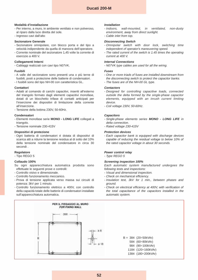
Modalità d’installazione- Per interno, a muro, in ambiente ventilato e non polveroso,
al riparo dalla luce diretta del sole.- Ingresso cavi dall’alto
Sezionatore Generale- Sezionatore omnipolare, con blocco porta e del tipo a
velocità indipendente da quella di manovra dell’operatore.- Corrente nominale del sezionatore 1,45 volte la corrente di
esercizio a 400 V.
Collegamenti Interni- Cablaggi realizzati con cavi tipo N07VK.
Fusibili- A valle del sezionatore sono presenti una o più terne di
fusibili, posti a protezione delle batterie di condensatori.- I fusibili sono del tipo NH-00 con caratteristica GL.
Contattori- Adatti al comando di carichi capacitivi, inseriti all’esterno
del triangolo formato dagli elementi capacitivi monofase,dotati di un blocchetto trifase di contatti anticipati perl’inserzione dei dispositivi di limitazione della correnteall’inserzione.
- Tensione della bobina 230V, 50-60Hz.
Condensatori- Elementi monofase serie MONO - LONG LIFE collegati a
triangolo.- Tensione nominale 230-415V
Dispositivi di protezione- Ogni batteria di condensatori é dotata di dispositivi di
scarica atti a ridurre la tensione residua al di sotto del 10%della tensione nominale del condensatore in circa 30secondi .
Regolatore- Tipo REGO 5
Collaudo 100%Su ogni apparecchiatura automatica prodotta sono
effettuate le seguenti prove e controlli:- Controllo visivo e dimensionale.- Controllo funzionamento meccanico.- Prova di tensione applicata verso massa sui circuiti di
potenza: 3kV per 1 minuto.- Controllo funzionamento elettrico a 400V, con controllo
della capacità totale delle batterie di condensatori installatesull’apparecchiatura automatica.
Installation- Indoors, wall-mounted, in ventilated, non-dusty
environment, away from direct sunlight.- Cable inlet from top.
Disconnecting Switch- Omnipolar switch with door lock, switching time
independent of operator’s maneuvering speed.- The rated current of the switch is 1.45 times the operating
current at 400 V.
Internal Connections- N07VK type cables are used for all the wiring.
Fuses- One or more triads of fuses are installed downstream from
the disconnecting switch to protect the capacitor banks.- The fuses are of the NH-00 GL type.
Contactors- Designed for controlling capacitive loads, connected
outside the delta formed by the single-phase capacitorelements, equipped with an inrush current limitingdevice.
- Coil voltage 230V, 50-60Hz.
Capacitors- Single-phase elements series MONO - LONG LIFE in
delta connection.- Rated voltage 230-415V
Protection devices- Each capacitor bank is equipped with discharge devices
capable of reducing the residual voltage to below 10% ofthe rated capacitor voltage in about 30 seconds.
Power control relay- Type REGO 5
Screening inspection 100%Each automatic system manufactured undergoes thefollowing tests and inspections:- Visual and dimensional inspection.- Check on mechanical efficiency.- Insulation test, 3kV for 1 min., between phases and
ground.- Check on electrical efficiency at 400V, with verification of
the total capacitance of the capacitors installed in theautomatic system.
52
Ducati 200-M
B = 384 (20÷50kVAr)584 (60÷80kVAr)984 (90÷100kVAr)
1184 (120÷160kVAr)1384 (180÷200kVAr)
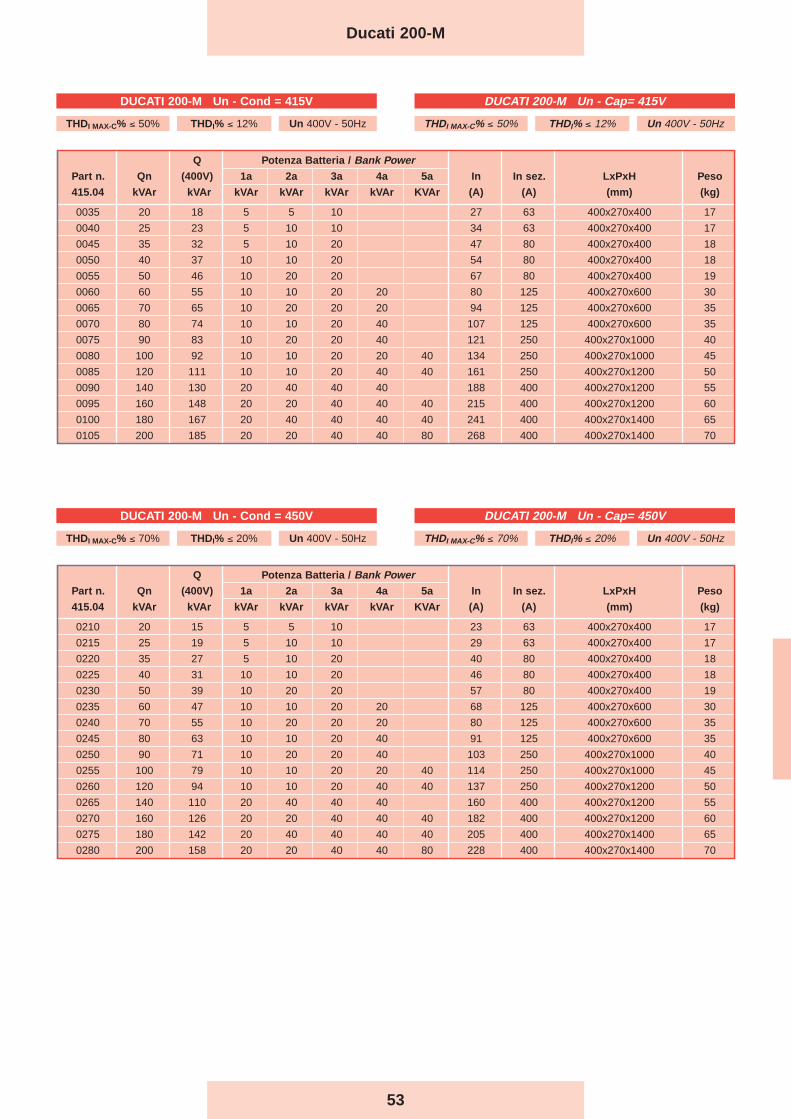
53
Q Potenza Batteria / Bank PowerPart n. Qn (400V) 1a 2a 3a 4a 5a In In sez. LxPxH Peso
415.04 kVAr kVAr kVAr kVAr kVAr kVAr KVAr (A) (A) (mm) (kg)
0035 20 18 5 5 10 27 63 400x270x400 17
0040 25 23 5 10 10 34 63 400x270x400 17
0045 35 32 5 10 20 47 80 400x270x400 18
0050 40 37 10 10 20 54 80 400x270x400 18
0055 50 46 10 20 20 67 80 400x270x400 19
0060 60 55 10 10 20 20 80 125 400x270x600 30
0065 70 65 10 20 20 20 94 125 400x270x600 35
0070 80 74 10 10 20 40 107 125 400x270x600 35
0075 90 83 10 20 20 40 121 250 400x270x1000 40
0080 100 92 10 10 20 20 40 134 250 400x270x1000 45
0085 120 111 10 10 20 40 40 161 250 400x270x1200 50
0090 140 130 20 40 40 40 188 400 400x270x1200 55
0095 160 148 20 20 40 40 40 215 400 400x270x1200 60
0100 180 167 20 40 40 40 40 241 400 400x270x1400 65
0105 200 185 20 20 40 40 80 268 400 400x270x1400 70
Q Potenza Batteria / Bank PowerPart n. Qn (400V) 1a 2a 3a 4a 5a In In sez. LxPxH Peso
415.04 kVAr kVAr kVAr kVAr kVAr kVAr KVAr (A) (A) (mm) (kg)
0210 20 15 5 5 10 23 63 400x270x400 17
0215 25 19 5 10 10 29 63 400x270x400 17
0220 35 27 5 10 20 40 80 400x270x400 18
0225 40 31 10 10 20 46 80 400x270x400 18
0230 50 39 10 20 20 57 80 400x270x400 19
0235 60 47 10 10 20 20 68 125 400x270x600 30
0240 70 55 10 20 20 20 80 125 400x270x600 35
0245 80 63 10 10 20 40 91 125 400x270x600 35
0250 90 71 10 20 20 40 103 250 400x270x1000 40
0255 100 79 10 10 20 20 40 114 250 400x270x1000 45
0260 120 94 10 10 20 40 40 137 250 400x270x1200 50
0265 140 110 20 40 40 40 160 400 400x270x1200 55
0270 160 126 20 20 40 40 40 182 400 400x270x1200 60
0275 180 142 20 40 40 40 40 205 400 400x270x1400 65
0280 200 158 20 20 40 40 80 228 400 400x270x1400 70
Ducati 200-M
DUCATI 200-M Un - Cap= 415V
THDI MAX-C% ≤ 50% THDI% ≤ 12% Un 400V - 50Hz
DUCATI 200-M Un - Cap= 450V
THDI MAX-C% ≤ 70% THDI% ≤ 20% Un 400V - 50Hz
DUCATI 200-M Un - Cond = 415V
THDI MAX-C% ≤ 50% THDI% ≤ 12% Un 400V - 50Hz
DUCATI 200-M Un - Cond = 450V
THDI MAX-C% ≤ 70% THDI% ≤ 20% Un 400V - 50Hz

54
Ducati 200-M
Q Potenza Batteria / Bank PowerPart n. Qn (400V) 1a 2a 3a 4a 5a In In sez. LxPxH Peso
415.04 kVAr kVAr kVAr kVAr kVAr kVAr KVAr (A) (A) (mm) (kg)
0310 20 11 5 5 10 17 63 400x270x400 17
0315 25 14 5 10 10 21 63 400x270x400 17
0320 35 20 5 10 20 29 80 400x270x400 18
0325 40 23 10 10 20 34 80 400x270x400 18
0330 50 29 10 20 20 42 80 400x270x400 19
0335 60 34 10 10 20 20 50 125 400x270x600 30
0340 70 40 10 20 20 20 59 125 400x270x600 35
0345 80 46 10 10 20 40 67 125 400x270x600 35
0350 90 52 10 20 20 40 75 250 400x270x1000 40
0355 100 58 10 10 20 20 40 84 250 400x270x1000 45
0360 120 69 10 10 20 40 40 101 250 400x270x1200 50
0365 140 81 20 40 40 40 117 400 400x270x1200 55
0370 160 92 20 20 40 40 40 134 400 400x270x1200 60
0375 180 104 20 40 40 40 40 151 400 400x270x1400 65
0380 200 116 20 20 40 40 80 168 400 400x270x1400 70
DUCATI 200-M Un - Cap= 525V
THDI MAX-C% ≤ 85% THDI% ≤ 27% Un 400V - 50Hz
DUCATI 200-M Un - Cond = 525V
THDI MAX-C% ≤ 85% THDI% ≤ 27% Un 400V - 50Hz

55
Ducati 200-M IP54
Q Potenza Batteria / Bank PowerPart n. Qn (400V) 1a 2a 3a 4a 5a In In sez. LxPxH Peso
415.04 kVAr kVAr kVAr kVAr kVAr kVAr KVAr (A) (A) (mm) (kg)
0211 20 15 5 5 10 23 63 500x250x700 41
0216 25 19 5 10 10 29 63 500x250x700 41
0221 35 27 5 10 20 40 80 500x250x700 42
0226 40 31 10 10 20 46 80 500x250x700 42
0231 50 39 10 20 20 57 80 500x250x700 43
0236 60 47 10 10 20 20 68 125 500x250x700 54
0241 70 55 10 20 20 20 80 125 500x250x700 59
0246 80 63 10 10 20 40 91 125 500x250x700 59
0251 90 71 10 20 20 40 103 250 600x300x1000 77
0256 100 79 10 10 20 20 40 114 250 600x300x1000 82
0261 120 94 10 10 20 40 40 137 250 600x300x1200 93
0266 140 110 20 40 40 40 160 400 600x300x1200 98
0271 160 126 20 20 40 40 40 182 400 600x300x1200 109
0276 180 142 20 40 40 40 40 205 400 600x300x1400 114
0281 200 158 20 20 40 40 80 228 400 600x300x1400 119
Q Potenza Batteria / Bank PowerPart n. Qn (400V) 1a 2a 3a 4a 5a In In sez. LxPxH Peso
415.04 kVAr kVAr kVAr kVAr kVAr kVAr KVAr (A) (A) (mm) (kg)
0036 20 18 5 5 10 27 63 500x250x700 41
0041 25 23 5 10 10 34 63 500x250x700 41
0046 35 32 5 10 20 47 80 500x250x700 42
0051 40 37 10 10 20 54 80 500x250x700 42
0056 50 46 10 20 20 67 80 500x250x700 43
0061 60 55 10 10 20 20 80 125 500x250x700 54
0067 70 65 10 20 20 20 94 125 500x250x700 59
0071 80 74 10 10 20 40 107 125 500x250x700 59
0076 90 83 10 20 20 40 121 250 600x300x1000 77
0081 100 92 10 10 20 20 40 134 250 600x300x1000 82
0086 120 111 10 10 20 40 40 161 250 600x300x1000 93
0091 140 130 20 40 40 40 188 400 600x300x1000 98
0096 160 148 20 20 40 40 40 215 400 600x300x1200 109
0101 180 167 20 40 40 40 40 241 400 600x300x1400 114
0106 200 185 20 20 40 40 80 268 400 600x300x1400 119
DUCATI 200-M IP54 Un - Cap= 415V
THDI MAX-C% ≤ 50% THDI% ≤ 12% Un 400V - 50Hz
DUCATI 200-M IP54 Un - Cap= 450V
THDI MAX-C% ≤ 70% THDI% ≤ 20% Un 400V - 50Hz
DUCATI 200-M IP54 Un - Cond = 415V
THDI MAX-C% ≤ 50% THDI% ≤ 12% Un 400V - 50Hz
DUCATI 200-M IP54 Un - Cond = 450V
THDI MAX-C% ≤ 70% THDI% ≤ 20% Un 400V - 50Hz

56
Ducati 200-M IP54
Q Potenza Batteria / Bank PowerPart n. Qn (400V) 1a 2a 3a 4a 5a In In sez. LxPxH Peso
415.04 kVAr kVAr kVAr kVAr kVAr kVAr KVAr (A) (A) (mm) (kg)
0311 20 11 5 5 10 17 63 500x250x700 41
0316 25 14 5 10 10 21 63 500x250x700 41
0321 35 20 5 10 20 29 80 500x250x700 42
0326 40 23 10 10 20 34 80 500x250x700 42
0331 50 29 10 20 20 42 80 500x250x700 43
0336 60 34 10 10 20 20 50 125 500x250x700 54
0341 70 40 10 20 20 20 59 125 500x250x700 59
0346 80 46 10 10 20 40 67 125 500x250x700 59
0351 90 52 10 20 20 40 75 250 600x300x1000 77
0356 100 58 10 10 20 20 40 84 250 600x300x1000 82
0361 120 69 10 10 20 40 40 101 250 600x300x1200 93
0366 140 81 20 40 40 40 117 400 600x300x1200 98
0371 160 92 20 20 40 40 40 134 400 600x300x1200 109
0376 180 104 20 40 40 40 40 151 400 600x300x1400 114
0381 200 116 20 20 40 40 80 168 400 600x300x1400 119
H
90 ÷ 200 KVAR20 ÷ 80 KVAR
Fissaggio a pareteWall mounting
H
90 ÷ 200 KVAR20 ÷ 80 KVAR
DUCATI 200-M IP54 Un - Cap= 525V
THDI MAX-C% ≤ 85% THDI% ≤ 27% Un 400V - 50Hz
DUCATI 200-M IP54 Un - Cond = 525V
THDI MAX-C% ≤ 85% THDI% ≤ 27% Un 400V - 50Hz
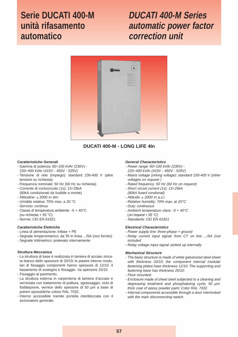
General Characteristics- Power range: 60÷100 kVAr (230V) -
220÷400 kVAr (415V - 450V - 525V)- Mains voltage (orking voltage): standard 230-400 V (other
voltages on request )- Rated frequency: 50 Hz (60 Hz on request)- Short circuit current (1s): 13÷25kA
(80kA fused condional)- Altitude: ≤ 2000 m a.s.l.- Relative humidity: 70% max. at 20°C- Duty: continuous- Ambient temperature class: -5 + 40°C
(on request + 55 °C)- Standards: CEI EN 61921
Electrical Characteristics- Power supply line: three-phase + ground- Relay current input signal: from CT on line .../5A (not
included- Relay voltage input signal: picked up internally
Mechanical Structure- The basic structure is made of white galvanized steel sheet
with thickness 20/10; the component internal modularfastening plates have thickness 12/10. The supporting andfastening base has thickness 20/10.
- Floor mounted.- Enclosure made of sheet steel subjected to a cleaning and
degreasing treatment and phosphatizing cycle, 50 µm-thick coat of epoxy powder paint. Color RAL 7032.
- Internal components accessible through a door interlockedwith the main disconnecting switch.
Caratteristiche Generali- Gamma di potenza: 60÷100 kVAr (230V) -
220÷400 kVAr (415V - 450V - 525V)- Tensione di rete (impiego): standard 230-400 V (altre
tensioni su richiesta)- Frequenza nominale: 50 Hz (60 Hz su richiesta)- Corrente di cortocircuito (1s): 13÷25kA
(80kA condizionati da fusibile a monte)- Altitudine: ≤ 2000 m slm- Umidità relativa: 70% max. a 20 °C- Servizio: continuo- Classe di temperatura ambiente: -5 + 40°C
(su richiesta + 55 °C)- Norme: CEI EN 61921
Caratteristiche Elettriche- Linea di alimentazione: trifase + PE- Segnale Amperometrico: da TA in linea .../5A (non fornito)- Segnale Voltmetrico: prelevato internamente
Struttura Meccanica- La struttura di base è realizzata in lamiera di acciaio zinca-
ta bianco dello spessore di 20/10; le piastre interne modu-lari di fissaggio componenti hanno spessore di 12/10. Ilbasamento di sostegno e fissaggio ha spessore 20/10
- Fissaggio al pavimento.- La struttura esterna in carpenteria di lamiera d’acciaio è
verniciata con trattamento di pulitura, sgrassaggio, ciclo difosfatazione, vernice dello spessore di 50 µm a base dipolveri epossidiche colore RAL 7032.
- Interno accessibile tramite portella interbloccata con ilsezionatore generale.
Serie DUCATI 400-Munità rifasamentoautomatico
DUCATI 400-M Seriesautomatic power factorcorrection unit
DUCATI 400-M - LONG LIFE 4In
57
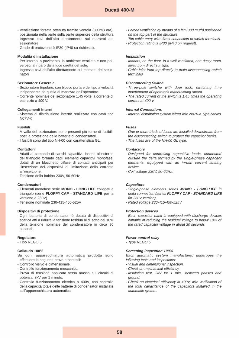
58
- Ventilazione forzata ottenuta tramite ventola (300m3 ora),posizionata nella parte sulla parte superiore della struttura
- Ingresso cavi dall’alto direttamente sui morsetti delsezionatore
- Grado di protezione è IP30 (IP40 su richiesta).
Modalità d’installazione- Per interno, a pavimento, in ambiente ventilato e non pol-
veroso, al riparo dalla luce diretta del sole.- Ingresso cavi dall’alto direttamente sui morsetti dei sezio-
natori
Sezionatore Generale- Sezionatore tripolare, con blocco porta e del tipo a velocità
indipendente da quella di manovra dell’operatore.- Corrente nominale del sezionatore 1,45 volte la corrente di
esercizio a 400 V.
Collegamenti Interni- Sistema di distribuzione interno realizzato con cavo tipo
N07V-K
Fusibili- A valle del sezionatore sono presenti più terne di fusibili,
posti a protezione delle batterie di condensatori.- I fusibili sono del tipo NH-00 con caratteristica GL.
Contattori- Adatti al comando di carichi capacitivi, inseriti all’esterno
del triangolo formato dagli elementi capacitivi monofase,dotati di un blocchetto trifase di contatti anticipati perl’inserzione dei dispositivi di limitazione della correnteall’inserzione.
- Tensione della bobina 230V, 50-60Hz.
Condensatori- Elementi monofase serie MONO - LONG LIFE collegati a
triangolo (serie FLOPPY CAP - STANDARD LIFE per laversione a 230V).
- Tensione nominale 230-415-450-525V
Dispositivi di protezione- Ogni batteria di condensatori é dotata di dispositivi di
scarica atti a ridurre la tensione residua al di sotto del 10%della tensione nominale del condensatore in circa 30secondi .
Regolatore- Tipo REGO 5
Collaudo 100%Su ogni apparecchiatura automatica prodotta sono
effettuate le seguenti prove e controlli:- Controllo visivo e dimensionale.- Controllo funzionamento meccanico.- Prova di tensione applicata verso massa sui circuiti di
potenza: 3kV per 1 minuto.- Controllo funzionamento elettrico a 400V, con controllo
della capacità totale delle batterie di condensatori installatesull’apparecchiatura automatica.
- Forced ventilation by means of a fan (300 m3/h) positionedon the top part of the structure
- Top cable entry with direct connection to switch terminals.- Protection rating is IP30 (IP40 on request).
Installation- Indoors, on the floor, in a well-ventilated, non-dusty room,
away from direct sunlight.- Cable inlet from top directly to main disconnecting switch
terminals
Disconnecting Switch- Three-pole switche with door lock, switching time
independent of operator’s maneuvering speed.- The rated current of the switch is 1.45 times the operating
current at 400 V.
Internal Connections- Internal distribution system wired with N07V-K type cables.
Fuses- One or more triads of fuses are installed downstream from
the disconnecting switch to protect the capacitor banks.- The fuses are of the NH-00 GL type.
Contactors- Designed for controlling capacitive loads, connected
outside the delta formed by the single-phase capacitorelements, equipped with an inrush current limitingdevice.
- Coil voltage 230V, 50-60Hz.
Capacitors- Single-phase elements series MONO - LONG LIFE in
delta connection (series FLOPPY CAP - STANDARD LIFEfor 230V version).
- Rated voltage 230-415-450-525V
Protection devices- Each capacitor bank is equipped with discharge devices
capable of reducing the residual voltage to below 10% ofthe rated capacitor voltage in about 30 seconds.
Power control relay- Type REGO 5
Screening inspection 100%Each automatic system manufactured undergoes thefollowing tests and inspections:- Visual and dimensional inspection.- Check on mechanical efficiency.- Insulation test, 3kV for 1 min., between phases and
ground.- Check on electrical efficiency at 400V, with verification of
the total capacitance of the capacitors installed in theautomatic system.
Ducati 400-M
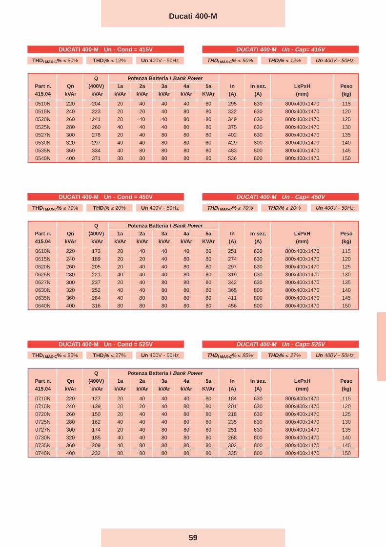
59
Q Potenza Batteria / Bank PowerPart n. Qn (400V) 1a 2a 3a 4a 5a In In sez. LxPxH Peso
415.04 kVAr kVAr kVAr kVAr kVAr kVAr KVAr (A) (A) (mm) (kg)
0510N 220 204 20 40 40 40 80 295 630 800x400x1470 115
0515N 240 223 20 20 40 80 80 322 630 800x400x1470 120
0520N 260 241 20 40 40 80 80 349 630 800x400x1470 125
0525N 280 260 40 40 40 80 80 375 630 800x400x1470 130
0527N 300 278 20 40 80 80 80 402 630 800x400x1470 135
0530N 320 297 40 40 80 80 80 429 800 800x400x1470 140
0535N 360 334 40 80 80 80 80 483 800 800x400x1470 145
0540N 400 371 80 80 80 80 80 536 800 800x400x1470 150
Q Potenza Batteria / Bank PowerPart n. Qn (400V) 1a 2a 3a 4a 5a In In sez. LxPxH Peso
415.04 kVAr kVAr kVAr kVAr kVAr kVAr KVAr (A) (A) (mm) (kg)
0610N 220 173 20 40 40 40 80 251 630 800x400x1470 115
0615N 240 189 20 20 40 80 80 274 630 800x400x1470 120
0620N 260 205 20 40 40 80 80 297 630 800x400x1470 125
0625N 280 221 40 40 40 80 80 319 630 800x400x1470 130
0627N 300 237 20 40 80 80 80 342 630 800x400x1470 135
0630N 320 252 40 40 80 80 80 365 800 800x400x1470 140
0635N 360 284 40 80 80 80 80 411 800 800x400x1470 145
0640N 400 316 80 80 80 80 80 456 800 800x400x1470 150
Q Potenza Batteria / Bank PowerPart n. Qn (400V) 1a 2a 3a 4a 5a In In sez. LxPxH Peso
415.04 kVAr kVAr kVAr kVAr kVAr kVAr KVAr (A) (A) (mm) (kg)
0710N 220 127 20 40 40 40 80 184 630 800x400x1470 115
0715N 240 139 20 20 40 80 80 201 630 800x400x1470 120
0720N 260 150 20 40 40 80 80 218 630 800x400x1470 125
0725N 280 162 40 40 40 80 80 235 630 800x400x1470 130
0727N 300 174 20 40 80 80 80 251 630 800x400x1470 135
0730N 320 185 40 40 80 80 80 268 800 800x400x1470 140
0735N 360 209 40 80 80 80 80 302 800 800x400x1470 145
0740N 400 232 80 80 80 80 80 335 800 800x400x1470 150
Ducati 400-M
DUCATI 400-M Un - Cap= 415V
THDI MAX-C% ≤ 50% THDI% ≤ 12% Un 400V - 50Hz
DUCATI 400-M Un - Cap= 450V
THDI MAX-C% ≤ 70% THDI% ≤ 20% Un 400V - 50Hz
DUCATI 400-M Un - Cap= 525V
THDI MAX-C% ≤ 85% THDI% ≤ 27% Un 400V - 50Hz
DUCATI 400-M Un - Cond = 415V
THDI MAX-C% ≤ 50% THDI% ≤ 12% Un 400V - 50Hz
DUCATI 400-M Un - Cond = 450V
THDI MAX-C% ≤ 70% THDI% ≤ 20% Un 400V - 50Hz
DUCATI 400-M Un - Cond = 525V
THDI MAX-C% ≤ 85% THDI% ≤ 27% Un 400V - 50Hz
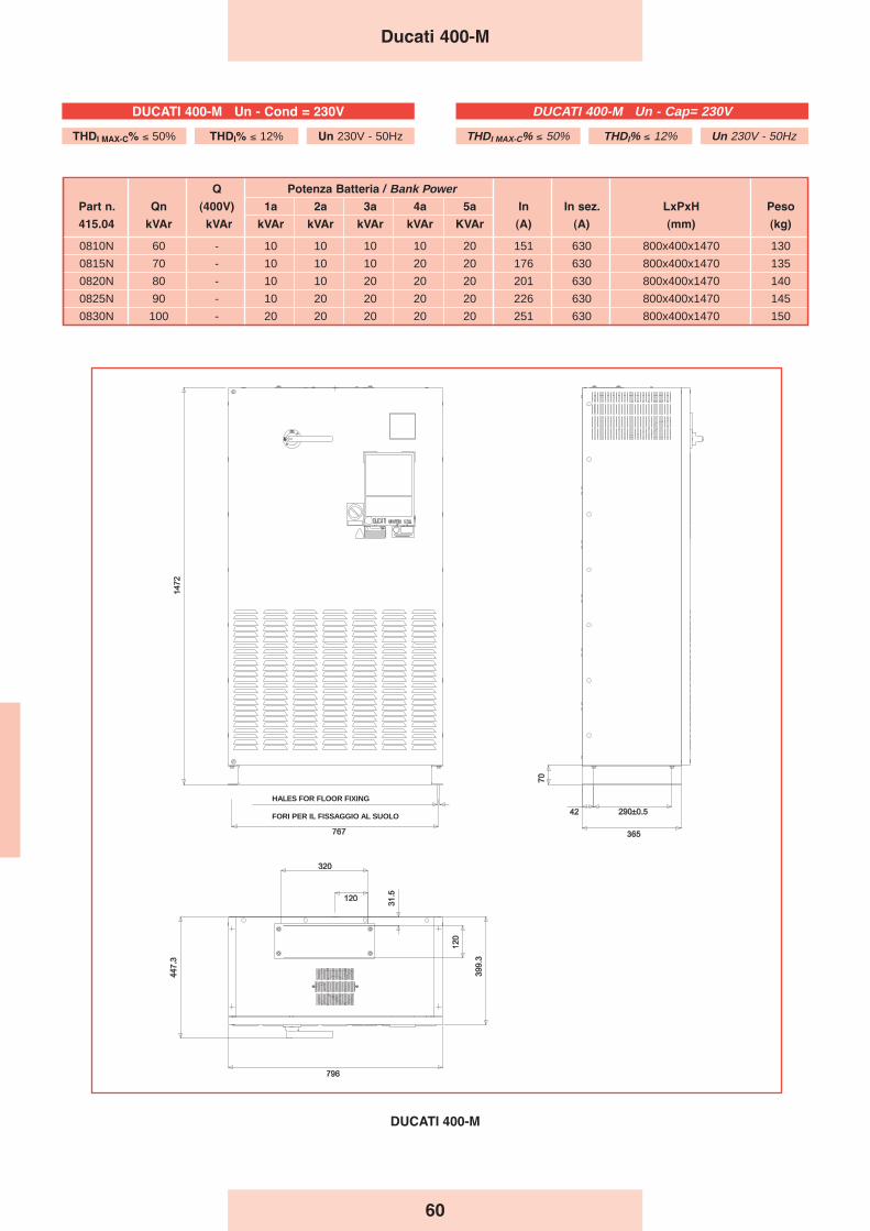
60
Q Potenza Batteria / Bank PowerPart n. Qn (400V) 1a 2a 3a 4a 5a In In sez. LxPxH Peso
415.04 kVAr kVAr kVAr kVAr kVAr kVAr KVAr (A) (A) (mm) (kg)
0810N 60 - 10 10 10 10 20 151 630 800x400x1470 130
0815N 70 - 10 10 10 20 20 176 630 800x400x1470 135
0820N 80 - 10 10 20 20 20 201 630 800x400x1470 140
0825N 90 - 10 20 20 20 20 226 630 800x400x1470 145
0830N 100 - 20 20 20 20 20 251 630 800x400x1470 150
Ducati 400-M
DUCATI 400-M
FORI PER IL FISSAGGIO AL SUOLO
HALES FOR FLOOR FIXING
DUCATI 400-M Un - Cap= 230V
THDI MAX-C% ≤ 50% THDI% ≤ 12% Un 230V - 50Hz
DUCATI 400-M Un - Cond = 230V
THDI MAX-C% ≤ 50% THDI% ≤ 12% Un 230V - 50Hz
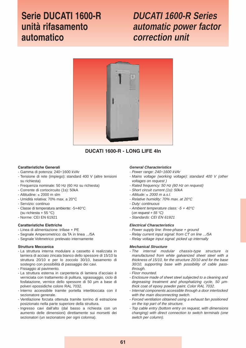
61
General Characteristics- Power range: 240÷1600 kVAr - Mains voltage (working voltage): standard 400 V (other
voltages on request )- Rated frequency: 50 Hz (60 Hz on request)- Short circuit current (1s): 50kA - Altitude: ≤ 2000 m a.s.l.- Relative humidity: 70% max. at 20°C- Duty: continuous- Ambient temperature class: -5 + 40°C
(on request + 55 °C)- Standards: CEI EN 61921
Electrical Characteristics- Power supply line: three-phase + ground- Relay current input signal: from CT on line .../5A- Relay voltage input signal: picked up internally
Mechanical Structure- The internal modular chassis-type structure is
manufactured from white galvanized sheet steel with athickness of 15/10, for the structure 20/10 and for the base30/10, supporting base with possibility of cable pass-through.
- Floor mounted.- Enclosure made of sheet steel subjected to a cleaning and
degreasing treatment and phosphatizing cycle, 50 µm-thick coat of epoxy powder paint. Color RAL 7032.
- Internal components accessible through a door interlockedwith the main disconnecting switch.
- Forced ventilation obtained using a exhaust fan positionedon the top part of the structure.
- Top cable entry (bottom entry on request, with dimensionschanging) with direct connection to switch terminals (oneswitch per column).
Caratteristiche Generali
- Gamma di potenza: 240÷1600 kVAr- Tensione di rete (impiego): standard 400 V (altre tensioni
su richiesta)- Frequenza nominale: 50 Hz (60 Hz su richiesta)- Corrente di cortocircuito (1s): 50kA- Altitudine: ≤ 2000 m slm- Umidità relativa: 70% max. a 20°C- Servizio: continuo- Classe di temperatura ambiente: -5+40°C
(su richiesta + 55 °C)- Norme: CEI EN 61921
Caratteristiche Elettriche
- Linea di alimentazione: trifase + PE- Segnale Amperometrico: da TA in linea .../5A- Segnale Voltmetrico: prelevato internamente
Struttura Meccanica
- La struttura interna modulare a cassetto è realizzata inlamiera di acciaio zincata bianco dello spessore di 15/10 lastruttura 20/10 e per lo zoccolo 30/10, basamento disostegno con possibilità di passaggio dei cavi.
- Fissaggio al pavimento.- La struttura esterna in carpenteria di lamiera d’acciaio è
verniciata con trattamento di pulitura, sgrassaggio, ciclo difosfatazione, vernice dello spessore di 50 µm a base dipolveri epossidiche colore RAL 7032.
- Interno accessibile tramite portella interbloccata con ilsezionatore generale.
- Ventilazione forzata ottenuta tramite torrino di estrazioneposizionato nella parte superiore della struttura.
- Ingresso cavi dall’alto (dal basso a richiesta con unaumento delle dimensioni) direttamente sui morsetti deisezionatori (un sezionatore per ogni colonna).
Serie DUCATI 1600-Runità rifasamentoautomatico
DUCATI 1600-R Seriesautomatic power factorcorrection unit
DUCATI 1600-R - LONG LIFE 4In
62
- Il grado di protezione è IP30 (IP superiori su richiesta).
Modalità dʼinstallazione
- Per interno, a pavimento, in ambiente ventilato e nonpolveroso, al riparo dalla luce diretta del sole.
Sezionatore Generale
- Sezionatore tripolare per ogni colonna, con blocco porta edel tipo a velocità indipendente da quella di manovradell’operatore.
- Corrente nominale del sezionatore 1,45 volte la corrente diesercizio a 400 V.
Collegamenti Interni
- Sistema di distribuzione interno realizzato con cavo tipoN07V-K
Fusibili
- A valle dei sezionatore sono presenti più terne di fusibili,posti a protezione delle batterie di condensatori.
- I fusibili sono del tipo NH-00 con caratteristica GL.
Contattori
- Adatti al comando di carichi capacitivi, inseriti all’esternodel triangolo formato dagli elementi capacitivi monofase,dotati di un blocchetto trifase di contatti anticipati perl’inserzione dei dispositivi di limitazione della correnteall’inserzione.
- Tensione della bobina 230V, 50-60Hz.
Condensatori
- Elementi monofase serie MONO - LONG LIFE collegati atriangolo (a richiesta elementi trifase serie MODULO XD).
- Tensione nominale 415-450-525V
Dispositivi di protezione
- Ogni batteria di condensatori é dotata di dispositivi discarica atti a ridurre la tensione residua al di sotto del 10%della tensione nominale del condensatore in circa 30secondi.
Regolatore
- Tipo REGO 7-12
Collaudo 100%
Su ogni apparecchiatura automatica prodotta sonoeffettuate le seguenti prove e controlli:- Controllo visivo e dimensionale.- Controllo funzionamento meccanico.- Prova di tensione applicata verso massa sui circuiti di
potenza: 3kV per 1 minuto.- Controllo funzionamento elettrico a 400V, con controllo
della capacità totale delle batterie di condensatori installatesull’apparecchiatura automatica.
- The protection rating is IP30 (higher IP ratings on request).
Installation- Indoors, on the floor, in a well-ventilated, non-dusty room,
away from direct sunlight.
Disconnecting Switch- Three-pole switch for each column, with door lock,
switching time independent of operator’s maneuveringspeed.
- The rated current of the switch is 1.45 times the operatingcurrent at 400 V.
Internal Connections- Internal distribution system wired with N07V-K type cables
Fuses- One or more triads of fuses are installed downstream from
the disconnecting switch to protect the capacitor banks.- The fuses are of the NH-00 GL type.
Contactors- Designed for controlling capacitive loads, connected
outside the delta formed by the single-phase capacitorelements, equipped with an inrush current limitingdevice.
- Coil voltage 230V, 50-60Hz.
Capacitors- Single-phase elements series MONO - LONG LIFE in
delta connection (on request three-phase elements seriesMODULO XD).
- Rated voltage 415-450-525V
Protection devices- Each capacitor bank is equipped with discharge devices
capable of reducing the residual voltage to below 10% ofthe rated capacitor voltage in about 30 seconds.
Power control relay- Type REGO 7-12
Screening inspection 100%Each automatic system manufactured undergoes thefollowing tests and inspections:- Visual and dimensional inspection.- Check on mechanical efficiency.- Insulation test, 3kV for 1 min., between phases and
ground.- Check on electrical efficiency at 400V, with verification of
the total capacitance of the capacitors installed in theautomatic system.
Ducati 1600-R
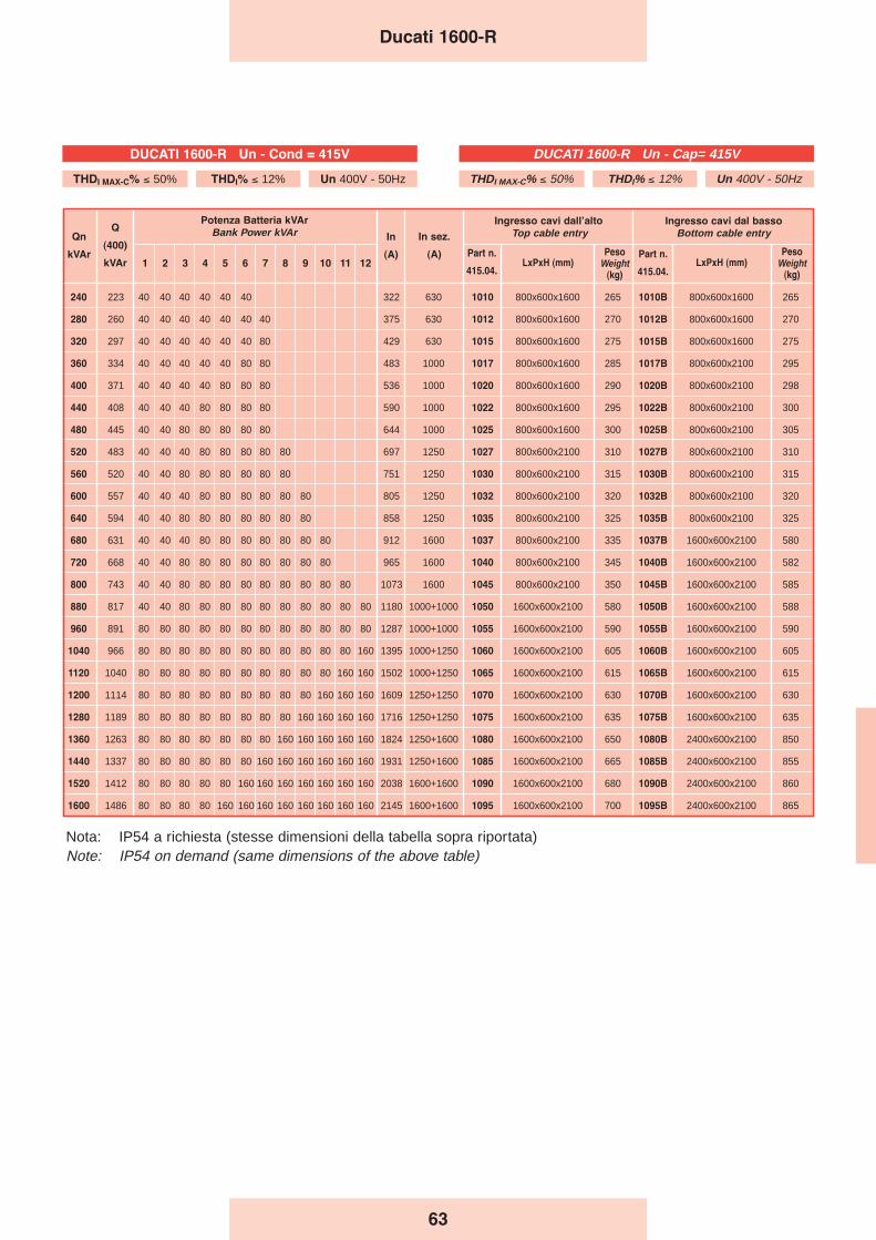
240 223 40 40 40 40 40 40 322 630 1010 800x600x1600 265 1010B 800x600x1600 265
280 260 40 40 40 40 40 40 40 375 630 1012 800x600x1600 270 1012B 800x600x1600 270
320 297 40 40 40 40 40 40 80 429 630 1015 800x600x1600 275 1015B 800x600x1600 275
360 334 40 40 40 40 40 80 80 483 1000 1017 800x600x1600 285 1017B 800x600x2100 295
400 371 40 40 40 40 80 80 80 536 1000 1020 800x600x1600 290 1020B 800x600x2100 298
440 408 40 40 40 80 80 80 80 590 1000 1022 800x600x1600 295 1022B 800x600x2100 300
480 445 40 40 80 80 80 80 80 644 1000 1025 800x600x1600 300 1025B 800x600x2100 305
520 483 40 40 40 80 80 80 80 80 697 1250 1027 800x600x2100 310 1027B 800x600x2100 310
560 520 40 40 80 80 80 80 80 80 751 1250 1030 800x600x2100 315 1030B 800x600x2100 315
600 557 40 40 40 80 80 80 80 80 80 805 1250 1032 800x600x2100 320 1032B 800x600x2100 320
640 594 40 40 80 80 80 80 80 80 80 858 1250 1035 800x600x2100 325 1035B 800x600x2100 325
680 631 40 40 40 80 80 80 80 80 80 80 912 1600 1037 800x600x2100 335 1037B 1600x600x2100 580
720 668 40 40 80 80 80 80 80 80 80 80 965 1600 1040 800x600x2100 345 1040B 1600x600x2100 582
800 743 40 40 80 80 80 80 80 80 80 80 80 1073 1600 1045 800x600x2100 350 1045B 1600x600x2100 585
880 817 40 40 80 80 80 80 80 80 80 80 80 80 1180 1000+1000 1050 1600x600x2100 580 1050B 1600x600x2100 588
960 891 80 80 80 80 80 80 80 80 80 80 80 80 1287 1000+1000 1055 1600x600x2100 590 1055B 1600x600x2100 590
1040 966 80 80 80 80 80 80 80 80 80 80 80 160 1395 1000+1250 1060 1600x600x2100 605 1060B 1600x600x2100 605
1120 1040 80 80 80 80 80 80 80 80 80 80 160 160 1502 1000+1250 1065 1600x600x2100 615 1065B 1600x600x2100 615
1200 1114 80 80 80 80 80 80 80 80 80 160 160 160 1609 1250+1250 1070 1600x600x2100 630 1070B 1600x600x2100 630
1280 1189 80 80 80 80 80 80 80 80 160 160 160 160 1716 1250+1250 1075 1600x600x2100 635 1075B 1600x600x2100 635
1360 1263 80 80 80 80 80 80 80 160 160 160 160 160 1824 1250+1600 1080 1600x600x2100 650 1080B 2400x600x2100 850
1440 1337 80 80 80 80 80 80 160 160 160 160 160 160 1931 1250+1600 1085 1600x600x2100 665 1085B 2400x600x2100 855
1520 1412 80 80 80 80 80 160 160 160 160 160 160 160 2038 1600+1600 1090 1600x600x2100 680 1090B 2400x600x2100 860
1600 1486 80 80 80 80 160 160 160 160 160 160 160 160 2145 1600+1600 1095 1600x600x2100 700 1095B 2400x600x2100 865
Ingresso cavi dal basso
Bottom cable entry
PesoWeight
(kg)
Qn
kVAr
Q
(400)
kVAr
Potenza Batteria kVAr
Bank Power kVAr
1 2 3 4 5 6 7 8 9 10 11 12
In
(A)
In sez.
(A) Part n.
415.04.
Ingresso cavi dallʼalto
Top cable entry
LxPxH (mm)Part n.
415.04.LxPxH (mm)
PesoWeight
(kg)
63
Ducati 1600-R
Nota: IP54 a richiesta (stesse dimensioni della tabella sopra riportata)Note: IP54 on demand (same dimensions of the above table)
DUCATI 1600-R Un - Cap= 415V
THDI MAX-C% ≤ 50% THDI% ≤ 12% Un 400V - 50Hz
DUCATI 1600-R Un - Cond = 415V
THDI MAX-C% ≤ 50% THDI% ≤ 12% Un 400V - 50Hz
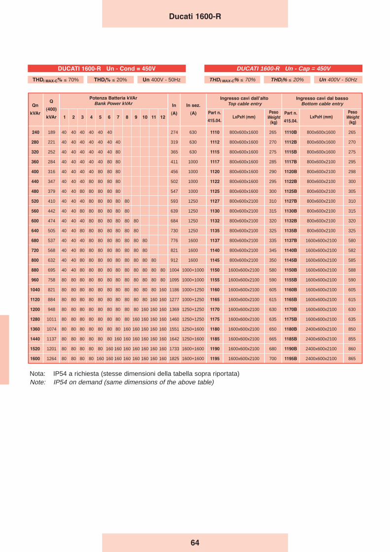
64
Ducati 1600-R
240 189 40 40 40 40 40 40 274 630 1110 800x600x1600 265 1110B 800x600x1600 265
280 221 40 40 40 40 40 40 40 319 630 1112 800x600x1600 270 1112B 800x600x1600 270
320 252 40 40 40 40 40 40 80 365 630 1115 800x600x1600 275 1115B 800x600x1600 275
360 284 40 40 40 40 40 80 80 411 1000 1117 800x600x1600 285 1117B 800x600x2100 295
400 316 40 40 40 40 80 80 80 456 1000 1120 800x600x1600 290 1120B 800x600x2100 298
440 347 40 40 40 80 80 80 80 502 1000 1122 800x600x1600 295 1122B 800x600x2100 300
480 379 40 40 80 80 80 80 80 547 1000 1125 800x600x1600 300 1125B 800x600x2100 305
520 410 40 40 40 80 80 80 80 80 593 1250 1127 800x600x2100 310 1127B 800x600x2100 310
560 442 40 40 80 80 80 80 80 80 639 1250 1130 800x600x2100 315 1130B 800x600x2100 315
600 474 40 40 40 80 80 80 80 80 80 684 1250 1132 800x600x2100 320 1132B 800x600x2100 320
640 505 40 40 80 80 80 80 80 80 80 730 1250 1135 800x600x2100 325 1135B 800x600x2100 325
680 537 40 40 40 80 80 80 80 80 80 80 776 1600 1137 800x600x2100 335 1137B 1600x600x2100 580
720 568 40 40 80 80 80 80 80 80 80 80 821 1600 1140 800x600x2100 345 1140B 1600x600x2100 582
800 632 40 40 80 80 80 80 80 80 80 80 80 912 1600 1145 800x600x2100 350 1145B 1600x600x2100 585
880 695 40 40 80 80 80 80 80 80 80 80 80 80 1004 1000+1000 1150 1600x600x2100 580 1150B 1600x600x2100 588
960 758 80 80 80 80 80 80 80 80 80 80 80 80 1095 1000+1000 1155 1600x600x2100 590 1155B 1600x600x2100 590
1040 821 80 80 80 80 80 80 80 80 80 80 80 160 1186 1000+1250 1160 1600x600x2100 605 1160B 1600x600x2100 605
1120 884 80 80 80 80 80 80 80 80 80 80 160 160 1277 1000+1250 1165 1600x600x2100 615 1165B 1600x600x2100 615
1200 948 80 80 80 80 80 80 80 80 80 160 160 160 1369 1250+1250 1170 1600x600x2100 630 1170B 1600x600x2100 630
1280 1011 80 80 80 80 80 80 80 80 160 160 160 160 1460 1250+1250 1175 1600x600x2100 635 1175B 1600x600x2100 635
1360 1074 80 80 80 80 80 80 80 160 160 160 160 160 1551 1250+1600 1180 1600x600x2100 650 1180B 2400x600x2100 850
1440 1137 80 80 80 80 80 80 160 160 160 160 160 160 1642 1250+1600 1185 1600x600x2100 665 1185B 2400x600x2100 855
1520 1201 80 80 80 80 80 160 160 160 160 160 160 160 1733 1600+1600 1190 1600x600x2100 680 1190B 2400x600x2100 860
1600 1264 80 80 80 80 160 160 160 160 160 160 160 160 1825 1600+1600 1195 1600x600x2100 700 1195B 2400x600x2100 865
Ingresso cavi dal basso
Bottom cable entry
PesoWeight
(kg)
Qn
kVAr
Q
(400)
kVAr
Potenza Batteria kVAr
Bank Power kVAr
1 2 3 4 5 6 7 8 9 10 11 12
In
(A)
In sez.
(A) Part n.
415.04.
Ingresso cavi dallʼalto
Top cable entry
LxPxH (mm)Part n.
415.04.LxPxH (mm)
PesoWeight
(kg)
Nota: IP54 a richiesta (stesse dimensioni della tabella sopra riportata)Note: IP54 on demand (same dimensions of the above table)
DUCATI 1600-R Un - Cap = 450V
THDI MAX-C% ≤ 70% THDI% ≤ 20% Un 400V - 50Hz
DUCATI 1600-R Un - Cond = 450V
THDI MAX-C% ≤ 70% THDI% ≤ 20% Un 400V - 50Hz
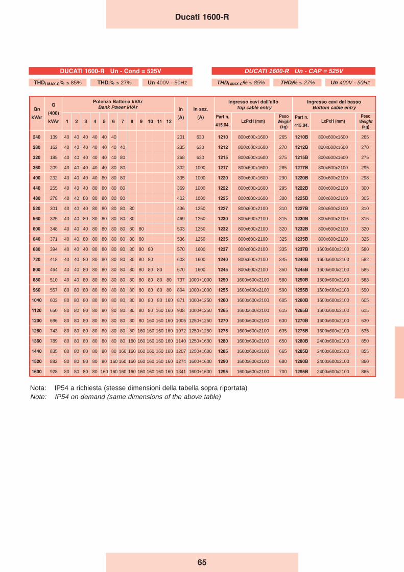
65
Ducati 1600-R
240 139 40 40 40 40 40 40 201 630 1210 800x600x1600 265 1210B 800x600x1600 265
280 162 40 40 40 40 40 40 40 235 630 1212 800x600x1600 270 1212B 800x600x1600 270
320 185 40 40 40 40 40 40 80 268 630 1215 800x600x1600 275 1215B 800x600x1600 275
360 209 40 40 40 40 40 80 80 302 1000 1217 800x600x1600 285 1217B 800x600x2100 295
400 232 40 40 40 40 80 80 80 335 1000 1220 800x600x1600 290 1220B 800x600x2100 298
440 255 40 40 40 80 80 80 80 369 1000 1222 800x600x1600 295 1222B 800x600x2100 300
480 278 40 40 80 80 80 80 80 402 1000 1225 800x600x1600 300 1225B 800x600x2100 305
520 301 40 40 40 80 80 80 80 80 436 1250 1227 800x600x2100 310 1227B 800x600x2100 310
560 325 40 40 80 80 80 80 80 80 469 1250 1230 800x600x2100 315 1230B 800x600x2100 315
600 348 40 40 40 80 80 80 80 80 80 503 1250 1232 800x600x2100 320 1232B 800x600x2100 320
640 371 40 40 80 80 80 80 80 80 80 536 1250 1235 800x600x2100 325 1235B 800x600x2100 325
680 394 40 40 40 80 80 80 80 80 80 80 570 1600 1237 800x600x2100 335 1237B 1600x600x2100 580
720 418 40 40 80 80 80 80 80 80 80 80 603 1600 1240 800x600x2100 345 1240B 1600x600x2100 582
800 464 40 40 80 80 80 80 80 80 80 80 80 670 1600 1245 800x600x2100 350 1245B 1600x600x2100 585
880 510 40 40 80 80 80 80 80 80 80 80 80 80 737 1000+1000 1250 1600x600x2100 580 1250B 1600x600x2100 588
960 557 80 80 80 80 80 80 80 80 80 80 80 80 804 1000+1000 1255 1600x600x2100 590 1255B 1600x600x2100 590
1040 603 80 80 80 80 80 80 80 80 80 80 80 160 871 1000+1250 1260 1600x600x2100 605 1260B 1600x600x2100 605
1120 650 80 80 80 80 80 80 80 80 80 80 160 160 938 1000+1250 1265 1600x600x2100 615 1265B 1600x600x2100 615
1200 696 80 80 80 80 80 80 80 80 80 160 160 160 1005 1250+1250 1270 1600x600x2100 630 1270B 1600x600x2100 630
1280 743 80 80 80 80 80 80 80 80 160 160 160 160 1072 1250+1250 1275 1600x600x2100 635 1275B 1600x600x2100 635
1360 789 80 80 80 80 80 80 80 160 160 160 160 160 1140 1250+1600 1280 1600x600x2100 650 1280B 2400x600x2100 850
1440 835 80 80 80 80 80 80 160 160 160 160 160 160 1207 1250+1600 1285 1600x600x2100 665 1285B 2400x600x2100 855
1520 882 80 80 80 80 80 160 160 160 160 160 160 160 1274 1600+1600 1290 1600x600x2100 680 1290B 2400x600x2100 860
1600 928 80 80 80 80 160 160 160 160 160 160 160 160 1341 1600+1600 1295 1600x600x2100 700 1295B 2400x600x2100 865
Ingresso cavi dal basso
Bottom cable entry
PesoWeight
(kg)
Qn
kVAr
Q
(400)
kVAr
Potenza Batteria kVAr
Bank Power kVAr
1 2 3 4 5 6 7 8 9 10 11 12
In
(A)
In sez.
(A) Part n.
415.04.
Ingresso cavi dallʼalto
Top cable entry
LxPxH (mm)Part n.
415.04.LxPxH (mm)
PesoWeight
(kg)
Nota: IP54 a richiesta (stesse dimensioni della tabella sopra riportata)Note: IP54 on demand (same dimensions of the above table)
DUCATI 1600-R Un - CAP = 525V
THDI MAX-C% ≤ 85% THDI% ≤ 27% Un 400V - 50Hz
DUCATI 1600-R Un - Cond = 525V
THDI MAX-C% ≤ 85% THDI% ≤ 27% Un 400V - 50Hz
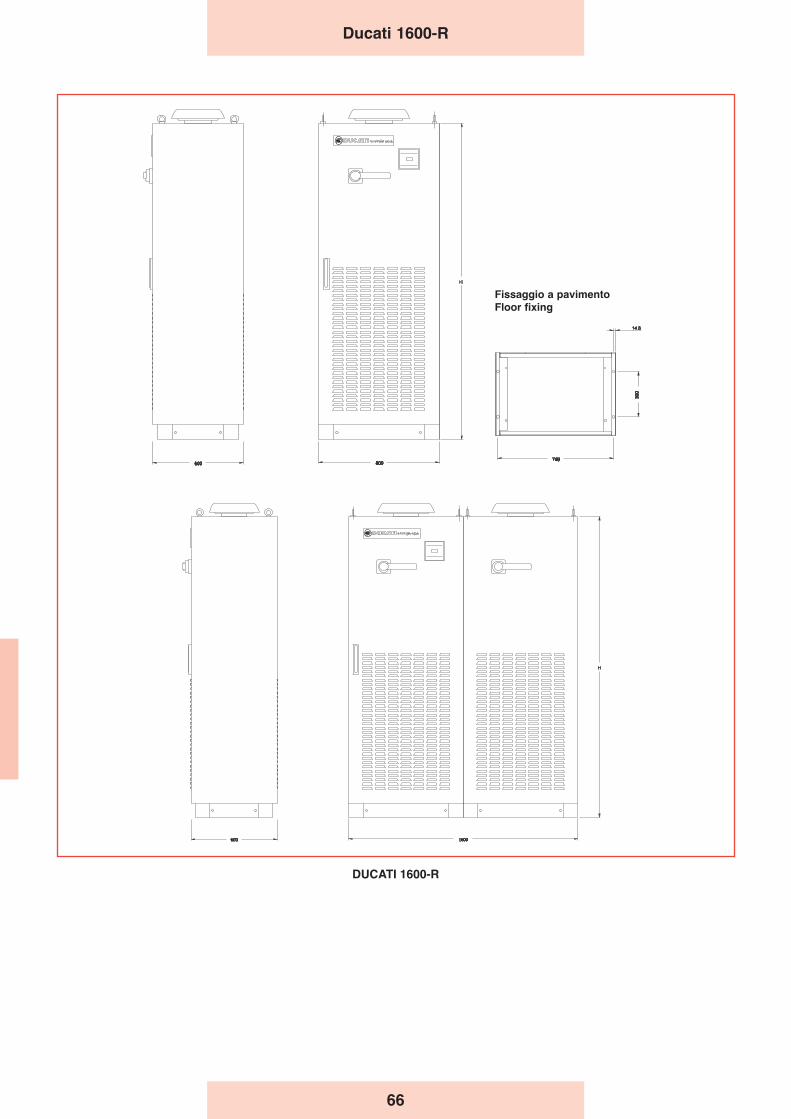
Ducati 1600-R
DUCATI 1600-R
Fissaggio a pavimento
Floor fixing
66
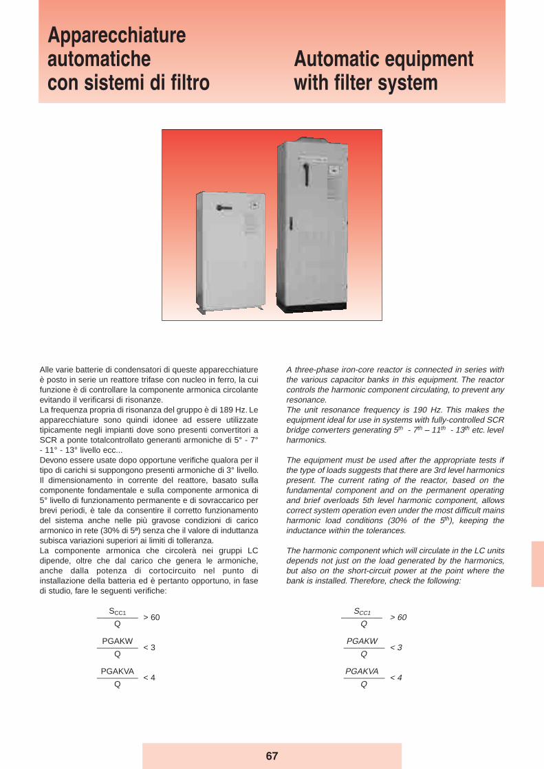
Apparecchiatureautomatichecon sistemi di filtro
Automatic equipmentwith filter system
A three-phase iron-core reactor is connected in series withthe various capacitor banks in this equipment. The reactorcontrols the harmonic component circulating, to prevent anyresonance.The unit resonance frequency is 190 Hz. This makes theequipment ideal for use in systems with fully-controlled SCRbridge converters generating 5th - 7th – 11th - 13th etc. levelharmonics.
The equipment must be used after the appropriate tests ifthe type of loads suggests that there are 3rd level harmonicspresent. The current rating of the reactor, based on thefundamental component and on the permanent operatingand brief overloads 5th level harmonic component, allowscorrect system operation even under the most difficult mainsharmonic load conditions (30% of the 5th), keeping theinductance within the tolerances.
The harmonic component which will circulate in the LC unitsdepends not just on the load generated by the harmonics,but also on the short-circuit power at the point where thebank is installed. Therefore, check the following:
SCC1––––––––– > 60
Q
PGAKW––––––––– < 3
Q
PGAKVA––––––––– < 4
Q
Alle varie batterie di condensatori di queste apparecchiatureè posto in serie un reattore trifase con nucleo in ferro, la cuifunzione è di controllare la componente armonica circolanteevitando il verificarsi di risonanze.La frequenza propria di risonanza del gruppo è di 189 Hz. Leapparecchiature sono quindi idonee ad essere utilizzatetipicamente negli impianti dove sono presenti convertitori aSCR a ponte totalcontrollato generanti armoniche di 5° - 7°- 11° - 13° livello ecc...Devono essere usate dopo opportune verifiche qualora per iltipo di carichi si suppongono presenti armoniche di 3° livello.Il dimensionamento in corrente del reattore, basato sullacomponente fondamentale e sulla componente armonica di5° livello di funzionamento permanente e di sovraccarico perbrevi periodi, è tale da consentire il corretto funzionamentodel sistema anche nelle più gravose condizioni di caricoarmonico in rete (30% di 5ª) senza che il valore di induttanzasubisca variazioni superiori ai limiti di tolleranza.La componente armonica che circolerà nei gruppi LCdipende, oltre che dal carico che genera le armoniche,anche dalla potenza di cortocircuito nel punto diinstallazione della batteria ed è pertanto opportuno, in fasedi studio, fare le seguenti verifiche:
SCC1––––––––– > 60
Q
PGAKW––––––––– < 3
Q
PGAKVA––––––––– < 4
Q
67
Where:- SCC1 = short-circuit power in KVA at the bank installation
point. If the value is unknown, the short-circuit power of thetransformers may be used:
where A is the transformer rated power (in kVA) and Vdc%is the transformer’s percentage short-circuit voltage.
- PGAKW = active power of the converter (e.g.: motors)- PGAKVA = apparent power of the converter (e.g.: UPS)- Q = power output of the capacitor bank in kVAr
If the above values are exceeded, more precise evaluationsare required to prevent the reactors from overheating.
Dove:- SCC1 = potenza di cortocircuito in KVA nel punto di
installazione della batteria. Se il valore non è noto, ci si puòriferire approssimativamente alla potenza di cortocircuito ditrasformatori:
dove A è la potenza nominale del trasformatore (espressain kVA) e Vcc% è la tensione di corto circuito percentualedel trasformatore.
- PGAKW = potenza attiva del convertitore (es. motori)- PGAKVA = Potenza apparente del convertitore (es. UPS)- Q = Potenza resa dal banco dei condensatori in kVAr
Qualora i valori suddetti siano superati è opportunoeffettuare valutazioni più precise per evitare ilsurriscaldamento dei reattori.
68
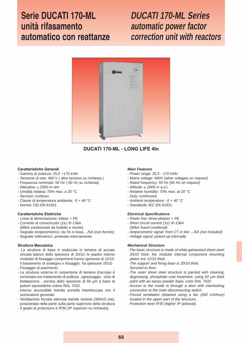
Serie DUCATI 170-MLunità rifasamentoautomatico con reattanze
DUCATI 170-ML Seriesautomatic power factorcorrection unit with reactors
DUCATI 170-ML - LONG LIFE 4In
Main Features- Power range: 25.5 - 170 kVAr - Mains voltage: 400V (other voltages on request)- Rated frequency: 50 Hz (60 Hz on request)- Altitude: ≤ 2000 m a.s.l.- Relative humidity: 70% max. at 20 °C- Duty: continuous- Ambient temperature: -5 + 40 °C- Standards: IEC EN 61921
Electrical Specifications- Power line: three-phases + PE- Short circuit current (1s): 8÷13kA
(80kA fused condional)- Amperometric signal: from CT in line .../5A (not included)- Voltage signal: picked up internally
Mechanical Structure- The basic structure is made of white galvanized sheet steel
20/10 thick; the modular internal component mountingplates are 12/10 thick.The support and fixing base is 20/10 thick.
- Secured to floor.- The outer sheet steel structure is painted with cleaning,
degreasing, phosphate coat treatment, using 50 µm thickpaint with an epoxy powder base, color RAL 7032.
- Access to the inside is through a door with interlockingconnection to the main disconnecting switch.
- Forced ventilation obtained using a fan (300 m3/hour)located in the upper part of the structure.
- Protection level IP30 (higher IP optional).
Caratteristiche Generali
- Gamma di potenza: 25,5 ÷170 kVAr - Tensione di rete: 400 V ( altre tensioni su richiesta )- Frequenza nominale: 50 Hz ( 60 Hz su richiesta)- Altitudine: ≤ 2000 m slm- Umidità relativa: 70% max. a 20 °C- Servizio: continuo- Classe di temperatura ambiente: -5 + 40 °C- Norme: CEI EN 61921
Caratteristiche Elettriche
- Linea di alimentazione: trifase + PE- Corrente di cortocircuito (1s): 8÷13kA
(80kA condizionati da fusibile a monte)- Segnale Amperometrico: da TA in linea .../5A (non fornito)- Segnale Voltmetrico: prelevato internamente
Struttura Meccanica
- La struttura di base è realizzata in lamiera di acciaiozincata bianco dello spessore di 20/10; le piastre internemodulari di fissaggio componenti hanno spessore di 12/10.Il basamento di sostegno e fissaggio ha spessore 20/10
- Fissaggio al pavimento.- La struttura esterna in carpenteria di lamiera d’acciaio è
verniciata con trattamento di pulitura , sgrassaggio , ciclo difosfatazione , vernice dello spessore di 50 µm a base dipolveri epossidiche colore RAL 7032.
- Interno accessibile tramite portella interbloccata con ilsezionatore generale.
- Ventilazione forzata ottenuta tramite ventola (300m3 ora),posizionata nella parte sulla parte superiore della struttura
- Il grado di protezione è IP30 (IP superiori su richiesta).
69
Modalità dʼinstallazione
- Per interno, a pavimento, in ambiente ventilato e nonpolveroso, al riparo dalla luce diretta del sole.
- Ingresso cavi dall’alto direttamente sui morsetti delsezionatore
Sezionatore Generale
- Sezionatore tripolare, con blocco porta e del tipo a velocitàindipendente da quella di manovra dell’operatore.
- Corrente nominale del sezionatore 1,45 volte la corrente diesercizio a 400 V.
Collegamenti Interni
- Sistema di distribuzione interno realizzato con cavo tipoN07V-K
Fusibili
- A valle del sezionatore sono presenti più terne di fusibili,posti a protezione delle batterie di condensatori.
- I fusibili sono del tipo NH-00 con caratteristica GL.
Contattori
- Adatti al comando di carichi capacitivi , inseriti all’esternodel triangolo formato dagli elementi capacitivi monofase,dotati di un blocchetto trifase di contatti anticipati perl’inserzione dei dispositivi di limitazione della correnteall’inserzione.
- Tensione della bobina 230V, 50-60Hz.
Condensatori
- Elementi monofase serie MONO - LONG LIFE collegati atriangolo.
- Tensione nominale 480-525V (in base alla frequenza diaccordo).
Dispositivi di protezione
- Ogni batteria di condensatori é dotata di dispositivi di scaricaatti a ridurre la tensione residua al di sotto del 10% dellatensione nominale del condensatore in circa 30 secondi.
Regolatore
- Tipo REGO 5
Reattori di filtro armonico
- frequenza di accordo: 189 Hz- linearità fino a 2 Ip/In- distorsione armonica in corrente ammessa in modo
continuativo: 30% In a 250 Hz; 15% In a 350 Hz- fattore di merito: Q > 20- materiali in classe H- sovratemperatura di funzionamento: 60 °C- protezione termica attraverso termistore con contatto NC.
Method of Installation- Indoor, on the floor, in a well-ventilated and dust-free
environment, protected from direct sunlight.- Top cable entry with direct connection to the terminals of
the disconnecting switches.
Main Disconnecting Switch- Three-pole disconnecting switch, with door lock and speed
independent of operator movement.- Disconnecting switch rated current 1.45 times the
operating current at 400V.
Internal Connections- Internal distribution system using N07V-K type cable.
Fuses- Downstream of the disconnecting switches there are
several triads of fuses, protecting the capacitor banks.- The fuses are of the NH-00 GL type.
Contactors- Suitable for controlling capacitive loads, inserted outside
the delta connection formed by the single-phase capacitiveelements, having a three-phase advance breaker block forinrush current limiting devices.
- Coil voltage 230V, 50-60Hz.
Capacitors- Single-phase elements series MONO - LONG LIFE in
delta connection.- Rated voltage 480-525V (according to tuning frequency).
Protection devices- Each capacitor bank has discharge devices designed to
reduce the residual voltage below 10% of the capacitor’srated voltage in approximately 30 seconds.
Regulator- REGO 5 type.
Harmonic filter reactors- tuning frequency: 189 Hz- linearity up to 2 Ip/In- continuous current harmonic distortion allowed: 30% In at
250 Hz; 15% In at 350 Hz- Q-factor: Q > 20- materials in class H- operating overtemperature: 60 °C- thermal protection using a thermistor with NC contact.
70
Ducati 170-ML
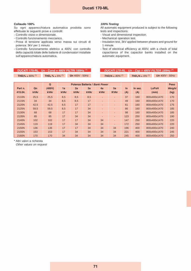
71
Q Potenza Batteria / Bank Power Peso
Part n. Qn (400V) 1a 2a 3a 4a 5a In In sez. LxPxH Weight415.04. kVAr kVAr kVAr kVAr kVAr kVAr KVAr (A) (A) (mm) (kg)
2110N 25,5 25,5 8,5 8,5 8,5 - - 37 160 800x400x1470 170
2115N 34 34 8,5 8,5 17 - - 49 160 800x400x1470 170
2120N 42,5 42,5 8,5 17 17 - - 61 160 800x400x1470 175
2125N 59,5 59,5 8,5 17 34 - - 86 160 800x400x1470 185
2130N 68 68 17 17 34 - - 98 160 800x400x1470 185
2135N 85 85 17 34 34 - - 123 250 800x400x1470 190
2140N 102 102 17 17 34 34 - 147 250 800x400x1470 220
2145N 119 119 17 34 34 34 - 172 250 800x400x1470 220
2150N 136 136 17 17 34 34 34 196 400 800x400x1470 240
2155N 153 153 17 34 34 34 34 221 400 800x400x1470 245
2160N 170 170 34 34 34 34 34 245 400 800x400x1470 250
Collaudo 100%
Su ogni apparecchiatura automatica prodotta sonoeffettuate le seguenti prove e controlli:- Controllo visivo e dimensionale.- Controllo funzionamento meccanico.- Prova di tensione applicata verso massa sui circuiti di
potenza: 3kV per 1 minuto.- Controllo funzionamento elettrico a 400V, con controllo
della capacità totale delle batterie di condensatori installatesull’apparecchiatura automatica.
100% TestingAll automatic equipment produced is subject to the followingtests and inspections:- Visual and dimensional inspection.- Mechanical operation test.- Insulation test, 3kV applied between phases and ground for
1 minute.- Test of electrical efficiency at 400V, with a check of total
capacitance of the capacitor banks installed on theautomatic equipment.
Ducati 170-ML
DUCATI 170-RL Un - Cap = 480V FILTER 189Hz (*)
THDI% ≤ 80% (*) THDV% ≤ 6% (*) Un 400V - 50Hz
DUCATI 170-RL Un - Cond = 480V FILTRI 189Hz (*)
THDI% ≤ 80% (*) THDV % ≤ 6% (*) Un 400V - 50Hz
* Altri valori a richiestaOther values on request

72
DUCATI 170-ML
Ducati 170-ML
FORI PER IL FISSAGGIO AL SUOLO
HALES FOR FLOOR FIXING
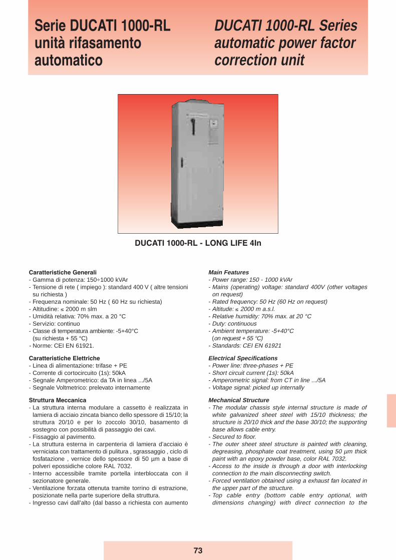
73
Caratteristiche Generali
- Gamma di potenza: 150÷1000 kVAr - Tensione di rete ( impiego ): standard 400 V ( altre tensioni
su richiesta )- Frequenza nominale: 50 Hz ( 60 Hz su richiesta)- Altitudine: ≤ 2000 m slm- Umidità relativa: 70% max. a 20 °C- Servizio: continuo- Classe di temperatura ambiente: -5+40°C
(su richiesta + 55 °C)- Norme: CEI EN 61921.
Caratteristiche Elettriche
- Linea di alimentazione: trifase + PE- Corrente di cortocircuito (1s): 50kA - Segnale Amperometrico: da TA in linea .../5A- Segnale Voltmetrico: prelevato internamente
Struttura Meccanica
- La struttura interna modulare a cassetto è realizzata inlamiera di acciaio zincata bianco dello spessore di 15/10; lastruttura 20/10 e per lo zoccolo 30/10, basamento disostegno con possibilità di passaggio dei cavi.
- Fissaggio al pavimento.- La struttura esterna in carpenteria di lamiera d’acciaio è
verniciata con trattamento di pulitura , sgrassaggio , ciclo difosfatazione , vernice dello spessore di 50 µm a base dipolveri epossidiche colore RAL 7032.
- Interno accessibile tramite portella interbloccata con ilsezionatore generale.
- Ventilazione forzata ottenuta tramite torrino di estrazione,posizionate nella parte superiore della struttura.
- Ingresso cavi dall’alto (dal basso a richiesta con aumento
Main Features- Power range: 150 - 1000 kVAr - Mains (operating) voltage: standard 400V (other voltages
on request)- Rated frequency: 50 Hz (60 Hz on request)- Altitude: ≤ 2000 m a.s.l.- Relative humidity: 70% max. at 20 °C- Duty: continuous- Ambient temperature: -5+40°C
(on request + 55 °C)- Standards: CEI EN 61921
Electrical Specifications- Power line: three-phases + PE- Short circuit current (1s): 50kA - Amperometric signal: from CT in line .../5A- Voltage signal: picked up internally
Mechanical Structure- The modular chassis style internal structure is made of
white galvanized sheet steel with 15/10 thickness; thestructure is 20/10 thick and the base 30/10; the supportingbase allows cable entry.
- Secured to floor.- The outer sheet steel structure is painted with cleaning,
degreasing, phosphate coat treatment, using 50 µm thickpaint with an epoxy powder base, color RAL 7032.
- Access to the inside is through a door with interlockingconnection to the main disconnecting switch.
- Forced ventilation obtained using a exhaust fan located inthe upper part of the structure.
- Top cable entry (bottom cable entry optional, withdimensions changing) with direct connection to the
Serie DUCATI 1000-RLunità rifasamentoautomatico
DUCATI 1000-RL Seriesautomatic power factorcorrection unit
DUCATI 1000-RL - LONG LIFE 4In
Ducati 1000-RL
terminals of the disconnecting switches (one switch percolumn).
- Protection level IP30 (higher IP optional).
Method of Installation- Inside, on the floor, in a well-ventilated and dust-free
environment, protected from direct sunlight.
Main Disconnecting Switch- Three-pole disconnecting switch for each column, with
door lock and speed independent of operator movement.- Disconnecting switch rated current 1.45 times the
operating current at 400 V.
Internal Connections- Internal distribution system using N07V-K type cable.
Fuses- Downstream of the disconnecting switches there are
several triads of fuses, protecting the capacitor banks.- The fuses are of the NH-00 GL type.
Contactors- Suitable for controlling capacitive loads, inserted outside
the delta connection formed by the single-phase capacitiveelements, having a three-phase advance breaker block forinrush current limiting devices.
- Coil voltage 230V, 50-60Hz.
Capacitors- Single-phase elements series MONO - LONG LIFE in
delta connection (on request three-phase elements seriesMODULO XD).
- Rated voltage 480-525V (according to tuning frequency)
Harmonic filter reactors- tuning frequency: 189 Hz- linearity up to 2 Ip/In- continuous current harmonic distortion allowed: 30% In at
250 Hz; 15% In at 350 Hz- Q-factor: Q > 20- materials in class H- operating overtemperature: 60 °C- thermal protection using a thermistor with NC contact.
Protection devices- Each capacitor bank has discharge devices designed to
reduce the residual voltage below 10% of the capacitor’srated voltage in approximately 30 seconds.
Regulator- REGO 7-12 type
delle dimensioni) direttamente sui morsetti dei sezionatori(un sezionatore per ogni colonna).
- Il grado di protezione è IP30 (IP superiori su richiesta).
Modalità dʼinstallazione
- Per interno, a pavimento, in ambiente ventilato e nonpolveroso, al riparo dalla luce diretta del sole.
Sezionatore Generale
- Sezionatore tripolare per ogni colonna, con blocco porta edel tipo a velocità indipendente da quella di manovradell’operatore.
- Corrente nominale del sezionatore 1,45 volte la corrente diesercizio a 400 V.
Collegamenti Interni
- Sistema di distribuzione interno realizzato con cavo tipoN07V-K
Fusibili
- A valle del sezionatore sono presenti più terne di fusibili,posti a protezione delle batterie di condensatori.
- I fusibili sono del tipo NH-00 con caratteristica GL.
Contattori
- Adatti al comando di carichi capacitivi, inseriti all’esterno deltriangolo formato dagli elementi capacitivi monofase, dotatidi un blocchetto trifase di contatti anticipati per l’inserzionedei dispositivi di limitazione della corrente all’inserzione.
- Tensione della bobina 230V, 50-60Hz.
Condensatori
- Elementi monofase serie MONO - LONG LIFE collegati atriangolo (a richiesta elementi trifase serie MODULO XD).
- Tensione nominale 480-525V (in base alla frequenza diaccordo)
Reattori di filtro armonico
- frequenza di accordo: 189 Hz- linearità fino a 2 Ip/In- distorsione armonica in corrente ammessa in modo
continuativo: 30% In a 250 Hz; 15% In a 350 Hz- fattore di merito: Q > 20- materiali in classe H- sovratemperatura di funzionamento: 60 °C- protezione termica attraverso termistore con contatto NC.
Dispositivi di protezione
- Ogni batteria di condensatori é dotata di dispositivi di scaricaatti a ridurre la tensione residua al di sotto del 10% dellatensione nominale del condensatore in circa 30 secondi.
Regolatore
- Tipo REGO 7-12
74
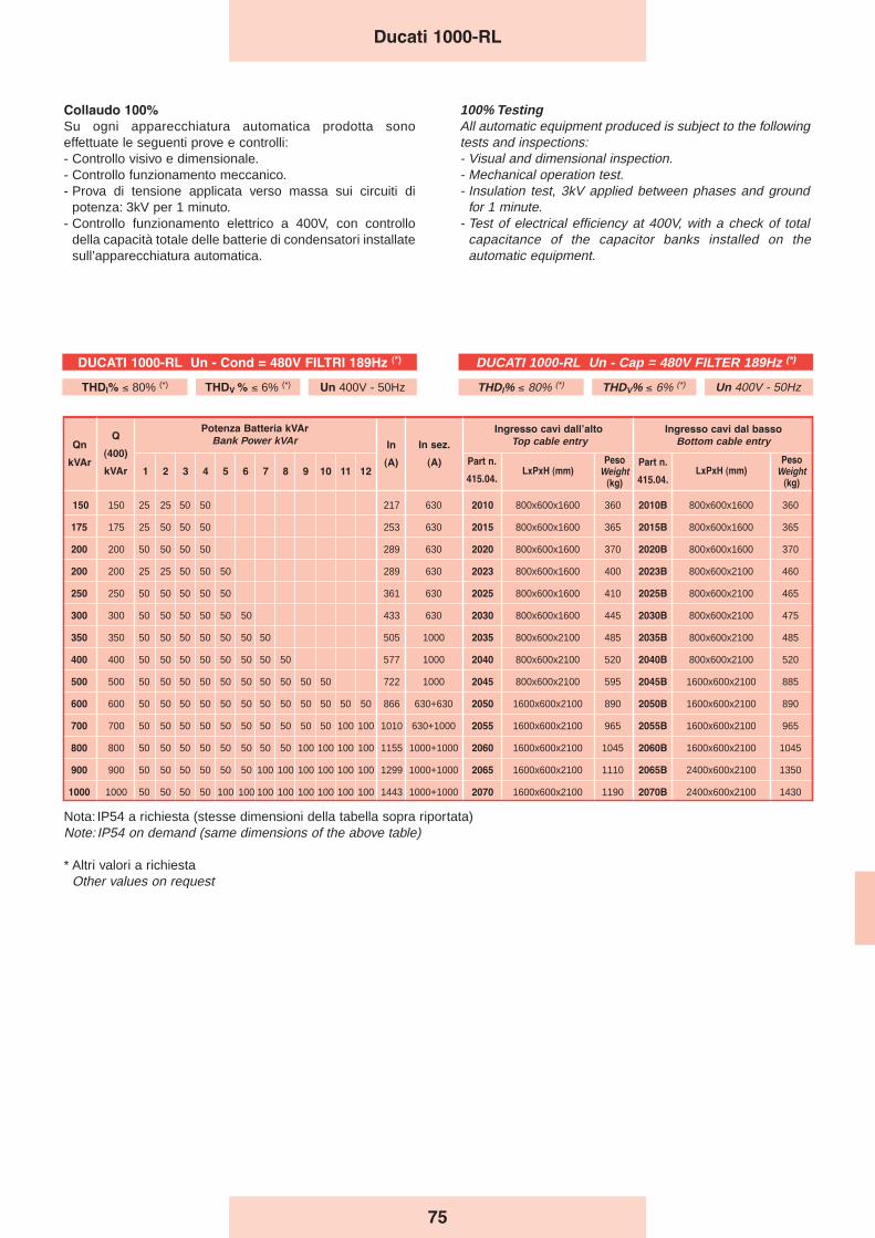
150 150 25 25 50 50 217 630 2010 800x600x1600 360 2010B 800x600x1600 360
175 175 25 50 50 50 253 630 2015 800x600x1600 365 2015B 800x600x1600 365
200 200 50 50 50 50 289 630 2020 800x600x1600 370 2020B 800x600x1600 370
200 200 25 25 50 50 50 289 630 2023 800x600x1600 400 2023B 800x600x2100 460
250 250 50 50 50 50 50 361 630 2025 800x600x1600 410 2025B 800x600x2100 465
300 300 50 50 50 50 50 50 433 630 2030 800x600x1600 445 2030B 800x600x2100 475
350 350 50 50 50 50 50 50 50 505 1000 2035 800x600x2100 485 2035B 800x600x2100 485
400 400 50 50 50 50 50 50 50 50 577 1000 2040 800x600x2100 520 2040B 800x600x2100 520
500 500 50 50 50 50 50 50 50 50 50 50 722 1000 2045 800x600x2100 595 2045B 1600x600x2100 885
600 600 50 50 50 50 50 50 50 50 50 50 50 50 866 630+630 2050 1600x600x2100 890 2050B 1600x600x2100 890
700 700 50 50 50 50 50 50 50 50 50 50 100 100 1010 630+1000 2055 1600x600x2100 965 2055B 1600x600x2100 965
800 800 50 50 50 50 50 50 50 50 100 100 100 100 1155 1000+1000 2060 1600x600x2100 1045 2060B 1600x600x2100 1045
900 900 50 50 50 50 50 50 100 100 100 100 100 100 1299 1000+1000 2065 1600x600x2100 1110 2065B 2400x600x2100 1350
1000 1000 50 50 50 50 100 100 100 100 100 100 100 100 1443 1000+1000 2070 1600x600x2100 1190 2070B 2400x600x2100 1430
Ingresso cavi dal basso
Bottom cable entry
PesoWeight
(kg)
Qn
kVAr
Q
(400)
kVAr
Potenza Batteria kVAr
Bank Power kVAr
1 2 3 4 5 6 7 8 9 10 11 12
In
(A)
In sez.
(A) Part n.
415.04.
Ingresso cavi dallʼalto
Top cable entry
LxPxH (mm)Part n.
415.04.LxPxH (mm)
PesoWeight
(kg)
Nota: IP54 a richiesta (stesse dimensioni della tabella sopra riportata)Note: IP54 on demand (same dimensions of the above table)
* Altri valori a richiestaOther values on request
Ducati 1000-RL
Collaudo 100%
Su ogni apparecchiatura automatica prodotta sonoeffettuate le seguenti prove e controlli:- Controllo visivo e dimensionale.- Controllo funzionamento meccanico.- Prova di tensione applicata verso massa sui circuiti di
potenza: 3kV per 1 minuto.- Controllo funzionamento elettrico a 400V, con controllo
della capacità totale delle batterie di condensatori installatesull’apparecchiatura automatica.
100% TestingAll automatic equipment produced is subject to the followingtests and inspections:- Visual and dimensional inspection.- Mechanical operation test.- Insulation test, 3kV applied between phases and ground
for 1 minute.- Test of electrical efficiency at 400V, with a check of total
capacitance of the capacitor banks installed on theautomatic equipment.
DUCATI 1000-RL Un - Cap = 480V FILTER 189Hz (*)
THDI% ≤ 80% (*) THDV% ≤ 6% (*) Un 400V - 50Hz
DUCATI 1000-RL Un - Cond = 480V FILTRI 189Hz (*)
THDI% ≤ 80% (*) THDV % ≤ 6% (*) Un 400V - 50Hz
75
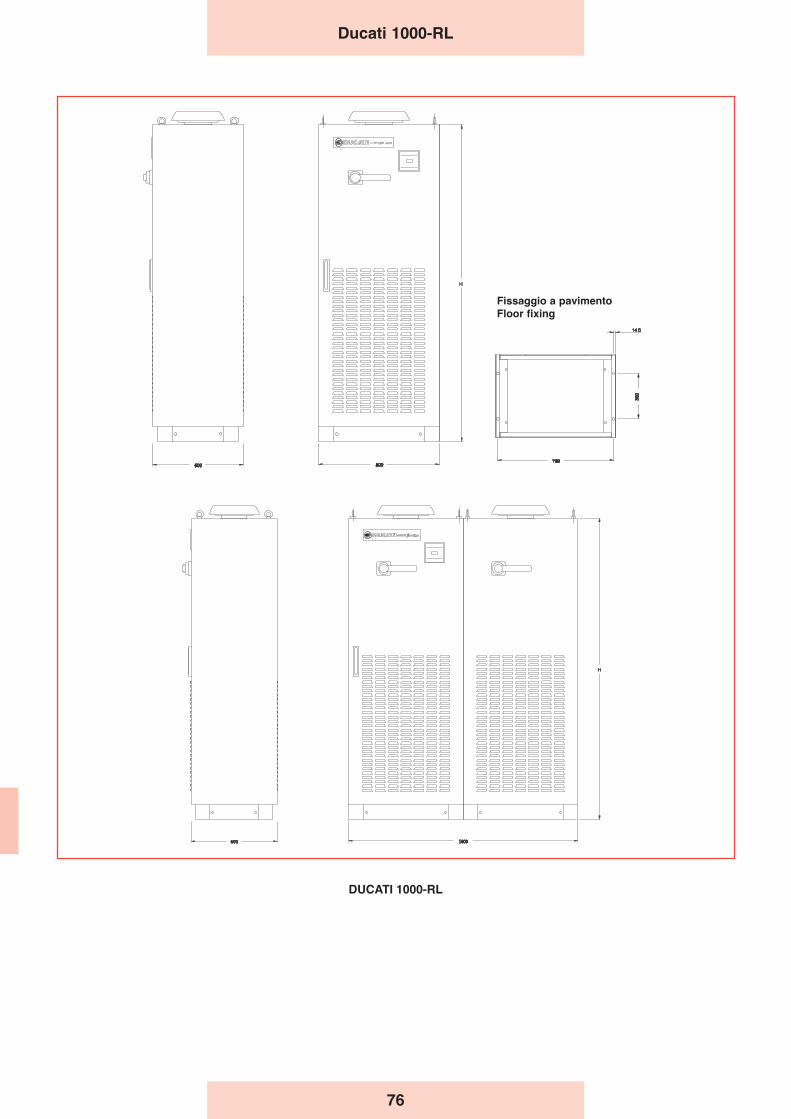
Ducati 1000-RL
DUCATI 1000-RL
Fissaggio a pavimento
Floor fixing
76
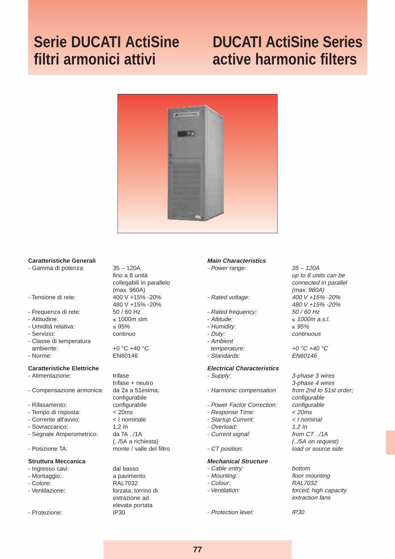
Main Characteristics- Power range: 35 – 120A
up to 8 units can be connected in parallel(max. 960A)
- Rated voltage: 400 V +15% -20%480 V +15% -20%
- Rated frequency: 50 / 60 Hz- Altitude: ≤ 1000m a.s.l.- Humidity: ≤ 95%- Duty: continuous- Ambient
temperature: +0 °C +40 °C- Standards: EN60146
Electrical Characteristics- Supply: 3-phase 3 wires
3-phase 4 wires- Harmonic compensation from 2nd to 51st order;
configurable- Power Factor Correction: configurable- Response Time: < 20ms- Startup Current: < I nominal- Overload: 1,2 In- Current signal: from CT ../1A
(../5A on request)- CT position: load or source side
Mechanical Structure- Cable entry: bottom- Mounting: floor mounting- Colour: RAL7032- Ventilation: forced; high capacity
extraction fans
- Protection level: IP30
Caratteristiche Generali- Gamma di potenza: 35 – 120A
fino a 8 unità collegabili in parallelo (max. 960A)
- Tensione di rete: 400 V +15% -20%480 V +15% -20%
- Frequenza di rete: 50 / 60 Hz- Altitudine: ≤ 1000m slm- Umidità relativa: ≤ 95%- Servizio: continuo- Classe di temperatura
ambiente: +0 °C +40 °C- Norme: EN60146
Caratteristiche Elettriche- Alimentazione: trifase
trifase + neutro- Compensazione armonica: da 2a a 51esima;
configurabile- Rifasamento: configurabile- Tempo di risposta: < 20ms- Corrente all'avvio: < I nominale- Sovraccarico: 1,2 In- Segnale Amperometrico: da TA ../1A
(../5A a richiesta)- Posizione TA: monte / valle del filtro
Struttura Meccanica- Ingresso cavi: dal basso- Montaggio: a pavimento- Colore: RAL7032- Ventilazione: forzata; torrino di
estrazione ad elevata portata
- Protezione: IP30
Serie DUCATI ActiSinefiltri armonici attivi
DUCATI ActiSine Seriesactive harmonic filters
77
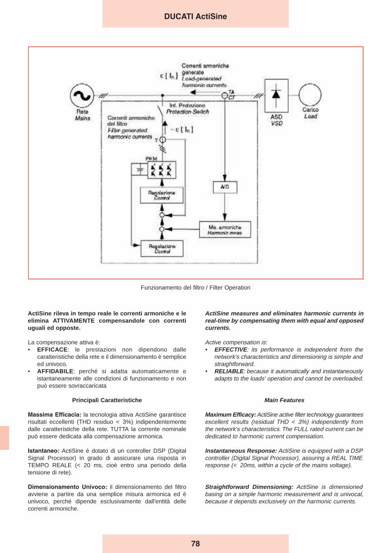
ActiSine measures and eliminates harmonic currents inreal-time by compensating them with equal and opposedcurrents.
Active compensation is:• EFFECTIVE: its performance is independent from the
network's characteristics and dimensioning is simple andstraightforward.
• RELIABLE: because it automatically and instantaneouslyadapts to the loads' operation and cannot be overloaded.
Main Features
Maximum Efficacy: ActiSine active filter technology guaranteesexcellent results (residual THD < 3%) independently fromthe network's characteristics. The FULL rated current can bededicated to harmonic current compensation.
Instantaneous Response: ActiSine is equipped with a DSPcontroller (Digital Signal Processor), assuring a REAL TIMEresponse (< 20ms, within a cycle of the mains voltage).
Straightforward Dimensioning: ActiSine is dimensionedbasing on a simple harmonic measurement and is univocal,because it depends exclusively on the harmonic currents.
ActiSine rileva in tempo reale le correnti armoniche e leelimina ATTIVAMENTE compensandole con correntiuguali ed opposte.
La compensazione attiva è:• EFFICACE: le prestazioni non dipendono dalle
caratteristiche della rete e il dimensionamento è sempliceed univoco.
• AFFIDABILE: perché si adatta automaticamente eistantaneamente alle condizioni di funzionamento e nonpuò essere sovraccaricata
Principali Caratteristiche
Massima Efficacia: la tecnologia attiva ActiSine garantiscerisultati eccellenti (THD residuo < 3%) indipendentementedalle caratteristiche della rete. TUTTA la corrente nominalepuò essere dedicata alla compensazione armonica.
Istantaneo: ActiSine è dotato di un controller DSP (DigitalSignal Processor) in grado di assicurare una risposta inTEMPO REALE (< 20 ms, cioè entro una periodo dellatensione di rete).
Dimensionamento Univoco: il dimensionamento del filtroavviene a partire da una semplice misura armonica ed èunivoco, perché dipende esclusivamente dall'entità dellecorrenti armoniche.
Funzionamento del filtro / Filter Operation
DUCATI ActiSine
78
Nessun rischio di sovraccarico: ActiSine non può esseresovraccaricato. Nel caso in cui le correnti armonichedovessero superare quelle per cui è stato dimensionato, ilsistema limita la propria azione alla sua corrente nominale,filtrando la massima parte possibile di armoniche.
Flessibilità e scalabilità: ActiSine abbina una strutturamodulare alla capacità di affiancare fino ad 8 unità inparallelo, per raggiungere potenze molto elevate. Questecaratteristiche assicurano la massima scalabilità in fase diinstallazione e l'espandibilità del sistema.
Filtraggio del Neutro: le armoniche di 3° ordine (e in modominore di ordine 9°, 15°, …, 6n+3) generate da carichidistorcenti mono-fase (PC, fotocopiatrici, ballast elettronici) sisommano nel neutro, sovraccaricandolo. ActiSine èdisponibile in versione trifase + neutro, in grado di filtrareefficacemente anche queste armoniche.
Selettività e Rifasamento: con le impostazioni di fabbrica,ActiSine agisce su tutte le armoniche, fino alla 51esima. Dalmenù utente può però essere impostata l'eliminazioneprioritaria di armoniche selezionate dall'utente (fino a 12),concentrando su di esse l'azione correttiva. ActiSine puòinoltre essere impostato per utilizzare parte della correntenominale per rifasare il carico e può però essere utilizzato incombinazione con i sistemi di rifasamento tradizionali –basati su banchi di condensatori – purché dotati di reattanzeanti-risonanza.
Semplicità di Installazione e Utilizzo: l'installazione diActiSine è semplice e flessibile perché viene collegato inparallelo ai carichi da filtrare e i TA per la misura delle correntipossono essere installati a monte o a valle del filtro (controlload anello chiuso o aperto). La messa in servizio è immediata,grazie alle impostazioni di default ed automatiche.L'interfaccia utente è semplice, immediata e completamentein ITALIANO.
No risk of overload: ActiSine cannot be overloaded. If theharmonic currents should exceed the value for which thefilter is dimensioned, the system will limit its action to itsnominal current, filtering the maximum possible amount ofharmonics.
Flexibility and expandability: ActiSine combines a modularstructure with the possibility of connecting up to 8 units inparallel, in order to obtain very high powers. Thesecharacteristics ensure the maximal flexibility duringinstallation and the expandability of the system.
Neutral Filtering: harmonics of 3rd order (and order 9th,15th, …, 6n+3) generated by single-phase distorting loads(PCs, copying machines, electronic ballasts) add up in theneutral cables, overloading them. ActiSine is available asthree-phase + neutral version, capable of effectivelycanceling these harmonics.
Selectivity and Power Factor Correction: with its defaultsettings ActiSine acts on all harmonics up to the 51st. Theuser can also set up to 12 harmonics on which toconcentrate the filtering action. Moreover, ActiSine can beset to use part of its current to correct the load's power factorand can be used together with traditional capacitor-basedPFC equipment, as long as they are equipped with detuningreactors.
Easy to Install and Operate: the installation is simple andflexible because ActiSine is connected in parallel to the loadsto be filtered and the CTs for the current measurement canbe mounted up- or down-stream (closed- or open-loopcontrol). The startup is immediate thanks to default andautomatic settings. The user interface is simple andstraightforward.
DUCATI ActiSine
79
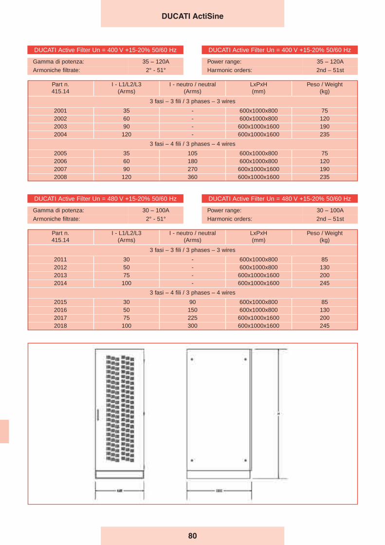
DUCATI ActiSine
DUCATI Active Filter Un = 400 V +15-20% 50/60 Hz
Gamma di potenza: 35 – 120A
Armoniche filtrate: 2° - 51°
DUCATI Active Filter Un = 400 V +15-20% 50/60 Hz
Power range: 35 – 120A
Harmonic orders: 2nd – 51st
DUCATI Active Filter Un = 480 V +15-20% 50/60 Hz
Gamma di potenza: 30 – 100A
Armoniche filtrate: 2° - 51°
DUCATI Active Filter Un = 480 V +15-20% 50/60 Hz
Power range: 30 – 100A
Harmonic orders: 2nd – 51st
Part n.415.14
I - L1/L2/L3(Arms)
I - neutro / neutral(Arms)
LxPxH(mm)
Peso / Weight(kg)
3 fasi – 3 fili / 3 phases – 3 wires
2001 35 - 600x1000x800 752002 60 - 600x1000x800 1202003 90 - 600x1000x1600 1902004 120 - 600x1000x1600 235
3 fasi – 4 fili / 3 phases – 4 wires
2005 35 105 600x1000x800 752006 60 180 600x1000x800 1202007 90 270 600x1000x1600 1902008 120 360 600x1000x1600 235
Part n.415.14
I - L1/L2/L3(Arms)
I - neutro / neutral(Arms)
LxPxH(mm)
Peso / Weight(kg)
3 fasi – 3 fili / 3 phases – 3 wires
2011 30 - 600x1000x800 852012 50 - 600x1000x800 1302013 75 - 600x1000x1600 2002014 100 - 600x1000x1600 245
3 fasi – 4 fili / 3 phases – 4 wires
2015 30 90 600x1000x800 852016 50 150 600x1000x800 1302017 75 225 600x1000x1600 2002018 100 300 600x1000x1600 245
80
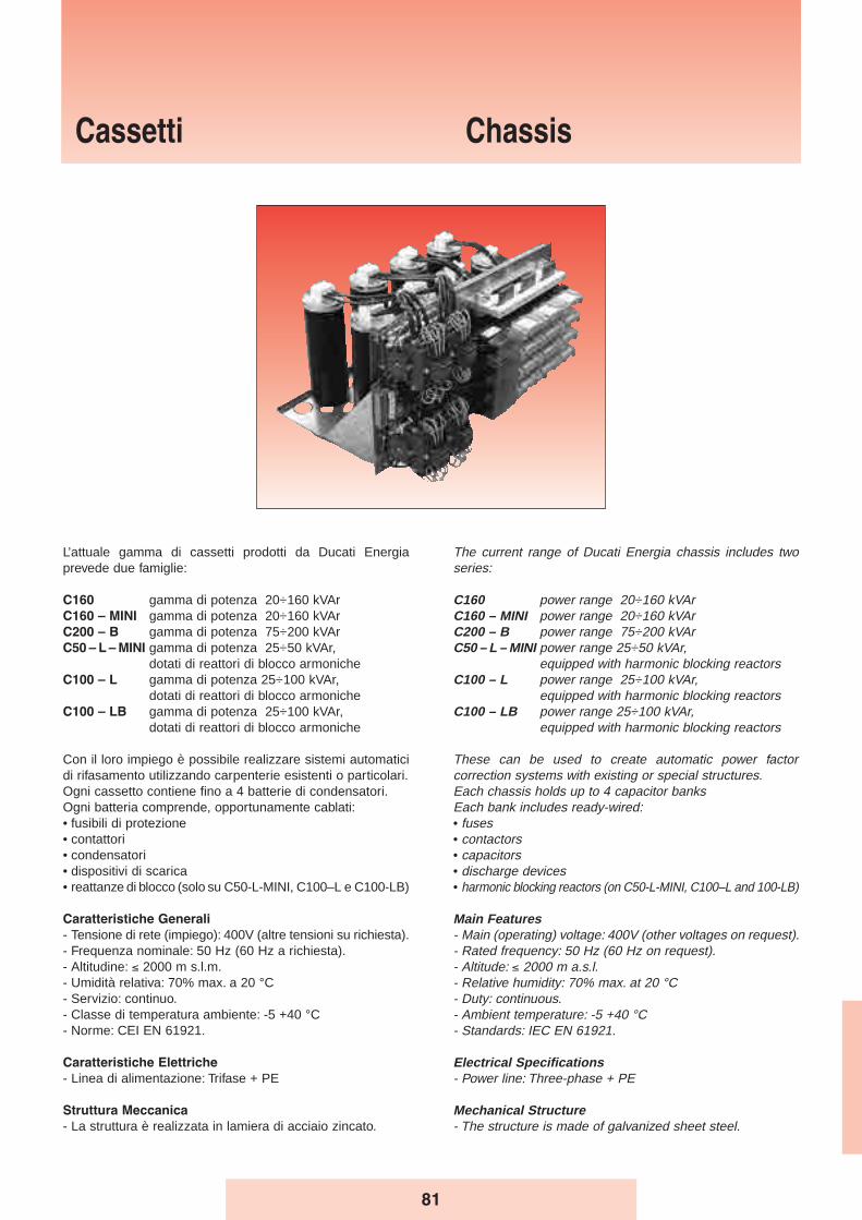
Cassetti Chassis
The current range of Ducati Energia chassis includes twoseries:
C160 power range 20÷160 kVAr C160 – MINI power range 20÷160 kVAr C200 – B power range 75÷200 kVAr C50 – L – MINI power range 25÷50 kVAr,
equipped with harmonic blocking reactorsC100 – L power range 25÷100 kVAr,
equipped with harmonic blocking reactorsC100 – LB power range 25÷100 kVAr,
equipped with harmonic blocking reactors
These can be used to create automatic power factorcorrection systems with existing or special structures.Each chassis holds up to 4 capacitor banks Each bank includes ready-wired:• fuses• contactors• capacitors• discharge devices• harmonic blocking reactors (on C50-L-MINI, C100–L and 100-LB)
Main Features- Main (operating) voltage: 400V (other voltages on request).- Rated frequency: 50 Hz (60 Hz on request).- Altitude: ≤ 2000 m a.s.l.- Relative humidity: 70% max. at 20 °C- Duty: continuous.- Ambient temperature: -5 +40 °C- Standards: IEC EN 61921.
Electrical Specifications- Power line: Three-phase + PE
Mechanical Structure- The structure is made of galvanized sheet steel.
L’attuale gamma di cassetti prodotti da Ducati Energiaprevede due famiglie:
C160 gamma di potenza 20÷160 kVAr C160 – MINI gamma di potenza 20÷160 kVAr C200 – B gamma di potenza 75÷200 kVAr C50 – L – MINI gamma di potenza 25÷50 kVAr,
dotati di reattori di blocco armonicheC100 – L gamma di potenza 25÷100 kVAr,
dotati di reattori di blocco armonicheC100 – LB gamma di potenza 25÷100 kVAr,
dotati di reattori di blocco armoniche
Con il loro impiego è possibile realizzare sistemi automaticidi rifasamento utilizzando carpenterie esistenti o particolari.Ogni cassetto contiene fino a 4 batterie di condensatori.Ogni batteria comprende, opportunamente cablati:• fusibili di protezione• contattori• condensatori• dispositivi di scarica• reattanze di blocco (solo su C50-L-MINI, C100–L e C100-LB)
Caratteristiche Generali
- Tensione di rete (impiego): 400V (altre tensioni su richiesta).- Frequenza nominale: 50 Hz (60 Hz a richiesta).- Altitudine: ≤ 2000 m s.l.m.- Umidità relativa: 70% max. a 20 °C- Servizio: continuo.- Classe di temperatura ambiente: -5 +40 °C- Norme: CEI EN 61921.
Caratteristiche Elettriche
- Linea di alimentazione: Trifase + PE
Struttura Meccanica
- La struttura è realizzata in lamiera di acciaio zincato.
81
Installation method- Indoor, horizontal.
Internal Connections- Connections use N07VK cables.
Fuses- Triads of fuses protect each pair of capacitor banks.- The fuses are of the NH-00 GL type.
Contactors- Suitable for controlling capacitive loads, inserted outside
the delta connection formed by the single-phase capacitiveelements, having a three-phase advance breaker block forinrush current limiting devices.
- Coil voltage 230V, 50-60Hz.
Capacitors- Single-fase elements series MONO - LONG LIFE in delta
connection for C160, C160-MINI, C50-L-MINI, C100-L- Three-phase elements series MODULO XD for C200-B
and C100-LB (on request they can be supplied also forC160, C160-MINI and C100-L series)
- Rated voltage415-450-525V for C160 family400-525V for C200-B family480-525V for C50-L-MINI, C100-L and C100-LB family (according to the tuning frequency)
Protection devices- Each capacitor bank has discharge devices designed to
reduce the residual voltage below 10% of the capacitor’srated voltage in approximately 30 seconds.
100% TestingAll automatic equipment produced is subject to the followingtests and inspections:- Visual and dimensional inspection.- Mechanical operation test.- Insulation test, 3kV applied between phases and ground
for 1 minute.- Test of electrical efficiency at 400V, with a check of total
capacitance of the capacitor banks installed on theautomatic equipment..
Harmonic filter reactors (only for C50–L-Mini, C100–Land C100–LB)- tuning frequency: 189 Hz- linearity up to 2 Ip/In- continuous current harmonic distortion allowed: 30% In at
250 Hz; 15% In at 350 Hz- Q-factor: Q > 20- materials in class H- operating overtemperature: 60 °C- thermal protection using a thermistor with NC contact.
82
Cassetti - Chassis
Modalità dʼinstallazione
- Per interno, orizzontale.
Collegamenti Interni
- Cablaggi realizzati con cavi tipo N07VK.
Fusibili
- Terne di fusibili poste a protezione di ciascuna coppia dibatterie di condensatori.
- Fusibili tipo NH-00 con caratteristica GL.
Contattori
- Adatti al comando di carichi capacitivi , inseriti all’esterno deltriangolo formato dagli elementi capacitivi monofase, dotatidi un blocchetto trifase di contatti anticipati per l’inserzionedei dispositivi di limitazione della corrente all’inserzione.
- Tensione della bobina 230V, 50-60Hz.
Condensatori
- Elementi monofase serie MONO - LONG LIFE collegati a triangolo per C160, C160-MINI, C50-L-MINI, C100-L
- Elementi trifase serie MODULO XD per C200-B e C100-LB (a richiesta fornibili anche per le serie C160, C160-MINI e C100-L)
- Tensione nominale415-450-525V per famiglia C160400-525V per la famiglia C200-B480-525V per famiglia C50-L-MINI, C100-L e C100-LB (in base alla frequenza di accordo)
Dispositivi di protezione
- Ogni batteria di condensatori é dotata di dispositivi di scaricaatti a ridurre la tensione residua al di sotto del 10% dellatensione nominale del condensatore in circa 30 secondi.
Collaudo 100%
Su ogni apparecchiatura automatica prodotta sonoeffettuate le seguenti prove e controlli:- Controllo visivo e dimensionale.- Controllo funzionamento meccanico.- Prova di tensione applicata verso massa sui circuiti di
potenza: 3kV per 1 minuto.- Controllo funzionamento elettrico a 400V, con controllo
della capacità totale delle batterie di condensatori installatesull’apparecchiatura automatica.
Reattori di filtro armonico (solo per C50–L-Mini, C100–L
e C100–LB)
- frequenza di accordo: 189 Hz- linearità fino a 2 Ip/In- distorsione armonica in corrente ammessa in modo
continuativo: 30% In a 250 Hz; 15% In a 350 Hz- fattore di merito: Q > 20- materiali in classe H- sovratemperatura di funzionamento: 60 °C- protezione termica attraverso termistore con contatto NC.
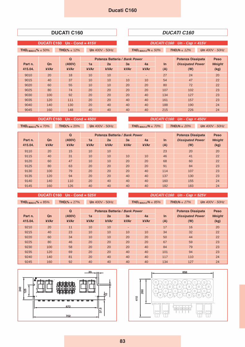
Q Potenza Batteria / Bank Power Potenza Dissipata Peso
Part n. Qn (400V) 1a 2a 3a 4a In Dissipated Power Weight415.04. kVAr kVAr kVAr kVAr kVAr kVAr (A) (W) (kg)
9010 20 18 10 10 - - 27 24 20
9015 40 37 10 10 10 10 54 47 22
9020 60 55 10 10 20 20 80 72 22
9025 80 74 20 20 20 20 107 102 23
9030 100 92 20 20 20 40 134 127 23
9035 120 111 20 20 40 40 161 157 23
9040 140 130 20 40 40 40 188 190 24
9045 160 148 40 40 40 40 215 226 24
Q Potenza Batteria / Bank Power Potenza Dissipata Peso
Part n. Qn (400V) 1a 2a 3a 4a In Dissipated Power Weight415.04. kVAr kVAr kVAr kVAr kVAr kVAr (A) (W) (kg)
9110 20 15 10 10 23 20 20
9115 40 31 10 10 10 10 46 41 22
9120 60 47 10 10 20 20 68 60 22
9125 80 63 20 20 20 20 91 84 23
9130 100 79 20 20 20 40 114 107 23
9135 120 94 20 20 40 40 137 130 23
9140 140 110 20 40 40 40 160 155 24
9145 160 126 40 40 40 40 182 183 24
Q Potenza Batteria / Bank Power Potenza Dissipata Peso
Part n. Qn (400V) 1a 2a 3a 4a In Dissipated Power Weight415.04. kVAr kVAr kVAr kVAr kVAr kVAr (A) (W) (kg)
9210 20 11 10 10 - - 17 16 20
9215 40 23 10 10 10 10 34 32 22
9220 60 34 10 10 20 20 50 44 22
9225 80 46 20 20 20 20 67 59 23
9230 100 58 20 20 20 40 84 79 23
9235 120 69 20 20 40 40 101 94 23
9240 140 81 20 40 40 40 117 110 24
9245 160 92 40 40 40 40 134 127 24
DUCATI C160 DUCATI C160
83
Ducati C160
DUCATI C160 Un - Cap = 415V
THDI MAX-C% ≤ 50% THDI% ≤ 12% Un 400V - 50Hz
DUCATI C160 Un - Cap = 450V
THDI MAX-C% ≤ 70% THDI% ≤ 20% Un 400V - 50Hz
DUCATI C160 Un - Cond = 415V
THDI MAX-C% ≤ 50% THDI% ≤ 12% Un 400V - 50Hz
DUCATI C160 Un - Cond = 450V
THDI MAX-C% ≤ 70% THDI% ≤ 20% Un 400V - 50Hz
DUCATI C160 Un - Cap = 525V
THDI MAX-C% ≤ 85% THDI% ≤ 27% Un 400V - 50Hz
DUCATI C160 Un - Cond = 525V
THDI MAX-C% ≤ 85% THDI% ≤ 27% Un 400V - 50Hz
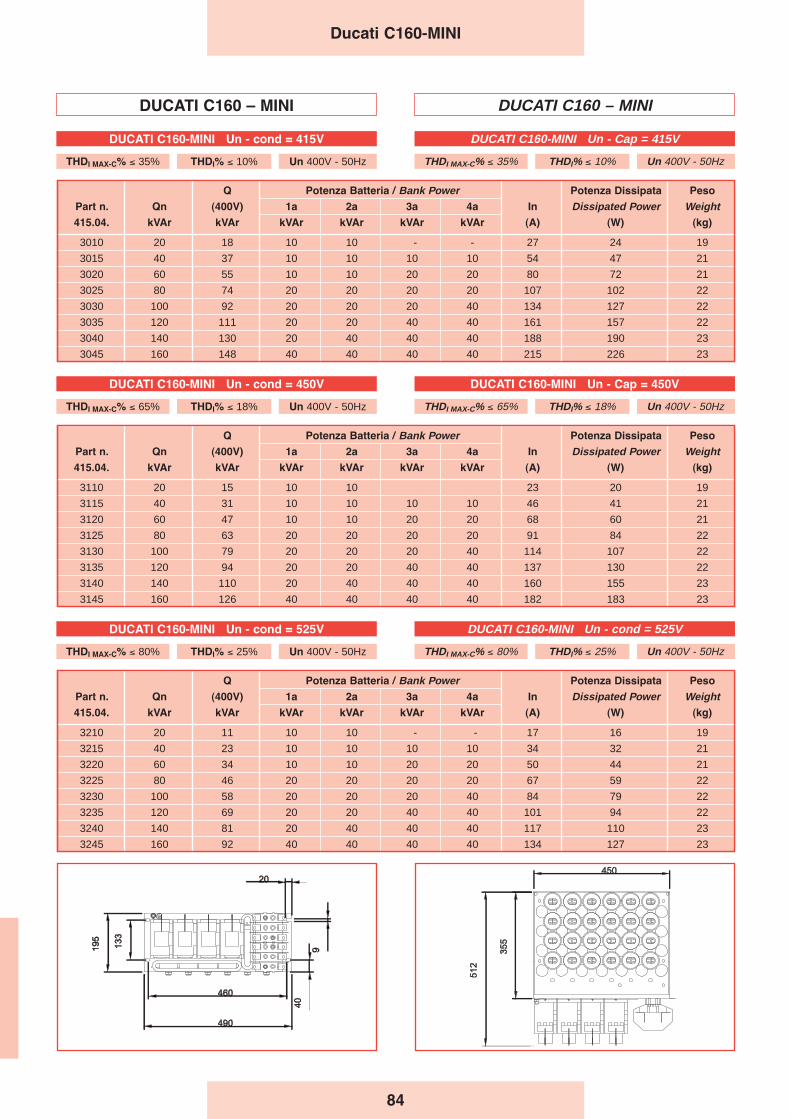
Q Potenza Batteria / Bank Power Potenza Dissipata Peso
Part n. Qn (400V) 1a 2a 3a 4a In Dissipated Power Weight415.04. kVAr kVAr kVAr kVAr kVAr kVAr (A) (W) (kg)
3010 20 18 10 10 - - 27 24 19
3015 40 37 10 10 10 10 54 47 21
3020 60 55 10 10 20 20 80 72 21
3025 80 74 20 20 20 20 107 102 22
3030 100 92 20 20 20 40 134 127 22
3035 120 111 20 20 40 40 161 157 22
3040 140 130 20 40 40 40 188 190 23
3045 160 148 40 40 40 40 215 226 23
Q Potenza Batteria / Bank Power Potenza Dissipata Peso
Part n. Qn (400V) 1a 2a 3a 4a In Dissipated Power Weight415.04. kVAr kVAr kVAr kVAr kVAr kVAr (A) (W) (kg)
3110 20 15 10 10 23 20 19
3115 40 31 10 10 10 10 46 41 21
3120 60 47 10 10 20 20 68 60 21
3125 80 63 20 20 20 20 91 84 22
3130 100 79 20 20 20 40 114 107 22
3135 120 94 20 20 40 40 137 130 22
3140 140 110 20 40 40 40 160 155 23
3145 160 126 40 40 40 40 182 183 23
Q Potenza Batteria / Bank Power Potenza Dissipata Peso
Part n. Qn (400V) 1a 2a 3a 4a In Dissipated Power Weight415.04. kVAr kVAr kVAr kVAr kVAr kVAr (A) (W) (kg)
3210 20 11 10 10 - - 17 16 19
3215 40 23 10 10 10 10 34 32 21
3220 60 34 10 10 20 20 50 44 21
3225 80 46 20 20 20 20 67 59 22
3230 100 58 20 20 20 40 84 79 22
3235 120 69 20 20 40 40 101 94 22
3240 140 81 20 40 40 40 117 110 23
3245 160 92 40 40 40 40 134 127 23
DUCATI C160 – MINI DUCATI C160 – MINI
Ducati C160-MINI
DUCATI C160-MINI Un - cond = 415V
THDI MAX-C% ≤ 35% THDI% ≤ 10% Un 400V - 50Hz
DUCATI C160-MINI Un - Cap = 415V
THDI MAX-C% ≤ 35% THDI% ≤ 10% Un 400V - 50Hz
DUCATI C160-MINI Un - cond = 450V
THDI MAX-C% ≤ 65% THDI% ≤ 18% Un 400V - 50Hz
DUCATI C160-MINI Un - Cap = 450V
THDI MAX-C% ≤ 65% THDI% ≤ 18% Un 400V - 50Hz
DUCATI C160-MINI Un - cond = 525V
THDI MAX-C% ≤ 80% THDI% ≤ 25% Un 400V - 50Hz
DUCATI C160-MINI Un - cond = 525V
THDI MAX-C% ≤ 80% THDI% ≤ 25% Un 400V - 50Hz
84
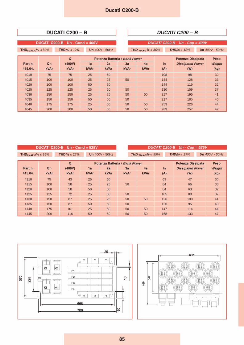
DUCATI C200 – B DUCATI C200 – B
Q Potenza Batteria / Bank Power Potenza Dissipata Peso
Part n. Qn (400V) 1a 2a 3a 4a In Dissipated Power Weight415.04. kVAr kVAr kVAr kVAr kVAr kVAr (A) (W) (kg)
4010 75 75 25 50 108 98 30
4015 100 100 25 25 50 144 128 33
4020 100 100 50 50 144 119 32
4025 125 125 25 50 50 180 159 37
4030 150 150 25 25 50 50 217 195 41
4035 150 150 50 50 50 217 185 40
4040 175 175 25 50 50 50 253 226 44
4045 200 200 50 50 50 50 289 257 47
Q Potenza Batteria / Bank Power Potenza Dissipata Peso
Part n. Qn (400V) 1a 2a 3a 4a In Dissipated Power Weight415.04. kVAr kVAr kVAr kVAr kVAr kVAr (A) (W) (kg)
4110 75 43 25 50 63 47 30
4115 100 58 25 25 50 84 66 33
4120 100 58 50 50 84 63 32
4125 125 72 25 50 50 105 80 37
4130 150 87 25 25 50 50 126 100 41
4135 150 87 50 50 50 126 95 40
4140 175 101 25 50 50 50 147 114 44
4145 200 116 50 50 50 50 168 133 47
Ducati C200-B
DUCATI C200-B Un - Cap = 400V
THDI MAX-C% ≤ 50% THDI% ≤ 12% Un 400V - 50Hz
DUCATI C200-B Un - Cond = 400V
THDI MAX-C% ≤ 50% THDI% ≤ 12% Un 400V - 50Hz
DUCATI C200-B Un - Cap = 525V
THDI MAX-C% ≤ 85% THDI% ≤ 27% Un 400V - 50Hz
DUCATI C200-B Un - Cond = 525V
THDI MAX-C% ≤ 85% THDI% ≤ 27% Un 400V - 50Hz
85
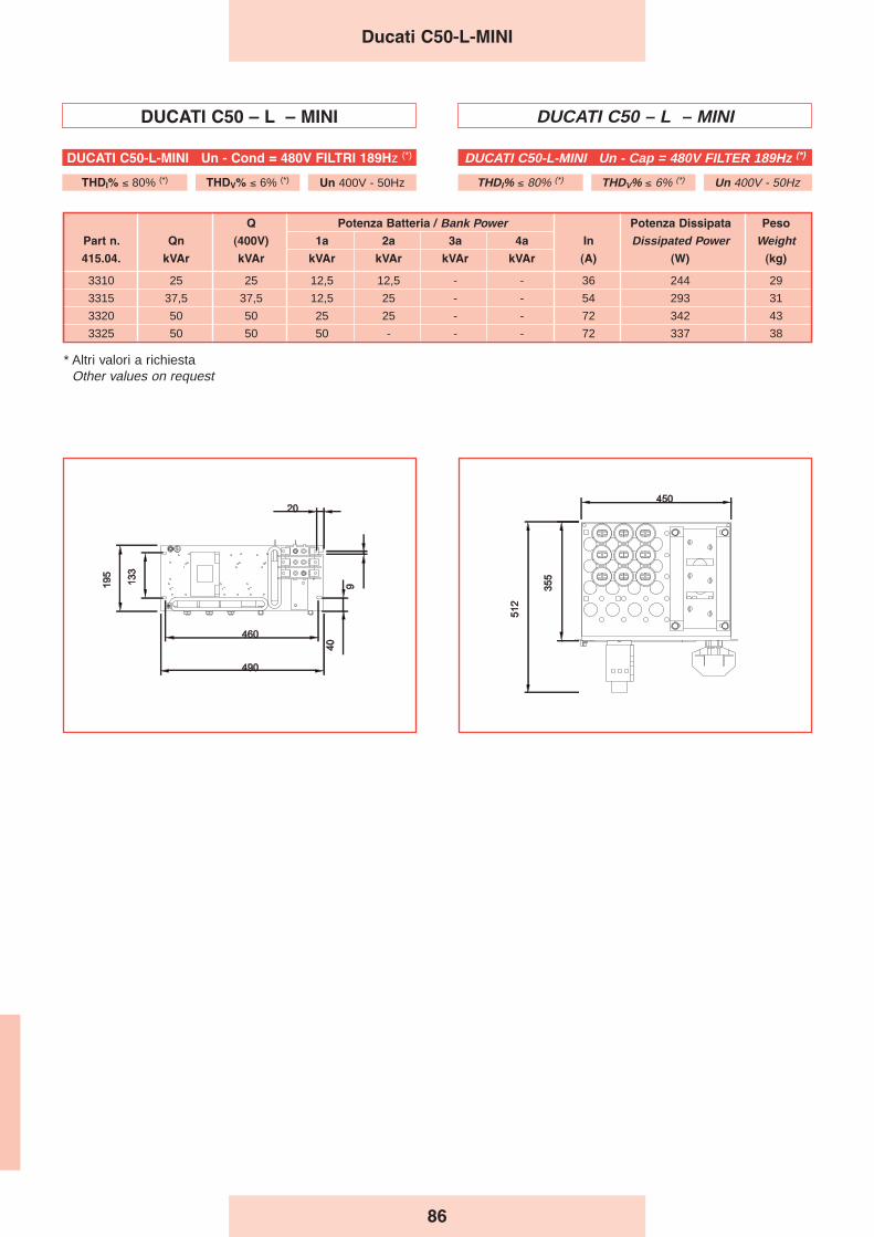
86
DUCATI C50 – L – MINI DUCATI C50 – L – MINI
Q Potenza Batteria / Bank Power Potenza Dissipata Peso
Part n. Qn (400V) 1a 2a 3a 4a In Dissipated Power Weight415.04. kVAr kVAr kVAr kVAr kVAr kVAr (A) (W) (kg)
3310 25 25 12,5 12,5 - - 36 244 29
3315 37,5 37,5 12,5 25 - - 54 293 31
3320 50 50 25 25 - - 72 342 43
3325 50 50 50 - - - 72 337 38
Ducati C50-L-MINI
DUCATI C50-L-MINI Un - Cap = 480V FILTER 189Hz (*)
THDI% ≤ 80% (*) THDV% ≤ 6% (*) Un 400V - 50Hz
DUCATI C50-L-MINI Un - Cond = 480V FILTRI 189Hz (*)
THDI% ≤ 80% (*) THDV% ≤ 6% (*) Un 400V - 50Hz
* Altri valori a richiestaOther values on request
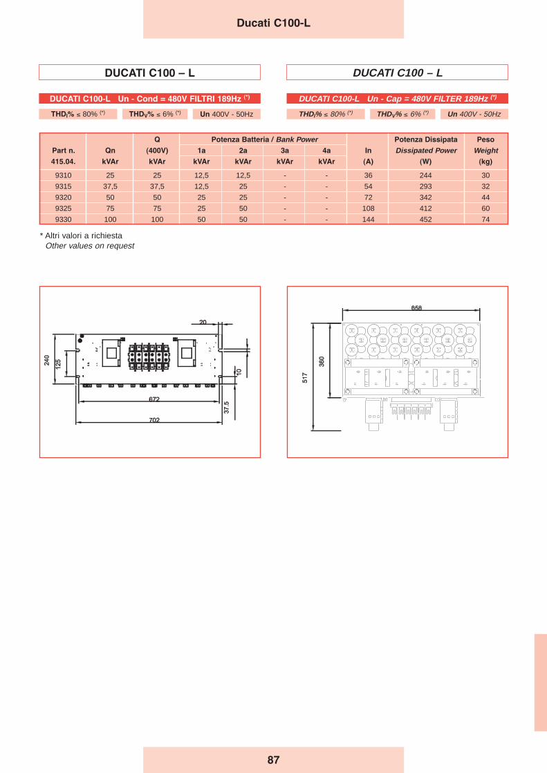
87
DUCATI C100 – L DUCATI C100 – L
Q Potenza Batteria / Bank Power Potenza Dissipata Peso
Part n. Qn (400V) 1a 2a 3a 4a In Dissipated Power Weight415.04. kVAr kVAr kVAr kVAr kVAr kVAr (A) (W) (kg)
9310 25 25 12,5 12,5 - - 36 244 30
9315 37,5 37,5 12,5 25 - - 54 293 32
9320 50 50 25 25 - - 72 342 44
9325 75 75 25 50 - - 108 412 60
9330 100 100 50 50 - - 144 452 74
Ducati C100-L
DUCATI C100-L Un - Cap = 480V FILTER 189Hz (*)
THDI% ≤ 80% (*) THDV% ≤ 6% (*) Un 400V - 50Hz
DUCATI C100-L Un - Cond = 480V FILTRI 189Hz (*)
THDI% ≤ 80% (*) THDV% ≤ 6% (*) Un 400V - 50Hz
* Altri valori a richiestaOther values on request

88
DUCATI C100 – LB DUCATI C100 – LB
Q Potenza Batteria / Bank Power Potenza Dissipata Peso
Part n. Qn (400V) 1a 2a 3a 4a In Dissipated Power Weight415.04. kVAr kVAr kVAr kVAr kVAr kVAr (A) (W) (kg)
4210 25 25 12,5 12,5 36 243 65
4215 37,5 37,5 12,5 25 54 293 70
4220 50 50 25 25 72 341 75
4225 62,5 62,5 12,5 50 90 352 85
4230 75 75 25 50 108 411 90
4235 100 100 50 50 144 451 100
Ducati C100-LB
DUCATI C100-LB Un - Cap = 480V FILTER 189Hz (*)
THDI% ≤ 80% (*) THDV% ≤ 6% (*) Un 400V - 50Hz
DUCATI C100-LB Un - Cond = 480V FILTRO 189Hz (*)
THDI% ≤ 80% (*) THDV% ≤ 6% (*) Un 400V - 50Hz
* Altri valori a richiestaOther values on request
89
Reference Notes -Warnings
Note di riferimento -Avvertenze
The capacitors and the automatic power factor correctionequipment must be installed in well-ventilated areas.
The air should be able to circulate freely through the airvents. The ambient temperature must comply with EN60831-1/2 standards.
When the system subject to power factor correction hasAC/DC static conversion systems (e.g. for the operation ofDC motors, uninterrupted power systems, etc.), harmoniccurrents are generated and may cause either current orvoltage overloads which the capacitors are unable towithstand.DUCATI energia can provide properly protected equipmentsuitable for use in such systems as well as filter systemsdesigned to eliminate harmonic components.
When the capacitors are used in automatic equipment, besure to check that the regulator response time is greaterthan the capacitor discharge time. If this is not the case,suitable discharge resistors should be installed.
The use of rigid connections should be avoided withcylindrical capacitors in order to avoid blocking theintervention of the overpressure device. For this reason atleast 3 cm should be left between the terminals and anysurface above the upper capacitor.
In the automatic equipment the integrity of the pre-chargingresistors should be checked every 10.000 operations or atleast once a year.Plan to replace the contactors every 100.000 operations.
The guarantee does not cover problems arising fromoperation:
- in the presence of excessive harmonic overloads (>1.3 In,>1.1 Un.)
- Contactors with worn-out electrical contacts or interruptedpre-charging resistors.
I condensatori e le apparecchiature automatiche dirifasamento devono essere installati in ambiente ben areato.
L’aria deve poter circolare liberamente attraverso le fessuredi ventilazione.La temperatura ambiente deve essere contenuta e conformea quanto specificato dalla normativa CEI EN 60831-1/2.
Quando nell’impianto da rifasare siano presenti sistemi diconversione statica CA/CC, ad esempio per l’azionamento dimotori in corrente continua, gruppi di continuità, ecc., questigenerano correnti armoniche della fondamentale chepossono determinare sovraccarichi sia di corrente che ditensione inammissibili per i condensatori.La DUCATI energia è in grado di fornire apparecchiatureadeguatamente protette adatte ad essere utilizzate in questiimpianti oltre che sistemi per l’eliminazione delle componentiarmoniche.
Quando i condensatori vengono utilizzati in apparecchiatureautomatiche, avere cura di verificare che i tempi di interventodel regolatore siano superiori al tempo di scarica deicondensatori. In caso contrario prevedere adatte resistenzedi scarica.
Evitare l’uso di collegamenti rigidi per i condensatori cilindriciin modo che l’intervento del dispositivo a sovrapressionenon sia impedito. Per lo stesso motivo lasciare almeno 3 cmfra i terminali e qualsiasi superficie al di sopra delcondensatore superiore.
Per le apparecchiature automatiche controllare l’integrità deiresistori di precarica ogni 10.000 manovre o almeno unavolta all’anno.Pianificare la sostituzione dei contattori ogni 100.000manovre.
La garanzia decade per gli inconvenienti derivanti dafunzionamento:
- In presenza di eccessivi sovraccarichi armonici (>1.3 In,>1.1 Un).
- Contatti elettrici dei contattori usurati o resistori di precariainterotti.
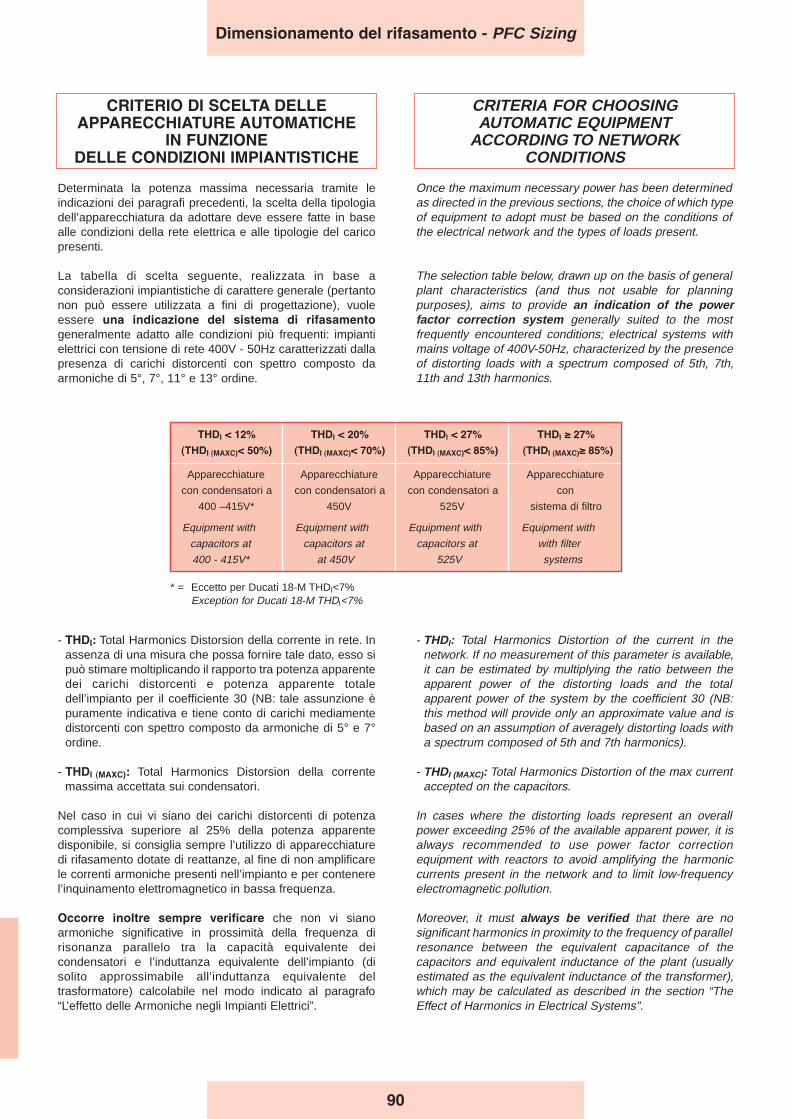
THDI < 12% THDI < 20% THDI < 27% THDI ≥ 27%
(THDI (MAXC)< 50%) (THDI (MAXC)< 70%) (THDI (MAXC)< 85%) (THDI (MAXC)≥ 85%)
Apparecchiature Apparecchiature Apparecchiature Apparecchiature
con condensatori a con condensatori a con condensatori a con
400 –415V* 450V 525V sistema di filtro
Equipment with Equipment with Equipment with Equipment with
capacitors at capacitors at capacitors at with filter
400 - 415V* at 450V 525V systems
90
CRITERIO DI SCELTA DELLEAPPARECCHIATURE AUTOMATICHE
IN FUNZIONE DELLE CONDIZIONI IMPIANTISTICHE
Determinata la potenza massima necessaria tramite leindicazioni dei paragrafi precedenti, la scelta della tipologiadell’apparecchiatura da adottare deve essere fatte in basealle condizioni della rete elettrica e alle tipologie del caricopresenti.
La tabella di scelta seguente, realizzata in base aconsiderazioni impiantistiche di carattere generale (pertantonon può essere utilizzata a fini di progettazione), vuoleessere una indicazione del sistema di rifasamento
generalmente adatto alle condizioni più frequenti: impiantielettrici con tensione di rete 400V - 50Hz caratterizzati dallapresenza di carichi distorcenti con spettro composto daarmoniche di 5°, 7°, 11° e 13° ordine.
CRITERIA FOR CHOOSING AUTOMATIC EQUIPMENT
ACCORDING TO NETWORK CONDITIONS
Once the maximum necessary power has been determinedas directed in the previous sections, the choice of which typeof equipment to adopt must be based on the conditions ofthe electrical network and the types of loads present.
The selection table below, drawn up on the basis of generalplant characteristics (and thus not usable for planningpurposes), aims to provide an indication of the powerfactor correction system generally suited to the mostfrequently encountered conditions; electrical systems withmains voltage of 400V-50Hz, characterized by the presenceof distorting loads with a spectrum composed of 5th, 7th,11th and 13th harmonics.
- THDI: Total Harmonics Distorsion della corrente in rete. Inassenza di una misura che possa fornire tale dato, esso sipuò stimare moltiplicando il rapporto tra potenza apparentedei carichi distorcenti e potenza apparente totaledell’impianto per il coefficiente 30 (NB: tale assunzione èpuramente indicativa e tiene conto di carichi mediamentedistorcenti con spettro composto da armoniche di 5° e 7°ordine.
- THDI (MAXC): Total Harmonics Distorsion della correntemassima accettata sui condensatori.
Nel caso in cui vi siano dei carichi distorcenti di potenzacomplessiva superiore al 25% della potenza apparentedisponibile, si consiglia sempre l’utilizzo di apparecchiaturedi rifasamento dotate di reattanze, al fine di non amplificarele correnti armoniche presenti nell’impianto e per contenerel’inquinamento elettromagnetico in bassa frequenza.
Occorre inoltre sempre verificare che non vi sianoarmoniche significative in prossimità della frequenza dirisonanza parallelo tra la capacità equivalente deicondensatori e l’induttanza equivalente dell’impianto (disolito approssimabile all’induttanza equivalente deltrasformatore) calcolabile nel modo indicato al paragrafo“L’effetto delle Armoniche negli Impianti Elettrici”.
- THDI: Total Harmonics Distortion of the current in thenetwork. If no measurement of this parameter is available,it can be estimated by multiplying the ratio between theapparent power of the distorting loads and the totalapparent power of the system by the coefficient 30 (NB:this method will provide only an approximate value and isbased on an assumption of averagely distorting loads witha spectrum composed of 5th and 7th harmonics).
- THDI (MAXC): Total Harmonics Distortion of the max currentaccepted on the capacitors.
In cases where the distorting loads represent an overallpower exceeding 25% of the available apparent power, it isalways recommended to use power factor correctionequipment with reactors to avoid amplifying the harmoniccurrents present in the network and to limit low-frequencyelectromagnetic pollution.
Moreover, it must always be verified that there are nosignificant harmonics in proximity to the frequency of parallelresonance between the equivalent capacitance of thecapacitors and equivalent inductance of the plant (usuallyestimated as the equivalent inductance of the transformer),which may be calculated as described in the section “TheEffect of Harmonics in Electrical Systems”.
Dimensionamento del rifasamento - PFC Sizing
* = Eccetto per Ducati 18-M THDI<7%Exception for Ducati 18-M THDI<7%
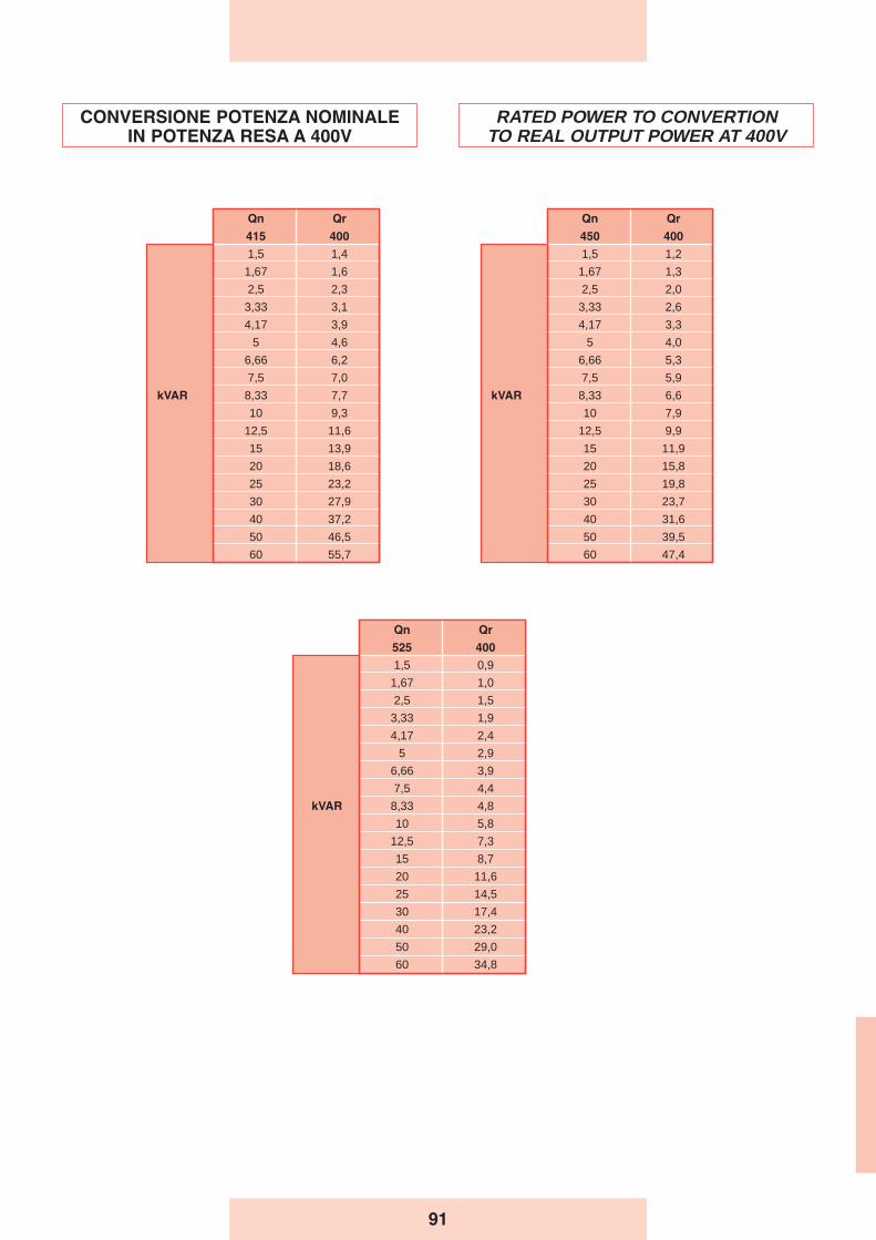
CONVERSIONE POTENZA NOMINALEIN POTENZA RESA A 400V
RATED POWER TO CONVERTIONTO REAL OUTPUT POWER AT 400V
Qn Qr
525 400
1,5 0,9
1,67 1,0
2,5 1,5
3,33 1,9
4,17 2,4
5 2,9
6,66 3,9
7,5 4,4
kVAR 8,33 4,8
10 5,8
12,5 7,3
15 8,7
20 11,6
25 14,5
30 17,4
40 23,2
50 29,0
60 34,8
Qn Qr
450 400
1,5 1,2
1,67 1,3
2,5 2,0
3,33 2,6
4,17 3,3
5 4,0
6,66 5,3
7,5 5,9
kVAR 8,33 6,6
10 7,9
12,5 9,9
15 11,9
20 15,8
25 19,8
30 23,7
40 31,6
50 39,5
60 47,4
Qn Qr
415 400
1,5 1,4
1,67 1,6
2,5 2,3
3,33 3,1
4,17 3,9
5 4,6
6,66 6,2
7,5 7,0
kVAR 8,33 7,7
10 9,3
12,5 11,6
15 13,9
20 18,6
25 23,2
30 27,9
40 37,2
50 46,5
60 55,7
91