CHIUSO - CONTACTPLASMA
16
Transcript of CHIUSO - CONTACTPLASMA
1
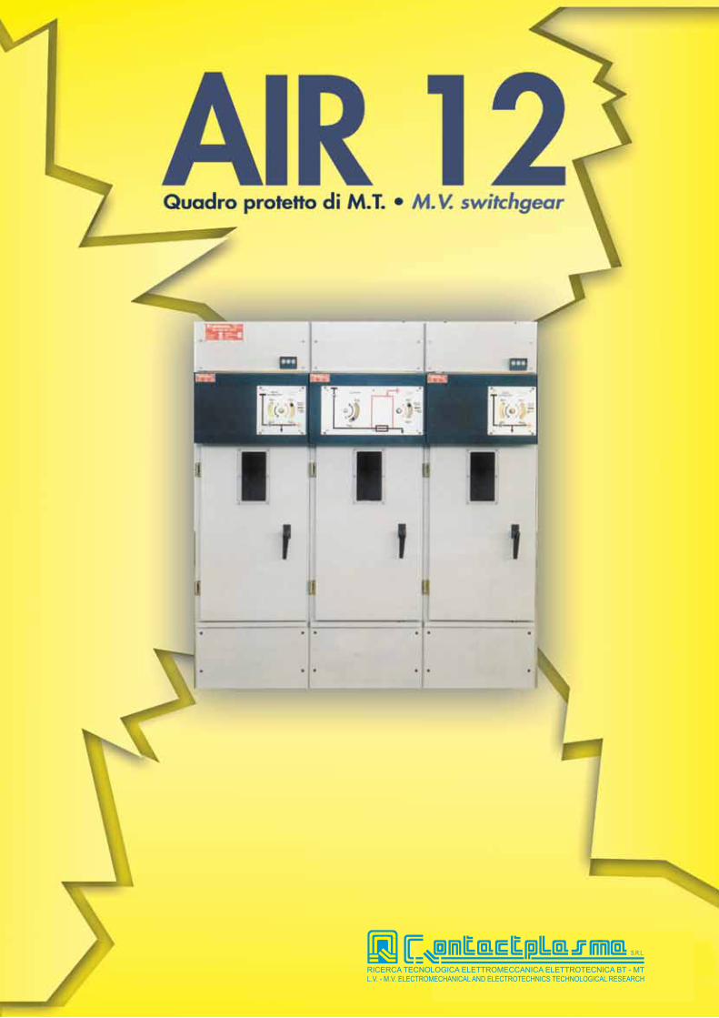
CHIUSOCLOSED
APERTOOPEN
A TERRAEARTHED
INTERRUTTORE TH 12kV - 630ASWITCH-DISCONNECTOR TH 12kV - 630A

2
GENERALITA’I quadri protetti della serie AIR 12 sono adatti per essere impiegati in sistemi di distribuzione con ten-sione nominale fino a 12 kV.Sono costituiti da scomparti unificati equipaggiati con interruttori di manovra-sezionatori della serie TH.Essi presentano le seguenti caratteristiche principali:• dimensioni ridotte:che consentono l’installazione in locali di piccole dimensioni. Il quadro può essere addossato a parete. Tutte le manovre si effettuano dal fronte del quadro.• massima continuità del servizio:le segregazioni che separano le varie celle permet-tono di intervenire in breve tempo con il quadro in tensione, per la sostituzione di componenti come un fusibile, trasformatori di misura o un terminale.• sicurezza per il personale:garantita con interblocchi semplici e sicuri, conformi alle norme IEC 60298.Inoltre la separazione fra la cella sbarre e la cella inferiore, con grado di protezione IP 20, impedisce a sezionatore aperto qualsiasi passaggio di corrente di fuga fra i morsetti di uscita, anche in ambienti ad alto grado di polluzione (art. 26 Norme IEC 60265).Naturalmente il quadro è provvisto di messa a terra di tutta la struttura e dei componenti.• facilità di trasporto ed installazione:gli scomparti sono provvisti di appositi golfari di sollevamento e vengono forniti già sistemati e col-laudati. Il fissaggio a pavimento può essere agevol-mente effettuato con tasselli ad espansione.• ispezione:visibilità diretta dell’apparecchio di manovra tramite oblò posti sul fronte del quadro (DPR 547)• esecuzione:il quadro viene fornito nella esecuzione base con gradi di protezione:-IP 30 sull’involucro esterno.-IP 20 all’interno fra le varie celle.• verniciatura:lamiera verniciata con ciclo automatico a deposizio-ne elettrostatica di polveri epossidiche.• rispondenza alle norme:-italiana CEI EN 60298-Internazionale IEC 60298-D.P.R. 547 del 27.04.1955.
GENERALThe AIR 12 series metal-enclosed switchboards are used in the distribution systems having a rated voltage up to 12 kV.They consist of standarsized units equipped with TH type switch-disconnectors.The technical aspects of the switchboard are sum-marized as follows:• reduced overall dimensions:allowing installation in srnall rooms. The switchgear can be leanerd againts the wall. All equipment opera-tions are carried out from the front of the switchboard.• maximun service reliability:the segregations, witch separate the different com-partments, allow to operate in a short time with the alive switchboard for the replacemen, of compo-nents such as fuses, metering trasformers or cable terminations.• personnel safety:granted by reliable and simple interblocks com-plying to IEC 60298 Std.Besides the segregation between the bus-bar and-lower compartrnent, having a protection degree IP 20, prevents any leakage current flow when the switch is in open position, even in heavy pollution enviroment (art. 26 of IEC Std. 60265)Of course, the switchboard is provided with groun-ding of the whole structure and components.• easy transport and installations:units are provided with lifting eye-bolts and are sup-plied completely assernbled and tested.Anchorage to the floor can be easily done using expanding nogs.• inspections:direct visibility of the switch throught inspection win-dow fitted on the front panel (DPR 547).• constructions:the standard construction of the switchboard has protection degree:-IP 30 on external housing .-IP 20 inside between the components.• painting:steel plate painted with automatic cycle of epoxy type electrostatic powder.• complicance with standards:-italian CEI EN 60298- In te rna t i ona l : IEC 60298

3
*
IL IL TP
ILIL IL TP
IL AP
APPLICAZIONE
Gli scomparti della serie AIR 12, che compongono gli schemi tipici della distribuzione secondaria di media tensione si identificano in:-IL: linea-TP: protezione trasformatore-AP: sezionamento
APPLICATION
The AIR 12 series cubicles typical schemes of M.V. secondary distri-bution are identified as:-IL: line switch panel-TP: transformer protection switch panel-AP: interruption panel
* interruttore escluso dalla fornitura* c. breaker out of supply
4
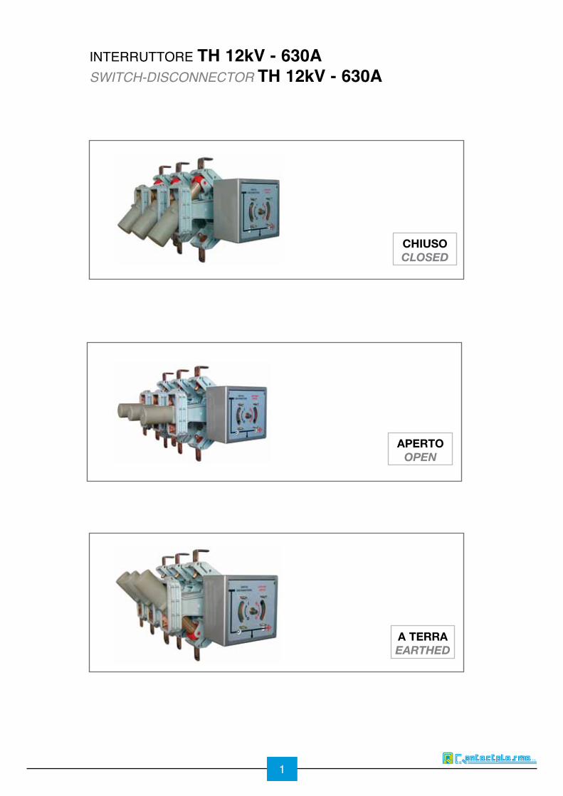
CODICE DI IDENTIFICAZIONE DEI TIPI
Gli scomparti vengono identificati nel seguente modo:-sigla che definisce il tipo-serie di numeri che definiscono le caratteristiche elettriche nel seguente modo:-tensione nominale (kV)-corrente termica nominale (A)-corrente nominale di breve durata per 1 s (kA)
E esempio di identificazione: IL 12-400-20 si tratta di:-IL: scomparto linee-12: tensione-400: corrente termica nominale 400A-20: corrente di breve durata per ls 20kA
TYPE DESIGNATION CODING
The panels are identified by code composed in the following way:-logo that indicates the type ,-sequence of figures defining the electrical cha-racteristics and namely:-rated voltage (kV)-rated thermal current (A)-rated short time current for 1 sec. (kA)
Designation example: IL 12-400-20 this is:-IL: incoming/outgoing feeder-12: rated vo1tage 12kV-400: rated thermal current 400A-20: rated short-time current 20kA (ls)
Caratteristiche tecniche (IEC 60298)Electrical features (IEC 60298)
Tensione nominaleRated voltage
kV 7,2 12
Tensione nominale di tenuta a 50 Hz per 1 minPower frequency apply voltage for 1 min
kV 20 28 42
Tensione nominale di tenuta ad impulso atmosfericoLightning impulse test voltage
kV 60 75
Corrente nominaleRated current
A 400/630 400/630
Corrente breve durata nominaleRated short time current
(kA x 1s) 25 25

5
CHIUSOCLOSED
APERTOOPEN
A TERRAEARTHED
FIGURA 1/ PICTURE1
INTERRUTTORE DI MANOVRA SEZIONATORE
L’apparecchio tipo TH può essumere 3 posizioni: chiuso, aperto, messo a terra (Vedi Fig. 1).In posizione di chiuso, si stabilisce il collegamento tra cella sbarre e cella apparecchiatura.In posizione di aperto è garantito il sezionamento tra la cella sbarre e la linea.In posizione messa a terra, si stabilisce il collega-mento a terra della linea (con potere di chiusura).
SWITCH DISCONNECTOR
The TH type switch-disconnector may reach three positions; closed, open, earthed (see Fig. 1).In closed position the connection between the bus-bar cubicle and the equipment cubicle is achieved.In open position the isolation between the bus-bar cubicle and the equipment is granted.In earthed position the connection to earth of the line is achieved (with making capacity).
COMANDI
I comandi necessari alle manovre delle apparec-chiature sono raggruppati nella parte anteriore degli scomparti; sono protetti da un carter sul quale viene montata la targa recante lo schema elettrico.• comando tipo T1:a scatto rapido sia in chiusura che in apertura. ottenuto mediante l’energia liberata da una molla caricata dalla manovra dell’operatore durante la manovra di chiusura o di apertura.
OPERATING MECHANISMS
The operating mechanisms for the equipment ope-rations are fitted in the front side of the panel: they are protected by removable metal box on which the mimic scheme is fixed.• operating mechanism, T1 type:with quick make and break operation by means of energy released by a spring charged by the opera-tor during the opening or closing operations.

6
• comando tipo T2:a scatto rapido sia in chiusura che in apertura, con dispositivo ad accilmolo di energia per l’apertura. Il comando è costituito da due molle una di chiusura e una di apertura, che vengono caricate dall’operatore durante la manovra di chiusura.Il dispositivo di sgancio per l’apertura può essere azio-nato nei seguenti modi:a) manualmente eseguendo la manovra di apertura.b) elettricamente a mezzo di sganciatore di apertura.c) con i percursori dei fusibili, quando esistono.Dopo le manovre b) e c), è necessario eseguire la ricarica del comando portando la leva verso l’alto.
• operating mechanism. T2 type:with quick make and break operation and with stored energy device for opening. The operating mechani-sm is made up of two springs. one opening and one closing, which are charged by the operator during the closing operation.The tripping device for opening can be activated in the following ways:a) manually by carrying out the opening operation.b) electrically by means of a shunt tripping release.c) whit the fuse strikers. when provided.After the b) and c) operations, the opening mechanism must be reset by turning-up the lever completely.
•comando tipo TN:non dispone di molle di apertura e di chiusura, pertan-to la velocità di manovra dipende dall’operatore.
•Operating mechanism, TN type:it is not provided with opening and closing springs, there-fore the operating speed is depending from the operator.

SCOMPARTO ILIL TYPE PANEL
7
Arrivo/partenza con interruttore sottocarico completo di:-sezionatore di messa a terra-comando tipo T1-sistema di sbarre
Accessori a richiesta-contatti ausiliari su IMS (2NA+2NC) o (4NA+4NC)-contatti ausiliari su sezionatore di terra (2NA + 2NC)-celle BT da 150 mmm-motorizzazione comando T1-indicatori presenza tensione-blocco a chiave sui sezionatori
Incoming/outgoing feeder with switch-discon-nector complete with:-earthing switch-T1 type operating mechanism-bus-bars system
Accessories on request-aux contacts on main switch (2NO+2NC) or (4NO+4NC)-aux contacts on earthing switch (2NO+2NC)-L.V. cubicle 150 mm depth-operating mechanism T1 type suitable to be motor operated-voltage presence indicators-key lock on the switches
motoremotor

8
Protezione trasformatore con interruttore sotto-carico e fusibili completo di:-sezionatore di messa a terra a monte e a valle dei fusibili-comando tipo T2-sistema di sbarre
Accessori a richiesta-contatti ausiliari su IMS (2NA+2NC) o (4NA+4NC)-contatti ausiliari su sezionatore di terra (2NA+2NC)-celle Br da 150 mm-sganciatore di apertura-blocco chiavi su IMS-N. 3 fusibili MT
Transformer protection with on-load switch-fuses complete with:-earthing switch upstream and downstream of fuse link-T2 type operating mechanism-bus-bar system
Accessories on request-aux contacts on main fuse switch (2NO+2NC) or (4NO+4NC)-aux contacts on earthing switch (2NO+2NC)-L.V. cubicle 150 mm depth-vo1tage presence indicators-trip release-key lock on the switch-3 nos. M.V. fuse links
sganciatore di aperturatrip release
contatti ausiliariauuuuxiliary contact
SCOMPARTO TPTP TYPE PANEL

9
Arrivo/partenza con sezionaore a vuoto comple-to di:-sezionatore di messa a terra-comando tipo TN-sistema di sbarre
Accessori a richiesta-contatti ausiliari su sezionatore (2NA+2NC)-contatti ausiliari su sezionatore di terra (2NA + 2NC)-celle BT da 150 mmm-indicatori presenza tensione-blocco a chiave sui sezionatore a terra-predisposizione per interruttore in SF6
Incoming/outgoing feeder with off-load isolator complete with:-earthing switch-TN type operating mechanism-bus-bar system
Accessories on request-aux contacts on the isolator (2NO+2NC)-aux contacts on earthing switch (2NO+2NC)-L.V. panel 150 mm depth-voltage presence indicators-key lock on the switch-provision for SF6 c. breaker
SCOMPARTO APAP TYPE PANEL
*
* interruttore escluso dalla fornitura* c. breaker out of supply

10
TERMINALI DEI CAVI
Esempio di terminazione per cavi estrusi
CABLES TERMINATIONSSample of xlpe cable termination
Da utilizzare nelle unità TP per tensione nominale di 12 kVTo be used in TP type panel for rating voltage of 12 kV
Da utilizzare nelle unità IL e AP fino a 12 kV e nelle unità TP per tensione nominale a 7,2 kVTo be used in IL and AP type panel for rating voltage up to 12 kV and in TP type panel for rating voltage up to 7,2 kV
tensione nominale (kV) 7,2 12
L1 (mm) 160 210
L2 (mm) 110 170
L3 (mm) 70 70
rated voltage (kV) 7,2 12
L1 (mm) 160 210
L2 (mm) 110 170
L3 (mm) 70 70

PART. ADETAIL A
11
46065
050
016
020
460 460
20
290 85
320
460
646
450
598
24
100
(4) O 12
part Adetail A
FRONTEFRONT
Distanze minime dalle paretiMinimum gap to walls
PesiWeight
INSTALLAZIONE INSTALLATION
scompartopanel type
pesoweight
IL 75 Kg
TP 85 Kg
AP 70 Kg
ViteScrew
Rondella pianaFlat Washer
M8
M8

12
DIMENSIONI D’INGOMBRO OVERALL DIMENSIONS
460 770
650
145 180 180 145
80
150
245
620
1150
1500

13
VISTA FRONTALEFRONTAL VIEW
VISTA LATERALESIDE VIEW
VISTA INTERNAINSIDE VIEW
VISTA SBARRE OMNIBUSBUSBARS VIEW

14
CAVIAGA
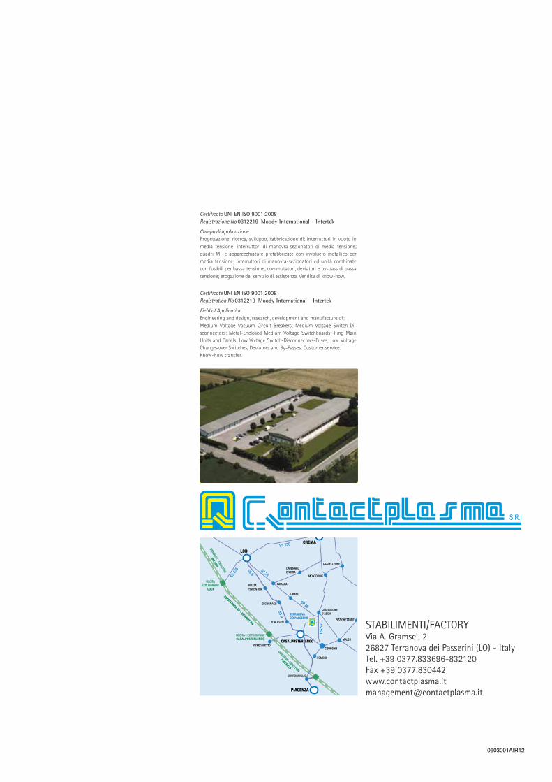
STABILIMENTI/FACTORYVia A. Gramsci, 2 26827 Terranova dei Passerini (LO) - ItalyTel. +39 0377.833696-832120Fax +39 0377.830442 [email protected]
Certificato UNI EN ISO 9001:2008Registrazione No 0312219 Moody International - Intertek
Campo di applicazioneProgettazione, ricerca, sviluppo, fabbricazione di: interruttori in vuoto in media tensione; interruttori di manovra-sezionatori di media tensione; quadri MT e apparecchiature prefabbricate con involucro metallico per media tensione; interruttori di manovra-sezionatori ed unità combinate con fusibili per bassa tensione; commutatori, deviatori e by-pass di bassa tensione; erogazione del servizio di assistenza. Vendita di know-how.
TGI_rv00
Certificate UNI EN ISO 9001:2008Registration No 0312219 Moody International - Intertek
Field of ApplicationEngineering and design, research, development and manufacture of:Medium Voltage Vacuum Circuit-Breakers; Medium Voltage Switch-Di-sconnectors; Metal-Enclosed Medium Voltage Switchboards; Ring Main Units and Panels; Low Voltage Switch-Disconnectors-Fuses; Low Voltage Change-over Switches, Deviators and By-Passes. Customer service. Know-how transfer.
0503001AIR12