cap 4_04 valvole Soffiaggio e Tampone
17
CAP 4 Elettrovalvole e valvole pneumatiche Solenoid and pneumatic valves 4.25 | Valvole soffiaggio - Dust Bag Valves
-
Upload
valair-srl -
Category
Documents
-
view
217 -
download
1
description
Dust bag valves, poppet valves
Transcript of cap 4_04 valvole Soffiaggio e Tampone

CAP 4 Elettrovalvole e valvole pneumaticheSolenoid and pneumatic valves
4.25 | Valvole soffiaggio - Dust Bag Valves
AC
DC
1 3 5 2 4
10
Intentional white
04/08/2011
X
12 Vd.c. =24 Vd.c. =
012C024C
STD = 0000
-
L
2
3
12 Va.c. =24 Va.c. =115Va.c. =230Va.c. =
012A024A115A230A
Su
bje
ct
to c
ha
ng
eS
wit
ho
ut
pr
ior
no
tic
e
Printed :
Fluid
Fixing
ConnectionsSwitching systemNominal rated flow and bore (6 bar) Working pressureSwitching - Unswitching timeAmbient-fluid temperature rangeBody / thread materialSeals materialLasting of connection EDProtection degree (with connector)Weight (without connector)
=Supply
=Output
=ExhauSt
=pilOtlinE
Voltage
Without solenoid
oVerride
Standard(withscrewdriver)=
Levermanualoverride =
Solenoid
Filteredlubricatedornotlubricatedair
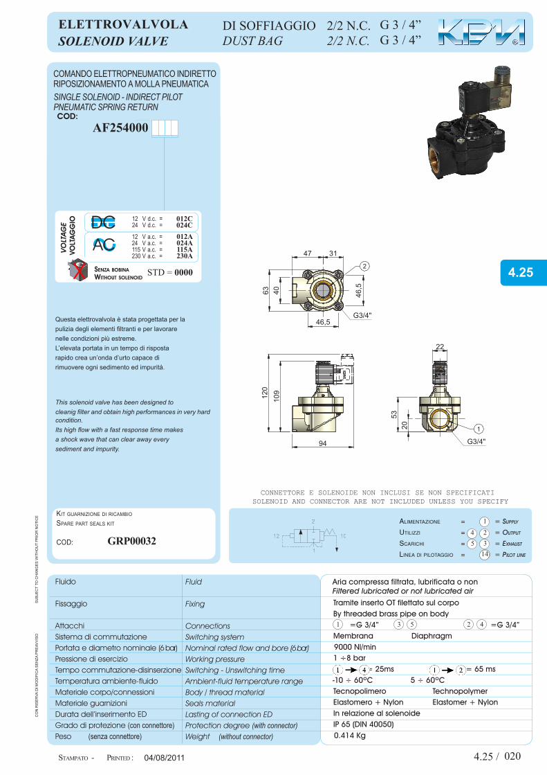
SOLENOID VALVE
Solenoid and connector are not included unleSS you Specify
DUST BAG 2/2 N.C.
SINGLE SOLENOID - INDIRECT PILOTPNEUMATIC SPRING RETURN
co
n r
iSe
rva
di m
od
ific
a S
en
za p
re
avv
iSo
StamPato -
Fluido
Fissaggio
AttacchiSistema di commutazionePortata e diametro nominale (6 bar)Pressione di esercizioTempo commutazione-disinserzioneTemperatura ambiente-fluidoMateriale corpo/connessioniMateriale guarnizioniDurata dell’inserimento EDGrado di protezione (conconnettore)Peso (senzaconnettore)
AlimentAzione =
Utilizzi =
ScArichi =
lineAdipilotAggio =
Volt
agg
io
senza bobina
ma
nua
le Standard(concacciavite) =
Comandomanualealeva =
Sole
no
ide
22mm
30mm
Aria compressa filtrata, lubrificata o non
eLettrovALvoLA
connettore e Solenoide non incluSi Se non Specificati
DI SOFFIAGGIO 2/2 N.C.
ComandoeLettropneumatiCoindirettoripoSizionamentoamoLLapneumatiCa
Tramite inserto OT filettato sul corpoBy threaded brass pipe on body
Membrana Diaphragm
1 ÷8 bar = 25ms = 65 ms
Tecnopolimero TechnopolymerElastomero + Nylon Elastomer + NylonIn relazione al solenoideIP 65 (DIN 40050)
Kit guarnizione di ricambio
Spare part SealS Kit
cod:
4.25 /
14
1
23
45
47 31
4063
46,5
46,5
g3/4"
109120
94
5320
22
g3/4"
1
2
ev
S000
01_e
Lva
So
ff3_
4Ø
10_c
ata
Log
o
-10 ÷ 60ºC 5 ÷ 60ºC
020
=G 3/4” =G 3/4”
9000 Nl/min
0.414 Kg
Cod:
G 3 / 4”G 3 / 4”
GrP00032
AF254000
This solenoid valve has been designed tocleanig filter and obtain high performances in very hard condition.Its high flow with a fast response time makesa shock wave that can clear away every sediment and impurity.
Questa elettrovalvola è stata progettata per la pulizia degli elementi filtranti e per lavorarenelle condizioni più estreme.L’elevata portata in un tempo di rispostarapido crea un’onda d’urto capace di rimuovere ogni sedimento ed impurità.
4.25

Questa apparecchiatura rispetta severe specifiche qualitative tuttavia un uso improprio od inadeguato potrebbe compromet-terne il funzionamento e decadere la garanzia. L’uso di olio lubrificante non consigliato fa decadere la garanzia.NON E’ UN DISPOSITIVO DI SICUREZZA.
Prima di ogni operazione assicurarsi che il compo-nente non sia in pressione.Ristabilirla solo dopo aver controllato l’esattezza delle connessioni.
NORME DI USO E MANUTENZIONEThis unit complies with strict quality specifications. Incorrect use or misuse of this unit will compromise performance and will invalidate the warranty.Not recommended lubricating oil will invalidate the warranty.THIS UNIT IS NOT A SAFETY DEVICE.
Warning before using this unit please ensure that you have made the correct port connection and that the unit is de-pressurised. When any maintenance work is done ensure the unit is also de-pressurised.
USE AND MAINTENANCE
4.25 /
I
04/08/2011
din 43650 22 mm
din 43650 30 mm
o P t I o N A L
COD: CNK000 __std =Led+VDR 12÷24V =Led+VDR 48÷115V =Led+VDR 230V =
22182944
COD: CNt000 __stdLed 12÷24 V =Led 48÷115 V =Led 230V =
23242627
12 V
24 V
115 V
230 V
Power Cod: Power Cod: Power Cod: Power Cod:DC ACDC AC
VOLTAG
E
± 1 0%VOLTAG
GIO
22 mm 30 mm
6 W
3.5 W
3.5 VA
5 VA
5 VA
5 VA
3.5 W
3.5 W
3.3 VA
3.3 VA
3.3 VA
3.3 VA
DA005001
DA005101
BOB00028
BOB00045
DA010803
BOB00064
DC030100
DC030200
DC030600
DC030700
DC030900
DC031000
Su
bje
ct
to c
ha
ng
eS
wit
ho
ut
pr
ior
no
tic
e
Diagram of normal rateD flow
- ConneCtor
StanDarD Coils
StamPato - Printed :
co
n r
iSe
rva
di m
od
ific
a S
en
za p
re
avv
iSo
Diagramma Di portata nominale
Connettore
Bobine elettriChe stanDarD -
021
Iev
S00
001_
eLv
aS
off
3_4
Ø10
_ca
taLo
go
_re
tro
pag
ina
12 V
24 V
48 V
115 V
230 V
DC ACP Cod: P Cod:
DC ACP Cod: P Cod:
VOLT
AGE
±10
%VOLT
AGGIO
±10
%
22 mm 30 mm
3.5 W
3.5 W
3.3 VA
3.3 VA
3.3 VA
3.3 VA
3.3 VA
15 W 10 VA
10 VA
10 VA
DC030100
DC030200
DC030600
DC030700
DC030800
DC030900
DC031000
BOB00050 BOB00021
BOB00041
BOB00042
www.Kpm.it ValVair Srl +39.059.698681
AC
DC
1 3 5 2 4
10
04/08/2011
X
12 Vd.c. =24 Vd.c. =
012C024C
STD = 0000
-
L
2
3
12 Va.c. =24 Va.c. =115Va.c. =230Va.c. =
012A024A115A230A
Su
bje
ct
to c
ha
ng
eS
wit
ho
ut
pr
ior
no
tic
e
Printed :
Fluid
Fixing
ConnectionsSwitching systemNominal rated flow and bore (6 bar) Working pressureSwitching - Unswitching timeAmbient-fluid temperature rangeBody / thread materialSeals materialLasting of connection EDProtection degree (with connector)Weight (without connector)
=Supply
=Output
=ExhauSt
=pilOtlinE
Voltage
Without solenoid
oVerride
Standard(withscrewdriver)=
Levermanualoverride =
Solenoid
Filteredlubricatedornotlubricatedair
SOLENOID VALVE
Solenoid and connector are not included unleSS you Specify
DUST BAG 2/2 N.C.
SINGLE SOLENOID - INDIRECT PILOTPNEUMATIC SPRING RETURN
co
n r
iSe
rva
di m
od
ific
a S
en
za p
re
avv
iSo
StamPato -
Fluido
Fissaggio
AttacchiSistema di commutazionePortata e diametro nominale (6 bar)Pressione di esercizioTempo commutazione-disinserzioneTemperatura ambiente-fluidoMateriale corpo/connessioniMateriale guarnizioniDurata dell’inserimento EDGrado di protezione (conconnettore)Peso (senzaconnettore)
AlimentAzione =
Utilizzi =
ScArichi =
lineAdipilotAggio =
Volt
agg
io
senza bobina
ma
nua
le Standard(concacciavite) =
Comandomanualealeva =
Sole
no
ide
22mm
30mm
Aria compressa filtrata, lubrificata o non
eLettrovALvoLA
connettore e Solenoide non incluSi Se non Specificati
DI SOFFIAGGIO 2/2 N.C.
ComandoeLettropneumatiCoindirettoripoSizionamentoamoLLapneumatiCa
Tramite inserto OT filettato sul corpoBy threaded brass pipe on body
Membrana Diaphragm
1 ÷8 bar = 25ms = 65 ms
Tecnopolimero TechnopolymerElastomero + Nylon Elastomer + NylonIn relazione al solenoideIP 65 (DIN 40050)
Kit guarnizione di ricambio
Spare part SealS Kit
cod:
4.25 /
14
1
23
45
54 37,5
4775
g1"
2
55
55
101
118129
22
6524
g1"
1
evS
0000
2_e
Lva
So
ff1
Ø10
_ca
taLo
go
-10 ÷ 60ºC 5 ÷ 60ºC
110
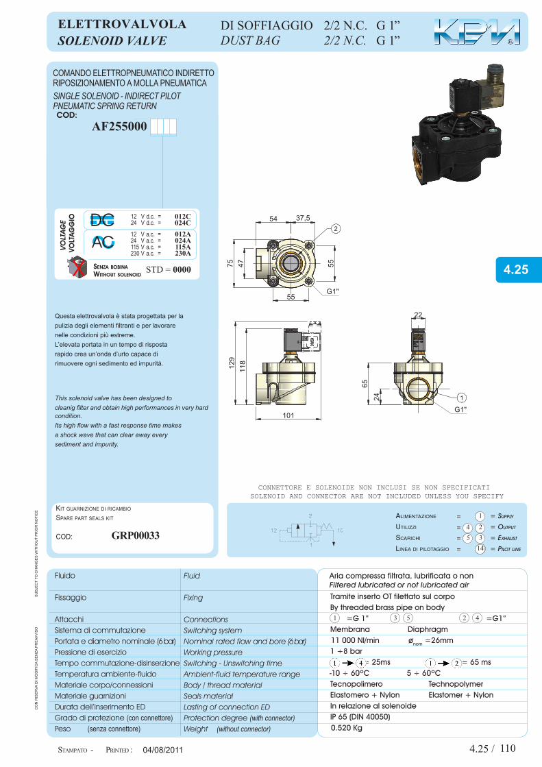
=G 1” =G1”
11 000 Nl/min ønom =26mm
0.520 Kg
Cod:
AF255000
GrP00033
G 1”G 1”
This solenoid valve has been designed tocleanig filter and obtain high performances in very hard condition.Its high flow with a fast response time makesa shock wave that can clear away every sediment and impurity.
Questa elettrovalvola è stata progettata per la pulizia degli elementi filtranti e per lavorarenelle condizioni più estreme.L’elevata portata in un tempo di rispostarapido crea un’onda d’urto capace di rimuovere ogni sedimento ed impurità.
4.25

Questa apparecchiatura rispetta severe specifiche qualitative tuttavia un uso improprio od inadeguato potrebbe compromet-terne il funzionamento e decadere la garanzia. L’uso di olio lubrificante non consigliato fa decadere la garanzia.NON E’ UN DISPOSITIVO DI SICUREZZA.
Prima di ogni operazione assicurarsi che il compo-nente non sia in pressione.Ristabilirla solo dopo aver controllato l’esattezza delle connessioni.
NORME DI USO E MANUTENZIONEThis unit complies with strict quality specifications. Incorrect use or misuse of this unit will compromise performance and will invalidate the warranty.Not recommended lubricating oil will invalidate the warranty.THIS UNIT IS NOT A SAFETY DEVICE.
Warning before using this unit please ensure that you have made the correct port connection and that the unit is de-pressurised. When any maintenance work is done ensure the unit is also de-pressurised.
USE AND MAINTENANCE
4.25 /
I
04/08/2011
din 43650 22 mm
din 43650 30 mm
o P t I o N A L
COD: CNK000 __std =Led+VDR 12÷24V =Led+VDR 48÷115V =Led+VDR 230V =
22182944
COD: CNt000 __stdLed 12÷24 V =Led 48÷115 V =Led 230V =
23242627
12 V
24 V
115 V
230 V
Power Cod: Power Cod: Power Cod: Power Cod:DC ACDC AC
VOLTAG
E
± 1 0%VOLTAG
GIO
22 mm 30 mm
6 W
3.5 W
3.5 VA
5 VA
5 VA
5 VA
3.5 W
3.5 W
3.3 VA
3.3 VA
3.3 VA
3.3 VA
DA005001
DA005101
BOB00028
BOB00045
DA010803
BOB00064
DC030100
DC030200
DC030600
DC030700
DC030900
DC031000
Su
bje
ct
to c
ha
ng
eS
wit
ho
ut
pr
ior
no
tic
e
Diagram of normal rateD flow
- ConneCtor
StanDarD Coils
StamPato - Printed :
co
n r
iSe
rva
di m
od
ific
a S
en
za p
re
avv
iSo
Diagramma Di portata nominale
Connettore
Bobine elettriChe stanDarD -
111
I
evS
0000
2_eL
va
Soff
1Ø
10_c
ata
Log
o_r
etr
opa
gin
a
12 V
24 V
48 V
115 V
230 V
DC ACP Cod: P Cod:
DC ACP Cod: P Cod:
VOLT
AGE
±10
%VOLT
AGGIO
±10
%
22 mm 30 mm
3.5 W
3.5 W
3.3 VA
3.3 VA
3.3 VA
3.3 VA
3.3 VA
15 W 10 VA
10 VA
10 VA
DC030100
DC030200
DC030600
DC030700
DC030800
DC030900
DC031000
BOB00050 BOB00021
BOB00041
BOB00042
www.Kpm.it ValVair Srl +39.059.698681

AC
DC
1 3 5 2 4
10
04/08/2011
X
12 Vd.c. =24 Vd.c. =
012C024C
STD = 0000
-
L
2
3
12 Va.c. =24 Va.c. =115Va.c. =230Va.c. =
012A024A115A230A
Su
bje
ct
to c
ha
ng
eS
wit
ho
ut
pr
ior
no
tic
e
Printed :
Fluid
Fixing
ConnectionsSwitching systemNominal rated flow and bore (6 bar) Working pressureSwitching - Unswitching timeAmbient-fluid temperature rangeBody / thread materialSeals materialLasting of connection EDProtection degree (with connector)Weight (without connector)
=Supply
=Output
=ExhauSt
=pilOtlinE
Voltage
Without solenoid
oVerride
Standard(withscrewdriver)=
Levermanualoverride =
Solenoid
Filteredlubricatedornotlubricatedair
SOLENOID VALVE
Solenoid and connector are not included unleSS you Specify
DUST BAG 2/2 N.C.
SINGLE SOLENOID - INDIRECT PILOTPNEUMATIC SPRING RETURN
co
n r
iSe
rva
di m
od
ific
a S
en
za p
re
avv
iSo
StamPato -
Fluido
Fissaggio
AttacchiSistema di commutazionePortata e diametro nominale (6 bar)Pressione di esercizioTempo commutazione-disinserzioneTemperatura ambiente-fluidoMateriale corpo/connessioniMateriale guarnizioniDurata dell’inserimento EDGrado di protezione (conconnettore)Peso (senzaconnettore)
AlimentAzione =
Utilizzi =
ScArichi =
lineAdipilotAggio =
Volt
agg
io
senza bobina
ma
nua
le Standard(concacciavite) =
Comandomanualealeva =
Sole
no
ide
22mm
30mm
Aria compressa filtrata, lubrificata o non
eLettrovALvoLA
connettore e Solenoide non incluSi Se non Specificati
DI SOFFIAGGIO 2/2 N.C.
ComandoeLettropneumatiCoindirettoripoSizionamentoamoLLapneumatiCa
Tramite inserto OT filettato sul corpoBy threaded brass pipe on body
Membrana Diaphragm
1 ÷8 bar = 25ms = 65 ms
Tecnopolimero TechnopolymerElastomero + Nylon Elastomer + NylonIn relazione al solenoideIP 65 (DIN 40050)
Kit guarnizione di ricambio
Spare part SealS Kit
cod:
4.25 /
14
1
23
45
62138
79 6113
7
148
140
31
80
22
g1"1/2
1
g1"1/211
8
2
evS
0000
3_e
Lva
Soff
11_
2Ø
10_c
ata
Log
o
-10 ÷ 60ºC 5 ÷ 60ºC
210
=G 1” ½ =G1”½
15 000 Nl/min ønom =45 mm
1.025 Kg
Cod:
GrP00034
AF256300
G 1”½G 1”½
This solenoid valve has been designed tocleanig filter and obtain high performances in very hard condition.Its high flow with a fast response time makesa shock wave that can clear away every sediment and impurity.
Questa elettrovalvola è stata progettata per la pulizia degli elementi filtranti e per lavorarenelle condizioni più estreme.L’elevata portata in un tempo di rispostarapido crea un’onda d’urto capace di rimuovere ogni sedimento ed impurità.
4.25

Questa apparecchiatura rispetta severe specifiche qualitative tuttavia un uso improprio od inadeguato potrebbe compromet-terne il funzionamento e decadere la garanzia. L’uso di olio lubrificante non consigliato fa decadere la garanzia.NON E’ UN DISPOSITIVO DI SICUREZZA.
Prima di ogni operazione assicurarsi che il compo-nente non sia in pressione.Ristabilirla solo dopo aver controllato l’esattezza delle connessioni.
NORME DI USO E MANUTENZIONEThis unit complies with strict quality specifications. Incorrect use or misuse of this unit will compromise performance and will invalidate the warranty.Not recommended lubricating oil will invalidate the warranty.THIS UNIT IS NOT A SAFETY DEVICE.
Warning before using this unit please ensure that you have made the correct port connection and that the unit is de-pressurised. When any maintenance work is done ensure the unit is also de-pressurised.
USE AND MAINTENANCE
4.25 /
I
04/08/2011
din 43650 22 mm
din 43650 30 mm
o P t I o N A L
COD: CNK000 __std =Led+VDR 12÷24V =Led+VDR 48÷115V =Led+VDR 230V =
22182944
COD: CNt000 __stdLed 12÷24 V =Led 48÷115 V =Led 230V =
23242627
12 V
24 V
115 V
230 V
Power Cod: Power Cod: Power Cod: Power Cod:DC ACDC AC
VOLTAG
E
± 1 0%VOLTAG
GIO
22 mm 30 mm
6 W
3.5 W
3.5 VA
5 VA
5 VA
5 VA
3.5 W
3.5 W
3.3 VA
3.3 VA
3.3 VA
3.3 VA
DA005001
DA005101
BOB00028
BOB00045
DA010803
BOB00064
DC030100
DC030200
DC030600
DC030700
DC030900
DC031000
Su
bje
ct
to c
ha
ng
eS
wit
ho
ut
pr
ior
no
tic
e
Diagram of normal rateD flow
- ConneCtor
StanDarD Coils
StamPato - Printed :
co
n r
iSe
rva
di m
od
ific
a S
en
za p
re
avv
iSo
Diagramma Di portata nominale
Connettore
Bobine elettriChe stanDarD -
211
Ie
vS
0000
3_e
Lva
So
ff1
1_2
Ø10
_ca
taLo
go
_re
tro
pag
ina
12 V
24 V
48 V
115 V
230 V
DC ACP Cod: P Cod:
DC ACP Cod: P Cod:
VOLT
AGE
±10
%VOLT
AGGIO
±10
%
22 mm 30 mm
3.5 W
3.5 W
3.3 VA
3.3 VA
3.3 VA
3.3 VA
3.3 VA
15 W 10 VA
10 VA
10 VA
DC030100
DC030200
DC030600
DC030700
DC030800
DC030900
DC031000
BOB00050 BOB00021
BOB00041
BOB00042
www.Kpm.it ValVair Srl +39.059.698681
14
1
23
45
1 3 5 2 4
10
pNEumAtIc VALVEvALvoLA PNeumAtICA
04/08/2011
Cod:
Su
bje
ct
to c
ha
ng
eS
wit
ho
ut
pr
ior
no
tic
e
Printed :
Fluid
Fixing
ConnectionsSwitching systemNominal rated flow and bore (6 bar) Working pressureSwitching - Unswitching timeAmbient-fluid temperature rangeBody / thread materialSeals materialLasting of connection EDProtection degree (with connector)Weight (without connector)
=Supply
=Output
=ExhauSt
=pilOtlinE
Filteredlubricatedornotlubricatedair
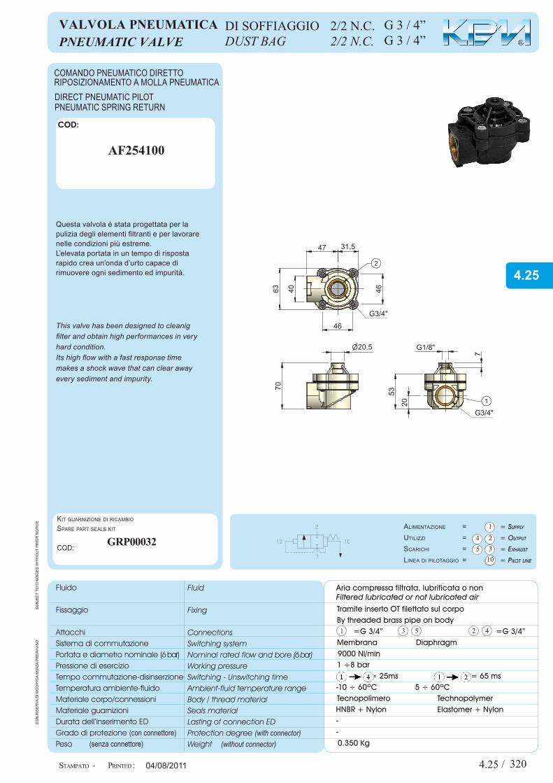
This valve has been designed to cleanigfilter and obtain high performances in veryhard condition.Its high flow with a fast response timemakes a shock wave that can clear awayevery sediment and impurity.
direCtpneumatiCpiLotpneumatiCSprinGreturn
DUST BAG 2/2 N.C. c
on
riS
er
va d
i mo
dif
ica
Se
nza
pr
eav
viS
o
StamPato -
Fluido
Fissaggio
AttacchiSistema di commutazionePortata e diametro nominale (6 bar)Pressione di esercizioTempo commutazione-disinserzioneTemperatura ambiente-fluidoMateriale corpo/connessioniMateriale guarnizioniDurata dell’inserimento EDGrado di protezione (conconnettore)Peso (senzaconnettore)
alimentazione =utilizzi =Scarichi =linea di pilotaggio =
Aria compressa filtrata, lubrificata o non
Questa valvola è stata progettata per la pulizia degli elementi filtranti e per lavorarenelle condizioni più estreme.L’elevata portata in un tempo di rispostarapido crea un’onda d’urto capace di rimuovere ogni sedimento ed impurità.
ComandopneumatiCodirettoripoSizionamentoamoLLapneumatiCa
DI SOFFIAGGIO 2/2 N.C.
Kit guarnizione di ricambio
Spare part SealS Kit
cod:
Tramite inserto OT filettato sul corpoBy threaded brass pipe on body
Membrana Diaphragm
1 ÷8 bar = 25ms = 65 ms
Tecnopolimero Technopolymer + Nylon Elastomer + Nylon
4.25 /
4063
47 31,5
46
46
g3/4"
2
n20,5
70
20
53
g3/4"1
g1/8"
7
vpS
0000
1_v
aLp
So
ff3_
41_
8_c
ata
Log
o
-10 ÷ 60ºC 5 ÷ 60ºC
HNBR--
320
=G 3/4” =G 3/4”
9000 Nl/min
0.350 Kg
AF254100
GrP00032
G 3 / 4”G 3 / 4”
4.25
Questa apparecchiatura rispetta severe specifiche qualitative tuttavia un uso improprio od inadeguato potrebbe compromet-terne il funzionamento e decadere la garanzia. L’uso di olio lubrificante non consigliato fa decadere la garanzia.NON E’ UN DISPOSITIVO DI SICUREZZA.
Prima di ogni operazione assicurarsi che il compo-nente non sia in pressione.Ristabilirla solo dopo aver controllato l’esattezza delle connessioni.
NORME DI USO E MANUTENZIONEThis unit complies with strict quality specifications. Incorrect use or misuse of this unit will compromise performance and will invalidate the warranty.Not recommended lubricating oil will invalidate the warranty.THIS UNIT IS NOT A SAFETY DEVICE.
Warning before using this unit please ensure that you have made the correct port connection and that the unit is de-pressurised. When any maintenance work is done ensure the unit is also de-pressurised.
USE AND MAINTENANCE
4.25 / 04/08/2011
Su
bje
ct
to c
ha
ng
eS
wit
ho
ut
pr
ior
no
tic
e
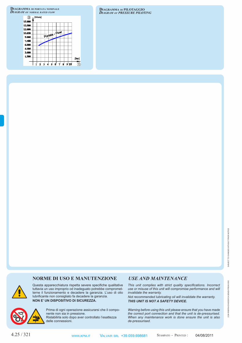
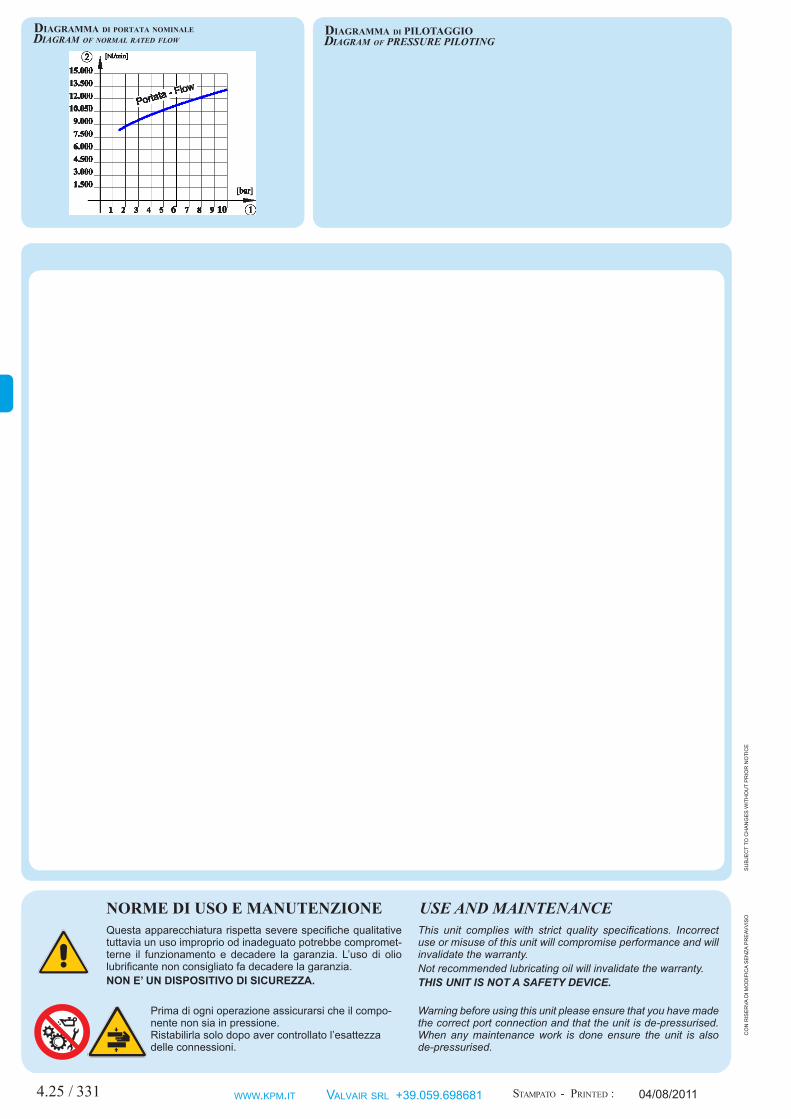
Diagram of normal rateD flow Diagram of prESSurE pILOtINg
StamPato - Printed :
co
n r
iSe
rva
di m
od
ific
a S
en
za p
re
avv
iSo
Diagramma Di portata nominale Diagramma Di pilotaggio
321 www.Kpm.it ValVair Srl +39.059.698681
14
1
23
45
1 3 5 2 4
10
pNEumAtIc VALVEvALvoLA PNeumAtICA
04/08/2011
Cod:
Su
bje
ct
to c
ha
ng
eS
wit
ho
ut
pr
ior
no
tic
e
Printed :
Fluid
Fixing
ConnectionsSwitching systemNominal rated flow and bore (6 bar) Working pressureSwitching - Unswitching timeAmbient-fluid temperature rangeBody / thread materialSeals materialLasting of connection EDProtection degree (with connector)Weight (without connector)
=Supply
=Output
=ExhauSt
=pilOtlinE
Filteredlubricatedornotlubricatedair
This valve has been designed to cleanigfilter and obtain high performances in veryhard condition.Its high flow with a fast response timemakes a shock wave that can clear awayevery sediment and impurity.
direCtpneumatiCpiLotpneumatiCSprinGreturn
DUST BAG 2/2 N.C. c
on
riS
er
va d
i mo
dif
ica
Se
nza
pr
eav
viS
o
StamPato -
Fluido
Fissaggio
AttacchiSistema di commutazionePortata e diametro nominale (6 bar)Pressione di esercizioTempo commutazione-disinserzioneTemperatura ambiente-fluidoMateriale corpo/connessioniMateriale guarnizioniDurata dell’inserimento EDGrado di protezione (conconnettore)Peso (senzaconnettore)
alimentazione =utilizzi =Scarichi =linea di pilotaggio =
Aria compressa filtrata, lubrificata o non
Questa valvola è stata progettata per la pulizia degli elementi filtranti e per lavorarenelle condizioni più estreme.L’elevata portata in un tempo di rispostarapido crea un’onda d’urto capace di rimuovere ogni sedimento ed impurità.
ComandopneumatiCodirettoripoSizionamentoamoLLapneumatiCa
DI SOFFIAGGIO 2/2 N.C.
Kit guarnizione di ricambio
Spare part SealS Kit
cod:
Tramite inserto OT filettato sul corpoBy threaded brass pipe on body
Membrana Diaphragm
1 ÷8 bar = 25ms = 65 ms
Tecnopolimero Technopolymer + Nylon Elastomer + Nylon
4.25 /
477554 37,5
g1"
55
55
n20,5
78,5
24
65
g1/8"
9
g1"1
2
vp
S00
002_
va
LpS
off
11_
8_c
ata
Log
o
-10 ÷ 60ºC 5 ÷ 60ºC
HNBR--
330
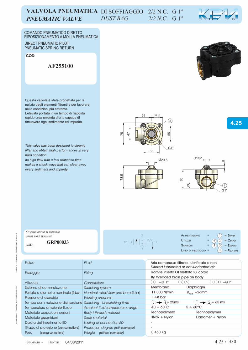
=G 1” =G1”
11 000 Nl/min ønom =26mm
0.450 Kg
AF255100
GrP00033
G 1”G 1”
4.25
Questa apparecchiatura rispetta severe specifiche qualitative tuttavia un uso improprio od inadeguato potrebbe compromet-terne il funzionamento e decadere la garanzia. L’uso di olio lubrificante non consigliato fa decadere la garanzia.NON E’ UN DISPOSITIVO DI SICUREZZA.
Prima di ogni operazione assicurarsi che il compo-nente non sia in pressione.Ristabilirla solo dopo aver controllato l’esattezza delle connessioni.
NORME DI USO E MANUTENZIONEThis unit complies with strict quality specifications. Incorrect use or misuse of this unit will compromise performance and will invalidate the warranty.Not recommended lubricating oil will invalidate the warranty.THIS UNIT IS NOT A SAFETY DEVICE.
Warning before using this unit please ensure that you have made the correct port connection and that the unit is de-pressurised. When any maintenance work is done ensure the unit is also de-pressurised.
USE AND MAINTENANCE
4.25 / 04/08/2011
Su
bje
ct
to c
ha
ng
eS
wit
ho
ut
pr
ior
no
tic
e
Diagram of normal rateD flow Diagram of prESSurE pILOtINg
StamPato - Printed :
co
n r
iSe
rva
di m
od
ific
a S
en
za p
re
avv
iSo
Diagramma Di portata nominale Diagramma Di pilotaggio
331 www.Kpm.it ValVair Srl +39.059.698681
14
1
23
45
1 3 5 2 4
10
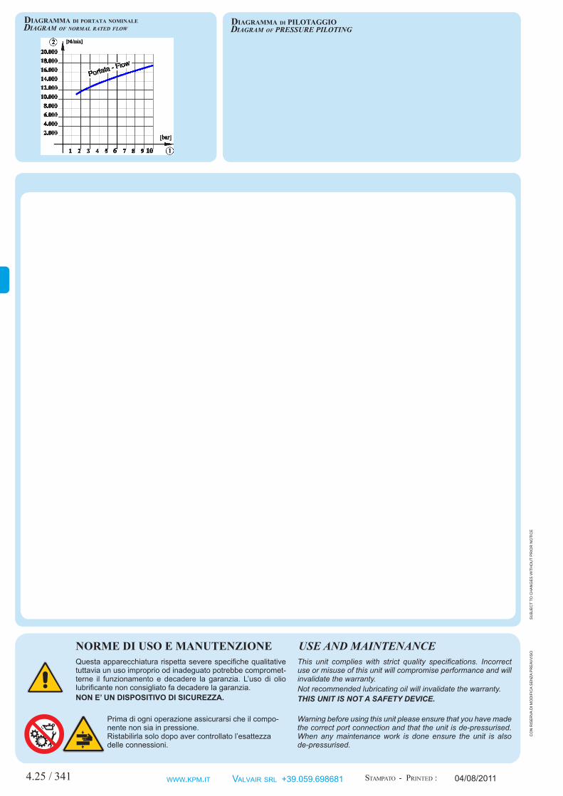
pNEumAtIc VALVEvALvoLA PNeumAtICA
04/08/2011
Cod:
Su
bje
ct
to c
ha
ng
eS
wit
ho
ut
pr
ior
no
tic
e
Printed :
Fluid
Fixing
ConnectionsSwitching systemNominal rated flow and bore (6 bar) Working pressureSwitching - Unswitching timeAmbient-fluid temperature rangeBody / thread materialSeals materialLasting of connection EDProtection degree (with connector)Weight (without connector)
=Supply
=Output
=ExhauSt
=pilOtlinE
Filteredlubricatedornotlubricatedair
This valve has been designed to cleanigfilter and obtain high performances in veryhard condition.Its high flow with a fast response timemakes a shock wave that can clear awayevery sediment and impurity.
direCtpneumatiCpiLotpneumatiCSprinGreturn
DUST BAG 2/2 N.C. c
on
riS
er
va d
i mo
dif
ica
Se
nza
pr
eav
viS
o
StamPato -
Fluido
Fissaggio
AttacchiSistema di commutazionePortata e diametro nominale (6 bar)Pressione di esercizioTempo commutazione-disinserzioneTemperatura ambiente-fluidoMateriale corpo/connessioniMateriale guarnizioniDurata dell’inserimento EDGrado di protezione (conconnettore)Peso (senzaconnettore)
alimentazione =utilizzi =Scarichi =linea di pilotaggio =
Aria compressa filtrata, lubrificata o non
Questa valvola è stata progettata per la pulizia degli elementi filtranti e per lavorarenelle condizioni più estreme.L’elevata portata in un tempo di rispostarapido crea un’onda d’urto capace di rimuovere ogni sedimento ed impurità.
ComandopneumatiCodirettoripoSizionamentoamoLLapneumatiCa
DI SOFFIAGGIO 2/2 N.C.
Kit guarnizione di ricambio
Spare part SealS Kit
cod:
Tramite inserto OT filettato sul corpoBy threaded brass pipe on body
Membrana Diaphragm
1 ÷8 bar = 25ms = 65 ms
Tecnopolimero Technopolymer + Nylon Elastomer + Nylon
4.25 /
62138
118
g1"1/2
g1"1/2
2
1
97,5
n20,5
79 61
8031
g1/4"
20
vp
S00
003_
va
LpSo
ff1
1_2
1_4_
ca
taLo
go
-10 ÷ 60ºC 5 ÷ 60ºC
HNBR--
340
=G 1” ½ =G1”½
15 000 Nl/min ønom =45 mm
0.900 Kg
AF256400
GrP00034
G 1”½G 1”½
4.25
Questa apparecchiatura rispetta severe specifiche qualitative tuttavia un uso improprio od inadeguato potrebbe compromet-terne il funzionamento e decadere la garanzia. L’uso di olio lubrificante non consigliato fa decadere la garanzia.NON E’ UN DISPOSITIVO DI SICUREZZA.
Prima di ogni operazione assicurarsi che il compo-nente non sia in pressione.Ristabilirla solo dopo aver controllato l’esattezza delle connessioni.
NORME DI USO E MANUTENZIONEThis unit complies with strict quality specifications. Incorrect use or misuse of this unit will compromise performance and will invalidate the warranty.Not recommended lubricating oil will invalidate the warranty.THIS UNIT IS NOT A SAFETY DEVICE.
Warning before using this unit please ensure that you have made the correct port connection and that the unit is de-pressurised. When any maintenance work is done ensure the unit is also de-pressurised.
USE AND MAINTENANCE
4.25 / 04/08/2011
Su
bje
ct
to c
ha
ng
eS
wit
ho
ut
pr
ior
no
tic
e
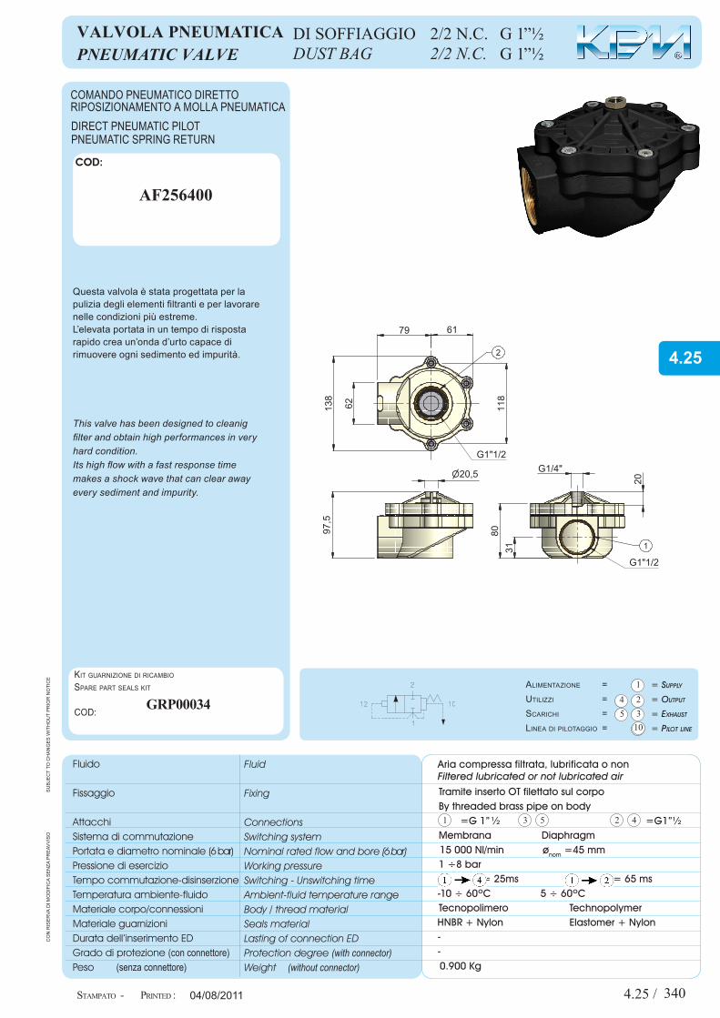
Diagram of normal rateD flow Diagram of prESSurE pILOtINg
StamPato - Printed :
co
n r
iSe
rva
di m
od
ific
a S
en
za p
re
avv
iSo
Diagramma Di portata nominale Diagramma Di pilotaggio
341 www.Kpm.it ValVair Srl +39.059.698681

Intentional white
CAP 4 Elettrovalvole e valvole pneumaticheSolenoid and pneumatic valves
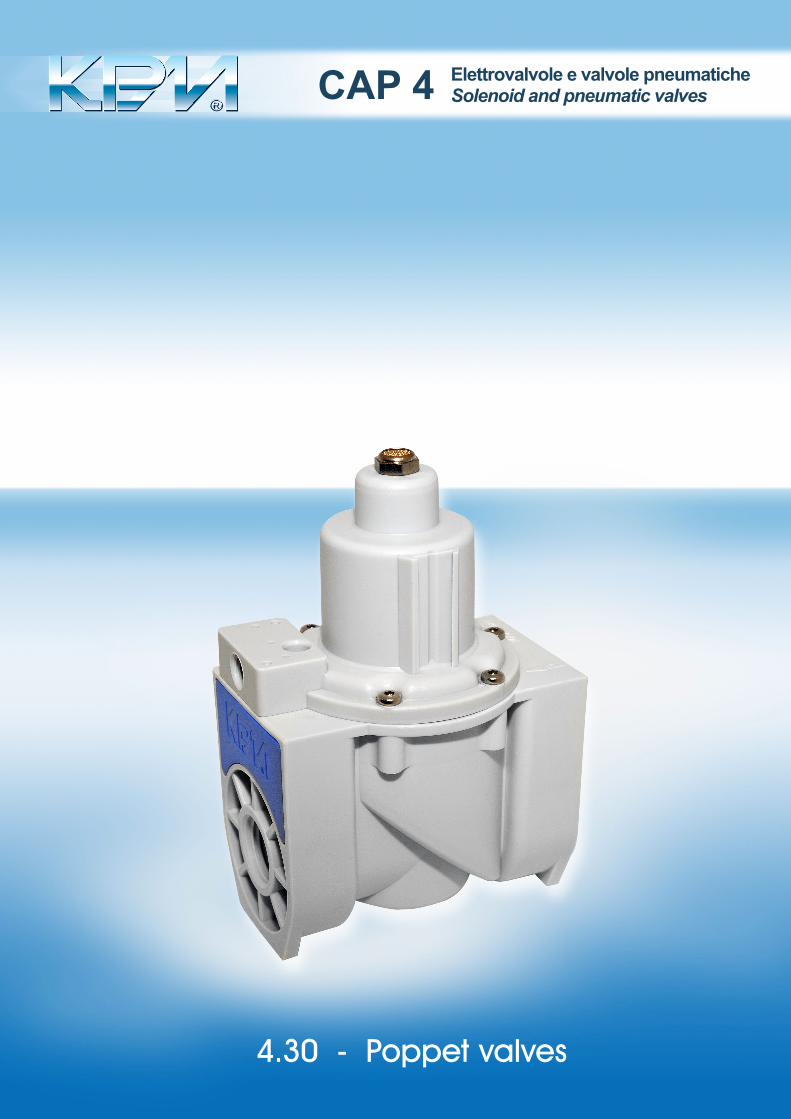
4.30 - Poppet valves

4.30 / 010
14
1
23
45
1 3 5 2 4
1 2
G1/8"
88
12
x
VPT00001_V
ALV
OLA
PNEUMAT
TAMPONE1_2SE
p p
100
63
G1/8"
76 60
10
10
pNEumAtIc VALVEvALvoLA PNeumAtICA
Intentional white
04/08/2011
Cod:
Su
bje
ct
to c
ha
ng
eS
wit
ho
ut
pr
ior
no
tic
e
Printed :
Fluid
Fixing
ConnectionsSwitching systemNominal rated flow and bore (6 bar) Working pressureSwitching - Unswitching timeAmbient-fluid temperature rangeBody / thread materialSeals materialLasting of connection EDProtection degree (with connector)Weight (without connector)
=Supply
=Output
=ExhauSt
=pilOtlinE
Filteredlubricatedornotlubricatedair
2/2 wAyS pOppEt
OPERATION This valve opens and closes a large section pipe with pneu-matic piloting.USEThe poppet valve can be used in any application where the remote interception of pipes with liquid or gas fluids is required. Therefore it can be used both in the chemical industry and by dry cleaning machinery manufacturers.The Double Acting type maintains the position of the last piloting impulse.The magnetic version of this item is available in case a constant monitoring of the valve is needed .PERFORMANCES- Designed for hard environments.- Available with G½” - G¾” - G1” - G1”¼ - G1”½ connections.- Possible mounting of magnetic reed switches.
SinGLeordoubLedireCtpneumatiCpiLot
co
n r
iSe
rva
di m
od
ific
a S
en
za p
re
avv
iSo
StamPato -
Fluido
Fissaggio
AttacchiSistema di commutazionePortata e diametro nominale (6 bar)Pressione di esercizioTempo commutazione-disinserzioneTemperatura ambiente-fluidoMateriale corpo/connessioniMateriale guarnizioniDurata dell’inserimento EDGrado di protezione (conconnettore)Peso (senzaconnettore)
alimentazione =utilizzi =Scarichi =linea di pilotaggio =
Aria compressa filtrata, lubrificata o non
2/2 vIe tAmPoNe
funzionamentoQuesta valvola svolge la funzione di apertura o chiusura di un condotto a sezione elevata in presenza di pilotaggio pneumatico.impiegoLa valvola a tampone può essere impiegata ovunque vi sia la necessità di intercettare a distanza condotti con fluidi liquidi o gassosi. dunque l’applicazione spazia dall’industria chimica al settore del lavasecco.La versione a doppio effetto rimane commutata nella posi-zione dell’ultimo impulso di pilotaggio.Se occorre monitorare continuamente lo stato della valvola è disponibile la versione magnetica .caratteriStiche- ideale per ambienti gravosi.- disponibile con attacchi g½”-g¾”-g1”-g1”¼-g1”½.- versione predisposta al montaggio di sensori magnetici.
SinGoLoodoppioComandopneumatiCodiretto
1
12
10
2
1
12
2
10
S ingle Acting Double Acting
=Supply
=Output
=pilOtline
=MechanicalSpringreturn
/ Supply
/ Output
/ pilOtlineS
Semplice Effetto Doppio Effetto
aliMentaziOne=
utilizzO=
lineadipilOtaggiO=
ripOSiziOnaMentO=
= aliMentaziOne
= utilizzO
= lineadipilOtaggiO
-10 ÷ 60ºC 5 ÷ 60ºC
HNBR--
G1”½
G1”¼
G1”G¾”G½” vPt00001
vPt00011vPt00002vPt00012vPt00003vPt00013vPt00004vPt00014vPt00005vPt00015
vPt00006vPt00016vPt00007vPt00017vPt00008vPt00018vPt00009vPt00019vPt00010vPt00020
Single Acting Double ActingSize
- type
- Magnetic Version
Special typeS on requeSt
Semplice Effetto Doppio EffettoGrandezza versioni
= Versione Magnetica
Varianti Speciali Su richieSta -
0 ÷ 8 bar
-10 ÷ 60ºC
5÷ 80ºC 5 ÷ 80ºC
Nylon - Acetalic resin
Inox - Viton
0.425 Kg
Fluid
Connections
Switching system
Nominal rated flow and diameter
Working pressure (1 —> 2)
Pilot pressure
Ambient temperature range
Fluid temperature range: Air - Liquid
Body - cover materials
Materials in contact with the fluid
Weight
Compressed air and liquids
See the Tabel
Poppet
Please turn over
Please turn over
Fluido
Attacchi
Sistema di commutazione
Portata e diametro nominale
Pressione di esercizio (1 —> 2)
Pressione di pilotaggio
Temperatura ambiente
Temperatura fluido : Aria - Liquido
Materiali corpo - coperchio
Materiali a contatto con fluido
Peso
Aria compressa filtrata e liquidi
Vedi Tabella
Otturatore
Vedi retro
Vedi Retro
4.30

Questa apparecchiatura rispetta severe specifiche qualitative tuttavia un uso improprio od inadeguato potrebbe compromet-terne il funzionamento e decadere la garanzia. L’uso di olio lubrificante non consigliato fa decadere la garanzia.NON E’ UN DISPOSITIVO DI SICUREZZA.
Prima di ogni operazione assicurarsi che il compo-nente non sia in pressione.Ristabilirla solo dopo aver controllato l’esattezza delle connessioni.
NORME DI USO E MANUTENZIONEThis unit complies with strict quality specifications. Incorrect use or misuse of this unit will compromise performance and will invalidate the warranty.Not recommended lubricating oil will invalidate the warranty.THIS UNIT IS NOT A SAFETY DEVICE.
Warning before using this unit please ensure that you have made the correct port connection and that the unit is de-pressurised. When any maintenance work is done ensure the unit is also de-pressurised.
USE AND MAINTENANCE
4.30 / 0114.20 / 031 03/04/2007
I COD:
COD:
SNK000041
2
COD:
COD:
SNK000101
22.5m CNK000485m CNK00049
2.5m CNT000555m CNT00056
SU
BJE
CT
TO C
HA
NG
ES
WIT
HO
UT
PR
IOR
NO
TIC
E
- DIAGRAM OF NORMAL RATED FLOW PILOT PRESSURE
PRINTED :
This unit complies with strict quality specifications.The incorrect use or misuse of this unit willcompromise performance and will invalidate thewarranty.THIS UNIT IS NOT A SAFETY DEVICE.
WARNING: before this unit is used and any maintenancework is done please ensure that you have made thecorrect connections, and that the unit is notpressurised. Pressure can be restored when theconnections are checked.
USE AND MAINTENANCE
TAPERED THREADS FORBIDDEN ON POLIMER THREADS.
ADVISABLE TO USE A LIQUID HERMETIC SEAL.
- REED SWITCH
This reed switch can be mounted directly on the valve.
Magnetic reed
Cable with plug
Magnetic reed
Cable with plug
CO
N R
ISE
RV
A D
I MO
DIF
ICA
SE
NZA
PR
EA
VV
ISO
Sensore magnetico
Cavo di prolunga
Sensore magnetico
Cavo di prolunga
Micro l ine
DIAGRAMMA DI PORTATA NOMINALE PRESSIONE DI PILOTAGGIO -
STAMPATO -
O P T I O N A L
Questa apparecchiatura rispetta severe specifi-che qualitative tuttavia un uso improprio odinadeguato potrebbe comprometterne il funzio-namento e decadere la garanzia.NON E' UN DISPOSITIVO DI SICUREZZA
ATTENZIONE: prima di ogni operazioneassicurarsi che il componente non sia inpressione. Ristabilire solo dopo avercontrollato l'esattezza delle connessioni.
NORME DI USO E MANUTENZIONE
SCONSIGLIATO USARE FILETTATURE CONICHE SUFILETTATURE IN POLIMERO.
CONSIGLIATO USARE GUARNIZIONE LIQUIDADI TENUTA.
SENSORE
Questo sensore è fissabile direttamente sulla valvola.
���������������������
� ����������� � ������������� ����� � ��������� �� ���������������� �� ���������������� �� ���������������� �� ���������������� �� �������
���������������� �� ������ ����������� ����������� ����������� ����������� ����������� ��
���������������������
� ����������� � ������������� ������ � ������������������������� ���������������������������������������������
��������� ���������� ���������� ���������� ���������� ������ �� ���������� ���������� ���������� ���������� ��������� �� ��������� ����������� ����������� ����������� ����������� ����������� ��
VP
T000
01_V
ALV
OLA
PN
EU
MA
T.TA
MP
ON
E 1
_2 S
E_C
ATA
LOG
O_R
ETR
OPA
GIN
A
I
4.20 / 031 03/04/2007
I COD:
COD:
SNK000041
2
COD:
COD:
SNK000101
22.5m CNK000485m CNK00049
2.5m CNT000555m CNT00056
SU
BJE
CT
TO C
HA
NG
ES
WIT
HO
UT
PR
IOR
NO
TIC
E
- DIAGRAM OF NORMAL RATED FLOW PILOT PRESSURE
PRINTED :
This unit complies with strict quality specifications.The incorrect use or misuse of this unit willcompromise performance and will invalidate thewarranty.THIS UNIT IS NOT A SAFETY DEVICE.
WARNING: before this unit is used and any maintenancework is done please ensure that you have made thecorrect connections, and that the unit is notpressurised. Pressure can be restored when theconnections are checked.
USE AND MAINTENANCE
TAPERED THREADS FORBIDDEN ON POLIMER THREADS.
ADVISABLE TO USE A LIQUID HERMETIC SEAL.
- REED SWITCH
This reed switch can be mounted directly on the valve.
Magnetic reed
Cable with plug
Magnetic reed
Cable with plug
CO
N R
ISE
RV
A D
I MO
DIF
ICA
SE
NZA
PR
EA
VV
ISO
Sensore magnetico
Cavo di prolunga
Sensore magnetico
Cavo di prolunga
Micro l ine
DIAGRAMMA DI PORTATA NOMINALE PRESSIONE DI PILOTAGGIO -
STAMPATO -
O P T I O N A L
Questa apparecchiatura rispetta severe specifi-che qualitative tuttavia un uso improprio odinadeguato potrebbe comprometterne il funzio-namento e decadere la garanzia.NON E' UN DISPOSITIVO DI SICUREZZA
ATTENZIONE: prima di ogni operazioneassicurarsi che il componente non sia inpressione. Ristabilire solo dopo avercontrollato l'esattezza delle connessioni.
NORME DI USO E MANUTENZIONE
SCONSIGLIATO USARE FILETTATURE CONICHE SUFILETTATURE IN POLIMERO.
CONSIGLIATO USARE GUARNIZIONE LIQUIDADI TENUTA.
SENSORE
Questo sensore è fissabile direttamente sulla valvola.
���������������������
� ����������� � ������������� ����� � ��������� �� ���������������� �� ���������������� �� ���������������� �� ���������������� �� �������
���������������� �� ������ ����������� ����������� ����������� ����������� ����������� ��
���������������������
� ����������� � ������������� ������ � ������������������������� ���������������������������������������������
��������� ���������� ���������� ���������� ���������� ������ �� ���������� ���������� ���������� ���������� ��������� �� ��������� ����������� ����������� ����������� ����������� ����������� ��
04/08/2011
COD:
COD:
SNK000111
2
2.5m CNt000555m CNt00056
Su
bje
ct
to c
ha
ng
eS
wit
ho
ut
pr
ior
no
tic
e
Diagram of normal rateD flow Diagram of prESSurE pILOtINg
this unit complies with strict quality specifications. the incorrect use or misuse of this unit will compromise perfor-mance and will invalidate the warranty.THIS UNIT IS NOT A SAFETY DEVICE.
Warning: before this unit is used and any maintenance work is done please ensure that you have made the correct connec-tions, and that the unit is not pressurised. pressure can be restored when the connections are checked.
uSe AND mAINteNANCe
Tapered Threads forbidden on polimer Threads.
advisable To use a liquid hermeTic seal.
- reed Switch
this reed switch can be mounted directly on the valve.
magneticreed
Cablewithplug
StamPato - Printed :
co
n r
iSe
rva
di m
od
ific
a S
en
za p
re
avv
iSo
Diagramma Di portata nominale Diagramma Di pilotaggio
Sensoremagnetico
Cavodiprolunga
o P t I o N A L
Questa apparecchiatura rispetta severe specifiche qualitative tuttavia un uso improprio od inadeguato potrebbe comprometterne il funzionamento e decadere la garanzia.NON E’ UN DISPOSITIVO DI SICUREZZA
aTTenzione: prima di ogni operazione assicurarsi che il componente non sia in pressione. ristabi-lire solo dopo aver controllato l’esattezza delle connessioni.
Norme DI uSo e mANuteNZIoNe
sconsigliaTo usare fileTTaTure coniche su fileTTaTure in polimero.
consigliaTo usare guarnizione liquidadi TenuTa.
SenSore
Questo sensore è fissabile direttamente sulla valvola.
www.Kpm.it ValVair Srl +39.059.698681