Bruciatori di gas ad aria soffiata D...
56
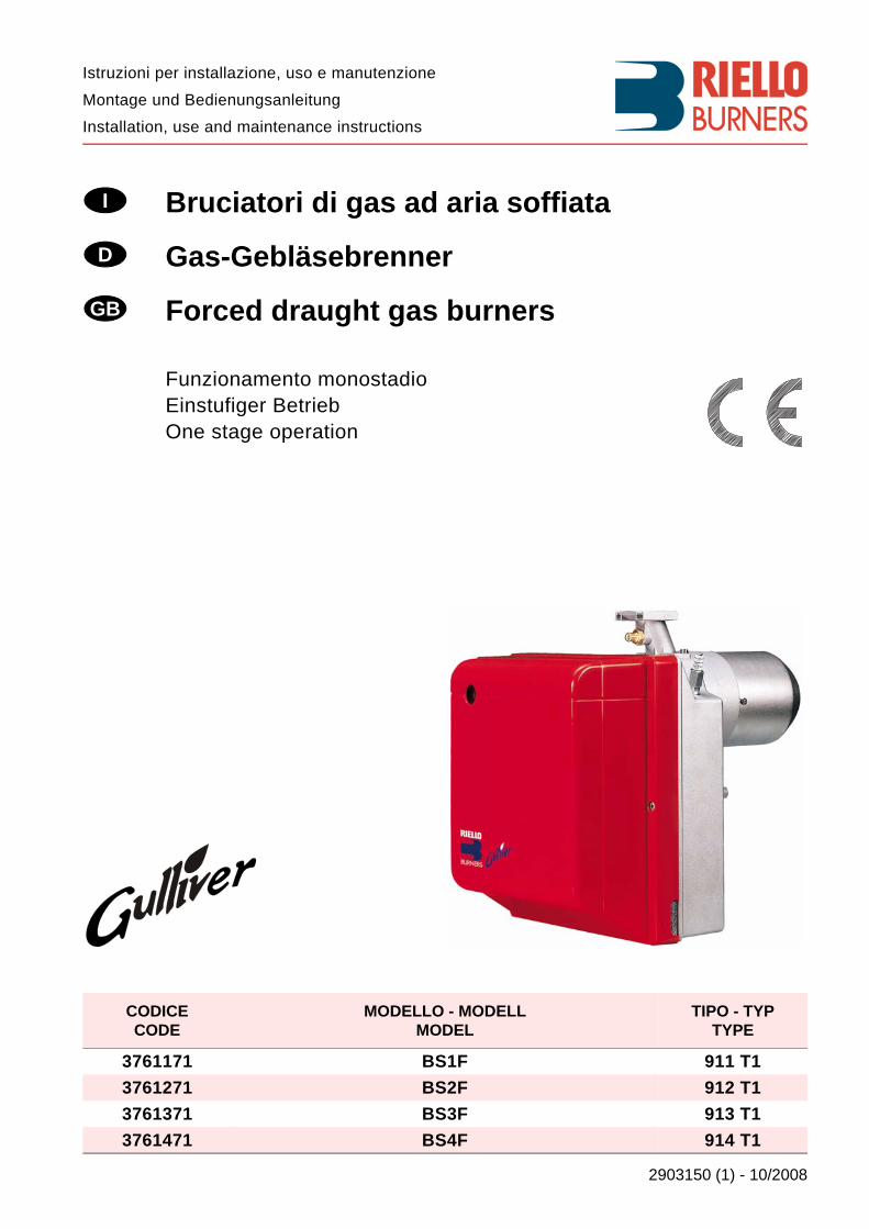
2903150 (1) - 10/2008 Montage und Bedienungsanleitung Istruzioni per installazione, uso e manutenzione Installation, use and maintenance instructions Bruciatori di gas ad aria soffiata Gas-Gebläsebrenner Forced draught gas burners CODICE CODE MODELLO - MODELL MODEL TIPO - TYP TYPE 3761171 BS1F 911 T1 3761271 BS2F 912 T1 3761371 BS3F 913 T1 3761471 BS4F 914 T1 I D GB Funzionamento monostadio Einstufiger Betrieb One stage operation
Transcript of Bruciatori di gas ad aria soffiata D...
2903150 (1) - 10/2008
Montage und Bedienungsanleitung
Istruzioni per installazione, uso e manutenzione
Installation, use and maintenance instructions
Bruciatori di gas ad aria soffiata
Gas-Gebläsebrenner
Forced draught gas burners
CODICECODE
MODELLO - MODELLMODEL
TIPO - TYPTYPE
3761171 BS1F 911 T13761271 BS2F 912 T13761371 BS3F 913 T13761471 BS4F 914 T1
I
D
GB
Funzionamento monostadioEinstufiger BetriebOne stage operation
3150
DICHIARAZIONE DI CONFORMITA’RIELLO S.p.A. dichiara sotto la propria responsabilità che i sotto elencati bruciatori di gas ad aria soffiatasono conformi alle seguenti Direttive Europee: - Direttiva del Consiglio 73/23/CEE - 2006/95/CE – relativa al Materiale Elettrico- Direttiva del Consiglio 89/336/CEE - 2004/108/CE – relativa alla Compatibilità Elettromagnetica- Direttiva del Consiglio 90/396/CEE – relativa agli Apparecchi a Gas e con le seguenti Norme Tecniche: EN 676, EN 50081-1, EN 50081-2, EN 60335-1, EN 50165, EN 60529 (IP X0D)e le sezioni applicabili della EN 746-2 – Apparecchiature di Processo Termico Industriale.
Marcatura CE N° 0085AQ0409 secondo Direttiva Gas 90/396/CEE.Il bruciatore è omologato per funzionamento intermittente secondo la Normativa EN 676.
KONFORMITÄTSERKLÄRUNGRIELLO S.p.A. erklärt unter ihrer Haftung, das die unten verzeichneten Gas-Gebläsebrenner mit folgendenEuropäischen Richtlinien: - Richtlinie 73/23/EWG - 2006/95/EG – Elektrisches Material- Richtlinie 89/336/EWG - 2004/108/EG – Elektromagnetische Verträglichkeit- Richtlinie 90/396/EWG – Gasgeräte und mit folgenden Technischen Normen konform sind:EN 676, EN 50081-1, EN 50081-2, EN 60335-1, EN 50165, EN 60529 (IP X0D)und die anwendbaren Abschnitte der EN 746-2 – Apparaturen für Industrielle Wärmeprozesse.
CE Kennzeichnung Nr. 0085AQ0409 gemäß der Gasgeräterichtlinie 90/396/EWG.Der Brenner ist gemäß der Norm EN 676 für intermittierenden Betrieb typgenehmigt.
DECLARATION OF CONFORMITYRIELLO S.p.A. hereby declares under its sole responsibility that the forced draught gas burners listed belowconform to the following European Directives: - Council Directive 73/23/EEC - 2006/95/EC – relating to Electrical Equipment- Council Directive 89/336/EEC - 2004/108/EC – relating to Electromagnetic Compatibility- Council Directive 90/396/EEC – relating to Gas Appliances, and to the following Technical Standards:EN 676, EN 50081-1, EN 50081-2, EN 60335-1, EN 50165, EN 60529 (IP X0D)and applicable sections of EN 746-2 – Industrial Thermoprocessing Equipment.
CE marking No. 0085AQ0409 according to Gas Appliance Directive 90/396/EEC.The burner is approved for intermittent operation as per Directive EN 676.
Prodotto - ProduktreiheProduct
Tipo -TypType
Modello - AusführungModel
Bruciatori di gas ad aria soffiataGas-GebläsebrennerForced draught gas burners
911 T1 - 912 T1913 T1 - 914 T1
BS1F - BS2FBS3F - BS4F
RIELLO S.p.A.
3150
1 I
INDICE
1. DESCRIZIONE DEL BRUCIATORE . . . . . . . . . . . . . . . . . . . . . . . . . . . . . . . . . . . . . . . . . . . . . . 2
1.1 Materiale a corredo . . . . . . . . . . . . . . . . . . . . . . . . . . . . . . . . . . . . . . . . . . . . . . . . . . . . . . . . . . . 2
1.2 Accessori . . . . . . . . . . . . . . . . . . . . . . . . . . . . . . . . . . . . . . . . . . . . . . . . . . . . . . . . . . . . . . . . . . . 2
2. DATI TECNICI . . . . . . . . . . . . . . . . . . . . . . . . . . . . . . . . . . . . . . . . . . . . . . . . . . . . . . . . . . . . . . . 3
2.1 Dati tecnici . . . . . . . . . . . . . . . . . . . . . . . . . . . . . . . . . . . . . . . . . . . . . . . . . . . . . . . . . . . . . . . . . . 3
2.2 Dimensioni. . . . . . . . . . . . . . . . . . . . . . . . . . . . . . . . . . . . . . . . . . . . . . . . . . . . . . . . . . . . . . . . . . 4
2.3 Campi di lavoro . . . . . . . . . . . . . . . . . . . . . . . . . . . . . . . . . . . . . . . . . . . . . . . . . . . . . . . . . . . . . . 5
3. INSTALLAZIONE . . . . . . . . . . . . . . . . . . . . . . . . . . . . . . . . . . . . . . . . . . . . . . . . . . . . . . . . . . . . 7
3.1 Fissaggio al generatore . . . . . . . . . . . . . . . . . . . . . . . . . . . . . . . . . . . . . . . . . . . . . . . . . . . . . . . . 7
3.2 Posizione di funzionamento . . . . . . . . . . . . . . . . . . . . . . . . . . . . . . . . . . . . . . . . . . . . . . . . . . . . . 8
3.3 Rampa gas . . . . . . . . . . . . . . . . . . . . . . . . . . . . . . . . . . . . . . . . . . . . . . . . . . . . . . . . . . . . . . . . . 8
3.4 Alimentazione elettrica rampa . . . . . . . . . . . . . . . . . . . . . . . . . . . . . . . . . . . . . . . . . . . . . . . . . . . 8
3.5 Linea di alimentazione gas . . . . . . . . . . . . . . . . . . . . . . . . . . . . . . . . . . . . . . . . . . . . . . . . . . . . . 9
3.6 Collegamenti elettrici . . . . . . . . . . . . . . . . . . . . . . . . . . . . . . . . . . . . . . . . . . . . . . . . . . . . . . . . . . 10
4. FUNZIONAMENTO . . . . . . . . . . . . . . . . . . . . . . . . . . . . . . . . . . . . . . . . . . . . . . . . . . . . . . . . . . . 11
4.1 Regolazione della combustione . . . . . . . . . . . . . . . . . . . . . . . . . . . . . . . . . . . . . . . . . . . . . . . . . . 11
4.2 Regolazione testa di combustione . . . . . . . . . . . . . . . . . . . . . . . . . . . . . . . . . . . . . . . . . . . . . . . . 11
4.3 Regolazione serranda aria . . . . . . . . . . . . . . . . . . . . . . . . . . . . . . . . . . . . . . . . . . . . . . . . . . . . . . 12
4.4 Posizionamento sonda elettrodo . . . . . . . . . . . . . . . . . . . . . . . . . . . . . . . . . . . . . . . . . . . . . . . . . 12
4.5 Posizionamento presa di pressione . . . . . . . . . . . . . . . . . . . . . . . . . . . . . . . . . . . . . . . . . . . . . . . 12
4.6 Controllo della combustione. . . . . . . . . . . . . . . . . . . . . . . . . . . . . . . . . . . . . . . . . . . . . . . . . . . . . 12
4.7 Pressostato aria. . . . . . . . . . . . . . . . . . . . . . . . . . . . . . . . . . . . . . . . . . . . . . . . . . . . . . . . . . . . . . 13
4.8 Programma di avviamento . . . . . . . . . . . . . . . . . . . . . . . . . . . . . . . . . . . . . . . . . . . . . . . . . . . . . . 13
4.9 Funzione di riciclo . . . . . . . . . . . . . . . . . . . . . . . . . . . . . . . . . . . . . . . . . . . . . . . . . . . . . . . . . . . . 13
4.10 Funzione di post-ventilazione. . . . . . . . . . . . . . . . . . . . . . . . . . . . . . . . . . . . . . . . . . . . . . . . . . . . 13
4.11 Sbocco apparecchiatura . . . . . . . . . . . . . . . . . . . . . . . . . . . . . . . . . . . . . . . . . . . . . . . . . . . . . . . 13
5. MANUTENZIONE . . . . . . . . . . . . . . . . . . . . . . . . . . . . . . . . . . . . . . . . . . . . . . . . . . . . . . . . . . . . 14
5.1 Diagnostica visiva apparecchiatura . . . . . . . . . . . . . . . . . . . . . . . . . . . . . . . . . . . . . . . . . . . . . . . 14
6. ANOMALIE / RIMEDI . . . . . . . . . . . . . . . . . . . . . . . . . . . . . . . . . . . . . . . . . . . . . . . . . . . . . . . . . 15
6.1 Difficoltà di avviamento . . . . . . . . . . . . . . . . . . . . . . . . . . . . . . . . . . . . . . . . . . . . . . . . . . . . . . . . 15
6.2 Anomalie in funzionamento . . . . . . . . . . . . . . . . . . . . . . . . . . . . . . . . . . . . . . . . . . . . . . . . . . . . . 17
7. AVVERTENZE E SICUREZZA. . . . . . . . . . . . . . . . . . . . . . . . . . . . . . . . . . . . . . . . . . . . . . . . . . . 17
7.1 Identificazione bruciatore . . . . . . . . . . . . . . . . . . . . . . . . . . . . . . . . . . . . . . . . . . . . . . . . . . . . . . . 17
7.2 Regole fondamentali di sicurezza . . . . . . . . . . . . . . . . . . . . . . . . . . . . . . . . . . . . . . . . . . . . . . . . . . . . . . 17
3150
2 I
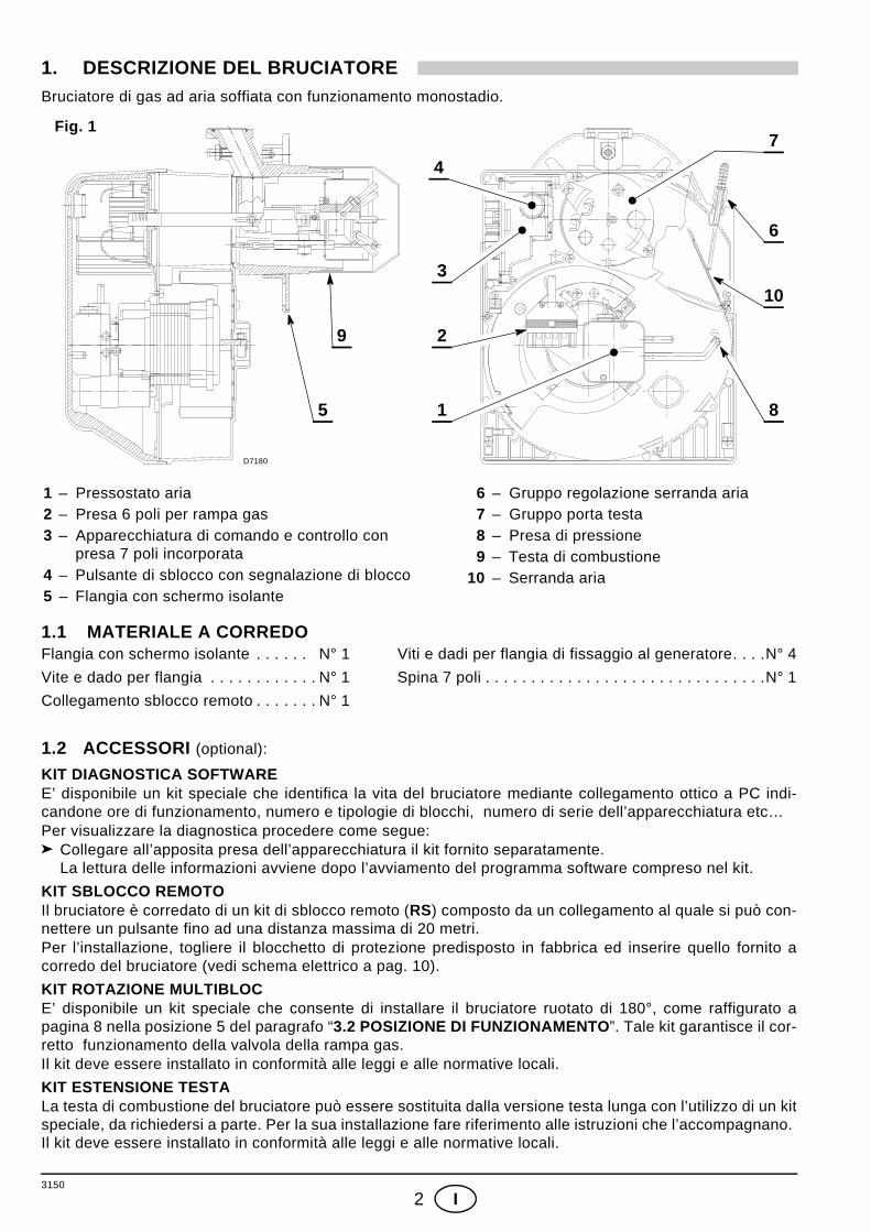
1. DESCRIZIONE DEL BRUCIATOREBruciatore di gas ad aria soffiata con funzionamento monostadio.
1.1 MATERIALE A CORREDOFlangia con schermo isolante . . . . . . N° 1 Viti e dadi per flangia di fissaggio al generatore. . . .N° 4
Vite e dado per flangia . . . . . . . . . . . . N° 1 Spina 7 poli . . . . . . . . . . . . . . . . . . . . . . . . . . . . . . .N° 1
Collegamento sblocco remoto . . . . . . . N° 1
1.2 ACCESSORI (optional):
KIT DIAGNOSTICA SOFTWAREE’ disponibile un kit speciale che identifica la vita del bruciatore mediante collegamento ottico a PC indi-candone ore di funzionamento, numero e tipologie di blocchi, numero di serie dell’apparecchiatura etc…Per visualizzare la diagnostica procedere come segue:
Collegare all’apposita presa dell’apparecchiatura il kit fornito separatamente. La lettura delle informazioni avviene dopo l’avviamento del programma software compreso nel kit.
KIT SBLOCCO REMOTOIl bruciatore è corredato di un kit di sblocco remoto (RS) composto da un collegamento al quale si può con-nettere un pulsante fino ad una distanza massima di 20 metri.Per l’installazione, togliere il blocchetto di protezione predisposto in fabbrica ed inserire quello fornito acorredo del bruciatore (vedi schema elettrico a pag. 10).
KIT ROTAZIONE MULTIBLOCE’ disponibile un kit speciale che consente di installare il bruciatore ruotato di 180°, come raffigurato apagina 8 nella posizione 5 del paragrafo “3.2 POSIZIONE DI FUNZIONAMENTO”. Tale kit garantisce il cor-retto funzionamento della valvola della rampa gas.Il kit deve essere installato in conformità alle leggi e alle normative locali.
KIT ESTENSIONE TESTALa testa di combustione del bruciatore può essere sostituita dalla versione testa lunga con l’utilizzo di un kitspeciale, da richiedersi a parte. Per la sua installazione fare riferimento alle istruzioni che l’accompagnano. Il kit deve essere installato in conformità alle leggi e alle normative locali.
1 – Pressostato aria2 – Presa 6 poli per rampa gas3 – Apparecchiatura di comando e controllo con
presa 7 poli incorporata4 – Pulsante di sblocco con segnalazione di blocco5 – Flangia con schermo isolante
Fig. 1
D7180
4
3
2
1
9
8
6
5
10
7
6 – Gruppo regolazione serranda aria 7 – Gruppo porta testa 8 – Presa di pressione 9 – Testa di combustione10 – Serranda aria
3150
3 I
KIT GPL
E’ disponibile un kit speciale che montato sulla testa di combustione consente ai bruciatori, previsti per fun-zionamento a gas naturale, di bruciare GPL. Per l’installazione del “kit GPL” fare riferimento alle istruzioniche l’accompagnano. Il kit deve essere installato in conformità alle leggi e alle normative locali.
KIT TESTA DI COMBUSTIONE ALTERNATIVA
Il kit può essere utilizzato per evitare instabilità di combustione che potrebbe verificarsi in applicazioni par-ticolari. Il kit deve essere installato in conformità alle leggi e alle normative locali.
KIT CONTROLLO DI TENUTA
E’ disponibile un kit speciale che consente la verifica della tenuta della valvola della rampa gas.Tale kit non può essere utilizzato per le rampe gas con valvola modello MULTIBLOC MBDLE 055. Il kit deve essere installato in conformità alle leggi e alle normative locali.
2. DATI TECNICI
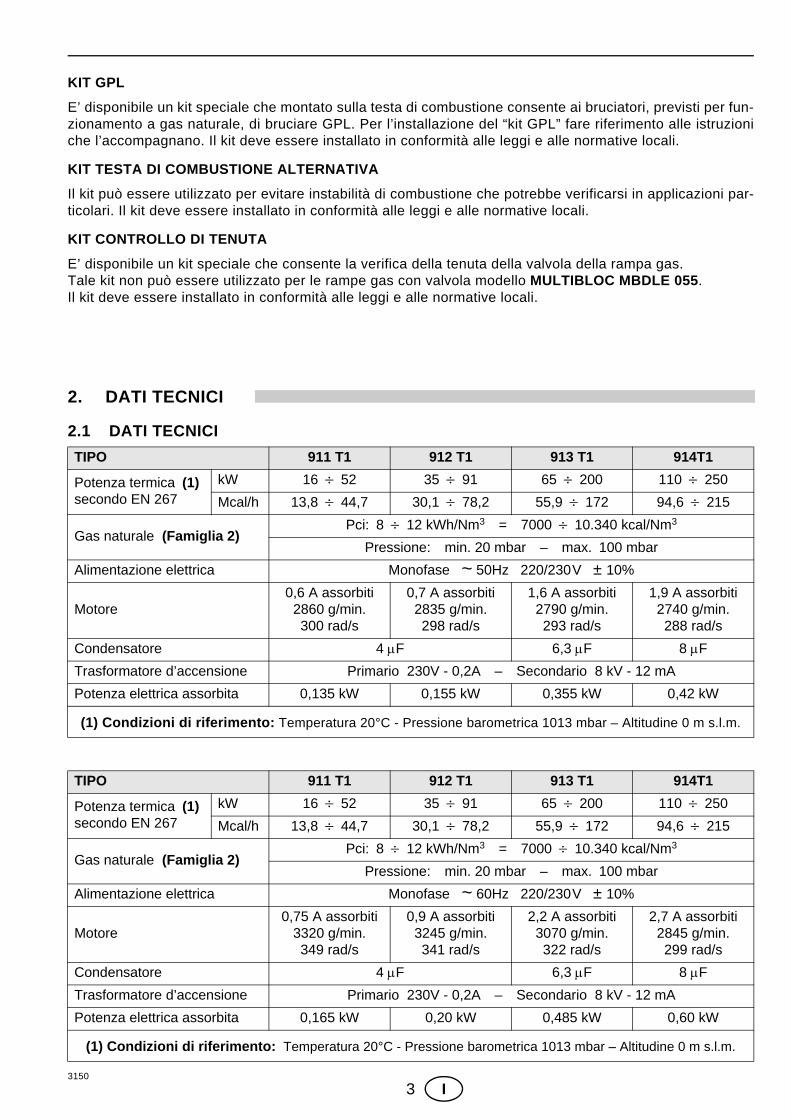
2.1 DATI TECNICI TIPO 911 T1 912 T1 913 T1 914T1
Potenza termica (1)secondo EN 267
kW 16 ÷ 52 35 ÷ 91 65 ÷ 200 110 ÷ 250
Mcal/h 13,8 ÷ 44,7 30,1 ÷ 78,2 55,9 ÷ 172 94,6 ÷ 215
Gas naturale (Famiglia 2)Pci: 8 ÷ 12 kWh/Nm3 = 7000 ÷ 10.340 kcal/Nm3
Pressione: min. 20 mbar – max. 100 mbar
Alimentazione elettrica Monofase ~ 50Hz 220/230V ± 10%
Motore0,6 A assorbiti
2860 g/min.300 rad/s
0,7 A assorbiti2835 g/min.298 rad/s
1,6 A assorbiti2790 g/min.293 rad/s
1,9 A assorbiti2740 g/min.288 rad/s
Condensatore 4 µF 6,3 µF 8 µF
Trasformatore d’accensione Primario 230V - 0,2A – Secondario 8 kV - 12 mA
Potenza elettrica assorbita 0,135 kW 0,155 kW 0,355 kW 0,42 kW
(1) Condizioni di riferimento: Temperatura 20°C - Pressione barometrica 1013 mbar – Altitudine 0 m s.l.m.
TIPO 911 T1 912 T1 913 T1 914T1
Potenza termica (1)secondo EN 267
kW 16 ÷ 52 35 ÷ 91 65 ÷ 200 110 ÷ 250
Mcal/h 13,8 ÷ 44,7 30,1 ÷ 78,2 55,9 ÷ 172 94,6 ÷ 215
Gas naturale (Famiglia 2)Pci: 8 ÷ 12 kWh/Nm3 = 7000 ÷ 10.340 kcal/Nm3
Pressione: min. 20 mbar – max. 100 mbar
Alimentazione elettrica Monofase ~ 60Hz 220/230V ± 10%
Motore0,75 A assorbiti
3320 g/min.349 rad/s
0,9 A assorbiti3245 g/min.341 rad/s
2,2 A assorbiti3070 g/min.322 rad/s
2,7 A assorbiti2845 g/min.299 rad/s
Condensatore 4 µF 6,3 µF 8 µF
Trasformatore d’accensione Primario 230V - 0,2A – Secondario 8 kV - 12 mA
Potenza elettrica assorbita 0,165 kW 0,20 kW 0,485 kW 0,60 kW
(1) Condizioni di riferimento: Temperatura 20°C - Pressione barometrica 1013 mbar – Altitudine 0 m s.l.m.
3150
4 I
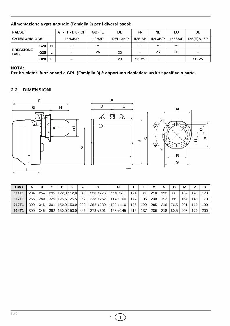
Alimentazione a gas naturale (Famiglia 2) per i diversi paesi:
NOTA:Per bruciatori funzionanti a GPL (Famiglia 3) è opportuno richiedere un kit specifico a parte.
2.2 DIMENSIONI
PAESE AT - IT - DK - CH GB - IE DE FR NL LU BE
CATEGORIA GAS II2H3B/P II2H3P II2ELL3B/P II2Er3P II2L3B/P II2E3B/P I2E(R)B, I3P
PRESSIONEGAS
G20 H 20 – – – – – –
G25 L – 25 20 – 25 25 –
G20 E – – 20 20/25 – – 20/25
TIPO A B C D E F G H I L M N O P R S
911T1 234 254 295 122,0 112,0 346 230 ÷276 116 ÷70 174 89 210 192 66 167 140 170
912T1 255 280 325 125,5 125,5 352 238 ÷252 114 ÷100 174 106 230 192 66 167 140 170
913T1 300 345 391 150,0 150,0 390 262 ÷280 128 ÷110 196 129 285 216 76,5 201 160 190
914T1 300 345 392 150,0 150,0 446 278 ÷301 168 ÷145 216 137 286 218 80,5 203 170 200
F
HG
AD E
I
R
S
N
45°
45° 11
OP
B
C
M
ø L
D5008
3150
5 I
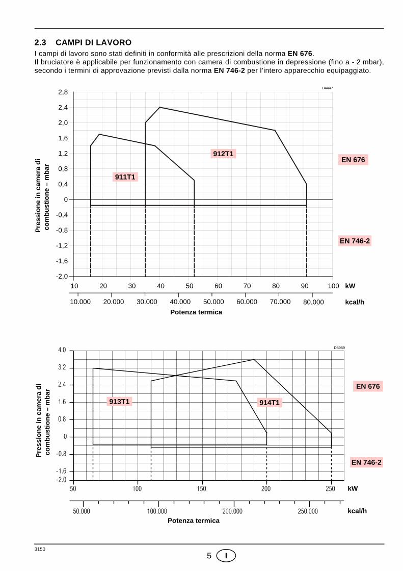
2.3 CAMPI DI LAVORO I campi di lavoro sono stati definiti in conformità alle prescrizioni della norma EN 676.Il bruciatore è applicabile per funzionamento con camera di combustione in depressione (fino a - 2 mbar),secondo i termini di approvazione previsti dalla norma EN 746-2 per l’intero apparecchio equipaggiato.
Potenza termica
Pre
ssio
ne in
cam
era
dico
mbu
stio
ne –
mba
r
10.000 80.000
kW10
kcal/h
2,4
0,8
0,4
0
D4447
20 30 40 50 60 70 80 90 100
1,2
1,6
2,0
20.000 30.000 40.000 50.000 60.000 70.000
2,8
-0,4
-0,8
-1,2
-1,6
-2,0
EN 676
EN 746-2
911T1
912T1
50 100 150 200 250
50.000 100.000 200.000 250.000
0
0.8
1.6
2.4
3.2
4.0
-0.8
-1.6-2.0
Potenza termica
Pre
ssio
ne in
cam
era
dico
mbu
stio
ne –
mba
r
kW
kcal/h
D8989
913T1 914T1
EN 676
EN 746-2
3150
6 I
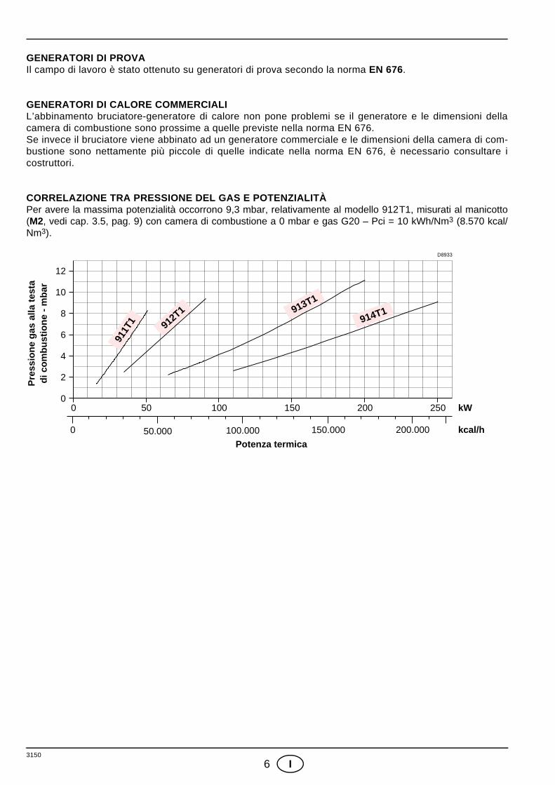
GENERATORI DI PROVAIl campo di lavoro è stato ottenuto su generatori di prova secondo la norma EN 676.
GENERATORI DI CALORE COMMERCIALIL’abbinamento bruciatore-generatore di calore non pone problemi se il generatore e le dimensioni dellacamera di combustione sono prossime a quelle previste nella norma EN 676. Se invece il bruciatore viene abbinato ad un generatore commerciale e le dimensioni della camera di com-bustione sono nettamente più piccole di quelle indicate nella norma EN 676, è necessario consultare icostruttori.
CORRELAZIONE TRA PRESSIONE DEL GAS E POTENZIALITÀPer avere la massima potenzialità occorrono 9,3 mbar, relativamente al modello 912T1, misurati al manicotto(M2, vedi cap. 3.5, pag. 9) con camera di combustione a 0 mbar e gas G20 – Pci = 10 kWh/Nm3 (8.570 kcal/Nm3).
Potenza termica
D8933
Pre
ssio
ne g
as a
lla te
sta
di c
ombu
stio
ne -
mba
r
0 50 100 150 200 kW
0 50.000 100.000 150.000 kcal/h
10
8
6
4
2
0250
200.000
12
911T
1 912T1 913T1
914T1
3150
7 I
3. INSTALLAZIONE
L’INSTALLAZIONE DEL BRUCIATORE DEVE ESSERE EFFETTUATA IN CONFORMITÀ ALLE LEGGI ENORMATIVE LOCALI.
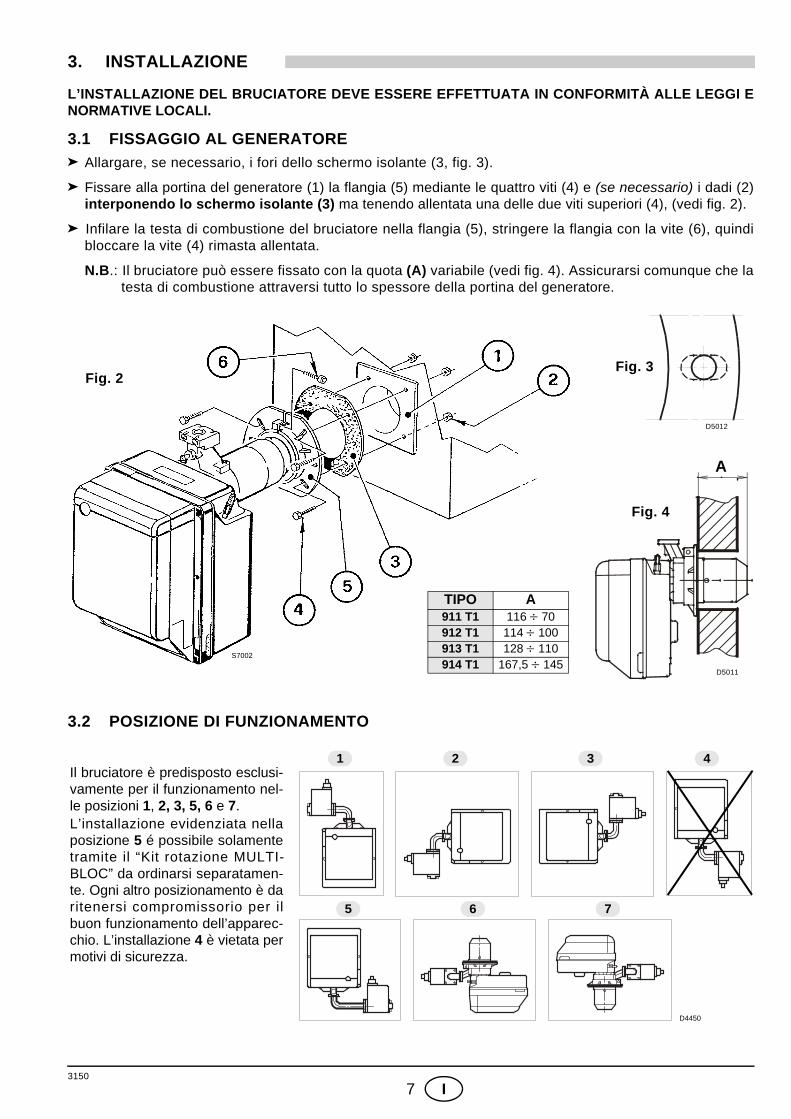
3.1 FISSAGGIO AL GENERATORE Allargare, se necessario, i fori dello schermo isolante (3, fig. 3).
Fissare alla portina del generatore (1) la flangia (5) mediante le quattro viti (4) e (se necessario) i dadi (2)interponendo lo schermo isolante (3) ma tenendo allentata una delle due viti superiori (4), (vedi fig. 2).
Infilare la testa di combustione del bruciatore nella flangia (5), stringere la flangia con la vite (6), quindibloccare la vite (4) rimasta allentata.
N.B.: Il bruciatore può essere fissato con la quota (A) variabile (vedi fig. 4). Assicurarsi comunque che latesta di combustione attraversi tutto lo spessore della portina del generatore.
3.2 POSIZIONE DI FUNZIONAMENTO
Fig. 2Fig. 3
Fig. 4
TIPO A911 T1 116 ÷ 70912 T1 114 ÷ 100913 T1 128 ÷ 110914 T1 167,5 ÷ 145
A
D5012
D5011
S7002
Il bruciatore è predisposto esclusi-vamente per il funzionamento nel-le posizioni 1, 2, 3, 5, 6 e 7. L’installazione evidenziata nellaposizione 5 é possibile solamentetramite il “Kit rotazione MULTI-BLOC” da ordinarsi separatamen-te. Ogni altro posizionamento è daritenersi compromissorio per ilbuon funzionamento dell’apparec-chio. L’installazione 4 è vietata permotivi di sicurezza.
D4450
1 2 3 4
5 6 7
3150
8 I
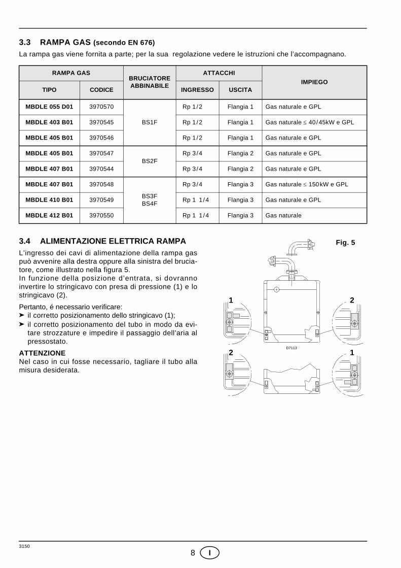
3.3 RAMPA GAS (secondo EN 676)La rampa gas viene fornita a parte; per la sua regolazione vedere le istruzioni che l’accompagnano.
3.4 ALIMENTAZIONE ELETTRICA RAMPAL’ingresso dei cavi di alimentazione della rampa gaspuò avvenire alla destra oppure alla sinistra del brucia-tore, come illustrato nella figura 5.In funzione della posizione d’entrata, si dovrannoinvertire lo stringicavo con presa di pressione (1) e lostringicavo (2).
Pertanto, é necessario verificare:il corretto posizionamento dello stringicavo (1);il corretto posizionamento del tubo in modo da evi-tare strozzature e impedire il passaggio dell’aria alpressostato.
ATTENZIONENel caso in cui fosse necessario, tagliare il tubo allamisura desiderata.
RAMPA GASBRUCIATOREABBINABILE
ATTACCHIIMPIEGO
TIPO CODICE INGRESSO USCITA
MBDLE 055 D01 3970570
BS1F
Rp 1 /2 Flangia 1 Gas naturale e GPL
MBDLE 403 B01 3970545 Rp 1 /2 Flangia 1 Gas naturale ≤ 40 /45kW e GPL
MBDLE 405 B01 3970546 Rp 1 /2 Flangia 1 Gas naturale e GPL
MBDLE 405 B01 3970547BS2F
Rp 3 /4 Flangia 2 Gas naturale e GPL
MBDLE 407 B01 3970544 Rp 3 /4 Flangia 2 Gas naturale e GPL
MBDLE 407 B01 3970548
BS3FBS4F
Rp 3 /4 Flangia 3 Gas naturale ≤ 150kW e GPL
MBDLE 410 B01 3970549 Rp 1 1 /4 Flangia 3 Gas naturale e GPL
MBDLE 412 B01 3970550 Rp 1 1 /4 Flangia 3 Gas naturale
2
1 2
1D7113
Fig. 5
3150
9 I
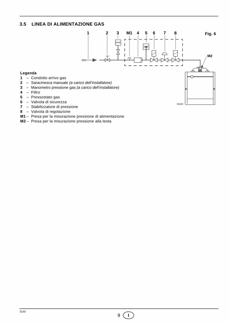
3.5 LINEA DI ALIMENTAZIONE GAS
M2
D5209
1 2 3 M1 5 6 74 8 Fig. 6
Legenda1 – Condotto arrivo gas2 – Saracinesca manuale (a carico dell’installatore)3 – Manometro pressione gas (a carico dell’installatore)4 – Filtro5 – Pressostato gas6 – Valvola di sicurezza7 – Stabilizzatore di pressione8 – Valvola di regolazione M1 – Presa per la misurazione pressione di alimentazioneM2 – Presa per la misurazione pressione alla testa
3150
10 I
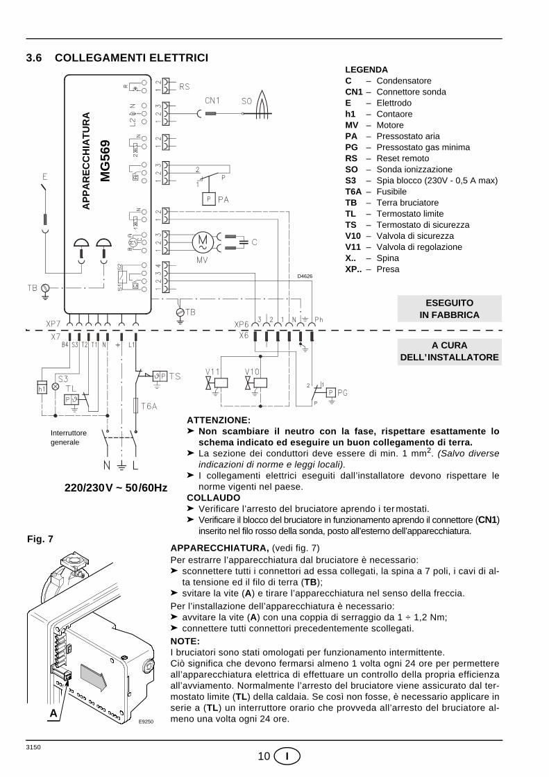
3.6 COLLEGAMENTI ELETTRICI
Interruttoregenerale
220/230V ~ 50/60Hz
D4626
ATTENZIONE:Non scambiare il neutro con la fase, rispettare esattamente loschema indicato ed eseguire un buon collegamento di terra.La sezione dei conduttori deve essere di min. 1 mm2. (Salvo diverseindicazioni di norme e leggi locali).I collegamenti elettrici eseguiti dall’installatore devono rispettare lenorme vigenti nel paese.
COLLAUDOVerificare l’arresto del bruciatore aprendo i ter mostati.Verificare il blocco del bruciatore in funzionamento aprendo il connettore (CN1)inserito nel filo rosso della sonda, posto all’esterno dell’apparecchiatura.
APPARECCHIATURA, (vedi fig. 7)Per estrarre l’apparecchiatura dal bruciatore è necessario:
sconnettere tutti i connettori ad essa collegati, la spina a 7 poli, i cavi di al-ta tensione ed il filo di terra (TB);svitare la vite (A) e tirare l’apparecchiatura nel senso della freccia.
Per l’installazione dell’apparecchiatura è necessario:avvitare la vite (A) con una coppia di serraggio da 1 ÷ 1,2 Nm;connettere tutti connettori precedentemente scollegati.
NOTE:I bruciatori sono stati omologati per funzionamento intermittente. Ciò significa che devono fermarsi almeno 1 volta ogni 24 ore per permettereall’apparecchiatura elettrica di effettuare un controllo della propria efficienzaall’avviamento. Normalmente l’arresto del bruciatore viene assicurato dal ter-mostato limite (TL) della caldaia. Se così non fosse, è necessario applicare inserie a (TL) un interruttore orario che provveda all’arresto del bruciatore al-meno una volta ogni 24 ore.
LEGENDAC – CondensatoreCN1 – Connettore sondaE – Elettrodoh1 – ContaoreMV – MotorePA – Pressostato ariaPG – Pressostato gas minimaRS – Reset remotoSO – Sonda ionizzazioneS3 – Spia blocco (230V - 0,5 A max)T6A – FusibileTB – Terra bruciatoreTL – Termostato limiteTS – Termostato di sicurezzaV10 – Valvola di sicurezzaV11 – Valvola di regolazioneX.. – Spina XP.. – Presa
MG
569
AP
PA
RE
CC
HIA
TUR
A
A
Fig. 7
A CURADELL’INSTALLATORE
ESEGUITOIN FABBRICA
E9250
3150
11 I
4. FUNZIONAMENTO4.1 REGOLAZIONE DELLA COMBUSTIONEL’applicazione del bruciatore al generatore di calore, la regolazione e il collaudo, devono essere eseguitinell’osservanza del manuale d’istruzione del generatore stesso, compreso il controllo della concentrazionedi CO e CO2 nei fumi, della loro temperatura e di quella media dell’acqua o dell’aria del generatore. A seconda della portata richiesta dal generatore vanno definite le regolazioni della testa di combustione edella serranda aria.
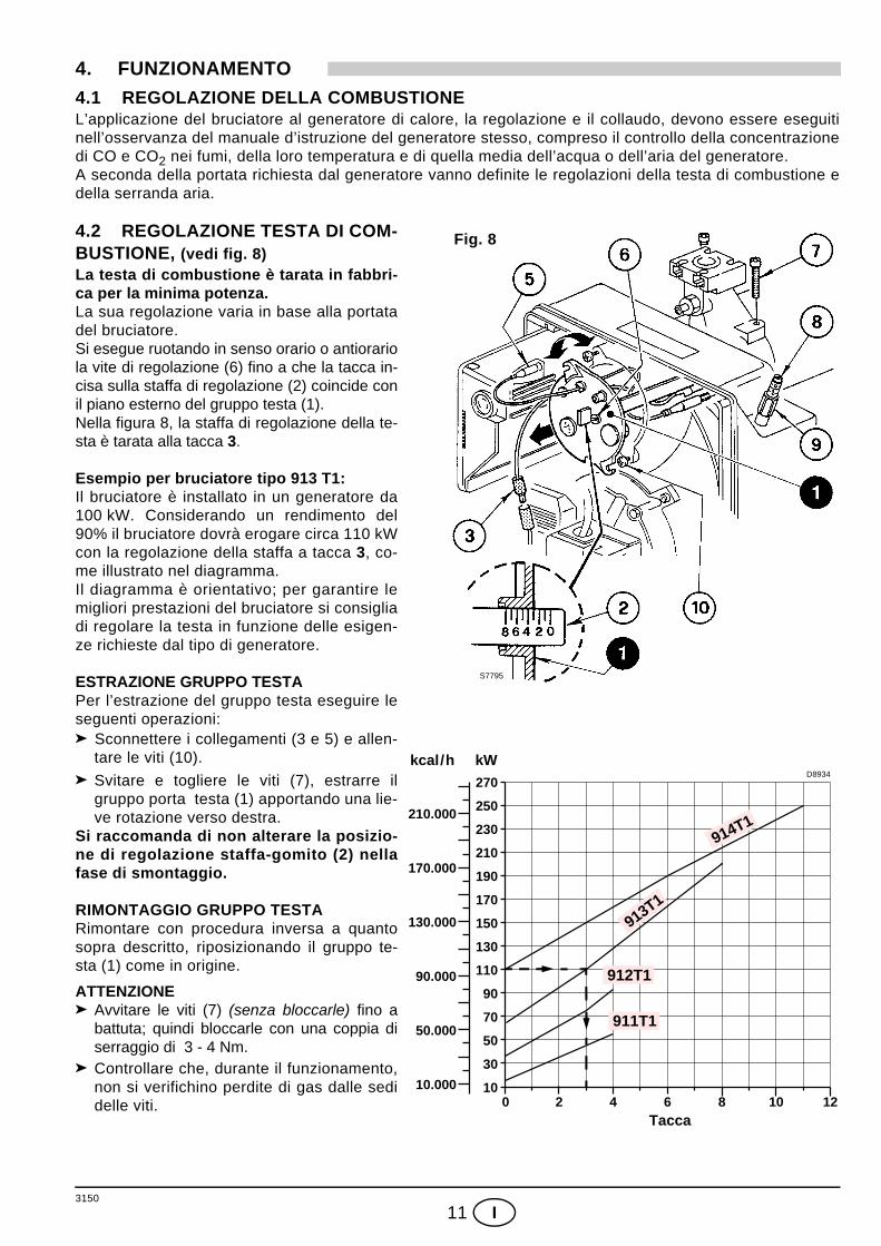
4.2 REGOLAZIONE TESTA DI COM-BUSTIONE, (vedi fig. 8)La testa di combustione è tarata in fabbri-ca per la minima potenza.La sua regolazione varia in base alla portatadel bruciatore.Si esegue ruotando in senso orario o antiorariola vite di regolazione (6) fino a che la tacca in-cisa sulla staffa di regolazione (2) coincide conil piano esterno del gruppo testa (1).Nella figura 8, la staffa di regolazione della te-sta è tarata alla tacca 3.
Esempio per bruciatore tipo 913 T1:Il bruciatore è installato in un generatore da100 kW. Considerando un rendimento del90% il bruciatore dovrà erogare circa 110 kWcon la regolazione della staffa a tacca 3, co-me illustrato nel diagramma.Il diagramma è orientativo; per garantire lemigliori prestazioni del bruciatore si consigliadi regolare la testa in funzione delle esigen-ze richieste dal tipo di generatore.
ESTRAZIONE GRUPPO TESTAPer l’estrazione del gruppo testa eseguire leseguenti operazioni:
Sconnettere i collegamenti (3 e 5) e allen-tare le viti (10).
Svitare e togliere le viti (7), estrarre ilgruppo porta testa (1) apportando una lie-ve rotazione verso destra.
Si raccomanda di non alterare la posizio-ne di regolazione staffa-gomito (2) nellafase di smontaggio.
RIMONTAGGIO GRUPPO TESTARimontare con procedura inversa a quantosopra descritto, riposizionando il gruppo te-sta (1) come in origine.
ATTENZIONEAvvitare le viti (7) (senza bloccarle) fino abattuta; quindi bloccarle con una coppia diserraggio di 3 - 4 Nm.Controllare che, durante il funzionamento,non si verifichino perdite di gas dalle sedidelle viti.
S7795
Fig. 8
Tacca
D8934
170.000
50.000
210.000
130.000
90.000
10.000
kcal/h kW
0 82 4 6
210
10
50
70
110
130
150
170
190
30
90
230
250
10
270
12
911T1
912T1
913T1
914T1
3150
12 I
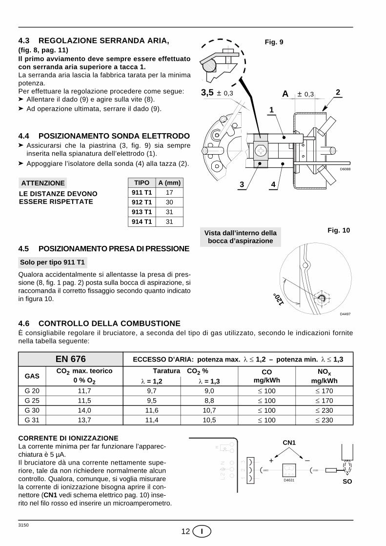
4.3 REGOLAZIONE SERRANDA ARIA, (fig. 8, pag. 11) Il primo avviamento deve sempre essere effettuatocon serranda aria superiore a tacca 1.La serranda aria lascia la fabbrica tarata per la minimapotenza.Per effettuare la regolazione procedere come segue:
Allentare il dado (9) e agire sulla vite (8).Ad operazione ultimata, serrare il dado (9).
4.4 POSIZIONAMENTO SONDA ELETTRODOAssicurarsi che la piastrina (3, fig. 9) sia sempreinserita nella spianatura dell’elettrodo (1).
Appoggiare l’isolatore della sonda (4) alla tazza (2).
4.5 POSIZIONAMENTO PRESA DI PRESSIONE
Qualora accidentalmente si allentasse la presa di pres-sione (8, fig. 1 pag. 2) posta sulla bocca di aspirazione, siraccomanda il corretto fissaggio secondo quanto indicatoin figura 10.
4.6 CONTROLLO DELLA COMBUSTIONEÈ consigliabile regolare il bruciatore, a seconda del tipo di gas utilizzato, secondo le indicazioni fornitenella tabella seguente:
CORRENTE DI IONIZZAZIONE La corrente minima per far funzionare l’apparec-chiatura è 5 µA.Il bruciatore dà una corrente nettamente supe-riore, tale da non richiedere normalmente alcuncontrollo. Qualora, comunque, si voglia misurarela corrente di ionizzazione bisogna aprire il con-nettore (CN1 vedi schema elettrico pag. 10) inse-rito nel filo rosso ed inserire un microamperometro.
EN 676 ECCESSO D’ARIA: potenza max. λ ≤ 1,2 – potenza min. λ ≤ 1,3
GASCO2 max. teorico
0 % O2
Taratura CO2 % COmg/kWh
NOxmg/kWhλ = 1,2 λ = 1,3
G 20 11,7 9,7 9,0 ≤ 100 ≤ 170G 25 11,5 9,5 8,8 ≤ 100 ≤ 170G 30 14,0 11,6 10,7 ≤ 100 ≤ 230G 31 13,7 11,4 10,5 ≤ 100 ≤ 230
D6088
± 0,3 3,5 ± 0,3 A
Fig. 9
1
3
2
4
Fig. 10
120°
D4497
Vista dall’interno dellabocca d’aspirazione
TIPO A (mm)911 T1 17
912 T1 30
913 T1 31
914 T1 31
LE DISTANZE DEVONO ATTENZIONE
ESSERE RISPETTATE
Solo per tipo 911 T1
D4631
+ _
SO
CN1
3150
13 I
4.7 PRESSOSTATO ARIA Eseguire la regolazione del pressostato aria dopo aver effettuato tutte le altre regolazioni del bruciatorecon il pressostato aria regolato a inizio scala. Con il bruciatore funzionante alla potenza minima aumentarela pressione di regolazione girando lentamente in senso orario l’apposita manopolina fino al blocco delbruciatore. Girare quindi in senso antiorario la manopolina di una tacca e ripetere l’avviamento delbruciatore per verificare la regolarità. Se il bruciatore si blocca nuovamente, girare ancora la manopolina dimezza tacca.Attenzione:In accordo con la norma EN 676, il pressostato aria deve intervenire prima che il CO nei fumi superi l’ 1%(10.000 ppm). Per accertarsi di ciò, inserire un analizzatore della combustione nel camino, chiudere lentamentela bocca di aspirazione del ventilatore e verificare che avvenga il blocco del bruciatore, prima che il CO nei fumisuperi l’ 1%.
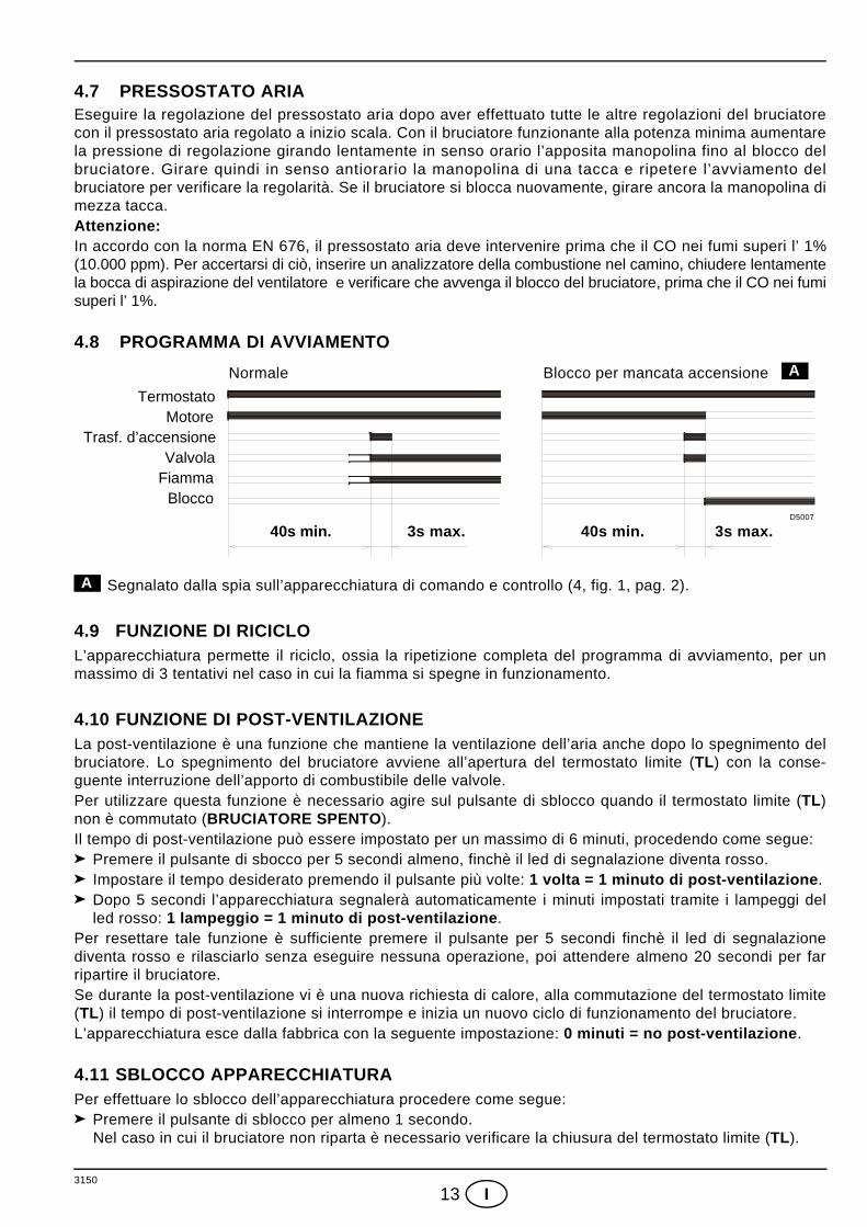
4.8 PROGRAMMA DI AVVIAMENTO
Segnalato dalla spia sull’apparecchiatura di comando e controllo (4, fig. 1, pag. 2).
4.9 FUNZIONE DI RICICLOL’apparecchiatura permette il riciclo, ossia la ripetizione completa del programma di avviamento, per unmassimo di 3 tentativi nel caso in cui la fiamma si spegne in funzionamento.
4.10 FUNZIONE DI POST-VENTILAZIONE La post-ventilazione è una funzione che mantiene la ventilazione dell’aria anche dopo lo spegnimento delbruciatore. Lo spegnimento del bruciatore avviene all’apertura del termostato limite (TL) con la conse-guente interruzione dell’apporto di combustibile delle valvole.Per utilizzare questa funzione è necessario agire sul pulsante di sblocco quando il termostato limite (TL)non è commutato (BRUCIATORE SPENTO).Il tempo di post-ventilazione può essere impostato per un massimo di 6 minuti, procedendo come segue:
Premere il pulsante di sbocco per 5 secondi almeno, finchè il led di segnalazione diventa rosso.Impostare il tempo desiderato premendo il pulsante più volte: 1 volta = 1 minuto di post-ventilazione.Dopo 5 secondi l’apparecchiatura segnalerà automaticamente i minuti impostati tramite i lampeggi delled rosso: 1 lampeggio = 1 minuto di post-ventilazione.
Per resettare tale funzione è sufficiente premere il pulsante per 5 secondi finchè il led di segnalazionediventa rosso e rilasciarlo senza eseguire nessuna operazione, poi attendere almeno 20 secondi per farripartire il bruciatore.Se durante la post-ventilazione vi è una nuova richiesta di calore, alla commutazione del termostato limite(TL) il tempo di post-ventilazione si interrompe e inizia un nuovo ciclo di funzionamento del bruciatore.L’apparecchiatura esce dalla fabbrica con la seguente impostazione: 0 minuti = no post-ventilazione.
4.11 SBLOCCO APPARECCHIATURA Per effettuare lo sblocco dell’apparecchiatura procedere come segue:
Premere il pulsante di sblocco per almeno 1 secondo. Nel caso in cui il bruciatore non riparta è necessario verificare la chiusura del termostato limite (TL).
TermostatoMotore
Trasf. d’accensioneValvola
FiammaBlocco
40s min. 3s max. 40s min. 3s max.
Blocco per mancata accensione ANormale
D5007
A
3150
14 I
5. MANUTENZIONEPrima di effettuare qualsiasi operazione di pulizia o controllo, togliere alimentazione elettrica al bru-ciatore agendo sull’interruttore generale dell’impianto e chiudere la valvola d’intercettazione del gas.Il bruciatore richiede una manutenzione periodica, che deve essere eseguita da personale abilitato e in con-formità alle leggi e normative locali.La periodica manutenzione è essenziale per un buon funzionamento del bruciatore; evita in questo modo con-sumi inutili di combustibile e riduce le emissioni inquinanti nell’ambiente.
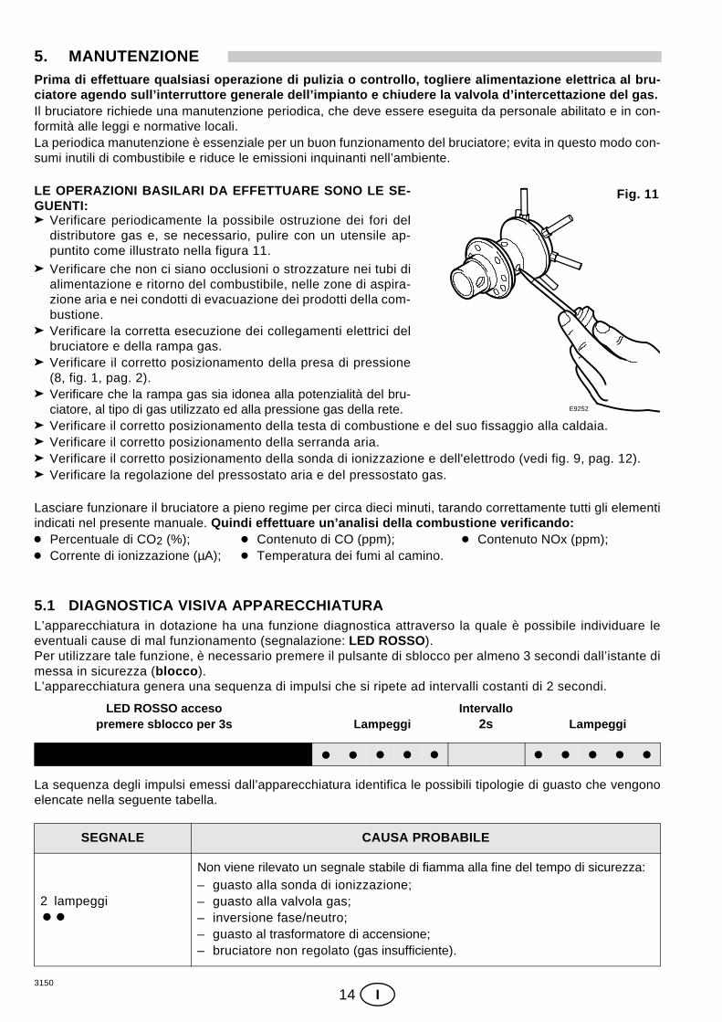
LE OPERAZIONI BASILARI DA EFFETTUARE SONO LE SE-GUENTI:
Verificare periodicamente la possibile ostruzione dei fori deldistributore gas e, se necessario, pulire con un utensile ap-puntito come illustrato nella figura 11.
Verificare che non ci siano occlusioni o strozzature nei tubi dialimentazione e ritorno del combustibile, nelle zone di aspira-zione aria e nei condotti di evacuazione dei prodotti della com-bustione.Verificare la corretta esecuzione dei collegamenti elettrici delbruciatore e della rampa gas.Verificare il corretto posizionamento della presa di pressione(8, fig. 1, pag. 2).Verificare che la rampa gas sia idonea alla potenzialità del bru-ciatore, al tipo di gas utilizzato ed alla pressione gas della rete.Verificare il corretto posizionamento della testa di combustione e del suo fissaggio alla caldaia.Verificare il corretto posizionamento della serranda aria.Verificare il corretto posizionamento della sonda di ionizzazione e dell'elettrodo (vedi fig. 9, pag. 12). Verificare la regolazione del pressostato aria e del pressostato gas.
Lasciare funzionare il bruciatore a pieno regime per circa dieci minuti, tarando correttamente tutti gli elementiindicati nel presente manuale. Quindi effettuare un’analisi della combustione verificando:
Percentuale di CO2 (%); Contenuto di CO (ppm); Contenuto NOx (ppm); Corrente di ionizzazione (µA); Temperatura dei fumi al camino.
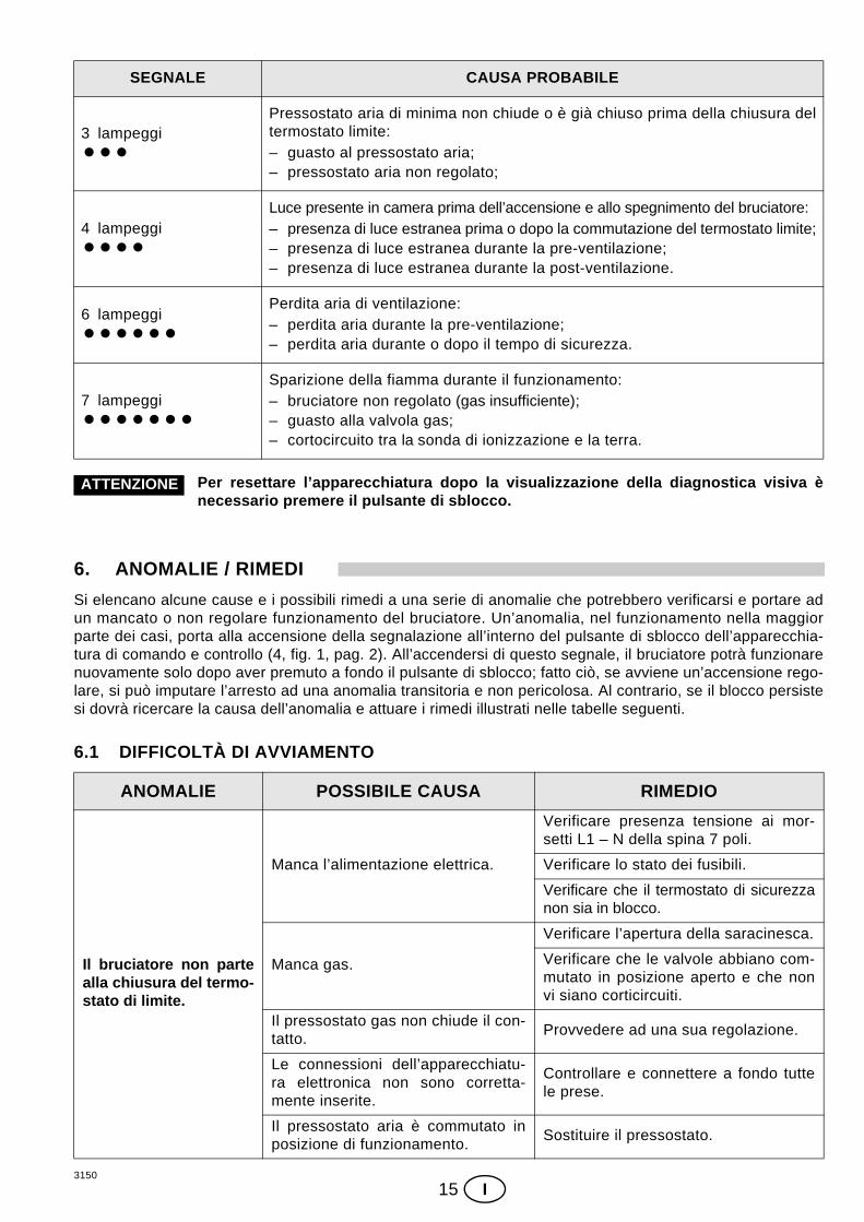
5.1 DIAGNOSTICA VISIVA APPARECCHIATURAL’apparecchiatura in dotazione ha una funzione diagnostica attraverso la quale è possibile individuare leeventuali cause di mal funzionamento (segnalazione: LED ROSSO).Per utilizzare tale funzione, è necessario premere il pulsante di sblocco per almeno 3 secondi dall’istante dimessa in sicurezza (blocco). L’apparecchiatura genera una sequenza di impulsi che si ripete ad intervalli costanti di 2 secondi.
La sequenza degli impulsi emessi dall’apparecchiatura identifica le possibili tipologie di guasto che vengonoelencate nella seguente tabella.
SEGNALE CAUSA PROBABILE
2 lampeggi
Non viene rilevato un segnale stabile di fiamma alla fine del tempo di sicurezza:– guasto alla sonda di ionizzazione;– guasto alla valvola gas;– inversione fase/neutro;– guasto al trasformatore di accensione;– bruciatore non regolato (gas insufficiente).
Fig. 11
E9252
2sLampeggi LampeggiLED ROSSO acceso
premere sblocco per 3sIntervallo
3150
15 I
Per resettare l’apparecchiatura dopo la visualizzazione della diagnostica visiva ènecessario premere il pulsante di sblocco.
6. ANOMALIE / RIMEDISi elencano alcune cause e i possibili rimedi a una serie di anomalie che potrebbero verificarsi e portare adun mancato o non regolare funzionamento del bruciatore. Un’anomalia, nel funzionamento nella maggiorparte dei casi, porta alla accensione della segnalazione all’interno del pulsante di sblocco dell’apparecchia-tura di comando e controllo (4, fig. 1, pag. 2). All’accendersi di questo segnale, il bruciatore potrà funzionarenuovamente solo dopo aver premuto a fondo il pulsante di sblocco; fatto ciò, se avviene un’accensione rego-lare, si può imputare l’arresto ad una anomalia transitoria e non pericolosa. Al contrario, se il blocco persistesi dovrà ricercare la causa dell’anomalia e attuare i rimedi illustrati nelle tabelle seguenti.
6.1 DIFFICOLTÀ DI AVVIAMENTO
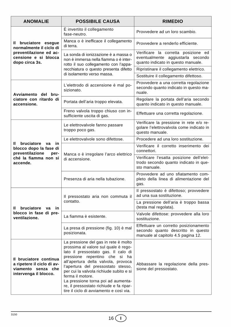
SEGNALE CAUSA PROBABILE
3 lampeggiPressostato aria di minima non chiude o è già chiuso prima della chiusura deltermostato limite:– guasto al pressostato aria;– pressostato aria non regolato;
4 lampeggiLuce presente in camera prima dell’accensione e allo spegnimento del bruciatore:– presenza di luce estranea prima o dopo la commutazione del termostato limite;– presenza di luce estranea durante la pre-ventilazione;– presenza di luce estranea durante la post-ventilazione.
6 lampeggiPerdita aria di ventilazione:– perdita aria durante la pre-ventilazione;– perdita aria durante o dopo il tempo di sicurezza.
7 lampeggiSparizione della fiamma durante il funzionamento:– bruciatore non regolato (gas insufficiente);– guasto alla valvola gas;– cortocircuito tra la sonda di ionizzazione e la terra.
ANOMALIE POSSIBILE CAUSA RIMEDIO
Il bruciatore non partealla chiusura del termo-stato di limite.
Manca l’alimentazione elettrica.
Verificare presenza tensione ai mor-setti L1 – N della spina 7 poli.
Verificare lo stato dei fusibili.
Verificare che il termostato di sicurezzanon sia in blocco.
Manca gas.
Verificare l’apertura della saracinesca.
Verificare che le valvole abbiano com-mutato in posizione aperto e che nonvi siano corticircuiti.
Il pressostato gas non chiude il con-tatto.
Provvedere ad una sua regolazione.
Le connessioni dell’apparecchiatu-ra elettronica non sono corretta-mente inserite.
Controllare e connettere a fondo tuttele prese.
Il pressostato aria è commutato inposizione di funzionamento.
Sostituire il pressostato.
ATTENZIONE
3150
16 I
Il bruciatore eseguenormalmente il ciclo dipreventilazione ed ac-censione e si bloccadopo circa 3s.
È invertito il collegamentofase-neutro.
Provvedere ad un loro scambio.
Manca o è inefficace il collegamentodi terra.
Provvedere a renderlo efficiente.
La sonda di ionizzazione è a massa onon è immersa nella fiamma o è inter-rotto il suo collegamento con l’appa-recchiatura o questo presenta difettodi isolamento verso massa.
Verificare la corretta posizione edeventualmente aggiustarla secondoquanto indicato in questo manuale.
Ripristinare il collegamento elettrico.
Sostituire il collegamento difettoso.
Avviamento del bru-ciatore con ritardo diaccensione.
L’elettrodo di accensione è mal po-sizionato.
Provvedere a una corretta regolazionesecondo quanto indicato in questo ma-nuale.
Portata dell’aria troppo elevata.Regolare la portata dell’aria secondoquanto indicato in questo manuale.
Freno valvola troppo chiuso con in-sufficiente uscita di gas.
Effettuare una corretta regolazione.
Il bruciatore va inblocco dopo la fase dipreventilazione per-ché la fiamma non siaccende.
Le elettrovalvole fanno passare troppo poco gas.
Verificare la pressione in rete e/o re-golare l’elettrovalvola come indicato inquesto manuale.
Le elettrovalvole sono difettose. Procedere ad una loro sostituzione.
Manca o è irregolare l’arco elettricodi accensione.
Verificare il corretto inserimento deiconnettori.
Verificare l’esatta posizione dell’elet-trodo secondo quanto indicato in que-sto manuale.
Presenza di aria nella tubazione.Provvedere ad uno sfiatamento com-pleto della linea di alimentazione delgas.
Il bruciatore va inblocco in fase di pre-ventilazione.
Il pressostato aria non commuta ilcontatto.
Il pressostato è difettoso; provvederead una sua sostituzione.
La pressione dell’aria è troppo bassa(testa mal regolata).
La fiamma è esistente.Valvole difettose: provvedere alla lorosostituzione.
La presa di pressione (fig. 10) è malposizionata.
Effettuare un corretto posizionamentosecondo quanto descritto in questomanuale al capitolo 4.5 pagina 12.
Il bruciatore continuaa ripetere il ciclo di av-viamento senza cheintervenga il blocco.
La pressione del gas in rete è moltoprossima al valore sul quale è rego-lato il pressostato gas. Il calo dipressione repentino che si haall’apertura della valvola, provocal’apertura del pressostato stesso,per cui la valvola richiude subito e siferma il motore. La pressione torna poi ad aumenta-re, il pressostato richiude e fa ripar-tire il ciclo di avviamento e così via.
Abbassare la regolazione della pres-sione del pressostato.
ANOMALIE POSSIBILE CAUSA RIMEDIO
3150
17 I
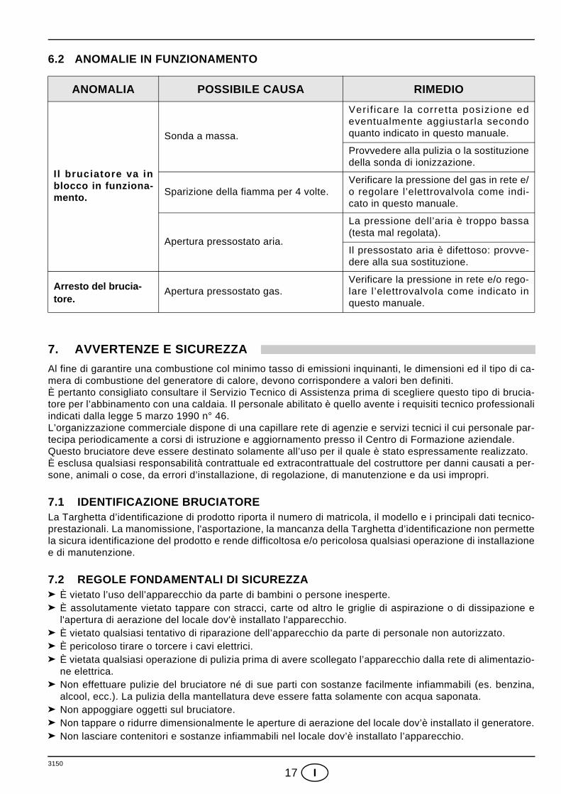
6.2 ANOMALIE IN FUNZIONAMENTO
7. AVVERTENZE E SICUREZZAAl fine di garantire una combustione col minimo tasso di emissioni inquinanti, le dimensioni ed il tipo di ca-mera di combustione del generatore di calore, devono corrispondere a valori ben definiti.È pertanto consigliato consultare il Servizio Tecnico di Assistenza prima di scegliere questo tipo di brucia-tore per l’abbinamento con una caldaia. Il personale abilitato è quello avente i requisiti tecnico professionaliindicati dalla legge 5 marzo 1990 n° 46.L’organizzazione commerciale dispone di una capillare rete di agenzie e servizi tecnici il cui personale par-tecipa periodicamente a corsi di istruzione e aggiornamento presso il Centro di Formazione aziendale. Questo bruciatore deve essere destinato solamente all’uso per il quale è stato espressamente realizzato. È esclusa qualsiasi responsabilità contrattuale ed extracontrattuale del costruttore per danni causati a per-sone, animali o cose, da errori d’installazione, di regolazione, di manutenzione e da usi impropri.
7.1 IDENTIFICAZIONE BRUCIATORELa Targhetta d’identificazione di prodotto riporta il numero di matricola, il modello e i principali dati tecnico-prestazionali. La manomissione, l'asportazione, la mancanza della Targhetta d’identificazione non permettela sicura identificazione del prodotto e rende difficoltosa e/o pericolosa qualsiasi operazione di installazionee di manutenzione.
7.2 REGOLE FONDAMENTALI DI SICUREZZAÈ vietato l’uso dell’apparecchio da parte di bambini o persone inesperte.È assolutamente vietato tappare con stracci, carte od altro le griglie di aspirazione o di dissipazione el'apertura di aerazione del locale dov'è installato l'apparecchio.È vietato qualsiasi tentativo di riparazione dell’apparecchio da parte di personale non autorizzato.È pericoloso tirare o torcere i cavi elettrici.È vietata qualsiasi operazione di pulizia prima di avere scollegato l’apparecchio dalla rete di alimentazio-ne elettrica. Non effettuare pulizie del bruciatore né di sue parti con sostanze facilmente infiammabili (es. benzina,alcool, ecc.). La pulizia della mantellatura deve essere fatta solamente con acqua saponata.Non appoggiare oggetti sul bruciatore.Non tappare o ridurre dimensionalmente le aperture di aerazione del locale dov’è installato il generatore.Non lasciare contenitori e sostanze infiammabili nel locale dov’è installato l’apparecchio.
ANOMALIA POSSIBILE CAUSA RIMEDIO
Il bruciatore va inblocco in funziona-mento.
Sonda a massa.
Veri f icare la corretta posizione edeventualmente aggiustarla secondoquanto indicato in questo manuale.
Provvedere alla pulizia o la sostituzionedella sonda di ionizzazione.
Sparizione della fiamma per 4 volte.Verificare la pressione del gas in rete e/o regolare l’elettrovalvola come indi-cato in questo manuale.
Apertura pressostato aria.
La pressione dell’aria è troppo bassa(testa mal regolata).
Il pressostato aria è difettoso: provve-dere alla sua sostituzione.
Arresto del brucia-tore.
Apertura pressostato gas.Verificare la pressione in rete e/o rego-lare l’elettrovalvola come indicato inquesto manuale.

3150
1 D
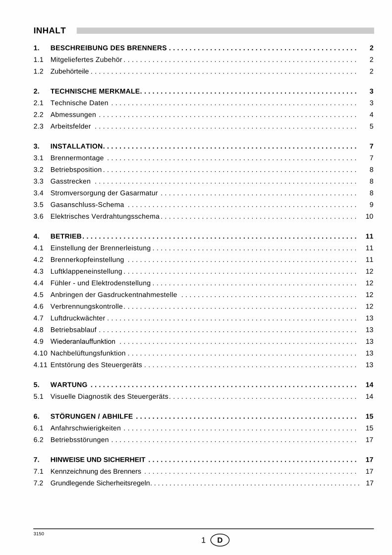
INHALT
1. BESCHREIBUNG DES BRENNERS . . . . . . . . . . . . . . . . . . . . . . . . . . . . . . . . . . . . . . . . . . . . . . 2
1.1 Mitgeliefertes Zubehör . . . . . . . . . . . . . . . . . . . . . . . . . . . . . . . . . . . . . . . . . . . . . . . . . . . . . . . . . 2
1.2 Zubehörteile . . . . . . . . . . . . . . . . . . . . . . . . . . . . . . . . . . . . . . . . . . . . . . . . . . . . . . . . . . . . . . . . . 2
2. TECHNISCHE MERKMALE. . . . . . . . . . . . . . . . . . . . . . . . . . . . . . . . . . . . . . . . . . . . . . . . . . . . . 3
2.1 Technische Daten . . . . . . . . . . . . . . . . . . . . . . . . . . . . . . . . . . . . . . . . . . . . . . . . . . . . . . . . . . . . 3
2.2 Abmessungen . . . . . . . . . . . . . . . . . . . . . . . . . . . . . . . . . . . . . . . . . . . . . . . . . . . . . . . . . . . . . . . 4
2.3 Arbeitsfelder . . . . . . . . . . . . . . . . . . . . . . . . . . . . . . . . . . . . . . . . . . . . . . . . . . . . . . . . . . . . . . . . 5
3. INSTALLATION. . . . . . . . . . . . . . . . . . . . . . . . . . . . . . . . . . . . . . . . . . . . . . . . . . . . . . . . . . . . . . 7
3.1 Brennermontage . . . . . . . . . . . . . . . . . . . . . . . . . . . . . . . . . . . . . . . . . . . . . . . . . . . . . . . . . . . . . 7
3.2 Betriebsposition . . . . . . . . . . . . . . . . . . . . . . . . . . . . . . . . . . . . . . . . . . . . . . . . . . . . . . . . . . . . . . 8
3.3 Gasstrecken . . . . . . . . . . . . . . . . . . . . . . . . . . . . . . . . . . . . . . . . . . . . . . . . . . . . . . . . . . . . . . . . 8
3.4 Stromversorgung der Gasarmatur . . . . . . . . . . . . . . . . . . . . . . . . . . . . . . . . . . . . . . . . . . . . . . . . 8
3.5 Gasanschluss-Schema . . . . . . . . . . . . . . . . . . . . . . . . . . . . . . . . . . . . . . . . . . . . . . . . . . . . . . . . 9
3.6 Elektrisches Verdrahtungsschema . . . . . . . . . . . . . . . . . . . . . . . . . . . . . . . . . . . . . . . . . . . . . . . . 10
4. BETRIEB. . . . . . . . . . . . . . . . . . . . . . . . . . . . . . . . . . . . . . . . . . . . . . . . . . . . . . . . . . . . . . . . . . . 11
4.1 Einstellung der Brennerleistung . . . . . . . . . . . . . . . . . . . . . . . . . . . . . . . . . . . . . . . . . . . . . . . . . . 11
4.2 Brennerkopfeinstellung . . . . . . . . . . . . . . . . . . . . . . . . . . . . . . . . . . . . . . . . . . . . . . . . . . . . . . . . 11
4.3 Luftklappeneinstellung . . . . . . . . . . . . . . . . . . . . . . . . . . . . . . . . . . . . . . . . . . . . . . . . . . . . . . . . . 12
4.4 Fühler - und Elektrodenstellung . . . . . . . . . . . . . . . . . . . . . . . . . . . . . . . . . . . . . . . . . . . . . . . . . . 12
4.5 Anbringen der Gasdruckentnahmestelle . . . . . . . . . . . . . . . . . . . . . . . . . . . . . . . . . . . . . . . . . . . 12
4.6 Verbrennungskontrolle . . . . . . . . . . . . . . . . . . . . . . . . . . . . . . . . . . . . . . . . . . . . . . . . . . . . . . . . . 12
4.7 Luftdruckwächter . . . . . . . . . . . . . . . . . . . . . . . . . . . . . . . . . . . . . . . . . . . . . . . . . . . . . . . . . . . . . 13
4.8 Betriebsablauf . . . . . . . . . . . . . . . . . . . . . . . . . . . . . . . . . . . . . . . . . . . . . . . . . . . . . . . . . . . . . . . 13
4.9 Wiederanlauffunktion . . . . . . . . . . . . . . . . . . . . . . . . . . . . . . . . . . . . . . . . . . . . . . . . . . . . . . . . . . 13
4.10 Nachbelüftungsfunktion . . . . . . . . . . . . . . . . . . . . . . . . . . . . . . . . . . . . . . . . . . . . . . . . . . . . . . . . 13
4.11 Entstörung des Steuergeräts . . . . . . . . . . . . . . . . . . . . . . . . . . . . . . . . . . . . . . . . . . . . . . . . . . . . 13
5. WARTUNG . . . . . . . . . . . . . . . . . . . . . . . . . . . . . . . . . . . . . . . . . . . . . . . . . . . . . . . . . . . . . . . . . 14
5.1 Visuelle Diagnostik des Steuergeräts. . . . . . . . . . . . . . . . . . . . . . . . . . . . . . . . . . . . . . . . . . . . . . 14
6. STÖRUNGEN / ABHILFE . . . . . . . . . . . . . . . . . . . . . . . . . . . . . . . . . . . . . . . . . . . . . . . . . . . . . . 15
6.1 Anfahrschwierigkeiten . . . . . . . . . . . . . . . . . . . . . . . . . . . . . . . . . . . . . . . . . . . . . . . . . . . . . . . . . 15
6.2 Betriebsstörungen . . . . . . . . . . . . . . . . . . . . . . . . . . . . . . . . . . . . . . . . . . . . . . . . . . . . . . . . . . . . 17
7. HINWEISE UND SICHERHEIT . . . . . . . . . . . . . . . . . . . . . . . . . . . . . . . . . . . . . . . . . . . . . . . . . . . 17
7.1 Kennzeichnung des Brenners . . . . . . . . . . . . . . . . . . . . . . . . . . . . . . . . . . . . . . . . . . . . . . . . . . . . 17
7.2 Grundlegende Sicherheitsregeln. . . . . . . . . . . . . . . . . . . . . . . . . . . . . . . . . . . . . . . . . . . . . . . . . . . . . . . 17
3150
2 D
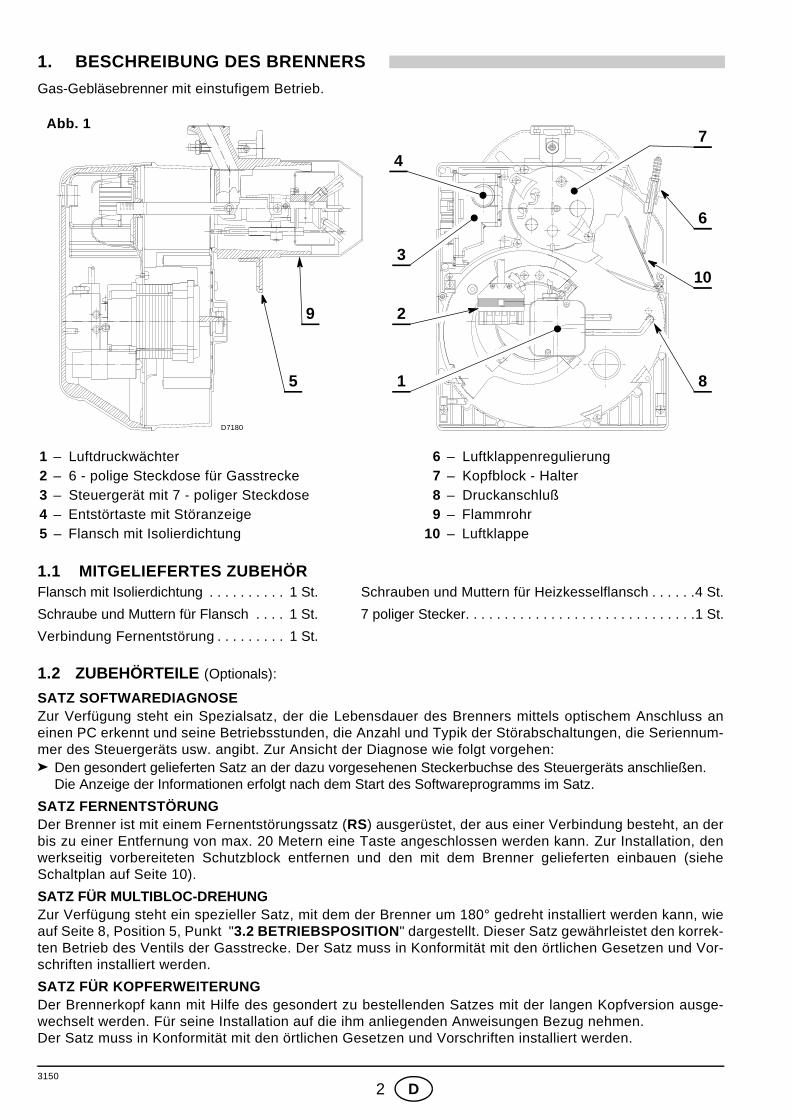
1. BESCHREIBUNG DES BRENNERSGas-Gebläsebrenner mit einstufigem Betrieb.
1.1 MITGELIEFERTES ZUBEHÖRFlansch mit Isolierdichtung . . . . . . . . . . 1 St. Schrauben und Muttern für Heizkesselflansch . . . . . .4 St.
Schraube und Muttern für Flansch . . . . 1 St. 7 poliger Stecker. . . . . . . . . . . . . . . . . . . . . . . . . . . . . .1 St.
Verbindung Fernentstörung . . . . . . . . . 1 St.
1.2 ZUBEHÖRTEILE (Optionals):
SATZ SOFTWAREDIAGNOSEZur Verfügung steht ein Spezialsatz, der die Lebensdauer des Brenners mittels optischem Anschluss aneinen PC erkennt und seine Betriebsstunden, die Anzahl und Typik der Störabschaltungen, die Seriennum-mer des Steuergeräts usw. angibt. Zur Ansicht der Diagnose wie folgt vorgehen:
Den gesondert gelieferten Satz an der dazu vorgesehenen Steckerbuchse des Steuergeräts anschließen. Die Anzeige der Informationen erfolgt nach dem Start des Softwareprogramms im Satz.
SATZ FERNENTSTÖRUNGDer Brenner ist mit einem Fernentstörungssatz (RS) ausgerüstet, der aus einer Verbindung besteht, an derbis zu einer Entfernung von max. 20 Metern eine Taste angeschlossen werden kann. Zur Installation, denwerkseitig vorbereiteten Schutzblock entfernen und den mit dem Brenner gelieferten einbauen (sieheSchaltplan auf Seite 10).
SATZ FÜR MULTIBLOC-DREHUNGZur Verfügung steht ein spezieller Satz, mit dem der Brenner um 180° gedreht installiert werden kann, wieauf Seite 8, Position 5, Punkt "3.2 BETRIEBSPOSITION" dargestellt. Dieser Satz gewährleistet den korrek-ten Betrieb des Ventils der Gasstrecke. Der Satz muss in Konformität mit den örtlichen Gesetzen und Vor-schriften installiert werden.
SATZ FÜR KOPFERWEITERUNGDer Brennerkopf kann mit Hilfe des gesondert zu bestellenden Satzes mit der langen Kopfversion ausge-wechselt werden. Für seine Installation auf die ihm anliegenden Anweisungen Bezug nehmen. Der Satz muss in Konformität mit den örtlichen Gesetzen und Vorschriften installiert werden.
1 – Luftdruckwächter2 – 6 - polige Steckdose für Gasstrecke3 – Steuergerät mit 7 - poliger Steckdose4 – Entstörtaste mit Störanzeige5 – Flansch mit Isolierdichtung
6 – Luftklappenregulierung 7 – Kopfblock - Halter 8 – Druckanschluß 9 – Flammrohr10 – Luftklappe
Abb. 1
D7180
4
3
2
1
9
8
6
5
10
7
3150
3 D
SATZ FÜR FLÜSSIGGASZur Verfügung steht ein spezieller Satz, der nach der Montage an den Kopf von Erdgasbrennern den Betrieb mitFlüssiggas ermöglicht. Für die Installation des “Flüssiggassatzes” auf die ihm anliegenden Anweisungen Bezug nehmen. Der Satz muss in Konformität mit den örtlichen Gesetzen und Vorschriften installiert werden.
SATZ ALTERNATIVER FLAMMKOPFDer Satz kann verwendet werden, um bei besonderen Anwendungen eine Verbrennungsunstabilität zu vermei-den. Der Satz muss in Konformität mit den örtlichen Gesetzen und Vorschriften installiert werden.
SATZ DICHTHEITSKONTROLLEZur Verfügung steht ein spezieller Satz für die Überprüfung der Dichtheit des Ventils der Gasstrecke.
Dieser Satz kann an Gasstrecken mit Ventil MULTIBLOC MBDLE 055 nicht verwendet werden.
Der Satz muss in Konformität mit den örtlichen Gesetzen und Vorschriften installiert werden.
2. TECHNISCHE MERKMALE
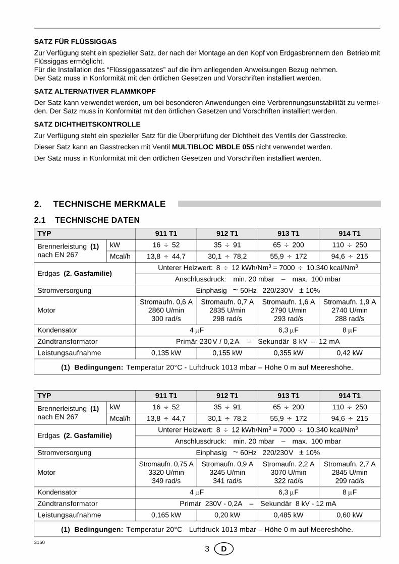
2.1 TECHNISCHE DATEN TYP 911 T1 912 T1 913 T1 914 T1
Brennerleistung (1)nach EN 267
kW 16 ÷ 52 35 ÷ 91 65 ÷ 200 110 ÷ 250
Mcal/h 13,8 ÷ 44,7 30,1 ÷ 78,2 55,9 ÷ 172 94,6 ÷ 215
Erdgas (2. Gasfamilie)Unterer Heizwert: 8 ÷ 12 kWh/Nm3 = 7000 ÷ 10.340 kcal/Nm3
Anschlussdruck: min. 20 mbar – max. 100 mbar
Stromversorgung Einphasig ~ 50Hz 220/230V ± 10%
MotorStromaufn. 0,6 A
2860 U/min300 rad/s
Stromaufn. 0,7 A2835 U/min298 rad/s
Stromaufn. 1,6 A2790 U/min293 rad/s
Stromaufn. 1,9 A2740 U/min288 rad/s
Kondensator 4 µF 6,3 µF 8 µF
Zündtransformator Primär 230V / 0,2A – Sekundär 8 kV – 12 mA
Leistungsaufnahme 0,135 kW 0,155 kW 0,355 kW 0,42 kW
(1) Bedingungen: Temperatur 20°C - Luftdruck 1013 mbar – Höhe 0 m auf Meereshöhe.
TYP 911 T1 912 T1 913 T1 914 T1
Brennerleistung (1)nach EN 267
kW 16 ÷ 52 35 ÷ 91 65 ÷ 200 110 ÷ 250
Mcal/h 13,8 ÷ 44,7 30,1 ÷ 78,2 55,9 ÷ 172 94,6 ÷ 215
Erdgas (2. Gasfamilie)Unterer Heizwert: 8 ÷ 12 kWh/Nm3 = 7000 ÷ 10.340 kcal/Nm3
Anschlussdruck: min. 20 mbar – max. 100 mbar
Stromversorgung Einphasig ~ 60Hz 220/230V ± 10%
MotorStromaufn. 0,75 A
3320 U/min349 rad/s
Stromaufn. 0,9 A3245 U/min341 rad/s
Stromaufn. 2,2 A3070 U/min322 rad/s
Stromaufn. 2,7 A2845 U/min299 rad/s
Kondensator 4 µF 6,3 µF 8 µF
Zündtransformator Primär 230V - 0,2A – Sekundär 8 kV - 12 mA
Leistungsaufnahme 0,165 kW 0,20 kW 0,485 kW 0,60 kW
(1) Bedingungen: Temperatur 20°C - Luftdruck 1013 mbar – Höhe 0 m auf Meereshöhe.

3150
4 D
Erdgasversorgung (2. Gasfamilie) für die verschiedenen Länder:
ANMERKUNG:Für Brenner, die mit Flüssiggas funktionieren (3. Gasfamilie) sollte gesondert ein spezieller Bausatzangefordert werden.
2.2 ABMESSUNGEN
LAND AT - IT - DK - CH GB - IE DE FR NL LU BE
GASKATEGORIE II2H3B/P II2H3P II2ELL3B/P II2Er3P II2L3B/P II2E3B/P I2E(R)B, I3P
GAS-ANSCHLUSS DRUCK
G20 H 20 – – – – – –
G25 L – 25 20 – 25 25 –
G20 E – – 20 20/25 – – 20/25
TYP A B C D E F G H I L M N O P R S
911T1 234 254 295 122,0 112,0 346 230 ÷276 116 ÷70 174 89 210 192 66 167 140 170
912T1 255 280 325 125,5 125,5 352 238 ÷252 114 ÷100 174 106 230 192 66 167 140 170
913T1 300 345 391 150,0 150,0 390 262 ÷280 128 ÷110 196 129 285 216 76,5 201 160 190
914T1 300 345 392 150,0 150,0 446 278 ÷301 168 ÷145 216 137 286 218 80,5 203 170 200
F
HG
AD E
I
R
S
N
45°
45° 11
OP
B
C
M
ø L
D5008
3150
5 D
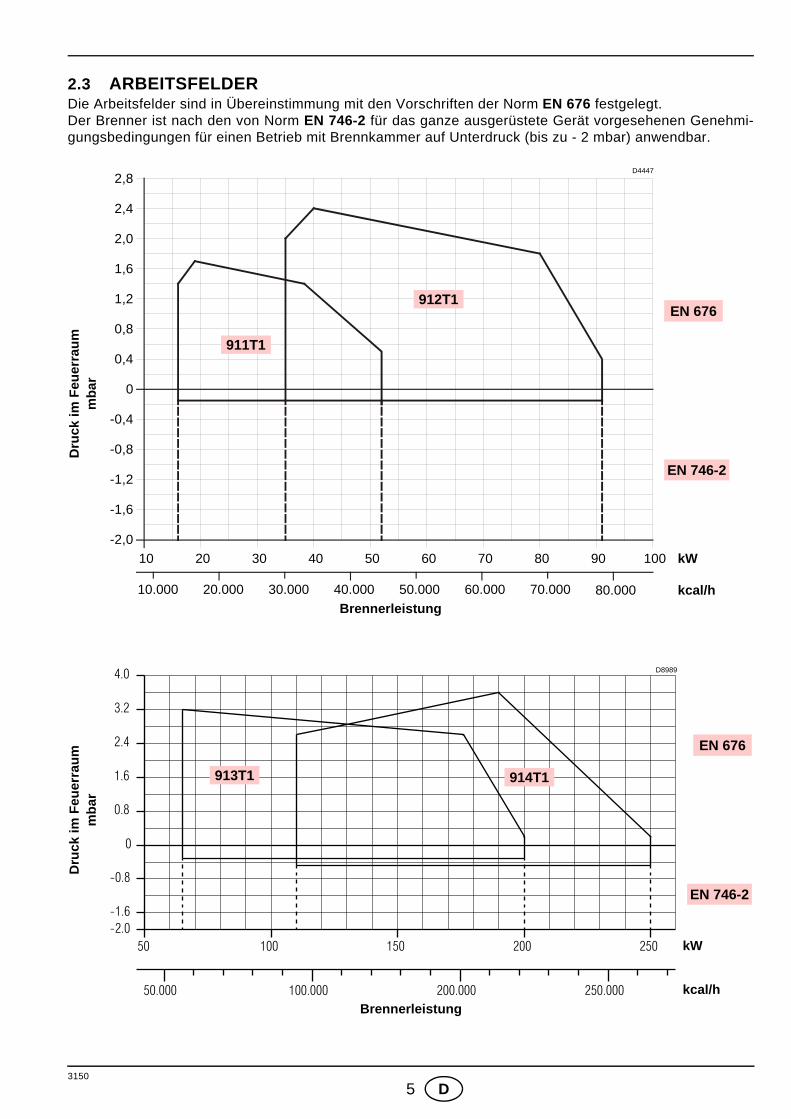
2.3 ARBEITSFELDER Die Arbeitsfelder sind in Übereinstimmung mit den Vorschriften der Norm EN 676 festgelegt.Der Brenner ist nach den von Norm EN 746-2 für das ganze ausgerüstete Gerät vorgesehenen Genehmi-gungsbedingungen für einen Betrieb mit Brennkammer auf Unterdruck (bis zu - 2 mbar) anwendbar.
Brennerleistung
Dru
ck im
Feu
erra
umm
bar
Brennerleistung
Dru
ck im
Feu
erra
umm
bar
10.000 80.000
kW10
kcal/h
2,4
0,8
0,4
0
D4447
20 30 40 50 60 70 80 90 100
1,2
1,6
2,0
20.000 30.000 40.000 50.000 60.000 70.000
2,8
-0,4
-0,8
-1,2
-1,6
-2,0
EN 676
EN 746-2
911T1
912T1
50 100 150 200 250
50.000 100.000 200.000 250.000
0
0.8
1.6
2.4
3.2
4.0
-0.8
-1.6-2.0
kW
kcal/h
D8989
913T1 914T1
EN 676
EN 746-2

3150
6 D
HEIZKESSELDas Arbeitsfeld wurde an einem Heizkessel, gemäß der Norm EN 676, ermittelt.
HANDELSÜBLICHE HEIZKESSELDie Vereinigung von Brenner und Wärmeerzeuger gibt keine Probleme, falls Heizkessel und Brennkam-merabmessungen jenen von Norm EN 676 vorgesehenen ähneln. Wird der Brenner dagegen mit einem handelsüblichen Heizkessel vereint und die Brennkammerabmessun-gen sind entschieden kleiner als jene von Norm EN 676 angegeben, so müssen die Hersteller zu Rategezogen werden.
VOM GASDRUCK AM BRENNERKOPF ABHÄNGIGE BRENNERLEISTUNGBei einem an dem Verbindungsrohr (M2, siehe Kap. 3.5, Seite 9) gemessenen Druck von 9,3 mbar, hin-sichtlich des Modells 912 T1, mit einem feuerraumseitigen Druck von 0 mbar und mit Gas G20 - untererHeizwert = 10 kWh/Nm3 (8.570 kcal/Nm3), erreicht man die Höchstleistung.
Brennerleistung
Gas
druc
k im
mba
ram
Bre
nner
kopf
D8933
0 50 100 150 200 kW
0 50.000 100.000 150.000 kcal/h
10
8
6
4
2
0250
200.000
12
911T
1 912T
1 913T1
914T1
3150
7 D
3. INSTALLATION
DIE INSTALLATION DES BRENNERS MUSS IN ÜBEREINSTIMMUNG MIT DEN ÖRTLICHEN GESETZENUND VORSCHRIFTEN AUSGEFÜHRT WERDEN.
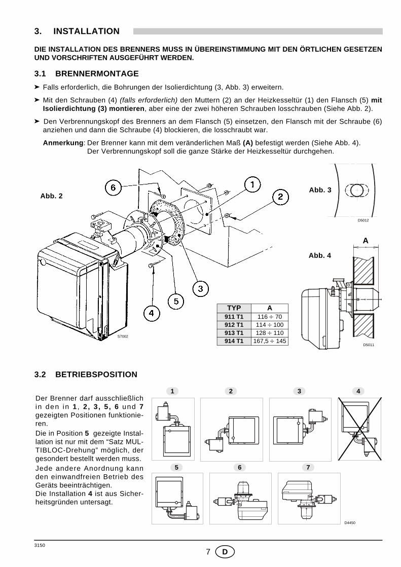
3.1 BRENNERMONTAGE Falls erforderlich, die Bohrungen der Isolierdichtung (3, Abb. 3) erweitern.
Mit den Schrauben (4) (falls erforderlich) den Muttern (2) an der Heizkesseltür (1) den Flansch (5) mitIsolierdichtung (3) montieren, aber eine der zwei höheren Schrauben losschrauben (Siehe Abb. 2).
Den Verbrennungskopf des Brenners an dem Flansch (5) einsetzen, den Flansch mit der Schraube (6)anziehen und dann die Schraube (4) blockieren, die losschraubt war.
Anmerkung: Der Brenner kann mit dem veränderlichen Maß (A) befestigt werden (Siehe Abb. 4). Der Verbrennungskopf soll die ganze Stärke der Heizkesseltür durchgehen.
3.2 BETRIEBSPOSITION
Abb. 2Abb. 3
Abb. 4
TYP A911 T1 116 ÷ 70912 T1 114 ÷ 100913 T1 128 ÷ 110914 T1 167,5 ÷ 145
A
D5012
D5011
S7002
Der Brenner darf ausschließlichin den in 1 , 2, 3 , 5 , 6 und 7gezeigten Positionen funktionie-ren. Die in Position 5 gezeigte Instal-lation ist nur mit dem “Satz MUL-TIBLOC-Drehung” möglich, dergesondert bestellt werden muss. Jede andere Anordnung kannden einwandfreien Betrieb desGeräts beeinträchtigen. Die Installation 4 ist aus Sicher-heitsgründen untersagt.
D4450
1 2 3 4
5 6 7
3150
8 D
3.3 GASSTRECKE, (nach EN 676)Die Gasstrecke wird extra bestellt; die Einregulierung wird entsprechend der beigefügten Betriebsanleitungdurchgeführt.
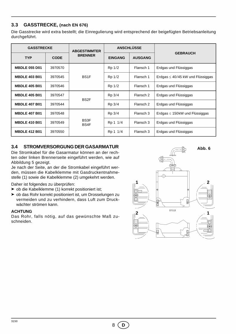
3.4 STROMVERSORGUNG DER GASARMATUR Die Stromkabel für die Gasarmatur können an der rech-ten oder linken Brennerseite eingeführt werden, wie aufAbbildung 5 gezeigt.Je nach der Seite, an der die Stromkabel eingeführt wer-den, müssen die Kabelklemme mit Gasdruckentnahme-stelle (1) sowie die Kabelklemme (2) umgekehrt werden.
Daher ist folgendes zu überprüfen:ob die Kabelklemme (1) korrekt positioniert ist;ob das Rohr korrekt positioniert ist, um Drosselungen zuvermeiden und zu verhindern, dass Luft zum Druck-wächter strömen kann.
ACHTUNGDas Rohr, falls nötig, auf das gewünschte Maß zu-schneiden.
GASSTRECKEABGESTIMMTER
BRENNER
ANSCHLÜSSEGEBRAUCH
TYP CODE EINGANG AUSGANG
MBDLE 055 D01 3970570
BS1F
Rp 1/2 Flansch 1 Erdgas und Flüssiggas
MBDLE 403 B01 3970545 Rp 1/2 Flansch 1 Erdgas ≤ 40/45 kW und Flüssiggas
MBDLE 405 B01 3970546 Rp 1/2 Flansch 1 Erdgas und Flüssiggas
MBDLE 405 B01 3970547BS2F
Rp 3/4 Flansch 2 Erdgas und Flüssiggas
MBDLE 407 B01 3970544 Rp 3/4 Flansch 2 Erdgas und Flüssiggas
MBDLE 407 B01 3970548
BS3FBS4F
Rp 3/4 Flansch 3 Erdgas ≤ 150kW und Flüssiggas
MBDLE 410 B01 3970549 Rp 1 1/4 Flansch 3 Erdgas und Flüssiggas
MBDLE 412 B01 3970550 Rp 1 1/4 Flansch 3 Erdgas und Flüssiggas
2
1 2
1D7113
Abb. 6
3150
9 D
3.5 GASANSCHLUSS–SCHEMA
M2
D5209
1 2 3 M1 5 6 74 8 Abb. 6
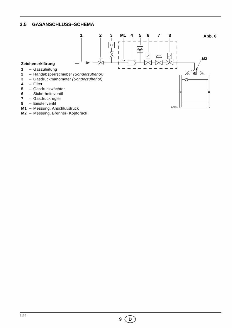
Zeichenerklärung1 – Gaszuleitung 2 – Handabsperrschieber (Sonderzubehör)3 – Gasdruckmanometer (Sonderzubehör)4 – Filter5 – Gasdruckwächter6 – Sicherheitsventil7 – Gasdruckregler8 – EinstellventilM1 – Messung, AnschlußdruckM2 – Messung, Brenner- Kopfdruck

3150
10 D
3.6 ELEKTRISCHES VERDRAHTUNGSSCHEMA
Hauptschalter
220/230V ~ 50/60Hz
D4626
ACHTUNG: Nullleiter nicht mit Phase austauschen; sich genau an das angegebeneSchema halten und eine gute Erdung ausführen.Der Leiterquerschnitt muss mindestens 1 mm2 sein. (Außer im Falle an-derslautender Angaben durch Normen und örtliche Gesetze).Die vom Installateur ausgeführten elektrischen Verbindungen müssen denlokalen Bestimmungen entsprechen.
PRÜFUNGDas Anhalten des Brenners überprüfen, indem die Thermostate geöffnet werden.Die Störabschaltung des Brenners während des Betriebes überprüfen, indem derVerbinder (CN1) geöffnet wird, der sich am roten Draht des Fühlers außen amSteuergerät befindet.
STEUERGERÄT, (siehe Abb. 7)Um das Steuergerät aus dem Brenner zu nehmen, ist folgendes notwendig:
alle an ihm angeschlossenen Verbinder, den 7-poligen Stecker, die Hoch-spannungskabel und den Erdleiter (TB) abnehmen;die Schraube (A) losschrauben und das Steuergerät in Pfeilrichtung ziehen.
Für die Installation des Steuergeräts ist folgendes notwendig:die Schraube (A) mit einem Anzugsmoment von 1 ÷ 1,2 Nm anschrauben;alle vorher abgetrennten Verbinder wieder anschließen.
ANMERKUNGEN:Das bedeutet, dass sie mindestens 1 Mal alle 24 Stunden anhalten müssen, da-mit das elektrische Steuergerät eine Kontrolle seiner Effizienz beim Anfahrenausführen kann. Gewöhnlich wird das Anhalten des Brenners durch den Be-grenzungsthermostat (TL) des Heizkessels gewährleistet. Sollte dies nicht derFall sein, muss ein Zeitschalter mit (TL) seriengeschaltet werden, der für dasAnhalten des Brenners mindestens einmal alle 24 Stunden sorgt.
ZEICHENERKLÄRUNGC – KondensatorCN1 – Verbinder FühlerE – Zündelektrodeh1 – 1. Stufe StundenzählerMV – MotorPA – MinimalluftdruckwächterPG – MinimalgasdruckwächterRS – FernentstörungSO – FlammenfühlerS3 – Störabschaltung-Fernmeldung
(230V - 0,5A max.)T6A – SicherungTB – Brenner-ErdungTL – GrenzthermostatTS – SicherheitsthermostatV10 – SicherheitsventilV11 – EinstellventilX.. – SteckerXP.. – Steckdose
MG
569
STE
UE
RG
ER
ÄT
VOM INSTALLATEURAUSZUFÜHREN
WERKSSEITIGEEINSTELLUNG
A
Abb. 7
E9250
3150
11 D
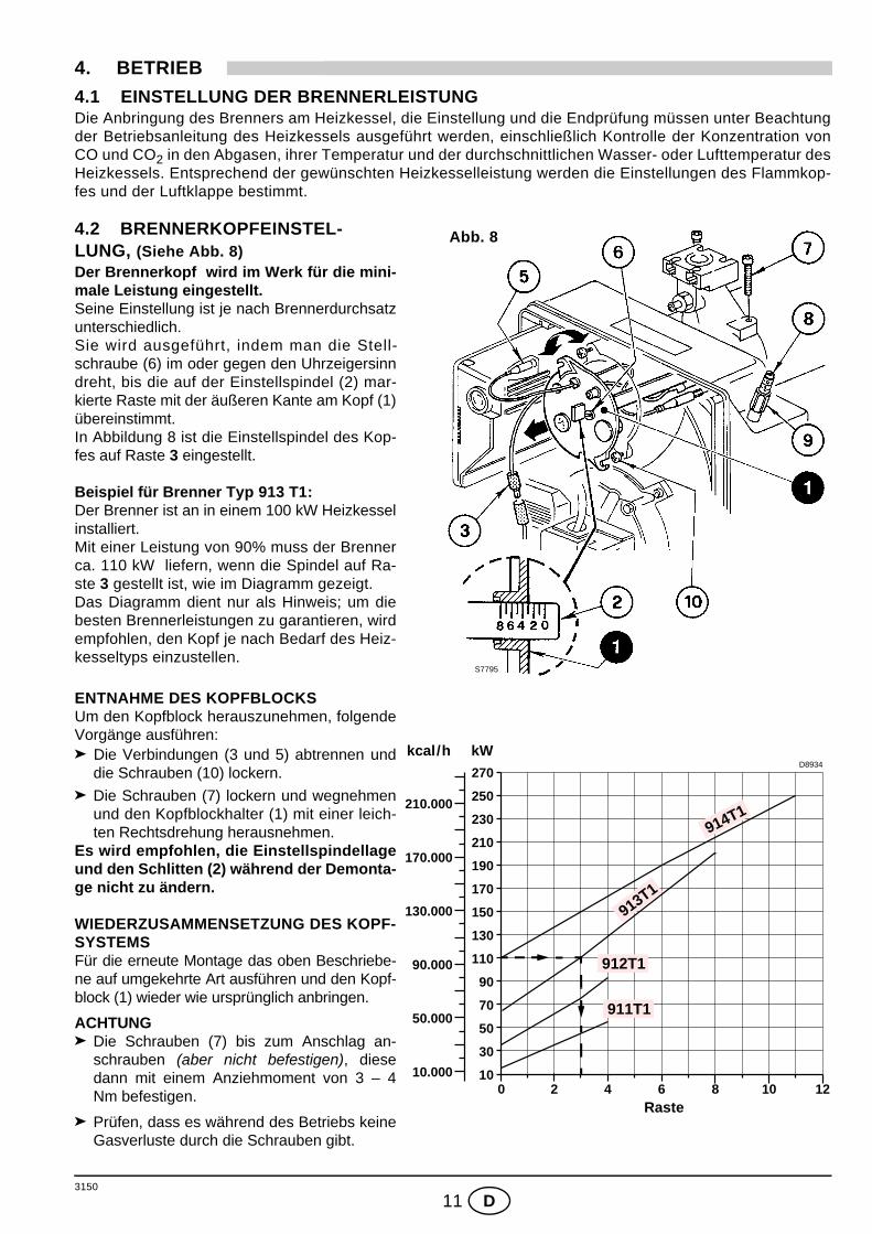
4. BETRIEB4.1 EINSTELLUNG DER BRENNERLEISTUNGDie Anbringung des Brenners am Heizkessel, die Einstellung und die Endprüfung müssen unter Beachtungder Betriebsanleitung des Heizkessels ausgeführt werden, einschließlich Kontrolle der Konzentration vonCO und CO2 in den Abgasen, ihrer Temperatur und der durchschnittlichen Wasser- oder Lufttemperatur desHeizkessels. Entsprechend der gewünschten Heizkesselleistung werden die Einstellungen des Flammkop-fes und der Luftklappe bestimmt.
4.2 BRENNERKOPFEINSTEL-LUNG, (Siehe Abb. 8)Der Brennerkopf wird im Werk für die mini-male Leistung eingestellt.Seine Einstellung ist je nach Brennerdurchsatzunterschiedlich.Sie wird ausgeführt, indem man die Stell-schraube (6) im oder gegen den Uhrzeigersinndreht, bis die auf der Einstellspindel (2) mar-kierte Raste mit der äußeren Kante am Kopf (1)übereinstimmt.In Abbildung 8 ist die Einstellspindel des Kop-fes auf Raste 3 eingestellt.
Beispiel für Brenner Typ 913 T1:Der Brenner ist an in einem 100 kW Heizkesselinstalliert.Mit einer Leistung von 90% muss der Brennerca. 110 kW liefern, wenn die Spindel auf Ra-ste 3 gestellt ist, wie im Diagramm gezeigt.Das Diagramm dient nur als Hinweis; um diebesten Brennerleistungen zu garantieren, wirdempfohlen, den Kopf je nach Bedarf des Heiz-kesseltyps einzustellen.
ENTNAHME DES KOPFBLOCKSUm den Kopfblock herauszunehmen, folgendeVorgänge ausführen:
Die Verbindungen (3 und 5) abtrennen unddie Schrauben (10) lockern.
Die Schrauben (7) lockern und wegnehmenund den Kopfblockhalter (1) mit einer leich-ten Rechtsdrehung herausnehmen.
Es wird empfohlen, die Einstellspindellageund den Schlitten (2) während der Demonta-ge nicht zu ändern.
WIEDERZUSAMMENSETZUNG DES KOPF-SYSTEMSFür die erneute Montage das oben Beschriebe-ne auf umgekehrte Art ausführen und den Kopf-block (1) wieder wie ursprünglich anbringen.
ACHTUNGDie Schrauben (7) bis zum Anschlag an-schrauben (aber nicht befestigen), diesedann mit einem Anziehmoment von 3 – 4Nm befestigen.
Prüfen, dass es während des Betriebs keineGasverluste durch die Schrauben gibt.
S7795
Abb. 8
Raste
D8934
170.000
50.000
210.000
130.000
90.000
10.000
kcal/h kW
0 82 4 6
210
10
50
70
110
130
150
170
190
30
90
230
250
10
270
12
911T1
912T1
913T1
914T1
3150
12 D
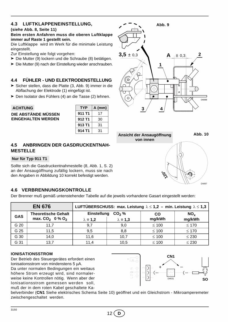
4.3 LUFTKLAPPENEINSTELLUNG, (siehe Abb. 8, Seite 11) Beim ersten Anfahren muss die oberen Luftklappeimmer auf Raste 1 gestellt sein.Die Luftklappe wird im Werk für die minimale Leistungeingestellt.Zur Einstellung wie folgt vorgehen:
Die Mutter (9) lockern und die Schraube (8) betätigen.Die Mutter (9) nach der Einstellung wieder anschrauben.
4.4 FÜHLER - UND ELEKTRODENSTELLUNGSicher stellen, dass die Platte (3, Abb. 9) immer in dieAbflachung der Elektrode (1) eingefügt ist.
Den Isolator des Fühlers (4) an die Tasse (2) lehnen.
4.5 ANBRINGEN DER GASDRUCKENTNAH-MESTELLE
Sollte sich die Gasdruckentnahmestelle (8, Abb. 1, S. 2)an der Ansaugöffnung zufällig lockern, muss sie nachden Angaben in Abbildung 10 korrekt befestigt werden.
4.6 VERBRENNUNGSKONTROLLEDer Brenner muß gemäß untenstehender Tabelle auf die jeweils vorhandene Gasart eingestellt werden:
IONISATIONSSTROM Der Betrieb des Steuergerätes erfordert einenIonisationsstrom von mindenstens 5 µA. Da unter normalen Bedingungen ein weitaushöhere Strom erzeugt wird, sind normaler-weise keine Kontrollen nötig. Wenn aber derIonisationsstrom gemessen werden soll,muß der in dem roten Kabel geschaltete Ka-belverbinder (CN1 Siehe elektrisches Schema Seite 10) geöffnet und ein Gleichstrom - Mikroamperemeterzwischengeschaltet werden.
EN 676 LUFTÜBERSCHUSS: max. Leistung λ ≤ 1,2 – min. Leistung λ ≤ 1,3
GASTheoretische Gehaltmax. CO2 0 % O2
Einstellung CO2 % COmg/kWh
NOxmg/kWhλ = 1,2 λ = 1,3
G 20 11,7 9,7 9,0 ≤ 100 ≤ 170G 25 11,5 9,5 8,8 ≤ 100 ≤ 170G 30 14,0 11,6 10,7 ≤ 100 ≤ 230G 31 13,7 11,4 10,5 ≤ 100 ≤ 230
D6088
± 0,3 3,5 ± 0,3 A
Abb. 9
1
3
2
4
Abb. 10
120°
D4497
Ansicht der Ansaugöffnungvon innen
TYP A (mm)911 T1 17
912 T1 30
913 T1 31
914 T1 31
DIE ABSTÄNDE MÜSSEN ACHTUNG
EINGEHALTEN WERDEN
Nur für Typ 911 T1
D4631
+ _
SO
CN1
3150
13 D
4.7 LUFTDRUCKWÄCHTER Während der Einregulierung des Gasbrenners wird der Luftdruckwächter auf 0 gestellt.Ist die Einregulierung abgeschlossen, wird der Luftdruck einreguliert. Die Regulierskala langsam im Uhrzei-gersinn drehen, bis der Brenner abschaltet. Dann die Regulierskala entgegengesetz um einen Wert zurück-drehen, bis der Brenner wieder einschaltet. Mit dieser Einstellung den Brennerstart mehrmals wiederholenund bei Bedarf den Luftdruckwächter nachregulieren.
Achtung:Der Luftdruckwächter muss nach Norm EN 676 den Brenner abschalten, bevor der CO-Wert in den Abgasen1% (10.000 ppm) überschreitet. Um dies zu prüfen, ein Verbrennungsanalysegerät im Kamin anschließen,die Luftansaugung des Ventilators langsam schließen und prüfen, ob der Brenner abschaltet, bevor der CO-Wert in den Abgasen höher als 1% ist.
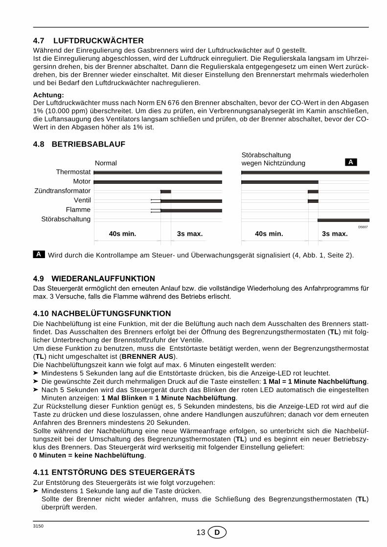
4.8 BETRIEBSABLAUF
Wird durch die Kontrollampe am Steuer- und Überwachungsgerät signalisiert (4, Abb. 1, Seite 2).
4.9 WIEDERANLAUFFUNKTIONDas Steuergerät ermöglicht den erneuten Anlauf bzw. die vollständige Wiederholung des Anfahrprogramms fürmax. 3 Versuche, falls die Flamme während des Betriebs erlischt.
4.10 NACHBELÜFTUNGSFUNKTION Die Nachbelüftung ist eine Funktion, mit der die Belüftung auch nach dem Ausschalten des Brenners statt-findet. Das Ausschalten des Brenners erfolgt bei der Öffnung des Begrenzungsthermostaten (TL) mit folg-licher Unterbrechung der Brennstoffzufuhr der Ventile.Um diese Funktion zu benutzen, muss die Entstörtaste betätigt werden, wenn der Begrenzungsthermostat(TL) nicht umgeschaltet ist (BRENNER AUS).Die Nachbelüftungszeit kann wie folgt auf max. 6 Minuten eingestellt werden:
Mindestens 5 Sekunden lang auf die Entstörtaste drücken, bis die Anzeige-LED rot leuchtet.Die gewünschte Zeit durch mehrmaligen Druck auf die Taste einstellen: 1 Mal = 1 Minute Nachbelüftung.Nach 5 Sekunden wird das Steuergerät durch das Blinken der roten LED automatisch die eingestelltenMinuten anzeigen: 1 Mal Blinken = 1 Minute Nachbelüftung.
Zur Rückstellung dieser Funktion genügt es, 5 Sekunden mindestens, bis die Anzeige-LED rot wird auf dieTaste zu drücken und diese loszulassen, ohne andere Handlungen auszuführen; danach vor dem erneutenAnfahren des Brenners mindestens 20 Sekunden.Sollte während der Nachbelüftung eine neue Wärmeanfrage erfolgen, so unterbricht sich die Nachbelüf-tungszeit bei der Umschaltung des Begrenzungsthermostaten (TL) und es beginnt ein neuer Betriebszy-klus des Brenners. Das Steuergerät wird werkseitig mit folgender Einstellung geliefert: 0 Minuten = keine Nachbelüftung.
4.11 ENTSTÖRUNG DES STEUERGERÄTS Zur Entstörung des Steuergeräts ist wie folgt vorzugehen:
Mindestens 1 Sekunde lang auf die Taste drücken. Sollte der Brenner nicht wieder anfahren, muss die Schließung des Begrenzungsthermostaten (TL)überprüft werden.
ThermostatMotor
ZündtransformatorVentil
FlammeStörabschaltung
40s min. 3s max. 40s min. 3s max.
Störabschaltung wegen Nichtzündung ANormal
D5007
A

3150
14 D
5. WARTUNGVor der Durchführung von Reinigungs- oder Kontrollarbeiten, immer die elektrische Versorgungzum Brenner durch Betätigung des Hauptschalters der Anlage abschalten und das Gasabsperrven-til schließen. Der Brenner bedarf regelmäßiger Wartung, die von autorisiertem Personal und in Übereinstimmung mit ört-lichen Gesetzen und Vorschriften ausgeführt werden muss.Die regelmäßige Wartung ist für den korrekten Betrieb des Brenners von grundlegender Wichtigkeit; man ver-meidet auf diese Weise unnützen Brennstoffverbrauch und verringert die Schadstoffemissionen in die Umwelt.
DIE AUSZUFÜHRENDEN HAUPTARBEITEN SIND:In regelmäßigen Abständen die Löcher am Gasverteiler auf Ver-stopfungen überprüfen und gegebenenfalls mit einem geeigne-ten Werkzeug reinigen, wie auf der Abbildung 11 gezeigt. Prüfen, dass die Brennerzu- und –rückleitungen die Luftansaug-zonen und die Leitungen, durch welche die Verbrennungspro-dukte ausgestoßen werden, keine Verstopfungen oderDrosselungen aufweisen.Die korrekte Durchführung der elektrischen Anschlüsse desBrenners und der Gasstrecke überprüfen.Die korrekte Positionierung der Luftdruckanschluß überprüfen(8, Abb. 1 Seite 2).Prüfen, ob sich die Gasstrecke für das Potential des Bren-ners, den benutzten Gastyp und den Gasdruck des Gasnet-zes eignet.Die korrekte Positionierung des Flammkopfes und dessen Befestigung am Heizkessel überprüfen.Die korrekte Positionierung der Luftklappe überprüfen.Die korrekte Positionierung des Ionisationsfühlers und der Elektrode überprüfen (siehe Abb. 9, Seite 12).Die Einstellung des Luft- und des Gasdruckwächters überprüfen.
Den Brenner ca. zehn Minuten auf Vollbetrieb funktionieren lassen und alle in der vorliegenden Anleitungangegebenen Elemente korrekt einstellen.Dann eine Verbrennungsanalyse ausführen, mit Überprüfung von:
CO2 Anteil (%); CO Gehalt (ppm); NOx Gehalt (ppm); Ionisationsstrom (µA). Temperatur der Abgase zum Kamin.
5.1 VISUELLE DIAGNOSTIK DES STEUERGERÄTSDas mitgelieferte Steuergerät hat eine Diagnosefunktion, um die eventuellen Ursachen von Betriebsstörungenzu ermitteln (Anzeige: ROTE LED).Um diese Funktion zu benutzen, muss mindestens 3 Sekunden lang ab dem Augenblick der Störabschaltungauf die Entstörtaste gedrückt werden. Das Steuergerät erzeugt eine Impulssequenz, die sich konstant alle 2 Sekunden wiederholt.
Die Sequenz der vom Steuergerät abgegebenen Impulse gibt die möglichen Defekte an, die in der nachfol-genden Tabelle verzeichnet sind.
SIGNAL MÖGLICHE URSACHE
2 Blinken
Am Ende der Sicherheitszeit wird keine stabile Flamme aufgenommen :– Defekt am Ionisationsfühler;– Defekt an den Gasventilen;– Umkehrung von Phase/Nullleiter;– Defekt am Zündtransformator;– Brenner nicht eingestellt (Gas nicht ausreichend).
Abb. 11
E9252
2sBlinken BlinkenROTE LED leuchtet
Entstörtaste 3s drückenPause
3150
15 D
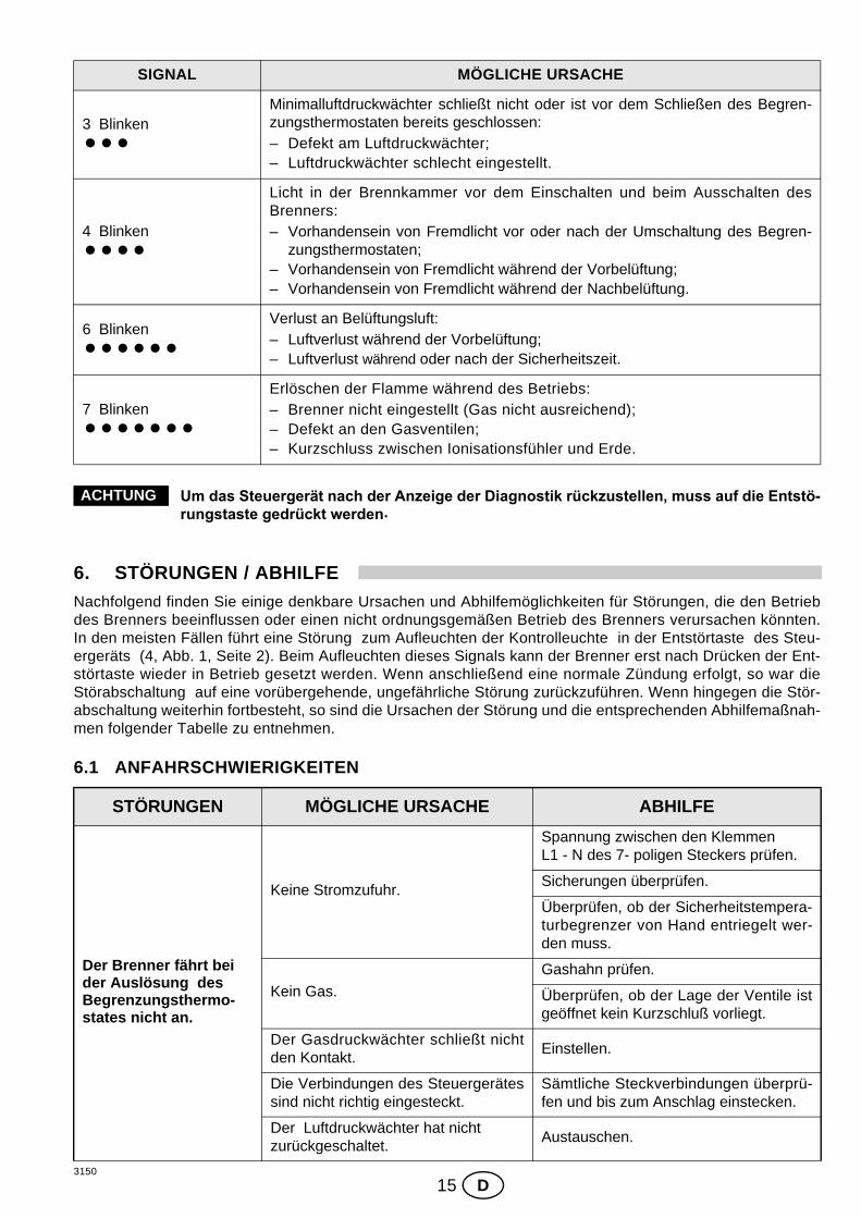
Um das Steuergerät nach der Anzeige der Diagnostik rückzustellen, muss auf die Entstö-rungstaste gedrückt werden.
6. STÖRUNGEN / ABHILFENachfolgend finden Sie einige denkbare Ursachen und Abhilfemöglichkeiten für Störungen, die den Betriebdes Brenners beeinflussen oder einen nicht ordnungsgemäßen Betrieb des Brenners verursachen könnten.In den meisten Fällen führt eine Störung zum Aufleuchten der Kontrolleuchte in der Entstörtaste des Steu-ergeräts (4, Abb. 1, Seite 2). Beim Aufleuchten dieses Signals kann der Brenner erst nach Drücken der Ent-störtaste wieder in Betrieb gesetzt werden. Wenn anschließend eine normale Zündung erfolgt, so war dieStörabschaltung auf eine vorübergehende, ungefährliche Störung zurückzuführen. Wenn hingegen die Stör-abschaltung weiterhin fortbesteht, so sind die Ursachen der Störung und die entsprechenden Abhilfemaßnah-men folgender Tabelle zu entnehmen.
6.1 ANFAHRSCHWIERIGKEITEN
SIGNAL MÖGLICHE URSACHE
3 BlinkenMinimalluftdruckwächter schließt nicht oder ist vor dem Schließen des Begren-zungsthermostaten bereits geschlossen:– Defekt am Luftdruckwächter;– Luftdruckwächter schlecht eingestellt.
4 Blinken
Licht in der Brennkammer vor dem Einschalten und beim Ausschalten desBrenners:– Vorhandensein von Fremdlicht vor oder nach der Umschaltung des Begren-
zungsthermostaten;– Vorhandensein von Fremdlicht während der Vorbelüftung;– Vorhandensein von Fremdlicht während der Nachbelüftung.
6 BlinkenVerlust an Belüftungsluft:– Luftverlust während der Vorbelüftung;– Luftverlust während oder nach der Sicherheitszeit.
7 BlinkenErlöschen der Flamme während des Betriebs:– Brenner nicht eingestellt (Gas nicht ausreichend);– Defekt an den Gasventilen;– Kurzschluss zwischen Ionisationsfühler und Erde.
STÖRUNGEN MÖGLICHE URSACHE ABHILFE
Der Brenner fährt bei der Auslösung des Begrenzungsthermo-states nicht an.
Keine Stromzufuhr.
Spannung zwischen den Klemmen L1 - N des 7- poligen Steckers prüfen.
Sicherungen überprüfen.
Überprüfen, ob der Sicherheitstempera-turbegrenzer von Hand entriegelt wer-den muss.
Kein Gas.
Gashahn prüfen.
Überprüfen, ob der Lage der Ventile istgeöffnet kein Kurzschluß vorliegt.
Der Gasdruckwächter schließt nichtden Kontakt.
Einstellen.
Die Verbindungen des Steuergerätessind nicht richtig eingesteckt.
Sämtliche Steckverbindungen überprü-fen und bis zum Anschlag einstecken.
Der Luftdruckwächter hat nicht zurückgeschaltet.
Austauschen.
ACHTUNG

3150
16 D
Der Brenner führt den Vorbelüftungs- und Zündzyklus regulär aus; nach ungefähr 3 Sekunden erfolgt eine Störabschaltung.
Der Anschluss Phase - Nulleiter ist verwechselt.
Umpolen.
Kein oder unwirksames Erdungska-bel.
Instand setzen.
Der Ionisationsfühler hat eine Kurz-schluß oder in der Flamme nicht ein-getaucht. Die Verbindung mit dem Steuergerätist unterbrochen oder hat eine Isolati-onsstörung gegen die Masse.
Gemäß den Angaben dieser Anleitungden richtigen Lage prüfen und den Ioni-sationsfühler einstellen.
Die elektrische Verbindung wiederin-standsetzen.
Die schadhafte Verbindung austau-schen.
Anfahren des Bren-ners mit verspäteter Zündung.
Zündelektrode nicht in richtiger Position.
Gemäß den Angaben dieser Anleitungkorrekt einstellen.
Zu höher Luftdurchsatz.Gemäß den Angaben dieser Anleitungden Luftdurchsatz einstellen.
Zu geschlossene Ventilsbremse mitungenügendem Gasauslauf.
Einstellen.
Störabschaltung des Brenners nach Vorlüf-tung, keine Flammen-bildung.
Gasdurchsatz zu gering.Gemäß den Angaben dieser Anleitungden Gasdruck prüfen und/oder dieMagnetventile einstellen.
Die Magnetventile sind verschmutzt. Austauschen.
Kein oder unregelmäßiger elektrischer Zündfunken.
Die richtigen Kabelverbindung über-prüfen.
Gemäß den Angaben dieser Anleitungeinstellen die richtige Elektrodelage ein-stellen.
Luft in der Rohrleitung. Gasleitung entlüften.
Störabschaltung des Brenners während der Vorlüftung.
Der Luftdruckwächter schaltet nichtden Kontakt um.
Der Druckwächter ist verschmutzt oderdefekt. Austauschen.
Zu niedriger Luftdruck (Kopf ist nichtrichtig eingestellt).
Flammenbildung. Die Ventile sind defekt: austauschen.
Druckanschluß nicht in richtiger Posi-tion (Abb. 10).
Gemäß den Angaben dieser Anleitungkorrekt einstellen (4.5, Seite 12).
Der Brenner macht den Startzyklus fortwäh-rend ohne Störabschal-tung wieder.
Der Gasdruck ist kurz vor dem einge-stellten Wert des Gasdruckwächters.Die augenblickliche Druckabnahmewährend der Ventilöffnung öffnet denDruckwächter und das Ventil schließtsich sofort wieder und der Motor stelltsich ab. Dann steigt der Druck undder Druckwächter führt den Zündzy-klus, und so weiter aus.
Die Druckeinstellung des Druckwäch-ters korrigiere.
STÖRUNGEN MÖGLICHE URSACHE ABHILFE
3150
17 D
6.2 BETRIEBSSTÖRUNGEN
7. HINWEISE UND SICHERHEITUm bestmögliche Verbrennungs-Ergebnisse sowie niedrige Emissionswerte zu erzielen, muß die Brenn-kammer-Geometrie des Heizkessels für den Brenner geeignet sein.Deshalb ist es notwendig, vor Einsatz des Brenners Informationen bei einzuholen, um ein einwandfreiesFunktionieren des Brenners zu gewährleisten.Dieser Brenner darf nur für den Einsatzzweck verwendet werden, für den er hergestellt wurde. Eine vertragliche und außervertragliche Haftung des Herstellers für Personen-, Tier- und Sachschäden auf-grund von Fehlern bei der Installation, der Einstellung, der Wartung und aufgrund von unsachgemäßem Ge-brauch ist ausgeschlossen.
7.1 KENNZEICHNUNG DES BRENNERSAuf dem Typenschild sind die Seriennummer, das Modell und die wichtigsten technischen Angaben und Lei-stungsdaten angegeben. Durch eine Beschädigung und/oder Entfernung und/oder das Fehlen des Typen-schildes kann das Produkt nicht genau identifiziert werden, wodurch Installations- und Wartungsarbeitenschwierig und/oder gefährlich werden.
7.2 GRUNDLEGENDE SICHERHEITSVORSCHRIFTENDer Gebrauch des Geräts durch Kinder oder Unerfahrene ist verboten.
Es ist absolut verboten, die Ansaug- oder Dissipationsgitter und die Belüftungsöffnung des Installations-raumes des Geräts mit Lumpen, Papier oder sonstigem zu verstopfen.
Reparaturversuche am Gerät durch nicht autorisiertes Personal sind verboten.
Es ist gefährlich, an elektrischen Kabeln zu ziehen oder diese zu biegen.
Reinigungsarbeiten vor der Abschaltung des Geräts vom elektrischen Versorgungsnetz sind verboten.
Den Brenner und seine Teile nicht mit leicht entzündbaren Substanzen (wie Benzin, Spiritus, usw.) reini-gen. Die Brennerhaube darf nur mit Seifenwasser gereinigt werden.
Keine Gegenstände auf den Brenner legen.
Die Belüftungsöffnungen des Installationsraums des Erzeugers nicht verstopfen bzw. verkleinern.
Keine Behälter und entzündbare Stoffe im Installationsraum des Geräts lassen.
STÖRUNGEN MÖGLICHE URSACHE ABHILFE
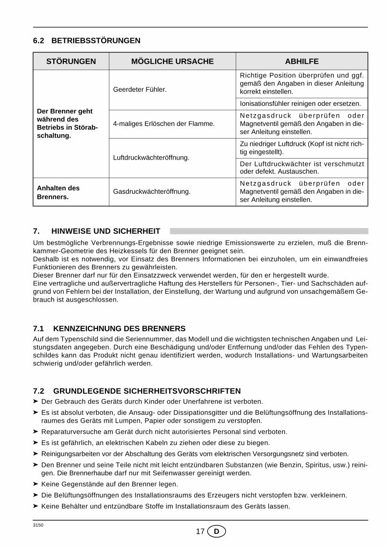
Der Brenner geht während des Betriebs in Störab-schaltung.
Geerdeter Fühler.
Richtige Position überprüfen und ggf.gemäß den Angaben in dieser Anleitungkorrekt einstellen.
Ionisationsfühler reinigen oder ersetzen.
4-maliges Erlöschen der Flamme.Netzgasdruck überp rü fen oderMagnetventil gemäß den Angaben in die-ser Anleitung einstellen.
Luftdruckwächteröffnung.
Zu niedriger Luftdruck (Kopf ist nicht rich-tig eingestellt).
Der Luftdruckwächter ist verschmutztoder defekt. Austauschen.
Anhalten des Brenners.
Gasdruckwächteröffnung.Netzgasdruck überp rü fen oderMagnetventil gemäß den Angaben in die-ser Anleitung einstellen.

3150
1 GB
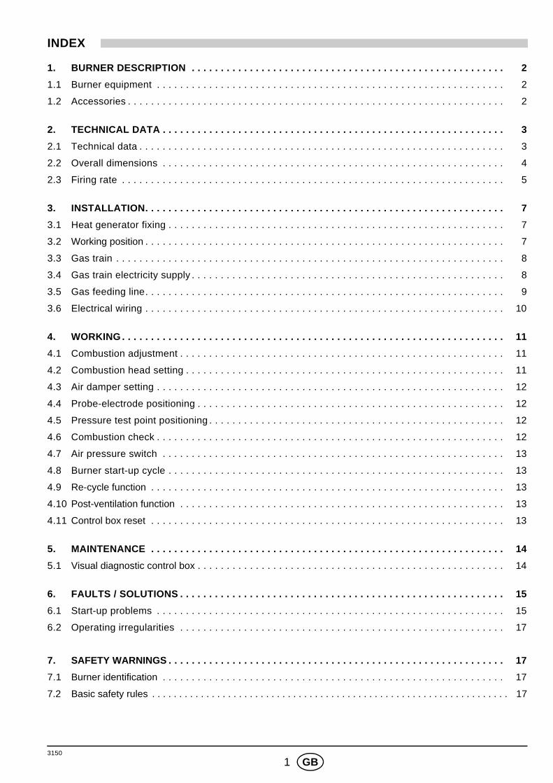
INDEX
1. BURNER DESCRIPTION . . . . . . . . . . . . . . . . . . . . . . . . . . . . . . . . . . . . . . . . . . . . . . . . . . . . . . 2
1.1 Burner equipment . . . . . . . . . . . . . . . . . . . . . . . . . . . . . . . . . . . . . . . . . . . . . . . . . . . . . . . . . . . . 2
1.2 Accessories . . . . . . . . . . . . . . . . . . . . . . . . . . . . . . . . . . . . . . . . . . . . . . . . . . . . . . . . . . . . . . . . . 2
2. TECHNICAL DATA . . . . . . . . . . . . . . . . . . . . . . . . . . . . . . . . . . . . . . . . . . . . . . . . . . . . . . . . . . . 3
2.1 Technical data . . . . . . . . . . . . . . . . . . . . . . . . . . . . . . . . . . . . . . . . . . . . . . . . . . . . . . . . . . . . . . . 3
2.2 Overall dimensions . . . . . . . . . . . . . . . . . . . . . . . . . . . . . . . . . . . . . . . . . . . . . . . . . . . . . . . . . . . 4
2.3 Firing rate . . . . . . . . . . . . . . . . . . . . . . . . . . . . . . . . . . . . . . . . . . . . . . . . . . . . . . . . . . . . . . . . . . 5
3. INSTALLATION. . . . . . . . . . . . . . . . . . . . . . . . . . . . . . . . . . . . . . . . . . . . . . . . . . . . . . . . . . . . . . 7
3.1 Heat generator fixing . . . . . . . . . . . . . . . . . . . . . . . . . . . . . . . . . . . . . . . . . . . . . . . . . . . . . . . . . . 7
3.2 Working position . . . . . . . . . . . . . . . . . . . . . . . . . . . . . . . . . . . . . . . . . . . . . . . . . . . . . . . . . . . . . . 7
3.3 Gas train . . . . . . . . . . . . . . . . . . . . . . . . . . . . . . . . . . . . . . . . . . . . . . . . . . . . . . . . . . . . . . . . . . . 8
3.4 Gas train electricity supply . . . . . . . . . . . . . . . . . . . . . . . . . . . . . . . . . . . . . . . . . . . . . . . . . . . . . . 8
3.5 Gas feeding line. . . . . . . . . . . . . . . . . . . . . . . . . . . . . . . . . . . . . . . . . . . . . . . . . . . . . . . . . . . . . . 9
3.6 Electrical wiring . . . . . . . . . . . . . . . . . . . . . . . . . . . . . . . . . . . . . . . . . . . . . . . . . . . . . . . . . . . . . . 10
4. WORKING . . . . . . . . . . . . . . . . . . . . . . . . . . . . . . . . . . . . . . . . . . . . . . . . . . . . . . . . . . . . . . . . . . 11
4.1 Combustion adjustment . . . . . . . . . . . . . . . . . . . . . . . . . . . . . . . . . . . . . . . . . . . . . . . . . . . . . . . . 11
4.2 Combustion head setting . . . . . . . . . . . . . . . . . . . . . . . . . . . . . . . . . . . . . . . . . . . . . . . . . . . . . . . 11
4.3 Air damper setting . . . . . . . . . . . . . . . . . . . . . . . . . . . . . . . . . . . . . . . . . . . . . . . . . . . . . . . . . . . . 12
4.4 Probe-electrode positioning . . . . . . . . . . . . . . . . . . . . . . . . . . . . . . . . . . . . . . . . . . . . . . . . . . . . . 12
4.5 Pressure test point positioning . . . . . . . . . . . . . . . . . . . . . . . . . . . . . . . . . . . . . . . . . . . . . . . . . . . 12
4.6 Combustion check . . . . . . . . . . . . . . . . . . . . . . . . . . . . . . . . . . . . . . . . . . . . . . . . . . . . . . . . . . . . 12
4.7 Air pressure switch . . . . . . . . . . . . . . . . . . . . . . . . . . . . . . . . . . . . . . . . . . . . . . . . . . . . . . . . . . . 13
4.8 Burner start-up cycle . . . . . . . . . . . . . . . . . . . . . . . . . . . . . . . . . . . . . . . . . . . . . . . . . . . . . . . . . . 13
4.9 Re-cycle function . . . . . . . . . . . . . . . . . . . . . . . . . . . . . . . . . . . . . . . . . . . . . . . . . . . . . . . . . . . . . 13
4.10 Post-ventilation function . . . . . . . . . . . . . . . . . . . . . . . . . . . . . . . . . . . . . . . . . . . . . . . . . . . . . . . . 13
4.11 Control box reset . . . . . . . . . . . . . . . . . . . . . . . . . . . . . . . . . . . . . . . . . . . . . . . . . . . . . . . . . . . . . 13
5. MAINTENANCE . . . . . . . . . . . . . . . . . . . . . . . . . . . . . . . . . . . . . . . . . . . . . . . . . . . . . . . . . . . . . 14
5.1 Visual diagnostic control box . . . . . . . . . . . . . . . . . . . . . . . . . . . . . . . . . . . . . . . . . . . . . . . . . . . . . 14
6. FAULTS / SOLUTIONS . . . . . . . . . . . . . . . . . . . . . . . . . . . . . . . . . . . . . . . . . . . . . . . . . . . . . . . . 15
6.1 Start-up problems . . . . . . . . . . . . . . . . . . . . . . . . . . . . . . . . . . . . . . . . . . . . . . . . . . . . . . . . . . . . 15
6.2 Operating irregularities . . . . . . . . . . . . . . . . . . . . . . . . . . . . . . . . . . . . . . . . . . . . . . . . . . . . . . . . 17
7. SAFETY WARNINGS . . . . . . . . . . . . . . . . . . . . . . . . . . . . . . . . . . . . . . . . . . . . . . . . . . . . . . . . . . 17
7.1 Burner identification . . . . . . . . . . . . . . . . . . . . . . . . . . . . . . . . . . . . . . . . . . . . . . . . . . . . . . . . . . . 17
7.2 Basic safety rules . . . . . . . . . . . . . . . . . . . . . . . . . . . . . . . . . . . . . . . . . . . . . . . . . . . . . . . . . . . . . . . . . . 17
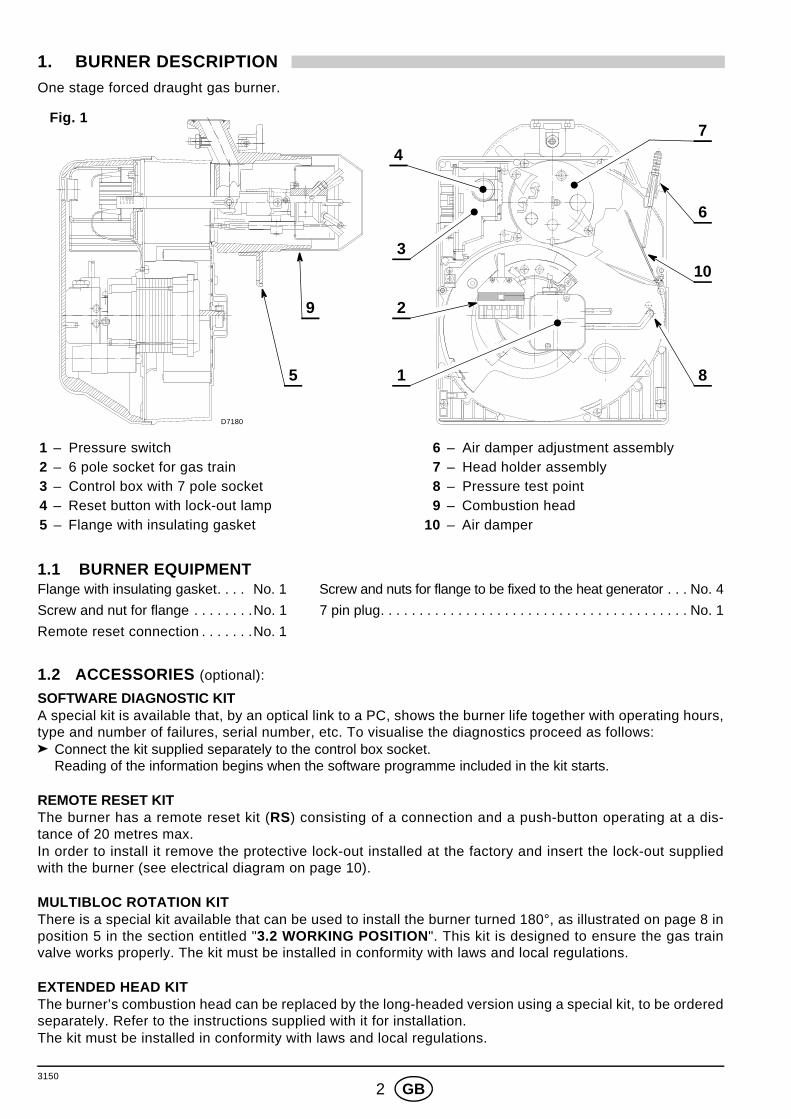
3150
2 GB
1. BURNER DESCRIPTIONOne stage forced draught gas burner.
1.1 BURNER EQUIPMENTFlange with insulating gasket. . . . No. 1 Screw and nuts for flange to be fixed to the heat generator . . . No. 4
Screw and nut for flange . . . . . . . .No. 1 7 pin plug. . . . . . . . . . . . . . . . . . . . . . . . . . . . . . . . . . . . . . . . No. 1
Remote reset connection . . . . . . .No. 1
1.2 ACCESSORIES (optional):
SOFTWARE DIAGNOSTIC KITA special kit is available that, by an optical link to a PC, shows the burner life together with operating hours,type and number of failures, serial number, etc. To visualise the diagnostics proceed as follows:
Connect the kit supplied separately to the control box socket. Reading of the information begins when the software programme included in the kit starts.
REMOTE RESET KITThe burner has a remote reset kit (RS) consisting of a connection and a push-button operating at a dis-tance of 20 metres max.In order to install it remove the protective lock-out installed at the factory and insert the lock-out suppliedwith the burner (see electrical diagram on page 10).
MULTIBLOC ROTATION KITThere is a special kit available that can be used to install the burner turned 180°, as illustrated on page 8 inposition 5 in the section entitled "3.2 WORKING POSITION". This kit is designed to ensure the gas trainvalve works properly. The kit must be installed in conformity with laws and local regulations.
EXTENDED HEAD KITThe burner’s combustion head can be replaced by the long-headed version using a special kit, to be orderedseparately. Refer to the instructions supplied with it for installation.The kit must be installed in conformity with laws and local regulations.
1 – Pressure switch2 – 6 pole socket for gas train3 – Control box with 7 pole socket4 – Reset button with lock-out lamp5 – Flange with insulating gasket
6 – Air damper adjustment assembly 7 – Head holder assembly 8 – Pressure test point 9 – Combustion head10 – Air damper
Fig. 1
D7180
4
3
2
1
9
8
6
5
10
7

3150
3 GB
LPG KITThere is a special kit available that, when mounted on the combustion head, enables burners designed torun off natural gas to burn LPG instead. Refer to the instructions supplied with the “LPG kit” for installation.
The kit must be installed in conformity with laws and local regulations.
ALTERNATIVE COMBUSTION HEAD KITThe kit can be used to avoid combustion instability that might be encountered in special applications.The kit must be installed in conformity with laws and local regulations.
SEAL CONTROL KITThere is a special kit available that can be used to check the seal of the gas train’s valve.
This kit cannot be used for gas trains with valve model MULTIBLOC MBDLE 055.
The kit must be installed in conformity with laws and local regulations.
2. TECHNICAL DATA
2.1 TECHNICAL DATA TYPE 911 T1 912 T1 913 T1 914 T1
Thermal power (1)as EN 267
kW 16 – 52 35 – 91 65 ÷ 200 110 ÷ 250
Mcal/h 13.8 – 44.7 30.1 – 78.2 55,9 ÷ 172 94,6 ÷ 215
Natural gas (Family 2)Net heat value: 8 – 12 kWh/Nm3 = 7000 – 10,340 kcal/Nm3
Pressure: min. 20 mbar – max. 100 mbar
Electrical supply Single phase ~ 50Hz 220/230V ± 10%
MotorRun current 0.6 A
2860 rpm300 rad/s
Run current 0.7 A2835 rpm298 rad/s
Run current 1.6 A2790 rpm293 rad/s
Run current 1.9 A2740 rpm288 rad/s
Capacitor 4 µF 6.3 µF 8 µF
Ignition transformer Primary 230V / 0.2A – Secondary 8 kV / 12 mA
Absorbed electrical power 0.135 kW 0.155 kW 0.355 kW 0.42 kW
(1) Reference conditions: Temperature 20°C - Barometric pressure 1013 mbar – Altitude 0 m above sea level.
TYPE 911 T1 912 T1 913 T1 914 T1
Thermal power (1)as EN 267
kW 16 – 52 35 – 91 65 ÷ 200 110 ÷ 250
Mcal/h 13.8 – 44.7 30.1 – 78.2 55,9 ÷ 172 94,6 ÷ 215
Natural gas (Family 2)Net heat value: 8 – 12 kWh/Nm3 = 7000 – 10,340 kcal/Nm3
Pressure: min. 20 mbar – max. 100 mbar
Electrical supply Single phase ~ 60Hz 220/230V ± 10%
MotorRun current 0.75 A
3320 rpm349 rad/s
Run current 0.9 A3245 rpm341 rad/s
Run current 2.2 A3070 rpm322 rad/s
Run current 2.7 A2845 rpm299 rad/s
Capacitor 4 µF 6.3 µF 8 µF
Ignition transformer Primary 230V / 0.2A – Secondary 8 kV / 12 mA
Absorbed electrical power 0.165 kW 0.20 kW 0.485 kW 0.60 kW
(1) Reference conditions: Temperature 20°C - Barometric pressure 1013 mbar – Altitude 0 m above sea level.
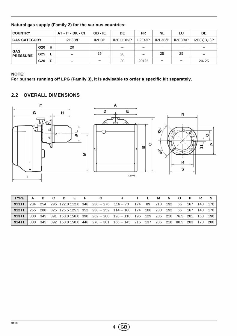
3150
4 GB
Natural gas supply (Family 2) for the various countries:
NOTE:For burners running off LPG (Family 3), it is advisable to order a specific kit separately.
2.2 OVERALL DIMENSIONS
COUNTRY AT - IT - DK - CH GB - IE DE FR NL LU BE
GAS CATEGORY II2H3B/P II2H3P II2ELL3B/P II2Er3P II2L3B/P II2E3B/P I2E(R)B, I3P
GASPRESSURE
G20 H 20 – – – – – –
G25 L – 25 20 – 25 25 –
G20 E – – 20 20/25 – – 20/25
TYPE A B C D E F G H I L M N O P R S
911T1 234 254 295 122.0 112.0 346 230 − 276 116 − 70 174 89 210 192 66 167 140 170
912T1 255 280 325 125.5 125.5 352 238 − 252 114 − 100 174 106 230 192 66 167 140 170
913T1 300 345 391 150.0 150.0 390 262 − 280 128 − 110 196 129 285 216 76.5 201 160 190
914T1 300 345 392 150.0 150.0 446 278 − 301 168 − 145 216 137 286 218 80.5 203 170 200
F
HG
AD E
I
R
S
N
45°
45° 11
OP
B
C
M
ø L
D5008
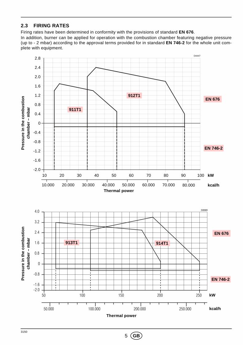
3150
5 GB
2.3 FIRING RATES Firing rates have been determined in conformity with the provisions of standard EN 676. In addition, burner can be applied for operation with the combustion chamber featuring negative pressure(up to - 2 mbar) according to the approval terms provided for in standard EN 746-2 for the whole unit com-plete with equipment.
Thermal power
Thermal power
Pre
ssur
e in
the
com
bust
ion
cham
ber
– m
bar
Pre
ssur
e in
the
com
bust
ion
cham
ber
– m
bar
10.000 80.000
kW10
kcal/h
2.4
0.8
0.4
0
D4447
20 30 40 50 60 70 80 90 100
1.2
1.6
2.0
20.000 30.000 40.000 50.000 60.000 70.000
2.8
-0.4
-0.8
-1.2
-1.6
-2.0
EN 676
EN 746-2
911T1
912T1
50 100 150 200 250
50.000 100.000 200.000 250.000
0
0.8
1.6
2.4
3.2
4.0
-0.8
-1.6-2.0
kW
kcal/h
D8989
913T1 914T1
EN 676
EN 746-2
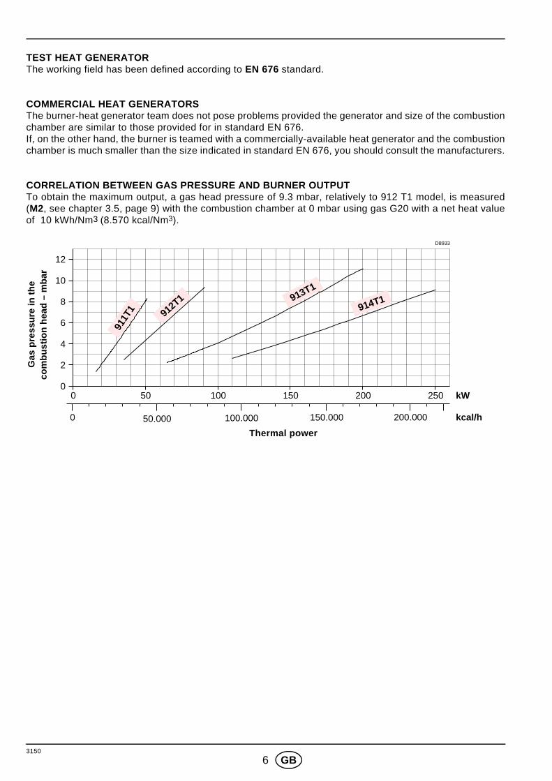
3150
6 GB
TEST HEAT GENERATORThe working field has been defined according to EN 676 standard.
COMMERCIAL HEAT GENERATORSThe burner-heat generator team does not pose problems provided the generator and size of the combustionchamber are similar to those provided for in standard EN 676.If, on the other hand, the burner is teamed with a commercially-available heat generator and the combustionchamber is much smaller than the size indicated in standard EN 676, you should consult the manufacturers.
CORRELATION BETWEEN GAS PRESSURE AND BURNER OUTPUTTo obtain the maximum output, a gas head pressure of 9.3 mbar, relatively to 912 T1 model, is measured(M2, see chapter 3.5, page 9) with the combustion chamber at 0 mbar using gas G20 with a net heat valueof 10 kWh/Nm3 (8.570 kcal/Nm3).
Thermal power
Gas
pre
ssur
e in
the
com
bust
ion
head
– m
bar
D8933
0 50 100 150 200 kW
0 50.000 100.000 150.000 kcal/h
10
8
6
4
2
0250
200.000
12
911T
1 912T1 913T1
914T1

3150
7 GB
3. INSTALLATION
THE BURNER MUST BE INSTALLED IN CONFORMITY WITH LEGISLATION AND LOCAL STANDARDS.
3.1 HEAT GENERATOR FIXING Widen, if necessary, the insulating gasket holes (3, fig. 3).
Fix the flange (5) to the heat generator door (1) using four screws (4) and (if necessary) the nuts (2)interposing the insulating gasket (3) but keep unloosing one of the two upper screws (4) (see fig. 2).
Put on the flange (5) the burner combustion head, tighten the flange with the screws (6) and lock theloose screw (4).
N.B.: The burner can be fixed with the variable dimension (A) (see fig. 4). Anyway, make sure that thecombustion head crosses completely the heat generator door thickness.
3.2 WORKING POSITION
Fig. 2Fig. 3
TYPE A911 T1 116 - 70912 T1 114 - 100913 T1 128 - 110914 T1 167.5 - 145
D5012
S7002
Fig. 4
A
D5011
The burner is designed to workonly in the positions 1, 2, 3, 5, 6and 7. The installation layout illustratedin position 5 is only possible us-ing the “MULTI-BLOC rotationkit”, to be ordered separately.
Any other position could compro-mise the correct working of theappliance. Installation 3 are for-bidden for safety reasons.
D4450
1 2 3 4
5 6 7
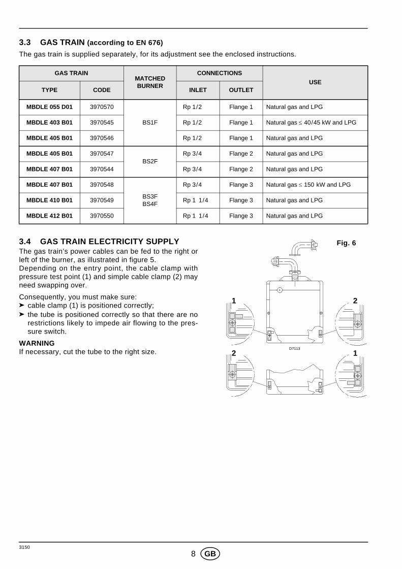
3150
8 GB
3.3 GAS TRAIN (according to EN 676)The gas train is supplied separately, for its adjustment see the enclosed instructions.
3.4 GAS TRAIN ELECTRICITY SUPPLY The gas train’s power cables can be fed to the right orleft of the burner, as illustrated in figure 5.Depending on the entry point, the cable clamp withpressure test point (1) and simple cable clamp (2) mayneed swapping over.
Consequently, you must make sure:cable clamp (1) is positioned correctly;the tube is positioned correctly so that there are norestrictions likely to impede air flowing to the pres-sure switch.
WARNINGIf necessary, cut the tube to the right size.
GAS TRAINMATCHED BURNER
CONNECTIONSUSE
TYPE CODE INLET OUTLET
MBDLE 055 D01 3970570
BS1F
Rp 1/2 Flange 1 Natural gas and LPG
MBDLE 403 B01 3970545 Rp 1/2 Flange 1 Natural gas ≤ 40/45 kW and LPG
MBDLE 405 B01 3970546 Rp 1/2 Flange 1 Natural gas and LPG
MBDLE 405 B01 3970547BS2F
Rp 3/4 Flange 2 Natural gas and LPG
MBDLE 407 B01 3970544 Rp 3/4 Flange 2 Natural gas and LPG
MBDLE 407 B01 3970548
BS3FBS4F
Rp 3/4 Flange 3 Natural gas ≤ 150 kW and LPG
MBDLE 410 B01 3970549 Rp 1 1/4 Flange 3 Natural gas and LPG
MBDLE 412 B01 3970550 Rp 1 1/4 Flange 3 Natural gas and LPG
2
1 2
1
Fig. 6
D7113

3150
9 GB
3.5 GAS FEEDING LINE
M2
D5209
1 2 3 M1 5 6 74 8 Fig. 6
Key to lay-out1 – Gas supply pipe 2 – Manual cock (charged to the installer)3 – Gas pressure gauge (charged to the installer)4 – Filter5 – Gas pressure switch6 – Safety valve7 – Pressure governor8 – Adjusting valveM1 – Gas-supply pressure test pointM2 – Pressure coupling test point
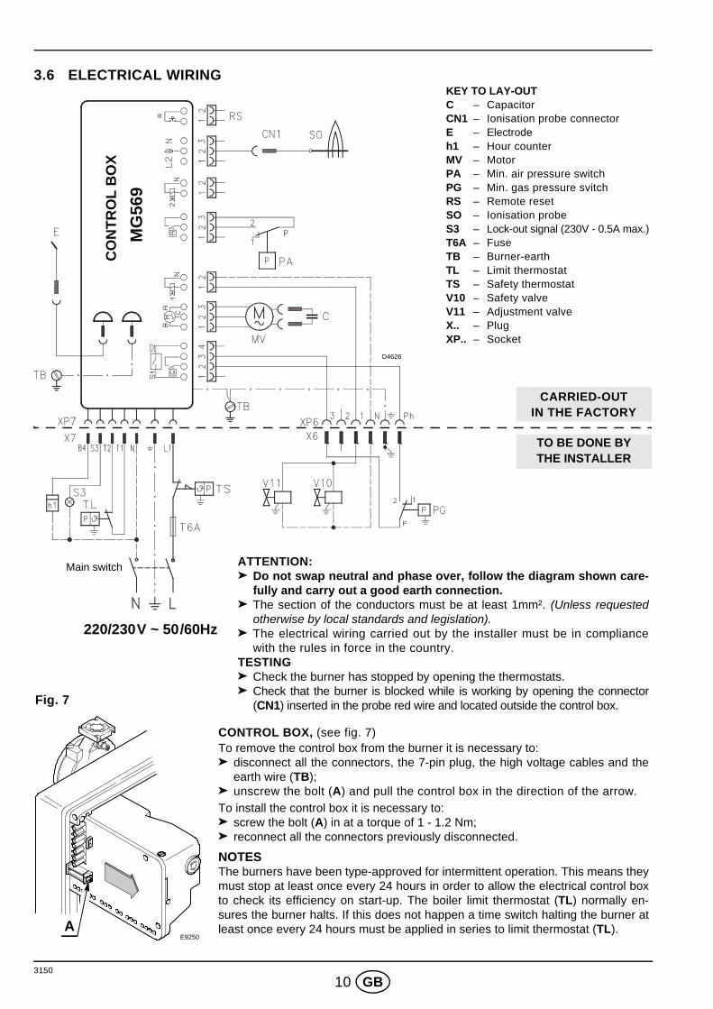
3150
10 GB
3.6 ELECTRICAL WIRING
Main switch
220/230V ~ 50/60Hz
D4626
ATTENTION: Do not swap neutral and phase over, follow the diagram shown care-fully and carry out a good earth connection.The section of the conductors must be at least 1mm². (Unless requestedotherwise by local standards and legislation).The electrical wiring carried out by the installer must be in compliancewith the rules in force in the country.
TESTINGCheck the burner has stopped by opening the thermostats.Check that the burner is blocked while is working by opening the connector(CN1) inserted in the probe red wire and located outside the control box.
CONTROL BOX, (see fig. 7)To remove the control box from the burner it is necessary to:
disconnect all the connectors, the 7-pin plug, the high voltage cables and theearth wire (TB);unscrew the bolt (A) and pull the control box in the direction of the arrow.
To install the control box it is necessary to:screw the bolt (A) in at a torque of 1 - 1.2 Nm;reconnect all the connectors previously disconnected.
NOTESThe burners have been type-approved for intermittent operation. This means theymust stop at least once every 24 hours in order to allow the electrical control boxto check its efficiency on start-up. The boiler limit thermostat (TL) normally en-sures the burner halts. If this does not happen a time switch halting the burner atleast once every 24 hours must be applied in series to limit thermostat (TL).
KEY TO LAY-OUTC – CapacitorCN1 – Ionisation probe connectorE – Electrodeh1 – Hour counterMV – MotorPA – Min. air pressure switchPG – Min. gas pressure svitchRS – Remote resetSO – Ionisation probeS3 – Lock-out signal (230V - 0.5A max.)T6A – FuseTB – Burner-earthTL – Limit thermostatTS – Safety thermostatV10 – Safety valveV11 – Adjustment valveX.. – PlugXP.. – Socket
MG
569
CO
NTR
OL
BO
X
TO BE DONE BYTHE INSTALLER
CARRIED-OUTIN THE FACTORY
A
Fig. 7
E9250
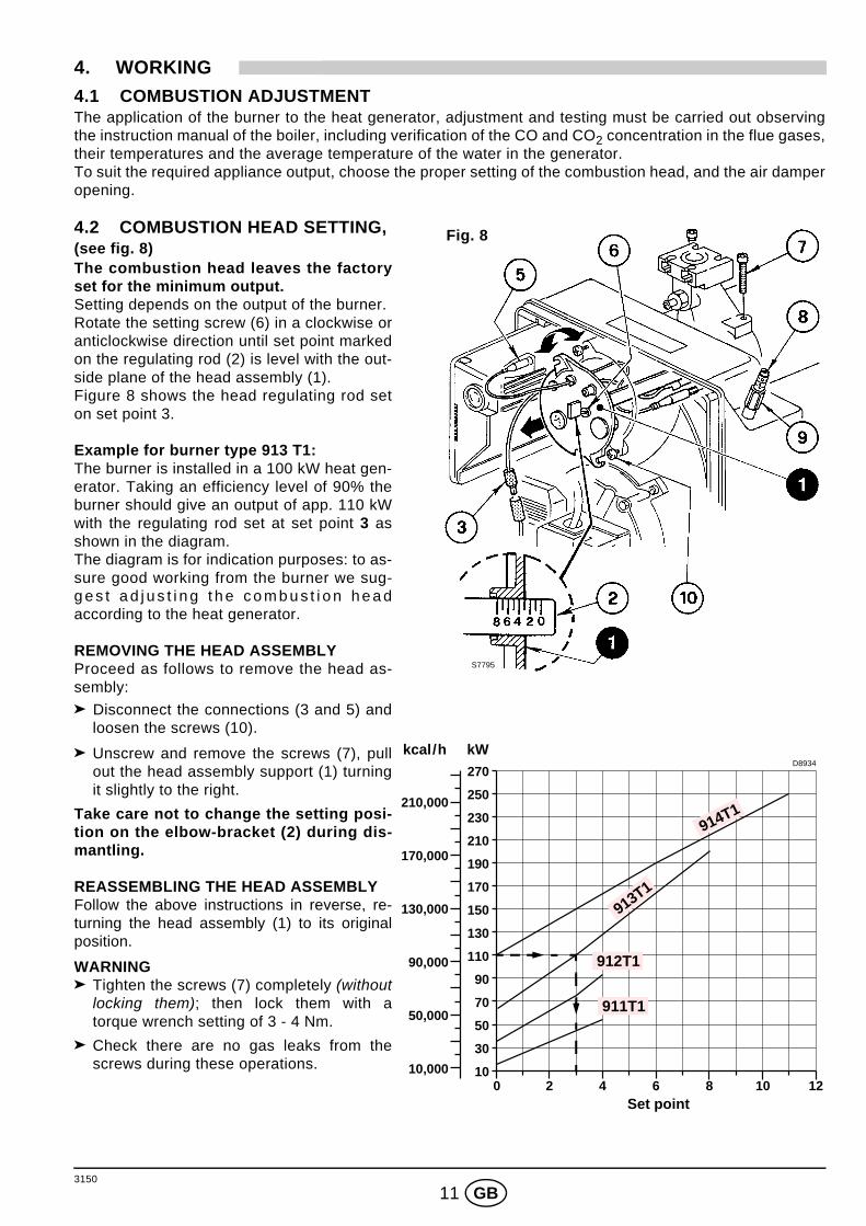
3150
11 GB
4. WORKING4.1 COMBUSTION ADJUSTMENTThe application of the burner to the heat generator, adjustment and testing must be carried out observingthe instruction manual of the boiler, including verification of the CO and CO2 concentration in the flue gases,their temperatures and the average temperature of the water in the generator. To suit the required appliance output, choose the proper setting of the combustion head, and the air damperopening.
4.2 COMBUSTION HEAD SETTING, (see fig. 8)The combustion head leaves the factoryset for the minimum output.Setting depends on the output of the burner.Rotate the setting screw (6) in a clockwise oranticlockwise direction until set point markedon the regulating rod (2) is level with the out-side plane of the head assembly (1).Figure 8 shows the head regulating rod seton set point 3.
Example for burner type 913 T1:The burner is installed in a 100 kW heat gen-erator. Taking an efficiency level of 90% theburner should give an output of app. 110 kWwith the regulating rod set at set point 3 asshown in the diagram.The diagram is for indication purposes: to as-sure good working from the burner we sug-g e s t a d j u s t i n g t h e c o m b u s t i o n h e a daccording to the heat generator.
REMOVING THE HEAD ASSEMBLYProceed as follows to remove the head as-sembly:
Disconnect the connections (3 and 5) andloosen the screws (10).
Unscrew and remove the screws (7), pullout the head assembly support (1) turningit slightly to the right.
Take care not to change the setting posi-tion on the elbow-bracket (2) during dis-mantling.
REASSEMBLING THE HEAD ASSEMBLYFollow the above instructions in reverse, re-turning the head assembly (1) to its originalposition.
WARNINGTighten the screws (7) completely (withoutlocking them); then lock them with atorque wrench setting of 3 - 4 Nm.
Check there are no gas leaks from thescrews during these operations.
S7795
Fig. 8
Set point
D8934
170,000
50,000
210,000
130,000
90,000
10,000
kcal/h kW
0 82 4 6
210
10
50
70
110
130
150
170
190
30
90
230
250
10
270
12
911T1
912T1
913T1
914T1
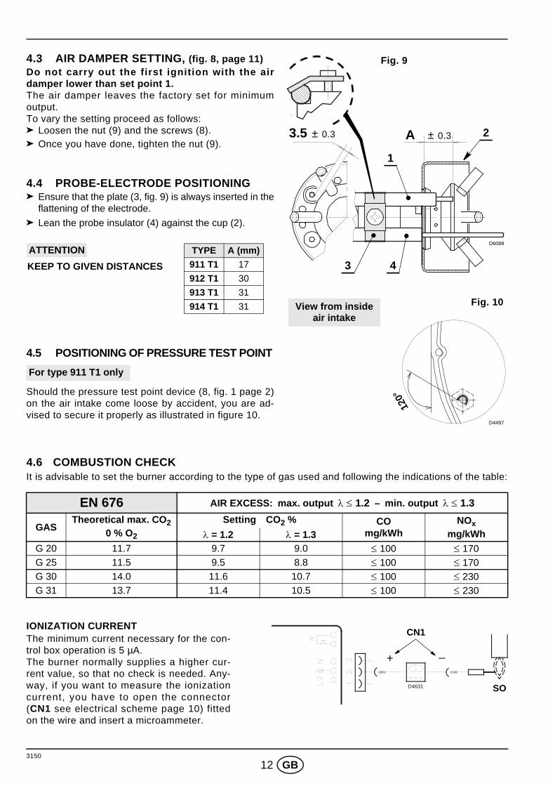
3150
12 GB
4.3 AIR DAMPER SETTING, (fig. 8, page 11) Do not carry out the first ignition with the airdamper lower than set point 1.The air damper leaves the factory set for minimumoutput.To vary the setting proceed as follows:
Loosen the nut (9) and the screws (8).Once you have done, tighten the nut (9).
4.4 PROBE-ELECTRODE POSITIONINGEnsure that the plate (3, fig. 9) is always inserted in theflattening of the electrode.
Lean the probe insulator (4) against the cup (2).
4.5 POSITIONING OF PRESSURE TEST POINT
Should the pressure test point device (8, fig. 1 page 2)on the air intake come loose by accident, you are ad-vised to secure it properly as illustrated in figure 10.
4.6 COMBUSTION CHECKIt is advisable to set the burner according to the type of gas used and following the indications of the table:
IONIZATION CURRENT The minimum current necessary for the con-trol box operation is 5 µA.The burner normally supplies a higher cur-rent value, so that no check is needed. Any-way, if you want to measure the ionizationcurrent, you have to open the connector(CN1 see electrical scheme page 10) fittedon the wire and insert a microammeter.
EN 676 AIR EXCESS: max. output λ ≤ 1.2 – min. output λ ≤ 1.3
GASTheoretical max. CO2
0 % O2
Setting CO2 % COmg/kWh
NOxmg/kWhλ = 1.2 λ = 1.3
G 20 11.7 9.7 9.0 ≤ 100 ≤ 170G 25 11.5 9.5 8.8 ≤ 100 ≤ 170G 30 14.0 11.6 10.7 ≤ 100 ≤ 230G 31 13.7 11.4 10.5 ≤ 100 ≤ 230
D6088
± 0.3 3.5 ± 0.3 A
Fig. 9
1
3
2
4
Fig. 10
120°
D4497
View from insideair intake
TYPE A (mm)911 T1 17
912 T1 30
913 T1 31
914 T1 31
KEEP TO GIVEN DISTANCES
ATTENTION
For type 911 T1 only
D4631
+ _
SO
CN1
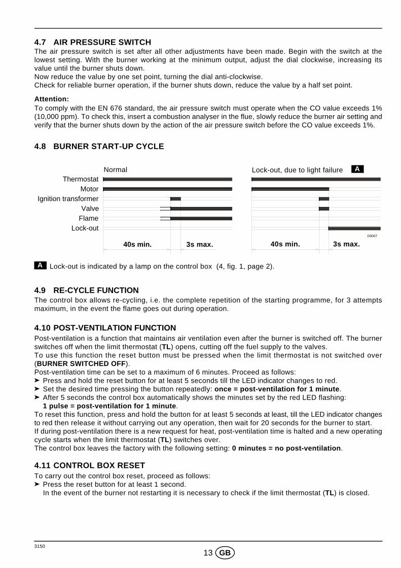
3150
13 GB
4.7 AIR PRESSURE SWITCH The air pressure switch is set after all other adjustments have been made. Begin with the switch at thelowest setting. With the burner working at the minimum output, adjust the dial clockwise, increasing itsvalue until the burner shuts down. Now reduce the value by one set point, turning the dial anti-clockwise.Check for reliable burner operation, if the burner shuts down, reduce the value by a half set point.
Attention:To comply with the EN 676 standard, the air pressure switch must operate when the CO value exceeds 1%(10,000 ppm). To check this, insert a combustion analyser in the flue, slowly reduce the burner air setting andverify that the burner shuts down by the action of the air pressure switch before the CO value exceeds 1%.
4.8 BURNER START-UP CYCLE
Lock-out is indicated by a lamp on the control box (4, fig. 1, page 2).
4.9 RE-CYCLE FUNCTIONThe control box allows re-cycling, i.e. the complete repetition of the starting programme, for 3 attemptsmaximum, in the event the flame goes out during operation.
4.10 POST-VENTILATION FUNCTION Post-ventilation is a function that maintains air ventilation even after the burner is switched off. The burnerswitches off when the limit thermostat (TL) opens, cutting off the fuel supply to the valves.To use this function the reset button must be pressed when the limit thermostat is not switched over(BURNER SWITCHED OFF).Post-ventilation time can be set to a maximum of 6 minutes. Proceed as follows:
Press and hold the reset button for at least 5 seconds till the LED indicator changes to red.Set the desired time pressing the button repeatedly: once = post-ventilation for 1 minute.After 5 seconds the control box automatically shows the minutes set by the red LED flashing: 1 pulse = post-ventilation for 1 minute.
To reset this function, press and hold the button for at least 5 seconds at least, till the LED indicator changesto red then release it without carrying out any operation, then wait for 20 seconds for the burner to start.If during post-ventilation there is a new request for heat, post-ventilation time is halted and a new operatingcycle starts when the limit thermostat (TL) switches over.The control box leaves the factory with the following setting: 0 minutes = no post-ventilation.
4.11 CONTROL BOX RESET To carry out the control box reset, proceed as follows:
Press the reset button for at least 1 second. In the event of the burner not restarting it is necessary to check if the limit thermostat (TL) is closed.
ThermostatMotor
Ignition transformerValve
FlameLock-out
40s min. 3s max. 40s min. 3s max.
Lock-out, due to light failure ANormal
D5007
A
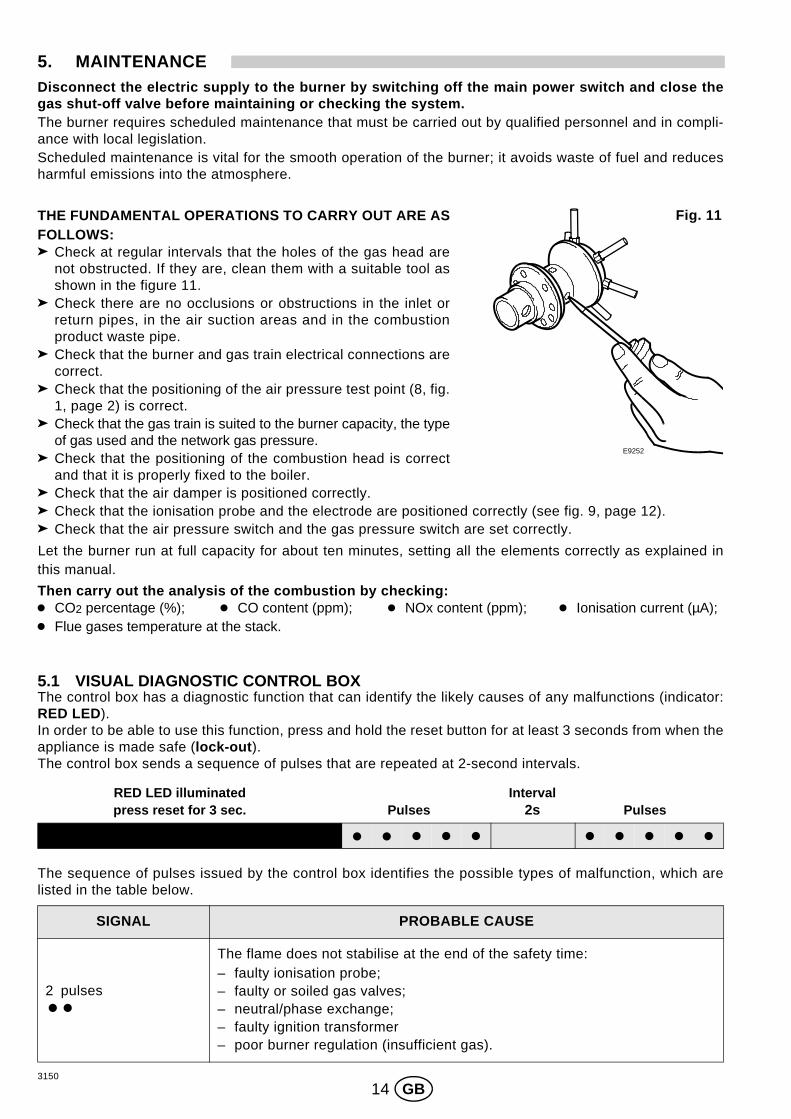
3150
14 GB
5. MAINTENANCEDisconnect the electric supply to the burner by switching off the main power switch and close thegas shut-off valve before maintaining or checking the system. The burner requires scheduled maintenance that must be carried out by qualified personnel and in compli-ance with local legislation.Scheduled maintenance is vital for the smooth operation of the burner; it avoids waste of fuel and reducesharmful emissions into the atmosphere.
THE FUNDAMENTAL OPERATIONS TO CARRY OUT ARE ASFOLLOWS:
Check at regular intervals that the holes of the gas head arenot obstructed. If they are, clean them with a suitable tool asshown in the figure 11.Check there are no occlusions or obstructions in the inlet orreturn pipes, in the air suction areas and in the combustionproduct waste pipe.Check that the burner and gas train electrical connections arecorrect. Check that the positioning of the air pressure test point (8, fig.1, page 2) is correct.Check that the gas train is suited to the burner capacity, the typeof gas used and the network gas pressure.Check that the positioning of the combustion head is correctand that it is properly fixed to the boiler.Check that the air damper is positioned correctly.Check that the ionisation probe and the electrode are positioned correctly (see fig. 9, page 12).Check that the air pressure switch and the gas pressure switch are set correctly.
Let the burner run at full capacity for about ten minutes, setting all the elements correctly as explained inthis manual.
Then carry out the analysis of the combustion by checking: CO2 percentage (%); CO content (ppm); NOx content (ppm); Ionisation current (µA); Flue gases temperature at the stack.
5.1 VISUAL DIAGNOSTIC CONTROL BOXThe control box has a diagnostic function that can identify the likely causes of any malfunctions (indicator:RED LED).In order to be able to use this function, press and hold the reset button for at least 3 seconds from when theappliance is made safe (lock-out). The control box sends a sequence of pulses that are repeated at 2-second intervals.
The sequence of pulses issued by the control box identifies the possible types of malfunction, which arelisted in the table below.
SIGNAL PROBABLE CAUSE
2 pulses
The flame does not stabilise at the end of the safety time:– faulty ionisation probe;– faulty or soiled gas valves;– neutral/phase exchange;– faulty ignition transformer– poor burner regulation (insufficient gas).
Fig. 11
E9252
2sPulses PulsesRED LED illuminatedpress reset for 3 sec.
Interval
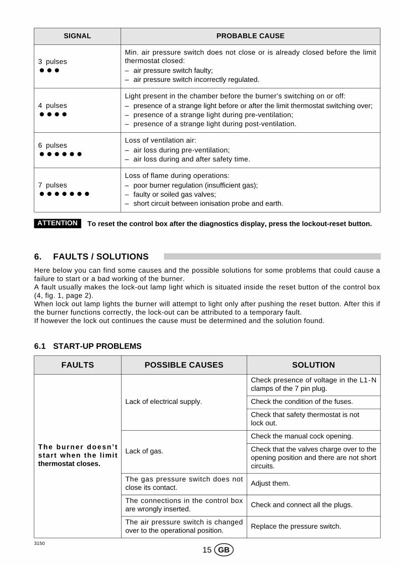
3150
15 GB
To reset the control box after the diagnostics display, press the lockout-reset button.
6. FAULTS / SOLUTIONSHere below you can find some causes and the possible solutions for some problems that could cause afailure to start or a bad working of the burner. A fault usually makes the lock-out lamp light which is situated inside the reset button of the control box(4, fig. 1, page 2).When lock out lamp lights the burner will attempt to light only after pushing the reset button. After this ifthe burner functions correctly, the lock-out can be attributed to a temporary fault.If however the lock out continues the cause must be determined and the solution found.
6.1 START-UP PROBLEMS
SIGNAL PROBABLE CAUSE
3 pulsesMin. air pressure switch does not close or is already closed before the limitthermostat closed:– air pressure switch faulty;– air pressure switch incorrectly regulated.
4 pulsesLight present in the chamber before the burner’s switching on or off:– presence of a strange light before or after the limit thermostat switching over;– presence of a strange light during pre-ventilation;– presence of a strange light during post-ventilation.
6 pulsesLoss of ventilation air:– air loss during pre-ventilation;– air loss during and after safety time.
7 pulsesLoss of flame during operations:– poor burner regulation (insufficient gas);– faulty or soiled gas valves;– short circuit between ionisation probe and earth.
FAULTS POSSIBLE CAUSES SOLUTION
The burner doesn’ tstart when the l imitthermostat closes.
Lack of electrical supply.
Check presence of voltage in the L1-Nclamps of the 7 pin plug.
Check the condition of the fuses.
Check that safety thermostat is not lock out.
Lack of gas.
Check the manual cock opening.
Check that the valves charge over to theopening position and there are not shortcircuits.
The gas pressure switch does notclose its contact.
Adjust them.
The connections in the control boxare wrongly inserted.
Check and connect all the plugs.
The air pressure switch is changedover to the operational position.
Replace the pressure switch.
ATTENTION
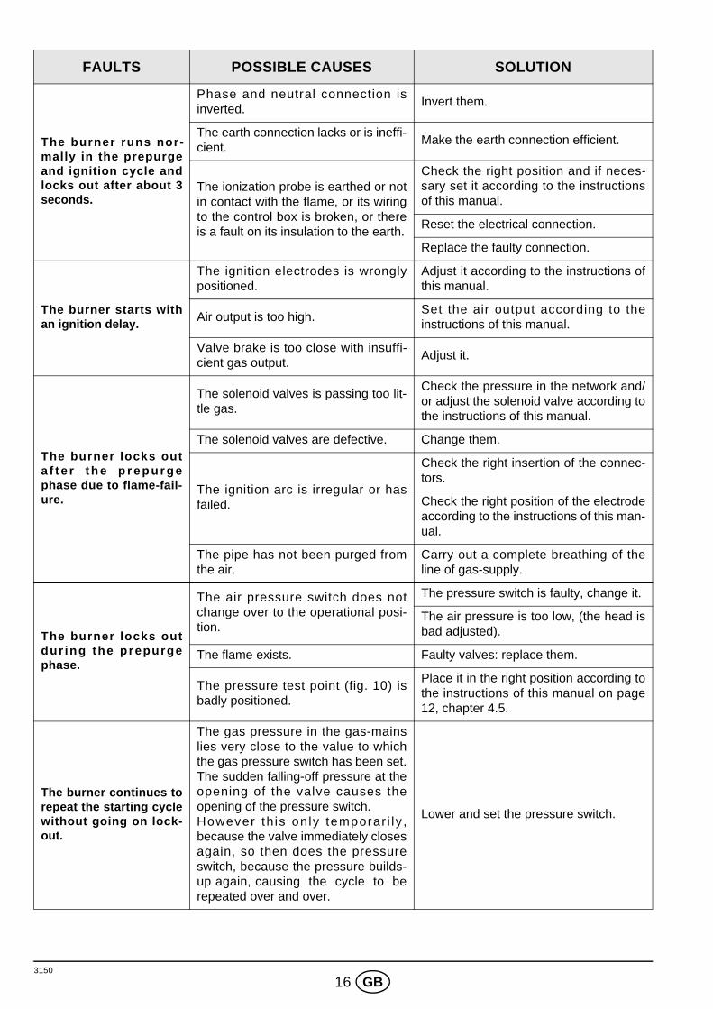
3150
16 GB
The burner runs nor-mally in the prepurgeand ignition cycle andlocks out after about 3seconds.
Phase and neutral connection isinverted.
Invert them.
The earth connection lacks or is ineffi-cient.
Make the earth connection efficient.
The ionization probe is earthed or notin contact with the flame, or its wiringto the control box is broken, or thereis a fault on its insulation to the earth.
Check the right position and if neces-sary set it according to the instructionsof this manual.
Reset the electrical connection.
Replace the faulty connection.
The burner starts withan ignition delay.
The ignition electrodes is wronglypositioned.
Adjust it according to the instructions ofthis manual.
Air output is too high.Set the air output according to theinstructions of this manual.
Valve brake is too close with insuffi-cient gas output.
Adjust it.
The burner locks outa f t e r t h e p r e p u r g ephase due to flame-fail-ure.
The solenoid valves is passing too lit-tle gas.
Check the pressure in the network and/or adjust the solenoid valve according tothe instructions of this manual.
The solenoid valves are defective. Change them.
The ignition arc is irregular or hasfailed.
Check the right insertion of the connec-tors.
Check the right position of the electrodeaccording to the instructions of this man-ual.
The pipe has not been purged fromthe air.
Carry out a complete breathing of theline of gas-supply.
The burner locks outdur ing the prepurgephase.
The air pressure switch does notchange over to the operational posi-tion.
The pressure switch is faulty, change it.
The air pressure is too low, (the head isbad adjusted).
The flame exists. Faulty valves: replace them.
The pressure test point (fig. 10) isbadly positioned.
Place it in the right position according tothe instructions of this manual on page12, chapter 4.5.
The burner continues torepeat the starting cyclewithout going on lock-out.
The gas pressure in the gas-mainslies very close to the value to whichthe gas pressure switch has been set.The sudden falling-off pressure at theopening of the valve causes theopening of the pressure switch.However th is only temporar i ly ,because the valve immediately closesagain, so then does the pressureswitch, because the pressure builds-up again, causing the cycle to berepeated over and over.
Lower and set the pressure switch.
FAULTS POSSIBLE CAUSES SOLUTION
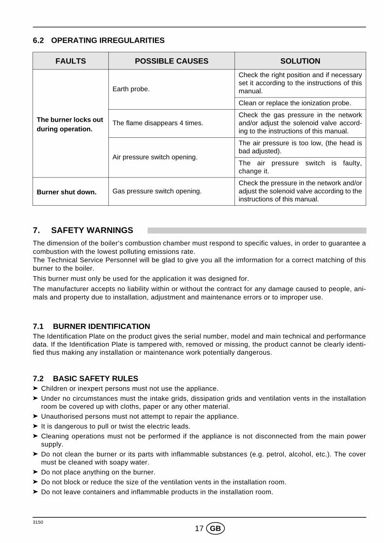
3150
17 GB
6.2 OPERATING IRREGULARITIES
7. SAFETY WARNINGSThe dimension of the boiler’s combustion chamber must respond to specific values, in order to guarantee acombustion with the lowest polluting emissions rate. The Technical Service Personnel will be glad to give you all the imformation for a correct matching of thisburner to the boiler.
This burner must only be used for the application it was designed for.
The manufacturer accepts no liability within or without the contract for any damage caused to people, ani-mals and property due to installation, adjustment and maintenance errors or to improper use.
7.1 BURNER IDENTIFICATIONThe Identification Plate on the product gives the serial number, model and main technical and performancedata. If the Identification Plate is tampered with, removed or missing, the product cannot be clearly identi-fied thus making any installation or maintenance work potentially dangerous.
7.2 BASIC SAFETY RULESChildren or inexpert persons must not use the appliance.
Under no circumstances must the intake grids, dissipation grids and ventilation vents in the installationroom be covered up with cloths, paper or any other material.
Unauthorised persons must not attempt to repair the appliance.
It is dangerous to pull or twist the electric leads.
Cleaning operations must not be performed if the appliance is not disconnected from the main powersupply.
Do not clean the burner or its parts with inflammable substances (e.g. petrol, alcohol, etc.). The covermust be cleaned with soapy water.
Do not place anything on the burner.
Do not block or reduce the size of the ventilation vents in the installation room.
Do not leave containers and inflammable products in the installation room.
FAULTS POSSIBLE CAUSES SOLUTION
The burner locks out during operation.
Earth probe.
Check the right position and if necessaryset it according to the instructions of thismanual.
Clean or replace the ionization probe.
The flame disappears 4 times.Check the gas pressure in the networkand/or adjust the solenoid valve accord-ing to the instructions of this manual.
Air pressure switch opening.
The air pressure is too low, (the head isbad adjusted).
The air pressure switch is faulty,change it.
Burner shut down. Gas pressure switch opening.Check the pressure in the network and/oradjust the solenoid valve according to theinstructions of this manual.

RIELLO S.p.A.
I-37045 Legnago (VR)
Tel.: +39.0442.630111
http:// www.rielloburners.com
Con riserva di modifiche - Änderungen vorbehalten! - Subject to modifications