BIE320T BIE420T BIE420TZ BIS640T BIS830T -...
40
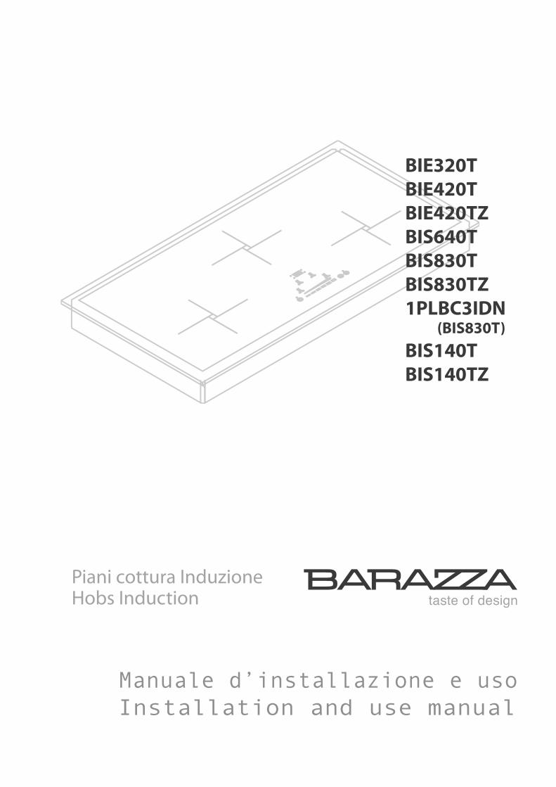
BIE320T BIE420T BIE420TZ BIS640T BIS830T BIS830TZ 1PLBC3IDN (BIS830T) BIS140T BIS140TZ taste of design Piani cottura Induzione Hobs Induc tion Manuale d’installazione e uso Installation and use manual
Transcript of BIE320T BIE420T BIE420TZ BIS640T BIS830T -...
BIE320T
BIE420T
BIE420TZ
BIS640T
BIS830T
BIS830TZ
1PLBC3IDN (BIS830T)
BIS140T
BIS140TZ
taste of design
Piani cottura InduzioneHobs Induction
Manuale d’installazione e uso
Installation and use manual
2
Complimenti per aver acquistato una apparec-
chiatura Barazza!
Questa è un’apparecchiatura di grande qualità in grado di accompagnarvi nel Vostro lavoro per lungo tempo in modo affidabile e sicuro fornendo presta-zioni di altissimo livello.
L’installazione e l’uso dell’apparecchiatura è semplice e immediato.
Vi invitiamo a leggere attentamente questo manuale: ciò permetterà un’ installazione e un utilizzo corretto che manterrà la Vostra apparecchiatura sempre per-fetta ed efficiente negli anni.
Per agevolare la lettura del manuale sono riportati i seguenti simboli:
Prescrizioni importanti per la sicurezza perso-nale e dell’apparecchiatura
Informazioni generali
Congratulations on purchasing a Barazza ap-
pliance!
This safe and reliable high-quality appliance can assist
you in your work with long-lasting top-level perform-
ance.
It also has the added advantage of being quick and
simple to install and easy to use.
Please read this manual carefully, as it provides im-
portant information for the correct installation and
use of the appliance which will ensure its long-term
efficiency.
The following symbols are used to assist you in reading
this manual:
Important rules for personal safety and the
safety of the appliance
General information
Il Costruttore si riserva di apportare ai propri prodotti e a questo manuale le modi!che che riterrà opportune senza obbligo di preavviso. I disegni, gli schemi di installazione e le tabelle contenuti all’in-terno del manuale sono da ritenersi indicativi ed esclusivamente a titolo d’informazione.
Gli impianti di allacciamento dell’immobile devono rispettare le normative nazionali vigenti.
É vietata la copia, la riproduzione parziale o totale dei conte-nuti e l’inoltro di questo manuale a terzi senza il permesso del Costruttore.
Questo apparecchio è conforme alle prescrizioni delle direttive comunitarie CEE 87/308 del 2.6.87 (recepita con D.M. del 13.4.89) sulla prevenzione ed eliminazione dei radiodisturbi, n. 89/336 sul-la compatibilità elettromagnetica e 73/23 sulla bassa tensione.Le istruzioni del presente libretto sono valide solamente per il Paese di destinazione.
The manufacturer reserves the right to make any changes
deemed suitable to the product without prior notice.
The drawings, installation diagrams and tables contained in this
manual are approximate and for informational purposes only.
The systems for connecting the appliance must comply with current
national regulations.
The partial or complete reproduction or photocopying of the contents
of this manual is forbidden, as well as the sending of this manual to
third parties , without the Manufacturer’s permission.
This appliance conforms to the EEC community guidelines 87/308
of 2.6.87 (acknowledged with Ministerial Decree of 13.4.89) on the
prevention and elimination of radio interference, no. 89/336 on
electromagnetic compatibility, 73/23 on low voltage.
The instructions in this booklet are valid only for the country of
destination.

3
INDICE INDEX
DESCRIZIONE PAG.
DATI TECNICI 4
INSTALLAZIONE 6
Avvertenze di sicurezza 6
Controllo e movimentazione 7
Smaltimento degli imballi 7
Scelta del luogo di installazione 8
Collegamento elettrico 9
Incasso apparecchiatura 11
USO 15
Avvertenze di sicurezza 15
Prima di cominciare 17
Conoscere l’apparecchiatura 17
Zona comandi 18
Uso dell’apparecchiatura
BIE420T - BIE420TZ - BIE320T19
Uso dell’apparecchiatura
BIS830T - BIS830TZ - BIS140T - BIS140TZ -
BIS640T
26
MANUTENZIONE 34
Avvertenze di sicurezza 34
Manutenzione ordinaria 34
Pulizia 34
Periodi di inattività 35
Smaltimento a "ne vita 36
Assistenza post-vendita 36
DESCRIPTION PAGE
TECHNICAL DATA 4
INSTALLATION 6
Safety warnings 6
Checks and handling 7
Disposal of the packaging 7
Installation site choice 8
Connection to the power mains 9
Built-in unit installation 11
USAGE 15
Safety warnings 15
Before starting 17
Understanding the appliance 17
Control panel 18
Using the appliance
BIE420T - BIE420TZ - BIE320T19
Using the appliance
BIS830T - BIS830TZ - BIS140T - BIS140TZ -
BIS640T
26
MAINTENANCE 34
Safety warnings 34
Schedule maintenance 34
Cleaning 34
Periods of inactivity 35
End-of-life disposal 36
After-sales service 36
4
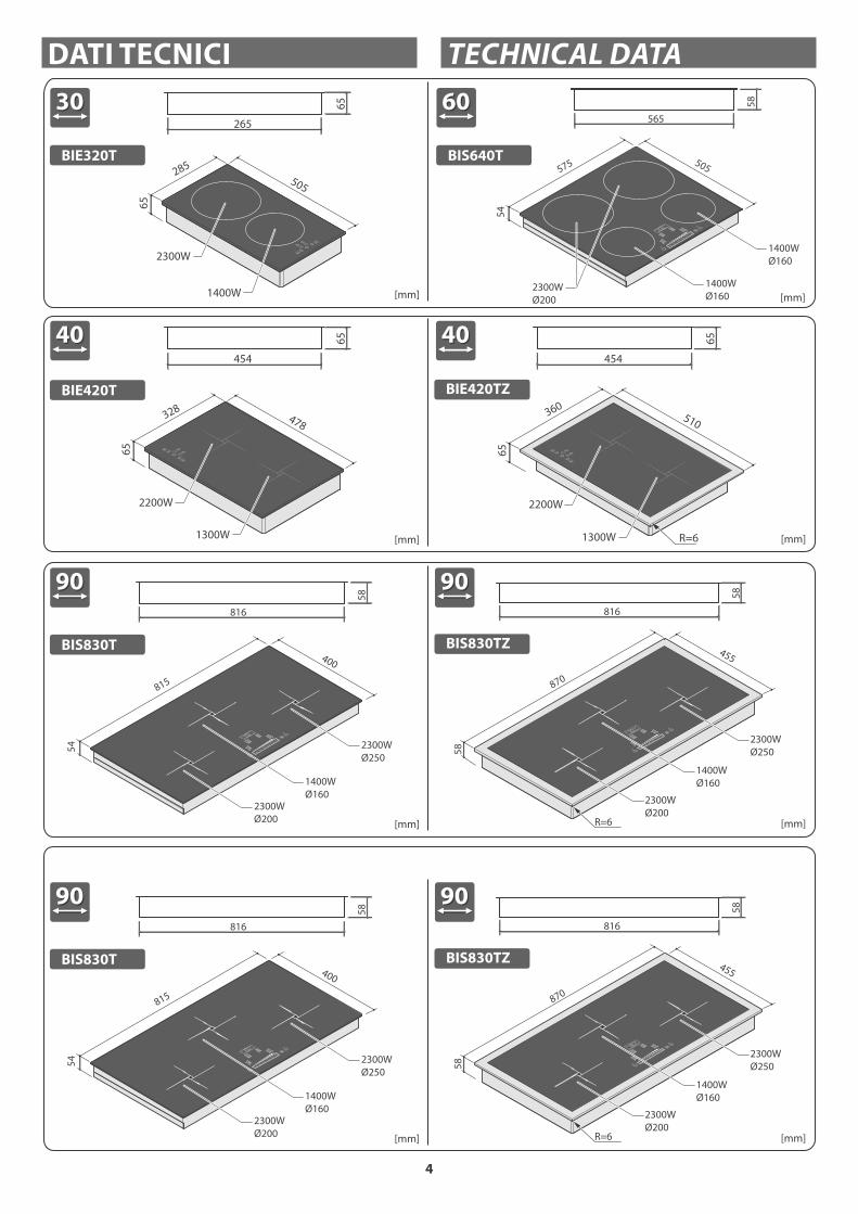
DATI TECNICI TECHNICAL DATA
[mm] [mm]
BIS830T
816
589090 9090
BIS830TZ
[mm] [mm]
BIE420TZBIE420T
4040 4040
65
454
65
478328
2200W
1300W
65
454
65
R=6
510360
400
54
815
2300W
Ø250
2300W
Ø200
1400W
Ø160
2200W
1300W
816
58
455
58
870
R=6
2300W
Ø200
2300W
Ø250
1400W
Ø160
[mm] [mm]
BIS830T
816
589090 9090
BIS830TZ400
54
815
2300W
Ø250
2300W
Ø200
1400W
Ø160
816
58
455
58
870
R=6
2300W
Ø200
2300W
Ø250
1400W
Ø160
[mm]
BIS640T
565
58
6060
505
54
575
1400W
Ø160
1400W
Ø160
2300W
Ø200[mm]
BIE320T
3030
65
265
65
505
285
2300W
1400W

5
Dati tecnici Technical data BIE420T - BIE420TZ
BIE320T
BIS830T - BIS830TZ
BIS140T - BIS140TZ
BIS640TZ
Tensione Voltage V 220-240 220-240
Frequenza Frequency Hz 50/60 50/60
Lunghezza cavo Cable length cm 90 90
Tipo cavo Cable type H05V2V2-F 3x1,5 mm2 H05V2V2-F 3x2,5 mm2
[mm] [mm]
BIS140T
1070
58
BIS140TZ
120120
1070
58
400
58
1095
2300W
Ø200
1400W
Ø160
2300W
Ø200
1400W
Ø160
455
58
1150
R=6
1400W
Ø160
2300W
Ø200
1400W
Ø160
2300W
Ø200
[mm]
1PLBC3IDN
9090
510
870
70
41
3
37558.5 48.5
36
MA
X 4
21
59
100˚
R=6
6
SAFETY WARNINGS
Read this instruction booklet carefully before instal-
lation and/or use of the appliance and keep it handy
so that all the users can consult it; if you give away or sell
the appliance, please ensure that you give this booklet
to the new user so that he can be informed about its
installation, use and safety rules.
The installation and any interventions on the
appliance (special maintenance, etc.) must be carried out
by qualified personnel only, as specified in this booklet.
The connection systems and installation rooms must
be suitable and satisfy the safety standards in force in
the country of use (protective isolating switch, earthing
system, equipotential system, etc.).
The manufacturer will not be held liable if the above
requirements are not satisfied.
During installation, maintenance or repair work,
always switch off the main electrical switch and remove
the connection plug from the socket.
The appliance is not designed for outdoor use.
Appliances may have sharp edges; handle them
with caution and use personal safety equipment (protec-
tive shoes, safety gloves, etc.).
INSTALLAZIONE INSTALLATION
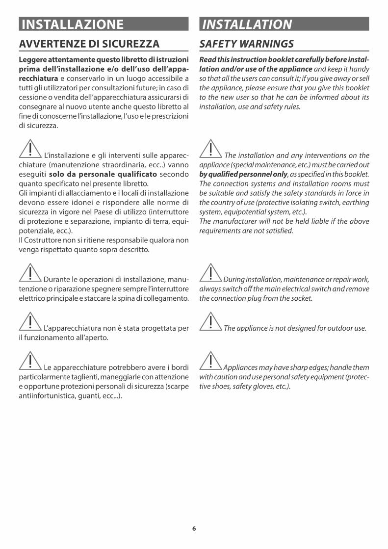
AVVERTENZE DI SICUREZZA
Leggere attentamente questo libretto di istruzioni
prima dell’installazione e/o dell’uso dell’appa-
recchiatura e conservarlo in un luogo accessibile a
tutti gli utilizzatori per consultazioni future; in caso di
cessione o vendita dell’apparecchiatura assicurarsi di
consegnare al nuovo utente anche questo libretto al
fine di conoscerne l’installazione, l’uso e le prescrizioni
di sicurezza.
L’installazione e gli interventi sulle apparec-
chiature (manutenzione straordinaria, ecc..) vanno
eseguiti solo da personale qualificato secondo
quanto specificato nel presente libretto.
Gli impianti di allacciamento e i locali di installazione
devono essere idonei e rispondere alle norme di
sicurezza in vigore nel Paese di utilizzo (interruttore
di protezione e separazione, impianto di terra, equi-
potenziale, ecc.).
Il Costruttore non si ritiene responsabile qualora non
venga rispettato quanto sopra descritto.
Durante le operazioni di installazione, manu-
tenzione o riparazione spegnere sempre l’interruttore
elettrico principale e staccare la spina di collegamento.
L’apparecchiatura non è stata progettata per
il funzionamento all’aperto.
Le apparecchiature potrebbero avere i bordi
particolarmente taglienti, maneggiarle con attenzione
e opportune protezioni personali di sicurezza (scarpe
antiinfortunistica, guanti, ecc...).

7
CHECKS AND HANDLING
After having unpacked the appliance and removed all
the packing materials and protective films from the sur-
faces, check for any anomalies: if you find an anomaly,
do not proceed with the installation but contact your
retailer within 8 days, reporting the data provided on
the appliance’s data plate and describing the problems
you found (figure 1).
Attention! Do not leave the packing materials (plas-
tic bags, polystyrene, etc.) unattended, as they are a
potential hazard for children and animals (danger
of suffocation).
Move the appliance to the installation location using
appropriate personal safety equipment (figure 1) and
adopting all the precautions necessary to prevent dam-
age to the appliance, people, animals and property.
DISPOSAL OF THE PACKAGING
Attention! Dispose of the packaging in compliance
with current regulations in the country where the
appliance is installed.
Package composition:
- cardboard
- polyethylene/ polypropylene: outer packaging film,
instructions bag
- expanded polystyrene: impact protections.
CONTROLLO E MOVIMENTAZIONE
Dopo aver disimballato l’apparecchiatura rimuovendo
tutti i materiali di imballo e le pellicole a protezione
delle superfici, controllare se si notano anomalie
evidenti: in caso affermativo, non procedere all’in-
stallazione e rivolgersi al Rivenditore entro 8 giorni,
comunicando i dati riportati nella targa matricola
dell’apparecchiatura ed i problemi riscontrati (fig. 1).
Attenzione! Non lasciare incustodito il materiale
utilizzato per l’imballo (sacchetti, polistirolo, ecc...)
perché potenzialmente pericoloso per bambini e
animali (pericolo di soffocamento).
Trasportare l’apparecchiatura sul luogo dell’installa-
zione muniti di adeguate protezioni personali (fig. 1)
e adottando tutte le precauzioni necessarie per non
arrecare danni all’apparecchiatura stessa, a persone,
animali e cose.
OK!
1
SMALTIMENTO DEGLI IMBALLI
Attenzione! Smaltire gli imballi in ottemperanza
alle normative vigenti nel Paese di installazione.
Composizione imballo:
- cartone
- polietilene/ polipropilene: pellicola esterna imballo,
sacchetto istruzioni
- polistirolo espanso: protezioni antiurto.

8
SCELTA DEL LUOGO DI INSTALLAZIONE
Caratteristiche del locale di installazione
Le apparecchiature devono essere posizionate in locali interni idonei allo scopo con temperatura max. 25°C e umidità max. 60%; essi devono rispondere alle norme di sicurezza in vigore nel Paese di utilizzo (interruttore di protezione e separazione, impianto di terra, equi-potenziale, ecc.). Le apparecchiature non sono adatte all’installazione all’aperto, esposte agli agenti atmosferici o alle intemperie. Le apparecchiature possono essere montate su mobili il cui materiale sia resistente al calore.
Un piano di cottura incassato a filo del piano di lavoro
è adatto solo per basi in pietra naturale (granito, mar-
mo), legno massello e piastrellate.
Per piani di lavoro in altri materiali chiedere al produt-
tore se sono adatti per l’incasso di piani cottura a filo.
Ventilazione
La distanza tra il piano di cottura e i mobili da cucina o gli altri apparecchi da incasso deve essere tale da garantire una sufficiente ventilazione ed un sufficiente scarico dell’aria (fig. 2).Non utilizzare il piano di cottura se nel forno è in corso il processo di pirolisi.
AIRAIR
min
. 7
0 c
m AIR
2
INSTALLATION SITE CHOICE
Installation site characteristics The appliances must be placed in suitable interior loca-tions with a maximum temperature of 25°C and maximum humidity of 60%; the locations must satisfy the safety standards in force in the country of use (protective isolating switch, earthing system, equipotential system, etc.). The appliances are not designed for outdoor use, to be exposed to the elements or bad weather conditions. Appliances may be assembled onto units made of heat-resistant materials.
A built-in hob, flush with the worktop, is only suitable
with natural stone (granite, marble), solid wood and
tiled bases.
In the instance of bases made from other materials,
please ask the manufacturer whether they are suitable
for flush hobs.
Ventilation clearance
The clearance between the hob and the kitchen units or other built-in appliances must ensure there is sufficient ventilation and a sufficient air outlet (figure 2).Do not use the hob if the oven is performing a pyrolysis process.

9
CONNECTION TO THE POWER MAINS
Before making the connection, make certain
that the voltage and frequency indicated on the data
plate match those of the power supply system.
The appliance is supplied with a 90cm-long power cord
(H05V2V2) to be directly connected to the distribution
network (fig. 3): in this case an omnipolar disconnecting
switch must be provided, with a minimum opening of the
contacts that allows complete disconnection in category
III overvoltage conditions.
Both the power outlet and omnipolar switch must
be up to standard and located in a position which is
accessible even after the appliance is installed.
If the appliance is installed together with an oven, the
connection of the two appliances must be independ-
ent for electrical safety reasons.
The power cord must NOT:
- be crushed or rolled up;
- come into contact with any type of liquid, sharp or hot
objects or corrosive substances;
- reach, at any point, a temperature which is 50°C higher
than the room temperature;
- be replaced with a different type of cable (see “Techni-
cal data” on page 4) or with a cable which is not up to
standard;
- be lengthened with extensions.
COLLEGAMENTO ELETTRICO
Prima dell’allacciamento accertarsi che la
tensione e la frequenza riportate sulla targhetta
caratteristiche corrispondano a quelle dell’impianto
di alimentazione.
L’apparecchiatura viene fornita già provvista di un cavo di
alimentazione (H05V2V2) lungo 90 cm da collegare diret-
tamente alla rete di distribuzione (fig. 3): in questo caso
deve essere previsto un dispositivo per la disconnessione
onnipolare con una distanza di apertura dei contatti che
consenta la disconnessione completa nelle condizioni
della categoria di sovratensione III.
Sia la presa di corrente che l’interruttore onnipolare
devono essere a norma e collocati in posizione accessi-
bile anche con l’apparecchiatura incassata. Se l’appa-
recchiatura viene inserita in abbinamento a un forno,
l’allacciamento delle due apparecchiature deve essere
indipendente per motivi di sicurezza elettrica.
Il cavo di alimentazione NON deve:
- essere schiacciato o arrotolato su se stesso;
- entrare in contatto con liquidi di qualsiasi tipo,
oggetti taglienti o caldi e sostanze corrosive;
- raggiungere in nessun punto una temperatura che
superi di 50°C la temperatura ambiente;
- essere sostituito con uno di tipo diverso (vedi “Dati
tecnici” pag. 4) o non a norma;
- essere allungato con prolunghe.
H05V2V2-F90 cm
A
Mod.Art.N°
...V ...Hz ...Kw
Questo apparecchio deve essere installato conformemente
alle norme in vigore. Consultare il libretto istruzioni prima
di installare e usare l’apparecchio
F.lli Barazza S.r.l MADE IN ITALY
3

10
SOSTITUZIONE DEL CAVO DI ALIMENTAZIONE
In caso di necessità, il cavo di alimentazio-
ne può essere sostituito con uno di tipo identico
(vedi “Dati tecnici” pag. 4) in ottemperanza alle
normative vigenti nel Paese di installazione.
Se l’apparecchiatura è già collegata, stac-
carla dall’alimentazione elettrica.
Per accedere ai collegamenti elettrici, fare leva sui
ganci come indicato (fig. 4).
Staccare il vecchio cavo dai morsetti e rimuoverlo;
collegare il nuovo cavo (unicamente di tipo H05V2V2-
F ) nei rispettivi morsetti, N - L - Terra.
Bloccare il nuovo cavo con l’apposito passacavo
e richiudere la morsettiera riposizionando il suo
coperchio.
4
POWER CORD REPLACEMENT
If necessary, the power cord can be replaced
with an identical type (see “Technical data” on page
4) in compliance with current regulations in the
country where the appliance is installed.
If the appliance is already connected, discon-
nect the electrical power.
To access the electrical connections, to insist on the
hooks like indicated (figure 4).
Disconnect the old cord from the terminals and remove
it; connect the new cord (only the H05V2V2-F type) into
the respective terminals N - L - Earth.
Cover the new cord with the appropriate cord holder and
re-close the terminal, replacing its cover.
* Posizione indicativa
* Example placement
1
4
2
3
1
4
2
3
L
220-240 V ~
H05V2V2-F
380 -415 V 2N ~
L2
L1
NN
2,5 mm2
IND
UZ
ION
E /
IND
UC
TIO
N L
AB
BIS830T
BIS640T
BIS830TZ
BIS140T
BIS140TZ
BIE420T
BIE320T
BIE420TZ
H05V2V2-F
1,5 mm2
220-240 V ~
L N
220-240 V2 ~
single phasetwo phase
L L2
I piani cottura sono predisposti per l’allacciamen-to ad una linea domestica con tensione 220V monofase, è tuttavia possibile adattare l’apparecchiatura ad una diversa tensione secondo quanto riportato nello schema seguente.
The hobs are pre-arranged for connection to a domestic single-phase voltage power supply of 220V; you can adapt the appliance to a different voltage value by following the instructions provided in the diagram below.

11
INCASSO APPARECCHIATURA
Accertarsi del perfetto stato e della stabilità
del mobile nel quale saranno incassate le apparec-
chiature (Normativa DIN 68930).
Preparare un foro di incasso con le misure indicate in
fig. 5a-5b; se l’apparecchiatura sarà incassata sopra un
forno, è necessario predisporre anche un pannello di separazione (B) distante almeno 2 cm dal fondo della stessa, forato nella parte posteriore per il passaggio dell’alimentazione elettrica dell’apparecchiatura.
Inc
ass
o /
Bu
ilt-
in
Fil
o /
Flu
sh
45
8
873
850
43
5
R= 7,5
49
0
873
860
51
3
R= 7,5
363
51
3
49
0
340
R= 7,5
45
8
1153
1130
43
5
R= 7,5
850
860
43
54
90
1130
43
5
1,2
1[mm]1[mm]
120120
9090
9090
4040
49
0
340
5A
BUILT-IN UNIT INSTALLATION
Make certain that the cabinet in which you
will be installing the appliance is in perfect condition
and completely stable (Standard DIN 68930).
Prepare an embedded hole with measurements as specified
in figure 5a-5b; if the appliance is to be installed above an
oven, it is also necessary to provide an isolating panel (B)
with a distance of at least 2 cm from the base of the appli-
ance; the isolating panel must be placed under the appliance
to allow for the appliance’s supply of electrical power.
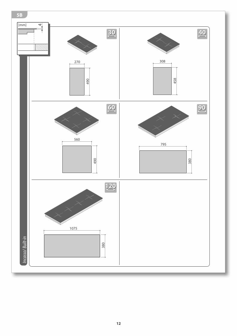
12
Incasso
/ Built-in
3030
6060
560
49
0
49
0
270
1075
38
0
120120
4[mm]
4040
9090
795
38
0
45
8
308
5B
13
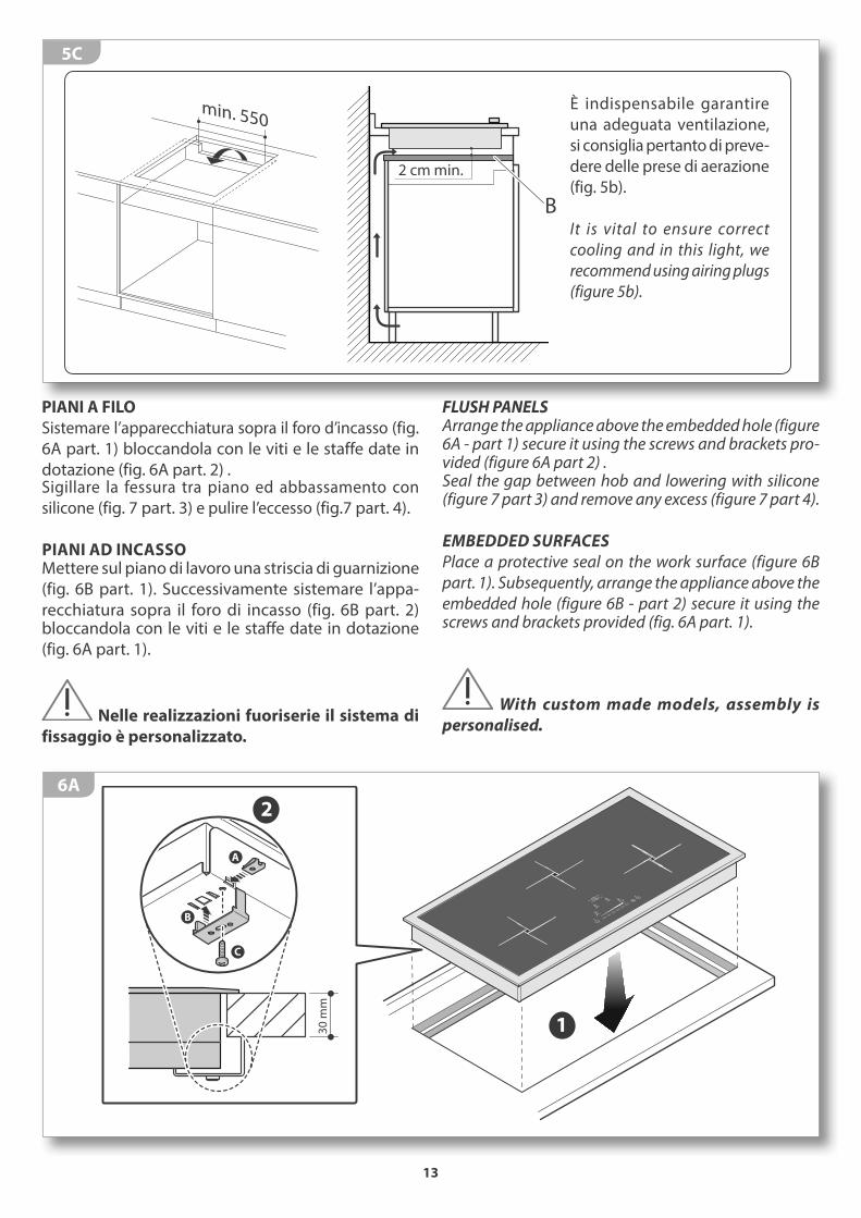
2 cm min.
min. 550
B
5C
FLUSH PANELSArrange the appliance above the embedded hole (figure 6A - part 1) secure it using the screws and brackets pro-vided (figure 6A part 2) .Seal the gap between hob and lowering with silicone (figure 7 part 3) and remove any excess (figure 7 part 4).
EMBEDDED SURFACES
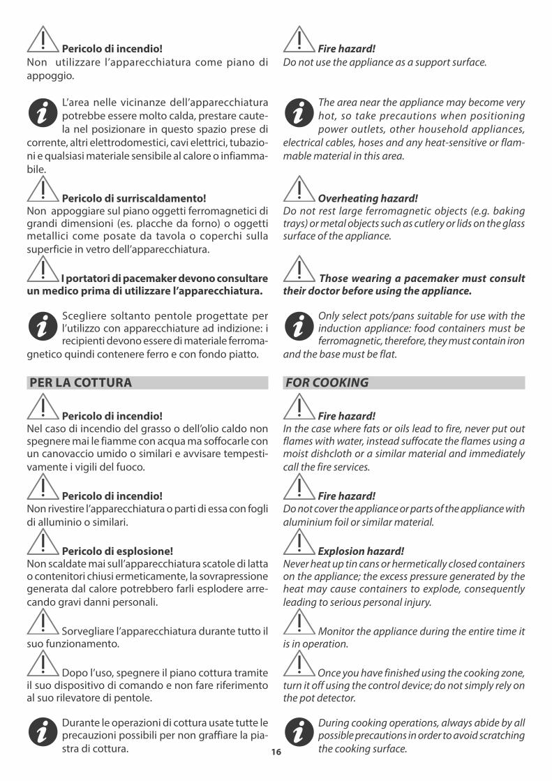
Place a protective seal on the work surface (figure 6B
part. 1). Subsequently, arrange the appliance above the
embedded hole (figure 6B - part 2) secure it using the screws and brackets provided (fig. 6A part. 1).
With custom made models, assembly is
personalised.
È indispensabile garantire una adeguata ventilazione, si consiglia pertanto di preve-dere delle prese di aerazione (fig. 5b).
It is vital to ensure correct
cooling and in this light, we
recommend using airing plugs (figure 5b).
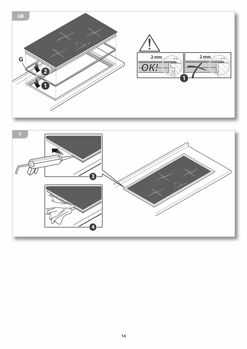
PIANI A FILO
Sistemare l’apparecchiatura sopra il foro d’incasso (fig. 6A part. 1) bloccandola con le viti e le staffe date in dotazione (fig. 6A part. 2) .Sigillare la fessura tra piano ed abbassamento con silicone (fig. 7 part. 3) e pulire l’eccesso (fig.7 part. 4).
PIANI AD INCASSOMettere sul piano di lavoro una striscia di guarnizione (fig. 6B part. 1). Successivamente sistemare l’appa-recchiatura sopra il foro di incasso (fig. 6B part. 2) bloccandola con le viti e le staffe date in dotazione (fig. 6A part. 1).
Nelle realizzazioni fuoriserie il sistema di
fissaggio è personalizzato.
1
A
B
C
30
mm
2
6A
14
3
4
7
2
G
1
1
2 mm 2 mm
OK!
6B

15
USO
AVVERTENZE DI SICUREZZA
PER UN USO CORRETTO E SICURO
Questa apparecchiatura è stata concepita e
realizzata esclusivamente per la cottura degli alimenti.
Un uso diverso è considerato improprio e quindi po-
tenzialmente pericoloso per persone, animali e cose.
Inoltre potrebbe danneggiare irrimediabilmente l’ap-
parecchiatura: in questo caso il Costruttore non si ritiene
responsabile e non riconosce il diritto di Garanzia.
Chiudere sempre l’interruttore elettrico
onnipolare prima di ogni operazione di pulizia o in
previsione di lunga inattività.
Assicurarsi che tutte le manopole siano in
posizione “0 - spento” al termine dell’utilizzo.
Se la superficie del piano è incrinata, spegnere
l’apparecchio e disconnettere dalla rete elettrica per
evitare l’eventualità di scosse elettriche.
L’apparecchiatura non è stata concepita e
realizzata per essere comandata da un timer esterno,
o da un sistema di controllo remoto separato.
Se si dovesse notare una qualsiasi anomalia
non utilizzare l’apparecchiatura e contattare un Centro
di Assistenza autorizzato comunicando i dati presenti
nella targa matricola.
Questa apparecchiatura non è adatta all’uso da parte di persone (inclusi i bambini) con difficoltà fisi-che, sensoriali o mentali o con mancanza di esperienza e conoscenza, a meno che una persona responsabile della loro sicurezza fornisca a queste una supervisione
o un’istruzione riguardo l’uso dell’apparecchiatura.
I bambini devono essere sorvegliati per as-
sicurarsi che non giochino con l’apparecchiatura o
con parti di essa.
Non utilizzare prodotti spray nelle vicinaze di
questa apparecchiatura mentre è in funzione.
Non modificare questa apparecchiatura.
USAGE
SAFETY WARNINGS
FOR SAFE AND CORRECT USE
This appliance has been designed and manufac-
tured exclusively for cooking food. Any other use is consid-
ered improper and thus potentially hazardous for people,
animals and property. Furthermore, it may permanently
damage the appliance: in this case, the Manufacturer will
not be held liable and the Guarantee will be void.
Always disconnect the appliance from the power
supply using the omnipolar switch before carrying out
any cleaning operations or when the appliance will not
be used for an extended period.
Make sure that all the knobs are turned to “0 - off”
when you finish using the appliance.
If the surface of the hob is cracked, turn off the
appliance and disconnect from the electrical main in
order to avoid any possible electric shocks.
The appliance was not designed and manu-
factured to be controlled by an independent timer or a
separate remote control system.
If you should note any anomalies, do not use the
appliance but contact an authorized Service Centre and
report the data indicated on the data plate.
This appliance is not suited for use by persons (including children) with physical, sensorial or mental difficulties or lacking proper experience and knowledge, unless supervised or instructed on the use of the appli-ance by the person responsible for their safety.
Children must be supervised to ensure that they
do not play with the appliance or parts of it.
Do not spray aerosols in the vicinity of this ap-
pliance while it is in operation.
Do not modify this appliance.
16
Pericolo di incendio!
Non utilizzare l’apparecchiatura come piano di
appoggio.
L’area nelle vicinanze dell’apparecchiatura
potrebbe essere molto calda, prestare caute-
la nel posizionare in questo spazio prese di
corrente, altri elettrodomestici, cavi elettrici, tubazio-
ni e qualsiasi materiale sensibile al calore o infiamma-
bile.
Pericolo di surriscaldamento!Non appoggiare sul piano oggetti ferromagnetici di grandi dimensioni (es. placche da forno) o oggetti metallici come posate da tavola o coperchi sulla
superficie in vetro dell’apparecchiatura.
I portatori di pacemaker devono consultare un medico prima di utilizzare l’apparecchiatura.
Scegliere soltanto pentole progettate per l’utilizzo con apparecchiature ad indizione: i recipienti devono essere di materiale ferroma-
gnetico quindi contenere ferro e con fondo piatto.
PER LA COTTURA
Pericolo di incendio!Nel caso di incendio del grasso o dell’olio caldo non spegnere mai le fiamme con acqua ma soffocarle con un canovaccio umido o similari e avvisare tempesti-
vamente i vigili del fuoco.
Pericolo di incendio!Non rivestire l’apparecchiatura o parti di essa con fogli
di alluminio o similari.
Pericolo di esplosione!Non scaldate mai sull’apparecchiatura scatole di latta o contenitori chiusi ermeticamente, la sovrapressione generata dal calore potrebbero farli esplodere arre-
cando gravi danni personali.
Sorvegliare l’apparecchiatura durante tutto il suo funzionamento.
Dopo l’uso, spegnere il piano cottura tramite il suo dispositivo di comando e non fare riferimento al suo rilevatore di pentole.
Durante le operazioni di cottura usate tutte le precauzioni possibili per non graffiare la pia-
stra di cottura.
Fire hazard!
Do not use the appliance as a support surface.
The area near the appliance may become very
hot, so take precautions when positioning
power outlets, other household appliances,
electrical cables, hoses and any heat-sensitive or flam-
mable material in this area.
Overheating hazard!Do not rest large ferromagnetic objects (e.g. baking trays) or metal objects such as cutlery or lids on the glass surface of the appliance.
Those wearing a pacemaker must consult their doctor before using the appliance.
Only select pots/pans suitable for use with the induction appliance: food containers must be ferromagnetic, therefore, they must contain iron
and the base must be flat.
FOR COOKING
Fire hazard!In the case where fats or oils lead to fire, never put out flames with water, instead suffocate the flames using a moist dishcloth or a similar material and immediately
call the fire services.
Fire hazard!Do not cover the appliance or parts of the appliance with
aluminium foil or similar material.
Explosion hazard!Never heat up tin cans or hermetically closed containers on the appliance; the excess pressure generated by the heat may cause containers to explode, consequently
leading to serious personal injury.
Monitor the appliance during the entire time it is in operation.
Once you have finished using the cooking zone, turn it off using the control device; do not simply rely on the pot detector.
During cooking operations, always abide by all possible precautions in order to avoid scratching
the cooking surface.
17
PRIMA DI COMINCIARE
CONOSCERE L’APPARECCHIATURA
I piani cottura ad induzione sono dotati di spe-ciali bobine ad induzione in grado di generare un campo magnetico che viene trasferito diret-
tamente ai componenti ferrosi del fondo della pentola.I vantaggi della cottura ad induzione sono molteplici:- ottimi rendimenti senza alcuna dispersione e quindi
riduzione dei consumi- rapidità di cottura - assoluta sicurezza (la zona di cottura si attiva sola-
mente a contatto con una pentola e la superficie del piano resta fredda)
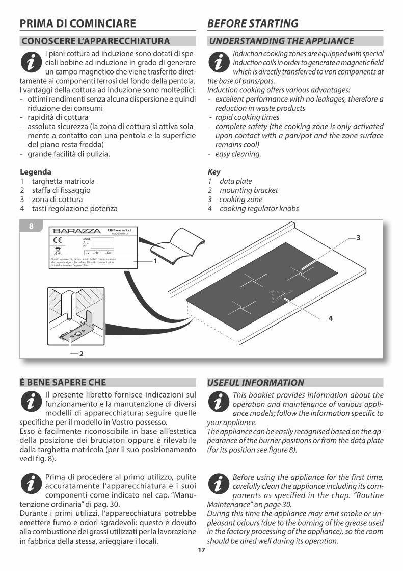
- grande facilità di pulizia. Legenda1 targhetta matricola2 staffa di fissaggio3 zona di cottura4 tasti regolazione potenza
BEFORE STARTING
UNDERSTANDING THE APPLIANCE
Induction cooking zones are equipped with special induction coils in order to generate a magnetic field which is directly transferred to iron components at
the base of pans/pots. Induction cooking offers various advantages:- excellent performance with no leakages, therefore a
reduction in waste products - rapid cooking times - complete safety (the cooking zone is only activated
upon contact with a pan/pot and the zone surface remains cool)
- easy cleaning. Key1 data plate2 mounting bracket3 cooking zone4 cooking regulator knobs
É BENE SAPERE CHE
Il presente libretto fornisce indicazioni sul funzionamento e la manutenzione di diversi modelli di apparecchiatura; seguire quelle
specifiche per il modello in Vostro possesso. Esso è facilmente riconoscibile in base all’estetica della posizione dei bruciatori oppure è rilevabile dalla targhetta matricola (per il suo posizionamento vedi fig. 8).
Prima di procedere al primo utilizzo, pulite accuratamente l’apparecchiatura e i suoi componenti come indicato nel cap. “Manu-
tenzione ordinaria” di pag. 30.Durante i primi utilizzi, l’apparecchiatura potrebbe emettere fumo e odori sgradevoli: questo è dovuto alla combustione dei grassi utilizzati per la lavorazione
in fabbrica della stessa, arieggiare i locali.
1
Mod.Art.N°
...V ...Hz ...Kw
Questo apparecchio deve essere installato conformemente
alle norme in vigore. Consultare il libretto istruzioni prima
di installare e usare l’apparecchio
F.lli Barazza S.r.l MADE IN ITALY
2
3
4
8
USEFUL INFORMATION
This booklet provides information about the operation and maintenance of various appli-ance models; follow the information specific to
your appliance. The appliance can be easily recognised based on the ap-pearance of the burner positions or from the data plate (for its position see figure 8).
Before using the appliance for the first time, carefully clean the appliance including its com-ponents as specified in the chap. “Routine
Maintenance” on page 30.During this time the appliance may emit smoke or un-pleasant odours (due to the burning of the grease used in the factory processing of the appliance), so the room
should be aired well during its operation.

18
A Tasto ON - OFF: accende e spegne l’apparecchiaturaB Tasto selezione zona sinistra. C Tasto selezione zona destra.
D Tasto decremento. E Tasto incremento. G Display zona di cottura: indica la potenza o il Timer relativo alla zona di cottura
A ON - OFF key: switch the appliance on and offB Left zone selection key. C Right zone selection key.
D Decrease key E Increase key G Cooking zone display: cooking zone display (e. g. power, timer)
ZONA COMANDI
Per individuare il punto di cottura in rapporto ai tasti da utilizzare, consultare la serigrafia riportata vicino agli stessi che identificano in modo chiaro ed inequi-vocabile le zone di cottura (fig. 9).
CONTROL PANEL
In order to determine which keys controls which cooking
zone, consult the silk-screen printing which appears next
to the keys, which clearly and definitively identifies the
zone (figure 9).
QA
AGB G C
O
BIE420TBIE320T
BIE420TZ
BIS830TBIS640T
BIS830TZ
BIS140T BIS140TZ
ED
P R
G
G
G
G
O
9
O Display Timer: indica il tempo programmato di cottura residuoP Tasto aumento Timer: aumento il tempo di programmazione del TimerQ Tasto Pausa: mette in pausa l’apparecchio interrompendo la cotturaR Tasto cottura veloce / Booster: riduce il tempo di cottura di una data zona
O Timer Display (OPTIONAL): display timer countdownP Timer Plus key (OPTIONAL): increase timer valueQ Pause key: pauses the appliance, interrupting cookingR Rapid cooking/Booster key: reduces the cooking time within a specific zone
19
USO DELL’APPARECCHIATURA
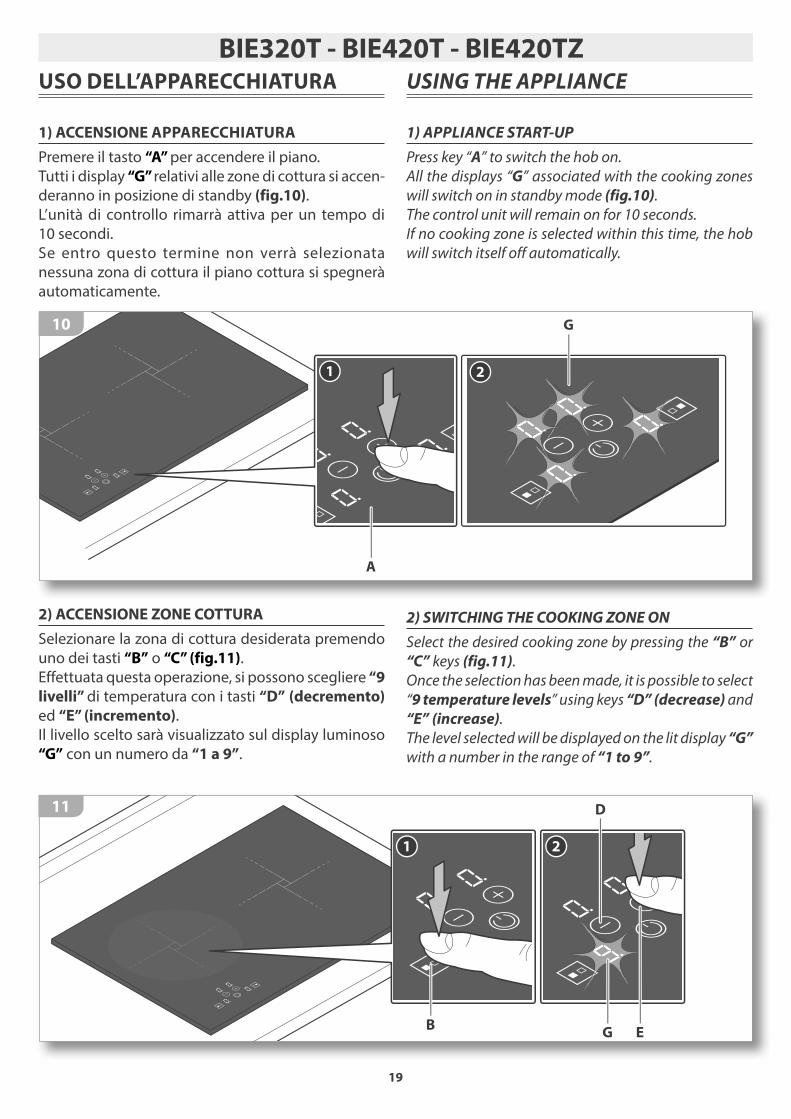
1) ACCENSIONE APPARECCHIATURA
Premere il tasto “A” per accendere il piano.
Tutti i display “G” relativi alle zone di cottura si accen-
deranno in posizione di standby (fig.10).
L’unità di controllo rimarrà attiva per un tempo di 10 secondi.Se entro questo termine non verrà selezionata nessuna zona di cottura il piano cottura si spegnerà automaticamente.
2) ACCENSIONE ZONE COTTURA
Selezionare la zona di cottura desiderata premendo uno dei tasti “B” o “C” (fig.11).Effettuata questa operazione, si possono scegliere “9
livelli” di temperatura con i tasti “D” (decremento) ed “E” (incremento).Il livello scelto sarà visualizzato sul display luminoso “G” con un numero da “1 a 9”.
USING THE APPLIANCE
1) APPLIANCE START-UP
Press key “A” to switch the hob on.
All the displays “G” associated with the cooking zones
will switch on in standby mode (fig.10).
The control unit will remain on for 10 seconds.
If no cooking zone is selected within this time, the hob
will switch itself off automatically.
2) SWITCHING THE COOKING ZONE ON
Select the desired cooking zone by pressing the “B” or
“C” keys (fig.11).
Once the selection has been made, it is possible to select
“9 temperature levels” using keys “D” (decrease) and
“E” (increase).
The level selected will be displayed on the lit display “G”
with a number in the range of “1 to 9”.
BIE320T - BIE420T - BIE420TZ
1
B
2
D
EG
11
G
21
A
10

20
3) RISCALDAMENTO VELOCE/BOOSTER
Questa funzione riduce ulteriormente il tempo di
cottura di una data zona portando la temperatura
alla massima potenza per un intervallo di 10 minuti.
Al termine di questo intervallo la potenza della zona
di cottura torna automaticamente al livello 9.
L’uso di questa funzione è indicato per il riscaldamento
in tempi brevissimi di grandi quantità di liquidi (es.
acqua per la cottura della pasta) o pietanze.
Per attivare questa funzione selezionare la zona di
cottura e premere il tasto “E” fino al livello “9”.
Premere nuovamente il tasto “E” (fig.12).
Verrà emesso un segnale acustico ed il simbolo “P”
sarà visualizzato nel display relativo alla zona.
3) RAPID/BOOSTER HEATING
This function further reduces cooking time in a given
zone bringing the temperature to the maximum power
for a 10 minute interval. At the end of this interval, the
cooking zone power automatically returns to level 9.
This function is recommended for quickly heating up
large quantities of liquids (e.g. water for cooking pasta)
or dishes.
To enable this function, where available, select the cook-
ing zone and press the “E” key until it reads level “9”.
Press the “E” key once again (fig.12).
An acoustic signal will be heard and the “P” symbol will
be displayed in the relative zone.
5
1 2
E
3
E
5 min
4
B
12
21
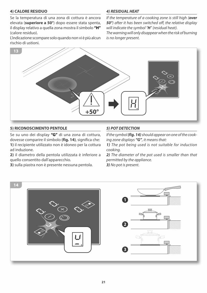
4) CALORE RESIDUO
Se la temperatura di una zona di cottura è ancora
elevata (superiore a 50°) dopo essere stata spenta,
il display relativo a quella zona mostra il simbolo “H”
(calore residuo).
L’indicazione scompare solo quando non vi è più alcun
rischio di ustioni.
5) RICONOSCIMENTO PENTOLE
Se su uno dei display “G” di una zona di cottura,
dovesse comparire il simbolo (fig. 14), significa che:
1) il recipiente utilizzato non è idoneo per la cottura
ad induzione.
2) il diametro della pentola utilizzata è inferiore a
quello consentito dall’apparecchio.
3) sulla piastra non è presente nessuna pentola.
4) RESIDUAL HEAT
If the temperature of a cooking zone is still high (over
50°) after it has been switched off, the relative display
will indicate the symbol “H” (residual heat).
The warning will only disappear when the risk of burning
is no longer present.
5) POT DETECTION
If the symbol (fig. 14) should appear on one of the cook-
ing zone displays “G”, it means that:
1) The pot being used is not suitable for induction
cooking.
2) The diameter of the pot used is smaller than that
permitted by the appliance.
3) No pot is present.
+50°
13
1
2
3
14
22
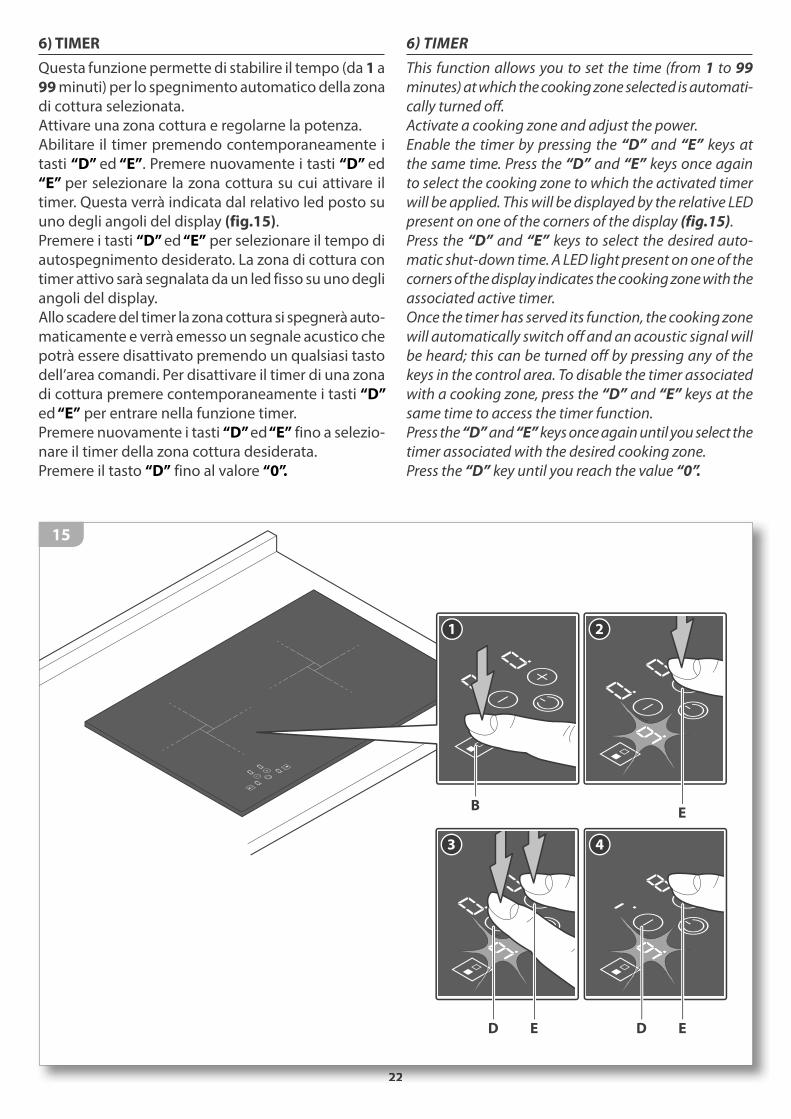
6) TIMER
Questa funzione permette di stabilire il tempo (da 1 a
99 minuti) per lo spegnimento automatico della zona
di cottura selezionata.
Attivare una zona cottura e regolarne la potenza.
Abilitare il timer premendo contemporaneamente i
tasti “D” ed “E”. Premere nuovamente i tasti “D” ed
“E” per selezionare la zona cottura su cui attivare il
timer. Questa verrà indicata dal relativo led posto su uno degli angoli del display (fig.15).Premere i tasti “D” ed “E” per selezionare il tempo di autospegnimento desiderato. La zona di cottura con timer attivo sarà segnalata da un led fisso su uno degli angoli del display.Allo scadere del timer la zona cottura si spegnerà auto-maticamente e verrà emesso un segnale acustico che potrà essere disattivato premendo un qualsiasi tasto dell’area comandi. Per disattivare il timer di una zona di cottura premere contemporaneamente i tasti “D”
ed “E” per entrare nella funzione timer.Premere nuovamente i tasti “D” ed “E” fino a selezio-nare il timer della zona cottura desiderata.Premere il tasto “D” fino al valore “0”.
6) TIMER
This function allows you to set the time (from 1 to 99
minutes) at which the cooking zone selected is automati-
cally turned off.
Activate a cooking zone and adjust the power.
Enable the timer by pressing the “D” and “E” keys at
the same time. Press the “D” and “E” keys once again
to select the cooking zone to which the activated timer
will be applied. This will be displayed by the relative LED
present on one of the corners of the display (fig.15).
Press the “D” and “E” keys to select the desired auto-
matic shut-down time. A LED light present on one of the
corners of the display indicates the cooking zone with the
associated active timer.
Once the timer has served its function, the cooking zone
will automatically switch off and an acoustic signal will
be heard; this can be turned off by pressing any of the
keys in the control area. To disable the timer associated
with a cooking zone, press the “D” and “E” keys at the
same time to access the timer function.
Press the “D” and “E” keys once again until you select the
timer associated with the desired cooking zone.
Press the “D” key until you reach the value “0”.
2222
1
B
2
E
3
ED
4
ED
15

23
7) EGG TIMER/PROMEMORIA
E’ possibile impostare un promemoria acustico pre-
mendo contemporanemente i tasti “D” ed “E”.
Il led centrale della zona timer lampeggia.
Attraverso il tasto “D” o “E” regolare un tempo per il
promemoria da 1 a 99 minuti (fig.16).
Allo scadere del tempo impostato verrà emesso un se-gnale acustico che potrà essere disattivato premendo un qualsiasi tasto dell’area comandi.Le zone cottura precedentemente in funzione rimar-ranno attive.La funzione “egg timer/promemoria” rimane attiva anche dopo lo spegnimento dell’apparecchio.Per disattivare questa funzione premere contempora-neamente i tasti “D” ed “E” e successivamente il tasto “D” fino al valore “0”.
7) EGG TIMER/REMINDER
It is possible to set a sound reminder by pressing the “D”
and “E” keys at the same time.
The LED light at the centre of the timer area will flash.
Using the “D” or “E” keys set a reminder time in the range
of 1 to 99 minutes (fig.16).
Once the set time has lapsed, an acoustic signal will be
heard; this can be turned off by pressing any of the keys
in the control area.
Cooking zones which were previously in operation, will
remain on.
The “egg timer/reminder” function will remain on even
after the appliance is turned off.
To disable this function, press the “D” and “E” keys at
the same time and subsequently the “D” key until you
reach the value “0”.
38 min
1
ED
2
ED
3
ED
4
D
16
24
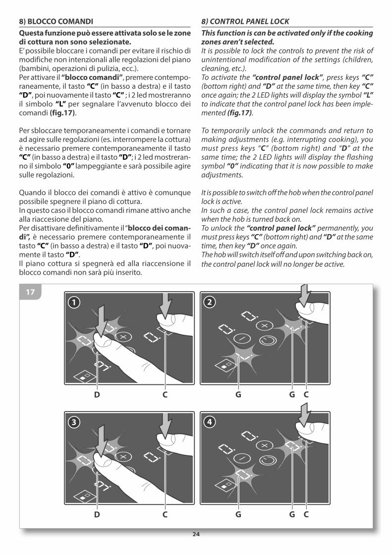
8) BLOCCO COMANDI
Questa funzione può essere attivata solo se le zone di cottura non sono selezionate.E’ possibile bloccare i comandi per evitare il rischio di modifiche non intenzionali alle regolazioni del piano (bambini, operazioni di pulizia, ecc.).Per attivare il “blocco comandi”, premere contempo-raneamente, il tasto “C” (in basso a destra) e il tasto “D”, poi nuovamente il tasto “C” ; i 2 led mostreranno il simbolo “L” per segnalare l’avvenuto blocco dei comandi (fig.17).
Per sbloccare temporaneamente i comandi e tornare ad agire sulle regolazioni (es. interrompere la cottura) è necessario premere contemporaneamente il tasto “C” (in basso a destra) e il tasto “D”; i 2 led mostreran-no il simbolo “0” lampeggiante e sarà possibile agire sulle regolazioni.
Quando il blocco dei comandi è attivo è comunque possibile spegnere il piano di cottura. In questo caso il blocco comandi rimane attivo anche alla riaccesione del piano. Per disattivare definitivamente il “blocco dei coman-di”, è necessario premere contemporaneamente il tasto “C” (in basso a destra) e il tasto “D”, poi nuova-mente il tasto “D”.Il piano cottura si spegnerà ed alla riaccensione il blocco comandi non sarà più inserito.
8) CONTROL PANEL LOCK
This function is can be activated only if the cooking zones aren’t selected.It is possible to lock the controls to prevent the risk of unintentional modification of the settings (children, cleaning, etc.).To activate the “control panel lock”, press keys “C” (bottom right) and “D” at the same time, then key “C” once again; the 2 LED lights will display the symbol “L” to indicate that the control panel lock has been imple-mented (fig.17).
To temporarily unlock the commands and return to making adjustments (e.g. interrupting cooking), you must press keys “C” (bottom right) and “D” at the same time; the 2 LED lights will display the flashing symbol “0” indicating that it is now possible to make adjustments. It is possible to switch off the hob when the control panel lock is active. In such a case, the control panel lock remains active when the hob is turned back on.To unlock the “control panel lock” permanently, you must press keys “C” (bottom right) and “D” at the same time, then key “D” once again.The hob will switch itself off and upon switching back on,
the control panel lock will no longer be active.
2424
1
CD
2
CG G
3
CD
4
CG G
17

25
11) SPEGNIMENTO ZONE COTTURA
Per spegnere una zona di cottura, premere il tasto “D”
fino alla posizione “0”.
12) SPEGNIMENTO PIANO COTTURA
Per spegnere completamente il piano di cottura
premere il tasto “A” .
11) SWITCHING THE COOKING AREA OFF
To switch off a cooking zone, press the “D” key until you
reach the value “0”.
12) SWITCHING THE COOKING TOP OFF
To turn off the hob completely, hold down the “A” key.
D
18
A
19
26
USO DELL’APPARECCHIATURA
1) ACCENSIONE APPARECCHIATURA
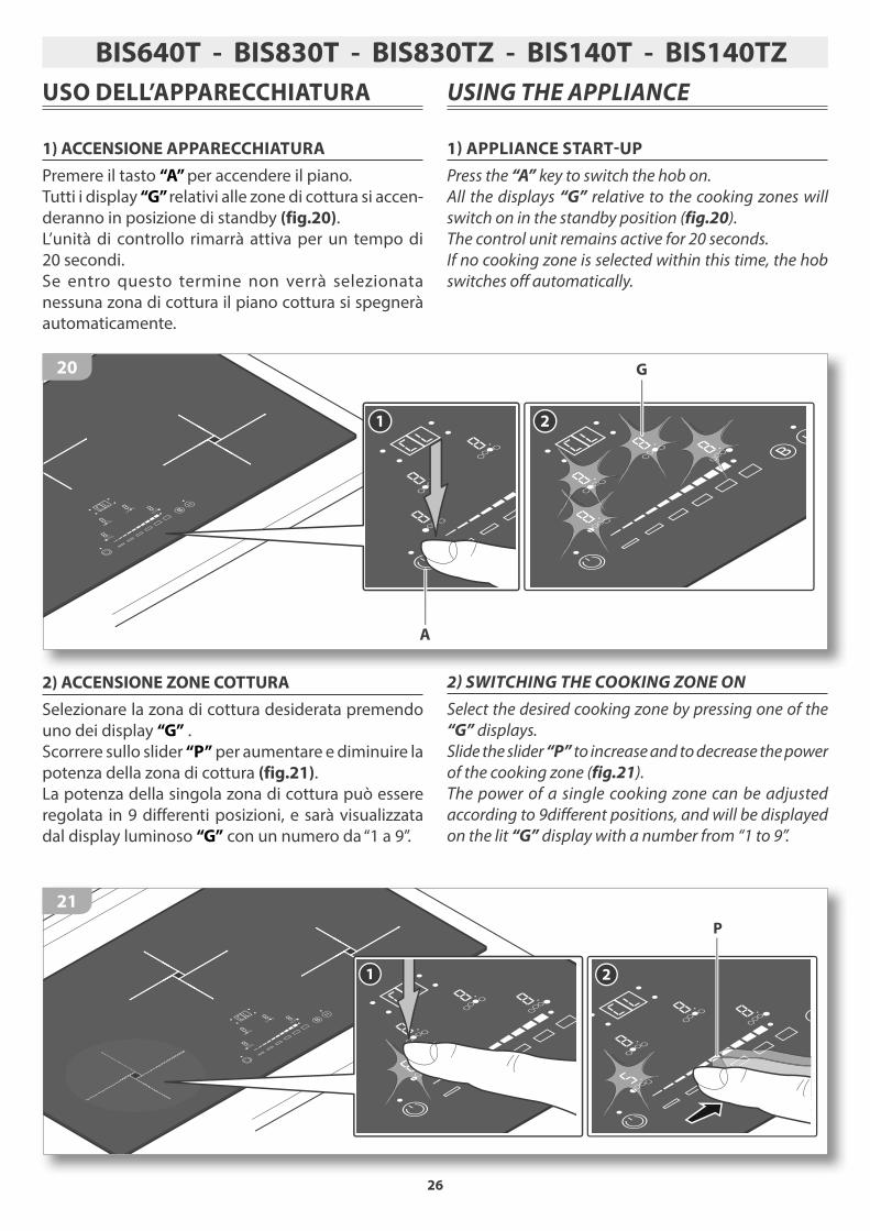
Premere il tasto “A” per accendere il piano.
Tutti i display “G” relativi alle zone di cottura si accen-
deranno in posizione di standby (fig.20).
L’unità di controllo rimarrà attiva per un tempo di 20 secondi.Se entro questo termine non verrà selezionata nessuna zona di cottura il piano cottura si spegnerà automaticamente.
1 2
A
G20
2) ACCENSIONE ZONE COTTURA
Selezionare la zona di cottura desiderata premendo uno dei display “G” .Scorrere sullo slider “P” per aumentare e diminuire la potenza della zona di cottura (fig.21).La potenza della singola zona di cottura può essere
regolata in 9 differenti posizioni, e sarà visualizzata dal display luminoso “G” con un numero da “1 a 9”.
1 2
P
21
USING THE APPLIANCE
1) APPLIANCE START-UP
Press the “A” key to switch the hob on.
All the displays “G” relative to the cooking zones will
switch on in the standby position (fig.20).
The control unit remains active for 20 seconds.
If no cooking zone is selected within this time, the hob
switches off automatically.
2) SWITCHING THE COOKING ZONE ON
Select the desired cooking zone by pressing one of the
“G” displays.
Slide the slider “P” to increase and to decrease the power
of the cooking zone (fig.21).
The power of a single cooking zone can be adjusted
according to 9different positions, and will be displayed
on the lit “G” display with a number from “1 to 9”.
BIS640T - BIS830T - BIS830TZ - BIS140T - BIS140TZ
27
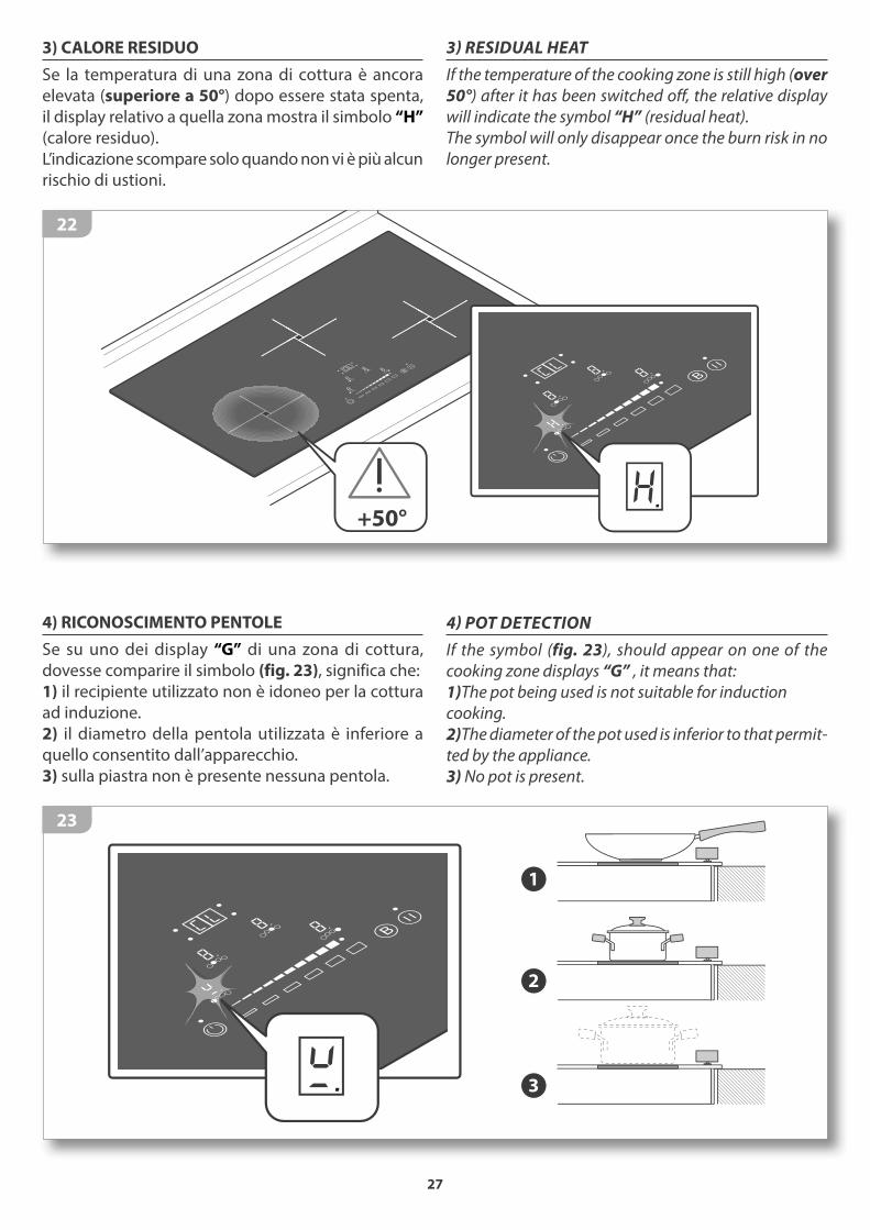
3) CALORE RESIDUO
Se la temperatura di una zona di cottura è ancora
elevata (superiore a 50°) dopo essere stata spenta,
il display relativo a quella zona mostra il simbolo “H”
(calore residuo).
L’indicazione scompare solo quando non vi è più alcun
rischio di ustioni.
+50°
22
4) RICONOSCIMENTO PENTOLE
Se su uno dei display “G” di una zona di cottura,
dovesse comparire il simbolo (fig. 23), significa che:
1) il recipiente utilizzato non è idoneo per la cottura
ad induzione.
2) il diametro della pentola utilizzata è inferiore a
quello consentito dall’apparecchio.
3) sulla piastra non è presente nessuna pentola.
1
2
3
23
3) RESIDUAL HEAT
If the temperature of the cooking zone is still high (over
50°) after it has been switched off, the relative display
will indicate the symbol “H” (residual heat).
The symbol will only disappear once the burn risk in no
longer present.
4) POT DETECTION
If the symbol (fig. 23), should appear on one of the
cooking zone displays “G” , it means that:
1)The pot being used is not suitable for induction
cooking.
2)The diameter of the pot used is inferior to that permit-
ted by the appliance.
3) No pot is present.
28
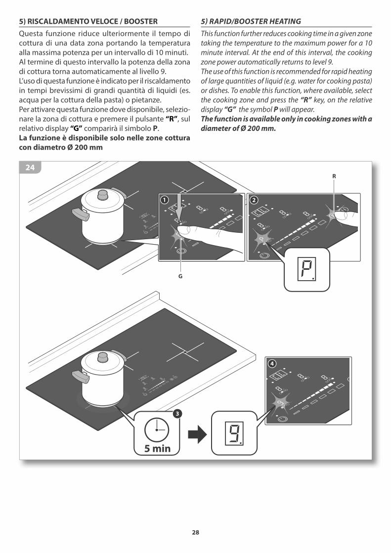
5) RISCALDAMENTO VELOCE / BOOSTER
Questa funzione riduce ulteriormente il tempo di
cottura di una data zona portando la temperatura
alla massima potenza per un intervallo di 10 minuti.
Al termine di questo intervallo la potenza della zona
di cottura torna automaticamente al livello 9.
L’uso di questa funzione è indicato per il riscaldamento
in tempi brevissimi di grandi quantità di liquidi (es.
acqua per la cottura della pasta) o pietanze.
Per attivare questa funzione dove disponibile, selezio-
nare la zona di cottura e premere il pulsante “R”, sul
relativo display “G” comparirà il simbolo P.
La funzione è disponibile solo nelle zone cottura
con diametro Ø 200 mm
1
5 min
3
4
2
R
G
24
5) RAPID/BOOSTER HEATING
This function further reduces cooking time in a given zone
taking the temperature to the maximum power for a 10
minute interval. At the end of this interval, the cooking
zone power automatically returns to level 9.
The use of this function is recommended for rapid heating
of large quantities of liquid (e.g. water for cooking pasta)
or dishes. To enable this function, where available, select
the cooking zone and press the “R” key, on the relative
display “G” the symbol P will appear.
The function is available only in cooking zones with a
diameter of Ø 200 mm.
29
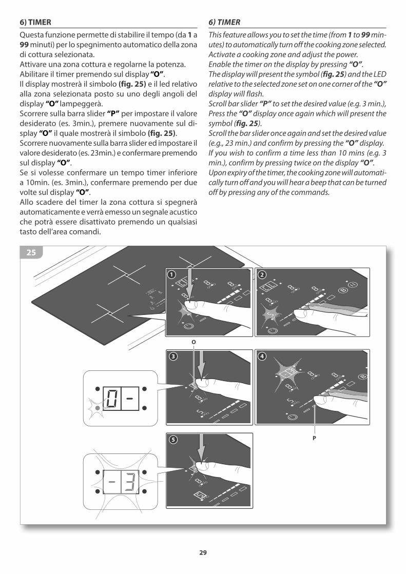
6) TIMER
Questa funzione permette di stabilire il tempo (da 1 a
99 minuti) per lo spegnimento automatico della zona
di cottura selezionata.
Attivare una zona cottura e regolarne la potenza.
Abilitare il timer premendo sul display “O”.
Il display mostrerà il simbolo (fig. 25) e il led relativo alla zona selezionata posto su uno degli angoli del display “O” lampeggerà. Scorrere sulla barra slider “P” per impostare il valore desiderato (es. 3min.), premere nuovamente sul di-splay “O” il quale mostrerà il simbolo (fig. 25).Scorrere nuovamente sulla barra slider ed impostare il valore desiderato (es. 23min.) e confermare premendo sul display “O”.Se si volesse confermare un tempo timer inferiore a 10min. (es. 3min.), confermare premendo per due volte sul display “O”. Allo scadere del timer la zona cottura si spegnerà automaticamente e verrà emesso un segnale acustico che potrà essere disattivato premendo un qualsiasi tasto dell’area comandi.
1
3
2
4
5
O
P
25
6) TIMER
This feature allows you to set the time (from 1 to 99 min-
utes) to automatically turn off the cooking zone selected.
Activate a cooking zone and adjust the power.
Enable the timer on the display by pressing “O”.
The display will present the symbol (fig. 25) and the LED
relative to the selected zone set on one corner of the “O”
display will flash.
Scroll bar slider “P” to set the desired value (e.g. 3 min.),
Press the “O” display once again which will present the
symbol (fig. 25).
Scroll the bar slider once again and set the desired value
(e.g., 23 min.) and confirm by pressing the “O” display.
If you wish to confirm a time less than 10 mins (e.g. 3
min.), confirm by pressing twice on the display “O”.
Upon expiry of the timer, the cooking zone will automati-
cally turn off and you will hear a beep that can be turned
off by pressing any of the commands.

30
7) EGG TIMER/PROMEMORIA
Questa funzione permette di impostare un prome-
moria acustico.
Per accedere a questa funzione nessuna delle zone di
cottura deve essere in funzione.
Accendere il piano cottura tramite il tasto “A”, attivare
la zona timer premendo sul display “O” e regolare
un qualsiasi tempo compreso tra 1 a 99 minuti come
spiegato nel precedente paragrafo TIMER.
Dopo la conferma del promemoria , rimarranno attivi
il led relativo al tasto “A” e il display “O” con il tempo
precedentemente impostato (fig. 26A).
A questo punto è possibile accendere nuovamente
il piano cottura tramite il tasto “A” e regolare le zone
di cottura.
Allo scadere del timer verrà emesso un segnale acusti-
co che potrà essere disattivato premendo un qualsiasi
tasto dell’area comandi (fig. 26B).
Con il promemoria attivo non è possibile accedere
alla funzione timer.
1 2 3
O
PA
26A
30
1 2 3
A
3 min
26B
7) EGG TIMER / REMINDER
This feature allows you to set a reminder sound.
None of the coking zones must be in operation in order
to access this feature.
Turn on the hob using the “A” key, activate the timer by
pressing the display “O” and set any time between 1
to 99 minutes as described in the previous paragraph
TIMER.
After confirmation of the reminder the LEDs of the rela-
tive “A” key and “O” display, presenting the time previ-
ously set (fig. 26A) will remain active.
At this point, it is possible to turn the hob back on using
the “A” key and adjust the cooking zones.
When the timer expires you will hear a beep that can be
turned off by pressing any of the keys within the com-
mand area (fig. 26B).
When the reminder is active, it is not possible to access
the active timer.

31
8) PAUSA
Premendo il tasto “Q” quando almeno una zona
di cottura è in azione è possibile mettere in pausa
l’apparecchio, interrompendo momentaneamente
la cottura. Il relativo led si accende.
La pausa ha una durata di 10 minuti allo scadere dei
quali l’apparecchio si spegne automaticamente.
La funzione pausa può essere disattivata premendo
il tasto “Q”, ed entro 10 secondi, un qualsiasi tasto
dell’area comandi. L’uso della funzione pausa inter-
rompe gli eventuali timer attivi.
Q
27
9) RICHIAMA
Se per errore si spegne il piano cottura è possibile ri-
chiamare i settaggi precedentemente attivi sulle zone
cottura riaccendendo il piano con il tasto “A” entro
6 secondi e premendo il tasto “Q” entro 6 secondi.
Quando questa funzione è disponibile alla riaccensio-
ne del piano il led del tasto “Q” è illuminato.
2
R
1
A
6 sec
28
8) PAUSE
When at least one cooking zone is operating, it is possible
to momentarily pause the appliance, interrupt cooking,
by pressing the “Q” key. The relative LED will light up.
The pause lasts for 10 minutes. If the status is not ter-
minated within this time the appliance switches off.
The pause function can be deactivated by pressing the
“Q” key and, within 10 seconds, any of the control keys.
Previously programmed timers will be interrupted dur-
ing the pause.
9) RECALL
When the appliance has been switched off by mistake, it
is possible to quickly recall the previously active settings
by pressing key “A” within 6 seconds, then pressing the
“Q” key within 6 seconds.
If the recall function is available, the “Q” key LED will light
up when the appliance is switched on again.
32
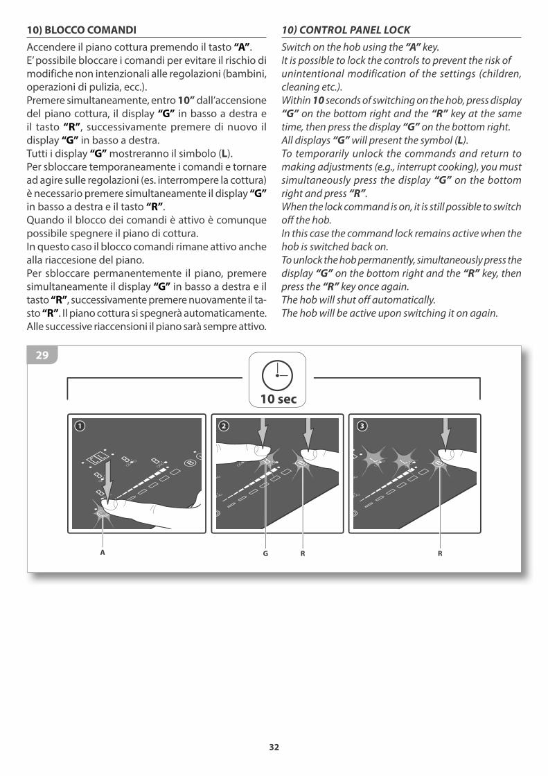
10) BLOCCO COMANDI
Accendere il piano cottura premendo il tasto “A”.
E’ possibile bloccare i comandi per evitare il rischio di
modifiche non intenzionali alle regolazioni (bambini,
operazioni di pulizia, ecc.).
Premere simultaneamente, entro 10” dall’accensione
del piano cottura, il display “G” in basso a destra e
il tasto “R”, successivamente premere di nuovo il
display “G” in basso a destra.
Tutti i display “G” mostreranno il simbolo (L).
Per sbloccare temporaneamente i comandi e tornare
ad agire sulle regolazioni (es. interrompere la cottura)
è necessario premere simultaneamente il display “G”
in basso a destra e il tasto “R”.
Quando il blocco dei comandi è attivo è comunque
possibile spegnere il piano di cottura.
In questo caso il blocco comandi rimane attivo anche
alla riaccesione del piano.
Per sbloccare permanentemente il piano, premere
simultaneamente il display “G” in basso a destra e il
tasto “R”, successivamente premere nuovamente il ta-
sto “R”. Il piano cottura si spegnerà automaticamente.
Alle successive riaccensioni il piano sarà sempre attivo.
3
R
1
A
2
RG
10 sec
29
10) CONTROL PANEL LOCK
Switch on the hob using the “A” key.
It is possible to lock the controls to prevent the risk of
unintentional modification of the settings (children,
cleaning etc.).
Within 10 seconds of switching on the hob, press display
“G” on the bottom right and the “R” key at the same
time, then press the display “G” on the bottom right.
All displays “G” will present the symbol (L).
To temporarily unlock the commands and return to
making adjustments (e.g., interrupt cooking), you must
simultaneously press the display “G” on the bottom
right and press “R”.
When the lock command is on, it is still possible to switch
off the hob.
In this case the command lock remains active when the
hob is switched back on.
To unlock the hob permanently, simultaneously press the
display “G” on the bottom right and the “R” key, then
press the “R” key once again.
The hob will shut off automatically.
The hob will be active upon switching it on again.
33
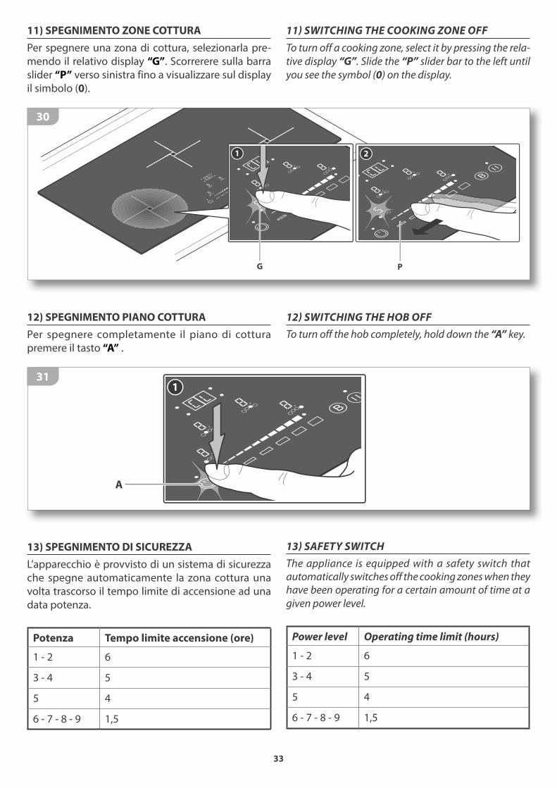
11) SWITCHING THE COOKING ZONE OFF
To turn off a cooking zone, select it by pressing the rela-
tive display “G”. Slide the “P” slider bar to the left until
you see the symbol (0) on the display.
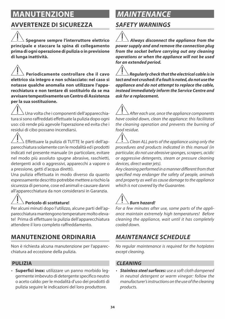
12) SWITCHING THE HOB OFF
To turn off the hob completely, hold down the “A” key.
13) SAFETY SWITCH
The appliance is equipped with a safety switch that automatically switches off the cooking zones when they have been operating for a certain amount of time at a
given power level.
Power level Operating time limit (hours)
1 - 2 6
3 - 4 5
5 4
6 - 7 - 8 - 9 1,5
11) SPEGNIMENTO ZONE COTTURA
Per spegnere una zona di cottura, selezionarla pre-
mendo il relativo display “G”. Scorrerere sulla barra
slider “P” verso sinistra fino a visualizzare sul display
il simbolo (0).
1 2
G P
30
12) SPEGNIMENTO PIANO COTTURA
Per spegnere completamente il piano di cottura
premere il tasto “A” .
1
A
31
13) SPEGNIMENTO DI SICUREZZA
L’apparecchio è provvisto di un sistema di sicurezza
che spegne automaticamente la zona cottura una
volta trascorso il tempo limite di accensione ad una
data potenza.
Potenza Tempo limite accensione (ore)
1 - 2 6
3 - 4 5
5 4
6 - 7 - 8 - 9 1,5
34
AVVERTENZE DI SICUREZZA
Spegnere sempre l’interruttore elettrico
principale e staccare la spina di collegamento
prima di ogni operazione di pulizia o in previsione
di lunga inattività.
Periodicamente controllare che il cavo
elettrico sia integro e non schiacciato: nel caso si
notasse qualche anomalia non utilizzare l’appa-
recchiatura e non tentare di sostituirlo da se ma
avvisare tempestivamente un Centro di Assistenza
per la sua sostituzione.
Una volta che i componenti dell’apparecchia-
tura si sono raffreddati effettuate la pulizia dopo ogni
uso: ciò rende più agevole l’operazione ed evita che i
residui di cibo possano incendiarsi.
Effettuare la pulizia di TUTTE le parti dell’ap-
parecchiatura solamente con le modalità ed i prodotti
indicati nel presente manuale (in particolare, evitare
nel modo più assoluto spugne abrasive, raschietti,
detergenti acidi o aggressivi, apparecchi a vapore o
a pressione, getti d’acqua diretti).
Una pulizia effettuata in modo diverso da quanto
espressamente descritto potrebbe mettere a rischio la
sicurezza di persone, cose ed animali e causare danni
all’apparecchiatura da non considerarsi in Garanzia.
Pericolo di scottature!
Per alcuni minuti dopo l’utilizzo, alcune parti dell’ap-
parecchiatura mantengono temperature molto eleva-
te! Prima di effettuare la pulizia dell’apparecchiatura
attendere il loro completo raffreddamento.
MANUTENZIONE ORDINARIA
Non è richiesta alcuna manutenzione per l’apparec-
chiatura ad eccezione della pulizia.
PULIZIA
• Superfici inox: utilizzare un panno morbido leg-
germente imbevuto di detergente specifico neutro
o aceto caldo: per le modalità d’uso dei prodotti di
pulizia seguire le indicazioni del loro produttore.
MANUTENZIONE
SAFETY WARNINGS
Always disconnect the appliance from the
power supply and and remove the connection plug
from the socket before carrying out any cleaning
operations or when the appliance will not be used
for an extended period.
Regularly check that the electrical cable is in
tact and not crushed: if a fault is noted, do not use the
appliance and do not attempt to replace the cable,
instead immediately inform the Service Centre and
ask for a replacement.
After each use, once the appliance components
have cooled down, clean the appliance: this facilitates
the cleaning operation and prevents the burning of
food residue.
Clean ALL parts of the appliance using only the
procedures and products indicated in this manual (in
particular, do not use abrasive sponges, scrapers, acidic
or aggressive detergents, steam or pressure cleaning
devices, direct water jets).
Any cleaning performed in a manner different from that
specified may endanger the safety of people, animals
and property as well as cause damage to the appliance
which is not covered by the Guarantee.
Burn hazard!
For a few minutes after use, some parts of the appli-
ance maintain extremely high temperatures! Before
cleaning the appliance, wait until it has completely
cooled down.
MAINTENANCE SCHEDULE
No regular maintenance is required for the hotplates
except cleaning.
CLEANING
• Stainless steel surfaces: use a soft cloth dampened
in neutral detergent or warm vinegar: follow the
manufacturer’s instructions on the use of the cleaning
products.
MAINTENANCE

35
• Superfici in vetroceramica:
Conoscere il materiale
Le superfici in vetroceramica sono estre-
mamente resistenti al calore (fino a 800°C
circa), agli shock termici (cioè non si rompono se sul
piano caldo viene versata acqua fredda) e offrono
una buona resistenza ai graffi derivanti da un uso
quotidiano del piano.
Hanno inoltre un’ ottima resistenza alle sostanze aci-
de (es. aceto, succo di limone, ecc...) ma le sostanze
ad alto contenuto zuccherino, fondendo possono
opacizzare il vetro, senza tuttavia pregiudicarne le
prestazioni.
Come pulirlo
Pulire il piano dopo ogni utilizzo, in questo modo lo
sporco non si accumula e la pulizia risulta più facile
e veloce.
Attendere che l’apparecchiatura sia fredda, suc-
cessivamente rimuovere dal piano i residui più
grandi aiutandosi con un raschietto specifico per
vetroceramica: se si tratta di frammenti di allumi-
nio, materiale plastico scioltasi inavvertitamente o
alimenti contenenti zucchero, pulire il piano prima
possibile in quanto queste sostanze possono opa-
cizzare irrimediabilmente le superfici in vetro.
Eliminati i residui più grandi, pulire il piano utilizzan-
do un panno morbido (o un panno carta da cucina)
imbevuto leggermente con prodotti specifici per il
vetroceramica o con semplice detersivo per piatti e
seguendo le indicazioni date dal Produttore sull’uso
degli stessi.
Non utilizzare in nessun caso spugne o pro-
dotti abrasivi, eccessivamente acidi, candeg-
gina, prodotti per la pulizia del forno o smac-
chiatori.
PERIODI DI INATTIVITÀ
Se pensate di non utilizzare l’apparecchio per un lungo
periodo di tempo (superiore alle 2-3 settimane):
• effettuate un’accurata pulizia dell’apparecchiatura
seguendo quanto indicato nel capitolo dedicato;
• scollegate la spina di alimentazione elettrica.
• Glass-ceramic surfaces:
Useful information on the material
Glass-ceramic surfaces are extremely heat-
resistant (they can withstand heats of up to
approx 800°C), they are resistant to thermal shocks
(they do not break when cold water is poured on the
hot surface) and they provide good scratch-resistance,
the results of daily wear and tear.
Additionally, they have excellent resistance to acidic
substances (e.g. vinegar, lemon juice, etc...) however,
substances, rich in sugar, upon melting, may clouden
the glass; this however does not affect the operation
of the appliance.
Cleaning instructions
Clean the surface after each use, so that dirt does
not accumulate, making cleaning easier and more
rapid.
Wait until the appliance is cool, subsequently, remove
the larger residue from the surface with the help of
a scraper specifically designed for glass-ceramic
surfaces: if residues consist of aluminium fragments,
accidentally melted plastic material or sugary sub-
stances, clean the surface as soon as possible as the
above mentioned may irreparably clouden the glass
surface.
After having removed the larger residue, clean the
surface using a soft cloth (or a piece of kitchen roll)
lightly dampened in products specifically designed
for glass-ceramic surfaces or with basic washing-up
detergent,following the manufacturer’s instructions
on the use of the cleaning products.
Never use sponges or abrasive products, ex-
tremely acidic products, bleach, oven cleaning
products or stain removers.
PERIODS OF INACTIVITY
If the appliance will not be used for a long period of time
(more than 2-3 weeks):
• thoroughly clean the appliance following the instruc-
tions in the respective chapter;
• disconnect the electric power supply plug.

36
SMALTIMENTO A FINE VITA
Il prodotto alla fine della propria vita
utile NON deve venire assimilato agli altri
rifiuti ma deve essere smaltito separata-
mente negli idonei centri di raccolta dif-
ferenziata dei rifiuti elettronici ed elettro-
tecnici; lo smaltimento abusivo o non corretto del
prodotto comporta l’applicazione delle sanzioni
previste dalla corrente normativa di legge.
Per maggiori informazioni rivolgersi al servizio
locale di smaltimento rifiuti.
Rendere inutilizzabile l’apparecchiatura per lo
smaltimento rimuovendo il cavo di alimentazione.
ASSISTENZA POST VENDITA
Barazza srl Vi assicura la massima collaborazione
nell’eventualità dovessero sorgere problemi tecnici o qualunque altra necessità.
Procedura in caso di malfunzionamento
Prima di contattare il Centro di Assistenza più comodo
effettuare le seguenti operazioni:
• verificare che ci sia corrente elettrica;
• rilevare i dati dell’apparecchiatura dalla targa ma-
tricola (posizione targa matricola - vedi pag. 17);
• reperire la data di acquisto dell’apparecchiatura.
Attenzione! In attesa della risoluzione del
problema è opportuno non utilizzare l’apparec-
chiatura e scollegarla dall’alimentazione elettrica.
Non tentate di riparare o modificare l’apparecchio
in nessuna delle sue parti: oltre a far decadere la
Garanzia, ciò può essere potenzialmente peri-
coloso.
Richiedere e pretendere che siano utilizzati
unicamente ricambi originali: l’utilizzo di
componentistica diversa da quella fornita dal
Costruttore fa decadere la Garanzia e può arrecare
danni alle persone e all’apparecchiatura stessa.
END-OF-LIFE DISPOSAL
At the end of its service life, the product
must NOT be disposed of together with
other waste but must be disposed of sepa-
rately in the appropriate separate waste
collection centres for electronic and elec-
trotechnical waste; illegal or incorrect disposal of
the product entails the application of sanctions
provided for in current legislation.
For more information, contact your local waste
disposal service.
Before disposing of the appliance, render it unus-
able by removing the power cord.
AFTER-SALES SERVICE
Barazza srl ensures you the utmost collaboration in the
event of technical problems or for any other needs you
may have.
Procedure to follow if your appliance is malfunctioning
Before contacting your nearest Service Centre, do the
following:
• check that the appliance is supplied with power;
• obtain the appliance data from the data plate (for
data plate position - see page 17);
• find the appliance purchase data.
Attention! While waiting for resolution of
the problem, you should stop using the appliance
and disconnect it from the power supply. Do not
attempt to repair or modify the appliance in any of
its parts: in addition to voiding the Guarantee, this
may be dangerous.
Request or demand that only original spare parts
be used: the use of components other than those
supplied by the manufacturer voids the Guaran-
tee and may cause personal injuries or damage the
appliance.
Note / Notes .................................................................................................................................................
.............................................................................................................................................................................................
.............................................................................................................................................................................................
.............................................................................................................................................................................................
.............................................................................................................................................................................................
.............................................................................................................................................................................................
.............................................................................................................................................................................................
.............................................................................................................................................................................................
.............................................................................................................................................................................................
.............................................................................................................................................................................................
.............................................................................................................................................................................................
.............................................................................................................................................................................................
.............................................................................................................................................................................................
.............................................................................................................................................................................................
.............................................................................................................................................................................................
.............................................................................................................................................................................................
.............................................................................................................................................................................................
.............................................................................................................................................................................................
..............................................................
..............................................................
..............
..............................................................
..............................................................
.........
..............................................................
...........
.............
..............................................................
....................... ..............................................................
.........................................................................................
....................................................................................
....................................................................................
..............................................................
..............................................................
.........................................................................................................................
.............................................................................................
.........................................................................................
....................................................................... ............................................................................................................................
..................
..............................................................

38
Note / Notes .................................................................................................................................................
.............................................................................................................................................................................................
.............................................................................................................................................................................................
.............................................................................................................................................................................................
.............................................................................................................................................................................................
.............................................................................................................................................................................................
.............................................................................................................................................................................................
.............................................................................................................................................................................................
.............................................................................................................................................................................................
.............................................................................................................................................................................................
.............................................................................................................................................................................................
.............................................................................................................................................................................................
.............................................................................................................................................................................................
.............................................................................................................................................................................................
.............................................................................................................................................................................................
.............................................................................................................................................................................................
.............................................................................................................................................................................................
.............................................................................................................................................................................................
...................................................
...................................................
.........
...................................................
.....
.........................................................................................................
...................................................
.........
....................................................................................................
..............................................................
.................. ...................................................
................................................................................................
................................................................................................
................................................................................................
...................................................
...................................................
...........................................................................................................................
................................................................................................
................................................................................................
........................................
.........................................................................................................
...................................................

39
Note / Notes .................................................................................................................................................
.............................................................................................................................................................................................
.............................................................................................................................................................................................
.............................................................................................................................................................................................
.............................................................................................................................................................................................
.............................................................................................................................................................................................
.............................................................................................................................................................................................
.............................................................................................................................................................................................
.............................................................................................................................................................................................
.............................................................................................................................................................................................
.............................................................................................................................................................................................
.............................................................................................................................................................................................
.............................................................................................................................................................................................
.............................................................................................................................................................................................
.............................................................................................................................................................................................
.............................................................................................................................................................................................
.............................................................................................................................................................................................
.............................................................................................................................................................................................
...................................................
...................................................
.........
...................................................
.....
.........................................................................................................
...................................................
.........
....................................................................................................
..............................................................
.................. ...................................................
................................................................................................
................................................................................................
................................................................................................
...................................................
...................................................
...........................................................................................................................
................................................................................................
................................................................................................
........................................
.........................................................................................................
...................................................

Pro
get
to g
rafi
co A
rtli
ne
a
cod
.PIN
D1
re
v. 0
3 -
05
.20
15
Barazza srl
31025 Sarano di S.Lucia di Piave (TV) ITALIA
Via Risorgimento, 14
Tel. +39 0438 62888
Fax +39 0438 64901
www.barazzasrl.it
taste of design