Bernini thesis - Software Architecture Laboratory - Universit degli
164
UNIVERSITÀ DEGLI STUDI DI MILANO BICOCCA FACOLTÀ DI SCIENZE MATEMATICHE, FISICHE E NATURALI DIPARTIMENTO DI INFORMATICA, SISTEMISTICA E COMUNICAZIONE DOTTORATO DI RICERCA IN INFORMATICA XXIV CICLO Architectural Abstractions for Spaces-based Communication in Responsive Environments Doctoral Thesis of Diego Bernini Supervisor: Prof. Francesco Tisato Tutor: Prof. Carla Simone Ph.D. Program Coordinator: Prof. Stefania Bandini Academic Year 2010-2011
Transcript of Bernini thesis - Software Architecture Laboratory - Universit degli
UNIVERSITÀ DEGLI STUDI DI MILANO BICOCCA FACOLTÀ DI SCIENZE MATEMATICHE, FISICHE E NATURALI
DIPARTIMENTO DI INFORMATICA, SISTEMISTICA E COMUNICAZIONE
DOTTORATO DI RICERCA IN INFORMATICA
XXIV CICLO
Architectural Abstractions for Spaces-based Communication in
Responsive Environments
Doctoral Thesis of
Diego Bernini
Supervisor: Prof. Francesco Tisato Tutor: Prof. Carla Simone
Ph.D. Program Coordinator: Prof. Stefania Bandini
Academic Year 2010-2011


Abstract Responsive Environments are ordinary environments augmented with input devices (e.g., sensors, cameras, vision and tracking systems, tangible and wearable interfaces) and output devices (e.g., screens, lights, speakers and mechanical actuators) that are able to sense and respond to the users who inhabit them. Whatever the computing approach behind the scenes, a Responsive Environment requires the establishment of rich and flexible information flows between users and the environments in which they live. From a Software Architecture point of view, information flows between users and their environments are mediated by software components that manage specific devices, perform customized tasks and coordinate activities. Hence Responsive Environments necessitates a technological platform supporting the seamless integration of multifarious components via suitable communication mechanisms. The platform should capture metaphors that are widely and effectively exploited in Responsive Environments. The platform should also be lightweight and efficient. Therefore, the challenge is to identify a few domain-oriented concepts that are both general and simple enough to be effectively reified by a technological platform supporting Responsive Environments. The concept of space is a good candidate for reification in terms of communication mechanisms. Space and related keywords (e.g., position, location, area, proximity and distance) are natural reference concepts that users exploit to communicate with and through an environment according to different representations (e.g., name space, organizational space, grid space and so on). However, few approaches in the literature focus on space as a provider of communication mechanisms. Moreover, the existing approaches exclusively consider geo-referenced spatial representations. This thesis proposes a set of architectural abstractions and a related technological platform to establish information flows in Responsive Environments through a multiple-spaces metaphor. An environment space is a set of locations defined according to a specific spatial model (e.g., grid-based, graph-based or name-based). Different environment spaces that model subjective views of the overall environments can co-exist. For example, the physical environment may be modeled by a grid space, where cells represent small portions of the physical space. The topology of a building can be modeled by a graph space, where nodes represent rooms and arcs represent passages. Users' names can be represented by name spaces and users' roles by graph spaces. Mappings relate different environment spaces by, for example, associating cells of a grid space representing geo-referenced cells to nodes of a graph space representing rooms. Software components communicate by publishing and receiving information on multiple spatial contexts. Each component may be aware of different environment spaces. Mappings enable communication among components, even if they rely on different environment spaces. The architectural abstractions are supported by a concrete framework called Space Integration Services (SIS), which implements the proposed spaces-based communication. The proposed abstractions and related framework have been tested in several Responsive Environment applications. The experiments confirmed that the approach based on multiple spaces can be effectively implemented and facilitates the development of Responsive Environments.

Table of contents 1 Introduction ............................................................................................................................................... 9 1.1 Motivations ........................................................................................................................................ 9 1.2 Contributions .................................................................................................................................... 9 1.3 Outline of the thesis .................................................................................................................... 10 2 State of the art ........................................................................................................................................ 11 2.1 Software Architecture ................................................................................................................ 11 2.1.1 Overview ................................................................................................................................. 11 2.1.2 Software components and connectors ....................................................................... 12 2.1.3 Architectural models & views ........................................................................................ 14 2.1.4 Generic architectures ......................................................................................................... 17 2.1.5 Architectural styles, patterns & abstractions .......................................................... 17 2.1.6 Concrete frameworks ........................................................................................................ 18 2.2 Responsive Environments ........................................................................................................ 19 2.2.1 Overview ................................................................................................................................. 19 2.2.2 Responsive Environments vs. other visions ............................................................ 22 2.2.3 Enabling hardware technologies .................................................................................. 24 2.2.4 Computing approaches ..................................................................................................... 27 2.3 Software Architecture for Responsive Environments .................................................. 28 2.3.1 Conceptual reference schema ........................................................................................ 29 2.3.2 Key architectural requirements and qualities ......................................................... 29 2.3.3 Logical architecture view ................................................................................................. 30 2.3.4 Communication architectural abstractions .............................................................. 33 2.3.5 Component deployment ................................................................................................... 34 2.4 Communication architectural abstractions for Responsive Environments ......... 34 2.4.1 Direct communication ....................................................................................................... 34 2.4.2 Event-based publish/subscribe communication ................................................... 37 2.4.3 Tuple-mediated communication ................................................................................... 42 2.4.4 Evaluating communication abstractions ................................................................... 45 2.5 Space and Responsive Environments .................................................................................. 46 2.5.1 Space as an explicit concern ........................................................................................... 46 2.5.2 Multiple space models ....................................................................................................... 46 2.5.3 Spatial ontologies ................................................................................................................ 48 2.5.4 Location-based programming infrastructures ........................................................ 48 3 Architectural abstractions for spaces-based communication ............................................ 51 3.1 Reference scenario ...................................................................................................................... 52
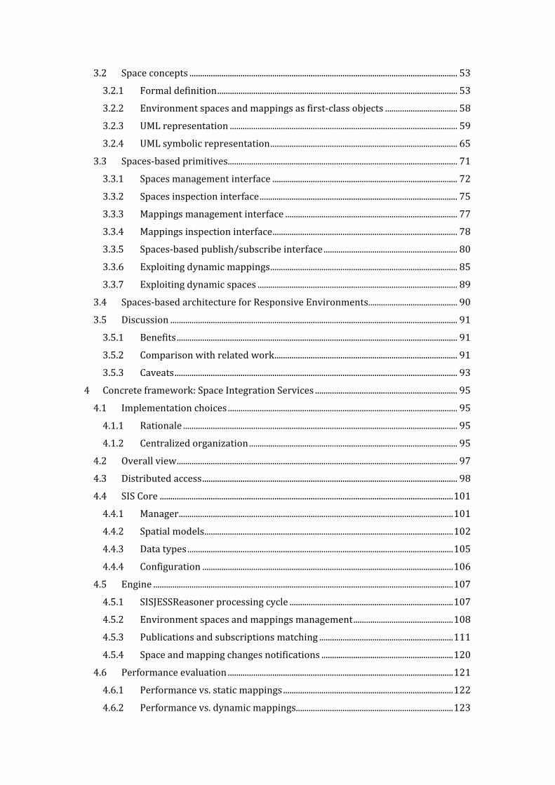
3.2 Space concepts .............................................................................................................................. 53 3.2.1 Formal definition ................................................................................................................. 53 3.2.2 Environment spaces and mappings as first-class objects .................................. 58 3.2.3 UML representation ........................................................................................................... 59 3.2.4 UML symbolic representation ........................................................................................ 65 3.3 Spaces-based primitives ............................................................................................................ 71 3.3.1 Spaces management interface ....................................................................................... 72 3.3.2 Spaces inspection interface ............................................................................................. 75 3.3.3 Mappings management interface ................................................................................. 77 3.3.4 Mappings inspection interface ....................................................................................... 78 3.3.5 Spaces-based publish/subscribe interface ............................................................... 80 3.3.6 Exploiting dynamic mappings ........................................................................................ 85 3.3.7 Exploiting dynamic spaces .............................................................................................. 89 3.4 Spaces-based architecture for Responsive Environments.......................................... 90 3.5 Discussion ....................................................................................................................................... 91 3.5.1 Benefits .................................................................................................................................... 91 3.5.2 Comparison with related work ...................................................................................... 91 3.5.3 Caveats ..................................................................................................................................... 93 4 Concrete framework: Space Integration Services ................................................................... 95 4.1 Implementation choices ............................................................................................................ 95 4.1.1 Rationale ................................................................................................................................. 95 4.1.2 Centralized organization .................................................................................................. 95 4.2 Overall view .................................................................................................................................... 97 4.3 Distributed access ........................................................................................................................ 98 4.4 SIS Core .......................................................................................................................................... 101 4.4.1 Manager ................................................................................................................................. 101 4.4.2 Spatial models ..................................................................................................................... 102 4.4.3 Data types ............................................................................................................................. 105 4.4.4 Configuration ...................................................................................................................... 106 4.5 Engine ............................................................................................................................................. 107 4.5.1 SISJESSReasoner processing cycle ............................................................................. 107 4.5.2 Environment spaces and mappings management ............................................... 108 4.5.3 Publications and subscriptions matching ............................................................... 111 4.5.4 Space and mapping changes notifications .............................................................. 120 4.6 Performance evaluation .......................................................................................................... 121 4.6.1 Performance vs. static mappings ................................................................................ 122 4.6.2 Performance vs. dynamic mappings.......................................................................... 123
4.6.3 Performance vs. size of publication contexts ......................................................... 125 4.6.4 Analysis of the results ..................................................................................................... 126 4.7 Discussion ..................................................................................................................................... 127 5 Case studies ........................................................................................................................................... 129 5.1 The G.A.S. – Intelligent Building project ........................................................................... 129 5.2 Smart Building ............................................................................................................................. 129 5.2.1 Scenario description ........................................................................................................ 129 5.2.2 Spaces and mappings analysis ..................................................................................... 130 5.2.3 Applying the spaces-based architecture .................................................................. 132 5.2.4 Scenario implementation ............................................................................................... 133 5.3 Augmented Classroom ............................................................................................................. 139 5.3.1 Scenario description ........................................................................................................ 139 5.3.2 Spaces and mappings analysis ..................................................................................... 140 5.3.3 Applying the spaces-based architecture .................................................................. 142 5.3.4 Scenario implementation ............................................................................................... 143 5.4 Interactive art installations .................................................................................................... 145 5.5 The InSyEme project ................................................................................................................. 147 5.6 The IMPULSO project ............................................................................................................... 149 6 Conclusions ........................................................................................................................................... 151 6.1 Summary of contributions...................................................................................................... 151 6.2 Future work .................................................................................................................................. 151 6.3 Publications .................................................................................................................................. 151 References ...................................................................................................................................................... 153

9
1 Introduction
1.1 Motivations Responsive Environments (Negroponte 1976) (Bullivant 2006) (F. S. C. da Silva & Vasconcelos 2007) are ordinary environments augmented with input devices (e.g., sensors, cameras, vision and tracking systems, tangible and wearable interfaces) and output devices (e.g., screens, lights, speakers and mechanical actuators) that are able to sense and respond to the users who inhabit them. Whatever the computing approach behind the scenes, a Responsive Environment requires the establishment of rich and flexible information flows between users and the environments in which they live. From a Software Architecture point of view the information flows between users and environment are mediated by application components that wrap specific devices, perform customized tasks and coordinate overall activities. This leads to a need for a technological platform supporting the seamless integration of multifarious application components via suitable communication mechanisms (Kusznir & Cook 2010) (Bavafa & Navidi 2010) (Goumopoulos & Kameas 2009) (Fernandez-Montes et al. 2009) (Ristau 2008) (Aiello & Dustdar 2008). The platform should capture metaphors that are widely and effectively exploited in Responsive Environments. The platform should also be lightweight and efficient (Kusznir & Cook 2010). Therefore, the challenge is to identify a few domain-oriented concepts that are both general and simple enough to be effectively reified by a technological platform supporting Responsive Environments. Basic communication mechanisms (for example, publish-subscribe) are widely used and supported by sound technological platforms. However, they are generic and require a significant effort to fill the gap between basic mechanisms and domain-specific concepts. On the other side, content-, context- and tuple-based approaches (Mühl et al. 2006) (Cugola et al. 2009) (Murth & Kühn 2010) support high-level communication styles, which can be easily specialized to cope with domain issues; however, they are still somehow generic and possibly suffer from implementation inefficiency. The conjecture is that there is room for abstractions that, on one side, are not generic, as they capture concepts widely used in Responsive Environments; on the other side, they do not suffer from the inefficiencies of high-level general approaches. The concept of space is a good candidate for reification in terms of communication mechanisms. Space and related keywords (e.g., position, location, area, proximity and distance) are natural reference concepts that users exploit to communicate with and through an environment according to different representations (e.g., name space, organizational space, grid space and so on), as highlighted by several works (Turner & E. Davenport 2005) (Harper et al. 2005) (Dobson 2005) (Steed et al. 2004). However, few approaches in the literature focus on space as a provider of communication mechanisms ((Cugola et al. 2009) (X. Chen et al. 2003) (Eugster et al. 2005) (Schilit & Theimer 1994); moreover, they exclusively consider geo-referenced spatial representations. 1.2 Contributions The main contribution of this thesis is the proposal of architectural abstractions (Kristensen 1996) (Shaw et al. 1995) to establish information flows in Responsive Environments through a multiple-spaces metaphor. The architectural abstractions are supported by a concrete framework (R. N. Taylor et al. 2009) called Space Integration Services (SIS), which implements spaces-based communication mechanisms.
10
The proposed abstractions lie at an intermediate level between high-level content, context and tuple-based approaches and basic communication mechanisms. They leverage the multiple-spaces metaphor in order to provide an effective support for the development of Responsive Environments. An environment space is a set of locations defined according to a specific spatial model (e.g., grid-based, graph-based or name-based). Different environment spaces that model subjective views of the overall environments can co-exist. For example, the physical environment may be modeled by a grid space, where cells represent small portions of the physical space. The topology of a building can be modeled by a graph space, where nodes represent rooms and arcs represent passages. Names can be represented by name spaces and roles by a graph space. Mappings relate different environment spaces by, for example, associating cells of a grid space representing the geo-referenced cells to nodes of a graph space representing rooms. Software components communicate by publishing and receiving information on multiple spatial contexts. Each component may be aware of different environment spaces. Mapping enables communication among components even if they rely on different spaces. The proposed abstractions and related framework have been tested in several Responsive Environment applications. The experiments confirmed that the approach based on multiple spaces can be effectively implemented and facilitates the development of Responsive Environments. 1.3 Outline of the thesis The thesis is organized as follows. Chapter 2 presents the relevant state of the art, covering the research perspective (Software Architecture), the application domain (Responsive Environments), the architectural communication styles and the spaces-related concepts in Responsive Environments. Chapter 3 presents the proposed architectural abstractions. Chapter 4 describes the concrete framework reifying the abstractions and its prototypal implementation, together with quantitative evaluations of the provided performance. Chapter 5 shows the applications of the abstractions and the concrete framework for the realization of several Responsive Environments. Finally, Chapter 6 highlights conclusions, future work and publications related to the thesis.

11
2 State of the art This chapter presents significant state-of-the-art achievements related to the topics covered in this thesis. First, overviews of the research area (Software Architecture) and the application domain (Responsive Environment) are provided. Second, Responsive Environments are analyzed from the Software Architecture perspective, proposing a conceptual reference schema and a logical reference architecture. Third, the most widespread communication styles adopted for the realization of Responsive Environments are presented. Finally, an overview of space concepts and their relevance to Responsive Environments is presented. 2.1 Software Architecture
2.1.1 Overview
“As the size and complexity of software systems increases, the design problem goes beyond the algorithms and data structures of the computation: designing and specifying the overall system structure emerges as a new kind of problem. Structural issues include gross organization and global control structure protocols for communication, synchronization, and data access; assignment of functionality to design elements; physical distribution; composition of design elements; scaling and performance; and selection among design alternatives. This is the software architecture level of design." (Garlan & Shaw 1994) “Software architecture is the principled study of the overall structure of software systems, especially the relations among subsystems and components. From its roots in qualitative descriptions of useful system organizations, software architecture has matured to encompass broad explorations of notations, tools, and analysis techniques. Whereas initially the research area interpreted software practice, it now offers concrete guidance for complex software design and development.” (Shaw & Clements 2006) These quotations summarize the focus of Software Architecture: studying the gross,
large-scale organization of software systems (Garlan 2000). In fact, the term “software architecture” has two widely used definitions. First, it may denote a discipline and research area inside Software Engineering that focuses on the design of modular, flexible and extendible software systems. In this case, the term has uppercase initial letters. Software Engineering (Ghezzi et al. 2002) (Sommerville 2004) is a discipline and research field developed with the goal of providing a systematic approach to build software systems that a) are large and complex, b) are built by teams, c) exist in many versions, d) last many years and e) undergo changes. This discipline emerged in the 1960s as a consequence of the so-called software crisis (Naur & B. Randell 1969), i.e., the chronic failures of large software projects to meet schedule and budget constraints.

12
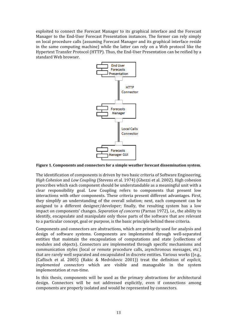
These failures demonstrate the needs of a paradigm shift: from “programming-in-the-small” to "programming-in-the-large" skills (DeRemer & Kron 1976), such as conceptual analysis of the system and reasoning at various levels of abstraction. Software Engineering has provided models, methodologies, methods and techniques to address all of the phases involved in the realization of software systems: requirements analysis and specification (understanding the problem that should be solved by a system), system design and implementation (realizing a system to solve the problem), system maintenance and evolution (maintaining and updating the system) and resource estimation, planning and management (determining the necessary resources and their schedule). Software Architecture focuses on the architectural design of software systems, i.e., the design process of software systems that aim to identify main subsystems and components together with their communication modalities (Sommerville 2004). It provides models, methodologies and techniques to guide the architectural design process. Secondly, the term “software architecture” may denote the output of the architectural design, which is the set of principal design decisions concerning a system (R. N. Taylor et al. 2009). The IEEE 1471 standard1 defines software architecture as “the fundamental organization of a system embodied in its components, their relationships to each other and to the environment and the principles guiding its design and evolution.” In practice, software architecture can be considered a blueprint for the construction and evolution of a software system. Generally, use of the term is made clear by its context. In this thesis, “Software Architecture” indicates the research area, while “software architecture” (or briefly, “architecture”) indicates the large-scale structure of a software system. 2.1.2 Software components and connectors According to the dominant approach (R. N. Taylor et al. 2009) (Shaw & Garlan 1996), a software architecture is defined by two main kinds of elements, software components and connectors. A software component (R. N. Taylor et al. 2009) (Heineman & Councill 2001) (Shaw & Garlan 1996) is a software entity that encapsulates computations and states in a self-contained whole that can be utilized through well-defined component interfaces. A component interface determines the features that a component provides and/or requires. Moreover, in its simplest form, a component has to be executed entirely on a single computing node, which satisfies some required computational capabilities. A software connector (R. N. Taylor et al. 2009) (Mehta et al. 2000) (Shaw & Clements 1997) is a software entity which mediates communication, coordination or cooperation among software components. For example, Figure 1 shows the software architecture of a (very) simple weather forecast dissemination system according to the Unified Modeling Language (UML) (Fowler 2003) representation of components and connectors2 (Ivers et al. 2004). An instance of the Forecasts Manager component manages the forecast provided by external operators through an instance of the Forecasts Manager Graphical User Interface (GUI) component. Instances of the End-User Forecasts Presentation component allow retrieving and displaying of the forecasts. Two kinds of connectors are 1 http://www.iso-architecture.org/ieee-1471/ 2 The “plug” boxes model components, whereas connectors are modeled as straight lines attached to component ports (the small rectangles at the end of connectors). For more details see (Ivers et al. 2004).
13
exploited to connect the Forecast Manager to its graphical interface and the Forecast Manager to the End-User Forecast Presentation instances. The former can rely simply on local procedure calls (assuming Forecast Manager and its graphical interface reside in the same computing machine) while the latter can rely on a Web protocol like the Hypertext Transfer Protocol (HTTP). Thus, the End-User Presentation can be reified by a standard Web browser.
Figure 1. Components and connectors for a simple weather forecast dissemination system. The identification of components is driven by two basic criteria of Software Engineering, High Cohesion and Low Coupling (Stevens et al. 1974) (Ghezzi et al. 2002). High cohesion prescribes which each component should be understandable as a meaningful unit with a clear responsibility goal. Low Coupling refers to components that present low interactions with other components. These criteria present different advantages. First, they simplify an understanding of the overall solution; next, each component can be assigned to a different designer/developer; finally, the resulting system has a low impact on components’ changes. Separation of concerns (Parnas 1972), i.e., the ability to identify, encapsulate and manipulate only those parts of the software that are relevant to a particular concept, goal or purpose, is the basic principle behind these criteria. Components and connectors are abstractions, which are primarily used for analysis and design of software systems. Components are implemented through well-separated entities that maintain the encapsulation of computations and state (collections of modules and objects). Connectors are implemented through specific mechanisms and communication styles (local or remote procedure calls, asynchronous messages, etc.) that are rarely well separated and encapsulated in discrete entities. Various works ((e.g., (Caflisch et al. 2005) (Rakic & Medvidovic 2001)) treat the definition of explicit, implemented connectors which are visible and manageable in the system implementation at run-time. In this thesis, components will be used as the primary abstractions for architectural design. Connectors will be not addressed explicitly, even if connections among components are properly isolated and would be represented by connectors.

14
2.1.3 Architectural models & views Software architecture may be described by various models, each focused on a particular perspective. (Sommerville 2004) identifies these models as follows: • Static structural model shows the major component types; • Interface model defines component interfaces; • Dynamic process model shows the process structure of the system, i.e., the dynamic interaction among component instances; • Relationships model shows components' relationships. The need for different perspectives by different models is captured by the notion of
architectural views. An architectural view (Clements et al. 2002) is a representation of a set of system elements and the relations associated with them. Modern software architectures are designed and documented according to different views. (Kruchten 1995) is a seminal work that proposes an approach based on five (“4+1”) views: • Scenarios, a set of user cases to identify architectural elements and validate the final architecture; • Logical Architecture, which identifies the functionality that must be provided by the system; • Process Architecture, which explains the run-time behavior of the system, taking non-functional requirements into account; • Development Architecture, which focuses on the software module organization; • Physical Architecture, which defines the physical configuration of the system, the allocation of software components on computing nodes and the necessary communication apparatus. (Bernini & F. Tisato 2010) presents the approach followed by the author of this thesis. It identifies five key sets of architectural views (Problem, Logical, Concrete, Implementation
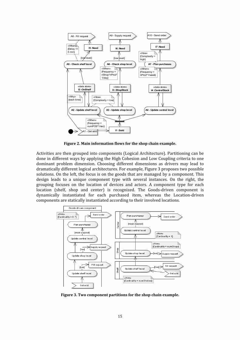
and Deployment Architecture) that highlight the aspects covered by Kruchten’s approach in a more analysis-oriented form. The main rationale of this approach is to define components and their connections starting from an analysis of the problem focused on the conceptual activities and the information flows that must be realized by the system (Problem Architecture). Hence system functionalities and the overall dynamic behavior are early specified in the Problem Architecture view together with the fundamental data types. Moreover, particular emphasis is placed on the identification of non-functional aspects (e.g., the average frequency of an activity or the size and precision of some information) and constraints (e.g., the acceptable delay for the completion of a sequence of activities). For example, consider the problem of managing the demand process of a chain of shops. Purchased goods are recognized at each Point Of Sale (POS) via barcodes. Product stocks are managed at three levels: shelf (to notify an operator of the need for replenishment), local shop inventory (to require the delivery of goods from central to local warehouses) and global inventory (to plan purchases or production). The UML activity diagram in Figure 2 reports the main activities and information flows.
15
A2 - Update shelf level
«data store»I2 :OnShelf
A5 - Check shelf level
I5 :Need
A3 - Update shop level
«data store»I3 :ShopStock
A6 - Check shop level
I6 :Need
A4 - Update central level
«data store»I4 :CentralStock
A7 - Plan purchases
I7 :Need
A1 - Get sold I1 :Sold
A8 - Fill request A9 - Supply request A10 - Send order
«How»{Complexity = low}
«How»{Complexity = high}
«When»{Frequency = numPOS*1/sec}
«When»{Frequency = nShop*nProd*1/day}
«When»{Frequency = nProd*1/week}
«Why»{each time}
«When»{Delay <=5 min}
[low level][low level]
Figure 2. Main information flows for the shop chain example. Activities are then grouped into components (Logical Architecture). Partitioning can be done in different ways by applying the High Cohesion and Low Coupling criteria to one dominant problem dimension. Choosing different dimensions as drivers may lead to dramatically different logical architectures. For example, Figure 3 proposes two possible solutions. On the left, the focus is on the goods that are managed by a component. This design leads to a unique component type with several instances. On the right, the grouping focuses on the location of devices and actors. A component type for each location (shelf, shop and center) is recognized. The Goods-driven component is dynamically instantiated for each purchased item, whereas the Location-driven components are statically instantiated according to their involved locations.
Figure 3. Two component partitions for the shop chain example.
16
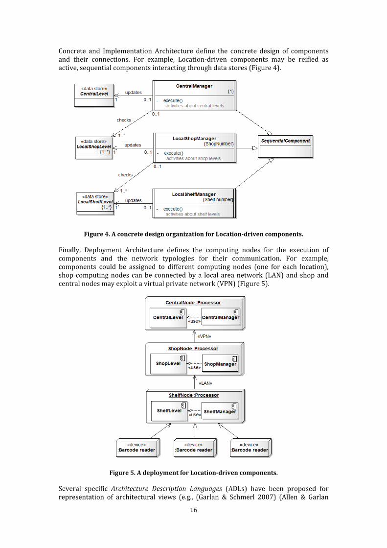
Concrete and Implementation Architecture define the concrete design of components and their connections. For example, Location-driven components may be reified as active, sequential components interacting through data stores (Figure 4).
Figure 4. A concrete design organization for Location-driven components. Finally, Deployment Architecture defines the computing nodes for the execution of components and the network typologies for their communication. For example, components could be assigned to different computing nodes (one for each location), shop computing nodes can be connected by a local area network (LAN) and shop and central nodes may exploit a virtual private network (VPN) (Figure 5).
Figure 5. A deployment for Location-driven components. Several specific Architecture Description Languages (ADLs) have been proposed for representation of architectural views (e.g., (Garlan & Schmerl 2007) (Allen & Garlan
17
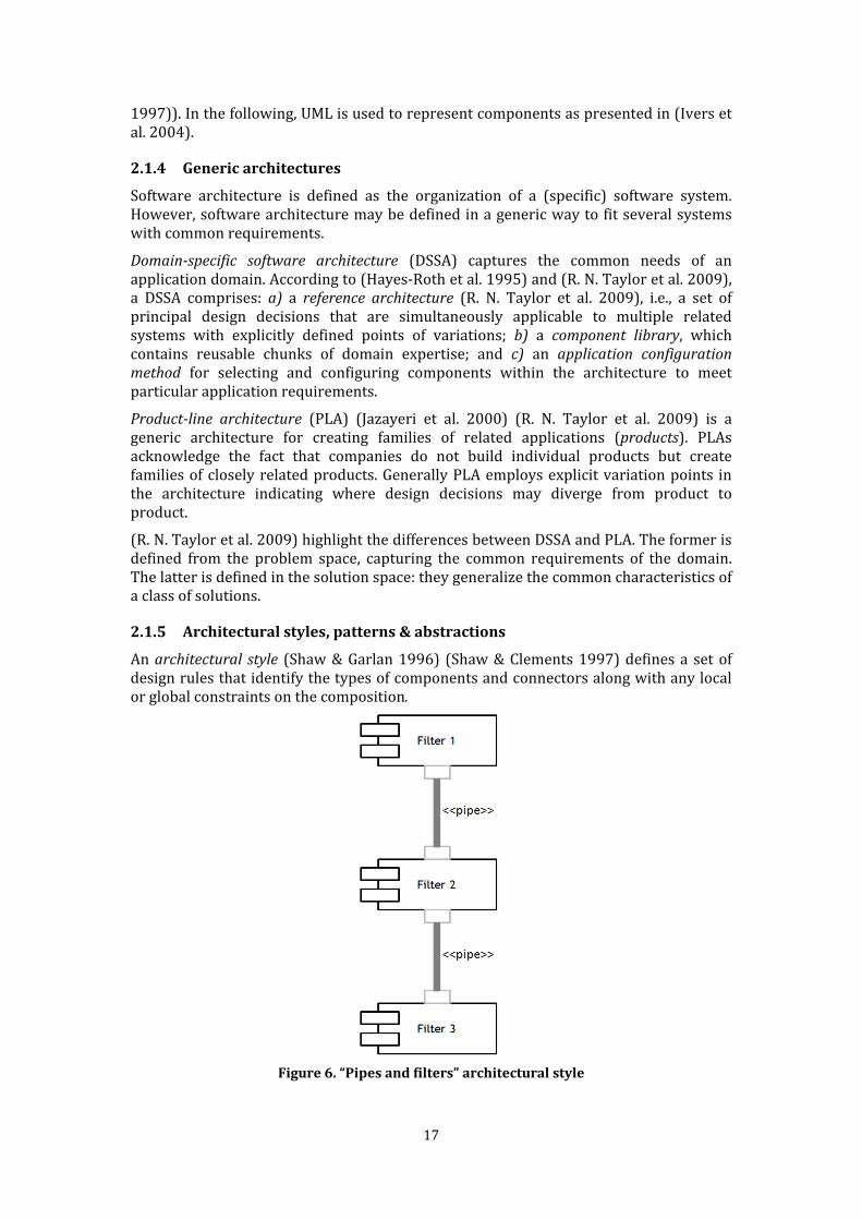
1997)). In the following, UML is used to represent components as presented in (Ivers et al. 2004). 2.1.4 Generic architectures Software architecture is defined as the organization of a (specific) software system. However, software architecture may be defined in a generic way to fit several systems with common requirements. Domain-specific software architecture (DSSA) captures the common needs of an application domain. According to (Hayes-Roth et al. 1995) and (R. N. Taylor et al. 2009), a DSSA comprises: a) a reference architecture (R. N. Taylor et al. 2009), i.e., a set of principal design decisions that are simultaneously applicable to multiple related systems with explicitly defined points of variations; b) a component library, which contains reusable chunks of domain expertise; and c) an application configuration method for selecting and configuring components within the architecture to meet particular application requirements. Product-line architecture (PLA) (Jazayeri et al. 2000) (R. N. Taylor et al. 2009) is a generic architecture for creating families of related applications (products). PLAs acknowledge the fact that companies do not build individual products but create families of closely related products. Generally PLA employs explicit variation points in the architecture indicating where design decisions may diverge from product to product. (R. N. Taylor et al. 2009) highlight the differences between DSSA and PLA. The former is defined from the problem space, capturing the common requirements of the domain. The latter is defined in the solution space: they generalize the common characteristics of a class of solutions. 2.1.5 Architectural styles, patterns & abstractions An architectural style (Shaw & Garlan 1996) (Shaw & Clements 1997) defines a set of design rules that identify the types of components and connectors along with any local or global constraints on the composition.
Figure 6. “Pipes and filters” architectural style
18
For example, Figure 6 describes one of the most basic well-known architectural styles, “pipes and filters” (Garlan & Shaw 1994). In this style, each component reads sequences of data on its inputs and produces sequences of data on its outputs, delivering a complete instance of the results in a standard order. This design is usually accomplished by applying a computation to the input streams and incrementally computing the output stream. Output begins before input is completely consumed. Therefore, components are referred to as “filters.” The connectors transmit outputs of one filter to inputs of another. For this reason, they are termed “pipes.” Software architecture can often combine different styles. (Garlan & Shaw 1994) and (Avgeriou & Zdun 2005) present sets of commonly recurring styles. The notion of architectural style is very close to the notion of architectural pattern (Buschmann et al. 1996). As an analogy to the notion of pattern in Building Architecture (Alexander 1979), it expresses a fundamental structural organization for software systems. It provides a set of predefined component types and includes rules and guidelines for organizing the relationships between them. (Avgeriou & Zdun 2005) clarify that the two terms “architectural styles” and “architectural pattern” correspond to two “schools of thought” regarding Software Architecture. Both terms refer to recurring solutions that solve problems at the architectural design level and provide a common vocabulary to facilitate communication. According to (Avgeriou & Zdun 2005), the concepts are similar and only differ in their use of different description forms. Architectural patterns are considered problem-solution pairs that occur in and are affected by a given context. They stress the description of the problem and the rationale behind the proposed solution. From the perspective of the architectural style, the problem and the rationale behind selecting a specific solution do not receive significant attention. Architectural abstractions (Kristensen 1996) (Shaw et al. 1995) are design abstractions that represent systems' architectural aspects, such as the overall organization, the decomposition into components, the assignment of functionality to components and the interactions among the components. Suitable architectural abstractions are the foundation of any architectural design process; components and connectors, generic architectures and architectural styles/patterns are examples of architectural abstractions with different scopes and abstraction levels. 2.1.6 Concrete frameworks Architectural abstractions provide reference organizations for overall system design, which should then reified in the system implementation. Rather than starting from scratch, architectural implementation frameworks can be exploited to implement the adopted architectural abstractions (Figure 7). An architecture implementation framework (R. N. Taylor et al. 2009) is a piece of software that acts as a bridge between a particular set of architectural abstractions and a set of implementation technologies. It provides architectural abstractions in code, in a way that assists developers in the implementation of systems that conform to the prescriptions and constraints of the abstractions. For example, the standard input/output library available in the UNIX operating systems (“stdio”) is an example of a (small) framework supporting the “pipe-and-filter” architectural style. In the following, the term “concrete framework” is used as a synonym for “architectural implementation framework”.

19
Figure 7. Architectural abstractions vs. concrete frameworks. (R. N. Taylor et al. 2009) describes architecture implementation frameworks as forms of
middleware (Sommerville 2004), a general term used to indicate software that manages and supports the different components of a system. However, (R. N. Taylor et al. 2009) observes that there is a subtle difference between how middleware and architectural implementation frameworks emerge and develop. The evolution of middleware is generally based upon on a set of services that the developers want to make available (e.g., support for programming language heterogeneity, distribution transparency3 and portability on different operating systems). The evolution of architectural implementation frameworks is generally based upon a particular set of architectural abstractions (typically architectural styles). By focusing on services, middleware developers often make other decisions that substantially impact architecture. For example, in supporting distribution transparency and language heterogeneity, the Common Object Request Broker Architecture (CORBA, see Section 2.4.1) middleware exploits remote procedure calls4 (RPC), while Java Message Service (JMS, see Section 2.4.1) uses middleware message passing5. Are RPC or messages necessary for these services or are they simply enabling techniques? In practice, middleware induces architectural abstractions. For example, CORBA induces the “distributed objects” architectural style, while JMS induces a distributed, “implicit invocation” style (Garlan & Shaw 1994) (Avgeriou & Zdun 2005). 2.2 Responsive Environments
2.2.1 Overview A Responsive Environment (Bullivant, 2006) (F. S. C. da Silva & Vasconcelos 2007) is an ordinary environment that is capable of sensing and responding to entities that inhabit it, use it or pass through or by it. The term was first introduced by Nicholas Negroponte in the late 1960s, referring to applications of Informatics to the Building Architecture. In (Negroponte 1976), he proposed the term Responsive Architecture, where “responsive 3 Distribution transparency (Tanenbaum & Steen 2006) is the ability of a system to hide the fact that software components and other resources are physically distributed across multiple computing machines. 4 Remote procedure calls (Tanenbaum & Steen 2006) is a distributed communication technique that allows components to execute procedures provided by other components that are not physically located on the same computing machine. See Section 2.4.1. 5 Message passing (Tanenbaum & Steen 2006) is a distributed communication technique that allows components to send and receive messages to or from other components. See Section 2.4.1.
20
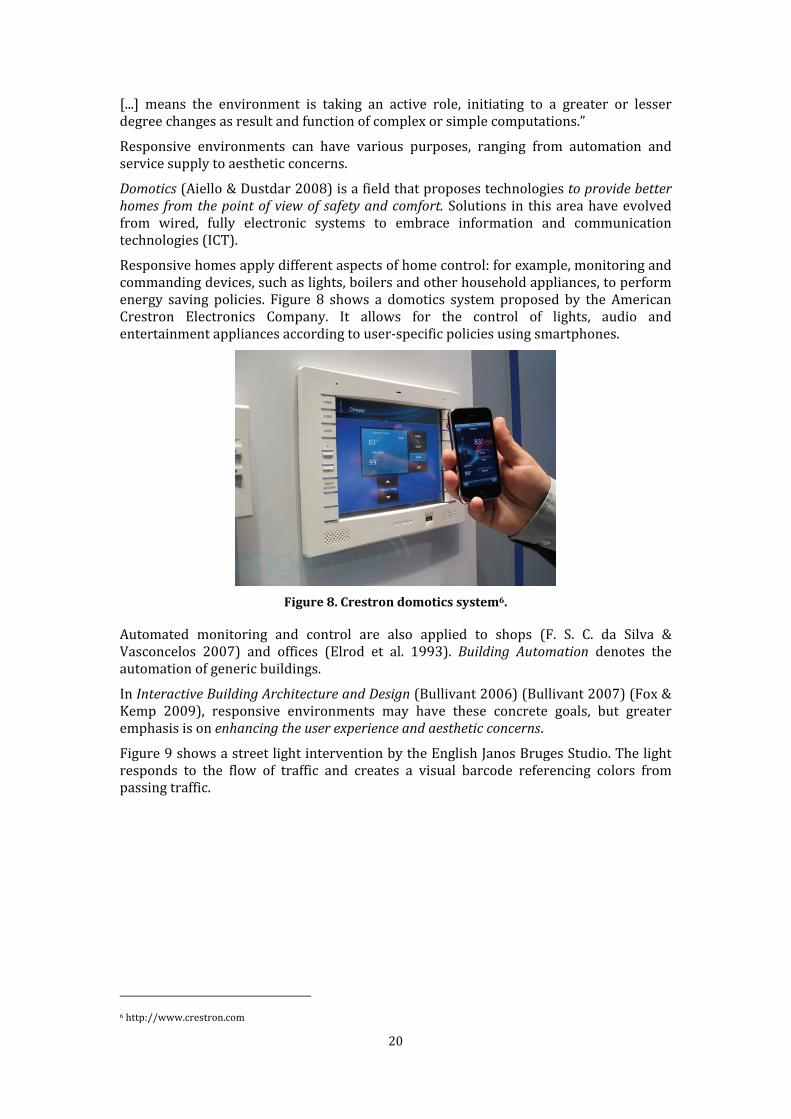
[...] means the environment is taking an active role, initiating to a greater or lesser degree changes as result and function of complex or simple computations.” Responsive environments can have various purposes, ranging from automation and service supply to aesthetic concerns. Domotics (Aiello & Dustdar 2008) is a field that proposes technologies to provide better homes from the point of view of safety and comfort. Solutions in this area have evolved from wired, fully electronic systems to embrace information and communication technologies (ICT). Responsive homes apply different aspects of home control: for example, monitoring and commanding devices, such as lights, boilers and other household appliances, to perform energy saving policies. Figure 8 shows a domotics system proposed by the American Crestron Electronics Company. It allows for the control of lights, audio and entertainment appliances according to user-specific policies using smartphones.
Figure 8. Crestron domotics system6. Automated monitoring and control are also applied to shops (F. S. C. da Silva & Vasconcelos 2007) and offices (Elrod et al. 1993). Building Automation denotes the automation of generic buildings. In Interactive Building Architecture and Design (Bullivant 2006) (Bullivant 2007) (Fox & Kemp 2009), responsive environments may have these concrete goals, but greater emphasis is on enhancing the user experience and aesthetic concerns. Figure 9 shows a street light intervention by the English Janos Bruges Studio. The light responds to the flow of traffic and creates a visual barcode referencing colors from passing traffic.
6 http://www.crestron.com

21
Figure 9. “Leicester Lights,” Jason Bruges Studio (2006), Leicester, London7. Service supply (at least in the most explicit and apparent form) seems to disappear in
Interactive Art (Burnham 1968) (Marcos et al. 2009), a general classification of any type of primarily interactive art in which the viewer becomes an active player in dialogue with the artwork. Responsive Environments in Interactive Art appear as interactive installations, i.e., artworks consisting of several elements distributed along a physical space. They are artworks in which space plays a central role, or “art that appropriates space to its own artistic ends” (Bestor 1996). Figure 10 shows an interactive installation by the artist Camille Utterback. A camera mounted on the City Hall building of San Jose (California, USA) monitors the presence of visitors. Different-colored patterns are projected onto the building based on varied factors, such as people's locations and whether they move alone or in groups. Individuals erase the background color, while groups fill it back in. In certain places, people’s positions launch moon-shaped graphics that travel in a trajectory opposite the person’s path. If another person moves across the “moon,” it disintegrates and releases a colored burst, further adding to the projection’s colorful appearance.
Figure 10. “Abundance,” Camille Utterback (2007), City Hall plaza, San Jose, California8.
7 http://www.jasonbruges.com/projects/uk-projects/leicester-lights 8 http://camilleutterback.com/projects/abundance
22
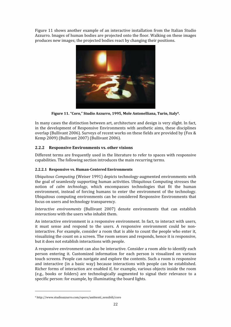
Figure 11 shows another example of an interactive installation from the Italian Studio Azzurro. Images of human bodies are projected onto the floor. Walking on these images produces new images; the projected bodies react by changing their positions.
Figure 11. “Coro,” Studio Azzurro, 1995, Mole Antonelliana, Turin, Italy9. In many cases the distinction between art, architecture and design is very slight. In fact, in the development of Responsive Environments with aesthetic aims, these disciplines overlap (Bullivant 2006). Surveys of recent works on these fields are provided by (Fox & Kemp 2009) (Bullivant 2007) (Bullivant 2006).
2.2.2 Responsive Environments vs. other visions Different terms are frequently used in the literature to refer to spaces with responsive capabilities. The following section introduces the main recurring terms. 2.2.2.1 Responsive vs. Human-Centered Environments
Ubiquitous Computing (Weiser 1991) depicts technology-augmented environments with the goal of seamlessly supporting human activities. Ubiquitous Computing stresses the notion of calm technology, which encompasses technologies that fit the human environment, instead of forcing humans to enter the environment of the technology. Ubiquitous computing environments can be considered Responsive Environments that focus on users and technology transparency. Interactive environments (Bullivant 2007) denote environments that can establish interactions with the users who inhabit them. An interactive environment is a responsive environment. In fact, to interact with users, it must sense and respond to the users. A responsive environment could be non-interactive. For example, consider a room that is able to count the people who enter it, visualizing the count on a screen. The room senses and responds, hence it is responsive, but it does not establish interactions with people. A responsive environment can also be interactive. Consider a room able to identify each person entering it. Customized information for each person is visualized on various touch screens. People can navigate and explore the contents. Such a room is responsive and interactive (in a basic way) because interactions with people can be established. Richer forms of interaction are enabled if, for example, various objects inside the room (e.g., books or folders) are technologically augmented to signal their relevance to a specific person: for example, by illuminating the board lights. 9 http://www.studioazzurro.com/opere/ambienti_sensibili/coro

23
The word “interactive” is often used to indicate environments which provide very simple forms of interaction (Haque 2007). (Haque 2007) and (Dubberly et al. 2009) try to distinguish and clarify the lexicon, identifying different interaction levels in which full interactivity is characterized as a constructive and conversational process (Haque 2007). 2.2.2.2 Responsive vs. Smart and Intelligent Environments
Smart Environments (Cook and Das 2007) are defined as “environments able to acquire and apply knowledge about the environment and its inhabitants to improve their experience.” Intelligent Responsive Environments (Silva & Vasconselos 2007) are defined as “responsive environments which analyze their context, adapt itself to the people and objects that reside in it, learn from their behavior, and eventually recognize as well as express emotion.” Such definitions describe responsive environments according to the Ambient Intelligence vision (Ramos et al. 2008) (Shadbolt 2003). This concept was introduced in 2001 by ISTAG10 (European Commission’s IST Advisory Group) and refers to digital environments that proactively assist people in their daily lives, acting autonomously to anticipate the user’s needs. 2.2.2.3 Responsive Environment vs. Ambient Ecologies The term ambient ecology introduced by (Goumopoulos & Kameas 2009) is a “metaphor to conceptualize a space populated by connected devices and services that are interrelated with each other, the environment and the people, supporting the users’ everyday activities in a meaningful way.” This concept represents an emerging vision for focusing on responsive environments in which the provided behavior is obtained by the cooperation of several computing units, either devices, services or so-called smart objects (Kortuem et al. 2010). 2.2.2.4 A comparison Responsive Environments can be viewed as a generic class of environments capable of sensing and responding. According to the actual richness of the provided behavior (more or less interactive, more or less “intelligent”), specific subclasses of Responsive Environments can be identified (Figure 12). Consider the original vision, where “responsive [...] means the environment is taking an active role, initiating to a greater or lesser degree changes as result and function of complex or simple computations” (Negroponte 1976).
10 ftp://ftp.cordis.lu/pub/ist/docs/istagscenarios2010.pdf

24
Figure 12. Responsive Environment classification. Figure 13 presents a comparison between the previous definitions with respect to their main foci.
Figure 13. Responsive vs. other types of environments.
2.2.3 Enabling hardware technologies Sensing and actuation technologies are crucial for the realization of responsive environments. Current state-of-the-art sensing technologies (e.g., sensors and sensor networks, vision and tracking systems and tangible and wearable devices) allow a large number of environmental properties to be sensed. These properties include strict physical environmental properties such as pressure, temperature, humidity, lighting conditions and noise levels, as well as user properties including presence (contact, proximity, distance/range and motion), identification of personal features, motion (position, velocity, angular velocity and acceleration), contact (strain, force, torque, slip and vibration) and physiological and biochemical conditions (e.g., heartbeat). The literature presents various surveys (Cook et al. 2009) (Papagiannakis et al. 2008) (Cook & Das 2007) that describe the heterogeneity of sensing devices (Figure 14).
25
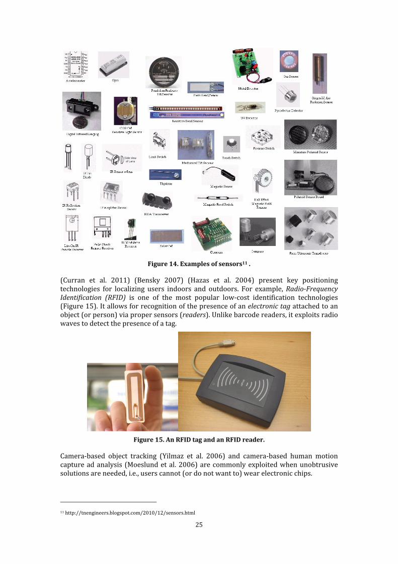
Figure 14. Examples of sensors11 . (Curran et al. 2011) (Bensky 2007) (Hazas et al. 2004) present key positioning technologies for localizing users indoors and outdoors. For example, Radio-Frequency
Identification (RFID) is one of the most popular low-cost identification technologies (Figure 15). It allows for recognition of the presence of an electronic tag attached to an object (or person) via proper sensors (readers). Unlike barcode readers, it exploits radio waves to detect the presence of a tag.
Figure 15. An RFID tag and an RFID reader. Camera-based object tracking (Yilmaz et al. 2006) and camera-based human motion capture ad analysis (Moeslund et al. 2006) are commonly exploited when unobtrusive solutions are needed, i.e., users cannot (or do not want to) wear electronic chips.
11 http://tnengineers.blogspot.com/2010/12/sensors.html
26
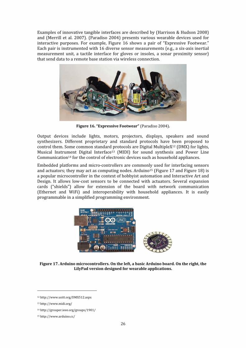
Examples of innovative tangible interfaces are described by (Harrison & Hudson 2008) and (Merrill et al. 2007). (Paradiso 2004) presents various wearable devices used for interactive purposes. For example, Figure 16 shows a pair of “Expressive Footwear.” Each pair is instrumented with 16 diverse sensor measurements (e.g., a six-axis inertial measurement unit, a tactile interface for gloves or insoles, a sonar proximity sensor) that send data to a remote base station via wireless connection.
Figure 16. “Expressive Footwear” (Paradiso 2004). Output devices include lights, motors, projectors, displays, speakers and sound synthesizers. Different proprietary and standard protocols have been proposed to control them. Some common standard protocols are Digital MultipleX12 (DMX) for lights, Musical Instrument Digital Interface13 (MIDI) for sound synthesis and Power Line Communication14 for the control of electronic devices such as household appliances. Embedded platforms and micro-controllers are commonly used for interfacing sensors and actuators; they may act as computing nodes. Arduino15 (Figure 17 and Figure 18) is a popular microcontroller in the context of hobbyist automation and Interactive Art and Design. It allows low-cost sensors to be connected with actuators. Several expansion cards (“shields”) allow for extension of the board with network communication (Ethernet and WiFi) and interoperability with household appliances. It is easily programmable in a simplified programming environment.
Figure 17. Arduino microcontrollers. On the left, a basic Arduino board. On the right, the
LilyPad version designed for wearable applications.
12 http://www.usitt.org/DMX512.aspx 13 http://www.midi.org/ 14 http://grouper.ieee.org/groups/1901/ 15 http://www.arduino.cc/
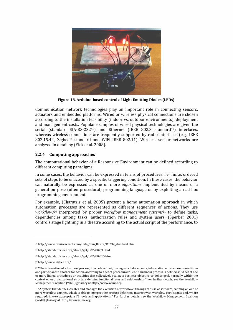
27
Figure 18. Arduino-based control of Light Emitting Diodes (LEDs). Communication network technologies play an important role in connecting sensors, actuators and embedded platforms. Wired or wireless physical connections are chosen according to the installation feasibility (indoor vs. outdoor environments), deployment and management costs. Popular examples of wired physical technologies are given the serial (standard EIA-RS-23216) and Ethernet (IEEE 802.3 standard17) interfaces, whereas wireless connections are frequently supported by radio interfaces (e.g., IEEE 802.15.418, Zigbee19 standard and WiFi IEEE 802.11). Wireless sensor networks are analyzed in detail by (Yick et al. 2008).
2.2.4 Computing approaches The computational behavior of a Responsive Environment can be defined according to different computing paradigms. In some cases, the behavior can be expressed in terms of procedures, i.e., finite, ordered sets of steps to be enacted by a specific triggering condition. In these cases, the behavior can naturally be expressed as one or more algorithms implemented by means of a general purpose (often procedural) programming language or by exploiting an ad-hoc programming environment. For example, (Charatsis et al. 2005) present a home automation approach in which automation processes are represented as different sequences of actions. They use workflows20 interpreted by proper workflow management systems21 to define tasks, dependencies among tasks, authorization rules and system users. (Sperber 2001) controls stage lightning in a theatre according to the actual script of the performance, to 16 http://www.camiresearch.com/Data_Com_Basics/RS232_standard.htm 17 http://standards.ieee.org/about/get/802/802.3.html 18 http://standards.ieee.org/about/get/802/802.15.html 19 http://www.zigbee.org/ 20 “The automation of a business process, in whole or part, during which documents, information or tasks are passed from one participant to another for action, according to a set of procedural rules.” A business process is defined as “A set of one or more linked procedures or activities that collectively realize a business objective or policy goal, normally within the context of an organizational structure defining functional roles and relationships.” For further details, see the Workflow Management Coalition (WMC) glossary at http://www.wfmc.org. 21 “A system that defines, creates and manages the execution of workflows through the use of software, running on one or more workflow engines, which is able to interpret the process definition, interact with workflow participants and, where required, invoke appropriate IT tools and applications.” For further details, see the Workflow Management Coalition (WMC) glossary at http://www.wfmc.org.
28
emphasize actors or important moments in the play. Here the behavior is realized as a sort of parallel script. In other cases, the desired relationship between inputs and outputs cannot be simply expressed as an algorithm because the elaboration process might involve a more complex form of reasoning, employing a cognitive model for the inference of the best suited reaction to sensed stimuli or the triggering of some form of sub-symbolic information processing mechanism. For example, (Herbert et al. 2008) exploit a rule-based approach (Brownston et al. 1985) in which the current context triggers a certain rule and the service specified by that rule is executed. A rule might specify that, “if a user enters the meeting room between 3:00 p.m. and 5:00 p.m., then a certain file is downloaded to the user’s mobile device,” or, “if the temperature in a certain room falls below 22 degrees Celsius on a weekday between 8:30 a.m. and 5:00 p.m., then the heating system is activated.” (Youngblood & Cook 2007) utilize a decision-learning algorithm that learns a strategy for controlling a smart environment based on sensor observations and power line control by constructing hierarchical hidden Markov models (Fine et al. 1998). (Mozer 2005) uses a neural network (MacKay 2003) and a reinforcement learner (Sutton & Barto 1998) to determine ideal settings for lights and fans in the home from the inhabitants' observed behavior over time. Finally, the relationship between inputs and outputs could be achieved as a result of local actions and interactions among autonomous entities that are effectively present in the environment (e.g., sensing and actuating devices). The single behaviors of these entities could be specified in terms of algorithms, but their overall behavior is achieved by means of their concurrent execution. For example, (Loke 2010) proposes an approach in which the overall environment's behavior emerges from the single behaviors of a collection of “smart artifacts.” Each artifact uses a proper extension of the Prolog language (“PeerProlog”) to support a form of collective reasoning (e.g., sub-goal evaluations can be passed to other smart artifacts). Each artifact is viewed as an independent physical unit: it has an embedded processor and networking and sensing capabilities. Distributed and autonomous computing based on the multi-agent approach (Ferber 1999) are exploited by several authors. (F. S. C. da Silva & Vasconcelos 2007) propose a multi-agent model and architecture for the management of intelligent shops. (Sparacino et al. 2000) and (Nguyen et al. 2006) exploit multi-agent approaches for the development of interactive art installations. (Sommerer & Mignonneau 1998) describe different interactive installations realized with evolutionary computing and genetic programming (Banzhaf et al. 1997) techniques. (Bandini et al. 2008) present an approach to adaptive lightning that involves interaction among sensors and actuators that are organized and structured in a distributed multi-layered Cellular Automata (Neumann 1966) (Gutowitz 1991) model. 2.3 Software Architecture for Responsive Environments This section analyzes Responsive Environments from a Software Architecture point of view, highlighting the key role of suitable communication in architectural abstractions.

29
2.3.1 Conceptual reference schema
Figure 19. Reference schema for a Responsive Environment. Figure 19 sketches a conceptual reference schema for a Responsive Environment architecture, which does not imply any concrete implementation or deployment choice. A Responsive Environment is a physical space enriched with input devices (sensors, cameras, vision and tracking systems and tangible and wearable interfaces), sensing stimuli from entities that inhabit the environment and output devices (screens, projectors, lights and audio synthesizers) that provide responses to the environment given proper commands. Some devices can play both input and output roles (for example, touch screens) and provide computing capabilities. Some devices are embedded within the physical space so that people remain unaware of them. The ICT system receives sensing stimuli from the input devices (input flow) and delivers commands to the output devices (output flow). It realizes the behavior of the Smart Environment, that is, how the input flow turns into output flow. The overall behavior of the Smart Environment could be defined via many computing approaches, as presented in Section 2.2.3.
2.3.2 Key architectural requirements and qualities Literature on Responsive Environments recognizes different key requirements and qualities for the ICT system behind these environments. Common key requirements relate to the space, context and multimodality. Space is important because the behavior of a Response Environment depends on user location. Multiple spatial representations are often exploited (Turner & E. Davenport 2005) (Harper et al. 2005) (Dobson 2005) (Steed et al. 2004) to describe the physical environment and other logical information (e.g., names or role hierarchies). Section 2.5 highlights the main space topics related to Responsive Environments. More generally, Responsive Environments must be aware of their contexts, i.e., “any information that can be used to characterize the situation of entities (i.e., whether a person, place or object) that are considered relevant to the interaction between a user and an application, including the user and the application themselves” (Dey 2001). Spatial localization information is a subset of contextual information (A. Schmidt 1999). Other relevant contextual information includes the users and their roles, profiles and preferences.
30
Multimodality (Bongers & Veer 2007) consists of supporting multiple heterogeneous types of input and output flows. As input, a Responsive Environment can measure strict physical environmental properties (pressure, temperature, humidity, lighting conditions and noise levels) and sense entity properties (presence, identification, motion, contact and physiological conditions). As output, it can control specific devices such as engines and household appliances and produce audio and visual effects. The richness of the provided behavior is strongly influenced by the richness of available sensing and responding devices. A key quality is the richness of the Responsive Environment behavior, which often depends on the expressiveness of the adopted computing approach. The desired input-output behavior can be more or less rich, and different typologies of behavior can be identified from purely reactive behaviors, where every output is directly determined by a set of inputs, or less predictable, autonomous behaviors. Finally, different traditional Software Engineering qualities play relevant roles: • modifiability, signifying the ease of making changes; • openness and heterogeneity, indicating the possibility of integrating new and heterogeneous hardware and software technologies; • technological scalability, for example, the ability to scale from a few homogenous sensors to larger numbers of heterogeneous sensors without affecting the functionality and performance of the overall system.
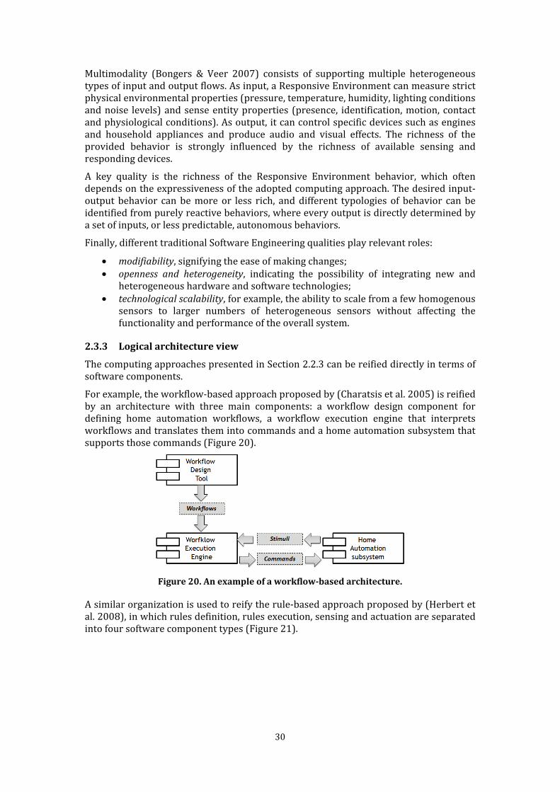
2.3.3 Logical architecture view The computing approaches presented in Section 2.2.3 can be reified directly in terms of software components. For example, the workflow-based approach proposed by (Charatsis et al. 2005) is reified by an architecture with three main components: a workflow design component for defining home automation workflows, a workflow execution engine that interprets workflows and translates them into commands and a home automation subsystem that supports those commands (Figure 20).
Figure 20. An example of a workflow-based architecture. A similar organization is used to reify the rule-based approach proposed by (Herbert et al. 2008), in which rules definition, rules execution, sensing and actuation are separated into four software component types (Figure 21).

31
Figure 21. An example of a rule-based architecture. The multi-agent approach proposed by (F. S. C. da Silva & Vasconcelos 2007) is reified and visualized in Figure 22. Agent components obtain stimuli from the environment and act on them through Sensing and Actuation Devices components. Administrative Agent components manage the dynamic creation and deletion of agent components. A tuple space (see Section 2.4.3) is exploited for communication.
Figure 22. An example of multi-agent based architecture. This type of “computing-driven” architectural design can provide effective solutions; however, the component organizations and the resulting behavior strongly depend on the computing approach followed. This thesis focuses on the definition of architectural abstractions and a corresponding concrete framework that supports the seamless integration of heterogeneous components
whose cooperation enhances the functionalities of an open-ended Responsive Environment. These components can exploit different computing approaches according to the specific applications' needs; the result is an integrated system that supports highly open and flexible Responsive Environments. Figure 23 shows the three main types of components relevant to this view. Several component subtypes and instances may be present in a real system.
32
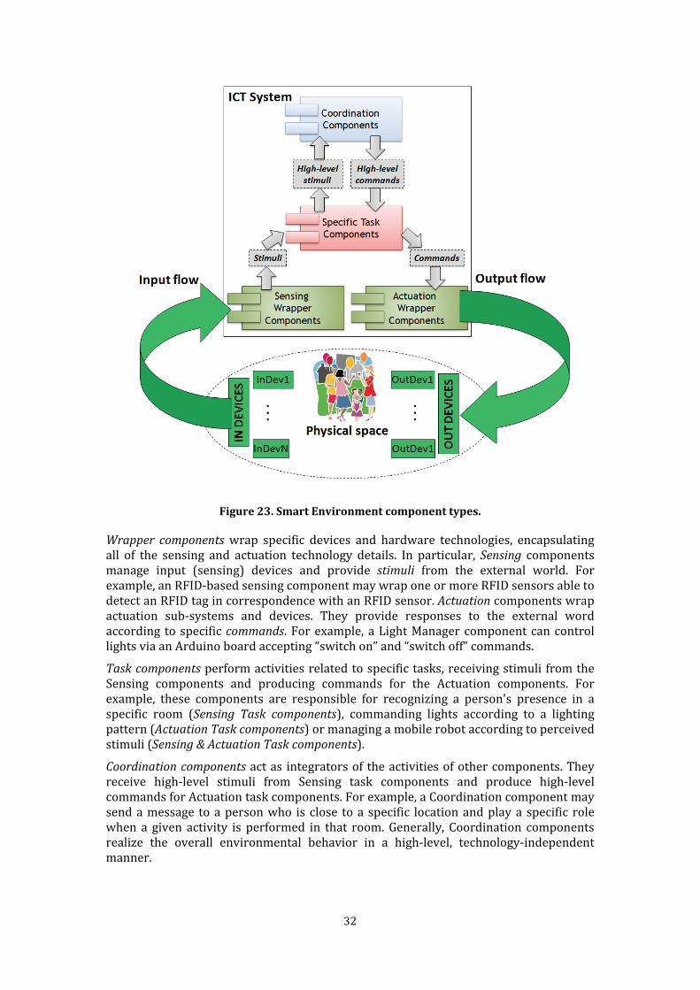
Figure 23. Smart Environment component types.
Wrapper components wrap specific devices and hardware technologies, encapsulating all of the sensing and actuation technology details. In particular, Sensing components manage input (sensing) devices and provide stimuli from the external world. For example, an RFID-based sensing component may wrap one or more RFID sensors able to detect an RFID tag in correspondence with an RFID sensor. Actuation components wrap actuation sub-systems and devices. They provide responses to the external word according to specific commands. For example, a Light Manager component can control lights via an Arduino board accepting “switch on” and “switch off” commands. Task components perform activities related to specific tasks, receiving stimuli from the Sensing components and producing commands for the Actuation components. For example, these components are responsible for recognizing a person's presence in a specific room (Sensing Task components), commanding lights according to a lighting pattern (Actuation Task components) or managing a mobile robot according to perceived stimuli (Sensing & Actuation Task components). Coordination components act as integrators of the activities of other components. They receive high-level stimuli from Sensing task components and produce high-level commands for Actuation task components. For example, a Coordination component may send a message to a person who is close to a specific location and play a specific role when a given activity is performed in that room. Generally, Coordination components realize the overall environmental behavior in a high-level, technology-independent manner.
33
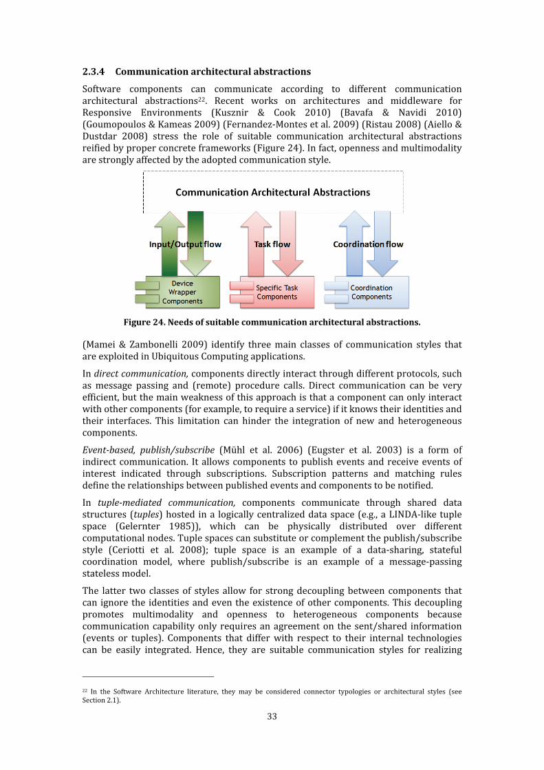
2.3.4 Communication architectural abstractions Software components can communicate according to different communication architectural abstractions22. Recent works on architectures and middleware for Responsive Environments (Kusznir & Cook 2010) (Bavafa & Navidi 2010) (Goumopoulos & Kameas 2009) (Fernandez-Montes et al. 2009) (Ristau 2008) (Aiello & Dustdar 2008) stress the role of suitable communication architectural abstractions reified by proper concrete frameworks (Figure 24). In fact, openness and multimodality are strongly affected by the adopted communication style.
Figure 24. Needs of suitable communication architectural abstractions. (Mamei & Zambonelli 2009) identify three main classes of communication styles that are exploited in Ubiquitous Computing applications. In direct communication, components directly interact through different protocols, such as message passing and (remote) procedure calls. Direct communication can be very efficient, but the main weakness of this approach is that a component can only interact with other components (for example, to require a service) if it knows their identities and their interfaces. This limitation can hinder the integration of new and heterogeneous components.
Event-based, publish/subscribe (Mühl et al. 2006) (Eugster et al. 2003) is a form of indirect communication. It allows components to publish events and receive events of interest indicated through subscriptions. Subscription patterns and matching rules define the relationships between published events and components to be notified. In tuple-mediated communication, components communicate through shared data structures (tuples) hosted in a logically centralized data space (e.g., a LINDA-like tuple space (Gelernter 1985)), which can be physically distributed over different computational nodes. Tuple spaces can substitute or complement the publish/subscribe style (Ceriotti et al. 2008); tuple space is an example of a data-sharing, stateful coordination model, where publish/subscribe is an example of a message-passing stateless model. The latter two classes of styles allow for strong decoupling between components that can ignore the identities and even the existence of other components. This decoupling promotes multimodality and openness to heterogeneous components because communication capability only requires an agreement on the sent/shared information (events or tuples). Components that differ with respect to their internal technologies can be easily integrated. Hence, they are suitable communication styles for realizing 22 In the Software Architecture literature, they may be considered connector typologies or architectural styles (see Section 2.1).
34
open and heterogeneous Responsive Environments. Publish/subscribe is the reference style used by many recent approaches proposed for realizing Responsive Environments, such as (Gámez & Fuentes 2011), (Kusznir and Cook 2010), (Goumopoulos and Kameas 2009), (Aiello & Dustdar 2008) and (Ristau 2008), while tuple-mediated communication is exploited by several works such as (Viroli et al. 2011), (Mamei & Zambonelli 2009) and (MacColl et al. 2002). Communication styles are generally supported by specific concrete frameworks. Several industrial and academic frameworks are available for each previous style. Section 2.4 presents the previous communication styles in detail and provides some examples of the concrete frameworks that support them. 2.3.5 Component deployment Once the overall architecture and, in particular, the communication styles are defined and supported by a proper concrete framework, the Responsive Environment can be implemented as a collection of components. In its simplest form, a component is an executable piece of software entirely hosted by a single computing node that provides suitable computational capabilities. Different components may rely on different hardware and software technologies, provided that they agree on a common interaction style. The deployment of application components to computing nodes requires consideration of software and hardware technologies for sensing, responding and computing. For example, a set of software components can be executed on a single computing node rather than being distributed over different nodes. On the other hand, for performance reasons, a complex algorithm could be parallelized and split into micro-components running on different nodes. The deployment schema for Responsive Environments may range from a centralized schema (one or more computing nodes separated from input and output devices) to a highly distributed one, up to the scenario in which input and output devices also have computing capabilities and execute one or more software components. For example, a smart-phone could host one or more sensing component (e.g., touch-screen for user inputs and GPS-based localization), one or more actuation components (e.g., screen and speaker) and one or more specific task component (e.g., local reasoning based on local sensor data). A smartphone and, in general, a smart object, is “smart” when it runs these three types of application components, which together realize smart behavior. 2.4 Communication architectural abstractions for Responsive
Environments In the following section, state-of-the art communication architectural abstractions and their concrete frameworks for Responsive Environments are presented. Following (Mamei & Zambonelli 2009), three main classes of communication styles are widely adopted in Ubiquitous Computing applications: direct communication, event-based publish/subscribe communication and tuple-based communication. 2.4.1 Direct communication Direct communication is the basic communication form available to software components. Two specific direct communication styles can be identified: procedure calls and message passing. Local procedure calls are well-known mechanisms supported by any programming languages, whether imperative (e.g., C, C++, Java), functional (e.g., LISP) or declarative (e.g., Prolog). Remote Procedure Calls (RPC) (Tanenbaum & Steen 2006) extend the
35
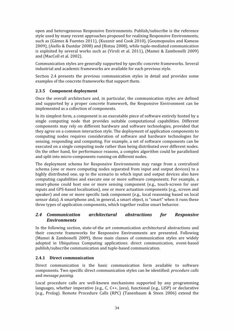
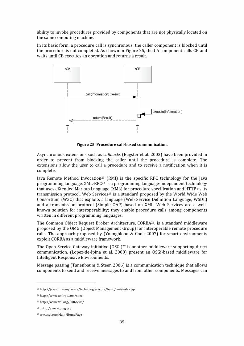
ability to invoke procedures provided by components that are not physically located on the same computing machine. In its basic form, a procedure call is synchronous; the caller component is blocked until the procedure is not completed. As shown in Figure 25, the CA component calls CB and waits until CB executes an operation and returns a result. :CA :CB
call(Information) :Result
execute(Information)
return(Result)
Figure 25. Procedure call-based communication. Asynchronous extensions such as callbacks (Eugster et al. 2003) have been provided in order to prevent from blocking the caller until the procedure is complete. The extensions allow the user to call a procedure and to receive a notification when it is complete. Java Remote Method Invocation23 (RMI) is the specific RPC technology for the Java programming language. XML-RPC24 is a programming language-independent technology that uses eXtended Markup Language (XML) for procedure specification and HTTP as its transmission protocol. Web Services25 is a standard proposed by the World Wide Web Consortium (W3C) that exploits a language (Web Service Definition Language, WSDL) and a transmission protocol (Simple OAP) based on XML. Web Services are a well-known solution for interoperability; they enable procedure calls among components written in different programming languages. The Common Object Request Broker Architecture, CORBA26, is a standard middleware proposed by the OMG (Object Management Group) for interoperable remote procedure calls. The approach proposed by (Youngblood & Cook 2007) for smart environments exploit CORBA as a middleware framework. The Open Service Gateway initiative (OSGi)27 is another middleware supporting direct communication. (Lopez-de-Ipina et al. 2008) present an OSGi-based middleware for Intelligent Responsive Environments. Message passing (Tanenbaum & Steen 2006) is a communication technique that allows components to send and receive messages to and from other components. Messages can
23 http://java.sun.com/javase/technologies/core/basic/rmi/index.jsp 24 http://www.xmlrpc.com/spec 25 http://www.w3.org/2002/ws/ 26 : http://www.omg.org 27 ww.osgi.org/Main/HomePage
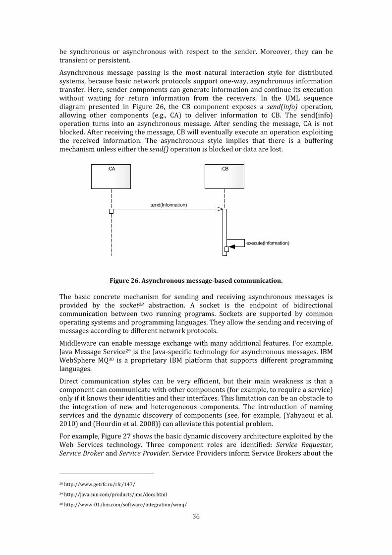
36
be synchronous or asynchronous with respect to the sender. Moreover, they can be transient or persistent. Asynchronous message passing is the most natural interaction style for distributed systems, because basic network protocols support one-way, asynchronous information transfer. Here, sender components can generate information and continue its execution without waiting for return information from the receivers. In the UML sequence diagram presented in Figure 26, the CB component exposes a send(info) operation, allowing other components (e.g., CA) to deliver information to CB. The send(info) operation turns into an asynchronous message. After sending the message, CA is not blocked. After receiving the message, CB will eventually execute an operation exploiting the received information. The asynchronous style implies that there is a buffering mechanism unless either the send() operation is blocked or data are lost. :CA :CB
send(Information)
execute(Information)
Figure 26. Asynchronous message-based communication. The basic concrete mechanism for sending and receiving asynchronous messages is provided by the socket28 abstraction. A socket is the endpoint of bidirectional communication between two running programs. Sockets are supported by common operating systems and programming languages. They allow the sending and receiving of messages according to different network protocols. Middleware can enable message exchange with many additional features. For example, Java Message Service29 is the Java-specific technology for asynchronous messages. IBM WebSphere MQ30 is a proprietary IBM platform that supports different programming languages. Direct communication styles can be very efficient, but their main weakness is that a component can communicate with other components (for example, to require a service) only if it knows their identities and their interfaces. This limitation can be an obstacle to the integration of new and heterogeneous components. The introduction of naming services and the dynamic discovery of components (see, for example, (Yahyaoui et al. 2010) and (Hourdin et al. 2008)) can alleviate this potential problem. For example, Figure 27 shows the basic dynamic discovery architecture exploited by the Web Services technology. Three component roles are identified: Service Requester,
Service Broker and Service Provider. Service Providers inform Service Brokers about the 28 http://www.getrfc.ru/rfc/147/ 29 http://java.sun.com/products/jms/docs.html 30 http://www-01.ibm.com/software/integration/wmq/
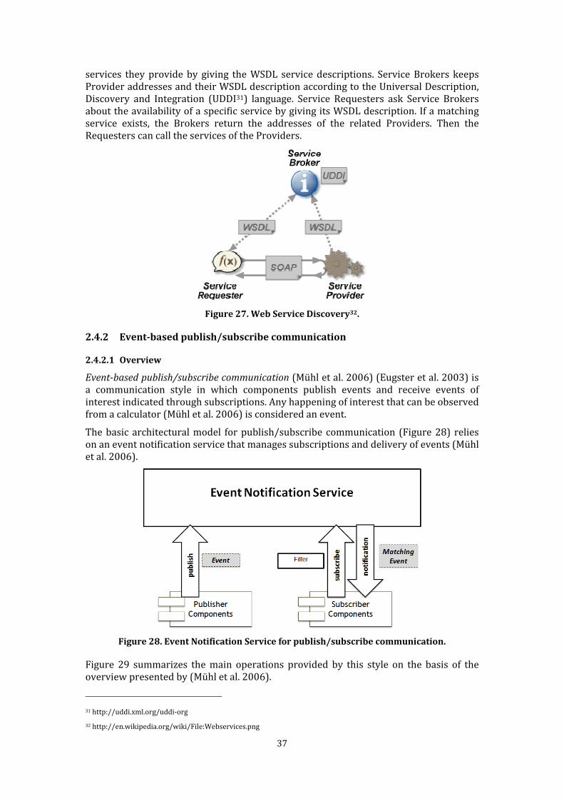
37
services they provide by giving the WSDL service descriptions. Service Brokers keeps Provider addresses and their WSDL description according to the Universal Description, Discovery and Integration (UDDI31) language. Service Requesters ask Service Brokers about the availability of a specific service by giving its WSDL description. If a matching service exists, the Brokers return the addresses of the related Providers. Then the Requesters can call the services of the Providers.
Figure 27. Web Service Discovery32.
2.4.2 Event-based publish/subscribe communication
2.4.2.1 Overview
Event-based publish/subscribe communication (Mühl et al. 2006) (Eugster et al. 2003) is a communication style in which components publish events and receive events of interest indicated through subscriptions. Any happening of interest that can be observed from a calculator (Mühl et al. 2006) is considered an event. The basic architectural model for publish/subscribe communication (Figure 28) relies on an event notification service that manages subscriptions and delivery of events (Mühl et al. 2006).
Figure 28. Event Notification Service for publish/subscribe communication. Figure 29 summarizes the main operations provided by this style on the basis of the overview presented by (Mühl et al. 2006).
31 http://uddi.xml.org/uddi-org 32 http://en.wikipedia.org/wiki/File:Webservices.png

38
The subscribe(f, sub) operation registers the interest of the caller component (subscriber) in events. The interest is specified through a filter defined according to various techniques. Subscribers should support a notify(e) primitive, which is called to deliver an event matching the filter. The operation returns a subscription identifier, which univocally identifies the subscription. To notify the subscriber, the notification service needs to recognize it (e.g., through an address according to a specific network protocol). Generally, an additional parameter identifying the subscriber is added to the primitive subscription; however, this step is regarded as an implementation detail and is left implicit. The unsubscribe(subID) operation unregisters the previous subscription of a subscriber, given its identifier. The publish(e) operation allows components (publishers) to publish events. The event service propagates the event to all relevant subscribers. Every subscriber will be notified of every event matching the provided filters.
Figure 29. Publish/subscribe operation interfaces. Other operations may be provided according to the different existing variants. For example, an advertise operation allows publishers to advertise the nature of future events. The provided information can be useful to help the event service adjust to the expected flows of events and for the subscribers to be aware of the availability of new information. The adopted technique of expressing and interpreting filters in subscriptions determines the different versions of publish/subscribe communication (Mühl et al. 2006) (Eugster et al. 2003).
Topic-based (also called subject-based) publish/subscribe components can publish events and subscribe to individual topics, which are identified by proper strings (keywords). String matching is exploited for notification selection. For example, a sensing component can publish temperature data under the subject /room1/property/temperature. Task components can subscribe to /room1/property/∗ to receive the available property values. In type-based publish/subscribe (Eugster 2007), events are filtered according to their type. Content-based (also called property-based) publish/subscribe is the most widespread publish/subscribe scheme. It considers the actual content of published events, such as the internal attributes of data. Consumers subscribe to select events by specifying filters

39
using a subscription language. The filters define specific constraints, which are usually in the form of name-value pairs of properties and basic comparison operators. Constraints can be logically combined to form complex subscription patterns. Subscription patterns are used to identify events of interest for a given subscriber and propagate events accordingly. There are several means of representing such patterns. Available solutions range from template matching (Cugola et al. 2001), expression of name/value pairs (Mühl & Fiege 2001) and query languages such as XPath on XML (Altinel & Franklin 2000). The publish/subscribe style provides components with uncoupled communication in space and time without the need to know the identities of other components. This attribute clearly leads to open systems, in which publisher and subscribers can be dynamically inserted and removed. For these reasons, it has been exploited in many recent generic architectures and middlewares proposed for Responsive Environments, such as in (Kusznir and Cook 2010), (Gámez & Fuentes 2011), (Goumopoulos and Kameas 2009), (Aiello & Dustdar 2008) and (Ristau 2008)). The only key requirement of this style is an agreement on the exchanged events, which must be interpretable by each component. This agreement can obtained with the use of common data formats; alternatively, data interoperability via semantic technologies (Hitzler et al. 2009) could be exploited (e.g., (Ma et al. 2006)). Publish/subscribe is widely supported by major industrial middleware in addition to direct communication (e.g., OSGi and CORBA). Several standard specifications aim to add publish/subscribe communication to Web Services, such as WS-Events33, WS-Eventing34 and WS-Notification35. A significant publish/subscribe standard is provided by the Data Distribution Service for Real-Time Systems36 (DDS) proposed by OMG in 2004. It includes a publish/subscribe interface, which is targeted toward the efficient delivery of information. It allows for content-based publish/subscribe communication between publishers and subscribers focusing on quality of service (QoS). For example, DDS automatically handles the dynamic switching of redundant publishers if the primary publishers fail. Related industrial products are Splice DDS from Thales (US) (van ’t Hag 2003) and NDDS from Real-Time Innovations37 (US). From the perspective of application components, the notification service is a black box; it is conceptually centralized and its function does not depend on its being distributed, which is a matter of implementation. However, its nonfunctional attributes, such as efficiency, scalability and availability, are influenced by the architecture and the communication techniques used to distribute notifications. Commercial systems such as IBM WebSphere MQ rely on centralized implementation of the notifications service. In many cases, centralized implementation provides a bottleneck for the applications. For this reason, several implementations of event notification services rely on a network of event notification subcomponents (called brokers, Figure 30) executing on different 33 Catania et al. Ws-events specification, 2003. http://devresource.hp.com/drc/specifications/wsmf/WS-Events.pdf 34 Box et al. Ws-eventing specification, 2004. ftp://www6.software.ibm.com/software/developer/library/ws-eventing/WS-Eventing.pdf 35 Graham et al., WS-Notification: Publish-subscribe notification for Web services, http://www-106.ibm.com/developerworks/library/ specification/ws-notification/, 2004 36 http://www.omg.org/technology/documents/dds_spec_catalog.htm 37 http://www.rti.com/products/dds/index.html
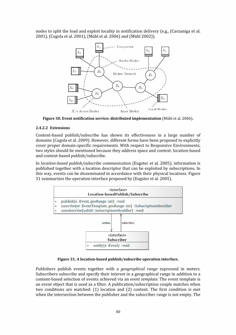
40
nodes to split the load and exploit locality in notification delivery (e.g., (Carzaniga et al. 2001), (Cugola et al. 2001), (Mühl et al. 2006) and (Mühl 2002)).
Figure 30. Event notification service: distributed implementation (Mühl et al. 2006).
2.4.2.2 Extensions Content-based publish/subscribe has shown its effectiveness in a large number of domains (Cugola et al. 2009). However, different forms have been proposed to explicitly cover proper domain-specific requirements. With respect to Responsive Environments, two styles should be mentioned because they address space and context: location-based and context-based publish/subscribe. In location-based publish/subscribe communication (Eugster et al. 2005), information is published together with a location descriptor that can be exploited by subscriptions. In this way, events can be disseminated in accordance with their physical locations. Figure 31 summarizes the operation interface proposed by (Eugster et al. 2005).
Figure 31. A location-based publish/subscribe operation interface. Publishers publish events together with a geographical range expressed in meters. Subscribers subscribe and specify their interest in a geographical range in addition to a content-based selection of events achieved via an event template. The event template is an event object that is used as a filter. A publication/subscription couple matches when two conditions are matched: (1) location and (2) content. The first condition is met when the intersection between the publisher and the subscriber range is not empty. The

41
content match condition is met when the published event contains all of the attributes specified in the subscribed event template. Active Map (Schilit & Theimer 1994) is an early location-based publish/subscribe system. It provides an “active map service” where clients can publish information about objects at a particular location and/or submit queries to obtain information about other published located objects. It is based on a hierarchical location model that represents rooms, floors and buildings. (X. Chen et al. 2003) provide a richer approach for spatial publish/subscribe communication. Publishers publish spatial events described by a set of properties specified by name-value (NV) pairs. Three properties are mandatory: 1) Object Identifier (OID), a unique identifier indicating the owner of the location; 2) Timestamp (TS), the time at which the object is positioned; 3) Location (LOC), the geographical location specified by a predefined spatial reference system or textual description of a location that could be translated into a geographical location. An optional Uncertainty (UNC) field describes the uncertainty of the detected location. Subscribers receive events specifying their spatial interests in two forms. First, they are received through a Within predicate with the syntax (oid-1,oid-2, … oid-n) within (zone-1,zone-2, … zone-n). The predicate is true if and only if one of the locations of the object identified by (oid-i) is within one of the zones (zone-j). A zone is used to represent an interested region. Second, a Distance predicate is available. It has the syntax (oid) distance (D, oid-1,oid-2, … oid-n). The predicate is true if and only if the distance between oid and oid-i (1≤i≤n) is less than D. Context-based publish/subscribe communication (Cugola et al. 2009) enables the diffusion of events based on a general notion of context. It could be considered as a generalization of the location-based version. Figure 32 summarizes the operation interface proposed by (Cugola et al. 2009) according to the basic interface proposed in Section 2.4.2.2.
Figure 32. A context-based publish/subscribe operation interface. Each component may set its current context by invoking the setContext(c) operation. The type of context representation (e.g., a string rather than a name/value pair) is not specified by (Cugola et al. 2009). Subscribers subscribe to events matching the content
filter fm and the context filter fc through the subscribe(e, fc) operation. Publishers publish events whose context matches the context filter fc by invoking the publish(e; fc) operation. An event reaches a subscriber when 1) the context of the publication matches the context specified by the subscriber and/or when the context in the subscription

42
matches the context specified by the publisher and 2) a match occurs between the message and the content filter. (Frey & Roman 2007) propose another context-aware publish-subscribe model. The authors factor context information into events and subscriptions. This method ensures that publishers and subscribers are able to control the diffusion of messages and to restrict the identities of communication parties. A match occurs when the publisher and subscriber contexts overlap. These extended forms can be implemented over traditional content-based middleware and, therefore, can be considered particular content-based variants, treating location and context as particular properties of the event content. However, (Cugola et al. 2009) suggest separating events from their location/context on the basis of efficiency and separation of concerns. With respect to the last point, they highlight that, “tying the two concepts together might reduce the readability of code, forcing complex interaction among parts of the application that should be kept separate.” 2.4.3 Tuple-mediated communication
2.4.3.1 Overview
Tuple spaces38 (also called shared data spaces) mediate communication through common data structures (tuples), which are created and read by components according to different forms of pattern matching. A tuple space is normally considered to be a logically centralized data space, which, analogous to the event notification service of publish/subscribe communication, could be implemented in a centralized or decentralized manner. Linda (Gelernter 1985) is the programming language that introduced the notion of tuple space. It originates from parallel processing and was developed for use in distributed environments (Carriero & Gelernter 1989). Figure 33 presents the basic operation interface provided by a Linda-like tuple space.
Figure 33. A tuple space, Linda-like operation interface. The out(t) operation puts a new tuple in the tuple space after evaluating all fields; the caller component immediately continues. The in(t) operation looks for a tuple in the tuple space. If it is not found, the component suspends; when it is found, it reads and deletes it. The retrieved tuple is returned through the operation’s tuple parameter. For example,
out("sum", 2,3) adds the tuple ("sum", 2, 3)into the tuple space. After that in("sum",?i,?j)
38 They are also known as the repositories/blackboard architectural style (Garlan & Shaw 1994).

43
will match the previous tuple, assigning 2 to the i variable and 3 to the j variable. Next, the tuple is removed from the tuple space. The tuple provided as the parameter in in(t) operation is a template tuple. In Linda programming, it is assumed that the tuples are unordered in the tuple space, so the tuple that will be returned and removed cannot be determined in the presence of multiple matches. In practice, implementation introduces a form of order. The rd(t) operation looks for a tuple in the tuple space. If not found, the component suspends; if found, it is read. The inp(t) operation looks for a tuple in the tuple space. If found, it is deletes and returns TRUE; if it is not found, it returns FALSE. The rdp(t) operation looks for a tuple in the tuple space. If it is found, it is copied and returns TRUE; if it is not found, it returns FALSE. Several concrete frameworks supporting tuple spaces are available, for example LightTS (Picco et al. 2005), JavaSpaces (Freeman et al. 1999) and TSpaces (Wyckoff et al. 1998). Equip (MacColl et al. 2002) is an example of tuple space concrete framework that has been applied to realize several responsive environments. Tuple spaces offer the same advantages as publish/subscribe communication: they strongly decouple the communication components with respect to time, space and identity. Hence, they promote openness and dynamic insertion/removal of components. They also require an agreement among the tuple data format. Tuple spaces are an example of a data-sharing, stateful coordination model, where publish/subscribe is an example of a message-passing stateless model (Ceriotti et al. 2008). Tuple spaces can substitute for or complement the publish/subscribe style (Ceriotti et al. 2008). In fact, several concrete frameworks for tuple spaces provide components with publish/subscribe notification mechanisms: for example, to be notified when a matching tuple is inserted into the tuple space (e.g., JavaSpaces). Conversely, some publish/subscribe models may include persistent publications (e.g., (Eugster et al. 2005)). 2.4.3.2 Extensions Semantic Tuple Spaces (Fensel 2004) (L. J. B. Nixon et al. 2008) extend Linda-based template matching using semantic technologies, in particular ontologies39 (Guarino 1998) and related languages like Ontology Web Language40 (OWL) and Resource Description Framework41 (RDF). A semantic space finds data that matches a template by employing a reasoning engine to infer additional data with respect to the data directly inserted by the components. (Murth & Kühn 2010) analyzed several semantic tuple space models, including TripCom (Simperl et al. 2007), Semantic Web Spaces (SWS) (L. Nixon et al. 2007) and CSpaces (Martín-Recuerda 2006). From this analysis, they propose a reference operation interface for semantic tuple space (Figure 34). 39 "In its most prevalent use in Artificial Intelligence, an ontology refers to an engineering artifact, constituted by a specific vocabulary used to describe a certain reality, plus a set of explicit assumptions regarding the intended meaning of the vocabulary words." (Guarino 1998) 40 http://www.w3.org/TR/owl-features/ 41 http://www.w3.org/TR/rdf-primer/
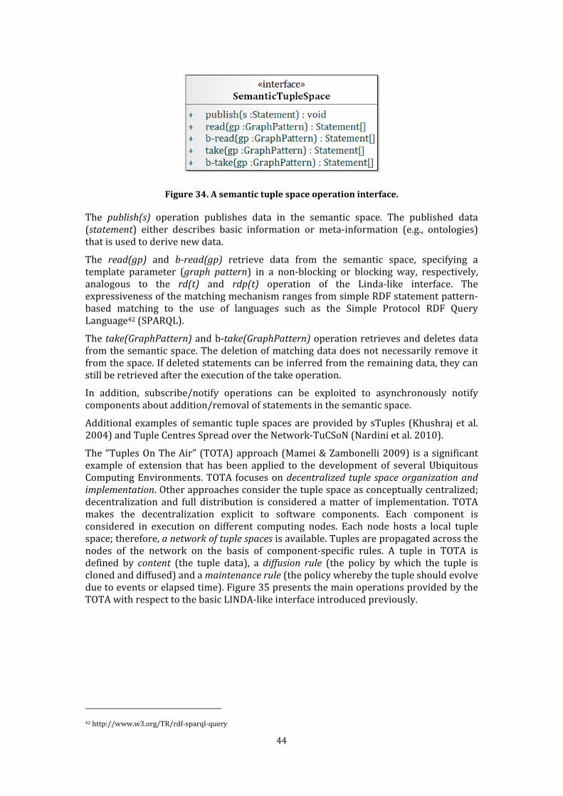
44
Figure 34. A semantic tuple space operation interface. The publish(s) operation publishes data in the semantic space. The published data (statement) either describes basic information or meta-information (e.g., ontologies) that is used to derive new data. The read(gp) and b-read(gp) retrieve data from the semantic space, specifying a template parameter (graph pattern) in a non-blocking or blocking way, respectively, analogous to the rd(t) and rdp(t) operation of the Linda-like interface. The expressiveness of the matching mechanism ranges from simple RDF statement pattern-based matching to the use of languages such as the Simple Protocol RDF Query Language42 (SPARQL). The take(GraphPattern) and b-take(GraphPattern) operation retrieves and deletes data from the semantic space. The deletion of matching data does not necessarily remove it from the space. If deleted statements can be inferred from the remaining data, they can still be retrieved after the execution of the take operation. In addition, subscribe/notify operations can be exploited to asynchronously notify components about addition/removal of statements in the semantic space. Additional examples of semantic tuple spaces are provided by sTuples (Khushraj et al. 2004) and Tuple Centres Spread over the Network-TuCSoN (Nardini et al. 2010). The “Tuples On The Air” (TOTA) approach (Mamei & Zambonelli 2009) is a significant example of extension that has been applied to the development of several Ubiquitous Computing Environments. TOTA focuses on decentralized tuple space organization and
implementation. Other approaches consider the tuple space as conceptually centralized; decentralization and full distribution is considered a matter of implementation. TOTA makes the decentralization explicit to software components. Each component is considered in execution on different computing nodes. Each node hosts a local tuple space; therefore, a network of tuple spaces is available. Tuples are propagated across the nodes of the network on the basis of component-specific rules. A tuple in TOTA is defined by content (the tuple data), a diffusion rule (the policy by which the tuple is cloned and diffused) and a maintenance rule (the policy whereby the tuple should evolve due to events or elapsed time). Figure 35 presents the main operations provided by the TOTA with respect to the basic LINDA-like interface introduced previously.
42 http://www.w3.org/TR/rdf-sparql-query
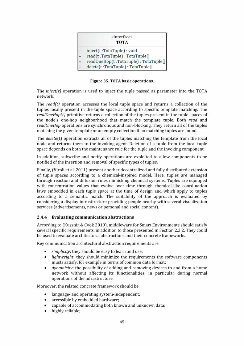
45
Figure 35. TOTA basic operations. The inject(t) operation is used to inject the tuple passed as parameter into the TOTA network. The read(t) operation accesses the local tuple space and returns a collection of the tuples locally present in the tuple space according to specific template matching. The
readOneHop(t) primitive returns a collection of the tuples present in the tuple spaces of the node’s one-hop neighborhood that match the template tuple. Both read and readOneHop operations are synchronous and non-blocking. They return all of the tuples matching the given template or an empty collection if no matching tuples are found. The delete(t) operation extracts all of the tuples matching the template from the local node and returns them to the invoking agent. Deletion of a tuple from the local tuple space depends on both the maintenance rule for the tuple and the invoking component. In addition, subscribe and notify operations are exploited to allow components to be notified of the insertion and removal of specific types of tuples. Finally, (Viroli et al. 2011) present another decentralized and fully distributed extension of tuple spaces according to a chemical-inspired model. Here, tuples are managed through reaction and diffusion rules mimicking chemical systems. Tuples are equipped with concentration values that evolve over time through chemical-like coordination laws embedded in each tuple space at the time of design and which apply to tuples according to a semantic match. The suitability of the approach is evaluated by considering a display infrastructure providing people nearby with several visualization services (advertisements, news or personal and social content). 2.4.4 Evaluating communication abstractions According to (Kusznir & Cook 2010), middleware for Smart Environments should satisfy several specific requirements, in addition to those presented in Section 2.3.2. They could be used to evaluate architectural abstractions and their concrete frameworks. Key communication architectural abstraction requirements are
• simplicity: they should be easy to learn and use; • lightweight: they should minimize the requirements the software components musts satisfy, for example in terms of common data format; • dynamicity: the possibility of adding and removing devices to and from a home network without affecting its functionalities, in particular during normal operations of the infrastructure. Moreover, the related concrete framework should be • language- and operating system-independent; • accessible by embedded hardware; • capable of accommodating both known and unknown data; • highly reliable;
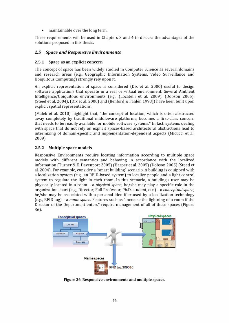
46
• maintainable over the long term. These requirements will be used in Chapters 3 and 4 to discuss the advantages of the solutions proposed in this thesis. 2.5 Space and Responsive Environments
2.5.1 Space as an explicit concern The concept of space has been widely studied in Computer Science as several domains and research areas (e.g., Geographic Information Systems, Video Surveillance and Ubiquitous Computing) strongly rely upon it. An explicit representation of space is considered (Dix et al. 2000) useful to design software applications that operate in a real or virtual environment. Several Ambient Intelligence/Ubiquitous environments (e.g., (Locatelli et al. 2009), (Dobson 2005), (Steed et al. 2004), (Dix et al. 2000) and (Benford & Fahlén 1993)) have been built upon explicit spatial representations. (Malek et al. 2010) highlight that, “the concept of location, which is often abstracted away completely by traditional middleware platforms, becomes a first-class concern that needs to be readily available for mobile software systems.” In fact, systems dealing with space that do not rely on explicit spaces-based architectural abstractions lead to intermixing of domain-specific and implementation-dependent aspects (Micucci et al. 2009). 2.5.2 Multiple space models Responsive Environments require locating information according to multiple space models with different semantics and behaving in accordance with the localized information (Turner & E. Davenport 2005) (Harper et al. 2005) (Dobson 2005) (Steed et al. 2004). For example, consider a “smart building” scenario. A building is equipped with a localization system (e.g., an RFID-based system) to localize people and a light control system to regulate the light in each room. In this scenario, a building’s user may be physically located in a room – a physical space; he/she may play a specific role in the organization chart (e.g., Director, Full Professor, Ph.D. student, etc.) – a conceptual space; he/she may be associated with a personal identifier used by a localization technology (e.g., RFID tag) – a name space. Features such as “increase the lightning of a room if the Director of the Department enters” require management of all of these spaces (Figure 36).
Figure 36. Responsive environments and multiple spaces.
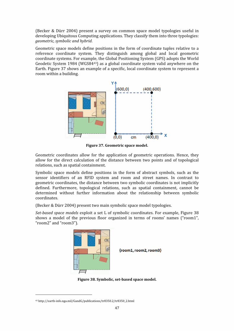
47
(Becker & Dürr 2004) present a survey on common space model typologies useful in developing Ubiquitous Computing applications. They classify them into three typologies: geometric, symbolic and hybrid. Geometric space models define positions in the form of coordinate tuples relative to a reference coordinate system. They distinguish among global and local geometric coordinate systems. For example, the Global Positioning System (GPS) adopts the World Geodetic System 1984 (WGS8443) as a global coordinate system valid anywhere on the Earth. Figure 37 shows an example of a specific, local coordinate system to represent a room within a building.
Figure 37. Geometric space model. Geometric coordinates allow for the application of geometric operations. Hence, they allow for the direct calculation of the distance between two points and of topological relations, such as spatial containment. Symbolic space models define positions in the form of abstract symbols, such as the sensor identifiers of an RFID system and room and street names. In contrast to geometric coordinates, the distance between two symbolic coordinates is not implicitly defined. Furthermore, topological relations, such as spatial containment, cannot be determined without further information about the relationship between symbolic coordinates. (Becker & Dürr 2004) present two main symbolic space model typologies.
Set-based space models exploit a set L of symbolic coordinates. For example, Figure 38 shows a model of the previous floor organized in terms of rooms’ names (“room1”, “room2” and “room3”).
Figure 38. Symbolic, set-based space model.
43 http://earth-info.nga.mil/GandG/publications/tr8350.2/tr8350_2.html
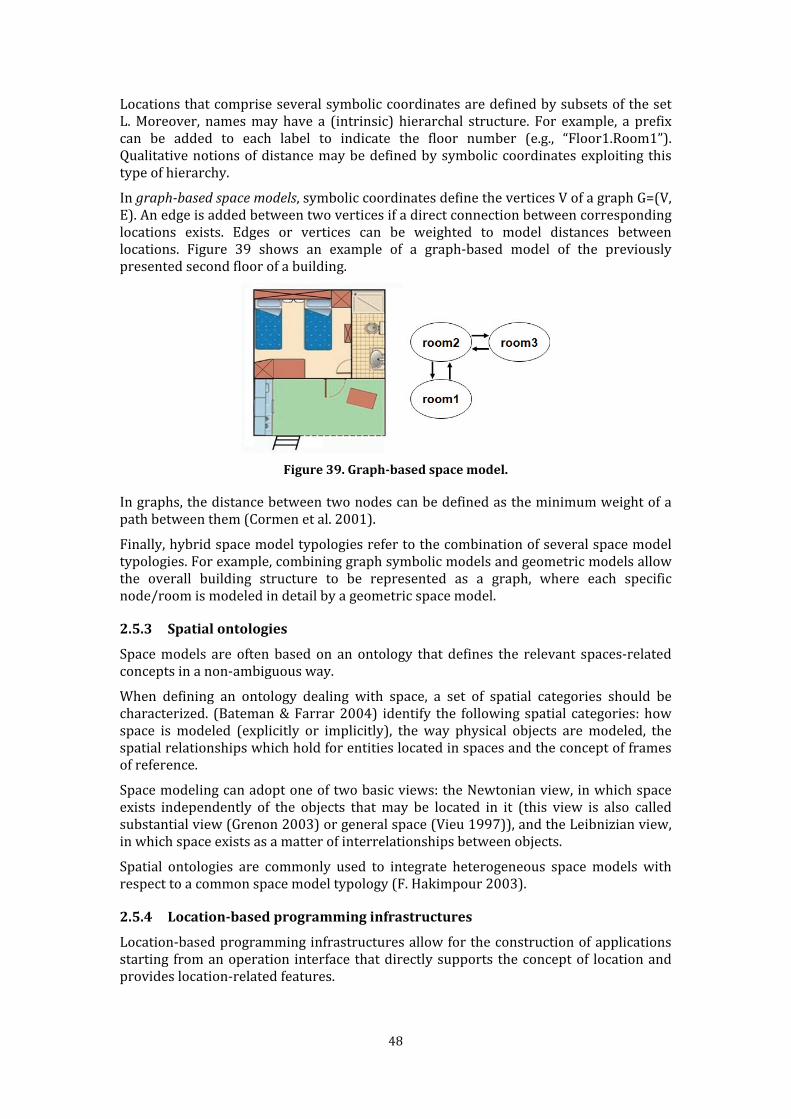
48
Locations that comprise several symbolic coordinates are defined by subsets of the set L. Moreover, names may have a (intrinsic) hierarchal structure. For example, a prefix can be added to each label to indicate the floor number (e.g., “Floor1.Room1”). Qualitative notions of distance may be defined by symbolic coordinates exploiting this type of hierarchy. In graph-based space models, symbolic coordinates define the vertices V of a graph G=(V, E). An edge is added between two vertices if a direct connection between corresponding locations exists. Edges or vertices can be weighted to model distances between locations. Figure 39 shows an example of a graph-based model of the previously presented second floor of a building.
Figure 39. Graph-based space model. In graphs, the distance between two nodes can be defined as the minimum weight of a path between them (Cormen et al. 2001). Finally, hybrid space model typologies refer to the combination of several space model typologies. For example, combining graph symbolic models and geometric models allow the overall building structure to be represented as a graph, where each specific node/room is modeled in detail by a geometric space model.
2.5.3 Spatial ontologies Space models are often based on an ontology that defines the relevant spaces-related concepts in a non-ambiguous way. When defining an ontology dealing with space, a set of spatial categories should be characterized. (Bateman & Farrar 2004) identify the following spatial categories: how space is modeled (explicitly or implicitly), the way physical objects are modeled, the spatial relationships which hold for entities located in spaces and the concept of frames of reference. Space modeling can adopt one of two basic views: the Newtonian view, in which space exists independently of the objects that may be located in it (this view is also called substantial view (Grenon 2003) or general space (Vieu 1997)), and the Leibnizian view, in which space exists as a matter of interrelationships between objects. Spatial ontologies are commonly used to integrate heterogeneous space models with respect to a common space model typology (F. Hakimpour 2003). 2.5.4 Location-based programming infrastructures Location-based programming infrastructures allow for the construction of applications starting from an operation interface that directly supports the concept of location and provides location-related features.
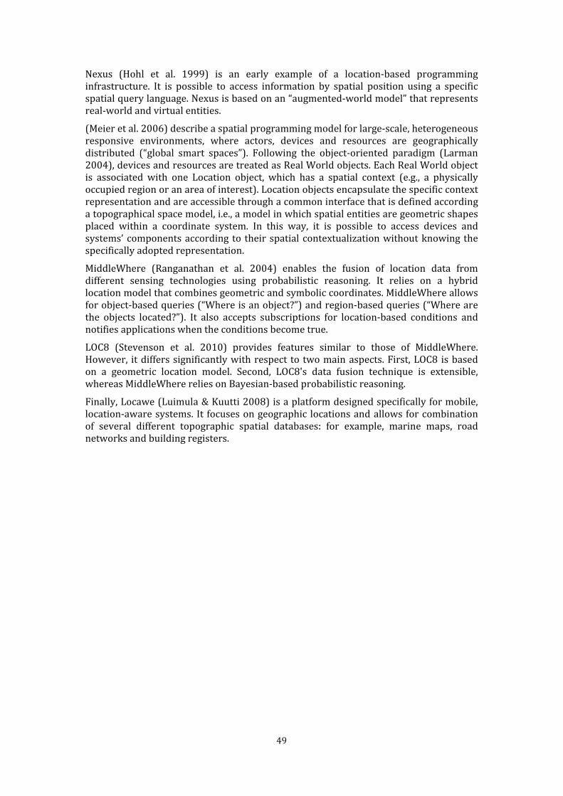
49
Nexus (Hohl et al. 1999) is an early example of a location-based programming infrastructure. It is possible to access information by spatial position using a specific spatial query language. Nexus is based on an “augmented-world model” that represents real-world and virtual entities. (Meier et al. 2006) describe a spatial programming model for large-scale, heterogeneous responsive environments, where actors, devices and resources are geographically distributed (“global smart spaces”). Following the object-oriented paradigm (Larman 2004), devices and resources are treated as Real World objects. Each Real World object is associated with one Location object, which has a spatial context (e.g., a physically occupied region or an area of interest). Location objects encapsulate the specific context representation and are accessible through a common interface that is defined according a topographical space model, i.e., a model in which spatial entities are geometric shapes placed within a coordinate system. In this way, it is possible to access devices and systems’ components according to their spatial contextualization without knowing the specifically adopted representation. MiddleWhere (Ranganathan et al. 2004) enables the fusion of location data from different sensing technologies using probabilistic reasoning. It relies on a hybrid location model that combines geometric and symbolic coordinates. MiddleWhere allows for object-based queries (“Where is an object?”) and region-based queries (“Where are the objects located?”). It also accepts subscriptions for location-based conditions and notifies applications when the conditions become true. LOC8 (Stevenson et al. 2010) provides features similar to those of MiddleWhere. However, it differs significantly with respect to two main aspects. First, LOC8 is based on a geometric location model. Second, LOC8's data fusion technique is extensible, whereas MiddleWhere relies on Bayesian-based probabilistic reasoning. Finally, Locawe (Luimula & Kuutti 2008) is a platform designed specifically for mobile, location-aware systems. It focuses on geographic locations and allows for combination of several different topographic spatial databases: for example, marine maps, road networks and building registers.

51
3 Architectural abstractions for spaces-based communication “It is easy to see by formal-logical methods that there exist certain [instruction sets]
that are in abstract adequate to control and cause the execution of any sequence of operations....
The really decisive considerations from the present point of view, in selecting an [instruction set], are more of a practical nature: simplicity of the equipment demanded by the [instruction set],
and the clarity of its application to the actually important problems together with the speed of its handling of those problems” (Burks, Goldstine and von Neumann 1947) Chapter 2 showed that state-of-the-art communication abstractions, with few exceptions, do not exploit the concept of space as a provider of communication mechanisms. Mainstream solutions adopt “full-fledged” content-based approaches (Mühl et al. 2006) or generic context-based (Cugola et al. 2009) and tuple-based approaches (Murth & Kühn 2010). Some proposals focus on space (X. Chen et al. 2003) (Eugster et al. 2005) (Schilit & Theimer 1994), but they consider geo-referenced spatial representations only. This chapter presents a set of architectural abstractions that exploit a multiple-spaces
metaphor for enhanced publish/subscribe communication. An environment space is a set of locations defined according to a specific spatial model (e.g., grid-based, graph-based or name-based). Different environment spaces, which model subjective views of the overall environments, may co-exist. For example, the physical environment may be modeled by a grid space, in which cells represent small portions of the physical space. The topology of a building can be modeled by a graph space, in which nodes represent rooms and arcs represent passages. Names and phone numbers can be represented by name spaces and roles by a graph space. Mappings relate different environment spaces. For example, they might associate cells of a geo-referenced grid space to nodes of a graph space representing rooms. Software components communicate publishing and receiving information on multiple spatial contexts. Each component may be aware of different environment spaces. Mapping enables communication among components, even if they rely on different spaces. Information flows can be transparently established through multiple environment spaces and mappings. Components may diffuse and receive information without knowing the other components and by relying on their subjective views of the environment. The key advantage of the proposed communication abstractions relies on openness: heterogeneous components can be integrated by defining their distinctive spaces and relating them through mappings. Environment spaces and mappings are first class-objects that can be instantiated and deleted at runtime. Dynamic management of spaces and mappings support dynamic insertion or removal of software components. The chapter is organized as follows. Section 3.1 describes a simple reference scenario in the Building Automation domain (“Smart Building”), which is exploited in the following sections to exemplify the proposed solution.

52
Section 3.2 presents the spatial concepts, proposing their formal definition and a UML representation. Section 3.3 presents four sets of communication primitives that realize a spaces-based publish/subscribe communication. Section 3.4 shows the generic architecture resulting from exploitation of the primitives. Finally, Section 3.5 discusses the benefits of the approach and compares it with significant related work. 3.1 Reference scenario A university building is enriched with sensing and actuation technologies. Users are identified by their names together with their positions in the overall company hierarchy (e.g., Director, Professor and Student). The Building has two floors equipped with presence-sensing technologies. On both the first and second floors, RFID sensors located in rooms and passages recognize the presence of RFID tags carried by users. On the second floor, a WiFi-based localization system recognizes the phone numbers of devices owned by users and provides their positions in a grid representation of the floor. Actuators located in each room can regulate windows, lights and other electronic appliances. Mobile cameras can be oriented to watch specific areas. The Smart Building has multiple features, including “close the window of room 2.1 when Mr. Brown enters,” “increase the lighting of any room that the Director enters,” and “move mobile cameras to follow Mr. Green.”
Figure 40. Logical architecture for the reference scenario. Figure 40 presents a simplified application of the logical reference architecture introduced in Section 2.3, which will be used in the next sections to exemplify the architectural abstractions. Localization Wrapper components wrap RFID and WiFi subsystems. A Lights & Windows Wrapper wraps light and windows actuators, while a Mobile Cameras Wrapper wraps mobile cameras.
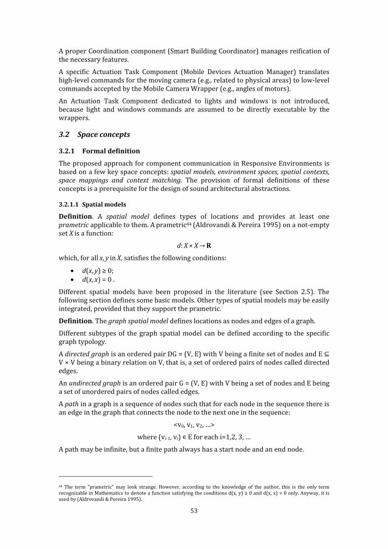
53
A proper Coordination component (Smart Building Coordinator) manages reification of the necessary features. A specific Actuation Task Component (Mobile Devices Actuation Manager) translates high-level commands for the moving camera (e.g., related to physical areas) to low-level commands accepted by the Mobile Camera Wrapper (e.g., angles of motors). An Actuation Task Component dedicated to lights and windows is not introduced, because light and windows commands are assumed to be directly executable by the wrappers. 3.2 Space concepts
3.2.1 Formal definition The proposed approach for component communication in Responsive Environments is based on a few key space concepts: spatial models, environment spaces, spatial contexts, space mappings and context matching. The provision of formal definitions of these concepts is a prerequisite for the design of sound architectural abstractions. 3.2.1.1 Spatial models
Definition. A spatial model defines types of locations and provides at least one prametric applicable to them. A prametric44 (Aldrovandi & Pereira 1995) on a not-empty set X is a function:
d: X × X → R which, for all x, y in X, satisfies the following conditions: • d(x, y) ≥ 0; • d(x, x) = 0 . Different spatial models have been proposed in the literature (see Section 2.5). The following section defines some basic models. Other types of spatial models may be easily integrated, provided that they support the prametric.
Definition. The graph spatial model defines locations as nodes and edges of a graph. Different subtypes of the graph spatial model can be defined according to the specific graph typology. A directed graph is an ordered pair DG = (V, E) with V being a finite set of nodes and E ⊆ V × V being a binary relation on V, that is, a set of ordered pairs of nodes called directed edges. An undirected graph is an ordered pair G = (V, E) with V being a set of nodes and E being a set of unordered pairs of nodes called edges. A path in a graph is a sequence of nodes such that for each node in the sequence there is an edge in the graph that connects the node to the next one in the sequence: <v0, v1, v2, …> where (vi-1, vi) ∊ E for each i=1,2, 3, … A path may be infinite, but a finite path always has a start node and an end node. 44 The term "prametric" may look strange. However, according to the knowledge of the author, this is the only term recognizable in Mathematics to denote a function satisfying the conditions d(x, y) ≥ 0 and d(x, x) = 0 only. Anyway, it is used by (Aldrovandi & Pereira 1995).
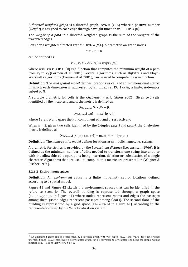
54
A directed weighted graph is a directed graph DWG = (V, E) where a positive number (weight) is assigned to each edge through a weight function w: E → R+ ∪ 0 . The weight of a path in a directed weighted graph is the sum of the weights of the traversed edges. Consider a weighted directed graph45 DWG = (V,E). A prametric on graph nodes d: V × V → R can be defined as ∀ v1, v2 ∊ V d(v1,v2) = wsp(v1,v2) where wsp: V × V → R+ ∪ 0 is a function that computes the minimum weight of a path from v1 to v2 (Cormen et al. 2001). Several algorithms, such as Dijkstra’s and Floyd-Warshall’s algorithms (Cormen et al. 2001), can be used to compute the wsp function.
Definition. The grid spatial model defines locations as cells of an n-dimensional matrix in which each dimension is addressed by an index set ISk, 1≤k≤n, a finite, not-empty subset of N. A suitable prametric for cells is the Chebyshev metric (Anon 2002). Given two cells identified by the n-tuples p and q, the metric is defined as DChebyshev: Nn × Nn → R DChebyshev(p,q) = maxi(|pi-qi|) where 1≤i≤n, pi and qi are the i-th component of p and q, respectively. When n = 2, given two cells identified by the 2-tuples (x1,y1) and (x2,y2), the Chebyshev metric is defined as DChebyshev((x1,y1), (x2, y2)) = max(|x2-x1|, |y2-y1|). Definition. The name spatial model defines locations as symbolic names, i.e., strings. A prametric for strings is provided by the Levenshtein distance (Levenshtein 1966). It is defined as the minimum number of edits needed to transform one string into another with the allowable edit operations being insertion, deletion or substitution of a single character. Algorithms that are used to compute this metric are presented in (Wagner & Fischer 1974). 3.2.1.2 Environment spaces
Definition. An environment space is a finite, not-empty set of locations defined according to a spatial model. Figure 41 and Figure 42 sketch the environment spaces that can be identified in the reference scenario. The overall building is represented through a graph space (BuildingGraph in Figure 41) where nodes represent rooms and edges the passages among them (some edges represent passages among floors). The second floor of the building is represented by a grid space (Floor2Grid in Figure 41), according to the representation used by the WiFi localization system.
45 An undirected graph can be represented by a directed graph with two edges (v1,v2) and (v2,v1) for each original unordered edge (v1,v2). Moreover, a not-weighted graph can be converted to a weighted one using the simple weight function w: E → R such that w(e)=1 ∀ e ∊ E.
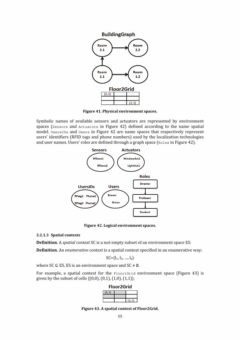
55
Figure 41. Physical environment spaces. Symbolic names of available sensors and actuators are represented by environment spaces (Sensors and Actuators in Figure 42) defined according to the name spatial model. UsersIDs and Users in Figure 42 are name spaces that respectively represent users' identifiers (RFID tags and phone numbers) used by the localization technologies and user names. Users’ roles are defined through a graph space (Roles in Figure 42).
Figure 42. Logical environment spaces.
3.2.1.3 Spatial contexts
Definition. A spatial context SC is a not-empty subset of an environment space ES. Definition. An enumerative context is a spatial context specified in an enumerative way: SC={l1, l2, …, ln} where SC ⊆ ES, ES is an environment space and SC ≠ ∅. For example, a spatial context for the Floor1Grid environment space (Figure 43) is given by the subset of cells {(0,0), (0,1), (1,0), (1,1)}.
Figure 43. A spatial context of Floor2Grid.
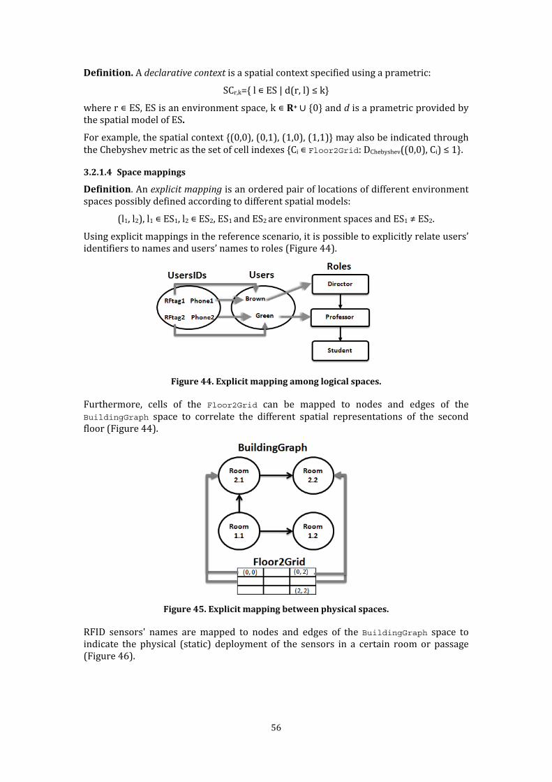
56
Definition. A declarative context is a spatial context specified using a prametric: SCr,k={ l ∊ ES | d(r, l) ≤ k} where r ∊ ES, ES is an environment space, k ∊ R+ ∪ 0 and d is a prametric provided by the spatial model of ES. For example, the spatial context {(0,0), (0,1), (1,0), (1,1)} may also be indicated through the Chebyshev metric as the set of cell indexes {Ci ∊ Floor2Grid: DChebyshev((0,0), Ci) ≤ 1}. 3.2.1.4 Space mappings
Definition. An explicit mapping is an ordered pair of locations of different environment spaces possibly defined according to different spatial models: (l1, l2), l1 ∊ ES1, l2 ∊ ES2, ES1 and ES2 are environment spaces and ES1 ≠ ES2. Using explicit mappings in the reference scenario, it is possible to explicitly relate users’ identifiers to names and users’ names to roles (Figure 44).
Figure 44. Explicit mapping among logical spaces. Furthermore, cells of the Floor2Grid can be mapped to nodes and edges of the
BuildingGraph space to correlate the different spatial representations of the second floor (Figure 44).
Figure 45. Explicit mapping between physical spaces. RFID sensors' names are mapped to nodes and edges of the BuildingGraph space to indicate the physical (static) deployment of the sensors in a certain room or passage (Figure 46).

57
Figure 46. Explicit mapping for sensor placement. Similarly, nodes and edges of the BuildingGraph space are mapped to actuators' names to represent the physical area covered by each actuator (Figure 47).
Figure 47. Explicit mapping of area covered by actuators.
Definition. The explicit mapping relation (EMR) is the relation given by the set of all of the defined explicit mappings. It is a binary relation on US, where US is the union of all of the defined environment spaces: EMR ⊆ US × US, US = ES1 ∪ … ∪ ESn, ESi is an environment space ∀ i ∊ {1,2,..,n}. The explicit mapping relation is anti-reflexive: ∀ l ∊ US (l,l) ∉ EMR because explicit mappings are only defined among the locations of different environment spaces. Definition. The restricted transitive closure MR of the explicit mapping relation (EMR) is the binary relation containing the following elements:
• All of the explicit mappings (li, lj) ∊ EMR; • All of the implicit mappings, i.e., the pairs (li, lk) where li ∈ ESp lk ∈ ESq, ESp ≠ ESq, (li, lm) ∊ EMR and (lm, lk) ∊ MR for some lm. Implicit mappings are mappings that can be derived according to the transitive property, excluding those involving locations in the same environment space.
3.2.1.5 Context matching The previous concepts can be utilized to define the notion of matching between spatial contexts.

58
Definition. Let SC1 and SC2 be spatial contexts defined in the environment space ES, i.e., SC1 ⊂ ES and SC2 ⊂ ES. A direct match between SC1 and SC2 occurs when SC1 ∩ SC2 ≠ ∅ (Figure 48).
Figure 48. Direct matching. Given two spatial contexts, SC1 and SC2, with a direct match between them, direct
matching context MC is the context, so MC = SC1 ∩ SC2. Definition. Let SC1 and SC2 be spatial contexts defined in different environment spaces ES1 and ES2, i.e., SC1 ⊂ ES1 and SC2 ⊂ ES2 and ES1 ≠ ES2. An indirect match between SC1 and SC2 occurs when l1 ∊ SC1, r1 ∊ SC2 and (l1, r1) EMR (Figure 49).
Figure 49. Indirect matching. Given two spatial contexts, SC1 and SC2, with an indirect match between them, an indirect
matching context is the context MC2 ⊆ SC2 containing the locations of SC2 that indirectly match locations of SC1. 3.2.2 Environment spaces and mappings as first-class objects One of the fundamental conjecture of this thesis is that software components in Responsive Environments can effectively communicate through the concepts of environment spaces and mappings. The operational interfaces that will be presented later (see section 3.3) realizes a form of spaces-based communication based on these concepts. The following subsections propose the rationale of the proposed solution and they present a reification of the spatial concepts which is exploited by the proposed primitives. Environment spaces and mappings between them must be dynamically instantiated to allow new domain-specific spatial representations to be created and to meet the changing requirements of Responsive Environment applications. For example, spaces change when a sensor is added (thus changing the Sensors name space), when a new actor enters the stage (thus changing the UserIDs space) or when the organizational

59
structure changes (thus changing the Roles space). Finally, new spaces could be added, for example to integrate an external application. Therefore environment spaces and mappings must be viewed as first-class objects and software components must be allowed to define, modify and inspect environment spaces and mappings. On the opposite, spatial models are at a high level of abstraction and correspond to established and widely agreed concepts, which are valid in different application domains, have a sound formal definition and seldom change. Therefore spatial models can be considered to be static and can be embedded into the implementation of the concrete framework. In other words, spatial models are not treated as first class objects. This solution paves the way to an efficient implementation of the platform at the price of a limited loss of generality. 3.2.3 UML representation This section presents a representation46 of the introduced spatial concepts through the UML 2.0 language where constraints are specified by the Object Constraint Language47 2.0 (OCL). 3.2.3.1 Spatial models and environment spaces Figure 50 shows the concepts of spatial models and environment spaces. An environment space is an instance of a spatial model. It is a not-empty set of locations. Each environment space supports at least one prametric, which is provided by the related spatial model. The <<meta>> stereotype on the SpatialModel class highlights that spatial models defines how the related environment spaces represent locations, but they are not first class objects modifiable at run-time.
Figure 50. Spatial models and environment spaces. Figure 51 presents an example considering environment spaces based on weighted, directed graphs. A location is a node or a weighted edge. A graph-based space must contain at least one node (graph consistency constraint).
46 In Software Engineering parlance, this is a domain model (Larman 2004). 47 http://www.omg.org/spec/OCL/2.0/
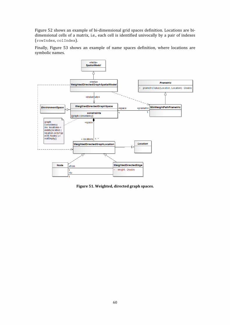
60
Figure 52 shows an example of bi-dimensional grid spaces definition. Locations are bi-dimensional cells of a matrix, i.e., each cell is identified univocally by a pair of indexes (rowIndex, colIndex). Finally, Figure 53 shows an example of name spaces definition, where locations are symbolic names.
Figure 51. Weighted, directed graph spaces.
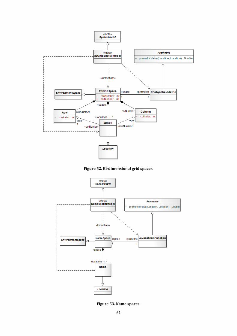
61
Figure 52. Bi-dimensional grid spaces.
Figure 53. Name spaces.
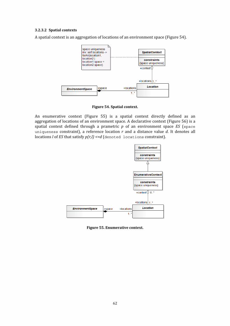
62
3.2.3.2 Spatial contexts A spatial context is an aggregation of locations of an environment space (Figure 54).
Figure 54. Spatial context. An enumerative context (Figure 55) is a spatial context directly defined as an aggregation of locations of an environment space. A declarative context (Figure 56) is a spatial context defined through a prametric p of an environment space ES (space
uniqueness constraint), a reference location r and a distance value d. It denotes all locations l of ES that satisfy p(r,l) <=d (denoted locations constraint).
Figure 55. Enumerative context.

63
Figure 56. Declarative context.
3.2.3.3 Space mappings Figure 57 summarizes the concepts of explicit mappings, implicit mappings and restricted transitive closures of explicit mapping relations. An explicit mapping is a binary mapping, i.e., an ordered pair of locations. The locations of the pair must belong to different spaces (space disjunction constraint). Implicit mappings are binary mappings defined by application of the recursive part of the restricted transitive closure MR (see Subsection 3.2.1 and the implicit mapping existence constraint48 in Figure 57).
48 Notice that this constraint also excludes implicit mapping duplicates. The mathematical definition does not state this directly because the restricted transitive closure is a set and duplicates are avoided by definition.

64
Figure 57. Mappings.
3.2.3.4 Context matching Figure 58 summarizes the direct matching and indirect matching definitions. A matching context is a defined spatial context that begins with two matching contexts, sourceContext and targetContext. In the case of direct matching (direct matching constraint), a direct matching context contains the locations given by the intersection of sourceContext and targetContext. In the case of indirect matching (indirect matching constraint), an indirect matching context contains the locations of targetContext that indirectly match locations of sourceContext.

65
Figure 58. Matching Context.
3.2.4 UML symbolic representation The UML domain model presented in Subsection 3.2.2 can be used to translate the space concepts into data types. This section refines the previous representation using symbolic names, i.e., strings, to univocally identify the main entities. Names are introduced in order to provide an efficient way to refer entities in distributed contexts. This representation will be utilized for definition of the operations presented in the following sections. Chapter 4 proposes a reification of the representation according to WSDL language. 3.2.4.1 Spatial models and environment spaces Figure 59 presents the names introduced for spatial models and environment spaces. Each available spatial model is univocally identified by a name (spatial model name). Each prametric of a spatial model is identified by a name (prametric name), which is univocal with respect to the spatial model. Each environment space is univocally identified by a proper name (space name). Each location is also identified by a proper name (location name), which is univocal with respect to the belonging spaces.

66
Figure 59. Names and spatial models, prametrics, environments spaces and locations. Figure 60 presents the application of this representation to weighted, directed graph spaces. Both nodes and edges have proper location names. Figure 61 and Figure 62 provide the definitions of the BuildingGraph and Roles spaces of the reference scenario.
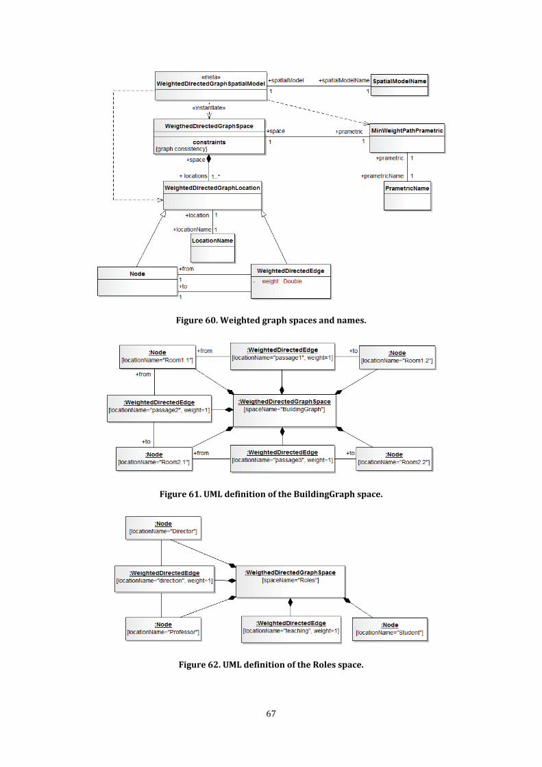
67
Figure 60. Weighted graph spaces and names.
Figure 61. UML definition of the BuildingGraph space.
Figure 62. UML definition of the Roles space.

68
Figure 63 shows the representation of bi-dimensional grid spaces. In this case, the names of cells coincide with the strings given by the pair of indexes (row, col) that identify them. Figure 64 shows the related definition for the Floor1Grid space of the reference scenario.
Figure 63. Grid spaces and names.
Figure 64. UML definition of the Floor1Grid space. Finally, Figure 65 provides the representation for name spaces. Each location of name spaces (a name) has a proper location name. Although it may seem redundant, the general case is as follows: in implementation-oriented terms, LocationNames may be strings in a common format, while Names are strings according to another format. Figure 66 provides the definition of the UsersIDs name space of the reference scenario.
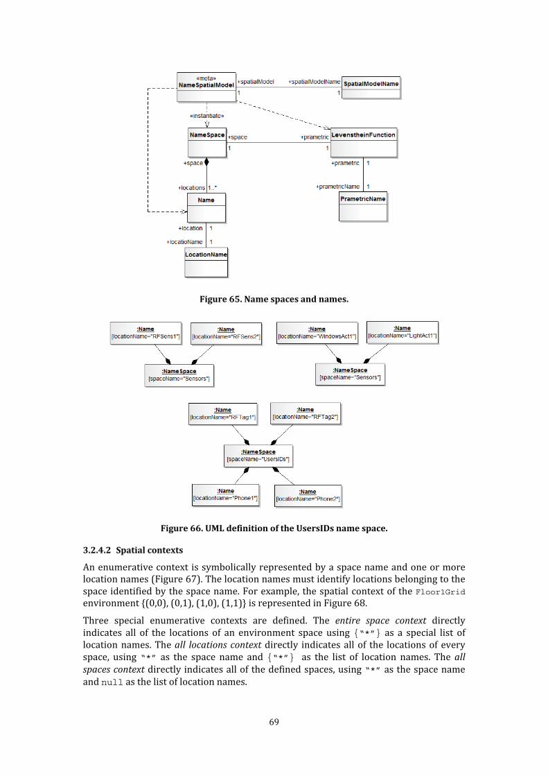
69
Figure 65. Name spaces and names.
Figure 66. UML definition of the UsersIDs name space.
3.2.4.2 Spatial contexts An enumerative context is symbolically represented by a space name and one or more location names (Figure 67). The location names must identify locations belonging to the space identified by the space name. For example, the spatial context of the Floor1Grid environment {(0,0), (0,1), (1,0), (1,1)} is represented in Figure 68. Three special enumerative contexts are defined. The entire space context directly indicates all of the locations of an environment space using {“*”} as a special list of location names. The all locations context directly indicates all of the locations of every space, using “*” as the space name and {“*”} as the list of location names. The all spaces context directly indicates all of the defined spaces, using “*” as the space name and null as the list of location names.

70
Figure 67. Enumerative contexts by names.
Figure 68. Example of enumerative context definition with UML representation. Declarative contexts are symbolically represented by a space name, a prametric name, a reference location name and a distance value d (Figure 69). The prametric name must identify a prametric p supported by the spatial model of the space identified by a space name; moreover, the reference location name must identify a location r belonging to the same space. A declarative context denotes all of the locations l with p(r,l)<=d. For example, the declarative context {Ci ∊ Floor2Grid: DChebyshev((0,0), Ci) ≤ 1} is provided by the symbolic representation in Figure 70.

71
Figure 69. UML definition of declarative contexts by names.
Figure 70. Example of declarative context definition with UML representation. Matching contexts are not reified as additional subtypes of SpatialContexts. They are simply reified as enumerative or declarative context instances.
3.3 Spaces-based primitives The following sections present four sets of primitives that exploit the defined spatial concepts for the provision of software components with a form of spaces-based publish/subscribe communication. The definition of the primitives exploits the UML symbolic representation presented in Subsection 3.2.3, where the key concepts (e.g., spatial models, spaces and locations) are identified by symbolic names. Subsection 3.3.1 presents the primitives for creating and deleting environment spaces (spaces management interface). Subsection 3.3.2 presents the primitives for inspecting environment spaces (spaces inspection interface). Subsection 3.3.3 presents the primitives for creating and deleting explicit mappings (mappings management interface). Subsection 3.3.4 presents the primitives for inspecting mappings (mappings inspection interface). Subsection 3.3.5 presents the publish/subscribe primitives to diffuse information according to spaces and mappings (spaces-based publish/subscribe interface). Subsection 3.3.6 shows how the spaces and mapping primitives allow support of the spaces-based publish/subscribe communication.
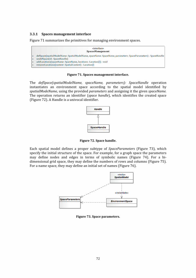
72
3.3.1 Spaces management interface Figure 71 summarizes the primitives for managing environment spaces.
Figure 71. Spaces management interface. The defSpace(spatialModelName, spaceName, parameters): SpaceHandle operation instantiates an environment space according to the spatial model identified by
spatialModeName, using the provided parameters and assigning it the given spaceName. The operation returns an identifier (space handle), which identifies the created space (Figure 72). A Handle is a univocal identifier.
Figure 72. Space handle. Each spatial model defines a proper subtype of SpaceParameters (Figure 73), which specify the initial structure of the space. For example, for a graph space the parameters may define nodes and edges in terms of symbolic names (Figure 74). For a bi-dimensional grid space, they may define the numbers of rows and columns (Figure 75). For a name space, they may define an initial set of names (Figure 76).
Figure 73. Space parameters.

73
Figure 74. Example of space parameters for weighted, direct graphs.
Figure 75. Example of space parameters for bi-dimensional grid spaces.
Figure 76. Example of space parameters for name spaces. The environment spaces of the reference scenario may be defined by the following defSpace invocations (Figure 77 and Figure 78 provide the definition of the parameters’ instances):
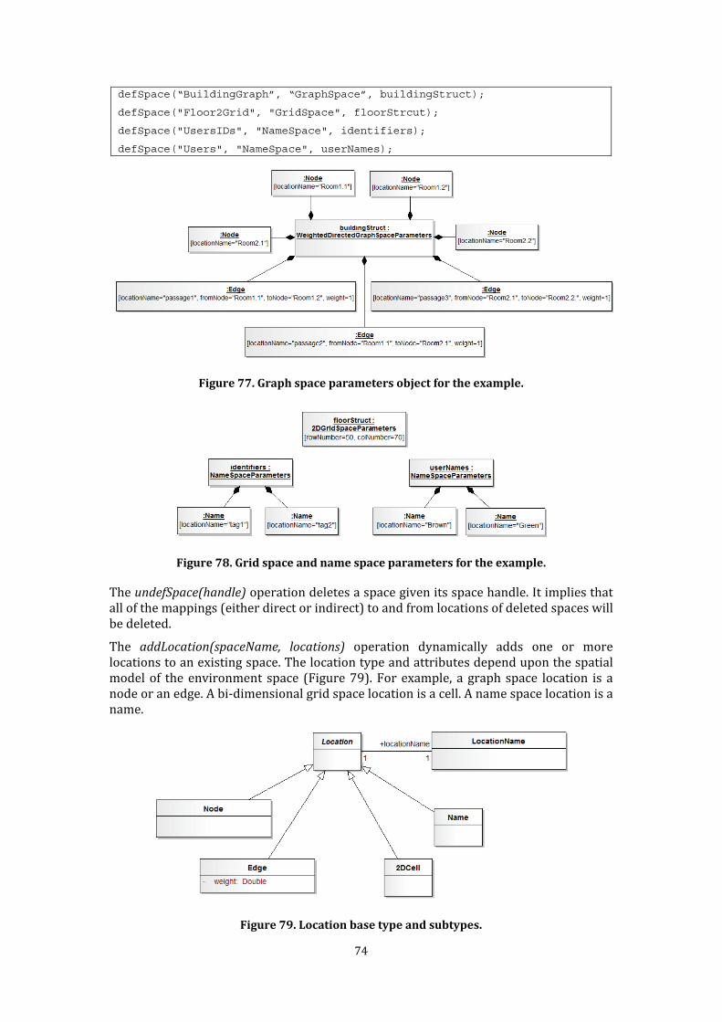
74
defSpace(“BuildingGraph”, “GraphSpace”, buildingStruct);
defSpace("Floor2Grid", "GridSpace", floorStrcut);
defSpace("UsersIDs", "NameSpace", identifiers);
defSpace("Users", "NameSpace", userNames);
Figure 77. Graph space parameters object for the example.
Figure 78. Grid space and name space parameters for the example. The undefSpace(handle) operation deletes a space given its space handle. It implies that all of the mappings (either direct or indirect) to and from locations of deleted spaces will be deleted. The addLocation(spaceName, locations) operation dynamically adds one or more locations to an existing space. The location type and attributes depend upon the spatial model of the environment space (Figure 79). For example, a graph space location is a node or an edge. A bi-dimensional grid space location is a cell. A name space location is a name.
Figure 79. Location base type and subtypes.
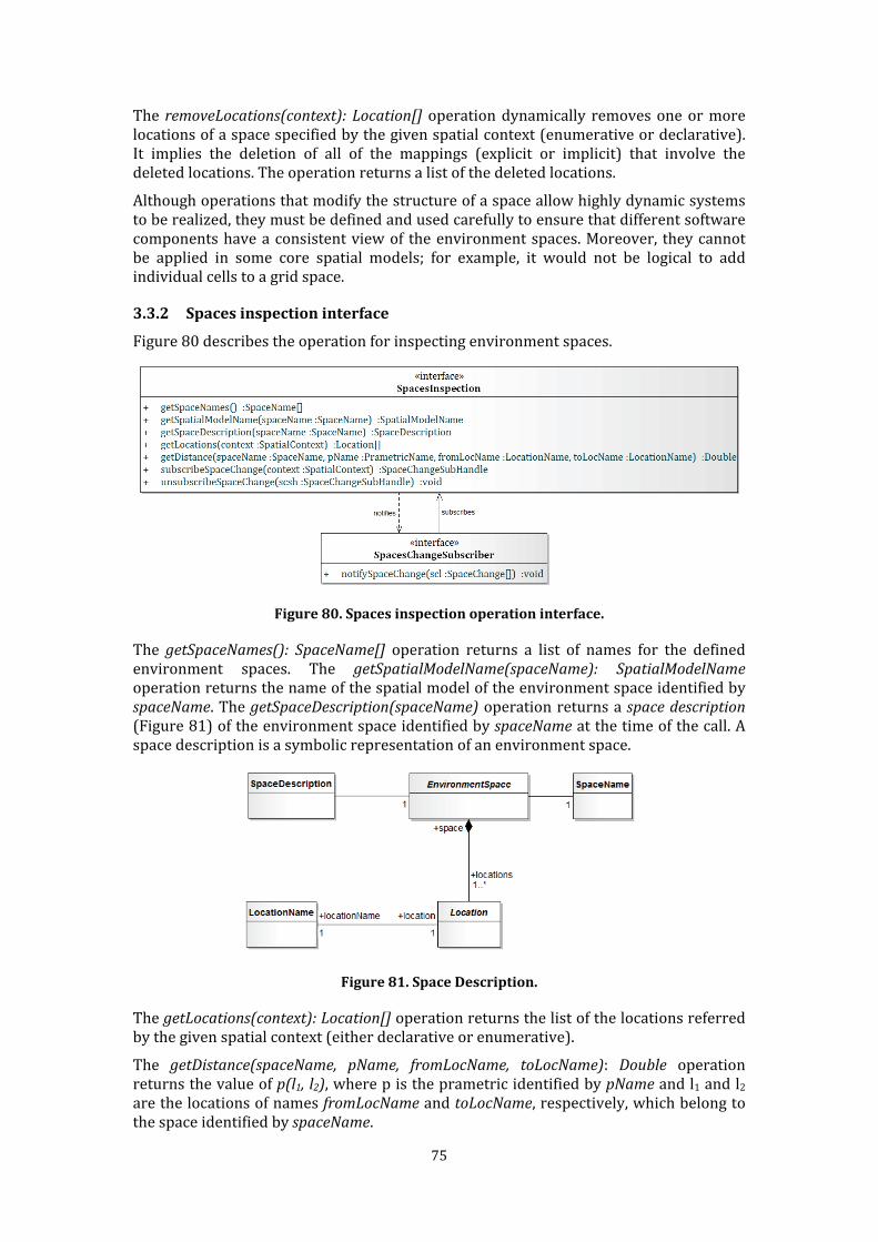
75
The removeLocations(context): Location[] operation dynamically removes one or more locations of a space specified by the given spatial context (enumerative or declarative). It implies the deletion of all of the mappings (explicit or implicit) that involve the deleted locations. The operation returns a list of the deleted locations. Although operations that modify the structure of a space allow highly dynamic systems to be realized, they must be defined and used carefully to ensure that different software components have a consistent view of the environment spaces. Moreover, they cannot be applied in some core spatial models; for example, it would not be logical to add individual cells to a grid space. 3.3.2 Spaces inspection interface Figure 80 describes the operation for inspecting environment spaces.
Figure 80. Spaces inspection operation interface. The getSpaceNames(): SpaceName[] operation returns a list of names for the defined environment spaces. The getSpatialModelName(spaceName): SpatialModelName operation returns the name of the spatial model of the environment space identified by
spaceName. The getSpaceDescription(spaceName) operation returns a space description (Figure 81) of the environment space identified by spaceName at the time of the call. A space description is a symbolic representation of an environment space.
Figure 81. Space Description. The getLocations(context): Location[] operation returns the list of the locations referred by the given spatial context (either declarative or enumerative). The getDistance(spaceName, pName, fromLocName, toLocName): Double operation returns the value of p(l1, l2), where p is the prametric identified by pName and l1 and l2 are the locations of names fromLocName and toLocName, respectively, which belong to the space identified by spaceName.
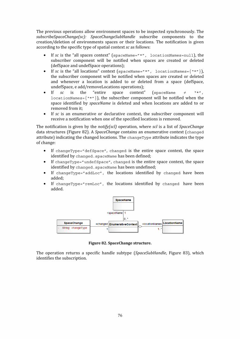
76
The previous operations allow environment spaces to be inspected synchronously. The subscribeSpaceChange(sc): SpaceChangeSubHandle subscribe components to the creation/deletion of environments spaces or their locations. The notification is given according to the specific type of spatial context sc as follows:
• If sc is the “all spaces context” (spaceName=”*”, locationNames=null), the subscriber component will be notified when spaces are created or deleted (defSpace and undefSpace operations); • If sc is the “all locations” context (spaceName=”*”, locationNames={“*”}), the subscriber component will be notified when spaces are created or deleted and whenever a location is added to or deleted from a space (defSpace, undefSpace, e add/removeLocations operations); • If sc is the “entire space context” (spaceName ≠ “*”,
locationNames={“*”}), the subscriber component will be notified when the space identified by spaceName is deleted and when locations are added to or removed from it; • If sc is an enumerative or declarative context, the subscriber component will receive a notification when one of the specified locations is removed. The notification is given by the notify(scl) operation, where scl is a list of SpaceChange data structures (Figure 82). A SpaceChange contains an enumerative context (changed attribute) indicating the changed locations. The changeType attribute indicates the type of change: • If changeType=”defSpace”, changed is the entire space context, the space identified by changed.spaceName has been defined; • If changeType=”undefSpace”, changed is the entire space context, the space identified by changed.spaceName has been undefined; • If changeType=”addLoc”, the locations identified by changed have been added; • If changeType=”remLoc”, the locations identified by changed have been added.
Figure 82. SpaceChange structure. The operation returns a specific handle subtype (SpaceSubHandle, Figure 83), which identifies the subscription.
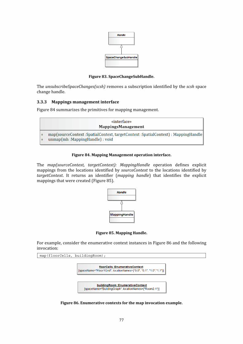
77
Figure 83. SpaceChangeSubHandle. The unsubscribeSpaceChanges(scsh) removes a subscription identified by the scsh space change handle.
3.3.3 Mappings management interface Figure 84 summarizes the primitives for mapping management.
Figure 84. Mapping Management operation interface. The map(sourceContext, targetContext): MappingHandle operation defines explicit mappings from the locations identified by sourceContext to the locations identified by
targetContext. It returns an identifier (mapping handle) that identifies the explicit mappings that were created (Figure 85).
Figure 85. Mapping Handle. For example, consider the enumerative context instances in Figure 86 and the following invocation:
map(floorCells, buildingRoom);
Figure 86. Enumerative contexts for the map invocation example.
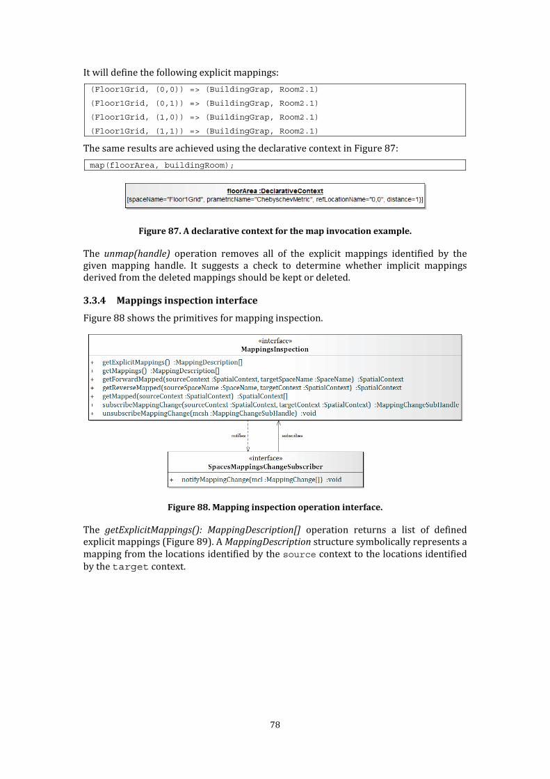
78
It will define the following explicit mappings: (Floor1Grid, (0,0)) => (BuildingGrap, Room2.1)
(Floor1Grid, (0,1)) => (BuildingGrap, Room2.1)
(Floor1Grid, (1,0)) => (BuildingGrap, Room2.1)
(Floor1Grid, (1,1)) => (BuildingGrap, Room2.1) The same results are achieved using the declarative context in Figure 87: map(floorArea, buildingRoom);
Figure 87. A declarative context for the map invocation example. The unmap(handle) operation removes all of the explicit mappings identified by the given mapping handle. It suggests a check to determine whether implicit mappings derived from the deleted mappings should be kept or deleted.
3.3.4 Mappings inspection interface Figure 88 shows the primitives for mapping inspection.
Figure 88. Mapping inspection operation interface. The getExplicitMappings(): MappingDescription[] operation returns a list of defined explicit mappings (Figure 89). A MappingDescription structure symbolically represents a mapping from the locations identified by the source context to the locations identified by the target context.
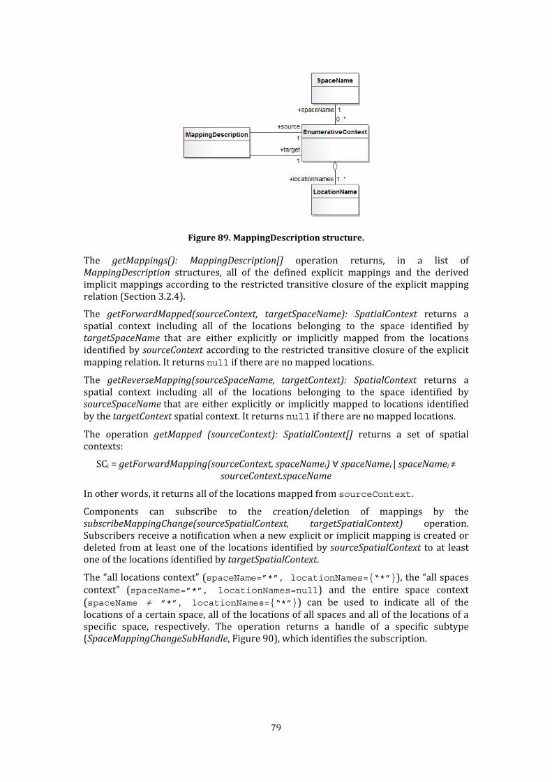
79
Figure 89. MappingDescription structure. The getMappings(): MappingDescription[] operation returns, in a list of
MappingDescription structures, all of the defined explicit mappings and the derived implicit mappings according to the restricted transitive closure of the explicit mapping relation (Section 3.2.4). The getForwardMapped(sourceContext, targetSpaceName): SpatialContext returns a spatial context including all of the locations belonging to the space identified by targetSpaceName that are either explicitly or implicitly mapped from the locations identified by sourceContext according to the restricted transitive closure of the explicit mapping relation. It returns null if there are no mapped locations. The getReverseMapping(sourceSpaceName, targetContext): SpatialContext returns a spatial context including all of the locations belonging to the space identified by sourceSpaceName that are either explicitly or implicitly mapped to locations identified by the targetContext spatial context. It returns null if there are no mapped locations. The operation getMapped (sourceContext): SpatialContext[] returns a set of spatial contexts: SCi = getForwardMapping(sourceContext, spaceNamei) ∀ spaceNamei | spaceNamei ≠
sourceContext.spaceName In other words, it returns all of the locations mapped from sourceContext. Components can subscribe to the creation/deletion of mappings by the subscribeMappingChange(sourceSpatialContext, targetSpatialContext) operation. Subscribers receive a notification when a new explicit or implicit mapping is created or deleted from at least one of the locations identified by sourceSpatialContext to at least one of the locations identified by targetSpatialContext. The “all locations context” (spaceName=”*”, locationNames={“*”}), the “all spaces context” (spaceName=”*”, locationNames=null) and the entire space context (spaceName ≠ ”*”, locationNames={“*”}) can be used to indicate all of the locations of a certain space, all of the locations of all spaces and all of the locations of a specific space, respectively. The operation returns a handle of a specific subtype (SpaceMappingChangeSubHandle, Figure 90), which identifies the subscription.
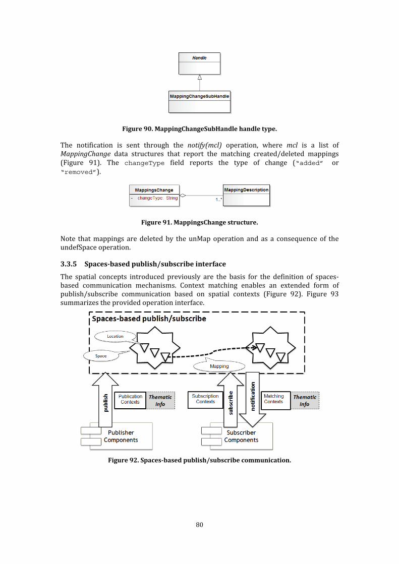
80
Figure 90. MappingChangeSubHandle handle type. The notification is sent through the notify(mcl) operation, where mcl is a list of
MappingChange data structures that report the matching created/deleted mappings (Figure 91). The changeType field reports the type of change (“added” or “removed”).
Figure 91. MappingsChange structure. Note that mappings are deleted by the unMap operation and as a consequence of the undefSpace operation.
3.3.5 Spaces-based publish/subscribe interface The spatial concepts introduced previously are the basis for the definition of spaces-based communication mechanisms. Context matching enables an extended form of publish/subscribe communication based on spatial contexts (Figure 92). Figure 93 summarizes the provided operation interface.
Figure 92. Spaces-based publish/subscribe communication.
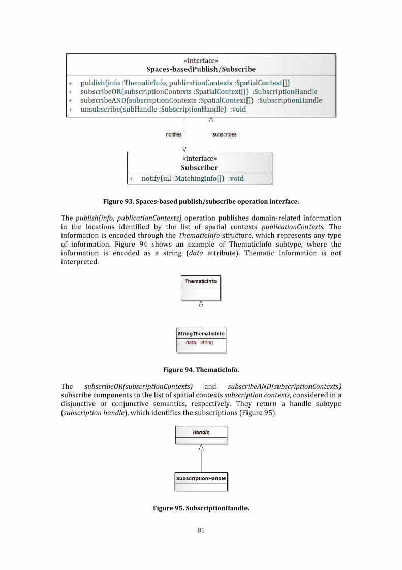
81
Figure 93. Spaces-based publish/subscribe operation interface. The publish(info, publicationContexts) operation publishes domain-related information in the locations identified by the list of spatial contexts publicationContexts. The information is encoded through the ThematicInfo structure, which represents any type of information. Figure 94 shows an example of ThematicInfo subtype, where the information is encoded as a string (data attribute). Thematic Information is not interpreted.
Figure 94. ThematicInfo. The subscribeOR(subscriptionContexts) and subscribeAND(subscriptionContexts) subscribe components to the list of spatial contexts subscription contexts, considered in a disjunctive or conjunctive semantics, respectively. They return a handle subtype (subscription handle), which identifies the subscriptions (Figure 95).
Figure 95. SubscriptionHandle.
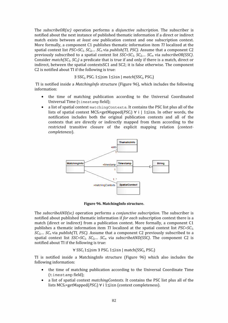
82
The subscribeOR(sc) operation performs a disjunctive subscription. The subscriber is notified about the next instance of published thematic information if a direct or indirect match exists between at least one publication context and one subscription context. More formally, a component C1 publishes thematic information item TI localized at the spatial context list PSC=SC1, SC2,… SCn via publish(TI, PSC). Assume that a component C2 previously subscribed to a spatial context list SSC=SC1, SC2,… SCm via subscribeOR(SSC). Consider match(SC1, SC2) a predicate that is true if and only if there is a match, direct or indirect, between the spatial contextsSC1 and SC2; it is false otherwise. The component C2 is notified about TI if the following is true: ∃ SSCj, PSCi 1≤j≤m 1≤i≤n | match(SSCj, PSCi) TI is notified inside a MatchingInfo structure (Figure 96), which includes the following information: • the time of matching publication according to the Universal Coordinated Universal Time (timestamp field); • a list of spatial context matchingContexts. It contains the PSC list plus all of the lists of spatial context MCSi=getMapped(PSCi) ∀ i | 1≤i≤n. In other words, the notification includes both the original publication contexts and all of the contexts that are directly or indirectly mapped from them according to the restricted transitive closure of the explicit mapping relation (context-
completeness).
Figure 96. MatchingInfo structure. The subscribeAND(sc) operation performs a conjunctive subscription. The subscriber is notified about published thematic information if for each subscription context there is a match (direct or indirect) from a publication context. More formally, a component C1 publishes a thematic information item TI localized at the spatial context list PSC=SC1,
SC2,… SCn via publish(TI, PSC). Assume that a component C2 previously subscribed to a spatial context list SSC=SC1, SC2,… SCm via subscribeAND(SSC). The component C2 is notified about TI if the following is true: ∀ SSCj 1≤j≤m ∃ PSCi 1≤i≤n | match(SSCj, PSCi) TI is notified inside a MatchingInfo structure (Figure 96) which also includes the following information: • the time of matching publication according to the Universal Coordinate Time (timestamp field); • a list of spatial context matchingContexts. It contains the PSC list plus all of the lists MCSi=getMapped(PSCi) ∀ i 1≤i≤n (context completeness).

83
Consider a possible application of this interface to the reference scenario architecture introduced in section 3.1 (Figure 97). As presented in Section 3.1, the Lights and Windows Wrapper wraps lights and windows actuators. A Smart Building Coordinator manages realization of the Smart Building features of the reference scenario.
Figure 97. A spaces-based publish/subscribe interaction in the reference scenario. The Coordinator can send actuation commands related to physical areas via the parameters presented in Figure 98.
publish(command, room);
Figure 98. An example of thematic information and enumerative context for a publish
invocation. The Lights and Window Wrapper can receive the command via the parameter in Figure 98: subscribeOR(room); where room represents the room in which the wrapped actuator is physically deployed according to the BuildingGraph space. The wrapper will be notified of the command because there is a direct match between publication and subscription contexts. Hence, the notify operation will be called in accordance with the MatchingInfo structure in Figure 99. notify(matching);
Figure 99. An example of MatchingInfo structure (direct matching).
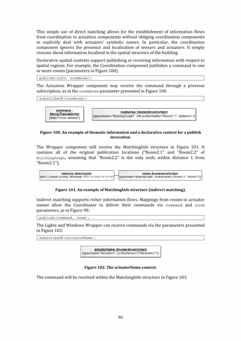
84
This simple use of direct matching allows for the establishment of information flows from coordination to actuation components without obliging coordination components to explicitly deal with actuators’ symbolic names. In particular, the coordination component ignores the presence and localization of sensors and actuators. It simply reasons about information localized in the spatial structure of the building. Declarative spatial contexts support publishing or receiving information with respect to spatial regions. For example, the Coordination component publishes a command to one or more rooms (parameters in Figure 100). publish(info, roomArea); The Actuation Wrapper component may receive the command through a previous subscription, as in the roomArea parameter presented in Figure 100. subscribeOR(roomArea);
Figure 100. An example of thematic information and a declarative context for a publish
invocation. The Wrapper component will receive the MatchingInfo structure in Figure 101. It contains all of the original publication locations (“Room2.1” and “Room2.2” of BuildingGraph, assuming that “Room2.2” is the only node within distance 1 from “Room2.1”).
Figure 101. An example of MatchingInfo structure (indirect matching). Indirect matching supports richer information flows. Mappings from rooms to actuator names allow the Coordinator to deliver their commands via command and room parameters, as in Figure 98:
publish(command, room); The Lights and Windows Wrapper can receive commands via the parameters presented in Figure 102: subscribeOR(actuatorName);
Figure 102. The actuatorName context. The command will be received within the MatchingInfo structure in Figure 103.
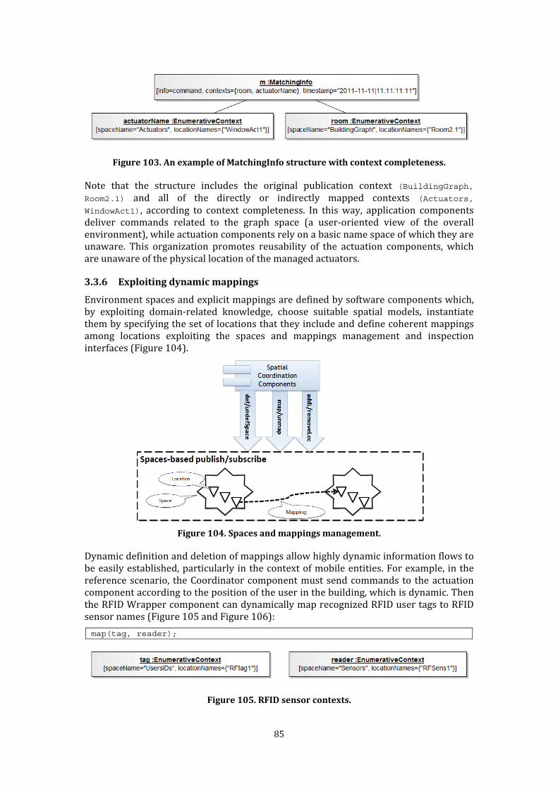
85
Figure 103. An example of MatchingInfo structure with context completeness. Note that the structure includes the original publication context (BuildingGraph,
Room2.1) and all of the directly or indirectly mapped contexts (Actuators,
WindowAct1), according to context completeness. In this way, application components deliver commands related to the graph space (a user-oriented view of the overall environment), while actuation components rely on a basic name space of which they are unaware. This organization promotes reusability of the actuation components, which are unaware of the physical location of the managed actuators. 3.3.6 Exploiting dynamic mappings Environment spaces and explicit mappings are defined by software components which, by exploiting domain-related knowledge, choose suitable spatial models, instantiate them by specifying the set of locations that they include and define coherent mappings among locations exploiting the spaces and mappings management and inspection interfaces (Figure 104).
Figure 104. Spaces and mappings management. Dynamic definition and deletion of mappings allow highly dynamic information flows to be easily established, particularly in the context of mobile entities. For example, in the reference scenario, the Coordinator component must send commands to the actuation component according to the position of the user in the building, which is dynamic. Then the RFID Wrapper component can dynamically map recognized RFID user tags to RFID sensor names (Figure 105 and Figure 106):
map(tag, reader);
Figure 105. RFID sensor contexts.
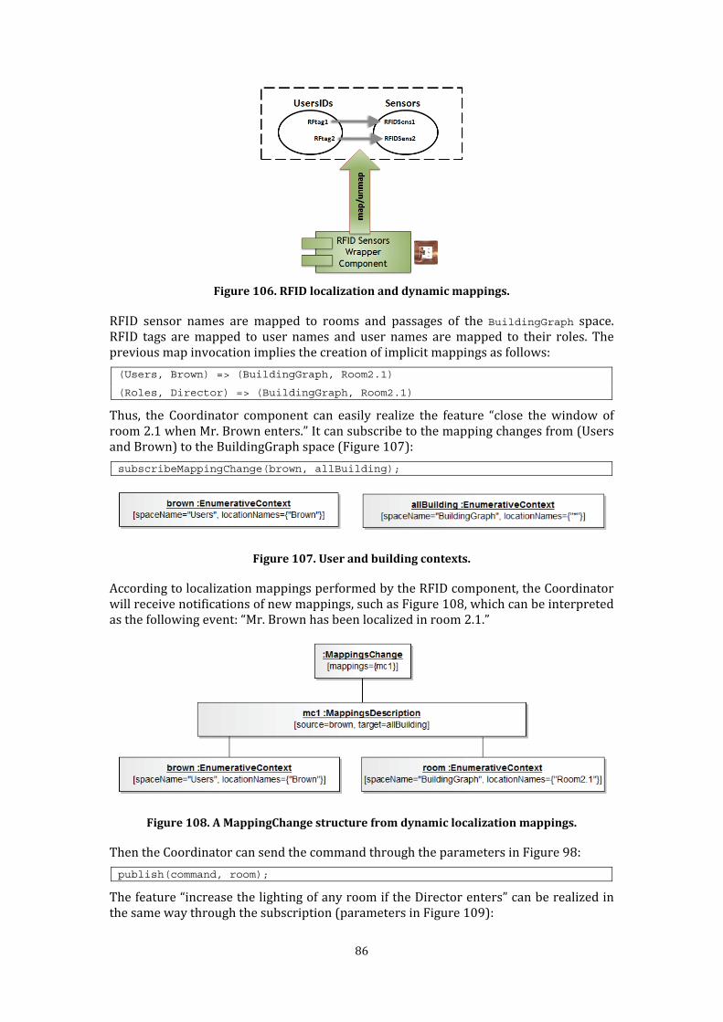
86
Figure 106. RFID localization and dynamic mappings. RFID sensor names are mapped to rooms and passages of the BuildingGraph space. RFID tags are mapped to user names and user names are mapped to their roles. The previous map invocation implies the creation of implicit mappings as follows:
(Users, Brown) => (BuildingGraph, Room2.1)
(Roles, Director) => (BuildingGraph, Room2.1) Thus, the Coordinator component can easily realize the feature “close the window of room 2.1 when Mr. Brown enters.” It can subscribe to the mapping changes from (Users and Brown) to the BuildingGraph space (Figure 107): subscribeMappingChange(brown, allBuilding);
Figure 107. User and building contexts. According to localization mappings performed by the RFID component, the Coordinator will receive notifications of new mappings, such as Figure 108, which can be interpreted as the following event: “Mr. Brown has been localized in room 2.1.”
Figure 108. A MappingChange structure from dynamic localization mappings. Then the Coordinator can send the command through the parameters in Figure 98:
publish(command, room); The feature “increase the lighting of any room if the Director enters” can be realized in the same way through the subscription (parameters in Figure 109):
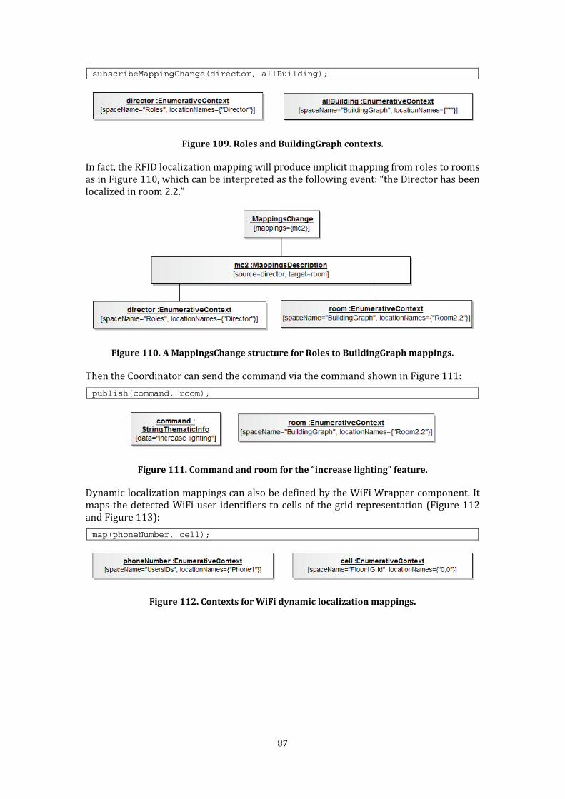
87
subscribeMappingChange(director, allBuilding);
Figure 109. Roles and BuildingGraph contexts. In fact, the RFID localization mapping will produce implicit mapping from roles to rooms as in Figure 110, which can be interpreted as the following event: “the Director has been localized in room 2.2.”
Figure 110. A MappingsChange structure for Roles to BuildingGraph mappings. Then the Coordinator can send the command via the command shown in Figure 111:
publish(command, room);
Figure 111. Command and room for the “increase lighting” feature. Dynamic localization mappings can also be defined by the WiFi Wrapper component. It maps the detected WiFi user identifiers to cells of the grid representation (Figure 112 and Figure 113):
map(phoneNumber, cell);
Figure 112. Contexts for WiFi dynamic localization mappings.
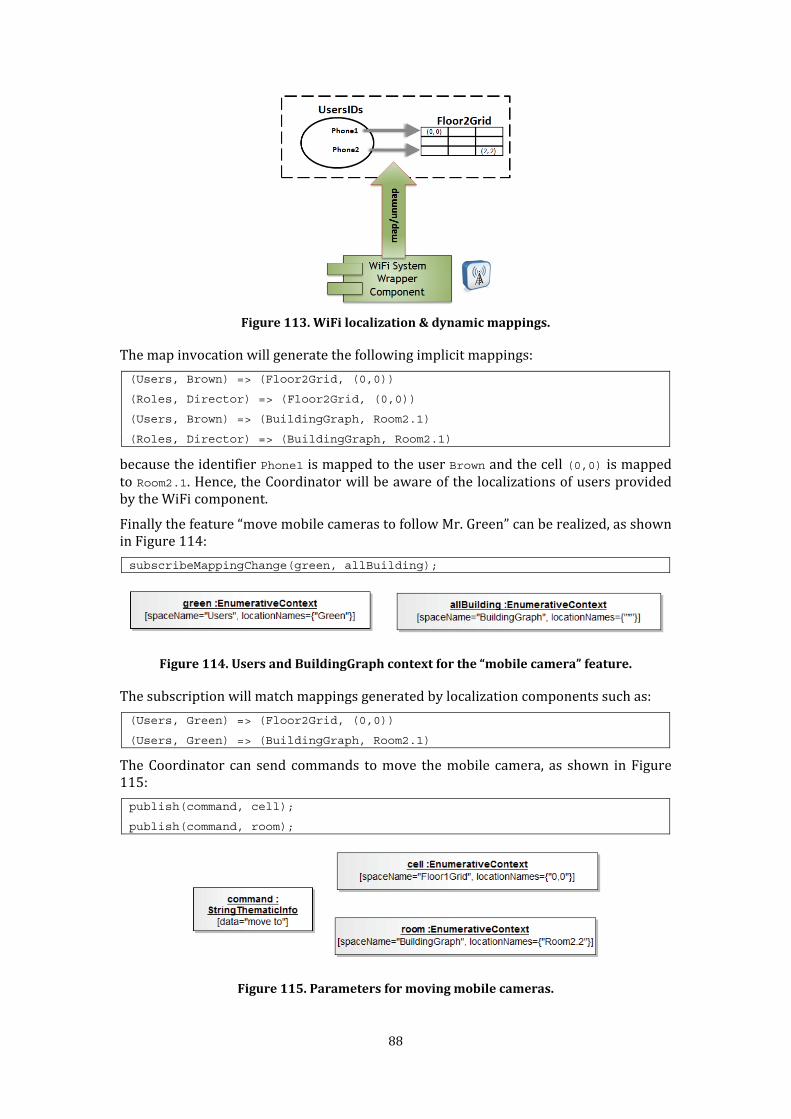
88
Figure 113. WiFi localization & dynamic mappings. The map invocation will generate the following implicit mappings:
(Users, Brown) => (Floor2Grid, (0,0))
(Roles, Director) => (Floor2Grid, (0,0))
(Users, Brown) => (BuildingGraph, Room2.1)
(Roles, Director) => (BuildingGraph, Room2.1) because the identifier Phone1 is mapped to the user Brown and the cell (0,0) is mapped to Room2.1. Hence, the Coordinator will be aware of the localizations of users provided by the WiFi component. Finally the feature “move mobile cameras to follow Mr. Green” can be realized, as shown in Figure 114: subscribeMappingChange(green, allBuilding);
Figure 114. Users and BuildingGraph context for the “mobile camera” feature. The subscription will match mappings generated by localization components such as:
(Users, Green) => (Floor2Grid, (0,0))
(Users, Green) => (BuildingGraph, Room2.1) The Coordinator can send commands to move the mobile camera, as shown in Figure 115: publish(command, cell);
publish(command, room);
Figure 115. Parameters for moving mobile cameras.
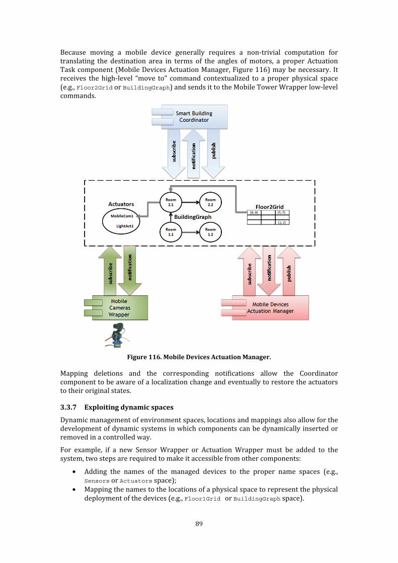
89
Because moving a mobile device generally requires a non-trivial computation for translating the destination area in terms of the angles of motors, a proper Actuation Task component (Mobile Devices Actuation Manager, Figure 116) may be necessary. It receives the high-level “move to” command contextualized to a proper physical space (e.g., Floor2Grid or BuildingGraph) and sends it to the Mobile Tower Wrapper low-level commands.
Figure 116. Mobile Devices Actuation Manager. Mapping deletions and the corresponding notifications allow the Coordinator component to be aware of a localization change and eventually to restore the actuators to their original states.
3.3.7 Exploiting dynamic spaces Dynamic management of environment spaces, locations and mappings also allow for the development of dynamic systems in which components can be dynamically inserted or removed in a controlled way. For example, if a new Sensor Wrapper or Actuation Wrapper must be added to the system, two steps are required to make it accessible from other components: • Adding the names of the managed devices to the proper name spaces (e.g.,
Sensors or Actuators space); • Mapping the names to the locations of a physical space to represent the physical deployment of the devices (e.g., Floor1Grid or BuildingGraph space).

90
These steps allows the new component to communicate via indirect matching through its symbolic name; furthermore, the presence of the new component can be checked by other components inspecting the Sensor and Actuator spaces. 3.4 Spaces-based architecture for Responsive Environments Figure 117 summarizes the generic software architecture promoted by exploiting the spaces-based publish/subscribe communication. Sensing Wrapper Components diffuse their sensed data, publishing the data in one or more sensing spaces. For example, a sensing space may be a name space representing their identifiers or a graph/cell space representing the physical environment, as exemplified in Section 3.3. Localization Wrapper Components are a special type of Sensing Wrapper that may communicate their localization information through the dynamic management of proper mappings from users’ (entities’) identifiers (which belong to a sensing space) to the location of physical spaces, i.e., environment spaces representing the physical environment. Actuation Wrapper Components receive their commands through proper subscriptions to actuation spaces. Like Sensing Wrappers, they may subscribe either to a name space containing actuators’ identifiers or to a physical space representing their physical position in the environment.
Figure 117. Spaces-based architecture. Specific Task components may be distinguished in Sensing and Actuation Task components. Sensing Task components subscribe to receive sensing data, which are generally enriched with contexts related to physical spaces and produce high-level data by
91
publishing them in different contexts. They may exploit specific user spaces. They may also subscribe to changes on mappings to obtain localization information. Actuation Task components subscribe to receive high-level commands that are generally contextualized in physical spaces. They translate these commands into low-level commands, which are directly acceptable by Actuation Wrappers, by publishing them in a space known to the Actuation Wrappers. Coordination components realize the overall features of Responsive Environments by receiving high-level data and by producing high-level data referred to physical and logical spaces, such as users' and roles spaces. They may exploit coordination spaces. Finally, Spatial Coordination components are privileged components that manage spaces and mappings. 3.5 Discussion
3.5.1 Benefits Information flows can be transparently established through multiple environment spaces and mappings. Components may diffuse and receive information without knowing the other components and by relying on their subjective views of the environment. Hence, the key advantage of the proposed communication abstractions relies on openness: heterogeneous components can be integrated by defining their distinctive spaces and relating them through mappings. Information can be localized in multiple environment spaces with different semantics, such as role hierarchies or physical spaces. This aspect is a key concept for the realization of responsive environments because it supports full and rich context-based interactions, according to the definition of context as “any information that can be used to characterize the situation of entities (i.e., whether a person, place or object) that are considered relevant to the interaction between a user and an application, including the user and the application themselves” (Dey 2001). Moreover, with respect to the requirements presented in Section 2.4.3, the proposed abstractions lead to several advantages. Simplicity. Components interact through five small sets of primitives only. These sets are defined according to the separation of concerns principle by distinguishing management and inspection of environments spaces, management and inspection of mappings and spaces-based publish/subscribe communication. Light weight. Components must know only the interfaces of the primitives. Components must agree on an interpretation of the exchanged information, which has been separated from its localization. For example, Coordination and Task components must agree on the syntax and semantics of the exchanged high-level stimuli and commands. However, this agreement is up to the components and is not part of the proposed architectural abstractions. Therefore, the abstractions do not impose a reference data format. Dynamicity. Dynamic management of spaces and mappings support a controlled dynamic insertion or removal of software components to or from the system. 3.5.2 Comparison with related work
3.5.2.1 Comparison with related communication architectural abstractions Publish/subscribe is one of the leading communication paradigm for engineering Responsive Environments. Several recent works like (Gámez & Fuentes 2011)(Kusznir
92
& Cook 2010)(Aiello & Dustdar 2008) exploit content-based publish subscribe, i.e., subscriptions are based on conditions about the published information. On the contrary, this thesis introduced space concepts to diffuse information respect to spatial contexts, defining a specialized form of context-based publish/subscribe (Cugola et al. 2009). Actually the proposed approach can be viewed as a particular type of context-based publish/subscribe in which the context is represented in terms of localization in environment spaces. Other contextual information (e.g., sensor data about the environment such as temperature and the presence of people and things) is left to the published thematic information. With respect to location-based publish/subscribe communication (Eugster et al. 2005) the approach proposed in this thesis is more general. First, it does not assume a unique reference location model (e.g., geometrical or geographical) but supports any (finite) location representation. Information can be published and received through different spatial contexts if proper explicit mappings exist. Moreover, using multiple spatial models supports the treatment of both physical and logical spaces: a graph may represent both a physical space and hierarchical dependencies among people. Overall, the abstractions proposed by this thesis lie at an intermediate level between high-level content, context and tuple-based approaches and basic communication mechanisms. They leverage the multiple-spaces metaphor in order to provide an effective support for the development of Responsive Environments. The proposed approach extends the publish/subscribe style because spaces-based message passing is a suitable communication foundation for Responsive Environments; however, the defined space concepts and matching could also be applicable to tuple spaces. 3.5.2.2 Comparison with related work on space The proposed approach grounds on the idea that spatial concepts should be first-class objects in designing Responsive Environments, as highlighted by (Malek et al. 2010) (Turner & E. Davenport 2005) (Harper et al. 2005) (Dobson 2005) (Steed et al. 2004). Moreover the approach exploits both physical and logical spaces as suggested by (Ciolfi & Bannon 2005). The separation between thematic information and spatial context is in accord with most of the proposed works on space representation, which carefully separate entities from their locations in space, as argued in (Bateman & Farrar 2004), (Mark et al. 2001) and (Parent et al. 1999). The representation proposed by (Perry et al. 2006) is one example of this type of analysis. All techniques dealing with the integration of heterogeneous spatial data include some form of mapping (Euzenat & Shvaiko 2007) (Sotnykova et al. 2005). For example, in (Euzenat & Shvaiko 2007) ontology mapping aims to relate similar concepts and relationships from data sources, exploiting an equivalence relation. The mappings proposed in this thesis are related to a simple notion of equivalence between locations: they make the same piece of information available, irrespective of any semantics associated with each space containing the information. Although mappings between spaces are not explicitly taken into account by all spaces-model based approaches, they have been introduced in different ways. (Steed et al. 2004) define four spatial services that place a predefined set of different spatial models in relation to one another. (Dix et al. 2000) also provide support for mapping (as a relation between spaces together with topological and boundary relations). For example, they link locations in real space to locations in an information space so that the user can walk around the real space while navigating the virtual space. The proposed space mappings are more general, as they support these types of relationships without differentiating among them.
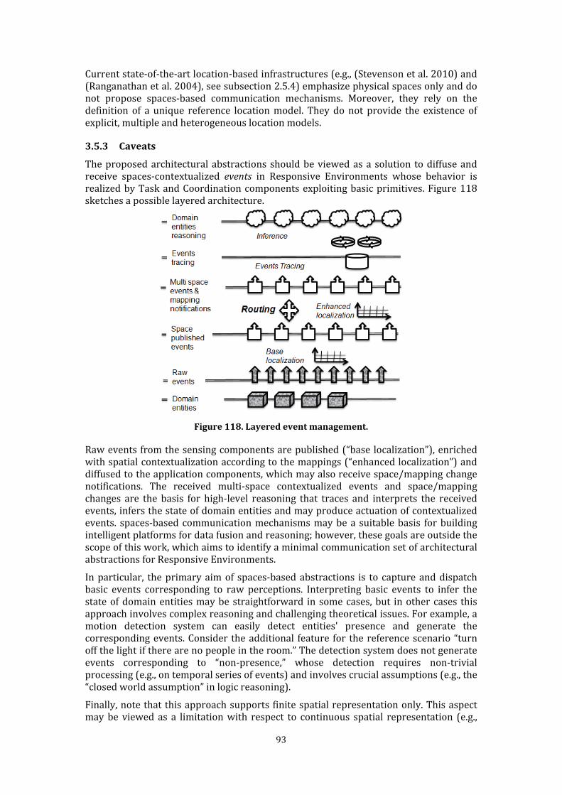
93
Current state-of-the-art location-based infrastructures (e.g., (Stevenson et al. 2010) and (Ranganathan et al. 2004), see subsection 2.5.4) emphasize physical spaces only and do not propose spaces-based communication mechanisms. Moreover, they rely on the definition of a unique reference location model. They do not provide the existence of explicit, multiple and heterogeneous location models. 3.5.3 Caveats The proposed architectural abstractions should be viewed as a solution to diffuse and receive spaces-contextualized events in Responsive Environments whose behavior is realized by Task and Coordination components exploiting basic primitives. Figure 118 sketches a possible layered architecture.
Figure 118. Layered event management. Raw events from the sensing components are published (“base localization”), enriched with spatial contextualization according to the mappings (“enhanced localization”) and diffused to the application components, which may also receive space/mapping change notifications. The received multi-space contextualized events and space/mapping changes are the basis for high-level reasoning that traces and interprets the received events, infers the state of domain entities and may produce actuation of contextualized events. spaces-based communication mechanisms may be a suitable basis for building intelligent platforms for data fusion and reasoning; however, these goals are outside the scope of this work, which aims to identify a minimal communication set of architectural abstractions for Responsive Environments. In particular, the primary aim of spaces-based abstractions is to capture and dispatch basic events corresponding to raw perceptions. Interpreting basic events to infer the state of domain entities may be straightforward in some cases, but in other cases this approach involves complex reasoning and challenging theoretical issues. For example, a motion detection system can easily detect entities' presence and generate the corresponding events. Consider the additional feature for the reference scenario “turn off the light if there are no people in the room.” The detection system does not generate events corresponding to “non-presence,” whose detection requires non-trivial processing (e.g., on temporal series of events) and involves crucial assumptions (e.g., the “closed world assumption” in logic reasoning). Finally, note that this approach supports finite spatial representation only. This aspect may be viewed as a limitation with respect to continuous spatial representation (e.g.,

94
Cartesian or geo-referenced). However, continuous spaces can be approximated by a suitable grid representation. In practice, these types of discrete approximations are widely used because of the location tolerance of positioning technologies.

95
4 Concrete framework: Space Integration Services This chapter presents Space Integration Services (SIS), a prototypal concrete framework that reifies the communication architectural abstractions proposed in Chapter 3. SIS has been developed in the context of the GAS (“Grandi Attrezzature Scientifiche”) project developed at the Department of Informatics, Systems and Communication (DISCo) of the University of Milano-Bicocca. The aim of the GAS project is to augment the Department building with a technological platform, so that the building becomes a workbench for experimental activities, including Responsive Environments, Ambient Intelligence, Robotics, Video Surveillance and Co-operative Work. The next sections present significant insights about the design of the service and its current implementation along with quantitative performance evaluation tests. 4.1 Implementation choices
4.1.1 Rationale The major requirement of the GAS project was the capability to integrate a wide range of independently developed and heterogeneous devices and applications in a seamless way. Therefore, the design of SIS focused on the careful identification of communication architectural abstractions (i.e., spaces-based publish/subscribe). Another key requirement was to develop the integration framework in a timely and cost-effective manner. The contribution of SIS stems from the fact that it facilitates the development of responsive environments by integrating heterogeneous components via multiple spaces, not from the technical complexities of its implementation. Therefore, SIS relies on off-the-shelf technologies: Web Services, Java and Jess49. The semantic interpretation of the information flowing among software components strongly depends on specific domain-related aspects that are encapsulated by the applications wrapped as software components. Spatial models are at a high level of abstraction and correspond to established and widely agreed-upon concepts, which are valid in different application domains, have a sound formal definition and seldom change. Therefore, to ensure timely and efficient implementation, spatial models are hard-coded into the framework, together with the related spaces-aware communication operations that support virtual information flows. Environment spaces and space mappings can be dynamically defined and inspected according to the space and mapping management interfaces presented in Chapter 3. 4.1.2 Centralized organization SIS reifies the operation interfaces described in Chapter 3 in a centralized way (Figure 119).
49 http://www.jessrules.com/. For an introduction see (Friedman-Hill 2003).
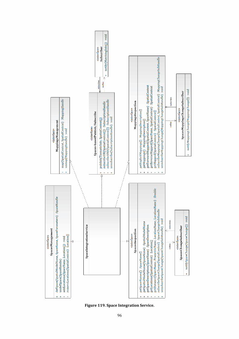
96
Figure 119. Space Integration Service.
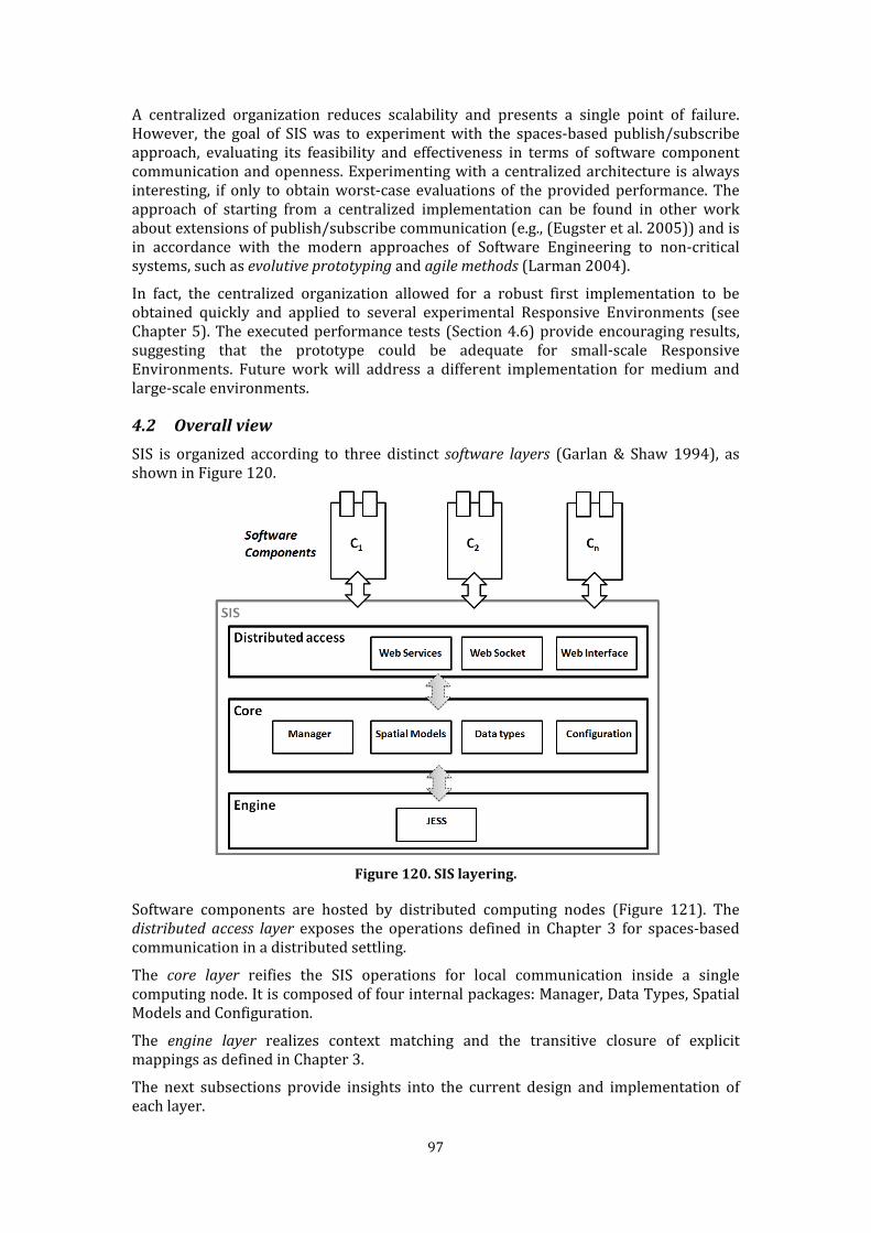
97
A centralized organization reduces scalability and presents a single point of failure. However, the goal of SIS was to experiment with the spaces-based publish/subscribe approach, evaluating its feasibility and effectiveness in terms of software component communication and openness. Experimenting with a centralized architecture is always interesting, if only to obtain worst-case evaluations of the provided performance. The approach of starting from a centralized implementation can be found in other work about extensions of publish/subscribe communication (e.g., (Eugster et al. 2005)) and is in accordance with the modern approaches of Software Engineering to non-critical systems, such as evolutive prototyping and agile methods (Larman 2004). In fact, the centralized organization allowed for a robust first implementation to be obtained quickly and applied to several experimental Responsive Environments (see Chapter 5). The executed performance tests (Section 4.6) provide encouraging results, suggesting that the prototype could be adequate for small-scale Responsive Environments. Future work will address a different implementation for medium and large-scale environments. 4.2 Overall view SIS is organized according to three distinct software layers (Garlan & Shaw 1994), as shown in Figure 120.
Figure 120. SIS layering. Software components are hosted by distributed computing nodes (Figure 121). The
distributed access layer exposes the operations defined in Chapter 3 for spaces-based communication in a distributed settling. The core layer reifies the SIS operations for local communication inside a single computing node. It is composed of four internal packages: Manager, Data Types, Spatial Models and Configuration. The engine layer realizes context matching and the transitive closure of explicit mappings as defined in Chapter 3. The next subsections provide insights into the current design and implementation of each layer.
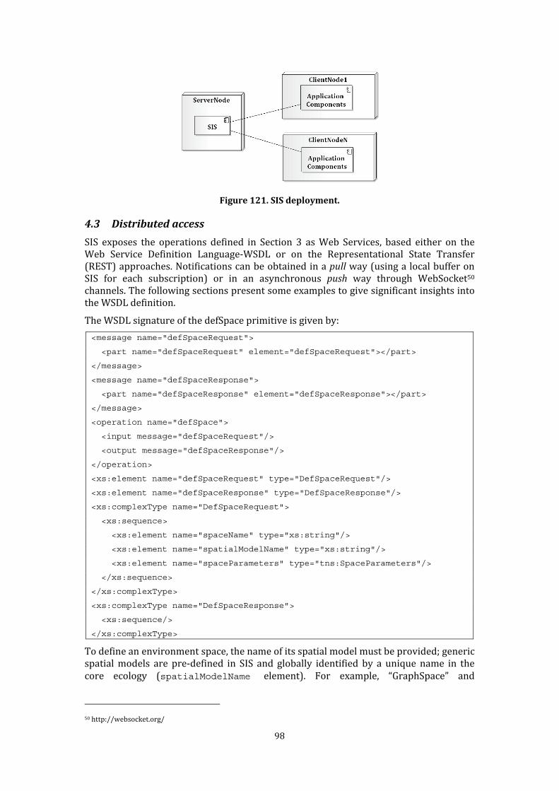
98
Figure 121. SIS deployment.
4.3 Distributed access SIS exposes the operations defined in Section 3 as Web Services, based either on the Web Service Definition Language-WSDL or on the Representational State Transfer (REST) approaches. Notifications can be obtained in a pull way (using a local buffer on SIS for each subscription) or in an asynchronous push way through WebSocket50 channels. The following sections present some examples to give significant insights into the WSDL definition. The WSDL signature of the defSpace primitive is given by: <message name="defSpaceRequest">
<part name="defSpaceRequest" element="defSpaceRequest"></part>
</message>
<message name="defSpaceResponse">
<part name="defSpaceResponse" element="defSpaceResponse"></part>
</message>
<operation name="defSpace">
<input message="defSpaceRequest"/>
<output message="defSpaceResponse"/>
</operation>
<xs:element name="defSpaceRequest" type="DefSpaceRequest"/>
<xs:element name="defSpaceResponse" type="DefSpaceResponse"/>
<xs:complexType name="DefSpaceRequest">
<xs:sequence>
<xs:element name="spaceName" type="xs:string"/>
<xs:element name="spatialModelName" type="xs:string"/>
<xs:element name="spaceParameters" type="tns:SpaceParameters"/>
</xs:sequence>
</xs:complexType>
<xs:complexType name="DefSpaceResponse">
<xs:sequence/>
</xs:complexType> To define an environment space, the name of its spatial model must be provided; generic spatial models are pre-defined in SIS and globally identified by a unique name in the core ecology (spatialModelName element). For example, “GraphSpace” and 50 http://websocket.org/
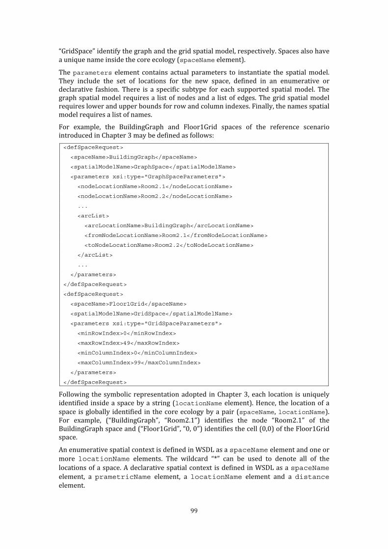
99
“GridSpace” identify the graph and the grid spatial model, respectively. Spaces also have a unique name inside the core ecology (spaceName element). The parameters element contains actual parameters to instantiate the spatial model. They include the set of locations for the new space, defined in an enumerative or declarative fashion. There is a specific subtype for each supported spatial model. The graph spatial model requires a list of nodes and a list of edges. The grid spatial model requires lower and upper bounds for row and column indexes. Finally, the names spatial model requires a list of names. For example, the BuildingGraph and Floor1Grid spaces of the reference scenario introduced in Chapter 3 may be defined as follows: <defSpaceRequest>
<spaceName>BuildingGraph</spaceName>
<spatialModelName>GraphSpace</spatialModelName>
<parameters xsi:type="GraphSpaceParameters">
<nodeLocationName>Room2.1</nodeLocationName>
<nodeLocationName>Room2.2</nodeLocationName>
...
<arcList>
<arcLocationName>BuildingGraph</arcLocationName>
<fromNodeLocationName>Room2.1</fromNodeLocationName>
<toNodeLocationName>Room2.2</toNodeLocationName>
</arcList>
...
</parameters>
</defSpaceRequest>
<defSpaceRequest>
<spaceName>Floor1Grid</spaceName>
<spatialModelName>GridSpace</spatialModelName>
<parameters xsi:type="GridSpaceParameters">
<minRowIndex>0</minRowIndex>
<maxRowIndex>49</maxRowIndex>
<minColumnIndex>0</minColumnIndex>
<maxColumnIndex>99</maxColumnIndex>
</parameters>
</defSpaceRequest> Following the symbolic representation adopted in Chapter 3, each location is uniquely identified inside a space by a string (locationName element). Hence, the location of a space is globally identified in the core ecology by a pair (spaceName, locationName). For example, (“BuildingGraph”, “Room2.1”) identifies the node “Room2.1” of the BuildingGraph space and (“Floor1Grid”, “0, 0”) identifies the cell (0,0) of the Floor1Grid space. An enumerative spatial context is defined in WSDL as a spaceName element and one or more locationName elements. The wildcard “*” can be used to denote all of the locations of a space. A declarative spatial context is defined in WSDL as a spaceName element, a prametricName element, a locationName element and a distance element.

100
The map operation creates explicit mappings. It maps locations identified by a source spatial context to the location identified by a target context. For example, an explicit mapping definition from the Floor1Grid space to the BuildingGraph space is given as follows: <mapRequest>
<sourceContext xsi:type="EnumerativeContext">
<spaceName>Floor1Grid</spaceName><locationName>0,0</locationName>
</sourceContext>
<targetContext xsi:type="EnumerativeContext">
<spaceName>BuildingGraph</spaceName><locationName>Room2.1</locationName>
</targetContext>
</mapRequest> The publish primitive publishes thematic information localized at all of the locations specified by one or more spatial contexts (publicationContext element). Each context must refer to valid locations, i.e., locations belonging to the specified space according to its definition. The content of a piece of thematic information (info element) can be submitted as textual information, which is directly expressible in XML types or in binary form51 by means of standard technologies like SOAP-MTOM52. For example, thematic information can be published on the cell (0, 0) of the Floor1Grid space as follows: <publishRequest>
<info>...</info>
<publicationContext xsi:type="EnumerativeContext">
<spaceName>Floor1Grid</spaceName><locationName>0,0</locationName>
</publicationContext>
</publishRequest> The subscribe primitive creates a disjunctive subscription to one or more spatial contexts (subscriptionContext element). The support of conjunctive subscriptions is under development. The following fragment makes a subscription to the cell (0, 0) of the Floor1Grid space: <subscribeRequest>
<subscriptionContext xsi:type="EnumerativeContext">
<spaceName>Floor1Grid</spaceName><locationName>0,0</locationName>
</subscriptionContext>
</subscribeRequest> The subscriber receives a notification as a MatchingInfo structure. This structure includes an information item with the context in which it was originally localized and those which are either explicitly or implicitly mapped from them (see Section 3.5). The timestamp element represents the time at which the emission was perceived by SIS in Coordinated Universal Time. For example, the previous publication and subscription examples will match with respect to the cell (0,0). The notification is received by the subscriber as follows (note that the mapped BuildingGraph context is included): <matchingInfo>
51 http://www.w3.org/TR/2004/PER-xmlschema-2-20040318/#base64Binary 52 http://www.w3.org/TR/soap12-mtom
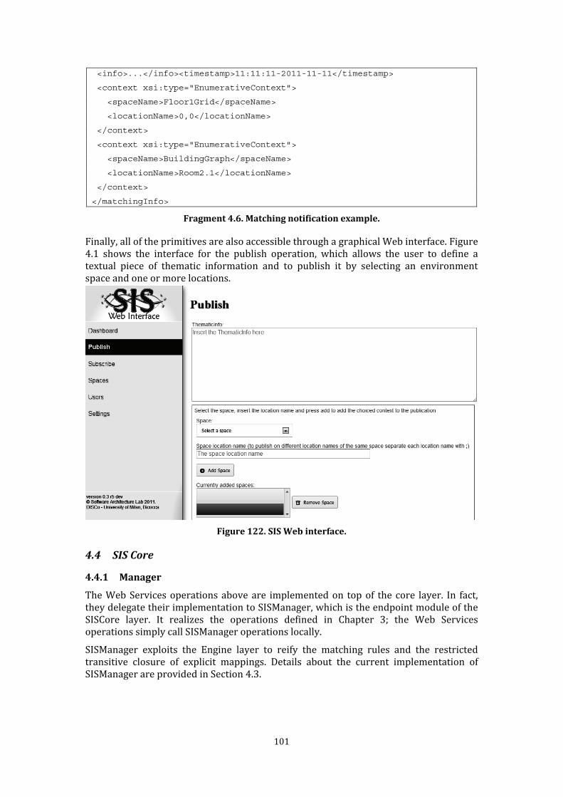
101
<info>...</info><timestamp>11:11:11-2011-11-11</timestamp>
<context xsi:type="EnumerativeContext">
<spaceName>Floor1Grid</spaceName>
<locationName>0,0</locationName>
</context>
<context xsi:type="EnumerativeContext">
<spaceName>BuildingGraph</spaceName>
<locationName>Room2.1</locationName>
</context>
</matchingInfo>
Fragment 4.6. Matching notification example. Finally, all of the primitives are also accessible through a graphical Web interface. Figure 4.1 shows the interface for the publish operation, which allows the user to define a textual piece of thematic information and to publish it by selecting an environment space and one or more locations.
Figure 122. SIS Web interface.
4.4 SIS Core
4.4.1 Manager The Web Services operations above are implemented on top of the core layer. In fact, they delegate their implementation to SISManager, which is the endpoint module of the SISCore layer. It realizes the operations defined in Chapter 3; the Web Services operations simply call SISManager operations locally. SISManager exploits the Engine layer to reify the matching rules and the restricted transitive closure of explicit mappings. Details about the current implementation of SISManager are provided in Section 4.3.
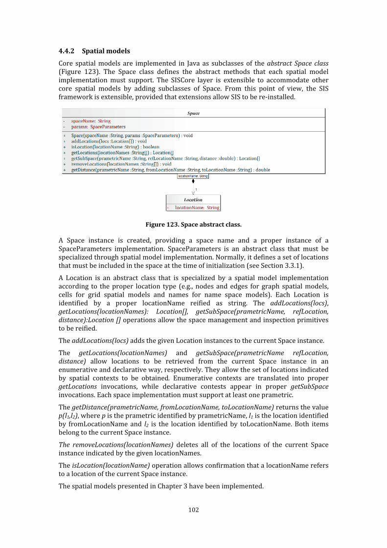
102
4.4.2 Spatial models Core spatial models are implemented in Java as subclasses of the abstract Space class (Figure 123). The Space class defines the abstract methods that each spatial model implementation must support. The SISCore layer is extensible to accommodate other core spatial models by adding subclasses of Space. From this point of view, the SIS framework is extensible, provided that extensions allow SIS to be re-installed.
Figure 123. Space abstract class. A Space instance is created, providing a space name and a proper instance of a SpaceParameters implementation. SpaceParameters is an abstract class that must be specialized through spatial model implementation. Normally, it defines a set of locations that must be included in the space at the time of initialization (see Section 3.3.1). A Location is an abstract class that is specialized by a spatial model implementation according to the proper location type (e.g., nodes and edges for graph spatial models, cells for grid spatial models and names for name space models). Each Location is identified by a proper locationName reified as string. The addLocations(locs),
getLocations(locationNames): Location[], getSubSpace(prametricName, refLocation, distance):Location [] operations allow the space management and inspection primitives to be reified. The addLocations(locs) adds the given Location instances to the current Space instance. The getLocations(locationNames) and getSubSpace(prametricName refLocation, distance) allow locations to be retrieved from the current Space instance in an enumerative and declarative way, respectively. They allow the set of locations indicated by spatial contexts to be obtained. Enumerative contexts are translated into proper getLocations invocations, while declarative contests appear in proper getSubSpace invocations. Each space implementation must support at least one prametric. The getDistance(prametricName, fromLocationName, toLocationName) returns the value p(l1,l2), where p is the prametric identified by prametricName, l1 is the location identified by fromLocationName and l2 is the location identified by toLocationName. Both items belong to the current Space instance. The removeLocations(locationNames) deletes all of the locations of the current Space instance indicated by the given locationNames. The isLocation(locationName) operation allows confirmation that a locationName refers to a location of the current Space instance. The spatial models presented in Chapter 3 have been implemented.
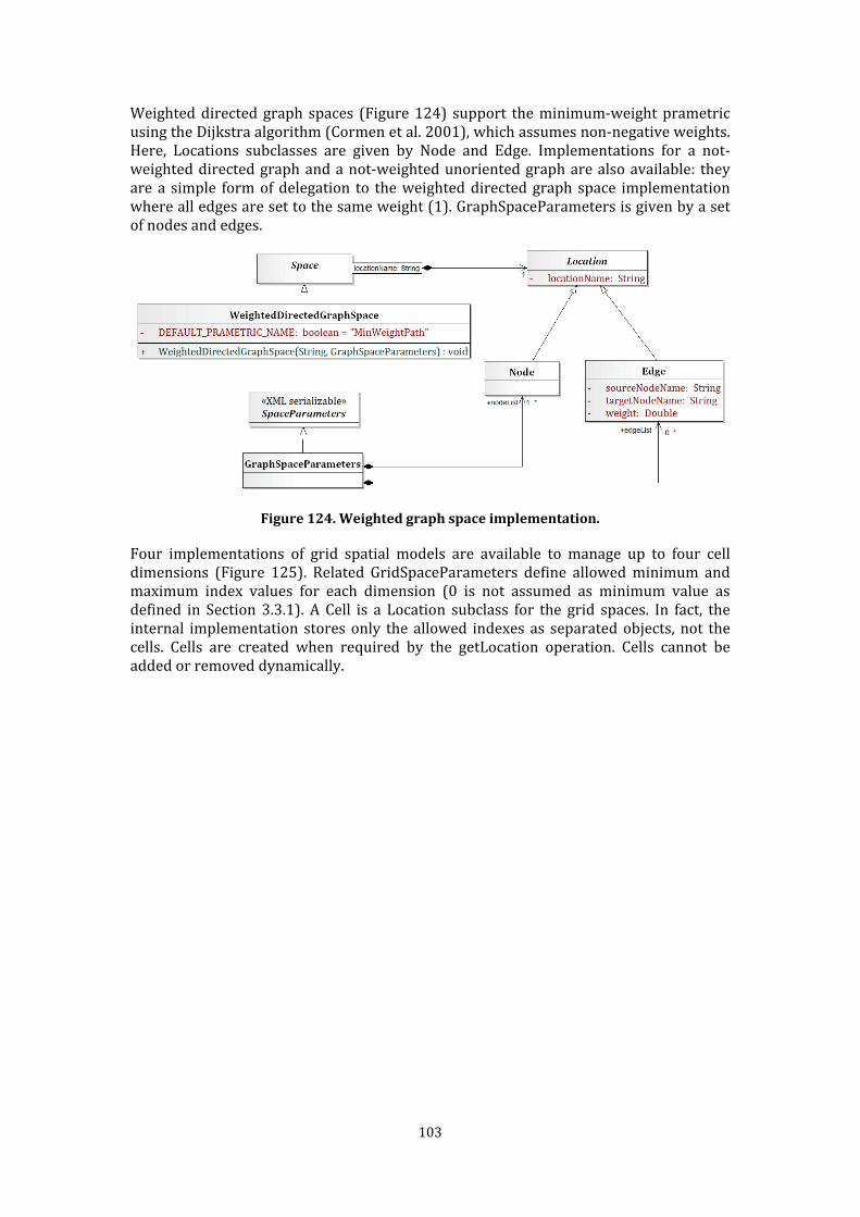
103
Weighted directed graph spaces (Figure 124) support the minimum-weight prametric using the Dijkstra algorithm (Cormen et al. 2001), which assumes non-negative weights. Here, Locations subclasses are given by Node and Edge. Implementations for a not-weighted directed graph and a not-weighted unoriented graph are also available: they are a simple form of delegation to the weighted directed graph space implementation where all edges are set to the same weight (1). GraphSpaceParameters is given by a set of nodes and edges.
Figure 124. Weighted graph space implementation. Four implementations of grid spatial models are available to manage up to four cell dimensions (Figure 125). Related GridSpaceParameters define allowed minimum and maximum index values for each dimension (0 is not assumed as minimum value as defined in Section 3.3.1). A Cell is a Location subclass for the grid spaces. In fact, the internal implementation stores only the allowed indexes as separated objects, not the cells. Cells are created when required by the getLocation operation. Cells cannot be added or removed dynamically.

104
Figure 125. Grid space implementation. Finally, the name spatial model is reified with a straight implementation, in which names are realized as strings (Figure 126). The Name location class extends the Location class without adding further attributes: the locationName attribute is exploited to represent the name-string itself. This implementation supports the Levensthein prametric (Levenshtein 1966). NameSpaceParameters is given by a set of Name instances.
Figure 126. Name spatial model implementation. The weighted directed graph spatial model realizes the minimum weight prametric using the Dijkstra algorithm (Cormen et al. 2001), which assumes not-negative weights. Implementations for not-weighted directed graph and not-weighted unoriented graphs are available: they are a simple form of delegation to the weighted directed graph space implementation where all edges are set to the same weight (1).
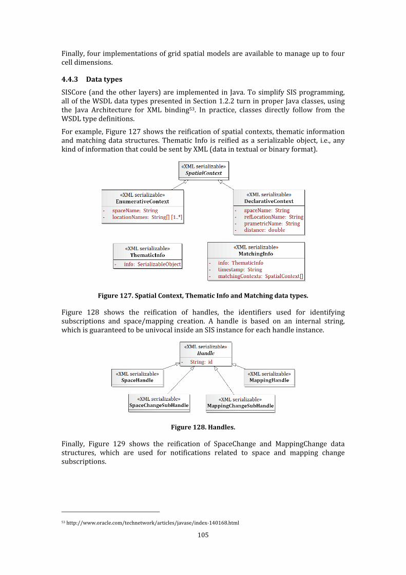
105
Finally, four implementations of grid spatial models are available to manage up to four cell dimensions. 4.4.3 Data types SISCore (and the other layers) are implemented in Java. To simplify SIS programming, all of the WSDL data types presented in Section 1.2.2 turn in proper Java classes, using the Java Architecture for XML binding53. In practice, classes directly follow from the WSDL type definitions. For example, Figure 127 shows the reification of spatial contexts, thematic information and matching data structures. Thematic Info is reified as a serializable object, i.e., any kind of information that could be sent by XML (data in textual or binary format).
Figure 127. Spatial Context, Thematic Info and Matching data types. Figure 128 shows the reification of handles, the identifiers used for identifying subscriptions and space/mapping creation. A handle is based on an internal string, which is guaranteed to be univocal inside an SIS instance for each handle instance.
Figure 128. Handles. Finally, Figure 129 shows the reification of SpaceChange and MappingChange data structures, which are used for notifications related to space and mapping change subscriptions.
53 http://www.oracle.com/technetwork/articles/javase/index-140168.html
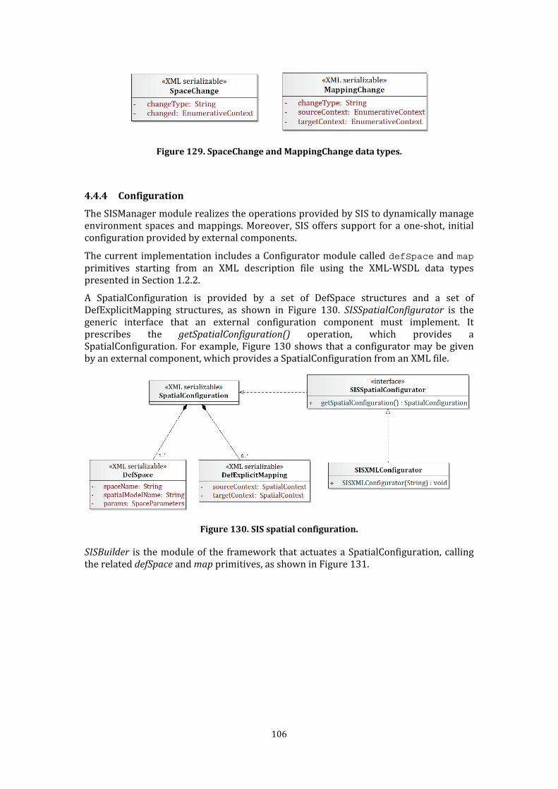
106
Figure 129. SpaceChange and MappingChange data types.
4.4.4 Configuration The SISManager module realizes the operations provided by SIS to dynamically manage environment spaces and mappings. Moreover, SIS offers support for a one-shot, initial configuration provided by external components. The current implementation includes a Configurator module called defSpace and map primitives starting from an XML description file using the XML-WSDL data types presented in Section 1.2.2. A SpatialConfiguration is provided by a set of DefSpace structures and a set of DefExplicitMapping structures, as shown in Figure 130. SISSpatialConfigurator is the generic interface that an external configuration component must implement. It prescribes the getSpatialConfiguration() operation, which provides a SpatialConfiguration. For example, Figure 130 shows that a configurator may be given by an external component, which provides a SpatialConfiguration from an XML file.
Figure 130. SIS spatial configuration.
SISBuilder is the module of the framework that actuates a SpatialConfiguration, calling the related defSpace and map primitives, as shown in Figure 131.
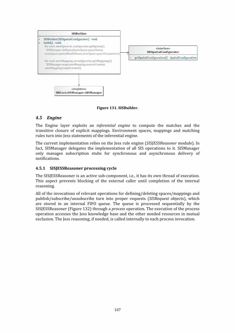
107
Figure 131. SISBuilder.
4.5 Engine The Engine layer exploits an inferential engine to compute the matches and the transitive closure of explicit mappings. Environment spaces, mappings and matching rules turn into Jess statements of the inferential engine. The current implementation relies on the Jess rule engine (SISJESSReasoner module). In fact, SISManager delegates the implementation of all SIS operations to it. SISManager only manages subscription stubs for synchronous and asynchronous delivery of notifications. 4.5.1 SISJESSReasoner processing cycle The SISJESSReasoner is an active sub-component, i.e., it has its own thread of execution. This aspect prevents blocking of the external caller until completion of the internal reasoning. All of the invocations of relevant operations for defining/deleting spaces/mappings and publish/subscribe/unsubscribe turn into proper requests (SISRequest objects), which are stored in an internal FIFO queue. The queue is processed sequentially by the SISJESSReasoner (Figure 132) through a process operation. The execution of the process operation accesses the Jess knowledge base and the other needed resources in mutual exclusion. The Jess reasoning, if needed, is called internally to each process invocation.
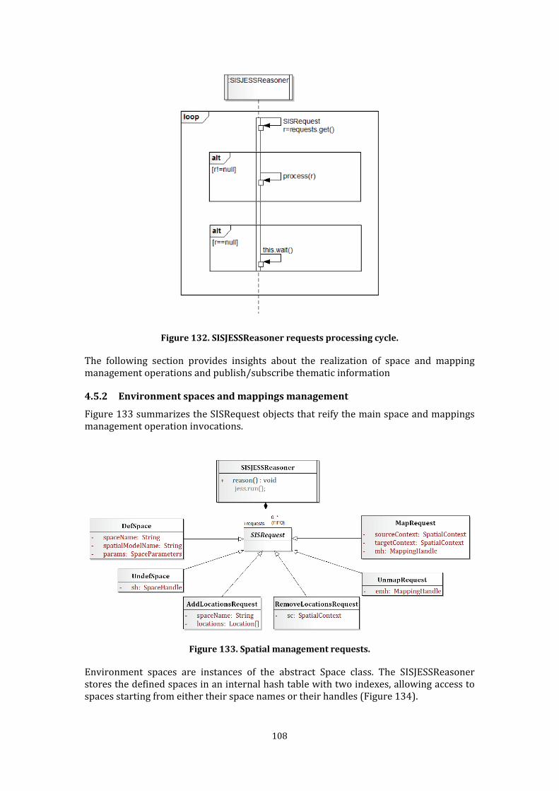
108
Figure 132. SISJESSReasoner requests processing cycle. The following section provides insights about the realization of space and mapping management operations and publish/subscribe thematic information
4.5.2 Environment spaces and mappings management Figure 133 summarizes the SISRequest objects that reify the main space and mappings management operation invocations.
Figure 133. Spatial management requests. Environment spaces are instances of the abstract Space class. The SISJESSReasoner stores the defined spaces in an internal hash table with two indexes, allowing access to spaces starting from either their space names or their handles (Figure 134).
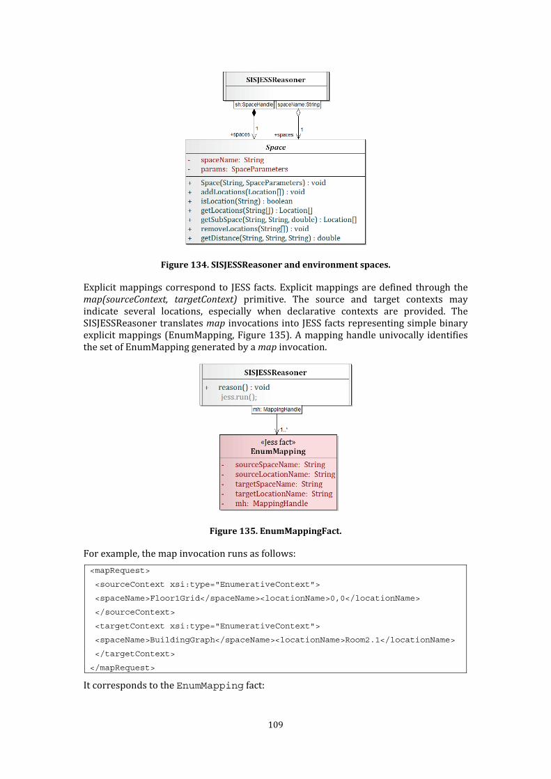
109
Figure 134. SISJESSReasoner and environment spaces. Explicit mappings correspond to JESS facts. Explicit mappings are defined through the
map(sourceContext, targetContext) primitive. The source and target contexts may indicate several locations, especially when declarative contexts are provided. The SISJESSReasoner translates map invocations into JESS facts representing simple binary explicit mappings (EnumMapping, Figure 135). A mapping handle univocally identifies the set of EnumMapping generated by a map invocation.
Figure 135. EnumMappingFact. For example, the map invocation runs as follows:
<mapRequest>
<sourceContext xsi:type="EnumerativeContext">
<spaceName>Floor1Grid</spaceName><locationName>0,0</locationName>
</sourceContext>
<targetContext xsi:type="EnumerativeContext">
<spaceName>BuildingGraph</spaceName><locationName>Room2.1</locationName>
</targetContext>
</mapRequest> It corresponds to the EnumMapping fact:
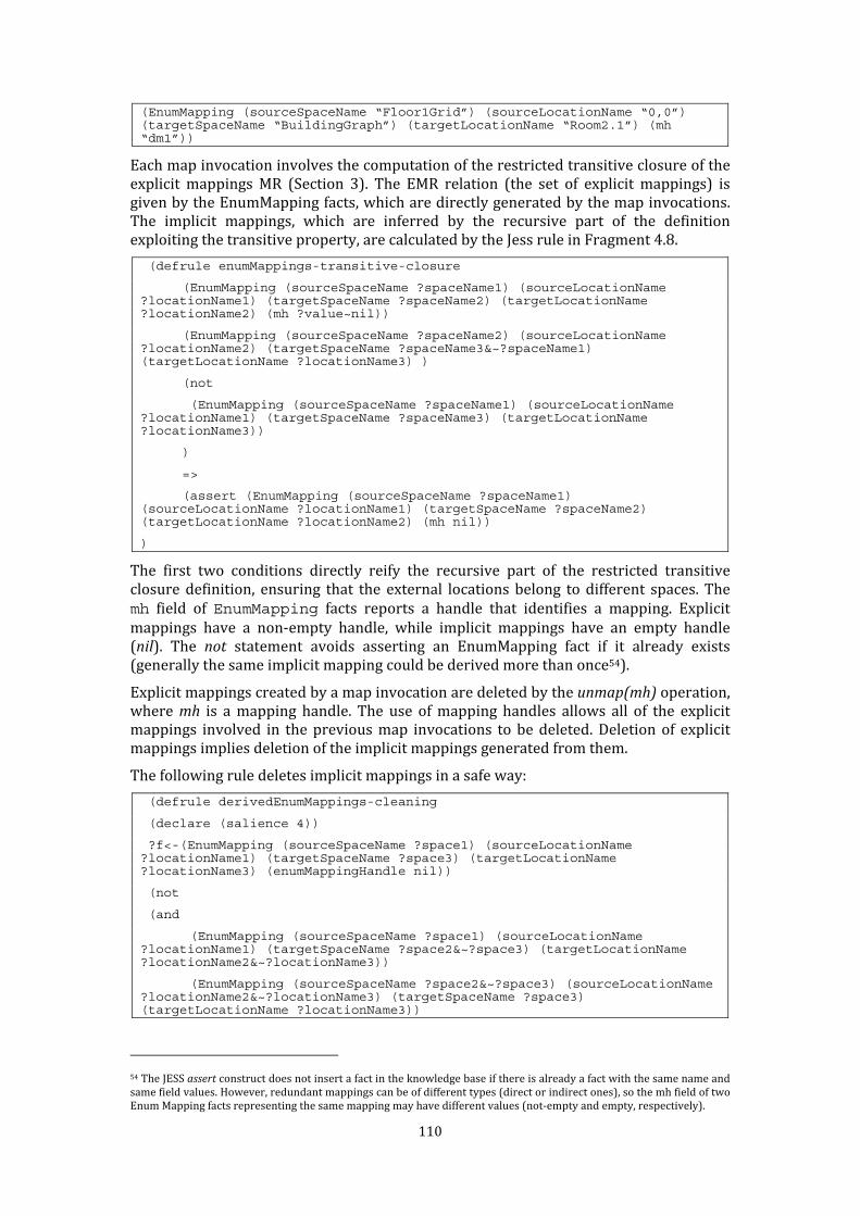
110
(EnumMapping (sourceSpaceName “Floor1Grid”) (sourceLocationName “0,0”) (targetSpaceName “BuildingGraph”) (targetLocationName “Room2.1”) (mh “dm1”)) Each map invocation involves the computation of the restricted transitive closure of the explicit mappings MR (Section 3). The EMR relation (the set of explicit mappings) is given by the EnumMapping facts, which are directly generated by the map invocations. The implicit mappings, which are inferred by the recursive part of the definition exploiting the transitive property, are calculated by the Jess rule in Fragment 4.8. (defrule enumMappings-transitive-closure
(EnumMapping (sourceSpaceName ?spaceName1) (sourceLocationName ?locationName1) (targetSpaceName ?spaceName2) (targetLocationName ?locationName2) (mh ?value~nil))
(EnumMapping (sourceSpaceName ?spaceName2) (sourceLocationName ?locationName2) (targetSpaceName ?spaceName3&~?spaceName1) (targetLocationName ?locationName3) )
(not
(EnumMapping (sourceSpaceName ?spaceName1) (sourceLocationName ?locationName1) (targetSpaceName ?spaceName3) (targetLocationName ?locationName3))
)
=>
(assert (EnumMapping (sourceSpaceName ?spaceName1) (sourceLocationName ?locationName1) (targetSpaceName ?spaceName2) (targetLocationName ?locationName2) (mh nil))
) The first two conditions directly reify the recursive part of the restricted transitive closure definition, ensuring that the external locations belong to different spaces. The mh field of EnumMapping facts reports a handle that identifies a mapping. Explicit mappings have a non-empty handle, while implicit mappings have an empty handle (nil). The not statement avoids asserting an EnumMapping fact if it already exists (generally the same implicit mapping could be derived more than once54). Explicit mappings created by a map invocation are deleted by the unmap(mh) operation, where mh is a mapping handle. The use of mapping handles allows all of the explicit mappings involved in the previous map invocations to be deleted. Deletion of explicit mappings implies deletion of the implicit mappings generated from them. The following rule deletes implicit mappings in a safe way: (defrule derivedEnumMappings-cleaning
(declare (salience 4))
?f<-(EnumMapping (sourceSpaceName ?space1) (sourceLocationName ?locationName1) (targetSpaceName ?space3) (targetLocationName ?locationName3) (enumMappingHandle nil))
(not
(and
(EnumMapping (sourceSpaceName ?space1) (sourceLocationName ?locationName1) (targetSpaceName ?space2&~?space3) (targetLocationName ?locationName2&~?locationName3))
(EnumMapping (sourceSpaceName ?space2&~?space3) (sourceLocationName ?locationName2&~?locationName3) (targetSpaceName ?space3) (targetLocationName ?locationName3))
54 The JESS assert construct does not insert a fact in the knowledge base if there is already a fact with the same name and same field values. However, redundant mappings can be of different types (direct or indirect ones), so the mh field of two Enum Mapping facts representing the same mapping may have different values (not-empty and empty, respectively).
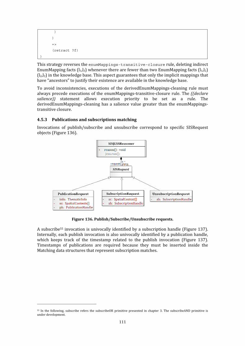
111
)
)
=>
(retract ?f)
) This strategy reverses the enumMappings-transitive-closure rule, deleting indirect EnumMapping facts (l1,l3) whenever there are fewer than two EnumMapping facts (l1,l2) (l2,l3) in the knowledge base. This aspect guarantees that only the implicit mappings that have “ancestors” to justify their existence are available in the knowledge base. To avoid inconsistencies, executions of the derivedEnumMappings-cleaning rule must always precede executions of the enumMappings-transitive-closure rule. The ((declare salience)) statement allows execution priority to be set as a rule. The derivedEnumMappings-cleaning has a salience value greater than the enumMappings-transitive closure. 4.5.3 Publications and subscriptions matching Invocations of publish/subscribe and unsubscribe correspond to specific SISRequest objects (Figure 136).
Figure 136. Publish/Subscribe/Unsubscribe requests. A subscribe55 invocation is univocally identified by a subscription handle (Figure 137). Internally, each publish invocation is also univocally identified by a publication handle, which keeps track of the timestamp related to the publish invocation (Figure 137). Timestamps of publications are required because they must be inserted inside the Matching data structures that represent subscription matches.
55 In the following, subscribe refers the subscribeOR primitive presented in chapter 3. The subscribeAND primitive is under development.
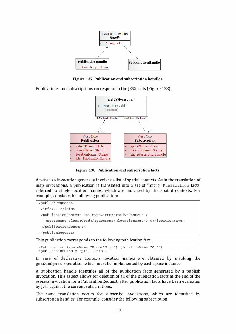
112
Figure 137. Publication and subscription handles. Publications and subscriptions correspond to the JESS facts (Figure 138).
Figure 138. Publication and subscription facts. A publish invocation generally involves a list of spatial contexts. As in the translation of map invocations, a publication is translated into a set of “micro” Publication facts, referred to single location names, which are indicated by the spatial contexts. For example, consider the following publication:
<publishRequest>
<info>...</info>
<publicationContext xsi:type="EnumerativeContext">
<spaceName>Floor1Grid</spaceName><locationName>0,0</locationName>
</publicationContext>
</publishRequest> This publication corresponds to the following publication fact: (Publication (spaceName “Floor1Grid”) (locationName “0,0”) (publicationHandle “p1”) (info …)) In case of declarative contexts, location names are obtained by invoking the
getSubSpace operation, which must be implemented by each space instance. A publication handle identifies all of the publication facts generated by a publish invocation. This aspect allows for deletion of all of the publication facts at the end of the process invocation for a PublicationRequest, after publication facts have been evaluated by Jess against the current subscriptions. The same translation occurs for subscribe invocations, which are identified by subscription handles. For example, consider the following subscription:
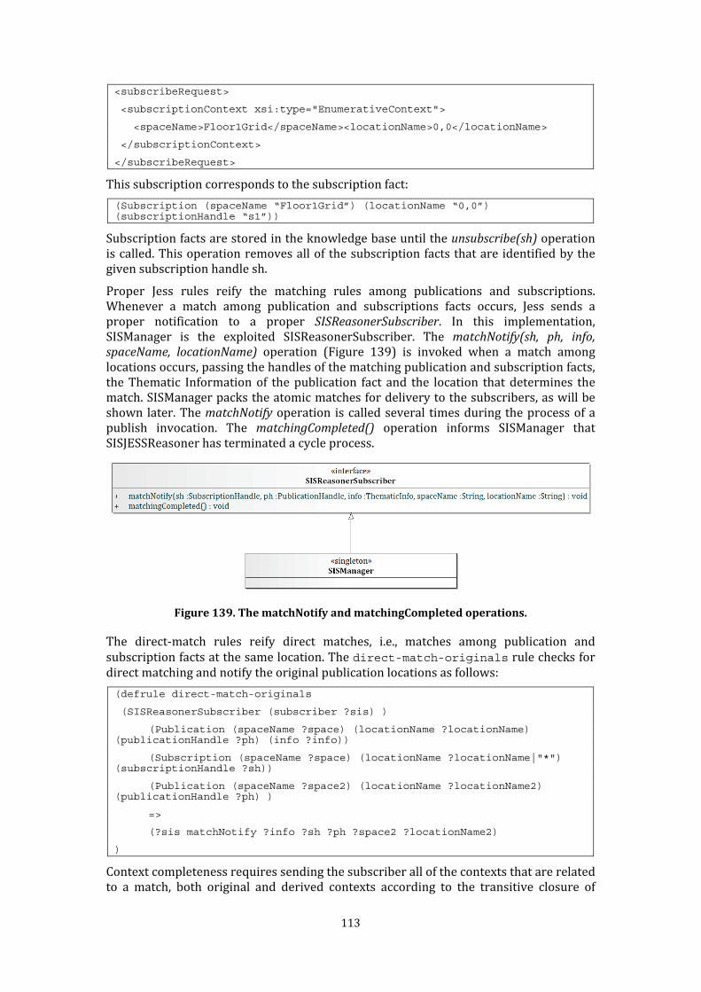
113
<subscribeRequest>
<subscriptionContext xsi:type="EnumerativeContext">
<spaceName>Floor1Grid</spaceName><locationName>0,0</locationName>
</subscriptionContext>
</subscribeRequest> This subscription corresponds to the subscription fact: (Subscription (spaceName “Floor1Grid”) (locationName “0,0”) (subscriptionHandle “s1”)) Subscription facts are stored in the knowledge base until the unsubscribe(sh) operation is called. This operation removes all of the subscription facts that are identified by the given subscription handle sh. Proper Jess rules reify the matching rules among publications and subscriptions. Whenever a match among publication and subscriptions facts occurs, Jess sends a proper notification to a proper SISReasonerSubscriber. In this implementation, SISManager is the exploited SISReasonerSubscriber. The matchNotify(sh, ph, info,
spaceName, locationName) operation (Figure 139) is invoked when a match among locations occurs, passing the handles of the matching publication and subscription facts, the Thematic Information of the publication fact and the location that determines the match. SISManager packs the atomic matches for delivery to the subscribers, as will be shown later. The matchNotify operation is called several times during the process of a publish invocation. The matchingCompleted() operation informs SISManager that SISJESSReasoner has terminated a cycle process.
Figure 139. The matchNotify and matchingCompleted operations. The direct-match rules reify direct matches, i.e., matches among publication and subscription facts at the same location. The direct-match-originals rule checks for direct matching and notify the original publication locations as follows:
(defrule direct-match-originals
(SISReasonerSubscriber (subscriber ?sis) )
(Publication (spaceName ?space) (locationName ?locationName) (publicationHandle ?ph) (info ?info))
(Subscription (spaceName ?space) (locationName ?locationName|"*") (subscriptionHandle ?sh))
(Publication (spaceName ?space2) (locationName ?locationName2) (publicationHandle ?ph) )
=>
(?sis matchNotify ?info ?sh ?ph ?space2 ?locationName2)
) Context completeness requires sending the subscriber all of the contexts that are related to a match, both original and derived contexts according to the transitive closure of

114
explicit mappings. The direct-match-originals rule invokes the matchNotify() operation for each location included in a publication where a direct match is found. For example, consider the following invocations: <subscribeRequest>
<subscriptionContext xsi:type="EnumerativeContext">
<spaceName>Floor1Grid</spaceName><locationName>0,0</locationName>
</subscriptionContext>
</subscribeRequest>
<publishRequest>
<info>...</info>
<publicationContext xsi:type="EnumerativeContext">
<spaceName>aFloor</spaceName>
<locationName>0,0</locationName>
<locationName>0,1</locationName>
<locationName>0,2</locationName>
</publicationContext>
</publishRequest> These invocations lead to the following facts: (Subscription (spaceName “Floor1Grid”)(locationName “0,0”) (subscriptionHandle “s1”))
(Publication (spaceName “Floor1Grid”) (locationName “0,0”) (publicationHandle “p1”) (info ?info))
(Publication (spaceName “Floor1Grid”) (locationName “0,1”) (publicationHandle “p1”) (info ?info))
(Publication (spaceName “Floor1Grid”) (locationName “0,2”) (publicationHandle “p1”) (info ?info)) The direct-match-originals rule will be executed three times. In fact, a direct match occurs among the “s1” subscription and the “p1” publication on the (0,0) location; moreover, three locations are indicated by the original publication context. The direct-match-derived rule sends to the subscriber all of the locations that are mapped from the locations indicated by a publication in case of a direct match. It is the same as the previous rule, but also checks for an EnumMapping fact: (defrule direct-match-derived
(SISReasonerSubscriber (subscriber ?sis) )
(Publication (spaceName ?space) (locationName ?locationName) (publicationHandle ?ph) (info ?info))
(Subscription (spaceName ?space) (locationName ?locationName|"*") (subscriptionHandle ?sh))
(Publication (spaceName ?space2) (locationName ?locationName2) (publicationHandle ?ph))
(EnumMapping (firstSpaceName ?space2) (firstLocationName ?locationName2) (secondSpaceName ?space3) (secondLocationName ?locationName3))
=>
(?sis matchNotify ?info ?sh ?ph ?space3 ?locationName3)
) The restricted transitive closure of EnumMapping facts (Section 4.3.2.3) ensures context completeness. For example, suppose that the knowledge base contains the following facts:

115
(EnumMapping (sourceSpaceName “Floor1Grid”) (sourceLocationName “0,0”) (targetSpaceName “BuildingGraph”) (targetLocationName “Room2.1”) (mh “dm1”))
(EnumMapping (sourceSpaceName “Floor1Grid”) (sourceLocationName “0,1”) (targetSpaceName “BuildingGraph”) (targetLocationName “Room2.1”) (mh “dm1”))
(EnumMapping (sourceSpaceName “Floor1Grid”) (sourceLocationName “0,2”) (targetSpaceName “BuildingGraph”) (targetLocationName “Room2.1”) (mh “dm1”))
(Subscription (spaceName “Floor1Grid”)(locationName “0,0”) (subscriptionHandle “s1”))
(Publication (spaceName “Floor1Grid”) (locationName “0,1”) (publicationHandle “p1”) (info “info”))
(Publication (spaceName “Floor1Grid”) (locationName “0,2”) (publicationHandle “p1”) (info “info”)) The direct-match-derived rule sends the mapped location (BuildingGraph, Room2.1) through the matchNotify operation. In fact, it will send the location three times, because each cell location is mapped to (BuildingGraph, Room2.1); this repetition does not cause problems because SISManager filters duplicated locations. The indirect-match-originals rule checks for indirect matches and sends to SISManager all of the original locations of the matching publication: (defrule indirect-match-originals
(SISReasonerSubscriber (subscriber ?sis) )
(Publication (spaceName ?space1) (locationName ?locationName1) (publicationHandle ?ph) (info ?info))
(EnumMapping (firstSpaceName ?space1) (firstLocationName ?locationName1) (secondSpaceName ?space2) (secondLocationName ?locationName2) )
(Subscription (spaceName ?space2) (locationName ?locationName2|"*") (subscriptionHandle ?sh))
(Publication (spaceName ?space3) (locationName ?locationName3) (publicationHandle ?ph))
=>
(?sis matchNotify ?info ?sh ?ph ?space3 ?locationName3)
) For example, consider the following invocations: <mapRequest>
<sourceContext xsi:type="EnumerativeContext">
<spaceName>aFloor</spaceName>
<locationName>0,0</locationName>
<locationName>0,1</locationName>
<locationName>0,2</locationName>
</sourceContext>
<targetContext xsi:type="EnumerativeContext">
<spaceName>aBuilding</spaceName><locationName>Room2.1</locationName>
</targetContext>
</mapRequest>
<subscribeRequest>
<subscriptionContext xsi:type="EnumerativeContext">
<spaceName>BuildinGraph</spaceName><locationName>Room2.1</locationName>
</subscriptionContext>
</subscribeRequest>
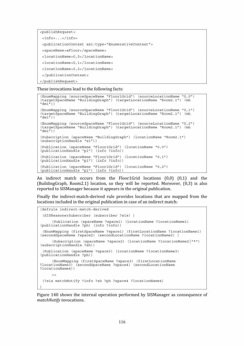
116
<publishRequest>
<info>...</info>
<publicationContext xsi:type="EnumerativeContext">
<spaceName>aFloor</spaceName>
<locationName>0,0</locationName>
<locationName>0,1</locationName>
<locationName>0,2</locationName>
</publicationContext>
</publishRequest> These invocations lead to the following facts: (EnumMapping (sourceSpaceName “Floor1Grid”) (sourceLocationName “0,0”) (targetSpaceName “BuildingGraph”) (targetLocationName “Room2.1”) (mh “dm1”))
(EnumMapping (sourceSpaceName “Floor1Grid”) (sourceLocationName “0,1”) (targetSpaceName “BuildingGraph”) (targetLocationName “Room2.1”) (mh “dm1”))
(EnumMapping (sourceSpaceName “Floor1Grid”) (sourceLocationName “0,2”) (targetSpaceName “BuildingGraph”) (targetLocationName “Room2.1”) (mh “dm1”))
(Subscription (spaceName “BuildingGraph”) (locationName “Room2.1”) (subscriptionHandle “s1”))
(Publication (spaceName “Floor1Grid”) (locationName “0,0”) (publicationHandle “p1”) (info ?info))
(Publication (spaceName “Floor1Grid”) (locationName “0,1”) (publicationHandle “p1”) (info ?info))
(Publication (spaceName “Floor1Grid”) (locationName “0,2”) (publicationHandle “p1”) (info ?info)) An indirect match occurs from the Floor1Grid locations (0,0) (0,1) and the (BuildingGraph, Room2.1) location, so they will be reported. Moreover, (0,3) is also reported to SISManager because it appears in the original publication. Finally the indirect-match-derived rule provides locations that are mapped from the locations included in the original publication in case of an indirect match: (defrule indirect-match-derived
(SISReasonerSubscriber (subscriber ?sis) )
(Publication (spaceName ?space1) (locationName ?locationName1) (publicationHandle ?ph) (info ?info))
(EnumMapping (firstSpaceName ?space1) (firstLocationName ?locationName1) (secondSpaceName ?space2) (secondLocationName ?locationName2) )
(Subscription (spaceName ?space2) (locationName ?locationName2|"*") (subscriptionHandle ?sh))
(Publication (spaceName ?space3) (locationName ?locationName3) (publicationHandle ?ph))
(EnumMapping (firstSpaceName ?space3) (firstLocationName ?locationName3) (secondSpaceName ?space4) (secondLocationName ?locationName4))
=>
(?sis matchNotify ?info ?sh ?ph ?space4 ?locationName4)
) Figure 140 shows the internal operation performed by SISManager as consequence of matchNotify invocations.
117
For each subscribe invocation, SISManager creates a proper stub (EventSubscriberStub object) identified by the subscription handle, which is returned by the operation. Hence, each subscription has a proper EventSubscriberStub object. SISManager is notified of a subscription matching a single location through a calling of the matchNotify operation. SISManager exploits the first parameter (a subscription handle) to identify the EventSubscriberStub object sb related to the matching subscriptions. Other details about the match (publication handle, thematic information and matching location) are redirected to sb, calling its matchNotify operations. The matchNotify operation of EventSubscriberStub objects stores the received data in a MatchingInfo object (ongoingMatching). When a SISJESSReasoner cycle of processing is complete, the matchingCompleted operation of SISManager operation is called. This step has the effect of calling the matchingCompleted operation provided by each EventSubscriberStub object. The matchingCompleted operation of a stub has the following effect: 1. “freeze” the ongoingMatching object used to store data passed with previously
matchNotify invocations, adding it to a collection of “ready to notify” MatchingInfo objects (completedMatching) that are available via the getMatching() operation; 2. a new, empty ongoingMatching object is allocated. Subscription matches represented by completedMatching collections are delivered to subscribers in one of two ways: synchronous or asynchronous delivery. The synchronous notification delivery implementation (Figure 141) relies on the basic EventSubscriberStub, calling the getMatching() operation directly. SIS exposes a
syncSubscribe(SpatialContext) operation, which returns a special subscription handle of type SyncSubscriptionHandle. SIS also exposes a getMatching(ssh) operation, where ssh is a SyncSubscriptionHandle. The getMatching(ssh) operation calls the getMatching() operation of the EventSubscriberStub object identified by ssh. The syncSusbcribe and getMatching() operations are exported by the distributed access layer as Web Services. The asynchronous notification delivery implementation (Figure 142) relies on a specialization of the EventSubscriberStub (EventServerStub), which sends the subscriber the completedMatching collection after the matchingCompleted operation is called. The delivery is currently implemented through Web Sockets.

118
Figure 140. SISManager matching notifications management.
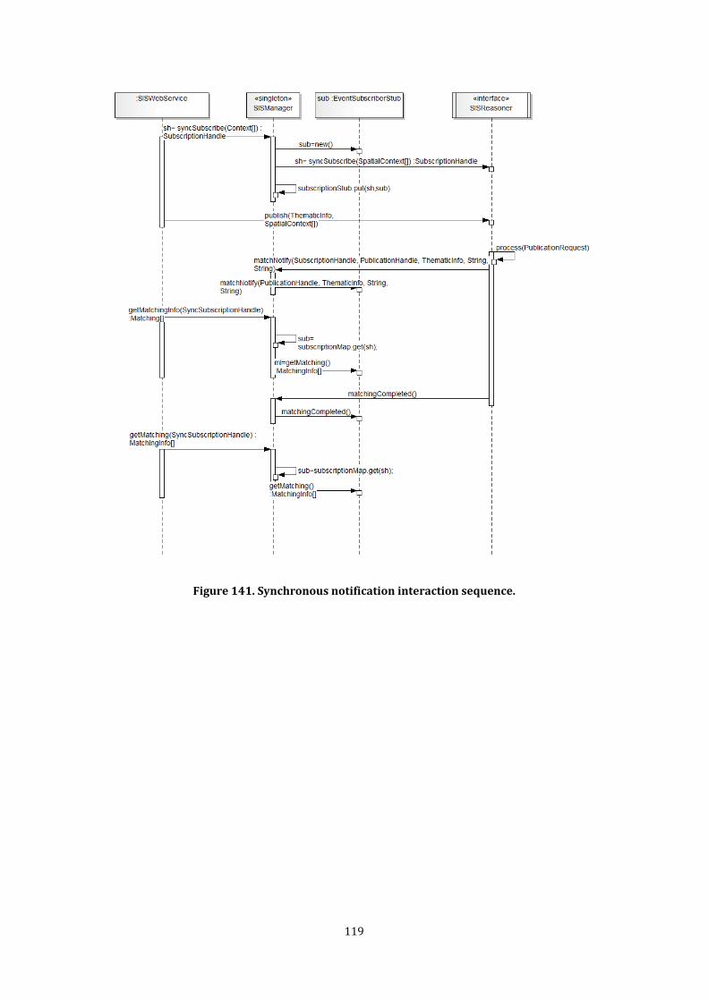
119
Figure 141. Synchronous notification interaction sequence.
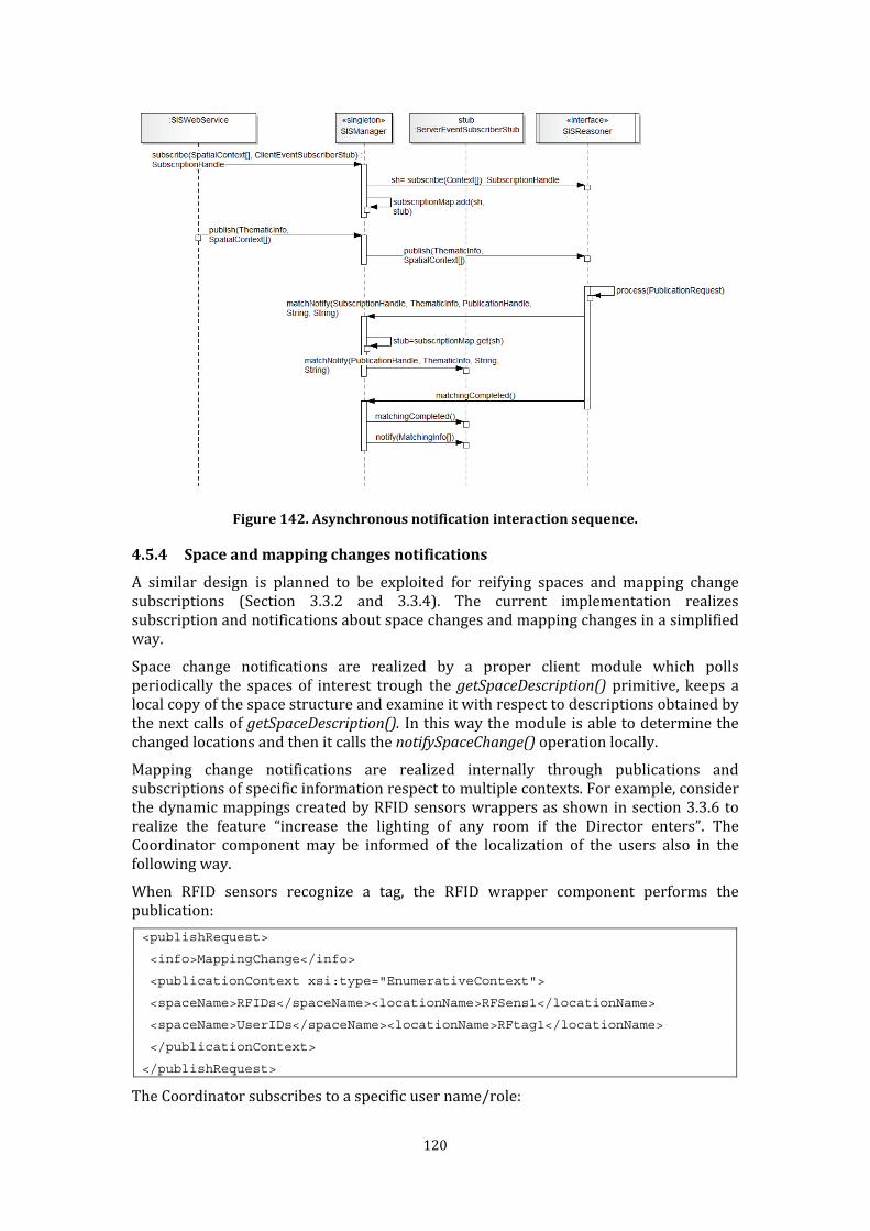
120
Figure 142. Asynchronous notification interaction sequence.
4.5.4 Space and mapping changes notifications A similar design is planned to be exploited for reifying spaces and mapping change subscriptions (Section 3.3.2 and 3.3.4). The current implementation realizes subscription and notifications about space changes and mapping changes in a simplified way. Space change notifications are realized by a proper client module which polls periodically the spaces of interest trough the getSpaceDescription() primitive, keeps a local copy of the space structure and examine it with respect to descriptions obtained by the next calls of getSpaceDescription(). In this way the module is able to determine the changed locations and then it calls the notifySpaceChange() operation locally. Mapping change notifications are realized internally through publications and subscriptions of specific information respect to multiple contexts. For example, consider the dynamic mappings created by RFID sensors wrappers as shown in section 3.3.6 to realize the feature “increase the lighting of any room if the Director enters”. The Coordinator component may be informed of the localization of the users also in the following way. When RFID sensors recognize a tag, the RFID wrapper component performs the publication: <publishRequest>
<info>MappingChange</info>
<publicationContext xsi:type="EnumerativeContext">
<spaceName>RFIDs</spaceName><locationName>RFSens1</locationName>
<spaceName>UserIDs</spaceName><locationName>RFtag1</locationName>
</publicationContext>
</publishRequest> The Coordinator subscribes to a specific user name/role:

121
<subscribeRequest>
<subscriptionContext xsi:type="EnumerativeContext">
<spaceName>Roles</spaceName><locationName>Director</locationName>
</subscriptionContext>
</subscribeRequest> The Coordinator will receive the thematic information “MappingChange” with all the original publication locations (the RFID sensor name, the recognized tag) and all the mapped locations (the node-room where the sensor is deployed, the name and role of the user): <matchingInfo>
<info>MappingChange</info><timestamp>11:11:11-2011-11-11</timestamp>
<context xsi:type="EnumerativeContext">
<spaceName>RFIDs</spaceName>
<locationName>RFSens1</locationName>
</context>
<context xsi:type="EnumerativeContext">
<spaceName>UserIDs</spaceName>
<locationName>RFTag1</locationName>
</context>
<context xsi:type="EnumerativeContext">
<spaceName>BuildingGraph</spaceName>
<locationName>Room2.1</locationName>
</context>
<context xsi:type="EnumerativeContext">
<spaceName>Users</spaceName>
<locationName>Mr. Brown</locationName>
</context>
<context xsi:type="EnumerativeContext">
<spaceName>Roles</spaceName>
<locationName>Director</locationName>
</context>
</matchingInfo> Hence the Coordinator can be aware of the localization of the Director in the room “Room2.1”. This simplified implementation has been applied for realizing mapping change notifications in the considered case studies (see Chapter 4). However a straight implementation of space and mapping notification using the design presented in section 4.5.3 is ongoing. 4.6 Performance evaluation Several performance tests have been performed on the current SIS implementation. The experimental tests have been performed on an SIS instance running on an Intel Core i5 2.8 GHz pc with 4GB of RAM, running Linux 2.6 and version 1.6.0 64-bit Java Runtime Environment. Publications were generated on a separate machine (in order to avoid affecting time measurements) and then sent to the SIS server through the network. The tests measured the mean reasoning time and the maximum RAM occupation. The mean reasoning time is the mean time between the reception of a publication and the end of
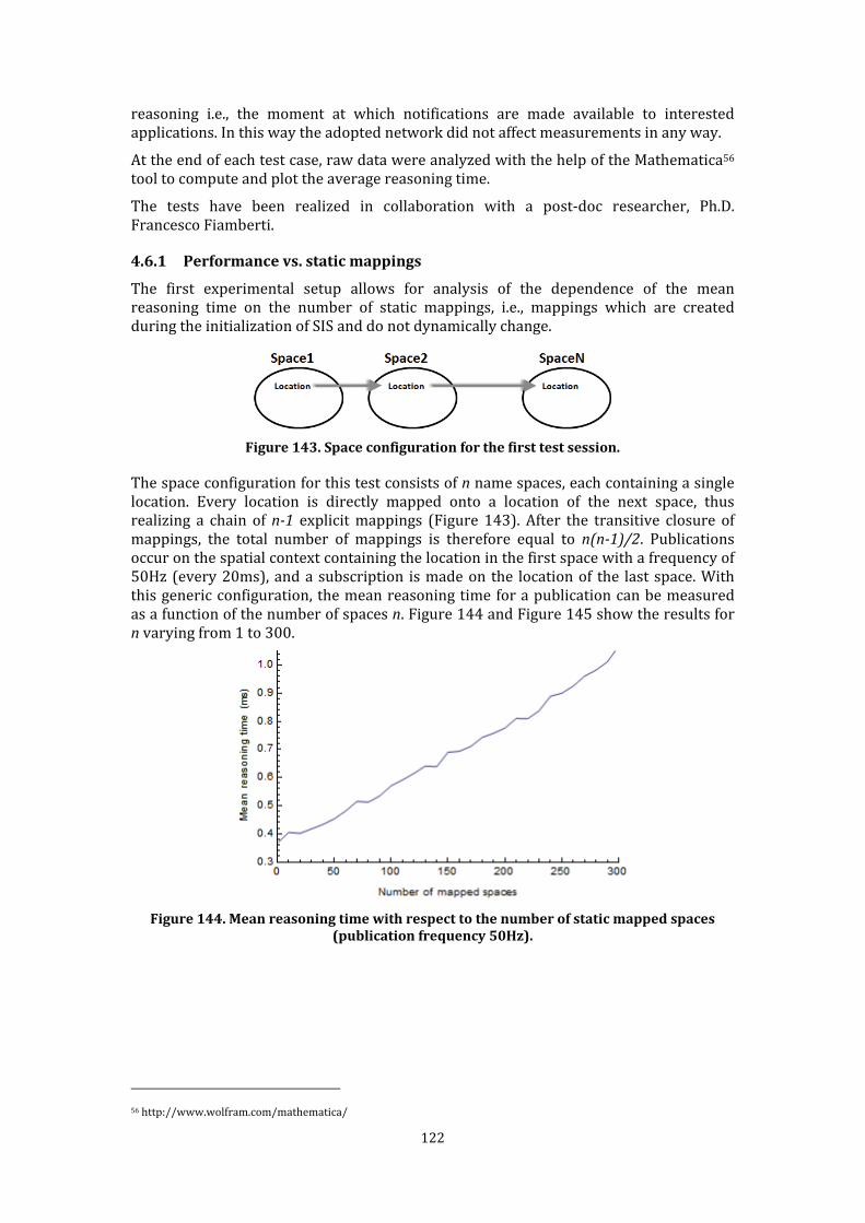
122
reasoning i.e., the moment at which notifications are made available to interested applications. In this way the adopted network did not affect measurements in any way. At the end of each test case, raw data were analyzed with the help of the Mathematica56 tool to compute and plot the average reasoning time. The tests have been realized in collaboration with a post-doc researcher, Ph.D. Francesco Fiamberti. 4.6.1 Performance vs. static mappings The first experimental setup allows for analysis of the dependence of the mean reasoning time on the number of static mappings, i.e., mappings which are created during the initialization of SIS and do not dynamically change.
Figure 143. Space configuration for the first test session. The space configuration for this test consists of n name spaces, each containing a single location. Every location is directly mapped onto a location of the next space, thus realizing a chain of n-1 explicit mappings (Figure 143). After the transitive closure of mappings, the total number of mappings is therefore equal to n(n-1)/2. Publications occur on the spatial context containing the location in the first space with a frequency of 50Hz (every 20ms), and a subscription is made on the location of the last space. With this generic configuration, the mean reasoning time for a publication can be measured as a function of the number of spaces n. Figure 144 and Figure 145 show the results for
n varying from 1 to 300.
Figure 144. Mean reasoning time with respect to the number of static mapped spaces
(publication frequency 50Hz).
56 http://www.wolfram.com/mathematica/

123
Figure 145. Maximum RAM occupation with respect to the number of static mapped spaces
(publication frequency 50Hz). Figure 144 shows that when n=300 the mean reasoning time is about 1.5 ms. Moreover the reasoning time57 behaves like O(n) even if the total number of mappings is O(n2). This finding may be explained by the fact that the JESS rule engine is implemented using the efficient Rete algorithm (Forgy 1982). A naïve implementation of rule-based engines might check each rule against the known facts executing that rule if necessary, then moving on to the next rule (and looping back to the first rule when finished). With such an implementation, if the number of mapping facts is O(n2), the execution of matching rules should require at least O(n2) steps (there are 44850 total mappings with n=300). The Rete algorithm stores past test results across iterations in a specific network structure, keeping a list of the facts that currently match each rule. This approach increases the speed of significant magnitude orders in the average case (Forgy 1982), at the price of memory occupation. In fact, Figure 145 clearly shows the counterpart of the high temporal performance: the occupied memory reaches 1 GB. 4.6.2 Performance vs. dynamic mappings The second test session extended the previous configuration in order to test the mean reasoning time with dynamically changing mappings. Spaces are again mapped to form a chain; however they have two locations, each separately mapped as sketched in Figure 146. Publications are performed on the first location of the first space at a frequency of 50Hz, whereas subscriptions are performed on the first location of the last space. The mappings between the second locations of each pair of spaces are dynamically removed and re-created cyclically at the frequency of 1Hz: the mapping between the second locations of the first space and the second space is deleted and re-created; then the mapping between the second locations of the second and third space is deleted and re-created; these change are then repeated for the other pair of spaces modulo n. Moreover n varies from 1 to 200.
Figure 146. Space configuration for the second test session.
57 In the following, the “Big O notation” is used to refer to time complexity estimations.
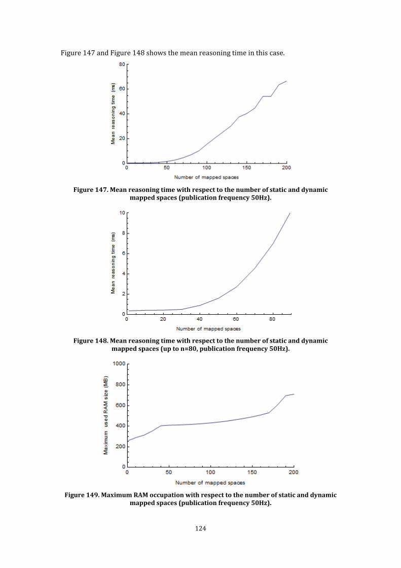
124
Figure 147 and Figure 148 shows the mean reasoning time in this case.
Figure 147. Mean reasoning time with respect to the number of static and dynamic
mapped spaces (publication frequency 50Hz).
Figure 148. Mean reasoning time with respect to the number of static and dynamic
mapped spaces (up to n=80, publication frequency 50Hz).
Figure 149. Maximum RAM occupation with respect to the number of static and dynamic
mapped spaces (publication frequency 50Hz).

125
Figure 147 shows that the mean reasoning time increases of an order with respect to the first test with static mappings. Moreover, when n reaches a value between 90 and 100 the mean reasoning time became greater than publication period (20 ms). Figure 148 presents the data of Figure 147 restricted up to n=90. Finally, Figure 149 shows that the maximum RAM occupation reaches about 800 MB. 4.6.3 Performance vs. size of publication contexts A different series of experiments aimed to study the impact of increasing the dimension of publication contexts. In this case, the space configuration consisted of a single name space with 500 locations. The mean reasoning time was measured for different values of the number of locations included in the publication context, starting from 1 to 100. Publication occurs at a frequency of 50Hz. Figure 150 and Figure 151 show the corresponding results.
Figure 150. Mean reasoning time with respect to the number of locations in the
publication context (publication frequency 50Hz).
Figure 151. Maximum RAM occupation with respect to the number of locations in the
publication context (publication frequency 50Hz). Figure 150 shows that, even in this case, at a certain point (n between 75 and 80) the mean reasoning time become greater than the publication period. Moreover here the reasoning time behaves like O(n2). The maximum RAM occupation reaches about 600 MB (Figure 151).

126
Figure 152 and Figure 153 shows the same tests executed with a lower publication frequency (2 Hz) but the number of locations extended to 300. Obviously in that case the mean reasoning time is always lower than the publication period (500ms). The memory occupation reaches about 600 MB.
Figure 152. Mean reasoning time with respect to the number of locations in the publication context (publication frequency 2Hz).
Figure 153. Maximum RAM occupation with respect to the number of locations in the publication context (publication frequency 2Hz).
4.6.4 Analysis of the results The performed tests suggest that small-scale responsive environments could be well managed by the current implementation. In facts: • consider an overall publication frequency of 50Hz; • at this frequency, the system may comprise up to 50 different publishers with a mean publication frequency of 1Hz, which may correspond to 50 different sensors which publishes data every second. This frequency is well suited for non-critical responsive environments and it can satisfy the needs of a grained tracking of entities; • a large number of static mappings can be managed without problems: the mean reasoning time is about 1 ms with about 50000 total mappings; • publishers (or other components) can dynamically change one mapping every second or they can indicates up to 75 location inside the same publications.

127
Significant enhancements could be obtained with a high-performance machine. However medium and large scale responsive environments will require of course a distributed implementation of the concrete framework. Anyway, considering the limits of the prototypal implementation, these tests confirm that the choice of identifying a few core spatial concepts and embedding the implementation of the related algorithms into an efficient reasoning engine paves the way for achievement of a good cost/performance trade-off. 4.7 Discussion The performance test presented in the previous section provided significant indications about the maximum acceptable load for the current SIS implementation. Moreover the framework has been successfully applied to realize several small scale responsive environments, which are presented in Chapter 4. These experimentations confirm the previous performance tests, in the sense that all the developed system showed successfully response time: no delay was perceived by users. Moreover, they lead to the following evaluations about the framework qualities introduced in Section 2.4.4. Language and operating system independency. The implementation of the spaces-based primitives as Web Services and Web Sockets allow components to interact with the framework from the most common programming languages (C++, Java, .NET) and web/scripting languages supported by Web browsers. The implementation of SIS in Java allows its deployment to be independent of the underlying operating system. Accessible by embedded hardware. Sensors, actuators and other embedded devices access SIS through a proper wrapper component capable of calling the SIS Web Services. Moreover, Web-based technologies allow easy access from smartphones. In addition, microcontrollers such as Arduino have properly expanding hardware modules (e.g., Ethernet/WiFi connection) and programming libraries, allowing them to directly call Web Services. Capable of accommodating both known and unknown data. SIS does not interpret thematic information in any way. It simply delivers data according to direct and indirect context matching. Highly reliable. The current implementation has been running without interruption since September 2010, indicating a high degree of reliability. Maintainable over the long term. SIS is based on an explicit set of architectural abstractions (Chapter 3) and it has been designed according to a modular internal organization. Therefore, it supports a broad array of extensions (e.g., distributed access technology, supported spatial models and inferential engine).

129
5 Case studies This chapter summarizes several applications of the proposed architectural abstractions and their framework to realize various Responsive Environments and research projects. Section 5.1 outlines the context of the G.A.S. – Intelligent Building project, where the proposed abstractions and their related framework represent the reference architecture for the development of integrated Ambient Intelligence applications. Section 5.2 presents the Smart Building scenario exploited in Section 3 to exemplify the proposed solutions. Section 5.3 describes the realization of an Augmented Classroom. Section 5.4 outline ongoing applications of the approach for engineering interactive art installations. Finally, Section 5.5 and 5.6 two other research projects there the spaces-based approach has been applied. 5.1 The G.A.S. – Intelligent Building project The GAS (“Grandi Attrezzature Scientifiche”) – Intelligent Building is a project which has been developed at the Department of Informatics, Systems and Communication (DISCo) of the University of Milano-Bicocca. The aim of the GAS project is to augment the Department building with a technological platform, so that the building becomes a workbench for experimental activities, including Responsive Environments, Ambient Intelligence, Robotics, Video Surveillance and Co-operative Work. The devices adopted in the project includes RFID sensors, cameras and interaction devices, either fixed (multi-touch monitors) or mobile (e-paper, robot). Several sub-projects have been defined in order to address specific classes of applications, for example environmental monitoring, user localization and information dissemination. The architectural abstractions proposed in this thesis and the related concrete framework are the reference architecture and platform for the development of GAS applications. Section 5.2 and 5.3 present two significant developed applications, Smart Building and Augmented Classroom respectively. 5.2 Smart Building
5.2.1 Scenario description As introduced in Section 3.1, the Smart Building scenario consists of a university building enriched with sensing and actuation technologies. Users are identified by their names together with their position in the organization (e.g., Director, Professor and Student). The Building has two floors equipped with technologies for presence sensing. In the first and second floor, RFID sensors located in rooms and passages recognize the presence of RFID tags carried by persons. In the second floor, a WiFi-based localization system recognizes the phone numbers of devices carried by users and provides their position in a grid representation of the floor. Actuators located in each room can regulate windows, lights and other electronic appliances. Mobile cameras can be oriented to watch specific areas. The Smart Building provides features such as “close the window of room 2.1 when Mr. Brown enters”, “increase the lighting of any room that the Director enters” and “move mobile cameras to follow Mr. Green.”
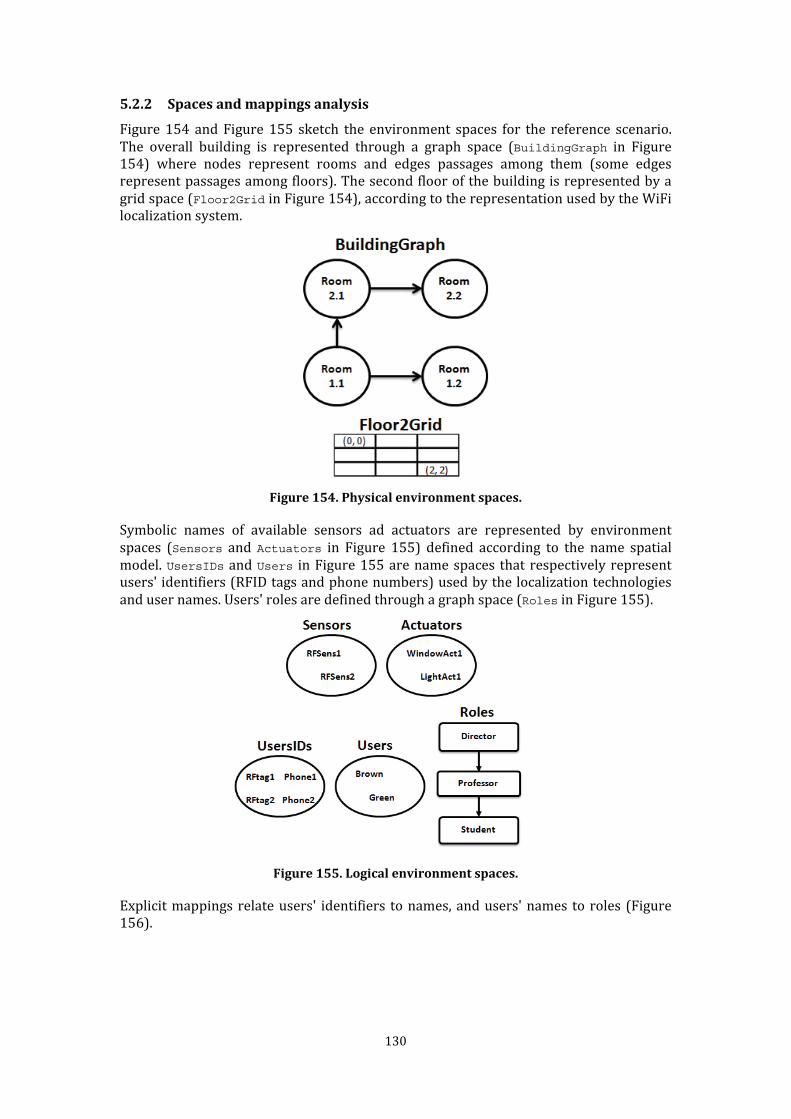
130
5.2.2 Spaces and mappings analysis Figure 154 and Figure 155 sketch the environment spaces for the reference scenario. The overall building is represented through a graph space (BuildingGraph in Figure 154) where nodes represent rooms and edges passages among them (some edges represent passages among floors). The second floor of the building is represented by a grid space (Floor2Grid in Figure 154), according to the representation used by the WiFi localization system.
Figure 154. Physical environment spaces. Symbolic names of available sensors ad actuators are represented by environment spaces (Sensors and Actuators in Figure 155) defined according to the name spatial model. UsersIDs and Users in Figure 155 are name spaces that respectively represent users' identifiers (RFID tags and phone numbers) used by the localization technologies and user names. Users' roles are defined through a graph space (Roles in Figure 155).
Figure 155. Logical environment spaces. Explicit mappings relate users' identifiers to names, and users' names to roles (Figure 156).

131
Figure 156. Explicit mappings among logical spaces. Moreover, cells of the Floor2Grid can be mapped to nodes and edges of the
BuildingGraph space to correlate the different spatial representations of the second floor (Figure 157).
Figure 157. Explicit mappings between physical spaces. RFID sensor names are mapped to the nodes and edges of the BuildingGraph space to recognize the physical (static) deployment of the sensors in a certain room or passage (Figure 158).
Figure 158. Explicit mappings for sensor placement. Similarly, nodes and edges of the BuildingGraph space are mapped to actuators' names to represent the physical area covered by each actuator (Figure 159).

132
Figure 159. Explicit mappings for actuators’ covered area.
5.2.3 Applying the spaces-based architecture Figure 160 summarizes the software architecture for this scenario.
Figure 160. Architecture for the reference scenario. The generic architecture introduced in Section 3.1 has been adopted with a simplification: the Coordinator component and the Mobile Devices Actuation Manager component are realized in a unique component (Coordinator in the following). Moreover, the Window Manager is not currently available. All of the components interact via an instance of the SIS platform. The next section presents insight into each component.
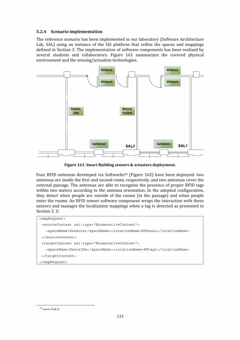
133
5.2.4 Scenario implementation The reference scenario has been implemented in our laboratory (Software Architecture Lab, SAL) using an instance of the SIS platform that reifies the spaces and mappings defined in Section 3. The implementation of software components has been realized by several students and collaborators. Figure 161 summarizes the covered physical environment and the sensing/actuation technologies.
Figure 161. Smart Building sensors & actuators deployment. Four RFID antennas developed via Softworks58 (Figure 162) have been deployed: two antennas are inside the first and second room, respectively, and two antennas cover the external passage. The antennas are able to recognize the presence of proper RFID tags within two meters according to the antenna orientation. In the adopted configuration, they detect when people are outside of the rooms (in the passage) and when people enter the rooms. An RFID sensor software component wraps the interaction with these sensors and manages the localization mappings when a tag is detected as presented in Section 3. 3:
<mapRequest>
<sourceContext xsi:type="EnumerativeContext">
<spaceName>Sensors</spaceName><locationName>RFSens1</locationName>
</sourceContext>
<targetContext xsi:type="EnumerativeContext">
<spaceName>UsersIDs</spaceName><locationName>RFtag1</locationName>
</targetContext>
</mapRequest>
58 www.rf-id.it/
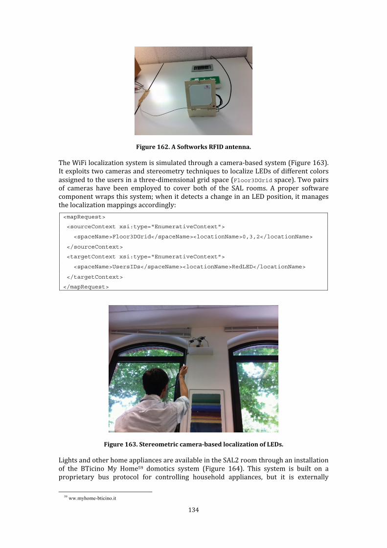
134
Figure 162. A Softworks RFID antenna. The WiFi localization system is simulated through a camera-based system (Figure 163). It exploits two cameras and stereometry techniques to localize LEDs of different colors assigned to the users in a three-dimensional grid space (Floor3DGrid space). Two pairs of cameras have been employed to cover both of the SAL rooms. A proper software component wraps this system; when it detects a change in an LED position, it manages the localization mappings accordingly: <mapRequest>
<sourceContext xsi:type="EnumerativeContext">
<spaceName>Floor3DGrid</spaceName><locationName>0,3,2</locationName>
</sourceContext>
<targetContext xsi:type="EnumerativeContext">
<spaceName>UsersIDs</spaceName><locationName>RedLED</locationName>
</targetContext>
</mapRequest>
Figure 163. Stereometric camera-based localization of LEDs. Lights and other home appliances are available in the SAL2 room through an installation of the BTicino My Home59 domotics system (Figure 164). This system is built on a proprietary bus protocol for controlling household appliances, but it is externally 59 ww.myhome-bticino.it
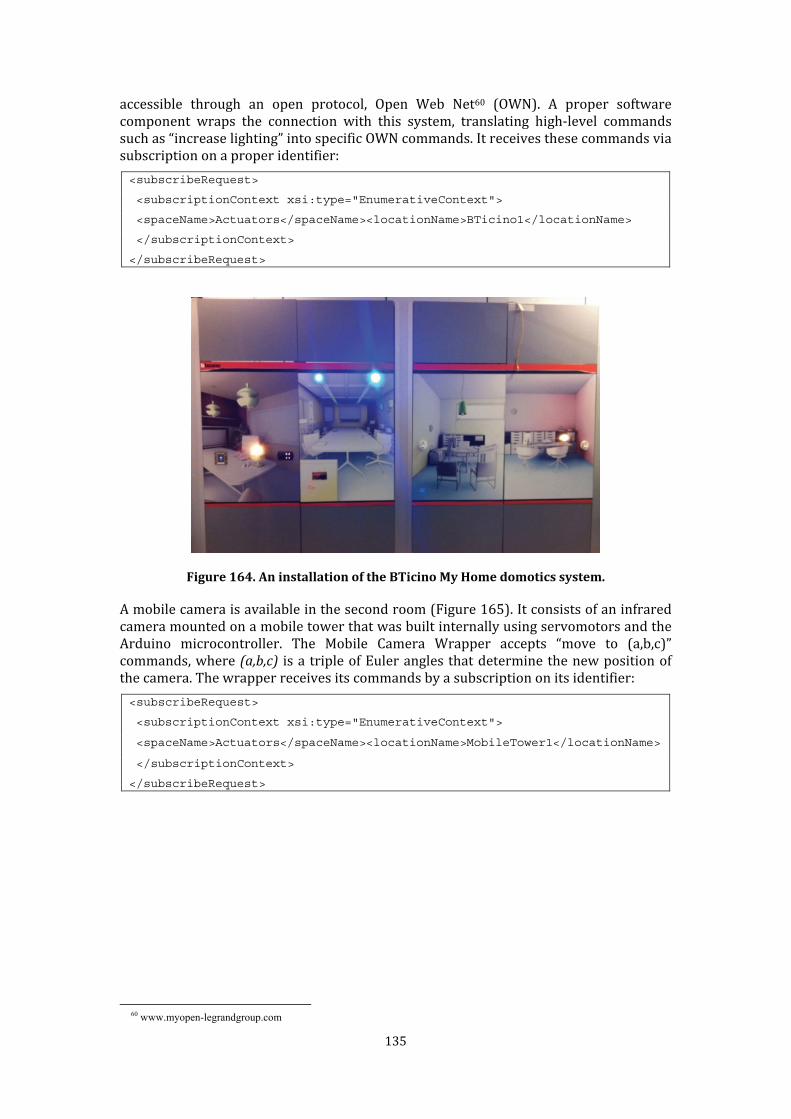
135
accessible through an open protocol, Open Web Net60 (OWN). A proper software component wraps the connection with this system, translating high-level commands such as “increase lighting” into specific OWN commands. It receives these commands via subscription on a proper identifier: <subscribeRequest>
<subscriptionContext xsi:type="EnumerativeContext">
<spaceName>Actuators</spaceName><locationName>BTicino1</locationName>
</subscriptionContext>
</subscribeRequest>
Figure 164. An installation of the BTicino My Home domotics system. A mobile camera is available in the second room (Figure 165). It consists of an infrared camera mounted on a mobile tower that was built internally using servomotors and the Arduino microcontroller. The Mobile Camera Wrapper accepts “move to (a,b,c)” commands, where (a,b,c) is a triple of Euler angles that determine the new position of the camera. The wrapper receives its commands by a subscription on its identifier: <subscribeRequest>
<subscriptionContext xsi:type="EnumerativeContext">
<spaceName>Actuators</spaceName><locationName>MobileTower1</locationName>
</subscriptionContext>
</subscribeRequest>
60 www.myopen-legrandgroup.com
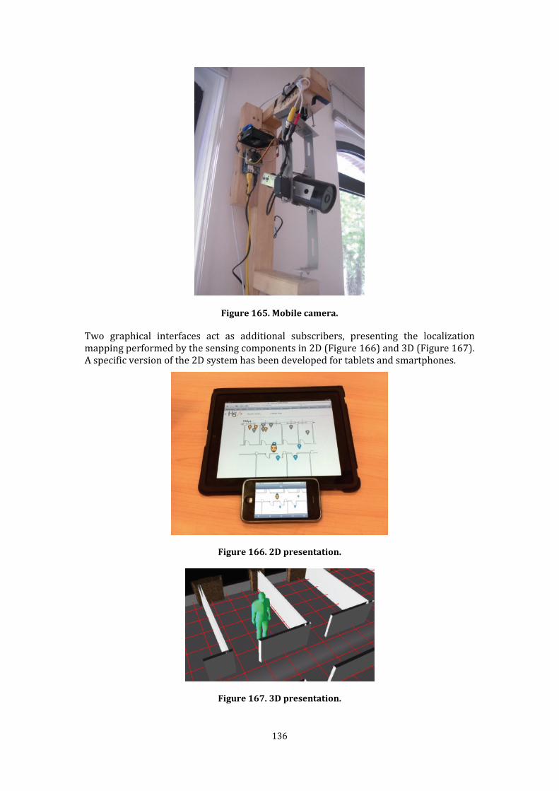
136
Figure 165. Mobile camera. Two graphical interfaces act as additional subscribers, presenting the localization mapping performed by the sensing components in 2D (Figure 166) and 3D (Figure 167). A specific version of the 2D system has been developed for tablets and smartphones.
Figure 166. 2D presentation.
Figure 167. 3D presentation.
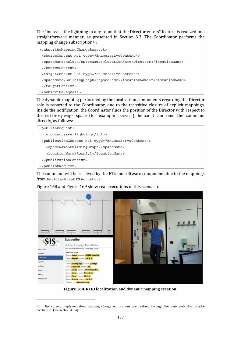
137
The “increase the lightning in any room that the Director enters” feature is realized in a straightforward manner, as presented in Section 3.3. The Coordinator performs the mapping change subscription61: <subscribeMappingChangeRequest>
<sourceContext xsi:type="EnumerativeContext">
<spaceName>Roles</spaceName><locationName>Director</locationName>
</sourceContext>
<targetContext xsi:type="EnumerativeContext">
<spaceName>BuildingGraph</spaceName><locationName>*</locationName>
</targetContext>
</subscribeRequest> The dynamic mapping performed by the localization components regarding the Director role is reported to the Coordinator, due to the transitive closure of explicit mappings. Inside the notification, the Coordinator finds the position of the Director with respect to the BuildingGraph space (for example Room2.2), hence it can send the command directly, as follows: <publishRequest>
<info>increase lighting</info>
<publicationContext xsi:type="EnumerativeContext">
<spaceName>BuildingGraph</spaceName>
<locationName>Room2.2</locationName>
</publicationContext>
</publishRequest> The command will be received by the BTicino software component, due to the mappings from BuildingGraph to Actuators. Figure 168 and Figure 169 show real executions of this scenario.
Figure 168. RFID localization and dynamic mapping creation.
61 In the current implementation mapping change notifications are realized through the basic publish/subscribe mechanism (see section 4.5.4).
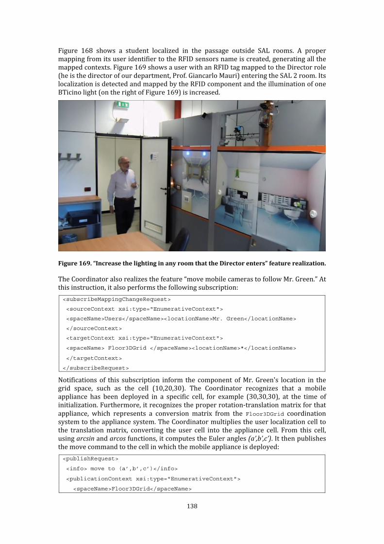
138
Figure 168 shows a student localized in the passage outside SAL rooms. A proper mapping from its user identifier to the RFID sensors name is created, generating all the mapped contexts. Figure 169 shows a user with an RFID tag mapped to the Director role (he is the director of our department, Prof. Giancarlo Mauri) entering the SAL 2 room. Its localization is detected and mapped by the RFID component and the illumination of one BTicino light (on the right of Figure 169) is increased.
Figure 169. “Increase the lighting in any room that the Director enters” feature realization. The Coordinator also realizes the feature “move mobile cameras to follow Mr. Green.” At this instruction, it also performs the following subscription: <subscribeMappingChangeRequest>
<sourceContext xsi:type="EnumerativeContext">
<spaceName>Users</spaceName><locationName>Mr. Green</locationName>
</sourceContext>
<targetContext xsi:type="EnumerativeContext">
<spaceName> Floor3DGrid </spaceName><locationName>*</locationName>
</targetContext>
</subscribeRequest> Notifications of this subscription inform the component of Mr. Green's location in the grid space, such as the cell (10,20,30). The Coordinator recognizes that a mobile appliance has been deployed in a specific cell, for example (30,30,30), at the time of initialization. Furthermore, it recognizes the proper rotation-translation matrix for that appliance, which represents a conversion matrix from the Floor3DGrid coordination system to the appliance system. The Coordinator multiplies the user localization cell to the translation matrix, converting the user cell into the appliance cell. From this cell, using arcsin and arcos functions, it computes the Euler angles (a’,b’,c’). It then publishes the move command to the cell in which the mobile appliance is deployed: <publishRequest>
<info> move to (a’,b’,c’)</info>
<publicationContext xsi:type="EnumerativeContext">
<spaceName>Floor3DGrid</spaceName>
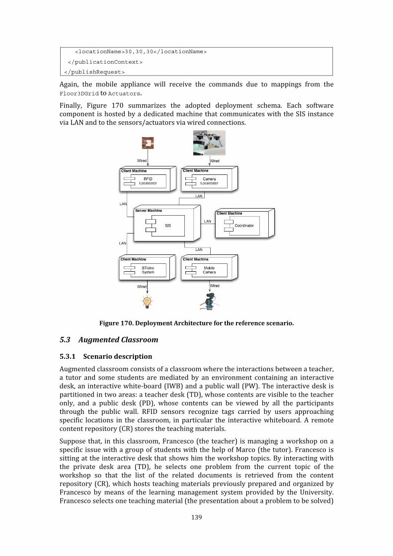
139
<locationName>30,30,30</locationName>
</publicationContext>
</publishRequest> Again, the mobile appliance will receive the commands due to mappings from the Floor3DGrid to Actuators. Finally, Figure 170 summarizes the adopted deployment schema. Each software component is hosted by a dedicated machine that communicates with the SIS instance via LAN and to the sensors/actuators via wired connections.
Figure 170. Deployment Architecture for the reference scenario.
5.3 Augmented Classroom
5.3.1 Scenario description Augmented classroom consists of a classroom where the interactions between a teacher, a tutor and some students are mediated by an environment containing an interactive desk, an interactive white-board (IWB) and a public wall (PW). The interactive desk is partitioned in two areas: a teacher desk (TD), whose contents are visible to the teacher only, and a public desk (PD), whose contents can be viewed by all the participants through the public wall. RFID sensors recognize tags carried by users approaching specific locations in the classroom, in particular the interactive whiteboard. A remote content repository (CR) stores the teaching materials. Suppose that, in this classroom, Francesco (the teacher) is managing a workshop on a specific issue with a group of students with the help of Marco (the tutor). Francesco is sitting at the interactive desk that shows him the workshop topics. By interacting with the private desk area (TD), he selects one problem from the current topic of the workshop so that the list of the related documents is retrieved from the content repository (CR), which hosts teaching materials previously prepared and organized by Francesco by means of the learning management system provided by the University. Francesco selects one teaching material (the presentation about a problem to be solved)
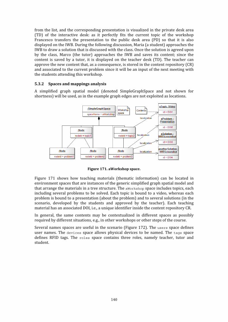
140
from the list, and the corresponding presentation is visualized in the private desk area (TD) of the interactive desk: as it perfectly fits the current topic of the workshop Francesco transfers the presentation to the public desk area (PD) so that it is also displayed on the IWB. During the following discussion, Maria (a student) approaches the IWB to draw a solution that is discussed with the class. Once the solution is agreed upon by the class, Marco (the tutor) approaches the IWB and saves its content; since the content is saved by a tutor, it is displayed on the teacher desk (TD). The teacher can approve the new content that, as a consequence, is stored in the content repository (CR) and associated to the current problem since it will be an input of the next meeting with the students attending this workshop. 5.3.2 Spaces and mappings analysis A simplified graph spatial model (denoted SimpleGraphSpace and not shown for shortness) will be used, as in the example graph edges are not exploited as locations.
Figure 171. aWorkshop space. Figure 171 shows how teaching materials (thematic information) can be located in environment spaces that are instances of the generic simplified graph spatial model and that arrange the materials in a tree structure. The aWorkshop space includes topics, each including several problems to be solved. Each topic is bound to a video, whereas each problem is bound to a presentation (about the problem) and to several solutions (in the scenario, developed by the students and approved by the teacher). Each teaching material has an associated DOI, i.e., a unique identifier inside the content repository CR. In general, the same contents may be contextualized in different spaces as possibly required by different situations, e.g., in other workshops or other steps of the course. Several names spaces are useful in the scenario (Figure 172). The users space defines user names. The devices space allows physical devices to be named. The tags space defines RFID tags. The roles space contains three roles, namely teacher, tutor and student.

141
Figure 172. Name spaces for the augmented classroom. Finally, the classroom space is defined as a grid spatial model like the smart building scenario. Once spaces have been defined, then the mappings between their locations allow the definition of the logic governing a (direct and indirect) communication flow among the organisms. Figure 173 shows the mappings that are relevant to the reference scenario. The right side of the figure shows that a location in the tags space is mapped to one location in the users space (because each user has a tag assigned), which in turn is mapped to a location in the roles space (because each user has a role assigned). The left side shows that RFID sensor names (from the devices space) are mapped to locations in the classroom space, modeling “where” sensors are in the classroom. classroom locations, in turn, are mapped to the IWB name (from the devices space), modeling that the IWB is “close to” those locations.
Figure 173. Mappings for the augmented classroom. Mappings between the users and the roles locations are defined by the same Coordinator virtual organism that defines the required ecology spaces relying on the existing information system of the University. The human operator who defined the classroom, devices and tags ecology spaces also defines the mappings between the cells of the classroom and the names of the devices and between the names of the tags space and the names of the users space.

142
5.3.3 Applying the spaces-based architecture Figure 174 sketches the software components introduced to reify the scenario.
Figure 174. Software components for the augmented classroom. Each component is aware of a subset of the overall spaces where it is interested to publish or subscribe thematic information. This is represented by the dependencies shown in the bottom of Figure 174. For example, TeacherDesk, the more complex component, still exploits three spaces only. The other components exploit just one or two spaces. Components perform some subscriptions to be informed about contextualized information of their interest. TeacherDesk subscribes to the tutor location of the roles space to be informed about new materials saved by the tutor (wherever he saved them); PublicDesk and PublicWall subscribe to the PD location of devices to be informed about materials that should be shown publicly, in fact PD is the location where public content will be localized; InteractiveWhiteBoard subscribes to the IWB location of devices to be informed about the users that work at the IWB itself; finally, ContentRepository subscribes to the teacher location of the roles space to be informed when the teacher approves a new material. In addition, a Coordinator component is in charge of initially defining (i.e., instantiating via the defSpace primitive, see Section 3.3) the users, roles and aWorkshop spaces and to consequently maintain them updated and coherent. The Coordinator relies on the existing services provided by the University, from which it retrieves the required information and translates it in terms of the defined ecology spaces. In particular, the users and roles spaces are managed according to the information retrieved from the information system of the University, whereas the aWorkshop space according to the information retrieved from the learning management system, where courses and workshops are managed by the teachers. In general, the Coordinator component allows the integration of existing services in the ecology by keeping aligned the contents of the information sources with their spatial representation in the specific application (in this case the augmented classroom) and vice-versa. For completeness, the classroom, devices and tags spaces are defined by a human operator who knows the physical structure of the class, the name of the devices and the identifiers of the tags.

143
5.3.4 Scenario implementation The augmented scenario has been implemented in a room of our department, in collaboration with the group of Prof. Carla Simone. It exploits an instance of the SIS platform, the same made available for the Smart Building scenario. The implementation of software components presented in the previous section has been managed by Dr. Marco Locatelli. Figure 175 shows the exploited interactive whiteboards and the interactive desk. Figure 176 shows the adopted RFID sensors from the Touchatag62 company.
Figure 175. Interactive whiteboards and desk.
Figure 176. Touchatag RFID sensors and tags. The following interaction scenario has been implemented (Figure 177). At a certain point of the workshop, the interactive desk must show the teacher the workshop topics. To this aim the TeacherDesk (TD) gets the structure of the aWorkshop space from SIS, to build the user interface showing topics and problems related to the current workshop. TD analyzes the aWorkshop structure and retrieves the list of topics by looking for nodes with a nodeId (i.e., a node name) that matches the topicN pattern (where N is the topicID). In fact, the component TD knows the semantics of the nodes and applies it to the structure of the graph space aWorkshop.
62 http://www.touchatag.com/
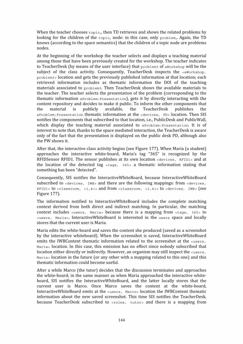
144
When the teacher chooses topic2, then TD retrieves and shows the related problems by looking for the children of the topic2 node: in this case, only problem3. Again, the TD knows (according to the space semantics) that the children of a topic node are problems nodes. At the beginning of the workshop the teacher selects and displays a teaching material among those that have been previously created for the workshop. The teacher indicates to TeacherDesk (by means of the user interface) that problem3 of aWorkshop will be the subject of the class activity. Consequently, TeacherDesk inspects the <aWorkshop, problem3> location and gets the previously published information at that location; each retrieved information includes as thematic information the DOI of the teaching materials associated to problem3. Then TeacherDesk shows the available materials to the teacher. The teacher selects the presentation of the problem (corresponding to the thematic information aProblem:Presentation), gets it by directly interacting with the content repository and decides to make it public. To inform the other components that the material is publicly available, the TeacherDesk publishes the aProblem:Presentation thematic information at the <devices, PD> location. Then SIS notifies the components that subscribed to that location, i.e., PublicDesk and PublicWall, which display the teaching material associated to aProblem:Presentation. It is of interest to note that, thanks to the space mediated interaction, the TeacherDesk is aware only of the fact that the presentation is displayed on the public desk PD, although also the PW shows it. After that, the interactive class activity begins (see Figure 177). When Maria (a student) approaches the interactive white-board, Maria’s tag “365” is recognized by the RFIDSensor RFID1. The sensor publishes at its own location <devices, RFID1> and at the location of the detected tag <tags, 365> a thematic information stating that something has been “detected”. Consequently, SIS notifies the InteractiveWhiteBoard, because InteractiveWhiteBoard subscribed to <devices, IWB> and there are the following mappings: from <devices, RFID1> to <classroom, <1,4>> and from <classroom, <1,4>> to <devices, IWB> (see Figure 177). The information notified to InteractiveWhiteBoard includes the complete matching context derived from both direct and indirect matching. In particular, the matching context includes <users, Maria> because there is a mapping from <tags, 365> to <users, Maria>. InteractiveWhiteBoard is interested in the users space and locally stores that the current user is Maria. Maria edits the white-board and saves the content she produced (saved as a screenshot by the interactive whiteboard). When the screenshot is saved, InteractiveWhiteBoard emits the IWBContent thematic information related to the screenshot at the <users, Maria> location. In this case, this emission has no effect since nobody subscribed that location either directly or indirectly. However, an organism may still inspect the <users, Maria> location in the future (or any other with a mapping related to this one) and this thematic information could become useful. After a while Marco (the tutor) decides that the discussion terminates and approaches the white-board; in the same manner as when Maria approached the interactive white-board, SIS notifies the InteractiveWhiteBoard, and the latter locally stores that the current user is Marco. Once Marco saves the content at the white-board, InteractiveWhiteBoard emits at the <users, Marco> location the IWBContent thematic information about the new saved screenshot. This time SIS notifies the TeacherDesk, because TeacherDesk subscribed to <roles, tutor> and there is a mapping from
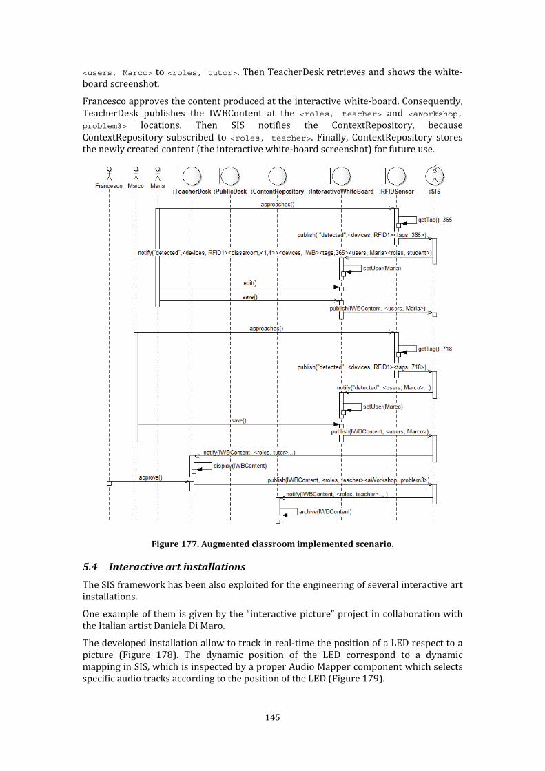
145
<users, Marco> to <roles, tutor>. Then TeacherDesk retrieves and shows the white-board screenshot. Francesco approves the content produced at the interactive white-board. Consequently, TeacherDesk publishes the IWBContent at the <roles, teacher> and <aWorkshop, problem3> locations. Then SIS notifies the ContextRepository, because ContextRepository subscribed to <roles, teacher>. Finally, ContextRepository stores the newly created content (the interactive white-board screenshot) for future use.
Figure 177. Augmented classroom implemented scenario.
5.4 Interactive art installations The SIS framework has been also exploited for the engineering of several interactive art installations. One example of them is given by the “interactive picture” project in collaboration with the Italian artist Daniela Di Maro. The developed installation allow to track in real-time the position of a LED respect to a picture (Figure 178). The dynamic position of the LED correspond to a dynamic mapping in SIS, which is inspected by a proper Audio Mapper component which selects specific audio tracks according to the position of the LED (Figure 179).

146
Figure 178. LED recognition with respect to a picture.
Figure 179. Deployment architecture for the developed installation. If LEDs are exploited as individual markers for visitors in museums, and audio tracks are executed on wireless stereo phones worn by visitors, then the system allows visitors to hear specific sound related to the portion of the picture they are watching.

147
Using SIS as reference platform boosts the development of the current prototype; moreover it enables to integrate other types of sensors and actuators in a easy way. 5.5 The InSyEme project The Integrated Systems for Emergency (InSyEme) project was a research project funded by MIUR (Italian Ministry of Research) under the FIRB program (grant RBIP063BPH). It started on November 2007 and it ended on June 2011. The main aim of InSyEme was defining an efficient integrated system to support emergency operations in different scenarios. In particular, the project proposed an innovative methodology and technology supporting emergency management applications exploiting enhanced grid computing models and dynamic architectures. In this context SIS has been proposed as platform for supporting context-based information flows among emergency operators. In the followings, a simple reference scenario is presented. Actors involved in emergency prevention and management activities (firemen and rescue squads, policemen, medics, etc.) are identified by their names (Actors name space) together with their organization role in the overall hierarchy (Roles graph space). They exploit personal mobile devices (Devices space), which are characterized by a network address (be it a phone number or a static network address or the like) and allow the actors to be localized in a geographical space, for example by means of GPS or GSM-based techniques. Significant critical entities (e.g., critical areas in case of floods) located in the geographical space (Territory grid space) are previously identified together with the major routes connecting them (CriticalRegions graph space). Figure 180 summarizes the defined spaces and their mappings.
Figure 180. Spaces for the emergency scenario. In this scenario SIS has been proposed for the realization of queries like “what actors are present on a specific critical region?” and communication flows like “this information has to be sent to firemen head (wherever he/she is)”.

148
Assume that mobile devices manage dynamic mappings between actor names and cells of the Territory space. Then a query like “what actors are present on the critical region ‘River section #12’?” is easily fulfilled by the mapping change subscription: <subscribeMappingChangeRequest>
<sourceContext xsi:type="EnumerativeContext">
<spaceName>Actors</spaceName><locationName>*</locationName>
</sourceContext>
<targetContext xsi:type="EnumerativeContext">
<spaceName>CriticalRegions</spaceName><locationName>River section #12</locationName>
</targetContext>
</subscribeRequest> The dynamic mapping performed by mobile devices is reported to the subscriber, due to the transitive closure of explicit mappings. Inside the notification, the susbcriber finds the name of the localized actor (Figure 181).
Figure 181. Actor localization. Communication flows like “this information has to be sent to firemen head” can be reified through publications on roles of the Roles space and subscriptions on device addresses of the Devices space (Figure 182). Thanks to the mappings from Actors to
Devices and Roles to Actors, the firemen head’s device will receive also all the information sent to contexts of Actors and Roles.

149
Figure 182. Information dissemination by role.
5.6 The IMPULSO project Finally, the architectural abstractions proposed in this thesis constitutes the kernel of the Integrated Multimodal Platform for Urban and extra urban Logistic System Optimization (IMPULSO) project, funded by the Italian Ministry of Economic Development. The project aims at creating an integrated system for the management and control of transport and logistics of goods. The spaces-based communication abstractions have been proposed as reference architecture for dispatching logistic events. Even in this case, the multiple-spaces metaphor seems well suited to cover domain aspects (localization of goods and actors).

151
6 Conclusions This chapter summarizes this work's contributions, its future extensions and related publications. 6.1 Summary of contributions This thesis proposed a set of architectural abstractions and a related concrete framework to reify information flows in Responsive Environments through a multiple-spaces metaphor. The main contribution of this thesis is a technology to integrate multifarious sensing and actuation devices in Responsive Environments, which is at an intermediate level between high-level content, context and tuple-based approaches and basic communication mechanisms. It exploits the multiple-spaces metaphor in order to provide an effective support for the development of Responsive Environments. Information flows can be transparently created through multiple spaces and mappings. Furthermore, components may retrieve information without knowing the other components in the system and, conversely, components may diffuse information without knowing the other parties in the system. Therefore, heterogeneous components can be seamlessly integrated by defining their distinctive spaces and relating them through mappings. Moreover, dynamic management of spaces and mappings allows for controlled dynamic insertion or removal of software components to and from the system. The concrete framework has been successfully tested in different application scenarios. The experience gained in these scenarios and the performance tests confirm that spaces-based communication has a sound basis for effective and efficient development of Responsive Environments including heterogeneous components. 6.2 Future work Future work will concern two improvements to the current version of the concrete framework. First, adding additional mechanisms to cope with privacy and security issues. If accessing environments spaces become subject to authorization, environment spaces could be exploited as visibility descriptors, and then act directly as mechanisms for creating private information flows among components. Secondly, conceiving alternative implementations of the framework that overcome the current service-oriented architecture in order to exploit the architectural model in the area of highly distributed systems and better-suited application domains with strong real-time requirements, such as robotics and automation. 6.3 Publications Journals Bernini, D., Fiamberti, F., Micucci, D. and Tisato, F. Architectural Abstractions for Spaces-Based Communication in Smart Environments. Journal of Ambient Intelligence and Smart Environments, Thematic Issue A Software Engineering Perspective on Smart Applications for AmI. Accepted with minor review (revised version to be sent by January 15, 2012). Tisato, F., Simone, C., Bernini, D., Locatelli, M. and Micucci, D. Grounding ecologies on multiple spaces. Journal of Pervasive and Mobile Computing, Special Issue on Ambient Ecologies. To Appear.

152
Proceedings of International Conferences and Workshops with refereeing Bernini, D. Architectural abstractions for space and time awareness: the case of responsive environments. In Proceedings of the Fourth European Conference on Software Architecture: Companion Volume (Copenhagen, Denmark, August 23 - 26, 2010). C. E. Cuesta, Ed. ECSA '10. ACM, New York, NY, 12-16. Bernini, D., Micucci, D., and Tisato, F. A spaces-Based Interoperability Model. In Proceedings of CAISE 2010 Workshops, Lecture Notes in Business Information Processing, Springer (2010) . Bernini, D., Micucci, D., and Tisato, F. A Platform for Interoperability via Multiple Spatial Views in Open Smart Spaces. In Proceedings of Computers and Communications (ISCC), 2010 IEEE Symposium on, IEEE (2010). Bernini, D., Micucci, D., and Tisato, F. 2010. Space integration services: a platform for spaces-aware communication. In Proceedings of the 6th international Wireless Communications and Mobile Computing Conference (IWCMC), ACM (2010). Poster abstracts Bernini, D., Tisato, F. and Vizzari, G. 2010. Informatics and Responsive Environments: the Role of Computational Models and Software Architectures. Presented at the Fourth International Conference on Design Computing and Cognition (DCC'10), July 2010, Stuttgart, Germany.

153
References Aiello, M. & Dustdar, S., 2008. Are our homes ready for services? A domotic infrastructure based on the Web service stack. Pervasive Mob. Comput., 4(4), pp.506-525. Available at: http://portal.acm.org/citation.cfm?id=1393804. Aldrovandi, R. & Pereira, J.G., 1995. An introduction to geometrical physics, World Scientific. Available at: http://books.google.com/books?id=w8hBT4DV1vkC&pgis=1 [Accessed May 8, 2011]. Alexander, C., 1979. The Timeless Way of Building, Oxford University Press. Available at: http://www.amazon.com/Timeless-Way-Building-Christopher-Alexander/dp/0195024028 [Accessed July 8, 2011]. Allen, R. & Garlan, D., 1997. A formal basis for architectural connection. ACM Trans. Softw. Eng. Methodol., 6(3), pp.213-249. Available at: http://portal.acm.org/citation.cfm?id=258078. Altinel, M. & Franklin, M.J., 2000. Efficient Filtering of XML Documents for Selective Dissemination of Information. In Proceedings of the 26th International Conference on Very Large Data Bases (VLDB ’00). Morgan Kaufmann Publishers Inc., San Francisco, CA, USA, pp. 53-64. Available at: http://portal.acm.org/citation.cfm?id=645926.671841 [Accessed August 1, 2011]. Anon, 2002. Handbook of Massive Data Sets (Massive Computing), Springer. Available at: http://www.amazon.com/Handbook-Massive-Data-Sets-Computing/dp/1402004893 [Accessed May 8, 2011]. Avgeriou, P. & Zdun, U., 2005. Architectural Patterns Revisited - a Pattern Language. In Proceedings of the 10th European Conference on Pattern Languages of Programs (EuroPLoP 2005). Available at: http://eprints.cs.univie.ac.at/2698/. Bandini, S. et al., 2008. A CA-Based Approach to Self-Organized Adaptive Environments: The Case of an Illumination Facility. In Proceedings of the Second IEEE International Conference on Self-Adaptive and Self-Organizing Systems Workshops. IEEE Computer Society, pp. 1-6. Available at: http://portal.acm.org/citation.cfm?id=1524875.1525025&coll=ACM&dl=GUIDE&CFID=48503908&CFTOKEN=17388936. Banzhaf, W. et al., 1997. Genetic Programming: An Introduction (The Morgan Kaufmann Series in Artificial Intelligence), Morgan Kaufmann. Available at: http://www.amazon.com/Genetic-Programming-Introduction-Artificial-Intelligence/dp/155860510X [Accessed July 23, 2011]. Bateman, J. & Farrar, S., 2004. Spatial ontology baseline, Collaborative Research Center for Spatial Cognition, University of Bremen, Germany. Bavafa, M. & Navidi, N., 2010. Towards a reference middleware architecture for Ambient Intelligence Systems. In Proceedings of the Eighth International Conference on ICT and Knowledge Engineering. IEEE, pp. 98-102. Available at: http://ieeexplore.ieee.org/xpl/freeabs_all.jsp?arnumber=5692922 [Accessed July 14, 2011]. Becker, C. & Dürr, F., 2004. On location models for ubiquitous computing. Personal and Ubiquitous Computing, 9(1), pp.20-31. Available at: http://www.springerlink.com/content/7qjyl3g9hly15ky2/ [Accessed October 14, 2010].

154
Benford, S. & Fahlén, L., 1993. A spatial model of interaction in large virtual environments. In Proceedings of the third conference on European Conference on Computer-Supported Cooperative Work (ECSCW’93). Kluwer Academic Publishers Norwell, MA, USA, pp. 109-124. Available at: http://portal.acm.org/citation.cfm?id=1241934.1241942 [Accessed July 13, 2011]. Bensky, A., 2007. Wireless Positioning Technologies and Applications, Artech House, Inc. Norwood, MA, USA. Available at: http://portal.acm.org/citation.cfm?id=1557266 [Accessed August 8, 2011]. Bernini, D. & Tisato, F., 2010. Explaining Architectural Choices to Non-Architects. In M. Ali Babar & I. Gorton, eds. Proceedings of the 4th European conference on Software architecture (ECSA’10). Copenhagen, Denmark: Springer-Verlag Berlin, Heidelberg, pp. 352-359. Bestor, C., 1996. MAX as an overall control mechanism for multidiscipline installation art. Computers & Mathematics with Applications, 32(1), pp.11-16. Available at: http://www.sciencedirect.com/science/article/B6TYJ-3VTJFTS-G/2/7ba8fabdce11ce24964e67a4cbb8f6bf. Bongers, B. & Veer, G.C., 2007. Towards a Multimodal Interaction Space: categorisation and applications. Personal Ubiquitous Comput., 11(8), pp.609-619. Available at: http://portal.acm.org/citation.cfm?id=1297128. Brownston, L. et al., 1985. Programming expert systems in OPS5: an introduction to rule-based programming, Addison-Wesley Longman Publishing Co., Inc. Boston, MA, USA. Available at: http://portal.acm.org/citation.cfm?id=3927 [Accessed July 23, 2011]. Bullivant, L., 2007. 4dSocial: Interactive Design Environments, John Wiley & Sons. Bullivant, L., 2006. Responsive Environments: architecture, art and design, Victoria and Albert Museum. Burnham, J., 1968. Beyond Modern Sculpture: The Effects of Science and Technology on the Sculpture of This Century, George Braziller. Buschmann, F. et al., 1996. Pattern-Oriented Software Architecture Volume 1: A System of Patterns, Wiley. Available at: http://www.amazon.com/Pattern-Oriented-Software-Architecture-System-Patterns/dp/0471958697 [Accessed July 8, 2011]. Caflisch, L. et al., 2005. A software architecture for real-time, embedded monitoring systems. Advanced Video and Signal Based Surveillance, 2005. AVSS 2005. IEEE Conference on, pp.540-545. Available at: http://ieeexplore.ieee.org/xpl/freeabs_all.jsp?arnumber=1577326 [Accessed August 18, 2011]. Carriero, N. & Gelernter, D., 1989. Linda in context. Communications of the ACM, 32(4), pp.444-458. Available at: http://portal.acm.org/citation.cfm?id=63334.63337 [Accessed February 5, 2011]. Carzaniga, A., Rosenblum, D.S. & Wolf, A.L., 2001. Design and evaluation of a wide-area event notification service. ACM Transactions on Computer Systems, 19(3), pp.332-383. Available at: http://portal.acm.org/citation.cfm?id=380749.380767 [Accessed August 4, 2011]. Ceriotti, M., Murphy, A.L. & Picco, G.P., 2008. Data sharing vs. message passing: synergy or incompatibility? In Proceedings of the 2008 ACM symposium on Applied computing - SAC ’08. New York, New York, USA: ACM Press, p. 100. Available at: http://portal.acm.org/citation.cfm?id=1363686.1363714 [Accessed May 5, 2011].
155
Charatsis, K. et al., 2005. Home / Building Automation Environment Architecture Enabling Interoperability, Flexibility and Reusability. In Proceedings of the IEEE International Symposium on Industrial Electronics (ISIE 2005). IEEE, pp. 1441-1446. Available at: http://ieeexplore.ieee.org/lpdocs/epic03/wrapper.htm?arnumber=1529144 [Accessed July 14, 2011]. Chen, X., Chen, Y. & Rao, F., 2003. An efficient spatial publish/subscribe system for intelligent location-based services. In Proceedings of the 2nd international workshop on Distributed event-based systems - DEBS ’03. New York, New York, USA: ACM Press, p. 1. Available at: http://portal.acm.org/citation.cfm?id=966618.966625 [Accessed January 12, 2011]. Ciolfi, L. & Bannon, L., 2005. Space, Place and the Design of Technologically-Enhanced Physical Environments. In Spaces, Spatiality and Technology. Springer Netherlands, pp. 217-232. Available at: http://dx.doi.org/10.1007/1-4020-3273-0_15. Clements, P. et al., 2002. Documenting Software Architectures: Views and Beyond, Addison-Wesley Professional. Cook, D.J. & Das, S.K., 2007. How smart are our environments? An updated look at the state of the art. Pervasive Mob. Comput., 3(2), pp.53-73. Available at: http://portal.acm.org/citation.cfm?id=1225943.1226005 [Accessed May 14, 2011]. Cook, D.J., Augusto, Juan C. & Jakkula, V.R., 2009. Ambient intelligence: Technologies, applications, and opportunities. Pervasive and Mobile Computing, 5(4), pp.277-298. Available at: http://dx.doi.org/10.1016/j.pmcj.2009.04.001 [Accessed August 4, 2011]. Cormen, T.H. et al., 2001. Introduction to Algorithms, Second Edition, The MIT Press. Available at: http://www.amazon.com/Introduction-Algorithms-Second-Thomas-Cormen/dp/0262032937 [Accessed May 8, 2011]. Cugola, G., Margara, A. & Migliavacca, M., 2009. Context-aware publish-subscribe: Model, implementation, and evaluation. In Proceedings of the 2009 IEEE Symposium on Computers and Communications. IEEE, pp. 875-881. Available at: http://ieeexplore.ieee.org/xpl/freeabs_all.jsp?arnumber=5202277 [Accessed January 25, 2011]. Cugola, G., Di Nitto, E. & Fuggetta, A., 2001. The JEDI event-based infrastructure and its application to the development of the OPSS WFMS. IEEE Transactions on Software Engineering, 27(9), pp.827-850. Available at: http://ieeexplore.ieee.org/xpl/freeabs_all.jsp?arnumber=950318 [Accessed August 1, 2011]. Curran, K. et al., 2011. An evaluation of indoor location determination technologies. Journal of Location Based Services, 5(2), pp.61-78. Available at: http://tandfprod.literatumonline.com/doi/abs/10.1080/17489725.2011.562927 [Accessed August 8, 2011]. DeRemer, F. & Kron, H.H., 1976. Programming-in-the-Large Versus Programming-in-the-Small. IEEE Transactions on Software Engineering, SE-2(2), pp.80-86. Available at: http://portal.acm.org/citation.cfm?id=1313308.1313383 [Accessed July 18, 2011]. Dey, A.K., 2001. Understanding and Using Context. Personal and Ubiquitous Computing, 5(1), pp.4-7. Available at: http://portal.acm.org/citation.cfm?id=593570.593572 [Accessed January 24, 2011].
156
Dix, A. et al., 2000. Exploiting space and location as a design framework for interactive mobile systems. ACM Trans. Comput.-Hum. Interact., 7(3), pp.285-321. Available at: http://portal.acm.org/citation.cfm?id=355324.355325. Dobson, S., 2005. Leveraging the subtleties of location. In Proceedings of the 2005 joint conference on Smart objects and ambient intelligence innovative context-aware services: usages and technologies - sOc-EUSAI ’05. New York, New York, USA: ACM Press, p. 189. Available at: http://portal.acm.org/citation.cfm?id=1107548.1107597 [Accessed January 28, 2011]. Dubberly, H., Pangaro, P. & Haque, U., 2009. ON MODELING What is interaction?: are there different types? interactions, 16(1), pp.69-75. Available at: http://portal.acm.org/ft_gateway.cfm?id=1456220&type=html&coll=GUIDE&dl=GUIDE&CFID=49339205&CFTOKEN=89219591. Elrod, S. et al., 1993. Responsive office environments. Commun. ACM, 36(7), pp.84-85. Available at: http://portal.acm.org/citation.cfm?doid=159544.159626. Eugster, P., 2007. Type-based publish/subscribe. ACM Transactions on Programming Languages and Systems, 29(1), p.6-es. Available at: http://portal.acm.org/citation.cfm?id=1180475.1180481 [Accessed June 13, 2011]. Eugster, P. et al., 2003. The many faces of publish/subscribe. ACM Computing Surveys, 35(2), pp.114-131. Available at: http://portal.acm.org/citation.cfm?id=857076.857078 [Accessed December 13, 2010]. Eugster, P., Garbinato, B. & Holzer, A., 2005. Location-based Publish/Subscribe. In Proceedings of the Fourth IEEE International Symposium on Network Computing and Applications. IEEE, pp. 279-282. Available at: http://portal.acm.org/citation.cfm?id=1097873.1098327 [Accessed January 31, 2011]. Euzenat, J. & Shvaiko, P., 2007. Ontology matching, Heidelberg (DE): Springer-Verlag. Fensel, D., 2004. Triple-space computing: Semantic Web Services based on persistent publication of information. In Proceedings of the IFIP International Conference on Intelligence in Communication Systems. In IFIP Int’l Conf. on Intelligence in Communication Systems, pp. 43-53. Available at: http://citeseerx.ist.psu.edu/viewdoc/summary?doi=10.1.1.108.7817 [Accessed August 7, 2011]. Ferber, J., 1999. Multi-agent systems: An introduction to distributed artificial intelligence, Addison-Wesley Professional. Available at: http://www.amazon.com/Multi-agent-systems-introduction-distributed-intelligence/dp/0201360489 [Accessed July 23, 2011]. Fernandez-Montes, A. et al., 2009. Smart Environment Software Reference Architecture. In Proceedings of the 2009 Fifth International Joint Conference on INC, IMS and IDC. IEEE, pp. 397-403. Available at: http://ieeexplore.ieee.org/xpl/freeabs_all.jsp?arnumber=5331692 [Accessed June 8, 2011]. Fine, S., Singer, Y. & Tishby, N., 1998. The Hierarchical Hidden Markov Model: Analysis and Applications. Machine Learning, 32(1), pp.41-62. Available at: http://portal.acm.org/citation.cfm?id=325865.325879 [Accessed August 4, 2011]. Forgy, C.L., 1982. Rete: A fast algorithm for the many pattern/many object pattern match problem. Artificial Intelligence, 19(1), pp.17-37. Available at: http://linkinghub.elsevier.com/retrieve/pii/0004370282900200.
157
Fowler, M., 2003. UML Distilled: A Brief Guide to the Standard Object Modeling Language (3rd Edition), Addison-Wesley Professional. Available at: http://www.amazon.com/UML-Distilled-Standard-Modeling-Language/dp/0321193687 [Accessed August 2, 2011]. Fox, M. & Kemp, M., 2009. Interactive Architecture, Princeton Architectural Press. Freeman, E., Arnold, K. & Hupfer, S., 1999. JavaSpaces Principles, Patterns, and Practice, Addison-Wesley Longman Ltd. Essex, UK. Frey, D. & Roman, G.-C., 2007. Context-Aware Publish Subscribe in Mobile Ad Hoc Networks. In Coordination Models and Languages. pp. 37-55. Available at: http://dx.doi.org/10.1007/978-3-540-72794-1_3. Friedman-Hill, E., 2003. Jess in Action: Java Rule-Based Systems (In Action series), Manning Publications. Available at: http://www.amazon.com/Jess-Action-Java-Rule-Based-Systems/dp/1930110898 [Accessed September 4, 2011]. Garlan, D., 2000. Software architecture: a roadmap. In Proceedings of the Conference on The Future of Software Engineering (ICSE ’00). Limerick, Ireland: ACM, pp. 91-101. Available at: http://portal.acm.org/citation.cfm?id=336537. Garlan, D. & Schmerl, B., 2007. Architecture-driven modelling and analysis. In Proceedings of the eleventh Australian workshop on Safety critical systems and software (SCS ’06). pp. 3-17. Available at: http://portal.acm.org/citation.cfm?id=1274236.1274238 [Accessed August 4, 2011]. Garlan, D. & Shaw, M., 1994. An Introduction to Software Architecture, Carnegie Mellon University. Available at: http://citeseerx.ist.psu.edu/viewdoc/summary?doi=10.1.1.25.8626. Gelernter, D., 1985. Generative communication in Linda. ACM Transactions on Programming Languages and Systems, 7(1), pp.80-112. Available at: http://portal.acm.org/citation.cfm?id=2363.2433 [Accessed June 28, 2011]. Ghezzi, C., Jazayeri, M. & Mandrioli, D., 2002. Fundamentals of Software Engineering, Prentice Hall PTR. Available at: http://portal.acm.org/citation.cfm?id=560394. Goumopoulos, C. & Kameas, A., 2009. Ambient Ecologies in Smart Homes. Comput. J., 52(8), pp.922-937. Available at: http://portal.acm.org/citation.cfm?id=1666930.1666935&coll=portal&dl=ACM. Grenon, P., 2003. Tucking RCC in Cyc’s ontological bed. In Proceedings of the 18th international joint conference on Artificial intelligence. San Francisco, CA, USA: Morgan Kaufmann Publishers Inc., pp. 894-899. Available at: http://portal.acm.org/citation.cfm?id=1630659.1630788. Guarino, N., 1998. Formal Ontologies and Information Systems. In Proceedings of FOIS98. pp. 3-15. Available at: http://alarcos.inf-cr.uclm.es/doc/masi/doc/lec/parte3/guarino-fois98.pdf. Gutowitz, H., 1991. Cellular Automata: Theory and Experiment (Special Issues of Physica D), The MIT Press. Available at: http://www.amazon.com/Cellular-Automata-Experiment-Special-Physica/dp/0262570866 [Accessed August 8, 2011]. Gámez, N. & Fuentes, L., 2011. FamiWare: a family of event-based middleware for ambient intelligence. Personal and Ubiquitous Computing, 15(4), pp.329-339. Available at: http://www.springerlink.com/content/j83m45qhjum63461/ [Accessed June 8, 2011].
158
van ’t Hag, J.H., 2003. Data-Centric to the Max The SPLICE Architecture Experience. In Proceedings of the 23rd International Conference on Distributed Computing Systems (ICDCSW ’03). IEEE Computer Society, p. 207. Available at: http://portal.acm.org/citation.cfm?id=839280.840572 [Accessed August 2, 2011]. Hakimpour, F., 2003. Using Ontologies to Resolve Semantic Heterogeneity for Integrating Spatial Database Schemata. Zurich University. Haque, U., 2007. Distinguishing Concepts: Lexicons of Interactive Art and Architecture. Architectural Design, 77(4), pp.24-31. Available at: http://dx.doi.org/10.1002/ad.484. Harper, R. et al., 2005. Spaces, Spatiality and Technology P. Turner & E. Davenport, eds., Berlin/Heidelberg: Springer-Verlag. Available at: http://www.springerlink.com/content/jnt05wv384117u2k/ [Accessed July 13, 2011]. Harrison, C. & Hudson, S.E., 2008. Scratch input: creating large, inexpensive, unpowered and mobile finger input surfaces. In Proceedings of the 21st annual ACM symposium on User interface software and technology. Monterey, CA, USA: ACM, pp. 205-208. Available at: http://portal.acm.org/citation.cfm?id=1449715.1449747. Hayes-Roth, B. et al., 1995. A domain-specific software architecture for adaptive intelligent systems. IEEE Transactions on Software Engineering, 21(4), pp.288-301. Available at: http://ieeexplore.ieee.org/xpl/freeabs_all.jsp?arnumber=385968 [Accessed July 4, 2011]. Hazas, M., Scott, J. & Krumm, J., 2004. Location-aware computing comes of age. Computer, 37(2), pp.95-97. Available at: http://ieeexplore.ieee.org/xpl/freeabs_all.jsp?arnumber=1266301 [Accessed January 24, 2011]. Heineman, G.T. & Councill, W.T. eds., 2001. Component-based software engineering: putting the pieces together, Boston, MA, USA: Addison-Wesley Longman Publishing Co., Inc. Herbert, J., O’Donoghue, J. & Chen, Xiang, 2008. A Context-Sensitive Rule-Based Architecture for a Smart Building Environment, IEEE. Available at: http://ieeexplore.ieee.org/lpdocs/epic03/wrapper.htm?arnumber=4734251 [Accessed June 8, 2011]. Hitzler, P., Krötzsch, M. & Rudolph, S., 2009. Foundations of Semantic Web Technologies (Chapman & Hall/CRC Textbooks in Computing), Chapman and Hall/CRC. Available at: http://www.amazon.com/Foundations-Semantic-Technologies-Textbooks-Computing/dp/142009050X [Accessed August 7, 2011]. Hohl, F. et al., 1999. Next century challenges: Nexus--an open global infrastructure for spatial-aware applications. In Proceedings of the 5th annual ACM/IEEE international conference on Mobile computing and networking. New York, NY, USA: ACM, pp. 249-255. Available at: http://doi.acm.org/10.1145/313451.313549. Hourdin, V. et al., 2008. SLCA, composite services for ubiquitous computing. In Proceedings of the International Conference on Mobile Technology, Applications, and Systems - Mobility ’08. New York, New York, USA: ACM Press, p. 1. Available at: http://dl.acm.org/citation.cfm?id=1506270.1506284 [Accessed September 2, 2011]. Ivers, J. et al., 2004. Documenting Component and Connector Views with UML 2.0, Carnegie Mellon University. Jazayeri, M., Ran, A. & Linden, F. van der, 2000. Software architecture for product families: principles and practice, Addison-Wesley Longman Publishing Co., Inc. Available at: http://portal.acm.org/citation.cfm?id=337672.

159
Khushraj, D., Lassila, O. & Finin, T., 2004. sTuples: semantic tuple spaces. In Proceedings of the First Annual International Conference on Mobile and Ubiquitous Systems: Networking and Services (MOBIQUITOUS 2004). IEEE, pp. 268-277. Available at: http://www.computer.org/portal/web/csdl/doi/10.1109/MOBIQ.2004.1331733 [Accessed March 11, 2011]. Kortuem, G. et al., 2010. Smart objects as building blocks for the Internet of things. IEEE Internet Computing, 14(1), pp.44-51. Available at: http://www.computer.org/portal/web/csdl/doi/10.1109/MIC.2009.143 [Accessed June 8, 2011]. Kristensen, B.B., 1996. Architectural Abstractions and Language Mechanisms. In Proceedings of the Third Asia-Pacific Software Engineering Conference (APSEC ’96). IEEE Computer Society, p. 288. Available at: http://portal.acm.org/citation.cfm?id=785506&dl=GUIDE&coll=GUIDE. Kruchten, P.P.B., 1995. The 4+1 View Model of Architecture. IEEE Softw., 12(6), pp.42-50. Available at: http://portal.acm.org/citation.cfm?id=625529 [Accessed May 11, 2011]. Kusznir, J. & Cook, D.J., 2010. Designing Lightweight Software Architectures for Smart Environments, IEEE. Available at: http://portal.acm.org/citation.cfm?id=1912609.1913465 [Accessed July 14, 2011]. Larman, C., 2004. Applying UML and Patterns : An Introduction to Object-Oriented Analysis and Design and Iterative Development (3rd Edition), Prentice Hall PTR. Available at: http://www.amazon.ca/exec/obidos/redirect?tag=citeulike09-20&path=ASIN/0131489062. Levenshtein, V.I., 1966. Binary codes capable of correcting deletions, insertions, and reversals. Soviet Physics Doklady, 10(8), pp.707-710. Available at: http://sascha.geekheim.de/wp-content/uploads/2006/04/levenshtein.pdf. Locatelli, M.P., Loregian, M. & Vizzari, G., 2009. Artificial Societies in a Community-Based Approach to Ambient Intelligence. The Computer Journal, 53(8), pp.1152-1168. Available at: http://portal.acm.org/citation.cfm?id=1883388.1883393 [Accessed July 13, 2011]. Loke, S.W., 2010. Building Intelligent Environments by Adding Smart Artifacts to Spaces: A Peer-to-Peer Architecture, IEEE. Available at: http://portal.acm.org/citation.cfm?id=1912609.1913507 [Accessed June 8, 2011]. Lopez-de-Ipina, D. et al., 2008. Dynamic discovery and semantic reasoning for next generation intelligent environments. In Intelligent Environments, 2008 IET 4th International Conference on. pp. 1-10. Luimula, M. & Kuutti, K., 2008. Locawe: a novel platform for location-aware multimedia services. In Proceedings of the 7th International Conference on Mobile and Ubiquitous Multimedia. New York, NY, USA: ACM, pp. 122-129. Available at: http://doi.acm.org/10.1145/1543137.1543164. Ma, J. et al., 2006. A Semantic Publish/subscribe System for Selective Dissemination of the RSS Documents. In 2006 Fifth International Conference on Grid and Cooperative Computing (GCC’06). IEEE, pp. 432-439. Available at: http://portal.acm.org/citation.cfm?id=1170137.1170628 [Accessed August 7, 2011]. MacColl, I. et al., 2002. Shared visiting in EQUATOR city. In Proceedings of the 4th international conference on Collaborative virtual environments (CVE ’02). New York, New York, USA: ACM

160
Press, pp. 88-94. Available at: http://portal.acm.org/citation.cfm?id=571878.571892 [Accessed March 11, 2011]. MacKay, D.J.C., 2003. Information Theory, Inference and Learning Algorithms, Cambridge University Press. Available at: http://www.amazon.com/Information-Theory-Inference-Learning-Algorithms/dp/0521642981 [Accessed July 23, 2011]. Malek, S. et al., 2010. An architecture-driven software mobility framework. Journal of Systems and Software, 83(6), pp.972-989. Available at: http://www.sciencedirect.com/science/article/B6V0N-4XM6K60-4/2/b1990c2c01154fd775dcb1d6ccbf8edd. Mamei, M. & Zambonelli, F., 2009. Programming pervasive and mobile computing applications: The TOTA approach. ACM Trans. Softw. Eng. Methodol., 18(4), pp.1-56. Available at: http://portal.acm.org/citation.cfm?id=1538942.1538945&coll=GUIDE&dl=GUIDE&CFID=84739387&CFTOKEN=91479187. Marcos, A.F., Branco, P. & Carvalho, J.Á., 2009. The Computer Medium in Digital Art’s Creative Process. In Handbook of Research on Computational Arts and Creative Informatics. Information Science Publishing. Mark, D., Skupin, A. & Smith, B., 2001. Features, Objects, and other Things: Ontological Distinctions in the Geographic Domain. In D. Montello, ed. Spatial Information Theory. Springer Berlin / Heidelberg, pp. 489-502. Available at: http://dx.doi.org/10.1007/3-540-45424-1_33. Martín-Recuerda, F., 2006. Application Integration Using Conceptual Spaces (CSpaces). In R. Mizoguchi, Z. Shi, & F. Giunchiglia, eds. The Semantic Web – ASWC 2006. Springer Berlin / Heidelberg, pp. 234-248. Available at: http://dx.doi.org/10.1007/11836025_24. Mehta, N.R., Medvidovic, N. & Phadke, S., 2000. Towards a taxonomy of software connectors. In Proceedings of the 22nd international conference on Software engineering (ICSE ’00). Limerick, Ireland: ACM, pp. 178-187. Available at: http://portal.acm.org/citation.cfm?id=337201. Meier, R. et al., 2006. A Spatial Programming Model for Real Global Smart Space Applications. In F. Eliassen & A. Montresor, eds. Distributed Applications and Interoperable Systems. Springer Berlin / Heidelberg, pp. 16-31. Available at: http://dx.doi.org/10.1007/11773887_2. Merrill, D., Kalanithi, J. & Maes, P., 2007. Siftables: towards sensor network user interfaces. In Proceedings of the 1st international conference on Tangible and embedded interaction. Baton Rouge, Louisiana: ACM, pp. 75-78. Available at: http://portal.acm.org/citation.cfm?id=1226969.1226984&coll=ACM&dl=GUIDE&CFID=48966263&CFTOKEN=66455512. Micucci, D., Tisato, Francesco & Adorni, M., 2009. Engineering spatial concepts. Knowl. Eng. Rev., 24(1), pp.77-93. Available at: http://portal.acm.org/citation.cfm?id=1520274. Moeslund, T.B., Hilton, A. & Krüger, V., 2006. A survey of advances in vision-based human motion capture and analysis. Comput. Vis. Image Underst., 104(2), pp.90-126. Available at: http://portal.acm.org/citation.cfm?id=1225846. Mozer, M.C., 2005. Lessons from an Adaptive Home. Smart Environments, pp.271-294. Available at: http://dx.doi.org/10.1002/047168659X.ch12. Murth, M. & Kühn, E., 2010. Knowledge-Based Interaction Patterns for Semantic Spaces. In 2010 International Conference on Complex, Intelligent and Software Intensive Systems. IEEE, pp.
161
1036-1043. Available at: http://portal.acm.org/citation.cfm?id=1796176.1796605 [Accessed August 7, 2011]. Mühl, G., 2002. Large-Scale Content-Based Publish/Subscribe Systems. Technische Universität Darmstadt. Mühl, G. & Fiege, L., 2001. Supporting Covering and Merging in Content-Based Publish/Subscribe Systems: Beyond Name/Value Pairs. IEEE Distributed Systems Online (DSOnline), 2(7). Available at: http://computer.org/dsonline/0107/features/muh0107.htm. Mühl, G., Fiege, L. & Pietzuch, P., 2006. Distributed Event-Based Systems, Springer. Available at: http://www.amazon.com/Distributed-Event-Based-Systems-Gero-Mühl/dp/3540326510 [Accessed May 8, 2011]. Nardini, E., Viroli, M. & Panzavolta, E., 2010. Coordination in open and dynamic environments with TuCSoN semantic tuple centres. In Proceedings of the 2010 ACM Symposium on Applied Computing - SAC ’10. New York, New York, USA: ACM Press, p. 2037. Available at: http://portal.acm.org/citation.cfm?id=1774088.1774515 [Accessed August 7, 2011]. Naur, P. & Randell, B. eds., 1969. Software Engineering: Report of a conference sponsored by the NATO Science Committee. In Garmisch, Germany: Brussels. Negroponte, N., 1976. Soft Architecture Machines, The MIT Press. Available at: http://www.amazon.com/Soft-Architecture-Machines-Nicholas-Negroponte/dp/0262140187 [Accessed March 11, 2011]. Neumann, J.V., 1966. Theory of Self-Reproducing Automata, Available at: http://portal.acm.org/citation.cfm?id=1102024 [Accessed August 10, 2011]. Nguyen, Q. et al., 2006. Motion swarms: video interaction for art in complex environments. In Proceedings of the 14th annual ACM international conference on Multimedia (MULTIMEDIA ’06). Santa Barbara, CA, USA: ACM, pp. 461-469. Available at: http://portal.acm.org/citation.cfm?id=1180639.1180732. Nixon, L., Antonechko, O. & Tolksdorf, R., 2007. Towards Semantic tuplespace computing. In Proceedings of the 2007 ACM symposium on Applied computing - SAC ’07. New York, New York, USA: ACM Press, p. 360. Available at: http://portal.acm.org/citation.cfm?id=1244002.1244087 [Accessed August 7, 2011]. Nixon, L.J.B. et al., 2008. Tuple spaces-based computing for the Semantic Web: a survey of the state-of-the-art. The Knowledge Engineering Review, 23(02), pp.181-212. Available at: http://portal.acm.org/citation.cfm?id=1394822.1394825 [Accessed August 7, 2011]. Papagiannakis, G., Singh, G. & Magnenat-Thalmann, N., 2008. A survey of mobile and wireless technologies for augmented reality systems. Comput. Animat. Virtual Worlds, 19(1), pp.3-22. Available at: http://portal.acm.org/citation.cfm?id=1348087. Paradiso, J., 2004. Wearable Wireless Sensing for Interactive Media. In International Workshop on Wearable and Implantable Body Sensor Networks. Available at: http://citeseerx.ist.psu.edu/viewdoc/download?doi=10.1.1.71.8081&rep=rep1&type=pdf. Parent, C., Spaccapietra, S. & Zimányi, E., 1999. Spatio-temporal conceptual models: data structures + space + time. In Proceedings of the 7th ACM international symposium on Advances in geographic information systems. Kansas City, Missouri, United States: ACM, pp. 26-33. Available at: http://portal.acm.org/citation.cfm?id=320134.320142.
162
Parnas, D.L., 1972. On the criteria to be used in decomposing systems into modules. Commun. ACM, 15(12), pp.1053-1058. Available at: http://portal.acm.org/citation.cfm?id=361623. Perry, M., Hakimpour, Farshad & Sheth, A., 2006. Analyzing theme, space, and time: an ontology-based approach. In Proceedings of the 14th annual ACM international symposium on Advances in geographic information systems (GIS ’06). Arlington, Virginia, USA: ACM, pp. 147-154. Available at: http://portal.acm.org/citation.cfm?id=1183496. Picco, G.P., Balzarotti, D. & Costa, P., 2005. LighTS. In Proceedings of the 2005 ACM symposium on Applied computing - SAC ’05. New York, New York, USA: ACM Press, p. 413. Available at: http://doi.acm.org/10.1145/1066677.1066775 [Accessed August 7, 2011]. Rakic, M. & Medvidovic, N., 2001. Increasing the confidence in off-the-shelf components: a software connector-based approach. SIGSOFT Softw. Eng. Notes, 26(3), pp.11-18. Available at: http://portal.acm.org/citation.cfm?doid=379377.375228. Ramos, C., Augusto, Juan Carlos & Shapiro, D., 2008. Ambient Intelligence—the Next Step for Artificial Intelligence. IEEE Intelligent Systems, 23(2), pp.15-18. Available at: http://portal.acm.org/citation.cfm?id=1399090.1399244 [Accessed July 14, 2011]. Ranganathan, A. et al., 2004. MiddleWhere: a middleware for location awareness in ubiquitous computing applications. In Proceedings of the 5th ACM/IFIP/USENIX international conference on Middleware. pp. 397-416. Available at: http://portal.acm.org/citation.cfm?id=1045658.1045686 [Accessed January 27, 2011]. Ristau, H., 2008. Publish/process/subscribe: message based communication for smart environments. IET Conference Publications, 2008(CP541), p.2C3. Available at: http://link.aip.org/link/abstract/IEECPS/v2008/iCP541/p2C3/s1 [Accessed June 8, 2011]. Schilit, B.N. & Theimer, M.M., 1994. Disseminating active map information to mobile hosts. IEEE Network, 8(5), pp.22-32. Available at: http://ieeexplore.ieee.org/xpl/freeabs_all.jsp?arnumber=313011 [Accessed January 27, 2011]. Schmidt, A., 1999. There is more to context than location. Computers & Graphics, 23(6), pp.893-901. Available at: http://linkinghub.elsevier.com/retrieve/pii/S009784939900120X. Shaw, M. & Clements, P., 1997. A Field Guide to Boxology: Preliminary Classification of Architectural Styles for Software Systems. In Proceedings of the 21st International Computer Software and Applications Conference (COMPSAC ’97). IEEE Computer Society, pp. 6-13. Available at: http://portal.acm.org/citation.cfm?id=676005. Shaw, M. & Clements, P., 2006. The Golden Age of Software Architecture. IEEE Softw., 23(2), pp.31-39. Available at: http://portal.acm.org/citation.cfm?id=1128707. Shaw, M. & Garlan, D., 1996. Software architecture: perspectives on an emerging discipline, Upper Saddle River, NJ, USA: Prentice-Hall, Inc. Available at: http://portal.acm.org/citation.cfm?id=231003. Shaw, M. et al., 1995. Abstractions for Software Architecture and Tools to Support Them. IEEE Trans. Softw. Eng., 21(4), pp.314-335. Available at: http://portal.acm.org/citation.cfm?id=205313.205319 [Accessed July 19, 2011]. Silva, F.S.C. da & Vasconcelos, W.W., 2007. Managing Responsive Environments with Software Agents. Appl. Artif. Intell., 21(4-5), pp.469-488. Available at: http://portal.acm.org/citation.cfm?id=1392628.1392640&coll=ACM&dl=GUIDE&CFID=47519323&CFTOKEN=45825422.
163
Simperl, E., Krummenacher, R. & Nixon, L., 2007. A coordination model for triplespace computing. In Proceedings of the 9th international conference on Coordination models and languages (COORDINATION’07). Springer-Verlag, Berlin, Heidelberg, pp. 1-18. Available at: http://portal.acm.org/citation.cfm?id=1764606.1764608 [Accessed August 7, 2011]. Sommerer, C. & Mignonneau, L., 1998. The application of artificial life to interactive computer installations. Artificial Life and Robotics, 2(4), pp.151-156. Available at: http://dx.doi.org/10.1007/BF02471174. Sommerville, I., 2004. Software Engineering (7th Edition), Pearson Addison Wesley. Available at: http://portal.acm.org/citation.cfm?id=983346. Sotnykova, A. et al., 2005. Semantic mappings in description logics for spatio-temporal database schema integration. In Journal on Data Semantics (JoDS), Special Issue on Semantic-based Geographical Information Systems, III. Sparacino, F., Davenport, G. & Pentland, A., 2000. Media in performance: interactive spaces for dance, theater, circus, and museum exhibits. IBM Syst. J., 39(3-4), pp.479,479-510,510. Available at: http://portal.acm.org/citation.cfm?id=1011424. Sperber, M., 2001. Developing a stage lighting system from scratch. In Proceedings of the sixth ACM SIGPLAN international conference on Functional programming (ICFP ’01). New York, NY, USA: ACM, pp. 122-133. Steed, A. et al., 2004. Models of Space in a Mixed-Reality System. In Proceedings of the Information Visualisation, Eighth International Conference (IV ’04). IEEE Computer Society, pp. 768-777. Available at: http://portal.acm.org/citation.cfm?id=1018435.1021700 [Accessed July 13, 2011]. Stevens, W.P., Myers, G.J. & Constantine, L.L., 1974. Structured design. IBM Systems Journal, 13(2), pp.115-139. Available at: http://ieeexplore.ieee.org/Xplore/defdeny.jsp?url=http://ieeexplore.ieee.org/stamp/stamp.jsp?tp=&arnumber=5388187&isnumber=5388185&userType=inst. Stevenson, G. et al., 2010. LOC8: A Location Model and Extensible Framework for Programming with Location. IEEE Pervasive Computing, 9(1), pp.28-37. Available at: http://portal.acm.org/citation.cfm?id=1729467.1729485 [Accessed January 25, 2011]. Sutton, R.S. & Barto, A.G., 1998. Reinforcement Learning: An Introduction (Adaptive Computation and Machine Learning), The MIT Press. Available at: http://www.amazon.com/Reinforcement-Learning-Introduction-Adaptive-Computation/dp/0262193981 [Accessed July 23, 2011]. Tanenbaum, A.S. & Steen, M.V., 2006. Distributed Systems: Principles and Paradigms (2nd Edition), Prentice Hall. Available at: http://www.amazon.com/Distributed-Systems-Principles-Paradigms-2nd/dp/0132392275 [Accessed July 30, 2011]. Taylor, R.N., Medvidovic, N. & Dashofy, E., 2009. Software Architecture: Foundations, Theory, and Practice, Wiley. Turner, P. & Davenport, E., 2005. Spaces, Spatiality and Technology (The Computer Supported Cooperative Work Series), Springer-Verlag New York, Inc. Available at: http://portal.acm.org/citation.cfm?id=1088951. Vieu, L., 1997. Spatial Representation and Reasoning in Artificial Intelligence. Spatial and Temporal Reasoning, Volume 7 o, pp.5-41. Available at:

164
http://www.mendeley.com/research/spatial-representation-and-reasoning-in-artificial-intelligence/ [Accessed July 13, 2011]. Viroli, M. et al., 2011. Spatial Coordination of Pervasive Services through Chemical-Inspired Tuple Spaces. ACM Transactions on Autonomous and Adaptive Systems, 6(2), pp.1-24. Available at: http://portal.acm.org/citation.cfm?id=1968513.1968517 [Accessed August 7, 2011]. Wagner, R.A. & Fischer, M.J., 1974. The String-to-String Correction Problem. Journal of the ACM, 21(1), pp.168-173. Available at: http://portal.acm.org/citation.cfm?id=321796.321811 [Accessed May 8, 2011]. Wyckoff, P. et al., 1998. T Spaces. IBM Systems Journal, 37(3), pp.454-474. Available at: http://ieeexplore.ieee.org/xpl/freeabs_all.jsp?arnumber=5387119&abstractAccess=no&userType= [Accessed August 2, 2011]. Yahyaoui, H., Maamar, Z. & Boukadi, K., 2010. A framework to coordinate web services in composition scenarios. International Journal of Web and Grid Services, 6(2), pp.95-123. Available at: http://dl.acm.org/citation.cfm?id=1831392.1831393 [Accessed September 2, 2011]. Yick, J., Mukherjee, B. & Ghosal, D., 2008. Wireless sensor network survey. Comput. Netw., 52(12), pp.2292-2330. Available at: http://portal.acm.org/citation.cfm?id=1389832. Yilmaz, A., Javed, O. & Shah, M., 2006. Object tracking: A survey. ACM Comput. Surv., 38(4), p.13. Available at: http://portal.acm.org/citation.cfm?id=1177352.1177355. Youngblood, G.M. & Cook, D.J., 2007. Data Mining for Hierarchical Model Creation. IEEE Transactions on Systems, Man, and Cybernetics, Part C (Applications and Reviews), 37(4), pp.561-572. Available at: http://ieeexplore.ieee.org/lpdocs/epic03/wrapper.htm?arnumber=4252263 [Accessed August 1, 2011].

![Chantal Elizabeth Bernini[1]](https://static.fdocumenti.com/doc/165x107/548ce286b4795982638b460b/chantal-elizabeth-bernini1.jpg)