Assignment for Cooperative Relay Network
10
64:3 (2013) 73–82 | www.jurnalteknologi.utm.my | eISSN 2180–3722 | ISSN 0127–9696 Full paper Jurnal Teknologi Spectral-efficiency and Demand-based Joint Relay and Bandwidth Assignment for Cooperative Relay Network Aimi Syamimi Ab Ghafar a* , Norsheila Fisal a , Anthony Lo b , Siti Marwangi Mohamad Maharum a , Faiz Asraf Saparudin a , Norshidah Katiran a a Faculty of Electrical Engineering, Universiti Teknologi Malaysia, 81310 UTM Johor Bahru, Johor, Malaysia b Wireless and Mobile Communication (WMC) Group, Faculty of Electrical Engineering, Mathematics and Computer Science, Delft University of Technology, P.O. Box 5031, 2600 GA Delft, The Netherlands *Corresponding author: [email protected] Article history Received :12 July 2012 Received in revised form: 4 April 2013 Accepted :15 April 2013 Graphical abstract Abstract Cooperative communication system by exploiting multiple relay nodes (RN) offers significant performance improvement in terms of coverage and capacity. However, using all available RNs in the network is not optimal. Some RNs are located far from user equipment (UE), or having bad link quality due to fading and shadowing. Therefore, only several RNs with good link quality to the UE need to be chosen. Furthermore, in a high user density network, bandwidth is limited which requires proper resource allocation. In addition, each UE has different traffic demand to be satisfied. There are scenarios where eNodeB (eNB) and RN are wasting their resources to UE with low demand, whereas the resources can be used for different UE to compensate for its high demand. In this project, joint problem of relay and bandwidth assignment in a network with heterogeneous user traffic are studied. Accordingly, a Spectral-efficiency and Demand-based Joint Relay and Bandwidth Assignment (SE-D-JRBA) scheme is proposed which is flexible for network with diverse user traffic demands. Numerical evaluation is analyzed for SE-D-JRBA with full-duplex (FDX) and half-duplex (HDX) RN and decode-and-forward (DCF) operation, hence compared to system without relay cooperation. The results demonstrated that the proposed method obtained good system efficiency and fairness. Keywords: Cooperative communication; relay assignment; bandwidth assignment; achievable rate; fairness Abstrak Sistem komunikasi kerjasama dengan mengeksploitasi beberapa nod geganti (RN) menawarkan peningkatan prestasi yang ketara dari segi liputan dan kapasiti. Walau bagaimanapun, menggunakan semua RNs yang terdapat dalam rangkaian adalah tidak optimum. Beberapa RNs terletak jauh daripada peralatan pengguna (UE), atau mempunyai kualiti talian yang buruk kerana isyarat menjadi pudar dan dibayangi. Oleh itu, hanya beberapa RNs dengan kualiti talian yang baik kepada UE perlu dipilih. Tambahan pula, dalam ketumpatan pengguna rangkaian yang tinggi, jalur lebar adalah terhad yang memerlukan peruntukan sumber yang betul. Tambahan itu, setiap UE mempunyai permintaan lalu lintas yang berlainan untuk dipenuhi. Terdapat senario di mana eNodeB (eNB) dan RN membazirkan sumber-sumber mereka untuk UE dengan permintaan yang rendah, walhal sumber-sumber itu boleh digunakan untuk UE berbeza untuk mengimbangi permintaannya yang tinggi. Dalam projek ini, masalah bersama pengurusan geganti dan jalur lebar dalam rangkaian dengan trafik pengguna heterogen dikaji. Oleh itu, skim pengurusan bersama geganti dan jalur lebar berasaskan kecekapan spektrum dan permintaan (SE-D-JRBA) dicadangkan di mana ia fleksibel untuk rangkaian dengan pelbagai permintaan trafik pengguna. Penilaian berangka dianalisis untuk SE-D-JRBA dengan geganti dupleks penuh (FDX) dan dupleks separa (HDX) dan pengendalian nyahkod dan ke hadapan (DCF), kemudian dibandingkan dengan sistem tanpa kerjasama geganti. Keputusan menunjukkan bahawa kaedah yang dicadangkan memperoleh kecekapan sistem yang baik dan adil. Kata kunci: Perhubungan kerjasama; pemilihan geganti; pengurusan jalur lebar; kadar penghantaran data; kesamarataan © 2013 Penerbit UTM Press. All rights reserved. 1.0 INTRODUCTION Recently, the entire world is moving towards next generation wireless broadband technology in order to meet the ever- increasing demand for high data rates, high throughput, extended coverage and low latencies which are defined in International Mobile Telecommunications-Advanced (IMT-A) requirements [1]. As an enhancement to the formerly developed LTE Release 8 standard, the Third Generation Partnership Project (3GPP) working group is currently carrying out studies for LTE- Advanced (or LTE Release 10) [2]. Five key technologies of LTE-Advanced are carrier aggregation, enhanced multiple-input 10 14 18 22 26 30 34 38 42 46 50 10 15 20 25 30 35 40 45 Number of UEs Achievable Rate (Mbps) Sum Rate vs Number of UEs FDX---SE-D-JRBA HDX---SE-D-JRBA No coop+SE-D-BA
Transcript of Assignment for Cooperative Relay Network

64:3 (2013) 73–82 | www.jurnalteknologi.utm.my | eISSN 2180–3722 | ISSN 0127–9696
Full paper Jurnal
Teknologi
Spectral-efficiency and Demand-based Joint Relay and Bandwidth Assignment for Cooperative Relay Network Aimi Syamimi Ab Ghafara*, Norsheila Fisala, Anthony Lob, Siti Marwangi Mohamad Maharuma, Faiz Asraf Saparudina, Norshidah Katirana
aFaculty of Electrical Engineering, Universiti Teknologi Malaysia, 81310 UTM Johor Bahru, Johor, Malaysia bWireless and Mobile Communication (WMC) Group, Faculty of Electrical Engineering, Mathematics and Computer Science, Delft University of Technology, P.O. Box 5031, 2600 GA Delft, The Netherlands
*Corresponding author: [email protected]
Article history
Received :12 July 2012
Received in revised form: 4 April 2013
Accepted :15 April 2013
Graphical abstract
Abstract
Cooperative communication system by exploiting multiple relay nodes (RN) offers significant performance
improvement in terms of coverage and capacity. However, using all available RNs in the network is not
optimal. Some RNs are located far from user equipment (UE), or having bad link quality due to fading and shadowing. Therefore, only several RNs with good link quality to the UE need to be chosen. Furthermore,
in a high user density network, bandwidth is limited which requires proper resource allocation. In addition,
each UE has different traffic demand to be satisfied. There are scenarios where eNodeB (eNB) and RN are wasting their resources to UE with low demand, whereas the resources can be used for different UE to
compensate for its high demand. In this project, joint problem of relay and bandwidth assignment in a
network with heterogeneous user traffic are studied. Accordingly, a Spectral-efficiency and Demand-based Joint Relay and Bandwidth Assignment (SE-D-JRBA) scheme is proposed which is flexible for network
with diverse user traffic demands. Numerical evaluation is analyzed for SE-D-JRBA with full-duplex
(FDX) and half-duplex (HDX) RN and decode-and-forward (DCF) operation, hence compared to system without relay cooperation. The results demonstrated that the proposed method obtained good system
efficiency and fairness.
Keywords: Cooperative communication; relay assignment; bandwidth assignment; achievable rate; fairness
Abstrak
Sistem komunikasi kerjasama dengan mengeksploitasi beberapa nod geganti (RN) menawarkan peningkatan prestasi yang ketara dari segi liputan dan kapasiti. Walau bagaimanapun, menggunakan semua
RNs yang terdapat dalam rangkaian adalah tidak optimum. Beberapa RNs terletak jauh daripada peralatan
pengguna (UE), atau mempunyai kualiti talian yang buruk kerana isyarat menjadi pudar dan dibayangi. Oleh itu, hanya beberapa RNs dengan kualiti talian yang baik kepada UE perlu dipilih. Tambahan pula,
dalam ketumpatan pengguna rangkaian yang tinggi, jalur lebar adalah terhad yang memerlukan peruntukan
sumber yang betul. Tambahan itu, setiap UE mempunyai permintaan lalu lintas yang berlainan untuk dipenuhi. Terdapat senario di mana eNodeB (eNB) dan RN membazirkan sumber-sumber mereka untuk
UE dengan permintaan yang rendah, walhal sumber-sumber itu boleh digunakan untuk UE berbeza untuk
mengimbangi permintaannya yang tinggi. Dalam projek ini, masalah bersama pengurusan geganti dan jalur lebar dalam rangkaian dengan trafik pengguna heterogen dikaji. Oleh itu, skim pengurusan bersama geganti
dan jalur lebar berasaskan kecekapan spektrum dan permintaan (SE-D-JRBA) dicadangkan di mana ia
fleksibel untuk rangkaian dengan pelbagai permintaan trafik pengguna. Penilaian berangka dianalisis untuk SE-D-JRBA dengan geganti dupleks penuh (FDX) dan dupleks separa (HDX) dan pengendalian nyahkod
dan ke hadapan (DCF), kemudian dibandingkan dengan sistem tanpa kerjasama geganti. Keputusan
menunjukkan bahawa kaedah yang dicadangkan memperoleh kecekapan sistem yang baik dan adil.
Kata kunci: Perhubungan kerjasama; pemilihan geganti; pengurusan jalur lebar; kadar penghantaran data;
kesamarataan
© 2013 Penerbit UTM Press. All rights reserved.
1.0 INTRODUCTION
Recently, the entire world is moving towards next generation
wireless broadband technology in order to meet the ever-
increasing demand for high data rates, high throughput, extended
coverage and low latencies which are defined in International
Mobile Telecommunications-Advanced (IMT-A) requirements
[1]. As an enhancement to the formerly developed LTE Release
8 standard, the Third Generation Partnership Project (3GPP)
working group is currently carrying out studies for LTE-
Advanced (or LTE Release 10) [2]. Five key technologies of
LTE-Advanced are carrier aggregation, enhanced multiple-input
10 14 18 22 26 30 34 38 42 46 5010
15
20
25
30
35
40
45
Number of UEs
Ach
ieva
ble
Ra
te (
Mb
ps)
Sum Rate vs Number of UEs
FDX---SE-D-JRBA
HDX---SE-D-JRBA
No coop+SE-D-BA
74 Aimi Syamimi Ab Ghafar et al. / Jurnal Teknologi (Sciences & Engineering) 64:3 (2013), 73–82
multiple-output (MIMO) transmission (spatial multiplexing of
eight layers for downlink and four layers for uplink), coordinated
multi-point transmission (CoMP), heterogeneous network and
relaying [3-6].
Relay is used widely in multi-hop cellular network mainly
because it offers two main benefits which are coverage extension
and capacity enhancement of the network [7-8]. The problem
with traditional relaying where one source-destination pair is
assisted by one relay is that if one of the source-relay or relay-
destination links are broken, then the transmission will fail and
retransmission is needed leading to longer delay. Therefore,
cooperative relaying is introduced where multiple relay nodes are
used to forward signals for the source-destination pair [9]. The
destination then combines the signals coming from source and
multiple relays, which created cooperative spatial diversity by
taking the advantage of sending redundant data through multipath
transmission. Thus, cell throughput is improved significantly.
However, considering environment where we have a large
number of UEs to be served, using all RNs available in the
network is not optimal as some RNs might be located far from a
particular UE, or even having bad link quality due to fading and
shadowing. Therefore, only some RNs having good channel
quality with the UE need to be chosen in order to conserve the
resources [10]. RN selection schemes have been proposed in the
literature, taking into account many different parameters in the
selection decision, and also various scenario considerations [11-
14].
Generally, RN selection scheme can be classified into
several types namely best relay selection, nearest neighbour
selection, best worst selection and harmonic mean selection [11-
14]. In best relay selection algorithm, the RN with the best first
hop link quality is chosen while for nearest neighbour relay
selection, RN which is the closest to the source will be chosen to
cooperate. Besides, in best worst selection, each RN is considered
to have two links; source-relay (first hop) and relay-destination
(second hop) links. The worst link between both hops for each
RN will be distinguished and compared with other RNs, and RN
with the best link among the worst is chosen to cooperate. On the
other hand, for harmonic mean selection, the SNR of both hops
are averaged by using harmonic mean formula, and RN with the
maximum harmonic mean SNR is chosen to cooperate. Despite
the fact that methods presented in [11,14] are efficient,
complexity is an issue. Author in [15] has done outage probability
and symbol error rate analysis for a DCF cooperative network
with partial relay selection. The concept of partial relay selection
is similar to best relay selection where the selection decision is
done based on first hop channel information only rather than two
hops. Therefore, complexity of the system is reduced.
In a network with large number of users, bandwidth sharing
is also one of the challenges concerned. In [16], a utility-based
joint routing and spectrum partitioning for LTE-Advanced
networks are proposed to alleviate the inter-cell interference
problem of cell-edge users. However, this work considered equal
bandwidth allocation to all users. In a network with diverse users
traffic demand, it will be unfair if a certain user gets large portion
of bandwidth while the others are suffering from bandwidth
shortage that leads to their demand dissatisfaction. Thus,
available bandwidth needs to be shared among the users based on
their traffic demands.
It is more efficient to couple both relay selection and
bandwidth sharing problems considering the relation between
cooperative spatial diversity and bandwidth allocation. Although
using more RNs can provide higher diversity gain and therefore
reduces the bandwidth needed to accommodate user traffic
demand, it is not optimal to use all RNs to cooperatively transmit
to UE due to wastage of resources. Thus, a joint relay and
bandwidth assignment technique is required. Multiple aspects are
considered in the proposed meta-heuristic algorithm by taking the
advantage of cooperative communication gain while reducing the
effective bandwidth of users in a resource limited scenario. The
designed algorithm took into account both traffic demand and
link quality to achieve better network performance.
This article is organized as follows. Section 2 provides the
system model considered with full-duplex (FDX) DCF and half-
duplex (HDX) modes. In section 3, the basis of relaying
technology for cooperative communication as compared to direct
transmission in terms of their spectral efficiency are derived, and
the problem of relay selection and bandwidth allocation in the
network topology considered are formulated. Subsequently, the
proposed Spectral-efficiency and Demand-based Joint Relay and
Bandwidth Assignment (SE-D-JRBA) algorithm is presented in
section 4 as compared to the conventional system without RN
cooperation. Numerical results for the proposed algorithm are
discussed in section 5. Finally, the conclusion and future work are
presented in section 6.
2.0 SYSTEM MODEL
Throughout this paper, we refer the linkage between eNB and UE
as direct link (DL), eNB and RN linkage as relay link (RL) and
RN to UE linkage as access link (AL). As illustrated in Figure 1,
we consider a tri-sector single cell scenario with an eNB in the
center. Each sector is denoted as sector 𝑗 ∈ {1,2,3}. The cell has
𝓜 set of RNs (i.e. 𝑚 ∈ {1,2, … , |𝓜|}) where each sector j has |𝓜|/3 RNs. eNB serves 𝓚 set of UEs with various traffic
demand. In each sector, there is a set of 𝓚𝑗 UEs such that 𝓚𝑗 ⊂
𝓚. For a UE k located in sector j, it will have a set of RNs
candidate 𝓜𝑐𝑘,𝑗 such that 𝓜𝑐𝑘,𝑗⊂ 𝓜. For instance, all of the
UEs located in sector 1 have the same RNs candidate set
𝓜𝑐𝑘,1 = {1,2}. In the network model, all RNs and UEs are equipped with a
single antenna while eNB is equipped with an antenna per sector.
In this project, only downlink transmission will be evaluated.
Both half-duplex (HDX) and full-duplex (FDX) RN with DCF
operation is considered in our analysis. For FDX RN, adequate
transmitter and receiver antenna isolation at RN is assumed to
avoid loop interference. In FDX transmission mode, RN can
receive and transmit simultaneously at RL and AL. As defined by
3GPP, only Type 1 RN has its own cell ID and can be seen by the
UEs [17]. Therefore, measurement report for AL can be done
only for Type 1 RN and thus enabling the selection of suitable
RNs for cooperation. Block fading channels are assumed. It
means that the channel coefficients for DL, RL and AL will not
vary within a fading block. In addition, it is assumed that they are
independent and identically distributed (i.i.d.) complex random
variables with zero mean and unit variance. As a centralized
system, eNB has full channel state information (CSI) of all the
DL, RL and AL. This makes it easier for eNB to make decision
on the RN selection and bandwidth allocation.

75 Aimi Syamimi Ab Ghafar et al. / Jurnal Teknologi (Sciences & Engineering) 64:3 (2013), 73–82
RN1
RN2
UE2
...
UE1
eNB
MIMO-BC
RN1
RN2
RN3
RN4
RN5
RN6
Sector 1
Sector 2
Sector 3
Direct Link (DL)Relay Link (RL)Access Link (AL)
MIMO-MAC
UE|K1|
Figure 1 Network topology considered
When eNB transmit to UE in DL, the signals are also
received by RNs in RL. This concurrent DL and RL transmissions
can be viewed as virtual multiple input multiple output broadcast
channel (MIMO-BC) from a single node to multiple nodes. Then,
RNs cooperate with eNB and forward UE data in AL while eNB
continues DL transmission. This concurrent DL and AL
transmissions can be viewed as virtual MIMO multiple access
channel (MIMO-MAC) where multiple nodes send signal
concurrently to a single node. For full duplex mode, both MIMO-
BC and MIMO-MAC transmissions can occur simultaneously. In
this paper, the considered system model is similar to Lo [18], but
extended to multiple-relays and multiple-users network rather
than just a single RN and single UE case.
2.1 Full-duplex Mode
In DCF operation, the RN will first decode the signal it received;
re-encode it before forwarding it to the end destination which is
UE. Unwanted noise will be eliminated but at the expense of
some delay. We assume this delay to be constant and denoted as
τ. Therefore, the signal propagation through any RN will be
delayed by τ period. The signal received by RN 𝑚, intended for
UE k in sector j is given by
𝑦𝑟𝑚,𝑘[𝑖] = √𝐸𝑅𝑚
ℎ𝑅𝑚𝑥𝑘[𝑖] + 𝑛𝑅𝑚
[𝑖] ;𝑚 ∈ 𝓜𝑐𝑘,𝑗 , 𝑘 ∈ 𝓚𝑗 (1)
where 𝐸𝑅𝑚 is the received power at RN 𝑚 from eNB, with path
loss and shadowing have been taken into consideration. ℎ𝑅𝑚 is
the channel coefficient for RL, 𝑥𝑘[𝑖] is the intended UE 𝑘 signal,
and 𝑛𝑅𝑚[𝑖] is the additive white Gaussian noise at RN with
variance 𝜎2.
For full-duplex mode, although MIMO-BC and MIMO-
MAC transmissions can occur simultaneously without self-
interference at relay, we still need to consider the processing
delay 𝜏. The signal received by UE 𝑘 at time i and time (𝑖 + 𝜏) is
given as
𝑦𝑢𝑘[𝑖] = √𝐸𝐷𝑘
ℎ𝐷𝑘𝑥𝑘[𝑖] + ∑ √𝐸𝐴𝑚,𝑘
ℎ𝐴𝑚,𝑘𝑥𝑘[𝑖 − 𝜏]
𝑚∈𝓜𝑐𝑘,𝑗
+ 𝑛𝐷𝑘[𝑖] (2)
𝑦𝑢𝑘[𝑖 + 𝜏] = √𝐸𝐷𝑘
ℎ𝐷𝑘𝑥𝑘[𝑖 + 𝜏] + ∑ √𝐸𝐴𝑚,𝑘
ℎ𝐴𝑚,𝑘𝑥𝑘[𝑖]
𝑚∈𝓜𝑐𝑘,𝑗
+ 𝑛𝐷𝑘[𝑖 + 𝜏] (3)
where the first and second terms in the equation correspond to UE
k received signals from DL and AL respectively. We assume
Maximal Ratio Combining (MRC) at the destination UE k, where
all the received signals are added together. 𝐸𝐷𝑘 and 𝐸𝐴𝑚,𝑘
are the
received power at UE k from eNB and RN m respectively. ℎ𝐷𝑘
and ℎ𝐴𝑚,𝑘 are the channel coefficients for the DL and RL, and
𝑛𝐷𝑘[𝑖 + 𝜏] is the additive white Gaussian noise at destination UE
k with variance 𝜎2. To generalize, (2) and (3) can be expressed
as
𝒚𝑘 = 𝑯𝑘𝑓𝑑𝑥
𝒙𝑘 + 𝒏𝑘 (4)
where 𝒚𝑘 = [𝑦𝑢𝑘[𝑖] 𝑦𝑢𝑘
[𝑖 + 𝜏]]𝑇 is the received signal vector,
𝑯𝑘𝑓𝑑𝑥
is the channel matrix for FDX DCF operation given as
𝑯𝑘𝑓𝑑𝑥
=
[ ∑ √𝐸𝐴𝑚,𝑘
ℎ𝐴𝑚,𝑘
𝑚∈𝓜𝑐𝑘,𝑗
√𝐸𝐷𝑘ℎ𝐷𝑘
0
0 ∑ √𝐸𝐴𝑚,𝑘ℎ𝐴𝑚,𝑘
𝑚∈𝓜𝑐𝑘,𝑗
√𝐸𝐷𝑘ℎ𝐷𝑘
]
(5)
𝒙𝑘 = [𝑥𝑘[𝑖 − 𝜏] 𝑥𝑘[𝑖] 𝑥𝑘[𝑖 + 𝜏]]𝑇 is the transmitted signal
vector and 𝒏𝑘 is the additive white Gaussian noise vector.

76 Aimi Syamimi Ab Ghafar et al. / Jurnal Teknologi (Sciences & Engineering) 64:3 (2013), 73–82
2.2 Half-duplex Mode
For HDX mode, since RN cannot transmit and receive
simultaneously, the transmission is done by two phases. During
Phase I (denoted as time i), the signal received by RN 𝑚, intended
for UE k in sector j is given as (1). Since RN will not transmit in
Phase I, UE k will receive signal from DL only, given by
𝑦𝑢𝑘[𝑖] = √𝐸𝐷𝑘
ℎ𝐷𝑘𝑥𝑘[𝑖] + 𝑛𝐷𝑘
[𝑖] (6)
During Phase II (denoted as time 𝑖 + 𝜏), the signal received by
UE k if all RNs in the sector cooperate is given as follows
𝑦𝑢𝑘[𝑖 + 𝜏] = √𝐸𝐷𝑘
ℎ𝐷𝑘𝑥𝑘[𝑖 + 𝜏] + ∑ √𝐸𝐴𝑚,𝑘
ℎ𝐴𝑚,𝑘𝑥𝑘[𝑖]
𝑚∈𝓜𝑐𝑘,𝑗
+ 𝑛𝐷𝑘[𝑖 + 𝜏] (7)
To generalize, (6) and (7) can be expressed as
[𝑦𝑢𝑘
[𝑖]
𝑦𝑢𝑘[𝑖 + 𝜏]
] =
[ √𝐸𝐷𝑘
ℎ𝐷𝑘0
∑ √𝐸𝐴𝑚,𝑘ℎ𝐴𝑚,𝑘
𝑚∈𝓜𝑐𝑘,𝑗
√𝐸𝐷𝑘ℎ𝐷𝑘
]
[𝑥𝑘[𝑖]
𝑥𝑘[𝑖 + 𝜏]]
+ [𝑛𝐷𝑘
[𝑖]
𝑛𝐷𝑘[𝑖 + 𝜏]
] (8)
Equation (8) can then be simplified as
𝒚𝑘 = 𝑯𝑘ℎ𝑑𝑥𝒙𝑘 + 𝒏𝑘 (9)
where 𝒚𝑘 is the received signal vector, 𝑯𝑘𝑓𝑑𝑥
is the channel matrix
for HDX DCF, 𝒙𝑘 is the transmitted signal vector and 𝒏𝑘 is the
additive white Gaussian noise vector.
3.0 PROBLEM FORMULATION
In this section, we present the achievable spectral efficiency
analysis of the system considered, together with the insights of
why efficient relay and bandwidth allocation assignment is
needed.
3.1 Spectral Efficiency Analysis with Direct Link
Transmission
We assume the spectral efficiencies over DL as SEDk. Without
RN cooperation, the link spectral efficiency at UE k from DL is
denoted as ℓkd, and written as
ℓ𝑘𝑑 = log2 (1 +
𝐸𝐷𝑘
𝜎2 |ℎ𝐷𝑘|2) b/s/Hz (10)
which determines the link quality of DL.
3.2 Spectral Efficiency Analysis for Full Relay Node
Cooperation
We assume the spectral efficiencies over AL to UE 𝑘 as 𝑆𝐸𝐴𝑚,𝑘.
As mentioned previously, the concurrent transmission of DL and
AL can be seen as MIMO-MAC transmission. Hence, we denote
them as 𝑆𝐸𝑚𝑖𝑚𝑜−𝑚𝑎𝑐𝑘. Apart from that, the spectral efficiency
over RL link to RN 𝑚 is denoted as 𝑆𝐸𝑅𝑚. With FDX RN
cooperation, the RN can decode 𝑥𝑘[𝑖] reliably without overflow
if 𝑆𝐸𝐷𝑘 and 𝑆𝐸𝐴𝑚,𝑘
is slower or equal to 𝑆𝐸𝑅𝑚 [18]. Both links
spectral efficiency must satisfy
𝑆𝐸𝐷𝑘= 𝑆𝐸𝐴𝑚,𝑘
≤ 𝑆𝐸𝑅𝑚= log2 (1 +
𝐸𝑅𝑚
𝜎2 |ℎ𝑅𝑚|2) (11)
If (11) is satisfied, the retransmission by RN produces an error-
free estimates of the received signals. The total link spectral
efficiency for 𝑆𝐸𝑚𝑖𝑚𝑜−𝑚𝑎𝑐𝑘 is given by
𝑆𝐸𝐷𝑘+ 𝑆𝐸𝐴𝑚,𝑘
≤ 𝑆𝐸𝑚𝑖𝑚𝑜−𝑚𝑎𝑐𝑘= log2 |𝑰 +
1
𝜎2 𝑯𝑘𝑯𝑘∗ | (12)
where 𝑯𝑘 is 𝑯𝑘𝑓𝑑𝑥
or 𝑯𝑘ℎ𝑑𝑥 for FDX and HDX RN respectively.
If RL is weak, it becomes the bottleneck in the transmission and
𝑆𝐸𝑚𝑖𝑚𝑜−𝑚𝑎𝑐𝑘 is not achievable [18]. Hence, for FDX mode, the
maximum achievable link spectral efficiency ℓ𝑘𝑓𝑑𝑥
(in b/s/Hz) for
UE 𝑘 with multiple cooperating RNs in sector 𝑗 is constrained by
ℓ𝑘𝑓𝑑𝑥
= 𝑚𝑖𝑛 {1
2𝑆𝐸𝑚𝑖𝑚𝑜−𝑚𝑎𝑐𝑘
, ∑ 𝑆𝐸𝑅𝑚
𝑚∈𝓜𝑐𝑘,𝑗
}
ℓ𝑘𝑓𝑑𝑥
= 𝑚𝑖𝑛 {1
2log2 |𝑰 +
1
𝜎2𝑯𝑘
𝑓𝑑𝑥𝑯𝑘
𝑓𝑑𝑥∗| , ∑ log2 (1 +
𝐸𝑅𝑚
𝜎2|ℎ𝑅𝑚
|2)
𝑚∈𝓜𝑐𝑘,𝑗
}
(13)
The link spectral efficiency for HDX mode, denoted as ℓ𝑘ℎ𝑑𝑥
(in b/s/Hz) is given by
ℓ𝑘ℎ𝑑𝑥 =
1
2𝑚𝑖𝑛{𝑆𝐸𝑚𝑖𝑚𝑜−𝑚𝑎𝑐𝑘
, 𝑆𝐸𝑚𝑖𝑚𝑜−𝑏𝑐𝑘}
ℓ𝑘ℎ𝑑𝑥 =
1
2𝑚𝑖𝑛 {log2 |𝑰 +
1
𝜎2𝑯𝑘
ℎ𝑑𝑥𝑯𝑘ℎ𝑑𝑥∗
| , log2 (1 +𝐸𝐷𝑘
𝜎2|ℎ𝐷𝑘
|2)
+ ∑ log2 (1 +𝐸𝑅𝑚
𝜎2 |ℎ𝑅𝑚|2)
𝑚∈𝓜𝑐𝑘,𝑗
} (14)
where the factor ½ accounts for the fact that information is
transmitted to the destination over two phases.
3.3 Spectral Efficiency Analysis for Selective Relay Node
Cooperation
As mentioned previously, we have a set of 𝓜 RNs in the cell.
Accordingly, a node selection matrix 𝓥𝑘 =[𝛼(1) 𝛼(2) ⋯ 𝛼(|𝓜|)] is introduced to sort out
cooperating and non-cooperating RNs. 𝛼(𝑚) is a binary
indicator, set as 𝛼(𝑚)=1 if the RN 𝑚 cooperates and 𝛼(𝑚)=0 if
it is not. Taking into account the node selection matrix 𝓥𝑘, the
channel matrix 𝑯𝑘𝑓𝑑𝑥
from (4) and 𝑯𝑘ℎ𝑑𝑥 from (9) can be written
as
𝑯𝑘𝑓𝑑𝑥
=
[ 𝓥𝑘𝑯𝐴𝑘 √𝐸𝐷𝑘
ℎ𝐷𝑘0
0 𝓥𝑘𝑯𝐴𝑘 √𝐸𝐷𝑘ℎ𝐷𝑘]
(15)

77 Aimi Syamimi Ab Ghafar et al. / Jurnal Teknologi (Sciences & Engineering) 64:3 (2013), 73–82
𝑯𝑘ℎ𝑑𝑥 =
[ √𝐸𝐷𝑘
ℎ𝐷𝑘0
𝓥𝑘𝑯𝐴𝑘 √𝐸𝐷𝑘ℎ𝐷𝑘]
(16)
with
𝑯𝐴𝑘= [√𝐸𝐴1,𝑘
ℎ𝐴1,𝑘 √𝐸𝐴2,𝑘ℎ𝐴2,𝑘
⋯ √𝐸𝐴|𝓜|,𝑘ℎ𝐴|𝓜|,𝑘
]𝑇
(17)
By multiplying 𝓥𝑘 to 𝑯𝐴𝑘, we obtain summation of AL gains
from the cooperating relays. For FDX mode, the link spectral
efficiency with selective relays is therefore given by
ℓ𝑘𝑓𝑑𝑥
= 𝑚𝑖𝑛 {1
2log2 |𝑰 +
1
𝜎2 𝑯𝑘𝑓𝑑𝑥
𝑯𝑘𝑓𝑑𝑥∗
| , 𝓥𝑘𝑯𝑅} b/s/Hz (18)
And the link spectral efficiency for HDX mode is written as
ℓ𝑘ℎ𝑑𝑥 =
1
2𝑚𝑖𝑛 {log2 |𝑰 +
1
𝜎2𝑯𝑘
ℎ𝑑𝑥𝑯𝑘ℎ𝑑𝑥∗
| , log2 (1 +𝐸𝐷𝑘
𝜎2|ℎ𝐷𝑘
|2)
+𝓥𝑘𝑯𝑅}
b/s/Hz (19)
Again, the multiplication of 𝓥𝑘 to 𝑯𝑅 yields summation of RL
gains from relays that cooperate.
3.4 Bandwidth Sharing
Let the total available bandwidth that needs to be shared among
all UEs in a cell as 𝑊𝑡𝑜𝑡. This total available bandwidth is divided
into a set of 𝓝 subchannels. Based on 3GPP Physical Resource
Block, the subchannel size is set to be 180kHz each. To facilitate
the sharing of these subchannels, a variable 𝜌𝑒𝑓𝑓𝑘 is introduced,
which denotes the effective number of subchannels allocated to
each UE 𝑘. We denote 𝑊𝑒𝑓𝑓𝑘 as the effective bandwidth (Hz) for
each UE 𝑘 that will be used for data transmission. Considering
effective subchannel allocation variable 𝜌𝑒𝑓𝑓𝑘, 𝑊𝑒𝑓𝑓𝑘
is
computed as
𝑊𝑒𝑓𝑓𝑘= 𝜌𝑒𝑓𝑓𝑘
× 180 × 103 Hz (20)
Every UE 𝑘 has its own traffic demand denoted as 𝑑𝑘 (b/s).
In order to serve UE k with demand 𝑑𝑘, the achievable rate for
UE 𝑘 based on Shannon’s formula must satisfy the following
condition
𝜌𝑒𝑓𝑓𝑘× 180 × 103 × log2(1 +
𝐸𝐷𝑘
𝜎2 |ℎ𝐷𝑘|2) ≥ 𝑑𝑘 b/s
𝑊𝑒𝑓𝑓𝑘× ℓ𝑘
𝑑 ≥ 𝑑𝑘 b/s (21)
for the case of no RN cooperation. To meet the UE demand, the
achievable rate must be greater or equal to the demanded traffic
rate. Based on (21), 𝑊𝑒𝑓𝑓𝑘 must be given appropriately by
adjusting 𝜌𝑒𝑓𝑓𝑘 to closely meet UE demand 𝑑𝑘. However, since
there are many UEs in the cell, the total available bandwidth will
be shared. Hence, the bandwidth allocation to all UEs must
satisfy
∑ 𝜌𝑒𝑓𝑓𝑘
𝑘∈𝓚
≤ |𝓝| (22)
where the equation implies that summation of effective
subchannel allocation 𝜌𝑒𝑓𝑓𝑘 must not exceed the total number of
subchannels in the system to ensure interference-free
transmission.
4.0 SPECTRAL-EFFICIENCY AND DEMAND-BASED
JOINT RELAY AND BANDWIDTH ASSIGNMENT
SCHEME
In this section, our proposed algorithm is explained for two cases.
First case is transmission without any RN cooperation and
secondly, transmission with selective RN cooperation. Since the
algorithm for FDX and HDX modes RN are the same, we will
explain the algorithm in terms of FDX mode only.
4.1 Spectral-efficiency and Demand-based (SE-D-BA)
Bandwidth Assignment without RN Cooperation
We first derived the generalized equations for all UEs in terms of
their spectral efficiencies. From (6), we denote the generalized
equation for all UEs spectral efficiencies with direct transmission
as 𝓛𝑑 where it can be written as
𝓛𝑑 =
[ ℓ1
𝑑
ℓ2𝑑
⋮ℓ|𝓚|
𝑑]
=
[ log2(1 +
𝐸𝐷1
𝜎2 |ℎ𝐷1|2)
log2(1 +𝐸𝐷2
𝜎2 |ℎ𝐷2|2)
⋮
log2(1 +𝐸𝐷|𝓚|
𝜎2 |ℎ𝐷|𝓚||2)]
(23)
In order to serve multiple UEs with diverse traffic demand,
the effective bandwidth 𝑊𝑒𝑓𝑓𝑘 in (20) must be provided
sufficiently such that each UE demand is satisfied as shown in
(21). We first estimate the bandwidth needed to satisfy a UE
demand without RN cooperation, which is denoted as 𝑊𝑘. The
estimated bandwidth 𝑊𝑘 for each UEk is determined as follows
𝑊𝑘= 𝑑𝑘
ℓ𝑘𝑑
Hz (24)
where it is the division of demanded traffic 𝑑𝑘 to the UE’s
estimated link quality ℓ𝑘𝑑 with DL transmission Then, the number
of subchannels 𝜌𝑘 needed to satisfy UE k demand without RN
cooperation is determined as follows
𝜌𝑘= ⌈𝑊𝑘
180× 103 ⌉ (25)
To ensure that the UE demand is satisfied, we estimate the
number of subchannels 𝜌𝑘 as a ceiling function of the equation.
However, considering large number of UEs, we cannot always
provide the amount of subchannels as needed by UE. Therefore,
the proposed algorithm consists of resource checking to check
whether the resources can be provided sufficiently as to meet
UEs’ demand. This checking is crucial to ensure that the total
allocated subchannels do not exceed total available subchannels |𝓝| as in constraint (22). The sum of all UEs allocated
subchannels is compared to |𝓝| as follows
𝜌𝑒𝑥𝑐 = ∑ 𝜌𝑘
𝑘∈𝓚
− |𝓝| (26)
78 Aimi Syamimi Ab Ghafar et al. / Jurnal Teknologi (Sciences & Engineering) 64:3 (2013), 73–82
If 𝜌𝑒𝑥𝑐 less than or equal to zero, it means that the resources are
enough to be allocated to all UEs. Hence, the final effective
subchannels allocation for all UEs follow
[
𝜌𝑒𝑓𝑓1𝜌𝑒𝑓𝑓2
⋮𝜌𝑒𝑓𝑓|𝓚|
] = [
𝜌1
𝜌2
⋮𝜌|𝓚|
] (27)
where all UEs effective subchannels allocation equal to their
required subchannels. The effective bandwidth 𝑊𝑒𝑓𝑓𝑘 is
determined by simply multiplying the UE 𝜌𝑒𝑓𝑓𝑘 with the
subchannel size as in (20). In this case, all UE demands are
satisfied. Hence, the resultant achievable rate 𝐶𝑘 for all UEs
satisfy
[
𝐶1
𝐶2
⋮𝐶|𝓚|
] =
[
𝑊𝑒𝑓𝑓1ℓ1𝑑
𝑊𝑒𝑓𝑓2ℓ2𝑑
⋮𝑊𝑒𝑓𝑓|𝓚|
ℓ|𝓚|𝑑
]
≥ [
𝑑1
𝑑2
⋮𝑑|𝓚|
] (28)
However, in high UE density network, sum of 𝜌𝑘 may
exceed |𝓝|, which means 𝜌𝑒𝑥𝑐 more than zero. Assuming that all
UEs are willing to accept connection with lower transmission rate
then what is demanded, we allocate the effective subchannels
allocation to UE sequentially based on their demand, in
descending order. The steps to determine the effective
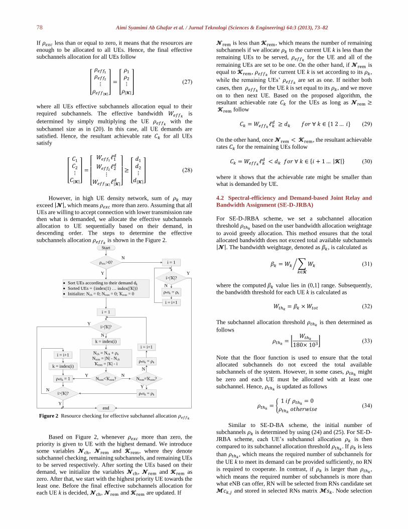
subchannels allocation 𝜌𝑒𝑓𝑓𝑘 is shown in the Figure 2.
Figure 2 Resource checking for effective subchannel allocation 𝜌𝑒𝑓𝑓𝑘
Based on Figure 2, whenever 𝜌𝑒𝑥𝑐 more than zero, the
priority is given to UE with the highest demand. We introduce
some variables 𝓝ch, 𝓝rem and 𝓚rem, where they denote
subchannel checking, remaining subchannels, and remaining UEs
to be served respectively. After sorting the UEs based on their
demand, we initialize the variables 𝓝ch, 𝓝rem and 𝓚rem as
zero. After that, we start with the highest priority UE towards the
least one. Before the final effective subchannels allocation for
each UE k is decided, 𝓝ch, 𝓝rem and 𝓚rem are updated. If
𝓝rem is less than 𝓚rem, which means the number of remaining
subchannels if we allocate 𝜌𝑘 to the current UE k is less than the
remaining UEs to be served, 𝜌𝑒𝑓𝑓𝑘 for the UE and all of the
remaining UEs are set to be one. On the other hand, if 𝓝rem is
equal to 𝓚rem, 𝜌𝑒𝑓𝑓𝑘 for current UE k is set according to its 𝜌𝑘,
while the remaining UEs’ 𝜌𝑒𝑓𝑓𝑘 are set as one. If neither both
cases, then 𝜌𝑒𝑓𝑓𝑘 for the UE k is set equal to its 𝜌𝑘, and we move
on to then next UE. Based on the proposed algorithm, the
resultant achievable rate 𝐶𝑘 for the UEs as long as 𝓝rem ≥ 𝓚rem follow
𝐶𝑘 = 𝑊𝑒𝑓𝑓𝑘ℓ𝑘
𝑑 ≥ 𝑑𝑘 𝑓𝑜𝑟 ∀ 𝑘 ∈ {1 2… 𝑖} (29)
On the other hand, once 𝓝rem < 𝓚rem, the resultant achievable
rates 𝐶𝑘 for the remaining UEs follow
𝐶𝑘 = 𝑊𝑒𝑓𝑓𝑘ℓ𝑘
𝑑 < 𝑑𝑘 𝑓𝑜𝑟 ∀ 𝑘 ∈ {𝑖 + 1… |𝓚|} (30)
where it shows that the achievable rate might be smaller than
what is demanded by UE.
4.2 Spectral-efficiency and Demand-based Joint Relay and
Bandwidth Assignment (SE-D-JRBA)
For SE-D-JRBA scheme, we set a subchannel allocation
threshold 𝜌𝑡ℎ𝑘 based on the user bandwidth allocation weightage
to avoid greedy allocation. This method ensures that the total
allocated bandwidth does not exceed total available subchannels |𝓝|. The bandwidth weightage, denoted as 𝛽𝑘, is calculated as
𝛽𝑘 = 𝑊𝑘 ∑ 𝑊𝑘
𝑘∈𝓚
⁄ (31)
where the computed 𝛽𝑘 value lies in (0,1] range. Subsequently,
the bandwidth threshold for each UE k is calculated as
𝑊𝑡ℎ𝑘= 𝛽𝑘 × 𝑊𝑡𝑜𝑡 (32)
The subchannel allocation threshold 𝜌𝑡ℎ𝑘 is then determined as
follows
𝜌𝑡ℎ𝑘= ⌊
𝑊𝑡ℎ𝑘
180× 103⌋ (33)
Note that the floor function is used to ensure that the total
allocated subchannels do not exceed the total available
subchannels of the system. However, in some cases, 𝜌𝑡ℎ𝑘 might
be zero and each UE must be allocated with at least one
subchannel. Hence, 𝜌𝑡ℎ𝑘 is updated as follows
𝜌𝑡ℎ𝑘= {
1 𝑖𝑓 𝜌𝑡ℎ𝑘= 0
𝜌𝑡ℎ𝑘 𝑜𝑡ℎ𝑒𝑟𝑤𝑖𝑠𝑒
(34)
Similar to SE-D-BA scheme, the initial number of
subchannels 𝜌𝑘 is determined by using (24) and (25). For SE-D-
JRBA scheme, each UE’s subchannel allocation 𝜌𝑘 is then
compared to its subchannel allocation threshold 𝜌𝑡ℎ𝑘. If 𝜌𝑘 is less
than 𝜌𝑡ℎ𝑘, which means the required number of subchannels for
the UE k to meet its demand can be provided sufficiently, no RN
is required to cooperate. In contrast, if 𝜌𝑘 is larger than 𝜌𝑡ℎ𝑘,
which means the required number of subchannels is more than
what eNB can offer, RN will be selected from RNs candidate set
𝓜𝑐𝑘,𝑗 and stored in selected RNs matrix 𝓜𝑠𝑘. Node selection
Start
ρexc>0?
· Sort UEs according to their demand dk
· Sorted UEs = {index(1) … index(|Ҡ|)}
· Initialize: Nch = 0; Nrem = 0; Ҡrem = 0
i = 1
i>|Ҡ|?
Nch = Nch + ρk
Nrem = |N| - Nch
Ҡrem = |Ҡ| - i
k = index(i)
Nrem<Ҡrem?
i = i+1
k = index(i)
ρeffk = 1
i>|Ҡ|?
end
Nrem=Ҡrem?
ρeffk = ρk
ρeffk = ρk
i = i+1
i = 1
i>|Ҡ|?
ρeffk = ρk
i = i+1
Y
N
Y N
Y
NY
N
Y
N
N
Y
79 Aimi Syamimi Ab Ghafar et al. / Jurnal Teknologi (Sciences & Engineering) 64:3 (2013), 73–82
matrix 𝓥𝑘 for the UE is also updated based on the chosen RNs.
Based on (13), the updated matrix of all UEs spectral efficiencies
with FDX RN cooperation, denoted as 𝓛fdx, is given by
𝓛𝑓𝑑𝑥 =
[ 𝑚𝑖𝑛 {
1
2log2 |𝑰 +
1
𝜎2𝑯1
𝑓𝑑𝑥𝑯1
𝑓𝑑𝑥∗| , ∑ log2 (1 +
𝐸𝑅𝑚
𝜎2|ℎ𝑅𝑚
|2)
𝑚∈𝓜𝑐1,𝑗
}
𝑚𝑖𝑛 {1
2log2 |𝑰 +
1
𝜎2 𝑯2𝑓𝑑𝑥
𝑯2𝑓𝑑𝑥∗
| , ∑ log2 (1 +𝐸𝑅𝑚
𝜎2 |ℎ𝑅𝑚|2)
𝑚∈𝓜𝑐2,𝑗
}
⋮
𝑚𝑖𝑛 {1
2log2 |𝑰 +
1
𝜎2𝑯|𝓚|
𝑓𝑑𝑥𝑯|𝓚|
𝑓𝑑𝑥∗| , ∑ log2 (1 +
𝐸𝑅𝑚
𝜎2|ℎ𝑅𝑚
|2)
𝑚∈𝓜𝑐|𝓚|,𝑗
}
]
ℒ𝑓𝑑𝑥 =
[ ℓ1
+
ℓ2+
⋮ℓ|𝓚|
+]
(35)
It is shown in (24) that the allocated bandwidth for each UE
k is inversely proportional to its link quality. With the help of
RNs, better link quality is achieved and thus reduces the amount
of bandwidth allocation for UE k. The reduced allocated
bandwidth, denoted as 𝑊𝑘+, is determined by considering the
improved link quality with RN cooperation as follows
𝑊𝑘+ =
𝑑𝑘
ℓk+ Hz (36)
Consequently, 𝜌𝑘+ is updated and re-compared to its 𝜌𝑡ℎ𝑘
.
Again, as long as 𝜌𝑘+ larger than 𝜌𝑡ℎ𝑘
, another RN is selected to
cooperate. Note that the number of cooperating RNs for each UE
k is limited to the number of RNs of the same sector as given in
the following constraint
|𝓜𝑠𝑘|≤|𝓜𝑐𝑘,𝑗| (37)
The iteration for each UE k will break whenever 𝜌𝑘+ less
than 𝜌𝑡ℎ𝑘 or number of chosen RNs has reached its limit. For
some UEs, even though number of cooperating RNs has already
reached its limit |𝓜𝑐𝑘,𝑗|, 𝜌𝑘+ is still exceeding 𝜌𝑡ℎ𝑘
. Therefore,
a final checking is crucial to ensure that the total allocated
subchannels does not exceed total subchannel |𝓝| as in
constraint (22). Similar to SE-D-BA scheme without RN
cooperation, final effective subchannel allocation 𝜌𝑒𝑓𝑓𝑘 is
determined by using the same method shown in Figure 2. The
resultant achievable rate 𝐶𝑘 for the UEs as long as 𝓝rem ≥ 𝓚rem follow
𝐶𝑘 = 𝑊𝑒𝑓𝑓𝑘ℓk
+ ≥ 𝑑𝑘 𝑓𝑜𝑟 ∀ 𝑘 ∈ {1 2… 𝑖} (38)
Again, once 𝓝rem < 𝓚rem, the resultant achievable rates 𝐶𝑘 for
the remaining UEs follow
𝐶𝑘 = 𝑊𝑒𝑓𝑓𝑘ℓk
+ < 𝑑𝑘 𝑓𝑜𝑟 ∀ 𝑘 ∈ {𝑖 + 1… |𝓚|} (39)
with RN cooperation taken into account.
5.0 NUMERICAL EVALUATION
We assume that both FDX and HDX RN operate in DCF
operation and compared to system without RN cooperation. The
evaluation comparison descriptions are as follows:
· Spectral-efficiency and demand-based bandwidth
assignment without RN cooperation (No coop+SE-D-BA):
By using DL transmission only, bandwidth assignment
decision is determined based on DL spectral efficiency and
UE demanded rate.
· Spectral-efficiency and demand-based joint relay and
bandwidth assignment with FDX mode (FDX—SE-D-
JRBA): Both cooperating nodes and bandwidth assignment
decision are determined based on partial information of AL
only rather than both hops information, with information on
UE demanded rate. The RN operates in FDX mode. The
RNs are chosen consequently based on AL as follows
ℓ𝑚,𝑘𝑎𝑙 = log2(1 +
𝐸𝐴𝑚,𝑘
𝜎2 |ℎ𝐴𝑚,𝑘|2) (40)
· Spectral-efficiency and demand-based joint relay and
bandwidth assignment with HDX mode (HDX—SE-D-
JRBA): The cooperating nodes and bandwidth assignment
decision are the same as above-mentioned FDX—SE-D-
JRBA. The only difference is that the RN operates in HDX
mode.
Table 1 Simulation parameters
Inter Site Distance 500m
Bandwidth (W) 10 MHz
eNB Tx Power (PB) 46dBm
RN Tx Power (PR) 30dBm
Path Loss PL = Prob(LOS)*PL(LOS) + Prob(NLOS)*PL(NLOS)
eNB-UE Path Loss PL(LOS) = 103.4 + 24.2*log10(R) PL(NLOS) = 131.1 + 42.8*log10(R)
Prob(LOS) = min(0.018/R,1)*(1-exp(-R/0.063)) + exp(-R/0.063)
eNB-RN Path Loss PL(LOS) = 100.7 + 23.5*log10(R) PL(NLOS) = 125.2 + 36.3*log10(R)
Prob(LOS) = min(0.018/R,1)*(1-exp(-R/0.072)) + exp(-R/0.072)
RN-UE Path Loss PL(LOS) = 103.8 + 20.9*log10(R) PL(NLOS) = 145.4 + 37.5*log10(R)
Prob(LOS) = 0.5 - min(0.5,5*exp(-0.156/R)) + min(0.5,5*exp(-R/0.03))
Thermal Noise -174dBm/Hz
The simulation parameters and path-loss for each link are
given in Table 1 [17]. The proposed algorithm is evaluated in
urban environment with 100 topology realizations. There are 4
RNs per sector, located at 3/5 of the cell radius. UEs are
80 Aimi Syamimi Ab Ghafar et al. / Jurnal Teknologi (Sciences & Engineering) 64:3 (2013), 73–82
uniformly distributed within the cell. The performance
evaluations have been carried out by varying two parameters.
Firstly, the number of UEs to be served in the system is varied. In
this case, every UE traffic demand 𝑑𝑘 is randomly generated in
[500, 1000] kbps [19]. The results for this case are shown in
Figure 3-4. For the second case, the maximum user traffic
demand in the range [500, max] kbps is varied for fixed 50 UEs
scenario. The results are shown in Figure 5-6.
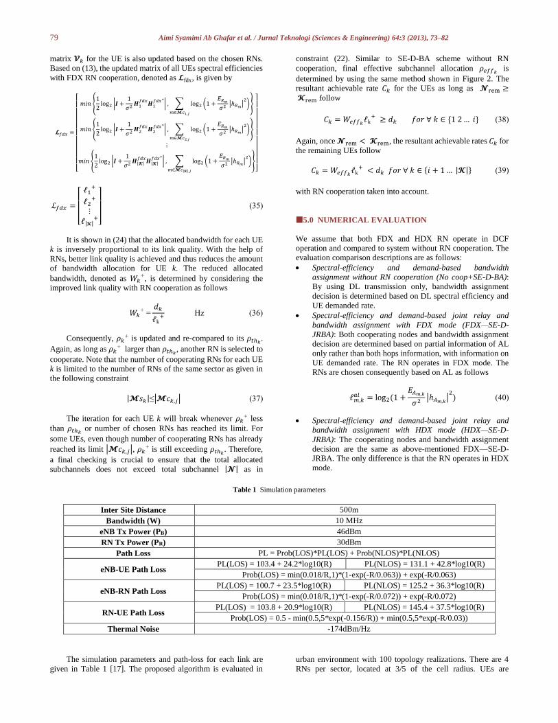
Figure 3 Sum rate vs. number of users
Performance of the proposed scheme is evaluated in terms
of sum rate. Sum rate expression of the system, denoted as 𝐶𝑇, is
the summation of all UEs achievable rate 𝐶𝑘 and is given as
𝐶𝑇 = ∑ 𝐶𝑘
𝑘∈𝓚
(41)
In Figure 3, the sum of user achievable rate with different
number of UEs is presented. Based on the results, it is shown that
the sum rates of all schemes are increasing as the number of UEs
increases. The performance of FDX—SE-D-JRBA is almost
linear while performances of HDX—SE-D-JRBA and no
coop+D-BA are saturated starting at number of UEs more than
34 and 28 respectively. This result shows the benefit of FDX—
SE-D-JRBA as it gives high spatial diversity gain. Hence, the
user link quality is enhanced significantly, reducing effective
bandwidth of users and thus ensuring enough resources to meet
users’ demand even in high density network. For the case of
HDX—SE-D-JRBA and no coop+SE-D-BA, the schemes offers
only slight performance increment when we do not have enough
resources to cater the needs of users. Therefore, in order to be fair,
we need to allocate effective subchannels less than what the UEs
actually need to satisfy their individual demands. To that reason,
the sum rate increment is small for both HDX—SE-D-JRBA and
without cooperation case.
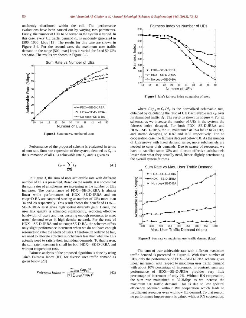
Fairness analysis of the proposed algorithm is done by using
Jain’s Fairness Index (JFI) for diverse user traffic demand as
given below [20]
𝐹𝑎𝑖𝑟𝑛𝑒𝑠𝑠 𝐼𝑛𝑑𝑒𝑥 = (∑ 𝐶𝑎𝑝𝑘𝑘∈𝓚 )2
|𝓚| ∑ (𝐶𝑎𝑝𝑘)2
𝑘∈𝓚 (42)
Figure 4 Jain’s fairness index vs. number of users
where 𝐶𝑎𝑝𝑘 = 𝐶𝑘 𝑑𝑘⁄ is the normalized achievable rate,
obtained by calculating the ratio of UE k achievable rate 𝐶𝑘 over
its demanded traffic 𝑑𝑘. The result is shown in Figure 4. For all
schemes, as we increase the number of UEs in the system, the
fairness index decayed. For both FDX—SE-D-JRBA and
HDX—SE-D-JRBA, the JFI maintained at 0.94 for up to 24 UEs,
and started decaying to 0.87 and 0.83 respectively. For no
cooperation case, the fairness decayed below 0.8. As the number
of UEs grows with fixed demand range, more subchannels are
needed to cater their demands. Due to scarce of resources, we
have to sacrifice some UEs and allocate effective subchannels
lesser than what they actually need, hence slightly deteriorating
the overall system fairness.
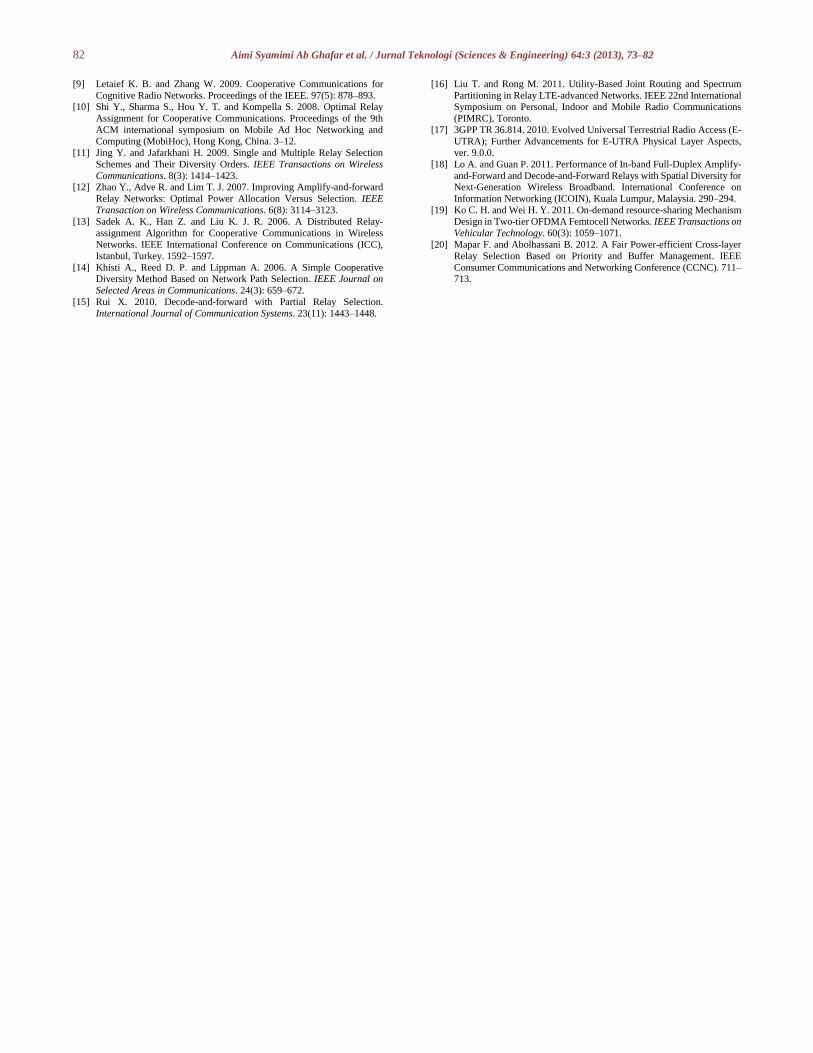
Figure 5 Sum rate vs. maximum user traffic demand (kbps)
The sum of user achievable rate with different maximum
traffic demand is presented in Figure 5. With fixed number of
UEs, only the performance of FDX—SE-D-JRBA scheme gives
linear increment with respect to maximum user traffic demand
with about 10% percentage of increment. In contrast, sum rate
performance of HDX—SE-D-JRBA provides very little
percentage of increment of only 2%. Without RN cooperation,
the sum rate maintained at 37.3Mbps as we increase the
maximum UE traffic demand. This is due to low spectral
efficiency obtained without RN cooperation which leads to
insufficient resources even with low UE demand. To that reason,
no performance improvement is gained without RN cooperation.
10 14 18 22 26 30 34 38 42 46 5010
15
20
25
30
35
40
45
Number of UEs
Achie
vable
Rate
(M
bps)
Sum Rate vs Number of UEs
FDX---SE-D-JRBA
HDX---SE-D-JRBA
No coop+SE-D-BA
10 14 18 22 26 30 34 38 42 46 500.78
0.8
0.82
0.84
0.86
0.88
0.9
0.92
0.94
0.96
Number of UEs
Fa
irn
ess I
nd
ex
Fairness Index vs Number of UEs
FDX---SE-D-JRBA
HDX---SE-D-JRBA
No coop+SE-D-BA
600 650 700 750 800 850 900 950 100037
38
39
40
41
42
43
44
Max. User Traffic Demand (kbps)
Achie
vable
Rate
(M
bps)
Sum Rate vs Max. User Traffic Demand
FDX---SE-D-JRBA
HDX---SE-D-JRBA
No coop+SE-D-BA

81 Aimi Syamimi Ab Ghafar et al. / Jurnal Teknologi (Sciences & Engineering) 64:3 (2013), 73–82
Figure 6 Jain’s fairness index vs. maximum user traffic demand (kbps)
In Figure 6, we show the JFI for evaluation of different maximum
user traffic demand. As the maximum traffic demand increases,
FDX—SE-D-JRBA demonstrates better fairness while for other
schemes, the fairness decreases. Based on the results, since
FDX—SE-D-JRBA scheme offers high spectral efficiency, the
effective subchannel allocation to the UEs lead to excessive rate
compared to what the UE actually demanded. Therefore, as the
maximum demand gets higher, the difference between UE’s
achievable rate to UE’s demanded rate gets smaller resulting in
better fairness performance. Comply with previous result in
Figure 4, fairness of HDX—SE-D-JRBA and no cooperation
scheme decay due to insufficient resources.
Figure 7 Cumulative density function (CDF) of users achievable rate
The results in Figure 7 show the CDF of UE achievable rate
for our proposed FDX—SE-D-JRBA, HDX—SE-D-JRBA and
case without RN cooperation. Based on the figure, performance
of the proposed FDX—SE-D-JRBA is the closest to maximum
UE traffic demand which is 1Mbps. 90% of the UEs achieved
0.89Mbps, 0.8Mbps and 0.77Mbps with FDX—SE-D-JRBA,
HDX—SE-D-JRBA and no coop+SE-D-BA respectively.
6.0 CONCLUSION
In this paper, a joint relay and bandwidth assignment algorithm
has been proposed, namely SE-D-JRBA scheme that takes into
account link quality and user traffic demand in deciding whether
RNs should be selected for cooperation, together with UE
bandwidth allocation. Performance of the proposed algorithm
with RN that operates in HDX and FDX mode is compared to
conventional system without RN in terms of achievable rate and
fairness index. Numerical results are done in LTE-Advanced
context. Numerical results demonstrated that FDX—SE-D-JRBA
scheme is able to provide both fairness and efficiency even for
large number of UEs and high traffic demand. Although HDX—
SE-D-JRBA gives adequate fairness index, it lacks system
efficiency. Apart from that, it is also shown that by exploiting the
advantage of FDX RN spatial diversity, we can lessen the user
effective bandwidth efficiently in order to ensure sufficient
resources in high density network which is also very flexible with
diverse user traffic demand scenario. However, our algorithm is
sub-optimal and future work in progress is to further optimize the
proposed SE-D-JRBA by incorporating spatial reuse between
sectors to cater the problem when the resources are not enough.
Acknowledgement
The authors would like to thank to the UTM-MIMOS Center of
Excellent and Research Management Center (RMC) of Universiti
Teknologi Malaysia for their full support and advice in realizing
this research project. Also, thanks to all anonymous reviewers for
their invaluable comments and the guest editors for handling the
review for this paper. The work is financed by Institutional
Scholarship provided by Ministry of Higher Education (MOHE)
and Ministry of Science, Technology and Innovation of Malaysia
(MOSTI).
References [1] ITU-R Rep. M.2134. 2008. Requirements Related to technical
Performance for IMT-Advanced Radio Interface(s).
[2] 3GPP TR 36.913. 2009. Requirements for Further Advancements for
Evolved Universal Terrestrial Radio Access (E-UTRA).
[3] Saparudin F. A., Fisal N., A. Rashid R., Ab Ghafar A. S. and Mohamad
Maharum S. M. 2011. Cooperative Communication and Cognitive Radio
(CR) Technology in LTE- Advanced. The International Conference on Informatics Engineering & Information Science (ICIEIS 2011), Kuala
Lumpur, Malaysia. Part III: 701–710.
[4] Katiran N., Fisal N., Syed Yusof S. K., Mohamad Maharum S. M., Ab
Ghafar A. S. and Saparudin F. A. 2011. Inter-cell Interference Mitigation
and Coordination in CoMP Systems. The International Conference on
Informatics Engineering & Information Science (ICIEIS 2011), Kuala
Lumpur, Malaysia. Part III: 654–665.
[5] Mohamad Maharum S. M., Fisal N., A. Rashid R., Ab Ghafar A. S., Saparudin F. A. and Katiran N. 2011. Challenges and Practical
Implementation of Self-Organizing Networks in LTE/LTE-Advanced
Systems. 2011 5th International conference on Information Technology
and Multimedia (ICIMu2011), Selangor, Malaysia. 1–5.
[6] Ab Ghafar A. S., Satiman N., Fisal N., Mohamad Maharum S. M.,
Saparudin F. A., A. Rashid R., Syed Yusof S. K. and Katiran N. 2011.
Communications in Computer and Information Science: Techniques on Relaying for LTE-Advanced Network. The International Conference on
Informatics Engineering & Information Science (ICIEIS 2011), Kuala
Lumpur, Malaysia. Part III: 624–638.
[7] Ghosh A. M., Ratasuk R., Mondal B., Mangalvedhe N. and Thomas T.
2010. LTE-Advanced: Next-Generation Wireless Broadband
Technology. Invited Paper in: IEEE Wireless Communications. 17(3):
10–22.
[8] Yang Y., Hu H., Xu J. and Mao G. 2009. Relay Technologies for WiMAX and LTE-Advanced Mobile Systems. IEEE Communications
Magazine. 47(10): 100–105.
600 650 700 750 800 850 900 950 10000.79
0.8
0.81
0.82
0.83
0.84
0.85
0.86
0.87
0.88
Max. User Traffic Demand (kbps)
Fairness I
ndex
Fairness Index vs Max. User Traffic Demand
FDX---SE-D-JRBA
HDX---SE-D-JRBA
No coop+SE-D-BA
0.7 0.75 0.8 0.85 0.9 0.950
0.1
0.2
0.3
0.4
0.5
0.6
0.7
0.8
0.9
1
Achievable Rate (Mbps)
Ach
ieva
ble
Ra
te C
DF
UE Achievable Rate
FDX---SE-D-JRBA
HDX---SE-D-JRBA
No coop+SE-D-BA
82 Aimi Syamimi Ab Ghafar et al. / Jurnal Teknologi (Sciences & Engineering) 64:3 (2013), 73–82
[9] Letaief K. B. and Zhang W. 2009. Cooperative Communications for
Cognitive Radio Networks. Proceedings of the IEEE. 97(5): 878–893. [10] Shi Y., Sharma S., Hou Y. T. and Kompella S. 2008. Optimal Relay
Assignment for Cooperative Communications. Proceedings of the 9th
ACM international symposium on Mobile Ad Hoc Networking and
Computing (MobiHoc), Hong Kong, China. 3–12.
[11] Jing Y. and Jafarkhani H. 2009. Single and Multiple Relay Selection
Schemes and Their Diversity Orders. IEEE Transactions on Wireless
Communications. 8(3): 1414–1423. [12] Zhao Y., Adve R. and Lim T. J. 2007. Improving Amplify-and-forward
Relay Networks: Optimal Power Allocation Versus Selection. IEEE
Transaction on Wireless Communications. 6(8): 3114–3123.
[13] Sadek A. K., Han Z. and Liu K. J. R. 2006. A Distributed Relay-
assignment Algorithm for Cooperative Communications in Wireless
Networks. IEEE International Conference on Communications (ICC),
Istanbul, Turkey. 1592–1597.
[14] Khisti A., Reed D. P. and Lippman A. 2006. A Simple Cooperative Diversity Method Based on Network Path Selection. IEEE Journal on
Selected Areas in Communications. 24(3): 659–672.
[15] Rui X. 2010. Decode-and-forward with Partial Relay Selection.
International Journal of Communication Systems. 23(11): 1443–1448.
[16] Liu T. and Rong M. 2011. Utility-Based Joint Routing and Spectrum
Partitioning in Relay LTE-advanced Networks. IEEE 22nd International Symposium on Personal, Indoor and Mobile Radio Communications
(PIMRC), Toronto.
[17] 3GPP TR 36.814. 2010. Evolved Universal Terrestrial Radio Access (E-
UTRA); Further Advancements for E-UTRA Physical Layer Aspects,
ver. 9.0.0.
[18] Lo A. and Guan P. 2011. Performance of In-band Full-Duplex Amplify-
and-Forward and Decode-and-Forward Relays with Spatial Diversity for Next-Generation Wireless Broadband. International Conference on
Information Networking (ICOIN), Kuala Lumpur, Malaysia. 290–294.
[19] Ko C. H. and Wei H. Y. 2011. On-demand resource-sharing Mechanism
Design in Two-tier OFDMA Femtocell Networks. IEEE Transactions on
Vehicular Technology. 60(3): 1059–1071.
[20] Mapar F. and Abolhassani B. 2012. A Fair Power-efficient Cross-layer
Relay Selection Based on Priority and Buffer Management. IEEE
Consumer Communications and Networking Conference (CCNC). 711–713.