APRICANCELLO SCORREVOLE … · Libro istruzioni e catalogo ricambi ... Ancrage avec réglage sur...
32
L8542104 Rev. 07/07/01 BULL 20T APRICANCELLO SCORREVOLE ELETTROMECCANICO ELECTROMECHANICAL SLIDING GATE OPENER ELEKTROMECHANISCHE AUTOMATION FÜR SCHIEBEGITTER AUTOMATISATION ÉLECTROMÉCANIQUE POUR GRILLES COULISSANTES ABRECANCELA ELECTROMECANICO PARA CORREDERAS ELEKTROMECHANICZNY, POSUWOWY OTWIERACZ BRAM Libro istruzioni e catalogo ricambi Operating instructions and spare parts catalogue Betriebsanleitung und Ersatzteilliste Livret d’instructions et catalogue des pieces de rechange Libro de instrucciones y catálogo de recambios Książeczka z instrukcjami i katalog części wymiennych UNIONE NAZIONALE COSTRUTTORI AUTOMATISMI PER CANCELLI, PORTE SERRANDE ED AFFINI
Transcript of APRICANCELLO SCORREVOLE … · Libro istruzioni e catalogo ricambi ... Ancrage avec réglage sur...
L8542104Rev. 07/07/01
BULL20T
APRICANCELLO SCORREVOLE ELETTROMECCANICO
ELECTROMECHANICAL SLIDING GATE OPENER
ELEKTROMECHANISCHE AUTOMATION FÜR SCHIEBEGITTER
AUTOMATISATION ÉLECTROMÉCANIQUE POUR GRILLES COULISSANTES
ABRECANCELA ELECTROMECANICO PARA CORREDERAS
ELEKTROMECHANICZNY, POSUWOWY OTWIERACZ BRAM
Libro istruzioni e catalogo ricambi
Operating instructions and spare parts catalogue
Betriebsanleitung und Ersatzteilliste
Livret d’instructions et catalogue des pieces de rechange
Libro de instrucciones y catálogo de recambios
Książeczka z instrukcjami i katalog części wymiennych
UNIONE NAZIONALE COSTRUTTORIAUTOMATISMI PER CANCELLI, PORTE
SERRANDE ED AFFINI
2 3
Dichiarazione CE di conformità per macchine(Direttiva 98/37 CE, Allegato II, parte B)
Divieto di messa in servizio
Fabbricante: Automatismi Benincà SpA.Indirizzo: Via Capitello, 45 - 36066 Sandrigo (VI) - Italia
Dichiara che: l’automazione per cancelli scorrevoli modello BULL 20T
• è costruita per essere incorporata in una macchina o per essere assemblata con altri macchinari per costituire una macchina consi-derata dalla Direttiva 98/37 CE, come modificata;
• non è dunque conforme in tutti i punti alle disposizioni di questa Direttiva;• è conforme alle condizioni delle seguenti altre Direttive CE: Direttiva bassa tensione 73/23/CEE, 93/68/CEE. Direttiva compatibilità elettromagnetica 89/336/CEE, 93/68/CEE.
e inoltre dichiara che non è consentito mettere in servizio il macchinario fino a che la macchina in cui sarà incorporata o di cui diverrà componente sia stata identificata e ne sia stata dichiarata la conformità alle condizioni della Direttiva 98/37 CE e alla legislazione nazionale che la traspone, vale a dire fino a che il macchinario di cui alla presente dichiarazione non formi un complesso unico con la macchina finale.
Benincà Luigi, Responsabile legale.Sandrigo, 05/10/2005.
Declaration by the manufacturer(Directive 98/37/EEC, Art. 4.2 and Annex II, sub B)
Divieto di messa in servizio
Manufacturer: Automatismi Benincà SpA.Address: Via Capitello, 45 - 36066 Sandrigo (VI) - Italia
Herewith declares that: the operator for sliding gates model BULL 20T
• is intended to be incorpored into machinery or to be assembled with other machinery to constitute machinery covered by Directive 98/37 EEC, as amended;
• does therefore not in every respect comply with the provisions of this Directive;• does comply with the provisions of the following other EEC Directives: Direttiva bassa tensione 73/23/CEE, 93/68/CEE. Direttiva compatibilità elettromagnetica 89/336/CEE, 93/68/CEE.
and furthermore declares that it is not allowed to put the machinery into service until the machinery into which it is to be incorporated or of which it is to be a component has been found and declared to be in conformity with the provisions of Directive 98/37/EEC and with national implementing legislation, i.e. as a whole, including the machinery referred to in this declaration.
Benincà Luigi, Responsabile legale.Sandrigo, 05/10/2005.

2 3
Herstellerklärung(gemäß EG-Richtlinie 98/37/EWG, Artikel 4.2 und Anhang II, sub B.)
Verbot der Inbetriebnahme
Hersteller: Automatismi Benincà SpA.Adresse: Via Capitello, 45 - 36066 Sandrigo (VI) - Italia
erklärt hiermit, daß: Antriebe für Schiebegittertore BULL 20T
• vorgesehen ist zum Einbau in eine Maschine oder mit anderen Maschinen zu einer Maschine im Sinne der Richtlinie 98/37/EWG, inklusive deren Änderunge, zusammengefügt werden soll;
• aus diesem Grunde nicht in allen Teilen den Bestimmungen dieser Richtlinie entspricht;• den Bestimmungen der folgenden anderen EG-Richtlinien entspricht: Direttiva bassa tensione 73/23/CEE, 93/68/CEE. Direttiva compatibilità elettromagnetica 89/336/CEE, 93/68/CEE.
und erklärt des weiteren daß die Inbetriebnahme solange untersagt ist, bis die Maschine oder Anlage, in welche diese Maschine eingebaut wird oder von welcher sie eine Komponente dasteilt, als Ganzes (d.h. inklusive der Maschine, für welche diese Erklärung ausgesteilt wurde) den Bestimmungen der Richtlinie 98/37/EWG sowie dem entsprechenden nationalen Reschtserlaß zur Umsetzung der Richtlinie in nationales Recht entspricht, und die entsprechende Konformitätserklärung ausgestellt ist.
Benincà Luigi, Responsabile legale.Sandrigo, 05/10/2005.
Declaration du fabricant(Directive 98/37/CEE, Article 4.2 et Annex II, Chapitre B)
Interdiction de mise en service
Fabricant: Automatismi Benincà SpA.Adresse: Via Capitello, 45 - 36066 Sandrigo (VI) - Italia
Déclaire ci-apres que: l’automation pour grilles coulissantes BULL 20T
• est prévu pour être incorporé dans une machine ou être assemblé avec d’autres machines pour consituer une machine couverte par la norme 98/37/CEE, modifiée;
• n’est donc pas conforme en tout point aux dispositions de cette directive;• est conforme aux dispositions des directives CEE suivantes: Direttiva bassa tensione 73/23/CEE, 93/68/CEE. Direttiva compatibilità elettromagnetica 89/336/CEE, 93/68/CEE.
et déclare par ailleurs qu’il est interdit de mettre la machine en service avant que la machine dans laquelle elle sera incorporée ou dont elle constitue une parte ait été considerée et declarée conforme aux dispositions de la Directive 98/37/CEE et aux législations nationales la transposant, c’est-à-dire formant un ensemble incluant la machine concernée par la présente déclaration.
Benincà Luigi, Responsabile legale.Sandrigo, 05/10/2005.
4 5
Declaración CE de conformidad para maquinas(Directiva 98/37 CE, Apartado II, parte B)Prohibición de puesta en servicio
Fabricante: Automatismi Benincà SpA.Dirección: Via Capitello, 45 - 36066 Sandrigo (VI) - Italia
Declara que: la automatización para correderas BULL 20T
• está construída para ser incorporada en una máquina o para ser ensamblada con otras maquinarias para construir una máquina considerada por la Directiva 98/37 CE, como modificada;
• no es, por consiguiente, conforme en todos los puntos a la posiciones de esta Directiva;• es conforme a las condiciones de las siguientes otras Directivas CE: Directiva de la baja tensión 73/23/CEE, 93/68/CEE. Directiva de compatibilidad electromagnética 89/336/CEE, 93/68/CEE
además declara que no ha permitido poner en servicio la maquinaria hasta que la máquina en la cual será incorporada o de la cual resultará componente esté identificada y no sea declarada la conformidad a las condiciones de la Directiva 98/37 CE y a la legislación nacional que le corresponda, vale decir, hasta que la maquinaria correspondiente a la presente declaración no forme un conjunto único con la máquina final.
Benincà Luigi, Responsable legal.Sandrigo, 05/10/2005.
Deklaracja UE o zgodności z normami dla maszyn(Wytyczna 98/37 UE, Załącznik II, Część B)
Zakaz użytkowania
Producent: Automatismi Benincà SpA.Adres: Via Capitello, 45 - 36066 Sandrigo (VI) - Italia
Oświadcza że: Automatyzm do bram przesuwnych model BULL 20T
• został opracowany z myślą o wbudowaniu go do maszyny lub zmontowania z innymi urządzeniami w celu skonstruowania maszyny uznanej przez Wytyczną 98/37 UE, za zmodyfikowaną;
• nie jest więc zgodny we wszystkich punktach z Wytyczną;• jest natomiast zgodny z wymogami innych, poniżej wyszczególnionych, Wytycznych UE: Wytyczna o niskim napięciu 73/23/EWG i 93/68/EWG Wytyczna o zdolności współdziałania elektromagnetycznego 89/336/EWG, 93/68/EWG.
ponadto oświadcza, że zabronione jest stosowanie automatyzmu do czasu kiedy maszyna, do której ma być wbudowany lub stanowić jej element składowy, nie uzyska świadectwa identyfikacyjnego oraz świadectwa orzekającego jej zgodność z wymogami Wytycznej 98/37 UE oraz z przepisami obowiązującymi w kraju sprowadzającym urządzenie, a więc do czasu kiedy automatyzm stanowiący przedmiot niniejszego oświadczenia nie stanie się częścią składową urządzenia gotowego.
Benincà Luigi, Radca prawnySandrigo, 05/10/2005.

4 5
Dati tecnici Technical data Technische Daten BULL20TAlimentazionePotenza assorbitaAssorbimentoCoppiaIntermittenza di lavoroGrado di protezioneClasse di isolamentoInterv. termoprotez.Temp. funzionamentoPeso max. cancelloModulo cremaglieraVelocità aperturaRumorositàLubrificazionePeso
FeedAbsorbed powerAbsorptionTorqueOperating joggingProtection classInsulation classThermoprot. interv.Working temperatureMax. gate weightRack modulusOpening speedNoise levelLubricationWeight
SpeisungAufgenom. LeistungVerbrauchKräftepaarBetriebsintermittenzSchutzklasseIsolierklasseEingriff ThermorelaisBetriebstemperaturGittersgewicht max.Modul der Zahnstange ÖffnungsgeschwindigkeitGeräuschentwicklungSchmierungGewicht
400Vac 50Hz500 W1,6 A
55 Nm60%IP54
F150°C
-20°C/+70°C2000kg
M410,5m/min
<70 dBAgip GR MU EP/2
18 kg
Donnees technique Datos técnicos Dane techniczne BULL20T
AlimentationPuissance absorbéeAbsorptionCoupleIntermittence de travailDegré de protectionClasse d'isolementInterv. protect. therm.Temp. fonctionnementPoids max. portailModule de la crémaillèreVitesse d'ouvertureBruitLubrificationPoids
AlimentaciónConsumo de potenciaAbsorciónParIntermitencia de trabajoGrado de protecciónClase de aislamientoInterv. termoprotecciónTemp. funcionamientoPeso máx. de la cancelaMódulo de cremalleraVelocidad de aperturaRuidoLubrificaciónPeso
ZasilanieNatężeniePobór mocyMoment obrotowyRodzaj pracyStopień ochronyKlasa izolacjiInterw. TermostatuTemp. podczas pracyCiężar max. bramyTyp listwy zębatejPrędkość otwieraiaMax. halasSmarowanieCiężar
400Vac 50Hz500 W4,5 A
55 Nm60%IP54
F150°C
-20°C/+70°C2000kg
M410,5m/min
<70 dBAgip GR MU EP/2
18 kg
20039
5
Dimensioni d’ingombro - Overall dimensionsAbmessungen - Dimensions d’encombrement
Dimensiones exteriores - Wymiary gabarytowe
300
395
215
245
316
6 7
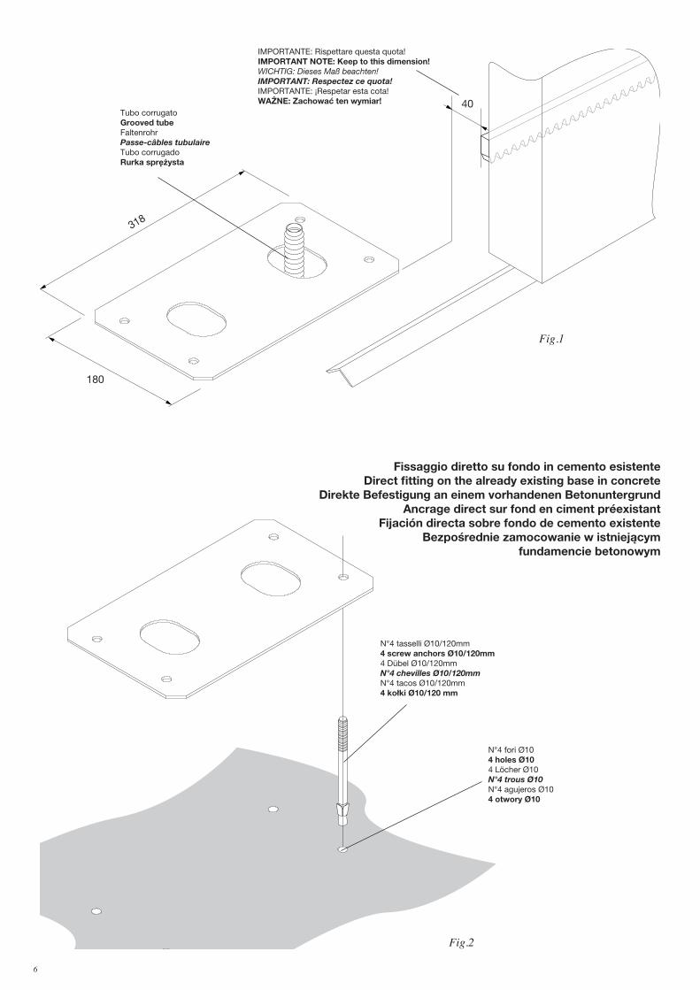
180
318
Fig.1
40Tubo corrugatoGrooved tubeFaltenrohrPasse-câbles tubulaireTubo corrugadoRurka sprężysta
IMPORTANTE: Rispettare questa quota!IMPORTANT NOTE: Keep to this dimension!WICHTIG: Dieses Maß beachten!IMPORTANT: Respectez ce quota!IMPORTANTE: ¡Respetar esta cota!WAŻNE: Zachować ten wymiar!
N°4 tasselli Ø10/120mm4 screw anchors Ø10/120mm4 Dübel Ø10/120mmN°4 chevilles Ø10/120mmN°4 tacos Ø10/120mm4 kołki Ø10/120 mm
N°4 fori Ø104 holes Ø104 Löcher Ø10N°4 trous Ø10N°4 agujeros Ø104 otwory Ø10
Fig.2
Fissaggio diretto su fondo in cemento esistenteDirect fitting on the already existing base in concrete
Direkte Befestigung an einem vorhandenen BetonuntergrundAncrage direct sur fond en ciment préexistant
Fijación directa sobre fondo de cemento existenteBezpośrednie zamocowanie w istniejącym
fundamencie betonowym
6 7
Fig.4
Scavo per getto di calcestruzzoHole for concrete layer Baugrube für BettonierungCavage pour coulée de béton Excavación para vaciado de hormigónWykopy do wylania betonu
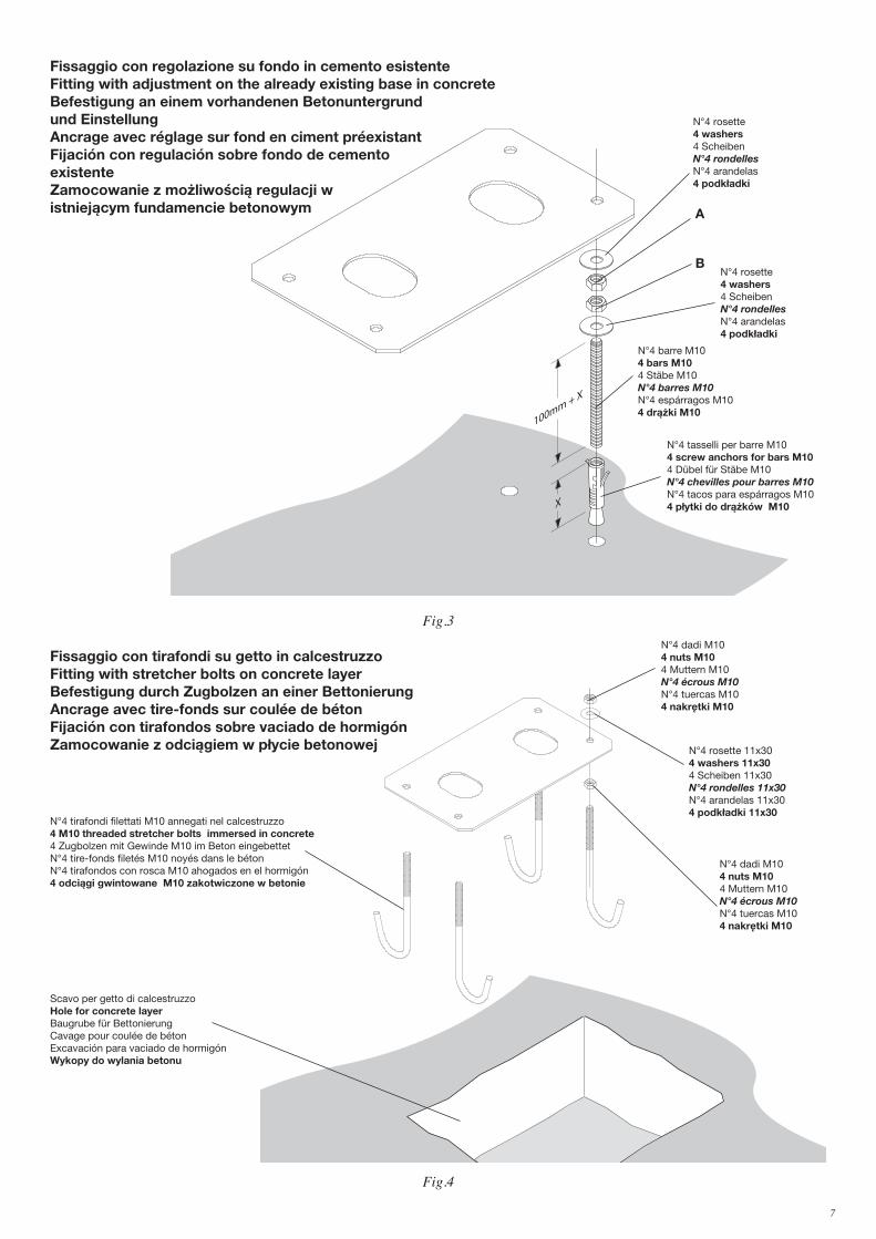
N°4 rosette 11x304 washers 11x304 Scheiben 11x30N°4 rondelles 11x30N°4 arandelas 11x304 podkładki 11x30
N°4 dadi M104 nuts M104 Muttern M10N°4 écrous M10N°4 tuercas M104 nakrętki M10
N°4 tirafondi filettati M10 annegati nel calcestruzzo4 M10 threaded stretcher bolts immersed in concrete 4 Zugbolzen mit Gewinde M10 im Beton eingebettetN°4 tire-fonds filetés M10 noyés dans le bétonN°4 tirafondos con rosca M10 ahogados en el hormigón4 odciągi gwintowane M10 zakotwiczone w betonie
Fig.3
100mm + X
X
N°4 barre M104 bars M104 Stäbe M10N°4 barres M10N°4 espárragos M104 drążki M10
N°4 rosette 4 washers 4 Scheiben N°4 rondelles N°4 arandelas 4 podkładki
A
N°4 tasselli per barre M104 screw anchors for bars M104 Dübel für Stäbe M10N°4 chevilles pour barres M10N°4 tacos para espárragos M104 płytki do drążków M10
BN°4 rosette 4 washers 4 Scheiben N°4 rondelles N°4 arandelas 4 podkładki
Fissaggio con regolazione su fondo in cemento esistenteFitting with adjustment on the already existing base in concrete Befestigung an einem vorhandenen Betonuntergrund und Einstellung Ancrage avec réglage sur fond en ciment préexistantFijación con regulación sobre fondo de cemento existenteZamocowanie z możliwością regulacji w istniejącym fundamencie betonowym
Fissaggio con tirafondi su getto in calcestruzzoFitting with stretcher bolts on concrete layer Befestigung durch Zugbolzen an einer BettonierungAncrage avec tire-fonds sur coulée de bétonFijación con tirafondos sobre vaciado de hormigónZamocowanie z odciągiem w płycie betonowej
Fig.3
N°4 dadi M104 nuts M104 Muttern M10N°4 écrous M10N°4 tuercas M104 nakrętki M10
8 9
Fig.6
��� � � ����� � �� ��
��� ���� ����� � ��� ��
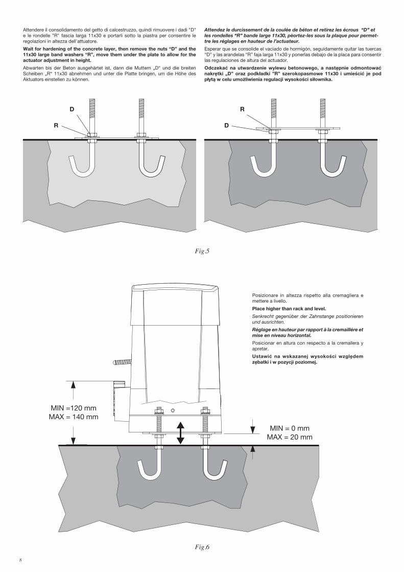
Posizionare in altezza rispetto alla cremagliera e mettere a livello.
Place higher than rack and level.
Senkrecht gegenüber der Zahnstange positionieren und ausrichten.
Réglage en hauteur par rapport à la cremaillére et mise en niveau horizontal.
Posicionar en altura con respecto a la cremallera y apretar.
Ustawić na wskazanej wysokości względem zębatki i w pozycji poziomej.
Fig.5
Attendere il consolidamento del getto di calcestruzzo, quindi rimuovere i dadi "D" e le rondelle "R" fascia larga 11x30 e portarli sotto la piastra per consentire le regolazioni in altezza dell'attuatore.
Wait for hardening of the concrete layer, then remove the nuts “D” and the 11x30 large band washers “R”, move them under the plate to allow for the actuator adjustment in height.
Abwarten bis der Beton ausgehärtet ist, dann die Muttern „D“ und die breiten Scheiben „R“ 11x30 abnehmen und unter die Platte bringen, um die Höhe des Aktuators einstellen zu können.
Attendez le durcissement de la coulée de béton et retirez les écrous “D” et les rondelles “R” bande large 11x30, pèortez-les sous la plaque pour permet-tre les réglages en hauteur de l’actuateur.
Esperar que se consolide el vaciado de hormigón, seguidamente quitar las tuercas “D” y las arandelas “R” faja larga 11x30 y ponerlas debajo de la placa para consentir las regulaciones de altura del actuador.
Odczekać na utwardzenie wylewu betonowego, a następnie odmontować nakrętki „D” oraz podkładki ”R” szerokopasmowe 11x30 i umieścić je pod płytą w celu umożliwienia regulacji wysokości siłownika.
D
R
R
D
8 9
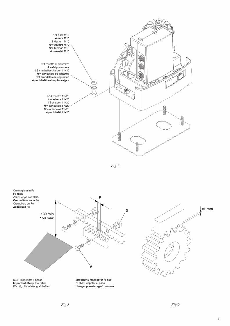
N.B.: Rispettare il passoImportant: Keep the pitchWichtig: Zahnteilung einhalten
Important: Respecter le pasNOTA: Respetar el pasoUwaga: przestrzegać posuwu
Fig.8
130 min150 max
P
D
V
Cremagliera in FeFe rackZahnstange aus StahlCremaillére en acierCremallera en FeZębatka z Fe
≈1 mm
Fig.9
N°4 dadi M104 nuts M10
4 Muttern M10N°4 écrous M10N°4 tuercas M104 nakrętki M10
Fig.7
N°4 rosette di sicurezza4 safety washers
4 Sicherheitsscheiben 11x30N°4 rondelles de sécurité
N°4 arandelas de seguridad4 podkładki zabezpieczające
N°4 rosette 11x20 4 washers 11x20 4 Scheiben 11x20
N°4 rondelles 11x20 N°4 arandelas 11x20
4 podkładki 11x20

10 11
A
S
1 ÷ 3 cm
G
Fig.11
Fig.10
Finecorsa appena premuto.Just pressed limit stop.Gedrückter Endanschlag.Fin de course à peine appuyé.Final de carrera apenas presionado.Krańcówka dopiero co naciśnięta.
CL
N.B.: La staffa del finecorsa deve essere posizionata in modo tale da permettere l’arresto del cancello senza che questo vada a sbattere contro l’arresto meccanicoN.b. The limit stop flask must be positioned to ensure that the gate stops without knocking against the mechanical stop.Der Endanschlagtbügel muß so positioniert werden, daß die Sperre des Gitters ohne das Flattern des Schiebegitters gegen den Endschalter A erfolgen kann.N.B. L’étrier de fin de course doit être positionné de façon à pouvoir arrêter le
portail, sans qu’il aille bûter sur le fin de course mécanique.NOTA: La pletina del final de carrera debe ser colocada de tal forma que permita la parada de la cancela sin que ésta vaya a tocar con el tope mecánico.Uwaga: Zaczep krańcówki musi być w pozycji takiej by możliwe było zatrzymanie bramy niedopuszczając do jej zderzenia z zaporą mechaniczną.
10 11
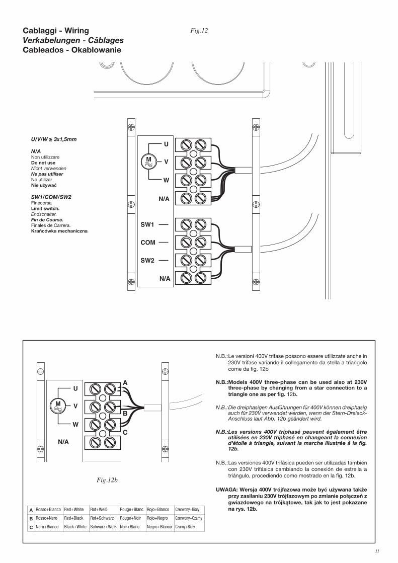
Cablaggi - Wiring Verkabelungen - Câblages Cableados - Okablowanie
N.B.:Le versioni 400V trifase possono essere utilizzate anche in 230V trifase variando il collegamento da stella a triangolo come da fig. 12b
N.B.:Models 400V three-phase can be used also at 230V three-phase by changing from a star connection to a triangle one as per fig. 12b.
N.B.:Die dreiphasigen Ausführungen für 400V können dreiphasig auch für 230V verwendet werden, wenn der Stern-Dreieck-Anschluss laut Abb. 12b geändert wird.
N.B.: Les versions 400V triphasé peuvent également être utilisées en 230V triphasé en changeant la connexion d’étoile à triangle, suivant la marche illustrée à la fig. 12b.
N.B.:Las versiones 400V trifásica pueden ser utilizadas también con 230V trifásica cambiando la conexión de estrella a triángulo, procediendo como mostrado en la fig. 12b.
UWAGA: Wersja 400V trójfazowa może być używana także przy zasilaniu 230V trójfazowym po zmianie połączeń z gwiazdowego na trójkątowe, tak jak to jest pokazane na rys. 12b.
Fig.12
�
�
�
���
���
���
���
���
U/V/W ≥ 3x1,5mm
N/ANon utilizzareDo not useNicht verwendenNe pas utiliserNo utilizarNie używać
SW1/COM/SW2Finecorsa Limit switch.Endschalter.Fin de Course.Finales de Carrera.Krańcówka mechaniczna
U
V
W
N/A
SW1
COM
SW2
STOP
A
B
C
A Rosso+Bianco Red+White Rot+Weiß Rouge+Blanc Rojo+Blanco Czerwony+Biały
B Rosso+Nero Red+Black Rot+Schwarz Rouge+Noir Rojo+Negro Czerwony+Czarny
C Nero+Bianco Black+White Schwarz+Weiß Noir+Blanc Negro+Blanco Czarny+Biały
Fig.12b
12 13
Fig.13
8
7
4
1
2
3
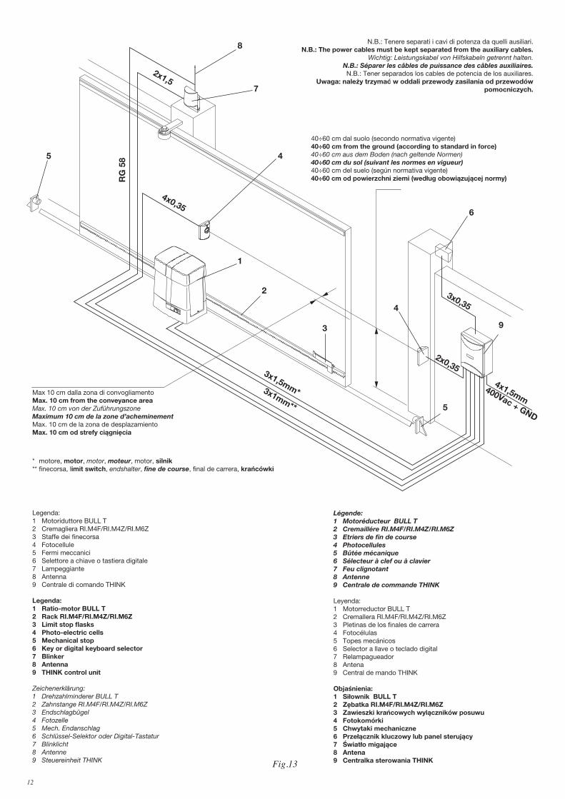
Legenda:1 Motoriduttore BULL T2 Cremagliera RI.M4F/RI.M4Z/RI.M6Z3 Staffe dei finecorsa4 Fotocellule 5 Fermi meccanici6 Selettore a chiave o tastiera digitale 7 Lampeggiante 8 Antenna9 Centrale di comando THINK
Legenda:1 Ratio-motor BULL T2 Rack RI.M4F/RI.M4Z/RI.M6Z3 Limit stop flasks4 Photo-electric cells 5 Mechanical stop6 Key or digital keyboard selector 7 Blinker 8 Antenna 9 THINK control unit
Zeichenerklärung:1 Drehzahlminderer BULL T 2 Zahnstange RI.M4F/RI.M4Z/RI.M6Z3 Endschlagbügel4 Fotozelle 5 Mech. Endanschlag6 Schlüssel-Selektor oder Digital-Tastatur 7 Blinklicht8 Antenne9 Steuereinheit THINK
Légende:1 Motoréducteur BULL T2 Cremaillére RI.M4F/RI.M4Z/RI.M6Z3 Etriers de fin de course4 Photocellules 5 Bûtée mécanique6 Sélecteur à clef ou à clavier 7 Feu clignotant 8 Antenne9 Centrale de commande THINK
Leyenda:1 Motorreductor BULL T2 Cremallera RI.M4F/RI.M4Z/RI.M6Z3 Pletinas de los finales de carrera4 Fotocélulas 5 Topes mecánicos6 Selector a llave o teclado digital 7 Relampagueador 8 Antena 9 Central de mando THINK
Objaśnienia:1 Siłownik BULL T2 Zębatka RI.M4F/RI.M4Z/RI.M6Z3 Zawieszki krańcowych wylączników posuwu4 Fotokomórki 5 Chwytaki mechaniczne6 Przełącznik kluczowy lub panel sterujący 7 Światło migające 8 Antena9 Centralka sterowania THINK
2x1,5
RG
585
4x0,35
4
6
5
40÷60 cm dal suolo (secondo normativa vigente)40÷60 cm from the ground (according to standard in force)40÷60 cm aus dem Boden (nach geltende Normen)40÷60 cm du sol (suivant les normes en vigueur)40÷60 cm del suelo (según normativa vigente)40÷60 cm od powierzchni ziemi (według obowiązującej normy)
Max 10 cm dalla zona di convogliamentoMax. 10 cm from the conveyance areaMax. 10 cm von der ZuführungszoneMaximum 10 cm de la zone d’acheminementMax. 10 cm de la zona de desplazamientoMax. 10 cm od strefy ciągnięcia
9
4x1,5mm
3x0,35
2x0,35
400Vac + GND
3x1,5mm*3x1mm**
* motore, motor, motor, moteur, motor, silnik** finecorsa, limit switch, endshalter, fine de course, final de carrera, krańcówki
N.B.: Tenere separati i cavi di potenza da quelli ausiliari.N.B.: The power cables must be kept separated from the auxiliary cables.
Wichtig: Leistungskabel von Hilfskabeln getrennt halten.N.B.: Séparer les câbles de puissance des câbles auxiliaires.N.B.: Tener separados los cables de potencia de los auxiliares.
Uwaga: należy trzymać w oddali przewody zasilania od przewodów pomocniczych.
12 13
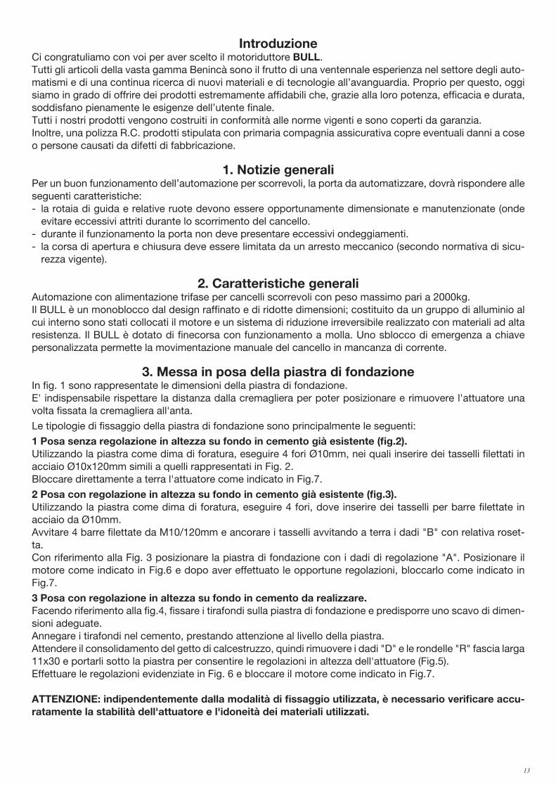
IntroduzioneCi congratuliamo con voi per aver scelto il motoriduttore BULL. Tutti gli articoli della vasta gamma Benincà sono il frutto di una ventennale esperienza nel settore degli auto-matismi e di una continua ricerca di nuovi materiali e di tecnologie all’avanguardia. Proprio per questo, oggi siamo in grado di offrire dei prodotti estremamente affidabili che, grazie alla loro potenza, efficacia e durata, soddisfano pienamente le esigenze dell’utente finale.Tutti i nostri prodotti vengono costruiti in conformità alle norme vigenti e sono coperti da garanzia.Inoltre, una polizza R.C. prodotti stipulata con primaria compagnia assicurativa copre eventuali danni a cose o persone causati da difetti di fabbricazione.
1. Notizie generaliPer un buon funzionamento dell’automazione per scorrevoli, la porta da automatizzare, dovrà rispondere alle seguenti caratteristiche:- la rotaia di guida e relative ruote devono essere opportunamente dimensionate e manutenzionate (onde
evitare eccessivi attriti durante lo scorrimento del cancello.- durante il funzionamento la porta non deve presentare eccessivi ondeggiamenti.- la corsa di apertura e chiusura deve essere limitata da un arresto meccanico (secondo normativa di sicu-
rezza vigente).
2. Caratteristiche generaliAutomazione con alimentazione trifase per cancelli scorrevoli con peso massimo pari a 2000kg.Il BULL è un monoblocco dal design raffinato e di ridotte dimensioni; costituito da un gruppo di alluminio al cui interno sono stati collocati il motore e un sistema di riduzione irreversibile realizzato con materiali ad alta resistenza. Il BULL è dotato di finecorsa con funzionamento a molla. Uno sblocco di emergenza a chiave personalizzata permette la movimentazione manuale del cancello in mancanza di corrente.
3. Messa in posa della piastra di fondazioneIn fig. 1 sono rappresentate le dimensioni della piastra di fondazione.E' indispensabile rispettare la distanza dalla cremagliera per poter posizionare e rimuovere l'attuatore una volta fissata la cremagliera all'anta.
Le tipologie di fissaggio della piastra di fondazione sono principalmente le seguenti:
1 Posa senza regolazione in altezza su fondo in cemento già esistente (fig.2). Utilizzando la piastra come dima di foratura, eseguire 4 fori Ø10mm, nei quali inserire dei tasselli filettati in acciaio Ø10x120mm simili a quelli rappresentati in Fig. 2. Bloccare direttamente a terra l'attuatore come indicato in Fig.7.
2 Posa con regolazione in altezza su fondo in cemento già esistente (fig.3). Utilizzando la piastra come dima di foratura, eseguire 4 fori, dove inserire dei tasselli per barre filettate in acciaio da Ø10mm.Avvitare 4 barre filettate da M10/120mm e ancorare i tasselli avvitando a terra i dadi "B" con relativa roset-ta.Con riferimento alla Fig. 3 posizionare la piastra di fondazione con i dadi di regolazione "A". Posizionare il motore come indicato in Fig.6 e dopo aver effettuato le opportune regolazioni, bloccarlo come indicato in Fig.7.
3 Posa con regolazione in altezza su fondo in cemento da realizzare. Facendo riferimento alla fig.4, fissare i tirafondi sulla piastra di fondazione e predisporre uno scavo di dimen-sioni adeguate.Annegare i tirafondi nel cemento, prestando attenzione al livello della piastra. Attendere il consolidamento del getto di calcestruzzo, quindi rimuovere i dadi "D" e le rondelle "R" fascia larga 11x30 e portarli sotto la piastra per consentire le regolazioni in altezza dell'attuatore (Fig.5).Effettuare le regolazioni evidenziate in Fig. 6 e bloccare il motore come indicato in Fig.7.
ATTENZIONE: indipendentemente dalla modalità di fissaggio utilizzata, è necessario verificare accu-ratamente la stabilità dell'attuatore e l'idoneità dei materiali utilizzati.

14 15
4. Fissaggio cremaglieraCremagliera in Fe 12x30mm.Posizionare i distanziali D saldandoli o avvitandoli sul cancello ad una altezza di 130/150 mm dalla mezzeria dell’asola di fissaggio alla base sulla quale andrà fissata la piastra di fondazione. Rispettare il passo di dentatura anche tra uno spezzone di cremagliera e l’altro; a tale scopo può essere utile accoppiare un’altro spezzone di cremagliera (vedi Fig.8).Fissare infine la cremagliera con le viti V, avendo cura, una volta installato l’attuatore, che rimanga circa 1mm di gioco tra cremagliera e ruota di trascinamento (vedi Fig.9); a tale scopo usufruire delle asole sulla cremagliera.
5. Posizionamento staffe dei finecorsa (Fig.10)Portare manualmente il cancello in apertura lasciando una luce da 1 a 3cm a seconda del peso del cancello tra il portone stesso e l’arresto meccanico A; fissare quindi la staffa del finecorsa S mediante i grani G in modo che il micro finecorsa sia premuto. Ripetere poi l’operazione con il portone in chiusura.
6. Manovra manuale (Fig.11)In caso di mancanza dell’energia elettrica o di guasto, per azionare manualmente l'anta procedere come segue: - Inserita la chiave personalizzata C, farla ruotare in senso antiorario e tirare la leva L.- Il motoriduttore è così sbloccato ed è possibile movimentare manualmete l'anta.- Per ristabilire il normale funzionamento richiudere la leva L ed azionare il cancello manualmente fino ad
ingranamento avvenuto.
7. Collegamenti elettrici (Fig.12)Per il collegamento elettrico dell'automazione e per la regolazione delle modalità di funzionamento, consultate il manuale istruzioni della centrale di comando.Ricordiamo inoltre che è obbligatorio effettuare il collegamento di messa a terra utilizzando l'apposito morsetto.
ATTENZIONELa polizza RC prodotti, che risponde di eventuali danni a cose o persone causati da difetti di fabbricazione, richiede la conformità dell’impianto alla normativa vigente e l’utilizzo di accessori originali Benincà.
14 15
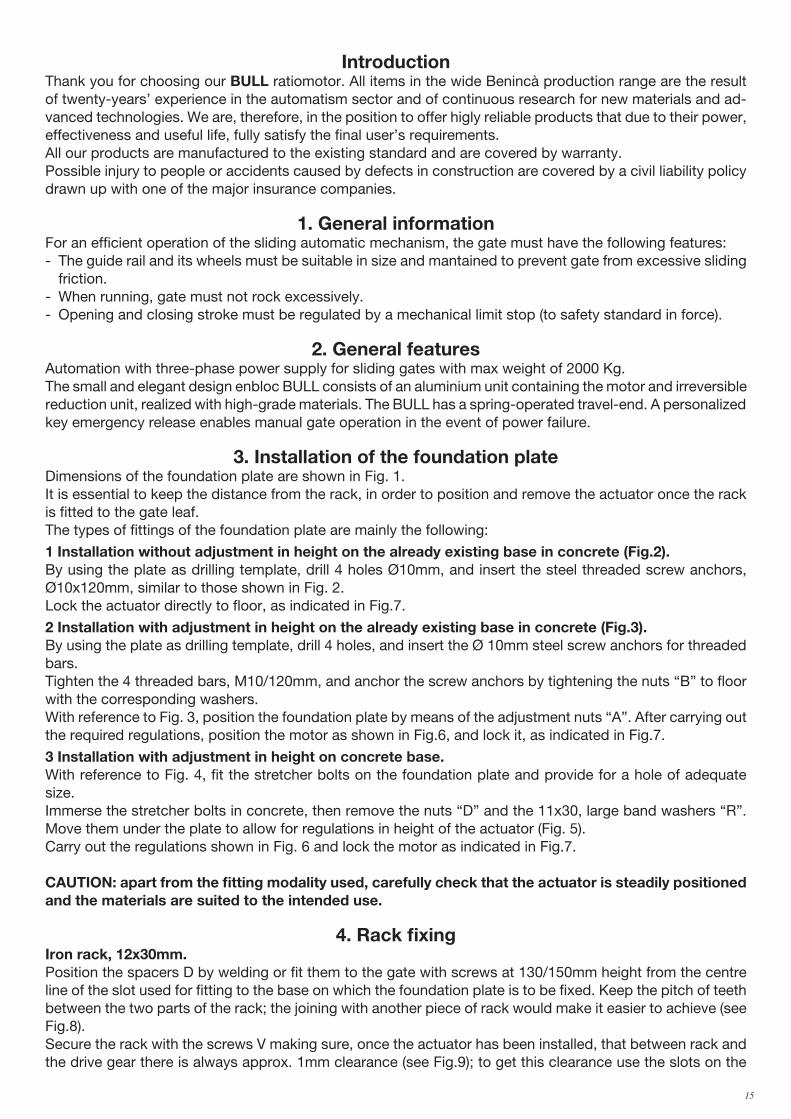
IntroductionThank you for choosing our BULL ratiomotor. All items in the wide Benincà production range are the result of twenty-years’ experience in the automatism sector and of continuous research for new materials and ad-vanced technologies. We are, therefore, in the position to offer higly reliable products that due to their power, effectiveness and useful life, fully satisfy the final user’s requirements.All our products are manufactured to the existing standard and are covered by warranty.Possible injury to people or accidents caused by defects in construction are covered by a civil liability policy drawn up with one of the major insurance companies.
1. General informationFor an efficient operation of the sliding automatic mechanism, the gate must have the following features:- The guide rail and its wheels must be suitable in size and mantained to prevent gate from excessive sliding
friction.- When running, gate must not rock excessively.- Opening and closing stroke must be regulated by a mechanical limit stop (to safety standard in force).
2. General featuresAutomation with three-phase power supply for sliding gates with max weight of 2000 Kg.The small and elegant design enbloc BULL consists of an aluminium unit containing the motor and irreversible reduction unit, realized with high-grade materials. The BULL has a spring-operated travel-end. A personalized key emergency release enables manual gate operation in the event of power failure.
3. Installation of the foundation plateDimensions of the foundation plate are shown in Fig. 1.It is essential to keep the distance from the rack, in order to position and remove the actuator once the rack is fitted to the gate leaf.The types of fittings of the foundation plate are mainly the following:
1 Installation without adjustment in height on the already existing base in concrete (Fig.2). By using the plate as drilling template, drill 4 holes Ø10mm, and insert the steel threaded screw anchors, Ø10x120mm, similar to those shown in Fig. 2.Lock the actuator directly to floor, as indicated in Fig.7.
2 Installation with adjustment in height on the already existing base in concrete (Fig.3). By using the plate as drilling template, drill 4 holes, and insert the Ø 10mm steel screw anchors for threaded bars.Tighten the 4 threaded bars, M10/120mm, and anchor the screw anchors by tightening the nuts “B” to floor with the corresponding washers.With reference to Fig. 3, position the foundation plate by means of the adjustment nuts “A”. After carrying out the required regulations, position the motor as shown in Fig.6, and lock it, as indicated in Fig.7.
3 Installation with adjustment in height on concrete base. With reference to Fig. 4, fit the stretcher bolts on the foundation plate and provide for a hole of adequate size.Immerse the stretcher bolts in concrete, then remove the nuts “D” and the 11x30, large band washers “R”. Move them under the plate to allow for regulations in height of the actuator (Fig. 5).Carry out the regulations shown in Fig. 6 and lock the motor as indicated in Fig.7.
CAUTION: apart from the fitting modality used, carefully check that the actuator is steadily positioned and the materials are suited to the intended use.
4. Rack fixingIron rack, 12x30mm.Position the spacers D by welding or fit them to the gate with screws at 130/150mm height from the centre line of the slot used for fitting to the base on which the foundation plate is to be fixed. Keep the pitch of teeth between the two parts of the rack; the joining with another piece of rack would make it easier to achieve (see Fig.8).Secure the rack with the screws V making sure, once the actuator has been installed, that between rack and the drive gear there is always approx. 1mm clearance (see Fig.9); to get this clearance use the slots on the

16 17
rack.
5. Limit stop flask positioning (see Fig.10)Open manually the gate and leave approximately of 1÷3cm, depending on gate weight, between gate and positive mechanical stop A; tighten the limit stop flask S with the grains G to press the limit stop micro. Repeat the sequence with closing gate.
6. Manual operation (see Fig.11)In the event of power failure or malfunction, to manually operate the gate proceed as follows:- After inserting the customized key C, turn it anti-clockwise and pull the lever L.- The geared motor is unlocked and the gate can be moved by hand.- To return to the normal operating mode, close the lever L again and manually activate the gate until it is
geared.
7. Wire diagram (see Fig.12)For the wire connections of the system and to adjust the operating modes, please refer to the Instruction Manual of the control unit.Please remember that the device should be earthed by means of the appropriate terminal.
CAUTIONThe civil liability policy, which covers possible injuries to people or accidents caused by defects in construction, requires the system to be to existing standard and to use original Benincà accessories.
16 17
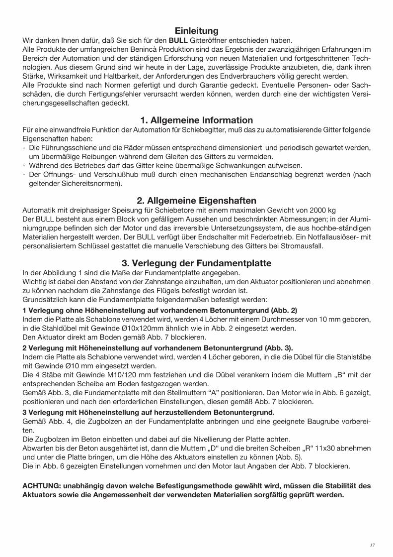
EinleitungWir danken Ihnen dafür, daß Sie sich für den BULL Gitteröffner entschieden haben.Alle Produkte der umfangreichen Benincà Produktion sind das Ergebnis der zwanzigjährigen Erfahrungen im Bereich der Automation und der ständigen Erforschung von neuen Materialien und fortgeschrittenen Tech-nologien. Aus diesem Grund sind wir heute in der Lage, zuverlässige Produkte anzubieten, die, dank ihren Stärke, Wirksamkeit und Haltbarkeit, der Anforderungen des Endverbrauchers völlig gerecht werden.Alle Produkte sind nach Normen gefertigt und durch Garantie gedeckt. Eventuelle Personen- oder Sach-schäden, die durch Fertigungsfehler verursacht werden können, werden durch eine der wichtigsten Versi-cherungsgesellschaften gedeckt.
1. Allgemeine InformationFür eine einwandfreie Funktion der Automation für Schiebegitter, muß das zu automatisierende Gitter folgende Eigenschaften haben:- Die Führungsschiene und die Räder müssen entsprechend dimensioniert und periodisch gewartet werden,
um übermäßige Reibungen während dem Gleiten des Gitters zu vermeiden.- Während des Betriebes darf das Gitter keine übermaßige Schwankungen aufweisen.- Der Offnungs- und Verschlußhub muß durch einen mechanischen Endanschlag begrenzt werden (nach
geltender Sichereitsnormen).
2. Allgemeine EigenshaftenAutomatik mit dreiphasiger Speisung für Schiebetore mit einem maximalen Gewicht von 2000 kgDer BULL besteht aus einem Block von gefälligem Aussehen und beschränkten Abmessungen; in der Alumi-niumgruppe befinden sich der Motor und das irreversible Untersetzungssystem, die aus hochbe-ständigen Materialien hergestellt werden. Der BULL verfügt über Endschalter mit Federbetrieb. Ein Notfallauslöser- mit personalisiertem Schlüssel gestattet die manuelle Verschiebung des Gitters bei Stromausfall.
3. Verlegung der FundamentplatteIn der Abbildung 1 sind die Maße der Fundamentplatte angegeben.Wichtig ist dabei den Abstand von der Zahnstange einzuhalten, um den Aktuator positionieren und abnehmen zu können nachdem die Zahnstange des Flügels befestigt worden ist.Grundsätzlich kann die Fundamentplatte folgendermaßen befestigt werden:
1 Verlegung ohne Höheneinstellung auf vorhandenem Betonuntergrund (Abb. 2) Indem die Platte als Schablone verwendet wird, werden 4 Löcher mit einem Durchmesser von 10 mm geboren, in die Stahldübel mit Gewinde Ø10x120mm ähnlich wie in Abb. 2 eingesetzt werden.Den Aktuator direkt am Boden gemäß Abb. 7 blockieren.
2 Verlegung mit Höheneinstellung auf vorhandenem Betonuntergrund (Abb. 3). Indem die Platte als Schablone verwendet wird, werden 4 Löcher geboren, in die die Dübel für die Stahlstäbe mit Gewinde Ø10 mm eingesetzt werden.Die 4 Stäbe mit Gewinde M10/120 mm festziehen und die Dübel verankern indem die Muttern „B“ mit der entsprechenden Scheibe am Boden festgezogen werden.Gemäß Abb. 3, die Fundamentplatte mit den Stellmuttern “A” positionieren. Den Motor wie in Abb. 6 gezeigt, positionieren und nach den erforderlichen Einstellungen, diesen gemäß Abb. 7 blockieren.
3 Verlegung mit Höheneinstellung auf herzustellendem Betonuntergrund. Gemäß Abb. 4, die Zugbolzen an der Fundamentplatte anbringen und eine geeignete Baugrube vorberei-ten.Die Zugbolzen im Beton einbetten und dabei auf die Nivellierung der Platte achten. Abwarten bis der Beton ausgehärtet ist, dann die Muttern „D“ und die breiten Scheiben „R“ 11x30 abnehmen und unter die Platte bringen, um die Höhe des Aktuators einstellen zu können (Abb. 5).Die in Abb. 6 gezeigten Einstellungen vornehmen und den Motor laut Angaben der Abb. 7 blockieren.
ACHTUNG: unabhängig davon welche Befestigungsmethode gewählt wird, müssen die Stabilität des Aktuators sowie die Angemessenheit der verwendeten Materialien sorgfältig geprüft werden.

18 19
4. Befestigung der ZahnstangeZahnstange aus Fe 12x30mm.Distanzstücke D positionieren und am Tor in einem Abstand von 130/150 mm Höhe von der Mittellinie des Befestigungsschlitzlochs an der Basis, an der die Fundamentplatte befestigt wird, schweißen oder festschrau-ben.Die Zahnteilung zwischen den Zahnstangenstücken muß außerdem eingehalten werden; zu diesem Zweck wäre es nützlich ein zweites Zahnstangenstück zu paaren (siehe Bild 8).Durch die Schrauben V, die Zahnstange befestigen; bitte beachten, daß nach der Installation des Aktuators, ein Spiel von ca. 1mm zwischen Zahnstange und Zahnrad bleibt (siehe Bild 9). Zu diesem Zweck können die in der Zahnstange gefrästen Nuten verwendet werden.
5. Positionierung der Endanschlagbügeln (Bild 10)Das Schiebegitter manuell öffnen, damit ein Abstand von 1 bis 3cm zwischen Gitter und Endschalter A bleibt; der Endanschlagtbügel S mittels der Stifte G befestigen, bis der Mikroschalter gedrückt wird. Den Vorgang mit geschlossenem Gitter wiederholen.
6. Manuelle Betätigung (Bild 11)Bei einem Stromausfall oder im Falle einer Störung, kann der Flügel folgendermaßen manuell gesteuert wer-den:- Den personalisierten Schlüssel C in den Sitz stecken und gegen den Uhrzeigersinn drehen und Hebel L
ziehen.- Der Getriebemotor wird dadurch entsichert und der Flügel kann von Hand bewegt werden.- Um den normalen Betrieb wieder herzustellen, den Hebel L wieder schließen und das Tor von Hand bewe-
gen bis das Einrasten erfolgt.
7. Elektrische Anschlüsse (Bild 12)Um die Automatik elektrisch anzuschließen und den Betriebsmodus einzustellen, siehe Gebrauchsanweisun-gen der Steuerungszentrale.Bitte beachten Sie, dass die Erdung durch die entsprechende Klemme vorgeschrieben ist.
BITTE BEACHTENDie Versicherung deckt nur Personen- oder Sachschäden, die durch Fertigungsfehler verursacht werden und gilt nur bei Einsatz von Benincà Original-Ersatzteilen und wenn die Anlage der Normen entspricht.

18 19
IntroductionNous ne pouvons que féliciter d’avoir porté votre choix sur le moto-réducteur BULL. Vingt années d’expérience dans le secteur des automatismes ainsi que dans le recherche de nouveaux matériaux et technologies de pointe, nous ont permis de développer tous les nombreux articles de la gamme Benincà. Pour ces raisons, nous sommes en mesure de proposer des produits extrémement fiables et qui grâce à leurs puissances, performances et longévité, répondent aux exigences des utilisateurs. Tous nos produits sont construits se-lon les normes et sont garantis. En plus, une police d’assurance responsabilité civile garantie la couverture d’éventuels sinistres à personnes ou objects causés par les défauts de fabrication.
1. Notice généralesPour une parfaite automatisation de portails coulissants, vérifier que les suivantes caractéristiques soient respectées:- Le rail de guide et les roues devront être correctement dimensionnés et entretenus (pour éviter trop de
frottement pendant le coulissement du portail).- Pendant le fonctionnement, le portail ne devra pas trop onduler.- L’ouverture et la fermeture devront être stopées par une bûtée mécanique (selon les normes en vigeur).
2. Caractéristiques généralesAutomation avec alimentation triphasée pour portails coulissantsavec poids maxi égal à 2000kg.Le BULL est un monobloc au design raffiné et de dimensions réduites; il est constitué d’un groupe en alu-minium à l’intérieur duquel ont été placés le moteur et un système de réduction irréversible réalisé avec des matériaux très résistants. Le BULL est doté de fin de course à ressort. En cas de panne de courant, un dé-blocage d’urgence à clé personnalisée permet le déplacement manuel de la grille.
3. Mise en pose de la plaque de fondation La Fig. 1 représente les dimensions de la plaque de fondation.Il faut absolument respecter la distance de la crémaillère pour avoir la possibilité de placer et ôter l’actuateur une fois la crémaillère du vantail fixée.Voila ci de suite les principales typologies d’ancrage de la plaque de fondation:
1 Pose sans réglage en hauteur sur fond en ciment préexistant (Fig.2). En utilisant la plaque comme gabarit de forage, exécutez 4 trous Ø10mm, où insérer des chevilles filetées en acier Ø10x120mm comme celles illustrées dans la Fig. 2. Fixez directement sur le sol l’actuateur comme l’indique la Fig.7.
2 Pose avec réglage en hauteur sur fond en ciment préexistant (Fig.3). En utilisant la plaque comme gabarit de forage, exécutez 4 trous pour l’insertion des chevilles pour barres filetées en acier de Ø 10mm.Vissez 4 barres filetées de M10/120mm et ancrez les chevilles en vissant à terre les écrous “B” avec leurs rondelles.Comme l’indique la Fig. 3 placez la plaque de fondation avec les écrous de réglage “A”. Placez le moteur comme indiqué dans la Fig.6 et après avoir effectué tous les réglages du cas, bloquez-le comme l’indique la Fig.7.
3 Pose avec réglage en hauteur sur fond en ciment à réaliser. Comme indiqué dans la Fig.4, ancrez les tire-fonds sur la plaque de fondation et prédisposez un cavages de dimensions.Noyez les tire-fonds dans le ciment, en faisant attention au niveau de la plaque. Attendez le durcissement de la colée de béton et enlevez donc les écrous «D» et les rondelles «R» bande large 11x30. Portez-les sous la plaque pour permettre les réglages en hauteur de l’actuateur (Fig.5).Effectuez les réglages mis en évidence dans la Fig. 6 et bloquez le moteur comme l’indique la Fig.7.
ATTENTION: indépendamment des modalités d’ancrage utilisées, il faut vérifier avec soin la stabilité de l’actuateur et l’aptitude des matériaux utilisés.
4. Fixation de la cremailléreCrémaillère en Fe 12x30mm.Mettre en place les entretoises D en les soudant ou en les vissant au portail à une hauteur de 130/150 mm de la ligne médiane du trou de fixation à la base sur laquelle sera fixée la plaque de fondation.
20 21
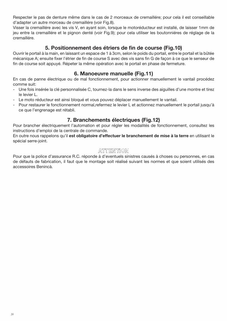
Respecter le pas de denture même dans le cas de 2 morceaux de cremaillére; pour cela il est conseillable d’adapter un autre morceau de cremaillére (voir Fig.8).Visser la cremaillére avec les vis V, en ayant soin, lorsque le motoréducteur est installé, de laisser 1mm de jeu entre la cremaillére et le pignon denté (voir Fig.9); pour cela utiliser les boutonniéres de réglage de la cremaillére.
5. Positionnement des étriers de fin de course (Fig.10)Ouvrir le portail à la main, en laissant un espace de 1 à 3cm, selon le poids du portail, entre le portail et la bûtée mécanique A; ensuite fixer l’étrier de fin de course S avec des vis sans fin G de façon à ce que le senseur de fin de course soit appuyé. Répeter la même opération avec le portail en phase de fermeture.
6. Manoeuvre manuelle (Fig.11)En cas de panne électrique ou de mal fonctionnement, pour actionner manuellement le vantail procédez comme suit: - Une fois insérée la clé personnalisée C, tournez-la dans le sens inverse des aiguilles d’une montre et tirez
le levier L.- Le moto réducteur est ainsi bloqué et vous pouvez déplacer manuellement le vantail.- Pour restaurer le fonctionnement normal,refermez le levier L et actionnez manuellement le portail jusqu’à
ce que l’engrenage est rétabli.
7. Branchements électriques (Fig.12)Pour brancher électriquement l’automation et pour régler les modalités de fonctionnement, consultez les instructions d’emploi de la centrale de commande.En outre nous rappelons qu’il est obligatoire d’effectuer le branchement de mise à la terre en utilisant le spécial serre-joint.
ATTENTIONPour que la police d’assurance R.C. réponde à d’eventuels sinistres causés à choses ou personnes, en cas de défauts de fabrication, il faut que le montage soit réalisé suivant les normes et que soient utilisés des accessoires Benincà.

20 21
IntroducciónNos congratulamos con vd. por haber elegido el BULL. Todos los artículos de la vasta gama Benincà son el fruto de una veinteañal experiencia en el sector de los automatismos y de una continua búsqueda de nuevos materiales y de tecnología de vanguardia. Precisamente por esto, hoy nos encontramos en situación de po-der ofrecer productos extremadamentes fiables que, gracias a su potencia, eficacia y duración, satisfacen plenamente las exigencias del usuario final. Todos nuestros productos están construidos de conformidad con la norma y están garantizados. Además, una póliza R.C. productos, estipulada con una de las principales compañías de seguros, cubre eventuales daños a personas o cosas causados por defectos de fabricación.
1. Noticias generalesPara un buen funcionamiento de la automatización para correderas, la puerta a automatizar, deberá responder a las siguientes características:- el carril de guía y las ruedas correspondientes deben estar correctamente dimensionadas y en perfecto
estado (a fin de evitar excesivas fricciones durante el desplazamiento de la cancela).- durante el funcionamiento la puerta no debe presentar excesivas ondulaciones.- los desplazamientos de apertura y cierre deben estar limitados por un tope mecánico (según normativa de
seguridad vigente).
2. Características generalesAutomatización con alimentación trifásica para cancelas correderas con peso máximo de 2000kg.El BULL es un monobloque de diseño refinado y reducidas dimensiones; constituido por un grupo de aluminio en cuyo interior han sido colocados el motor y un sistema de reducción irreversible realizado con materiales de alta resistencia. El BULL está provisto de final de carrera con funcionamiento por muelle. Un desbloqueo de emergencia por llave personalizada permite el movimiento manual de la cancela en au-sencia de corriente.
3. Colocación de la placa de fundaciónEn la Fig. 1 se presentan las medidas de la placa de fundación.Es indispensable respetar la distancia con respecto a la cremallera para poder colocar y sacar el actuador una vez fijada la cremallera a la hoja.Los tipos de fijación de la placa de fundación son principalmente las siguientes:
1 Colocación sin regulación de la altura sobre fondo de cemento ya existente (fig.2). Utilizando la placa como patrón de perforación, taladrar 4 agujeros Ø10mm, en los cuales introducir unos tacos con rosca de acero Ø10x120mm parecidos a los mostrados en la Fig. 2. Bloquear directamente al suelo el actuador como indicado en la Fig.7.
2 Colocación con regulación de la altura sobre fondo de cemento ya existente (fig.3). Utilizando la placa como patrón de perforación, taladrar 4 agujeros en los cuales introducir unos espárragos con rosca de acero da Ø 10mm.Enroscar 4 espárragos con rosca M10/120mm y anclar los tacos enroscando en el suelo las tuercas “B” con correspondiente arandela.Con referencia a la Fig. 3, colocar la placa de fundación con las tuercas de regulación “A”. Colocar el motor como indicado en la Fig.6 y después de haber efectuado las oportunas regulaciones, bloquearlo como indi-cado en la Fig.7.
3 Colocación con regulación de la altura sobre fondo de cemento a realizar. Haciendo referencia a la fig.4, fijar los tirafondos sobre la placa de fundación y realizar una excavación de medidas adecuadas.Ahogar los tirafondos en el cemento, prestando atención al nivel de la placa. Esperar que se consolide el vaciado de hormigón, seguidamente quitar las tuercas “D” y las arandelas “R” faja larga 11x30 y ponerlas debajo de la placa para consentir las regulaciones de altura del actuador (Fig. 5).Efectuar las regulaciones indicadas en la Fig. 6 y bloquear el motor como indicado en la Fig.7.
ATENCIÓN: independientemente de la modalidad de fijación utilizada, es necesario comprobar cuida-dosamente la estabilidad del actuador y la idoneidad de los materiales utilizados.

22 23
4. Fijación de la cremalleraCremallera de Fe 12x30mm.Colocar los espaciadores D soldándolos o atornillándolos en la puerta a una altura de 130/150 mm de la línea central del ojal de fijación en la base, donde se fijará la placa de fundación.Respetar el paso de los dientes también entre una y otra pieza de la cremallera; a tal fin puede ser útil acoplar otra pieza de cremallera (véase Fig.8).Fijar finalmente la cremallera con los tornillos V, teniendo cuidado, una vez instalado el operador, que quede 1mm. de juego entre la cremallera y el piñón de tracción (véase Fig.9); a tal fin manejarse con la holgura de los orificios de la cremallera.
5. Posicionamiento de la pletinas de los finales de carrera (Fig.10)Llevar manualmente la cancela en apertura dejando una luz entre 1 y 3cms. según el peso de la cancela, entre la misma cancela y el tope mecánico A; fijar entonces la pletina del final de carrera S mediante los granos G de forma que el micro del final de carrera sea presionado. Repetir después la operación con la cancela en el cierre.
6. Maniobra manual (Fig.11)En caso de falta de energía eléctrica o de avería, para accionar manualmente la hoja proceder como sigue : - Insertar la llave personalizada C, darle la vuelta en sentido antihorario y tirar de la palanca L.- El motorreductor de esta forma queda desbloqueado y es posible desplazar manualmente la hoja.- Para restablecer el funcionamiento normal cerrar de nuevo la palanca L y desplazar la cancela manualmente
hasta que se produzca el engrane.
7. Conexiones eléctricas (Fig.12)Para el conexionado eléctrico de la automatización y para la regulación de las modalidades de funcionamiento, consúltese el manual de instrucciones de la centralita de comando.Cabe así mismo recordar que es obligatorio efectuar el conexionado de puesta a tierra utilizando el borne apropiado.
ATENCIONLa póliza RC productos, que responde de eventuales daños a personas o cosas causados por defectos de fabricación, requiere la conformidad de la instalación según la normativa y la utilización de accesorios origi-nales Benincà.

22 23
WprowadzenieGratulujemy Państwu wyboru siłownika BULL. Cały asortyment szerokiej gamy produktów Benincà jest owocem dwudziestoletniego doświadczenia nabytego w zakresie automatyzmów oraz ustawicznego poszukiwania nowych materiałów i nowoczesnych technologii. Z tego też względu jesteśmy dzisiaj w stanie zaoferować państwu nadzwyczaj godne zaufania produkty, które to dzięki ich skuteczności, sprawności oraz trwałości w pełni zaspakajają wymagania naszych odbiorców. Wszystkie nasze produkty są produkowane w oparciu o normy i opatrzone są gwarancją. Ponadto, polisa ubezpieczeniowa o odpowiedzialności cywilnej za produkty, wystawiona przez jedno ze znaczniejszych Towarzystw Ubezpieczeniowych, zapewnia odszkodowanie za szkody poniesione przez rzeczy lub osoby w wyniku wad produkcyjnych.
1. Informacje ogólneDla sprawnego funkcjonowania automatyzmów do bram przesuwnych, bramy do zautomatyzowania powinny spełniać następujące warunki:- tor prowadnicy z odpowiednimi kółkami powinien posiadać właściwe rozmiary i należytą konserwację (by
uniknąć nadmiernych tarć w trakcie przesuwu skrzydeł bramy),- w trakcie przesuwu brama nie powinna wykazywać nadmiernych falowań,- posuw otwierania i zamykania musi być ograniczony przez chwytak krańcowy, zgodnie z obowiązującą
normą bezpieczeństwa.
2. Charakterystyka ogólnaNapęd automatyczny z zasilaniem trójfazowym do bram przesuwnych, do dyspozycji o ciężarze maksymalniedo 2000kg.BULL to jednokadłubowy, małogabarytowy siłownik o eleganckiej linii, pokryty grupą lakierowanego aluminium z umieszczonym wewnątrz silnikiem i systemem nienawrotnej redukcji, zrealizowanych z wysoce odpornego materiału. BULL wyposażone są w sprężynowe wyłączniki posuwu. W przypadku braku napięcia, natychmiastowe odblokowanie przy użyciu klucza osobistego umożliwia ręczną obsługę bramy.
3. Zamontowanie płyty fundamentowej Na Rys. 1 przedstawione są wymiary płyty fundamentowej. Konieczne jest przestrzeganie odległości od zębatki, pozwalające na ustawienie w położeniu i wyjęcie siłownika po zamocowaniu zębatki do skrzydła. Typologie zamocowania płyty fundamentowej są głównie takie, jak podane poniżej:
1 Zamocowanie na istniejącym fundamencie betonowym bez możliwości regulacji wysokości (Rys.2). Używając płyty jako wzornika do odwiertów, wykonać 4 otwory Ø10 mm, do których założyć stalowe kołki gwintowane Ø10x120 mm, takie, jak przedstawione na Rys. 2. Zamocować siłownik bezpośrednio do podłoża, tak, jak pokazane na Rys. 7.
2 Zamocowanie na istniejącym fundamencie betonowym z możliwością regulacji wysokości (Rys.3). Używając płyty jako wzornika do odwiertów, wykonać 4 otwory, do których założyć płytki do stalowych drążków gwintowanych Ø 10 mm.Wkręcić 4 drążki gwintowane M10/120 mm i zamocować płytki dokręcając do podłoża nakrętki „B” wraz z odpowiednimi podkładkami.Tak jak wskazano na Rys. 3 umieścić płytę fundamentową wraz z nakrętkami regulacji „A”. Umieścić silnik tak, jak wskazano na Rys.6 i po dokonaniu odpowiedniego wyregulowania zamocować go w sposób wskazany na Rys.7.
3 Zamocowanie na nowo wykonanym fundamencie betonowym z możliwością regulacji wysokości. Tak jak wskazano na Rys.4, zakotwiczyć odciągi w płycie fundamentowej i przygotować odpowiednio zwymiarowany wykop.Zalać odciągi betonem, zwracając uwagę na poziom płyty. Odczekać na utwardzenie wylewu betonowego, a następnie wyjąć nakrętki „D” i szerokopasmowe podkładki „R” 11x30 i umieścić je pod płytą w celu umożliwienia regulacji wysokości siłownika (Rys.5).Wykonać regulacje tak, jak wskazano na Rys. 6 i zamocować silnik tak, jak wskazano na Rys.7.
UWAGA: niezależnie od wybranego sposobu zamocowania należy dokładnie sprawdzić stabilność siłownika i upewnić się, czy zastosowane materiały są odpowiednie.

24 25
4. Zamocowanie zębatkiZębatka z Fe 12x30 mm (rys.3)Rozmieścić odstępniki D i przyspawać lub wkręcić je do bramy w odległości 130/150 mm od płyty fundamentowej i w odstępach równych 1 przerwie między zębami zębatki. Przestrzegać odtsępów pomiędzy jednym a drugim przedziałem zębatki; w tym celu pomocne może być dołączenie dodatkowego przedziału zębatki (zob. rys.3)Zamocować wreszcie zębatkę za pomącą śrub V, pamiętając aby, po zamontowaniu siłownika, pozostawał luz= mm pomiędzy zębatką a kołem ciągnącym (zob. rys.4); do tego celu można wykorzystać otwory zębatki.
5. Ustawienie zawieszek krańcowego wyłącznika posuwu (rys.10)Otworzyć ręcznie bramę uchylając ją na szerokość wpadania światła, pomiędzy samą bramą a chwytakiem mechanicznym A, od 1 do 3 cm, w zależności od ciężaru bramy; po czym zamocować zawieszki krańcowego wyłącznika posuwu S za pomocą trybów G, w taki sposób aby mikrowyłącznik posuwu był wciśnięty. Powtórzyć czynność podczas zamykania bramy.
6. Manewr ręczny (rys.11)W przypadku braku energii elektrycznej lub uszkodzenia można otworzyć bramę ręcznie w następujący sposób:- Po wprowadzeniu klucza osobistego C, należy obrócić go w kierunku przeciwnym do obrotu wskazówek
zegara i pociągnąć dźwignię L.- Siłownik jest teraz odblokowany i można przesunąć bramę ręcznie.- W celu przywrócenia normalnego działania automatyzmu należy zamknąć dźwignię L i przesunąć ręcznie
bramę aż do wysprzęglenia.
7. Połączenia elektryczne (rys.11)W celu dokonania połączenia elektrycznego automatyzmu oraz wyregulowania trybu działania należy skonsultować instrukcję obsługi centralki sterowania.Przypominamy ponadto, że obowiązkowe jest uziemienie poprzez odpowiedni zacisk.
UWAGAPolisa ubezpieczeniowa o odpowiedzialności cywilnej za produkty, odpowiada tytułu ewentualnych szkód poniesionych przez rzeczy lub osoby w wyniku wad produkcyjnych, pod warunkiem że instalacja jest zgodna z obowiązującą normą i posiada origanalne części Benincà.
24 25
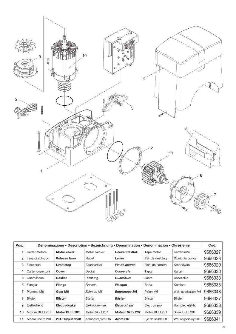
Pos. Denominazione - Description - Bezeichnung - Dénomination - Denominación - Określenie Cod.
1 Carter motore Motor cover Motor Deckel Couvercle mot. Tapa motor Karter silnik 96863272 Leva di sblocco Release lever Hebel Levier Pal. de desbloq. Dźwignia odrygl. 96863283 Finecorsa Limit stop Endschalter Fin de course Final de carrera Krańcówka 96863294 Carter copertura Cover Deckel Couvercle Tapa Karter 96863305 Guarnizione Gasket Dichtung Guarniture Junta Uszczelka 96863336 Flangia Flange Flansch Flasque . Brida Kołnierz 96863357 Pignone M6 Gear M6 Zahnrad M6 Engrenage M6 Piñon M6 Wał napędzający M6 96860488 Blister Blister Blister Blister Blister Blister 96863379 Elettrofreno Electrobrake Elektrobremse Électro-frein Electrofreno Hamulec elektr. 9686338
10 Motore BULL20T Motor BULL20T Motor BULL20T Moteur BULL20T Motor BULL20T Silnik BULL20T 968633911 Albero uscita 20T 20T Output shaft Antriebszapfen 20T Arbre 20T Eje de salida 20T Wał wyjściowy 20T 9686341
3
10
11
2
5
1
4
6
9
7
8
10
11

26 27
Norme di sicurezza• Non sostare nella zona di movimento dell'anta.• Non lasciare che i bambini giochino con i comandi o in prossimità dell'anta.• In caso di anomalie di funzionamento non tentare di riparare il guasto ma avvertire un tecnico specializzato.
Manovra manuale e d’emergenzaIn caso di mancanza dell’energia elettrica o di guasto, per azionare manualmente l'anta procedere come segue : - Inserita la chiave personalizzata C, farla ruotare in senso antiorario e tirare la leva L.- Il motoriduttore è così sbloccato ed è possibile movimentare manualmte l'anta.- Per ristabilire il normale funzionamento richiudere la leva L ed azionare il cancello manualmente fino ad
ingranamento avvenuto.
Manutenzione• Controllare periodicamente l’efficienza dello sblocco manuale di emergenza.• Astenersi assolutamente dal tentativo di effettuare riparazioni, potreste incorrere in incidenti; per queste
operazioni contattare un tecnico specializzato.• L’attuatore non richiede manutenzioni ordinarie, tuttavia è necessario verificare periodicamente l’efficienza
dei dispositivi di sicurezza e le altre parti dell’impianto che potrebbero creare pericoli in seguito ad usura.
SmaltimentoQualora il prodotto venga posto fuori servizio, è necessario seguire le disposizioni legislative in vigore al momento per quanto riguarda lo smaltimento differenziato ed il riciclaggio dei vari componenti (metalli, pla-stiche, cavi elettrici, ecc.); è consigliabile contattare il vostro installatore o una ditta specializzata ed abilitata allo scopo.
AttenzioneTutti i prodotti Benincà sono coperti da polizza assicurativa che risponde di eventuali danni a cose o persone causati da difetti di fabbricazione, richiede però la marcatura CE della ”macchina” e l’utilizzo di componenti originali Benincà.
BULLLibro istruzioni per l’utilizzatore
CL
26 27
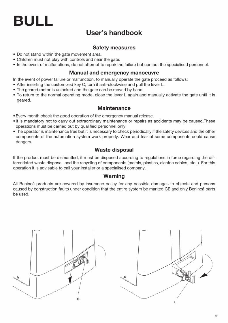
BULLUser’s handbook
Safety measures• Do not stand within the gate movement area.• Children must not play with controls and near the gate.• In the event of malfunctions, do not attempt to repair the failure but contact the specialised personnel.
Manual and emergency manoeuvre In the event of power failure or malfunction, to manually operate the gate proceed as follows:• After inserting the customized key C, turn it anti-clockwise and pull the lever L.• The geared motor is unlocked and the gate can be moved by hand.• To return to the normal operating mode, close the lever L again and manually activate the gate until it is
geared.
Maintenance• Every month check the good operation of the emergency manual release.• It is mandatory not to carry out extraordinary maintenance or repairs as accidents may be caused.These
operations must be carried out by qualified personnel only.• The operator is maintenance free but it is necessary to check periodically if the safety devices and the other
components of the automation system work properly. Wear and tear of some components could cause dangers.
Waste disposalIf the product must be dismantled, it must be disposed according to regulations in force regarding the dif-ferentiated waste disposal and the recycling of components (metals, plastics, electric cables, etc..). For this operation it is advisable to call your installer or a specialised company.
WarningAll Benincá products are covered by insurance policy for any possible damages to objects and persons caused by construction faults under condition that the entire system be marked CE and only Benincá parts be used.
CL

28 29
BULLHandbuch für den Verbraucher
Sicherheitsvorschriften • Sich nicht im Bewegungsbereich des Flügels aufhalten.• Nicht zulassen dass Kinder mit den Steuerungen oder in der Nähe des Flügels spielen.• Im Falle von Betriebsstörungen, versuchen Sie nicht die Störung selbst zu beheben, sondern wenden Sie
sich an einen qualifizierten Fachmann.
Manuelle Bedienung und NotbetriebBei einem Stromausfall oder im Falle einer Störung, kann der Flügel folgendermaßen manuell gesteuert wer-den: • Den personalisierten Schlüssel C in den Sitz stecken und gegen den Uhrzeigersinn drehen und Hebel L
ziehen.• Der Getriebemotor wird dadurch entsichert und der Flügel kann von Hand bewegt werden.• Um den normalen Betrieb wieder herzustellen, den Hebel L wieder schließen und das Tor von Hand be-
wegen bis das Einrasten erfolgt.
Wartung• Monatliche Kontrolle der manuellen Notentriegelung.• Es ist absolut untersagt, selbstständig Sonderwartung oder Reparaturen vorzunehmen, da Unfälle die Folge
sein können; wenden Sie sich an den Techniker.• Der Antrieb braucht keine ordentliche Unterhaltung aber es ist periodisch notwendig die Leistungsfähigkeit
der Sicherheitsvorrichtungen und die andere Teile des Anlages zu prüfen. Sie könnten durch Abnutzung Gefaht hervorbringen.
EntsorgungWird das Gerät außer Betrieb gesetzt, müssen die gültigen Gesetzesvorschriften zur differenzierten Entsorgung und Wiederverwendung der Einzelkomponenten, wie Metall, Plastik, Elektrokabel, usw., beachtet werden. Rufen Sie Ihren Installateur oder eine Entsorgungsfirma.
AchtungAlle Produkte BENINCA’ wurden mit einem Versicherungsschein versehen, der alle eventuellen Schäden an Dingen oder Personen abdeckt, die durch Herstellungsdefekte hervorgerufen wurden, vorausgesetzt, das Gerät besitzt die Kennzeichnung EU und es wurden original BENINCA’ Einzelkomponenten verwendet.
CL
28 29
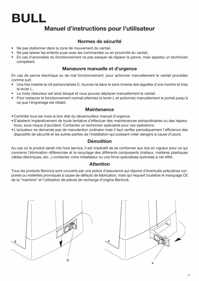
BULLManuel d’instructions pour l’utilisateur
Normes de sécurité• Ne pas stationner dans la zone de mouvement du vantail.• Ne pas laisser les enfants jouer avec les commandes ou en proximité du vantail.• En cas d’anomalies du fonctionnement ne pas essayer de réparer la panne, mais appelez un technicien
compétent.
Manœuvre manuelle et d’urgenceEn cas de panne électrique ou de mal fonctionnement, pour actionner manuellement le vantail procédez comme suit: • Une fois insérée la clé personnalisée C, tournez-la dans le sens inverse des aiguilles d’une montre et tirez
le levier L.• Le moto réducteur est ainsi bloqué et vous pouvez déplacer manuellement le vantail.• Pour restaurer le fonctionnement normal,refermez le levier L et actionnez manuellement le portail jusqu’à
ce que l’engrenage est rétabli.
Maintenance• Contrôler tous les mois le bon état du déverrouilleur manuel d’urgence.• S’abstenir impérativement de toute tentative d’effectuer des maintenances extraordinaires ou des répara-
tions, sous risque d’accident. Contactez un technicien spécialisé pour ces opérations.• L’actuateur ne demande pas de manutention ordinaire mais il faut verifier periodiquement l’efficience des
dispositifs de sécurité et les autres parties de l’installation qui puissent créer dangers à cause d’usure.
DémolitionAu cas où le produit serait mis hors service, il est impératif de se conformer aux lois en vigueur pour ce qui concerne l’élimination différenciée et le recyclage des différents composants (métaux, matières plastiques câbles électriques, etc...) contactez votre installateur ou une firme spécialisée autorisée à cet effet.
AttentionTous les produits Benincà sont couverts par une police d’assurance qui répond d’éventuels préjudices cor-porels ou matériels provoqués à cause de défauts de fabrication, mais qui requiert toutefois le marquage CE de la “machine” et l’utilisation de pièces de rechange d’origine Benincà.
CL

30 31
BULLManual de instrucciones para el usuario
Normas de seguridad• No pararse en la zona de movimiento de la hoja.• No dejar que los niños jueguen con los comandos ni cerca de la cancela.• En caso de anomalía de funcionamiento no intentar reparar el avería sino avisar a un técnico especializa-
do.
Maniobra manual y de emergenciaEn caso de falta de energía eléctrica o de avería, para accionar manualmente la hoja proceder como sigue : • Insertar la llave personalizada C, darle la vuelta en sentido antihorario y tirar de la palanca L.• El motorreductor de esta forma queda desbloqueado y es posible desplazar manualmente la hoja.• Para restablecer el funcionamiento normal cerrar de nuevo la palanca L y desplazar la cancela manualmente
hasta que se produzca el engrane.
Mantenimiento• Controlar periódicamente la eficiencia del desbloqueo manual de emergencia.• Abstenerse absolutamente de intentar efectuar reparaciones, podrían incurrir en accidentes; para estas
operaciones contactar con un técnico especializado.• El operador no requiere mantenimiento habitual, no obstante es necesario verificar periódicamente la efi-
ciencia de los dispositivos de seguridad y las otras partes de la instalación que pudiesen crear peligros a causa del desgaste.
Eliminación de aguas suciasCada vez que el producto esté fuera de servicio, es necesario seguir las disposiciones legislativas en vigor en ese momento en cuanto concierne a la eliminación de suciedad y al reciclaje de varios componentes (metales, plásticos, cables eléctricos, etc.), es aconsejable contactar con su instalador o con una empresa especializada y habilitada para tal fin.
AtenciónTodos los productos Benincà están cubiertos por una póliza de seguros que responde de eventuales daños a personas o cosas, causados por defectos de fabricación, requiere sin embargo la marca CE de la ”máquina” y la utilización de componentes originales Benincà.
CL

30 31
BULLKsiążeczka z instrukcjami dla użytkownika
Normy bezpieczeństwa• Nie przestawać w obszarze przesuwu skrzydła bramy.• Nie pozwolić, żeby dzieci bawiły się sterowaniem bramy lub ogólnie w pobliżu skrzydła.• W przypadku nieprawidłowego działania nie próbować samodzielnie naprawiać uszkodzenie, należy zwrócić
się do wyspecjalizowanego technika.
Sterowanie ręczne i awaryjneW przypadku braku energii elektrycznej lub uszkodzenia można otworzyć bramę ręcznie w następujący sposób:• Po wprowadzeniu klucza osobistego C, należy obrócić go w kierunku przeciwnym do obrotu wskazówek
zegara i pociągnąć dźwignię L.• Siłownik jest teraz odblokowany i można przesunąć bramę ręcznie.• W celu przywrócenia normalnego działania automatyzmu należy zamknąć dźwignię L i przesunąć ręcznie
bramę aż do wysprzęglenia.
Konserwacja• Sprawdzać okresowo sprawność działania ręcznego mechanizmu odblokowującego i bezpieczeństwa.• Nie starać się w żadnym wypadku dokonywać napraw samemu z racji na możliwość ulegnięcia wypadkowi,
w celu naprawy należy skontaktować się z technikiem wyspecjalizowanym.• Siłownik nie wymaga normalnej konserwacji, tym niemniej wskazane jest okresowe sprawdzanie sprawności
działania elementów bezpieczeństwa i pozostałych części instalacji, mogących stanowić zagrożenie z racji na stan zużycia.
Eliminacja i demolowanieW przypadku gdy urządzenie nie nadaje się już do dalszego użytkowania, w celu pozbycia się go należy ściśle przestrzegać obowiązujących w danym momencie norm prawnych regulujących zróżnicowany rozkład na części i odzyskiwanie niektórych elementów składowych (metale, plastyk, kable elektryczne, itp.); wskazane jest skontaktowanie się z instalatorem lub wyspecjalizowaną firmą, autoryzowaną do tego rodzaju prac.
UwagaWszystkie produkty Benincà objęte są polisą ubezpieczeniową na pokrycie szkód poniesionych przez rzeczy lub osoby w wyniku wad produkcyjnych, pod warunkiem że urządzenia posiadają oznakowanie CE i oryginalne części Benincà.
CL

AUTOMATISMI BENINCÀ SpA - Via Capitello, 45 - 36066 Sandrigo (VI) - Tel. 0444 751030 r.a. - Fax 0444 759728