
ACTIVE SUB-WOOFER 5 1 B U S A R E P O - images.thomann.de · Per la pulizia delle p arti esterne...
15
420120099 OPERA SUB 15 ACTIVE SUB-WOOFER ACTIVE SUB-WOOFER MANUALE D’USO USER MANUAL BEDIENUNGSANLEITUNG CARACTERISTIQUES TECHNIQUES
Transcript of ACTIVE SUB-WOOFER 5 1 B U S A R E P O - images.thomann.de · Per la pulizia delle p arti esterne...
420120099
OPER
A SUB
15OP
ERA S
UB 15
ACTIVESUB-WOOFER
ACTIVESUB-WOOFER
MANUALE D’USOUSER MANUALBEDIENUNGSANLEITUNGCARACTERISTIQUES TECHNIQUES
1
Ita
lian
oIta
lian
oIta
lian
oM
an
ua
le d
’us
oM
an
ua
le d
’us
o
Ita
lian
oIta
lian
oIta
lian
oM
an
ua
le d
’us
oM
an
ua
le d
’us
o
2
Carrelli, sostegni e accessoriL’apparecchio va utilizzato solo su carrelli o sostegni consigliati dal produttore. L’apparecchio va mosso con estrema cura.
Ingresso di liquidi e oggetti nell' apparecchioAssicurarsi che oggetti non cadano sull’apparecchio o che non si versino liquidi attraverso le aperture.
Danni che richiedono l'assistenzaL'apparecchio deve essere riparato dal personale qualificato nei seguenti casi:- il cavo di alimentazione o la presa siano danneggiati- sono caduti oggetti sull’apparecchio o liquidi siano entrati all’interno- l'apparecchio è stato esposto alla pioggia- l'apparecchio non sembra funzionare normalmente oppure ha cambiato le sue prestazioni- l'apparecchio è caduto oppure è danneggiato
ManutenzioneL'utente non deve tentare di riparare l'apparecchio al di là di quello descritto nelle istruzioni. Tutte le altre riparazioni devono essere eseguite da personale qualificato.
IMPORTANTE
Il presente manuale costituisce parte integrante del prodotto e deve accompagnare quest’ultimo anche nei passaggi di proprietà, per permettere al nuovo proprietario di conoscere le modalità d’installazione e d’utilizzo e le avvertenze per la sicurezza.
L’installazione errata del diffusore esime la dB Technologies da ogni responsabilità.
PRECAUZIONI PER L’UTILIZZO
- Evitate di far lavorare l’amplificatore interno al diffusore in sovraccarico per lungo tempo.- Non utilizzare la forza con gli organi di comando (tasti, controlli, ecc.).
ATTENZIONE
- Collocate il diffusore in modo stabile e sicuro, così da evitare qualsiasi condizione di pericolo per l’incolumità di persone o strutture.
COLLEGAMENTI
ATTENZIONE
- Per il collegamento del diffusore si raccomanda di rivolgersi a personale qualificato ed addestrato, ossia personale avente conoscenze tecniche o esperienza o istruzioni specifiche sufficienti per permettergli di realizzare correttamente le connessioni e prevenire i pericoli dell’elettricità.
- Per evitare il rischio di shock elettrici, il diffusore deve essere alimentato dalla tensione di rete solo dopo aver terminato tutti i collegamenti.
- Prima di alimentare il diffusore è buona norma ricontrollare tutte le connessioni.
- Tutto l’impianto di sonorizzazione dovrà essere realizzato in conformità con le norme e le leggi vigenti in materia di impianti elettrici.
AVVERTENZA
- Per evitare che fenomeni induttivi diano luogo a ronzii, disturbi e compromettano il buon funzionamento del diffusore, i cavi che trasmettono segnali microfonici o segnali a livello linea (es. 0 dB/V) devono essere schermati e non devono essere posti in prossimità di:1) apparecchiature che producono forti campi magnetici (es. grossi trasformatori di
alimentazione).2) conduttori dell’energia elettrica.3) linee che alimentano diffusori.
ISTRUZIONI DI SICUREZZA
AVVERTENZA: PER RIDURRE IL RISCHIO DI SCOSSA E L E T T R I C A , N O N T O G L I E R E I L C O P E R C H I O ( O I L P A N N E L L O POSTERIORE). ALL’INTERNO NON SONO C O N T E N U T E PA R T I R I PA R A B I L I DALL’UTENTE; AFFIDARE LE RIPARAZIONI A PERSONALE QUALIFICATO.
ATTENZIONE: PER RIDURRE IL RISCHIO DI INCENDIO O DI SCOSSA ELETTRICA, NON ESPORRE QUESTO APPARECCHIO ALLA PIOGGIA O ALL’UMIDITÀ.
Questo simbolo, dove compare, ha lo scopo di avvisare l’utente di presenza di tensione pericolosa all’interno del prodotto che può essere di portata sufficiente a costituire un rischio di scossa elettrica per le persone.
Questo simbolo, dove appare, ha lo scopo di avvisare l’utente di presenza di importanti istruzioni d’uso e manutenzione (assistenza) nella documentazione che accompagna l’apparecchio.
ISTRUZIONI DI SICUREZZA NEL DETTAGLIO:
Tutte le istruzioni di sicurezza e di funzionamento devono essere lette prima di mettere in funzione l'apparecchio.
Conservare le istruzioniLe istruzioni di sicurezza e di funzionamento devono essere conservate per ogni riferimento futuro.
Prestare attenzioneTutte le avvertenze sull'apparecchio e le istruzioni di funzionamento devono essere seguite fedelmente.
Seguire le istruzioniTutte le istruzioni di funzionamento e per l'utente devono essere seguite.
Acqua e umiditàL'apparecchio non deve essere usato in prossimità di acqua (per esempio vicino a vasche da bagno, lavabi, lavelli da cucina, vasche per il bucato, su pavimento bagnato oppure in prossimità di piscine….)
CaloreL'apparecchio deve essere posto lontano da fonti di calore come radiatori, fornelli oppure altri apparecchi (inclusi gli amplificatori) che producono calore.
VentilazioneL’apparecchio deve essere posto in modo tale che la sua collocazione o posizione non interferisca con l’adeguata ventilazione. Non bloccare le aperture per impedirne il flusso d’aria.
AlimentazioneL'apparecchio deve essere collegato solo al tipo di alimentazione descritto nelle istruzioni d'uso oppure riportato sull'apparecchio stesso. Per non compromettere la sicurezza del diffusore, quest’ultimo deve essere connesso alla rete di alimentazione solamente tramite il cavo di alimentazione fornito a corredo. Se la spina del cavo di alimentazione non si inserisce nella vostra presa di corrente, contattare un elettricista qualificato, che provvedrà a sostituire la presa con una adeguata.
Messa a terra
Le dovute precauzioni devono essere prese in modo tale che la messa a terra o la polarizzazione dell'apparecchio non siano pregiudicate. Per evitare il rischio di shock elettrici le parti metalliche del diffusore devono essere connesse a terra. Se le presa di corrente utilizzata per l’alimentazione è provvista del polo di terra, il diffusore risulta connesso a terra tramite il cavo di alimentazione.
Cavo di alimentazioneIl cavo di alimentazione essere installato in modo che non venga calpestato o pizzicato da oggetti posti sopra oppure contro di esso, prestare particolare attenzione ai cavi ed alle spine, alla comodità delle prese ed al punto dove in cui loro escono dall'apparecchio.
PuliziaPer la pulizia delle parti esterne evitare l’uso di diluenti, alcool, benzina o altre sostanze volatili.
Periodi di non utilizzoIl cavo di alimentazione dell'apparecchio deve essere staccato dalla presa nel caso di tuoni e lampi o se rimane inutilizzato per un lungo periodo di tempo.
"AVIS" RISQUE DE CHOC ELECTRIQUE
NE PAS OUVRIR POUR PREVENIR TOUT RISQUE DE FEU
REPLACER UN FUSIBLE DE MÊME CARACTERISTIQUES
CET APPAREIL DOIT ÊNTRE RELIÉ A LA TERRE
"CAUTION" TO PREVENT ELECTRICAL SHOCK
DO NOT REMOVE COVERTO PREVENT RISK OF FIRE
REPLACE FUSES WITHSAME TYPE AND RATINGS
THIS APPARATUS MUST BE EARTHED
Ita
lian
oIta
lian
oIta
lian
oM
an
ua
le d
’us
oM
an
ua
le d
’us
o
4
Ita
lian
oIta
lian
oIta
lian
oM
an
ua
le d
’us
oM
an
ua
le d
’us
o
3
CARATTERISTICHE
MicroprocessoreL’amplificatore SUB 15 è equipaggiato con un processore per la gestione e il controllo degli indicatori luminosi (POWER, STATUS, SIGNAL) e dei circuiti di controllo/protezione per garantire il corretto funzionamento del sistema.
RaffreddamentoIl raffreddamento dell’amplificatore è garantito da una ventola gestita da un circuito che ne regola automaticamente la velocità in relazione all’aumento della temperatura interna dell’amplificatore. Le quattro velocità , compreso lo stand-by, ottimizzano il raffreddamento e garantiscono un ridotto rumore del raffreddamento forzato.Per un migliore utilizzo del diffusore si raccomanda di garantire una adeguata aereazione dell’ amplificatore e di non ostruire le griglie predisposte.
PROTEZIONI
Termiche
La protezione termica è garantita da un circuito che controlla la temperatura interna dell’amplificatore e lo protegge dal surriscaldamento (temperatura >90°).L’intervento è segnalato con un lampeggio lento dell’indicatore luminoso “STATUS” e il segnale audio in stato di “mute” (vedi tabella diagnostica).
E’ presente anche un circuito che controlla la temperatura del trasformatore toroidale e lo protegge nelle condizioni di utilizzo più esasperate. L’intervento di tale protezione indica l’uso al limite delle caratteristiche. L’intervento è segnalato con un lampeggio veloce dell’indicatore luminoso “STATUS” e il segnale audio in stato di “mute”(vedi tabella diagnostica).
La riaccensione e la ripresa di tutte le funzioni è automatica al raggiungimento delle normali temperature di esercizio.
Il tempo di ripristino può essere molto lungo soprattutto nel caso di intervento della protezione termica del trasformatore visto che il nucleo impiegherà molto tempo a dissipare il calore accumulato.
CC/DC/RFI
L’amplificatore è provvisto di una protezione contro il corto circuito per ogni uscita. Tale protezione pone in stato di “mute” il segnale in uscita dello stadio interessato.
L’amplificatore è provvisto di relè sulle uscite audio. Questi dispositivi proteggono gli altoparlanti in caso di tensione continua , radio-disturbi, frequenze subsoniche e svolgono una funzione di anti-bump nella fase di accensione dell’amplificatore.
L’intervento delle protezioni verrà segnalato con lo spegnimento dell’indicatore luminoso “POWER” e dai differenti lampeggi dell’indicatore luminoso “STATUS” (vedi tabella diagnostica).
La normale ripresa del funzionamento dell’amplificatore avverrà automaticamente quando la condizione di protezione verrà rimossa.
Tensione di alimentazione
Nell’amplificatore è presente un circuito che assicura il corretto funzionamento del diffusore nel caso in cui la tensione di alimentazione di rete sia troppo alta.
Se la tensione di alimentazione supera il valore massimo prestabilito (+15%) per un breve periodo (picco di tensione), l’anomalia verrà segnalata tramite il lampeggio veloce dell’indicatore luminoso “POWER” per circa 10 sec. (vedi tabella diagnostica). Nel caso in cui la tensione di alimentazione si stabilizzi su livelli alti l’amplificatore si disabiliterà.
Nel caso in cui la tensione di alimentazione scenda al di sotto del valore minimo prestabilito (circa -20%) l’anomalia verrà segnalata tramite il lampeggio lento dell’indicatore luminoso “POWER” (vedi tabella diagnostica).Questa funzione risulta utile anche in caso di inadeguato cablaggio dell’ alimentazione.
STATO D L MO ULO INDIC TORE INDI AT RE FUN I NI AU IO E D A C O Z O D
ccension cc s Ac e o per 5 sec. In mu e per 5 e .A e A e o c s t s c
so normale cce o S ento Compl teU A s p e
ensione di reteT
Temperatura rop o a tat p l
Amplifi tore ca
UMIN S LUMINOSO L O O POWE ” (verde “ST TUS (gial o)“ R ) A ” l
troppo bas Lampe gi lento Spento Complet sa g o etr ppo alta Lampe gi ve oce Spen o Disattiv too g o l t a
a p i icatore Acc so Lam egg o lento In utem l f e p i m tr sf r ato e Acceso Lampeggio veloc In mu e a o m r e t
in c r o circu t CC S ento 1 la pegg o 1 pausa In m teo t i o p m i + uten on co t nu DC S ento 1 lam egg o + 1 pausa In m tesi e n i a p p i uguasto ene ico Spento 1 lam egg o + 1 pausa n m teg r p i I u
TABELLA DELLA DIAGNOSTICA
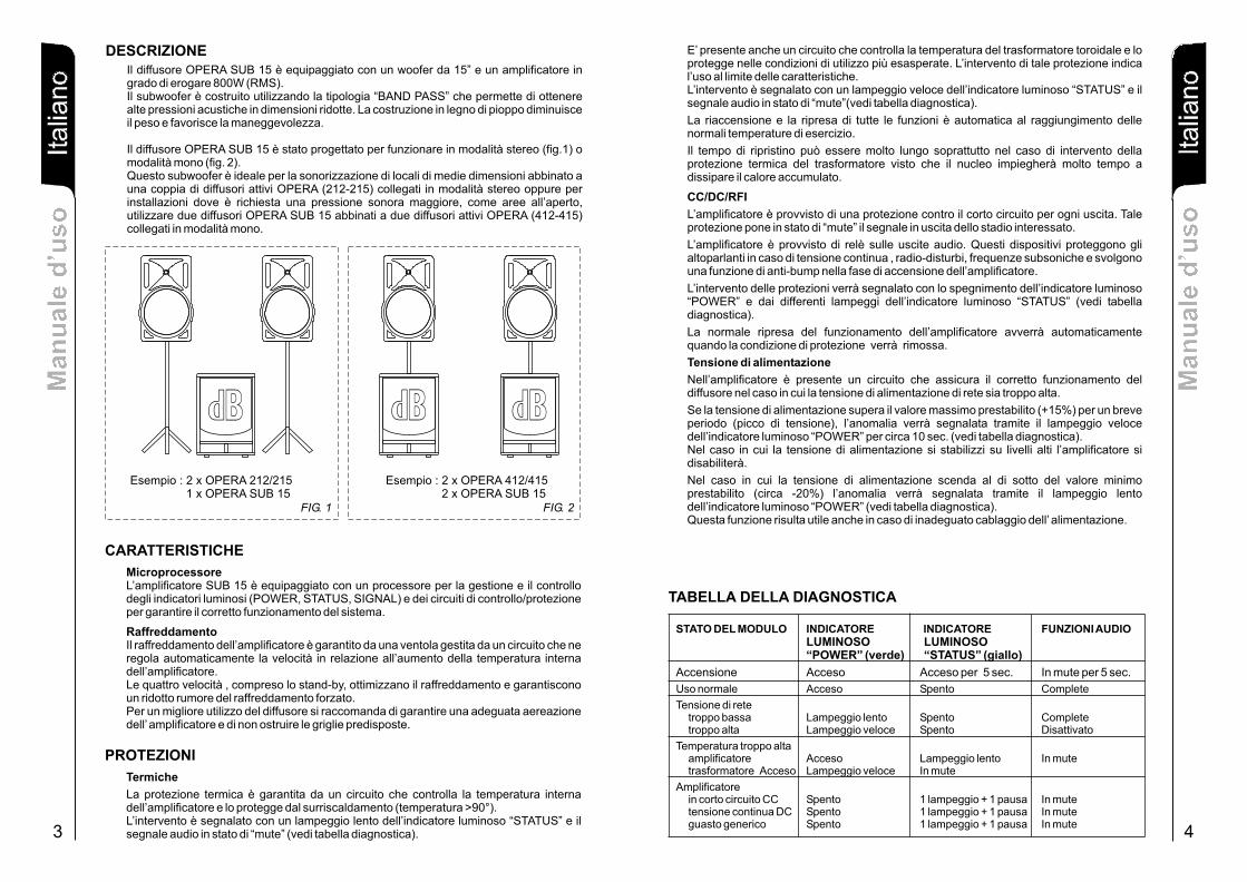
DESCRIZIONEIl diffusore OPERA SUB 15 è equipaggiato con un woofer da 15” e un amplificatore in grado di erogare 800W (RMS).Il subwoofer è costruito utilizzando la tipologia “BAND PASS” che permette di ottenere alte pressioni acustiche in dimensioni ridotte. La costruzione in legno di pioppo diminuisce il peso e favorisce la maneggevolezza.
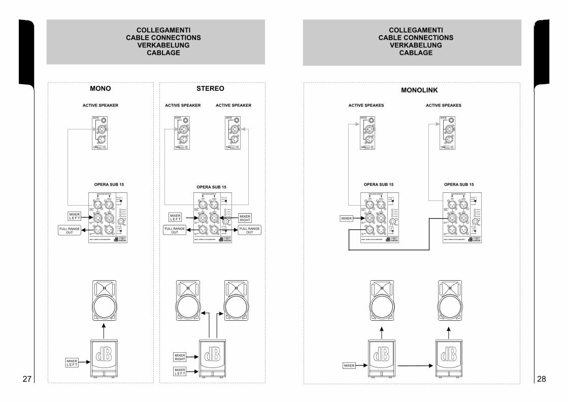
Il diffusore OPERA SUB 15 è stato progettato per funzionare in modalità stereo (fig.1) o modalità mono (fig. 2).Questo subwoofer è ideale per la sonorizzazione di locali di medie dimensioni abbinato a una coppia di diffusori attivi OPERA (212-215) collegati in modalità stereo oppure per installazioni dove è richiesta una pressione sonora maggiore, come aree all’aperto, utilizzare due diffusori OPERA SUB 15 abbinati a due diffusori attivi OPERA (412-415) collegati in modalità mono.
Esempio : 2 x OPERA 412/415 2 x OPERA SUB 15
FIG. 2
BBdd
Esempio : 2 x OPERA 212/215 1 x OPERA SUB 15
FIG. 1
BBdd BBdd
Ita
lian
oIta
lian
oIta
lian
oM
an
ua
le d
’us
oM
an
ua
le d
’us
o
Ita
lian
oIta
lian
oIta
lian
oM
an
ua
le d
’us
oM
an
ua
le d
’us
o
5 6
COMANDI E FUNZIONI
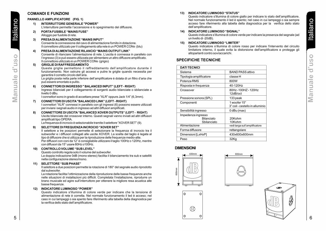
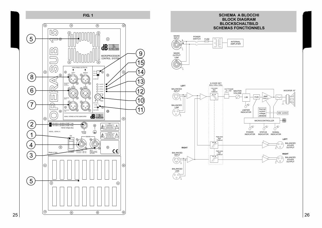
PANNELLO AMPLIFICATORE (FIG. 1)
1) INTERRUTTORE GENERALE "POWER"L’interruttore permette l’accensione e lo spegnimento del diffusore.
2) PORTA FUSIBILE “MAINS FUSE”Alloggio per fusibile di rete.
3) PRESA DI ALIMENTAZIONE “MAINS INPUT”Consente la connessione del cavo di alimentazione fornito in dotazione.Il connettore utilizzato per il collegamento alla rete è un POWER CON® (blu)
4) PRESA DI ALIMENTAZIONE RILANCIO “MAINS OUTPUT LINK”Consente di rilanciare l’alimentazione di rete. L’uscita è connessa in parallelo con l’ingresso (3) e può essere utilizzata per alimentare un altro diffusore amplificato. Il connettore utilizzato è un POWER CON® (grigio)
5) GRIGLIE DI RAFFREDDAMENTOQueste griglie permettono il raffreddamento dell’amplificatore durante il funzionamento. Non ostruire gli accessi e pulire le griglie quando necessita per garantire il corretto circolo dell’aria.La griglia posta nella parte inferiore dell’amplificatore è dotata di un filtro d’aria che può essere smontato e pulito.
6) CONNETTORI DI INGRESSO " BALANCED INPUT” (LEFT - RIGHT)Ingressi bilanciati per il collegamento di sorgenti audio bilanciate o sbilanciate a livello 0 dBu.I connettori sono in grado di accettare prese “XLR” oppure Jack 1/4” (6,3mm).
7) CONNETTORI DI USCITA "BALANCED LINK” (LEFT - RIGHT)I connettori “XLR” connessi in parallelo con gli ingressi (6) possono essere utilizzati per inviare i segnali audio in ingresso ad altri diffusori amplificati.
8) CONNETTORE DI USCITA ”BALANCED XOVER OUTPUTS” (LEFT - RIGHT)Uscite bilanciate del crossover interno. Questi segnali vanno inviati ad altri diffusori amplificati tipo OPERA.La frequenza di incrocio è selezionabile tramite il selettore “XOVER SET” (9).
9) SELETTORE DI FREQUENZA INCROCIO “XOVER SET”Il selettore a tre posizioni permette di selezionare la frequenza di incrocio tra il subwoofer e i diffusori collegati alle uscite XOVER. La scelta del taglio è legata al tipo di diffusore che si utilizza per la riproduzione delle frequenze medio-alte.Per diffusori con coni da 12” è consigliabile utilizzare il taglio 100Hz o 120Hz, mentre con diffusori da 15” usare 80Hz o100Hz.
10) CONTROLLO VOLUME “SUB LEVEL”Questo controllo regola solo il volume del subwoofer. La doppia indicazione 0dB (mono-stereo) facilita il bilanciamento tra sub e satelliti nella configurazione stereo/mono.
11) SELETTORE “SUB PHASE”Il selettore a due posizioni permette la rotazione di 180° del segnale audio riprodotto dal subwoofer.La rotazione facilita l’ottimizzazione della riproduzione delle basse frequenze anche nelle situazioni di installazioni più difficili. Completata l’installazione, riprodurre un brano musicale ed agire sull’interruttore per ottenere la migliore resa acustica alle basse frequenze.
12) INDICATORE LUMINOSO “POWER”Questo indicatore s'illumina di colore verde per indicare che la tensione di alimentazione di rete è corretta. Nel normale funzionamento il led è acceso; nel caso in cui lampeggi o sia spento fare riferimento alla tabella della diagnostica per la verifica dello stato dell’amplificatore.
SPECIFICHE TECNICHE
DATI TECNICI
Sistema BAND PASS attivo
Tipologia amplificatore classe H
Potenza RMS 800W
Risposta in frequenza 40-120Hz
Crossover
Pressione sonora (SPL) 133 peak
Componenti 1 woofer 15”
Sensibilità ingresso 0 dBu (max)
Impedenza ingresso20Kohm
Forma diffusore rettangolare
Dimensioni [LxHxP] 430x600x600mm
Peso 32Kg
80Hz -100HZ - 120Hz12dB/oct
3” coil - cestello in alluminio
BilanciatoSbilanciato 10Kohm
Alimentazione vedi targa sull’amplificatore
13) INDICATORE LUMINOSO “STATUS”Questo indicatore s'illumina di colore giallo per indicare lo stato dell’amplificatore. Nel normale funzionamento il led è spento; nel caso in cui lampeggi o sia sempre acceso fare riferimento alla tabella della diagnostica per la verifica dello stato dell’amplificatore.
Questo indicatore s'illumina di colore verde per indicare la presenza del segnale (ad un livello di -20dB).
15) INDICATORE LUMINOSO “LIMITER”Questo indicatore s’illumina di colore rosso per indicare l'intervento del circuito limitatore interno, il quale evita la distorsione dell'amplificatore e protegge gli altoparlanti contro sovraccarichi.
14) INDICATORE LUMINOSO “SIGNAL”
DIMENSIONI
430mm
60
0m
m BBdd600mm
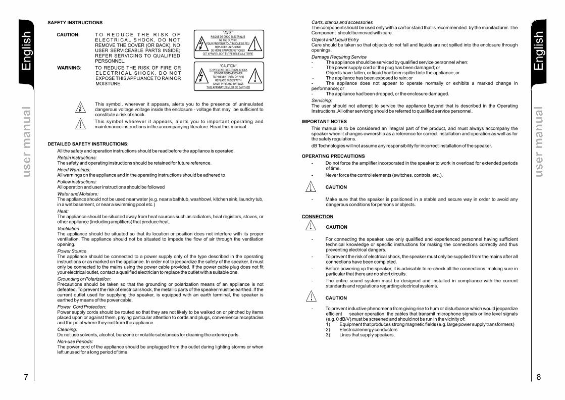
SAFETY INSTRUCTIONS
CAUTION: T O R E D U C E T H E R I S K O F E L E C T R I C A L S H O C K , D O N O T REMOVE THE COVER (OR BACK). NO USER SERVICEABLE PARTS INSIDE; REFER SERVICING TO QUALIFIED PERSONNEL.
WARNING: TO REDUCE THE RISK OF FIRE OR E L E C T R I C A L S H O C K . D O N O T EXPOSE THIS APPLIANCE TO RAIN OR MOISTURE.
This symbol, wherever it appears, alerts you to the presence of uninsulated dangerous voltage voltage inside the enclosure - voltage that may be sufficient to constitute a risk of shock.
This symbol wherever it appears, alerts you to important operating and maintenance instructions in the accompanying literature. Read the manual.
DETAILED SAFETY INSTRUCTIONS:
All the safety and operation instructions should be read before the appliance is operated.
Retain instructions:The safety and operating instructions should be retained for future reference.
Heed Warnings:All warnings on the appliance and in the operating instructions should be adhered to
Follow instructions:All operation and user instructions should be followed
Water and Moisture:The appliance should not be used near water (e.g. near a bathtub, washbowl, kitchen sink, laundry tub, in a wet basement, or near a swimming pool etc.)
Heat:The appliance should be situated away from heat sources such as radiators, heat registers, stoves, or other appliance (including amplifiers) that produce heat.
VentilationThe appliance should be situated so that its location or position does not interfere with its proper ventilation. The appliance should not be situated to impede the flow of air through the ventilation opening.
Power SourceThe appliance should be connected to a power supply only of the type described in the operating instructions or as marked on the appliance. In order not to jeopardize the safety of the speaker, it must only be connected to the mains using the power cable provided. If the power cable plug does not fit your electrical outlet, contact a qualified electrician to replace the outlet with a suitable one.
Grounding or Polarization:Precautions should be taken so that the grounding or polarization means of an appliance is not defeated. To prevent the risk of electrical shock, the metallic parts of the speaker must be earthed. If the current outlet used for supplying the speaker, is equipped with an earth terminal, the speaker is earthed by means of the power cable.
Power Cord Protection:Power supply cords should be routed so that they are not likely to be walked on or pinched by items placed upon or against them, paying particular attention to cords and plugs, convenience receptacles and the point where they exit from the appliance.
Cleaning:Do not use solvents, alcohol, benzene or volatile substances for cleaning the exterior parts.
Non-use Periods:The power cord of the appliance should be unplugged from the outlet during lighting storms or when left unused for a long period of time.
7
En
glis
hE
ng
lish
En
glis
hu
se
r m
an
ua
lu
se
r m
an
ua
l
En
glis
hE
ng
lish
En
glis
hu
se
r m
an
ua
lu
se
r m
an
ua
l
8
Carts, stands and accessoriesThe component should be used only with a cart or stand that is recommended by the manifacturer. The Component should be moved with care.
Object and Liquid EntryCare should be taken so that objects do not fall and liquids are not spilled into the enclosure through openings.
Damage Requiring Service- The appliance should be serviced by qualified service personnel when:- The power supply cord or the plug has been damaged; or Objects have fallen, or liquid had been spilled into the appliance; or - The appliance has been exposed to rain; or- The appliance does not appear to operate normally or exhibits a marked change in performance; or - The appliance had been dropped, or the enclosure damaged.
Servicing:The user should not attempt to service the appliance beyond that is described in the Operating Instructions. All other servicing should be referred to qualified service personnel.
IMPORTANT NOTES
This manual is to be considered an integral part of the product, and must always accompany the speaker when it changes ownership as a reference for correct installation and operation as well as for the safety regulations.
dB Technologies will not assume any responsibility for incorrect installation of the speaker.
OPERATING PRECAUTIONS
- Do not force the amplifier incorporated in the speaker to work in overload for extended periods of time.
- Never force the control elements (switches, controls, etc.).
CAUTION
- Make sure that the speaker is positioned in a stable and secure way in order to avoid any dangerous conditions for persons or objects.
CONNECTION
CAUTION
- For connecting the speaker, use only qualified and experienced personnel having sufficient technical knowledge or specific instructions for making the connections correctly and thus preventing electrical dangers.
- To prevent the risk of electrical shock, the speaker must only be supplied from the mains after all connections have been completed.
- Before powering up the speaker, it is advisable to re-check all the connections, making sure in particular that there are no short circuits.
- The entire sound system must be designed and installed in compliance with the current standards and regulations regarding electrical systems.
CAUTION
- To prevent inductive phenomena from giving rise to hum or disturbance which would jeopardize efficient seaker operation, the cables that transmit microphone signals or line level signals (e.g. 0 dB/V) must be screened and should not be run in the vicinity of:1) Equipment that produces strong magnetic fields (e.g. large power supply transformers)2) Electrical energy conductors3) Lines that supply speakers.
"AVIS" RISQUE DE CHOC ELECTRIQUE
NE PAS OUVRIR POUR PREVENIR TOUT RISQUE DE FEU
REPLACER UN FUSIBLE DE MÊME CARACTERISTIQUES
CET APPAREIL DOIT ÊNTRE RELIÉ A LA TERRE
"CAUTION" TO PREVENT ELECTRICAL SHOCK
DO NOT REMOVE COVERTO PREVENT RISK OF FIRE
REPLACE FUSES WITHSAME TYPE AND RATINGS
THIS APPARATUS MUST BE EARTHED
En
glis
hE
ng
lish
En
glis
hu
se
r m
an
ua
lu
se
r m
an
ua
l
109
En
glis
hE
ng
lish
En
glis
hu
se
r m
an
ua
lu
se
r m
an
ua
l
FEATURESMicroprocessor
Cooling
Amplifier cooling is ensured by a fan controlled by a circuit that automatically regulates speed in relation to any increase in temperature inside the amplifier.
The four speeds, including stand-by, optimize cooling and ensure reduced forced cooling noise levels.
For best speaker use, always make sure the amplifier is properly ventilated and never block the ventilation grilles.
The OPERA SUB 15 amplifier features a processor for managing and controlling the light indicators (POWER, STATUS, SIGNAL) and the control/protection circuits to ensure correct system operation.
Also featured is a circuit that controls the temperature of the toroidal transformer and protects this against even the most exasperated operating conditions. If this cutout trips, then the equipment is being used at the limits of its characteristics. Such tripping is indicated by the fast flashing of the "STATUS" indicator light and by the "mute" status audio signal (see diagnostics table).
All functions restart automatically when normal operating temperature is achieved.
Restart times can be fairly long, especially when the thermal cutout of the transformer trips because the core takes a long time to dissipate the accumulated heat.
CC/DC/RFI
The amplifier features a short-circuit cutout for each output. This cutout places the output signal of the stage involved in "mute".
The amplifier features relays on the audio outputs. These devices protect the speakers in case of direct current, radio disturbances, subsonic frequencies and have an anti-bump function at amplifier switch-on.
Tripping of these cutouts is indicated by the "POWER" indicator light going off and by the different flashing sequences of the "STATUS" indicator light (see diagnostics table).
The amplifier will start operating normally again when the cutout condition is eliminated.
Power voltage
The amplifier features a circuit that ensures correct speaker operation in case the mains power voltage is too high.
If the power voltage exceeds a max pre-established value (+15%) for a short time (power peak), the fault will be indicated by means of the "POWER" indicator light, which will flash quickly for about 10 seconds (see diagnostics table). If the power voltage stabilizes at high levels, the amplifier will become disabled.
If the power voltage drops below the minimum established value (about -20%), the fault will be indicated by means of the "POWER" indicator light which will start flashing slowly (see diagnostics table).
This function is also useful in case of inadequate power supply wiring.
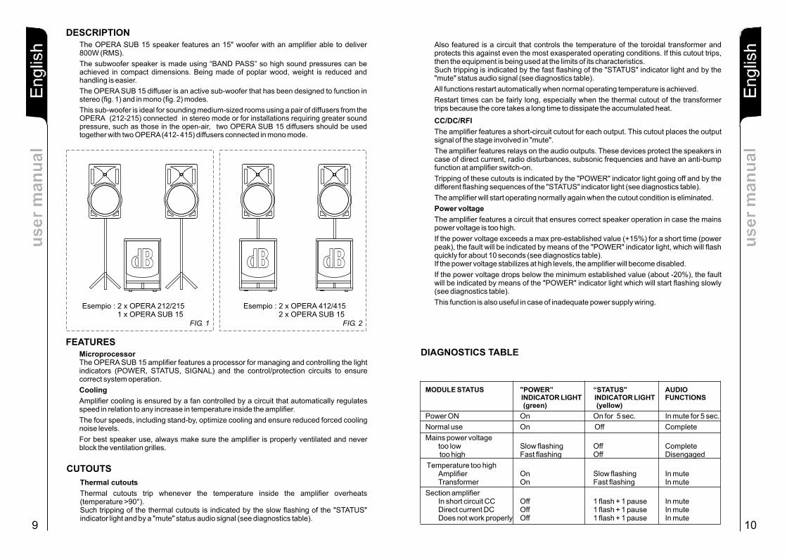
MODULE STATUS "POWER”C INDICATOR LIGHT INDICATOR LIGHT FUN TIONS
(green) (yellow)
too low Slow flashing Off Complete too high Fast flashing Off Disengaged
Amplifier On Slow flashing In muterTransforme On Fast flashing In mute
SIn short circuit CC Off 1 flash + 1 pause In muteDirect current DC Off 1 flash + 1 pause In mute
sDoes not work properly Off 1 fla h + 1 pause In mute
“STATUS" AUDIO
Power ON On On for 5 sec. In mute for 5 sec.
Normal use On Off Complete
Mains power voltage
Temperature too high
ection amplifier
DIAGNOSTICS TABLE
DESCRIPTIONThe OPERA SUB 15 speaker features an 15" woofer with an amplifier able to deliver 800W (RMS).
The subwoofer speaker is made using “BAND PASS” so high sound pressures can be achieved in compact dimensions. Being made of poplar wood, weight is reduced and handling is easier.
The OPERA SUB 15 diffuser is an active sub-woofer that has been designed to function in stereo (fig. 1) and in mono (fig. 2) modes.
This sub-woofer is ideal for sounding medium-sized rooms using a pair of diffusers from the OPERA (212-215) connected in stereo mode or for installations requiring greater sound pressure, such as those in the open-air, two OPERA SUB 15 diffusers should be used together with two OPERA (412- 415) diffusers connected in mono mode.
Esempio : 2 x OPERA 412/415 2 x OPERA SUB 15
FIG. 2
BBdd
Esempio : 2 x OPERA 212/215 1 x OPERA SUB 15
FIG. 1
BBdd BBdd
CUTOUTS
Thermal cutouts
Thermal cutouts trip whenever the temperature inside the amplifier overheats (temperature >90°).Such tripping of the thermal cutouts is indicated by the slow flashing of the "STATUS" indicator light and by a "mute" status audio signal (see diagnostics table).
11
En
glis
hE
ng
lish
En
glis
hu
se
r m
an
ua
lu
se
r m
an
ua
l
En
glis
hE
ng
lish
En
glis
h
12
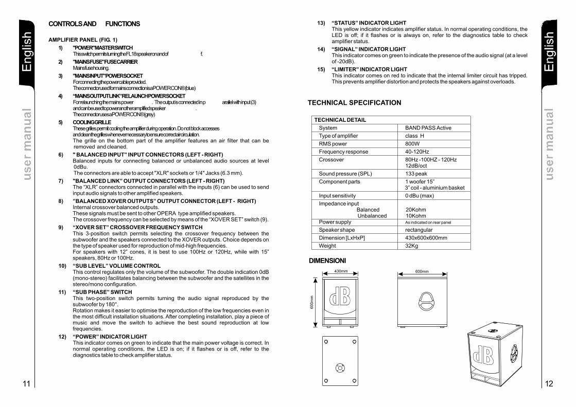
CONTROLS AND FUNCTIONS
1) "POWER" MASTER SWITCHThis switch permits turning the FL18 speaker on and of f.
2) "MAINS FUSE" FUSE CARRIERMains fuse housing.
3) "MAINS INPUT" POWER SOCKETFor connecting the power cable provided.The connector used for mains connection is a POWER CON® (blue)
4) “MAINS OUTPUT LINK” RELAUNCH POWER SOCKETFor relaunching the mains power . The output is connected in p arallel with input (3) and can be used to power another amplified speaker . The connector uses a POWER CON® (grey)
5) COOLING GRILLEThese grilles permit cooling the amplifier during operation. Do not block accesses and clean the grilles whenever necessary to ensure correct air circulation.The grille on the bottom part of the amplifier features an air filter that can be removed and cleaned.
6) " BALANCED INPUT” INPUT CONNECTORS (LEFT - RIGHT)Balanced inputs for connecting balanced or unbalanced audio sources at level 0dBu. The connectors are able to accept "XLR" sockets or 1/4" Jacks (6.3 mm).
7) "BALANCED LINK” OUTPUT CONNECTORS (LEFT - RIGHT)The “XLR” connectors connected in parallel with the inputs (6) can be used to send input audio signals to other amplified speakers.
8) ”BALANCED XOVER OUTPUTS” OUTPUT CONNECTOR (LEFT - RIGHT)Internal crossover balanced outputs. These signals must be sent to other OPERA type amplified speakers.The crossover frequency can be selected by means of the “XOVER SET” switch (9).
9) “XOVER SET” CROSSOVER FREQUENCY SWITCHThis 3-position switch permits selecting the crossover frequency between the subwoofer and the speakers connected to the XOVER outputs. Choice depends on the type of speaker used for reproduction of mid-high frequencies.For speakers with 12” cones, it is best to use 100Hz or 120Hz, while with 15” speakers, 80Hz or 100Hz.
10) “SUB LEVEL” VOLUME CONTROLThis control regulates only the volume of the subwoofer. The double indication 0dB (mono-stereo) facilitates balancing between the subwoofer and the satellites in the stereo/mono configuration.
11) “SUB PHASE” SWITCHThis two-position switch permits turning the audio signal reproduced by the subwoofer by 180°.Rotation makes it easier to optimise the reproduction of the low frequencies even in the most difficult installation situations. After completing installation, play a piece of music and move the switch to achieve the best sound reproduction at low frequencies.
12) “POWER” INDICATOR LIGHTThis indicator comes on green to indicate that the main power voltage is correct. In normal operating conditions, the LED is on; if it flashes or is off, refer to the diagnostics table to check amplifier status.
AMPLIFIER PANEL (FIG. 1)
TECHNICAL SPECIFICATION
TECHNICAL DETAIL
System BAND PASS Active
Type of amplifier class H
RMS power 800W
Frequency response 40-120Hz
Crossover
Sound pressure (SPL) 133 peak
Component parts 1 woofer 15”
Input sensitivity 0 dBu (max)
Impedance inputBalanced 20Kohm Unbalanced
Speaker shape rectangular
Dimension [LxHxP] 430x600x600mm
Weight 32Kg
80Hz -100HZ - 120Hz12dB/oct
3” coil - aluminium basket
10KohmPower supply As indicated on rear panel
us
er
ma
nu
al
us
er
ma
nu
al
DIMENSIONI
430mm
60
0m
m BBdd600mm
13) “STATUS” INDICATOR LIGHTThis yellow indicator indicates amplifier status. In normal operating conditions, the LED is off; if it flashes or is always on, refer to the diagnostics table to check amplifier status.
14) “SIGNAL” INDICATOR LIGHTThis indicator comes on green to indicate the presence of the audio signal (at a level of -20dB).
15) “LIMITER” INDICATOR LIGHTThis indicator comes on red to indicate that the internal limiter circuit has tripped. This prevents amplifier distortion and protects the speakers against overloads.
De
uts
chD
eu
tsch
De
uts
chB
ed
ien
un
gs
an
leit
un
gB
ed
ien
un
gs
an
leit
un
g
ES
PA
OL
ÑE
sp
añ
ol
ES
PA
OL
Ñ E
SP
AO
LÑ
ES
PA
OL
ÑIta
lian
oIta
lian
oIta
lian
oIta
lian
oIta
lian
oIta
lian
oD
eu
tsch
De
uts
chD
eu
tsch
Be
die
nu
ng
sa
nle
itu
ng
Be
die
nu
ng
sa
nle
itu
ng
13 14
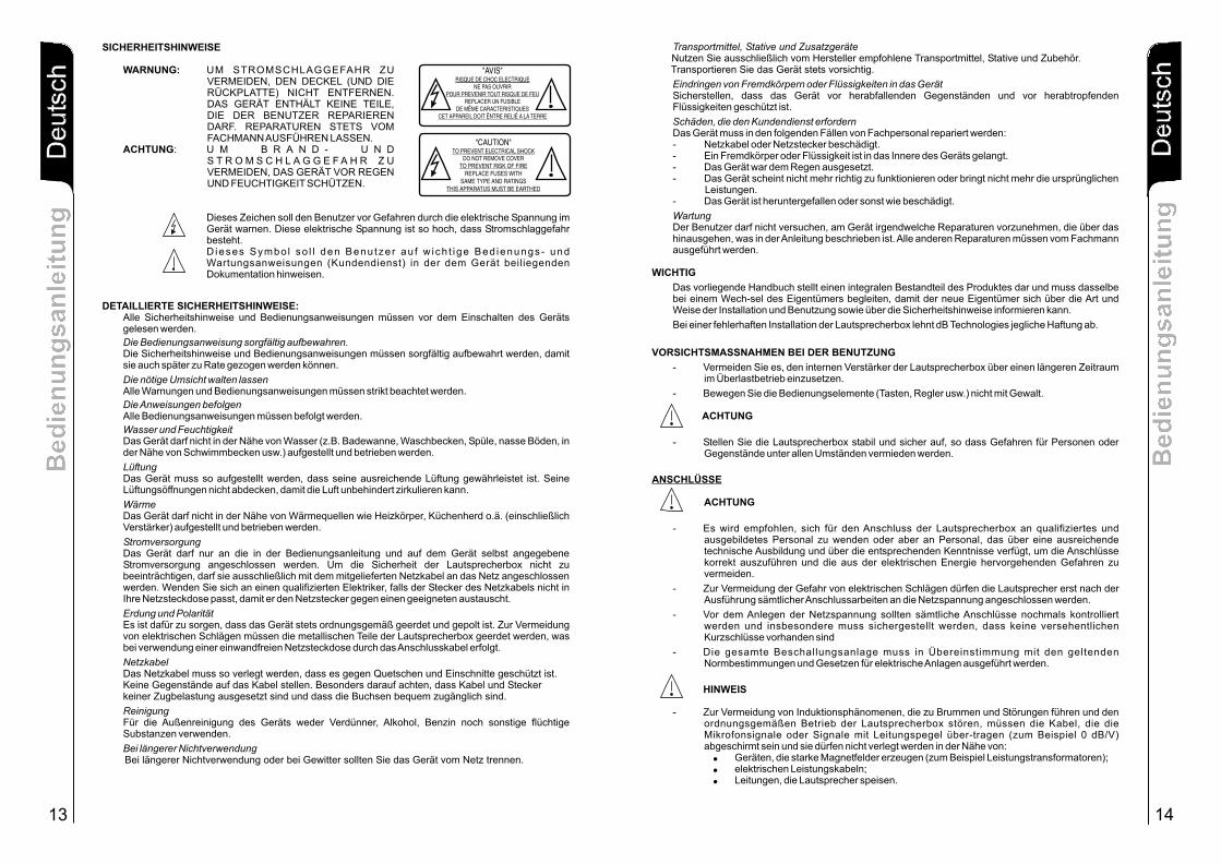
SICHERHEITSHINWEISE
WARNUNG: UM STROMSCHLAGGEFAHR ZU VERMEIDEN, DEN DECKEL (UND DIE RÜCKPLATTE) NICHT ENTFERNEN. DAS GERÄT ENTHÄLT KEINE TEILE, DIE DER BENUTZER REPARIEREN DARF. REPARATUREN STETS VOM FACHMANN AUSFÜHREN LASSEN.
ACHTUNG: U M B R A N D - U N D S T R O M S C H L A G G E F A H R Z U VERMEIDEN, DAS GERÄT VOR REGEN UND FEUCHTIGKEIT SCHÜTZEN.
Dieses Zeichen soll den Benutzer vor Gefahren durch die elektrische Spannung im Gerät warnen. Diese elektrische Spannung ist so hoch, dass Stromschlaggefahr besteht. D ieses Symbo l so l l den Benu tze r au f w ich t ige Bed ienungs- und Wartungsanweisungen (Kundendienst) in der dem Gerät beiliegenden Dokumentation hinweisen.
DETAILLIERTE SICHERHEITSHINWEISE:Alle Sicherheitshinweise und Bedienungsanweisungen müssen vor dem Einschalten des Geräts gelesen werden.
Die Bedienungsanweisung sorgfältig aufbewahren. Die Sicherheitshinweise und Bedienungsanweisungen müssen sorgfältig aufbewahrt werden, damit sie auch später zu Rate gezogen werden können.
Die nötige Umsicht walten lassenAlle Warnungen und Bedienungsanweisungen müssen strikt beachtet werden.
Die Anweisungen befolgenAlle Bedienungsanweisungen müssen befolgt werden.
Wasser und FeuchtigkeitDas Gerät darf nicht in der Nähe von Wasser (z.B. Badewanne, Waschbecken, Spüle, nasse Böden, in der Nähe von Schwimmbecken usw.) aufgestellt und betrieben werden.
LüftungDas Gerät muss so aufgestellt werden, dass seine ausreichende Lüftung gewährleistet ist. Seine Lüftungsöffnungen nicht abdecken, damit die Luft unbehindert zirkulieren kann.
WärmeDas Gerät darf nicht in der Nähe von Wärmequellen wie Heizkörper, Küchenherd o.ä. (einschließlich Verstärker) aufgestellt und betrieben werden.
StromversorgungDas Gerät darf nur an die in der Bedienungsanleitung und auf dem Gerät selbst angegebene Stromversorgung angeschlossen werden. Um die Sicherheit der Lautsprecherbox nicht zu beeinträchtigen, darf sie ausschließlich mit dem mitgelieferten Netzkabel an das Netz angeschlossen werden. Wenden Sie sich an einen qualifizierten Elektriker, falls der Stecker des Netzkabels nicht in Ihre Netzsteckdose passt, damit er den Netzstecker gegen einen geeigneten austauscht.
Erdung und PolaritätEs ist dafür zu sorgen, dass das Gerät stets ordnungsgemäß geerdet und gepolt ist. Zur Vermeidung von elektrischen Schlägen müssen die metallischen Teile der Lautsprecherbox geerdet werden, was bei verwendung einer einwandfreien Netzsteckdose durch das Anschlusskabel erfolgt.
NetzkabelDas Netzkabel muss so verlegt werden, dass es gegen Quetschen und Einschnitte geschützt ist. Keine Gegenstände auf das Kabel stellen. Besonders darauf achten, dass Kabel und Stecker keiner Zugbelastung ausgesetzt sind und dass die Buchsen bequem zugänglich sind.
ReinigungFür die Außenreinigung des Geräts weder Verdünner, Alkohol, Benzin noch sonstige flüchtige Substanzen verwenden.
Bei längerer Nichtverwendung Bei längerer Nichtverwendung oder bei Gewitter sollten Sie das Gerät vom Netz trennen.
Transportmittel, Stative und Zusatzgeräte Nutzen Sie ausschließlich vom Hersteller empfohlene Transportmittel, Stative und Zubehör.
Transportieren Sie das Gerät stets vorsichtig.
Eindringen von Fremdkörpern oder Flüssigkeiten in das GerätSicherstellen, dass das Gerät vor herabfallenden Gegenständen und vor herabtropfenden Flüssigkeiten geschützt ist.
Schäden, die den Kundendienst erfordernDas Gerät muss in den folgenden Fällen von Fachpersonal repariert werden: - Netzkabel oder Netzstecker beschädigt. - Ein Fremdkörper oder Flüssigkeit ist in das Innere des Geräts gelangt. - Das Gerät war dem Regen ausgesetzt. - Das Gerät scheint nicht mehr richtig zu funktionieren oder bringt nicht mehr die ursprünglichen
Leistungen. - Das Gerät ist heruntergefallen oder sonst wie beschädigt.
WartungDer Benutzer darf nicht versuchen, am Gerät irgendwelche Reparaturen vorzunehmen, die über das hinausgehen, was in der Anleitung beschrieben ist. Alle anderen Reparaturen müssen vom Fachmann ausgeführt werden.
WICHTIG
Das vorliegende Handbuch stellt einen integralen Bestandteil des Produktes dar und muss dasselbe bei einem Wech-sel des Eigentümers begleiten, damit der neue Eigentümer sich über die Art und Weise der Installation und Benutzung sowie über die Sicherheitshinweise informieren kann.
Bei einer fehlerhaften Installation der Lautsprecherbox lehnt dB Technologies jegliche Haftung ab.
VORSICHTSMASSNAHMEN BEI DER BENUTZUNG
- Vermeiden Sie es, den internen Verstärker der Lautsprecherbox über einen längeren Zeitraum im Überlastbetrieb einzusetzen.
- Bewegen Sie die Bedienungselemente (Tasten, Regler usw.) nicht mit Gewalt.
ACHTUNG
- Stellen Sie die Lautsprecherbox stabil und sicher auf, so dass Gefahren für Personen oder Gegenstände unter allen Umständen vermieden werden.
ANSCHLÜSSE
ACHTUNG
- Es wird empfohlen, sich für den Anschluss der Lautsprecherbox an qualifiziertes und ausgebildetes Personal zu wenden oder aber an Personal, das über eine ausreichende technische Ausbildung und über die entsprechenden Kenntnisse verfügt, um die Anschlüsse korrekt auszuführen und die aus der elektrischen Energie hervorgehenden Gefahren zu vermeiden.
- Zur Vermeidung der Gefahr von elektrischen Schlägen dürfen die Lautsprecher erst nach der Ausführung sämtlicher Anschlussarbeiten an die Netzspannung angeschlossen werden.
- Vor dem Anlegen der Netzspannung sollten sämtliche Anschlüsse nochmals kontrolliert werden und insbesondere muss sichergestellt werden, dass keine versehentlichen Kurzschlüsse vorhanden sind
- Die gesamte Beschallungsanlage muss in Übereinstimmung mit den geltenden Normbestimmungen und Gesetzen für elektrische Anlagen ausgeführt werden.
HINWEIS
- Zur Vermeidung von Induktionsphänomenen, die zu Brummen und Störungen führen und den ordnungsgemäßen Betrieb der Lautsprecherbox stören, müssen die Kabel, die die Mikrofonsignale oder Signale mit Leitungspegel über-tragen (zum Beispiel 0 dB/V) abgeschirmt sein und sie dürfen nicht verlegt werden in der Nähe von:! Geräten, die starke Magnetfelder erzeugen (zum Beispiel Leistungstransformatoren);! elektrischen Leistungskabeln;! Leitungen, die Lautsprecher speisen.
"AVIS" RISQUE DE CHOC ELECTRIQUE
NE PAS OUVRIR POUR PREVENIR TOUT RISQUE DE FEU
REPLACER UN FUSIBLE DE MÊME CARACTERISTIQUES
CET APPAREIL DOIT ÊNTRE RELIÉ A LA TERRE
"CAUTION" TO PREVENT ELECTRICAL SHOCK
DO NOT REMOVE COVERTO PREVENT RISK OF FIRE
REPLACE FUSES WITHSAME TYPE AND RATINGS
THIS APPARATUS MUST BE EARTHED
De
uts
chD
eu
tsch
De
uts
chB
ed
ien
un
gs
an
leit
un
gB
ed
ien
un
gs
an
leit
un
g
ES
PA
OL
ÑE
sp
añ
ol
ES
PA
OL
Ñ E
SP
AO
LÑ
ES
PA
OL
ÑIta
lian
oIta
lian
oIta
lian
oIta
lian
oIta
lian
oIta
lian
oD
eu
tsch
De
uts
chD
eu
tsch
Be
die
nu
ng
sa
nle
itu
ng
Be
die
nu
ng
sa
nle
itu
ng
ES
PA
OL
ÑE
sp
añ
ol
ES
PA
OL
Ñ E
SP
AO
LÑ
ES
PA
OL
ÑIta
lian
oIta
lian
oIta
lian
oIta
lian
oIta
lian
oIta
lian
oD
eu
tsch
De
uts
chD
eu
tsch
Be
die
nu
ng
sa
nle
itu
ng
Be
die
nu
ng
sa
nle
itu
ng
15 16
AUSSTATTUNGMikroprozessor
Kühlung
Zur Gewährleistung des optimalen Betriebs der Lautsprecher muss die angemessene Lüftung gewährleistet sein. Die Lüftungsöffnungen dürfen keinesfalls abgedeckt werden.
Thermische Schutzschaltungen
Der Verstärker OPERA SUB 15 verfügt zur Gewährleistung des einwandfreien Betriebs des Systems über einen Prozessor für die Steuerung und Überwachung der LEDs (POWER, STATUS, SIGNAL) und der Steuerkreise und Schutzschaltungen.
Die Kühlung des Verstärkers besorgt ein Lüfter, der von einer Schaltung gesteuert wird, die seine Geschwindigkeit in Abhängigkeit vom Anstieg der Innentemperatur des Verstärkers reguliert. Die vier Geschwindigkeitsstufen (einschl. Standby) optimieren die Kühlung und garantieren eine geringe Geräuschentwicklung der Zwangskühlung.
Den Schutz gegen Überhitzung (Temperatur > 90°) garantiert eine Schutzschaltung, die die Innentemperatur des Verstärkers überwacht.
SCHUTZSCHALTUNGEN
Die Auslösung wird signalisiert, indem die LED “STATUS” langsam blinkt und das Audiosignal stummgeschaltet wird (siehe die Diagnosetabelle).
Es gibt auch eine Schaltung zur Überwachung der Temperatur des Ringkerntransformators, die ihn auch bei schwersten Betriebsbedingungen schützt. Wenn diese Schutzschaltung anspricht, heißt das, dass das Gerät an den Grenzen seiner Leistungsfähigkeit betrieben wird.
Die Wiedereinschaltung und die Wiederaufnahme aller Funktionen erfolgen automatisch, wenn die Betriebstemperatur wieder einen normalen Wert erreicht hat.
Die Wiedereinschaltzeit kann sehr lang sein; dies gilt vor allem bei Ansprechen der thermischen Schutzschaltung des Transformators, da es sehr lange dauert, bis der Kern die gespeicherte Wärme wieder abgegeben hat.
CC/DC/RFI
Jeder Ausgang des Verstärkers ist gegen Kurzschluss geschützt. Diese Schutzschaltung schaltet das Ausgangssignal der betroffenen Stufe stumm.
Die Audioausgänge des Verstärkers sind mit Relais versehen. Diese Schutzrelais schützen die Lautsprecher gegen Gleichspannung, Hochfrequenzstörungen und subsonische Frequenzen; ferner fungieren sie als Schutz gegen den Einschaltstromstoß beim Einschalten des Verstärkers.
Die Auslösung der Schutzschaltungen wird durch die Ausschaltung der LED “POWER” und durch unterschiedliche Blinkfrequenzen der LED “STATUS” signalisiert (siehe die Diagnosetabelle).
Der Verstärker nimmt den normalen Betrieb nach Beseitigung der Ursache für die Schutzauslösung automatisch wieder auf.
Versorgungsspannung
Eine Schutzschaltung im Verstärker garantiert den einwandfreien Betrieb des Lautsprechers, falls die Netzspannung zu hoch ist.
Wenn die Netzspannung den festgelegten Höchstwert (+15%) für kurze Zeit überschreitet (Spannungsspitze), wird diese Störung durch das schnelle Blinken der LED “POWER” für rund 10 s angezeigt (siehe die Diagnosetabelle).
Wenn die Netzspannung den festgelegten Mindestwert (rund -20%) unterschreitet, wird diese Störung durch das langsame Blinken der LED “POWER” angezeigt (siehe die Diagnosetabelle).
Die Auslösung wird signalisiert, indem die LED “STATUS” schnell blinkt und das Audiosignal stummgeschaltet wird (siehe die Diagnosetabelle).
Wenn sich die Netzspannung auf einen zu hohen Wert stabilisiert, wird der Verstärker ausgeschaltet.
Diese Funktion ist auch als Schutz gegen einen falschen Netzanschluss von Nutzen.
EDZUSTAND DES MODULS L “POWER” LED “POWER” AUDIO-FUNKTIONEN
n h uEi sc alt ng EIN EIN für 5 s . Stummgeschaltet für 5 s.
aNorm lbetrieb EIN AUS Komplett
pNetzs annungizu niedr g Langsames Blinken AUS Komplett
zu hoch Schnelles Blinken AUS Abgeschaltet
cTemperatur zu ho htVers ärker EIN Langsames Blinken Stummgeschaltet
e h eTransformator EIN Schnelles Blinken Stummg sc alt t
Verstärkeru K rzschluss CC AUS 1-mal Blinken + 1 Pause Stummgeschaltet
S mAU 1-mal Blinken + 1 Pause Stum geschaltet AUS 1-mal Blinken + 1 Pause Stummgeschaltet
b (Grün) (gel )
Gleichspannung DC Funktioniert nicht richtig
DIAGNOSETABELLE
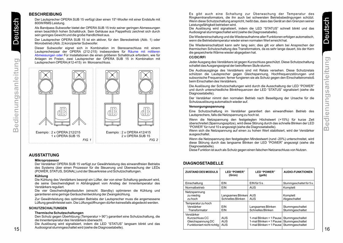
BESCHREIBUNGDer Lautsprecher OPERA SUB 15 verfügt über einen 15"-Woofer mit einer Endstufe mit 800W/RMS Leistung.
Als Bandpass-Subwoofer bietet der OPERA SUB 15 trotz seiner geringen Abmessungen einen beachtlich hohen Schalldruck. Sein Gehäuse aus Pappelholz zeichnet sich durch sein geringes Gewicht und die große Handlichkeit aus.
Der Lautsprecher OPERA SUB 15 ist ein aktiver, für den Stereobetrieb (Abb. 1) oder Monobetrieb (Abb. 2) konzipierter Subwoofer.
Dieser Subwoofer eignet sich in Kombination im Stereoanschluss mit einem Lautsprecherpaar der OPERA (212-215) insbesondere für
Für Installationen die einen größeren Schalldruck erfordern, wie für Anlagen im Freien, zwei Lautsprecher der OPERA SUB 15 in Kombination mit Lautsprechern OPERA (412-415) im Monoanschluss.
Räume mit mittleren Abmessungen oder
Esempio : 2 x OPERA 412/415 2 x OPERA SUB 15
FIG. 2
BBdd
Esempio : 2 x OPERA 212/215 1 x OPERA SUB 15
FIG. 1
BBdd BBdd
ES
PA
OL
ÑD
eu
tsch
De
uts
chD
eu
tsch
Be
die
nu
ng
sa
nle
itu
ng
Be
die
nu
ng
sa
nle
itu
ng
17
ES
PA
OL
ÑE
sp
añ
ol
ES
PA
OL
Ñ E
SP
AO
LÑ
ES
PA
OL
ÑIta
lian
oIta
lian
oIta
lian
oIta
lian
oIta
lian
oIta
lian
oD
eu
tsch
De
uts
chD
eu
tsch
Be
die
nu
ng
sa
nle
itu
ng
Be
die
nu
ng
sa
nle
itu
ng
ES
PA
OL
ÑE
sp
añ
ol
ES
PA
OL
Ñ E
SP
AO
LÑ
ES
PA
OL
ÑIta
lian
oIta
lian
oIta
lian
oIta
lian
oIta
lian
oIta
lian
oD
eu
tsch
De
uts
chD
eu
tsch
Be
die
nu
ng
sa
nle
itu
ng
Be
die
nu
ng
sa
nle
itu
ng
18
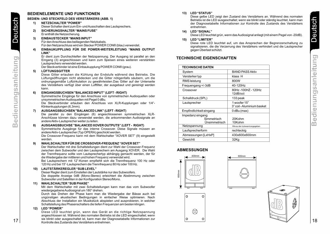
BEDIENELEMENTE UND FUNKTIONEN
1) NETZSCHALTER "POWER"Dieser Schalter dient zum Ein- und Ausschalten des Lautsprechers.
2) SICHERUNGSHALTER “MAINS FUSE”Er enthält die Netzsicherung.
3) EINBAUSTECKER “MAINS INPUT”Für den Anschluss des beiliegenden Netzkabels.Für den Netzanschluss wird ein Stecker POWER CON® (blau) verwendet.
4) EINBAUKUPPLUNG FÜR DIE POWER-WEITERLEITUNG “MAINS OUTPUT LINK”Er dient zum Durchschleifen der Netzspannung. Der Ausgang ist parallel an den Eingang (3) angeschlossen und kann zum Speisen eines weiteren verstärkten Lautsprechers verwendet werden. Der Steckverbinder ist eine Einbaukupplung POWER CON® (grau).
5) LÜFTUNGSGITTERDiese Gitter erlauben die Kühlung der Endstufe während des Betriebs. Die Lüftungsöffnungen nicht abdecken und die Gitter nötigenfalls säubern, um dieordnungsgemäße Luftzirkulation zu gewährleisten.Das Gitter auf der Unterseite des Verstärkers verfügt über einen Luftfilter, der ausgebaut und gereinigt werden kann.
6) EINGANGSBUCHSEN "BALANCED INPUT” (LEFT - RIGHT)Symmetrische Eingänge für den Anschluss von symmetrischen Audioquellen oder unsymmetrischen Audioquellen mit Pegel 0 dBu. Die Steckverbinder erlauben den Anschluss von XLR-Kupplungen oder 1/4”-Klinkenkupplungen (6,3mm).
7) AUSGANGSBUCHSEN "BALANCED LINK” (LEFT - RIGHT)Die parallel zu den Eingängen (6) angeschlossenen symmetrischen XLR-Anschlüsse können dazu verwendet werden, die ankommenden Audiosignale an andere Aktiv-Lautsprecher weiter zu leiten.
8) AUSGANGSBUCHSE ”BALANCED XOVER OUTPUTS” (LEFT - RIGHT)Symmetrische Ausgänge für das interne Crossover. Diese Signale müssen an andere Aktiv-Lautsprecher (Typ OPERA) geschickt werden. Die Crossover-Frequenz kann mit dem Wahlschalter “XOVER SET” (9) eingestellt werden.
9) WAHLSCHALTER FÜR DIE CROSSOVER-FREQUENZ “XOVER SET”Der Wahlschalter mit drei Schaltstellungen dient zur Wahl der Crossover-Frequenz zwischen dem Subwoofer und den Lautsprechern am Ausgang XOVER. Die Wahl der Trennfrequenz sollte vom Lautsprechertyp abhängig gemacht werden, der für die Wiedergabe der mittleren und hohen Frequenz verwendet wird. Bei Lautsprechern mit 12”-Konen empfiehlt sich die Trennfrequenz 100 Hz oder 120 Hz und bei 15”-Lautsprechern die Trennfrequenz 80 Hz oder 100 Hz.
10) LAUTSTÄRKEREGLER “SUB LEVEL”Dieser Regler dient zum Einstellen der Lautstärke nur des Subwoofers. Die doppelte Anzeige 0dB (Mono-Stereo) erleichtert die Abstimmung zwischen Subwoofer und Satelliten in der Konfiguration Stereo/Mono.
11) WAHLSCHALTER “SUB PHASE”Mit dem Wahlschalter mit zwei Schaltstellungen kann man das vom Subwoofer wiedergegebene Audiosignal um 180° drehen. Durch das Drehen der Phase kann man die Wiedergabe der Bässe auch bei ungünstigen akustischen Bedingungen in einfacher Weise optimieren. Nach Abschluss der Installation ein Musikstück abspielen und ausprobieren, in welcher Schaltstellung des Phasenschalters die tiefen Frequenzen am besten klingen.
12) LED “POWER”Diese LED leuchtet grün, wenn das Gerät an die richtige Netzspannung angeschlossen ist. Während des normalen Betriebs ist die LED eingeschaltet; wenn sie blinkt oder ausgeschaltet ist, kann man der Diagnosetabelle Informationen zur Kontrolle des Zustands des Verstärkers entnehmen.
BEDIEN- UND STECKFELD DES VERSTÄRKERS (ABB. 1)
13) LED “STATUS”Diese gelbe LED zeigt den Zustand des Verstärkers an. Während des normalen Betriebs ist die LED ausgeschaltet; wenn sie blinkt oder ständig leuchtet, kann man der Diagnosetabelle Informationen zur Kontrolle des Zustands des Verstärkers entnehmen.
14) LED “SIGNAL”Diese LED leuchtet grün, wenn das Audiosignal anliegt (mit einem Pegel von -20dB).
15) LED “LIMITER”Diese rote LED leuchtet auf, um das Ansprechen der Begrenzerschaltung zu signalisieren, die die Verzerrung des Verstärkers verhindert und die Lautsprecher gegen Überlast schützt.
TECHNISCHE EIGENSCHAFTEN
TECHNISCHE DATEN
System BAND PASS Aktiv
Versterker typ klass H
RMS leistung 800W
requengang +/-3dB 40-120Hz
Crossover
Schalldruck (SPL) 133 peak
Lautsprecher 1 woofer 15”Aluminium basket
Empfindlichkeit eingang 0 dBu (max)
Impedanz eingangSimmetrisch 20Kohm Ünsimmetrisch
Netzspannung Wie au der rückwand angegeben
Laufsprecherform rechteckig
Abmessungen [LxHxP] 430x600x600mm
Gewichtt 32Kg
F
80Hz -100HZ - 120Hz12dB/oct
3” coil -
10Kohm
ABMESSUNGEN
430mm
60
0m
m BBdd600mm
Ca
rac
teri
sti
qu
es
te
ch
niq
ue
sC
ara
cte
ris
tiq
ue
s t
ec
hn
iqu
es
Fra
nç
ais
20
Fra
nç
ais
Ca
rac
teri
sti
qu
es
te
ch
niq
ue
sC
ara
cte
ris
tiq
ue
s t
ec
hn
iqu
es
19
INSTRUCTIONS DE SÉCURITÉ
AVERTISSEMENTS: AFIN DE LIMITER LES RISQUES DE DÉCHARGE ÉLECTRIQUE, NE PAS ENLEVER LE COUVERCLE (OU LE PA N N E A U A R R I È R E ) . L E S COMPOSANTS INTERNES NE PEUVENT PAS ÊTRE RÉPARÉS PAR L'UTILISATEUR; CONFIER L E S R É P A R A T I O N S À D U PERSONNEL QUALIFIÉ.
ATTENTION: AFIN DE RÉDUIRE LES RISQUES D'INCENDIE OU DE DÉCHARGE ÉLECTRIQUE, NE PAS EXPOSER CET APPAREIL À LA PLUIE OU À L'HUMIDITÉ.
Ce symbole a la fonction de signaler à l'utilisateur, là où il est apposé, la présence de tension dangereuse à l'intérieur du produit, avec une valeur suffisante pour représenter un risque de décharge électrique pour les personnes.
Ce symbole, là où il est reporté, a la fonction de signaler à l'utilisateur la présence d'instructions d'utilisation et entretien (assistance) importantes dans la documentation qui accompagne l'appareil.
INSTRUCTIONS DE SÉCURITÉ DÉTAILLÉES:
Avant de mettre en fonction l'appareil, lire toutes les instructions de sécurité et de fonctionnement.
Conserver les instructionsLes instructions de sécurité et de fonctionnement doivent être conservées pour toute éventuelle consultation future.
Faire attentionRespecter scrupuleusement tous les avertissements présents sur l'appareil et les instructions de fonctionnement.
Suivre les instructionsToutes les instructions de fonctionnement et pour l'utilisateur doivent être respectées.
Eau et humiditéL'appareil ne doit pas être utilisé à proximité de l'eau (par exemple à proximité de baignoires, lavabos, éviers, lavoirs, sur le sol mouillé ou à proximité de piscines…)
VentilationNe jamais placer l’appareil dans un endroit qui risque d’empêcher une bonne ventilation.
ChaleurL'appareil doit être placé à l'écart des sources de chaleur comme radiateurs, réchauds ou tout autre appareil (y compris les amplificateurs) qui produit de la chaleur.
AlimentationL'appareil ne doit être branché qu'au type d'alimentation indiqué dans les instructions d'utilisation ou reporté sur l'appareil.Pour ne pas compromettre la sécurité de l’enceinte, utilisez pour la brancher exclusivement le câble d’alimentation fourni dans l’emballage. Si la fiche du câble d’alimentation n’entre pas dans votre prise de courant, appelez un électricien qualifié qui la remplacera par une prise adéquate.
Mise à la terre et polaritésAdopter les précautions nécessaires afin d'assurer une mise à la terre correcte et le respect des polarités de l'appareil. Pour éviter le risque de chocs électriques, les parties métalliques de l’enceinte doivent être reliées à la terre. Si la prise de courant utilisée pour l’alimentation est dotée d’un pôle de terre, l’enceinte résultera relié à la terre par le câble d’alimentation.
Cordon d'alimentationLe cordon d'alimentation doit être installé de façon à ce qu'il ne soit pas piétiné ou écrasé par des objets situés sur ou contre lui. Veiller particulièrement aux câbles et aux fiches, aux prises qui doivent être en position optimale et au point d'où ils sortent de l'appareil.
NettoyagePour le nettoyange des parties extérieures, évitez les diluants, l’alcool, l’essence ou autres substances volatiles.
Périodes de non-utilisationDébrancher le cordon d'alimentation de la prise pendant les orages de foudre et si l'appareil doit rester longtemps inutilisé.
Chariots, support et accessoiresL’appareil doit être monté exclusivement sur des chariots ou des support conseillés par le producteur. L’ appareil doit très prudemment.
Entrée de liquides et d'objets dans l'appareilVeiller à ce qu'aucun objet ne tombe sur l'appareil et qu'aucun liquide ne passe à travers les ouvertures.
Dommages nécessitant l'intervention du service d'assistanceL'appareil doit être réparé par du personnel qualifié dans les cas suivants:- le cordon d'alimentation ou la prise sont endommagés;- des objets sont tombés sur l'appareil ou des liquides sont entrés dedans;- l'appareil a été exposé à la pluie;- l'appareil ne semble pas fonctionner correctement ou ses performances ont changé;- l'appareil est tombé ou il est endommagé.
EntretienL'utilisateur ne doit pas essayer d'effectuer des réparations autres que celles décrites dans les instructions. Toutes les autres réparations doivent être exécutées par du personnel qualifié.
MPORTANT
Ce manuel fait partie intégrante du produit et doit suivre celuici même dans les passages de propriété, pour permettre au nouveau propriétaire de connaître les modalités d’installation et d’utilisation ainsi que les consignes de sécurité.
Toute mauvaise installation de l’enceinte décharge dB Technologies de toute responsabilité.
PRÉCAUTIONS
- Evitez de faire longtemps travailler en surcharge l’amplificateur à l’intérieur de l’enceinte.
- Ne forcez pas les organes de commandes (touches, contrôles, etc.)
ATTENTION
- Installez l’enceinte de manière stable et sûre pour éviter tout risque de blessures et/ou dégâts.
BRANCHEMENTS
ATTENTION
- Pour brancher l’enceinte, adressez-vous à un spécialiste bien formé, c’est-à-dire à une personne ayant de l’expérience ou des connaissances techniques ou ayant reçu des instructions spécifiques qui lui permettent de réaliser correctement les connexions et de prévenir les dangers de l’électricité.
- Pour éviter les risques de chocs électriques, terminez toutes les connexions avant de brancher l’enceinte sur le secteur.
- Avant d’alimenter l’enceinte, il est de bonne règle de recontrôler toutes les connexions et de s’assurer en particulier qu’il n’y a pas de courts-circuits accidentels.
- Tout le système de sonorisation devra être réalisé conformément aux normes et aux lois en vigueur en matière d’instal-lations électriques.
MISE EN GARDE
- Pour éviter que des phénomènes inductifs provoquent des bourdonnements, perturbent et compromettent le bon fonctionnement de l’enceinte, blindez les fils qui transmettent des signaux microphoniques ou des signaux au niveau de la ligne (0 dB/V) et évitez de les poser à proximité de :! appareils produisant de forts champs magnétiques (gros transformateurs
d’alimentation) ;! conducteurs de l’énergie électrique.! lignes qui alimentent les enceintes.
"AVIS" RISQUE DE CHOC ELECTRIQUE
NE PAS OUVRIR POUR PREVENIR TOUT RISQUE DE FEU
REPLACER UN FUSIBLE DE MÊME CARACTERISTIQUES
CET APPAREIL DOIT ÊNTRE RELIÉ A LA TERRE
"CAUTION" TO PREVENT ELECTRICAL SHOCK
DO NOT REMOVE COVERTO PREVENT RISK OF FIRE
REPLACE FUSES WITHSAME TYPE AND RATINGS
THIS APPARATUS MUST BE EARTHED
Fra
nç
ais
Ca
rac
teri
sti
qu
es
te
ch
niq
ue
sC
ara
cte
ris
tiq
ue
s t
ec
hn
iqu
es
Ca
rac
teri
sti
qu
es
te
ch
niq
ue
sC
ara
cte
ris
tiq
ue
s t
ec
hn
iqu
es
Fra
nç
ais
21 22
LES CARACTERISTIQUESMicroprocesseur
Afin de garantir le fonctionnement correct du système, l'amplificateur OPERA SUB 15 est équipé d'un processeur pour la gestion et le contrôle des indicateurs lumineux (POWER, STATUS, SIGNAL) et des circuits de contrôle/protection.
Refroidissement
Le refroidissement de l'amplificateur est assuré par un ventilateur géré par un circuit qui règle automatiquement sa vitesse en fonction de l'augmentation de la température interne de l'amplificateur.
Les quatre vitesses, y compris la mise en attente, optimisent le refroidissement et garantissent une émission limitée de bruit du refroidissement forcé.
Pour une utilisation optimale de l'enceinte, il est recommandé de garantir une ventilation adéquate à l'amplificateur et de ne pas boucher les fentes prévues à cet effet.
Protections thermiques
La protection thermique est garantie par un circuit qui contrôle la température interne de l'amplificateur et le protège contre la surchauffe (température >90°).
PROTECTIONS
L'intervention est signalée par le clignotement lent de l'indicateur lumineux “STATUS” et le signal audio en état de “mute” (voir tableau diagnostic).
La protection est également assurée par un circuit qui contrôle la température du transformateur toroïdal et qui le protège dans les conditions d'utilisation les plus contraignantes. L'intervention de cette protection indique que l'appareil est utilisé à la limite de ses caractéristiques.
La remise en fonction et la réactivation de toutes les fonctions s'effectuent automatiquement une fois les températures de fonctionnement normales rétablies.
Le temps de rétablissement du fonctionnement normal peut être très prolongé, surtout en cas d'intervention de la protection thermique du transformateur car, dans ce cas, il faut beaucoup de temps pour que le noyau dissipe la chaleur accumulée.
CC (court-circuit) / DC (courant continu) / RFI (perturbations radio)
L'amplificateur est muni sur chaque sortie d'une protection contre le court-circuit. Cette protection place en état de “mute” le signal en sortie de l'étage concerné.
L'amplificateur est doté de relais sur les sorties audio. Ces dispositifs protègent les haut-parleurs en cas de tension continue, perturbations radio, fréquences subsoniques et exercent également une fonction d'anti-bump dans la phase de mise sous tension de l'amplificateur.
L'intervention des protections est signalée par l'indicateur lumineux “POWER” qui s'éteint et par différents clignotements de l'indicateur lumineux “STATUS” (voir tableau diagnostic).
Le rétablissement du fonctionnement normal de l'amplificateur s'effectue automatiquement lorsque la condition qui a provoqué la protection est éliminée.
Tension d'alimentation
L'amplificateur comprend un circuit qui assure le fonctionnement correct de l'enceinte quand la tension d'alimentation de réseau est trop élevée.
Si la tension d'alimentation dépasse la valeur maximum fixée (+15%) pendant une brève période (crête de tension), l'anomalie est signalée par l'indicateur lumineux “POWER” qui clignote rapidement pendant environ 10 s (voir tableau diagnostic).
Si la tension d'alimentation descend sous la valeur minimum fixée (environ -20%), l'anomalie est signalée par l'indicateur lumineux “POWER” qui clignote lentement (voir tableau diagnostic).
L'intervention est signalée par le clignotement rapide de l'indicateur lumineux “STATUS” et le signal audio en état de “mute” (voir tableau diagnostic).
Si la tension d'alimentation se stabilise sur des niveaux élevés, l'amplificateur se désactive.
Cette fonction s'avère également utile en cas de câblage incorrect de l'alimentation.
ÉT DU OD L I D C E R DICA EUR AT M U E N I AT U IN T LU INE X LUM N U AU IOM U I E X D “POWER” vert “ST U ” ja ne)( ) AT S ( u
r p bas e Cli notement e t É eint Fon t on ct v st o s g l n t c i s a i er p él vé li notement a d eint Dés ct vt o e e C g r pi e Ét a i é
if c t r us t nsion igno emen l t En muteAmpl i a eu So e Cl t t en an o mat ur us t nsion igno emen ra i En muteTr sf r e So e Cl t t p de
En cou t cir ui C- e nt l g t t + 1 paus En muter - c t C Ét i 1 c i no emen e Ten i onti ue DC e n l g t t + 1 paus E mutes on c n Ét i t 1 c i no emen e n Fonc ionn m nt inc r ct te n l g t m nt + 1 paus u et e e or e É i t 1 c i no e e e En m t
F NC IONO T S
Mise so s t sion So e si n So e si n x 5 s En m t u en us t n o us t n o u e x 5 s
ti isa ion norm l So s te sion Ét i t Fon tion t v sU l t a e u n e n c s ac i e
ens on d és u T i e r ea
empérat re t op é ev eT u r l é
m l f t r s t oA p i ica eu ec i n
TABLEAU DE DIAGNOSTIC
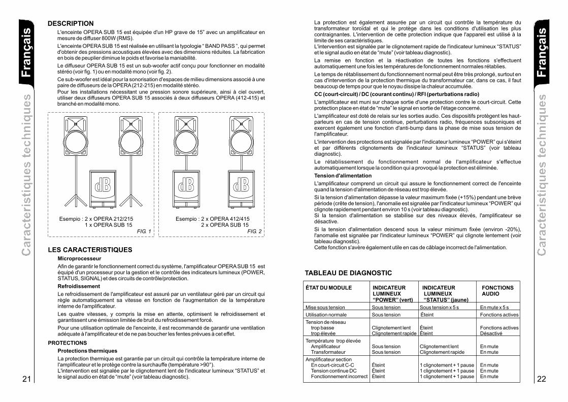
DESCRIPTIONL'enceinte OPERA SUB 15 est équipée d'un HP grave de 15” avec un amplificateur en mesure de diffuser 800W (RMS).
L'enceinte OPERA SUB 15 est réalisée en utilisant la typologie “ BAND PASS ”, qui permet d'obtenir des pressions acoustiques élevées avec des dimensions réduites. La fabrication en bois de peuplier diminue le poids et favorise la maniabilité.
Le diffuseur OPERA SUB 15 est un sub-woofer actif conçu pour fonctionner en modalité stéréo (voir fig. 1) ou en modalité mono (voir fig. 2).
Ce sub-woofer est idéal pour la sonorisation d'espaces de milieu dimensions associé à une paire de diffuseurs de la OPERA (212-215) en modalité stéréo.Pour les installations nécessitant une pression sonore supérieure, ainsi à ciel ouvert, utiliser deux diffuseurs OPERA SUB 15 associés à deux diffuseurs OPERA (412-415) et branché en modalité mono.
Esempio : 2 x OPERA 412/415 2 x OPERA SUB 15
FIG. 2
BBdd
Esempio : 2 x OPERA 212/215 1 x OPERA SUB 15
FIG. 1
BBdd BBdd

Ca
rac
teri
sti
qu
es
te
ch
niq
ue
sC
ara
cte
ris
tiq
ue
s t
ec
hn
iqu
es
23
Fra
nç
ais
COMMANDES ET FONCTIONS
1) INTERRUPTEUR GÉNÉRAL "POWER"Cet interrupteur permet de mettre sous et hors tension l'enceinte FL18.
2) BLOC À FUSIBLE “MAINS FUSE”Logement pour le fusible de réseau.
3) PRISE D'ALIMENTATION “MAINS INPUT”Elle permet de connecter le cordon d'alimentation fourni.Le connecteur utilisé pour le branchement au réseau est du type POWER CON® (bleu)
4) PRISE D'ALIMENTATION RELANCE “MAINS OUTPUT LINK”Elle permet de relancer l'alimentation de réseau. La sortie est branchée en parallèle avec l'entrée (3) et peut être utilisée pour alimenter une autre enceinte amplifiée. Le connecteur utilisé est du type POWER CON® (gris)
5) FENTES DE REFROIDISSEMENTCes fentes assurent le refroidissement de l 'ampli f icateur pendant le fonctionnement. Ne jamais les boucher et, si cela est nécessaire, les nettoyer afin d'assurer une ventilation efficace.Les fentes situées dans la partie inférieure de l'amplificateur sont munies d'un filtre à air qui peut être démonté et nettoyé.
6) CONNECTEURS D'ENTRÉE " BALANCED INPUT” (GAUCHE - DROITE)Entrées symétriques pour la connexion de sources audio symétriques ou asymétriques au niveau 0 dBu.Les connecteurs peuvent accueillir des prises “XLR” ou Jack 1/4” (6,3mm).
7) CONNECTEURS DE SORTIE “BALANCED LINK” (GAUCHE - DROITE)Connectés en parallèle avec les entrées (6), les connecteurs “XLR” peuvent être utilisés pour envoyer les signaux audio en entrée à d'autres enceintes amplifiées
8) CONNECTEUR DE SORTIE “BALANCED XOVER OUTPUTS” (GAUCHE - DROITE)Sorties symétriques du crossover interne. Ces signaux doivent être envoyés à d'autres enceintes amplifiées du type OPERA.La fréquence de croisement peut être sélectionnée à l'aide du sélecteur “XOVER SET” (9).
9) SÉLECTEUR DE FRÉQUENCE DE CROISEMENT “XOVER SET”Le sélecteur à trois positions permet de sélectionner la fréquence de croisement entre le caisson de grave et les enceintes connectées aux sorties XOVER. Le choix de la coupure est lié au type d'enceinte que l'on utilise pour la reproduction des moyennes-hautes fréquences.Avec des enceintes équipées de cônes de 12”, il est conseillé d'utiliser la coupure à 100Hz ou à 120Hz; tandis que, avec des enceintes de 15”, il est conseillé d'utiliser 80Hz ou 100Hz.
10) CONTRÔLE VOLUME “SUB LEVEL”Ce contrôle règle uniquement le volume du caisson de grave. La double indication 0dB (mono-stéréo) facilite la balance entre caisson et enceintes satellites dans la configuration stéréo/mono.
11) SÉLECTEUR “SUB PHASE”Le sélecteur à deux positions permet la rotation de 180° du signal audio reproduit par le caisson de grave.Cette rotation de phase facilite l'optimisation de la reproduction des basses fréquences même dans les conditions d'installation les plus difficiles. Une fois l'installation terminée, reproduire un morceau de musique et agir sur l'interrupteur afin d'obtenir la meilleure restitution acoustique des basses fréquences.
12) INDICATEUR LUMINEUX “POWER”Cet indicateur s'allume de couleur verte pour indiquer que la tension d'alimentation de réseau est correcte. Pendant le fonctionnement normal, la LED est allumée; si elle clignote ou si elle est éteinte, se référer au tableau de diagnostic pour contrôler l'état de l'amplificateur.
FAÇADE AMPLIFICATEUR (FIG. 1)
CARACTÉRISTIQUE TECHNIQUES
DIMENSIONS Ca
rac
teri
sti
qu
es
te
ch
niq
ue
sC
ara
cte
ris
tiq
ue
s t
ec
hn
iqu
es
24
13) INDICATEUR LUMINEUX “STATUS”Cet indicateur de couleur jaune indique l'état de l'amplificateur. Pendant le fonctionnement normal, la LED est éteinte; si elle clignote ou si elle reste allumée fixe, se référer au tableau de diagnostic pour contrôler l'état de l'amplificateur.
14) INDICATEUR LUMINEUX “SIGNAL”Cet indicateur s'allume de couleur verte pour indiquer la présence du signal audio (à un niveau de -20dB).
15) INDICATEUR LUMINEUX “LIMITER”Cet indicateur s'allume de couleur rouge pour indiquer l'intervention du circuit limiteur interne qui évite la distorsion de l'amplificateur et protège les haut-parleurs contre les surcharges.
Fra
nç
ais
DONNES TECHNIQUES
Système BAND PASS Active
Typologie amplificateur klass H
Puissance RMS 800W
+/-3dB 40-120Hz
Crossover
Pression sonore (SPL) 133 peak
Composantes 1 woofer 15”
Entrée sensibilité 0 dBu (max)
Impedance entréeSymétrique 20KohmAsymétrique
Alimentation
Forme enceinte rectangulaire
Dimensions [LxHxP] 430x600x600mm
Poids 32Kg
Réponse en fréquence
Voir plaque
80Hz -100HZ - 120Hz12dB/oct
3” coil -Aluminium basket
10Kohm
430mm
60
0m
m BBdd600mm
25 26
3
4
1
2
5
5
12
13
14
15
11
10
9
7
6
8
L
N
MAINSOUTPUT
LINK
SCHEMA A BLOCCHIBLOCK DIAGRAM
BLOCKSCHALTBILDSCHEMAS FONCTIONNELS
mute
rele’ control
WOOFER 15”
thermalcurrentvoltagesensors
SIGNALINDICATOR
STATUSINDICATOR
POWERINDICATOR
BALANCEDINPUT
LIMITERINDICATOR
BALANCEDLINK
MICROCONTROLLER
Low-pass filter
12dB/oct
High-pass filter
12dB/oct
X-OVER SET80Hz-100Hz-120Hz
BALANCEDINPUT
BALANCEDLINK
OUT PHASE0° / 180°
LEFT
RIGHT
High-pass filter
12dB/oct
LEFT
RIGHT
MAINSINPUT
BALANCEDXOVER
OUTPUT
BALANCEDXOVER
OUTPUT
220-240V 50-60Hz (FUSE T 5A)
OUTPUT LINK INPUT
Internal voltage setup
MODULE POWER CONSUMPTION
220-240V AC MAX 15A110-120V AC MAX 10A
900 VA MAX
110-120V 50-60Hz (FUSE T10A)
MAINS
POWER
ON
FUSEMAINS
OP
ER
A S
UB
15
OP
ER
A S
UB
15
Made in Italy
"AVIS" RISQUE DE CHOC ELECTRIQUE
NE PAS OUVRIR POUR PREVENIR TOUT RISQUE DE FEU
REPLACER UN FUSIBLE DE MÊME CARACTERISTIQUES
CET APPAREIL DOIT ÊNTRE RELIÉ A LA TERRE
"CAUTION" TO PREVENT ELECTRICAL SHOCK
DO NOT REMOVE COVERTO PREVENT RISK OF FIRE
REPLACE FUSES WITHSAME TYPE AND RATINGS
THIS APPARATUS MUST BE EARTHED
MODEL : SERIAL N.
MICROPROCESSORCONTROL SYSTEM
FIG. 1
(STEREO) 0dB
SUB LEVEL
LIMITER
SIGNAL
STATUS
BALANCEDINPUT
BALANCEDLINK
POWER
XOVER SET
MONO / STEREO ACTIVE SUBWOOFER
100Hz
120Hz
80Hz
BALANCEDXOVEROUTPUTS
0dB(MONO)
RIGHT
HIGH PASS OUTPUTS
LEFT
SUB PHASE
IN
OUT
8
PUSH PUSH
27 28
STEREO
FULL RANGE OUT
OPERA SUB 15
MONO MONOLINK
MIXERRIGHT
MIXERL E F T
MIXER
ACTIVE SPEAKER ACTIVE SPEAKER
BBdd
(STEREO) 0dB
SUB LEVEL
LIMITER
SIGNAL
STATUS
BALANCEDINPUT
BALANCEDLINK
POWER
XOVER SET
MONO / STEREO ACTIVE SUBWOOFER
100Hz
120Hz
80Hz
BALANCEDXOVEROUTPUTS
0dB(MONO)
RIGHT
HIGH PASS OUTPUTS
LEFT
SUB PHASE
IN
OUT
8
PUSH PUSH
BALANCEDINPUTS / LINK
1 - GND2 - HOT3 - COLD
PUSH
BALANCEDINPUTS / LINK
1 - GND2 - HOT3 - COLD
PUSH
FULL RANGE OUT
BALANCEDINPUTS / LINK
1 - GND2 - HOT3 - COLD
PUSH
ACTIVE SPEAKER
OPERA SUB 15
FULL RANGE OUT
BBdd
OPERA SUB 15
MIXER
OPERA SUB 15
ACTIVE SPEAKESACTIVE SPEAKES
BBdd BBdd
MIXERRIGHT
MIXERL E F T
COLLEGAMENTICABLE CONNECTIONS
VERKABELUNGCABLAGE
MIXERL E F T
MIXERL E F T
BALANCEDINPUTS / LINK
1 - GND2 - HOT3 - COLD
PUSH
BALANCEDINPUTS / LINK
1 - GND2 - HOT3 - COLD
PUSH
(STEREO) 0dB
SUB LEVEL
LIMITER
SIGNAL
STATUS
BALANCEDINPUT
BALANCEDLINK
POWER
XOVER SET
MONO / STEREO ACTIVE SUBWOOFER
100Hz
120Hz
80Hz
BALANCEDXOVEROUTPUTS
0dB(MONO)
RIGHT
HIGH PASS OUTPUTS
LEFT
SUB PHASE
IN
OUT
8
PUSH PUSH
(STEREO) 0dB
SUB LEVEL
LIMITER
SIGNAL
STATUS
BALANCEDINPUT
BALANCEDLINK
POWER
XOVER SET
MONO / STEREO ACTIVE SUBWOOFER
100Hz
120Hz
80Hz
BALANCEDXOVEROUTPUTS
0dB(MONO)
RIGHT
HIGH PASS OUTPUTS
LEFT
SUB PHASE
IN
OUT
8
PUSH PUSH
COLLEGAMENTICABLE CONNECTIONS
VERKABELUNGCABLAGE