A TLA S - c-o-k.ru · istruzioni. Dopo l installazione della caldaia, ... La ringraziamo di aver...
16
cod. 3540S123 — 07/2010 (Rev. 00) ATLAS ISTRUZIONE PER L’USO L'INSTALLAZIONE E LA MANUTENZIONE INSTRUCCIONES DE USO, INSTALACIÓN Y MANTENIMIENTO KULLANMA, KURULUM VE BAK M TALIMATLAR INSTRUCTIONS FOR USE, INSTALLATION AND MAINTENANCE INSTRUCTIONS D'UTILISATION, D'INSTALLATION ET D'ENTRETIEN , AANWIJZINGEN VOOR GEBRUIK, INSTALLATIE EN ONDERHOUD ,
Transcript of A TLA S - c-o-k.ru · istruzioni. Dopo l installazione della caldaia, ... La ringraziamo di aver...
cod.
354
0S12
3 —
07/
2010
(Re
v. 0
0)
ATLAS
ISTRUZIONE PER L’USO L'INSTALLAZIONE E LA MANUTENZIONEINSTRUCCIONES DE USO, INSTALACIÓN Y MANTENIMIENTOKULLANMA, KURULUM VE BAK M TALIMATLARINSTRUCTIONS FOR USE, INSTALLATION AND MAINTENANCEINSTRUCTIONS D'UTILISATION, D'INSTALLATION ET D'ENTRETIEN
,AANWIJZINGEN VOOR GEBRUIK, INSTALLATIE EN ONDERHOUD
,
DiAmon
New Stamp
ATLAS
2 IT cod. 3540S123 - 07/2010 (Rev. 00)
IT1. AVVERTENZE GENERALI• Leggere ed osservare attentamente le avvertenze contenute in questo libretto di
istruzioni.• Dopo l’installazione della caldaia, informare l’utilizzatore sul funzionamento e con-
segnargli il presente manuale che costituisce parte integrante ed essenziale del pro-dotto e deve essere conservato con cura per ogni ulteriore consultazione.
• L’installazione e la manutenzione devono essere effettuate in ottemperanza allenorme vigenti, secondo le istruzioni del costruttore e devono essere eseguite dapersonale professionalmente qualificato. È vietato ogni intervento su organi di rego-lazione sigillati.
• Un’errata installazione o una cattiva manutenzione possono causare danni a perso-ne, animali o cose. È esclusa qualsiasi responsabilità del costruttore per i danni cau-sati da errori nell’installazione e nell’uso e comunque per inosservanza delleistruzioni.
• Prima di effettuare qualsiasi operazione di pulizia o di manutenzione, disinserirel’apparecchio dalla rete di alimentazione agendo sull’interruttore dell’impianto e/oattraverso gli appositi organi di intercettazione.
• In caso di guasto e/o cattivo funzionamento dell’apparecchio, disattivarlo, astenen-dosi da qualsiasi tentativo di riparazione o di intervento diretto. Rivolgersi esclusiva-mente a personale professionalmente qualificato. L’eventuale riparazione-sostituzione dei prodotti dovrà essere effettuata solamente da personale professio-nalmente qualificato utilizzando esclusivamente ricambi originali. Il mancato rispettodi quanto sopra può compromettere la sicurezza dell’apparecchio.
• Questo apparecchio dovrà essere destinato solo all’uso per il quale è stato espres-samente previsto. Ogni altro uso è da considerarsi improprio e quindi pericoloso.
• Gli elementi dell’imballaggio non devono essere lasciati alla portata di bambini inquanto potenziali fonti di pericolo.
• Le immagini riportate nel presente manuale sono una rappresentazione semplifica-ta del prodotto. In questa rappresentazione possono esserci lievi e non significativedifferenze con il prodotto fornito.
2. ISTRUZIONI D’USO2.1 PresentazioneGentile Cliente,La ringraziamo di aver scelto una caldaia FERROLI di concezione avanzata, tecnologiad’avanguardia, elevata affidabilità e qualità costruttiva. La preghiamo di leggere attenta-mente il presente manuale perchè fornisce importanti indicazioni riguardanti la sicurezzadi installazione, uso e manutenzione.ATLAS è un generatore di calore ad alto rendimento, per la produzione di acqua caldaper il riscaldamento, adatto a funzionare con bruciatori soffiati a gas o gasolio. Il corpocaldaia è costituito da elementi in ghisa, assemblati con biconi e tiranti in acciaio, il cuiprofilo è stato particolarmente curato con un'ottimale ripartizione delle alette, che con-sente un'alta efficienza termica e conseguente alto risparmio energetico.2.2 Pannello comandi
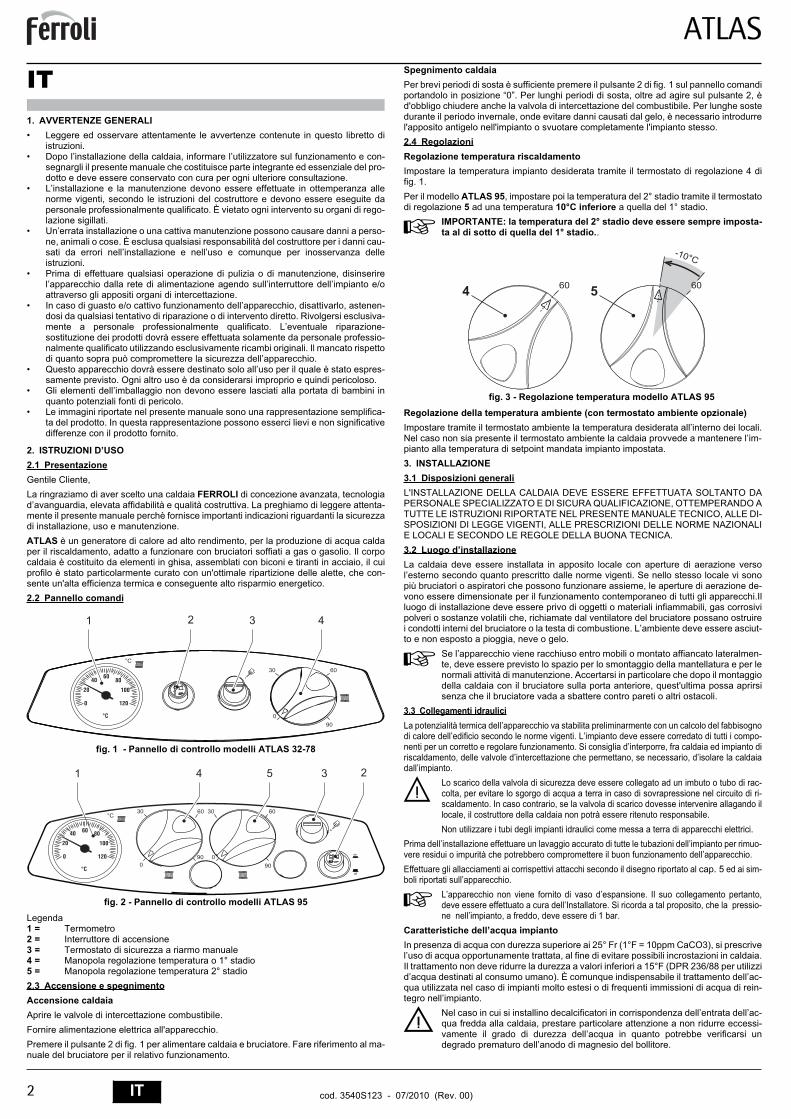
fig. 1 - Pannello di controllo modelli ATLAS 32-78
fig. 2 - Pannello di controllo modelli ATLAS 95Legenda1 = Termometro2 = Interruttore di accensione3 = Termostato di sicurezza a riarmo manuale4 = Manopola regolazione temperatura o 1° stadio5 = Manopola regolazione temperatura 2° stadio2.3 Accensione e spegnimentoAccensione caldaiaAprire le valvole di intercettazione combustibile.Fornire alimentazione elettrica all'apparecchio.Premere il pulsante 2 di fig. 1 per alimentare caldaia e bruciatore. Fare riferimento al ma-nuale del bruciatore per il relativo funzionamento.
Spegnimento caldaiaPer brevi periodi di sosta è sufficiente premere il pulsante 2 di fig. 1 sul pannello comandiportandolo in posizione “0”. Per lunghi periodi di sosta, oltre ad agire sul pulsante 2, èd'obbligo chiudere anche la valvola di intercettazione del combustibile. Per lunghe sostedurante il periodo invernale, onde evitare danni causati dal gelo, è necessario introdurrel'apposito antigelo nell'impianto o svuotare completamente l'impianto stesso.2.4 RegolazioniRegolazione temperatura riscaldamentoImpostare la temperatura impianto desiderata tramite il termostato di regolazione 4 difig. 1.Per il modello ATLAS 95, impostare poi la temperatura del 2° stadio tramite il termostatodi regolazione 5 ad una temperatura 10°C inferiore a quella del 1° stadio.
AIMPORTANTE: la temperatura del 2° stadio deve essere sempre imposta-ta al di sotto di quella del 1° stadio..
fig. 3 - Regolazione temperatura modello ATLAS 95Regolazione della temperatura ambiente (con termostato ambiente opzionale)Impostare tramite il termostato ambiente la temperatura desiderata all’interno dei locali.Nel caso non sia presente il termostato ambiente la caldaia provvede a mantenere l’im-pianto alla temperatura di setpoint mandata impianto impostata.3. INSTALLAZIONE3.1 Disposizioni generaliL'INSTALLAZIONE DELLA CALDAIA DEVE ESSERE EFFETTUATA SOLTANTO DAPERSONALE SPECIALIZZATO E DI SICURA QUALIFICAZIONE, OTTEMPERANDO ATUTTE LE ISTRUZIONI RIPORTATE NEL PRESENTE MANUALE TECNICO, ALLE DI-SPOSIZIONI DI LEGGE VIGENTI, ALLE PRESCRIZIONI DELLE NORME NAZIONALIE LOCALI E SECONDO LE REGOLE DELLA BUONA TECNICA.3.2 Luogo d’installazioneLa caldaia deve essere installata in apposito locale con aperture di aerazione versol’esterno secondo quanto prescritto dalle norme vigenti. Se nello stesso locale vi sonopiù bruciatori o aspiratori che possono funzionare assieme, le aperture di aerazione de-vono essere dimensionate per il funzionamento contemporaneo di tutti gli apparecchi.Illuogo di installazione deve essere privo di oggetti o materiali infiammabili, gas corrosivipolveri o sostanze volatili che, richiamate dal ventilatore del bruciatore possano ostruirei condotti interni del bruciatore o la testa di combustione. L’ambiente deve essere asciut-to e non esposto a pioggia, neve o gelo.
ASe l’apparecchio viene racchiuso entro mobili o montato affiancato lateralmen-te, deve essere previsto lo spazio per lo smontaggio della mantellatura e per lenormali attività di manutenzione. Accertarsi in particolare che dopo il montaggiodella caldaia con il bruciatore sulla porta anteriore, quest'ultima possa aprirsisenza che il bruciatore vada a sbattere contro pareti o altri ostacoli.
3.3 Collegamenti idrauliciLa potenzialità termica dell’apparecchio va stabilita preliminarmente con un calcolo del fabbisognodi calore dell’edificio secondo le norme vigenti. L’impianto deve essere corredato di tutti i compo-nenti per un corretto e regolare funzionamento. Si consiglia d’interporre, fra caldaia ed impianto diriscaldamento, delle valvole d’intercettazione che permettano, se necessario, d’isolare la caldaiadall’impianto.
BLo scarico della valvola di sicurezza deve essere collegato ad un imbuto o tubo di rac-colta, per evitare lo sgorgo di acqua a terra in caso di sovrapressione nel circuito di ri-scaldamento. In caso contrario, se la valvola di scarico dovesse intervenire allagando illocale, il costruttore della caldaia non potrà essere ritenuto responsabile.Non utilizzare i tubi degli impianti idraulici come messa a terra di apparecchi elettrici.
Prima dell’installazione effettuare un lavaggio accurato di tutte le tubazioni dell’impianto per rimuo-vere residui o impurità che potrebbero compromettere il buon funzionamento dell’apparecchio.Effettuare gli allacciamenti ai corrispettivi attacchi secondo il disegno riportato al cap. 5 ed ai sim-boli riportati sull’apparecchio.
AL’apparecchio non viene fornito di vaso d’espansione. Il suo collegamento pertanto,deve essere effettuato a cura dell’Installatore. Si ricorda a tal proposito, che la pressio-ne nell’impianto, a freddo, deve essere di 1 bar.
Caratteristiche dell’acqua impiantoIn presenza di acqua con durezza superiore ai 25° Fr (1°F = 10ppm CaCO3), si prescrivel’uso di acqua opportunamente trattata, al fine di evitare possibili incrostazioni in caldaia.Il trattamento non deve ridurre la durezza a valori inferiori a 15°F (DPR 236/88 per utilizzid’acqua destinati al consumo umano). È comunque indispensabile il trattamento dell’ac-qua utilizzata nel caso di impianti molto estesi o di frequenti immissioni di acqua di rein-tegro nell’impianto.
BNel caso in cui si installino decalcificatori in corrispondenza dell’entrata dell’ac-qua fredda alla caldaia, prestare particolare attenzione a non ridurre eccessi-vamente il grado di durezza dell’acqua in quanto potrebbe verificarsi undegrado prematuro dell’anodo di magnesio del bollitore.
� ���
����
���
��
��
� �
�� ��
��
��
� �
� ��
�� �
�� �� ��
���
����
�
���
� ���
�� ��
���
��
��
�
�����
�� ��� �
ATLAS
3ITcod. 3540S123 - 07/2010 (Rev. 00)
Sistema antigelo, liquidi antigelo, additivi ed inibitoriQualora si renda necessario, è consentito l’uso di liquidi antigelo, additivi e inibitori, soloed esclusivamente se il produttore di suddetti liquidi o additivi fornisce una garanzia cheassicuri che i suoi prodotti sono idonei all’uso e non arrecano danni allo scambiatore dicaldaia o ad altri componenti e/o materiali di caldaia ed impianto. È proibito l’uso di liquidiantingelo, additivi e inibitori generici, non espressamente adatti all’uso in impianti termicie compatibili con i materiali di caldaia ed impianto.3.4 Collegamento bruciatoreIl bruciatore a gasolio o a gas, ad aria soffiata per focolari pressurizzati, può essere uti-lizzato se le sue caratteristiche di funzionamento sono adatte alle dimensioni del focolaredella caldaia ed alla sua sovrappressione. La scelta del bruciatore deve essere fatta pre-liminarmente seguendo le istruzioni del fabbricante, in funzione del campo di lavoro, deiconsumi del combustibile e delle pressioni, nonchè della lunghezza della camera di com-bustione. Montare il bruciatore seguendo le istruzioni del Suo Costruttore.3.5 Collegamenti elettriciCollegamento alla rete elettrica
BLa sicurezza elettrica dell’apparecchio è raggiunta soltanto quando lo stesso ècorrettamente collegato ad un efficace impianto di messa a terra eseguito comeprevisto dalle vigenti norme di sicurezza. Far verificare da personale professio-nalmente qualificato l’efficienza e l’adeguatezza dell’impianto di terra, il costrut-tore non è responsabile per eventuali danni causati dalla mancanza di messaa terra dell’impianto. Far verificare inoltre che l’impianto elettrico sia adeguatoalla potenza massima assorbita dall’apparecchio, indicata in targhetta dati cal-daia.
La caldaia è precablata e dotata di cavo di allacciamento alla linea elettrica di tipo "Y"sprovvisto di spina. I collegamenti alla rete devono essere eseguiti con allacciamento fis-so e dotati di un interruttore bipolare i cui contatti abbiano una apertura di almeno 3 mm,interponendo fusibili da 3A max tra caldaia e linea. E’ importante rispettare le polarità (LI-NEA: cavo marrone / NEUTRO: cavo blu / TERRA: cavo giallo-verde) negli allacciamentialla linea elettrica. In fase di installazione o sostituzione del cavo di alimentazione, il con-duttore di terra deve essere lasciato 2 cm più lungo degli altri.
BII cavo di alimentazione dell’apparecchio non deve essere sostituito dall’utente.In caso di danneggiamento del cavo, spegnere l’apparecchio e, per la sua so-stituzione, rivolgersi esclusivamente a personale professionalmente qualifica-to. In caso di sostituzione del cavo elettrico di alimentazione, utilizzareesclusivamente cavo “HAR H05 VV-F” 3x0,75 mm2 con diametro esternomassimo di 8 mm.
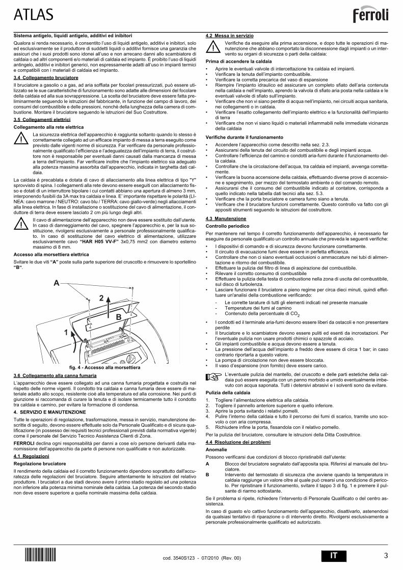
Accesso alla morsettiera elettricaSvitare le due viti “A” poste sulla parte superiore del cruscotto e rimuovere lo sportellino“B“.
fig. 4 - Accesso alla morsettiera3.6 Collegamento alla canna fumariaL’apparrecchio deve essere collegato ad una canna fumaria progettata e costruita nelrispetto delle norme vigenti. Il condotto tra caldaia e canna fumaria deve essere di ma-teriale adatto allo scopo, resistente cioè alla temperatura ed alla corrosione. Nei punti digiunzione si raccomanda di curare la tenuta e di isolare termicamente tutto il condottotra caldaia e camino, per evitare la formazione di condensa.4. SERVIZIO E MANUTENZIONETutte le operazioni di regolazione, trasformazione, messa in servizio, manutenzione de-scritte di seguito, devono essere effettuate solo da Personale Qualificato e di sicura qua-lificazione (in possesso dei requisiti tecnici professionali previsti dalla normativa vigente)come il personale del Servizio Tecnico Assistenza Clienti di Zona.FERROLI declina ogni responsabilità per danni a cose e/o persone derivanti dalla ma-nomissione dell’apparecchio da parte di persone non qualificate e non autorizzate.4.1 RegolazioniRegolazione bruciatoreIl rendimento della caldaia ed il corretto funzionamento dipendono soprattutto dall'accu-ratezza delle regolazioni del bruciatore. Seguire attentamente le istruzioni del relativoproduttore. I bruciatori a due stadi devono avere il primo stadio regolato ad una potenzanon inferiore alla potenza minima nominale della caldaia. La potenza del secondo stadionon deve essere superiore a quella nominale massima della caldaia.
4.2 Messa in servizio
BVerifiche da eseguire alla prima accensione, e dopo tutte le operazioni di ma-nutenzione che abbiano comportato la disconnessione dagli impianti o un inter-vento su organi di sicurezza o parti della caldaia:
Prima di accendere la caldaia• Aprire le eventuali valvole di intercettazione tra caldaia ed impianti.• Verificare la tenuta dell’impianto combustibile.• Verificare la corretta precarica del vaso di espansione• Riempire l’impianto idraulico ed assicurare un completo sfiato dell’aria contenuta
nella caldaia e nell’impianto, aprendo la valvola di sfiato aria posta nella caldaia e leeventuali valvole di sfiato sull’impianto.
• Verificare che non vi siano perdite di acqua nell’impianto, nei circuiti acqua sanitaria,nei collegamenti o in caldaia.
• Verificare l’esatto collegamento dell’impianto elettrico e la funzionalità dell’impiantodi terra
• Verificare che non vi siano liquidi o materiali infiammabili nelle immediate vicinanzedella caldaia
Verifiche durante il funzionamento• Accendere l’apparecchio come descritto nella sez. 2.3.• Assicurarsi della tenuta del circuito del combustibile e degli impianti acqua.• Controllare l’efficienza del camino e condotti aria-fumi durante il funzionamento del-
la caldaia.• Controllare che la circolazione dell’acqua, tra caldaia ed impianti, avvenga corretta-
mente.• Verificare la buona accensione della caldaia, effettuando diverse prove di accensio-
ne e spegnimento, per mezzo del termostato ambiente o del comando remoto.• Assicurarsi che il consumo del combustibile indicato al contatore, corrisponda a
quello indicato nella tabella dati tecnici alla sez. 5.3.• Verificare che la porta bruciatore e camera fumo siano a tenuta.• Verificare che il bruciatore funzioni correttamente. Questo controllo va fatto con gli
appositi strumenti seguendo le istruzioni del costruttore.
4.3 ManutenzioneControllo periodicoPer mantenere nel tempo il corretto funzionamento dell’apparecchio, è necessario fareseguire da personale qualificato un controllo annuale che preveda le seguenti verifiche:• I dispositivi di comando e di sicurezza devono funzionare correttamente.• Il circuito di evacuazione fumi deve essere in perfetta efficienza.• Controllare che non ci siano eventuali occlusioni o ammaccature nei tubi di alimen-
tazione e ritorno del combustibile.• Effettuare la pulizia del filtro di linea di aspirazione del combustibile.• Rilevare il corretto consumo di combustibile• Effettuare la pulizia della testa di combustione nella zona di uscita del combustibile,
sul disco di turbolenza.• Lasciare funzionare il bruciatore a pieno regime per circa dieci minuti, quindi effet-
tuare un'analisi della combustione verificando:- Le corrette tarature di tutti gli elementi indicati nel presente manuale- Temperature dei fumi al camino- Contenuto della percentuale di CO2
• I condotti ed il terminale aria-fumi devono essere liberi da ostacoli e non presentareperdite
• Il bruciatore e lo scambiatore devono essere puliti ed esenti da incrostazioni. Perl’eventuale pulizia non usare prodotti chimici o spazzole di acciaio.
• Gli impianti combustibile e acqua devono essere a tenuta.• La pressione dell’acqua dell’impianto a freddo deve essere di circa 1 bar; in caso
contrario riportarla a questo valore.• La pompa di circolazione non deve essere bloccata.• Il vaso d’espansione (non fornito) deve essere carico.
AL’eventuale pulizia del mantello, del cruscotto e delle parti estetiche della cal-daia può essere eseguita con un panno morbido e umido eventualmente imbe-vuto con acqua saponata. Tutti i detersivi abrasivi e i solventi sono da evitare.
Pulizia della caldaia1. Togliere l’alimentazione elettrica alla caldaia.2. Togliere il pannello anteriore superiore e quello inferiore.3. Aprire la porta svitando i relativi pomelli.4. Pulire l’interno della caldaia e tutto il percorso dei fumi di scarico, tramite uno sco-
volo o con aria compressa.5. Richiudere infine la porta, fissandola con il relativo pomello.Per la pulizia del bruciatore, consultare le istruzioni della Ditta Costruttrice.4.4 Risoluzione dei problemiAnomaliePossono verificarsi due condizioni di blocco ripristinabili dall’utente:A Blocco del bruciatore segnalato dall’apposita spia. Riferirsi al manuale del bru-
ciatore.B Intervento del termostato di sicurezza che avviene quando la temperatura in
caldaia raggiunge un valore oltre al quale può crearsi una condizione di perico-lo. Per ripristinare il funzionamento, svitare il tappo 3 di fig. 1 e premere il pul-sante di riarmo sottostante.
Se il problema si ripete, richiedere l’intervento di Personale Qualificato o del centro as-sistenza.In caso di guasto e/o cattivo funzionamento dell’apparecchio, disattivarlo, astenendosida qualsiasi tentativo di riparazione o di intervento diretto. Rivolgersi esclusivamente apersonale professionalmente qualificato ed autorizzato.
�
�
�
�
ATLAS
4 IT cod. 3540S123 - 07/2010 (Rev. 00)
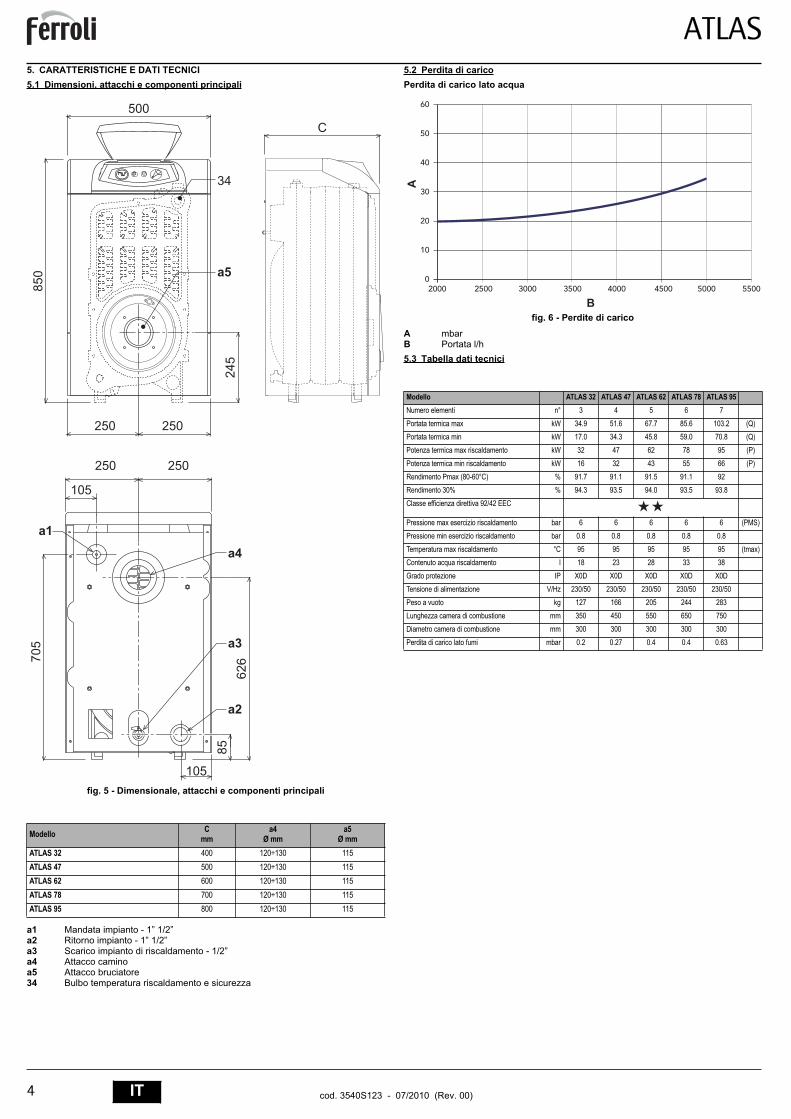
5. CARATTERISTICHE E DATI TECNICI5.1 Dimensioni, attacchi e componenti principali
fig. 5 - Dimensionale, attacchi e componenti principali
a1 Mandata impianto - 1” 1/2”a2 Ritorno impianto - 1” 1/2”a3 Scarico impianto di riscaldamento - 1/2”a4 Attacco caminoa5 Attacco bruciatore34 Bulbo temperatura riscaldamento e sicurezza
5.2 Perdita di caricoPerdita di carico lato acqua
fig. 6 - Perdite di caricoA mbarB Portata l/h5.3 Tabella dati tecnici
Modello Cmm
a4Ø mm
a5Ø mm
ATLAS 32 400 120÷130 115ATLAS 47 500 120÷130 115ATLAS 62 600 120÷130 115ATLAS 78 700 120÷130 115ATLAS 95 800 120÷130 115
���
�
���
�
�� ��
�� ��
����
�
���
��
��
�
��
��
���
�
��
Modello ATLAS 32 ATLAS 47 ATLAS 62 ATLAS 78 ATLAS 95Numero elementi n° 3 4 5 6 7
Portata termica max kW 34.9 51.6 67.7 85.6 103.2 (Q)Portata termica min kW 17.0 34.3 45.8 59.0 70.8 (Q)
Potenza termica max riscaldamento kW 32 47 62 78 95 (P)
Potenza termica min riscaldamento kW 16 32 43 55 66 (P)
Rendimento Pmax (80-60°C) % 91.7 91.1 91.5 91.1 92Rendimento 30% % 94.3 93.5 94.0 93.5 93.8
Classe efficienza direttiva 92/42 EEC
Pressione max esercizio riscaldamento bar 6 6 6 6 6 (PMS)
Pressione min esercizio riscaldamento bar 0.8 0.8 0.8 0.8 0.8
Temperatura max riscaldamento °C 95 95 95 95 95 (tmax)Contenuto acqua riscaldamento l 18 23 28 33 38
Grado protezione IP X0D X0D X0D X0D X0D
Tensione di alimentazione V/Hz 230/50 230/50 230/50 230/50 230/50Peso a vuoto kg 127 166 205 244 283
Lunghezza camera di combustione mm 350 450 550 650 750
Diametro camera di combustione mm 300 300 300 300 300
Perdita di carico lato fumi mbar 0.2 0.27 0.4 0.4 0.63
�
��
��
��
��
��
��
���� ���� ���� ���� ���� ���� ���� ����
�
�
ATLAS
5ITcod. 3540S123 - 07/2010 (Rev. 00)
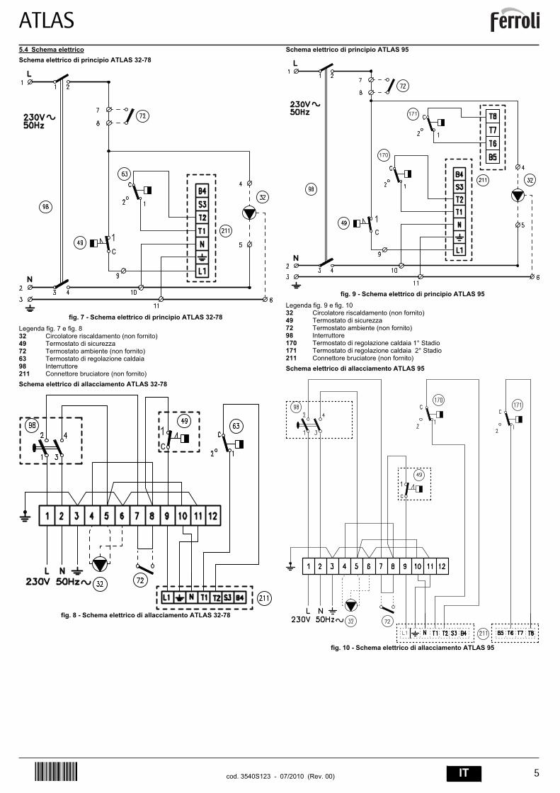
5.4 Schema elettricoSchema elettrico di principio ATLAS 32-78
fig. 7 - Schema elettrico di principio ATLAS 32-78Legenda fig. 7 e fig. 832 Circolatore riscaldamento (non fornito)49 Termostato di sicurezza72 Termostato ambiente (non fornito)63 Termostato di regolazione caldaia98 Interruttore211 Connettore bruciatore (non fornito)Schema elettrico di allacciamento ATLAS 32-78
fig. 8 - Schema elettrico di allacciamento ATLAS 32-78
Schema elettrico di principio ATLAS 95
fig. 9 - Schema elettrico di principio ATLAS 95Legenda fig. 9 e fig. 1032 Circolatore riscaldamento (non fornito)49 Termostato di sicurezza72 Termostato ambiente (non fornito)98 Interruttore170 Termostato di regolazione caldaia 1° Stadio171 Termostato di regolazione caldaia 2° Stadio211 Connettore bruciatore (non fornito)Schema elettrico di allacciamento ATLAS 95
fig. 10 - Schema elettrico di allacciamento ATLAS 95
��
��
���
���
��
�
�

ATLAS
17ENcod. 3540S123 - 07/2010 (Rev. 00)
EN1. GENERAL INSTRUCTIONS• Carefully read the instructions contained in this instruction booklet.• After boiler installation, inform the user regarding its operation and give him this
manual, which is an integral and essential part of the product and must be kept withcare for future reference.
• Installation and maintenance must be carried out by professionally qualified person-nel, according to current regulations and the manufacturer's instructions. Do not car-ry out any operation on the sealed control parts.
• Incorrect installation or inadequate maintenance can result in damage or injury. TheManufacturer declines any liability for damage due to errors in installation and useor failure to follow the instructions.
• Before carrying out any cleaning or maintenance operation, disconnect the unit fromthe power supply using the system switch and/or the special cut-off devices.
• In case of a fault and/or poor operation, deactivate the unit and do not attempt torepair it or directly intervene. Contact professionally qualified personnel. Repair/re-placement of the products must only be carried out by professionally qualified usingoriginal spare parts. Failure to comply with the above could affect the safety of theunit.
• This unit must only be used for its intended purpose. Any other use is consideredimproper and therefore dangerous.
• The packing materials are potentially hazardous and must not be left within thereach of children.
• The images given in this manual are a simplified representation of the product. Inthis representation there may be slight and insignificant differences with respect tothe product supplied.
2. OPERATING INSTRUCTIONS2.1 IntroductionDear Customer,Thank you for choosing a FERROLI boiler featuring advanced design, cutting-edgetechnology, high reliability and quality construction. Please read this manual carefullysince it provides important information on safe installation, use and maintenance.ATLAS is a high-efficiency heat generator for the production of heating hot water, suita-ble for operation with blown oil or gas burners. The boiler shell consists of cast iron ele-ments, assembled with steel stays and double cones, whose profile is specially designedwith optimum division of the fins, offering high thermal efficiency and therefore high en-ergy-saving.2.2 Control panel
fig. 1 - Control panel for models ATLAS 32-78
fig. 2 - Control panel for models ATLAS 95Key1 = Thermometer2 = Ignition switch3 = Manual reset safety thermostat4 = 1st stage temperature control knob5 = 2nd stage temperature control knob2.3 Turning on and offBoiler lightingOpen the fuel shutoff valves.Switch on the power to the unit.Press button 2 of fig. 1 to feed the boiler and burner. Refer to the burner manual for op-eration.Turning the boiler offFor brief shutdown periods just press button 2 of fig. 1 on the control panel , bringing itto position “0”. For long shutdown periods, as well as operating button 2 also close thefuel shutoff valve . To avoid damage caused by freezing during long shutdowns in winter,add a suitable antifreeze to the system or completely drain the system.
2.4 AdjustmentsHeating temperature settingSet the required system temperature with the control thermostat 4 of fig. 1.For the model ATLAS 95, with the control thermostat 5 then set the temperature of the2nd stage to a temperature 10°C lower than that of the 1st stage.
AIMPORTANT: The temperature setting of the 2nd stage must always belower than that of the 1st stage..
fig. 3 - Temperature adjustment for model ATLAS 95Room temperature adjustment (with optional room thermostat)Using the room thermostat, set the temperature desired in the rooms. If the room ther-mostat is not installed the boiler will keep the heating system at its setpoint temperature.3. INSTALLATION3.1 General InstructionsBOILER INSTALLATION MUST ONLY BE PERFORMED BY QUALIFIED PERSON-NEL, IN ACCORDANCE WITH ALL THE INSTRUCTIONS GIVEN IN THIS TECHNICALMANUAL, THE PROVISIONS OF CURRENT LAW, THE PRESCRIPTIONS OF NA-TIONAL AND LOCAL STANDARDS AND THE RULES OF PROPER WORKMANSHIP.3.2 Place of installationThe boiler must be installed in a special room with ventilation openings towards the out-side in conformity with current regulations. If there are several burners or extraction unitsthat can work together in the same room, the ventilation openings must be sized for si-multaneous operation of all the units. The place of installation must be free of flammableobjects or materials, corrosive gases, volatile substances or dusts which, sucked by theburner fan, can obstruct the pipes inside the burner or the combustion head. The roommust be dry and not exposed to rain, snow or frost.
AIf the unit is enclosed in a cabinet or mounted alongside, a space must be pro-vided for removing the casing and for normal maintenance operations. In par-ticular, after boiler installation with burner on the front door, make sure the frontdoor can open freely without the burner striking walls or other obstacles.
3.3 Plumbing connectionsThe heating capacity of the unit must be previously established by calculating the build-ing's heat requirement according to the current regulations. The system must be provid-ed with all the components for correct and regular operation. It is advisable to installshutoff valves between the boiler and heating system allowing the boiler to be isolatedfrom the system if necessary.
BThe safety valve outlet must be connected to a funnel or collection pipe to pre-vent water spurting onto the floor in case of overpressure in the heating circuit.Otherwise, if the discharge valve cuts in and floods the room, the boiler manu-facturer cannot be held liable.Do not use the water system pipes to earth electrical appliances.
Before installation, carefully wash all the pipes of the system to remove any residuals orimpurities that could affect proper operation of the unit.Carry out the relevant connections according to the diagram in and thecap. 5 symbolsgiven on the unit.
AThe unit is not supplied with an expansion tank; its connection must thereforebe carried out by the Installer. The pressure in the system, when cold, must be1 bar.
Water system characteristicsIn the presence of water harder than 25° Fr (1°F = 10ppm CaCO3), use suitably treatedwater in order to avoid possible scaling in the boiler. Treatment must not reduce the hard-ness to values below 15°F (Decree 236/88 for uses of water intended for human con-sumption). Treatment of the water used is indispensable in case of very large systemsor with frequent introduction of replenishing water in the system.
BIf water softeners are installed at the boiler cold water inlet, make sure not toreduce the water hardness too much, as this could cause early deterioration ofthe magnesium anode in the hot water tank.
Antifreeze system, antifreeze fluids, additives and inhibitorsIf it becomes necessary, it is permissible to use antifreeze fluid, additives and inhibitorsonly if the manufacturer of these fluids or additives guarantees they are suitable for thisuse and cause no damage to the heat exchanger or other components and/or materialsof the boiler unit and system. It is prohibited to use generic antifreeze fluid, additives orinhibitors that are not expressly suited for use in heating systems and compatible withthe materials of the boiler unit and system.3.4 Burner connectionAn oil or gas burner, with blown air for pressured furnaces, can be used if its operationcharacteristics are suitable for the size of the boiler furnace and its overpressure. Thechoice of burner must be made beforehand, following the manufacturer's instructions,according to the work range, fuel consumption and pressures, as well as the length ofthe firebox. Install the burner in compliance with the Manufacturer's instructions.
� ���
����
���
��
��
� �
�� ��
��
��
� �
� ��
�� �
�� �� ��
���
����
�
���
� ���
�� ��
���
��
��
�
�����
�� ��� �
ATLAS
18 EN cod. 3540S123 - 07/2010 (Rev. 00)
3.5 Electrical connectionsConnection to the electrical grid
BThe unit's electrical safety is only guaranteed when correctly connected to anefficient earthing system executed according to current safety standards. Havethe efficiency and suitability of the earthing system checked by professionallyqualified personnel. The manufacturer is not responsible for any damagecaused by failure to earth the system. Also make sure that the electrical systemis adequate for the maximum power absorbed by the unit, as specified on theboiler dataplate.
The boiler is prewired and provided with a Y-cable and plug for connection to the elec-tricity line. The connections to the grid must be made with a permanent connection andequipped with a bipolar switch whose contacts have a minimum opening of at least 3mm, interposing fuses of max. 3A between the boiler and the line. It is important to re-spect the polarities (LINE: brown wire / NEUTRAL: blue wire / EARTH: yellow-greenwire) in making connections to the electrical line. During installation or when changingthe power cable, the earth wire must be left 2 cm longer than the others.
BThe user must never change the unit's power cable. If the cable gets damaged,switch off the unit and have it changed solely by professionally qualified person-nel. If changing the electric power cable, use solely “HAR H05 VV-F” 3x0.75mm2 cable with a maximum outside diameter of 8 mm.
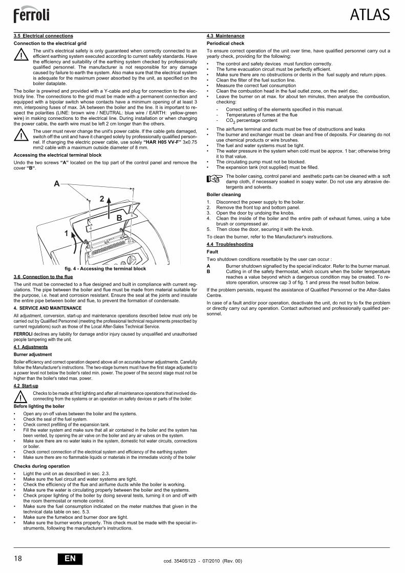
Accessing the electrical terminal blockUndo the two screws “A” located on the top part of the control panel and remove thecover “B“.
fig. 4 - Accessing the terminal block3.6 Connection to the flueThe unit must be connected to a flue designed and built in compliance with current reg-ulations. The pipe between the boiler and flue must be made from material suitable forthe purpose, i.e. heat and corrosion resistant. Ensure the seal at the joints and insulatethe entire pipe between boiler and flue, to prevent the formation of condensate.4. SERVICE AND MAINTENANCEAll adjustment, conversion, start-up and maintenance operations described below must only becarried out by Qualified Personnel (meeting the professional technical requirements prescribed bycurrent regulations) such as those of the Local After-Sales Technical Service.FERROLI declines any liability for damage and/or injury caused by unqualified and unauthorisedpeople tampering with the unit.4.1 AdjustmentsBurner adjustmentBoiler efficiency and correct operation depend above all on accurate burner adjustments. Carefullyfollow the Manufacturer's instructions. The two-stage burners must have the first stage adjusted toa power level not below the boiler's rated min. power. The power of the second stage must not behigher than the boiler's rated max. power.4.2 Start-up
BChecks to be made at first lighting and after all maintenance operations that involved dis-connecting from the systems or an operation on safety devices or parts of the boiler:
Before lighting the boiler• Open any on-off valves between the boiler and the systems.• Check the seal of the fuel system.• Check correct prefilling of the expansion tank.• Fill the water system and make sure that all air contained in the boiler and the system has
been vented, by opening the air valve on the boiler and any air valves on the system. • Make sure there are no water leaks in the system, domestic hot water circuits, connections
or boiler.• Check correct connection of the electrical system and efficiency of the earthing system• Make sure there are no flammable liquids or materials in the immediate vicinity of the boiler
Checks during operation• Light the unit on as described in sec. 2.3.• Make sure the fuel circuit and water systems are tight.• Check the efficiency of the flue and air/fume ducts while the boiler is working.• Make sure the water is circulating properly between the boiler and the systems.• Check proper lighting of the boiler by doing several tests, turning it on and off with
the room thermostat or remote control.• Make sure the fuel consumption indicated on the meter matches that given in the
technical data table on sec. 5.3.• Make sure the fumebox and burner door are tight.• Make sure the burner works properly. This check must be made with the special in-
struments, following the manufacturer's instructions.
4.3 MaintenancePeriodical checkTo ensure correct operation of the unit over time, have qualified personnel carry out ayearly check, providing for the following:• The control and safety devices must function correctly.• The fume evacuation circuit must be perfectly efficient.• Make sure there are no obstructions or dents in the fuel supply and return pipes.• Clean the filter of the fuel suction line.• Measure the correct fuel consumption• Clean the combustion head in the fuel outlet zone, on the swirl disc.• Leave the burner on at max. for about ten minutes, then analyse the combustion,
checking:- Correct setting of the elements specified in this manual.- Temperatures of fumes at the flue- CO2 percentage content
• The air/fume terminal and ducts must be free of obstructions and leaks• The burner and exchanger must be clean and free of deposits. For cleaning do not
use chemical products or wire brushes.• The fuel and water systems must be tight.• The water pressure in the system when cold must be approx. 1 bar; otherwise bring
it to that value.• The circulating pump must not be blocked.• The expansion tank (not supplied) must be filled.
AThe boiler casing, control panel and aesthetic parts can be cleaned with a softdamp cloth, if necessary soaked in soapy water. Do not use any abrasive de-tergents and solvents.
Boiler cleaning1. Disconnect the power supply to the boiler.2. Remove the front top and bottom panel.3. Open the door by undoing the knobs.4. Clean the inside of the boiler and the entire path of exhaust fumes, using a tube
brush or compressed air.5. Then close the door, securing it with the knob.To clean the burner, refer to the Manufacturer's instructions.4.4 TroubleshootingFaultTwo shutdown conditions resettable by the user can occur :A Burner shutdown signalled by the special indicator. Refer to the burner manual.B Cutting in of the safety thermostat, which occurs when the boiler temperature
reaches a value beyond which a dangerous condition may be created. To re-store operation, unscrew cap 3 of fig. 1 and press the reset button below.
If the problem persists, request the assistance of Qualified Personnel or the After-SalesCentre.In case of a fault and/or poor operation, deactivate the unit, do not try to fix the problemor directly carry out any operation. Contact authorised and professionally qualified per-sonnel.
�
�
�
�
ATLAS
19ENcod. 3540S123 - 07/2010 (Rev. 00)
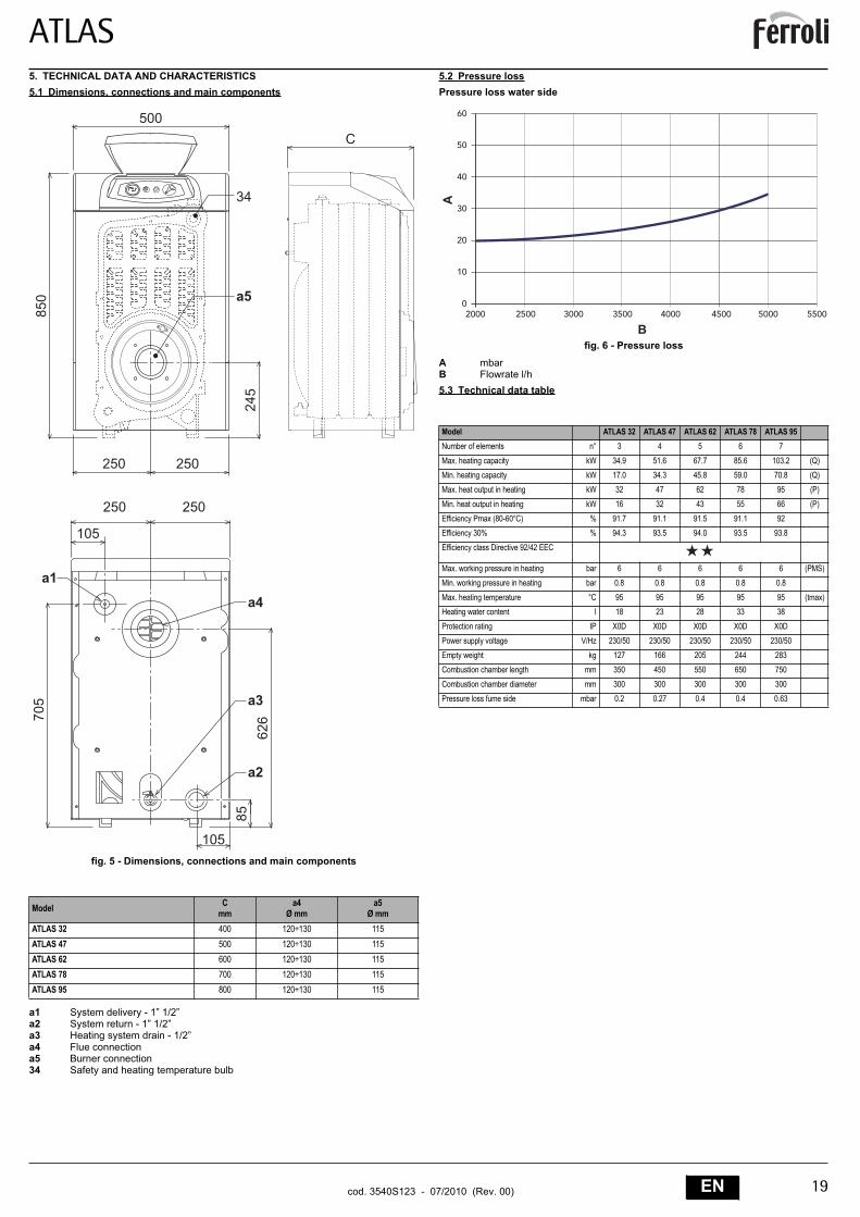
5. TECHNICAL DATA AND CHARACTERISTICS5.1 Dimensions, connections and main components
fig. 5 - Dimensions, connections and main components
a1 System delivery - 1” 1/2”a2 System return - 1” 1/2”a3 Heating system drain - 1/2”a4 Flue connectiona5 Burner connection34 Safety and heating temperature bulb
5.2 Pressure lossPressure loss water side
fig. 6 - Pressure lossA mbarB Flowrate l/h5.3 Technical data table
Model Cmm
a4Ø mm
a5Ø mm
ATLAS 32 400 120÷130 115ATLAS 47 500 120÷130 115ATLAS 62 600 120÷130 115ATLAS 78 700 120÷130 115ATLAS 95 800 120÷130 115
���
�
���
�
�� ��
�� ��
����
�
���
��
��
�
��
��
���
�
��
Model ATLAS 32 ATLAS 47 ATLAS 62 ATLAS 78 ATLAS 95Number of elements n° 3 4 5 6 7
Max. heating capacity kW 34.9 51.6 67.7 85.6 103.2 (Q)Min. heating capacity kW 17.0 34.3 45.8 59.0 70.8 (Q)
Max. heat output in heating kW 32 47 62 78 95 (P)
Min. heat output in heating kW 16 32 43 55 66 (P)
Efficiency Pmax (80-60°C) % 91.7 91.1 91.5 91.1 92Efficiency 30% % 94.3 93.5 94.0 93.5 93.8
Efficiency class Directive 92/42 EEC
Max. working pressure in heating bar 6 6 6 6 6 (PMS)
Min. working pressure in heating bar 0.8 0.8 0.8 0.8 0.8
Max. heating temperature °C 95 95 95 95 95 (tmax)Heating water content l 18 23 28 33 38
Protection rating IP X0D X0D X0D X0D X0D
Power supply voltage V/Hz 230/50 230/50 230/50 230/50 230/50Empty weight kg 127 166 205 244 283
Combustion chamber length mm 350 450 550 650 750
Combustion chamber diameter mm 300 300 300 300 300
Pressure loss fume side mbar 0.2 0.27 0.4 0.4 0.63
�
��
��
��
��
��
��
���� ���� ���� ���� ���� ���� ���� ����
�
�
ATLAS
20 EN cod. 3540S123 - 07/2010 (Rev. 00)
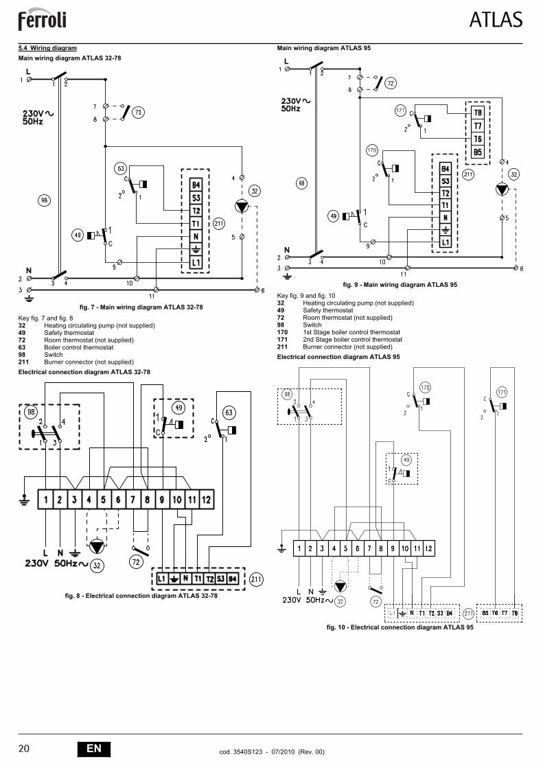
5.4 Wiring diagramMain wiring diagram ATLAS 32-78
fig. 7 - Main wiring diagram ATLAS 32-78Key fig. 7 and fig. 832 Heating circulating pump (not supplied)49 Safety thermostat72 Room thermostat (not supplied)63 Boiler control thermostat98 Switch211 Burner connector (not supplied)Electrical connection diagram ATLAS 32-78
fig. 8 - Electrical connection diagram ATLAS 32-78
Main wiring diagram ATLAS 95
fig. 9 - Main wiring diagram ATLAS 95Key fig. 9 and fig. 1032 Heating circulating pump (not supplied)49 Safety thermostat72 Room thermostat (not supplied)98 Switch170 1st Stage boiler control thermostat171 2nd Stage boiler control thermostat211 Burner connector (not supplied)Electrical connection diagram ATLAS 95
fig. 10 - Electrical connection diagram ATLAS 95
��
��
���
���
��
�
�
ATLAS
33RUcod. 3540S123 - 07/2010 (Rev. 00)
RU1.• , .•
;.
•.
- .•
., ,
.•
/.
• / ,.
.-
..
• ., , .
•, .
•.
2.2.1
,, FERROLI,
,. , . .
,.
ATLAS ,.
,.
.2.2
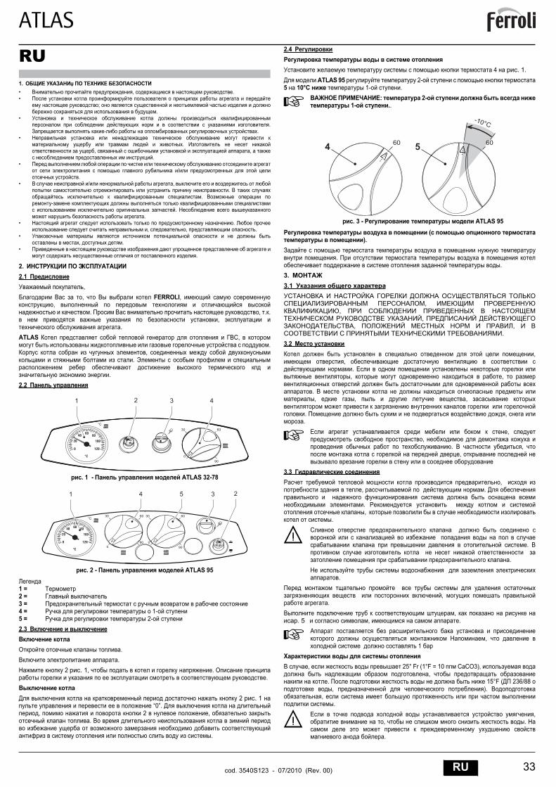
. 1 - ATLAS 32-78
. 2 - ATLAS 95
1 =2 =3 =4 = o 1-5 = 2-2.3
..
2 . 1, ..
2 . 1 “0”.
, 2 ,.
.
2.4
4 . 1.ATLAS 95 2-
5 10°C 1- .
A: 2-
1- ..
. 3 - ATLAS 95 (
).
..
3.3.1
,,
,, ,
.3.2
,,
., ,
., , ,
. ,.
A,
,. ,
,
3.3,
, .
.,
.
B .
.
.
,.
,cap. 5 , .
A , 1
, 25° Fr (1°F = 10 CaCO3), ,
. 15°F ( 236/88 , ).
,.
B,
, .
.
� ���
����
���
��
��
� �
�� ��
��
��
� �
� ��
�� �
�� �� ��
���
����
�
���
� ���
�� ��
���
��
��
�
�����
�� ��� �
ATLAS
34 RU cod. 3540S123 - 07/2010 (Rev. 00)
, ,, ,
, ,,
/ ,. - ,
,, .
3.4
,.
, ,.
.3.5
B ,.
. ,. ,
, .,
"Y" . ,
3 ,. 3A.
( : / : / : -).
2 .
B.
;.
“HAR H05 VV-F” 3x0,75 2 8 .
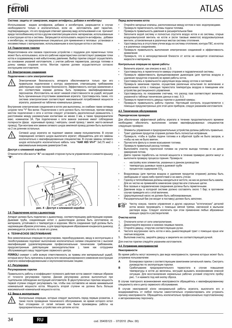
“A”“B“.
. 4 - 3.6
, .,
, .,
.4.
, ,
( , ),
.FERROLI ,
.4.1
..
,.
.4.2
B, ,
,
:
• , - .• .•• ,
( ), .
• , ,.
•
• ,.
• , sez. 2.3.• .• (
) .• .• ,
.• , ,
sez. 5.3.• .• .
, .
4.3
:• .• .• , ,
.• .• .•
.•
. :- ,-- CO2
• ( )-
• , ..
• .• 1 ;
.• .• ( ) .
A, " "
,.
.
1. .2. .3. , .4.
.5. , .
.4.4
,:
A ..
B,
.. 1 .
./ ,
..
�
�
�
�
ATLAS
35RUcod. 3540S123 - 07/2010 (Rev. 00)
5.5.1 ,
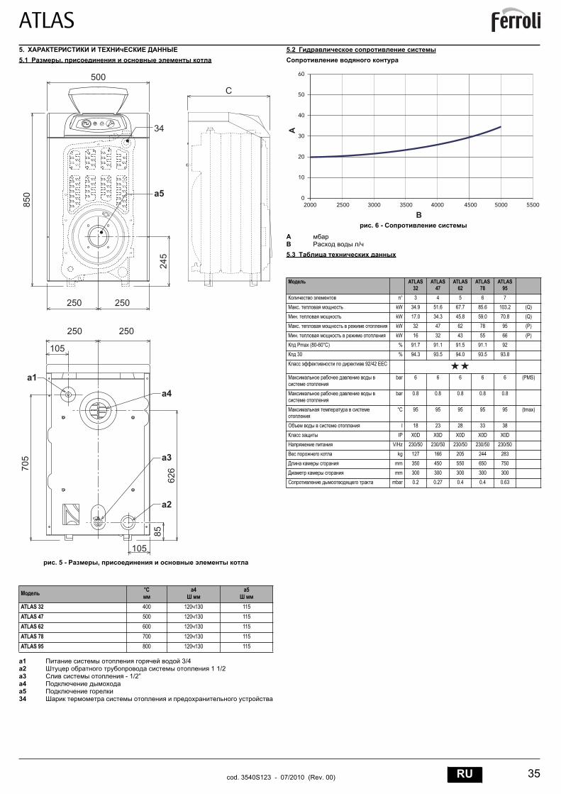
. 5 - ,
a1 3/4a2 1 1/2a3 - 1/2”a4a534
5.2
. 6 - AB /5.3
°C a4 a5
ATLAS 32 400 120 130 115ATLAS 47 500 120 130 115ATLAS 62 600 120 130 115ATLAS 78 700 120 130 115ATLAS 95 800 120 130 115
���
�
���
�
�� ��
�� ��
����
�
���
��
��
�
��
��
���
�
��
ATLAS 32
ATLAS 47
ATLAS 62
ATLAS 78
ATLAS 95
n° 3 4 5 6 7. kW 34.9 51.6 67.7 85.6 103.2 (Q)
. kW 17.0 34.3 45.8 59.0 70.8 (Q)
. kW 32 47 62 78 95 (P)
. kW 16 32 43 55 66 (P) Pmax (80-60°C) % 91.7 91.1 91.5 91.1 92
30 % 94.3 93.5 94.0 93.5 93.8
92/42 EEC
bar 6 6 6 6 6 (PMS)
bar 0.8 0.8 0.8 0.8 0.8
°C 95 95 95 95 95 (tmax)
l 18 23 28 33 38
IP X0D X0D X0D X0D X0D
V/Hz 230/50 230/50 230/50 230/50 230/50kg 127 166 205 244 283
mm 350 450 550 650 750
mm 300 300 300 300 300mbar 0.2 0.27 0.4 0.4 0.63
�
��
��
��
��
��
��
���� ���� ���� ���� ���� ���� ���� ����
�
�

ATLAS
36 RU cod. 3540S123 - 07/2010 (Rev. 00)
5.4 ATLAS 32-78
. 7 - ATLAS 32-78. 7 . 8
32 ( )4972 ( )6398211 ( )
ATLAS 32-78
. 8 - ATLAS 32-78
ATLAS 95
. 9 - ATLAS 95. 9 . 10
32 ( )4972 ( )98170 1-171 2-211 ( )
ATLAS 95
. 10 - ATLAS 95
��
��
���
���
��
�
�

Declaración de conformidadEl fabricante: FERROLI S.p.A.
Dirección: Via Ritonda 78/a 37047 San Bonifacio (Verona)
declara que este equipo satisface las siguientes directivas CEE:• Directiva de Aparatos de Gas 90/396• Directiva de Rendimientos 92/42• Directiva de Baja Tensión 73/23 (modificada por la 93/68) • Directiva de Compatibilidad Electromagnética 89/336 (modificada por la 93/68)
Presidente y representante legalCaballero del Trabajo
Dante Ferroli
ES
Dichiarazione di conformitàIl costruttore: FERROLI S.p.A.
Indirizzo: Via Ritonda 78/a 37047 San Bonifacio VR
dichiara che questo apparecchio è conforme alle seguenti direttive CEE:• Direttiva Apparecchi a Gas 90/396• Direttiva Rendimenti 92/42• Direttiva Bassa Tensione 73/23 (modificata dalla 93/68)• Direttiva Compatibilità Elettromagnetica 89/336 (modificata dalla 93/68)
Presidente e Legale rappresentanteCav. del Lavoro
Dante Ferroli
IT
Declaration of conformityManufacturer: FERROLI S.p.A.
Address: Via Ritonda 78/a 37047 San Bonifacio VR Italy
declares that this unit complies with the following EU directives:• Gas Appliance Directive 90/396• Efficiency Directive 92/42• Low Voltage Directive 73/23 (amended by 93/68)• Electromagnetic Compatibility Directive 89/336 (amended by 93/68)
President and Legal Representative Cav. del Lavoro
Dante Ferroli
TR Uygunluk beyanimalatçi: FERROLI S.p.A.
Adres: Via Ritonda 78/a 37047 San Bonifacio VR
bu cihazin; asagida yer alan AET(EEC) yönergelerine uygunluk içinde oldugunu beyan etmektedir:• 90/396 Gazla çalistirilan üniteler için Yönetmelik• 92/42 Randiman/Verimlilik Yönetmeligi• Yönerge 73/23, Düsük Voltaj (93/68 nolu direktifle degisiklige ugratildi)• 89/336 Elektromanyetik Uygunluk Yönetmeligi (93/68 ile degisiklik yapilmistir)
Baskan ve yasal temsilci. Dep.
Dante Ferroli
ES
EN
: FERROLI S.p.A., : Via Ritonda 78/a 37047 San Bonifacio VR,
, CEE:• 90/396 • . . . 92/42 • 73/23 ( , 93/68) • 89/336 ( ,
93/68).
( ,
)Dante Ferroli
RU
ConformiteitsverklaringDe fabrikant: FERROLI S.p.A.
Adres: Via Ritonda 78/a 37047 San Bonifacio VR
verklaart dat dit apparaat conform is aan de volgende EEG richtlijnen:• Richtlijn Gastoestellen 90/396/EEG• Richtlijn Rendementseisen 92/42/EEG• Laagspanningsrichtlijn 73/23/EEG (gewijzigd door 93/68)• Richtlijn Elektromagnetische compatibiliteit 89/336/EEG (gewijzigd door 93/68)
Voorzitter Raad van Bestuur en wettelijk vertegenwoordigerOnderscheiden voor verdiensten op economisch gebied
Dante Ferroli
: FERROLI S.p.A.
: Via Ritonda 78/a 37047 San Bonifacio VR
:• O 90/396• O 92/42• O T 73/23 ( 93/68)• O H 89/336 ( 93/68)
Presidente e Legale rappresentanteO
Dante Ferroli
NL
Déclaration de conformitéLe constructeur : FERROLI S.p.A.
Adresse: Via Ritonda 78/a 37047 San Bonifacio VR
déclare que cet appareil est conforme aux directives CEE ci-dessous:• Directives appareils à gaz 90/396• Directive rendements 92/42• Directive basse tension 73/23 (modifiée 93/68)• Directive Compatibilité Electromagnétique 89/336 (modifiée 93/68)
Président et fondé de pouvoirs
Cav. du travail
Dante Ferroli
FR
EL

FERROLI S.p.A.Via Ritonda 78/a
37047 San Bonifacio - Verona - ITALYwww.ferroli.it