3D Hierarchical Porous TiO 2 Films from Colloidal Composite Fluidic...
6
3D Hierarchical Porous TiO 2 Films from Colloidal Composite Fluidic Deposition Chiara Dionigi,* Pierpaolo Greco, Giampiero Ruani, Massimiliano Cavallini, Francesco Borgatti, and Fabio Biscarini Consiglio Nazionale delle Ricerche, Istituto per lo Studio dei Materiali Nanostrutturati, Via P. Gobetti 101, I-40129, Bologna, Italy ReceiVed June 25, 2008. ReVised Manuscript ReceiVed September 24, 2008 We use a “structure director” colloidal composite to fabricate porous titanium oxide films having a hierarchical pore architecture consisting of mesopores regularly distributed in the macropore shell. The colloidal composite consists of polystyrene beads coated with (ammonium lactate)titanium dihydroxide deposited by means of a fluidic technique. The pore properties and interconnections are controlled at different length scales: a macroscale, which is imposed by the polystyrene beads; a mesoscale, which is controlled by the composition and by the thermal history of the composite; a nanometer-scale, controlled by the nanocrystal sintering in air. Our approach can be extended to a wide class of water-soluble metal oxide precursors; therefore, it opens interesting perspectives for “bottom-up” nanotechnology of functional arrays and devices. Introduction The hierarchical organization of a material into a multi- modal architecture of pores with controlled size is attractive because it imparts “smart” properties on the structure, in terms of exposed surface, active sites, rheology, and size- selection. This aspect is required for several applications like chromatography, catalysis sensors, photonics, and photovol- taics. 1,2 Interest in the multimodal porosity of titanium oxide, TiO 2 , has emerged in the last 10 years because of its optical and electronic properties, which have made it one of the most studied materials in photonic and photovoltaic applications. The control of the porosity in films consisting of TiO 2 inverse opals represents a crucial advance in the field of photonic band gap materials because it leads to a periodic modulation of the refractive index generating a photonic stop band that does not allow the propagation of light with definite frequencies. 3-5 The substitution of disordered mesoporous TiO 2 films with inverse titania opals, in photovoltaic dye-sensitized solar cells (DSSC) 5-8 represented a breakthrough to improve the conversion efficiency of all solid state DSSC up to the highest limit of 11% obtained by Gra ¨tzel et al. in liquid electrolyte based devices. 3,4,8-14 As electron transport strictly depends on the network morphology and interconnection of TiO 2 nanoparticles, 9 attention has been focused on the TiO 2 particle network in order to improve its electron transport and, consequently, to increase the efficiency of DSSCs. Geometric confinement controls the diffusive movement and forces the electron transport to take a specific direction. A one-dimensional network has been considered an excellent compromise to achieve the optimum amount of nanoparticle contacts, generating a direct electron transport. In any case, an inverse opal structure combines the regular spatial arrangement of nanoparticles and an extended specific surface. Two-dimensional geometric confinement in the thin TiO 2 shells can speed up electron transport with respect to a three-dimensional chaotic network, thanks to the reduction of the degrees of freedom for electron movement. 12 Further improvement in the morphology of thin TiO 2 shells indubi- tably represents an advance in the research on the optimum electron transport network. Templates made of colloidal crystals of polymeric mono- disperse beads have been used to generate TiO 2 inverse opals having differently sized (meso and macro) interconnected pores. 9,15,16 During template removal by thermal treatment, * Corresponding author. E-mail: [email protected]. Tel.: 390516398502. Fax: 390516398540. (1) Sakatani, Y.; Boissie `re, C.; Grosso, D.; Nicole, L.; Soler-Illia, G. J. A. A.; Sanchez, C Chem. Mater. 2008, 20, 1049–1056. (2) Sanchez, C.; Boissiere, C.; Grosso, D.; Laberty, C.; Nicole, L. Chem. Mater. 2008, 20, 682–737. (3) Wong, S.; Kitaev, V.; Ozin, G. A. J. Am. Chem. Soc. 2003, 125, 15589–15598. (4) Stein, A.; Li, F.; Denny, N. R. Chem. Mater. 2008, 20, 649–666. (5) Somani, P. R.; Dionigi, C.; Murgia, M.; Palles, D.; Nozar, P.; Ruani, G. Sol Energy Mater. Sol. Cells 2005, 87, 513–519. (6) Diguna, L. J.; Shen, Q.; Kobayashi, J.; Toyoda, T. Appl. Phys. Lett. 2007, 91, 023116. (7) Zhang, Y.; Wang, J.; Zhao, Y.; Zhai, J.; Jiang, L.; Song, Y.; Zhu, D. J. Mater. Chem. 2008, 18, 2650–2652. (8) Kuo, C-Y.; Lu, S-Y. Nanotechnology 2008, 19, 095705. (9) Gra ¨tzel, M. Nature 2001, 414, 338. (10) Gates, B.; Park, S. H.; Xia, Y. AdV. Mater. 2000, 12, 653–556. (11) Radtchenko, I. L.; Sulkhorukov; G, B.; Gaponik, N.; Kornowski, A.; Rogach, A.m.L.; Mo ¨hwald, H. AdV. Mater. 200113, 1684. (12) Halaoui, L. I.; Abrams, N. M.; Mallouk, T. E. J. Phys. Chem. B 2005, 109, 6334–6342. (13) Diguna, L. J.; Murakami, M.; Sato, A.; Kugamai, Y.; Ishihara, T.; Kobayashi, N.; Shen, Q.; Toyoda, T. Jpn. J. Appl. Phys. 2006, 45, 5563–5568. (14) Ruani, G.; Ancora, C.; Corticelli, F.; Dionigi, C.; Rossi, C. Sol. Energy Mater. Sol. Cells 2008, 92, 5, 537–542. (15) Velikov, K. P.; Christova, C. G.; Dullens, R. P. A.; van Blaaderen, A. Science 2002, 296, 106–109. (16) The designation of pores of less than 2 nm, 2 to 50 nm, and over 50 nm size (diameter) as micro-, meso-, and macropores is in accord with accepted IUPAC terminology and definition. 7130 Chem. Mater. 2008, 20, 7130–7135 10.1021/cm801734y CCC: $40.75 2008 American Chemical Society Published on Web 10/29/2008
Transcript of 3D Hierarchical Porous TiO 2 Films from Colloidal Composite Fluidic...
3D Hierarchical Porous TiO2 Films from Colloidal CompositeFluidic Deposition
Chiara Dionigi,* Pierpaolo Greco, Giampiero Ruani, Massimiliano Cavallini,Francesco Borgatti, and Fabio Biscarini
Consiglio Nazionale delle Ricerche, Istituto per lo Studio dei Materiali Nanostrutturati,Via P. Gobetti 101, I-40129, Bologna, Italy
ReceiVed June 25, 2008. ReVised Manuscript ReceiVed September 24, 2008
We use a “structure director” colloidal composite to fabricate porous titanium oxide films having ahierarchical pore architecture consisting of mesopores regularly distributed in the macropore shell. Thecolloidal composite consists of polystyrene beads coated with (ammonium lactate)titanium dihydroxidedeposited by means of a fluidic technique. The pore properties and interconnections are controlled atdifferent length scales: a macroscale, which is imposed by the polystyrene beads; a mesoscale, which iscontrolled by the composition and by the thermal history of the composite; a nanometer-scale, controlledby the nanocrystal sintering in air. Our approach can be extended to a wide class of water-soluble metaloxide precursors; therefore, it opens interesting perspectives for “bottom-up” nanotechnology of functionalarrays and devices.
Introduction
The hierarchical organization of a material into a multi-modal architecture of pores with controlled size is attractivebecause it imparts “smart” properties on the structure, interms of exposed surface, active sites, rheology, and size-selection. This aspect is required for several applications likechromatography, catalysis sensors, photonics, and photovol-taics.1,2 Interest in the multimodal porosity of titanium oxide,TiO2, has emerged in the last 10 years because of its opticaland electronic properties, which have made it one of the moststudied materials in photonic and photovoltaic applications.The control of the porosity in films consisting of TiO2 inverseopals represents a crucial advance in the field of photonicband gap materials because it leads to a periodic modulationof the refractive index generating a photonic stop band thatdoes not allow the propagation of light with definitefrequencies.3-5
The substitution of disordered mesoporous TiO2 films withinverse titania opals, in photovoltaic dye-sensitized solar cells(DSSC)5-8 represented a breakthrough to improve theconversion efficiency of all solid state DSSC up to the highestlimit of 11% obtained by Gratzel et al. in liquid electrolyte
based devices.3,4,8-14 As electron transport strictly dependson the network morphology and interconnection of TiO2
nanoparticles,9 attention has been focused on the TiO2
particle network in order to improve its electron transportand, consequently, to increase the efficiency of DSSCs.Geometric confinement controls the diffusive movement andforces the electron transport to take a specific direction. Aone-dimensional network has been considered an excellentcompromise to achieve the optimum amount of nanoparticlecontacts, generating a direct electron transport. In any case,an inverse opal structure combines the regular spatialarrangement of nanoparticles and an extended specificsurface. Two-dimensional geometric confinement in the thinTiO2 shells can speed up electron transport with respect toa three-dimensional chaotic network, thanks to the reductionof the degrees of freedom for electron movement.12 Furtherimprovement in the morphology of thin TiO2 shells indubi-tably represents an advance in the research on the optimumelectron transport network.
Templates made of colloidal crystals of polymeric mono-disperse beads have been used to generate TiO2 inverse opalshaving differently sized (meso and macro) interconnectedpores.9,15,16 During template removal by thermal treatment,
* Corresponding author. E-mail: [email protected]. Tel.: 390516398502.Fax: 390516398540.
(1) Sakatani, Y.; Boissiere, C.; Grosso, D.; Nicole, L.; Soler-Illia,G. J. A. A.; Sanchez, C Chem. Mater. 2008, 20, 1049–1056.
(2) Sanchez, C.; Boissiere, C.; Grosso, D.; Laberty, C.; Nicole, L. Chem.Mater. 2008, 20, 682–737.
(3) Wong, S.; Kitaev, V.; Ozin, G. A. J. Am. Chem. Soc. 2003, 125,15589–15598.
(4) Stein, A.; Li, F.; Denny, N. R. Chem. Mater. 2008, 20, 649–666.(5) Somani, P. R.; Dionigi, C.; Murgia, M.; Palles, D.; Nozar, P.; Ruani,
G. Sol Energy Mater. Sol. Cells 2005, 87, 513–519.(6) Diguna, L. J.; Shen, Q.; Kobayashi, J.; Toyoda, T. Appl. Phys. Lett.
2007, 91, 023116.(7) Zhang, Y.; Wang, J.; Zhao, Y.; Zhai, J.; Jiang, L.; Song, Y.; Zhu, D.
J. Mater. Chem. 2008, 18, 2650–2652.(8) Kuo, C-Y.; Lu, S-Y. Nanotechnology 2008, 19, 095705.
(9) Gratzel, M. Nature 2001, 414, 338.(10) Gates, B.; Park, S. H.; Xia, Y. AdV. Mater. 2000, 12, 653–556.(11) Radtchenko, I. L.; Sulkhorukov; G, B.; Gaponik, N.; Kornowski, A.;
Rogach, A.m.L.; Mohwald, H. AdV. Mater. 200113, 1684.(12) Halaoui, L. I.; Abrams, N. M.; Mallouk, T. E. J. Phys. Chem. B 2005,
109, 6334–6342.(13) Diguna, L. J.; Murakami, M.; Sato, A.; Kugamai, Y.; Ishihara, T.;
Kobayashi, N.; Shen, Q.; Toyoda, T. Jpn. J. Appl. Phys. 2006, 45,5563–5568.
(14) Ruani, G.; Ancora, C.; Corticelli, F.; Dionigi, C.; Rossi, C. Sol. EnergyMater. Sol. Cells 2008, 92, 5, 537–542.
(15) Velikov, K. P.; Christova, C. G.; Dullens, R. P. A.; van Blaaderen,A. Science 2002, 296, 106–109.
(16) The designation of pores of less than 2 nm, 2 to 50 nm, and over 50nm size (diameter) as micro-, meso-, and macropores is in accord withaccepted IUPAC terminology and definition.
7130 Chem. Mater. 2008, 20, 7130–7135
10.1021/cm801734y CCC: $40.75 2008 American Chemical SocietyPublished on Web 10/29/2008
random mesoporosity is produced by the partial sintering ofoxide nanoparticles in the shells of the macropores.17
Controlling mesoporosity in three dimensions representsan innovation for standard templating methods. Specificallyfor film fabrication, codeposition of ultrafine metal oxidenanoparticles and polymeric templating beads on a substratewas applied to obtain controlled trimodal porosity in SiO2
films using differently sized templating beads duringcodeposition.4,18,19 Up to now, it has only been possible toachieve controlled mesoporosity in TiO2 films by a templat-ing method based on embossing of the titania sol-gelprecursor by a poly-(methyl methacrylate) mold.20 In bothprevious examples, the size and shape of the resultingstructures are univocally correlated to the size and shape ofthe template and can not be tuned by varying the processparameters.
In the recent review articles on templating methods,2,21
the concept of “structure director” was introduced to describea situation in which the relationship between templatemorphology and the resulting porous structure is not univo-cally established but determined by molecule (mainly sur-factants) self-assembling.
In this work, we present a colloidal composite acting as a“structure director” for the fabrication of TiO2 films havingcontrolled and geometrically ordered porosity at differentlength scales. The composite consists of monodispersepolystyrene beads (PS) coated with a titanium oxide precur-sor named bis(ammonium lactate)titanium dihydroxide(TALH).6,13,14,22-24 The multilayered films of orderedTALH/PS composite10 were deposited in a single step by afluidic technique called “vertical deposition”.19,25,26 Specif-ically in these films, annealing 13,27,28 produces an additionalcontrolled porosity at the mesoscale (pore diameter ∼ 30nm), resulting in a chain morphology that we term “me-sochain”. Mesochains are confined regions regularly placedin the TiO2 macropore shells and connected only by poorlyaccessible porosity caused by the partial sintering of the TiO2
nanocrystals. We show that a fundamental “structure direc-tor” requirement for controlling mesopore distribution in themacropore shells is the absence of reciprocal solubilitybetween the composite components. Highly hydrophilicTALH is orthogonal soluble, at any temperature, to highly
hydrophobic polystyrene. By taking advantage of the vis-coelastic and relaxation properties of both the polystyreneand the TiO2 precursor, we developed a process of fabricationleading to a hierarchical pore architecture of the oxideskeleton. In particular, the increase in the Poisson ratio ofthe TALH coating during the thermal treatment and thecritical mass ratio between the PS nanobeads and TALH,which extensively regulates the compliance of the TiO2
precursor walls, allowed us to select the presence and thecharacteristic thickness of the mesochains in the metal oxideskeleton. We present results about the fabrication of inter-penetrated 3D periodic arrays of differently sized pore shellswhere 12 mesopores are embedded in the macropore shells.
The novelty of this work is the demonstration that well-known materials like polystyrene and bis(ammonium lac-tate)titanium dihydroxide can be properly combined to forma “structure directing” composite that, under annealing,generates periodic and hierarchically ordered meso-macropore shells in the TiO2 structures.
Experimental Section
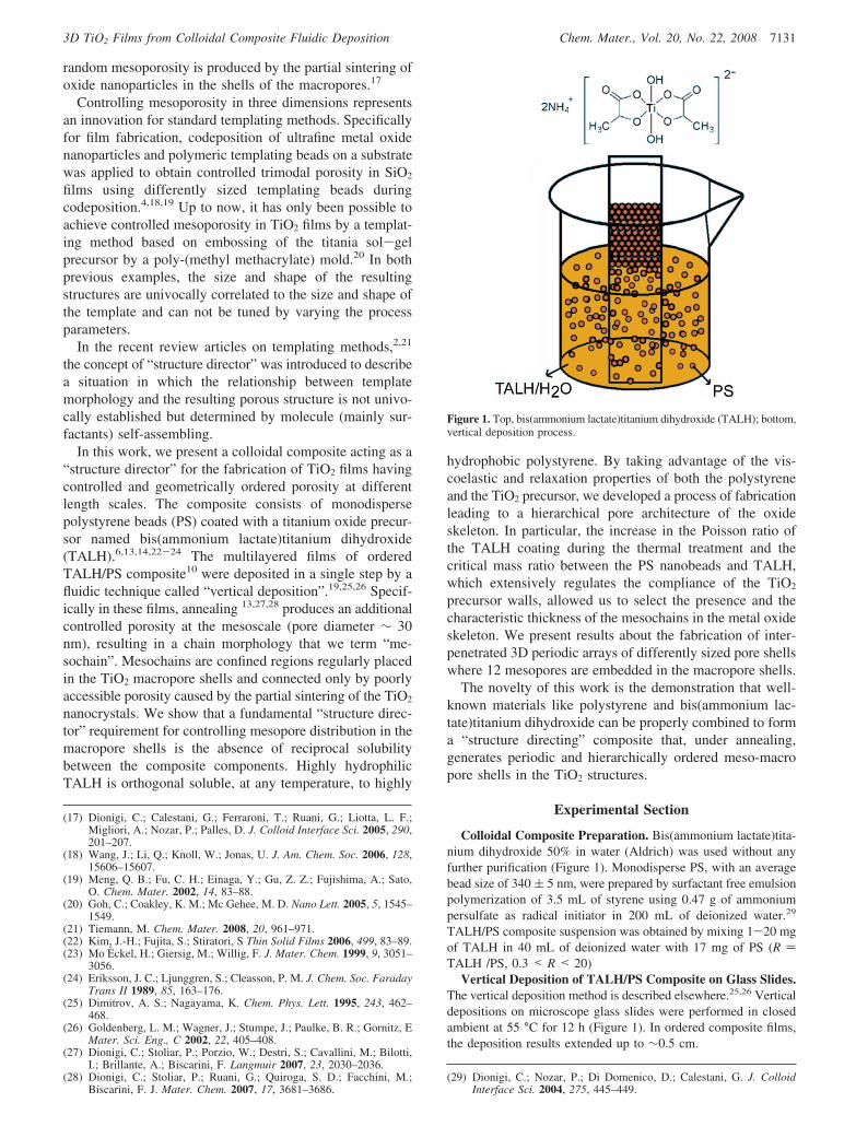
Colloidal Composite Preparation. Bis(ammonium lactate)tita-nium dihydroxide 50% in water (Aldrich) was used without anyfurther purification (Figure 1). Monodisperse PS, with an averagebead size of 340 ( 5 nm, were prepared by surfactant free emulsionpolymerization of 3.5 mL of styrene using 0.47 g of ammoniumpersulfate as radical initiator in 200 mL of deionized water.29
TALH/PS composite suspension was obtained by mixing 1-20 mgof TALH in 40 mL of deionized water with 17 mg of PS (R )TALH /PS, 0.3 < R < 20)
Vertical Deposition of TALH/PS Composite on Glass Slides.The vertical deposition method is described elsewhere.25,26 Verticaldepositions on microscope glass slides were performed in closedambient at 55 °C for 12 h (Figure 1). In ordered composite films,the deposition results extended up to ∼0.5 cm.
(17) Dionigi, C.; Calestani, G.; Ferraroni, T.; Ruani, G.; Liotta, L. F.;Migliori, A.; Nozar, P.; Palles, D. J. Colloid Interface Sci. 2005, 290,201–207.
(18) Wang, J.; Li, Q.; Knoll, W.; Jonas, U. J. Am. Chem. Soc. 2006, 128,15606–15607.
(19) Meng, Q. B.; Fu, C. H.; Einaga, Y.; Gu, Z. Z.; Fujishima, A.; Sato,O. Chem. Mater. 2002, 14, 83–88.
(20) Goh, C.; Coakley, K. M.; Mc Gehee, M. D. Nano Lett. 2005, 5, 1545–1549.
(21) Tiemann, M. Chem. Mater. 2008, 20, 961–971.(22) Kim, J.-H.; Fujita, S.; Stiratori, S Thin Solid Films 2006, 499, 83–89.(23) Mo Eckel, H.; Giersig, M.; Willig, F. J. Mater. Chem. 1999, 9, 3051–
3056.(24) Eriksson, J. C.; Ljunggren, S.; Cleasson, P. M. J. Chem. Soc. Faraday
Trans II 1989, 85, 163–176.(25) Dimitrov, A. S.; Nagayama, K. Chem. Phys. Lett. 1995, 243, 462–
468.(26) Goldenberg, L. M.; Wagner, J.; Stumpe, J.; Paulke, B. R.; Gornitz, E
Mater. Sci. Eng., C 2002, 22, 405–408.(27) Dionigi, C.; Stoliar, P.; Porzio, W.; Destri, S.; Cavallini, M.; Bilotti,
I.; Brillante, A.; Biscarini, F. Langmuir 2007, 23, 2030–2036.(28) Dionigi, C.; Stoliar, P.; Ruani, G.; Quiroga, S. D.; Facchini, M.;
Biscarini, F. J. Mater. Chem. 2007, 17, 3681–3686.(29) Dionigi, C.; Nozar, P.; Di Domenico, D.; Calestani, G. J. Colloid
Interface Sci. 2004, 275, 445–449.
Figure 1. Top, bis(ammonium lactate)titanium dihydroxide (TALH); bottom,vertical deposition process.
7131Chem. Mater., Vol. 20, No. 22, 20083D TiO2 Films from Colloidal Composite Fluidic Deposition
Thermal Treatments. Dry samples were thermally processedin air up to 450 °C with a thermal ramp of 3 °C/min followed bya 2 h stationary step at 450 °C.
Thermal and Calorimetric Analysis. Differential scanningcalorimetry analysis (DSC) was performed with a STA1500 System(Simultaneous Thermal Analyzer) in an air atmosphere. A temper-ature ramp of 5 °C/min was used.
Raman Measurements. Raman spectra were collected in backscattering geometry using a Renishaw 1000 micro-Raman instru-ment equipped with charge coupled device CCD cameras andmicroscope lense with 50× magnification. The excitation wasprovided by the 632.8 nm line of a HeNe laser. Because the cutoffedge of the holographic filter does not allow sharp detection of theEg Raman mode of TiO2 around 145 cm-1, Raman spectra werealso collected using a FT-Raman RFS100 Bruker system equippedwith a liquid nitrogen cooled Ge detector, an Nd:YAG laser line at1064 nm was used as an excitation source. In both cases theresolution was 1.0 cm-1 and the accuracy better than 0.5 cm-1.
Scanning Electron Microscopy. The morphology of the inversestructures of the titanium oxide samples were detected by scanningelectron microscopy (SEM). SEM analyses of bead and titaniumoxide structures were performed using a Philips XL30 electronmicroscope operating at 30 kV accelerating voltage. The sampleswere metallized by sputtering a 3-5 nm thick layer of gold on thesurface.
Atomic Force Microscopy. Atomic force microscopy (AFM)images were recorded with a stand alone AFM (SMENA NT-MDTMoscow) operating in air, in intermittent contact mode (25 °C withrelative humidity 55%). Silicon cantilever (NT-MDT NSG10, witha typical curvature radius of 10 nm tip and a typical resonantfrequency 255 KHz) were used. All images are unfiltered. Thetopographic images were corrected line-by-line for background trendeffects by removal of the second-order polynomial fitting.
Results and Discussion
A crucial point in the mesochain formation is the thermaltreatment of TALH/PS films. We characterized thermally theTALH/PS composites and followed TiO2 skeleton formationby Raman spectroscopy. Scanning electron microscopy(SEM) and atomic force microscopy (AFM) were used tomeasure pore size and to detect morphology transformationcaused by TALH/PS composition and by annealing tempe-rature.
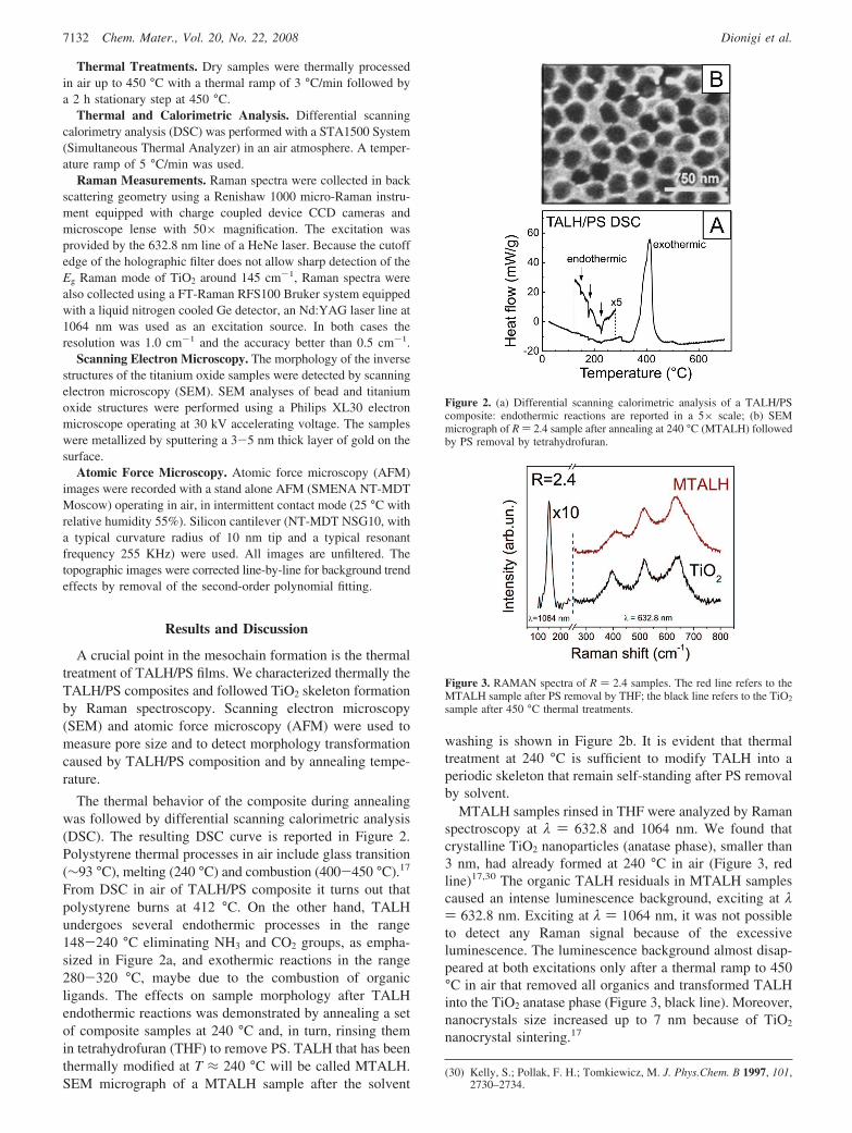
The thermal behavior of the composite during annealingwas followed by differential scanning calorimetric analysis(DSC). The resulting DSC curve is reported in Figure 2.Polystyrene thermal processes in air include glass transition(∼93 °C), melting (240 °C) and combustion (400-450 °C).17
From DSC in air of TALH/PS composite it turns out thatpolystyrene burns at 412 °C. On the other hand, TALHundergoes several endothermic processes in the range148-240 °C eliminating NH3 and CO2 groups, as empha-sized in Figure 2a, and exothermic reactions in the range280-320 °C, maybe due to the combustion of organicligands. The effects on sample morphology after TALHendothermic reactions was demonstrated by annealing a setof composite samples at 240 °C and, in turn, rinsing themin tetrahydrofuran (THF) to remove PS. TALH that has beenthermally modified at T ≈ 240 °C will be called MTALH.SEM micrograph of a MTALH sample after the solvent
washing is shown in Figure 2b. It is evident that thermaltreatment at 240 °C is sufficient to modify TALH into aperiodic skeleton that remain self-standing after PS removalby solvent.
MTALH samples rinsed in THF were analyzed by Ramanspectroscopy at λ ) 632.8 and 1064 nm. We found thatcrystalline TiO2 nanoparticles (anatase phase), smaller than3 nm, had already formed at 240 °C in air (Figure 3, redline)17,30 The organic TALH residuals in MTALH samplescaused an intense luminescence background, exciting at λ) 632.8 nm. Exciting at λ ) 1064 nm, it was not possibleto detect any Raman signal because of the excessiveluminescence. The luminescence background almost disap-peared at both excitations only after a thermal ramp to 450°C in air that removed all organics and transformed TALHinto the TiO2 anatase phase (Figure 3, black line). Moreover,nanocrystals size increased up to 7 nm because of TiO2
nanocrystal sintering.17
(30) Kelly, S.; Pollak, F. H.; Tomkiewicz, M. J. Phys.Chem. B 1997, 101,2730–2734.
Figure 2. (a) Differential scanning calorimetric analysis of a TALH/PScomposite: endothermic reactions are reported in a 5× scale; (b) SEMmicrograph of R ) 2.4 sample after annealing at 240 °C (MTALH) followedby PS removal by tetrahydrofuran.
Figure 3. RAMAN spectra of R ) 2.4 samples. The red line refers to theMTALH sample after PS removal by THF; the black line refers to the TiO2
sample after 450 °C thermal treatments.
7132 Chem. Mater., Vol. 20, No. 22, 2008 Dionigi et al.
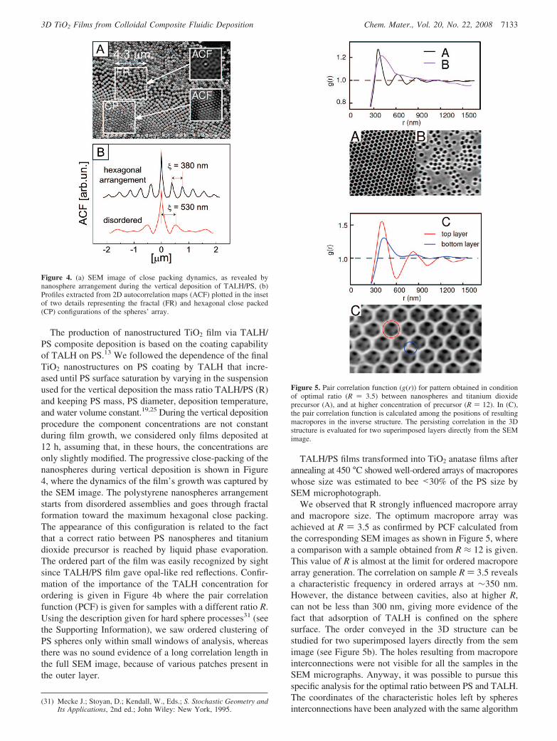
The production of nanostructured TiO2 film via TALH/PS composite deposition is based on the coating capabilityof TALH on PS.13 We followed the dependence of the finalTiO2 nanostructures on PS coating by TALH that incre-ased until PS surface saturation by varying in the suspensionused for the vertical deposition the mass ratio TALH/PS (R)and keeping PS mass, PS diameter, deposition temperature,and water volume constant.19,25 During the vertical depositionprocedure the component concentrations are not constantduring film growth, we considered only films deposited at12 h, assuming that, in these hours, the concentrations areonly slightly modified. The progressive close-packing of thenanospheres during vertical deposition is shown in Figure4, where the dynamics of the film’s growth was captured bythe SEM image. The polystyrene nanospheres arrangementstarts from disordered assemblies and goes through fractalformation toward the maximum hexagonal close packing.The appearance of this configuration is related to the factthat a correct ratio between PS nanospheres and titaniumdioxide precursor is reached by liquid phase evaporation.The ordered part of the film was easily recognized by sightsince TALH/PS film gave opal-like red reflections. Confir-mation of the importance of the TALH concentration forordering is given in Figure 4b where the pair correlationfunction (PCF) is given for samples with a different ratio R.Using the description given for hard sphere processes31 (seethe Supporting Information), we saw ordered clustering ofPS spheres only within small windows of analysis, whereasthere was no sound evidence of a long correlation length inthe full SEM image, because of various patches present inthe outer layer.
TALH/PS films transformed into TiO2 anatase films afterannealing at 450 °C showed well-ordered arrays of macroporeswhose size was estimated to bee <30% of the PS size bySEM microphotograph.
We observed that R strongly influenced macropore arrayand macropore size. The optimum macropore array wasachieved at R ) 3.5 as confirmed by PCF calculated fromthe corresponding SEM images as shown in Figure 5, wherea comparison with a sample obtained from R ≈ 12 is given.This value of R is almost at the limit for ordered macroporearray generation. The correlation on sample R ) 3.5 revealsa characteristic frequency in ordered arrays at ∼350 nm.However, the distance between cavities, also at higher R,can not be less than 300 nm, giving more evidence of thefact that adsorption of TALH is confined on the spheresurface. The order conveyed in the 3D structure can bestudied for two superimposed layers directly from the semimage (see Figure 5b). The holes resulting from macroporeinterconnections were not visible for all the samples in theSEM micrographs. Anyway, it was possible to pursue thisspecific analysis for the optimal ratio between PS and TALH.The coordinates of the characteristic holes left by spheresinterconnections have been analyzed with the same algorithm
(31) Mecke J.; Stoyan, D.; Kendall, W., Eds.; S. Stochastic Geometry andIts Applications, 2nd ed.; John Wiley: New York, 1995.
Figure 4. (a) SEM image of close packing dynamics, as revealed bynanosphere arrangement during the vertical deposition of TALH/PS, (b)Profiles extracted from 2D autocorrelation maps (ACF) plotted in the insetof two details representing the fractal (FR) and hexagonal close packed(CP) configurations of the spheres’ array.
Figure 5. Pair correlation function (g(r)) for pattern obtained in conditionof optimal ratio (R ) 3.5) between nanospheres and titanium dioxideprecursor (A), and at higher concentration of precursor (R ) 12). In (C),the pair correlation function is calculated among the positions of resultingmacropores in the inverse structure. The persisting correlation in the 3Dstructure is evaluated for two superimposed layers directly from the SEMimage.
7133Chem. Mater., Vol. 20, No. 22, 20083D TiO2 Films from Colloidal Composite Fluidic Deposition
given for correlation between the main cavities in the inverseopal, and a characteristic frequency of ∼380 nm can beestablished from PCF peak analysis, both for the first andsecond layer of the oxide structure.
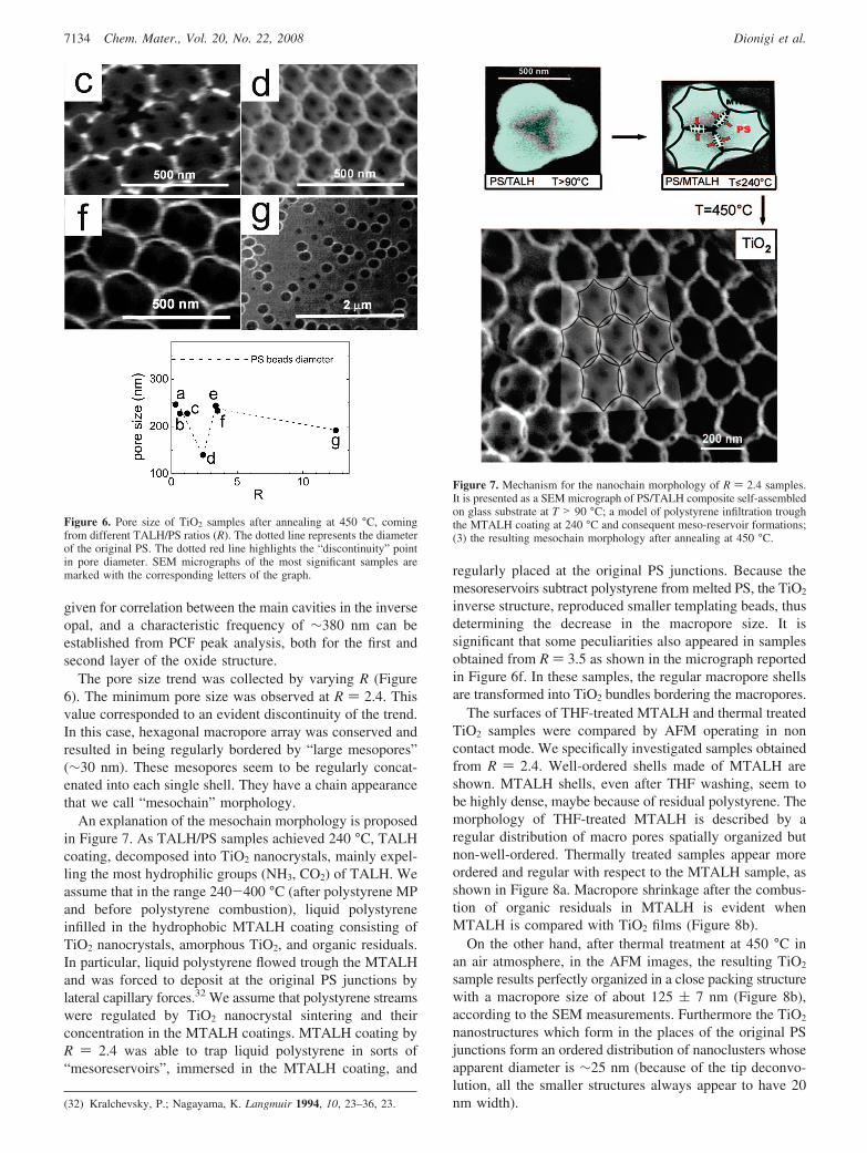
The pore size trend was collected by varying R (Figure6). The minimum pore size was observed at R ) 2.4. Thisvalue corresponded to an evident discontinuity of the trend.In this case, hexagonal macropore array was conserved andresulted in being regularly bordered by “large mesopores”(∼30 nm). These mesopores seem to be regularly concat-enated into each single shell. They have a chain appearancethat we call “mesochain” morphology.
An explanation of the mesochain morphology is proposedin Figure 7. As TALH/PS samples achieved 240 °C, TALHcoating, decomposed into TiO2 nanocrystals, mainly expel-ling the most hydrophilic groups (NH3, CO2) of TALH. Weassume that in the range 240-400 °C (after polystyrene MPand before polystyrene combustion), liquid polystyreneinfilled in the hydrophobic MTALH coating consisting ofTiO2 nanocrystals, amorphous TiO2, and organic residuals.In particular, liquid polystyrene flowed trough the MTALHand was forced to deposit at the original PS junctions bylateral capillary forces.32 We assume that polystyrene streamswere regulated by TiO2 nanocrystal sintering and theirconcentration in the MTALH coatings. MTALH coating byR ) 2.4 was able to trap liquid polystyrene in sorts of“mesoreservoirs”, immersed in the MTALH coating, and
regularly placed at the original PS junctions. Because themesoreservoirs subtract polystyrene from melted PS, the TiO2
inverse structure, reproduced smaller templating beads, thusdetermining the decrease in the macropore size. It issignificant that some peculiarities also appeared in samplesobtained from R ) 3.5 as shown in the micrograph reportedin Figure 6f. In these samples, the regular macropore shellsare transformed into TiO2 bundles bordering the macropores.
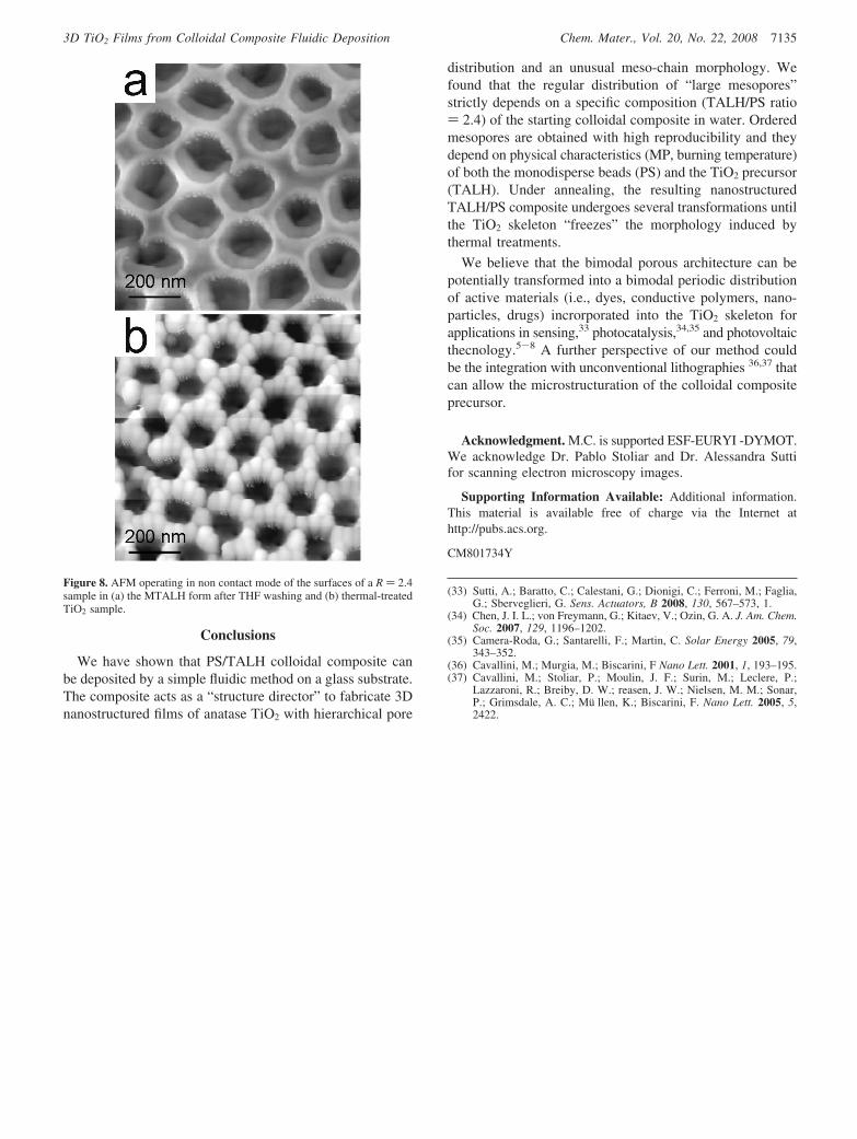
The surfaces of THF-treated MTALH and thermal treatedTiO2 samples were compared by AFM operating in noncontact mode. We specifically investigated samples obtainedfrom R ) 2.4. Well-ordered shells made of MTALH areshown. MTALH shells, even after THF washing, seem tobe highly dense, maybe because of residual polystyrene. Themorphology of THF-treated MTALH is described by aregular distribution of macro pores spatially organized butnon-well-ordered. Thermally treated samples appear moreordered and regular with respect to the MTALH sample, asshown in Figure 8a. Macropore shrinkage after the combus-tion of organic residuals in MTALH is evident whenMTALH is compared with TiO2 films (Figure 8b).
On the other hand, after thermal treatment at 450 °C inan air atmosphere, in the AFM images, the resulting TiO2
sample results perfectly organized in a close packing structurewith a macropore size of about 125 ( 7 nm (Figure 8b),according to the SEM measurements. Furthermore the TiO2
nanostructures which form in the places of the original PSjunctions form an ordered distribution of nanoclusters whoseapparent diameter is ∼25 nm (because of the tip deconvo-lution, all the smaller structures always appear to have 20nm width).(32) Kralchevsky, P.; Nagayama, K. Langmuir 1994, 10, 23–36, 23.
Figure 6. Pore size of TiO2 samples after annealing at 450 °C, comingfrom different TALH/PS ratios (R). The dotted line represents the diameterof the original PS. The dotted red line highlights the “discontinuity” pointin pore diameter. SEM micrographs of the most significant samples aremarked with the corresponding letters of the graph.
Figure 7. Mechanism for the nanochain morphology of R ) 2.4 samples.It is presented as a SEM micrograph of PS/TALH composite self-assembledon glass substrate at T > 90 °C; a model of polystyrene infiltration troughthe MTALH coating at 240 °C and consequent meso-reservoir formations;(3) the resulting mesochain morphology after annealing at 450 °C.
7134 Chem. Mater., Vol. 20, No. 22, 2008 Dionigi et al.
Conclusions
We have shown that PS/TALH colloidal composite canbe deposited by a simple fluidic method on a glass substrate.The composite acts as a “structure director” to fabricate 3Dnanostructured films of anatase TiO2 with hierarchical pore
distribution and an unusual meso-chain morphology. Wefound that the regular distribution of “large mesopores”strictly depends on a specific composition (TALH/PS ratio) 2.4) of the starting colloidal composite in water. Orderedmesopores are obtained with high reproducibility and theydepend on physical characteristics (MP, burning temperature)of both the monodisperse beads (PS) and the TiO2 precursor(TALH). Under annealing, the resulting nanostructuredTALH/PS composite undergoes several transformations untilthe TiO2 skeleton “freezes” the morphology induced bythermal treatments.
We believe that the bimodal porous architecture can bepotentially transformed into a bimodal periodic distributionof active materials (i.e., dyes, conductive polymers, nano-particles, drugs) incrorporated into the TiO2 skeleton forapplications in sensing,33 photocatalysis,34,35 and photovoltaicthecnology.5-8 A further perspective of our method couldbe the integration with unconventional lithographies 36,37 thatcan allow the microstructuration of the colloidal compositeprecursor.
Acknowledgment. M.C. is supported ESF-EURYI -DYMOT.We acknowledge Dr. Pablo Stoliar and Dr. Alessandra Suttifor scanning electron microscopy images.
Supporting Information Available: Additional information.This material is available free of charge via the Internet athttp://pubs.acs.org.
CM801734Y
(33) Sutti, A.; Baratto, C.; Calestani, G.; Dionigi, C.; Ferroni, M.; Faglia,G.; Sberveglieri, G. Sens. Actuators, B 2008, 130, 567–573, 1.
(34) Chen, J. I. L.; von Freymann, G.; Kitaev, V.; Ozin, G. A. J. Am. Chem.Soc. 2007, 129, 1196–1202.
(35) Camera-Roda, G.; Santarelli, F.; Martin, C. Solar Energy 2005, 79,343–352.
(36) Cavallini, M.; Murgia, M.; Biscarini, F Nano Lett. 2001, 1, 193–195.(37) Cavallini, M.; Stoliar, P.; Moulin, J. F.; Surin, M.; Leclere, P.;
Lazzaroni, R.; Breiby, D. W.; reasen, J. W.; Nielsen, M. M.; Sonar,P.; Grimsdale, A. C.; Mu llen, K.; Biscarini, F. Nano Lett. 2005, 5,2422.
Figure 8. AFM operating in non contact mode of the surfaces of a R ) 2.4sample in (a) the MTALH form after THF washing and (b) thermal-treatedTiO2 sample.
7135Chem. Mater., Vol. 20, No. 22, 20083D TiO2 Films from Colloidal Composite Fluidic Deposition