24 COLORI.docx · Web viewLa CABEL ENERGY opera criteri di QUALITA’ nella pro- gettazione,...
30
CABEL ENERGY srl - Via Olmi, 5 Z.I. - 33050 Gonars UD Italy – comP.Iva 02295110304 Tel. 0432 992253 - Fax. 0432 931091 - E-mail: [email protected] - Web: www.cabelenergy.com Quadro protetto di M.T. • M.V. switchgear
Transcript of 24 COLORI.docx · Web viewLa CABEL ENERGY opera criteri di QUALITA’ nella pro- gettazione,...

CABEL ENERGY srl - Via Olmi, 5 Z.I. - 33050 Gonars UD Italy – comP.Iva 02295110304Tel. 0432 992253 - Fax. 0432 931091 - E-mail: [email protected] - Web: www.cabelenergy.com
Quadro protetto di M.T. • M.V. switchgear

1INDICEINDEX
• Caratteristiche generali del quadroGeneral features pag2
• Caratteristiche del gas SF6SF6 gas characteristics pag4
• Interruttore di manovra-sezionatore rotativoRotary switch-disconnector pag5
• Principali tipologie di scompartiMain swichtboard types pag6
• Comandi ed interblocchiOperating mechanisms and interlocks pag9
• Accessori varianti disponibili a richiestaAccessories available on request pag10
• Box trasformatoreTransformer box pag10
• InstallazioneInstallation pag11
• Realizzazioni tipicheTypical configurations pag12
La CABEL ENERGY opera criteri di QUALITA’ nella pro- gettazione, sviluppo, fabbricazione, installazione ed assi- stenza dei propri prodotti in ottemperanza a quanto prescrit- to nelle norme UNI EN ISO 9001.La struttura organizzativa, le responsabilità, le procedure ed ogni altra risorsa, costituenti tutti il “SISTEMA DI QUALITA’ AZIENDALE”, sono costantemente mirati al raggiungimen- to dell’ottimizzazione nella propria realtà produttiva.
CABEL ENERGY applies QUALITY criteria in the design, development, production, installation and service of its pro- ducts in compliance with the standards UNI EN ISO 9001. The organisational structure, responsability, processes and all other resources whic comprise the “COMPANY QUA- LITY SISTEM”, are designed with the specific aim of achie- ving consistently excellent production.
2
GENERALITÀ
I quadri protetti della serie AIR24 sono adatti per esse- re impiegati in sistemi di distribuzione con tensione nominale fino a 24 kV. Sono costituiti da scomparti modulari e compatti, equipaggiati con apparecchi rota- tivi della serie TGA, con interruttori automatici in esa- fluoruro di zolfo (SF6) e con interruttori a vuoto.La gamma di scomparti standard disponibili consente la realizzazione di tutti gli schemi tipici di impianti di distri-buzione di media tensione.
CARATTERISTICHE PRINCIPALI• Per interno - ambiente normale.• Estrema facilità di montaggio: ogni unità è movimen- tabile indipendentemente, essendo provvista di golfari per il sollevamento e completa di tutti gli accessori per l’accoppiamento con altre unità.• Dimensioni ridotte.• Possibilità di montaggio a parete o a centro stanza.
SICUREZZA DEL PERSONALEGarantita con interblocchi ad impedimento semplici e sicuri, rispondenti alle norme di riferimento, che impedi- scono ogni possibilità di manovra errata.La sicurezza del personale è garantita inoltre da:• doppio sezionamento ed isolamento in aria, ad appa- recchio aperto, fra i terminali in entrata e i terminali in uscita, contro la polluzione in servizio e contro eventua- li correnti di fuga.• In posizione di aperto i passanti dell’apparecchio sono collegati a terra.• Visibilità diretta del sezionamento e della messa a terra tramite appositi oblò montato sul fronte delloscomparto.• Segregazione tra cella sbarre e cella inferiore garan- tita dal corpo rotante dell’apparecchio.• Possibilità di accesso all’interno dello scomparto solo con il sezionatore di terra in posizione di chiuso a terra.• Impossibilità di azionare l’apparecchiatura con laporta aperta.• Sezionatore di messa a terra con potere di chiusura su corto circuito.• Blocchi a chiave (forniti a richiesta) e possibilità di applicazione lucchetti.
MANOVRE• Tutte le manovre di comando si effettuano dal fronte del quadro.Grado di protezione:• IP30 sull’involucro metallico• IP20 all’internoNorme di riferimento:• Norme italiane: CEI 17-6• Norme internazionali: IEC 62271-200
COMPATIBILITÀ AMBIENTALELa scelta dei materiali impiegati per questo prodotto è stata effettuata in base ai più recenti progressi nel campo dei materiali ecologici, ad esempio evitando di utilizzare materiali pesanti ed il cadmio per i contatti. La plastica utilizzata è di tipo riciclabile. Anche gli imballi dei nostri prodotti sono realizzati con materiali riciclabi- li. L’apparecchiatura della serie TGA, iniziando dal pro- getto che vede una notevole riduzione del volume di SF6 utilizzato e proseguendo nello sviluppo e realizza- zione del prodotto finito, è costruita tenendo conto delle indicazioni riportate nell norma UNI EN ISO 14001.
GENERAL
The AIR24 series switchboards are used in the distri- bution system having a rated voltage up to 24 kV.They consist of a standardized modular and compactseries of protected panels, equipped with air-operated rotary on-load and rotary off-load switches (TGA and TGN series) and SF6 or vacuum circuit breakers.The range of standard panels available allows to reali-ze all typical arrangements of medium voltage distribu- tion system class 12 kV and 24 kV.
MAIN CHARACTERISTICS:• Indoor use -normal ambient conditions.• Easy to assemble: each unit is fitted with lifting eye- bolts, so it can be handled indipendently. All accesso- ries for connection to other units are normally supplied with each unit.• Reduced overall dimensions.• Possibility of being placed against a wall or in the cen- tre of a room.
PERSONNEL SAFETY:Is assured by simple series of mechanical locks in accordance to IEC standards, preventing from any wrong operations.Is ensured by:• Double isolation and air insulation, with opened switch across the upper incoming and outgoing terminals, condition of maximum safety against pollution during operation and possible leakage currents.• Bushing insulators, earthing in open position.Direct view on isolation and earthing through inspection windows placed on the front of the panel.• Segregation between the busbar compartment andthe lower compartment is assured by the frame of switch.• The line compartment door open only with switch in the earthed position.• When the door is open, all operations af all switches are locked and are released when the door is closedonly.• Earthing switch with making capacity.• Key locks (optional), with possibility to install padlocks.
OPERATIONS:• All control operation are performed from the front panel of the switchboard.Degree of protection:• On the external housing: IP30• Inside the switchboard: IP20Standards:• Italian standards: C.E.I. 17-6• International standards: IEC 62271-200
ENVIRONMENTAL COMPATIBILITYMaterials used with our products have been choosen watching out the recent technical evolution of ecologi- cal materials, e.g. to avoid to use heavy metals and cadmium inside our contacts.Plastic parts are recyclable. Our products packaging are recyclable too.Our TGA switching and isolating equipment, starting fromproject oriented to a big reduction of SF6 volume's used and going on to develop and realize a finished product, has built according to recommendations inclu-ded on EN ISO 14001.
3

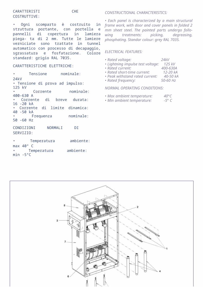
CARATTERISTI CHE COSTRUTTIVE:
• Ogni scomparto è costruito in struttura portante, con portella e pannelli di copertura in lamiera piega- ta di 2 mm. Tutte le lamiere verniciate sono trattate in tunnel automatico con processo di decapaggio, sgrassatura e fosfatazione. Colore standard: grigio RAL 7035.
CARATTERISTICHE ELETTRICHE:
• Tensione nominale: 24kV• Tensione di prova ad impulso: 125 kV• Corrente nominale: 400-630 A• Corrente di breve durata: 16 -20 kA• Corrente di limite dinamica: 40 -50 kA• Frequenza nominale: 50 -60 Hz
CONDIZIONI NORMALI DI SERVIZIO:
• Temperatura ambiente: max 40° C• Temperatura ambiente: min -5°C
CONSTRUCTIONAL CHARACTERISTICS:
• Each panel is characterized by a main structural frame work, with door and cover panels in folded 2 mm sheet steel. The painted parts undergo follo- wing treatments: picking, degreasing, phosphating. Standar colour: grey RAL 7035.
ELECTRICAL FEATURES:
• Rated voltage: 24kV• Lightning impulse test voltage: 125 kV• Rated current: 400-630A• Rated short-time current: 12-20 kA• Peak withstand rated current: 40-50 kA• Rated frequency: 50-60 Hz
NORMAL OPERATING CONDITIONS:
• Max ambient temperature: 40°C• Min ambient temperature: -5° C
LEGENDA:
1 -Sistema di sbarre per il collegamento tra scomparti2 -Interruttore di manovra-sezionatore rotativo (IMS)3 -Comandi IMS4 -Fusibili5 -Cavi di connessione6 -Sezionatore di messa a terra7 -Portella di accesso8 -Zona disponibile per ausiliari BT
CAPTION:
1 -Interconnection bus bars2 -Rotary switch-disconnector3 -Operating mechanism4 -Fuses5 -HV cables6 -Earthing switch7- Door8 -Zone for LV auxiliares
4

CARATTERISTICHE GENERALI GENERAL CHARACTERISTICS
Il gas esafluoruro di zolfo (SF6) è molto stabile, non tossico e non infiammabile ed ha una densità 5 volte superiore a quella dell'aria. A pressione atmo- sferica la sua tenuta dielettrica è superiore a quella dell'aria, come superiore è la sua capacità di tra- smissione del calore.Per tutti questi motivi il gas SF6 viene utilizzato per ridurre gli effetti dell'arco negli interruttori e nei sezionatori sottocarico di M. T.Considerato che la decomposizione molecolare provocata dall'arco elettrico nel gas SF6 è una tra- sformazione reversibile, si può aggiungere alle pre- cedenti caratteristiche positive quella che la carica iniziale di gas è sufficiente a far lavorare l'apparec- chio per tutta la sua vita elettrica.I vantaggi ottenibili dell'uso del gas SF6 nel nostro interruttore di manovra sezionatore sotto caricosono così riassumibili:• lunga vita dell'apparecchiatura sia per l'affidabilità del prodotto che per la pressoché totale assenza di usura• sicurezza di funzionamento
The SF6 is a very stable gas, non tòxic and unflam- mable and it has a density approximately five times higher than air.At atmospheric pressure its dielectric strength and its heat's transfer capacity are higher than air.For these reasons SF6 is used to reduce the elec- tric arc effects in medium voltage circuit breakers and switch disconnectors.One further positive characteristic of the SF6 gas considering that the molecular decomposition af SF6 provoked by the electric arc is a reversible pro- cess, is that the initial quantity of gas is sufficient for the correct functioning of the apparatus all along its electric life.The advantages of CABEL ENERGY SF6 switch disconnector may be summaried as follows:• long working life due to high reliability of the appa-ratus and due to almost no wear• working safety
FIG. 2STRUTTURA MOLECOLARE DEL SF6SF6 MOLECOLAR STRUCTURE
PRECAUZIONI DI SICUREZZA
L'esafluoruro di zolfo è un gas inodore ed incolore che ha una densità più elevata di quella dell'aria. Data la quantità molto modesta di gas SF6 contenu- ta nell'interruttore di manovra- sezionato re la bassa pressione di lavoro (1.1-1.3 bar assoluti) si può affermare che il suo impiego non costituisce alcun rischio per le persone, neppure nel caso fortuito di una fuga di gas.
INTERVENTI DI MANUTENZIONE SUL SEZIONA- TORE IN SF6
Tenendo conto della lunga vita elettrica di questo tipo di apparecchi l'eventualità di dover eseguire un intervento di manutenzione è molto raro. L'unico intervento di manutenzione che si consiglia di fare al Cliente in maniera sistematica è quello di effet- tuare almeno una manovra di apertura ed una di chiusura all'anno. Qualora si rendessero necessari interventi più impegnativi si consiglia di prendere comunque contatto con la CABEL ENERGY, che, se necessario, provvederà a revisionare l'apparec- chio presso le proprie officine.
PRELIMINARY CONSIDERATIONS
The Sulphur Hexafluoride (SF6) is a colourless and odourless gas which has a density higher than air. Due to the small quantity of SF6 contained in the switch disconnector and the low working pressure, (1.1-1.3 bar absolute), we can state that its use does not constitute any danger for the persons, not even in case of leak.
SF6 SWITCH DISCONNECTOR'S MAINTENAN- CE OPERATIONS
Due to the long electrical life of these switchboard it is very improbable that any maintenance operation may be necessary. The only maintenance operation that the Client is advised to do regularly is switching ON and OFF the switch disconnector at least once a year. In the event that other maintenance opera- tions become necessary the Client is advised to enter in contact with CABEL ENERGY, and if it is necessary CABEL ENERGY will overhaul it in its workshop.
5
CARATTERISTICHE GENERALI DELL’APPARECCHIO
SWITCHES GENERAL CHARACTERISTICS
CARATTERISTICHE COSTRUTTIVE:
• Telaio costruito con profilati in acciaio pressopiegati, saldati e zincati elettroliticamente. Il particolare disegno del telaio consente l'introduzione dell'apparecchio dal fronte dello scomparto facendolo scorrere su guide late- rali.• Corpo rotante costituito da un monoblocco compren- dente tre passanti in resina epossidica a profilo alettato con linea di fuga allungata. All'interno del monoblocco sono stati montati i contatti d'arco fissi e mobili, isolati in SF6.• In posizione di aperto il corpo rotante è messo a terra.• Tre isolatori portanti superiori e tre inferiori, in resina epossidica con linea di fuga allungata, fanno da suppor- to ai contatti fissi e consentono il fissaggio delle sbarre e/ o dei cavi in partenza.• Sezionatore di terra con potere di chiusura.• Visibilità diretta dello stato dell'apparecchio e del sezio- natore di terra.• Nessun organo in movimento per garantire la separa- zione tra la cella sbarre e la cella inferiore.• Possibilità di blocchi lucchettabili e blocchi a chiave.• Doppio sezionamento ed isolamento in aria. Ad apparecchio aperto tra i terminali superiori ed i ter- minali inferiori è garantita la condizione di sicurezza contro la polluzione in servizio e contro eventuali correnti di fuga.
CARATTERISTICHE DI FUNZIONAMENTO
L'arco elettrico viene spento all'interno del corpo rotante contenente SF6. Durante la manovra di apertura i contat- ti d'arco mobili, montati all'interno del monoblocco, si disaccoppiano dai contatti d'arco fissi interrompendo il circuito mentre i contatti principali, superiori ed inferiori, isolati in aria, sono ancora accoppiati. Nel proseguo della manovra, ad arco ormai estinto, si disaccoppiano anche i contatti principali ed il monoblocco con i tre passanti, compiendo una rotazione di 90°, si porta in posizione di aperto con i passanti collegati a terra.
Caratterisitche elettriche / Electrical features
MAIN CHARACTERISTICS:
• Frame made of die-bended, soldered and electrolyti- cally zinked steel sections. The special design of the frame allows the racking in the equipment from the front of the panel making it slide on suitable supports.• Rotaring body composed of monobloc complete of three epoxy resin insulators with sheds and long leakage line. Inside the monobloc are mounted the arc's contacts,SF6 insulated.• Rotaring body earthing in open position.• Three upper and three lower epoxy resing stand-off insulators with sheds and long leakage line. They sup- port the upper and the lower fixed contacts, and aIIow the main bars clamping and the connection of cables coming from the bottom.• Earthing switch with making capacity.• Direct view on isolation and earthing position.• No mechanical component in motion to grant separa- tion between the busbars compartment and the lower compartment.• Key locks (optional) with possibility to instaII padlocks.• Isolation and insulation in air, with "open" switch across the upper incoming and outgoing terminals, condition of maximum safety against pollution and possible leakage currents.
OPERATING CHARACTERISTICS
The arc quenching occurs inside the rotating body con- teining SF6 gas. During the opening operation the arching moving contacts, fitted inside the rotaring block, plug-out the arching fix contacts cutting the circuit, while both the upper and the lower air insulated main contacts still remain coupled.During the finishing operation, when the arc is already quenched, the main contacts disjoin themselves and the rotating body through a rotation of 90 degrees reaches the open position with the three bushing connected to the ground.
ApparecchiSwitches
SezionatoriOff-load switches
Interruttori di manovra sezionatori
Switch-Disconnector
Sezionatori di massa a terra
Earth swithesTipo / Type TGN TGN-F TGA-1 TGA-2 TGA-2V STTensione nominaleRated voltage kV 12 17,5 24 12 17,5 24 12 17,5 24Tensione di tenuta a 50 Hz per 1 minutoPower frequency apply voltage for 1 min kV 28 38 50 28 38 50 28 38 50Tensionedi tenuta ad impuso atmosfericoLighting impulse test voltage kV 75 95 125 75 95 125 75 95 125Corrente nominaleRated current A 400 630 400 630 -Corrente di breve durata nominaleRated short-time current
(1s) kA 1620
1620
16(3s) 16 16Potere di chiusuraMaking capacity kA - - 40 50 40
Potere di interruzione
Breaking capacity
Carico attivoActive load A - - 400 630 -Carico ad anelloRing load A - - 400 630 -Trasformatori a vuotoNo load transformers A - - 4-16 4-16 -Cavi a vuotoNo load cables A - - 25 25 -
6
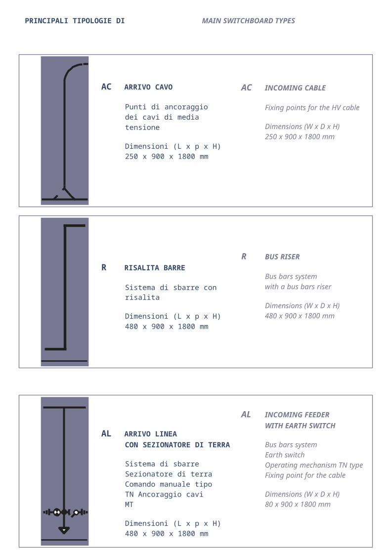
PRINCIPALI TIPOLOGIE DI SCOMPARTI MAIN SWITCHBOARD TYPES
AC ARRIVO CAVO
Punti di ancoraggio dei cavi di media tensione
Dimensioni (L x p x H)250 x 900 x 1800 mm
R RISALITA BARRE
Sistema di sbarre con risalita
Dimensioni (L x p x H)480 x 900 x 1800 mm
AL ARRIVO LINEACON SEZIONATORE DI TERRA
Sistema di sbarre Sezionatore di terra Comando manuale tipo TN Ancoraggio cavi MT
Dimensioni (L x p x H)480 x 900 x 1800 mm
AC INCOMING CABLE
Fixing points for the HV cable
Dimensions (W x D x H)250 x 900 x 1800 mm
R BUS RISER
Bus bars system with a bus bars riser
Dimensions (W x D x H)480 x 900 x 1800 mm
AL INCOMING FEEDER WITH EARTH SWITCH
Bus bars systemEarth switchOperating mechanism TN typeFixing point for the cable
Dimensions (W x D x H)80 x 900 x 1800 mm
7

PRINCIPALI TIPOLOGIE DI SCOMPARTI MAIN SWITCHBOARD TYPES
AS ARRIVO/PARTENZA CON COMANDO TI
IMS rotativo e sezionatore di terra
Comando manuale tipo TI Sistema di sbarre Ancoraggio cavi MT
Dimensioni (L x p x H)480 x 900 x 1800 mm
TP PARTENZA CON FUSIBILI
IMS rotativo combinato con fusibili
Comando manuale tipo T2Segnalazione dello stato dei fusibili Sezionatore di terra a valle dei fusibili Sistema di sbarre
Dimensioni (L x p x H)480 x 900 x 1800 mm
IG PARTENZA CON INTERRUTTORE
Sezione rotativo
Comando manuale tipo TN Interruttore isolato in SF6Sezionatore di terra a valleSistema di sbarre
Dimensioni (L x p x H)750 x 900 x 1800 mm
AS INCOMING/OUTGOING CUBICLE WITH OPERATING MECHANISM TI TYPE
Rotary switch-disconnector and earth switchOperating mechanism Ti typeBus bars systemFixing point for the cables
Dimensions (W x D x H)480 x 900 x 1800 mm
TP TRANSFORMER PROTECTION WITH FUSE-SWITCH
Rotary fuse-switchOperating mechanism T2 typeMechanical signaling of state of the fusesEarthing down stream switchBus bars system
Dimensions (W x D x H)480 x 900 x 1800 mm
IG OUTGOING FEEDER WITH SF6CIRCUIT BREAKER
Rotary isolatorOperating mechanism TN typeSF6 circuit breakerEarthing down stream switchBus bars system
Dimensions (W x D x H)750 x 900 x 1800 mm
8

PRINCIPALI TIPOLOGIE DI SCOMPARTI MAIN SWITCHBOARD TYPES
IG-l PARTENZA CON INTERRUTTORE ESTRAIBILE
Sezionatore rotativo
Comando manuale tipo TN Interruttore isolato in SF6in esecuzione estraibile Sezionatore di terra a valle Sistema di barre
Dimensioni (L x p x H)750 x 900 x 1800 mm
M SCOMPARTO MISURE
IMS rotativo e sezionatore di terra
Comando manuale tipo TI Porta fusibiliPredisposizione per il fissaggio di2/3 trasformatori di tensioneSistema di sbarre
Dimensioni (L x P x H)480 x 900 x 1800 mm
MI SCOMPARTO MISURE
IMS rotativo e sezionatore di terra
Comando manuale tipo TI Porta fusibiliPredisposizione per il fissaggio di2/3 trasformatori di tensionePredisposizione per il fissaggio di2/3 trasformatori di correnteSistema di sbarre
Dimensioni (L x P x H)750 x 900 x 1800 mm
IG-l OUTGOING FEEDERWITH DRAW-OUT SWITCH
Rotary isolatorOperating mechanism TN type Draw-out SF6 circuit breaker Earthing down stream switch Bus bars system
Dimensions (W x D x H)750 x 900 x 1800 mm
M VOLTAGE TRANSFORMER PANEL
Rotary switch-disconnector and earth switchOperating mechanism T1 typeFuse holderArrangement for fixing of 2/3 voltage transformersBus bars system
Dimensions (W x D x H)480 x 900 x 1800 mm
Ml C.T. AND V.T. MEASUREMENTS
Rotary switch-disconnector and earth switchOperating mechanism T1 typeFuse holderArrangement for fixing of 2/3 voltage transformers Arrangement for fixing of 2/3Current transformersBus bars system
Dimensions (W x D x H)750 x 900 x 1800 mm
9

COMANDI E INTERBLOCCHI
I dispositivi di comando delle apparecchiature sono montati direttamente sul corpo dell'apparecchio e sono protetti da un carter in lamiera di acciaio ver- niciata, sul quale viene montata la targa con lo schema elettrico.
Comando tipo TI
Linea e terra: a scatto rapido, sia in chiusura che in apertura, ottenuto mediante l' energia accumulata da una molla caricata dall'operatore durante la manovra di chiusura e/o apertura.
Comando tipo T2
Linea: a scatto rapido, sia in chiusura che in apertu- ra, con dispositivo di accumulo di energia per l'aper- tura. Il comando è provvisto di due molle, una per la chiusura e una per l'apertura che vengono caricate contemporaneamente dall'operatore durante la manovra di chiusura.Il dispositivo di sgancio per l'apertura può essere azionato nei seguenti modi:l) manualmente, ruotando l'asta di manovra insenso antiorario.2) elettricamente, tramite bobina di sgancio.3) automaticamente, tramite intervento di un fusibi- le (quando previsto).Dopo la manovra 2) e 3) è necessario il ripristino del comando completando la rotazione in senso antio- rario dell'asta di manovra.Terra: a scatto rapido, sia in chiusura che in apertu- ra, ottenuta mediante l'energia accumulata da una molla caricata dall'operatore durante la manovra di chiusura e/o di apertura.
Comando tipo TN
Linea: a manovra dipendente, si effettua tramite l'a- sta di manovra ruotando in senso orario per la chiu- sura ed in senso antiorario per l'apertura.Terra: a scatto rapido, sia in chiusura che in apertu- ra ottenuta mediante l'energia accumulata da una molla caricata dall'operatore durante la manovra di chiusura e/o apertura.
lnterblocchi
Tutti i comandi sono provvisti di interblocchi ad impedimento estremamente sicuri, che non consen- tono manovre errate. Di serie è inoltre prevista la possibilità di un blocco lucchettabile.A richiesta viene fornito anche il blocco a chiave.
OPERATING MECHANISM AND INTERLOCKS
The operating mechanism of apparatus are moun- ted directly on the body of the equipment, they are protected by removable metal box on which mimic scheme is fixed.
TI type
Line and earth switch: with quick make and break operation by means of energy released by spring charged by operator during opening or closing ope- rations.
T2 type
Line switch: with quick made and break operation and with stored energy device for opening. The ope- rating mechanism is made up of two springs, one opening and one closing, which are charged by the operator during the closing operation.The tripping device for opening can be activated in the following ways:1) Manually by carring out the opening operation counterclockwise.2) Electrically by means of a shunt trip release.3) With the fuse strikers, when provided.After the 2) and 3) operation, the opening mecha- nism must be reset by turning-up the lever comple- tely counterclockwise.Earth switch: with quick make and break operation by means of energy released by a spring charged by the operator during the opening or closing ope- rations.
TN type
Line switch: operated by rotation of a lever, clockwi- se for closing and counterclockwise for opening. Earth switch: with quick make and break operation by means of energy realesed by a spring charged by the operator during the opening or closing ope- ration.
Interlocks
All the above operating mechanisms are provided with very safe interlocks, that don't allow wrong operations, and complete with a padlock facility.On request, it's possible to supply the key lock.
10

ACCESSORI E VARIANTI DISPONIBILI A RICHIESTA
Basamento H=300 mm per scomparti larghi 500 mmBasamento H=300 mm per scomparti larghi 750 mmBlocco a chiaveBobina di aperturaCassonetto per strumenti e ausiliariContatti ausiliari su IMS (2NC+2NO)Contatti ausiliari su sezionatore di terra (2NC+2NO)Fusibili MT (varie tarature) Motorizzazione comando TI (24 V cc) Piastra chiusura di fondoProtezione omopolare con toroide Resistenza anticondensa con termostato Segnalazione presenza tensione
BOX TRASFORMATORE
I box trasformatore vengono forniti smontati, com- pleti di accessori ed istruzioni necessarie al mon- taggio. Sono realizzati in lamiere d'acciaio 15-20/lO verniciate color grigio RAL 7035; speciali griglie di ventilazione sono previste sul fronte e sul retro.A richiesta possono essere forniti i seguenti acces- sori:• coppia di oblò• serratura a chiave• grado di protezione IP31• colore diverso da RAL 7035
OPTIONAL ITEMS AND ACCESSORIES
Under-base H=300 mm for cubicles 500 mm width Under-base H=300 mm for cubicles 750 mm width Key lockShunt trip with 1NC+ 1NO aux contactsHousing of instruments and aux apparatus2NC+2NO aux contacts for the line switchboard2NC+2NO aux contacts for the earth switchboardHV fusesOperating mechanism Tl type, suitable to be motor operated (24Vcc)Bottom closing coverHomopolar protection with toroidal C.T. Panel heatersVoltage presence indicators
TRASFORMER BOX
The transformer boxes are supplied disassembled, complete with all accessories, tools and instruction to be assembled.The material of the transformer box is painted sheet steel 15/20 (Standard colour grey RAL 7035 ); spe- cial air gratings are provided on the front and on the roof of transformer box.Upon require, is possible to supply the following accessories:• Couple of inspection windows• key lock• protection degree IP 31• different colour (RAL 7035 standard)The transformer box height can be 2100 or 2250 mm and must be indicated in the order.
ALTEZZA HEIGHT
LARGHEZZA WIDTH
PROFONDITA’DEPTH
TIPOTYPE
Potenza trafo kVATrafo power kVA
Largezza mmWidth mm
Profondità mmDepth mm
Altezza mmHeight mm
BT 1 400 1800 1200 2100
BT 2 1250 2200 1200 2100
BT 3 2000 2200 2100 2100
Su richiesta l’altezza del box trasformatore può essere 2300 mmUpon request transformer box height 2300 mm
11

TIPOTYPE
ProfonditàDepthA (mm)
Distanza minima dal froteMinimum distance from the front wall
B (mm)Distanza minima dal frote
250 480 750ACR AL AS TP M M1
IGIG-1
1025 500 900 900
1150 - - 1050
A B C
580 750 680
A B C
310 480 410
900
826
==
850
Nel posizionare il quadro nel locale previsto, deve essere preso in considerazione lo spazio libero minimo, richiesto sulla parte frontale del quadro stesso e la distanza minima rispetto alle pareti ed agli eventuali ostacoli presenti nel locale.Lo spazio minimo raccomandato è indicato nella tabella sottostante.La distanza minima sul fronte del quadro deve essere sufficiente a permettere l'apertura della porte, l'estrazione e l'inserzione dell'interruttore ed il trasferimento dello stesso in altri scomparti.Le distanze riportate nella tabella sottostante non tengono conto dell'eventuale impiego di mezzi spe- ciali di sollevamento e trasporto.
When deciding on the final position of the switch- board, it is important to take into account the mini- mum space required between the front of the switchboard and any walls or other obstacles.The minimum space requirements are indicated in the bottom table.There must be sufficient space to the front to allow the opening of the doors, the removal and insertion of circuit breakers and also their transfer to other columns or other locations using an elevator truck. The distances shown in bottom table do not take into account the space required to use any special lifting or handling equipment.
A B
FISSAGGIO SCOMPARTI FIXING THE COLUMNS TO THE FLOORLo scomparto deve essere fissato con quattro tas- selli ad espansione e bulloni M8 (vedi disegni sotto- stanti).
The columns must be fixed to the floor with four screws M8 and expansions plugs (see the figures below).
B
= C = 4 FORI Ø12 VEDI DETTAGLIO”A”4 HOLES Ø12 SEE DETAIL “A”
M 8 boltwasher
A
FRONT SIDE DETTAGLIO ADETAIL A
Vedi scomparto tipo R, AL, AS, TP, M, M1 a pagina 6-7-8.See switchboard type R, AL, AS, TP, M, M1 page 6-7-8.
Vedi scomparto tipo IG, IG1 a pagina 6-7-8.See switchboard type IG, IG1 page 6-7-8.
12
REALIZZAZIONI TIPICHE TYPICAL UNIT
Entra-esci con protezione linea o trasformatore. Incoming/outing unit complete with line’s or tran- sformer’s protection.
Arrivo con interruttore di manovra-sezionaore gene- rale e protezione trasformatori.
Transformer protection unit with incoming feeder with main switch disconnector.
X
Arrivo-partenza protezione trasformatore e prote- zione linea.
Incoming/outing unit complete with lne’s and tran- sformer’s protection.
13

SEZIONATORE IN POSIZIONE APERTO-ESTRATTO
ISOLATOR IN OPEN DRAW-OUT POSITION