1 - NORME GENERALI APPLICATE - Piusi USA, INC · 1 - NORME GENERALI APPLICATE This manual is giving...
20
-
Upload
hoangthuan -
Category
Documents
-
view
229 -
download
0
Transcript of 1 - NORME GENERALI APPLICATE - Piusi USA, INC · 1 - NORME GENERALI APPLICATE This manual is giving...


Questo manuale ha lo scopo di dare informazioni sul corretto montaggio, uso e manutenzione degli avvolgitubo in modo che non si possano verificare incidenti. L'avvolgitubo è stato progettato in conformità alle attuali normative della Comunità Europea.
1 - NORME GENERALI APPLICATE
This manual is giving information about a correct assembly, use and maintenance of the hose reels in order to prevent accidents. The hose reel has been planned in conformity to the present EEC rules.
1 - GENERAL RULES APPLIED
1 GENERAL RULES APPLIED 2 TECHNICAL CHARACTERISTICS 3 INSTALLATION 4 LINK 4A DIESEL FUEL VERSION CONNECTION 4B WATER/UREA VERSION CONNECTION 5 USE AND MAINTENANCE 6 MOUNTING OF THE HOSE 7 REPLACEMENT OF THE HOSE 8 REPLACEMENT OF THE SPRING 9 DISPODISPOSING OF CONTAMINATED MATERIALS 10 DECLARATION OF CONFORMITY
..............................INDICE DEGLI ARGOMENTI................................
1 NORME GENERALI APPLICATE 2 CARATTERISTICHE TECNICHE 3 INSTALLAZIONE 4 ALLACCIAMENTO 4A ALLACCIAMENTO VERSIONE GASOLIO 4B ALLACCIAMENTO VERSIONE ACQUA/UREA 5 USO E MANUTENZIONE 6 MONTAGGIO DEL TUBO 7 SOSTITUZIONE DEL TUBO 8 SOSTITUZIONE DELLA MOLLA 9 SMALTIMENTO DI MATERIALE INQUINANTE 10 DICHIARAZIONE DI CONFORMITA'
.............................INDEX OF SUBJECT MATTERS...........................
- 2 -
IT
EN

Aus dieser Betriebsanleitung sind sämtliche Hinweise und Vorschriften für eine korrekte Montage sowie eine richtige Handhabung (gefahrlose Benützung) zu entnehmen.Der Schlauchaufroller wurde conform den aktuellen Normen (Bestimmungen) der EG entwickelt.
Ce manuel a été conçu pour donner des renseignements pour un montage correct, pour l'utilisation et l'entretien des enrouleurs afin d'éviter de possibles accidents. L'enrouleur a été projeté conformément aux actuelles normes de la Communauté Européenne.
1 - NORMES GENERALES APPLIQUEES
....................................INHALTSVERZEICHNIS.................................
1 ALLGEMEINE ANGEWENDETE NORMEN 2 TECHNISCHE EIGENSCHAFTEN 3 INSTALLATION 4 ANSCHLUSS 4A ANSCHLUSS VERSION DIESEL 4B ANSCHLUSS VERSION WASSER/UREA 5 GEBRAUCH UND WARTUNG 6 MONTAGE DES SCHLAUCHES 7 AUSWECHSLUNG DES SCHLAUCHES 8 AUSWECHSLUNG DER FEDER 9 ENTSORGUNG VON VERSEUCHTEM MATERIAL 10 KONFORMITATSERKLARUNG
..............................INDEX DES ARGUMENTS...................................
1 NORMES GENERALES APPLIQUEES 2 CARACTERISTIQUES TECHNIQUES 3 INSTALLATION 4 BRANCHEMENT 4A BRANCHEMENT VERSION CARBURANT 4B BRANCHEMENT VERSION EAU/UREE 5 UTILISATION ET ENTRETIEN 6 MONTAGE DU TUYAU 7 REMPLACEMENT DU TUYAU 8 REMPLACEMENT DU RESSORT 9 ELIMINATION DU MATERIEL POLLUE 10 DECLARATION DE CONFORMITE
1 - ALLGEMEIN ANGEWENDETE BESTIMMUNGEN
- 3 -
FR
DE

Gli avvolgitubo sono costruiti in lamiera d' acciaio stampata e verniciata a polveri epossidiche per garantire una buona durata nel tempo.Gli apparecchi riavvolgono automaticamente il tubo mediante una molla in acciaio di alta qualità incor-porata nel tamburo e permettono di arrestarlo alla lunghezza voluta tramite un dispositivo automatico.Questi avvolgitubo devono essere utilizzati esclusivamente per la distribuzione di fluidi alle pressioni e temperature indicate nelle tabelle.Si declina ogni responsabilità per anomalie o pericolosità che derivano dal montaggio di tubi con carat-teristiche ed impieghi diversi da quelli descritti.Gli avvolgitubo nella versione senza tubo sono forniti con la molla scarica. Seguire le istruzioni descritte al capitolo "MONTAGGIO DEL TUBO".
2 - CARATTERISTICHE TECNICHE
2 - TECHNISCHE EIGENSCHAFTEN
The hose reels are made of moulded steel and painted with electrostatic powder system in order to guarantee a long life of the product.The hose rolling is done automatically by a spring made of high quality iron, incorporated in the drum.The stop can be done at any desired length, through an automatic locking device.These hose reels have to be used only for distributing fluids, at the pressures and temperatures indicated on the schedule.We decline any responsibility for anomalies or dangers which could arise by an hose assembly with characteristics and uses different from the ones described herein.The hose reels supplied without hose are provided with the unloaded spring. Follow the instruc-tions described at the chapter " HOSE ASSEMBLY".
Um eine lange Lebensdauer zu gewährleisten sind die Schlauchaufroller aus Stahlblech gebaut, und der Lack wurde magnetisch gespritzt.Die Aufrollung des Schlauches wird durch eine qualitativ hochwertige Stahlfeder, welche in der Trommel intergriert ist, automatisch gesteuert. Durch eine automatische Vorrichtung wird ermöglicht, die gewun-schte Lange abzustoppen.Diese Schlauchaufroller dürfen ausschliesslich nur für die angegebene Flüssigkeitsverteilung, Druck und Temperaturen eingesetzt werden. (siehe Tabelle).Bei Schäden oder Unfällen infolge von unsachgemässer Installation/Gebrauch wird jede Haftung ab-gelehnt.ACHTUNG: Die Schlauchaufroller "Ausführung ohne Schlauch" werden mit ungespannter Fede-rung geliefert. Es sind die Anweisungen unter Kapitel "MONTAGE DES SCHLAUCHES" zu befolgen.
Les enrouleurs sont construits en tôle d'acier imprimée et laquée par poudre pour garantir solidité et durée.Les appareils réenroulent automatiquement le tuyau par un ressort traité haute qualité incorporé dans le tambour. Le tuyau peut être arrêté à la longueur demandée par un dispositif automatique.Ces enrouleurs doivent être utilisés seulement pour la distribution de fluides aux pressions et températures indiquées sur les prospectus.Le constructeur décline toute responsabilité pour les anomalies ou les dangers qui pourraient être causés d'un montage de tuyaux avec caractéristiques et utilisations différentes de celles décrites.Les enrouleurs sans tuyau sont livrés avec le ressort déchargé. Suivre le mode d'emploi du chapitre "MONTAGE DU TUYAU".
2 - CARACTERISTIQUES TECHNIQUES
2 - TECHNICAL CHARACTERISTICS
- 4 -
IT
EN
FR
DE

Enrouleur modelSchlauchaufroller mod.
Avvolgitubo modelliHose reels model
- 5 -
IMPORTANTE: L'avvolgitubo deve essere collocato a parete ad un'altezza minima dal pavimento di 2,50 m per evitare incidenti durante le operazioni di lavoro. Dato il peso e dimensione dell’av-volgitore, la sua movimentazione richiede l’utilizzo di mezzi di sollevamento. Prima della spedizione, gli avvolgitubo vengono accuratamente imballati. Controllare l’imballo al ricevimento ed immagazzinare in luogo asciutto.CONTROLLI PRELIMINARI:- Verificare la presenza di tutti i componenti. Richiedere al produttore gli eventuali pezzi mancanti.- Controllare che la macchina non abbia subito danni durante il trasporto o l’immagazzinamento.- Pulire con cura le bocche di ingresso e uscita liquido, rimuovendo eventuale polvere o eventuale
materiale di imballo residuo.- Assicurarsi che l’avvolgitore ruoti liberamente”- Installare sempre in luogo adeguatamente illuminatoIn casi particolari é possibile il montaggio a pavimento o come accessorio su altre macchine soltanto se viene applicata una protezione di tipo fisso. è possibile fissare i bracci guidatubo in tre diverse posizioni in modo da consentire l'installazione desiderata (vedi figure A-B-C).Montare l'avvolgitubo già completo di tubo su pareti rigide e consistenti impiegando 4 tasselli diametro 10 mm. Il montaggio con la staffa girevole o fissa (optional) va eseguito impiegando 2 tasselli diametro 10 mm.ATTENZIONE! La ditta costruttrice declina ogni responsabilità per danni a persone o cose causate da un montaggio non corretto dell'avvolgitubo.
3 - INSTALLAZIONE
Dimensions
A
C
B
MODELLOMODEL
MODELEMUSTER
FLUIDOFLUID
FLUIDEFLUSSIGKEIT
MAX. PRESS.MAX. PRESS.
PRESSION MAX.MAX. DRUCK.
ENTRATAINLET
ENTREEEINGANG
TUBO DIAM.HOSE DIAM.
TUYAUSCHLAUCH
LUNGH. TUBO AVVOLTOHOSE LENGHT
LONGUEUR TUYAUSCHLAUCHLANGE
LUNGH. TUBOHOSE LENGHT
LONGUEUR TUYAUSCHLAUCHLANGE
PESOWEIGHTPOIDS
GEWICHT
TUBO 3/4" - 14 m OLIO - GASOLIOOIL - GASOLINE
OEL - CARBURANTHUILE - BRENSTOFF
10 BAR
G 1" M 27 mm 13 14 16
TUBO 3/4" - 9,5 m G 1" M 27 mm 8,5 9,5 14
TUBO 1" - 10 m G 1" M 35 mm 9 10 16
TUBO 3/4" - 9,5 m
ACQUA/UREAWATER/UREA
EAU/UREEWASSER/UR
10 BAR G 1" M 27 mm 8,5 9,5 14
MODELLO D E F G
TUBO 3/4" - 14 m 475 460 150 200
TUBO 3/4" - 9,5 m 475 460 150 150
TUBO 1" - 10m 495 475 150 200
IT

3 - INSTALLATION
3 - INSTALLATION
3 - INSTALLATION
- 6 -
Important : l’enrouleur doit être fixé à paroi à une hauteur mini du carrelage de 2,50mt afin d’éviter d’accidents pendant les travaux. Compte tenu du poids et des dimension de l’enrouleur, son mouvement demande l’utilisation de machines de soulèvement.Les enrouleurs sont soigneusement emballés avant d’être livrés. Au moment de la réception, vérifier l’emballage et garder à un endroit sec.CONTROLES PRELIMINAIRES:- Vérifier d’avoir reçu tous les composants. Demander au revendeur pour éventuelles pièces manquantes.- Vérifier que l’équipement ne soit pas endommagé pendant le transport ou le stockage.- Nettoyer soigneusement les bouches d’entrée et de sortie du liquide, en enlevant l’éventuelle poussière ou
matériel d’emballage restant.- Vérifier que l’enrouleur soit libre de tourner.- Installer dans un endroit bien illuminé.En cas particuliers il est possible de fixer a carrelage ou comme accessoire sur d’autres machines seulement en plaçant une protection fixe. Il est possible de fixer les bras guide-tuyau en trois positions différentes pour permettre l’installation désirée. (voir ill. A-B-C).Monter l’enrouleur déjà équipé du tuyau sur parois rigides et consistantes en utilisant 4 trous diamètre 10 mm. Le montage avec le support pivotant ou fixe (disponible en option) doit être effectué en utilisant de 2 trous diamètre 10 mm.ATTENTION ! Le constructeur décline toute responsabilité pour d’éventuels accidents corporels ou pour objets endommagés à cause d’un montage incorrect de l’enrouleur.
WICHTIG: Der Schlauchaufroller muss an einer Wand, mindestens 2,5 m über dem Fuâboden, montiert werden um die Sicherheit während des Arbeitsvorganges zu gewährleisten. Aufgrund des Gewichtes und der Abmessungen des Schlauchaufrollers sollte bei Installation bzw. Versetzung eine Hebevorrichtung eingesetzt werden.Vor der Auslieferung werden die Schlauchaufroller sorgfältig verpackt. Bei Erhalt muss die Verpackung geprüft werden und die Ware sollte an einem trocken Ort gelagert werden.KONTROLLE VOR DER INSTALLATION:- Prüfung des kompletten Verpackungsinhaltes. Bei eventuell fehlenden Teilen Rückfrage beim Hersteller.- Sofortige Kontrolle auf eventuell entstandene Transportschäden oder Schäden durch die Lagerung.- Die Ansaug-und Förderstutzen sorgfältig säubern und eventuellen Staub und Rückstände der Verpackung
entfernen.- Sicherstellen, dass der Schlauchaufroller sich frei drehen kann.- Die Installation sollte an einem geeigneten und beleuchteten Ort erfolgen.Unter besonderen Umständen, ist eine Montage am Fuâboden oder als Zubehör über einer anderen Maschine möglich, jedoch nur wenn diese fest montiert ist. Die Führung des Schlauchauslaufes kann in 3 verschiedenen Lagen eingestellt werden um somit die Montage in der gewünschten Position zu ermöglichen (siehe Abbildungen A-B-C).Der komplett ausgestattete Schlauchaufroller darf nur an geeigneten Wänden mit 4 Dübeln von 10 mm montiert werden. Zur Montage mit dem drehbaren oder ortfesten Bügel (optional) werden 2 Dübel mit 10 mm verwendet.ACHTUNG: Der Hersteller lehnt jede Haftung für Schäden ab, welche aus unsachgemäâer Installation des Schlauchaufrollers entstehen.
IMPORTANT : The hose reel has to be wall mounted at a minimum height of the floor of 2,50 m in order to prevent accidents during work operations. Considering the hose reel weight and dimensions, his movement requires the use of lifter devices.Before delivery, each hose reel is packed with care. Please, check the packaging at the reception of the goods and store only at a dry place.Preliminary verifications:- Make sure you receive all the components. Ask the manufacturer for any possible missing component.- Verify that the device hasn’t been damaged during transport or storage operations.- Accurately Clean suction and recovery openings, removing dust and rest of packing.- Make sure that the hose reel is free to turn.- Make sure to install it in a well lighted place.- It is suggested to use a suction filterIn particular cases it is possible to mount it on the floor or on other machines as accessory, only if complete with a fixed support. The hose-guide arms can be fixed in three different positions according to the hose reel installation (see pictures A-B-C). Mount the hose reel already complete with hose on stiff and consistent walls, using 4 dowels of 10 mm diameter. The assembly with the revolving stand (optional) shall be carried out using dowels of 10 mm diameter. WARNING! The manufacturer declines any responsibility for injuries to people or damages to things caused by a wrong assembly of the hose reel.
EN
FR
DE

4 - ANSCHLUSS4A - ANSCHLUSS VERSION DIESEL
Die Schlauchaufroller der offenen Serie sind geeignet für die Verteiligung von Oel und dieselol und zu oben genann-tem Druck. Die Verwendung des Gerätes für irgendwelche andere Flüssigkeiten ist untersagt. Unter Gebrauch einer geeigneten Dichtungsmasse den Drehanschluss (und das etwaige Kniestück) mit dem Anschluss des Schlauchaufrollers verbinden. Die Schlauchaufroller immer gradlinig mit Anschlüssen und flexiblem Schlauch (A) anschliessen, welche die richtigen Eigenschaften für diese Anwendung haben.WICHTIG: Bei der Montage des Anschluss-Schlauches immer mit Schlüssel das Drehgelenk festhalten, dadurch werden die Dichtungen geschützt.
4B - ANSCHLUSS VERSION WASSER/UREADie Version für Wasser oder Urea ist bereits mit einem 90°-Drehanschluss und einem Schlauchanschlussstück, Durchm. 19mm, ausgestattet, die aus nicht leitendem, weißem Kunststoff bestehen. Den Drehanschluss von Hand anziehen. Den Schlauch in das Schlauchanschlussstück stecken und mit der mitgelieferten Schelle befestigen. WICHTIG: Es werden keine Dichtungsmassen benötigt.
ACHTUNG! Laut den Vorschriften an die Speisungslinie des Schlauchaufrollers einen Kugelhahn anschliessen, um die Wartung zu erleichtern und ihn als Sicherheitsventil im Notfall zu verwenden.
4 - ALLACCIAMENTO VERSIONE GASOLIO
4A - BRANCHEMENT VERSION CARBURANTLes enrouleurs de la série ouverte sont adaptés pour la distribution d'huile et de gasoil aux pressions déjà indiquées. Il est interdit d'utiliser l'appareil pour n'importe quel type de fluide différent de ceux indiqués ci-dessus. Monter le raccord pivotant (et le coude éventuel) sur la connexion de l’enrouleur et utiliser un mastic approprié. Connecter toujours l'enrouleur à la ligne par les raccords et le tuyau flexible (A) avec caractéristiques adaptées à l'emploi. IMPORTANT! En serrant le raccord, retener par la clé le joint tournant (B) afin de ne pas l'endommager.
4B - BRANCHEMENT VERSION EAU/UREELa version pour eau ou urée est déjà pourvue d’un raccord pivotant à 90° et d’un embout diam. 19mm, en plastique non conductible de couleur blanche. Serrer le raccord pivotant à la main, enfiler le tuyau dans l’embout et le fixer avec le collier fourni. IMPORTANT : Aucun besoin de colle.
ATTENTION! Conformément aux normes sur la ligne d'alimentation à l'enrouleur, appliquer une vanne à boisseau sphérique afin de faciliter les travaux d'entretien et à utiliser comme valve d'émergence pour situations dangereuses.
4 - BRANCHEMENT
4A - DIESEL FUEL VERSION CONNECTIONThe hose reels of the open series are suitable for distributing oil and diesel at the pressures already indicated. It is forbidden to use the machine for any other kind of fluid. Fix the swivel (and the elbow, if any) on the hose reel connector, using a suitable sealer. Always connect the hose reel to the line by the couplers and the flexible hose (A) suitable for this use.IMPORTANT! When you lock the coupler, keep back the swivel joint (B) by the wrench in order not to damage it.
4B - WATER/UREA VERSION CONNECTIONThe water or urea version already features a 90° swivel and a 19 mm dia. hose-end fitting, made of white non-con-ductive plastic. Tighten the swivel manually, fit the hose on the hose-end fitting and fasten using the clamp provided. IMPORTANT: no sealants are needed.
ATTENTION! According to the rules, put a ball-tap on the feeding line of the hose reels in order to make the maintenance operations easier. The said ball-tap can be used as a safety valve for dangerous situations.
4 - LINK
4A - VERSIONE GASOLIO Gli avvolgitubo della serie aperta sono adatti per distribuire olio e gasolio alle pressioni già indicate in precedenza. E' vietato l'uso della macchina per qualsiasi altro tipo di fluido. Montare il girevole (e l’eventuale gomito) sull’attacco dell’arrotolatore, utilizzando un adeguato sigillante. Collegare sempre l'avvolgitubo alla linea mediante raccordi e tubo flessibile (A) con caratteristiche adatte all' impiego.IMPORTANTE! Quando si fa il serraggio del raccordo, trattenere con la chiave il giunto girevole (B) in modo da non danneggiarlo.
4B - VERSIONE ACQUA/UREA La versione per acqua o urea è già dotata di un girevole a 90° e di un portagomma diam. 19mm, fatti in materiale plastico non conduttivo, di colore bianco. Eseguire a mano il serraggio del girevole. infilare il tubo nel portagomma e fissarlo con la fascetta in dotazione. IMPORTANTE: non servono sigillanti.
ATTENZIONE! In rispetto alle normative, sulla linea di alimentazione all'avvolgitubo applicare un rubinetto a sfera in modo da facilitare le operazioni di manutenzione e da utilizzare come valvola di emergenza per situazioni pericolose.
- 7 -
A
B
IT
EN
FR
DE
Il dispositivo automatico d' arresto del tubo funziona su un arco corrispondente a 1/3 di giro del tamburo. Per sbloccare il tubo esercitare una lieve trazione sul tubo stesso.E' importante sempre trattenere il tubo durante il riavvolgimento per impedire danni all' apparecchio, a persone o cose circostanti.Evitare di salire sulla macchina o appoggiarvici materiale di qualsiasi genere.Verificare periodicamente che l' avvolgitubo installato funzioni correttamente; che non vi siano perdite di fluido e che i raccordi siano ben serrati. IMPORTANTE! Qualsiasi operazione di manutenzione deve essere eseguita da personale opportunamente addestrato tenendo conto delle informazioni date da questo manuale.Assicurarsi che la molla sia distesa senza carico prima di iniziare operazioni all'interno dell'avvolgitubo.Chiudere sempre l' alimentazione del fluido all' apparecchio prima di eseguire qualsiasi manutenzione su di esso.Sostituire il tubo flessibile non appena presenta segni di usura o di deterioramento dovuto alle diverse condizioni dell' ambiente in cui si lavora. Si consiglia la sostituzione ogni anno nel caso sia usato poche ore alla settimana.Sostituire il giunto girevole se si verificano perdite per usura. Qualsiasi sostituzione di pezzi costituenti l' avvolgitubo deve essere fatta utilizzando ricambi originali.Per qualsiasi anomalia e prima di procedere ad eventuali sostituzioni di pezzi si consiglia di interpellare la casa costruttrice.Dopo ogni operazione di manutenzione ripristinare le eventuali protezioni.
5 - USO E MANUTENZIONE
The automatic device to stop the hose is working on an area corresponding to 1/3 turn of the drum. For releasing the hose, put a light traction on it.It is important always to keep the hose back when you rewind it, in order to avoid damages to the machine, injuries to people or to surrounding things.Avoid to get on the machine or to lay any kind of material on it.Check periodically the correct operation of the hose reel, and control that the couplers are well locked and there are no fluid losses.
IMPORTANT: Any maintenance operation shall be carried out by a suitably trained staff, following carefully the information given in this manual.Ensure that there is no tension in the spring before starting any operations inside the hose reel.Always close the feeding of fluid to the machine before carrying out any maintenance on it. R e p l a c e the flexible hose as soon as it shows any sign of wear and tear or of deterioration due to the different conditions of the labour environment. We advise you to replace it every year in case it is used for a few hours a week.Replace the revolving joint in case of losses due to wear and tear.Any replacement of hose reel parts has to be done using original spare parts.We advise you to contact the manufacturer for any possible anomaly and before replacing any part.After every maintenance operation, put again the eventual supports.
5 - USE AND MAINTENANCE
- 8 -
IT
EN

5 - UTILISATION ET ENTRETIEN
Die Funktion der automatischen Stopp-Vorrichtung entspricht 1/3 Drehung der Trommel. Um die Blockie-rung des Schlauches aufzuheben/zulösen, genügt ein leichter Zug am Schlauch.Um Schäden am Apparat oder an Personen zu vermeiden, ist es wichtig, beim Aufrollen des Schlauches, denselben zu führen. Nicht auf die Maschine steigen oder irgendwelche Gegerstände darauf deponieren oder lagern.Sich periodisch vergewissern, dass der installierte Schlauchaufroller korrekt funktioniert, dass keine Flüssigkeit austritt und die Wiederverbindung dicht ist.
WICHTIG: Jede Wartung muss von einer fachkundingen Person ausgeführt werden.Stellen Sie sicher, daß keine Federspannung anliegt, bevor Sie die Rolle in Betrieb nehmen.Es ist ratsam nach Gebrauch oder vor der Wartung immer den Zuflusshahnen abzusperren. (bei Flüs-sigkeit, Oel etc.)Sobald irgendwelche Abnützungserscheinungen am Schlauch auftreten muss er ausgewechselt werden. Es ist empfehlenswert, den Schlauch alljährlich zu ersetzen, auch wenn der Apparat wenige Stunden pro Woche benutzt wurde. Bei der Dichtung der inneren Halterung, bei der drehbaren Welle muss die Manchette ausgewechselt werden.Es dürfen nur Original-Ersatzteile verwendet werden. Bei jeder allfällig auftretenden Fehlfunktion und evt. vor der Auswechslung der Ersatzteile ist es ratsam, für das weitere Vorgehen sich an den Hersteller zu wenden.
5 - GEBRAUCH UND WARTUNG (für den Schlauch)
Le cliquet d'arrêt fonctionne sur une zone correspondante à 1/3 de tour du tambour. Pour débloquer le tuyau, exercer une courte traction sur le tuyau.Il est important de toujours retenir le tuyau lors du réenroulement pour éviter d'eventuels accidents corporels ou de dégâts à objets environnants.Eviter de monter sur l'appareil ou d'y appuyer n'importe quel type de matériel.Contrôler de temps en temps que l'enrouleur fonctionne correctement; que les raccords soient bien serrés, qu'il n'y ait pas de pertes de fluide.
IMPORTANT! Tout travail d'entretien doit être effectué par des techniciens opportuné-ment entraînés, suivant les instructions données sur ce manuel.Toujour détendre le ressort avant de travailler dans l'enrouleur.Fermer toujours l'alimentation du fluide à l'appareil avant d'effectuer n'importe quel travail d'entretien.Remplacer le tuyau flexible dès qu'il montre des marques d'usure ou de déterioration dues aux diffé-rentes conditions du milieu de travail. On conseille de le remplacer tous les ans si l'on utilise seulement quelques heures par semaine.Remplacer le raccord tournant en cas de pertes dues à l'usure.N'importe quel remplacement de pièces de l'enrouleur doit être fait en utilisant des pièces détachées originales.Pour n'importe quelle anomalie et avant de procéder à d'eventuels remplacements de pièces, on conseille de contacter le constructeur.Après toute opération d'entretien, fixer de nouveau les éventuelles protections.
- 9 -
FR
DE

6 - MONTAGGIO DEL TUBO (Modelli senza tubo)
6.6
6.3
6.4
Gli avvolgitubo nella versione senza tubo sono forniti con la molla scarica.
Utilizzare un tubo che abbia caratteristiche dimensionali e di pressione adatte all'impiego come descritto nelle tabelle in base al codice dell'avvolgitubo.
6.1) Fissare l'avvolgitubo in modo rigido al banco.
6.2) Inserire il tubo attraverso i rullini di guida.
IMPORTANTE: Utilizzare tubo di tipo antistatico ( R<1 mΩ/m ), compatibile con olio e gasolio. Non necessario per versione acqua/urea.
6.3) Rimuovere la protezione in plastica, in-serire prima la fascetta e poi il tubo sul portagomma.Stringere la fascetta e orien-tarla in modo che durante la rotazione non tocchi alcun elemento dell’avvolgitore.
IMPORTANTE: Rimontare la protezione in plastica e verificare che durante la rotazione non vi siano strisciamenti.
6.4) Ruotare il tamburo manualmente in modo da avvolgere tutto il tubo.
6.5) Afferrare l’estremità del tubo e far ruotare il tamburo nel senso opposto, in modo da precaricare la molla:
di 5 giri per il tubo da 1" (lungh. 10 mt) di 3 giri per il tubo da 3/4" (lungh. 9,5 m) di 2 giri per il tubo da 3/4" (lungh 14 mt) Inserire nuovamente l’estremità del tubo
attraverso i rullini di guida.
6.6) Montare il tampone di arresto alla distanza desiderata.
6.7) Srotolare e arrotolare interamente il tubo per verificare il corretto funzionamento.
NON INSERIRE LE MANI O ALTRI OG-GETTI ALL'INTERNO DEL TAMBURO!
- 10 -
6.5
6.3
IT

6 - MOUNTING OF THE HOSE (Models without hose)The hose reels without hose are supplied with the unloaded spring.Use a hose with dimension and pressure characteristics suitable for use according to the hose reel model. 6.1) Fix the hose reel to the bench.6.2) Put the hose between the guide rollers.IMPORTANT:Use an antistatic type hose (R<1mΩ/m), for oil and diesel fuel only. Not required for water/urea version.6.3) Remove plastic protection, put first the clamp and then the hose into the hose fitting. Fix the clamp
and adjust it so that during roattion the hose reel is free to turn.WARNING: Refit plastic protection and check that nothing obstructs the rotation.6.4) Rotate manually the drum in order to rewind completely the hose. 6.5) Hold the hose-end and rotate the drum in the opposite direction to pre-load the spring: 5 turns for 1” hoses (10 mt. long), 3 turns for 3/4" hoses (9,5 mt long), 2 turns for 3/4" hoses (15
mt. long). Insert again the hose-end between the guide rollers.6.6) Put the hose rubber stopper at the desired length.6.7) Unwind the hose and rewind it completely, to check if the hose reel works properly. DO NOT PUT HANDS OR ANY OTHER THING INSIDE THE DRUM!
6 - MONTAGE DU TUYAU (Modèles sans tuyau)Les enrouleurs sans tuyau sont livrés avec le ressort déchargé.Utiliser un tuyau ayant des caractèristiques de dimensions et de pressions adaptées à l'emploi sur la base du modéle d'enrouleur.6.1) Fixer l'enrouleur sur l'établi.6.2) Insérer le tuyau dans les rouleaux de guidage.IMPORTANT: Utiliser un tuyau antistatique (R<1mΩ/m), seulement avec huile et gasoil. Pas nécessaire pour la version eau/urée.6.3) Enlever la protection en plastique, insérer d’abord le collier et puis le tuyau sur le porte tuyau.
Serrer le collier et l’orienter de façon que la rotation ne soit pas émpechée.IMPORTANT: Monter encore la protection en plastique et vérifier que rien en émpeche la rotation.6.4) Tourner le tambour manuellement pour enrouler complètement le tuyau.6.5) Saisir l’extrémité du tuyau et faire tourner le tambour dans le sens opposé afin de précharger le
ressort : de 5 tours pour tuyau de 1" (longueur 10 m), de 3 tours pour tuyau de 3/4" (longueur 9,5 m), de 2 tours pour tuyau de 3/4" (longueur 15 m).
Insérer à nouveau l’extrémité du tuyau par le biais des rouleaux de guidage.6.6) Monter la butée d'arrêt à la distance demandée.6.7) Dérouler et enrouler complètement le tuyau pour contrôler le bon fonctionnement. NE PAS METTRE LES MAINS OU AUTRE DANS LE TAMBOUR!
Die Schlauchaufroller ohne Schlauch werden mit ungespannter Feder geliefert.Es darf nur der vorgschriebene Schlauch verwendet werden.6.1) Den Schlauchchaufroller an eine stabile Montagefläche montieren. 6.2) Den Schlauch durch das Rollenjoch einfhüren.WICHTIG: Nur im Falle von Öl und Diesel, einen antistatischen Schlauch (R<1mΩ/m) verwenden. Bei der Version Wasser/Urea nicht nötig.6.3) Plastikschutz entfernen, dann den Schlauch mit der Tülle verbinden und mittels Schlauchschelle
befestigen. Die Schlauchschelle festziehen und in eine Position drehen, so dass bei Rotation des Schlauchaufrollers kein Teil diesen berührt.
WICHTIG: Den Plastikschutz wieder montieren und kontrollieren, dass während der Rotation der Schlauchaufroller frei dreht.6.4) Den Trommelkörper manuell drehen, bis der gesamte schlauch aufgewickelt ist.6.5) Das Schlauchende nehmen und zum Vorspannen der Feder die Trommel in entgegengesetzter
Richtung drehen lassen: 5 Umdrehungen im Falle eines 1" - Schlauches (Länge 10 m), 3 Umdrehun-gen im falle eines 3/4" - Schlauches (Länge 9,5 m), 2 Umdrehungen im Falle eines 3/4" - Schlauches (Länge 15 m). Das Schlauchende durch die Führungsrollen wieder einführen.
6.6) Den Schlauchstopper an del gewünschten Position anbringen.6.7) Am Ende den gesamten Schlauch vom Trommelkörper abwickeln und wieder aufrollen lassen um
zu sehen ob der Schlauchaufroller funktioniert. NICHT HÄNDE ODER GEGESTÄNDE INS INNERE DER TROMMEL HALTEN ODER EINFÜHREN!
6 - MONTAGE DES SCHLAUCHES (Ohne Schlauch)
- 11 -
EN
FR
DE

7 - SOSTITUZIONE DEL TUBO
7.3
7.4
7.1
7.2
ATTENZIONE! Per ragioni di sicurezza è necessario eseguire le operazioni di so-stituzione del tubo al banco.
Sostituire il tubo con uno di uguali dimensioni e caratteristiche.
7.1) Togliere il tampone di arresto in gomma e rilasciare il tubo len-tamente in modo da scaricare completamente la molla dell'avvol-gitubo.
7.2) Togliere le protezioni plastiche e svitare il giunto girevole.
7.3) Svitare le 2 viti del mozzo attacco molla con una chiave da 10 mm.
7.4) Smontare la fiancata lato molla con una chiave da 10 e srotolare completamente il tubo dal tamburo.
7.5) Estrarre il tamburo, svitare il rac-cordo interno con la chiave adatta e montare il nuovo tubo (vedi se-zione “montaggio del tubo”).
7.6) Rimontare l'avvolgitubo seguendo le operazioni inverse. Ingrassare eventualmente i supporti ed il not-tolino.
7.7) Procedere come previsto nel capi-tolo: "Montaggio del tubo".
NON INSERIRE LE MANI O ALTRI OGGETTI ALL'INTER-NO DEL TAMBURO!
- 12 -
IT
ACHTUNG! Aus Sichereitsgründen dürfen die Schlauchauswechselarbeiten nur auf einer Werkbank vorgenommen werden.
Den Schlauch nur mit einem gleichdimensionalen oder mit gleichen Eigenschaften ersetzen. 7.1) Den Gummistopper entfernen und den Schlauch langsam entspannen, bis die Feder ganz entspannt
ist. 7.2) Den Plastikshutz entfernen und das drehgelenk abschrauben.Die Drehkupplung losschrauben.7.3) Die beiden Schrauben der Federnabe mit einem 10-mm-Schlüssel lösen. 7.4) Die Flanke auf der Federseite mit einem 10-mm-Schlüssel entnehmen und den Schlauch ganz
von der Trommel abrollen.7.5) Die Trommel entnehmen, den inneren Steg mit einem entsprechenden Schlüssel losschrauben
und den neuen Schlauch einsetzen (Siehe kapitel “Montage aus Schlauches).7.6) Den Schlauchaufroller wieden einbauen - hierzu in umgekehrter Ausbaureihenfolge vorgehen. Die Träger und die Raste schmieren, wenn nötig.7.7) Wie bei Kapitel "montage des schlauches" weiterfahren. NICHT HÄNDE ODER GEGENSTÄNDE INS INNERE DER TROMMEL HALTEN
ODER EINFÜHREN!
7 - AUSWECHSLUNG DES SCHLAUCHES
7 - REPLACEMENT OF THE HOSE
7 - REMPLACEMENT DU TUYAU
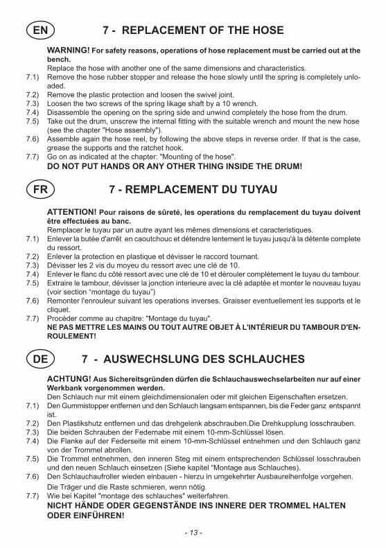
WARNING! For safety reasons, operations of hose replacement must be carried out at the bench.
Replace the hose with another one of the same dimensions and characteristics. 7.1) Remove the hose rubber stopper and release the hose slowly until the spring is completely unlo-
aded.7.2) Remove the plastic protection and loosen the swivel joint. 7.3) Loosen the two screws of the spring likage shaft by a 10 wrench. 7.4) Disassemble the opening on the spring side and unwind completely the hose from the drum.7.5) Take out the drum, unscrew the internal fitting with the suitable wrench and mount the new hose (see the chapter "Hose assembly"). 7.6) Assemble again the hose reel, by following the above steps in reverse order. If that is the case,
grease the supports and the ratchet hook.7.7) Go on as indicated at the chapter: "Mounting of the hose". DO NOT PUT HANDS OR ANY OTHER THING INSIDE THE DRUM!
ATTENTION! Pour raisons de sûreté, les operations du remplacement du tuyau doivent être effectuées au banc.
Remplacer le tuyau par un autre ayant les mêmes dimensions et caracteristiques. 7.1) Enlever la butée d'arrêt en caoutchouc et détendre lentement le tuyau jusqu'à la détente complete
du ressort.7.2) Enlever la protection en plastique et dévisser le raccord tournant.7.3) Dévisser les 2 vis du moyeu du ressort avec une clé de 10. 7.4) Enlever le flanc du côté ressort avec une clé de 10 et dérouler complètement le tuyau du tambour.7.5) Extraire le tambour, dévisser la jonction interieure avec la clé adaptée et monter le nouveau tuyau
(voir section “montage du tuyau”)7.6) Remonter l'enrouleur suivant les operations inverses. Graisser eventuellement les supports et le
cliquet.7.7) Procéder comme au chapitre: "Montage du tuyau". NE PAS METTRE LES MAINS OU TOUT AUTRE OBJET À L'INTÉRIEUR DU TAMBOUR D'EN-
ROULEMENT!
- 13 -
EN
FR
DE

8 - SOSTITUZIONE DELLA MOLLALa molla che permette il rientro del tubo è collocata all' interno di un apposito carter che è solidale al tamburo.ATTENZIONE! Lo smontaggio della molla è consentito soltanto a personale autorizzato ed opportunamente addestrato dalla ditta costruttrice.Maneggiare con molta attenzione le molle; potrebbero verificarsi gravi incidenti.
8.2
8.4 8.5
8.6 8.7
8.7 8.9
8.1) Assicurarsi che il siste-ma di recupero sia com-pletamente scarico ed il tamburo sia libero (vedi punto 7.1).
8.2) Svitare il giunto girevole e rimuovere la protezione.
8.3) Svitare le 2 viti del mozzo attacco molla con una chiave da 10 (vedi punto 7.3).
8.4) Smontare la fiancata lato molla con una chiave da 10 ed estrarre il tamburo.
8.5) Estrarre il mozzo dal carter portamolla.
8.6) Sollevare le linguette sul tamburo con un caccia-vite e far ruotare il carter portamolla in modo da svincolarlo dal tamburo.
8.7) Capovolgere il tambu-ro ed estrarre il carter portamolla facendo mol-ta attenzione a non far fuoriuscire la molla da quest'ultimo.
8.8) Inserire ed agganciare il mozzo nel nuovo pacco molla. Ingrassare la molla ed il mozzo.
8.9) Mettere in piedi il tam-buro ed inserire il nuovo pacco molla con molta attenzione. Bloccare le linguette.
8.10) Assemblare tutti i pezzi e procedere come previsto nel capitolo: "Montaggio del tubo".
- 14 -
IT
Die Feder welche die Einrollung des Schlauches ermöglicht, ist im Innern einer eigens dazu bestimmter Verschalung untergebracht, welche mit der Trommel verbunden ist.ACHTUNG: Die Demontage der Feder darf nur vom Fachmann vorgenommen werden.Die Feder sehr vorsichtig hantieren; es könnten sich schwere Unfälle ereignen.8.1) Sich vergewissern, ob die Feder komplett entlastet ist, und die Trommel leer ist. (siehe Punkt 7.1) 8.2) Das Drehgelenk abschrauben und den plastikschutz entfernen. 8.3) Die 2 Schrauben seitl. der Feder mit dem Schlüssel 10 mm (siehe Punkt 7.3) wegschrauben.8.4) Die Seitenflügel seitlich der Feder mit dem Schlüssel 10 mm abmontieren, damit die Trommel
entfernt werden kann.8.5) Den Mitnehmer vom Federspanner entfernen.8.6) Mittels eines Schraubenziehers die Laschen über die Trommel heben und den Federspanner drehen
lassen, so dass er sich von der Trommel löst. 8.7) Die Trommel kippen und den Federspanner entfernen. Vorsicht, dass die Feder nicht aus dem Gehäuse springt.8.8) Den Federspanner in der Mitte des Federgehäuses einführen und die Feder einrasten lassen. Feder und Spannmutter fetten. 8.9) Die Trommel aufstellen und die neue Federhaltung mit der Feder sehr vorsichtig einführen. Die Laschen in den Rasterverschluss bringen.8.10) Alle Teile einfügen und wie bei Kapitel "montage des schlauches" weiterfahren.
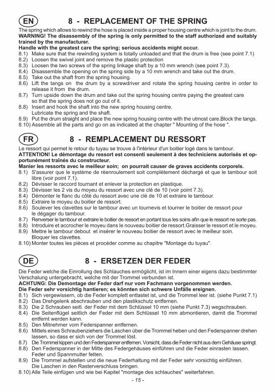
The spring which allows to rewind the hose is placed inside a proper housing centre which is joint to the drum.WARNING! The disassembly of the spring is only permitted to the staff authorized and suitably trained by the manufacturer.Handle with the greatest care the spring; serious accidents might occur.8.1) Make sure that the rewinding system is totally unloaded and that the drum is free (see point 7.1)8.2) Loosen the swivel joint and remove the plastic protection8.3) Loosen the two screws of the spring linkage shaft by a 10 mm wrench (see point 7.3).8.4) Disassemble the opening on the spring side by a 10 mm wrench and take out the drum.8.5) Take out the shaft from the spring housing.8.6) Lift the tangs on the drum by a screwdriver and rotate the spring housing centre in order to
release it from the drum.8.7) Turn upside down the drum and take out the spring housing centre paying the greatest care so that the spring does not go out of it.8.8) Insert and hook the shaft into the new spring housing centre. Lubricate the spring and the shaft.8.9) Put the drum straight and place the new spring housing centre with the utmost care.Block the tangs.8.10) Assemble all the parts and go on as indicated at the chapter " Mounting of the hose ".
8 - REPLACEMENT OF THE SPRING
Le ressort qui permet le retour du tuyau se trouve à l'intérieur d'un boitier logé dans le tambour.ATTENTION! Le démontage du ressort est consenti seulement à des techniciens autorisés et op-portunément traînés du constructeur.Manier les ressorts avec le meilleur soin; on pourrait causer de graves accidents corporels.8.1) S'assurer que le système de réenroulement soit complètement déchargé et que le tambour soit
libre (voir point 7.1).8.2) Dévisser le raccord tournant et enlever la protection en plastique.8.3) Dévisser les 2 vis du moyeu du ressort avec une clé de 10 (voir point 7.3). 8.4) Démonter le flanc du côté du ressort avec une clé de 10 et extraire le tambour. 8.5) Extraire le moyeu du boitier de ressort.8.6) Soulever les clavettes sur le tambour avec un tournevis et tourner le boitier de ressort pour le dégager du tambour.8.7) Renverser le tambour et extraire le boitier de ressort en portant tous les soins afin que le ressort ne sorte pas.8.8) Introduire et accrocher le moyeu dans le nouveau boitier de ressort.Graisser le ressort et le moyeu.8.9) Mettre le tambour debout et insérer le nouveau boitier de ressort avec le meilleur soin. Bloquer les clavettes.8.10) Monter toutes les pièces et procéder comme au chapitre "Montage du tuyau".
8 - REMPLACEMENT DU RESSORT
8 - ERSETZEN DER FEDER
- 15 -
FR
EN
DE

- 16 -
9 - SMALTIMENTO DI MATERIALE INQUINATO
In caso di manutenzione o demolizione del distributore, le parti di cui è composto devono essere affidate a ditte specializzate nello smaltimento e riciclaggio dei rifiuti industriali e, in particolare:SMALTIMENTO DELL’IMBALLAGGIO:L’imballaggio è costituito da cartone biodegradabile che può essere consegnato alle aziende per il normale recupero della cellulosa.SMALTIMENTO DELLE PARTI METALLICHE:Le parti metalliche, sia quelle verniciate, sia quelle in acciaio inox sono normalmente recuperabili dalle aziende specializzate nel settore della rottamazione dei metalli.SMALTIMENTO DEI COMPONENTI ELETTRICI ED ELETTRONICI:devono obbligatoriamente essere smaltite da aziende specializzate nello smaltimento dei componenti elettronici, in conformità alle indicazioni della direttiva 2002/96/CE.SMALTIMENTO DI ULTERIORI PARTI:Ulteriori parti costituenti il distributore, come tubi, guarnizioni in gomma, parti in plastica e cablaggi, sono da affidare a ditte specializzate nello smaltimento dei rifiuti industriali.
In case of maintenance or demolition by the distributor, the parts that make it up must be sent to companies that specialize in the disposal and recycling of industrial refuse and, in particular:DISPOSAL OF PACKING MATERIALThe packaging consists of biodegradable cardboard which can be delivered to companies for normal recycling of cellulose.DISPOSAL OF METAL COMPONENTSMetal parts, whether paint-finished or in stainless steel, can be consigned to scrap metal collectors.DISPOSAL OF ELECTRIC AND ELECTRONIC COMPONENTS:these have to be disposed by companies that are specialised in the disposal of electronic components, in accordance with the instructions of 2002/96/EC.DISPOSAL OF OTHER PARTS:Other components, such as pipes, rubber gaskets, plastic parts and wires, must be disposed of by companies specialising in the disposal of industrial waste.
9 - DISPOSING OF CONTAMINATED MATERIALS
IT
EN
- 17 -
En cas d’entretien ou démolition du distributeur, ses parties devront être confiées à des entreprises spécialisées dans l’élimination et le recyclage des déchets industriels et, notamment:ELIMINATION DE L’EMBALLAGE :L’emballage est constitué par du carton biodégradable qui peut être confié aux entreprises s’occupant de la récupération de la cellulose.ELIMINATION DES PARTIES METALLIQUES :Les parties métalliques, qu’elles soient peintes ou en acier inox, sont normalement récupérables par les entreprises spécialisées dans le secteur de la démolition des métaux.ELIMINATION DES COMPOSANTS ELECTRIQUES ET ELECTRONIQUES :Ils doivent obligatoirement être éliminés par des entreprises spécialisées dans la démolition des composants électroniques, conformément aux indications de la directive 2002/96/CE.ELIMINATION DES AUTRES PARTIES :Les autres parties qui constituent le distributeur, comme les tuyaux, les joints en caoutchouc, les parties en plastique et les câbles, doivent être confiées à des entreprises spécialisées dans l’élimination des déchets industriels.
Bei Verschrottung der Zapfsäule müssen deren Bauteile Fachbetrieben für die Entsorgung und das Recycling von Industrieabfällen zugeführt werden. D.h.:ENTSORGUNG DER VERPACKUNG:Die Verpackung besteht aus biologisch abbaubarem Karton; sie kann Fachbetrieben zur normalen Wiedergewinnung von Zellulose zugeführt werden.ENTSORGUNG DER METALLTEILE:Die Metallteile der Verkleidung und Struktur wie auch die lackierten Teile und die Edelstahlteile können normalerweise Fachbetrieben für die Verschrottung von Metallen zugeführt werden.ENTSORGUNG DER ELEKTRISCHEN UND ELEKTRONISCHEN BAUTEILE:Sie müssen obligatorisch von Unternehmen entsorgt werden, die auf die Entsorgung von Elektronikbauteilen gemäß den Anweisungen der EG-Richtlinie 2002/96/CE.ENTSORGUNG WEITERER BAUTEILE:Die weiteren Bauteile, aus denen sich die Zapfsäule zusammensetzt, wie Schläuche, Gummidichtungen, Kunststoffteile und Verkabelungen sind Fachbetrieben für die Entsorgung von Industrieabfällen zuzuführen.
9 - ENTSORGUNG VON VERSEUCHTEM MATERIAL
9 - ELIMINATION DU MATERIEL POLLUEFR
DE

Il presente manuale è stato redatto secondo le seguenti norme:10653 : 2003 - Documentazione tecnica - Qualità della documentazione tecnica di
prodotto10893 : 2000 - Documentazione tecnica di prodotto - istruzioni per l’uso - Articolazione
e ordine espositivo del contenuto.
This manual has been drafted according to the following norms:10653 : 2003 - Technical documentation - Quality of the product technical
documentation10893 : 2000 - Product technical documentation - instructions for use - Sections and
order of the content.
Ce manuel a été rédigé conformément aux normes suivantes :10653 : 2003 - Documentation technique - Qualité de la documentation technique de
produit10893 : 2000 - Documentation technique de produit - instructions pour l’utilisation -
Articulation et ordre d’exposition du contenu.
Das vorliegende Handbuch wurde laut folgenden Vorschriften verfasst:10653 : 2003 - Technische Dokumentation - Qualität der technischen
Produktdokumentation10893 : 2000 - Technische Produktdokumentation - Betriebsanleitung - Aufgliederung
und Reihenfolge des Inhalts.
- 18 -
IT Lingua originale
EN Translated from Italian
FR Traduit de l'italien
DE Übersetzt aus dem Italienischen

- 19 -
EC DECLARATION OF CONFORMITY
The undersigned:PIUSI S.p.AVia Pacinotti c.m. z.i.Rangavino46029 Suzzara - Mantova - Italy
HEREBY STATES under its own responsibility, that the equipment described below:
Description: Automatic Reeling drumModel: Arrotolatore per tubo ¾”14 mt, Arrotolatore per tubo 1”10 mt, Arrotolatore per tubo ¾” 9,5 mtSerial number: refer to Lot Number shown on CE plate affixed to productYear of manufacture: refer to the year of production shown on the CE plate affixed to the product
is in conformity with the legal provisions indicated in the directives: - Machine Directive 2006/42/ECThe documentation is at the disposal of the competent authority following motivated request at Piusi S.p.A. or following request sent to the email address: [email protected] person authorised to compile the technical file and draw up the declaration is Otto Varini as legal representative.
DECLARATION DE CONFORMITE
La société soussignée :PIUSI S.p.AVia Pacinotti c.m. z.i.Rangavino46029 Suzzara - Mantova - Italie
DECLARE sous sa responsabilité que l’équipement décrit ci-après: Description: Enroleurautomatique Modèle: Arrotolatore per tubo ¾”14 mt, Arrotolatore per tubo 1”10 mt, Arrotolatore per tubo ¾” 9,5 mtN° de matricule: se référer au Numéro du lot repris sur la plaquette CE appliquée au produit.Année de construction: se référer à l’année de production reprise sur la plaquette CE appliquée au produit.
est conforme aux dispositions de loi qui transposent les directives: - Directive Machines 2006/42/CE La documentation est à la disposition de l’autorité compétente après requête motivée adressée à Piusi S.p.A. ou en la demandant à l’adresse e-mail : [email protected] personne autorisée à constituer le fascicule technique et à rédiger la déclaration est M. Otto Varini en sa qualité de représentant légal.
KONFORMITÄTSBESCHEINIGUNG
Die unterzeichnete Firma:PIUSI S.p.AVia Pacinotti c.m. z.i.Rangavino46029 Suzzara - Mantua - Italien
ERKLÄRT auf ihre eigene Verantwortung, dass das folgend beschriebene Gerät:
Bezeichnung: Automatischer AufwicklerModell: Arrotolatore per tubo ¾” 14 mt,Arrotolatore per tubo 1” 10 mt,Arrotolatore per tubo ¾” 9,5 mtMaschinennummer: siehe Losnummer auf dem am Produkt angebrachten CE TypenschildBaujahr: siehe Baujahr auf dem am Produkt angebrachten CE Typenschild,
den Gesetzesbestimmungen entspricht, die folgende Richtlinien umsetzen: - Maschinenrichtlinie 2006/42/EG Die Dokumentation steht der zuständigen Behörde auf begründetes Verlangen bei der Firma Piusi S.p.A. oder Beantragung unter der E-Mail Adresse: [email protected] zur Verfügung.Die zur Erstellung des technischen Heftes und Abfassung der Erklärung autorisierte Person ist Herr Otto Varini in seiner Eigenschaft als gesetzlicher Vertreter.
FR
EN
DE

Suzzara 01/01/2010
PIUSI S.p.a.Via pacinotti, Z.I. Rangavino46029 Suzzara (Mantova) - Italy
DICHIARAZIONE CE DI CONFORMITA’
La sottoscritta:PIUSI S.p.AVia Pacinotti c.m. z.i.Rangavino46029 Suzzara - Mantova - Italia
DICHIARA sotto la propria responsabilità, che l’apparecchiatura descritta in appresso:Descrizione: Avvolgitubo automaticoModello:Arrotolatore per tubo ¾”14 mt,Arrotolatore per tubo 1”10 mt,Arrotolatore per tubo ¾”9,5 mt
Matricola: riferirsi al Lot Number riportato sulla targa CE apposta sul prodottoAnno di costruzione: riferirsi all’anno di produzione riportato sulla targa CE apposta sul prodotto.
è conforme alle disposizioni legislative che traspongono le direttive: - Direttiva Macchine 2006/42/CE La documentazione è a disposizione dell’autorità competente su motivata richiesta presso Piusi S.p.A. o richiedendola all’indirizzo e-mail: [email protected]
La persona autorizzata a costituire il fascicolo tecnico e a redigere la dichiarazione è Otto Varini in qualità di legale rappresentante.
Il legale rappresentante
Otto Varini
IT