


Le lingue
Pagine
Legale

11
BASIC DRESS-UP FEATURES

LESSON II : DRESS UP FEATURES12
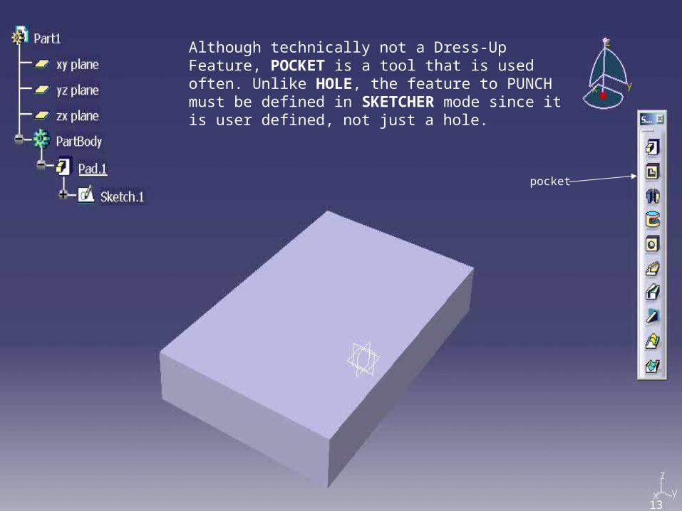
Although technically not a Dress-Up Feature, POCKET is a tool that is used often. Unlike HOLE, the feature to PUNCH must be defined in SKETCHER mode since it is user defined, not just a hole.
13

The first thing to do is pick the face that you want to pocket the void through, then pick Sketcher…
Line is picked
14

In Sketcher, pick the proper shape icon from the Primary toolbar, and sketch the shape ON THE 3D PART represented in sketcher. Once this is done, EXIT sketcher to return to 3D mode…
Notice that the shape that will
eventually become a hole in your part is represented in the
part tree as Sketch2
Sketched circle
15
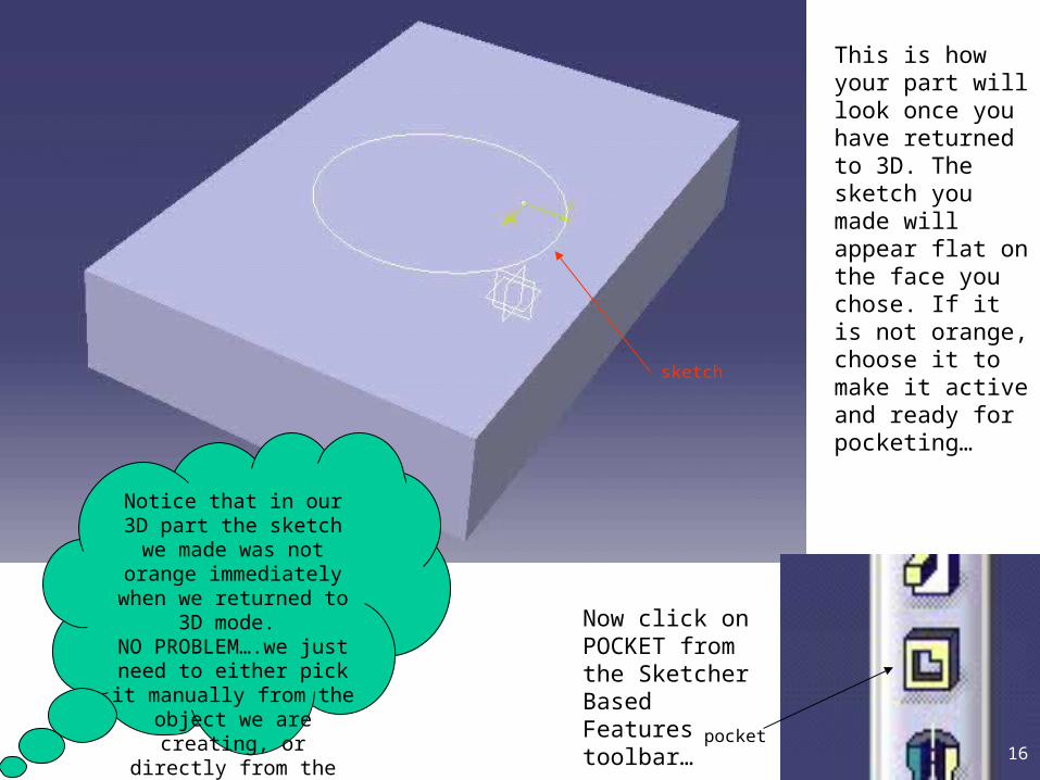
This is how your part will look once you have returned to 3D. The sketch you made will appear flat on the face you chose. If it is not orange, choose it to make it active and ready for pocketing…
Now click on POCKET from the Sketcher Based Features toolbar…
Notice that in our 3D part the sketch we
made was not orange immediately when we returned to 3D mode. NO PROBLEM….we just need to either pick it manually from the
object we are creating, or directly from the
parts tree.
sketch
pocket16
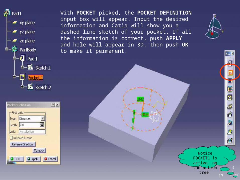
With POCKET picked, the POCKET DEFINITION input box will appear. Input the desired information and Catia will show you a dashed line sketch of your pocket. If all the information is correct, push APPLY and hole will appear in 3D, then push OK to make it permanent.
Notice POCKET1 is active on the
action tree.
17

From TYPE, you can enter a dimension or constrain the depth of the punch by choosing “up to next”,”up to last”,”up to plane”, etc…using the arrow.
Depth is where you enter the dimension for the depth of your pocket.
Click on Mirrored extent to “mirror” or send your pocket in both directions.
Since Catia automatically sends your pocket in the most logical direction, if you want it to go the other way click on Reverse Direction.
18

Here is your part with your pocket in it. Now lets begin to DRESS IT UP…
Dress Up Features toolbar
19

A close up look at your DRESS UP TOOLBAR shows that it is ready to do five basic functions for you…
Fillet
Chamfer
Draft
Shell
Mirror
DRAFT is what you use to angle the
sides of your part in preparation for possible casting
processes.20
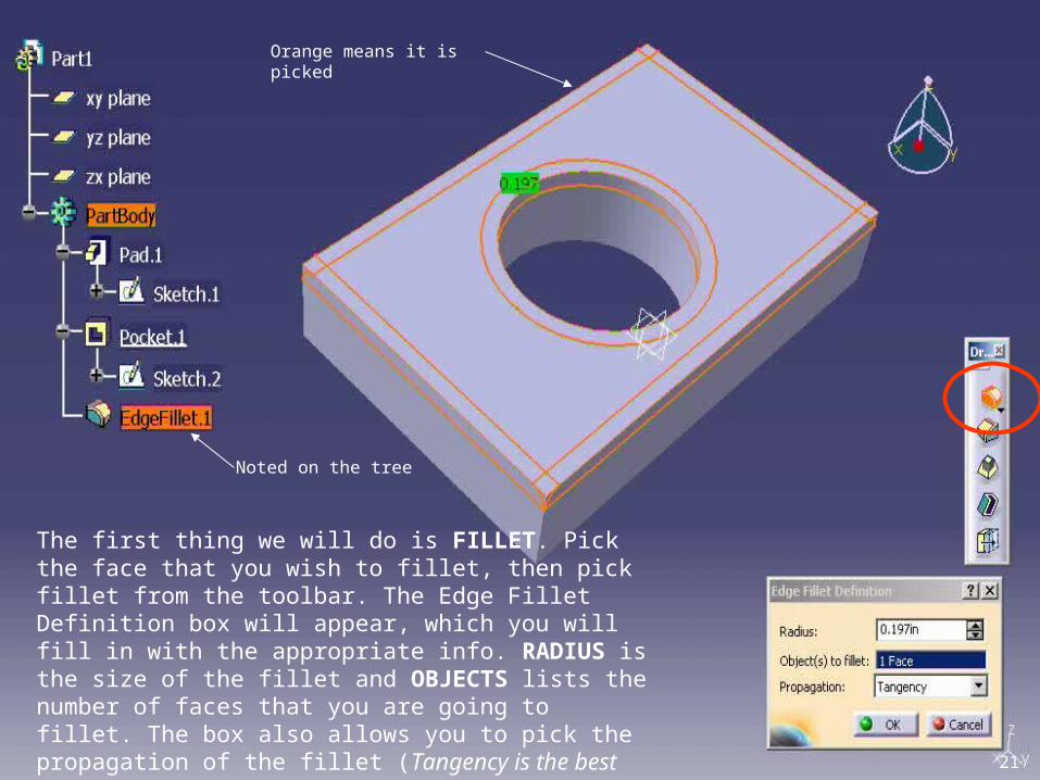
The first thing we will do is FILLET. Pick the face that you wish to fillet, then pick fillet from the toolbar. The Edge Fillet Definition box will appear, which you will fill in with the appropriate info. RADIUS is the size of the fillet and OBJECTS lists the number of faces that you are going to fillet. The box also allows you to pick the propagation of the fillet (Tangency is the best for now).
Orange means it is picked
Noted on the tree
21

You don’t have to pick an entire face…a single edge may be picked instead. To pick MORE than one edge, but NOT and entire face simply hold down CONTROL.
Here we have chosen two different edges using the CONTROL button…notice the
edges you choose turn red. MULTIPLE faces
can be picked the same way. 22
Top Related