


Le lingue
Pagine
Legale

1 I
ALP4T 125/200cc
Grazie per la fiducia accordata e buon divertimento. Con que-sto libretto abbiamo voluto darLe le informazioni necessarie perun corretto uso e una buona manutenzione della Sua moto.
I dati e le caratteristiche indicate sul presente manuale non impegnano laBETAMOTOR S.p.A che si riserva il diritto di apportare modifiche e miglio-ramenti ai propri modelli in qualsiasi momento e senza preavviso.
2I
AVVERTENZA
Si raccomanda, dopo la prima o seconda ora di utilizzo infuoristrada, di controllare tutti i serraggi con particolare attenzio-ne a:
� corona� supporti pedane� pinza freno anteriore� supporto parafango� bulloneria motore� bulloneria ammortizzatore� raggi ruota� telaietto posteriore
AVVERTENZA
In caso di interventi da eseguire sulla moto rivolgersi alla catenadi assistenza autorizzata Betamotor.
IND
ICE
3 I
Avvertenze sull’uso ................................................................................. 5Guida ecologica ................................................................................... 5Guida sicura ......................................................................................... 6
CAP. 1 INFORMAZIONI GENERALI ............................................. 7Dati identificazione veicolo ...................................................................... 8Fornitura ............................................................................................... 8Carico ................................................................................................. 9Pneumatici ............................................................................................ 9Conoscenza del veicolo ........................................................................ 11Chiavi e serrature ................................................................................. 12Commutatore / bloccasterzo ................................................................. 12Serratura casco ................................................................................... 12Cruscotto e comandi ............................................................................ 13Istruzioni di settaggio e funzionamento contachilometri ................................ 14Dati tecnici generici .............................................................................. 31Dati tecnici motore ALP125 .................................................................... 33Dati tecnici motore ALP200 .................................................................... 34Schema elettrico ALP125 ....................................................................... 35Schema elettrico ALP200 ....................................................................... 37Dispositivi elettrici ................................................................................. 39
CAP. 2 UTILIZZO DEL VEICOLO ................................................ 41Controlli e manutenzione prima e dopo l’utilizzo in fuoristrada ...................... 42Lubrificanti e liquidi consigliati ................................................................ 43Rodaggio ........................................................................................... 43Avviamento del motore .......................................................................... 44Arresto del motore ................................................................................ 45Rifornimento carburante ......................................................................... 46
CAP. 3 CONTROLLI E MANUTENZIONE .................................... 47Olio motore e filtro olio ALP200 ............................................................. 48Olio motore e filtro olio ALP125 ............................................................. 50Tubo raccolta fumi ................................................................................ 51Olio pompa freni, spurgo freni ............................................................... 51Olio forcelle ........................................................................................ 53Filtro aria ............................................................................................ 54Candela............................................................................................. 55Freni: anteriore, posteriore ..................................................................... 56Batteria .............................................................................................. 57Rimozione carrozzeria .......................................................................... 58Note per trial ...................................................................................... 59Pulizia del veicolo e controlli .................................................................. 61Manutenzione programmata .................................................................. 62Lunga inattività del veicolo ..................................................................... 63
IND
ICE
4I
CAP. 4 REGOLAZIONI ............................................................. 65Regolazione freni ................................................................................. 66Regolazione frizione ............................................................................. 66Regolazione minimo ............................................................................. 67Regolazione flusso benzina (solo per ALP125) ........................................... 67Regolazione gioco gas ......................................................................... 67Controllo e regolazione gioco sterzo ....................................................... 68Tensionamento catena .......................................................................... 69Fascio luminoso ................................................................................... 70
CAP. 5 SOSTITUZIONI ............................................................. 71Sostituzione pastiglie freni ...................................................................... 72Sostituzione lampada faro anteriore ......................................................... 74Sostituzione lampada faro posteriore ....................................................... 74Sostituzione lampade indicatori di direzione ............................................. 75
CAP. 6 COSA FARE IN CASO DI EMERGENZA ........................... 77
INDICE ALFABETICO ............................................................................ 79
5 I
AVVERTENZE SULL’USO DEL VEICOLO� Il veicolo deve essere obbligatoriamente corredato di: targa, libretto di circolazio-ne, bollo ed assicurazione.
�È vietato il trasporto di animali e oggetti non resi solidali al veicolo, che sporgonodall’ingombro del veicolo stesso e che superino il carico previsto dal Costruttore.
� Il casco è obbligatorio.�Viaggiare con luci anabaglianti sempre accese.�Modifiche al motore o altri organi che possano determinare un aumento di poten-za e quindi di velocità, è punita dalla legge con severe sanzioni, tra le quali laconfisca del mezzo.
�Per salvaguardare la tua vita e quella degli altri guidare con prudenza e portaresempre il casco di sicurezza e le luci anabaglianti sempre accese
ATTENZIONE:Modifiche e manomissioni durante il periodo di garanzia, esimono il Costruttoreda qualsiasi responsabilità e fanno decadere la garanzia stessa.
GUIDA ECOLOGICA�Ogni veicolo con motore a scoppio produce più o meno rumore (inquinamentoacustico) e più o meno (inquinamento atmosferico) a seconda del tipo di guidaadottato.
� L’abbattimento, per quanto più possibile, di queste condizioni è oggi un dovereper tutti, quindi evitare partenze a tutto gas, improvvise ed inutili accelerazioni edimprovvise ed altrettanto inutili frenate, limitando così la rumorosità, l’usura preco-ce dei pneumatici e delle parti meccaniche del veicolo e risparmiando notevol-mente sui consumi di carburante.
6I
GUIDA SICURA�Rispettare il Codice Stradale� Indossare sempre casco omologato ed allacciato�Mantenere sempre pulita la visiera protettiva� Indossare indumenti senza estremità penzolanti�Non viaggiare con in tasca oggetti acuminati o fragili�Regolare correttamente lo specchietto retrovisore�Guidare sempre seduti e con entrambe le mani sul manubrio ed i piedi sulle pedane�Mai distrarsi o farsi distrarre durante la guida�Non mangiare, bere, fumare, usare il cellulare, ecc... durante la guida�Non ascoltare musica in “cuffia” durante la guida�Non viaggiare mai appaiato ad altri veicoli�Non trainare o farsi trainare da altri veicoli�Mantenere sempre le distanze di sicurezza�Viaggiare con le luci anabbaglianti accese anche di giorno�Non sostare seduti sul veicolo in cavalletto�Non partire con il veicolo sul cavalletto�Non estrarre il cavalletto con il fronte/marcia del veicolo in discesa� Impennate, serpentine, ondeggiamenti, sono pericolosissimi per Te, per gli altri eper il Tuo veicolo
�Su strada asciutta e senza ghiaia o sabbia, usare entrambi i freni, uno solo puòcausare slittamenti pericolosi ed incontrollabili
� In caso di frenata utilizzare entrambi i freni, ottenendo così un arresto del veicoloin spazi più brevi
�Su strada bagnata, guidare con prudenza ed a velocità moderata: usare i frenicon maggior sensibilità
�Non avviare il motore in ambienti chiusi.
1
INFO
RM
AZ
ION
I G
ENER
ALI
7 I
INDICE ARGOMENTI
CAP. 1 INFORMAZIONI GENERALI
Dati identificazione veicolo
Fornitura
Carico
Pneumatici
Conoscenza del veicolo
Chiavi e serrature
Commutatore / bloccasterzo
Serratura casco
Cruscotto e comandi
Indicazioni su LCD
Dati tecnici
Schema elettrico
Dispositivi elettrici
1
INFO
RM
AZ
ION
I G
ENER
ALI
8I
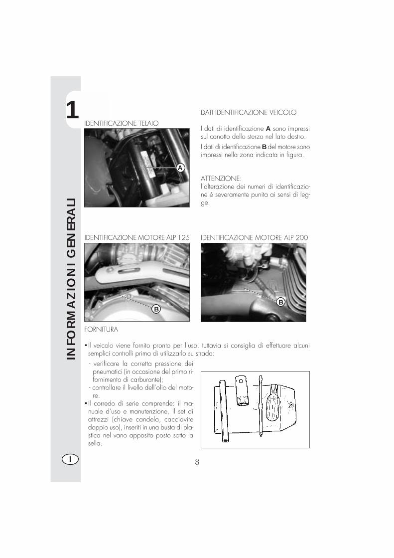
DATI IDENTIFICAZIONE VEICOLO
I dati di identificazione A sono impressisul canotto dello sterzo nel lato destro.
IDENTIFICAZIONE TELAIO
I dati di identificazione B del motore sonoimpressi nella zona indicata in figura.
ATTENZIONE:l’alterazione dei numeri di identificazio-ne è severamente punita ai sensi di leg-ge.
IDENTIFICAZIONE MOTORE ALP 125
FORNITURA
� Il veicolo viene fornito pronto per l’uso, tuttavia si consiglia di effettuare alcunisemplici controlli prima di utilizzarlo su strada:- verificare la corretta pressione deipneumatici (in occasione del primo ri-fornimento di carburante);
- controllare il livello dell’olio del moto-re.
� Il corredo di serie comprende: il ma-nuale d’uso e manutenzione, il set diattrezzi (chiave candela, cacciavitedoppio uso), inseriti in una busta di pla-stica nel vano apposito posto sotto lasella.
A
IDENTIFICAZIONE MOTORE ALP 200
BB
1
INFO
RM
AZ
ION
I G
ENER
ALI
9 I
CARICO
�Carico massimo (conducente + passeggero): 280 Kg.�Non trasportare assolutamente oggetti voluminosi o troppo pesanti, che potrebbe-ro pregiudicare la stabilità del veicolo.
�Non trasportare oggetti che sporgano dal veicolo o che coprano i dispositivid’illuminazione e di segnalazione.
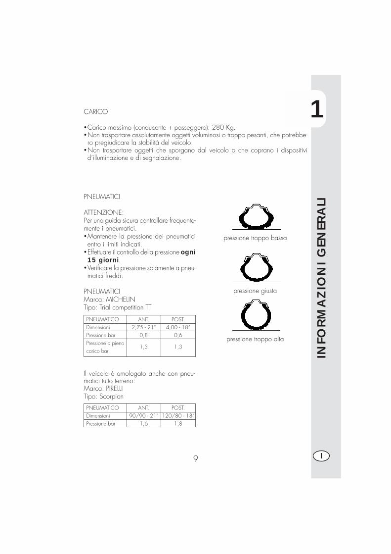
PNEUMATICI
ATTENZIONE:Per una guida sicura controllare frequente-mente i pneumatici.�Mantenere la pressione dei pneumaticientro i limiti indicati.
�Effettuare il controllo della pressione ogni15 giorni.
�Verificare la pressione solamente a pneu-matici freddi.
PNEUMATICIMarca: MICHELINTipo: Trial competition TT
PNEUMATICODimensioniPressione barPressione a pienocarico bar
POST.4,00 - 18”
0,6
1,3
ANT.2,75 - 21”
0,8
1,3
Il veicolo è omologato anche con pneu-matici tutto terreno:Marca: PIRELLITipo: Scorpion
pressione troppo bassa
pressione giusta
pressione troppo alta
PNEUMATICODimensioniPressione bar
POST.120/80 - 18”
1,8
ANT.90/90 - 21”
1,6
1
INFO
RM
AZ
ION
I G
ENER
ALI
10I
Nota:Lo spessore minimo del battistrada dei pneumatici (TUBE TYPE) non deve mai essereinferiore ai 2 mm.La mancata adempienza a questa norma è punita ai sensi di legge.
�Controllare prima di ogni viaggio che i pneumatici non presentino tagli, screpola-ture, abrasioni, rigonfiamenti, ecc... In questi casi far esaminare il pneumatico daun esperto in quanto potrebbero verificarsi condizioni estremamente pericolose.
� In caso di foratura arrestare subito il veicolo; proseguire la marcia, oltre ad essererischioso, può provocare irrimediabili danni al pneumatico ed al cerchio ruota.
� In condizioni di max. carico sono consigliate pressioni maggiori (vedi tabella apag. 9).
1
INFO
RM
AZ
ION
I G
ENER
ALI
11 I
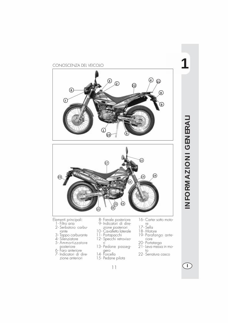
Elementi principali:1- Filtro aria2- Serbatoio carbu-
rante3- Tappo carburante4- Silenziatore5- Ammortizzatore
posteriore6- Faro anteriore7- Indicatori di dire-
zione anteriori
8- Fanale posteriore9- Indicatori di dire-
zione posteriori10 - Cavalletto laterale11 - Portapacchi12 - Specchi retroviso-
ri13 - Pedane passeg-
gero14 - Forcella15 - Pedane pilota
16 - Carter sotto moto-re
17 - Sella18 - Motore19 - Parafango ante-
riore20 - Portatarga21 - Leva messa in mo-
to22 - Serratura casco
1
6
7
32 22
4 11
8
9
10 5
CONOSCENZA DEL VEICOLO
13 15
1621
18
14 19
1217
20
1
INFO
RM
AZ
ION
I G
ENER
ALI
12I
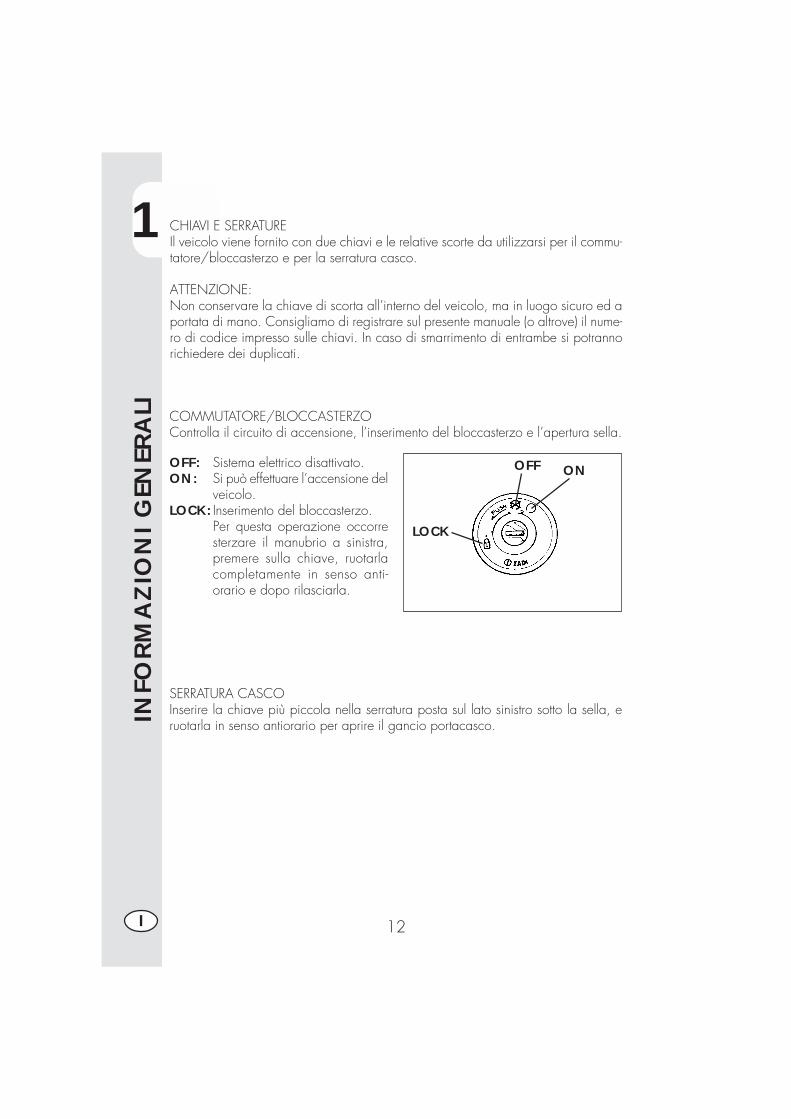
CHIAVI E SERRATUREIl veicolo viene fornito con due chiavi e le relative scorte da utilizzarsi per il commu-tatore/bloccasterzo e per la serratura casco.
ATTENZIONE:Non conservare la chiave di scorta all’interno del veicolo, ma in luogo sicuro ed aportata di mano. Consigliamo di registrare sul presente manuale (o altrove) il nume-ro di codice impresso sulle chiavi. In caso di smarrimento di entrambe si potrannorichiedere dei duplicati.
OFF: Sistema elettrico disattivato.ON: Si può effettuare l’accensione del
veicolo.LOCK: Inserimento del bloccasterzo.
Per questa operazione occorresterzare il manubrio a sinistra,premere sulla chiave, ruotarlacompletamente in senso anti-orario e dopo rilasciarla.
SERRATURA CASCOInserire la chiave più piccola nella serratura posta sul lato sinistro sotto la sella, eruotarla in senso antiorario per aprire il gancio portacasco.
ONOFF
LOCK
COMMUTATORE/BLOCCASTERZOControlla il circuito di accensione, l’inserimento del bloccasterzo e l’apertura sella.
1
INFO
RM
AZ
ION
I G
ENER
ALI
13 I
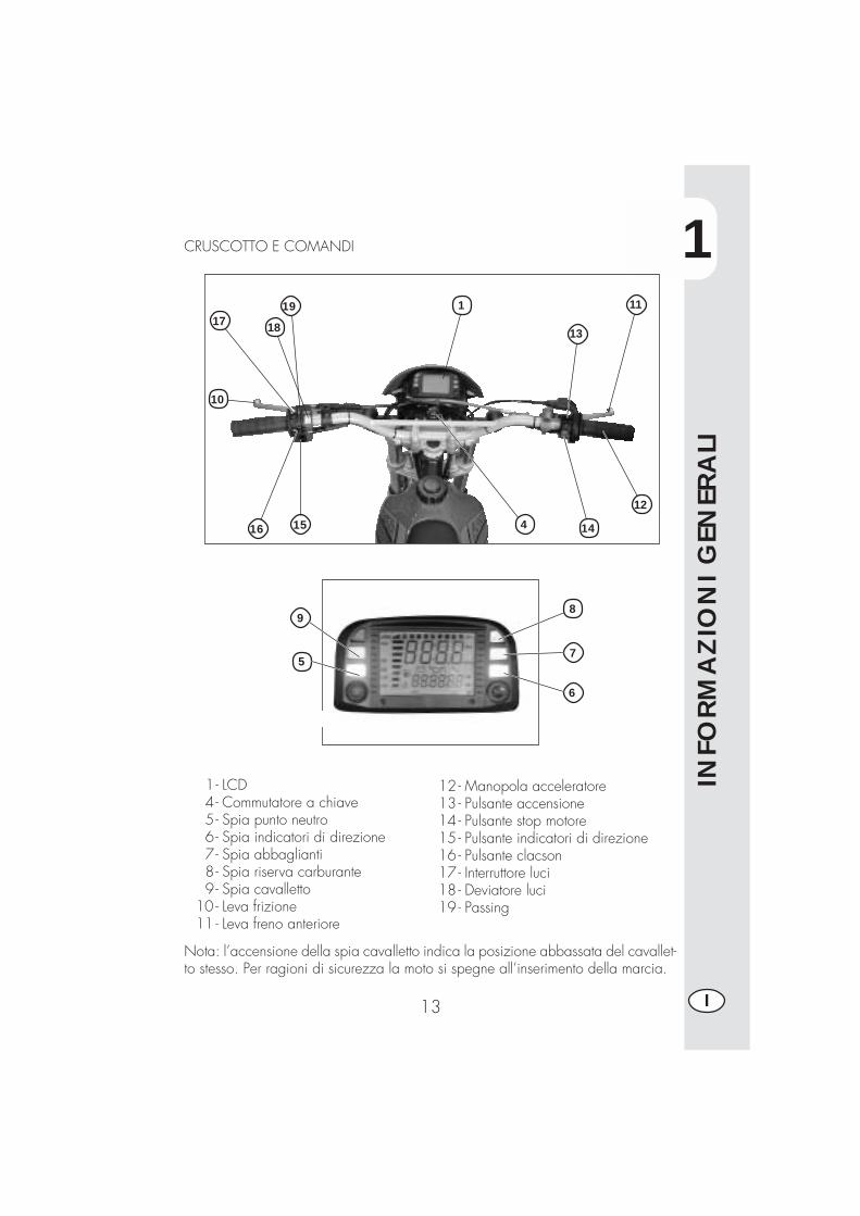
1- LCD4- Commutatore a chiave5- Spia punto neutro6- Spia indicatori di direzione7- Spia abbaglianti8 - Spia riserva carburante9- Spia cavalletto
10 - Leva frizione11 - Leva freno anteriore
12 - Manopola acceleratore13 - Pulsante accensione14 - Pulsante stop motore15 - Pulsante indicatori di direzione16 - Pulsante clacson17 - Interruttore luci18 - Deviatore luci19 - Passing
CRUSCOTTO E COMANDI
Nota: l’accensione della spia cavalletto indica la posizione abbassata del cavallet-to stesso. Per ragioni di sicurezza la moto si spegne all’inserimento della marcia.
10
17 18
1516 4 14
12
11
13
5
19
6
7
9
1
8
1
INFO
RM
AZ
ION
I G
ENER
ALI
14I
ISTRUZIONI DI SETTAGGIO E FUNZIONAMENTO CONTACHILOMETRI(per costruttore e concessionario)La descrizione relativa al setup di base dello strumento digitale riveste un caratterepuramente informativo; è consigliabile rivolgersi ad un Officina autorizzata Betamotorper effettuare questa operazione.
Serie ALP 125 - ALP 200
INDICE DEGLI ARGOMENTI
PARAGRAFO CONTENUTO
10.1 Caratteristiche ruota10.2 Caratteristiche motore10.3 Precaricamento codici10.4 Codici caricati
20.0 SETUP LIVELLO 1 (per costruttore moto e concessionario)20.1 Esecuzione setuo livello 120.2 Selezione codici20.3 Verifica contenuto codici20.4 Inserimento valori non codificati
20.4.1 Inserimento Ln (sviluppo ruota) o di (diametro ruota)20.4.2 Inserimento numero impulsi giro ruota20.4.3 Inserimento numero impulsi giro motore
20.4.3.1 Inserimento numero giri massimi motore20.4.4 Selezione Km/h o Mph20.4.5 Inserimento ore per cambio olio20.4.6 Inserimento ore o Km per tagliando
20.5 Uscita da setup
40.0 LCD DISPLAY40.1 Funzionamento e visualizzazione pagine40.2 Oscuramento delle pagine40.3 Cancellazione parametri TRP, SPEED max, LAP
50.0 IIntervento delle icone di sorveglianza (olio motore e tagliando)50.1 Verifica del contenuto attivo delle icone di sorveglianza
1
INFO
RM
AZ
ION
I G
ENER
ALI
15 I
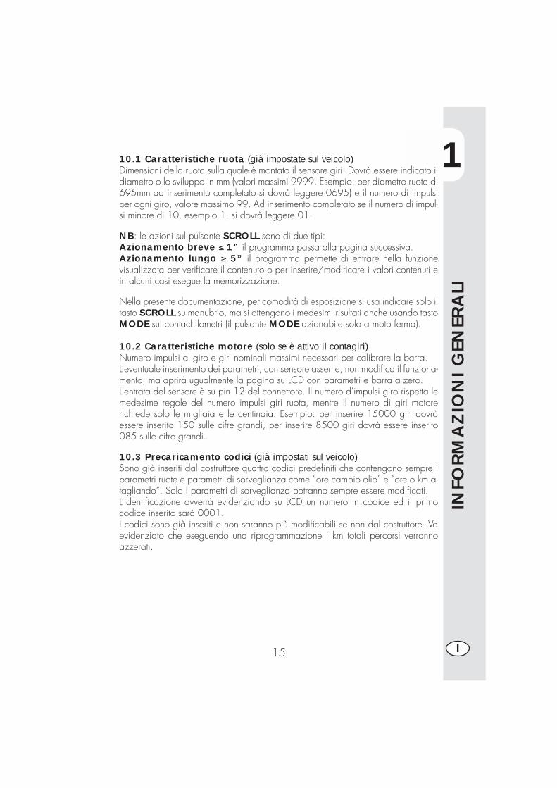
10.1 Caratteristiche ruota (già impostate sul veicolo)Dimensioni della ruota sulla quale è montato il sensore giri. Dovrà essere indicato ildiametro o lo sviluppo in mm (valori massimi 9999. Esempio: per diametro ruota di695mm ad inserimento completato si dovrà leggere 0695) e il numero di impulsiper ogni giro, valore massimo 99. Ad inserimento completato se il numero di impul-si minore di 10, esempio 1, si dovrà leggere 01.
NB: le azioni sul pulsante SCROLL sono di due tipi:Azionamento breve ≤ 1” il programma passa alla pagina successiva.Azionamento lungo ≥ 5” il programma permette di entrare nella funzionevisualizzata per verificare il contenuto o per inserire/modificare i valori contenuti ein alcuni casi esegue la memorizzazione.
Nella presente documentazione, per comodità di esposizione si usa indicare solo iltasto SCROLL su manubrio, ma si ottengono i medesimi risultati anche usando tastoMODE sul contachilometri (il pulsante MODE azionabile solo a moto ferma).
10.2 Caratteristiche motore (solo se è attivo il contagiri)Numero impulsi al giro e giri nominali massimi necessari per calibrare la barra.L’eventuale inserimento dei parametri, con sensore assente, non modifica il funziona-mento, ma aprirà ugualmente la pagina su LCD con parametri e barra a zero.L’entrata del sensore è su pin 12 del connettore. Il numero d’impulsi giro rispetta lemedesime regole del numero impulsi giri ruota, mentre il numero di giri motorerichiede solo le migliaia e le centinaia. Esempio: per inserire 15000 giri dovràessere inserito 150 sulle cifre grandi, per inserire 8500 giri dovrà essere inserito085 sulle cifre grandi.
10.3 Precaricamento codici (già impostati sul veicolo)Sono già inseriti dal costruttore quattro codici predefiniti che contengono sempre iparametri ruote e parametri di sorveglianza come “ore cambio olio” e “ore o km altagliando”. Solo i parametri di sorveglianza potranno sempre essere modificati.L’identificazione avverrà evidenziando su LCD un numero in codice ed il primocodice inserito sarà 0001.I codici sono già inseriti e non saranno più modificabili se non dal costruttore. Vaevidenziato che eseguendo una riprogrammazione i km totali percorsi verrannoazzerati.
1
INFO
RM
AZ
ION
I G
ENER
ALI
16I
10.4 Codici caricatiSu ogni disegno d'assieme dei contachilometri, è riportata la tabella con i codici erelative descrizioni.E possibile, in qualsiasi momento, verificare il contenuto di ogni codice.
20.0 SETUP LIVELLO 1Permette di operare scelte e inserimenti su tutti i campi e cioè: • Selezione codiceo in alternativa: • inserimento di
• sviluppo o diametro ruota,• numero impulsi giro ruota,• numero impulsi giri motore,• numero giri massimo.
• carico o modifica dei valori di• ore al cambio olio,• km o ore al tagliando,• unità di misura Km/h o Mph, l'unità di misura impostata di default per la velocità è km/h.
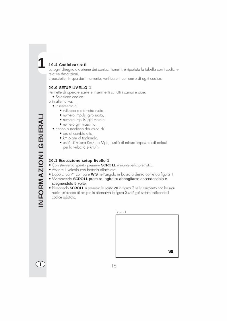
20.1 Esecuzione setup livello 1• Con strumento spento premere SCROLL e mantenerlo premuto.• Avviare il veicolo con batteria allacciata.• Dopo circa 7” compare WS nell'angolo in basso a destra come da figura 1• Mantenendo SCROLL premuto, agire su abbagliante accendendolo e
spegnendolo 5 volte.• Rilasciando SCROLL si presenta la scritta cu in figura 2 se lo strumento non ha mai
subito un’azione di setup e in alternativa la figura 3 se è già settato indicando ilcodice adottato.
Figura 1
1
INFO
RM
AZ
ION
I G
ENER
ALI
17 I
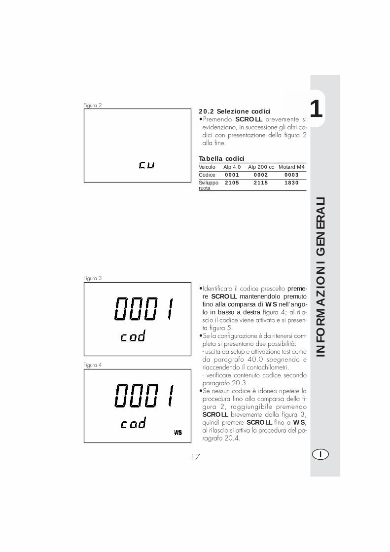
20.2 Selezione codici•Premendo SCROLL brevemente sievidenziano, in successione gli altri co-dici con presentazione della figura 2alla fine.
Tabella codiciVeicolo Alp 4.0 Alp 200 cc Motard M4Codice 0001 0002 0003Sviluppo 2105 2115 1830ruota
•Identificato il codice prescelto preme-re SCROLL mantenendolo premutofino alla comparsa di WS nell'ango-lo in basso a destra figura 4; al rila-scio il codice viene attivato e si presen-ta figura 5.
•Se la configurazione è da ritenersi com-pleta si presentano due possibilità:- uscita da setup e attivazione test comeda paragrafo 40.0 spegnendo eriaccendendo il contachilometri.- verificare contenuto codice secondoparagrafo 20.3.
•Se nessun codice è idoneo ripetere laprocedura fino alla comparsa della fi-gura 2, raggiungibile premendoSCROLL brevemente dalla figura 3,quindi premere SCROLL fino a WS,al rilascio si attiva la procedura del pa-ragrafo 20.4.
Figura 2
Figura 3
Figura 4
1
INFO
RM
AZ
ION
I G
ENER
ALI
18I
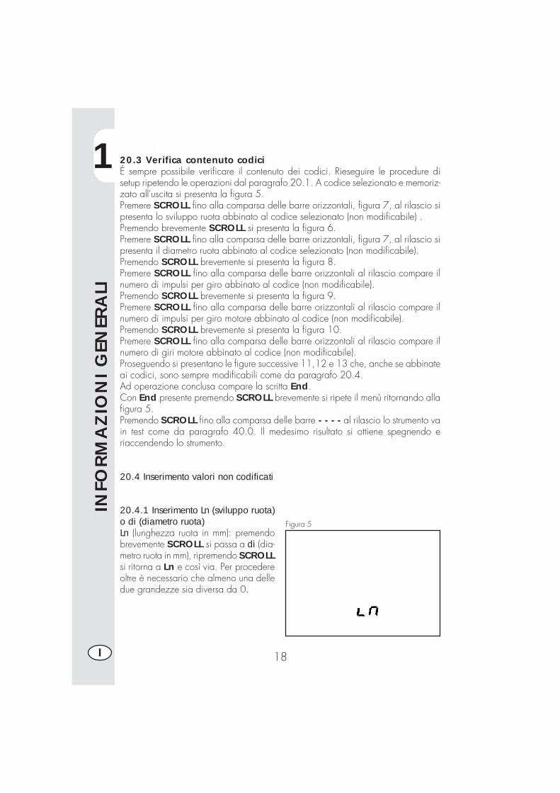
20.4.1 Inserimento Ln (sviluppo ruota)o di (diametro ruota)Ln (lunghezza ruota in mm): premendobrevemente SCROLL si passa a di (dia-metro ruota in mm), ripremendo SCROLLsi ritorna a Ln e così via. Per procedereoltre è necessario che almeno una delledue grandezze sia diversa da 0.
Figura 5
20.3 Verifica contenuto codiciÉ sempre possibile verificare il contenuto dei codici. Rieseguire le procedure disetup ripetendo le operazioni dal paragrafo 20.1. A codice selezionato e memoriz-zato all'uscita si presenta la figura 5.Premere SCROLL fino alla comparsa delle barre orizzontali, figura 7, al rilascio sipresenta lo sviluppo ruota abbinato al codice selezionato (non modificabile) .Premendo brevemente SCROLL si presenta la figura 6.Premere SCROLL fino alla comparsa delle barre orizzontali, figura 7, al rilascio sipresenta il diametro ruota abbinato al codice selezionato (non modificabile).Premendo SCROLL brevemente si presenta la figura 8.Premere SCROLL fino alla comparsa delle barre orizzontali al rilascio compare ilnumero di impulsi per giro abbinato al codice (non modificabile).Premendo SCROLL brevemente si presenta la figura 9.Premere SCROLL fino alla comparsa delle barre orizzontali al rilascio compare ilnumero di impulsi per giro motore abbinato al codice (non modificabile).Premendo SCROLL brevemente si presenta la figura 10.Premere SCROLL fino alla comparsa delle barre orizzontali al rilascio compare ilnumero di giri motore abbinato al codice (non modificabile).Proseguendo si presentano le figure successive 11,12 e 13 che, anche se abbinateai codici, sono sempre modificabili come da paragrafo 20.4.Ad operazione conclusa compare la scritta End.Con End presente premendo SCROLL brevemente si ripete il menù ritornando allafigura 5.Premendo SCROLL fino alla comparsa delle barre - - - - al rilascio lo strumento vain test come da paragrafo 40.0. Il medesimo risultato si ottiene spegnendo eriaccendendo lo strumento.
20.4 Inserimento valori non codificati
1
INFO
RM
AZ
ION
I G
ENER
ALI
19 I
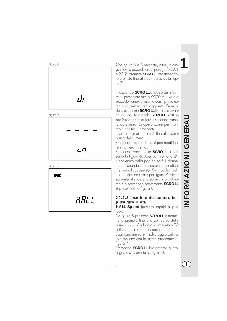
Figura 6 Con figura 5 o 6 presente, ottenute ese-guendo la procedura dal paragrafo 20.1e 20.2, premere SCROLL mantenendo-lo premuto fino alla comparsa della figu-ra 7.
Rilasciando SCROLL al posto delle bar-re si presenteranno o 0000 o il valoreprecedentemente inserito con il primo nu-mero di sinistra lampeggiante. Premen-do brevemente SCROLL il numero avan-za di uno. Lasciando SCROLL inattivoper 2 secondi oscillerà il secondo nume-ro da sinistra. Si opera come per il pri-mo e per tutti i rimanenti.Inserita la Ln attendere 2" fino alla scom-parsa del numero.Ripetendo l'operazione si può modifica-re il numero inserito.Premendo brevemente SCROLL si pre-senta la figura 6. Avendo inserito la Ln,il contenuto della pagina sarà il diame-tro corrispondente, calcolato automatica-mente dallo strumento. Se si vuole modi-ficare operare come per figura 7, diver-samente attendere la scomparsa del nu-mero e premendo brevemente SCROLLsi presenterà la figura 8.
20.4.2 Inserimento numero im-pulsi giro ruotaHALL Speed (numero impulsi al giroruota).Da figura 8 premere SCROLL e mante-nerlo premuto fino alla comparsa dellebarre - - - - . Al rilascio si presenta o 00o il valore precedentemente caricato.L’aggiornamento e il salvataggio del va-lore avviene con la stessa procedura difigura 7.Premendo SCROLL brevemente si pro-segue e si presenta la figura 9.
Figura 7
Figura 8
1
INFO
RM
AZ
ION
I G
ENER
ALI
20I
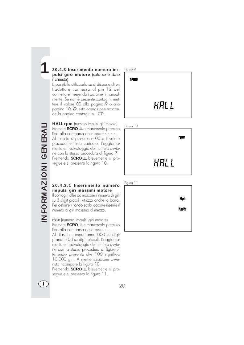
20.4.3 Inserimento numero im-pulsi giro motore (solo se è statorichiesto)È possibile utilizzarlo se si dispone di untraduttore connesso al pin 12 delconnettore inserendo i parametri manual-mente. Se non è presente contagiri, met-tere il valore 00 alla pagina 9 o allapagina 10. Questa operazione nascon-de la pagina contagiri su LCD.
HALL rpm (numero impulsi giri motore).Premere SCROLL e mantenerlo premutofino alla comparsa delle barre - - - -.Al rilascio si presenta o 00 o il valoreprecedentemente caricato. L’aggiorna-mento e il salvataggio del numero avvie-ne con la stessa procedura di figura 7.Premendo SCROLL brevemente si pro-segue e si presenta la figura 10.
20.4.3.1 Inserimento numeroimpulsi giri massimi motoreIl contagiri offre ad indicare il numero di girisu 5 digit piccoli, utilizza anche la barra.Per definire il fondo scala occorre inserire ilnumero di giri massimo al mezzo.
max (numero impulsi giri motore).Premere SCROLL e mantenerlo premutofino alla comparsa delle barre - - - -.Al rilascio compariranno 000 su digitgrandi e 00 su digit piccoli. L’aggiorna-mento e il salvataggio del numero avvie-ne con la stessa procedura di figura 7tenendo presente che 100 significa10.000 giri. A memorizzazione avve-nuta ricompare la figura 10.Premendo SCROLL brevemente si pro-segue e si presenta la figura 11.
Figura 9
Figura 10
Figura 11
1
INFO
RM
AZ
ION
I G
ENER
ALI
21 I
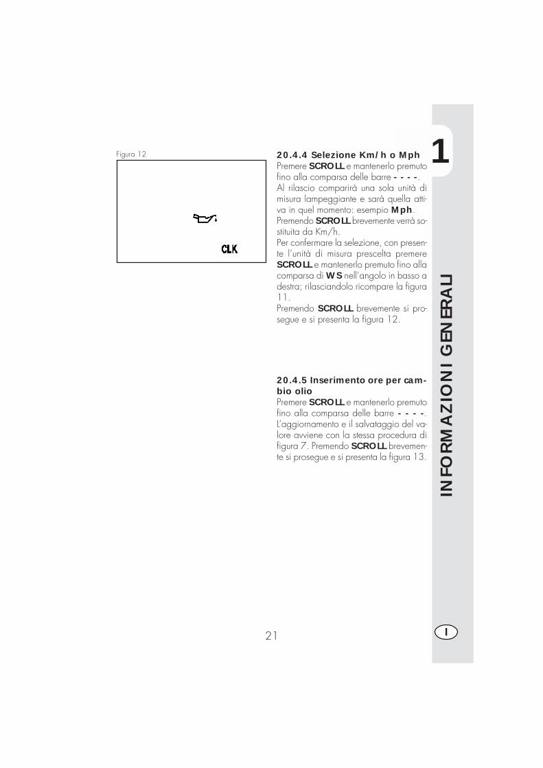
20.4.4 Selezione Km/h o MphPremere SCROLL e mantenerlo premutofino alla comparsa delle barre - - - -.Al rilascio comparirà una sola unità dimisura lampeggiante e sarà quella atti-va in quel momento: esempio Mph.Premendo SCROLL brevemente verrà so-stituita da Km/h.Per confermare la selezione, con presen-te l’unità di misura prescelta premereSCROLL e mantenerlo premuto fino allacomparsa di WS nell‘angolo in basso adestra; rilasciandolo ricompare la figura11.Premendo SCROLL brevemente si pro-segue e si presenta la figura 12.
Figura 12
20.4.5 Inserimento ore per cam-bio olioPremere SCROLL e mantenerlo premutofino alla comparsa delle barre - - - -.L’aggiornamento e il salvataggio del va-lore avviene con la stessa procedura difigura 7. Premendo SCROLL brevemen-te si prosegue e si presenta la figura 13.
1
INFO
RM
AZ
ION
I G
ENER
ALI
22I
20.4.6 Inserimento ore o Km pertagliando
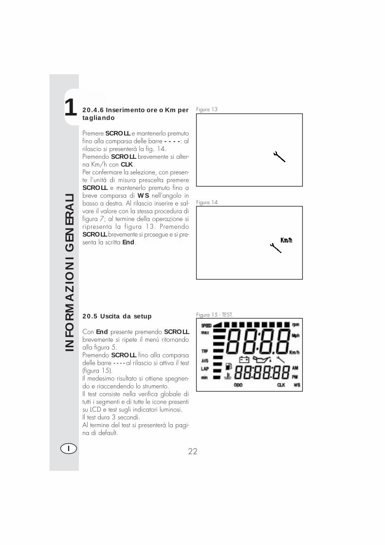
Premere SCROLL e mantenerlo premutofino alla comparsa delle barre - - - -: alrilascio si presenterà la fig. 14.Premendo SCROLL brevemente si alter-na Km/h con CLK.Per confermare la selezione, con presen-te l’unità di misura prescelta premereSCROLL e mantenerlo premuto fino abreve comparsa di WS nell’angolo inbasso a destra. Al rilascio inserire e sal-vare il valore con la stessa procedura difigura 7; al termine della operazione siripresenta la figura 13. PremendoSCROLL brevemente si prosegue e si pre-senta la scritta End.
20.5 Uscita da setup
Con End presente premendo SCROLLbrevemente si ripete il menù ritornandoalla figura 5.Premendo SCROLL fino alla comparsadelle barre - - - - al rilascio si attiva il test(figura 15).Il medesimo risultato si ottiene spegnen-do e riaccendendo lo strumento.Il test consiste nella verifica globale ditutti i segmenti e di tutte le icone presentisu LCD e test sugli indicatori luminosi.Il test dura 3 secondi.Al termine del test si presenterà la pagi-na di default.
Figura 13
Figura 14
Figura 15 - TEST.
1
INFO
RM
AZ
ION
I G
ENER
ALI
23 I
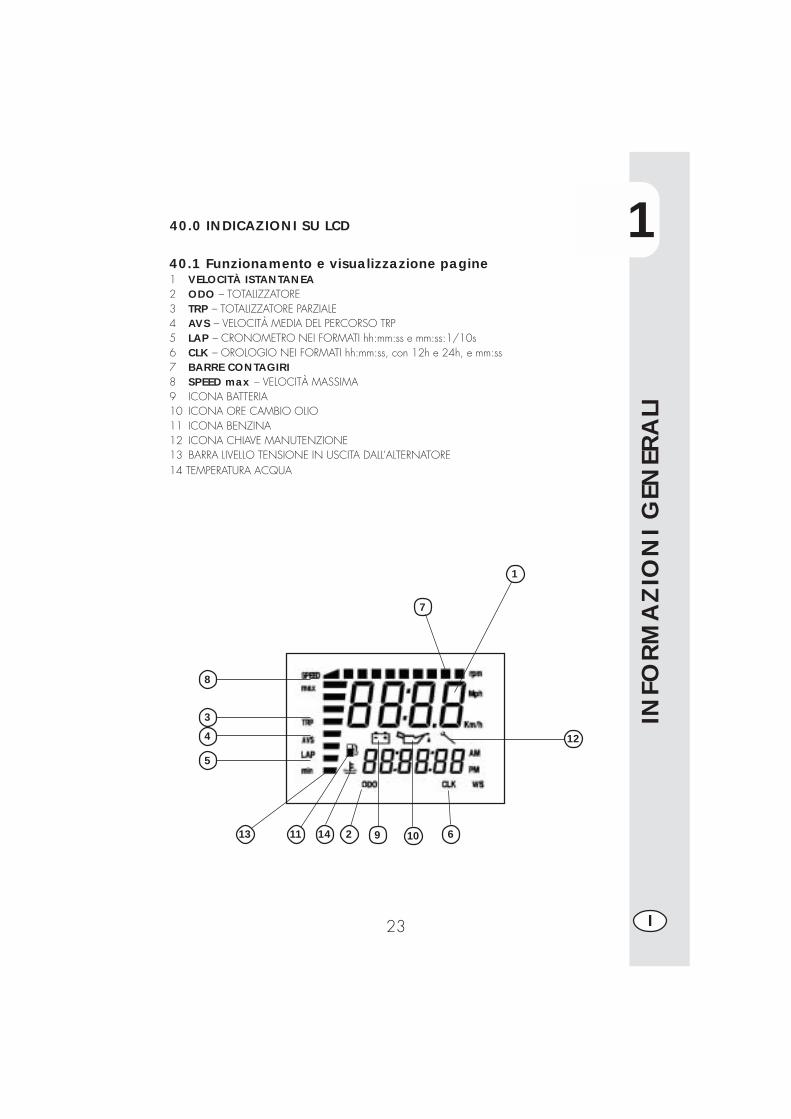
40.0 INDICAZIONI SU LCD
40.1 Funzionamento e visualizzazione pagine1 VELOCITÀ ISTANTANEA2 ODO – TOTALIZZATORE3 TRP – TOTALIZZATORE PARZIALE4 AVS – VELOCITÀ MEDIA DEL PERCORSO TRP5 LAP – CRONOMETRO NEI FORMATI hh:mm:ss e mm:ss:1/10s6 CLK – OROLOGIO NEI FORMATI hh:mm:ss, con 12h e 24h, e mm:ss7 BARRE CONTAGIRI8 SPEED max – VELOCITÀ MASSIMA9 ICONA BATTERIA10 ICONA ORE CAMBIO OLIO11 ICONA BENZINA12 ICONA CHIAVE MANUTENZIONE13 BARRA LIVELLO TENSIONE IN USCITA DALL’ALTERNATORE14 TEMPERATURA ACQUA
12
10 614
5
4
3
8
1
1113 92
7

1
INFO
RM
AZ
ION
I G
ENER
ALI
24I
Successione pagine su LCDTutte le pagine a partire dalla pagina di default sono raggiungibili solo nella lorosequenza.
Girare il commutatore a chiave su ON.Verifica globale di tutti i segmenti e ditutte le icone presenti su LCD e test sugliindicatori luminosi.Il test dura 3 secondi.Al termine del test si presenterà la pagi-na di default.
La pagina di default si attiva automatica-mente dopo il TEST.Visualizza:Batteria - indica lo stato di carica subarra verticale (min 10,4V, max 14,5V).Velocità istantanea in alto (max 199Km/h o Mph)ODO totalizzatore dei Km o migliapercorsi dal primo setup. Visualizzato inbasso (percorrenza massima 999.999 Kmo miglia). Parametro non azzerabile.
Pagina 1 - TEST.
Pagina 2 - PAGINA DI DEFAULT
1
INFO
RM
AZ
ION
I G
ENER
ALI
25 I
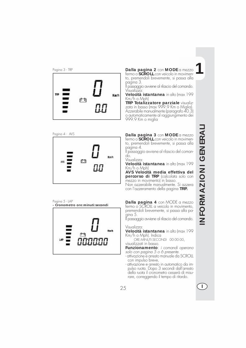
Pagina 3 - TRP
Pagina 4 - AVS
Pagina 5 - LAP- Cronometro ore:minuti:secondi
Dalla pagina 2 con MODE a mezzofermo o SCROLL con veicolo in movimen-to, premendoli brevemente, si passa allapagina 3.Il passaggio avviene al rilascio del comando.Visualizza:Velocità istantanea in alto (max 199Km/h o Mph)TRP Totalizzatore parziale visualiz-zata in basso (max 999.9 Km o Miglia).Azzerabile manualmente (paragrafo 40.3)o automaticamente al raggiungimento dei999.9 Km o miglia
Dalla pagina 3 con MODE a mezzofermo o SCROLL con veicolo in movimen-to, premendoli brevemente, si passa allapagina 4.Il passaggio avviene al rilascio del coman-do.Visualizza:Velocità istantanea in alto (max 199Km/h o Mph)AVS Velocità media effettiva delpercorso di TRP (calcolata solo conmezzo in movimento) in basso.Non azzerabile manualmente. Si azzeracon l’azzeramento della pagina TRP.
Dalla pagina 4 con MODE a mezzofermo o SCROLL a veicolo in movimento,premendoli brevemente, si passa alla pa-gina 5.Il passaggio avviene al rilascio del comando.
Visualizza:Velocità istantanea in alto (max 199Km/h o Mph). Indica
ORE:MINUTI:SECONDI 00:00:00,visualizzati in basso.Funzionamento: i comandi operanosolo con pagina 5 o 6 presente.- attivazione e arresto manuale da SCROLLcon impulso breve,
- attivazione e arresto in automatico da im-pulso ruota. Dopo 3 secondi dall’arrestodella ruota il cronometro cesserà di misu-rare, correggendo il tempo di ritardo.
1
INFO
RM
AZ
ION
I G
ENER
ALI
26I
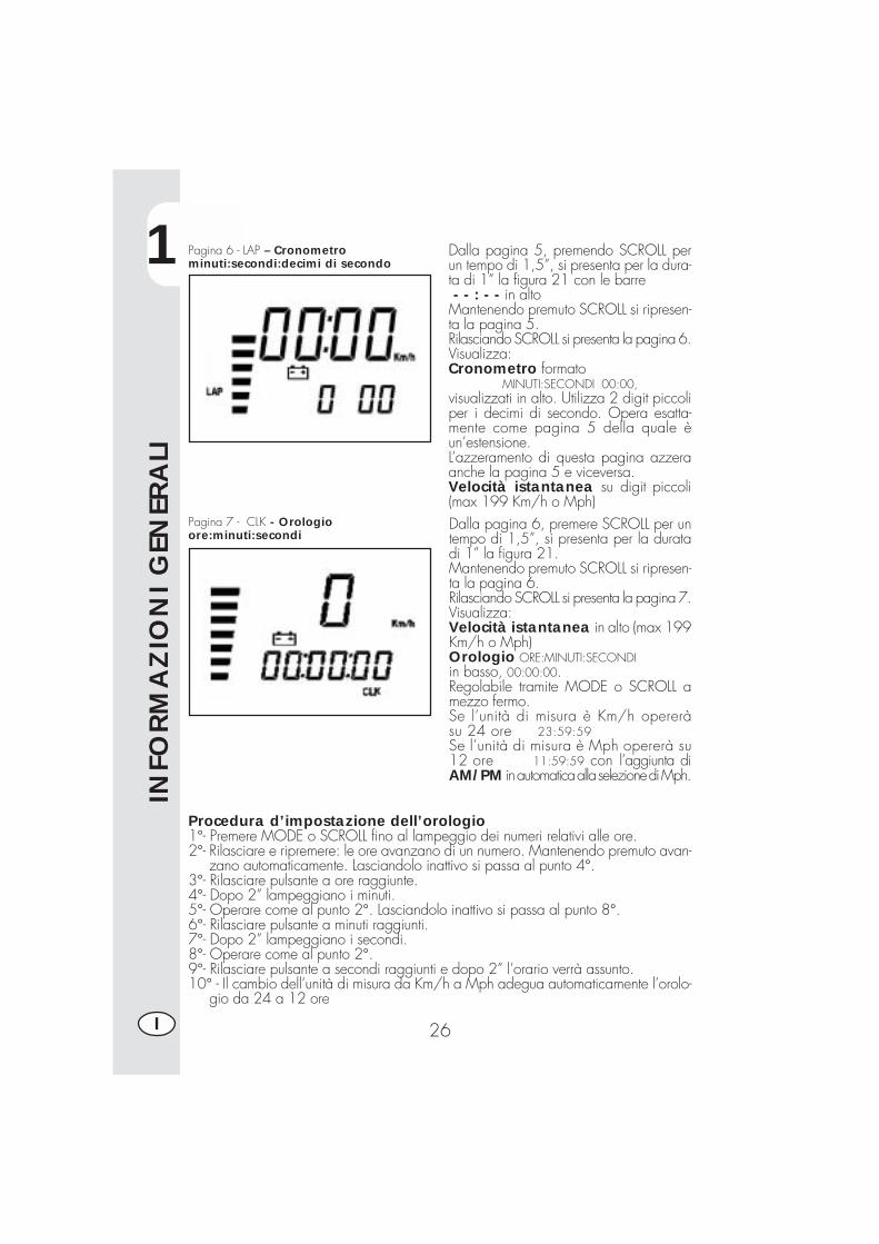
Pagina 6 - LAP – Cronometrominuti:secondi:decimi di secondo
Pagina 7 - CLK - Orologioore:minuti:secondi
Dalla pagina 5, premendo SCROLL perun tempo di 1,5”, si presenta per la dura-ta di 1” la figura 21 con le barre - - : - - in altoMantenendo premuto SCROLL si ripresen-ta la pagina 5.Rilasciando SCROLL si presenta la pagina 6.Visualizza:Cronometro formato
MINUTI:SECONDI 00:00,visualizzati in alto. Utilizza 2 digit piccoliper i decimi di secondo. Opera esatta-mente come pagina 5 della quale èun’estensione.L’azzeramento di questa pagina azzeraanche la pagina 5 e viceversa.Velocità istantanea su digit piccoli(max 199 Km/h o Mph)Dalla pagina 6, premere SCROLL per untempo di 1,5”, si presenta per la duratadi 1” la figura 21.Mantenendo premuto SCROLL si ripresen-ta la pagina 6.Rilasciando SCROLL si presenta la pagina 7.Visualizza:Velocità istantanea in alto (max 199Km/h o Mph)Orologio ORE:MINUTI:SECONDIin basso, 00:00:00.Regolabile tramite MODE o SCROLL amezzo fermo.Se l’unità di misura è Km/h opereràsu 24 ore 23:59:59Se l’unità di misura è Mph opererà su12 ore 11:59:59 con l’aggiunta diAM/PM in automatica alla selezione di Mph.
Procedura d’impostazione dell’orologio1°- Premere MODE o SCROLL fino al lampeggio dei numeri relativi alle ore.2°- Rilasciare e ripremere: le ore avanzano di un numero. Mantenendo premuto avan-
zano automaticamente. Lasciandolo inattivo si passa al punto 4°.3°- Rilasciare pulsante a ore raggiunte.4°- Dopo 2” lampeggiano i minuti.5°- Operare come al punto 2°. Lasciandolo inattivo si passa al punto 8°.6°- Rilasciare pulsante a minuti raggiunti.7°- Dopo 2” lampeggiano i secondi.8°- Operare come al punto 2°.9°- Rilasciare pulsante a secondi raggiunti e dopo 2” l’orario verrà assunto.10° - Il cambio dell’unità di misura da Km/h a Mph adegua automaticamente l’orolo-
gio da 24 a 12 ore
1
INFO
RM
AZ
ION
I G
ENER
ALI
27 I
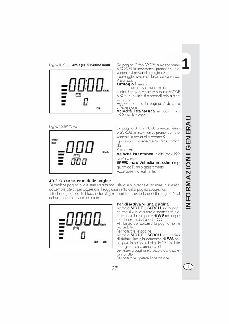
Pagina 8 - CLK - Orologio minuti:secondi
Pagina 10 SPEED max
Da pagina 7 con MODE a mezzo fermoo SCROLL in movimento, premendoli bre-vemente si passa alla pagina 8.Il passaggio avviene al rilascio del comando.Visualizza:Orologio formato
MINUTI:SECONDI 00:00in alto. Regolabile tramite pulsante MODEo SCROLL su minuti e secondi solo a mez-zo fermo.Aggiorna anche la pagina 7 di cui èun’estensione.Velocità istantanea in basso (max199 Km/h o Mph).
Da pagina 8 con MODE a mezzo fermoo SCROLL in movimento, premendoli bre-vemente si passa alla pagina 9.Il passaggio avviene al rilascio del coman-do.Visualizza:Velocità istantanea in alto (max 199Km/h o Mph)SPEED max Velocità massima rag-giunta dall’ultimo azzeramento.Azzerabile manualmente.
40.2 Oscuramento delle pagineSe qualche pagina può essere ritenuta non utile la si può rendere invisibile, pur restan-do sempre attiva, per accelerare il raggiungimento della pagina successiva.Tutte le pagine, sia in blocco che singolarmente, ad esclusione della pagina 2 didefault, possono essere oscurate.
Per disattivare una pagina:premere MODE o SCROLL dalla pagi-na che si vuol oscurare e mantenerlo pre-muto fino alla comparsa di WS nell’ango-lo in basso a destra dell’ LCD.Al rilascio del pulsante la pagina non èpiù visibile.Per riattivare le pagine:premere MODE o SCROLL da paginadi default fino alla comparsa di WS nel-l’angolo in basso a destra dell’ LCD e tuttele pagine ritorneranno visibili.Se nessuna pagina era oscurata si oscure-ranno tutte.Per riattivarle ripetere l’operazione.

1
INFO
RM
AZ
ION
I G
ENER
ALI
28I
40.3 Cancellazione parametri TRP, SPEED max, LAPI parametri cancellabili sono:- Percorso indicato da TRP e conseguentemente AVS- SPEED max velocità massima raggiuntaTempi indicati da LAP in entrambe le configurazioni da una qualsiasi delle 2 pagine.La cancellazione dei parametri è attuabile con MODE a mezzo fermo e con SCROLLsempre.
Cancellazione TRP e SPEED max
Premere MODE o SCROLL per un tempo≥ 5”, dopo di che al posto del numero sipresenterà 0.0La cancellazione del TRP è fattibile solo amoto ferma. Tale operazione azzera an-che AVS.
Cancellazione LAP L’azzeramento del tempo di LAP azzerasia la pagina 5 che la pagina 6 che sonorigidamente collegate.I numeri saranno sostituiti dalle barretteorizzontali che rimarranno visibili per 1”.Se in presenza delle barre - - - - vienerilasciato MODE o SCROLL il numero vie-ne cancellato.Se MODE o SCROLL viene mantenutopremuto si passa alla pagina successivaconservando i valori della pagina.
1
INFO
RM
AZ
ION
I G
ENER
ALI
29 I
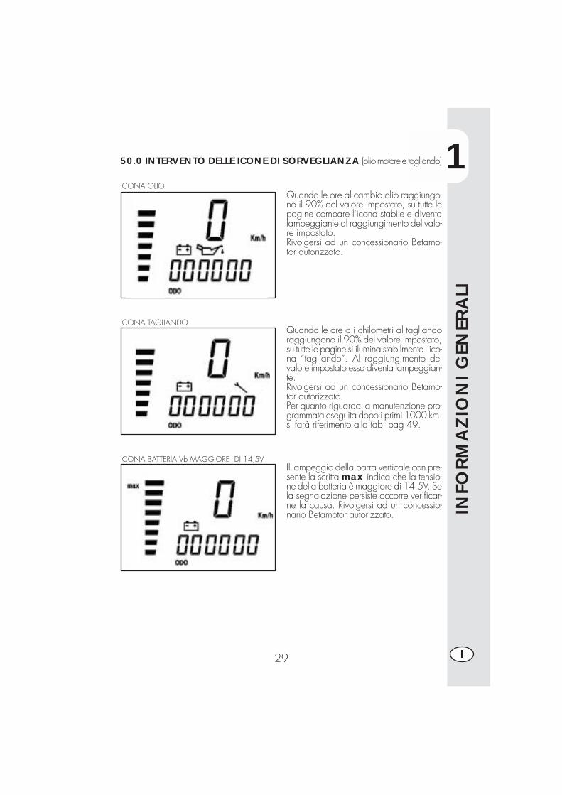
50.0 INTERVENTO DELLE ICONE DI SORVEGLIANZA (olio motore e tagliando)
ICONA OLIOQuando le ore al cambio olio raggiungo-no il 90% del valore impostato, su tutte lepagine compare l’icona stabile e diventalampeggiante al raggiungimento del valo-re impostato.Rivolgersi ad un concessionario Betamo-tor autorizzato.
Quando le ore o i chilometri al tagliandoraggiungono il 90% del valore impostato,su tutte le pagine si ilumina stabilmente l’ico-na “tagliando”. Al raggiungimento delvalore impostato essa diventa lampeggian-te.Rivolgersi ad un concessionario Betamo-tor autorizzato.Per quanto riguarda la manutenzione pro-grammata eseguita dopo i primi 1000 km.si farà riferimento alla tab. pag 49.
ICONA TAGLIANDO
ICONA BATTERIA Vb MAGGIORE DI 14,5VIl lampeggio della barra verticale con pre-sente la scritta max indica che la tensio-ne della batteria è maggiore di 14,5V. Sela segnalazione persiste occorre verificar-ne la causa. Rivolgersi ad un concessio-nario Betamotor autorizzato.
1
INFO
RM
AZ
ION
I G
ENER
ALI
30I
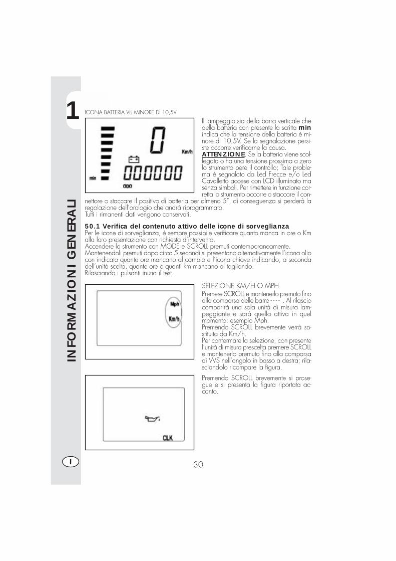
ICONA BATTERIA Vb MINORE DI 10,5V
Il lampeggio sia della barra verticale chedella batteria con presente la scritta minindica che la tensione della batteria è mi-nore di 10,5V. Se la segnalazione persi-ste occorre verificarne la causa.ATTENZIONE. Se la batteria viene scol-legata o ha una tensione prossima a zerolo strumento pere il controllo; Tale proble-ma è segnalato da Led Frecce e/o LedCavalletto accese con LCD illuminato masenza simboli. Per rimettere in funzione cor-retta lo strumento occorre o staccare il con-
nettore o staccare il positivo di batteria per almeno 5”, di conseguenza si perderà laregolazione dell’orologio che andrà riprogrammato.Tutti i rimanenti dati vengono conservati.
50.1 Verifica del contenuto attivo delle icone di sorveglianzaPer le icone di sorveglianza, è sempre possibile verificare quanto manca in ore o Kmalla loro presentazione con richiesta d’intervento.Accendere lo strumento con MODE e SCROLL premuti contemporaneamente.Mantenendoli premuti dopo circa 5 secondi si presentano alternativamente l’icona oliocon indicato quante ore mancano al cambio e l’icona chiave indicando, a secondadell’unità scelta, quante ore o quanti km mancano al tagliando.Rilasciando i pulsanti inizia il test.
SELEZIONE KM/H O MPHPremere SCROLL e mantenerlo premuto finoalla comparsa delle barre - - - - . Al rilasciocomparirà una sola unità di misura lam-peggiante e sarà quella attiva in quelmomento: esempio Mph.Premendo SCROLL brevemente verrà so-stituita da Km/h.Per confermare la selezione, con presentel’unità di misura prescelta premere SCROLLe mantenerlo premuto fino alla comparsadi WS nell’angolo in basso a destra; rila-sciandolo ricompare la figura.
Premendo SCROLL brevemente si prose-gue e si presenta la figura riportata ac-canto.
1
INFO
RM
AZ
ION
I G
ENER
ALI
31 I
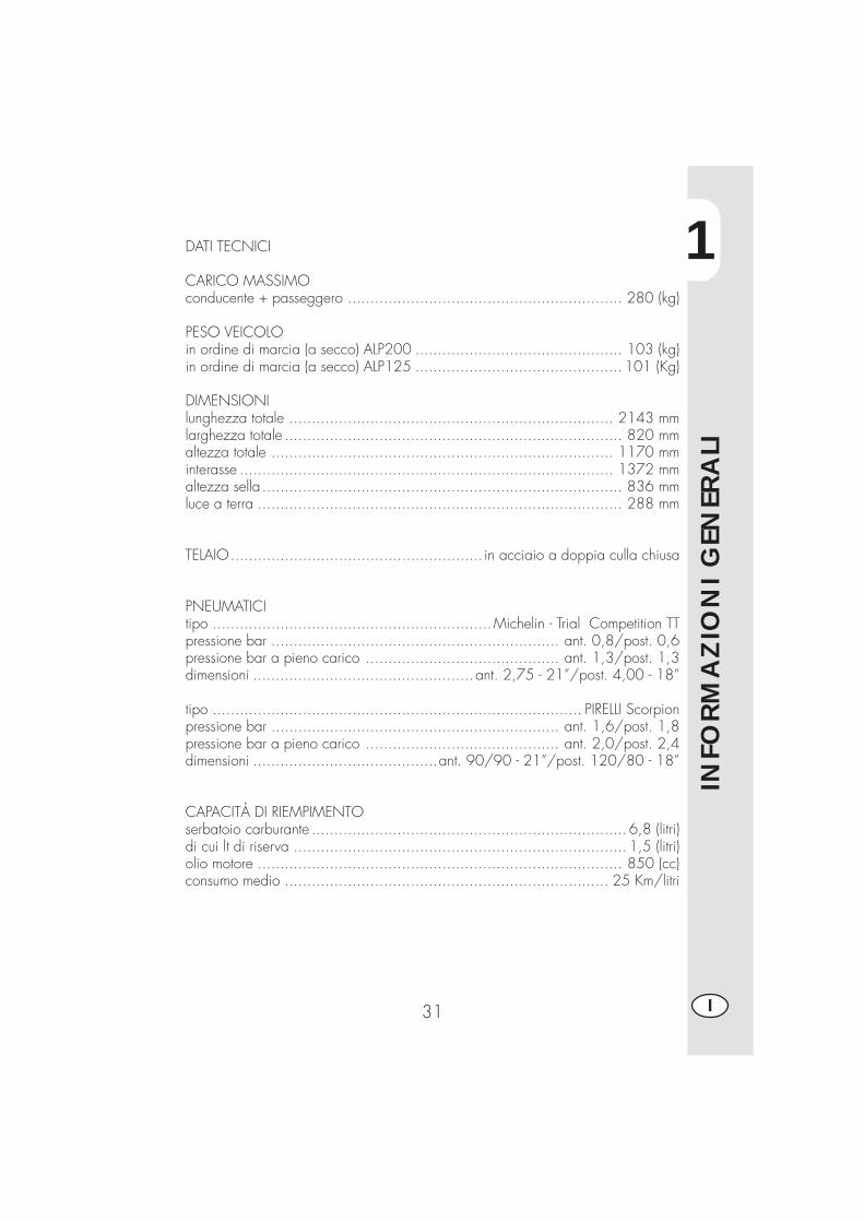
DATI TECNICI
CARICO MASSIMOconducente + passeggero ............................................................. 280 (kg)
PESO VEICOLOin ordine di marcia (a secco) ALP200 .............................................. 103 (kg)in ordine di marcia (a secco) ALP125 .............................................. 101 (Kg)
DIMENSIONIlunghezza totale ........................................................................ 2143 mmlarghezza totale ........................................................................... 820 mmaltezza totale ............................................................................ 1170 mminterasse ................................................................................... 1372 mmaltezza sella ................................................................................ 836 mmluce a terra ................................................................................. 288 mm
TELAIO........................................................ in acciaio a doppia culla chiusa
PNEUMATICItipo ..............................................................Michelin - Trial Competition TTpressione bar ................................................................ ant. 0,8/post. 0,6pressione bar a pieno carico ........................................... ant. 1,3/post. 1,3dimensioni ................................................. ant. 2,75 - 21”/post. 4,00 - 18”
tipo .................................................................................. PIRELLI Scorpionpressione bar ................................................................ ant. 1,6/post. 1,8pressione bar a pieno carico ........................................... ant. 2,0/post. 2,4dimensioni .........................................ant. 90/90 - 21”/post. 120/80 - 18”
CAPACITÀ DI RIEMPIMENTOserbatoio carburante ...................................................................... 6,8 (litri)di cui lt di riserva .......................................................................... 1,5 (litri)olio motore ................................................................................. 850 (cc)consumo medio ........................................................................ 25 Km/litri
1
INFO
RM
AZ
ION
I G
ENER
ALI
32I
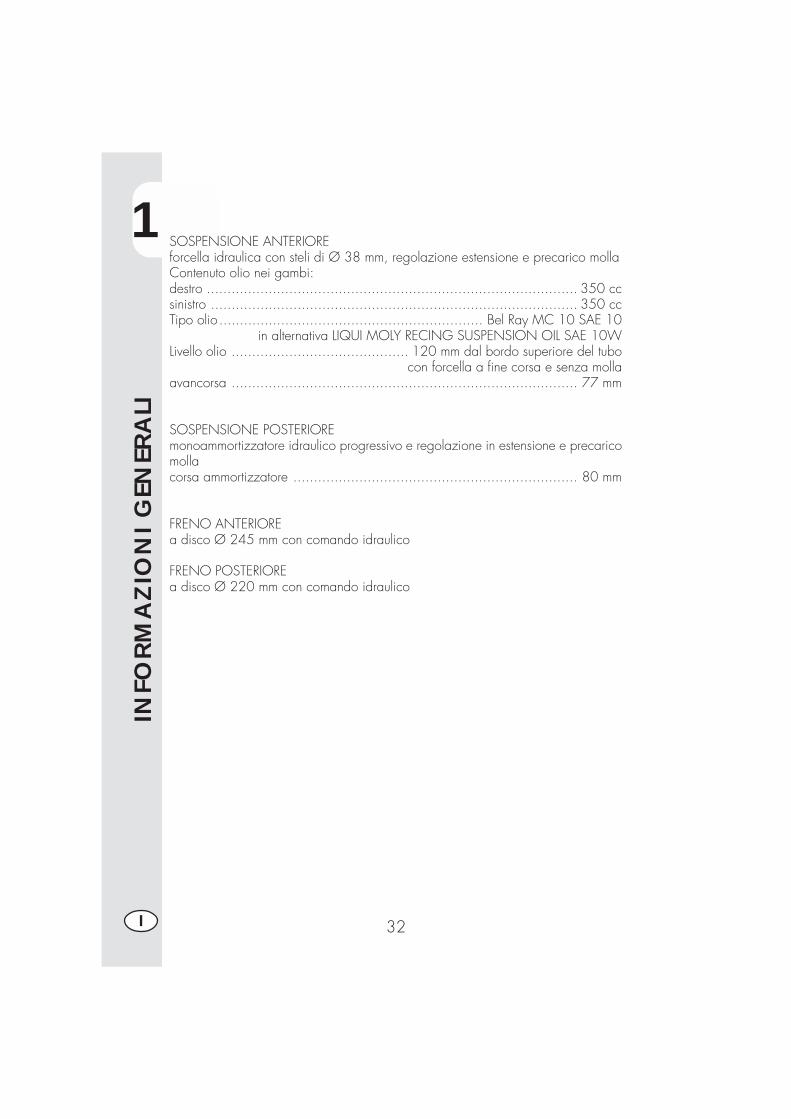
SOSPENSIONE ANTERIOREforcella idraulica con steli di Ø 38 mm, regolazione estensione e precarico mollaContenuto olio nei gambi:destro .......................................................................................... 350 ccsinistro ......................................................................................... 350 ccTipo olio ................................................................ Bel Ray MC 10 SAE 10
in alternativa LIQUI MOLY RECING SUSPENSION OIL SAE 10WLivello olio ........................................... 120 mm dal bordo superiore del tubo
con forcella a fine corsa e senza mollaavancorsa .................................................................................... 77 mm
SOSPENSIONE POSTERIOREmonoammortizzatore idraulico progressivo e regolazione in estensione e precaricomollacorsa ammortizzatore ..................................................................... 80 mm
FRENO ANTERIOREa disco Ø 245 mm con comando idraulico
FRENO POSTERIOREa disco Ø 220 mm con comando idraulico
1
INFO
RM
AZ
ION
I G
ENER
ALI
33 I
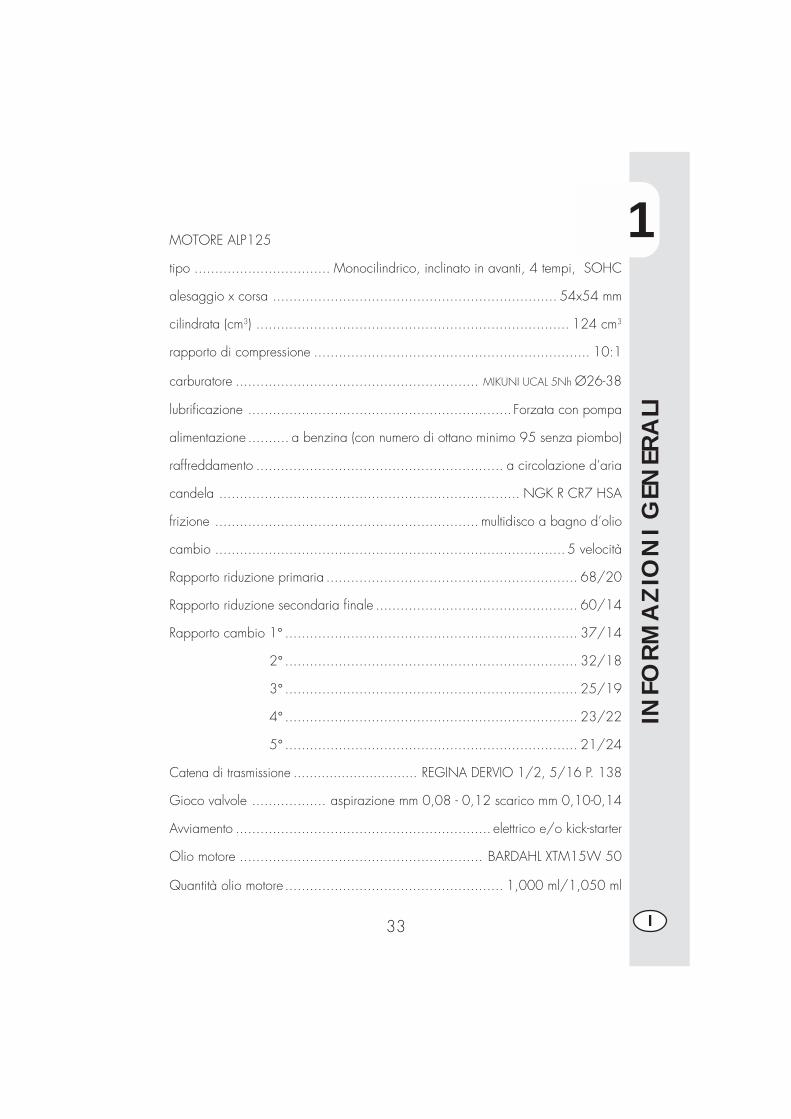
MOTORE ALP125
tipo ................................. Monocilindrico, inclinato in avanti, 4 tempi, SOHC
alesaggio x corsa ..................................................................... 54x54 mm
cilindrata (cm3) ............................................................................ 124 cm3
rapporto di compressione ................................................................... 10:1
carburatore ........................................................... MIKUNI UCAL 5Nh Ø26-38
lubrificazione ................................................................ Forzata con pompa
alimentazione .......... a benzina (con numero di ottano minimo 95 senza piombo)
raffreddamento ............................................................ a circolazione d’aria
candela ......................................................................... NGK R CR7 HSA
frizione ................................................................ multidisco a bagno d’olio
cambio ..................................................................................... 5 velocità
Rapporto riduzione primaria ............................................................. 68/20
Rapporto riduzione secondaria finale ................................................. 60/14
Rapporto cambio 1° ....................................................................... 37/14
2° ....................................................................... 32/18
3° ....................................................................... 25/19
4° ....................................................................... 23/22
5° ....................................................................... 21/24
Catena di trasmissione ............................... REGINA DERVIO 1/2, 5/16 P. 138
Gioco valvole .................. aspirazione mm 0,08 - 0,12 scarico mm 0,10-0,14
Avviamento .............................................................. elettrico e/o kick-starter
Olio motore ........................................................... BARDAHL XTM15W 50
Quantità olio motore ..................................................... 1,000 ml/1,050 ml
1
INFO
RM
AZ
ION
I G
ENER
ALI
34I
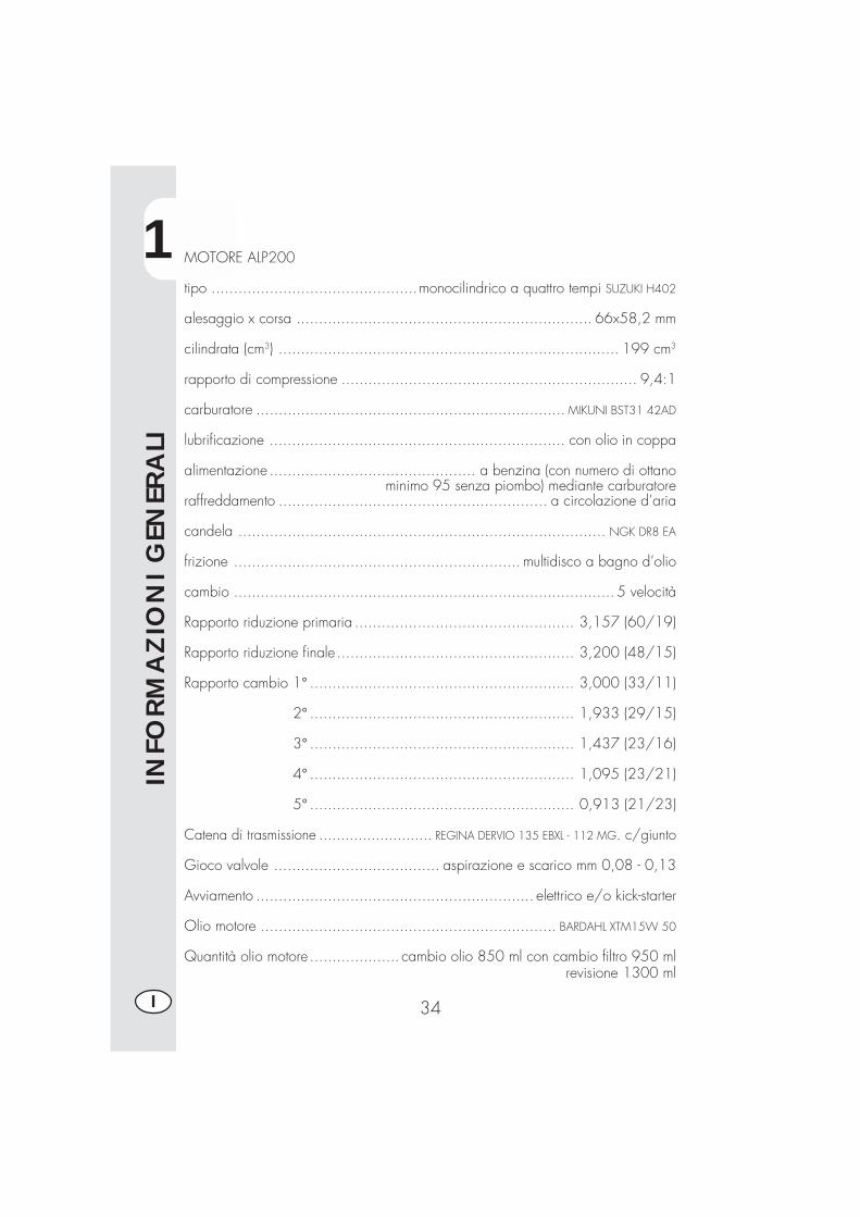
MOTORE ALP200
tipo ..............................................monocilindrico a quattro tempi SUZUKI H402
alesaggio x corsa .................................................................. 66x58,2 mm
cilindrata (cm3) ............................................................................ 199 cm3
rapporto di compressione .................................................................. 9,4:1
carburatore ..................................................................... MIKUNI BST31 42AD
lubrificazione .................................................................. con olio in coppa
alimentazione .............................................. a benzina (con numero di ottanominimo 95 senza piombo) mediante carburatore
raffreddamento ............................................................ a circolazione d’aria
candela .................................................................................. NGK DR8 EA
frizione ................................................................ multidisco a bagno d’olio
cambio ..................................................................................... 5 velocità
Rapporto riduzione primaria ................................................. 3,157 (60/19)
Rapporto riduzione finale..................................................... 3,200 (48/15)
Rapporto cambio 1° ........................................................... 3,000 (33/11)
2° ........................................................... 1,933 (29/15)
3° ........................................................... 1,437 (23/16)
4° ........................................................... 1,095 (23/21)
5° ........................................................... 0,913 (21/23)
Catena di trasmissione .......................... REGINA DERVIO 135 EBXL - 112 MG. c/giunto
Gioco valvole ..................................... aspirazione e scarico mm 0,08 - 0,13
Avviamento .............................................................. elettrico e/o kick-starter
Olio motore .................................................................. BARDAHL XTM15W 50
Quantità olio motore .................... cambio olio 850 ml con cambio filtro 950 mlrevisione 1300 ml

1
INFO
RM
AZ
ION
I G
ENER
ALI
35 I
SCHEMA ELETTRICO ALP 125N
e
Bi-N
e
Gi
Bl-N
e
Gr
Bi-N
e
Bl-N
e
Gi
Bi-G
i
Bi-A
r
Bl-V
e
Ne
Ma
Bl-N
e
Az
Bi-B
l
Rs-
Gi
Bi-G
i
Bi-A
r
Bl-V
e
Gr
Ma
Vi
MaM
a-N
eN
e
Ve Vi
Bl-N
e
Ro
Vi
Ve
Rs-
Gi
Bi-B
l
Ro
Az
Bl-N
eB
l
2 61V
e
11B
l-Ne
3N
e-A
r
5M
a-N
e
4 14R
s
13N
e
7M
a-G
i
9G
r-V
e
Bl-N
e
Bl
Ne
MaB
lRs
Bl
Ne
Vi
Gi
Ve
Bi
Bi
Ma
Ne
Gi
Bi B
l Ne N
eR
sVe
Gi
Ve
Gi
Bl
Bi
+-Ne
RsBi
NeN
e Ne
Rs
Bi
Gi
Ve
NeBi
Bl-N
eB L
Rs-
Gi
Az
Ro
Ne
Ar
Ne
Ne
Ro
Vi
Ne
Rs
Ne
Rs
Ne
Gi
Bi
Ne
Ro
Ne
Ro
NeBl
NeBl
NeBl
Rs
Rs
Rs
Ar
Bi
M
Rs
Bi
Bl
Gr-
Ve
Ne
Ne
Bl-N
e
Bi-N
e
Bl-V
eB
l-Ve
Ve
Ne V
iN
e
Gi
NeM
aR
o
Ma V
eNe
Ne
NeVi
Ve
Bi-B
lG
iG
iB
i-Bl
Ve Vi
Ne
Ne
Bi-B
l
Ne
Bi-B
l
Ne
Ne
Ne
Rs
Bi-N
e
Gr
Vi
Gi
Rs
Rs
Az
Ro
Bl
Bi
+
Ne
Ve
Ve
Ne
Bl-N
eG
i
Ne
Ne
Ne Gi
Ne
Bi-B
lG
i
01
2
Bi-R
o
Bl
Ne
Ne
Ro
-+
Ne
1 2
3 4 5 6 7 8 9 10 11 12 13 14 15 16 17 18 19
2221
20
23
25 2426
27
2829
3031
323333
3435
3637383940
4142
4344
4546
4748
49
50
1
INFO
RM
AZ
ION
I G
ENER
ALI
36I
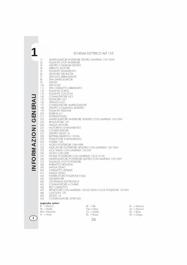
SCHEMA ELETTRICO ALP 125
1) LAMPEGGIATORI ANTERIORE DESTRO (LAMPADA 12V-10W)2) PULSANTE STOP ANTERIORE3) GRUPPO COMANDI DESTRO4) ARRESTO MOTORE5) PULSANTE AVVIAMENTO6) SENSORE GIRI RUOTA7) SPIA LUCE ABBAGLIANTE8) SPIA LAMPEGGIATORI9) DISPLAY10) SPIA FOLLE11) SPIA CAVALLETTO ABBASSATO12) PULSANTE SCROLL13) PULSANTE CLACSON14) COMMUTATORE LUCI15) DEVIATORE LUCI16) SPRAZZO LUCI17) COMMUTATORE LAMPEGGIATORI18) GRUPPO COMANDO SINISTRO19) PULSANTE FRIZIONE20) BOBINA A.T.21) INTERMITTENZA22) LAMPEGGIATORE ANTERIORE SINISTRO CON LAMPADA 12V-10W23) REGOLATORE 12V24) MASSA MOTORE25) MOTORINO D’AVVIAMENTO26) CONDENSATORE27) GRUPPO DIODI 1A28) BATTERIA ERMETICA 12V-9A29) TELERUTTORE D’AVVIAMENTO30) FUSIBILE 10A31) NODO POSTERIORE CAVI NERI32) INDICATORE POSTERIORE SINISTRO CON LAMPADA 12V-10W33) LUCE TARGA CON LAMPADA 12V-5W34) NODO CAVI NERI35) FANALE POSTERIORE CON LAMPADA 12V-5/21W36) LAMPEGGIATORE POSTERIORE DESTRO CON LAMPADA 12V-10W37) PULSANTE STOP POSTERIORE38) RUBINETTO BENZINA39) MASSA TELAIO40) CAVALLETTO LATERALE41) MASSA TELAIO42) INTERRUTTORE POSIZIONE FOLLE43) GENERATORE44) CENTRALINA ELETTRONICA45) COMMUTATORE A CHIAVE46) RELE CAVALLETTO47) PROIETTORE CON LAMPADA 12V-55/60W E LUCE POSIZIONE 12V-5W48) CLACSON 12V49) DIODO 1A50) CONDENSATORE 47MF-50V
Legenda coloriBi = BiancoVe = VerdeMa= MarroneVi = Viola
Bl = BluNe = NeroGi = GialloRs = Rosso
Ar = ArancioAz = AzzurroRo = RosaGr = Grigio
1
INFO
RM
AZ
ION
I G
ENER
ALI
37 I
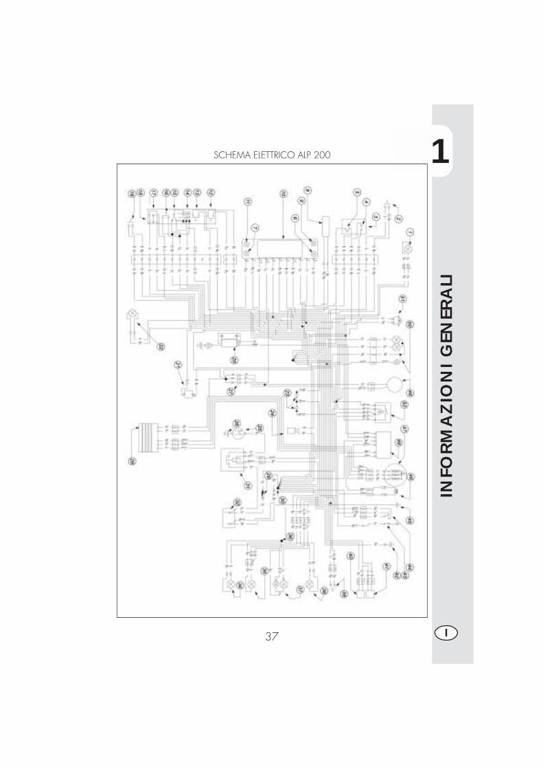
SCHEMA ELETTRICO ALP 200
1
INFO
RM
AZ
ION
I G
ENER
ALI
38I
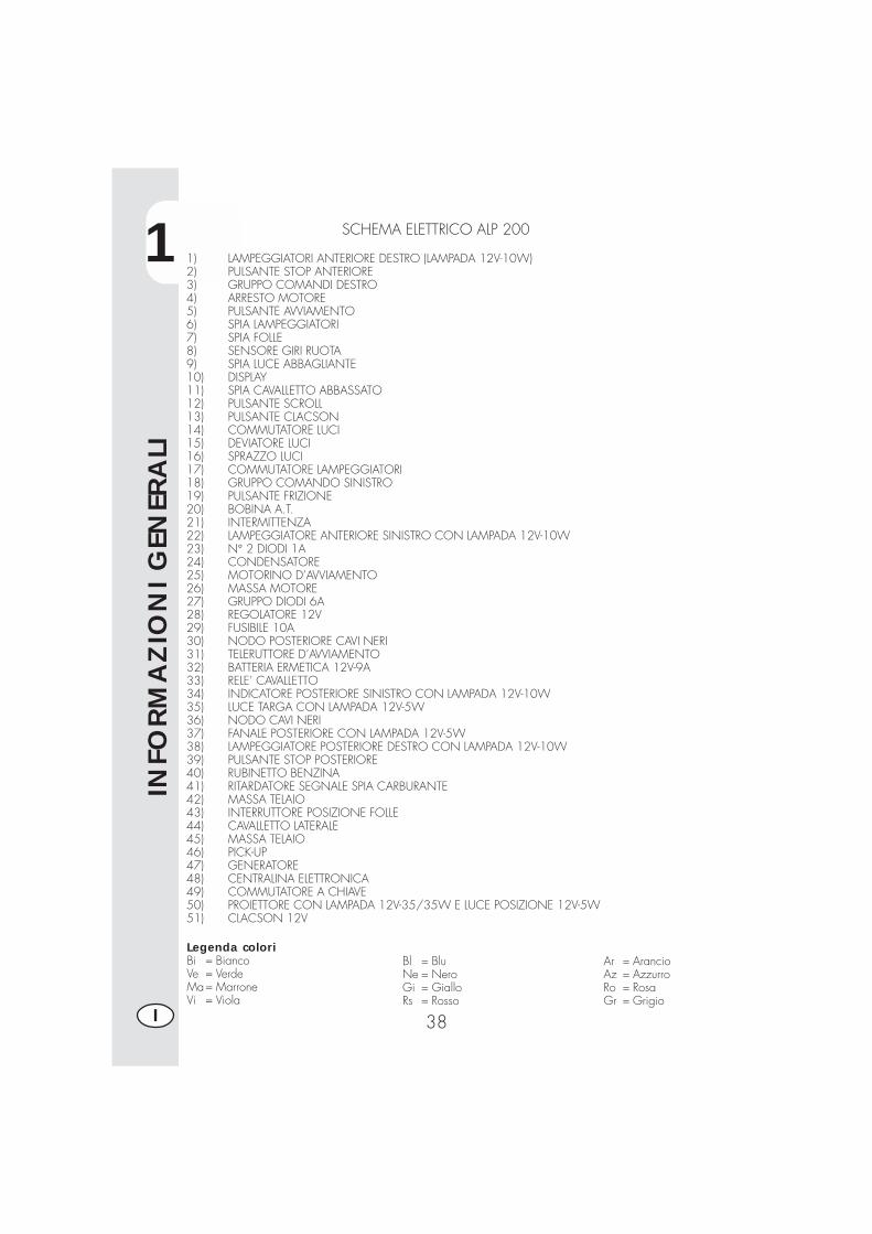
SCHEMA ELETTRICO ALP 200
1) LAMPEGGIATORI ANTERIORE DESTRO (LAMPADA 12V-10W)2) PULSANTE STOP ANTERIORE3) GRUPPO COMANDI DESTRO4) ARRESTO MOTORE5) PULSANTE AVVIAMENTO6) SPIA LAMPEGGIATORI7) SPIA FOLLE8) SENSORE GIRI RUOTA9) SPIA LUCE ABBAGLIANTE10) DISPLAY11) SPIA CAVALLETTO ABBASSATO12) PULSANTE SCROLL13) PULSANTE CLACSON14) COMMUTATORE LUCI15) DEVIATORE LUCI16) SPRAZZO LUCI17) COMMUTATORE LAMPEGGIATORI18) GRUPPO COMANDO SINISTRO19) PULSANTE FRIZIONE20) BOBINA A.T.21) INTERMITTENZA22) LAMPEGGIATORE ANTERIORE SINISTRO CON LAMPADA 12V-10W23) N° 2 DIODI 1A24) CONDENSATORE25) MOTORINO D’AVVIAMENTO26) MASSA MOTORE27) GRUPPO DIODI 6A28) REGOLATORE 12V29) FUSIBILE 10A30) NODO POSTERIORE CAVI NERI31) TELERUTTORE D’AVVIAMENTO32) BATTERIA ERMETICA 12V-9A33) RELE’ CAVALLETTO34) INDICATORE POSTERIORE SINISTRO CON LAMPADA 12V-10W35) LUCE TARGA CON LAMPADA 12V-5W36) NODO CAVI NERI37) FANALE POSTERIORE CON LAMPADA 12V-5W38) LAMPEGGIATORE POSTERIORE DESTRO CON LAMPADA 12V-10W39) PULSANTE STOP POSTERIORE40) RUBINETTO BENZINA41) RITARDATORE SEGNALE SPIA CARBURANTE42) MASSA TELAIO43) INTERRUTTORE POSIZIONE FOLLE44) CAVALLETTO LATERALE45) MASSA TELAIO46) PICK-UP47) GENERATORE48) CENTRALINA ELETTRONICA49) COMMUTATORE A CHIAVE50) PROIETTORE CON LAMPADA 12V-35/35W E LUCE POSIZIONE 12V-5W51) CLACSON 12V
Legenda coloriBi = BiancoVe = VerdeMa= MarroneVi = Viola
Bl = BluNe = NeroGi = GialloRs = Rosso
Ar = ArancioAz = AzzurroRo = RosaGr = Grigio
1
INFO
RM
AZ
ION
I G
ENER
ALI
39 I
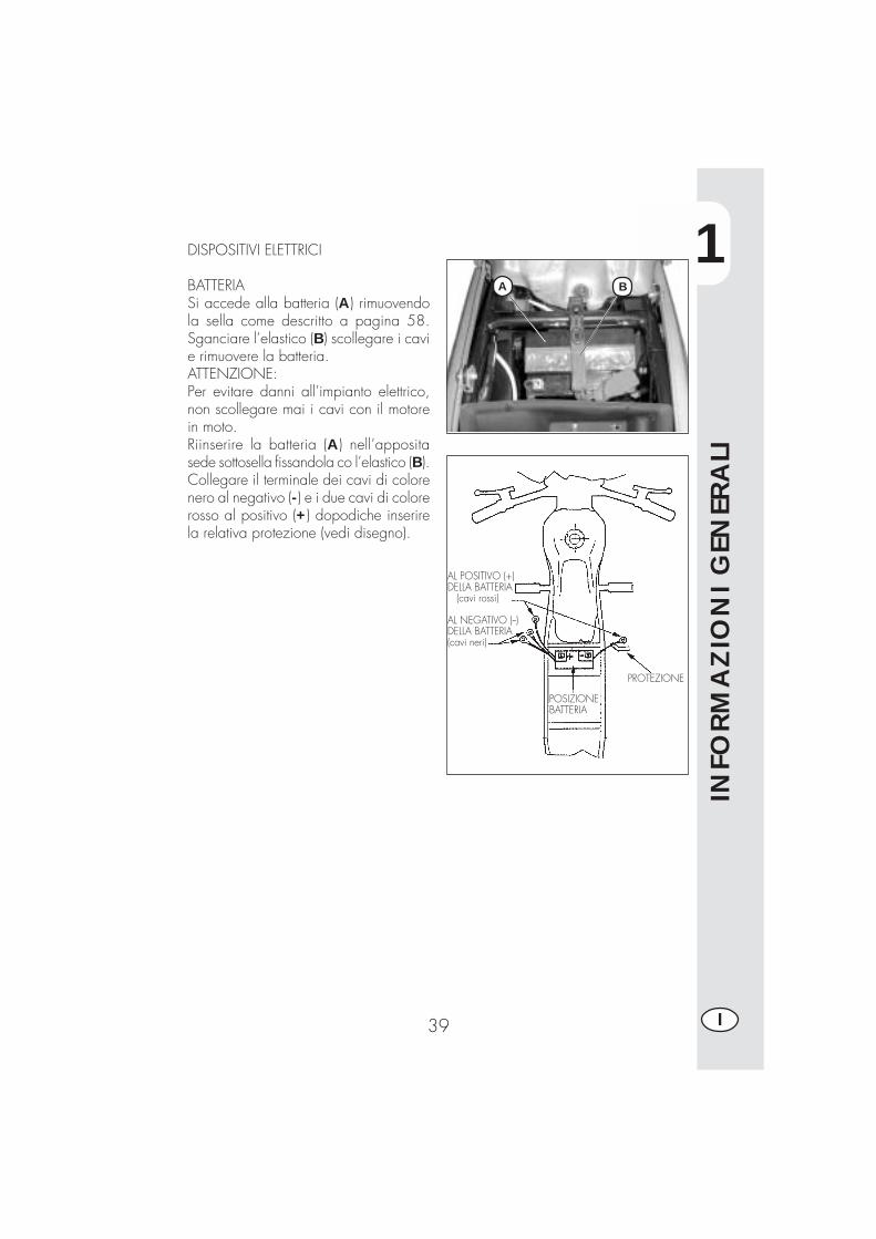
DISPOSITIVI ELETTRICI
BATTERIASi accede alla batteria (A) rimuovendola sella come descritto a pagina 58.Sganciare l’elastico (B) scollegare i cavie rimuovere la batteria.ATTENZIONE:Per evitare danni all’impianto elettrico,non scollegare mai i cavi con il motorein moto.Riinserire la batteria (A) nell’appositasede sottosella fissandola co l’elastico (B).Collegare il terminale dei cavi di colorenero al negativo (-) e i due cavi di colorerosso al positivo (+) dopodiche inserirela relativa protezione (vedi disegno).
AL POSITIVO (+)DELLA BATTERIA (cavi rossi)
AL NEGATIVO (--)DELLA BATTERIA(cavi neri)
POSIZIONEBATTERIA
PROTEZIONE
A B
1
INFO
RM
AZ
ION
I G
ENER
ALI
40I
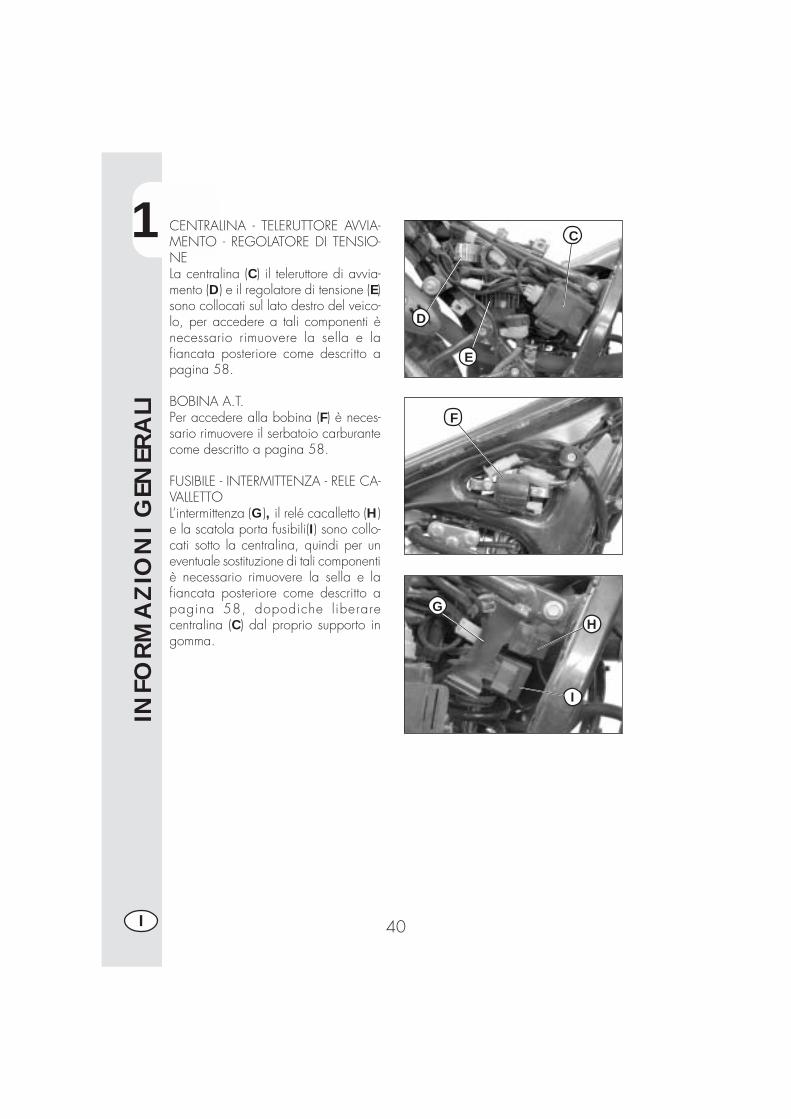
CENTRALINA - TELERUTTORE AVVIA-MENTO - REGOLATORE DI TENSIO-NELa centralina (C) il teleruttore di avvia-mento (D) e il regolatore di tensione (E)sono collocati sul lato destro del veico-lo, per accedere a tali componenti ènecessario rimuovere la sella e lafiancata posteriore come descritto apagina 58.
BOBINA A.T.Per accedere alla bobina (F) è neces-sario rimuovere il serbatoio carburantecome descritto a pagina 58.
FUSIBILE - INTERMITTENZA - RELE CA-VALLETTOL’intermittenza (G), il relé cacalletto (H)e la scatola porta fusibili(I) sono collo-cati sotto la centralina, quindi per uneventuale sostituzione di tali componentiè necessario rimuovere la sella e lafiancata posteriore come descritto apagina 58, dopodiche liberarecentralina (C) dal proprio supporto ingomma.
C
D
E
F
GH
I

2
UTI
LIZ
ZO
DEL
VEI
CO
LO
41 I
INDICE ARGOMENTI
CAP. 2 UTILIZZO DEL VEICOLO
Controlli e manutenzione prima e dopo l’utilizzo in fuoristrada
Lubrificanti e liquidi consigliati
Rodaggio
Avviamento del motore
Arresto del motore
Rifornimento carburante
2
UTI
LIZ
ZO
DEL
VEI
CO
LO
42I
CONTROLLI E MANUTENZIONE PRIMA E DOPOL’UTILIZZO IN FUORISTRADA
Onde evitare spiacevoli inconvenienti durante il funzionamento del veicolo èconsigliabile effettuare, sia prima che dopo l’utilizzo, alcune operazioni di controlloe manutenzione. Infatti pochi minuti dedicati a queste operazioni, oltre a rendere laguida più sicura, possono farvi risparmiare tempo e denaro. Quindi procederecome segue:
PNEUMATICI verificare la pressione, lo stato generale e lo spessore del batti-strada
RAGGI verificare la corretta tensioneBULLONERIA risentire completamente tutta la bulloneriaCATENA verificare la tensione (gioco 20 mm) e se necessario ingrassareFILTRO ARIA pulire il filtro e bagnarlo con olio
Nota:Controllare la presenza dei documenti di identificazione del veicolo.Nei giorni freddi è consigliabile prima della potenza, fare scaldare il motore facen-dolo funzionare al minimo per alcuni istanti. Ogni volta che il veicolo viene utilizza-to in fuoristrada occorre lavarlo accuratamente.
2
UTI
LIZ
ZO
DEL
VEI
CO
LO
43 I
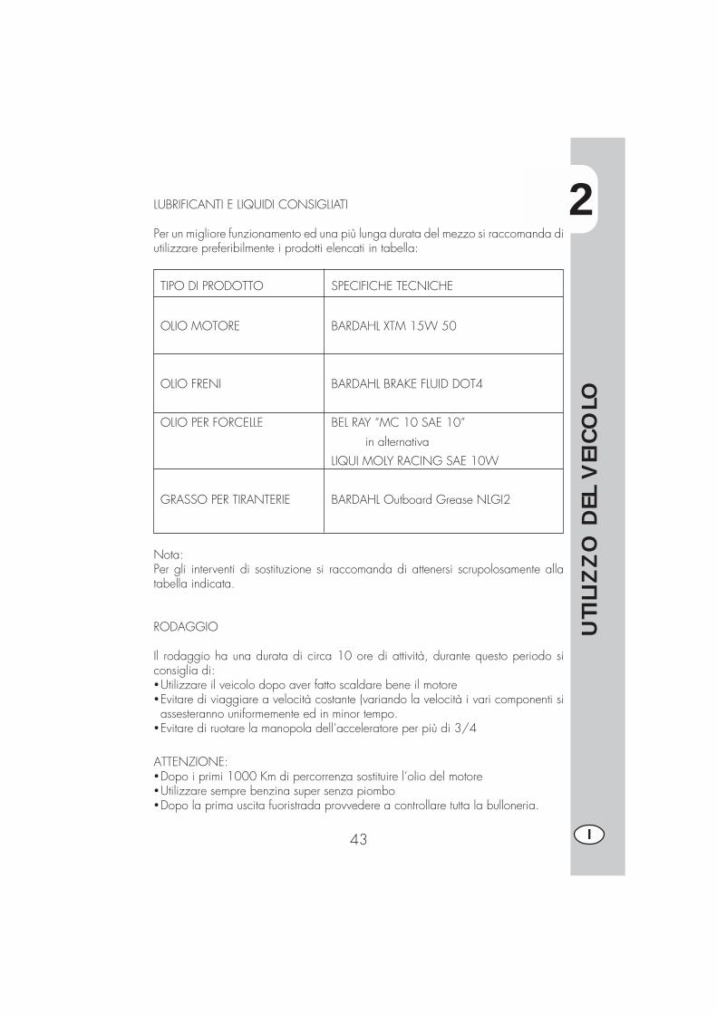
LUBRIFICANTI E LIQUIDI CONSIGLIATI
Per un migliore funzionamento ed una più lunga durata del mezzo si raccomanda diutilizzare preferibilmente i prodotti elencati in tabella:
TIPO DI PRODOTTO SPECIFICHE TECNICHE
OLIO MOTORE BARDAHL XTM 15W 50
OLIO FRENI BARDAHL BRAKE FLUID DOT4
OLIO PER FORCELLE BEL RAY “MC 10 SAE 10”
in alternativa
LIQUI MOLY RACING SAE 10W
GRASSO PER TIRANTERIE BARDAHL Outboard Grease NLGI2
Nota:Per gli interventi di sostituzione si raccomanda di attenersi scrupolosamente allatabella indicata.
RODAGGIO
Il rodaggio ha una durata di circa 10 ore di attività, durante questo periodo siconsiglia di:�Utilizzare il veicolo dopo aver fatto scaldare bene il motore�Evitare di viaggiare a velocità costante (variando la velocità i vari componenti siassesteranno uniformemente ed in minor tempo.
�Evitare di ruotare la manopola dell’acceleratore per più di 3/4
ATTENZIONE:�Dopo i primi 1000 Km di percorrenza sostituire l’olio del motore�Utilizzare sempre benzina super senza piombo�Dopo la prima uscita fuoristrada provvedere a controllare tutta la bulloneria.
2
UTI
LIZ
ZO
DEL
VEI
CO
LO
44I
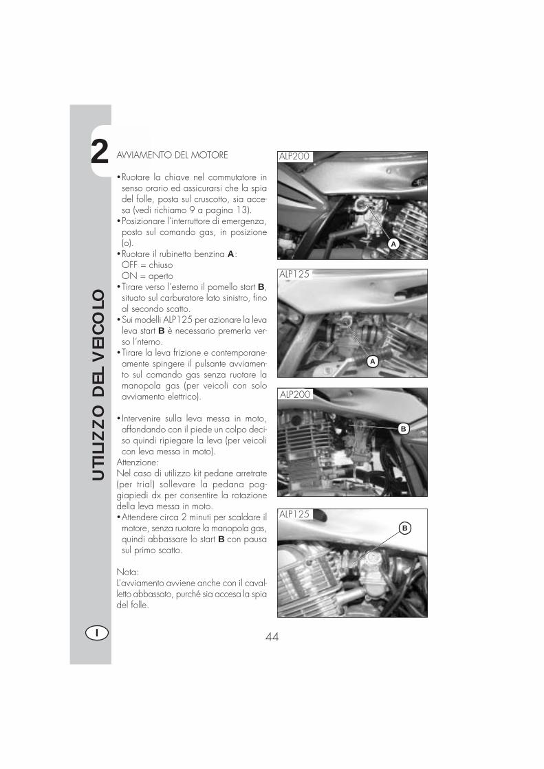
AVVIAMENTO DEL MOTORE
�Ruotare la chiave nel commutatore insenso orario ed assicurarsi che la spiadel folle, posta sul cruscotto, sia acce-sa (vedi richiamo 9 a pagina 13).
�Posizionare l’interruttore di emergenza,posto sul comando gas, in posizione(o).
�Ruotare il rubinetto benzina A:OFF = chiusoON = aperto
�Tirare verso l’esterno il pomello start B,situato sul carburatore lato sinistro, finoal secondo scatto.
�Sui modelli ALP125 per azionare la levaleva start B è necessario premerla ver-so l’nterno.
�Tirare la leva frizione e contemporane-amente spingere il pulsante avviamen-to sul comando gas senza ruotare lamanopola gas (per veicoli con soloavviamento elettrico).
� Intervenire sulla leva messa in moto,affondando con il piede un colpo deci-so quindi ripiegare la leva (per veicolicon leva messa in moto).
Attenzione:Nel caso di utilizzo kit pedane arretrate(per trial) sollevare la pedana pog-giapiedi dx per consentire la rotazionedella leva messa in moto.�Attendere circa 2 minuti per scaldare ilmotore, senza ruotare la manopola gas,quindi abbassare lo start B con pausasul primo scatto.
Nota:L’avviamento avviene anche con il caval-letto abbassato, purché sia accesa la spiadel folle.
A
B
ALP200
ALP125
ALP200
ALP125B
A
2
UTI
LIZ
ZO
DEL
VEI
CO
LO
45 I
Avvertenza:Con cavalletto abbassato, la spia rossasul cruscotto rimane accesa, e per ragio-ni di sicurezza la moto si spegne all’inse-rimento della marcia, anche con frizionetirata.Quindi è necessario chiudere il cavallet-to e poi procedere all’inserimento dellamarcia.
Nota:In caso di emergenza, questo veicolo puòfunzionare anche senza l’uso della bat-teria.
ARRESTO DEL MOTORE
�Da fermo e con il cambio in folle, ruotarela chiave nel commutatore in posizione“OFF”.
�Dopo un lungo percorso, prima di spe-gnere il motore, si consiglia di lasciarloruotare per alcuni istanti.
�A motore fermo, chiudere sempre il ru-binetto della benzina.
2
UTI
LIZ
ZO
DEL
VEI
CO
LO
46I
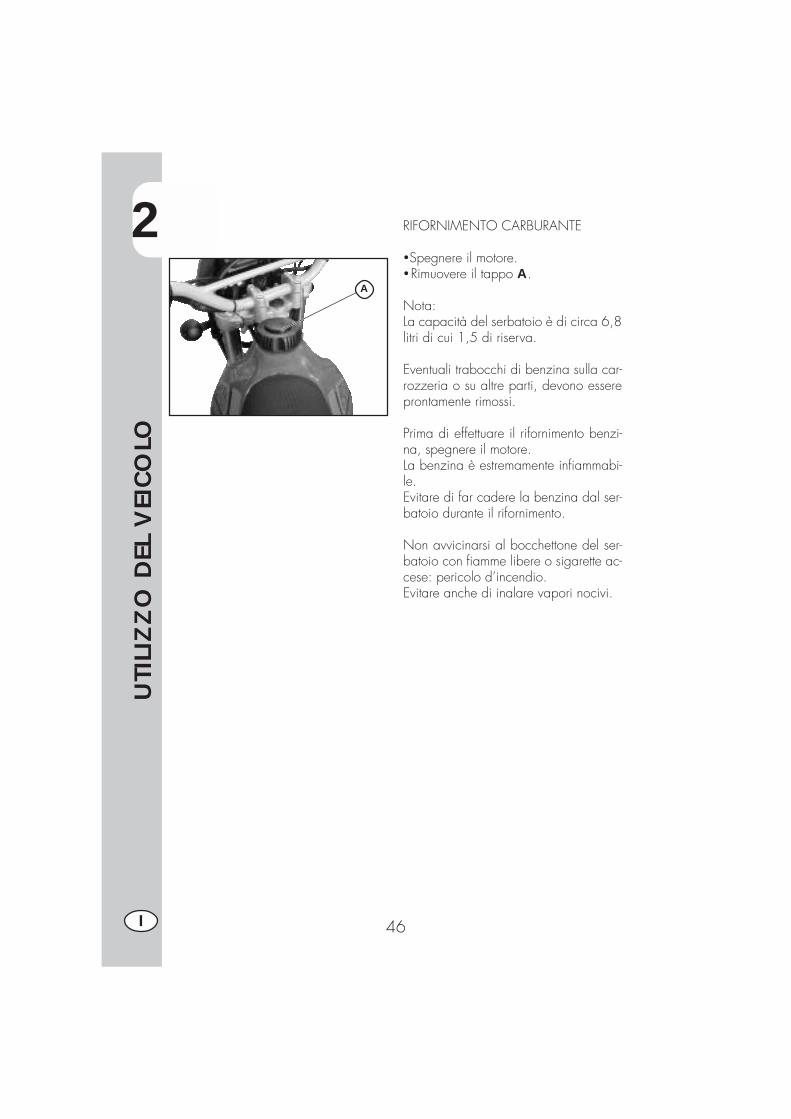
RIFORNIMENTO CARBURANTE
�Spegnere il motore.�Rimuovere il tappo A.
Nota:La capacità del serbatoio è di circa 6,8litri di cui 1,5 di riserva.
Eventuali trabocchi di benzina sulla car-rozzeria o su altre parti, devono essereprontamente rimossi.
Prima di effettuare il rifornimento benzi-na, spegnere il motore.La benzina è estremamente infiammabi-le.Evitare di far cadere la benzina dal ser-batoio durante il rifornimento.
Non avvicinarsi al bocchettone del ser-batoio con fiamme libere o sigarette ac-cese: pericolo d’incendio.Evitare anche di inalare vapori nocivi.
A
3
CO
NTR
OLL
I E
MA
NU
TEN
ZIO
NE
47 I
INDICE ARGOMENTI
CAP. 3 CONTROLLI E MANUTENZIONE
Olio motore e filtro olio
Tubo raccolta fumi
Olio pompa freni, spurgo freni
Olio forcelle
Filtro aria
Candela
Freni: anteriore, posteriore
Batteria
Rimozione carrozzeria
Note per trial
Pulizia del veicolo e controlli
Manutenzione programmata
Lunga inattività del veicolo
3
CO
NTR
OLL
I E
MA
NU
TEN
ZIO
NE
48I
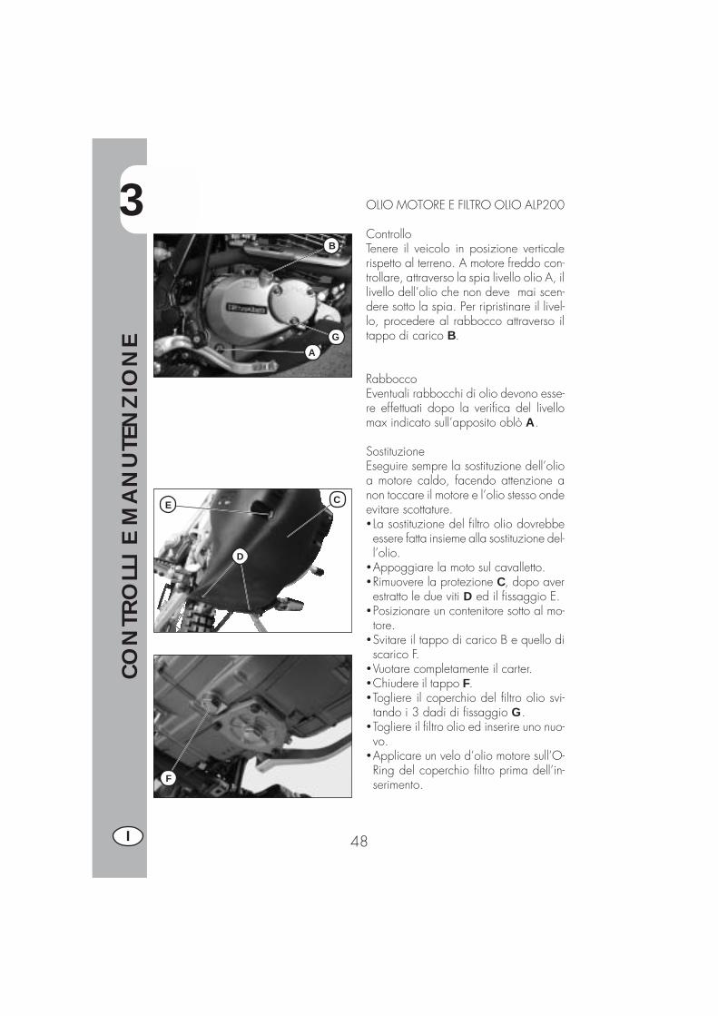
OLIO MOTORE E FILTRO OLIO ALP200
ControlloTenere il veicolo in posizione verticalerispetto al terreno. A motore freddo con-trollare, attraverso la spia livello olio A, illivello dell’olio che non deve mai scen-dere sotto la spia. Per ripristinare il livel-lo, procedere al rabbocco attraverso iltappo di carico B.
RabboccoEventuali rabbocchi di olio devono esse-re effettuati dopo la verifica del livellomax indicato sull’apposito oblò A.
SostituzioneEseguire sempre la sostituzione dell’olioa motore caldo, facendo attenzione anon toccare il motore e l’olio stesso ondeevitare scottature.� La sostituzione del filtro olio dovrebbeessere fatta insieme alla sostituzione del-l’olio.
�Appoggiare la moto sul cavalletto.�Rimuovere la protezione C, dopo averestratto le due viti D ed il fissaggio E.
�Posizionare un contenitore sotto al mo-tore.
�Svitare il tappo di carico B e quello discarico F.
�Vuotare completamente il carter.�Chiudere il tappo F.�Togliere il coperchio del filtro olio svi-tando i 3 dadi di fissaggio G.
�Togliere il filtro olio ed inserire uno nuo-vo.
�Applicare un velo d’olio motore sull’O-Ring del coperchio filtro prima dell’in-serimento.
B
GA
C
D
E
F

3
CO
NTR
OLL
I E
MA
NU
TEN
ZIO
NE
49 I
� Inserire il coperchio filtro olio, dopo avermontato molla ed O-Ring e serrare i tredadi di fissaggio.
� Introdurre la giusta quantità di olio (ta-bella pag. 35).
�Richiudere il tappo di carico, montarenuovamente la protezione avendo curadi posizionare i distanziali nella giustasequenza.
�Avviare il motore lasciandolo girare perqualche minuto prima di spegnerlo
�Spegnere il motore ed attendere circaun minuto, quindi controllare il livello edeventualmente rabboccare, senza mai su-perare il livello max.quantità olio motore:cambio olio ......................... 850 mlcon cambio filtro ................... 950 mlrevisione ............................ 1300 ml
Nota:superati i primi 1000 km di percorrenzasostituire l’olio motore. Le successive sosti-tuzioni devono essere effettuate ogni 5000km o 15 mesi (vedere tabella pag. 62),utilizzando i lubrificanti consigliati a pag. 43.Per il filtro olio, invece, la prima sostituzio-ne deve essere effettuata insieme all’oliomotore; le successive ogni 10.000 km (30mesi).
Avvertenza:Smaltire l’olio usato nel rispetto delle norma-tive vigenti.

3
CO
NTR
OLL
I E
MA
NU
TEN
ZIO
NE
50I
OLIO MOTORE E FILTRO OLIO ALP125
ControlloTenere il veicolo in posizione verticalerispetto al terreno. A motore freddo con-trollare la presenza dell’olio.
RabboccoPer ripristinare il livello procedere alrabbocco attraverso il tappo A
SostituzioneEseguire sempre la sostituzione dell’olioa motore caldo, facendo attenzione anon toccare il motore e l’olio stesso ondeevitare scottature.�Appoggiare la moto sul cavalletto.�Rimuovere la protezione C, dopo averestratto le due viti D ed il fissaggio E.
� Posizionare un contenitore sotto al mo-tore.
�Svitare il tappo di carico A e quello discarico B
�Vuotare completamente il carter.�Chiudere il tappo B� Introdurre 1000 c.c. di olio.�Richiudere il tappo di carico A.
ATTENZIONE:L’olio caldo può causare gravi ustioni
Nota:Dopo i primi 500 Km di percorrenzasostituire l’olio motore. Per le sostituzio-ni attenersi alla tabella a pagina 62,utilizzando lubrificanti consigliati a pa-gina 43.
Avvertenza:Smaltire l’olio usato nel rispetto dellenormative vigenti.5
A
C
D
E
B

3
CO
NTR
OLL
I E
MA
NU
TEN
ZIO
NE
51 I
TUBO RACCOLTA FUMI
Il tubo raccolta fumi A è situato sulla par-te sinistra del veicolo vicino all’ammor-tizzatore, esce dalla parte inferiore dellascatola filtro e raccoglie i gas prodottidall’olio motore. Nel caso si riscontrassela presenza di olio all’interno del tubo,questo deve essere svuotato, togliendo iltappo all’estremità inferiore e facendodefluire l’olio o la miscela di olio e ben-zina in un apposito recipiente ed effet-tuare lo smaltimento secondo le normevigenti.Nota:Effettuare lo svuotamento ogni 3000 Km.
OLIO POMPA FRENI, SPURGO FRENI
Freno anterioreControllare attraverso la spia livello A, lapresenza dell’olio. Il livello minimo del-l’olio non deve mai essere inferiore al ri-ferimento ricavato nella spia A. Per ripri-stinare il livello procedere al rabboccosvitando le due viti B, sollevando il tap-po C e inserendo l’olio.
Freno posterioreControllare attraverso il contenitore olioD, la presenza dell’olio. Il livello dell’olionon deve mai essere inferiore alla taccadi livello minimo incisa sul contenitore D.Per ripristinare il livello procedere alrabbocco attraverso il tappo di carico E.
ATTENZIONE:Nel caso in cui si rilevi una scarsa resi-stenza azionando la leva del freno, l’ano-malia potrebbe essere causata da unabolla d’aria nell’impianto frenante. È ne-cessario rivolgersi al più presto ad un’of-ficina autorizzata.
Nota:Per le sostituzioni attenersi alla tabella apag. 62, utilizzando i lubrificanti consi-gliati a pag. 43.
A
C
BA
DE

3
CO
NTR
OLL
I E
MA
NU
TEN
ZIO
NE
52I
Spurgo freno anteriorePer lo spurgo aria dal circuito del frenoanteriore procedere come segue:�Togliere il cappuccio di gomma A dal-la valvola B
�Aprire il tappo della vaschetta olio� Inserire un’estremità di un tubicino nellavalvola B, e l’altra all’interno di un con-tenitore
�Svitare la valvola B (con leva tirata) epompare con la leva del freno fino adottenere una fuoriuscita d’olio continuasenza vuoti d’aria; durante questa ope-razione è importante non rilasciare com-pletamente la leva, rabboccare conti-nuamente la vaschetta della pompa fre-no per compensare l’olio fuoriuscito.
�Stringere la valvola, estrarre il tubicino.�Rimettere il cappuccio.
Spurgo freno posteriorePer lo spurgo aria dal circuito del frenoposteriore procedere come segue:�Togliere il cappuccio di gomma C�Aprire il tappo della vaschetta olio� Inserire un’estremità di un tubicino nellavalvola D, e l’altra all’interno di un con-tenitore
�Svitare la valvola D (con leva tirata) epompare con la leva del freno fino adottenere una fuoriuscita d’olio continuasenza vuoti d’aria; durante questa ope-razione è importante non rilasciare com-pletamente la leva, rabboccare conti-nuamente la vaschetta della pompa fre-no per compensare l’olio fuoriuscito.
�Stringere la valvola, estrarre il tubicino.�Rimettere il cappuccio.
DC
A
B

3
CO
NTR
OLL
I E
MA
NU
TEN
ZIO
NE
53 I
OLIO FORCELLE
SteliLa descrizione relativa alla sostituzionedell’olio delle forcelle riveste un caratterepuramente informativo. Infatti è consi-gliabile rivolgersi ad un’officina autoriz-zata BETAMOTOR per effettuare questaoperazione.Per la sostituzione procedere nel modoseguente:1) Allentare la vite A di serraggio del-
lo stelo.2) Togliere il tappo inferiore (vite
brugola nel gambaletto) ed il tapposuperiore B.
3) Attendere il completo svuotamentodell’olio dallo stelo.
4) Riavvitare il tappo inferiore del gam-baletto.
5) Immettere olio indicato nella tabellaa pag. 43.
6) Riavvitare il tappo superiore B.7) Restringere la vite A.
Nota: la procedura di sostituizione olioè valida sia per lo stelo destro che sini-stro.
A
B

3
CO
NTR
OLL
I E
MA
NU
TEN
ZIO
NE
54I
FILTRO ARIA
Per accedere al filtro è necessario:�Rimuovere la sella, girare di 90° in sen-so antiorario il fissaggio D, sfilare lasella tirandola all’indietro
�Smontare la fiancata B, svitando le vitiin figura
�Smontare la copertura di plastica A svi-tando le 7 relative viti di fissaggio, quin-di procedere nel modo seguente:� togliere il filtro C svitando la vite difissaggio del coperchio ferma filtro
� lavarlo con acqua e sapone�asciugarlo�bagnarlo con olio per filtri, eliminan-done poi l’eccedenza in modo chenon goccioli
�se necessario pulire anche l’internodella scatola filtro
�procedere al rimontaggio prestandoattenzione all’esatta chiusura ermeti-ca della guarnizione in gomma
Nota: nel caso in cui il filtro fosse moltosporco lavarlo prima con detergente spe-cifico poi con acqua e shampoo.Nel caso che il filtro risulti danneggiatoprocedere immediatamente alla sua so-stituzione.
ATTENZIONE:Dopo ogni intervento controllare che al-l’interno della scatola del filtro non ci siarimasto nessun oggetto.
Eseguire la pulizia del filtro ogni voltache i l mezzo viene uti l izzato infuoristrada.
C
B
A
D
3
CO
NTR
OLL
I E
MA
NU
TEN
ZIO
NE
55 I
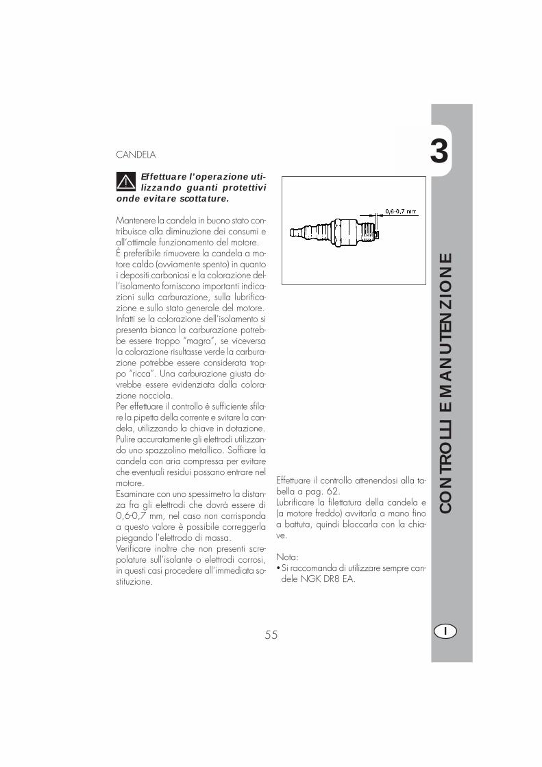
CANDELA
Effettuare l’operazione uti-lizzando guanti protettivi
onde evitare scottature.
Mantenere la candela in buono stato con-tribuisce alla diminuzione dei consumi eall’ottimale funzionamento del motore.È preferibile rimuovere la candela a mo-tore caldo (ovviamente spento) in quantoi depositi carboniosi e la colorazione del-l’isolamento forniscono importanti indica-zioni sulla carburazione, sulla lubrifica-zione e sullo stato generale del motore.Infatti se la colorazione dell’isolamento sipresenta bianca la carburazione potreb-be essere troppo “magra”, se viceversala colorazione risultasse verde la carbura-zione potrebbe essere considerata trop-po “ricca”. Una carburazione giusta do-vrebbe essere evidenziata dalla colora-zione nocciola.Per effettuare il controllo è sufficiente sfila-re la pipetta della corrente e svitare la can-dela, utilizzando la chiave in dotazione.Pulire accuratamente gli elettrodi utilizzan-do uno spazzolino metallico. Soffiare lacandela con aria compressa per evitareche eventuali residui possano entrare nelmotore.Esaminare con uno spessimetro la distan-za fra gli elettrodi che dovrà essere di0,6-0,7 mm, nel caso non corrispondaa questo valore è possibile correggerlapiegando l’elettrodo di massa.Verificare inoltre che non presenti scre-polature sull’isolante o elettrodi corrosi,in questi casi procedere all’immediata so-stituzione.
Effettuare il controllo attenendosi alla ta-bella a pag. 62.Lubrificare la filettatura della candela e(a motore freddo) avvitarla a mano finoa battuta, quindi bloccarla con la chia-ve.
Nota:�Si raccomanda di utilizzare sempre can-dele NGK DR8 EA.

3
CO
NTR
OLL
I E
MA
NU
TEN
ZIO
NE
56I
FRENO ANTERIORE
ControlloPer verificare lo stato di usura del frenoanteriore è sufficiente visionare la pinzadalla parte anteriore, dove è possibileintravedere le estremità delle due pasti-glie che dovranno presentare almeno unostrato di 2 mm di ferodo. Nel caso lostrato fosse inferiore procedere immedia-tamente alla loro sostituzione.
Nota:Effettuare il controllo attenendosi ai tem-pi indicati in tabella a pag. 62.
FRENO POSTERIORE
ControlloPer verificare lo stato di usura del frenoposteriore è sufficiente visionare la pin-za dalla parte superiore, dove è possibi-le intravedere le estremità delle due pa-stiglie che dovranno presentare almenouno strato di 2 mm di ferodo. Nel casolo strato fosse inferiore procedere imme-diatamente alla loro sostituzione.
Nota:Effettuare il controllo attenendosi ai tem-pi indicati in tabella a pag. 62.

3
CO
NTR
OLL
I E
MA
NU
TEN
ZIO
NE
57 I
BATTERIA
Verificare lo stato di carica della batte-ria, misurando la tensione con batteria ariposo “Veicolo spento” con un voltmetro.Il voltaggio non deve essere inferiore a12,8V.Non è necessario controllare il livellodell’elettrolita o rabboccare con acqua.Tenere puliti i poli della batteria e se ne-cessario, ingrassarli leggermente congrassi privi di acidi.
3
CO
NTR
OLL
I E
MA
NU
TEN
ZIO
NE
58I
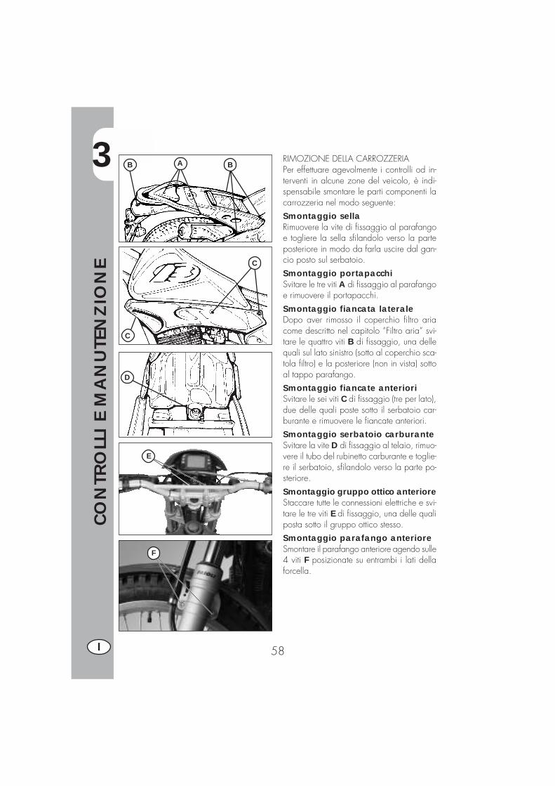
RIMOZIONE DELLA CARROZZERIAPer effettuare agevolmente i controlli od in-terventi in alcune zone del veicolo, è indi-spensabile smontare le parti componenti lacarrozzeria nel modo seguente:Smontaggio sellaRimuovere la vite di fissaggio al parafangoe togliere la sella sfilandolo verso la parteposteriore in modo da farla uscire dal gan-cio posto sul serbatoio.Smontaggio portapacchiSvitare le tre viti A di fissaggio al parafangoe rimuovere il portapacchi.Smontaggio fiancata lateraleDopo aver rimosso il coperchio filtro ariacome descritto nel capitolo “Filtro aria” svi-tare le quattro viti B di fissaggio, una dellequali sul lato sinistro (sotto al coperchio sca-tola filtro) e la posteriore (non in vista) sottoal tappo parafango.Smontaggio fiancate anterioriSvitare le sei viti C di fissaggio (tre per lato),due delle quali poste sotto il serbatoio car-burante e rimuovere le fiancate anteriori.Smontaggio serbatoio carburanteSvitare la vite D di fissaggio al telaio, rimuo-vere il tubo del rubinetto carburante e toglie-re il serbatoio, sfilandolo verso la parte po-steriore.Smontaggio gruppo ottico anterioreStaccare tutte le connessioni elettriche e svi-tare le tre viti E di fissaggio, una delle qualiposta sotto il gruppo ottico stesso.Smontaggio parafango anterioreSmontare il parafango anteriore agendo sulle4 viti F posizionate su entrambi i lati dellaforcella.
B BA
C
C
D
F
E
3
CO
NTR
OLL
I E
MA
NU
TEN
ZIO
NE
59 I
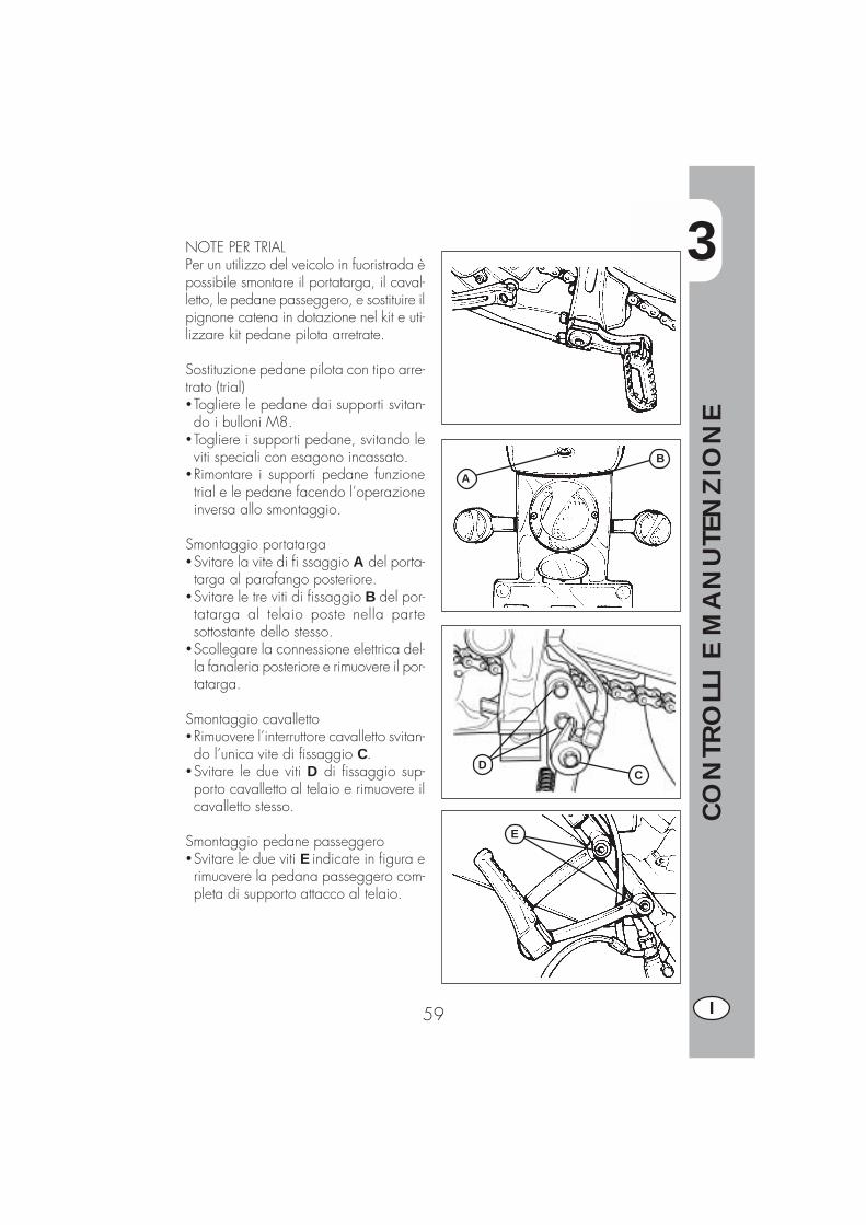
NOTE PER TRIALPer un utilizzo del veicolo in fuoristrada èpossibile smontare il portatarga, il caval-letto, le pedane passeggero, e sostituire ilpignone catena in dotazione nel kit e uti-lizzare kit pedane pilota arretrate.
Sostituzione pedane pilota con tipo arre-trato (trial)�Togliere le pedane dai supporti svitan-do i bulloni M8.
�Togliere i supporti pedane, svitando leviti speciali con esagono incassato.
�Rimontare i supporti pedane funzionetrial e le pedane facendo l’operazioneinversa allo smontaggio.
Smontaggio portatarga�Svitare la vite di fi ssaggio A del porta-targa al parafango posteriore.
�Svitare le tre viti di fissaggio B del por-tatarga al telaio poste nella partesottostante dello stesso.
�Scollegare la connessione elettrica del-la fanaleria posteriore e rimuovere il por-tatarga.
Smontaggio cavalletto�Rimuovere l’interruttore cavalletto svitan-do l’unica vite di fissaggio C.
�Svitare le due viti D di fissaggio sup-porto cavalletto al telaio e rimuovere ilcavalletto stesso.
Smontaggio pedane passeggero�Svitare le due viti E indicate in figura erimuovere la pedana passeggero com-pleta di supporto attacco al telaio.
A
B
CD
E
3
CO
NTR
OLL
I E
MA
NU
TEN
ZIO
NE
60I
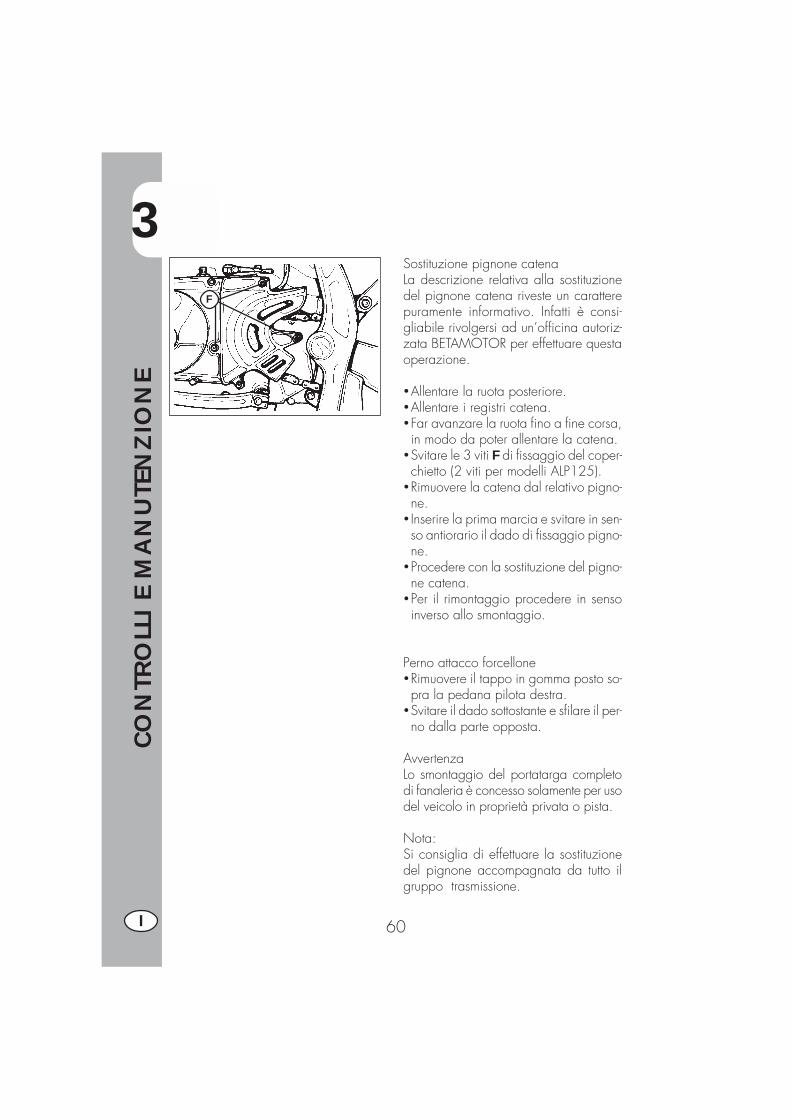
Sostituzione pignone catenaLa descrizione relativa alla sostituzionedel pignone catena riveste un caratterepuramente informativo. Infatti è consi-gliabile rivolgersi ad un’officina autoriz-zata BETAMOTOR per effettuare questaoperazione.
�Allentare la ruota posteriore.�Allentare i registri catena.�Far avanzare la ruota fino a fine corsa,in modo da poter allentare la catena.
�Svitare le 3 viti F di fissaggio del coper-chietto (2 viti per modelli ALP125).
�Rimuovere la catena dal relativo pigno-ne.
� Inserire la prima marcia e svitare in sen-so antiorario il dado di fissaggio pigno-ne.
�Procedere con la sostituzione del pigno-ne catena.
�Per il rimontaggio procedere in sensoinverso allo smontaggio.
Perno attacco forcellone�Rimuovere il tappo in gomma posto so-pra la pedana pilota destra.
�Svitare il dado sottostante e sfilare il per-no dalla parte opposta.
AvvertenzaLo smontaggio del portatarga completodi fanaleria è concesso solamente per usodel veicolo in proprietà privata o pista.
Nota:Si consiglia di effettuare la sostituzionedel pignone accompagnata da tutto ilgruppo trasmissione.
F
3
CO
NTR
OLL
I E
MA
NU
TEN
ZIO
NE
61 I
PULIZIA DEL VEICOLO E CONTROLLI
Per ammorbidire lo sporco e il fango depositato sulle superfici verniciate usare ungetto di acqua a bassa pressione. Una volta ammorbiditi, fango e sporcizia devonoessere tolti con una spugna soffice per carrozzeria imbevuta di molta acqua e“shampoo” (2-4% di shampoo in acqua). Successivamente sciacquare abbondante-mente con acqua, ed asciugare con pelle scamosciata. Per l’esterno del motoreservirsi di petrolio, pennello e stracci puliti. Il petrolio è dannoso per la vernice. Siricorda che l’eventuale lucidatura con cere siliconiche deve essere sempre precedu-ta dal lavaggio.
I detersivi inquinano le acque. Pertanto il lavaggio del veicolo va effettuato inzone attrezzate per la raccolta e la depurazione dei liquidi impiegati per il
lavaggio stesso.
Il lavaggio non deve mai essere eseguito al sole specialmente d’estate quan-do la carrozzeria è ancora calda in quanto lo shampoo, asciugandosi prima
del risciacquo, può causare danni alla vernice. Non usare mai stracci imbevuti dibenzina o nafta per il lavaggio delle superfici verniciate o in materia plastica, perevitare la perdita della loro brillantezza e delle caratteristiche meccaniche dei mate-riali.
CONTROLLI DOPO LA PULIZIA
Dopo la pulizia del motociclo è buona norma:
�Pulire il filtro dell’aria (procedere come descritto a pag. 54)� Ingrassare la catena.
3
CO
NTR
OLL
I E
MA
NU
TEN
ZIO
NE
62I
MANUTENZIONE PROGRAMMATA
c s c s c s cp p p s p s pc c c s c c cc c c c c c cs s s s s s sc c c c c c cc c c c c c c
c c cc c c s c c ct t t t t t tc c c c c c c
s s sc c c
c c c c c c cc c c c c c cc c c c c c c
c c c c c c c
c c c c c c cc c c c c c c
MOTOCICLO 4t Alp 125/200
fine
roda
ggio
1.0
00 k
m
1°
tagl
iand
o 5.0
00 k
m
2°
tagl
iand
o 10.0
00 k
m
3°
tagl
iand
o 15.0
00 k
m
4°
tagl
iand
o 20.0
00 k
m
5°
tagl
iand
o 25.0
00 k
m
6°
tagl
iand
o 30.0
00 k
m
7°
tagl
iand
o 35.0
00 k
m
motore
candelafiltro olio motore p frizione cgioco valvole colio motore e filtro olio s regolazione minimotubazioni dell'olio motore c
ciclistica
ammortizzatore posteriore cbatteriabulloneria * tcuscinetti di sterzo e gioco sterzo cfiltro ariaforcella anteriore cimpianto elettrico cimpianto frenante cliquido freno (sostituire o gni 2 anni) cpulizia catena trasmissionestato e pressione pneumatici c
tensione e lubrificazione catena trasmissione (ogni 1000 km) c c c c c c c ctubazioni freno (sostituire o gni 2 anni) ctubi carburante (sostituire o gni 2 anni) c
* si raccomanda il serraggio dopo ogni utilizzo in fuoristrada
legenda:c - controllo (pulizia, regolazione, lubrificazione, sostituzione se necessari)s - sostituzioner- re golazionep - puliziat - serra ggio
pulire o gni 1000 km
ogni 1000 km
c
AVVERTENZA:
In caso di interventi da eseguire sulla moto rivolgersi alla catena di Assistenza Autorizzata BETAMOTOR.
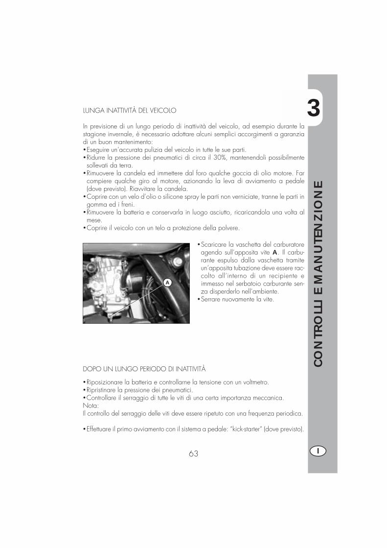
3
CO
NTR
OLL
I E
MA
NU
TEN
ZIO
NE
63 I
LUNGA INATTIVITÀ DEL VEICOLO
In previsione di un lungo periodo di inattività del veicolo, ad esempio durante lastagione invernale, è necessario adottare alcuni semplici accorgimenti a garanziadi un buon mantenimento:�Eseguire un’accurata pulizia del veicolo in tutte le sue parti.�Ridurre la pressione dei pneumatici di circa il 30%, mantenendoli possibilmentesollevati da terra.
�Rimuovere la candela ed immettere dal foro qualche goccia di olio motore. Farcompiere qualche giro al motore, azionando la leva di avviamento a pedale(dove previsto). Riavvitare la candela.
�Coprire con un velo d’olio o silicone spray le parti non verniciate, tranne le parti ingomma ed i freni.
�Rimuovere la batteria e conservarla in luogo asciutto, ricaricandola una volta almese.
�Coprire il veicolo con un telo a protezione della polvere.
�Scaricare la vaschetta del carburatoreagendo sull’apposita vite A. Il carbu-rante espulso dalla vaschetta tramiteun’apposita tubazione deve essere rac-colto all’interno di un recipiente eimmesso nel serbatoio carburante sen-za disperderlo nell’ambiente.
�Serrare nuovamente la vite.
A
DOPO UN LUNGO PERIODO DI INATTIVITÀ
�Riposizionare la batteria e controllarne la tensione con un voltmetro.�Ripristinare la pressione dei pneumatici.�Controllare il serraggio di tutte le viti di una certa importanza meccanica.Nota:Il controllo del serraggio delle viti deve essere ripetuto con una frequenza periodica.
�Effettuare il primo avviamento con il sistema a pedale: “kick-starter” (dove previsto).


4
REG
OLA
ZIO
NI
65 I
INDICE ARGOMENTI
CAP. 4 REGOLAZIONI
Regolazione freni
Regolazione frizione
Regolazione minimo
Regolazione gioco gas
Controllo e regolazione gioco sterzo
Tensionamento catena
Fascio luminoso
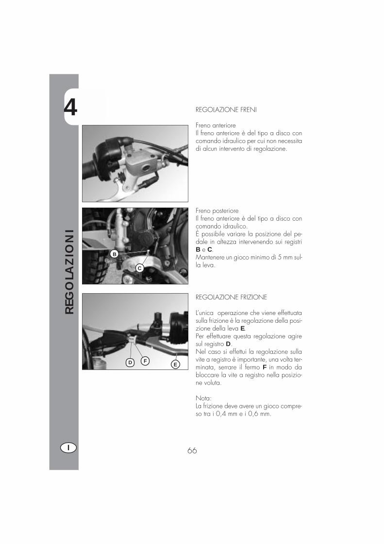
4
REG
OLA
ZIO
NI
66I
REGOLAZIONE FRENI
Freno anterioreIl freno anteriore è del tipo a disco concomando idraulico per cui non necessitadi alcun intervento di regolazione.
Freno posterioreIl freno anteriore è del tipo a disco concomando idraulico.È possibile variare la posizione del pe-dale in altezza intervenendo sui registriB e C.Mantenere un gioco minimo di 5 mm sul-la leva.
REGOLAZIONE FRIZIONE
L’unica operazione che viene effettuatasulla frizione è la regolazione della posi-zione della leva E.Per effettuare questa regolazione agiresul registro D.Nel caso si effettui la regolazione sullavite a registro è importante, una volta ter-minata, serrare il fermo F in modo dabloccare la vite a registro nella posizio-ne voluta.
Nota:La frizione deve avere un gioco compre-so tra i 0,4 mm e i 0,6 mm.
C
B
FD E
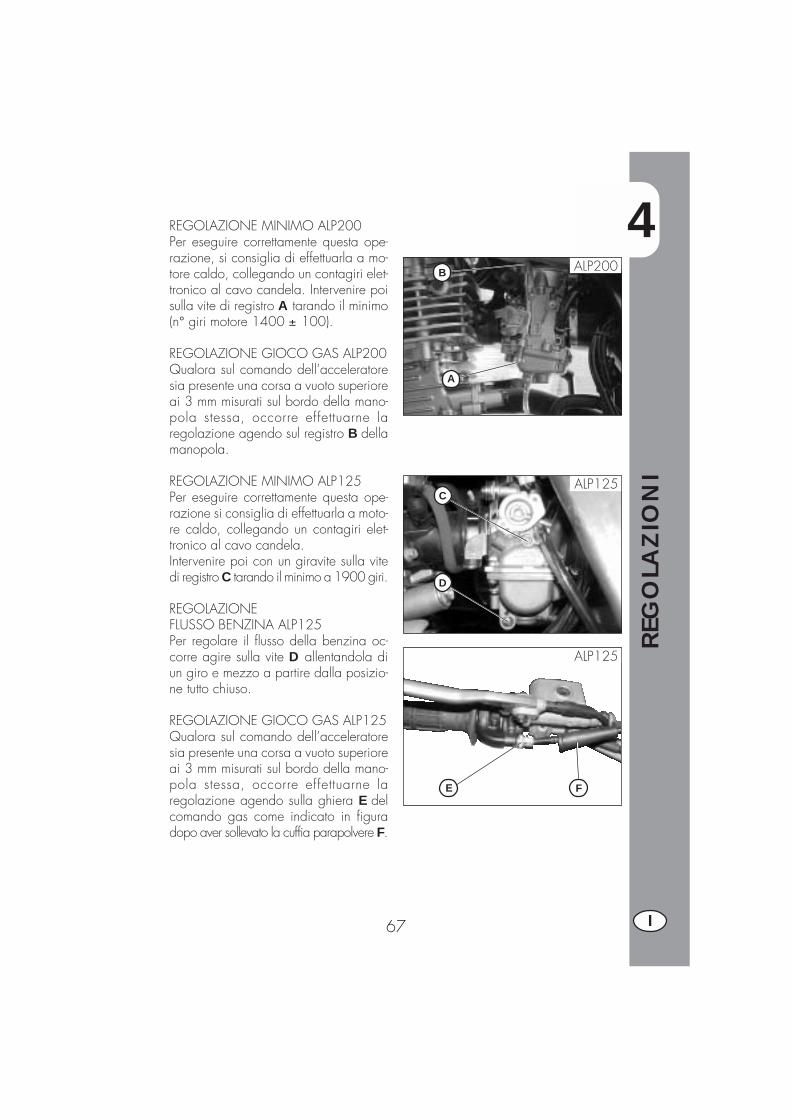
4
REG
OLA
ZIO
NI
67 I
REGOLAZIONE MINIMO ALP200Per eseguire correttamente questa ope-razione, si consiglia di effettuarla a mo-tore caldo, collegando un contagiri elet-tronico al cavo candela. Intervenire poisulla vite di registro A tarando il minimo(n° giri motore 1400 ± 100).
REGOLAZIONE GIOCO GAS ALP200Qualora sul comando dell’acceleratoresia presente una corsa a vuoto superioreai 3 mm misurati sul bordo della mano-pola stessa, occorre effettuarne laregolazione agendo sul registro B dellamanopola.
REGOLAZIONE MINIMO ALP125Per eseguire correttamente questa ope-razione si consiglia di effettuarla a moto-re caldo, collegando un contagiri elet-tronico al cavo candela.Intervenire poi con un giravite sulla vitedi registro C tarando il minimo a 1900 giri.
REGOLAZIONEFLUSSO BENZINA ALP125Per regolare il flusso della benzina oc-corre agire sulla vite D allentandola diun giro e mezzo a partire dalla posizio-ne tutto chiuso.
REGOLAZIONE GIOCO GAS ALP125Qualora sul comando dell’acceleratoresia presente una corsa a vuoto superioreai 3 mm misurati sul bordo della mano-pola stessa, occorre effettuarne laregolazione agendo sulla ghiera E delcomando gas come indicato in figuradopo aver sollevato la cuffia parapolvere F.
A
B ALP200
ALP125
ALP125
D
C
FE

4
REG
OLA
ZIO
NI
68I
CONTROLLO E REGOLAZIONE GIO-CO STERZO
Verificare periodicamente il gioco delcannotto di sterzo muovendo avanti e in-dietro le forcelle come illustrato in figura.Qualora si avverta del gioco, procederealla regolazione operando nel modo se-guente:�Svitare le 4 viti C�Estrarre il manubrio D, porgendo parti-colare attenzione ai cavallotti E
�Allentare il dado F�Recuperare il gioco intervenendo sullaghiera G
Per il ribloccaggio procedere nel modoinverso.
Nota:Una corretta regolazione, oltre a non la-sciare del gioco, non deve causareindurimenti o irregolarità durante la rota-zione del manubrio; verificare il senso dimontaggio dei cavallotti che può varia-re l’assetto del manubrio.
D
F
G E
C

4
REG
OLA
ZIO
NI
69 I
TENSIONAMENTO CATENA
Per una più lunga durata della catena ditrasmissione è opportuno controllare pe-riodicamente la sua tensione.Tenerla sempre pulita dalla sporcizia de-positata e lubrificarla.Se il gioco della catena supera i 20 mmprocedere al suo tensionamento.
�Allentare i dadi su entrambi i bracci del-la forcella
�Agire sul dado B fino al raggiungimentodella tensione desiderata della catena
�Procedere analogamente agendo suldado B situato sull’altro braccio dellaforcella fino ad ottenere il perfetto alli-neamento della ruota
�Serrare il dado A su entrambi i braccidel forcellone.
20 mm
B
A
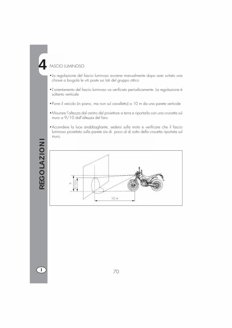
4
REG
OLA
ZIO
NI
70I
FASCIO LUMINOSO
� La regolazione del fascio luminoso avviene manualmente dopo aver svitato unachiave a brugola le viti poste sui lati del gruppo ottico
� L’orientamento del fascio luminoso va verificato periodicamente. La regolazione èsoltanto verticale
�Porre il veicolo (in piano, ma non sul cavalletto) a 10 m da una parete verticale
�Misurare l’altezza dal centro del proiettore a terra e riportarla con una crocetta sulmuro a 9/10 dall’altezza del faro
�Accendere la luce anabbagliante, sedersi sulla moto e verificare che il fascioluminoso proiettato sulla parete sia di poco al di sotto della crocetta riportata sulmuro.
9/10
h
10 m
h
5
SOST
ITU
ZIO
NI
71 I
INDICE ARGOMENTI
CAP. 5 SOSTITUZIONI
Sostituzione pastiglie freni
Sostituzione lampade faro anteriore
Sostituzione lampade faro posteriore
Sostituzione lampade indicatori di direzione
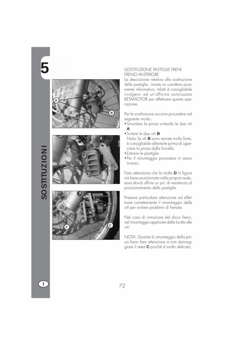
5
SOST
ITU
ZIO
NI
72I
SOSTITUZIONE PASTIGLIE FRENIFRENO ANTERIORELa descrizione relativa alla sostituzionedelle pastiglie, riveste un carattere pura-mente informativo; infatti è consigliabilerivolgersi ad un’officina autorizzataBETAMOTOR per effettuare questa ope-razione.
Per la sostituzione occorre procedere nelseguente modo:�Smontare la pinza svitando le due vitiA
�Svitare le due viti BNota: le viti B sono serrate molto forte,è consigliabile allentarle prima di sgan-ciare la pinza dalla forcella
�Estrarre le pastiglie�Per il rimontaggio procedere in sensoinverso.
Fare attenzione che la molla D in figurasia bene posizionata nella propria sede,essa dovrà offrire un po’ di resistenza alposizionamento delle pastiglie.
Prestare particolare attenzione ad effet-tuare correttamente il rimontaggio delleviti per evitare problemi di frenata.
Nel caso di rimozione del disco freno,nel rimontaggio applicare della loctite alleviti.
NOTA: Durante lo smontaggio della pin-za freno fare attenzione a non danneg-giare il reed C poiché è molto delicato.
A
B
CC
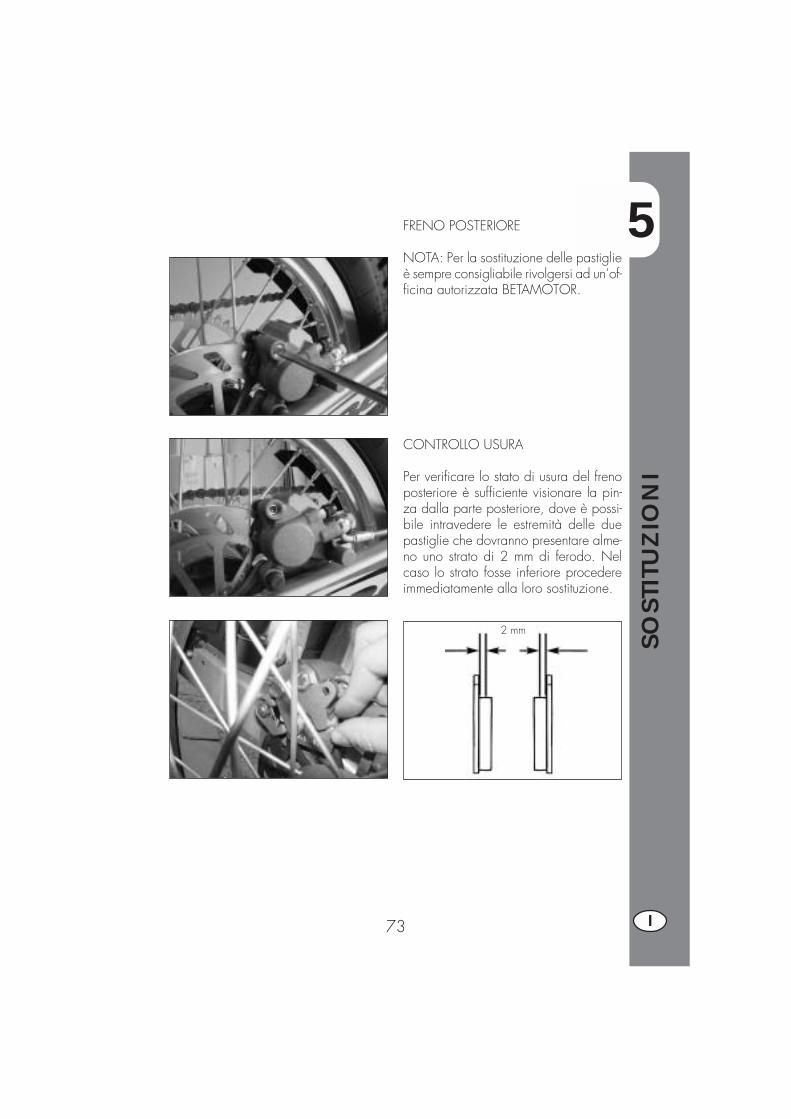
5
SOST
ITU
ZIO
NI
73 I
FRENO POSTERIORE
NOTA: Per la sostituzione delle pastiglieè sempre consigliabile rivolgersi ad un’of-ficina autorizzata BETAMOTOR.
2 mm
CONTROLLO USURA
Per verificare lo stato di usura del frenoposteriore è sufficiente visionare la pin-za dalla parte posteriore, dove è possi-bile intravedere le estremità delle duepastiglie che dovranno presentare alme-no uno strato di 2 mm di ferodo. Nelcaso lo strato fosse inferiore procedereimmediatamente alla loro sostituzione.

5
SOST
ITU
ZIO
NI
74I
SOSTITUZIONE LAMPADA DEL FAROANTERIORERimuovere le tre viti di fissaggio e la cor-nice del faro.
Rimuovere le tre viti che fissano la para-bola ed estrarla.
Sfilare il connettore della lampada.Ruotare il blocco della lampada in sen-so antiorario ed estrarre la lampada bru-ciata.
Inserire una lampada nuova avendo curadi non toccarne il bulbo per evitare dicomprometterne l’efficienza e ruotare ilblocco in senso orario fino a battuta.
Rimontare il connettore, la parabola e lacornice del faro procedendo nell’ordineinverso a quello utilizzato per lo smon-taggio.
SOSTITUZIONE LAMPADA DEL FAROPOSTERIORE
Rimuovere le due viti di fissaggio ed iltrasparente.Sostituire la lampada difettosa.Le lampadine hanno un fissaggio a baio-netta, quindi per rimuoverle basta pre-merle leggermente, ruotare in sensoantiorario per 30° e successivamenteestrarle.

5
SOST
ITU
ZIO
NI
75 I
SOSTITUZIONE LAMPADE INDICATORI DIDIREZIONE
Svitare la vite A e rimuovere il trasparen-te.
A

6
CO
SA F
ARE
IN C
ASO
DI EM
ERG
ENZ
A
77 I
INDICE ARGOMENTI
CAP. 6 COSA FARE IN CASO DI EMERGENZA
INDICE ALFABETICO
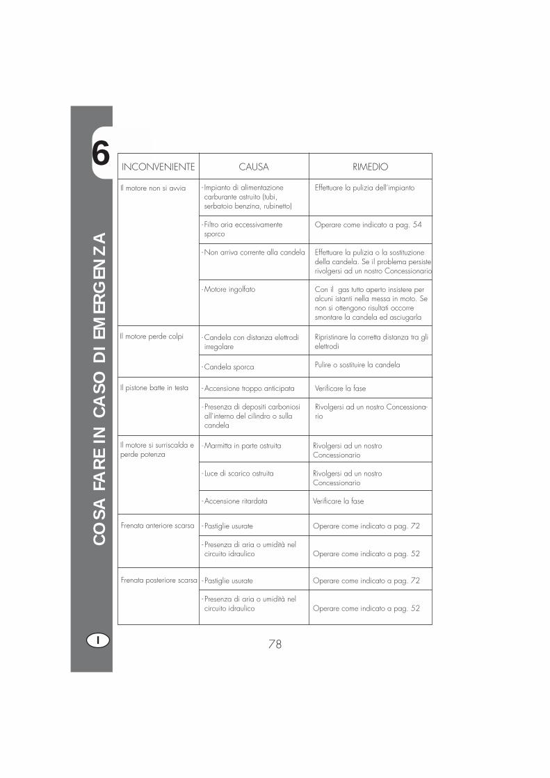
6
CO
SA F
ARE
IN C
ASO
DI EM
ERG
ENZ
A
78I
INCONVENIENTE CAUSA
Il motore non si avvia
RIMEDIO
- Impianto di alimentazionecarburante ostruito (tubi,serbatoio benzina, rubinetto)
- Filtro aria eccessivamentesporco
-Non arriva corrente alla candela
-Motore ingolfato
Effettuare la pulizia dell’impianto
Operare come indicato a pag. 54
Effettuare la pulizia o la sostituzionedella candela. Se il problema persisterivolgersi ad un nostro Concessionario
Con il gas tutto aperto insistere peralcuni istanti nella messa in moto. Senon si ottengono risultati occorresmontare la candela ed asciugarla
Il motore perde colpi - Candela con distanza elettrodiirregolare
- Candela sporca
Ripristinare la corretta distanza tra glielettrodi
Pulire o sostituire la candela
Il pistone batte in testa - Accensione troppo anticipata
- Presenza di depositi carboniosiall’interno del cilindro o sullacandela
Verificare la fase
Rivolgersi ad un nostro Concessiona-rio
Il motore si surriscalda eperde potenza
- Marmitta in parte ostruita
- Luce di scarico ostruita
- Accensione ritardata
Rivolgersi ad un nostroConcessionario
Rivolgersi ad un nostroConcessionario
Verificare la fase
Frenata anteriore scarsa - Pastiglie usurate
- Presenza di aria o umidità nelcircuito idraulico
Operare come indicato a pag. 72
Operare come indicato a pag. 52
Frenata posteriore scarsa - Pastiglie usurate
- Presenza di aria o umidità nelcircuito idraulico
Operare come indicato a pag. 72
Operare come indicato a pag. 52
6
CO
SA F
ARE
IN C
ASO
DI EM
ERG
ENZ
A
79 I
Avviamento ......................................................................................... 44
Candela............................................................................................. 55Chiavi e serrature ................................................................................. 12Commutatore / bloccasterzo ................................................................. 12Controlli dopo la pulizia ........................................................................ 61Controlli e manutenzione prima e dopo utilizzo in fuoristrada ....................... 61Cruscotto e comandi ............................................................................ 13
Dati identificazione veicolo ...................................................................... 8Dati tecnici ......................................................................................... 31
Filtro aria ............................................................................................ 54Freno anteriore: controllo e sostituzione .................................................... 56Freno posteriore: controllo e sostituzione ................................................... 56Frizione .............................................................................................. 66
Lubrificanti e liquidi consigliati ................................................................ 43LCD ................................................................................................... 14
Manutenzione programmata .................................................................. 62
Olio motore: controllo e sostituzione ALP200 ............................................ 48Olio motore: controllo e sostituzione ALP125 ............................................ 50Olio pompa freni ................................................................................. 51Olio forcelle ........................................................................................ 53
Regolazione freni ................................................................................. 66Regolazione frizione ............................................................................. 66Regolazione flusso benzina (solo per ALP125) ........................................... 67Regolazione gioco gas ......................................................................... 67Regolazione minimo ............................................................................. 78Ricerca del guasto................................................................................ 46Rifornimento carburante ......................................................................... 43Rodaggio ........................................................................................... 35
Schema elettrico ALP125 ....................................................................... 35Schema elettrico ALP200 ....................................................................... 37Serratura casco ................................................................................... 12Sostituzione lampade ............................................................................ 74Spurgo freni ........................................................................................ 51Sterzo: controllo e regolazione ............................................................... 68
Tensionamento catena ........................................................................... 69

80
............................................................................................................
............................................................................................................
............................................................................................................
............................................................................................................
............................................................................................................
............................................................................................................
............................................................................................................
............................................................................................................
............................................................................................................
............................................................................................................
............................................................................................................
............................................................................................................
............................................................................................................
............................................................................................................
............................................................................................................
............................................................................................................
............................................................................................................
............................................................................................................
............................................................................................................
............................................................................................................
............................................................................................................
............................................................................................................
............................................................................................................
............................................................................................................
............................................................................................................
............................................................................................................
............................................................................................................
............................................................................................................
............................................................................................................
............................................................................................................
............................................................................................................
............................................................................................................
............................................................................................................
81 GB
ALP4T 125/200 cc
Thanks for you preference, and have a good time! This hand-book contains the information you need to properly operate andmaintain your motorcycle.
The data and specifications provided in this manual does not constitute anengagement on the part of BETAMOTOR S.p.A. BETAMOTOR reserves theright to make any changes and improvements to its models at any momentand without notice.
82GB
IMPORTANT
We recommend checking all the tightenings after the first one ortwo hours’ ride over rough ground. Special attention should bepaid to the following parts:
� rear sprocket� footrest supports� front brake caliper� mudguard bracket� engine bolts� shock absorber bolts� wheel spokes� rear frame
IMPORTANT
For any servicing requirements, please contact Betamotor’s au-thorized service network.
CO
NTE
ENTS
83 GB
Operating notes.................................................................................. 85Ecologic guide ................................................................................... 85Riding safety ...................................................................................... 86
CHAPTER 1 GENERAL INFORMATION ..................................... 87Vehicle identification data ..................................................................... 88Delivery ............................................................................................ 88Load ................................................................................................. 89Tyres ................................................................................................. 89Familiarizing with your vehicle ............................................................... 91Keys and locks ................................................................................... 92Ignition switch / Steering lock ............................................................... 92Helmet lock ........................................................................................ 92Instrument panel and controls .................................................................. 93Speedometer setting and operating istructions ........................................... 94General specifications ........................................................................ 111Engine specifications ALP125 ............................................................... 113Engine specifications ALP200 ............................................................... 114Wiring diagrams ALP125 ................................................................... 115Wiring diagrams ALP 200 .................................................................. 116Electrical devices .............................................................................. 119
CHAPTER 2 OPERATION ....................................................... 121Checks and maintenance before and after off-road use ............................ 122Recommended lubricants and fluids ...................................................... 123Running-in ........................................................................................ 123Starting the engine ............................................................................ 124Shutting off the engine ....................................................................... 125Refuelling......................................................................................... 126
CHAPTER 3 CHECKS AND MAINTENANCE ............................. 127Engine oil and oil filter ALP 200........................................................... 128Engine oil and oil filter ALP 125............................................................ 130Fume collecting tube .......................................................................... 131Brake pump oil - Bleeding the brakes .................................................... 131Fork oil ............................................................................................ 133Air filter ........................................................................................... 134Spark plug ....................................................................................... 135Brakes ............................................................................................ 136Battery ............................................................................................ 137Removing the bodywork ..................................................................... 138Notes for trial use.............................................................................. 139Cleaning and checking the vehicle ....................................................... 141Scheduled maintenance ..................................................................... 142Prolonged inactivity ........................................................................... 143
CO
NTE
ENTS
84GB
CHAPTER 4 ADJUSTMENTS ................................................... 145Adjusting the brakes .......................................................................... 146Adjusting the clutch ............................................................................ 146Adjusting the slow running .................................................................. 147Fuel flow adjustment (ALP125 only) ........................................................ 147Adjusting the throttle play .................................................................... 147Checking and adjusting the steering play .............................................. 147Tensioning the chain .......................................................................... 148Adjusting the headlight ....................................................................... 149
CHAPTER 5 REPLACEMENTS ................................................. 151Replacing the brake pads ................................................................... 152Replacing the headlight bulb ............................................................... 154Replacing the rear light bulb ................................................................ 154Replacing the turn indicator bulbs ......................................................... 155
CHAPTER 6 TROUBLESHOOTING .......................................... 157
INDEX.................................................................................. 159
85 GB
OPERATING NOTES�The vehicle must be accompanied by: number-plate, registration document, taxdisc and insurance.
�Do not carry any animals or objects which are not securely fastened to the vehicle,or exceed the vehicle’s overall dimensions or the maximum load specified by themanufacturer.
�Riding without a helmet is forbidden.�Any modifications of the engine or other parts resulting in a power and/or speedincrease are punishable by severe sanctions including the confiscation of the vehi-cle.
�To protect your safety and that of others, always wear a helmet and adopt a saferiding conduct.
WARNINGAny modifications and tampering with the vehicle during the warranty periodexempt the manufacturer from all responsibility and make the warranty null andvoid.
ECOLOGIC GUIDE�Every vehicle powered by an internal combustion engine produces an amount ofnoise (noise pollution) and gases (air pollution) which varies with the riding style.
�The abatement of noise and air pollution levels is the duty of everybody. Avoid full-throttle starts, sudden acceleration and abrupt braking. This will reduce noise emis-sion as well as the wear and tear of the tyres and mechanical parts, and will alsoallow a considerable reduction in fuel consumption.
86GB
RIDING SAFETY�Observe the Highway Code.�Always put on and fasten a homologated helmet.�Always keep the helmet visor clean.�Avoid wearing garments with hanging ends.�Do not keep sharp or brittle objects in your pockets while riding.�Be sure to correctly adjust the rearview mirrors.�Always ride in a seated position, with both hands on the handlebars and both feeton the footrests.
�Always pay attention and do not allow anything to distract you while riding.�Do not eat, drink, smoke, use a mobile phone, etc. while riding.�Do not wear headphones to listen to music while riding.�Never ride abreast with other vehicles.�Do not tow and avoid being towed by other vehicles.�Always keep a safe distance from other vehicles.�Ride with the lights (low beam) on, even during the day.�Do not sit on the vehicle when it is on its stand.�Do not start off while the vehicle is on its stand.�Do not pull out the stand when the vehicle is facing downhill.�Avoid swaying and wheelies as they are extremely dangerous for your own andother people’s safety as well as for your vehicle.
�Always apply both brakes on dry roads with no gravel and sand. Using one brakemay result in dangerous and uncontrolled skidding.
�To reduce the braking distance, always apply both brakes.�On wet roads, ride at moderate speed and be very careful, especially whenapplying the brakes.
�Do not start the engine in closed places.
1
GEN
ERA
L IN
FORM
ATI
ON
87 GB
CONTENTS
CHAPTER 1 GENERAL INFORMATION
Vehicle identification data
Delivery
Load
Tyres
Familiarizing with your vehicle
Keys and locks
Ignition switch / Steering lock
Helmet lock
Instrument panel and controls
Specifications
Wiring diagram
Electrical devices
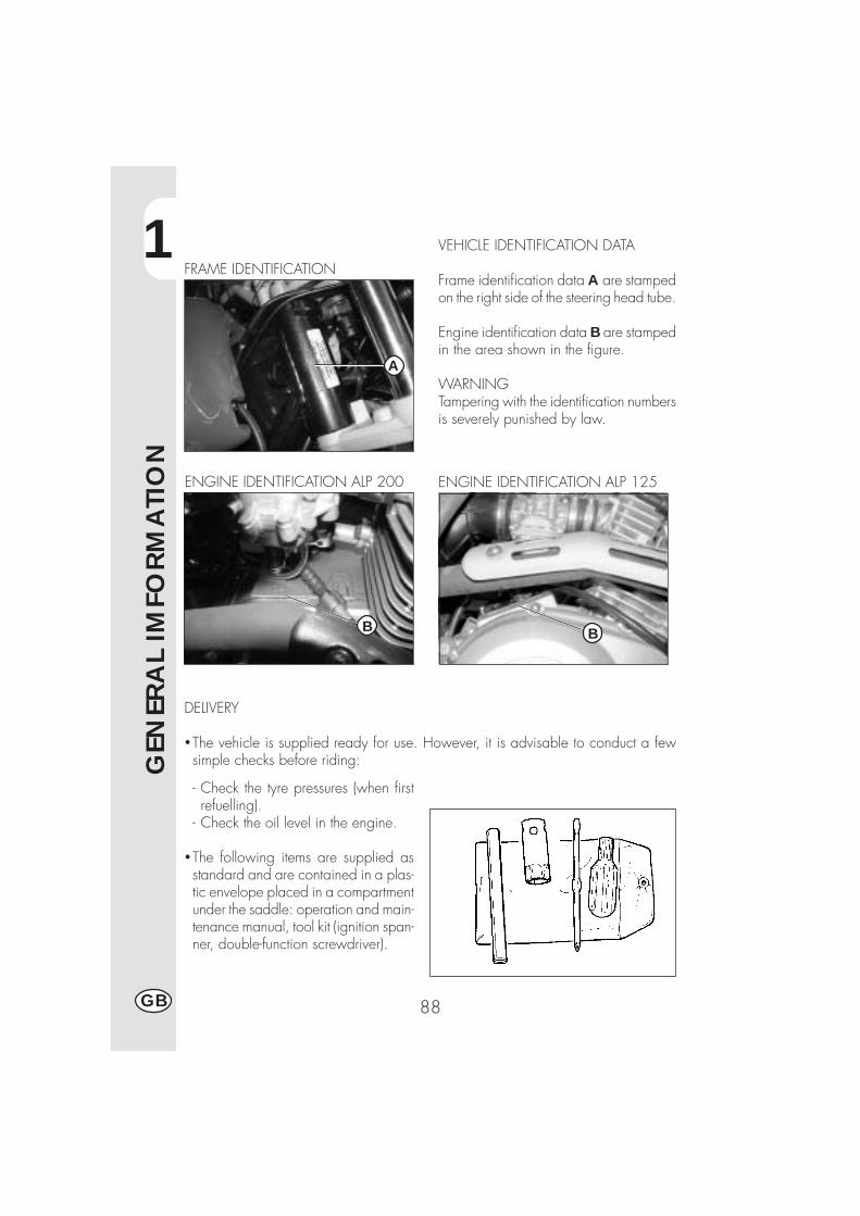
1
GEN
ERA
L IM
FORM
ATI
ON
88GB
VEHICLE IDENTIFICATION DATA
Frame identification data A are stampedon the right side of the steering head tube.
Engine identification data B are stampedin the area shown in the figure.
WARNINGTampering with the identification numbersis severely punished by law.
FRAME IDENTIFICATION
ENGINE IDENTIFICATION ALP 200
B
A
DELIVERY
�The vehicle is supplied ready for use. However, it is advisable to conduct a fewsimple checks before riding:
- Check the tyre pressures (when firstrefuelling).
- Check the oil level in the engine.
�The following items are supplied asstandard and are contained in a plas-tic envelope placed in a compartmentunder the saddle: operation and main-tenance manual, tool kit (ignition span-ner, double-function screwdriver).
ENGINE IDENTIFICATION ALP 125
B
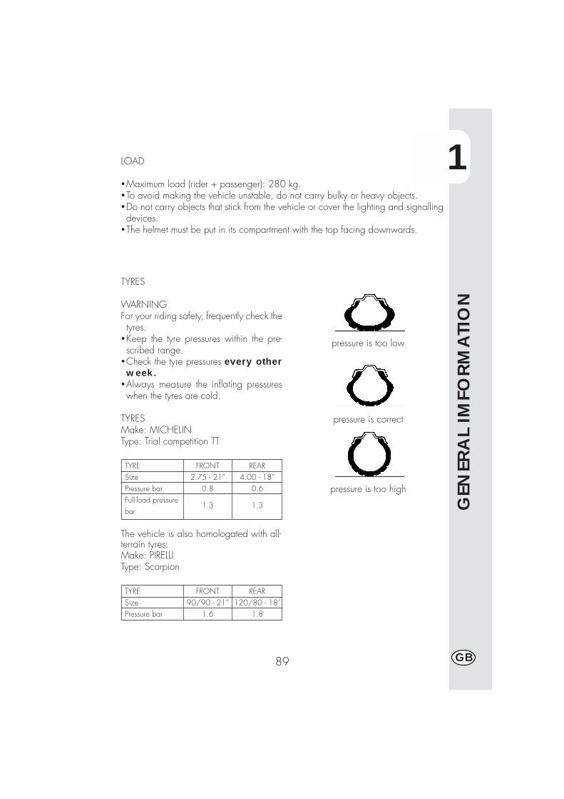
1
GEN
ERA
L IM
FORM
ATI
ON
89 GB
pressure is too low
pressure is correct
pressure is too high
LOAD
�Maximum load (rider + passenger): 280 kg.�To avoid making the vehicle unstable, do not carry bulky or heavy objects.�Do not carry objects that stick from the vehicle or cover the lighting and signallingdevices.
�The helmet must be put in its compartment with the top facing downwards.
TYRES
WARNINGFor your riding safety, frequently check thetyres.
�Keep the tyre pressures within the pre-scribed range.
�Check the tyre pressures every otherweek.
�Always measure the inflating pressureswhen the tyres are cold.
TYRESMake: MICHELINType: Trial competition TT
TYRESizePressure barFull-load pressurebar
REAR4.00 - 18”
0.6
1.3
FRONT2.75 - 21”
0.8
1.3
The vehicle is also homologated with all-terrain tyres:Make: PIRELLIType: Scorpion
TYRESizePressure bar
REAR120/80 - 18”
1.8
FRONT90/90 - 21”
1.6
1
GEN
ERA
L IM
FORM
ATI
ON
90GB
Note:The tyre (TUBE TYPE) tread depth must never be less than 2 mm.Failure to comply with this rule is punished under the regulations in force.
�Before riding, check the tyres for cuts, cracks, abrasions, bulges, etc. If any defectsare found, have the tyres checked by an expert as riding with a damaged tyre canbe extremely dangerous.
� If a tyre gets punctured, stop the vehicle immediately. Riding with a flat tyre isdangerous and may seriously damage the tyre itself and the wheel rim.∗Higher inflating pressures are recommended when riding in maximum load condi-tion (refer to the table on page 89).
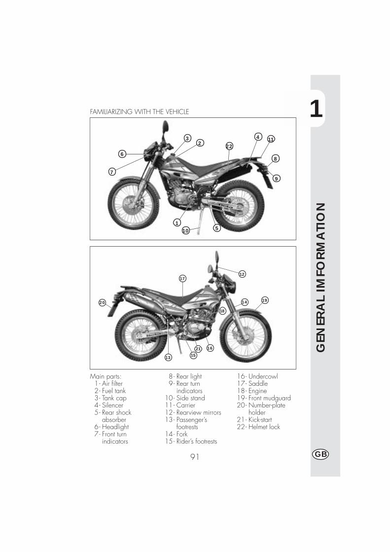
1
GEN
ERA
L IM
FORM
ATI
ON
91 GB
1
6
7
32 22
4 11
8
9
10 5
FAMILIARIZING WITH THE VEHICLE
13 15
1621
18
14 19
1217
20
Main parts:1 - Air filter2 - Fuel tank3- Tank cap4- Silencer5- Rear shock
absorber6- Headlight7- Front turn
indicators
8- Rear light9 - Rear turn
indicators10- Side stand11- Carrier12- Rearview mirrors13- Passenger’s
footrests14- Fork15- Rider’s footrests
16- Undercowl17- Saddle18- Engine19- Front mudguard20- Number-plate
holder21- Kick-start22- Helmet lock
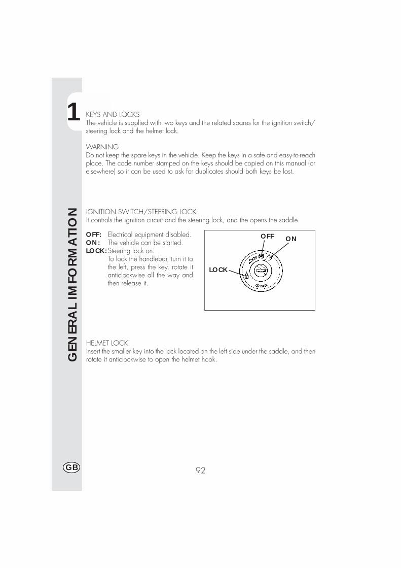
1
GEN
ERA
L IM
FORM
ATI
ON
92GB
ONOFF
LOCK
KEYS AND LOCKSThe vehicle is supplied with two keys and the related spares for the ignition switch/steering lock and the helmet lock.
WARNINGDo not keep the spare keys in the vehicle. Keep the keys in a safe and easy-to-reachplace. The code number stamped on the keys should be copied on this manual (orelsewhere) so it can be used to ask for duplicates should both keys be lost.
IGNITION SWITCH/STEERING LOCKIt controls the ignition circuit and the steering lock, and the opens the saddle.
OFF: Electrical equipment disabled.ON: The vehicle can be started.LOCK:Steering lock on.
To lock the handlebar, turn it tothe left, press the key, rotate itanticlockwise all the way andthen release it.
HELMET LOCKInsert the smaller key into the lock located on the left side under the saddle, and thenrotate it anticlockwise to open the helmet hook.
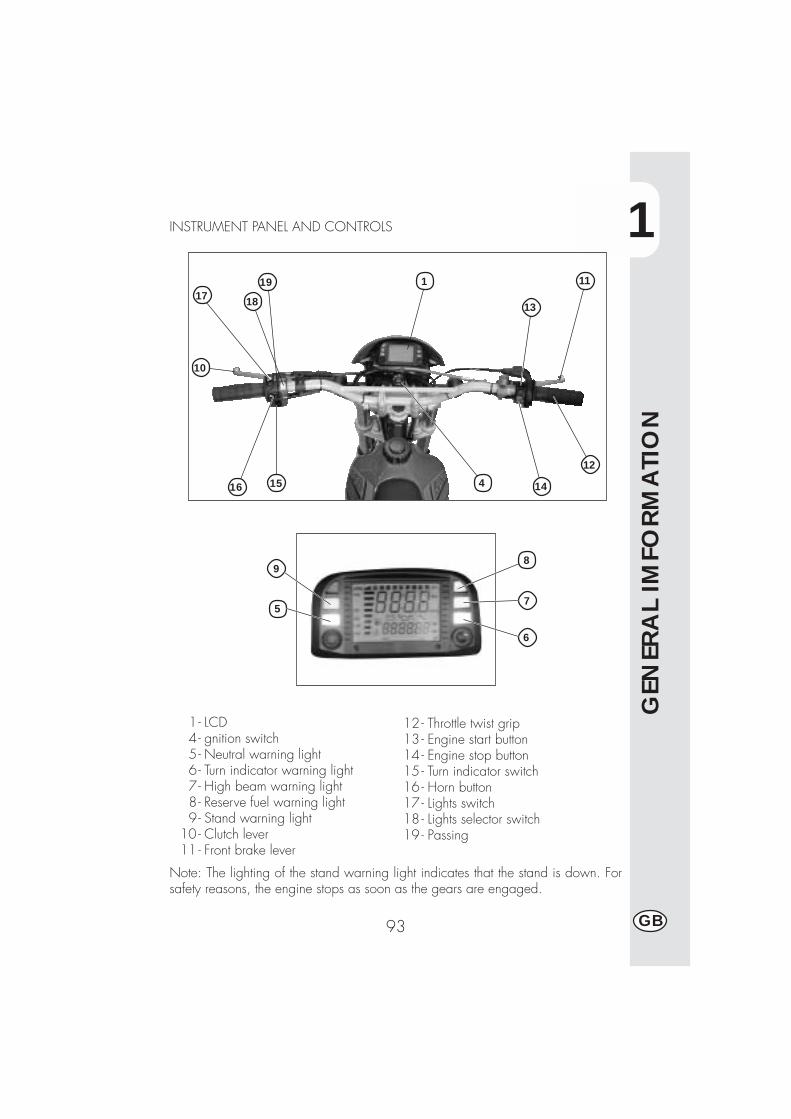
1
GEN
ERA
L IM
FORM
ATI
ON
93 GB
1- LCD4- gnition switch5- Neutral warning light6 - Turn indicator warning light7 - High beam warning light8 - Reserve fuel warning light9 - Stand warning light
10 - Clutch lever11 - Front brake lever
12 - Throttle twist grip13 - Engine start button14 - Engine stop button15 - Turn indicator switch16 - Horn button17 - Lights switch18 - Lights selector switch19 - Passing
INSTRUMENT PANEL AND CONTROLS
10
17 18
1516 4 14
12
11
13
5
19
6
7
9
1
8
Note: The lighting of the stand warning light indicates that the stand is down. Forsafety reasons, the engine stops as soon as the gears are engaged.
1
GEN
ERA
L IM
FORM
ATI
ON
94GB
SPEEDOMETER SETTING AND OPERATING INSTRUCTIONS(for manufacturer and dealers)A description of the basic procedure for setting up the digital instrument is providedfor information purposes only. We recommend having the operation performed byan authorized Betamotor dealer.
ALP 125 - ALP 200 Series
CONTENTS
PARAGRAPH SUBJECT
10.1 Wheel specifications10.2 Engine specifications10.3 Preloaded codes10.4 Loaded codes
20.0 LEVEL 1 SETUP (for manufacturer and dealers)20.1 Performing level 1 setup20.2 Selecting codes20.3 Checking codes20.4 Entering uncoded values
20.4.1 Setting Ln (wheel circumference) or di (wheel diameter)20.4.2 Setting the number of pulses per wheel revolution20.4.3 Setting the number of pulses per engine revolution
20.4.3.1 Setting the number of pulses for the maximum rpm20.4.4 Selecting Km/h or Mph20.4.5 Setting the number of hours to the next oil change20.4.6 Setting the number of hours or kilometres to the next service
20.5 Exiting setup
40.0 LCD DISPLAY40.1 Operation and display of pages and icons40.2 Blanking out pages40.3 Resetting the TRP, SPEED max and LAP parameters.
50.0 Monitoring icons (engine oil and service icons)50.1 Checking the active contents of the monitoring icons.
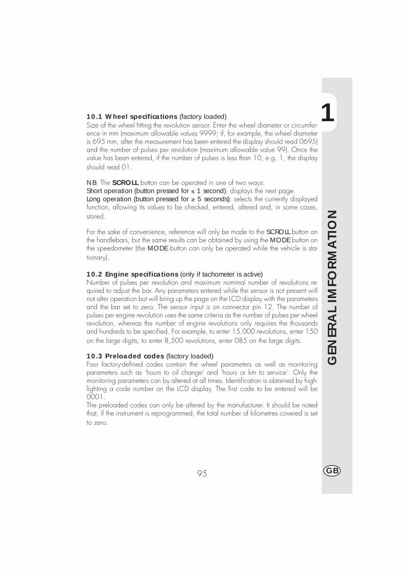
1
GEN
ERA
L IM
FORM
ATI
ON
95 GB
10.1 Wheel specifications (factory loaded)Size of the wheel fitting the revolution sensor. Enter the wheel diameter or circumfer-ence in mm (maximum allowable values 9999; if, for example, the wheel diameteris 695 mm, after the measurement has been entered the display should read 0695)and the number of pulses per revolution (maximum allowable value 99). Once thevalue has been entered, if the number of pulses is less than 10, e.g. 1, the displayshould read 01.
NB: The SCROLL button can be operated in one of two ways:Short operation (button pressed for ≤ 1 second): displays the next page.Long operation (button pressed for ≥ 5 seconds): selects the currently displayedfunction, allowing its values to be checked, entered, altered and, in some cases,stored.
For the sake of convenience, reference will only be made to the SCROLL button onthe handlebars, but the same results can be obtained by using the MODE button onthe speedometer (the MODE button can only be operated while the vehicle is sta-tionary).
10.2 Engine specifications (only if tachometer is active)Number of pulses per revolution and maximum nominal number of revolutions re-quired to adjust the bar. Any parameters entered while the sensor is not present willnot alter operation but will bring up the page on the LCD display with the parametersand the bar set to zero. The sensor input is on connector pin 12. The number ofpulses per engine revolution uses the same criteria as the number of pulses per wheelrevolution, whereas the number of engine revolutions only requires the thousandsand hundreds to be specified. For example, to enter 15,000 revolutions, enter 150on the large digits; to enter 8,500 revolutions, enter 085 on the large digits.
10.3 Preloaded codes (factory loaded)Four factory-defined codes contain the wheel parameters as well as monitoringparameters such as ‘hours to oil change’ and ‘hours or km to service’. Only themonitoring parameters can by altered at all times. Identification is obtained by high-lighting a code number on the LCD display. The first code to be entered will be0001.The preloaded codes can only be altered by the manufacturer. It should be notedthat, if the instrument is reprogrammed, the total number of kilometres covered is setto zero.
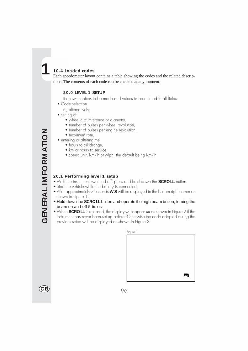
1
GEN
ERA
L IM
FORM
ATI
ON
96GB
10.4 Loaded codesEach speedometer layout contains a table showing the codes and the related descrip-tions. The contents of each code can be checked at any moment.
20.0 LEVEL 1 SETUPIt allows choices to be made and values to be entered in all fields:
• Code selectionor, alternatively:
• setting of• wheel circumference or diameter,• number of pulses per wheel revolution,• number of pulses per engine revolution,• maximum rpm.
• entering or altering the• hours to oil change,• km or hours to service,• speed unit, Km/h or Mph, the default being Km/h.
20.1 Performing level 1 setup• With the instrument switched off, press and hold down the SCROLL button.• Start the vehicle while the battery is connected.• After approximately 7 seconds WS will be displayed in the bottom right corner as
shown in Figure 1.• Hold down the SCROLL button and operate the high beam button, turning the
beam on and off 5 times.• When SCROLL is released, the display will appear cu as shown in Figure 2 if the
instrument has never been set up before. Otherwise the code adopted during theprevious setup will be displayed as shown in Figure 3.
Figure 1

1
GEN
ERA
L IM
FORM
ATI
ON
97 GB
20.2 Selecting codes•Pressing SCROLL for a short time cyclesthrough the other codes until the displayappears as shown in Figure 2.
Table of codesModel Alp 4.0 Alp 200 cc
Motard M4Code 0001 0002 0003Wheel 2105 2115 1830circ.
•After selecting the desired code, pressand hold down SCROLL until WS isdisplayed in the bottom right corner(Figure 4). Once the button is released,the code is activated and the displayappears as shown in Figure 5.
•If the configuration is complete, thereare two possibilities:- exiting the setup procedure and launch-ing the test as described in paragraph40.0 by turning the speedometer offand then on again;- checking the code as described inparagraph 20.3.
•If no code is appropriate, repeat theprocedure until the display is as shownin Figure 2, which can be obtained bybriefly pressing SCROLL while Figure3 is displayed. Subsequently pressSCROLL until WS is shown and thenrelease it to activate the procedure de-scribed in paragraph 20.4.
Figure 2
Figure 3
Figure 4
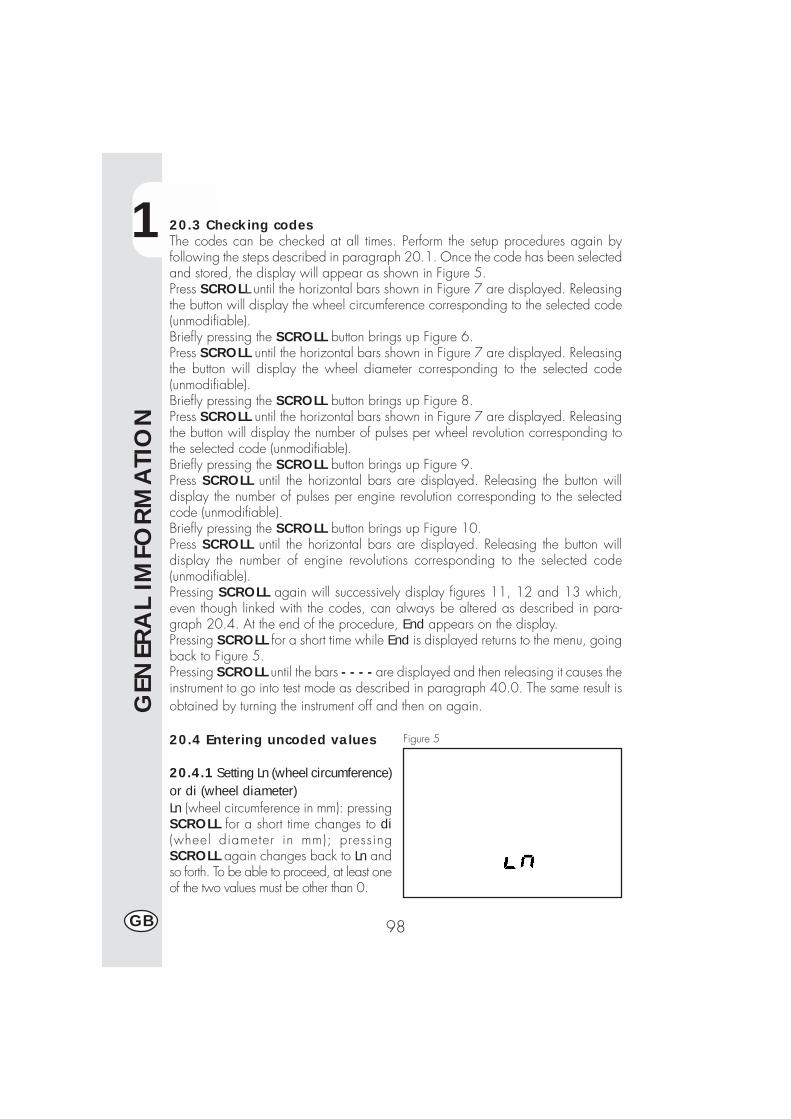
1
GEN
ERA
L IM
FORM
ATI
ON
98GB
20.3 Checking codesThe codes can be checked at all times. Perform the setup procedures again byfollowing the steps described in paragraph 20.1. Once the code has been selectedand stored, the display will appear as shown in Figure 5.Press SCROLL until the horizontal bars shown in Figure 7 are displayed. Releasingthe button will display the wheel circumference corresponding to the selected code(unmodifiable).Briefly pressing the SCROLL button brings up Figure 6.Press SCROLL until the horizontal bars shown in Figure 7 are displayed. Releasingthe button will display the wheel diameter corresponding to the selected code(unmodifiable).Briefly pressing the SCROLL button brings up Figure 8.Press SCROLL until the horizontal bars shown in Figure 7 are displayed. Releasingthe button will display the number of pulses per wheel revolution corresponding tothe selected code (unmodifiable).Briefly pressing the SCROLL button brings up Figure 9.Press SCROLL until the horizontal bars are displayed. Releasing the button willdisplay the number of pulses per engine revolution corresponding to the selectedcode (unmodifiable).Briefly pressing the SCROLL button brings up Figure 10.Press SCROLL until the horizontal bars are displayed. Releasing the button willdisplay the number of engine revolutions corresponding to the selected code(unmodifiable).Pressing SCROLL again will successively display figures 11, 12 and 13 which,even though linked with the codes, can always be altered as described in para-graph 20.4. At the end of the procedure, End appears on the display.Pressing SCROLL for a short time while End is displayed returns to the menu, goingback to Figure 5.Pressing SCROLL until the bars - - - - are displayed and then releasing it causes theinstrument to go into test mode as described in paragraph 40.0. The same result isobtained by turning the instrument off and then on again.
20.4 Entering uncoded values
20.4.1 Setting Ln (wheel circumference)or di (wheel diameter)Ln (wheel circumference in mm): pressingSCROLL for a short time changes to di(wheel diameter in mm); pressingSCROLL again changes back to Ln andso forth. To be able to proceed, at least oneof the two values must be other than 0.
Figure 5
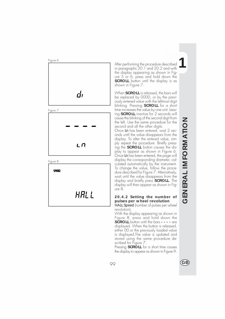
1
GEN
ERA
L IM
FORM
ATI
ON
99 GB
Figure 6After performing the procedure describedin paragraphs 20.1 and 20.2 and withthe display appearing as shown in Fig-ure 5 or 6, press and hold down theSCROLL button until the display is asshown in Figure 7.
When SCROLL is released, the bars willbe replaced by 0000, or by the previ-ously entered value with the leftmost digitblinking. Pressing SCROLL for a shorttime increases the value by one unit. Leav-ing SCROLL inactive for 2 seconds willcause the blinking of the second digit fromthe left. Use the same procedure for thesecond and all the other digits.Once Ln has been entered, wait 2 sec-onds until the value disappears from thedisplay. To alter the entered value, sim-ply repeat the procedure. Briefly press-ing the SCROLL button causes the dis-play to appear as shown in Figure 6.Once Ln has been entered, the page willdisplay the corresponding diameter, cal-culated automatically by the instrument.To change the value, follow the proce-dure described for Figure 7. Alternatively,wait until the value disappears from thedisplay and briefly press SCROLL. Thedisplay will then appear as shown in Fig-ure 8.
20.4.2 Setting the number ofpulses per wheel revolutionHALL Speed (number of pulses per wheelrevolution).With the display appearing as shown inFigure 8, press and hold down theSCROLL button until the bars - - - - aredisplayed. When the button is released,either 00 or the previously loaded valueis displayed.The value is updated andstored using the same procedure de-scribed for Figure 7.Pressing SCROLL for a short time causesthe display to appear as shown in Figure 9.
Figure 7
Figure 8
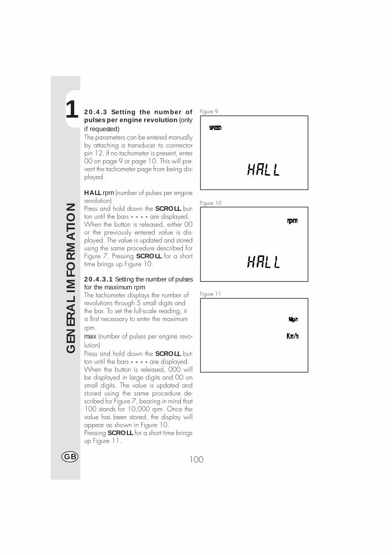
1
GEN
ERA
L IM
FORM
ATI
ON
100GB
20.4.3 Setting the number ofpulses per engine revolution (onlyif requested)The parameters can be entered manuallyby attaching a transducer to connectorpin 12. If no tachometer is present, enter00 on page 9 or page 10. This will pre-vent the tachometer page from being dis-played.
HALL rpm (number of pulses per enginerevolution)Press and hold down the SCROLL but-ton until the bars - - - - are displayed.When the button is released, either 00or the previously entered value is dis-played. The value is updated and storedusing the same procedure described forFigure 7. Pressing SCROLL for a shorttime brings up Figure 10.
20.4.3.1 Setting the number of pulsesfor the maximum rpmThe tachometer displays the number ofrevolutions through 5 small digits andthe bar. To set the full-scale reading, itis first necessary to enter the maximumrpm.max (number of pulses per engine revo-lution)Press and hold down the SCROLL but-ton until the bars - - - - are displayed.When the button is released, 000 willbe displayed in large digits and 00 onsmall digits. The value is updated andstored using the same procedure de-scribed for Figure 7, bearing in mind that100 stands for 10,000 rpm. Once thevalue has been stored, the display willappear as shown in Figure 10.Pressing SCROLL for a short time bringsup Figure 11.
Figure 9
Figure 10
Figure 11
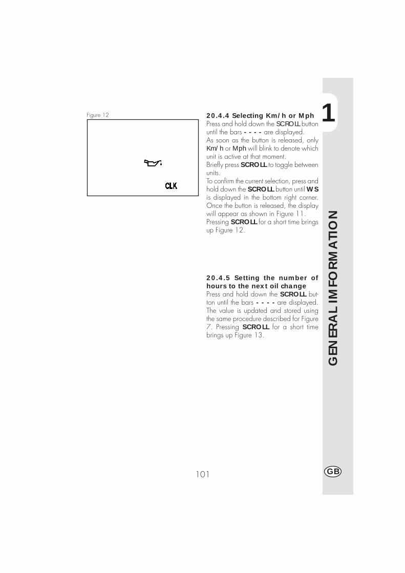
1
GEN
ERA
L IM
FORM
ATI
ON
101 GB
20.4.4 Selecting Km/h or MphPress and hold down the SCROLL buttonuntil the bars - - - - are displayed.As soon as the button is released, onlyKm/h or Mph will blink to denote whichunit is active at that moment.Briefly press SCROLL to toggle betweenunits.To confirm the current selection, press andhold down the SCROLL button until WSis displayed in the bottom right corner.Once the button is released, the displaywill appear as shown in Figure 11.Pressing SCROLL for a short time bringsup Figure 12.
Figure 12
20.4.5 Setting the number ofhours to the next oil changePress and hold down the SCROLL but-ton until the bars - - - - are displayed.The value is updated and stored usingthe same procedure described for Figure7. Pressing SCROLL for a short timebrings up Figure 13.
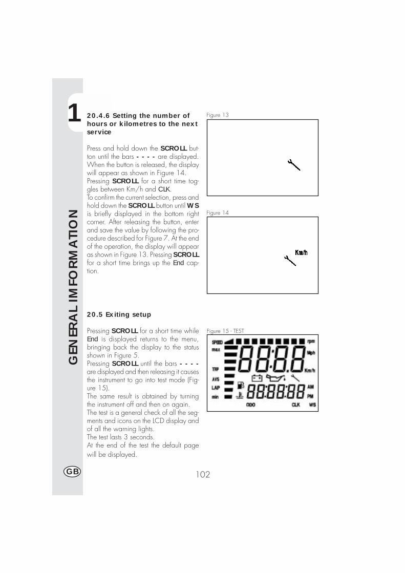
1
GEN
ERA
L IM
FORM
ATI
ON
102GB
20.4.6 Setting the number ofhours or kilometres to the nextservice
Press and hold down the SCROLL but-ton until the bars - - - - are displayed.When the button is released, the displaywill appear as shown in Figure 14.Pressing SCROLL for a short time tog-gles between Km/h and CLK.To confirm the current selection, press andhold down the SCROLL button until WSis briefly displayed in the bottom rightcorner. After releasing the button, enterand save the value by following the pro-cedure described for Figure 7. At the endof the operation, the display will appearas shown in Figure 13. Pressing SCROLLfor a short time brings up the End cap-tion.
20.5 Exiting setup
Pressing SCROLL for a short time whileEnd is displayed returns to the menu,bringing back the display to the statusshown in Figure 5.Pressing SCROLL until the bars - - - -are displayed and then releasing it causesthe instrument to go into test mode (Fig-ure 15).The same result is obtained by turningthe instrument off and then on again.The test is a general check of all the seg-ments and icons on the LCD display andof all the warning lights.The test lasts 3 seconds.At the end of the test the default pagewill be displayed.
Figure 13
Figure 14
Figure 15 - TEST
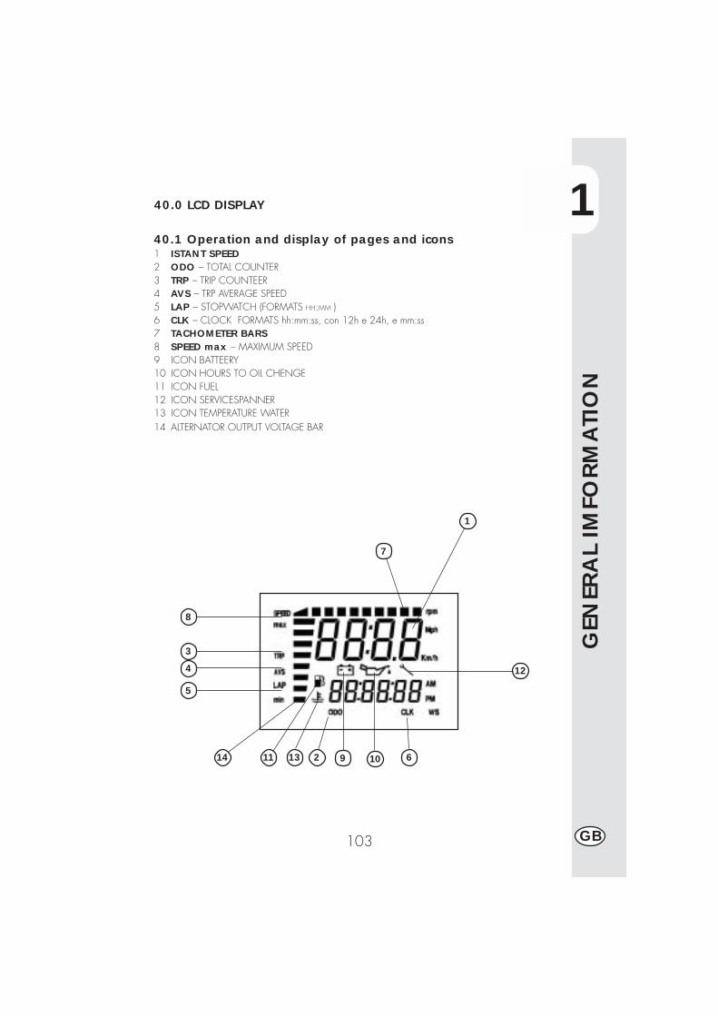
1
GEN
ERA
L IM
FORM
ATI
ON
103 GB
40.0 LCD DISPLAY
40.1 Operation and display of pages and icons1 ISTANT SPEED2 ODO – TOTAL COUNTER3 TRP – TRIP COUNTEER4 AVS – TRP AVERAGE SPEED5 LAP – STOPWATCH (FORMATS HH:MM )6 CLK – CLOCK FORMATS hh:mm:ss, con 12h e 24h, e mm:ss7 TACHOMETER BARS8 SPEED max – MAXIMUM SPEED9 ICON BATTEERY10 ICON HOURS TO OIL CHENGE11 ICON FUEL12 ICON SERVICESPANNER13 ICON TEMPERATURE WATER14 ALTERNATOR OUTPUT VOLTAGE BAR
12
10 613
5
4
3
8
1
1114 92
7
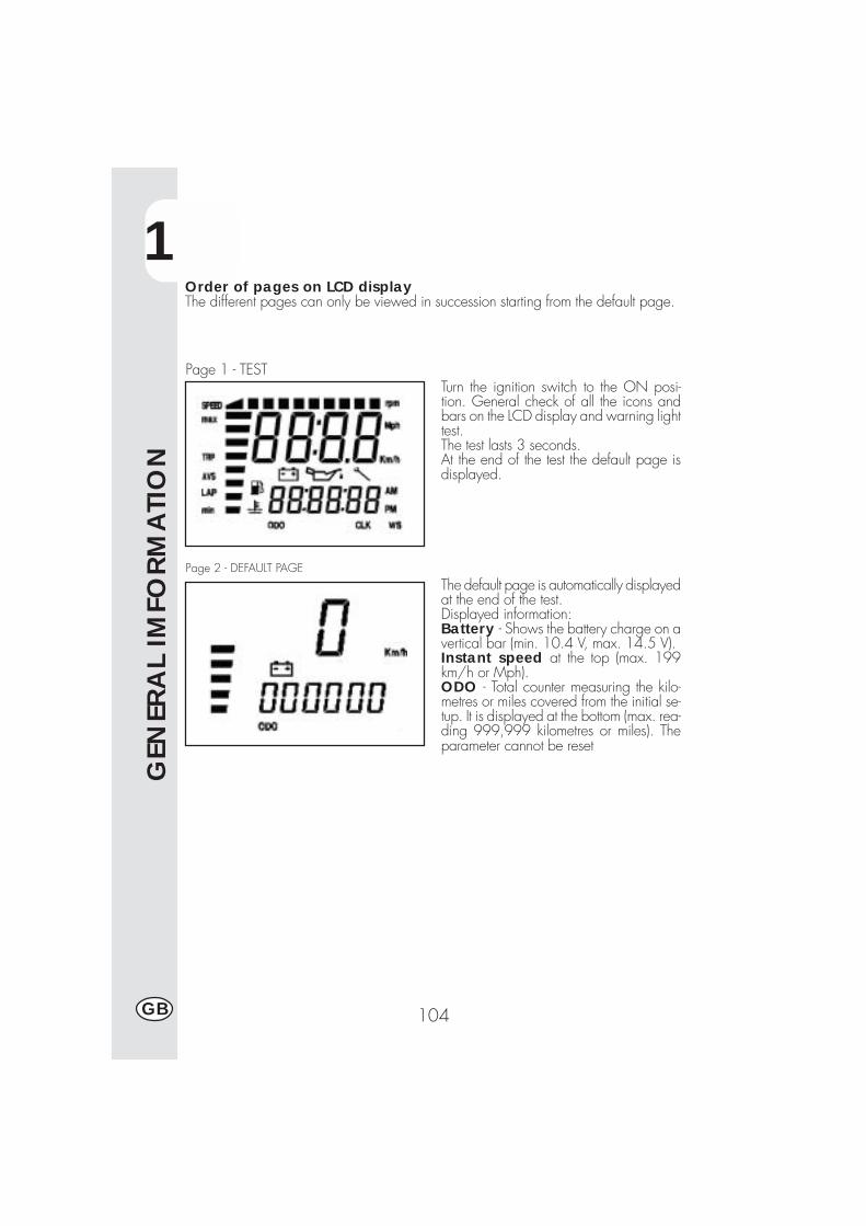
1
GEN
ERA
L IM
FORM
ATI
ON
104GB
Order of pages on LCD displayThe different pages can only be viewed in succession starting from the default page.
Turn the ignition switch to the ON posi-tion. General check of all the icons andbars on the LCD display and warning lighttest.The test lasts 3 seconds.At the end of the test the default page isdisplayed.
The default page is automatically displayedat the end of the test.Displayed information:Battery - Shows the battery charge on avertical bar (min. 10.4 V, max. 14.5 V).Instant speed at the top (max. 199km/h or Mph).ODO - Total counter measuring the kilo-metres or miles covered from the initial se-tup. It is displayed at the bottom (max. rea-ding 999,999 kilometres or miles). Theparameter cannot be reset
Page 1 - TEST
Page 2 - DEFAULT PAGE
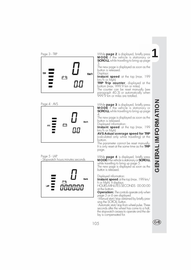
1
GEN
ERA
L IM
FORM
ATI
ON
105 GB
Page 3 - TRP
Page 4 - AVS
Page 5 - LAP- Stopwatch hours:minutes:seconds
While page 2 is displayed, briefly pressMODE if the vehicle is stationary orSCROLL while travelling to bring up page3.The new page is displayed as soon as thebutton is released.Displays:Instant speed at the top (max. 199km/h or Mph)TRP Trip counter, displayed at thebottom (max. 999.9 km or miles)The counter can be reset manually (seeparagraph 40.3) or automatically when999.9 km or miles are totalled.
While page 3 is displayed, briefly pressMODE if the vehicle is stationary orSCROLL while travelling to bring up page4.The new page is displayed as soon as thebutton is released.Displayed information:Instant speed at the top (max. 199km/h or Mph)AVS Actual average speed for TRP(calculated only while travelling) at thebottom.The parameter cannot be reset manually.It is only reset at the same time as the TRPpage.
While page 4 is displayed, briefly pressMODE if the vehicle is stationary or SCROLLwhile travelling to bring up page 5.The new page is displayed as soon as thebutton is released.
Displayed information:Instant speed at the top (max. 199 km/h or Mph). It displays:HOURS:MINUTES:SECONDS 00:00:00at the bottom.Operation: The controls operate only whenpage 5 or 6 are displayed.- Manual start/stop obtained by briefly pres-sing the SCROLL button.- Automatic start/stop from wheel pulse. Threeseconds after the wheel has come to a halt,the stopwatch ceases to operate and the de-lay is compensated for.
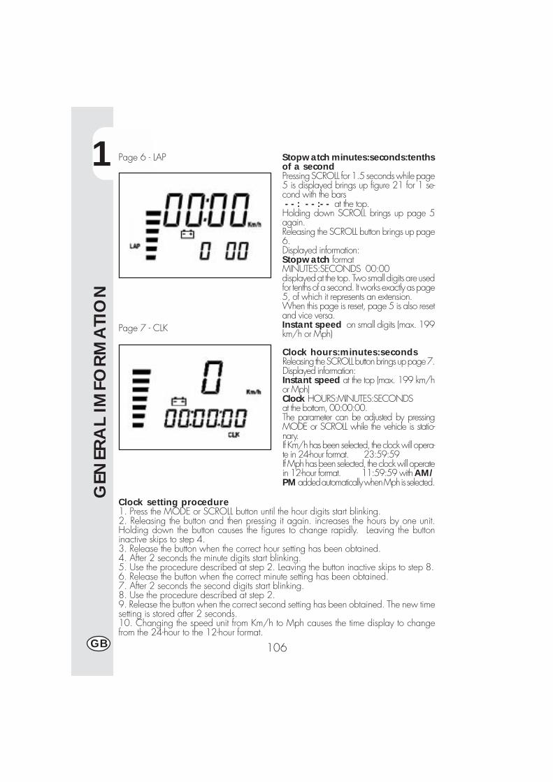
1
GEN
ERA
L IM
FORM
ATI
ON
106GB
Page 6 - LAP
Page 7 - CLK
Stopwatch minutes:seconds:tenthsof a secondPressing SCROLL for 1.5 seconds while page5 is displayed brings up figure 21 for 1 se-cond with the bars - - : - - :- - at the top.Holding down SCROLL brings up page 5again.Releasing the SCROLL button brings up page6.Displayed information:Stopwatch formatMINUTES:SECONDS 00:00displayed at the top. Two small digits are usedfor tenths of a second. It works exactly as page5, of which it represents an extension.When this page is reset, page 5 is also resetand vice versa.Instant speed on small digits (max. 199km/h or Mph)
Clock hours:minutes:secondsReleasing the SCROLL button brings up page 7.Displayed information:Instant speed at the top (max. 199 km/hor Mph)Clock HOURS:MINUTES:SECONDSat the bottom, 00:00:00.The parameter can be adjusted by pressingMODE or SCROLL while the vehicle is statio-nary.If Km/h has been selected, the clock will opera-te in 24-hour format. 23:59:59If Mph has been selected, the clock will operatein 12-hour format. 11:59:59 with AM/PM added automatically when Mph is selected.
Clock setting procedure1. Press the MODE or SCROLL button until the hour digits start blinking.2. Releasing the button and then pressing it again. increases the hours by one unit.Holding down the button causes the figures to change rapidly. Leaving the buttoninactive skips to step 4.3. Release the button when the correct hour setting has been obtained.4. After 2 seconds the minute digits start blinking.5. Use the procedure described at step 2. Leaving the button inactive skips to step 8.6. Release the button when the correct minute setting has been obtained.7. After 2 seconds the second digits start blinking.8. Use the procedure described at step 2.9. Release the button when the correct second setting has been obtained. The new timesetting is stored after 2 seconds.10. Changing the speed unit from Km/h to Mph causes the time display to changefrom the 24-hour to the 12-hour format.
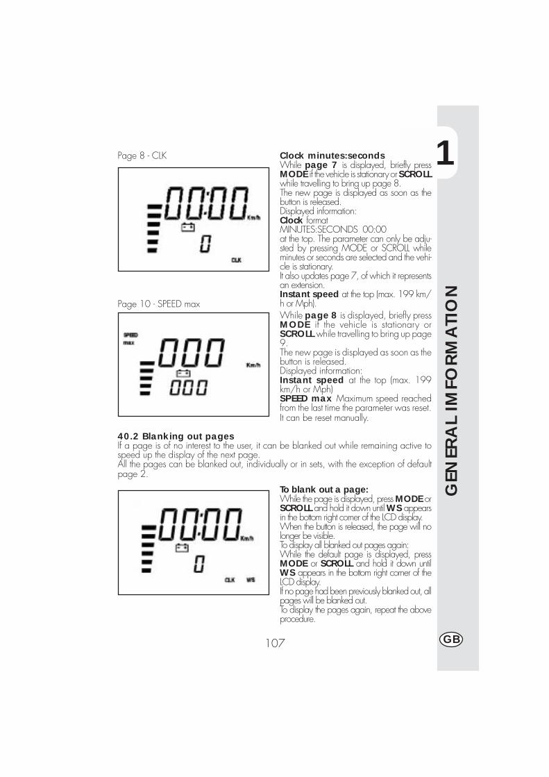
1
GEN
ERA
L IM
FORM
ATI
ON
107 GB
Page 8 - CLK
Page 10 - SPEED max
Clock minutes:secondsWhile page 7 is displayed, briefly pressMODE if the vehicle is stationary or SCROLLwhile travelling to bring up page 8.The new page is displayed as soon as thebutton is released.Displayed information:Clock formatMINUTES:SECONDS 00:00at the top. The parameter can only be adju-sted by pressing MODE or SCROLL whileminutes or seconds are selected and the vehi-cle is stationary.It also updates page 7, of which it representsan extension.Instant speed at the top (max. 199 km/h or Mph).While page 8 is displayed, briefly pressMODE if the vehicle is stationary orSCROLL while travelling to bring up page9.The new page is displayed as soon as thebutton is released.Displayed information:Instant speed at the top (max. 199km/h or Mph)SPEED max Maximum speed reachedfrom the last time the parameter was reset.It can be reset manually.
40.2 Blanking out pagesIf a page is of no interest to the user, it can be blanked out while remaining active tospeed up the display of the next page.All the pages can be blanked out, individually or in sets, with the exception of defaultpage 2.
To blank out a page:While the page is displayed, press MODE orSCROLL and hold it down until WS appearsin the bottom right corner of the LCD display.When the button is released, the page will nolonger be visible.To display all blanked out pages again:While the default page is displayed, pressMODE or SCROLL and hold it down untilWS appears in the bottom right corner of theLCD display.If no page had been previously blanked out, allpages will be blanked out.To display the pages again, repeat the aboveprocedure.
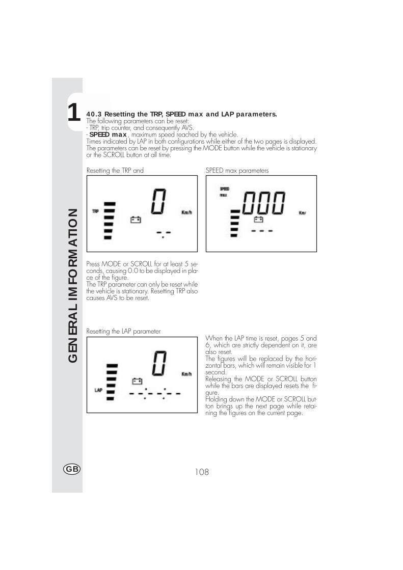
1
GEN
ERA
L IM
FORM
ATI
ON
108GB
40.3 Resetting the TRP, SPEED max and LAP parameters.The following parameters can be reset:- TRP, trip counter, and consequently AVS.- SPEED max, maximum speed reached by the vehicle.Times indicated by LAP in both configurations while either of the two pages is displayed.The parameters can be reset by pressing the MODE button while the vehicle is stationaryor the SCROLL button at all time.
Resetting the TRP and SPEED max parameters
Press MODE or SCROLL for at least 5 se-conds, causing 0.0 to be displayed in pla-ce of the figure.The TRP parameter can only be reset whilethe vehicle is stationary. Resetting TRP alsocauses AVS to be reset.
Resetting the LAP parameterWhen the LAP time is reset, pages 5 and6, which are strictly dependent on it, arealso reset.The figures will be replaced by the hori-zontal bars, which will remain visible for 1second.Releasing the MODE or SCROLL buttonwhile the bars are displayed resets the fi-gure.Holding down the MODE or SCROLL but-ton brings up the next page while retai-ning the figures on the current page.
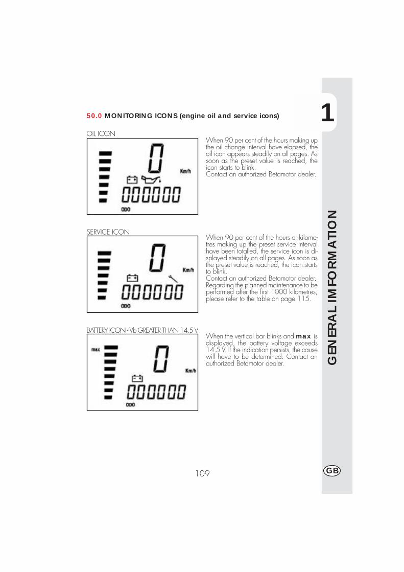
1
GEN
ERA
L IM
FORM
ATI
ON
109 GB
50.0 MONITORING ICONS (engine oil and service icons)
OIL ICONWhen 90 per cent of the hours making upthe oil change interval have elapsed, theoil icon appears steadily on all pages. Assoon as the preset value is reached, theicon starts to blink.Contact an authorized Betamotor dealer.
When 90 per cent of the hours or kilome-tres making up the preset service intervalhave been totalled, the service icon is di-splayed steadily on all pages. As soon asthe preset value is reached, the icon startsto blink.Contact an authorized Betamotor dealer.Regarding the planned maintenance to beperformed after the first 1000 kilometres,please refer to the table on page 115.
SERVICE ICON
BATTERY ICON - Vb GREATER THAN 14.5 VWhen the vertical bar blinks and max isdisplayed, the battery voltage exceeds14.5 V. If the indication persists, the causewill have to be determined. Contact anauthorized Betamotor dealer.
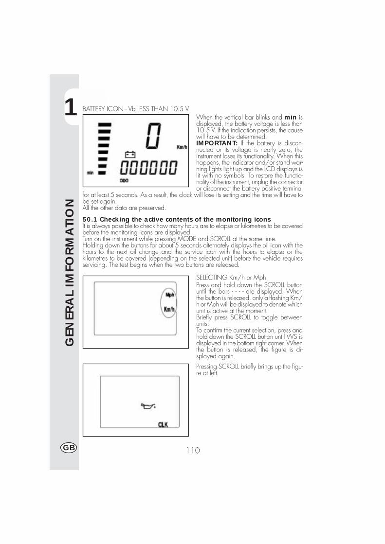
1
GEN
ERA
L IM
FORM
ATI
ON
110GB
BATTERY ICON - Vb LESS THAN 10.5 VWhen the vertical bar blinks and min isdisplayed, the battery voltage is less than10.5 V. If the indication persists, the causewill have to be determined.IMPORTANT: If the battery is discon-nected or its voltage is nearly zero, theinstrument loses its functionality. When thishappens, the indicator and/or stand war-ning lights light up and the LCD displays islit with no symbols. To restore the functio-nality of the instrument, unplug the connectoror disconnect the battery positive terminal
for at least 5 seconds. As a result, the clock will lose its setting and the time will have tobe set again.All the other data are preserved.
50.1 Checking the active contents of the monitoring iconsIt is always possible to check how many hours are to elapse or kilometres to be coveredbefore the monitoring icons are displayed.Turn on the instrument while pressing MODE and SCROLL at the same time.Holding down the buttons for about 5 seconds alternately displays the oil icon with thehours to the next oil change and the service icon with the hours to elapse or thekilometres to be covered (depending on the selected unit) before the vehicle requiresservicing. The test begins when the two buttons are released.
SELECTING Km/h or MphPress and hold down the SCROLL buttonuntil the bars - - - - are displayed. Whenthe button is released, only a flashing Km/h or Mph will be displayed to denote whichunit is active at the moment.Briefly press SCROLL to toggle betweenunits.To confirm the current selection, press andhold down the SCROLL button until WS isdisplayed in the bottom right corner. Whenthe button is released, the figure is di-splayed again.
Pressing SCROLL briefly brings up the figu-re at left.
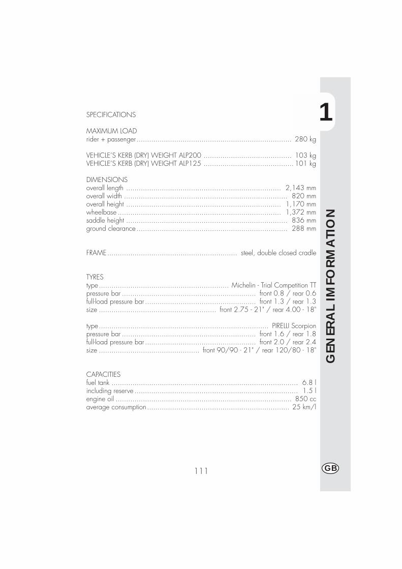
1
GEN
ERA
L IM
FORM
ATI
ON
111 GB
SPECIFICATIONS
MAXIMUM LOADrider + passenger.......................................................................... 280 kg
VEHICLE’S KERB (DRY) WEIGHT ALP200 .......................................... 103 kgVEHICLE’S KERB (DRY) WEIGHT ALP125 ........................................... 101 kg
DIMENSIONSoverall length .......................................................................... 2,143 mmoverall width .............................................................................. 820 mmoverall height .......................................................................... 1,170 mmwheelbase .............................................................................. 1,372 mmsaddle height ............................................................................. 836 mmground clearance ........................................................................ 288 mm
FRAME.............................................................. steel, double closed cradle
TYREStype.............................................................. Michelin - Trial Competition TTpressure bar ................................................................ front 0.8 / rear 0.6full-load pressure bar ..................................................... front 1.3 / rear 1.3size ........................................................ front 2.75 - 21" / rear 4.00 - 18"
type................................................................................. PIRELLI Scorpionpressure bar ................................................................ front 1.6 / rear 1.8full-load pressure bar ..................................................... front 2.0 / rear 2.4size ................................................ front 90/90 - 21" / rear 120/80 - 18"
CAPACITIESfuel tank ......................................................................................... 6.8 lincluding reserve .............................................................................. 1.5 lengine oil .................................................................................... 850 ccaverage consumption .................................................................... 25 km/l
1
GEN
ERA
L IM
FORM
ATI
ON
112GB
FRONT SUSPENSIONHydraulic fork with Ø 38 mm rods, adjustable rebound and spring preloadLeg oil capacity:left ............................................................................................. 350 ccright ........................................................................................... 350 ccOil type ............................................................... Bel Ray MC 10 SAE 10
or LIQUI MOLY RECING SUSPENSION OIL SAE 10WOil level ......................................................... 120 mm from tube upper rim
with fork at end of travel and no springTrail .................................................................................... 170 ± 3 mm
REAR SUSPENSIONSingle progressive hydraulic shock absorber with adjustable rebound and springpreloadshock absorber travel ..................................................................... 80 mm
FRONT BRAKEØ 220 mm disc brake with hydraulic control
REAR BRAKEØ 220 mm disc brake with hydraulic control

1
GEN
ERA
L IM
FORM
ATI
ON
113 GB
ENGINE ALP 125
Type ................................ Single-cylinder, forward-inclined, four-stroke, SOHC
Bore x stroke ............................................................................ 54X54 mm
Displacement ................................................................................ 124 cc
Compression ratio ............................................................................. 10:1
Carburettor .................................................... MIKUNI UCAL 5Nh Ø 26-38
Lubrication ............................................................................... oil in sump
Fuel system .... petrol (unleaded, with a minimum octane number of 95), by carburettor
Cooling system ................................................................. by air circulation
Spark plug ........................................................................ NGK DR7 HSA
Clutch ..................................................................... multiple-disc in oil bath
transmission ............................................. 5-speed, with constant-mesh gears
Primary gearbox ratio ..................................................................... 68/20
Final gearbox ratio ......................................................................... 60/14
Gear ratios 1st ...................................................................... 37/14
2nd..................................................................... 32/18
3rd ..................................................................... 25/19
4th ...................................................................... 23/22
5th ...................................................................... 21/24
Drive chain .......................................... REGINA DERVIO 1/2, 5/15 P. 138
Play of valves ...................... intake mm 0.08 - 0.12 , exhaust mm 0,10 - 0,14
Starting ................................................................. electric and/or kick-start
Engine oil ............................................................. BARDAHL XTM15W 50
Engine oil capacity ...................................................... 1,000 ml/1,050 ml
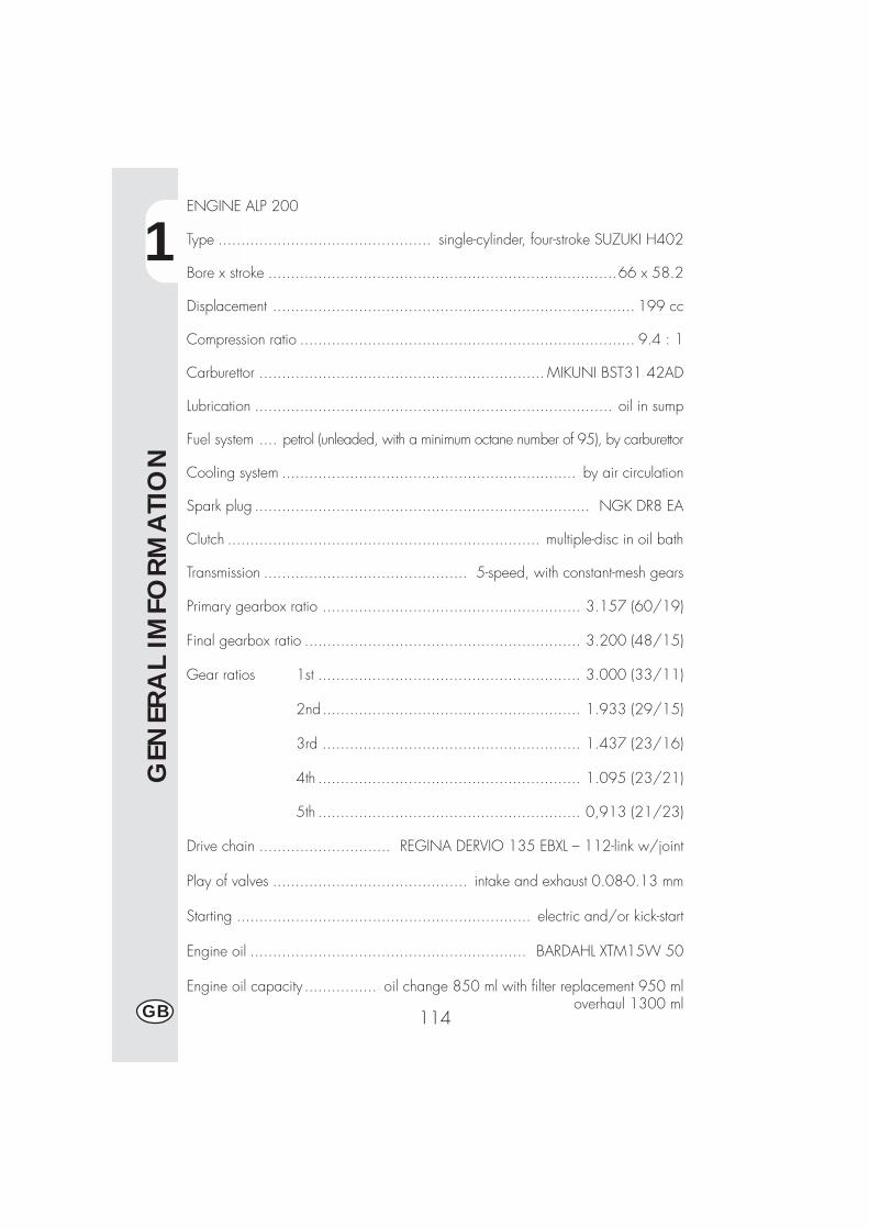
1
GEN
ERA
L IM
FORM
ATI
ON
114GB
ENGINE ALP 200
Type ............................................... single-cylinder, four-stroke SUZUKI H402
Bore x stroke .............................................................................66 x 58.2
Displacement ................................................................................ 199 cc
Compression ratio .......................................................................... 9.4 : 1
Carburettor ............................................................... MIKUNI BST31 42AD
Lubrication ............................................................................... oil in sump
Fuel system .... petrol (unleaded, with a minimum octane number of 95), by carburettor
Cooling system ................................................................. by air circulation
Spark plug .......................................................................... NGK DR8 EA
Clutch ..................................................................... multiple-disc in oil bath
Transmission ............................................. 5-speed, with constant-mesh gears
Primary gearbox ratio ......................................................... 3.157 (60/19)
Final gearbox ratio ............................................................. 3.200 (48/15)
Gear ratios 1st .......................................................... 3.000 (33/11)
2nd......................................................... 1.933 (29/15)
3rd ......................................................... 1.437 (23/16)
4th .......................................................... 1.095 (23/21)
5th .......................................................... 0,913 (21/23)
Drive chain ............................. REGINA DERVIO 135 EBXL – 112-link w/joint
Play of valves ........................................... intake and exhaust 0.08-0.13 mm
Starting ................................................................. electric and/or kick-start
Engine oil ............................................................. BARDAHL XTM15W 50
Engine oil capacity ................ oil change 850 ml with filter replacement 950 ml overhaul 1300 ml
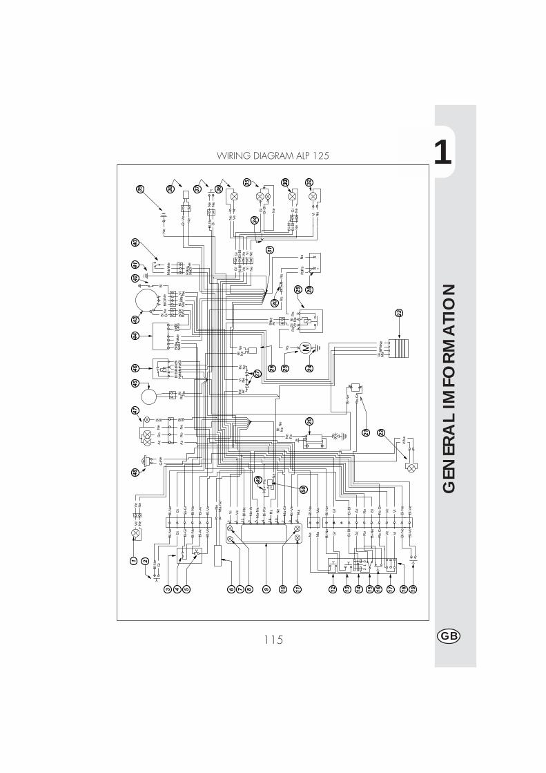
1
GEN
ERA
L IM
FORM
ATI
ON
115 GB
WIRING DIAGRAM ALP 125
Ne
Bi-N
e
Gi
Bl-N
e
Gr
Bi-N
e
Bl-N
e
Gi
Bi-G
i
Bi-A
r
Bl-V
e
Ne
Ma
Bl-N
e
Az
Bi-B
l
Rs-
Gi
Bi-G
i
Bi-A
r
Bl-V
e
Gr
Ma
Vi
MaM
a-N
eN
e
Ve Vi
Bl-N
e
Ro
Vi
Ve
Rs-
Gi
Bi-B
l
Ro
Az
Bl-N
eB
l
2 61V
e
11B
l-Ne
3N
e-A
r
5M
a-N
e
4 14R
s
13N
e
7M
a-G
i
9G
r-V
e
Bl-N
e
Bl
Ne
MaB
lRs
Bl
Ne
Vi
Gi
Ve
Bi
Bi
Ma
Ne
Gi
Bi B
l Ne N
eR
sVe
Gi
Ve
Gi
Bl
Bi
+-Ne
RsBi
NeN
e Ne
Rs
Bi
Gi
Ve
NeBi
Bl-N
eB L
Rs-
Gi
Az
Ro
Ne
Ar
Ne
Ne
Ro
Vi
Ne
Rs
Ne
Rs
Ne
Gi
Bi
Ne
Ro
Ne
Ro
NeBl
NeBl
NeBl
Rs
Rs
Rs
Ar
Bi
M
Rs
Bi
Bl
Gr-
Ve
Ne
Ne
Bl-N
e
Bi-N
e
Bl-V
eB
l-Ve
Ve
Ne V
iN
e
Gi
NeM
aR
o
Ma V
eNe
Ne
NeVi
Ve
Bi-B
lG
iG
iB
i-Bl
Ve Vi
Ne
Ne
Bi-B
l
Ne
Bi-B
l
Ne
Ne
Ne
Rs
Bi-N
e
Gr
Vi
Gi
Rs
Rs
Az
Ro
Bl
Bi
+
Ne
Ve
Ve
Ne
Bl-N
eG
i
Ne
Ne
Ne Gi
Ne
Bi-B
lG
i
01
2
Bi-R
o
Bl
Ne
Ne
Ro
-+
Ne
1 2
3 4 5 6 7 8 9 10 11 12 13 14 15 16 17 18 19
2221
20
23
25 2426
27
2829
3031
323333
3435
3637383940
4142
4344
4546
4748
49
50

1
GEN
ERA
L IN
FORM
ATI
ON
116GB
WIRING DIAGRAM ALP 125
1) RIGHT-HAND FRONT TURN INDICATOR (12V-10W BULB)2) FRONT BRAKE LIGHT BUTTON3) RIGHT-HAND CONTROL SET4) ENGINE STOP BUTTON5) START BUTTON6) WHEEL REVOLUTION SENSOR7) HIGH BEAM WARNING LIGHT8) TURN INDICATOR WARNING LIGHT9) DISPLAY10) NEUTRAL WARNING LIGHT11) STAND-DOWN WARNING LIGHT12) SCROLL BUTTON13) HORN BUTTON14) LIGHTS SWITCH15) LIGHTS SELECTOR SWITCH16) HIGH-BEAM FLASH17) TURN INDICATOR SWITCH18) LEFT-HAND CONTROL SET19) CLUTCH BUTTON20) HV COIL21) FLASHER UNIT22) LEFT-HAND FRONT TURN INDICATOR (12V-10W BULB)23) 12V DC REGULATOR24) ENGINE EARTH CONNECTION25) STARTER MOTOR26) CAPACITOR27) 1A DIODE CLUSTER28) 12V-9Ah SEALED BATTERY29) STARTING RELAY30) 10 A FUSE31) REAR BLACK WIRE CONNECTOR32) LEFT-HAND REAR TURN INDICATOR (12V-10W BULB)33) NUMBER-PLATE LIGHT (12V-5W BULB)34) BLACK WIRE CONNECTOR35) REAR LIGHT (12V-5/5W BULB)36) RIGHT-HAND REAR TURN INDICATOR (12V-10W BULB)37) REAR BRAKE LIGHT BUTTON38) FUEL COCK39) FRAME EARTH CONNECTION40) SIDE STAND41) FRAME EARTH CONNECTION42) NEUTRAL POSITION SWITCH43) GENERATOR44) ELECTRONIC CONTROL UNIT45) IGNITION SWITCH46) STAND RELAY47) HEADLIGHT WITH 12V-35/35W BULB AND 12V-5W PARKING LIGHT BULB48) 12V HORN49) 1A DIODE50) CAPACITOR 47MF - 50V
Key to coloursBi = WhiteVe = GreenMa= BrownVi = Purple
Bl = BlueNe = BlackGi = YellowRs = Red
Ar = OrangeAz = Sky-blueRo = PinkGr = Grey
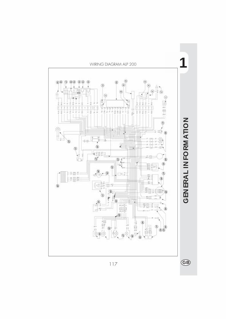
1
GEN
ERA
L IN
FORM
ATI
ON
117 GB
WIRING DIAGRAM ALP 200
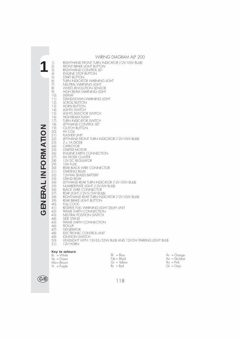
1
GEN
ERA
L IN
FORM
ATI
ON
118GB
1) RIGHT-HAND FRONT TURN INDICATOR (12V-10W BULB)2) FRONT BRAKE LIGHT BUTTON3) RIGHT-HAND CONTROL SET4) ENGINE STOP BUTTON5) START BUTTON6) TURN INDICATOR WARNING LIGHT7) NEUTRAL WARNING LIGHT8) WHEEL REVOLUTION SENSOR9) HIGH BEAM WARNING LIGHT10) DISPLAY11) STAND-DOWN WARNING LIGHT12) SCROLL BUTTON13) HORN BUTTON14) LIGHTS SWITCH15) LIGHTS SELECTOR SWITCH16) HIGH-BEAM FLASH17) TURN INDICATOR SWITCH18) LEFT-HAND CONTROL SET19) CLUTCH BUTTON20) HV COIL21) FLASHER UNIT22) LEFT-HAND FRONT TURN INDICATOR (12V-10W BULB)23) 2 x 1A DIODE24) CAPACITOR25) STARTER MOTOR26) ENGINE EARTH CONNECTION27) 6A DIODE CLUSTER28) 12V DC REGULATOR29) 10A FUSE30) REAR BLACK WIRE CONNECTOR31) STARTING RELAY32) 12V-9Ah SEALED BATTERY33) STAND RELAY34) LEFT-HAND REAR TURN INDICATOR (12V-10W BULB)35) NUMBER-PLATE LIGHT (12V-5W BULB)36) BLACK WIRE CONNECTOR37) REAR LIGHT (12V-5/5W BULB)38) RIGHT-HAND REAR TURN INDICATOR (12V-10W BULB)39) REAR BRAKE LIGHT BUTTON40) FULL COCK41) RESERVE FUEL WARNING LIGHT DELAY UNIT42) FRAME EARTH CONNECTION43) NEUTRAL POSITION SWITCH44) SIDE STAND45) FRAME EARTH CONNECTION46) PICK-UP47) GENERATOR48) ELECTRONIC CONTROL UNIT49) IGNITION SWITCH50) HEADLIGHT WITH 12V-35/35W BULB AND 12V-5W PARKING LIGHT BULB51) 12V HORN
WIRING DIAGRAM ALP 200
Key to coloursBi = WhiteVe = GreenMa= BrownVi = Purple
Bl = BlueNe = BlackGi = YellowRs = Red
Ar = OrangeAz = Sky-blueRo = PinkGr = Grey
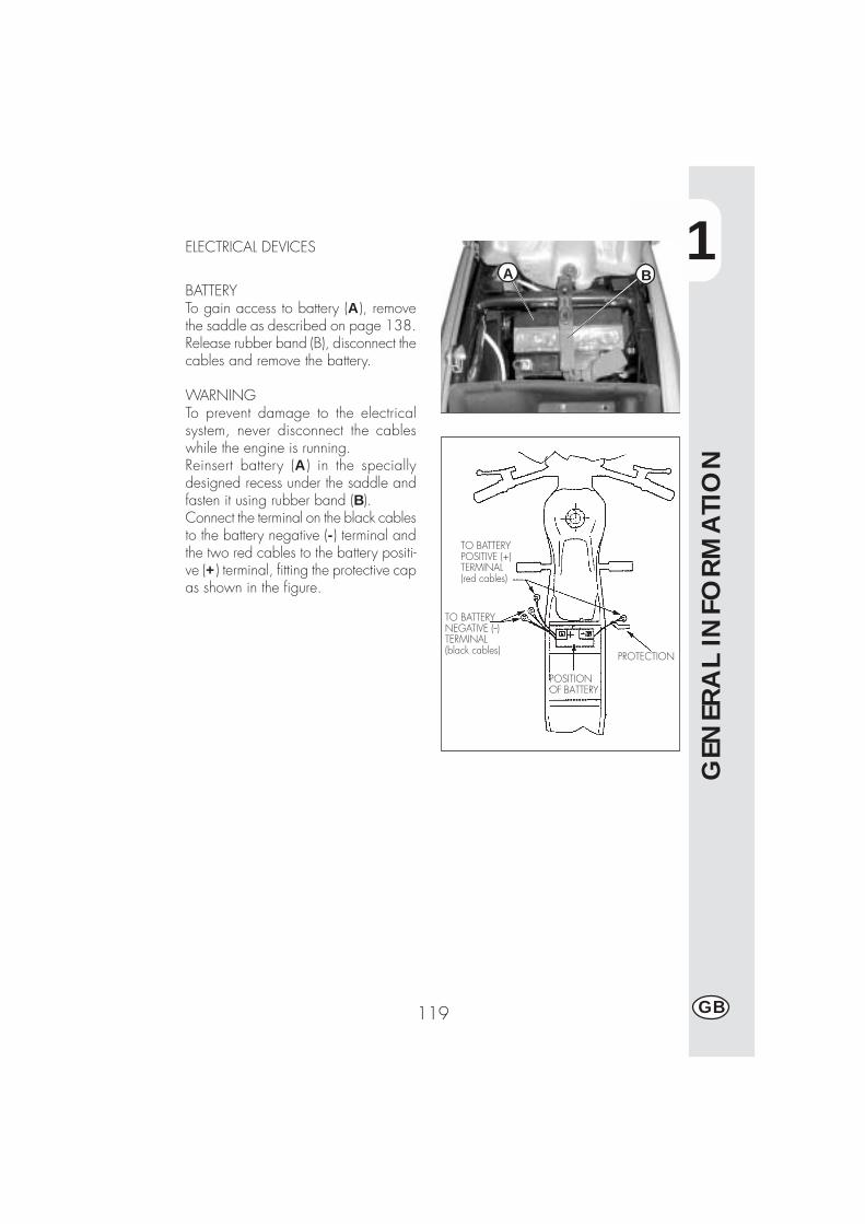
1
GEN
ERA
L IN
FORM
ATI
ON
119 GB
TO BATTERYPOSITIVE (+)TERMINAL(red cables)
TO BATTERYNEGATIVE (--)TERMINAL(black cables)
POSITIONOF BATTERY
PROTECTION
ELECTRICAL DEVICES
BATTERYTo gain access to battery (A), removethe saddle as described on page 138.Release rubber band (B), disconnect thecables and remove the battery.
WARNINGTo prevent damage to the electricalsystem, never disconnect the cableswhile the engine is running.Reinsert battery (A) in the speciallydesigned recess under the saddle andfasten it using rubber band (B).Connect the terminal on the black cablesto the battery negative (-) terminal andthe two red cables to the battery positi-ve (+) terminal, fitting the protective capas shown in the figure.
BA

1
GEN
ERA
L IN
FORM
ATI
ON
120GB
ELECTRONIC CONTROL UNIT -STARTING RELAY - VOLTAGEREGULATORControl unit (C), starter relay switch (D)and voltage regulator (E) are locatedon the right side of the vehicle. To haveaccess to these components, remove thesaddle and the rear side panel asdescribed on page 138.
HV COILTo gain access to coil (F), remove thefuel tank as described on page 138.
FUSE - FLASHER UNIT - STAND RELAYFlasher unit (G), stand relay (H) and fusebox (I) are installed under the controlunit. To replace any of thesecomponents, remove the saddle and therear side panel as described on page138, then disengage control unit (C)from its rubber support.
C
D
E
F
GH
I
2
OPER
ATI
ON
121 GB
CONTENTS
CHAPTER 2 OPERATION
Checks and maintenance before and after off-road use
Recommended lubricants and fluids
Running-in
Starting the engine
Shutting off the engine
Refuelling
2
OPER
ATI
ON
122GB
CHECKS AND MAINTENANCE OPERATIONS BEFORE AND AFTER OFF-ROADUSE
To avoid trouble during operation, it is advisable to perform a few checks andmaintenance operations before and after riding. In addition to making your vehiclesafer, a few minutes spent carrying out these operations will enable you to save timeand money.Follow these steps:
TYRES Check the inflating pressures, the general condition, and thetread depth.
SPOKES Check the tensioning.NUTS AND BOLTS Check the tightening of all nuts and bolts.DRIVE CHAIN Check the tension (play = 20 mm) and if necessary grease.AIR FILTER Clean the filter and wet it with oil.
NoteCheck for the presence of the vehicle identification papers.In cold weather, it is advisable to warm up the engine by letting it idle for a fewmoments before starting off.The vehicle needs to be carefully washed every time it is used over rough ground.
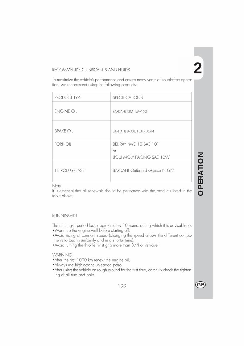
2
OPER
ATI
ON
123 GB
PRODUCT TYPE SPECIFICATIONS
ENGINE OIL BARDAHL XTM 15W 50
BRAKE OIL BARDAHL BRAKE FLUID DOT4
FORK OIL BEL RAY “MC 10 SAE 10”
or
LIQUI MOLY RACING SAE 10W
TIE ROD GREASE BARDAHL Outboard Grease NLGI2
RECOMMENDED LUBRICANTS AND FLUIDS
To maximize the vehicle’s performance and ensure many years of trouble-free opera-tion, we recommend using the following products:
NoteIt is essential that all renewals should be performed with the products listed in thetable above.
RUNNING-IN
The running-in period lasts approximately 10 hours, during which it is advisable to:�Warm up the engine well before starting off.�Avoid riding at constant speed (changing the speed allows the different compo-nents to bed in uniformly and in a shorter time).
�Avoid turning the throttle twist grip more than 3/4 of its travel.
WARNING�After the first 1000 km renew the engine oil.�Always use high-octane unleaded petrol.�After using the vehicle on rough ground for the first time, carefully check the tighten-ing of all nuts and bolts.
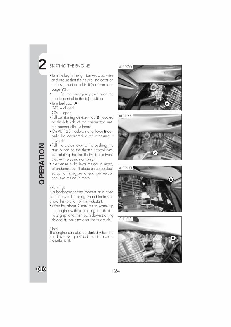
2
OPER
ATI
ON
124GB
STARTING THE ENGINE
�Turn the key in the ignition key clockwiseand ensure that the neutral indicator onthe instrument panel is lit (see item 5 onpage 93).
� Set the emergency switch on thethrottle control to the (o) position.
�Turn fuel cock A:OFF = closedON = open
�Pull out starting device knob B, locatedon the left side of the carburettor, untilthe second click is heard.
�On ALP125 models, starter lever B canonly be operated after pressing itinwards.
�Pull the clutch lever while pushing thestart button on the throttle control with-out rotating the throttle twist grip (vehi-cles with electric start only).
� Intervenire sulla leva messa in moto,affondando con il piede un colpo deci-so quindi ripiegare la leva (per veicolicon leva messa in moto).
Warning:If a backward-shifted footrest kit is fitted(for trial use), lift the right-hand footrest toallow the rotation of the kick-start.�Wait for about 2 minutes to warm upthe engine without rotating the throttletwist grip, and then push down startingdevice B, pausing after the first click.
Note:The engine can also be started when thestand is down provided that the neutralindicator is lit.
A
B
ALP200
ALP125
ALP125
ALP200
A
B
2
OPER
ATI
ON
125 GB
ImportantWhen the stand is down, the red warn-ing light on the instrument panel stays litand the engine stops for safety reasonsas soon as the gears are engaged, evenif the clutch lever is pulled.Always retract the stand before puttinginto gear.
NoteIn an emergency, the vehicle can alsobe operated without a battery.
SHUTTING OFF THE ENGINE
�While the vehicle is stationary and inneutral gear, rotate the ignition key tothe “OFF” position.
�Before stopping the engine after a longride, it is advisable to let it idle for afew moments.
�Always close the fuel cock after stop-ping the engine.

2
OPER
ATI
ON
126GB
A
REFUELLING
�Switch off the engine.�Remove cap A.
NoteThe fuel tank capacity is approximately6.8 litres, including 1.5 litres reserve.
Any spills of petrol on the bodywork orother parts of the motorcycle must be re-moved immediately.
Shut off the engine before refuelling.Petrol is extremely flammable. Take carenot to spill any petrol from the tank orwhile refuelling.
Do not keep open flames or lighted ciga-rettes close to the fuel filler: fire hazard.Also avoid inhaling noxious fumes.
3
CH
ECK
S A
ND
MA
INTE
NA
NCE
127 GB
CONTENTS
CHAPTER 3 CHECKS AND MAINTENANCE
Engine oil and oil filter
Fume collecting tube
Brake pump oil - Bleeding the brakes
Fork oil
Air filter
Spark plug
Front and rear brakes
Battery
Removing the bodywork
Notes for trial use
Cleaning and checking the vehicle
Scheduled maintenance
Prolonged inactivity
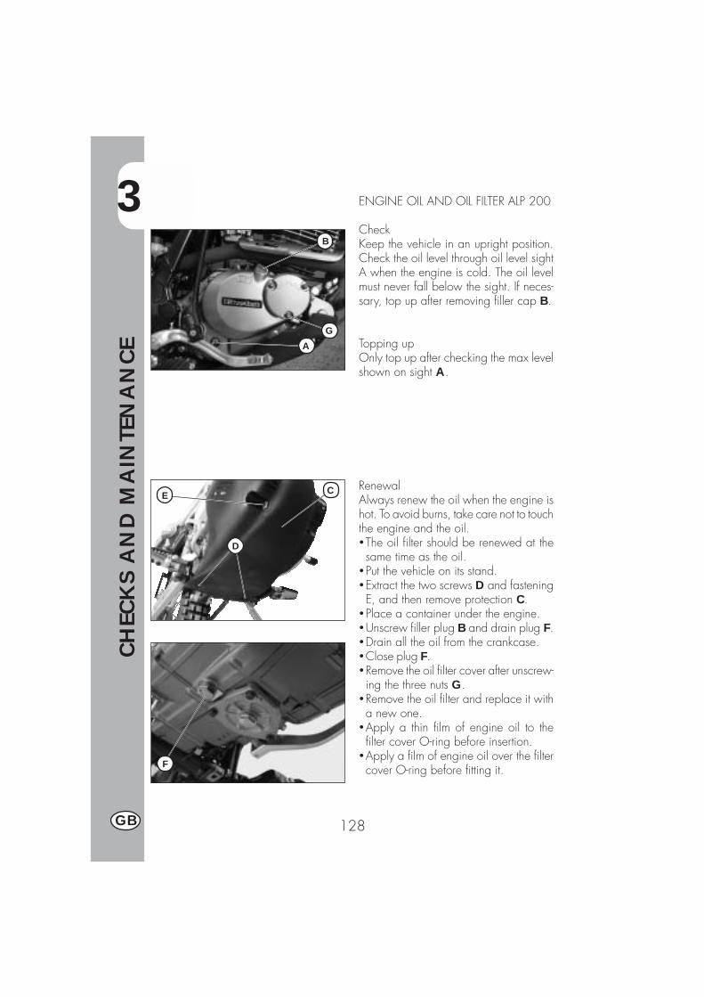
3
CH
ECK
S A
ND
MA
INTE
NA
NCE
128GB
ENGINE OIL AND OIL FILTER ALP 200
CheckKeep the vehicle in an upright position.Check the oil level through oil level sightA when the engine is cold. The oil levelmust never fall below the sight. If neces-sary, top up after removing filler cap B.
Topping upOnly top up after checking the max levelshown on sight A.
RenewalAlways renew the oil when the engine ishot. To avoid burns, take care not to touchthe engine and the oil.�The oil filter should be renewed at thesame time as the oil.
�Put the vehicle on its stand.�Extract the two screws D and fasteningE, and then remove protection C.
�Place a container under the engine.�Unscrew filler plug B and drain plug F.�Drain all the oil from the crankcase.�Close plug F.�Remove the oil filter cover after unscrew-ing the three nuts G.
�Remove the oil filter and replace it witha new one.
�Apply a thin film of engine oil to thefilter cover O-ring before insertion.
�Apply a film of engine oil over the filtercover O-ring before fitting it.
B
GA
C
D
E
F
3
CH
ECK
S A
ND
MA
INTE
NA
NCE
129 GB
�Fit the oil filter cover after fitting the springand the O-ring, and then tighten the threefastening nuts.
�Pour in the necessary quantity of oil.�Close the filler plug and then refit the pro-tection taking care to position the spacersin sequence.
�Start the engine and allow it to idle for afew minutes.
�Switch off the engine, wait for about aminute, and then check the level. If nec-essary top up without exceeding the maxlevel.Engine oil capacity:oil change ........................... 850 mlwith filter replacement ............ 950 mloverhaul ........................... 1,300 ml
NoteRenew the oil after the first 1,000 km.Subsequent renewals should be every5,000 km 15 months, (refer to the tableon page 142). Always use the lubricantsshown on page 123.The oil filter should be replaced for the firsttime when the oil is first renewed, and sub-sequently every 10,000 km (30 months).
ImportantDispose of used oil in compliance with theregulations in force.
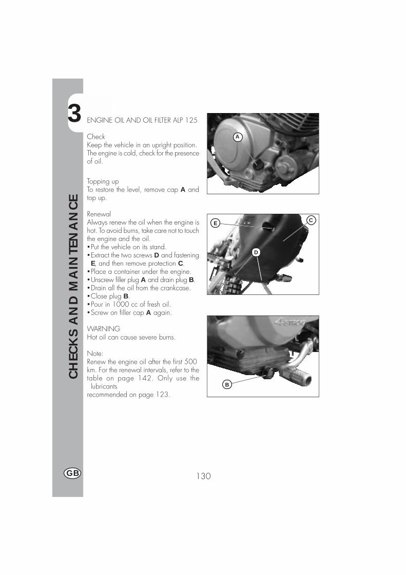
3
CH
ECK
S A
ND
MA
INTE
NA
NCE
130GB
A
C
D
E
B
ENGINE OIL AND OIL FILTER ALP 125
CheckKeep the vehicle in an upright position.The engine is cold, check for the presenceof oil.
Topping upTo restore the level, remove cap A andtop up.
RenewalAlways renew the oil when the engine ishot. To avoid burns, take care not to touchthe engine and the oil.�Put the vehicle on its stand.�Extract the two screws D and fasteningE, and then remove protection C.
�Place a container under the engine.�Unscrew filler plug A and drain plug B.�Drain all the oil from the crankcase.�Close plug B.�Pour in 1000 cc of fresh oil.�Screw on filler cap A again.
WARNINGHot oil can cause severe burns.
Note:Renew the engine oil after the first 500km. For the renewal intervals, refer to thetable on page 142. Only use thelubricants
recommended on page 123.

3
CH
ECK
S A
ND
MA
INTE
NA
NCE
131 GB
FUME COLLECTING PIPE
Fume collecting tube A is located on theleft side of the vehicle next to the shockabsorber. It comes out of the lower part ofthe filter box and is designed to collect thefumes produced by the engine oil. It is de-signed to collect the fumes produced bythe engine oil. Should any oil be found inthe tube, remove the cap at the lower endof the tube and drain the oil, or the mixtureof oil and petrol, into a suitable container.Disposal is to be made according to theregulations in force.Note
A
C
BA
DE
Empty the fume collecting tube every3,000 km.
BRAKE PUMP OIL - BLEEDING THEBRAKES
Front brakeCheck that oil is present by lookingthrough oil level sight A. The minimumoil level should never be lower than themark on sight A. To restore the oil level,loosen the two screws B, lift cover C andpour in fresh oil.
Rear brakeCheck that oil is present by lookingthrough reservoir D. The oil level mustnever be lower than the minimum levelmark on reservoir D. To restore the level,remove filler cap E and top up with freshoil.
WARNINGA spongy feel of the brake lever may bedue to an air bubble in the braking sys-tem. Immediately contact an authorizedworkshop.
NoteFor information on oil renewals, refer tothe table on page 142. Use the recom-mended lubricants shown on page 123.
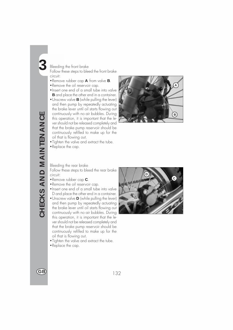
3
CH
ECK
S A
ND
MA
INTE
NA
NCE
132GB
DC
A
B
Bleeding the front brakeFollow these steps to bleed the front brakecircuit:�Remove rubber cap A from valve B.�Remove the oil reservoir cap.� Insert one end of a small tube into valveB and place the other end in a container.
�Unscrew valve B (while pulling the lever)and then pump by repeatedly actuatingthe brake lever until oil starts flowing outcontinuously with no air bubbles. Duringthis operation, it is important that the le-ver should not be released completely andthat the brake pump reservoir should becontinuously refilled to make up for theoil that is flowing out.
�Tighten the valve and extract the tube.�Replace the cap.
Bleeding the rear brakeFollow these steps to bleed the rear brakecircuit:�Remove rubber cap C.�Remove the oil reservoir cap.� Insert one end of a small tube into valveD and place the other end in a container.
�Unscrew valve D (while pulling the lever)and then pump by repeatedly actuatingthe brake lever until oil starts flowing outcontinuously with no air bubbles. Duringthis operation, it is important that the le-ver should not be released completely andthat the brake pump reservoir should becontinuously refilled to make up for theoil that is flowing out.
�Tighten the valve and extract the tube.�Replace the cap.
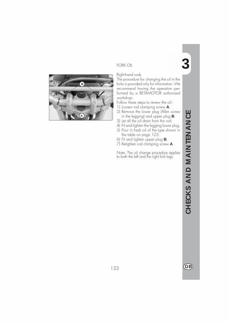
3
CH
ECK
S A
ND
MA
INTE
NA
NCE
133 GB
FORK OIL
Right-hand rodsThe procedure for changing the oil in theforks is provided only for information. Werecommend having the operation per-formed by a BETAMOTOR authorizedworkshop.Follow these steps to renew the oil:1) Loosen rod clamping screw A.2) Remove the lower plug (Allen screw
in the legging) and upper plug B.3) Let all the oil drain from the rod.4) Fit and tighten the legging lower plug.5) Pour in fresh oil of the type shown in
the table on page 123.6) Fit and tighten upper plug B.7) Retighten rod clamping screw A.
Note: The oil change procedure appliesto both the left and the right fork legs.
A
B

3
CH
ECK
S A
ND
MA
INTE
NA
NCE
134GB
AIR FILTER
Follow these steps to gain access to theair filter.�Turn fastener D 90 degrees anti-clockwise and remove the saddle bypulling it towards the back of the vehicle.
�Remove side panel B after unscrewingthe screws shown in the figure.
�Take off plastic cover A after unscrewingthe 7 fixing screws, then follow thesesteps:�Unscrew the filter cover fixing screwand remove filter C .
�Wash it with soap and water.�Dry the filter.�Wet the filter with filter oil. Removeany excess lubricant to prevent it fromdripping.
� If necessary, also clean the inside ofthe filter casing.
�Refit the parts, making sure of the sealof the rubber gasket.
Note: If the filter is very dirty, first wash itwith a special detergent and then withwater and shampoo.If the filter is damaged, immediately re-place it.
WARNING:After working on the filter, ensure thatnothing is left inside the filter casing.
Clean the filter every time the vehicle isused off road.
C
B
A
D
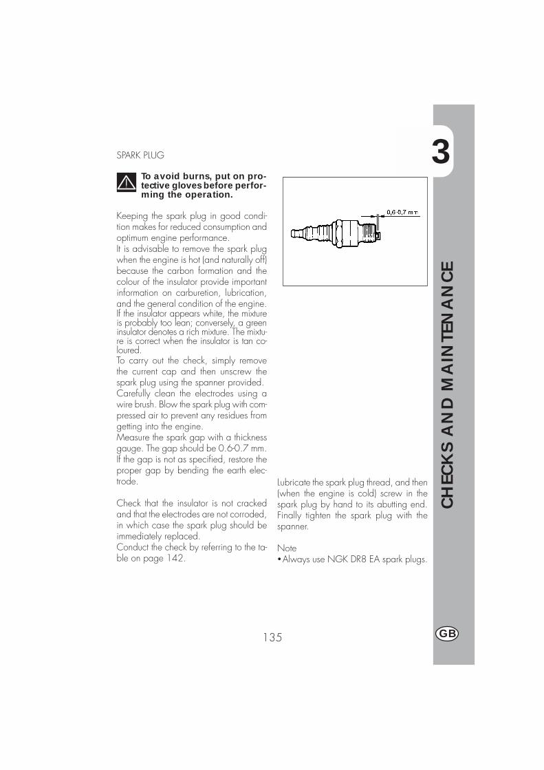
3
CH
ECK
S A
ND
MA
INTE
NA
NCE
135 GB
SPARK PLUG
To avoid burns, put on pro-tective gloves before perfor-ming the operation.
Keeping the spark plug in good condi-tion makes for reduced consumption andoptimum engine performance.It is advisable to remove the spark plugwhen the engine is hot (and naturally off)because the carbon formation and thecolour of the insulator provide importantinformation on carburetion, lubrication,and the general condition of the engine.If the insulator appears white, the mixtureis probably too lean; conversely, a greeninsulator denotes a rich mixture. The mixtu-re is correct when the insulator is tan co-loured.To carry out the check, simply removethe current cap and then unscrew thespark plug using the spanner provided.Carefully clean the electrodes using awire brush. Blow the spark plug with com-pressed air to prevent any residues fromgetting into the engine.Measure the spark gap with a thicknessgauge. The gap should be 0.6-0.7 mm.If the gap is not as specified, restore theproper gap by bending the earth elec-trode.
Check that the insulator is not crackedand that the electrodes are not corroded,in which case the spark plug should beimmediately replaced.Conduct the check by referring to the ta-ble on page 142.
Lubricate the spark plug thread, and then(when the engine is cold) screw in thespark plug by hand to its abutting end.Finally tighten the spark plug with thespanner.
Note�Always use NGK DR8 EA spark plugs.

3
CH
ECK
S A
ND
MA
INTE
NA
NCE
136GB
FRONT BRAKE
CheckTo check the wear of the front brake, visu-ally inspect the brake pad ends by look-ing at the brake caliper from the front.The brake linings should be at least 2mm thick. If the linings are thinner, replacethe pads immediately.
NoteCarry out the check at the intervals shownin the table on page 142.
REAR BRAKE
CheckTo check the wear of the rear brake, visu-ally inspect the brake pad ends by look-ing at the brake caliper from above. Thebrake linings should be at least 2 mmthick. If the linings are thinner, replacethe pads immediately.
NoteCarry out the check at the intervals shownin the table on page 142.

3
CH
ECK
S A
ND
MA
INTE
NA
NCE
137 GB
BATTERY
Check the charge of the battery by meas-uring the voltage with a voltmeter whilethe battery is at rest (engine off). The volt-age must not be less than 12.8 V.There is no need to check the level of theelectrolyte or top up with water.Keep the battery terminals clean. Ifnecessary, protect them with a thin filmof acid-free grease.

3
CH
ECK
S A
ND
MA
INTE
NA
NCE
138GB
B BA
C
C
D
F
E
REMOVING THE BODYWORKTo facilitate checks and operations in cer-tain areas of the vehicle, it is essential toremove the bodywork sections as de-scribed below.
Removing the saddleRemove the screw fixing the saddle to themudguard and then remove the saddle bypushing it towards the rear of the vehicleso as to disengage it from the hook on thefuel tank.
Removing the carrierRemove the three screws A fixing the car-rier to the mudguard and then remove thecarrier.
Removing the side panelAfter removing the air filter cover as de-scribed in the chapter “Air Filter”, unscrewthe four fixing screws B. One of the screwsis on the left side (under the filter box cover)whereas the rear screw is located under-neath the mudguard cover (not in view).
Removing the front side panelsRemove the six fixing screws C (three oneach side), two of which located underthe fuel tank, and then remove the frontside panels.
Removing the fuel tankRemove screw D fixing the fuel tank to theframe, detach the fuel cock line and thenremove the tank by pulling it towards therear of the vehicle.
Removing the headlightDetach all the electrical connections andunscrew the three fixing screws E, one ofwhich located under the headlight.
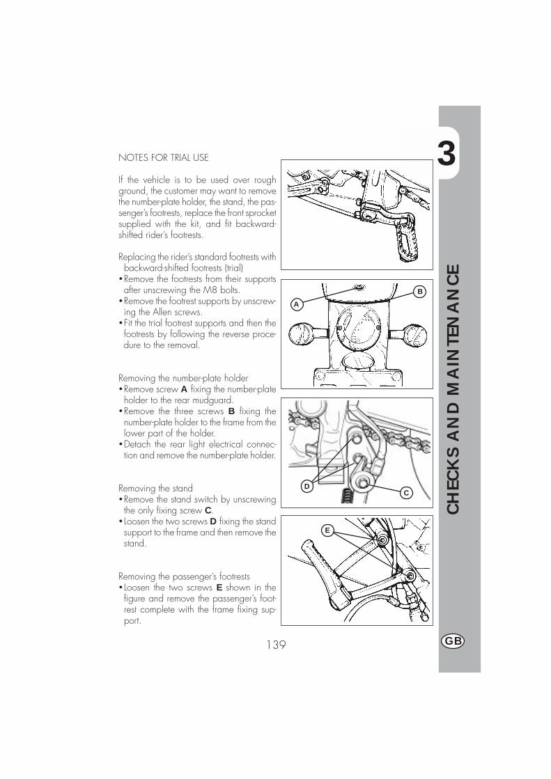
3
CH
ECK
S A
ND
MA
INTE
NA
NCE
139 GB
A
B
CD
E
NOTES FOR TRIAL USE
If the vehicle is to be used over roughground, the customer may want to removethe number-plate holder, the stand, the pas-senger’s footrests, replace the front sprocketsupplied with the kit, and fit backward-shifted rider’s footrests.
Replacing the rider’s standard footrests withbackward-shifted footrests (trial)
�Remove the footrests from their supportsafter unscrewing the M8 bolts.
�Remove the footrest supports by unscrew-ing the Allen screws.
�Fit the trial footrest supports and then thefootrests by following the reverse proce-dure to the removal.
Removing the number-plate holder�Remove screw A fixing the number-plateholder to the rear mudguard.
�Remove the three screws B fixing thenumber-plate holder to the frame from thelower part of the holder.
�Detach the rear light electrical connec-tion and remove the number-plate holder.
Removing the stand�Remove the stand switch by unscrewingthe only fixing screw C.
� Loosen the two screws D fixing the standsupport to the frame and then remove thestand.
Removing the passenger’s footrests� Loosen the two screws E shown in thefigure and remove the passenger’s foot-rest complete with the frame fixing sup-port.
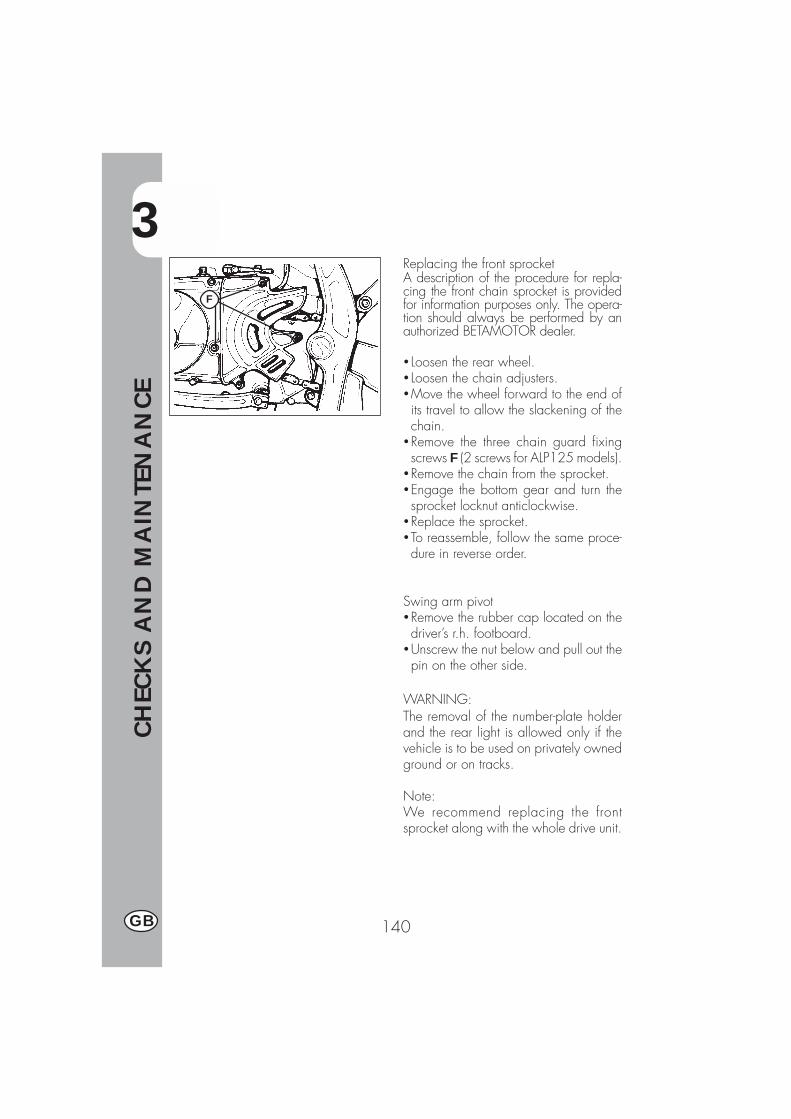
3
CH
ECK
S A
ND
MA
INTE
NA
NCE
140GB
Replacing the front sprocketA description of the procedure for repla-cing the front chain sprocket is providedfor information purposes only. The opera-tion should always be performed by anauthorized BETAMOTOR dealer.
� Loosen the rear wheel.� Loosen the chain adjusters.�Move the wheel forward to the end ofits travel to allow the slackening of thechain.
�Remove the three chain guard fixingscrews F (2 screws for ALP125 models).
�Remove the chain from the sprocket.�Engage the bottom gear and turn thesprocket locknut anticlockwise.
�Replace the sprocket.�To reassemble, follow the same proce-dure in reverse order.
Swing arm pivot�Remove the rubber cap located on thedriver’s r.h. footboard.
�Unscrew the nut below and pull out thepin on the other side.
WARNING:The removal of the number-plate holderand the rear light is allowed only if thevehicle is to be used on privately ownedground or on tracks.
Note:We recommend replacing the frontsprocket along with the whole drive unit.
F
3
CH
ECK
S A
ND
MA
INTE
NA
NCE
141 GB
CLEANING AND CHECKING THE VEHICLE
Use a low-pressure water jet to soften the dirt and mud accumulated on the paintwork,then remove them with a soft bodywork sponge soaked in water and shampoo (2-4percent shampoo in water). Rinse generously with water and wipe dry with chamoisleather. For the outside of the engine use a brush soaked in petroleum and cleanrags. Petroleum damages the paintwork. Always wash the vehicle before waxing itwith silicon waxes.
Detergents pollute the waters. Always wash the vehicle in areas equipped forthe collection and purification of the washing liquids.
Never wash the vehicle in the sun, particularly during the summer when thebodywork is hot. The shampoo would dry before being rinsed off and cause
damage to the paintwork. Do not clean the plastic surfaces with cloths soaked inpetrol or naphtha as they would lose their shine and mechanical properties.
CHECKS AFTER CLEANING
After cleaning the motorcycle, it is advisable to:
�Clean the air filter (refer to the procedure described on page 134).�Grease the chain.
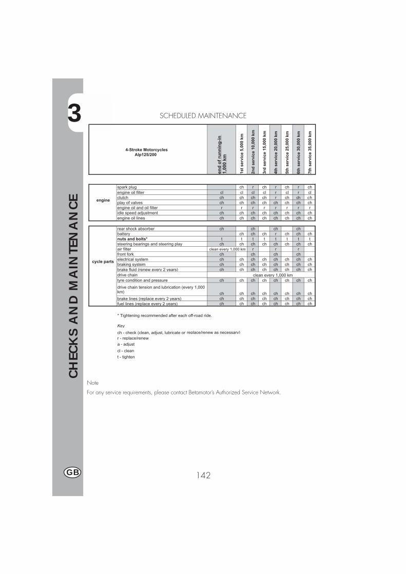
3
CH
ECK
S A
ND
MA
INTE
NA
NCE
142GB
SCHEDULED MAINTENANCE
Note
For any service requirements, please contact Betamotor’s Authorized Service Network.
4-Stroke Motorcycles Alp125/200
end
of
run
nin
g-i
n
1,00
0 km
1st
serv
ice
5,00
0 km
2nd
ser
vice
10,
000
km
3rd
ser
vice
15,
000
km
4th
ser
vice
20,
000
km
5th
ser
vice
25,
000
km
6th
ser
vice
30,
000
km
7th
ser
vice
35,
000
km
engine
spark plug ch r ch r ch r chengine oil filter cl cl cl cl r cl r clclutch ch ch ch ch r ch ch chplay of valves ch ch ch ch ch ch ch chengine oil and oil filter r r r r r r r ridle speed adjustment ch ch ch ch ch ch ch chengine oil lines ch ch ch ch ch ch ch ch
cycle parts
rear shock absorber ch ch ch chbattery ch ch ch r ch ch chnuts and bolts* t t t t t t t tsteering bearings and steering play ch ch ch ch ch ch ch chair filter r r rfront fork ch ch ch chelectrical system ch ch ch ch ch ch ch chbraking system ch ch ch ch ch ch ch chbrake fluid (renew every 2 years) ch ch ch ch ch ch ch chdrive chaintyre condition and pressure ch ch ch ch ch ch ch ch
drive chain tension and lubrication (every 1,000 km) ch ch ch ch ch ch ch chbrake lines (replace every 2 years) ch ch ch ch ch ch ch chfuel lines (replace every 2 years) ch ch ch ch ch ch ch ch
* Tightening recommended after each off-road ride.
Key
ch - check (clean, adjust, lubricate or replace/renew as necessary)r - replace/renewa - adjust
cl - clean
t - tighten
clean every 1,000 km
clean every 1,000 km
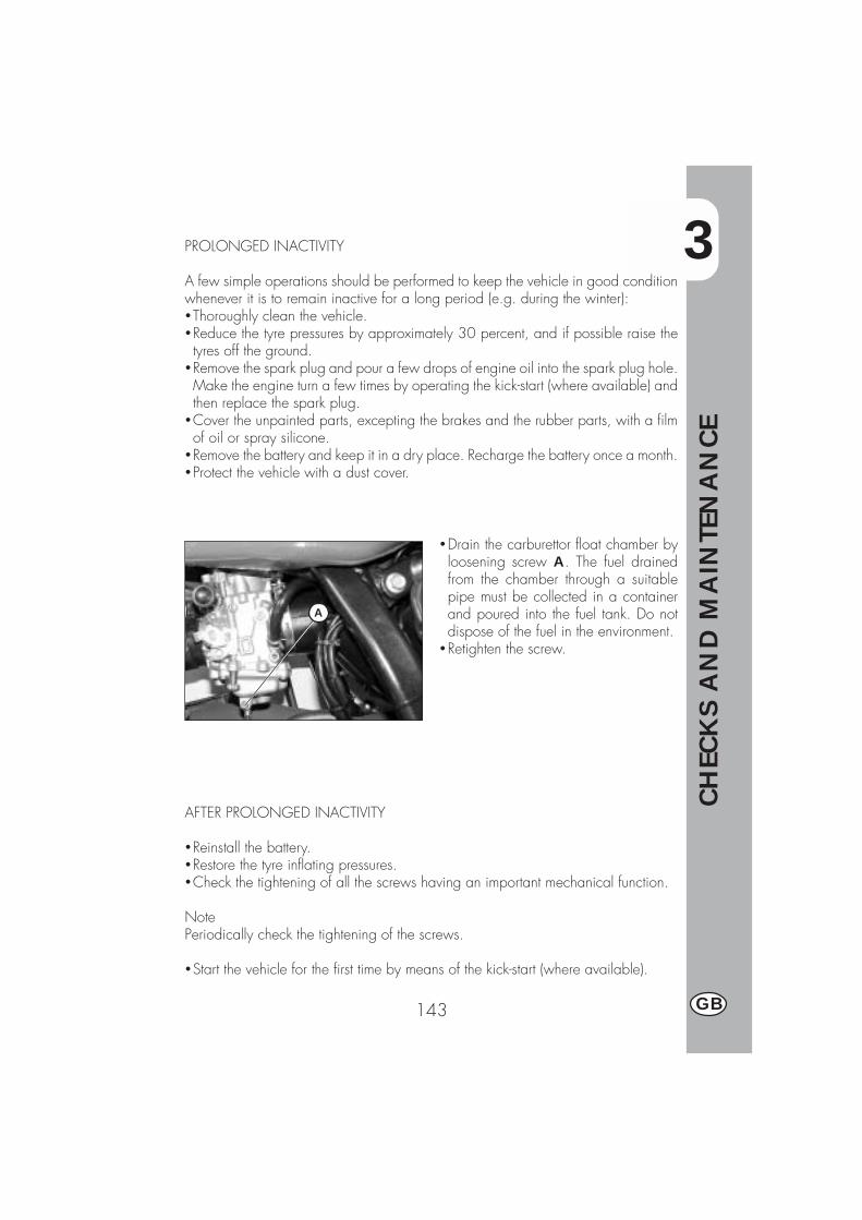
3
CH
ECK
S A
ND
MA
INTE
NA
NCE
143 GB
�Drain the carburettor float chamber byloosening screw A. The fuel drainedfrom the chamber through a suitablepipe must be collected in a containerand poured into the fuel tank. Do notdispose of the fuel in the environment.
�Retighten the screw.
AFTER PROLONGED INACTIVITY
�Reinstall the battery.�Restore the tyre inflating pressures.�Check the tightening of all the screws having an important mechanical function.
NotePeriodically check the tightening of the screws.
�Start the vehicle for the first time by means of the kick-start (where available).
PROLONGED INACTIVITY
A few simple operations should be performed to keep the vehicle in good conditionwhenever it is to remain inactive for a long period (e.g. during the winter):�Thoroughly clean the vehicle.�Reduce the tyre pressures by approximately 30 percent, and if possible raise thetyres off the ground.
�Remove the spark plug and pour a few drops of engine oil into the spark plug hole.Make the engine turn a few times by operating the kick-start (where available) andthen replace the spark plug.
�Cover the unpainted parts, excepting the brakes and the rubber parts, with a filmof oil or spray silicone.
�Remove the battery and keep it in a dry place. Recharge the battery once a month.�Protect the vehicle with a dust cover.
A


4
AD
JUST
MEN
TS
145 GB
CONTENTS
CHAPTER 4 ADJUSTMENTS
Adjusting the brakes
Adjusting the clutch
Adjusting the slow running
Adjusting the throttle play
Checking and adjusting the steering play
Tensioning the chain
Adjusting the headlight

4
AD
JUST
MEN
TS
146GB
C
B
FD E
ADJUSTING THE BRAKES
Front brakeThe front brake is a hydraulically operateddisc brake, and therefore requires noadjustment.
Rear brakeThe rear brake is a hydraulically operateddisc brake.The brake pedal can be adjusted for heightby means of adjusters B and C.The brake lever play should never be lessthan 5 mm.
ADJUSTING THE CLUTCH
The only operation that may be required isthe adjustment of the position of clutch le-ver E.The adjustment is obtained by means ofadjuster D.After adjusting the lever with the adjustingscrew, be sure to tighten stop F so as tolock the screw in the desired position.
NoteThe play of the clutch should range from0.4 to 0.6 mm.
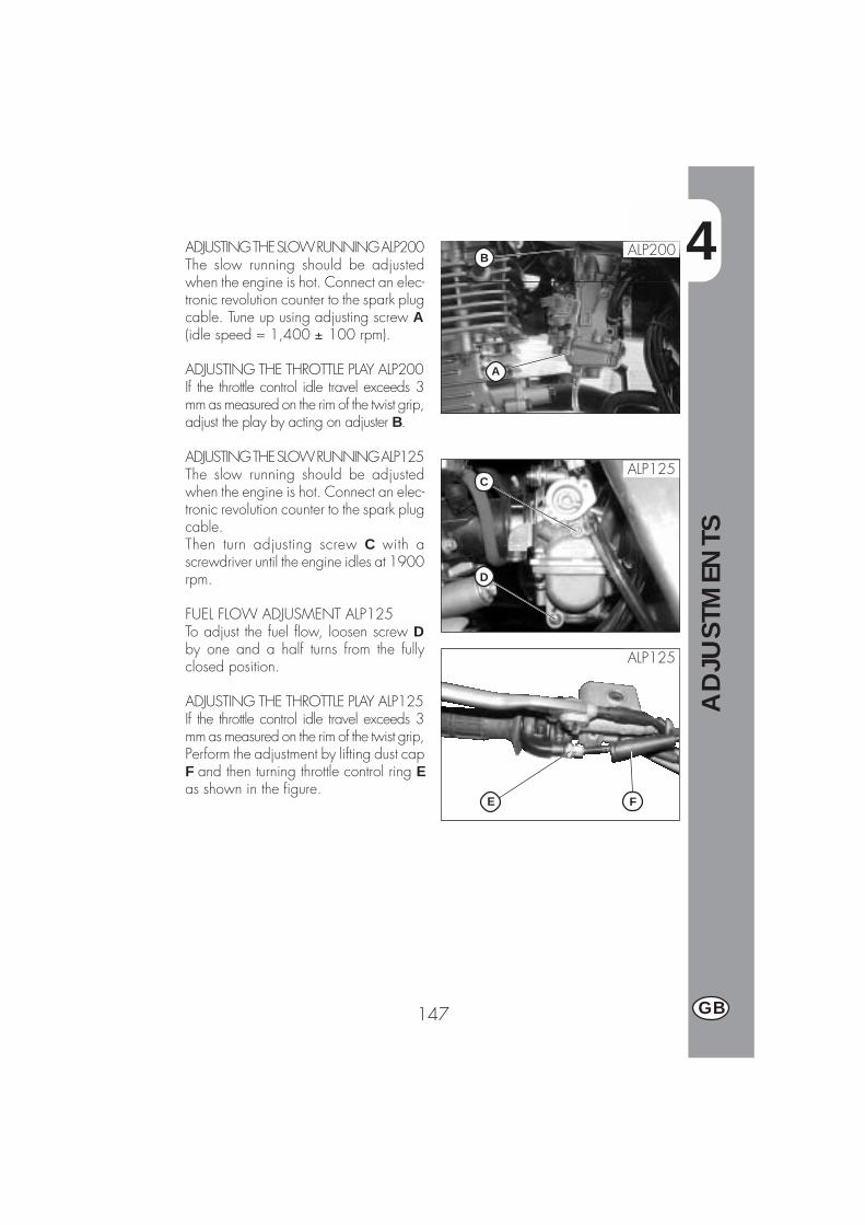
4
AD
JUST
MEN
TS
147 GB
A
BADJUSTING THE SLOW RUNNING ALP200The slow running should be adjustedwhen the engine is hot. Connect an elec-tronic revolution counter to the spark plugcable. Tune up using adjusting screw A(idle speed = 1,400 ± 100 rpm).
ADJUSTING THE THROTTLE PLAY ALP200If the throttle control idle travel exceeds 3mm as measured on the rim of the twist grip,adjust the play by acting on adjuster B.
ADJUSTING THE SLOW RUNNING ALP125The slow running should be adjustedwhen the engine is hot. Connect an elec-tronic revolution counter to the spark plugcable.Then turn adjusting screw C with ascrewdriver until the engine idles at 1900rpm.
FUEL FLOW ADJUSMENT ALP125To adjust the fuel flow, loosen screw Dby one and a half turns from the fullyclosed position.
ADJUSTING THE THROTTLE PLAY ALP125If the throttle control idle travel exceeds 3mm as measured on the rim of the twist grip,Perform the adjustment by lifting dust capF and then turning throttle control ring Eas shown in the figure.
ALP125
ALP125
D
C
FE
ALP200

4
AD
JUST
MEN
TS
148GB
D
F
G E
C
CHECKING AND ADJUSTING THESTEERING PLAY
Periodically check the play of thesteering head tube by moving the forksbackwards and forwards as shown inthe figure. If any play is felt, carry outthe adjustment by following these steps:�Unscrew the four screws C.�Pull out handlebar D, paying specialattention to clevises E.
� Loosen nut F.�Reduce the play by turning ring G.To refit the parts, follow the reverse pro-cedure.
NoteProper adjustment must leave no playand cause no stiffness, and allow thesteering to rotate smoothly. Check thefitting direction of the clevises as it canalter the geometry of the handlebar.
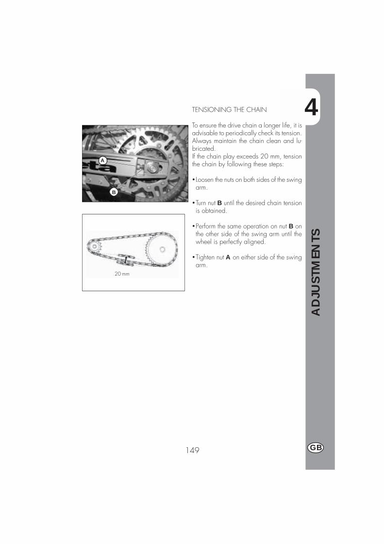
4
AD
JUST
MEN
TS
149 GB
20 mm
B
A
TENSIONING THE CHAIN
To ensure the drive chain a longer life, it isadvisable to periodically check its tension.Always maintain the chain clean and lu-bricated.If the chain play exceeds 20 mm, tensionthe chain by following these steps:
� Loosen the nuts on both sides of the swingarm.
�Turn nut B until the desired chain tensionis obtained.
�Perform the same operation on nut B onthe other side of the swing arm until thewheel is perfectly aligned.
�Tighten nut A on either side of the swingarm.
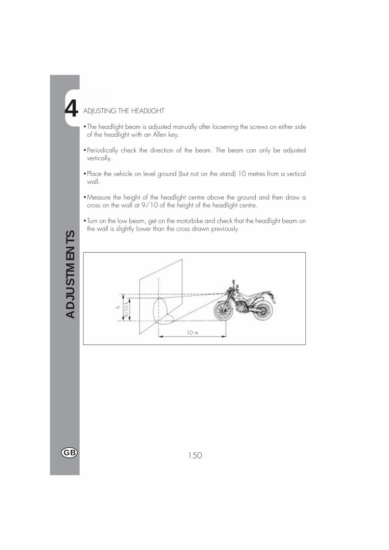
4
AD
JUST
MEN
TS
150GB
9/10
h
10 m
hADJUSTING THE HEADLIGHT
�The headlight beam is adjusted manually after loosening the screws on either sideof the headlight with an Allen key.
�Periodically check the direction of the beam. The beam can only be adjustedvertically.
�Place the vehicle on level ground (but not on the stand) 10 metres from a verticalwall.
�Measure the height of the headlight centre above the ground and then draw across on the wall at 9/10 of the height of the headlight centre.
�Turn on the low beam, get on the motorbike and check that the headlight beam onthe wall is slightly lower than the cross drawn previously.
5
REP
LACEM
ENTS
151 GB
CONTENTS
CHAPTER 5 REPLACEMENTS
Replacing the brake pads
Replacing the headlight bulb
Replacing the rear light bulb
Replacing the turn indicator bulbs

5
REP
LACEM
ENTS
152GB
REPLACING THE BRAKE PADSFRONT BRAKEThe procedure for replacing the brakepads is provided only for information. Werecommend having the operation per-formed by a BETAMOTOR authorizedworkshop.
Follow these steps to replace the pads:
� Loosen the two screws A and removethe brake caliper.
�Unscrew the two screws B.Note: Screws B are secured very tightlyand should be loosened before removingthe caliper from the fork.�Extract the brake pads.�To refit the parts, follow the reverse pro-cedure.
Ensure that the spring D shown in the figu-re is properly seated by checking that itoffers some resistance to the insertion ofthe brake pads.
To avoid braking problems, take specialcare in ensuring that the screws are refittedproperly.
Whenever the brake disc is removed, ap-ply Loctite to the screws when refitting
NOTE: When removing the brakecaliper, take care not to damage reedC, as it is extremely fragile.
A
B
C
D
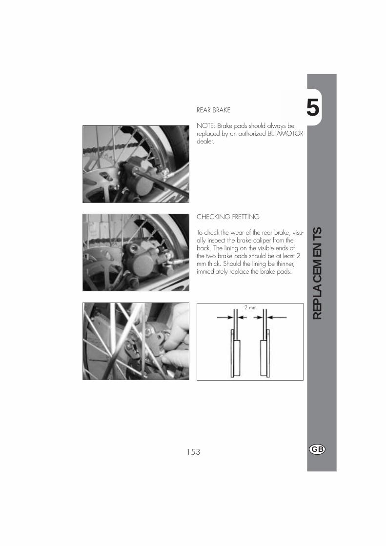
5
REP
LACEM
ENTS
153 GB
REAR BRAKE
NOTE: Brake pads should always bereplaced by an authorized BETAMOTORdealer.
2 mm
CHECKING FRETTING
To check the wear of the rear brake, visu-ally inspect the brake caliper from theback. The lining on the visible ends ofthe two brake pads should be at least 2mm thick. Should the lining be thinner,immediately replace the brake pads.
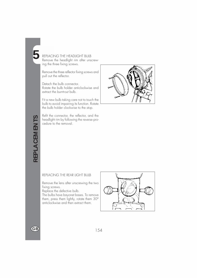
5
REP
LACEM
ENTS
154GB
REPLACING THE HEADLIGHT BULBRemove the headlight rim after unscrew-ing the three fixing screws.
Remove the three reflector fixing screws andpull out the reflector.
Detach the bulb connector.Rotate the bulb holder anticlockwise andextract the burnt-out bulb.
Fit a new bulb taking care not to touch thebulb to avoid impairing its function. Rotatethe bulb holder clockwise to the stop.
Refit the connector, the reflector, and theheadlight rim by following the reverse pro-cedure to the removal.
REPLACING THE REAR LIGHT BULB
Remove the lens after unscrewing the twofixing screws.Replace the defective bulb.The bulbs have bayonet bases. To removethem, press them lightly, rotate them 30°anticlockwise and then extract them.
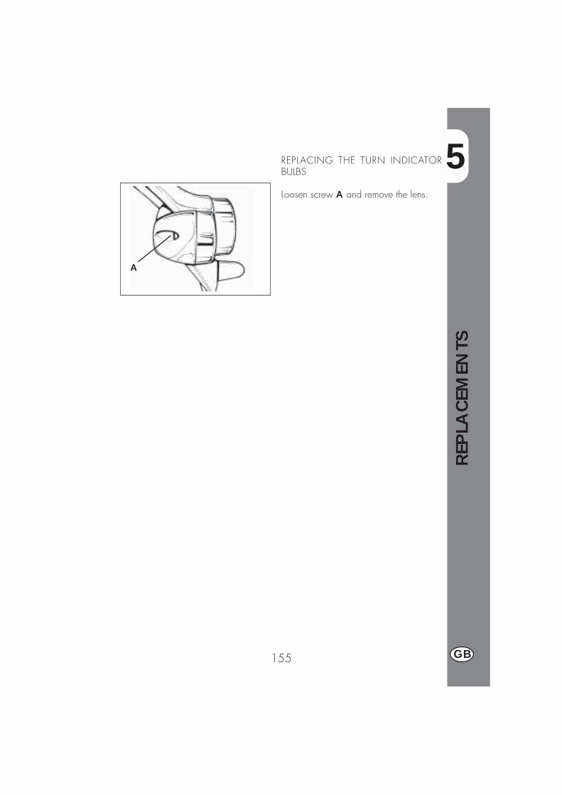
5
REP
LACEM
ENTS
155 GB
REPLACING THE TURN INDICATORBULBS
Loosen screw A and remove the lens.
A

6
TRO
UBLE
SHO
OTI
NG
157 GB
CONTENTS
CHARTER 6 TROUBLESHOOTING
INDEX
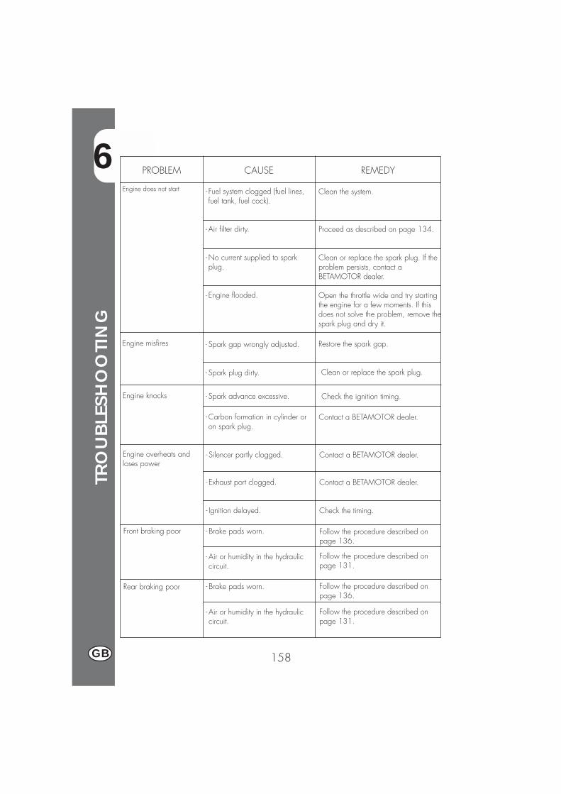
6
TRO
UBLE
SHO
OTI
NG
158GB
PROBLEM CAUSE
Engine does not start
REMEDY
- Fuel system clogged (fuel lines,fuel tank, fuel cock).
- Air filter dirty.
-No current supplied to sparkplug.
- Engine flooded.
Clean the system.
Proceed as described on page 134.
Clean or replace the spark plug. If theproblem persists, contact aBETAMOTOR dealer.
Open the throttle wide and try startingthe engine for a few moments. If thisdoes not solve the problem, remove thespark plug and dry it.
Engine misfires - Spark gap wrongly adjusted.
- Spark plug dirty.
- Spark advance excessive.
- Carbon formation in cylinder oron spark plug.
Restore the spark gap.
Clean or replace the spark plug.
Engine knocks Check the ignition timing.
Contact a BETAMOTOR dealer.
Engine overheats andloses power
- Silencer partly clogged.
- Exhaust port clogged.
- Ignition delayed.
Contact a BETAMOTOR dealer.
Contact a BETAMOTOR dealer.
Check the timing.
Front braking poor - Brake pads worn.
- Air or humidity in the hydrauliccircuit.
- Brake pads worn.
- Air or humidity in the hydrauliccircuit.
Follow the procedure described onpage 136.
Follow the procedure described onpage 131.
Follow the procedure described onpage 136.
Follow the procedure described onpage 131.
Rear braking poor
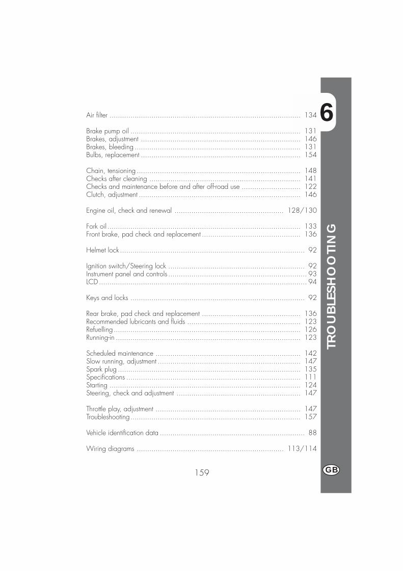
6
TRO
UBLE
SHO
OTI
NG
159 GB
Air filter ........................................................................................... 134
Brake pump oil ................................................................................. 131Brakes, adjustment ............................................................................ 146Brakes, bleeding ............................................................................... 131Bulbs, replacement ............................................................................ 154
Chain, tensioning .............................................................................. 148Checks after cleaning ........................................................................ 141Checks and maintenance before and after off-road use ............................ 122Clutch, adjustment ............................................................................. 146
Engine oil, check and renewal .................................................... 128/130
Fork oil ............................................................................................ 133Front brake, pad check and replacement ............................................... 136
Helmet lock ........................................................................................ 92
Ignition switch/Steering lock ................................................................. 92Instrument panel and controls .................................................................. 93LCD ................................................................................................... 94
Keys and locks ................................................................................... 92
Rear brake, pad check and replacement ............................................... 136Recommended lubricants and fluids ...................................................... 123Refuelling ......................................................................................... 126Running-in ........................................................................................ 123
Scheduled maintenance ..................................................................... 142Slow running, adjustment .................................................................... 147Spark plug ....................................................................................... 135Specifications ................................................................................... 111Starting ........................................................................................... 124Steering, check and adjustment ........................................................... 147
Throttle play, adjustment ..................................................................... 147Troubleshooting................................................................................. 157
Vehicle identification data ..................................................................... 88
Wiring diagrams ...................................................................... 113/114

161 F
ALP4T 125/200 cc
Merci de votre confiance et bon divertissement. Ce livret vousdonnera les informations nécessaires pour une utilisation correcteet un bon entretien de votre moto.
Les informations et les caractéristiques indiquées dans ce manuel n’engagentpas BETAMOTOR S.p.A. qui se réserve le droit d’apporter des modifica-tions et des améliorations à ses modèles à tout moment et sans préavis.
162F
AVERTISSEMENT
Il est recommandé, au bout de la première ou de la secondeheure d’utilisation en tout-terrain, de contrôler tous les serragesavec une attention particulière pour:
� Couronne� Supports de cale-pieds� Étrier de frein avant� Support de garde-boue� Boulonnerie moteur� Boulonnerie amortisseur.� Rayons roue� Cadre arrière
AVERTISSEMENT
En cas d’intervention à effectuer sur la moto, s’adresser au ré-seau d’assistance agréé Betamotor.
TABLE
DES
MA
TIÈR
ES
163 F
Conseils d’utilisation ........................................................................... 165Conduite écologique .......................................................................... 165Conduire en sécurité ........................................................................... 166
CHAP. 1 GÉNÉRALITÉS .......................................................... 167Données d’identification du véhicule ...................................................... 168Equipement ....................................................................................... 168Charge ............................................................................................ 169Pneumatiques .................................................................................... 169Connaissance du véhicule ................................................................... 171Clés et serrures .................................................................................. 172Commutateur / verrouillage de la direction ............................................. 172Serrure du casque .............................................................................. 172Tableau de bord et commandes ............................................................ 173Istructions de mise au point et fonctionnement compteur kilometrique ............ 174Caractéristiques techniques générales .................................................... 191Caractéristiques techniques du moteur ALP 125 ....................................... 193Caractéristiques techniques du moteur ALP 200 ....................................... 194Schéma électrique ALP 125 ................................................................. 195Schéma électrique ALP 200 ................................................................. 197Equipement électrique ......................................................................... 199
CHAP. 2 UTILISATION DU VÉHICULE....................................... 201Contrôles et entretien avant et après l’utilisation en tout-terrain ..................... 202Lubrifiants et liquides conseillés ............................................................. 203Rodage ............................................................................................ 203Démarrage du moteur ......................................................................... 204Arrêt du moteur .................................................................................. 205Approvisionnement en carburant ........................................................... 206
CHAP. 3 CONTRÔLES ET ENTRETIEN ....................................... 207Huile moteur et filtre à huile .......................................................... 208/210Tuyau de récupération des fumées ......................................................... 211Liquide de frein, purge du circuit ........................................................... 211Huile de fourche ................................................................................ 213Filtre à air ......................................................................................... 214Bougie ............................................................................................. 215Freins : avant, arrière .......................................................................... 216Batterie ............................................................................................ 217Dépose de la carrosserie ..................................................................... 218Notes pour le trial .............................................................................. 219Nettoyage du véhicule et contrôles ........................................................ 221Entretien programmé ........................................................................... 222Longue inactivité du véhicule ................................................................ 223
TABLE
DES
MA
TIÈR
ES
164F
HAP. 4 RÉGLAGES ................................................................ 225Réglage des freins .............................................................................. 226Réglage de l’embrayage ..................................................................... 226Réglage du ralenti .............................................................................. 227Réglage du débit d'essence (uniquement pour ALP125) ............................. 227Réglage du jeu à la poignée des gaz .................................................... 227Contrôle et réglage du jeu à la direction ................................................ 228Tension de la chaîne ........................................................................... 229Faisceau lumineux .............................................................................. 230
CHAP. 5 REMPLACEMENTS .................................................... 231Remplacement des plaquettes de frein .................................................... 232Remplacement de l’ampoule de phare avant ........................................... 234Remplacement de l’ampoule de phare arrière .......................................... 234Remplacement des ampoules des clignotants ........................................... 235
CHAP. 6 QUE FAIRE EN CAS D’URGENCE................................ 237
INDEX ALPHABÉTIQUE ....................................................................... 239
165 F
CONSEILS POUR L’UTILISATION DU VÉHICULE� Le véhicule doit être obligatoirement pourvu de: plaque d’immatriculation, cartergrise, vignette et assurance.
� Il est interdit de transporter des animaux ou objets qui ne soient pas rendus solidai-res du véhicule, qui dépassent l’encombrement du véhicule et la charge utile pré-vue par le constructeur;
� Le casque est obligatoire.�Toute modification apportée au moteur ou aux autres organes, destinée à augmen-ter la puissance et par conséquent la vitesse, est sévèrement sanctionnée par la loiet entraîne la saisie du véhicule.
�Pour ne pas risquer sa vie ni celle des autres, conduire prudemment et toujoursporter le casque de sécurité.
ATTENTIONLes modifications ou transformations au cours de la période de garantie dégagentle Constructeur de toute responsabilité et annulent la garantie.
CONDUITE ÉCOLOGIQUE�Tous les véhicules ayant un moteur à explosion produisent un certain bruit (pollutionsonore) et plus ou moins de gaz toxiques (pollution atmosphérique) en fonction dumode de conduite adoptée.
� L’abaissement, autant que possible, de ces conditions constitue de nos jours undevoir pour tous, éviter donc les départs plein gaz, les accélérations brutales etinutiles ainsi que les freinages impromptus et tout aussi inutiles, afin de limiter lebruit, l’usure précoce des pneus et des parties mécaniques du véhicule ainsi que,de manière non négligeable, la consommation de carburant.
TABLE
DES
MA
TIÈR
ES
166F
CONDUIRE EN SÉCURITÉ�Respecter le code de la route�Toujours porter un casque homologué et attaché�Toujours garder propre la visière de protection�Porter des vêtements sans pans flottants�Ne pas rouler avec des objets pointus ou fragiles dans les poches�Régler le rétroviseur correctement�Toujours conduire assis avec le deux mains sur le guidon et les pieds sur les cale-pieds
�Ne jamais se distraire ou se laisser distraire en conduisant�Ne pas manger, boire, fumer, téléphoner etc... en conduisant�Ne pas écouter de musique avec un baladeur en conduisant�Ne pas rouler de front avec d’autres véhicules�Ne pas remorquer ou se faire remorquer par d’autres véhicules�Toujours maintenir les distances de sécurité�Rouler avec les feux de croisement allumés même de jour�Ne pas rester assis sur le véhicule sur béquille�Ne pas partir avec le véhicule sur béquille�Ne pas sortir la béquille avec l’avant du véhicule en descente�Cabrages, lacets et zigzags sont très dangereux pour le pilote, les autres et levéhicule
�Sur route sèche et sans gravillon ni sable, utiliser les deux freins. L’utilisation d’unseul frein peut provoquer des glissades dangereuses et incontrôlables.
�En cas de freinage, utiliser les deux freins pour avoir un arrêt du véhicule sur unedistance plus réduite
�Sur route mouillée, conduire avec prudence et à vitesse modéré: utiliser les freinsavec plus de sensibilité
�Ne pas mettre le moteur en marche dans une pièce close.
1
GÉN
ÉRA
LITÉ
S
167 F
TABLE DES MATIÈRES
CHAP. 1 GÉNÉRALITÉS
Données d’identification du véhicule
Equipement
Charge
Pneumatiques
Connaissance du véhicule
Clés et serrures
Commutateur / verrouillage de la direction
Serrure du casque
Tableau de bord et commandes
indications sur ecran LCD
Caractéristiques techniques
Schéma électrique
Equipement électrique
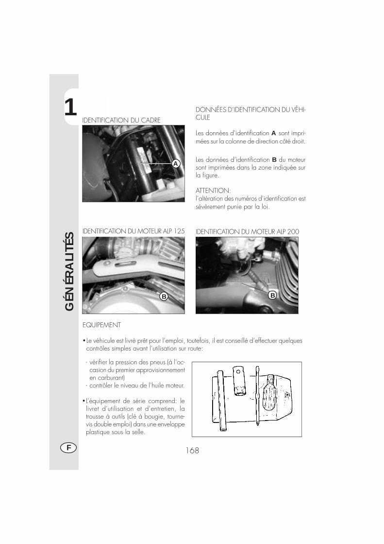
1
GÉN
ÉRA
LITÉ
S
168F
IDENTIFICATION DU CADRE
IDENTIFICATION DU MOTEUR ALP 125
A
EQUIPEMENT
� Le véhicule est livré prêt pour l’emploi, toutefois, il est conseillé d’effectuer quelquescontrôles simples avant l’utilisation sur route:
- vérifier la pression des pneus (à l’oc-casion du premier approvisionnementen carburant)
- contrôler le niveau de l’huile moteur.
� L’équipement de série comprend: lelivret d’utilisation et d’entretien, latrousse à outils (clé à bougie, tourne-vis double emploi) dans une enveloppeplastique sous la selle.
DONNÉES D’IDENTIFICATION DU VÉHI-CULE
Les données d’identification A sont impri-mées sur la colonne de direction côté droit.
Les données d’identification B du moteursont imprimées dans la zone indiquée surla figure.
ATTENTION:l’altération des numéros d’identification estsévèrement punie par la loi.
IDENTIFICATION DU MOTEUR ALP 200
BB
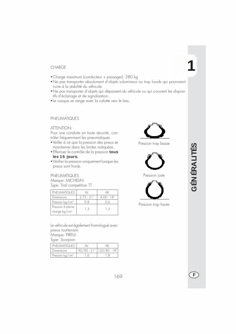
1
GÉN
ÉRA
LITÉ
S
169 F
Pression trop basse
Pression juste
Pression trop haute
CHARGE
�Charge maximum (conducteur + passager): 280 kg�Ne pas transporter absolument d’objets volumineux ou trop lourds qui pourraientnuire à la stabilité du véhicule.
�Ne pas transporter d’objets qui dépassent du véhicule ou qui couvrent les disposi-tifs d’éclairage et de signalisation.
� Le casque se range avec la calotte vers le bas.
PNEUMATIQUES
ATTENTION:Pour une conduite en toute sécurité, con-trôler fréquemment les pneumatiques.�Veiller à ce que la pression des pneus semaintienne dans les limites indiquées.
�Effectuer le contrôle de la pression tousles 15 jours.
�Vérifier la pression uniquement lorsque lespneus sont froids.
PNEUMATIQUESMarque: MICHELINType: Trial competition TT
PNEUMATIQUESDimensionsPression kg/cm2
Pression à pleinecharge kg/cm2
AR.4,00 - 18”
0,6
1,3
AV.2,75 - 21”
0,8
1,3
Le véhicule est également homologué avecpneus tout-terrain:Marque: PIRELLIType: ScorpionPNEUMATIQUESDimensionsPression kg/cm2
AR.120/80 - 18”
1,8
AV.90/90 - 21”
1,6
1
GÉN
ÉRA
LITÉ
S
170F
L’épaisseur minimum de la bande de roulement des pneumatiques (TUBE TYPE) nedoit jamais être inférieure à 2 mm.Toute infraction à cette norme est punie par la loi.
�Avant chaque trajet, contrôler que les pneus ne présentent pas de coupures, fissu-res, usure, renflements, etc... Dans tous ces cas, faire vérifier le pneu par un expertcar il pourrait s’agir de conditions extrêmement dangereuses.
�En cas de crevaison, arrêter immédiatement le véhicule. Poursuivre sa route, enplus d’être risqué, peut causer des dommages irréparables au pneumatique et à lajante.
*En conditions de chargement maximum, des pressions de gonflage plus élevéessont conseillées (voir tableau à page 169).
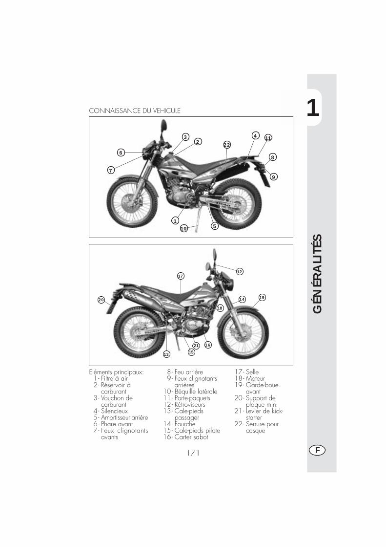
1
GÉN
ÉRA
LITÉ
S
171 F
1
6
7
32 22
4 11
8
9
10 5
CONNAISSANCE DU VEHICULE
13 15
1621
18
14 19
1217
20
Eléments principaux:1- Filtre à air2 - Réservoir à
carburant3- Vouchon de
carburant4- Silencieux5- Amortisseur arrière6- Phare avant7- Feux clignotants
avants
8- Feu arrière9- Feux clignotants
arrières10- Béquille latérale11- Porte-paquets12- Rétroviseurs13- Cale-pieds
passager14- Fourche15- Cale-pieds pilote16- Carter sabot
17- Selle18- Moteur19- Garde-boue
avant20- Support de
plaque min.21- Levier de kick-
starter22- Serrure pour
casque
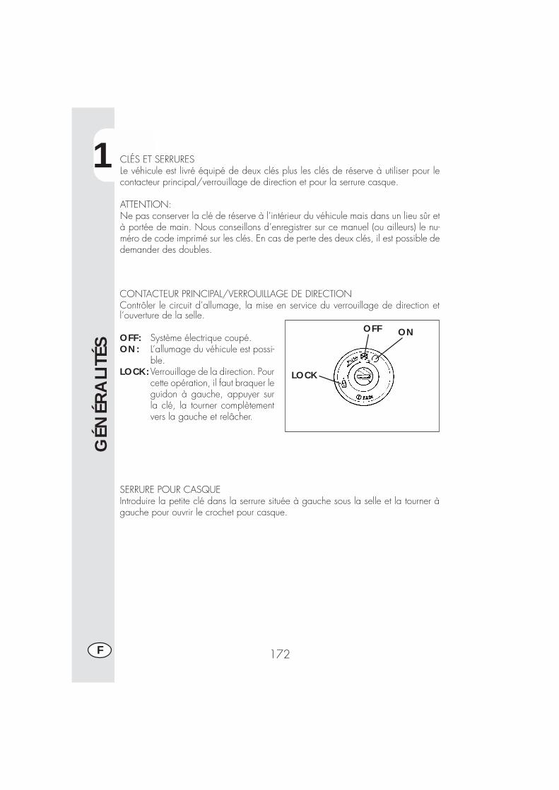
1
GÉN
ÉRA
LITÉ
S
172F
CLÉS ET SERRURESLe véhicule est livré équipé de deux clés plus les clés de réserve à utiliser pour lecontacteur principal/verrouillage de direction et pour la serrure casque.
ATTENTION:Ne pas conserver la clé de réserve à l’intérieur du véhicule mais dans un lieu sûr età portée de main. Nous conseillons d’enregistrer sur ce manuel (ou ailleurs) le nu-méro de code imprimé sur les clés. En cas de perte des deux clés, il est possible dedemander des doubles.
l’ouverture de la selle.
OFF: Système électrique coupé.ON: L’allumage du véhicule est possi-
ble.LOCK:Verrouillage de la direction. Pour
cette opération, il faut braquer leguidon à gauche, appuyer surla clé, la tourner complètementvers la gauche et relâcher.
SERRURE POUR CASQUEIntroduire la petite clé dans la serrure située à gauche sous la selle et la tourner àgauche pour ouvrir le crochet pour casque.
ONOFF
LOCK
CONTACTEUR PRINCIPAL/VERROUILLAGE DE DIRECTIONContrôler le circuit d’allumage, la mise en service du verrouillage de direction et
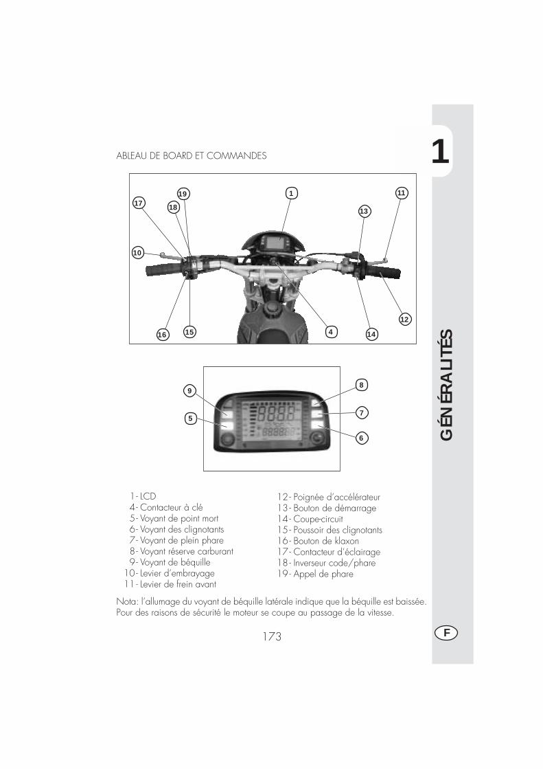
1
GÉN
ÉRA
LITÉ
S
173 F
1- LCD4- Contacteur à clé5- Voyant de point mort6 - Voyant des clignotants7- Voyant de plein phare8- Voyant réserve carburant9- Voyant de béquille
10 - Levier d’embrayage11 - Levier de frein avant
12 - Poignée d’accélérateur13 - Bouton de démarrage14 - Coupe-circuit15 - Poussoir des clignotants16 - Bouton de klaxon17 - Contacteur d’éclairage18 - Inverseur code/phare19 - Appel de phare
ABLEAU DE BOARD ET COMMANDES
Nota: l’allumage du voyant de béquille latérale indique que la béquille est baissée.Pour des raisons de sécurité le moteur se coupe au passage de la vitesse.
10
17 18
1516 4 14
12
11
13
5
19
6
7
9
1
8
1
GÉN
ÉRA
LITÉ
S
174F
INSTRUCTIONS DE MISE AU POINT ET FONCTIONNEMENT COMP-TEUR KILOMETRIQUE (pour le constructeur et le concessionnaire)La description relative à la mise au point de base de l’instrument digital n’est présen-tée qu’a titre d’information; pour effectuer cette opération il est conseillé de s’adres-ser à un atelier autorisé Betamotor.
Série ALP 125 - ALP 200
TABLE DES MATIERES
PARAGRAPHE CONTENU
10.1 Caractéristiques roue10.2 Caractéristiques du moteur10.3 Pré-chargement codes10.4 Codes chargés
20.0 MISE AU POINT NIVEAU 1 (pour le constructeur et leconcessionnaire)
20.1 Exécution mise au point niveau 120.2 Sélection codes20.3 Contrôle contenu codes20.4 Introduction valeurs non codifiées
20.4.1 Introduction Ln (développement roue) ou di (diamètre roue)20.4.2 Introduction nombres impulsions au tour roue20.4.3 Introduction nombre impulsions tour moteur
20.4.3.1 Introduction nombre impulsions tours max. moteur20.4.4 Sélection Km/h ou Mph20.4.5 Introduction heures pour changement huile20.4.6 Introduction heures ou Km pour la révision
20.5 Sortie de la mise au point
40.0 Indications sur ecra LCD40.1 Fonctionnement et visualisation pages40.2 Obscurcissement des pages40.3 Annulation des paramètres TRP, SPEED max, LAP
50.0 Activations des icones de surveillance (huile moteur et révision)50.1 Vérification du contenu actif des icônes de surveillance.
1
GÉN
ÉRA
LITÉ
S
175 F
10.1 Caractéristiques roue (déjà établies sur la moto)Dimensions de la roue sur laquelle est installé le capteur des tours. Il faudra indiquerle diamètre ou le développement en mm (valeurs max. 9999. Exemple: si le diamè-tre de la roue est égal à 695 mm, une fois la valeur introduite vous devrez lire0695), ainsi que le nombre d’impulsions pour chaque tour (valeur max. 99). Unefois la valeur introduite, si le nombre d’impulsions est inférieur à 10, par exemple 1,vous devrez lire 01.
NB: il y a deux types d’opérations que vous pouvez effectuer en agissant sur lebouton SCROLL:Actionnement bref ≤1” le programme passe à la page successive.Actionnement long ≥5” le programme permet d’entrer dans la fonctionvisualisée pour vérifier le contenu ou pour introduire/modifier les valeurs descontenus; en quelques cas il est possible de mémoriser les paramètres.
Dans cette documentation, pour plus de commodité, nous prenons en considéra-tion uniquement le bouton SCROLL positionné sur le guidon, mais il est possibled’obtenir les mêmes résultats si vous agissez sur le bouton MODE placé sur lecompteur kilométrique (le bouton MODE peut être actionné seulement si la motoest arrêtée).
10.2 Caractéristiques du moteur (seulement si le compteur de tours est ac-tionné)Nombre d’impulsions au tour et tours nominaux max. qui sont nécessaires pour régler la barre.L’introduction éventuelle des paramètres, sans capteur, ne modifie pas le fonctionnement;toutefois, sur l’écran LCD la page s’ouvrira avec les paramètres et la barre à zéro.L’entrée du capteur est sur pin 12 du connecteur. Le nombre d’impulsion tour res-pecte les mêmes règles que le nombre impulsions tours roue, alors que le nombre detours moteur ne demande que les milliers et les centaines. Exemple: pour introduire15000 tours il faudra introduire 150 sur les chiffres grands, pour introduire 8500tours il faudra introduire 085 sur les chiffres grands.
10.3 Pré-chargement codes (déjà établi sur la moto)Les constructeurs ont déjà introduit quatre codes prédéfinis qui contiennent toujoursles paramètres roues et les paramètres de surveillance comme “heures changementhuile” et “heures ou km à la révision”. Seulement les paramètres de surveillancepourront être modifiés. L’identification aura lieu en marquant sur l’écran LCD unnuméro en code et le premier code introduit sera 0001.Les codes sont déjà introduits et il ne sera plus possible de les modifier: seul leconstructeur pourra les modifier. Il faut souligner que si vous effectuez une nouvelleprogrammation, les kilomètres parcourus seront mis à zéro.
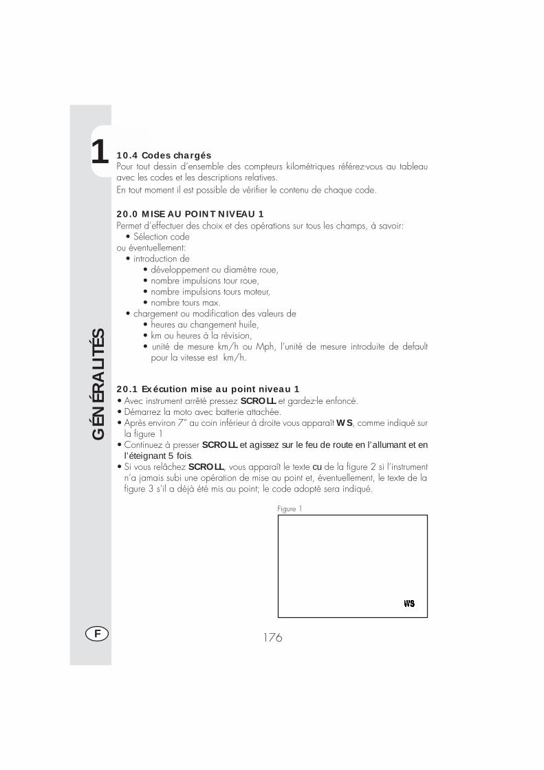
1
GÉN
ÉRA
LITÉ
S
176F
10.4 Codes chargésPour tout dessin d’ensemble des compteurs kilométriques référez-vous au tableauavec les codes et les descriptions relatives.En tout moment il est possible de vérifier le contenu de chaque code.
20.0 MISE AU POINT NIVEAU 1Permet d’effectuer des choix et des opérations sur tous les champs, à savoir: • Sélection codeou éventuellement: • introduction de
• développement ou diamètre roue,• nombre impulsions tour roue,• nombre impulsions tours moteur,• nombre tours max.
• chargement ou modification des valeurs de• heures au changement huile,• km ou heures à la révision,• unité de mesure km/h ou Mph, l’unité de mesure introduite de default pour la vitesse est km/h.
20.1 Exécution mise au point niveau 1• Avec instrument arrêté pressez SCROLL et gardez-le enfoncé.• Démarrez la moto avec batterie attachée.• Après environ 7” au coin inférieur à droite vous apparaît WS, comme indiqué sur
la figure 1• Continuez à presser SCROLL et agissez sur le feu de route en l’allumant et en
l’éteignant 5 fois.• Si vous relâchez SCROLL, vous apparaît le texte cu de la figure 2 si l’instrument
n’a jamais subi une opération de mise au point et, éventuellement, le texte de lafigure 3 s’il a déjà été mis au point; le code adopté sera indiqué.
Figure 1
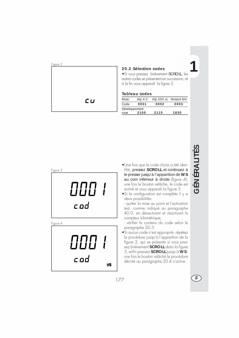
1
GÉN
ÉRA
LITÉ
S
177 F
20.2 Sélection codes•Si vous pressez brièvement SCROLL, lesautres codes se présentent en succession, età la fin vous apparaît la figure 2.
Tableau codesMoto Alp 4.0 Alp 200 cc Motard M4Code 0001 0002 0003Développementroue 2105 2115 1830
•Une fois que le code choisi a été iden-tifié, pressez SCROLL et continuez àle presser jusqu’à l’apparition de WSau coin inférieur à droite (figure 4);une fois le bouton relâché, le code estactivé et vous apparaît la figure 5.
•Si la configuration est complète il y adeux possibilités:- quitter la mise au point et l’activationtest, comme indiqué au paragraphe40.0, en désactivant et réactivant lecompteur kilométrique;- vérifier le contenu du code selon leparagraphe 20.3.
•Si aucun code n’est approprié, répétezla procédure jusqu’à l’apparition de lafigure 2, qui se présente si vous pres-sez brièvement SCROLL dans la figure3, enfin pressez SCROLL jusqu’à WS;une fois le bouton relâché la procéduredécrite au paragraphe 20.4 s’active.
Figure 2
Figure 3
Figure 4
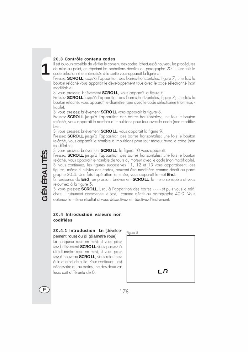
1
GÉN
ÉRA
LITÉ
S
178F
20.3 Contrôle contenu codesIl est toujours possible de vérifier le contenu des codes. Effectuez à nouveau les procéduresde mise au point, en répétant les opérations décrites au paragraphe 20.1. Une fois lecode sélectionné et mémorisé, à la sortie vous apparaît la figure 5.Pressez SCROLL jusqu’à l’apparition des barres horizontales, figure 7; une fois lebouton relâché vous apparaît le développement roue avec le code sélectionné (nonmodifiable).Si vous pressez brièvement SCROLL, vous apparaît la figure 6.Pressez SCROLL jusqu’à l’apparition des barres horizontales, figure 7; une fois lebouton relâché, vous apparaît le diamètre roue avec le code sélectionné (non modi-fiable).Si vous pressez brièvement SCROLL vous apparaît la figure 8.Pressez SCROLL jusqu’à l’apparition des barres horizontales; une fois le boutonrelâché, vous apparaît le nombre d’impulsions pour tour avec le code (non modifia-ble).Si vous pressez brièvement SCROLL, vous apparaît la figure 9.Pressez SCROLL jusqu’à l’apparition des barres horizontales; une fois le boutonrelâché, vous apparaît le nombre d’impulsions pour tour moteur avec le code (nonmodifiable).Si vous pressez brièvement SCROLL, la figure 10 vous apparaît.Pressez SCROLL jusqu’à l’apparition des barres horizontales; une fois le boutonrelâché, vous apparaît le nombre de tours du moteur avec le code (non modifiable).Si vous continuez, les figures successives 11, 12 et 13 vous apparaissent; cesfigures, même si suivies des codes, peuvent être modifiées comme décrit au para-graphe 20.4. Une fois l’opération terminée, vous apparaît le mot End.En présence de End, en pressant brièvement SCROLL, le menu se répète et vousretournez à la figure 5.Si vous pressez SCROLL jusqu’à l’apparition des barres - - - - et puis vous le relâ-chez, l’instrument commence le test, comme décrit au paragraphe 40.0. Vousobtenez le même résultat si vous désactivez et réactivez l’instrument.
20.4 Introduction valeurs noncodifiées
20.4.1 Introduction Ln (dévelop-pement roue) ou di (diamètre roue)Ln (longueur roue en mm): si vous pres-sez brièvement SCROLL vous passez àdi (diamètre roue en mm); si vous pres-sez à nouveau SCROLL, vous retournezà Ln et ainsi de suite. Pour continuer il estnécessaire qu’au moins une des deux va-leurs soit différente de 0.
Figure 5
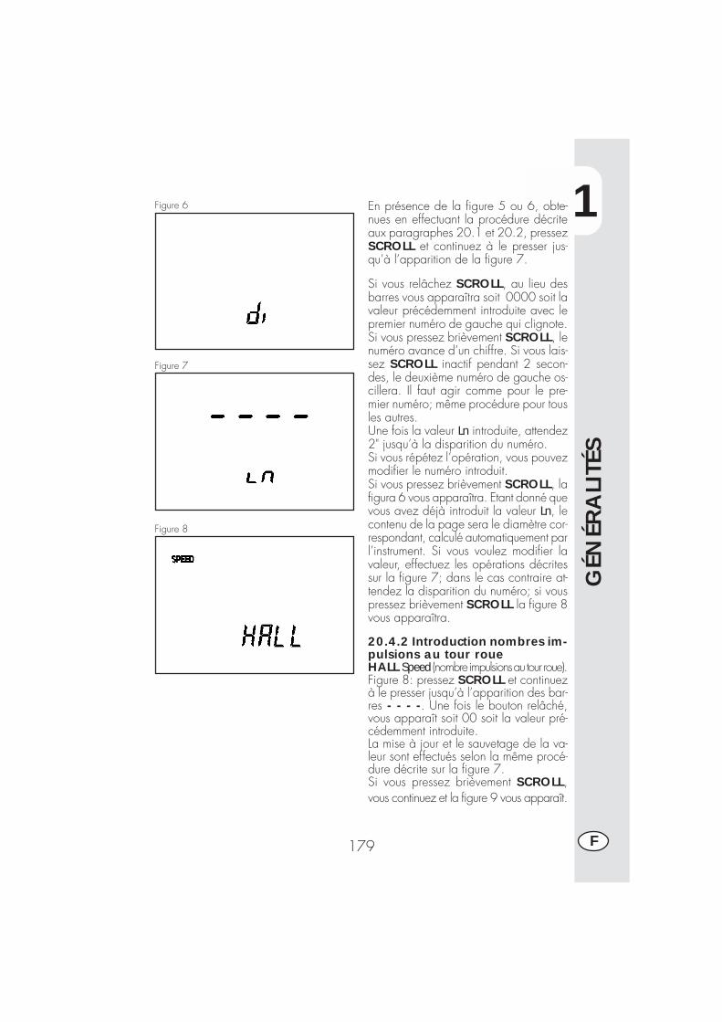
1
GÉN
ÉRA
LITÉ
S
179 F
Figure 6 En présence de la figure 5 ou 6, obte-nues en effectuant la procédure décriteaux paragraphes 20.1 et 20.2, pressezSCROLL et continuez à le presser jus-qu’à l’apparition de la figure 7.
Si vous relâchez SCROLL, au lieu desbarres vous apparaîtra soit 0000 soit lavaleur précédemment introduite avec lepremier numéro de gauche qui clignote.Si vous pressez brièvement SCROLL, lenuméro avance d’un chiffre. Si vous lais-sez SCROLL inactif pendant 2 secon-des, le deuxième numéro de gauche os-cillera. Il faut agir comme pour le pre-mier numéro; même procédure pour tousles autres.Une fois la valeur Ln introduite, attendez2" jusqu’à la disparition du numéro.Si vous répétez l’opération, vous pouvezmodifier le numéro introduit.Si vous pressez brièvement SCROLL, lafigura 6 vous apparaîtra. Etant donné quevous avez déjà introduit la valeur Ln, lecontenu de la page sera le diamètre cor-respondant, calculé automatiquement parl’instrument. Si vous voulez modifier lavaleur, effectuez les opérations décritessur la figure 7; dans le cas contraire at-tendez la disparition du numéro; si vouspressez brièvement SCROLL la figure 8vous apparaîtra.
20.4.2 Introduction nombres im-pulsions au tour roueHALL Speed (nombre impulsions au tour roue).Figure 8: pressez SCROLL et continuezà le presser jusqu’à l’apparition des bar-res - - - -. Une fois le bouton relâché,vous apparaît soit 00 soit la valeur pré-cédemment introduite.La mise à jour et le sauvetage de la va-leur sont effectués selon la même procé-dure décrite sur la figure 7.Si vous pressez brièvement SCROLL,vous continuez et la figure 9 vous apparaît.
Figure 7
Figure 8
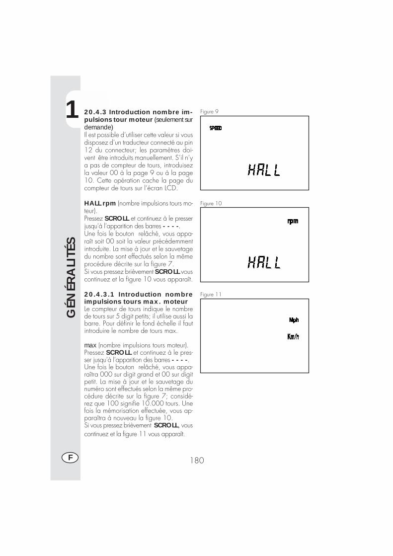
1
GÉN
ÉRA
LITÉ
S
180F
20.4.3 Introduction nombre im-pulsions tour moteur (seulement surdemande)Il est possible d’utiliser cette valeur si vousdisposez d’un traducteur connecté au pin12 du connecteur; les paramètres doi-vent être introduits manuellement. S’il n’ya pas de compteur de tours, introduisezla valeur 00 à la page 9 ou à la page10. Cette opération cache la page ducompteur de tours sur l’écran LCD.
HALL rpm (nombre impulsions tours mo-teur).Pressez SCROLL et continuez à le presserjusqu’à l’apparition des barres - - - -.Une fois le bouton relâché, vous appa-raît soit 00 soit la valeur précédemmentintroduite. La mise à jour et le sauvetagedu nombre sont effectués selon la mêmeprocédure décrite sur la figure 7.Si vous pressez brièvement SCROLL vouscontinuez et la figure 10 vous apparaît.
Figure 9
Figure 10
Figure 1120.4.3.1 Introduction nombreimpulsions tours max. moteurLe compteur de tours indique le nombrede tours sur 5 digit petits; il utilise aussi labarre. Pour définir le fond échelle il fautintroduire le nombre de tours max.
max (nombre impulsions tours moteur).Pressez SCROLL et continuez à le pres-ser jusqu’à l’apparition des barres - - - -.Une fois le bouton relâché, vous appa-raîtra 000 sur digit grand et 00 sur digitpetit. La mise à jour et le sauvetage dunuméro sont effectués selon la même pro-cédure décrite sur la figure 7; considé-rez que 100 signifie 10.000 tours. Unefois la mémorisation effectuée, vous ap-paraîtra à nouveau la figure 10.Si vous pressez brièvement SCROLL, vouscontinuez et la figure 11 vous apparaît.
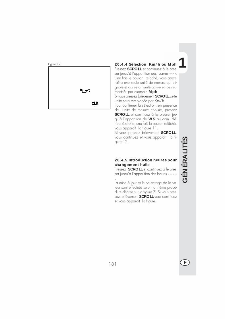
1
GÉN
ÉRA
LITÉ
S
181 F
20.4.4 Sélection Km/h ou MphPressez SCROLL et continuez à le pres-ser jusqu’à l’apparition des barres - - - -.Une fois le bouton relâché, vous appa-raîtra une seule unité de mesure qui cli-gnote et qui sera l’unité active en ce mo-ment-là: par exemple Mph.Si vous pressez brièvement SCROLL cetteunité sera remplacée par Km/h.Pour confirmer la sélection, en présencede l’unité de mesure choisie, pressezSCROLL et continuez à le presser jus-qu’à l’apparition de WS au coin infé-rieur à droite; une fois le bouton relâché,vous apparaît la figure 11.Si vous pressez brièvement SCROLL,vous continuez et vous apparaît la fi-gure 12.
Figure 12
20.4.5 Introduction heures pourchangement huilePressez SCROLL et continuez à le pres-ser jusqu’à l’apparition des barres - - - -.La mise à jour et le sauvetage de la va-leur sont effectués selon la même procé-dure décrite sur la figure 7. Si vous pres-sez brièvement SCROLL vous continuezet vous apparaît la figure.
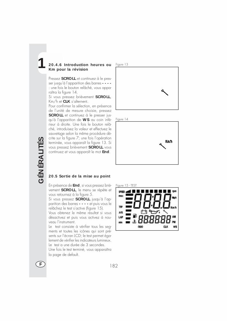
1
GÉN
ÉRA
LITÉ
S
182F
20.4.6 Introduction heures ouKm pour la révision
Pressez SCROLL et continuez à le pres-ser jusqu’à l’apparition des barres - - - -: une fois le bouton relâché, vous appa-raîtra la figure 14.Si vous pressez brièvement SCROLL,Km/h et CLK s’alternent.Pour confirmer la sélection, en présencede l’unité de mesure choisie, pressezSCROLL et continuez à le presser jus-qu’à l’apparition de WS au coin infé-rieur à droite. Une fois le bouton relâ-ché, introduisez la valeur et effectuez lesauvetage selon la même procédure dé-crite sur la figure 7; une fois l’opérationterminée, vous apparaît la figure 13. Sivous pressez brièvement SCROLL vouscontinuez et vous apparaît le mot End.
20.5 Sortie de la mise au point
En présence de End, si vous pressez briè-vement SCROLL, le menu se répète etvous retournez à la figure 5.Si vous pressez SCROLL jusqu’à l’ap-parition des barres - - - - et puis vous lerelâchez le test s’active (figure 15).Vous obtenez le même résultat si vousdésactivez et puis vous activez à nou-veau l’instrument.Le test consiste à vérifier tous les seg-ments et toutes les icônes qui sont pré-sents sur l’écran LCD; le test permet éga-lement de vérifier les indicateurs lumineux.Le test a une durée de 3 secondes.Une fois le test terminé, vous apparaîtrala page de default.
Figure 13
Figure 14
Figure 15 - TEST
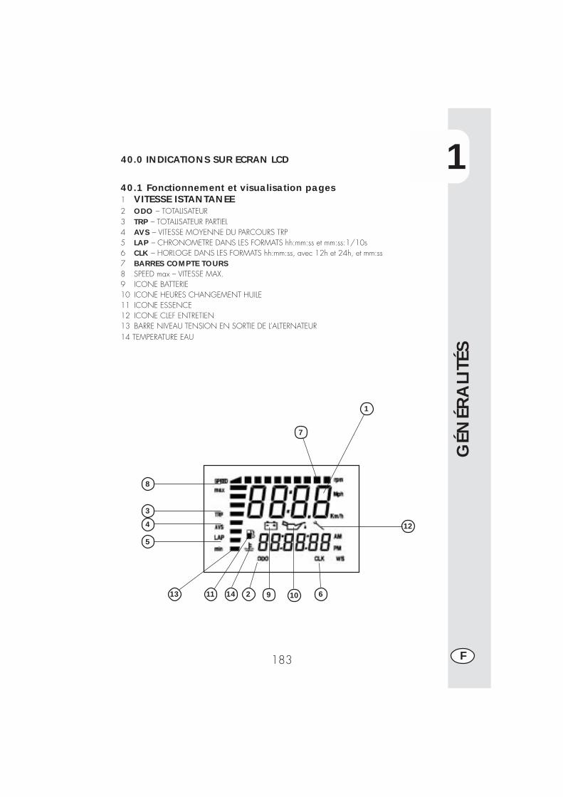
1
GÉN
ÉRA
LITÉ
S
183 F
40.0 INDICATIONS SUR ECRAN LCD
40.1 Fonctionnement et visualisation pages1 VITESSE ISTANTANEE2 ODO – TOTALISATEUR3 TRP – TOTALISATEUR PARTIEL4 AVS – VITESSE MOYENNE DU PARCOURS TRP5 LAP – CHRONOMETRE DANS LES FORMATS hh:mm:ss et mm:ss:1/10s6 CLK – HORLOGE DANS LES FORMATS hh:mm:ss, avec 12h et 24h, et mm:ss7 BARRES COMPTE TOURS8 SPEED max – VITESSE MAX.9 ICONE BATTERIE10 ICONE HEURES CHANGEMENT HUILE11 ICONE ESSENCE12 ICONE CLEF ENTRETIEN13 BARRE NIVEAU TENSION EN SORTIE DE L’ALTERNATEUR14 TEMPERATURE EAU
12
10 614
5
4
3
8
1
1113 92
7
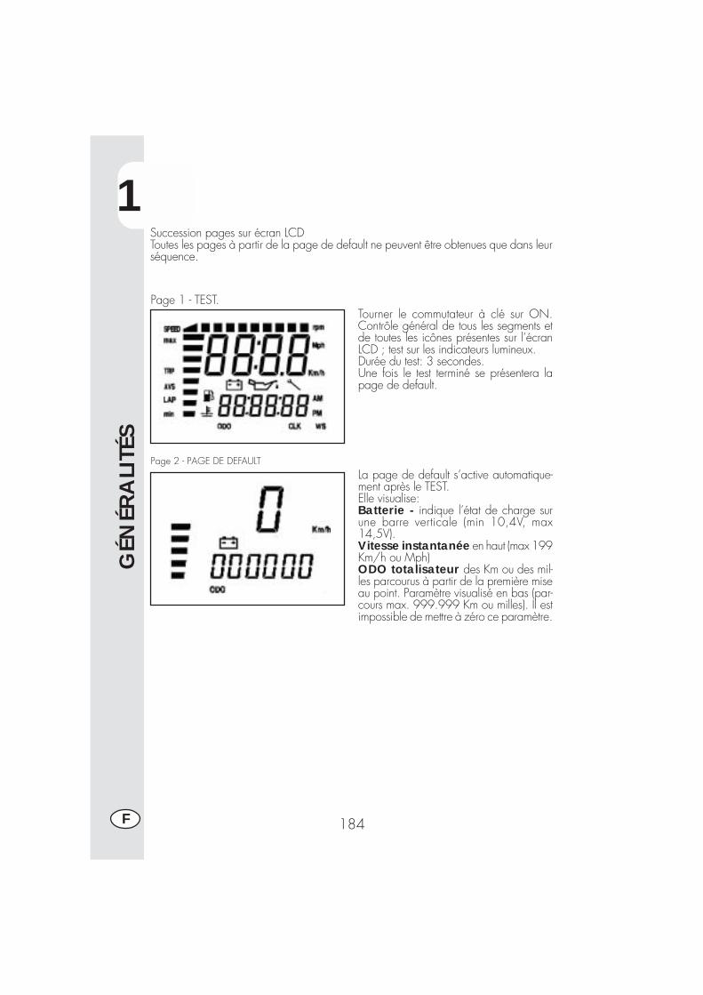
1
GÉN
ÉRA
LITÉ
S
184F
Succession pages sur écran LCDToutes les pages à partir de la page de default ne peuvent être obtenues que dans leurséquence.
Tourner le commutateur à clé sur ON.Contrôle général de tous les segments etde toutes les icônes présentes sur l’écranLCD ; test sur les indicateurs lumineux.Durée du test: 3 secondes.Une fois le test terminé se présentera lapage de default.
La page de default s’active automatique-ment après le TEST.Elle visualise:Batterie - indique l’état de charge surune barre verticale (min 10,4V, max14,5V).Vitesse instantanée en haut (max 199Km/h ou Mph)ODO totalisateur des Km ou des mil-les parcourus à partir de la première miseau point. Paramètre visualisé en bas (par-cours max. 999.999 Km ou milles). Il estimpossible de mettre à zéro ce paramètre.
Page 1 - TEST.
Page 2 - PAGE DE DEFAULT
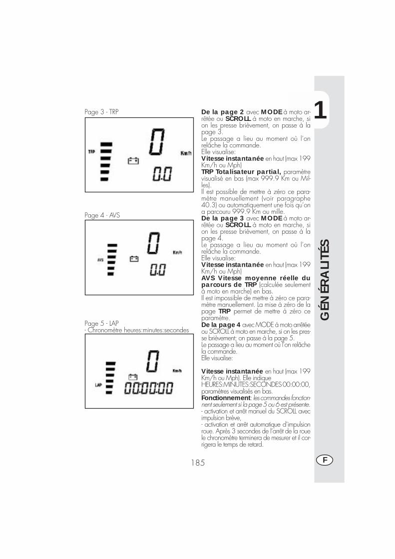
1
GÉN
ÉRA
LITÉ
S
185 F
Page 3 - TRP
Page 4 - AVS
Page 5 - LAP- Chronomètre heures:minutes:secondes
De la page 2 avec MODE à moto ar-rêtée ou SCROLL à moto en marche, sion les presse brièvement, on passe à lapage 3.Le passage a lieu au moment où l’onrelâche la commande.Elle visualise:Vitesse instantanée en haut (max 199Km/h ou Mph)TRP Totalisateur partial, paramètrevisualisé en bas (max 999.9 Km ou Mil-les).Il est possible de mettre à zéro ce para-mètre manuellement (voir paragraphe40.3) ou automatiquement une fois qu’ona parcouru 999.9 Km ou mille.De la page 3 avec MODE à moto ar-rêtée ou SCROLL à moto en marche, sion les presse brièvement, on passe à lapage 4.Le passage a lieu au moment où l’onrelâche la commande.Elle visualise:Vitesse instantanée en haut (max 199Km/h ou Mph)AVS Vitesse moyenne réelle duparcours de TRP (calculée seulementà moto en marche) en bas.Il est impossible de mettre à zéro ce para-mètre manuellement. La mise à zéro de lapage TRP permet de mettre à zéro ceparamètre.De la page 4 avec MODE à moto arrêtéeou SCROLL à moto en marche, si on les pres-se brièvement; on passe à la page 5.Le passage a lieu au moment où l’on relâchela commande.Elle visualise:
Vitesse instantanée en haut (max 199Km/h ou Mph). Elle indiqueHEURES:MINUTES:SECONDES 00:00:00,paramètres visualisés en bas.Fonctionnement: les commandes fonction-nent seulement si la page 5 ou 6 est présente.- activation et arrêt manuel du SCROLL avecimpulsion brève,- activation et arrêt automatique d’impulsionroue. Après 3 secondes de l’arrêt de la rouele chronomètre terminera de mesurer et il cor-rigera le temps de retard.
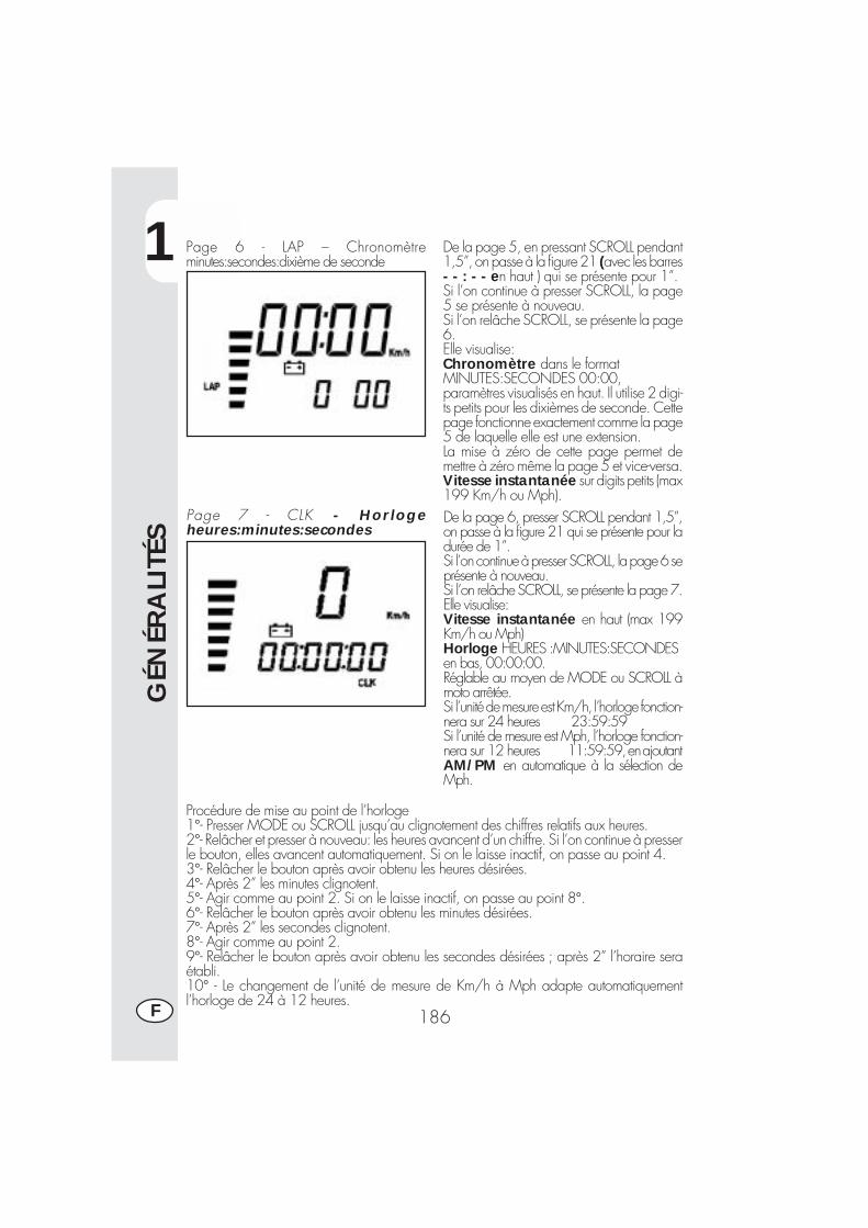
1
GÉN
ÉRA
LITÉ
S
186F
Page 6 - LAP – Chronomètreminutes:secondes:dixième de seconde
Page 7 - CLK - Horlogeheures:minutes:secondes
De la page 5, en pressant SCROLL pendant1,5”, on passe à la figure 21 (avec les barres- - : - - en haut ) qui se présente pour 1”.Si l’on continue à presser SCROLL, la page5 se présente à nouveau.Si l’on relâche SCROLL, se présente la page6.Elle visualise:Chronomètre dans le formatMINUTES:SECONDES 00:00,paramètres visualisés en haut. Il utilise 2 digi-ts petits pour les dixièmes de seconde. Cettepage fonctionne exactement comme la page5 de laquelle elle est une extension.La mise à zéro de cette page permet demettre à zéro même la page 5 et vice-versa.Vitesse instantanée sur digits petits (max199 Km/h ou Mph).De la page 6, presser SCROLL pendant 1,5”,on passe à la figure 21 qui se présente pour ladurée de 1”.Si l’on continue à presser SCROLL, la page 6 seprésente à nouveau.Si l’on relâche SCROLL, se présente la page 7.Elle visualise:Vitesse instantanée en haut (max 199Km/h ou Mph)Horloge HEURES :MINUTES:SECONDESen bas, 00:00:00.Réglable au moyen de MODE ou SCROLL àmoto arrêtée.Si l’unité de mesure est Km/h, l’horloge fonction-nera sur 24 heures 23:59:59Si l’unité de mesure est Mph, l’horloge fonction-nera sur 12 heures 11:59:59, en ajoutantAM/PM en automatique à la sélection deMph.
Procédure de mise au point de l’horloge1°- Presser MODE ou SCROLL jusqu’au clignotement des chiffres relatifs aux heures.2°- Relâcher et presser à nouveau: les heures avancent d’un chiffre. Si l’on continue à presserle bouton, elles avancent automatiquement. Si on le laisse inactif, on passe au point 4.3°- Relâcher le bouton après avoir obtenu les heures désirées.4°- Après 2” les minutes clignotent.5°- Agir comme au point 2. Si on le laisse inactif, on passe au point 8°.6°- Relâcher le bouton après avoir obtenu les minutes désirées.7°- Après 2” les secondes clignotent.8°- Agir comme au point 2.9°- Relâcher le bouton après avoir obtenu les secondes désirées ; après 2” l’horaire seraétabli.10° - Le changement de l’unité de mesure de Km/h à Mph adapte automatiquementl’horloge de 24 à 12 heures.
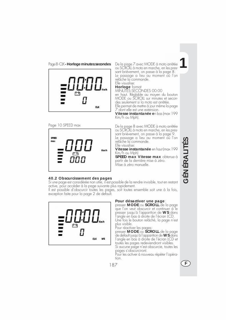
1
GÉN
ÉRA
LITÉ
S
187 F
Page 8 - CLK - Horloge minutes:secondes
Page 10 SPEED max
De la page 7 avec MODE à moto arrêtéeou SCROLL à moto en marche, en les pres-sant brièvement, on passe à la page 8.Le passage a lieu au moment où l’onrelâche la commande.Elle visualise:Horloge formatMINUTES:SECONDES 00:00en haut. Réglable au moyen du boutonMODE ou SCROLL sur minutes et secon-des seulement si la moto est arrêtée.Elle permet de mettre à jour même la page7 dont elle est une extension.Vitesse instantanée en bas (max 199Km/h ou Mph).
De la page 8 avec MODE à moto arrêtéeou SCROLL à moto en marche, en les pres-sant brièvement, on passe à la page 9.Le passage a lieu au moment où l’onrelâche la commande.Elle visualise:Vitesse instantanée en haut (max 199Km/h ou Mph)SPEED max Vitesse max obtenue àpartir de la dernière mise à zéro.Mise à zéro manuelle.
40.2 Obscurcissement des pagesSi une page est considérée non utile, il est possible de la rendre invisible, tout en restantactive, pour accéder à la page suivante plus rapidement.Il est possible d’obscurcir toutes les pages, soit toutes ensemble soit une à la fois,exception faite pour la page 2 de default.
Pour désactiver une page:presser MODE ou SCROLL de la pageque l’on veut obscurcir et continuer à lepresser jusqu’à l’apparition de WS dansl’angle en bas à droite de l’écran LCD.Une fois le bouton relâché, la page n’estplus visible.Pour réactiver les pages:presser MODE ou SCROLL de la pagede default jusqu’à l’apparition de WS dansl’angle en bas à droite de l’écran LCD ettoutes les pages redeviendront visibles.Si aucune page n’est obscurcie, toutes lespages s’obscurciront.Pour les activer à nouveau répéter l’opéra-tion.
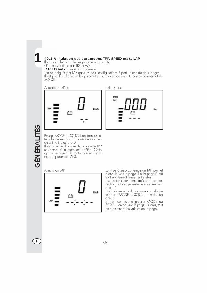
1
GÉN
ÉRA
LITÉ
S
188F
40.3 Annulation des paramètres TRP, SPEED max, LAPIl est possible d’annuler les paramètres suivants:- Parcours indiqué par TRP et AVS- SPEED max vitesse max. obtenueTemps indiqués par LAP dans les deux configurations à partir d’une de deux pages.Il est possible d’annuler les paramètres au moyen de MODE à moto arrêtée et deSCROLL.
Annulation TRP et SPEED max
Presser MODE ou SCROLL pendant un in-tervalle de temps ≥ 5”, après quoi au lieudu chiffre il y aura 0.0Il est possible d’annuler le paramètre TRPseulement si la moto est arrêtée. Cetteopération permet de mettre à zéro égale-ment le paramètre AVS.
Annulation LAP La mise à zéro du temps de LAP permetd’annuler soit la page 5 et la page 6 quisont étroitement reliées entre elles.Les chiffres seront remplacés par des bar-res horizontales qui resteront invisibles pen-dant 1”.Si en présence des barres - - - - on relâchele bouton MODE ou SCROLL, le chiffre estannulé.Si l’on continue à presser MODE ouSCROLL, on passe à la page suivante, touten maintenant les valeurs de la page.
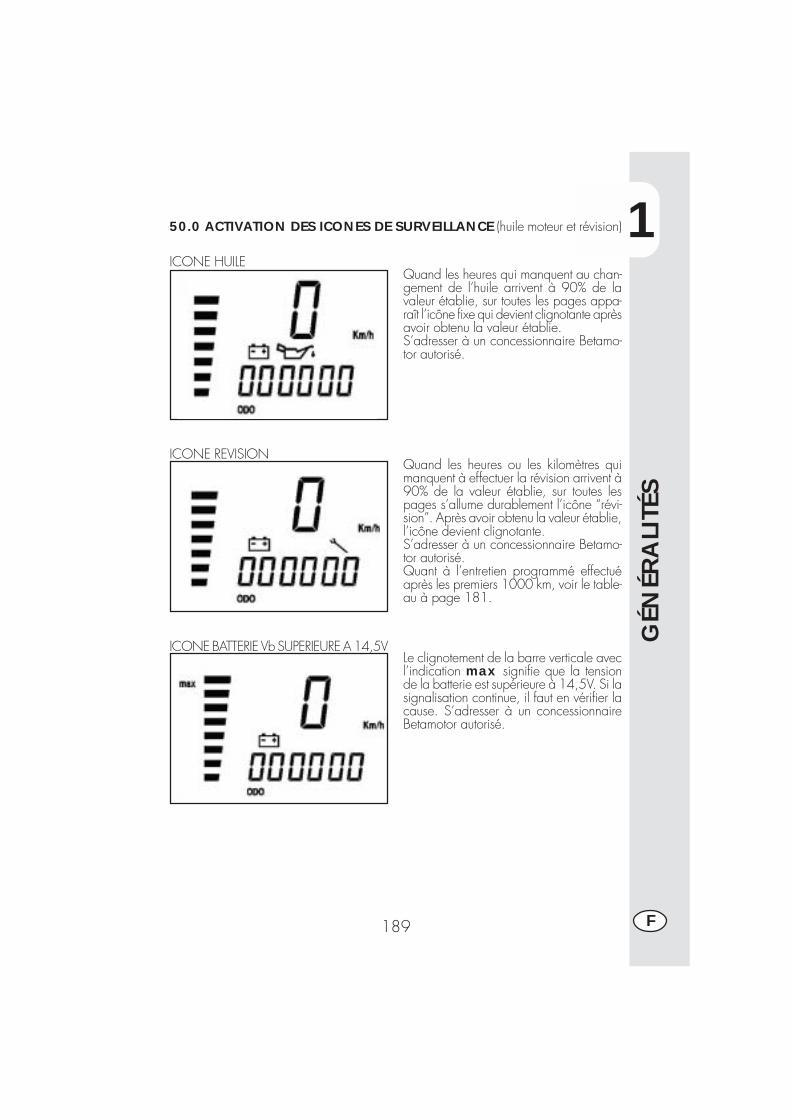
1
GÉN
ÉRA
LITÉ
S
189 F
50.0 ACTIVATION DES ICONES DE SURVEILLANCE (huile moteur et révision)
ICONE HUILEQuand les heures qui manquent au chan-gement de l’huile arrivent à 90% de lavaleur établie, sur toutes les pages appa-raît l’icône fixe qui devient clignotante aprèsavoir obtenu la valeur établie.S’adresser à un concessionnaire Betamo-tor autorisé.
Quand les heures ou les kilomètres quimanquent à effectuer la révision arrivent à90% de la valeur établie, sur toutes lespages s’allume durablement l’icône “révi-sion”. Après avoir obtenu la valeur établie,l’icône devient clignotante.S’adresser à un concessionnaire Betamo-tor autorisé.Quant à l’entretien programmé effectuéaprès les premiers 1000 km, voir le table-au à page 181.
ICONE REVISION
ICONE BATTERIE Vb SUPERIEURE A 14,5VLe clignotement de la barre verticale avecl’indication max signifie que la tensionde la batterie est supérieure à 14,5V. Si lasignalisation continue, il faut en vérifier lacause. S’adresser à un concessionnaireBetamotor autorisé.
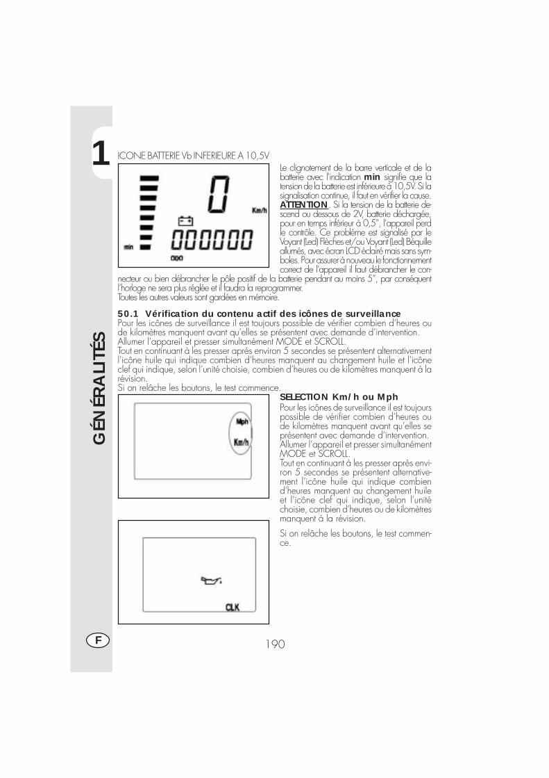
1
GÉN
ÉRA
LITÉ
S
190F
ICONE BATTERIE Vb INFERIEURE A 10,5VLe clignotement de la barre verticale et de labatterie avec l’indication min signifie que latension de la batterie est inférieure à 10,5V. Si lasignalisation continue, il faut en vérifier la cause.ATTENTION. Si la tension de la batterie de-scend ou dessous de 2V, batterie déchargée,pour en temps inférieur à 0,5”, l’appareil perdle contrôle. Ce problème est signalisé par leVoyant (Led) Flèches et/ou Voyant (Led) Béquilleallumés, avec écran LCD éclairé mais sans sym-boles. Pour assurer à nouveau le fonctionnementcorrect de l’appareil il faut débrancher le con-
necteur ou bien débrancher le pôle positif de la batterie pendant au moins 5”, par conséquentl’horloge ne sera plus réglée et il faudra la reprogrammer.Toutes les autres valeurs sont gardées en mémoire.
50.1 Vérification du contenu actif des icônes de surveillancePour les icônes de surveillance il est toujours possible de vérifier combien d’heures oude kilomètres manquent avant qu’elles se présentent avec demande d’intervention.Allumer l’appareil et presser simultanément MODE et SCROLL.Tout en continuant à les presser après environ 5 secondes se présentent alternativementl’icône huile qui indique combien d’heures manquent au changement huile et l’icôneclef qui indique, selon l’unité choisie, combien d’heures ou de kilomètres manquent à larévision.Si on relâche les boutons, le test commence.
SELECTION Km/h ou MphPour les icônes de surveillance il est toujourspossible de vérifier combien d’heures oude kilomètres manquent avant qu’elles seprésentent avec demande d’intervention.Allumer l’appareil et presser simultanémentMODE et SCROLL.Tout en continuant à les presser après envi-ron 5 secondes se présentent alternative-ment l’icône huile qui indique combiend’heures manquent au changement huileet l’icône clef qui indique, selon l’unitéchoisie, combien d’heures ou de kilomètresmanquent à la révision.
Si on relâche les boutons, le test commen-ce.
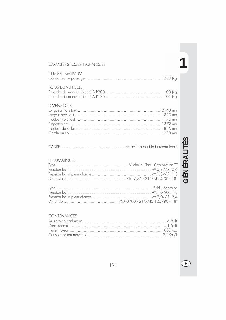
1
GÉN
ÉRA
LITÉ
S
191 F
CARACTÉRISTIQUES TECHNIQUES
CHARGE MAXIMUMConducteur + passager ................................................................. 280 (kg)
POIDS DU VÉHICULEEn ordre de marche (à sec) ALP200 ................................................ 103 (kg)En ordre de marche (à sec) ALP125 ................................................ 101 (kg)
DIMENSIONSLongueur hors tout ...................................................................... 2143 mmLargeur hors tout .......................................................................... 820 mmHauteur hors tout ........................................................................ 1170 mmEmpattement ............................................................................. 1372 mmHauteur de selle........................................................................... 836 mmGarde au sol .............................................................................. 288 mm
CADRE ...................................................... en acier à double berceau fermé
PNEUMATIQUESType .............................................................Michelin - Trial Competition TTPression bar ..........................................................................................................................AV.0,8/AR. 0,6Pression bar à plein charge .................................................. AV.1,3/AR. 1,3Dimensions .................................................. AR. 2,75 - 21”/AR. 4,00 - 18”
Type ................................................................................. PIRELLI ScorpionPression bar ..........................................................................................................................AV.1,6/AR. 1,8Pression bar à plein charge .................................................. AV.2,0/AR. 2,4Dimensions ........................................... AV.90/90 - 21”/AR. 120/80 - 18”
CONTENANCESRéservoir à carburant ....................................................................... 6,8 (lt)Dont réserve ................................................................................... 1,5 (lt)Huile moteur ............................................................................... 850 (cc)Consommation moyenne .............................................................. 25 Km/lt
1
GÉN
ÉRA
LITÉ
S
192F
SUSPENSION AVANTFourche hydraulique avec tubes de Ø 38 mm, réglage détente et précharge duressortContenance en huile par tube:droit ............................................................................................ 350 ccgauche ........................................................................................ 350 ccType d’huile ........................................................... Bel Ray MC 10 SAE 10
ou à défaut LIQUI MOLY RECING SUSPENSION OIL SAE 10WNiveau d’huile .......................................... 120 mm du bord supérieur du tube
avec fourche en fin de course et sans ressort.Chasse ................................................................................ 170 ± 3 mm
SUSPENSION ARRIÈREMono-amortisseur hydraulique progressif et réglage détente et précharge du ressortDébattement amortisseur .................................................................. 80 mm
FREIN AVANTÀ disque Ø 220 mm à commande hydraulique
FREIN ARRIÈREÀ disque Ø 200 mm à commande hydraulique
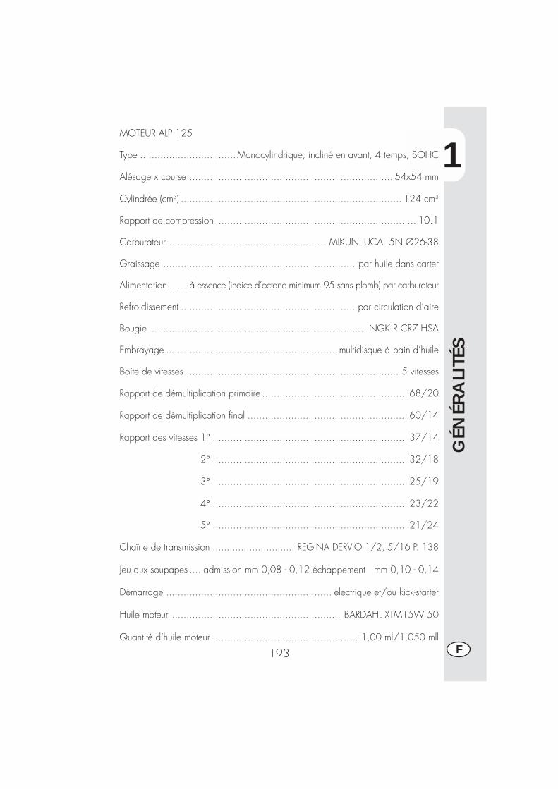
1
GÉN
ÉRA
LITÉ
S
193 F
MOTEUR ALP 125
Type .................................Monocylindrique, incliné en avant, 4 temps, SOHC
Alésage x course ...................................................................... 54x54 mm
Cylindrée (cm3) ............................................................................ 124 cm3
Rapport de compression ..................................................................... 10.1
Carburateur ...................................................... MIKUNI UCAL 5N Ø26-38
Graissage .................................................................. par huile dans carter
Alimentation ...... à essence (indice d’octane minimum 95 sans plomb) par carburateur
Refroidissement ............................................................ par circulation d’aire
Bougie ........................................................................... NGK R CR7 HSA
Embrayage ........................................................... multidisque à bain d’huile
Boîte de vitesses ......................................................................... 5 vitesses
Rapport de démultiplication primaire .................................................. 68/20
Rapport de démultiplication final ....................................................... 60/14
Rapport des vitesses 1° ................................................................... 37/14
2° ................................................................... 32/18
3° ................................................................... 25/19
4° ................................................................... 23/22
5° ................................................................... 21/24
Chaîne de transmission ............................. REGINA DERVIO 1/2, 5/16 P. 138
Jeu aux soupapes .... admission mm 0,08 - 0,12 échappement mm 0,10 - 0,14
Démarrage ......................................................... électrique et/ou kick-starter
Huile moteur .......................................................... BARDAHL XTM15W 50
Quantité d’huile moteur .................................................. l1,00 ml/1,050 mll
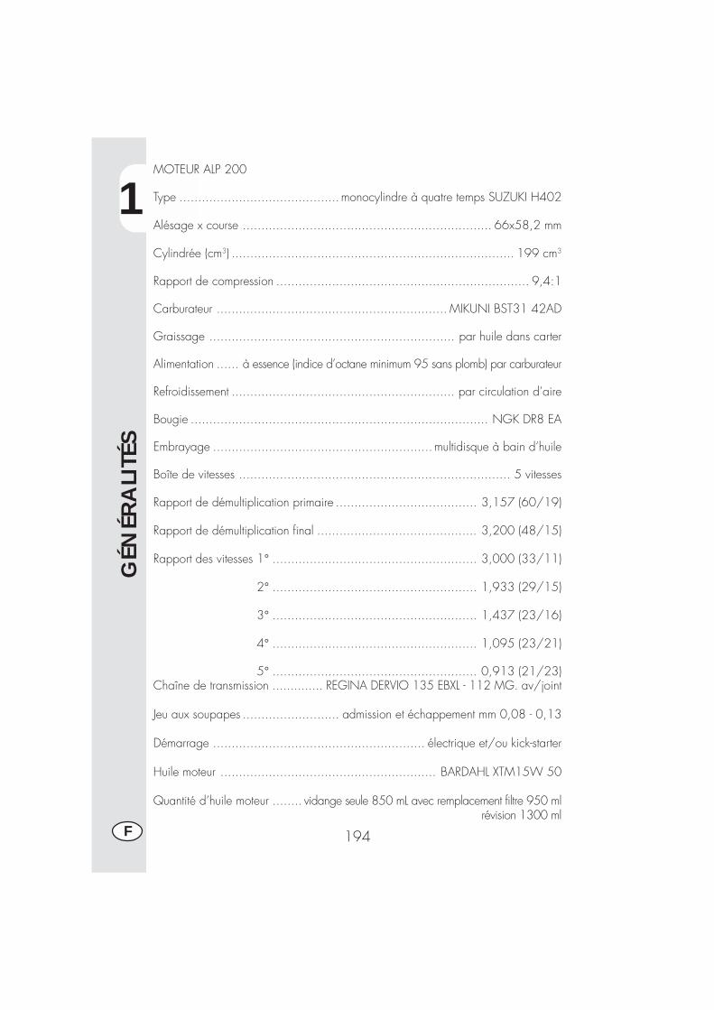
1
GÉN
ÉRA
LITÉ
S
194F
MOTEUR ALP 200
Type ...........................................monocylindre à quatre temps SUZUKI H402
Alésage x course ................................................................... 66x58,2 mm
Cylindrée (cm3) ............................................................................ 199 cm3
Rapport de compression .................................................................... 9,4:1
Carburateur .............................................................. MIKUNI BST31 42AD
Graissage .................................................................. par huile dans carter
Alimentation ...... à essence (indice d’octane minimum 95 sans plomb) par carburateur
Refroidissement ............................................................ par circulation d’aire
Bougie ................................................................................ NGK DR8 EA
Embrayage ........................................................... multidisque à bain d’huile
Boîte de vitesses ......................................................................... 5 vitesses
Rapport de démultiplication primaire ...................................... 3,157 (60/19)
Rapport de démultiplication final ........................................... 3,200 (48/15)
Rapport des vitesses 1° ....................................................... 3,000 (33/11)
2° ....................................................... 1,933 (29/15)
3° ....................................................... 1,437 (23/16)
4° ....................................................... 1,095 (23/21)
5° ....................................................... 0,913 (21/23)Chaîne de transmission .............. REGINA DERVIO 135 EBXL - 112 MG. av/joint
Jeu aux soupapes .......................... admission et échappement mm 0,08 - 0,13
Démarrage ......................................................... électrique et/ou kick-starter
Huile moteur .......................................................... BARDAHL XTM15W 50
Quantité d’huile moteur ........ vidange seule 850 mL avec remplacement filtre 950 mlrévision 1300 ml
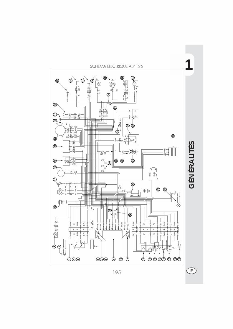
1
GÉN
ÉRA
LITÉ
S
195 F
SCHEMA ELECTRIQUE ALP 125
Ne
Bi-N
e
Gi
Bl-N
e
Gr
Bi-N
e
Bl-N
e
Gi
Bi-G
i
Bi-A
r
Bl-V
e
Ne
Ma
Bl-N
e
Az
Bi-B
l
Rs-
Gi
Bi-G
i
Bi-A
r
Bl-V
e
Gr
Ma
Vi
MaM
a-N
eN
e
Ve Vi
Bl-N
e
Ro
Vi
Ve
Rs-
Gi
Bi-B
l
Ro
Az
Bl-N
eB
l
2 61V
e
11B
l-Ne
3N
e-A
r
5M
a-N
e
4 14R
s
13N
e
7M
a-G
i
9G
r-V
e
Bl-N
e
Bl
Ne
MaB
lRs
Bl
Ne
Vi
Gi
Ve
Bi
Bi
Ma
Ne
Gi
Bi B
l Ne N
eR
sVe
Gi
Ve
Gi
Bl
Bi
+-Ne
RsBi
NeN
e Ne
Rs
Bi
Gi
Ve
NeBi
Bl-N
eB L
Rs-
Gi
Az
Ro
Ne
Ar
Ne
Ne
Ro
Vi
Ne
Rs
Ne
Rs
Ne
Gi
Bi
Ne
Ro
Ne
Ro
NeBl
NeBl
NeBl
Rs
Rs
Rs
Ar
Bi
M
Rs
Bi
Bl
Gr-
Ve
Ne
Ne
Bl-N
e
Bi-N
e
Bl-V
eB
l-Ve
Ve
Ne V
iN
e
Gi
NeM
aR
o
Ma V
eNe
Ne
NeVi
Ve
Bi-B
lG
iG
iB
i-Bl
Ve Vi
Ne
Ne
Bi-B
l
Ne
Bi-B
l
Ne
Ne
Ne
Rs
Bi-N
e
Gr
Vi
Gi
Rs
Rs
Az
Ro
Bl
Bi
+
Ne
Ve
Ve
Ne
Bl-N
eG
i
Ne
Ne
Ne Gi
Ne
Bi-B
lG
i
01
2
Bi-R
o
Bl
Ne
Ne
Ro
-+
Ne
1 2
3 4 5 6 7 8 9 10 11 12 13 14 15 16 17 18 19
2221
20
23
25 2426
27
2829
3031
323333
3435
3637383940
4142
4344
4546
4748
49
50
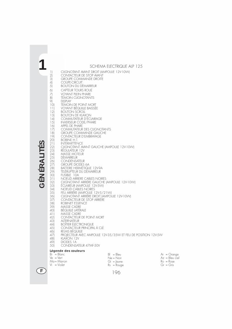
1
GÉN
ÉRA
LITÉ
S
196F
SCHEMA ELECTRIQUE ALP 1251) CLIGNOTANT AVANT DROIT (AMPOULE 12V-10W)2) CONTACTEUR DE STOP AVANT3) GROUPE COMMANDE DROITE4) COUPE-CIRCUIT5) BOUTON DU DÉMARREUR6) CAPTEUR TOURS ROUE7) VOYANT PLEIN PHARE8) TÉMOIN CLIGNOTANTS9) DISPLAY10) TÉMOIN DE POINT MORT11) VOYANT BÉQUILLE BAISSÉE12) BOUTON SCROLL13) BOUTON DE KLAXON14) COMMUTATEUR D’ÉCLAIRAGE15) INVERSEUR CODE/PHARE16) APPEL DE PHARE17) COMMUTATEUR DES CLIGNOTANTS18) GROUPE COMMANDE GAUCHE19) CONTACTEUR D’EMBRAYAGE20) BOBINE H.T.21) INTERMITTENCE22) CLIGNOTANT AVANT GAUCHE (AMPOULE 12V-10W)23) RÉGULATEUR 12V24) MASSE MOTEUR25) DÉMARREUR26) CONDENSATEUR27) GROUPE DIODES 6A28) BATTERIE HERMÉTIQUE 12V-9A29) TELÉRUPTEUR DU DÉMARREUR30) FUSIBLE 10A31) NOEUD ARRIERE CABLES NOIRES32) CLIGNOTANT ARRIÈRE GAUCHE (AMPOULE 12V-10W)33) ÉCLAIREUR (AMPOULE 12V-5W)34) NOEUD CABLES NOIRES35) FEU ARRIÈRE (AMPOULE 12V-5/21W)36) CLIGNOTANT ARRIÈRE DROIT (AMPOULE 12V-10W)37) CONTACTEUR DE STOP ARRIÈRE38) ROBINET ESSENCE39) MASSE CADRE40) BÉQUILLE LATÉRALE41) MASSE CADRE42) CONTACTEUR DE POINT MORT43) ALTERNATEUR44) BOÎTIER ÉLECTRONIQUE45) CONTACTEUR PRINCIPAL À CLÉ46) RELAIS BÉQUILLE47) PROJECTEUR AVEC AMPOULE 12V-35/35W ET FEU DE POSITION 12V-5W48) KLAXON 12V49) DIODES 1A50) CONDENSATEUR 47MF-50V
Légende des couleursBi = BlancVe = VertMa= MarronVi = Violet
Bl = BleuNe = NoirGi = JauneRs = Rouge
Ar = OrangeAz = Bleu cielRo = RoseGr = Gris
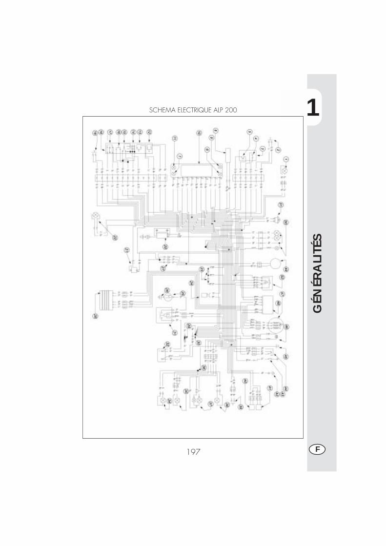
1
GÉN
ÉRA
LITÉ
S
197 F
SCHEMA ELECTRIQUE ALP 200
1
GÉN
ÉRA
LITÉ
S
198F
SCHEMA ELETTRICO
1) CLIGNOTANT AVANT DROIT (AMPOULE 12V-10W)2) CONTACTEUR DE STOP AVANT3) GROUPE COMMANDE DROITE4) COUPE-CIRCUIT5) BOUTON DU DÉMARREUR6) TÉMOIN CLIGNOTANTS7) TÉMOIN DE POINT MORT8) CAPTEUR TOURS ROUE9) VOYANT PLEIN PHARE10) DISPLAY11) VOYANT BÉQUILLE BAISSÉE12) BOUTON SCROLL13) BOUTON DE KLAXON14) COMMUTATEUR D’ÉCLAIRAGE15) INVERSEUR CODE/PHARE16) APPEL DE PHARE17) COMMUTATEUR DES CLIGNOTANTS18) GROUPE COMMANDE GAUCHE19) CONTACTEUR D’EMBRAYAGE20) BOBINE H.T.21) CENTRALE CLIGNOTANTE22) CLIGNOTANT AVANT GAUCHE (AMPOULE 12V-10W)23) N°2 DIODES 1A24) CONDENSATEUR25) DÉMARREUR26) MASSE MOTEUR27) GROUPE DIODES 6A28) RÉGULATEUR 12V29) FUSIBLE 10A30) NOEUD ARRIERE CABLES NOIRES31) TELÉRUPTEUR DU DÉMARREUR32) BATTERIE HERMÉTIQUE 12V-9A33) RELAIS BÉQUILLE34) CLIGNOTANT ARRIÈRE GAUCHE (AMPOULE 12V-10W)35) ÉCLAIREUR (AMPOULE 12V-5W)36) NOEUD CABLES NOIRES37) FEU ARRIÈRE (AMPOULE 12V-5/21W)38) CLIGNOTANT ARRIÈRE DROIT (AMPOULE 12V-10W)39) CONTACTEUR DE STOP ARRIÈRE40) ROBINET ESSENCE41) RETARDATEUR SIGNAL VOYANT CARBURANT42) MASSE CADRE43) CONTACTEUR DE POINT MORT44) BÉQUILLE LATÉRALE45) MASSE CADRE46) CAPTEUR D’ALLUMAGE47) ALTERNATEUR48) BOÎTIER ÉLECTRONIQUE49) CONTACTEUR PRINCIPAL À CLÉ50) PROJECTEUR AVEC AMPOULE 12V-35/35W ET FEU DE POSITION 12V-5W51) KLAXON 12VLégende des couleursBi = BlancVe = VertMa= MarronVi = Violet
Bl = BleuNe = NoirGi = JauneRs = Rouge
Ar = OrangeAz = Bleu cielRo = RoseGr = Gris
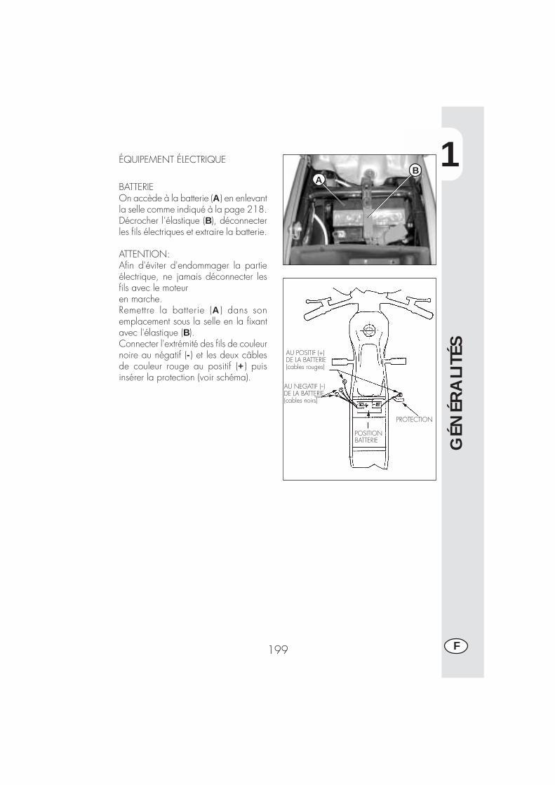
1
GÉN
ÉRA
LITÉ
S
199 F
AU POSITIF (+)DE LA BATTERIE(cables rouges)
AU NEGATIF (--)DE LA BATTERIE(cables noirs)
POSITIONBATTERIE
PROTECTION
BATTERIEOn accède à la batterie (A) en enlevantla selle comme indiqué à la page 218.Décrocher l’élastique (B), déconnecterles fils électriques et extraire la batterie.
ATTENTION:Afin d'éviter d'endommager la partieélectrique, ne jamais déconnecter lesfils avec le moteuren marche.Remettre la batterie (A) dans sonemplacement sous la selle en la fixantavec l'élastique (B).Connecter l'extrémité des fils de couleurnoire au négatif (-) et les deux câblesde couleur rouge au positif (+) puisinsérer la protection (voir schéma).
ÉQUIPEMENT ÉLECTRIQUEB
A
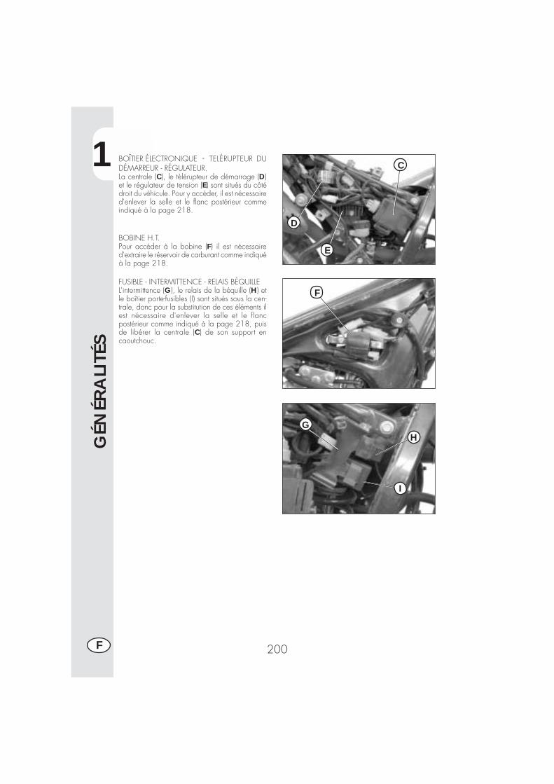
1
GÉN
ÉRA
LITÉ
S
200F
BOÎTIER ÉLECTRONIQUE - TELÉRUPTEUR DUDÉMARREUR - RÉGULATEUR.La centrale (C), le télérupteur de démarrage (D)et le régulateur de tension (E) sont situés du côtédroit du véhicule. Pour y accéder, il est nécessaired'enlever la selle et le flanc postérieur commeindiqué à la page 218.
BOBINE H.T.Pour accéder à la bobine (F) il est nécessaired'extraire le réservoir de carburant comme indiquéà la page 218.
FUSIBLE - INTERMITTENCE - RELAIS BÉQUILLEL’intermittence (G), le relais de la béquille (H) etle boîtier porte-fusibles (I) sont situés sous la cen-trale, donc pour la substitution de ces éléments ilest nécessaire d'enlever la selle et le flancpostérieur comme indiqué à la page 218, puisde libérer la centrale (C) de son support encaoutchouc.
C
D
E
F
GH
I
2
UTI
LISA
TIO
N D
U V
ÉHIC
ULE
201 F
TABLE DES MATIÈRES
CHAP. 2 UTILISATION DU VÉHICULE
Contrôles et entretien avant et après l’utilisation en tout-terrain
Lubrifiants et liquides conseillés
Rodage
Démarrage du moteur
Arrêt du moteur
Approvisionnement en carburant
2
UTI
LISA
TIO
N D
U V
ÉHIC
ULE
202F
CONTRÔLES ET ENTRETIEN AVANT ET APRÈS L’UTILISATION EN TOUT-TERRAIN
Pour éviter des problèmes ennuyeux pendant le fonctionnement du véhicule, il estpréférable d’effectuer aussi bien avant qu’après l’utilisation, quelques opérations decontrôle et d’entretien. En effet, quelques minutes consacrées à ces opérations, enplus de rendre la conduite plus sûre, peuvent vous faire économiser du temps et del’argent. Il faut donc procéder ainsi:
PNEUMATIQUES vérifier la pression de gonflage, l’état général et l’épaisseur de labande
RAYONS vérifier la tension correcteBOULONNERIE vérifier le serrage de toute la boulonnerieCHAÎNE vérifier la tension (flèche de 20 mm) et graisser si nécessaireFILTRE A AIR nettoyer le filtre et l’humecter d’huile
Nota:Contrôler la présence des papiers du véhicule.Les jours de froid, il est préférable de chauffer le moteur en le laissant tourner auralenti quelques minutes avant de se mettre en route. Toutes les fois que le véhiculeest utilisé en tout-terrain, il faut le laver soigneusement.
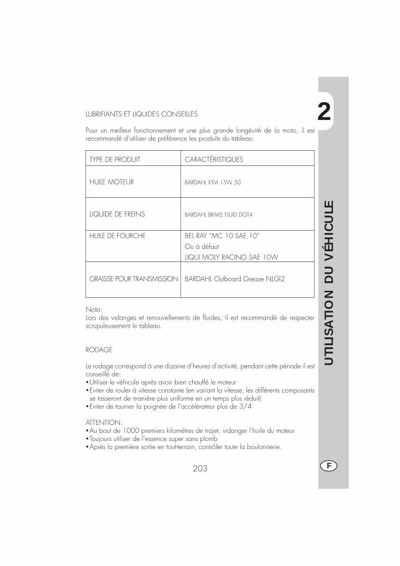
2
UTI
LISA
TIO
N D
U V
ÉHIC
ULE
203 F
LUBRIFIANTS ET LIQUIDES CONSEILLES
Pour un meilleur fonctionnement et une plus grande longévité de la moto, il estrecommandé d’utiliser de préférence les produits du tableau:
TYPE DE PRODUIT CARACTÉRISTIQUES
HUILE MOTEUR BARDAHL XTM 15W 50
LIQUIDE DE FREINS BARDAHL BRAKE FLUID DOT4
HUILE DE FOURCHE BEL RAY “MC 10 SAE 10”
Ou à défaut
LIQUI MOLY RACING SAE 10W
GRAISSE POUR TRANSMISSION BARDAHL Outboard Grease NLGI2
Nota:Lors des vidanges et renouvellements de fluides, il est recommandé de respecterscrupuleusement le tableau.
RODAGE
Le rodage correspond à une dizaine d’heures d’activité, pendant cette période il estconseillé de:�Utiliser le véhicule après avoir bien chauffé le moteur�Eviter de rouler à vitesse constante (en variant la vitesse, les différents composantsse tasseront de manière plus uniforme en un temps plus réduit)
�Eviter de tourner la poignée de l’accélérateur plus de 3/4
ATTENTION:�Au bout de 1000 premiers kilomètres de trajet, vidanger l’huile du moteur�Toujours utiliser de l’essence super sans plomb�Après la première sortie en tout-terrain, contrôler toute la boulonnerie.
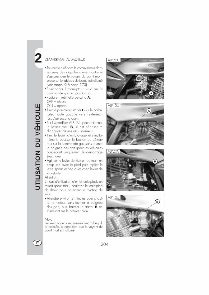
2
UTI
LISA
TIO
N D
U V
ÉHIC
ULE
204F
DEMARRAGE DU MOTEUR
�Tourner la clef dans le commutateur dansles sens des aiguilles d’une montre ets’assurer que le voyant du point mort,placé sur le tableau de bord, soit allumé(voir rappel 9 à page 173).
�Positionner l’interrupteur situé sur lacommande gaz en position (o).
�Ruotare il rubinetto benzina A:OFF = chiusoON = aperto
�Tirer le pommeau starter B sur le carbu-rateur côté gauche vers l’extérieur,jusqu’au second cran.
�Sur les modèles ALP125, pour actionnerle levier start B, il est nécessaired'appuyer dessus vers l'intérieur.
�Tirer le levier d’embrayage et simulta-nément, pousser le bouton du démar-reur sur la commande gaz sans tournerla poignée des gaz (pour les véhiculespossédant uniquement le démarrageélectrique).
�Agir sur le levier de kick en donnant uncoup sec avec le pied puis replier lelevier (pour les véhicules avec levier dekick-starter).
Attention:En cas d’utilisation d’un kit cale-pieds enretrait (pour trial), soulever le cale-piedde droite pour permettre la rotation dukick.�Attendre environ 2 minutes pour chauf-fer le moteur, sans tourner la poignéedes gaz, puis baisser le starter B ens’arrêtant sur le premier cran.
Nota:Le démarrage a lieu même avec la béquil-le baissée, à condition que le voyant dupoint mort soit allumé.
A
B
ALP200
ALP125
ALP200
ALP125
A
B
2
UTI
LISA
TIO
N D
U V
ÉHIC
ULE
205 F
Avertissement:Avec la béquille baissée, le voyant rougesur le tableau de bord reste allumé et, pourdes raisons de sécurité, le moteur se coupeau passage de la vitesse, même en dé-brayant.Il est donc nécessaire de rentrer la béquilleavant de passer la vitesse.
Nota:En cas d’urgence, ce véhicule peut fonc-tionner également sans batterie.
ARRÊT DU MOTEUR
�A l’arrêt et avec les vitesses au point mort,tourner la clé de contact en position “OFF“.
�Après un long parcours, avant de cou-per le moteur, il est conseillé de le laissertourner quelques instants.
� Lorsque le moteur est coupé, toujours fer-mer le robinet d’essence.

2
UTI
LISA
TIO
N D
U V
ÉHIC
ULE
206F
A
APPROVISIONNEMENT EN CARBU-RANT
�Couper le moteur�Retirer le bouchon A.
Nota:La capacité du réservoir est d’environ 6,8litres dont 1,5 de réserve.
Les débordements éventuels d’essence surla carrosserie ou sur d’autres parties doi-vent être rapidement nettoyés.
Avant d’effectuer l’approvisionnement encarburant, couper le moteur.L’essence est extrêmement inflammable.Eviter de faire tomber de l’essence du ré-servoir pendant l’approvisionnement.
Ne pas s’approcher de l’embout du réser-voir avec des flammes libres ou des ciga-rettes allumées: danger d’incendie.Eviter également d’inhaler les vapeurs no-cives.
3
CO
NTR
ÔLE
S ET
EN
TRET
IEN
207 F
TABLE DES MATIÈRES
CHAP. 3 CONTRÔLES ET ENTRETIEN
Huile moteur et filtre à huile
Tuyau de récupération des fumées
Liquide de frein, purge du circuit
Huile de fourche
Filtre à air
Bougie
Freins: avant, arrière
Batterie
Dépose de la carrosserie
Notes pour le trial
Nettoyage du véhicule et contrôles
Entretien programmé
Longue inactivité du véhicule
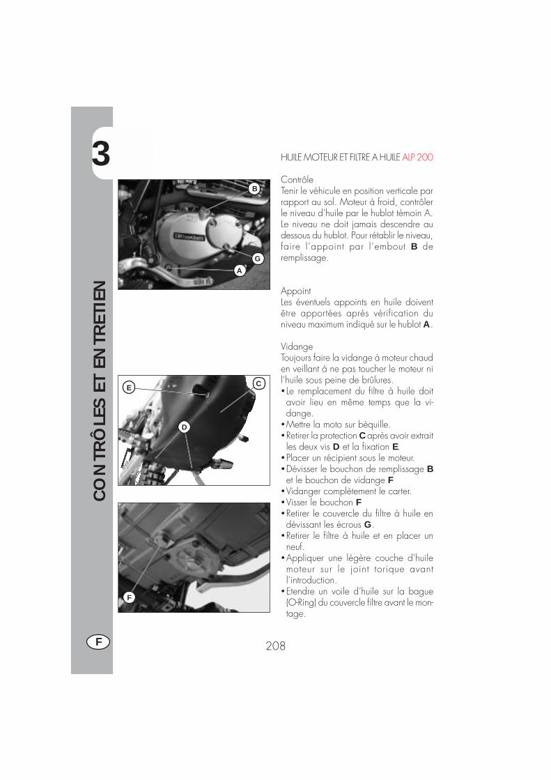
3
CO
NTR
ÔLE
S ET
EN
TRET
IEN
208F
HUILE MOTEUR ET FILTRE A HUILE ALP 200
ContrôleTenir le véhicule en position verticale parrapport au sol. Moteur à froid, contrôlerle niveau d’huile par le hublot témoin A.Le niveau ne doit jamais descendre audessous du hublot. Pour rétablir le niveau,faire l’appoint par l’embout B deremplissage.
AppointLes éventuels appoints en huile doiventêtre apportées après vérification duniveau maximum indiqué sur le hublot A.
VidangeToujours faire la vidange à moteur chauden veillant à ne pas toucher le moteur nil’huile sous peine de brûlures.� Le remplacement du filtre à huile doitavoir lieu en même temps que la vi-dange.
�Mettre la moto sur béquille.�Retirer la protection C après avoir extraitles deux vis D et la fixation E.
�Placer un récipient sous le moteur.�Dévisser le bouchon de remplissage Bet le bouchon de vidange F
�Vidanger complètement le carter.�Visser le bouchon F�Retirer le couvercle du filtre à huile endévissant les écrous G.
�Retirer le filtre à huile et en placer unneuf.
�Appliquer une légère couche d’huilemoteur sur le joint torique avantl’introduction.
�Etendre un voile d’huile sur la bague(O-Ring) du couvercle filtre avant le mon-tage.
B
GA
C
D
E
F
3
CO
NTR
ÔLE
S ET
EN
TRET
IEN
209 F
�Remettre le couvercle du filtre à huile aprèsmontage du ressort et du joint torique etserrer les 3 écrous de fixation.
� Introduire la juste quantité d’huile.�Remettre le bouchon de remplissage,monter à nouveau la protection en veillantà bien positionner les entretoises dansl’ordre correct.
�Démarrer le moteur en laissant tournerquelques minutes avant de le couper.
�Couper le moteur et attendre environ uneminute, puis contrôler le niveau et éven-tuellement faire l’appoint sans jamaisdépasser le niveau maximum.Quantité d’huile moteur:vidange seule ....................... 850 mlavec changement de filtre ....... 950 mlrévision ............................. 1300 ml
Nota:lorsque les 1000 premiers kilomètre deparcours ont été effectués, vidanger l’huilemoteur. Les vidanges suivantes s’effectuenttous les 5000 km15 mois,(voir tableaupage 222), en utilisant les lubrifiants con-seillés à page 203.Pour le filtre à huile en revanche, le pre-mier changement a lieu en même tempsque la vidange. Les remplacements sui-vants tous les 10.000 km (30 mois).
Attention:Evacuer l’huile usée dans le respect desnormes en vigueur.

3
CO
NTR
ÔLE
S ET
EN
TRET
IEN
210F
HUILE MOTEUR ET FILTRE A HUILE ALP 125
ContrôleTenir le véhicule en position verticale parrapport au sol. Moteur à froid, contrôlerla présence d’huile.
AppoinPour rétablir le niveau, procéder auremplissage à travers le bouchon A.
VidangeToujours faire la vidange à moteur chauden veillant à ne pas toucher le moteur nil’huile sous peine de brûlures.� Le remplacement du filtre à huile doit avoirlieu en même temps que la vidange.
�Mettre la moto sur béquille.�Retirer la protection C après avoir extraitles deux vis D et la fixation E.
�Placer un récipient sous le moteur.�Dévisser le bouchon de remplissage Aet le bouchon de vidange B
�Vidanger complètement le carter.�Fermer le bouchon B� Introduire 1 l. d'huile.�Refermer le bouchon de remplissage A.
ATTENTION:L’huile chaude peut provoquer de gravesbrûlures.
Nota:lorsque les 500 premiers kilomètre deparcours ont été effectués, vidangerl’huile moteur. Les vidanges suivantes s’ef-fectuent tous les 5000 km 15 mois,( voirtableau page 222), en utilisant leslubrifiants conseillés à page 203.
Attention:Evacuer l’huile usée dans le respect desnormes en vigueur.
A
C
D
E
B
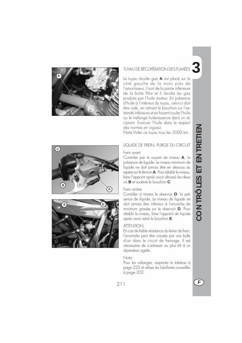
3
CO
NTR
ÔLE
S ET
EN
TRET
IEN
211 F
TUYAU DE RÉCUPÉRATION DES FUMÉES
Le tuyau récolte gaz A est placé sur lecôté gauche de la moto près del’amortisseur, il sort de la partie inférieurede la boîte filtre et il récolte les gazproduits par l’huile moteur. En présenced’huile à l’intérieur du tuyau, celui-ci doitêtre vidé, en retirant le bouchon sur l’ex-trémité inférieure et en faisant couler l’huileou le mélange huile-essence dans un ré-cipient. Evacuer l’huile dans le respectdes normes en vigueur.Nota:Vider ce tuyau tous les 3000 km.
LIQUIDE DE FREIN, PURGE DU CIRCUIT
Frein avantContrôler par le voyant de niveau A, laprésence de liquide. Le niveau minimum deliquide ne doit jamais être en dessous durepère sur le témoin A. Pour rétablir le niveau,faire l’appoint après avoir dévissé les deuxvis B et soulevé le bouchon C.
Frein arrièreContrôler à travers le réservoir D, la pré-sence de liquide. Le niveau de liquide nedoit jamais être inférieur à l’encoche deminimum gravée sur le réservoir D. Pourrétablir le niveau, faire l’appoint de liquideaprès avoir retiré le bouchon E.
ATTENTION:En cas de faible résistance du levier de frein,l’anomalie peut être causée par une bulled’air dans le circuit de freinage. Il estnécessaire de s’adresser au plus tôt à unréparateur agréé.
Nota:Pour les vidanges, respecter le tableau àpage 222 et utiliser les lubrifiants conseillésà page 203.
A
C
BA
DE
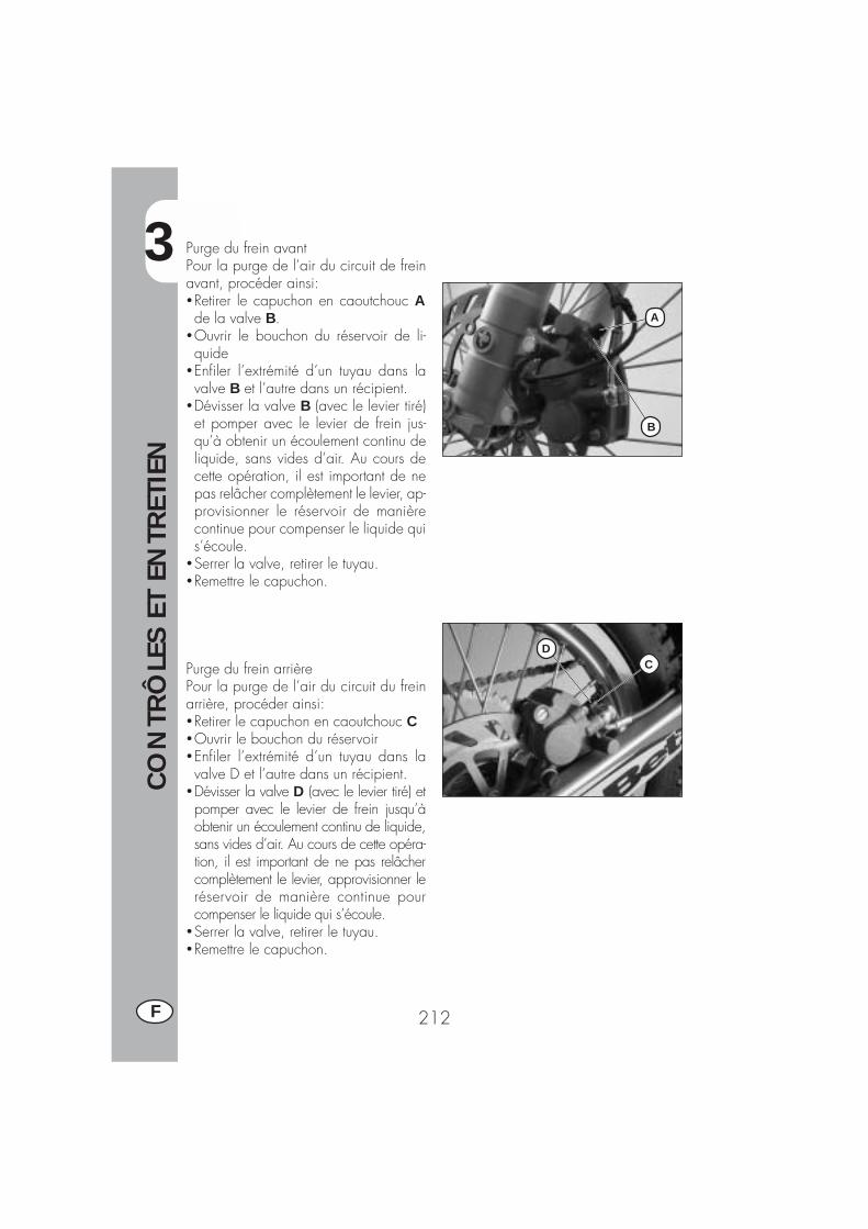
3
CO
NTR
ÔLE
S ET
EN
TRET
IEN
212F
DC
A
B
Purge du frein avantPour la purge de l’air du circuit de freinavant, procéder ainsi:�Retirer le capuchon en caoutchouc Ade la valve B.
�Ouvrir le bouchon du réservoir de li-quide
�Enfiler l’extrémité d’un tuyau dans lavalve B et l’autre dans un récipient.
�Dévisser la valve B (avec le levier tiré)et pomper avec le levier de frein jus-qu’à obtenir un écoulement continu deliquide, sans vides d’air. Au cours decette opération, il est important de nepas relâcher complètement le levier, ap-provisionner le réservoir de manièrecontinue pour compenser le liquide quis’écoule.
�Serrer la valve, retirer le tuyau.�Remettre le capuchon.
Purge du frein arrièrePour la purge de l’air du circuit du freinarrière, procéder ainsi:�Retirer le capuchon en caoutchouc C�Ouvrir le bouchon du réservoir�Enfiler l’extrémité d’un tuyau dans lavalve D et l’autre dans un récipient.
�Dévisser la valve D (avec le levier tiré) etpomper avec le levier de frein jusqu’àobtenir un écoulement continu de liquide,sans vides d’air. Au cours de cette opéra-tion, il est important de ne pas relâchercomplètement le levier, approvisionner leréservoir de manière continue pourcompenser le liquide qui s’écoule.
�Serrer la valve, retirer le tuyau.�Remettre le capuchon.

3
CO
NTR
ÔLE
S ET
EN
TRET
IEN
213 F
HUILE DE FOURCHE
Tubes droitLa description relative au renouvellementde l’huile des fourches est simplement àtitre d’information.Il est en effet conseillé de s’adresser à ungarage agréé BETAMOTOR pour effec-tuer cette opération.Pour le remplacement, procéder de lamanière suivante:1) Desserrer la vis A de serrage du tube.2) Retirer le bouchon inférieur (vis allen
sur l’extrémité du fourreau) ainsi quele bouchon supérieur B.
3) Attendre l’écoulement total de l’huiledu tube.
4) Revisser le bouchon inférieur.5) Verser l’huile indiquée au tableau à
page 222.6) Revisser le bouchon supérieur B.7) Serrer la vis A.
Note: la procédure de remplacement hui-le est valable soit pour la tige droite quepour la tige gauche.
A
B
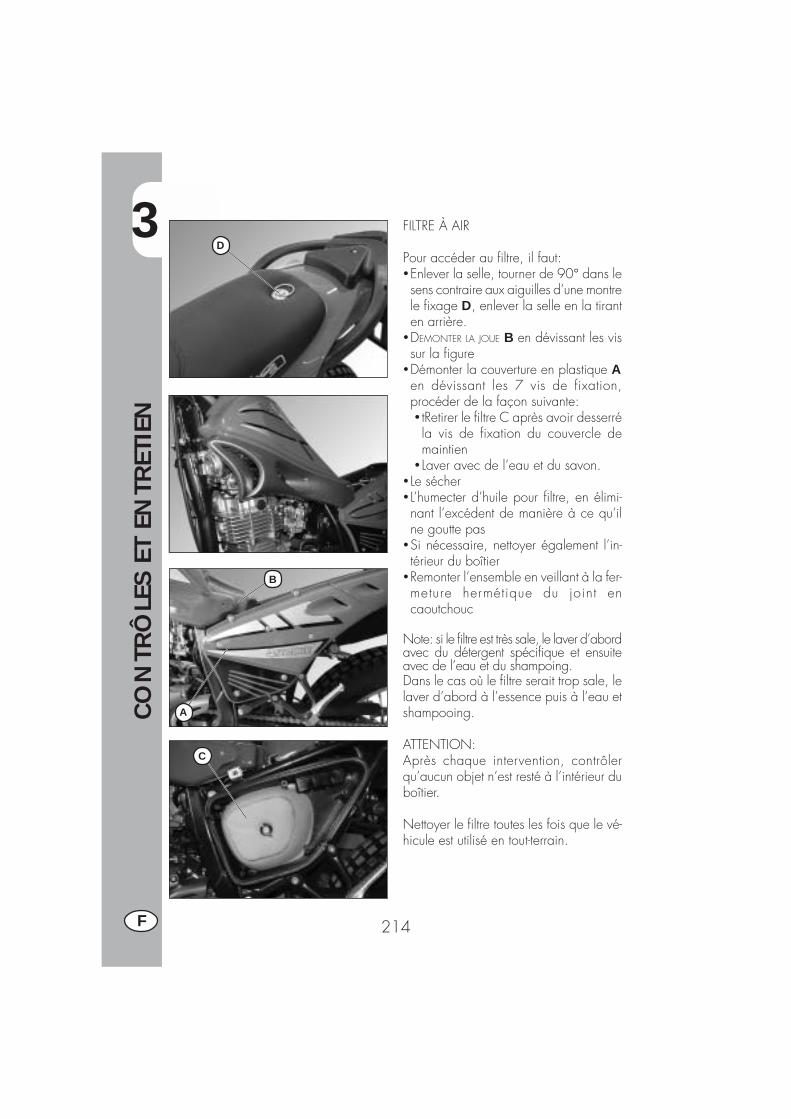
3
CO
NTR
ÔLE
S ET
EN
TRET
IEN
214F
FILTRE À AIR
Pour accéder au filtre, il faut:�Enlever la selle, tourner de 90° dans lesens contraire aux aiguilles d’une montrele fixage D, enlever la selle en la tiranten arrière.
�DEMONTER LA JOUE B en dévissant les vissur la figure
�Démonter la couverture en plastique Aen dévissant les 7 vis de fixation,procéder de la façon suivante:� tRetirer le filtre C après avoir desserréla vis de fixation du couvercle demaintien
� Laver avec de l’eau et du savon.� Le sécher� L’humecter d’huile pour filtre, en élimi-nant l’excédent de manière à ce qu’ilne goutte pas
�Si nécessaire, nettoyer également l’in-térieur du boîtier
�Remonter l’ensemble en veillant à la fer-meture hermétique du joint encaoutchouc
Note: si le filtre est très sale, le laver d’abordavec du détergent spécifique et ensuiteavec de l’eau et du shampoing.Dans le cas où le filtre serait trop sale, lelaver d’abord à l’essence puis à l’eau etshampooing.
ATTENTION:Après chaque intervention, contrôlerqu’aucun objet n’est resté à l’intérieur duboîtier.
Nettoyer le filtre toutes les fois que le vé-hicule est utilisé en tout-terrain.
C
B
A
D
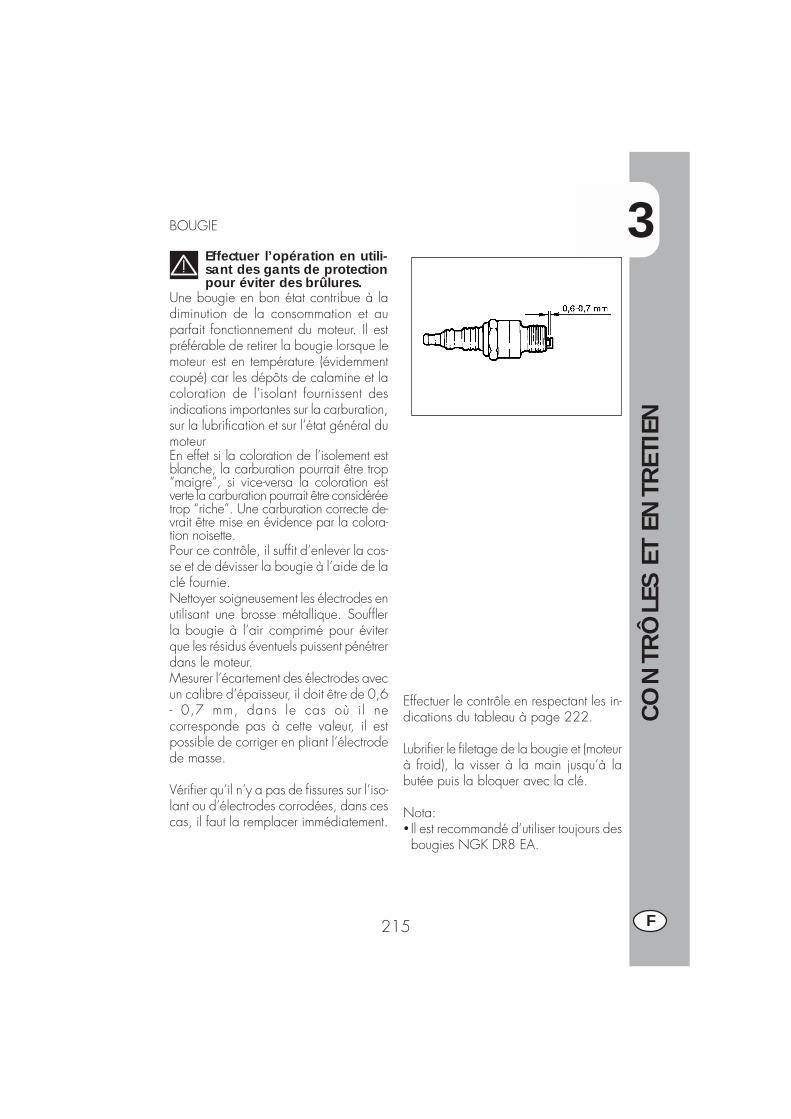
3
CO
NTR
ÔLE
S ET
EN
TRET
IEN
215 F
BOUGIE
Effectuer l’opération en utili-sant des gants de protectionpour éviter des brûlures.
Une bougie en bon état contribue à ladiminution de la consommation et auparfait fonctionnement du moteur. Il estpréférable de retirer la bougie lorsque lemoteur est en température (évidemmentcoupé) car les dépôts de calamine et lacoloration de l’isolant fournissent desindications importantes sur la carburation,sur la lubrification et sur l’état général dumoteurEn effet si la coloration de l’isolement estblanche, la carburation pourrait être trop“maigre”, si vice-versa la coloration estverte la carburation pourrait être considéréetrop “riche”. Une carburation correcte de-vrait être mise en évidence par la colora-tion noisette.Pour ce contrôle, il suffit d’enlever la cos-se et de dévisser la bougie à l’aide de laclé fournie.Nettoyer soigneusement les électrodes enutilisant une brosse métallique. Soufflerla bougie à l’air comprimé pour éviterque les résidus éventuels puissent pénétrerdans le moteur.Mesurer l’écartement des électrodes avecun calibre d’épaisseur, il doit être de 0,6- 0,7 mm, dans le cas où i l necorresponde pas à cette valeur, il estpossible de corriger en pliant l’électrodede masse.
Vérifier qu’il n’y a pas de fissures sur l’iso-lant ou d’électrodes corrodées, dans cescas, il faut la remplacer immédiatement.
Effectuer le contrôle en respectant les in-dications du tableau à page 222.
Lubrifier le filetage de la bougie et (moteurà froid), la visser à la main jusqu’à labutée puis la bloquer avec la clé.
Nota:� Il est recommandé d’utiliser toujours desbougies NGK DR8 EA.

3
CO
NTR
ÔLE
S ET
EN
TRET
IEN
216F
FREIN AVANT
ContrôlePour vérifier l’état d’usure du frein avant ,il suffit de regarder l’étrier par l’avant, làoù il est possible d’entrevoir les extrémitésdes deux plaquettes qui doivent présenterau moins 2 mm de garniture. Dans lecas où la couche serait inférieure,procéder immédiatement à leurremplacement.
Nota:Effectuer le contrôle en respectant les tempsindiqués dans le tableau à page 222.
FREIN ARRIÈRE
ContrôlePour vérifier l’usure du frein arrière, il suffitde regarder l’étrier par le haut d’où l’onvoit l’extrémité des deux plaquettes quidoivent présenter au moins 2 mm de gar-niture. Dans le cas où la couche seraitinférieure, procéder immédiatement à leurremplacement.
Nota:Effectuer le contrôle en respectant les tempsindiqués dans le tableau à page 222.
3
CO
NTR
ÔLE
S ET
EN
TRET
IEN
217 F
BATTERIE
Vérifier la charge de la batterie avec unvoltmètre en mesurant la tension avec labatterie au repos: moteur coupé. Le vol-tage ne doit pas être inférieur à 12,8 V.Il n'est pas nécessaire de contrôler leniveau de l'électrolyte ni de remplir avecde l'eau.Maintenir les pôles de la batteriepropres et si nécessaire lubrifier ceux-cià l'aide de graisses sans acides.

3
CO
NTR
ÔLE
S ET
EN
TRET
IEN
218F
B BA
C
C
D
F
E
DÉPOSE DE LA CARROSSERIEPour effectuer en toute commodité, les con-trôles ou les interventions dans certaineszones du véhicule, il est indispensable dedémonter les parties qui composent lacarrosserie de la manière suivante:
Dépose de la selleRetirer la vis de fixation au garde-boue etretirer la selle en la tirant vers la partiearrière de manière à la dégager du cro-chet placé sur le réservoir.
Dépose du porte-paquetsDévisser les 3 vis A de fixation sur le pare-chocs et déposer le porte-paquets.
Dépose de l’habillage latéralAprès avoir déposé le couvercle du filtre àair comme décrit au chapitre “Filtre à air“,dévisser les quatre vis B de fixation, l’uned’elles sur le côté gauche (sous le couver-cle du boîtier de filtre) et une autre à l’ar-rière dissimulée sous le bouchon du garde-boue.
Dépose des capots latéraux avantsDévisser les six vis C de fixation (trois parcôté), dont deux se trouvent sous le réser-voir à carburant et déposer les capotsavants.
Dépose du réservoir à carburantDévisser la vis D de fixation au cadre,débrancher le tuyau du robinet à carbu-rant et retirer le réservoir en le tirant versl’arrière.
Dépose de l’optique avantDébrancher toutes les connexions électri-ques et dévisser les trois vis E de fixation,l’une desquelles se trouve directement sousl’optique.
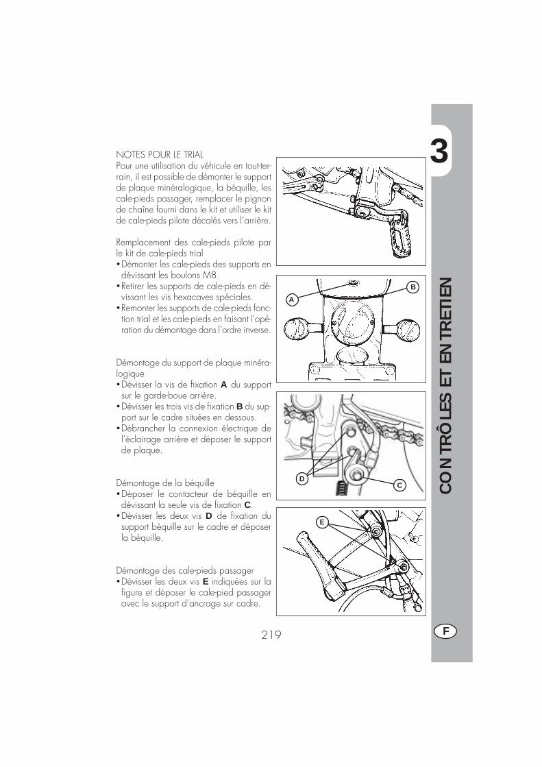
3
CO
NTR
ÔLE
S ET
EN
TRET
IEN
219 F
A
B
CD
E
NOTES POUR LE TRIALPour une utilisation du véhicule en tout-ter-rain, il est possible de démonter le supportde plaque minéralogique, la béquille, lescale-pieds passager, remplacer le pignonde chaîne fourni dans le kit et utiliser le kitde cale-pieds pilote décalés vers l’arrière.
Remplacement des cale-pieds pilote parle kit de cale-pieds trial�Démonter les cale-pieds des supports endévissant les boulons M8.
�Retirer les supports de cale-pieds en dé-vissant les vis hexacaves spéciales.
�Remonter les supports de cale-pieds fonc-tion trial et les cale-pieds en faisant l’opé-ration du démontage dans l’ordre inverse.
Démontage du support de plaque minéra-logique�Dévisser la vis de fixation A du supportsur le garde-boue arrière.
�Dévisser les trois vis de fixation B du sup-port sur le cadre situées en dessous.
�Débrancher la connexion électrique del’éclairage arrière et déposer le supportde plaque.
Démontage de la béquille�Déposer le contacteur de béquille endévissant la seule vis de fixation C.
�Dévisser les deux vis D de fixation dusupport béquille sur le cadre et déposerla béquille.
Démontage des cale-pieds passager�Dévisser les deux vis E indiquées sur lafigure et déposer le cale-pied passageravec le support d’ancrage sur cadre.

3
CO
NTR
ÔLE
S ET
EN
TRET
IEN
220F
Remplacement du pignon de chaîneLa description relative au remplacement dupignon chaîne a le but de fournir des ren-seignements utiles. Toutefois il est recom-mandé de s’adresser à un atelier autoriséBETAMOTOR pour effectuer cette opéra-tion.
�Desserrer la roue arrière.�Desserrer les vis de tension de la chaîne.�Faire avancer la roue en bout de coursede manière à détendre la chaîne
�Dévisser les 3 vis F de fixation du cache(2 vis pour modèles ALP125).
�Dégager la chaîne du pignon.�Passer la première vitesse et dévisserl’écrou de fixation du pignon de chaîne.
�Procéder au remplacement du pignonde chaîne.
�Pour le remontage, procéder dans l’or-dre inverse.
Axe d’ancrage bras oscillant�Retirer le bouchon en caoutchouc ducale-pied droit pilote.
�Dévisser l’écrou en dessous et extrairel’axe du côté opposé.
AvertissementLe démontage du support de plaque mi-néralogique et de l’éclairage est auto-risé uniquement pour une utilisation de lamoto sur propriété privée ou piste.
Remarque:Il est conseillé d'effectuer la substitutiondu pignon avec tout le groupetransmission.
F
3
CO
NTR
ÔLE
S ET
EN
TRET
IEN
221 F
NETTOYAGE DU VÉHICULE ET CONTRÔLES
Pour ramollir la saleté et la boue accumulées sur les peintures, utiliser un jet d’eau àbasse pression. Une fois ramollis, la boue et la saleté doivent être enlevées avec uneéponge douce pour carrosserie imprégnée de beaucoup d’eau et shampooing (2-4% de shampooing dans l’eau). Rincer ensuite abondamment à l’eau et essuyeravec une peau de chamois. Pour l’extérieur du moteur, utiliser du pétrole avec pin-ceaux et chiffons propres. Le pétrole est nocif pour les peintures. Il est rappelé que lelustrage éventuel avec des cires au silicone doit toujours être précédé d’un lavage.
Les détergents polluent les eaux. Aussi, le lavage du véhicule doit s’effectuerdans un endroit équipé pour la récupération et l’épuration des liquides de
lavage.
Le lavage ne doit jamais avoir lieu au soleil, en particulier l’été lorsque lacarrosserie est encore chaude et que le shampooing sèche avant le rinçage
pouvant provoquer des dommages à la peinture. Ne jamais utiliser de chiffon impré-gnés d’essence ou de mazout pour le lavage des peintures ou des plastiques car ilperdent leur brillant et les caractéristiques mécaniques des matériaux se détériorent.
CONTRÔLES APRÈS LE NETTOYAGE
Après le nettoyage de la moto, il est préférable de:
�Nettoyer le filtre à air (procéder comme décrit à page 214)�Graisser la chaîne.
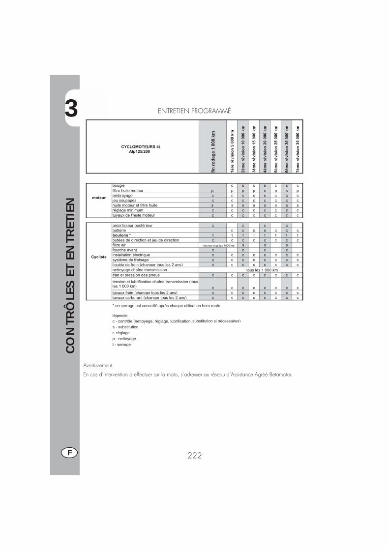
3
CO
NTR
ÔLE
S ET
EN
TRET
IEN
222F
ENTRETIEN PROGRAMMÉ
Avertissement:
En cas d’intervention à effectuer sur la moto, s’adresser au réseau d’Assistance Agréé Betamotor.
CYCLOMOTEURS 4t Alp125/200
fin
ro
dag
e 1
000
km
1ère
rév
isio
n 5
000
km
2èm
e ré
visi
on
10
000
km
3èm
e ré
visi
on
15
000
km
4èm
e ré
visi
on
20
000
km
5èm
e ré
visi
on
25
000
km
6èm
e ré
visi
on
30
000
km
7èm
e ré
visi
on
35
000
km
moteur
bougie c s c s c s cfiltre huile moteur p p p p s p s pembrayage c c c c s c c cjeu soupapes c c c c c c c chuile moteur et filtre huile s s s s s s s sréglage minimum c c c c c c c ctuyaux de l'huile moteur c c c c c c c c
Cycliste
amortisseur postérieur c c c cbatterie c c c s c c cboulons * t t t t t t t tbutées de direction et jeu de direction c c c c c c c cfiltre air s s sfourche avant c c c cinstallation électrique c c c c c c c csystème de freinage c c c c c c c cliquide de frein (changer tous les 2 ans) c c c c c c c cnettoyage chaîne transmissionétat et pression des pneus c c c c c c c c
tension et lubrification chaîne transmission (tous les 1 000 km) c c c c c c c ctuyaux frein (changer tous les 2 ans) c c c c c c c ctuyaux carburant (changer tous les 2 ans) c c c c c c c c
* un serrage est conseillé après chaque utilisation hors-route
légende :c - contrôle (nettoyage, réglage, lubrification, substitution si nécessaires)
s - substitutionr- réglagep - nettoyage
t - serrage
nettoyer tous les 1000 km
tous les 1 000 km
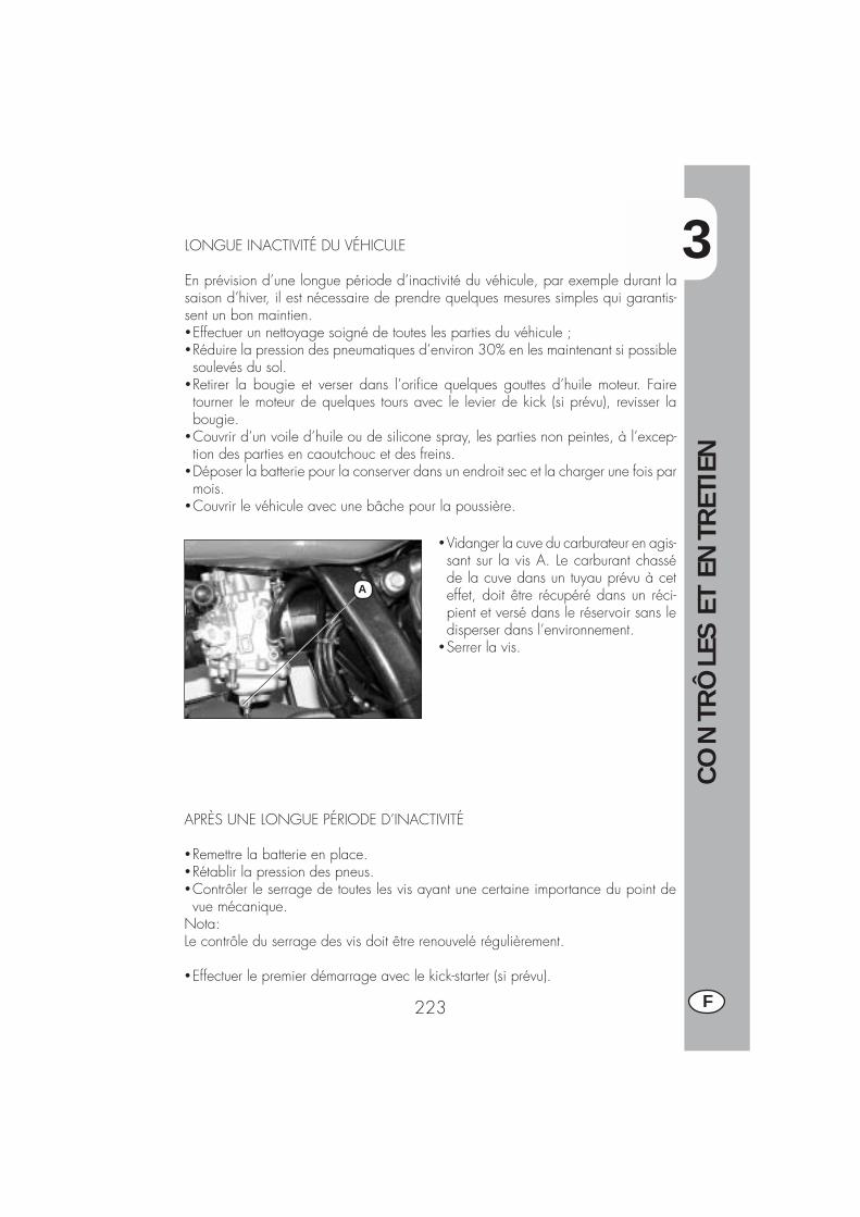
3
CO
NTR
ÔLE
S ET
EN
TRET
IEN
223 F
LONGUE INACTIVITÉ DU VÉHICULE
En prévision d’une longue période d’inactivité du véhicule, par exemple durant lasaison d’hiver, il est nécessaire de prendre quelques mesures simples qui garantis-sent un bon maintien.�Effectuer un nettoyage soigné de toutes les parties du véhicule ;�Réduire la pression des pneumatiques d’environ 30% en les maintenant si possiblesoulevés du sol.
�Retirer la bougie et verser dans l’orifice quelques gouttes d’huile moteur. Fairetourner le moteur de quelques tours avec le levier de kick (si prévu), revisser labougie.
�Couvrir d’un voile d’huile ou de silicone spray, les parties non peintes, à l’excep-tion des parties en caoutchouc et des freins.
�Déposer la batterie pour la conserver dans un endroit sec et la charger une fois parmois.
�Couvrir le véhicule avec une bâche pour la poussière.
�Vidanger la cuve du carburateur en agis-sant sur la vis A. Le carburant chasséde la cuve dans un tuyau prévu à ceteffet, doit être récupéré dans un réci-pient et versé dans le réservoir sans ledisperser dans l’environnement.
�Serrer la vis.
APRÈS UNE LONGUE PÉRIODE D’INACTIVITÉ
�Remettre la batterie en place.�Rétablir la pression des pneus.�Contrôler le serrage de toutes les vis ayant une certaine importance du point devue mécanique.
Nota:Le contrôle du serrage des vis doit être renouvelé régulièrement.
�Effectuer le premier démarrage avec le kick-starter (si prévu).
A

4
RÉG
LAG
ES
225 F
TABLE DES MATIÈRES
CHAP. 4 RÉGLAGES
Réglage des freins
Réglage de l’embrayage
Réglage du ralenti
Réglage du jeu à la poignée des gaz
Contrôle et réglage du jeu à la direction
Tension de la chaîne
Faisceau lumineux
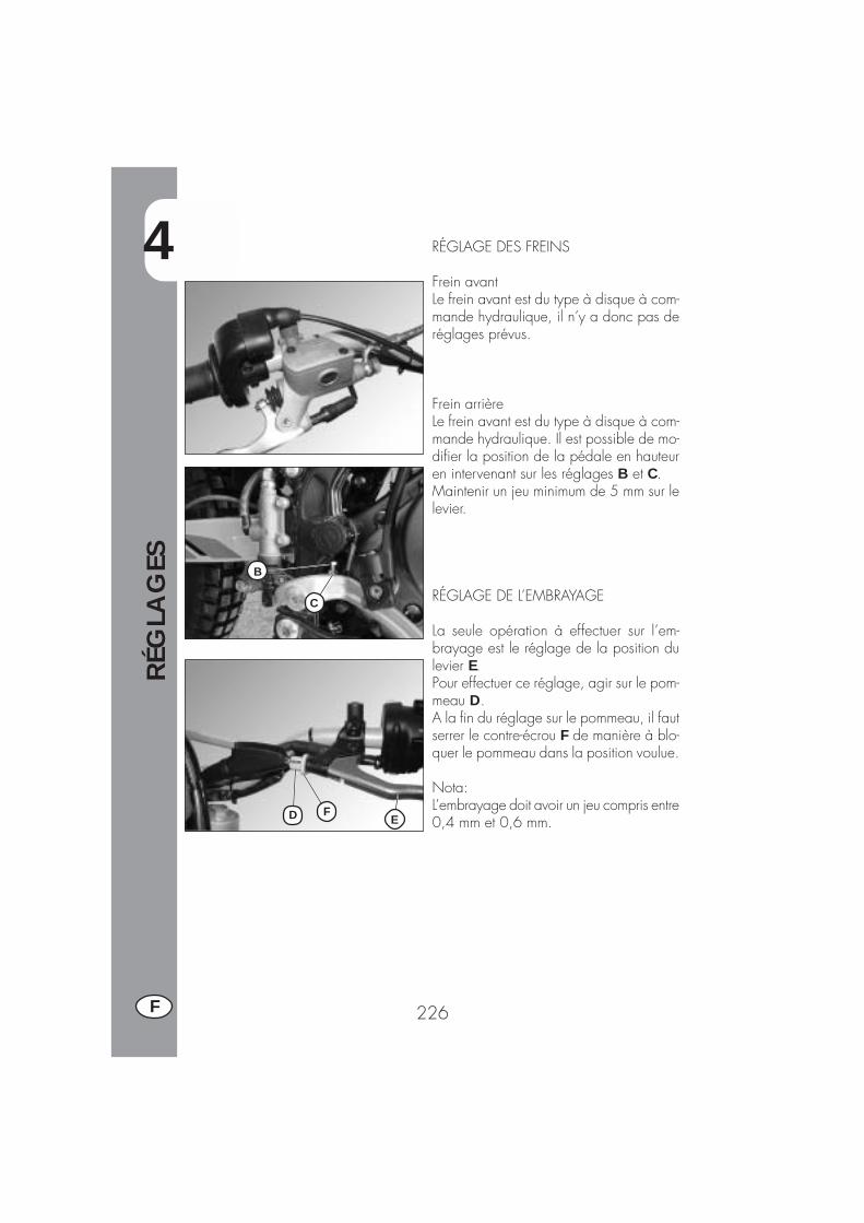
4
RÉG
LAG
ES
226F
C
B
FD E
RÉGLAGE DES FREINS
Frein avantLe frein avant est du type à disque à com-mande hydraulique, il n’y a donc pas deréglages prévus.
Frein arrièreLe frein avant est du type à disque à com-mande hydraulique. Il est possible de mo-difier la position de la pédale en hauteuren intervenant sur les réglages B et C.Maintenir un jeu minimum de 5 mm sur lelevier.
RÉGLAGE DE L’EMBRAYAGE
La seule opération à effectuer sur l’em-brayage est le réglage de la position dulevier E.Pour effectuer ce réglage, agir sur le pom-meau D.A la fin du réglage sur le pommeau, il fautserrer le contre-écrou F de manière à blo-quer le pommeau dans la position voulue.
Nota:L’embrayage doit avoir un jeu compris entre0,4 mm et 0,6 mm.
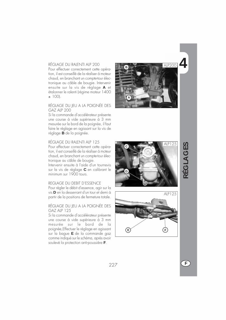
4
RÉG
LAG
ES
227 F
A
BRÉGLAGE DU RALENTI ALP 200Pour effectuer correctement cette opéra-tion, il est conseillé de la réaliser à moteurchaud, en branchant un compte-tour élec-tronique au câble de bougie. Intervenirensuite sur la vis de réglage A etétalonner le ralenti (régime moteur 1400± 100).
RÉGLAGE DU JEU A LA POIGNÉE DESGAZ ALP 200Si la commande d’accélérateur présenteune course à vide supérieure à 3 mmmesurée sur le bord de la poignée, il fautfaire le réglage en agissant sur la vis deréglage B de la poignée.
RÉGLAGE DU RALENTI ALP 125Pour effectuer correctement cette opéra-tion, il est conseillé de la réaliser à moteurchaud, en branchant un compte-tour élec-tronique au câble de bougie.Intervenir ensuite à l'aide d'un tournevissur la vis de réglage C en calibrant leminimum sur 1900 tours.
REGLAGE DU DEBIT D’ESSENCEPour régler le débit d'essence, agir sur lavis D en la desserrant d'un tour et demi àpartir de la positions de fermeture totale.
RÉGLAGE DU JEU A LA POIGNÉE DESGAZ ALP 125Si la commande d’accélérateur présenteune course à vide supérieure à 3 mmmesurée sur le bord de lapoignée,Effectuer le réglage en agissantsur la bague E de la commande gazcomme indiqué sur le schéma, après avoirsoulevé la protection anti-poussière F.
ALP125
ALP125
D
C
FE
ALP200
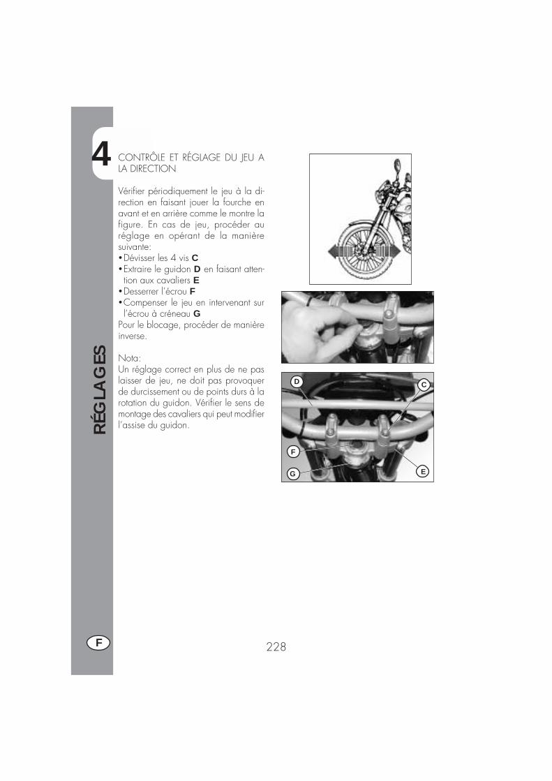
4
RÉG
LAG
ES
228F
D
F
G E
C
CONTRÔLE ET RÉGLAGE DU JEU ALA DIRECTION
Vérifier périodiquement le jeu à la di-rection en faisant jouer la fourche enavant et en arrière comme le montre lafigure. En cas de jeu, procéder auréglage en opérant de la manièresuivante:�Dévisser les 4 vis C�Extraire le guidon D en faisant atten-tion aux cavaliers E
�Desserrer l’écrou F�Compenser le jeu en intervenant surl’écrou à créneau G
Pour le blocage, procéder de manièreinverse.
Nota:Un réglage correct en plus de ne paslaisser de jeu, ne doit pas provoquerde durcissement ou de points durs à larotation du guidon. Vérifier le sens demontage des cavaliers qui peut modifierl’assise du guidon.

4
RÉG
LAG
ES
229 F
TENSION DE LA CHAINE
Per una più lunga durata della catena ditrasmissione è opportuno controllare pe-riodicamente la sua tensione.Tenerla sempre pulita dalla sporcizia de-positata e lubrificarla.Se il gioco della catena supera i 20 mmprocedere al suo tensionamento.
�Allentare i dadi su entrambi i bracci del-la forcella
�Agire sul dado B fino al raggiungimentodella tensione desiderata della catena
�Procedere analogamente agendo suldado B situato sull’altro braccio dellaforcella fino ad ottenere il perfetto alli-neamento della ruota
�Serrare il dado A su entrambi i braccidel forcellone.
20 mm
B
A
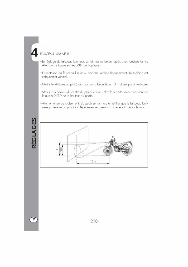
4
RÉG
LAG
ES
230F
9/10
h
10 m
hFAISCEAU LUMINEUX
� Le réglage du faisceau lumineux se fait manuellement après avoir dévissé les visAllen qui se trouve sur les côtés de l’optique.
� L’orientation du faisceau lumineux doit être vérifiée fréquemment. Le réglage estuniquement vertical.
�Mettre le véhicule au plat (mais pas sur la béquille) à 10 m d’une paroi verticale.
�Mesurer la hauteur du centre du projecteur au sol et la reporter avec une croix surle mur à 9/10 de la hauteur du phare.
�Allumer le feu de croisement, s’asseoir sur la moto et vérifier que le faisceau lumi-neux projeté sur la paroi soit légèrement en dessous du repère tracé sur le mur.
5
REM
PLA
CEM
ENTS
231 F
TABLE DES MATIÈRES
CHAP. 5 REMPLACEMENTS
Remplacement des plaquettes de frein
Remplacement de l’ampoule de phare avant
Remplacement de l’ampoule de phare arrière
Remplacement des ampoules des clignotants

5
REM
PLA
CEM
ENTS
232F
REMPLACEMENT DES PLAQUETTES DESFREINSFREIN AVANTLa description relative au remplacementdes plaquettes est purement à titre d’in-formation. En effet, il préférable des’adresser à un garage Agréé Betamotorpour effectuer l’opération.
Pour le remplacement, il faut procéderde la manière suivante:�Démonter l’étrier en dévissant les deuxvis A
�Dévisser les deux vis B.Note: les vis B sont serrées très fortement,il est recommandé de les desserrer avantde détacher la pince de la fourche.�Extraire les plaquettes�Pour le remontage, procéder en sensinverse.
Attention: le ressort indiqué sur la figuredoit être correctement positionné dans sonlogement et il devrait opposer unecertaine résistance au positionnement desplaquettes. .
Veiller à effectuer correctement le remon-tage des vis pour éviter les problèmes defreinage.
En cas de dépose du disque de frein,appliquer de la loctite sur les vis aumoment du remontage.
ATTENTION :Pendant le démontage de la pince dufrein, faire attention à ne pasendommager le capteur C.
A
B
C

5
REM
PLA
CEM
ENTS
233 F
FREIN ARRIERE
NOTE: Pour le remplacement desplaquettes il est conseillé de s’adresserà un atelier autorisé BETAMOTOR.
2 mm
CONTROLE USURE
-Pour vérifier l’état d’usure du frein arrièreil est suffisant de visionner l’étau de lapartie arrière, là où il est possibled’entrevoir les extrémités des deuxplaquettes qui devront présenter au moinsune couche ayant une épaisseur d’aumoins 2 mm de ferodo. Si l’épaisseur dela couche est inférieure il faut lesremplacer immédiatement.
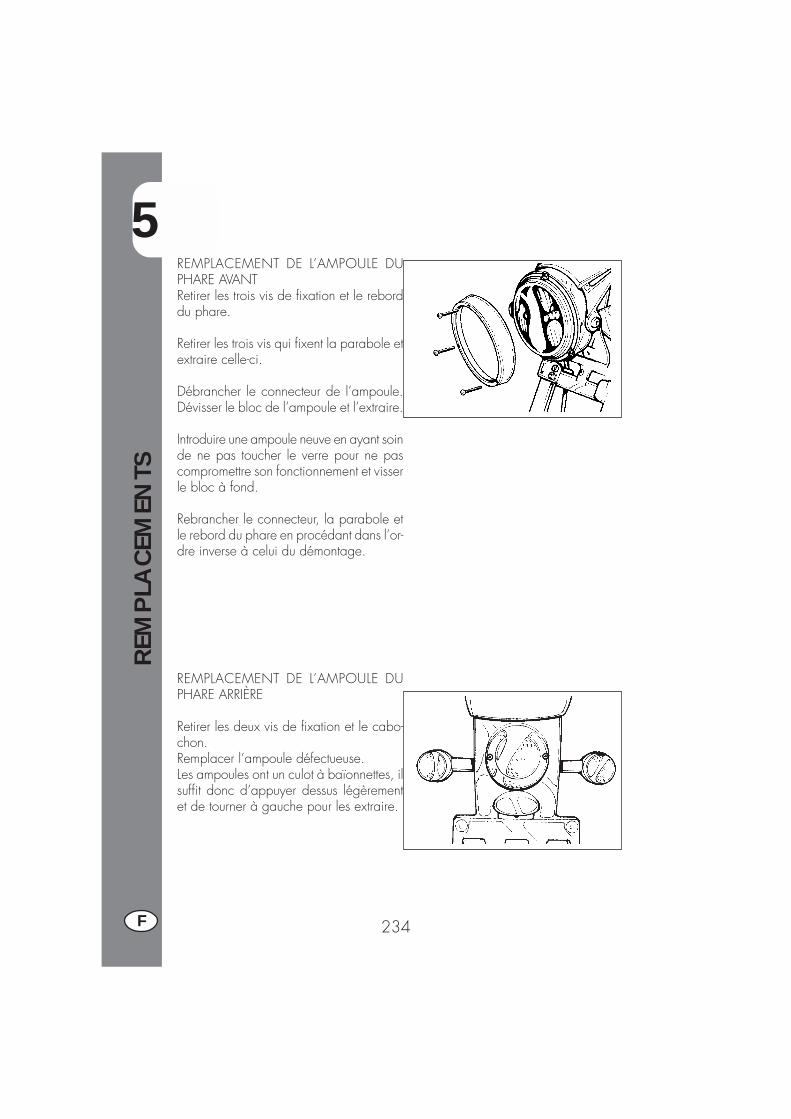
5
REM
PLA
CEM
ENTS
234F
REMPLACEMENT DE L’AMPOULE DUPHARE AVANTRetirer les trois vis de fixation et le reborddu phare.
Retirer les trois vis qui fixent la parabole etextraire celle-ci.
Débrancher le connecteur de l’ampoule.Dévisser le bloc de l’ampoule et l’extraire.
Introduire une ampoule neuve en ayant soinde ne pas toucher le verre pour ne pascompromettre son fonctionnement et visserle bloc à fond.
Rebrancher le connecteur, la parabole etle rebord du phare en procédant dans l’or-dre inverse à celui du démontage.
REMPLACEMENT DE L’AMPOULE DUPHARE ARRIÈRE
Retirer les deux vis de fixation et le cabo-chon.Remplacer l’ampoule défectueuse.Les ampoules ont un culot à baïonnettes, ilsuffit donc d’appuyer dessus légèrementet de tourner à gauche pour les extraire.
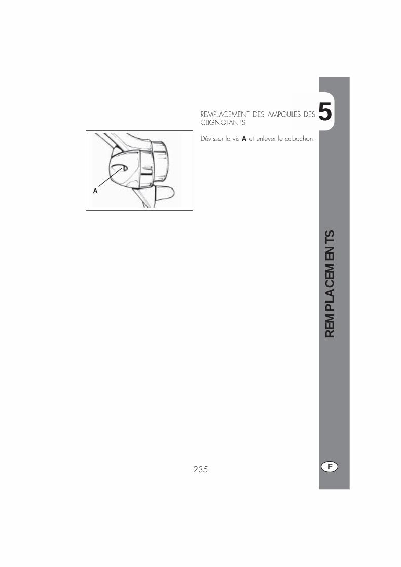
5
REM
PLA
CEM
ENTS
235 F
REMPLACEMENT DES AMPOULES DESCLIGNOTANTS
Dévisser la vis A et enlever le cabochon.
A

6
QU
E FA
IRE
EN C
AS
D’U
RG
ENCE
?
237 F
TABLE DES MATIÈRES
CHAP. 6 QUE FAIRE EN CAS D’URGENCE ?
INDEX ALPHABÉTIQUE
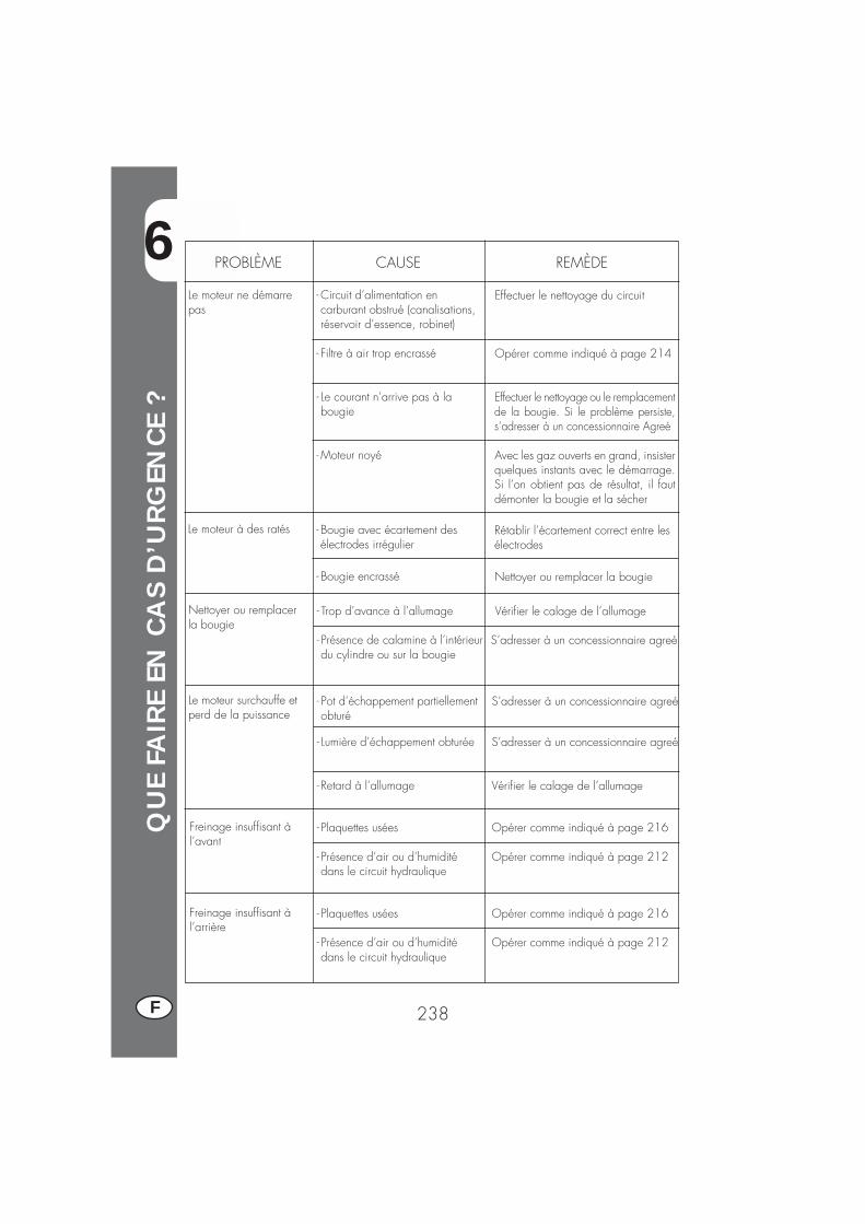
6
QU
E FA
IRE
EN C
AS
D’U
RG
ENCE
?
238F
PROBLÈME CAUSE
Le moteur ne démarrepas
REMÈDE
- Circuit d’alimentation encarburant obstrué (canalisations,réservoir d’essence, robinet)
- Filtre à air trop encrassé
- Le courant n’arrive pas à labougie
- Moteur noyé
Effectuer le nettoyage du circuit
Opérer comme indiqué à page 214
Effectuer le nettoyage ou le remplacementde la bougie. Si le problème persiste,s’adresser à un concessionnaire Agreé
Avec les gaz ouverts en grand, insisterquelques instants avec le démarrage.Si l’on obtient pas de résultat, il fautdémonter la bougie et la sécher
Le moteur à des ratés - Bougie avec écartement desélectrodes irrégulier
- Bougie encrassé
Rétablir l’écartement correct entre lesélectrodes
Nettoyer ou remplacer la bougie
Nettoyer ou remplacerla bougie
- Trop d’avance à l’allumage
- Présence de calamine à l’intérieurdu cylindre ou sur la bougie
Vérifier le calage de l’allumage
S’adresser à un concessionnaire agreé
Le moteur surchauffe etperd de la puissance
- Pot d’échappement partiellementobturé
- Lumière d’échappement obturée
- Retard à l’allumage
S’adresser à un concessionnaire agreé
S’adresser à un concessionnaire agreé
Vérifier le calage de l’allumage
Freinage insuffisant àl’avant
- Plaquettes usées
- Présence d’air ou d’humiditédans le circuit hydraulique
Opérer comme indiqué à page 216
Opérer comme indiqué à page 212
Freinage insuffisant àl’arrière
- Plaquettes usées
- Présence d’air ou d’humiditédans le circuit hydraulique
Opérer comme indiqué à page 216
Opérer comme indiqué à page 212
IND
EX A
LPH
ABÉT
IQU
E
239 F
Approvisionnement en carburant ........................................................... 206
Bougie ............................................................................................. 215
Caractéristiques techniques .................................................................. 191Clés et serrures .................................................................................. 172Contacteur principal/verrouillage direction ............................................. 172Contrôles après le nettoyage ................................................................ 221Contrôles et entretien avant et après l’utilisation tout-terrain ......................... 202
Démarrage ....................................................................................... 204Direction: contrôle et réglage ............................................................... 228Données d’identification du véhicule ...................................................... 168
Embrayage ....................................................................................... 226Entretien programmé ........................................................................... 222
Filtre à air ......................................................................................... 214Frein avant: contrôle et remplacement .................................................... 216Frein arrière: contrôle et remplacement ................................................... 216
Huile de fourche ................................................................................ 213Huile moteur: contrôle et vidange .................................................. 208/210
Liquide de frein .................................................................................. 211LCD................................................................................................. 174Lubrifiants et fluides conseillés ............................................................... 203
Purge des freins ................................................................................. 212
Recherche des pannes ........................................................................ 238Réglage de l’embrayage ..................................................................... 226Réglage des freins .............................................................................. 226Réglage du jeu à la poignée des gaz .................................................... 227Réglage du ralenti .............................................................................. 227Remplacement des ampoules ................................................................ 237Rodage ............................................................................................ 203
Schéma électrique ...................................................................... 195/197Serrure du casque .............................................................................. 177
Tableau de bord et commandes ............................................................ 173Tension de la chaîne ........................................................................... 229

241 D
ALP4T 125/200 cc
Vielen Dank für Ihr Vertrauen und viel Spaß.Mit dieser Bedienungsanleitung möchten wir Ihnen die notwen-digen Informationen für einen richtigen Gebrauch und einegute Wartung Ihres Motorrads geben.
Alle Angaben zu Technik und Ausstattung sind unverbindlich. DieBetamotor S.p.A. behält sich das Recht vor, an ihren Fahrzeugmodellenjederzeit und ohne Vorankündigung Änderungen und Verbesserungenvorzunehmen.
242D
HINWEIS
Wir raten Ihnen nach der ersten bzw. zweiten Betriebsstunde mitGeländefahrt alle Sicherheits-Anzugsmomente zu überprüfen unddabei besonders auf folgende Bauteile zu achten:
� Zahnkranz� Fußrastenbefestigung� Vorderer Bremssattel� Kotflügelbefestigung� Alle Schrauben und Bolzen am Motor� Alle Schrauben und Bolzen an den Stoßdämpfern� Radspeichen� Hinterer Rahmen
HINWEIS
Für Arbeiten am Motorrad wenden Sie sich bitte an dasKundendienstnetz der Betamotor Vertragshändler.
INH
ALT
SVER
ZEI
CH
NIS
243 D
Hinweise zum Gebrauch des Fahrzeugs ................................................. 245Umweltfreundliches Fahren ................................................................... 245Sicheres Fahren ................................................................................. 246
KAPITEL 1 ALLGEMEINE ANGABEN........................................ 247Rahmen- und Motornummer .................................................................. 248Auslieferung ...................................................................................... 248Zuladung .......................................................................................... 249Reifen .............................................................................................. 249Wichtigste Fahrzeugteile ..................................................................... 251Schlüssel und Schlösser ....................................................................... 252Zünd-/ Lenkerschloß ........................................................................... 252Helmschloß ....................................................................................... 252Armaturenbrett und Bedienungselemente ................................................. 253Anleitung zum einstellen und betrib des kilometerzahlers ............................ 254Allgemeine technische Angaben ........................................................... 271Technische Angaben Motor ALP 125 ..................................................... 273Technische Angaben Motor ALP 200 ..................................................... 274Elektrische Schaltpläne ALP125 ............................................................ 275Elektrische Schaltpläne ALP200 ............................................................ 277Elektrische Anlage .............................................................................. 279
KAPITEL 2 BEDIENUNGSVORSCHRIFTEN ................................ 281Kontrollen und Wartung vor und nach Einsatz im Gelände ......................... 282Empfohlene Schmiermittel und Flüssigkeiten ............................................. 283Einfahren .......................................................................................... 283Starten des Motors ............................................................................. 284Abstellen des Motors .......................................................................... 285Tanken ............................................................................................. 286
KAPITEL 3 WARTUNG UND KONTROLLEN ............................. 287Motoröl und Ölfilter ALP 200 ............................................................... 288Motoröl und Ölfilter ALP 125 ............................................................... 290Leitung Öldampfsammlung ................................................................... 291Bremsflüssigkeit, Entlüften der Bremsen .................................................... 292Gabelöl ........................................................................................... 293Luftfilter ............................................................................................. 294Zündkerze ........................................................................................ 295Bremsen: Vorderradbremse, Hinterradbremse........................................... 296Batterie ............................................................................................ 297Ausbau von Karosserie- und anderen Fahrzeugteilen ................................. 298Hinweise für Trial ............................................................................... 299Fahrzeugpflege und Kontrollen .............................................................. 301Wartungsprogramm............................................................................ 302Längeres Stilllegen des Fahrzeugs.......................................................... 303
INH
ALT
SVER
ZEI
CH
NIS
244D
KAPITEL 4 EINSTELLUNGEN ................................................... 305Einstellen der Bremsen ......................................................................... 306Einstellen der Kupplung ....................................................................... 306Leerlaufeinstellung .............................................................................. 307Einstellung Benzinfluss (nur für ALP125) ................................................... 307Einstellen des Gaszuges ...................................................................... 307Kontrolle und Einstellen Lenkerspiels ....................................................... 308Spannen der Kette .............................................................................. 309Einstellen des Scheinwerfers ................................................................. 310
KAPITEL 5 AUSTAUSCHEN/ AUSWECHSELN VON TEILEN ........ 313Auswechseln der Bremsbeläge ............................................................. 314Auswechseln der Scheinwerferlampen .................................................... 316Auswechseln der Rücklichtlampe ........................................................... 316Auswechseln der Blinkerlampen ............................................................ 317
KAPITEL 6 WAS IST IM NOTFALL ZU TUN ............................... 319
ALPHABETISCHES INHALTSVERZEICHNIS .............................................. 321
245 D
HINWEISE ZUM GEBRAUCH DES FAHRZEUGS
�Das Fahrzeug muß vorschriftsmäßig mit folgendem ausgestattet sein: Nummern-schild, Fahrzeugschein, Fahrzeugsteuer- und Versicherungsmarke.
�Das Fahren und der Transport mit Tieren und nicht fest am Fahrzeug befestigtenoder am Fahrzeug überstehenden Gegenständen ist verboten. Die vom Herstellerangegebene Nutzlast darf nicht überschritten werden.
�Es besteht Helmpflicht.�Veränderungen am Motor oder anderen Fahrzeugteilen, die die Fahrzeugleistungund damit die Geschwindigkeit erhöhen, sind gesetzlich verboten und werden, u.a. mit Beschlagnahmung des Fahrzeugs, bestraft.
�Zum Schutz des eigenen Lebens und des Lebens anderer Personen stets vorsichtigfahren und immer einen Sturzhelm tragen.
ACHTUNG:Bei Änderungen am Fahrzeug während der Garantiezeit haftet der Hersteller nichtund es verfallen sämtliche Garantieansprüche.
UMWELTFREUNDLICHES FAHREN� Jedes Fahrzeug mit Verbrennungsmotor ist mehr oder weniger laut (Geräusch-belastung) und belastet je nach Fahrstil mehr oder weniger die Umwelt (Luftver-schmutzung).
�Die Verringerung dieser Umweltbelastungen ist heute für alle zur Pflicht geworden.Vermeiden Sie daher ein Anfahren mit Vollgas sowie unnötiges plötzliches Be-schleunigen und Abbremsen des Fahrzeugs. Die Geräuschbelastung ist danngeringer, die Reifen und die mechanischen Fahrzeugteile verschleißen langsamer,der Benzinverbrauch kann deutlich gesenkt werden.
INH
ALT
SVER
ZEI
CH
NIS
246D
SICHERES FAHREN�Die Straßenverkehrsordnung beachten.�Stets einen zugelassenen Sturzhelm tragen und diesen festschnallen.�Das Schutzvisier am Helm immer sauber halten.�Enganliegende Kleidung tragen.�Niemals mit spitzen oder zerbrechlichen Gegenständen in den Taschen fahren.�Die Rückspiegel richtig einstellen.�Nur im Sitzen fahren, beide Hände am Lenker halten und die Füße auf das Tritt-brett/ die Fußrasten stellen.
�Stets aufmerksam fahren und sich nie ablenken lassen.�Beim Fahren nie essen, trinken, rauchen, telefonieren usw…�Beim Fahren niemals über Kopfhörer Musik hören.�Nie neben anderen Fahrzeugen fahren.�Nie andere Fahrzeuge abschleppen oder sich abschleppen lassen.� Immer den Sicherheitsabstand einhalten.�Auch tagsüber das Licht (Fahrlicht) einschalten.�Nicht auf das Fahrzeug setzen, solange dieses auf dem Ständer steht.�Nicht mit dem Motorroller anfahren, wenn dieses auf dem Ständer steht.�Den Ständer nicht benutzen, wenn das Fahrzeug in Fahrtrichtung auf abschüssigerStraße steht.
�Fahren mit angehobenem Vorderrad, Schlangenfahren, Wippen ist gefährlich fürDich, für die anderen und für den Motorroller.
�Auf trockener, sand- und kiesfreier Straße stets mit beiden Bremsen gleichzeitigbremsen, um ein gefährliches und nicht kontrollierbares Rutschen oder Ausbrechendes Fahrzeugs zu vermeiden.
�Stets mit beiden Bremsen gleichzeitig bremsen, der Bremsweg wird kürzer.�Auf nassen Straßen vorsichtig und langsam fahren, weniger stark bremsen.�Den Motor niemals in geschlossenen Räumen laufen lassen.
1
ALL
GEM
EIN
E A
NG
ABEN
247 D
INHALTSVERZEICHNIS
KAPITEL 1 ALLGEMEINE ANGABEN
Rahmen- und Motornummer
Auslieferung
Zuladung
Reifen
Wichtigste Fahrzeugteile
Schlüssel und Schlösser
Zünd-/ Lenkerschloß
Helmschloß
Armaturenbrett und Bedienungselemente
Anzeigen am LCD
Technische Daten
Elektrische Schaltpläne
Elektrische Anlage
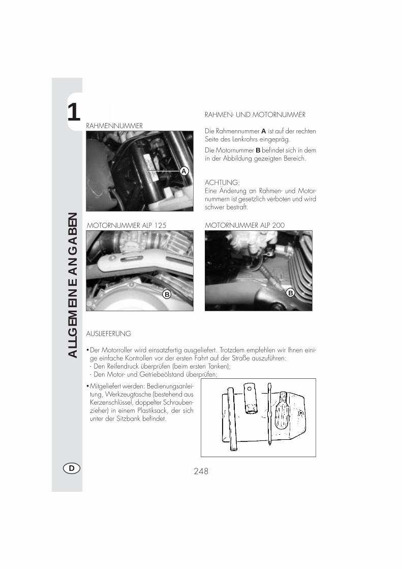
1
ALL
GEM
EIN
E A
NG
ABEN
248D
RAHMEN- UND MOTORNUMMER
Die Rahmennummer A ist auf der rechtenSeite des Lenkrohrs eingepräg.
RAHMENNUMMER
Die Motornummer B befindet sich in demin der Abbildung gezeigten Bereich.
ACHTUNG:Eine Änderung an Rahmen- und Motor-nummern ist gesetzlich verboten und wirdschwer bestraft.
MOTORNUMMER ALP 200
AUSLIEFERUNG
�Der Motorroller wird einsatzfertig ausgeliefert. Trotzdem empfehlen wir Ihnen eini-ge einfache Kontrollen vor der ersten Fahrt auf der Straße auszuführen:- Den Reifendruck überprüfen (beim ersten Tanken);- Den Motor- und Getriebeölstand überprüfen;
B
�Mitgeliefert werden: Bedienungsanlei-tung, Werkzeugtasche (bestehend ausKerzenschlüssel, doppelter Schrauben-zieher) in einem Plastiksack, der sichunter der Sitzbank befindet.
A
MOTORNUMMER ALP 125
B
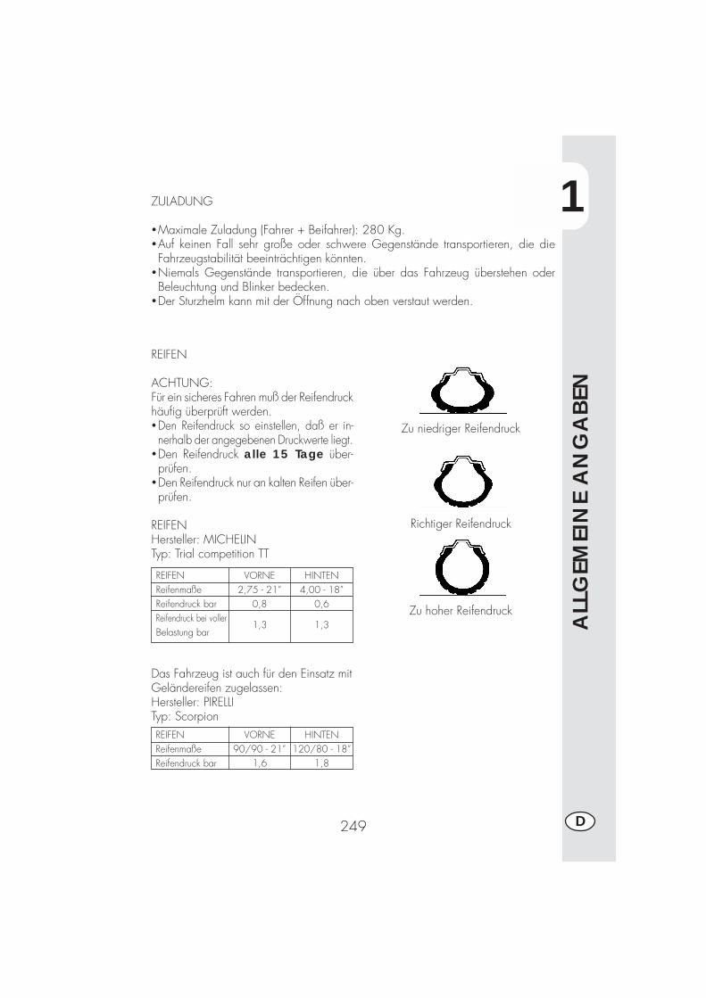
1
ALL
GEM
EIN
E A
NG
ABEN
249 D
ZULADUNG
�Maximale Zuladung (Fahrer + Beifahrer): 280 Kg.�Auf keinen Fall sehr große oder schwere Gegenstände transportieren, die dieFahrzeugstabilität beeinträchtigen könnten.
�Niemals Gegenstände transportieren, die über das Fahrzeug überstehen oderBeleuchtung und Blinker bedecken.
�Der Sturzhelm kann mit der Öffnung nach oben verstaut werden.
REIFEN
ACHTUNG:Für ein sicheres Fahren muß der Reifendruckhäufig überprüft werden.�Den Reifendruck so einstellen, daß er in-nerhalb der angegebenen Druckwerte liegt.
�Den Reifendruck alle 15 Tage über-prüfen.
�Den Reifendruck nur an kalten Reifen über-prüfen.
REIFENHersteller: MICHELINTyp: Trial competition TT
REIFENReifenmaßeReifendruck barReifendruck bei vollerBelastung bar
HINTEN4,00 - 18”
0,6
1,3
VORNE2,75 - 21”
0,8
1,3
Das Fahrzeug ist auch für den Einsatz mitGeländereifen zugelassen:Hersteller: PIRELLITyp: Scorpion
Zu niedriger Reifendruck
Richtiger Reifendruck
Zu hoher Reifendruck
REIFENReifenmaßeReifendruck bar
HINTEN120/80 - 18”
1,8
VORNE90/90 - 21”
1,6
1
ALL
GEM
EIN
E A
NG
ABEN
250D
Anmerkung:Das Reifenprofil (Schlauchreifen - TUBE TYPE) muß mindestens 2 mm betragen.Fahren mit geringerem Reifenprofil wird gesetzlich bestraft.
�Vor jedem Fahrtantritt die Reifen auf Schnittstellen, Abschürfungen, Aufblähen usw.überprüfen. Werden Beschädigungen am Reifen festgestellt, muß der Reifen voneinem Fachmann überprüft werden. Das Fahren mit beschädigten Reifen ist sehrgefährlich.
�Bei einem Loch im Reifen das Fahrzeug sofort anhalten. Weiterfahren ist sehr ge-fährlich und kann den Reifen und die Radfelgen schwer beschädigen.
*Bei voller Belastung werden höhere Reifendrücke empfohlen (siehe Tabelle aufSeite 249).

1
ALL
GEM
EIN
E A
NG
ABEN
251 D
1
6
7
32 22
4 11
8
9
10 5
WICHTIGSTE FAHRZEUGTEILE
13 15
1621
18
14 19
1217
20
Wichtigste Fahrzeugteile:1 - Luftfilter2 - Benzintank3- Tankverschluß4- Schalldämpfer5- Hinterer
Stoßdämpfer6- Scheinwerfer7- Vordere Blinker
8- Rücklicht9 - Hintere Blinker
10- Seitenständer11- Gepäckträger12- Rückspiegel13- Beifahrerfußraste14- Gabel15- Fahrerfußraste16- Motorschutz
17- Sitzbank18- Motor19- Vorderer Kotflügel20- Nummernschildhalter21- Kickstarterhebel22- Helmschloß
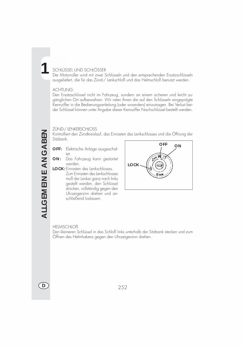
1
ALL
GEM
EIN
E A
NG
ABEN
252D
ONOFF
LOCK
SCHLÜSSEL UND SCHLÖSSERDer Motorroller wird mit zwei Schlüsseln und den entsprechenden Ersatzschlüsselnausgeliefert, die für das Zünd-/ Lenkschloß und das Helmschloß benutzt werden.
ACHTUNG:Den Ersatzschlüssel nicht im Fahrzeug, sondern an einem sicheren und leicht zu-gänglichen Ort aufbewahren. Wir raten Ihnen die auf den Schlüsseln eingeprägteKennziffer in die Bedienungsanleitung (oder woanders) einzutragen. Bei Verlust bei-der Schlüssel können unter Angabe dieser Kennziffer Nachschlüssel bestellt werden.
ZÜND-/ LENKERSCHLOSSKontrolliert den Zündkreislauf, das Einrasten des Lenkschlosses und die Öffnung derSitzbank.
OFF: Elektrische Anlage ausgeschal-tet.
ON: Das Fahrzeug kann gestartetwerden.
LOCK:Einrasten des Lenkschlosses.Zum Einrasten des Lenkschlossesmuß der Lenker ganz nach linksgestellt werden, den Schlüsseldrücken, vollständig gegen denUhrzeigersinn drehen und an-schließend loslassen.
HELMSCHLOßDen kleineren Schlüssel in das Schloß links unterhalb der Sitzbank stecken und zumÖffnen des Helmhakens gegen den Uhrzeigersinn drehen.

1
ALL
GEM
EIN
E A
NG
ABEN
253 D
1- LCD4- Zündschloß5- Kontrollampe Leerlauf6- Blinkerkontrolle7- Fernlichtkontrolle8- Zender benzinemeter9- Kontrollampe Seitenständer
10 - Kupplungshebel11 - Vorderradbremshebel
12 - Gasgriff13 - Startschalter14 - Schalter zum Abstellen des Motors15 - Blinkerschalter16 - Hupenschalter17 - Lichtschalter18 - Licht-Wechselschalter19 - Lichthupe
ARMATURENBRETT UND BEDIENUNGSELEMENTE
Anmerkung: Das Aufleuchten der Kontrollampe Seitenständer zeigt an, dass derSeitenständer ausgeklappt ist. Aus Sicherheitsgründen stellt sich dann bei Einlegeneines Gangs das Motorrad ab.
10
17 18
1516 4 14
12
11
13
5
19
6
7
9
1
8
1
ALL
GEM
EIN
E A
NG
ABEN
254D
ANLEITUNG ZUM EINSTELLEN UND BETRIEB DES KILOMETERZÄHLERS(für Hersteller und Vertragshändler)Die Beschreibung zur Grundeinstellung des Digitalinstrumentes hat rein informativenCharakter. Wir raten Ihnen sich für diese Einstellung an eine Betamotor-Vertragswerk-statt zu wenden.
Modellreihe ALP 125 - ALP 200
INHALTSVERZEICHNIS
ABSCHNITT INHALT
10.1 Technische Angaben zum Rad10.2 Technische Angaben zum Motor10.3 Code Voreingabe10.4 Geladene Code
20.0 SETUP STUFE 1 (für Motorrad-Hersteller und Vertragshändler)20.1 Setup-Vorgang für Stufe 120.2 Code-Auswahl20.3 Kontrolle Code-Inhalt20.4 Eingabe nicht kodifizierter Werte
20.4.1 Eingabe von Ln (Radumfang) oder di (Raddurchmesser)20.4.2 Eingabe Impulsanzahl pro Raddrehung20.4.3 Eingabe Impulsanzahl pro Motordrehung
20.4.3.1 Eingabe maximale Motordrehzahl20.4.4 Auswahl Km/h oder Mph20.4.5 Eingabe Stunden für Ölwechsel20.4.6 Stunden oder km bis zum Wartungscoupon
20.5 Beenden des Setup-Vorgangs
40.0 Anzeigen am LCD40.1 Funktion und Seiten-Anzeige40.2 Abschalten von Seiten40.3 Löschen der Parameter TRP, SPEED max (Höchstgeschwindigkeit), LAP
50.0 Auslosen der Überwanchungs-ikonen (motorol und Wartungscoupon)50.1 Kontrolle des aktiven Inhalts der Überwachungs-Ikonen
1
ALL
GEM
EIN
E A
NG
ABEN
255 D
10.1 Technische Angaben zum Rad (bereits am Fahrzeug eingegeben)Die Maße für das Rad, an dem der Drehzahlsensor montiert ist. Es müssen derRaddurchmesser oder der Radumfang in mm angegeben werden (Maximaler Wert9999. Beispiel: für einen Raddurchmesser von 695 mm muss nach der Eingabe0695 abgelesen werden). Zusätzlich muss die Impulsanzahl pro Raddrehung, miteinem Höchstwert von 99, angegeben werden. Ist die Impulsanzahl kleiner als 10,zum Beispiel 1, muss 01 abgelesen werden.
ANMERKUNG: Die Taste SCROLL kann auf zwei Arten betätigt werden:Kurzes Drücken ≤ 1”, das Programm stellt sich auf die nächste Seite ein.Langes Drücken ≥ 5”, das Programm öffnet die angezeigte Funktion, so dassder Inhalt kontrolliert werden kann bzw. die entsprechenden Werte eingegebenoder enthaltene Werte geändert werden können. In einigen Fällen kann auch ge-speichert werden.
In der vorliegenden Anleitung wird zur Vereinfachung nur auf die Taste SCROLL amLenker verwiesen. Die gleichen Ergebnisse erhält man aber auch durch Drücken derTaste MODE am Kilometerzähler (die Taste MODE kann nur bei ausgeschaltetemMotor betätigt werden).
10.2 Technische Angaben zum Motor (nur wenn der Drehzahlmessereingeschaltet ist)Impulsanzahl pro Radumdrehung und maximale Motordrehzahl zur Eichung derAnzeigeleiste. Eine eventuelle Eingabe dieser Parameter bei nicht vorhandenemDrehzahlmesser ändert den Betrieb nicht, öffnet aber trotzdem eine Seite am LCDmit Parametern und Anzeigeleiste auf Null. Der Eingang des Drehzahlmessers ist anPin 12 am Kabelstecker. Bei der Impulsanzahl pro Motordrehung gelten die glei-chen Regeln wie bei der Impulsanzahl pro Radumdrehung. Für die Anzahl der Motor-drehzahl sind nur die Tausender und Hunderter erforderlich. Beispiel: zur Eingabeeiner Drehzahl von 15000 Umdrehungen muss 150 bei den großen Ziffern einge-geben werden. Zur Eingabe einer Drehzahl von 8500 Umdrehungen muss 085 beiden großen Ziffern eingegeben werden.
10.3 Code Voreingabe (bereits am Fahrzeug eingegeben)Der Hersteller hat bereits vier vorgegebene Code eingegeben. Diese Code enthal-ten immer die Rad-Parameter sowie die Überwachungs-Parameter, wie „Stunden fürÖlwechsel“ und „Stunden oder km bis zum Wartungscoupon“. Nur dieÜberwachungs-Parameter können stets geändert werden. Die Code-Kennzeichnungerfolgt durch Hervorheben einer Code-Zahl am LCD. Der erste eingegebene Codehat die Nummer 0001.Die Code sind bereits eingegeben und können, außer vom Hersteller, nicht mehrgeändert werden. Es wird darauf hingewiesen, dass bei einer Neuprogrammierungdie zurückgelegte Gesamt-Kilometerzahl auf Null zurückgestellt wird.
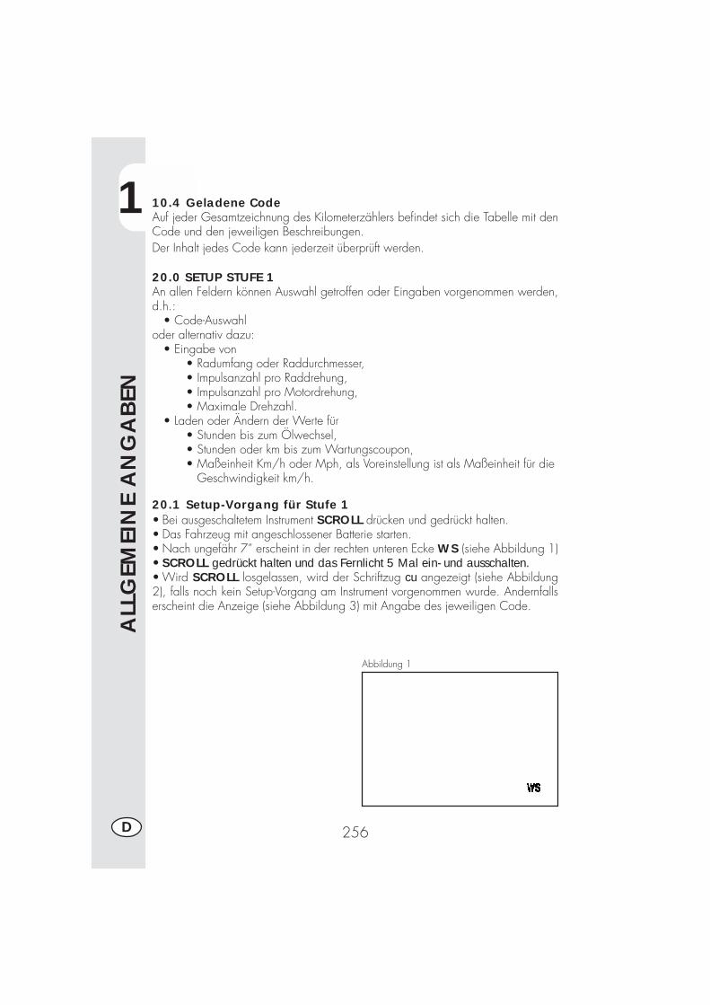
1
ALL
GEM
EIN
E A
NG
ABEN
256D
10.4 Geladene CodeAuf jeder Gesamtzeichnung des Kilometerzählers befindet sich die Tabelle mit denCode und den jeweiligen Beschreibungen.Der Inhalt jedes Code kann jederzeit überprüft werden.
20.0 SETUP STUFE 1An allen Feldern können Auswahl getroffen oder Eingaben vorgenommen werden,d.h.: • Code-Auswahloder alternativ dazu: • Eingabe von
• Radumfang oder Raddurchmesser,• Impulsanzahl pro Raddrehung,• Impulsanzahl pro Motordrehung,• Maximale Drehzahl.
• Laden oder Ändern der Werte für• Stunden bis zum Ölwechsel,• Stunden oder km bis zum Wartungscoupon,• Maßeinheit Km/h oder Mph, als Voreinstellung ist als Maßeinheit für die Geschwindigkeit km/h.
20.1 Setup-Vorgang für Stufe 1• Bei ausgeschaltetem Instrument SCROLL drücken und gedrückt halten.• Das Fahrzeug mit angeschlossener Batterie starten.• Nach ungefähr 7” erscheint in der rechten unteren Ecke WS (siehe Abbildung 1)• SCROLL gedrückt halten und das Fernlicht 5 Mal ein- und ausschalten.• Wird SCROLL losgelassen, wird der Schriftzug cu angezeigt (siehe Abbildung2), falls noch kein Setup-Vorgang am Instrument vorgenommen wurde. Andernfallserscheint die Anzeige (siehe Abbildung 3) mit Angabe des jeweiligen Code.
Abbildung 1
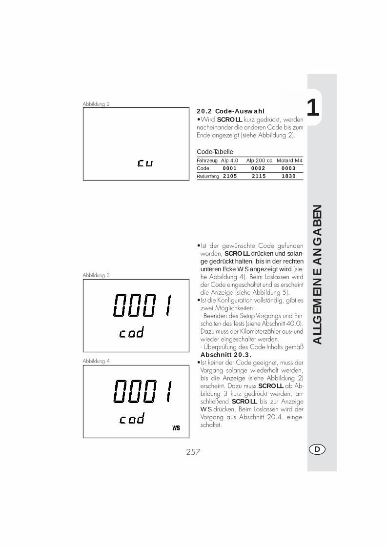
1
ALL
GEM
EIN
E A
NG
ABEN
257 D
20.2 Code-Auswahl•Wird SCROLL kurz gedrückt, werdennacheinander die anderen Code bis zumEnde angezeigt (siehe Abbildung 2).
Code-TabelleFahrzeug Alp 4.0 Alp 200 cc Motard M4Code 0001 0002 0003Radumfang 2105 2115 1830
•Ist der gewünschte Code gefundenworden, SCROLL drücken und solan-ge gedrückt halten, bis in der rechtenunteren Ecke WS angezeigt wird (sie-he Abbildung 4). Beim Loslassen wirdder Code eingeschaltet und es erscheintdie Anzeige (siehe Abbildung 5).
•Ist die Konfiguration vollständig, gibt eszwei Möglichkeiten:- Beenden des Setup-Vorgangs und Ein-schalten des Tests (siehe Abschnitt 40.0).Dazu muss der Kilometerzähler aus- undwieder eingeschaltet werden.- Überprüfung des Code-Inhalts gemäßAbschnitt 20.3.
•Ist keiner der Code geeignet, muss derVorgang solange wiederholt werden,bis die Anzeige (siehe Abbildung 2)erscheint. Dazu muss SCROLL ab Ab-bildung 3 kurz gedrückt werden, an-schließend SCROLL bis zur AnzeigeWS drücken. Beim Loslassen wird derVorgang aus Abschnitt 20.4. einge-schaltet.
Abbildung 2
Abbildung 3
Abbildung 4
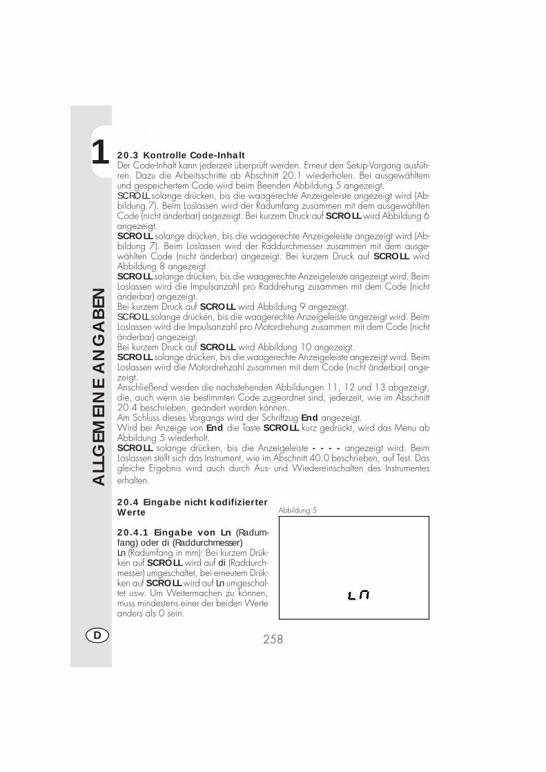
1
ALL
GEM
EIN
E A
NG
ABEN
258D
Abbildung 520.4 Eingabe nicht kodifizierterWerte
20.4.1 Eingabe von Ln (Radum-fang) oder di (Raddurchmesser)Ln (Radumfang in mm): Bei kurzem Drük-ken auf SCROLL wird auf di (Raddurch-messer) umgeschaltet, bei erneutem Drük-ken auf SCROLL wird auf Ln umgeschal-tet usw. Um Weitermachen zu können,muss mindestens einer der beiden Werteanders als 0 sein.
20.3 Kontrolle Code-InhaltDer Code-Inhalt kann jederzeit überprüft werden. Erneut den Setup-Vorgang ausfüh-ren. Dazu die Arbeitsschritte ab Abschnitt 20.1 wiederholen. Bei ausgewähltemund gespeichertem Code wird beim Beenden Abbildung 5 angezeigt.SCROLL solange drücken, bis die waagerechte Anzeigeleiste angezeigt wird (Ab-bildung 7). Beim Loslassen wird der Radumfang zusammen mit dem ausgewähltenCode (nicht änderbar) angezeigt. Bei kurzem Druck auf SCROLL wird Abbildung 6angezeigt.SCROLL solange drücken, bis die waagerechte Anzeigeleiste angezeigt wird (Ab-bildung 7). Beim Loslassen wird der Raddurchmesser zusammen mit dem ausge-wählten Code (nicht änderbar) angezeigt. Bei kurzem Druck auf SCROLL wirdAbbildung 8 angezeigt.SCROLL solange drücken, bis die waagerechte Anzeigeleiste angezeigt wird. BeimLoslassen wird die Impulsanzahl pro Raddrehung zusammen mit dem Code (nichtänderbar) angezeigt.Bei kurzem Druck auf SCROLL wird Abbildung 9 angezeigt.SCROLL solange drücken, bis die waagerechte Anzeigeleiste angezeigt wird. BeimLoslassen wird die Impulsanzahl pro Motordrehung zusammen mit dem Code (nichtänderbar) angezeigt.Bei kurzem Druck auf SCROLL wird Abbildung 10 angezeigt.SCROLL solange drücken, bis die waagerechte Anzeigeleiste angezeigt wird. BeimLoslassen wird die Motordrehzahl zusammen mit dem Code (nicht änderbar) ange-zeigt.Anschließend werden die nachstehenden Abbildungen 11, 12 und 13 abgezeigt,die, auch wenn sie bestimmten Code zugeordnet sind, jederzeit, wie im Abschnitt20.4 beschrieben, geändert werden können.Am Schluss dieses Vorgangs wird der Schriftzug End angezeigt.Wird bei Anzeige von End die Taste SCROLL kurz gedrückt, wird das Menu abAbbildung 5 wiederholt.SCROLL solange drücken, bis die Anzeigeleiste - - - - angezeigt wird. BeimLoslassen stellt sich das Instrument, wie im Abschnitt 40.0 beschrieben, auf Test. Dasgleiche Ergebnis wird auch durch Aus- und Wiedereinschalten des Instrumenteserhalten.
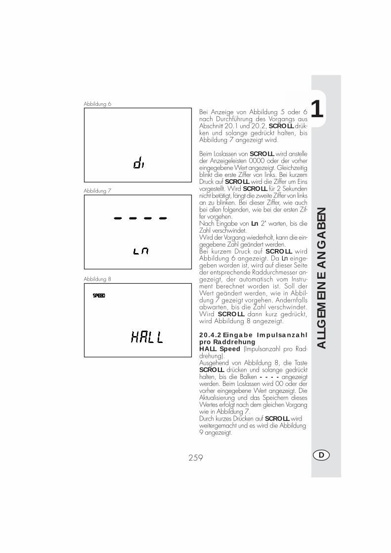
1
ALL
GEM
EIN
E A
NG
ABEN
259 D
Abbildung 6
Bei Anzeige von Abbildung 5 oder 6nach Durchführung des Vorgangs ausAbschnitt 20.1 und 20.2, SCROLL drük-ken und solange gedrückt halten, bisAbbildung 7 angezeigt wird.
Beim Loslassen von SCROLL wird anstelleder Anzeigeleisten 0000 oder der vorhereingegebene Wert angezeigt. Gleichzeitigblinkt die erste Ziffer von links. Bei kurzemDruck auf SCROLL wird die Ziffer um Einsvorgestellt. Wird SCROLL für 2 Sekundennicht betätigt, fängt die zweite Ziffer von linksan zu blinken. Bei dieser Ziffer, wie auchbei allen folgenden, wie bei der ersten Zif-fer vorgehen.Nach Eingabe von Ln 2" warten, bis dieZahl verschwindet.Wird der Vorgang wiederholt, kann die ein-gegebene Zahl geändert werden.Bei kurzem Druck auf SCROLL wirdAbbildung 6 angezeigt. Da Ln einge-geben worden ist, wird auf dieser Seiteder entsprechende Raddurchmesser an-gezeigt, der automatisch vom Instru-ment berechnet worden ist. Soll derWert geändert werden, wie in Abbil-dung 7 gezeigt vorgehen. Andernfallsabwarten, bis die Zahl verschwindet.Wird SCROLL dann kurz gedrückt,wird Abbildung 8 angezeigt.
20.4.2Eingabe Impulsanzahlpro RaddrehungHALL Speed (Impulsanzahl pro Rad-drehung).Ausgehend von Abbildung 8, die TasteSCROLL drücken und solange gedrückthalten, bis die Balken - - - - angezeigtwerden. Beim Loslassen wird 00 oder dervorher eingegebene Wert angezeigt. DieAktualisierung und das Speichern diesesWertes erfolgt nach dem gleichen Vorgangwie in Abbildung 7.Durch kurzes Drücken auf SCROLL wirdweitergemacht und es wird die Abbildung9 angezeigt.
Abbildung 7
Abbildung 8
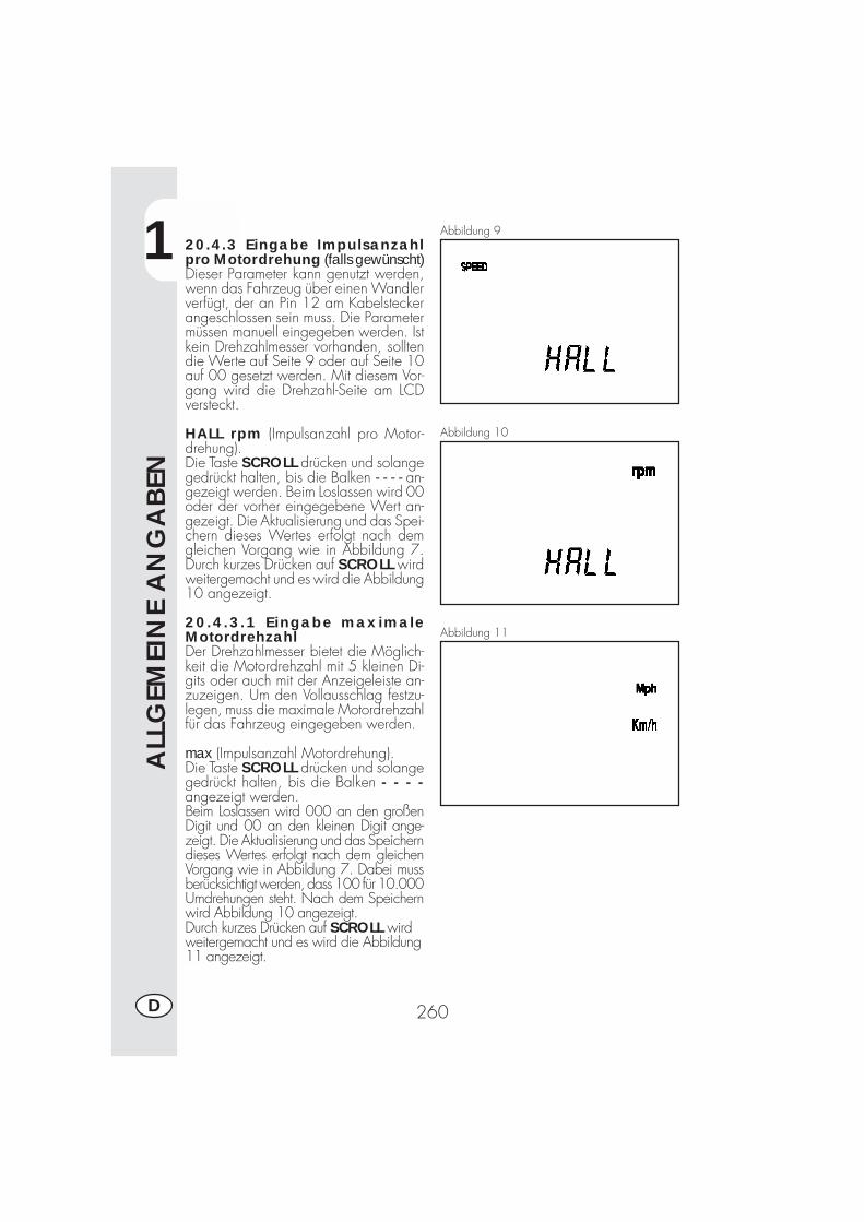
1
ALL
GEM
EIN
E A
NG
ABEN
260D
Abbildung 9
Abbildung 10
Abbildung 11
20.4.3 Eingabe Impulsanzahlpro Motordrehung (falls gewünscht)Dieser Parameter kann genutzt werden,wenn das Fahrzeug über einen Wandlerverfügt, der an Pin 12 am Kabelsteckerangeschlossen sein muss. Die Parametermüssen manuell eingegeben werden. Istkein Drehzahlmesser vorhanden, solltendie Werte auf Seite 9 oder auf Seite 10auf 00 gesetzt werden. Mit diesem Vor-gang wird die Drehzahl-Seite am LCDversteckt.
HALL rpm (Impulsanzahl pro Motor-drehung).Die Taste SCROLL drücken und solangegedrückt halten, bis die Balken - - - - an-gezeigt werden. Beim Loslassen wird 00oder der vorher eingegebene Wert an-gezeigt. Die Aktualisierung und das Spei-chern dieses Wertes erfolgt nach demgleichen Vorgang wie in Abbildung 7.Durch kurzes Drücken auf SCROLL wirdweitergemacht und es wird die Abbildung10 angezeigt.
20.4.3.1 Eingabe maximaleMotordrehzahlDer Drehzahlmesser bietet die Möglich-keit die Motordrehzahl mit 5 kleinen Di-gits oder auch mit der Anzeigeleiste an-zuzeigen. Um den Vollausschlag festzu-legen, muss die maximale Motordrehzahlfür das Fahrzeug eingegeben werden.
max (Impulsanzahl Motordrehung).Die Taste SCROLL drücken und solangegedrückt halten, bis die Balken - - - -angezeigt werden.Beim Loslassen wird 000 an den großenDigit und 00 an den kleinen Digit ange-zeigt. Die Aktualisierung und das Speicherndieses Wertes erfolgt nach dem gleichenVorgang wie in Abbildung 7. Dabei mussberücksichtigt werden, dass 100 für 10.000Umdrehungen steht. Nach dem Speichernwird Abbildung 10 angezeigt.Durch kurzes Drücken auf SCROLL wirdweitergemacht und es wird die Abbildung11 angezeigt.
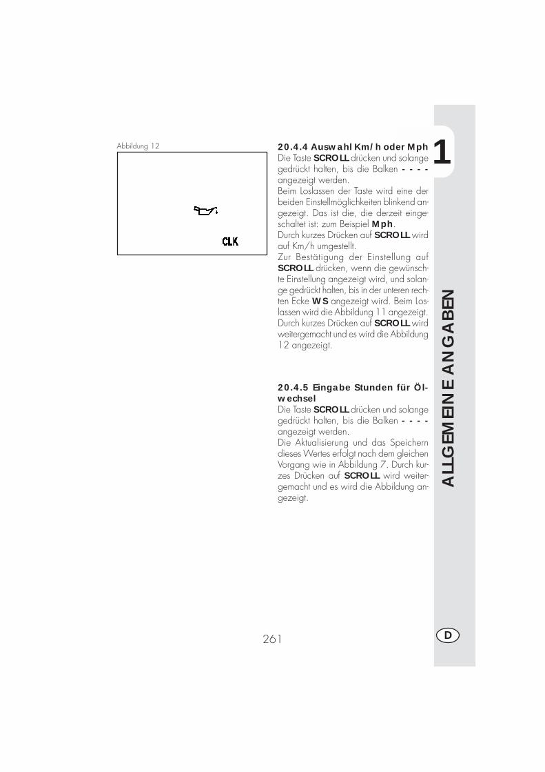
1
ALL
GEM
EIN
E A
NG
ABEN
261 D
20.4.4 Auswahl Km/h oder MphDie Taste SCROLL drücken und solangegedrückt halten, bis die Balken - - - -angezeigt werden.Beim Loslassen der Taste wird eine derbeiden Einstellmöglichkeiten blinkend an-gezeigt. Das ist die, die derzeit einge-schaltet ist: zum Beispiel Mph.Durch kurzes Drücken auf SCROLL wirdauf Km/h umgestellt.Zur Bestätigung der Einstellung aufSCROLL drücken, wenn die gewünsch-te Einstellung angezeigt wird, und solan-ge gedrückt halten, bis in der unteren rech-ten Ecke WS angezeigt wird. Beim Los-lassen wird die Abbildung 11 angezeigt.Durch kurzes Drücken auf SCROLL wirdweitergemacht und es wird die Abbildung12 angezeigt.
Abbildung 12
20.4.5 Eingabe Stunden für Öl-wechselDie Taste SCROLL drücken und solangegedrückt halten, bis die Balken - - - -angezeigt werden.Die Aktualisierung und das Speicherndieses Wertes erfolgt nach dem gleichenVorgang wie in Abbildung 7. Durch kur-zes Drücken auf SCROLL wird weiter-gemacht und es wird die Abbildung an-gezeigt.
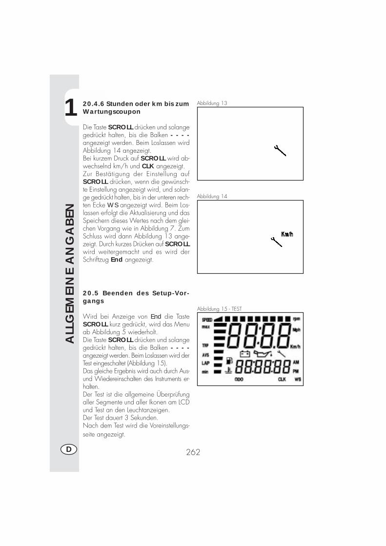
1
ALL
GEM
EIN
E A
NG
ABEN
262D
20.4.6 Stunden oder km bis zumWartungscoupon
Die Taste SCROLL drücken und solangegedrückt halten, bis die Balken - - - -angezeigt werden. Beim Loslassen wirdAbbildung 14 angezeigt.Bei kurzem Druck auf SCROLL wird ab-wechselnd km/h und CLK angezeigt.Zur Bestätigung der Einstellung aufSCROLL drücken, wenn die gewünsch-te Einstellung angezeigt wird, und solan-ge gedrückt halten, bis in der unteren rech-ten Ecke WS angezeigt wird. Beim Los-lassen erfolgt die Aktualisierung und dasSpeichern dieses Wertes nach dem glei-chen Vorgang wie in Abbildung 7. ZumSchluss wird dann Abbildung 13 ange-zeigt. Durch kurzes Drücken auf SCROLLwird weitergemacht und es wird derSchriftzug End angezeigt.
20.5 Beenden des Setup-Vor-gangs
Wird bei Anzeige von End die TasteSCROLL kurz gedrückt, wird das Menuab Abbildung 5 wiederholt.Die Taste SCROLL drücken und solangegedrückt halten, bis die Balken - - - -angezeigt werden. Beim Loslassen wird derTest eingeschaltet (Abbildung 15).Das gleiche Ergebnis wird auch durch Aus-und Wiedereinschalten des Instruments er-halten.Der Test ist die allgemeine Überprüfungaller Segmente und aller Ikonen am LCDund Test an den Leuchtanzeigen.Der Test dauert 3 Sekunden.Nach dem Test wird die Voreinstellungs-seite angezeigt.
Abbildung 13
Abbildung 14
Abbildung 15 - TEST
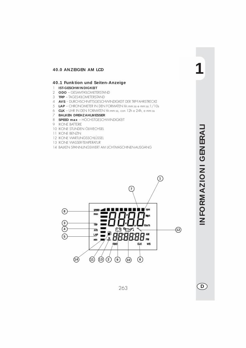
1
INFO
RM
AZ
ION
I G
ENER
ALI
263 D
40.0 ANZEIGEN AM LCD
40.1 Funktion und Seiten-Anzeige1 IST-GESCHWINDIGKEIT2 ODO – GESAMT-KILOMETERSTAND3 TRP – TAGES-KILOMETERSTAND4 AVS – DURCHSCHNITTSGESCHWINDIGKEIT DER TRP-FAHRSTRECKE5 LAP – CHRONOMETER IN DEN FORMATEN hh:mm:ss e mm:ss:1/10s6 CLK – UHR IN DEN FORMATEN hh:mm:ss, con 12h e 24h, e mm:ss7 BALKEN DREHZAHLMESSER8 SPEED max – HÖCHSTGESCHWINDIGKEIT9 IKONE BATTERIE10 IKONE STUNDEN ÖLWECHSEL11 IKONE BENZIN12 IKONE WARTUNGSSCHLÜSSEL13 IKONE WASSER-TEMPERATUR14 BALKEN SPANNUNGSWERT AM LICHTMASCHINEN-AUSGANG
12
10 613
5
4
3
8
1
1114 92
7

1
ALL
GEM
EIN
E A
NG
ABEN
264D
Seitenabfolge am LCDAlle Seiten sind ab der Voreinstellungsseite nur in Abfolge zugänglich.
Den Zündschlüssel auf ON drehen. All-gemeine Überprüfung aller Segmente undaller Ikonen am LCD und Test an denLeuchtanzeigen.Der Test dauert 3 Sekunden.Nach dem Test wird die Voreinstellungs-seite angezeigt.
Die Voreinstellungsseite wird nach demTEST automatisch angezeigt.Es wird angezeigt:Batterie - zeigt den Ladezustand mitsenkrechtem Strich an (Min 10,4 Volt max.14,5 Volt)Aktuelle Geschwindigkeit oben(max. 199 Km/h oder Mph)ODO Gesamt-Kilometer- oderMeilenstand ab erstem Setup. Wirdunten angezeigt (max. 999.999 Km oderMeilen) Dieser Parameter kann nicht aufNull zurückgestellt werden.
Seite 1 – TEST.
Seite 2 - VOREINSTELLUNGSSEITE
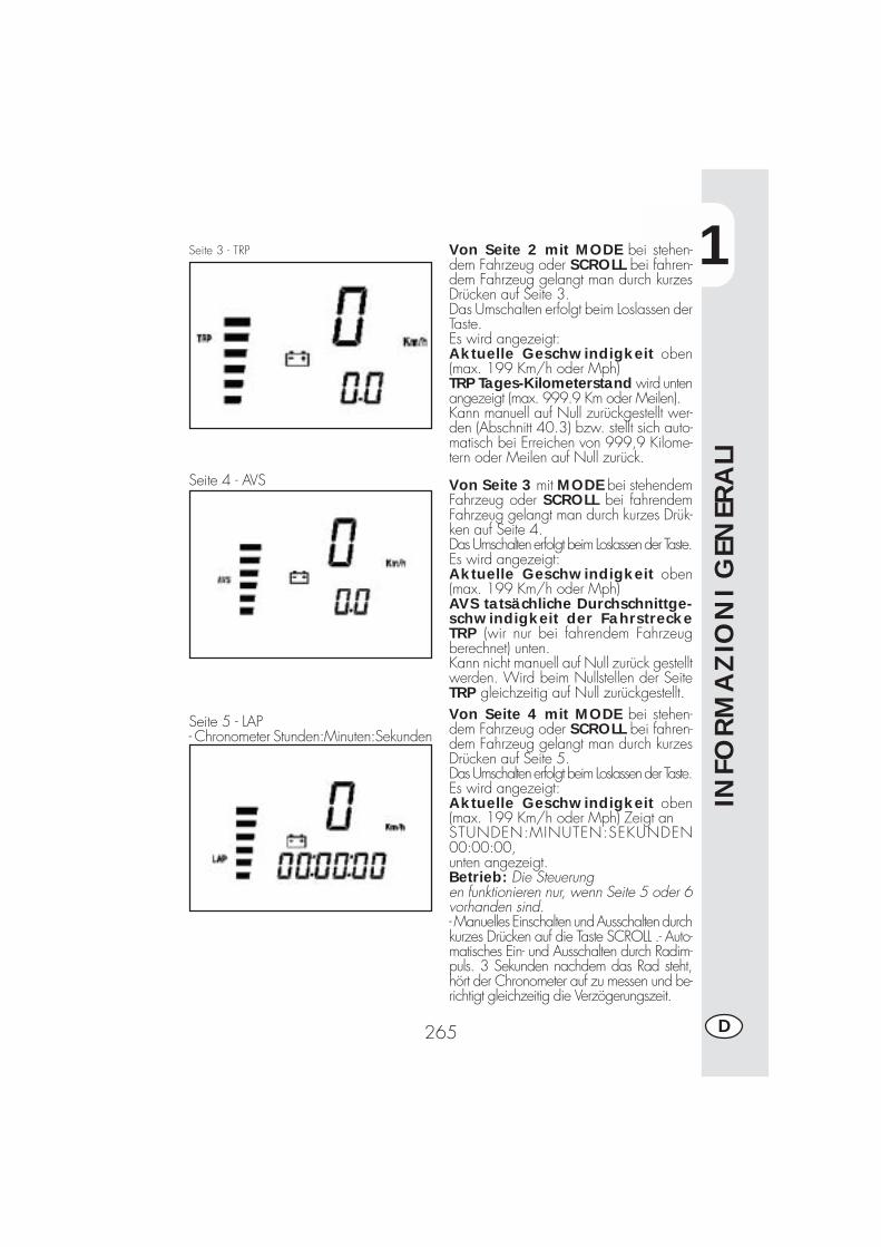
1
INFO
RM
AZ
ION
I G
ENER
ALI
265 D
Seite 3 - TRP
Seite 4 - AVS
Seite 5 - LAP- Chronometer Stunden:Minuten:Sekunden
Von Seite 2 mit MODE bei stehen-dem Fahrzeug oder SCROLL bei fahren-dem Fahrzeug gelangt man durch kurzesDrücken auf Seite 3.Das Umschalten erfolgt beim Loslassen derTaste.Es wird angezeigt:Aktuelle Geschwindigkeit oben(max. 199 Km/h oder Mph)TRP Tages-Kilometerstand wird untenangezeigt (max. 999.9 Km oder Meilen).Kann manuell auf Null zurückgestellt wer-den (Abschnitt 40.3) bzw. stellt sich auto-matisch bei Erreichen von 999,9 Kilome-tern oder Meilen auf Null zurück.
Von Seite 3 mit MODE bei stehendemFahrzeug oder SCROLL bei fahrendemFahrzeug gelangt man durch kurzes Drük-ken auf Seite 4.Das Umschalten erfolgt beim Loslassen der Taste.Es wird angezeigt:Aktuelle Geschwindigkeit oben(max. 199 Km/h oder Mph)AVS tatsächliche Durchschnittge-schwindigkeit der FahrstreckeTRP (wir nur bei fahrendem Fahrzeugberechnet) unten.Kann nicht manuell auf Null zurück gestelltwerden. Wird beim Nullstellen der SeiteTRP gleichzeitig auf Null zurückgestellt.Von Seite 4 mit MODE bei stehen-dem Fahrzeug oder SCROLL bei fahren-dem Fahrzeug gelangt man durch kurzesDrücken auf Seite 5.Das Umschalten erfolgt beim Loslassen der Taste.Es wird angezeigt:Aktuelle Geschwindigkeit oben(max. 199 Km/h oder Mph) Zeigt anSTUNDEN:MINUTEN:SEKUNDEN00:00:00,unten angezeigt.Betrieb: Die Steuerungen funktionieren nur, wenn Seite 5 oder 6vorhanden sind.- Manuelles Einschalten und Ausschalten durchkurzes Drücken auf die Taste SCROLL .- Auto-matisches Ein- und Ausschalten durch Radim-puls. 3 Sekunden nachdem das Rad steht,hört der Chronometer auf zu messen und be-richtigt gleichzeitig die Verzögerungszeit.
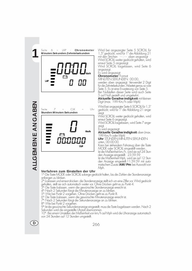
1
ALL
GEM
EIN
E A
NG
ABEN
266D
Seite 6 – LAP - ChronometerMinuten:Sekunden:Zehntelsekunden
Seite 7 – CLK – UhrStunden:Minuten:Sekunden
Wird bei angezeigter Seite 5 SCROLL für1,5" gedrückt, wird für 1" die Abbildung 21mit den Strichen - - : - - oben angezeigtWird SCROLL weiter gedrückt gehalten, wirderneut Seite 5 angezeigt.Wird SCROLL losgelassen, wird Seite 6angezeigt.Es wird angezeigt:Chronometer FormatMINUTEN:SEKUNDEN 00:00,werden oben angezeigt. Verwendet 2 Digitfür die Zehntelsekunden. Arbeitet genau so wieSeite 5. Es ist eine Erweiterung von Seite 5.Bei Nullstellen dieser Seite wird auch Seite5 auf Null gestellt und umgekehrt.Aktuelle Geschwindigkeit mit kleinenDigit (max. 199 Km/h oder Mph)Wird bei angezeigter Seite 6 SCROLL für 1,5"gedrückt, wird für 1" die Abbildung 21 ange-zeigtWird SCROLL weiter gedrückt gehalten, wirderneut Seite 6 angezeigt.Wird SCROLL losgelassen, wird Seite 7 ange-zeigt.Es wird angezeigt:Aktuelle Geschwindigkeit oben (max.199 Km/h oder Mph)Uhr STUNDEN:MINUTEN:SEKUNDENunten, 00:00:00.Kann bei stehendem Fahrzeug über die TasteMODE oder SCROLL eingestellt werden..Ist die Maßeinheit km/h, wird sie auf 24 Stun-den Anzeige eingestellt. 23:59:59Ist die Maßeinheit Mph, wird sie auf 12 Stun-den Anzeige eingestellt.11:59:59 mit auto-matischem Zusatz AM/Pm bei Auswahl vonMph.
Verfahren zum Einstellen der Uhr1°- Die Taste MODE oder SCROLL solange gedrückt halten, bis die Zahlen der Stundenanzeigeanfangen zu blinken.2°- Loslassen und erneut drücken: die Stundenanzeige stellt sich um eine Ziffer vor. Wird gedrücktgehalten, stellt sie sich automatisch weiter vor. Ohne Drücken geht es zu Punkt 4.3°- Die Taste loslassen, wenn die gewünschte Stundenanzeige erreicht ist.4°- Nach 2 Sekunden fängt die Minutenanzeige an zu blinken.5°- Wie bei Punkt 2 vorgehen. Ohne Drücken geht es zu Punkt 8.6°- Die Taste loslassen, wenn die gewünschte Minutenanzeige erreicht ist.7°- Nach 2 Sekunden fängt die Sekundenanzeige an zu blinken.8°- Wie bei Punkt 2 vorgehen.9°- Ist die gewünschte Sekundenanzeige eingestellt, muss die Taste losgelassen werden. Nach 2Sekunden wird die eingestellte Uhrzeit übernommen.10° - Bei einem Umstellen der Maßeinheit von km/h auf Mph wird die Uhranzeige automatischvon 24 Stunden auf 12 Stunden umgestellt.
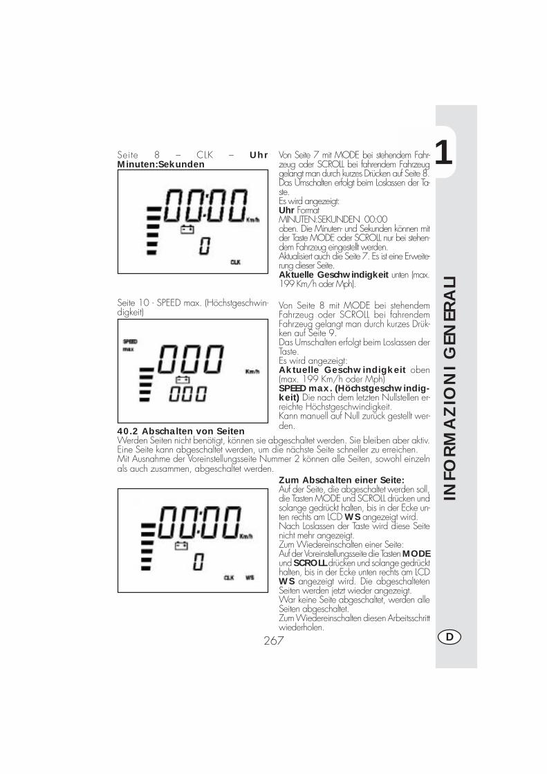
1
INFO
RM
AZ
ION
I G
ENER
ALI
267 D
Seite 8 – CLK – UhrMinuten:Sekunden
Seite 10 - SPEED max. (Höchstgeschwin-digkeit)
Von Seite 7 mit MODE bei stehendem Fahr-zeug oder SCROLL bei fahrendem Fahrzeuggelangt man durch kurzes Drücken auf Seite 8.Das Umschalten erfolgt beim Loslassen der Ta-ste.Es wird angezeigt:Uhr FormatMINUTEN:SEKUNDEN 00:00oben. Die Minuten- und Sekunden können mitder Taste MODE oder SCROLL nur bei stehen-dem Fahrzeug eingestellt werden.Aktualisiert auch die Seite 7. Es ist eine Erweite-rung dieser Seite.Aktuelle Geschwindigkeit unten (max.199 Km/h oder Mph).
Von Seite 8 mit MODE bei stehendemFahrzeug oder SCROLL bei fahrendemFahrzeug gelangt man durch kurzes Drük-ken auf Seite 9.Das Umschalten erfolgt beim Loslassen derTaste.Es wird angezeigt:Aktuelle Geschwindigkeit oben(max. 199 Km/h oder Mph)SPEED max. (Höchstgeschwindig-keit) Die nach dem letzten Nullstellen er-reichte Höchstgeschwindigkeit.Kann manuell auf Null zurück gestellt wer-den.40.2 Abschalten von Seiten
Werden Seiten nicht benötigt, können sie abgeschaltet werden. Sie bleiben aber aktiv.Eine Seite kann abgeschaltet werden, um die nächste Seite schneller zu erreichen.Mit Ausnahme der Voreinstellungsseite Nummer 2 können alle Seiten, sowohl einzelnals auch zusammen, abgeschaltet werden.
Zum Abschalten einer Seite:Auf der Seite, die abgeschaltet werden soll,die Tasten MODE und SCROLL drücken undsolange gedrückt halten, bis in der Ecke un-ten rechts am LCD WS angezeigt wird.Nach Loslassen der Taste wird diese Seitenicht mehr angezeigt.Zum Wiedereinschalten einer Seite:Auf der Voreinstellungsseite die Tasten MODEund SCROLL drücken und solange gedrückthalten, bis in der Ecke unten rechts am LCDWS angezeigt wird. Die abgeschaltetenSeiten werden jetzt wieder angezeigt.War keine Seite abgeschaltet, werden alleSeiten abgeschaltet.Zum Wiedereinschalten diesen Arbeitsschrittwiederholen.
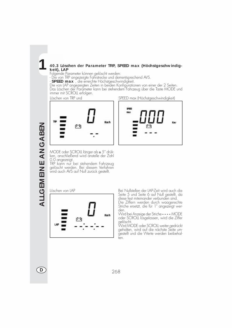
1
ALL
GEM
EIN
E A
NG
ABEN
268D
40.3 Löschen der Parameter TRP, SPEED max (Höchstgeschwindig-keit), LAPFolgende Parameter können gelöscht werden:- Die von TRP angezeigte Fahrstrecke und dementsprechend AVS.- SPEED max , die erreichte Höchstgeschwindigkeit.Die von LAP angezeigten Zeiten in beiden Konfigurationen von einer der 2 Seiten.Das Löschen der Parameter kann bei stehendem Fahrzeug über die Taste MODE undimmer mit SCROLL erfolgen.Löschen von TRP und SPEED max (Höchstgeschwindigkeit)
MODE oder SCROLL länger als ≥ 5” drük-ken, anschließend wird anstelle der Zahl0.0 angezeigt.TRP kann nur bei stehendem Fahrzeuggelöscht werden. Bei diesem Verfahrenwird auch AVS auf Null zurück gestellt.
Löschen von LAP Bei Nullstellen der LAP-Zeit wird auch dieSeite 5 und Seite 6 auf Null gestellt, dadiese fest miteinander verbunden sind.Die Ziffern werden durch waagerechteStriche ersetzt, die für 1" angezeigt wer-den.Wird bei Anzeige der Striche - - - - MODEoder SCROLL losgelassen, wird die Ziffergelöscht.Wird MODE oder SCROLL weiter gedrücktgehalten, wird auf die nächste Seite um-gestellt und die Werte werden beibehal-ten.
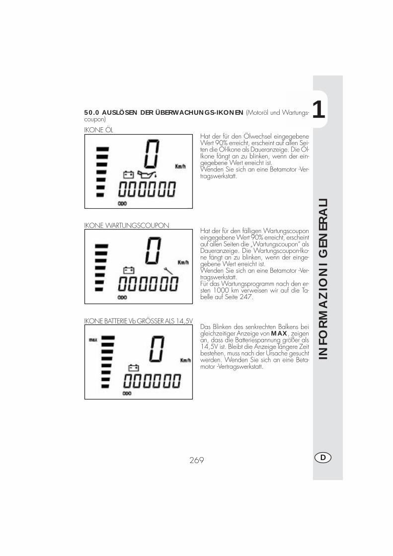
1
INFO
RM
AZ
ION
I G
ENER
ALI
269 D
50.0 AUSLÖSEN DER ÜBERWACHUNGS-IKONEN (Motoröl und Wartungs-coupon)
IKONE ÖLHat der für den Ölwechsel eingegebeneWert 90% erreicht, erscheint auf allen Sei-ten die Öl-Ikone als Daueranzeige. Die Öl-Ikone fängt an zu blinken, wenn der ein-gegebene Wert erreicht ist.Wenden Sie sich an eine Betamotor -Ver-tragswerkstatt.
Hat der für den fälligen Wartungscouponeingegebene Wert 90% erreicht, erscheintauf allen Seiten die „Wartungscoupon“ alsDaueranzeige. Die Wartungscoupon-Iko-ne fängt an zu blinken, wenn der einge-gebene Wert erreicht ist.Wenden Sie sich an eine Betamotor -Ver-tragswerkstatt.Für das Wartungsprogramm nach den er-sten 1000 km verweisen wir auf die Ta-belle auf Seite 247.
IKONE WARTUNGSCOUPON
IKONE BATTERIE Vb GRÖSSER ALS 14,5VDas Blinken des senkrechten Balkens beigleichzeitiger Anzeige von MAX, zeigenan, dass die Batteriespannung größer als14,5V ist. Bleibt die Anzeige längere Zeitbestehen, muss nach der Ursache gesuchtwerden. Wenden Sie sich an eine Beta-motor -Vertragswerkstatt.
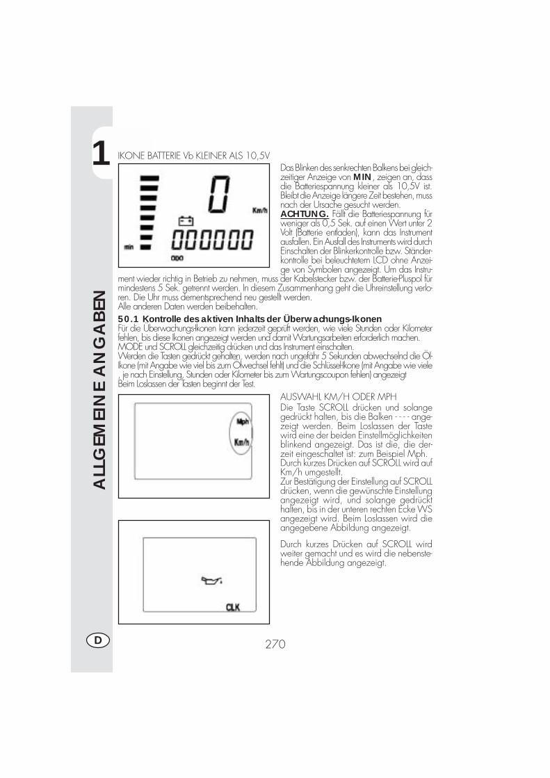
1
ALL
GEM
EIN
E A
NG
ABEN
270D
IKONE BATTERIE Vb KLEINER ALS 10,5VDas Blinken des senkrechten Balkens bei gleich-zeitiger Anzeige von MIN, zeigen an, dassdie Batteriespannung kleiner als 10,5V ist.Bleibt die Anzeige längere Zeit bestehen, mussnach der Ursache gesucht werden.ACHTUNG. Fällt die Batteriespannung fürweniger als 0,5 Sek. auf einen Wert unter 2Volt (Batterie entladen), kann das Instrumentausfallen. Ein Ausfall des Instruments wird durchEinschalten der Blinkerkontrolle bzw. Ständer-kontrolle bei beleuchtetem LCD ohne Anzei-ge von Symbolen angezeigt. Um das Instru-
ment wieder richtig in Betrieb zu nehmen, muss der Kabelstecker bzw. der Batterie-Pluspol fürmindestens 5 Sek. getrennt werden. In diesem Zusammenhang geht die Uhreinstellung verlo-ren. Die Uhr muss dementsprechend neu gestellt werden.Alle anderen Daten werden beibehalten.50.1 Kontrolle des aktiven Inhalts der Überwachungs-IkonenFür die Überwachungs-Ikonen kann jederzeit geprüft werden, wie viele Stunden oder Kilometerfehlen, bis diese Ikonen angezeigt werden und damit Wartungsarbeiten erforderlich machen.MODE und SCROLL gleichzeitig drücken und das Instrument einschalten.Werden die Tasten gedrückt gehalten, werden nach ungefähr 5 Sekunden abwechselnd die Öl-Ikone (mit Angabe wie viel bis zum Ölwechsel fehlt) und die Schlüssel-Ikone (mit Angabe wie viele, je nach Einstellung, Stunden oder Kilometer bis zum Wartungscoupon fehlen) angezeigtBeim Loslassen der Tasten beginnt der Test.
AUSWAHL KM/H ODER MPHDie Taste SCROLL drücken und solangegedrückt halten, bis die Balken - - - - ange-zeigt werden. Beim Loslassen der Tastewird eine der beiden Einstellmöglichkeitenblinkend angezeigt. Das ist die, die der-zeit eingeschaltet ist: zum Beispiel Mph.Durch kurzes Drücken auf SCROLL wird aufKm/h umgestellt.Zur Bestätigung der Einstellung auf SCROLLdrücken, wenn die gewünschte Einstellungangezeigt wird, und solange gedrückthalten, bis in der unteren rechten Ecke WSangezeigt wird. Beim Loslassen wird dieangegebene Abbildung angezeigt.
Durch kurzes Drücken auf SCROLL wirdweiter gemacht und es wird die nebenste-hende Abbildung angezeigt.
1
INFO
RM
AZ
ION
I G
ENER
ALI
271 D
TECHNISCHE DATEN
MAXIMALE ZULADUNGFahrer + Beifahrer .......................................................................... 280 kg
FAHRZEUGGEWICHTFahrbereit (leer) ALP 200 ................................................................. 103 kgFahrbereit (leer) ALP 125 ................................................................. 101 kg
FAHRZEUGMAßEGesamtlänge ............................................................................ 2143 mmGesamtbreite .............................................................................. 820 mmGesamthöhe ............................................................................. 1170 mmRadstand .................................................................................. 1372 mmZitzhöhe ..................................................................................... 836 mmBodenfreiheit ............................................................................... 288 mm
RAHMEN .. Doppelschleifen Rohrrahnen aus Stahl mit Geschloßenen Unterzuegen
REIFENMichelin - Trial Competition TTReifendruck bar .......................................................... vorne 0,8/ hinten 0,6Reifendruck bei voller Belastung bar ............................... vorne 1,3/ hinten 1,3Reifenmaße ............................................ vorne 2,75 - 21"/ hinten 4,00 - 18"
PIRELLI ScorpionReifendruck bar .......................................................... vorne 1,6/ hinten 1,8Reifendruck bei voller Belastung bar ............................... vorne 2,0/ hinten 2,4Reifenmaße .................................. vorne 90/ 90 - 21"/ hinten 120/ 80 - 18"
FASSUNGSVERMÖGENTank inhalt ..................................................................................... 6,8 (lt)Reserve ......................................................................................... 1,5 (lt)Motoröl ...................................................................................... 850 cm3
Durchschnittsverbrauch ............................................................... 25 km/ (lt)
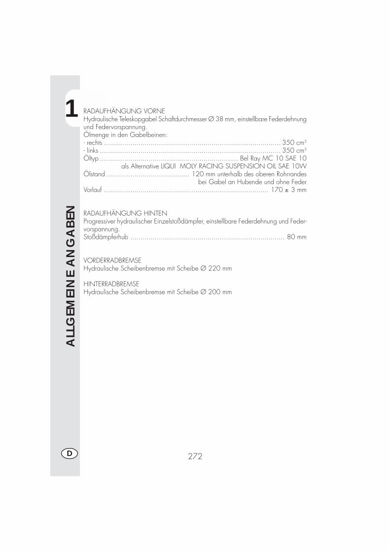
1
ALL
GEM
EIN
E A
NG
ABEN
272D
RADAUFHÄNGUNG VORNEHydraulische Teleskopgabel Schaftdurchmesser Ø 38 mm, einstellbare Federdehnungund Federvorspannung.Ölmenge in den Gabelbeinen:- rechts ....................................................................................... 350 cm3
- links ......................................................................................... 350 cm3
Öltyp .................................................................... Bel Ray MC 10 SAE 10als Alternative LIQUI MOLY RACING SUSPENSION OIL SAE 10W
Ölstand ......................................... 120 mm unterhalb des oberen Rohrrandesbei Gabel an Hubende und ohne Feder
Vorlauf ................................................................................. 170 ± 3 mm
RADAUFHÄNGUNG HINTENProgressiver hydraulischer Einzelstoßdämpfer, einstellbare Federdehnung und Feder-vorspannung.Stoßdämpferhub ............................................................................ 80 mm
VORDERRADBREMSEHydraulische Scheibenbremse mit Scheibe Ø 220 mm
HINTERRADBREMSEHydraulische Scheibenbremse mit Scheibe Ø 200 mm
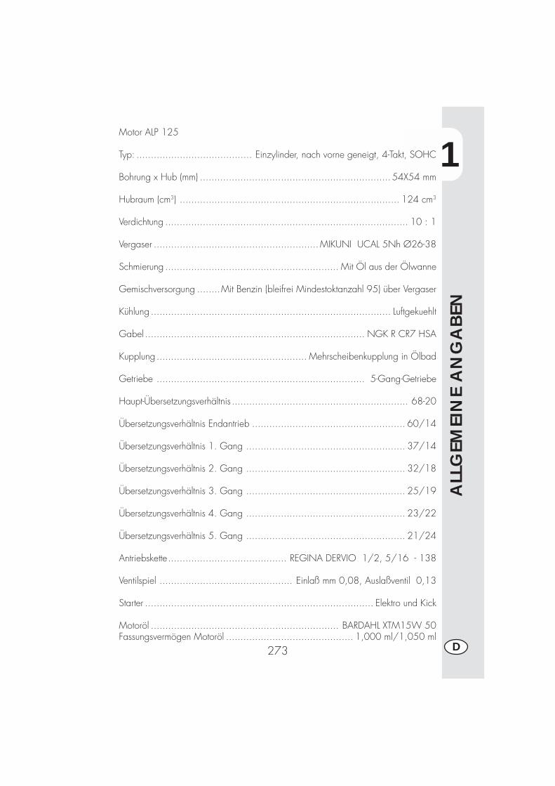
1
ALL
GEM
EIN
E A
NG
ABEN
273 D
Motor ALP 125
Typ: ........................................ Einzylinder, nach vorne geneigt, 4-Takt, SOHC
Bohrung x Hub (mm) .................................................................. 54X54 mm
Hubraum (cm3) ............................................................................ 124 cm3
Verdichtung .................................................................................... 10 : 1
Vergaser .........................................................MIKUNI UCAL 5Nh Ø26-38
Schmierung ............................................................ Mit Öl aus der Ölwanne
Gemischversorgung ........Mit Benzin (bleifrei Mindestoktanzahl 95) über Vergaser
Kühlung ................................................................................... Luftgekuehlt
Gabel ............................................................................ NGK R CR7 HSA
Kupplung .................................................... Mehrscheibenkupplung in Ölbad
Getriebe ........................................................................ 5-Gang-Getriebe
Haupt-Übersetzungsverhältnis ............................................................. 68-20
Übersetzungsverhältnis Endantrieb ..................................................... 60/14
Übersetzungsverhältnis 1. Gang ....................................................... 37/14
Übersetzungsverhältnis 2. Gang ....................................................... 32/18
Übersetzungsverhältnis 3. Gang ....................................................... 25/19
Übersetzungsverhältnis 4. Gang ....................................................... 23/22
Übersetzungsverhältnis 5. Gang ....................................................... 21/24
Antriebskette......................................... REGINA DERVIO 1/2, 5/16 - 138
Ventilspiel .............................................. Einlaß mm 0,08, Auslaßventil 0,13
Starter ............................................................................... Elektro und Kick
Motoröl ................................................................. BARDAHL XTM15W 50Fassungsvermögen Motoröl ............................................ 1,000 ml/1,050 ml
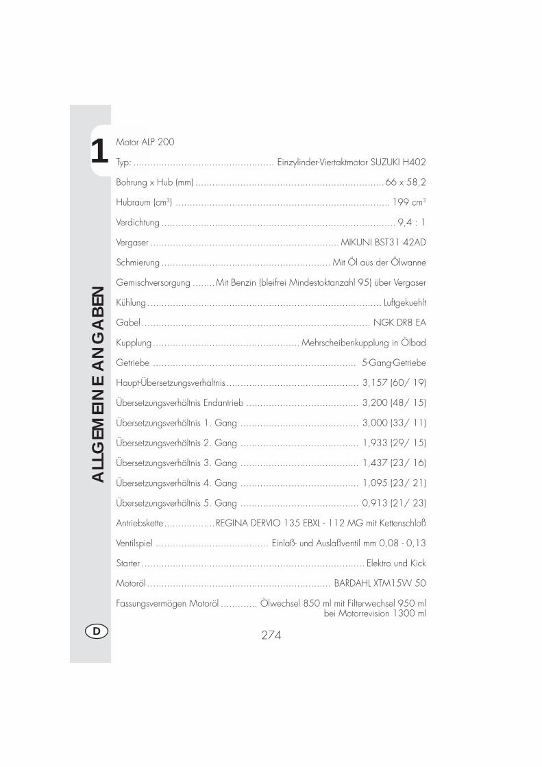
1
ALL
GEM
EIN
E A
NG
ABEN
274D
Motor ALP 200
Typ: .................................................. Einzylinder-Viertaktmotor SUZUKI H402
Bohrung x Hub (mm) ...................................................................66 x 58,2
Hubraum (cm3) ............................................................................ 199 cm3
Verdichtung ................................................................................... 9,4 : 1
Vergaser ................................................................... MIKUNI BST31 42AD
Schmierung ............................................................ Mit Öl aus der Ölwanne
Gemischversorgung ........Mit Benzin (bleifrei Mindestoktanzahl 95) über Vergaser
Kühlung ................................................................................... Luftgekuehlt
Gabel ................................................................................. NGK DR8 EA
Kupplung .................................................... Mehrscheibenkupplung in Ölbad
Getriebe ........................................................................ 5-Gang-Getriebe
Haupt-Übersetzungsverhältnis ............................................... 3,157 (60/ 19)
Übersetzungsverhältnis Endantrieb ........................................ 3,200 (48/ 15)
Übersetzungsverhältnis 1. Gang .......................................... 3,000 (33/ 11)
Übersetzungsverhältnis 2. Gang .......................................... 1,933 (29/ 15)
Übersetzungsverhältnis 3. Gang .......................................... 1,437 (23/ 16)
Übersetzungsverhältnis 4. Gang .......................................... 1,095 (23/ 21)
Übersetzungsverhältnis 5. Gang .......................................... 0,913 (21/ 23)
Antriebskette..................REGINA DERVIO 135 EBXL - 112 MG mit Kettenschloß
Ventilspiel ........................................ Einlaß- und Auslaßventil mm 0,08 - 0,13
Starter ............................................................................... Elektro und Kick
Motoröl ................................................................. BARDAHL XTM15W 50
Fassungsvermögen Motoröl ............. Ölwechsel 850 ml mit Filterwechsel 950 mlbei Motorrevision 1300 ml

1
INFO
RM
AZ
ION
I G
ENER
ALI
275 D
ELEKTRISCHER SCHALTPLAN ALP125
Ne
Bi-N
e
Gi
Bl-N
e
Gr
Bi-N
e
Bl-N
e
Gi
Bi-G
i
Bi-A
r
Bl-V
e
Ne
Ma
Bl-N
e
Az
Bi-B
l
Rs-
Gi
Bi-G
i
Bi-A
r
Bl-V
e
Gr
Ma
Vi
MaM
a-N
eN
e
Ve Vi
Bl-N
e
Ro
Vi
Ve
Rs-
Gi
Bi-B
l
Ro
Az
Bl-N
eB
l
2 61V
e
11B
l-Ne
3N
e-A
r
5M
a-N
e
4 14R
s
13N
e
7M
a-G
i
9G
r-V
e
Bl-N
e
Bl
Ne
MaB
lRs
Bl
Ne
Vi
Gi
Ve
Bi
Bi
Ma
Ne
Gi
Bi B
l Ne N
eR
sVe
Gi
Ve
Gi
Bl
Bi
+-Ne
RsBi
NeN
e Ne
Rs
Bi
Gi
Ve
NeBi
Bl-N
eB L
Rs-
Gi
Az
Ro
Ne
Ar
Ne
Ne
Ro
Vi
Ne
Rs
Ne
Rs
Ne
Gi
Bi
Ne
Ro
Ne
Ro
NeBl
NeBl
NeBl
Rs
Rs
Rs
Ar
Bi
M
Rs
Bi
Bl
Gr-
Ve
Ne
Ne
Bl-N
e
Bi-N
e
Bl-V
eB
l-Ve
Ve
Ne V
iN
e
Gi
NeM
aR
o
Ma V
eNe
Ne
NeVi
Ve
Bi-B
lG
iG
iB
i-Bl
Ve Vi
Ne
Ne
Bi-B
l
Ne
Bi-B
l
Ne
Ne
Ne
Rs
Bi-N
e
Gr
Vi
Gi
Rs
Rs
Az
Ro
Bl
Bi
+
Ne
Ve
Ve
Ne
Bl-N
eG
i
Ne
Ne
Ne Gi
Ne
Bi-B
lG
i
01
2
Bi-R
o
Bl
Ne
Ne
Ro
-+
Ne
1 2
3 4 5 6 7 8 9 10 11 12 13 14 15 16 17 18 19
2221
20
23
25 2426
27
2829
3031
323333
3435
3637383940
4142
4344
4546
4748
49
50
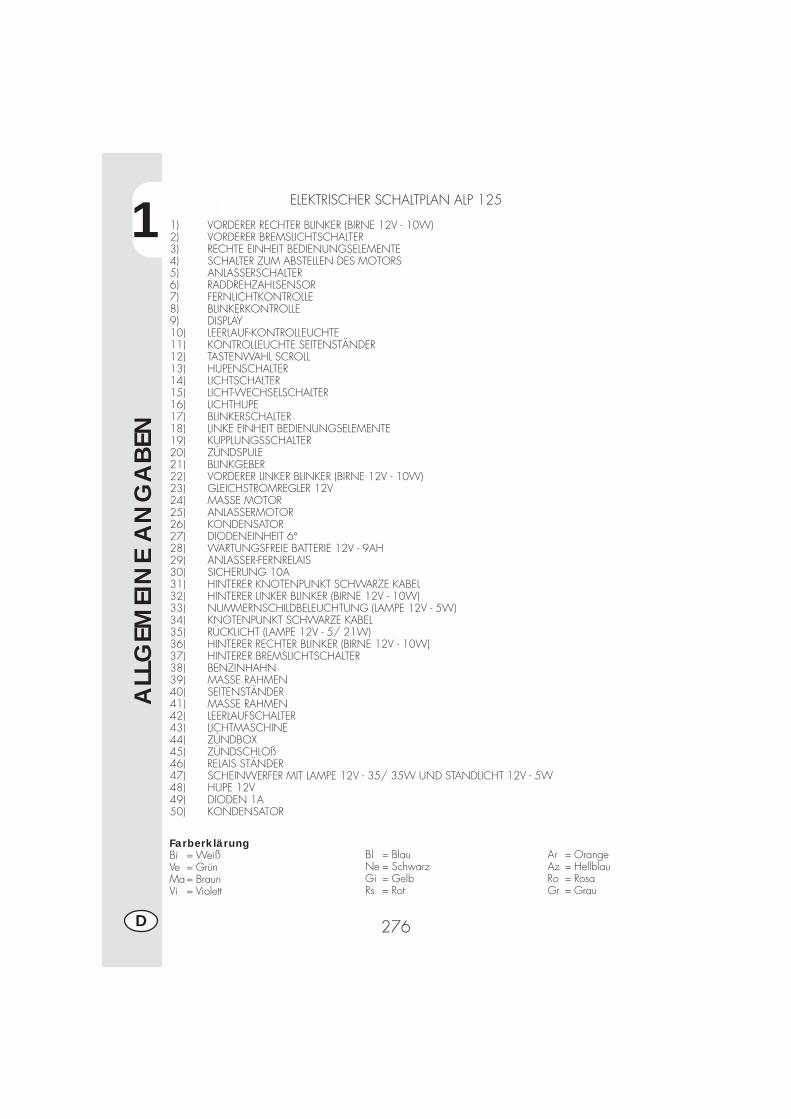
1
ALL
GEM
EIN
E A
NG
ABEN
276D
ELEKTRISCHER SCHALTPLAN ALP 125
1) VORDERER RECHTER BLINKER (BIRNE 12V - 10W)2) VORDERER BREMSLICHTSCHALTER3) RECHTE EINHEIT BEDIENUNGSELEMENTE4) SCHALTER ZUM ABSTELLEN DES MOTORS5) ANLASSERSCHALTER6) RADDREHZAHLSENSOR7) FERNLICHTKONTROLLE8) BLINKERKONTROLLE9) DISPLAY10) LEERLAUF-KONTROLLEUCHTE11) KONTROLLEUCHTE SEITENSTÄNDER12) TASTENWAHL SCROLL13) HUPENSCHALTER14) LICHTSCHALTER15) LICHT-WECHSELSCHALTER16) LICHTHUPE17) BLINKERSCHALTER18) LINKE EINHEIT BEDIENUNGSELEMENTE19) KUPPLUNGSSCHALTER20) ZÜNDSPULE21) BLINKGEBER22) VORDERER LINKER BLINKER (BIRNE 12V - 10W)23) GLEICHSTROMREGLER 12V24) MASSE MOTOR25) ANLASSERMOTOR26) KONDENSATOR27) DIODENEINHEIT 6°28) WARTUNGSFREIE BATTERIE 12V - 9AH29) ANLASSER-FERNRELAIS30) SICHERUNG 10A31) HINTERER KNOTENPUNKT SCHWARZE KABEL32) HINTERER LINKER BLINKER (BIRNE 12V - 10W)33) NUMMERNSCHILDBELEUCHTUNG (LAMPE 12V - 5W)34) KNOTENPUNKT SCHWARZE KABEL35) RÜCKLICHT (LAMPE 12V - 5/ 21W)36) HINTERER RECHTER BLINKER (BIRNE 12V - 10W)37) HINTERER BREMSLICHTSCHALTER38) BENZINHAHN39) MASSE RAHMEN40) SEITENSTÄNDER41) MASSE RAHMEN42) LEERLAUFSCHALTER43) LICHTMASCHINE44) ZÜNDBOX45) ZÜNDSCHLOß46) RELAIS STÄNDER47) SCHEINWERFER MIT LAMPE 12V - 35/ 35W UND STANDLICHT 12V - 5W48) HUPE 12V49) DIODEN 1A50) KONDENSATOR
FarberklärungBi = WeißVe = GrünMa= BraunVi = Violett
Bl = BlauNe = SchwarzGi = GelbRs = Rot
Ar = OrangeAz = HellblauRo = RosaGr = Grau
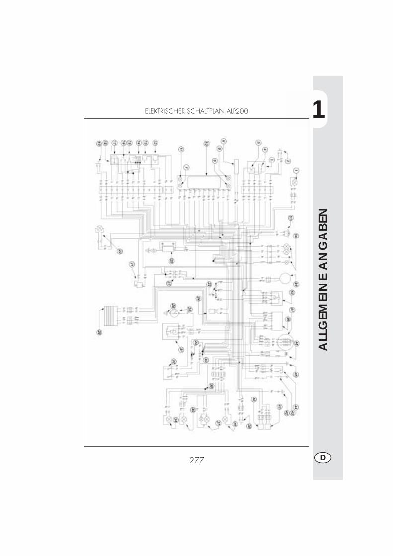
1
ALL
GEM
EIN
E A
NG
ABEN
277 D
ELEKTRISCHER SCHALTPLAN ALP200
1
ALL
GEM
EIN
E A
NG
ABEN
278D
ELEKTRISCHER SCHALTPLAN ALP 200
1) VORDERER RECHTER BLINKER (BIRNE 12V - 10W)2) VORDERER BREMSLICHTSCHALTER3) RECHTE EINHEIT BEDIENUNGSELEMENTE4) SCHALTER ZUM ABSTELLEN DES MOTORS5) ANLASSERSCHALTER6) BLINKERKONTROLLE7) LEERLAUF-KONTROLLEUCHTE8) RADDREHZAHLSENSOR9) FERNLICHTKONTROLLE10) DISPLAY11) KONTROLLEUCHTE SEITENSTÄNDER12) TASTENWAHL SCROLL13) HUPENSCHALTER14) LICHTSCHALTER15) LICHT-WECHSELSCHALTER16) LICHTHUPE17) BLINKERSCHALTER18) LINKE EINHEIT BEDIENUNGSELEMENTE19) KUPPLUNGSSCHALTER20) ZÜNDSPULE21) BLINKGEBER22) VORDERER LINKER BLINKER (BIRNE 12V - 10W)23) 2 DIODEN 1A24) KONDENSATOR25) ANLASSERMOTOR26) MASSE MOTOR27) DIODENEINHEIT 6°28) GLEICHSTROMREGLER 12V29) SICHERUNG 10A30) HINTERER KNOTENPUNKT SCHWARZE KABEL31) ANLASSER-FERNRELAIS32) WARTUNGSFREIE BATTERIE 12V - 9AH33) RELAIS STÄNDER34) HINTERER LINKER BLINKER (BIRNE 12V - 10W)35) NUMMERNSCHILDBELEUCHTUNG (LAMPE 12V - 5W)36) KNOTENPUNKT SCHWARZE KABEL37) RÜCKLICHT (LAMPE 12V - 5/ 21W)38) HINTERER RECHTER BLINKER (BIRNE 12V - 10W)39) HINTERER BREMSLICHTSCHALTER40) BENZINHAHN41) SIGNALVERZÖGERER BENZINKONTROLLE42) MASSE RAHMEN43) LEERLAUFSCHALTER44) SEITENSTÄNDER45) MASSE RAHMEN46) PICK-UP47) LICHTMASCHINE48) ZÜNDBOX49) ZÜNDSCHLOß50) SCHEINWERFER MIT LAMPE 12V - 35/ 35W UND STANDLICHT 12V - 5W51) HUPE 12V
FarberklärungBi = WeißVe = GrünMa= BraunVi = Violett
Bl = BlauNe = SchwarzGi = GelbRs = Rot
Ar = OrangeAz = HellblauRo = RosaGr = Grau
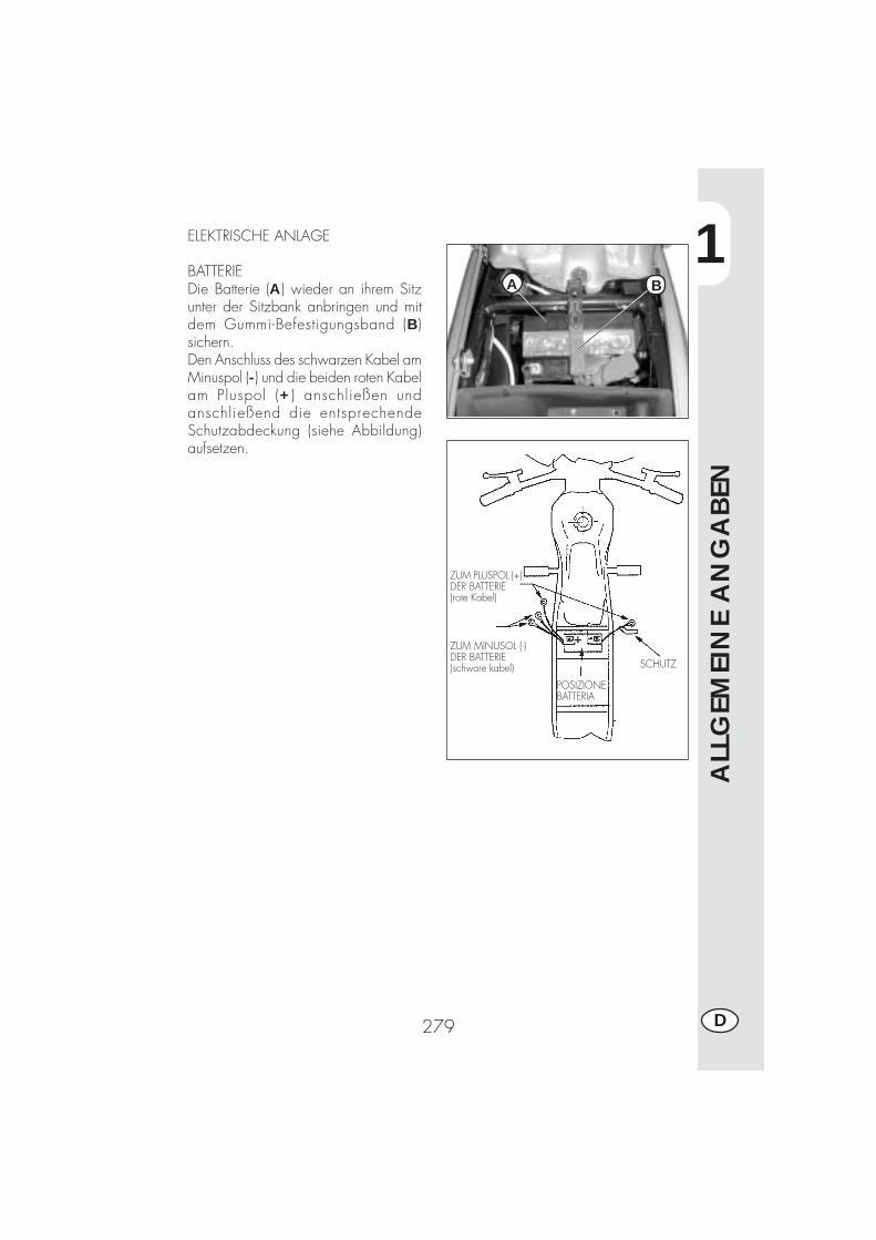
1
ALL
GEM
EIN
E A
NG
ABEN
279 D
ZUM PLUSPOL (+)DER BATTERIE(rote Kabel)
ZUM MINUSOL (-)DER BATTERIE(schware kabel)
POSIZIONEBATTERIA
SCHUTZ
ELEKTRISCHE ANLAGE
BATTERIEDie Batterie (A) wieder an ihrem Sitzunter der Sitzbank anbringen und mitdem Gummi-Befestigungsband (B)sichern.Den Anschluss des schwarzen Kabel amMinuspol (-) und die beiden roten Kabelam Pluspol (+ ) anschließen undanschließend die entsprechendeSchutzabdeckung (siehe Abbildung)aufsetzen.
BA
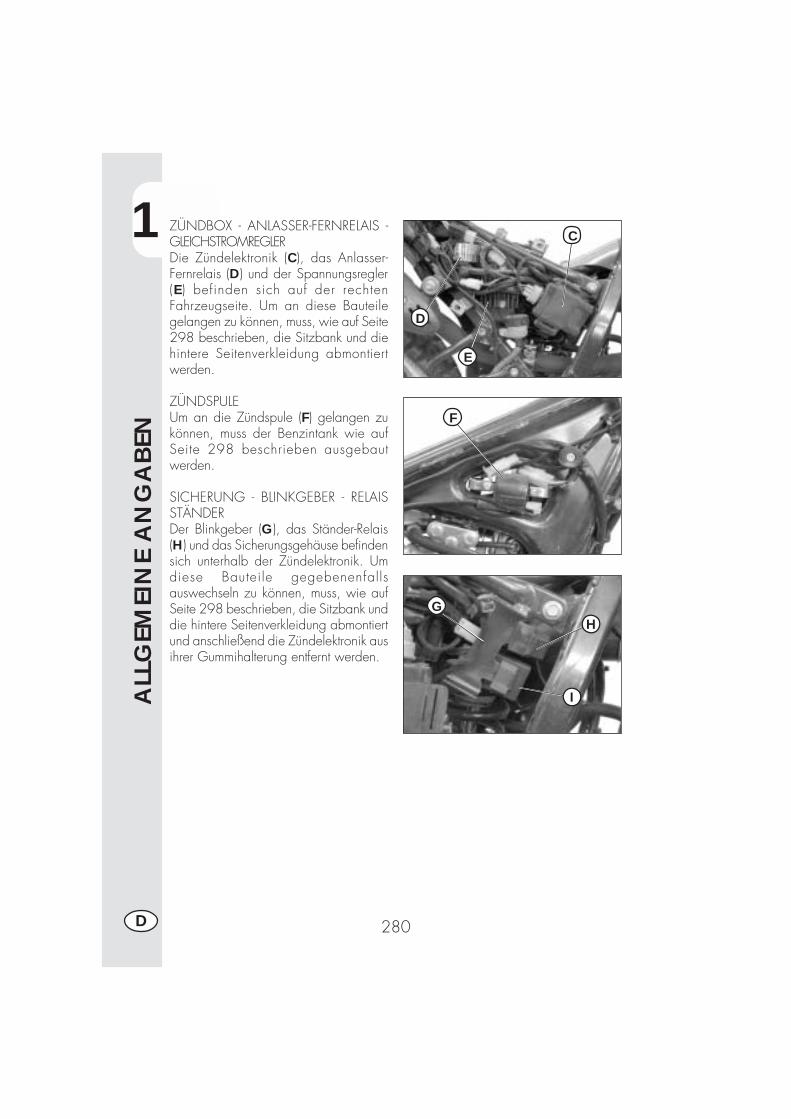
1
ALL
GEM
EIN
E A
NG
ABEN
280D
ZÜNDBOX - ANLASSER-FERNRELAIS -GLEICHSTROMREGLERDie Zündelektronik (C), das Anlasser-Fernrelais (D) und der Spannungsregler(E ) befinden sich auf der rechtenFahrzeugseite. Um an diese Bauteilegelangen zu können, muss, wie auf Seite298 beschrieben, die Sitzbank und diehintere Seitenverkleidung abmontiertwerden.
ZÜNDSPULEUm an die Zündspule (F) gelangen zukönnen, muss der Benzintank wie aufSeite 298 beschrieben ausgebautwerden.
SICHERUNG - BLINKGEBER - RELAISSTÄNDERDer Blinkgeber (G), das Ständer-Relais(H) und das Sicherungsgehäuse befindensich unterhalb der Zündelektronik. Umdiese Bauteile gegebenenfallsauswechseln zu können, muss, wie aufSeite 298 beschrieben, die Sitzbank unddie hintere Seitenverkleidung abmontiertund anschließend die Zündelektronik ausihrer Gummihalterung entfernt werden.
C
D
E
F
GH
I
2
BED
IEN
UN
GSV
ORSC
HRIF
TEN
281 D
INHALTSVERZEICHNIS
KAPITEL 2 BEDIENUNGSVORSCHRIFTEN
Kontrollen und Wartung vor und nach Einsatz im Gelände
Empfohlene Schmiermittel und Flüssigkeiten
Einfahren
Starten des Motors
Abstellen des Motors
Tanken
2
BED
IEN
UN
GSV
ORSC
HRIF
TEN
282D
KONTROLLEN UND WARTUNG VOR UND NACH EINSATZ IM GELÄNDE
Um unangenehme Störungen während der Fahrt mit dem Fahrzeug zu vermeiden,sollte das Fahrzeug vor und nach jedem Einsatz kontrolliert und gewartet werden.Die kurze Zeit, die sie für diese Arbeiten aufbringen, wird Ihnen helfen, Geld undZeit zu sparen. Wie folgt vorgehen:
REIFEN Reifendruck und Profiltiefe prüfenRADSPEICHEN Speichen auf richtige Spannung überprüfenSCHRAUBEN UND BOLZEN Alle Schrauben und Bolzen richtig festziehenKETTE Kettenspannung prüfen (Durchhang 20 mm) und ge-
gebenenfalls fettenLUFTFILTER Filter reinigen und mit Öl tränken
Anmerkung:Sicherstellen, dass die Fahrzeugpapier vorhanden sind.An kalten Tagen sollte der Motor vorm Losfahren für kurze Zeit im Leerlauf warmlau-fen. Nach jedem Einsatz im Gelände muß das Fahrzeug gründlich gereinigt werden.
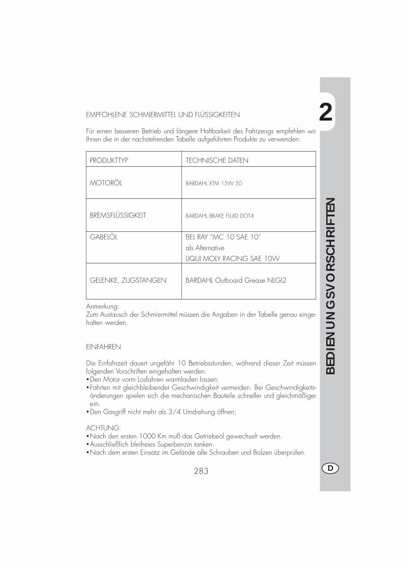
2
BED
IEN
UN
GSV
ORSC
HRIF
TEN
283 D
PRODUKTTYP TECHNISCHE DATEN
MOTORÖL BARDAHL XTM 15W 50
BREMSFLÜSSIGKEIT BARDAHL BRAKE FLUID DOT4
GABELÖL BEL RAY “MC 10 SAE 10”
als Alternative
LIQUI MOLY RACING SAE 10W
GELENKE, ZUGSTANGEN BARDAHL Outboard Grease NLGI2
EMPFOHLENE SCHMIERMITTEL UND FLÜSSIGKEITEN
Für einen besseren Betrieb und längere Haltbarkeit des Fahrzeugs empfehlen wirIhnen die in der nachstehenden Tabelle aufgeführten Produkte zu verwenden:
Anmerkung:Zum Austausch der Schmiermittel müssen die Angaben in der Tabelle genau einge-halten werden.
EINFAHREN
Die Einfahrzeit dauert ungefähr 10 Betriebsstunden, während dieser Zeit müssenfolgenden Vorschriften eingehalten werden:�Den Motor vorm Losfahren warmlaufen lassen;�Fahrten mit gleichbleibender Geschwindigkeit vermeiden. Bei Geschwindigkeits-änderungen spielen sich die mechanischen Bauteile schneller und gleichmäßigerein.
�Den Gasgriff nicht mehr als 3/4 Umdrehung öffnen;
ACHTUNG:�Nach den ersten 1000 Km muß das Getriebeöl gewechselt werden.�Ausschließlich bleifreies Superbenzin tanken.�Nach dem ersten Einsatz im Gelände alle Schrauben und Bolzen überprüfen.
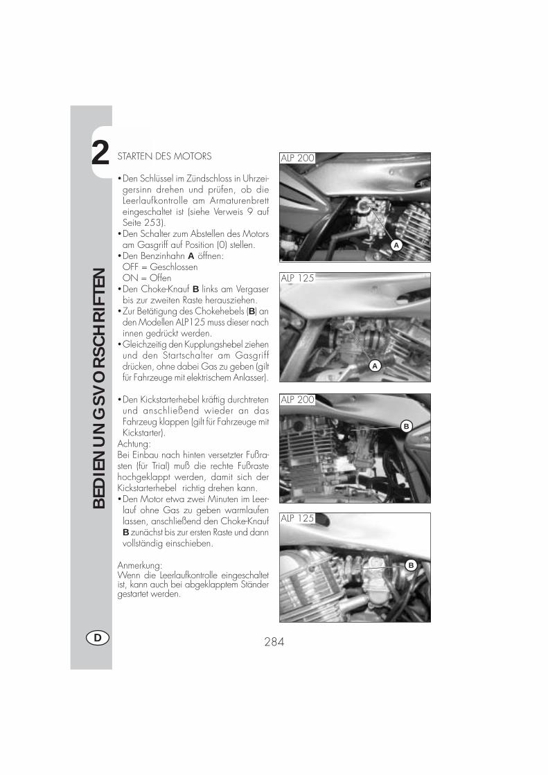
2
BED
IEN
UN
GSV
ORSC
HRIF
TEN
284D
STARTEN DES MOTORS
�Den Schlüssel im Zündschloss in Uhrzei-gersinn drehen und prüfen, ob dieLeerlaufkontrolle am Armaturenbretteingeschaltet ist (siehe Verweis 9 aufSeite 253).
�Den Schalter zum Abstellen des Motorsam Gasgriff auf Position (0) stellen.
�Den Benzinhahn A öffnen:OFF = GeschlossenON = Offen
�Den Choke-Knauf B links am Vergaserbis zur zweiten Raste herausziehen.
�Zur Betätigung des Chokehebels (B) anden Modellen ALP125 muss dieser nachinnen gedrückt werden.
�Gleichzeitig den Kupplungshebel ziehenund den Startschalter am Gasgriffdrücken, ohne dabei Gas zu geben (giltfür Fahrzeuge mit elektrischem Anlasser).
�Den Kickstarterhebel kräftig durchtretenund anschließend wieder an dasFahrzeug klappen (gilt für Fahrzeuge mitKickstarter).
Achtung:Bei Einbau nach hinten versetzter Fußra-sten (für Trial) muß die rechte Fußrastehochgeklappt werden, damit sich derKickstarterhebel richtig drehen kann.�Den Motor etwa zwei Minuten im Leer-lauf ohne Gas zu geben warmlaufenlassen, anschließend den Choke-KnaufB zunächst bis zur ersten Raste und dannvollständig einschieben.
Anmerkung:Wenn die Leerlaufkontrolle eingeschaltetist, kann auch bei abgeklapptem Ständergestartet werden.
A
B
A
B
ALP 200
ALP 200
ALP 125
ALP 125
2
BED
IEN
UN
GSV
ORSC
HRIF
TEN
285 D
Hinweis:Bei abgeklapptem Seitenständer bleibt dierote Kontrolleuchte am Armaturenbrett ein-geschaltet. . Aus Sicherheitsgründen stelltsich dann bei Einlegen eines Gangs, auchbei gezogenem Kupplungshebel, das Mo-torrad ab.Vorm Einlegen eines Ganges muß daherder Seitenständer hochgeklappt werden.
Anmerkung:Im Notfall funktioniert dieses Fahrzeug auchohne Batterie.
ABSTELLEN DES MOTORS
� Im Stand und im Leerlauf den Zündschlüs-sel auf “OFF” drehen.
�Nach längerer Fahrt raten wir Ihnen denMotor vorm Abstellen einen kurzen Mo-ment im Leerlauf laufen zu lassen.
�Nach Abstellen des Motors stets denBenzinhahn schließen.

2
BED
IEN
UN
GSV
ORSC
HRIF
TEN
286D
A
TANKEN
�Den Motor abstellen.�Den Tankdeckel A öffnen.
Anmerkung:Der Tankinhalt beträgt ungefähr 6,8 Liter,davon sind 1,5 Liter Reserve.
Eventuell auf die Karosserie oder andereFahrzeugteile getropftes Benzin muß sofortentfernt werden.
Vorm Tanken den Motor abstellen.Benzin ist äußert leicht entzündbar.Unbedingt vermeiden, dass beim Tankenoder aus dem Tank Benzin austropft.
Brandgefahr. Offene Flammen und Ziga-retten von der Tanköffnung fernhalten.Benzindämpfe sind giftig und dürfen nichteingeatmet werden.
3
WA
RTU
NG
UN
D K
ON
TRO
LLEN
287 D
INHALTSVERZEICHNIS
KAPITEL 3 WARTUNG UND KONTROLLEN
Motoröl und Ölfilter
Leitung Öldampfsammlung
Bremsflüssigkeit, Entlüften der Bremsen
Gabelöl
Luftfilter
Zündkerze
Bremsen: Vorderradbremse, Hinterradbremse
Batterie
Ausbau von Karosserie- und anderen Fahrzeugteilen
Hinweise für Trial
Fahrzeugpflege und Kontrollen
Wartungsprogramm
Längeres Stilllegen des Fahrzeugs

3
WA
RTU
NG
UN
D K
ON
TRO
LLEN
288D
MOTORÖL UND ÖLFILTER ALP 200
KontrolleDas Fahrzeug auf einen waagerechtenUntergrund stellen. Bei kaltem Motor denÖlstand am Kontrollfenster A überprüfen.Der Ölstand darf nie unterhalb desKontrollfensters absinken. Das Motoröldurch die Einfüllöffnung B nachfüllen.
NachfüllenVorm Nachfüllen von Motoröl überprüfen,dass der Ölstand die Markierung MAXnicht übersteigt A.
ÖlwechselDas Motoröl muß bei warmem Motor ge-wechselt werden. Beim Ölwechsel denMotor nicht berühren, Verbrennungs-gefahr.�Der Ölfilter muß beim Ölwechsel eben-falls ausgetauscht werden.
�Das Motorrad auf den Ständer stellen.�Die beiden Befestigungsschrauben Dund die Schraube E entfernen und dieSchutzabdeckung C abbauen.
�Einen Behälter zum Auffangen des Altölsunter dem Motor aufstellen.
�Die Einfüllschraube B und die Ablaß-schraube F abschrauben.
�Das Öl vollständig aus dem Gehäuseabfließen lassen.
�Die Ablaßschraube F wieder festschrau-ben.
�Die drei Befestigungsmuttern G am Filter-deckel lösen und den Ölfilterdeckel ent-fernen.
�Den Ölfilter ausbauen und durch einenneuen ersetzen.
Vorm Einsetzen eine dünnen Ölfilm am O-Ring des Filterdeckels anbringen.
B
GA
C
D
E
F
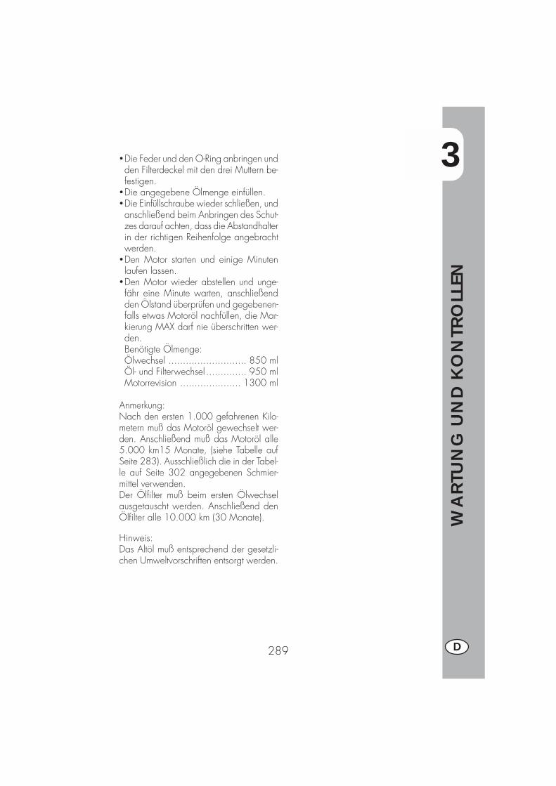
3
WA
RTU
NG
UN
D K
ON
TRO
LLEN
289 D
�Die Feder und den O-Ring anbringen undden Filterdeckel mit den drei Muttern be-festigen.
�Die angegebene Ölmenge einfüllen.�Die Einfüllschraube wieder schließen, undanschließend beim Anbringen des Schut-zes darauf achten, dass die Abstandhalterin der richtigen Reihenfolge angebrachtwerden.
�Den Motor starten und einige Minutenlaufen lassen.
�Den Motor wieder abstellen und unge-fähr eine Minute warten, anschließendden Ölstand überprüfen und gegebenen-falls etwas Motoröl nachfüllen, die Mar-kierung MAX darf nie überschritten wer-den.Benötigte Ölmenge:Ölwechsel ........................... 850 mlÖl- und Filterwechsel .............. 950 mlMotorrevision ..................... 1300 ml
Anmerkung:Nach den ersten 1.000 gefahrenen Kilo-metern muß das Motoröl gewechselt wer-den. Anschließend muß das Motoröl alle5.000 km15 Monate, (siehe Tabelle aufSeite 283). Ausschließlich die in der Tabel-le auf Seite 302 angegebenen Schmier-mittel verwenden.Der Ölfilter muß beim ersten Ölwechselausgetauscht werden. Anschließend denÖlfilter alle 10.000 km (30 Monate).
Hinweis:Das Altöl muß entsprechend der gesetzli-chen Umweltvorschriften entsorgt werden.

3
WA
RTU
NG
UN
D K
ON
TRO
LLEN
290D
MOTORÖL UND ÖLFILTER ALP 125
KontrolleDas Fahrzeug auf einen waagerechtenUntergrund stellen. Bei kaltem MotorDen Ölstand prüfen.
NachfüllenZum Nachfül len Öl über dieEinfüllöffnung A einfüllen.
ÖlwechselDas Motoröl muß bei warmem Motorgewechselt werden. Beim Ölwechselden Motor nicht berühren, Verbrennungs-gefahr.�Der Ölfilter muß beim Ölwechsel eben-falls ausgetauscht werden.
�Das Motorrad auf den Ständer stellen.�Die beiden Befestigungsschrauben Dund die Schraube E entfernen und dieSchutzabdeckung C abbauen.
�Einen Behälter zum Auffangen desAltöls unter dem Motor aufstellen.
�Die Einfüllschraube A und die Ablaß-schraube B abschrauben.
�Das Öl vollständig aus dem Gehäuseabfließen lassen.
�Die Öl-Ablassschraube B wiederschließen.
�1000 cm3 Öl einfüllen.�Die Öl-Einfüllschraube (A) wiederschließen.
ACHTUNG:Heißes Öl kann schwere Verbrühungenverursachen.
Anmerkung:Nach den ersten 500 km muss das Motorölgewechselt werden. Für das Wechseln dieAngaben aus der Tabelle auf Seite 283beachten. Die auf Seite 302 angegebenenempfohlenen Schmiermittel benutzen.
A
C
D
E
B

3
WA
RTU
NG
UN
D K
ON
TRO
LLEN
291 D
ÖLDAMPF-SAMMELLEITUNG
Die Öldampf-Sammelleitung A befindet sichauf der linken Fahrzeugseite in der Nähedes Stoßdämpfers. Sie wird aus derUnterseite des Filtergehäuses herausgeführtund sammelt die Motoröldämpfe. Sobaldsich Öl in dieser Leitung befindet, muß diesegeleert werden. Dazu den Verschluß amunteren Ende der Leitung abnehmen und dasausfließende Öl bzw. Benzin- Ölgemisch ineinem geeigneten Behälter auffangen. DasAltöl muß entsprechend der gesetzlichen Um-weltvorschriften entsorgt werden.Anmerkung: Die Leitung muß alle 3.000km entleert werden.
A
C
BA
DE
BREMSFLÜSSIGKEIT, ENTLÜFTEN DERBREMSENVorderradbremseDen Bremsflüssigkeit am Kontrollfenster Aüberprüfen. Der Bremsflüssigkeitsstand darfnie unter die entsprechende Markierung amKontrollfenster A abfallen. Zum Nachfüllender Bremsflüssigkeit die beiden SchraubenB lösen, den Deckel C anheben und dieBremsflüssigkeit einfüllen.HinterradbremseDen Bremsflüssigkeitsstand am Brems-flüssigkeitsbehälter D überprüfen. Der Brems-flüssigkeitsstand darf nie unter dieentsprechende Markierung am Brems-flüssigkeitsbehälter abfallen. Zum Nachfül-len der Bremsflüssigkeit den Verschluß Eabschrauben, die Bremsflüssigkeit einfüllenund den Verschluß wieder festschrauben.ACHTUNG:Gibt der Bremshebel beim Bremsennach, befindet sich wahrscheinlich Luft inder Bremsanlage. Wenden Sie sich bitteumgehend an den Kundendienst.Anmerkung:Zum Wechseln der Bremsflüssigkeit bittedie Angaben in der Tabelle aus Seite 302einhalten. Die in der Tabelle auf Seite 283angegebenen Schmiermittel und Flüssig-keiten verwenden.
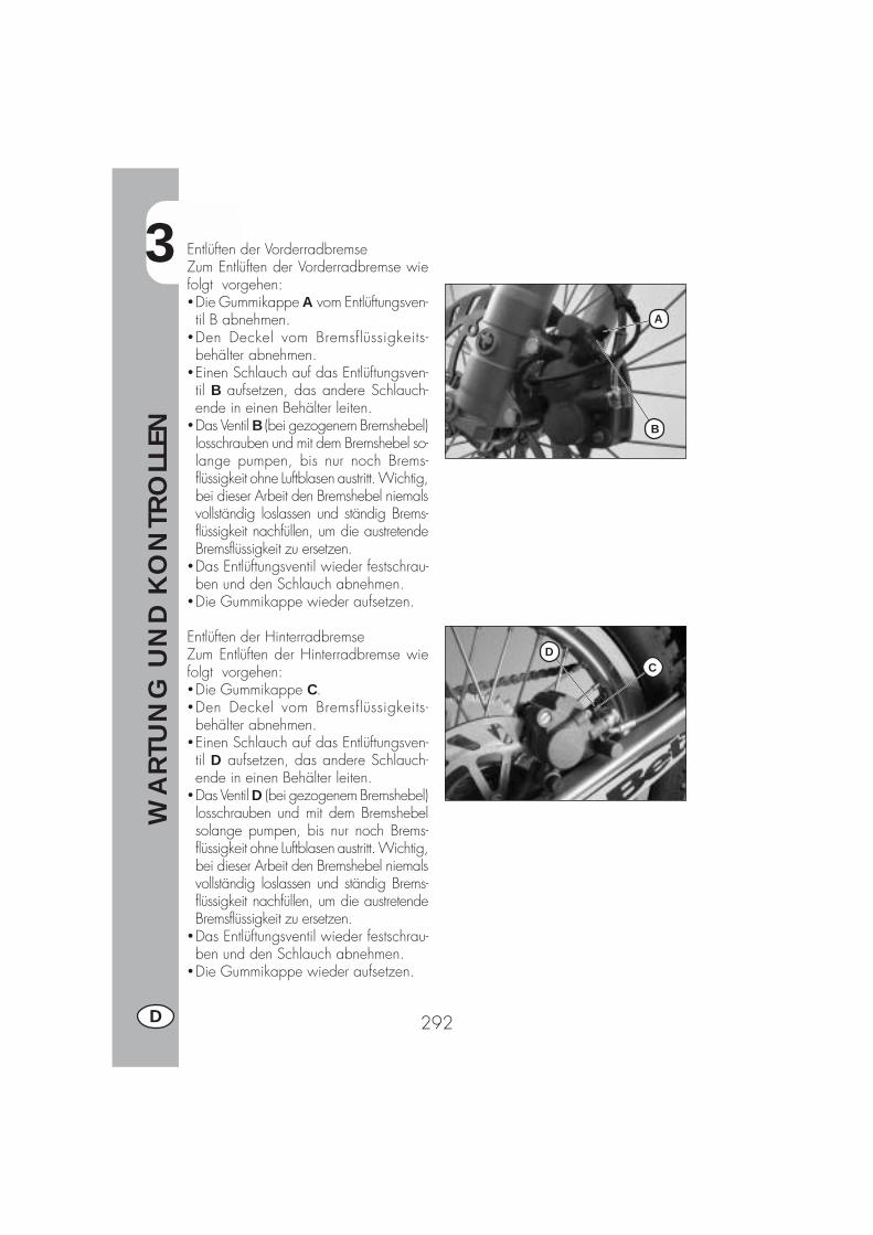
3
WA
RTU
NG
UN
D K
ON
TRO
LLEN
292D
DC
A
B
Entlüften der VorderradbremseZum Entlüften der Vorderradbremse wiefolgt vorgehen:�Die Gummikappe A vom Entlüftungsven-til B abnehmen.
�Den Deckel vom Bremsflüssigkeits-behälter abnehmen.
�Einen Schlauch auf das Entlüftungsven-til B aufsetzen, das andere Schlauch-ende in einen Behälter leiten.
�Das Ventil B (bei gezogenem Bremshebel)losschrauben und mit dem Bremshebel so-lange pumpen, bis nur noch Brems-flüssigkeit ohne Luftblasen austritt. Wichtig,bei dieser Arbeit den Bremshebel niemalsvollständig loslassen und ständig Brems-flüssigkeit nachfüllen, um die austretendeBremsflüssigkeit zu ersetzen.
�Das Entlüftungsventil wieder festschrau-ben und den Schlauch abnehmen.
�Die Gummikappe wieder aufsetzen.
Entlüften der HinterradbremseZum Entlüften der Hinterradbremse wiefolgt vorgehen:�Die Gummikappe C.�Den Deckel vom Bremsflüssigkeits-behälter abnehmen.
�Einen Schlauch auf das Entlüftungsven-til D aufsetzen, das andere Schlauch-ende in einen Behälter leiten.
�Das Ventil D (bei gezogenem Bremshebel)losschrauben und mit dem Bremshebelsolange pumpen, bis nur noch Brems-flüssigkeit ohne Luftblasen austritt. Wichtig,bei dieser Arbeit den Bremshebel niemalsvollständig loslassen und ständig Brems-flüssigkeit nachfüllen, um die austretendeBremsflüssigkeit zu ersetzen.
�Das Entlüftungsventil wieder festschrau-ben und den Schlauch abnehmen.
�Die Gummikappe wieder aufsetzen.
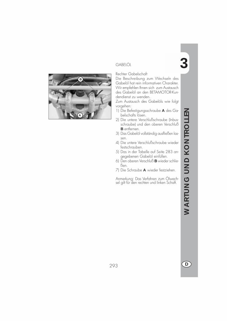
3
WA
RTU
NG
UN
D K
ON
TRO
LLEN
293 D
GABELÖL
Rechter GabelschaftDie Beschreibung zum Wechseln desGabelöl hat rein informativen Charakter.Wir empfehlen Ihnen sich zum Austauschdes Gabelöl an den BETAMOTOR-Kun-dendienst zu wenden.Zum Austausch des Gabelöls wie folgtvorgehen:1) Die Befestigungsschraube A des Ga-
belschafts lösen.2) Die untere Verschlußschraube (Inbus-
schraube) und den oberen VerschlußB entfernen.
3) Das Gabelöl vollständig ausfließen las-sen.
4) Die untere Verschlußschraube wiederfestschrauben.
5) Das in der Tabelle auf Seite 283 an-gegebenen Gabelöl einfüllen.
6) Den oberen Verschluß B wieder schlie-ßen.
7) Die Schraube A wieder festziehen.
Anmerkung: Das Verfahren zum Ölwech-sel gilt für den rechten und linken Schaft.
B
A

3
WA
RTU
NG
UN
D K
ON
TRO
LLEN
294D
LUFTFILTER
Um an den Luftfilter gelangen zu können,wie folgt vorgehen:�Die Sitzbank entfernen, die BefestigungD um 90° gegen den Uhrzeigersinndrehen, die Sitzbank nach hintenherausziehen.
�Die Sitzbank entfernen.�Zunächst die Schraube B des Seitenteilsabschrauben, dann die siebenBefestigungsschrauben lösen und diePlastikabdeckung A ausbauen. Anschlie-ßend wie folgt weitermachen:�Die Befestigungsschraube des Filter-deckels abschrauben und den FilterC ausbauen.
�Mit Wasser und Seife waschen.�Trocknen.�Mit Filteröl tränken und überschüssi-ges Öl ausdrücken.
�Gegebenenfalls auch das Innere desFiltergehäuses reinigen.
�Beim Einbau des Filters darauf ach-ten, dass die Gummidichtung denFilter hermetisch abschließt.
Anmerkung: Ist der Filter sehr schmutzig,zuerst mit einem Spezial-Reinigungsmittelreinigen und dann mit Wasser und einemmilden Waschmittel waschen.Ein beschädigter Filter muß sofort ausge-wechselt werden.
ACHTUNG:Nach jeder Filterreinigung darauf achten,dass keine Gegenstände im Filtergehäusevergessen worden sind.
Der Filter muß nach jedem Geländeein-satz des Fahrzeugs gereinigt werden.
C
B
A
D
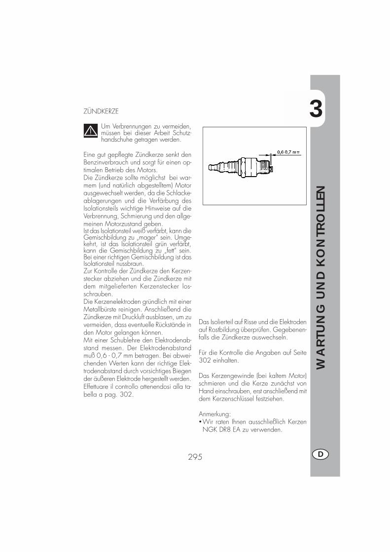
3
WA
RTU
NG
UN
D K
ON
TRO
LLEN
295 D
ZÜNDKERZE
Um Verbrennungen zu vermeiden,müssen bei dieser Arbeit Schutz-handschuhe getragen werden.
Eine gut gepflegte Zündkerze senkt denBenzinverbrauch und sorgt für einen op-timalen Betrieb des Motors.Die Zündkerze sollte möglichst bei war-mem (und natürlich abgestelltem) Motorausgewechselt werden, da die Schlacke-ablagerungen und die Verfärbung desIsolationsteils wichtige Hinweise auf dieVerbrennung, Schmierung und den allge-meinen Motorzustand geben.Ist das Isolationsteil weiß verfärbt, kann dieGemischbildung zu „mager“ sein. Umge-kehrt, ist das Isolationsteil grün verfärbt,kann die Gemischbildung zu „fett“ sein.Bei einer richtigen Gemischbildung ist dasIsolationsteil nussbraun.Zur Kontrolle der Zündkerze den Kerzen-stecker abziehen und die Zündkerze mitdem mitgelieferten Kerzenstecker los-schrauben.Die Kerzenelektroden gründlich mit einerMetallbürste reinigen. Anschließend dieZündkerze mit Druckluft ausblasen, um zuvermeiden, dass eventuelle Rückstände inden Motor gelangen können.Mit einer Schublehre den Elektrodenab-stand messen. Der Elektrodenabstandmuß 0,6 - 0,7 mm betragen. Bei abwei-chenden Werten kann der richtige Elek-trodenabstand durch vorsichtiges Biegender äußeren Elektrode hergestellt werden.Effettuare il controllo attenendosi alla ta-bella a pag. 302.
Das Isolierteil auf Risse und die Elektrodenauf Rostbildung überprüfen. Gegebenen-falls die Zündkerze auswechseln.
Für die Kontrolle die Angaben auf Seite302 einhalten.
Das Kerzengewinde (bei kaltem Motor)schmieren und die Kerze zunächst vonHand einschrauben, erst anschließend mitdem Kerzenschlüssel festziehen.
Anmerkung:�Wir raten Ihnen ausschließlich KerzenNGK DR8 EA zu verwenden.

3
WA
RTU
NG
UN
D K
ON
TRO
LLEN
296D
VORDERRADBREMSE
KontrolleUm den Verschleißzustand der Vorderrad-bremse zu überprüfen, reicht es aus denBremssattel von der Vorderseite her zu be-trachten. Von dort aus sieht man die bei-den Bremsbeläge, die eine Belagstärkevon mindestens 2 mm haben müssen. Beigeringerer Belagstärke müssen die Brems-beläge sofort ausgewechselt werden.
Anmerkung:Bei den Kontrollen müssen die in der Ta-belle auf Seite 302 angegebenen Zeit-räume eingehalten werden.
HINTERRADBREMSE
KontrolleUm den Verschleißzustand der Vorderrad-bremse zu überprüfen, reicht es aus denBremssattel von der oben her zu betrach-ten. Von dort aus sieht man die beidenBremsbeläge, die eine Belagstärke vonmindestens 2 mm haben müssen. Bei ge-ringerer Belagstärke müssen die Brems-beläge sofort ausgewechselt werden.
Anmerkung:Bei den Kontrollen müssen die in der Ta-belle auf Seite 302 angegebenen Zeit-räume eingehalten werden.

3
WA
RTU
NG
UN
D K
ON
TRO
LLEN
297 D
BATTERIE
Den Ladezustand der Batterie überprüfen.Dazu die Batteriespannung bei abgestell-tem Fahrzeug und nicht laufendem Motormit einem Spannungsmeter messen. DieBatteriespannung darf nicht weniger als12,8V betragen.Der Batterieflüssigkeitsstand braucht nichtkontrolliert zu werden. Ein Nachfüllen mitWasser ist nicht erforderlich.Die Batteriepole sauber halten.Gegebenenfalls mit etwas säurefreiemFett schmieren.

3
WA
RTU
NG
UN
D K
ON
TRO
LLEN
298D
B BA
C
C
D
F
E
AUSBAU VON KAROSSERIE- UND AN-DEREN FAHRZEUGTEILENUm Kontrollen oder andere Arbeiten aneinigen Fahrzeugbereichen leicht ausfüh-ren zu können, müssen Karosserie- undandere Fahrzeugteile ausgebaut werden.
Ausbau der SitzbankDie Befestigungsschraube am Kotflügel lö-sen und die Sitzbank zum Ausbau nachhinten verschieben, so dass sie sich ausdem Haken am Tank löst.
Ausbau GepäckträgerDie drei Befestigungsschrauben am Kotflü-gel lösen und den Gepäckträger abbau-en.
Ausbau seitliche KarosserieverkleidungNach Ausbau des Filterdeckels (siehe An-leitung im Kapitel “Luftfilter”) die vierBefestigungsschrauben B lösen. Eine derBefestigungsschrauben befindet sich aufder linken Seite (unter dem Filtergehäuse),eine andere (nicht sichtbar) unter demVerschlußelement des Kotflügels.
Ausbau vordere SeitenkarosserieDie sechs Befestigungsschrauben C amRahmen lösen (drei auf jeder Seite), zweivon ihnen befinden sich unter dem Tank, unddie vordere Seitenkarosserie ausbauen.
Ausbau BenzintankDie Befestigungsschraube D am Rahmenlösen, die Leitung vom Benzinhahn abneh-men und den Benzintank durch Ziehennach hinten ausbauen.
Ausbau vordere ScheinwerfereinheitAlle elektrischen Anschlüsse abnehmen unddie drei Befestigungsschrauben E lösen.Eine der Schrauben befindet sich unterhalbder Scheinwerfereinheit.
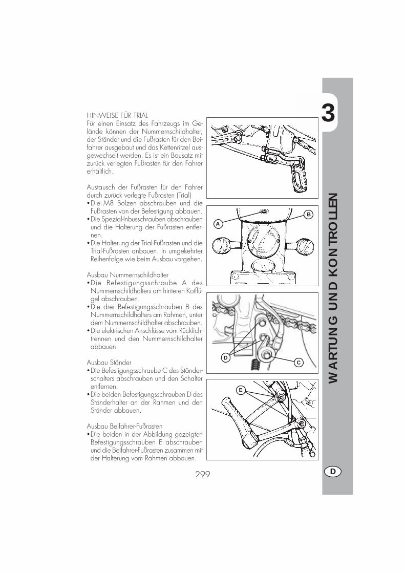
3
WA
RTU
NG
UN
D K
ON
TRO
LLEN
299 D
A
B
CD
E
HINWEISE FÜR TRIALFür einen Einsatz des Fahrzeugs im Ge-lände können der Nummernschildhalter,der Ständer und die Fußrasten für den Bei-fahrer ausgebaut und das Kettenritzel aus-gewechselt werden. Es ist ein Bausatz mitzurück verlegten Fußrasten für den Fahrererhältlich.
Austausch der Fußrasten für den Fahrerdurch zurück verlegte Fußrasten (Trial)�Die M8 Bolzen abschrauben und dieFußrasten von der Befestigung abbauen.
�Die Spezial-Inbusschrauben abschraubenund die Halterung der Fußrasten entfer-nen.
�Die Halterung der Trial-Fußrasten und dieTrial-Fußrasten anbauen. In umgekehrterReihenfolge wie beim Ausbau vorgehen.
Ausbau Nummernschildhalter�Die Befestigungsschraube A desNummernschildhalters am hinteren Kotflü-gel abschrauben.
�Die drei Befestigungsschrauben B desNummernschildhalters am Rahmen, unterdem Nummernschildhalter abschrauben.
�Die elektrischen Anschlüsse vom Rücklichttrennen und den Nummernschildhalterabbauen.
Ausbau Ständer�Die Befestigungsschraube C des Ständer-schalters abschrauben und den Schalterentfernen.
�Die beiden Befestigungsschrauben D desStänderhalter an der Rahmen und denStänder abbauen.
Ausbau Beifahrer-Fußrasten�Die beiden in der Abbildung gezeigtenBefestigungsschrauben E abschraubenund die Beifahrer-Fußrasten zusammen mitder Halterung vom Rahmen abbauen.
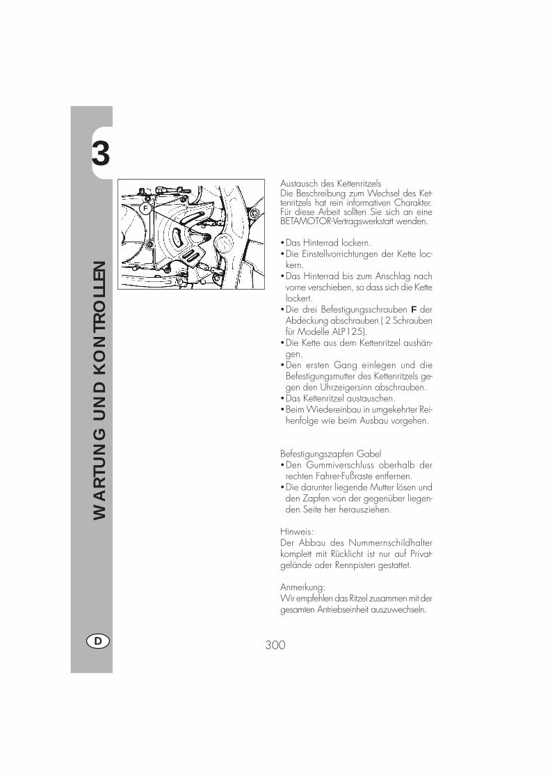
3
WA
RTU
NG
UN
D K
ON
TRO
LLEN
300D
Austausch des KettenritzelsDie Beschreibung zum Wechsel des Ket-tenritzels hat rein informativen Charakter.Für diese Arbeit sollten Sie sich an eineBETAMOTOR-Vertragswerkstatt wenden.
�Das Hinterrad lockern.�Die Einstellvorrichtungen der Kette loc-kern.
�Das Hinterrad bis zum Anschlag nachvorne verschieben, so dass sich die Kettelockert.
�Die drei Befestigungsschrauben F derAbdeckung abschrauben ( 2 Schraubenfür Modelle ALP125).
�Die Kette aus dem Kettenritzel aushän-gen.
�Den ersten Gang einlegen und dieBefestigungsmutter des Kettenritzels ge-gen den Uhrzeigersinn abschrauben.
�Das Kettenritzel austauschen.�Beim Wiedereinbau in umgekehrter Rei-henfolge wie beim Ausbau vorgehen.
Befestigungszapfen Gabel�Den Gummiverschluss oberhalb derrechten Fahrer-Fußraste entfernen.
�Die darunter liegende Mutter lösen undden Zapfen von der gegenüber liegen-den Seite her herausziehen.
Hinweis:Der Abbau des Nummernschildhalterkomplett mit Rücklicht ist nur auf Privat-gelände oder Rennpisten gestattet.
Anmerkung:Wir empfehlen das Ritzel zusammen mit dergesamten Antriebseinheit auszuwechseln.
F

3
WA
RTU
NG
UN
D K
ON
TRO
LLEN
301 D
FAHRZEUGPFLEGE UND KONTROLLEN
Zum Aufweichen von Schmutz und Schlamm auf den lackierten Oberflächen einenWasserstrahl mit niedrigem Druck benutzen. Ist der Schmutz aufgeweicht, muß er miteinem weichen Schwamm mit viel Wasser und Autoshampoo (2-4% Shampoo imWasser) entfernt werden. Anschließend mit viel klarem Wasser nachspülen und miteinem Wildledertuch abledern. Den Motor außen mit Petroleum, Pinsel und reinenLappen säubern. Petroleum schädigt den Lack. Eine Glanzbehandlung darf erstnach erfolgtem Waschen durchgeführt werden.
Die Reinigungsmittel verschmutzen das Wasser. Daher muß die Fahrzeug-reinigung an Orten stattfinden, die mit einer Anlage zur Waschwasser-
rückführung und Aufbereitung ausgestattet sind.
Das Fahrzeug nie in praller Sonne waschen. Dies gilt besonders im Sommer,wenn die Karosserie noch warm ist und das Shampoo noch vor dem abspü-
len antrocknen kann. Dies kann Schäden an der Karosserie verursachen. BenutzenSie nie in Benzin oder Öl getränkte Lappen zur Reinigung lackierter Fahrzeugteile,um Glanzverluste und den Verlust mechanischer Eigenschaften zu vermeiden.
KONTROLLEN NACH DER FAHRZEUGPFLEGE
Nach der Fahrzeugpflege sollten folgende Kontrollen durchgeführt werden:
�Den Luftfilter reinigen (siehe Anleitung aus Seite 294).�Die Kette schmieren.
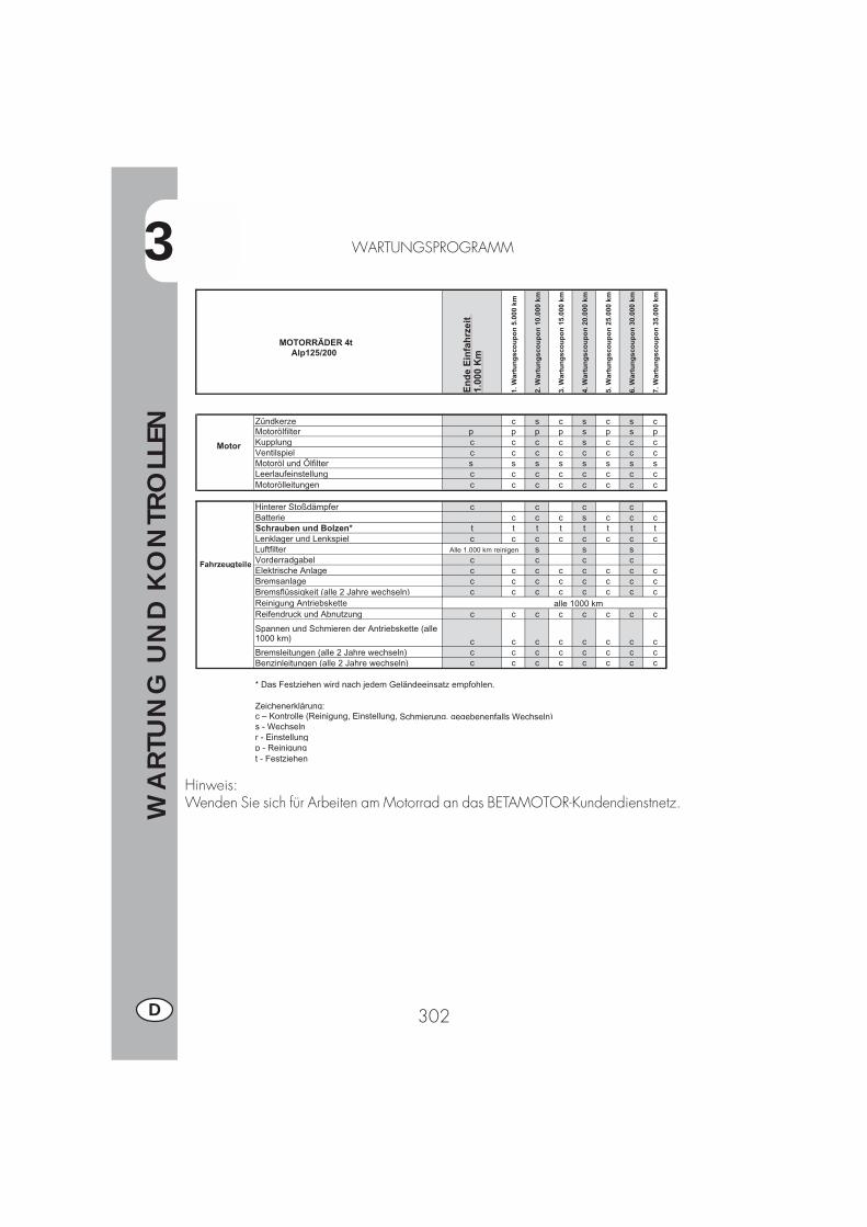
3
WA
RTU
NG
UN
D K
ON
TRO
LLEN
302D
WARTUNGSPROGRAMM
Hinweis:Wenden Sie sich für Arbeiten am Motorrad an das BETAMOTOR-Kundendienstnetz.
MOTORRÄDER 4t Alp125/200
En
de
Ein
fah
rzei
t 1.
000
Km
1. W
artu
ng
sco
up
on
5.0
00 k
m
2. W
artu
ng
sco
up
on
10.
000
km
3. W
artu
ng
sco
up
on
15.
000
km
4. W
artu
ng
sco
up
on
20.
000
km
5. W
artu
ng
sco
up
on
25.
000
km
6. W
artu
ng
sco
up
on
30.
000
km
7. W
artu
ng
sco
up
on
35.
000
km
Motor
Zündkerze c s c s c s cMotorölfilter p p p p s p s pKupplung c c c c s c c cVentilspiel c c c c c c c cMotoröl und Ölfilter s s s s s s s sLeerlaufeinstellung c c c c c c c cMotorölleitungen c c c c c c c c
Fahrzeugteile
Hinterer Stoßdämpfer c c c cBatterie c c c s c c cSchrauben und Bolzen* t t t t t t t tLenklager und Lenkspiel c c c c c c c cLuftfilter s s sVorderradgabel c c c cElektrische Anlage c c c c c c c cBremsanlage c c c c c c c cBremsflüssigkeit (alle 2 Jahre wechseln) c c c c c c c cReinigung AntriebsketteReifendruck und Abnutzung c c c c c c c c
Spannen und Schmieren der Antriebskette (alle 1000 km) c c c c c c c cBremsleitungen (alle 2 Jahre wechseln) c c c c c c c cBenzinleitungen (alle 2 Jahre wechseln) c c c c c c c c
* Das Festziehen wird nach jedem Geländeeinsatz empfohlen.
Zeichenerklärung:c – Kontrolle (Reinigung, Einstellung, Schmierung, gegebenenfalls Wechseln)s - Wechselnr - Einstellungp - Reinigungt - Festziehen
Alle 1.000 km reinigen
alle 1000 km
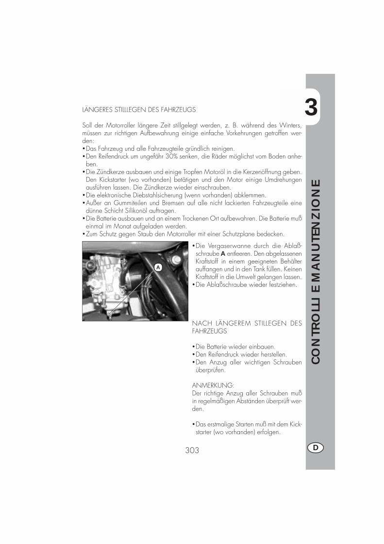
3
CO
NTR
OLL
I E
MA
NU
TEN
ZIO
NE
303 D
A
LÄNGERES STILLLEGEN DES FAHRZEUGS
Soll der Motorroller längere Zeit stillgelegt werden, z. B. während des Winters,müssen zur richtigen Aufbewahrung einige einfache Vorkehrungen getroffen wer-den:�Das Fahrzeug und alle Fahrzeugteile gründlich reinigen.�Den Reifendruck um ungefähr 30% senken, die Räder möglichst vom Boden anhe-ben.
�Die Zündkerze ausbauen und einige Tropfen Motoröl in die Kerzenöffnung geben.Den Kickstarter (wo vorhanden) betätigen und den Motor einige Umdrehungenausführen lassen. Die Zündkerze wieder einschrauben.
�Die elektronische Diebstahlsicherung (wenn vorhanden) abklemmen.�Außer an Gummiteilen und Bremsen auf alle nicht lackierten Fahrzeugteile einedünne Schicht Silikonöl auftragen.
�Die Batterie ausbauen und an einem Trockenen Ort aufbewahren. Die Batterie mußeinmal im Monat aufgeladen werden.
�Zum Schutz gegen Staub den Motorroller mit einer Schutzplane bedecken.
�Die Vergaserwanne durch die Ablaß-schraube A entleeren. Den abgelassenenKraftstoff in einem geeigneten Behälterauffangen und in den Tank füllen. KeinenKraftstoff in die Umwelt gelangen lassen.
�Die Ablaßschraube wieder festziehen.
NACH LÄNGEREM STILLEGEN DESFAHRZEUGS
�Die Batterie wieder einbauen.�Den Reifendruck wieder herstellen.�Den Anzug aller wichtigen Schraubenüberprüfen.
ANMERKUNG:Der richtige Anzug aller Schrauben mußin regelmäßigen Abständen überprüft wer-den.
�Das erstmalige Starten muß mit dem Kick-starter (wo vorhanden) erfolgen.

4
EIST
ELLU
NG
EN
305 D
INHALTSVERZEICHNIS
KAPITEL 4 EINSTELLUNGEN
Einstellen der Bremsen
Einstellen der Kupplung
Leerlaufeinstellung
Einstellen des Gaszuges
Kontrolle und Einstellen des Lenkerspiels
Spannen der Kette
Einstellen des Scheinwerfers
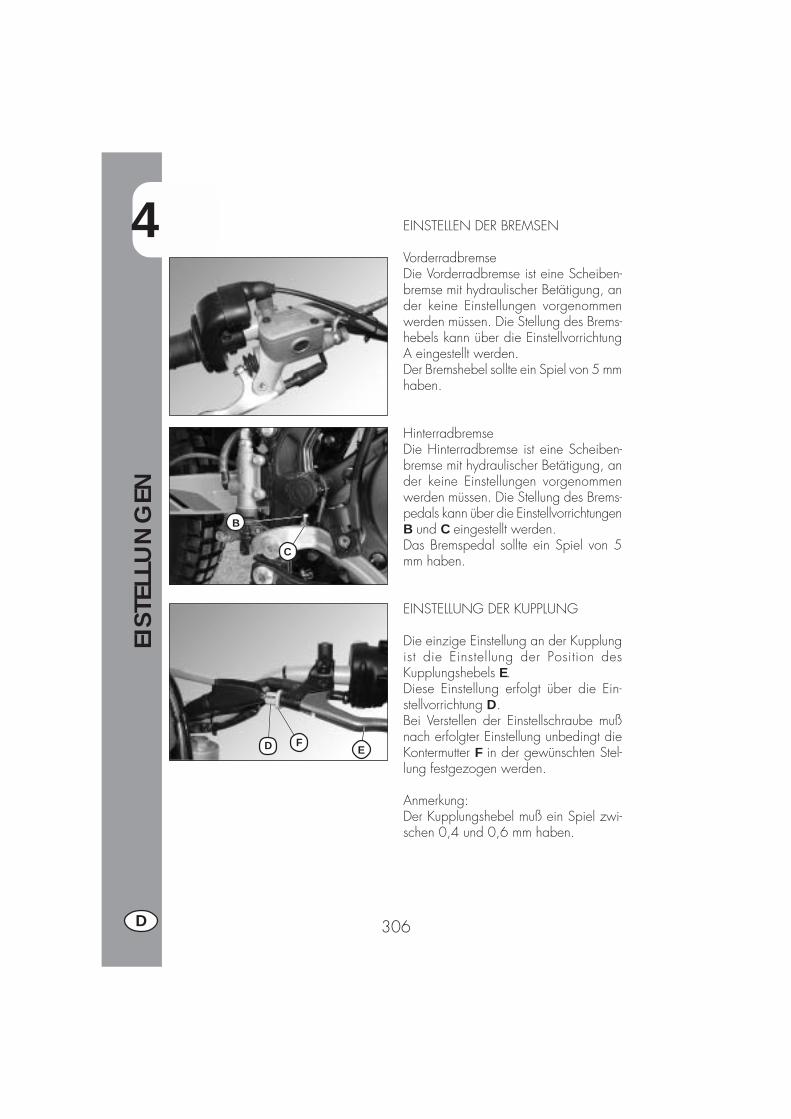
4
EIST
ELLU
NG
EN
306D
C
B
FD E
EINSTELLEN DER BREMSEN
VorderradbremseDie Vorderradbremse ist eine Scheiben-bremse mit hydraulischer Betätigung, ander keine Einstellungen vorgenommenwerden müssen. Die Stellung des Brems-hebels kann über die EinstellvorrichtungA eingestellt werden.Der Bremshebel sollte ein Spiel von 5 mmhaben.
HinterradbremseDie Hinterradbremse ist eine Scheiben-bremse mit hydraulischer Betätigung, ander keine Einstellungen vorgenommenwerden müssen. Die Stellung des Brems-pedals kann über die EinstellvorrichtungenB und C eingestellt werden.Das Bremspedal sollte ein Spiel von 5mm haben.
EINSTELLUNG DER KUPPLUNG
Die einzige Einstellung an der Kupplungist die Einstellung der Position desKupplungshebels E.Diese Einstellung erfolgt über die Ein-stellvorrichtung D.Bei Verstellen der Einstellschraube mußnach erfolgter Einstellung unbedingt dieKontermutter F in der gewünschten Stel-lung festgezogen werden.
Anmerkung:Der Kupplungshebel muß ein Spiel zwi-schen 0,4 und 0,6 mm haben.
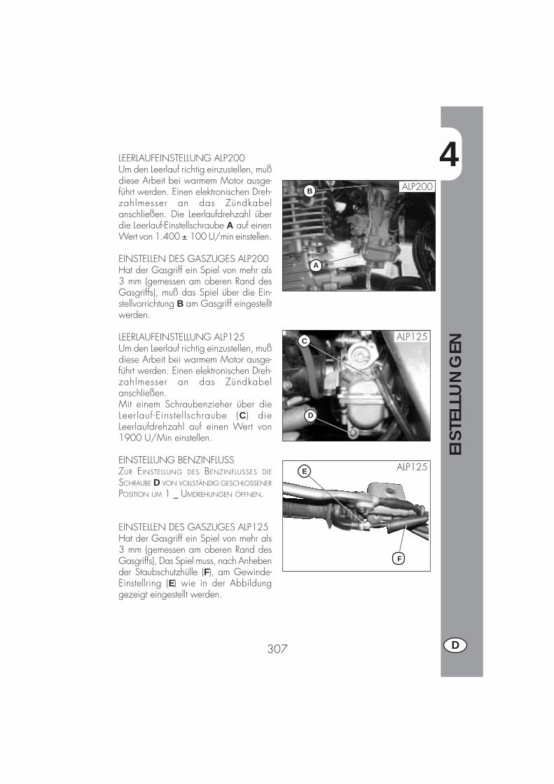
4
EIST
ELLU
NG
EN
307 D
A
B
LEERLAUFEINSTELLUNG ALP200Um den Leerlauf richtig einzustellen, mußdiese Arbeit bei warmem Motor ausge-führt werden. Einen elektronischen Dreh-zahlmesser an das Zündkabelanschließen. Die Leerlaufdrehzahl überdie Leerlauf-Einstellschraube A auf einenWert von 1.400 ± 100 U/min einstellen.
EINSTELLEN DES GASZUGES ALP200Hat der Gasgriff ein Spiel von mehr als3 mm (gemessen am oberen Rand desGasgriffs), muß das Spiel über die Ein-stellvorrichtung B am Gasgriff eingestelltwerden.
LEERLAUFEINSTELLUNG ALP125Um den Leerlauf richtig einzustellen, mußdiese Arbeit bei warmem Motor ausge-führt werden. Einen elektronischen Dreh-zahlmesser an das Zündkabelanschließen.Mit einem Schraubenzieher über dieLeerlauf-Einstel lschraube (C ) dieLeerlaufdrehzahl auf einen Wert von1900 U/Min einstellen.
EINSTELLUNG BENZINFLUSSZUR EINSTELLUNG DES BENZINFLUSSES DIE
SCHRAUBE D VON VOLLSTÄNDIG GESCHLOSSENER
POSITION UM 1 _ UMDREHUNGEN ÖFFNEN.
EINSTELLEN DES GASZUGES ALP125Hat der Gasgriff ein Spiel von mehr als3 mm (gemessen am oberen Rand desGasgriffs), Das Spiel muss, nach Anhebender Staubschutzhülle (F), am Gewinde-Einstellring (E) wie in der Abbildunggezeigt eingestellt werden.
ALP200
D
C ALP125
F
E ALP125

4
EIST
ELLU
NG
EN
308D
D
F
G E
C
KONTROLLE UND EINSTELLEN DESLENKERSPIELS
Das Spiel am Lenkrohr regelmäßig über-prüfen. Dazu das Vorderrad bremsen unddas Fahrzeug wie in der Abbildung ge-zeigt nach vorne und hinten bewegen.Wird ein Spiel am Lenkrohr festgestellt,muß wie folgt vorgegangen werden:�Die vier Schrauben C abschrauben.�Den Lenker D herausziehen. Dabei be-sonders auf die Bügelschrauben E ach-ten.
�Die Mutter F lösen.�Das Spiel über die Nutmutter G einstel-len.
Zum Befestigen in umgekehrter Reihen-folge vorgehen.
Anmerkung:Ist die Einstellung richtig ausgeführt wor-den, ist das Spiel vollständig beseitigt,das Drehen des Lenkers er folgtleichtgängig und gleichmäßig. DieEinbaustellung der Bügelschraubenüberprüfen, da diese die Lenkereinstellungändern können
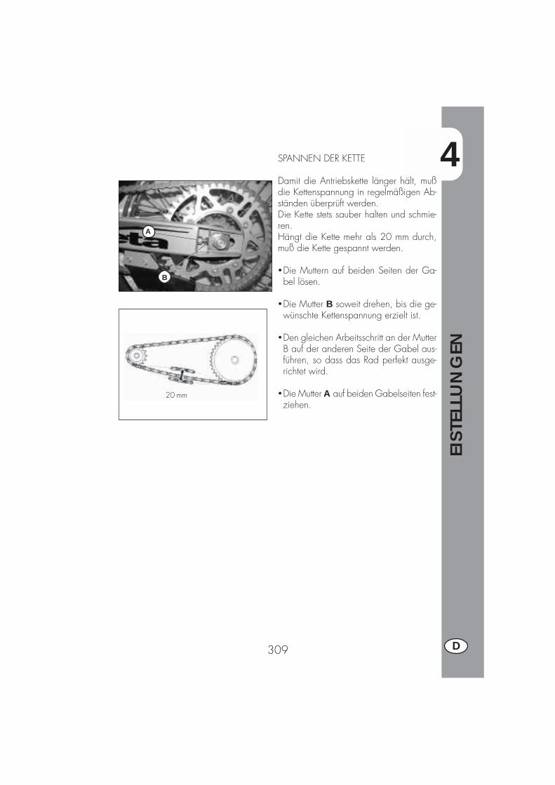
4
EIST
ELLU
NG
EN
309 D
20 mm
B
A
SPANNEN DER KETTE
Damit die Antriebskette länger hält, mußdie Kettenspannung in regelmäßigen Ab-ständen überprüft werden.Die Kette stets sauber halten und schmie-ren.Hängt die Kette mehr als 20 mm durch,muß die Kette gespannt werden.
�Die Muttern auf beiden Seiten der Ga-bel lösen.
�Die Mutter B soweit drehen, bis die ge-wünschte Kettenspannung erzielt ist.
�Den gleichen Arbeitsschritt an der MutterB auf der anderen Seite der Gabel aus-führen, so dass das Rad perfekt ausge-richtet wird.
�Die Mutter A auf beiden Gabelseiten fest-ziehen.
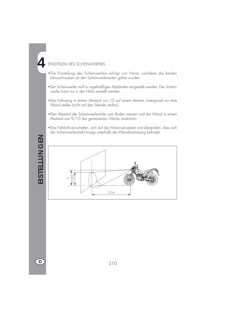
4
EIST
ELLU
NG
EN
310D
9/10
h
10 m
hEINSTELLEN DES SCHEINWERFERS
�Die Einstellung des Scheinwerfers erfolgt von Hand, nachdem die beidenInbusschrauben an den Scheinwerferseiten gelöst wurden.
�Der Scheinwerfer muß in regelmäßigen Abständen eingestellt werden. Der Schein-werfer kann nur in der Höhe verstellt werden.
�Das Fahrzeug in einem Abstand von 10 auf einem ebenen Untergrund vor eineWand stellen (nicht auf den Ständer stellen).
�Den Abstand der Scheinwerfermitte vom Boden messen und die Wand in einemAbstand von 9/10 des gemessenen Wertes markieren.
�Das Fahrlicht einschalten, sich auf das Motorrad setzen und überprüfen, dass sichder Scheinwerferstrahl knapp unterhalb der Wandmarkierung befindet.

5
AU
STA
USC
HEN
/ A
USW
ECH
SELN
VO
N T
EILE
N
311 D
INHALTSVERZEICHNIS
KAPITEL 5 AUSTAUSCHEN/ AUSWECHSELN VON TEILEN
Auswechseln der Bremsbeläge
Auswechseln der Scheinwerferlampen
Auswechseln der Rücklichtlampe
Auswechseln der Blinkerlampen
Auswechseln der Armaturenbrettlampen
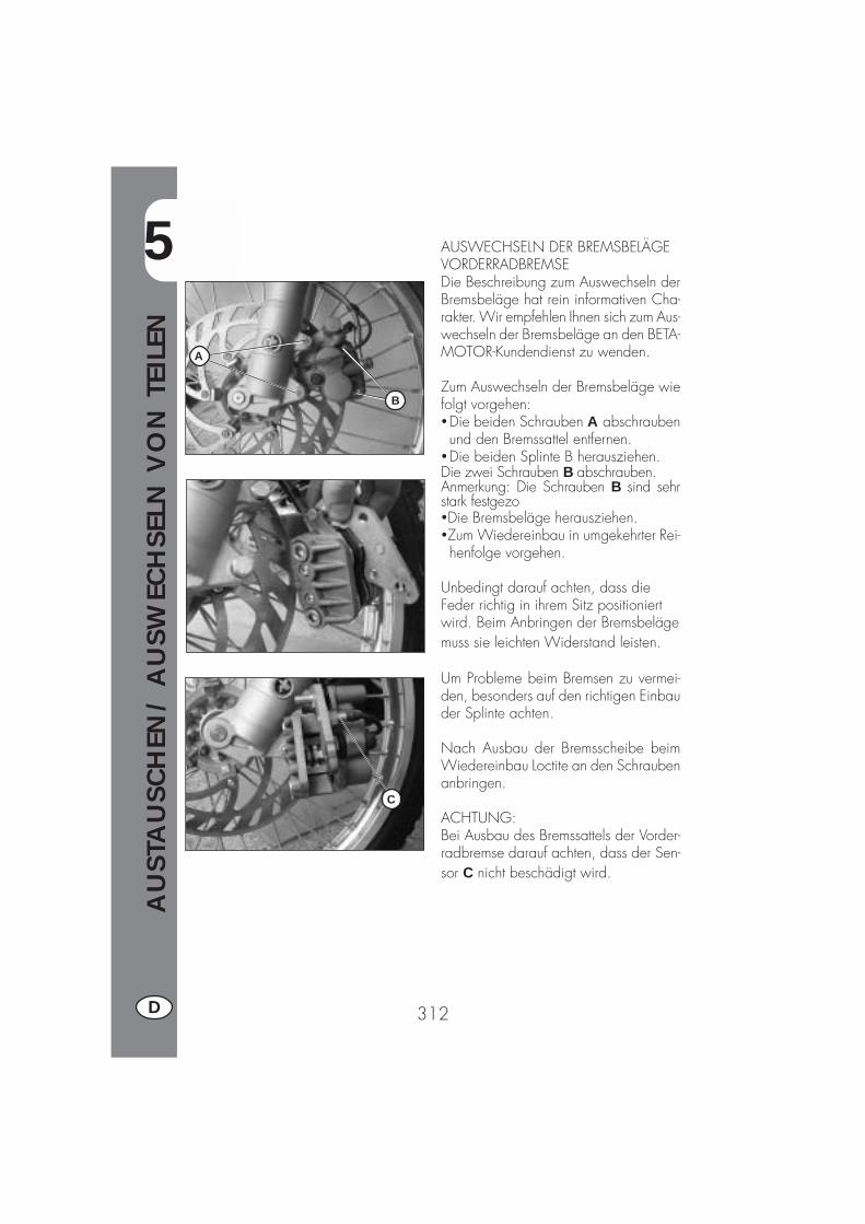
5
AU
STA
USC
HEN
/ A
USW
ECH
SELN
VO
N T
EILE
N
312D
AUSWECHSELN DER BREMSBELÄGEVORDERRADBREMSEDie Beschreibung zum Auswechseln derBremsbeläge hat rein informativen Cha-rakter. Wir empfehlen Ihnen sich zum Aus-wechseln der Bremsbeläge an den BETA-MOTOR-Kundendienst zu wenden.
Zum Auswechseln der Bremsbeläge wiefolgt vorgehen:�Die beiden Schrauben A abschraubenund den Bremssattel entfernen.
�Die beiden Splinte B herausziehen.Die zwei Schrauben B abschrauben.Anmerkung: Die Schrauben B sind sehrstark festgezo�Die Bremsbeläge herausziehen.�Zum Wiedereinbau in umgekehrter Rei-henfolge vorgehen.
Unbedingt darauf achten, dass dieFeder richtig in ihrem Sitz positioniertwird. Beim Anbringen der Bremsbelägemuss sie leichten Widerstand leisten.
Um Probleme beim Bremsen zu vermei-den, besonders auf den richtigen Einbauder Splinte achten.
Nach Ausbau der Bremsscheibe beimWiedereinbau Loctite an den Schraubenanbringen.
ACHTUNG:Bei Ausbau des Bremssattels der Vorder-radbremse darauf achten, dass der Sen-sor C nicht beschädigt wird.
A
B
C
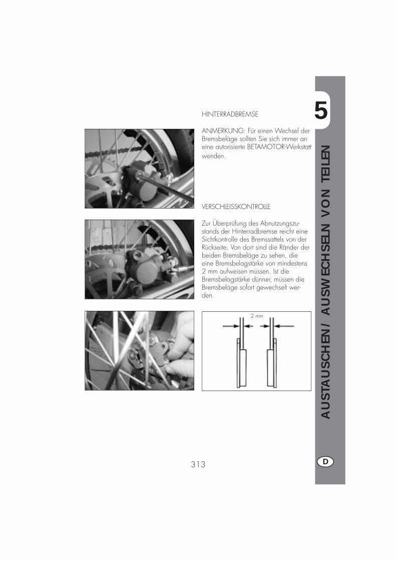
5
AU
STA
USC
HEN
/ A
USW
ECH
SELN
VO
N T
EILE
N
313 D
HINTERRADBREMSE
ANMERKUNG: Für einen Wechsel derBremsbeläge sollten Sie sich immer aneine autorisierte BETAMOTOR-Werkstattwenden.
2 mm
VERSCHLEISSKONTROLLE
Zur Überprüfung des Abnutzungszu-stands der Hinterradbremse reicht eineSichtkontrolle des Bremssattels von derRückseite. Von dort sind die Ränder derbeiden Bremsbeläge zu sehen, dieeine Bremsbelagstärke von mindestens2 mm aufweisen müssen. Ist dieBremsbelagstärke dünner, müssen dieBremsbeläge sofort gewechselt wer-den.
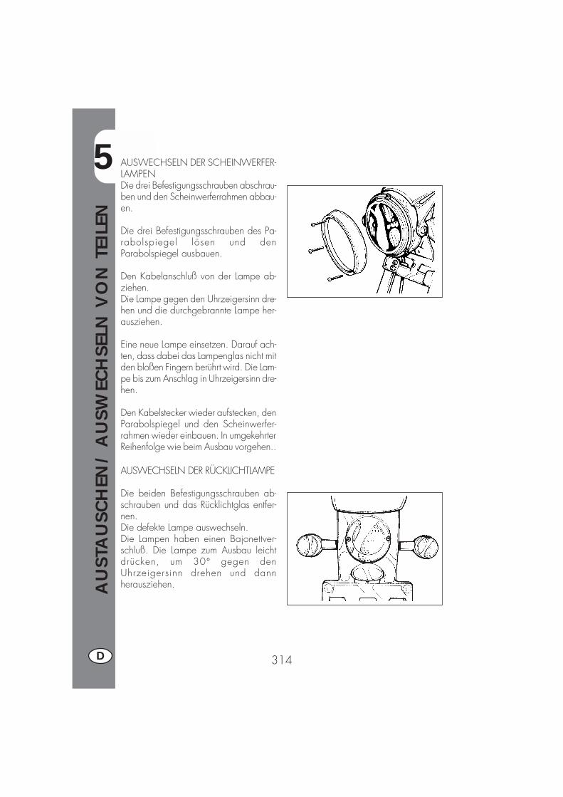
5
AU
STA
USC
HEN
/ A
USW
ECH
SELN
VO
N T
EILE
N
314D
AUSWECHSELN DER SCHEINWERFER-LAMPENDie drei Befestigungsschrauben abschrau-ben und den Scheinwerferrahmen abbau-en.
Die drei Befestigungsschrauben des Pa-rabolspiegel lösen und denParabolspiegel ausbauen.
Den Kabelanschluß von der Lampe ab-ziehen.Die Lampe gegen den Uhrzeigersinn dre-hen und die durchgebrannte Lampe her-ausziehen.
Eine neue Lampe einsetzen. Darauf ach-ten, dass dabei das Lampenglas nicht mitden bloßen Fingern berührt wird. Die Lam-pe bis zum Anschlag in Uhrzeigersinn dre-hen.
Den Kabelstecker wieder aufstecken, denParabolspiegel und den Scheinwerfer-rahmen wieder einbauen. In umgekehrterReihenfolge wie beim Ausbau vorgehen..
AUSWECHSELN DER RÜCKLICHTLAMPE
Die beiden Befestigungsschrauben ab-schrauben und das Rücklichtglas entfer-nen.Die defekte Lampe auswechseln.Die Lampen haben einen Bajonettver-schluß. Die Lampe zum Ausbau leichtdrücken, um 30° gegen denUhrzeigersinn drehen und dannherausziehen.
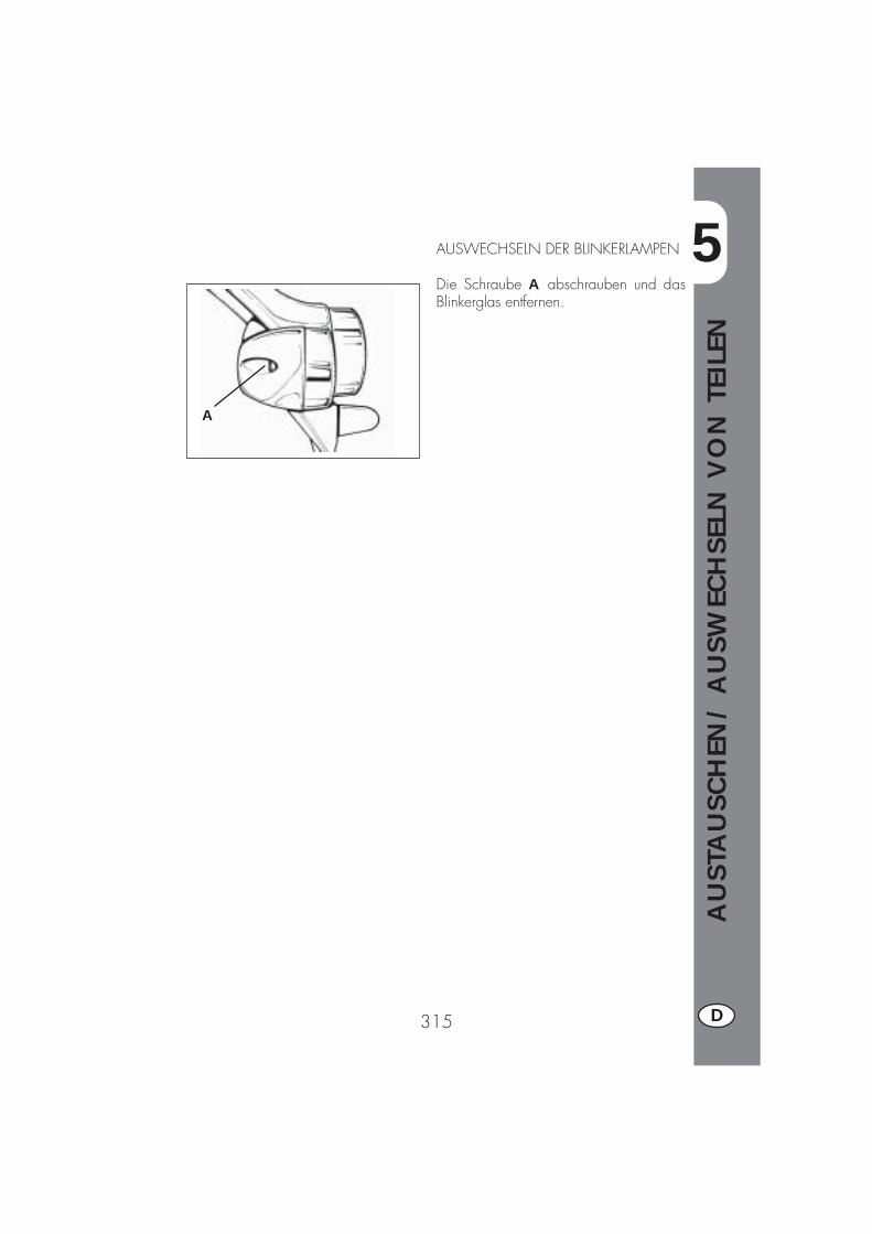
5
AU
STA
USC
HEN
/ A
USW
ECH
SELN
VO
N T
EILE
N
315 D
AUSWECHSELN DER BLINKERLAMPEN
Die Schraube A abschrauben und dasBlinkerglas entfernen.
A


6
ALP
HA
BET
ISCH
ES IN
HA
LTSV
ERZ
EICH
NIS
317 D
INHALTSVERZEICHNIS
KAPITEL 6 WAS IST IM NOTFALL ZU TUN
ALPHABETISCHES INHALTSVERZEICHNIS
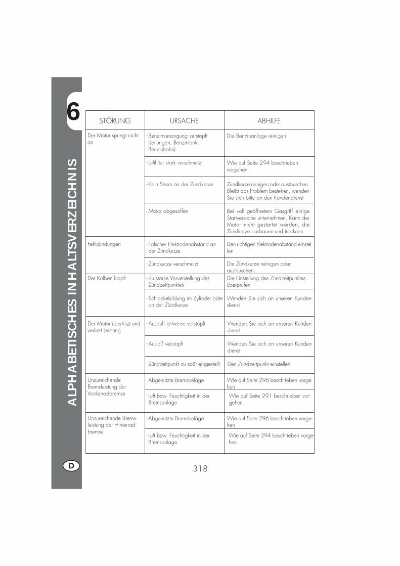
6
ALP
HA
BET
ISCH
ES IN
HA
LTSV
ERZ
EICH
NIS
318D
STÖRUNG URSACHE
Der Motor springt nichtan
ABHILFE
- Benzinversorgung verstopft(Leitungen, Benzintank,Benzinhahn)
- Luftfilter stark verschmutzt
- Kein Strom an der Zündkerze
- Motor abgesoffen
Die Benzinanlage reinigen
Wie auf Seite 294 beschriebenvorgehen
Zündkerze reinigen oder austauschen.Bleibt das Problem bestehen, wendenSie sich bitte an den Kundendienst
Bei voll geöffnetem Gasgriff einigeStartversuche unternehmen. Kann derMotor nicht gestartet werden, dieZündkerze ausbauen und trocknen
Fehlzündungen - Falscher Elektrodenabstand ander Zündkerze
Den richtigen Elektrodenabstand einstel-len
Der Kolben klopft - Zu starke Vorverstellung desZündzeitpunktes
- Schlackebildung im Zylinder oderan der Zündkerze
Die Einstellung des Zündzeitpunktesüberprüfen
Wenden Sie sich an unseren Kunden-dienst
Der Motor überhitzt undverliert Leistung
- Auspuff teilweise verstopft
- Auslaß verstopft
- Zündzeitpunkt zu spät eingestellt
Wenden Sie sich an unseren Kunden-dienst
Wenden Sie sich an unseren Kunden-dienst
Den Zündzeitpunkt einstellen
UnzureichendeBremsleistung derVorderradbremse
- Abgenutzte Bremsbeläge Wie auf Seite 296 beschrieben vorge-hen
Unzureichende Brems-leistung der Hinterrad-bremse
- Abgenutzte Bremsbeläge Wie auf Seite 296 beschrieben vorge-hen
Die Zündkerze reinigen oderaustauschen.
- Zündkerze verschmutzt
- Luft bzw. Feuchtigkeit in derBremsanlage
Wie auf Seite 291 beschrieben vor-gehen
- Luft bzw. Feuchtigkeit in derBremsanlage
Wie auf Seite 294 beschrieben vorge-hen
6
ALP
HA
BET
ISCH
ES IN
HA
LTSV
ERZ
EICH
NIS
319 D
Armaturenbrett und Bedienungselemente ................................................. 256
Bremsen: Entlüften .............................................................................. 291Bremsen: Einstellung ........................................................................... 306Bremsflüssigkeit .................................................................................. 291
Einfahren .......................................................................................... 283Elektrischer Schaltplan ......................................................................... 279
Fehlersuche ....................................................................................... 318
Gabelöl ........................................................................................... 293Gasgriff: Einstellung ............................................................................ 308
Helmschloß ....................................................................................... 252Hinterradbremse: Kontrolle und Wechsel der Bremsbeläge ......................... 296
Kettenspannung ................................................................................. 309Kontrollen nach der Fahrzeugpflege ....................................................... 301Kontrollen und Wartung vor und nach Einsatz im Gelände ......................... 283Kupplung .......................................................................................... 306Kupplung: Einstellung .......................................................................... 306
Lampen: Auswechseln ......................................................................... 314Leerlaufeinstellung .............................................................................. 307Lenkung: Kontrolle und Einstellen ........................................................... 308Luftfilter ............................................................................................. 239LCD................................................................................................. 294
Motoröl: Kontrolle und Ölwechsel ................................................. 288/290
Rahmen- und Motornummer .................................................................. 248
Schlüssel und Schlösser ....................................................................... 252Schmiermittel und empfohlene Flüssigkeiten ............................................. 283Starten ............................................................................................. 284
Tanken ............................................................................................. 286Technische Daten ............................................................................... 271
Vorderradbremse: Kontrolle und Wechsel der Bremsbeläge ........................ 296
Wartungsprogramm............................................................................ 302
Zündkerze ........................................................................................ 295Zündschloß/ Lenkerschloß ................................................................... 252

321 E
ALP4T 125/200cm3
Gracias por la confianza que nos han concedido y buena diver-sión. Con este libro hemos querido darle las informaciones ne-cesarias para un uso correcto y un buen mantenimiento de Sumoto.
Los datos y las características indicadas en éste manual no comprometenBETAMOTOR S.p.A que se reserva los derechos a realizar modificaciones ymejoras a sus propios modelos en cualquier momento sin previo aviso.
322E
ADVERTENCIA
Recomendamos después de la primera o segunda hora de utili-zación en todo terreno, de controlar todos los aprietesespecialménte a los siguientes:
� corona� soportes estribos� pinza freno delantero� soporte guardabarros� tornillos del motor� tornillos amortiguador� rayos rueda� chasis trasero
ADVERTENCIA
En el caso de intervenciones en la moto, dirigirse a la cadenade asistencia autorizada Betamotor.
IND
ICE
323 E
Advertencias sobre el uso .................................................................... 325Conducción ecologica ........................................................................ 325Conducción segura ............................................................................ 326
CAP. 1 INFORMACIONES GENERALES .................................... 327Datos identificación vehìculo ................................................................ 328Suministro ......................................................................................... 328Carga ............................................................................................. 329Neumáticos ...................................................................................... 329Conocimiento del vehìculo ................................................................... 331Llaves y cerradura .............................................................................. 332Conmutador / bloquéo tubo dirección................................................... 332Cerradura casco ................................................................................ 332Tablero y mandos .............................................................................. 333Instrucciones para el ajuste y funcionamento del cuentakilometros ................ 334Datos técnicos ................................................................................... 351Datos técnicos del motor ALP125 .......................................................... 353Datos técnicos del motor ALP200 .......................................................... 354Esquema eléctrico ALP 125 ................................................................. 355Esquema eléctrico ALP 200 ................................................................. 357Dispositivos electrónicos ...................................................................... 359
CAP. 2 USO DEL VEHICULO ................................................... 361Controles y mantenimiento antes y después del uso en todoterreno .............. 362Lubricantes y lìquidos aconsejados ........................................................ 363Rodaje ............................................................................................. 363Arranque del motor ............................................................................ 364Parada del motor ............................................................................... 365Abastecimiento de gasolina ................................................................. 366
CAP. 3 COMPROBACIONES Y MANUTENCION ....................... 367Aceite motor y filtro aceite ALP 200 ....................................................... 368Aceite motor y filtro aceite ALP 125 ....................................................... 370Tubo recuperación de humos ................................................................ 371Aceite bomba de frenos, espurgo frenos ................................................ 372Aceite horquilla ................................................................................. 373Filtro aire .......................................................................................... 374Bujìa................................................................................................ 375Frenos: delantero y trasero ................................................................... 376Baterìa ............................................................................................. 377Extracción de la carrocerìa .................................................................. 378Notas para trial ................................................................................. 379Limpieza del vehìculo y comprobaciomnes ............................................. 381Manutención programada ................................................................... 382Larga inactividad del vehìculo .............................................................. 383
IND
ICE
324E
CAP. 4 REGULACIONES ......................................................... 385Regulación frenos ............................................................................... 385Regulación embrague ......................................................................... 386Regulación ralentì ............................................................................... 387Ajuste del flujo de la gasolina (solo para ALP125).................................... 387Regulación juego gas ......................................................................... 387Comprobación y regulación juego tubo dirección .................................... 388Tensionamiento cadena ....................................................................... 389Haz luminoso .................................................................................... 390
CAP. 5 SUSTITUCIONES ....................................................... 391Sustitución pastillas frenos .................................................................... 392Sustitución bombillo faro delantero ........................................................ 393Sustitución bombillo piloto trasero.......................................................... 394Sustitución bombillos indicadores de dirección ........................................ 395
CAP. 6 QUE HACER EN CASO DE EMERGENCIA ...................... 397
INDICE ALFABETICO .......................................................................... 399
325 E
ADVERTENCIAS SOBRE EL USO DEL VEHICULO�El vehículo debe ser obligatoriaménte provisto de: placa, libreto de identificación,impuesto y seguro.
�Está prohibido transportar animales u otros objetos no integrado al vahículo, que“salgan” de las dimenciones máximas ocupadas por el vehículo y que superen lacarga prevista pr el constructor.
�Es obligatorio el uso del casco.�Modificaciones al motor o a otros organos que puedan determinar un aumento depotencia y por consiguiente aumento de velocidad, es castigado por la ley conseveras sanciones, entre las cuales el secuestro del vehículo.
�Para salvaguardar su vida y la de los demás, conducir con prudencia y ponersesiempre el casco.
ATENCION:Modificaciones o intervenciones durante la garantía, liberan al Constructor decualquier responsabilidad y hacen decaer la misma garantía.
CONDUCCION ECOLOGICA�Cada vehículo con motor a explosión produce mas o menos ruido (contaminaciónde sonido) y mas o menos (contaminación atmosférica) según el tipo de conduc-ción adoptada.
� La mayor reducción posible de estas condiciones es hoy un deber para todos, porlo tanto evitar salidas a todo gas, improvisas e inutiles aceleraciones e improvisasigualmente inutiles frenadas, limitando asì la rumorosidad, el desgaste precoz delos neumáticos y de las partes mecanicas del vehículo y ahorrando en el gasto decombustible.
326E
CONDUCCION SEGURA�Respetar el código de la circulación�Ponerse siempre el casco homologado y enganchado�Tener siempre limpia la visera protectiva�Ponerse siempre ropa sin extremos colgando�No viajar teniendo en el bolsillo objetos con punta o fragiles�Regular correctaménte los espejos retrovisores�Conducir siempre sentados, con las dos manos en el manillar y los pies sobre losestribos
�No distraerse nunca durante la conducción�No comer, beber, fumar, usar el celular, etc…. mientras conduce�No escuchar musica con auriculares mientras conduce�No viajar nunca en pareja con otros vehículos�No remolcar o dejarse remolcar por otros vehículos�Tener siempre una distancia de seguridad�Viajar con las luces (de cruce) encendidas también de día�No estar sentados cuando el vehículo se encuentra sobre el caballete�No salir con el vehículo sobre el caballete�No extraer el caballete cuando el vehículo se encuentra con su parte anterior enbajada
�Empinadas, serpentinas, oscilaciones, son peligrosas para Ti, para los demás ypara tu vehículo
�En calle seca y sin grava o arena, usar ambos frenos, un solo freno puede provo-car deslizamientos peligrosos e incontrolables.
�En caso de frenada utilizar ambos frenos, se obtendrá una parada del vehículo enun espacio mas corto
�En calle mojada, conducir con prudencia y a velocidad moderada : utilizar losfrenos con mas sensibilidad
�No arrancar el motor en locales cerrados
1
INFO
RM
ACIO
NES
GEN
ERA
LES
327 E
INDICE DE LOS ARGUMENTOS
CAP. 1 INFORMACIONES GENERALES
Datos identificación vehículo
Suministro
Carga
Neumáticos
Conocimiento del vehículo
Llaves y cerradura
Conmutador/bloquéo de la dirección
Cerradura casco
Tablero y mandos
Indicaciones sobre LCD
Datos técnicos
Esquema eléctrico
Dispositivos eléctricos
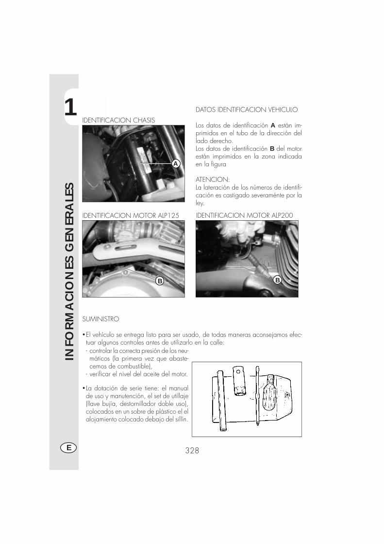
1
INFO
RM
ACIO
NES
GEN
ERA
LES
328E
DATOS IDENTIFICACION VEHICULO
Los datos de identificación A están im-primidos en el tubo de la dirección dellado derecho.Los datos de identificación B del motorestán imprimidos en la zona indicadaen la figura
ATENCION:La lateración de los números de identifi-cación es castigado severaménte por laley.
IDENTIFICACION CHASIS
IDENTIFICACION MOTOR ALP200
SUMINISTRO
�El vehículo se entrega listo para ser usado, de todas maneras aconsejamos efec-tuar algunos controles antes de utilizarlo en la calle:
B
- controlar la correcta presión de los neu-máticos (la primera vez que abaste-cemos de combustible),
- verificar el nivel del aceite del motor.
� La dotación de serie tiene: el manualde uso y manutención, el set de utillaje(llave bujía, destornillador doble uso),colocados en un sobre de plástico el elalojamiento colocado debajo del sillín.
A
IDENTIFICACION MOTOR ALP125
B
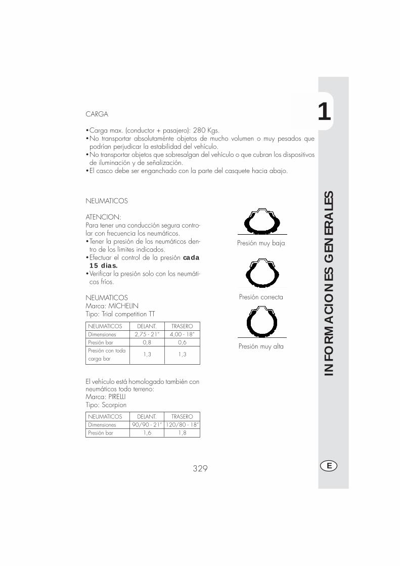
1
INFO
RM
ACIO
NES
GEN
ERA
LES
329 E
CARGA
�Carga max. (conductor + pasajero): 280 Kgs.�No transportar absolutaménte objetos de mucho volumen o muy pesados quepodrían perjudicar la estabilidad del vehículo.
�No transportar objetos que sobresalgan del vehículo o que cubran los dispositivosde iluminación y de señalización.
�El casco debe ser enganchado con la parte del casquete hacia abajo.
NEUMATICOS
ATENCION:Para tener una conducción segura contro-lar con frecuencia los neumáticos.�Tener la presión de los neumáticos den-tro de los limites indicados.
�Efectuar el control de la presión cada15 dias.
�Verificar la presión solo con los neumáti-cos fríos.
NEUMATICOSMarca: MICHELINTipo: Trial competition TT
Presión muy baja
Presión correcta
Presión muy alta
NEUMATICOSDimensionesPresión barPresión con todacarga bar
TRASERO4,00 - 18”
0,6
1,3
DELANT.2,75 - 21”
0,8
1,3
El vehículo está homologado también conneumáticos todo terreno:Marca: PIRELLITipo: Scorpion
NEUMATICOSDimensionesPresión bar
TRASERO120/80 - 18”
1,8
DELANT.90/90 - 21”
1,6
1
INFO
RM
ACIO
NES
GEN
ERA
LES
330E
Nota:El espesor mínimo de la banda de rodadura de los neumáticos (TUBE TYPE) nodebe ser nunca inferior a los 2 mm.La falta de respeto de esta norma es castigada por la ley.
�Controlar antes de cada viaje que los neumáticos no tengan cortes, rajaduras,abrasiones, hinchazones, etc…. En tal caso hecer examinar el neumático por unexperto puesto que se podrían verificar condiciones extremamente peligrosas.
�En el caso de pinchazo parar inmediatamente el vehículo; seguir viajando, ade-más de ser riesgoso, puede provocar irremediables daños al neumático y a lallanta.
*Con la carga máxima se aconsejan presiones superiores (ver tabla en la pag. 329).

1
INFO
RM
ACIO
NES
GEN
ERA
LES
331 E
1
6
7
32 22
4 11
8
9
10 5
CONOCIMIENTO DEL VEHICULO
13 15
1621
18
14 19
1217
20
Elementos principales1- Filtro aire2- Depósito combus-
tible3- Tapón del depósi-
to4- Silenciador5- Amortiguador tra-
sero6- Farol delantero
7- Indicadores de di-rección delantero
8- Piloto trasero9- Indicadores de di-
rección traseros10- Caballete lateral11- Portaequipaje12- Espejos retroviso-
res13- Estribo pasajero14- Horquilla
15- Estribo piloto16- Carter debajo del
motor17- Sillín18- Motor19- Guardabarros de-
lantero20- Portaplaca21 - Palanca de arran-
que22 - Cerradura casco
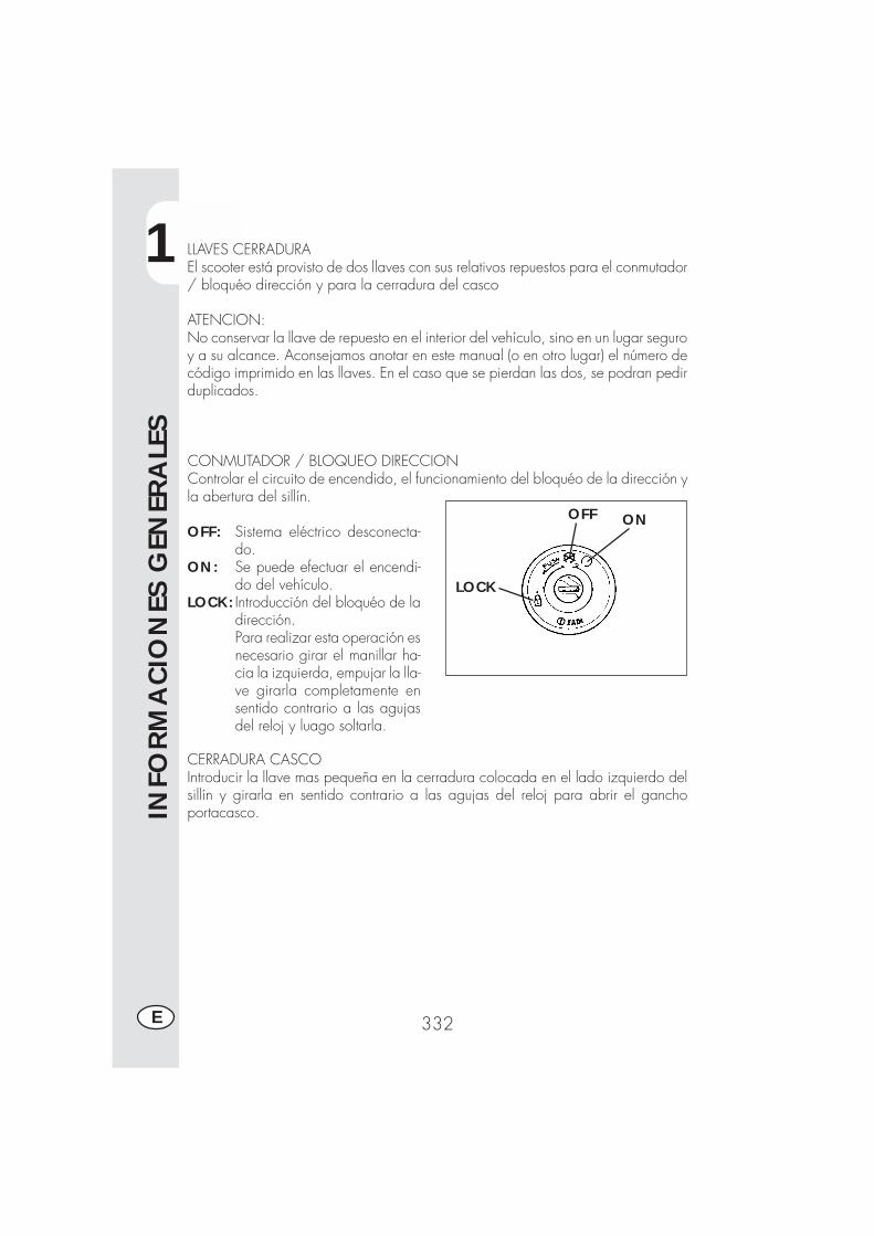
1
INFO
RM
ACIO
NES
GEN
ERA
LES
332E
ONOFF
LOCK
LLAVES CERRADURAEl scooter está provisto de dos llaves con sus relativos repuestos para el conmutador/ bloquéo dirección y para la cerradura del casco
ATENCION:No conservar la llave de repuesto en el interior del vehículo, sino en un lugar seguroy a su alcance. Aconsejamos anotar en este manual (o en otro lugar) el número decódigo imprimido en las llaves. En el caso que se pierdan las dos, se podran pedirduplicados.
CONMUTADOR / BLOQUEO DIRECCIONControlar el circuito de encendido, el funcionamiento del bloquéo de la dirección yla abertura del sillín.
OFF: Sistema eléctrico desconecta-do.
ON: Se puede efectuar el encendi-do del vehículo.
LOCK: Introducción del bloquéo de ladirección.Para realizar esta operación esnecesario girar el manillar ha-cia la izquierda, empujar la lla-ve girarla completamente ensentido contrario a las agujasdel reloj y luago soltarla.
CERRADURA CASCOIntroducir la llave mas pequeña en la cerradura colocada en el lado izquierdo delsillín y girarla en sentido contrario a las agujas del reloj para abrir el ganchoportacasco.
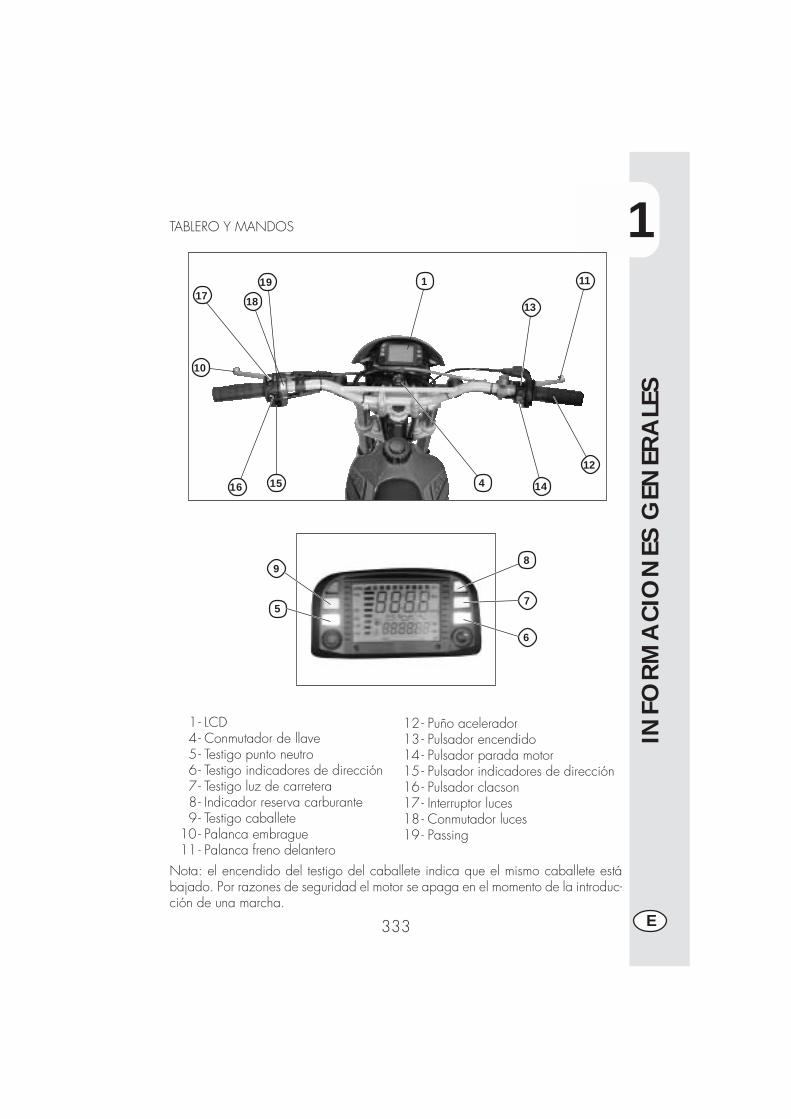
1
INFO
RM
ACIO
NES
GEN
ERA
LES
333 E
1- LCD4- Conmutador de llave5- Testigo punto neutro6- Testigo indicadores de dirección7- Testigo luz de carretera8- Indicador reserva carburante9- Testigo caballete
10 - Palanca embrague11 - Palanca freno delantero
12 - Puño acelerador13 - Pulsador encendido14 - Pulsador parada motor15 - Pulsador indicadores de dirección16 - Pulsador clacson17 - Interruptor luces18 - Conmutador luces19 - Passing
TABLERO Y MANDOS
Nota: el encendido del testigo del caballete indica que el mismo caballete estábajado. Por razones de seguridad el motor se apaga en el momento de la introduc-ción de una marcha.
10
17 18
1516 4 14
12
11
13
5
19
6
7
9
1
8
1
INFO
RM
ACIO
NES
GEN
ERA
LES
334E
INSTRUCCIONES PARA EL AJUSTE Y FUNCIONAMIENTO DEL CUENTAKILO-METROS (para fabricante y concesionario)La descripción relativa al ajuste de base del instrumento digital tiene simplementecarácter informativo; es recomendable dirigirse a un Taller autorizado Betamotorpara realizar dicha operación.
Serie ALP 200 - ALP 4.0 - MOTARD M4
INDICE DE ARGUMENTOS
PÁRRAFO CONTENIDO
10.1 Características de la rueda10.2 Características del motor10.3 Carga de los códigos10.4 Códigos cargados
20.0 SETUP NIVEL 1 (para fabricante moto y concesionario)20.1 Ejecución setup nivel 120.2 Selección códigos20.3 Verificación contenido códigos20.4 Introducción códigos sin codificación
20.4.1 Introducción Ln (desarrollo rueda) o di (diámetro rueda)20.4.2 Introducción cantidad de impulsos giro rueda20.4.3 Introducción cantidad impulsos giro motor
20.4.3.1 Introducción cantidad giros máximos motor20.4.4 Selección Km/h o M/h20.4.5 Introducción hora para cambio aceite20.4.6 Introducción hora o Km para cupón de servicio
20.5 Salida del setup
40.0 INDICACIONES SOBRE LCD (Pantalla de cristales líquidos)40.1 Funcionamiento y visualización páginas40.2 Oscurecimiento de las páginas40.3 Anulación parámetros TRP, SPEED max, LAP
50.0 INTERVENCIÓN ICONOS DE VIGILANCIA (aceite motor y cupones deservicio)
50.1 Verificación del contenido activo de los iconos de vigilancia
1
INFO
RM
ACIO
NES
GEN
ERA
LES
335 E
10.1 Características de la rueda (ya determinados en el vehículo)Dimensiones de la rueda sobre la cual ha sido montado el sensor de giros. Sedeberá indicar el diámetro o el desarrollo de la rueda en mm (valor máximo 9999.Ejemplo: para un diámetro de la rueda de 695 mm una vez introducido se deberáleer 0695) y la cantidad de impulsos por cada vuelta, valor máximo 99. Una vezintroducido los datos si la cantidad de impulsos es inferior a 10, ejemplo 1, sedeberá leer 01.
NOTA: la acción en el pulsador SCROLL es de dos tipos:Acción breve ≤ 1“ el programa pasa a la página siguiente.Acción prolongada ≥ 5“ el programa permite la entrada en la funciónvisualizada para comprobar el contenido o para introducir/modificar los valorescontenidos y en algunos casos realiza la memorización.
En la presente documentación, para una exposición mas cómoda se usa indicarsolamente el pulsador SCROLL en el manillar, y se obtiene el mismo resultadotambién usando el pulsador MODE en el cuentakilómetros (el pulsador MODE sepuede accionar únicamente con el vehículo detenido).
10.2 Características del motor (solo si se encuentra activado el cuentarre-voluciones)Cantidad de impulsos por vuelta y giros nominales máximos necesarios para cali-brar la barra.La eventual introducción de los parámetros, sin los sensores, no modifica el funcio-namiento, pero aparecerá de igual manera la página en el LCD con parámetros ybarra a cero.La entrada del sensor es en el contacto 12 del conector. La cantidad de impulsosgiro respeta las mismas reglas de la cantidad de impulsos giro rueda, mientras lacantidad de giros del motor necesita solo los millares y las centenas. Ejemplo: paraintroducir 15000 vueltas se deberá colocar 150 en las cifras grandes, para intro-ducir 8500 vueltas se deberá colocar 085 en las cifras grandes.
10.3 Carga de códigos (ya determinados en el vehículo)Ya han sido introducidos por el fabricante cuatro códigos predefinidos los cualescontienen siempre los parámetros rueda y parámetros de vigilancia tal como “horacambio aceite” y “hora o km que faltan al cupón de servicio”. Unicamente losparámetros de vigilancia podrán ser siempre modificados.La identificación se realizará indicando en el LCD un número en código y el primercódigo introducido será 0001.Los códigos ya han sido introducidos y podrán ser modificados únicamente por elfabricante. Hay que destacar que efectuando una nueva programación, el kilome-traje total recorrido será llevado a cero.
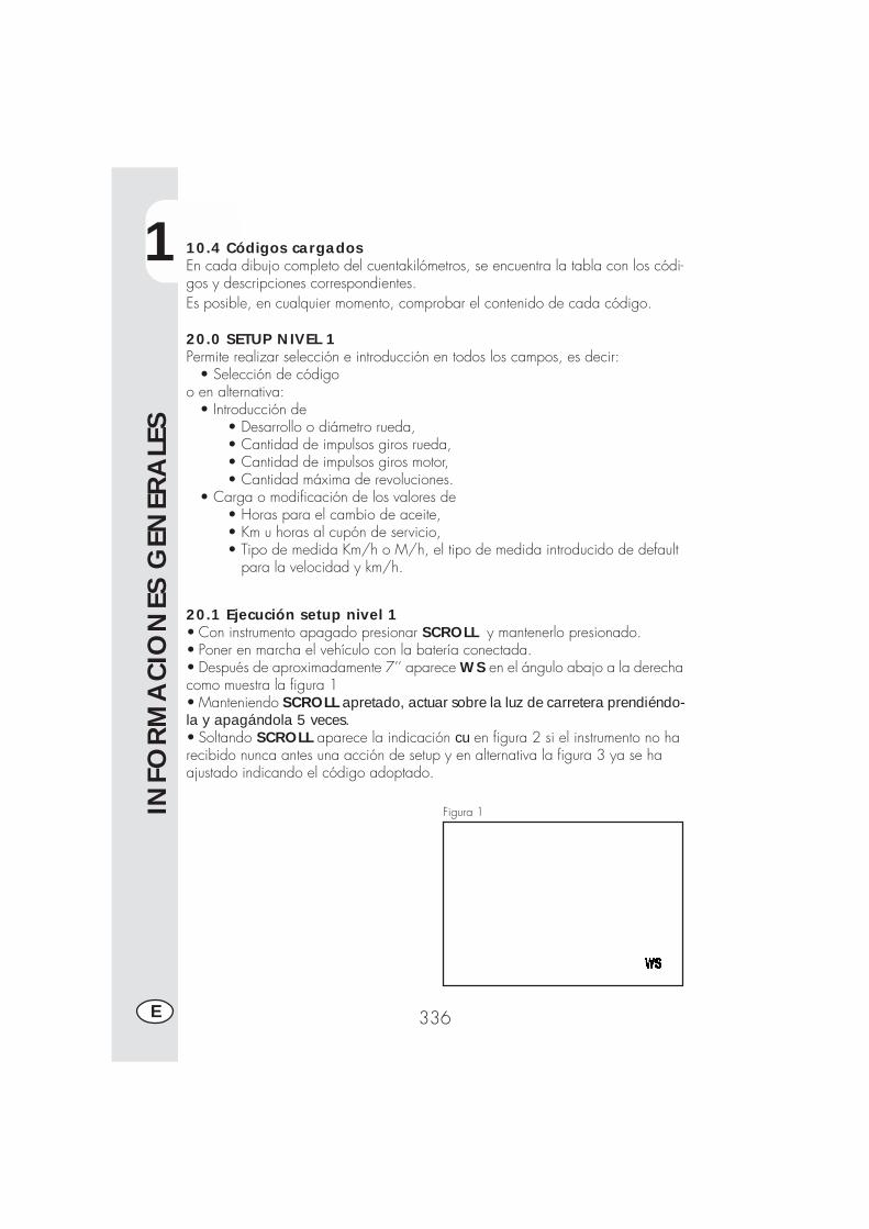
1
INFO
RM
ACIO
NES
GEN
ERA
LES
336E
10.4 Códigos cargadosEn cada dibujo completo del cuentakilómetros, se encuentra la tabla con los códi-gos y descripciones correspondientes.Es posible, en cualquier momento, comprobar el contenido de cada código.
20.0 SETUP NIVEL 1Permite realizar selección e introducción en todos los campos, es decir: • Selección de códigoo en alternativa: • Introducción de
• Desarrollo o diámetro rueda,• Cantidad de impulsos giros rueda,• Cantidad de impulsos giros motor,• Cantidad máxima de revoluciones.
• Carga o modificación de los valores de• Horas para el cambio de aceite,• Km u horas al cupón de servicio,• Tipo de medida Km/h o M/h, el tipo de medida introducido de default para la velocidad y km/h.
20.1 Ejecución setup nivel 1• Con instrumento apagado presionar SCROLL y mantenerlo presionado.• Poner en marcha el vehículo con la batería conectada.• Después de aproximadamente 7’’ aparece WS en el ángulo abajo a la derechacomo muestra la figura 1• Manteniendo SCROLL apretado, actuar sobre la luz de carretera prendiéndo-la y apagándola 5 veces.• Soltando SCROLL aparece la indicación cu en figura 2 si el instrumento no harecibido nunca antes una acción de setup y en alternativa la figura 3 ya se haajustado indicando el código adoptado.
Figura 1
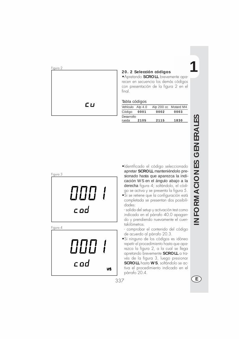
1
INFO
RM
ACIO
NES
GEN
ERA
LES
337 E
20. 2 Selección códigos•Apretando SCROLL brevemente apa-recen en secuencia los demás códigoscon presentación de la figura 2 en elfinal.
Tabla códigosVehículo Alp 4.0 Alp 200 cc Motard M4Código 0001 0002 0003Desarrollorueda 2105 2115 1830
•Identificado el código seleccionadoapretar SCROLL manteniéndolo pre-sionado hasta que aparezca la indi-cación WS en el ángulo abajo a laderecha figura 4; soltándolo, el códi-go se activa y se presenta la figura 5.
•Si se retiene que la configuración estácompletada se presentan dos posibili-dades:- salida del setup y activación test comoindicado en el párrafo 40.0 apagan-do y prendiendo nuevamente el cuen-takilómetros.- comprobar el contenido del códigode acuerdo al párrafo 20.3.
•Si ninguno de los códigos es idóneorepetir el procedimiento hasta que apa-rezca la figura 2, a la cual se llegaapretando brevemente SCROLL a tra-vés de la figura 3, luego presionarSCROLL hasta WS, soltándolo se ac-tiva el procedimiento indicado en elpárrafo 20.4.
Figura 2
Figura 3
Figura 4
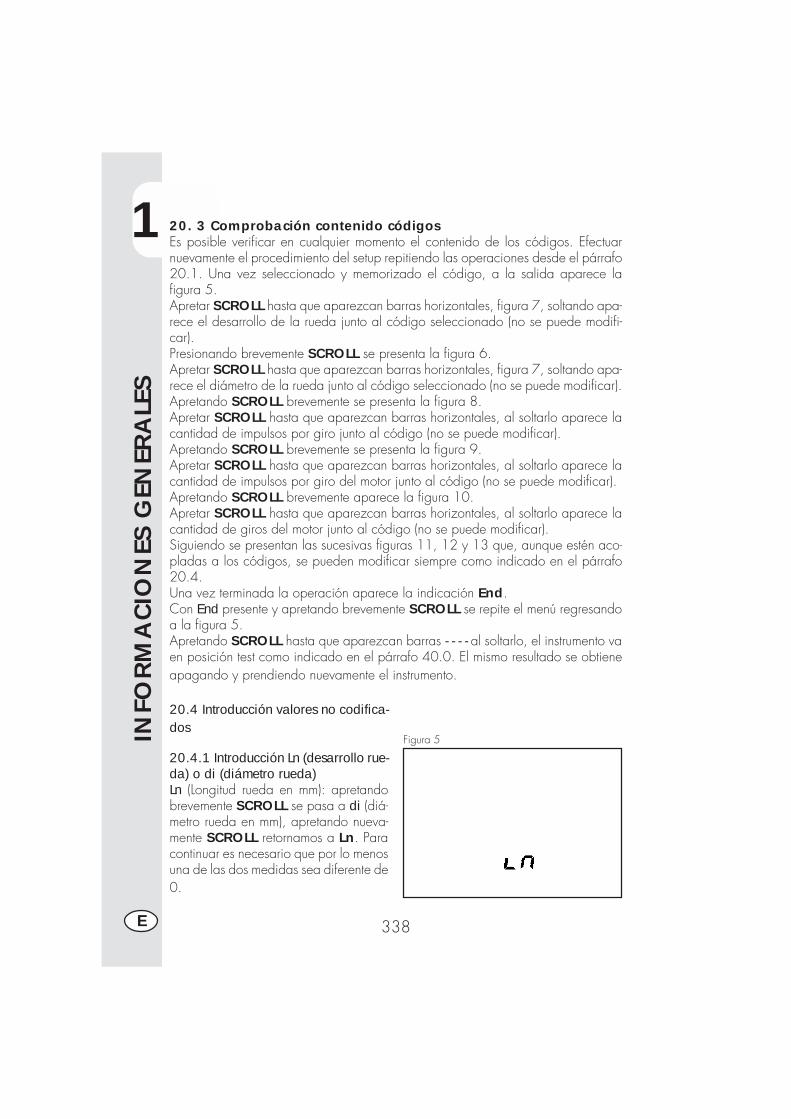
1
INFO
RM
ACIO
NES
GEN
ERA
LES
338E
20. 3 Comprobación contenido códigosEs posible verificar en cualquier momento el contenido de los códigos. Efectuarnuevamente el procedimiento del setup repitiendo las operaciones desde el párrafo20.1. Una vez seleccionado y memorizado el código, a la salida aparece lafigura 5.Apretar SCROLL hasta que aparezcan barras horizontales, figura 7, soltando apa-rece el desarrollo de la rueda junto al código seleccionado (no se puede modifi-car).Presionando brevemente SCROLL se presenta la figura 6.Apretar SCROLL hasta que aparezcan barras horizontales, figura 7, soltando apa-rece el diámetro de la rueda junto al código seleccionado (no se puede modificar).Apretando SCROLL brevemente se presenta la figura 8.Apretar SCROLL hasta que aparezcan barras horizontales, al soltarlo aparece lacantidad de impulsos por giro junto al código (no se puede modificar).Apretando SCROLL brevemente se presenta la figura 9.Apretar SCROLL hasta que aparezcan barras horizontales, al soltarlo aparece lacantidad de impulsos por giro del motor junto al código (no se puede modificar).Apretando SCROLL brevemente aparece la figura 10.Apretar SCROLL hasta que aparezcan barras horizontales, al soltarlo aparece lacantidad de giros del motor junto al código (no se puede modificar).Siguiendo se presentan las sucesivas figuras 11, 12 y 13 que, aunque estén aco-pladas a los códigos, se pueden modificar siempre como indicado en el párrafo20.4.Una vez terminada la operación aparece la indicación End.Con End presente y apretando brevemente SCROLL se repite el menú regresandoa la figura 5.Apretando SCROLL hasta que aparezcan barras - - - - al soltarlo, el instrumento vaen posición test como indicado en el párrafo 40.0. El mismo resultado se obtieneapagando y prendiendo nuevamente el instrumento.
Figura 5
20.4 Introducción valores no codifica-dos
20.4.1 Introducción Ln (desarrollo rue-da) o di (diámetro rueda)Ln (Longitud rueda en mm): apretandobrevemente SCROLL se pasa a di (diá-metro rueda en mm), apretando nueva-mente SCROLL retornamos a Ln. Paracontinuar es necesario que por lo menosuna de las dos medidas sea diferente de0.
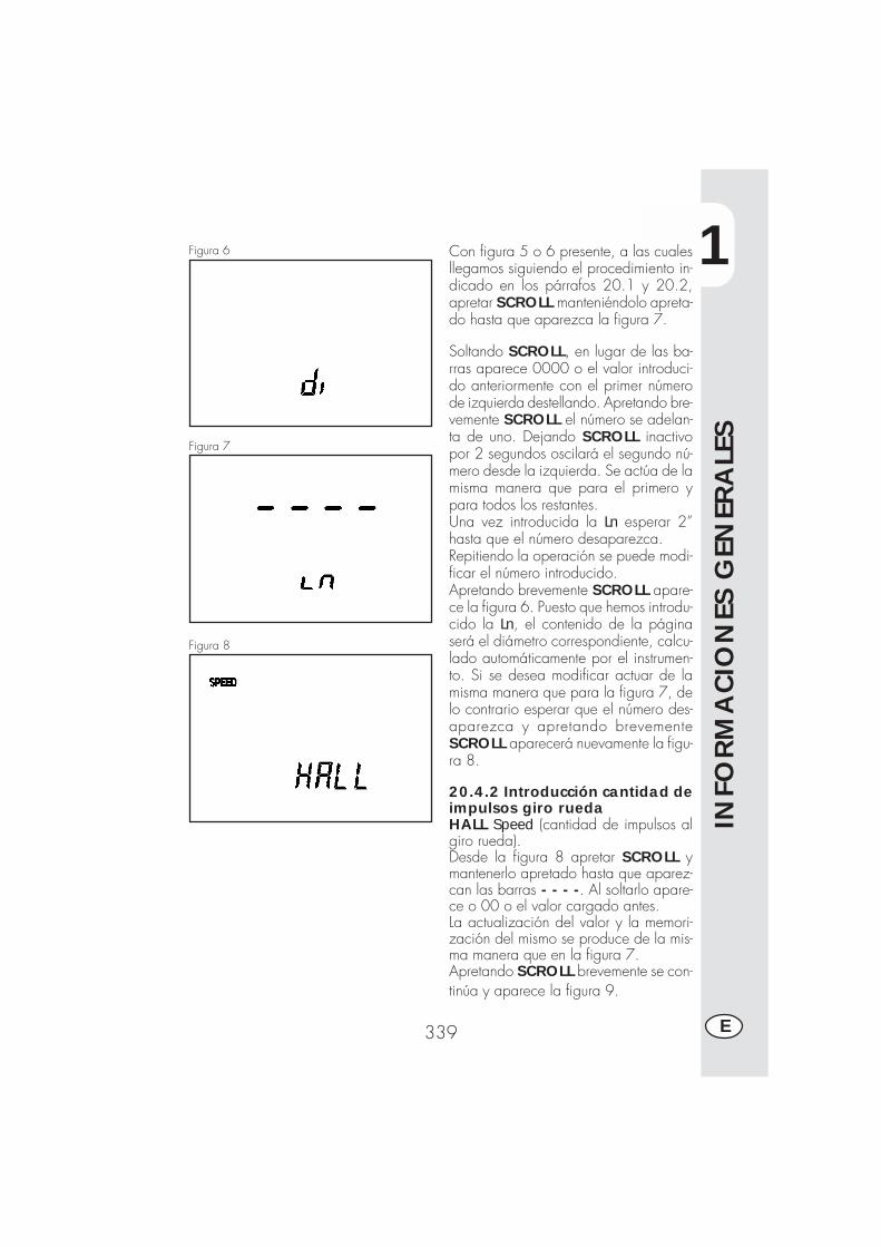
1
INFO
RM
ACIO
NES
GEN
ERA
LES
339 E
Figura 6 Con figura 5 o 6 presente, a las cualesllegamos siguiendo el procedimiento in-dicado en los párrafos 20.1 y 20.2,apretar SCROLL manteniéndolo apreta-do hasta que aparezca la figura 7.
Soltando SCROLL, en lugar de las ba-rras aparece 0000 o el valor introduci-do anteriormente con el primer númerode izquierda destellando. Apretando bre-vemente SCROLL el número se adelan-ta de uno. Dejando SCROLL inactivopor 2 segundos oscilará el segundo nú-mero desde la izquierda. Se actúa de lamisma manera que para el primero ypara todos los restantes.Una vez introducida la Ln esperar 2”hasta que el número desaparezca.Repitiendo la operación se puede modi-ficar el número introducido.Apretando brevemente SCROLL apare-ce la figura 6. Puesto que hemos introdu-cido la Ln, el contenido de la páginaserá el diámetro correspondiente, calcu-lado automáticamente por el instrumen-to. Si se desea modificar actuar de lamisma manera que para la figura 7, delo contrario esperar que el número des-aparezca y apretando brevementeSCROLL aparecerá nuevamente la figu-ra 8.
20.4.2 Introducción cantidad deimpulsos giro ruedaHALL Speed (cantidad de impulsos algiro rueda).Desde la figura 8 apretar SCROLL ymantenerlo apretado hasta que aparez-can las barras - - - -. Al soltarlo apare-ce o 00 o el valor cargado antes.La actualización del valor y la memori-zación del mismo se produce de la mis-ma manera que en la figura 7.Apretando SCROLL brevemente se con-tinúa y aparece la figura 9.
Figura 7
Figura 8
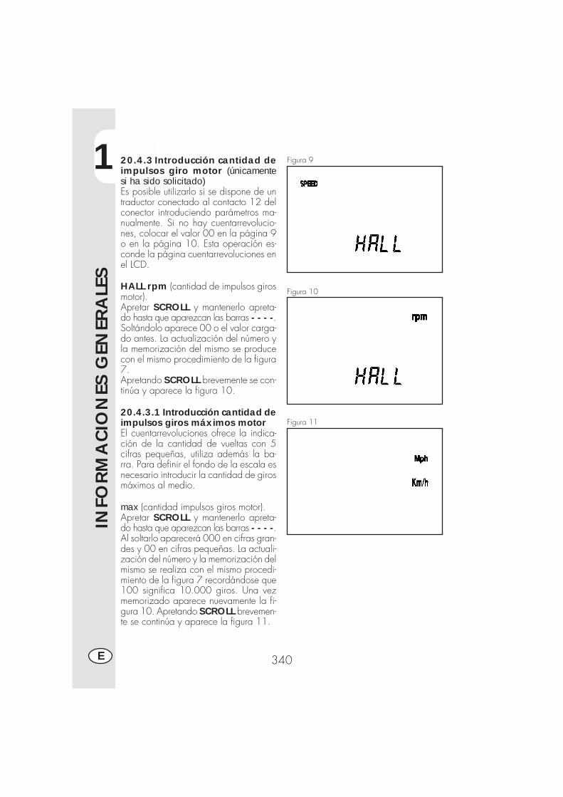
1
INFO
RM
ACIO
NES
GEN
ERA
LES
340E
20.4.3 Introducción cantidad deimpulsos giro motor (únicamentesi ha sido solicitado)Es posible utilizarlo si se dispone de untraductor conectado al contacto 12 delconector introduciendo parámetros ma-nualmente. Si no hay cuentarrevolucio-nes, colocar el valor 00 en la página 9o en la página 10. Esta operación es-conde la página cuentarrevoluciones enel LCD.
HALL rpm (cantidad de impulsos girosmotor).Apretar SCROLL y mantenerlo apreta-do hasta que aparezcan las barras - - - -.Soltándolo aparece 00 o el valor carga-do antes. La actualización del número yla memorización del mismo se producecon el mismo procedimiento de la figura7.Apretando SCROLL brevemente se con-tinúa y aparece la figura 10.
20.4.3.1 Introducción cantidad deimpulsos giros máximos motorEl cuentarrevoluciones ofrece la indica-ción de la cantidad de vueltas con 5cifras pequeñas, utiliza además la ba-rra. Para definir el fondo de la escala esnecesario introducir la cantidad de girosmáximos al medio.
max (cantidad impulsos giros motor).Apretar SCROLL y mantenerlo apreta-do hasta que aparezcan las barras - - - -.Al soltarlo aparecerá 000 en cifras gran-des y 00 en cifras pequeñas. La actuali-zación del número y la memorización delmismo se realiza con el mismo procedi-miento de la figura 7 recordándose que100 significa 10.000 giros. Una vezmemorizado aparece nuevamente la fi-gura 10. Apretando SCROLL brevemen-te se continúa y aparece la figura 11.
Figura 9
Figura 10
Figura 11
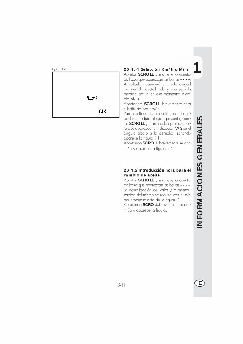
1
INFO
RM
ACIO
NES
GEN
ERA
LES
341 E
20.4. 4 Selección Km/h o M/hApretar SCROLL y mantenerlo apreta-do hasta que aparezcan las barras - - - -.Al soltarlo aparecerá una sola unidadde medida destellando y esa será lamedida activa en ese momento: ejem-plo M/h.Apretando SCROLL brevemente serásubstituido por Km/h.Para confirmar la selección, con la uni-dad de medida elegida presente, apre-tar SCROLL y mantenerlo apretado has-ta que aparezca la indicación WS en elángulo abajo a la derecha; soltandoaparece la figura 11.Apretando SCROLL brevemente se con-tinúa y aparece la figura 12.
Figura 12
20.4.5 Introducción hora para elcambio de aceiteApretar SCROLL y mantenerlo apreta-do hasta que aparezcan las barras - - - -.La actualización del valor y la memori-zación del mismo se realiza con el mis-mo procedimiento de la figura 7.Apretando SCROLL brevemente se con-tinúa y aparece la figura.
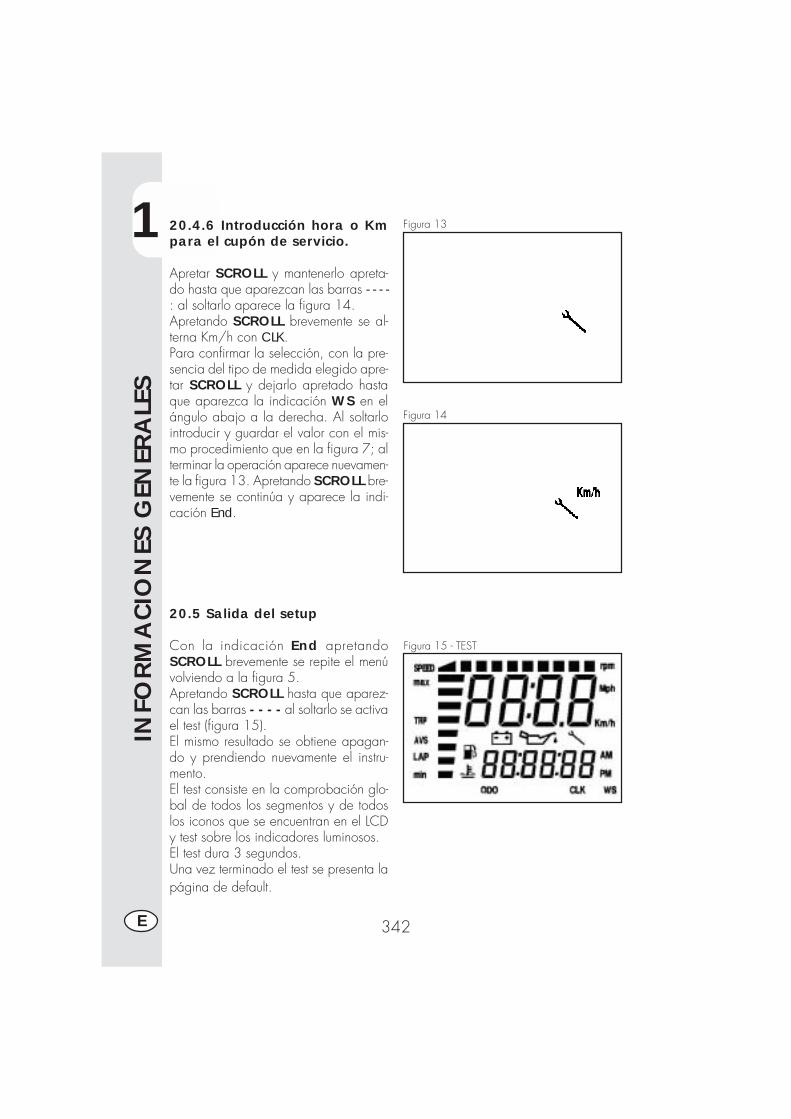
1
INFO
RM
ACIO
NES
GEN
ERA
LES
342E
20.4.6 Introducción hora o Kmpara el cupón de servicio.
Apretar SCROLL y mantenerlo apreta-do hasta que aparezcan las barras - - - -: al soltarlo aparece la figura 14.Apretando SCROLL brevemente se al-terna Km/h con CLK.Para confirmar la selección, con la pre-sencia del tipo de medida elegido apre-tar SCROLL y dejarlo apretado hastaque aparezca la indicación WS en elángulo abajo a la derecha. Al soltarlointroducir y guardar el valor con el mis-mo procedimiento que en la figura 7; alterminar la operación aparece nuevamen-te la figura 13. Apretando SCROLL bre-vemente se continúa y aparece la indi-cación End.
20.5 Salida del setup
Con la indicación End apretandoSCROLL brevemente se repite el menúvolviendo a la figura 5.Apretando SCROLL hasta que aparez-can las barras - - - - al soltarlo se activael test (figura 15).El mismo resultado se obtiene apagan-do y prendiendo nuevamente el instru-mento.El test consiste en la comprobación glo-bal de todos los segmentos y de todoslos iconos que se encuentran en el LCDy test sobre los indicadores luminosos.El test dura 3 segundos.Una vez terminado el test se presenta lapágina de default.
Figura 13
Figura 14
Figura 15 - TEST
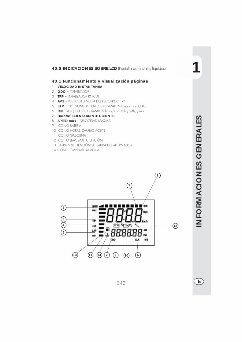
1
INFO
RM
ACIO
NES
GEN
ERA
LES
343 E
40.0 INDICACIONES SOBRE LCD (Pantalla de cristales líquidos)
40.1 Funcionamiento y visualización páginas1 VELOCIDAD INSTANTÁNEA2 ODO – TOTALIZADOR3 TRP – TOTALIZADOR PARCIAL4 AVS – VELOCIDAD MEDIA DEL RECORRIDO TRP5 LAP – CRONOMETRO EN LOS FORMATOS h:m:s y m:s:1/10s6 CLK –RELOJ EN LOS FORMATOS h:m:s, con 12h y 24h, y m:s7 BARRAS CUENTARREVOLUCIONES8 SPEED max – VELOCIDAD MAXIMA9 ICONO BATERIA10 ICONO HORAS CAMBIO ACEITE11 ICONO GASOLINA12 ICONO LLAVE MANUTENCIÓN13 BARRA NIVEL TENSIÓN DE SALIDA DEL ALTERNADOR14 ICONO TEMPERATURA AGUA
12
10 614
5
4
3
8
1
1113 92
7
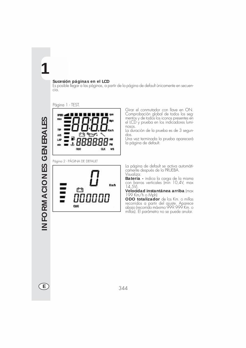
1
INFO
RM
ACIO
NES
GEN
ERA
LES
344E
Sucesión páginas en el LCDEs posible llegar a las páginas, a partir de la página de default únicamente en secuen-cia.
Girar el conmutador con llave en ON.Comprobación global de todos los seg-mentos y de todos los iconos presentes enel LCD y prueba en los indicadores lumi-nosos.La duración de la prueba es de 3 segun-dos.Una vez terminada la prueba aparecerála página de default.
La página de default se activa automáti-camente después de la PRUEBA.Visualiza:Batería - indica la carga de la mismacon barras verticales (min 10,4V, max14,5V).Velocidad instantánea arriba (max199 Km/h o Mph)ODO totalizador de los Km. o millasrecorridos a partir del ajuste. Apareceabajo (recorrido máximo 999.999 Km. omillas). El parámetro no se puede anular.
Página 1 - TEST.
Página 2 - PÁGINA DE DEFAULT
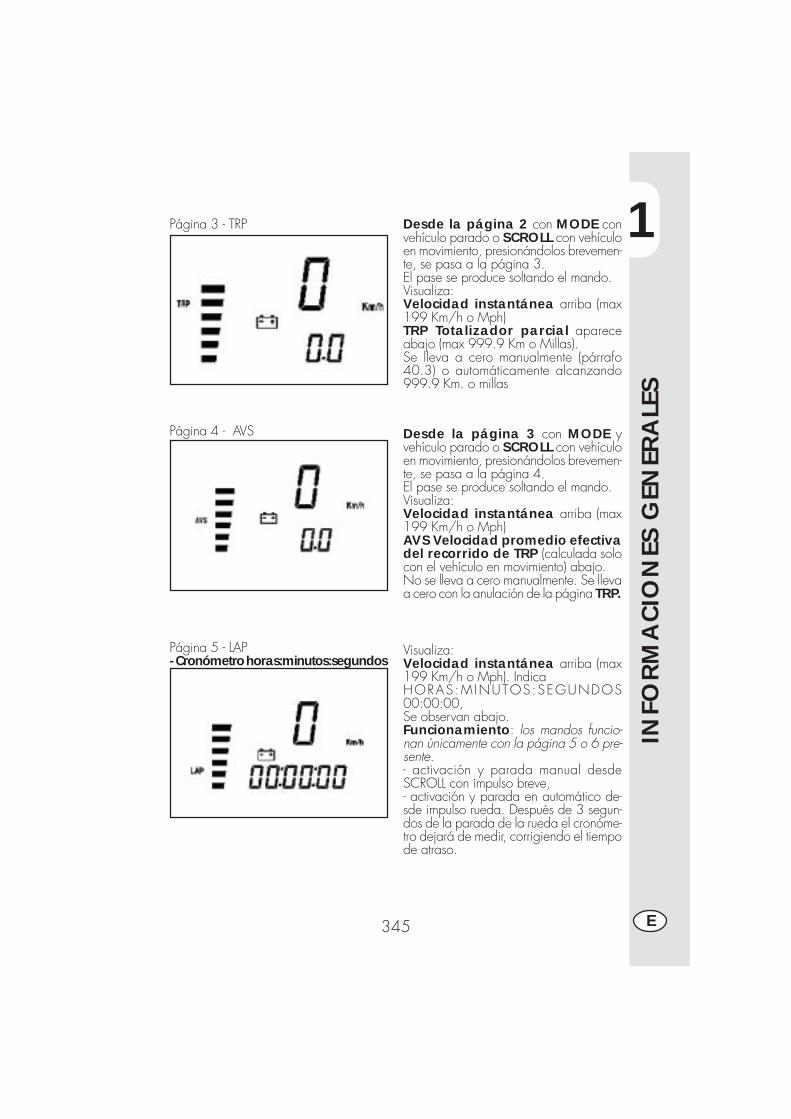
1
INFO
RM
ACIO
NES
GEN
ERA
LES
345 E
Página 3 - TRP
Página 4 - AVS
Página 5 - LAP- Cronómetro horas:minutos:segundos
Desde la página 2 con MODE convehículo parado o SCROLL con vehículoen movimiento, presionándolos brevemen-te, se pasa a la página 3.El pase se produce soltando el mando.Visualiza:Velocidad instantánea arriba (max199 Km/h o Mph)TRP Totalizador parcial apareceabajo (max 999.9 Km o Millas).Se lleva a cero manualmente (párrafo40.3) o automáticamente alcanzando999.9 Km. o millas
Desde la página 3 con MODE yvehículo parado o SCROLL con vehículoen movimiento, presionándolos brevemen-te, se pasa a la página 4.El pase se produce soltando el mando.Visualiza:Velocidad instantánea arriba (max199 Km/h o Mph)AVS Velocidad promedio efectivadel recorrido de TRP (calculada solocon el vehículo en movimiento) abajo.No se lleva a cero manualmente. Se llevaa cero con la anulación de la página TRP.
Visualiza:Velocidad instantánea arriba (max199 Km/h o Mph). IndicaHORAS:MINUTOS:SEGUNDOS00:00:00,Se observan abajo.Funcionamiento: los mandos funcio-nan únicamente con la página 5 o 6 pre-sente.- activación y parada manual desdeSCROLL con impulso breve,- activación y parada en automático de-sde impulso rueda. Después de 3 segun-dos de la parada de la rueda el cronóme-tro dejará de medir, corrigiendo el tiempode atraso.
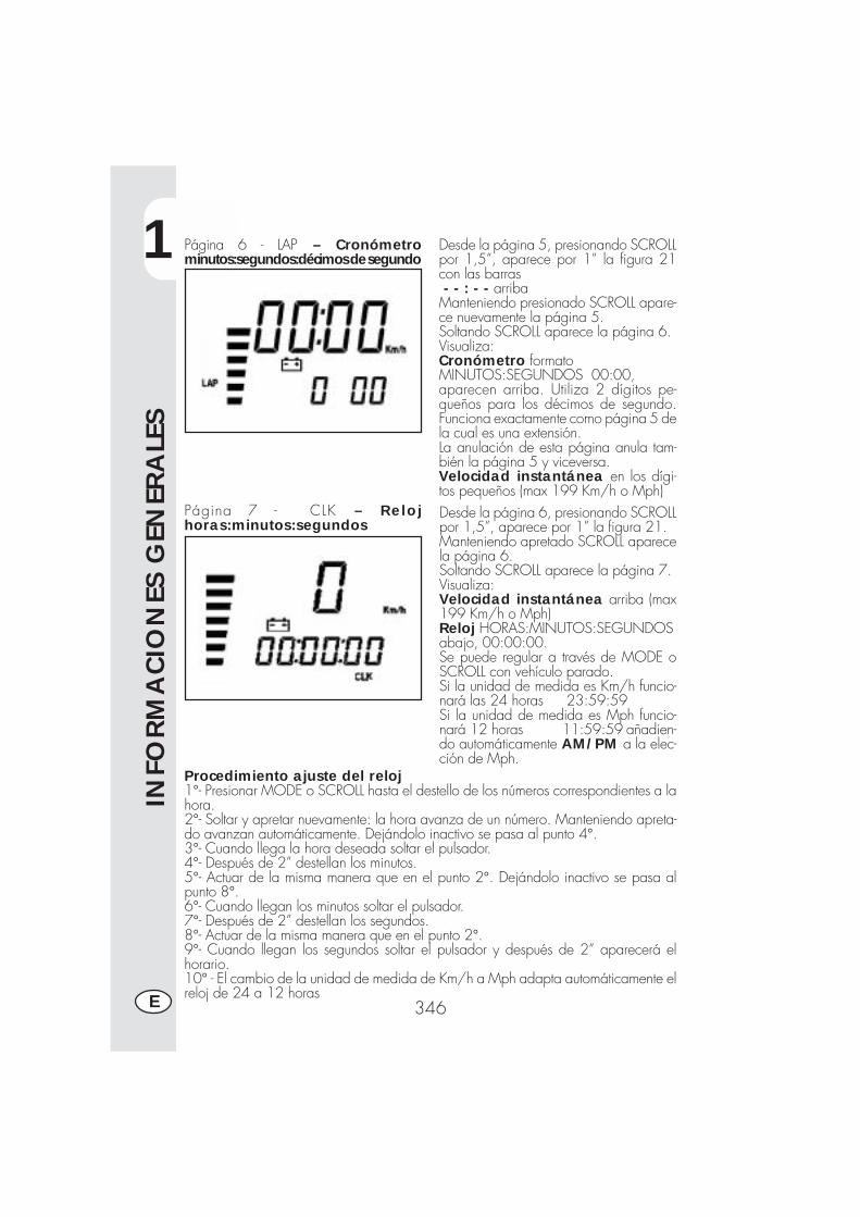
1
INFO
RM
ACIO
NES
GEN
ERA
LES
346E
Página 6 - LAP – Cronómetrominutos:segundos:décimos de segundo
Página 7 - CLK – Relojhoras:minutos:segundos
Desde la página 5, presionando SCROLLpor 1,5”, aparece por 1” la figura 21con las barras - - : - - arribaManteniendo presionado SCROLL apare-ce nuevamente la página 5.Soltando SCROLL aparece la página 6.Visualiza:Cronómetro formatoMINUTOS:SEGUNDOS 00:00,aparecen arriba. Utiliza 2 dígitos pe-queños para los décimos de segundo.Funciona exactamente como página 5 dela cual es una extensión.La anulación de esta página anula tam-bién la página 5 y viceversa.Velocidad instantánea en los dígi-tos pequeños (max 199 Km/h o Mph)Desde la página 6, presionando SCROLLpor 1,5”, aparece por 1” la figura 21.Manteniendo apretado SCROLL aparecela página 6.Soltando SCROLL aparece la página 7.Visualiza:Velocidad instantánea arriba (max199 Km/h o Mph)Reloj HORAS:MINUTOS:SEGUNDOSabajo, 00:00:00.Se puede regular a través de MODE oSCROLL con vehículo parado.Si la unidad de medida es Km/h funcio-nará las 24 horas 23:59:59Si la unidad de medida es Mph funcio-nará 12 horas 11:59:59 añadien-do automáticamente AM/PM a la elec-ción de Mph.
Procedimiento ajuste del reloj1°- Presionar MODE o SCROLL hasta el destello de los números correspondientes a lahora.2°- Soltar y apretar nuevamente: la hora avanza de un número. Manteniendo apreta-do avanzan automáticamente. Dejándolo inactivo se pasa al punto 4°.3°- Cuando llega la hora deseada soltar el pulsador.4°- Después de 2” destellan los minutos.5°- Actuar de la misma manera que en el punto 2°. Dejándolo inactivo se pasa alpunto 8°.6°- Cuando llegan los minutos soltar el pulsador.7°- Después de 2” destellan los segundos.8°- Actuar de la misma manera que en el punto 2°.9°- Cuando llegan los segundos soltar el pulsador y después de 2” aparecerá elhorario.10° - El cambio de la unidad de medida de Km/h a Mph adapta automáticamente elreloj de 24 a 12 horas
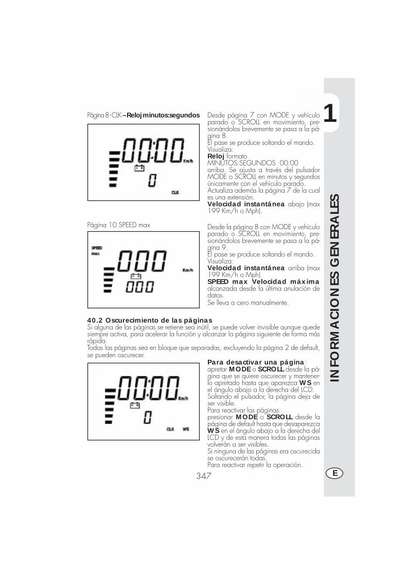
1
INFO
RM
ACIO
NES
GEN
ERA
LES
347 E
Página 8 - CLK – Reloj minutos:segundos
Página 10 SPEED max
Desde página 7 con MODE y vehículoparado o SCROLL en movimiento, pre-sionándolos brevemente se pasa a la pá-gina 8.El pase se produce soltando el mando.Visualiza:Reloj formatoMINUTOS:SEGUNDOS 00:00arriba. Se ajusta a través del pulsadorMODE o SCROLL en minutos y segundosúnicamente con el vehículo parado.Actualiza además la página 7 de la cuales una extensión.Velocidad instantánea abajo (max199 Km/h o Mph).
Desde la página 8 con MODE y vehículoparado o SCROLL en movimiento, pre-sionándolos brevemente se pasa a la pá-gina 9.El pase se produce soltando el mando.Visualiza:Velocidad instantánea arriba (max199 Km/h o Mph)SPEED max Velocidad máximaalcanzada desde la última anulación dedatos.Se lleva a cero manualmente.
40.2 Oscurecimiento de las páginasSi alguna de las páginas se retiene sea inútil, se puede volver invisible aunque quedesiempre activa, para acelerar la función y alcanzar la página siguiente de forma másrápida.Todas las páginas sea en bloque que separadas, excluyendo la página 2 de default,se pueden oscurecer.
Para desactivar una página:apretar MODE o SCROLL desde la pá-gina que se quiere oscurecer y mantener-lo apretado hasta que aparezca WS enel ángulo abajo a la derecha del LCD.Soltando el pulsador, la página deja deser visible.Para reactivar las páginas:presionar MODE o SCROLL desde lapágina de default hasta que desaparezcaWS en el ángulo abajo a la derecha delLCD y de esta manera todas las páginasvolverán a ser visibles.Si ninguna de las páginas era oscurecidase oscurecerán todas.Para reactivar repetir la operación.
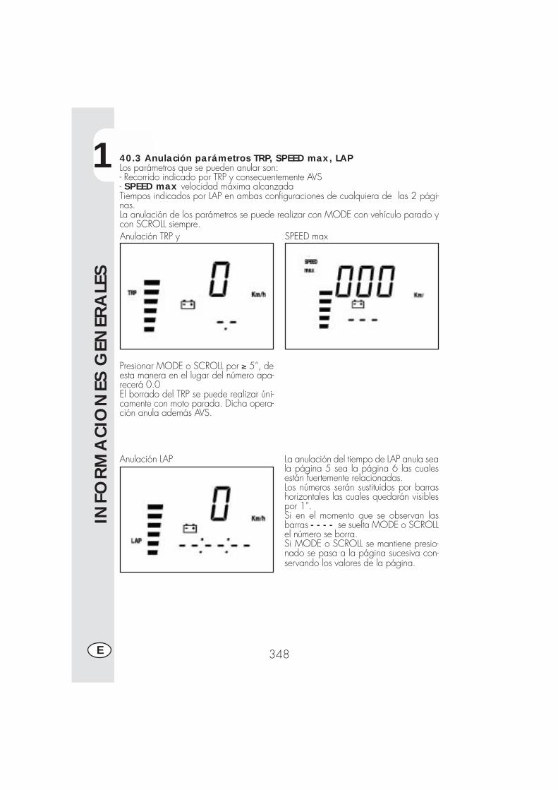
1
INFO
RM
ACIO
NES
GEN
ERA
LES
348E
40.3 Anulación parámetros TRP, SPEED max, LAPLos parámetros que se pueden anular son:- Recorrido indicado por TRP y consecuentemente AVS- SPEED max velocidad máxima alcanzadaTiempos indicados por LAP en ambas configuraciones de cualquiera de las 2 pági-nas.La anulación de los parámetros se puede realizar con MODE con vehículo parado ycon SCROLL siempre.Anulación TRP y SPEED max
Presionar MODE o SCROLL por ≥ 5”, deesta manera en el lugar del número apa-recerá 0.0El borrado del TRP se puede realizar úni-camente con moto parada. Dicha opera-ción anula además AVS.
Anulación LAP La anulación del tiempo de LAP anula seala página 5 sea la página 6 las cualesestán fuertemente relacionadas.Los números serán sustituidos por barrashorizontales las cuales quedarán visiblespor 1”.Si en el momento que se observan lasbarras - - - - se suelta MODE o SCROLLel número se borra.Si MODE o SCROLL se mantiene presio-nado se pasa a la página sucesiva con-servando los valores de la página.
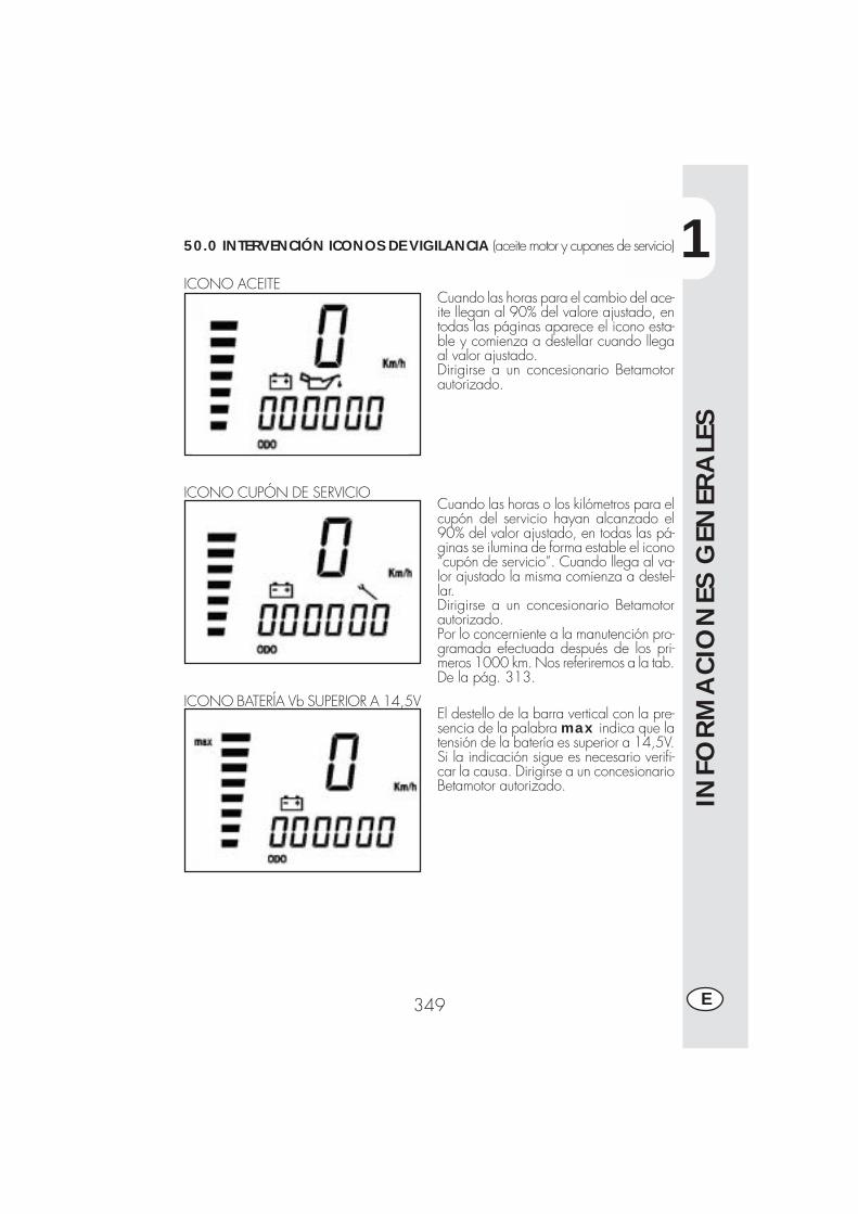
1
INFO
RM
ACIO
NES
GEN
ERA
LES
349 E
50.0 INTERVENCIÓN ICONOS DE VIGILANCIA (aceite motor y cupones de servicio)
ICONO ACEITECuando las horas para el cambio del ace-ite llegan al 90% del valore ajustado, entodas las páginas aparece el icono esta-ble y comienza a destellar cuando llegaal valor ajustado.Dirigirse a un concesionario Betamotorautorizado.
Cuando las horas o los kilómetros para elcupón del servicio hayan alcanzado el90% del valor ajustado, en todas las pá-ginas se ilumina de forma estable el icono“cupón de servicio”. Cuando llega al va-lor ajustado la misma comienza a destel-lar.Dirigirse a un concesionario Betamotorautorizado.Por lo concerniente a la manutención pro-gramada efectuada después de los pri-meros 1000 km. Nos referiremos a la tab.De la pág. 313.
ICONO CUPÓN DE SERVICIO
ICONO BATERÍA Vb SUPERIOR A 14,5VEl destello de la barra vertical con la pre-sencia de la palabra max indica que latensión de la batería es superior a 14,5V.Si la indicación sigue es necesario verifi-car la causa. Dirigirse a un concesionarioBetamotor autorizado.
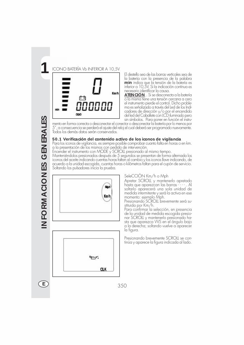
1
INFO
RM
ACIO
NES
GEN
ERA
LES
350E
ICONO BATERÍA Vb INFERIOR A 10,5VEl destello sea de las barras verticales sea dela batería con la presencia de la palabramin indica que la tensión de la batería esinferior a 10,5V. Si la indicación continua esnecesario identificar la causa.ATENCIÓN.. Si se desconecta a la bateríao la misma tiene una tensión cercana a ceroel instrumento pierde el control. Dicho proble-ma es señalizado a través del Led de los Indi-cadores de dirección y/o por el encendidodel led del Caballete con LCD iluminado perosin símbolos. Para poner en función el instru-
mento en forma correcta o desconectar el conector o desconectar la batería por lo menos por5”, a consecuencia se perderá el ajuste del reloj el cual deberá ser programado nuevamente.Todos los demás datos serán conservados.
50.1 Verificación del contenido activo de los iconos de vigilanciaPara los iconos de vigilancia, es siempre posible comprobar cuanto falta en horas o en km.a la presentación de los mismos con pedido de intervención.Encender el instrumento con MODE y SCROLL presionado al mismo tiempo.Manteniéndolos presionados después de 5 segundos se presentan de forma alternada losiconos del aceite indicando cuentas horas faltan al cambio y los iconos llave indicando, deacuerdo a la unidad escogida, cuantas horas o kilómetros faltan para el cupón de servicio.Soltando los pulsadores inicia la prueba.
SeleCCIÓN Km/h o MphApretar SCROLL y mantenerlo apretadohasta que aparezcan las barras - - - - . Alsoltarlo aparecerá una sola unidad demedida intermitente y será la activa en esemomento: ejemplo Mph.Presionando SCROLL brevemente será su-stituida por Km/h.Para confirmar la selección, en presenciade la unidad de medida escogida presio-nar SCROLL y mantenerlo presionado ha-sta que aparezca WS en el ángulo bajoa la derecha; soltando vuelve a aparecerla figura.
Presionando brevemente SCROLL se con-tinúa y aparece la figura indicada al lado.
1
INFO
RM
ACIO
NES
GEN
ERA
LES
351 E
DATOS TECNICOS
CARGA MAXIMAConductor + pasajero.................................................................. 280 (kgs)
PESO DEL VEHICULOPeso total en vacío ALP 200 ......................................................... 103 (kgs)Peso total en vacío ALP 125 ......................................................... 101 (kgs)
DIMENSIONESLongitud total ............................................................................. 2143 mmAnchura total ............................................................................... 820 mmAltura total ................................................................................ 1170 mmDistancia entre ejes .................................................................... 1372 mmAltura sillín .................................................................................. 836 mmDistancia al terreno ...................................................................... 288 mm
BASTIDOR.................. ................................ de acero de doble cuna cerrada
NEUMATICOSTipo......................... .....................................Michelin - Trial Competition TTPresión bar .................................................................. del. 0,8 / tras. 0,6Presión bar cargado ...................................................... del. 1,3 / tras. 1,3Dimensiones..................... ........................... del. 2,75 - 21" / tras. 4,00-18"
Tipo ................................................................................. PIRELLI ScorpionPresión bar .................................................................. del. 1,6 / tras. 1,8Presión bar cargado ...................................................... del. 2,0 / tras. 2,4Dimensiones ...................................... del. 90/90 - 21" / tras. 120/80 - 18"
CAPACIDAD DE LLENADOTanque combustible ........................................................................ 6,8 (lts)De los cuales lts. De reserva ............................................................. 1,5 (lts)Aceite motor ............................................................................... 850 (cc)Consumo promedio ....................................................................25 kms/lt.
1
INFO
RM
ACIO
NES
GEN
ERA
LES
352E
SUSPENSION DELANTERAHorquilla hidráulica con barras de Ø 38 mm, regulación en extención y precargadel muelle.Contenido de aceite:Derecho ....................................................................................... 350 ccIzquierdo ...................................................................................... 350 ccTipo de aceite ........................................................ Bel Ray MC 10 SAE 10 o tambièn LIQUI MOLY RECING SUSPENSION OIL SAE 10WNivel del aceite...................................120 mm del borde superior del tubo de
la horquilla a final de carrera y sin muelle.Antecarrera ........................................................................... 170 ± 3 mm
SUSPENSION TRASERAMonoamortiguador hidráulico progresivo y regulación en extención y precarga delmuelle.Carrera amortiguador ..................................................................... 80 mm
FRENO DELANTERODe disco Ø 220 mm con mando hidráulico
FRENO TRASERODe disco Ø 220 mm con mando hidráulico
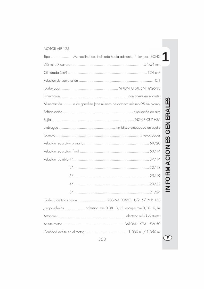
1
INFO
RM
ACIO
NES
GEN
ERA
LES
353 E
MOTOR ALP 125
Tipo .................... Monocilíndrico, inclinado hacia adelante, 4 tiempos, SOHC
Diámetro X carrera .................................................................... 54x54 mm
Cilindrada (cm3) .......................................................................... 124 cm3
Relación de compresión ..................................................................... 10:1
Carburador ...................................................... MIKUNI UCAL 5Nh Ø26-38
Lubricación ............................................................... con aceite en el carter
Alimentación ......... a de gasolina (con número de octanos mínimo 95 sin plomo)
Refrigeración .................................................................. circulación de aire
Bujía.............................................................................. NGK R CR7 HSA
Embrague ..................................................... multidisco empapado en aceite
Cambio .............................................................................. 5 velocidades
Relación reducción primaria ............................................................. 68/20
Relación reducción final ................................................................. 60/14
Relación cambio 1° ....................................................................... 37/14
2° ....................................................................... 32/18
3° ....................................................................... 25/19
4° ....................................................................... 23/22
5° ....................................................................... 21/24
Cadena de transmisión ............................ REGINA DERVIO 1/2, 5/16 P. 138
Juego válvulas ................... admisión mm 0,08 - 0,12 escape mm 0,10 - 0,14
Arranque ................................................................ eléctrico y/o kick-starter
Aceite motor ......................................................... BARDAHL XTM 15W 50
Cantidad aceite en el motor, ........................................ 1,000 ml / 1,050 ml
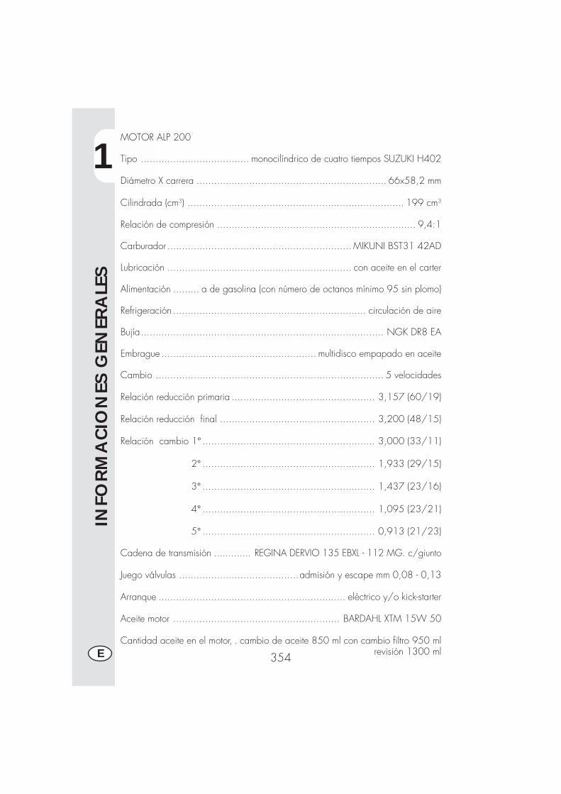
1
INFO
RM
ACIO
NES
GEN
ERA
LES
354E
MOTOR ALP 200
Tipo ..................................... monocilíndrico de cuatro tiempos SUZUKI H402
Diámetro X carrera ................................................................. 66x58,2 mm
Cilindrada (cm3) .......................................................................... 199 cm3
Relación de compresión .................................................................... 9,4:1
Carburador ............................................................... MIKUNI BST31 42AD
Lubricación ............................................................... con aceite en el carter
Alimentación ......... a de gasolina (con número de octanos mínimo 95 sin plomo)
Refrigeración .................................................................. circulación de aire
Bujía................................................................................... NGK DR8 EA
Embrague ..................................................... multidisco empapado en aceite
Cambio .............................................................................. 5 velocidades
Relación reducción primaria ................................................. 3,157 (60/19)
Relación reducción final ..................................................... 3,200 (48/15)
Relación cambio 1° ........................................................... 3,000 (33/11)
2° ........................................................... 1,933 (29/15)
3° ........................................................... 1,437 (23/16)
4° ........................................................... 1,095 (23/21)
5° ........................................................... 0,913 (21/23)
Cadena de transmisión ............. REGINA DERVIO 135 EBXL - 112 MG. c/giunto
Juego válvulas .........................................admisión y escape mm 0,08 - 0,13
Arranque ................................................................ eléctrico y/o kick-starter
Aceite motor ......................................................... BARDAHL XTM 15W 50
Cantidad aceite en el motor, . cambio de aceite 850 ml con cambio filtro 950 mlrevisión 1300 ml

1
INFO
RM
ACIO
NES
GEN
ERA
LES
355 E
SCHEMA ELETTRICO ALP 125
Ne
Bi-N
e
Gi
Bl-N
e
Gr
Bi-N
e
Bl-N
e
Gi
Bi-G
i
Bi-A
r
Bl-V
e
Ne
Ma
Bl-N
e
Az
Bi-B
l
Rs-
Gi
Bi-G
i
Bi-A
r
Bl-V
e
Gr
Ma
Vi
MaM
a-N
eN
e
Ve Vi
Bl-N
e
Ro
Vi
Ve
Rs-
Gi
Bi-B
l
Ro
Az
Bl-N
eB
l
2 61V
e
11B
l-Ne
3N
e-A
r
5M
a-N
e
4 14R
s
13N
e
7M
a-G
i
9G
r-V
e
Bl-N
e
Bl
Ne
MaB
lRs
Bl
Ne
Vi
Gi
Ve
Bi
Bi
Ma
Ne
Gi
Bi B
l Ne N
eR
sVe
Gi
Ve
Gi
Bl
Bi
+-Ne
RsBi
NeN
e Ne
Rs
Bi
Gi
Ve
NeBi
Bl-N
eB L
Rs-
Gi
Az
Ro
Ne
Ar
Ne
Ne
Ro
Vi
Ne
Rs
Ne
Rs
Ne
Gi
Bi
Ne
Ro
Ne
Ro
NeBl
NeBl
NeBl
Rs
Rs
Rs
Ar
Bi
M
Rs
Bi
Bl
Gr-
Ve
Ne
Ne
Bl-N
e
Bi-N
e
Bl-V
eB
l-Ve
Ve
Ne V
iN
e
Gi
NeM
aR
o
Ma V
eNe
Ne
NeVi
Ve
Bi-B
lG
iG
iB
i-Bl
Ve Vi
Ne
Ne
Bi-B
l
Ne
Bi-B
l
Ne
Ne
Ne
Rs
Bi-N
e
Gr
Vi
Gi
Rs
Rs
Az
Ro
Bl
Bi
+
Ne
Ve
Ve
Ne
Bl-N
eG
i
Ne
Ne
Ne Gi
Ne
Bi-B
lG
i
01
2
Bi-R
o
Bl
Ne
Ne
Ro
-+
Ne
1 2
3 4 5 6 7 8 9 10 11 12 13 14 15 16 17 18 19
2221
20
23
25 2426
27
2829
3031
323333
3435
3637383940
4142
4344
4546
4748
49
50
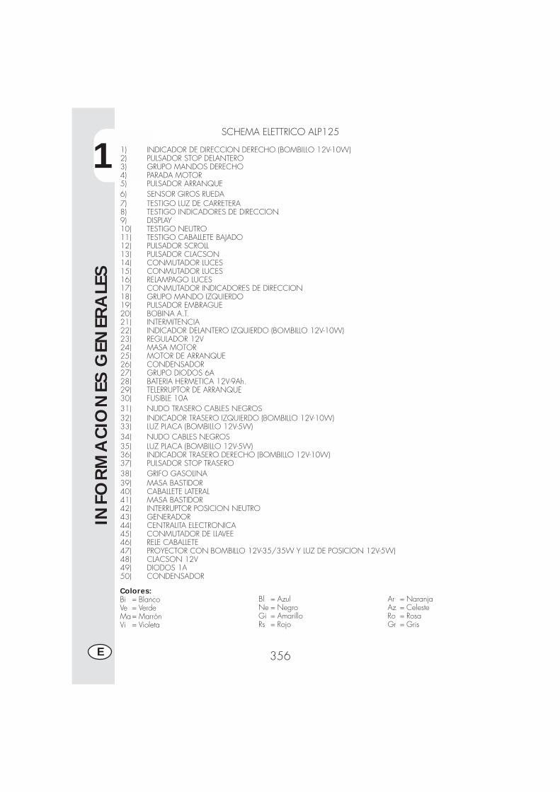
1
INFO
RM
ACIO
NES
GEN
ERA
LES
356E
SCHEMA ELETTRICO ALP125
1) INDICADOR DE DIRECCION DERECHO (BOMBILLO 12V-10W)2) PULSADOR STOP DELANTERO3) GRUPO MANDOS DERECHO4) PARADA MOTOR5) PULSADOR ARRANQUE6) SENSOR GIROS RUEDA7) TESTIGO LUZ DE CARRETERA8) TESTIGO INDICADORES DE DIRECCION9) DISPLAY10) TESTIGO NEUTRO11) TESTIGO CABALLETE BAJADO12) PULSADOR SCROLL13) PULSADOR CLACSON14) CONMUTADOR LUCES15) CONMUTADOR LUCES16) RELAMPAGO LUCES17) CONMUTADOR INDICADORES DE DIRECCION18) GRUPO MANDO IZQUIERDO19) PULSADOR EMBRAGUE20) BOBINA A.T.21) INTERMITENCIA22) INDICADOR DELANTERO IZQUIERDO (BOMBILLO 12V-10W)23) REGULADOR 12V24) MASA MOTOR25) MOTOR DE ARRANQUE26) CONDENSADOR27) GRUPO DIODOS 6A28) BATERIA HERMETICA 12V-9Ah.29) TELERRUPTOR DE ARRANQUE30) FUSIBLE 10A31) NUDO TRASERO CABLES NEGROS32) INDICADOR TRASERO IZQUIERDO (BOMBILLO 12V-10W)33) LUZ PLACA (BOMBILLO 12V-5W)34) NUDO CABLES NEGROS35) LUZ PLACA (BOMBILLO 12V-5W)36) INDICADOR TRASERO DERECHO (BOMBILLO 12V-10W)37) PULSADOR STOP TRASERO38) GRIFO GASOLINA39) MASA BASTIDOR40) CABALLETE LATERAL41) MASA BASTIDOR42) INTERRUPTOR POSICION NEUTRO43) GENERADOR44) CENTRALITA ELECTRONICA45) CONMUTADOR DE LLAVEE46) RELE CABALLETE47) PROYECTOR CON BOMBILLO 12V-35/35W Y LUZ DE POSICION 12V-5W)48) CLACSON 12V49) DIODOS 1A50) CONDENSADOR
Colores:Bi = BlancoVe = VerdeMa= MarrónVi = Violeta
Bl = AzulNe = NegroGi = AmarilloRs = Rojo
Ar = NaranjaAz = CelesteRo = RosaGr = Gris
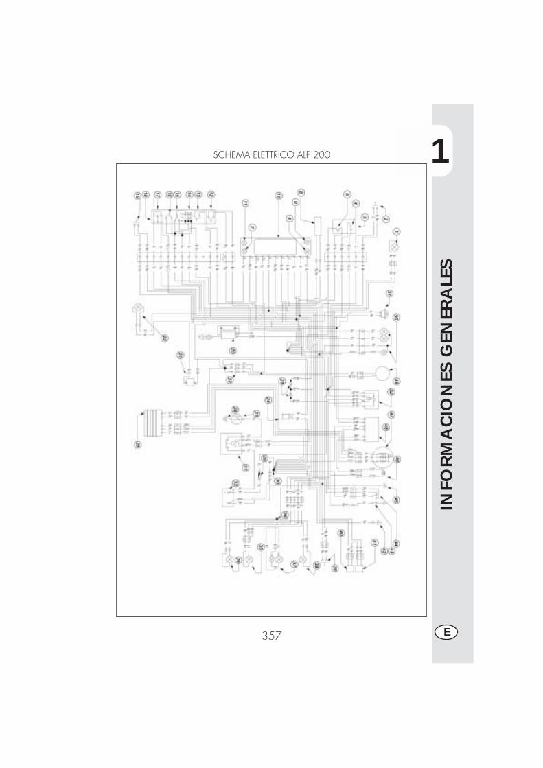
1
INFO
RM
ACIO
NES
GEN
ERA
LES
357 E
SCHEMA ELETTRICO ALP 200
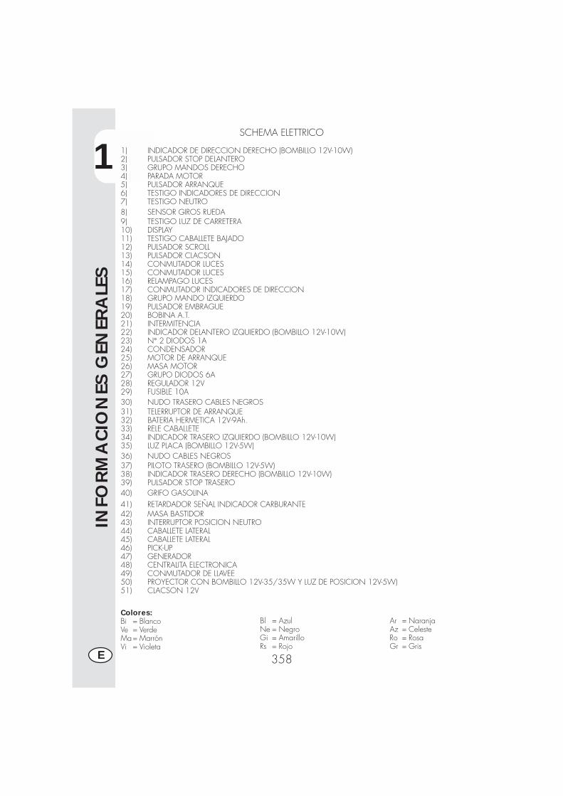
1
INFO
RM
ACIO
NES
GEN
ERA
LES
358E
SCHEMA ELETTRICO
1) INDICADOR DE DIRECCION DERECHO (BOMBILLO 12V-10W)2) PULSADOR STOP DELANTERO3) GRUPO MANDOS DERECHO4) PARADA MOTOR5) PULSADOR ARRANQUE6) TESTIGO INDICADORES DE DIRECCION7) TESTIGO NEUTRO8) SENSOR GIROS RUEDA9) TESTIGO LUZ DE CARRETERA10) DISPLAY11) TESTIGO CABALLETE BAJADO12) PULSADOR SCROLL13) PULSADOR CLACSON14) CONMUTADOR LUCES15) CONMUTADOR LUCES16) RELAMPAGO LUCES17) CONMUTADOR INDICADORES DE DIRECCION18) GRUPO MANDO IZQUIERDO19) PULSADOR EMBRAGUE20) BOBINA A.T.21) INTERMITENCIA22) INDICADOR DELANTERO IZQUIERDO (BOMBILLO 12V-10W)23) N° 2 DIODOS 1A24) CONDENSADOR25) MOTOR DE ARRANQUE26) MASA MOTOR27) GRUPO DIODOS 6A28) REGULADOR 12V29) FUSIBLE 10A30) NUDO TRASERO CABLES NEGROS31) TELERRUPTOR DE ARRANQUE32) BATERIA HERMETICA 12V-9Ah.33) RELE CABALLETE34) INDICADOR TRASERO IZQUIERDO (BOMBILLO 12V-10W)35) LUZ PLACA (BOMBILLO 12V-5W)36) NUDO CABLES NEGROS37) PILOTO TRASERO (BOMBILLO 12V-5W)38) INDICADOR TRASERO DERECHO (BOMBILLO 12V-10W)39) PULSADOR STOP TRASERO40) GRIFO GASOLINA41) RETARDADOR SEÑAL INDICADOR CARBURANTE42) MASA BASTIDOR43) INTERRUPTOR POSICION NEUTRO44) CABALLETE LATERAL45) CABALLETE LATERAL46) PICK-UP47) GENERADOR48) CENTRALITA ELECTRONICA49) CONMUTADOR DE LLAVEE50) PROYECTOR CON BOMBILLO 12V-35/35W Y LUZ DE POSICION 12V-5W)51) CLACSON 12V
Colores:Bi = BlancoVe = VerdeMa= MarrónVi = Violeta
Bl = AzulNe = NegroGi = AmarilloRs = Rojo
Ar = NaranjaAz = CelesteRo = RosaGr = Gris

1
INFO
RM
ACIO
NES
GEN
ERA
LES
359 E
DISPOSITIVOS ELECTRICOS
BATERIADesmontando la batería (A) comodescrito en la página 378, tenemos ac-ceso a la batería.Desenganchar el elástico (B ),desconectar los cables y quitar la batería.ATENCIÓN:Para evitar daños a la instalacióneléctrica, no desconectar nunca loscables con el motor en marcha.Colocar nuevamente la batería (A) en sualojamiento debajo de asiento y fijarlacon el elástico (B).Conectar el terminal de los cables decolor negro en el negativo (-) y los doscables rojos en el positivo (+) y luegocolocar la protección (ver el dibujo).
AL NEGATIVO (--)DE LA BATERIA(cablesnegros)
PROTECCION
AL POSITIVO (+)DE LA BATERIA(cables rojos)
POSICIONBATERIA
BA

1
INFO
RM
ACIO
NES
GEN
ERA
LES
360E
CENTRALITA - TELERRUPTOR DEARRANQUE - REGULADORLa centralita (C), el relé de arranque (D)y el regulador de voltaje (E ) seencuentran ubicados en el lado derechodel vehículo, para acceder a dichoscomponentes es necesario desmontarel asiento y el panel trasero comoindicado en la página 378.
BOBINA A.T.Para acceder a la bobina (F) esnecesario desmontar el deposito delcarburante como descrito en la página378.
FUSIBLE - INTERMITENCIA - RELECABALLETELa intermitencia (G), el relé delcaballete (H) y la caja de fusibles (I) seencuentran ubicados debajo de lacentralita, por tanto para una eventualsustitución de dichos componentes esnecesario desmontar el asiento y elpanel lateral trasero como indicado enla página 378, y luego liberar lacentralita (C) del soporte de goma.
C
D
E
F
GH
I
2
UTI
LIZ
ACIO
N D
EL V
EHIC
ULO
361 E
INDICE ARGUMENTOS
CAP. 2 UTILIZACION DEL VEHICULO
Controles y manutención antes y después de la utilización en todo terreno
Lubricantes y líquidos aconsejados.
Rodaje.
Arranque del motor.
Parada del motor.
Abastecimiento combustible
2
UTI
LIZ
ACIO
N D
EL V
EHIC
ULO
362E
COMPROBACIONES Y MANUTENCION ANTES Y DESPUES DE LA UTILIZACIONEN TODO TERRENO
Para evitar desagradables inconvenientes durante el funcionamiento del vehículo seaconseja efectuar, sea antes que después del uso, algunas operaciones de controly manutención. En efecto, pocos minutos dedicados a ésta operación, además deobtener una conducción mas segura, pueden hacerle ahorrar tiempo y dinero. Porlo tanto proceder de la siguiente manera:
NEUMATICOS verificar la presión, las condiciones generales y el espe-sor de la banda de rodadura.
RAYOS verificar el correcto tensionamiento.CONJUNTO DE PERNOS verificar el apriete de todos los pernos.CADENA verificar el tensionamiento (juego 20 mm) y si es nece-
sario engrasar.FILTRO DEL AIRE limpiar el filtro y empaparlo en aceite.
Nota:Verificar la presencia de los documentos de identificación del vehículo.En los dias frios se aconseja antes de la salida, calentar el motor dejandolo enfunción en ralentí por algunos instantes. Cada vez que utilizamos el vehículo entodo terreno es necesario lavarlo con muy bien.
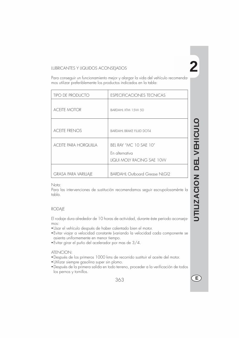
2
UTI
LIZ
ACIO
N D
EL V
EHIC
ULO
363 E
TIPO DE PRODUCTO ESPECIFICACIONES TECNICAS
ACEITE MOTOR BARDAHL XTM 15W 50
ACEITE FRENOS BARDAHL BRAKE FLUID DOT4
ACEITE PARA HORQUILLA BEL RAY “MC 10 SAE 10”
En alternativa
LIQUI MOLY RACING SAE 10W
GRASA PARA VARILLAJE BARDAHL Outboard Grease NLGI2
LUBRICANTES Y LIQUIDOS ACONSEJADOS
Para conseguir un funcionamiento mejor y alargar la vida del vehículo recomenda-mos utilizar preferiblemente los productos indicados en la tabla:
Nota:Para las intervenciones de sustitución recomendamos seguir escrupolosaménte latabla.
RODAJE
El rodaje dura alrededor de 10 horas de actividad, durante éste periodo aconseja-mos:�Usar el vehículo después de haber calentado bien el motor.�Evitar viajar a velocidad constante (variando la velocidad cada componente seasienta uniformemente en menor tiempo.
�Evitar girar el puño del acelerador por mas de 3/4.
ATENCION:�Después de los primeros 1000 kms de recorrido sustituir el aceite del motor.�Utilizar siempre gasolina super sin plomo.�Después de la primera salida en todo terreno, proceder a la verificación de todoslos pernos y tornillos.

2
UTI
LIZ
ACIO
N D
EL V
EHIC
ULO
364E
ARRANQUE DEL MOTOR
�Girar la llave del conmutador en elsentido de las agujas del reloj ycerciorarse que la luz testigo del puntomuerto, ubicada en el panel deinstrumentos, esté prendida (verindicación 9 en la página 332).
�Colocar el interruptor de emergencia,ubicado sobre el mando del gas, enposición (0).
�Girar el grifo del combustible A:OFF = cerradoON = abierto
�Tirar hacia el externo el botón del startB, colocado en el carburador del ladoizquierdo, hasta la segunda posición.
�En los modelos ALP125 para accionarla palanca start B es necesarioempujarla hacia el interior.
�Tirar la palanca del embrague y almismo tiempo empujar el pulsador dearranque sobre el mando gas sin girarel puño del gas (para vehículos sola-mente con arranque eléctrico).
�Actuar en la palanca de arranque,empujando con el pié un golpe fuerte yluego plegar la palanca misma (paravehículos con palanca de arranque).
Atención:En el caso se utilice kit estribo desplaza-do hacia atras (para trial) levantar elestribo apoyapié derecho para permitirla rotación de la palanca arranque motor.�Esperar unos 2 minutos para recalentar elmotor sin girar el puño del gas y luegobajar el start B parandose en la primeraposición.
Nota:La puesta en marcha se realiza tambiéncon el caballete bajado, siempre que estéprendida la luz testigo del punto muerto.
A
B
ALP200
ALP200
A
ALP125
B
2
UTI
LIZ
ACIO
N D
EL V
EHIC
ULO
365 E
Advertencia:Con el caballete bajado, el testigo rojoen el tablero queda prendido y por razo-nes de seguridad el motor se apaga en elmomento que se introduce la marcha, in-clusive con la palanca del embrague tira-da.Por lo tanto es necesario cerrar el caballe-te y luego poner la marcha.
Nota:En caso de emergencia, éste vehículopuede funcionar también sin usar la bate-ría.
PARADA DEL MOTOR
�Parados, con el cambio en neutro, girarla llave en el conmutador en posición“OFF”.
�Después de un largo recorrido, antes deapagar el motor, es aconsejable dejarlogirar por algunos instantes.
�Con el motor parado cerrar siempre elgrifo del combustible.

2
UTI
LIZ
ACIO
N D
EL V
EHIC
ULO
366E
A
ABASTECIMIENTO DEL COMBUSTIBLE
�Apagar el motor.�Quitar la tapa A.
Nota:La capacidad del tanque es de unos 6,8litros de los cuales 1,5 de reserva.
Eventuales desbordamientos de gasolinaencima de la carrocería u otras partes,deben ser quitadas inmediatamente.
Antes de abastecer gasolina apagar elmotor.La gasolina es extremamente inflamable.Evitar derramar gasolina del deposito odurante el abastecimiento.
No acercarse a la boca del tanque conllamas libres o cigarrillos encendidos: pe-ligro de incendio.Evitar también de respirar vapores noci-vos.

3
CO
NTR
OLE
S Y
MA
NU
TEN
CIO
N
367 E
INDICE DE LOS ARGUMENTOS
CAP. 3 CONTROLES Y MANUTENCION
Aceite y filtro aceite
Tubo recolección humo
Aceite bomba frenos, espurgo frenos
Aceite horquilla
Filtro aire
Bujía
Frenos: delantero, trasero
Batería
Remoción carrocería
Nota para trial
Limpieza del vehículo y comprobaciones
Manutención programada
Larga inactividad del vehículo

3
CO
NTR
OLE
S Y
MA
NU
TEN
CIO
N
368E
ACEITE MOTOR Y FILTRO ACEITE ALP200
VerificaciónTener el vehículo en posición vertical conrespecto al terreno. Con el motor friocontrolar por medio de la mirilla el niveldel aceite A, el nivel del aceite que nodebe bajar nunca por debajo de la miri-lla. Para restablecer el nivel proceder alllenado a travez de la tapa de carga B.
LlenadoEventuales restablecimientos del nivel sedeben efectuar después del control delnivel max. indicado en la mirilla A.
SustituciónEfectuar siempre la sustitución del aceitecon el motor caliente, prestando atenciónen no tocar el motor y el mismo aceitepara evitar quemaduras.� La sustitución del filtro del aceite deberíarealizarse junto con la sustitución delaceite.
�Colocar la moto sobre el caballete.�Quitar la protección C, después de ha-ber quitado los dos tornillos D y la fija-ción E.
�Colocar un contenedor debajo del mo-tor.
�Destornillar el tapón de llenado B y devaciado F.
�Vaciar completamente el carter.�Cerrar el tapón F.�Quitar la tapa del filtro aceite destorni-llando las 3 tuercas de fijación G.
�Quitar el filtro e introducir uno nuevo.� Lubricar con aceite del motor el O-Ringde la tapa del filtro antes del montaje.
�Colocar la tapa del filtro después de
B
GA
C
D
E
F

3
CO
NTR
OLE
S Y
MA
NU
TEN
CIO
N
369 E
haber montadomuelle y Oring y apretarlas tres tuercas de fijación.
� Introducir la correcta cantidad de aceite.�Cerrar el tapón de llenado, colocar nue-vamente la protección teniendo cuidadoen posicionar los distanciadores en lasecuencia correcta.
�Arrancar el motor dejandolo girar poralgunos minutos antes de apagarlo.
�Apagar el motor y esperar un minuto lue-go verificar el nivel y eventualmentehechar mas aceite sin sobrepasar el ni-vel max.cantidad aceite motor...............850 mlcon cambio filtro.....................950 mlrevisión.................................1300 ml
Nota:Después de los primeros 1000 kms de re-corrido sustituir el aceite del motor. Las sus-tituciones siguientes deberán realizarse acada 5000 kms15 meses, (ver tabla pag.382) utilizando lubricantes aconsejados enpag. 363.En cambio para el filtro de aceite la pri-mera sustitución se debe realizar junto alaceite motor, las siguientes cada 10.000kms (30 meses).
Advertencia:Eliminar el aceite usado respetando lasnormas vigentes.
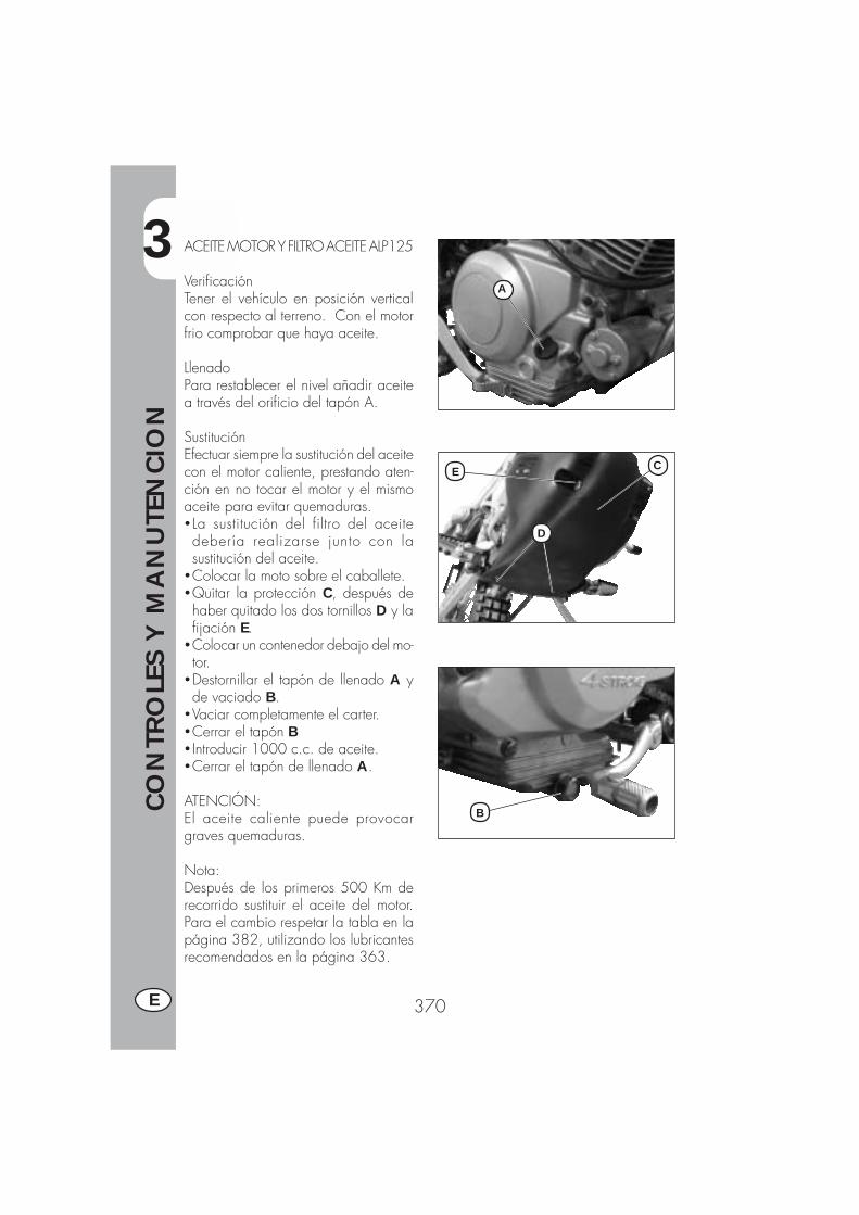
3
CO
NTR
OLE
S Y
MA
NU
TEN
CIO
N
370E
ACEITE MOTOR Y FILTRO ACEITE ALP125
VerificaciónTener el vehículo en posición verticalcon respecto al terreno. Con el motorfrio comprobar que haya aceite.
LlenadoPara restablecer el nivel añadir aceitea través del orificio del tapón A.
SustituciónEfectuar siempre la sustitución del aceitecon el motor caliente, prestando aten-ción en no tocar el motor y el mismoaceite para evitar quemaduras.� La sustitución del filtro del aceitedebería realizarse junto con lasustitución del aceite.
�Colocar la moto sobre el caballete.�Quitar la protección C, después dehaber quitado los dos tornillos D y lafijación E.
�Colocar un contenedor debajo del mo-tor.
�Destornillar el tapón de llenado A yde vaciado B.
�Vaciar completamente el carter.�Cerrar el tapón B� Introducir 1000 c.c. de aceite.�Cerrar el tapón de llenado A.
ATENCIÓN:El aceite caliente puede provocargraves quemaduras.
Nota:Después de los primeros 500 Km derecorrido sustituir el aceite del motor.Para el cambio respetar la tabla en lapágina 382, utilizando los lubricantesrecomendados en la página 363.
A
C
D
E
B

3
CO
NTR
OLE
S Y
MA
NU
TEN
CIO
N
371 E
TUBO RECOLECCIÓN HUMOEl tubo para la recolección de humo Aestá ubicado en la parte izquierda delvehículo cerca del amortiguador, sale porla parte inferior de la caja del filtro yrecoge el gas producido por el aceitedel motor. En caso de presencia de aceiteen el interior del tubo, éste debe servaciado quitando el tapón en la puntainferior y dejando salir el aceite o lamezcla de aceite gasolina en una reci-piente adapto y eliminarlo según lasnormas en vigor.Nota:Efectuar el vaciado a cada 3000 kms.
ACEITE BOMBA FRENOS, ESPURGOFRENOSFarol delanteroControlar a traves de la mirilla el nivel Ala presencia de aceite. El nivel mínimodel aceite no debe ser nunca inferior ala referencia marcada en la mirilla A.Para restablecer el nivel proceder alllenado destornillando los dos tornillos Blevantando la tapa C y colocar el aceite.Freno traseroVerificar la existencia de aceite en el con-tenedor D. El nivel del aceite no debeser nunca inferior a la marca del nivelmínimo que se encuentra en elcontenedor D. Para restablecer el nivelproceder al llenado a traves de la tapade llenado E.ATENCION:En el caso que se notara una escasa re-sistencia accionando la palanca del fre-no, el defecto podría ser provocado poruna burbuja de aire en el circuito. Es ne-cesario entonces dirigirse antes posiblea un taller autorizado.Nota:Para la sustitución seguir la tabla a pag.382 utilizando los lubricantes aconseja-dos en pag. 363.
A
C
BA
DE

3
CO
NTR
OLE
S Y
MA
NU
TEN
CIO
N
372E
DC
A
B
Espurgo freno delanteroPara quitar aire del circuito del freno de-lantero proceder de la siguiente manera:�Quitar el capuchón de goma A de laválvula B
�Abrir el tapón del recipiente de aceite� Introducir una extremidad de un tubo enla válvula B y la otra en el interior de uncontenedor.
�Destornillar la válvula B (con palanca ti-rada) y bombear con la palanca del fre-no hasta que salga aceite sin burbujasde aire; durante ésta operación es im-portante no soltar completamente la pa-lanca, rellenar continuamente el recipien-te del aceite de la bomba del freno paracompensar el aceite salido.
�Apretar la válvula y extraer el tubo�Volver a colocar el capuchón.
Espurgo freno traseroPara quitar aire del circuito del freno tra-sero proceder de la siguiente manera:�Quitar el capuchón de goma C�Abrir la tapa del recipiente de aceite� Introducir una extremidad de un tubo enla válvula D y la otra en el interior de uncontenedor.
�Destornillar la válvula D (con palanca ti-rada) y bombear con la palanca del fre-no hasta que salga aceite sin burbujasde aire; durante ésta operación es im-portante no soltar completamente la pa-lanca, rellenar continuamente el recipien-te del aceite de la bomba del freno paracompensar el aceite salido.
�Apretar la válvula y extraer el tubo�Volver a colocar el capuchón.
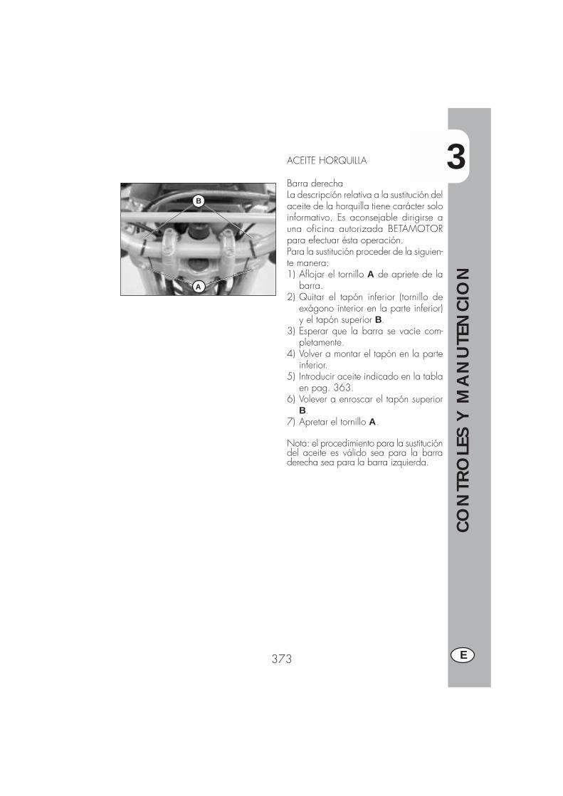
3
CO
NTR
OLE
S Y
MA
NU
TEN
CIO
N
373 E
ACEITE HORQUILLA
Barra derechaLa descripción relativa a la sustitución delaceite de la horquilla tiene carácter soloinformativo. Es aconsejable dirigirse auna oficina autorizada BETAMOTORpara efectuar ésta operación.Para la sustitución proceder de la siguien-te manera:1) Aflojar el tornillo A de apriete de la
barra.2) Quitar el tapón inferior (tornillo de
exágono interior en la parte inferior)y el tapón superior B.
3) Esperar que la barra se vacie com-pletamente.
4) Volver a montar el tapón en la parteinferior.
5) Introducir aceite indicado en la tablaen pag. 363.
6) Volever a enroscar el tapón superiorB.
7) Apretar el tornillo A.
Nota: el procedimiento para la sustitucióndel aceite es válido sea para la barraderecha sea para la barra izquierda.
B
A
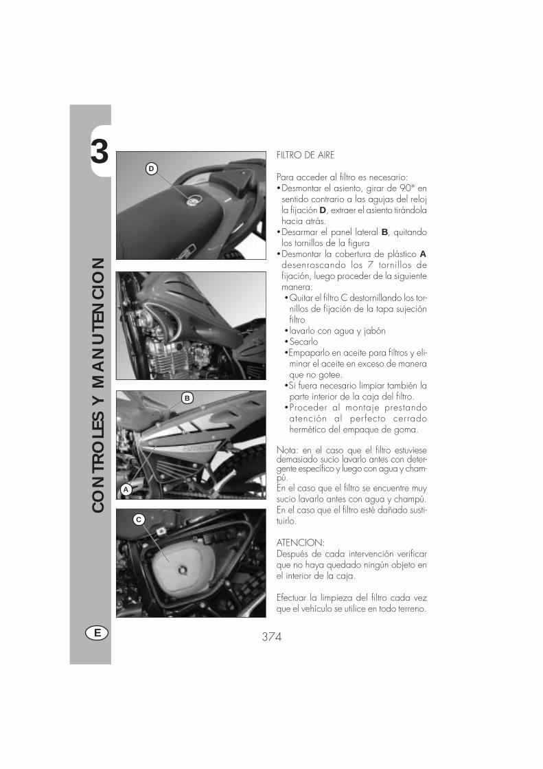
3
CO
NTR
OLE
S Y
MA
NU
TEN
CIO
N
374E
FILTRO DE AIRE
Para acceder al filtro es necesario:�Desmontar el asiento, girar de 90° ensentido contrario a las agujas del relojla fijación D, extraer el asiento tirándolahacia atrás.
�Desarmar el panel lateral B, quitandolos tornillos de la figura
�Desmontar la cobertura de plástico Adesenroscando los 7 tornillos defijación, luego proceder de la siguientemanera:�Quitar el filtro C destornillando los tor-nillos de fijación de la tapa sujeciónfiltro
� lavarlo con agua y jabón�Secarlo�Empaparlo en aceite para filtros y eli-minar el aceite en exceso de maneraque no gotee.
�Si fuera necesario limpiar también laparte interior de la caja del filtro.
�Proceder al montaje prestandoatención al per fecto cerradohermético del empaque de goma.
Nota: en el caso que el filtro estuviesedemasiado sucio lavarlo antes con deter-gente específico y luego con agua y cham-pú.En el caso que el filtro se encuentre muysucio lavarlo antes con agua y champú.En el caso que el filtro esté dañado susti-tuirlo.
ATENCION:Después de cada intervención verificarque no haya quedado ningún objeto enel interior de la caja.
Efectuar la limpieza del filtro cada vezque el vehículo se utilice en todo terreno.
C
B
A
D
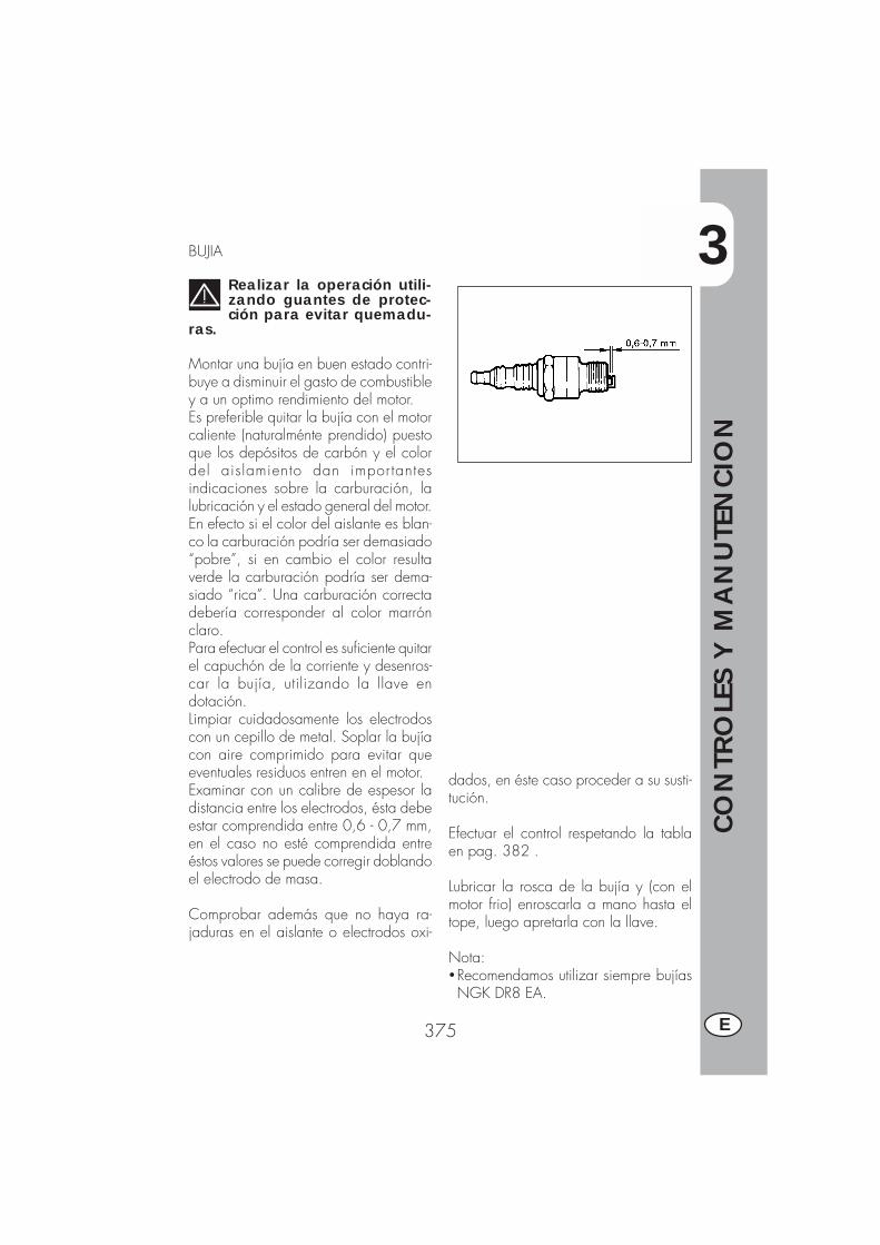
3
CO
NTR
OLE
S Y
MA
NU
TEN
CIO
N
375 E
BUJIA
Realizar la operación utili-zando guantes de protec-ción para evitar quemadu-
ras.
Montar una bujía en buen estado contri-buye a disminuir el gasto de combustibley a un optimo rendimiento del motor.Es preferible quitar la bujía con el motorcaliente (naturalménte prendido) puestoque los depósitos de carbón y el colordel aislamiento dan importantesindicaciones sobre la carburación, lalubricación y el estado general del motor.En efecto si el color del aislante es blan-co la carburación podría ser demasiado“pobre”, si en cambio el color resultaverde la carburación podría ser dema-siado “rica”. Una carburación correctadebería corresponder al color marrónclaro.Para efectuar el control es suficiente quitarel capuchón de la corriente y desenros-car la bujía, utilizando la llave endotación.Limpiar cuidadosamente los electrodoscon un cepillo de metal. Soplar la bujíacon aire comprimido para evitar queeventuales residuos entren en el motor.Examinar con un calibre de espesor ladistancia entre los electrodos, ésta debeestar comprendida entre 0,6 - 0,7 mm,en el caso no esté comprendida entreéstos valores se puede corregir doblandoel electrodo de masa.
Comprobar además que no haya ra-jaduras en el aislante o electrodos oxi-
dados, en éste caso proceder a su susti-tución.
Efectuar el control respetando la tablaen pag. 382 .
Lubricar la rosca de la bujía y (con elmotor frio) enroscarla a mano hasta eltope, luego apretarla con la llave.
Nota:�Recomendamos utilizar siempre bujíasNGK DR8 EA.
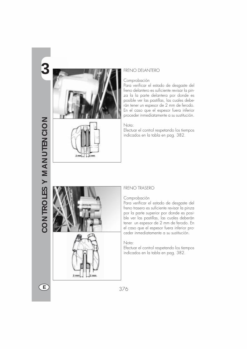
3
CO
NTR
OLE
S Y
MA
NU
TEN
CIO
N
376E
FRENO DELANTERO
ComprobaciónPara verificar el estado de desgaste delfreno delantero es suficiente revisar la pin-za la la parte delantera por donde esposible ver las pastillas, las cuales debe-rán tener un espesor de 2 mm de ferodo.En el caso que el espesor fuera inferiorproceder inmediatamente a su sustitución.
Nota:Efectuar el control respetando los tiemposindicados en la tabla en pag. 382.
FRENO TRASERO
ComprobaciónPara verificar el estado de desgaste delfreno trasero es suficiente revisar la pinzapor la parte superior por donde es posi-ble ver las pastillas, las cuales deberántener un espesor de 2 mm de ferodo. Enel caso que el espesor fuera inferior pro-ceder inmediatamente a su sustitución.
Nota:Efectuar el control respetando los tiemposindicados en la tabla en pag. 382.

3
CO
NTR
OLE
S Y
MA
NU
TEN
CIO
N
377 E
BATERIA
Verificar el estado de carga de la ba-tería, midiendo la tensión con labatería en descanso “Vehículoapagado” con un voltmetro. Los voltiosno deben ser inferior a 12,8 V.No es necesario controlar el nivel delelectrólito o añadir agua.Mantener limpios los polos de labatería y si fuese necesario,engrasarlos apenas con grasa que nocontenga ácido.
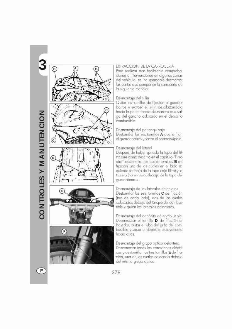
3
CO
NTR
OLE
S Y
MA
NU
TEN
CIO
N
378E
B BA
C
C
D
F
E
EXTRACCION DE LA CARROCERIAPara realizar mas facilmente comproba-ciones o intervenciones en algunas zonasdel vehículo, es indispensable desmontarlas partes que componen la carrocería dela siguiente manera:
Desmontaje del sillínQuitar los tornillos de fijación al guarda-barros y extraer el sillín desplazandolahacia la parte trasera de manera que sal-ga del gancho colocado en el depósitocombustible.
Desmontaje del portaequipajeDestornillar los tres tornillos A que lo fijanal guardabarros y sacar el portaequipaje.
Desmontaje del lateralDespués de haber quitado la tapa del fil-tro aire como descrito en el capítulo “Filtroaire“ destornillar los cuatro tornillos B defijación una de las cuales en el lado iz-quierdo (debajo de la tapa caja filtro) y latrasera (no en vista) debajo de la tapa delguardabarros .
Desmontaje de los laterales delanterosDestornillar los seis tornillos C de fijación(tres de cada lado), dos de las cualescolocadas debajo del tanque del combus-tible y quitar los laterales delanteros.
Desmontaje del depósito de combustibleDesenroscar el tornillo D de fijación albastidor, quitar el tubo del grifo del com-bustible y sacar el depósito extrayendolohacia atras.
Desmontaje del grupo optico delantero.Desconectar todas las conexiones eléctri-cas y destornillar los tres tornillos E de fija-ción, una de las cuales colocada debajodel mismo grupo optico.
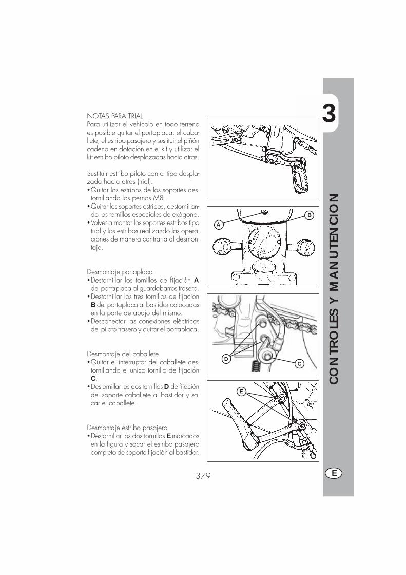
3
CO
NTR
OLE
S Y
MA
NU
TEN
CIO
N
379 E
A
B
CD
E
NOTAS PARA TRIALPara utilizar el vehícolo en todo terrenoes posible quitar el portaplaca, el caba-llete, el estribo pasajero y sustituir el piñóncadena en dotación en el kit y utilizar elkit estribo piloto desplazadas hacia atras.
Sustituir estribo piloto con el tipo despla-zada hacia atras (trial).�Quitar los estribos de los soportes des-tornillando los pernos M8.
�Quitar los soportes estribos, destornillan-do los tornillos especiales de exágono.
�Volver a montar los soportes estribos tipotrial y los estribos realizando las opera-ciones de manera contraria al desmon-taje.
Desmontaje portaplaca�Destornillar los tornillos de fijación Adel portaplaca al guardabarros trasero.
�Destornillar los tres tornillos de fijaciónB del portaplaca al bastidor colocadasen la parte de abajo del mismo.
�Desconectar las conexiones eléctricasdel piloto trasero y quitar el portaplaca.
Desmontaje del caballete�Quitar el interruptor del caballete des-tornillando el unico tornillo de fijaciónC.
�Destornillar los dos tornillos D de fijacióndel soporte caballete al bastidor y sa-car el caballete.
Desmontaje estribo pasajero�Destornillar los dos tornillos E indicadosen la figura y sacar el estribo pasajerocompleto de soporte fijación al bastidor.
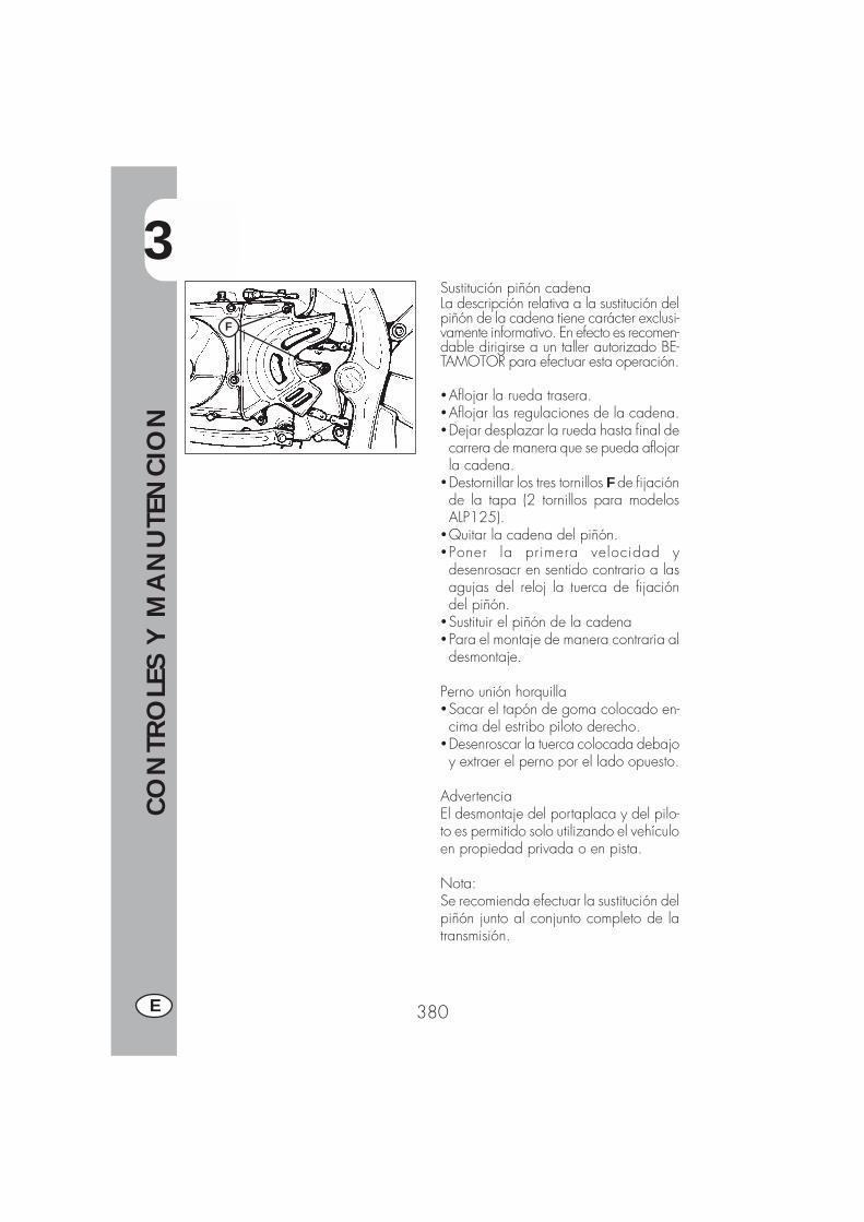
3
CO
NTR
OLE
S Y
MA
NU
TEN
CIO
N
380E
Sustitución piñón cadenaLa descripción relativa a la sustitución delpiñón de la cadena tiene carácter exclusi-vamente informativo. En efecto es recomen-dable dirigirse a un taller autorizado BE-TAMOTOR para efectuar esta operación.
�Aflojar la rueda trasera.�Aflojar las regulaciones de la cadena.�Dejar desplazar la rueda hasta final decarrera de manera que se pueda aflojarla cadena.
�Destornillar los tres tornillos F de fijaciónde la tapa (2 tornillos para modelosALP125).
�Quitar la cadena del piñón.�Poner la primera velocidad ydesenrosacr en sentido contrario a lasagujas del reloj la tuerca de fijacióndel piñón.
�Sustituir el piñón de la cadena�Para el montaje de manera contraria aldesmontaje.
Perno unión horquilla�Sacar el tapón de goma colocado en-cima del estribo piloto derecho.
�Desenroscar la tuerca colocada debajoy extraer el perno por el lado opuesto.
AdvertenciaEl desmontaje del portaplaca y del pilo-to es permitido solo utilizando el vehículoen propiedad privada o en pista.
Nota:Se recomienda efectuar la sustitución delpiñón junto al conjunto completo de latransmisión.
F
3
CO
NTR
OLE
S Y
MA
NU
TEN
CIO
N
381 E
LIMPIEZA DEL VEHICULO Y VERIFICACIONES
Para ablandar la suciedad y el barro depositado en la superficie pintada usar unchorro de agua de baja presión. Una vez ablandado el barro y suciedad se debenquitar con una esponja blanda para carrocería empapada con mucha agua y “champú “ (2-4 % de champú en agua) . Luego enjuagar abundantemente con aguay secar con piel. Para la parte externa del motor usar petrolio, pincel y traposlimpios. El petrolio daña la pintura. Recordamos que para eventual lustrado conceras siliconicas hay que proceder antes a un lavado.
Los detergentes contaminan las aguas. Por lo tanto el lavado del vehículo hayque realizarlo en zona equipada para la recolección y la depuración de
líquidos empleados para el mismo lavado.
El lavado no debe ser nunca realizado bajo el sol especialmente de veranocuando la carrocería está aún caliente puesto que el champú que se seca
antes que el agua puede provocar daños a la pintura. No utilizar nunca traposmojado con gasolina o gasoil para lavar superficies pintadas o de material plásti-co, para evitar que pierdan su brillantez y las características mecánicas de losmateriales.
COMPROBACIONES DESPUES DE LA LIMPIEZA
Después de limpiar la moto es buena norma:
� Limpiar el filtro de aire (proceder como descrito en pag. 374)�Engrasar la cadena.
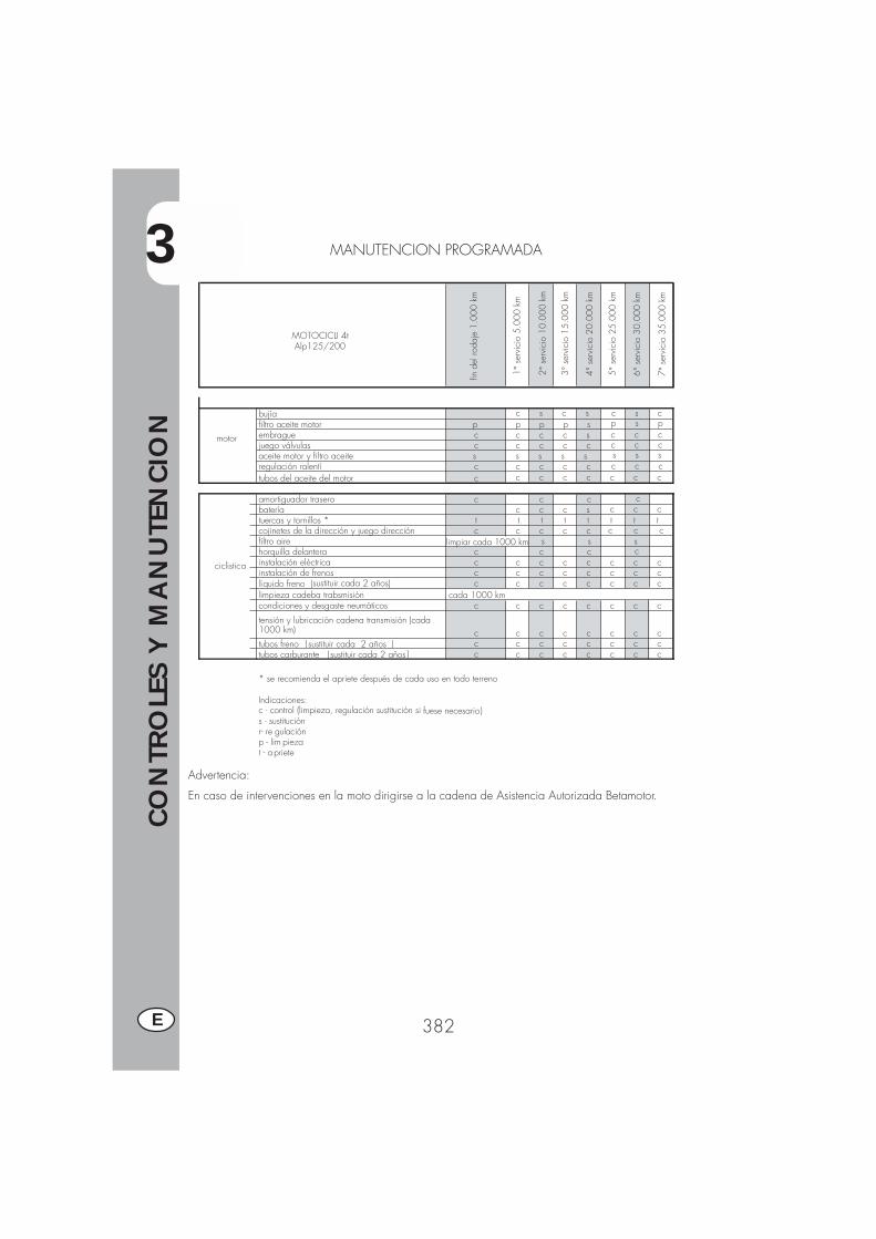
3
CO
NTR
OLE
S Y
MA
NU
TEN
CIO
N
382E
MANUTENCION PROGRAMADA
Advertencia:
En caso de intervenciones en la moto dirigirse a la cadena de Asistencia Autorizada Betamotor.
MOTOCICLI 4t Alp125/200
motor
bujía c s c sfiltro aceite motor p p p p sembrague c c c c sjuego válvulas c c c c caceite motor y filtro aceite s s s s sregulación ralentí c c c c ctubos del aceite del motor c c c c c c c c
ciclistica
amortiguador trasero c c cbatería c c c stuercas y tornillos * t t t t t t t tcojinetes de la dirección y juego dirección c c c c cfiltro aire s s shorquilla delantera c c cinstalación eléctrica c c c c c c c cinstalación de frenos c c c c c c c clíquido freno (sustituir cada 2 años) c c c c c c c climpieza cadeba trabsmisión cada 1000 kmcondiciones y desgaste neumáticos c c c c c c c c
tensión y lubricación cadena transmisión (cada 1000 km) c c c c c c c ctubos freno (sustituir cada 2 años ) c c c c c c c ctubos carburante (sustituir cada 2 años c c c c c c c c
* se recomienda el apriete después de cada uso en todo terreno
Indicaciones:c - control (limpieza, regulación sustitución si fuese necesario)s - sustituciónr- re gulaciónp - lim piezat - apriete
limpiar cada 1000 km
fin d
el ro
daje
1.0
00 k
m
1° s
ervi
cio
5.00
0 km
2° s
ervi
cio
10.0
00 k
m
3° s
ervi
cio
15.0
00 k
m
4° s
ervi
cio
20.0
00 k
m
5° s
ervi
cio
25.0
00 k
m
6° s
ervi
cio
30.0
00 k
m
7° s
ervi
cio
35.0
00 k
m
c s cp s pc c cc c cs s sc c c
c c c c
c c c
c
)
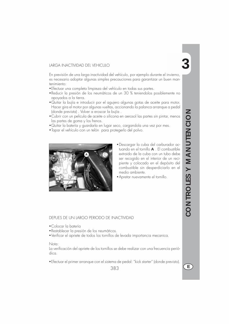
3
CO
NTR
OLE
S Y
MA
NU
TEN
CIO
N
383 E
LARGA INACTIVIDAD DEL VEHICULO
En previsión de una larga inactividad del vehículo, por ejemplo durante el invierno,es necesario adoptar algunas simples precauciones para garantizar un buen man-tenimiento:�Efectuar una completa limpieza del vehículo en todas sus partes.�Reducir la presión de los neumáticos de un 30 % teniendolos posiblemente noapoyados a la tierra.
�Quitar la bujía e introducir por el agujero algunas gotas de aceite para motor.Hacer gira el motor por algunas vueltas, accionando la palanca arranque a pedal(donde prevista) . Volver a eroscar la bujía .
�Cubrir con un pelicula de aceite o silicona en aerosol las partes sin pintar, menoslas partes de goma y los frenos.
�Quitar la batería y guardarla en lugar seco, cargandola una vez por mes.�Tapar el vehículo con un telón para protegerlo del polvo.
�Descargar la cuba del carburador ac-tuando en el tornillo A . El combustibleextraido de la cuba con un tubo debeser recogido en el interior de un reci-piente y colocado en el depósito delcombustible sin desperdiciarlo en elmedio ambiente.
�Apretar nuevamente el tornillo.
A
DEPUES DE UN LARGO PERIODO DE INACTIVIDAD
�Colocar la batería�Restablecer la presión de los neumáticos.�Verificar el apriete de todos los tornillos de levada importancia mecanica.
Nota:La verificación del apriete de los tornillos se debe realizar con una frecuencia perió-dica.
�Efectuar el primer arranque con el sistema de pedal: “kick starter“ (donde previsto).

4
REG
ULA
CIO
NES
385 E
INDICE ARGUMENTOS
CAP. 4 REGULACIONES
Regulación frenos
Regulación embregue
Regulación ralentí
Regulación juego gas
Comprobación y regulación juego dirección
Tensionamiento cadena
Haz luminoso
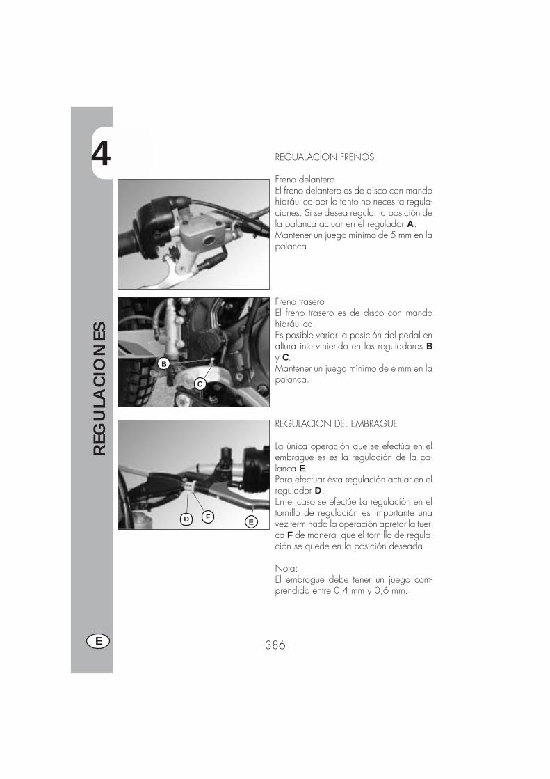
4
REG
ULA
CIO
NES
386E
C
B
FD E
REGUALACION FRENOS
Freno delanteroEl freno delantero es de disco con mandohidráulico por lo tanto no necesita regula-ciones. Si se desea regular la posición dela palanca actuar en el regulador A.Mantener un juego mínimo de 5 mm en lapalanca
Freno traseroEl freno trasero es de disco con mandohidráulico.Es posible variar la posición del pedal enaltura interviniendo en los reguladores By C.Mantener un juego mínimo de e mm en lapalanca.
REGULACION DEL EMBRAGUE
La única operación que se efectúa en elembrague es es la regulación de la pa-lanca E.Para efectuar ésta regulación actuar en elregulador D.En el caso se efectúe La regulación en eltornillo de regulación es importante unavez terminada la operación apretar la tuer-ca F de manera que el tornillo de regula-ción se quede en la posición deseada.
Nota:El embrague debe tener un juego com-prendido entre 0,4 mm y 0,6 mm.
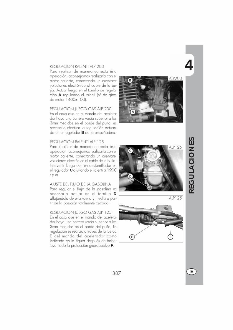
4
REG
ULA
CIO
NES
387 E
A
B
REGULACION RALENTI ALP 200Para realizar de manera correcta éstaoperación, aconsejamos realizarla con elmotor caliente, conectando un cuentare-voluciones electrónico al cable de la bu-jía. Actuar luego en el tornillo de regula-ción A regulando el ralentí (n° de girosde motor 1400±100).
REGULACION JUEGO GAS ALP 200En el caso que en el mando del acelera-dor haya una carrera vacia superior a los3mm medidos en el borde del puño, esnecesario efectuar la regulación actuan-do en el regulador B de la empuñadura.
REGULACION RALENTI ALP 125Para realizar de manera correcta éstaoperación, aconsejamos realizarla con elmotor caliente, conectando un cuentare-voluciones electrónico al cable de la bujía.Intervenir luego con un destornillador enel regulador C ajustando el ralentí a 1900r.p.m.
AJUSTE DEL FLUJO DE LA GASOLINAPara regular el flujo de la gasolina esnecesario actuar en el tornil lo Daflojándola de una vuelta y media a par-tir de la posición totalmente cerrada.
REGULACION JUEGO GAS ALP 125En el caso que en el mando del acelera-dor haya una carrera vacia superior a los3mm medidos en el borde del puño, Laregulación se realiza a través de la tuercaE del mando del acelerador comoindicado en la figura después de haberlevantado la protección guardapolvo F.
ALP125
ALP125
D
C
FE
ALP200
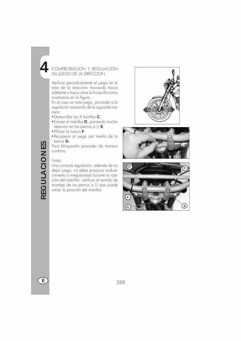
4
REG
ULA
CIO
NES
388E
D
F
G E
C
COMPROBACION Y REGULACIONDEL JUEGO DE LA DIRECCION
Verificar periodicaménte el juego en eltubo de la dirección moviendo haciaadelante y hacia atras la horquilla comomostramos en la figura.En el caso se note juego, proceder a laregulación actuando de la siguiente ma-nera:�Destornillar los 4 tornillos C.�Extraer el manillar D, poniendo muchaatención en los pernos a U E.
�Aflojar la tuerca F�Recuperar el juego por medio de latuerca G.
Para bloquearlo proceder de maneracontaria.
Nota:Una correcta regulación, además de nodejar juego, no debe provocar endure-cimiento o irregularidad durante la rota-ción del manillar; verificar el sentido demontaje de los pernos a U que puedevariar la posición del manillar.
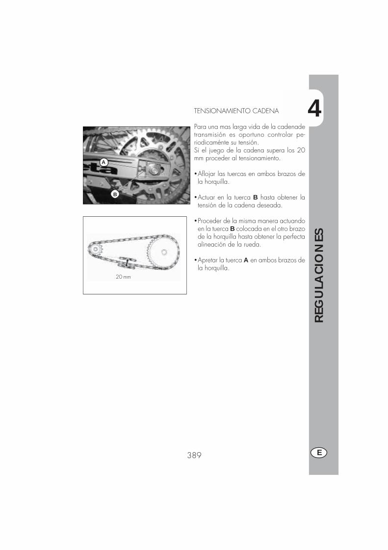
4
REG
ULA
CIO
NES
389 E
20 mm
B
A
TENSIONAMIENTO CADENA
Para una mas larga vida de la cadenadetransmisión es oportuno controlar pe-riodicaménte su tensión.Si el juego de la cadena supera los 20mm proceder al tensionamiento.
�Aflojar las tuercas en ambos brazos dela horquilla.
�Actuar en la tuerca B hasta obtener latensión de la cadena deseada.
�Proceder de la misma manera actuandoen la tuerca B colocada en el otro brazode la horquilla hasta obtener la perfectaalineación de la rueda.
�Apretar la tuerca A en ambos brazos dela horquilla.
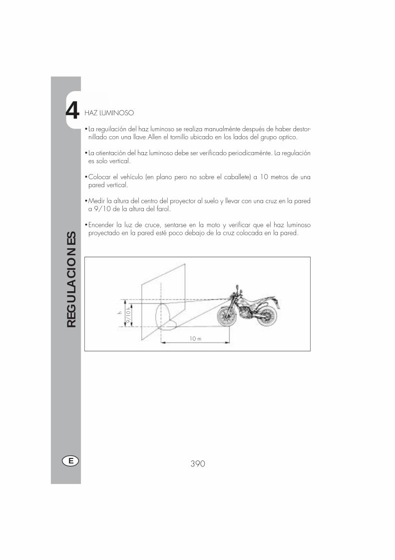
4
REG
ULA
CIO
NES
390E
9/10
h
10 m
hHAZ LUMINOSO
� La reguilación del haz luminoso se realiza manualménte después de haber destor-nillado con una llave Allen el tornillo ubicado en los lados del grupo optico.
� La otientación del haz luminoso debe ser verificado periodicaménte. La regulaciónes solo vertical.
�Colocar el vehículo (en plano pero no sobre el caballete) a 10 metros de unapared vertical.
�Medir la altura del centro del proyector al suelo y llevar con una cruz en la pareda 9/10 de la altura del farol.
�Encender la luz de cruce, sentarse en la moto y verificar que el haz luminosoproyectado en la pared esté poco debajo de la cruz colocada en la pared.
5
SUST
ITU
CIO
NES
391 E
INDICE DE ARGUMENTOS
CAP. 5 SUSTITUCIONES
Sustitución pastillas freno
Sustitución bombillos faro delantero.
Sustitución bombillos piloto trasero.
Sustitución bombillos indicadores de dirección.
Sustitución bombillos tablero.
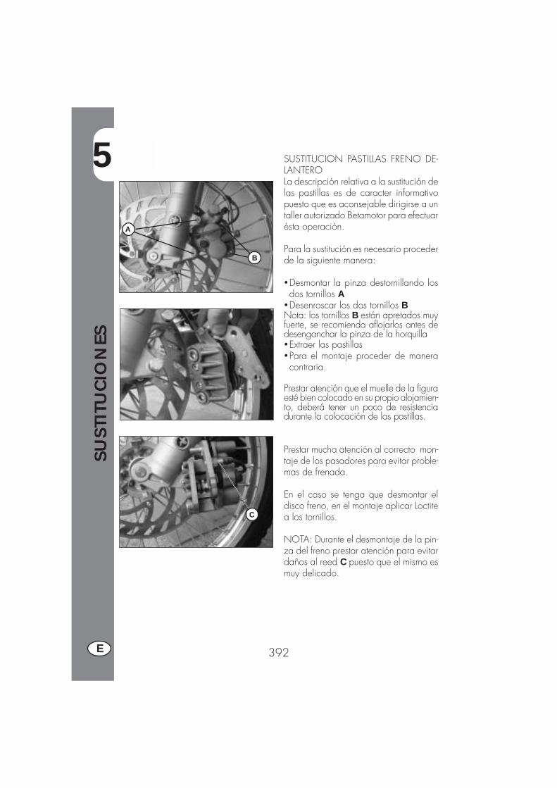
5
SUST
ITU
CIO
NES
392E
SUSTITUCION PASTILLAS FRENO DE-LANTEROLa descripción relativa a la sustitución delas pastillas es de caracter informativopuesto que es aconsejable dirigirse a untaller autorizado Betamotor para efectuarésta operación.
Para la sustitución es necesario procederde la siguiente manera:
�Desmontar la pinza destornillando losdos tornillos A
�Desenroscar los dos tornillos BNota: los tornillos B están apretados muyfuerte, se recomienda aflojarlos antes dedesenganchar la pinza de la horquilla�Extraer las pastillas�Para el montaje proceder de maneracontraria.
Prestar atención que el muelle de la figuraesté bien colocado en su propio alojamien-to, deberá tener un poco de resistenciadurante la colocación de las pastillas.
Prestar mucha atención al correcto mon-taje de los pasadores para evitar proble-mas de frenada.
En el caso se tenga que desmontar eldisco freno, en el montaje aplicar Loctitea los tornillos.
NOTA: Durante el desmontaje de la pin-za del freno prestar atención para evitardaños al reed C puesto que el mismo esmuy delicado.
A
B
C

5
SUST
ITU
CIO
NES
393 E
FRENO TRASEROPara la sustitución de las pastillas es siem-pre aconsejable dirigirse a un taller au-torizado BETAMOTOR.
2 mm
CONTROL DESGASTE
Para comprobar las condiciones dedesgaste del freno trasero es suficienteobservar la pinza desde la partetrasera, desde donde es posible ver losextremos de las dos pastillas las cualesdeberán tener por lo menos un estratode 2 mm de superficie de fricción. Enel caso que el estrato fuese inferiorproceder de inmediato con lasustitución de las mismas.
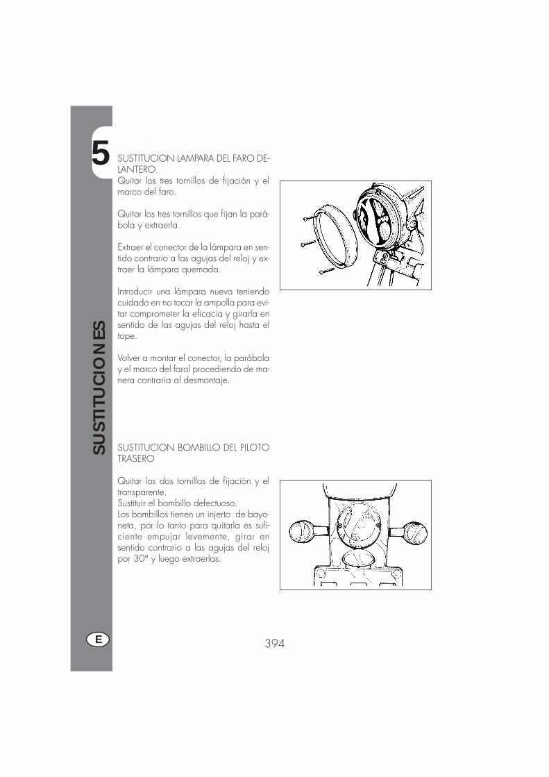
5
SUST
ITU
CIO
NES
394E
SUSTITUCION LAMPARA DEL FARO DE-LANTERO.Quitar los tres tornillos de fijación y elmarco del faro.
Quitar los tres tornillos que fijan la pará-bola y extraerla.
Extraer el conector de la lámpara en sen-tido contrario a las agujas del reloj y ex-traer la lámpara quemada.
Introducir una lámpara nueva teniendocuidado en no tocar la ampolla para evi-tar comprometer la eficacia y girarla ensentido de las agujas del reloj hasta eltope.
Volver a montar el conector, la parábolay el marco del farol procediendo de ma-nera contraria al desmontaje.
SUSTITUCION BOMBILLO DEL PILOTOTRASERO
Quitar los dos tornillos de fijación y eltransparente.Sustituir el bombillo defectuoso.Los bombillos tienen un injerto de bayo-neta, por lo tanto para quitarla es sufi-ciente empujar levemente, girar ensentido contrario a las agujas del relojpor 30° y luego extraerlas.
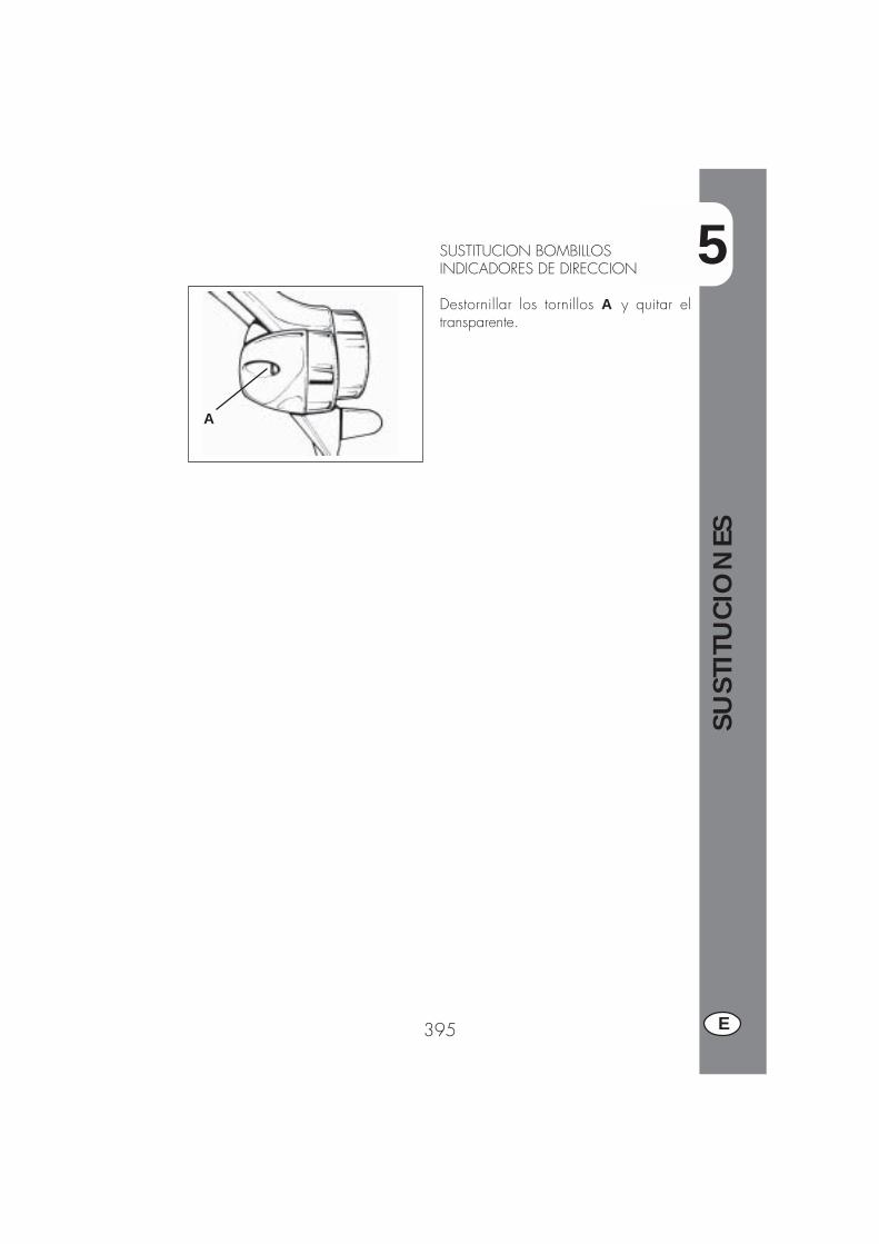
5
SUST
ITU
CIO
NES
395 E
SUSTITUCION BOMBILLOSINDICADORES DE DIRECCION
Destornillar los tornillos A y quitar eltransparente.
A

6
QU
E H
ACER
EN
CA
SO D
E EM
ERG
ENCIA
397 E
INDICE DE LOS ARGUMENTOS
CAP. 6 QUE HACER EN CASO DE MERGENCIA
INDICE ALFABETICO
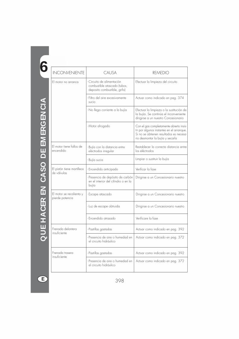
6
QU
E H
ACER
EN
CA
SO D
E EM
ERG
ENCIA
398E
INCONVENIENTE CAUSA
El motor no arranca
REMEDIO
-Circuito de alimentacióncombustible atascado (tubos,deposito combustible, grifo)
- Filtro del aire excesivamentesucio
-No llega corriente a la bujía
-Motor ahogado
Efectuar la limpieza del circuito
Actuar como indicado en pag. 374
Efectuar la limpieza o la sustitución dela bujía. Se continúa el inconvenientedirigirse a un nuestro Concesionario
Con el gas completamente abierto insis-tir por algunos instantes en el arranque.Si no se obtienen resultados es necesa-rio desmontar la bujía y secarla
El motor tiene fallos deencendido
- Bujía con la distancia entreeléctrodos irregular
- Bujía sucia
Restablecer la correcta distancia entrelos eléctrodos
Limpiar o sustituir la bujía
El pistón tiene martilleosde válvulas
- Encendido anticipado
- Presencia de depósito de carbónen el interior del cilindro o en labujía
Verificar la fase
Dirigirse a un Concesionario nuestro
El motor se recalienta ypierde potencia
- Escape atascado
- Luz de escape obtruida
- Encendido atrasado
Dirigirse a un Concesionario nuestro
Dirigirse a un Concesionario nuestro
Verificare la fase
Frenada delanterainsuficiente
- Pastillas gastadas
- Presencia de aire o humedad enel circuito hidráulico
Actuar como indicado en pag. 392
Actuar como indicado en pag. 372
Frenada traserainsuficiente
- Pastillas gastadas
- Presencia de aire o humedad enel circuito hidráulico
Actuar como indicado en pag. 392
Actuar como indicado en pag. 372
6
QU
E H
ACER
EN
CA
SO D
E EM
ERG
ENCIA
399 E
Abastecimiento combustible ................................................................. 366Aceite bomba frenos .......................................................................... 372Aceite horquilla ................................................................................. 373Aceite motor: control y sustitución .................................................. 368/370Arranque .......................................................................................... 364
Busca de inconveniente ....................................................................... 398
Cerradura casco ................................................................................ 332Conmutador / bloquéo dirección ......................................................... 332Controles después de la limpieza.......................................................... 231Controles y manutención antes y después del utilizo en todo terreno ............ 332
Datos identificación vehículo ................................................................ 328Datos técnicos ................................................................................... 351Dirección: control y regulación ............................................................. 388
Embrague ......................................................................................... 386Espurgo frenos ................................................................................... 372Esquema eléctrico ...................................................................... 355/357
Filtro aire .......................................................................................... 374Freno delantero control y sustitución ....................................................... 392Freno trasero control y sustitución .......................................................... 393
Llaves y cerraduras ............................................................................. 337Lubricantes y líquidos aconsejados ........................................................ 363LCD................................................................................................. 334
Manutención programada ................................................................... 382
Regulación embrague ......................................................................... 386Regulación frenos ............................................................................... 386Regulación juego gas ......................................................................... 387Regulación mínimo ............................................................................. 387Rodaje ............................................................................................. 263
Sustitución lámparas ........................................................................... 393
Tablero y mandos .............................................................................. 333Tensionamiento cadena ....................................................................... 389


Edition No. 3 / October 2006
Top Related