
XX KX - Tercesa€¦ · le serie KX, XX e KK. Le serie KX e KK sono disponibili esclusi - vamente...
65
XX KX 5.0 RIDUTTORI A VITE SENZA FINE COMBINATI COMBINED WORM GEARBOXES KOMBINIERTE- SCHNECKENGETRIEBE 5.1 Caratteristiche Characteristics Merkmale 86 5.2 Designazione Designation Bezeichnung 86 5.3 Lubrificazione e posizioni di montaggio Lubrication and mounting position Schmierung und Einbaulage 90 5.4 Posizione morsettiera Terminal board position Lage der Klemmenkaste 92 5.5 Dati tecnici Technical data Technische Daten 93 5.6 Dimensioni Dimensions Abmessungen 98 5.7 Limitatore di coppia cavo passante Torque limiter with through hollow shaft Drehmomentbegrenzer mit durchgehender Hohlwelle 105 5.8 Esecuzione con vite bisporgente Double extended worm shaft design Versionen mit doppelseitig herausragender Schneckenwelle 106 5.9 Accessori Accessories Zubehör 107 5.10 Lista parti di ricambio Spare parts list Ersatzteilliste 108 KK 1
Transcript of XX KX - Tercesa€¦ · le serie KX, XX e KK. Le serie KX e KK sono disponibili esclusi - vamente...

XX KX
5.0RIDUTTORI A VITE SENZA FINE COMBINATI
COMBINED WORM GEARBOXES
KOMBINIERTE-SCHNECKENGETRIEBE
5.1 Caratteristiche Characteristics Merkmale 865.2 Designazione Designation Bezeichnung 865.3 Lubrificazione e posizioni
di montaggioLubrication andmounting position
Schmierung und Einbaulage
90
5.4 Posizione morsettiera Terminal board position Lage der Klemmenkaste 925.5 Dati tecnici Technical data Technische Daten 935.6 Dimensioni Dimensions Abmessungen 985.7 Limitatore di coppia
cavo passanteTorque limiter with through hollow shaft
Drehmomentbegrenzermit durchgehender Hohlwelle
105
5.8 Esecuzione con vitebisporgente
Double extended worm shaft design
Versionen mit doppelseitigherausragender Schneckenwelle
106
5.9 Accessori Accessories Zubehör 1075.10 Lista parti di ricambio Spare parts list Ersatzteilliste 108
KK
1

5.1 Merkmale
Die Kombination zweier Schneckenge-triebe bringt sehr niedrigen Wirkungsgrad mit sich, es handelt sich jedoch um eine interessante und manchmal unersetzba-re Lösung, weil hohe Drehzahlverringe-rung in einem beträchtlich reduzierten Raum erhalten werden kann. Kombinierte Schneckengetriebe sind in folgende Seri-en erhältlich: KX, XX und KK.Die Serien KX und KK sind nur mit IEC-Motoranbau verfügbar.
Die Serie XX ist mit Welle (XXA Version), oder mit Kupplung für Motoranschluss (XXC kompakt und XXF mit Glocke und Verbindsstück) lieferbar.
Die Hohlwelle gehört zur serienmäßi-gen Ausstattung. Eine breite Auswahl an Zubehör ist erhältlich: zweiter Antrieb, Kegelrollenlager auf Schneckenrad, Ab-triebs- flansch, Standard oder doppelsei-tig herausrangende Abtriebswelle, Dreh-momentbegrenzer mit durchgehender Hohlwelle, Drehmomentstütze.
5.1 Characteristics
The combination of two worm gearboxes provides very low efficiency, however the fact that substantial reduction in speed can be obtained in an extremely reduced space makes this solution very interesting and sometimes irreplaceable. Combined worm gearboxes are available in series: KX , XX and KK.
The KX and KK series are available for IEC version only.
The XX series is available in the XXA ver-sion with shaft and in two versions with motor coupling: XXC (compact) and XXF (with bell and joint).
The hollow shaft is supplied as standard. A broad range of accessories is avalable:second input, tapered roller bearings on the worm wheel, output flange, single or double extended output shaft, torque limiter with through hollow shaft, torque arm.
5.1 Caratteristiche
La combinazione di due riduttori a vite senza fine comporta rendimenti molto bassi, ma l’elevata riduzione di velocità ottenuta in uno spazio ridottissimo rende comunque interessante, e a volte insosti- tuibile, questa soluzione. I riduttori a vite senza fine combinati sono disponibili nel-le serie KX, XX e KK.
Le serie KX e KK sono disponibili esclusi-vamente nella versione p.a.m.
La serie XX è invece disponibile nella ver-sione alberata XXA e nelle due versioni con predisposizione attacco motore in forma compatta XXC o con campana e giunto XXF.
Sono forniti con albero cavo di serie ed esiste un’ampia gamma di accessori:seconda entrata, cuscinetti conici sulla corona, flangia uscita, albero lento con 1 o 2 sporgenze, limitatore di coppia con cavo passante, braccio di reazione.
5.2 Bezeichnung5.2 Designation5.2 Designazione
Rid
utto
re e
ntra
taG
earb
ox a
t inp
utG
etrie
be a
m A
ntrie
b
Mac
chin
a us
cita
Gea
rbox
at o
utpu
tG
etrie
be a
m A
btrie
b
Tipo
ent
rata
Inpu
t typ
eA
ntrie
bsar
t
Gra
ndez
za
Siz
eG
röß
e
Rap
port
o rid
. R
atio
Unt
erse
tzun
g
Pre
disp
os.a
tt. m
ot.
Mot
or c
oupl
ing
Mot
oran
schl
uss
Ver
sion
eV
ersi
onV
ersi
on
For
ma
cost
rutti
vaE
xecu
tion
Bau
form
Pos
izio
ne d
i mon
t. M
ount
ing
posi
tion
Ein
baul
age
Lim
itato
re d
i cop
pia.
Torq
ue li
mite
rD
rehm
omen
t-be
gren
zer
Sec
onda
ent
rata
Add
ition
al in
put
Zus
atza
ntrie
b
Alb
ero
usci
taO
utpu
t sha
ftA
btrie
bsw
elle
Bra
ccio
di r
eazi
one
Torq
ue a
rmD
rehm
omen
tstü
tze
K K C 50/110 1200 P.A.M. F1 a B3 LD SeA1 H BR
Rid
utt
ore
a v
ite
sen
za f
ine
com
bin
ato
C
om
bin
ed w
orm
gea
rbo
xD
op
pel
sch
nec
ken
get
rieb
e
C
30/3030/4030/5030/6340/6340/7540/9050/7550/9050/11063/11063/130
150200300450600900120015001950250032504000500010000
5663718090
P
F (1-2-3)
A (1-2)
B (1-2)
V (1-2)
ab
cd
ef
gh
ik
im
no
pq
B3
B6
B7
B8
V5
V6
LD
LS
SeA1
SeA2
H
SD
SS
DD
BR
2
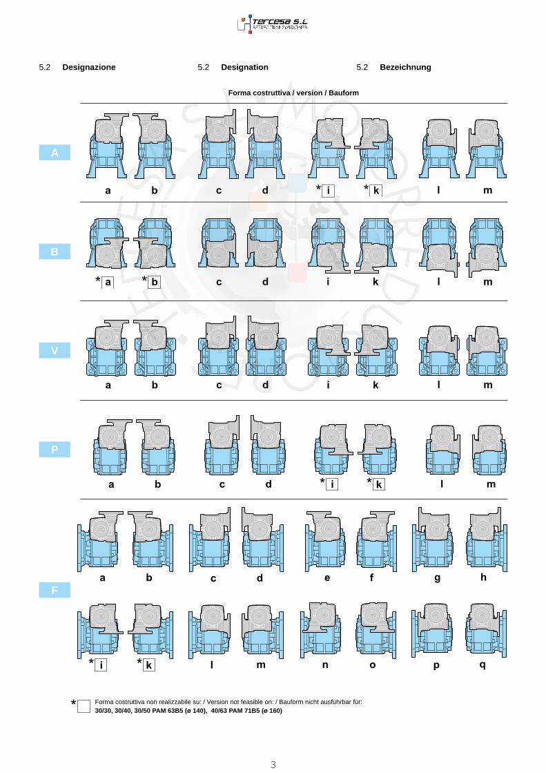
5.2 Bezeichnung5.2 Designation5.2 Designazione
A
B
V
P
F
Forma costruttiva / version / Bauform
Forma costruttiva non realizzabile su: / Version not feasible on: / Bauform nicht ausführbar für:30/30, 30/40, 30/50 PAM 63B5 (ø 140), 40/63 PAM 71B5 (ø 160)
3

5.2 Bezeichnung5.2 Designation5.2 Designazione
Rid
utto
re e
ntra
taG
earb
ox a
t inp
utG
etrie
be a
m A
ntrie
b
Mac
chin
a us
cita
Gea
rbox
at o
utpu
tG
etrie
be a
m A
btrie
b
Tipo
ent
rata
Inpu
t typ
eA
ntrie
bsar
t
Gra
ndez
za
Siz
eG
röß
e
Rap
port
o rid
. R
atio
Unt
erse
tzun
g
Pre
disp
os.a
tt. m
ot.
Mot
or c
oupl
ing
Mot
oran
schl
uss
Ver
sion
eV
ersi
onV
ersi
on
For
ma
cost
rutti
vaE
xecu
tion
Bau
form
Pos
izio
ne d
i mon
t. M
ount
ing
posi
tion
Ein
baul
age
Lim
itato
re d
i cop
pia.
Torq
ue li
mite
rD
rehm
omen
t-be
gren
zer
Sec
onda
ent
rata
Add
ition
al in
put
Zus
atza
ntrie
b
Alb
ero
usci
taO
utpu
t sha
ftA
btrie
bsw
elle
Bra
ccio
di r
eazi
one
Torq
ue a
rmD
rehm
omen
tstü
tze
K X C 50/110 1200 P.A.M. F1 a B3 LD SeA1 H BR
Rid
utt
ore
a v
ite
sen
za f
ine
com
bin
ato
C
om
bin
ed w
orm
gea
rbo
xD
op
pel
sch
nec
ken
get
rieb
e
C
30/3030/4030/5030/6340/6340/7540/9050/7550/9050/11063/11063/130
150200300450600900120015001950250032504000500010000
5663718090
P
F(1-2-3)
ab
cd
ef
gh
ik
lm
no
pq
B3
B6
B7
B8
V5
V6
LD
LS
SeA1
SeA2
H
SD
SS
DD
BR
Rid
utto
re e
ntra
taG
earb
ox a
t inp
utG
etrie
be a
m A
ntrie
b
Mac
chin
a us
cita
Gea
rbox
at o
utpu
tG
etrie
be a
m A
btrie
b
Tipo
ent
rata
Inpu
t typ
eA
ntrie
bsar
t
Gra
ndez
za
Siz
eG
röß
e
Rap
port
o rid
. R
atio
Unt
erse
tzun
g
Pre
disp
os.a
tt. m
ot.
Mot
or c
oupl
ing
Mot
oran
schl
uss
Ver
sion
eV
ersi
onV
ersi
on
For
ma
cost
rutti
vaE
xecu
tion
Bau
form
Pos
izio
ne d
i mon
t. M
ount
ing
posi
tion
Ein
baul
age
Lim
itato
re d
i cop
pia.
Torq
ue li
mite
rD
rehm
omen
t-be
gren
zer
Sec
onda
ent
rata
Add
ition
al in
put
Zus
atza
ntrie
b
Alb
ero
usci
taO
utpu
t sha
ftA
btrie
bsw
elle
Bra
ccio
di r
eazi
one
Torq
ue a
rmD
rehm
omen
tstü
tze
X X C 50/110 1200 P.A.M. F1 a B3 LD SeA1 H BR
Rid
utt
ore
a v
ite
sen
za f
ine
com
bin
ato
C
om
bin
ed w
orm
gea
rbo
xD
op
pel
sch
nec
ken
get
rieb
e A
C
F
30/3030/4030/5030/6340/6340/7540/9050/7550/9050/11063/11063/130
150200300450600900120015001950250032504000500010000
5663718090
P
F(1-2-3)
ab
cd
ef
gh
ik
lm
no
pq
B3
B6
B7
B8
V5
V6
LD
LS
SeA1
SeA2
H
SD
SS
DD
BR
4

5.2 Bezeichnung5.2 Designation5.2 Designazione
P
Forma costruttiva / version / Bauform
F
Forma costruttiva non realizzabile su:Version not feasible on:Bauform nicht ausführbar für:
30/30, 30/40, 30/50 PAM 63B5 (ø 140), 40/63 PAM 71B5 (ø 160)
5

5.3 Schmierung und Einbaulage
Kombinierte Schneckengetriebe werden mit synthetischem Schmiermittel auf PAG Basis und Viskosität Index ISO VG320 geliefert.Im Auftrag sind immer Einbaulage und Bauform anzugeben.
5.3 Lubrication and mounting position Combined worm gearboxes are supplied with synthetic lubricant, PAG base, vis-cosity index ISO VG320.Required version and mounting position always to be specified when ordering.
5.3 Lubrificazione e posizioni di montaggio
I riduttori a vite senza fine combinati sono forniti completi di lubrificante sintetico a base PAG con indice di viscosità ISO VG320. Si raccomanda di precisare sem-pre in fase di ordine la forma costruttiva e la posizione di lavoro desiderata.
Carico e sfiato / Filling and breather Einfüll und EntlüftungLivello / Level / ÖlstandScarico / Drain / Ablass
Gehäuse aus Alumiunium Größe 30, 40, 50, 63 und 75 verfügen über nur eine Einfüllschraube.
Aluminium housings size 30, 40, 50, 63 and 75 have one filling plug only.
Nei corpi in alluminio 30, 40, 50, 63, 75 è presente un solo tappo di riempimento olio.
Q.tà olio / Oil quantity / Schmiermittelmenge [lt]
XXA - XXC - KXC - XXF30/30 30/40 30/50 30/63 40/63 40/75 40/90 50/75 50/90 50/110 63/110 63/130
Pos
izio
ni d
i mon
tagg
ioM
ount
ing
posi
tions
Ein
baul
age
B3IN 0.015 0.04 0.08 0.16 0.4
OUT 0.015 0.04 0.08 0.16 0.16 0.26 1.1 0.26 1.1 2.2 2.2 3.6
B6IN 0.015 0.04 0.08 0.16 0.4
OUT 0.015 0.04 0.08 0.16 0.16 0.26 0.9 0.26 0.9 1.8 1.8 3.0
B7IN 0.015 0.04 0.08 0.16 0.4
OUT 0.015 0.04 0.08 0.16 0.16 0.26 0.9 0.26 0.9 1.8 1.8 3.0
B8IN 0.015 0.04 0.08 0.16 0.4
OUT 0.015 0.04 0.08 0.16 0.16 0.26 1 0.26 1 1.6 1.6 2.5
V5IN 0.015 0.04 0.08 0.16 0.4
OUT 0.015 0.04 0.08 0.16 0.16 0.26 1.5 0.26 1.5 2.6 2.6 3.8
V6IN 0.015 0.04 0.08 0.16 0.4
OUT 0.015 0.04 0.08 0.16 0.16 0.26 1.5 0.26 1.5 2.6 2.6 3.8
IN = Riduttore entrata / Gearbox at input / Getriebe am Antrieb
OUT = Riduttore uscita / Gearbox at output / Getriebe am Abtrieb
B3 B6 B7 B8 V5 V6
B3 B6 B7 B8 V5 V6
F (b, d, f, h, k, m, o, q) P (a, b, c, d, i, k, l, m)
F (a, c, e, g, i, l, n, p)
6

F (b, d, f, h, k, m, o, q) P (a, b, c, d, i, k, l, m)
F (a, c, e, g, i, l, n, p)
B3 B6 B7 B8 V5 V6
Q.tà olio / Oil quantity / Schmiermittelmenge [lt]
Combinato tipo: KKC30/30 30/40 30/50 30/63 40/63 40/75 40/90 50/75 50/90 50/110 63/110 63/130
Pos
izio
ni d
i mon
tagg
ioM
ount
ing
posi
tions
Ein
baul
age
B3IN 0.015 0.04 0.08 0.16 0.16
OUT 0.015 0.04 0.08 0.16 0.16 0.26 1 0.26 1 2 2 3
B6IN 0.015 0.04 0.08 0.16 0.16
OUT 0.015 0.04 0.08 0.16 0.16 0.26 0.8 0.26 0.8 1.5 1.5 2.6
B7IN 0.015 0.04 0.08 0.16 0.16
OUT 0.015 0.04 0.08 0.16 0.16 0.26 0.8 0.26 0.8 1.5 1.5 2.6
B8IN 0.015 0.04 0.08 0.16 0.16
OUT 0.015 0.04 0.08 0.16 0.16 0.26 0.8 0.26 0.8 2 2 2.1
V5IN 0.015 0.04 0.08 0.16 0.16
OUT 0.015 0.04 0.08 0.16 0.16 0.26 1.3 0.26 1.3 2 2 2.8
V6IN 0.015 0.04 0.08 0.16 0.16
OUT 0.015 0.04 0.08 0.16 0.16 0.26 1.3 0.26 1.3 2 2 2.8
IN = Riduttore entrata / Gearbox at input / Getriebe am Antrieb OUT = Riduttore uscita / Gearbox at output / Getriebe am Abtrieb
7

5.4 Lage der Klemmenkaste5.4 Terminal board position5.4 Posizione morsettiera
A
A
B
B
C
C
D
D
B3
B8
B6 B7
V5 V6
A
B
C
D
A
B
D
C
A
B
C
DA
B
C
D
E H
GF
EH
G F
E
H G
F
E
H
F
G
E
H G
F E
HG
F
Bei der Bestellung immer die gewünschte Montageposition und Bauform angeben.Lage der Klemmenkaste Seite 105-106(PM=1; PM=2)
Mounting position always to be specified when ordering.Terminal board position see page 105-106(PM=1; PM=2)
Specificare sempre in fase di ordinazio-ne la posizione di montaggio e la forma costruttiva.Posizione morsettiera v. pag. 105 - 106(PM=1; PM=2)
8

30/30
n1 = 1400 XXA KXC - XXC - XXF - KKC
in30 30 n2
RdT2M P T2 P1
FS’Input - IEC
i1 i2 [min-1] [Nm] [kW] [Nm] [kW]KC - XC XFB5/B14 B5 B14
15010
15 9.3 0.51 37 0.070 32 0.06 1.2
—
63
56 — 63 56 — 63 56
200 20 7.0 0.47 32 0.050 39 0.06 0.8300
30
4.7 0.42 39 0.045 52* 0.06 0.8*450 15 3.1 0.40 39 0.032 73* 0.06 0.5*600 20 2.3 0.37 39 0.026 91* 0.06 0.4*900 30 1.6 0.34 39 0.019 125* 0.06 0.3*
1200 40 1.2 0.30 39 0.016 149* 0.06 0.3*1500 50 0.9 0.28 39 0.014 173* 0.06 0.2*1950 65 0.7 0.26 39 0.011 209* 0.06 0.2* —2500 50
50
0.6 0.23 30 0.008 235* 0.06 0.1* 633.0 3250 65 0.4 0.21 30 0.006 283* 0.06 0.11*
—4000 80 0.4 0.20 30 0.005 328* 0.06 0.09*5000
1000.3 0.19 30 0.005 385* 0.06 0.08*
10000 100 0.1 0.15 17 0.002 609* 0.06 0.03*
5.5 Technische Daten5.5 Technical data5.5 Dati tecnici
* ACHTUNG: das max. anwendbare Drehmoment [T2M] muss mit folgendem Betriebsfaktor berechnet werden: T2M = T2 x FS‘
* WARNING: Maximum allowable torque [T2M] must be calculated using the follow-ing service factor : T2M = T2 x FS’
* ATTENZIONE: la coppia massima utiliz-zabile [T2M] deve essere calcolata utiliz-zando il fattore di servizio: T2M = T2 x FS’
30/40
n1 = 1400 XXA KXC - XXC - XXF - KKC
in30 40 n2
RdT2M P T2 P1
FS’Input - IEC
i1 i2 [min-1] [Nm] [kW] [Nm] [kW]KC - XC XFB5/B14 B5 B14
15010
15 9.3 0.54 82 0.148 72 0.13 1.1
—
63
56 — 63 56 — 63 56
200 20 7.0 0.51 76 0.110 76 0.11 1.0300
30
4.7 0.43 82 0.094 79 0.09 1.0450 15 3.1 0.40 82 0.067 74 0.06 1.1600 20 2.3 0.37 82 0.054 92 0.06 0.9900 30 1.6 0.34 82 0.039 126* 0.06 0.6*
1200 40 1.2 0.31 82 0.033 151* 0.06 0.5*1500 50 0.9 0.29 82 0.028 176* 0.06 0.5*1950 65 0.7 0.27 82 0.023 212* 0.06 0.4* —2500 50
50
0.6 0.23 68 0.017 236* 0.06 0.3* 634.0 3250 65 0.4 0.21 68 0.014 285* 0.06 0.24*
—4000 80 0.4 0.20 68 0.012 330* 0.06 0.21*5000
1000.3 0.19 68 0.011 387* 0.06 0.18*
10000 100 0.1 0.15 35 0.003 626* 0.06 0.06*
30/50
n1 = 1400 XXA KXC - XXC - XXF - KKC
in30 50 n2
RdT2 P T2 P1
FS’Input - IEC
i1 i2 [min-1] [Nm] [kW] [Nm] [kW]KC - XC XFB5/B14 B5 B14
15010
15 9.3 0.55 149 0.265 124 0.22 1.2
—
63
56 — 63 56 — 63 56
200 20 7.0 0.52 144 0.201 129 0.18 1.1300
30
4.7 0.44 150 0.166 118 0.13 1.3450 15 3.1 0.42 150 0.118 140 0.11 1.1600 20 2.3 0.39 150 0.094 143 0.09 1.0900 30 1.6 0.36 150 0.069 131 0.06 1.11200 40 1.2 0.32 150 0.058 156 0.06 1.01500 50 0.9 0.30 150 0.049 182 0.06 0.81950 65 0.7 0.28 150 0.041 220* 0.06 0.7* —2500 50
50
0.6 0.25 125 0.030 253* 0.06 0.5* 636.0 3250 65 0.4 0.23 125 0.025 305* 0.06 0.41*
—4000 80 0.4 0.22 125 0.021 354* 0.06 0.35*5000
1000.3 0.20 125 0.018 414* 0.06 0.30*
10000 100 0.1 0.16 69 0.006 645* 0.06 0.11*
9

30/63
n1 = 1400 XXA KXC - XXC - XXF - KKC
in30 63 n2
RdT2M P T2 P1
FS’Input - IEC
i1 i2 [min-1] [Nm] [kW] [Nm] [kW]KC - XC XFB5/B14 B5 B14
15010
15 9.3 0.56 228 0.400 126 0.22 1.8
—
63
56 — 63 56 — 63 56
200 20 7.0 0.54 279 0.378 162 0.22 1.7300
30
4.7 0.46 268 0.285 207 0.22 1.3450 15 3.1 0.43 268 0.202 238 0.18 1.1600 20 2.3 0.40 268 0.162 215 0.13 1.2900 30 1.6 0.37 268 0.118 250 0.11 1.11200 40 1.2 0.33 268 0.099 243 0.09 1.11500 50 0.9 0.31 268 0.085 189 0.06 1.41950 65 0.7 0.29 268 0.071 228 0.06 1.2 —2500 50
50
0.6 0.26 222 0.050 265 0.06 0.8 638.5 3250 65 0.4 0.24 222 0.042 319* 0.06 0.70*
—4000 80 0.4 0.23 222 0.036 369* 0.06 0.60*5000
1000.3 0.21 222 0.031 433* 0.06 0.51*
10000 100 0.1 0.16 138 0.012 663* 0.06 0.21*
5.5 Technische Daten5.5 Technical data5.5 Dati tecnici
* ACHTUNG: das max. anwendbare Drehmoment [T2M] muss mit folgendem Betriebsfaktor berechnet werden: T2M = T2 x FS‘
* WARNING: Maximum allowable torque [T2M] must be calculated using the follow-ing service factor : T2M = T2 x FS’
* ATTENZIONE: la coppia massima utiliz-zabile [T2M] deve essere calcolata utiliz-zando il fattore di servizio: T2M = T2 x FS’
40/63
n1 = 1400 XXA KXC - XXC - XXF - KKC
in40 63 n2
RdT2M P T2 P1
FS’Input - IEC
i1 i2 [min-1] [Nm] [kW] [Nm] [kW]KC - XC XFB5/B14 B5 B14
15010
15 9.3 0.56 261 0.452 214 0.37 1.2
71
63
—
71 63 56 71 63 —
200 20 7.0 0.55 279 0.373 277 0.37 1.0300
30
4.7 0.46 268 0.282 238 0.25 1.1450 15 3.1 0.44 268 0.197 244 0.18 1.1600 20 2.3 0.43 268 0.154 226 0.13 1.2900 30 1.6 0.38 268 0.115 257 0.11 1.01200 40 1.2 0.36 268 0.091 264 0.09 1.01500 50 0.9 0.33 268 0.079 203 0.06 1.3
— 56
1950 65 0.7 0.30 268 0.067 241 0.06 1.12500 50
50
0.6 0.28 222 0.047 284 0.06 0.89.5 3250 65 0.4 0.25 222 0.039 338* 0.06 0.66*
4000 80 0.4 0.24 222 0.033 400* 0.06 0.55*5000
1000.3 0.23 222 0.028 471* 0.06 0.47*
10000 100 0.1 0.18 138 0.011 722* 0.06 0.19*
10

40/75
n1 = 1400 XXA KXC - XXC - XXF - KKC
in40 75 n2
RdT2M P T2 P1
FS’Input - IEC
i1 i2 [min-1] [Nm] [kW] [Nm] [kW]KC - XC XFB5/B14 B5 B14
15010
15 9.3 0.57 409 0.698 322 0.55 1.3
71
63
—
71 63 56 71 63 —
200 20 7.0 0.56 442 0.583 417 0.55 1.1300
30
4.7 0.47 418 0.432 358 0.37 1.2450 15 3.1 0.45 418 0.302 346 0.25 1.2600 20 2.3 0.43 418 0.236 390 0.22 1.1900 30 1.6 0.39 418 0.176 309 0.13 1.41200 40 1.2 0.36 418 0.140 388 0.13 1.11500 50 0.9 0.34 418 0.121 379 0.11 1.1
— 56
1950 65 0.7 0.31 418 0.102 368 0.09 1.12500 50
50
0.6 0.29 381 0.077 296 0.06 1.314.5 3250 65 0.4 0.26 381 0.065 352 0.06 1.08
4000 80 0.4 0.25 381 0.055 417 0.06 0.915000
1000.3 0.24 381 0.047 491* 0.06 0.78*
10000 100 0.1 0.19 232 0.018 762* 0.06 0.30*
5.5 Technische Daten5.5 Technical data5.5 Dati tecnici
* ACHTUNG: das max. anwendbare Drehmoment [T2M] muss mit folgendem Betriebsfaktor berechnet werden: T2M = T2 x FS‘
* WARNING: Maximum allowable torque [T2M] must be calculated using the follow-ing service factor : T2M = T2 x FS’
* ATTENZIONE: la coppia massima utiliz-zabile [T2M] deve essere calcolata utiliz-zando il fattore di servizio: T2M = T2 x FS’
50/75
n1 = 1400 XXA KXC - XXC - XXF - KKC
in50 75 n2
RdT2M P T2 P1
FS’Input - IEC
i1 i2 [min-1] [Nm] [kW] [Nm] [kW]KC - XC XFB5/B14 B5 B14
15010
15 9.3 0.57 409 0.750 409 0.75 1.0
80
71
—
80 71 63 80 71 —
200 20 7.0 0.56 442 0.576 422 0.55 1.0300
30
4.7 0.48 418 0.427 363 0.37 1.2450 15 3.1 0.46 418 0.299 350 0.25 1.2600 20 2.3 0.42 418 0.250 418 0.25 1.0900 30 1.6 0.40 418 0.180 418 0.18 1.01200 40 1.2 0.38 418 0.134 406 0.13 1.0
63
1500 50 0.9 0.35 418 0.116 470 0.13 0.9
—
1950 65 0.7 0.33 418 0.095 572* 0.13 0.7*2500 50
50
0.6 0.30 381 0.074 674* 0.13 0.6*16.5 3250 65 0.4 0.28 381 0.060 819* 0.13 0.47*
4000 80 0.4 0.26 381 0.053 939* 0.13 0.41*5000
1000.3 0.25 381 0.045 1108* 0.13 0.34*
10000 100 0.1 0.19 232 0.018 1719* 0.13 0.13*
11

40/90
n1 = 1400 XXA KXC - XXC - XXF - KKC
in40 90 n2
RdT2M P T2 P1
FS’Input - IEC
i1 i2 [min-1] [Nm] [kW] [Nm] [kW]KC - XC XFB5/B14 B5 B14
15010
15 9.3 0.58 435 0.732 327 0.55 1.3
71
63
—
71 63 56 71 63 —
200 20 7.0 0.56 560 0.727 424 0.55 1.3300
30
4.7 0.48 673 0.683 542 0.55 1.2450 15 3.1 0.46 673 0.478 520 0.37 1.3600 20 2.3 0.44 673 0.373 668 0.37 1.0900 30 1.6 0.39 673 0.278 605 0.25 1.11200 40 1.2 0.37 673 0.221 668 0.22 1.01500 50 0.9 0.34 660 0.188 630 0.18 1.0
— 56
1950 65 0.7 0.31 620 0.149 542 0.13 1.12500 50
50
0.6 0.30 634 0.124 564 0.11 1.127 3250 65 0.4 0.28 634 0.104 549 0.09 1.15
4000 80 0.4 0.27 634 0.088 651 0.09 0.975000
1000.3 0.25 634 0.074 767 0.09 0.83
10000 100 0.1 0.19 401 0.031 1173* 0.09 0.34*
5.5 Technische Daten5.5 Technical data5.5 Dati tecnici
50/90
n1 = 1400 XXA KXC - XXC - XXF - KKC
in50 90 n2
RdT2M P T2 P1
FS’Input - IEC
i1 i2 [min-1] [Nm] [kW] [Nm] [kW]KC - XC XFB5/B14 B5 B14
15010
15 9.3 0.59 655 1.089 541 0.90 1.2
80
71
—
80 71 63 80 71 —
200 20 7.0 0.57 709 0.910 584 0.75 1.2300
30
4.7 0.49 673 0.675 548 0.55 1.2450 15 3.1 0.46 673 0.473 527 0.37 1.3600 20 2.3 0.45 673 0.363 463 0.25 1.5900 30 1.6 0.41 673 0.266 632 0.25 1.11200 40 1.2 0.39 673 0.212 573 0.18 1.2
63
1500 50 0.9 0.36 673 0.183 662 0.18 1.0
—
1950 65 0.7 0.34 673 0.150 582 0.13 1.22500 50
50
0.6 0.32 634 0.118 701 0.13 0.929 3250 65 0.4 0.30 634 0.097 853* 0.13 0.74*
4000 80 0.4 0.28 634 0.084 977* 0.13 0.65*5000
1000.3 0.26 634 0.071 1153* 0.13 0.55*
10000 100 0.1 0.20 401 0.030 1764* 0.13 0.23*
* ACHTUNG: das max. anwendbare Drehmoment [T2M] muss mit folgendem Betriebsfaktor berechnet werden: T2M = T2 x FS‘
* WARNING: Maximum allowable torque [T2M] must be calculated using the follow-ing service factor : T2M = T2 x FS’
* ATTENZIONE: la coppia massima utiliz-zabile [T2M] deve essere calcolata utiliz-zando il fattore di servizio: T2M = T2 x FS’
12

50/110
n1 = 1400 XXA KXC - XXC - XXF - KKC
in50 110 n2
RdT2M P T2 P1
FS’Input - IEC
i1 i2 [min-1] [Nm] [kW] [Nm] [kW]KC - XC XFB5/B14 B5 B14
15010
15 9.3 0.60 785 1.269 557 0.9 1.4
80
71
—
80 71 63 80 71 —
200 20 7.0 0.58 1000 1.265 712 0.9 1.4300
30
4.7 0.50 1165 1.130 928 0.9 1.3450 15 3.1 0.48 1165 0.791 1105 0.75 1.1600 20 2.3 0.47 1165 0.608 1054 0.55 1.1900 30 1.6 0.43 1165 0.445 968 0.37 1.21200 40 1.2 0.40 1165 0.354 823 0.25 1.4
63
1500 50 0.9 0.37 1165 0.306 952 0.25 1.2
—
1950 65 0.7 0.35 1150 0.248 1018 0.22 1.12500 50
50
0.6 0.33 1119 0.200 1009 0.18 1.149 3250 65 0.4 0.31 1119 0.164 886 0.13 1.26
4000 80 0.4 0.29 1119 0.143 1015 0.13 1.105000
1000.3 0.27 1119 0.121 1198 0.13 0.93
10000 100 0.1 0.21 727 0.051 1854* 0.13 0.39*
5.5 Technische Daten5.5 Technical data5.5 Dati tecnici
63/110
n1 = 1400 XXA KXC - XXC - XXF - KKC
in63 110 n2
RdT2M P T2 P1
FS’Input - IEC
i1 i2 [min-1] [Nm] [kW] [Nm] [kW]KC - XC XFB5/B14 B5 B14
15010
15 9.3 0.61 1123 1.793 939 1.5 1.2
90
80
—
90 80 71 90 80 —
200 20 7.0 0.59 1229 1.536 1200 1.5 1.0300
30
4.7 0.51 1165 1.116 1148 1.1 1.0450 15 3.1 0.49 1165 0.781 1119 0.75 1.0600 20 2.3 0.48 1165 0.593 1081 0.55 1.1900 30 1.6 0.44 1165 0.433 995 0.37 1.21200 40 1.2 0.40 1165 0.370 1165 0.37 1.0
— 71
1500 50 0.9 0.39 1165 0.292 998 0.25 1.21950 65 0.7 0.37 1165 0.239 1217 0.25 1.02500 50
50
0.6 0.34 1119 0.190 1469 0.25 0.852 3250 65 0.4 0.32 1119 0.156 1792* 0.25 0.62*
4000 80 0.4 0.31 1119 0.133 2097* 0.25 0.53*5000
1000.3 0.28 1119 0.117 2395* 0.25 0.47*
10000 100 0.1 0.22 727 0.049 3706* 0.25 0.20*
* ACHTUNG: das max. anwendbare Drehmoment [T2M] muss mit folgendem Betriebsfaktor berechnet werden: T2M = T2 x FS‘
* WARNING: Maximum allowable torque [T2M] must be calculated using the follow-ing service factor : T2M = T2 x FS’
* ATTENZIONE: la coppia massima utiliz-zabile [T2M] deve essere calcolata utiliz-zando il fattore di servizio: T2M = T2 x FS’
63/130
n1 = 1400 XXA KXC - XXC - XXF - KKC
in63 130 n2
RdT2M P T2 P1
FS’Input - IEC
i1 i2 [min-1] [Nm] [kW] [Nm] [kW]KC - XC XFB5/B14 B5 B14
15010
15 9.3 0.64 1438 2.2 1176 1.8 1.2
90
80
—
90 80 71 90 80 —
200 20 7 0.61 1831 2.2 1498 1.8 1.2300
30
4.7 0.53 1890 1.7 1627 1.5 1.2450 15 3.1 0.49 1890 1.3 1655 1.1 1.1600 20 2.3 0.47 1890 0.98 1731 0.9 1.1900 30 1.6 0.42 1890 0.73 1934 0.75 11200 40 1.2 0.39 1890 0.59 1756 0.55 1.1
— 71
1500 50 0.9 0.36 1890 0.51 2026 0.55 0.91950 65 0.7 0.34 1890 0.42 1673 0.37 1.12500 50
50
0.6 0.33 1920 0.34 2082 0.37 0.963 3250 65 0.4 0.3 1920 0.29 1663 0.25 1.2
4000 80 0.4 0.29 1920 0.24 1978 0.25 1.15000
1000.3 0.26 1920 0.22 2217 0.25 0.9
10000 100 0.1 0.2 1276 0.09 3411 0.25 0.4
13

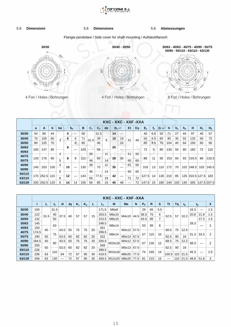
5.6 Abmessungen5.6 Dimensions5.6 Dimensioni
KXC
XXA
XXF
XXC
q
14
5.6 Abmessungen5.6 Dimensions5.6 Dimensioni
Flangia pendolare / Side cover for shaft mounting / Aufsteckflansch
KXC - XXC - XXF -XXAa A b be b2 B C1 C2 de D2 H7 Et Eq E2 f2 G h8 h h1 h2 H H1 H2
30/30 54 80 44
3
5 — 56
31.5
31.5
9
14 —
41 40
40 6.5 55 71 27 44 97 40 57
30/40 70 105 60 6 6 71 39 18 19 50 6.5 60 90 35 55 125 50 7530/50 80 125 70
88 85 46
2524 60 8.5 70 104 40 64 150 60 90
30/63100 147 85 — 103 56 — 72 9 80 130 50 80 182 72 110
40/634 39 11 51 50
40/75120 176 90 8 8 112 60 28 30 86 11 95 153 60 93 219.5 86 133.5
50/75 5 46 14 60 6040/90
140 203 1004
10 — 13039
7011
35 —51 50
103 13 110 172 70 102 248.5 103 145.550/90
5 46 14 60 6050/110
170 252.5 115 12 — 143 77.5 42 — 127.5 14 130 210 85 125 310.5 127.5 18363/110 6 56 19 71 7263/130 200 292.5 120 6 14 14 155 56 85 19 45 48 — 72 147.5 15 180 240 100 140 355 147.5 207.5
KXC - XXC - XXF -XXAI I1 I2 Jt Jq Kc Kq L Lt M Me N PP R S Tt Tq te t2 X
30/30 100
31.5
31.5
37.5 40 57 57 15
171.5 M6x8
M4x10 44.5
29 65 5.5
52.5 57 10.2
16.3 — 1.5
30/40 122 40 203.5 M6x10 36.5 75 6 20.8 21.8 1.530/50 132 50 223.5 M8x10 43.5 85 7
28.327.3 1.5
30/63 14563
248.5M8x14 53 95 8 — 2
40/63 15040 43.5 50 75 75 20
261M4x12 57.5 68.5 75 12.5
40/75 174.575
299.5M8x14 57 115 10 31.3 33.3 2
50/75 190 50 53.5 60 82 82 25 322 M5x13 67.5 82.5 90 1640/90 184.5 40
9043.5 50 75 75 20 326.5
M10x18M4x12 57.5
67 130 1268.5 75 12.2
38.3 — 250/90 200
50 53.5 60 82 82 25349
M5x13 67.5 82.5 90 1650/110 226
110399.5
M10x18 74 165 14 45.3 — 2.563/110 236 63 64 72 97 95 30 419.5 M8x20 77.5 100.5 110 21.563/130 256 63 130 — 72 97 95 30 459.5 M12x20 M8x20 77.5 81 215 15 — 110 21.5 48.8 51.8 3
30/40 - 30/5030/30 30/63 - 40/63 - 40/75 - 40/90 - 50/7550/90 - 50/110 - 63/110 - 63/130
15

5.6 Abmessungen5.6 Dimensions5.6 Dimensioni
KKC_A
KKC_B
KKC_V
KKC_P
c
16
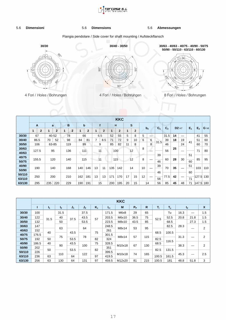
5.6 Abmessungen5.6 Dimensions5.6 Dimensioni
KKC
A a B b f H Sb2 C1 C2 D2 H7 E1 E2 G h8
1 2 1 2 1 2 1 2 1 2 1 2 1 2
30/30 67 40-52 78 66 6.5 52 55 5 8 5 —
31.5
31.5 14 —
41
41 5530/40 86.5 70 52 98 84 81 7 8.5 71 72 9 10 6 6 39 18 19 51 6030/50 106 63-85 119 99 9 85 82 11 8
88 46
2524 60 70
30/63127.5 95 136 111 11 100 12 — 56 — 71 80
40/6339 51
40/75155.5 120 140 115 11 115 12 8 — 60 28 30 85 95
50/75 46 6040/90
190 140 168 140 146 13 11 135 142 14 10 —39
70 35 —51
103 11050/90
46 6050/110
250 200 210 162 181 13 13 171 170 17 15 12 — 77.5 42 — 127.5 13063/110 56 7163/130 295 235 220 229 190 191 15 200 195 20 15 14 56 85 45 48 71 147.5 180
KKCI I1 I2 J1 J2 Kc Lt M PP R Ti Tu t2 X
30/30 100
31.5
31.5
37.5
37.5
57
171.5 M6x8 29 65
52.5
Tu 16.3 — 1.5
30/40 122 40 43.5 203.5 M6x10 36.5 75 52.5 20.8 21.8 1.530/50 132 50 53.5 223.5 M8x10 43.5 85 68.5
28.327.3 1.5
30/63 14763 64
248.5M8x14 53 95
82.5— 2
40/63 15240 43.5 75
26168.5 100.5
40/75 176.575 78
301.5M8x14 57 115 31.3 — 2
50/75 192 50 53.5 82 324 82.5116.5
40/90 186.5 4090
43.5100
75 328.5M10x18 67 130
68.538.3 — 2
50/90 20250 53.5 82
35182.5 131.5
50/110 226110 122
399.5M10x18 74 165 45.3 — 2.5
63/110 236 63 64 97 419.5 100.5 161.563/130 256 63 130 64 131 97 459.5 M12x20 81 215 100.5 181 48.8 51.8 3
Flangia pendolare / Side cover for shaft mounting / Aufsteckflansch
30/40 - 30/5030/30 30/63 - 40/63 - 40/75 - 40/90 - 50/75 50/90 - 50/110 - 63/110 - 60/130
17

Flangia uscita / Output flange / Abtriebsflansch
KXXXKK
TipoTypeTyp
C
FGH8
P Q R U
V
ZØ
30/30F1
31.566 50 54.5 23 68 4 n* 4 6.5 6
F2F3
30/40F1
3985 60 67 28 75-90 4 n* 4 9 8
F2 85 60 97 58 75-90 4 n* 4 9 8F3 140 95 80 41 115 5 n° 7 9 10
30/50F1
4694 70 90 44 85-100 5 n* 4 11 10
F2 160 110 89 43 130 5 n* 7 11 11F3
30/6340/63
F156
142 115 82 26 150 5 n* 4 11 11F2 142 115 112 56 150 5 n* 4 11 11F3 160 110 80.5 24.5 130 5 n* 4 11 12
40/7550/75
F160
160 130 111 51 165 5 n* 4 13 12F2 160 110 90 30 130 6 n* 4 11 13F3
40/9050/90
F170
200 152 111 41 175 5 n* 4 13 12F2 200 152 151 81 175 5 n* 4 13 13F3 200 130 110 40 165 6 n* 4 11 11
50/11063/110
F177.5
260 170 131 53.5 230 6 n° 8 13 15F2 250 180 150 72.5 215 5 n* 4 15 16F3
63/130F1
85320 180
140 55255
7 n° 8 * 16 16F2 300 230 265F3
30/30
F1——
30/40 30/50
— —— F2F3 —
30/40 30/50
F1 F1F2 —— —
30/6340/63
40/7550/75
— —— F2F3 —
30/6340/63
40/7550/75
F1 F1F2 —— —
40/9050/90
50/11063/110
F1 —F2 F2F3 —
40/9050/90
50/11063/110
— F1— —— —
Vista da A / View from A / Ansicht von A
5.6 Abmessungen5.6 Dimensions5.6 Dimensioni
63/130
F1F2—
* Foratura ruotata di 22.5° * Drilling t * Durchbohrung 22.5° versetzt
18

N.B.: E’ possibile realizzare anche tutte le com-posizioni ibride ottenibili dalle flange esistenti.
N.B.: it is possible to create hybrid combina-tions with the existing flanges.
ANMERKUNG: Mischkombinationen mit der verfügbaren Flanschen sind möglich.
Flangia entrata / Input flange / Antriebsflansch
KXCXXCKKC
IEC G1H7
PM
R1 U1
V1
Y Z1
Diametro fori PAM / Holes diameter IECIEC Durchmesser
1 2 Ø150200300
450 600 900 1200 15002500
19503250 4000 5000
10000
30/3030/4030/5030/63
56 B5 80 • • 100 4 7 8 120 8 9 9 9 9 9 9 9 9 956 B14 50 • • 65 3.5 6 8 80 8 9 9 9 9 9 9 9 9 963 B5 95 • • 115 4 9 8 140 8 11 11 11 11 11 11 / / /63 B14 60 • • 75 4 6 8 90 8 11 11 11 11 11 11 / / /
40/6340/7540/90
56 B5 80 • • 100 4 7 8 120 9 / / / / / 9 9 9 956 B14 50 • 65 3.5 6 4 80 8 / / / / / 9 9 9 963 B5 95 • • 115 4 9 8 140 9 11 11 11 11 11 11 11 11 1163 B14 60 • 75 3.5 6 4 90 8 11 11 11 11 11 11 11 11 1171 B5 110 • • 130 4.5 9 8 160 10 14 14 14 14 14 / / / /71 B14 70 • • 85 3.5 7 8 105 8 14 14 14 14 14 / / / /
50/7550/9050/110
63 B5 95 • • 115 4 9 8 140 9 / / / / 11 11 11 11 1163 B14 60 • 75 3.5 6 4 90 8 / / / / 11 11 11 11 1171 B5 110 • • 130 4.5 9 8 160 10 14 14 14 14 14 14 14 14 1471 B14 70 • 85 3.5 7 4 105 8 14 14 14 14 14 14 14 14 1480 B5 130 • • 165 4.5 11 8 200 10 19 19 19 19 19 / / / /80 B14 80 • • 100 4 7 8 120 10 19 19 19 19 19 / / / /
63/11063/130
71 B5 110 • • 130 4.5 9 8 160 10 / / / / 14 14 14 14 1471 B14 70 • 85 3.5 7 4 105 10 / / / / 14 14 14 14 1480 B5 130 • • 165 4.5 11 8 200 10 19 19 19 19 19 19 19 19 1980 B14 80 • 100 4 7 4 120 10 19 19 19 19 19 19 19 19 1990 B5 130 • • 165 4.5 11 8 200 10 24 24 24 24 / / / / /90 B14 95 • • 115 4 8.5 8 140 10 24 24 24 24 / / / / /
5.6 Abmessungen5.6 Dimensions5.6 Dimensioni
KX ..C XX ..C KK ..C
Z1U1
YR1
G1
V1
PM = 1 PM = 2
45°A
B
C
DE H
GF
19

5.7 Drehmomentbegrenzer mit durchgehender Hohlwelle
5.7 Torque limiter with through hollow shaft
5.7 Limitatore di coppia cavo passante
5.6 Abmessungen5.6 Dimensions5.6 Dimensioni
XXF IEC
PMG1H7
KF
V1
Y Z11 2 R1 U1 Ø
30/3030/4030/5030/63
56 B5 • • 80 82.5 100 3.5 7 8 120 856 B14 • 50 82.5 65 3.5 6 4 80 863 B5 • • 95 85.5 115 4 9 8 140 1063 B14 • • 60 85.5 75 3.5 6 8 90 8
40/6340/7540/90
56 B5 • • 80 101.5 100 3.5 7 8 120 863 B5 • • 95 104.5 115 4 9 8 140 1063 B14 • • 60 104.5 75 3.5 6 8 90 871 B5 • • 110 111.5 130 4.5 9 8 160 1071 B14 • • 70 111.5 85 4 7 8 105 10
50/7550/9050/110
63 B5 • • 95 119.5 115 4 9 8 140 1071 B5 • • 110 126.5 130 4.5 9 8 160 1071 B14 • 70 126.5 85 3.5 7 4 105 1080 B5 • • 130 136.5 165 4.5 11 8 200 1080 B14 • • 80 136.5 100 4 7 8 120 10
63/11063/130
71 B5 • • 110 141.5 130 4.5 9 8 160 1080/90 B5 • • 130 161.5 165 4.5 11 8 200 1080 B14 • • 80 151.5 100 4 7 8 120 1090 B14 • • 95 161.5 115 4 9 8 140 10
Flangia entrata / Input flange / Antriebsflansch
Z1U1
KF
YR1
G1
V1
XX ..F
PM = 1 PM = 2
45°A
B
C
DE H
GF
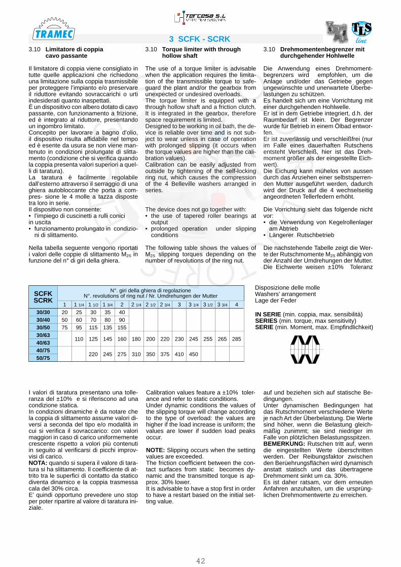
Er ist zuverlässig und verschleißfrei (nur im Falle eines dauerhaften Rutschens entsteht Verschleiß, hier ist das Dreh-moment größer als der eingestellte Eich-wert).Die Eichung kann mühelos von aussen durch das Anziehen einer selbstsperren-den Mutter ausgeführt werden, dadurch wird der Druck auf die 4 wechselseitig angeordneten Tellerfedern erhöht.
Die Vorrichtung sieht das folgende nicht vor:• die Verwendung von Kegelrollenlager
am Abtrieb• Längerer Rutschbetrieb
Die nachstehende Tabelle zeigt die Wer-te der Rutschmomente M2S abhängig von der Anzahl der Umdrehungen der Mutter. Die Eichwerte weisen ±10% Toleranz
Designed to be working in oil bath, the de-vice is reliable over time and is not sub-ject to wear unless in case of operation with prolonged slipping (it occurs when the torque values are higher than the cali-bration values). Calibration can be easily adjusted from outside by tightening of the self-locking ring nut, which causes the compression of the 4 Belleville washers arranged in series.
The device does not go together with:• the use of tapered roller bearings at
output• prolonged operation under slipping
conditions
The following table shows the values of M2S slipping torques depending on the number of revolutions of the ring nut.
Concepito per lavorare a bagno d’olio, il dispositivo risulta affidabile nel tempo ed è esente da usura se non viene man-tenuto in condizioni prolungate di slitta-mento (condizione che si verifica quando la coppia presenta valori superiori a quel-li di taratura).La taratura è facilmente regolabile dall’e-sterno attraverso il serraggio di una ghie-ra autobloccante che porta a compres- sione le 4 molle a tazza disposte tra loro in serie.Il dispositivo non consente:• l’impiego di cuscinetti a rulli conici in uscita• funzionamento prolungato in condizio-
ni di slittamento.
Nella tabella seguente vengono riportati i valori delle coppie di slittamento M2S in funzione del n° di giri della ghiera.
20

IN SERIE (min. coppia, max. sensibilità)SERIES (min. torque, max sensitivity)SERIE (min. Moment, max. Empfindlichkeit)
Disposizione delle molleWashers’ arrangementLage der Feder
XX-KXKK
N°. giri della ghiera di regolazione / N°. revolutions of ring nut / Nr. Umdrehungen der Mutter1 1 1/4 1 1/2 1 3/4 2 2 1/4 2 1/2 2 3/4 3 3 1/4 3 1/2 3 3/4 4 4 1/4 4 1/2
30/30 20 25 30 35 4030/40 50 60 70 80 9030/50 75 95 115 135 15530/63
110 125 145 160 180 200 220 230 245 255 265 28540/6340/75
220 245 275 310 350 375 410 45050/7540/90
330 365 410 435 465 500 530 560 580 600 630 67050/9050/110
750 860 1000 1100 123063/11063/130
XX - KXC2 CL Ct
D2H7
G2 M2LD - LS
30/30 31.5 55.5 87 14 M25x1.5 50x25.4x1.530/40 39 65 104 18 (19) M30x1.5 56x30.5x230/50 46 76 122 25 (24) M40x1.5 63x40.5x2.530/63
56 91 147 25 M40x1.5 71x40.5x2.540/6340/75
60 100 160 28 (30) M50x1.5 90x50.5x3.550/7540/90
70 109 179 35 (32) M50x1.5 100x51x3.550/9050/110
77.5 127.5 205 42 M60x2 125x61x563/11063/130
5.7 Drehmomentbegrenzer mit durchgehender Hohlwelle
5.7 Torque limiter with through hollow shaft
5.7 Limitatore di coppia cavo passante
LD LS
I valori di taratura presentano una tolle-ranza del ±10% e si riferiscono ad una condizione statica.In condizioni dinamiche è da notare che la coppia di slittamento assume valori di-versi a seconda del tipo e/o modalità in cui si verifica il sovraccarico: con valori maggiori in caso di carico uniformemente crescente rispetto a volori più contenuti in seguito al verificarsi di picchi improv-visi di carico. NOTA: quando si supera il valore di tara-tura si ha slittamento. Il coefficiente di at-trito tra le superfici di contatto da statico diventa dinamico e la coppia trasmessa cala del 30% circa.E’ quindi opportuno prevedere uno stop per poter ripartire al valore di taratura ini-ziale.
Calibration values feature a ±10% toler-ance and refer to static conditions. Under dynamic conditions the values of the slipping torque will change according to the type of overload: the values are higher if the load increase is uniform; the values are lower if sudden load peaks occur.
NOTE: Slipping occurs when the setting values are exceeded. The friction coefficient between the con-tact surfaces from static becomes dy-namic and the transmitted torque is ap-prox. 30% lower. It is advisable to have a stop first in order to have a restart based on the initial set-ting value.
auf und beziehen sich auf statische Be-dingungen.Unter dynamischen Bedingungen hat das Rutschmoment verschiedene Werte je nach Art der Überbelastung. Die Werte sind höher, wenn die Belastung gleich-mäßig zunimmt; sie sind niedriger im Falle von plötzlichen Belastungsspitzen. BEMERKUNG: Rutschen tritt auf, wenn die eingestellten Werte überschritten werden. Der Reibungsfaktor zwischen den Berüehrungsflächen wird dynamisch anstatt statisch und das übertragene Drehmoment sinkt um ca. 30%. Es ist daher ratsam, vor dem erneuten Anfahren anzuhalten, um die ursprüng-lichen Drehmomentwerte zu erreichen.
21
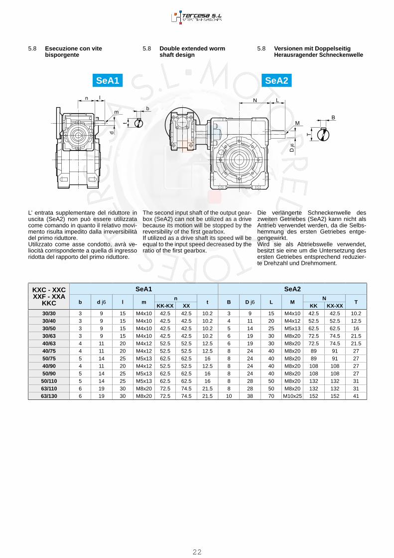
5.8 Versionen mit Doppelseitig Herausragender Schneckenwelle
5.8 Double extended worm shaft design
5.8 Esecuzione con vite bisporgente
SeA2
KXC - XXCXXF - XXA
KKC
SeA1 SeA2
b d j6 l mn
t B D j6 L MN
TKK-KX XX KK KX-XX
30/30 3 9 15 M4x10 42.5 42.5 10.2 3 9 15 M4x10 42.5 42.5 10.230/40 3 9 15 M4x10 42.5 42.5 10.2 4 11 20 M4x12 52.5 52.5 12.530/50 3 9 15 M4x10 42.5 42.5 10.2 5 14 25 M5x13 62.5 62.5 1630/63 3 9 15 M4x10 42.5 42.5 10.2 6 19 30 M8x20 72.5 74.5 21.540/63 4 11 20 M4x12 52.5 52.5 12.5 6 19 30 M8x20 72.5 74.5 21.540/75 4 11 20 M4x12 52.5 52.5 12.5 8 24 40 M8x20 89 91 2750/75 5 14 25 M5x13 62.5 62.5 16 8 24 40 M8x20 89 91 2740/90 4 11 20 M4x12 52.5 52.5 12.5 8 24 40 M8x20 108 108 2750/90 5 14 25 M5x13 62.5 62.5 16 8 24 40 M8x20 108 108 2750/110 5 14 25 M5x13 62.5 62.5 16 8 28 50 M8x20 132 132 3163/110 6 19 30 M8x20 72.5 74.5 21.5 8 28 50 M8x20 132 132 3163/130 6 19 30 M8x20 72.5 74.5 21.5 10 38 70 M10x25 152 152 41
SeA1
Die verlängerte Schneckenwelle des zweiten Getriebes (SeA2) kann nicht als Antrieb verwendet werden, da die Selbs-hemmung des ersten Getriebes entge-gengewirkt. Wird sie als Abtriebswelle verwendet, besitzt sie eine um die Untersetzung des ersten Getriebes entsprechend reduzier-te Drehzahl und Drehmoment.
The second input shaft of the output gear-box (SeA2) can not be utilized as a drive because its motion will be stopped by the reversibility of the first gearbox. If utilized as a drive shaft its speed will be equal to the input speed decreased by the ratio of the first gearbox.
L’ entrata supplementare del riduttore in uscita (SeA2) non può essere utilizzata come comando in quanto il relativo movi-mento risulta impedito dalla irreversibilità del primo riduttore.Utilizzato come asse condotto, avrà ve-liocità corrispondente a quella di ingresso ridotta del rapporto del primo riduttore.
22

5.9 Accessories5.9 Accessories5.9 Accessori
Albero lento Output shaft AbtriebswelleAlbero lento semplice
Single output shaftStandard Abtriebswelle
Albero lento doppioDouble output shaft
Doppelte Abtriebswelle
Braccio di reazione Torque arm Drehmomentstütze
Kit di protezione: solo su versione P Protection Kit: only for P version Schutzvorrichtung: nur für Version P
Opzioni disponibili:
Cuscinetti a rulli conici corona
Available options:
Tapered roller bearing on wormgear
Auf Anfrage ist folgendes Zubehör erhältlich:Kegelrollenlager auf Schneckenrad
Albero cavo / Hollow shaft / Hohlwelle Limitatore di coppia / Torque limiter / Drehmomentbegrenzer
KKKXXX
a b D1 E H K Lt O S1 S2
30/30 85 37.5 55 65 8 24 141.5 7 14 430/40 100 45 60 75 10 31.5 167 7 14 430/50 100 50 70 85 10 39 172 9 14 530/6340/63 150 55 80 95 10 49 227 9 14 6
40/7550/75 200 70 95 115 20 47.5 302 9 25 6
40/9050/90 200 80 110 130 20 57.5 312 11 25 6
50/11063/110 250 100 130 165 25 62 390 11 30 6
63/130 250 125 180 215 25 69 415 13 30 6
KKKXXX
A B C
IN OUT IN OUT IN OUT
30/30
12
12
13
13
39
3930/40 14 15.5 4430/50 15 16.5 5430/63
17 19 6040/63
14 15.5 4440/75
18 20 7050/75 15 16.5 5440/90 14
21.515.5
2444
8050/90
15 16.5 5450/110
22 25 9663/110 17 19 6063/130 17 22 19 25 60 130
KKKXXX
A B C
IN OUT IN OUT IN OUT
30/30
36
36
37
37
36
3630/40 40 41.5 4430/50 47 48.5 5330/63
52 54 5540/63
40 41.5 4440/75
58 60 6850/75 47 48.5 5340/90 40
60.541.5
6344
7050/90
47 48.5 5350/110
72 75 8563/110 52 54 5563/130 52 54 55
KK-KX-XX A B dh6
d1 e L M m S
30/30 30 62 14 18.5 20 94.5 M6 16 2.530/40 40 77 18 19 23.5 30 120 M6 16 330/50 50 90 25 24 31.5 40 143.5 M8 22 3.530/6340/63 50 111 25 31.5 40 165 M8 22 4
40/7550/75 60 119 28 30 34.5 50 183 M8 22 4
40/9050/90 80 139 35 41.5 60 224 M10 28 5
50/11063/110 80 154.5 42 49.5 60 242.5 M10 28 8
63/130 80 168 45 54.5 70 253 M16 36 5
A A b Bbdh6
d1 e Lb Sb
30 29 64 14 18.5 20 126 2.540 39 79 18 23.5 30 161 350 49 93 25 31.5 40 195.5 3.5
50 49 113 25 31.5 40 216 4
60 59 121 28 34.5 50 244 4
80 78.5 141.5 35 41.5 60 305 5
80 77.5 157 42 49.5 60 322.5 8
80 78 172 45 54.5 70 335 5
23

5.10 Ersatzteilliste5.10 Spare parts list5.10 Lista parti di ricambio
KXC - XXC - XXA - XXF - KKC
INX..P - K..P KIT OUT
XC - KC
30/30X30
KC30
KIT 30/30 (2850002010) 30/930/40 KIT 30/40 (2850002013) 40/1130/50 KIT 30/50 (2850002016) 50/1430/63 KIT 30/63 (2850002019) 63/1940/63
X40KC40
KIT 40/63 (2850002028) 63/1940/75
KIT 40/75-90 (2850002031)75/24
40/90 90/2450/75
X50KC50
KIT 50/75-90 (2850002034)75/24
50/90 90/2450/110 KIT 50/110 (2850002049) 110/28
63/110 X63KC63 KIT 63/110-130 (2850002052) 110/28
63/130 X63KC63 KIT 63/110-130 (2850002052) 110/28
1 32
2
3
1
24

5.10 Ersatzteilliste5.10 Spare parts list5.10 Lista parti di ricambio
X - H - K - KX - XX - KK
A BX - H - K
30 (LD - LS) 40 (LD - LS) 50 (LD - LS) 63 (LD - LS) 75 (LD - LS) 90 (LD - LS) 110 (LD - LS) 130 (LD - LS)
KX - XX - KK
30/30 (L1-LD-LS)30/40 (L1)30/50 (L1)30/63 (L1)
30/40 (LD - LS)40/63 (L1)40/75 (L1)40/90 (L1)
30/50 (LD - LS)50/75 (L1)50/90 (L1)50/110 (L1)
30/63 (LD - LS)40/63 (LD - LS)
63/110 (L1)
40/75 (LD - LS)50/75 (LD - LS)
40/90 (LD - LS)50/90 (LD - LS)
50/110 (LD - LS)63/110 (LD - LS) 63/130 (LD - LS)
1 Corona in bronzo / Bronze wheel / Bronzerad /
2 Albero cavo limitatore / Hollow shaft torque limiter / Rutschkupplungs-Hohlwelle
3 Anello di frizione / Friction ring / Reibring
4 Distanziale molle / Washers’ distance ring / Federdistanzring
5Linguetta / key / Passfeder
8x7x10AB 10x8x13AB 12x8x18AB 12x8x40A 16x10x40A 16x10x50A 18x11x60A
6 Molle a tazza / Belleville washers / Tellerfeder
7 Ghiera / Metal ring / Metall Ring
8 6005 25x47x12
600630x55x13
600840x68x15
600840x68x15
601050x80x16
601050x80x16
601260x95x18
9 25x40x7 30x47x7 40x62x8 40x62x8 50x72x8 50x72x8 60x85x8
10 30x40x5 35x47x7 48x62x8 48x62x8 58x72x8 58x72x8 70x85x8
11 OR2087 21.95x1.78
OR210626.7x1.78
OR36.27x1.78
OR36.27x1.78
OR218747.37x1.78
OR218747.37x1.78
OR222556.87x1.78
12 — Distanziale / Spacer / Abstandshülse
A B
Drehmomentbegrenzer mit durchgehende Hohlwelle
Torque limiter with through hollow shaftLimitatore di coppia cavo passante
25

26

line
3 RIDUTTORI A VITE SENZA FINE COMBINATI SCFK-SCRK
SCFK-SCRK COMBINED WORM GEARBOXES
KOMBINIERTE-SCHNECKENGETRIEBE SCFK-SCRK
3.1 Caratteristiche Characteristics Merkmale 343.2 Designazione Designation Bezeichnung 343.3 Lubrificazione e posizioni
di montaggioLubrication andmounting position
Schmierung undEinbaulage
36
3.4 Posizione morsettiera Terminal board position Lage des Klemmkasten 373.5 Dati tecnici Technical data Technische Daten 383.6 Predisposizioni possibili Possible set-ups Mögliche Vorrichtungen 413.7 Dimensioni Dimensions Abmessungen 423.8 Accessori Accessories Zubehör 463.9 Esecuzione con vite bisporgente Double extended worm shaft
designVersionen mit Doppelseitig Herausragender Schneckenwelle
47
3.10 Limitatore di coppiacavo passante
Torque limiter with throughhollow shaft
Drehmomentbegrenzermit durchgehender Hohlwelle
48
3.11 Lista parti di ricambio Spare parts list Ersatzteilliste 50
27

34
line3 SCFK - SCRK
3.2 Bezeichnung3.2 Designation3.2 Designazione
Ausführungen Versions Versioni
Bei der Bestellung immer die Bauform angeben.
Specify the version when ordering.Specificare sempre in fase di ordinazio-ne la versione.
SCFK..A_ SCRK..A_
SCFK..B_ SCRK..B_
SCFK..V_ SCRK..V_
SCFK..P_ SCRK..P_
SCFK..F_S SCRK..F_S
SCFK..F_D SCRK..F_D
Rid
utto
reG
earb
oxG
etrie
be
Gra
ndez
za
Siz
eG
röß
e
Rap
port
o rid
. R
atio
Unt
erse
tzun
g
Pre
disp
os.a
tt. m
ot.
Mot
or c
oupl
ing
Mot
oran
schl
uss
Ver
sion
eV
ersi
onV
ersi
on
For
ma
cost
rutti
vaE
xecu
tion
Bau
form
Pos
izio
ne d
i mon
t. M
ount
ing
posi
tion
Ein
baul
age
Lim
itato
re d
i cop
pia.
Torq
ue li
mite
rD
rehm
omen
t-be
gren
zer
Sec
onda
ent
rata
Add
ition
al in
put
Zus
atza
ntrie
b
Alb
ero
usci
taO
utpu
t sha
ftA
btrie
bsw
elle
Bra
ccio
di r
eazi
one
Torq
ue a
rmD
rehm
omen
tstü
tze
SCFK 50/75 1200 P.A.M. FS a B3 LD SeA1 H BR
SCFK
SCRK
30/3030/4030/5030/6340/6340/7550/75
150200300450600900120015001950250032504000500010000
5663718090
ABV
P
F...S F...D
ab
cd
ef
gh
ik
im
no
pq
B3
B6
B7
B8
V5
V6
SeA1
SeA2
H
SD
SS
DD
BR1
BR2
3.1 Merkmale
Die Kombination zweier Schneckenge-triebe bringt sehr niedrigen Wirkungs-grad mit sich, es handelt sich jedoch um eine interessante und manchmal uner-setzbare Lösung, weil eine hohe Dreh-zahlverringerung in einem beträchtlich reduzierten Raum erzielt werden kann.
Die Hohlwelle gehört zur serienmäßi-gen Ausstattung. Eine breite Auswahl an Zubehör ist erhältlich: zweiter Antrieb, Kegelrollenlager auf Schneckenrad, Ab-triebs- flansch, standard oder doppelsei-tig herausragende Abtriebswelle, Dreh-momentbegrenzer mit durchgehender Hohlwelle, Drehmomentstütze.
3.1 Characteristics
The combination of two worm gearboxes provides very low efficiency, however the fact that substantial reduction in speed can be obtained in an extremely reduced space makes this solution very interesting and sometimes irreplaceable.
The hollow shaft is supplied as standard. A broad range of accessories is avalable:second input, tapered roller bearings on the worm wheel, output flange, single or double extended output shaft, torque limiter with through hollow shaft, torque arm.
3.1 Caratteristiche
La combinazione di due riduttori a vite senza fine comporta rendimenti molto bassi, ma l’elevata riduzione di velocità ottenuta in uno spazio ridottissimo rende comunque interessante, e a volte insosti- tuibile, questa soluzione.
Sono forniti con albero cavo di serie ed esiste un’ampia gamma di accessori:seconda entrata, cuscinetti conici sulla corona, flangia uscita, albero lento con 1 o 2 sporgenze, limitatore di coppia con cavo passante, braccio di reazione.
LD
LS
28

line 3 SCFK - SCRK3.2 Bezeichnung3.2 Designation3.2 Designazione
A
B
V
P
F
Forma costruttiva / version / Bauform
Forma costruttiva non realizzabile su: / Version not feasible on: / Bauform nicht ausführbar für:30/30, 30/40, 30/50 PAM 63B5 (ø 140), 40/63 PAM 71B5 (ø 160)
29

line3 SCFK - SCRK
F (b, d, f, h, k, m, o, q) P (a, b, c, d, i, k, l, m)
F (a, c, e, g, i, l, n, p)
F,P
A
B
V
3.3 Schmierung
SCFK - SCRK Schneckengetriebe wer-den mit PAG synthetischen Schmierstoff Viskositätsklasse ISO 320 geliefert. Gehäuse aus Alumiunium verfügen über nur eine Einfüllschraube.Im Auftrag sind immer Einbaulage und Bauform anzugeben.
3.3 Lubrication
SCFK - SCRK worm gearboxes are sup-plied with PAG synthetic lubricant featur-ing an ISO 320 viscosity class.Aluminium housings have one filling plug only.Always specify the version and the mounting position when ordering.
3.3 Lubrificazione
I riduttori a vite senza fine SCFK - SCRK sono forniti tutti e sempre completi di lu-brificante sintetico a base PAG con clas-se di viscosità ISO 320.Nei corpi in alluminio è presente un solo tappo di riempimento olio.Si raccomanda di precisare sempre in fase di ordine la forma costruttiva e la po-sizione di lavoro desiderata.
BezeichnungMounting positionsPosizioni di montaggio
B3 B6 B7 B8 V5 V6
30
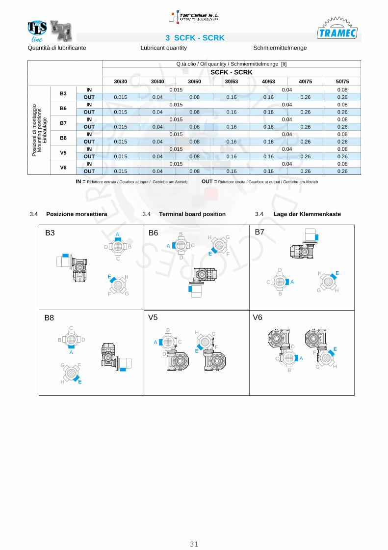
line 3 SCFK - SCRKSchmiermittelmengeLubricant quantityQuantità di lubrificante
Q.tà olio / Oil quantity / Schmiermittelmenge [lt]
SCFK - SCRK30/30 30/40 30/50 30/63 40/63 40/75 50/75
Pos
izio
ni d
i mon
tagg
ioM
ount
ing
posi
tions
Ein
baul
age
B3IN 0.015 0.04 0.08
OUT 0.015 0.04 0.08 0.16 0.16 0.26 0.26
B6IN 0.015 0.04 0.08
OUT 0.015 0.04 0.08 0.16 0.16 0.26 0.26
B7IN 0.015 0.04 0.08
OUT 0.015 0.04 0.08 0.16 0.16 0.26 0.26
B8IN 0.015 0.04 0.08
OUT 0.015 0.04 0.08 0.16 0.16 0.26 0.26
V5IN 0.015 0.04 0.08
OUT 0.015 0.04 0.08 0.16 0.16 0.26 0.26
V6IN 0.015 0.04 0.08
OUT 0.015 0.04 0.08 0.16 0.16 0.26 0.26
IN = Riduttore entrata / Gearbox at input / Getriebe am Antrieb OUT = Riduttore uscita / Gearbox at output / Getriebe am Abtrieb
3.4 Lage der Klemmenkaste3.4 Terminal board position3.4 Posizione morsettiera
A
A
B
B
C
C
D
D
B3
B8
B6 B7
V5 V6
A
B
C
D
A
A
B
B
C
C
D
DA
B
C
D
E H
GF
E
H G
F
E
H
F
G
EH
G F
E
H G
F E
HG
F
31

line3 SCFK - SCRK3.5 Technische Daten3.5 Technical data3.5 Dati tecnici
30/30
n1 = 1400 SCFK SCRK
in30 30 n2 T2 P1 FS’
input IEC T2M PRd
i1 i2 [min-1] [Nm] [kW] B5 B14 [Nm] [kW]150
1015 9.3 32 0.06 1.2
56-63
37 0.070 0.51200 20 7.0 39 0.06 0.8 32 0.050 0.47300
30
4.7 52* 0.06 0.8* 39 0.045 0.42450 15 3.1 73* 0.06 0.5* 39 0.032 0.40600 20 2.3 91* 0.06 0.4* 39 0.026 0.37900 30 1.6 125* 0.06 0.3* 39 0.019 0.34
1200 40 1.2 149* 0.06 0.3* 39 0.016 0.301500 50 0.9 173* 0.06 0.2* 39 0.014 0.281950 65 0.7 209* 0.06 0.2* 56 39 0.011 0.262500 50
50
0.6 235* 0.06 0.1* 56-63 30 0.008 0.233.0 3250 65 0.4 283* 0.06 0.11*
56
30 0.006 0.214000 80 0.4 328* 0.06 0.09* 30 0.005 0.205000
1000.3 385* 0.06 0.08* 30 0.005 0.19
10000 100 0.1 609* 0.06 0.03* 17 0.002 0.15
* ACHTUNG: das max. anwendbare Drehmoment [T2M] muss mit folgendem Betriebsfaktor berechnet werden: T2M = T2 x FS’
* WARNING: Maximum allowable torque [T2M] must be calculated using the follow-ing service factor : T2M = T2 x FS’
* ATTENZIONE: la coppia massima utiliz-zabile [T2M] deve essere calcolata utiliz-zando il fattore di servizio: T2M = T2 x FS’
30/40
n1 = 1400 SCFK SCRK
in30 40 n2 T2 P1 FS’
input IEC T2M PRd
i1 i2 [min-1] [Nm] [kW] B5 B14 [Nm] [kW]150
1015 9.3 72 0.13 1.1
56-63
82 0.148 0.54200 20 7.0 76 0.11 1.0 76 0.110 0.51300
30
4.7 79 0.09 1.0 82 0.094 0.43450 15 3.1 74 0.06 1.1 82 0.067 0.40600 20 2.3 92 0.06 0.9 82 0.054 0.37900 30 1.6 126* 0.06 0.6* 82 0.039 0.34
1200 40 1.2 151* 0.06 0.5* 82 0.033 0.311500 50 0.9 176* 0.06 0.5* 82 0.028 0.291950 65 0.7 212* 0.06 0.4* 56 82 0.023 0.272500 50
50
0.6 236* 0.06 0.3* 56-63 68 0.017 0.234.0 3250 65 0.4 285* 0.06 0.24*
56
68 0.014 0.214000 80 0.4 330* 0.06 0.21* 68 0.012 0.205000
1000.3 387* 0.06 0.18* 68 0.011 0.19
10000 100 0.1 626* 0.06 0.06* 35 0.003 0.15
30/50
n1 = 1400 SCFK SCRK
in30 50 n2 T2 P1 FS’
input IEC T2M PRd
i1 i2 [min-1] [Nm] [kW] B5 B14 [Nm] [kW]150
1015 9.3 124 0.22 1.2
56-63
149 0.265 0.55200 20 7.0 129 0.18 1.1 144 0.201 0.52300
30
4.7 118 0.13 1.3 150 0.166 0.44450 15 3.1 140 0.11 1.1 150 0.118 0.42600 20 2.3 143 0.09 1.0 150 0.094 0.39900 30 1.6 131 0.06 1.1 150 0.069 0.36
1200 40 1.2 156 0.06 1.0 150 0.058 0.321500 50 0.9 182 0.06 0.8 150 0.049 0.301950 65 0.7 220* 0.06 0.7* 56 150 0.041 0.282500 50
50
0.6 253* 0.06 0.5* 56-63 125 0.030 0.256.0 3250 65 0.4 305* 0.06 0.41*
56
125 0.025 0.234000 80 0.4 354* 0.06 0.35* 125 0.021 0.225000
1000.3 414* 0.06 0.30* 125 0.018 0.20
10000 100 0.1 645* 0.06 0.11* 69 0.006 0.16
32

line 3 SCFK - SCRK3.5 Technische Daten3.5 Technical data3.5 Dati tecnici
30/63
n1 = 1400 SCFK SCRK
in30 63 n2 T2 P1 FS’
input IEC T2M PRd
i1 i2 [min-1] [Nm] [kW] B5 B14 [Nm] [kW]150
1015 9.3 126 0.22 1.8
56-63
228 0.400 0.56200 20 7.0 162 0.22 1.7 279 0.378 0.54300
30
4.7 207 0.22 1.3 268 0.285 0.46450 15 3.1 238 0.18 1.1 268 0.202 0.43600 20 2.3 215 0.13 1.2 268 0.162 0.40900 30 1.6 250 0.11 1.1 268 0.118 0.37
1200 40 1.2 243 0.09 1.1 268 0.099 0.331500 50 0.9 189 0.06 1.4 268 0.085 0.311950 65 0.7 228 0.06 1.2 56 268 0.071 0.292500 50
50
0.6 265 0.06 0.8 56-63 222 0.050 0.268.5 3250 65 0.4 319* 0.06 0.70*
56
222 0.042 0.244000 80 0.4 369* 0.06 0.60* 222 0.036 0.235000
1000.3 433* 0.06 0.51* 222 0.031 0.21
10000 100 0.1 663* 0.06 0.21* 138 0.012 0.16
40/63
n1 = 1400 SCFK SCRK
in40 63 n2 T2 P1 FS’
input IEC T2M PRd
i1 i2 [min-1] [Nm] [kW] B5 B14 [Nm] [kW]150
1015 9.3 214 0.37 1.2
63-71
261 0.452 0.56200 20 7.0 277 0.37 1.0 279 0.373 0.55300
30
4.7 238 0.25 1.1 268 0.282 0.46450 15 3.1 244 0.18 1.1 268 0.197 0.44600 20 2.3 226 0.13 1.2 268 0.154 0.43900 30 1.6 257 0.11 1.0 268 0.115 0.38
1200 40 1.2 264 0.09 1.0 268 0.091 0.361500 50 0.9 203 0.06 1.3 63 268 0.079 0.331950 65 0.7 241 0.06 1.1
56-63
268 0.067 0.302500 50
50
0.6 284 0.06 0.8 222 0.047 0.289.5 3250 65 0.4 338* 0.06 0.66* 222 0.039 0.25
4000 80 0.4 400* 0.06 0.55* 222 0.033 0.245000
1000.3 471* 0.06 0.47* 222 0.028 0.23
10000 100 0.1 722* 0.06 0.19* 138 0.011 0.18
* ACHTUNG: das max. anwendbare Drehmoment [T2M] muss mit folgendem Betriebsfaktor berechnet werden: T2M = T2 x FS’
* WARNING: Maximum allowable torque [T2M] must be calculated using the follow-ing service factor : T2M = T2 x FS’
* ATTENZIONE: la coppia massima utiliz-zabile [T2M] deve essere calcolata utiliz-zando il fattore di servizio: T2M = T2 x FS’
33

line3 SCFK - SCRK
40/75
n1 = 1400 SCFK SCRK
in40 75 n2 T2 P1 FS’
input IEC T2M PRd
i1 i2 [min-1] [Nm] [kW] B5 B14 [Nm] [kW]150
1015 9.3 322 0.55 1.3
63-71
409 0.698 0.57200 20 7.0 417 0.55 1.1 442 0.593 0.56300
30
4.7 358 0.37 1.2 418 0.432 0.47450 15 3.1 346 0.25 1.2 418 0.302 0.45600 20 2.3 390 0.22 1.1 418 0.236 0.43900 30 1.6 309 0.13 1.4 418 0.176 0.39
1200 40 1.2 388 0.13 1.1 418 0.140 0.361500 50 0.9 379 0.11 1.1 63 418 0.121 0.341950 65 0.7 368 0.09 1.1
56-63
418 0.102 0.312500 50
50
0.6 296 0.06 1.3 381 0.077 0.2914.5 3250 65 0.4 352 0.06 1.08 381 0.065 0.26
4000 80 0.4 417 0.06 0.91 381 0.055 0.255000
1000.3 491* 0.06 0.78* 381 0.047 0.24
10000 100 0.1 762* 0.06 0.30* 232 0.018 0.19
* ACHTUNG: das max. anwendbare Drehmoment [T2M] muss mit folgendem Betriebsfaktor berechnet werden: T2M =
2 x FS‘
* WARNING: Maximum allowable torque [T2M] must be calculated using the follow-ing service factor : T2M = T2 x FS’
* ATTENZIONE: la coppia massima utiliz-zabile [T2M] deve essere calcolata utiliz-zando il fattore di servizio: T2M = T2 x FS’
3.5 Technische Daten3.5 Technical data3.5 Dati tecnici
50/75
n1 = 1400 SCFK SCRK
in50 75 n2 T2 P1 FS’
input IEC T2M PRd
i1 i2 [min-1] [Nm] [kW] B5 B14 [Nm] [kW]150
1015 9.3 409 0.75 1.0
71-80
409 0.750 0.57200 20 7.0 422 0.55 1.0 442 0.576 0.56300
30
4.7 363 0.37 1.2 418 0.427 0.48450 15 3.1 350 0.25 1.2 418 0.299 0.46600 20 2.3 418 0.25 1.0 418 0.250 0.42900 30 1.6 418 0.18 1.0 418 0.180 0.40
1200 40 1.2 406 0.13 1.0 418 0.134 0.381500 50 0.9 470 0.13 0.9 71 418 0.116 0.351950 65 0.7 572* 0.13 0.7*
63-71
418 0.095 0.332500 50
50
0.6 674* 0.13 0.6* 381 0.074 0.3014.5 3250 65 0.4 819* 0.13 0.47* 381 0.060 0.28
4000 80 0.4 939* 0.13 0.41* 381 0.053 0.265000
1000.3 1108* 0.13 0.34* 381 0.045 0.25
10000 100 0.1 1719* 0.13 0.13* 232 0.018 0.19
34

line 3 SCFK - SCRK3.6 Mögliche Vorrichtungen3.6 Possible set-ups 3.6 Predisposizioni possibili
SCFK PAMIEC G1 K R1 U1
V1Y Z1
Diametro fori PAM / Holes diameter IEC-InputBohrungdurchmesser IEC-Antrieb
Ø150200300
450 600 900 1200 15002500
19503250 4000 5000
10000
30/30 30/4030/5030/63
56 B5 80
57
100 4 7 n° 8 120 8 9 9 9 9 9 9 9 9 9
56 B14 50 65 3.5 6 n° 8 80 8 9 9 9 9 9 9 9 9 9
63 B5 95 115 4 9 n° 8 140 8 11 11 11 11 11 11 11 11 /
63 B14 60 75 4 6 n° 8 90 8 11 11 11 11 11 11 11 11 /
40/6340/75
56 B5 80
75
100 4 7 n° 8 120 9 / / / / / / / 9 9
56 B14 50 65 3.5 6 n° 4 80 8 / / / / / / / 9 9
63 B5 95 115 4 9 n° 8 140 9 11 11 11 11 11 11 11 11 11
63 B14 60 75 3.5 6 n° 4 90 8 11 11 11 11 11 11 11 11 11
71 B5 110 130 4.5 9 n° 8 160 10 14 14 14 14 14 14 14 / /
71 B14 70 85 3.5 7 n° 8 105 8 14 14 14 14 14 14 14 / /
50/75
63 B5 95
82
115 4 9 n° 8 140 9 / / / / / / 11 11 11
63 B14 60 75 3.5 6 n° 4 90 8 / / / / / / 11 11 11
71 B5 110 130 4.5 9 n° 8 160 10 14 14 14 14 14 14 14 14 14
71 B14 70 85 3.5 7 (n° 8)* n° 4 105 8 14 14 14 14 14 14 14 14 14
80 B5 130 165 4.5 11 n° 8 200 10 19 19 19 19 19 19 19 / /
80 B14 80 100 4 7 n° 8 120 10 19 19 19 19 19 19 19 / /
* A richiesta, solo con corpo speciale / Upon request, only with special body / Auf Wunsch nur mit speziellen Körper
35

line3 SCFK - SCRK3.7 Abmessungen3.7 Dimensions3.7 Dimensioni
D
t2
b2
l1
C1
C1Lt
l
l
Lt
E2
E2 C2 C2
l2
TiJ1
S
a
a
a
J2l2
Tu
S
S
H
f
f
fE1
b
B
K
b
b
B
B
C2
C2
C2
C2
J2
TuH
A
A
A
Tu
J1 Ti
l1
l2
Lt
E2
lC
1
HJ2
E1
E1
K
K
YY
l1
l2
TiJ1
Y
SCFK.../A
SCFK.../B
SCFK.../V
A, B, V
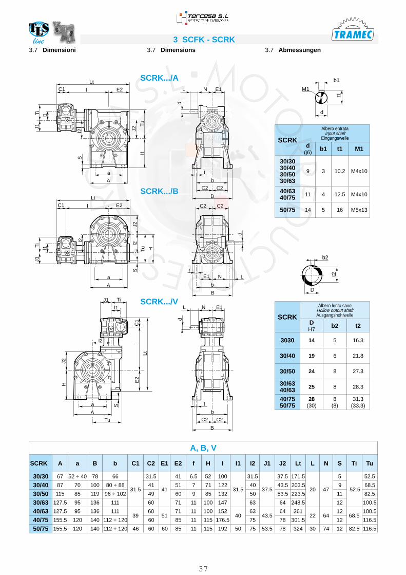
SCFK A a B b C1 C2 E1 E2 f H I I1 I2 J1 J2 Kc Lt S Ti Tu
30/30 67 52 ÷ 40 78 66
31.5
31.5
41
41 6.5 52 100
31.5
31.5
37.5
37.5 57 171.5 5
52.5
52.5
30/40 87 70 100 80 ÷ 88 41 51 7 71 122 40 43.5 57 203.5 9 68.5
30/50 115 85 119 96 ÷ 102 49 60 9 85 132 50 53.5 57 223.5 11 82.5
30/63 127.5 95 136 111 60 71 11 100 147 63 64 57 248.5 12 100.5
40/63 127.5 95 136 11139
6051
71 11 100 15240
6343.5
64 75 261 1268.5
100.5
40/75 155.5 120 140 112÷120 60 85 11 115 176.5 75 78 75 301.5 12 116.5
50/75 155.5 120 140 112÷120 46 60 60 85 11 115 192 50 75 53.5 78 82 324 12 82.5 116.5
SCFK
Albero lento cavo Hollow output shaft Ausgangshohlwelle
D H7
b2 t2
30/30 14 5 16.3
30/40 19 6 21.8
30/50 24 8 27.3
30/6340/63 25 8 28.3
40/7550/75
28(30)
8(8)
31.3(33.3)
36
line 3 SCFK - SCRKl1
C1
C1Lt
l
l
Lt
E2
E2 C2 C2
l2
TiJ1
da
a
a
J2l2
Tu
S
S
H
f
f
fE1
b
B
N
b
b
B
C2
C2
C2
C2
J2
TuH
A
A
A
Tu
J1 Ti
l1
l2
Lt
E2
lC
1
HJ2
E1
E1
N
N
L
L
S
d
B
l1
l2
TiJ1
d
L
3.7 Abmessungen3.7 Dimensions3.7 Dimensioni
SCRK.../A
SCRK
Albero lento cavo Hollow output shaft Ausgangshohlwelle
D H7
b2 t2
3030 14 5 16.3
30/40 19 6 21.8
30/50 24 8 27.3
30/6340/63 25 8 28.3
40/7550/75
28(30)
8(8)
31.3(33.3)
SCRK
Albero entrata Input shaft
Eingangswelle
d(j6)
b1 t1 M1
30/3030/4030/5030/63
9 3 10.2 M4x10
40/6340/75 11 4 12.5 M4x10
50/75 14 5 16 M5x13
d
M1
t1
b1
D
t2
b2
A, B, V
SCRK A a B b C1 C2 E1 E2 f H I I1 I2 J1 J2 Lt L N S Ti Tu
30/30 67 52 ÷ 40 78 66
31.5
31.5
41
41 6.5 52 100
31.5
31.5
37.5
37.5 171.5
20 47
5
52.5
52.5
30/40 87 70 100 80 ÷ 88 41 51 7 71 122 40 43.5 203.5 9 68.5
30/50 115 85 119 96 ÷ 102 49 60 9 85 132 50 53.5 223.5 11 82.5
30/63 127.5 95 136 111 60 71 11 100 147 63 64 248.5 12 100.5
40/63 127.5 95 136 11139
6051
71 11 100 15240
6343.5
64 26122 64
1268.5
100.5
40/75 155.5 120 140 112 ÷ 120 60 85 11 115 176.5 75 78 301.5 12 116.5
50/75 155.5 120 140 112 ÷ 120 46 60 60 85 11 115 192 50 75 53.5 78 324 30 74 12 82.5 116.5
SCRK.../B
SCRK.../V
37

line3 SCFK - SCRK
Gp
H8
X
E1Kc
X
Pp Pp
C2 C2Y
G
LC1Lt
l E2
M
R
J1T
1
I1
J2
l2
T u
E1N
Solo per / Only for / Nur für
SCFK - SCRK 30/30
Flangia pendolare / Side cover for shaft mounting / Flansch für Drehmomentstutze
4 Fori / Holes / Bohrungen
30 40 - 50(FP2) 50 - 63 - 75
8 Fori / Holes / Bohrungen
PSCFK SCRK 30/30 30/40 30/50 30/63
40/6340/75 50/75
Gp 42* H8 60 h8 70 h8 70 h8 80 h8
M M6x8 M6X10 M8x10 M8x14 M8x14
Pp 36 38 46 57.5 57
Rp 56 83 85 85 100
X 5.5 2 2 3.5 2
* Vedere dettaglio (SCFK - SCRK 30/P) Pls refer to above detail (SCFK - SCRK 30/P)Siehe o.g. Einzelheit (SCFK - SCRK 30/P)
FP2SCFK SCRK 30/30 30/40 30/50 30/63
40/6340/75 50/75
Gp h8 — 50 h8 60 h8 — —
M — M6X8.5 M6X9 — —
Pp — 38 46 — —
Rp — 65 75 — —
X — 2 2 — —
SCFK.../P SCFK.../FP2
SCRK.../P SCRK.../FP2
3.7 Abmessungen3.7 Dimensions3.7 Dimensioni
P - FP2SCFK SCRK C1 C2 E1 E2 I I1 I2 J1 J2 Kc L Lt N Ti Tu
30/30
31.5
31.5
41
41 100
31.5
31.5
37.5
37.5 57
20
171.5
47 52.5
52.5
30/40 41 51 122 40 43.5 57 203.5 68.5
30/50 49 60 132 50 53.5 57 223.5 82.5
30/63 60 71 147 63 64 57 248.5 100.5
40/6339 51
71 15240
6343.5
64 7522
26164 68.5
100.5
40/75 60 85 176.6 75 78 75 301.5 116.5
50/75 46 60 85 192 50 75 53.5 78 82 30 324 74 82.5 116.5
d
M1
t1
b1
D
t2
b2
SCRK
Albero entrata Input shaft
Eingangswelle
d(j6)
b1 t1 M1
30/3030/4030/5030/63
9 3 10.2 M4x10
40/6340/75 11 4 12.5 M4x10
50/75 14 5 16 M5x13
SCFK SCRK
Albero lento cavo Hollow output shaft Ausgangshohlwelle
D H7
b2 t2
30/30 14 5 16.3
30/40 19(18)
6(6)
21.8(20.8)
30/50 24(25)
8(8)
27.3(28.3)
30/6340/63 25 8 28.3
40/7550/75
28(30)
8(8)
31.3(33.3)
38

line 3 SCFK - SCRK
C P
C1Lt
l E2
øG
øF
øR
Q
øV
UZ
Flangia uscita / Output flange / Abtriebsflansch
F...D Standard
F...S
SCFK.../F
SCFK SCRK
Tipo flangia Type flange Typ flansch
C
FG
(H8)P Q R U
V
Zø
30/30 F 31.5 71 40 50.5 19 56 ÷ 60 3 n° 4 6.5 6
30/40F
41140 95 82 41 115 5 n° 4 9 9
F1* 85 60 68.5 27.5 75 ÷ 90 4 n° 4 9 8F2* 85 60 98.5 57.5 75 ÷ 90 4 n° 4 9 8
30/50
F
49
160 110 92 43 130 5 n° 7 11 11F1 94 70 92.5 43.5 85 ÷ 100 5 n° 4 11 10F2 125 70 73 24 90 ÷ 100 5 n° 4 10.5 10F3 125 70 85 36 90 5 n° 4 10.5 10
30/6340/63
F*60
180 115 116 56 150 7 n° 8 11 12F1* 180 115 86 26 150 5 n° 7 11 11F2* 200 130 102 42 165 6 n° 4 11 11
40/7550/75
F*
60
200 130 111 51 165 6 n° 7 13 13F1* 200 130 85 25 165 6 n° 7 13 13F2* 175 115 116 56 150 6 n° 4 11 12F3* 175 115 85 25 150 5 n° 4 11 12
F3A* 160 110 85 25 130 5 n° 4 11 12F4* 160 110 101 41 130 6 n° 4 11 12
SCRK.../F
30/30 30/40 30/50
F F F1* - F2* F F1 F2 - F3
30/6340/63 63 40/75
50/7530/6340/63
40/7550/75
40/7550/75
F* F1* F* - F1* F2* F2* - F3* F3A* F4*
Tipo flangia / Type flange / Typ flansch
3.7 Abmessungen3.7 Dimensions3.7 Dimensioni
N.B.La flangia uscita può essere montata solo sul riduttore in versione P.Le flangie indicate con (*) necessitano di un coperchio speciale.
The output flange is to be mounted to the gearbox P version only. A special cover is required for the flanges marked by (*).
Der Abtriebsflansch darf nur auf das Getriebe Version P montiert werden Für die Flansche mit (*) ausgezeichnet ist einen Sonderdeckel nötig.
39

line3 SCFK - SCRK
Albero lento semplice / Single output shaft / Standard Abtriebswelle Albero lento doppio / Double output shaft / Doppelte Abtriebswelle
SCFK SCRK A Ab B Bb d (h6) d1 e L Lb M m S Sb
30/30 30 29 62 64 14 18.5 20 94.5 126 M6 16 2.5 2.5
30/40 40 39 77 83.2 19 24.5 30 120 165.2 M6 16 3 3
30/50 50 49 90 99.2 24 29.5 40 143.5 201.2 M8 22 3.5 3.5
30/6340/63
60 59 119 121.2 25 29.5 50 183 244.2 M8 22 4 4
40/7550/75
60 59 119 121.5 28 34.5 50 183 244.5 M8 22 4 4
Braccio di reazione / Torque arm / DrehmomentstützeSCFK SCRK a b D1 E H1 K1 Lt O S1 S2
30/30 70 34.5 42 56 9 36 119.5 7 — 4
30/40 90 50 60 83 10 38 165 7 — 4
30/50 100 55 70 85 10 46 180 9 — 4
30/63150 53 70 85 10 57.5 230 9 — 6
40/63
SCFK SCRK a b D1 E H2 K2 Lt O S1 S2
30/40 90 50 60 83 8 33 165 7 14 4
30/50 100 50 70 85 10 40.5 180 9 14 4
30/6340/63
150 53 70 85 10 50.5 230 9 20 6
40/7550/75
150 62 80 100 10 50 240 9 20 6
Con boccola / With bush / Mit Büchse
Senza boccola / Without bush / Ohne BüchseBR1
BR2
3.8 Zubehör3.8 Accessories3.8 Accessori
Opzioni disponibili:
Cuscinetti a rulli conici corona
Available options:
Tapered roller bearing for worm wheel
Auf Anfrage ist folgendes Zubehör erhältlich:Kegelrollenlager für Schneckenrad
40

line 3 SCFK - SCRK3.9 Versionen mit Doppelseitig Herausragender Schneckenwelle
3.9 Double extended worm shaft design
3.9 Esecuzione con vite bisporgente
SeA2SeA1
t
b
T
Bm
I
d
n
M
L
Dj6
N
SCFKSeA1
b d j6 l m n t
30/3030/4030/5030/63
3 9 15 M4x10 42.5 10.2
40/6340/75 4 11 20 M4x12 52.5 12.5
50/75 5 14 25 M5x13 62.5 16
Die verlängerte Schneckenwelle des zweiten Getriebes (SeA2) kann nicht als Antrieb verwendet werden, da die Selbs-hemmung des ersten Getriebes entge-gengewirkt. Wird sie als Abtriebswelle verwendet, besitzt sie eine um die Untersetzung des ersten Getriebes entsprechend reduzier-te Drehzahl und Drehmoment.
The second input shaft of the output gear-box (SeA2) can not be utilized as a drive because its motion will be stopped by the reversibility of the first gearbox. If utilized as a drive shaft its speed will be equal to the input speed decreased by the ratio of the first gearbox.
L’entrata supplementare del riduttore in uscita (SeA2) non può essere utilizzata come comando in quanto il relativo movi-mento risulta impedito dalla irreversibilità del primo riduttore.Utilizzato come asse condotto, avrà ve-liocità corrispondente a quella di ingresso ridotta del rapporto del primo riduttore.
SCFKSCRK
SeA2
B D j6 L M N T
30/30 3 9 15 M4x10 42.5 10.2
30/40 4 11 20 M4x12 52.5 12.5
30/50 5 14 25 M5x13 62.5 16
30/6340/63 6 19 30 M8x20 72.5 21.5
40/7550/75 8 24 40 M8x20 93 27
SCRKSeA1
b d j6 l m n t
30/3030/4030/5030/63
3 9 20 M4x10 42.5 10.2
40/6340/75 4 11 22 M4x10 52.5 12.5
50/75 5 14 30 M5x13 62.5 16
41
line3 SCFK - SCRK3.10 Drehmomentenbegrenzer mit durchgehender Hohlwelle
Die Anwendung eines Drehmoment- begrenzers wird empfohlen, um die Anlage und/oder das Getriebe gegen ungewünschte und unerwartete Überbe- lastungen zu schützen. Es handelt sich um eine Vorrichtung mit einer durchgehenden Hohlwelle. Er ist in dem Getriebe integriert, d.h. der Raumbedarf ist klein. Der Begrenzer wurde für Betrieb in einem Ölbad entwor-fen. Er ist zuverlässig und verschleißfrei (nur im Falle eines dauerhaften Rutschens entsteht Verschleiß, hier ist das Dreh-moment größer als der eingestellte Eich-wert).Die Eichung kann mühelos von aussen durch das Anziehen einer selbstsperren-den Mutter ausgeführt werden, dadurch wird der Druck auf die 4 wechselseitig angeordneten Tellerfedern erhöht.
Die Vorrichtung sieht das folgende nicht vor:• die Verwendung von Kegelrollenlager
am Abtrieb• Längerer Rutschbetrieb
Die nachstehende Tabelle zeigt die Wer-te der Rutschmomente M2S abhängig von der Anzahl der Umdrehungen der Mutter. Die Eichwerte weisen ±10% Toleranz
3.10 Torque limiter with through hollow shaft
The use of a torque limiter is advisable when the application requires the limita-tion of the transmissible torque to safe-guard the plant and/or the gearbox from unexpected or undesired overloads. The torque limiter is equipped with a through hollow shaft and a friction clutch. It is integrated in the gearbox, therefore space requirement is limited. Designed to be working in oil bath, the de-vice is reliable over time and is not sub-ject to wear unless in case of operation with prolonged slipping (it occurs when the torque values are higher than the cali-bration values). Calibration can be easily adjusted from outside by tightening of the self-locking ring nut, which causes the compression of the 4 Belleville washers arranged in series.
The device does not go together with:• the use of tapered roller bearings at
output• prolonged operation under slipping
conditions
The following table shows the values of M2S slipping torques depending on the number of revolutions of the ring nut.
3.10 Limitatore di coppia cavo passante
Il limitatore di coppia viene consigliato in tutte quelle applicazioni che richiedono una limitazione sulla coppia trasmissibile per proteggere l’impianto e/o preservare il riduttore evitando sovraccarichi o urti indesiderati quanto inaspettati.È un dispositivo con albero dotato di cavo passante, con funzionamento a frizione, ed è integrato al riduttore, presentando un ingombro limitato.Concepito per lavorare a bagno d’olio, il dispositivo risulta affidabile nel tempo ed è esente da usura se non viene man-tenuto in condizioni prolungate di slitta-mento (condizione che si verifica quando la coppia presenta valori superiori a quel-li di taratura).La taratura è facilmente regolabile dall’esterno attraverso il serraggio di una ghiera autobloccante che porta a com-pres- sione le 4 molle a tazza disposte tra loro in serie.Il dispositivo non consente:• l’impiego di cuscinetti a rulli conici in uscita• funzionamento prolungato in condizio-
ni di slittamento.
Nella tabella seguente vengono riportati i valori delle coppie di slittamento M2S in funzione del n° di giri della ghiera.
IN SERIE (min. coppia, max. sensibilità)SERIES (min. torque, max sensitivity)SERIE (min. Moment, max. Empfindlichkeit)
Disposizione delle molleWashers’ arrangementLage der Feder
I valori di taratura presentano una tolle-ranza del ±10% e si riferiscono ad una condizione statica.In condizioni dinamiche è da notare che la coppia di slittamento assume valori di-versi a seconda del tipo e/o modalità in cui si verifica il sovraccarico: con valori maggiori in caso di carico uniformemente crescente rispetto a volori più contenuti in seguito al verificarsi di picchi improv-visi di carico. NOTA: quando si supera il valore di tara-tura si ha slittamento. Il coefficiente di at-trito tra le superfici di contatto da statico diventa dinamico e la coppia trasmessa cala del 30% circa.E’ quindi opportuno prevedere uno stop per poter ripartire al valore di taratura ini-ziale.
Calibration values feature a ±10% toler-ance and refer to static conditions. Under dynamic conditions the values of the slipping torque will change according to the type of overload: the values are higher if the load increase is uniform; the values are lower if sudden load peaks occur.
NOTE: Slipping occurs when the setting values are exceeded. The friction coefficient between the con-tact surfaces from static becomes dy-namic and the transmitted torque is ap-prox. 30% lower. It is advisable to have a stop first in order to have a restart based on the initial set-ting value.
auf und beziehen sich auf statische Be-dingungen.Unter dynamischen Bedingungen hat das Rutschmoment verschiedene Werte je nach Art der Überbelastung. Die Werte sind höher, wenn die Belastung gleich-mäßig zunimmt; sie sind niedriger im Falle von plötzlichen Belastungsspitzen. BEMERKUNG: Rutschen tritt auf, wenn die eingestellten Werte überschritten werden. Der Reibungsfaktor zwischen den Berüehrungsflächen wird dynamisch anstatt statisch und das übertragene Drehmoment sinkt um ca. 30%. Es ist daher ratsam, vor dem erneuten Anfahren anzuhalten, um die ursprüng-lichen Drehmomentwerte zu erreichen.
SCFK SCRK
N°. giri della ghiera di regolazioneN°. revolutions of ring nut / Nr. Umdrehungen der Mutter
1 1 1/4 1 1/2 1 3/4 2 2 1/4 2 1/2 2 3/4 3 3 1/4 3 1/2 3 3/4 430/30 20 25 30 35 4030/40 50 60 70 80 9030/50 75 95 115 135 15530/63
110 125 145 160 180 200 220 230 245 255 265 28540/6340/75
220 245 275 310 350 375 410 45050/75
42

line 3 SCFK - SCRK
Es ist wichtig zu beachten, dass das Rutschmoment über die gesamte Le-bensdauer der Rutschkupplung nicht konstant bleibt, sondern üblicherweise in Verbindung mit längeren Rutschzyklen aufgrund der eingelaufenen Berührungs-flächen abnimmt.Deswegen ist es ratsam, die Eichung der Vorrichtung besonders während der Ein-laufzeit zu prüfen. Falls ein niedrigerer Eichfehler ge-wünscht ist, sollte das übertragbare Drehmoment auf der Anlage getestet werden.Wenn die Vorrichtung geliefert wird, ist sie schon auf das im Katalog T2M angegebenen Drehmoment geeicht, ausser wenn es in der Bestellung an-ders angegebene wird.
It is important to note that the slipping torque is not the same for the whole life of the torque limiter. It usually decreases in connection with the numbers and the duration of the slip-ping which because of the surfaces’ lap-ping will increase the efficiency.For this reason it is advisable to check the calibration of the device at regular intervals, specially during the running-in period. Should a smaller calibration error be re-quired, it is necessary to test the trans-missible torque on the plant.The device is supplied already cali-brated at the torque reported in the catalogue T2M, unless otherwise speci-fied in the order.
E’ importante notare che la coppia di slit-tamento non resta sempre la medesima durante tutta la vita del limitatore.Tende infatti a diminuire in rapporto al numero e alla durata degli slittamenti che, rodando le superfici di contatto, ne aumentano il rendimento.È quindi opportuno verificare periodica-mente, soprattutto durante la fase di ro-daggio, la taratura del dispositivo.Là dove sia richiesto un errore più conte-nuto nella taratura, è necessario testare la coppia trasmissibile sull’impianto.
Il dispositivo viene consegnato tara-to alla coppia riportata a catalogo T2M salvo diversa indicazione espressa in fase di ordinazione.
3.10 Drehmomentenbegrenzer mit durchgehender Hohlwelle
3.10 Torque limiter with through hollow shaft
3.10 Limitatore di coppia cavo passante
( ) A richiesta / On request / Auf Anfrage
The version with torque limiter is supplied without output shafts. The device is supplied already calibrated at the torque reported in the catalogue T2M, unless otherwise specified in the order.
Die Version mit Drehmomentbegrenzer wird ohne Abtriebswellen geliefert. Wenn die Vorrichtung geliefert wird, ist sie schon auf dem im Katalog T2M angegebenen Drehmoment geeicht, ausser wenn es in der Bestellung anders angegeben wird.
SCFK SCRK C2 CL Ct
D2H7
M2 G2
LD - LS30/30 31.5 61.5 93 14 50x25.4x1.5 M25X1.5
30/40 41 67 108 19 56x30.5x2 M30X1.5
30/50 49 79 128 24 63x40.5x2.5 M40X1.5
30/63 40/63 60 97 157 25 71x40.5x2.5 M40X1.5
40/7550/75 60 100 160 28 (30) 90x50.5x3.5 M50X1.5
Nella versione con limitatore non è prevista la fornitura degli alberi lenti. Il dispositivo viene consegnato tarato alla coppia riportata a catalogo T2M salvo diversa indicazione espressa in fase di ordinazione.
LD LS
43

line3 SCFK - SCRK3.11 Ersatzteilliste3.11 Spare parts list3.11 Lista parti di ricambio
SCFK - SCRK
IN (SCFK) IN (SCRK) KIT OUT
30/30
KC30 KA30
KIT 30/30 (2850002010) 30/930/40 KIT 30/40 (2850002013) 40/1130/50 KIT 30/50 (2850002016) 50/1430/63 KIT 30/63 (2850002019) 63/1940/63 KC40 KA40
KIT 40/63 (2850002028) 63/1940/75 KIT 40/75 (2850002031) 75/2450/75 KC50 KA50 KIT 50/75 (2850002034) 75/24
1 32
2
3
1
SCFK
SCRK
44

line 3 SCFK - SCRK3.11 Ersatzteilliste3.11 Spare parts list3.11 Lista parti di ricambio
SCFK - SCRK
Drehmomentbegrenzer mit durchgehende Hohlwelle
Torque limiter with through hollow shaftLimitatore di coppia cavo passante
982315312 1381067
Solo per
Nur fürOnly for
SCFK-SCRK30/6340/63
98213581011 114 467
A B
A BSCFK - SCRK
30/30 (L1-LD-LS)30/40 (L1)30/50 (L1)30/63 (L1)
30/40 (LD - LS)40/63 (L1)40/75 (L1)
30/50 (LD - LS)50/75 (L1)
30/63 (LD - LS)40/63 (LD - LS)
40/75 (LD - LS)50/75 (LD - LS)
1 Corona in bronzo / Bronze wheel / Bronzerad2 Albero cavo limitatore / Hollow shaft torque limiter / Rutschkupplungs-Hohlwelle3 Anello di frizione / Friction ring / Reibring4 Distanziale molle / Washers’ distance ring / Federdistanzring
5Linguetta / Key / Passfeder
8x7x10AB 10x8x13AB 12x8x18AB 12x8x40A 16x10x40A6 Molle a tazza / Belleville washers / Tellerfeder7 Ghiera / Metal ring / Metall Ring
8Cuscinetti / Bearings / Lager
6005 25x47x12
600630x55x13
600840x68x15
600840x68x15
601050x80x16
9Anelli di tenuta / Oilseals / Öldichtungen
25x40x7 30x47x7 40x62x8 40x62x8 50x72x8
10Anelli di tenuta / Oilseals / Öldichtungen
30x40x5 35x47x7 48x62x8 48x62x8 58x72x8
11 O-rings in gomma / Rubber O-rings / Gummi-O-ringe
OR2087 21.95x1.78
OR210626.7x1.78
OR36.27x1.78
OR36.27x1.78
OR218747.37x1.78
12 - Distanziale / Spacer / Abstandshülse
13 -Distanziale /
Spacer / Abstandshülse
-
45

line3 SCFK - SCRK
46

line
5 RIDUTTORI A VITE SENZA FINE COMBINATIBCFK-BCRK
BCFK-BCRK COMBINED WORM GEARBOXES
KOMBINIERTE-SCHNECKENGETRIEBE BCFK-BCRK
5.1 Caratteristiche Characteristics Merkmale 725.2 Designazione Designation Bezeichnung 725.3 Lubrificazione e posizioni
di montaggioLubrication andmounting position
Schmierung undEinbaulage
74
5.4 Posizione morsettiera Terminal board position Lage des Klemmkasten 755.5 Dati tecnici Technical data Technische Daten 765.6 Predisposizioni possibili Possible set-ups Mögliche Vorrichtungen 795.7 Dimensioni Dimensions Abmessungen 805.8 Accessori Accessories Zubehör 845.9 Esecuzione con vite bisporgente Double extended worm shaft
designVersionen mit Doppelseitig Herausragender Schneckenwelle
85
5.10 Limitatore di coppiacavo passante
Torque limiter with throughhollow shaft
Drehmomentbegrenzermit durchgehender Hohlwelle
86
5.11 Lista parti di ricambio Spare parts list Ersatzteilliste 88
47

line5 BCFK - BCRK
5.2 Bezeichnung5.2 Designation5.2 Designazione
Ausführungen Versions Versioni
Bei der Bestellung immer die Bauform angeben.
Specify the version when ordering.Specificare sempre in fase di ordinazio-ne la versione.
BCFK..A_ BCRK..A_
BCFK..B_ BCRK..B_
BCFK..V_ BCRK..V_
BCFK..P_ BCRK..P_
BCFK..F_S BCRK..F_S
BCFK..F_D BCRK..F_D
Rid
utto
reG
earb
oxG
etrie
be
Gra
ndez
za
Siz
eG
röß
e
Rap
port
o rid
. R
atio
Unt
erse
tzun
g
Pre
disp
os.a
tt. m
ot.
Mot
or c
oupl
ing
Mot
oran
schl
uss
Ver
sion
eV
ersi
onV
ersi
on
For
ma
cost
rutti
vaE
xecu
tion
Bau
form
Pos
izio
ne d
i mon
t. M
ount
ing
posi
tion
Ein
baul
age
Lim
itato
re d
i cop
pia.
Torq
ue li
mite
rD
rehm
omen
t-be
gren
zer
Sec
onda
ent
rata
Add
ition
al in
put
Zus
atza
ntrie
b
Alb
ero
usci
taO
utpu
t sha
ftA
btrie
bsw
elle
Bra
ccio
di r
eazi
one
Torq
ue a
rmD
rehm
omen
tstü
tze
BCFK 50/75 1200 P.A.M. FS a B3 LD SeA1 H BR
BCFK
BCRK
30/3030/4030/5030/6340/6340/7550/75
150200300450600900120015001950250032504000500010000
5663718090
ABV
P
F...S F...D
ab
cd
ef
gh
ik
im
no
pq
B3
B6
B7
B8
V5
V6
SeA1
SeA2
H
SD
SS
DD
BR1
BR2
5.1 Merkmale
Die Kombination zweier Schneckenge-triebe bringt sehr niedrigen Wirkungs-grad mit sich, es handelt sich jedoch um eine interessante und manchmal uner-setzbare Lösung, weil eine hohe Dreh-zahlverringerung in einem beträchtlich reduzierten Raum erzielt werden kann.
Die Hohlwelle gehört zur serienmäßi-gen Ausstattung. Eine breite Auswahl an Zubehör ist erhältlich: zweiter Antrieb, Kegelrollenlager auf Schneckenrad, Ab-triebs- flansch, standard oder doppelsei-tig herausragende Abtriebswelle, Dreh-momentbegrenzer mit durchgehender Hohlwelle, Drehmomentstütze.
5.1 Characteristics
The combination of two worm gearboxes provides very low efficiency, however the fact that substantial reduction in speed can be obtained in an extremely reduced space makes this solution very interesting and sometimes irreplaceable.
The hollow shaft is supplied as standard. A broad range of accessories is avalable:second input, tapered roller bearings on the worm wheel, output flange, single or double extended output shaft, torque limiter with through hollow shaft, torque arm.
5.1 Caratteristiche
La combinazione di due riduttori a vite senza fine comporta rendimenti molto bassi, ma l’elevata riduzione di velocità ottenuta in uno spazio ridottissimo rende comunque interessante, e a volte insosti- tuibile, questa soluzione.
Sono forniti con albero cavo di serie ed esiste un’ampia gamma di accessori:seconda entrata, cuscinetti conici sulla corona, flangia uscita, albero lento con 1 o 2 sporgenze, limitatore di coppia con cavo passante, braccio di reazione.
LD
LS
48

line 5 BCFK - BCRK5.2 Bezeichnung5.2 Designation5.2 Designazione
A
B
V
P
F
Forma costruttiva / version / Bauform
Forma costruttiva non realizzabile su: / Version not feasible on: / Bauform nicht ausführbar für:30/30, 30/40, 30/50 PAM 63B5 (ø 140), 40/63 PAM 71B5 (ø 160)
49
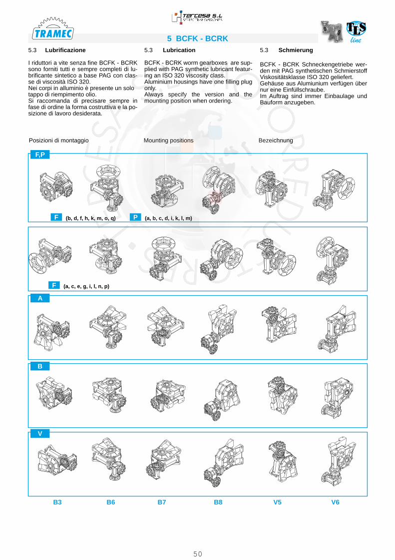
line5 BCFK - BCRK
F (b, d, f, h, k, m, o, q) P (a, b, c, d, i, k, l, m)
F (a, c, e, g, i, l, n, p)
F,P
A
B
V
5.3 Schmierung
BCFK - BCRK Schneckengetriebe wer-den mit PAG synthetischen Schmierstoff Viskositätsklasse ISO 320 geliefert. Gehäuse aus Alumiunium verfügen über nur eine Einfüllschraube.Im Auftrag sind immer Einbaulage und Bauform anzugeben.
5.3 Lubrication
BCFK - BCRK worm gearboxes are sup-plied with PAG synthetic lubricant featur-ing an ISO 320 viscosity class.Aluminium housings have one filling plug only.Always specify the version and the mounting position when ordering.
5.3 Lubrificazione
I riduttori a vite senza fine BCFK - BCRK sono forniti tutti e sempre completi di lu-brificante sintetico a base PAG con clas-se di viscosità ISO 320.Nei corpi in alluminio è presente un solo tappo di riempimento olio.Si raccomanda di precisare sempre in fase di ordine la forma costruttiva e la po-sizione di lavoro desiderata.
BezeichnungMounting positionsPosizioni di montaggio
B3 B6 B7 B8 V5 V6
50

line 5 BCFK - BCRKSchmiermittelmengeLubricant quantityQuantità di lubrificante
Q.tà olio / Oil quantity / Schmiermittelmenge [lt]
BCFK - BCRK30/30 30/40 30/50 30/63 40/63 40/75 50/75
Pos
izio
ni d
i mon
tagg
ioM
ount
ing
posi
tions
Ein
baul
age
B3IN 0.015 0.04 0.08
OUT 0.015 0.04 0.08 0.16 0.16 0.26 0.26
B6IN 0.015 0.04 0.08
OUT 0.015 0.04 0.08 0.16 0.16 0.26 0.26
B7IN 0.015 0.04 0.08
OUT 0.015 0.04 0.08 0.16 0.16 0.26 0.26
B8IN 0.015 0.04 0.08
OUT 0.015 0.04 0.08 0.16 0.16 0.26 0.26
V5IN 0.015 0.04 0.08
OUT 0.015 0.04 0.08 0.16 0.16 0.26 0.26
V6IN 0.015 0.04 0.08
OUT 0.015 0.04 0.08 0.16 0.16 0.26 0.26
IN = Riduttore entrata / Gearbox at input / Getriebe am Antrieb OUT = Riduttore uscita / Gearbox at output / Getriebe am Abtrieb
5.4 Lage der Klemmenkaste5.4 Terminal board position5.4 Posizione morsettiera
A
A
B
B
C
C
D
D
B3
B8
B6 B7
V5 V6
A
B
C
D
A
A
B
B
C
C
D
DA
B
C
D
E H
GF
E
H G
F
E
H
F
G
EH
G F
E
H G
F E
HG
F
51

line5 BCFK - BCRK5.5 Technische Daten5.5 Technical data5.5 Dati tecnici
30/30
n1 = 1400 BCFK BCRK
in30 30 n2 T2 P1 FS’
Input IEC T2M PRd
i1 i2 [min-1] [Nm] [kW] B5/B14 [Nm] [kW]150
1015 9.3 32 0.06 1.2
56-63
37 0.070 0.51200 20 7.0 39 0.06 0.8 32 0.050 0.47300
30
4.7 52* 0.06 0.8* 39 0.045 0.42450 15 3.1 73* 0.06 0.5* 39 0.032 0.40600 20 2.3 91* 0.06 0.4* 39 0.026 0.37900 30 1.6 125* 0.06 0.3* 39 0.019 0.34
1200 40 1.2 149* 0.06 0.3* 39 0.016 0.301500 50 0.9 173* 0.06 0.2* 39 0.014 0.281950 65 0.7 209* 0.06 0.2* 56 39 0.011 0.262500 50
50
0.6 235* 0.06 0.1* 56-63 30 0.008 0.233.0 3250 65 0.4 283* 0.06 0.11*
56
30 0.006 0.214000 80 0.4 328* 0.06 0.09* 30 0.005 0.205000
1000.3 385* 0.06 0.08* 30 0.005 0.19
10000 100 0.1 609* 0.06 0.03* 17 0.002 0.15
* ACHTUNG: das max. anwendbare Drehmoment [T2M] muss mit folgendem Betriebsfaktor berechnet werden: T2M = T2 x FS’
* WARNING: Maximum allowable torque [T2M] must be calculated using the follow-ing service factor : T2M = T2 x FS’
* ATTENZIONE: la coppia massima utiliz-zabile [T2M] deve essere calcolata utiliz-zando il fattore di servizio: T2M = T2 x FS’
30/40
n1 = 1400 BCFK BCRK
in30 40 n2 T2 P1 FS’
Input IEC T2M PRd
i1 i2 [min-1] [Nm] [kW] B5/B14 [Nm] [kW]150
1015 9.3 72 0.13 1.1
56-63
82 0.148 0.54200 20 7.0 76 0.11 1.0 76 0.110 0.51300
30
4.7 79 0.09 1.0 82 0.094 0.43450 15 3.1 74 0.06 1.1 82 0.067 0.40600 20 2.3 92 0.06 0.9 82 0.054 0.37900 30 1.6 126* 0.06 0.6* 82 0.039 0.34
1200 40 1.2 151* 0.06 0.5* 82 0.033 0.311500 50 0.9 176* 0.06 0.5* 82 0.028 0.291950 65 0.7 212* 0.06 0.4* 56 82 0.023 0.272500 50
50
0.6 236* 0.06 0.3* 56-63 68 0.017 0.234.0 3250 65 0.4 285* 0.06 0.24*
56
68 0.014 0.214000 80 0.4 330* 0.06 0.21* 68 0.012 0.205000
1000.3 387* 0.06 0.18* 68 0.011 0.19
10000 100 0.1 626* 0.06 0.06* 35 0.003 0.15
30/50
n1 = 1400 BCFK BCRK
in30 50 n2 T2 P1 FS’
Input IEC T2M PRd
i1 i2 [min-1] [Nm] [kW] B5/B14 [Nm] [kW]150
1015 9.3 124 0.22 1.2
56-63
149 0.265 0.55200 20 7.0 129 0.18 1.1 144 0.201 0.52300
30
4.7 118 0.13 1.3 150 0.166 0.44450 15 3.1 140 0.11 1.1 150 0.118 0.42600 20 2.3 143 0.09 1.0 150 0.094 0.39900 30 1.6 131 0.06 1.1 150 0.069 0.36
1200 40 1.2 156 0.06 1.0 150 0.058 0.321500 50 0.9 182 0.06 0.8 150 0.049 0.301950 65 0.7 220* 0.06 0.7* 56 150 0.041 0.282500 50
50
0.6 253* 0.06 0.5* 56-63 125 0.030 0.256.0 3250 65 0.4 305* 0.06 0.41*
56
125 0.025 0.234000 80 0.4 354* 0.06 0.35* 125 0.021 0.225000
1000.3 414* 0.06 0.30* 125 0.018 0.20
10000 100 0.1 645* 0.06 0.11* 69 0.006 0.16
52

line 5 BCFK - BCRK5.5 Technische Daten5.5 Technical data5.5 Dati tecnici
30/63
n1 = 1400 BCFK BCRK
in30 63 n2 T2 P1 FS’
Input IEC T2M PRd
i1 i2 [min-1] [Nm] [kW] B5/B14 [Nm] [kW]150
1015 9.3 126 0.22 1.8
56-63
228 0.400 0.56200 20 7.0 162 0.22 1.7 279 0.378 0.54300
30
4.7 207 0.22 1.3 268 0.285 0.46450 15 3.1 238 0.18 1.1 268 0.202 0.43600 20 2.3 215 0.13 1.2 268 0.162 0.40900 30 1.6 250 0.11 1.1 268 0.118 0.37
1200 40 1.2 243 0.09 1.1 268 0.099 0.331500 50 0.9 189 0.06 1.4 268 0.085 0.311950 65 0.7 228 0.06 1.2 56 268 0.071 0.292500 50
50
0.6 265 0.06 0.8 56-63 222 0.050 0.268.5 3250 65 0.4 319* 0.06 0.70*
56
222 0.042 0.244000 80 0.4 369* 0.06 0.60* 222 0.036 0.235000
1000.3 433* 0.06 0.51* 222 0.031 0.21
10000 100 0.1 663* 0.06 0.21* 138 0.012 0.16
40/63
n1 = 1400 BCFK BCRK
in40 63 n2 T2 P1 FS’
Input IEC T2M PRd
i1 i2 [min-1] [Nm] [kW] B5/B14 [Nm] [kW]150
1015 9.3 214 0.37 1.2
63-71
261 0.452 0.56200 20 7.0 277 0.37 1.0 279 0.373 0.55300
30
4.7 238 0.25 1.1 268 0.282 0.46450 15 3.1 244 0.18 1.1 268 0.197 0.44600 20 2.3 226 0.13 1.2 268 0.154 0.43900 30 1.6 257 0.11 1.0 268 0.115 0.38
1200 40 1.2 264 0.09 1.0 268 0.091 0.361500 50 0.9 203 0.06 1.3 63 268 0.079 0.331950 65 0.7 241 0.06 1.1
56-63
268 0.067 0.302500 50
50
0.6 284 0.06 0.8 222 0.047 0.289.5 3250 65 0.4 338* 0.06 0.66* 222 0.039 0.25
4000 80 0.4 400* 0.06 0.55* 222 0.033 0.245000
1000.3 471* 0.06 0.47* 222 0.028 0.23
10000 100 0.1 722* 0.06 0.19* 138 0.011 0.18
* ACHTUNG: das max. anwendbare Drehmoment [T2M] muss mit folgendem Betriebsfaktor berechnet werden: T2M = T2 x FS’
* WARNING: Maximum allowable torque [T2M] must be calculated using the follow-ing service factor : T2M = T2 x FS’
* ATTENZIONE: la coppia massima utiliz-zabile [T2M] deve essere calcolata utiliz-zando il fattore di servizio: T2M = T2 x FS’
53

line5 BCFK - BCRK
40/75
n1 = 1400 BCFK BCRK
in40 75 n2 T2 P1 FS’
Input IEC T2M PRd
i1 i2 [min-1] [Nm] [kW] B5/B14 [Nm] [kW]150
1015 9.3 322 0.55 1.3
63-71
409 0.698 0.57200 20 7.0 417 0.55 1.1 442 0.593 0.56300
30
4.7 358 0.37 1.2 418 0.432 0.47450 15 3.1 346 0.25 1.2 418 0.302 0.45600 20 2.3 390 0.22 1.1 418 0.236 0.43900 30 1.6 309 0.13 1.4 418 0.176 0.39
1200 40 1.2 388 0.13 1.1 418 0.140 0.361500 50 0.9 379 0.11 1.1 63 418 0.121 0.341950 65 0.7 368 0.09 1.1
56-63
418 0.102 0.312500 50
50
0.6 296 0.06 1.3 381 0.077 0.2914.5 3250 65 0.4 352 0.06 1.08 381 0.065 0.26
4000 80 0.4 417 0.06 0.91 381 0.055 0.255000
1000.3 491* 0.06 0.78* 381 0.047 0.24
10000 100 0.1 762* 0.06 0.30* 232 0.018 0.19
* ACHTUNG: das max. anwendbare Drehmoment [T2M] muss mit folgendem Betriebsfaktor berechnet werden: T2M = T2 x FS‘
* WARNING: Maximum allowable torque [T2M] must be calculated using the follow-ing service factor : T2M = T2 x FS’
* ATTENZIONE: la coppia massima utiliz-zabile [T2M] deve essere calcolata utiliz-zando il fattore di servizio: T2M = T2 x FS’
5.5 Technische Daten5.5 Technical data5.5 Dati tecnici
50/75
n1 = 1400 BCFK BCRK
in50 75 n2 T2 P1 FS’
Input IEC T2M PRd
i1 i2 [min-1] [Nm] [kW] B5/B14 [Nm] [kW]150
1015 9.3 409 0.75 1.0
71-80
409 0.750 0.57200 20 7.0 422 0.55 1.0 442 0.576 0.56300
30
4.7 363 0.37 1.2 418 0.427 0.48450 15 3.1 350 0.25 1.2 418 0.299 0.46600 20 2.3 418 0.25 1.0 418 0.250 0.42900 30 1.6 418 0.18 1.0 418 0.180 0.40
1200 40 1.2 406 0.13 1.0 418 0.134 0.381500 50 0.9 470 0.13 0.9 71 418 0.116 0.351950 65 0.7 572* 0.13 0.7*
63-71
418 0.095 0.332500 50
50
0.6 674* 0.13 0.6* 381 0.074 0.3014.5 3250 65 0.4 819* 0.13 0.47* 381 0.060 0.28
4000 80 0.4 939* 0.13 0.41* 381 0.053 0.265000
1000.3 1108* 0.13 0.34* 381 0.045 0.25
10000 100 0.1 1719* 0.13 0.13* 232 0.018 0.19
54

line 5 BCFK - BCRK5.6 Mögliche Vorrichtungen5.6 Possible set-ups 5.6 Predisposizioni possibili
* A richiesta, solo con corpo speciale / Upon request, only with special body / Auf Wunsch nur mit speziellen Körper
BCFK PAMIEC G1 K R1 U1
V1Y Z1
Diametro fori PAM / Holes diameter IEC-InputBohrungdurchmesser IEC-Antrieb
Ø150200300
450 600 900 1200 15002500
19503250 4000 5000
10000
30/30 30/4030/5030/63
56 B5 80
57
100 4 7 n° 8 120 8 9 9 9 9 9 9 9 9 9
56 B14 50 65 3.5 6 n° 8 80 8 9 9 9 9 9 9 9 9 9
63 B5 95 115 4 9 n° 8 140 8 11 11 11 11 11 11 11 11 /
63 B14 60 75 4 6 n° 8 90 8 11 11 11 11 11 11 11 11 /
40/6340/75
56 B5 80
75
100 4 7 n° 8 120 9 / / / / / / / 9 9
56 B14 50 65 3.5 6 n° 4 80 8 / / / / / / / 9 9
63 B5 95 115 4 9 n° 8 140 9 11 11 11 11 11 11 11 11 11
63 B14 60 75 3.5 6 n° 4 90 8 11 11 11 11 11 11 11 11 11
71 B5 110 130 4.5 9 n° 8 160 10 14 14 14 14 14 14 14 / /
71 B14 70 85 3.5 7 n° 8 105 8 14 14 14 14 14 14 14 / /
50/75
63 B5 95
82
115 4 9 n° 8 140 9 / / / / / / 11 11 11
63 B14 60 75 3.5 6 n° 4 90 8 / / / / / / 11 11 11
71 B5 110 130 4.5 9 n° 8 160 10 14 14 14 14 14 14 14 14 14
71 B14 70 85 3.5 7 (n° 8)* n° 4 105 8 14 14 14 14 14 14 14 14 14
80 B5 130 165 4.5 11 n° 8 200 10 19 19 19 19 19 19 19 / /
80 B14 80 100 4 7 n° 8 120 10 19 19 19 19 19 19 19 / /
55
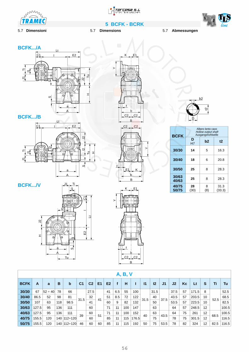
line5 BCFK - BCRK5.7 Abmessungen5.7 Dimensions5.7 Dimensioni
D
t2
b2
l1
C1
C1Lt
l
l
Lt
E2
E2 C2 C2
l2
TiJ1
S
a
a
a
J2l2
Tu
S
S
H
f
f
fE1
b
B
K
b
b
B
B
C2
C2
C2
C2
J2
TuH
A
A
A
Tu
J1 Ti
l1
l2
Lt
E2
lC
1
HJ2
E1
E1
K
K
YY
l1
l2
TiJ1
Y
BCFK.../A
BCFK.../B
BCFK.../V
A, B, V
BCFK A a B b C1 C2 E1 E2 f H I I1 I2 J1 J2 Kc Lt S Ti Tu
30/30 67 52 ÷ 40 78 66
31.5
27.5
41
41 6.5 55 100
31.5
31.5
37.5
37.5 57 171.5 8
52.5
52.5
30/40 86.5 52 98 81 32 51 8.5 72 122 40 43.5 57 203.5 10 68.5
30/50 107 63 118 98.5 41 60 9 82 132 50 53.5 57 223.5 10 82.5
30/63 127.5 95 136 111 60 71 11 100 147 63 64 57 248.5 12 100.5
40/63 127.5 95 136 11139
6051
71 11 100 15240
6343.5
64 75 261 1268.5
100.5
40/75 155.5 120 140 112÷120 60 85 11 115 176.5 75 78 75 301.5 12 116.5
50/75 155.5 120 140 112÷120 46 60 60 85 11 115 192 50 75 53.5 78 82 324 12 82.5 116.5
BCFK
Albero lento cavo Hollow output shaft Ausgangshohlwelle
D H7
b2 t2
30/30 14 5 16.3
30/40 18 6 20.8
30/50 25 8 28.3
30/6340/63 25 8 28.3
40/7550/75
28(30)
8(8)
31.3(33.3)
56

line 5 BCFK - BCRKl1
C1
C1Lt
l
l
Lt
E2
E2 C2 C2
l2
TiJ1
da
a
a
J2l2
Tu
S
S
H
f
f
fE1
b
B
N
b
b
B
C2
C2
C2
C2
J2
TuH
A
A
A
Tu
J1 Ti
l1
l2
Lt
E2
lC
1
HJ2
E1
E1
N
N
L
L
S
d
B
l1
l2
TiJ1
d
L
5.7 Abmessungen5.7 Dimensions5.7 Dimensioni
BCRK.../A
BCRK
Albero lento cavo Hollow output shaft Ausgangshohlwelle
D H7
b2 t2
3030 14 5 16.3
30/40 18 6 20.8
30/50 25 8 28.3
30/6340/63 25 8 28.3
40/7550/75
28(30)
8(8)
31.3(33.3)
BCRK
Albero entrata Input shaft
Eingangswelle
d(j6)
b1 t1 M1
30/3030/4030/5030/63
9 3 10.2 M4x10
40/6340/75 11 4 12.5 M4x10
50/75 14 5 16 M5x13
d
M1
t1
b1
D
t2
b2
A, B, V
BCRK A a B b C1 C2 E1 E2 f H I I1 I2 J1 J2 Lt L N S Ti Tu
30/30 67 52 ÷ 40 78 66
31.5
27.5
41
41 6.5 55 100
31.5
31.5
37.5
37.5 171.5
20 47
8
52.5
52.5
30/40 86.5 52 98 81 32 51 8.5 72 122 40 43.5 203.5 10 68.5
30/50 107 63 118 98.5 41 60 9 82 132 50 53.5 223.5 10 82.5
30/63 127.5 95 136 111 60 71 11 100 147 63 64 248.5 12 100.5
40/63 127.5 95 136 11139
6051
71 11 100 15240
6343.5
64 26122 64
1268.5
100.5
40/75 155.5 120 140 112÷120 60 85 11 115 176.5 75 78 301.5 12 116.5
50/75 155.5 120 140 112÷120 46 60 60 85 11 115 192 50 75 53.5 78 324 30 74 12 82.5 116.5
BCRK.../B
BCRK.../V
57

line5 BCFK - BCRK
E1K
X
Pp
C2 C2Y
Gp
LC1Lt
l E2
M
Rp
J1T
1
I1
J2
l2
Tu
E1N
Flangia pendolare / Side cover for shaft mounting / Flansch für Drehmomentstutze
4 Fori / Holes / Bohrungen
45° 45°
45°45°
90°90°
90°
30 - 40 - 50 63 - 75
8 Fori / Holes / Bohrungen
PBCFK BCRK 30/30 30/40 30/50 30/63
40/6340/75 50/75
Gp h8 50 50 68 75 90
M M6x8 M6X10 M6x8 M8x14 M8x14
Pp 30 38 44 45 46
Rp 65 65 94 90 110
X 1.5 1.5 2 10 13
BCFK.../P BCRK.../P
5.7 Abmessungen5.7 Dimensions5.7 Dimensioni
PBCFK BCRK C1 C2 E1 E2 I I1 I2 J1 J2 Kc L Lt N Ti Tu
30/30
27.5
27.5
41
41 100
31.5
31.5
37.5
37.5 57
20
171.5
47 52.5
52.5
30/40 32 51 122 40 43.5 57 203.5 68.5
30/50 41 60 132 50 53.5 57 223.5 82.5
30/63 60 71 147 63 64 57 248.5 100.5
40/6332
6051
71 15240
6343.5
64 7522
26164 68.5
100.5
40/75 60 85 176.6 75 78 75 301.5 116.5
50/75 41 60 60 85 192 50 75 53.5 78 82 30 324 74 82.5 116.5
d
M1
t1
b1
D
t2
b2
BCRK
Albero entrata Input shaft
Eingangswelle
d(j6)
b1 t1 M1
30/3030/4030/5030/63
9 3 10.2 M4x10
40/6340/75 11 4 12.5 M4x10
50/75 14 5 16 M5x13
BCFK BCRK
Albero lento cavo Hollow output shaft Ausgangshohlwelle
D H7
b2 t2
30/30 14 5 16.3
30/40 18 6 20.8
30/50 25 8 28.3
30/6340/63 25 8 28.3
40/7550/75
28(30)
8(8)
31.3(33.3)
58

line 5 BCFK - BCRK
C P
C1Lt
l E2
øG
øF
øR
Q
øV
UZ
Flangia uscita / Output flange / Abtriebsflansch
F...D Standard
F...S
BCFK.../F BCRK.../F
Tipo flangia / Type flange / Typ flansch
5.7 Abmessungen5.7 Dimensions5.7 Dimensioni
30/30 30/40 30/50 30/6340/63
30/6340/63
40/7550/75
30/6340/63
40/7550/75
40/7550/75
F F F - F1 F F1 F - F1 F2 F2 - F3 F3A F4
BFK BRK
Tipo flangia Type flange Typ flansch
C
FG
(H8)P Q R U
V
Zø
30/30 F 27.5 82 50 50.5 23 68 3.5 n° 4 6.0 6
30/40 F 32 110 60 60 28 87 5 n° 4 9 8
30/50F
41125 70 85 44 90 5 n° 4 10.5 10
F1 125 70 115 74 90 5 n° 4 10.5 10
30/6340/63
F60
180 115 116 56 150 7 n° 8 11 12F1 180 115 86 26 150 5 n° 7 11 11F2 200 130 102 42 165 6 n° 4 11 11
40/7550/75
F
60
200 130 111 51 165 6 n° 7 13 13F1 200 130 85 25 165 6 n° 7 13 13F2 175 115 116 56 150 6 n° 4 11 12F3 175 115 85 25 150 5 n° 4 11 12
F3A 160 110 85 25 130 5 n° 4 11 12F4 160 110 101 41 130 6 n° 4 11 12
59

line5 BCFK - BCRK
Albero lento semplice / Single output shaft / Standard Abtriebswelle Albero lento doppio / Double output shaft / Doppelte Abtriebswelle
BCFK BCRK A Ab B Bb d (h6) d1 e L Lb M m S Sb
30/30 30 29 52 56 14 18.5 20 84.5 117.5 M6 16 2.5 2.5
30/40 40 39 62 65.2 18 24.5 30 105 147.2 M6 16 3 3
30/50 60 59 80 83.2 25 29.5 50 143.5 205.7 M8 22 3.5 3.5
30/6340/63
60 59 119 121.2 25 29.5 50 183 244.2 M8 22 4 4
40/7550/75
60 59 119 121.5 28 34.5 50 183 244.5 M8 22 4 4
Braccio di reazione / Torque arm / Drehmomentstütze
K2
ab
Lt
ø OS2
S1
øD
1
øE
øH
2
BR2
BR2
BCFK BCRK a b D1 E H2 K2 Lt O S1 S2
30/30 100 40 50 65 8 24.5 157.5 7 15 4
30/40 100 40 50 65 8 32.5 157.5 7 15 4
30/50 100 55 68 94 8 38.5 175 7 15 4
30/6340/63
150 55 75 90 10 38 233 9 20 6
40/7550/75
200 63 90 110 10 36.5 300 9 25 6
Con boccola / With bush / Mit BüchseBR2
5.8 Zubehör5.8 Accessories5.8 Accessori
Opzioni disponibili:
Cuscinetti a rulli conici corona
Available options:
Tapered roller bearing for worm wheel
Auf Anfrage ist folgendes Zubehör erhältlich:Kegelrollenlager für Schneckenrad
60

line 5 BCFK - BCRK5.9 Versionen mit Doppelseitig Herausragender Schneckenwelle
5.9 Double extended worm shaft design
5.9 Esecuzione con vite bisporgente
SeA2
BCFK
SeA1
b d j6 l m n t
30/3030/4030/5030/63
3 9 15 M4x10 42.5 10.2
40/6340/75 4 11 20 M4x12 52.5 12.5
50/75 5 14 25 M5x13 62.5 16
SeA1
Die verlängerte Schneckenwelle des zweiten Getriebes (SeA2) kann nicht als Antrieb verwendet werden, da die Selbs-hemmung des ersten Getriebes entge-gengewirkt. Wird sie als Abtriebswelle verwendet, besitzt sie eine um die Untersetzung des ersten Getriebes entsprechend reduzier-te Drehzahl und Drehmoment.
The second input shaft of the output gear-box (SeA2) can not be utilized as a drive because its motion will be stopped by the reversibility of the first gearbox. If utilized as a drive shaft its speed will be equal to the input speed decreased by the ratio of the first gearbox.
L’entrata supplementare del riduttore in uscita (SeA2) non può essere utilizzata come comando in quanto il relativo movi-mento risulta impedito dalla irreversibilità del primo riduttore.Utilizzato come asse condotto, avrà ve-liocità corrispondente a quella di ingresso ridotta del rapporto del primo riduttore.
t
b
T
Bm
I
d
n
M
L
Dj6
N
BCFK BCRK
SeA2
B D j6 L M N T
30/30 3 9 15 M4x10 42.5 10.2
30/40 4 11 20 M4x12 52.5 12.5
30/50 5 14 25 M5x13 62.5 16
30/6340/63 6 19 30 M8x20 72.5 21.5
40/7550/75 8 24 40 M8x20 93 27
BCRK
SeA1
b d j6 l m n t
30/3030/4030/5030/63
3 9 20 M4x10 42.5 10.2
40/6340/75 4 11 22 M4x10 52.5 12.5
50/75 5 14 30 M5x13 62.5 16
61
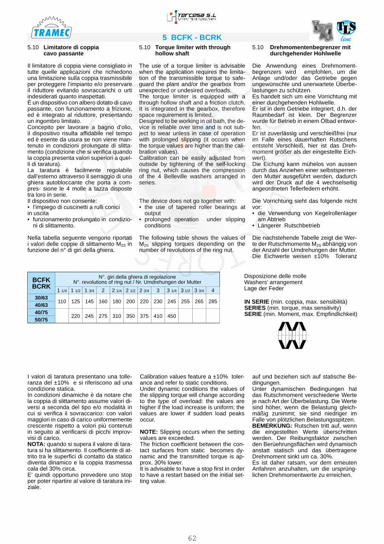
line5 BCFK - BCRK5.10 Drehmomentenbegrenzer mit durchgehender Hohlwelle
Die Anwendung eines Drehmoment- begrenzers wird empfohlen, um die Anlage und/oder das Getriebe gegen ungewünschte und unerwartete Überbe- lastungen zu schützen. Es handelt sich um eine Vorrichtung mit einer durchgehenden Hohlwelle. Er ist in dem Getriebe integriert, d.h. der Raumbedarf ist klein. Der Begrenzer wurde für Betrieb in einem Ölbad entwor-fen. Er ist zuverlässig und verschleißfrei (nur im Falle eines dauerhaften Rutschens entsteht Verschleiß, hier ist das Dreh-moment größer als der eingestellte Eich-wert).Die Eichung kann mühelos von aussen durch das Anziehen einer selbstsperren-den Mutter ausgeführt werden, dadurch wird der Druck auf die 4 wechselseitig angeordneten Tellerfedern erhöht.
Die Vorrichtung sieht das folgende nicht vor:• die Verwendung von Kegelrollenlager
am Abtrieb• Längerer Rutschbetrieb
Die nachstehende Tabelle zeigt die Wer-te der Rutschmomente M2S abhängig von der Anzahl der Umdrehungen der Mutter. Die Eichwerte weisen ±10% Toleranz
5.10 Torque limiter with through hollow shaft
The use of a torque limiter is advisable when the application requires the limita-tion of the transmissible torque to safe-guard the plant and/or the gearbox from unexpected or undesired overloads. The torque limiter is equipped with a through hollow shaft and a friction clutch. It is integrated in the gearbox, therefore space requirement is limited. Designed to be working in oil bath, the de-vice is reliable over time and is not sub-ject to wear unless in case of operation with prolonged slipping (it occurs when the torque values are higher than the cali-bration values). Calibration can be easily adjusted from outside by tightening of the self-locking ring nut, which causes the compression of the 4 Belleville washers arranged in series.
The device does not go together with:• the use of tapered roller bearings at
output• prolonged operation under slipping
conditions
The following table shows the values of M2S slipping torques depending on the number of revolutions of the ring nut.
5.10 Limitatore di coppia cavo passante
Il limitatore di coppia viene consigliato in tutte quelle applicazioni che richiedono una limitazione sulla coppia trasmissibile per proteggere l’impianto e/o preservare il riduttore evitando sovraccarichi o urti indesiderati quanto inaspettati.È un dispositivo con albero dotato di cavo passante, con funzionamento a frizione, ed è integrato al riduttore, presentando un ingombro limitato.Concepito per lavorare a bagno d’olio, il dispositivo risulta affidabile nel tempo ed è esente da usura se non viene man-tenuto in condizioni prolungate di slitta-mento (condizione che si verifica quando la coppia presenta valori superiori a quel-li di taratura).La taratura è facilmente regolabile dall’esterno attraverso il serraggio di una ghiera autobloccante che porta a com-pres- sione le 4 molle a tazza disposte tra loro in serie.Il dispositivo non consente:• l’impiego di cuscinetti a rulli conici in uscita• funzionamento prolungato in condizio-
ni di slittamento.
Nella tabella seguente vengono riportati i valori delle coppie di slittamento M2S in funzione del n° di giri della ghiera.
I valori di taratura presentano una tolle-ranza del ±10% e si riferiscono ad una condizione statica.In condizioni dinamiche è da notare che la coppia di slittamento assume valori di-versi a seconda del tipo e/o modalità in cui si verifica il sovraccarico: con valori maggiori in caso di carico uniformemente crescente rispetto a volori più contenuti in seguito al verificarsi di picchi improv-visi di carico. NOTA: quando si supera il valore di tara-tura si ha slittamento. Il coefficiente di at-trito tra le superfici di contatto da statico diventa dinamico e la coppia trasmessa cala del 30% circa.E’ quindi opportuno prevedere uno stop per poter ripartire al valore di taratura ini-ziale.
Calibration values feature a ±10% toler-ance and refer to static conditions. Under dynamic conditions the values of the slipping torque will change according to the type of overload: the values are higher if the load increase is uniform; the values are lower if sudden load peaks occur.
NOTE: Slipping occurs when the setting values are exceeded. The friction coefficient between the con-tact surfaces from static becomes dy-namic and the transmitted torque is ap-prox. 30% lower. It is advisable to have a stop first in order to have a restart based on the initial set-ting value.
auf und beziehen sich auf statische Be-dingungen.Unter dynamischen Bedingungen hat das Rutschmoment verschiedene Werte je nach Art der Überbelastung. Die Werte sind höher, wenn die Belastung gleich-mäßig zunimmt; sie sind niedriger im Falle von plötzlichen Belastungsspitzen. BEMERKUNG: Rutschen tritt auf, wenn die eingestellten Werte überschritten werden. Der Reibungsfaktor zwischen den Berüehrungsflächen wird dynamisch anstatt statisch und das übertragene Drehmoment sinkt um ca. 30%. Es ist daher ratsam, vor dem erneuten Anfahren anzuhalten, um die ursprüng-lichen Drehmomentwerte zu erreichen.
IN SERIE (min. coppia, max. sensibilità)SERIES (min. torque, max sensitivity)SERIE (min. Moment, max. Empfindlichkeit)
Disposizione delle molleWashers’ arrangementLage der Feder
BCFK BCRK
N°. giri della ghiera di regolazioneN°. revolutions of ring nut / Nr. Umdrehungen der Mutter
1 1/4 1 1/2 1 3/4 2 2 1/4 2 1/2 2 3/4 3 3 1/4 3 1/2 3 3/4 430/63
110 125 145 160 180 200 220 230 245 255 265 28540/6340/75
220 245 275 310 350 375 410 45050/75
62

line 5 BCFK - BCRK
Es ist wichtig zu beachten, dass das Rutschmoment über die gesamte Le-bensdauer der Rutschkupplung nicht konstant bleibt, sondern üblicherweise in Verbindung mit längeren Rutschzyklen aufgrund der eingelaufenen Berührungs-flächen abnimmt.Deswegen ist es ratsam, die Eichung der Vorrichtung besonders während der Ein-laufzeit zu prüfen. Falls ein niedrigerer Eichfehler ge-wünscht ist, sollte das übertragbare Drehmoment auf der Anlage getestet werden.Wenn die Vorrichtung geliefert wird, ist sie schon auf das im Katalog T2M angegebenen Drehmoment geeicht, ausser wenn es in der Bestellung an-ders angegebene wird.
It is important to note that the slipping torque is not the same for the whole life of the torque limiter. It usually decreases in connection with the numbers and the duration of the slip-ping which because of the surfaces’ lap-ping will increase the efficiency.For this reason it is advisable to check the calibration of the device at regular intervals, specially during the running-in period. Should a smaller calibration error be re-quired, it is necessary to test the trans-missible torque on the plant.The device is supplied already cali-brated at the torque reported in the catalogue T2M, unless otherwise speci-fied in the order.
E’ importante notare che la coppia di slit-tamento non resta sempre la medesima durante tutta la vita del limitatore.Tende infatti a diminuire in rapporto al numero e alla durata degli slittamenti che, rodando le superfici di contatto, ne aumentano il rendimento.È quindi opportuno verificare periodica-mente, soprattutto durante la fase di ro-daggio, la taratura del dispositivo.Là dove sia richiesto un errore più conte-nuto nella taratura, è necessario testare la coppia trasmissibile sull’impianto.
Il dispositivo viene consegnato tara-to alla coppia riportata a catalogo T2M salvo diversa indicazione espressa in fase di ordinazione.
5.10 Drehmomentenbegrenzer mit durchgehender Hohlwelle
5.10 Torque limiter with through hollow shaft
5.10 Limitatore di coppia cavo passante
( ) A richiesta / On request / Auf Anfrage
The version with torque limiter is supplied without output shafts. The device is supplied already calibrated at the torque reported in the catalogue T2M, unless otherwise specified in the order.
Die Version mit Drehmomentbegrenzer wird ohne Abtriebswellen geliefert. Wenn die Vorrichtung geliefert wird, ist sie schon auf dem im Katalog T2M angegebenen Drehmoment geeicht, ausser wenn es in der Bestellung anders angegeben wird.
BCFK BCRK C2 CL Ct
D2H7
M2 G2
LD - LS30/6340/63 60 97 157 25 71x40.5x2.5 M40X1.5
40/7550/75 60 100 160 28 (30) 90x50.5x3.5 M50X1.5
Nella versione con limitatore non è prevista la fornitura degli alberi lenti. Il dispositivo viene consegnato tarato alla coppia riportata a catalogo T2M salvo diversa indicazione espressa in fase di ordinazione.
LD LS
63
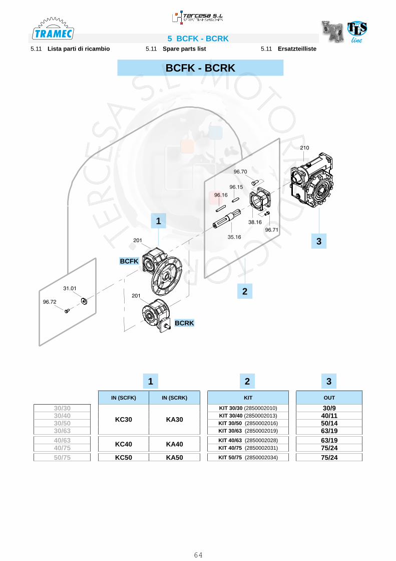
line5 BCFK - BCRK5.11 Ersatzteilliste5.11 Spare parts list5.11 Lista parti di ricambio
BCFK - BCRK
2
3
1
IN (SCFK) IN (SCRK) KIT OUT
30/30
KC30 KA30
KIT 30/30 (2850002010) 30/930/40 KIT 30/40 (2850002013) 40/1130/50 KIT 30/50 (2850002016) 50/1430/63 KIT 30/63 (2850002019) 63/1940/63 KC40 KA40
KIT 40/63 (2850002028) 63/1940/75 KIT 40/75 (2850002031) 75/2450/75 KC50 KA50 KIT 50/75 (2850002034) 75/24
1 32
BCFK
BCRK
64
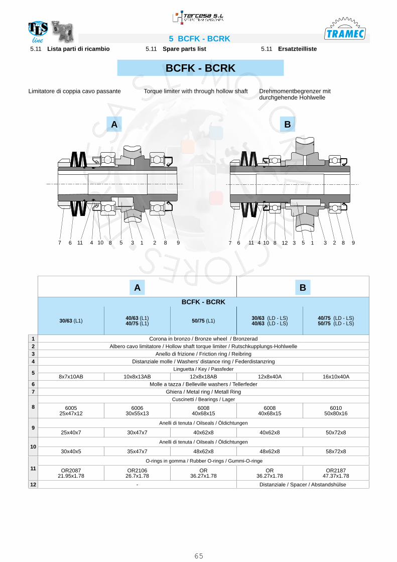
line 5 BCFK - BCRK5.11 Ersatzteilliste5.11 Spare parts list5.11 Lista parti di ricambio
BCFK - BCRK
Drehmomentbegrenzer mit durchgehende Hohlwelle
Torque limiter with through hollow shaftLimitatore di coppia cavo passante
9823153128106798213581011 114 467
A B
A BBCFK - BCRK
30/63 (L1) 40/63 (L1)40/75 (L1) 50/75 (L1) 30/63 (LD - LS)
40/63 (LD - LS)40/75 (LD - LS)50/75 (LD - LS)
1 Corona in bronzo / Bronze wheel / Bronzerad2 Albero cavo limitatore / Hollow shaft torque limiter / Rutschkupplungs-Hohlwelle3 Anello di frizione / Friction ring / Reibring4 Distanziale molle / Washers’ distance ring / Federdistanzring
5Linguetta / Key / Passfeder
8x7x10AB 10x8x13AB 12x8x18AB 12x8x40A 16x10x40A6 Molle a tazza / Belleville washers / Tellerfeder7 Ghiera / Metal ring / Metall Ring
8Cuscinetti / Bearings / Lager
6005 25x47x12
600630x55x13
600840x68x15
600840x68x15
601050x80x16
9Anelli di tenuta / Oilseals / Öldichtungen
25x40x7 30x47x7 40x62x8 40x62x8 50x72x8
10Anelli di tenuta / Oilseals / Öldichtungen
30x40x5 35x47x7 48x62x8 48x62x8 58x72x8
11 O-rings in gomma / Rubber O-rings / Gummi-O-ringe
OR2087 21.95x1.78
OR210626.7x1.78
OR36.27x1.78
OR36.27x1.78
OR218747.37x1.78
12 - Distanziale / Spacer / Abstandshülse
65


![Unità di comunicazione video HD KX-VC1600/KX … · Quando arriva uno squillo di una chiamata in entrata e si visualizza una finestra di dialogo, premere [START]. Se è impostata](https://static.fdocumenti.com/doc/165x107/5b9cc85f09d3f2f6368d37d0/unita-di-comunicazione-video-hd-kx-vc1600kx-quando-arriva-uno-squillo-di-una.jpg)